configuring ssl - cisco.com · step 5 copy and paste the csr into the certificate authority (ca)...
TRANSCRIPT
Cisco 4700 Series Application Control EngiOL-16197-01
C H A P T E R7
Configuring SSLThis topic describes the steps required to configure your ACE appliance as a virtual Secure Sockets Layer (SSL) server for SSL initiation or termination. The topics included in this section are:
• SSL Overview, page 7-1
• SSL Configuration Prerequisites, page 7-2
• Summary of SSL Configuration Steps, page 7-3
• Using SSL Certificates, page 7-4
• Using SSL Keys, page 7-7
• Configuring SSL Parameter Maps, page 7-13
• Configuring SSL Chain Group Parameters, page 7-15
• Configuring SSL CSR Parameters, page 7-16
• Generating CSRs, page 7-18
• Configuring SSL Proxy Service, page 7-19
• Enabling Client Authentication, page 7-20
SSL OverviewSSL is an application-level protocol that provides encryption technology for the Internet, ensuring secure transactions such as the transmission of credit card numbers for e-commerce Web sites. SSL initiation occurs when the ACE appliance acts as a client and initiates the SSL session between it and the SSL server. SSL termination occurs when the ACE, acting as an SSL server, terminates an SSL connection from a client and then establishes a TCP connection to an HTTP server.
SSL provides the secure transaction of data between a client and a server through a combination of privacy, authentication, and data integrity. SSL relies upon certificates and private-public key exchange pairs for this level of security.
Figure 7-1 shows the following network connections in which the ACE terminates the SSL connection with the client:
• Client to ACE—SSL connection between a client and the ACE acting as an SSL proxy server
• ACE to Server—TCP connection between the ACE and the HTTP server
7-1ne Appliance Device Manager Configuration Guide

Chapter 7 Configuring SSLSSL Configuration Prerequisites
Figure 7-1 SSL Termination with Client
The ACE uses parameter maps, SSL proxy services, and class maps to build the policy maps that determine the flow of information between the client, the ACE, and the server. SSL termination is a Layer 3 and Layer 4 application because it is based on the destination IP addresses of the inbound traffic flow from the client. For this type of application, you create a Layer 3 and Layer 4 policy map that the ACE applies to the inbound traffic.
If you have a need to delete any of the SSL objects (auth groups, chain groups, parameter maps, keys, CRLs, or certificates), you must remove the dependency from within the proxy service first before removing the SSL object.
Before configuring the ACE for SSL, see SSL Configuration Prerequisites, page 7-2.
SSL Configuration PrerequisitesBefore configuring your ACE for SSL operation, you must first ensure:
• Your ACE hardware is configured for server load balancing (SLB).
Note During the real server and server farm configuration process, when you associate a real server with a server farm, ensure that you assign an appropriate port number for the real server. The default behavior by the ACE is to automatically assign the same destination port that was used by the inbound connection to the outbound server connection if you do not specify a port.
• Your policy map is configured to define the SSL session parameters and client/server authentication tools, such as the certificate and RSA key pair.
• Your class map is associated with the policy map to define the virtual SSL server IP address that the destination IP address of the inbound traffic must match.
• You must import a digital certificate and its corresponding public and private key pair to the desired ACE context.
• At least one SSL certificate is available.
• If you do not have a certificate and corresponding key pair, you can generate an RSA key pair and a certificate signing request (CSR). Create a CSR when you need to apply for a certificate from a certificate authority (CA). The CA signs the CSR and returns the authorized digital certificate to you.
Client
Front-end Back-end
ServerCiphertext Clear Text
SSL Termination(ACE as Server) 15
3357
7-2Cisco 4700 Series Application Control Engine Appliance Device Manager Configuration Guide
OL-16197-01
Chapter 7 Configuring SSLSummary of SSL Configuration Steps
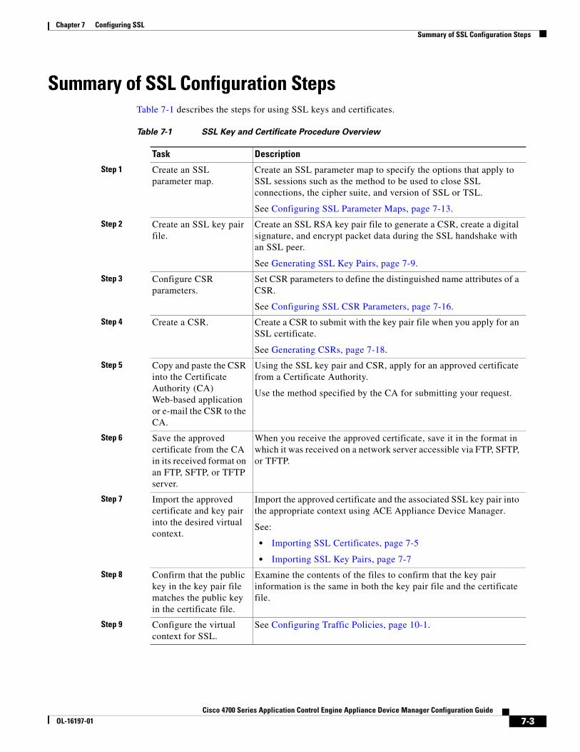
Summary of SSL Configuration StepsTable 7-1 describes the steps for using SSL keys and certificates.
Table 7-1 SSL Key and Certificate Procedure Overview
Task Description
Step 1 Create an SSL parameter map.
Create an SSL parameter map to specify the options that apply to SSL sessions such as the method to be used to close SSL connections, the cipher suite, and version of SSL or TSL.
See Configuring SSL Parameter Maps, page 7-13.
Step 2 Create an SSL key pair file.
Create an SSL RSA key pair file to generate a CSR, create a digital signature, and encrypt packet data during the SSL handshake with an SSL peer.
See Generating SSL Key Pairs, page 7-9.
Step 3 Configure CSR parameters.
Set CSR parameters to define the distinguished name attributes of a CSR.
See Configuring SSL CSR Parameters, page 7-16.
Step 4 Create a CSR. Create a CSR to submit with the key pair file when you apply for an SSL certificate.
See Generating CSRs, page 7-18.
Step 5 Copy and paste the CSR into the Certificate Authority (CA) Web-based application or e-mail the CSR to the CA.
Using the SSL key pair and CSR, apply for an approved certificate from a Certificate Authority.
Use the method specified by the CA for submitting your request.
Step 6 Save the approved certificate from the CA in its received format on an FTP, SFTP, or TFTP server.
When you receive the approved certificate, save it in the format in which it was received on a network server accessible via FTP, SFTP, or TFTP.
Step 7 Import the approved certificate and key pair into the desired virtual context.
Import the approved certificate and the associated SSL key pair into the appropriate context using ACE Appliance Device Manager.
See:
• Importing SSL Certificates, page 7-5
• Importing SSL Key Pairs, page 7-7
Step 8 Confirm that the public key in the key pair file matches the public key in the certificate file.
Examine the contents of the files to confirm that the key pair information is the same in both the key pair file and the certificate file.
Step 9 Configure the virtual context for SSL.
See Configuring Traffic Policies, page 10-1.
7-3Cisco 4700 Series Application Control Engine Appliance Device Manager Configuration Guide
OL-16197-01

Chapter 7 Configuring SSLUsing SSL Certificates
For more information about using SSL with ACE appliances, see the Cisco 4700 Series Application Control Engine Appliance SSL Configuration Guide.
To configure ACE appliances for SSL, see:
• Importing SSL Certificates, page 7-5
• Importing SSL Key Pairs, page 7-7
• Configuring SSL Parameter Maps, page 7-13
• Configuring SSL CSR Parameters, page 7-16
• Configuring SSL Chain Group Parameters, page 7-15
• Configuring SSL Proxy Service, page 7-19
Using SSL CertificatesDigital certificates and key pairs are a form of digital identification for user authentication. Certificate Authorities issue certificates that attest to the validity of the public keys they contain. A client or server certificate includes the following identification attributes:
• Name of the Certificate Authority and Certificate Authority digital signature
• Name of the client or server (the certificate subject) that the certificate authenticates
• Issuer
• Serial number
• Name of the client or server (the certificate subject) that the certificate authenticates
• Subject’s public key
• Time stamps that indicate the certificate's start date and expiration date
A Certificate Authority has one or more signing certificates that it uses for creating SSL certificates and certificate revocation lists (CRL). Each signing certificate has a matching private key that is used to create the Certificate Authority signature. The Certificate Authority makes the signing certificates (with the public key embedded) available to the public, enabling anyone to access and use the signing certificates to verify that an SSL certificate or CRL was actually signed by a specific Certificate Authority.
ACE appliances require certificates and corresponding key pairs for:
• SSL termination—The ACE appliance acts as an SSL proxy server and terminates the SSL session between it and the client. For SSL termination, you must obtain a server certificate and corresponding key pair.
• SSL initiation—The ACE appliance acts as a client and initiates the SSL session between it and the SSL server. For SSL initiation, you must obtain a client certificate and corresponding key pair.
Step 10 Configure auth group. Create a group of certificates that are trusted as certificate signers by creating an authentication group. See Configuring SSL Authentication Groups, page 7-20.
Step 11 Configure CRL. See Configuring CRLs for Client Authentication, page 7-21.
Table 7-1 SSL Key and Certificate Procedure Overview (continued)
Task Description
7-4Cisco 4700 Series Application Control Engine Appliance Device Manager Configuration Guide
OL-16197-01
Chapter 7 Configuring SSLImporting SSL Certificates
Related Topics
• Configuring SSL, page 7-1
• Exporting SSL Certificates, page 7-10
• Importing SSL Certificates, page 7-5
• Using SSL Keys, page 7-7
• Importing SSL Key Pairs, page 7-7
• Configuring SSL CSR Parameters, page 7-16
• Generating CSRs, page 7-18
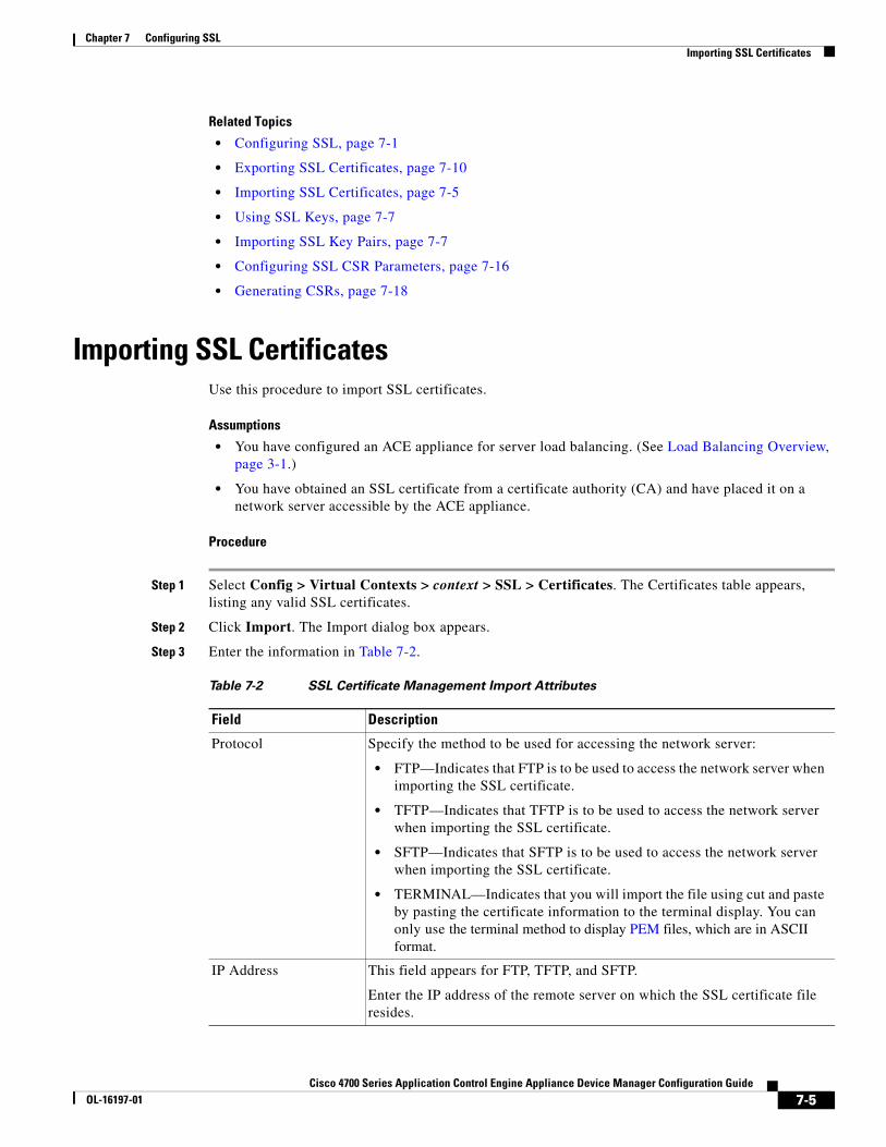
Importing SSL CertificatesUse this procedure to import SSL certificates.
Assumptions
• You have configured an ACE appliance for server load balancing. (See Load Balancing Overview, page 3-1.)
• You have obtained an SSL certificate from a certificate authority (CA) and have placed it on a network server accessible by the ACE appliance.
Procedure
Step 1 Select Config > Virtual Contexts > context > SSL > Certificates. The Certificates table appears, listing any valid SSL certificates.
Step 2 Click Import. The Import dialog box appears.
Step 3 Enter the information in Table 7-2.
Table 7-2 SSL Certificate Management Import Attributes
Field Description
Protocol Specify the method to be used for accessing the network server:
• FTP—Indicates that FTP is to be used to access the network server when importing the SSL certificate.
• TFTP—Indicates that TFTP is to be used to access the network server when importing the SSL certificate.
• SFTP—Indicates that SFTP is to be used to access the network server when importing the SSL certificate.
• TERMINAL—Indicates that you will import the file using cut and paste by pasting the certificate information to the terminal display. You can only use the terminal method to display PEM files, which are in ASCII format.
IP Address This field appears for FTP, TFTP, and SFTP.
Enter the IP address of the remote server on which the SSL certificate file resides.
7-5Cisco 4700 Series Application Control Engine Appliance Device Manager Configuration Guide
OL-16197-01
Chapter 7 Configuring SSLImporting SSL Certificates
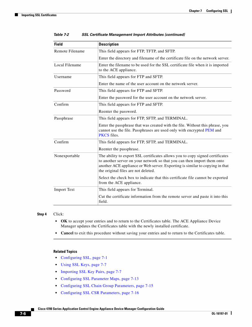
Step 4 Click:
• OK to accept your entries and to return to the Certificates table. The ACE Appliance Device Manager updates the Certificates table with the newly installed certificate.
• Cancel to exit this procedure without saving your entries and to return to the Certificates table.
Related Topics
• Configuring SSL, page 7-1
• Using SSL Keys, page 7-7
• Importing SSL Key Pairs, page 7-7
• Configuring SSL Parameter Maps, page 7-13
• Configuring SSL Chain Group Parameters, page 7-15
• Configuring SSL CSR Parameters, page 7-16
Remote Filename This field appears for FTP, TFTP, and SFTP.
Enter the directory and filename of the certificate file on the network server.
Local Filename Enter the filename to be used for the SSL certificate file when it is imported to the ACE appliance.
Username This field appears for FTP and SFTP.
Enter the name of the user account on the network server.
Password This field appears for FTP and SFTP.
Enter the password for the user account on the network server.
Confirm This field appears for FTP and SFTP.
Reenter the password.
Passphrase This field appears for FTP, SFTP, and TERMINAL.
Enter the passphrase that was created with the file. Without this phrase, you cannot use the file. Passphrases are used only with encrypted PEM and PKCS files.
Confirm This field appears for FTP, SFTP, and TERMINAL.
Reenter the passphrase.
Nonexportable The ability to export SSL certificates allows you to copy signed certificates to another server on your network so that you can then import them onto another ACE appliance or Web server. Exporting is similar to copying in that the original files are not deleted.
Select the check box to indicate that this certificate file cannot be exported from the ACE appliance.
Import Text This field appears for Terminal.
Cut the certificate information from the remote server and paste it into this field.
Table 7-2 SSL Certificate Management Import Attributes (continued)
Field Description
7-6Cisco 4700 Series Application Control Engine Appliance Device Manager Configuration Guide
OL-16197-01
Chapter 7 Configuring SSLUsing SSL Keys
• Configuring SSL Proxy Service, page 7-19
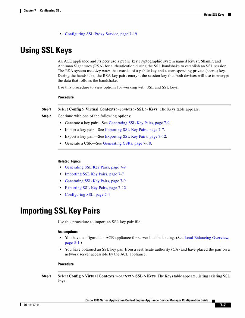
Using SSL KeysAn ACE appliance and its peer use a public key cryptographic system named Rivest, Shamir, and Adelman Signatures (RSA) for authentication during the SSL handshake to establish an SSL session. The RSA system uses key pairs that consist of a public key and a corresponding private (secret) key. During the handshake, the RSA key pairs encrypt the session key that both devices will use to encrypt the data that follows the handshake.
Use this procedure to view options for working with SSL and SSL keys.
Procedure
Step 1 Select Config > Virtual Contexts > context > SSL > Keys. The Keys table appears.
Step 2 Continue with one of the following options:
• Generate a key pair—See Generating SSL Key Pairs, page 7-9.
• Import a key pair—See Importing SSL Key Pairs, page 7-7.
• Export a key pair—See Exporting SSL Key Pairs, page 7-12.
• Generate a CSR—See Generating CSRs, page 7-18.
Related Topics
• Generating SSL Key Pairs, page 7-9
• Importing SSL Key Pairs, page 7-7
• Generating SSL Key Pairs, page 7-9
• Exporting SSL Key Pairs, page 7-12
• Configuring SSL, page 7-1
Importing SSL Key PairsUse this procedure to import an SSL key pair file.
Assumptions
• You have configured an ACE appliance for server load balancing. (See Load Balancing Overview, page 3-1.)
• You have obtained an SSL key pair from a certificate authority (CA) and have placed the pair on a network server accessible by the ACE appliance.
Procedure
Step 1 Select Config > Virtual Contexts > context > SSL > Keys. The Keys table appears, listing existing SSL keys.
7-7Cisco 4700 Series Application Control Engine Appliance Device Manager Configuration Guide
OL-16197-01
Chapter 7 Configuring SSLImporting SSL Key Pairs
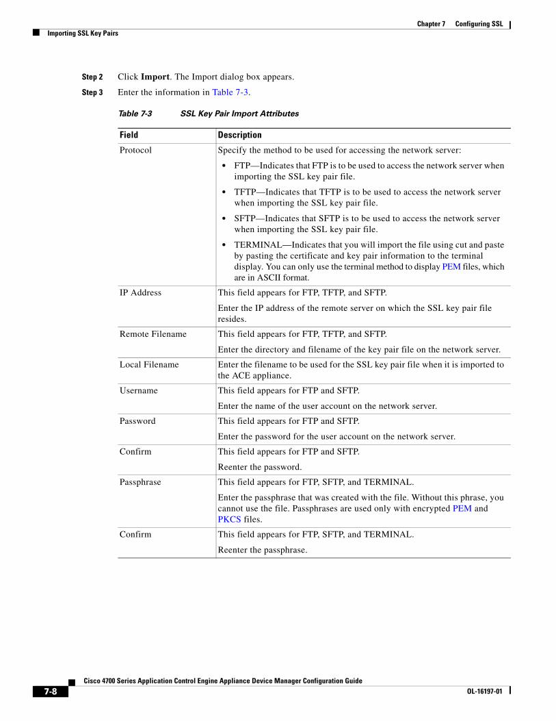
Step 2 Click Import. The Import dialog box appears.
Step 3 Enter the information in Table 7-3.
Table 7-3 SSL Key Pair Import Attributes
Field Description
Protocol Specify the method to be used for accessing the network server:
• FTP—Indicates that FTP is to be used to access the network server when importing the SSL key pair file.
• TFTP—Indicates that TFTP is to be used to access the network server when importing the SSL key pair file.
• SFTP—Indicates that SFTP is to be used to access the network server when importing the SSL key pair file.
• TERMINAL—Indicates that you will import the file using cut and paste by pasting the certificate and key pair information to the terminal display. You can only use the terminal method to display PEM files, which are in ASCII format.
IP Address This field appears for FTP, TFTP, and SFTP.
Enter the IP address of the remote server on which the SSL key pair file resides.
Remote Filename This field appears for FTP, TFTP, and SFTP.
Enter the directory and filename of the key pair file on the network server.
Local Filename Enter the filename to be used for the SSL key pair file when it is imported to the ACE appliance.
Username This field appears for FTP and SFTP.
Enter the name of the user account on the network server.
Password This field appears for FTP and SFTP.
Enter the password for the user account on the network server.
Confirm This field appears for FTP and SFTP.
Reenter the password.
Passphrase This field appears for FTP, SFTP, and TERMINAL.
Enter the passphrase that was created with the file. Without this phrase, you cannot use the file. Passphrases are used only with encrypted PEM and PKCS files.
Confirm This field appears for FTP, SFTP, and TERMINAL.
Reenter the passphrase.
7-8Cisco 4700 Series Application Control Engine Appliance Device Manager Configuration Guide
OL-16197-01
Chapter 7 Configuring SSLGenerating SSL Key Pairs
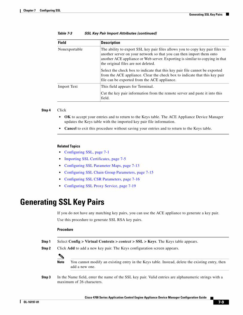
Step 4 Click
• OK to accept your entries and to return to the Keys table. The ACE Appliance Device Manager updates the Keys table with the imported key pair file information.
• Cancel to exit this procedure without saving your entries and to return to the Keys table.
Related Topics
• Configuring SSL, page 7-1
• Importing SSL Certificates, page 7-5
• Configuring SSL Parameter Maps, page 7-13
• Configuring SSL Chain Group Parameters, page 7-15
• Configuring SSL CSR Parameters, page 7-16
• Configuring SSL Proxy Service, page 7-19
Generating SSL Key PairsIf you do not have any matching key pairs, you can use the ACE appliance to generate a key pair.
Use this procedure to generate SSL RSA key pairs.
Procedure
Step 1 Select Config > Virtual Contexts > context > SSL > Keys. The Keys table appears.
Step 2 Click Add to add a new key pair. The Keys configuration screen appears.
Note You cannot modify an existing entry in the Keys table. Instead, delete the existing entry, then add a new one.
Step 3 In the Name field, enter the name of the SSL key pair. Valid entries are alphanumeric strings with a maximum of 26 characters.
Nonexportable The ability to export SSL key pair files allows you to copy key pair files to another server on your network so that you can then import them onto another ACE appliance or Web server. Exporting is similar to copying in that the original files are not deleted.
Select the check box to indicate that this key pair file cannot be exported from the ACE appliance. Clear the check box to indicate that this key pair file can be exported from the ACE appliance.
Import Text This field appears for Terminal.
Cut the key pair information from the remote server and paste it into this field.
Table 7-3 SSL Key Pair Import Attributes (continued)
Field Description
7-9Cisco 4700 Series Application Control Engine Appliance Device Manager Configuration Guide
OL-16197-01
Chapter 7 Configuring SSLExporting SSL Certificates
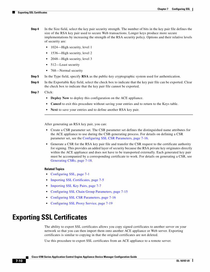
Step 4 In the Size field, select the key pair security strength. The number of bits in the key pair file defines the size of the RSA key pair used to secure Web transactions. Longer keys produce more secure implementations by increasing the strength of the RSA security policy. Options and their relative levels of security are:
• 1024—High security, level 1
• 1536—High security, level 2
• 2048—High security, level 3
• 512—Least security
• 768—Normal security
Step 5 In the Type field, specify RSA as the public-key cryptographic system used for authentication.
Step 6 In the Exportable Key field, select the check box to indicate that the key pair file can be exported. Clear the check box to indicate that the key pair file cannot be exported.
Step 7 Click:
• Deploy Now to deploy this configuration on the ACE appliance.
• Cancel to exit this procedure without saving your entries and to return to the Keys table.
• Next to save your entries and to define another RSA key pair.
After generating an RSA key pair, you can:
• Create a CSR parameter set. The CSR parameter set defines the distinguished name attributes for the ACE appliance to use during the CSR-generating process. For details on defining a CSR parameter set, see the Configuring SSL CSR Parameters, page 7-16.
• Generate a CSR for the RSA key pair file and transfer the CSR request to the certificate authority for signing. This provides an added layer of security because the RSA private key originates directly within the ACE appliance and does not have to be transported externally. Each generated key pair must be accompanied by a corresponding certificate to work. For details on generating a CSR, see Generating CSRs, page 7-18.
Related Topics
• Configuring SSL, page 7-1
• Importing SSL Certificates, page 7-5
• Importing SSL Key Pairs, page 7-7
• Configuring SSL Chain Group Parameters, page 7-15
• Configuring SSL CSR Parameters, page 7-16
• Configuring SSL Proxy Service, page 7-19
Exporting SSL CertificatesThe ability to export SSL certificates allows you copy signed certificates to another server on your network so that you can then import them onto another ACE appliance or Web server. Exporting certificates is similar to copying in that the original certificates are not deleted.
Use this procedure to export SSL certificates from an ACE appliance to a remote server.
7-10Cisco 4700 Series Application Control Engine Appliance Device Manager Configuration Guide
OL-16197-01
Chapter 7 Configuring SSLExporting SSL Certificates
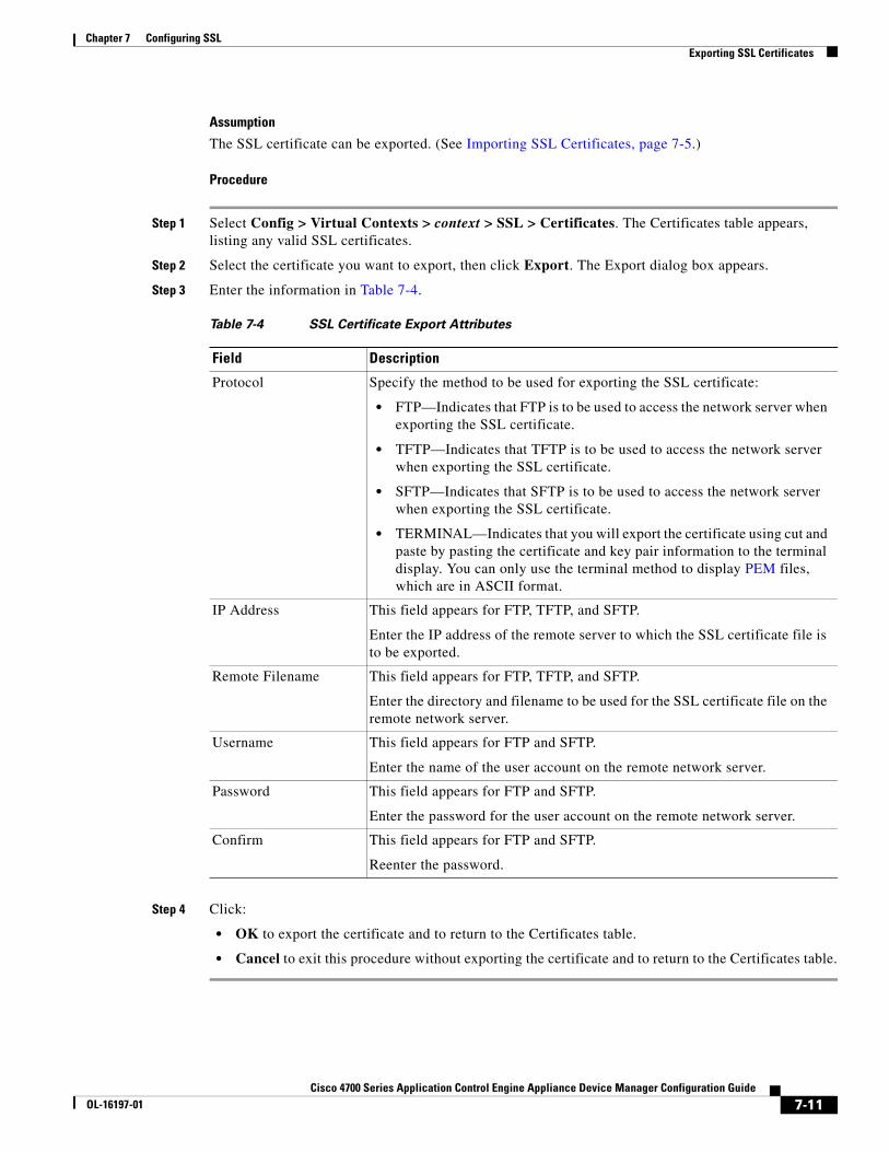
Assumption
The SSL certificate can be exported. (See Importing SSL Certificates, page 7-5.)
Procedure
Step 1 Select Config > Virtual Contexts > context > SSL > Certificates. The Certificates table appears, listing any valid SSL certificates.
Step 2 Select the certificate you want to export, then click Export. The Export dialog box appears.
Step 3 Enter the information in Table 7-4.
Step 4 Click:
• OK to export the certificate and to return to the Certificates table.
• Cancel to exit this procedure without exporting the certificate and to return to the Certificates table.
Table 7-4 SSL Certificate Export Attributes
Field Description
Protocol Specify the method to be used for exporting the SSL certificate:
• FTP—Indicates that FTP is to be used to access the network server when exporting the SSL certificate.
• TFTP—Indicates that TFTP is to be used to access the network server when exporting the SSL certificate.
• SFTP—Indicates that SFTP is to be used to access the network server when exporting the SSL certificate.
• TERMINAL—Indicates that you will export the certificate using cut and paste by pasting the certificate and key pair information to the terminal display. You can only use the terminal method to display PEM files, which are in ASCII format.
IP Address This field appears for FTP, TFTP, and SFTP.
Enter the IP address of the remote server to which the SSL certificate file is to be exported.
Remote Filename This field appears for FTP, TFTP, and SFTP.
Enter the directory and filename to be used for the SSL certificate file on the remote network server.
Username This field appears for FTP and SFTP.
Enter the name of the user account on the remote network server.
Password This field appears for FTP and SFTP.
Enter the password for the user account on the remote network server.
Confirm This field appears for FTP and SFTP.
Reenter the password.
7-11Cisco 4700 Series Application Control Engine Appliance Device Manager Configuration Guide
OL-16197-01
Chapter 7 Configuring SSLExporting SSL Key Pairs
Related Topics
• Configuring SSL, page 7-1
• Importing SSL Certificates, page 7-5
• Importing SSL Key Pairs, page 7-7
• Generating SSL Key Pairs, page 7-9
• Configuring SSL Chain Group Parameters, page 7-15
• Configuring SSL CSR Parameters, page 7-16
• Configuring SSL Proxy Service, page 7-19
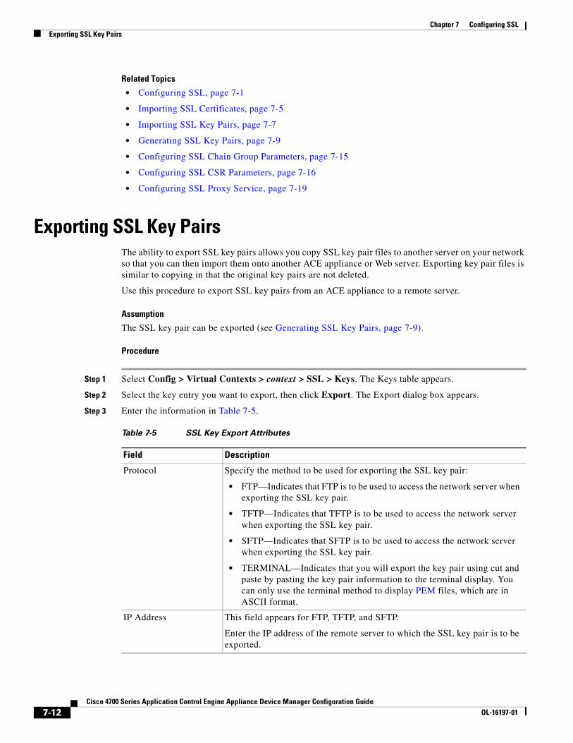
Exporting SSL Key PairsThe ability to export SSL key pairs allows you copy SSL key pair files to another server on your network so that you can then import them onto another ACE appliance or Web server. Exporting key pair files is similar to copying in that the original key pairs are not deleted.
Use this procedure to export SSL key pairs from an ACE appliance to a remote server.
Assumption
The SSL key pair can be exported (see Generating SSL Key Pairs, page 7-9).
Procedure
Step 1 Select Config > Virtual Contexts > context > SSL > Keys. The Keys table appears.
Step 2 Select the key entry you want to export, then click Export. The Export dialog box appears.
Step 3 Enter the information in Table 7-5.
Table 7-5 SSL Key Export Attributes
Field Description
Protocol Specify the method to be used for exporting the SSL key pair:
• FTP—Indicates that FTP is to be used to access the network server when exporting the SSL key pair.
• TFTP—Indicates that TFTP is to be used to access the network server when exporting the SSL key pair.
• SFTP—Indicates that SFTP is to be used to access the network server when exporting the SSL key pair.
• TERMINAL—Indicates that you will export the key pair using cut and paste by pasting the key pair information to the terminal display. You can only use the terminal method to display PEM files, which are in ASCII format.
IP Address This field appears for FTP, TFTP, and SFTP.
Enter the IP address of the remote server to which the SSL key pair is to be exported.
7-12Cisco 4700 Series Application Control Engine Appliance Device Manager Configuration Guide
OL-16197-01
Chapter 7 Configuring SSLConfiguring SSL Parameter Maps
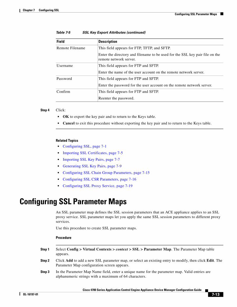
Step 4 Click:
• OK to export the key pair and to return to the Keys table.
• Cancel to exit this procedure without exporting the key pair and to return to the Keys table.
Related Topics
• Configuring SSL, page 7-1
• Importing SSL Certificates, page 7-5
• Importing SSL Key Pairs, page 7-7
• Generating SSL Key Pairs, page 7-9
• Configuring SSL Chain Group Parameters, page 7-15
• Configuring SSL CSR Parameters, page 7-16
• Configuring SSL Proxy Service, page 7-19
Configuring SSL Parameter MapsAn SSL parameter map defines the SSL session parameters that an ACE appliance applies to an SSL proxy service. SSL parameter maps let you apply the same SSL session parameters to different proxy services.
Use this procedure to create SSL parameter maps.
Procedure
Step 1 Select Config > Virtual Contexts > context > SSL > Parameter Map. The Parameter Map table appears.
Step 2 Click Add to add a new SSL parameter map, or select an existing entry to modify, then click Edit. The Parameter Map configuration screen appears.
Step 3 In the Parameter Map Name field, enter a unique name for the parameter map. Valid entries are alphanumeric strings with a maximum of 64 characters.
Remote Filename This field appears for FTP, TFTP, and SFTP.
Enter the directory and filename to be used for the SSL key pair file on the remote network server.
Username This field appears for FTP and SFTP.
Enter the name of the user account on the remote network server.
Password This field appears for FTP and SFTP.
Enter the password for the user account on the remote network server.
Confirm This field appears for FTP and SFTP.
Reenter the password.
Table 7-5 SSL Key Export Attributes (continued)
Field Description
7-13Cisco 4700 Series Application Control Engine Appliance Device Manager Configuration Guide
OL-16197-01
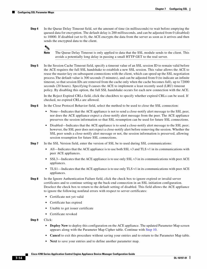
Chapter 7 Configuring SSLConfiguring SSL Parameter Maps
Step 4 In the Queue Delay Timeout field, set the amount of time (in milliseconds) to wait before emptying the queued data for encryption. The default delay is 200 milliseconds, and can be adjusted from 0 (disabled) to 10000. If disabled (set to 0), the ACE encrypts the data from the server as soon as it arrives and then sends the encrypted data to the client.
Note The Queue Delay Timeout is only applied to data that the SSL module sends to the client. This avoids a potentially long delay in passing a small HTTP GET to the real server.
Step 5 In the Session Cache Timeout field, specify a timeout value of an SSL session ID to remain valid before the ACE requires the full SSL handshake to establish a new SSL session. This value allows the ACE to reuse the master key on subsequent connections with the client, which can speed up the SSL negotiation process.The default value is 300 seconds (5 minutes), and can be adjusted from 0 (to indicate an infinite timeout, so that session IDs are removed from the cache only when the cache becomes full), up to 72000 seconds (20 hours). Specifying 0 causes the ACE to implement a least recently used (LRU) timeout policy. By disabling this option, the full SSL handshake occurs for each new connection with the ACE.
In the Reject Expired CRLs field, click the checkbox to specify whether expired CRLs can be used. If checked, no expired CRLs are allowed.
Step 6 In the Close Protocol Behavior field, select the method to be used to close the SSL connection:
• None—Indicates that the ACE appliance is not to send a close-notify alert message to the SSL peer, nor does the ACE appliance expect a close-notify alert message from the peer. The ACE appliance preserves the session information so that SSL resumption can be used for future SSL connections.
• Disabled—Indicates that the ACE appliance is to send a close-notify alert message to the SSL peer; however, the SSL peer does not expect a close-notify alert before removing the session. Whether the SSL peer sends a close-notify alert message or not, the session information is preserved, allowing session resumption for future SSL connections.
Step 7 In the SSL Version field, enter the version of SSL be to used during SSL communications:
• All—Indicates that the ACE appliance is to use both SSL v3 and TLS v1 in its communications with peer ACE appliances.
• SSL3—Indicates that the ACE appliance is to use only SSL v3 in its communications with peer ACE appliances.
• TLS1—Indicates that the ACE appliance is to use only TLS v1 in its communications with peer ACE appliances.
Step 8 In the Ignore Authentication Failure field, click the check box to ignore expired or invalid server certificates and to continue setting up the back-end connection in an SSL initiation configuration. Deselect the check box to return to the default setting of disabled. This field allows the ACE appliance to ignore the following nonfatal errors with respect to server certificates:
• Certificate not yet valid
• Certificate has expired
• Unable to get issuer certificate
• Certificate revoked
Step 9 Click:
• Deploy Now to deploy this configuration on the ACE appliance. The updated Parameter Map screen appears along with the Parameter Map Cipher table. Continue with Step 10.
• Cancel to exit this procedure without saving your entries and to return to the Parameter Map table.
• Next to save your entries and to define another parameter map.
7-14Cisco 4700 Series Application Control Engine Appliance Device Manager Configuration Guide
OL-16197-01
Chapter 7 Configuring SSLConfiguring SSL Chain Group Parameters
Step 10 In the Parameter Map Cipher table, click Add to add a cipher, or select an existing cipher, then click Edit. The Parameter Map Cipher configuration screen appears.
Step 11 In the Cipher Name field, select the cipher you want to use. For more information on the SSL cipher suites that ACE appliances support, see Cisco 4700 Series Application Control Engine Appliance SSL Configuration Guide.
Step 12 In the Cipher Priority field, enter the priority you want to assign to this cipher suite. The priority indicates the cipher’s preference for use. Valid entries are integers from 1 to 10 with 1 indicating the least preferred and 10 indicating the most preferred. When determining which cipher suite to use, the ACE appliance selects the cipher suite with the highest priority.
Step 13 Click:
• Deploy Now to deploy this configuration on the ACE appliance.
• Cancel to exit the procedure without saving your entries and to return to the Parameter Map Cipher table.
• Next to save your entries and to add another entry to the Parameter Map Cipher table.
Related Topics
• Configuring SSL, page 7-1
• Importing SSL Certificates, page 7-5
• Importing SSL Key Pairs, page 7-7
• Generating SSL Key Pairs, page 7-9
• Configuring SSL Chain Group Parameters, page 7-15
• Configuring SSL CSR Parameters, page 7-16
• Configuring SSL Proxy Service, page 7-19
Configuring SSL Chain Group ParametersA chain group specifies the certificate chains that the ACE appliance sends to its peer during the handshake process. A certificate chain is a hierarchal list of certificates that includes the ACE appliance’s certificate, the root certificate authority certificate, and any intermediate certificate authority certificates. Using the information provided in a certificate chain, the certificate verifier searches for a trusted authority in the certificate hierarchal list up to and including the root certificate authority. If the verifier finds a trusted authority before reaching the root certificate authority certificate, it stops searching further.
Use this procedure to configure certificate chains for a virtual context.
Assumption
At least one SSL certificate is available.
Procedure
Step 1 Select Config > Virtual Contexts > context > SSL > Chain Group Parameters. The Chain Group Parameters table appears.
7-15Cisco 4700 Series Application Control Engine Appliance Device Manager Configuration Guide
OL-16197-01
Chapter 7 Configuring SSLConfiguring SSL CSR Parameters
Step 2 Click Add to add a new chain group, or select an existing chain group, then click Edit to modify it. The Chain Group Parameters configuration screen appears.
Step 3 In the Chain Group Name field, enter a unique name for the chain group. Valid entries are alphanumeric strings with a maximum of 64 characters.
Step 4 Click:
• Deploy Now to deploy this configuration on the ACE appliance. The updated Chain Group Parameters screen appears along with the Chain Group Certificates table. Continue with Step 5.
• Cancel to exit the procedure without saving your entries and to return to the Chain Group Parameters table.
• Next to save your entries and to add another entry to the Chain Group Parameters table.
Step 5 In the Chain Group Certificates table, click Add to add an entry. The Chain Group Certificates configuration screen appears.
Note You cannot modify an existing entry in the Chain Group Certificates table. Instead, delete the entry, then add a new one.
Step 6 In the Certificate Name field, select the certificate to add to this chain group.
Step 7 Click:
• Deploy Now to deploy this configuration on the ACE appliance.
• Cancel to exit the procedure without saving your entries and to return to the Chain Group Certificates table.
• Next to save your entries and to add another certificate to this chain group table.
Related Topics
• Configuring SSL, page 7-1
• Importing SSL Certificates, page 7-5
• Importing SSL Key Pairs, page 7-7
• Generating SSL Key Pairs, page 7-9
• Configuring SSL Parameter Maps, page 7-13
• Configuring SSL CSR Parameters, page 7-16
• Configuring SSL Proxy Service, page 7-19
Configuring SSL CSR ParametersA certificate signing request (CSR) is a message you send to a certificate authority such as VeriSign and Thawte to apply for a digital identity certificate. The CSR contains information that identifies the SSL site, such as location and a serial number, and a public key that you choose. A corresponding private key is not included in the CSR, but is used to digitally sign the request. The CSR may be accompanied by other credentials or proofs of identity required by the certificate authority, and the certificate authority may contact the applicant for more information.
7-16Cisco 4700 Series Application Control Engine Appliance Device Manager Configuration Guide
OL-16197-01
Chapter 7 Configuring SSLConfiguring SSL CSR Parameters
If the request is successful, the certificate authority returns a digitally signed (with the private key of the certificate authority) identity certificate.
CSR parameters define the distinguished name attributes the ACE appliance applies to the CSR during the CSR-generating process. These attributes provide the certificate authority with the information it needs to authenticate your site. Defining a CSR parameter set lets you to generate multiple CSRs with the same distinguished name attributes.
Each context on an ACE appliance can contain up to eight CSR parameter sets.
Use this procedure to define the distinguished name attributes for SSL CSRs.
Procedure
Step 1 Select Config > Virtual Contexts > context > SSL > CSR Parameters. The CSR Parameters table appears.
Step 2 Click Add to add new set of CSR attributes, or select an existing entry to modify, then click Edit. The CSR Parameters configuration screen appears.
Step 3 In the Name field, enter a unique name for this parameter set. Valid entries are alphanumeric strings with a maximum of 64 characters.
Step 4 In the Country field, enter the name of the country where the SSL site resides. Valid entries are 2 alphabetic characters representing the country, such as US for the United States. The International Organization for Standardization (ISO) maintains the complete list of valid country codes on its Web site (www.iso.org).
Step 5 In the State field, enter the name of the state or province where the SSL site resides.
Step 6 In the Locality field, enter the name of the city where the SSL site resides.
Step 7 In the Common Name field, enter the name of the domain or host of the SSL site. Valid entries are alphanumeric strings with a maximum of 64 characters. The ACE supports the following special characters: , . / = + - ^ @ ! % ~ # $ * ( ) .
Step 8 In the Serial Number field, enter a serial number to assign to the certificate. Valid entries are alphanumeric strings with a maximum of 64 characters.
Step 9 In the Organization Name field, enter the name of the organization to include in the certificate. Valid entries are alphanumeric strings with a maximum of 64 characters.
Step 10 In the Email field, enter the site e-mail address. Valid entries are alphanumeric strings with a maximum of 40 characters.
Step 11 In the Organization Unit field, enter the name of the organization to include in the certificate. Valid entries are alphanumeric strings with a maximum of 64 characters.
Step 12 Click:
• Deploy Now to deploy this configuration on the ACE appliance.
• Cancel to exit this procedure without saving your entries and to return to the CSR Parameters table.
• Next to save your entries and to define another set of CSR attributes.
Related Topics
• Configuring SSL, page 7-1
• Importing SSL Certificates, page 7-5
• Importing SSL Key Pairs, page 7-7
7-17Cisco 4700 Series Application Control Engine Appliance Device Manager Configuration Guide
OL-16197-01
Chapter 7 Configuring SSLGenerating CSRs
• Configuring SSL Parameter Maps, page 7-13
• Configuring SSL Chain Group Parameters, page 7-15
• Configuring SSL Proxy Service, page 7-19
Generating CSRsA certificate signing request (CSR) is a message you send to a certificate authority such as VeriSign and Thawte to apply for a digital identity certificate. Create a CSR when you need to apply for a certificate from a certificate authority. When the certificate authority approves a request, it signs the CSR and returns the authorized digital certificate to you. This certificate includes the private key of the certificate authority. When you receive the authorized certificate and key pair, you can import them for use (see Importing SSL Certificates, page 7-5 and Importing SSL Key Pairs, page 7-7).
Use this procedure to generate SSL CSRs.
Assumption
You have configured SSL CSR parameters (see Configuring SSL CSR Parameters, page 7-16).
Procedure
Step 1 Select Config > Virtual Contexts > context > SSL > Keys. The Keys table appears.
Step 2 Select a key in the table, then click Generate CSR. The Generate a Certificate Signing Request dialog box appears.
Step 3 In the CSR Parameter field, select the CSR parameter to be used.
Step 4 Click:
• OK to generate the CSR. The CSR appears in a popup window which you can now submit to a certificate authority for approval. Work with your certificate authority to determine the method of submission, such as e-mail or a Web-based application. Click Close to close the popup window and to return to the Keys table.
• Cancel to exit this procedure without generating the CSR and to return to the Keys table.
Related Topics
• Configuring SSL, page 7-1
• Importing SSL Certificates, page 7-5
• Importing SSL Key Pairs, page 7-7
• Configuring SSL Parameter Maps, page 7-13
• Configuring SSL Chain Group Parameters, page 7-15
• Configuring SSL Proxy Service, page 7-19
7-18Cisco 4700 Series Application Control Engine Appliance Device Manager Configuration Guide
OL-16197-01
Chapter 7 Configuring SSLConfiguring SSL Proxy Service
Configuring SSL Proxy ServiceSSL proxy service defines the SSL parameter map, key pair, certificate, and chain group an ACE appliance uses during SSL handshakes. By configuring an SSL proxy server service on an ACE appliance, the ACE appliance can act as an SSL server.
Use this procedure to define the attributes that the ACE appliance is to use during SSL handshakes so that it can act as an SSL server.
Assumption
You have configured at least one SSL key pair, certificate, chain group, or parameter map to apply to this proxy service.
Procedure
Step 1 Select Config > Virtual Contexts > context > SSL > Proxy Service. The Proxy Service table appears.
Step 2 Click Add to add a new proxy service, or select an existing service, then click Edit to modify it. The Proxy Service configuration screen appears.
Step 3 In the Proxy Service Name field, enter a unique name for this proxy service. Valid entries are alphanumeric strings with a maximum of 26 characters.
Step 4 In the Key List field, select the key pair that the ACE appliance is to use during the SSL handshake for data encryption.
Step 5 In the Certificate List field, select the certificate that the ACE appliance is to use during the SSL handshake to prove its identity.
Step 6 In the Chain Group Name field, select the chain group that the ACE appliance is to use during the SSL handshake.
Step 7 In the Auth Group Name field, select the auth group name that the ACE is to use during the SSL handshake. To create an auth group, see Configuring SSL Authentication Groups, page 7-20.
The CRL Best-effort field displays only when Auth Group Name is selected. It allows the ACE appliance to search client certificates for the service to determine if it contains a CRL in the extension. The ACE appliance then retrieves the value, if it exists
Step 8 In the CRL Name field, enter the name of the CRL.
Step 9 In the Parameter Map Name field, select the SSL parameter map to associate with this SSL proxy server service.
Step 10 Click:
• Deploy Now to deploy this configuration on the ACE appliance.
• Cancel to exit this procedure without saving your entries and to return to the Proxy Service table.
• Next to save your entries and to add another proxy service.
Related Topics
• Configuring SSL, page 7-1
• Importing SSL Certificates, page 7-5
• Importing SSL Key Pairs, page 7-7
7-19Cisco 4700 Series Application Control Engine Appliance Device Manager Configuration Guide
OL-16197-01
Chapter 7 Configuring SSLEnabling Client Authentication
• Configuring SSL Parameter Maps, page 7-13
• Configuring SSL Chain Group Parameters, page 7-15
• Configuring SSL CSR Parameters, page 7-16
Enabling Client AuthenticationDuring the flow of a normal SSL handshake, the SSL server sends its certificate to the client. Then the client verifies the identity of the server through the certificate. However, the client does not send any identification of its own to the server. When you enable the client authentication feature enabled on the ACE, it will require that the client send a certificate to the server. Then the server verifies the following information on the certificate:
• A recognized CA issued the certificate.
• The valid period of the certificate is still in effect.
• The certificate signature is valid and not tampered.
• The CA has not revoked the certificate.
• At least one SSL certificate is available.
Use the following procedures to enable or disable client authentication:
• Configuring SSL Proxy Service, page 7-19
• Configuring SSL Authentication Groups, page 7-20
• Configuring CRLs for Client Authentication, page 7-21
Configuring SSL Authentication GroupsOn the ACE, you can implement a group of certificates that are trusted as certificate signers by creating an authentication group. After creating the authentication group and assigning its certificates, then you can assign the authentication group to a proxy service in an SSL termination configuration to enable client authentication. For information on client authentication, see Enabling Client Authentication, page 7-20.
For information on server authentication and assigning an authentication group, see Configuring SSL Proxy Service, page 7-19.
Use this procedure to specify the certificate authentication groups that the ACE uses during the SSL handshake and enable client authentication on this SSL-proxy service. The ACE includes the certificates configured in the group along with the certificate that you specified for the SSL proxy service.
Assumptions
• At least one SSL certificate is available.
• Your ACE appliance supports authentication groups.
Procedure
Step 1 Select Config > Virtual Contexts > context > SSL > Auth Group Parameters.
The Auth Group Parameters table appears.
7-20Cisco 4700 Series Application Control Engine Appliance Device Manager Configuration Guide
OL-16197-01
Chapter 7 Configuring SSLEnabling Client Authentication
Step 2 Click Add to add a authentication group, or select an existing auth group, then click Edit to modify it. The Auth Group Parameters configuration screen appears.
Step 3 In the Auth Group Name field, enter a unique name for the auth group. Valid entries are alphanumeric strings with a maximum of 64 characters.
Step 4 Click:
• Deploy Now to deploy this configuration on the ACE. The updated Auth Group Parameters screen appears along with the Auth Group Certificates table. Continue with Step 5.
• Cancel to exit the procedure without saving your entries and to return to the Auth Group Parameters table.
• Next to deploy your entries and to add another entry to the Auth Group Parameters table.
Step 5 In the Auth Group Certificates field, click Add to add an entry. The Auth Group Certificates configuration screen appears.
Note You cannot modify an existing entry in the Auth Group Certificates table. Instead, delete the entry, then add a new one.
Step 6 In the Certificate Name field, select the certificate to add to this auth group.
Step 7 Click:
• Deploy Now to deploy this configuration on the ACE.
• Cancel to exit the procedure without saving your entries and to return to the Auth Group Parameters table.
• Next to deploy your entries and to add another entry to the Auth Group Parameters table.
Step 8 You can repeat the previous step to add more certificates to the auth group or click Deploy Now.
Step 9 After you configure auth group parameters, you can configure the SSL proxy service to use a CRL. See Configuring CRLs for Client Authentication, page 7-21.
Note When you enable client authentication, a significant performance decrease may occur. Additional latency may occur when you configure CRL retrieval.
Related Topics
• Configuring SSL Chain Group Parameters, page 7-15
• Configuring CRLs for Client Authentication, page 7-21
Configuring CRLs for Client AuthenticationBy default, ACE does not use certificate revocation lists (CRLs) during client authentication. You can configure the SSL proxy service to use a CRL by having the ACE scan each client certificate for the service to determine if it contains a CRL in the extension and then retrieve the value, if it exists. For more information about SSL termination on the ACE, see the Cisco 4700 Series Application Control Engine Appliance SSL Configuration Guide.
7-21Cisco 4700 Series Application Control Engine Appliance Device Manager Configuration Guide
OL-16197-01
Chapter 7 Configuring SSLEnabling Client Authentication
Note When you enable client authentication, a significant performance decrease may occur. Additional latency may occur when you configure CRL retrieval.
Use this procedure to configure ACE to scan for CRLs and retrieve them.
Assumption
A CRL cannot be configured on an SSL proxy without first configuring an auth group.
Procedure
Step 1 Select Config > Virtual Contexts > context > SSL > Certificate Revocation List. The Certificate Revocation List table appears.
Step 2 Click Add to add a CRL or select an existing CRL, then click Edit to modify it. The Certificate Revocation List screen appears.
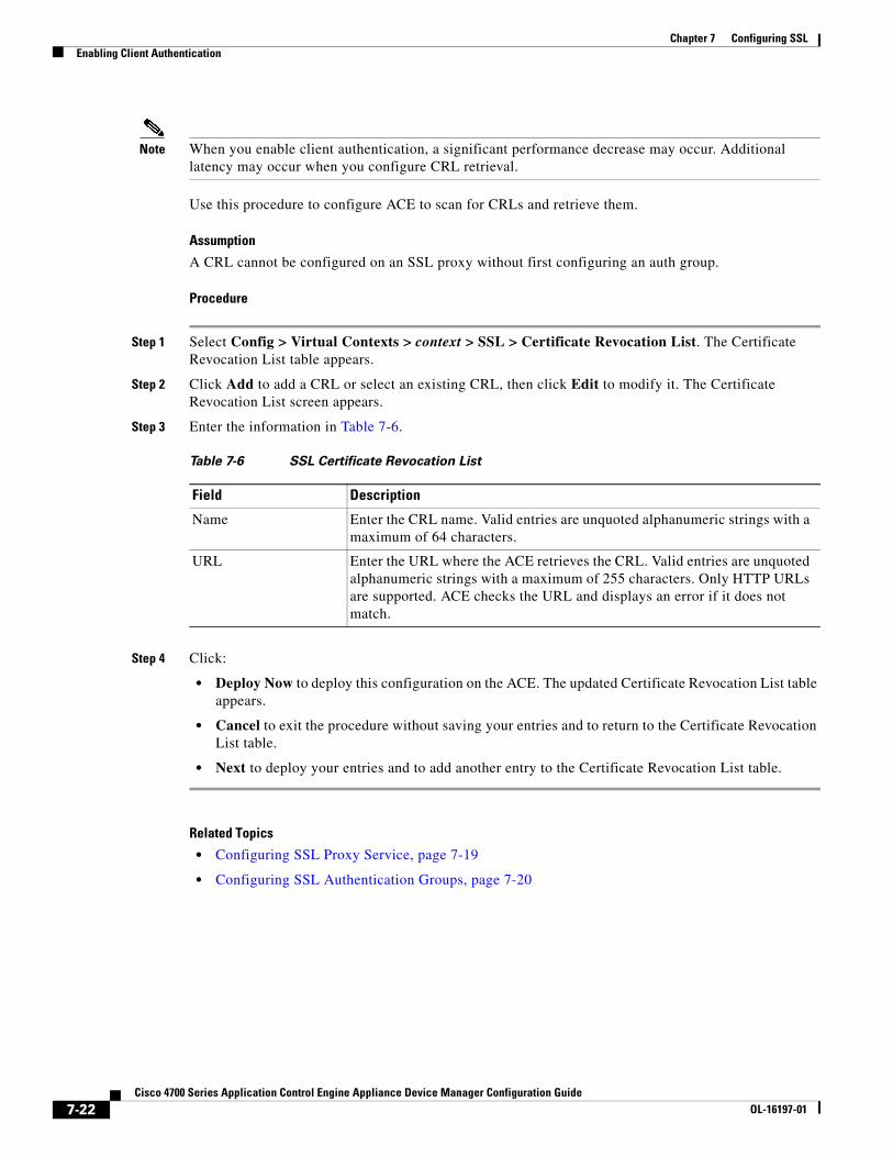
Step 3 Enter the information in Table 7-6.
Step 4 Click:
• Deploy Now to deploy this configuration on the ACE. The updated Certificate Revocation List table appears.
• Cancel to exit the procedure without saving your entries and to return to the Certificate Revocation List table.
• Next to deploy your entries and to add another entry to the Certificate Revocation List table.
Related Topics
• Configuring SSL Proxy Service, page 7-19
• Configuring SSL Authentication Groups, page 7-20
Table 7-6 SSL Certificate Revocation List
Field Description
Name Enter the CRL name. Valid entries are unquoted alphanumeric strings with a maximum of 64 characters.
URL Enter the URL where the ACE retrieves the CRL. Valid entries are unquoted alphanumeric strings with a maximum of 255 characters. Only HTTP URLs are supported. ACE checks the URL and displays an error if it does not match.
7-22Cisco 4700 Series Application Control Engine Appliance Device Manager Configuration Guide
OL-16197-01