configuring sonet - cisco. · pdf fileoverview of sonet...
TRANSCRIPT
Configuring SONET
This module describes how to configure Synchronous Optical NETwork (SONET). SONET defines opticalsignals and a synchronous frame structure for multiplexed digital traffic. SONET equipment is generally usedin North America.
The transport network using SONET provides much more powerful networking capabilities than existingasynchronous systems.
• Overview of SONET, on page 2• Restrictions for SONET, on page 2• SONET Switching , on page 3• SONET Hierarchy, on page 4• STS-1 and STS-3 Frames, on page 5• SONET Line and Section Configuration Parameters, on page 6• BERT, on page 7• Concatenated SONET Frames, on page 8• SONET Path Level Configuration Parameters, on page 8• Channelized SONET Frames, on page 9• SONET T1 Configuration Parameters, on page 9• SONET T3 Configuration Parameters, on page 9• SONET VT Configuration Parameters, on page 9• SONET Protection Switching , on page 10• Alarms at SONET Layers, on page 14• How to Configure SONET, on page 16• ONS Pluggables, on page 38• Configuring BERT in Sonet for CESoPSN, on page 40• Clock Recovery System in CESoPSN, on page 43• Configuring Clocking for ACR and DCR on APS for CESoPSN, on page 48• Configuring VT-15 mode of STS-1 for Framed SAToP, on page 52• Configuring DS1/T1 CT3 mode of STS-1 for Framed SAToP, on page 52• Verifying SONET Configuration for Framed SAToP, on page 53• Associated Commands, on page 53• Additional References for Configuring SONET on 1-Port OC192/STM-64 or 8-PortOC3/12/48/STM-1/-4/-16 Interface Module, on page 56
Configuring SONET1
Overview of SONETSONET is a set of standards that define the rates and formats for optical networks specified in GR–253–CORE.SONET is based on a structure that has a basic frame format and speed. The frame format used by SONETis the Synchronous Transport Signal (STS), with STS-1 as the base-level signal at 51.84 Mbps. An STS-1frame can be carried in an OC-1 signal.
SONET has a hierarchy of signaling speeds.
Restrictions for SONET• Rate combinations are 0-1, 2-3, 4-5, 6-7 and 8. A maximum rate of 4XOC-48 is supported on ports 0-7.
4XOC-48 can be configured in any one port of a port-group and other port is not used.
• Only 16 BERT Patterns can be configured at a time on 1-Port OC192/STM-64 or 8-PortOC3/12/48/STM-1/-4/-16 Module.
• VT1.5 VT cannot be configured if VT1.5 T1/DS1 is configured with the same KLM value.
• PMON fields are not supported for VT1.5 VT and DS3 or T3.
• PMON Far-end parameters are not supported.
Restrictions on Bandwidth
• Total available bandwidth for 1-Port OC192/STM-64 or 8-Port OC3/12/48/STM-1/-4/-16 Module is10G.
The following configuration is blocked and an error message is displayed after the maximum bandwidthis utilized:rate OC3| OC12| OC48| OC192
The bandwidth of adjacent ports should not exceed OC-48.
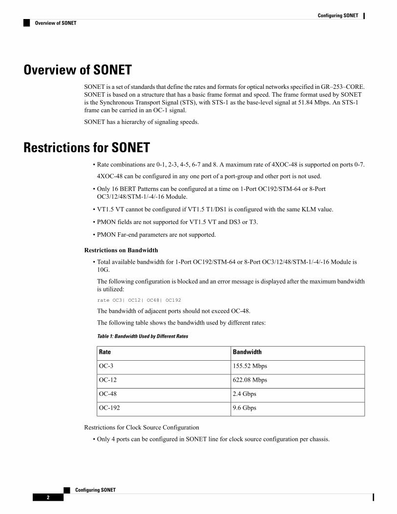
The following table shows the bandwidth used by different rates:
Table 1: Bandwidth Used by Different Rates
BandwidthRate
155.52 MbpsOC-3
622.08 MbpsOC-12
2.4 GbpsOC-48
9.6 GbpsOC-192
Restrictions for Clock Source Configuration
• Only 4 ports can be configured in SONET line for clock source configuration per chassis.
Configuring SONET2
Configuring SONETOverview of SONET
• You should configure the clock source line and network-clock sync together to receive the clock froma remote port that is connected to the SONET port.
SONET SwitchingSONET Switching is achieved on optical interface modules by circuit emulation. Circuit Emulation (CEM)is a way to carry TDMcircuits over packet switched network. CEM embeds TDMbits into packets, encapsulatesthem into an appropriate header and then sends that through Packet Switched Network (PSN). The receiverside of CEM restores the TDM bit stream from packets.
Modes of CEM:
• Structure Agnostic TDM over Packet (SAToP) (RFC 4553) – Structure-Agnostic TDM over Packet(SAToP) mode is used to encapsulate T1/E1 or T3/E3 unstructured (unchannelized) services over packetswitched networks. In SAToP mode, the bytes are sent out as they arrive on the TDM line. Bytes do nothave to be aligned with any framing.
In this mode, the interface is considered as a continuous framed bit stream. The packetization of thestream is done according to IETF RFC 4553. All signaling is carried transparently as a part of a bit stream.
• Circuit Emulation Service over Packet (CEP) (RFC 4842) - CEP mode is used to encapsulate SONETpayload envelopes (SPEs) like VT1.5 or VT2 or STS-1 or STS-Nc over packet switched networks. Inthis mode, the bytes from the corresponding SPE are sent out as they arrive on the TDM line. The interfaceis considered as a continuous framed bit stream. The packetization of the stream is done according toIETF RFC 4842.
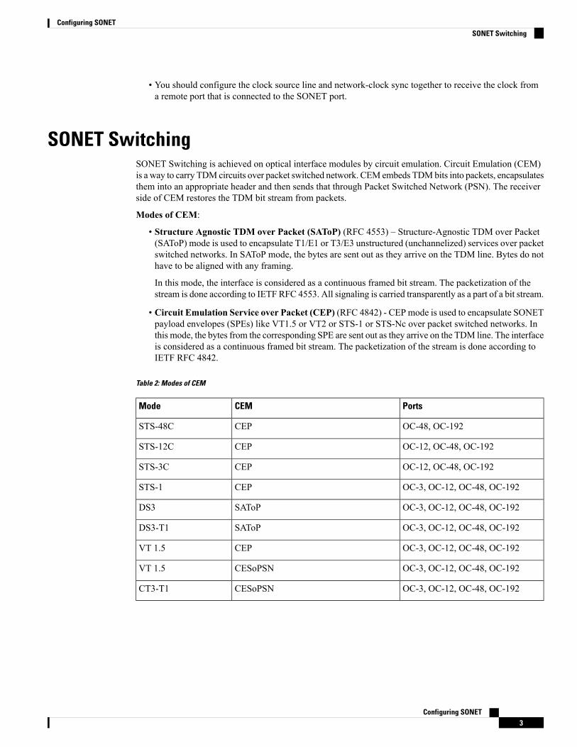
Table 2: Modes of CEM
PortsCEMMode
OC-48, OC-192CEPSTS-48C
OC-12, OC-48, OC-192CEPSTS-12C
OC-12, OC-48, OC-192CEPSTS-3C
OC-3, OC-12, OC-48, OC-192CEPSTS-1
OC-3, OC-12, OC-48, OC-192SAToPDS3
OC-3, OC-12, OC-48, OC-192SAToPDS3-T1
OC-3, OC-12, OC-48, OC-192CEPVT 1.5
OC-3, OC-12, OC-48, OC-192CESoPSNVT 1.5
OC-3, OC-12, OC-48, OC-192CESoPSNCT3-T1
Configuring SONET3
Configuring SONETSONET Switching
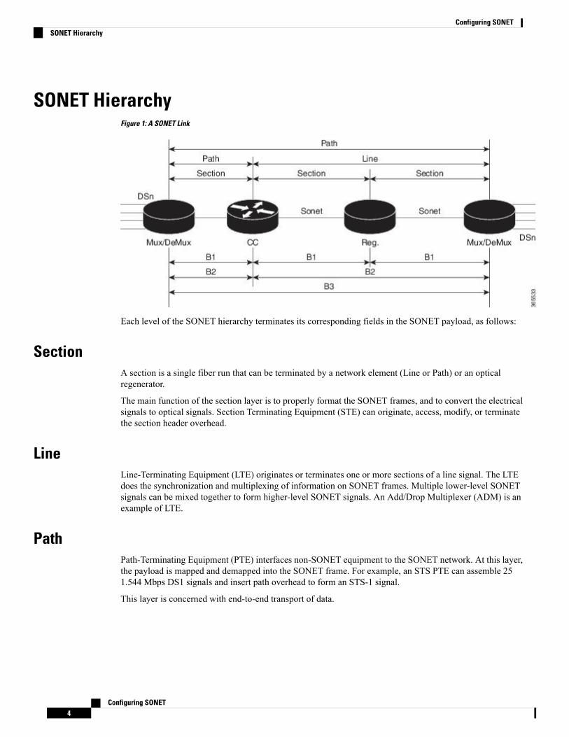
SONET HierarchyFigure 1: A SONET Link
Each level of the SONET hierarchy terminates its corresponding fields in the SONET payload, as follows:
SectionA section is a single fiber run that can be terminated by a network element (Line or Path) or an opticalregenerator.
The main function of the section layer is to properly format the SONET frames, and to convert the electricalsignals to optical signals. Section Terminating Equipment (STE) can originate, access, modify, or terminatethe section header overhead.
LineLine-Terminating Equipment (LTE) originates or terminates one or more sections of a line signal. The LTEdoes the synchronization and multiplexing of information on SONET frames. Multiple lower-level SONETsignals can be mixed together to form higher-level SONET signals. An Add/Drop Multiplexer (ADM) is anexample of LTE.
PathPath-Terminating Equipment (PTE) interfaces non-SONET equipment to the SONET network. At this layer,the payload is mapped and demapped into the SONET frame. For example, an STS PTE can assemble 251.544 Mbps DS1 signals and insert path overhead to form an STS-1 signal.
This layer is concerned with end-to-end transport of data.
Configuring SONET4
Configuring SONETSONET Hierarchy
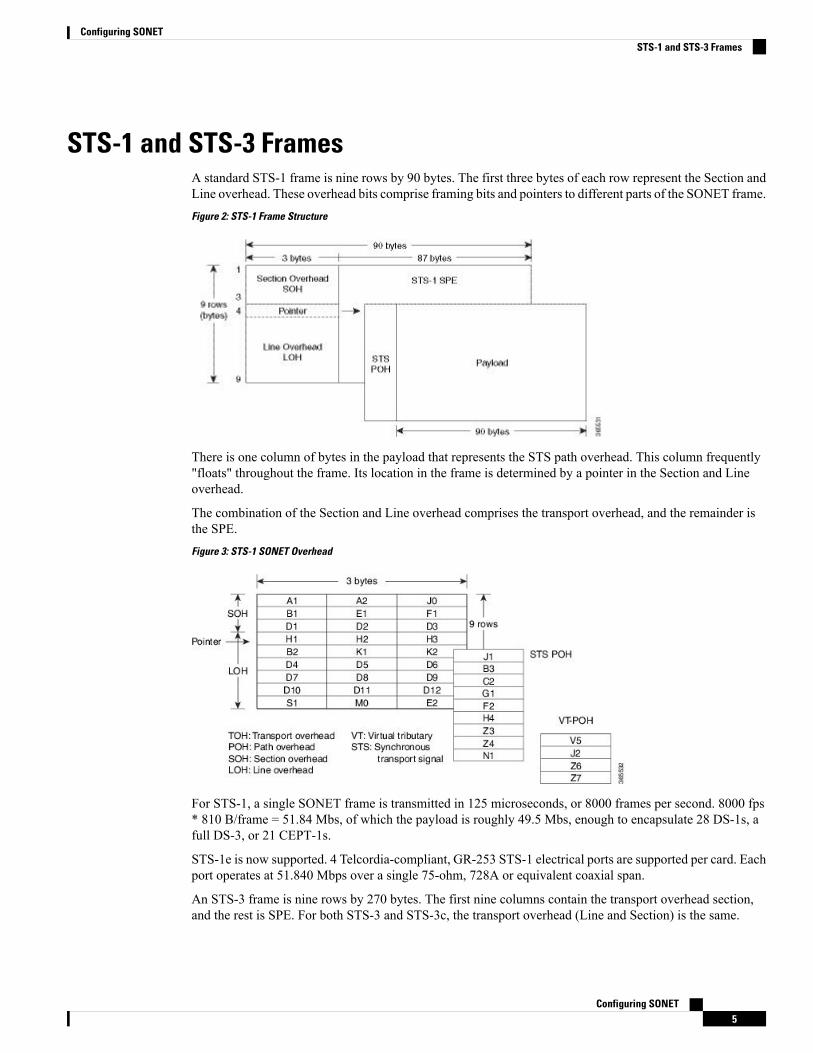
STS-1 and STS-3 FramesA standard STS-1 frame is nine rows by 90 bytes. The first three bytes of each row represent the Section andLine overhead. These overhead bits comprise framing bits and pointers to different parts of the SONET frame.Figure 2: STS-1 Frame Structure
There is one column of bytes in the payload that represents the STS path overhead. This column frequently"floats" throughout the frame. Its location in the frame is determined by a pointer in the Section and Lineoverhead.
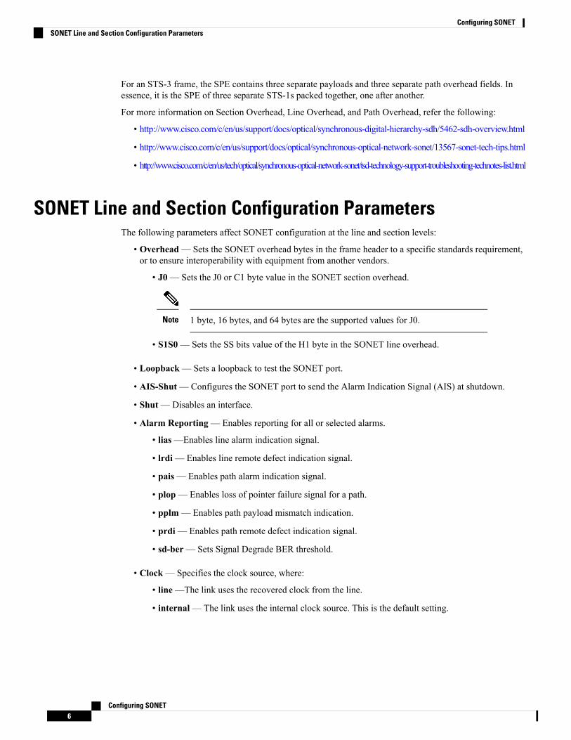
The combination of the Section and Line overhead comprises the transport overhead, and the remainder isthe SPE.Figure 3: STS-1 SONET Overhead
For STS-1, a single SONET frame is transmitted in 125 microseconds, or 8000 frames per second. 8000 fps* 810 B/frame = 51.84 Mbs, of which the payload is roughly 49.5 Mbs, enough to encapsulate 28 DS-1s, afull DS-3, or 21 CEPT-1s.
STS-1e is now supported. 4 Telcordia-compliant, GR-253 STS-1 electrical ports are supported per card. Eachport operates at 51.840 Mbps over a single 75-ohm, 728A or equivalent coaxial span.
An STS-3 frame is nine rows by 270 bytes. The first nine columns contain the transport overhead section,and the rest is SPE. For both STS-3 and STS-3c, the transport overhead (Line and Section) is the same.
Configuring SONET5
Configuring SONETSTS-1 and STS-3 Frames
For an STS-3 frame, the SPE contains three separate payloads and three separate path overhead fields. Inessence, it is the SPE of three separate STS-1s packed together, one after another.
For more information on Section Overhead, Line Overhead, and Path Overhead, refer the following:
• http://www.cisco.com/c/en/us/support/docs/optical/synchronous-digital-hierarchy-sdh/5462-sdh-overview.html
• http://www.cisco.com/c/en/us/support/docs/optical/synchronous-optical-network-sonet/13567-sonet-tech-tips.html
• http://www.cisco.com/c/en/us/tech/optical/synchronous-optical-network-sonet/tsd-technology-support-troubleshooting-technotes-list.html
SONET Line and Section Configuration ParametersThe following parameters affect SONET configuration at the line and section levels:
• Overhead— Sets the SONET overhead bytes in the frame header to a specific standards requirement,or to ensure interoperability with equipment from another vendors.
• J0— Sets the J0 or C1 byte value in the SONET section overhead.
1 byte, 16 bytes, and 64 bytes are the supported values for J0.Note
• S1S0— Sets the SS bits value of the H1 byte in the SONET line overhead.
• Loopback— Sets a loopback to test the SONET port.
• AIS-Shut—Configures the SONET port to send the Alarm Indication Signal (AIS) at shutdown.
• Shut—Disables an interface.
• Alarm Reporting— Enables reporting for all or selected alarms.
• lias—Enables line alarm indication signal.
• lrdi— Enables line remote defect indication signal.
• pais— Enables path alarm indication signal.
• plop— Enables loss of pointer failure signal for a path.
• pplm— Enables path payload mismatch indication.
• prdi— Enables path remote defect indication signal.
• sd-ber— Sets Signal Degrade BER threshold.
• Clock— Specifies the clock source, where:
• line—The link uses the recovered clock from the line.
• internal— The link uses the internal clock source. This is the default setting.
Configuring SONET6
Configuring SONETSONET Line and Section Configuration Parameters
BERTBit-Error Rate Testing (BERT) is used for analyzing quality and for problem resolution of digital transmissionequipment. BERT tests the quality of an interface by directly comparing a pseudorandom or repetitive testpattern with an identical locally generated test pattern.
The BERT operation is data-intensive. Regular data cannot flow on the path while the test is in progress. Thepath is reported to be in alarm state when BERT is in progress and restored to a normal state after BERT hasbeen terminated.
The supported BERT patterns are 2^15, 2^20, 2^23, all 0s.
BERT is supported in the following two directions:
• Line—Supports BERT in TDM direction.
• System—Supports BERT in PSN direction.
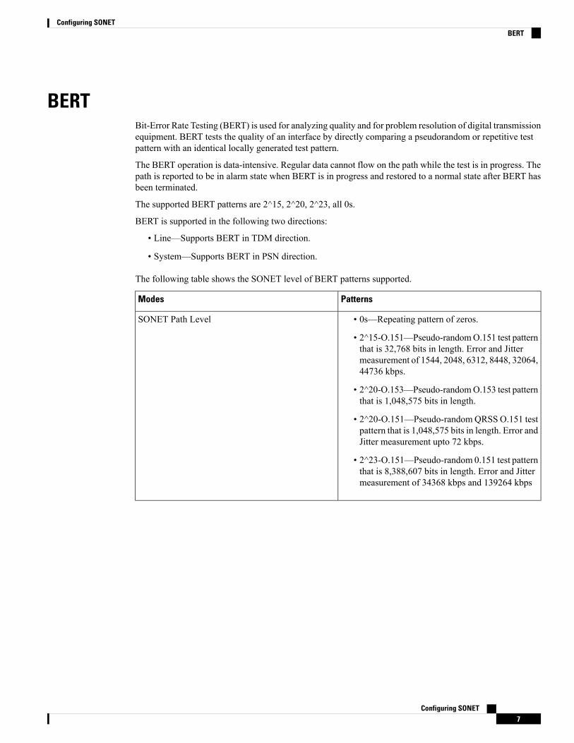
The following table shows the SONET level of BERT patterns supported.
PatternsModes
• 0s—Repeating pattern of zeros.
• 2^15-O.151—Pseudo-randomO.151 test patternthat is 32,768 bits in length. Error and Jittermeasurement of 1544, 2048, 6312, 8448, 32064,44736 kbps.
• 2^20-O.153—Pseudo-randomO.153 test patternthat is 1,048,575 bits in length.
• 2^20-O.151—Pseudo-randomQRSS O.151 testpattern that is 1,048,575 bits in length. Error andJitter measurement upto 72 kbps.
• 2^23-O.151—Pseudo-random 0.151 test patternthat is 8,388,607 bits in length. Error and Jittermeasurement of 34368 kbps and 139264 kbps
SONET Path Level
Configuring SONET7
Configuring SONETBERT
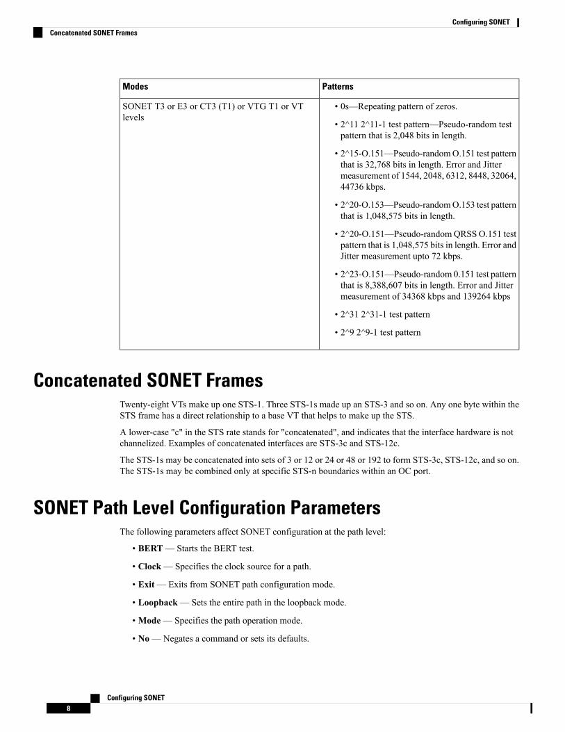
PatternsModes
• 0s—Repeating pattern of zeros.
• 2^11 2^11-1 test pattern—Pseudo-random testpattern that is 2,048 bits in length.
• 2^15-O.151—Pseudo-randomO.151 test patternthat is 32,768 bits in length. Error and Jittermeasurement of 1544, 2048, 6312, 8448, 32064,44736 kbps.
• 2^20-O.153—Pseudo-randomO.153 test patternthat is 1,048,575 bits in length.
• 2^20-O.151—Pseudo-randomQRSS O.151 testpattern that is 1,048,575 bits in length. Error andJitter measurement upto 72 kbps.
• 2^23-O.151—Pseudo-random 0.151 test patternthat is 8,388,607 bits in length. Error and Jittermeasurement of 34368 kbps and 139264 kbps
• 2^31 2^31-1 test pattern
• 2^9 2^9-1 test pattern
SONET T3 or E3 or CT3 (T1) or VTG T1 or VTlevels
Concatenated SONET FramesTwenty-eight VTs make up one STS-1. Three STS-1s made up an STS-3 and so on. Any one byte within theSTS frame has a direct relationship to a base VT that helps to make up the STS.
A lower-case "c" in the STS rate stands for "concatenated", and indicates that the interface hardware is notchannelized. Examples of concatenated interfaces are STS-3c and STS-12c.
The STS-1s may be concatenated into sets of 3 or 12 or 24 or 48 or 192 to form STS-3c, STS-12c, and so on.The STS-1s may be combined only at specific STS-n boundaries within an OC port.
SONET Path Level Configuration ParametersThe following parameters affect SONET configuration at the path level:
• BERT— Starts the BERT test.
• Clock— Specifies the clock source for a path.
• Exit— Exits from SONET path configuration mode.
• Loopback— Sets the entire path in the loopback mode.
• Mode— Specifies the path operation mode.
• No—Negates a command or sets its defaults.
Configuring SONET8
Configuring SONETConcatenated SONET Frames
• Overhead—Configures SONET path overhead flags.
• Shutdown—Disables the SONET path.
• Threshold— Sets the path BER threshold values.
• vtg— Sets the VT-15 configuration.
Channelized SONET FramesA channelized SONET interface is a composite of lower-speed STS streams. However, a channelized SONETinterface maintains the streams as independent frames with unique payload pointers. The frames are simplymultiplexed before transmission to increase the carrying capacity of the physical fiber. This process is similarto multiplexing 24 digital signal level 0 channels into a DS1 or multiplexing 28 DS1 streams into a DS3.
SONET T1 Configuration ParametersThe following parameters affect SONET T1 configuration:
• BERT— Starts the BERT test.
• Clock— Specifies the clock source for T1 interface.
• Description— Specifies the description of the controller.
• Framing— Specifies the type of a framing on T1 interface.
• Loopback— Sets the T1 interface in the loopback mode.
• Shutdown—Disables the T1 interface.
SONET T3 Configuration ParametersThe following parameters affect SONET T3 configuration:
• Clock— Specifies the clock source for T3 link.
• Description— Specifies the description of the controller.
• Framing— Specifies the type of a framing on T3 interface.
• Loopback— Sets the T3 link in the loopback mode.
• Shutdown—Disables the T3 interface.
SONET VT Configuration ParametersThe following parameters affect SONET VT configuration:
• BERT— Starts the BERT test.
Configuring SONET9
Configuring SONETChannelized SONET Frames
CEM Group— Specifies the time slots for CEM group mapping.
• Clock— Specifies the clock source for VT.
• Description— Specifies the description of the controller.
• Loopback— Sets the VT in the loopback mode.
• Overhead—Configures VT line path overhead flags.
• Shutdown—Disables the VT interface.
• Threshold—Configures the VT threshold values.
SONET Protection SwitchingAutomatic protection switching (APS) is a protection mechanism for SONET networks that enables SONETconnections to switch to another SONET circuit when a circuit failure occurs. A protection interface servesas the backup interface for the working interface. When the working interface fails, the protection interfacequickly assumes its traffic load.
The SONET protection schemes comply with GR-253 and ITU-T G.783. It allows Optical Interface Moduleto work seamlessly as SONETAdd or DropMultiplexers (ADMs). The implementation of the above protectionschemes allows a pair of SONET lines or paths to be configured for line or path redundancy. In the event ofa fiber cut, the active line or path switches automatically to the standby line or path up to 60 milliseconds(2/5/10 millisecond for holdover and 50 millisecond switchovers).
Optical Interface Module supports the following SONET protection switching schemes:
• Linear Bidirectional 1+1 APS
• Linear Unidirectional 1+1 APS
1+1 APSIn the 1+1 architecture, there is one working interface (circuit) and one protection interface, and the samepayload from the transmitting end is sent to both the receiving ends. The receiving end decides which interfaceto use. The line overhead (LOH) bytes (K1 and K2) in the SONET frame indicate both status and action.
The protection interfaces need to be configured with an IP address of the chassis that has the working interface,using APS commands. The APS Protect Group Protocol, which runs on top of UDP, provides communicationbetween the process controlling the working interface and the process controlling the protection interface.Using this protocol, interfaces can be switched because of a chassis failure, degradation or loss of channelsignal, or manual intervention. In bidirectional mode, the receive and transmit channels are switched as a pair.
Two SONET connections are required to support APS.
The following option is available for linear bidirectional 1+1 APS:
• Revertive option — For any failure on working line, the software switches to protection line and whenthe working line recovers, it waits based on the revertive timer and reverts back to working line as activelink.
• Non-revertive option —When the signal fails, the software switches to the protection line and does notautomatically revert back to the working line. This is the default option.
Configuring SONET10
Configuring SONETSONET Protection Switching
The following features are supported on 1+1 APS:
• SONET PW (SAToP or CEP)
• SONET local connect
Benefits of APSThe following lists the benefits of APS:
• APS performs switchovers with minimal loss of data and time-consuming reroutes are avoided.• There is no visibility that a failure has occurred beyond the network element in which it is residing; othernodes are not affected by the failure.
• Implementation of APS guards a network against complex restarts and resynchronizations since failuresare isolated to a local device.
• With APS, the effect of a failure is greatly minimized and a fast switchover guarantees minimal effecton the network.
APS 1+1 for SONET Layer 1 trafficSONET linear APS 1+1 provides protection against both fiber cuts and front card or back card failures. APS1+1 requires a redundant protection line for every working line. The traffic is simultaneously carried by theworking and the protection lines. Hence, the receiver that terminates the APS 1+1 should select the trafficfrom one of the lines and continue to forward the traffic. APS 1+1 provides protection in unidirectional andbi-directional modes:
• Uni-directional Protection: The receiving end can switch from working to protection line without anycoordination at the transmit end since both lines transmit the same information.
• Bi-directional Protection: The receiving end switches from working to protection line by coordinatingat the transmit end.
Scenario for Bidirectional APS 1+1
In the above figure, two are connected to provide APS 1+1 bi-directional protection. The highlighted one isthe working line and the other is the protection line. The traffic is transmitted on both working and protectionlines and received only on one line.
In a scenario where you encounter a fiber cut,
1. There is a cable cut in the working line. So, the receives a Loss of Signal (LOS) on working line.
2. starts generating K2 byte and sends it to the over the protection line.
3. receives the K2 byte and reacts on the receiving K2 byte.
4. starts sending K1 byte to the on the protection line.
5. starts sending K2 byte to on the protection line.
6. receives the K1/K2 byte and starts receiving the data from protection line. The protection line now actsas the active line.
7. sends K2 byte over the new active line to . receives this signal and starts accepting the data from this newactive line.
Configuring SONET11
Configuring SONETBenefits of APS
Scenario for Unidirectional APS 1+1
In the above figure, two are connected to provide APS 1+1 unidirectional protection. The figure shows aworking line and a protection line. The traffic is transmitted on both working and protection line and receivedonly on one line.
In a scenario where you encounter a fiber cut,
1. receives a LOS on RX working line.
2. detects LOS and starts receiving the data from the protection line. The protection line now becomes theactive line.
3. receives the K2 byte and knows about switching event on device 2.
UPSR Path Protection
A Unidirectional Path Switching Ring (UPSR) is a unidirectional network with two rings, one ring used asthe working ring and the other as the protection ring. The same signal flows through both rings, one clockwiseand the other counterclockwise. It is called UPSR because monitoring is done at the path layer. A node receivestwo copies of the electrical signals at the path layer, compares them, and chooses the one with the betterquality. If part of a ring between two ADMs fails, the other ring still can guarantee the continuation of dataflow. UPSR, like the one-plus-one scheme, has fast failure recovery.
Once a signal fail condition or a signal degrade condition is detected, the hardware initiates an interrupt tosoftware that switches from the working path to the protection path. Non-revertive options are valid for UPSRpath protection.
1XOC-192 and 8XOC-48 interface modules only supports the non-revertive option. The non-revertive optionis the default mode.
Note
When active link of UPSR and APS is configured on the same interface module and the interface modulereloads, the convergence number for UPSR circuits to switch to backup is high ranging from 100 ms to 200ms. When each circuit is configured separately, the convergence time is always under 50 ms.
Note
The below table gives the maximum number of path level circuits supported in each mode.
Supported ScaleModes
84VT 1.5
48STS-1
16STS 3c
4STS 12c
1STS 48c
The following feature is supported on UPSR Path Protection:
Configuring SONET12
Configuring SONETScenario for Unidirectional APS 1+1
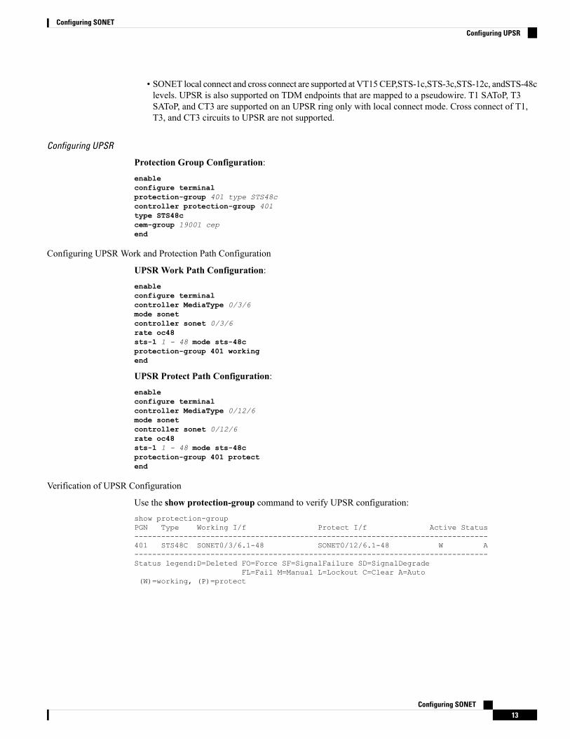
• SONET local connect and cross connect are supported at VT15CEP,STS-1c,STS-3c,STS-12c, andSTS-48clevels. UPSR is also supported on TDM endpoints that are mapped to a pseudowire. T1 SAToP, T3SAToP, and CT3 are supported on an UPSR ring only with local connect mode. Cross connect of T1,T3, and CT3 circuits to UPSR are not supported.
Configuring UPSR
Protection Group Configuration:enableconfigure terminalprotection-group 401 type STS48ccontroller protection-group 401type STS48ccem-group 19001 cepend
Configuring UPSR Work and Protection Path Configuration
UPSRWork Path Configuration:enableconfigure terminalcontroller MediaType 0/3/6mode sonetcontroller sonet 0/3/6rate oc48sts-1 1 - 48 mode sts-48cprotection-group 401 workingend
UPSR Protect Path Configuration:enableconfigure terminalcontroller MediaType 0/12/6mode sonetcontroller sonet 0/12/6rate oc48sts-1 1 - 48 mode sts-48cprotection-group 401 protectend
Verification of UPSR Configuration
Use the show protection-group command to verify UPSR configuration:show protection-groupPGN Type Working I/f Protect I/f Active Status-------------------------------------------------------------------------------401 STS48C SONET0/3/6.1-48 SONET0/12/6.1-48 W A-------------------------------------------------------------------------------Status legend:D=Deleted FO=Force SF=SignalFailure SD=SignalDegrade
FL=Fail M=Manual L=Lockout C=Clear A=Auto(W)=working, (P)=protect
Configuring SONET13
Configuring SONETConfiguring UPSR
Alarms at SONET LayersSONET equipment detects events and alarms at each of SONET's three layers — section, line and path.Typically, a SONET chassis sends alarms both upstream and downstream in order to notify other devices ofthe problem condition.
SONET Alarm SurveillanceSONET alarm surveillance uses two terms:
• State—Condition that is reported or detected. A SONET chassis enters a state when the chassis detectsthe occurrence of an event. A SONET chassis exits that state when the chassis no longer detects theevent.
• Indication—Prompted by a change of state. This indicates the presence of a condition. This documentdiscusses the Alarm Indication Signal (AIS), and Remote Defect Indicator (RDI).
The interface of active alarm or defect is maintained in a down/down state. The process used to troubleshootdown/down SONET interfaces is similar to that for digital interfaces, such as T1 and T3.
Section AlarmsThe following section alarms are supported:
• LOS — Loss of Signal
• LOF — Loss of Frame
• SEF — Severely Error Frame
Line AlarmsThe following line alarms are supported:
• AIS-L — Line AIS
• REI-L — Line Remote Error Indication
• RDI-L — Line Remote Defect Indication
• B2 — Line BIP Error (SF/SD)
• TCA for B2
Path AlarmsThe following path alarms are supported:
• AIS-P — STS Path AIS
• LOP-P — STS Path Loss of Pointer
• B3 (SF/SD) — STS Path BIP Error
Configuring SONET14
Configuring SONETAlarms at SONET Layers
• UNEQ-P — STS Path unequipped
• REI-P — STS Path Remote Error
• RDI-P — STS Path Remote Defect Indication
• PLM-P — STS path Payload Label Mismatch
• LOM— Loss of MultiFrame
• TCA for B3
VT AlarmsThe following VT alarms are supported:
• AIS-V — VT Path AIS
• LOP-V — VT Loss of Pointer
• V-BIP (SF/SD) — VT Path BIP error
• UNEQ-V — VT Path Unequipped
• REI-V — VT Path Remote Error
• RDI-V — VT Path Remote Defect Indication
• PLM-V — VT path Payload Label Mismatch
• TCA for VT Level BIP
T1 AlarmsThe following T1 alarms are supported:
• LOS — DS1/E1 Line loss of Signal
• AIS — DS1/E1 Path Alarm Indication Signal
• AIS-CI — DS1/E1 Path Alarm Indication Signal Customer Installation
• LOF — DS1/E1 Path Loss of Frame
• RDI/RAI — Remote Defect Indication or Remote Alarm Indication
• RAI-CI — Remote Alarm Indication Customer Installation
• TCA for Line and Path DS1
T3 AlarmsThe following T3 or path alarms are supported:
• LOS — DS3/E3 Line Loss of Signal
• OOF — DS3/E3 Path Loss of Frame
• SEF — DS3/E3 Path Severely Errored Frame
Configuring SONET15
Configuring SONETVT Alarms
• AIS — DS3/E3 Path Alarm Indication Signal
• SEF/AIS-FE — Far End SEF/AIS
• TCA for Line and Path DS3
Alarm IndicatorsTypically, a failure condition detected by a SONET chassis results in one or more error conditions sent bothupstream and downstream on the network. An AIS is sent in order to alert downstream chassis of a problemand in order to prevent consequential downstream failures or alarms from being raised.
How to Configure SONETThis section describes how to configure SONET.
Each SFP port (0-7) can be configured as OC-3, OC-12, OC-48, or Gigabit Ethernet. SFP+ port (8) can beconfigured as OC-192 or 10 Gigabit Ethernet.
To use the above features, you need to apply a valid license.Note
Prerequisites for Configuring SONETYou must select the MediaType controller to configure and enter the controller configuration mode.
You must configure the controller as a SONET port.
Configuring MediaType ControllerTo configure MediaType Controller, use the following commands:enableconfigure terminalcontroller MediaType 0/5/0mode sonetend
Configuring SONET PortsTo configure SONET ports, use the following commands:enableconfigure terminalcontroller MediaType 0/5/0mode sonetcontroller sonet 0/5/0rate OC12end
The above example shows how to configure SONET ports in OC-12 mode.
Configuring SONET16
Configuring SONETAlarm Indicators
Managing and Monitoring SONET LineThis section describes how to manage and monitor SONET.
Configuring Line and Section OverheadTo configure line and section overhead, use the following commands:enableconfigure terminalcontroller MediaType 0/5/0mode sonetcontroller sonet 0/5/0overhead s1s0 2overhead j0 tx length 1-byteend
To restore the system to its default condition, use the no form of the command.Note
Configuring Line and Section ThresholdTo configure line and section threshold, use the following commands:enableconfigure terminalcontroller sonet 0/5/0threshold b2-tca 3end
To restore the system to its default condition, use the no form of the command.Note
enableconfigure terminalcontroller sonet 0/5/0threshold b2-tca 3end
To restore the system to its default condition, use the no form of the command.Note
Configuring Line LoopbackTo configure loopback, use the following commands:enableconfigure terminalcontroller sonet 0/5/0loopback localend
Configuring SONET17
Configuring SONETManaging and Monitoring SONET Line
To restore the system to its default condition, use the no form of the command.Note
Configuring AIS ShutTo configure AIS-Shut, use the following commands:enableconfigure terminalcontroller sonet 0/5/0ais-shutend
The no ais-shut command will not send AIS.Note
Configuring ShutTo configure Shut, use the following commands:enableconfigure terminalcontroller sonet 0/5/0shutdownend
Use the no shutdown command to disable the interface.Note
Configuring Alarm ReportingTo configure alarm reporting, use the following commands:enableconfigure terminalcontroller sonet 0/5/0alarm-report b2-tcsend
To restore the system to its default condition, use the no form of the command.Note
Configuring ClockTo configure clock, use the following commands:enableconfigure terminalcontroller MediaType 0/5/0mode sonetcontroller sonet 0/5/0
Configuring SONET18
Configuring SONETConfiguring AIS Shut
clock source lineend
The default mode is internal.Note
To restore the system to its default condition, use the no form of the command.Note
Configuring Network-Clock SONET
To configure network-clock SONET, use the following commands:enableconfigure terminalnetwork-clock input-source 1 controller sonet 0/5/0end
Configuring STS-1 ModesTo configure STS-1 modes, use the following commands:enableconfigure terminalcontroller sonet 0/5/0sts-1 1mode vt-15end
There is no default mode. The following modes are supported:
• mode vt-15
• mode ct3
• mode cte-e1
• mode t3
• mode unframed
• mode vt-2
Note
To restore the system to its default condition, use the no form of the command.Note
Configuring DS1/T1 CT3 mode of STS-1
To configure DS1/T1 CT3 mode of STS-1, you can configure the T1 link using the following steps:enableconfigure terminal
Configuring SONET19
Configuring SONETConfiguring STS-1 Modes
controller sonet 0/5/0sts-1 1mode ct3t1 1 clock source internalt1 1 framing unframedend
To restore the system to its default condition, use the no form of the command.Note
Configuring STS-Nc - Contiguous Concatenation
To configure STS-Nc - contiguous concatenation, use the following commands:enableconfigure terminalcontroller sonet 0/5/0sts-1 1-3 mode sts-3cend
To restore the system to its default condition, use the no form of the command.Note
To configure STS-3c or STS-12c, use the numbers as multiples for 3 or 12, respectively.Note
Configuring CEM Group for Sonet Mode VT1.5-T1 in CESoPSN
To configure CEM group in VT 1.5 mode of STS-1 for CESoPSN, use the following commands:
enableconfigure terminalcontroller sonet 0/5/0sts-1 2mode vt-15vtg 1 t1 1 cem-group 56 timeslots 1 - 8end
Configuring CEM Group for Sonet Mode CT3-T1 in CESoPSN
To configure CEM group in CT3 mode of STS-1 for CESoPSN, use the following commands:
enableconfigure terminalcontroller sonet 0/5/0sts-1 1mode ct3t1 3 cem-group 28 timeslots 1 - 7end
Configuring APS for SAToP
This section describes the configuration of APS for SAToP.
Configuring SONET20
Configuring SONETConfiguring STS-Nc - Contiguous Concatenation
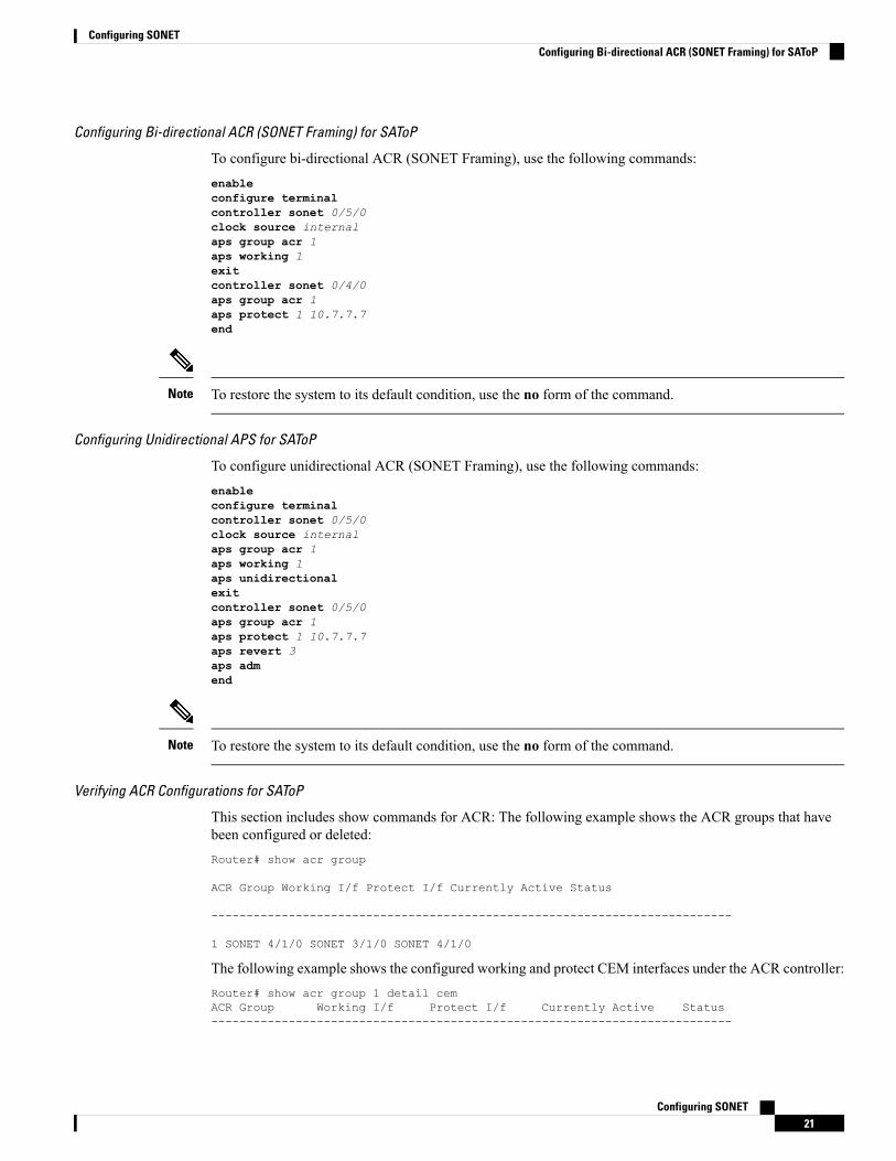
Configuring Bi-directional ACR (SONET Framing) for SAToP
To configure bi-directional ACR (SONET Framing), use the following commands:enableconfigure terminalcontroller sonet 0/5/0clock source internalaps group acr 1aps working 1exitcontroller sonet 0/4/0aps group acr 1aps protect 1 10.7.7.7end
To restore the system to its default condition, use the no form of the command.Note
Configuring Unidirectional APS for SAToP
To configure unidirectional ACR (SONET Framing), use the following commands:enableconfigure terminalcontroller sonet 0/5/0clock source internalaps group acr 1aps working 1aps unidirectionalexitcontroller sonet 0/5/0aps group acr 1aps protect 1 10.7.7.7aps revert 3aps admend
To restore the system to its default condition, use the no form of the command.Note
Verifying ACR Configurations for SAToP
This section includes show commands for ACR: The following example shows the ACR groups that havebeen configured or deleted:Router# show acr group
ACR Group Working I/f Protect I/f Currently Active Status
--------------------------------------------------------------------------
1 SONET 4/1/0 SONET 3/1/0 SONET 4/1/0
The following example shows the configured working and protect CEM interfaces under the ACR controller:Router# show acr group 1 detail cemACR Group Working I/f Protect I/f Currently Active Status--------------------------------------------------------------------------
Configuring SONET21
Configuring SONETConfiguring Bi-directional ACR (SONET Framing) for SAToP
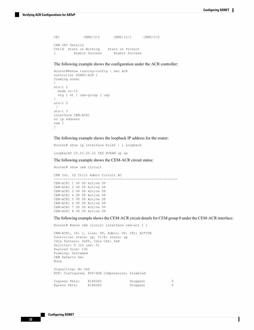
CE1 CEM0/3/0 CEM0/12/1 CEM0/3/0
CEM CKT DetailsCktid State on Working State on Protect1 Enable Success Enable Success
The following example shows the configuration under the ACR controller:Router##show running-config | sec ACRcontroller SONET-ACR 1framing sonet!sts-1 1mode vt-15vtg 1 vt 1 cem-group 1 cep
!sts-1 2!sts-1 3interface CEM-ACR1no ip addresscem 1!
The following example shows the loopback IP address for the router:Router# show ip interface brief | i Loopback
Loopback0 22.22.22.22 YES NVRAM up up
The following example shows the CEM-ACR circuit status:Router# show cem circuit
CEM Int. ID Ctrlr Admin Circuit AC--------------------------------------------------------------CEM-ACR1 1 UP UP Active UPCEM-ACR1 2 UP UP Active UPCEM-ACR1 3 UP UP Active UPCEM-ACR1 4 UP UP Active UPCEM-ACR1 5 UP UP Active UPCEM-ACR1 6 UP UP Active UPCEM-ACR1 7 UP UP Active UPCEM-ACR1 8 UP UP Active UP
The following example shows the CEM-ACR circuit details for CEM group 0 under the CEM-ACR interface:Router# #show cem circuit interface cem-acr 1 1
CEM-ACR1, ID: 1, Line: UP, Admin: UP, Ckt: ACTIVEController state: up, T1/E1 state: upIdle Pattern: 0xFF, Idle CAS: 0x8Dejitter: 6 (In use: 0)Payload Size: 192Framing: UnframedCEM Defects SetNone
Signalling: No CASRTP: Configured, RTP-HDR Compression: Disabled
Ingress Pkts: 8186065 Dropped: 0Egress Pkts: 8186065 Dropped: 0
Configuring SONET22
Configuring SONETVerifying ACR Configurations for SAToP
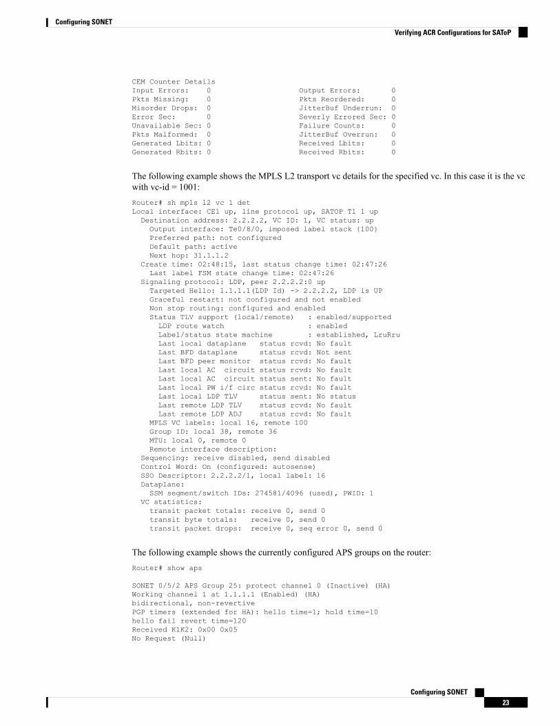
CEM Counter DetailsInput Errors: 0 Output Errors: 0Pkts Missing: 0 Pkts Reordered: 0Misorder Drops: 0 JitterBuf Underrun: 0Error Sec: 0 Severly Errored Sec: 0Unavailable Sec: 0 Failure Counts: 0Pkts Malformed: 0 JitterBuf Overrun: 0Generated Lbits: 0 Received Lbits: 0Generated Rbits: 0 Received Rbits: 0
The following example shows the MPLS L2 transport vc details for the specified vc. In this case it is the vcwith vc-id = 1001:Router# sh mpls l2 vc 1 detLocal interface: CE1 up, line protocol up, SATOP T1 1 upDestination address: 2.2.2.2, VC ID: 1, VC status: upOutput interface: Te0/8/0, imposed label stack {100}Preferred path: not configuredDefault path: activeNext hop: 31.1.1.2
Create time: 02:48:15, last status change time: 02:47:26Last label FSM state change time: 02:47:26
Signaling protocol: LDP, peer 2.2.2.2:0 upTargeted Hello: 1.1.1.1(LDP Id) -> 2.2.2.2, LDP is UPGraceful restart: not configured and not enabledNon stop routing: configured and enabledStatus TLV support (local/remote) : enabled/supportedLDP route watch : enabledLabel/status state machine : established, LruRruLast local dataplane status rcvd: No faultLast BFD dataplane status rcvd: Not sentLast BFD peer monitor status rcvd: No faultLast local AC circuit status rcvd: No faultLast local AC circuit status sent: No faultLast local PW i/f circ status rcvd: No faultLast local LDP TLV status sent: No statusLast remote LDP TLV status rcvd: No faultLast remote LDP ADJ status rcvd: No fault
MPLS VC labels: local 16, remote 100Group ID: local 38, remote 36MTU: local 0, remote 0Remote interface description:
Sequencing: receive disabled, send disabledControl Word: On (configured: autosense)SSO Descriptor: 2.2.2.2/1, local label: 16Dataplane:SSM segment/switch IDs: 274581/4096 (used), PWID: 1
VC statistics:transit packet totals: receive 0, send 0transit byte totals: receive 0, send 0transit packet drops: receive 0, seq error 0, send 0
The following example shows the currently configured APS groups on the router:Router# show aps
SONET 0/5/2 APS Group 25: protect channel 0 (Inactive) (HA)Working channel 1 at 1.1.1.1 (Enabled) (HA)bidirectional, non-revertivePGP timers (extended for HA): hello time=1; hold time=10hello fail revert time=120Received K1K2: 0x00 0x05No Request (Null)
Configuring SONET23
Configuring SONETVerifying ACR Configurations for SAToP
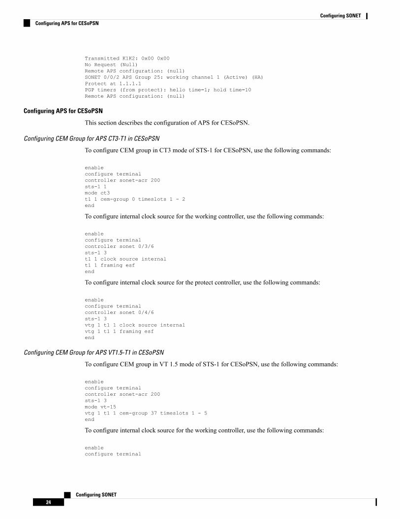
Transmitted K1K2: 0x00 0x00No Request (Null)Remote APS configuration: (null)SONET 0/0/2 APS Group 25: working channel 1 (Active) (HA)Protect at 1.1.1.1PGP timers (from protect): hello time=1; hold time=10Remote APS configuration: (null)
Configuring APS for CESoPSN
This section describes the configuration of APS for CESoPSN.
Configuring CEM Group for APS CT3-T1 in CESoPSN
To configure CEM group in CT3 mode of STS-1 for CESoPSN, use the following commands:
enableconfigure terminalcontroller sonet-acr 200sts-1 1mode ct3t1 1 cem-group 0 timeslots 1 - 2end
To configure internal clock source for the working controller, use the following commands:
enableconfigure terminalcontroller sonet 0/3/6sts-1 3t1 1 clock source internalt1 1 framing esfend
To configure internal clock source for the protect controller, use the following commands:
enableconfigure terminalcontroller sonet 0/4/6sts-1 3vtg 1 t1 1 clock source internalvtg 1 t1 1 framing esfend
Configuring CEM Group for APS VT1.5-T1 in CESoPSN
To configure CEM group in VT 1.5 mode of STS-1 for CESoPSN, use the following commands:
enableconfigure terminalcontroller sonet-acr 200sts-1 3mode vt-15vtg 1 t1 1 cem-group 37 timeslots 1 - 5end
To configure internal clock source for the working controller, use the following commands:
enableconfigure terminal
Configuring SONET24
Configuring SONETConfiguring APS for CESoPSN
controller sonet 0/3/6sts-1 3vtg 1 t1 1 clock source internalvtg 1 t1 1 framing esfend
To configure internal clock source for the protect controller, use the following commands:
enableconfigure terminalcontroller sonet 0/4/6sts-1 3vtg 1 t1 1 clock source internalvtg 1 t1 1 framing esfend
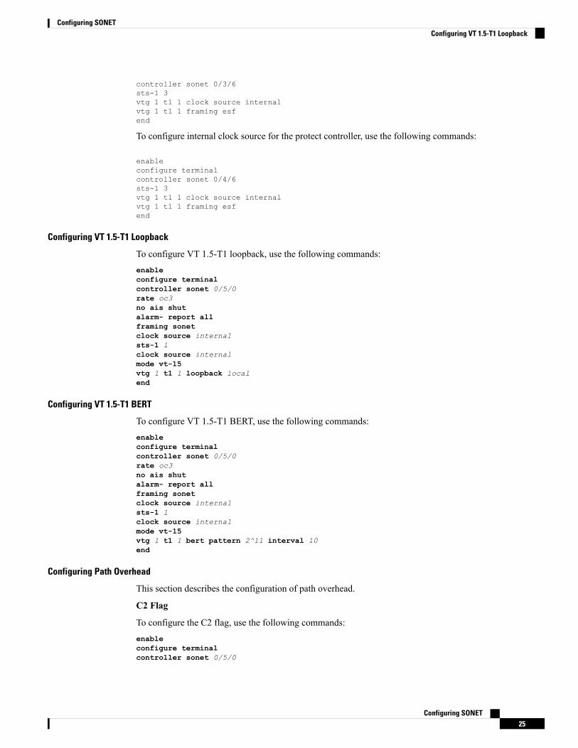
Configuring VT 1.5-T1 Loopback
To configure VT 1.5-T1 loopback, use the following commands:enableconfigure terminalcontroller sonet 0/5/0rate oc3no ais shutalarm- report allframing sonetclock source internalsts-1 1clock source internalmode vt-15vtg 1 t1 1 loopback localend
Configuring VT 1.5-T1 BERT
To configure VT 1.5-T1 BERT, use the following commands:enableconfigure terminalcontroller sonet 0/5/0rate oc3no ais shutalarm- report allframing sonetclock source internalsts-1 1clock source internalmode vt-15vtg 1 t1 1 bert pattern 2^11 interval 10end
Configuring Path Overhead
This section describes the configuration of path overhead.
C2 Flag
To configure the C2 flag, use the following commands:enableconfigure terminalcontroller sonet 0/5/0
Configuring SONET25
Configuring SONETConfiguring VT 1.5-T1 Loopback
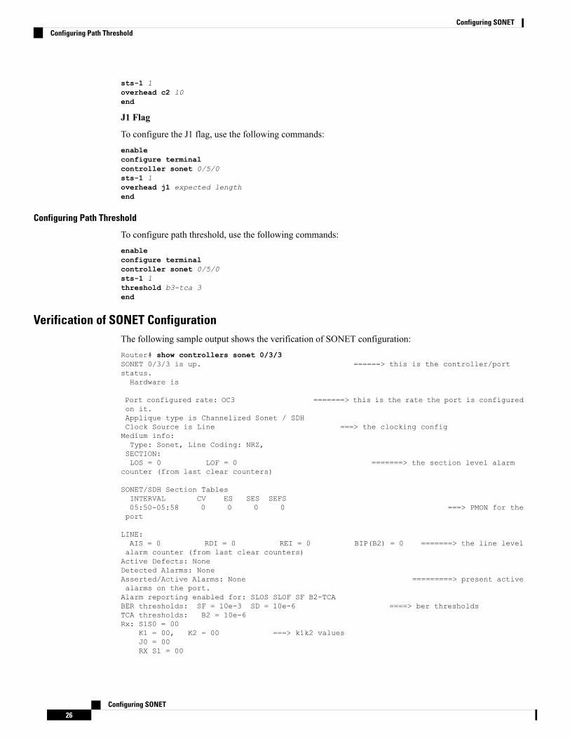
sts-1 1overhead c2 10end
J1 Flag
To configure the J1 flag, use the following commands:enableconfigure terminalcontroller sonet 0/5/0sts-1 1overhead j1 expected lengthend
Configuring Path Threshold
To configure path threshold, use the following commands:enableconfigure terminalcontroller sonet 0/5/0sts-1 1threshold b3-tca 3end
Verification of SONET ConfigurationThe following sample output shows the verification of SONET configuration:Router# show controllers sonet 0/3/3SONET 0/3/3 is up. ======> this is the controller/portstatus.Hardware is
Port configured rate: OC3 =======> this is the rate the port is configuredon it.Applique type is Channelized Sonet / SDHClock Source is Line ===> the clocking configMedium info:Type: Sonet, Line Coding: NRZ,SECTION:LOS = 0 LOF = 0 =======> the section level alarm
counter (from last clear counters)
SONET/SDH Section TablesINTERVAL CV ES SES SEFS05:50-05:58 0 0 0 0 ===> PMON for theport
LINE:AIS = 0 RDI = 0 REI = 0 BIP(B2) = 0 =======> the line levelalarm counter (from last clear counters)Active Defects: NoneDetected Alarms: NoneAsserted/Active Alarms: None =========> present activealarms on the port.Alarm reporting enabled for: SLOS SLOF SF B2-TCABER thresholds: SF = 10e-3 SD = 10e-6 ====> ber thresholdsTCA thresholds: B2 = 10e-6Rx: S1S0 = 00
K1 = 00, K2 = 00 ===> k1k2 valuesJ0 = 00RX S1 = 00
Configuring SONET26
Configuring SONETConfiguring Path Threshold
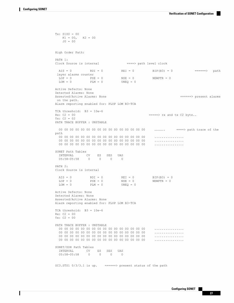
Tx: S1S0 = 00K1 = 00, K2 = 00J0 = 00
High Order Path:
PATH 1:Clock Source is internal ====> path level clock
AIS = 0 RDI = 0 REI = 0 BIP(B3) = 0 ======> pathlayer alarms counterLOP = 0 PSE = 0 NSE = 0 NEWPTR = 0LOM = 0 PLM = 0 UNEQ = 0
Active Defects: NoneDetected Alarms: NoneAsserted/Active Alarms: None ======> present alarmson the path.Alarm reporting enabled for: PLOP LOM B3-TCA
TCA threshold: B3 = 10e-6Rx: C2 = 00 =====> rx and tx C2 byte..Tx: C2 = 02PATH TRACE BUFFER : UNSTABLE
00 00 00 00 00 00 00 00 00 00 00 00 00 00 00 00 ……………. ====> path trace of thepath00 00 00 00 00 00 00 00 00 00 00 00 00 00 00 00 ................00 00 00 00 00 00 00 00 00 00 00 00 00 00 00 00 ................00 00 00 00 00 00 00 00 00 00 00 00 00 00 00 00 ................
SONET Path TablesINTERVAL CV ES SES UAS05:58-05:58 0 0 0 0
PATH 2:Clock Source is internal
AIS = 0 RDI = 0 REI = 0 BIP(B3) = 0LOP = 0 PSE = 0 NSE = 0 NEWPTR = 0LOM = 0 PLM = 0 UNEQ = 0
Active Defects: NoneDetected Alarms: NoneAsserted/Active Alarms: NoneAlarm reporting enabled for: PLOP LOM B3-TCA
TCA threshold: B3 = 10e-6Rx: C2 = 00Tx: C2 = 00
PATH TRACE BUFFER : UNSTABLE00 00 00 00 00 00 00 00 00 00 00 00 00 00 00 00 ................00 00 00 00 00 00 00 00 00 00 00 00 00 00 00 00 ................00 00 00 00 00 00 00 00 00 00 00 00 00 00 00 00 ................00 00 00 00 00 00 00 00 00 00 00 00 00 00 00 00 ................
SONET/SDH Path TablesINTERVAL CV ES SES UAS05:58-05:58 0 0 0 0
OC3.STS1 0/3/3.1 is up. ======> present status of the path
Configuring SONET27
Configuring SONETVerification of SONET Configuration
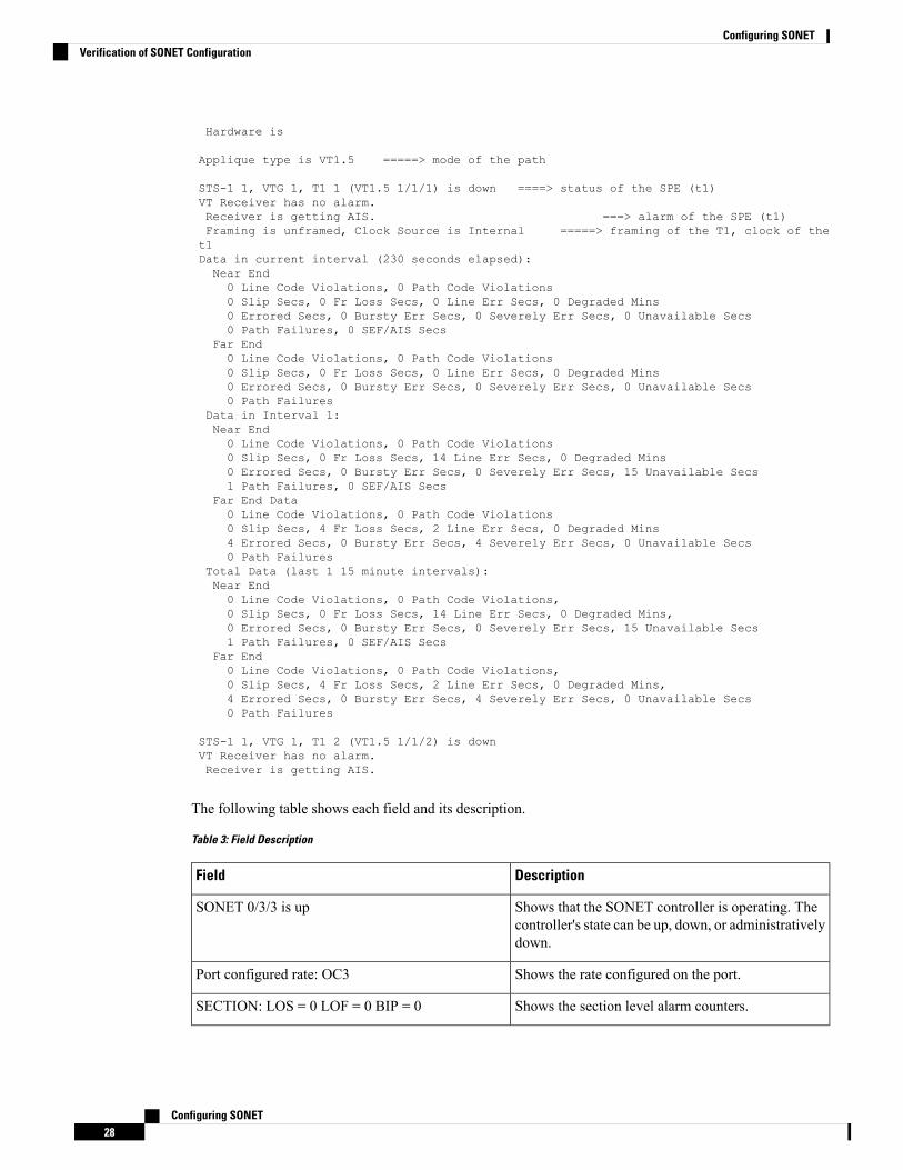
Hardware is
Applique type is VT1.5 =====> mode of the path
STS-1 1, VTG 1, T1 1 (VT1.5 1/1/1) is down ====> status of the SPE (t1)VT Receiver has no alarm.Receiver is getting AIS. ===> alarm of the SPE (t1)Framing is unframed, Clock Source is Internal =====> framing of the T1, clock of thet1Data in current interval (230 seconds elapsed):Near End0 Line Code Violations, 0 Path Code Violations0 Slip Secs, 0 Fr Loss Secs, 0 Line Err Secs, 0 Degraded Mins0 Errored Secs, 0 Bursty Err Secs, 0 Severely Err Secs, 0 Unavailable Secs0 Path Failures, 0 SEF/AIS Secs
Far End0 Line Code Violations, 0 Path Code Violations0 Slip Secs, 0 Fr Loss Secs, 0 Line Err Secs, 0 Degraded Mins0 Errored Secs, 0 Bursty Err Secs, 0 Severely Err Secs, 0 Unavailable Secs0 Path Failures
Data in Interval 1:Near End0 Line Code Violations, 0 Path Code Violations0 Slip Secs, 0 Fr Loss Secs, 14 Line Err Secs, 0 Degraded Mins0 Errored Secs, 0 Bursty Err Secs, 0 Severely Err Secs, 15 Unavailable Secs1 Path Failures, 0 SEF/AIS Secs
Far End Data0 Line Code Violations, 0 Path Code Violations0 Slip Secs, 4 Fr Loss Secs, 2 Line Err Secs, 0 Degraded Mins4 Errored Secs, 0 Bursty Err Secs, 4 Severely Err Secs, 0 Unavailable Secs0 Path Failures
Total Data (last 1 15 minute intervals):Near End0 Line Code Violations, 0 Path Code Violations,0 Slip Secs, 0 Fr Loss Secs, 14 Line Err Secs, 0 Degraded Mins,0 Errored Secs, 0 Bursty Err Secs, 0 Severely Err Secs, 15 Unavailable Secs1 Path Failures, 0 SEF/AIS Secs
Far End0 Line Code Violations, 0 Path Code Violations,0 Slip Secs, 4 Fr Loss Secs, 2 Line Err Secs, 0 Degraded Mins,4 Errored Secs, 0 Bursty Err Secs, 4 Severely Err Secs, 0 Unavailable Secs0 Path Failures
STS-1 1, VTG 1, T1 2 (VT1.5 1/1/2) is downVT Receiver has no alarm.Receiver is getting AIS.
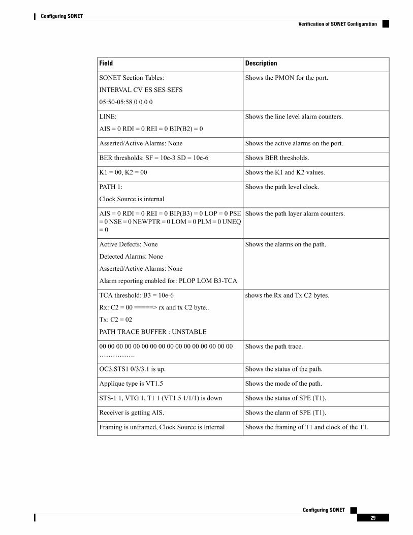
The following table shows each field and its description.
Table 3: Field Description
DescriptionField
Shows that the SONET controller is operating. Thecontroller's state can be up, down, or administrativelydown.
SONET 0/3/3 is up
Shows the rate configured on the port.Port configured rate: OC3
Shows the section level alarm counters.SECTION: LOS = 0 LOF = 0 BIP = 0
Configuring SONET28
Configuring SONETVerification of SONET Configuration
DescriptionField
Shows the PMON for the port.SONET Section Tables:
INTERVAL CV ES SES SEFS
05:50-05:58 0 0 0 0
Shows the line level alarm counters.LINE:
AIS = 0 RDI = 0 REI = 0 BIP(B2) = 0
Shows the active alarms on the port.Asserted/Active Alarms: None
Shows BER thresholds.BER thresholds: SF = 10e-3 SD = 10e-6
Shows the K1 and K2 values.K1 = 00, K2 = 00
Shows the path level clock.PATH 1:
Clock Source is internal
Shows the path layer alarm counters.AIS = 0 RDI = 0 REI = 0 BIP(B3) = 0 LOP = 0 PSE= 0NSE = 0NEWPTR = 0 LOM= 0 PLM= 0UNEQ= 0
Shows the alarms on the path.Active Defects: None
Detected Alarms: None
Asserted/Active Alarms: None
Alarm reporting enabled for: PLOP LOM B3-TCA
shows the Rx and Tx C2 bytes.TCA threshold: B3 = 10e-6
Rx: C2 = 00 =====> rx and tx C2 byte..
Tx: C2 = 02
PATH TRACE BUFFER : UNSTABLE
Shows the path trace.00 00 00 00 00 00 00 00 00 00 00 00 00 00 00 00…………….
Shows the status of the path.OC3.STS1 0/3/3.1 is up.
Shows the mode of the path.Applique type is VT1.5
Shows the status of SPE (T1).STS-1 1, VTG 1, T1 1 (VT1.5 1/1/1) is down
Shows the alarm of SPE (T1).Receiver is getting AIS.
Shows the framing of T1 and clock of the T1.Framing is unframed, Clock Source is Internal
Configuring SONET29
Configuring SONETVerification of SONET Configuration
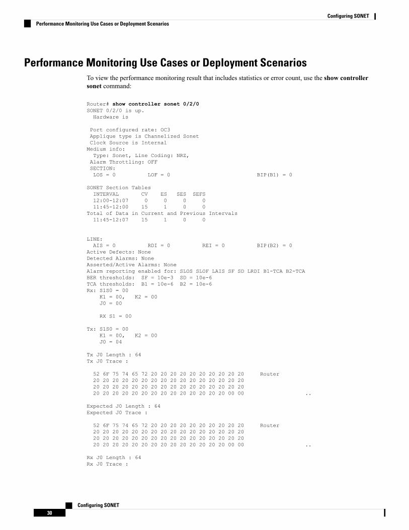
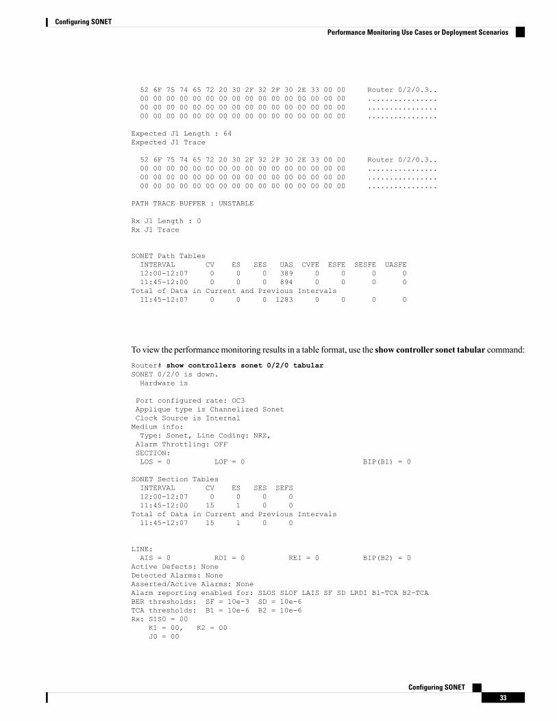
Performance Monitoring Use Cases or Deployment ScenariosTo view the performance monitoring result that includes statistics or error count, use the show controllersonet command:
Router# show controller sonet 0/2/0SONET 0/2/0 is up.Hardware is
Port configured rate: OC3Applique type is Channelized SonetClock Source is InternalMedium info:Type: Sonet, Line Coding: NRZ,Alarm Throttling: OFFSECTION:LOS = 0 LOF = 0 BIP(B1) = 0
SONET Section TablesINTERVAL CV ES SES SEFS12:00-12:07 0 0 0 011:45-12:00 15 1 0 0
Total of Data in Current and Previous Intervals11:45-12:07 15 1 0 0
LINE:AIS = 0 RDI = 0 REI = 0 BIP(B2) = 0
Active Defects: NoneDetected Alarms: NoneAsserted/Active Alarms: NoneAlarm reporting enabled for: SLOS SLOF LAIS SF SD LRDI B1-TCA B2-TCABER thresholds: SF = 10e-3 SD = 10e-6TCA thresholds: B1 = 10e-6 B2 = 10e-6Rx: S1S0 = 00
K1 = 00, K2 = 00J0 = 00
RX S1 = 00
Tx: S1S0 = 00K1 = 00, K2 = 00J0 = 04
Tx J0 Length : 64Tx J0 Trace :
52 6F 75 74 65 72 20 20 20 20 20 20 20 20 20 20 Router20 20 20 20 20 20 20 20 20 20 20 20 20 20 20 2020 20 20 20 20 20 20 20 20 20 20 20 20 20 20 2020 20 20 20 20 20 20 20 20 20 20 20 20 20 00 00 ..
Expected J0 Length : 64Expected J0 Trace :
52 6F 75 74 65 72 20 20 20 20 20 20 20 20 20 20 Router20 20 20 20 20 20 20 20 20 20 20 20 20 20 20 2020 20 20 20 20 20 20 20 20 20 20 20 20 20 20 2020 20 20 20 20 20 20 20 20 20 20 20 20 20 00 00 ..
Rx J0 Length : 64Rx J0 Trace :
Configuring SONET30
Configuring SONETPerformance Monitoring Use Cases or Deployment Scenarios
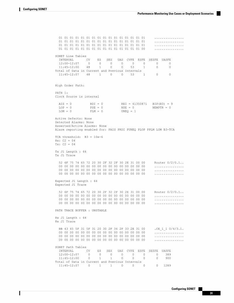
01 01 01 01 01 01 01 01 01 01 01 01 01 01 01 01 ................01 01 01 01 01 01 01 01 01 01 01 01 01 01 01 01 ................01 01 01 01 01 01 01 01 01 01 01 01 01 01 01 01 ................01 01 01 01 01 01 01 01 01 01 01 01 01 01 01 00 ................
SONET Line TablesINTERVAL CV ES SES UAS CVFE ESFE SESFE UASFE12:00-12:07 0 0 0 0 0 0 0 011:45-12:00 48 1 0 0 53 1 0 0
Total of Data in Current and Previous Intervals11:45-12:07 48 1 0 0 53 1 0 0
High Order Path:
PATH 1:Clock Source is internal
AIS = 0 RDI = 0 REI = 41350871 BIP(B3) = 9LOP = 0 PSE = 0 NSE = 0 NEWPTR = 0LOM = 0 PLM = 0 UNEQ = 1
Active Defects: NoneDetected Alarms: NoneAsserted/Active Alarms: NoneAlarm reporting enabled for: PAIS PRDI PUNEQ PLOP PPLM LOM B3-TCA
TCA threshold: B3 = 10e-6Rx: C2 = 04Tx: C2 = 04
Tx J1 Length : 64Tx J1 Trace
52 6F 75 74 65 72 20 30 2F 32 2F 30 2E 31 00 00 Router 0/2/0.1..00 00 00 00 00 00 00 00 00 00 00 00 00 00 00 00 ................00 00 00 00 00 00 00 00 00 00 00 00 00 00 00 00 ................00 00 00 00 00 00 00 00 00 00 00 00 00 00 00 00 ................
Expected J1 Length : 64Expected J1 Trace
52 6F 75 74 65 72 20 30 2F 32 2F 30 2E 31 00 00 Router 0/2/0.1..00 00 00 00 00 00 00 00 00 00 00 00 00 00 00 00 ................00 00 00 00 00 00 00 00 00 00 00 00 00 00 00 00 ................00 00 00 00 00 00 00 00 00 00 00 00 00 00 00 00 ................
PATH TRACE BUFFER : UNSTABLE
Rx J1 Length : 64Rx J1 Trace
BB 43 45 5F 31 5F 31 20 30 2F 34 2F 33 2E 31 00 .CE_1_1 0/4/3.1.00 00 00 00 00 00 00 00 00 00 00 00 00 00 00 00 ................00 00 00 00 00 00 00 00 00 00 00 00 00 00 00 00 ................00 00 00 00 00 00 00 00 00 00 00 00 00 00 00 00 ................
SONET Path TablesINTERVAL CV ES SES UAS CVFE ESFE SESFE UASFE12:00-12:07 0 0 0 0 0 0 0 38911:45-12:00 0 1 1 0 0 0 0 900
Total of Data in Current and Previous Intervals11:45-12:07 0 1 1 0 0 0 0 1289
Configuring SONET31
Configuring SONETPerformance Monitoring Use Cases or Deployment Scenarios
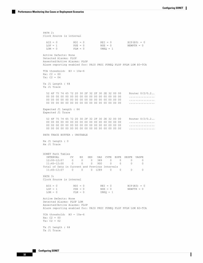
PATH 2:Clock Source is internal
AIS = 0 RDI = 0 REI = 0 BIP(B3) = 0LOP = 1 PSE = 0 NSE = 0 NEWPTR = 0LOM = 0 PLM = 0 UNEQ = 1
Active Defects: NoneDetected Alarms: PLOPAsserted/Active Alarms: PLOPAlarm reporting enabled for: PAIS PRDI PUNEQ PLOP PPLM LOM B3-TCA
TCA threshold: B3 = 10e-6Rx: C2 = 00Tx: C2 = 04
Tx J1 Length : 64Tx J1 Trace
52 6F 75 74 65 72 20 30 2F 32 2F 30 2E 32 00 00 Router 0/2/0.2..00 00 00 00 00 00 00 00 00 00 00 00 00 00 00 00 ................00 00 00 00 00 00 00 00 00 00 00 00 00 00 00 00 ................00 00 00 00 00 00 00 00 00 00 00 00 00 00 00 00 ................
Expected J1 Length : 64Expected J1 Trace
52 6F 75 74 65 72 20 30 2F 32 2F 30 2E 32 00 00 Router 0/2/0.2..00 00 00 00 00 00 00 00 00 00 00 00 00 00 00 00 ................00 00 00 00 00 00 00 00 00 00 00 00 00 00 00 00 ................00 00 00 00 00 00 00 00 00 00 00 00 00 00 00 00 ................
PATH TRACE BUFFER : UNSTABLE
Rx J1 Length : 0Rx J1 Trace
SONET Path TablesINTERVAL CV ES SES UAS CVFE ESFE SESFE UASFE12:00-12:07 0 0 0 389 0 0 0 011:45-12:00 0 0 0 900 0 0 0 0
Total of Data in Current and Previous Intervals11:45-12:07 0 0 0 1289 0 0 0 0
PATH 3:Clock Source is internal
AIS = 0 RDI = 0 REI = 0 BIP(B3) = 0LOP = 1 PSE = 0 NSE = 0 NEWPTR = 0LOM = 0 PLM = 0 UNEQ = 1
Active Defects: NoneDetected Alarms: PLOP LOMAsserted/Active Alarms: PLOPAlarm reporting enabled for: PAIS PRDI PUNEQ PLOP PPLM LOM B3-TCA
TCA threshold: B3 = 10e-6Rx: C2 = 00Tx: C2 = 02
Tx J1 Length : 64Tx J1 Trace
Configuring SONET32
Configuring SONETPerformance Monitoring Use Cases or Deployment Scenarios
52 6F 75 74 65 72 20 30 2F 32 2F 30 2E 33 00 00 Router 0/2/0.3..00 00 00 00 00 00 00 00 00 00 00 00 00 00 00 00 ................00 00 00 00 00 00 00 00 00 00 00 00 00 00 00 00 ................00 00 00 00 00 00 00 00 00 00 00 00 00 00 00 00 ................
Expected J1 Length : 64Expected J1 Trace
52 6F 75 74 65 72 20 30 2F 32 2F 30 2E 33 00 00 Router 0/2/0.3..00 00 00 00 00 00 00 00 00 00 00 00 00 00 00 00 ................00 00 00 00 00 00 00 00 00 00 00 00 00 00 00 00 ................00 00 00 00 00 00 00 00 00 00 00 00 00 00 00 00 ................
PATH TRACE BUFFER : UNSTABLE
Rx J1 Length : 0Rx J1 Trace
SONET Path TablesINTERVAL CV ES SES UAS CVFE ESFE SESFE UASFE12:00-12:07 0 0 0 389 0 0 0 011:45-12:00 0 0 0 894 0 0 0 0
Total of Data in Current and Previous Intervals11:45-12:07 0 0 0 1283 0 0 0 0
To view the performancemonitoring results in a table format, use the show controller sonet tabular command:Router# show controllers sonet 0/2/0 tabularSONET 0/2/0 is down.Hardware is
Port configured rate: OC3Applique type is Channelized SonetClock Source is InternalMedium info:Type: Sonet, Line Coding: NRZ,Alarm Throttling: OFFSECTION:LOS = 0 LOF = 0 BIP(B1) = 0
SONET Section TablesINTERVAL CV ES SES SEFS12:00-12:07 0 0 0 011:45-12:00 15 1 0 0
Total of Data in Current and Previous Intervals11:45-12:07 15 1 0 0
LINE:AIS = 0 RDI = 0 REI = 0 BIP(B2) = 0
Active Defects: NoneDetected Alarms: NoneAsserted/Active Alarms: NoneAlarm reporting enabled for: SLOS SLOF LAIS SF SD LRDI B1-TCA B2-TCABER thresholds: SF = 10e-3 SD = 10e-6TCA thresholds: B1 = 10e-6 B2 = 10e-6Rx: S1S0 = 00
K1 = 00, K2 = 00J0 = 00
Configuring SONET33
Configuring SONETPerformance Monitoring Use Cases or Deployment Scenarios
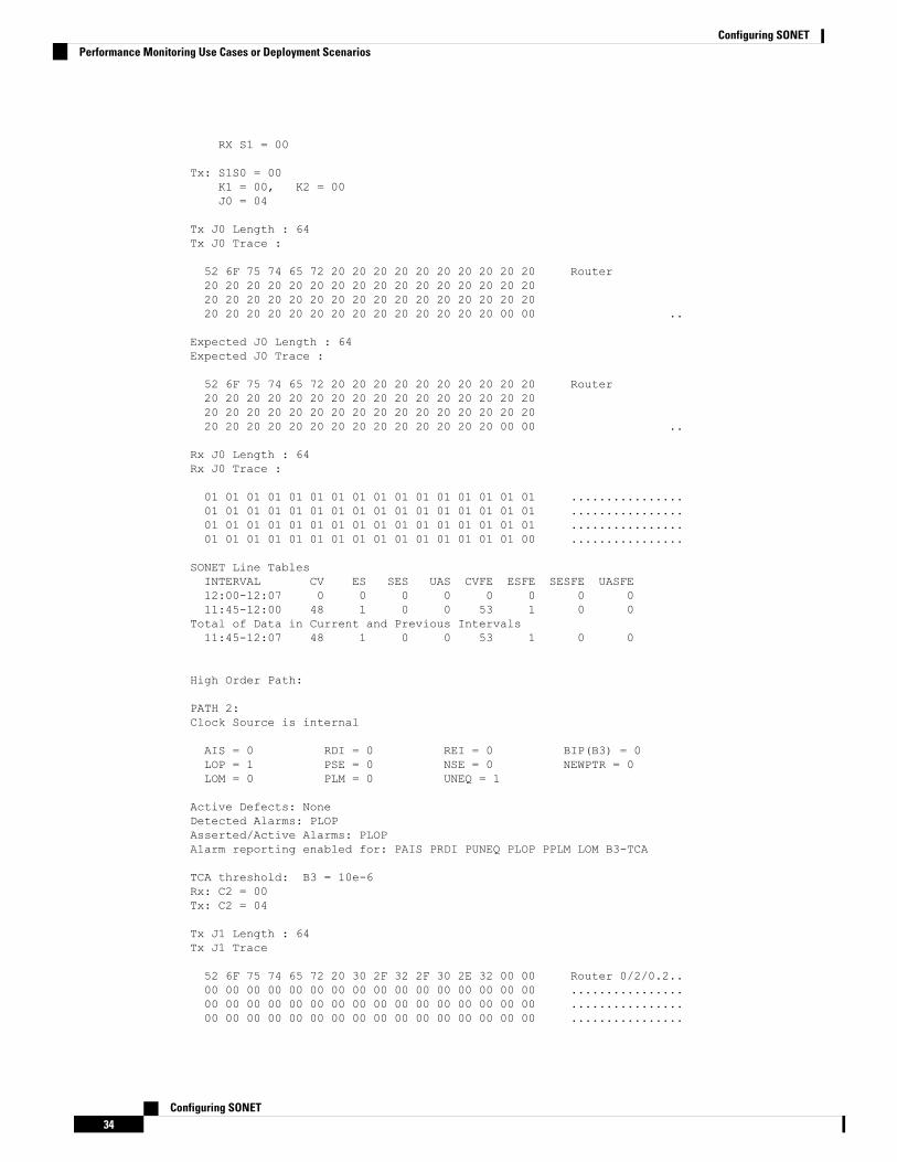
RX S1 = 00
Tx: S1S0 = 00K1 = 00, K2 = 00J0 = 04
Tx J0 Length : 64Tx J0 Trace :
52 6F 75 74 65 72 20 20 20 20 20 20 20 20 20 20 Router20 20 20 20 20 20 20 20 20 20 20 20 20 20 20 2020 20 20 20 20 20 20 20 20 20 20 20 20 20 20 2020 20 20 20 20 20 20 20 20 20 20 20 20 20 00 00 ..
Expected J0 Length : 64Expected J0 Trace :
52 6F 75 74 65 72 20 20 20 20 20 20 20 20 20 20 Router20 20 20 20 20 20 20 20 20 20 20 20 20 20 20 2020 20 20 20 20 20 20 20 20 20 20 20 20 20 20 2020 20 20 20 20 20 20 20 20 20 20 20 20 20 00 00 ..
Rx J0 Length : 64Rx J0 Trace :
01 01 01 01 01 01 01 01 01 01 01 01 01 01 01 01 ................01 01 01 01 01 01 01 01 01 01 01 01 01 01 01 01 ................01 01 01 01 01 01 01 01 01 01 01 01 01 01 01 01 ................01 01 01 01 01 01 01 01 01 01 01 01 01 01 01 00 ................
SONET Line TablesINTERVAL CV ES SES UAS CVFE ESFE SESFE UASFE12:00-12:07 0 0 0 0 0 0 0 011:45-12:00 48 1 0 0 53 1 0 0
Total of Data in Current and Previous Intervals11:45-12:07 48 1 0 0 53 1 0 0
High Order Path:
PATH 2:Clock Source is internal
AIS = 0 RDI = 0 REI = 0 BIP(B3) = 0LOP = 1 PSE = 0 NSE = 0 NEWPTR = 0LOM = 0 PLM = 0 UNEQ = 1
Active Defects: NoneDetected Alarms: PLOPAsserted/Active Alarms: PLOPAlarm reporting enabled for: PAIS PRDI PUNEQ PLOP PPLM LOM B3-TCA
TCA threshold: B3 = 10e-6Rx: C2 = 00Tx: C2 = 04
Tx J1 Length : 64Tx J1 Trace
52 6F 75 74 65 72 20 30 2F 32 2F 30 2E 32 00 00 Router 0/2/0.2..00 00 00 00 00 00 00 00 00 00 00 00 00 00 00 00 ................00 00 00 00 00 00 00 00 00 00 00 00 00 00 00 00 ................00 00 00 00 00 00 00 00 00 00 00 00 00 00 00 00 ................
Configuring SONET34
Configuring SONETPerformance Monitoring Use Cases or Deployment Scenarios
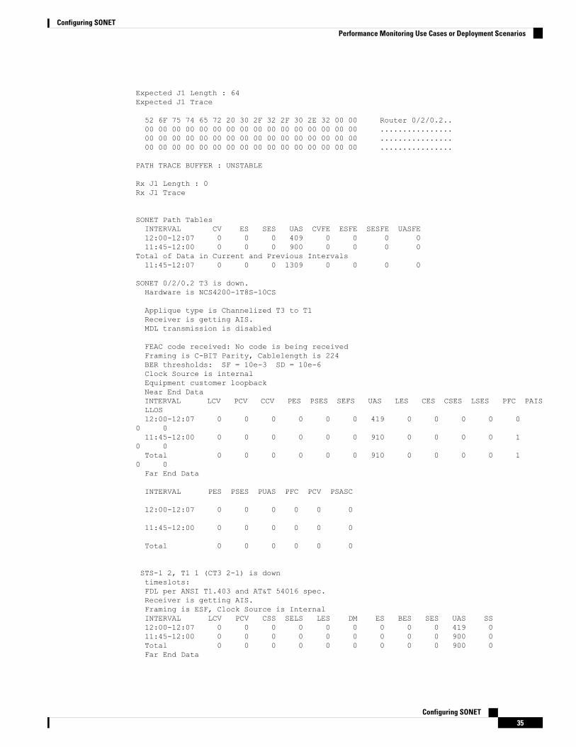
Expected J1 Length : 64Expected J1 Trace
52 6F 75 74 65 72 20 30 2F 32 2F 30 2E 32 00 00 Router 0/2/0.2..00 00 00 00 00 00 00 00 00 00 00 00 00 00 00 00 ................00 00 00 00 00 00 00 00 00 00 00 00 00 00 00 00 ................00 00 00 00 00 00 00 00 00 00 00 00 00 00 00 00 ................
PATH TRACE BUFFER : UNSTABLE
Rx J1 Length : 0Rx J1 Trace
SONET Path TablesINTERVAL CV ES SES UAS CVFE ESFE SESFE UASFE12:00-12:07 0 0 0 409 0 0 0 011:45-12:00 0 0 0 900 0 0 0 0
Total of Data in Current and Previous Intervals11:45-12:07 0 0 0 1309 0 0 0 0
SONET 0/2/0.2 T3 is down.Hardware is NCS4200-1T8S-10CS
Applique type is Channelized T3 to T1Receiver is getting AIS.MDL transmission is disabled
FEAC code received: No code is being receivedFraming is C-BIT Parity, Cablelength is 224BER thresholds: SF = 10e-3 SD = 10e-6Clock Source is internalEquipment customer loopbackNear End DataINTERVAL LCV PCV CCV PES PSES SEFS UAS LES CES CSES LSES PFC PAISLLOS12:00-12:07 0 0 0 0 0 0 419 0 0 0 0 0
0 011:45-12:00 0 0 0 0 0 0 910 0 0 0 0 1
0 0Total 0 0 0 0 0 0 910 0 0 0 0 1
0 0Far End Data
INTERVAL PES PSES PUAS PFC PCV PSASC
12:00-12:07 0 0 0 0 0 0
11:45-12:00 0 0 0 0 0 0
Total 0 0 0 0 0 0
STS-1 2, T1 1 (CT3 2-1) is downtimeslots:FDL per ANSI T1.403 and AT&T 54016 spec.Receiver is getting AIS.Framing is ESF, Clock Source is InternalINTERVAL LCV PCV CSS SELS LES DM ES BES SES UAS SS12:00-12:07 0 0 0 0 0 0 0 0 0 419 011:45-12:00 0 0 0 0 0 0 0 0 0 900 0Total 0 0 0 0 0 0 0 0 0 900 0Far End Data
Configuring SONET35
Configuring SONETPerformance Monitoring Use Cases or Deployment Scenarios
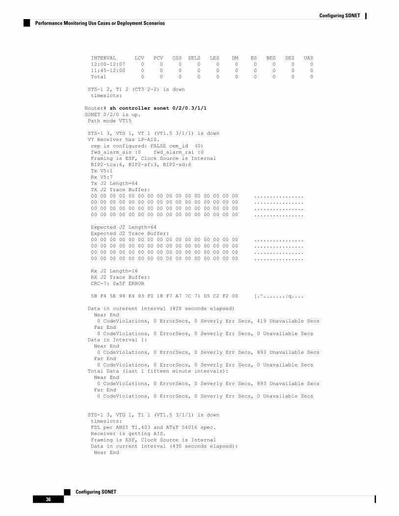
INTERVAL LCV PCV CSS SELS LES DM ES BES SES UAS12:00-12:07 0 0 0 0 0 0 0 0 0 011:45-12:00 0 0 0 0 0 0 0 0 0 0Total 0 0 0 0 0 0 0 0 0 0
STS-1 2, T1 2 (CT3 2-2) is downtimeslots:
Router# sh controller sonet 0/2/0.3/1/1SONET 0/2/0 is up.Path mode VT15
STS-1 3, VTG 1, VT 1 (VT1.5 3/1/1) is downVT Receiver has LP-AIS.cep is configured: FALSE cem_id (0)fwd_alarm_ais :0 fwd_alarm_rai :0Framing is ESF, Clock Source is InternalBIP2-tca:6, BIP2-sf:3, BIP2-sd:6Tx V5:1Rx V5:7Tx J2 Length=64TX J2 Trace Buffer:00 00 00 00 00 00 00 00 00 00 00 00 00 00 00 00 ................00 00 00 00 00 00 00 00 00 00 00 00 00 00 00 00 ................00 00 00 00 00 00 00 00 00 00 00 00 00 00 00 00 ................00 00 00 00 00 00 00 00 00 00 00 00 00 00 00 00 ................
Expected J2 Length=64Expected J2 Trace Buffer:00 00 00 00 00 00 00 00 00 00 00 00 00 00 00 00 ................00 00 00 00 00 00 00 00 00 00 00 00 00 00 00 00 ................00 00 00 00 00 00 00 00 00 00 00 00 00 00 00 00 ................00 00 00 00 00 00 00 00 00 00 00 00 00 00 00 00 ................
Rx J2 Length=16RX J2 Trace Buffer:CRC-7: 0x5F ERROR
5B F4 5E 94 E4 93 F0 18 F7 A7 7C 71 D5 C2 F2 00 [.^.......|q....
Data in curerent interval (420 seconds elapsed)Near End0 CodeViolations, 0 ErrorSecs, 0 Severly Err Secs, 419 Unavailable SecsFar End0 CodeViolations, 0 ErrorSecs, 0 Severly Err Secs, 0 Unavailable Secs
Data in Interval 1:Near End0 CodeViolations, 0 ErrorSecs, 0 Severly Err Secs, 893 Unavailable SecsFar End0 CodeViolations, 0 ErrorSecs, 0 Severly Err Secs, 0 Unavailable Secs
Total Data (last 1 fifteen minute intervals):Near End0 CodeViolations, 0 ErrorSecs, 0 Severly Err Secs, 893 Unavailable SecsFar End0 CodeViolations, 0 ErrorSecs, 0 Severly Err Secs, 0 Unavailable Secs
STS-1 3, VTG 1, T1 1 (VT1.5 3/1/1) is downtimeslots:FDL per ANSI T1.403 and AT&T 54016 spec.Receiver is getting AIS.Framing is ESF, Clock Source is InternalData in current interval (430 seconds elapsed):Near End
Configuring SONET36
Configuring SONETPerformance Monitoring Use Cases or Deployment Scenarios
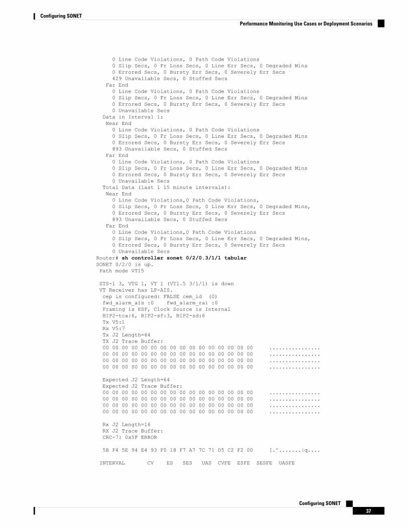
0 Line Code Violations, 0 Path Code Violations0 Slip Secs, 0 Fr Loss Secs, 0 Line Err Secs, 0 Degraded Mins0 Errored Secs, 0 Bursty Err Secs, 0 Severely Err Secs429 Unavailable Secs, 0 Stuffed Secs
Far End0 Line Code Violations, 0 Path Code Violations0 Slip Secs, 0 Fr Loss Secs, 0 Line Err Secs, 0 Degraded Mins0 Errored Secs, 0 Bursty Err Secs, 0 Severely Err Secs0 Unavailable Secs
Data in Interval 1:Near End0 Line Code Violations, 0 Path Code Violations0 Slip Secs, 0 Fr Loss Secs, 0 Line Err Secs, 0 Degraded Mins0 Errored Secs, 0 Bursty Err Secs, 0 Severely Err Secs893 Unavailable Secs, 0 Stuffed Secs
Far End0 Line Code Violations, 0 Path Code Violations0 Slip Secs, 0 Fr Loss Secs, 0 Line Err Secs, 0 Degraded Mins0 Errored Secs, 0 Bursty Err Secs, 0 Severely Err Secs0 Unavailable Secs
Total Data (last 1 15 minute intervals):Near End0 Line Code Violations,0 Path Code Violations,0 Slip Secs, 0 Fr Loss Secs, 0 Line Err Secs, 0 Degraded Mins,0 Errored Secs, 0 Bursty Err Secs, 0 Severely Err Secs893 Unavailable Secs, 0 Stuffed Secs
Far End0 Line Code Violations,0 Path Code Violations0 Slip Secs, 0 Fr Loss Secs, 0 Line Err Secs, 0 Degraded Mins,0 Errored Secs, 0 Bursty Err Secs, 0 Severely Err Secs0 Unavailable Secs
Router# sh controller sonet 0/2/0.3/1/1 tabularSONET 0/2/0 is up.Path mode VT15
STS-1 3, VTG 1, VT 1 (VT1.5 3/1/1) is downVT Receiver has LP-AIS.cep is configured: FALSE cem_id (0)fwd_alarm_ais :0 fwd_alarm_rai :0Framing is ESF, Clock Source is InternalBIP2-tca:6, BIP2-sf:3, BIP2-sd:6Tx V5:1Rx V5:7Tx J2 Length=64TX J2 Trace Buffer:00 00 00 00 00 00 00 00 00 00 00 00 00 00 00 00 ................00 00 00 00 00 00 00 00 00 00 00 00 00 00 00 00 ................00 00 00 00 00 00 00 00 00 00 00 00 00 00 00 00 ................00 00 00 00 00 00 00 00 00 00 00 00 00 00 00 00 ................
Expected J2 Length=64Expected J2 Trace Buffer:00 00 00 00 00 00 00 00 00 00 00 00 00 00 00 00 ................00 00 00 00 00 00 00 00 00 00 00 00 00 00 00 00 ................00 00 00 00 00 00 00 00 00 00 00 00 00 00 00 00 ................00 00 00 00 00 00 00 00 00 00 00 00 00 00 00 00 ................
Rx J2 Length=16RX J2 Trace Buffer:CRC-7: 0x5F ERROR
5B F4 5E 94 E4 93 F0 18 F7 A7 7C 71 D5 C2 F2 00 [.^.......|q....
INTERVAL CV ES SES UAS CVFE ESFE SESFE UASFE
Configuring SONET37
Configuring SONETPerformance Monitoring Use Cases or Deployment Scenarios
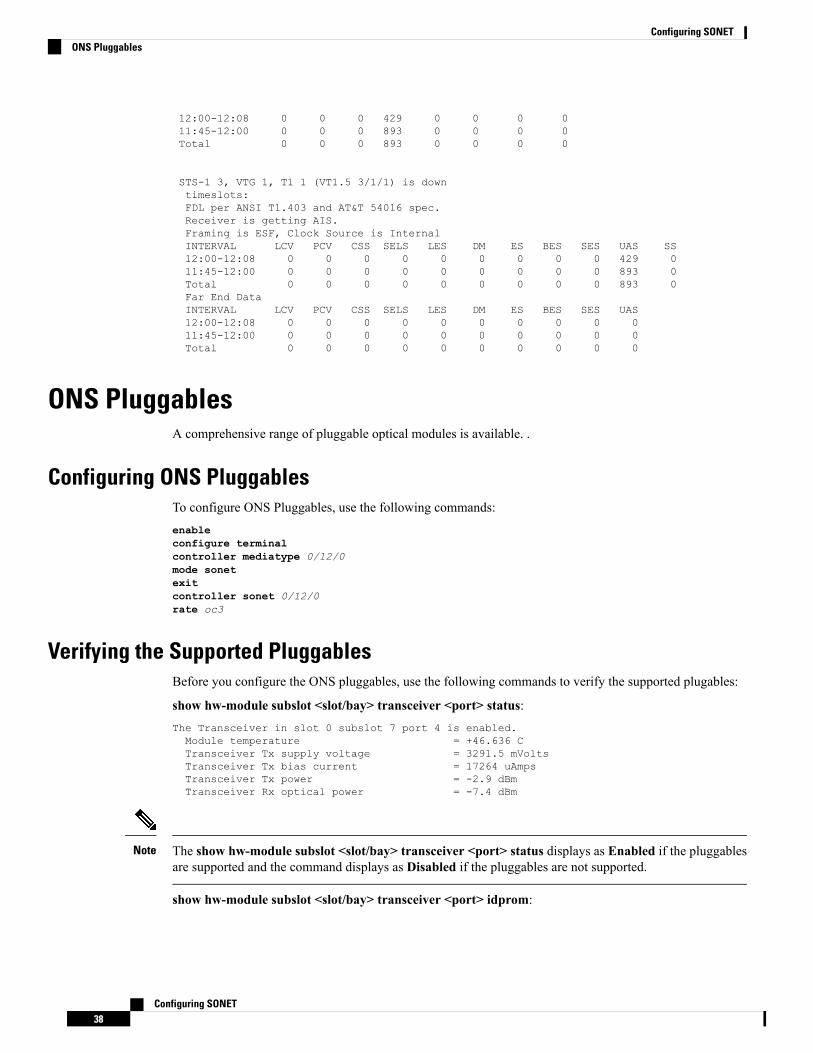
12:00-12:08 0 0 0 429 0 0 0 011:45-12:00 0 0 0 893 0 0 0 0Total 0 0 0 893 0 0 0 0
STS-1 3, VTG 1, T1 1 (VT1.5 3/1/1) is downtimeslots:FDL per ANSI T1.403 and AT&T 54016 spec.Receiver is getting AIS.Framing is ESF, Clock Source is InternalINTERVAL LCV PCV CSS SELS LES DM ES BES SES UAS SS12:00-12:08 0 0 0 0 0 0 0 0 0 429 011:45-12:00 0 0 0 0 0 0 0 0 0 893 0Total 0 0 0 0 0 0 0 0 0 893 0Far End DataINTERVAL LCV PCV CSS SELS LES DM ES BES SES UAS12:00-12:08 0 0 0 0 0 0 0 0 0 011:45-12:00 0 0 0 0 0 0 0 0 0 0Total 0 0 0 0 0 0 0 0 0 0
ONS PluggablesA comprehensive range of pluggable optical modules is available. .
Configuring ONS PluggablesTo configure ONS Pluggables, use the following commands:enableconfigure terminalcontroller mediatype 0/12/0mode sonetexitcontroller sonet 0/12/0rate oc3
Verifying the Supported PluggablesBefore you configure the ONS pluggables, use the following commands to verify the supported plugables:
show hw-module subslot <slot/bay> transceiver <port> status:The Transceiver in slot 0 subslot 7 port 4 is enabled.Module temperature = +46.636 CTransceiver Tx supply voltage = 3291.5 mVoltsTransceiver Tx bias current = 17264 uAmpsTransceiver Tx power = -2.9 dBmTransceiver Rx optical power = -7.4 dBm
The show hw-module subslot <slot/bay> transceiver <port> status displays as Enabled if the pluggablesare supported and the command displays as Disabled if the pluggables are not supported.
Note
show hw-module subslot <slot/bay> transceiver <port> idprom:
Configuring SONET38
Configuring SONETONS Pluggables
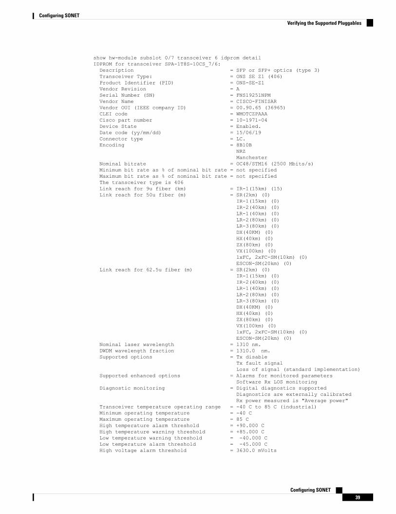
show hw-module subslot 0/7 transceiver 6 idprom detailIDPROM for transceiver SPA-1T8S-10CS_7/6:Description = SFP or SFP+ optics (type 3)Transceiver Type: = ONS SE Z1 (406)Product Identifier (PID) = ONS-SE-Z1Vendor Revision = ASerial Number (SN) = FNS19251NPMVendor Name = CISCO-FINISARVendor OUI (IEEE company ID) = 00.90.65 (36965)CLEI code = WMOTCZPAAACisco part number = 10-1971-04Device State = Enabled.Date code (yy/mm/dd) = 15/06/19Connector type = LC.Encoding = 8B10B
NRZManchester
Nominal bitrate = OC48/STM16 (2500 Mbits/s)Minimum bit rate as % of nominal bit rate = not specifiedMaximum bit rate as % of nominal bit rate = not specifiedThe transceiver type is 406Link reach for 9u fiber (km) = IR-1(15km) (15)Link reach for 50u fiber (m) = SR(2km) (0)
IR-1(15km) (0)IR-2(40km) (0)LR-1(40km) (0)LR-2(80km) (0)LR-3(80km) (0)DX(40KM) (0)HX(40km) (0)ZX(80km) (0)VX(100km) (0)1xFC, 2xFC-SM(10km) (0)ESCON-SM(20km) (0)
Link reach for 62.5u fiber (m) = SR(2km) (0)IR-1(15km) (0)IR-2(40km) (0)LR-1(40km) (0)LR-2(80km) (0)LR-3(80km) (0)DX(40KM) (0)HX(40km) (0)ZX(80km) (0)VX(100km) (0)1xFC, 2xFC-SM(10km) (0)ESCON-SM(20km) (0)
Nominal laser wavelength = 1310 nm.DWDM wavelength fraction = 1310.0 nm.Supported options = Tx disable
Tx fault signalLoss of signal (standard implementation)
Supported enhanced options = Alarms for monitored parametersSoftware Rx LOS monitoring
Diagnostic monitoring = Digital diagnostics supportedDiagnostics are externally calibratedRx power measured is "Average power"
Transceiver temperature operating range = -40 C to 85 C (industrial)Minimum operating temperature = -40 CMaximum operating temperature = 85 CHigh temperature alarm threshold = +90.000 CHigh temperature warning threshold = +85.000 CLow temperature warning threshold = -40.000 CLow temperature alarm threshold = -45.000 CHigh voltage alarm threshold = 3630.0 mVolts
Configuring SONET39
Configuring SONETVerifying the Supported Pluggables
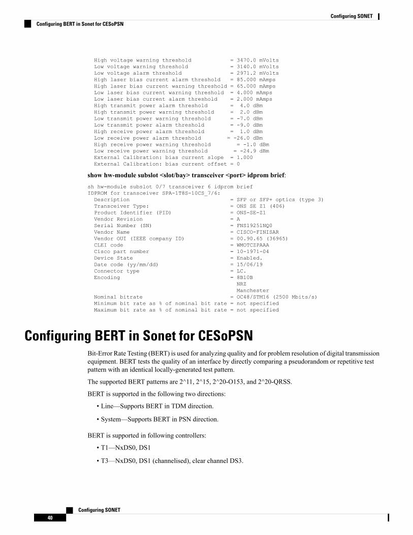
High voltage warning threshold = 3470.0 mVoltsLow voltage warning threshold = 3140.0 mVoltsLow voltage alarm threshold = 2971.2 mVoltsHigh laser bias current alarm threshold = 85.000 mAmpsHigh laser bias current warning threshold = 65.000 mAmpsLow laser bias current warning threshold = 4.000 mAmpsLow laser bias current alarm threshold = 2.000 mAmpsHigh transmit power alarm threshold = 4.0 dBmHigh transmit power warning threshold = 2.0 dBmLow transmit power warning threshold = -7.0 dBmLow transmit power alarm threshold = -9.0 dBmHigh receive power alarm threshold = 1.0 dBmLow receive power alarm threshold = -26.0 dBmHigh receive power warning threshold = -1.0 dBmLow receive power warning threshold = -24.9 dBmExternal Calibration: bias current slope = 1.000External Calibration: bias current offset = 0
show hw-module subslot <slot/bay> transceiver <port> idprom brief:sh hw-module subslot 0/7 transceiver 6 idprom briefIDPROM for transceiver SPA-1T8S-10CS_7/6:Description = SFP or SFP+ optics (type 3)Transceiver Type: = ONS SE Z1 (406)Product Identifier (PID) = ONS-SE-Z1Vendor Revision = ASerial Number (SN) = FNS19251NQ0Vendor Name = CISCO-FINISARVendor OUI (IEEE company ID) = 00.90.65 (36965)CLEI code = WMOTCZPAAACisco part number = 10-1971-04Device State = Enabled.Date code (yy/mm/dd) = 15/06/19Connector type = LC.Encoding = 8B10B
NRZManchester
Nominal bitrate = OC48/STM16 (2500 Mbits/s)Minimum bit rate as % of nominal bit rate = not specifiedMaximum bit rate as % of nominal bit rate = not specified
Configuring BERT in Sonet for CESoPSNBit-Error Rate Testing (BERT) is used for analyzing quality and for problem resolution of digital transmissionequipment. BERT tests the quality of an interface by directly comparing a pseudorandom or repetitive testpattern with an identical locally-generated test pattern.
The supported BERT patterns are 2^11, 2^15, 2^20-O153, and 2^20-QRSS.
BERT is supported in the following two directions:
• Line—Supports BERT in TDM direction.
• System—Supports BERT in PSN direction.
BERT is supported in following controllers:
• T1—NxDS0, DS1
• T3—NxDS0, DS1 (channelised), clear channel DS3.
Configuring SONET40
Configuring SONETConfiguring BERT in Sonet for CESoPSN
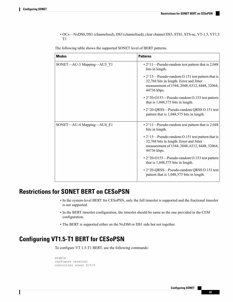
• OCx—NxDS0, DS1 (channelised), DS3 (channelised), clear channel DS3, STS1, STS-nc, VT-1.5, VT1.5T1
The following table shows the supported SONET level of BERT patterns.
PatternsModes
• 2^11—Pseudo-random test pattern that is 2,048bits in length.
• 2^15—Pseudo-randomO.151 test pattern that is32,768 bits in length. Error and Jittermeasurement of 1544, 2048, 6312, 8448, 32064,44736 kbps.
• 2^20-O153—Pseudo-randomO.153 test patternthat is 1,048,575 bits in length.
• 2^20-QRSS—Pseudo-randomQRSSO.151 testpattern that is 1,048,575 bits in length.
SONET—AU-3 Mapping—AU3_T1
• 2^11—Pseudo-random test pattern that is 2,048bits in length.
• 2^15—Pseudo-randomO.151 test pattern that is32,768 bits in length. Error and Jittermeasurement of 1544, 2048, 6312, 8448, 32064,44736 kbps.
• 2^20-O153—Pseudo-randomO.153 test patternthat is 1,048,575 bits in length.
• 2^20-QRSS—Pseudo-randomQRSSO.151 testpattern that is 1,048,575 bits in length.
SONET—AU-4 Mapping—AU4_E1
Restrictions for SONET BERT on CESoPSN• In the system-level BERT for CESoPSN, only the full timeslot is supported and the fractional timeslotis not supported.
• In the BERT timeslot configuration, the timeslot should be same as the one provided in the CEMconfiguration.
• The BERT is supported either on the NxDS0 or DS1 side but not together.
Configuring VT1.5-T1 BERT for CESoPSNTo configure VT 1.5-T1 BERT, use the following commands:
enableconfigure terminalcontroller sonet 0/5/0
Configuring SONET41
Configuring SONETRestrictions for SONET BERT on CESoPSN
rate oc3no ais shutalarm- report allclock source internalsts-1 1clock source internalmode vt-15vtg 1 t1 1 bert timeslots 1 pattern 2^11 interval 10end
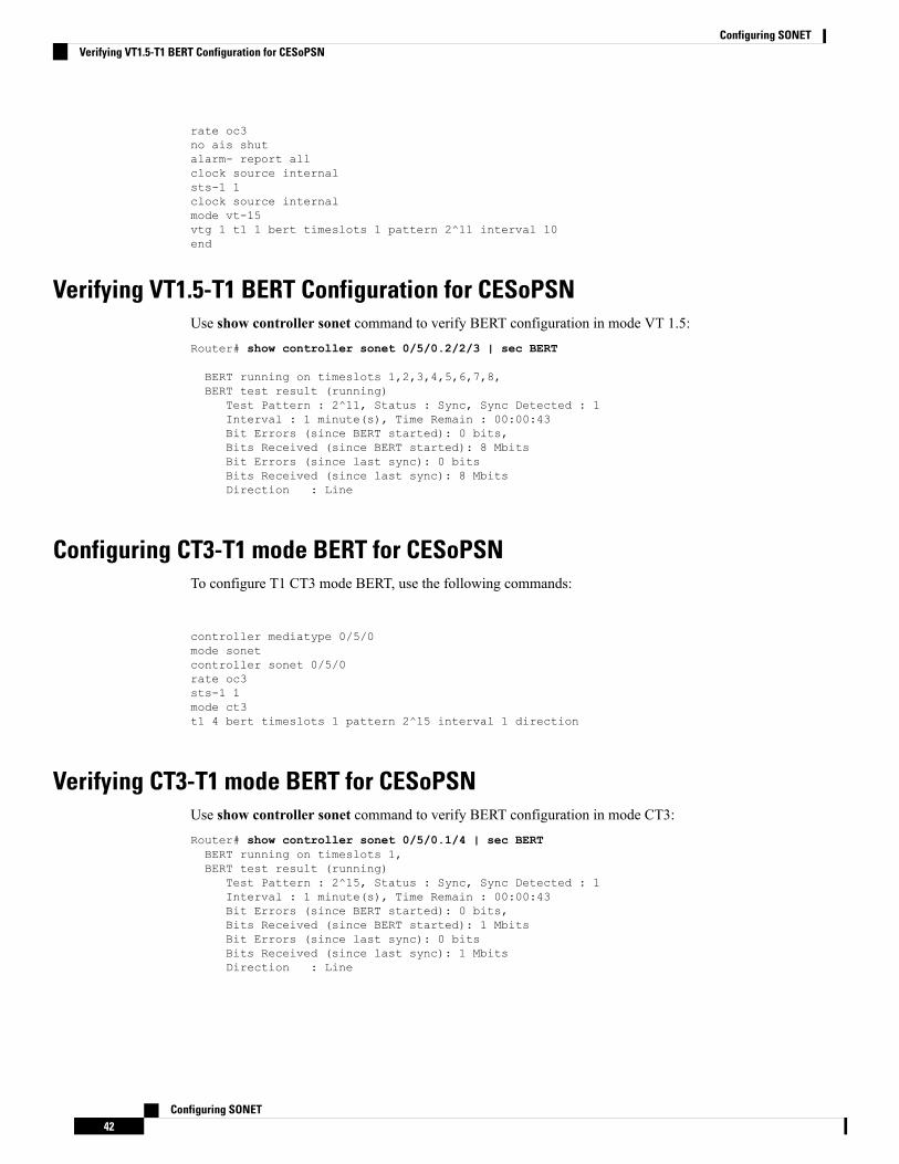
Verifying VT1.5-T1 BERT Configuration for CESoPSNUse show controller sonet command to verify BERT configuration in mode VT 1.5:Router# show controller sonet 0/5/0.2/2/3 | sec BERT
BERT running on timeslots 1,2,3,4,5,6,7,8,BERT test result (running)
Test Pattern : 2^11, Status : Sync, Sync Detected : 1Interval : 1 minute(s), Time Remain : 00:00:43Bit Errors (since BERT started): 0 bits,Bits Received (since BERT started): 8 MbitsBit Errors (since last sync): 0 bitsBits Received (since last sync): 8 MbitsDirection : Line
Configuring CT3-T1 mode BERT for CESoPSNTo configure T1 CT3 mode BERT, use the following commands:
controller mediatype 0/5/0mode sonetcontroller sonet 0/5/0rate oc3sts-1 1mode ct3t1 4 bert timeslots 1 pattern 2^15 interval 1 direction
Verifying CT3-T1 mode BERT for CESoPSNUse show controller sonet command to verify BERT configuration in mode CT3:Router# show controller sonet 0/5/0.1/4 | sec BERTBERT running on timeslots 1,BERT test result (running)
Test Pattern : 2^15, Status : Sync, Sync Detected : 1Interval : 1 minute(s), Time Remain : 00:00:43Bit Errors (since BERT started): 0 bits,Bits Received (since BERT started): 1 MbitsBit Errors (since last sync): 0 bitsBits Received (since last sync): 1 MbitsDirection : Line
Configuring SONET42
Configuring SONETVerifying VT1.5-T1 BERT Configuration for CESoPSN
Clock Recovery System in CESoPSNThe Clock Recovery System is able to recover the service clock using two methods, the Adaptive ClockRecovery and Differential Clock Recovery.
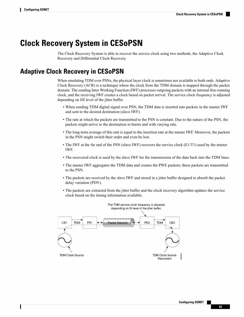
Adaptive Clock Recovery in CESoPSNWhen emulating TDM over PSNs, the physical layer clock is sometimes not available to both ends. AdaptiveClock Recovery (ACR) is a technique where the clock from the TDM domain is mapped through the packetdomain. The sending Inter Working Function (IWF) processes outgoing packets with an internal free-runningclock, and the receiving IWF creates a clock based on packet arrival. The service clock frequency is adjusteddepending on fill level of the jitter buffer.
• When sending TDM digital signal over PSN, the TDM data is inserted into packets in the master IWFand sent to the desired destination (slave IWF).
• The rate at which the packets are transmitted to the PSN is constant. Due to the nature of the PSN, thepackets might arrive to the destination in bursts and with varying rate.
• The long-term average of this rate is equal to the insertion rate at the master IWF. Moreover, the packetsin the PSN might switch their order and even be lost.
• The IWF at the far end of the PSN (slave IWF) recovers the service clock (E1/T1) used by the masterIWF.
• The recovered clock is used by the slave IWF for the transmission of the data back into the TDM lines.
• The master IWF aggregates the TDM data and creates the PWE packets; these packets are transmittedto the PSN.
• The packets are received by the slave IWF and stored in a jitter buffer designed to absorb the packetdelay variation (PDV).
• The packets are extracted from the jitter buffer and the clock recovery algorithm updates the serviceclock based on the timing information available.
Configuring SONET43
Configuring SONETClock Recovery System in CESoPSN
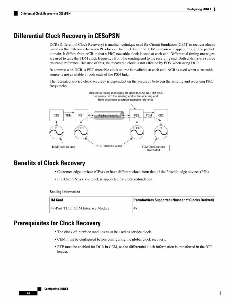
Differential Clock Recovery in CESoPSNDCR (Differential Clock Recovery) is another technique used for Circuit Emulation (CEM) to recover clocksbased on the difference between PE clocks. The clock from the TDM domain is mapped through the packetdomain. It differs from ACR in that a PRC traceable clock is used at each end. Differential timing messagesare used to tune the TDM clock frequency from the sending end to the receiving end. Both ends have a sourcetraceable reference. Because of this, the recovered clock is not affected by PDV when using DCR.
In contrast with DCR, a PRC traceable clock source is available at each end. ACR is used when a traceablesource is not available at both ends of the PSN link.
The recreated service clock accuracy is dependent on the accuracy between the sending and receiving PRCfrequencies.
Benefits of Clock Recovery• Customer-edge devices (CEs) can have different clock from that of the Provide-edge devices (PEs).
• In CESoPSN, a slave clock is supported for clock redundancy.
Scaling Information
Pseudowires Supported (Number of Clocks Derived)IM Card
4848-Port T1/E1 CEM Interface Module
Prerequisites for Clock Recovery• The clock of interface modules must be used as service clock.
• CEM must be configured before configuring the global clock recovery.
• RTP must be enabled for DCR in CEM, as the differential clock information is transferred in the RTPheader.
Configuring SONET44
Configuring SONETDifferential Clock Recovery in CESoPSN
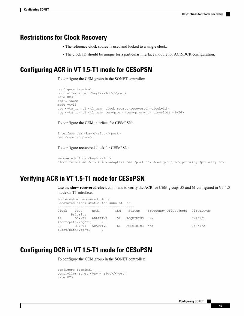
Restrictions for Clock Recovery• The reference clock source is used and locked to a single clock.
• The clock ID should be unique for a particular interface module for ACR/DCR configuration.
Configuring ACR in VT 1.5-T1 mode for CESoPSNTo configure the CEM group in the SONET controller:
configure terminalcontroller sonet <bay>/<slot>/<port>rate OC3sts-1 <num>mode vt-15vtg <vtg_no> t1 <t1_num> clock source recovered <clock-id>vtg <vtg_no> t1 <t1_num> cem-group <cem-group-no> timeslots <1-24>
To configure the CEM interface for CESoPSN:
interface cem <bay>/<slot>/<port>cem <cem-group-no>
To configure recovered clock for CESoPSN:
recovered-clock <bay> <slot>clock recovered <clock-id> adaptive cem <port-no> <cem-group-no> priority <priority no>
Verifying ACR in VT 1.5-T1 mode for CESoPSNUse the show recovered-clock command to verify the ACR for CEM groups 58 and 61 configured in VT 1.5mode on T1 interface:Router#show recovered clockRecovered clock status for subslot 0/5----------------------------------------Clock Type Mode CEM Status Frequency Offset(ppb) Circuit-No
Priority19 OCx-T1 ADAPTIVE 58 ACQUIRING n/a 0/2/1/1(Port/path/vtg/t1) 220 OCx-T1 ADAPTIVE 61 ACQUIRING n/a 0/2/1/2(Port/path/vtg/t1) 2
Configuring DCR in VT 1.5-T1 mode for CESoPSNTo configure the CEM group in the SONET controller:
configure terminalcontroller sonet <bay>/<slot>/<port>rate OC3
Configuring SONET45
Configuring SONETRestrictions for Clock Recovery
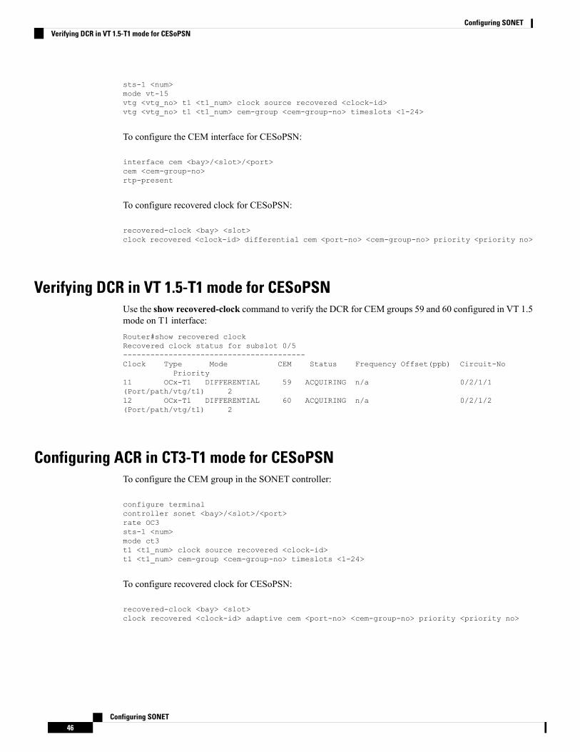
sts-1 <num>mode vt-15vtg <vtg_no> t1 <t1_num> clock source recovered <clock-id>vtg <vtg_no> t1 <t1_num> cem-group <cem-group-no> timeslots <1-24>
To configure the CEM interface for CESoPSN:
interface cem <bay>/<slot>/<port>cem <cem-group-no>rtp-present
To configure recovered clock for CESoPSN:
recovered-clock <bay> <slot>clock recovered <clock-id> differential cem <port-no> <cem-group-no> priority <priority no>
Verifying DCR in VT 1.5-T1 mode for CESoPSNUse the show recovered-clock command to verify the DCR for CEM groups 59 and 60 configured in VT 1.5mode on T1 interface:Router#show recovered clockRecovered clock status for subslot 0/5----------------------------------------Clock Type Mode CEM Status Frequency Offset(ppb) Circuit-No
Priority11 OCx-T1 DIFFERENTIAL 59 ACQUIRING n/a 0/2/1/1(Port/path/vtg/t1) 212 OCx-T1 DIFFERENTIAL 60 ACQUIRING n/a 0/2/1/2(Port/path/vtg/t1) 2
Configuring ACR in CT3-T1 mode for CESoPSNTo configure the CEM group in the SONET controller:
configure terminalcontroller sonet <bay>/<slot>/<port>rate OC3sts-1 <num>mode ct3t1 <t1_num> clock source recovered <clock-id>t1 <t1_num> cem-group <cem-group-no> timeslots <1-24>
To configure recovered clock for CESoPSN:
recovered-clock <bay> <slot>clock recovered <clock-id> adaptive cem <port-no> <cem-group-no> priority <priority no>
Configuring SONET46
Configuring SONETVerifying DCR in VT 1.5-T1 mode for CESoPSN
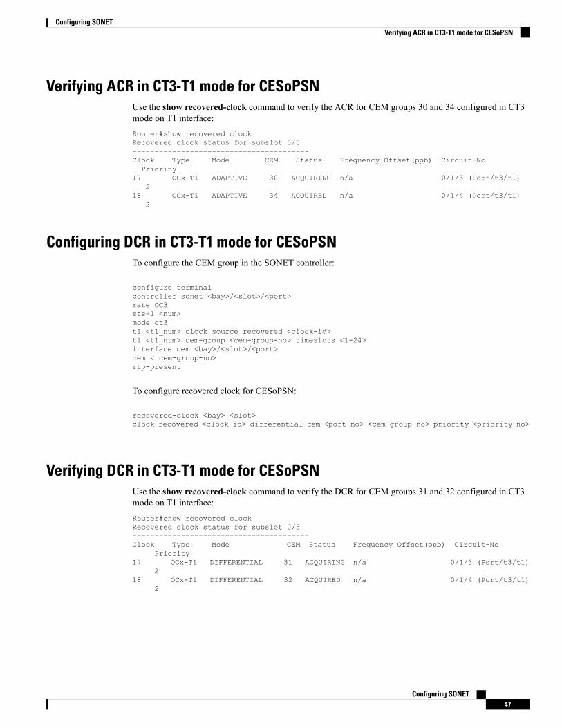
Verifying ACR in CT3-T1 mode for CESoPSNUse the show recovered-clock command to verify the ACR for CEM groups 30 and 34 configured in CT3mode on T1 interface:Router#show recovered clockRecovered clock status for subslot 0/5----------------------------------------Clock Type Mode CEM Status Frequency Offset(ppb) Circuit-NoPriority
17 OCx-T1 ADAPTIVE 30 ACQUIRING n/a 0/1/3 (Port/t3/t1)2
18 OCx-T1 ADAPTIVE 34 ACQUIRED n/a 0/1/4 (Port/t3/t1)2
Configuring DCR in CT3-T1 mode for CESoPSNTo configure the CEM group in the SONET controller:
configure terminalcontroller sonet <bay>/<slot>/<port>rate OC3sts-1 <num>mode ct3t1 <t1_num> clock source recovered <clock-id>t1 <t1_num> cem-group <cem-group-no> timeslots <1-24>interface cem <bay>/<slot>/<port>cem < cem-group-no>rtp-present
To configure recovered clock for CESoPSN:
recovered-clock <bay> <slot>clock recovered <clock-id> differential cem <port-no> <cem-group-no> priority <priority no>
Verifying DCR in CT3-T1 mode for CESoPSNUse the show recovered-clock command to verify the DCR for CEM groups 31 and 32 configured in CT3mode on T1 interface:Router#show recovered clockRecovered clock status for subslot 0/5----------------------------------------Clock Type Mode CEM Status Frequency Offset(ppb) Circuit-No
Priority17 OCx-T1 DIFFERENTIAL 31 ACQUIRING n/a 0/1/3 (Port/t3/t1)
218 OCx-T1 DIFFERENTIAL 32 ACQUIRED n/a 0/1/4 (Port/t3/t1)
2
Configuring SONET47
Configuring SONETVerifying ACR in CT3-T1 mode for CESoPSN
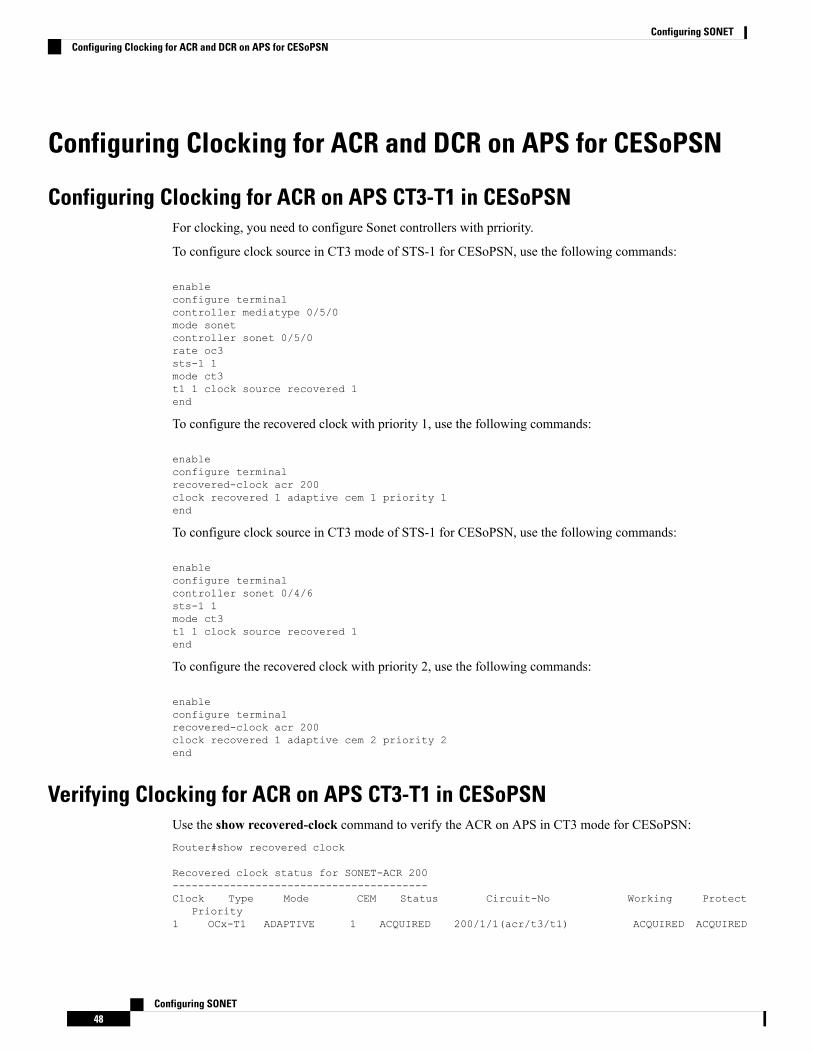
Configuring Clocking for ACR and DCR on APS for CESoPSN
Configuring Clocking for ACR on APS CT3-T1 in CESoPSNFor clocking, you need to configure Sonet controllers with prriority.
To configure clock source in CT3 mode of STS-1 for CESoPSN, use the following commands:
enableconfigure terminalcontroller mediatype 0/5/0mode sonetcontroller sonet 0/5/0rate oc3sts-1 1mode ct3t1 1 clock source recovered 1end
To configure the recovered clock with priority 1, use the following commands:
enableconfigure terminalrecovered-clock acr 200clock recovered 1 adaptive cem 1 priority 1end
To configure clock source in CT3 mode of STS-1 for CESoPSN, use the following commands:
enableconfigure terminalcontroller sonet 0/4/6sts-1 1mode ct3t1 1 clock source recovered 1end
To configure the recovered clock with priority 2, use the following commands:
enableconfigure terminalrecovered-clock acr 200clock recovered 1 adaptive cem 2 priority 2end
Verifying Clocking for ACR on APS CT3-T1 in CESoPSNUse the show recovered-clock command to verify the ACR on APS in CT3 mode for CESoPSN:Router#show recovered clock
Recovered clock status for SONET-ACR 200----------------------------------------Clock Type Mode CEM Status Circuit-No Working Protect
Priority1 OCx-T1 ADAPTIVE 1 ACQUIRED 200/1/1(acr/t3/t1) ACQUIRED ACQUIRED
Configuring SONET48
Configuring SONETConfiguring Clocking for ACR and DCR on APS for CESoPSN
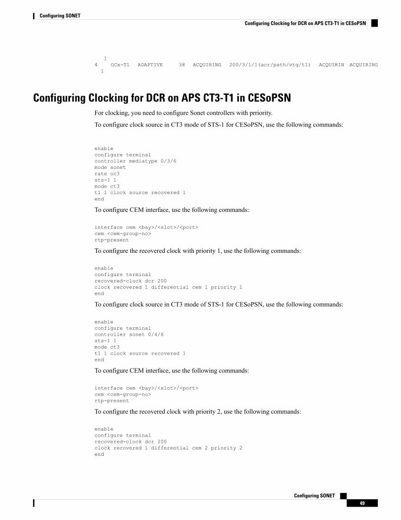
14 OCx-T1 ADAPTIVE 38 ACQUIRING 200/3/1/1(acr/path/vtg/t1) ACQUIRIN ACQUIRING1
Configuring Clocking for DCR on APS CT3-T1 in CESoPSNFor clocking, you need to configure Sonet controllers with prriority.
To configure clock source in CT3 mode of STS-1 for CESoPSN, use the following commands:
enableconfigure terminalcontroller mediatype 0/3/6mode sonetrate oc3sts-1 1mode ct3t1 1 clock source recovered 1end
To configure CEM interface, use the following commands:
interface cem <bay>/<slot>/<port>cem <cem-group-no>rtp-present
To configure the recovered clock with priority 1, use the following commands:
enableconfigure terminalrecovered-clock dcr 200clock recovered 1 differential cem 1 priority 1end
To configure clock source in CT3 mode of STS-1 for CESoPSN, use the following commands:
enableconfigure terminalcontroller sonet 0/4/6sts-1 1mode ct3t1 1 clock source recovered 1end
To configure CEM interface, use the following commands:
interface cem <bay>/<slot>/<port>cem <cem-group-no>rtp-present
To configure the recovered clock with priority 2, use the following commands:
enableconfigure terminalrecovered-clock dcr 200clock recovered 1 differential cem 2 priority 2end
Configuring SONET49
Configuring SONETConfiguring Clocking for DCR on APS CT3-T1 in CESoPSN
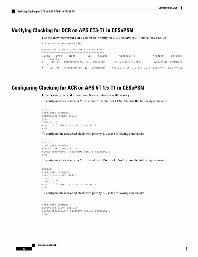
Verifying Clocking for DCR on APS CT3-T1 in CESoPSNUse the show recovered-clock command to verify the DCR on APS in CT3 mode for CESoPSN:Router#show recovered clock
Recovered clock status for SONET-DCR 200----------------------------------------Clock Type Mode CEM Status Circuit-No Working Protect
Priority2 OCx-T1 DIFFERENTIAL 13 ACQUIRED 200/2/1(dcr/t3/t1) ACQUIRED ACQUIRED
15 OCx-T1 DIFFERENTIAL 44 ACQUIRING 200/4/1/1(dcr/path/vtg/t1) ACQUIRIN ACQUIRING1
Configuring Clocking for ACR on APS VT 1.5-T1 in CESoPSNFor clocking, you need to configure Sonet controllers with prriority.
To configure clock source in VT 1.5 mode of STS-1 for CESoPSN, use the following commands:
enableconfigure terminalcontroller sonet 0/3/6sts-1 1mode vt-15vtg 1 t1 1 clock source recovered 4end
To configure the recovered clock with priority 1, use the following commands:
enableconfigure terminalrecovered-clock acr 200clock recovered 4 adaptive cem 38 priority 1end
To configure clock source in VT1.5 mode of STS-1 for CESoPSN, use the following commands:
enableconfigure terminalcontroller sonet 0/4/6sts-1 1mode vt-15vtg 1 t1 1 clock source recovered 4end
To configure the recovered clock with priority 2, use the following commands:
enableconfigure terminalrecovered-clock acr 200clock recovered 4 adaptive cem 39 priority 2end
Configuring SONET50
Configuring SONETVerifying Clocking for DCR on APS CT3-T1 in CESoPSN
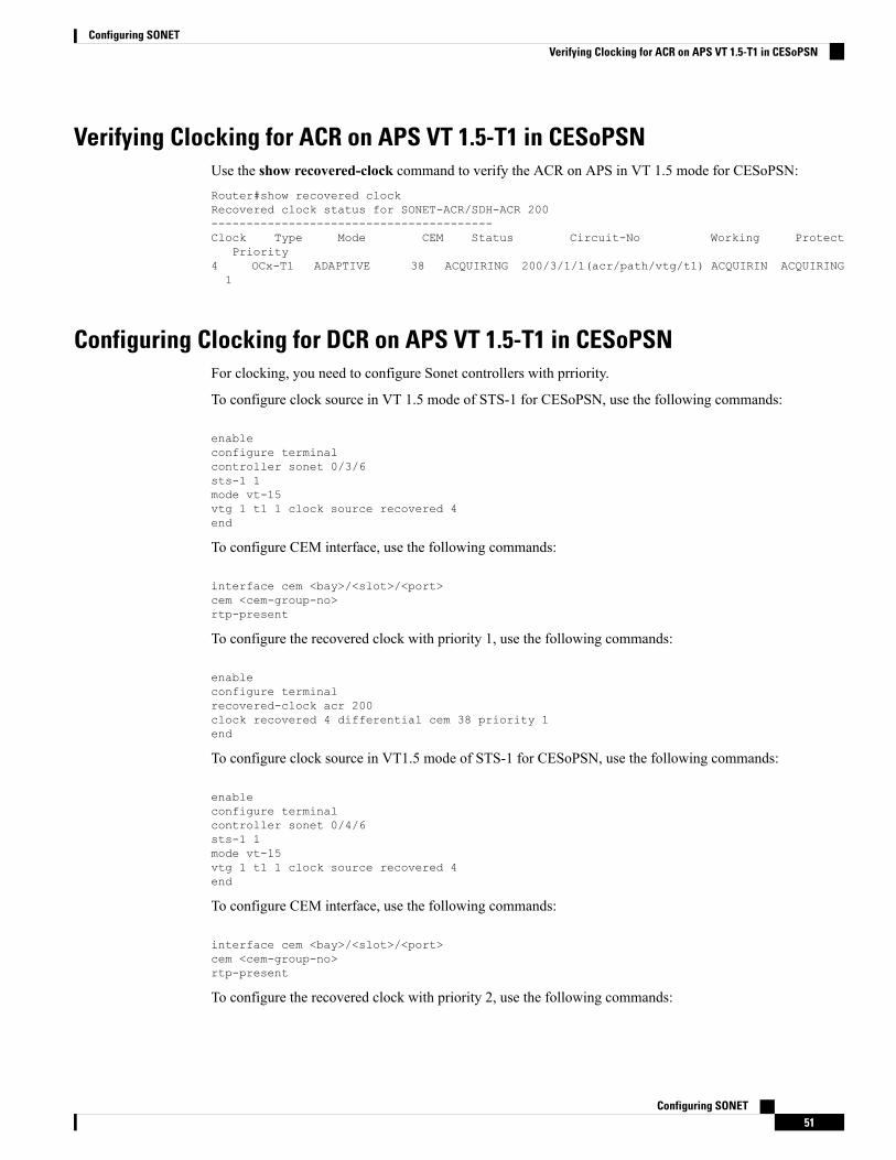
Verifying Clocking for ACR on APS VT 1.5-T1 in CESoPSNUse the show recovered-clock command to verify the ACR on APS in VT 1.5 mode for CESoPSN:Router#show recovered clockRecovered clock status for SONET-ACR/SDH-ACR 200----------------------------------------Clock Type Mode CEM Status Circuit-No Working Protect
Priority4 OCx-T1 ADAPTIVE 38 ACQUIRING 200/3/1/1(acr/path/vtg/t1) ACQUIRIN ACQUIRING1
Configuring Clocking for DCR on APS VT 1.5-T1 in CESoPSNFor clocking, you need to configure Sonet controllers with prriority.
To configure clock source in VT 1.5 mode of STS-1 for CESoPSN, use the following commands:
enableconfigure terminalcontroller sonet 0/3/6sts-1 1mode vt-15vtg 1 t1 1 clock source recovered 4end
To configure CEM interface, use the following commands:
interface cem <bay>/<slot>/<port>cem <cem-group-no>rtp-present
To configure the recovered clock with priority 1, use the following commands:
enableconfigure terminalrecovered-clock acr 200clock recovered 4 differential cem 38 priority 1end
To configure clock source in VT1.5 mode of STS-1 for CESoPSN, use the following commands:
enableconfigure terminalcontroller sonet 0/4/6sts-1 1mode vt-15vtg 1 t1 1 clock source recovered 4end
To configure CEM interface, use the following commands:
interface cem <bay>/<slot>/<port>cem <cem-group-no>rtp-present
To configure the recovered clock with priority 2, use the following commands:
Configuring SONET51
Configuring SONETVerifying Clocking for ACR on APS VT 1.5-T1 in CESoPSN
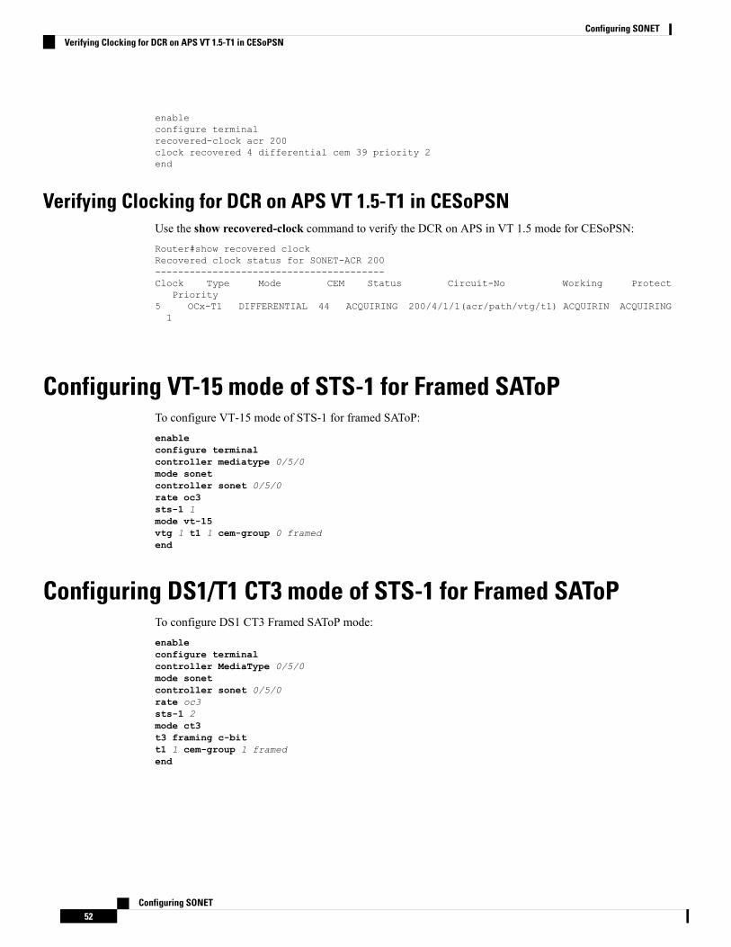
enableconfigure terminalrecovered-clock acr 200clock recovered 4 differential cem 39 priority 2end
Verifying Clocking for DCR on APS VT 1.5-T1 in CESoPSNUse the show recovered-clock command to verify the DCR on APS in VT 1.5 mode for CESoPSN:Router#show recovered clockRecovered clock status for SONET-ACR 200----------------------------------------Clock Type Mode CEM Status Circuit-No Working Protect
Priority5 OCx-T1 DIFFERENTIAL 44 ACQUIRING 200/4/1/1(acr/path/vtg/t1) ACQUIRIN ACQUIRING1
Configuring VT-15 mode of STS-1 for Framed SAToPTo configure VT-15 mode of STS-1 for framed SAToP:enableconfigure terminalcontroller mediatype 0/5/0mode sonetcontroller sonet 0/5/0rate oc3sts-1 1mode vt-15vtg 1 t1 1 cem-group 0 framedend
Configuring DS1/T1 CT3 mode of STS-1 for Framed SAToPTo configure DS1 CT3 Framed SAToP mode:enableconfigure terminalcontroller MediaType 0/5/0mode sonetcontroller sonet 0/5/0rate oc3sts-1 2mode ct3t3 framing c-bitt1 1 cem-group 1 framedend
Configuring SONET52
Configuring SONETVerifying Clocking for DCR on APS VT 1.5-T1 in CESoPSN
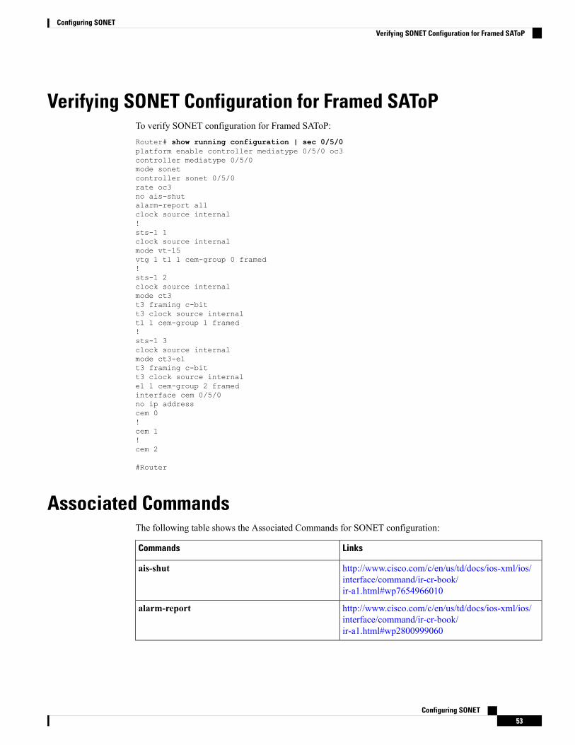
Verifying SONET Configuration for Framed SAToPTo verify SONET configuration for Framed SAToP:Router# show running configuration | sec 0/5/0platform enable controller mediatype 0/5/0 oc3controller mediatype 0/5/0mode sonetcontroller sonet 0/5/0rate oc3no ais-shutalarm-report allclock source internal!sts-1 1clock source internalmode vt-15vtg 1 t1 1 cem-group 0 framed!sts-1 2clock source internalmode ct3t3 framing c-bitt3 clock source internalt1 1 cem-group 1 framed!sts-1 3clock source internalmode ct3-e1t3 framing c-bitt3 clock source internale1 1 cem-group 2 framedinterface cem 0/5/0no ip addresscem 0!cem 1!cem 2
#Router
Associated CommandsThe following table shows the Associated Commands for SONET configuration:
LinksCommands
http://www.cisco.com/c/en/us/td/docs/ios-xml/ios/interface/command/ir-cr-book/ir-a1.html#wp7654966010
ais-shut
http://www.cisco.com/c/en/us/td/docs/ios-xml/ios/interface/command/ir-cr-book/ir-a1.html#wp2800999060
alarm-report
Configuring SONET53
Configuring SONETVerifying SONET Configuration for Framed SAToP
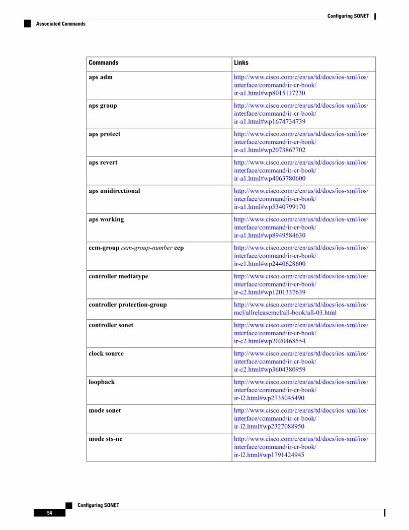
LinksCommands
http://www.cisco.com/c/en/us/td/docs/ios-xml/ios/interface/command/ir-cr-book/ir-a1.html#wp8015117230
aps adm
http://www.cisco.com/c/en/us/td/docs/ios-xml/ios/interface/command/ir-cr-book/ir-a1.html#wp1674734739
aps group
http://www.cisco.com/c/en/us/td/docs/ios-xml/ios/interface/command/ir-cr-book/ir-a1.html#wp2073867702
aps protect
http://www.cisco.com/c/en/us/td/docs/ios-xml/ios/interface/command/ir-cr-book/ir-a1.html#wp4063780600
aps revert
http://www.cisco.com/c/en/us/td/docs/ios-xml/ios/interface/command/ir-cr-book/ir-a1.html#wp5340799170
aps unidirectional
http://www.cisco.com/c/en/us/td/docs/ios-xml/ios/interface/command/ir-cr-book/ir-a1.html#wp8949584630
aps working
http://www.cisco.com/c/en/us/td/docs/ios-xml/ios/interface/command/ir-cr-book/ir-c1.html#wp2440628600
cem-group cem-group-number cep
http://www.cisco.com/c/en/us/td/docs/ios-xml/ios/interface/command/ir-cr-book/ir-c2.html#wp1201337639
controller mediatype
http://www.cisco.com/c/en/us/td/docs/ios-xml/ios/mcl/allreleasemcl/all-book/all-03.html
controller protection-group
http://www.cisco.com/c/en/us/td/docs/ios-xml/ios/interface/command/ir-cr-book/ir-c2.html#wp2020468554
controller sonet
http://www.cisco.com/c/en/us/td/docs/ios-xml/ios/interface/command/ir-cr-book/ir-c2.html#wp3604380959
clock source
http://www.cisco.com/c/en/us/td/docs/ios-xml/ios/interface/command/ir-cr-book/ir-l2.html#wp2735045490
loopback
http://www.cisco.com/c/en/us/td/docs/ios-xml/ios/interface/command/ir-cr-book/ir-l2.html#wp2327088950
mode sonet
http://www.cisco.com/c/en/us/td/docs/ios-xml/ios/interface/command/ir-cr-book/ir-l2.html#wp1791424945
mode sts-nc
Configuring SONET54
Configuring SONETAssociated Commands
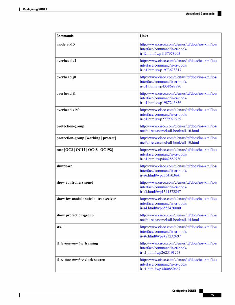
LinksCommands
http://www.cisco.com/c/en/us/td/docs/ios-xml/ios/interface/command/ir-cr-book/ir-l2.html#wp1137973905
mode vt-15
http://www.cisco.com/c/en/us/td/docs/ios-xml/ios/interface/command/ir-cr-book/ir-o1.html#wp1973678817
overhead c2
http://www.cisco.com/c/en/us/td/docs/ios-xml/ios/interface/command/ir-cr-book/ir-o1.html#wp4338698890
overhead j0
http://www.cisco.com/c/en/us/td/docs/ios-xml/ios/interface/command/ir-cr-book/ir-o1.html#wp1987243836
overhead j1
http://www.cisco.com/c/en/us/td/docs/ios-xml/ios/interface/command/ir-cr-book/ir-o1.html#wp2779929239
overhead s1s0
http://www.cisco.com/c/en/us/td/docs/ios-xml/ios/mcl/allreleasemcl/all-book/all-10.html
protection-group
http://www.cisco.com/c/en/us/td/docs/ios-xml/ios/mcl/allreleasemcl/all-book/all-10.html
protection-group [working | protect]
http://www.cisco.com/c/en/us/td/docs/ios-xml/ios/interface/command/ir-cr-book/ir-o1.html#wp4442889730
rate [OC3 | OC12 | OC48 | OC192]
http://www.cisco.com/c/en/us/td/docs/ios-xml/ios/interface/command/ir-cr-book/ir-s6.html#wp3364503641
shutdown
http://www.cisco.com/c/en/us/td/docs/ios-xml/ios/interface/command/ir-cr-book/ir-s3.html#wp1341372847
show controllers sonet
http://www.cisco.com/c/en/us/td/docs/ios-xml/ios/interface/command/ir-cr-book/ir-s4.html#wp6553420000
show hw-module subslot transceiver
http://www.cisco.com/c/en/us/td/docs/ios-xml/ios/mcl/allreleasemcl/all-book/all-14.html
show protection-group
http://www.cisco.com/c/en/us/td/docs/ios-xml/ios/interface/command/ir-cr-book/ir-s6.html#wp2423232697
sts-1
http://www.cisco.com/c/en/us/td/docs/ios-xml/ios/interface/command/ir-cr-book/ir-t1.html#wp2623191253
t1 t1-line-number framing
http://www.cisco.com/c/en/us/td/docs/ios-xml/ios/interface/command/ir-cr-book/ir-t1.html#wp3480850667
t1 t1-line-number clock source
Configuring SONET55
Configuring SONETAssociated Commands
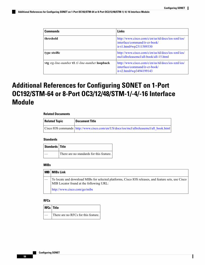
LinksCommands
http://www.cisco.com/c/en/us/td/docs/ios-xml/ios/interface/command/ir-cr-book/ir-t1.html#wp2311589330
threshold
http://www.cisco.com/c/en/us/td/docs/ios-xml/ios/mcl/allreleasemcl/all-book/all-15.html
type sts48c
http://www.cisco.com/c/en/us/td/docs/ios-xml/ios/interface/command/ir-cr-book/ir-t2.html#wp3494199143
vtg vtg-line-number t1 t1-line-number loopback
Additional References for Configuring SONET on 1-PortOC192/STM-64 or 8-Port OC3/12/48/STM-1/-4/-16 InterfaceModule
Related Documents
Document TitleRelated Topic
http://www.cisco.com/en/US/docs/ios/mcl/allreleasemcl/all_book.htmlCisco IOS commands
Standards
TitleStandards
There are no standards for this feature.—
MIBs
MIBs LinkMIB
To locate and download MIBs for selected platforms, Cisco IOS releases, and feature sets, use CiscoMIB Locator found at the following URL:
http://www.cisco.com/go/mibs
—
RFCs
TitleRFCs
There are no RFCs for this feature.—
Configuring SONET56
Configuring SONETAdditional References for Configuring SONET on 1-Port OC192/STM-64 or 8-Port OC3/12/48/STM-1/-4/-16 Interface Module
Technical Assistance
LinkDescription
http://www.cisco.com/cisco/web/support/index.htmlThe Cisco Support website provides extensive onlineresources, including documentation and tools fortroubleshooting and resolving technical issues withCisco products and technologies.
To receive security and technical information aboutyour products, you can subscribe to various services,such as the Product Alert Tool (accessed from FieldNotices), the Cisco Technical Services Newsletter, andReally Simple Syndication (RSS) Feeds.
Access to most tools on the Cisco Support websiterequires a Cisco.com user ID and password.
Configuring SONET57
Configuring SONETAdditional References for Configuring SONET on 1-Port OC192/STM-64 or 8-Port OC3/12/48/STM-1/-4/-16 Interface Module

Configuring SONET58
Configuring SONETAdditional References for Configuring SONET on 1-Port OC192/STM-64 or 8-Port OC3/12/48/STM-1/-4/-16 Interface Module