configure. build. deploy. - axios...
TRANSCRIPT

1ENGLISH
2
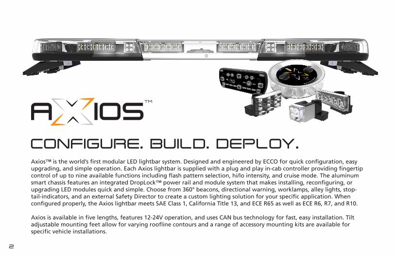
CONFIGURE. BUILD. DEPLOY.Axios™ is the world’s first modular LED lightbar system. Designed and engineered by ECCO for quick configuration, easy upgrading, and simple operation. Each Axios lightbar is supplied with a plug and play in-cab controller providing fingertip control of up to nine available functions including flash pattern selection, hi/lo intensity, and cruise mode. The aluminum smart chassis features an integrated DropLock™ power rail and module system that makes installing, reconfiguring, or upgrading LED modules quick and simple. Choose from 360° beacons, directional warning, worklamps, alley lights, stop-tail-indicators, and an external Safety Director to create a custom lighting solution for your specific application. When configured properly, the Axios lightbar meets SAE Class 1, California Title 13, and ECE R65 as well as ECE R6, R7, and R10.
Axios is available in five lengths, features 12-24V operation, and uses CAN bus technology for fast, easy installation. Tilt adjustable mounting feet allow for varying roofline contours and a range of accessory mounting kits are available for specific vehicle installations.

3ENGLISHENGLISH
INSTALLATION & OPERATION INSTRUCTIONS
Components & Specification ......................................................................................................................... 4 Unpacking & Pre-Installation ..................................................................................................................... 4 Specifications .............................................................................................................................................. 4 Certifications .............................................................................................................................................. 4Mounting ........................................................................................................................................................ 6 Permanent Mounting ................................................................................................................................ 6 Gutter Mounting ........................................................................................................................................ 8 Roof Mounting Kits .................................................................................................................................... 8Wiring Instructions ........................................................................................................................................ 10Programming & Operating .......................................................................................................................... 12 Primary Warning & General Function ...................................................................................................... 12 Safety Director Functions .......................................................................................................................... 13 Scene Illumination Functions .................................................................................................................... 13 Keypad Controller Mounting ................................................................................................................... 14 Flash Pattern Chart .................................................................................................................................... 15Assembly & Configuration ............................................................................................................................ 16 Smart Chassis ............................................................................................................................................. 16 Removing & Installing the Lens ................................................................................................................ 18 Installing DropLock™ LED Modules ......................................................................................................... 20 Directional Modules (EZ1401X) .......................................................................................................... 20 Beacon Modules (EZ1402X) ................................................................................................................ 22 Worklamp Modules (EZ1403WL) ........................................................................................................ 24 Alley Light Modules (EZ1403AL) ........................................................................................................ 26 Stop-Tail-Indicator Modules (EZ1404) ................................................................................................ 28 Safety Director™ (EZ1414) .................................................................................................................. 30Troubleshooting ............................................................................................................................................ 32Warranty & Limitation of Liability ............................................................................................................... 34Replacement Parts & Accessories ................................................................................................................. 35Register Your Axios™ Modular LED Lightbar .............................................................................................. 36
INSTALLATION & OPERATION
INSTRUCTIONS
Para ver este manual en español, vaya a AXIOSMODULAR.COM
Pour consulter ce manuel en français, rendez-vous sur AXIOSMODULAR.COM
Um dieses Handbuch auf Deutsch zu lesen, besuchen Sie AXIOSMODULAR.COM
Per visualizzare il manuale in Italiano, visita AXIOSMODULAR.COM
4
Unpacking & Pre-Installation
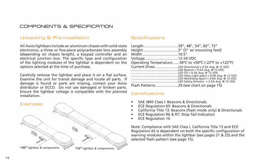
All Axios lightbars include an aluminum chassis with solid-state electronics, a three or five-piece polycarbonate lens assembly (depending on chassis length), a keypad controller and an electrical junction box. The specific type and configuration of the lighting modules of the lightbar is dependent on the options selected at the time of purchase.
Carefully remove the lightbar and place it on a flat surface. Examine the unit for transit damage and locate all parts. If damage is found or parts are missing, contact your Axios distributor or ECCO. Do not use damaged or broken parts. Ensure the lightbar voltage is compatible with the planned installation.
Examples
COMPONENTS & SPECIFICATION
Specifications
Length .................................39”, 48”, 54”, 60”, 72”Height .................................3” (5” w/ mounting feet)Width ..................................10.5”Voltage................................12-24 VDCOperating Temperature .....-30ºC to +50ºC (-22ºF to +122ºF)Current Draw ............................LED Directional = 0.5A Avg. @ 12 VDC..........................................................LED Beacon = 0.5A Avg. @ 12 VDC..........................................................LED STI = 0.3A Avg. @ 12 VDC..........................................................LED Alley Light (pair) = 0.9A Avg. @ 12 VDC..........................................................LED Worklamp (pair) = 0.9A Avg. @ 12 VDC..........................................................LED Safety Director = 2.5A Avg. @ 12 VDCFlash Patterns .....................29 (see chart on page 15)
Certifications
• SAE J845 Class I: Beacons & Directionals• ECE Regulation 65: Beacons & Directionals• California Title 13: Beacons (flash mode only) & Directionals• ECE Regulation R6 & R7: Stop-Tail-Indicators• ECE Regulation 10
Note: Compliance with SAE Class I, California Title 13 and ECE Regulation 65 is dependent on both the specific configuration of warning modules within the lightbar (see pages 21 & 23) and the selected flash pattern (see page 15).
72” lightbar & components48” lightbar & components
5ENGLISH
Read all instructions before installing and using. Installer: This manual must be delivered to the end user. This manual assumes installation by a suitably qualified Automotive Technician.
Failure to install or use this product according to manufacturer’s recommendations may result in property damage, serious bodily/personal injury, and/or death to you and those you are seeking to protect!
Do not install and/or operate this safety product unless you have read and understand the safety information contained in this manual.
IMPORTANT WARNINGS
1 Proper installation combined with operator training in the use, care and maintenance of emergency warning devices are essential to ensure the safety of emergency personnel and the public.
2 Emergency warning devices often require high electrical voltages and/or currents. Exercise caution when working with live electrical connections.
3 This product must be properly grounded. Inadequate grounding and/or shorting of electrical connections can cause high current arcing, which can cause personal injury and/or severe vehicle damage, including fire.
4 Proper placement and installation is vital to the performance of this warning device. Install this product so that output performance of the system
is maximized and the controls are placed within convenient reach of the operator so that s/he can operate the system without losing eye contact with the roadway.
5 It is the responsibility of the vehicle operator to ensure daily that all features of this product work correctly. In use, the vehicle operator should ensure the projection of the warning signal is not blocked by vehicle components (i.e., open trunks or compartment doors), people, vehicles or other obstructions.
6 The use of this or any other warning device does not ensure all drivers can or will observe or react to an emergency warning signal. Never take the right-of-way for granted. It is your responsibility to be sure you can proceed safely before entering an intersection, driving against traffic, responding
at a high rate of speed, or walking around traffic lanes.
7 This equipment is intended for use by authorized personnel only. The user is responsible for understanding and obeying all laws regarding emergency warning devices. Therefore, the user should check all applicable city, state, and federal laws and regulations. The manufacturer assumes no liability for any loss resulting from the use of this warning device.
8 This product may contain high intensity LEDs staring directly into these lights could result in temporary and/or permanent visionimpairment.
COMPONENTS & SPECIFICATION

6
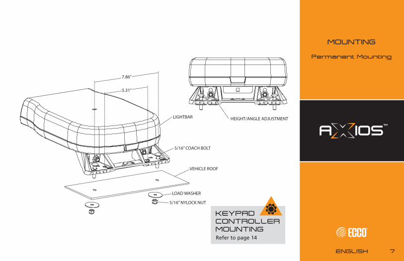
Before proceeding with installation, plan all wiring and cable routing. Select the mounting location for the lightbar on a flat, smooth surface and center the unit across the width of the vehicle. The mounting location for the lightbar should be chosen such that the lightbar is level and visibility to approaching traffic is optimized. Mounting should be such that there is no less than ½” clearance between the roof and the lightbar at any point. Both the height and angle of the mounting feet can be adjusted slightly if necessary using the bolts indicated opposite.
MOUNTING
Permanent Mounting
Determine the location of the lightbar, and the best route for the wiring.
Determine the position of the mounting feet and drill the 5/16”-11/32” diameter mounting holes accordingly, if needed. The spacing of the mounting feet from left to right is adjustable. It is suggested that the positioning of the feet be symmetrical and near the curved edges of the roof where the roof is strongest. Ideally, the outermost holes on the feet should be used for installation. The inner holes on the feet match the hole locations for ECCO 10 and 15 Series lightbars and can be used when one of these lightbars has been previously installed.
CAUTIONWhen drilling into any vehicle surface, make sure that the area is free from any electrical wires, fuel lines, vehicle upholstery, vehicle support members, etc. that could be damaged.
Mount the lightbar, with the bolts going through the holes drilled in step 2 (refer to diagram), routing the wire as planned in step 1. See the Wiring section (on page 10) of this manual for further wiring instructions. Install appropriate washers and nuts and secure the unit. The use of sealing compound is recommended.
Note: The cable exits the lightbar from the center of the chassis, and can be pressed into the channels on the underside of the chassis to route it toward the left or right of the vehicle.
1
2
3
7ENGLISH
VEHICLE ROOF
LIGHTBAR
LOAD WASHER
5/16” NYLOCK NUT
5/16” COACH BOLT
HEIGHT/ANGLE ADJUSTMENT
7.86”
5.31”
MOUNTING
Permanent Mounting
KEYPAD CONTROLLER MOUNTINGRefer to page 14
8
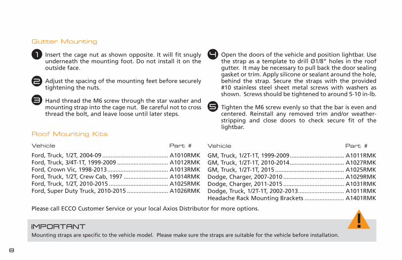
Gutter Mounting
Insert the cage nut as shown opposite. It will fit snugly underneath the mounting foot. Do not install it on the outside face.
Adjust the spacing of the mounting feet before securely tightening the nuts.
Hand thread the M6 screw through the star washer and mounting strap into the cage nut. Be careful not to cross thread the bolt, and leave loose until later steps.
IMPORTANTMounting straps are specific to the vehicle model. Please make sure the straps are suitable for the vehicle before installation.
Open the doors of the vehicle and position lightbar. Use the strap as a template to drill Ø1/8” holes in the roof gutter. It may be necessary to pull back the door sealing gasket or trim. Apply silicone or sealant around the hole, behind the strap. Secure the straps with the provided #10 stainless steel sheet metal screws with washers as shown. Screws should be tightened to around 5-10 in-lb.
Tighten the M6 screw evenly so that the bar is even and centered. Reinstall any removed trim and/or weather-stripping and close doors to check secure fit of the lightbar.
Please call ECCO Customer Service or your local Axios Distributor for more options.
Roof Mounting Kits
Ford, Truck, 1/2T, 2004-09 ........................................ A1010RMKFord, Truck, 3/4T-1T, 1999-2009 ............................... A1012RMKFord, Crown Vic, 1998-2013 ..................................... A1013RMKFord, Truck, 1/2T, Crew Cab, 1997 ........................... A1014RMKFord, Truck, 1/2T, 2010-2015 .................................... A1025RMKFord, Super Duty Truck, 2010-2015 ......................... A1026RMK
Vehicle Part #
GM, Truck, 1/2T-1T, 1999-2009 ................................. A1011RMKGM, Truck, 1/2T-1T, 2010-2014 ................................. A1027RMKGM, Truck, 1/2T-1T, 2015 .......................................... A1025RMKDodge, Charger, 2007-2010 ..................................... A1029RMKDodge, Charger, 2011-2015 ..................................... A1031RMKDodge, Truck, 1/2T-1T, 2002-2013 ............................ A1011RMKHeadache Rack Mounting Brackets ........................ A1401RMK
Vehicle Part #
1
2
3
4
5

9ENGLISH
SHEET METAL SCREWS
MOUNTING STRAP
#10 STAR WASHERS
M6 SCREWM6 STAR WASHER
VEHICLE ROOF
Ø1/8” HOLES
LIGHTBAR
M6 CAGE NUT
MOUNTING FOOT
MOUNTING
Gutter Mounting
KEYPAD CONTROLLER MOUNTINGRefer to page 14
10
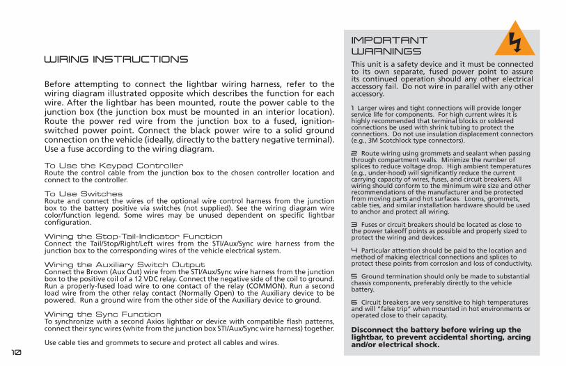
Before attempting to connect the lightbar wiring harness, refer to the wiring diagram illustrated opposite which describes the function for each wire. After the lightbar has been mounted, route the power cable to the junction box (the junction box must be mounted in an interior location). Route the power red wire from the junction box to a fused, ignition-switched power point. Connect the black power wire to a solid ground connection on the vehicle (ideally, directly to the battery negative terminal). Use a fuse according to the wiring diagram.
To Use the Keypad ControllerRoute the control cable from the junction box to the chosen controller location and connect to the controller.
To Use Switches Route and connect the wires of the optional wire control harness from the junction box to the battery positive via switches (not supplied). See the wiring diagram wire color/function legend. Some wires may be unused dependent on specific lightbar configuration.
Wiring the Stop-Tail-Indicator FunctionConnect the Tail/Stop/Right/Left wires from the STI/Aux/Sync wire harness from the junction box to the corresponding wires of the vehicle electrical system.
Wiring the Auxiliary Switch OutputConnect the Brown (Aux Out) wire from the STI/Aux/Sync wire harness from the junction box to the positive coil of a 12 VDC relay. Connect the negative side of the coil to ground. Run a properly-fused load wire to one contact of the relay (COMMON). Run a second load wire from the other relay contact (Normally Open) to the Auxiliary device to be powered. Run a ground wire from the other side of the Auxiliary device to ground.
Wiring the Sync FunctionTo synchronize with a second Axios lightbar or device with compatible flash patterns, connect their sync wires (white from the junction box STI/Aux/Sync wire harness) together.
Use cable ties and grommets to secure and protect all cables and wires.
WIRING INSTRUCTIONS This unit is a safety device and it must be connected to its own separate, fused power point to assure its continued operation should any other electrical accessory fail. Do not wire in parallel with any other accessory.
1 Larger wires and tight connections will provide longer service life for components. For high current wires it is highly recommended that terminal blocks or soldered connections be used with shrink tubing to protect the connections. Do not use insulation displacement connectors (e.g., 3M Scotchlock type connectors).
2 Route wiring using grommets and sealant when passing through compartment walls. Minimize the number of splices to reduce voltage drop. High ambient temperatures (e.g., under-hood) will significantly reduce the current carrying capacity of wires, fuses, and circuit breakers. All wiring should conform to the minimum wire size and other recommendations of the manufacturer and be protected from moving parts and hot surfaces. Looms, grommets, cable ties, and similar installation hardware should be used to anchor and protect all wiring.
3 Fuses or circuit breakers should be located as close to the power takeoff points as possible and properly sized to protect the wiring and devices.
4 Particular attention should be paid to the location and method of making electrical connections and splices to protect these points from corrosion and loss of conductivity. 5 Ground termination should only be made to substantial chassis components, preferably directly to the vehicle battery.
6 Circuit breakers are very sensitive to high temperatures and will “false trip” when mounted in hot environments or operated close to their capacity.
Disconnect the battery before wiring up the lightbar, to prevent accidental shorting, arcing and/or electrical shock.
IMPORTANT WARNINGS
11ENGLISH
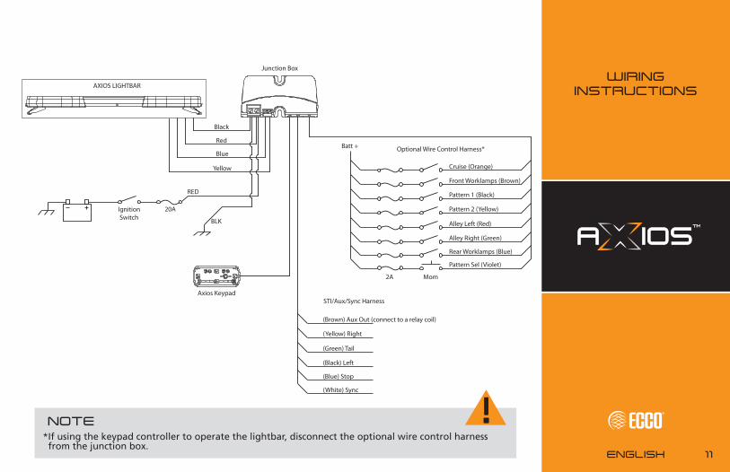
WIRING INSTRUCTIONSAXIOS LIGHTBAR
Junction Box
Black
Red
Blue
Yellow
BLK
RED
20AIgnition Switch
Axios Keypad
Pattern 1 (Black)
Pattern 2 (Yellow)
Alley Left (Red)
Alley Right (Green)
Rear Worklamps (Blue)
Pattern Sel (Violet)
Batt +
2A Mom
Cruise (Orange)
Front Worklamps (Brown)
Optional Wire Control Harness*
(Brown) Aux Out (connect to a relay coil)
(Yellow) Right
(Green) Tail
(Black) Left
(Blue) Stop
(White) Sync
STI/Aux/Sync Harness
NOTE*If using the keypad controller to operate the lightbar, disconnect the optional wire control harness from the junction box.

12
USING THE KEYPAD CONTROLLER TO PROGRAM & OPERATE AXIOS™
Keypad ControllerEZ1405
The controller provides convenient control of the Lightbar’s flash patterns and auxiliary functions and features soft touch buttons and LED function indicator lights. See page 14 for mounting instructions.
Power ButtonPress to cycle through three programmable flash pattern presets. Hold button down to shut down all functions. Press again to resume as before. Preset 1 Preset 2 Preset 3Off
Cruise ButtonPress to illuminate all beacon/directional modules (steady burn).
Day/Night Mode Button For use if parking lights are not connected to junction box. When active, provides backlight to keypad and lowers intensity of the beacon/directional modules in the lightbar.
Auxiliary Output ButtonFor use with the auxiliary output from the junction box to a relay (customer supplied), to control any auxiliary device via the junction box controlled relay.
Flash Pattern Select ButtonPress to cycle through beacon/directional flash patterns. The keypad will remember the pattern used and store it to the active preset. Double tap the button to begin cycling. The 4 corner leds will mimic the bar, to give pattern feedback.
Corner LED
Primary Warning & General Function

13ENGLISH
PROGRAMMING & OPERATING
Keypad Controller
Safety Director LEDs
Safety Director On/Off Button (if equipped)Will resume pattern selected.
Safety Director Pattern Select Button Press to cycle through Safety Director patterns. The 6 LED windows will mimic the pattern for realtime feedback.
Forward Worklamp ButtonWill turn on forward facing worklamps when properly configured.
RearWorklamp ButtonWill turn on rear facing worklamps when properly configured.
Alley LeftButtonWill turn on left alley lights when properly configured.
Alley Right ButtonWill turn on right alley lights when properly configured.
Safety Director™ Functions
Scene Illumination Functions

14
Keypad Controller Mounting
The Keypad is supplied with three mounting options: a bracket, VHB tape and hook and loop patch. The rear of the Keypad is designed to allow for the cable exit to be routed five different ways to maximize installation locations.
Mount the controller in a location within convenient reach of the operator so that s/he can operate the system without losing eye contact with the roadway.
BRACKET
HOOK AND LOOPPATCH
VHB TAPE
15ENGLISH
PROGRAMMING & OPERATING
Keypad Controller Mounting
& Flash Patterns
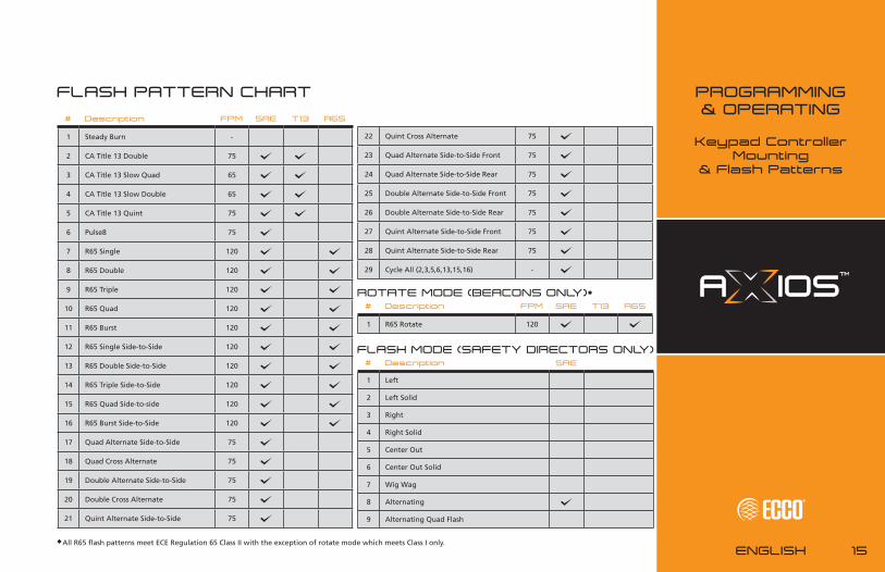
FLASH PATTERN CHART
# Description FPM SAE T13 R65
1 Steady Burn -
2 CA Title 13 Double 75
3 CA Title 13 Slow Quad 65
4 CA Title 13 Slow Double 65
5 CA Title 13 Quint 75
6 Pulse8 75
7 R65 Single 120
8 R65 Double 120
9 R65 Triple 120
10 R65 Quad 120
11 R65 Burst 120
12 R65 Single Side-to-Side 120
13 R65 Double Side-to-Side 120
14 R65 Triple Side-to-Side 120
15 R65 Quad Side-to-side 120
16 R65 Burst Side-to-Side 120
17 Quad Alternate Side-to-Side 75
18 Quad Cross Alternate 75
19 Double Alternate Side-to-Side 75
20 Double Cross Alternate 75
21 Quint Alternate Side-to-Side 75
22 Quint Cross Alternate 75
23 Quad Alternate Side-to-Side Front 75
24 Quad Alternate Side-to-Side Rear 75
25 Double Alternate Side-to-Side Front 75
26 Double Alternate Side-to-Side Rear 75
27 Quint Alternate Side-to-Side Front 75
28 Quint Alternate Side-to-Side Rear 75
29 Cycle All (2,3,5,6,13,15,16) -
# Description FPM SAE T13 R65
1 R65 Rotate 120
ROTATE MODE (BEACONS ONLY)*
# Description
1 Left
2 Left Solid
3 Right
4 Right Solid
5 Center Out
6 Center Out Solid
7 Wig Wag
8 Alternating
9 Alternating Quad Flash
FLASH MODE (SAFETY DIRECTORS ONLY)SAE
*All R65 flash patterns meet ECE Regulation 65 Class II with the exception of rotate mode which meets Class I only.

16
ASSEMBLY & CONFIGURATION
Axios is designed to enable quick and easy customization without the need for tools using any of the available Droplock™ LED modules while the Safety Director module requires only basic hand tools for installation. Each lightbar is sold pre-assembled with a minimum of two lighting modules installed. If reconfiguration of the existing modules in the lightbar, or the installation of additional modules is required this can be achieved in just a few minutes by following the instructions for each module outlined in this section. Additional modules can be obtained from Axios Distributors.
Before attempting to reconfigure or upgrade the lightbar, ensure power is disconnected and familiarize yourself with the features and components of the chassis.
Identify the central control board. The control board distributes power and control signals to the Droplock™ power rails and Safety Director. The logo illuminates when power is applied to the lightbar.
Identify the Safety Director data port on the central control board, this is used to supply power and control signals to the Safety Director.
Identify the Safety Director grommet blank. This notch
in the lip of the chassis is used to route the Safety Director cable into the lightbar. When a Safety Director is installed, the blank grommet is discarded and replaced with a cable grommet supplied with the Safety Director.
Identify the front and rear of the lightbar. To operate properly, some LED modules must be positioned in a specific orientation. The rear of the lightbar is easily identified as the Safety Director data port on the central control board faces the rear of the lightbar.
Identify the three DropLockTM power rails. The power rails supply power and control signals to the Droplock™ lighting modules.
1
2
3
4
5
SAFETYDIRECTOR
4 FRONT
7
8 5
a
b
a
17ENGLISH
ASSEMBLY & CONFIGURATION
Smart Chassis
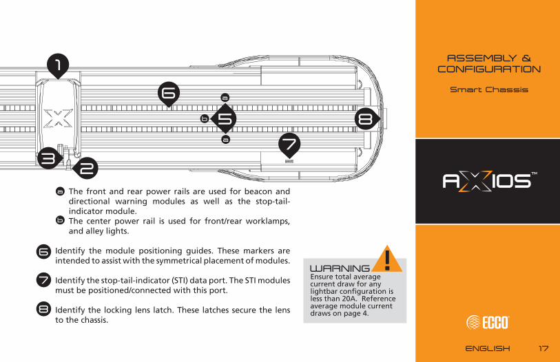
The front and rear power rails are used for beacon and directional warning modules as well as the stop-tail-indicator module.The center power rail is used for front/rear worklamps, and alley lights.
Identify the module positioning guides. These markers are intended to assist with the symmetrical placement of modules.
Identify the stop-tail-indicator (STI) data port. The STI modules must be positioned/connected with this port.
Identify the locking lens latch. These latches secure the lens to the chassis.
a
b
6
7
8
SAFETYDIRECTOR
1
2 3
5
6
7
8
a
a
b
WARNINGEnsure total average current draw for any lightbar configuration is less than 20A. Reference average module current draws on page 4.
18
Removing the Lens
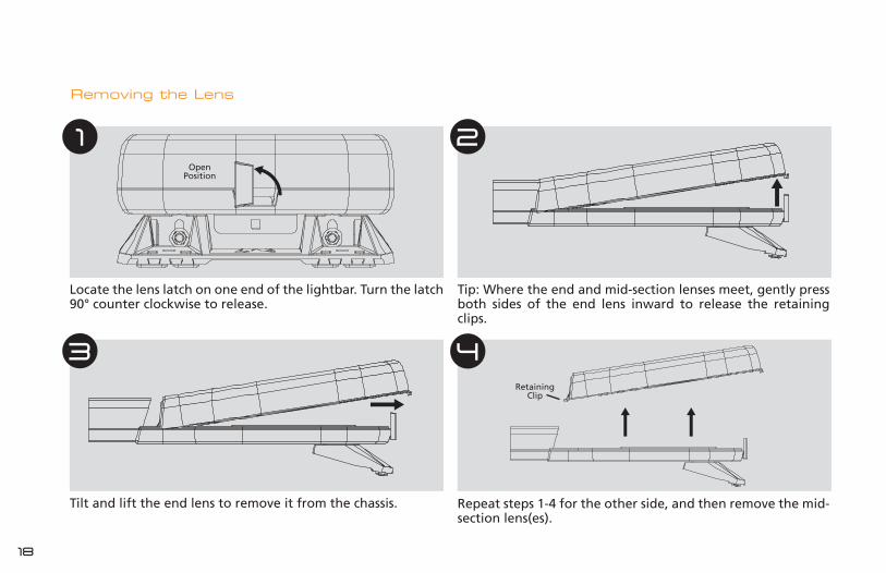
Repeat steps 1-4 for the other side, and then remove the mid-section lens(es).
Locate the lens latch on one end of the lightbar. Turn the latch 90° counter clockwise to release.
Tip: Where the end and mid-section lenses meet, gently press both sides of the end lens inward to release the retaining clips.
Tilt and lift the end lens to remove it from the chassis.
1 2
3 4
OpenPosition
Retaining Clip

19ENGLISH
Installing the Lens
Ensure the lens latches are in the open position. Install one of the end lenses, making sure the lens edge and retaining clips are seated properly. Turn the lens latch 90° clockwise to secure.
Install the mid-section lenses, making sure this lens is completely within the slot on the end lens. For four-piece lenses, install the center baffle and the second mid-section lens in the same manner.
Install the other end lens, making sure the lens edge and clips are seated properly. The mid-section lens must be seated in the slot on the end lens.
Apply gentle downward pressure at each joint to ensure lenses are properly seated in the chassis.
Turn the lens latch 90° clockwise to secure.
MAINTENANCEOccasional cleaning of the lenses will ensure optimum light output. Take care when cleaning lenses – although tough, polycarbonate can scratch. Clean the lens and base with soap and water or a lens polish using a soft cloth. Do not use solvents as they may damage the polycarbonate. Do not subject the lightbar to high-pressure washers or automatic car washers.
1
2
3
4
5
ASSEMBLY & CONFIGURATION
Lenses

20
INSTALLING DROPLOCK™ LED MODULES
DropLockTM LED modules are designed for simple, no-tool installation. During module installation, ensure the chassis is disconnected from the power source. Each LED module base is marked with a single and a double contact indicator. Care must be taken to ensure proper orientation of the contact indicators for each type of module where shown in this manual.
Directional ModulesEZ1401X
The EZ1401 LED directional module provides 120º high-intensity warning capability. Install these modules in the front or rear DropLockTM power rails only. Use the keypad controller to select desired flash patterns (page 15).
Remove the lenses (page 18) to access the DropLockTM power rail system. For standard operation, install the directional module base in the front or rear DropLock™ power rails.
Rotate the top of the module to the desired angle. For correct operation the single contact indicator on the base of the module must face towards central control board.
1 2 FRONT
Single Contact Indicator

21ENGLISH
CERTIFICATIONSThe image above depicts the minimum required configuration to meet SAE J845 Class I, ECE R65, and California Title 13. The location of the directional modules directly affects compliance with industry standards and regulations. They must be mounted in approved locations at a 45º angle.
FRONT
Apply power to the lightbar and press the power button on the keypad to turn on the directionals. Use the SEL and power buttons to set flash pattern presets.
To secure the module in the power rail, turn the locking knob clockwise a quarter turn. Install any other additional modules, and replace the lens.
3 4 ASSEMBLY & CONFIGURATION
DirectionalModule Installation

22
Beacon ModulesEZ1402X
The EZ1402 LED beacon module provides 360° warning capability and offers a variety of strobing flash patterns as well as rotating options with ECE R65 certification. Use the keypad controller to select desired flash patterns (page 15).
Remove the lenses to access the DropLockTM power rail system. Place the two beacon module bases in the front and/or rear power rails.
For correct operation, beacon module must be oriented so the ECCO logo is legible from rear of lightbar (data port on central control board faces rear of lightbar).
1 2
MO
DEL
EZ1
402A
12-
24 V
DC
908-0080-02 M
D EX XXXX
1/2
10R XX XXXX
FRONT
MO
DEL
EZ1
402A
12-
24 V
DC
908-0080-02 MD
EX XXXX
1/2
10R XX XXXX

23ENGLISH
Apply power to the lightbar and use the power button on the keypad to turn on the beacons. Use the SEL and power buttons to set flash pattern presets. Pressing both alley light buttons simultaneously for two seconds will switch the beacon mode between “flash” and “rotate” modes. See flash pattern chart on page 15.
To secure the beacon in the power rail, turn both locking knobs clockwise a quarter turn. Install any additional modules, and replace the lens.
3 4
CERTIFICATIONSThe image above depicts the minimum required configuration to meet SAE J845 Class 1, ECE R65, and California Title13. The location of the beacon modules directly affects compliance with industry standards and regulations. They must be mounted in approved locations.
MO
DEL
EZ1
402A
12-
24 V
DC
908-0080-02 M
D EX XXXX
1/2
10R XX XXXX
MO
DEL
EZ1
402A
12-
24 V
DC
908-0080-02 M
D EX XXXX
1/2
10R XX XXXX
FRONT
ASSEMBLY & CONFIGURATION
BeaconModule Installation
24
Worklamp ModulesEZ1403WL
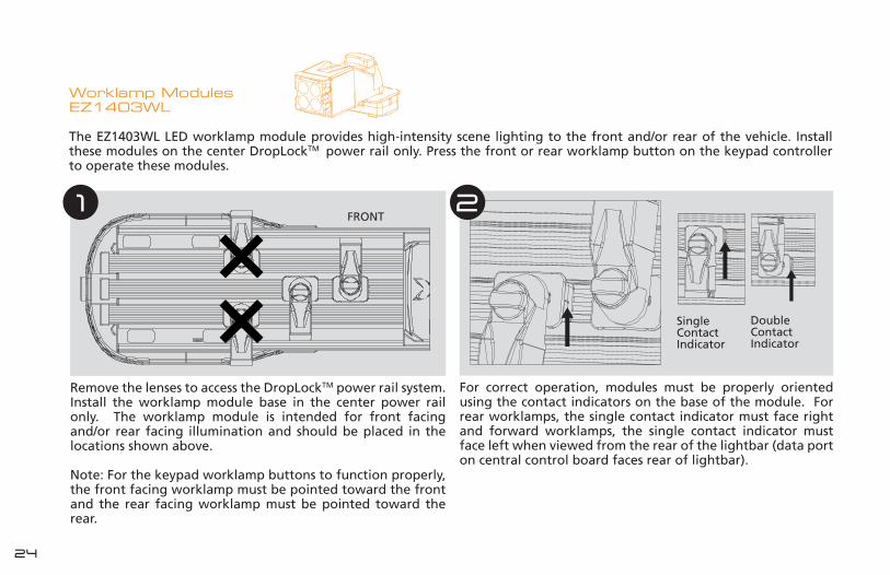
The EZ1403WL LED worklamp module provides high-intensity scene lighting to the front and/or rear of the vehicle. Install these modules on the center DropLockTM power rail only. Press the front or rear worklamp button on the keypad controller to operate these modules.
Remove the lenses to access the DropLockTM power rail system. Install the worklamp module base in the center power rail only. The worklamp module is intended for front facing and/or rear facing illumination and should be placed in the locations shown above.
Note: For the keypad worklamp buttons to function properly, the front facing worklamp must be pointed toward the front and the rear facing worklamp must be pointed toward the rear.
1 FRONT
For correct operation, modules must be properly oriented using the contact indicators on the base of the module. For rear worklamps, the single contact indicator must face right and forward worklamps, the single contact indicator must face left when viewed from the rear of the lightbar (data port on central control board faces rear of lightbar).
2
Single Contact Indicator
Double Contact Indicator

25ENGLISH
WARNINGThere is a four (4) module maximum per worklamp button on the keypad controller. Do not attempt to install worklamps in the front or rear power rails as damage to the central control board can occur.
Apply power to the lightbar and use the front and rear worklamp buttons on the keypad to operate.
ASSEMBLY & CONFIGURATION
WorklampModule Installation
If necessary, rotate the top of the module to the desired angle.
3
To secure the module in the power rail, turn the locking knob clockwise a quarter turn. Install any additional modules, and replace the lens.
4 5

26
Alley Light ModulesEZ1403AL
The EZ1403AL LED alley light module provides high-intensity scene lighting to the left and/or right of the vehicle. Install these modules in the center DropLockTM power rail, only. Press the left and/or right alley light button(s) on the keypad controller to operate these modules.
Remove the lenses to access the DropLockTM power rail system. Install the alley light base in the center power rail. The alley light is intended for side illumination and should be placed only in the location shown above.
If necessary, rotate the top of the module to aim the beam of light as desired. It does not matter which way the contact indicators are facing.
1 2 FRONT
27ENGLISH
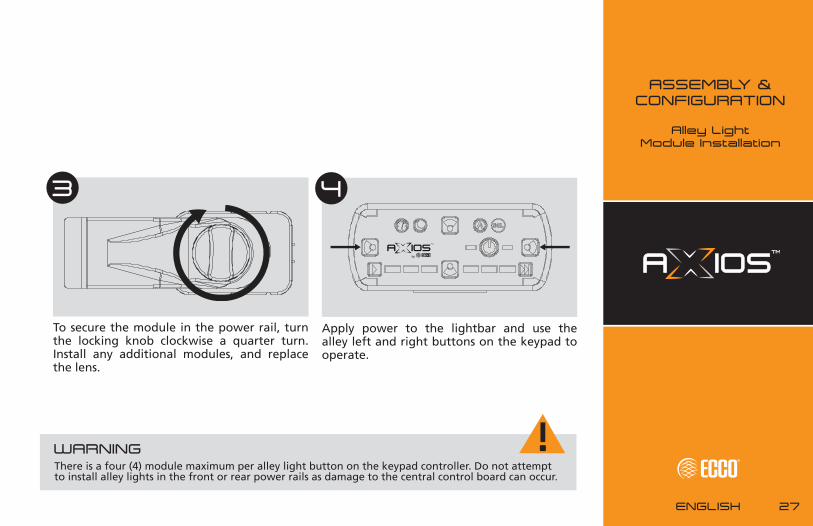
Apply power to the lightbar and use the alley left and right buttons on the keypad to operate.
To secure the module in the power rail, turn the locking knob clockwise a quarter turn. Install any additional modules, and replace the lens.
3 4
ASSEMBLY & CONFIGURATION
Alley LightModule Installation
WARNINGThere is a four (4) module maximum per alley light button on the keypad controller. Do not attempt to install alley lights in the front or rear power rails as damage to the central control board can occur.

28
Stop-Tail-Indicator ModulesEZ1404
The EZ1404 Stop-Tail-Indicator (STI) LED module enhances the vehicle’s standard position, brake, and turn indicator lighting. Installed on the rear DropLock™ power rail only, these modules provide high-intensity red light to warn other drivers of position and slowing. The turn signal indicator illuminates amber.
Remove the lenses to access the DropLockTM power rail system. Install the STI in the rear power rail only (refer to step 2).
The STI module can only be placed in one position on each end of the chassis. The connector on the bottom of the module must plug into the STI data port on the chassis as shown above.
1 2
FRONT

29ENGLISH
STI modules operate using the vehicle’s existing wiring system. Refer to wiring instructions on page 10 for more information.
To secure the STI module in the power rail, turn the locking knob clockwise a quarter turn. Install any additional modules, and replace the lightbar lens.
3
ASSEMBLY & CONFIGURATION
Stop-Tail-IndicatorModule Installation
CERTIFICATIONSTo meet ECE R6 and R7, place one (1) Stop-Tail-Indictor module at each of two (2) allowable rear facing locations with integrated data ports.

30
Safety Director™EZ1414
The EZ1414 LED Safety Director™ is designed to direct traffic approaching from the rear of a stationary vehicle. Nine flash modes can be selected using the keypad controller (see page 15).
Attached supplied mounting brackets to the Safety Director bar as shown above using supplied hardware.
Remove the lenses and plug the Safety Director cable into data port on central control board of lightbar as shown. Discard grommet blank from chassis and use grommet that is attached to the Safety Director cable.
1 2
31ENGLISH
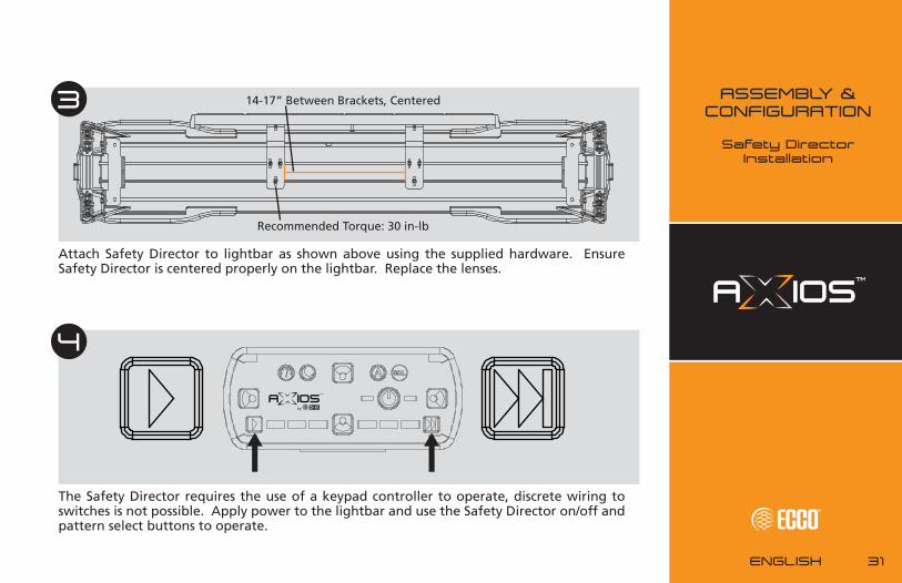
Attach Safety Director to lightbar as shown above using the supplied hardware. Ensure Safety Director is centered properly on the lightbar. Replace the lenses.
3
Recommended Torque: 30 in-lb
The Safety Director requires the use of a keypad controller to operate, discrete wiring to switches is not possible. Apply power to the lightbar and use the Safety Director on/off and pattern select buttons to operate.
4
ASSEMBLY & CONFIGURATION
Safety DirectorInstallation
14-17” Between Brackets, Centered
32
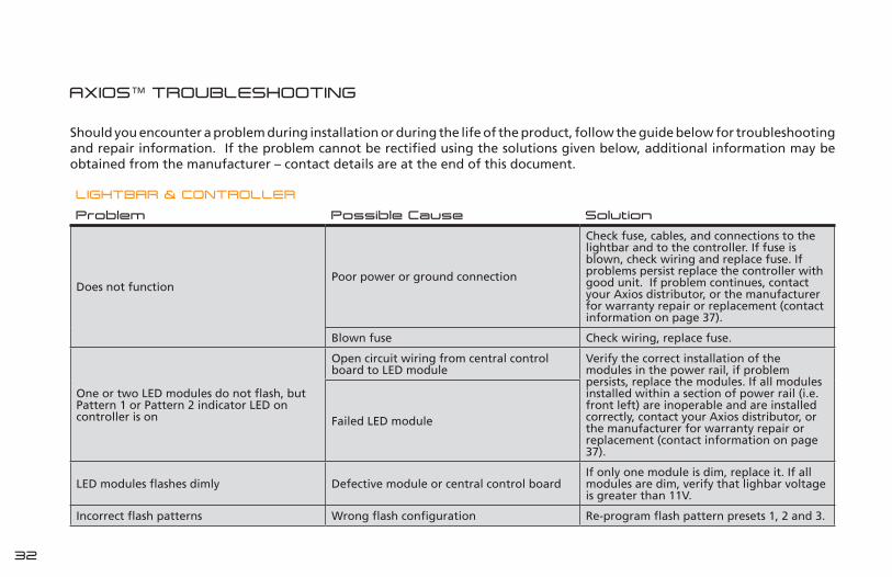
AXIOS™ TROUBLESHOOTING
Should you encounter a problem during installation or during the life of the product, follow the guide below for troubleshooting and repair information. If the problem cannot be rectified using the solutions given below, additional information may be obtained from the manufacturer – contact details are at the end of this document.
LIGHTBAR & CONTROLLER
Problem Possible Cause Solution
Does not functionPoor power or ground connection
Check fuse, cables, and connections to the lightbar and to the controller. If fuse is blown, check wiring and replace fuse. If problems persist replace the controller with good unit. If problem continues, contact your Axios distributor, or the manufacturer for warranty repair or replacement (contact information on page 37).
Blown fuse Check wiring, replace fuse.
One or two LED modules do not flash, but Pattern 1 or Pattern 2 indicator LED on controller is on
Open circuit wiring from central control board to LED module
Verify the correct installation of the modules in the power rail, if problem persists, replace the modules. If all modules installed within a section of power rail (i.e. front left) are inoperable and are installed correctly, contact your Axios distributor, or the manufacturer for warranty repair or replacement (contact information on page 37).
Failed LED module
LED modules flashes dimly Defective module or central control boardIf only one module is dim, replace it. If all modules are dim, verify that lighbar voltage is greater than 11V.
Incorrect flash patterns Wrong flash configuration Re-program flash pattern presets 1, 2 and 3.
33ENGLISH
TROUBLESHOOTING
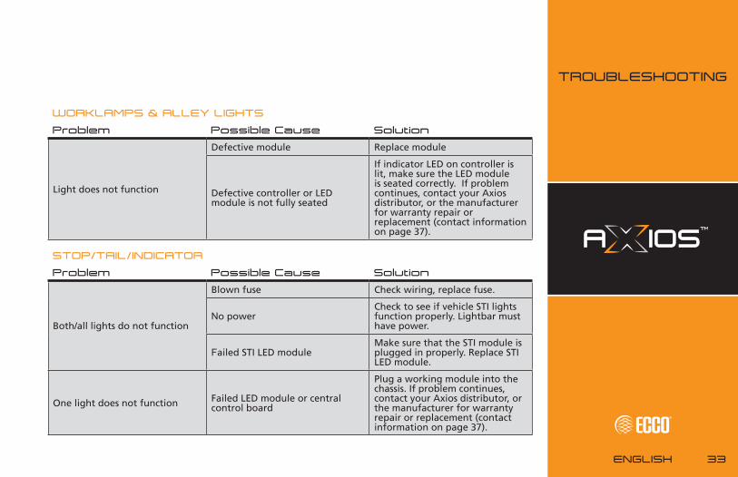
WORKLAMPS & ALLEY LIGHTS
Problem Possible Cause Solution
Light does not function
Defective module Replace module
Defective controller or LED module is not fully seated
If indicator LED on controller is lit, make sure the LED module is seated correctly. If problem continues, contact your Axios distributor, or the manufacturer for warranty repair or replacement (contact information on page 37).
STOP/TAIL/INDICATOR
Problem Possible Cause Solution
Both/all lights do not function
Blown fuse Check wiring, replace fuse.
No powerCheck to see if vehicle STI lights function properly. Lightbar must have power.
Failed STI LED moduleMake sure that the STI module is plugged in properly. Replace STI LED module.
One light does not function Failed LED module or central control board
Plug a working module into the chassis. If problem continues, contact your Axios distributor, or the manufacturer for warranty repair or replacement (contact information on page 37).

34
MANUFACTURER LIMITED WARRANTY & LIMITATION OF LIABILITY
Manufacturer warrants that on the date of purchase this product will conform to Manufacturer’s specifications for this product (which are available from the Manufacturer upon request). This Limited Warranty extends for Sixty (60) months from the date of purchase.
DAMAGE TO PARTS OR PRODUCTS RESULTING FROM TAMPERING, ACCIDENT, ABUSE, MISUSE, NEGLIGENCE, UNAPPROVED MODIFICATIONS, FIRE OR OTHER HAZARD; IMPROPER INSTALLATION OR OPERATION; OR NOT BEING MAINTAINED IN ACCORDANCE WITH THE MAINTENANCE PROCEDURES SET FORTH IN MANUFACTURER’S INSTALLATION AND OPERATING INSTRUCTIONS VOIDS THIS LIMITED WARRANTY.
Exclusion of Other Warranties:
MANUFACTURER MAKES NO OTHER WARRANTIES, EXPRESS OR IMPLIED. THE IMPLIED WARRANTIES FOR MERCHANTABILITY, QUALITY OR FITNESS FOR A PARTICULAR PURPOSE, OR ARISING FROM A COURSE OF DEALING, USAGE OR TRADE PRACTICE ARE HEREBY EXCLUDED AND SHALL NOT APPLY TO THE PRODUCT AND ARE HEREBY DISCLAIMED, EXCEPT TO THE EXTENT PROHIBITED BY APPLICABLE LAW. ORAL STATEMENTS OR REPRESENTATIONS ABOUT THE PRODUCT DO NOT CONSTITUTE WARRANTIES.
Remedies and Limitation of Liability:
MANUFACTURER’S SOLE LIABILITY AND BUYER’S EXCLUSIVE REMEDY IN CONTRACT, TORT (INCLUDING NEGLIGENCE), OR UNDER ANY OTHER THEORY AGAINST MANUFACTURER REGARDING THE PRODUCT AND ITS USE SHALL BE, AT MANUFACTURER’S DISCRETION, THE REPLACEMENT OR REPAIR
OF THE PRODUCT, OR THE REFUND OF THE PURCHASE PRICE PAID BY BUYER FOR NON-CONFORMING PRODUCT. IN NO EVENT SHALL MANUFACTURER’S LIABILITY ARISING OUT OF THIS LIMITED WARRANTY OR ANY OTHER CLAIM RELATED TO THE MANUFACTURER’S PRODUCTS EXCEED THE AMOUNT PAID FOR THE PRODUCT BY BUYER AT THE TIME OF THE ORIGINAL PURCHASE. IN NO EVENT SHALL MANUFACTURER BE LIABLE FOR LOST PROFITS, THE COST OF SUBSTITUTE EQUIPMENT OR LABOR, PROPERTY DAMAGE, OR OTHER SPECIAL, CONSEQUENTIAL, OR INCIDENTAL DAMAGES BASED UPON ANY CLAIM FOR BREACH OF CONTRACT, IMPROPER INSTALLATION, NEGLIGENCE, OR OTHER CLAIM, EVEN IF MANUFACTURER OR A MANUFACTURER’S REPRESENTATIVE HAS BEEN ADVISED OF THE POSSIBILITY OF SUCH DAMAGES. MANUFACTURER SHALL HAVE NO FURTHER OBLIGATION OR LIABILITY WITH RESPECT TO THE PRODUCT OR ITS SALE, OPERATION AND USE, AND MANUFACTURER NEITHER ASSUMES NOR AUTHORIZES THE ASSUMPTION OF ANY OTHER OBLIGATION OR LIABILITY IN CONNECTION WITH SUCH PRODUCT.
This Limited Warranty defines specific legal rights. You may have other legal rights which vary from jurisdiction to jurisdiction. Some jurisdictions do not allow the exclusion or limitation of incidental or consequential damages.
NOTEOperating the vehicle without the outer lens installed on the product may result in damage that will NOT be covered under the warranty.

35ENGLISH
REPLACEMENT PARTS & ACCESSORIES
LENSES Part #
Replacement End Lens EZ1406C
39” Clear - Replacement Mid Lens EZ1416C
39” Opal - Replacement Mid Lens EZ1416O
48” Clear - Replacement Mid Lens EZ1407C
48” Opal - Replacement Mid Lens EZ1407O
54” Clear - Replacement Mid Lens EZ1408C
54” Opal - Replacement Mid Lens EZ1408O
60” Clear - Replacement Mid Lens EZ1409C
60” Opal - Replacement Mid Lens EZ1409O
72” Clear - Replacement Mid Lens EZ1410C
72” Opal - Replacement Mid Lens EZ1410O
LEDs Part #
Accessory Worklamp LED EZ1403WL
Accessory Alley Light LED EZ1403AL
Accessory Stop-Tail-Indicator LED EZ1404
Accessory LED Directional Module - Amber EZ1401A
Accessory LED Directional Module - Blue EZ1401B
Accessory LED Directional Module - Clear EZ1401C
Accessory LED Directional Module - Green EZ1401G
Accessory LED Directional Module - Red EZ1401R
Accessory LED Beacon Module - Amber EZ1402A
Accessory LED Beacon Module - Blue EZ1402B
Accessory LED Beacon Module - Clear EZ1402C
Accessory LED Beacon Module - Green EZ1402G
Accessory LED Beacon Module - Red EZ1402RSAFETY DIRECTOR Part #
Safety Director EZ1414
CABLES Part #
Controller Cable EZ1413
CONTROLLER Part #
Keypad Controller EZ1405
JUNCTION BOX Part #
Junction Box EZ1412
MOUNTING Part #
Keypad Controller Mount (Suction Cup) EZ1415
Lens Latch EZ1417
WARRANTY & REPLACEMENT
PARTS

36
MANUFACTURED BY
REGISTER YOUR BAR @ AXIOSMODULAR.COM/REGISTER
PATENTS PENDING
ECCO Americas 1-800-635-5900 │ ECCO Europe +44 (0)113 237 5340 │ ECCO Asia Pacific +61 (0)3 63322444