configuration code sp01 fep-coated thermocouple assemblies ... · configuration code sp01...
TRANSCRIPT

Special-Purpose
© 2006 Pyromation, Inc.
X XTT (XX)
SP-1
Configuration Code SP01FEP-Coated Thermocouple Assemblies
Configuration Code SP02 FEP-Coated RTD Assemblies
171-9
ORDER CODES
The assemblies listed below are designed for a broad range of applications that require resistance to corrosion and chemical attack. They provide very good temperature measurement and service life in plating, pickeling, and acid bath applications. The stainless steel sheath is coated with FEP and includes a fused FEP tip for excellent corrosion resistance.
Maximum Temperature Rating 200 °C
1 Thermocouple Types
CODE T/C TYPE SHEATH O.D. (inches)JP38UT J 3/16
JP48UT J 1/4
KP38UT K 3/16
KP48UT K 1/4
TP38UT T 3/16
TP48UT T 1/4For grounded hot junctions substitute the letter 'G' in place of the 'U' above.
6 Leadwire Terminations
CODE DESCRIPTION0 No termination2 2" split leads, 1/4" stripped3 2" split leads with spade lugs4 Standard plug6 Miniature plug OptionsMC Mating connectorRB Rubber boot
5 Extension LeadwireCODE DESCRIPTION
T1 Fluoropolymer insulation - solid conductor (available in thermocouples only)
T3 Fluoropolymer insulation - stranded conductor
4 Head Terminations
CODE DESCRIPTION
8HN63 White polypropylene screw-cover head with 1/2" NPT stainless steel hex mounting fitting
9HP63 White polypropylene screw-cover head with 1/2" NPT bushing holding head to sheath
56CF63[1] White polypropylene screw-cover head with FEP compression fitting holding head to sheath
[1] Not available with 3/16" O.D. sheath
4-1 Sheath Terminations
CODE DESCRIPTION
4 Standard plug
5 Standard jack
Options
MC Mating connector
RB Rubber boot
4-2 Leadwire Transitions
CODE DESCRIPTION
TT
FEP coating: both sheath and leads (specify total length of FPE coating) Example: TT(36)
15 Extension leadwire transition with relief spring
16 Extension leadwire transition with heat-shrink tubing
1-2 1 latinum RTD 5 C-1 Tolerance[1] Class B
CODE LEADS SHEATH O.D. (inches)
RBF185L383T 3 3/16
RBF185L483T 3 1/4[1] Refer to RTD tolerance information in the General Information section for calculations to determine specific tolerance at temperature.
2 'X' DimensionInsert 3 Digit Sheath Length (X dimension) in Inches.
Re-Adjustable Compression Fittings
CODE DESCRIPTION NPT SIZE(inches)
AVAILABLE SHEATHDIAMETERS (inches)
10A 303 stainless steel 1/8 3/16
10B 303 stainless steel 1/4 1/4
10C 303 stainless steel 1/2 1/4
56B FEP 1/4 1/4
56C FEP 1/2 1/4
Sheath ountings
CODE DESCRIPTION00 No fitting
-1
Example Order Number: T -2
012 -3
00 -4
TT 6 -5
T 0 26
4
Distributed By: M&M Control Service, Inc. www.mmcontrol.com/pyromation.php 800-876-0036 847-356-0566

Special-Purpose
© 2006 Pyromation, Inc.
SP-2
Configuration Code SP09Chemical-Resistant Thermocouples
361-6
ORDER CODES
The thermocouples listed below are designed for a broad range of uses in applications that require resistance to corrosion and chemical attack. They provide very good temperature measurement and service life in plating, pickling, and acid bath applications. The fluoropolymer assemblies provide excellent resistance to strong acids, alkalines, and saline solutions.
1-1 Thermocouple Type
CODE DESCRIPTION
J4 Type J
K4 Type K
T4 Type T
3 Terminations
CODE DESCRIPTION
2 2" split leads, 1/4" stripped
3 2" split leads with spade lugs
4 Standard plug
5 Standard jack
6 Miniature plug
7 Miniature jack
Options
MC Mating connector
CG Cord grip (1/2" NPT PVC)
RB Rubber boot
SP Solid pin plug
2 Length
3 Digit "B" Length in Inches.
-1-1
Example Order Number: J4 TEF -2
0723
4, RB1-2
1-2 Outer Tubing
CODE DESCRIPTION TEMPERATURERATING
TEF TFE 260 ºC [500 ºF]
FEP FEP 200 ºC [392 ºF]
B
FEP ASSEMBLY TEF ASSEMBLY
B
Distributed By: M&M Control Service, Inc. www.mmcontrol.com/pyromation.php 800-876-0036 847-356-0566
Special-Purpose
© 2006 Pyromation, Inc.
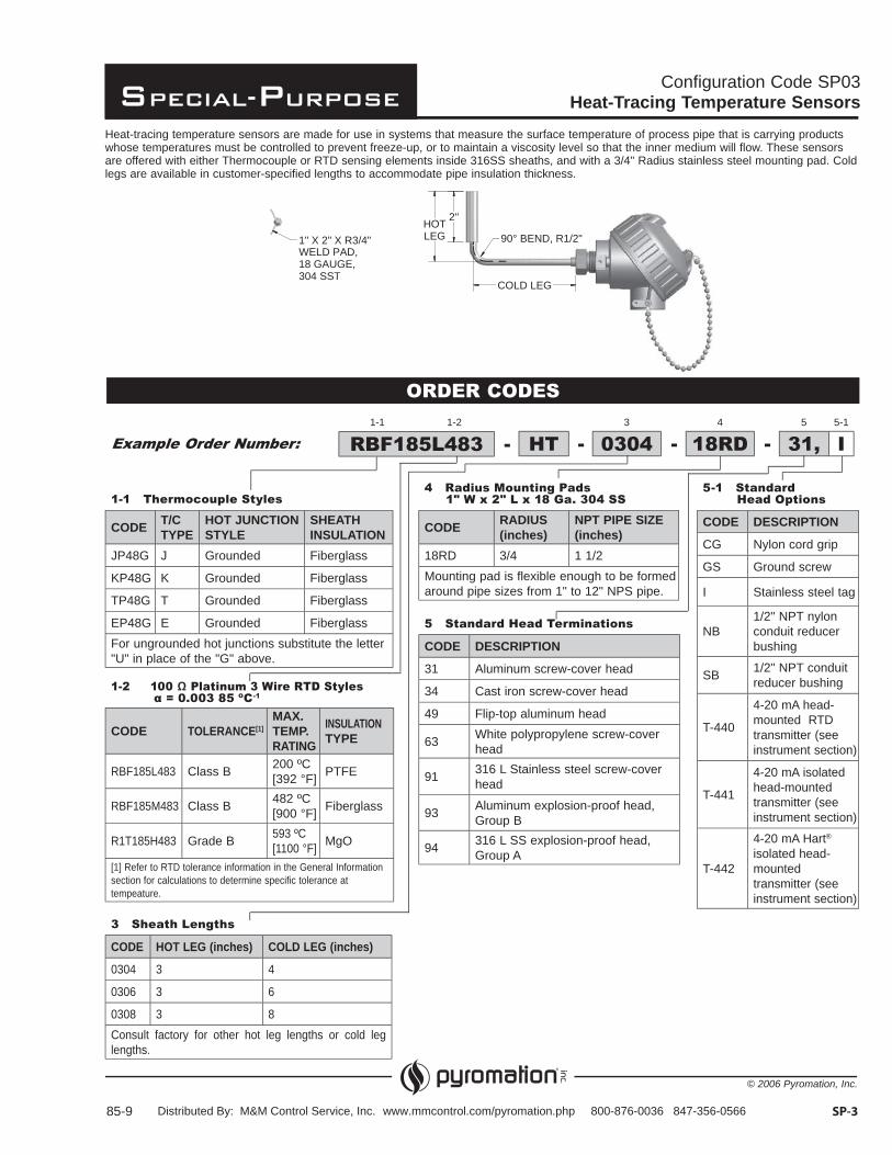
2"HOTLEG
COLD LEG
90° BEND, R1/2"R3/41" X 2" X "WELD PAD,18 GAUGE,304 SST
Configuration Code SP03Heat-Tracing Temperature Sensors
85-9 SP-3
ORDER CODES
Heat-tracing temperature sensors are made for use in systems that measure the surface temperature of process pipe that is carrying products whose temperatures must be controlled to prevent freeze-up, or to maintain a viscosity level so that the inner medium will flow. These sensors are offered with either Thermocouple or RTD sensing elements inside 316SS sheaths, and with a 3/4" Radius stainless steel mounting pad. Cold legs are available in customer-specified lengths to accommodate pipe insulation thickness.
1-1 Thermocouple Styles
CODE T/CTYPE
HOT JUNCTIONSTYLE
SHEATHINSULATION
JP48G J Grounded Fiberglass
KP48G K Grounded Fiberglass
TP48G T Grounded Fiberglass
EP48G E Grounded FiberglassFor ungrounded hot junctions substitute the letter "U" in place of the "G" above.
1-2 100 latinum 3 ire RTD Styles 0 003 5 C-1
CODE TOLERANCE[1]MAX.TEMP.RATING
INSULATIONTYPE
RBF185L483 Class B 200 ºC [392 °F] PTFE
RBF185M483 Class B 482 ºC [900 °F] Fiberglass
R1T185H483 Grade B 593 ºC[1100 °F] MgO
[1] Refer to RTD tolerance information in the General Information section for calculations to determine specific tolerance at tempeature.
3 Sheath Lengths
CODE HOT LEG (inches) COLD LEG (inches)
0304 3 4
0306 3 6
0308 3 8Consult factory for other hot leg lengths or cold leg lengths.
5-1 Standard Head Options
CODE DESCRIPTION
CG Nylon cord grip
GS Ground screw
I Stainless steel tag
NB1/2" NPT nylon conduit reducer bushing
SB 1/2" NPT conduit reducer bushing
T-440
4-20 mA head- mounted RTD transmitter (see instrument section)
T-441
4-20 mA isolated head-mounted transmitter (see instrument section)
T-442
4-20 mA Hart®
isolated head-mounted transmitter (see instrument section)
4 Radius ounting ads 1 x 2 L x 1 a 304 SS
CODE RADIUS(inches)
NPT PIPE SIZE(inches)
18RD 3/4 1 1/2Mounting pad is flexible enough to be formed around pipe sizes from 1" to 12" NPS pipe.
5 Standard Head Terminations
CODE DESCRIPTION
31 Aluminum screw-cover head
34 Cast iron screw-cover head
49 Flip-top aluminum head
63 White polypropylene screw-cover head
91 316 L Stainless steel screw-cover head
93 Aluminum explosion-proof head, Group B
94 316 L SS explosion-proof head, Group A
-Example Order Number: RBF1 5L4 3 -HT -3
0304 -4
1 RD5
31, I5-11-1 1-2
Distributed By: M&M Control Service, Inc. www.mmcontrol.com/pyromation.php 800-876-0036 847-356-0566

Special-Purpose
© 2006 Pyromation, Inc.
XU
XU
SP-4
Configuration Code SP04Abrasion-Resistant Thermocouples
82-10
ORDER CODES
The hardened tip aggregate temperature sensor assemblies illustrated in Figures 1, 2, and 3 below are typically used to measure the temperature of severely abrasive materials found in asphalt aggregate mixers and other granular material mixing and drying processes. Three styles of hardened tip constructions are offered to resist destructive abrasion and wear. Figure 4 illustrates an open-end tube style thermocouple assembly used to measure the temperature of hot sand and other similar free flowing materials on conveyors, or at drop chutes, where abrasion is not as severe, but where product temperature response time is important.
- --1
Example Order Number: J29GA12
184
31,3
6D12
1 Thermocouple Styles
CODE T/CTYPE
NOM. PIPE DIA. (inches)
MEASURING TIP CONSTRUCTION
FIG. NO.
J29GA1 J 0.540 Flame-sprayed tungsten carbide 1
J29GA2 J 0.840 Tool steel with carbide tip 2
J29GA3 J 0.540 Carbide tip 3
J14CS J 0.540 Open end tube 4
For ungrounded junctions, change 'G' in above order code to 'U'. Consult factory for availability of other thermocouple types and duplex elements.
3 Welded Bushings
CODE DESCRIPTION
6C(U) 1/2" NPT steel bushing (for use with figures 1, 3, and 4 only)
6D(U) 3/4" NPT welded steel bushing
6E(U) 1" NPT welded steel bushingSubstitute length in inches from hot tip to bottom of bushing for 'U' above
4 Head Terminations
CODE DESCRIPTION22[1] 3" individual leads with terminal pins
31 Aluminum screw-cover head
34 Cast iron screw-cover head
49 Flip-top aluminum head
91 316L stainless steel screw-cover head
[1] Not available with J14CS Series Options
HSB 1/2" NPT conduit reducer bushing
2 Length 'X'
CODE LENGTH(inches) CODE LENGTH
(inches)12 12 20 20
14 14 24 24
18 18 Specify other lengths
FIG. 3 SMALL-DIAMETER, HEAVY-WALL TUBE WITH CARBIDE TIP
FIG. 1 FLAME-SPRAYED, TUNGSTEN CARBIDE TIP
FIG. 4 BEVELED OPEN END TIP
FIG. 2 RUGGEDIZED BULLET-NOSED, HARDENED-TOOL STEEL WITH CARBIDE TIP
H
SMALL-DIAMETER, HEAVY-WALLTUBE WITH CARBIDE TIP
5"X
4 BEVELED OPEN END TIP
X2"1/4"
1/2"
Distributed By: M&M Control Service, Inc. www.mmcontrol.com/pyromation.php 800-876-0036 847-356-0566
Special-Purpose
© 2006 Pyromation, Inc.
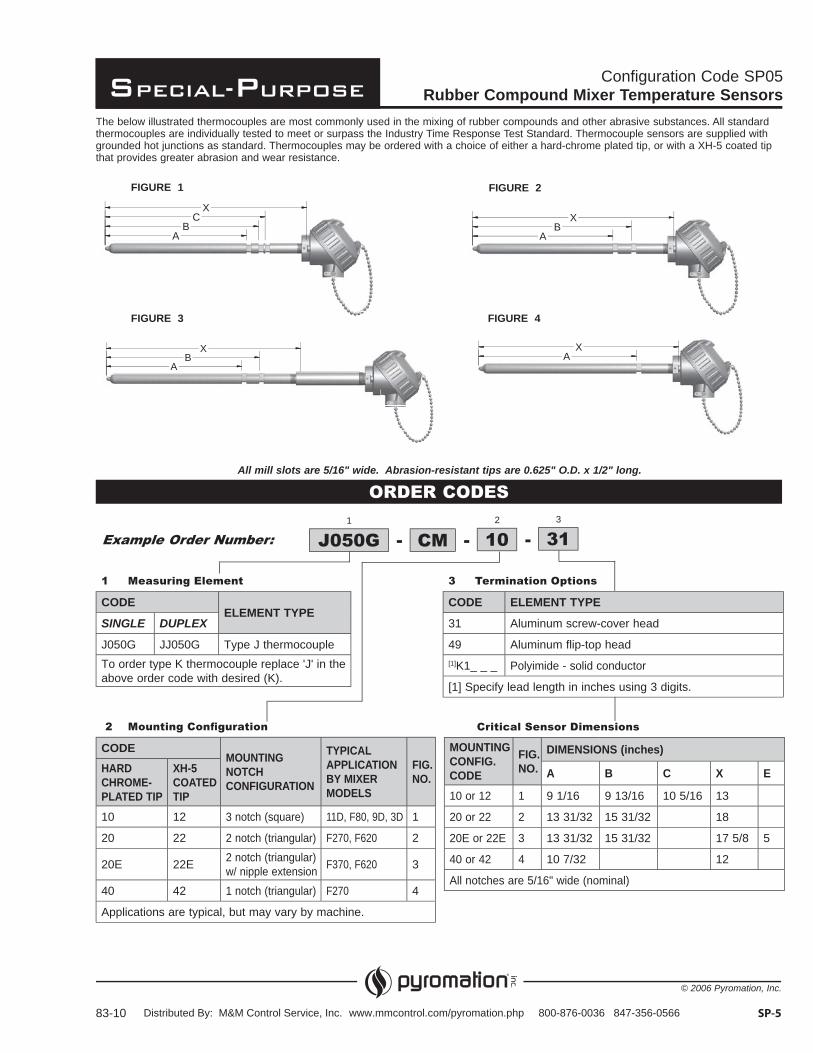
AB
XA
X
FIGURE 1
Configuration Code SP05Rubber Compound Mixer Temperature Sensors
83-10 SP-5
ORDER CODES
The below illustrated thermocouples are most commonly used in the mixing of rubber compounds and other abrasive substances. All standard thermocouples are individually tested to meet or surpass the Industry Time Response Test Standard. Thermocouple sensors are supplied with grounded hot junctions as standard. Thermocouples may be ordered with a choice of either a hard-chrome plated tip, or with a XH-5 coated tip that provides greater abrasion and wear resistance.
1 Measuring Element
CODEELEMENT TYPE
SINGLE DUPLEX
J050G JJ050G Type J thermocoupleTo order type K thermocouple replace 'J' in the above order code with desired (K).
3 Termination Options
CODE ELEMENT TYPE
31 Aluminum screw-cover head
49 Aluminum flip-top head[1]K1_ _ _ Polyimide - solid conductor
[1] Specify lead length in inches using 3 digits.
Critical Sensor Dimensions
MOUNTINGCONFIG.CODE
FIG.NO.
DIMENSIONS (inches)
A B C X E
10 or 12 1 9 1/16 9 13/16 10 5/16 13
20 or 22 2 13 31/32 15 31/32 18
20E or 22E 3 13 31/32 15 31/32 17 5/8 5
40 or 42 4 10 7/32 12
All notches are 5/16" wide (nominal)
2 Mounting Con guration
CODEMOUNTINGNOTCHCONFIGURATION
TYPICALAPPLICATIONBY MIXERMODELS
FIG.NO.
HARDCHROME-PLATED TIP
XH-5COATEDTIP
10 12 3 notch (square) 11D, F80, 9D, 3D 1
20 22 2 notch (triangular) F270, F620 2
20E 22E 2 notch (triangular) w/ nipple extension F370, F620 3
40 42 1 notch (triangular) F270 4
Applications are typical, but may vary by machine.
-1
Example Order Number: J050G -CM -2
103
31
All mill slots are 5/16" wide. Abrasion-resistant tips are 0.625" O.D. x 1/2" long.
FIGURE 2
FIGURE 3 FIGURE 4
AB
CX
AB
X
Distributed By: M&M Control Service, Inc. www.mmcontrol.com/pyromation.php 800-876-0036 847-356-0566
Special-Purpose
© 2006 Pyromation, Inc.
SP-6
Configuration Code SP06RTD Averaging Sensor
172-9
ORDER CODES
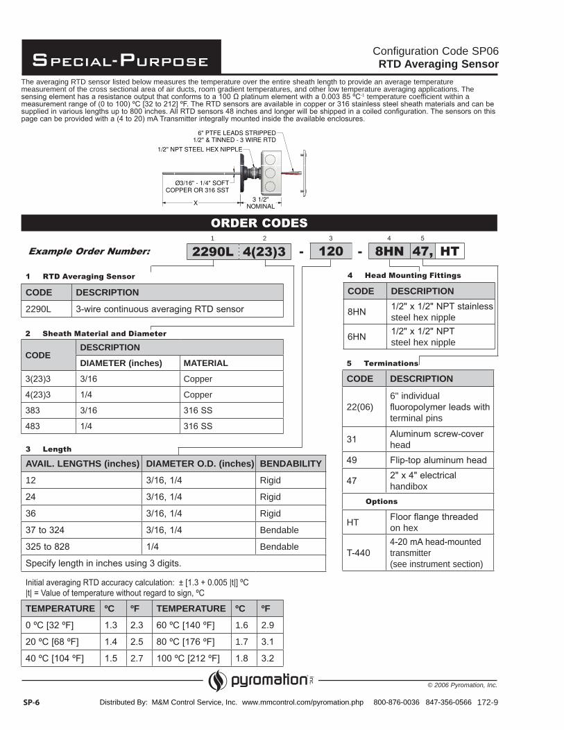
The averaging RTD sensor listed below measures the temperature over the entire sheath length to provide an average temperature measurement of the cross sectional area of air ducts, room gradient temperatures, and other low temperature averaging applications. The
-1 temperature coefficient within a
1 RTD Averaging Sensor
CODE DESCRIPTION
2290L
TEMPERATURE ºC ºF TEMPERATURE ºC ºF
1.6 2.9
1.7
2.7
2 Sheath Material and Diameter
CODEDESCRIPTION
DIAMETER (inches) MATERIAL
Copper
Copper
3 Length
AVAIL. LENGTHS (inches) DIAMETER O.D. (inches) BENDABILITY
12 Rigid
Rigid
Rigid
Bendable
Bendable
5 Terminations
CODE DESCRIPTION
22(06)6" individual
terminal pins
head
handibox Options
HT on hex
transmitter(see instrument section)
4 Head Mounting Fittings
CODE DESCRIPTION
steel hex nipple
steel hex nipple
-2290L 4(23)3Example Order Number:1 2
120 - 8HN 47, HT
6" PTFE LEADS STRIPPED1/2" & TINNED - 3 WIRE RTD
3 1/2"NOMINALX
3/16Ø " - 1/4" SOFTCOPPER OR 316 SST
1/2" NPT STEEL HEX NIPPLE
Distributed By: M&M Control Service, Inc. www.mmcontrol.com/pyromation.php 800-876-0036 847-356-0566

Special-Purpose
© 2006 Pyromation, Inc.
Configuration Code SP07Thermostat Temperature Sensors
173-7 SP-7
ORDER CODES
Thermostat Housings
CODE DESCRIPTION
2215 - RBF185L3 platinum RTD 0.003 85 0 °C-1 temperature coefficient Class B
2215 - (J, K, T, E) Thermostat housing with integral thermocouple element
2415 Thermostat housing with base plate and 4-position terminal strip - no sensing element
The Pyromation thermostat temperature sensors are provided with the sensor, or the sensor and a (4 to 20) mA temperature transmitter, mounted on a subplate within a standard size thermostat housing. The thermostat housing measures 2 3/4"h x 4 1/2"w x 1 5/8"d and can be mounted either horizontally or vertically on a 2" x 4" electrical handibox. The cover is vented on two sides to provide for airflow over the sensing element, regardless of mounting position. The standard temperature sensing elements are available as a fluoropolymer insulated thermocouple or a three-wire RTD. Matching transmitters are available for all configurations and output ranges.
-Example Order Number: 2215-RBF185L3 T
Option
CODE DESCRIPTION
T-4404-20 mA RTD transmitter mounted in housing with sensor (see instrument section)
T-4414-20 mA isolated transmitter mounted in housing with sensor (see instrument section)
Temperature Range (-40 to 85) ºC
Distributed By: M&M Control Service, Inc. www.mmcontrol.com/pyromation.php 800-876-0036 847-356-0566
Special-Purpose
© 2006 Pyromation, Inc.
SP-8
Configuration Code SP08Variable-Length RTD Elements
86-10
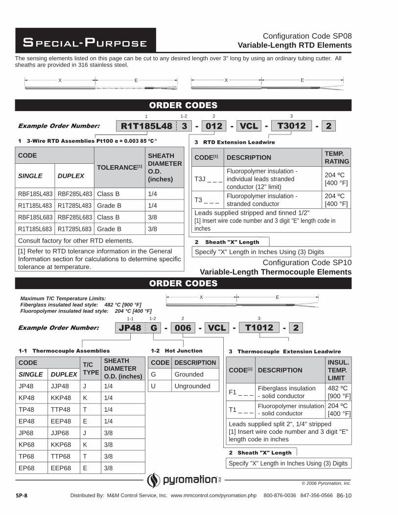
The sensing elements listed on this page can be cut to any desired length over 3" long by using an ordinary tubing cutter. All sheaths are provided in 316 stainless steel.
Configuration Code SP10Variable-Length Thermocouple Elements
Maximum T/C Temperature Limits:Fiberglass insulated lead style: 482 °C [900 °F]Fluoropolymer insulated lead style: 204 °C [400 °F]
ORDER CODES1
--Example Order Number: -012 - T3012R1T185L48 3 VCL 22 31-2
1 3-Wire RTD Assemblies Pt100 0 003 85 C-1
CODE
TOLERANCE[1]
SHEATHDIAMETERO.D. (inches)SINGLE DUPLEX
RBF185L483 RBF285L483 Class B 1/4
R1T185L483 R1T285L483 Grade B 1/4
RBF185L683 RBF285L683 Class B 3/8
R1T185L683 R1T285L683 Grade B 3/8
Consult factory for other RTD elements.[1] Refer to RTD tolerance information in the General
tolerance at temperature.
3 RTD Extension Leadwire
CODE[1] DESCRIPTION TEMP.RATING
T3J _ _ _Fluoropolymer insulation - individual leads stranded conductor (12" limit)
204 ºC[400 °F]
T3 _ _ _ Fluoropolymer insulation - stranded conductor
204 ºC[400 °F]
Leads supplied stripped and tinned 1/2"[1] Insert wire code number and 3 digit "E" length code in inches
2 Sheath "X" Length
Specify "X" Length in Inches Using (3) Digits
1-1 Thermocouple Assemblies
CODE T/CTYPE
SHEATHDIAMETERO.D. (inches)SINGLE DUPLEX
JP48 JJP48 J 1/4
KP48 KKP48 K 1/4
TP48 TTP48 T 1/4
EP48 EEP48 E 1/4
JP68 JJP68 J 3/8
KP68 KKP68 K 3/8
TP68 TTP68 T 3/8
EP68 EEP68 E 3/8
1-2 Hot Junction
CODE DESCRIPTION
G Grounded
U Ungrounded
3 Thermocouple Extension Leadwire
CODE[1] DESCRIPTIONINSUL.TEMP.LIMIT
F1 _ _ _ Fiberglass insulation- solid conductor
482 ºC[900 °F]
T1 _ _ _ Fluoropolymer insulation- solid conductor
204 ºC[400 °F]
Leads supplied split 2", 1/4" stripped[1] Insert wire code number and 3 digit "E" length code in inches
2 Sheath "X" Length
Specify "X" Length in Inches Using (3) Digits
--1-1
Example Order Number: -006 -2 3
T1012JP48 G1-2
VCL 2
ORDER CODES
EX
EX
EX
Distributed By: M&M Control Service, Inc. www.mmcontrol.com/pyromation.php 800-876-0036 847-356-0566
Special-Purpose
© 2006 Pyromation, Inc.
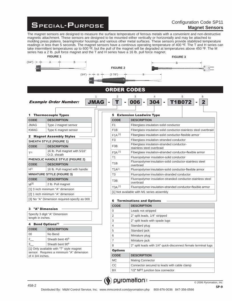
Configuration Code SP11Magnet Sensors
The magnet sensors are designed to measure the surface temperature of ferrous metals with a convenient and non-destructive magnetic attachment. These sensors are designed to be mounted either vertically or horizontally and may be attached to molding press platens, bearing/motor housings and various other metal surfaces. These sensors provide stabilized temperature readings in less than 5 seconds. The magnet sensors have a continous operating temperature of 400 ºF. The T and H series can take intermittent temperatures up to 600 ºF, but the pull of the magnet will be degraded at temperatures above 450 ºF. The M series has a 2 lb. pull force magnet and the T and H series have a 16 lb. pull force magnet.
ORDER CODES
Example Order Number: ---JMAG 1 2 3 4 5
- -T 006 304 T1B072 2 6
1 Thermocouple Types
CODE DESCRIPTIONJMAG Type J magnet sensorKMAG Type K magnet sensor
2 Magnet Assembly Styles
SHEATH STYLE (FIGURE 1)CODE DESCRIPTION
T[1] 16 lb. Pull magnet with 5/16" O.D. sheath
PHENOLIC HANDLE STYLE (FIGURE 2)CODE DESCRIPTIONH[2] 16 lb. Pull magnet with handleMINIATURE STYLE (FIGURE 3)CODE DESCRIPTIONM[3] 2 lb. Pull magnet [1] 3 inch minimum "A" dimension[2] 1 inch minimum "A" dimension[3] No "A" Dimension required-specify as 000
3 "A" Dimension
Specify 3 digit "A" Dimension length in inches.
4 Bend Options[1]
CODE DESCRIPTION00 No Bend2__ Sheath bent 45º3__ Sheath bent 90º[1] Only available with "T" style magnet sensor. Requires a minimum "A" dimension of 4 3/4 inches.
5 Extension Leadwire Type
CODE DESCRIPTIONF1 Fiberglass insulation-solid conductorF1B Fiberglass insulation-solid conductor-stainless steel overbraid
F1A [1]
F3 Fiberglass insulation-stranded conductor
F3B Fiberglass insulation-stranded conductor- stainless steel overbraid
F3A [1]
T1 Fluoropolymer insulation-solid conductor
T1B Fluoropolymer insulation-solid conductor-stainless steel overbraid
T1A[1] Fluoropolymer
T3 Fluoropolymer insulation-stranded conductor
T3B Fluoropolymer insulation-stranded conductor-stainless steel overbraid
T3A [1] Fluoropolymer
[1] Not available with M1 series assembly
6 Terminations and Options
CODE DESCRIPTION0 Leads not stripped2 2" split leads, 1/4" stripped3 2" split leads with spade lugs4 Standard plug5 Standard jack6 Miniature plug7 Miniature jack8 2" split leads with 1/4" quick-disconnect female terminal lugsOptionsCODE DESCRIPTIONMC Mating ConnectorCC Connector secured to leads with cable clampBX
SP-9
A B3/4( ")
A B3 7/8( ")3/4( ")
B
FIGURE 1 FIGURE 3
FIGURE 2
458-2Distributed By: M&M Control Service, Inc. www.mmcontrol.com/pyromation.php 800-876-0036 847-356-0566
Special-Purpose
© 2006 Pyromation, Inc.
ORDER CODES
0 ATEX Certi cation[1]
CODE DESCRIPTION
HL30 CE Ex II3G Ex ic IIC T4
for general-purpose sensors
1-1 Element Connection
CODE DESCRIPTION
2 2-Wire
3 3-Wire
1 100 Platinum RTD Elements (-40 to 204 ºC) SENSOR TYPE DESCRIPTIONCODE TOLERANCE[1] TEMPERATURE COEFFICIENTSINGLE DUPLEXRBF185LBS RBF285LBS Class B -1
RBF192LBS RBF292LBS Class B -1
[1] Refer to RTD tolerance information in the General Information section for calculations
WIRE TYPE CASE STYLE A [1] CASE STYLE B [1] CASE STYLE C [1] CASE STYLE D [1]
CODE DESCRIPTION Single Duplex Single Duplex Single Duplex Single Duplex
T3JFluoropolymer insulation- 2- or 3-wire
24 AWG2- or 3-wire28 AWG
2- or 3-wire24 AWG
2- or 3-wire28 AWG
2- or 3-wire28 AWG
2- or 3-wire30 AWG
2- or 3-wire30 AWG N/A
T3 Fluoropolymer insulation- 2- or 3-wire24 AWG
2- or 3-wire28 AWG
2- or 3-wire24 AWG
2- or 3-wire28 AWG
2- or 3-wire28 AWG
2- or 3-wire28 AWG N/A N/A
T3BFluoropolymer insulation- 2- or 3-wire
24 AWG2- or 3-wire28 AWG
2- or 3-wire24 AWG
2- or 3-wire28 AWG N/A N/A N/A N/A
T3BT
Fluoropolymer insulation-
outer jacket
2- or 3-wire24 AWG
2- or 3-wire30 AWG
2- or 3-wire24 AWG
2- or 3-wire30 AWG N/A N/A N/A N/A
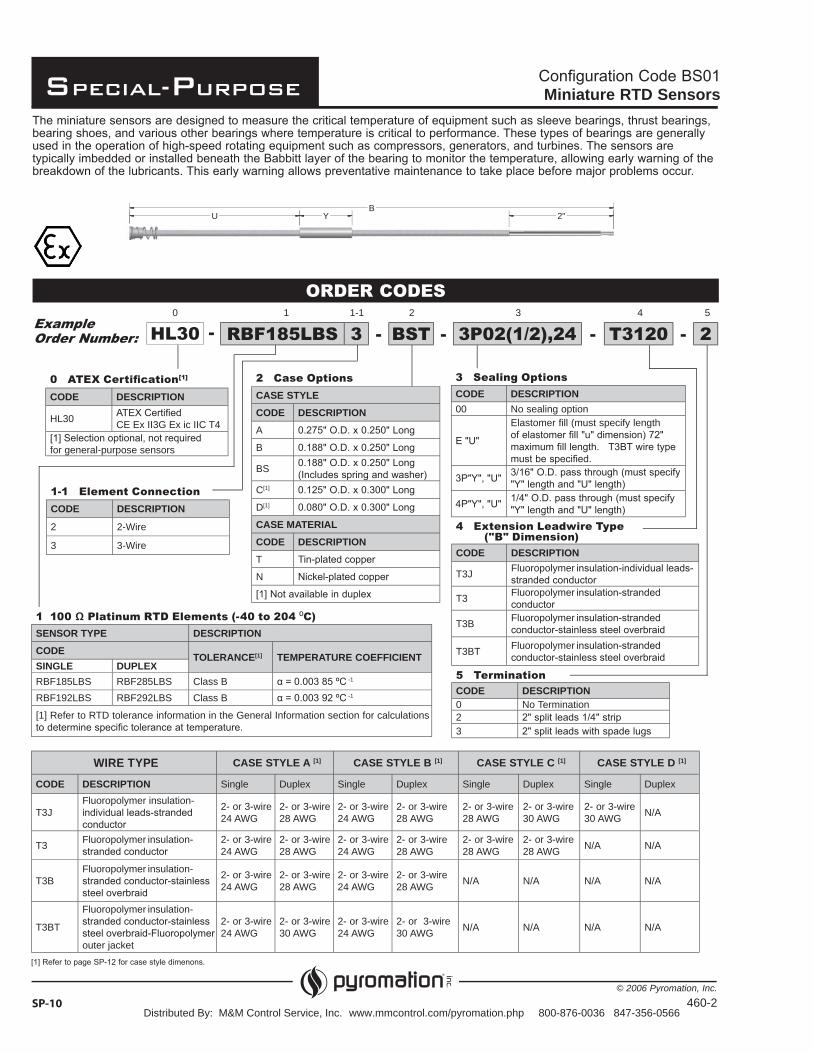
Miniature RTD Sensors
SP-10
Example Order Number: HL30 RBF185LBS 3 - BST - 3P02(1 2),24 - T3120 - 2-
1 1-1 2 3 4 50
2 Case Options
CASE STYLECODE DESCRIPTIONA
B
BS
C[1]
D[1]
CASE MATERIALCODE DESCRIPTIONT
N
3 Sealing Options
CODE DESCRIPTION00 No sealing option
Elastomer fill (must specify length
4 Extension Leadwire Type ("B" Dimension)CODE DESCRIPTION
T3J Fluoropolymer
T3 Fluoropolymer
T3B Fluoropolymer
T3BT Fluoropolymer
5 Termination
CODE DESCRIPTION0 No Termination23
U YB
2"
460-2Distributed By: M&M Control Service, Inc. www.mmcontrol.com/pyromation.php 800-876-0036 847-356-0566
Special-Purpose
© 2006 Pyromation, Inc.
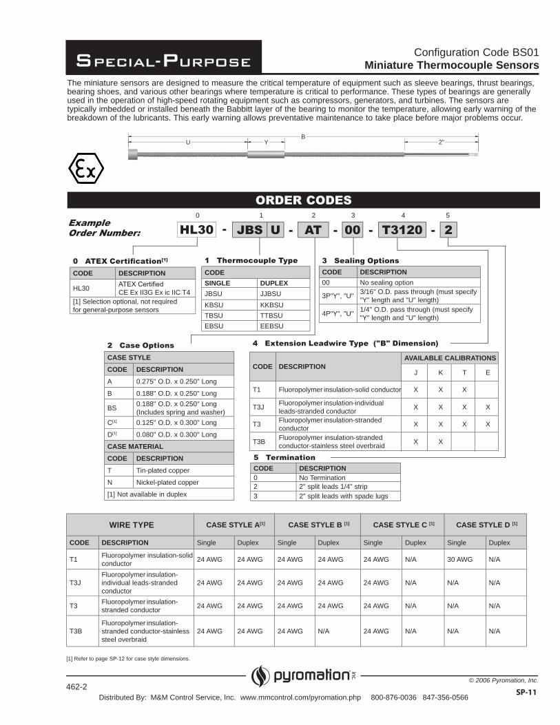
Configuration Code BS01Miniature Thermocouple Sensors
ORDER CODES
0 ATEX Certi cation[1]
CODE DESCRIPTION
HL30 CE Ex II3G Ex ic IIC T4[1] Selection optional, not required for general-purpose sensors
1 Thermocouple TypeCODESINGLE DUPLEXJBSU JJBSUKBSU KKBSUTBSU TTBSUEBSU EEBSU
WIRE TYPE CASE STYLE A[1] CASE STYLE B [1] CASE STYLE C [1] CASE STYLE D [1]
CODE DESCRIPTION Single Duplex Single Duplex Single Duplex Single Duplex
T1 Fluoropolymer insulation-solid conductor 24 AWG 24 AWG 24 AWG 24 AWG 24 AWG N/A 30 AWG N/A
T3JFluoropolymer insulation-individual leads-stranded conductor
24 AWG 24 AWG 24 AWG 24 AWG 24 AWG N/A N/A N/A
T3 Fluoropolymer insulation-stranded conductor 24 AWG 24 AWG 24 AWG 24 AWG 24 AWG N/A N/A N/A
T3BFluoropolymer insulation-stranded conductor-stainless steel overbraid
24 AWG 24 AWG 24 AWG N/A 24 AWG N/A N/A N/A
The miniature sensors are designed to measure the critical temperature of equipment such as sleeve bearings, thrust bearings, bearing shoes, and various other bearings where temperature is critical to performance. These types of bearings are generally used in the operation of high-speed rotating equipment such as compressors, generators, and turbines. The sensors are typically imbedded or installed beneath the Babbitt layer of the bearing to monitor the temperature, allowing early warning of the breakdown of the lubricants. This early warning allows preventative maintenance to take place before major problems occur.
Example Order Number: HL30 JBS U - AT - 00 - T3120 - 2-
1 2 3 4 50
2 Case OptionsCASE STYLECODE DESCRIPTIONA 0.275" O.D. x 0.250" Long
B 0.188" O.D. x 0.250" Long
BS 0.188" O.D. x 0.250" Long (Includes spring and washer)
C[1] 0.125" O.D. x 0.300" Long
D[1] 0.080" O.D. x 0.300" Long
CASE MATERIALCODE DESCRIPTIONT Tin-plated copper
N Nickel-plated copper
[1] Not available in duplex
3 Sealing Options
CODE DESCRIPTION00 No sealing option
3P"Y", "U" 3/16" O.D. pass through (must specify "Y" length and "U" length)
4P"Y", "U" 1/4" O.D. pass through (must specify "Y" length and "U" length)
4 Extension Leadwire Type ("B" Dimension)
CODE DESCRIPTIONAVAILABLE CALIBRATIONS
J K T E
T1 Fluoropolymer insulation-solid conductor X X X
T3J Fluoropolymer insulation-individual leads-stranded conductor X X X X
T3 Fluoropolymer insulation-stranded conductor X X X X
T3B Fluoropolymer insulation-stranded conductor-stainless steel overbraid X X
5 Termination
CODE DESCRIPTION0 No Termination2 2" split leads 1/4" strip3 2" split leads with spade lugs
[1] Refer to page SP-12 for case style dimensions.
SP-11
BU Y 2"
462-2Distributed By: M&M Control Service, Inc. www.mmcontrol.com/pyromation.php 800-876-0036 847-356-0566

Special-Purpose
© 2006 Pyromation, Inc.
Miniature Temperature Sensors
Installation Instructions
CASE STYLE INSTALLATION ILLUSTRATION
A
Install sensor just below the babbitt layer – near bearing shoe surface, then puddle the babbitt metal over the sensor tip and smooth.
B
This sensor is designed with a spring and retaining washer that allows for spring loading. Slide the spring and washer over the leads. Insert the sensor tip into a hole bored into the bearing shoe and push down on the retaining ring to compress the spring and secure the sensor.
C & D
Bore the sensor hole in the bearing shoe near, but not touching, the babbitt surface. Insert sensor and secure by potting/bonding with epoxy.
AccessoriesPART
NUMBER DESCRIPTION ILLUSTRATION
12920 Spring
12919 Retaining Washer
10494 Retaining Ring
LEADWIRE
Ø0.278"-0.281"[7.06-7.14 mm]
Ø0.188"[4.78mm]
BABBITTLAYER
SENSORBEARINGSHOE
Ø0.312"±0.001[7.92mm±0.03]
SENSOR
BABBITTLAYER
RETAINING WASHERLEADWIRE
SPRING
BEARING SHOE
SENSOR Ø+ 0.005"[0.01mm]
BABBITT LAYER
LEADWIRE
SENSOR BEARING SHOE
SP-12
CASE STYLE A
Ø 0.275" O.D. x 0.250" L
CASE STYLE B
Ø 0.188" O.D. x 0.250" LFlange 0.250" O.D. x 0.030" L
CASE STYLE C
Ø 0.125" O.D. x 0.300" L
CASE STYLE D
Ø 0.080" O.D. x 0.300" L
Case Style Dimensions
464-2Distributed By: M&M Control Service, Inc. www.mmcontrol.com/pyromation.php 800-876-0036 847-356-0566