configuration and sensor layout ac5 ac6 ac7 accelerometer-ac ac1 hammer vibpilot ac4 ac3 ac2 no...
TRANSCRIPT
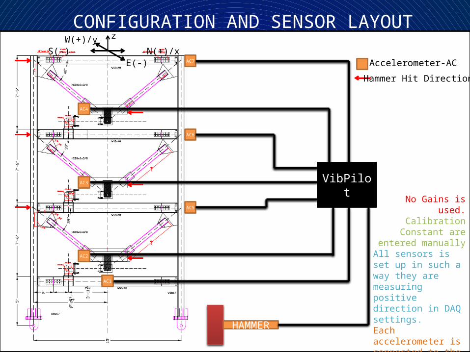
CONFIGURATION AND SENSOR LAYOUT
AC5
AC6
AC7 Accelerometer-AC
AC1
HAMMER
VibPilot
AC4
AC3
AC2
No Gains is used.Calibration Constant
are entered manuallyAll sensors is set up in such a way they are measuring positive direction in DAQ settings.Each accelerometer is connected to the channel associated with it’s number (i.e. AC1-Channel 1)(Hammer-Channel 8).
S(-) N(+)/xW(+)/y
E(-)
Hammer Hit Direction
z
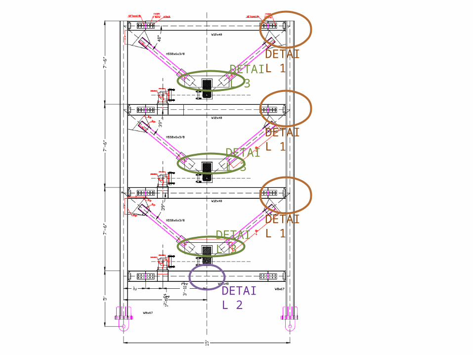
DETAIL 1
DETAIL 1
DETAIL 1
DETAIL 2
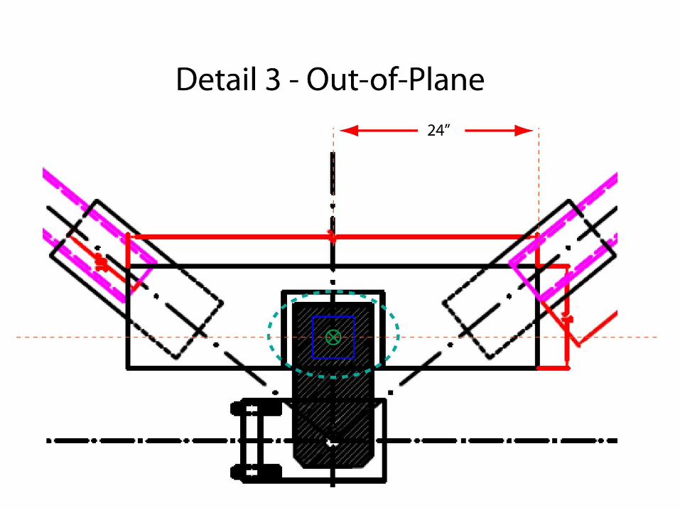
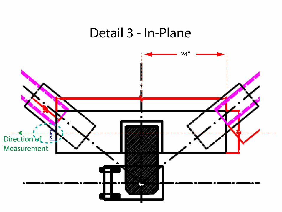
DETAIL 3
DETAIL 3
DETAIL 3
IN-PLANE MOTION SENSOR DETAILS
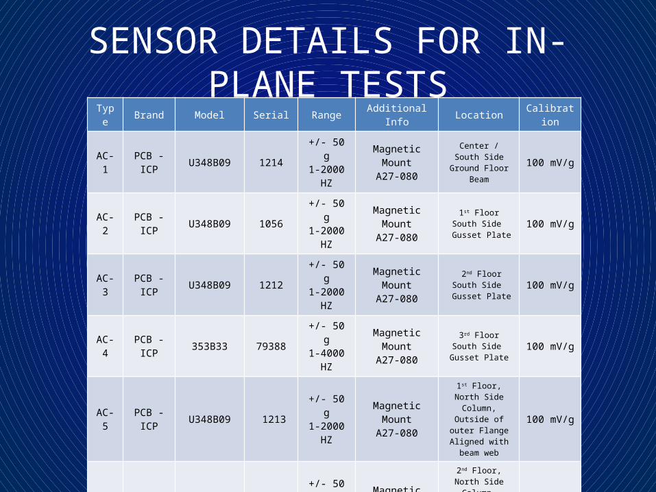
SENSOR DETAILS FOR IN-PLANE TESTSType Brand Model Serial Range Additional Info Location Calibration
AC-1 PCB - ICP U348B09 1214 +/- 50 g1-2000 HZ
Magnetic MountA27-080
Center / South SideGround Floor Beam 100 mV/g
AC-2 PCB - ICP U348B09 1056 +/- 50 g1-2000 HZ
Magnetic MountA27-080
1st FloorSouth Side
Gusset Plate100 mV/g
AC-3 PCB - ICP U348B09 1212 +/- 50 g1-2000 HZ
Magnetic MountA27-080
2nd FloorSouth Side
Gusset Plate100 mV/g
AC-4 PCB - ICP 353B33 79388 +/- 50 g1-4000 HZ
Magnetic MountA27-080
3rd FloorSouth Side
Gusset Plate100 mV/g
AC-5 PCB - ICP U348B09 1213 +/- 50 g1-2000 HZ
Magnetic MountA27-080
1st Floor, North Side Column, Outside of
outer FlangeAligned with beam
web
100 mV/g
AC-6 PCB - ICP U348B09 1038 +/- 50 g1-2000 HZ
Magnetic MountA27-080
2nd Floor, North Side Column, Outside of
outer FlangeAligned with beam
web
100 mV/g
AC-7 PCB - ICP 353B33 79599 +/- 50 g1-4000 HZ
Magnetic CapA27-080
3rd Floor, North Side Column, Outside of
outer FlangeAligned with beam
web
100 mV/g
EX-1 PCB - ICP 086D50 24659 22240 N Medium HardRed Plastic Tip - 0.22 mV/N
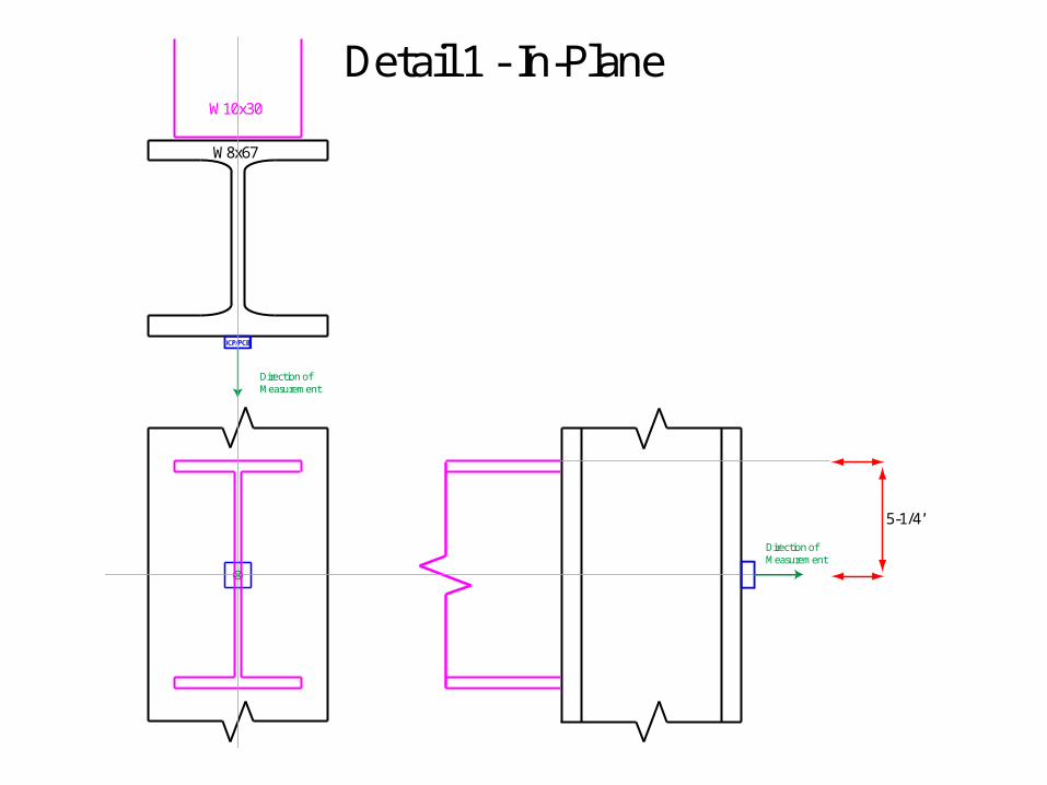
Detail 1 - In-Plane
W8x67
W10x30
Direction ofMeasurement
Direction ofMeasurement
5-1/4’’
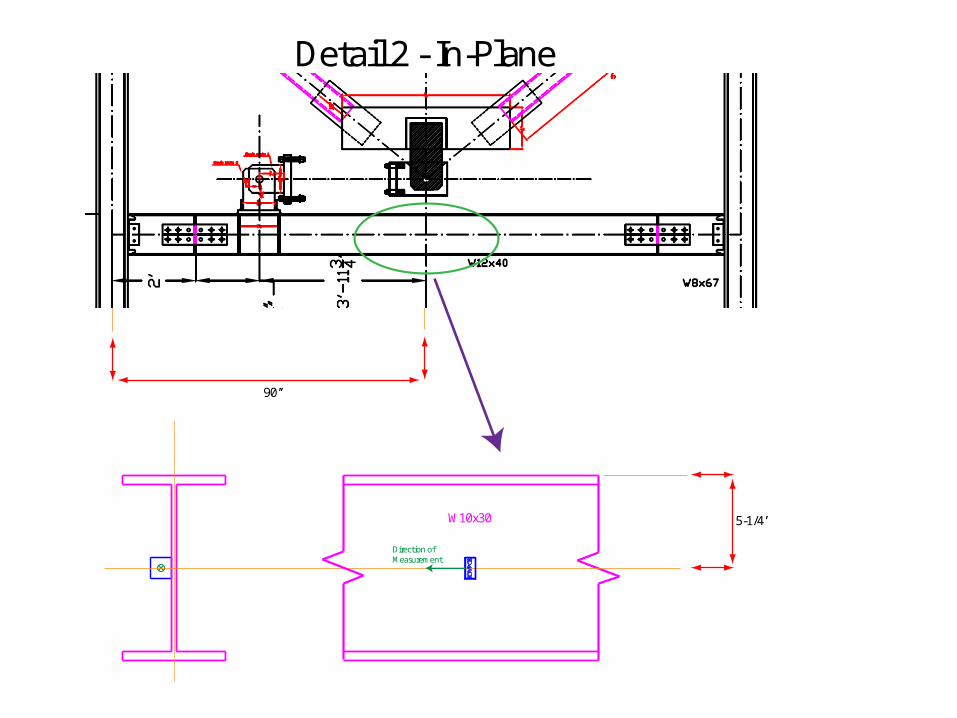
Detail 2 - In-Plane
Direction ofMeasurement
5-1/4’’W10x30
90’’
OUT-OF-PLANE MOTION SENSOR DETAILS
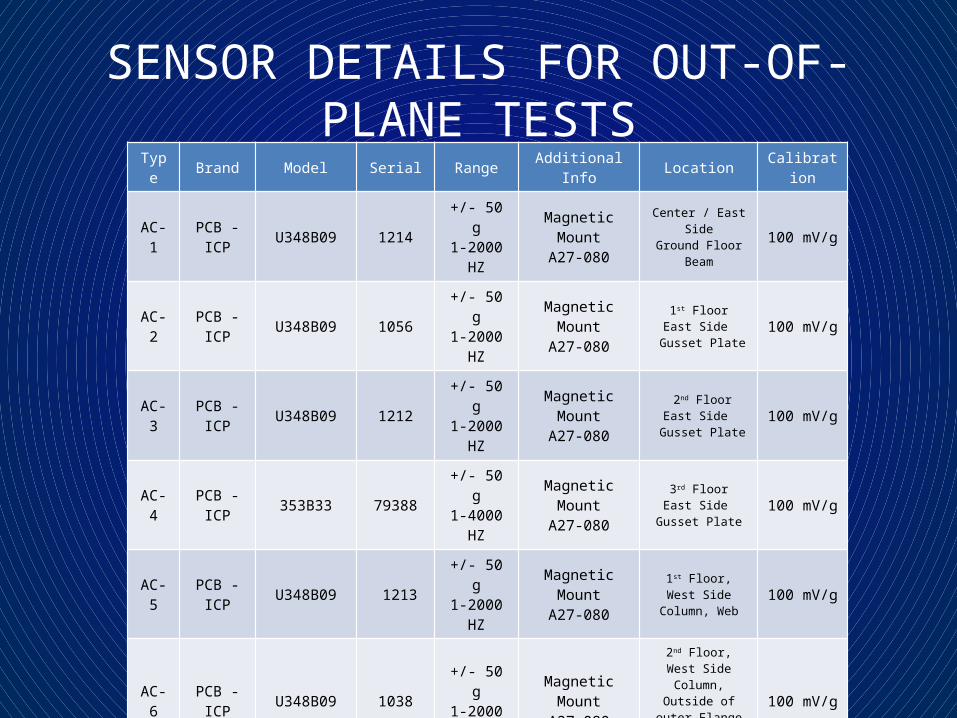
SENSOR DETAILS FOR OUT-OF-PLANE TESTSType Brand Model Serial Range Additional Info Location Calibration
AC-1 PCB - ICP U348B09 1214 +/- 50 g1-2000 HZ
Magnetic MountA27-080
Center / East SideGround Floor Beam 100 mV/g
AC-2 PCB - ICP U348B09 1056 +/- 50 g1-2000 HZ
Magnetic MountA27-080
1st FloorEast Side
Gusset Plate100 mV/g
AC-3 PCB - ICP U348B09 1212 +/- 50 g1-2000 HZ
Magnetic MountA27-080
2nd FloorEast Side
Gusset Plate100 mV/g
AC-4 PCB - ICP 353B33 79388 +/- 50 g1-4000 HZ
Magnetic MountA27-080
3rd FloorEast Side
Gusset Plate100 mV/g
AC-5 PCB - ICP U348B09 1213 +/- 50 g1-2000 HZ
Magnetic MountA27-080
1st Floor, West Side Column, Web 100 mV/g
AC-6 PCB - ICP U348B09 1038 +/- 50 g1-2000 HZ
Magnetic MountA27-080
2nd Floor, West Side Column, Outside of
outer FlangeAligned with beam
web
100 mV/g
AC-7 PCB - ICP 353B33 79599 +/- 50 g1-4000 HZ
Magnetic MountA27-080
3rd Floor, West Side Column, IOutside of
outer FlangeAligned with beam
web
100 mV/g
EX-1 PCB - ICP 086D50 24659 22240 N Medium HardRed Plastic Tip - 0.22 mV/N
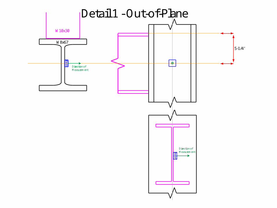
Detail 1 - Out-of-Plane
W8x67
W10x30
Direction ofMeasurement
Direction ofMeasurement
5-1/4’’
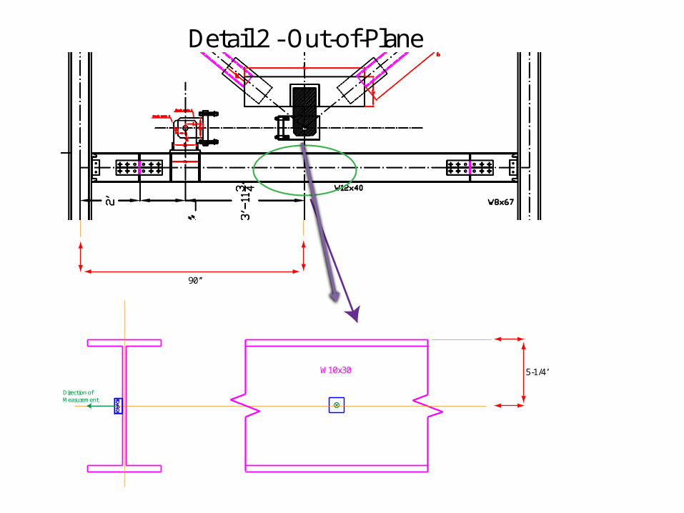
Detail 2 -Out-of-Plane
Direction ofMeasurement
5-1/4’’W10x30
90’’