configuration and operation - aotewell.com software or hardware described in this document is...
TRANSCRIPT
IndustrialIT800xA - Engineering
Process Engineering Tool IntegrationSystem Version 4.1
Configuration and Operation

IndustrialIT800xA - Engineering
Process Engineering Tool IntegrationSystem Version 4.1
Configuration and Operation

NOTICEThe information in this document is subject to change without notice and should not beconstrued as a commitment by ABB. ABB assumes no responsibility for any errors thatmay appear in this document.
In no event shall ABB be liable for direct, indirect, special, incidental or consequentialdamages of any nature or kind arising from the use of this document, nor shall ABB beliable for incidental or consequential damages arising from use of any software or hard-ware described in this document.
This document and parts thereof must not be reproduced or copied without written per-mission from ABB, and the contents thereof must not be imparted to a third party nor usedfor any unauthorized purpose.
The software or hardware described in this document is furnished under a license andmay be used, copied, or disclosed only in accordance with the terms of such license.
This product meets the requirements specified in EMC Directive 89/336/EEC and in LowVoltage Directive 72/23/EEC.
Copyright © 2005 by ABB. All rights reserved. Release: May 2005Document number: 3BUA000184R4101
TRADEMARKSAll rights to trademarks reside with their respective owners.
3BUA000184R4101 5
TABLE OF CONTENTS
About This BookGeneral ..............................................................................................................................7
Intended User.....................................................................................................................7
Document Conventions .....................................................................................................7
Use of Warning, Caution, Information, and Tip Icons ......................................................8
Terminology.......................................................................................................................9
Applicable Specifications ..................................................................................................9
Related Documentation ...................................................................................................10
Section 1 - IntroductionProduct Overview............................................................................................................11
Section 2 - Getting StartedIntroduction .....................................................................................................................13
Data Sources ....................................................................................................................13
File .............................................................................................................14
Database .............................................................................................................14
Configuration...................................................................................................................16
Logging............................................................................................................................16
Section 3 - MappingIntroduction .....................................................................................................................17
Operation .........................................................................................................................17
Section 4 - Data TransferIntroduction .....................................................................................................................21
Table of Contents
6 3BUA000184R4101
Operation.........................................................................................................................21
Data Comparison ................................................................................................. 22
Data Transfer........................................................................................................22
Application Assignment ...................................................................................... 22
Data Transfer in ExpressSync Mode............................................................................... 24
Data Transfer in ExpertSync Mode.................................................................................27
Section 5 - Licensing and SecurityIntroduction .....................................................................................................................31
Section 6 - Standalone ApplicationIntroduction .....................................................................................................................33
Functionality ...................................................................................................................33
Appendix A - Object CreationIntroduction .....................................................................................................................35
INDEX
3BUA000184R4101 7
About This Book
GeneralThe Process Engineering Tool Integration product (the product) is a tool that provides seamless data exchange between Intergraph Process, Power & Marine’s SmartPlant® Instrumentation Powered by INtools® process engineering database and ABB’s 800xA System.
This instruction provides a brief description of the product and procedures for configuring and operating the software.
Intended User Users must know how to run Windows XP programs and navigate around the file system. They must have a thorough understanding of the various structures and aspects in the 800xA System. For custom mapping, users must have experience using the various 800xA System libraries, such as PCDeviceLib, and have a good understanding of INtools objects and their structures.
Document ConventionsThe following conventions are used for the presentation of material:
• The words in names of screen elements (for example, the title in the title bar of a window, the label for a field of a dialog box) are initially capitalized.
• Capital letters are used for the name of a keyboard key if it is labeled on the keyboard. For example, press the ENTER key.
• Lowercase letters are used for the name of a keyboard key that is not labeled on the keyboard. For example, the space bar, comma key, and so on.
Use of Warning, Caution, Information, and Tip Icons About This Book
8 3BUA000184R4101
• Press CTRL+C indicates that you must hold down the CTRL key while pressing the C key (to copy a selected object in this case).
• Press ESC E C indicates that you press and release each key in sequence (to copy a selected object in this case).
• The names of push and toggle buttons are boldfaced. For example, click OK.
• The names of menus and menu items are boldfaced. For example, the File menu.
– The following convention is used for menu operations: MenuName > MenuItem > CascadedMenuItem. For example: select File > New > Type.
– The Start menu name always refers to the Start menu on the Windows Task Bar.
• System prompts/messages are shown in the Courier font, and user responses/input are in the boldfaced Courier font. For example, if you enter a value out of range, the following message is displayed:
Entered value is not valid. The value must be 0 to 30.
You may be told to enter the string TIC132 in a field. The string is shown as follows in the procedure:
TIC132
Variables are shown using lowercase letters.
sequence name
Use of Warning, Caution, Information, and Tip IconsThis publication includes Warning, Caution, and Information where appropriate to point out safety related or other important information. It also includes Tip to point out useful hints to the reader. The corresponding symbols should be interpreted as follows:
Electrical warning icon indicates the presence of a hazard which could result in electrical shock.
About This Book Terminology
3BUA000184R4101 9
Although Warning hazards are related to personal injury, and Caution hazards are associated with equipment or property damage, it should be understood that operation of damaged equipment could, under certain operational conditions, result in degraded process performance leading to personal injury or death. Therefore, comply fully with all Warning and Caution notices.
TerminologyThe following is a list of terms associated with the product that you should be familiar with. The list contains terms and abbreviations that are unique to ABB or have a usage or definition that is different from standard industry usage.
Applicable SpecificationsThis product meets the requirements specified in EMC Directive 89/336/EEC and in Low Voltage Directive 72/23/EEC.
Warning icon indicates the presence of a hazard which could result in personal injury.
Caution icon indicates important information or warning related to the concept discussed in the text. It might indicate the presence of a hazard which could result in corruption of software or damage to equipment/property.
Information icon alerts the reader to pertinent facts and conditions.
Tip icon indicates advice on, for example, how to design your project or how to use a certain function
Term/Acronym Description
CLS 800xA’s Central Licensing System.
Related Documentation About This Book
10 3BUA000184R4101
Related DocumentationThe following is a listing of documentation related to the product.
Category Title Description
Software Process Engineering Tool Integration - Installation 3BUA000185R4101
3BUA000184R4101 11
Section 1 Introduction
Product OverviewINtools manages and stores the history of the control system. INtools provides a single source of plant information that can be easily accessed and updated. It ensures consistency across different instrument tasks and deliverables.
The product has two core functions:
• Provide as much data exchange as possible between the basic, process, and instrumentation engineering phase and the control engineering phase (data exchange in one direction).
• Keep the process and control engineering data consistent over the entire life cycle of a plant (bidirectional data exchange, single point of data entry).
The product is a standalone application that interfaces with the INtools and 800xA System databases.
Product Overview Section 1 Introduction
12 3BUA000184R4101
3BUA000184R4101 13
Section 2 Getting Started
IntroductionLaunch the product by clicking the Process Engineering Tools Integration shortcut icon on the Desktop.
When the start window appears, two main options are available to the user:
• Mapping (refer to Section 3, Mapping for more information).• Transfer Data (refer to Section 4, Data Transfer for more information).
Once either of these two main options are chosen, the user then selects a data source.
Data SourcesThe product supports two types of data sources for the INtools data:
• File.• Database.
If there is no icon, the product is installed to the directory C:\Program Files\Process Engineering Tool Integration\ and the executable file is in the subfolder <PETI>\bin.
The license for the product is incorporated into the CLS (central licensing system) of 800xA. If the product is not licensed on the workstation, the user will see an error window when trying to launch the product. Refer to Section 5, Licensing and Security for more information.
The product uses large amounts of memory when synchronizing large INtools databases. The available memory on the machine must be evaluated before using the product.
File Section 2 Getting Started
14 3BUA000184R4101
File
The data is in the form of a CAEX file that has been generated from an INtools database (offline data source). If the user selects this option, select the CAEX file that represents the INtools data source.
Database
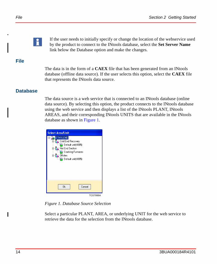
The data source is a web service that is connected to an INtools database (online data source). By selecting this option, the product connects to the INtools database using the web service and then displays a list of the INtools PLANT, INtools AREAS, and their corresponding INtools UNITS that are available in the INtools database as shown in Figure 1.
Select a particular PLANT, AREA, or underlying UNIT for the web service to retrieve the data for the selection from the INtools database.
If the user needs to initially specify or change the location of the webservice used by the product to connect to the INtools database, select the Set Server Name link below the Database option and make the changes.
TC07999A
Figure 1. Database Source Selection
Section 2 Getting Started Database
3BUA000184R4101 15
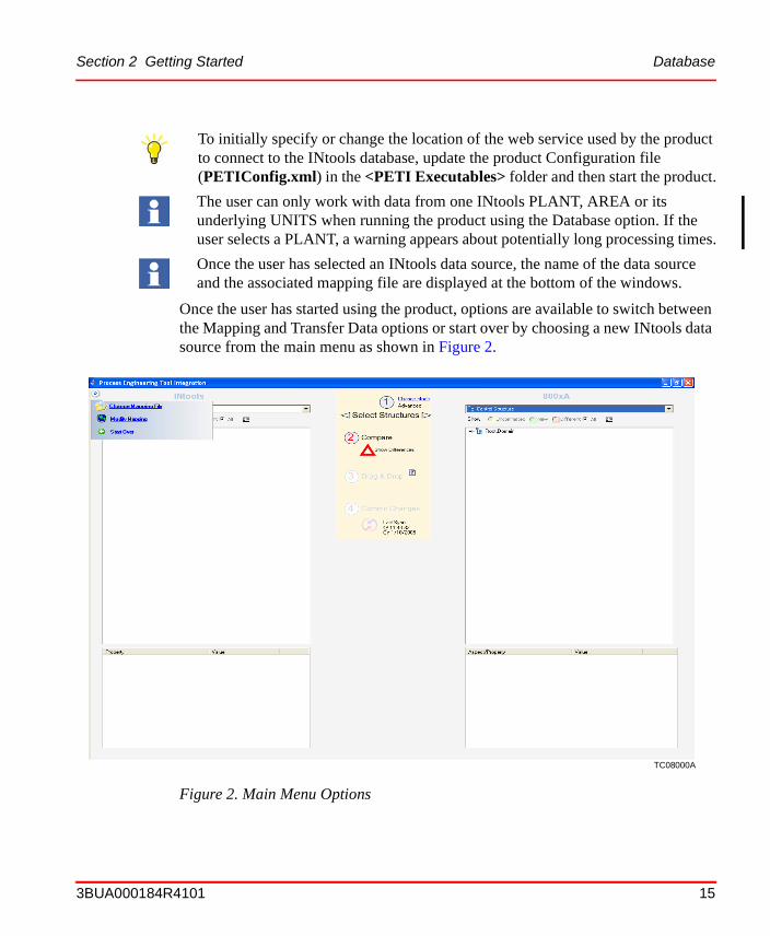
Once the user has started using the product, options are available to switch between the Mapping and Transfer Data options or start over by choosing a new INtools data source from the main menu as shown in Figure 2.
To initially specify or change the location of the web service used by the product to connect to the INtools database, update the product Configuration file (PETIConfig.xml) in the <PETI Executables> folder and then start the product.
The user can only work with data from one INtools PLANT, AREA or its underlying UNITS when running the product using the Database option. If the user selects a PLANT, a warning appears about potentially long processing times.
Once the user has selected an INtools data source, the name of the data source and the associated mapping file are displayed at the bottom of the windows.
TC08000A
Figure 2. Main Menu Options
Configuration Section 2 Getting Started
16 3BUA000184R4101
ConfigurationThe configuration parameters for the product are stored in the product configuration file (PETIConfig.xml) in the <PETI Executables> folder. The configuration file contains information about the following parameters:
• URL. This represents the location of the Web service connected to the INtools database. The value of this parameter should be set to (http://<WebserviceMachine>/PETIWeb/Intools.asmx).
• Transactiondensity. This represents the number of transactions that are performed by the product on the 800xA system at a time. The default value is 60.
• Objectspercontrolapp. This represents the number of objects that are created by the product per control application created. The default value is 30.
Additionally, the product creates a Document Associations aspect for every control module object created in the 800xA System. This aspect allows the user to view documentation related to the control module object generated by INtools in the 800xA System. The aspect uses Web services to send the document file from the INtools workstation to the 800xA workstation.
LoggingAll actions performed by the user as well as all errors generated during the use of the product are written to a log file (PETIlog.xml) that resides in the<PETI \logs> directory.
ShutdownThe user can shutdown the product at any time by closing the window.
3BUA000184R4101 17
Section 3 Mapping
IntroductionThe mapping function of the product is used to map various INtools object types and properties to corresponding object types in the 800xA System. The associated direction of data-transfer (from INtools to 800xA or vice versa) is stored in a mapping file. The mapping information saved in a mapping file can be loaded later during data transfer. The mapping file itself is saved on the workstation running the product as a DMF file.
OperationOnce the product has been started, perform the following:
1. Select the Mapping option from the Start window.
2. Select the source of the INtools data to be mapped.
If the user selects the File option, there is a prompt to select a CAEX file generated from the INtools database that is to be mapped.
If the user selects the Database option, then the product connects to the web service and consequent INtools databases specified in the product configuration file (PETIConfig.xml) located in the <PETI Executables> folder.
If the data source has never been mapped, then the user is prompted to select a mapping file that is used to map the data. The user can select the default mapping file provided with the installation as a starting point for the mapping. The application remembers the associated mapping file name from that point onwards. The selection of the mapping file has to be done only the first time a particular data
The source can be either a file in a CAEX format or the INtools database that is connected to the product via a web service.
Operation Section 3 Mapping
18 3BUA000184R4101
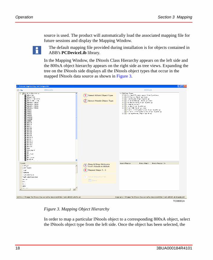
source is used. The product will automatically load the associated mapping file for future sessions and display the Mapping Window.
In the Mapping Window, the INtools Class Hierarchy appears on the left side and the 800xA object hierarchy appears on the right side as tree views. Expanding the tree on the INtools side displays all the INtools object types that occur in the mapped INtools data source as shown in Figure 3.
In order to map a particular INtools object to a corresponding 800xA object, select the INtools object type from the left side. Once the object has been selected, the
The default mapping file provided during installation is for objects contained in ABB’s PCDeviceLib library.
TC08001A
Figure 3. Mapping Object Hierarchy
Section 3 Mapping Operation
3BUA000184R4101 19
various properties of that object appear in the property box in the lower left frame. These are the various INtools properties that can be mapped to analogous properties of the various 800xA objects.
Once an INtools object type has been selected, select a corresponding 800xA object type from the tree on the 800xA side that needs to be mapped to that INtools object. Once the 800xA object type has been selected, the various properties grouped by the various aspects of that 800xA object will appear in the property box on the lower right side. The aspects can then be expanded to view the individual properties available under that aspect.
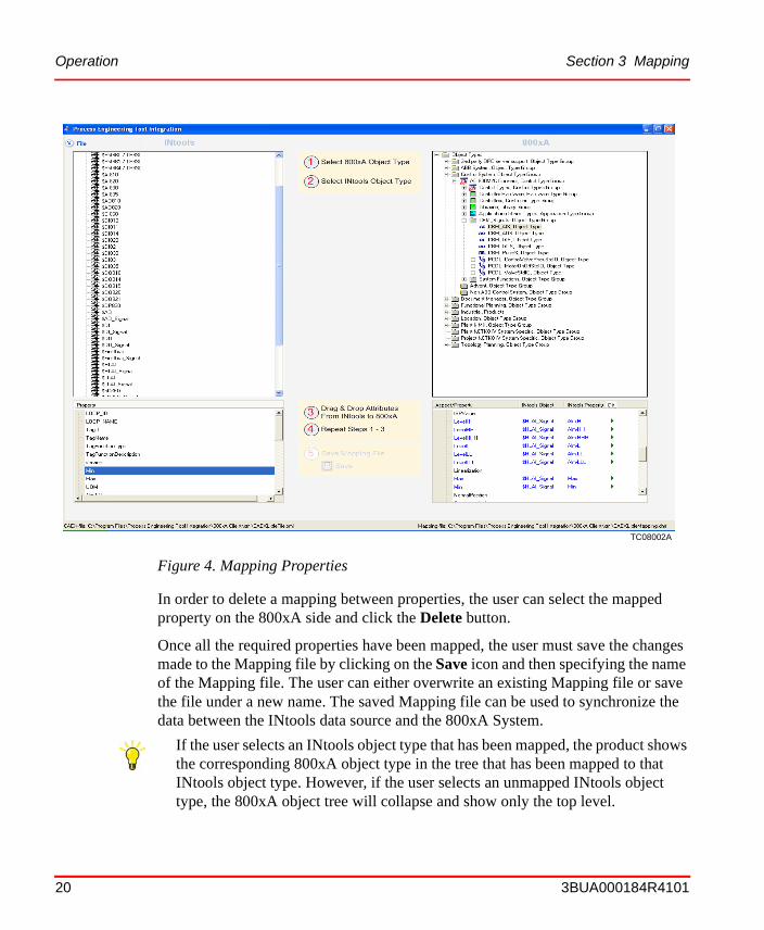
In order to start mapping the properties between the INtools object and the corresponding 800xA object, select the property to be mapped on the INtools side and drag-and-drop it to the corresponding property on the 800xA side. Once the property has been mapped, the INtools property name will appear next to the 800xA property in the 800xA property box. When an INtools property is dropped onto a 800xA property to be mapped, the color of the 800xA property as well as the parent aspect changes to blue as shown in Figure 4. All mapped properties and aspects are shown in blue. All unmapped properties and aspects are shown in black.
The user must specify the direction of the property data transfer between the INtools object and the corresponding 800xA object.
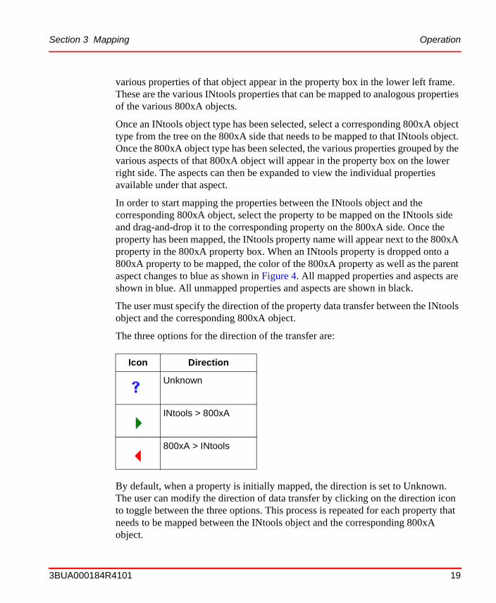
The three options for the direction of the transfer are:
By default, when a property is initially mapped, the direction is set to Unknown. The user can modify the direction of data transfer by clicking on the direction icon to toggle between the three options. This process is repeated for each property that needs to be mapped between the INtools object and the corresponding 800xA object.
Icon Direction
Unknown
INtools > 800xA
800xA > INtools
Operation Section 3 Mapping
20 3BUA000184R4101
In order to delete a mapping between properties, the user can select the mapped property on the 800xA side and click the Delete button.
Once all the required properties have been mapped, the user must save the changes made to the Mapping file by clicking on the Save icon and then specifying the name of the Mapping file. The user can either overwrite an existing Mapping file or save the file under a new name. The saved Mapping file can be used to synchronize the data between the INtools data source and the 800xA System.
TC08002A
Figure 4. Mapping Properties
If the user selects an INtools object type that has been mapped, the product shows the corresponding 800xA object type in the tree that has been mapped to that INtools object type. However, if the user selects an unmapped INtools object type, the 800xA object tree will collapse and show only the top level.
3BUA000184R4101 21
Section 4 Data Transfer
IntroductionThe Data Transfer function of the product is used to synchronize the data between the INtools data source and the 800xA System. The data synchronization can involve the creation of new objects as well as changes in values of properties of existing objects.
The product allows bidirectional data transfer between the INtools data source and 800xA System. The direction of the data transfer is determined by the direction specified in the mapping file for the INtools data source. Refer to Section 3, Mapping for mapping information.
OperationOnce the product has been started, perform the following:
1. Select the Transfer Data option from the Start window.
2. Select the source of the INtools data to be transferred.
The data is now loaded into the product and the main window the product appears. Depending on the security privileges of the user, the option of synchronizing the data between the INtools data source and the 800xA System in either the ExpressSync mode or the ExpertSync mode is available. For more information about access to these modes based on user security, refer to Section 5, Licensing and Security.
The Data Transfer function is divided into two parts:
• Data comparison.• Data transfer.
The source can be either a file in a CAEX format or the INtools database that is connected to the product via a web service.
Data Comparison Section 4 Data Transfer
22 3BUA000184R4101
Data Comparison
The product compares the data in the INtools data source and the 800xA System and then displays the differences between the two systems. The differences are displayed as shown in Table 1:
Data Transfer
Once the user accepts the differences presented and then synchronizes the data. The new objects are created in the 800xA System as well as updating the values of properties on either side depending on the data transfer direction specified in the mapping file.
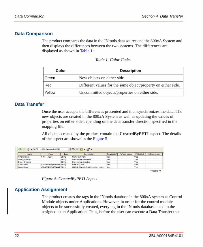
All objects created by the product contain the CreatedByPETI aspect. The details of the aspect are shown in the Figure 5.
Application Assignment
The product creates the tags in the INtools database in the 800xA system as Control Module objects under Applications. However, in order for the control module objects to be successfully created, every tag in the INtools database need to the assigned to an Application. Thus, before the user can execute a Data Transfer that
Table 1. Color Codes
Color Description
Green New objects on either side.
Red Different values for the same object/property on either side.
Yellow Uncommitted objects/properties on either side.
TC08027A
Figure 5. CreatedByPETI Aspect
Section 4 Data Transfer Application Assignment
3BUA000184R4101 23
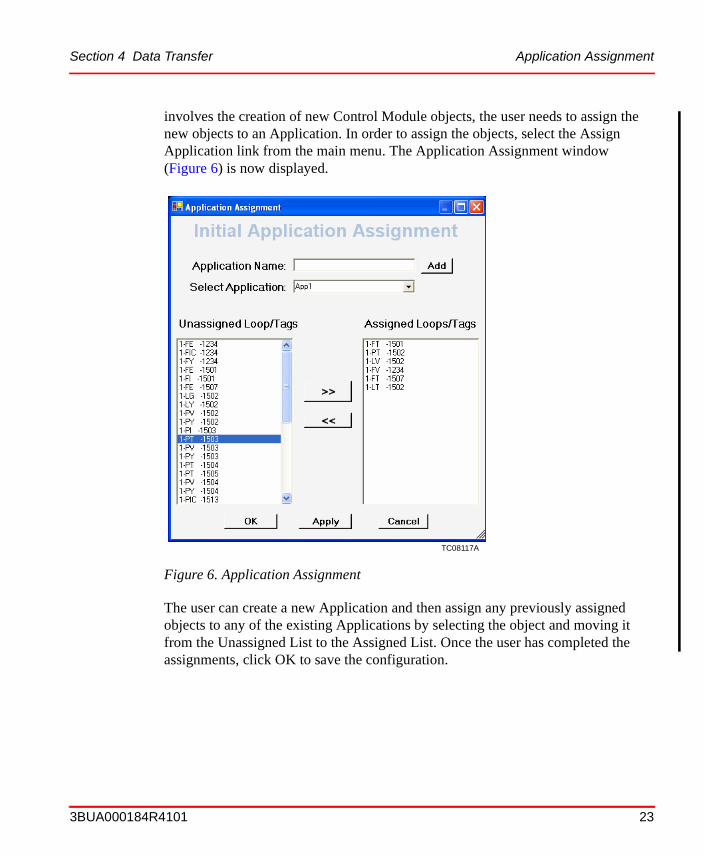
involves the creation of new Control Module objects, the user needs to assign the new objects to an Application. In order to assign the objects, select the Assign Application link from the main menu. The Application Assignment window (Figure 6) is now displayed.
The user can create a new Application and then assign any previously assigned objects to any of the existing Applications by selecting the object and moving it from the Unassigned List to the Assigned List. Once the user has completed the assignments, click OK to save the configuration.
TC08117A
Figure 6. Application Assignment
Data Transfer in ExpressSync Mode Section 4 Data Transfer
24 3BUA000184R4101
Data Transfer in ExpressSync ModeThe ExpressSync Mode of the Data Transfer function allows the user to synchronize the data between the INtools data source and the 800xA System similar to the data synchronization performed by a Personal Digital Assistant (PDA) with a computer. The data in the two systems are compared and then synchronized to remove the differences. The synchronization may involve the creation of new objects if necessary in the 800xA System in the same hierarchy as that of the INtools data source. The user does not have the option to override the hierarchy of the new objects. The synchronization may also involve updating the values of properties of objects on either side. The direction of the update is initially based on the direction specified in the mapping file and the user has the option to override the direction of the update provided the user is an 800xA System user.
The user then follows a series of steps to perform the Data Comparison and Data Transfer operations in order to synchronize the data between the INtools data source and the 800xA Systems. Perform the ExpressSync operation as follows:
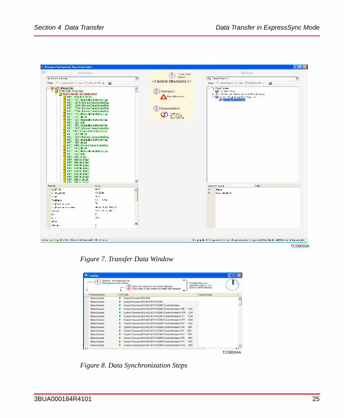
1. Select the Control Structure on both the INtools side and the 800xA side as shown in Figure 7.
2. Once the structures have been selected, the Show Differences link is activated. Click on the link to see the differences between the INtools data source and the 800xA System. The differences are colored according to the color codes specified in Table 1.
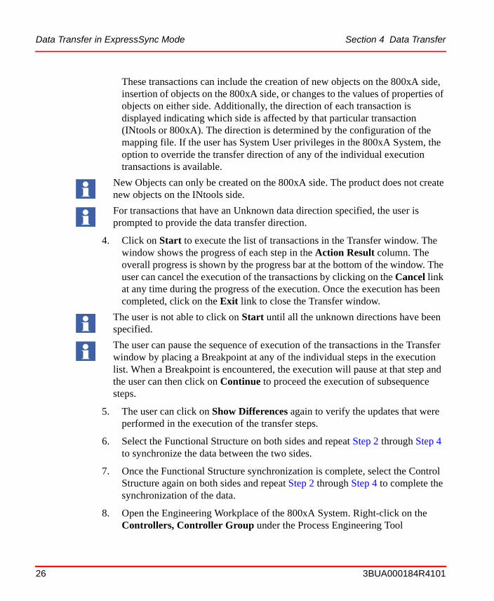
3. Once the differences between the two sides have been viewed, click the ExpressSync icon to list the transactions of the data from the two sides. The product displays the Transfer window (Figure 8) which shows the transactions that are executed in Step 4.
The following steps are for 800xA Systems using ABB’s PCDeviceLib objects.
If the user selects different structures on each side, the product will generate an error message.
The user can expand/collapse the data in the tree structures on either side by clicking on the plus and minus buttons.
Section 4 Data Transfer Data Transfer in ExpressSync Mode
3BUA000184R4101 25
TC08003A
Figure 7. Transfer Data Window
TC08004A
Figure 8. Data Synchronization Steps
Data Transfer in ExpressSync Mode Section 4 Data Transfer
26 3BUA000184R4101
These transactions can include the creation of new objects on the 800xA side, insertion of objects on the 800xA side, or changes to the values of properties of objects on either side. Additionally, the direction of each transaction is displayed indicating which side is affected by that particular transaction (INtools or 800xA). The direction is determined by the configuration of the mapping file. If the user has System User privileges in the 800xA System, the option to override the transfer direction of any of the individual execution transactions is available.
4. Click on Start to execute the list of transactions in the Transfer window. The window shows the progress of each step in the Action Result column. The overall progress is shown by the progress bar at the bottom of the window. The user can cancel the execution of the transactions by clicking on the Cancel link at any time during the progress of the execution. Once the execution has been completed, click on the Exit link to close the Transfer window.
5. The user can click on Show Differences again to verify the updates that were performed in the execution of the transfer steps.
6. Select the Functional Structure on both sides and repeat Step 2 through Step 4 to synchronize the data between the two sides.
7. Once the Functional Structure synchronization is complete, select the Control Structure again on both sides and repeat Step 2 through Step 4 to complete the synchronization of the data.
8. Open the Engineering Workplace of the 800xA System. Right-click on the Controllers, Controller Group under the Process Engineering Tool
New Objects can only be created on the 800xA side. The product does not create new objects on the INtools side.
For transactions that have an Unknown data direction specified, the user is prompted to provide the data transfer direction.
The user is not able to click on Start until all the unknown directions have been specified.
The user can pause the sequence of execution of the transactions in the Transfer window by placing a Breakpoint at any of the individual steps in the execution list. When a Breakpoint is encountered, the execution will pause at that step and the user can then click on Continue to proceed the execution of subsequence steps.
Section 4 Data Transfer Data Transfer in ExpertSync Mode
3BUA000184R4101 27
Integration area and select Advanced >Write Allocation into CBM. This will insert the Global variables created for the 800xA PCDeviceLib Control Module objects into the 800xA System.
The ExpressSync Mode synchronization of data between the INtools data source and the 800xA application is now complete.
Data Transfer in ExpertSync ModeThe ExpertSync mode of data synchronization between the INtools data source and the 800xA System is for expert users that have a good understanding of the data structures in the 800xA System. The functionality of the ExpertSync mode is very similar to the functionality of the ExpressSync mode with one difference. The expert user has the ability to drag-and-drop new objects from the INtools side to any allowed location on the 800xA side changing the hierarchy of the objects on the 800xA side from that on the INtools side. The product will then create the new objects on the 800xA side at the location of the dragged-and-dropped objects.
The user can select the ExpertSync mode by clicking on the Change Mode link at the top of the product window.
Perform the ExpertSync operation as follows:
1. Select the Control Structure on both the INtools side and the 800xA side.
2. Once the structures have been selected, the Show Differences link is activated. Click on the link to see the differences between the INtools data source and the 800xA System. The differences are colored according to the color codes specified in Table 1.
The ExpertSync mode is only available to users that have System User privileges in the 800xA System. The mode is not available to users with only Application User rights. Refer to Section 5, Licensing and Security for more information.
The following steps are for 800xA Systems using ABB’s PCDeviceLib objects.
If the user selects different structures on each side, an error message is generated.
The user can expand/collapse the data in the tree structures on either side by clicking on the plus and minus buttons.
Data Transfer in ExpertSync Mode Section 4 Data Transfer
28 3BUA000184R4101
3. The user has the option to drag-and-drop objects from the INtools data structure to any allowed location in the 800xA data structure. Once the objects have been dragged-and-dropped, they appear on the 800xA side.
Once the differences between the two sides have been viewed, click on the Commit Changes icon to start the synchronization of the data between the two sides. The product will display the Transfer window, which displays the transactions that can be executed to synchronize the data. These transactions may include the creation of new objects on the 800xA side, insertion of objects on the 800xA side, or changes to the values of properties of objects on either side. Additionally, the direction of each transaction is displayed indicating which side is affected by that particular step (INtools or 800xA). The direction is determined by the configuration in the mapping file. If the user has System User privileges in the 800xA System, then the option to override the transfer direction of any of the individual execution transactions is available.
4. Click on Start to proceed the execution of the listed transactions in the Transfer window. The window shows the progress of each step in the Action Result column. The overall progress is shown by the progress bar at the bottom of the window. The user can cancel the execution of the transactions by clicking on the Cancel link at any time during the progress of the execution. Once the execution has been completed, click on the Exit link to close the Transfer window.
If the user does not drag-and-drop objects in the ExpertSync mode, the objects are created in the same hierarchy as the INtools data source similar to the functionality in the ExpressSync Mode.
New Objects can only be created on the 800xA side. The product does not create new objects on the INtools side.
For transactions that have an Unknown data direction specified, the user is prompted to provide the data transfer direction.
The user is not able to click on Start until all the unknown directions have been specified.
The user can pause the sequence of execution of the transactions in the Transfer window by placing a Breakpoint at any of the individual steps in the execution list. When the product encounters a Breakpoint, the execution will pause at that step and the user can then click on Continue to proceed the execution of subsequence steps.
Section 4 Data Transfer Data Transfer in ExpertSync Mode
3BUA000184R4101 29
5. The user can click on Show Differences again to verify the updates that were performed in the execution of the transfer steps.
6. Select the Functional Structure on both sides and repeat Step 2 through Step 4 to synchronize the data between the two sides.
7. Once the Functional Structure synchronization is complete, select the Control Structure again on both sides and repeat Step 2 through Step 4 to complete the synchronization of the data.
8. Open the Engineering Workplace of the 800xA System. Right-click on the Controllers, Controller Group under the Process Engineering Tool Integration area and select Advanced >Write Allocation into CBM. This will insert the Global variables created for the 800xA PCDeviceLib Control Module objects into the 800xA System.
The ExpertSync Mode synchronization of data between the INtools data source and the 800xA application is now complete.
Data Transfer in ExpertSync Mode Section 4 Data Transfer
30 3BUA000184R4101
3BUA000184R4101 31
Section 5 Licensing and Security
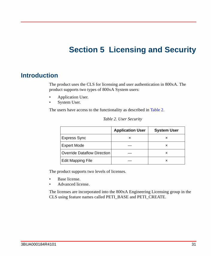
IntroductionThe product uses the CLS for licensing and user authentication in 800xA. The product supports two types of 800xA System users:
• Application User.• System User.
The users have access to the functionality as described in Table 2.
The product supports two levels of licenses.
• Base license.• Advanced license.
The licenses are incorporated into the 800xA Engineering Licensing group in the CLS using feature names called PETI_BASE and PETI_CREATE.
Table 2. User Security
Application User System User
Express Sync × ×
Expert Mode — ×
Override Dataflow Direction — ×
Edit Mapping File — ×
Introduction Section 5 Licensing and Security
32 3BUA000184R4101
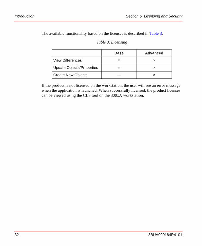
The available functionality based on the licenses is described in Table 3.
If the product is not licensed on the workstation, the user will see an error message when the application is launched. When successfully licensed, the product licenses can be viewed using the CLS tool on the 800xA workstation.
Table 3. Licensing
Base Advanced
View Differences × ×
Update Objects/Properties × ×
Create New Objects — ×
3BUA000184R4101 33
Section 6 Standalone Application
IntroductionThe standalone application interfaces with the INtools database. It is used to transfer data to and from the INtools database in case the Web service connection is not available. It also is used to install the necessary database utilities for the product.
The application resides in the <PETI Executables> directory on the workstation running the INtools software.
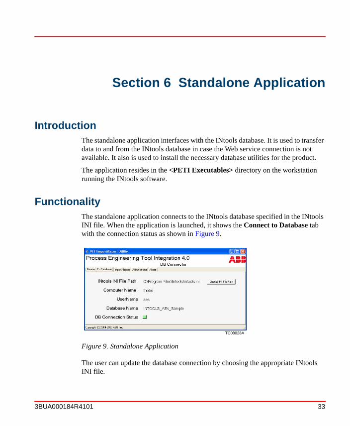
FunctionalityThe standalone application connects to the INtools database specified in the INtools INI file. When the application is launched, it shows the Connect to Database tab with the connection status as shown in Figure 9.
The user can update the database connection by choosing the appropriate INtools INI file.
TC08028A
Figure 9. Standalone Application
Functionality Section 6 Standalone Application
34 3BUA000184R4101
The standalone application can be used to import/export data from the INtools database in the form of a CAEX file. This is useful when there is no online Web service connection available to the INtools database. The Import/Export tab allows the user to perform this task.
Finally, the standalone application is used to install or uninstall the INtools Connector software, which includes the database utilities that are required to import/export data from the INtools database. The user can perform this action from the Administrator tab.
3BUA000184R4101 35
Appendix A Object Creation
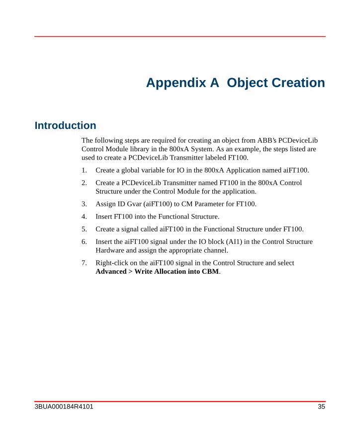
IntroductionThe following steps are required for creating an object from ABB’s PCDeviceLib Control Module library in the 800xA System. As an example, the steps listed are used to create a PCDeviceLib Transmitter labeled FT100.
1. Create a global variable for IO in the 800xA Application named aiFT100.
2. Create a PCDeviceLib Transmitter named FT100 in the 800xA Control Structure under the Control Module for the application.
3. Assign ID Gvar (aiFT100) to CM Parameter for FT100.
4. Insert FT100 into the Functional Structure.
5. Create a signal called aiFT100 in the Functional Structure under FT100.
6. Insert the aiFT100 signal under the IO block (AI1) in the Control Structure Hardware and assign the appropriate channel.
7. Right-click on the aiFT100 signal in the Control Structure and select Advanced > Write Allocation into CBM.

Introduction Appendix A Object Creation
36 3BUA000184R4101
3BUA000184R4101 37
Numerics800xA 7, 11, 17, 31, 35
AApplication assignment 22AREAS and UNITS 14
CCaution icon 8Core functions 11
Product overview 11
DData sources
Database 13 to 14File 13
Data transferExpertSync mode 27ExpressSync mode 24
Database data source 14Document conventions 7Documentation 10
EExecutable file 13, 15
FFile database source 14
GGetting started 13
Data sources 13Executable file 13Licensing 13
Main options 13
IIcons 8
Warning, caution, information, tip 8Information icon 8Intended user 7INtools 7, 11
LLicensing 32Logging 16
MMain options
Data transfer 13Mapping 13
MappingDatabase 17File 17overview 17
Mapping operation 17
OObject creation 35Operation
Mapping 17Transfer data 21
PProduct overview 11
Core functions 11
SSecurity 31
INDEX
Index
38 3BUA000184R4101
Index
38 3BUA000184R4101
Shutdown 16Specifications 9Standalone application 33
Functionality 33
TTerminology 9Tip icon 8Transfer data operation 21
UUser security 31
WWarning icon 8


3BUA000184R4101 Printed in U.S.A. May 2005Copyright © 2005 by ABB. All Rights Reserved® Registered Trademark of ABB.™ Trademark of ABB.
Automation Technology ProductsMannheim, Germanywww.abb.de/controlsystems
Automation Technology Products Wickliffe, Ohio, USAwww.abb.com/controlsystems
Automation Technology ProductsVästerås, Swedenwww.abb.com/controlsystems
http://www.abb.com