conductive polymer aluminum solid electrolytic capacitors...
TRANSCRIPT
38 CAT.8100H
CONDUCTIVE POLYMER ALUMINUM SOLID ELECTROLYTIC CAPACITORS
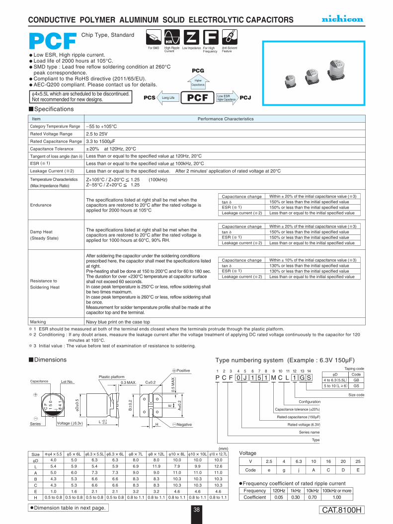
PCF Chip Type, Standard
Specifications
Temperature Characteristics
(Max.Impedance Ratio)
Category Temperature Range
Rated Voltage Range
Rated Capacitance Range
Capacitance Tolerance
Tangent of loss angle (tan δ)
ESR ( 1)
Leakage Current ( 2)
Performance CharacteristicsItem
–55 to +105°C
2.5 to 25V
3.3 to 1500µF
± 20% at 120Hz, 20°C
Less than or equal to the specified value at 120Hz, 20°C
Less than or equal to the specified value at 100kHz, 20°C
Less than or equal to the specified value. After 2 minutes' application of rated voltage at 20°C
Z+105°C / Z+20°C 1.25 (100kHz)Z–55°C / Z+20°C 1.25
Endurance
Damp Heat
(Steady State)
Resistance to
Soldering Heat
Marking
The specifications listed at right shall be met when the capacitors are restored to 20°C after the rated voltage is applied for 2000 hours at 105°C
The specifications listed at right shall be met when the capacitors are restored to 20°C after the rated voltage is applied for 1000 hours at 60°C, 90% RH.
After soldering the capacitor under the soldering conditions prescribed here, the capacitor shall meet the specifications listed at right.Pre-heating shall be done at 150 to 200°C and for 60 to 180 sec.The duration for over +230°C temperature at capacitor surface shall not exceed 60 seconds.In case peak temperature is 250°C or less, reflow soldering shall be two times maximum.In case peak temperature is 260°C or less, reflow soldering shall be once.Measurement for solder temperature profile shall be made at the capacitor top and the terminal.
Navy blue print on the case top
Capacitance changetan δ
Leakage current ( 2)ESR ( 1)
Within ± 20% of the initial capacitance value ( 3)150% or less than the initial specified value150% or less than the initial specified valueLess than or equal to the initial specified value
Capacitance changetan δ
Leakage current ( 2)ESR ( 1)
Within ± 20% of the initial capacitance value ( 3)150% or less than the initial specified value150% or less than the initial specified valueLess than or equal to the initial specified value
Capacitance changetan δ
Leakage current ( 2)ESR ( 1)
Within ± 10% of the initial capacitance value ( 3)130% or less than the initial specified value130% or less than the initial specified valueLess than or equal to the initial specified value
Low ESR, High ripple current.Load life of 2000 hours at 105°C.SMD type : Lead free reflow soldering condition at 260°C peak correspondence.Compliant to the RoHS directive (2011/65/EU).AEC-Q200 compliant. Please contact us for details.
1 ESR should be measured at both of the terminal ends closest where the terminals protrude through the plastic platform.2 Conditioning : If any doubt arises, measure the leakage current after the voltage treatment of applying DC rated voltage continuously to the capacitor for 120
minutes at 105°C.3 Initial value : The value before test of examination of resistance to soldering.
φD
4 to 6.3(5.5L)
5 to 10(L 6)
Code
GB
GS
P1
C2
F3
04
J5
16
57
18
M9
C10
L11
112
G13
S14
Configuration
Taping code
Size code
Capacitance tolerance (±20%)
Rated capacitance (150µF)
Rated voltage (6.3V)
Series name
Type
CF
15
0j 8
41
H
0.3 MAX.
φD±
0.5
B±
0.2
A±
0.2
C±0.2
0.5
MA
X.
E
LSeries Voltage ( j:6.3v)
Plastic platformLot No.Capacitance
Negative
Positive
+0.1-0.4
Dimensions Type numbering system (Example : 6.3V 150µF)
Voltage
V 2.5 4 6.3 10 16 20 25
Code e g j A C D E
Size
φD
L
A
B
C
E
H
φ4 × 5.54.0
5.4
5.0
4.3
4.3
1.00.5 to 0.8
φ5 × 6L5.0
5.9
6.0
5.3
5.3
1.60.5 to 0.8
φ6.3 × 5.5L6.3
5.4
7.3
6.6
6.6
2.10.5 to 0.8
φ6.3 × 6L6.3
5.9
7.3
6.6
6.6
2.10.5 to 0.8
φ8 × 7L8.0
6.9
9.0
8.3
8.3
3.20.8 to 1.1
φ8 × 12L8.0
11.9
9.0
8.3
8.3
3.20.8 to 1.1
φ10 × 8L10.0
7.9
11.0
10.3
10.3
4.60.8 to 1.1
φ10 × 10L10.0
9.9
11.0
10.3
10.3
4.60.8 to 1.1
φ10 × 12.7L10.0
12.6
11.0
10.3
10.3
4.60.8 to 1.1
(mm)
Dimension table in next page.
PCF Low ESRHigher Capacitance PCJLong LifePCS
Higher
Capacitance,
PCG
Frequency coefficient of rated ripple current0 Frequency0/
Coefficient 120Hz 1kHz 10kHz 100kHz or more 0.05 0.30 0.70 1.00
φ4×5.5L which are scheduled to be discontinued. Not recommended for new designs.
39 CAT.8100H
CONDUCTIVE POLYMER ALUMINUM SOLID ELECTROLYTIC CAPACITORS
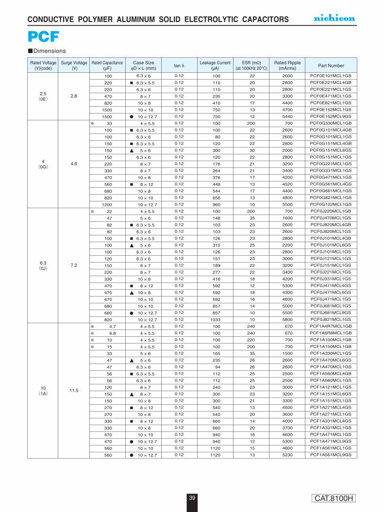
PCFDimensions
Rated Capacitance(µF)
Rated Voltage(V)(code)
Surge Voltage (V)
Leakage Current(µA)
ESR (mΩ)(at 100kHz 20°C)
Rated Ripple(mArms)tan δ Part Number
Case SizeφD × L (mm)
2.5(0E)
10(1A)
6.3(0J)
4(0G)
2.8
11.5
7.2
4.6
100
220
220
470
820
1500
1500
33
100
100
150
150
150
220
330
470
560
680
820
1200
22
47
82
82
100
100
100
120
150
220
330
470
470
470
680
680
820
4.7
6.8
10
15
33
47
47
56
56
120
150
150
270
270
330
330
470
470
560
560
100
110
110
235
410
750
750
100
100
80
120
300
120
176
264
376
448
544
656
960
100
148
103
103
126
315
126
151
189
277
416
592
592
592
857
857
1033
100
100
100
100
165
235
94
112
112
240
300
300
540
540
660
660
940
940
1120
1120
22
20
20
20
17
13
12
200
22
22
22
30
22
21
21
17
13
17
13
10
200
35
23
23
23
25
23
23
22
22
18
12
18
16
14
10
10
240
240
220
200
35
26
26
25
25
23
23
21
13
20
14
20
16
12
15
13
2600
2800
2800
3300
4400
4700
5440
700
2600
2600
2800
2000
2800
3200
3400
4200
4520
4400
4800
5500
700
1600
2600
2600
2800
2200
2800
3000
3200
3400
4200
5300
4300
4600
5000
5500
5800
670
670
700
700
1500
2600
2600
2500
2500
3000
3200
3300
4500
3600
4000
3700
4600
5300
4800
5230
PCF0E101MCL1GS
PCF0E221MCL4GB
PCF0E221MCL1GS
PCF0E471MCL1GS
PCF0E821MCL1GS
PCF0E152MCL1GS
PCF0E152MCL9GS
PCF0G330MCL1GB
PCF0G101MCL4GB
PCF0G101MCL1GS
PCF0G151MCL4GB
PCF0G151MCL6GS
PCF0G151MCL1GS
PCF0G221MCL1GS
PCF0G331MCL1GS
PCF0G471MCL1GS
PCF0G561MCL4GS
PCF0G681MCL1GS
PCF0G821MCL1GS
PCF0G122MCL1GS
PCF0J220MCL1GB
PCF0J470MCL1GS
PCF0J820MCL4GB
PCF0J820MCL1GS
PCF0J101MCL4GB
PCF0J101MCL6GS
PCF0J101MCL1GS
PCF0J121MCL1GS
PCF0J151MCL1GS
PCF0J221MCL1GS
PCF0J331MCL1GS
PCF0J471MCL4GS
PCF0J471MCL6GS
PCF0J471MCL1GS
PCF0J681MCL1GS
PCF0J681MCL9GS
PCF0J821MCL1GS
PCF1A4R7MCL1GB
PCF1A6R8MCL1GB
PCF1A100MCL1GB
PCF1A150MCL1GB
PCF1A330MCL1GS
PCF1A470MCL6GS
PCF1A470MCL1GS
PCF1A560MCL4GB
PCF1A560MCL1GS
PCF1A121MCL1GS
PCF1A151MCL6GS
PCF1A151MCL1GS
PCF1A271MCL4GS
PCF1A271MCL1GS
PCF1A331MCL4GS
PCF1A331MCL1GS
PCF1A471MCL1GS
PCF1A471MCL9GS
PCF1A561MCL1GS
PCF1A561MCL9GS
0.12
0.12
0.12
0.12
0.12
0.12
0.12
0.12
0.12
0.12
0.12
0.12
0.12
0.12
0.12
0.12
0.12
0.12
0.12
0.12
0.12
0.12
0.12
0.12
0.12
0.12
0.12
0.12
0.12
0.12
0.12
0.12
0.12
0.12
0.12
0.12
0.12
0.12
0.12
0.12
0.12
0.12
0.12
0.12
0.12
0.12
0.12
0.12
0.12
0.12
0.12
0.12
0.12
0.12
0.12
0.12
0.12
6.3 × 6
6.3 × 5.5
6.3 × 6
8 × 7
10 × 8
10 × 10
10 × 12.7
4 × 5.5
6.3 × 5.5
6.3 × 6
6.3 × 5.5
5 × 6
6.3 × 6
8 × 7
8 × 7
10 × 8
8 × 12
10 × 8
10 × 10
10 × 12.7
4 × 5.5
5 × 6
6.3 × 5.5
6.3 × 6
6.3 × 5.5
5 × 6
6.3 × 6
6.3 × 6
8 × 7
8 × 7
10 × 8
8 × 12
10 × 8
10 × 10
10 × 10
10 × 12.7
10 × 12.7
4 × 5.5
4 × 5.5
4 × 5.5
4 × 5.5
5 × 6
5 × 6
6.3 × 6
6.3 × 5.5
6.3 × 6
8 × 7
8 × 7
10 × 8
8 × 12
10 × 8
8 × 12
10 × 8
10 × 10
10 × 12.7
10 × 10
10 × 12.7
40 CAT.8100H
CONDUCTIVE POLYMER ALUMINUM SOLID ELECTROLYTIC CAPACITORS
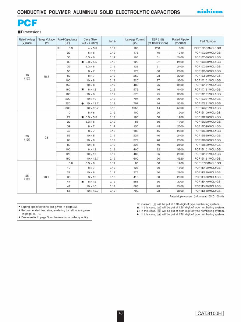
Taping specifications are given in page 23. Recommended land size, soldering by reflow are given
in page 18, 19. Please refer to page 3 for the minimum order quantity.
Rated ripple current (mArms) at 105°C 100kHz
PCFDimensions
Rated Capacitance(µF)
Rated Voltage(V)(code)
Surge Voltage (V)
Leakage Current(µA)
ESR (mΩ)(at 100kHz 20°C)
Rated Ripple(mArms)tan δ Part Number
Case SizeφD × L (mm)
16(1C)
20(1D)
25(1E)
18.4
23
28.7
3.3
22
33
39
39
56
82
100
150
180
180
220
220
330
10
22
22
39
47
56
68
82
100
120
150
6.8
10
22
33
47
47
56
100
176
106
125
125
179
262
320
480
576
576
704
704
1056
100
100
88
156
188
224
272
328
400
480
600
85
125
275
413
588
588
700
260
45
31
31
31
30
28
27
25
16
25
20
14
14
120
50
50
45
45
40
40
40
22
35
20
80
60
50
30
30
45
28
660
1210
2400
2400
2400
2900
3200
3300
3500
4400
3600
3900
5050
5000
900
1700
1700
2000
2000
2400
2600
2600
3200
2800
4320
1200
1600
2200
2800
3000
2400
3800
PCF1C3R3MCL1GB
PCF1C220MCL1GS
PCF1C330MCL1GS
PCF1C390MCL4GB
PCF1C390MCL1GS
PCF1C560MCL1GS
PCF1C820MCL1GS
PCF1C101MCL1GS
PCF1C151MCL1GS
PCF1C181MCL4GS
PCF1C181MCL1GS
PCF1C221MCL1GS
PCF1C221MCL9GS
PCF1C331MCL1GS
PCF1D100MCL1GS
PCF1D220MCL4GB
PCF1D220MCL1GS
PCF1D390MCL1GS
PCF1D470MCL1GS
PCF1D560MCL1GS
PCF1D680MCL1GS
PCF1D820MCL1GS
PCF1D101MCL1GS
PCF1D121MCL1GS
PCF1D151MCL1GS
PCF1E6R8MCL1GS
PCF1E100MCL1GS
PCF1E220MCL1GS
PCF1E330MCL1GS
PCF1E470MCL4GS
PCF1E470MCL1GS
PCF1E560MCL1GS
0.12
0.12
0.12
0.12
0.12
0.12
0.12
0.12
0.12
0.12
0.12
0.12
0.12
0.12
0.12
0.12
0.12
0.12
0.12
0.12
0.12
0.12
0.12
0.12
0.12
0.12
0.12
0.12
0.12
0.12
0.12
0.12
4 × 5.5
5 × 6
6.3 × 6
6.3 × 5.5
6.3 × 6
8 × 7
8 × 7
10 × 8
10 × 8
8 × 12
10 × 8
10 × 10
10 × 12.7
10 × 12.7
5 × 6
6.3 × 5.5
6.3 × 6
8 × 7
8 × 7
10 × 8
10 × 8
10 × 8
8 × 12
10 × 10
10 × 12.7
6.3 × 6
8 × 7
10 × 8
8 × 12
8 × 12
10 × 10
10 × 12.7
No marked, 1 will be put at 12th digit of type numbering system.: In this case, 4 will be put at 12th digit of type numbering system.: In this case, 6 will be put at 12th digit of type numbering system.: In this case, 9 will be put at 12th digit of type numbering system.