concurrent, oa-based mixed-signal implementation · concurrent, oa-based mixed-signal...
TRANSCRIPT
Concurrent, OA-based Mixed-signal Implementation
Mladen Nizic
Eng. Director, Mixed-signal Solution
© 2011, Cadence Design Systems, Inc. All rights reserved worldwide.
2 © 2012 Cadence Design Systems, Inc. All rights reserved.
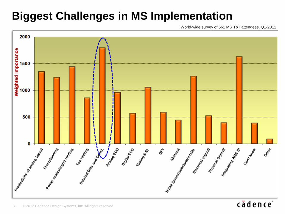
Results of World-wide MS ToT survey of 561 attendees; Q1-2011
Relative importance
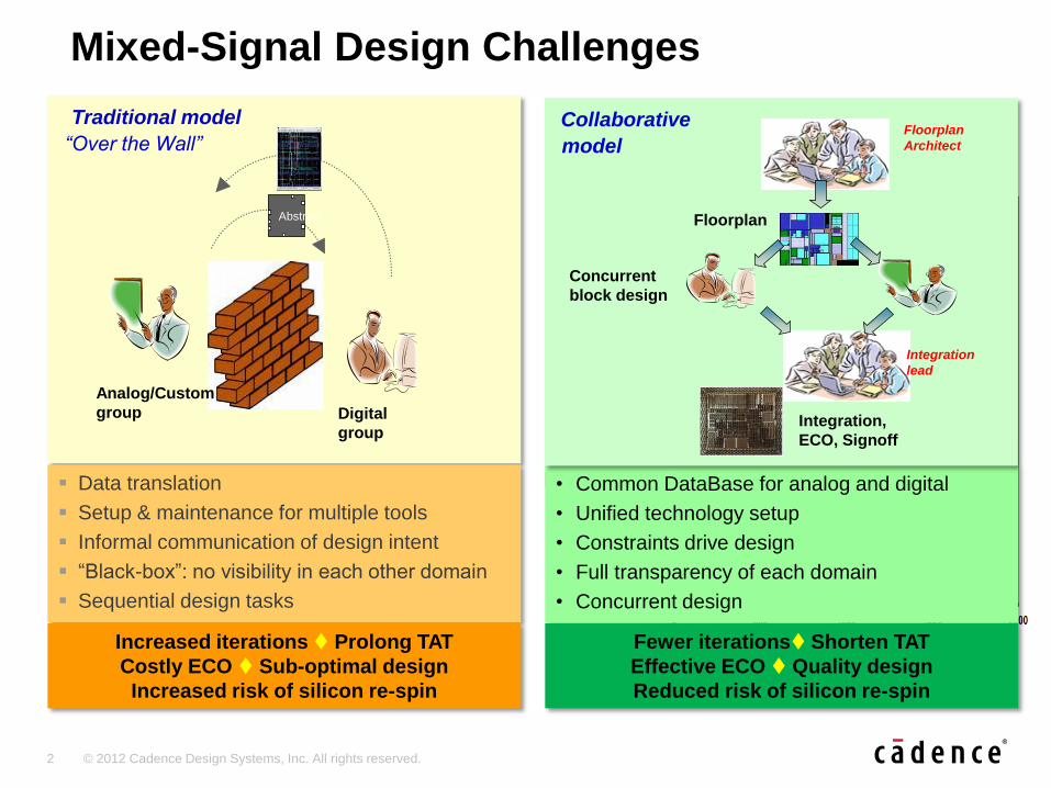
Traditional model
“Over the Wall”
Mixed-Signal Design Challenges
Data translation
Setup & maintenance for multiple tools
Informal communication of design intent
“Black-box”: no visibility in each other domain
Sequential design tasks
Abstract
Digital
group
Analog/Custom
group
Increased iterations Prolong TAT
Costly ECO Sub-optimal design
Increased risk of silicon re-spin
• Common DataBase for analog and digital
• Unified technology setup
• Constraints drive design
• Full transparency of each domain
• Concurrent design
Fewer iterations Shorten TAT
Effective ECO Quality design
Reduced risk of silicon re-spin
Collaborative
model
Floorplan
Integration,
ECO, Signoff
Floorplan
Architect
Integration
lead
Concurrent
block design
3 © 2012 Cadence Design Systems, Inc. All rights reserved.
Biggest Challenges in MS Implementation World-wide survey of 561 MS ToT attendees, Q1-2011
We
igh
ted
Im
po
rta
nce
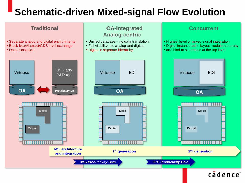
OA-integrated
Analog-centric
Concurrent
Schematic-driven Mixed-signal Flow Evolution
Traditional
Virtuoso
OA
3rd Party
P&R tool
Proprietary DB OA
Virtuoso EDI
Digital
Digital
Digital
Digital
OA
Virtuoso EDI
Digital
Digital
Separate analog and digital environments
Black-box/Abstract/GDS level exchange
Data translation
Unified database – no data translation
Full visibility into analog and digital,
Digital in separate hierarchy
Highest level of mixed-signal integration
Digital instantiated in layout module hierarchy
and bind to schematic at the top level
30% Productivity Gain
1st generation 2nd generation MS architecture
and integration
30% Productivity Gain
5 © 2012 Cadence Design Systems, Inc. All rights reserved.
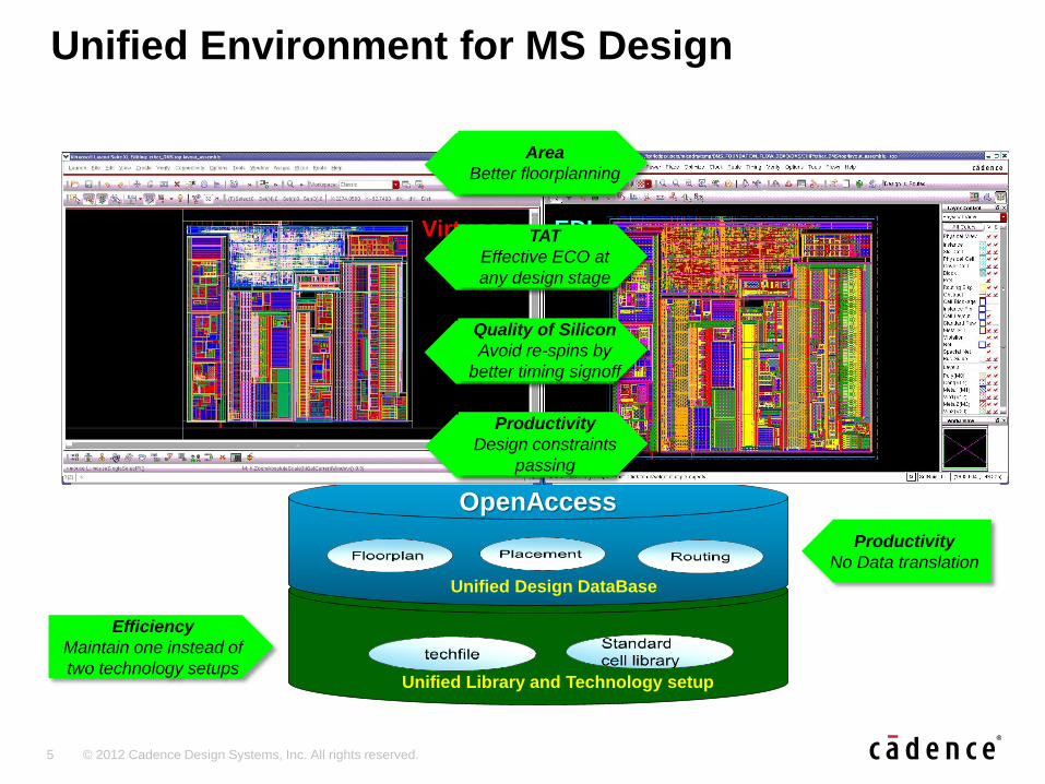
Unified Environment for MS Design
Unified Design DataBase
Unified Library and Technology setup
OpenAccess
Virtuoso EDI
Efficiency
Maintain one instead of
two technology setups
Productivity
No Data translation
Productivity
No Data translation
Area
Better floorplanning
Productivity
No Data translation
TAT
Effective ECO at
any design stage
Productivity
No Data translation
Quality of Silicon
Avoid re-spins by
better timing signoff
Productivity
No Data translation
Productivity
Design constraints
passing
6 © 2012 Cadence Design Systems, Inc. All rights reserved.
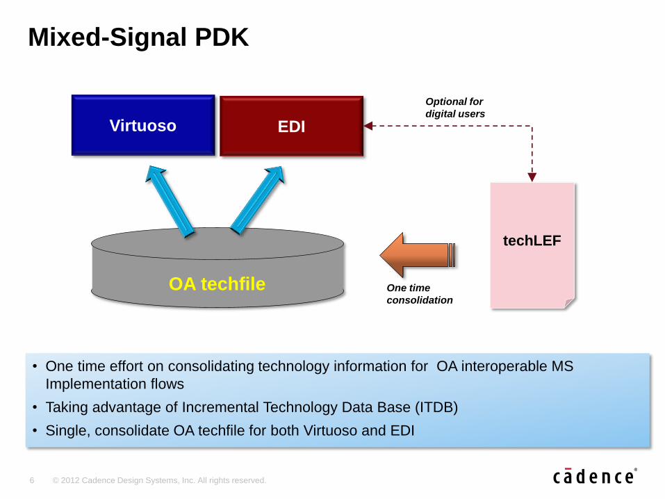
Mixed-Signal PDK
• One time effort on consolidating technology information for OA interoperable MS
Implementation flows
• Taking advantage of Incremental Technology Data Base (ITDB)
• Single, consolidate OA techfile for both Virtuoso and EDI
Virtuoso EDI
techLEF
OA techfile One time
consolidation
Optional for
digital users
7 © 2012 Cadence Design Systems, Inc. All rights reserved.
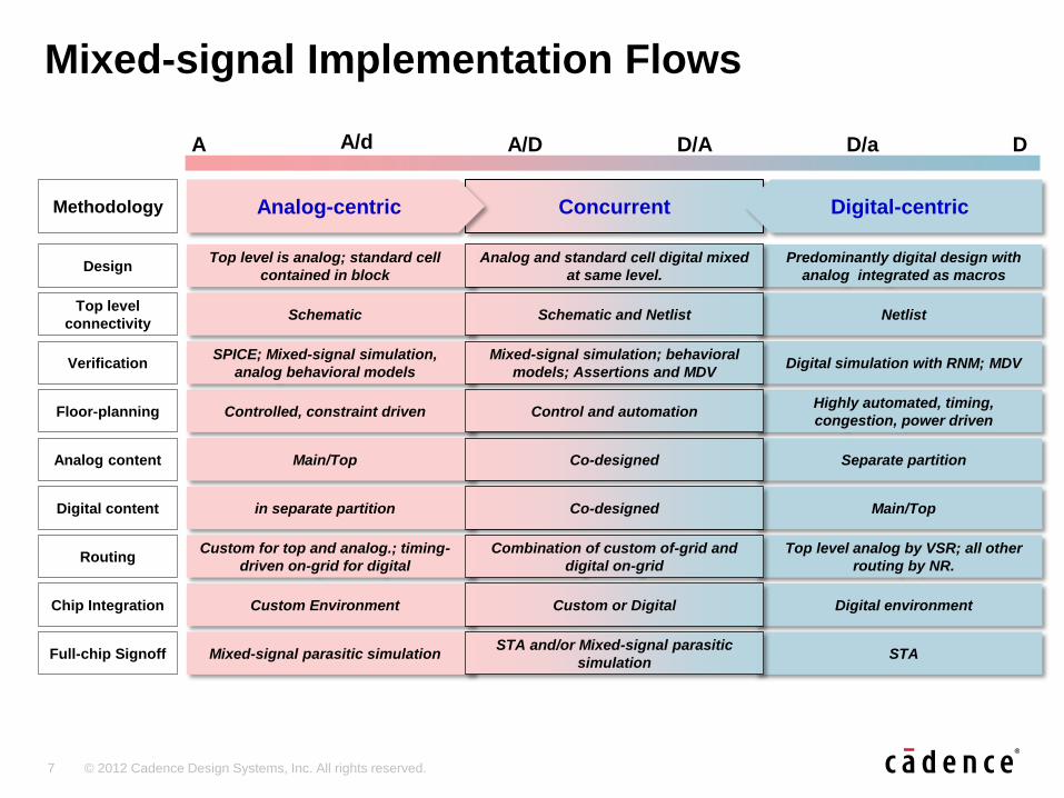
Mixed-signal Implementation Flows
Netlist
Highly automated, timing,
congestion, power driven
Separate partition
Main/Top
Top level analog by VSR; all other
routing by NR.
Digital environment
STA
Predominantly digital design with
analog integrated as macros
D A A/d A/D D/A D/a
Top level
connectivity
Floor-planning
Analog content
Digital content
Routing
Chip Integration
Full-chip Signoff
Main/Top
Schematic
Controlled, constraint driven
in separate partition
Custom for top and analog.; timing-
driven on-grid for digital
Custom Environment
Mixed-signal parasitic simulation
Schematic and Netlist
Control and automation
Co-designed
Co-designed
Combination of custom of-grid and
digital on-grid
Custom or Digital
STA and/or Mixed-signal parasitic
simulation
Methodology
Design Top level is analog; standard cell
contained in block
Analog and standard cell digital mixed
at same level.
Concurrent
Digital simulation with RNM; MDV Verification SPICE; Mixed-signal simulation,
analog behavioral models
Mixed-signal simulation; behavioral
models; Assertions and MDV
Analog-centric Digital-centric
8 © 2012 Cadence Design Systems, Inc. All rights reserved.
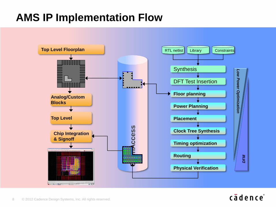
AMS IP Implementation Flow
Top Level Floorplan RTL netlist Library Constraints
Placement
Clock Tree Synthesis
Timing optimization
Routing
Physical Verification
Chip Integration
& Signoff
Power Planning
Synthesis
DFT Test Insertion
Op
en
Access
Floor planning Analog/Custom
Blocks
Top Level
DF
M
Lo
w P
ow
er O
ptim
izatio
n
9 © 2012 Cadence Design Systems, Inc. All rights reserved.
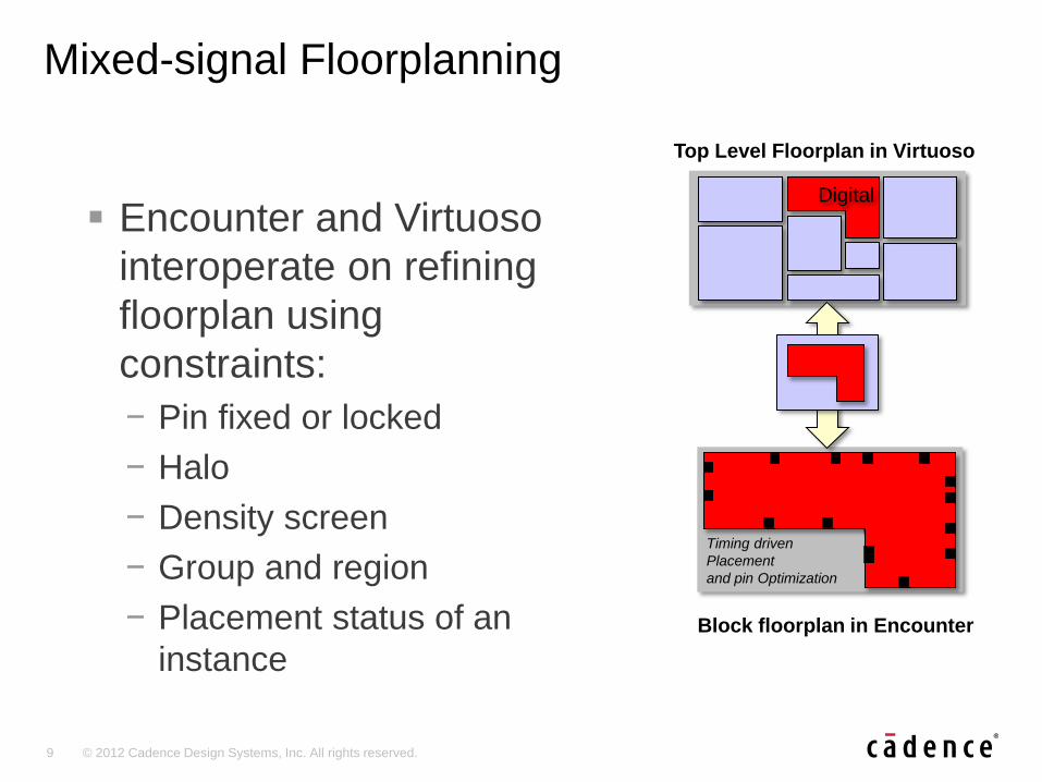
Mixed-signal Floorplanning
Encounter and Virtuoso
interoperate on refining
floorplan using
constraints:
− Pin fixed or locked
− Halo
− Density screen
− Group and region
− Placement status of an
instance
Top Level Floorplan in Virtuoso
Block floorplan in Encounter
Digital
Timing driven
Placement
and pin Optimization
10 © 2012 Cadence Design Systems, Inc. All rights reserved.
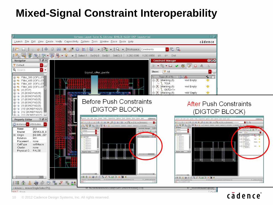
Mixed-Signal Constraint Interoperability
Specification and capture of MS
design integration intent
Hierarchical manipulation of
integration constraints
Storage and delivery through OA db
Implementation support within both
EDI System and Virtuoso
Signoff validation using PVS
Phase 1 support for MS routing
constraints
11 © 2012 Cadence Design Systems, Inc. All rights reserved.
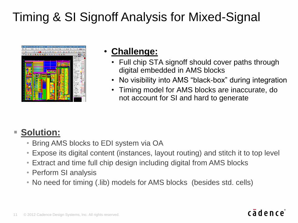
Timing & SI Signoff Analysis for Mixed-Signal
Solution: • Bring AMS blocks to EDI system via OA
• Expose its digital content (instances, layout routing) and stitch it to top level
• Extract and time full chip design including digital from AMS blocks
• Perform SI analysis
• No need for timing (.lib) models for AMS blocks (besides std. cells)
• Challenge: • Full chip STA signoff should cover paths through
digital embedded in AMS blocks
• No visibility into AMS “black-box” during integration
• Timing model for AMS blocks are inaccurate, do not account for SI and hard to generate
12 © 2012 Cadence Design Systems, Inc. All rights reserved.
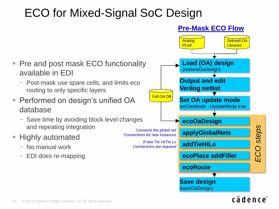
ECO for Mixed-Signal SoC Design
Pre and post mask ECO functionality
available in EDI
− Post-mask use spare cells, and limits eco
routing to only specific layers
Performed on design’s unified OA
database
− Save time by avoiding block level changes
and repeating integration
Highly automated
− No manual work
− EDI does re-mapping
Load (OA) design (restoreOaDesign)
Full OA DB
Stdceell OA
Libraries
Output and edit
Verilog netlist
Set OA update mode setOaxMode -UpdateMode true
EC
O s
teps ecoOaDesign
applyGlobalNets
addTieHiLo
ecoPlace addFiller
ecoRoute
Save design (saveOaDesign)
Pre-Mask ECO Flow
If new Tie Hi/Tie Lo
Connections are required
Connects the global net
Connections for new instances
Analog
PCell
13 © 2012 Cadence Design Systems, Inc. All rights reserved.
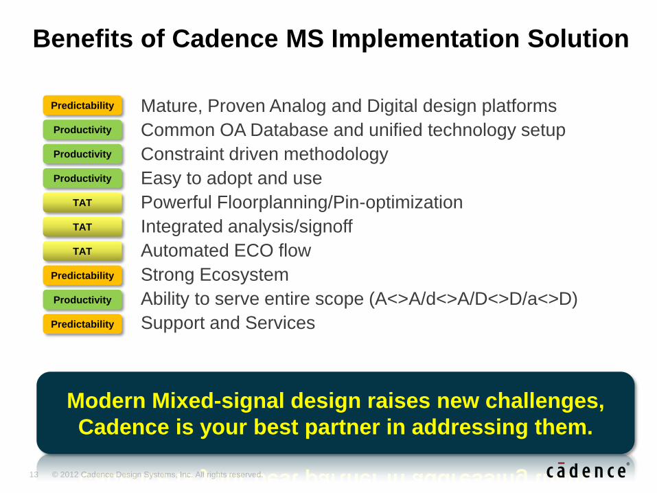
Benefits of Cadence MS Implementation Solution
Mature, Proven Analog and Digital design platforms
Common OA Database and unified technology setup
Constraint driven methodology
Easy to adopt and use
Powerful Floorplanning/Pin-optimization
Integrated analysis/signoff
Automated ECO flow
Strong Ecosystem
Ability to serve entire scope (A<>A/d<>A/D<>D/a<>D)
Support and Services
Predictability
Productivity
TAT
TAT
Predictability
Predictability
TAT
Productivity
Productivity
Productivity
Modern Mixed-signal design raises new challenges,
Cadence is your best partner in addressing them.
14 © 2012 Cadence Design Systems, Inc. All rights reserved.
15 © 2012 Cadence Design Systems, Inc. All rights reserved.