computer hardware and system software concepts · · 2014-07-01computer hardware and system...
TRANSCRIPT
1
Computer Hardware and System Software ConceptsIntroduction to Computer Architecture
Welcome to this course on Computer Hardware and System Software Concepts
2
2Copyright © 2004, Infosys Technologies Ltd
ER/CORP/CRS/OS09/003
Version No: 2.0
Course Objective
To introduce fundamentals of Computer Architecture
To introduce the concepts of System Software.
To introduce the concepts of Operating Systems.
To introduce the concepts of Computer Networks.
By the end of the course, you will have
• Knowledge of Computer Architecture
• Knowledge about different kinds of System Software viz., Compilers, Assemblers, Interpreters etc
• Knowledge about Operating System as a resource manager – managing resources like memory, processors, peripherals and information
• Knowledge about Computer Networks
NOTE:
This course does not cover
• Technologies used to fabricate CPU, memory etc.
• Design and implementation of compilers, linkers, loaders etc.
• No particular OS whether at the command level or internals
• No particular protocol such as TCP/IP
• No day to day software Internet, Netscape etc.
3
3Copyright © 2004, Infosys Technologies Ltd
ER/CORP/CRS/OS09/003
Version No: 2.0
References
Andrew S. Tanenbaum: Structured Computer Organization , PHI, 3rd edition,
1991.
Silberschatz and Galvin: Operating System Concepts , 4th edition, Addison-
Wesley Pub, 1995.
Andrew S. Tanenbaum: Computer Networks, PHI, 1991.
Alfred V.Aho, Ravi Sethi, Jeffrey D.Ullman: Compilers -Principles, Techniques
and Tools, Narosa Publishing House, 1986.
4
4Copyright © 2004, Infosys Technologies Ltd
ER/CORP/CRS/OS09/003
Version No: 2.0
Session Plan
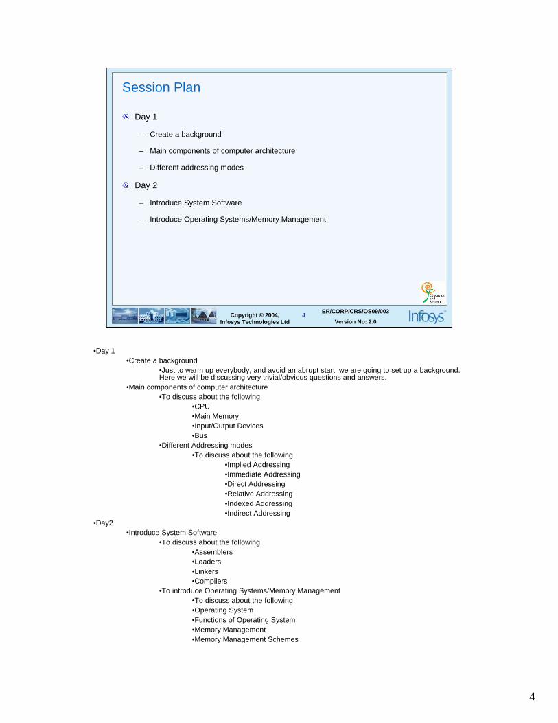
Day 1
– Create a background
– Main components of computer architecture
– Different addressing modes
Day 2
– Introduce System Software
– Introduce Operating Systems/Memory Management
•Day 1•Create a background
•Just to warm up everybody, and avoid an abrupt start, we are going to set up a background. Here we will be discussing very trivial/obvious questions and answers.
•Main components of computer architecture •To discuss about the following
•CPU•Main Memory•Input/Output Devices•Bus
•Different Addressing modes•To discuss about the following
•Implied Addressing•Immediate Addressing•Direct Addressing•Relative Addressing•Indexed Addressing•Indirect Addressing
•Day2•Introduce System Software
•To discuss about the following •Assemblers•Loaders•Linkers•Compilers
•To introduce Operating Systems/Memory Management•To discuss about the following•Operating System•Functions of Operating System•Memory Management •Memory Management Schemes
5
5Copyright © 2004, Infosys Technologies Ltd
ER/CORP/CRS/OS09/003
Version No: 2.0
Session Plan
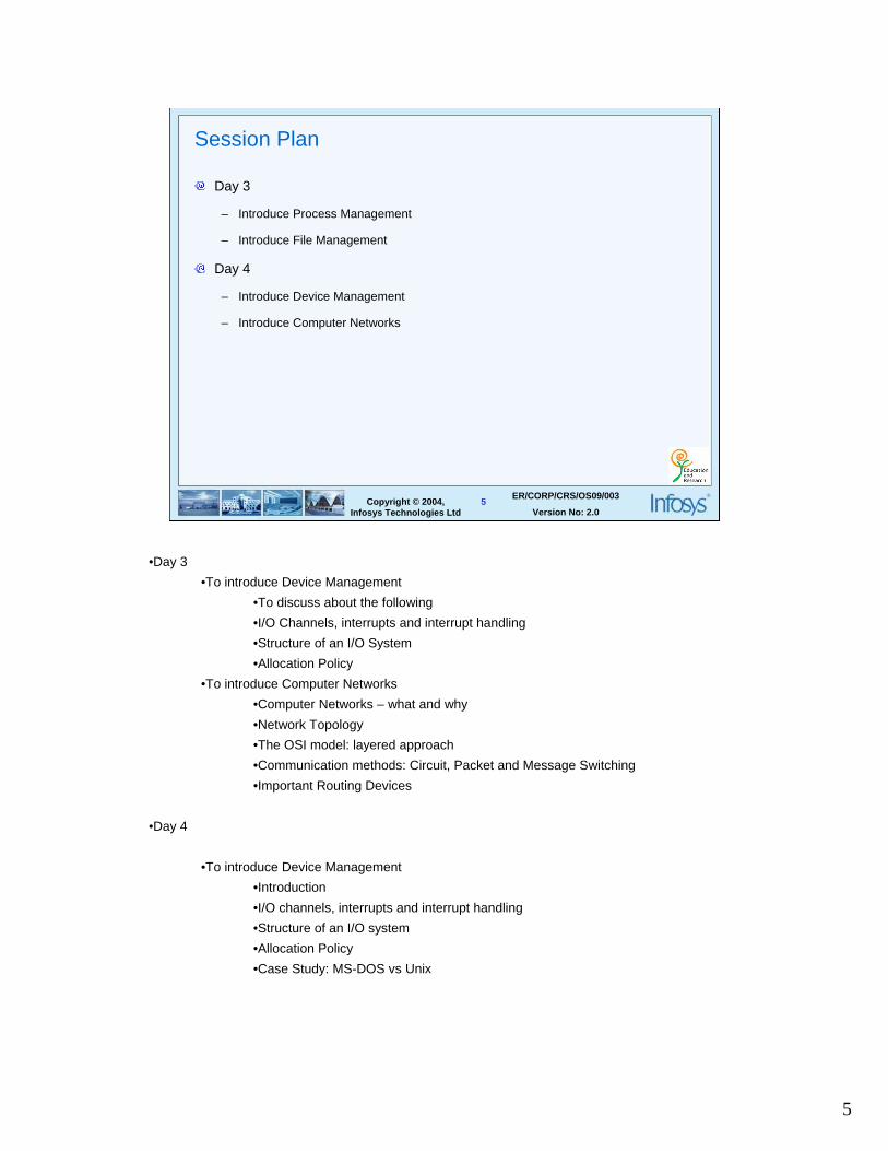
Day 3
– Introduce Process Management
– Introduce File Management
Day 4
– Introduce Device Management
– Introduce Computer Networks
•Day 3
•To introduce Device Management
•To discuss about the following
•I/O Channels, interrupts and interrupt handling
•Structure of an I/O System
•Allocation Policy
•To introduce Computer Networks
•Computer Networks – what and why
•Network Topology
•The OSI model: layered approach
•Communication methods: Circuit, Packet and Message Switching
•Important Routing Devices
•Day 4
•To introduce Device Management
•Introduction
•I/O channels, interrupts and interrupt handling
•Structure of an I/O system
•Allocation Policy
•Case Study: MS-DOS vs Unix
6
6Copyright © 2004, Infosys Technologies Ltd
ER/CORP/CRS/OS09/003
Version No: 2.0
Background
What is a Computer?
What is a Program?
Main components in a computer system
– Hardware
– Software
– Firmware
A Computer is a machine which solves problems for people written as programs.
A Program is a sequence of statements/steps stating how to perform a task. For each step an arithmetic and logical operation is done. For each operation a different set of control signals is needed – i.e. an instruction. An instruction can be machine language instructions or assembly language instructions or even high level language instructions.
A hardware is something that is tangible. For e.g. CPU, Memory, I/O devices, Bus etc.A software is a collection of programs. Trigger the question to identify the differences between software, program, function/procedure etc.Software is mainly of two types – system software and application software. Programs such as compilers, linkers, loaders, assemblers are known as system software. Application software provides a solution to user application by making use of system software. E.g. banking software, payroll software.
A firmware is software embedded in hardware during manufacture. E.g. home appliances etc

7
7Copyright © 2004, Infosys Technologies Ltd
ER/CORP/CRS/OS09/003
Version No: 2.0
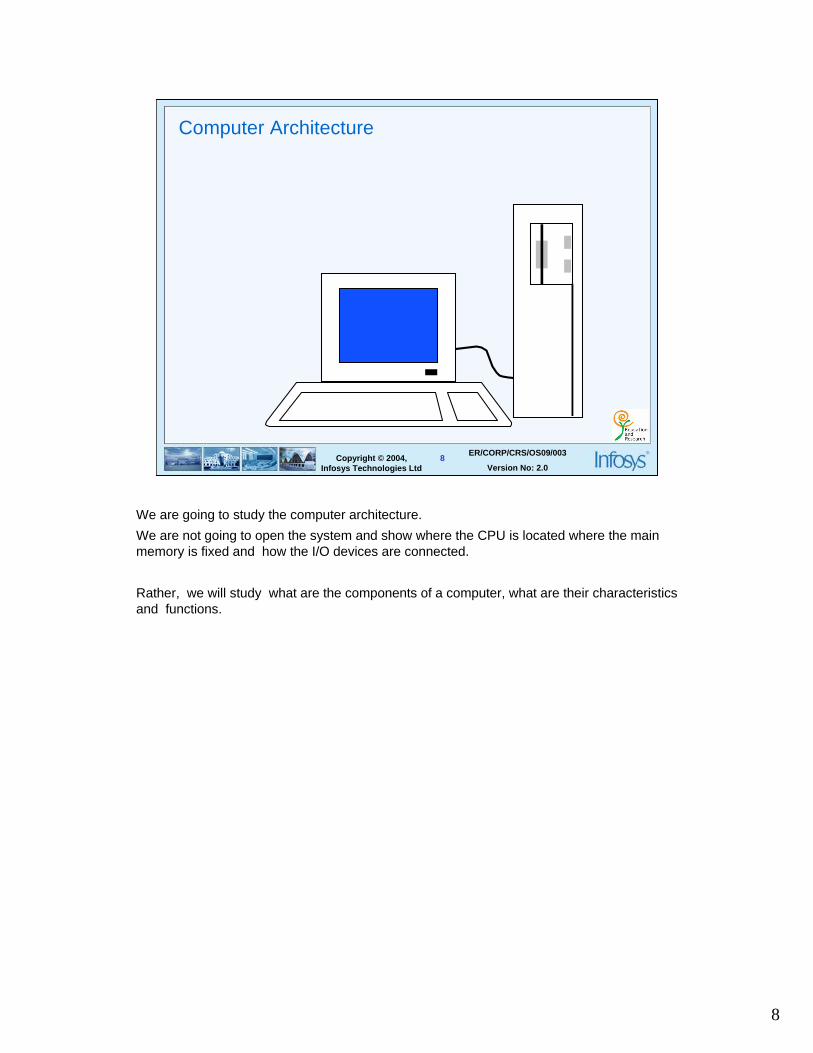
Computer Architecture
is concerned with the structure and behavior of the computer as seen by the
user/programmer. It includes attributes such as
– Instruction Formats
– Addressing Modes
– Instruction Sets
– I/O Mechanisms
Talk about the difference between computer architecture and organization.
Computer Organization is how features are implemented, typically hidden from the programmer. E.g. control signals, interfaces, memory technology etc. It is basically concerned with the way the hardware components operate and the way they are connected together to form the computer system.
An instruction consists of an opcode always, along with some additional information such as where the operands come from and where the final results go to etc. Thus, there can be zero, one, two or three addresses present.
Different machines have different instruction formats.
Addressing basically refers to the way in which the operands are specified in an instruction. There are different ways in which the bits of an address field can be interpreted to find the operand. Addressing modes refer to these different ways.
8
8Copyright © 2004, Infosys Technologies Ltd
ER/CORP/CRS/OS09/003
Version No: 2.0
Computer Architecture
We are going to study the computer architecture.
We are not going to open the system and show where the CPU is located where the main memory is fixed and how the I/O devices are connected.
Rather, we will study what are the components of a computer, what are their characteristics and functions.
9
9Copyright © 2004, Infosys Technologies Ltd
ER/CORP/CRS/OS09/003
Version No: 2.0
Main components of a computer system
Central Processing Unit (CPU)
Main Memory
Input / Output devices
Bus
10
10Copyright © 2004, Infosys Technologies Ltd
ER/CORP/CRS/OS09/003
Version No: 2.0
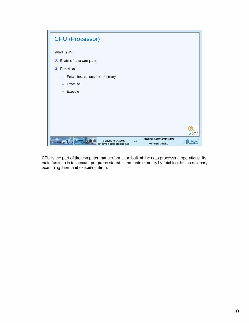
CPU (Processor)
What is it?
Brain of the computer
Function
– Fetch instructions from memory
– Examine
– Execute
CPU is the part of the computer that performs the bulk of the data processing operations. Its main function is to execute programs stored in the main memory by fetching the instructions, examining them and executing them.
11
11Copyright © 2004, Infosys Technologies Ltd
ER/CORP/CRS/OS09/003
Version No: 2.0
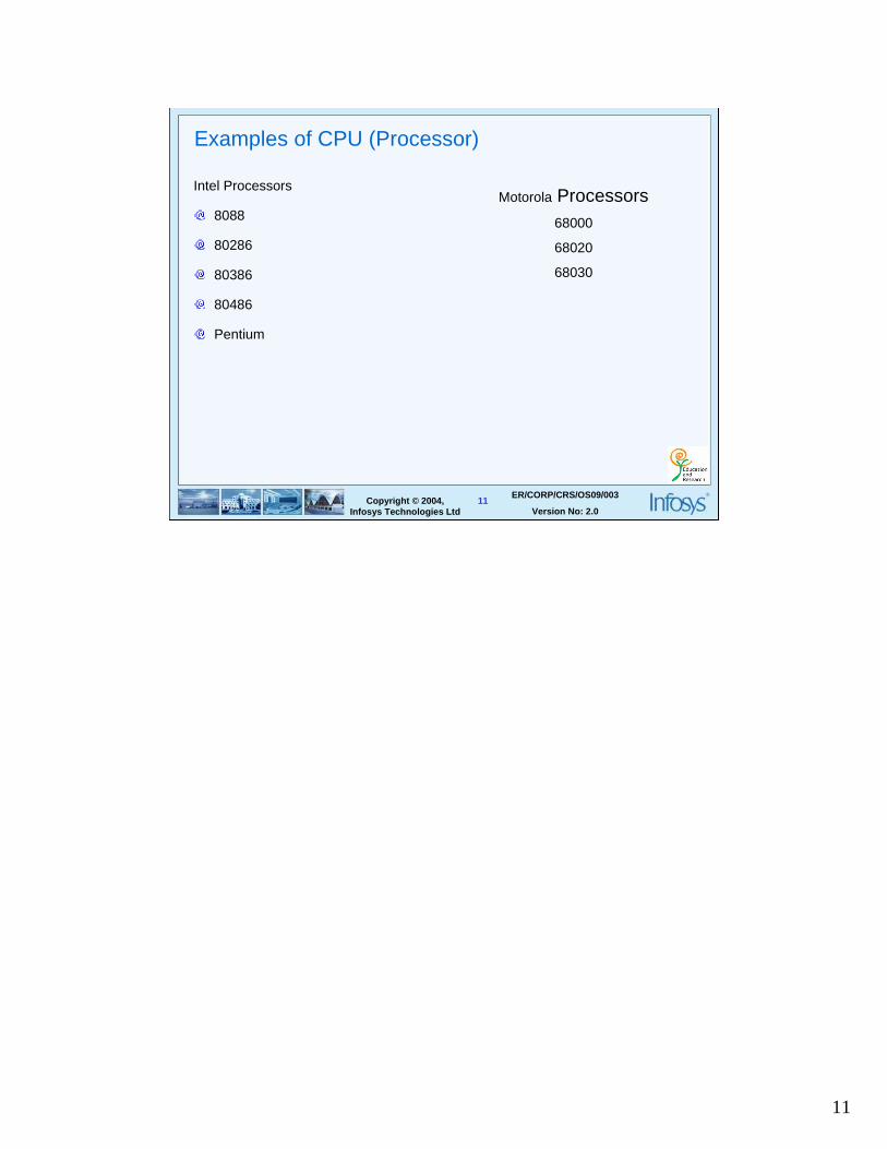
Examples of CPU (Processor)
Intel Processors
8088
80286
80386
80486
Pentium
Motorola Processors68000
68020
68030
12
12Copyright © 2004, Infosys Technologies Ltd
ER/CORP/CRS/OS09/003
Version No: 2.0
Parts of CPU
Control Unit ( CU )
Arithmetic and Logical Unit (ALU)
Registers
13
13Copyright © 2004, Infosys Technologies Ltd
ER/CORP/CRS/OS09/003
Version No: 2.0
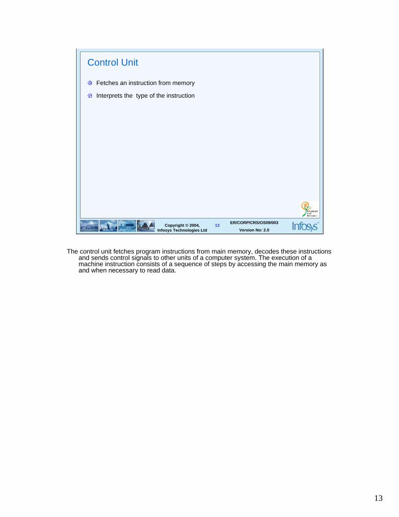
Control Unit
Fetches an instruction from memory
Interprets the type of the instruction
The control unit fetches program instructions from main memory, decodes these instructions and sends control signals to other units of a computer system. The execution of a machine instruction consists of a sequence of steps by accessing the main memory as and when necessary to read data.
14
14Copyright © 2004, Infosys Technologies Ltd
ER/CORP/CRS/OS09/003
Version No: 2.0
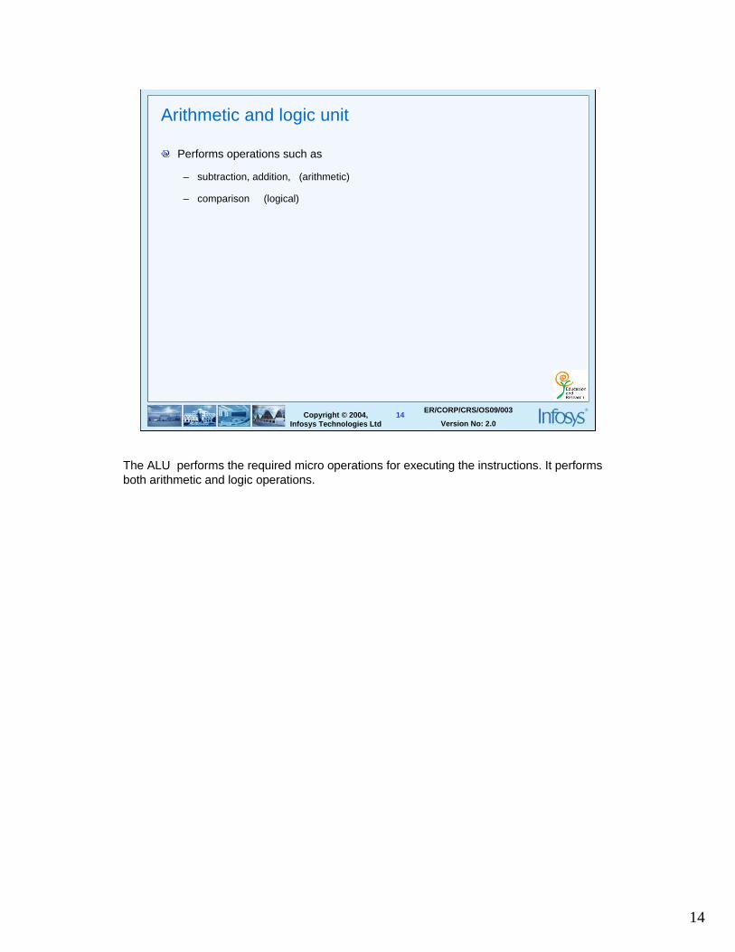
Arithmetic and logic unit
Performs operations such as
– subtraction, addition, (arithmetic)
– comparison (logical)
The ALU performs the required micro operations for executing the instructions. It performs both arithmetic and logic operations.
15
15Copyright © 2004, Infosys Technologies Ltd
ER/CORP/CRS/OS09/003
Version No: 2.0
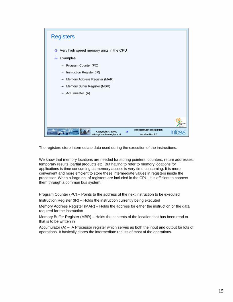
Registers
Very high speed memory units in the CPU
Examples
– Program Counter (PC)
– Instruction Register (IR)
– Memory Address Register (MAR)
– Memory Buffer Register (MBR)
– Accumulator (A)
The registers store intermediate data used during the execution of the instructions.
We know that memory locations are needed for storing pointers, counters, return addresses, temporary results, partial products etc. But having to refer to memory locations for applications is time consuming as memory access is very time consuming. It is more convenient and more efficient to store these intermediate values in registers inside the processor. When a large no. of registers are included in the CPU, it is efficient to connect them through a common bus system.
Program Counter (PC) – Points to the address of the next instruction to be executed
Instruction Register (IR) – Holds the instruction currently being executed
Memory Address Register (MAR) – Holds the address for either the instruction or the data required for the instruction
Memory Buffer Register (MBR) – Holds the contents of the location that has been read or that is to be written in
Accumulator (A) – A Processor register which serves as both the input and output for lots of operations. It basically stores the intermediate results of most of the operations.
16
16Copyright © 2004, Infosys Technologies Ltd
ER/CORP/CRS/OS09/003
Version No: 2.0
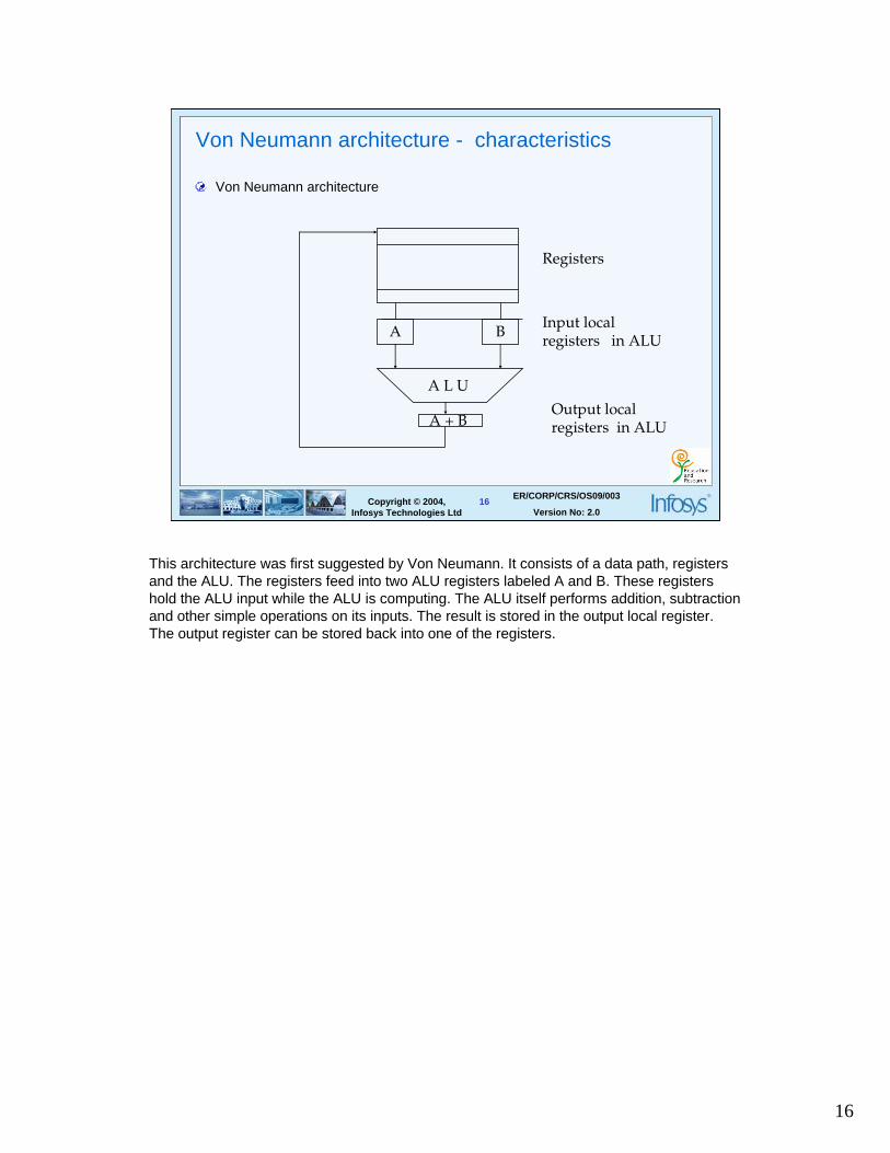
Von Neumann architecture - characteristics
Von Neumann architecture
A B
A L U
A + B
Registers
Input local registers in ALU
Output local registers in ALU
This architecture was first suggested by Von Neumann. It consists of a data path, registers and the ALU. The registers feed into two ALU registers labeled A and B. These registers hold the ALU input while the ALU is computing. The ALU itself performs addition, subtraction and other simple operations on its inputs. The result is stored in the output local register. The output register can be stored back into one of the registers.
17
17Copyright © 2004, Infosys Technologies Ltd
ER/CORP/CRS/OS09/003
Version No: 2.0
Von Neumann architecture - characteristics
One processor
Use of stored programs
Sequential processing of instructions
Single Instruction, Single Data stream (SISD) mode
18
18Copyright © 2004, Infosys Technologies Ltd
ER/CORP/CRS/OS09/003
Version No: 2.0
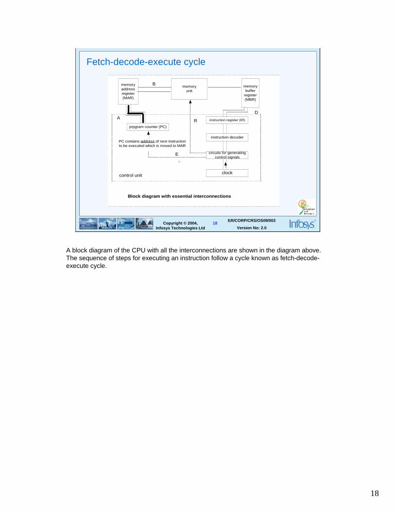
Fetch-decode-execute cycle
memoryaddressregister(MAR)
memorybuffer
register(MBR)
memoryunit
instruction register (IR)
instruction decoder
circuits for generatingcontrol signals
clock
prpgram counter (PC)
A
B
D
E
R
control unit
Block diagram with essential interconnect ions
PC contains address of next instructionto be executed which is moved to MAR
A block diagram of the CPU with all the interconnections are shown in the diagram above. The sequence of steps for executing an instruction follow a cycle known as fetch-decode-execute cycle.
19
19Copyright © 2004, Infosys Technologies Ltd
ER/CORP/CRS/OS09/003
Version No: 2.0
Fetch-decode-execute cycle
Fetch Phase
Decode Phase
Execute Phase
The fetch-decode-execute cycle are explained in the next slides.
20
20Copyright © 2004, Infosys Technologies Ltd
ER/CORP/CRS/OS09/003
Version No: 2.0
Fetch phase
Contents of PC are transferred to MAR
Main memory is accessed and current instruction is fetched into MBR
Instruction is transferred from MBR to IR
• The contents of the PC are transferred to MAR. • The main memory is accessed and the current instruction is fetched into MBR. • The operation code is transferred from MBR to IR where it is decoded.
21
21Copyright © 2004, Infosys Technologies Ltd
ER/CORP/CRS/OS09/003
Version No: 2.0
Decode phase
Opcode of the instruction is decoded
Contents of PC are incremented by 1(in case of 1 byte instruction or equal to
the no. of bytes of the instruction currently being executed.)
Execution phase follows ( specific to the given instruction )
•The opcode of the instruction is decoded by the decoder
•At the same time, the PC is incremented by 1 to prepare it for fetching the next instruction.
22
22Copyright © 2004, Infosys Technologies Ltd
ER/CORP/CRS/OS09/003
Version No: 2.0
Execute phase
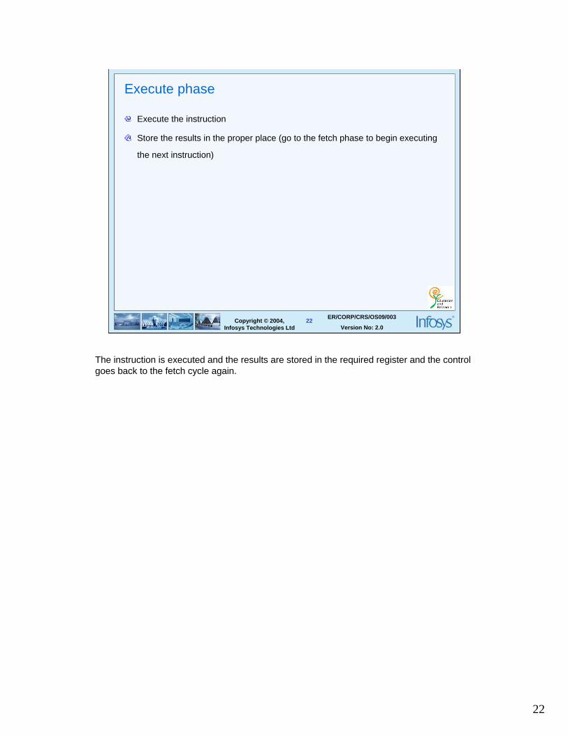
Execute the instruction
Store the results in the proper place (go to the fetch phase to begin executing
the next instruction)
The instruction is executed and the results are stored in the required register and the control goes back to the fetch cycle again.
23
23Copyright © 2004, Infosys Technologies Ltd
ER/CORP/CRS/OS09/003
Version No: 2.0
Instruction categories
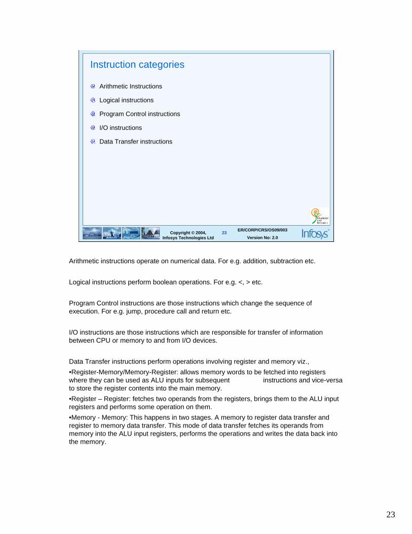
Arithmetic Instructions
Logical instructions
Program Control instructions
I/O instructions
Data Transfer instructions
Arithmetic instructions operate on numerical data. For e.g. addition, subtraction etc.
Logical instructions perform boolean operations. For e.g. <, > etc.
Program Control instructions are those instructions which change the sequence of execution. For e.g. jump, procedure call and return etc.
I/O instructions are those instructions which are responsible for transfer of information between CPU or memory to and from I/O devices.
Data Transfer instructions perform operations involving register and memory viz.,
•Register-Memory/Memory-Register: allows memory words to be fetched into registers where they can be used as ALU inputs for subsequent instructions and vice-versa to store the register contents into the main memory.
•Register – Register: fetches two operands from the registers, brings them to the ALU input registers and performs some operation on them.
•Memory - Memory: This happens in two stages. A memory to register data transfer and register to memory data transfer. This mode of data transfer fetches its operands from memory into the ALU input registers, performs the operations and writes the data back into the memory.
24
24Copyright © 2004, Infosys Technologies Ltd
ER/CORP/CRS/OS09/003
Version No: 2.0
Measures of CPU performance
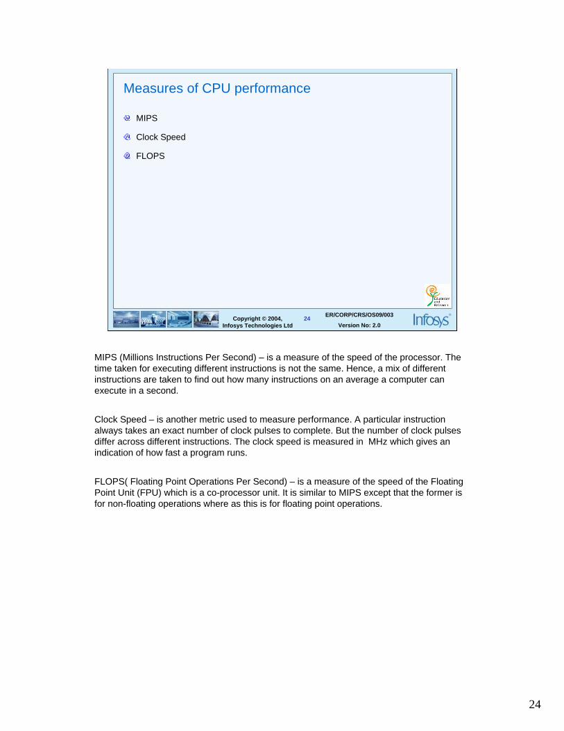
MIPS
Clock Speed
FLOPS
MIPS (Millions Instructions Per Second) – is a measure of the speed of the processor. The time taken for executing different instructions is not the same. Hence, a mix of different instructions are taken to find out how many instructions on an average a computer can execute in a second.
Clock Speed – is another metric used to measure performance. A particular instruction always takes an exact number of clock pulses to complete. But the number of clock pulses differ across different instructions. The clock speed is measured in MHz which gives an indication of how fast a program runs.
FLOPS( Floating Point Operations Per Second) – is a measure of the speed of the Floating Point Unit (FPU) which is a co-processor unit. It is similar to MIPS except that the former is for non-floating operations where as this is for floating point operations.
25
25Copyright © 2004, Infosys Technologies Ltd
ER/CORP/CRS/OS09/003
Version No: 2.0
Memory
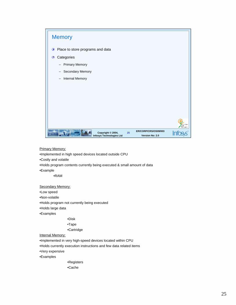
Place to store programs and data
Categories
– Primary Memory
– Secondary Memory
– Internal Memory
Primary Memory:
•Implemented in high speed devices located outside CPU
•Costly and volatile
•Holds program contents currently being executed & small amount of data
•Example
•RAM
Secondary Memory:
•Low speed
•Non-volatile
•Holds program not currently being executed
•Holds large data
•Examples
•Disk
•Tape
•Cartridge
Internal Memory:
•Implemented in very high-speed devices located within CPU
•Holds currently execution instructions and few data related items
•Very expensive
•Examples
•Registers
•Cache
26
26Copyright © 2004, Infosys Technologies Ltd
ER/CORP/CRS/OS09/003
Version No: 2.0
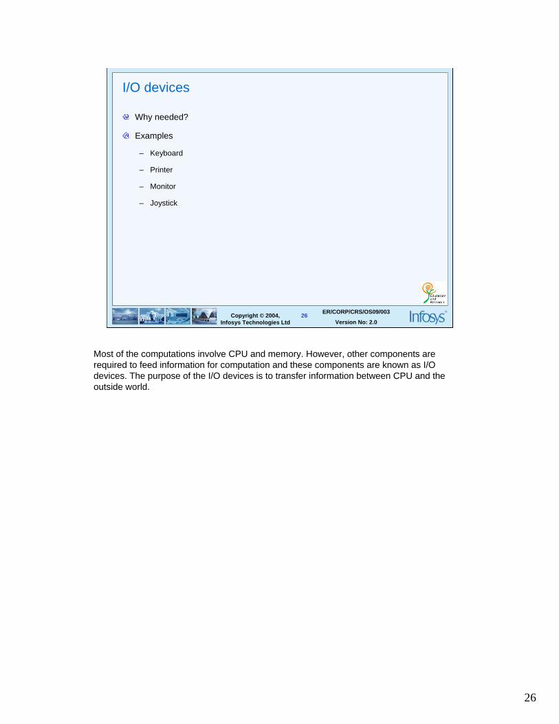
I/O devices
Why needed?
Examples
– Keyboard
– Printer
– Monitor
– Joystick
Most of the computations involve CPU and memory. However, other components are required to feed information for computation and these components are known as I/O devices. The purpose of the I/O devices is to transfer information between CPU and the outside world.
27
27Copyright © 2004, Infosys Technologies Ltd
ER/CORP/CRS/OS09/003
Version No: 2.0
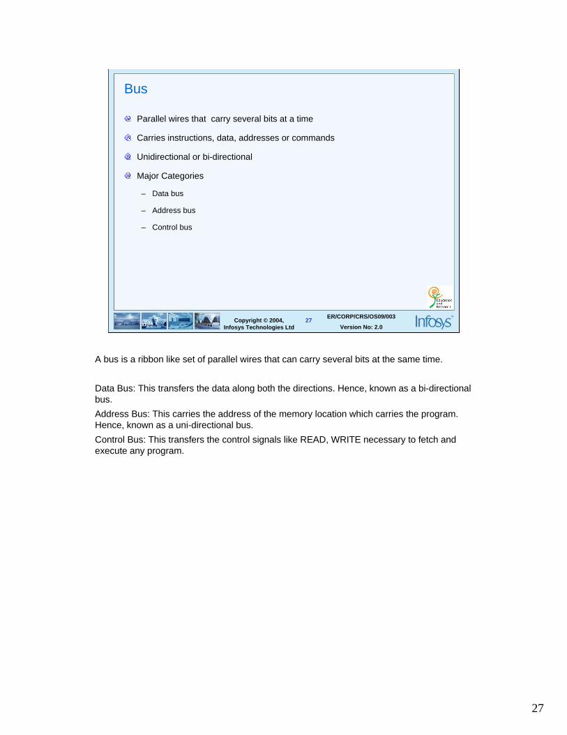
Bus
Parallel wires that carry several bits at a time
Carries instructions, data, addresses or commands
Unidirectional or bi-directional
Major Categories
– Data bus
– Address bus
– Control bus
A bus is a ribbon like set of parallel wires that can carry several bits at the same time.
Data Bus: This transfers the data along both the directions. Hence, known as a bi-directional bus.
Address Bus: This carries the address of the memory location which carries the program. Hence, known as a uni-directional bus.
Control Bus: This transfers the control signals like READ, WRITE necessary to fetch and execute any program.
28
28Copyright © 2004, Infosys Technologies Ltd
ER/CORP/CRS/OS09/003
Version No: 2.0
Addressing
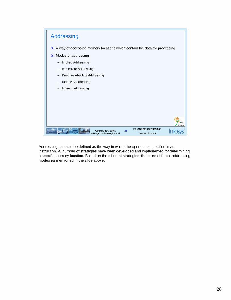
A way of accessing memory locations which contain the data for processing
Modes of addressing
– Implied Addressing
– Immediate Addressing
– Direct or Absolute Addressing
– Relative Addressing
– Indirect addressing
Addressing can also be defined as the way in which the operand is specified in an instruction. A number of strategies have been developed and implemented for determining a specific memory location. Based on the different strategies, there are different addressing modes as mentioned in the slide above.
29
29Copyright © 2004, Infosys Technologies Ltd
ER/CORP/CRS/OS09/003
Version No: 2.0
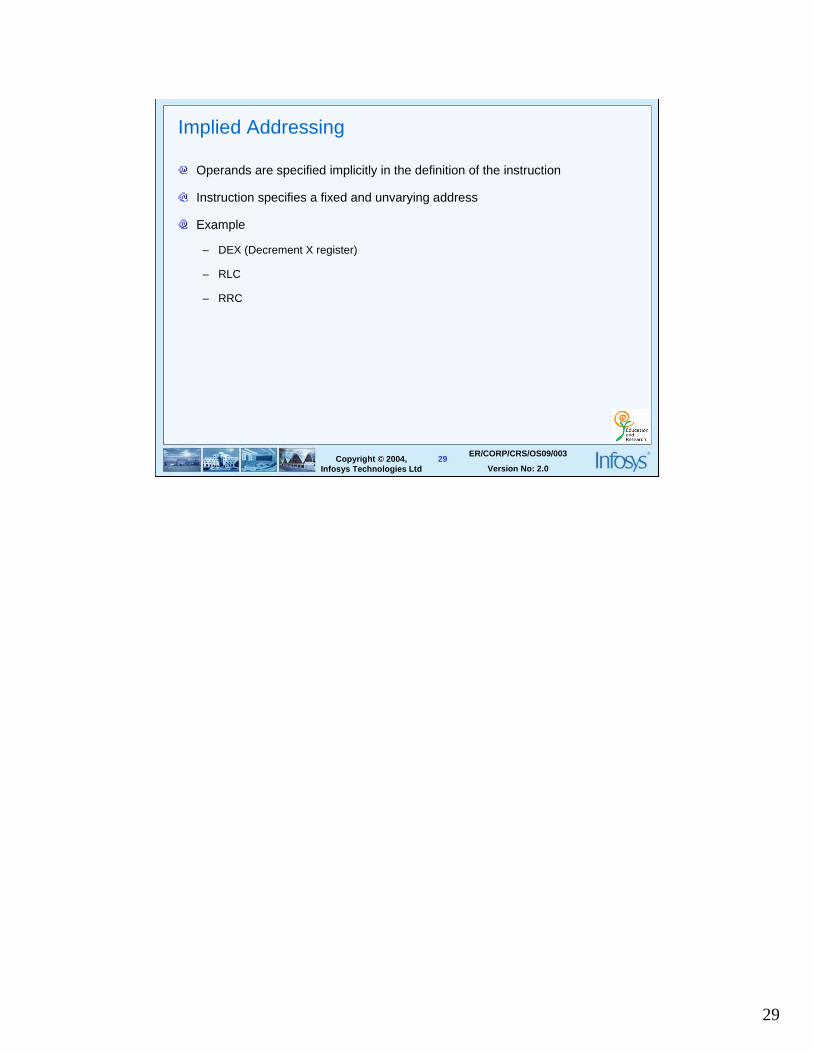
Implied Addressing
Operands are specified implicitly in the definition of the instruction
Instruction specifies a fixed and unvarying address
Example
– DEX (Decrement X register)
– RLC
– RRC
30
30Copyright © 2004, Infosys Technologies Ltd
ER/CORP/CRS/OS09/003
Version No: 2.0
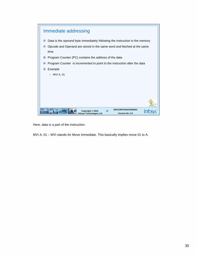
Immediate addressing
Data is the operand byte immediately following the instruction in the memory
Opcode and Operand are stored in the same word and fetched at the same
time
Program Counter (PC) contains the address of the data
Program Counter is incremented to point to the instruction after the data
Example
– MVI A, 01
Here, data is a part of the instruction.
MVI A, 01 – MVI stands for Move Immediate. This basically implies move 01 to A.
31
31Copyright © 2004, Infosys Technologies Ltd
ER/CORP/CRS/OS09/003
Version No: 2.0
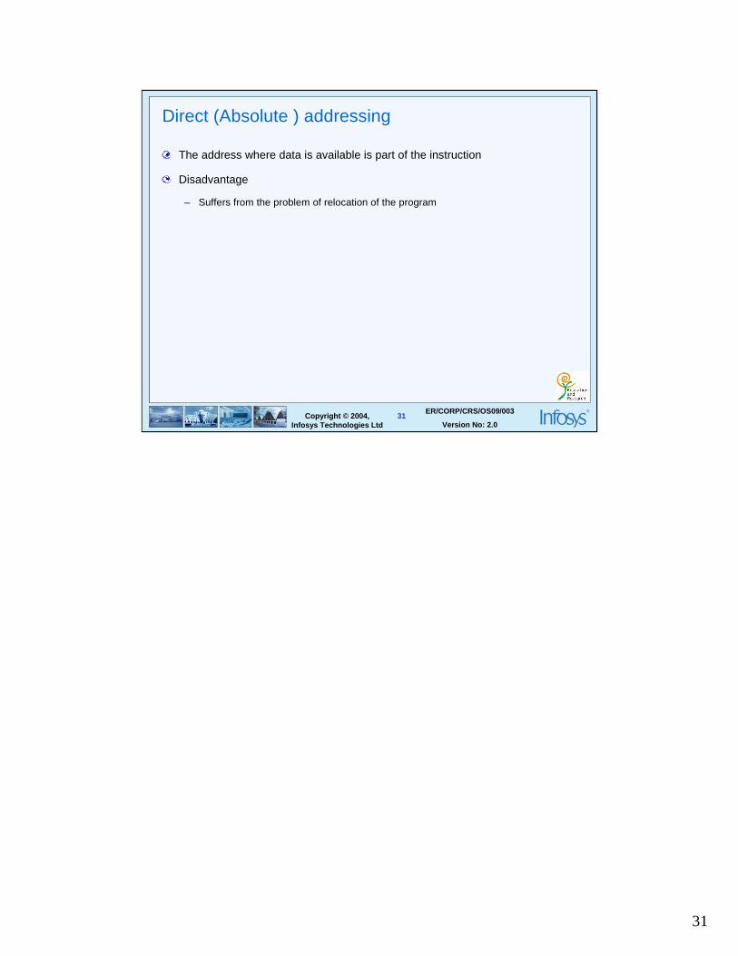
Direct (Absolute ) addressing
The address where data is available is part of the instruction
Disadvantage
– Suffers from the problem of relocation of the program
32
32Copyright © 2004, Infosys Technologies Ltd
ER/CORP/CRS/OS09/003
Version No: 2.0
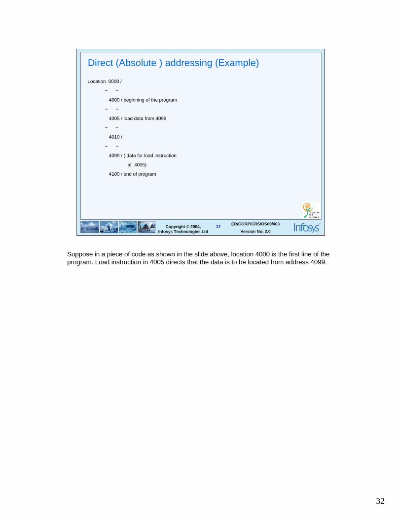
Direct (Absolute ) addressing (Example)
Location 0000 /
~ ~
4000 / beginning of the program
~ ~
4005 / load data from 4099
~ ~
4010 /
~ ~
4099 / ( data for load instruction
at 4005)
4100 / end of program
Suppose in a piece of code as shown in the slide above, location 4000 is the first line of the program. Load instruction in 4005 directs that the data is to be located from address 4099.
33
33Copyright © 2004, Infosys Technologies Ltd
ER/CORP/CRS/OS09/003
Version No: 2.0
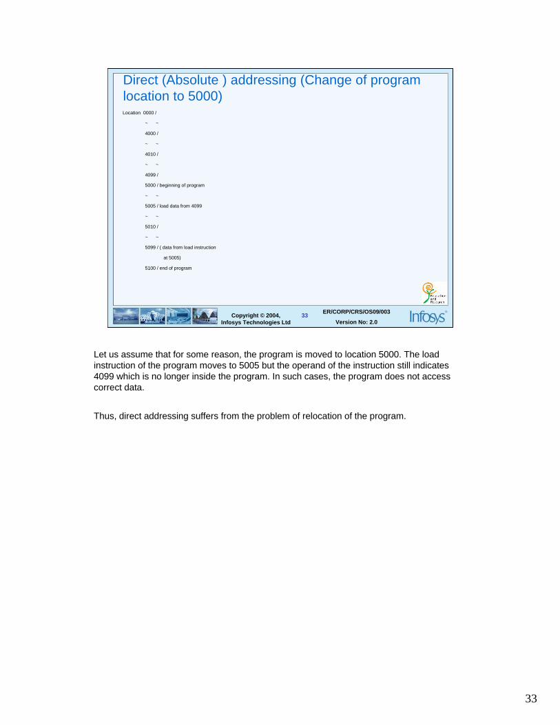
Direct (Absolute ) addressing (Change of program location to 5000)Location 0000 /
~ ~
4000 /
~ ~
4010 /
~ ~
4099 /
5000 / beginning of program
~ ~
5005 / load data from 4099
~ ~
5010 /
~ ~
5099 / ( data from load instruction
at 5005)
5100 / end of program
Let us assume that for some reason, the program is moved to location 5000. The load instruction of the program moves to 5005 but the operand of the instruction still indicates 4099 which is no longer inside the program. In such cases, the program does not access correct data.
Thus, direct addressing suffers from the problem of relocation of the program.
34
34Copyright © 2004, Infosys Technologies Ltd
ER/CORP/CRS/OS09/003
Version No: 2.0
Relative addressing
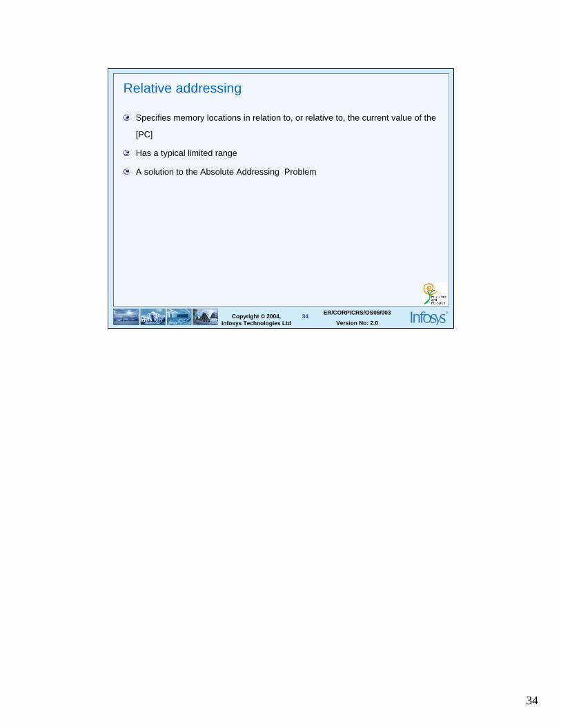
Specifies memory locations in relation to, or relative to, the current value of the
[PC]
Has a typical limited range
A solution to the Absolute Addressing Problem
35
35Copyright © 2004, Infosys Technologies Ltd
ER/CORP/CRS/OS09/003
Version No: 2.0
Relative addressing (Example)
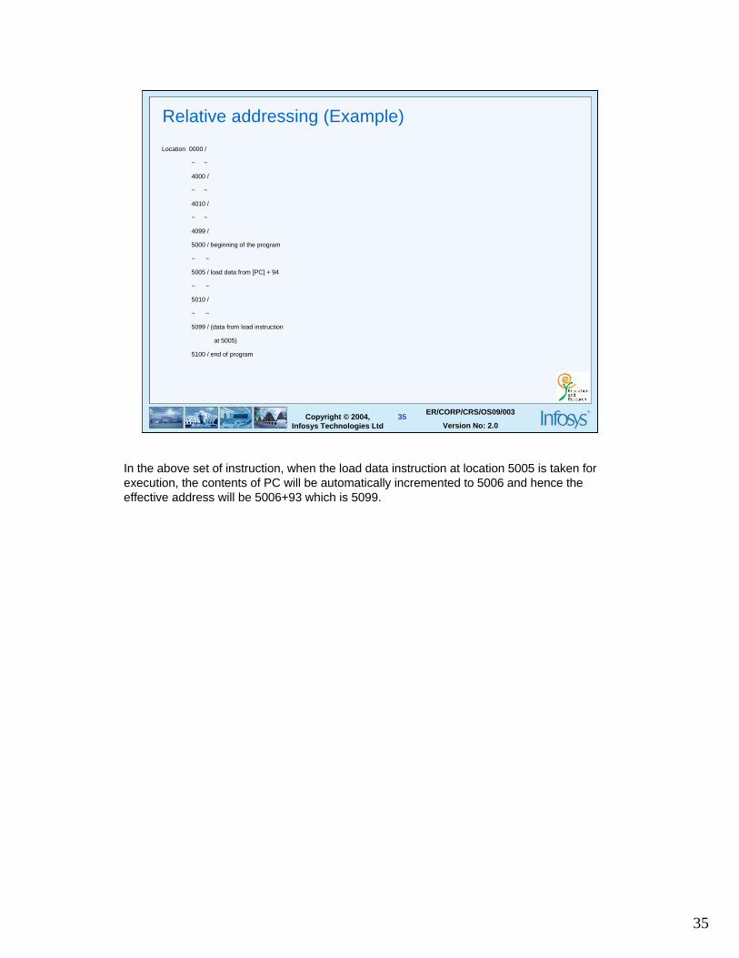
Location 0000 /
~ ~
4000 /
~ ~
4010 /
~ ~
4099 /
5000 / beginning of the program
~ ~
5005 / load data from [PC] + 94
~ ~
5010 /
~ ~
5099 / (data from load instruction
at 5005)
5100 / end of program
In the above set of instruction, when the load data instruction at location 5005 is taken for execution, the contents of PC will be automatically incremented to 5006 and hence the effective address will be 5006+93 which is 5099.
36
36Copyright © 2004, Infosys Technologies Ltd
ER/CORP/CRS/OS09/003
Version No: 2.0
Indirect Addressing
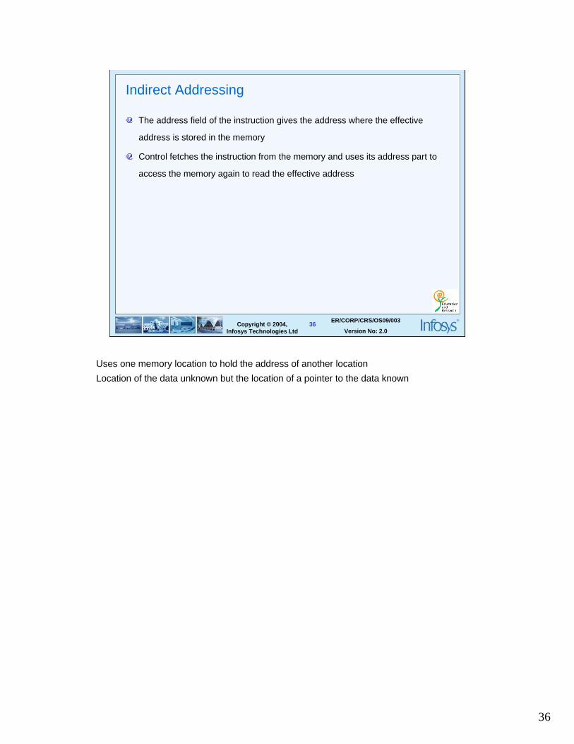
The address field of the instruction gives the address where the effective
address is stored in the memory
Control fetches the instruction from the memory and uses its address part to
access the memory again to read the effective address
Uses one memory location to hold the address of another location
Location of the data unknown but the location of a pointer to the data known
37
37Copyright © 2004, Infosys Technologies Ltd
ER/CORP/CRS/OS09/003
Version No: 2.0
Summary
Background
Components of a computer system
Von Neumann architecture
Fetch Decode Execute Cycle
Memory
I/O devices
Bus
Addressing Modes
38
38Copyright © 2004, Infosys Technologies Ltd
ER/CORP/CRS/OS09/003
Version No: 2.0
Thank You!