computer graphics & image processing chapter # 9 morphological image processing
DESCRIPTION
Computer Graphics & Image Processing Chapter # 9 Morphological Image Processing. ALI JAVED Lecturer SOFTWARE ENGINEERING DEPARTMENT U.E.T TAXILA Email:: [email protected] Office Room #:: 7. INTRODUCTION. - PowerPoint PPT PresentationTRANSCRIPT
Computer Graphics Computer Graphics &&
Image Processing Image Processing
Chapter # 9Chapter # 9
Morphological Image Processing
ALI JAVED Lecturer
SOFTWARE ENGINEERING DEPARTMENT
U.E.T TAXILA
Email:: [email protected]
Office Room #:: 7
INTRODUCTION
• The word Morphology denotes a branch of biology that deals with the form and structure of animals and plants.
• Here we use the same word in the context of Mathematical Morphology, which means as a tool for extracting image components that are useful in the representation and description of region shape, such as boundaries, skeletons etc.
• The language of Mathematical Morphology is set theory.
• Sets in Mathematical Morphology represents objects in an image.
• Motive is to extract useful features from shape
INTRODUCTION
• Morph means shape
• We do Morphology for shape analysis & shape study.
• Shape analysis became easy in case of binary images.
• Pixel Locations describe the shape.
• Digital Morphology is a way to describe or analyze the shape of a digital image
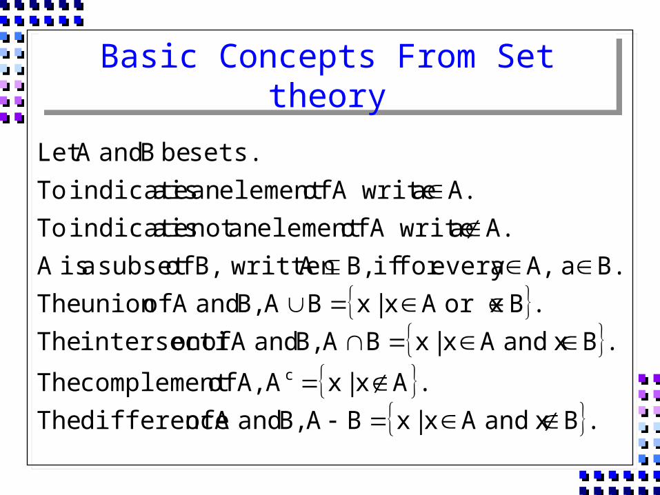
Basic Concepts From Set theory
.B xandA x|xBA B, andA of difference The
.Ax|xA A, of complement The
.B xandA x|xBA B, andA ofon intersecti The.Bor xA x|xBA B, andA ofunion The
.Ba A,aevery for if B,A written B, ofsubset a isA A.a A write ofelement an not is a indicate To
A.a A write ofelement an is a indicate To sets. be B andA Let
c
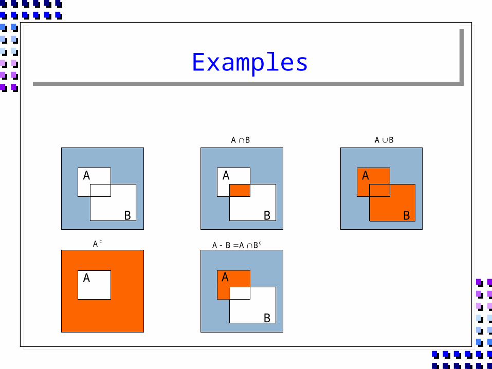
Examples
A
B
A
B
B
A
A
B
BA BA
cA cBABA
A
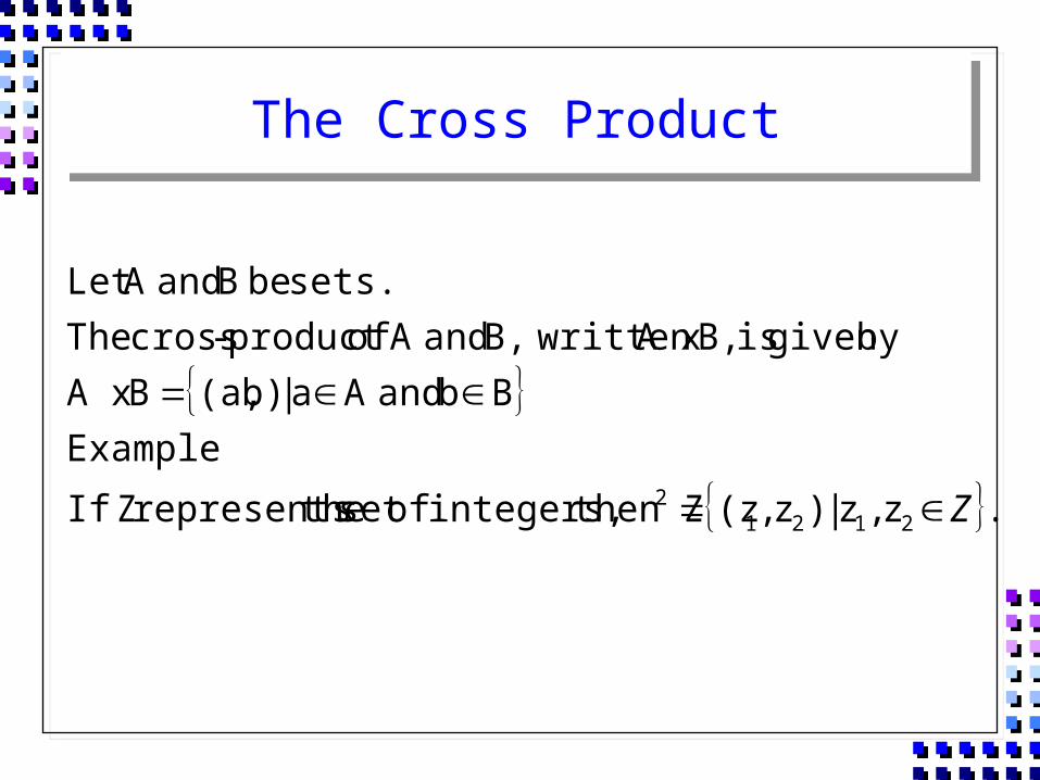
The Cross Product
.z ,z |)z ,(z then Zintegers, ofset therepresents ZIf
ExampleBb andA a |b) (a, BA x
bygiven is B,A x written B, andA ofproduct -cross Thesets. be B andA Let
21212 Z
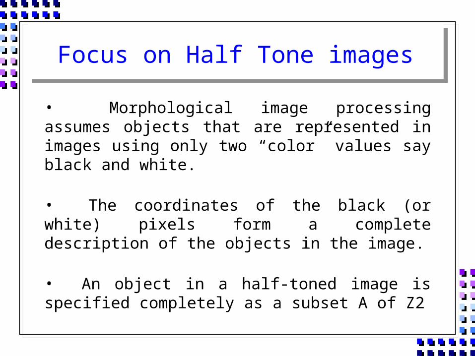
Focus on Half Tone images
• Morphological image processing assumes objects that are represented in images using only two “color” values say black and white.
• The coordinates of the black (or white) pixels form a complete description of the objects in the image.
• An object in a half-toned image is specified completely as a subset A of Z2
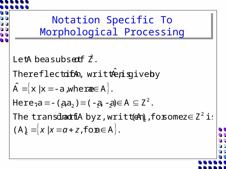
Notation Specific To Morphological Processing
.Aafor ,|(A)is Zz somefor ,(A) written z,by A ofon translatiThe
.ZA),-a(-a)a,-(aa- Here,
.Aa where-a,x|xA
bygiven is ,A written A, of reflection The
. Zofsubset a beA Let
z
2z
22121
2
zaxx
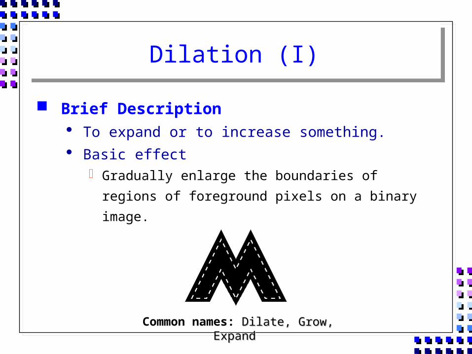
Dilation (I)
Brief Description To expand or to increase something. Basic effect
Gradually enlarge the boundaries of regions of foreground pixels on a binary image.
Common names: Dilate, Grow, ExpandDilate, Grow, Expand
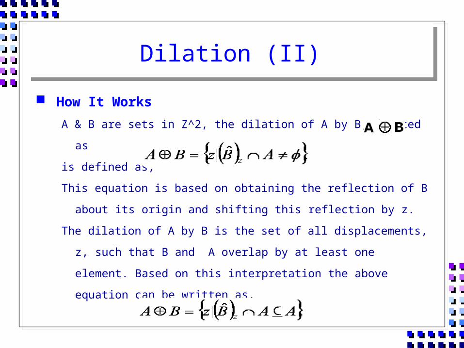
Dilation (II)
How It WorksA & B are sets in Z^2, the dilation of A by B, denoted as
is defined as,
This equation is based on obtaining the reflection of B about its
origin and shifting this reflection by z.
The dilation of A by B is the set of all displacements, z, such that B
and A overlap by at least one element. Based on this
interpretation the above equation can be written as,
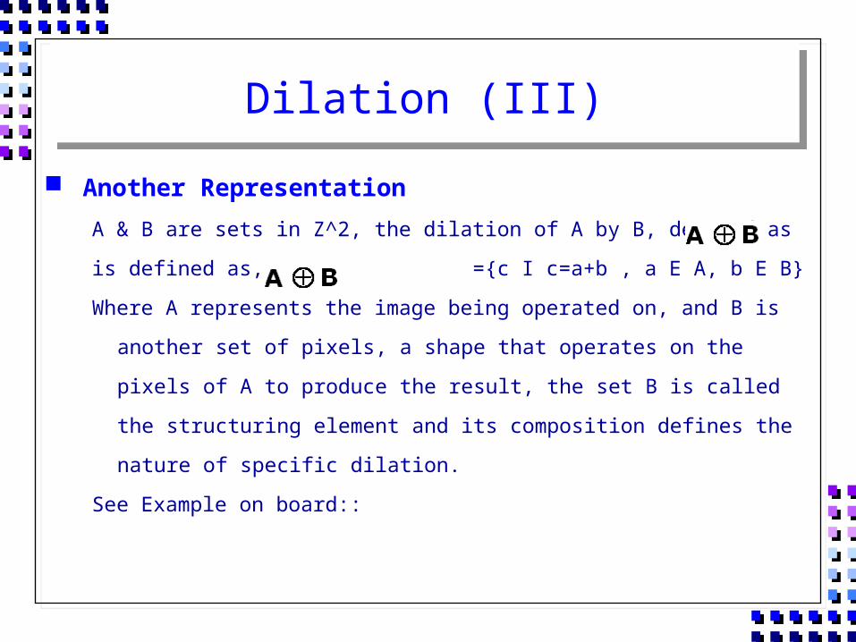
Dilation (III)
Another RepresentationA & B are sets in Z^2, the dilation of A by B, denoted as
is defined as, ={c I c=a+b , a E A, b E B}
Where A represents the image being operated on, and B is another set of
pixels, a shape that operates on the pixels of A to produce the result,
the set B is called the structuring element and its composition defines
the nature of specific dilation.
See Example on board::
Dilation (IV)
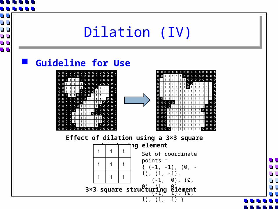
Guideline for Use
Effect of dilation using a 3×3 square structuring element
3×3 square structuring element
Set of coordinate points ={ (-1, -1), (0, -1), (1, -1), (-1, 0), (0, 0), (1, 0), (-1, 1), (0, 1), (1, 1) }
Dilation (V)
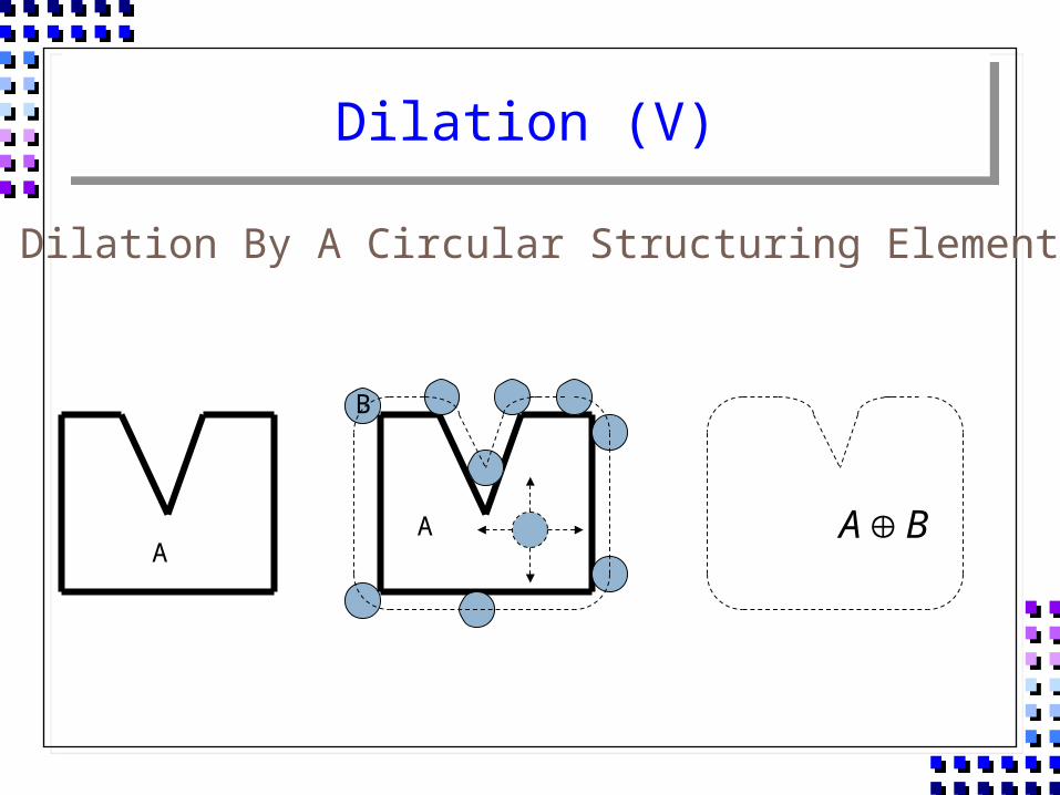
BAA
A
B
Dilation By A Circular Structuring Element
Dilation (VI)
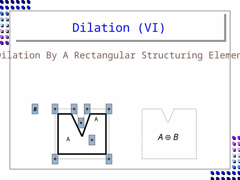
A
Dilation By A Rectangular Structuring Element
A BA
B
Dilation (VII)
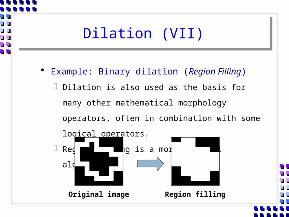
Example: Binary dilation (Region Filling)
Dilation is also used as the basis for many other mathematical
morphology operators, often in combination with some logical
operators.
Region filling is a morphological algorithm
Original image Region filling
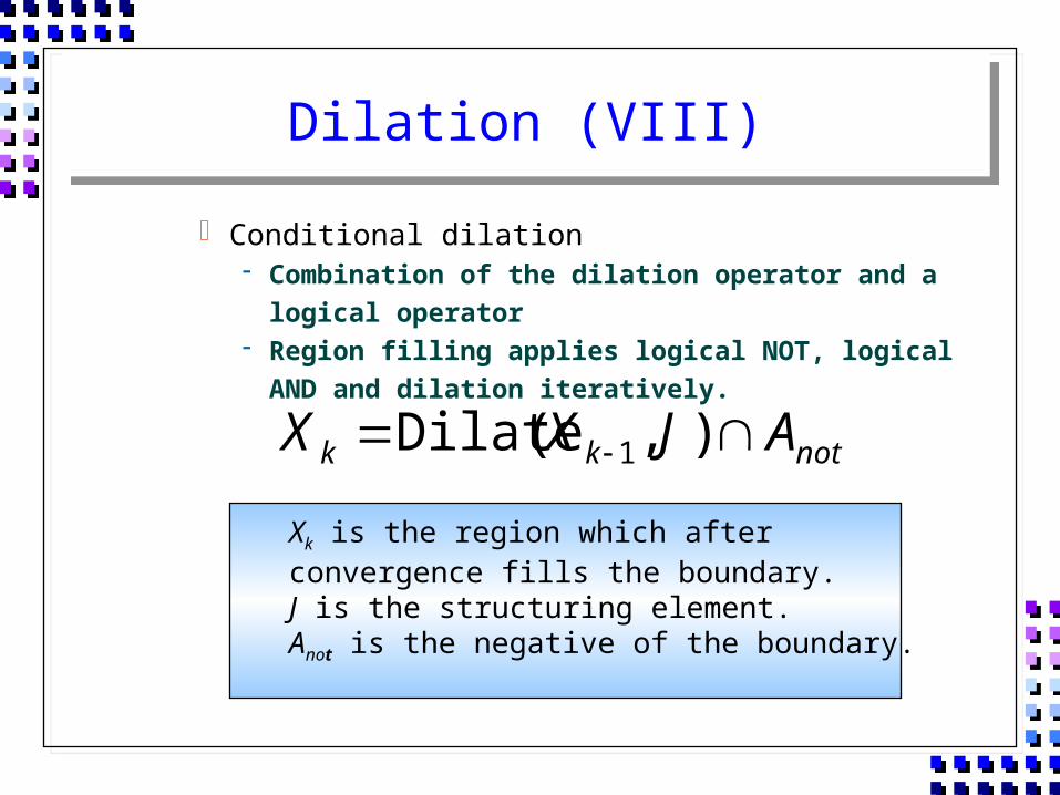
Dilation (VIII)
Conditional dilation Combination of the dilation operator and a logical operator Region filling applies logical NOT, logical AND and dilation
iteratively.
notkk AJXX ),(Dilate 1
Xk is the region which after convergence fills the boundary.J is the structuring element.Anot is the negative of the boundary.
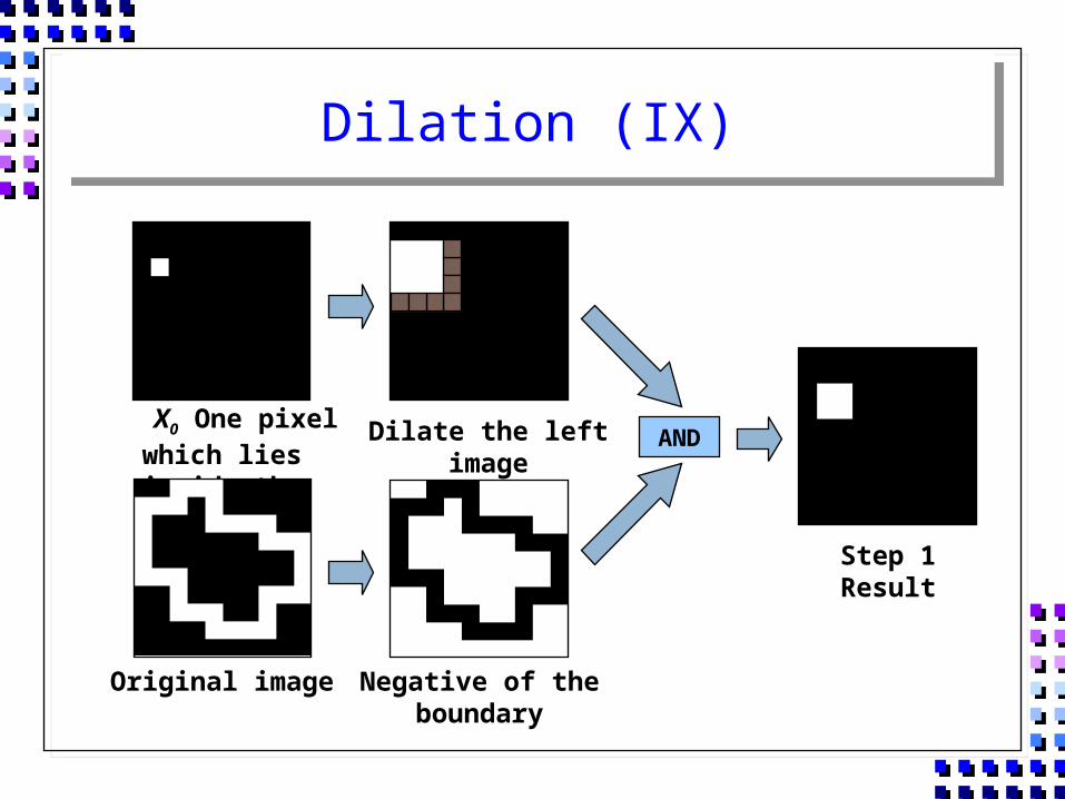
Dilation (IX)
X0 One pixel which lies inside the region
Dilate the left image
Negative of the boundary
Original image
AND
Step 1 Result
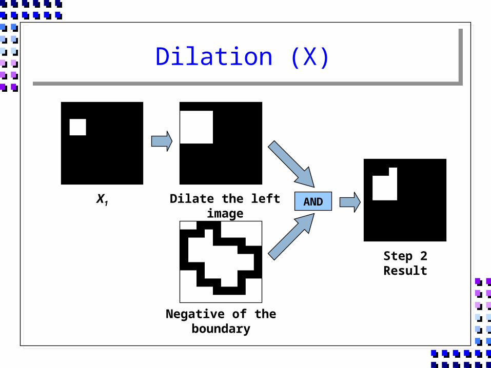
Dilation (X)
Dilate the left image
Negative of the boundary
AND
Step 2 Result
X1
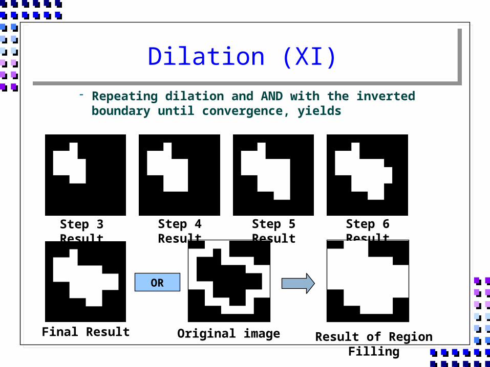
Dilation (XI) Repeating dilation and AND with the inverted boundary until
convergence, yields
Final Result
Step 3 Result Step 4 Result Step 5 Result Step 6 Result
OR
Original image Result of Region Filling
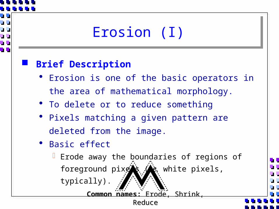
Erosion (I)
Brief Description Erosion is one of the basic operators in the area of
mathematical morphology. To delete or to reduce something Pixels matching a given pattern are deleted from the image. Basic effect
Erode away the boundaries of regions of foreground pixels (i.e. white pixels, typically).
Common names: Erode, Shrink, ReduceErode, Shrink, Reduce
Erosion (II)
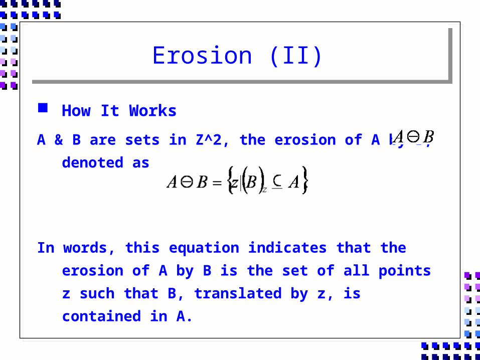
How It Works
A & B are sets in Z^2, the erosion of A by B, denoted as
In words, this equation indicates that the erosion of A by B is the set of all points z such that B, translated by z, is contained in A.
Erosion (III)
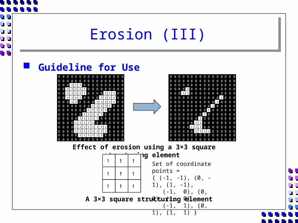
Guideline for Use
Effect of erosion using a 3×3 square structuring element
A 3×3 square structuring element
Set of coordinate points ={ (-1, -1), (0, -1), (1, -1), (-1, 0), (0, 0), (1, 0), (-1, 1), (0, 1), (1, 1) }
Erosion (IV)
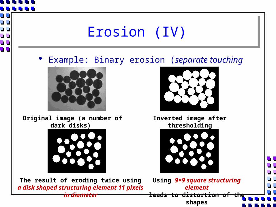
Example: Binary erosion (separate touching objects)
Original image (a number of dark disks) Inverted image after thresholding
The result of eroding twice using a disk shaped structuring element 11 pixels in diameter
Using 9×9 square structuring elementleads to distortion of the shapes
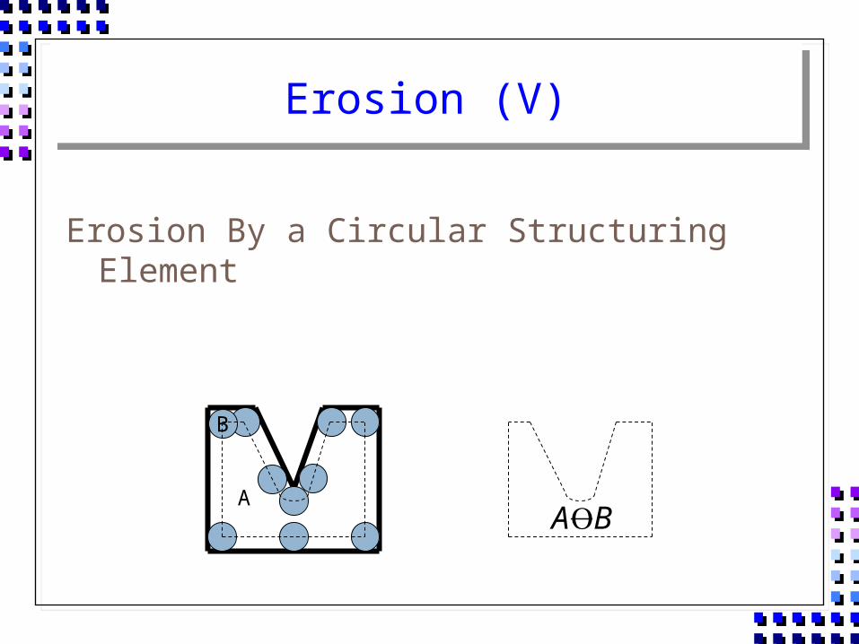
Erosion (V)
Erosion By a Circular Structuring Element
A
B
BA

Erosion (VI)
Erosion By a Rectangular Structuring Element
A
B
BA
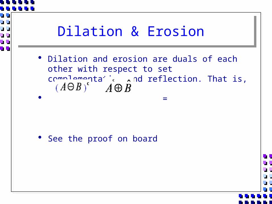
Dilation & Erosion
Dilation and erosion are duals of each other with respect to set complementation and reflection. That is,
=
See the proof on board
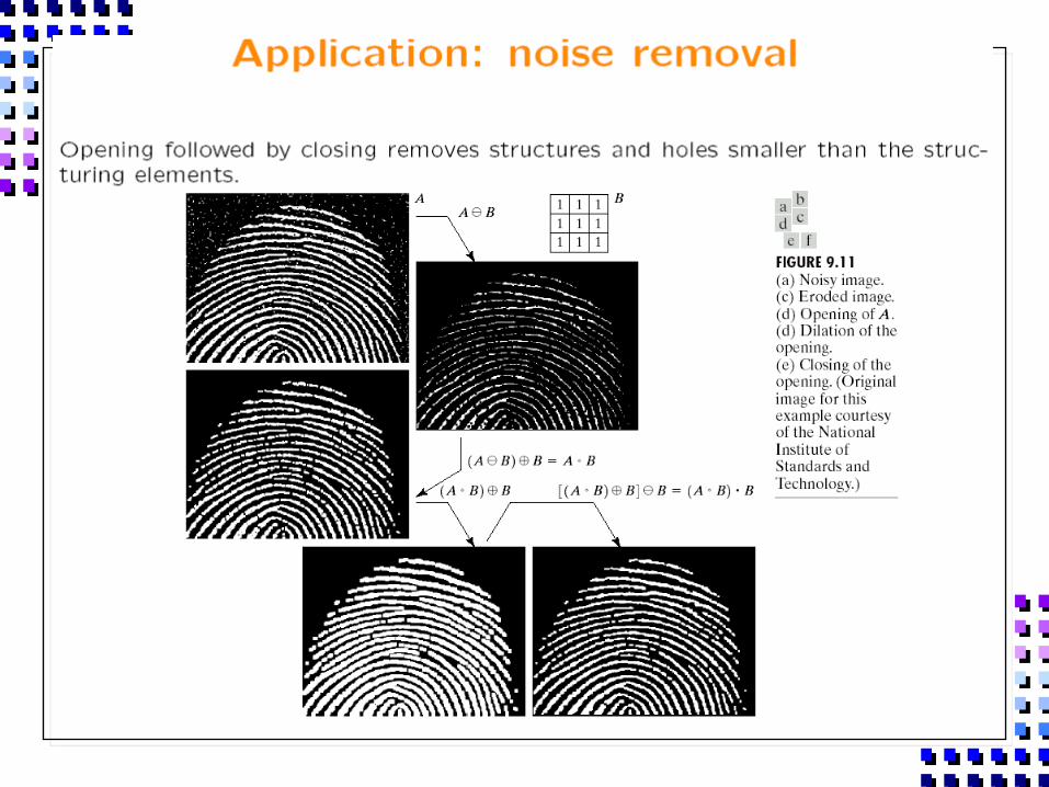
Opening (I)
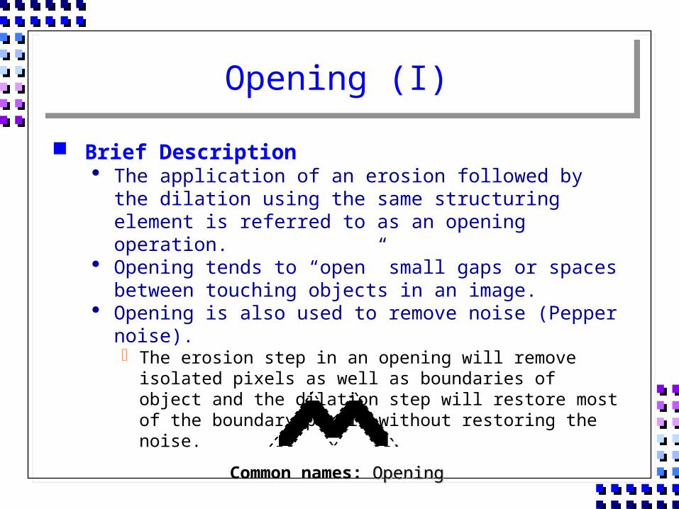
Brief Description The application of an erosion followed by the dilation using
the same structuring element is referred to as an opening operation.
Opening tends to “open” small gaps or spaces between touching objects in an image.
Opening is also used to remove noise (Pepper noise). The erosion step in an opening will remove isolated pixels as
well as boundaries of object and the dilation step will restore most of the boundary pixels without restoring the noise.
Common names: OpeningOpening
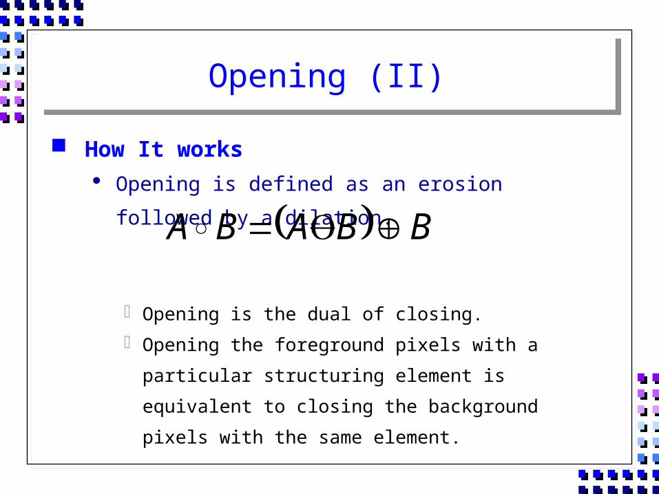
Opening (II)
How It works Opening is defined as an erosion followed by a dilation.
Opening is the dual of closing. Opening the foreground pixels with a particular structuring
element is equivalent to closing the background pixels with
the same element.
BBABA
Opening (III)
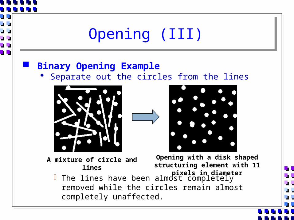
Binary Opening Example Separate out the circles from the lines
The lines have been almost completely removed while the circles remain almost completely unaffected.
A mixture of circle and lines Opening with a disk shaped structuring element with 11 pixels in diameter
Opening (IV)
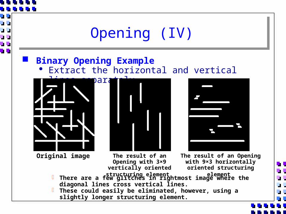
Binary Opening Example Extract the horizontal and vertical lines separately
There are a few glitches in rightmost image where the diagonal lines cross vertical lines.
These could easily be eliminated, however, using a slightly longer structuring element.
Original image The result of an Opening with 3×9 vertically oriented structuring element
The result of an Opening with 9×3 horizontally oriented structuring
element
Closing (I)
Brief Description Closing is similar to an opening except that the dilation is
performed first followed by the erosion using the same structuring element.
If an opening creates small gaps in an image, a closing will fill them, or “close” the gaps.
Closing is also used to remove white pixel noise (Salt noise).
Common names : ClosingClosing
Closing (II)
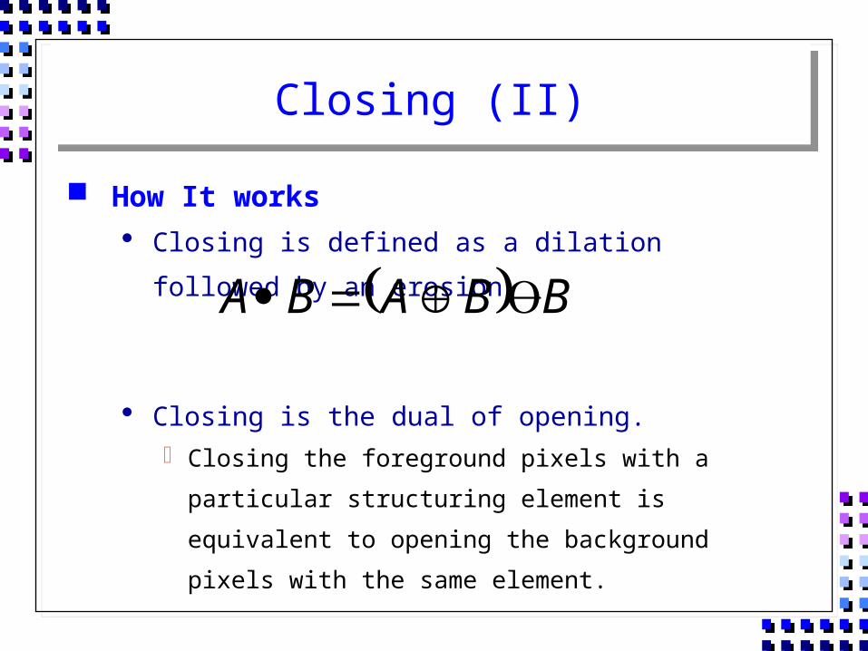
How It works Closing is defined as a dilation followed by an erosion.
Closing is the dual of opening. Closing the foreground pixels with a particular structuring
element is equivalent to opening the background pixels with
the same element.
BBABA
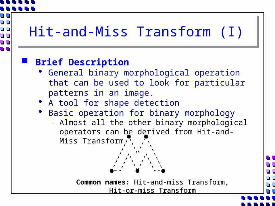
Hit-and-Miss Transform (I)
Brief Description General binary morphological operation that can be used to
look for particular patterns in an image. A tool for shape detection Basic operation for binary morphology
Almost all the other binary morphological operators can be derived from Hit-and-Miss Transform.
Common names: Hit-and-miss Transform, Hit-or-miss Hit-and-miss Transform, Hit-or-miss TransformTransform
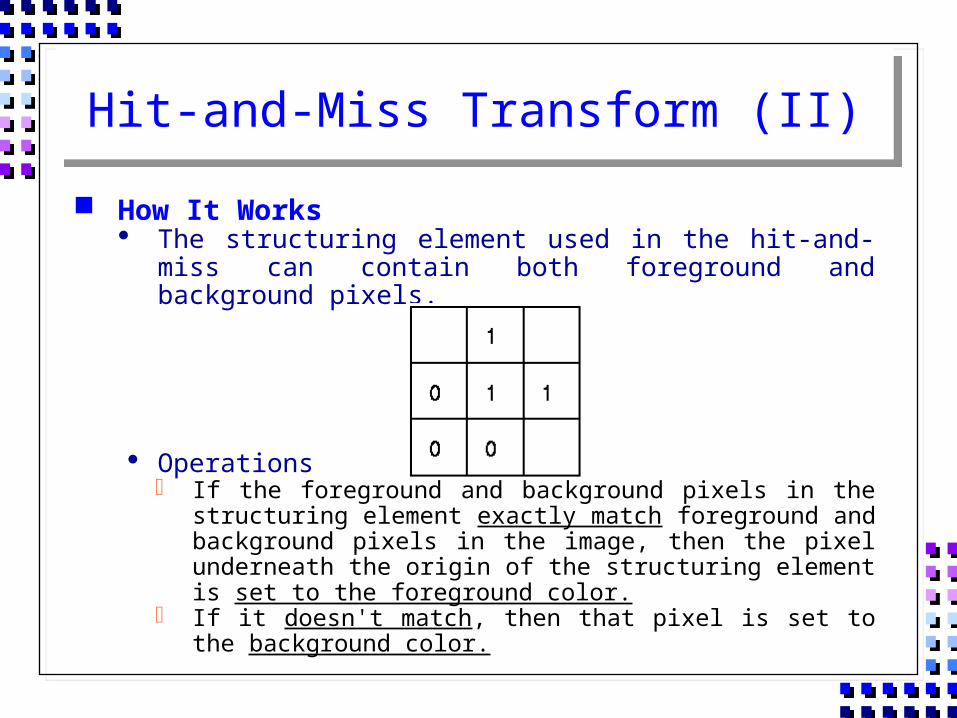
Hit-and-Miss Transform (II)
How It Works The structuring element used in the hit-and-miss can
contain both foreground and background pixels.
Operations If the foreground and background pixels in the structuring
element exactly match foreground and background pixels in the image, then the pixel underneath the origin of the structuring element is set to the foreground color.
If it doesn't match, then that pixel is set to the background color.
Hit-and-Miss Transform (III)
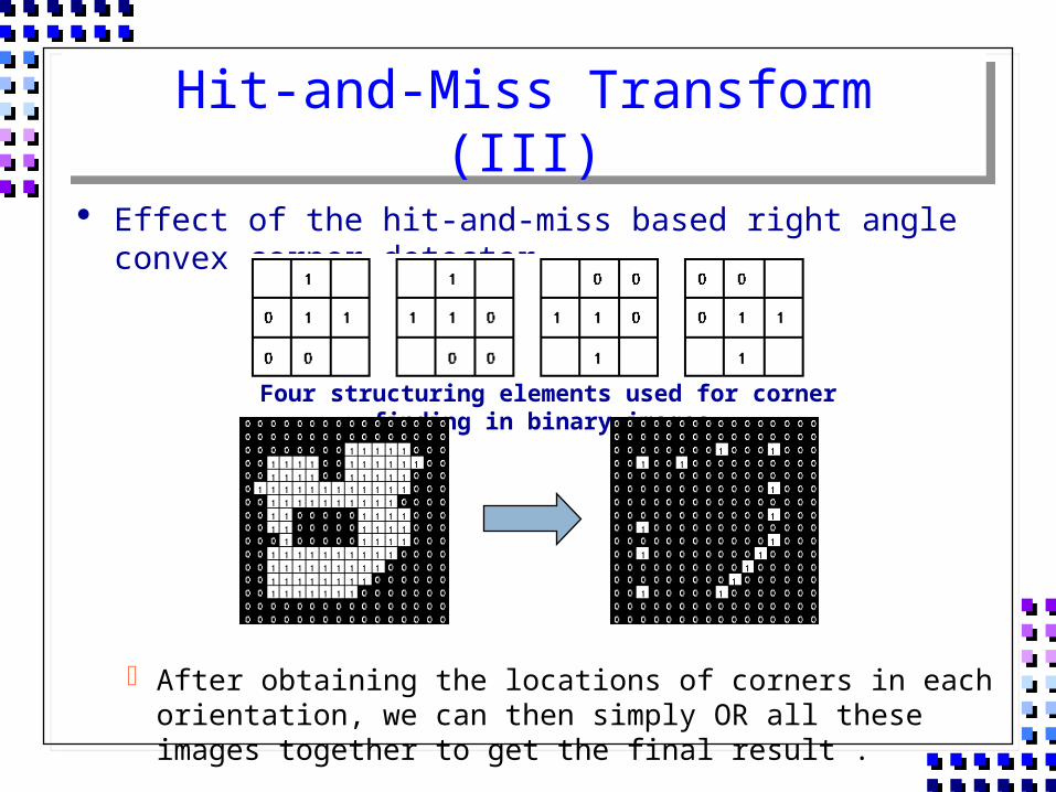
Effect of the hit-and-miss based right angle convex corner detector
After obtaining the locations of corners in each orientation, we can then simply OR all these images together to get the final result .
Four structuring elements used for corner finding in binary images
Hit-and-Miss Transform (IV)
Guidelines for Use The hit-and-miss transform is used to look for occurrences
of particular binary patterns. It can be used to look for several patterns.
Simply by running successive transforms using different structuring elements, and then ORing the results together.
The operations of erosion, dilation, opening, closing, thinning and thickening can all be derived from the hit-and-miss transform in conjunction with simple set operations.
Hit-and-Miss Transform (V)
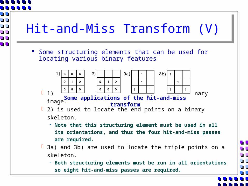
Some structuring elements that can be used for locating various binary features
1) is used to locate isolated points in a binary image. 2) is used to locate the end points on a binary skeleton.
Note that this structuring element must be used in all its orientations, and thus the four hit-and-miss passes are required.
3a) and 3b) are used to locate the triple points on a skeleton. Both structuring elements must be run in all orientations so
eight hit-and-miss passes are required.
Some applications of the hit-and-miss transform
Hit-and-Miss Transform (VI)
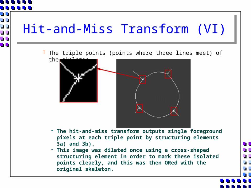
The triple points (points where three lines meet) of the skeleton
The hit-and-miss transform outputs single foreground pixels at each triple point by structuring elements 3a) and 3b).
This image was dilated once using a cross-shaped structuring element in order to mark these isolated points clearly, and this was then ORed with the original skeleton.

Hit-and-Miss Transform (VII)
The end points of the skeleton
The hit-and-miss transform outputs single foreground pixels at each end point by structuring element 2).
This image was dilated once using a square-shaped structuring element, and this was then ORed with the original skeleton.
Thinning (I)
Brief Description Remove selected foreground pixels from binary images,
somewhat like erosion or opening. Thinning is normally applied only to binary images.
Common names: ThinningThinning
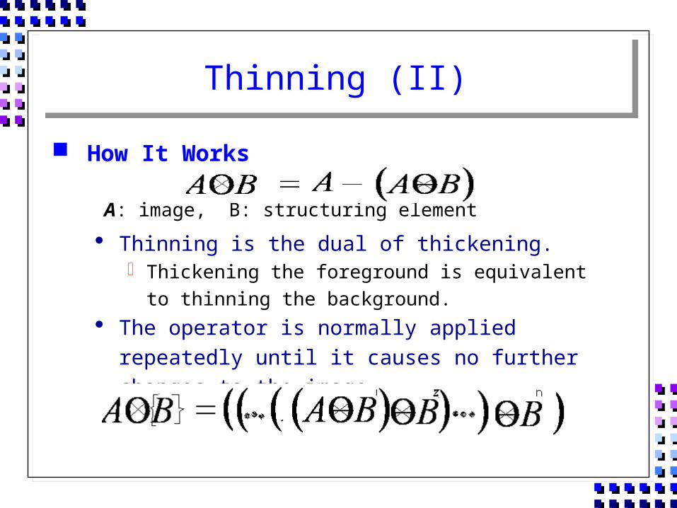
Thinning (II)
How It Works
Thinning is the dual of thickening. Thickening the foreground is equivalent to thinning the
background. The operator is normally applied repeatedly until it causes
no further changes to the image.
A: image, B: structuring element
Thinning (III)
Operation The thinning operation is calculated by translating the origin
of the structuring element to each possible pixel position in the image, and at each such position comparing it with the underlying image pixels.
If the foreground and background pixels in the structuring element exactly match foreground and background pixels in the image, then the image pixel underneath the origin of the structuring element is set to background (zero).
Otherwise, it is left unchanged.
Thinning (IV)
Thinning (V)
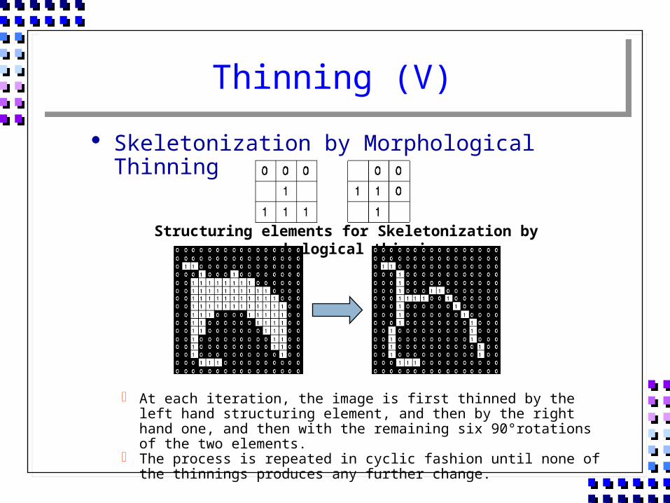
Skeletonization by Morphological Thinning
At each iteration, the image is first thinned by the left hand structuring element, and then by the right hand one, and then with the remaining six 90°rotations of the two elements.
The process is repeated in cyclic fashion until none of the thinnings produces any further change.
Structuring elements for Skeletonization by morphological thinning
Thinning (VI)
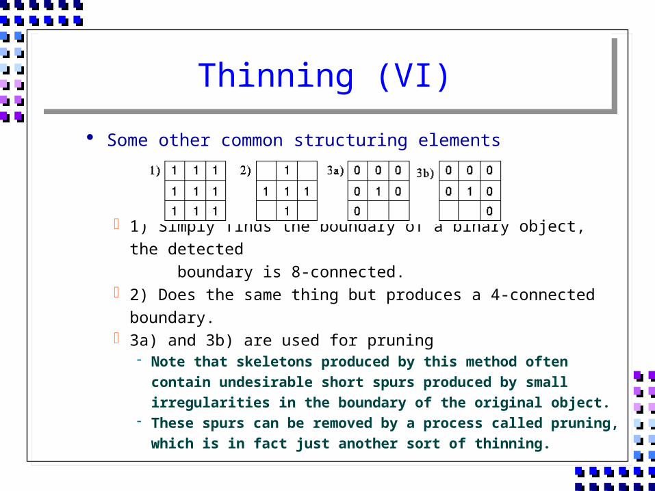
Some other common structuring elements
1) Simply finds the boundary of a binary object, the detected boundary is 8-connected.
2) Does the same thing but produces a 4-connected boundary. 3a) and 3b) are used for pruning
Note that skeletons produced by this method often contain undesirable short spurs produced by small irregularities in the boundary of the original object.
These spurs can be removed by a process called pruning, which is in fact just another sort of thinning.
Thinning (VII)
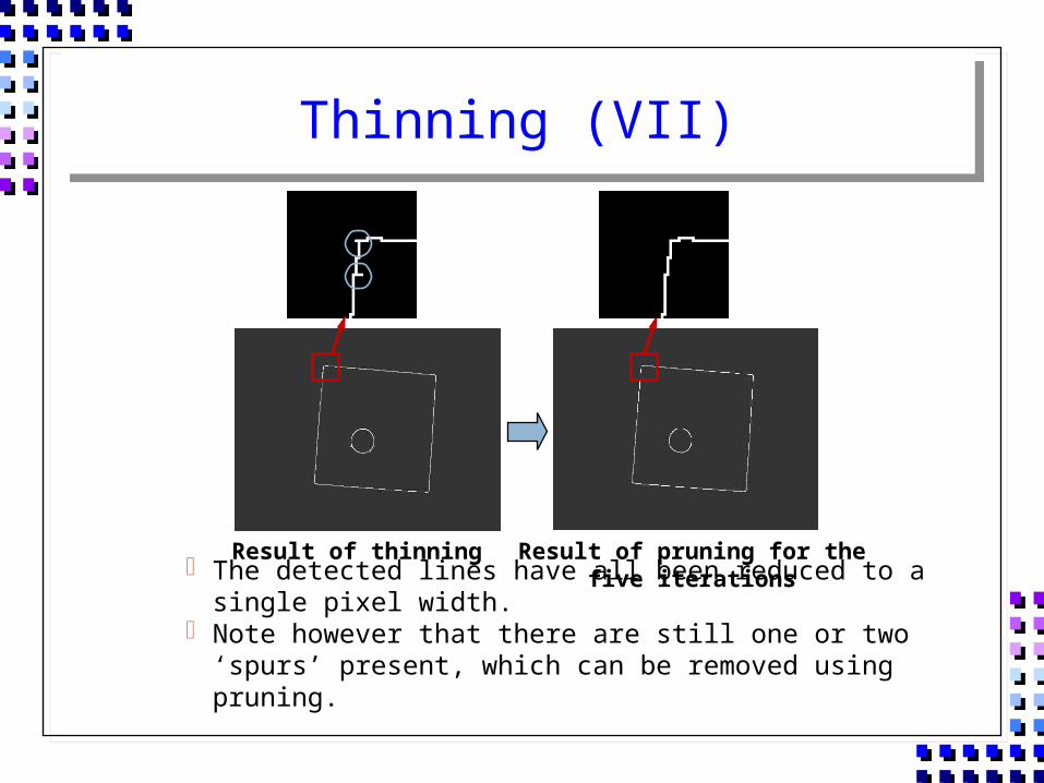
The detected lines have all been reduced to a single pixel width. Note however that there are still one or two ‘spurs’ present,
which can be removed using pruning.
Result of thinning Result of pruning for the five iterations
Thinning (VIII)
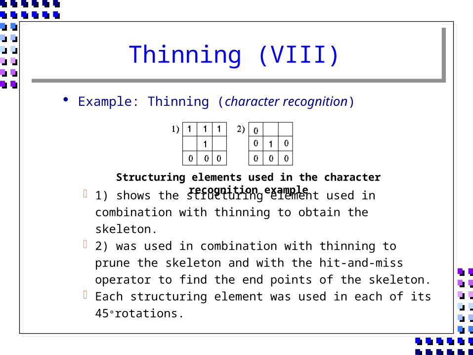
Example: Thinning (character recognition)
1) shows the structuring element used in combination with thinning to obtain the skeleton.
2) was used in combination with thinning to prune the skeleton and with the hit-and-miss operator to find the end points of the skeleton.
Each structuring element was used in each of its 45°rotations.
Structuring elements used in the character recognition example
Thinning (IX)
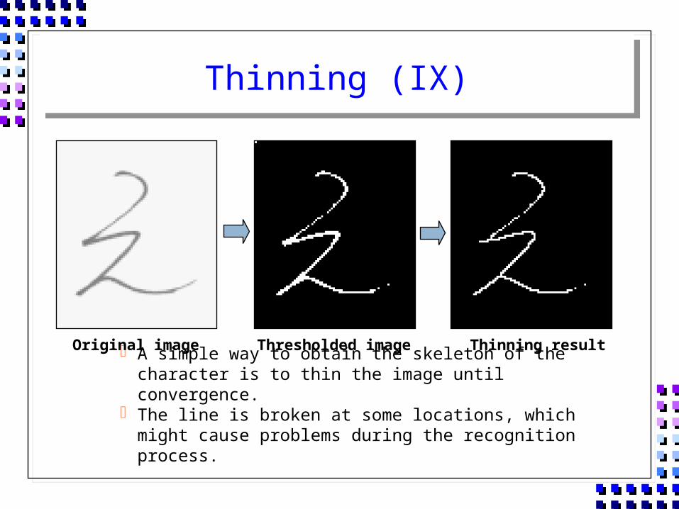
A simple way to obtain the skeleton of the character is to thin the image until convergence.
The line is broken at some locations, which might cause problems during the recognition process.
Original image Thresholded image Thinning result
Thinning (X)
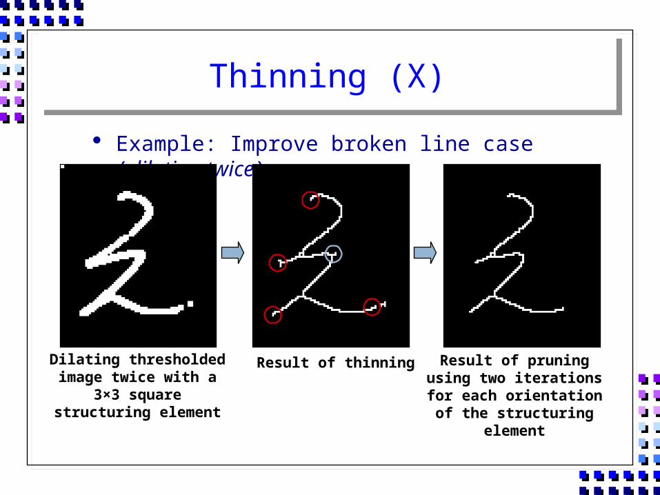
Example: Improve broken line case (dilating twice)
Dilating thresholded image twice with a 3×3 square
structuring element
Result of thinning Result of pruning using two iterations for each orientation
of the structuring element
Thinning (XI)
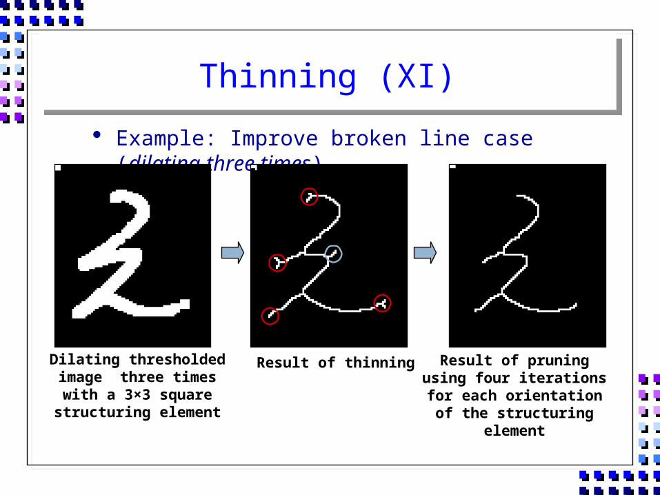
Example: Improve broken line case (dilating three times)
Dilating thresholded image three times with a 3×3 square
structuring element
Result of thinning Result of pruning using four iterations for each orientation
of the structuring element
Thickening (I)
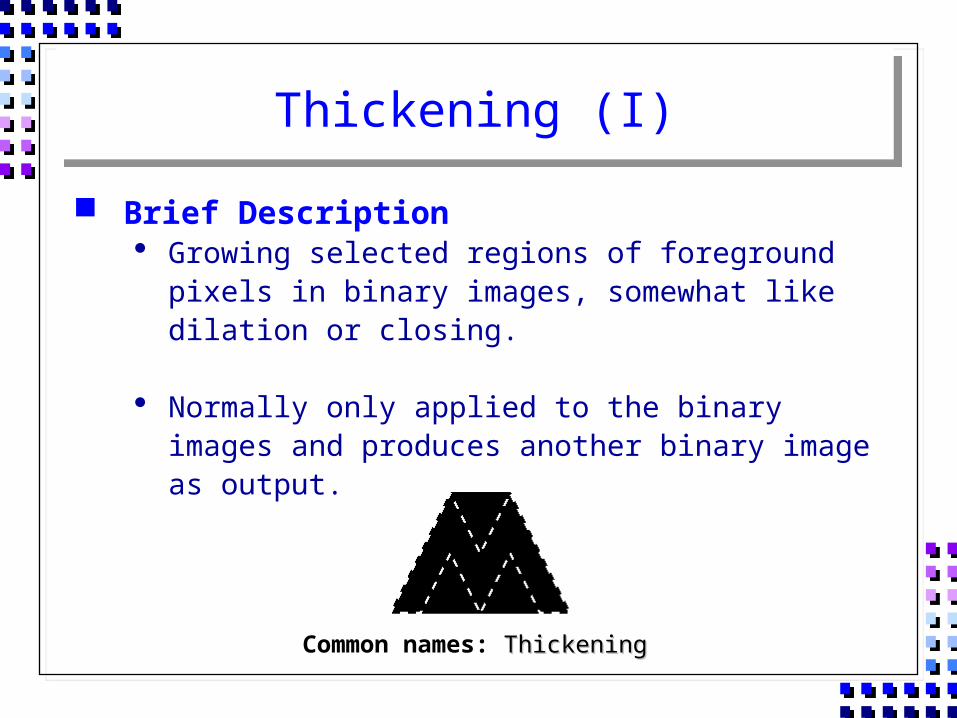
Brief Description Growing selected regions of foreground pixels in binary
images, somewhat like dilation or closing.
Normally only applied to the binary images and produces another binary image as output.
Common names: ThickeningThickening
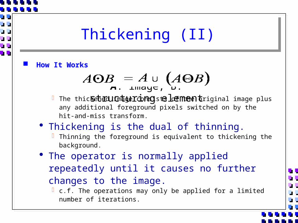
Thickening (II)
How It Works
The thickened image consists of the original image plus any additional foreground pixels switched on by the hit-and-miss transform.
Thickening is the dual of thinning. Thinning the foreground is equivalent to thickening the background.
The operator is normally applied repeatedly until it causes no further changes to the image. c.f. The operations may only be applied for a limited number of
iterations.
A: image, B: structuring element
Thickening (III)
Operation The thickening operation is calculated by translating the
origin of the structuring element to each possible pixel position in the image, and at each position comparing it with the underlying image pixels.
If the foreground and background pixels in the structuring element exactly match foreground and background pixels in the image, then the image pixel underneath the origin of the structuring element is set to foreground (one).
Otherwise, it is left unchanged.
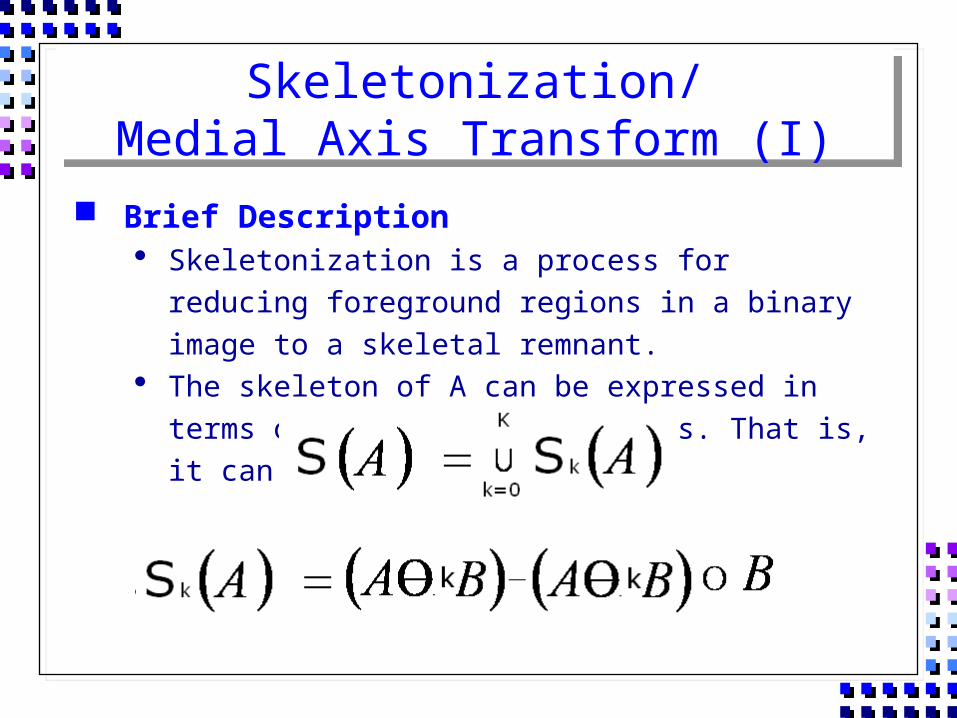
Skeletonization/Medial Axis Transform (I)
Brief Description Skeletonization is a process for reducing foreground regions
in a binary image to a skeletal remnant. The skeleton of A can be expressed in terms of erosions and
openings. That is, it can be shown as
With
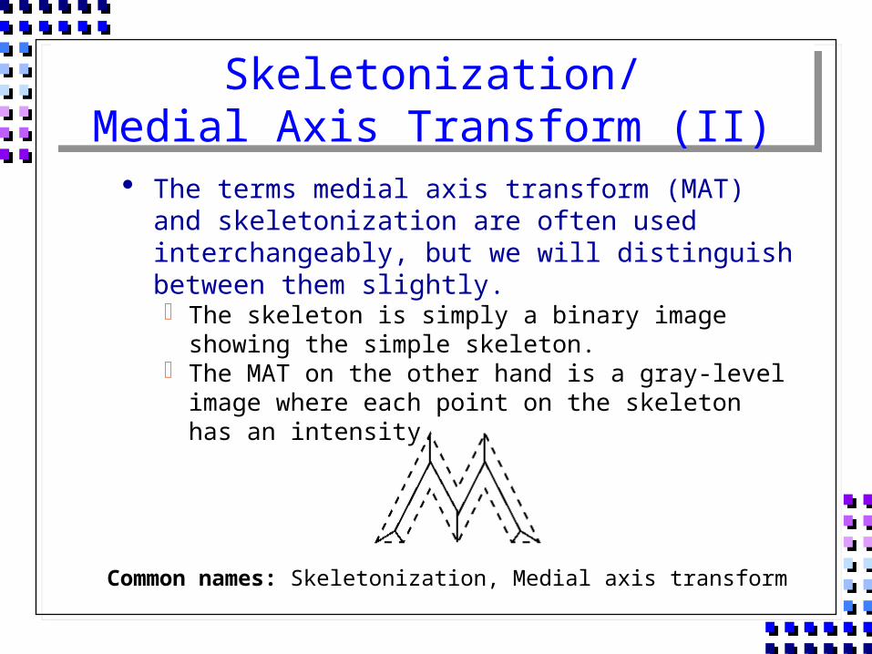
Skeletonization/Medial Axis Transform (II)
The terms medial axis transform (MAT) and skeletonization are often used interchangeably, but we will distinguish between them slightly. The skeleton is simply a binary image showing the simple
skeleton. The MAT on the other hand is a gray-level image where each
point on the skeleton has an intensity.
Common names: Skeletonization, Medial axis transform
Skeletonization/Medial Axis Transform (III)
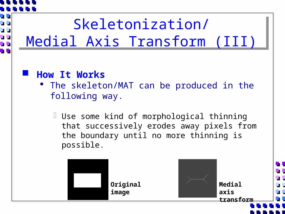
How It Works The skeleton/MAT can be produced in the following way.
Use some kind of morphological thinning that successively erodes away pixels from the boundary until no more thinning is possible.
Original image
Medial axis transform
Skeletonization/Medial Axis Transform (IV)
Guide Lines for Use
The skeleton is useful because it provides a simple and compact representation of a shape that preserves many of the topological and size characteristics of the original shape.
Get a rough idea of the length of a shape. Distinguish many qualitatively different shapes from one
another on the basis of how many ‘triple points’. Triple points: points where at least three branches of the
skeleton meet
Skeletonization/Medial Axis Transform (V)
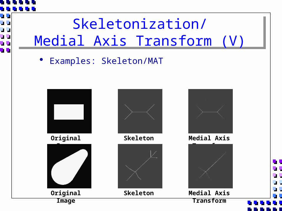
Examples: Skeleton/MAT
Original Image Skeleton Medial Axis Transform
Original Image Skeleton Medial Axis Transform
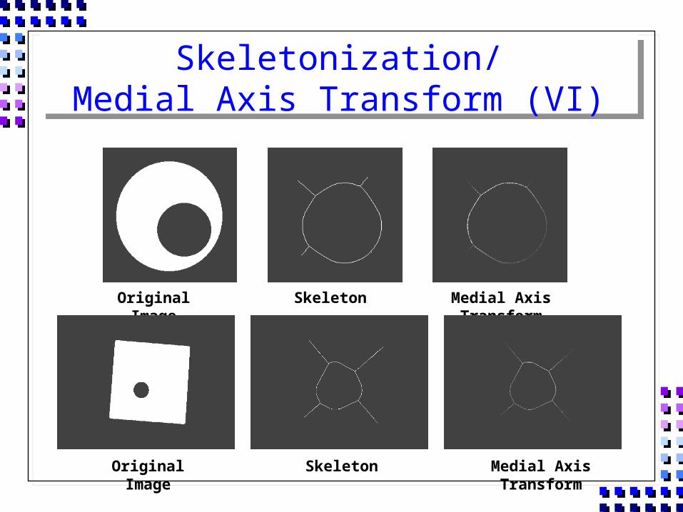
Skeletonization/Medial Axis Transform (VI)
Original Image Skeleton Medial Axis Transform
Original Image Skeleton Medial Axis Transform
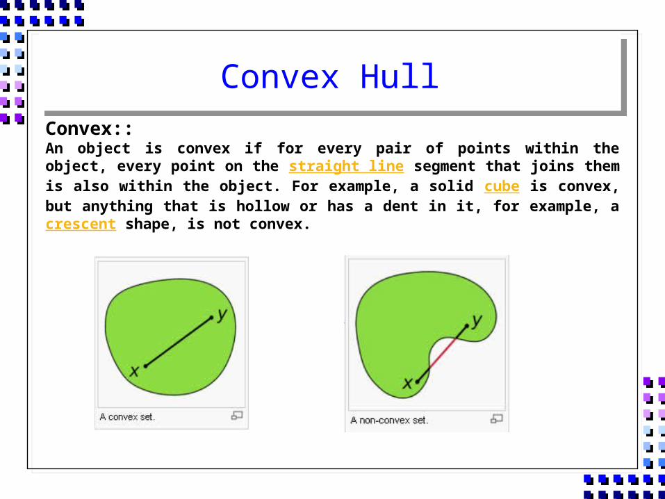
Convex HullConvex::An object is convex if for every pair of points within the object, every point on the straight line segment that joins them is also within the object. For example, a solid cube is convex, but anything that is hollow or has a dent in it, for example, a crescent shape, is not convex.
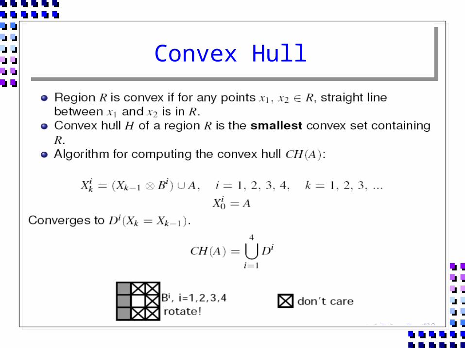
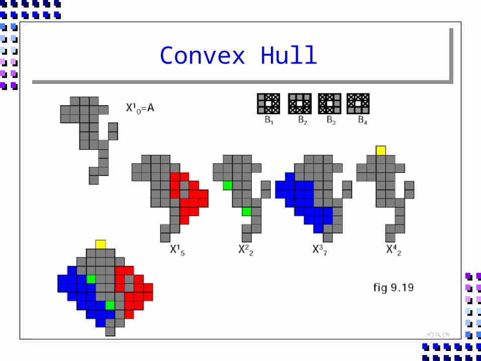
Convex Hull
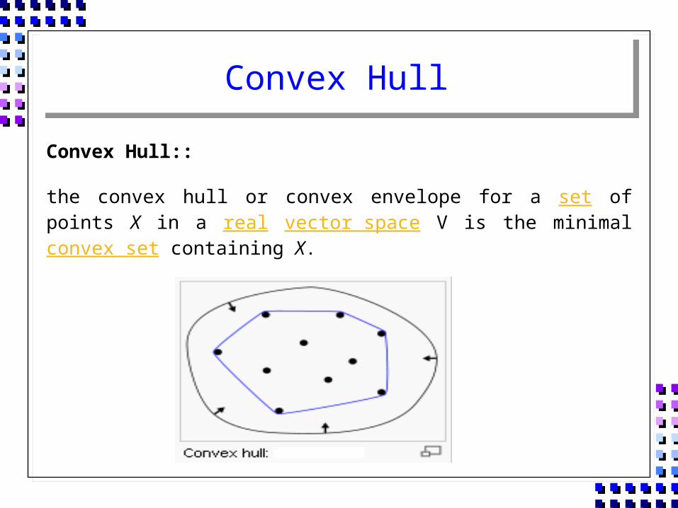
Convex Hull::
the convex hull or convex envelope for a set of points X in a real vector space V is the minimal convex set containing X.
Convex Hull
Convex Hull
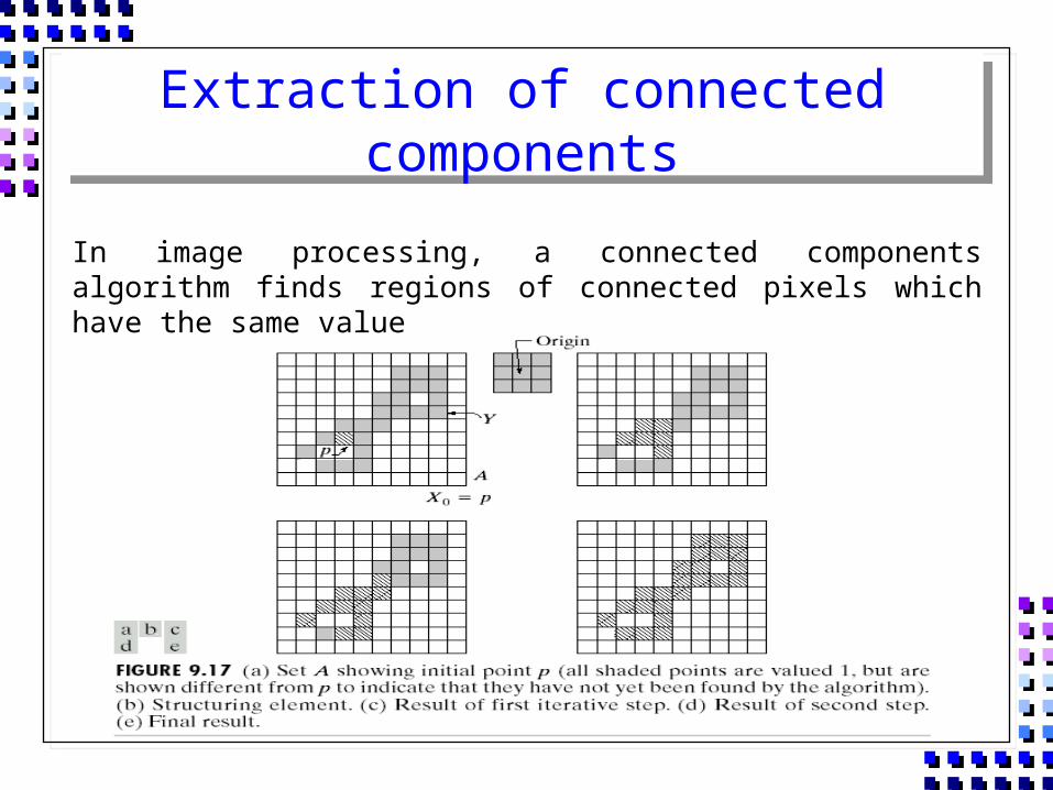
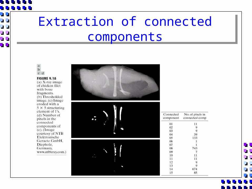
Extraction of connected components
In image processing, a connected components algorithm finds regions of connected pixels which have the same value
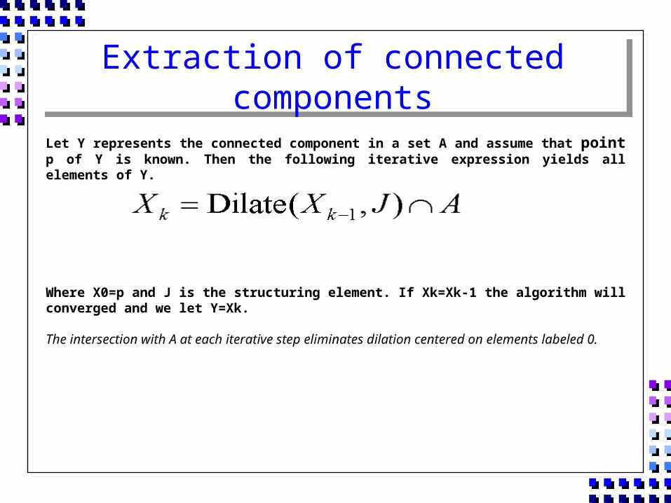
Extraction of connected components
Let Y represents the connected component in a set A and assume that point p of Y is known. Then the following iterative expression yields all elements of Y.
Where X0=p and J is the structuring element. If Xk=Xk-1 the algorithm will converged and we let Y=Xk.
The intersection with A at each iterative step eliminates dilation centered on elements labeled 0.
Extraction of connected components
QUIZ
5 10 5 10
5 10 5 10
5 10 5 10
20 15 20 5
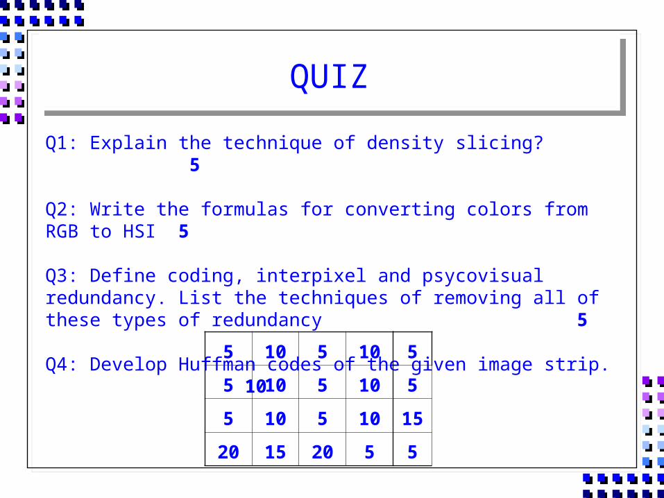
Q1: Explain the technique of density slicing? 5
Q2: Write the formulas for converting colors from RGB to HSI 5
Q3: Define coding, interpixel and psycovisual redundancy. List the techniques of removing all of these types of redundancy
5
Q4: Develop Huffman codes of the given image strip.10 5
5
15
5