computational materials scienceor.nsfc.gov.cn/bitstream/00001903-5/174810/1/... · ·...
TRANSCRIPT
Computational Materials Science 111 (2016) 148–156
Contents lists available at ScienceDirect
Computational Materials Science
journal homepage: www.elsevier .com/locate /commatsci
Microscopic damage mechanisms of fibre reinforced compositelaminates subjected to low velocity impact
http://dx.doi.org/10.1016/j.commatsci.2015.09.0390927-0256/� 2015 Elsevier B.V. All rights reserved.
⇑ Corresponding author. Tel./fax: +86 411 84706213.E-mail address: [email protected] (L. Yang).
Lei Yang ⇑, Zhanjun Wu, Dongyue Gao, Xin LiuState Key Laboratory of Structural Analysis for Industrial Equipment, School of Aeronautics and Astronautics, Dalian University of Technology, Dalian 116024, PR China
a r t i c l e i n f o
Article history:Received 11 July 2015Received in revised form 14 September2015Accepted 15 September 2015
Keywords:Fibre reinforced compositeLow velocity impactDamage mechanismsMultiscale modellingFinite element method (FEM)
a b s t r a c t
This paper presents an integrated multiscale model for the simulation of fibre reinforced polymericcomposite laminate subjected to low velocity impact. The multiscale model is based on the embeddedcell method, with detailed microstructure embedded into the macro laminate beneath the impact point,and a transition zone is introduced to link these two scales. Damage model is considered for the fibresand plastic behaviour for the matrix, and cohesive elements are used for the simulation of interfacedelamination. Both unidirectional and layup embedded cells are considered in the simulation so as toreveal the impact damage mechanisms from monolayer to layup levels. The simulation results indicatematrix cracking is the first damage form which occurs at the bottom of the laminate, and thendelamination is induced when the matrix crack propagates to the interface, followed by fibre pull-outand fibre breakage. The simulation results are compared with available experimental results from liter-atures, with good agreements achieved between them on the damage morphologies. Thus the ability ofthe presented multiscale model to reveal the damage mechanisms of composite laminate under lowvelocity impact is validated.
� 2015 Elsevier B.V. All rights reserved.
1. Introduction
Low velocity impact is considered as one of the most dangerousdamage sources of fibre reinforced polymeric composite struc-tures, as it can cause significant reduction on the stiffness andstrength of the structures, but the damage usually cannot bedetected from the surface of the component, thus causing greatsecurity risks to the structures. For this reason, there have been agreat number of researches on the low velocity impact damageof composites by both experimental and numerical approaches inthe last decades [1–10]. Recently, with the rapid development ofcomputer power and finite element method (FEM), numerical sim-ulation has gradually become an important method for theresearch of low velocity impact of composites.
During the low velocity impact process of composite laminates,various damage modes may occur simultaneously, including fibrebreakage, matrix cracking, matrix crush and delamination. To takeinto account all these damage forms, the combination of contin-uum damage mechanics (CDM) and cohesive zone model (CZM)is often used to simulate the low velocity impact damage of lami-nates, and has achieved great success in the prediction of damage
forms and damage extent of composite laminates subjected to lowvelocity impact [11]. However, these methods are based on themacro-scale, thus cannot capture the damage mechanisms at themicro-scale, including fibre/matrix debonding, fibre pull-out, andhighly localized plastic deformation of the resin. On the otherhand, though micro-mechanical simulations can capture theseeffects, they require high resolution mesh and significant computa-tional power. Therefore, modelling of low velocity impact onto acomposite at the micro-scale, capturing all these effects is cur-rently and in the near future not feasible [12]. To overcome thiscontradiction between simulation accuracy and computationalcost, an alternative is to use the multiscale method taking intoaccount the mechanical response at several length scales [13].
The wide range of multiscale methods can be broadly classedinto two groups: hierarchical and concurrent multiscale methods.In hierarchical methods [14,15], a ‘‘one-way” bottom-up couplingis established where information is passed from lower to higherscales. As a consequence, such methods are efficient in determin-ing the macroscopic stiffness and strength of composites, butmay have a limited predictive capability for problems involvingdamage [16]. Concurrent multiscale methods [17,18] introducethe concept of scale embedding instead of scale transition, thus dif-ferent scales coexist in adjacent regions of the model. This is espe-cially useful for investigating impact events of composite
L. Yang et al. / Computational Materials Science 111 (2016) 148–156 149
laminates, since large deformations and damage are restricted to alocal region. Thus only the damage zone requires a high resolutionmesh, so that high simulation accuracy can be achieved withaffordable computational cost.
Many researchers [19–22] have carried out multiscale numeri-cal simulation of the damage behaviour of composite materials.However, all these studies were aimed at the quasi-static damagesimulation of composites, thus are not applicable to the simulationof low velocity impact. Souza et al. [23] presented a multiscalemodel for predicting damage evolution in composites due toimpact loading. Yet, it was not a concurrent multiscale model asinformation transfer was required between the global and localscale. Ha-Minh et al. [24] developed a numerical multiscale modelfor textile woven fabric against ballistic impact, but the scale waslimited to the mesoscopic level (yarns). May et al. [12] proposedan adaptive multiscale methodology for modelling compositesunder high velocity impact. But the microscopic structure wasnot explicitly included in the model and the damage mechanismswere not discussed. So far, to the best of the authors’ knowledge,there is not any research on the multiscale modelling and simula-tion of fibre reinforced composites subjected to low velocityimpact.
In this paper, an integrated multiscale model based on finiteelement method will be developed for the simulation of fibre rein-forced polymeric composite laminates subjected to low velocityimpact. The micromechanical damage process of the compositeswill be discussed and compared with available experimentalresults, thus to provide a clear understanding of the micromechan-ical damage mechanisms of fibre reinforced composite laminatesunder low velocity impact.
2. Multiscale model
In order to simulate the micromechanical damage behaviour ofcomposite laminates under low velocity impact with affordablecomputational cost, an integrated multiscale model is requiredthat contains both macro boundary conditions and microstructuresof the damage zone. As the size of laminate is usually larger thanthe order of millimeter (length and width �101–102 mm, thickness�100 mm), while the dimension of constitutes is in the order ofmicron (fibre diameter �100 lm), it is impractical to use consistentmesh discretization for the whole model. Thus there should be aproper connection between these two scales. This can be accom-plished by the embedded cell model [25], in which the full detailsof the composite microstructure are resolved in the region of inter-est, while the remaining part is represented as homogeneousmaterial whose behaviour is given by any suitable homogenizationmodel.
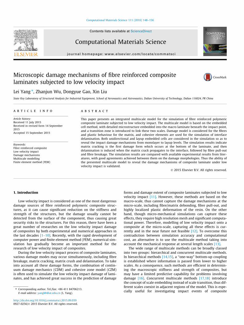
For a composite laminate subjected to low velocity impact, it iswell known that the region at the bottom of the laminate justunder the impactor is most prone to suffer damage. Therefore, thisarea is selected as the region of interest where embedded cell withdetailed microstructure is inserted, as shown in Fig. 1. The
Fig. 1. Schematic illustration of the integrated multiscale model for fibre reinforcedcomposite laminates under low velocity impact.
modelling and simulation platform of this paper is the FEM pack-age ABAQUS/Explicit, and tie constraint [26] provided in ABAQUSis used to accomplish the connection between the macro laminateand the micro embedded cell. However, as the tie constraint is anumerical connection technology, numerical error will be causedat the vicinity of the connecting surface. To avoid this issue, a tran-sition zone is introduced between the macro laminate and themicro embedded cell, which will be further depicted in the follow-ing. The impactor is modelled as a hemispherical rigid body withan initial velocity (1 m/s) in the vertical direction. The surface-to-surface contact algorithm is employed to simulate the contactbetween the impactor and the laminate, using a penalty formula-tion to take into account the effect of friction.
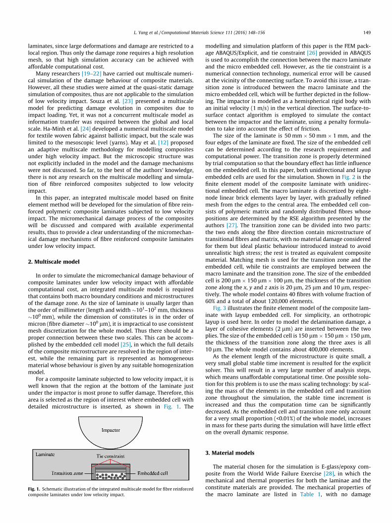
The size of the laminate is 50 mm � 50 mm � 1 mm, and thefour edges of the laminate are fixed. The size of the embedded cellcan be determined according to the research requirement andcomputational power. The transition zone is properly determinedby trial computation so that the boundary effect has little influenceon the embedded cell. In this paper, both unidirectional and layupembedded cells are used for the simulation. Shown in Fig. 2 is thefinite element model of the composite laminate with unidirec-tional embedded cell. The macro laminate is discretized by eight-node linear brick elements layer by layer, with gradually refinedmesh from the edges to the central area. The embedded cell con-sists of polymeric matrix and randomly distributed fibres whosepositions are determined by the RSE algorithm presented by theauthors [27]. The transition zone can be divided into two parts:the two ends along the fibre direction contain microstructure oftransitional fibres and matrix, with no material damage consideredfor them but ideal plastic behaviour introduced instead to avoidunrealistic high stress; the rest is treated as equivalent compositematerial. Matching mesh is used for the transition zone and theembedded cell, while tie constraints are employed between themacro laminate and the transition zone. The size of the embeddedcell is 200 lm � 150 lm � 100 lm, the thickness of the transitionzone along the x, y and z axis is 20 lm, 25 lm and 10 lm, respec-tively. The whole model contains 40 fibres with volume fraction of60% and a total of about 120,000 elements.
Fig. 3 illustrates the finite element model of the composite lam-inate with layup embedded cell. For simplicity, an orthotropiclayup is used here. In order to model the delamination damage, alayer of cohesive elements (2 lm) are inserted between the twoplies. The size of the embedded cell is 150 lm � 150 lm � 150 lm,the thickness of the transition zone along the three axes is all10 lm. The whole model contains about 400,000 elements.
As the element length of the microstructure is quite small, avery small global stable time increment is resulted for the explicitsolver. This will result in a very large number of analysis steps,which means unaffordable computational time. One possible solu-tion for this problem is to use the mass scaling technology: by scal-ing the mass of the elements in the embedded cell and transitionzone throughout the simulation, the stable time increment isincreased and thus the computation time can be significantlydecreased. As the embedded cell and transition zone only accountfor a very small proportion (<0.01%) of the whole model, increasesin mass for these parts during the simulation will have little effecton the overall dynamic response.
3. Material models
The material chosen for the simulation is E-glass/epoxy com-posite from the World Wide Failure Exercise [28], in which themechanical and thermal properties for both the laminae and theconstitute materials are provided. The mechanical properties ofthe macro laminate are listed in Table 1, with no damage
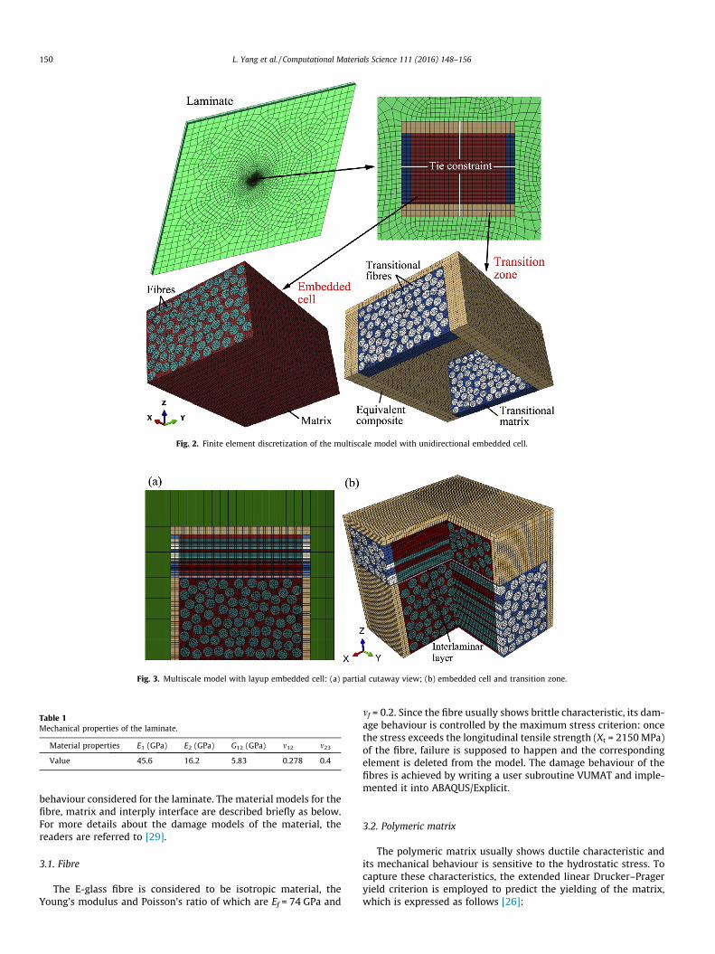
Fig. 2. Finite element discretization of the multiscale model with unidirectional embedded cell.
Fig. 3. Multiscale model with layup embedded cell: (a) partial cutaway view; (b) embedded cell and transition zone.
Table 1Mechanical properties of the laminate.
Material properties E1 (GPa) E2 (GPa) G12 (GPa) m12 m23
Value 45.6 16.2 5.83 0.278 0.4
150 L. Yang et al. / Computational Materials Science 111 (2016) 148–156
behaviour considered for the laminate. The material models for thefibre, matrix and interply interface are described briefly as below.For more details about the damage models of the material, thereaders are referred to [29].
3.1. Fibre
The E-glass fibre is considered to be isotropic material, theYoung’s modulus and Poisson’s ratio of which are Ef = 74 GPa and
mf = 0.2. Since the fibre usually shows brittle characteristic, its dam-age behaviour is controlled by the maximum stress criterion: oncethe stress exceeds the longitudinal tensile strength (Xt = 2150 MPa)of the fibre, failure is supposed to happen and the correspondingelement is deleted from the model. The damage behaviour of thefibres is achieved by writing a user subroutine VUMAT and imple-mented it into ABAQUS/Explicit.
3.2. Polymeric matrix
The polymeric matrix usually shows ductile characteristic andits mechanical behaviour is sensitive to the hydrostatic stress. Tocapture these characteristics, the extended linear Drucker–Prageryield criterion is employed to predict the yielding of the matrix,which is expressed as follows [26]:
L. Yang et al. / Computational Materials Science 111 (2016) 148–156 151
F ¼ t � p tanb� d ¼ 0; t ¼ 12q 1þ 1
k� 1� 1
k
� �rq
� �3" #
ð1Þ
where p is the hydrostatic stress, q is the Mises equivalent stress, r isthe third invariant of deviatoric stress, b is the slope of the linearyield surface in the p–t stress plane, d is the cohesion of the mate-rial, and k is the ratio of the yield stress in triaxial tension to that intriaxial compression and thus, introduces different yield behavioursbetween tension and compression.
The parameters in the equation, b, d and k can be determined bythe following formulae:
tanb ¼ 6 sin/3� sin/
ð2Þ
d ¼ 1� 13tanb
� �rmc ð3Þ
k ¼ 3� sin/3þ sin/
ð4Þ
where / is the internal friction angle of the material, which can beobtained from the tensile and compressive strength of the matrix:
sin/ ¼ rmc � rmt
rmc þ rmtð5Þ
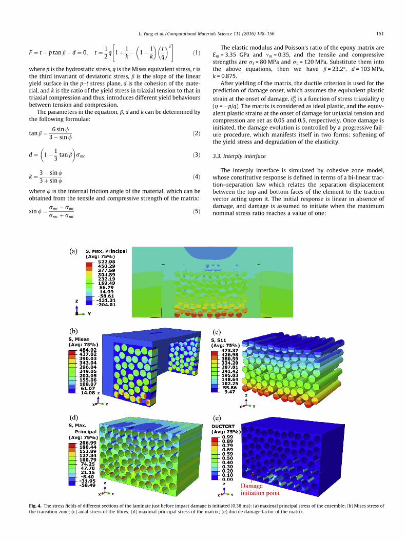
Fig. 4. The stress fields of different sections of the laminate just before impact damage isthe transition zone; (c) axial stress of the fibres; (d) maximal principal stress of the ma
The elastic modulus and Poisson’s ratio of the epoxy matrix areEm = 3.35 GPa and mm = 0.35, and the tensile and compressivestrengths are rt = 80 MPa and rc = 120 MPa. Substitute them intothe above equations, then we have b = 23.2�, d = 103 MPa,k = 0.875.
After yielding of the matrix, the ductile criterion is used for theprediction of damage onset, which assumes the equivalent plastic
strain at the onset of damage, �eplD is a function of stress triaxiality g(g = �p/q). The matrix is considered as ideal plastic, and the equiv-alent plastic strains at the onset of damage for uniaxial tension andcompression are set as 0.05 and 0.5, respectively. Once damage isinitiated, the damage evolution is controlled by a progressive fail-ure procedure, which manifests itself in two forms: softening ofthe yield stress and degradation of the elasticity.
3.3. Interply interface
The interply interface is simulated by cohesive zone model,whose constitutive response is defined in terms of a bi-linear trac-tion–separation law which relates the separation displacementbetween the top and bottom faces of the element to the tractionvector acting upon it. The initial response is linear in absence ofdamage, and damage is assumed to initiate when the maximumnominal stress ratio reaches a value of one:
initiated (0.38 ms): (a) maximal principal stress of the ensemble; (b) Mises stress oftrix; (e) ductile damage factor of the matrix.
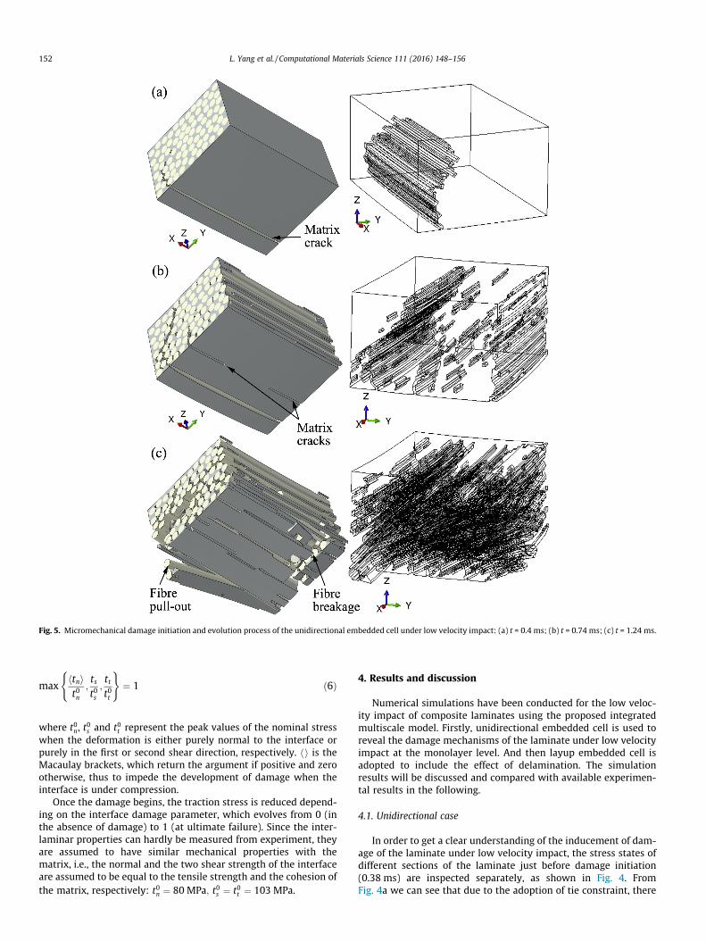
Fig. 5. Micromechanical damage initiation and evolution process of the unidirectional embedded cell under low velocity impact: (a) t = 0.4 ms; (b) t = 0.74 ms; (c) t = 1.24 ms.
152 L. Yang et al. / Computational Materials Science 111 (2016) 148–156
maxhtnit0n
;tst0s;ttt0t
( )¼ 1 ð6Þ
where t0n, t0s and t0t represent the peak values of the nominal stress
when the deformation is either purely normal to the interface orpurely in the first or second shear direction, respectively. hi is theMacaulay brackets, which return the argument if positive and zerootherwise, thus to impede the development of damage when theinterface is under compression.
Once the damage begins, the traction stress is reduced depend-ing on the interface damage parameter, which evolves from 0 (inthe absence of damage) to 1 (at ultimate failure). Since the inter-laminar properties can hardly be measured from experiment, theyare assumed to have similar mechanical properties with thematrix, i.e., the normal and the two shear strength of the interfaceare assumed to be equal to the tensile strength and the cohesion ofthe matrix, respectively: t0n ¼ 80 MPa; t0s ¼ t0t ¼ 103 MPa.
4. Results and discussion
Numerical simulations have been conducted for the low veloc-ity impact of composite laminates using the proposed integratedmultiscale model. Firstly, unidirectional embedded cell is used toreveal the damage mechanisms of the laminate under low velocityimpact at the monolayer level. And then layup embedded cell isadopted to include the effect of delamination. The simulationresults will be discussed and compared with available experimen-tal results in the following.
4.1. Unidirectional case
In order to get a clear understanding of the inducement of dam-age of the laminate under low velocity impact, the stress states ofdifferent sections of the laminate just before damage initiation(0.38 ms) are inspected separately, as shown in Fig. 4. FromFig. 4a we can see that due to the adoption of tie constraint, there
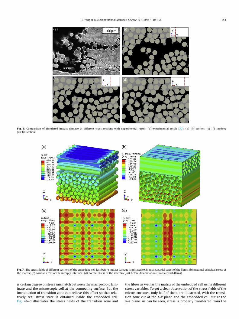
Fig. 6. Comparison of simulated impact damage at different cross sections with experimental result: (a) experimental result [30]; (b) 1/4 section; (c) 1/2 section;(d) 3/4 section.
Fig. 7. The stress fields of different sections of the embedded cell just before impact damage is initiated (0.31 ms): (a) axial stress of the fibres; (b) maximal principal stress ofthe matrix; (c) normal stress of the interply interface; (d) normal stress of the interface just before delamination is initiated (0.48 ms).
L. Yang et al. / Computational Materials Science 111 (2016) 148–156 153
is certain degree of stress mismatch between the macroscopic lam-inate and the microscopic cell at the connecting surface. But theintroduction of transition zone can relieve this effect so that rela-tively real stress state is obtained inside the embedded cell.Fig. 4b–d illustrates the stress fields of the transition zone and
the fibres as well as the matrix of the embedded cell using differentstress variables. To get a clear observation of the stress fields of themicrostructures, only half of them are illustrated, with the transi-tion zone cut at the z–x plane and the embedded cell cut at they–z plane. As can be seen, stress is properly transferred from the
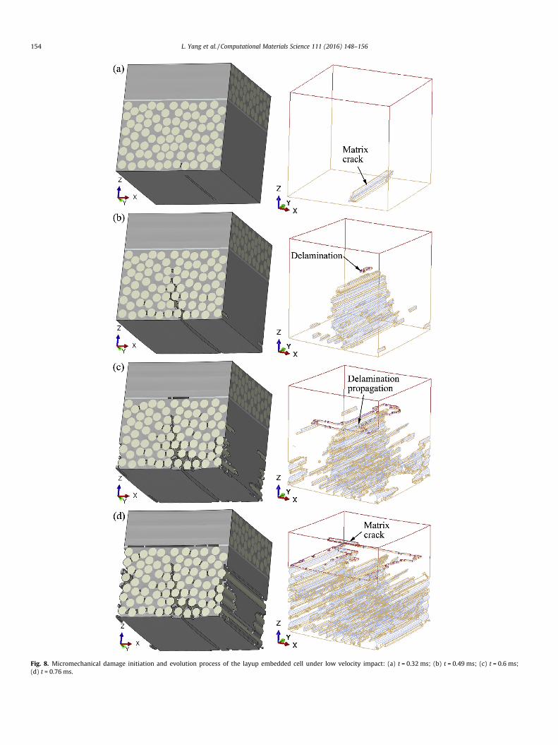
Fig. 8. Micromechanical damage initiation and evolution process of the layup embedded cell under low velocity impact: (a) t = 0.32 ms; (b) t = 0.49 ms; (c) t = 0.6 ms;(d) t = 0.76 ms.
154 L. Yang et al. / Computational Materials Science 111 (2016) 148–156
L. Yang et al. / Computational Materials Science 111 (2016) 148–156 155
transition zone to the fibres and matrix of the embedded cell. Thefibres are all in tensile state, with axial stresses increasing from topto bottom. However, the maximum axial stress of the fibres is stillmuch lower than the longitudinal tensile strength of the fibre, thusfibre breakage will not be induced. On the contrary, the maximumprincipal stress in the matrix has exceeded its tensile strength,especially at the bottom positions where two fibres are closelyadjacent. Ductile damage has been triggered in these high stressregions, and matrix cracking will be induced at the point withthe biggest damage factor in the following impact process, asmarked in Fig. 4e.
Fig. 5 illustrates the simulated micromechanical damage initia-tion and evolution process of the unidirectional embedded cellduring the impact event. As can be seen, matrix cracking firstoccurs at the locus as marked in Fig. 4e, and rapidly propagatesdownward to the bottom surface. Meanwhile, the crack also prop-agates upward, but the propagating path is significantly influencedby the fibre distribution, forming a crooked crack surface, as shownin Fig. 5a. With the proceeding of the impact event, the originalcrack surface continues to expand, and more dispersive matrixcracks are induced at different positions of the embedded cell, asshown in Fig. 5b. Finally, fibre pull-out and breakage are observedat the bottom of the embedded cell, and matrix cracks have spreadall over the embedded cell, as shown in Fig. 5c.
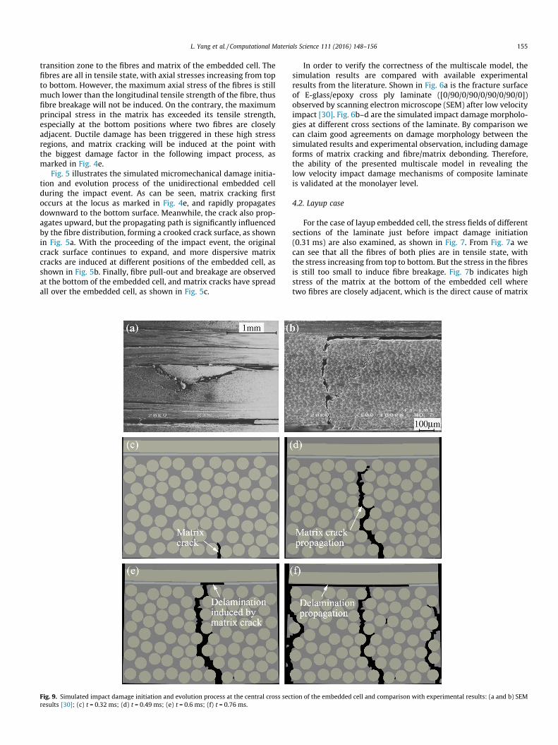
Fig. 9. Simulated impact damage initiation and evolution process at the central cross secresults [30]; (c) t = 0.32 ms; (d) t = 0.49 ms; (e) t = 0.6 ms; (f) t = 0.76 ms.
In order to verify the correctness of the multiscale model, thesimulation results are compared with available experimentalresults from the literature. Shown in Fig. 6a is the fracture surfaceof E-glass/epoxy cross ply laminate ([0/90/0/90/0/90/0/90/0])observed by scanning electron microscope (SEM) after low velocityimpact [30]. Fig. 6b–d are the simulated impact damage morpholo-gies at different cross sections of the laminate. By comparison wecan claim good agreements on damage morphology between thesimulated results and experimental observation, including damageforms of matrix cracking and fibre/matrix debonding. Therefore,the ability of the presented multiscale model in revealing thelow velocity impact damage mechanisms of composite laminateis validated at the monolayer level.
4.2. Layup case
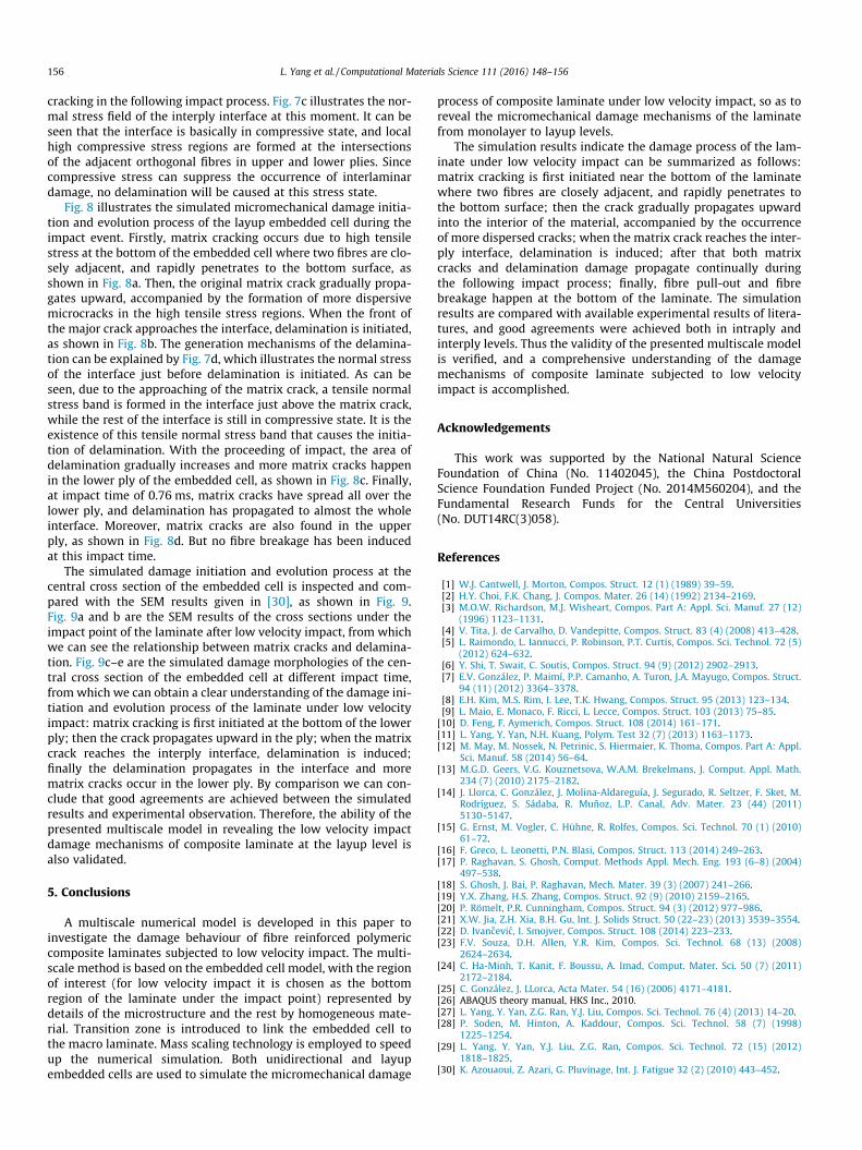
For the case of layup embedded cell, the stress fields of differentsections of the laminate just before impact damage initiation(0.31 ms) are also examined, as shown in Fig. 7. From Fig. 7a wecan see that all the fibres of both plies are in tensile state, withthe stress increasing from top to bottom. But the stress in the fibresis still too small to induce fibre breakage. Fig. 7b indicates highstress of the matrix at the bottom of the embedded cell wheretwo fibres are closely adjacent, which is the direct cause of matrix
tion of the embedded cell and comparison with experimental results: (a and b) SEM
156 L. Yang et al. / Computational Materials Science 111 (2016) 148–156
cracking in the following impact process. Fig. 7c illustrates the nor-mal stress field of the interply interface at this moment. It can beseen that the interface is basically in compressive state, and localhigh compressive stress regions are formed at the intersectionsof the adjacent orthogonal fibres in upper and lower plies. Sincecompressive stress can suppress the occurrence of interlaminardamage, no delamination will be caused at this stress state.
Fig. 8 illustrates the simulated micromechanical damage initia-tion and evolution process of the layup embedded cell during theimpact event. Firstly, matrix cracking occurs due to high tensilestress at the bottom of the embedded cell where two fibres are clo-sely adjacent, and rapidly penetrates to the bottom surface, asshown in Fig. 8a. Then, the original matrix crack gradually propa-gates upward, accompanied by the formation of more dispersivemicrocracks in the high tensile stress regions. When the front ofthe major crack approaches the interface, delamination is initiated,as shown in Fig. 8b. The generation mechanisms of the delamina-tion can be explained by Fig. 7d, which illustrates the normal stressof the interface just before delamination is initiated. As can beseen, due to the approaching of the matrix crack, a tensile normalstress band is formed in the interface just above the matrix crack,while the rest of the interface is still in compressive state. It is theexistence of this tensile normal stress band that causes the initia-tion of delamination. With the proceeding of impact, the area ofdelamination gradually increases and more matrix cracks happenin the lower ply of the embedded cell, as shown in Fig. 8c. Finally,at impact time of 0.76 ms, matrix cracks have spread all over thelower ply, and delamination has propagated to almost the wholeinterface. Moreover, matrix cracks are also found in the upperply, as shown in Fig. 8d. But no fibre breakage has been inducedat this impact time.
The simulated damage initiation and evolution process at thecentral cross section of the embedded cell is inspected and com-pared with the SEM results given in [30], as shown in Fig. 9.Fig. 9a and b are the SEM results of the cross sections under theimpact point of the laminate after low velocity impact, from whichwe can see the relationship between matrix cracks and delamina-tion. Fig. 9c–e are the simulated damage morphologies of the cen-tral cross section of the embedded cell at different impact time,from which we can obtain a clear understanding of the damage ini-tiation and evolution process of the laminate under low velocityimpact: matrix cracking is first initiated at the bottom of the lowerply; then the crack propagates upward in the ply; when the matrixcrack reaches the interply interface, delamination is induced;finally the delamination propagates in the interface and morematrix cracks occur in the lower ply. By comparison we can con-clude that good agreements are achieved between the simulatedresults and experimental observation. Therefore, the ability of thepresented multiscale model in revealing the low velocity impactdamage mechanisms of composite laminate at the layup level isalso validated.
5. Conclusions
A multiscale numerical model is developed in this paper toinvestigate the damage behaviour of fibre reinforced polymericcomposite laminates subjected to low velocity impact. The multi-scale method is based on the embedded cell model, with the regionof interest (for low velocity impact it is chosen as the bottomregion of the laminate under the impact point) represented bydetails of the microstructure and the rest by homogeneous mate-rial. Transition zone is introduced to link the embedded cell tothe macro laminate. Mass scaling technology is employed to speedup the numerical simulation. Both unidirectional and layupembedded cells are used to simulate the micromechanical damage
process of composite laminate under low velocity impact, so as toreveal the micromechanical damage mechanisms of the laminatefrom monolayer to layup levels.
The simulation results indicate the damage process of the lam-inate under low velocity impact can be summarized as follows:matrix cracking is first initiated near the bottom of the laminatewhere two fibres are closely adjacent, and rapidly penetrates tothe bottom surface; then the crack gradually propagates upwardinto the interior of the material, accompanied by the occurrenceof more dispersed cracks; when the matrix crack reaches the inter-ply interface, delamination is induced; after that both matrixcracks and delamination damage propagate continually duringthe following impact process; finally, fibre pull-out and fibrebreakage happen at the bottom of the laminate. The simulationresults are compared with available experimental results of litera-tures, and good agreements were achieved both in intraply andinterply levels. Thus the validity of the presented multiscale modelis verified, and a comprehensive understanding of the damagemechanisms of composite laminate subjected to low velocityimpact is accomplished.
Acknowledgements
This work was supported by the National Natural ScienceFoundation of China (No. 11402045), the China PostdoctoralScience Foundation Funded Project (No. 2014M560204), and theFundamental Research Funds for the Central Universities(No. DUT14RC(3)058).
References
[1] W.J. Cantwell, J. Morton, Compos. Struct. 12 (1) (1989) 39–59.[2] H.Y. Choi, F.K. Chang, J. Compos. Mater. 26 (14) (1992) 2134–2169.[3] M.O.W. Richardson, M.J. Wisheart, Compos. Part A: Appl. Sci. Manuf. 27 (12)
(1996) 1123–1131.[4] V. Tita, J. de Carvalho, D. Vandepitte, Compos. Struct. 83 (4) (2008) 413–428.[5] L. Raimondo, L. Iannucci, P. Robinson, P.T. Curtis, Compos. Sci. Technol. 72 (5)
(2012) 624–632.[6] Y. Shi, T. Swait, C. Soutis, Compos. Struct. 94 (9) (2012) 2902–2913.[7] E.V. González, P. Maimí, P.P. Camanho, A. Turon, J.A. Mayugo, Compos. Struct.
94 (11) (2012) 3364–3378.[8] E.H. Kim, M.S. Rim, I. Lee, T.K. Hwang, Compos. Struct. 95 (2013) 123–134.[9] L. Maio, E. Monaco, F. Ricci, L. Lecce, Compos. Struct. 103 (2013) 75–85.[10] D. Feng, F. Aymerich, Compos. Struct. 108 (2014) 161–171.[11] L. Yang, Y. Yan, N.H. Kuang, Polym. Test 32 (7) (2013) 1163–1173.[12] M. May, M. Nossek, N. Petrinic, S. Hiermaier, K. Thoma, Compos. Part A: Appl.
Sci. Manuf. 58 (2014) 56–64.[13] M.G.D. Geers, V.G. Kouznetsova, W.A.M. Brekelmans, J. Comput. Appl. Math.
234 (7) (2010) 2175–2182.[14] J. Llorca, C. González, J. Molina-Aldareguía, J. Segurado, R. Seltzer, F. Sket, M.
Rodríguez, S. Sádaba, R. Muñoz, L.P. Canal, Adv. Mater. 23 (44) (2011)5130–5147.
[15] G. Ernst, M. Vogler, C. Hühne, R. Rolfes, Compos. Sci. Technol. 70 (1) (2010)61–72.
[16] F. Greco, L. Leonetti, P.N. Blasi, Compos. Struct. 113 (2014) 249–263.[17] P. Raghavan, S. Ghosh, Comput. Methods Appl. Mech. Eng. 193 (6–8) (2004)
497–538.[18] S. Ghosh, J. Bai, P. Raghavan, Mech. Mater. 39 (3) (2007) 241–266.[19] Y.X. Zhang, H.S. Zhang, Compos. Struct. 92 (9) (2010) 2159–2165.[20] P. Römelt, P.R. Cunningham, Compos. Struct. 94 (3) (2012) 977–986.[21] X.W. Jia, Z.H. Xia, B.H. Gu, Int. J. Solids Struct. 50 (22–23) (2013) 3539–3554.[22] D. Ivancevic, I. Smojver, Compos. Struct. 108 (2014) 223–233.[23] F.V. Souza, D.H. Allen, Y.R. Kim, Compos. Sci. Technol. 68 (13) (2008)
2624–2634.[24] C. Ha-Minh, T. Kanit, F. Boussu, A. Imad, Comput. Mater. Sci. 50 (7) (2011)
2172–2184.[25] C. González, J. LLorca, Acta Mater. 54 (16) (2006) 4171–4181.[26] ABAQUS theory manual, HKS Inc., 2010.[27] L. Yang, Y. Yan, Z.G. Ran, Y.J. Liu, Compos. Sci. Technol. 76 (4) (2013) 14–20.[28] P. Soden, M. Hinton, A. Kaddour, Compos. Sci. Technol. 58 (7) (1998)
1225–1254.[29] L. Yang, Y. Yan, Y.J. Liu, Z.G. Ran, Compos. Sci. Technol. 72 (15) (2012)
1818–1825.[30] K. Azouaoui, Z. Azari, G. Pluvinage, Int. J. Fatigue 32 (2) (2010) 443–452.