computational analysis of viv observed on existing...
TRANSCRIPT
The Seventh International Colloquium on Bluff Body Aerodynamics and Applications (BBAA7)Shanghai, China; September 2-6, 2012
Computational analysis of VIV observed on existing bridges
Abraham S. Corriols a, Guido Morgenthal b
a Technical University of Madrid, Prof. Aranguren s/n, Spainb Bauhaus University of Weimar, Marienstraße 13A, Germany
ABSTRACT: This paper presents Computational Fluid Dynamics simulations of two existing bridges which exhibited vortex-induced vertical vibrations: Alconétar upper steel arch bridge (2006, Cáceres, Spain, 220 m main span) and the Volgograd Bridge (2009, Volgograd, Russia, 155 m main span). The Vortex Particle Method is used for the analysis.
KEYWORDS: Aerodynamics, Vortex shedding, Vibration, CFD, Bridge, Volgograd, Alconétar
1 INTRODUCTION
Vortex shedding from bridge cross sections can lead to significant aerodynamic excitation of the structure. This is a limited amplitude phenomenon, which however can be critical to the service-ability of the bridge or lead to fatigue damage. For structures sensitive to vortex shedding an ad-equately realistic assessment of the problem is required.
Traditional wind tunnel testing of all alternatives is often dismissed in early design stages un-less in the case of large-scale or other high-profile bridge projects. Various analytical models ex-ist for assessing vortex-induced vibrations (VIV), however these are of limited use for complex bridge deck geometries. Numerical simulations of the fluid flow provide a further method for modelling the physical problem. Such methods are gaining popularity in the field of civil engi-neering because of their growing reliability provided by the implementation of new computa-tional methods and the availability of more powerful computational resources.
2 GENERAL APPROACH TO THE AERODYNAMIC PROBLEM
2.1 Vortex shedding phenomenonDynamic actions due to wind flow are usually associated with long span bridges such as suspen-sion and cable stayed bridges. The design optimization has resulted in a reduction of the cross section depth to decrease its weight and static wind loads. However, this also brings increased flexibility and the likelihood of dynamic effects at lower wind speeds if the geometry of the cross section is not adequate. In particular, a characteristic of the aerodynamic problems in the range of low wind speeds is that of the vortex induced vibrations (VIV). When the wind imping-es on a body with sharp edges, a shear layer separation is produced resulting in vortical struc-tures, which are displaced downstream, as the air is a viscous fluid. These vortical structures in-duce differences in pressure between the upper and lower body surface, which result in aerodynamic forces. If the frequency of generation is near the natural frequency of the structure, a phenomenon of resonance or coupling between the two frequencies occurs, initiating a process whose vibrational amplitudes, although limited, can have serious consequences by affecting ser-viceability conditions, or even be the main cause of its long-term decline and decrease their ser-vice life.
(1)St =fs D
U
1536
where St=Strouhal number; fs=vortex shedding frequency; D=cross-sectional dimension perpen-dicular to the wind direction.
The Strouhal number relates the vortex shedding frequency with the incident wind speed, and depends mainly on the geometry of the section and the Reynolds number. In bridge aerodynam-ics, the latter parameter is usually always greater than 105, so the Strouhal number is not strongly conditioned by the Reynolds number. Furthermore, the shear layer is controlled by the sharp edges of the section, and not by the fluid flow regime [1].
The VIVs are associated with a single mode of vibration, so this is a decoupled phenomenon. It can result in vertical movement or rotations, depending on which natural frequency is being excited. The cases included in this study correspond to vertical vibrations, because bridges with high torsional stiffness have higher torsional natural frequencies, thus implying wind speeds well above the normal values. Nevertheless, there are cases, like the Bay Bridge in Tokyo, that have suffered vibrations associated with vortex shedding and whose primary mode of torsion was close to vertical modes [2].
The primary goal is the identification of the critical wind speed which gives rise to resonance phenomena between the vortices generated and the natural frequency of the bridge. Once the Strouhal number associated with a given geometry and the vortex shedding frequency matches the natural frequency, the critical velocity is estimated by the following expression:
(2)
where fs=vortex shedding frequency; fn=natural vibration frequency of the bridge; vcrit=critical wind speed; D=cross-sectional dimension perpendicular to the wind direction; St=Strouhal num-ber.
The study of fluid-structure interaction tends to classify the VIV phenomenon as an instability induced by the fluid (Instability Induced Excitation, IIE) [1], where the influence of movement of the structure in the steady state over the aerodynamic forces responsible for this movement is irrelevant, partly because these vibrations are of limited amplitude. At the time when the vibra-tions exceed a certain maximum amplitude (usually given as limit cross-sectional transversal dimension), the process of generation and shed of vortex along the wake becomes unstable caus-ing the excitatory action to disappear. The same happens if the wind speed generates a shedding frequency outside the interval of resonance of the bridge natural frequency (fn), which tradition-ally is considered limited between the values of 0.8fn and 1.2fn.
The resonance phenomena which gives rise to VIV can be avoided by furthering the vortex shedding frequency from to the considered natural frequency. This last parameter is determined by its mass and mechanical stiffness, in turn conditioned by resistant and constructive criteria, so it seems more logical to act on the cross section. The key is to design an efficient geometry sothat the resonant phenomenon can only occur with high wind speeds that fall outside the range of average wind speeds of where the bridge stands. The VIV only takes place when the wind re-gime is more or less regular and average speed remains substantially constant for a given time, usually greater than 20-30 minutes.
To simplify the analysis, the majority of the models consider that the aerodynamic forces act over the static section, and the parameters that identify the phenomenon, e.g. Strouhal number and force coefficients, are obtained from wind tunnel static testing. Simple or regular geometries values (circle, square, rectangle, U-sections) are reflected in various standards and publications,such as the Eurocode (EN 1991 1-4), the British Design Manual for Roads & Bridges (BS 49/01) and the Canadian Highway Bridge Design Code (CAN/CSA-S6-06) . Different expressions to obtain the maximum vibration amplitude of the oscillations associated with VIV are also includ-
fs ≈ fn ⇒ vcrit =fs D
St
1537

The Seventh International Colloquium on Bluff Body Aerodynamics and Applications (BBAA7)Shanghai, China; September 2-6, 2012
ed. Nevertheless, the parameters for sections of irregular or complex geometry are not included, and their estimation from static tests turns more complicated because several vortex shedding frequencies converge and it is not possible to distinguish which one is the main one.
This fact is also evident in sections whose aspect ratio (B/D) is greater than 2.0, since the evo-lution pattern of the wake does not obey the classical Von Karman vortex street (KV). Vortical structures generated in leading edge are not able to pass over the entire width of the section without causing its reattachment on its surface, resulting in a release pattern known as impinging leading edge vortex (ILEV) [1,3]. It has been found that the regularity of vortical structures shedding in the ILEV pattern are more affected by the movement of the section configuration than in the KV pattern. The static consideration of the aerodynamic forces is less accurate, alt-hough it remains valid. Nevertheless, the critical speed should be determined by other tests ra-ther than static tests. The phenomenon of vortex induced vibrations is still regarded as an in-duced instability excitation (IIE), according to the classification criteria offered by Rockwell and Naudascher [1], but the change in the shedding pattern as a result of the oscillations of the sec-tion in its interaction with the wind in the range of resonant frequencies, identified as movement-induced excitation (MIE) [1] can not be ignored.
For regular sections, the Strouhal number is very similar to the reduced frequency correspond-ing to the moving section. However, in the cases of asymmetric, twin tandem, multibox and oth-er complex sections, this does not hold true. Consequently, it is more accurate to use the reduced frequency parameter, fred, to refer to the relationship between the vortex shedding frequency and incident wind speed on any type of wind tunnel test, being the Strouhal number equal to the val-ue of reduced frequency referred only to static wind tunnel tests.
(3)
In order to avoid this drawback, forced wind tunnel tests can be addressed, assigning a fre-quency oscillation similar to their natural frequency and moderate amplitude of vibration. A val-ue between 0.1D and 0.2D (D, cross-sectional transversal dimension) is often used because the maximum amplitudes of oscillation of the phenomena of VIV on bridges studied stand close to these values.
Figure 1. Spectral amplitudes of lift coefficient for a static numerical simulation (left) and a dynamic (right).
It is also possible to achieve dynamic wind tunnel tests, assigning the model the corresponding mechanical properties of stiffness and mass, thus representing the real bridge for its scale, by the progressive increase in wind speed up to the point of resonance and critical speed, where the models vibrate regularly. Following increasing wind speed, the resonance disappears and the models cease to experience these vibrations.
fs, red =fs D
UStatic tests⇒ fred ≡ St
1538

2.2 Numerical simulationsIn this study several simulations of flow past bodies have been performed using a technique based on the Vortex-In-Cell (VIC) method. This is a hybrid particle-mesh algorithm that uses a discretization of the vorticity field and particles through a Lagrangian scheme for solving the Navier-Stokes equations describing fluid motion, while allowing high-resolving simulations res-olution with a reasonable computational cost. To model the diffusion term in the Navier-Stokes expression, the random walk method is applied, which has been very successful in some fields of engineering, such as bridge aerodynamics. A comprehensive description of the simulation meth-od can be found in [4] and in previous publications referenced in the mentioned document.
The use of numerical simulation methods are useful to achieve optimal geometric design of the cross section in those bridges that may be subjected to aerodynamic problems during its con-struction and service. It replaces or reduces aerodynamic tests necessary to verify the perfor-mance of several alternatives, thereby reducing cost and time, making it possible to extend its application to minor bridges that would not initially be tested. Although aerodynamic testing is essential for bridges with special features, the results can be compared with numerical simula-tions that can be carried out simultaneously.
This paper presents a computational analysis of the phenomenon of VIV in real bridges that have experienced an episode of vibrations of this type, and a comparison of critical speed values of wind and amplitudes of oscillation recorded.
3 THE VOLGOGRAD BRIDGE
3.1 Outline of the vibration episodeOn May 20th, 2010, the new bridge over the Volga River in the city of Volgograd was closed to traffic because it was swinging dangerously due to the wind regime existing in the area. Accord-ing to meteorological data, average speeds between 11.6 m/s and 15.6 m/s were recorded with a direction deviated 7 degrees from the normal direction to the longitudinal axis of the bridge. This suggested that it could be an episode of vertical vortex induced vibrations; there are other condi-tions surrounding the phenomenon that lead to the same hypothesis:
- Relatively low average wind speeds and constant regime with little turbulence, caused by the orography. The great width of the Volga River helps direct the wind along the smooth surface provided by the water.
- The oscillation frequency coincides with the fundamental frequency of vertical vibration of the bridge, indicating that there was a phenomenon of resonance or coupling between these frequencies associated to the vortex shedding.
- The amplitudes of vibration were limited (not exceeding one meter) according to the ob-servations made by people who witnessed the phenomenon. The image recordings made during the development of the phenomenon were used to estimate the vibration ampli-tudes more accurately, reaching around 65-70 cm.
Initially, there was speculation on the fact that the vibrations could be caused by a moderate earthquake, alone or in coalition with the wind, although this hypothesis was discarded because an earthquake would not correspond to the development of the vibrations. The board swung slowly and regularly for about four hours, while the oscillations due to earthquakes are more ir-regular (incorporating various frequencies) and generally only last for so long.
1539
The Seventh International Colloquium on Bluff Body Aerodynamics and Applications (BBAA7)Shanghai, China; September 2-6, 2012
A special commission was created to examine the state of the structure to check for damage that could keep the bridge from safely reopening. The bridge was reopened to pedestrians and passenger vehicle traffic five days later. However, traffic from heavy vehicles was not allowed until August 25th, 2010, once the bridge was examined in detail and no external or internal dam-age in the structure was found. After phenomenon experienced by the bridge, a monitoring sys-tem along the bridge to control its possible movements, and a weather station for the continued observance of the weather conditions in the area were implemented. An intervention plan was also designed so that emergency departments could act quickly if the phenomenon recurred. At the same time, wind tunnel tests on sectional models were carried out in Central Aero-Hydrodynamics Institute (TsAGI), near Moscow, to study the problem in detail. In recent years, a number of cable-stayed and girder bridges over rivers with wide channels that run through vast plains have been built in Russia. The aerodynamic problems observed on the bridge of Volgo-grad have focused attention on the remaining bridges of similar properties that may be subjected to the same problems. On March 2011, the bridge over the Volga River near Kineshma became the sixteenth bridge tested at the TsAGI wind tunnels.
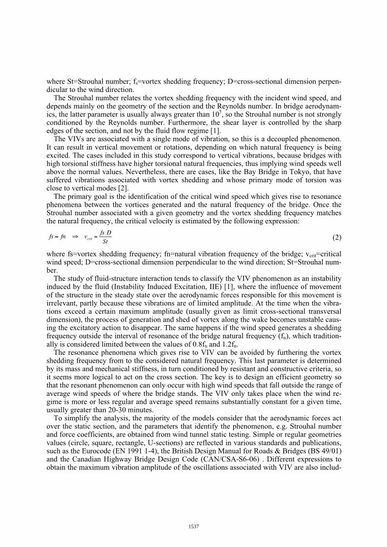
3.2 Numerical simulationsThe bridge, inaugurated in October 2009, is the only structure to cross over the Volga in the re-gion, in addition to the existing dam on the Volga Hydroelectric Power Station, near the city. It has a total length of 7110 m, including the flyovers. The middle section overpasses the Volga and is composed of seven spans of 155 m length each. The cross section is a steel box of 10.02 m wide, with an upper and lower width of 7.00 m; 7.44 m if the overall width, which forms the base, is taken into account. The deck has two flies over the box on both sides of 4.179 m and
Figure 2. Volgograd Bridge. Top, left: General view. Top, right: cross-section dimensions of bridge deck. Bottom, left: video snapshot showing the vortex-induced oscillations episode (20th, May, 2010). Bottom, right: Velocity field visualization frame, obtained from the numerical simulation carried out.
1540

3.185 m, so that the total bridge width is 17.38 m. It has two traffic lanes separated by a barrier free median, and a strip for pedestrian traffic. There are two guardrails at each along each side of the bridge and an additional one to separate the vehicle traffic from pedestrians. The deck has an inclination of 1.1 degrees counter-clockwise about its longitudinal axis, so that its horizontal di-mension parallels the wind direction at 17.25 m.
Figure 3 shows the interaction of the fluid stream with the section through the vortex streaks generated by the simulation code. During the interaction process, three points of particular im-portance can be identified: (1) the detachment of the shear layer, which reattaches again on the lower surface, resulting in the pattern known as ILEV; (2) the actual detachment of the fluid shear layer. On the upper surface, the interaction between the fluid and the structure is similar, generating a release ILEV type pattern that is maintained along the entire width; (3) the final take-off of the fluid stream at the top of the section and its junction with the bottom which will cause a series of vortex structures of certain regularity throughout the wake downstream. It somehow determines the cyclic variations of pressure on the two surfaces of the section and therefore the aerodynamic forces acting on it.
The Strouhal number defines the frequency of generation of said vortical structures, and hence the frequency of variation of the aerodynamic forces responsible for the vibrations. The fluid-structure interaction mechanism in sections of complex geometry can be likened to what occurs in a rectangular section of dimensions B* x D*. To do this, these parameters must first be identi-fied. B* represents the distance between the point of origin of the interaction of the surface of shorter length (1), which will condition the process and the final release point of the shear layer (2), that will subsequently converge with the other part of the fluid flow after passing the obsta-cle represented by the cross section. D* is the dimension perpendicular to the flow direction, causing the separation of the fluid flow. Figure 4 represents the Strouhal number against the B/D for rectangular sections, according to results of several investigators collected by Deniz & Staubli [3]. Results obtained by numerical simulation (Vortex Particle Method, VPM) of static tests have been added. The two different lines obtained for relations B/D between 2.0 and 5.0 confirm the coexistence of two patterns of evolution: the pure ILEV type, which identifies the lowest values, and another pattern closer to the KV type, where the shear layer reattachment on the surface of the body occurs alternately, resulting in higher values of the Strouhal number. When the section vibrates, the latter is favoured.
Figure 3. Flow visualization through vortex streaks and effective dimensions of cross-section with bars
1541

The Seventh International Colloquium on Bluff Body Aerodynamics and Applications (BBAA7)Shanghai, China; September 2-6, 2012
Furthermore, higher Strouhal numbers correspond to lower wind speeds, and therefore have greater probability of occurrence. For B/D ratios exceeding 2.0, the lower Strouhal numbers are less than 0.06, which would require an average wind speeds too high for the associated release pattern to be given in most of the bridge sections. The Reynolds number corresponding to the numerical simulations is of 2.24 · 106. Although its influence on the Strouhal number is not as significant in bluff bodies, there can be some slight variation.
To analyse the VIV episode suffered by the Volgograd Bridge, two types of two-dimensional numerical simulations have been performed, using the cross section of the bridge with barriers and without them. The contours of both have been identified, which represent the surface ex-posed to the air stream and define a simple degree of freedom model where the only motion pos-sible is vertical displacement. The natural frequency of the structure associated with the first ver-tical vibration mode is 0.42 Hz, and the mode shape is defined as a sinusoidal function, with the maximum in the centre span. The damping ratio relative to critical used is ζ=0.003, a typical val-ue for steel bridges. The corresponding sectional mass is 2,500 kg/m, its effective width B* is 17.25 m. The effective vertical dimension D* is 3.61 m for the section without barriers, and 4.82 m for the section with barriers, being the B*/D* ratio of 2.06 and 1.54. Strouhal numbers ob-tained from static tests are 0.133 and 0.155, respectively. Both are represented in figure 4 and keep some consistency with the other values showed.
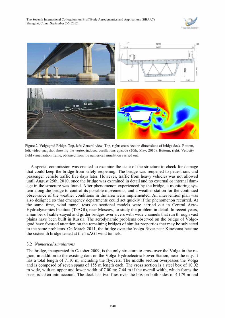
Figure 5 shows the evolution of the root mean square values (RMS) of the vibration amplitude as a function of the reduced wind speed of the two cases studied. To achieve a better comparison between them, the vertical dimension D of 3.61m in both cases has been considered, so that the Strouhal number of the barrier section is 0.116 instead of 0.155. The VIV takes place in the sec-tion with barriers in the low wind speed range of 6.60 and 9.60, corresponding to a wind speed of 10.0 m/s and 14.50 m/s. The critical speed is estimated around 13.0 m/s, the point where the structure reaches its maximum semi-amplitude vibration. This speed is included in the range of average speeds measured in the area between 11.6 m/s and 15.6m/s. The RMS value is estimated at 0.32 m, while the maximum value registered in the simulation is of 0.53 m. The temporal evo-lution of lift coefficient for this case is shown in figure 5. To determine the RMS value, the tem-poral force register has been filtered using a frequency range between and 1.1fs 0.9fs, being fsvortex shedding frequency calculated through the Fourier transform. Its value is RMS,Cl=0.55.
Figure 4. Strouhal number as a function of the side ratio, B/D, after [2] with present results added
1542
These figures are an accurate estimation of the values recorded during the vibration episode in May 2010, oscillations with a maximum amplitude of 0.71 m (0.36 m semi-amplitude), were reached. From 14.50 m/s, the amplitudes of vibration progressively increases as the wind speed increases, thus indicating the starting of another aerodynamic effect such as galloping, which leads to the dynamic instability of the structure if a certain speed is exceeded.
In the case of simulation of the section without barriers, the presence of VIV phenomenon is not detected as in the previous case, but a tendency to suffer obvious galloping effects as speed increases it is also checked. An interval in the curve where there is a sharper increase in the am-plitude of vibration (between the values of reduced wind speed of 6.85 and 10.0) can be identi-fied as a possible VIV effect.
A summary of previous results is shown in Table 1.
Table 1. Summary of results: Volgograd2D model B D B* D* B*/D* St (D*) vcrit MAX (y) RMS(y) RMS(Cl) Cd
m m m m - - - m m - -without bars 17.25 3.61 7.44 3.61 2.06 0.133 11.3 0.26 0.097 0.11 1.13with bars 17.25 4.83 7.44 4.83 1.54 0.116 12.9 0.53 0.32 0.55 1.46
where B=section width; D=section depth; B*=section effective width; D=section effective depth; St=Strouhal number (static sectional simulation); vcrit=critical wind speed; MAX(y)=maximum semi-amplitude of oscillation; RMS(y)=root mean square referred to the semi-amplitude of oscillation; RMS(Cl)=root mean square of lift coefficient, Cl=Fl/(1/2ρU2D), with Fl=lift force; U=wind speed, ρ=air density, and D=3.61m for both cases; Cd=Fd/(1/2ρU2B), drag coefficient, with Fd=drag force.
The code employed also allows a numerical simulation based on a multimodal quasi-3Dscheme. It is possible to discretize the total length of the bridge through slices of a given length and assign geometric and mechanical characteristics associated with each mode (fre-quency, mass, damping and mode shape). The fluid-structure interaction is developed in each slice independently of the others, i.e., there is no aerodynamic interference between the differ-ent slices. However, the movements of each slice depend on each other because there is a
! " # $ % &! &" &# &$ &% "!!
!’&
!’"
!’(
!’#
!’)
!’$
*+,-.+,/012,/34++,5/6*7892:;<=>/? @
ABC/3+D1ED4F1G-,+/?D@
/
/
6.*1G
H IJKL=J/MNACH IJK/MNAC
Figure 5. RMS semi-amplitude corresponding to the cases modeled (left), and lift coefficient history of the sec-tion with bars (right)
1543
The Seventh International Colloquium on Bluff Body Aerodynamics and Applications (BBAA7)Shanghai, China; September 2-6, 2012
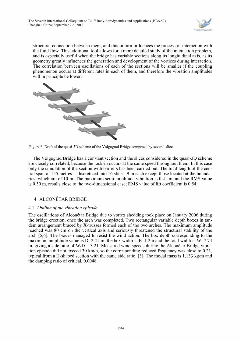
structural connection between them, and this in turn influences the process of interaction with the fluid flow. This additional tool allows for a more detailed study of the interaction problem, and is especially useful when the bridge has variable sections along its longitudinal axis, as its geometry greatly influences the generation and development of the vortices during interaction. The correlation between oscillations of each of the sections will be smaller if the coupling phenomenon occurs at different rates in each of them, and therefore the vibration amplitudes will in principle be lower.
The Volgograd Bridge has a constant section and the slices considered in the quasi-3D schemeare closely correlated, because the lock-in occurs at the same speed throughout them. In this case only the simulation of the section with barriers has been carried out. The total length of the cen-tral span of 155 metres is discretized into 16 slices, 9 m each except those located at the bounda-ries, which are of 10 m. The maximum semi-amplitude vibration is 0.41 m, and the RMS value is 0.30 m, results close to the two-dimensional case; RMS value of lift coefficient is 0.54.
4 ALCONÉTAR BRIDGE
4.1 Outline of the vibration episodeThe oscillations of Alconétar Bridge due to vortex shedding took place on January 2006 during the bridge erection, once the arch was completed. Two rectangular variable depth boxes in tan-dem arrangement braced by X-trusses formed each of the two arches. The maximum amplitude reached was 80 cm on the vertical axis and seriously threatened the structural stability of the arch [5,6]. The braces managed to resist the wind action. The box depth corresponding to the maximum amplitude value is D=2.41 m, the box width is B=1.2m and the total width is W=7.74 m, giving a side ratio of W/D = 3.21. Measured wind speeds during the Alconétar Bridge vibra-tion episode did not exceed 30 km/h, so the corresponding reduced frequency was close to 0.21, typical from a H-shaped section with the same side ratio. [3]. The modal mass is 1,133 kg/m and the damping ratio of critical, 0.0048.
Figure 6. Draft of the quasi-3D scheme of the Volgograd Bridge composed by several slices
1544
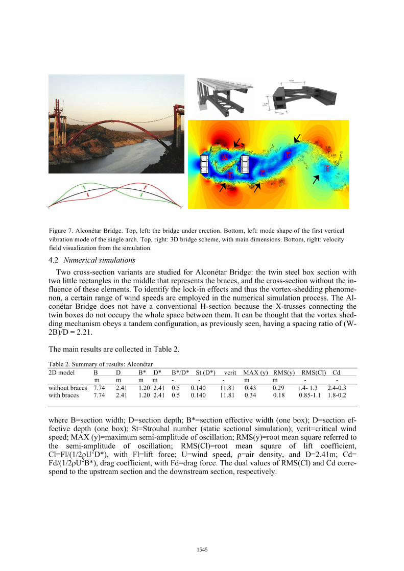
4.2 Numerical simulationsTwo cross-section variants are studied for Alconétar Bridge: the twin steel box section with
two little rectangles in the middle that represents the braces, and the cross-section without the in-fluence of these elements. To identify the lock-in effects and thus the vortex-shedding phenome-non, a certain range of wind speeds are employed in the numerical simulation process. The Al-conétar Bridge does not have a conventional H-section because the X-trusses connecting the twin boxes do not occupy the whole space between them. It can be thought that the vortex shed-ding mechanism obeys a tandem configuration, as previously seen, having a spacing ratio of (W-2B)/D = 2.21.
The main results are collected in Table 2.
Table 2. Summary of results: Alconétar 2D model B D B* D* B*/D* St (D*) vcrit MAX (y) RMS(y) RMS(Cl) Cd
m m m m - - - m m - -without braces 7.74 2.41 1.20 2.41 0.5 0.140 11.81 0.43 0.29 1.4- 1.3 2.4-0.3with braces 7.74 2.41 1.20 2.41 0.5 0.140 11.81 0.34 0.18 0.85-1.1 1.8-0.2
where B=section width; D=section depth; B*=section effective width (one box); D=section ef-fective depth (one box); St=Strouhal number (static sectional simulation); vcrit=critical wind speed; MAX (y)=maximum semi-amplitude of oscillation; RMS(y)=root mean square referred to the semi-amplitude of oscillation; RMS(Cl)=root mean square of lift coefficient, Cl=Fl/(1/2ρU2D*), with Fl=lift force; U=wind speed, ρ=air density, and D=2.41m; Cd= Fd/(1/2ρU2B*), drag coefficient, with Fd=drag force. The dual values of RMS(Cl) and Cd corre-spond to the upstream section and the downstream section, respectively.
Figure 7. Alconétar Bridge. Top, left: the bridge under erection. Bottom, left: mode shape of the first vertical vibration mode of the single arch. Top, right: 3D bridge scheme, with main dimensions. Bottom, right: velocity field visualization from the simulation.
1545

The Seventh International Colloquium on Bluff Body Aerodynamics and Applications (BBAA7)Shanghai, China; September 2-6, 2012
According to the results of the simulations the reduced frequency is 0.14 for both sections (without and with braces), and hence the estimated critical wind speed is:
!!!"! !" ! !!!"!!"!!!!!!!!!!!!"#$ !
!"!!
!!"#!
!!!"!!!!"
!!!"! !"!!! !!! !"!!!" !! (3)
Figure 7 c) shows the simulation of vortex shedding process in a rectangular prism with a side ratio B/D = 0.5, and its interaction with another twin section situated downstream. The vortex pattern for both sections corresponds to the KV. For a specific spacing ratio between 2.5D and 3.0D, vortices shed from upstream prism coalesce with those being formed downstream, thus leading to a resonance phenomenon. However, some arguments suggest that the vortex shedding pattern is closer to the H-section rather than the tandem configuration:
- The braces partially occupy the gap between the two boxes, interceding in the vortices convection process and thus hindering the coalescence phenomenon. In addition to that, the varying depth of the boxes results in different shedding frequencies, which are not excited by the same wind speed.
- The critical wind speed below 30 km/h, as measured during the excitation episode, does not correspond to the critical wind speed estimated for the tandem configuration.
- Wind tunnel sectional tests were carried out resulting in a measured Strouhal number of 0.15, closer to that of the tandem configuration. However, it is necessary to point out that three-dimensional effects must be taken into account: the fact that the wind speed is not homogeneous along its axis, the varying depth (D = 3.2 m in abutments and D=2.2 m in the central point) and the bracing configuration can greatly influence the resonance phenomenon.
Figure 8. Comparison of frequency spectrum and vertical displacements of the two cross-section variants (with and without braces) (left); semi-amplitudes corresponding to these numerical simulations (right)
!"! #!"! $!"! %!"! &!"! ’!!"! ’#!"!!"%
!"(
!"$
!")
!"#
!"’
!
!"’
!"#
!")
!"$
!"(
!"%
*
+,-*./0123.4510/,6,7*2869
:;<=>?@AB ACD<
!"! #!"! $!"! %!"! &!"! ’!!"! ’#!"! ’$!"!!"%
!"(
!"$
!")
!"#
!"’
!
!"’
!"#
!")
!"$
!"(
!"%
*
+,-*./0123.4510/,6,7*2869
:;<=>?@AB ACD<
0.0 0.1 0.2 0.30
0.5
1
1.5
2
2.5x 10
5
fD/U
S(C
L)
FREQUENCY SPECTRUM
0.0 0.1 0.2 0.30
0.5
1
1.5
2
2.5
3
3.5
4x 10
5
fD/U
S(C
L)
FREQUENCY SPECTRUM
! " # $% $&%
%’$
%’&
%’(
%’!
)*+,-*+./01+.23**+4.5)67819:;<=.> ?
@AB.2*C0DC3E0F,+*.>C?
.
.
5-)0F
G HIJK<I.L@MNOBG HIJ.L@MNOB
1546

The more homogeneous the bridge is, the more representative the sectional wind tunnel tests are. The specifications mentioned previously cause the vortex shedding mechanism to have a significant three-dimensional component, which must be taken into account. As a consequence, a full-bridge wind tunnel test should be conducted to consider all of these properties and experi-mentally corroborate the above results arisen.
5 COUNTERMEASURES
5.1 Volgograd BridgeWind tunnel sectional model tests conducted confirmed that the oscillations suffered by the
Volgograd Bridge were due to a problem of aerodynamic resonance, and it was decided to place three sets of dynamic dampers in its three main spans. Technical work began in mid-summer 2011 and was completed in October. The total cost was about 112 million roubles (3.8 billion US dollars), accounting for 4.5% of total budget of the bridge (2,500 million roubles, 84 million US dollars). The traffic was not interrupted during the assembly process.
No major vibrations since the dampers were added have been detected. A similar solution was adopted in Niterói Bridge in 2004 to end the nagging vibrations that were given from time to time. [7] Volgograd Bridge has thus become the first continuous deck bridge in Russia to adopt this solution. The damper system becomes an expensive alternative to reduce these effects and avoid the lock-in phenomenon with other natural frequencies that could be excited. An adequate aerodynamic study of the section prior to its erection could have raised the choice of a more effi-cient geometry against the effects of VIV. Figure 9 shows an example of an alternative section tested using the simulation code in which a small Savonius type turbine is added to the lower corner of the box section.
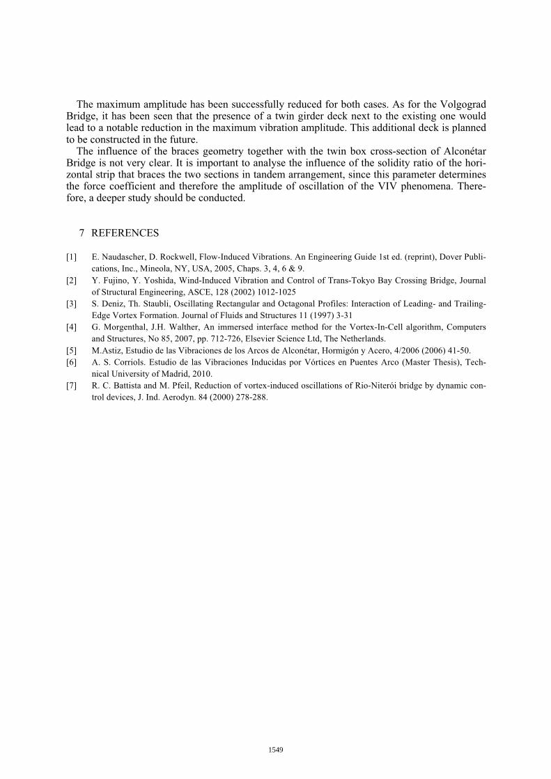
This configuration would modify the vortex-shedding pattern allowing the maximum ampli-tude to decrease to a half of the amplitude associated to the standard section (0.20 m). Moreover, this solution would have permitted the small-scale energy generation that could contribute to the bridge illumination and other small necessities related to its maintenance. It is also planned to build a second bridge deck next to the current in the future, so its influence over the aerodynamic actions have also been studied using the simulation code. As shown in Figure 10, the location of a second section reduces the amplitude of vibration of the initial section.
Figure 9. Damping system assembled inside Volgograd Bridge (left). Improvement of bridge behavior against VIV effects by adding a Savonius type turbine on the lower corner of the cross-section (right)
1547
The Seventh International Colloquium on Bluff Body Aerodynamics and Applications (BBAA7)Shanghai, China; September 2-6, 2012
For a critical wind speed of 13m/s, the RMS amplitude is 0.14 m while it was 0.32 m for the standard section. The lift coefficient is 0.24, not considering the contribution of the lift forces of the right section (downstream).
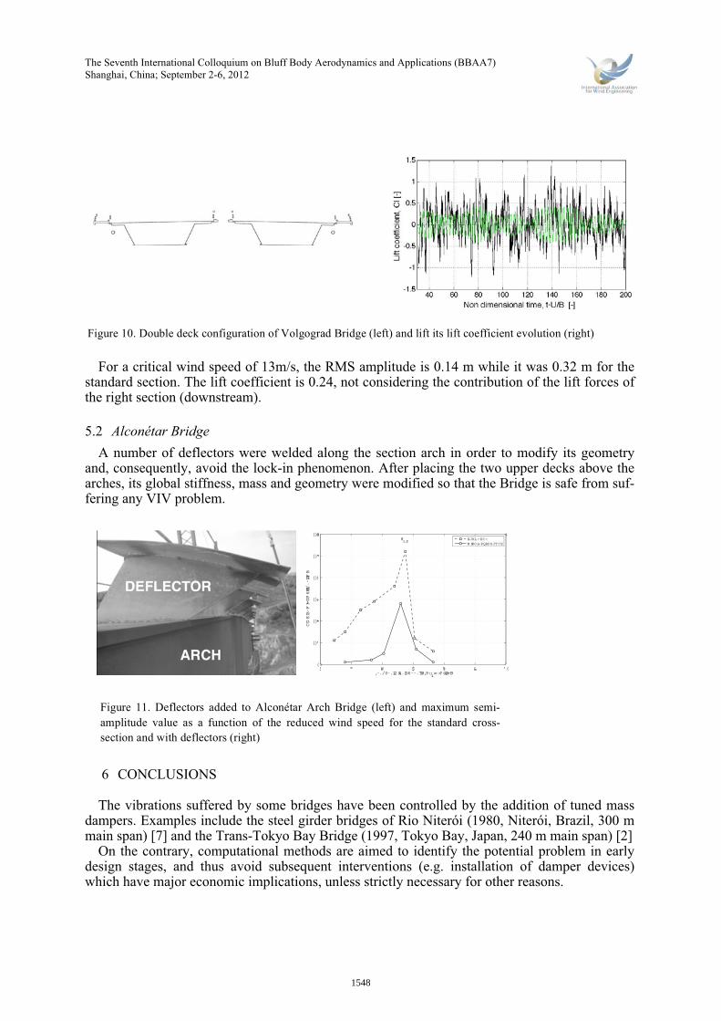
5.2 Alconétar BridgeA number of deflectors were welded along the section arch in order to modify its geometry
and, consequently, avoid the lock-in phenomenon. After placing the two upper decks above the arches, its global stiffness, mass and geometry were modified so that the Bridge is safe from suf-fering any VIV problem.
6 CONCLUSIONS
The vibrations suffered by some bridges have been controlled by the addition of tuned mass dampers. Examples include the steel girder bridges of Rio Niterói (1980, Niterói, Brazil, 300 m main span) [7] and the Trans-Tokyo Bay Bridge (1997, Tokyo Bay, Japan, 240 m main span) [2]
On the contrary, computational methods are aimed to identify the potential problem in early design stages, and thus avoid subsequent interventions (e.g. installation of damper devices) which have major economic implications, unless strictly necessary for other reasons.
Figure 10. Double deck configuration of Volgograd Bridge (left) and lift its lift coefficient evolution (right)
! " # $ % & ’((
()’
()*
()+
()!
()"
()#
,-./0-.1234.156--.718,9:;4<=>?@1A B
CDE15-F3GF6H3I/.-1AFB
1
180,3I
EJKL=KC=M NJO1=PQRPSJTCE
Figure 11. Deflectors added to Alconétar Arch Bridge (left) and maximum semi-amplitude value as a function of the reduced wind speed for the standard cross-section and with deflectors (right)
1548
The maximum amplitude has been successfully reduced for both cases. As for the Volgograd Bridge, it has been seen that the presence of a twin girder deck next to the existing one would lead to a notable reduction in the maximum vibration amplitude. This additional deck is planned to be constructed in the future.
The influence of the braces geometry together with the twin box cross-section of Alconétar Bridge is not very clear. It is important to analyse the influence of the solidity ratio of the hori-zontal strip that braces the two sections in tandem arrangement, since this parameter determines the force coefficient and therefore the amplitude of oscillation of the VIV phenomena. There-fore, a deeper study should be conducted.
7 REFERENCES
[1] E. Naudascher, D. Rockwell, Flow-Induced Vibrations. An Engineering Guide 1st ed. (reprint), Dover Publi-cations, Inc., Mineola, NY, USA, 2005, Chaps. 3, 4, 6 & 9.
[2] Y. Fujino, Y. Yoshida, Wind-Induced Vibration and Control of Trans-Tokyo Bay Crossing Bridge, Journal of Structural Engineering, ASCE, 128 (2002) 1012-1025
[3] S. Deniz, Th. Staubli, Oscillating Rectangular and Octagonal Profiles: Interaction of Leading- and Trailing-Edge Vortex Formation. Journal of Fluids and Structures 11 (1997) 3-31
[4] G. Morgenthal, J.H. Walther, An immersed interface method for the Vortex-In-Cell algorithm, Computers and Structures, No 85, 2007, pp. 712-726, Elsevier Science Ltd, The Netherlands.
[5] M.Astiz, Estudio de las Vibraciones de los Arcos de Alconétar, Hormigón y Acero, 4/2006 (2006) 41-50.[6] A. S. Corriols. Estudio de las Vibraciones Inducidas por Vórtices en Puentes Arco (Master Thesis), Tech-
nical University of Madrid, 2010.[7] R. C. Battista and M. Pfeil, Reduction of vortex-induced oscillations of Rio-Niterói bridge by dynamic con-
trol devices, J. Ind. Aerodyn. 84 (2000) 278-288.
1549