compression packing technical manual - galloup · compression packing technical manual. contents...
TRANSCRIPT

Compression Packing Technical Manual

ContentsSection A: Compression PackingStyles Flexible Graphite Packings ............................ A-2 Nuclear Applications ...................................... A-5 Pump Packing ................................................ A-6 Carbon Packings ............................................ A-8 Graphite Packing ........................................... A-9 SYNTHEPAK® Packings ................................ A-9 Blended Packings .......................................... A-10 PTFE Packings .............................................. A-11 Flush Water Products ..................................... A-12 Soot Blower Sets ........................................... A-13Engineering Guidelines Style Index ..................................................... A-14 Packing Materials ........................................... A-18 Construction ................................................... A-20 Material Selection .......................................... A-21 Equipment Condition ...................................... A-22 Installation Instructions .................................. A-23 Testing ............................................................ A-25 Gasket Spacers ............................................. A-26 Gland Load .................................................... A-26 pH Values ....................................................... A-27 Common Oxidizers ........................................ A-27 Bolt Torque Table for Die-Formed Sets .......... A-28 Ordering Information ...................................... A-29 Application Data Sheet .................................. A-30
Section B: Expansion JointsStyles Expansion Joint Selection .............................. B-2 GUARDIAN® 200 and 200HP ......................... B-3 Styles 204 and 204HP ................................... B-4 Style 204EVS ................................................. B-5 GUARDIAN® 306 EZ-FLO® ........................... B-6 Style 206 EZ-FLO® ........................................ B-8 Style 104GS ................................................... B-9 Styles 214 and 215 Flexible Couplings .......... B-10 Styles 207 and 208 ........................................ B-12 GARFLEX® 8100 ............................................ B-13 Style 9394 ...................................................... B-14 Style 8400 Flue Ducts .................................... B-15 Style 8420 Split .............................................. B-16 Navy & Coast Guard Approved Styles ........... B-17Engineering Data Technical Data ............................................... B-18 Types of Expansion Joints ............................. B-20 Expansion Joint Components ........................ B-21 Types of Pipe Movements .............................. B-22 Properties of Elastomers ................................ B-23 Temperature Ratings ...................................... B-23 Expansion Joint Installation ........................... B-24
Section C: Gasketing MaterialStyles Compressed Inorganic Fiber Gasketing ......... C-4 High Temp Compressed Graphite or Carbon Fiber Gasketing ................................ C-6 BLUE-GARD® Compressed Gasketing ........... C-8 Other Compressed Gasketing ........................ C-10 GYLON® Gasketing ......................................... C-12 GRAPH-LOCK® Gasketing ............................. C-19 Premium & Reinforced Rubber Gasketing ...... C-20 Vegetable Fiber Gasketing .............................. C-23Engineering Data Gasket Performance and Selection ................ C-24 Chemical Resistance Chart ............................ C-26 Sheet Sizes and Tolerances ........................... C-39 M & Y Data, Gasket Constants ....................... C-40 Bolting and Flange Information ....................... C-42 Installation ....................................................... C-43 Torque Tables .................................................. C-44 Design Tips ..................................................... C-48 Gasketing Terms ............................................. C-49 Test Procedures and Equipment ..................... C-54 Application Data Form .................................... C-58
Section D: Metallic GasketsStyles Spiral Wound Gaskets .................................... D-3 Handhole and Manhole Gaskets ..................... D-9 Heat Exchanger and Vessel Gaskets ............. D-13 Engineering Data Gasket Performance and Selection ................ D-18 Material Temperature Limits ............................ D-19 Thickness and Tolerances .............................. D-19 Flange Types, Finish, Bores ........................... D-20 Gasket Dimensions ......................................... D-23 Gasket Seating Requirements ........................ D-32 Torque Tables .................................................. D-35 Gasket Installation .......................................... D-42 Troubleshooting Leaking Joints ...................... D-43 Ordering Guide ............................................... D-44 Application Data Form .................................... D-45
Section E: Hydraulic ComponentsStyles CHEVRON® Vee Ring Packing ....................... E-2 Style 9220 GARTHANE® U-Seals ................... E-12 Polytop and SLUDGE-PAK® Sets ................... E-13 Roll Balance Packing ...................................... E-14
Troubleshooting ............................................. B-25 Weights .......................................................... B-26 Application Data Form ................................... B-27

A-1
Garlock Compression Packing
Packing ProductsFlexible Graphite Packings Style 1303-FEP ..................................................A-2 Style 1304 ..........................................................A-2 Style 1333-G ......................................................A-2 GRAPH-LOCK® Engineered Sets ......................A-3 QUICKSET® 9001 ..............................................A-3 9000 EVSP Simplified ........................................A-4Nuclear Applications Style G-700 ........................................................A-5Pump Packing HYDRA-JUST™ .................................................A-6 8093 DSA ...........................................................A-7 8094 DSA ...........................................................A-7Carbon Packings Style 98 ..............................................................A-8 CARBAE™ 105 ..................................................A-8 CARBAE™ 108 ..................................................A-8 Style 5000 ..........................................................A-9Graphite Packing Style G-200 ........................................................A-9SYNTHEPAK® Packings ...........................................A-9Blended Packings GAMUT™ Style 1812 ......................................A-10 Style 1925 ........................................................A-10 Style 1965 ........................................................A-11PTFE Packings Style 5888 ........................................................A-11 Style 5889 ........................................................A-11 Style 5904 ........................................................A-12Flush Water Products Style 1004 Lantern Ring Coil ..........................A-12 FLUSH-GARD™ Seal ......................................A-12 Crown Bush .....................................................A-13
The Garlock Compression Packing facility is com-mitted to supplying the highest quality engineered prod-ucts to industry throughout the world. Garlock packing is designed to give the user the greatest return on initial investment in terms of leakage control, service life, and dependable, cost-effective product.
The facility also houses the Garlock Textile Divi-sion, where we continue to research and develop new fiber blends to bring customers a wide array of pack-ings with optimum performance characteristics.
Soot Blower Sets GRAPH-LOCK® Sets .......................................A-13 TORNADO PACK™ F1 ....................................A-13 TORNADO PACK™ F3 ....................................A-13 TORNADO PACK™ F5 ....................................A-13
Engineering GuidelinesStyle Selection Style Index .......................................................A-14 Packing Materials .............................................A-18 Construction .....................................................A-20 Material Selection ............................................A-21Effective Sealing Equipment Condition ........................................A-22 Installation Instructions ....................................A-23 Testing ..............................................................A-25 Gasket Spacers ...............................................A-26 Gland Load ......................................................A-26
AppendixpH Values ...............................................................A-27Common Oxidizers .................................................A-27Bolt Torque Table for Die-Formed Sets ..................A-28Ordering Information ..............................................A-29RPM /FPM Conversion Table .................................A-29Application Data Sheet ...........................................A-30
CARBAE™, FLUSH-GARD™, GAMUT™ and TORNADO PACK™ are trademarks of Garlock Inc.
GARFITE®, GRAPH-LOCK®, LATTICE BRAID®, MILL-RIGHT®, PACK-MASTER®, QUICKBUSHINGS®, QUICKSET®, and SYNTHEPAK® are registered trademarks of Garlock Inc.
ContentsStyle 98

A-2
Flexible Graphite Packings
Style 1303-FEPSuperior performance ■ Compliance with the most stringent VOC and VHAP
emissions regulations■ Thermally conductive; resists heat, pressure and
chemicals■ Fire safe■ Dimensionally stable, impervious to gases and fluids■ Non-scoring, self-lubricating, non-hardening ■ Ideal for the hydrocarbon, chemical processing and
power generation industries
Convenience■ Spool stock reduces inventory and downtime■ Handles easily, retains integrity when cut and
formed■ No end rings required
SpecificationsConstruction: High-purity GRAPH-LOCK® flexible
graphite and 0.004" INCONEL* filament
Temperature: -328°F (-200°C) to +850°F (+455°C) atmosphere; to +1,200°F (+650°C) steam
pH range: 0-14 (except strong oxidizers)Pressure: To 4,500 psi (310 bar)
Style 1304Tough and versatile■ Handles both rotary and valve service■ Non-hardening, self-lubricating, dimensionally stable■ Easy to cut and install■ Ideally suited for the pulp and paper, mining,
primary metals and power generation industries■ Dry running capability—see Stealth Packing, pg 22
SpecificationsConstruction: Proprietary, high-purity flexible
GRAPH-LOCK® braided yarn, encapsulated by an aramid jacket
Temperature: -328°F (-200°C) to +700°F (+370°C)pH range: 0-14 (except strong oxidizers)Pressure: To 3,000 psi (200 bar) valves;
To 500 psi (34 bar) rotaryShaft speed: 4,000 fpm (20 m/s) rotary
Style 1333-GEconomical and easy to use■ Offset square design makes installation easy; en-
sures tight seal in worn or oversize stuffing boxes■ All-graphite, PTFE-free construction: • Maximizes reliability and stability in high tempera-
tures; also provides excellent chemical resistance • Dissipates heat quickly, so equipment runs cooler
and requires less flush water■ Graphite filament reinforcement resists extrusion in
high pressure applications■ Convenient spool stock reduces inventory, downtime■ Ideal for valves, steam service, rotary applications
SpecificationsConstruction: Offset square flexible graphite braid
reinforced with graphite filamentTemperature: -400°F (-240°C) to +850°F (+455°C)
atmosphere; +1,200°F (+650°C) steampH range: 0-14 (except strong oxidizers)Pressure: To 4,000 psi (275 bar) valves, no end
rings; To 500 psi (35 bar) rotaryShaft speed: To 4,800 fpm (23 m/s) rotary
*INCONEL® is a registered trademark of Inco Alloys International, Inc.

A-3
QUICKSET® 9001*
Top performance and versatility■ Five-ring set of die-formed cup and cone graphite
rings and high-density end rings ensure tight seal■ Meets global emissions standards■ Lowest stem friction ever for graphite packing sets
means longer equipment life■ Preassembled and ready to install■ No measuring, no cutting, no waste■ Fire Safe
SpecificationsConstruction: Die-formed cup and cone rings com-
bined with die-formed, high-density Style 1303-Dry end rings with zinc
Temperature: -328°F (-200°C) to +850°F (+455°C) atmosphere; to +1,200°F (+650°C) steam
pH range: 0-14 (except strong oxidizers)Pressure: To 10,000 psi plus (690 bar)
WARNING:Properties/applications shown throughout this brochure are typical. Your specific applica-tion should not be undertaken without independent study and evaluation for suitability. For specific application recommendations consult Garlock. Failure to select the proper sealing products could result in property damage and/or serious personal injury. Performance data published in this brochure has been developed from field testing, customer field reports and/or in-house testing.
GRAPH-LOCK® Engineered SetsThe Garlock patented cup and cone design of die-
formed graphite rings, used in 9000 EVSP and QUICK-SET® 9001 valve packing sets and in DSA series pump packing sets, offers unique advantages:■ I.D. and O.D.-specific pure graphite rings mean low
friction and superior sealing at high temperatures■ The cup & cone design increases radial expansion
of the sealing rings up to 1/8" (3.2 mm) or more ■ Better sealing and room for later adjustment; pro-
longs the life of the packing ■ Varying densities of the graphite rings allow for
direct loading of the center seal rings by the gland followerFlat die-formed rings cannot achieve the superior
results of Garlock die-formed cup & cone engineered valve and pump packing sets.
* Patent #5,806,858QUICKSET® 9001 Typical Ring Arrangement
Bushing MaterialsGarlock recommends the use of bushing materials
when stuffing box depths exceed the space required for installation of an effective sealing set.
Recommended materials include:■ 1303-Dry
• Highly densified rings using the same end material as in QUICKSET® 9001 • Furnished in square cross sections • Particularly useful when valve depth cannot be determined prior to repack
■ Carbon • Supplied split, drilled and tapped to specified length • Available in two standard grades: – Style 4525, Grade 250: for commercial use – Style 4540, Grade 580: for nuclear appli- cations
While the utmost care has been used in compiling this brochure, we assume no respon-sibility for errors. Specifications subject to change without notice. This edition cancels all previous issues. Subject to change without notice. GARLOCK is a registered trademark for packings, seals, gaskets, and other products of Garlock.
Style 1303-Dry30° ConcaveHigh-Density
Adapter End Ring
Style 1303-Dry30° ConvexHigh-Density
Adapter End Ring
Three 45°Concave/Convex
Low-DensityGRAPH-LOCK®
Center Preforms

A-4
Excellent sealing Our best available sealing technology for emissions compliance■ Patented cup and cone design permits selective
component compression and controlled radial flow for effective sealing on I.D. and O.D.
■ End rings act as wiper rings to restrict graphite particle transfer, prevent extrusion and provide extra resiliency
Custom design capability■ Patented cup and cone design provides sealability
in valves as shallow as three ring cross sections■ For deep stuffing boxes requiring more than a 7-ring
set, machined / split carbon bushings can shorten the box depth
• Grade 250 (Style #4525) for general services • Grade 580 (Style #4540) for nuclear services
■ Available in commercial and nuclear grades■ Consult Garlock Applications Engineering with
details of your application.■ Fire Safe
SpecificationsConstruction: GRAPH-LOCK® rings of high-purity
diamond texturized graphite tape, in cup and cone configuration; end rings made from Garlock Style 98
Temperature: -328°F (-200°C) to +850°F (+455°C) atmosphere; to +1,200°F (+650°C) steam
pH Range: 0-14 (except strong oxidizers)Pressure: To 10,000 psi plus (690 bar)* Patent #4,328,974
Live loadingLive loading can provide gland load retention for
in-service consolidation of the packing. A set of disc-spring washers placed on each gland stud bolt between the gland flange and gland bolt nut helps exert a con-tinuous compressive force on the gland follower flange and, therefore, on the packing set.
Live loading is recommended where any one of these five criteria is present:■ 5,000 or more complete valve stem actuations are
anticipated before the next scheduled repacking, or the valve stem is in a state of constant modulation
■ Standard installation procedures cannot be followed■ The valve is critical to the operation of the process■ Multiple thermal cycling of the valve is anticipated
due to the process system ■ The valve is inaccessible for future adjustment
Our live loading program is specifically designed to compensate for the reduced in-service consolidation needs of todayʼs asbestos-free graphite or carbon-based packing sets. It consists of even numbers of opposing disc-spring washers sandwiched between standard flat washers.
Valve StemLive Loaded
Adjustment Bolt
High Density GRAPH-LOCK®
Low Density GRAPH-LOCK®
High Density GRAPH-LOCK®
Braided End Rings
Bushing
CarbonBushing
Die-FormedCup & ConePacking Set
Live LoadSpringStack
9000 EVSP* Simplified

A-5
Nuclear Applications
Style G-700Highest standards■ When used as end rings together with high purity
GRAPH-LOCK® rings, G700 is ideal for critical valve applications** in nuclear and power genera-tion industries
■ Tested by independent laboratories; compliant with: • MIL-P-24583B (SH) • General Electric Spec. D50YP12 Rev. 2
■ Contains no PTFE or other lubricants■ Non-abrasive; very low coefficient of friction■ Will not fray
SpecificationsConstruction: Highest grade graphite filament with an exclusive graphite dispersion, in LATTICE BRAID® constructionTemperature: -328°F (-200°C) to +1200°F (+650°C) in steam; +1625°F (+900°C) in free oxygen-exclusive environments such as nitrogen and carbon dioxide; +850°F (+455°C) atmospherepH range: 0-14 (except strong oxidizers)Pressure: To 4,000 psi (275 bar) plus, when used with GRAPH-LOCK® center rings* INCONEL® is a registered trademark of Inco Alloys International, Inc.** Used as end rings ONLY.
WARNING:Properties/applications shown throughout this brochure are typical. Your specific applica-tion should not be undertaken without independent study and evaluation for suitability. For specific application recommendations consult Garlock. Failure to select the proper sealing products could result in property damage and/or serious personal injury. Performance data published in this brochure has been developed from field testing, customer field reports and/or in-house testing. While the utmost care has been used in compiling this brochure, we assume no respon-sibility for errors. Specifications subject to change without notice. This edition cancels all previous issues. Subject to change without notice. GARLOCK is a registered trademark for packings, seals, gaskets, and other products of Garlock.

A-6
Pump Packing
Better Than Both— Packing or Mechanical Seals.Ordinary packing must leak to perform. And common system upsets can spell disaster for mechanical seals. The HYDRA-JUST™ system provides a truly leak-free rotary seal—without the risk of catastrophic failure.
The Choice for Water Reduction.Because the HYDRA-JUST™ seal provides cool, dry operation with no product dilution, overall water consumption is significantly reduced. And, unlike mechanical seals, it actually works better in high pressure/low flow conditions.
Designed For True Outage-to-Outage Performance.Engineered from innovative materials, the HYDRA-JUST™ seal has the versatility to handle a wide range of system upsets and excels in the most hostile en-vironments and abrasive conditions for extraordinary long service life.
Easy to Install. Engineered from innovative materials, the HYDRA-JUST™ seal has the versatility to handle a wide range of system upsets and excels in the most hostile en-vironments and abrasive conditions for extraordinary long service life.
To learn more, visit www.hydrajust.com
Introducing the
Engineered Sealing System —the leak-free, no dilution sealing system designed to replace mechanical seals in industrial pumping applications.
A-7
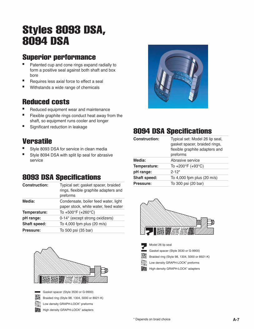
Styles 8093 DSA, 8094 DSASuperior performance■ Patented cup and cone rings expand radially to
form a positive seal against both shaft and box bore
■ Requires less axial force to effect a seal■ Withstands a wide range of chemicals
Reduced costs■ Reduced equipment wear and maintenance■ Flexible graphite rings conduct heat away from the
shaft, so equipment runs cooler and longer■ Significant reduction in leakage
Versatile■ Style 8093 DSA for service in clean media■ Style 8094 DSA with split lip seal for abrasive
service
Gasket spacer (Style 3530 or G-9900)
Braided ring (Style 98, 1304, 5000 or 8921-K)
Low density GRAPH-LOCK® preforms
High density GRAPH-LOCK® adapters
* Depends on braid choice
Model 26 lip seal
Gasket spacer (Style 3530 or G-9900)
Braided ring (Style 98, 1304, 5000 or 8921-K)
Low density GRAPH-LOCK® preforms
High density GRAPH-LOCK® adapters
8093 DSA Specifications Construction: Typical set: gasket spacer, braided rings, flexible graphite adapters and preforms Media: Condensate, boiler feed water, light paper stock, white water, feed waterTemperature: To +500°F (+260°C)pH range: 0-14* (except strong oxidizers)Shaft speed: To 4,000 fpm plus (20 m/s)Pressure: To 500 psi (35 bar)
8094 DSA Specifications Construction: Typical set: Model 26 lip seal, gasket spacer, braided rings, flexible graphite adapters and preforms Media: Abrasive serviceTemperature: To +200°F (+93°C)pH range: 2-12* Shaft speed: To 4,000 fpm plus (20 m/s)Pressure: To 300 psi (20 bar)
A-8
Carbon Packings
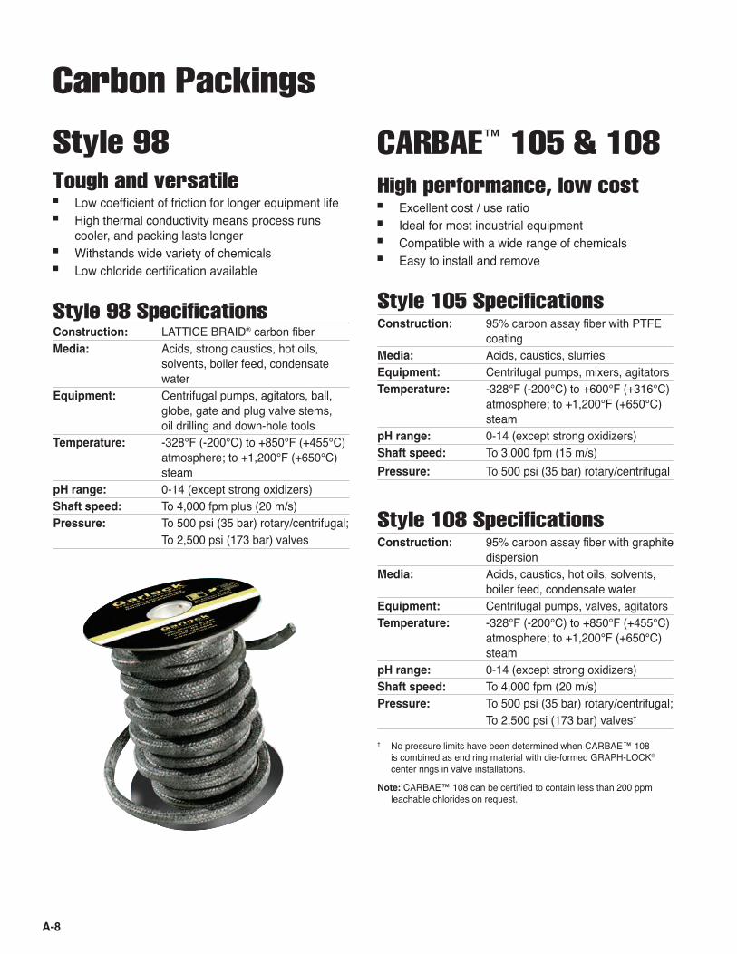
Style 98Tough and versatile■ Low coefficient of friction for longer equipment life■ High thermal conductivity means process runs
cooler, and packing lasts longer■ Withstands wide variety of chemicals■ Low chloride certification available
Style 98 Specifications Construction: LATTICE BRAID® carbon fiberMedia: Acids, strong caustics, hot oils, solvents, boiler feed, condensate waterEquipment: Centrifugal pumps, agitators, ball, globe, gate and plug valve stems, oil drilling and down-hole toolsTemperature: -328°F (-200°C) to +850°F (+455°C) atmosphere; to +1,200°F (+650°C) steampH range: 0-14 (except strong oxidizers)Shaft speed: To 4,000 fpm plus (20 m/s)Pressure: To 500 psi (35 bar) rotary/centrifugal; To 2,500 psi (173 bar) valves
CARBAE™ 105 & 108High performance, low cost■ Excellent cost / use ratio■ Ideal for most industrial equipment■ Compatible with a wide range of chemicals■ Easy to install and remove
Style 105 Specifications Construction: 95% carbon assay fiber with PTFE coatingMedia: Acids, caustics, slurries Equipment: Centrifugal pumps, mixers, agitatorsTemperature: -328°F (-200°C) to +600°F (+316°C) atmosphere; to +1,200°F (+650°C) steampH range: 0-14 (except strong oxidizers)Shaft speed: To 3,000 fpm (15 m/s)Pressure: To 500 psi (35 bar) rotary/centrifugal
Style 108 Specifications Construction: 95% carbon assay fiber with graphite dispersionMedia: Acids, caustics, hot oils, solvents, boiler feed, condensate waterEquipment: Centrifugal pumps, valves, agitatorsTemperature: -328°F (-200°C) to +850°F (+455°C) atmosphere; to +1,200°F (+650°C) steampH range: 0-14 (except strong oxidizers)Shaft speed: To 4,000 fpm (20 m/s)Pressure: To 500 psi (35 bar) rotary/centrifugal; To 2,500 psi (173 bar) valves†
† No pressure limits have been determined when CARBAE™ 108 is combined as end ring material with die-formed GRAPH-LOCK® center rings in valve installations.
Note: CARBAE™ 108 can be certified to contain less than 200 ppm leachable chlorides on request.

A-9
Style G-200High performance ■ Withstands elevated temperatures and aggressive
chemicals■ Low coefficient of friction reduces shaft wear■ Ideal end ring (with GRAPH-LOCK® center rings) in
valve service■ Low chloride certification available
Graphite Packing
SYNTHEPAK® PackingsSuperior performance■ Unique spun synthetic fiber; ideal replacement for
asbestos■ Excellent for pumps, valves, rods, plungers, rams,
expansion joints■ Reduction in shaft and sleeve wear lowers opera-
tional costs■ Versatile, multi-use packing means lower inventory
stocking costs■ See Styles 8909, 8913, 8921-K, 8922, 8922-PBI
on pages A-16, A-17 for specifications
* PBI is a registered trademark of Celanese Corporation.
Style 5000
Durable, non-contaminating■ Low abrasion and high chemical resistance for
long service■ Ideal where contamination is prohibited, as in pulp
and paper industry■ Low chloride certification available ■ Style 5000-PBI* offers extra abrasion resistance
Specifications Construction: LATTICE BRAID® carbon fiber impreg- nated with PTFE, hi-temp break-in lubeMedia: Acids, strong caustics, slurriesEquipment: Slip joints, mixers, agitators, reactors, autoclaves, centrifugal pumps, tur-binesTemperature: -328°F (-200°C) to +600°F (+315°C)pH range: 0-14 (except strong oxidizers)Shaft speed: To 3,000 fpm plus (15 m/s)Pressure: To 500 psi (35 bar) rotary/centrifugal
Specifications Construction: LATTICE BRAID® GARFITE® graphite yarnMedia: Acids, natural petroleum, synthetic oils, solvents, steam, waterEquipment: Boiler feed pumps, agitators, mixers, crystallizers, filters, continuous digest- ers, reciprocating pump rodsTemperature: -328°F (-200°C) to +850°F (+455°C) atmosphere; to +1,200°F (+650°C) steampH range: 0-14 (except strong oxidizers)Shaft speed: To 4,000 fpm plus (20 m/s)Pressure: To 500 psi (35 bar) rotary/ centrifugal
A-10
WARNING:Properties/applications shown throughout this brochure are typical. Your specific applica-tion should not be undertaken without independent study and evaluation for suitability. For specific application recommendations consult Garlock. Failure to select the proper sealing products could result in property damage and/or serious personal injury. Performance data published in this brochure has been developed from field testing, customer field reports and/or in-house testing. While the utmost care has been used in compiling this brochure, we assume no respon-sibility for errors. Specifications subject to change without notice. This edition cancels all previous issues. Subject to change without notice. GARLOCK is a registered trademark for packings, seals, gaskets, and other products of Garlock.
Blended Packing
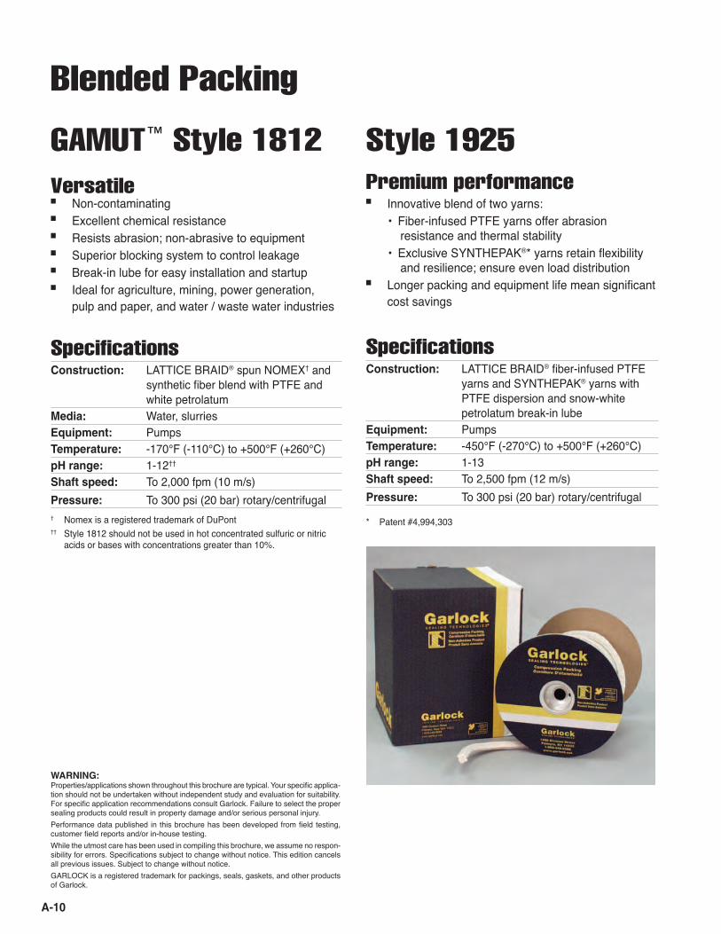
Style 1925Premium performance■ Innovative blend of two yarns: • Fiber-infused PTFE yarns offer abrasion
resistance and thermal stability • Exclusive SYNTHEPAK®* yarns retain flexibility
and resilience; ensure even load distribution■ Longer packing and equipment life mean significant
cost savings
Specifications Construction: LATTICE BRAID® fiber-infused PTFE yarns and SYNTHEPAK® yarns with PTFE dispersion and snow-white petrolatum break-in lubeEquipment: PumpsTemperature: -450°F (-270°C) to +500°F (+260°C) pH range: 1-13Shaft speed: To 2,500 fpm (12 m/s)Pressure: To 300 psi (20 bar) rotary/centrifugal
* Patent #4,994,303† Nomex is a registered trademark of DuPont†† Style 1812 should not be used in hot concentrated sulfuric or nitric
acids or bases with concentrations greater than 10%.
GAMUT™ Style 1812Versatile ■ Non-contaminating■ Excellent chemical resistance■ Resists abrasion; non-abrasive to equipment■ Superior blocking system to control leakage■ Break-in lube for easy installation and startup■ Ideal for agriculture, mining, power generation,
pulp and paper, and water / waste water industries
Specifications Construction: LATTICE BRAID® spun NOMEX† and synthetic fiber blend with PTFE and white petrolatumMedia: Water, slurries Equipment: PumpsTemperature: -170°F (-110°C) to +500°F (+260°C)pH range: 1-12††
Shaft speed: To 2,000 fpm (10 m/s)Pressure: To 300 psi (20 bar) rotary/centrifugal

A-11
Style 1965Superb flexibility & easy handling■ Protects machinery's critical components from abra-
sive media■ Lowers maintenance and sealing element expendi-
tures■ Product does not extrude and lasts longer in service■ Material flexibility and easy handling mean faster
change-out times■ Non-contaminating components keep end product
and pump area clean■ Shock resistant withstanding cavitation, pressure
surges and other system upsets■ Increased thermal stability conserves water
Specifications Construction: LATTICE BRAID® fiber-infused PTFE yarns* with Graphite and SYNTHEPAK® yarns, PTFE dispersion and snow white petrolatumEquipment: PumpsTemperature: -450°F (-270°C) to +500°F (+260°C) pH range: 1-13Shaft speed: 2,500 fpm (10 m/s)Pressure: 300 psi (20 bar) rotary/centrifugal
* Patent #4,994,303
PTFE Packings
Style 5888Valve stem packing with superior chemical resistance■ High density, dimensionally stable—very little water
absorption■ Ideal for valve and slower shaft speed applications■ PTFE dispersion ensures a low friction finish and
prevents leakage through the braid■ Resistant to most chemicals
SpecificationsConstruction: LATTICE BRAID® continuous filament PTFE braid with PTFE dispersionEquipment: Check and needle valve stems, reciprocating rods, rams and plungers, and rotary applicationsTemperature: -450°F (-270°C) to +500°F (+260°C)pH range: 0-14Shaft speed: To 1,000 fpm plus (5 m/s)Pressure: To 300 psi (20 bar) rotary / centrifugal; To 2,000 psi (138 bar) valves
Note: For oxygen service, specify Style 5898.
Style 5889Chemically resistant packing for pumps and rotary equipment ■ Preshrunk to avoid packing wear and shaft scoring■ Soft, flexible but very nonporous■ Excellent choice for rotary shaft service
SpecificationsConstruction: LATTICE BRAID® continuous filament PTFE braid with PTFE dispersion and inert break-in lubeEquipment: Expansion joints, reciprocating rods, rams, plungers, rotary serviceTemperature: -450°F (-270°C) to +500°F (+260°C)pH range: 0-14*Shaft speed: To 1,500 fpm plus (8 m/s)Pressure: To 300 psi (20 bar) rotary/centrifugal* Not recommended for chlorine service

A-12
WARNING:Properties/applications shown throughout this brochure are typical. Your specific applica-tion should not be undertaken without independent study and evaluation for suitability. For specific application recommendations consult Garlock. Failure to select the proper sealing products could result in property damage and/or serious personal injury. Performance data published in this brochure has been developed from field testing, customer field reports and/or in-house testing. While the utmost care has been used in compiling this brochure, we assume no respon-sibility for errors. Specifications subject to change without notice. This edition cancels all previous issues. Subject to change without notice. GARLOCK is a registered trademark for packings, seals, gaskets, and other products of Garlock.
Style 5904Food grade packing■ Ideal for food processing applications■ Pliable, wear-resistant and dimensionally stable ■ Resists most caustic media■ Rugged and non-toxic■ Ingredients conform to USDA requirements and
meet FDA Title 21 CFR 172.878, 177.1550, 178.3570 and 178.3620(a)
SpecificationsConstruction: LATTICE BRAID® PTFE filamentEquipment: Pumps, dryers, cookers, blenders, mixers, and other centrifugal rotary food processing equipmentTemperature: -450°F (-270°C) to +500°F (+260°C)pH range: 0-14Shaft speed: To 1,500 fpm plus (8 m/s)Pressure: To 300 psi (20 bar) rotary/centrifugal
Style 1004 Lantern Ring Coil*
Economical and easy to handle■ Costs up to 50% less than OE-supplied lantern rings■ Easily cut with knife or saw, and short lengths splice
together, eliminating waste■ Easy to install** and remove from stuffing box—re-
duces costly downtime■ High-purity PTFE offers chemical resistance in a
broad range of rotary services
Specifications Construction: Wear-resistant high-grade PTFEEquipment: PumpsTemperature: To +500°F (+260°C) pH range: 0-14 (except strong oxidizers)
Flush Water Products
FLUSH-GARD™ SealReduces flush water■ Throat cavity bushing reduces flush water
consumption■ Extends equipment life by protecting sleeve and
packing from media attack■ Split design installs easily, without equipment disas-
sembly
Specifications Construction: Graphite-filled PTFETemperature: -250°F (-157°C) to +450°F (+232°C) Surface speed: To 2,500 fpm (12.7 m/s)†
pH range: 0-14 (except strong oxidizers)
* U.S. Patent #4,498,681; Canada Patent #1,271,788** For maximum strength and density, install with slots toward shaft; for
maximum gland water flow, install with slots away from shaft.† Above 2,500 fpm, consult Garlock.†† INCONEL is a registered trademark of Inco Alloys International, Inc.††† PBI is a registered trademark of Celanese Corporation.
PTFE Packings

A-13
Soot Blower Sets
GRAPH-LOCK® SetsConstruction: Premium density GRAPH-LOCK® center rings (87.5 lbs/ft3 [1,400 kg/m3]) with 1303-FEP or 98 end ringsTemperature: To +850°F (+455°C) atmosphere, +1,200°F (+650°C) steam
TORNADO PACK™ F1Construction: Style 127-AFP: INCONEL wire rein- forced carbon over homogeneous coreTemperature: To +650°F (+345°C) atmosphere, +1,200°F (+650°C) steam
TORNADO PACK™ F3Construction: Style 1298: INCONEL wire reinforced PBI††† over carbon yarn coreTemperature: To +850°F (+455°C) atmosphere, +1,200°F (+650°C) steam
TORNADO PACK™ F5Construction: Style 1303-FEP: INCONEL wire rein- forced fl exible graphiteTemperature: To +850°F (+455°C) atmosphere, +1,200°F (+650°C) steam
Exceptional reliability■ Rugged materials for
extended service life■ INCONEL†† wire
reinforcement with-stands high temperatures and pressures
■ Die-formed rings en-sure accurate fi t and simple installation
■ Effi cient conical design allows outstanding sealing at low gland loads
■ Standard sizes for Diamond Power, Copes Vulcan and other soot blowers
Crown Bush Pump Sealing SystemLower your operating costs■ Signifi cantly reduce fl ush water usage■ Extend packing life■ Reduce sleeve wear■ Flush water distribution optimised to keep contami-
nants away from the gland packing■ Stainless Steel Crown Bush fl ow control device
resists erosion from abrasive contaminants■ Non-metallic construction available for non-abrasive
duties■ Split version available
Applications■ Pulp and paper■ Mining■ Mineral Sands■ Alumina Refi ning■ Coal Washing
A-14
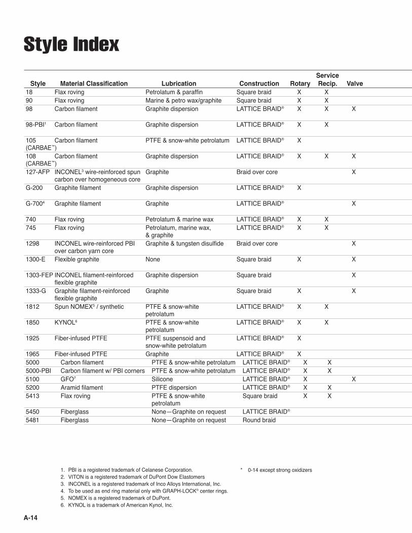
Service Temperature Pressure (psi) Pressure (bar) Shaft SpeedStyle Material Classification Lubrication Construction Rotary Recip. Valve Fahrenheit Centigrade Rotary Valve Rotary Valve fpm m/s pH
18 Flax roving Petrolatum & paraffin Square braid X X To +220° To +105° 150 10 1,200 6 5-990 Flax roving Marine & petro wax/graphite Square braid X X To +220° To +105° 300 20 1,200 6 5-998 Carbon filament Graphite dispersion LATTICE BRAID® X X X -328° to +850° atmosphere -200° to +455° atmosphere 500 2,500 35 173 4,000 20 0-14* +1,200° steam +650° steam98-PBI1 Carbon filament Graphite dispersion LATTICE BRAID® X X To +650° atmosphere To +345° atmosphere 500 35 4,000 20 1-12 105 Carbon filament PTFE & snow-white petrolatum LATTICE BRAID® X -328° to +600° atmosphere -200° to +316 ° atmosphere 500 35 3,000 15 0-14* (CARBAE™) 108 Carbon filament Graphite dispersion LATTICE BRAID® X X X -328° to +850° atmosphere -200° to +455° atmosphere 500 2,500 35 173 4,000 20 0-14* (CARBAE™) +1,200° steam +650° steam 127-AFP INCONEL3 wire-reinforced spun Graphite Braid over core X +850° atmosphere +455° atmosphere 1,200 82 1-12 carbon over homogeneous core +1,200° steam +650° steamG-200 Graphite filament Graphite dispersion LATTICE BRAID® X -328° to +850° atmosphere -200° to +455° atmosphere 500 35 4,000 20 0-14* +1,200° steam +650° steamG-7004 Graphite filament Graphite LATTICE BRAID® X To +850° atmosphere To +455° atmosphere 4,000 275 0-14* +1,200° steam +650 steam740 Flax roving Petrolatum & marine wax LATTICE BRAID® X X To +220° To +105° 150 10 1,200 6 5-9745 Flax roving Petrolatum, marine wax, LATTICE BRAID® X X To +220° To +105° 250 17 1,200 6 5-9 & graphite 1298 INCONEL wire-reinforced PBI Graphite & tungsten disulfide Braid over core X To +850° atmosphere To +455° atmosphere 4,500 310 1-12 over carbon yarn core +1,200° steam +650° steam1300-E Flexible graphite None Square braid X X -328° to +850° atmosphere -200° to +455° atmosphere 500 3,000 35 200 4,000 20 0-14* +1,200° steam +650° steam 1303-FEP INCONEL filament-reinforced Graphite dispersion Square braid X -328° to +850° atmosphere -200° to +455° atmosphere 4,500 310 0-14* flexible graphite +1,200° steam +650° steam 1333-G Graphite filament-reinforced Graphite Square braid X X -328° to +850° atmosphere -200° to +455° atmosphere 500 4,000 35 275 4,800 23 0-14* flexible graphite +1,200° steam +650° steam1812 Spun NOMEX5 / synthetic PTFE & snow-white LATTICE BRAID® X X -170° to +500° -110° to +260° 300 20 2,000 10 1-12 petrolatum 1850 KYNOL6 PTFE & snow-white LATTICE BRAID® X X -170° to +500° -110° to +260° 500 35 2,000 10 1-13 petrolatum 1925 Fiber-infused PTFE PTFE suspensoid and LATTICE BRAID® X -450° to +500° -270° to +260° 300 20 2,500 12 1-13 snow-white petrolatum 1965 Fiber-infused PTFE Graphite LATTICE BRAID® X -450° to +500° -270° to +260° 300 20 2,500 12 1-135000 Carbon filament PTFE & snow-white petrolatum LATTICE BRAID® X X -328° to +600° -200° to +315° 500 35 3,000 15 0-14*5000-PBI Carbon filament w/ PBI corners PTFE & snow-white petrolatum LATTICE BRAID® X X -328° to +600° -200° to +315° 500 35 3,000 15 1-125100 GFO7 Silicone LATTICE BRAID® X X -200° to +550° -130° to +288° 300 2,000 20 138 4,000 20 0-14*5200 Aramid filament PTFE dispersion LATTICE BRAID® X X -420° to +500° -250° to +260° 500 35 2,500 12 2-125413 Flax roving PTFE & snow-white Square braid X X To +250° To +120° 200 14 1,200 6 5-9 petrolatum5450 Fiberglass None—Graphite on request LATTICE BRAID® To +1000° To +540° 10 1 2-115481 Fiberglass None—Graphite on request Round braid To +1000° To +540° 10 1 2-11
Style Index
1. PBI is a registered trademark of Celanese Corporation.2. VITON is a registered trademark of DuPont Dow Elastomers3. INCONEL is a registered trademark of Inco Alloys International, Inc.4. To be used as end ring material only with GRAPH-LOCK® center rings.5. NOMEX is a registered trademark of DuPont.6. KYNOL is a trademark of American Kynol, Inc.
* 0-14 except strong oxidizers

A-15
Service Temperature Pressure (psi) Pressure (bar) Shaft SpeedStyle Material Classification Lubrication Construction Rotary Recip. Valve Fahrenheit Centigrade Rotary Valve Rotary Valve fpm m/s pH
18 Flax roving Petrolatum & paraffin Square braid X X To +220° To +105° 150 10 1,200 6 5-990 Flax roving Marine & petro wax/graphite Square braid X X To +220° To +105° 300 20 1,200 6 5-998 Carbon filament Graphite dispersion LATTICE BRAID® X X X -328° to +850° atmosphere -200° to +455° atmosphere 500 2,500 35 173 4,000 20 0-14* +1,200° steam +650° steam98-PBI1 Carbon filament Graphite dispersion LATTICE BRAID® X X To +650° atmosphere To +345° atmosphere 500 35 4,000 20 1-12 105 Carbon filament PTFE & snow-white petrolatum LATTICE BRAID® X -328° to +600° atmosphere -200° to +316 ° atmosphere 500 35 3,000 15 0-14* (CARBAE™) 108 Carbon filament Graphite dispersion LATTICE BRAID® X X X -328° to +850° atmosphere -200° to +455° atmosphere 500 2,500 35 173 4,000 20 0-14* (CARBAE™) +1,200° steam +650° steam 127-AFP INCONEL3 wire-reinforced spun Graphite Braid over core X +850° atmosphere +455° atmosphere 1,200 82 1-12 carbon over homogeneous core +1,200° steam +650° steamG-200 Graphite filament Graphite dispersion LATTICE BRAID® X -328° to +850° atmosphere -200° to +455° atmosphere 500 35 4,000 20 0-14* +1,200° steam +650° steamG-7004 Graphite filament Graphite LATTICE BRAID® X To +850° atmosphere To +455° atmosphere 4,000 275 0-14* +1,200° steam +650 steam740 Flax roving Petrolatum & marine wax LATTICE BRAID® X X To +220° To +105° 150 10 1,200 6 5-9745 Flax roving Petrolatum, marine wax, LATTICE BRAID® X X To +220° To +105° 250 17 1,200 6 5-9 & graphite 1298 INCONEL wire-reinforced PBI Graphite & tungsten disulfide Braid over core X To +850° atmosphere To +455° atmosphere 4,500 310 1-12 over carbon yarn core +1,200° steam +650° steam1300-E Flexible graphite None Square braid X X -328° to +850° atmosphere -200° to +455° atmosphere 500 3,000 35 200 4,000 20 0-14* +1,200° steam +650° steam 1303-FEP INCONEL filament-reinforced Graphite dispersion Square braid X -328° to +850° atmosphere -200° to +455° atmosphere 4,500 310 0-14* flexible graphite +1,200° steam +650° steam 1333-G Graphite filament-reinforced Graphite Square braid X X -328° to +850° atmosphere -200° to +455° atmosphere 500 4,000 35 275 4,800 23 0-14* flexible graphite +1,200° steam +650° steam1812 Spun NOMEX5 / synthetic PTFE & snow-white LATTICE BRAID® X X -170° to +500° -110° to +260° 300 20 2,000 10 1-12 petrolatum 1850 KYNOL6 PTFE & snow-white LATTICE BRAID® X X -170° to +500° -110° to +260° 500 35 2,000 10 1-13 petrolatum 1925 Fiber-infused PTFE PTFE suspensoid and LATTICE BRAID® X -450° to +500° -270° to +260° 300 20 2,500 12 1-13 snow-white petrolatum 1965 Fiber-infused PTFE Graphite LATTICE BRAID® X -450° to +500° -270° to +260° 300 20 2,500 12 1-135000 Carbon filament PTFE & snow-white petrolatum LATTICE BRAID® X X -328° to +600° -200° to +315° 500 35 3,000 15 0-14*5000-PBI Carbon filament w/ PBI corners PTFE & snow-white petrolatum LATTICE BRAID® X X -328° to +600° -200° to +315° 500 35 3,000 15 1-125100 GFO7 Silicone LATTICE BRAID® X X -200° to +550° -130° to +288° 300 2,000 20 138 4,000 20 0-14*5200 Aramid filament PTFE dispersion LATTICE BRAID® X X -420° to +500° -250° to +260° 500 35 2,500 12 2-125413 Flax roving PTFE & snow-white Square braid X X To +250° To +120° 200 14 1,200 6 5-9 petrolatum5450 Fiberglass None—Graphite on request LATTICE BRAID® To +1000° To +540° 10 1 2-115481 Fiberglass None—Graphite on request Round braid To +1000° To +540° 10 1 2-11
WARNING:Properties/applications shown throughout this brochure are typical. Your specific applica-tion should not be undertaken without independent study and evaluation for suitability. For specific application recommendations consult Garlock. Failure to select the proper sealing products could result in property damage and/or serious personal injury. Performance data published in this brochure has been developed from field testing, customer field reports and/or in-house testing.
While the utmost care has been used in compiling this brochure, we assume no respon-sibility for errors. Specifications subject to change without notice. This edition cancels all previous issues. Subject to change without notice. GARLOCK is a registered trademark for packings, seals, gaskets, and other products of Garlock.

A-16
5888 PTFE filament PTFE suspensoid LATTICE BRAID® X X X -450° to +500° -270° to +260° 300 2,000 20 138 1,000 5 0-145889 PTFE filament PTFE dispersion & silicone LATTICE BRAID® X -450° to +500° -270° to +260° 300 20 1,500 8 0-14**5898 PTFE filament PTFE dispersion LATTICE BRAID® X -450° to +500° -270° to +260° 300 2,000 20 138 1,000 5 0-145904 PTFE filament—FDA PTFE dispersion / mineral oil LATTICE BRAID® X X -450° to +500° -270° to +260° 300 20 1,500 8 0-148091 Dynamic Rotary N/A GYLON® & Graphite X To 500ºF 200ºC 500 35 4,000 20 0-14 HYDRA- Sealing Solution Braid with Graphite JUST Cup & Cone 8093 DSA Flexible graphite N/A Die-formed sets X To +500° To +260° 500 35 4,000 20 0-14*8094 DSA Flexible graphite / Model 26 N/A Die-formed sets X To +200° To +93° 300 20 4,000 20 2-128909 Spun synthetic Graphite & petrolatum Square braid X -170° to +500° -110° to +260° 300 20 1,500 8 4-108913 Spun synthetic Graphite & petrolatum LATTICE BRAID® X -170° to +500° -110° to +260° 300 20 1,500 8 4-108921-K Spun synthetic—aramid PTFE suspensoid & LATTICE BRAID® X X X -170° to +550° -110° to +288° 500 2,500 35 173 2,250 11 0-12 filament corners snow-white petrolatum 8922 Spun synthetic PTFE suspensoid & LATTICE BRAID® X X X -170° to +550° -110° to +288° 500 2,500 35 173 2,500 12 0-12 snow-white petrolatum 8922-PBI Spun synthetic / PBI corners PTFE suspensoid & LATTICE BRAID® X X -170° to +550° -110° to +288° 500 35 2,250 11 1-12 snow-white petrolatum 9000 EVSP Flexible graphite N/A Die-formed sets X -328° to +850° atmosphere -200° to +455° atmosphere 10,000 690 0-14* +1,200° steam +650° steam QUICKSET® Flexible graphite N/A Die-formed sets X -328° to +850° atmosphere -200° to +455° atmosphere 10,000 690 0-14* 9001 +1,200° steam +650° steam F1 INCONEL3 wire-reinforced spun Graphite & zinc Die-formed sets Soot blower To +650° atmosphere To +345° atmosphere 1-12 carbon over homogeneous core +1,200° steam +650° steamF3 INCONEL wire-reinforced PBI1 Graphite & tungsten disulfide Die-formed sets Soot blower To +850° atmosphere To +455° atmosphere 1-12 over carbon yarn core +1,200° steam +650° steamF5 INCONEL wire-reinforced spun Graphite dispersion Die-formed sets Soot blower To +850° atmosphere To +455° atmosphere 0-14 flexible graphite +1,200° steam +650° steam GRAPH- Flexible graphite N/A Die-formed sets, X X -328° to +850° atmosphere -200° to +455° atmosphere *** *** *** *** *** *** 0-14* LOCK® tape +1,200° steam +650° steamPM†-1 Spun synthetic PTFE suspensoid & LATTICE BRAID® X -170° to +500° -110° to +260° 300 20 1,500 8 4-10 snow-white petrolatum PM-2 Spun synthetic Petroleum oils & graphite LATTICE BRAID® X -170° to +500° -110° to +260° 300 20 1,500 8 4-10PM-3 Spun synthetic Petroleum oils & graphite Square braid X -170° to +500° -110° to +260° 200 14 1,000 5 4-10PM-5 Aramid filament Silicone LATTICE BRAID® X X -420° to +500° -250° to +260° 500 35 2,500 12 2-12PM-6 Expanded PTFE/graphite Silicone LATTICE BRAID® X -200° to +550° -130° to +288° 300 20 3,000 15 0-14**PM-6K Expanded PTFE filament— Silicone LATTICE BRAID® X X -200° to +550° -130° to +288° 500 35 1,900 10 3-12 aramid filament corners PM-7 PTFE filament PTFE suspensoid LATTICE BRAID® X X X -450° to 500° -270° to +260° 300 2,000 20 138 1,000 5 0-14PM-8 PTFE filament Silicone LATTICE BRAID® X -450° to 500° -270° to +260° 300 20 1,500 8 0-14**
Service Temperature Pressure (psi) Pressure (bar) Shaft SpeedStyle Material Classification Lubrication Construction Rotary Recip. Valve Fahrenheit Centigrade Rotary Valve Rotary Valve fpm m/s pH
Style Index (cont'd)
* 0-14 except strong oxidizers** Should not be used in chlorine*** Pressure and shaft speeds controlled by types of braid used in con-
junction with the GRAPH-LOCK® product† PM = PACKMASTER®
1. PBI is a registered trademark of Celanese Corporation.2. VITON is a registered trademark of DuPont Dow Elastomers3. INCONEL is a registered trademark of Inco Alloys International, Inc.4. To be used as end ring material only with GRAPH-LOCK® center rings.5. NOMEX is a registered trademark of DuPont6. KYNOL is a trademark of American Kynol, Inc.7. GFO is a trademark of WL Gore.

A-17
5888 PTFE filament PTFE suspensoid LATTICE BRAID® X X X -450° to +500° -270° to +260° 300 2,000 20 138 1,000 5 0-145889 PTFE filament PTFE dispersion & silicone LATTICE BRAID® X -450° to +500° -270° to +260° 300 20 1,500 8 0-14**5898 PTFE filament PTFE dispersion LATTICE BRAID® X -450° to +500° -270° to +260° 300 2,000 20 138 1,000 5 0-145904 PTFE filament—FDA PTFE dispersion / mineral oil LATTICE BRAID® X X -450° to +500° -270° to +260° 300 20 1,500 8 0-148091 Dynamic Rotary N/A GYLON® & Graphite X To 500ºF 200ºC 500 35 4,000 20 0-14 HYDRA- Sealing Solution Braid with Graphite JUST Cup & Cone 8093 DSA Flexible graphite N/A Die-formed sets X To +500° To +260° 500 35 4,000 20 0-14*8094 DSA Flexible graphite / Model 26 N/A Die-formed sets X To +200° To +93° 300 20 4,000 20 2-128909 Spun synthetic Graphite & petrolatum Square braid X -170° to +500° -110° to +260° 300 20 1,500 8 4-108913 Spun synthetic Graphite & petrolatum LATTICE BRAID® X -170° to +500° -110° to +260° 300 20 1,500 8 4-108921-K Spun synthetic—aramid PTFE suspensoid & LATTICE BRAID® X X X -170° to +550° -110° to +288° 500 2,500 35 173 2,250 11 0-12 filament corners snow-white petrolatum 8922 Spun synthetic PTFE suspensoid & LATTICE BRAID® X X X -170° to +550° -110° to +288° 500 2,500 35 173 2,500 12 0-12 snow-white petrolatum 8922-PBI Spun synthetic / PBI corners PTFE suspensoid & LATTICE BRAID® X X -170° to +550° -110° to +288° 500 35 2,250 11 1-12 snow-white petrolatum 9000 EVSP Flexible graphite N/A Die-formed sets X -328° to +850° atmosphere -200° to +455° atmosphere 10,000 690 0-14* +1,200° steam +650° steam QUICKSET® Flexible graphite N/A Die-formed sets X -328° to +850° atmosphere -200° to +455° atmosphere 10,000 690 0-14* 9001 +1,200° steam +650° steam F1 INCONEL3 wire-reinforced spun Graphite & zinc Die-formed sets Soot blower To +650° atmosphere To +345° atmosphere 1-12 carbon over homogeneous core +1,200° steam +650° steamF3 INCONEL wire-reinforced PBI1 Graphite & tungsten disulfide Die-formed sets Soot blower To +850° atmosphere To +455° atmosphere 1-12 over carbon yarn core +1,200° steam +650° steamF5 INCONEL wire-reinforced spun Graphite dispersion Die-formed sets Soot blower To +850° atmosphere To +455° atmosphere 0-14 flexible graphite +1,200° steam +650° steam GRAPH- Flexible graphite N/A Die-formed sets, X X -328° to +850° atmosphere -200° to +455° atmosphere *** *** *** *** *** *** 0-14* LOCK® tape +1,200° steam +650° steamPM†-1 Spun synthetic PTFE suspensoid & LATTICE BRAID® X -170° to +500° -110° to +260° 300 20 1,500 8 4-10 snow-white petrolatum PM-2 Spun synthetic Petroleum oils & graphite LATTICE BRAID® X -170° to +500° -110° to +260° 300 20 1,500 8 4-10PM-3 Spun synthetic Petroleum oils & graphite Square braid X -170° to +500° -110° to +260° 200 14 1,000 5 4-10PM-5 Aramid filament Silicone LATTICE BRAID® X X -420° to +500° -250° to +260° 500 35 2,500 12 2-12PM-6 Expanded PTFE/graphite Silicone LATTICE BRAID® X -200° to +550° -130° to +288° 300 20 3,000 15 0-14**PM-6K Expanded PTFE filament— Silicone LATTICE BRAID® X X -200° to +550° -130° to +288° 500 35 1,900 10 3-12 aramid filament corners PM-7 PTFE filament PTFE suspensoid LATTICE BRAID® X X X -450° to 500° -270° to +260° 300 2,000 20 138 1,000 5 0-14PM-8 PTFE filament Silicone LATTICE BRAID® X -450° to 500° -270° to +260° 300 20 1,500 8 0-14**
Service Temperature Pressure (psi) Pressure (bar) Shaft SpeedStyle Material Classification Lubrication Construction Rotary Recip. Valve Fahrenheit Centigrade Rotary Valve Rotary Valve fpm m/s pH
WARNING:Properties/applications shown throughout this brochure are typical. Your specific applica-tion should not be undertaken without independent study and evaluation for suitability. For specific application recommendations consult Garlock. Failure to select the proper sealing products could result in property damage and/or serious personal injury. Performance data published in this brochure has been developed from field testing, customer field reports and/or in-house testing.
While the utmost care has been used in compiling this brochure, we assume no respon-sibility for errors. Specifications subject to change without notice. This edition cancels all previous issues. Subject to change without notice. GARLOCK is a registered trademark for packings, seals, gaskets, and other products of Garlock.

A-18
Packing MaterialsAramid
These fibers are aromatic polyamides that were given the generic name “aramid.” With excellent re-sistance to high temperatures and exceptional tensile strength, aramid filaments are considered to be stron-ger, pound for pound, than steel. Garlock utilizes a variety of these fibers including spun and filament ver-sions. Filament yarns are added to the corners of pump packings for greater resistance to abrasive media.
Carbon/Graphite Filament PackingsGarlock carbon filament products are made from
carbon yarns having a 95% minimum carbon assay. Premium products (Styles 98, 98-VC and 5000) use pitch-based yarns, while CARBAE™ Styles 105 and 108 are made from P.A.N.* base yarns. Low friction coefficients are standard for less shaft wear and lower maintenance and replacement costs. Garlock carbon fibers also offer more value per pound than other pack-ings.
Garlock graphite filament products are braided from high-purity graphite filaments with a minimum carbon assay of 99%. They have excellent chemical resistance, are thermally conductive and can be used in extreme temperature and pressure conditions.
FiberglassGlass fibers exhibit superior thermal properties,
dimensional stability and tensile strength. Glass fibers will not burn, and they dissipate heat more rapidly than organic fibers. The glass fibers most commonly used in compression packings are “E” grade (electrical) and “S” grade (strength). Common solvents, oils, petroleum distillates, bleaches and most organic chemicals do not affect fiberglass.
FlaxGarlock carefully selects quality long-fiber roving
yarns, braids them, and then thoroughly impregnates them with the required lubricating agents. They are designed for optimum service in waste and dilute aque-ous solutions up to +250°F (+121°C) at low to medium pressures. Industries such as mining, milling, steel, waste/water treatment, marine, and pulp and paper regularly specify these packings for their operations.
GRAPH-LOCK® ProductsMade of extremely pure graphite, Garlock GRAPH-
LOCK® packing products offer unmatched service in industrial environments where searing temperatures and crushing pressures cause constant failure of con-ventional packings.
Flexible Graphite Tape Products
GRAPH-LOCK® is self-lubricating, dimensionally stable, impervious to gases and fluids, and corrosion-resistant. GRAPH-LOCK® products offer excellent sealing capabilities under extreme conditions for longer equipment life and less maintenance. It is available in tape and die-formed rings from Garlock Compression Packing and in sheet form from Garlock Sheet Prod-ucts.
Garlock Compression Packing offers two purity levels of our GRAPH-LOCK® products—commercial grade of 95% and nuclear grade of 99.5%. The nuclear grade material meets General Electric Spec. D50YP12, Rev. 2 dated Oct. 1992; MIL-P-24503B (SH); and can be certified for oxygen service.
Flexible Graphite Braided Products
Garlock offers a variety of high-purity braided flex-ible GRAPH-LOCK® products as well. We offer a plain braided graphite version (1300), INCONEL** wire-re-inforced versions (1303-FEP, 1398, 1399), an aramid-reinforced version (1304), and a graphite filament-rein-forced version (1333-G).
MILL-RIGHT® ProductsThe experience gained over 100 years as a
manufacturer has enabled Garlock to develop “Tough Technology” for the MILL-RIGHT® family of packings. Fiber-infused technology starts with yarns produced at our own facility. With the addition of an exclusive block-ing and lubricating system, Garlock non-contaminating packings can resist abrasion without being abrasive to equipment and perform successfully throughout a broad range of industries and applications.
* P.A.N.: poly-acrylo-nitrile** INCONEL is a registered trademark of Inco Alloys International, Inc.

A-19
PBIPBI is a registered trademark of Celanese Corpo-
ration, and is an acronym for the term “polybenzimi-dazole”, a high performance organic fiber. PBI fibers maintain dimensional stability at high temperatures and are compatible in a wide range of chemicals and sol-vents. Garlock incorporates wire-reinforced PBI yarns in valve stem packings as well as adding spun fila-ment yarns to the corners of pump packings for added strength and abrasion resistance.
PTFE PackingsGarlock starts with the advantage of PTFE—excel-
lent chemical resistance, a wide temperature range, flexibility with toughness—and combines them with the superior LATTICE BRAID® construction to form adapt-able, effective packings. High in quality and consistently uniform, they are used extensively in the food process-ing, chemical, agricultural and petroleum processing industries.
SYNTHEPAK® Products SYNTHEPAK® packings are a family of remarkable
spun synthetic fiber packings created and developed by Garlock for low-cost general industrial service. Since they undergo the same braiding and treatment process as asbestos packings, SYNTHEPAK® packings make an excellent replacement for asbestos. This extremely adaptable fiber has proved superior to many types of conventional packings.
XPGThe expanded PTFE/Graphite (XPG) yarn system
is a unique blend of expanded PTFE filament with a blend of micronized graphite powder. The yarn utilizes a high temperature silicone oil lubricant. It can be used through an extremely wide range of applications in-cluding acids, alkalies, aromatic and aliphatic solvents, alcohols, esters, petroleum and synthetic oils, steam, water and aqueous solutions, and air and dry industrial gases.
XPG features good thermal conductivity, speed capability, chemical resistance, low coefficient of fric-tion and low coefficient of thermal expansion, making it excellent for use in pumps, mixers and agitators.
WARNING:Properties/applications shown throughout this brochure are typical. Your specific applica-tion should not be undertaken without independent study and evaluation for suitability. For specific application recommendations consult Garlock. Failure to select the proper sealing products could result in property damage and/or serious personal injury. Performance data published in this brochure has been developed from field testing, customer field reports and/or in-house testing. While the utmost care has been used in compiling this brochure, we assume no respon-sibility for errors. Specifications subject to change without notice. This edition cancels all previous issues. Subject to change without notice. GARLOCK is a registered trademark for packings, seals, gaskets, and other products of Garlock.

A-20
Construction
Figure 1
Figure 2
Figure 3
Compression packings are made in a variety of shapes, sizes and constructions, from a wide range of materials. The following describes the most commonly-used constructions, and the advantages of each.
Braid-Over-Braid (Figure 1)Round braiding machines braid tubular jackets
using yarns, rovings, ribbons and various other materi-als, either alone or in combination. Size is obtained by braiding jackets one over the other (braid-over-braid). Finished packings can be supplied in round, square or rectangular cross section. Braid-over-braid packings, also known as round braid or multiple braid packings, are relatively dense and are recommended for high-pressure, slow-speed applications such as valve stems, expansion joints, groove gasketing, etc.
Braid-Over-Core (Figure 2)Finished product is produced by round braiding
one or more jackets of yarns, rovings, ribbons or other forms of various materials over a core, which may be extruded, twisted, wrapped or knitted. This construction allows for a wide range of densities and different cross sectional shapes.
Square Braid (Figure 3) Yarns, rovings, ribbons and other various materi-
als, either alone or in combination, are processed on equip-ment where strands pass over and under strands running in the same direction. Resulting packings are usually supplied in square cross section, but rectan-gular sizes can also be braided by this method. The packing is usually soft and can carry a large percent-age of lubricant. Square braided packings are easy on equipment and are generally used for high-speed rotary service at relatively low pressure. The packingʼs soft-ness makes it ideal for old or worn equipment.
LATTICE BRAID® (Figure 4)Yarns, rovings, ribbons and other forms of various
materials, either alone or in combination, are processed on equipment where the strands crisscross from the surface diagonally through the body of the packing. Each strand is strongly locked by other strands to form a solid integral structure that cannot easily ravel or come apart in service. There are no jackets to wear through, and no plaits to come loose. LATTICE BRAID® packing has a more even distribution of yarn density
throughout and has the potential for improved lubricant retention. The finished packing is relatively dense, but flexible.
LATTICE BRAID® packings are suitable for appli-cations on both reciprocating and centrifugal pumps, agitators, valves, expansion joints and in grooves.
Figure 4
A-21
Die-FormedMany compression packing materials can be sup-
plied in a pre-compressed ring form, which provides controlled density and size.
Mandrel CutRings formed by wrapping braided stock of the
required cross section on a mandrel or shaft with a diameter equal to the desired I.D.
Graphite TapeFlexible graphite tape (ribbon) is manufactured by
exfoliating (expanding) and then compressing natu-ral graphite flakes to a specific density. Graphite has almost universal chemical inertness and is naturally lubricious, compactible and resilient, as well as nuclear radiation resistant.
Flexible graphite tape can be die-molded or com-pressed to form endless true labyrinth rings. Graphite tape packings have a low coefficient of friction, a pH range of 0-14 and are noted for their excellent thermal properties enabling them to be used in applications to 5500°F (3000°C) in non-oxidizing atmospheres. Due to their temperature resistance and density, they make ideal valve packings in steam, VOC, hydrocarbons or chemical applications when used in combination with braided end rings such as Styles 1303-FEP, 98 or G-700.
LubricantsLubricants are usually added to compression pack-
ings when the packings are to be used on rotary equip-ment where frictional heat is generated. The lubricants provide a resiliency that allows the packing to deform and recover under slight mechanical deficiencies such as shaft deflection. They may also provide interfiber lubricity that reduces frictional heat.
Blocking AgentsLubricants that act as a fluid barrier by closing the
voids that are present in braided materials to prevent leakage through the cross section of the packing.
Single End CoatingA proprietary Garlock process that coats each yarn
used in packing prior to the braiding process. This provides a more consistent coating of packing materials for better sealing.
Material SelectionThe proper selection of packing materials is de-
pendent on the operating conditions of the equipment. Six parameters of the equipment must be determined before a proper packing recommendation can be made. The acronym “STAMPS” is commonly used to desig-nate these parameters:
S = Size — cross sectionT = Temperature — of media being sealedA = Application — type of equipment (i.e., pumps, valves, mixers, etc.)M = Media — material being sealedP = Pressure — of media being sealedS = Speed — shaft speed in fpm (pumps only)
A-22
Equipment ConditionNo matter what type of equipment you are trying
to seal, the condition of the equipment is critical to the success of the packing. Garlock recommends:
Valves■ Longitudinal scores on the valve stem are not to
exceed 1/32" depth and/or a depth-to-width ratio greater than 1.00.
■ Stem finish no greater than 32 (micro inches) AARH. ■ Stuffing box finish is recommended to be 125
(micro inches) AARH.■ Valve stem warpage / runout must be checked and
found not to exceed: Runout
Stem Diameter (TIR / ft)Up to and including 1.500" (38.1 mm) ±0.010"1.501" to 3.000" (38.1 mm to 76.2 mm) ±0.020"3.001" (76.2 mm) and above ±0.040"
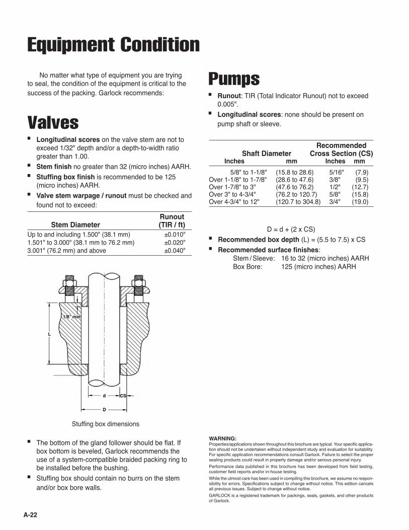
■ The bottom of the gland follower should be flat. If box bottom is beveled, Garlock recommends the use of a system-compatible braided packing ring to be installed before the bushing.
■ Stuffing box should contain no burrs on the stem and/or box bore walls.
Stuffing box dimensions
Recommended Shaft Diameter Cross Section (CS) Inches mm Inches mm
5/8" to 1-1/8" (15.8 to 28.6) 5/16" (7.9)Over 1-1/8" to 1-7/8" (28.6 to 47.6) 3/8" (9.5)Over 1-7/8" to 3" (47.6 to 76.2) 1/2" (12.7)Over 3" to 4-3/4" (76.2 to 120.7) 5/8" (15.8)Over 4-3/4" to 12" (120.7 to 304.8) 3/4" (19.0)
D = d + (2 x CS)■ Recommended box depth (L) = (5.5 to 7.5) x CS■ Recommended surface finishes:
Stem / Sleeve: 16 to 32 (micro inches) AARH Box Bore: 125 (micro inches) AARH
WARNING:Properties/applications shown throughout this brochure are typical. Your specific applica-tion should not be undertaken without independent study and evaluation for suitability. For specific application recommendations consult Garlock. Failure to select the proper sealing products could result in property damage and/or serious personal injury. Performance data published in this brochure has been developed from field testing, customer field reports and/or in-house testing. While the utmost care has been used in compiling this brochure, we assume no respon-sibility for errors. Specifications subject to change without notice. This edition cancels all previous issues. Subject to change without notice. GARLOCK is a registered trademark for packings, seals, gaskets, and other products of Garlock.
Pumps■ Runout: TIR (Total Indicator Runout) not to exceed
0.005".■ Longitudinal scores: none should be present on
pump shaft or sleeve.

A-23
Installation Instructions
1. Remove all of the old packing from the stuffing box. Clean box and stem thoroughly and examine stem for wear and scoring. Replace stem if wear is exces-sive. Recommended surface finishes are 32 (micro inches) AARH on the stem, and 125 (micro inches) AARH maximum on the box bore.
2. Measure and record stem diameter, stuffing box bore and box depth. To determine the correct pack-ing size, measure the diameter of the stem (inside the stuffing box area if possible), and the diameter of the stuffing box bore. Subtract the I.D. measurement from the O.D. measurement, and divide the differ-ence by two. This is the required cross-sectional size.
3. Always cut the packing into individual rings. Never wind the packing into a coil in the stuffing box. Rings should be cut with a butt joint. Cut rings by using a spare stem, a mandrel with the same diameter as the stem or a packing cutter. The illustration shows how to use a mandrel to cut packing.
Hold the packing tightly on the mandrel, but do not stretch excessively. Cut the ring and insert it into the stuffing box, making certain that it fits the packing space properly. Each additional ring can be cut in the same manner.
4. Install one ring at a time. Make sure it is clean, and has not picked up any dirt in handling. Seat each ring firmly, making sure it is fully seated before the next ring is installed. Joints of successive rings should be staggered and kept at least 90° apart. When enough rings have been individually seated so that the nose of the gland follower will reach them, individual tamping of the rings should be supplemented by the gland follower. Bring down the gland follower and apply load with the gland bolts.
5. After the last ring is installed, bring down the gland follower and apply 25% to 35% compression to the entire packing set. If possible, record the gland nut torque values and actuate the valve through five (5) complete cycles (ending with the stem in the down position). Retighten the gland bolt nuts to the pre-vi-ously recorded torque value after each full actuation.
Step 1
Step 2
Ruler
I.D. O.D.
Do NotStretchPacking
Mandrel
Step 3
Steps 4 and 5
Butt CutJoints
Valve Stem Packing

A-24
Pump Packing1. Remove all the old packing with packing hooks, be-
ing careful not to damage the shaft or sleeve. This means all rings, even the lantern ring and the rings below the lantern. Clean the stuffing box and exam-ine the shaft and sleeve. Replace any worn parts that are scored or deeply grooved.
2. Measure and record shaft diameter, stuffing box bore and box depth. To determine the correct pack-ing size, measure the diameter of the shaft and the stuffing box bore. Subtract the shaft diameter from the bore diameter and divide the difference by two. This is the required cross-sectional size.
3. Always cut the packing into individual rings. Never wind the packing into a coil in the stuffing box. Rings should be cut with a butt joint. Cut rings by using a mandrel with the same diameter as the shaft in the stuffing box area. If there is no wear, rings can be cut on the shaft outside the stuffing box.
Hold the packing tightly on the mandrel, but do not stretch excessively. Cut the ring and insert it into the stuffing box, making certain that it fits the packing space properly. Each additional ring can be cut in the same manner.
4. Install one ring at a time. Make sure it is clean, and has not picked up any dirt in handling. Lubricate the I.D. of each ring lightly. Start one end and then the other, butted closely. Work around circumference from either or both directions. Joints of successive rings should be staggered and kept at least 90° apart. Each individual ring should be firmly seated with a tamping tool. When enough rings have been individually seated so that the nose of the gland fol-lower will reach them, individual tamping should be supplemented by the gland.
5. If a lantern ring is provided, make sure the lantern ring is installed under the pipe tap hole.
6. After the last ring is installed, bring the follower down on the packing and finger-tighten the gland nuts. Do not jam the packing by excessive gland loading. Start pump, and tighten the bolts until leak-age is decreased to a tolerable minimum. Make sure gland bolts are tightened evenly. Stopping leakage entirely at this point will cause the packing to burn up.
7. Allow packing to leak freely upon startup after re-pack. Gradually reducing leakage during the first hour of operation will result in a better seal over a
Step 1 Step 2
Ruler
Step 3
Steps 5 and 6
I.D. O.D.
Butt CutJoints
Do NotStretchPacking
Mandrel
GlandFollower
LanternRing Flush
PortBraidedPacking
longer period of time. Tighten the gland nuts one flat at a time until the desired leakage is obtained, and the pump is running cool.
A-25
WARNING:Properties/applications shown throughout this brochure are typical. Your specific application should not be undertaken without independent study and evaluation for suitability. For specific application recommendations consult Garlock. Failure to select the proper sealing products could result in property damage and/or serious personal injury. Performance data published in this brochure has been developed from field testing, customer field reports and/or in-house testing. While the utmost care has been used in compiling this brochure, we assume no responsibility for errors. Specifications subject to change without notice. This edition cancels all previous issues. Subject to change without notice. GARLOCK is a registered trademark for packings, seals, gaskets, and other products of Garlock.
Testing
Functional TestingPump Test Fixtures
Garlock Compression Packing has three different pump test fixture designs used for evaluating pump packing set types and arrangements.
Media: Ambient temperature water Note: The end suction pump system, due to the dynamics of a closed loop system, can produce water temperatures as high as 160°F (70°C).
Abrasives: Can be introduced into the end suction pump systemShaft Speeds: From 367 fpm to 2,100 fpm (1.63 m/s to 9.33 m/s)Packing cross sections: Typically 3/8" (9.5 mm) cross section, but modifications can be made to test up to 5/8" (15.8 mm) cross section. Stuffing box pressures: 2 psi to 120 psi (0.1 to 8.3 bar)Note: Pressures above 60 psi (4.1 bar) are achieved by throttling down
the discharge flow in the end suction pump.
Stuffing box depths: 1.500" to 2.250" (38.1 mm to 57.2 mm)
High Temperature / Pressure Valve Test Fixtures
The basic design layout for this fixture was pro-duced by Dayton T. Brown (an independent test labora-tory in Bohemia, New York) for sanctioned qualification testing by the U.S. Military. Of four test valve positions, two use custom-made valve bonnets in MOV-type test scenarios, and two are standard production block valve bonnets that are hand-actuated.
Material TestingMaterial Testing Laboratory
The various testing capabilities are often used to check conformance to ISO material and processing specification requirements.
The Garlock Compression Packing facility has the capability to perform a range of in-house chemical and physical testing exercises. These tests are used to qualify or to check the conformance of incoming raw materials as an aid to in-process checks, or as a final qualification check to ensure that finished prod-ucts meet the customerʼs agreed-upon specifications. Whenever possible and practical, Garlock performs its testing pro-grams in conformance with existing ASTM procedures.
Examples of testing capabilities are:• Wet chemical testing• Weight loss determination• Exposure—radiation, argon, etc.• Yields—braid, ring• Tensile strength• Density determinations
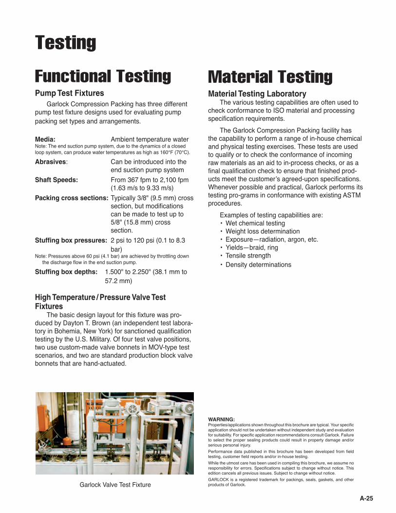
Garlock Valve Test Fixture

A-26
Gasket SpacersGasket spacers are used in conjunction with braided
packing rings to:■ Close up the clearances around the inside diameter
of the packing set, keeping solid particles from pro-gressing through the packing set along with the liquid leakage
■ Act as a throttle bushing and reduce the pressure on the outboard side of the spacer, in applications where the leakage rate is relatively high
■ Keep the packing from extruding beyond the stuffing box bottom, where there are excessive clearances between the I.D. of the stuffing box bottom and the shaft O.D. (This problem may occur through wear, corrosion, or simply the way a piece of equipment is manufactured)In applications involving high stuffing box pressures
(particularly reciprocating pumps) gasket spacers are also used to:■ Reduce the amount of leakage that occurs through
the body of the braid, by forcing leakage to the I.D. of the packing set and eliminating O.D. leakage
■ Keep the packing square, restrict packing movement, and prevent packing rollover and premature failure caused by excessive frictional forces
Gland LoadGarlock recommends using one of these two
methods to determine the proper gland load on a valve packing set. Percent Compression Method This method simply determines the distance the set should be compressed in order to achieve a seal. The recommended percent compression varies with pack-ing style.■ 9000-EVSP Simplified 30% compression
QUICKSET® 9001 30% compression■ 70# / ft3 density GRAPH-LOCK® 25% compression
70# / ft3 density #98 sets 25% compression■ 90# / ft3 density GRAPH-LOCK® 20% compression
90# / ft3 density #98 sets 20% compression■ Garlock braided packing only 25% compression
In cases where the system pressure is very high (over 2,500 psi or 72 bar), higher compression may be required to achieve a seal.
Predetermined gland bolt torque method This method determines a more precise gland load. The bolt torque depends upon packing size, gland bolt size, packing style system pressure, and the number of bolts. The gland studs and nuts must be in good condi-tion, cleaned with a wire brush and well-lubricated with a suitable grease.
Use the following equation to determine the appro-priate bolt torque:BoIt torque = (Bore dia.2 - Stem dia.2) x (Gland bolt dia.) x (Load factor) 76.39 x (No. of bolts)
Where: Bolt torque is in ft. lbs. Bore, stem, and bolt diameters are in inches Load factor is in psi
The load factor is determined by the following:■ For a 9000-EVSP Simplified set, a 9001 QUICK-
SET® or a Style #98 and GRAPH-LOCK® set:LF = 1.5 system pressure or 3,800 psi (whichever is greater)■ When using any other Garlock packing:LF = 1.5 system pressure or 5,500 psi (whichever is greater)
* Patent pending
Stealth Packing Set* Option■ Optimal dry running situation—eliminate flush and
lantern ring■ Combines Garlock Style 3530 GYLON® spacers
with Style 1304 or 1333-G cut rings■ Contact Applications Engineering for details
Stealth Packing Set Spacer and Ring Arrangement
Style 1304 or 1333-G Packing
Style 3530 Black GYLON®
Spacers

A-27
pH Values
Common Oxidizers
The scientific shorthand for indicating the level of acidity or alkalinity of a substance is the pH value. The
Oxidizers act as a catalyst and cause hydrocar-bons to combine with oxygen and cause breakdown of the fiber. Here is a partial listing of the most commonly used strong oxidizers. (A complete listing is available from Garlock Applications Engineering.)(a) Fluorine, used as an oxidizer or rocket fuel.(b) Sulfur Trioxide, used to make sulfuric acid.(c) Aqua Regia (nitric and hydrochloric acid), used to
dissolve metals.(d) Sodium Peroxide, used in dyeing, paper and oxy-
gen generation.(e) Oleum (fuming sulfuric), used in detergent and
explosive manufacturing.(f) Perchloric Acid, used in the manufacturing of explo-
sives, esters and medicine.(g) Sulfuric Acid, greater than 75% and over 250°F, the
most widely-used industrial chemical.(h) Chloric Acid, greater than 10% and over 200°F,
ignites organic materials on contact.
(i) Ferric Chloride, greater than 50% and over 200°F, used for sewage treatment, photography, medicine, etching, feed additives and oxidizing disinfectant.
(j) Nitric Acid, used in fertilizer, explosives, etching, medicine, dyeing and drugs.
(k) Chlorous Acid, greater than 10% and over 200°F.(I) Iodine, greater than 5% and over 200°F, used in
soaps, medicine, some lubricants, dyes and salt.(m) Hydrofluoric Acid, greater than 40% and over
200°F, used for pickling, purification, dissolving ores, cleaning castings, etching, cleaning stone and brick, and fermentation.
(n) Sodium Hypochlorite, greater than 5%, used in textiles, water purification and bleaching pulp and paper.
(o) Sodium Chlorate, greater than 5%, used as bleach for paper pulp, medicine and leather textiles.
(p) Calcium Chlorate, greater than 5%, used in pyro-technics and photography.
scale is logarithmic, making lye, at 13, ten times as alkaline as ammonia at 12.
ACIDIC ALKALINE / CAUSTIC
Severe Medium Mild to Medium Medium Severe Service Service Service Service Service
Battery Acid
LemonJuice
Vinegar
Acid Rain
DistilledWater
Seawater and Bak-ing Soda
Ammonia
Lye
0 1 2 3 4 5 6 7 8 9 10 11 12 13 14

A-28
Bolt Torques for Die-Formed Graphite SetsBore Diameter (inches)
Notes: 1. This table yields ft.-lb. torque values corresponding to a 3,800 psi
gland load. This is not a suitable gland load for all styles of packing.
0.375
0.438 0.500
0.563 0.625
0.688 0.750
0.813 0.875
0.938 1.000
1.063 1.125
1.188 1.250
1.313 1.375
1.438 1.500
1.563 1.625
1.688 1.750
1.813 1.875
1.938 2.000
2.063 2.125
2.188 2.250
2.313 2.375
2.438 2.500
0.625 6
5 3
2 0.688
8 7
6 4
2 0.750
10 9
8 6
4 2
0.813 13
12 10
9 7
5 2
0.875 16
14 13
11 9
7 5
3 0.938
18 17
16 14
12 10
8 5
3 1.000
21 20
19 17
15 13
11 8
6 3
1.063 25
23 22
20 18
16 14
12 9
6 3
1.125 28
27 25
24 22
20 17
15 12
10 7
3 1.188
32 30
29 27
25 23
21 19
16 13
10 7
4 1.250
35 34
33 31
29 27
25 22
20 17
14 11
7 4
1.313 39
38 37
35 33
31 29
26 24
21 18
15 11
8 4
1.375 44
42 41
39 37
35 33
31 28
25 22
19 16
12 8
4 1.438
47
45 44
42 40
37 35
32 30
27 23
20 16
13 9
4 1.500
50 48
46 44
42 40
37 34
31 28
24 21
17 13
9 5
1.563
53 51
49 47
44 42
39 36
33 29
26 22
18 14
9 5
1.625
58 56
54 52
49 47
44 41
38 34
31 27
23 19
14 10
5 1.688
61 59
57 54
52 49
46 43
39 36
32 28
24 19
15 10
5 1.750
64
62 60
57 54
51 48
45 41
37 33
29 25
20 15
10 5
1.813
68
65 63
60 57
54 50
47 43
39 35
30 26
21 16
11 6
1.875
73
71 68
66 63
59 56
52 49
45 40
36 31
27 22
17 11
6 1.938
77
74 72
68 65
62 58
55 51
46 42
37 33
28 23
17 12
6 2.000
80 78
75 71
68 64
61 57
52 48
44 39
34 29
23 18
12 6
2.063
84 81
78 74
71 67
63 59
54 50
45 40
35 30
24 18
12 6
2.125
90 87
84 81
77 73
69 65
61 56
52 47
41 36
31 25
19 13
7 2.188
94 91
88 84
80 76
72 68
63 58
53 48
43 37
32 26
20 13
7 2.250
98
94 91
87 83
79 75
70 65
60 55
50 44
38 33
26 20
14 7
2.313
102
98 94
90 86
82 77
72 67
62 57
51 46
40 34
27 21
14 7
2.375
109
105 101
97 93
89 84
80 75
69 64
59 53
47 41
34 28
21 14
7 2.438
113
109 105
101 96
92 87
82 77
72 66
60 54
48 42
35 29
22 15
7 2.500
117 113
108 104
99 95
90 85
79 74
68 62
56 50
43 36
30 22
15 8
2.563
120 116
112 107
103 98
92 87
82 76
70 64
58 51
44 37
30 23
16 8
2.625
129 124
120 115
111 106
101 95
90 84
78 72
66 59
52 45
38 31
24 16
2.688
133
128 124
119 114
109 103
98 92
86 80
74 67
61 54
47 39
32 24
2.750
137 132
127 122
117 112
106 101
95 89
82 76
69 62
55 48
40 33
2.813
141
136 131
126 121
115 109
103 97
91 84
78 71
64 56
49 41
2.875
150
145 140
135 129
124 118
112 106
100 93
87 80
73 65
58 50
2.938
154 149
144 138
133 127
121 115
109 102
96 89
82 74
67 59
3.000
158
153 148
142 136
130 124
118 112
105 98
91 84
76 68
3.063
162 157
152 146
140 134
127 121
114 107
100 93
85 78
3.125
172 167
161 155
150 143
137 131
124 117
110 103
95 87
3.188
177
171 165
159 153
147 140
134 127
120 112
105 97
3.250
181 175
169 163
157 150
144 137
130 122
115 107
3.313
185
180 173
167 161
154 147
140 133
125 117
3.375
196
190 184
177 171
164 157
150 143
136 128
3.438
201 194
188 182
175 168
161 154
146 138
3.500
205
199 192
186 179
172 164
157 149
3.563
210 203
197 190
183 175
168 160
3.625
221 215
208 201
194 187
179 171
3.688
226
219 212
205 198
190 183
3.750
231 224
217 209
202 194
3.813
236
229 221
214 206
3.875
248
240 233
226 218
3.938
253 245
238 230
4.000
258
250 242
Stem Diam
eter (inches)
2. The values in this table are given for a valve with two gland studs.
The values are not valid for valves with screw type packing nuts, or for valves with m
ore than two gland studs.
3. These torque values are valid only if gland studs are in good condi-tion and well-lubricated.
Torque in ft-lbs per inch of bolt diameter
To estimate stud torque required for 3,800 psi gland load,
multiply gland stud diam
eter by the number in the table cor-
responding to the correct stem and bore diam
eters.
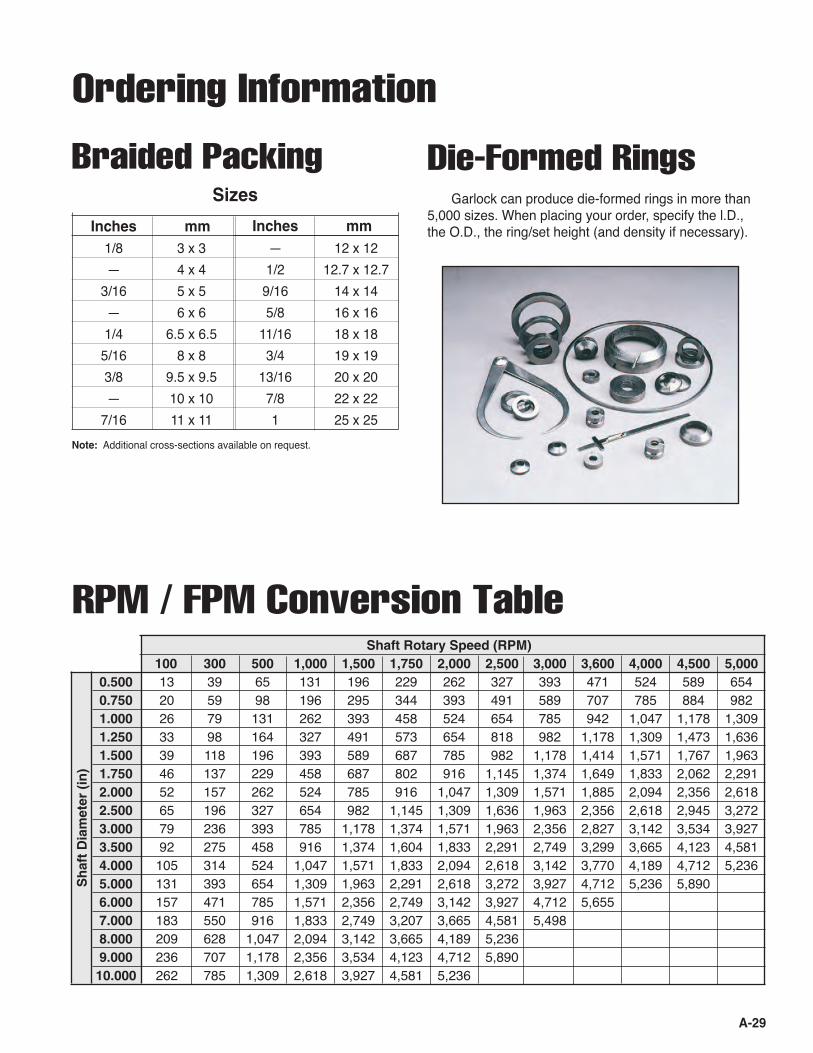
A-29
Ordering Information
Braided Packing Die-Formed RingsGarlock can produce die-formed rings in more than
5,000 sizes. When placing your order, specify the l.D., the O.D., the ring/set height (and density if necessary).
Shaft Rotary Speed (RPM) 100 300 500 1,000 1,500 1,750 2,000 2,500 3,000 3,600 4,000 4,500 5,000 0.500 13 39 65 131 196 229 262 327 393 471 524 589 654 0.750 20 59 98 196 295 344 393 491 589 707 785 884 982 1.000 26 79 131 262 393 458 524 654 785 942 1,047 1,178 1,309 1.250 33 98 164 327 491 573 654 818 982 1,178 1,309 1,473 1,636 1.500 39 118 196 393 589 687 785 982 1,178 1,414 1,571 1,767 1,963 1.750 46 137 229 458 687 802 916 1,145 1,374 1,649 1,833 2,062 2,291 2.000 52 157 262 524 785 916 1,047 1,309 1,571 1,885 2,094 2,356 2,618 2.500 65 196 327 654 982 1,145 1,309 1,636 1,963 2,356 2,618 2,945 3,272 3.000 79 236 393 785 1,178 1,374 1,571 1,963 2,356 2,827 3,142 3,534 3,927 3.500 92 275 458 916 1,374 1,604 1,833 2,291 2,749 3,299 3,665 4,123 4,581 4.000 105 314 524 1,047 1,571 1,833 2,094 2,618 3,142 3,770 4,189 4,712 5,236 5.000 131 393 654 1,309 1,963 2,291 2,618 3,272 3,927 4,712 5,236 5,890 6.000 157 471 785 1,571 2,356 2,749 3,142 3,927 4,712 5,655 7.000 183 550 916 1,833 2,749 3,207 3,665 4,581 5,498 8.000 209 628 1,047 2,094 3,142 3,665 4,189 5,236 9.000 236 707 1,178 2,356 3,534 4,123 4,712 5,890 10.000 262 785 1,309 2,618 3,927 4,581 5,236
Sh
aft
Dia
met
er (
in)
RPM / FPM Conversion Table
Inches mm 1/8 3 x 3 — 12 x 12 — 4 x 4 1/2 12.7 x 12.7 3/16 5 x 5 9/16 14 x 14 — 6 x 6 5/8 16 x 16 1/4 6.5 x 6.5 11/16 18 x 18 5/16 8 x 8 3/4 19 x 19 3/8 9.5 x 9.5 13/16 20 x 20 — 10 x 10 7/8 22 x 22 7/16 11 x 11 1 25 x 25
Sizes
Inches mm
Note: Additional cross-sections available on request.

A-30
Compression Packing Application Data Form
Customer _________________________________ Submitted by _____________________________
_________________________________________ ________________________________________
_________________________________________ Date ____________________________________
Phone ___________________________________ Fax _______________________________________
Email ______________________________________
Service ConditionsShaft speed ___________________________ rpm (or) __________________________________ fpm
Temperature ____________________________ °F (or) ___________________________________ °C
Pressure _______________________________ psi (or) ___________________________________bar
Media (What is being sealed) _____________________________________ pH __________________
EquipmentSpecify pump, valve, mixer, etc. ____________________________________________________________
______________________________________________________________________________________
Shaft dia. _____________________ Bore dia. _________________ Box depth ________________
General condition of equipment and environment _______________________________________________
______________________________________________________________________________________
______________________________________________________________________________________
PackingWhat is presently being used? _____________________________________________________________
Any problems with this material? ____________________________________________________________
______________________________________________________________________________________
______________________________________________________________________________________
Comments _____________________________________________________________________________
______________________________________________________________________________________
______________________________________________________________________________________

• ISO 9001:2000 registration for Industrial Gasketing, Industrial Packing, KLOZURE® Oil Seals, Bearing Protectors, and Mechani-cal Seals, Expansion Joints, Hydraulic Com-ponents,and Industrial Rubber Products.
• A global network of stocking Authorized Gar-lock Distributors.
• Factory sales representatives and applica-tions engineers available for problem solving when and where it is needed.
• Toll-free 800 telephone and fax numbers for immediate product information.
• In-plant surveys of equipment and processes, providing the customer with recommenda-tions to identify and eliminate sealing and packing problems before they start.
More than just great products…Beyond offering you the widest available range of products for packing and sealing, Garlock enhances the value of its products with technical services and comprehensive training programs:
• The most sophisticated and most compre-hensive test facilities available.
• Technical field seminars on all Garlock prod-ucts.
• Factory-sponsored product training pro-grams, including hands-on seminars, to ensure that Garlock representatives and their distributor personnel are the best in the industry.
• Technical Bulletins to keep you up-to-date on product enhancements and changes.
Customers who specify Garlock fluid sealing products get, at no extra cost, the high quality support needed to run a profitable operation.
AUTHORIZED REPRESENTATIVE
Other Garlock facilities are located in:Columbia, SC, USA Houston, TX, USA Sydney, AustraliaPhone 1.803.783.1880 Phone 1.281.459.7200 Phone 61.2.9793.2511Fax 1.803.783.4279 Fax 1.281.458.0502 Fax 61.2.9793.2544São Paulo, Brazil Sherbrooke, Canada W. Yorkshire, EnglandPhone 55.11.4352.6161 Phone 1.819.563.8080 Phone 44.1422.313600Fax 55.11.4352.8181 Fax 1.819-563.5620 Fax 44.1422.313601Saint-Étienne, France Neuss, Germany Mexico City, MexicoPhone 33.4.7743.5100 Phone 49.2131.3490 Phone 52.555.567.7011Fax 33.4.7743.5151 Fax 49.2131.349.222 Fax 52.555.368.0418Singapore Shanghai, China Dubai, UAEPhone 65.6285.9322 Phone 86.021.62789702 Phone 971.4.8833652Fax 65.6284.5843 Fax 86.021.62787826 Fax 971.4.8833682
WARNING:Properties/applications shown throughout this brochure are typical. Your specific application should not be undertaken without independent study and evaluation for suitability. For specific application recommendations consult Garlock. Failure to select the proper sealing products could result in property damage and/or serious personal injury. Performance data published in this brochure has been developed from field testing, customer field reports and/or in-house testing.While the utmost care has been used in compiling this brochure, we assume no responsibility for errors. Specifications subject to change without notice. This edition cancels all previous issues. Subject to change without notice.GARLOCK is a registered trademark for packings, seals, gaskets, and other products of Garlock.© Garlock Inc 2007. All rights reserved worldwide.
PRINTED IN U.S.A. CMP 4:41 VIA-2/05-C
Garlock Sealing Technologies1666 Division StreetPalmyra, New York 14522 USA1-315-597-48111-800-448-6688Fax: 1-800-543-05981-315-597-3039
www.garlock.com