compressible fluid flow
DESCRIPTION
Compressible Fluid FlowTRANSCRIPT

Compressible Fluid Flow
Objectives of the Course
� To develop the fundamental concepts of compressibleflow
� To solve engineering problems such as diffusers andnozzles of subsonic and supersonic airbreathing engines,supersonic wind tunnels, rocket nozzles, lift and drag onsupersonic wings
– p.1

Textbook
� It is not necessary to buy a textbook
� If you really want a textbook, buy "Compressible FluidFlow" 2nd Edition by Michel Saad
� You can save money by “writing your own book” basedon the lecture material
– p.2
English or Korean?
� Lecture – in English
� Assignments – in English
� Midterm and Final exams – questions will be written inenglish
� The good news: Compressible Fluid Flow is an engi-neering course and ... the “language of engineering” ismathematics
– p.3

Grading
Grading
� Mid-term – 40%
� Final – 60%
� Bonus – 15% Max.
or
� Midterm – 20%
� Final – 80%
� Bonus – 15% Max.
(whichever gives the highest mark)
– p.4

Grading System: No Relative Scoring!
� F if score<30% (no upgrade possible,no exception)
� F if 30%�score<50% (upgrade to D0 possible, but notautomatic. See below)
� D0 if 50%�score<55% and if you come to my officealoneafter the final exam and givevery good reasonswhy you failed (in english)
� D+ if 55%�score<60%
� C0 if 60%�score<65%
� C+ if 65%�score<70%
� B0 if 70%�score<75%
� B+ if 75%�score<80%
� A0 if 80%�score<85%
� A+ if score�85%– p.5

Canadian Style Grading System
� A0-A+ Great
� B0-B+ Good
� C0-C+ Fair
� D0-D+ Hmmmm
� F Not good enough to take more advanced courses
– p.6
Assignments
� 3-4 problems per week
� Questions may depend on student number
� Solutions will be given after due date
� Assignment questions and answers are in english
� Should require 5-7 hours of your time per week
� No late assignment will be accepted
� You must understand and remember the solutionsyou hand in
– p.7

Bonus System
� 15 points Bonus given to all students
� 4 points penalty for missing a lecture
� 2 points penalty for coming late to the lecture
� 3 points penalty for not submitting an assignment
� 3 points penalty for submitting an assignment late
� 4 points penalty for disturbing the class
� 15 points penalty for not remembering your own solu-tions to the assignments
Bonus can be positive, but can also benegative.
– p.8
Attendance
� Missing one class = 4 point penalty
� No certificate is accepted except those for jobinterviews
� For job interviews, you must notify me at least 48 hoursbefore the interview
� I may call the company and verify if the certificate isvalid
� In case you forged the certificate, you will get F
– p.9

Exams
� Exams are closed book
� Compressible Flow Tables will be handed out alongwith the question sheet
� Only simple calculators are allowed (not more than20,000 wons, no SD stick)
� Any attempt at cheating will result in F
� Bring your calculator to every class – there will be sur-prise exams
– p.10

Surprise Tests
� Surprise tests will be given once in a while
� The test will consist of solving one assignment problem
� If your solution is significantly different from the oneyou handed in, you will get a 15 points penalty
� If your solution is more or less the same as the one youhanded in, you will get no penalty
� Bring your calculator to every class – it will be neededfor the surprise test
– p.11

How to get a good mark
� Never miss a lecture
� Don’t disturb the others during the lecture
� Do the assignments by yourself as much as possible –There is no group work in the exams
� Understand and remember the solutions you hand in
– p.12

Learn by Doing, not just by Watching
Nam Hyun-hee. Justwatching Nam Hyun-heefoil won’t make someonea good fencer. One alsoneeds to practice. The sameapplies with learning Com-pressible Flow.
– p.13

Don’t let a problem remain unsolved
� First try to solve the problem by yourself – workseriously on it
� Discuss it with a friend
� Get the solution from another student by "bribing" himor her
� Send the professor an email asking him a specificquestion
� Come to see the professor in his office – make sure youare respectful of his time by preparing well your question
– p.14

Slides Shown Today
� All the slides shown in the class today can bedownloaded in pdf format from
http://www.bernardparent.com/
– p.15

http://www.bernardparent.com
You have to create an account on my website to downloadthe slides, the assignments, the tables, and check your scores.Note the following:
� Your account login ID must be your student ID
� Your account will become active only after I approve it
� It may take a couple of days before your account is ap-proved
– p.16

What is "Compressibility"?
In fluid mechanics, compressibility is a measure of the rel-ative volume change of a fluid as a response to a pressurechange.
compressibility� � 1
V
@V
@P
whereV is the volume andP is the pressure. Compressibil-ity can also be thought to be a measure of the relative densitychange of a fluid as a response to a pressure change. By def-inition, the density corresponds to:
density� mass
volume
– p.17

Bullet
Schlieren photograph ofa bullet “flying” at aspeed of 1500 kilome-ters/hour Schlieren photo-graph shows change in airdensity.
– p.18
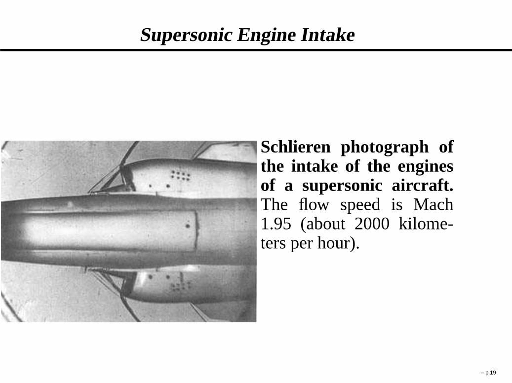
Supersonic Engine Intake
Schlieren photograph ofthe intake of the enginesof a supersonic aircraft.The flow speed is Mach1.95 (about 2000 kilome-ters per hour).
– p.19

Space Shuttle Main Engine
Photograph of the exhaust of the Space ShuttleMain Engine (SSME). The flow exiting the rocketis steady and uniform but soon downstream ’diamond-like’ features appear.
– p.20

Compressibility Effects in Aerodynamics
Compressibility is an important factor in aerodynamics. Atlow speeds, the compressibility of air is not significant in re-lation to aircraft design, but as the airflow nears and exceedsthe speed of sound, a host of new aerodynamic effects be-come important in the design of aircraft. These effects, oftenseveral of them at a time, made it very difficult for World WarII era aircraft to reach speeds much beyond 800 km/h (500mph), since they resulted in changes to the airflow that leadto problems in control. Such were observed on many WorldWar II aircraft such as the P38 Lighting, the Mitsubishi Zero,the Supermarine Spitfire, and the Messerschmitt Bf 109.
– p.21
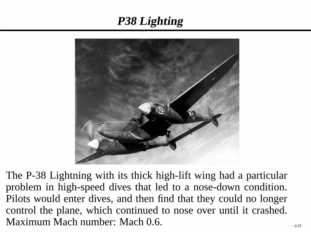
P38 Lighting
The P-38 Lightning with its thick high-lift wing had a particularproblem in high-speed dives that led to a nose-down condition.Pilots would enter dives, and then find that they could no longercontrol the plane, which continued to nose over until it crashed.Maximum Mach number: Mach 0.6. – p.22

Recommended Approach to the Solution of aCompressible Flow Problem
1. Outline of the laws of physics
2. Derivation of working relations from laws of physics
3. Statement of assumptions involved in obtaining theworking relations
4. Use of working relations to obtain a solution to a fluidflow problem
5. Discussion of the problem solution and limitations ofphysical model / working relations
Compressible flow physics can be particularlyunintuitive .Do not trust your intuition; rather, follow the steps above.
– p.23
Why Derivations of Working Relations from Laws ofPhysics are Important
� To learn about the assumptions related with the workingrelations
� To understand the limitations of the working relations
� To increase confidence about a design based on theworking relations
– p.24

Ideal Gas "Law"
� The state of an amount of gas is determined by itspressure, volume, and temperature according to theequation:P D �RT
P in Pa,� in kg/m3, R in J/kgK, andT in K.
� What is pressure? What is temperature? – Tounderstand the latter, we need to derive the ideal gas"law" from basic principles.
� The ideal gas law mathematically follows from astatistical mechanical treatment of primitive identicalparticles which do not interact, but exchangemomentum in elastic collisions
� Applicable to cases where the intermolecular forces arenegligible – not applicable to gases with relatively highpressure and low temperature – p.25

Benoit Paul Emile Clapeyron
� French engineer born in Paris in1799
� Clapeyron studied at the Ecolepolytechnique and the Ecole desMines
� First stated the ideal gas law asthe equation of state of ahypothetical ideal gas in 1834.
� In 1843, Clapeyron further devel-oped the idea of a reversible pro-cess to what is now known as thesecond law of thermodynamics
– p.26

Pressure
The pressure is the average in time of the force per unit areaacting on a surface due to molecular collisions
P �R �t
0Fdt
A�tD F
A
with
P the pressure (in Pa)
F the force acting on a wall due to elastic molecularcollisions (in N)
A the cross sectional area on which the force is acting (in m2)– p.27

Blaise Pascal (1623–1662)
� French mathematician, physicist,and philosopher born in 1623
� Clarified the concepts of pressureand vacuum
� At the time, most scientists didnot believe in the possibility ofvacuum
� Established the principle andvalue of the barometer
� His work in the calculus of proba-bilities laid important groundworkfor Leibniz’s formulation of theinfinitesimal calculus
– p.28

Temperature
Temperature is proportional to the average kinetic energy ofthe molecules.
T � mq2
3kD q2
3R(in degrees K, Kelvin)
with
k the Boltzmann constant (1:38 � 10�23 J/K)
m the mass of one molecule in kg
q the speed of a molecule in m/s
R the gas constant (equalsk=m in J/kgK)– p.29

Mass Conservation in Quasi-1D
Mass Conservation Equation:
d�Av D 0
or
�2A2v2 D �1A1v1
where the density� is in kg/m3, the cross-section areaA inm2, andv in m/s
� Applies to steady one-dimensional flow in ducts witharea change
– p.30

Momentum Conservation in Quasi-1D
Momentum Conservation Equation:
�vdv C dP D 0
where the density� is in kg/m3, the velocityv in m/s andPin Pa
� Derived from Newton’s second lawF D ma
� Applies to steady one-dimensional flow in streamtubesor ducts with area change
– p.31

Energy Conservation Equation(or First “Law” of Thermo)
de’
change of system energy
D �P d.1=�/š
work done on system
C ıq‘
heat added to system
� Based on what was discovered in the 19th century, theFirst Law of Thermo is now not a Law since it can beshown from other laws
� It can be shown by taking the dot product between thevelocity vector and Newton’s law in vector form appliedto a molecule, summing over a large number ofmolecules, and then taking the average in time.
� Not always necessary for incompressible flows unlessheat transfer or viscosity is present
� Always necessary for compressible flows to find the den-sity+pressure distribution
– p.32

The Joule Experiment, 1845
– p.33

James Prescott Joule (1818–1889)
� English physicist born in Salford,Lancashire, England in 1818
� Studied the nature of heat, anddiscovered its relationship tomechanical work.
� Fascinated by electricity. He andhis brother experimented bygiving electric shocks to eachother and to the family’s servants.
� Found the relationship betweenthe current through a resistanceand the heat dissipated
– p.34

Types of Energy Modes in a Gas
� Translational energy, etr D 3
2RT
� Rotational energy, erot D RT
� Vibrational energy
� Electronic energy
The latter can be shown from statistical thermodynamics.Atoms only have translational and electronic energy.
– p.35

Types of Thermodynamic Processes
� Isobaric. Constant pressure process.
� Isovolumetric. Constant volume process.
� Isothermal. Constant temperature process.
� Isentropic. Constant entropy process.
� Adiabatic. A process in which there is no energy addedor subtracted by heating or cooling.
� Reversible.A process which is both adiabatic and isen-tropic.
– p.36

Energy Conservation in Quasi-1D
1st “Law” of Thermo:de C P d.1=�/ D 0 or dh � dP=� D 0
Energy conservation equation:
d
�
h C v2
2
�
D 0
� holds for adiabatic and isentropic process (reversible)along a one-dimensional duct with varyingcross-section area
� v is the velocity in m/s
� h is the enthalpy in J
� h � e C P=�
� the enthalpy is the potential of the flow to do work– p.37

Isentropic Relationship
P2
P1
D�
�2
�1
�
or
P
� is constant along isentropic adiabatic (reversible) path
where � CP
CP � RD CP
CV
The latter assumes thatCP is not a function of temperature.
– p.38

Specific Heats
The specific heats at constant pressure and volume are de-fined as:
CP � dh
dTand CV � de
dT
For many gases (such as N2, O2, H2, air), the vibrational andelectronic energies can be neglected when the temperature isless than about 800 K. Then, the specific heats and the spe-cific heat ratio become:
CV CP
molecule 5
2R 7
2R 7
5
atom 3
2R 5
2R 5
3
– p.39

Calorically Perfect Gas
A calorically perfect gas is a gas where the specific heatsCP
andCV are constant.
This yields the following relationships:
h D CP T
e D CV T
A calorically perfect gas should not be confused with athermally perfect gas.
A calorically perfect gas entails constantCP andCV . A ther-mally perfect gas is one which is governed by the ideal gaslaw P D �RT .
– p.40

Terminal (or Exit) Velocity
The terminal velocity is the velocity that is obtained whena gas is expanded isentropically to a vacuum (that is, whenthe terminal pressure approaches zero).
For a calorically perfect gas, the terminal velocity corre-sponds to:
vterminal Dp
2CP Tı
wherevterminal is in m/s,CP is in J/kgK, andTı is in K.
– p.41

Speed of Sound
Speed of an infinitesimal wave propagating isentropically ina gas:
c Ds
@P
@�
ˇ
ˇ
ˇ
ˇ
s
In the case of a calorically perfect and thermally perfect gas,the sound speed becomes:
c Dp
RT
– p.42

Compressible Flow Tables and Charts
http://www.bernardparent.com/
� Contains most used equations as well as tables andcharts for solving problems
� The same document will be distributed during the mid-term and final exams
– p.43
Stagnation Pressure – Definition
The stagnation pressure can either refer to the static pressureat a stagnation point in a fluid flow or can refer to the pres-sure that would be obtained if the flow would be reversiblydecelerated to stagnation conditions.
The stagnation pressure can be obtained by integrating alongan adiabatic and isentropic path the momentum equationfrom the point under consideration to a state of vanishingvelocity.
– p.44

Stagnation Pressure Expressions
Stagnation pressure for incompressible flow (BernoulliEquation):
Pı D P C �v2
2
Stagnation pressure for compressible flow:
Pı D P
�
1 C � 1
2M 2
�
�1
whereM D v=c is the Mach number andv is the flow speed(magnitude of velocity). The gas is assumed calorically per-fect and thermally perfect throughout the path to stagnation.
– p.45

Daniel Bernoulli (1700–1782)
� Swiss mathematician
� Best known for his application ofmathematics to mechanics and hispioneering work in probabilityand statistics
� Earliest writer who attempted toformulate a kinetic theory ofgases, and he applied the idea toexplain Boyle’s “law”.
– p.46

Difference Between Compressible and IncompressibleStagnation Pressure
The incompressible stagnation pressure can also be writtenas:
P incompı
D 1 C 1
2 M 2
Using Taylor series, it can be shown that the compressiblestagnation pressure is equal to:
P compı
D 1 C 1
2 M 2 C 1
8 M 4 C :::
At Mach 0.5, 0.8, and 1.0, the difference is around 1%, 7%,and 18%.
– p.47
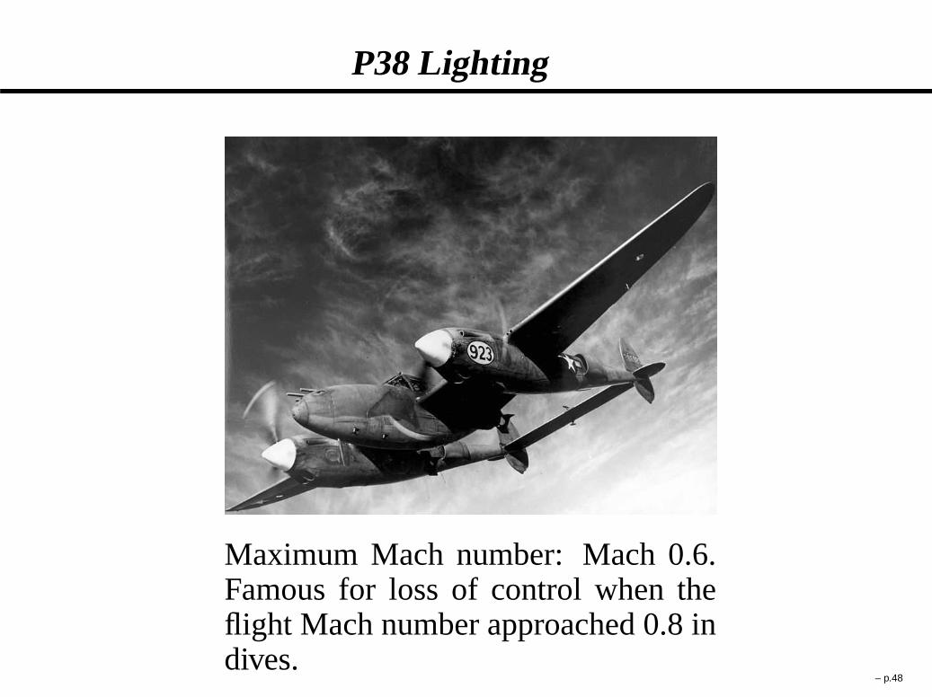
P38 Lighting
Maximum Mach number: Mach 0.6.Famous for loss of control when theflight Mach number approached 0.8 indives.
– p.48

Ernst Mach (1838–1916)
� Austrian physicist andphilosopher born in Chirlitz in theAustrian empire, now Brno,Czech Republic
� Mach’s main contribution tophysics was his description ofshock waves
� Using a so-called"schlierenmthod" he and his sonLudwig were able to photographthe shadows of the invisible shockwaves
� The Mach number is named afterhim
– p.49

Stagnation Density and Temperature
The stagnation temperature and density of a compressiblegas:
Tı
TD 1 C � 1
2M 2
�ı
�D�
1 C � 1
2M 2
�1
�1
with �ı andTı the stagnation density and temperature andwith M the Mach number and the ratio of the specificheats.
– p.50

Impact of Cross-Sectional Area on Flow Properties
dv
vD 1
M 2 � 1
dA
A
dP
PD M 2
1 � M 2
dA
A
d�
�D M 2
1 � M 2
dA
A
dT
TD . � 1/M 2
1 � M 2
dA
A
dM
MD 2 C . � 1/M 2
2.M 2 � 1/
dA
A
where is the ratio of the specific heats,M the Mach num-ber, A the flow cross sectional area, andv, P , T , � thevelocity, pressure, temperature, and density.
– p.51

Nozzle and Diffuser
Nozzle: Expands and accelerates the gas
Diffuser: Compresses and decelerates the gas
The definitions of “nozzle” and “diffuser” do not entail spe-cific shape characteristics. For instance, a diverging areaduct is a nozzle for supersonic flow but a diffuser for sub-sonic flow. Likewise, a converging area duct is a diffuser forsupersonic flow but a nozzle for subsonic flow.
– p.52

de Laval Nozzle
� A de Laval nozzle (orconvergent-divergentnozzle, CD nozzle or con-dinozzle) is a tube that ispinched in the middle,making an hourglass-shape.
� It is used as a means ofaccelerating the flow of agas passing through it to asupersonic speed.
� It is widely used in sometypes of steam turbine and isan essential part of the mod-ern rocket engine and super-sonic jet engines.
– p.53

Gustaf de Laval (1845–1913)
� Swedish engineer and inventor born inOrsa, Sweden
� Enrolled at the Institute of Technologyin Stockholm in 1863, receiving adegree in mechanical engineering in1866
� Completed a doctorate in chemistry in1872 at Uppsala University (Sweden)
� In 1890 developed a nozzle to increasethe steam jet to supersonic speed
� Now known as a de Laval nozzle, thenozzle is used in modern rocket en-gines.
– p.54

Critical Mach Number
The critical Mach number is defined as the ratio be-tween the flow speed and the critical sound speed. Thecritical sound speed is the sound speed that would oc-cur should the flow be accelerated or decelerated toMach 1. This yields a critical Mach number of:
M ? � vp RT ?
which can be shown to be equal to:
M ? DMq
1C
2
q
1 C �1
2M 2
– p.55

Critical Area
The critical areaA? is the cross-sectional area of theflow should the latter be accelerated or slowed downisentropically to Mach 1. The ratio between the areaand the critical area can be shown to be equal to:
A
A?D 1
M
��
2
C 1
��
1 C � 1
2M 2
��1C
2. �1/
– p.56
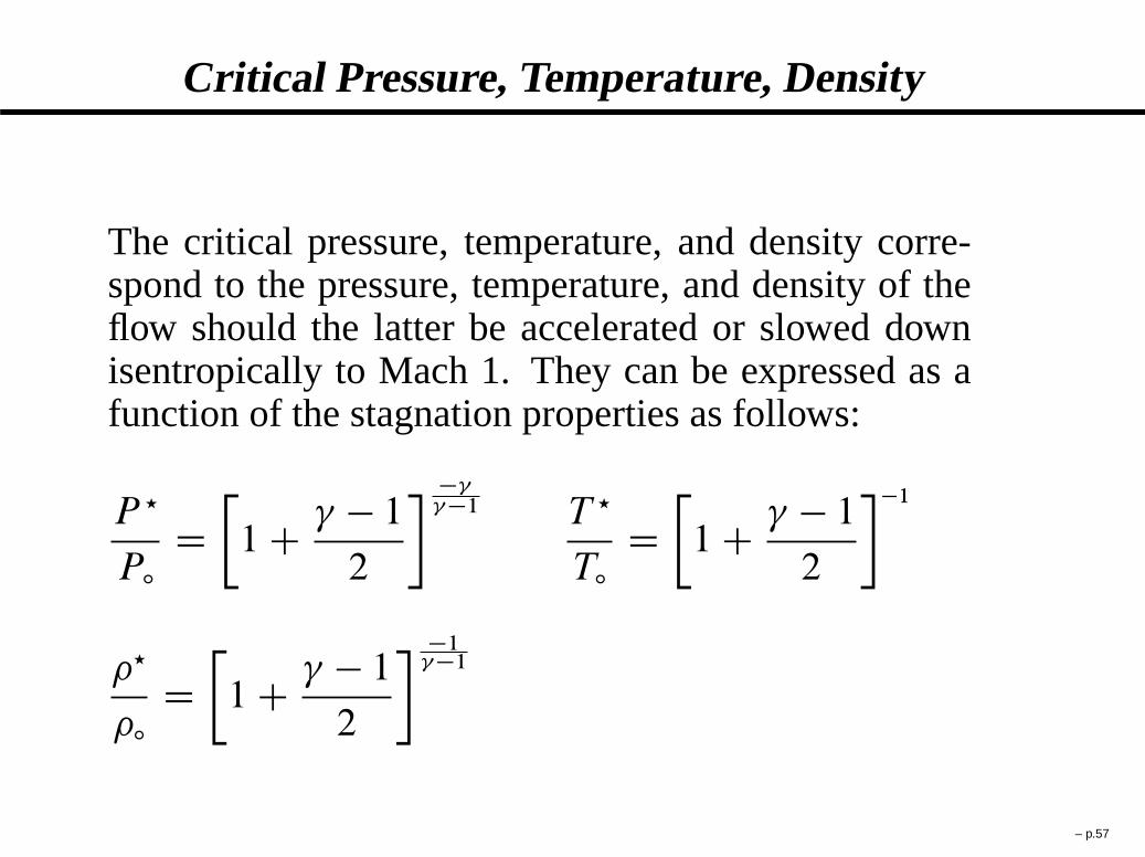
Critical Pressure, Temperature, Density
The critical pressure, temperature, and density corre-spond to the pressure, temperature, and density of theflow should the latter be accelerated or slowed downisentropically to Mach 1. They can be expressed as afunction of the stagnation properties as follows:
P ?
Pı
D�
1 C � 1
2
��
�1 T ?
Tı
D�
1 C � 1
2
��1
�?
�ı
D�
1 C � 1
2
��1
�1
– p.57

Example of a Diffuser
� The cross sectional area ofthe engine increases beforethe first blades
� At subsonic speed, adiverging area duct is adiffuser since it compressesthe flow
� The flow is hencecompressed beforeencountering the firstturbine blades
� The diffuser helps in obtain-ing a high compressor effi-ciency
– p.58

Effect of Back Pressure
� Subsonic Nozzle. The exit pressure must be equal orhigher than the back pressure. If the nozzle is choked,then the exit Mach number is 1 and the exit pressure isgreater than the back pressure. If the nozzle is notchoked, then the exit Mach number is less than 1 andthe exit pressure is equal to the back pressure.
� Supersonic Nozzle. If the exit pressure is greater thanthe back pressure, the flow will remain supersonic in thenozzle. If the exit pressure is less than the back pressure,then the flow may become subsonic at the nozzle exit.
– p.59

Choked Flow
Choked flowis a limiting condition which occurs when themass flux will not increase with a further decrease in thedownstream pressure environment.
Take for example a stagnant gas in a container with a higherpressure than the environment. As the gas is released to theenvironment, it goes through an expansion process througha converging area duct. At the throat, the flow is said to bechoked if a further decrease in environment pressure will notresult in a higher mass flow rate. For an inviscid compress-ible fluid, choking occurs when the Mach number reaches 1.For a viscous compressible fluid, choking occurs for a Machnumber slightly less than 1. For a liquid, choking may becaused by sudden cavitation.
– p.60

Mach Waves
� Mach waves are formed around supersonic object
� The flow Mach number can be found asM D 1
sin˛with
˛ the angle with respect to the flow streamline
– p.61

Nozzle Efficiency
The efficiency of a real nozzle is defined as the ratiobetween the actual kinetic energy at the nozzle exit andthe one that would be obtained should the flow expandisentropically through the nozzle:
�nozzle � v2e
v2i
whereve is the actual flow velocity at the nozzle exit,andvi is the velocity that would be obtained throughisentropic expansion from the same stagnation pressureand temperature to the same nozzle exit pressure.
– p.62
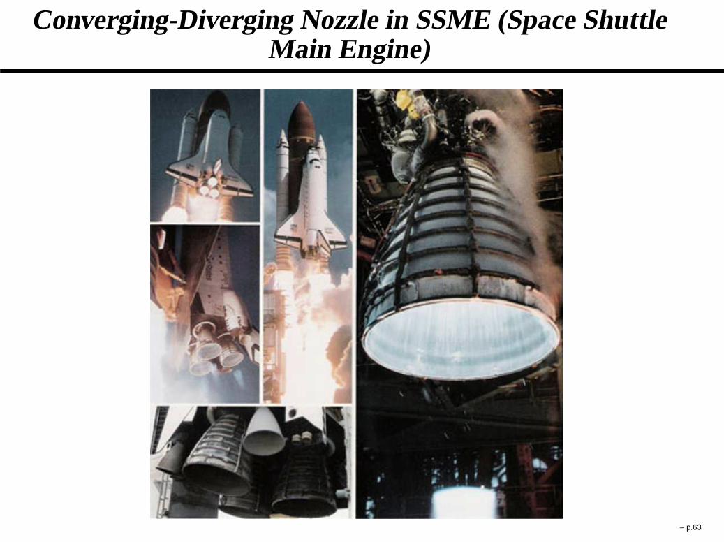
Converging-Diverging Nozzle in SSME (Space ShuttleMain Engine)
– p.63

C-D Nozzle in SSME – Discussion
The C-D nozzles intended for space propulsion have a di-verging section with a length typically more than 10 timesthe one of the converging section, hence resulting in a sub-stantial weight gain. How much additional thrust is given bya C-D nozzle compared to a standalone converging nozzle?Is the extra weight always justified? – p.64

Force Exerted on Duct by Flow
The force exerted on a duct in the opposite direction ofthe fluid flow path (i.e., the thrust) by a moving com-pressible fluid at steady-state corresponds to the changeof momentum of the flow:
F DZ 2
1
P dA D�
�v2A C PA�
2��
�v2A C PA�
1
withP the pressureA the cross sectional area� the densityv the velocity of the flow
– p.65

Ramjet
� Engine needs no moving parts – Flow is compressed entirelythrough a converging-diverging diffuser
� Can operate until Mach 5, but most efficient around Mach 3
� Generally used for missiles
� Invented and patented by René Lorin in 1913
– p.66

Leduc 0.10 Ramjet Aircraft
� First successful ramjet powered flight vehicle, built byBreguet Aircraft
� First flight: 21 October 1947
� Maximum flight Mach number: 0.85
� Could not take-off unassisted
– p.67

Project Pluto
� Mach 3 nuclear-powered ramjet developed by theLawrence Radiation Laboratory in 1961
� Combustor consists of an unshielded nuclear reactorheating the incoming air
� Was intended to be a long-range bomber to strike theSoviet Union with nuclear weapons
� Was never massively produced – replaced by ICBMs– p.68

Continuity, Momentum and Energy Equations withDiffusion Terms for 1D Constant-Area Flow
Mass Conservation:d
dx�v D 0
Momentum Conservation:d
dx
�
�v2 C P � �dv
dx
�
D 0
Energy Conservation:
�vd
dx
�
h C v2
2
�
� d
dx
�
KdT
dxC v�
dv
dx
�
D 0
where:� is the viscosityK is the thermal conductivity
– p.69

First “Law” of Thermo for a 1D Constant-Area Duct
dh
dx� 1
�
dP
dxD dQ
dx
with
dQ
dx� 1
�v
d
dx
�
KdT
dx
�
C �
�v
�
dv
dx
�2
The First “Law” of Thermo is not a law in gasdynam-ics, rather it is simply a “working relation” which canbe derived from more basic principles. We have shownthat the first “law” of thermo can be obtained from one(andonly one) law of physics, namely Newton’s lawEF D dmEv=d t .
– p.70

Second “Law” of Thermo for a 1D Constant-Area Duct
s2 �s1 DZ 2
1
K
�vT 2
�
dT
dx
�2
dxCZ 2
1
�
�vT
�
dv
dx
�2
dx
or
s2 � s1 � 0 along the flow path
The entropys is defined as
ds � 1
TdQ
Similarly to the first “law”, the second “law” of thermois a working relation and not a law in gasdynamics. Thesecond “law” of thermo has been here derived using
only Newton’s law EF D dmEv=d t .– p.71

Lazare Carnot (1753–1823)
� French politician, engineer, andmathematician
� In 1784 he published his first workEssai sur les machines en généralwhich contained the earliest proof ofirreversible processes (entropy)
� Participated to the creation ofEcolePolytechniquein 1794.
� In 1800 he was appointed Minister ofWar by Napoleon
� His son, Sadi Carnot, is the engineerwho invented the “Carnot Heat Engine”and the “Carnot Cycle”
� Was exiled as a regicide in 1814 duringthe reign of Louis XVIII – p.72
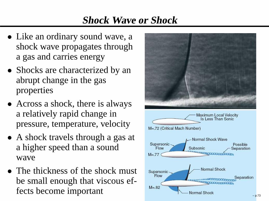
Shock Wave or Shock
� Like an ordinary sound wave, ashock wave propagates througha gas and carries energy
� Shocks are characterized by anabrupt change in the gasproperties
� Across a shock, there is alwaysa relatively rapid change inpressure, temperature, velocity
� A shock travels through a gas ata higher speed than a soundwave
� The thickness of the shock mustbe small enough that viscous ef-fects become important
– p.73

Rankine-Hugoniot Shock Relations For a Caloricallyand Thermally Perfect Gas
Pıy
Pıx
D��
� 1
C 1C 2
. C 1/M 2x
� �
2
C 1M 2
x� � 1
C 1
���1=. �1/
Py
Px
D 2
C 1M 2
x� � 1
C 1
Ty
Tx
D�
2
C 1M 2
x� � 1
C 1
��
� 1
C 1C 2
. C 1/M 2x
�
My D��
M 2
xC 2
� 1
�
=
�
2
� 1M 2
x� 1
��1=2
where the subscript “y” refers to the properties after theshock and “x” refers to the properties before the shock.My andMx are measured in the shock reference frame.
– p.74

William John Macquorn Rankine (1820–1872)
� Scottish engineer, born in Edinburgh in1820
� A founding contributor, with Clausiusand Kelvin, to the science ofthermodynamics
� One of the first engineers to recognisethat fatigue failures of railway axleswas caused by the initiation and growthof brittle cracks
� Professor of civil engineering andmechanics at the University ofGlasgow from 1855 until his death (asa bachelor) in 1872
� Best remembered for the Rankine cycleand the Rankine-Hugoniot Eqs.
– p.75

Pierre-Henri Hugoniot (1851-1887)
� French engineer, born in 1851 inAllenjoie, France
� Graduated from Ecole Polytechnique in1872
� Professor of mechanics and ballistics atthe Lorient Artillery school in 1879
� Appointed as auxiliary assistant inmechanics at Ecole Polytechnique in1884
� Published in the proceedings of theEcole Polytechnique in Volume 57(1887) and Volume 58 (1889) the shockrelations that now bear his name
– p.76

Pitot tube
The basic pitot tube consists of a tubepointing directly into the fluid flow. Themoving fluid is brought to rest as there isno outlet to allow flow to continue. Thepressure obtained within the pitot tube isthe so-called “pitot pressure”. The veloc-ity of the flow can be estimated by com-paring the difference between the pitotpressure and the static pressure. Inventedby Henri Pitot in the early 1700s andmodified to its modern form in the mid1800s by Henry Darcy, the Pitot tube isnow widely used to determine the air-speed of an aircraft and to measure airand gas velocities in industrial applica-tions.
– p.77

Pitot Probe on the Cessna 172 N/P
– p.78
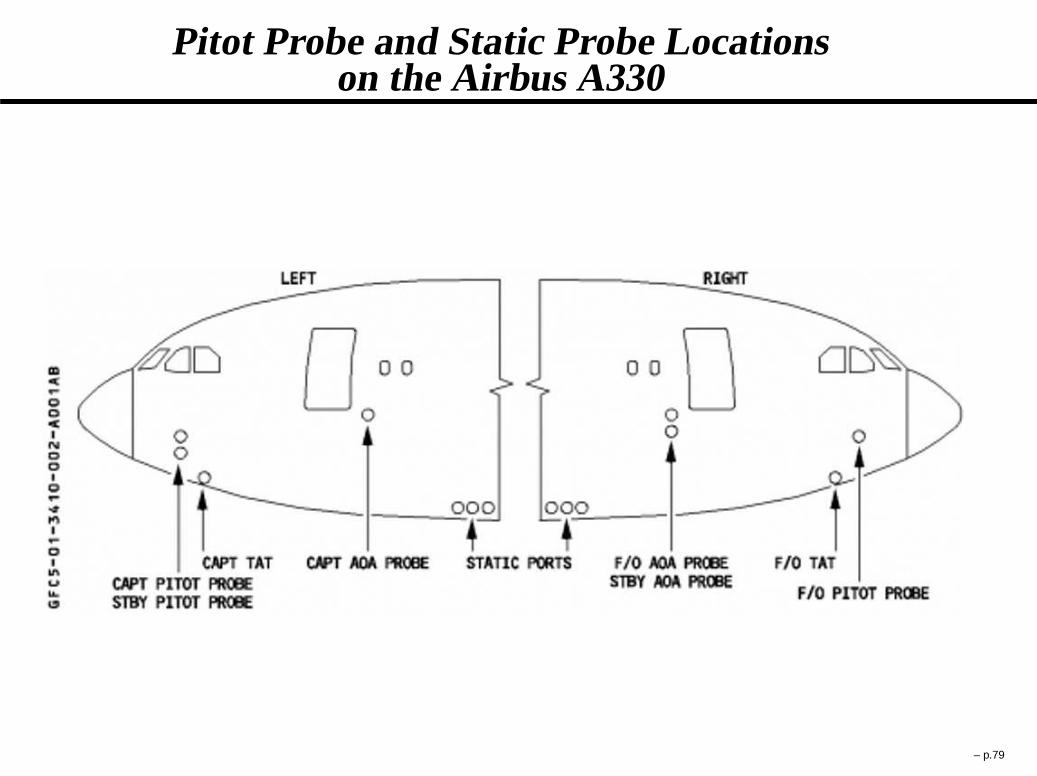
Pitot Probe and Static Probe Locationson the Airbus A330
– p.79

Pitot Probes on the Airbus A330
– p.80

Pitot Tube on the Nose of the F16 Falcon
– p.81

Pitot Tube on the Mirage F1
– p.82
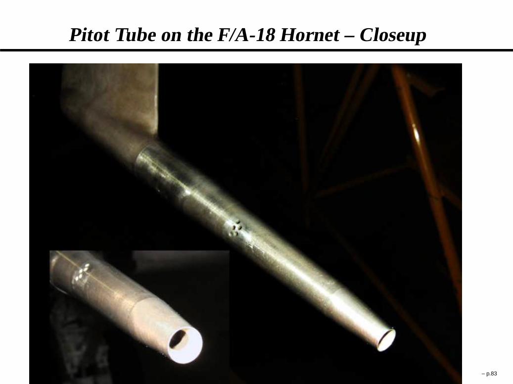
Pitot Tube on the F/A-18 Hornet – Closeup
– p.83
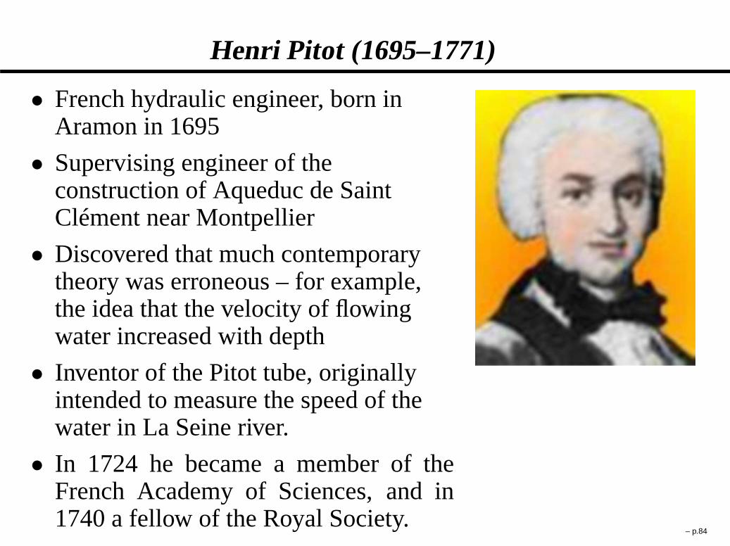
Henri Pitot (1695–1771)
� French hydraulic engineer, born inAramon in 1695
� Supervising engineer of theconstruction of Aqueduc de SaintClément near Montpellier
� Discovered that much contemporarytheory was erroneous – for example,the idea that the velocity of flowingwater increased with depth
� Inventor of the Pitot tube, originallyintended to measure the speed of thewater in La Seine river.
� In 1724 he became a member of theFrench Academy of Sciences, and in1740 a fellow of the Royal Society.
– p.84
Wind Tunnels
A wind tunnel is a research tool developed to assist with studyingthe effects of air moving over or around solid objects. The wind-speed and flow properties can be measured using threads, dye orsmoke, pitot tube probes, or particle image velocimetry. Differentwind tunnel configurations are used for different flow regimes:
� Subsonic wind tunnels:used for operations at rather lowspeeds, with a Mach number in the test section generally notexceeding 0.5
� Transonic wind tunnels:used to simulate a test section Machnumber between 0.5 and 1.0
� Supersonic wind tunnels:produces a flow Mach number inthe test section in the range1:2 < M < 4.
� Hypersonic wind tunnels:produces a test section flow Machnumber in excess of 4
– p.85

Open Subsonic Wind Tunnel
The air is moved with a large axial fan that creates a pressure dif-ference and essentially “sucks” the air in the tunnel from the en-vironment. The working principle is based on the continuity andBernoulli’s equation (flow is incompressible throughout).
– p.86
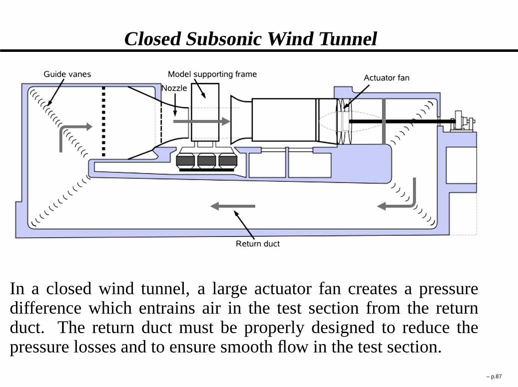
Closed Subsonic Wind Tunnel
In a closed wind tunnel, a large actuator fan creates a pressuredifference which entrains air in the test section from the returnduct. The return duct must be properly designed to reduce thepressure losses and to ensure smooth flow in the test section.
– p.87

Transonic Wind Tunnel
High subsonic wind tunnels (0:4 < M < 0:75) or transonic windtunnels (0:75 < M < 1:2) are designed on the same principlesas the subsonic wind tunnels. Transonic wind tunnels are able toachieve speeds close to the speeds of sound. The Mach number isapproximately one with combined subsonic and supersonic flowregions.Testing at transonic speeds presents additional prob-lems, mainly due to the reflection of the shock waves from thewalls of the test section. Therefore, perforated or slotted walls arerequired to reduce shock reflection from the walls. Since impor-tant viscous or inviscid interactions occur (such as shock wavesorboundary layer interaction) both Mach and Reynolds number areimportant and must be properly simulated.
– p.88
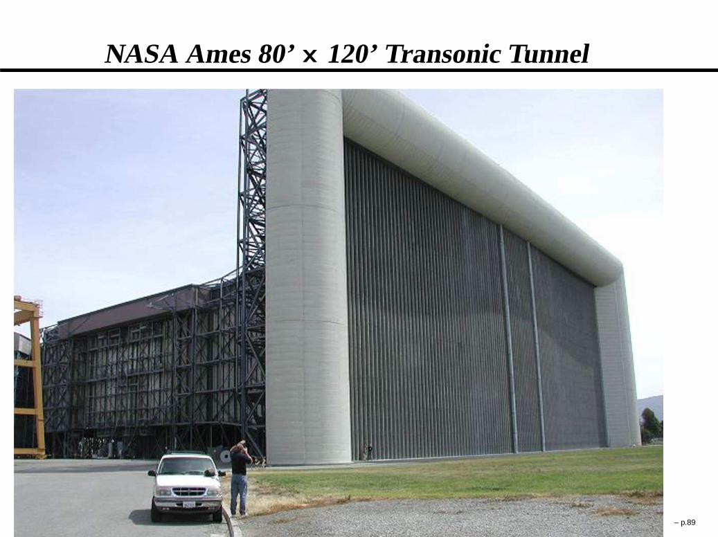
NASA Ames 80’� 120’ Transonic Tunnel
– p.89

Fans of NASA Ames 80’� 120’ Transonic Tunnel
– p.90

Test Section of NASA Ames 80’� 120’ TransonicTunnel
– p.91

Supersonic Wind Tunnels
A supersonic wind tunnel is a wind tunnel that produces super-sonic speeds (1:2 < M < 4) generally through the use of aconverging-diverging nozzle.The test section Mach numberis determined by the nozzle geometry while the Reynoldsnumber is varied by changing the stagnation pressure andtemperature of the flow in the settling chamber. To simulatehigh Mach number flows typical of high speed flight, a highpressure ratio is required between the settling chamber and thetest section (atM D 4 this ratio is about 200).
Supersonic wind tunnels can be regrouped in four categories:
� Suck-down
� Blow-down
� Suck-down-Blow-down
� Shock tunnel– p.92

Nozzle and Test Section of a Supersonic Wind Tunnel
In a supersonic wind tunnel, the flow can be accelerated from sub-sonic to supersonic speeds using a converging-diverging nozzle(also known as a “De Laval nozzle”). One of the challenges indesigning a supersonic wind tunnel is to prevent a normal shockfrom forming in the test section while the measurement is beingtaken. – p.93

Suck-down Supersonic Wind Tunnel
Suck-down supersonic wind tunnelsare characterized by very large vac-uum tanks “sucking” the air directlyfrom the atmosphere (typically at apressure of 101300 Pa and temperatureof about 300 K). While the flow can beaccelerated to Mach numbers greaterthan 10 through a De Laval nozzle,the stagnation pressure and stagnationtemperature are too low to simulateproperly flight conditions atM > 1:5.
– p.94
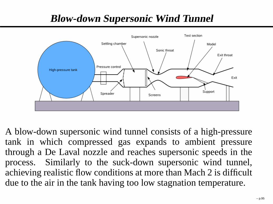
Blow-down Supersonic Wind Tunnel
A blow-down supersonic wind tunnel consists of a high-pressuretank in which compressed gas expands to ambient pressurethrough a De Laval nozzle and reaches supersonic speeds in theprocess. Similarly to the suck-down supersonic wind tunnel,achieving realistic flow conditions at more than Mach 2 is difficultdue to the air in the tank having too low stagnation temperature.
– p.95

Blow-down-Suck-down Supersonic Wind Tunnel
Due to the very large pressure difference between the high-pressure tanks and the vaccuum tanks, a blow-down-suck-downwind tunnel can achieve very high Mach numbers (M > 10) inthe test section. The air is heated through a pebble bed heater toobtain in the test section the high Reynolds number characteristicof hypersonic flight.
– p.96
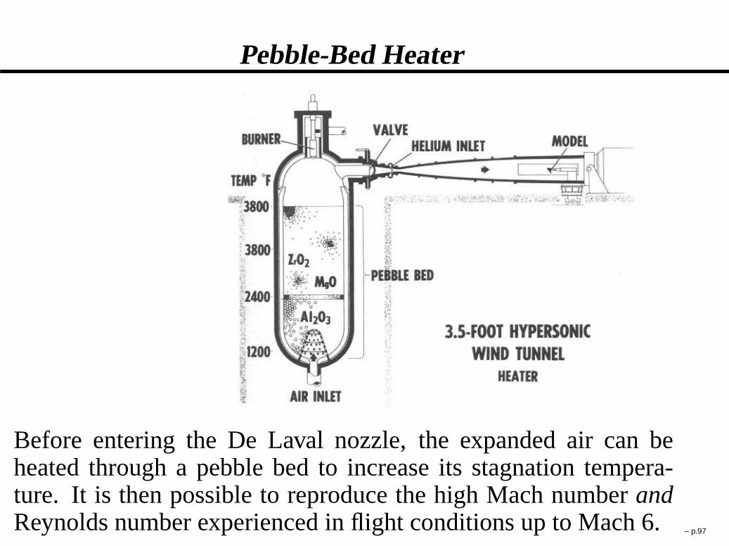
Pebble-Bed Heater
Before entering the De Laval nozzle, the expanded air can beheated through a pebble bed to increase its stagnation tempera-ture. It is then possible to reproduce the high Mach numberandReynolds number experienced in flight conditions up to Mach 6.– p.97
Shock Tunnel
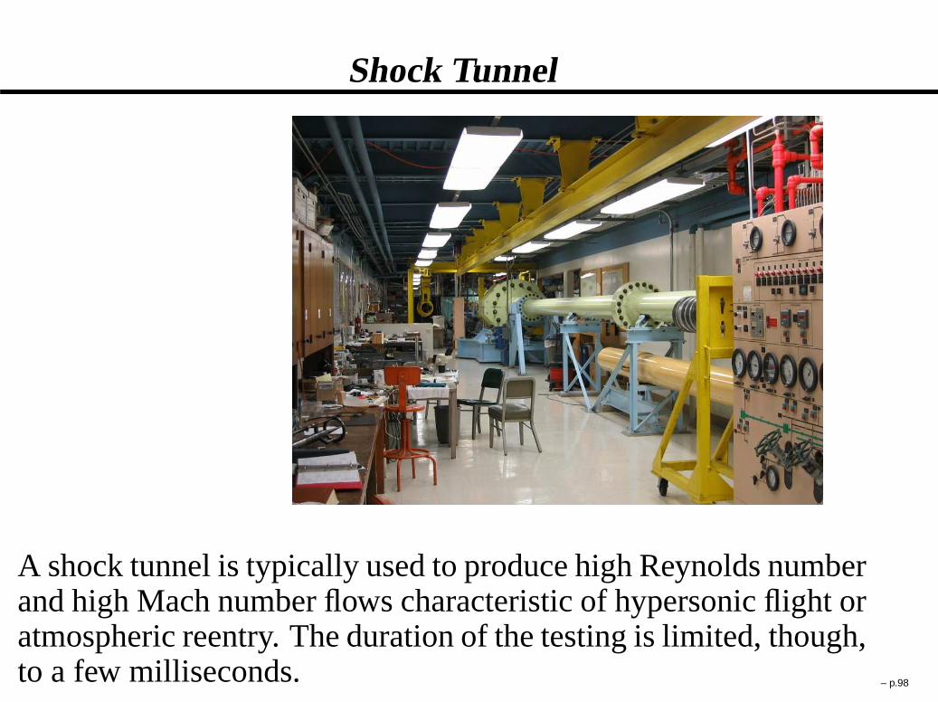
A shock tunnel is typically used to produce high Reynolds numberand high Mach number flows characteristic of hypersonic flight oratmospheric reentry. The duration of the testing is limited, though,to a few milliseconds. – p.98

HIEST Free Piston Shock Tunnel(Kakuda Research Center, Japan)
– p.99

HIEST Free Piston Shock Tunnel Schematics
The high enthalpy shock tunnel HIEST is the largest free-pistonshock tunnel in the world. The length and mass of the tunnel areapproximately 80 m and 300 ton, while the nozzle exit diameter isof 120 cm, and the scale model length is of 50 cm.Test section properties:u D 4 � 7 km/s, Tı D 10000 K, Pı D150 MPa, Test timeD 2:0 ms.
– p.100
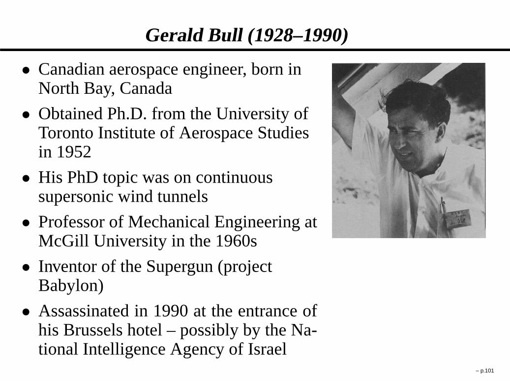
Gerald Bull (1928–1990)
� Canadian aerospace engineer, born inNorth Bay, Canada
� Obtained Ph.D. from the University ofToronto Institute of Aerospace Studiesin 1952
� His PhD topic was on continuoussupersonic wind tunnels
� Professor of Mechanical Engineering atMcGill University in the 1960s
� Inventor of the Supergun (projectBabylon)
� Assassinated in 1990 at the entrance ofhis Brussels hotel – possibly by the Na-tional Intelligence Agency of Israel
– p.101

Supergun – Project Babylon
� Project Babylon was intended to launch a projectile loadedwith explosives into orbit as a means to “blind” enemy spysatellites. Financial support by Saddam Hussein.
– p.102

1D Flow with Friction – Governing Equations
Conservation of Mass:
d
dx�v D 0
Conservation of Momentum:
d
dx
�
�v2 C P�
C 4f
DH
1
2�v2 D 0
Conservation of Energy:
d
dx.�vH/ D 0
with:
f � �w
ı
1
2�v2
DH � 4A =�
� � wetted perimeter
A � cross sectional area
�w � wall shear stress– p.103

Fanning Friction Factor vs Darcy Friction Factor
In this course,f will always refer to the fanningfriction factor,ffanning. In the litterature, sometimes theDarcy friction factor is used. The Darcy friction factorcorresponds to four times the fanning factor:
fDarcy D 4ffanning
For instance, for fully-developed laminar flow,
fDarcy D 64=Re
and
ffanning D 16=Re
– p.104

Friction factor versus the Reynolds Number
– p.105

Henry Darcy (1803–1858)
� French Engineer born in Dijon in 1803
� Attended École Polytechnique andÉcole des Ponts et Chaussées in 1821
� Married Englishwoman HanrietteCarey in 1828
� During the 1840s, was engineer incharge of building pressurized waterdistribution system in Dijon
� Developed Darcy-Weisbach equationand Darcy friction factor
� Improved the design of the Pitot tube c.1850
� The unit of fluid permeability, darcy, isnamed in his honour
– p.106

1D Flow with Friction – Working Relations
dM
MD M 2
�
1 C �1
2M 2
�
2 .1 � M 2/
4f
DH
dx
dP
PD dM 2
M 2
��1 � . � 1/M 2
2 C . � 1/M 2
�
dv2
v2D dM 2
M 2
�
1 C � 1
2M 2
��1
dT
TD dM 2
M 2
� �. � 1/M 2
2 C . � 1/M 2
�
dPı
Pı
D dM 2
M 2
�
M 2 � 1
2 C . � 1/M 2
�
– p.107
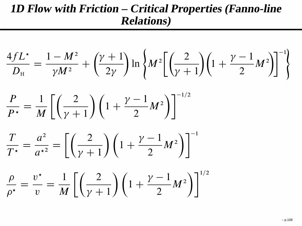
1D Flow with Friction – Critical Properties (Fanno-lineRelations)
4fL?
DH
D 1 � M 2
M 2C�
C 1
2
�
ln
(
M 2
��
2
C 1
��
1 C � 1
2M 2
���1)
P
P ?D 1
M
��
2
C 1
��
1 C � 1
2M 2
���1=2
T
T ?D a2
a?2D��
2
C 1
��
1 C � 1
2M 2
���1
�
�?D v?
vD 1
M
��
2
C 1
��
1 C � 1
2M 2
��1=2
– p.108
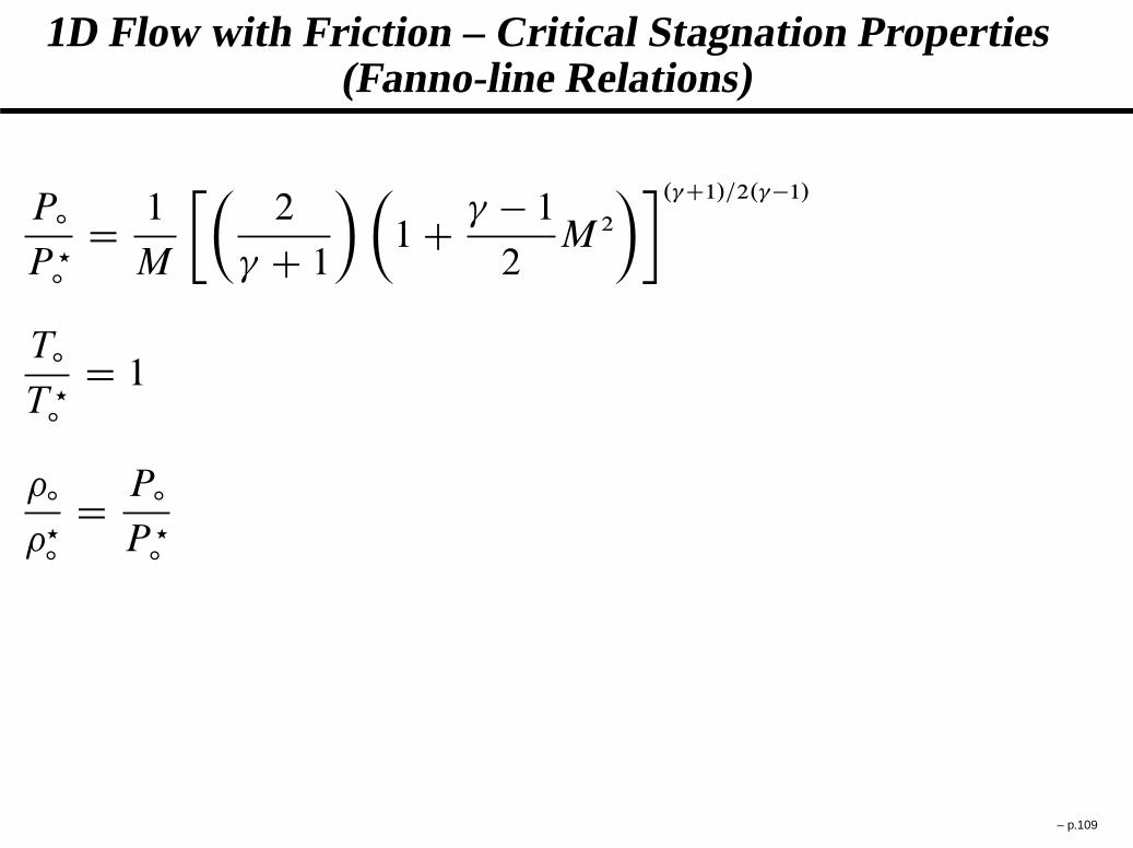
1D Flow with Friction – Critical Stagnation Properties(Fanno-line Relations)
Pı
P ?ı
D 1
M
��
2
C 1
��
1 C � 1
2M 2
��. C1/=2. �1/
Tı
T ?ı
D 1
�ı
�?ı
D Pı
P ?ı
– p.109

Gino Girolamo Fanno (1888–1960)
� Italian Engineer
� Obtained Bachelor’s degree inMechanical Engineering in Venice,Italy
� Moved to Zurich, Switzerland in 1900to attend graduate school for hisMaster’s degree
� Developed the Fanno-line flow modelas part of his Master’s thesis (1904)
� Returned to Italy for a job in theindustry
� Later obtained a Ph.D. from Regio Isti-tuto Superiore d’Ingegneria di Genova
– p.110

1D Flow with Heat Transfer – Governing Equations
Conservation of Mass:
d
dx�v D 0
Conservation of Momentum:
d
dx
�
�v2 C P�
D 0
Conservation of Energy:
d
dx.�vH/ D d
dx.�vCP Tı/ D qin�
with:
qin � average heatflux in W/m2
� � duct perimeter at agivenx-station through whichheat flux takes place
– p.111
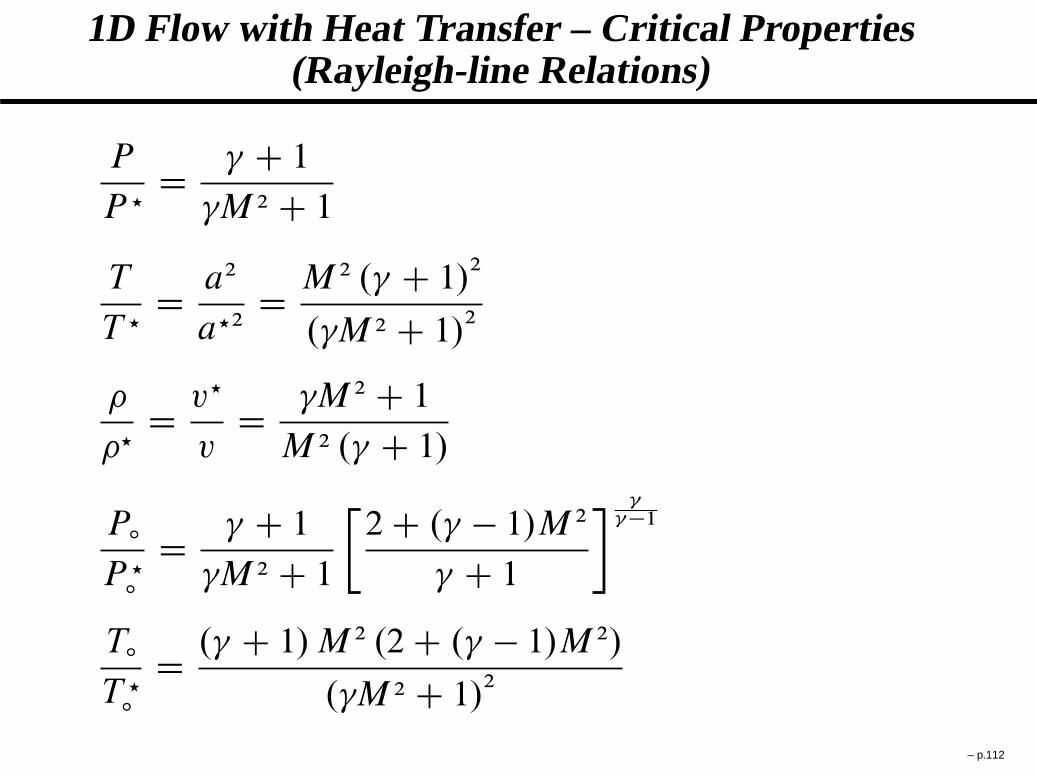
1D Flow with Heat Transfer – Critical Properties(Rayleigh-line Relations)
P
P ?D C 1
M 2 C 1
T
T ?D a2
a?2D M 2 . C 1/
2
. M 2 C 1/2
�
�?D v?
vD M 2 C 1
M 2 . C 1/
Pı
P ?ı
D C 1
M 2 C 1
�
2 C . � 1/M 2
C 1
�
�1
Tı
T ?ı
D . C 1/ M 2 .2 C . � 1/M 2/
. M 2 C 1/2
– p.112

John Strutt, 3rd Baron Rayleigh (1842–1919)
� English physicist, awarded the Nobel prizeof physics in 1904 for discovering argon
� Obtained BA and MA degrees inMathematics from Cambridge (1861–1868)
� Became the second Cavendish Professor ofPhysics from 1879 to 1884 at the Universityof Cambridge, following James ClerkMaxwell
� Was first to describe dynamic soaring byseabirds in 1883 in the British journalNature
� “Rayleigh-line flow” and the “Rayleighnumber” associated with buoyancy drivenflow are named in his honour
– p.113

2D Subsonic Flow Around Airfoil
Smoke-jets visualization. Since the flow is subsonic, pressurewaves can travel upstream. Well upstream of the airfoil, the flowis “aware” of it approaching and adapts in consequence. – p.114

2D Supersonic Flow Around Blunt Bullet
Schlieren photograph.
Flow becomes subsonicthrough quasi-normalshockwave and then ad-justs to the shape of theobject.
– p.115
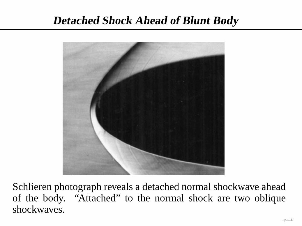
Detached Shock Ahead of Blunt Body
Schlieren photograph reveals a detached normal shockwave aheadof the body. “Attached” to the normal shock are two obliqueshockwaves.
– p.116
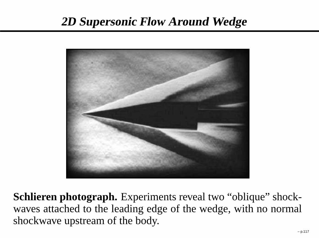
2D Supersonic Flow Around Wedge
Schlieren photograph.Experiments reveal two “oblique” shock-waves attached to the leading edge of the wedge, with no normalshockwave upstream of the body.
– p.117

2D Oblique Shockwaves – Governing Equations
Conservation of Mass:
.�vN/2 D .�vN/1
Conservation of N-Momentum:�
�v2
N C P�
2D�
�v2
N C P�
1
Conservation of T-Momentum:
.vT/2 D .vT/1
Conservation of Energy:�
h C 1
2v2
N
�
2
D�
h C 1
2v2
N
�
1
with:
vT the velocity componenttransverseto the shockwave
vN the velocity componentnormal to the shockwave
Subscripts “1” and “2” refer tothe properties before and afterthe shockwave, respectively
– p.118

2D Oblique Shockwaves – Working Relation
Starting from the governing equations, we can show that theworking relation linking the shock incoming Mach numberwith the deflection angle corresponds to:
tan.�/
tan.� � ı/D . C 1/M 2
1sin2
�
2 C . � 1/M 21sin2
�
where
ı is the flow turning angleM1 is the incoming flow Mach number� is angle of the shockwave with respect to the incomingflow
– p.119
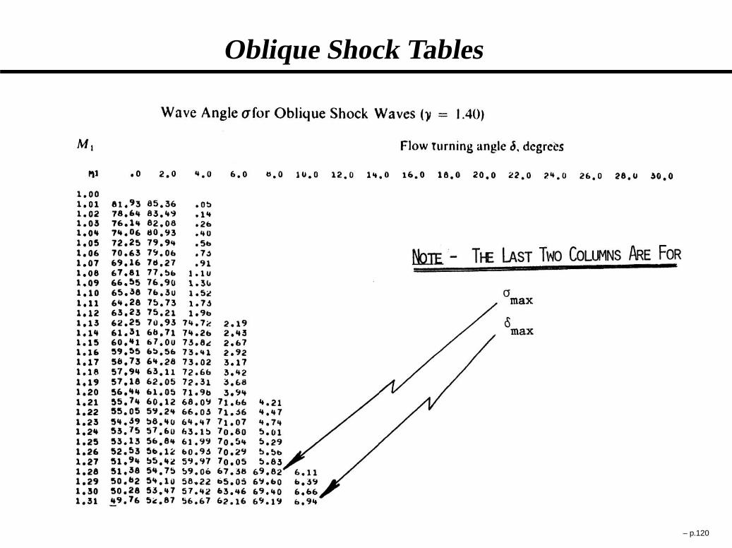
Oblique Shock Tables
– p.120

Concorde Inlet
– p.121

F14
– p.122

F14 Inlet
– p.123

F14 Inlet Hydraulics
– p.124

F14 Inlet Schematic
F14 inlet configuration in supersonic flight. The roleof the inlet is to slow the flow down to subsonic speedsbefore it reaches the turbine. Effectively, the Mach numberat the turbine entrance is maintained to Mach 0.5–0.7 insupersonic flight.
– p.125
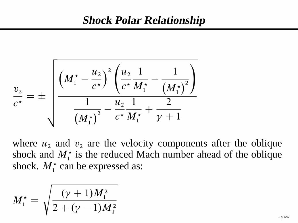
Shock Polar Relationship
v2
c?D ˙
v
u
u
u
u
u
u
u
t
�
M ?
1� u2
c?
�2
u2
c?
1
M ?1
� 1�
M ?1
�2
!
1�
M ?1
�2� u2
c?
1
M ?1
C 2
C 1
whereu2 and v2 are the velocity components after the obliqueshock andM ?
1is the reduced Mach number ahead of the oblique
shock.M ?1
can be expressed as:
M ?
1Ds
. C 1/M 21
2 C . � 1/M 21
– p.126
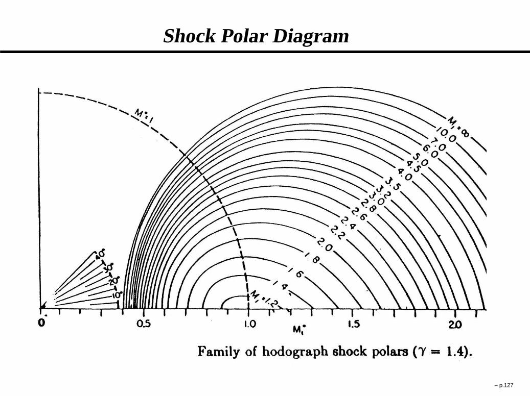
Shock Polar Diagram
– p.127

Shock Reflection
– p.128
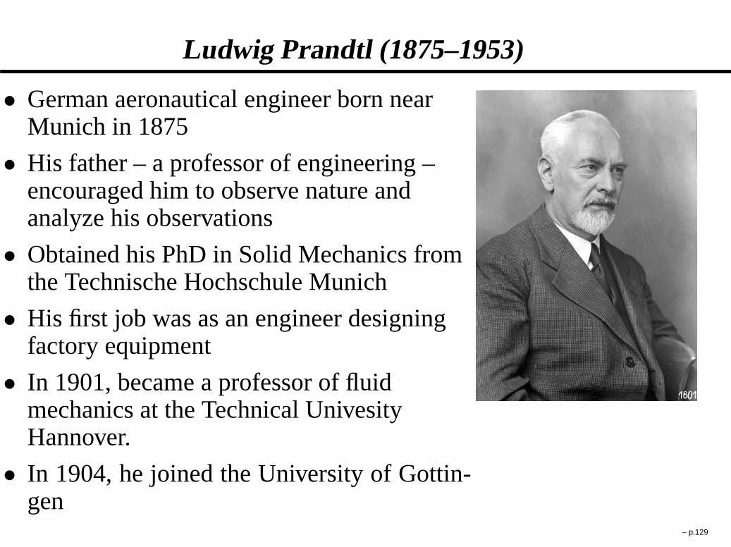
Ludwig Prandtl (1875–1953)
� German aeronautical engineer born nearMunich in 1875
� His father – a professor of engineering –encouraged him to observe nature andanalyze his observations
� Obtained his PhD in Solid Mechanics fromthe Technische Hochschule Munich
� His first job was as an engineer designingfactory equipment
� In 1901, became a professor of fluidmechanics at the Technical UnivesityHannover.
� In 1904, he joined the University of Gottin-gen
– p.129
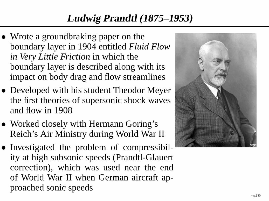
Ludwig Prandtl (1875–1953)
� Wrote a groundbraking paper on theboundary layer in 1904 entitledFluid Flowin Very Little Friction in which theboundary layer is described along with itsimpact on body drag and flow streamlines
� Developed with his student Theodor Meyerthe first theories of supersonic shock wavesand flow in 1908
� Worked closely with Hermann Goring’sReich’s Air Ministry during World War II
� Investigated the problem of compressibil-ity at high subsonic speeds (Prandtl-Glauertcorrection), which was used near the endof World War II when German aircraft ap-proached sonic speeds
– p.130
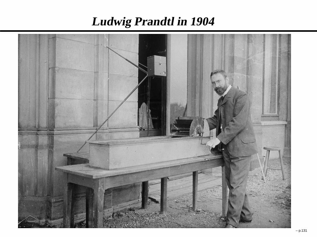
Ludwig Prandtl in 1904
– p.131

Lift and Drag Coefficients
CL D FL
1
2�1q2
1Aplanform
CD D FD
1
2�1q2
1Aplanform
where
FL is the lift forceFD is the drag forceq1 is the freestream air speed�1 is the freestream air densityAplanform is the planform area
– p.132

Overexpanded Nozzle Flow
– p.133

Overexpanded Nozzle Flow – Higher Back Pressure
– p.134

Overexpanded Nozzle Flow While Testing the SpaceShuttle Main Engine
While the flow is uniformat the nozzle exit, the exitpressure of the nozzle isless than the back pres-sure. This is referred to asan "overexpanded" nozzleflow, and is accompaniedby an interaction betweenthe exit flow and the envi-ronment in form of obliqueshocks and expansion fans.
– p.135

SR71 Blackbird at Take-off
Despite the flow being uniform at the nozzle exit, some "di-amonds" appear downstream due to overexpansion.
– p.136

Schematic of Overexpanded Nozzle Flow
– p.137
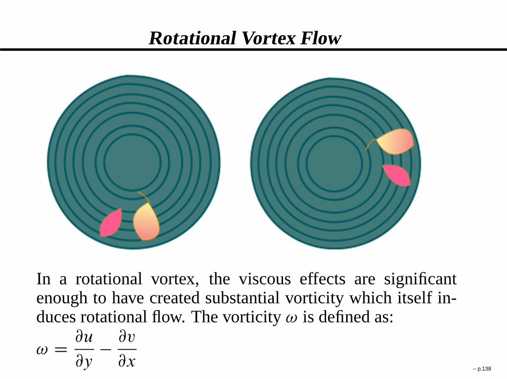
Rotational Vortex Flow
In a rotational vortex, the viscous effects are significantenough to have created substantial vorticity which itself in-duces rotational flow. The vorticity! is defined as:
! D @u
@y� @v
@x– p.138

Irrotational Vortex Flow
In an irrotational vortex, the viscous effects are insignificantand the vorticity is negligible:@u
@y� @v
@x! 0
– p.139
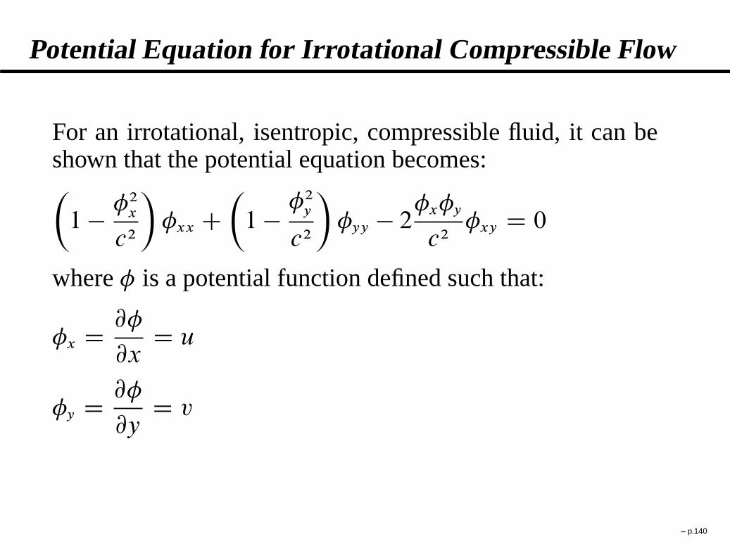
Potential Equation for Irrotational Compressible Flow
For an irrotational, isentropic, compressible fluid, it can beshown that the potential equation becomes:�
1 � �2x
c2
�
�xx C�
1 � �2y
c2
�
�yy � 2�x�y
c2�xy D 0
where� is a potential function defined such that:
�x D @�
@xD u
�y D @�
@yD v
– p.140
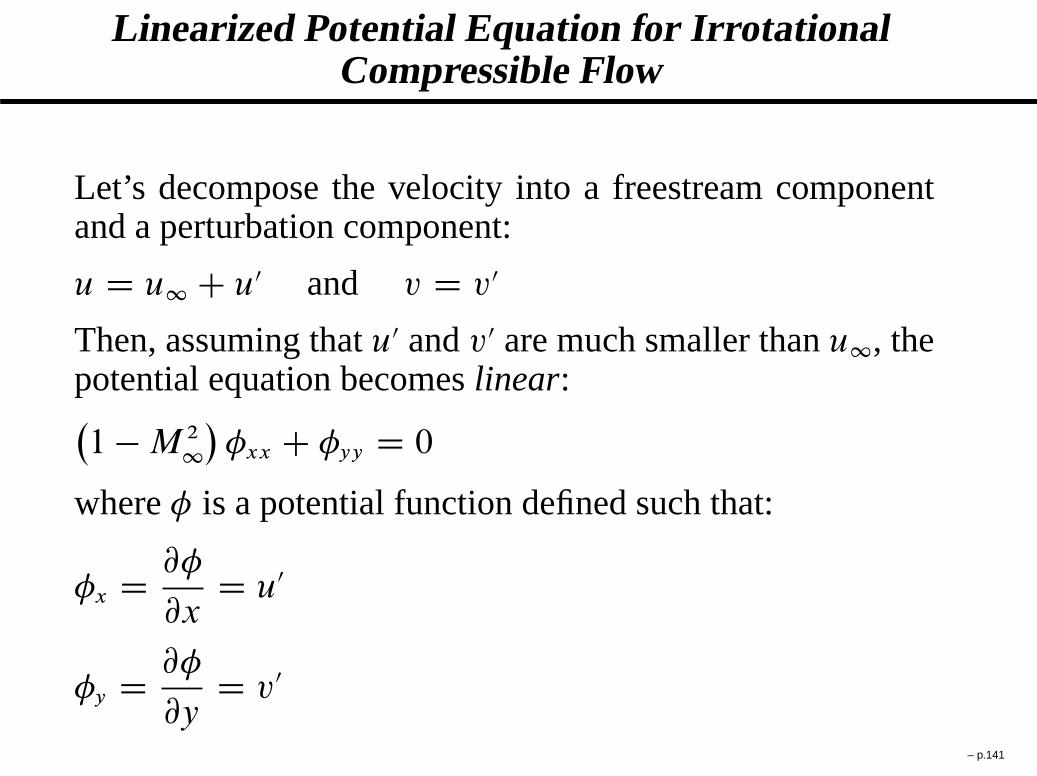
Linearized Potential Equation for IrrotationalCompressible Flow
Let’s decompose the velocity into a freestream componentand a perturbation component:
u D u1 C u0 and v D v0
Then, assuming thatu0 andv0 are much smaller thanu1, thepotential equation becomeslinear:�
1 � M 2
1
�
�xx C �yy D 0
where� is a potential function defined such that:
�x D @�
@xD u0
�y D @�
@yD v0
– p.141

Linearized Potential Equation for IrrotationalCompressible Supersonic Flow
In the case of supersonic flow the linearized potential equa-tion�
1 � M 2
1
�
�xx C �yy D 0
is of hyperbolic type since the coefficients preceding the�xx
and�yy terms have alternating signs.
Since the equation is hyperbolic, the solution for� corre-sponds to a sum off andg waves:
�.x; y/ D f�
x C yp
M 21
� 1�
C g�
x � yp
M 21
� 1�
– p.142

Pressure Coefficient for Linearized IrrotationalSupersonic Flow
Not to be confused with the specific heat at constantpressure, the pressure coefficientCP is defined as:
CP � P � P1
1
2�1q2
1
with q1 the freestream flow speed. In the case of supersonicflow, the linearized potential equation yields the followingexpression forCP :
CP D 2�deflp
M 21
� 1for theg waves
CP D � 2�deflp
M 21
� 1for thef waves
– p.143

Swept Wings
A swept-wing is a wing planform common on jet aircraft capa-ble of near-sonic or supersonic speeds. The wings are swept backinstead of being set at right angles to the fuselage which was com-mon on propeller driven aircraft and early jets. This is a usefuldrag-reducing measure for aircraft flying just below the speed ofsound, though straight wings are still favored for slower cruise andlanding speeds and aircraft with long range or endurance. Swept-wings also provide a degree of inherent stability and it was forthis reason that the concept was first employed in the designs ofJ.W.Dunne in the first decade of the 20th century, e.g. the DunneD.1. Swept wings as a means of reducing aerodynamic drag werefirst used on bombers and jet fighter aircraft. Today, they havesince become almost universal on all but the slowest jets, and mostfaster airliners and business jets.
– p.144
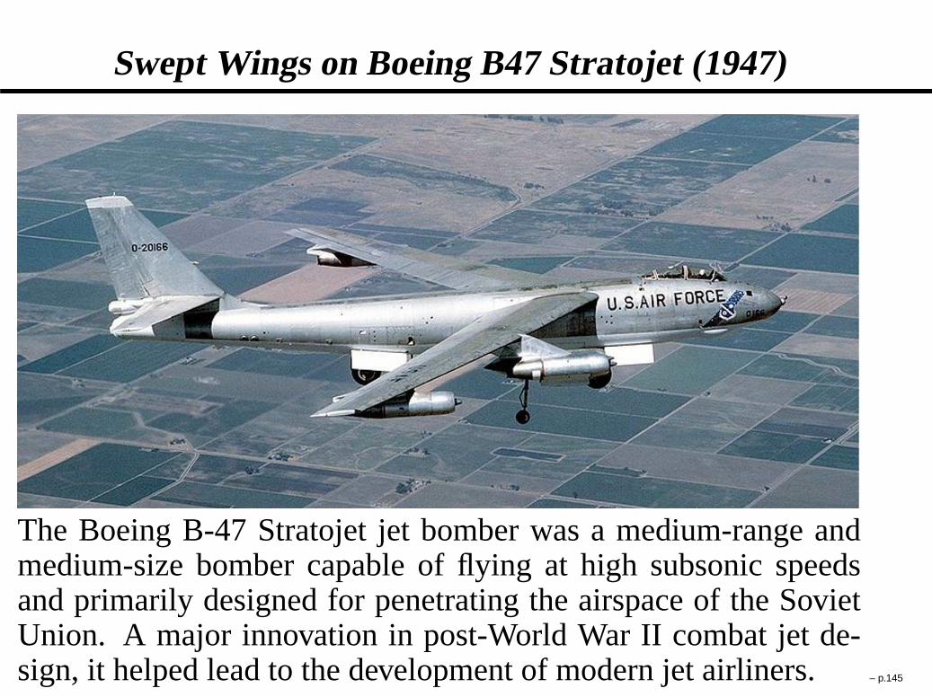
Swept Wings on Boeing B47 Stratojet (1947)
The Boeing B-47 Stratojet jet bomber was a medium-range andmedium-size bomber capable of flying at high subsonic speedsand primarily designed for penetrating the airspace of the SovietUnion. A major innovation in post-World War II combat jet de-sign, it helped lead to the development of modern jet airliners.– p.145

Boeing B47 Stratojet Taking Off (1947)
Many people consider the B-47 as “the most influential jet aircraftof all time.” All of Boeing’s jetliners adopted the same swept-wingconfiguration and most of them also fitted their engines on thewings just like the B-47. Other transonic airplane manufacturersalso adopted this configuration. The better performance of sweptwings at high speeds is due to their abeyance of the “area rule”. – p.146

What is the Area Rule?
At high-subsonic flight speeds, local supersonic airflowcan develop in areas where the flow accelerates aroundthe aircraft body and wings.The resulting shockwaves formed at these points of supersonic flow canform a sudden and strong form of drag, called wavedrag. Thearea rule states that in order to reduce thenumber and strength of these shock waves, anaerody-namic shape should change in cross-sectional areaas smoothly as possible.It was developed at NACALangley by Richard Whitcomb and Adolf Busemann.
– p.147

Richard T. WHITCOMB (1921–)
� American aeronautical engineer born inEvanston, Illinois, in 1921
� 1943 graduate in Mechanical Engineeringfrom Worcester Polytechnic Institute
� Spent most of his career at the LangleyLaboratory of the NACA and NASA
� Proposed in the 1950s the “area rule” tominimize shock drag in transonic flight
� In the 1960s, developed the “supercriticalairfoil” which effectively extends thesupersonic region over a transonic wing
� In the 1970s, developed the “winglets”which reduce wingtip vortices and the in-duced drag such vortices create
– p.148

Adolf BUSEMANN (1901–1986)
� German aeronautical engineer born inLubeck, Germany in 1901
� Received PhD in Aerospace Engineering atthe Technical University Braunschweig in1924
� In 1924, became aeronautical researchscientist at the Max-Planck Institute underLudwig Prandtl
� Busemann originated the concept of sweptwinged aircraft, presenting a paper on thetopic at the Volta Conference in Rome in1935
� Moved to NACA Langley in 1947 andhelped develop the area rule with Whitcomb
– p.149

McDonnell Douglas MD11 (Cruise Mach number of0.85)
The profile of the MD11 nose shows clearly the applicationof the area rule.
– p.150

NASA Convair 990 (Cruise Mach Number of 0.91)
Antishock bodies can be added to the wings of transonic air-craft to make the aircraft cross-section obey the area rule.
– p.151

Anti-Shock Bodies Impact on Transonic Flow Over aWing (Using Oilflow Visualization)
To reduce the adverse effects of the shockwave in transonicflight, anti-shock bodies are added according to the “arearule”
– p.152
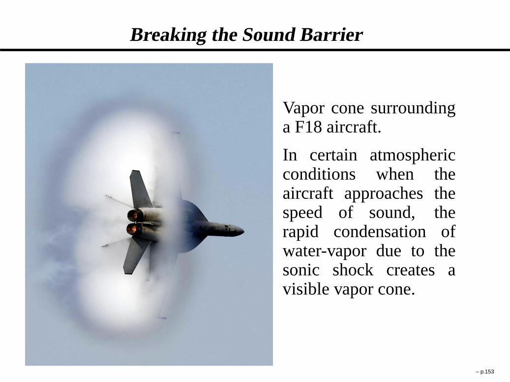
Breaking the Sound Barrier
Vapor cone surroundinga F18 aircraft.
In certain atmosphericconditions when theaircraft approaches thespeed of sound, therapid condensation ofwater-vapor due to thesonic shock creates avisible vapor cone.
– p.153

Supersonic Flight
One difficulty associated with supersonic flight is therather low lift to drag ratio (L/D ratio) of the wings. Atsupersonic speeds, airfoils generate lift in an entirely differ-ent manner than at subsonic speeds, and are invariably lessefficient. For this reason, considerable research has been putinto designing planforms for sustained supersonic cruise. Atabout Mach 2, a typical wing design will cut its L/D ra-tio in half (e.g., the Concorde vehicle managed a ratio of7.14, whereas the subsonic Boeing 747 has an L/D ratio of17). Because an aircraft’s design must provide enough lift toovercome its own weight, a reduction of its L/D ratio at su-personic speeds requires additional thrust to maintain its air-speed and altitude.Another difficulty associated with su-personic flight is the too-high pressure on a leading edgeof the aircraft designed according to the area rule. Thislead to the adoption of the “Haack body” shape.
– p.154

Haack Body
The shock wave drag can be further decreased in supersonicflight by imposing a pointed leading edge while minimizingthe area change difference alongx. This results in theHaack body:
Acs D .Acs/max
�
4
�
x
L� x2
L2
��32
where:x is the streamwise distance from the leading edgeL is the distance from the leading edge to the trailing edgeAcs is the cross-sectional area of the aircraft.Acs/max is the maximum cross-sectional area of the aircraft,located atx=L D 0:5
– p.155

Haack Body – Figure
Despite appearances, the cross sectional area of most super-sonic airplanes follows the Haack body distribution.
– p.156

Nose Cone Drag versus Mach Number for VariousShapes
Comparison of drag characteristics of various nose coneshapes in the transonic to low-supersonic regions. Rankingsare: superior (1), good (2), fair (3), inferior (4).
– p.157
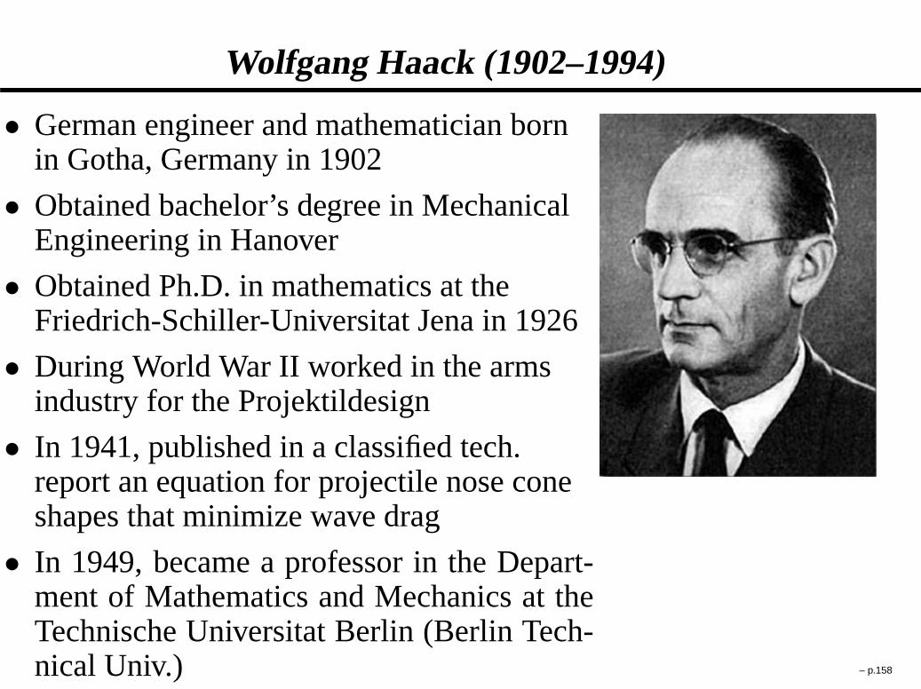
Wolfgang Haack (1902–1994)
� German engineer and mathematician bornin Gotha, Germany in 1902
� Obtained bachelor’s degree in MechanicalEngineering in Hanover
� Obtained Ph.D. in mathematics at theFriedrich-Schiller-Universitat Jena in 1926
� During World War II worked in the armsindustry for the Projektildesign
� In 1941, published in a classified tech.report an equation for projectile nose coneshapes that minimize wave drag
� In 1949, became a professor in the Depart-ment of Mathematics and Mechanics at theTechnische Universitat Berlin (Berlin Tech-nical Univ.) – p.158
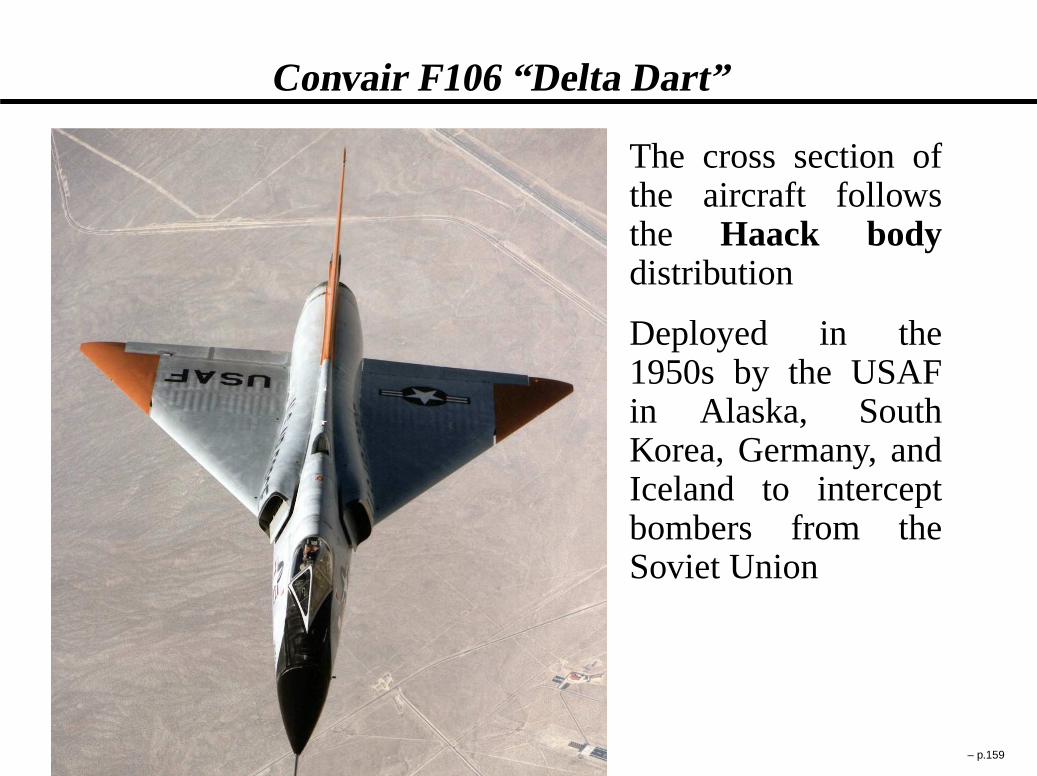
Convair F106 “Delta Dart”
The cross section ofthe aircraft followsthe Haack bodydistribution
Deployed in the1950s by the USAFin Alaska, SouthKorea, Germany, andIceland to interceptbombers from theSoviet Union
– p.159

CF-105 Avro Arrow Inauguration,Toronto, Canada, 1958
Mach 2.0 Canadian aircraft deployed in 1958 to intercept sovietbombers.
– p.160

CF-105 Avro Arrow in Flight,Avro Aircraft Company (Canada), 1958
The aircraft body and delta wing are designed following theHaack body to minimize wave drag.
– p.161

Avro Arrow – Choice of Delta Wing over Swept Wing
“At the time we laid down the design of the CF-105, therewas a somewhat emotional controversy going on in theUnited States on the relative merits of the delta planform ver-sus the straight wing for supersonic aircraft... our choice ofa tailless delta was based mainly on thecompromise of at-tempting to achieve structural and aeroelastic efficiencywith a very thin wing, and yet, at the same time, achievingthe large internal fuel capacity required for the specifiedrange.”
James C. Floyd
Chief Design Engineer of Avro Arrow Aircraft– p.162

Avro Arrow in Royal Canadian Air Force Hangar,Toronto, 1958
The Arrow had several world’s firsts, such asfly-by-wire technol-ogy (hydraulic system to move the various flight controls alongwith “artificial feel” added to the control stick) andcomputer-controlled stability augmentation system(long, "thin" aircrafthave coupling modes that can lead to departure from stable flightif not damped out quickly). – p.163

Avro Arrow Cockpit, Canada Aviation Museum,Ottawa, Canada, 2004
The Arrow program was cancelled in 1959 with instructions givento the Canadian military to immediately seize and destroy all air-craft and blueprints and to shut down Avro Aircraft Company.
– p.164

Avro Arrow Wing, Canada Aviation Museum, Ottawa,Canada, 2004
All that was left was a blow-torched cockpit and a wing. Wellpreserved at the Canadian Aviation Museum.
– p.165
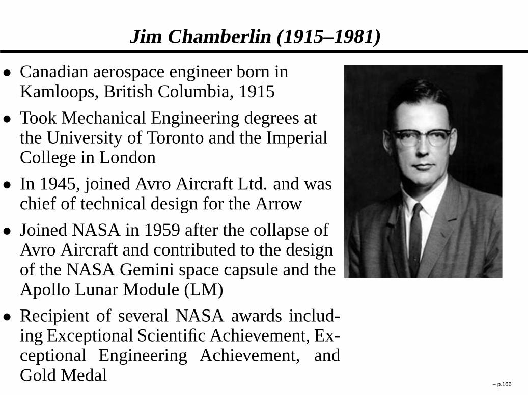
Jim Chamberlin (1915–1981)
� Canadian aerospace engineer born inKamloops, British Columbia, 1915
� Took Mechanical Engineering degrees atthe University of Toronto and the ImperialCollege in London
� In 1945, joined Avro Aircraft Ltd. and waschief of technical design for the Arrow
� Joined NASA in 1959 after the collapse ofAvro Aircraft and contributed to the designof the NASA Gemini space capsule and theApollo Lunar Module (LM)
� Recipient of several NASA awards includ-ing Exceptional Scientific Achievement, Ex-ceptional Engineering Achievement, andGold Medal
– p.166

Scramjet: Supersonic Combustion Ramjet
� Ground test of hydrogen-fuelled X43 at Dryden Centerin Dec. 1999
� Successful flight at Mach 10 on November 16, 2004 – p.167

X43 Wind Tunnel Test
� Wind tunnel testing of X43 at Mach 7 in NASA LangleyHTT (High Temperature Tunnel)
– p.168

The Renewal of Scramjet Research (1988-now)
� U.S.A.: Hystep, Hyper X/X43A (one flight attempt),Hytech (X43C), Hyset, X51A
� France: PREPHA, ONERA-DLR JAPHAR, DGAPROMETHEE
� Germany: MTU, DLR/TsAGI
� Australia : Hyshot
� Russia: Kholod test flights (1991-1998), Igla project
� China: Institute of Mechanics, Chinese Academy ofSciences
� Japan: NAL
– p.169

X51 Project
� X51 scramjet engine firing in NASA Langley HTT. TheX51 is planned to fly by 2009 at Mach 7.
� The X51 differs from the X43 through the use of hydro-carbons (kerosene or a variant) rather than hydrogen
– p.170

Typical Scramjet Flowfield
� Need of an isolator and shocktrain when using kerosenefuel
� Combustion takes place both subsonically andsupersonically
� Long combustor required due to high flow speed induc-ing slow mixing and combustion
– p.171

Antonio Ferri (1912–1975)
� Italian aeronautical engineer born in 1912in Norcia, Italy
� Obtained PhD in Electrical Eng. (1934) andPhD in Aeronautical Eng. (1936) at theUniv. of Rome
� Became the head of the Supersonic WindTunnel of Guidonia (near Rome) in 1937
� In 1944, moved to NACA Langley andbecame Head of Gasdynamics branch
� Authored the bookElements of SupersonicAerodynamicsin 1949
� Most known for pioneering supersonic com-bustion, the scramjet, and self-restarting su-personic inlets in the 1950s-60s
– p.172

Computational Fluid Dynamics (CFD)
The idea behind CFD is totransform the governing equa-tions from the differential form into an approximate dis-crete form and then solve the discrete form using a computer
– p.173

Method of Characteristics (MOC)
The MOC (method of characteristics) consists in reducinga partial differential equation to a family of ordinary differ-ential equations along which the solution can be integratedfrom some initial data given on a suitable hypersurface.
In the case of linear equations, the MOC would collapseto the linearized theory equations with thef waves andgwaves being the so-calledcharacteristics. But contrarilyto linearized theory, the MOC can be also applied to non-linear hyperbolic equations and can offer an exact solutionto the unsteady Euler equations or the steady supersonic Eu-ler equations.
The MOC is particularly useful whendesigning supersonicnozzlesor to offer an exact solution to which a CFD methodcan be validated against.
– p.174

Émile Coué (1857–1926)
� French psychologist of Breton stockborn in Troyes, France, in 1857
� Obtained degree in pharmacology in1876
� His book,Self-Mastery ThroughConscious Autosuggestionwaspublished in England (1920) and in theUnited States (1922)
� Coué’s Fundamental Theory is a U-turnto what almost everyone thinks ("Bywill power we can do anything")
� Rather, Coué’s Theory is thatany ideaexclusively occupying the mind turnsinto reality as long as the idea is withinthe realms of possibility
– p.175