comprehensive numerical investigations of...
TRANSCRIPT

Research ArticleComprehensive Numerical Investigations ofUnsteady Internal Flows and Cavitation Characteristics inDouble-Suction Centrifugal Pump
Xuelin Tang12 Mingde Zou1 FujunWang12 Xiaoqin Li12 and Xiaoyan Shi12
1College of Water Resources and Civil Engineering China Agricultural University Beijing 100083 China2Beijing Engineering Research Center of Safety and Energy Saving Technology for Water Supply Network SystemChina Agricultural University Beijing 100083 China
Correspondence should be addressed to Xuelin Tang xl-tangmailtsinghuaeducn
Received 27 April 2017 Accepted 5 July 2017 Published 14 August 2017
Academic Editor Ling Qian
Copyright copy 2017 Xuelin Tang et al This is an open access article distributed under the Creative Commons Attribution Licensewhich permits unrestricted use distribution and reproduction in any medium provided the original work is properly cited
The RNG k-120576 turbulence model combined with cavitation model was used to simulate unsteady cavitating flows inside a double-suction centrifugal pump under different flow rate conditions based on hexahedral structured grid The numerical externalcharacteristic performances agree well with the experimental performances The predicted results show that the turbulence kineticenergy and the turbulence dissipation rate inside the impeller at design flow rate are lower than those at other off-design flow rateswhich are caused by various vortexes Based on frequency-domain analyses in the volute casing the blade passing frequency is thedominant one of the pressure fluctuations except the vicinity of volute tongue for all operating cases and the dominant frequencynear the volute tongue ranges from0 to 05 times the blade passing frequency for other off-design points while the blade passing onenear the volute tongue is the dominant one of the pressure fluctuations at design pointThe increase of flow rate reduces the pressurefluctuations amplitude For cavitation cases the blade loading of the middle streamline increases a bit during the initial stage butfor serious cavitation the blade loading near the blade inlet reduces to 0 and even negative values and the serious cavitation bubblesblock the blade channels which results in a sharp drop in pump head Under noncavitation condition the predicted power relatedto the pressure in the impeller channels increases from the inlet to the exit while under different cavitation conditions at thedesign flow rate these power-transformation distributions in the impeller channels show that these power conversions are affectedby the available NPSHa and the corresponding work in leading regions of the blades increases increases gradually a bit and then itincreases sharply in the middle regions but it decreases in the blade trailing regions and is greatly influenced by secondary flows
1 Introduction
Centrifugal pumps are the most commonly used type amongvarious pumps where double-suction centrifugal pumpshave advantages of large flow rate high efficiency high headand so forth which occupies a large proportion of thepump products The internal flow inside a double-suctioncentrifugal pump is unsteady and extremely complex Thereare some possible phenomena in the flow such as rotor-statorinteraction rotating stalling and cavitation [1ndash3] With rapiddevelopment in computer technology and computationalfluid dynamics (CFD) the CFD method is a good tool toinvestigate complex turbulent flows inside pumps [4] In
numerical simulation of a centrifugal pump blade anglesblade number and turbulence model have great effect on thepredicted performances of centrifugal pump [5] Shigemitsuet al [6] numerically studied three types of impellers withdifferent outlet angles in the mini turbo-pumps and foundthat the change of the blade outlet angle has effect on perfor-mance and internal flows in mini turbo-pumps Chakrabortyet al [7] analyzed the static pressure distribution and char-acteristics of the two-dimensional (2D) incompressible flowinside a centrifugal pumprsquos impellers with different bladenumbers and the predicted results displayed that the headand static pressures of the pump increase with the increaseof the blade number while the efficiency with seven-blade
HindawiMathematical Problems in EngineeringVolume 2017 Article ID 5013826 13 pageshttpsdoiorg10115520175013826
2 Mathematical Problems in Engineering
pump is optimal Gonzalez et al [8] investigated numericallythe internal flow inside a double-suction centrifugal machinein the pump operation mode and found that the flow in thedouble-suction chamber is uniform at design flow rate buthas a strong unsteady characteristic at off-design flow ratesAt the same time the cavitation is a common phenomenonin centrifugal pumps When the pressure inside the pumpis below the saturation water vapor pressure cavitation mayoccur It will cause noise performance breakdown and costlydamage to hydraulic machineries [9] Liu et al [10] usedthe standard RNG k-120576 model and two modified RNG k-120576 models that is density correction based model (DCM)and filter-based model (FBM) to simulate the unsteadyattached sheet-cavitating flows in centrifugal pumps andthe studies suggested that all the turbulence models rarelyaffect the evolution of cavitation bubbles but the advancedturbulence model can significantly improve the predictionprecision of head coefficients and critical cavitation numbersThai and Lee [11] predicted the cavitation characteristicsof the centrifugal pump with two types of short and longblades at on-design and off-design points respectively Thenumerical results showed that the pump can safely operatewithout cavitation at design point but the cavitation developsinhomogeneously in the blade channels at off-design points
Themain focus of our work is to investigate the hydraulicperformance and the cavitation performance of a double-suction centrifugal pump Firstly based on ANSYS CFXsolver the RNG k-120576 turbulence model was used to calculatethe unsteady flow fields inside the pump without cavitationat different flow rates The predicted external characteristicsof the pump were in good agreement with the experimentalones For different NPSHa the blade loading and the vaporvolume fraction for cavitation flows in the impeller weresimulated numerically and analyzed systematically at designpoint and the studies on the influence of the cavitation andsecondary flows on power distributions were carried out
2 Basic Parameters and Computational Grids
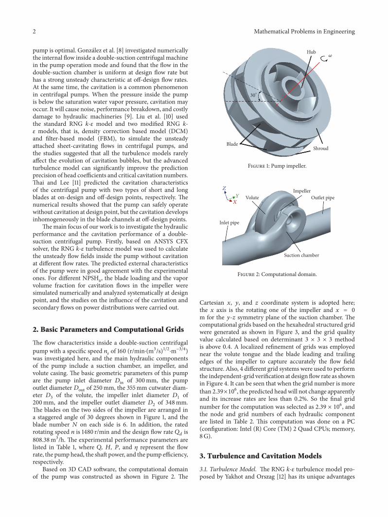
The flow characteristics inside a double-suction centrifugalpump with a specific speed 119899119904 of 160 (rminsdot(m3s)12sdotmminus34)was investigated here and the main hydraulic componentsof the pump include a suction chamber an impeller andvolute casing The basic geometric parameters of this pumpare the pump inlet diameter 119863in of 300mm the pumpoutlet diameter 119863out of 250mm the 355mm cutwater diam-eter 1198633 of the volute the impeller inlet diameter 1198631 of200mm and the impeller outlet diameter 1198632 of 348mmThe blades on the two sides of the impeller are arranged ina staggered angle of 30 degrees shown in Figure 1 and theblade number 119873 on each side is 6 In addition the ratedrotating speed 119899 is 1480 rmin and the design flow rate 119876119889 is80838m3h The experimental performance parameters arelisted in Table 1 where 119876 119867 119875 and 120578 represent the flowrate the pumphead the shaft power and the pump efficiencyrespectively
Based on 3D CAD software the computational domainof the pump was constructed as shown in Figure 2 The
Hub
BladeShroud
30∘
Figure 1 Pump impeller
XY
Z
Inlet pipe
Suction chamber
VoluteImpeller
Outlet pipe
Figure 2 Computational domain
Cartesian 119909 119910 and 119911 coordinate system is adopted herethe 119909 axis is the rotating one of the impeller and 119909 = 0m for the 119910-119911 symmetry plane of the suction chamber Thecomputational grids based on the hexahedral structured gridwere generated as shown in Figure 3 and the grid qualityvalue calculated based on determinant 3 times 3 times 3 methodis above 04 A localized refinement of grids was employednear the volute tongue and the blade leading and trailingedges of the impeller to capture accurately the flow fieldstructure Also 4 different grid systems were used to performthe independent-grid verification at design flow rate as shownin Figure 4 It can be seen that when the grid number is morethan 239times106 the predicted head will not change apparentlyand its increase rates are less than 02 So the final gridnumber for the computation was selected as 239 times 106 andthe node and grid numbers of each hydraulic componentare listed in Table 2 This computation was done on a PC(configuration Intel (R) Core (TM) 2 Quad CPUs memory8G)
3 Turbulence and Cavitation Models
31 Turbulence Model The RNG k-120576 turbulence model pro-posed by Yakhot and Orszag [12] has its unique advantages
Mathematical Problems in Engineering 3
Grids detail
Figure 3 Computational grids
H(m
)
Grid number (times106)
320
318
316
314
312
310
10 15 20 25 30 35 40 45 50
Figure 4 Head variation with grid number of pump grid system atdesign flow rate
Table 1 The experimental performance parameters of pump at dif-ferent flow rates
Flow rates Q (m3h) 119899 (rmin) 119867 (m) P (kW) 120578 ()057119876119889 45948 1480 3917 63792 7684072119876119889 58338 1480 3722 69411 852082119876119889 659 1480 3557 73276 8711091119876119889 73874 1480 3344 7616 8833100119876119889 80838 1480 315 77757 8918107119876119889 8614 1480 2965 79772 8718116119876119889 9364 1480 2671 82157 8291120119876119889 9717 1480 2455 81495 7973
of turbulent viscosity modified based on standard k-120576 tur-bulence model and allowing high curvature and strain ratefor the rotation and the swirl flow of the average flow Sothe turbulence model was adopted to investigate the complexturbulence flows in double-suction centrifugal pump in this
Table 2 The node and grid numbers of each of the hydrauliccomponents
Hydrauliccomponents Suction chamber Impeller Volute casing
Node number (times106) 101 099 059Grid number (times106) 096 087 056
paper The RNG k-120576 turbulence model is as follows
120597 (120588119896)120597119905 + 120597 (120588119896119906119894)120597119909119894 = 120597120597119909119895 [120572119896 (120583 + 120583119905)
120597119896120597119909119895] + 119866119896+ 120588120576
120597 (120588120576)120597119905 + 120597 (120588120576119906119894)120597119909119894 = 120597120597119909119895 [120572120576 (120583 + 120583119905)
120597120576120597119909119895] + 119862lowast1120576
120576119896119866119896minus 11986221205761205881205762119896
120583119905 = 120588119862120583 1198962120576 119866119896 = 120583119905 (120597119906119894120597119909119895 +
120597119906119895120597119909119894 )120597119906119894120597119909119895
119862lowast1120576 = 1198621120576 minus 120578 (1 minus 1205781205780)1 + 1205731205783 120578 = radic22 ( 120597119906119894120597119909119895 +
120597119906119895120597119909119894 )119896120576
(1)
where 120583119905 stands for the turbulent viscosity and 119866119896 representsthe turbulence production due to turbulent forcesThemodelcoefficients are taken as 1198621120576 = 142 1198622120576 = 168 119862120583 = 00845120572119896 = 120572120576 = 139 1205780 = 4377 and 120573 = 001232 Cavitation Model It is necessary to introduce a two-phase mixture model and a cavitation model in cavitatingflow calculation The basic governing equations of the two-phase mixture are based on the Navier-Stokes equations [13]and the continuity equation of the two-phasemixture is givenas
120597120588119898120597119905 + nabla sdot (120588119898u) = 0 (2)
the momentum equation is as follows
120597 (120588119898u)120597119905 + nabla sdot (120588119898u) = minusnabla119901 + 13nabla [(120583119898 + 120583119905) nabla sdot u]+ nabla [(120583119898 + 120583119905) nabla sdot u]
(3)
4 Mathematical Problems in Engineering
The cavitation model used is the transport equationdeduced from the Rayleigh-Plesset equation [14] Consider-ing the growth and collapse of cavitation bubbles the masstransport equation is expressed as
120597 (120572V120588V)120597119905 + nabla sdot (120572V120588Vu) = 119898eva minus 119898con119898eva = 119862eva
3120572V120588V119877119887 radic23max (119901V minus 119901 0)120588119897
119898con = 119862con3120572V120588V119877119887 radic23
max (119901 minus 119901V 0)120588119897
(4)
where 120588119898 represents the mass density of the two-phasemixture u represents the velocity vector of the two-phasemixture 120583119898 represents the dynamic viscosity coefficient ofthe two-phase mixture 120572V represents the volume fraction ofbubbles 120588V and 120588119897 represent the mass densities of vapor andliquid respectively 119898eva and119898con represent the evaporationrate and condensation rate of water vapor in unit volumerespectively 119862eva and 119862con represent the evaporation ratecoefficient and condensation rate coefficient of water vaporin unit volume respectively the saturated vapor pressure 119901Vof water is 3170 Pa at the temperature of 25∘C and the averagediameter of the bubbles 119877119887 is 2 times 10minus6m
4 Numerical Methods andBoundary Conditions
The ANSYS CFX solver was selected in this study In thediscrete process of governing equations the time-dependenttermswere discretized with the second-order backward Eulerscheme the second-order central scheme was used for thediffusive terms and the high resolution was used to solvethe convection terms In the ANSYS CFX solver the highresolution is a special discrete scheme for the convectionterms When dealing with the convection terms the convec-tive fluxes at the integral points are approximated by those ofthe adjacent nodes which can be expressed as
120593119901 = 120593119899 + 120573nabla120593 sdot Δ997888rarr119903 (5)
where 120593119901 and 120593119899 denote the convective fluxes at the integralpoints and the upwind nodes respectively nabla120593 denotesthe convective flux gradients within the control volumes120573 represents the coefficient of the numerical convectioncorrection Δ997888rarr119903 is the vector from the upwind node to theintegral point Different discrete schemes differ in choices for120573 and nabla120593 In the high resolution scheme 120573 at each node iscomputed to be as close to 1 (not exceed 1) as possible by usinga special nonlinear recipe that is based on the boundednessprinciples used by Barth and Jespersen [15] Obviously (5)indicates that the high resolution scheme preferentially usesthe second-order backward Euler scheme and reverts to thefirst-order backward Euler scheme only when the convectiveflux gradients are very small somewhere within the controlvolumes
The solving process was based on the fully implicit gridcoupling solution technique The rotating period 119879 of theimpeller was 00405 s The time step was set to 2252 times 10minus4 sin the transient calculation Number of periods per timestep was set to 10 to achieve the periodic unsteady solutionconvergence and the convergence criterion was set to RMSresiduals of 10minus5 The steady solution was used to initializethe unsteady calculation
In order to minimize edge effects and to improve numer-ical stability two extension domains were added upstreamand downstream The normal velocity condition was used atthe inlet The static pressure condition was used at the outletand the pressure values were given by the experimental dataThe dynamic-static coupling between the suction chamberand the impeller was realized by setting the rotor frozeninterface and the same setting was also used for the dynamic-static coupling between the impeller and the volute casingSimultaneously the no-slip boundary condition was used onthe solid wall and the near-wall region was treated by usingscalable wall function The cavitating flow was simulatedby gradually reducing the static pressure at the outlet andthe reference pressure value of fluid domain was set to 0Besides the cavitating flow calculation was initialized by thesolution of single-phase noncavitating flowcalculationAt thebeginning of cavitating flow calculation the volume fractionof vapor phase was set to 0 and that of liquid phase was setto 1
5 Analyses of Internal Flow inNoncavitation Condition
51 The External Characteristics Curves The numerical effi-ciency is only the hydraulic efficiency 120578ℎ In fact thereare also mechanical loss and volumetric loss in the pumpoperation In order to do comparisons between the numericalresults and the experimental data the total pump efficiency120578 must be considered which is actually composed of thehydraulic efficiency 120578ℎ the mechanical efficiency 120578119898 and thevolumetric efficiency 120578V [16] expressed as
120578 = 120578ℎ120578119898120578V (6)
The mechanical efficiency 120578119898 is calculated by the empiri-cal formula as follows
120578119898 asymp 1 minus 007 1(119899119904100)76 (7)
The volumetric efficiency 120578V caused by volumetric loss iscalculated by the following empirical formula
120578V asymp 11 + 068119899minus23119904 (8)
It can be seen from Figure 5 that with the increase offlow rate the pump head drops gradually while the pumpshaft power rises The calculated pump head is larger thanthe experimental data at large flow rates but smaller than theexperimental data at small flow ratesThe trends between the
Mathematical Problems in Engineering 5H
(m)
P(k
W)
Q (G3h)
(
)
CalculatedExperimental
100
90
80
70
60
50
45
40
35
30
25
20
450 500 550 600 650 700 750 800 850 900 950 1000
100
90
80
70
60
50
40
30
20
10
0
Figure 5 Comparison between performance curves
calculated pump shaft power and the experimental data areroughly identical and the calculated value is lower than theexperimental one The efficiency increases with the increaseof flow rate at first and it reaches the highest point at designflow rate then as the flow rate continues to increase it beginsto decline graduallyThe calculated efficiency is higher a littlethan the experimental one Overall the calculated resultsagree well with the experimental data
52 Static Pressure Distribution in the Impeller Viewed fromthe pump inlet the pump is divided by the 119910-119911 symmetryplane of the suction chamber into two parts that is left partand right one Figure 6 shows the static pressure distributionson the hubs of the right part and the left one at different flowrates It can be seen that the static pressure increases graduallyfrom the impeller inlet to the outlet and the fluid flowsinside the left and right parts are symmetric An obvious low-pressure region appears near the impeller inlet and near theblade suction surface the static pressure reaches the lowestand cavitation may happen here as shown in Figure 7 Whenthe fluid enters into the impeller channel it can get the energydue to the work done by the impeller It is shown in Figure 7that the static pressure on pressure surface is higher thanthat on suction surface and the pressure difference causes themoment of resistance on rotating impeller
53 Analysis of Pressure Fluctuations in the Volute CasingThere is dynamic-static coupling between the volute casingand the impeller which may cause the pressure fluctuationsand affects the stability of the pumpThe pressure fluctuationscharacteristics are usually characterized by pressure coeffi-cient 119862119901 [17] which is defined as
119862119901 = 119901 minus 1199010512058811990622 (9)
where 119901 represents the transient pressure 119901 is the averagevalue of all the transient pressure at all monitoring points for
8 rotor revolutions 1199062 represents the circumferential velocityat the impeller outlet and 120588 is the fluid mass density
In order tomonitor the pressure fluctuations in the volutecasing 6monitoring points (namely11988101198811 1198812 1198813 1198814 1198815)are set on the symmetric plane of the volute casing asillustrated in Figure 8 The sampling frequency 119891119904 is 4440Hz(119891119904 = 1119879) and the results for 8T sampling time are selectedfor analysis The blade passing frequency 119891119887 is 296Hz
At design flow rate the dominant frequency of thepressure fluctuations atmonitoring point1198810 ismainly causedby the blade passing frequency shown in Figure 9 followedby the frequencies that are 0sim05 times the blade passingfrequency However at monitoring points from 1198811 to 1198815the blade passing frequency is the dominant frequency of thepressure fluctuations followed by the second harmonic of theblade passing frequency At off-design flow rates the dom-inant frequency of the pressure fluctuations at monitoringpoint 1198810 is 0sim05 times the blade passing frequency and incontrast the dominant frequency of the pressure fluctuationsat monitoring points from 1198811 to 1198815 is mainly brought aboutby the blade passing frequency followed by the frequenciesthat are 0sim05 times the blade passing frequency Besides thepressure fluctuations amplitudes at all monitoring points involute casing decrease gradually with the increase of the flowrate
54 Distributions of the Relative Velocity and Streamlinein the Hydraulic Components Figure 10 shows the relativevelocity and streamline distributions in the impeller andthe volute casing at different flow rates At the flow rate of072119876119889 the relative velocity distribution in the impeller isnonaxisymmetric there is an obvious low-velocity region inthe impeller channel near the volute tongue and an axialvortex appears in the low-velocity region In most regions ofthe impeller channels the relative velocity is higher near thesuction surface than that near pressure surface of the bladeThe relative velocity and the streamlines in the volute casingdistribute nonsmoothly At the flow rate of 10119876119889 the relativevelocity distribution in the impeller appears axisymmetricand uniform and the axial vortex in blade channel disappearsat flow rate of 072119876119889 What is more the relative velocity andthe streamlines in the volute casing distribute much moresmoothly The relative velocity and streamline distributionsin the impeller and volute casing at the flow rate of 12119876119889 areroughly similar to those at the flow rate of 10119876119889 but the flowin the impeller at the flow rate of 12119876119889 is less axisymmetricthan that at flow rate of 10119876119889 In addition it can be concludedfrom Figure 10 that under the off-design conditions a low-velocity region will appear in the vicinity of volute outletwhich is caused by the reverse flow
Relative velocity and streamline distributions on theplane of 119909 = 016m in the suction chamber are shown inFigure 11 It can be found that the relative velocity increasesalong the streamwise direction and reaches the highest valueat the regions near the outletThemean relative velocity in thewhole channel increases with the increase of the flow rateThesemivolute spiral streamlines distribute smoothly and finallysurround the impeller inlet It is obvious that some vortexesappear in the vicinity of baffle tongue which is because
6 Mathematical Problems in Engineering
Pressure (Pa)4385E + 0053917E + 0053450E + 0052982E + 0052514E + 0052046E + 0051580E + 0051111E + 0056430E + 0041760E + 004minus2920E + 004minus7600E + 004
072Qd 10Qd 12Qd
XY
Z
(a) Right part of impeller
Pressure (Pa)4385E + 0053917E + 0053450E + 0052982E + 0052514E + 0052046E + 0051580E + 0051111E + 0056430E + 0041760E + 004minus2920E + 004minus7600E + 004
072Qd 10Qd 12Qd
XY
Z
(b) Left part of impeller
Figure 6 Static pressure distributions on impeller hub at different flow rates
Pressure (Pa)4385E + 0053917E + 0053450E + 0052982E + 0052514E + 0052046E + 0051580E + 0051111E + 0056430E + 0041760E + 004minus2920E + 004minus7600E + 004
072Qd 10Qd 12Qd
(a) Pressure surface
Pressure (Pa)4385E + 0053917E + 0053450E + 0052982E + 0052514E + 0052046E + 0051580E + 0051111E + 0056430E + 0041760E + 004minus2920E + 004minus7600E + 004
072Qd 10Qd 12Qd
(b) Suction surface
Figure 7 Static pressure distribution on blade surfaces
the liquid flow is blocked here All the calculated resultsshow that these vortexes gradually evolve shedding from thevicinity of baffle tongue into the impeller and bring velocitycirculation here which affects the hydraulic efficiency and theanticavitation performance of the impeller
55 Distributions of TurbulenceKinetic Energy andDissipationRate in the Impeller The distributions of turbulence kineticenergy 119896 and turbulence dissipation rate 120576 in impeller fromthe inlet to the outlet are shown in Figures 12 and 13respectively In the figures 1198771 is the inlet radius of impeller1198772 stands for the outlet radius and 119877 represents the radialdistance between a point in the blade channels and therotating center It can be seen that the variation tendenciesbetween 119896 and 120576 are very similar At different flow rates 119896and 120576 increase at first and then decrease until reaching theminimum values in the middle of the flow channels andfinally increase again At the flow rate of 072119876119889 there is asharp increase in k and 120576 near the point of (119877minus1198771)(1198772minus1198771) =02 due to the existence of axial vortexes here which enlargethe energy dissipationHowever at the flow rates of 10119876119889 and12119876119889 the changes of k and 120576 are relatively slow On the wholek and 120576 are lowest at design flow rate which indicates that theefficiency is highest
6 Analyses of Cavitation Characteristics
Normally to avoid cavitation the static pressure head at thepump inlet must be higher than the saturated vapor pressureby some margin which is defined as the cavitation marginand is expressed as [18]
NPSHa = 119901in minus 119901V120588119892 (10)
where 119901in and 119901V represent the static pressure head at thepump inlet and the saturated vapor pressure respectivelyFigure 14 shows the predicted cavitation characteristic curveat design flow rate If the point on the curve where the headdrops by 3 is regarded as the critical cavitation pointNPSHrof this pump at design flow rate is about 47m
61 Blade Loading Distribution in the Impeller The bladeloading is defined by the pressure difference between thepressure surface and the suction surface of one blade at thesame radius location The blade loading distribution of themiddle streamlines on the blade surfaces under differentcavitation margin conditions is shown in Figure 15 where119871 is the total length of the middle streamlines on the bladesurfaces and 119897 represents the distance from the blade inlet
Mathematical Problems in Engineering 7
V5
V4V3
V2
V1
V0
Figure 8 Monitoring points in volute wall
Cp
Monitoring points
0030
0025
0020
0015
0010
0005
00000
12
34
56
7V5
V4V3
V2V1
V0
ffb
(a) 072119876119889
Cp
Monitoring points
0030
0025
0020
0015
0010
0005
0000
V5V4
V3V2
V1V0
01
23
45
67
ffb
(b) 10119876119889
Cp
Monitoring points
0030
0025
0020
0015
0010
0005
0000
V5V4
V3V2
V1V0
01
23
45
67
ffb
(c) 12119876119889
Figure 9 Frequency domain of pressure fluctuations in volute casing at different flow rates
8 Mathematical Problems in Engineering
Volute tongue
18
16
14
12
10
8
6
4
2
Velocity (ms)
XY
Z
(a) 072119876119889
Volute tongue
18
16
14
12
10
8
6
4
2
Velocity (ms)
XY
Z
(b) 10119876119889
Volute tongue
18
16
14
12
10
8
6
4
2
Velocity (ms)
XY
Z
(c) 12119876119889
Figure 10 Relative velocity and streamline distributions in the impeller and volute casing
edge to a point of themiddle streamlines on the blade surfacesalong the streamlines It can be found that when NPSHa =114mand633m the cavitation does not occur and the bladeloading is not affected Under the condition of NPSHa =427m the pressure distribution of the middle streamline onthe pressure surface does not change but it obviously reduceson the suction surface and thus it increases the blade loadingWhen NPSHa drops to 394m the cavitation is more seriouswhich makes the pressure in the middle streamlines on boththe suction surface and the pressure surface of blade reducea lot In the positions from 119897119871 = 0 to 119897119871 = 03 the bladeloading is almost 0 and even reaches negative values
62 Vapor-Phase Volume Fraction Distribution in the ImpellerFigures 16 and 17 show the distribution of the vapor-phasevolume fraction in the impeller under conditions of differentNPSHa It can be concluded that the vapor-phase volumefraction increases with the decrease in NPSHa and thecavitation bubbles gradually spread from the impeller inletto the outlet And the bubbles mainly concentrate aroundthe blade suction surfaces near the inlet which is becauseof the low pressure appearing near the suction surfacesWhen NPSHa = 114m and 633m the vapor-phase volumefraction is almost 0 from the impeller inlet to the outletwhich indicates that the cavitation phenomenon does notappear and the pump head is not affected which can beconfirmed from the pump cavitation characteristic curves
shown in Figure 14 But when NPSHa = 427m and 394ma large number of cavitation bubbles appear in the impellerparticularly when NPSHa = 394m the cavitation is moreserious The bubbles have blocked the blade channels andthe pump head drops by more than 20 In addition thedistribution of vapor-phase volume fraction in the bladechannels is nonaxisymmetric which may be caused by thedynamic-static coupling between the tongue of the volutecasing and the impeller
63 Streamline Distribution in the Impeller The streamlinesin the impeller distribute smoothly under noncavitationcondition as shown in Figure 18(a) while the streamlinedistribution in impeller channels is relatively disorderedunder cavitation condition as shown in Figure 18(b) which iscaused by the secondary flows near the exit of the impellerThese vortices have great effects on the pump head as isshown in Figure 14
64 PowerDistribution in the Impeller The impeller is the keycomponent of the pump for energy conversions In additionbecause the cavitation occurrence is closely related to thepressure the power related to the pressure plays an importantrole in the impeller channels the power 119875sec on the crosssection of the passage is defined as
119875sec = int119878119901119905v sdot n d119878 (11)
Mathematical Problems in Engineering 9
65
55
45
35
25
15
05
Velocity (ms)
Baffle tongue
XY
Z
(a) 072119876119889
65
55
45
35
25
15
05
Velocity (ms)
XY
Z
(b) 10119876119889
65
55
45
35
25
15
05
Velocity (ms)
XY
Z
(c) 12119876119889
Figure 11 Relative velocity and streamline distributions in the suction chamber at different flow rates
where 119901119905 represents the total pressure of the fluid basedon the absolute coordinate system v represents the fluidabsolute velocity and n represents the unit vector normalto the cross section And the integral term 119901119905v sdot n rep-resents the power density on the cross section 7 crosssections in each impeller channel are selected to investi-gate the power distribution and these cross sections inimpeller channels are located on the cylinders the radiiof which range from 60mm to 174mm as shown inFigure 19
It can be seen from Figure 20 that the power in theimpeller channels increases with the increase of the radiusbecause the fluid obtains thework done by blades In the bladeleading regions the power is very low and increases slowlyfor different NPSHa and its growth rate decreases as NPSHadecreases which is related to the cavitation In the blademiddle regions a sharp increase in the power occurs becausea large proportion of energy conversion happens here and
the energy conversion becomes worse for serious cavitationIn the blade trailing regions the power increases slowly whenNPSHa = 114m and 633m and in contrast the secondarybackflows cause drop in the power for NPSHa = 427m andeven sudden drop for NPSHa = 394m which can be con-firmed by Figure 18 Overall the power distribution in the leftpart of the impeller is the same as that in the right part of theimpeller
The power density distributions on the cylindricalcross sections in the impeller under noncavitation andcavitation conditions are shown in Figure 21 It canbe seen that the power density on each cross sectiondistributes nonuniformly and the averaged power den-sity on the cross sections in the impeller under non-cavitation condition is larger than that under cavitationcondition In the same impeller channel the averagedpower density increases gradually from the inlet to theexit
10 Mathematical Problems in Engineering
00 02 04 06 08 10
(R minus R1)(R2 minus R1)
Turb
ulen
ce k
inet
ic en
ergy
(G2M
2)
035
030
025
020
015
010
005
000
072Qd
10Qd
12Qd
Figure 12The distribution of the turbulence kinetic energy 119896 in theimpeller at different flow rates
00 02 04 06 08 10
Turb
ulen
ce d
issip
atio
n ra
te(G
2M
3)
(R minus R1)(R2 minus R1)
350
300
250
200
150
100
50
0
072Qd
10Qd
12Qd
Figure 13 The distribution of the turbulence dissipation rate 120576 inthe impeller at different flow rates
7 Conclusions
Based on the RNG k-120576 turbulence model and the hexahedralstructured grid the unsteady flow inside a double-suctioncentrifugal pump was numerically investigated under differ-ent flow rate conditions In addition the blade loading andpower distributions related to the cavitation at design flowrate were analyzed systematically The results are listed anddiscussed as follows
(1) The external and internal flow characteristics of thepump obtained by numerical simulation are in accordwith the general law and agree well with the experi-mental results
Hea
d (m
)
NPSH (m)
Drops by 332
30
28
26
24
22
202 3 4 5 6 7 8 9 10 11 12
Figure 14 Predicted cavitation characteristics curve
Pres
sure
(times10
50)
Streamwise location (lL)
40
35
30
25
20
15
10
05
00
minus0500 02 04 06 08 10
03( = 394G
03( = 427 G
03( = 633G
03( = 1140G
Figure 15 Blade loading distribution on middle streamlines
(2) The predicted variation tendencies of the turbulencekinetic energy k and the turbulence dissipation rate 120576are very similar under different flow rate conditionsbut k and 120576 at design flow rate are lower than those atother off-design flow rates
(3) The blade passing frequency is the dominant fre-quency of the pressure fluctuations in the volutecasing except the vicinity of the volute tongue for alloperating cases and the dominant one near the volutetongue is the blade passing frequency at the designpoint and 0sim05 times the blade passing frequency atother off-design points
(4) At the design flow rate the cavitation causes the bladeloading of the middle streamline to increase a bitduring the initial stage and serious cavitation causesthe blade loading near the blade inlet to reduce to0 and even negative values which results in a sharpdrop in the pump head
(5) The power obtained from the impeller increaseswith the increase of radius in the whole impeller
Mathematical Problems in Engineering 11
Vapor-phasevolume fraction
10
09
08
07
06
05
04
03
02
01
0003( = 394G03( = 427 G
03( = 633G03( = 114 G
Figure 16 Vapor-phase volume fraction distribution in the impeller
Streamwise location (lL)
0000
02
02
03
01
04
04
06 08 10
Volu
me f
ract
ion
03( = 394G
03( = 427 G
03( = 633G
03( = 114 G
Figure 17 The volume fraction curves of vapor phase in the impeller from inlet to outlet
Left part of impeller Right part of impeller
(a) Under noncavitation condition
Left part of impeller Right part of impeller
(b) Under cavitation condition
Figure 18 Streamline distribution in the impeller
12 Mathematical Problems in Engineering
R174
R162
R142
R122
R102
R80
R60
Figure 19 Sketch of impeller sections
Pow
er (W
)
Radius (mm)
Leading region
Middle region
Trailingregion
35000
30000
25000
20000
15000
10000
5000
0
60 80 100 120 140 160 180
03( = 394G
03( = 427 G
03( = 633G
03( = 114 G
(a) The left part of impeller
Pow
er (W
)
Radius (mm)
Leading region
Middle region
Trailingregion
35000
30000
25000
20000
15000
10000
5000
0
60 80 100 120 140 160 180
03( = 394G
03( = 427 G
03( = 633G
03( = 114 G
(b) The right part of impeller
Figure 20 Power curves of the impeller sections
Power densitydistribution (7Gminus2)
1954e + 0071760e + 0071566e + 0071372e + 0071178e + 0079833e + 0067891e + 0065948e + 0064006e + 0062064e + 0061215e + 005
R102
R142
R174
The left part of impeller The right part of impeller
(a) Under noncavitation condition
Power densitydistribution (7Gminus2)
1390e + 0071251e + 0071112e + 0079732e + 0068343e + 0066953e + 0065564e + 0064174e + 0062785e + 0061396e + 0066161e + 003
The left part of impeller The right part of impeller
(b) Under cavitation condition
Figure 21 Power density contour of cross section (119877 = 102 142 174mm)
Mathematical Problems in Engineering 13
channels but the power in leading regions of theblades increases gradually a bit and then it increasessharply in the middle regions In the blade lead-ing regions the power increases slowly for non-cavitation cases while it decreases for cavitationcases in particular it suddenly drops for seri-ous cavitation which is caused by the secondaryflows
Nomenclature
119863in Pump inlet diameter119863out Pump outlet diameter1198631 Inlet diameter of impeller1198632 Outlet diameter of impeller1198633 Cutwater diameter of volute casing119873 Blade number119899119904 Specific speed of the pump119867 Pump head119875 Pump shaft power119875sec The power on the cross section of impeller119876 Flow rate120578 Pump efficiency120578119898 Mechanical efficiency120578V Volumetric efficiency120578ℎ Hydraulic efficiency120588 Fluid mass density120588V Mass density of vapor phase119901V Saturated vapor pressure of water119901 Transient pressure119862119901 Pressure coefficient119896 Turbulence kinetic energy120576 Turbulence dissipation rateNPSHa Available net positive suction headNPSHr Required net positive suction head119898eva Evaporation rate of water vapor119898con Condensation rate of water vapor119862eva Evaporation rate coefficient of water vapor119862con Condensation rate coefficient of water vapor119879 The rotating period of the impeller119891119904 Sampling frequency119891119887 Blade passing frequency
Conflicts of Interest
The authors declare that they have no conflicts of interest
Acknowledgments
This work was supported by the National Natural ScienceFoundation of China (Grants nos 51479196 51179192 and51139007) and the Program for New Century ExcellentTalents in University (NCET) (Grant no NETC-10-0784)
References
[1] R Barrio J Parrondo and E Blanco ldquoNumerical analysis ofthe unsteady flow in the near-tongue region in a volute-type
centrifugal pump for different operating pointsrdquo Computers ampFluids vol 39 no 5 pp 859ndash870 2010
[2] N Krause K Zahringer and E Pap ldquoTime-resolved particleimaging velocimetry for the investigation of rotating stall in aradial pumprdquo Experiments in Fluids vol 39 no 2 pp 192ndash2012005
[3] X Luo WWei B Ji Z Pan W Zhou and H Xu ldquoComparisonof cavitation prediction for a centrifugal pump with or withoutvolute casingrdquo Journal of Mechanical Science and Technologyvol 27 no 6 pp 1643ndash1648 2013
[4] S Shah S Jain R Patel and V Lakhera ldquoCFD for centrifugalpumps a review of the state-of-the-artrdquo Procedia Engineeringvol 51 pp 715ndash720 2013
[5] N P Jaiswal ldquoCFD analysis of centrifugal pump a reviewrdquoJournal of Engineering Research and Applications vol 4 pp 175ndash178 2014
[6] T Shigemitsu J Fukutomi R Nasada andK Kaji ldquoThe effect ofblade outlet angle on performance and internal flow conditionof mini turbo-pumprdquo Journal of Thermal Science vol 20 no 1pp 32ndash38 2011
[7] S Chakraborty K Choudhuri P Dutta and B DebbarmaldquoPerformance prediction of Centrifugal Pumps with variationsof blade numberrdquo Journal of Scientific and Industrial Researchvol 72 no 6 pp 373ndash378 2013
[8] J Gonzalez J M F Oro and K M Arguelles-Dıaz ldquoFlow anal-ysis for a double suction centrifugal machine in the pump andturbine operation modesrdquo International Journal for NumericalMethods in Fluids vol 61 no 2 pp 220ndash236 2009
[9] X-L Tang L-Y Bian F-J Wang X-Q Li and M HaoldquoNumerical investigations on cavitating flows with thermody-namic effects in a diffuser-type centrifugal pumprdquo Journal ofMechanical Science and Technology vol 27 no 6 pp 1655ndash16642013
[10] H Liu Y Wang D Liu S Yuan and J Wang ldquoAssessment of aturbulence model for numerical predictions of sheet-cavitatingflows in centrifugal pumpsrdquo Journal of Mechanical Science andTechnology vol 27 no 9 pp 2743ndash2750 2013
[11] Q Thai and C Lee ldquoThe cavitation behavior with short lengthblades in centrifugal pumprdquo Journal of Mechanical Science andTechnology vol 24 no 10 pp 2007ndash2016 2010
[12] V Yakhot and S A Orszag ldquoRenormalization group analysis ofturbulence I Basic theoryrdquo Journal of Scientific Computing vol1 no 1 pp 3ndash51 1986
[13] R B Medvitz R F Kunz et al ldquoPerformance analysis ofcavitating flow in centrifugal pumps using multiphase CFDrdquoJournal of Fluids Engineering vol 124 no 2 pp 377ndash383 2002
[14] A K Singhal M M Athavale H Li and Y Jiang ldquoMathemati-cal basis and validation of the full cavitation modelrdquo Journal ofFluids Engineering vol 124 no 3 pp 617ndash624 2002
[15] T Barth and D Jespersen ldquoThe design and application ofupwind schemes on unstructured meshesrdquo in Proceedings of the27th Aerospace Sciences Meeting Reno NV USA 1989
[16] G Xingfan Modern Pumps Theory and Design AstronauticsPress Beijing China 2011
[17] J L Parrondo-Gayo J Gonzalez-Perez and J Fernandez-Francos ldquoThe effect of the operating point on the pressurefluctuations at the blade passage frequency in the volute of acentrifugal pumprdquo Journal of Fluids Engineering vol 124 no 3pp 784ndash790 2002
[18] B Ji X W Luo R E Arndt X Peng and Y Wu ldquoLargeeddy simulation and theoretical investigations of the transientcavitating vortical flow structure around a NACA66 hydrofoilrdquoInternational Journal of Multiphase Flow vol 68 pp 121ndash1342015
Submit your manuscripts athttpswwwhindawicom
Hindawi Publishing Corporationhttpwwwhindawicom Volume 2014
MathematicsJournal of
Hindawi Publishing Corporationhttpwwwhindawicom Volume 2014
Mathematical Problems in Engineering
Hindawi Publishing Corporationhttpwwwhindawicom
Differential EquationsInternational Journal of
Volume 2014
Applied MathematicsJournal of
Hindawi Publishing Corporationhttpwwwhindawicom Volume 2014
Probability and StatisticsHindawi Publishing Corporationhttpwwwhindawicom Volume 2014
Journal of
Hindawi Publishing Corporationhttpwwwhindawicom Volume 2014
Mathematical PhysicsAdvances in
Complex AnalysisJournal of
Hindawi Publishing Corporationhttpwwwhindawicom Volume 2014
OptimizationJournal of
Hindawi Publishing Corporationhttpwwwhindawicom Volume 2014
CombinatoricsHindawi Publishing Corporationhttpwwwhindawicom Volume 2014
International Journal of
Hindawi Publishing Corporationhttpwwwhindawicom Volume 2014
Operations ResearchAdvances in
Journal of
Hindawi Publishing Corporationhttpwwwhindawicom Volume 2014
Function Spaces
Abstract and Applied AnalysisHindawi Publishing Corporationhttpwwwhindawicom Volume 2014
International Journal of Mathematics and Mathematical Sciences
Hindawi Publishing Corporationhttpwwwhindawicom Volume 201
The Scientific World JournalHindawi Publishing Corporation httpwwwhindawicom Volume 2014
Hindawi Publishing Corporationhttpwwwhindawicom Volume 2014
Algebra
Discrete Dynamics in Nature and Society
Hindawi Publishing Corporationhttpwwwhindawicom Volume 2014
Hindawi Publishing Corporationhttpwwwhindawicom Volume 2014
Decision SciencesAdvances in
Journal of
Hindawi Publishing Corporationhttpwwwhindawicom
Volume 2014 Hindawi Publishing Corporationhttpwwwhindawicom Volume 2014
Stochastic AnalysisInternational Journal of
2 Mathematical Problems in Engineering
pump is optimal Gonzalez et al [8] investigated numericallythe internal flow inside a double-suction centrifugal machinein the pump operation mode and found that the flow in thedouble-suction chamber is uniform at design flow rate buthas a strong unsteady characteristic at off-design flow ratesAt the same time the cavitation is a common phenomenonin centrifugal pumps When the pressure inside the pumpis below the saturation water vapor pressure cavitation mayoccur It will cause noise performance breakdown and costlydamage to hydraulic machineries [9] Liu et al [10] usedthe standard RNG k-120576 model and two modified RNG k-120576 models that is density correction based model (DCM)and filter-based model (FBM) to simulate the unsteadyattached sheet-cavitating flows in centrifugal pumps andthe studies suggested that all the turbulence models rarelyaffect the evolution of cavitation bubbles but the advancedturbulence model can significantly improve the predictionprecision of head coefficients and critical cavitation numbersThai and Lee [11] predicted the cavitation characteristicsof the centrifugal pump with two types of short and longblades at on-design and off-design points respectively Thenumerical results showed that the pump can safely operatewithout cavitation at design point but the cavitation developsinhomogeneously in the blade channels at off-design points
Themain focus of our work is to investigate the hydraulicperformance and the cavitation performance of a double-suction centrifugal pump Firstly based on ANSYS CFXsolver the RNG k-120576 turbulence model was used to calculatethe unsteady flow fields inside the pump without cavitationat different flow rates The predicted external characteristicsof the pump were in good agreement with the experimentalones For different NPSHa the blade loading and the vaporvolume fraction for cavitation flows in the impeller weresimulated numerically and analyzed systematically at designpoint and the studies on the influence of the cavitation andsecondary flows on power distributions were carried out
2 Basic Parameters and Computational Grids
The flow characteristics inside a double-suction centrifugalpump with a specific speed 119899119904 of 160 (rminsdot(m3s)12sdotmminus34)was investigated here and the main hydraulic componentsof the pump include a suction chamber an impeller andvolute casing The basic geometric parameters of this pumpare the pump inlet diameter 119863in of 300mm the pumpoutlet diameter 119863out of 250mm the 355mm cutwater diam-eter 1198633 of the volute the impeller inlet diameter 1198631 of200mm and the impeller outlet diameter 1198632 of 348mmThe blades on the two sides of the impeller are arranged ina staggered angle of 30 degrees shown in Figure 1 and theblade number 119873 on each side is 6 In addition the ratedrotating speed 119899 is 1480 rmin and the design flow rate 119876119889 is80838m3h The experimental performance parameters arelisted in Table 1 where 119876 119867 119875 and 120578 represent the flowrate the pumphead the shaft power and the pump efficiencyrespectively
Based on 3D CAD software the computational domainof the pump was constructed as shown in Figure 2 The
Hub
BladeShroud
30∘
Figure 1 Pump impeller
XY
Z
Inlet pipe
Suction chamber
VoluteImpeller
Outlet pipe
Figure 2 Computational domain
Cartesian 119909 119910 and 119911 coordinate system is adopted herethe 119909 axis is the rotating one of the impeller and 119909 = 0m for the 119910-119911 symmetry plane of the suction chamber Thecomputational grids based on the hexahedral structured gridwere generated as shown in Figure 3 and the grid qualityvalue calculated based on determinant 3 times 3 times 3 methodis above 04 A localized refinement of grids was employednear the volute tongue and the blade leading and trailingedges of the impeller to capture accurately the flow fieldstructure Also 4 different grid systems were used to performthe independent-grid verification at design flow rate as shownin Figure 4 It can be seen that when the grid number is morethan 239times106 the predicted head will not change apparentlyand its increase rates are less than 02 So the final gridnumber for the computation was selected as 239 times 106 andthe node and grid numbers of each hydraulic componentare listed in Table 2 This computation was done on a PC(configuration Intel (R) Core (TM) 2 Quad CPUs memory8G)
3 Turbulence and Cavitation Models
31 Turbulence Model The RNG k-120576 turbulence model pro-posed by Yakhot and Orszag [12] has its unique advantages
Mathematical Problems in Engineering 3
Grids detail
Figure 3 Computational grids
H(m
)
Grid number (times106)
320
318
316
314
312
310
10 15 20 25 30 35 40 45 50
Figure 4 Head variation with grid number of pump grid system atdesign flow rate
Table 1 The experimental performance parameters of pump at dif-ferent flow rates
Flow rates Q (m3h) 119899 (rmin) 119867 (m) P (kW) 120578 ()057119876119889 45948 1480 3917 63792 7684072119876119889 58338 1480 3722 69411 852082119876119889 659 1480 3557 73276 8711091119876119889 73874 1480 3344 7616 8833100119876119889 80838 1480 315 77757 8918107119876119889 8614 1480 2965 79772 8718116119876119889 9364 1480 2671 82157 8291120119876119889 9717 1480 2455 81495 7973
of turbulent viscosity modified based on standard k-120576 tur-bulence model and allowing high curvature and strain ratefor the rotation and the swirl flow of the average flow Sothe turbulence model was adopted to investigate the complexturbulence flows in double-suction centrifugal pump in this
Table 2 The node and grid numbers of each of the hydrauliccomponents
Hydrauliccomponents Suction chamber Impeller Volute casing
Node number (times106) 101 099 059Grid number (times106) 096 087 056
paper The RNG k-120576 turbulence model is as follows
120597 (120588119896)120597119905 + 120597 (120588119896119906119894)120597119909119894 = 120597120597119909119895 [120572119896 (120583 + 120583119905)
120597119896120597119909119895] + 119866119896+ 120588120576
120597 (120588120576)120597119905 + 120597 (120588120576119906119894)120597119909119894 = 120597120597119909119895 [120572120576 (120583 + 120583119905)
120597120576120597119909119895] + 119862lowast1120576
120576119896119866119896minus 11986221205761205881205762119896
120583119905 = 120588119862120583 1198962120576 119866119896 = 120583119905 (120597119906119894120597119909119895 +
120597119906119895120597119909119894 )120597119906119894120597119909119895
119862lowast1120576 = 1198621120576 minus 120578 (1 minus 1205781205780)1 + 1205731205783 120578 = radic22 ( 120597119906119894120597119909119895 +
120597119906119895120597119909119894 )119896120576
(1)
where 120583119905 stands for the turbulent viscosity and 119866119896 representsthe turbulence production due to turbulent forcesThemodelcoefficients are taken as 1198621120576 = 142 1198622120576 = 168 119862120583 = 00845120572119896 = 120572120576 = 139 1205780 = 4377 and 120573 = 001232 Cavitation Model It is necessary to introduce a two-phase mixture model and a cavitation model in cavitatingflow calculation The basic governing equations of the two-phase mixture are based on the Navier-Stokes equations [13]and the continuity equation of the two-phasemixture is givenas
120597120588119898120597119905 + nabla sdot (120588119898u) = 0 (2)
the momentum equation is as follows
120597 (120588119898u)120597119905 + nabla sdot (120588119898u) = minusnabla119901 + 13nabla [(120583119898 + 120583119905) nabla sdot u]+ nabla [(120583119898 + 120583119905) nabla sdot u]
(3)
4 Mathematical Problems in Engineering
The cavitation model used is the transport equationdeduced from the Rayleigh-Plesset equation [14] Consider-ing the growth and collapse of cavitation bubbles the masstransport equation is expressed as
120597 (120572V120588V)120597119905 + nabla sdot (120572V120588Vu) = 119898eva minus 119898con119898eva = 119862eva
3120572V120588V119877119887 radic23max (119901V minus 119901 0)120588119897
119898con = 119862con3120572V120588V119877119887 radic23
max (119901 minus 119901V 0)120588119897
(4)
where 120588119898 represents the mass density of the two-phasemixture u represents the velocity vector of the two-phasemixture 120583119898 represents the dynamic viscosity coefficient ofthe two-phase mixture 120572V represents the volume fraction ofbubbles 120588V and 120588119897 represent the mass densities of vapor andliquid respectively 119898eva and119898con represent the evaporationrate and condensation rate of water vapor in unit volumerespectively 119862eva and 119862con represent the evaporation ratecoefficient and condensation rate coefficient of water vaporin unit volume respectively the saturated vapor pressure 119901Vof water is 3170 Pa at the temperature of 25∘C and the averagediameter of the bubbles 119877119887 is 2 times 10minus6m
4 Numerical Methods andBoundary Conditions
The ANSYS CFX solver was selected in this study In thediscrete process of governing equations the time-dependenttermswere discretized with the second-order backward Eulerscheme the second-order central scheme was used for thediffusive terms and the high resolution was used to solvethe convection terms In the ANSYS CFX solver the highresolution is a special discrete scheme for the convectionterms When dealing with the convection terms the convec-tive fluxes at the integral points are approximated by those ofthe adjacent nodes which can be expressed as
120593119901 = 120593119899 + 120573nabla120593 sdot Δ997888rarr119903 (5)
where 120593119901 and 120593119899 denote the convective fluxes at the integralpoints and the upwind nodes respectively nabla120593 denotesthe convective flux gradients within the control volumes120573 represents the coefficient of the numerical convectioncorrection Δ997888rarr119903 is the vector from the upwind node to theintegral point Different discrete schemes differ in choices for120573 and nabla120593 In the high resolution scheme 120573 at each node iscomputed to be as close to 1 (not exceed 1) as possible by usinga special nonlinear recipe that is based on the boundednessprinciples used by Barth and Jespersen [15] Obviously (5)indicates that the high resolution scheme preferentially usesthe second-order backward Euler scheme and reverts to thefirst-order backward Euler scheme only when the convectiveflux gradients are very small somewhere within the controlvolumes
The solving process was based on the fully implicit gridcoupling solution technique The rotating period 119879 of theimpeller was 00405 s The time step was set to 2252 times 10minus4 sin the transient calculation Number of periods per timestep was set to 10 to achieve the periodic unsteady solutionconvergence and the convergence criterion was set to RMSresiduals of 10minus5 The steady solution was used to initializethe unsteady calculation
In order to minimize edge effects and to improve numer-ical stability two extension domains were added upstreamand downstream The normal velocity condition was used atthe inlet The static pressure condition was used at the outletand the pressure values were given by the experimental dataThe dynamic-static coupling between the suction chamberand the impeller was realized by setting the rotor frozeninterface and the same setting was also used for the dynamic-static coupling between the impeller and the volute casingSimultaneously the no-slip boundary condition was used onthe solid wall and the near-wall region was treated by usingscalable wall function The cavitating flow was simulatedby gradually reducing the static pressure at the outlet andthe reference pressure value of fluid domain was set to 0Besides the cavitating flow calculation was initialized by thesolution of single-phase noncavitating flowcalculationAt thebeginning of cavitating flow calculation the volume fractionof vapor phase was set to 0 and that of liquid phase was setto 1
5 Analyses of Internal Flow inNoncavitation Condition
51 The External Characteristics Curves The numerical effi-ciency is only the hydraulic efficiency 120578ℎ In fact thereare also mechanical loss and volumetric loss in the pumpoperation In order to do comparisons between the numericalresults and the experimental data the total pump efficiency120578 must be considered which is actually composed of thehydraulic efficiency 120578ℎ the mechanical efficiency 120578119898 and thevolumetric efficiency 120578V [16] expressed as
120578 = 120578ℎ120578119898120578V (6)
The mechanical efficiency 120578119898 is calculated by the empiri-cal formula as follows
120578119898 asymp 1 minus 007 1(119899119904100)76 (7)
The volumetric efficiency 120578V caused by volumetric loss iscalculated by the following empirical formula
120578V asymp 11 + 068119899minus23119904 (8)
It can be seen from Figure 5 that with the increase offlow rate the pump head drops gradually while the pumpshaft power rises The calculated pump head is larger thanthe experimental data at large flow rates but smaller than theexperimental data at small flow ratesThe trends between the
Mathematical Problems in Engineering 5H
(m)
P(k
W)
Q (G3h)
(
)
CalculatedExperimental
100
90
80
70
60
50
45
40
35
30
25
20
450 500 550 600 650 700 750 800 850 900 950 1000
100
90
80
70
60
50
40
30
20
10
0
Figure 5 Comparison between performance curves
calculated pump shaft power and the experimental data areroughly identical and the calculated value is lower than theexperimental one The efficiency increases with the increaseof flow rate at first and it reaches the highest point at designflow rate then as the flow rate continues to increase it beginsto decline graduallyThe calculated efficiency is higher a littlethan the experimental one Overall the calculated resultsagree well with the experimental data
52 Static Pressure Distribution in the Impeller Viewed fromthe pump inlet the pump is divided by the 119910-119911 symmetryplane of the suction chamber into two parts that is left partand right one Figure 6 shows the static pressure distributionson the hubs of the right part and the left one at different flowrates It can be seen that the static pressure increases graduallyfrom the impeller inlet to the outlet and the fluid flowsinside the left and right parts are symmetric An obvious low-pressure region appears near the impeller inlet and near theblade suction surface the static pressure reaches the lowestand cavitation may happen here as shown in Figure 7 Whenthe fluid enters into the impeller channel it can get the energydue to the work done by the impeller It is shown in Figure 7that the static pressure on pressure surface is higher thanthat on suction surface and the pressure difference causes themoment of resistance on rotating impeller
53 Analysis of Pressure Fluctuations in the Volute CasingThere is dynamic-static coupling between the volute casingand the impeller which may cause the pressure fluctuationsand affects the stability of the pumpThe pressure fluctuationscharacteristics are usually characterized by pressure coeffi-cient 119862119901 [17] which is defined as
119862119901 = 119901 minus 1199010512058811990622 (9)
where 119901 represents the transient pressure 119901 is the averagevalue of all the transient pressure at all monitoring points for
8 rotor revolutions 1199062 represents the circumferential velocityat the impeller outlet and 120588 is the fluid mass density
In order tomonitor the pressure fluctuations in the volutecasing 6monitoring points (namely11988101198811 1198812 1198813 1198814 1198815)are set on the symmetric plane of the volute casing asillustrated in Figure 8 The sampling frequency 119891119904 is 4440Hz(119891119904 = 1119879) and the results for 8T sampling time are selectedfor analysis The blade passing frequency 119891119887 is 296Hz
At design flow rate the dominant frequency of thepressure fluctuations atmonitoring point1198810 ismainly causedby the blade passing frequency shown in Figure 9 followedby the frequencies that are 0sim05 times the blade passingfrequency However at monitoring points from 1198811 to 1198815the blade passing frequency is the dominant frequency of thepressure fluctuations followed by the second harmonic of theblade passing frequency At off-design flow rates the dom-inant frequency of the pressure fluctuations at monitoringpoint 1198810 is 0sim05 times the blade passing frequency and incontrast the dominant frequency of the pressure fluctuationsat monitoring points from 1198811 to 1198815 is mainly brought aboutby the blade passing frequency followed by the frequenciesthat are 0sim05 times the blade passing frequency Besides thepressure fluctuations amplitudes at all monitoring points involute casing decrease gradually with the increase of the flowrate
54 Distributions of the Relative Velocity and Streamlinein the Hydraulic Components Figure 10 shows the relativevelocity and streamline distributions in the impeller andthe volute casing at different flow rates At the flow rate of072119876119889 the relative velocity distribution in the impeller isnonaxisymmetric there is an obvious low-velocity region inthe impeller channel near the volute tongue and an axialvortex appears in the low-velocity region In most regions ofthe impeller channels the relative velocity is higher near thesuction surface than that near pressure surface of the bladeThe relative velocity and the streamlines in the volute casingdistribute nonsmoothly At the flow rate of 10119876119889 the relativevelocity distribution in the impeller appears axisymmetricand uniform and the axial vortex in blade channel disappearsat flow rate of 072119876119889 What is more the relative velocity andthe streamlines in the volute casing distribute much moresmoothly The relative velocity and streamline distributionsin the impeller and volute casing at the flow rate of 12119876119889 areroughly similar to those at the flow rate of 10119876119889 but the flowin the impeller at the flow rate of 12119876119889 is less axisymmetricthan that at flow rate of 10119876119889 In addition it can be concludedfrom Figure 10 that under the off-design conditions a low-velocity region will appear in the vicinity of volute outletwhich is caused by the reverse flow
Relative velocity and streamline distributions on theplane of 119909 = 016m in the suction chamber are shown inFigure 11 It can be found that the relative velocity increasesalong the streamwise direction and reaches the highest valueat the regions near the outletThemean relative velocity in thewhole channel increases with the increase of the flow rateThesemivolute spiral streamlines distribute smoothly and finallysurround the impeller inlet It is obvious that some vortexesappear in the vicinity of baffle tongue which is because
6 Mathematical Problems in Engineering
Pressure (Pa)4385E + 0053917E + 0053450E + 0052982E + 0052514E + 0052046E + 0051580E + 0051111E + 0056430E + 0041760E + 004minus2920E + 004minus7600E + 004
072Qd 10Qd 12Qd
XY
Z
(a) Right part of impeller
Pressure (Pa)4385E + 0053917E + 0053450E + 0052982E + 0052514E + 0052046E + 0051580E + 0051111E + 0056430E + 0041760E + 004minus2920E + 004minus7600E + 004
072Qd 10Qd 12Qd
XY
Z
(b) Left part of impeller
Figure 6 Static pressure distributions on impeller hub at different flow rates
Pressure (Pa)4385E + 0053917E + 0053450E + 0052982E + 0052514E + 0052046E + 0051580E + 0051111E + 0056430E + 0041760E + 004minus2920E + 004minus7600E + 004
072Qd 10Qd 12Qd
(a) Pressure surface
Pressure (Pa)4385E + 0053917E + 0053450E + 0052982E + 0052514E + 0052046E + 0051580E + 0051111E + 0056430E + 0041760E + 004minus2920E + 004minus7600E + 004
072Qd 10Qd 12Qd
(b) Suction surface
Figure 7 Static pressure distribution on blade surfaces
the liquid flow is blocked here All the calculated resultsshow that these vortexes gradually evolve shedding from thevicinity of baffle tongue into the impeller and bring velocitycirculation here which affects the hydraulic efficiency and theanticavitation performance of the impeller
55 Distributions of TurbulenceKinetic Energy andDissipationRate in the Impeller The distributions of turbulence kineticenergy 119896 and turbulence dissipation rate 120576 in impeller fromthe inlet to the outlet are shown in Figures 12 and 13respectively In the figures 1198771 is the inlet radius of impeller1198772 stands for the outlet radius and 119877 represents the radialdistance between a point in the blade channels and therotating center It can be seen that the variation tendenciesbetween 119896 and 120576 are very similar At different flow rates 119896and 120576 increase at first and then decrease until reaching theminimum values in the middle of the flow channels andfinally increase again At the flow rate of 072119876119889 there is asharp increase in k and 120576 near the point of (119877minus1198771)(1198772minus1198771) =02 due to the existence of axial vortexes here which enlargethe energy dissipationHowever at the flow rates of 10119876119889 and12119876119889 the changes of k and 120576 are relatively slow On the wholek and 120576 are lowest at design flow rate which indicates that theefficiency is highest
6 Analyses of Cavitation Characteristics
Normally to avoid cavitation the static pressure head at thepump inlet must be higher than the saturated vapor pressureby some margin which is defined as the cavitation marginand is expressed as [18]
NPSHa = 119901in minus 119901V120588119892 (10)
where 119901in and 119901V represent the static pressure head at thepump inlet and the saturated vapor pressure respectivelyFigure 14 shows the predicted cavitation characteristic curveat design flow rate If the point on the curve where the headdrops by 3 is regarded as the critical cavitation pointNPSHrof this pump at design flow rate is about 47m
61 Blade Loading Distribution in the Impeller The bladeloading is defined by the pressure difference between thepressure surface and the suction surface of one blade at thesame radius location The blade loading distribution of themiddle streamlines on the blade surfaces under differentcavitation margin conditions is shown in Figure 15 where119871 is the total length of the middle streamlines on the bladesurfaces and 119897 represents the distance from the blade inlet
Mathematical Problems in Engineering 7
V5
V4V3
V2
V1
V0
Figure 8 Monitoring points in volute wall
Cp
Monitoring points
0030
0025
0020
0015
0010
0005
00000
12
34
56
7V5
V4V3
V2V1
V0
ffb
(a) 072119876119889
Cp
Monitoring points
0030
0025
0020
0015
0010
0005
0000
V5V4
V3V2
V1V0
01
23
45
67
ffb
(b) 10119876119889
Cp
Monitoring points
0030
0025
0020
0015
0010
0005
0000
V5V4
V3V2
V1V0
01
23
45
67
ffb
(c) 12119876119889
Figure 9 Frequency domain of pressure fluctuations in volute casing at different flow rates
8 Mathematical Problems in Engineering
Volute tongue
18
16
14
12
10
8
6
4
2
Velocity (ms)
XY
Z
(a) 072119876119889
Volute tongue
18
16
14
12
10
8
6
4
2
Velocity (ms)
XY
Z
(b) 10119876119889
Volute tongue
18
16
14
12
10
8
6
4
2
Velocity (ms)
XY
Z
(c) 12119876119889
Figure 10 Relative velocity and streamline distributions in the impeller and volute casing
edge to a point of themiddle streamlines on the blade surfacesalong the streamlines It can be found that when NPSHa =114mand633m the cavitation does not occur and the bladeloading is not affected Under the condition of NPSHa =427m the pressure distribution of the middle streamline onthe pressure surface does not change but it obviously reduceson the suction surface and thus it increases the blade loadingWhen NPSHa drops to 394m the cavitation is more seriouswhich makes the pressure in the middle streamlines on boththe suction surface and the pressure surface of blade reducea lot In the positions from 119897119871 = 0 to 119897119871 = 03 the bladeloading is almost 0 and even reaches negative values
62 Vapor-Phase Volume Fraction Distribution in the ImpellerFigures 16 and 17 show the distribution of the vapor-phasevolume fraction in the impeller under conditions of differentNPSHa It can be concluded that the vapor-phase volumefraction increases with the decrease in NPSHa and thecavitation bubbles gradually spread from the impeller inletto the outlet And the bubbles mainly concentrate aroundthe blade suction surfaces near the inlet which is becauseof the low pressure appearing near the suction surfacesWhen NPSHa = 114m and 633m the vapor-phase volumefraction is almost 0 from the impeller inlet to the outletwhich indicates that the cavitation phenomenon does notappear and the pump head is not affected which can beconfirmed from the pump cavitation characteristic curves
shown in Figure 14 But when NPSHa = 427m and 394ma large number of cavitation bubbles appear in the impellerparticularly when NPSHa = 394m the cavitation is moreserious The bubbles have blocked the blade channels andthe pump head drops by more than 20 In addition thedistribution of vapor-phase volume fraction in the bladechannels is nonaxisymmetric which may be caused by thedynamic-static coupling between the tongue of the volutecasing and the impeller
63 Streamline Distribution in the Impeller The streamlinesin the impeller distribute smoothly under noncavitationcondition as shown in Figure 18(a) while the streamlinedistribution in impeller channels is relatively disorderedunder cavitation condition as shown in Figure 18(b) which iscaused by the secondary flows near the exit of the impellerThese vortices have great effects on the pump head as isshown in Figure 14
64 PowerDistribution in the Impeller The impeller is the keycomponent of the pump for energy conversions In additionbecause the cavitation occurrence is closely related to thepressure the power related to the pressure plays an importantrole in the impeller channels the power 119875sec on the crosssection of the passage is defined as
119875sec = int119878119901119905v sdot n d119878 (11)
Mathematical Problems in Engineering 9
65
55
45
35
25
15
05
Velocity (ms)
Baffle tongue
XY
Z
(a) 072119876119889
65
55
45
35
25
15
05
Velocity (ms)
XY
Z
(b) 10119876119889
65
55
45
35
25
15
05
Velocity (ms)
XY
Z
(c) 12119876119889
Figure 11 Relative velocity and streamline distributions in the suction chamber at different flow rates
where 119901119905 represents the total pressure of the fluid basedon the absolute coordinate system v represents the fluidabsolute velocity and n represents the unit vector normalto the cross section And the integral term 119901119905v sdot n rep-resents the power density on the cross section 7 crosssections in each impeller channel are selected to investi-gate the power distribution and these cross sections inimpeller channels are located on the cylinders the radiiof which range from 60mm to 174mm as shown inFigure 19
It can be seen from Figure 20 that the power in theimpeller channels increases with the increase of the radiusbecause the fluid obtains thework done by blades In the bladeleading regions the power is very low and increases slowlyfor different NPSHa and its growth rate decreases as NPSHadecreases which is related to the cavitation In the blademiddle regions a sharp increase in the power occurs becausea large proportion of energy conversion happens here and
the energy conversion becomes worse for serious cavitationIn the blade trailing regions the power increases slowly whenNPSHa = 114m and 633m and in contrast the secondarybackflows cause drop in the power for NPSHa = 427m andeven sudden drop for NPSHa = 394m which can be con-firmed by Figure 18 Overall the power distribution in the leftpart of the impeller is the same as that in the right part of theimpeller
The power density distributions on the cylindricalcross sections in the impeller under noncavitation andcavitation conditions are shown in Figure 21 It canbe seen that the power density on each cross sectiondistributes nonuniformly and the averaged power den-sity on the cross sections in the impeller under non-cavitation condition is larger than that under cavitationcondition In the same impeller channel the averagedpower density increases gradually from the inlet to theexit
10 Mathematical Problems in Engineering
00 02 04 06 08 10
(R minus R1)(R2 minus R1)
Turb
ulen
ce k
inet
ic en
ergy
(G2M
2)
035
030
025
020
015
010
005
000
072Qd
10Qd
12Qd
Figure 12The distribution of the turbulence kinetic energy 119896 in theimpeller at different flow rates
00 02 04 06 08 10
Turb
ulen
ce d
issip
atio
n ra
te(G
2M
3)
(R minus R1)(R2 minus R1)
350
300
250
200
150
100
50
0
072Qd
10Qd
12Qd
Figure 13 The distribution of the turbulence dissipation rate 120576 inthe impeller at different flow rates
7 Conclusions
Based on the RNG k-120576 turbulence model and the hexahedralstructured grid the unsteady flow inside a double-suctioncentrifugal pump was numerically investigated under differ-ent flow rate conditions In addition the blade loading andpower distributions related to the cavitation at design flowrate were analyzed systematically The results are listed anddiscussed as follows
(1) The external and internal flow characteristics of thepump obtained by numerical simulation are in accordwith the general law and agree well with the experi-mental results
Hea
d (m
)
NPSH (m)
Drops by 332
30
28
26
24
22
202 3 4 5 6 7 8 9 10 11 12
Figure 14 Predicted cavitation characteristics curve
Pres
sure
(times10
50)
Streamwise location (lL)
40
35
30
25
20
15
10
05
00
minus0500 02 04 06 08 10
03( = 394G
03( = 427 G
03( = 633G
03( = 1140G
Figure 15 Blade loading distribution on middle streamlines
(2) The predicted variation tendencies of the turbulencekinetic energy k and the turbulence dissipation rate 120576are very similar under different flow rate conditionsbut k and 120576 at design flow rate are lower than those atother off-design flow rates
(3) The blade passing frequency is the dominant fre-quency of the pressure fluctuations in the volutecasing except the vicinity of the volute tongue for alloperating cases and the dominant one near the volutetongue is the blade passing frequency at the designpoint and 0sim05 times the blade passing frequency atother off-design points
(4) At the design flow rate the cavitation causes the bladeloading of the middle streamline to increase a bitduring the initial stage and serious cavitation causesthe blade loading near the blade inlet to reduce to0 and even negative values which results in a sharpdrop in the pump head
(5) The power obtained from the impeller increaseswith the increase of radius in the whole impeller
Mathematical Problems in Engineering 11
Vapor-phasevolume fraction
10
09
08
07
06
05
04
03
02
01
0003( = 394G03( = 427 G
03( = 633G03( = 114 G
Figure 16 Vapor-phase volume fraction distribution in the impeller
Streamwise location (lL)
0000
02
02
03
01
04
04
06 08 10
Volu
me f
ract
ion
03( = 394G
03( = 427 G
03( = 633G
03( = 114 G
Figure 17 The volume fraction curves of vapor phase in the impeller from inlet to outlet
Left part of impeller Right part of impeller
(a) Under noncavitation condition
Left part of impeller Right part of impeller
(b) Under cavitation condition
Figure 18 Streamline distribution in the impeller
12 Mathematical Problems in Engineering
R174
R162
R142
R122
R102
R80
R60
Figure 19 Sketch of impeller sections
Pow
er (W
)
Radius (mm)
Leading region
Middle region
Trailingregion
35000
30000
25000
20000
15000
10000
5000
0
60 80 100 120 140 160 180
03( = 394G
03( = 427 G
03( = 633G
03( = 114 G
(a) The left part of impeller
Pow
er (W
)
Radius (mm)
Leading region
Middle region
Trailingregion
35000
30000
25000
20000
15000
10000
5000
0
60 80 100 120 140 160 180
03( = 394G
03( = 427 G
03( = 633G
03( = 114 G
(b) The right part of impeller
Figure 20 Power curves of the impeller sections
Power densitydistribution (7Gminus2)
1954e + 0071760e + 0071566e + 0071372e + 0071178e + 0079833e + 0067891e + 0065948e + 0064006e + 0062064e + 0061215e + 005
R102
R142
R174
The left part of impeller The right part of impeller
(a) Under noncavitation condition
Power densitydistribution (7Gminus2)
1390e + 0071251e + 0071112e + 0079732e + 0068343e + 0066953e + 0065564e + 0064174e + 0062785e + 0061396e + 0066161e + 003
The left part of impeller The right part of impeller
(b) Under cavitation condition
Figure 21 Power density contour of cross section (119877 = 102 142 174mm)
Mathematical Problems in Engineering 13
channels but the power in leading regions of theblades increases gradually a bit and then it increasessharply in the middle regions In the blade lead-ing regions the power increases slowly for non-cavitation cases while it decreases for cavitationcases in particular it suddenly drops for seri-ous cavitation which is caused by the secondaryflows
Nomenclature
119863in Pump inlet diameter119863out Pump outlet diameter1198631 Inlet diameter of impeller1198632 Outlet diameter of impeller1198633 Cutwater diameter of volute casing119873 Blade number119899119904 Specific speed of the pump119867 Pump head119875 Pump shaft power119875sec The power on the cross section of impeller119876 Flow rate120578 Pump efficiency120578119898 Mechanical efficiency120578V Volumetric efficiency120578ℎ Hydraulic efficiency120588 Fluid mass density120588V Mass density of vapor phase119901V Saturated vapor pressure of water119901 Transient pressure119862119901 Pressure coefficient119896 Turbulence kinetic energy120576 Turbulence dissipation rateNPSHa Available net positive suction headNPSHr Required net positive suction head119898eva Evaporation rate of water vapor119898con Condensation rate of water vapor119862eva Evaporation rate coefficient of water vapor119862con Condensation rate coefficient of water vapor119879 The rotating period of the impeller119891119904 Sampling frequency119891119887 Blade passing frequency
Conflicts of Interest
The authors declare that they have no conflicts of interest
Acknowledgments
This work was supported by the National Natural ScienceFoundation of China (Grants nos 51479196 51179192 and51139007) and the Program for New Century ExcellentTalents in University (NCET) (Grant no NETC-10-0784)
References
[1] R Barrio J Parrondo and E Blanco ldquoNumerical analysis ofthe unsteady flow in the near-tongue region in a volute-type
centrifugal pump for different operating pointsrdquo Computers ampFluids vol 39 no 5 pp 859ndash870 2010
[2] N Krause K Zahringer and E Pap ldquoTime-resolved particleimaging velocimetry for the investigation of rotating stall in aradial pumprdquo Experiments in Fluids vol 39 no 2 pp 192ndash2012005
[3] X Luo WWei B Ji Z Pan W Zhou and H Xu ldquoComparisonof cavitation prediction for a centrifugal pump with or withoutvolute casingrdquo Journal of Mechanical Science and Technologyvol 27 no 6 pp 1643ndash1648 2013
[4] S Shah S Jain R Patel and V Lakhera ldquoCFD for centrifugalpumps a review of the state-of-the-artrdquo Procedia Engineeringvol 51 pp 715ndash720 2013
[5] N P Jaiswal ldquoCFD analysis of centrifugal pump a reviewrdquoJournal of Engineering Research and Applications vol 4 pp 175ndash178 2014
[6] T Shigemitsu J Fukutomi R Nasada andK Kaji ldquoThe effect ofblade outlet angle on performance and internal flow conditionof mini turbo-pumprdquo Journal of Thermal Science vol 20 no 1pp 32ndash38 2011
[7] S Chakraborty K Choudhuri P Dutta and B DebbarmaldquoPerformance prediction of Centrifugal Pumps with variationsof blade numberrdquo Journal of Scientific and Industrial Researchvol 72 no 6 pp 373ndash378 2013
[8] J Gonzalez J M F Oro and K M Arguelles-Dıaz ldquoFlow anal-ysis for a double suction centrifugal machine in the pump andturbine operation modesrdquo International Journal for NumericalMethods in Fluids vol 61 no 2 pp 220ndash236 2009
[9] X-L Tang L-Y Bian F-J Wang X-Q Li and M HaoldquoNumerical investigations on cavitating flows with thermody-namic effects in a diffuser-type centrifugal pumprdquo Journal ofMechanical Science and Technology vol 27 no 6 pp 1655ndash16642013
[10] H Liu Y Wang D Liu S Yuan and J Wang ldquoAssessment of aturbulence model for numerical predictions of sheet-cavitatingflows in centrifugal pumpsrdquo Journal of Mechanical Science andTechnology vol 27 no 9 pp 2743ndash2750 2013
[11] Q Thai and C Lee ldquoThe cavitation behavior with short lengthblades in centrifugal pumprdquo Journal of Mechanical Science andTechnology vol 24 no 10 pp 2007ndash2016 2010
[12] V Yakhot and S A Orszag ldquoRenormalization group analysis ofturbulence I Basic theoryrdquo Journal of Scientific Computing vol1 no 1 pp 3ndash51 1986
[13] R B Medvitz R F Kunz et al ldquoPerformance analysis ofcavitating flow in centrifugal pumps using multiphase CFDrdquoJournal of Fluids Engineering vol 124 no 2 pp 377ndash383 2002
[14] A K Singhal M M Athavale H Li and Y Jiang ldquoMathemati-cal basis and validation of the full cavitation modelrdquo Journal ofFluids Engineering vol 124 no 3 pp 617ndash624 2002
[15] T Barth and D Jespersen ldquoThe design and application ofupwind schemes on unstructured meshesrdquo in Proceedings of the27th Aerospace Sciences Meeting Reno NV USA 1989
[16] G Xingfan Modern Pumps Theory and Design AstronauticsPress Beijing China 2011
[17] J L Parrondo-Gayo J Gonzalez-Perez and J Fernandez-Francos ldquoThe effect of the operating point on the pressurefluctuations at the blade passage frequency in the volute of acentrifugal pumprdquo Journal of Fluids Engineering vol 124 no 3pp 784ndash790 2002
[18] B Ji X W Luo R E Arndt X Peng and Y Wu ldquoLargeeddy simulation and theoretical investigations of the transientcavitating vortical flow structure around a NACA66 hydrofoilrdquoInternational Journal of Multiphase Flow vol 68 pp 121ndash1342015
Submit your manuscripts athttpswwwhindawicom
Hindawi Publishing Corporationhttpwwwhindawicom Volume 2014
MathematicsJournal of
Hindawi Publishing Corporationhttpwwwhindawicom Volume 2014
Mathematical Problems in Engineering
Hindawi Publishing Corporationhttpwwwhindawicom
Differential EquationsInternational Journal of
Volume 2014
Applied MathematicsJournal of
Hindawi Publishing Corporationhttpwwwhindawicom Volume 2014
Probability and StatisticsHindawi Publishing Corporationhttpwwwhindawicom Volume 2014
Journal of
Hindawi Publishing Corporationhttpwwwhindawicom Volume 2014
Mathematical PhysicsAdvances in
Complex AnalysisJournal of
Hindawi Publishing Corporationhttpwwwhindawicom Volume 2014
OptimizationJournal of
Hindawi Publishing Corporationhttpwwwhindawicom Volume 2014
CombinatoricsHindawi Publishing Corporationhttpwwwhindawicom Volume 2014
International Journal of
Hindawi Publishing Corporationhttpwwwhindawicom Volume 2014
Operations ResearchAdvances in
Journal of
Hindawi Publishing Corporationhttpwwwhindawicom Volume 2014
Function Spaces
Abstract and Applied AnalysisHindawi Publishing Corporationhttpwwwhindawicom Volume 2014
International Journal of Mathematics and Mathematical Sciences
Hindawi Publishing Corporationhttpwwwhindawicom Volume 201
The Scientific World JournalHindawi Publishing Corporation httpwwwhindawicom Volume 2014
Hindawi Publishing Corporationhttpwwwhindawicom Volume 2014
Algebra
Discrete Dynamics in Nature and Society
Hindawi Publishing Corporationhttpwwwhindawicom Volume 2014
Hindawi Publishing Corporationhttpwwwhindawicom Volume 2014
Decision SciencesAdvances in
Journal of
Hindawi Publishing Corporationhttpwwwhindawicom
Volume 2014 Hindawi Publishing Corporationhttpwwwhindawicom Volume 2014
Stochastic AnalysisInternational Journal of
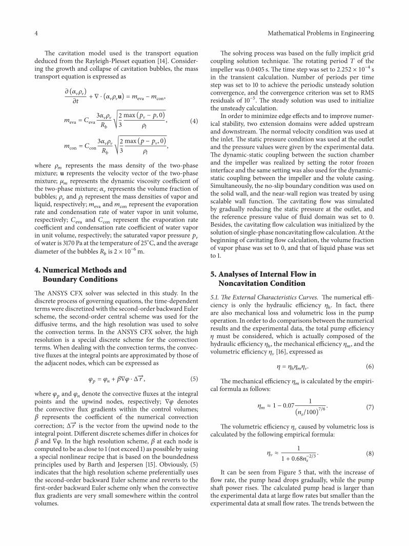
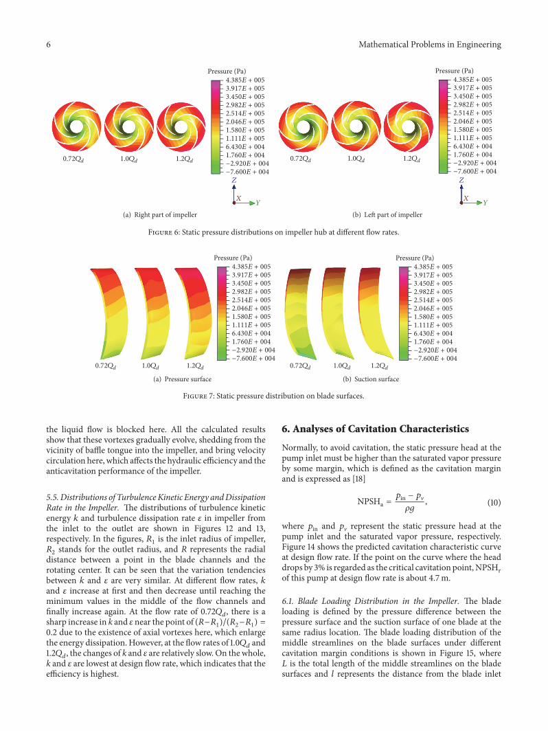
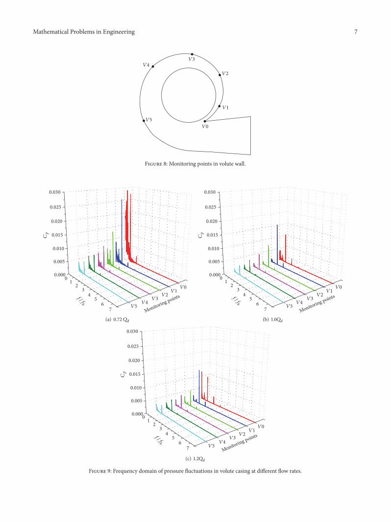
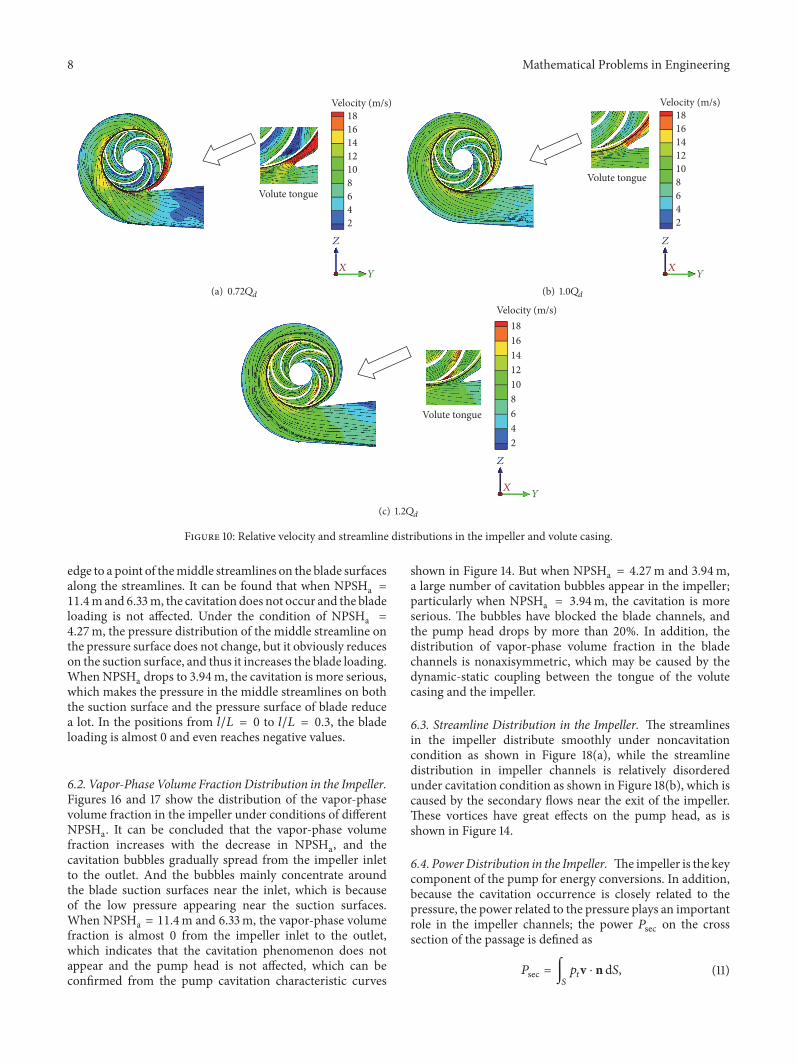
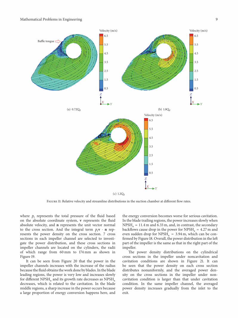
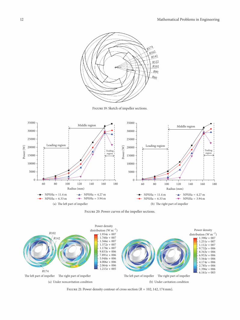