composition of oil shale ashes from pulverized firing and ... · composition of oil shale ashes...
TRANSCRIPT
Oil Shale, 2010, Vol. 27, No. 4, pp. 339–353 ISSN 0208-189X doi: 10.3176/oil.2010.4.07 © 2010 Estonian Academy Publishers
COMPOSITION OF OIL SHALE ASHES FROM PULVERIZED FIRING AND CIRCULATING FLUIDIZED-BED BOILER IN NARVA THERMAL POWER PLANTS, ESTONIA
L. BITYUKOVA(a)∗, R. MÕTLEP(b), K. KIRSIMÄE(b)
(a) Institute of Geology at Tallinn University of Technology, Ehitajate tee 5, 19086 Tallinn, Estonia
(b) Department of Geology, University of Tartu, Ravila 14A, 50411 Tartu, Estonia
The composition of oil shale ashes from pulverized firing (PF) and circulat-ing fluidized-bed boiler combustion (CFB) systems at the Eesti and the Balti Thermal Power Plants was studied by means of quantitative X-ray diffrac-tion, chemical analysis and scanning electron microscopy. The composition of ash varies systematically in the boiler gas pass, depending on the firing technology. PF ashes are dominated by free lime, whose content decreases from the furnace to the last fields of electrostatic precipitators. Same trends can be observed within residual fraction (i.e. mineral phases remaining in firing process) and Ca-silicates. Anhydrite, on the other hand, concentrates into the end of the gas pass. CFB ash shows more complex variations, and on several occasion the changes in certain phases are opposite to variations in respective PF ashes. Comparison of the phase composition of ashes from the same type of boilers in the Eesti and Balti TPP show remarkable differences in Ca-silicate phases. To our best knowledge, earlier mineralogical studies have not addressed compositional variations of ashes from two separate power plants. These differences are probably related to the heterogeneity of oil shale fuel, not so much to combustion temperature.
Introduction
The Estonian Thermal Power Plants (TPP) are fuelled by low-calorific kerogenous oil shale, which is characterized by high content of complex mineral residue. The amount of ash that remains after burning makes up 45–50% of the oil shale mass [1]. The formation of such a large amount of ash in boilers causes difficulties in heat-transfer and phase-separation processes, as well as in transport and deposition of ash [2].
∗ Corresponding author: e-mail [email protected]
L. Bityukova et al. 340
The two most powerful Estonian TPPs (the Eesti and the Balti TPP, together called Narva TPPs) use two different oil shale combustion techno-logies: pulverized firing (PF) and circulating fluidized-bed (CFB) technology [3]. The production of electricity and heat started in the Balti TPP and in the Eesti TPP in 1959 and 1969, respectively. The Balti TPP was put into operation in two stages. During the first stage (1959–62), 18 high-pressure TP-17 boilers (now stopped) were installed, and in the second stage (1963–65) 8 high-pressure TP-67 boilers were launched at the Balti TPP. All of these boilers operate on PF technology. The Eesti TPP, put into operation between 1969 and 1973, was equipped with 16 high-pressure TP-101 boilers [3]. In 2004 the old PF boilers in unit No. 11 in the Balti TPP and unit No. 8 in the Eesti TPP were replaced with new CFB boilers with the maximal power of 215 MW [4]. At present, 12 units (eight at the Eesti TPP and four at the Balti TPPs) are operative for electricity and heat supply. Each power unit is composed of two boilers and a condensing turbine. Currently 20 PF boilers and 4 CFB boilers are running at the Narva TPPs, with installed electric and thermal capacities of 2380 MW and 484 MW, respectively [5]. According to the Development Plan for the Estonian Electricity Sector until 2018 [6], the boilers using the PF technology will be partly shut down, partly replaced with CFB boilers, and 4 power units will be fitted with sulphur and nitrogen (oxides) capture devices by 2018, for higher efficiency and substantial fuel saving [7] in the CFB boilers and significant reducing of air pollution [4] of the renovated power units.
Different combustion conditions in the PF and CFB technologies cause remarkable differences in the phase composition as well as in chemical com-position of ash fractions [e.g. 2]. Recently, Liira et al. [8] showed different hydration characteristics of CFB ashes compared to PF ash, which has already resulted in technological difficulties of ash deposition in the waste ash landfills. Different composition of ash fractions has significant influence on the potential application of ashes as secondary raw materials. In earlier decades, PF ashes have been extensively studied [2, 9–12], and used for the production of construction materials and cement [13], in road construction [14] and for liming of acid soils [15]. Potential industrial scale applications and possible environmental aspects of CFB ashes are, however, virtually unexplored. In this contribution we undertake a detailed parallel characterization of PF and CFB ashes in the Eesti and Balti TPPs, in order to examine the distribution of mineral and chemical components in different ash fractions. The results of this study are important for more efficient reuse of ash wastes produced at Narva TPPs.
Material and methods
The ash samples were collected from different points of the ash-separation systems of CFB and PF boilers at the Balti and Eesti Thermal Power Plant in
Composition of Oil Shale Ashes from Pulverized Firing and Circulating Fluidized-Bed Boiler...
341
November the 5th, 2008. According to the information from the Narva TPPs, the moisture content of raw oil shale, used at this time as a fuel at the Balti and Eesti TPPs, was 13.3 and 10.24%, calorific value 8.55 MJ/kg (minimal calorific value 8.38 MJ/kg), and ash content 43% and 45.6%, respectively. The ash samples from the PF boiler of the Balti TPP were taken from the superheater, economizer, and from four electrostatic precipitator fields. At the Eesti TPP, ash from the PF boiler system was collected from furnace (bottom ash), super-heater, economizer, cyclone separator, and three electrostatic precipitator fields. The ash samples from CFB boilers of the Eesti TTP were taken from the furnace, INTREX, air-preheater, and four electrostatic precipitator fields. In the Balti TPP, in addition to the afore-mentioned ashes from the CFB system, samples were also collected from the superheater and economizer.
The chemical composition of the ash samples was determined in the Certified ACME Laboratory (Vancouver, Canada) by the ICP-MS method with 4-acid digestion. The mineral composition of crystalline phases in ash was studied by using powder X-ray diffraction (XRD) on a Bruker D8 diffractometer. Micromorphology of ash fractions was investigated using a Zeiss DSM 940 scanning electron microscope (SEM) equipped with an Idfix Si-drift technology energy-dispersive analyser (EDS), and a scanning electron microscope Zeiss EVO MA 15.
Results
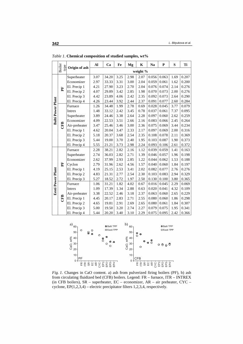
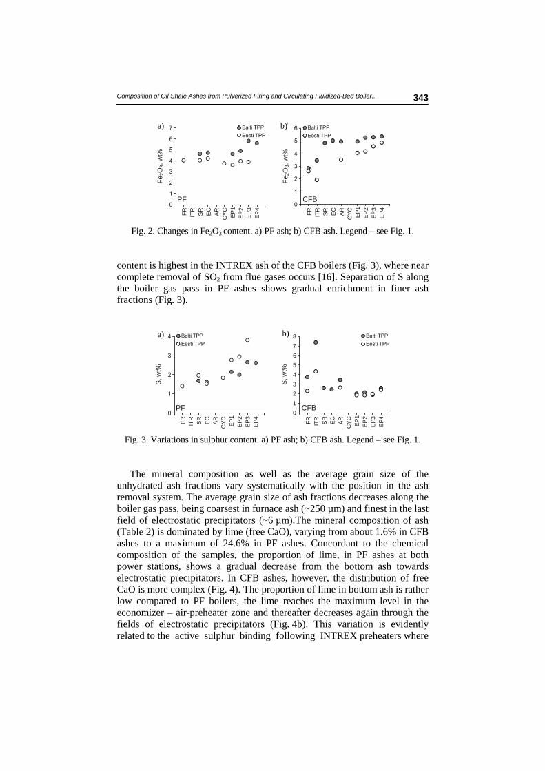
The chemical composition of all ash types is dominated by CaO, whose proportion varies form 26.4 to 54.5% in PF ashes and 26.4–49.1% in CFB ashes (Table 1). As reported earlier [2], the proportion of CaO decreases both in PF and CFB boilers along the boiler gas pass, from the average of 49.4% in bottom ash to 29.7% in the last fields of electrostatic precipitators (Fig. 1). The proportion of CaO was corrected for partial hydration into port-landite [Ca(OH)2]. The average proportion of MgO is 4.75% (Table 1), which is considerably lower than 7–15% of MgOtotal reported in earlier studies [e.g. 2]. Magnesium is mostly derived from the thermal decomposi-tion of dolomite [CaMg(CO3)2], and the difference in those figures evidently follows variation in dolomite admixture in raw oil shale, depending on geological section used for mining. Al2O3 content in PF and CFB ashes remains in the range of 2–10.5%, showing an increasing trend in finer frac-tions and reaching maximum values in the last fields of electrostatic pre-cipitators. The proportion of Fe2O3 is remarkably high (on average 4.3%) in all ash types. In PF ashes the Fe2O3 content is rather stable in different ash fractions, mostly between 4 and 5%. On the other hand, in CFB ashes the proportion of ferric oxide increases gradually from less than 3% in the bottom ash to more than 5% in electrostatic precipitators (Fig. 2). Variation in sulphur content agrees with the earlier studies and, as expected, the S
L. Bityukova et al. 342
Table 1. Chemical composition of studied samples, wt%
Al Ca Fe Mg K Na P S Ti
Boi
ler
type
Origin of ash
weight %
Superheater 3.07 34.20 3.25 2.98 2.07 0.056 0.063 1.69 0.207 Economizer 2.97 33.33 3.31 3.00 2.04 0.059 0.061 1.62 0.200 El. Precip 1 4.21 27.90 3.23 2.70 2.04 0.076 0.074 2.14 0.276 El. Precip 2 4.07 29.89 3.42 2.85 1.98 0.070 0.073 2.00 0.276 El. Precip 3 4.42 23.89 4.06 2.42 2.35 0.092 0.073 2.64 0.290
PF
El. Precip 4 4.26 23.44 3.92 2.44 2.37 0.091 0.077 2.60 0.284 Furnace 1.26 34.48 1.99 2.78 0.69 0.028 0.045 3.77 0.079 Intrex 1.48 33.12 2.42 3.45 0.78 0.037 0.061 7.37 0.095 Superheater 3.89 24.46 3.38 2.64 2.28 0.097 0.060 2.62 0.259 Economizer 4.09 22.53 3.51 2.66 2.16 0.083 0.066 2.45 0.264 Air-preheater 3.47 25.46 3.46 3.00 2.36 0.075 0.069 3.44 0.234 El. Precip 1 4.62 20.04 3.47 2.33 2.17 0.097 0.069 2.00 0.316 El. Precip 2 5.18 20.37 3.68 2.54 2.35 0.108 0.078 2.11 0.369 El. Precip 3 5.44 19.00 3.70 2.40 1.95 0.103 0.087 1.90 0.373
Bal
ti P
ower
Pla
nt
CF
B
El. Precip 4 5.55 21.21 3.73 2.98 2.24 0.093 0.106 2.61 0.372 Furnace 2.28 38.21 2.82 2.16 1.12 0.039 0.059 1.41 0.163 Superheater 2.74 36.03 2.82 2.71 1.39 0.046 0.057 1.96 0.198 Economizer 2.62 37.99 2.93 2.85 1.22 0.044 0.062 1.53 0.188 Cyclon 2.79 31.96 2.62 4.56 1.57 0.040 0.060 1.84 0.197 El. Precip 1 4.19 25.15 2.53 3.41 2.02 0.082 0.077 2.76 0.276 El. Precip 2 4.83 21.31 2.77 2.54 2.30 0.103 0.083 2.94 0.329
PF
El. Precip 3 5.27 18.52 2.72 1.97 2.50 0.130 0.100 3.80 0.365 Furnace 1.06 31.21 1.82 4.02 0.67 0.016 0.045 2.29 0.069 Intrex 1.09 17.39 1.34 2.88 0.63 0.020 0.041 4.32 0.109 Air-preheater 3.38 22.52 2.46 3.18 2.37 0.063 0.060 2.65 0.229 El. Precip 1 4.45 20.17 2.83 2.71 2.55 0.080 0.060 1.86 0.298 El. Precip 2 4.65 19.81 2.91 2.69 2.65 0.080 0.061 1.84 0.307 El. Precip 3 5.00 19.50 3.20 2.74 2.27 0.079 0.075 1.95 0.341
Ees
ti P
ower
Pla
nt
CF
B
El. Precip 4 5.44 20.20 3.40 3.10 2.29 0.075 0.095 2.42 0.366
PF CFB
CaO
, wt%
CaO
, wt%
a b
FR
FR
ITR
ITR
SR
SR
EC
EC
AR
AR
CY
C
CY
C
EP
1
EP
1
EP
2
EP
2
EP
3
EP
3
EP
4
EP
4
Fig. 1. Changes in CaO content. a) ash from pulverized firing boilers (PF), b) ash from circulating fluidized bed (CFB) boilers. Legend: FR – furnace, ITR – INTREX (in CFB boilers), SR – superheater, EC – economizer, AR – air preheater, CYC – cyclone, EP(1,2,3,4) – electric precipitator filters 1,2,3,4, respectively.
a) b)
Composition of Oil Shale Ashes from Pulverized Firing and Circulating Fluidized-Bed Boiler...
343
FR
ITR
SR
EC
AR
CY
CE
P1
EP
2E
P3
EP
4
FR
ITR
SR
EC
AR
CY
CE
P1
EP
2E
P3
EP
4
PF CFB
a b
Fe
O, w
t%2
3
Fe
O, w
t%2
3
Fig. 2. Changes in Fe2O3 content. a) PF ash; b) CFB ash. Legend – see Fig. 1. content is highest in the INTREX ash of the CFB boilers (Fig. 3), where near complete removal of SO2 from flue gases occurs [16]. Separation of S along the boiler gas pass in PF ashes shows gradual enrichment in finer ash fractions (Fig. 3).
0
1
2
3
4
5
6
7
8
FR
ITR
SR
EC
AR
CY
CE
P1
EP
2E
P3
EP
4
PF
FR
ITR
SR
EC
AR
CY
CE
P1
EP
2E
P3
EP
4
CFB
ba
S, w
t%
S, w
t%
Fig. 3. Variations in sulphur content. a) PF ash; b) CFB ash. Legend – see Fig. 1. The mineral composition as well as the average grain size of the
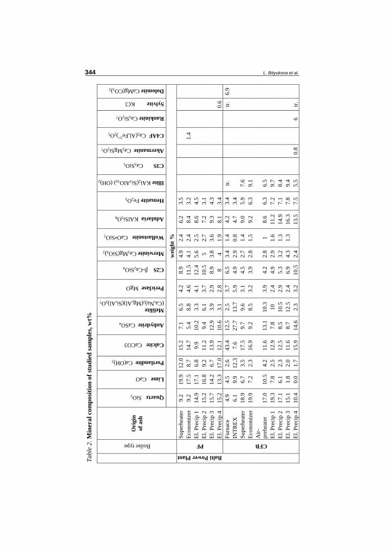
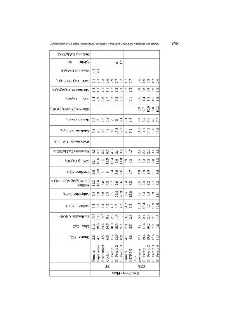
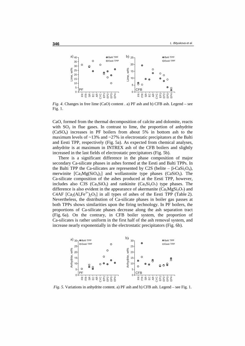
unhydrated ash fractions vary systematically with the position in the ash removal system. The average grain size of ash fractions decreases along the boiler gas pass, being coarsest in furnace ash (~250 µm) and finest in the last field of electrostatic precipitators (~6 µm).The mineral composition of ash (Table 2) is dominated by lime (free CaO), varying from about 1.6% in CFB ashes to a maximum of 24.6% in PF ashes. Concordant to the chemical composition of the samples, the proportion of lime, in PF ashes at both power stations, shows a gradual decrease from the bottom ash towards electrostatic precipitators. In CFB ashes, however, the distribution of free CaO is more complex (Fig. 4). The proportion of lime in bottom ash is rather low compared to PF boilers, the lime reaches the maximum level in the economizer – air-preheater zone and thereafter decreases again through the fields of electrostatic precipitators (Fig. 4b). This variation is evidently related to the active sulphur binding following INTREX preheaters where
a) b)
a) b)
Oil
Sha
le, 2
010,
Vol
. 27,
No.
4, p
p. 3
39–3
53
ISS
N 0
208-
189X
do
i: 10
.317
6/oi
l.201
0.4.
07
© 2
010
Est
onia
n A
cade
my
Pub
lishe
rs
Tab
le 2
. Min
eral
com
posi
tion
of
stud
ied
sam
ples
, wt%
Quartz SiO2
Lime CaO
Portlandite Ca(OH)2
Calcite CaCO3
Anhydrite CaSO4
Melilite (Ca,Na)2(Mg,Al)(Si,Al)3O7
Periclase MgO
C2S β-Ca2SiO4
Merwinite Ca3Mg(SiO4)2
Wollastonite CaO•SiO2
Adularia KAlSi3O8
Hematite Fe2O3
Illite KAl2(Si3AlO10) (OH)2
C3S Ca3SiO5
Akermanite Ca2MgSi2O7
C4AF Ca2(Al,Fe3+
)2O5
Rankinite Ca3Si2O7
Sylvite KCl
Dolomite CaMg(CO3)2
Boiler type
Ori
gin
of
ash
wei
ght
%
Sup
erhe
ater
9.
2 19
.9
12.0
15
.2
7.1
6.5
4.2
8.9
4.9
2.4
6.2
3.5
E
cono
miz
er
9.2
17.5
8.
7 14
.7
5.4
8.8
4.6
11.5
4.
1 2.
4 8.
4 3.
2
1.4
E
l. P
reci
p 1
14.9
17
.1
6.8
9.9
10.2
3.
3 4.
1 12
.4
5.6
2.5
8.6
4.5
E
l. P
reci
p 2
15.2
16
.8
9.2
11.2
9.
4 6.
1 3.
7 10
.5
5 2.
7 7.
2 3.
1
El.
Pre
cip
3 15
.7
14.2
6.
7 13
.9
12.9
3.
9 2.
9 8.
9 3.
8 3.
6 9.
3 4.
3
PF
El.
Pre
cip
4 15
.2
13.3
17
.0
12.1
10
.6
3.1
2.8
8 4
1.9
8.1
3.4
0.
6
Fur
nace
4.
9 4.
5 2.
6 43
.4
12.5
2.
5 3.
7 6.
5 3.
4 1.
4 4.
2 3.
4 tr
.
tr
. 6.
9 IN
TR
EX
6.
1 9.
9 12
.3
7.6
27.7
13
.7
5.9
4.9
2.9
0.8
4.7
3.4
S
uper
heat
er
18.9
6.
7 3.
5 17
.5
9.7
9.6
3.1
4.5
2.7
1.4
9.0
5.9
7.6
Eco
nom
izer
19
.9
7.2
2.3
16.9
9.
2 8.
5 3.
2 3.
9 2.
8 1.
5 9.
2 6.
3 9.
1
A
ir-
preh
eate
r 17
.0
10.5
4.
2 11
.6
13.1
10
.3
3.9
4.2
2.8
1 8.
6 6.
3 6.
5
E
l. P
reci
p 1
19.3
7.
8 2.
5 12
.9
7.8
10
2.4
4.9
2.9
1.6
11.2
7.
2 9.
7
E
l. P
reci
p 2
17.1
6.
1 2.
3 12
.5
8.5
10.5
2.
9 5.
3 3.
2 1.
3 14
.9
7.1
8.4
El.
Pre
cip
3 15
.1
1.8
2.0
11.6
8.
7 12
.5
2.4
6.9
4.3
1.3
16.3
7.
8 9.
4
Balti Power Plant
CFB
El.
Pre
cip
4 10
.4
0.0
1.7
15.9
14
.6
2.3
3.2
10.5
2.
4
13.5
7.
5 5.
5
0.8
6
tr.
344 L. Bityukova et al.
Com
posi
tion
of O
il S
hale
Ash
es fr
om P
ulve
rized
Firi
ng a
nd C
ircul
atin
g F
luid
ized
-Bed
Boi
ler.
.. 34
5
Quartz SiO2
Lime CaO
Portlandite Ca(OH)2
Calcite CaCO3
Anhydrite CaSO4
Melilite (Ca,Na)2(Mg,Al)(Si,Al)3O7
Periclase MgO
C2S β-Ca2SiO4
Merwinite Ca3Mg(SiO4)2
Wollastonite CaO•SiO2
Adularia KAlSi3O8
Hematite Fe2O3
Illite KAl2(Si3AlO10) (OH)2
C3S Ca3SiO5
Akermanite Ca2MgSi2O7
C4AF Ca2(Al,Fe3+
)2O5
Rankinite Ca3Si2O7
Sylvite KCl
Dolomite CaMg(CO3)2
Fur
nace
2.
6 21
.1
13.5
6.
4 5.
4 11
.3
2.9
19.1
4.
8
5.1
1.8
2.
4 1.
4 2.
1 4.
1
S
uper
heat
er
4.1
19.6
13
.6
3.3
8.9
10.6
3.
69
17.6
5.
7
4.6
2
2.9
1.2
2.3
4.1
Eco
nom
izer
4.
5 24
.6
14.8
4.
4 6.
9 7.
8 4
16
5.7
3.
6 1.
8
2.6
1.1
2.3
C
yclo
n 6.
8 24
.6
8.9
4.2
9.5
4.5
8 13
.9
6.7
4.
3 2.
2
2.7
1.1
2.6
E
l. P
reci
p 1
11.2
18
.9
2.6
4.3
16
3.2
6.4
12.4
4.
3
8.9
3.9
3.
3 1.
7 2.
9
El.
Pre
cip
2 13
.0
15.3
1.
9 4.
7 21
.4
2.9
3.9
9.9
3.4
10
.8
5
3.3
1.8
2.7
tr
.
PF
El.
Pre
cip
3 8.
8 9.
2 1.
0 4.
2 26
.9
3.6
2.6
11.8
3.
6
12.3
5.
1
2.7
2.3
3.2
1.
7
Fur
nace
4.
1 2.
9 3.
5 51
.2
7.5
2.4
5.1
3.9
1.9
4.
5 2.
1
1 8.
7 1.
2
INT
RE
X
4.8
3.5
2.3
6.5
15.8
3.
5 4.
7 4.
3 1.
7
5.2
1.5
0.
1 1.
5 0.
7
Air
-pr
ehea
ter
17.4
12
5.
7 13
.3
12
3.5
4.8
5.5
2.1
11
.5
4.4
5.9
0.6
0.8
0.6
E
l. P
reci
p 1
19.4
11
.6
2.4
13.4
8.
4 2.
3 2.
9 5.
3 2.
1
14.1
5.
4 9.
7 1.
4 0.
8 1.
0
El.
Pre
cip
2 19
.9
10.2
2.
6 12
8.
3 2.
2 2.
9 5.
5 2.
3
14.5
5.
6 10
.6
1.5
0.9
0.9
E
l. P
reci
p 3
17.6
7.
2 2.
3 10
.9
9.9
2.7
3.1
7.8
3.1
15
.0
6.8
9.8
1.5
0.9
1.3
Eesti Power Plant
CFB
El.
Pre
cip
4 11
.3
1.6
1.5
12.9
13
.1
3.3
3.8
11.2
4.
6
13.9
7.
7 10
.2
1.8
1.2
2.0
Composition of Oil Shale Ashes from Pulverized Firing and Circulating Fluidized-Bed Boiler... 345
L. Bityukova et al. 346
0
5
10
15
20
25
30
35
40a
FR
ITR
SR
EC
AR
CY
CE
P1
EP
2E
P3
EP
4
PF CFB
b
FR
ITR
SR
EC
AR
CY
CE
P1
EP
2E
P3
EP
4
Lim
e, w
t%
Lim
e, w
t%
Fig. 4. Changes in free lime (CaO) content . a) PF ash and b) CFB ash. Legend – see Fig. 1.
CaO, formed from the thermal decomposition of calcite and dolomite, reacts with SO2 in flue gases. In contrast to lime, the proportion of anhydrite (CaSO4) increases in PF boilers from about 5% in bottom ash to the maximum levels of ~13% and ~27% in electrostatic precipitators at the Balti and Eesti TPP, respectively (Fig. 5a). As expected from chemical analyses, anhydrite is at maximum in INTREX ash of the CFB boilers and slightly increased in the last fields of electrostatic precipitators (Fig. 5b).
There is a significant difference in the phase composition of major secondary Ca-silicate phases in ashes formed at the Eesti and Balti TPPs. In the Balti TPP the Ca-silicates are represented by C2S (belite – β-CaSi2O4), merwinite [Ca3Mg(SiO4)2] and wollastonite type phases (CaSiO3). The Ca-silicate composition of the ashes produced at the Eesti TPP, however, includes also C3S (Ca3SiO5) and rankinite (Ca3Si2O7) type phases. The difference is also evident in the appearance of akermanite (Ca2MgSi2O7) and C4AF [Ca2(Al,Fe3+)2O5] in all types of ashes of the Eesti TPP (Table 2). Nevertheless, the distribution of Ca-silicate phases in boiler gas passes at both TPPs shows similarities upon the firing technology. In PF boilers, the proportions of Ca-silicate phases decrease along the ash separation tract (Fig. 6a). On the contrary, in CFB boiler system, the proportion of Ca-silicates is rather uniform in the first half of the ash removal system, and increase nearly exponentially in the electrostatic precipitators (Fig. 6b).
0
5
10
15
20
25
30
PF CFB
Anh
ydrit
e, w
t%
Anh
ydrit
e, w
t%
a b
FR
FR
ITR
ITR
SR
SR
EC
EC
AR
AR
CY
C
CY
C
EP
1
EP
1
EP
2
EP
2
EP
3
EP
3
EP
4
EP
4
Fig. 5. Variations in anhydrite content. a) PF ash and b) CFB ash. Legend – see Fig. 1.
a) b)
a) b)
Composition of Oil Shale Ashes from Pulverized Firing and Circulating Fluidized-Bed Boiler...
347
02468
10
1214
16
18
20
PF CFB
Ca-
silic
ates
, wt%
Ca-
silic
ates
, wt%
a b
FR
FR
ITR
ITR
SR
SR
EC
EC
AR
AR
CY
C
CY
C
EP
1
EP
1
EP
2
EP
2
EP
3
EP
3
EP
4
EP
4
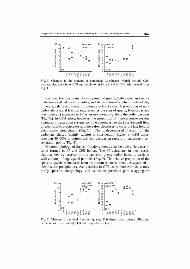
Fig. 6. Changes in the content of combined Ca-silicates, which include C2S, wollastonite, merwinite, C3S and rankinite. a) PF ash and b) CFB ash. Legend – see Fig. 1.
Residual fraction is mainly composed of quartz, K-feldspar, and minor undecomposed calcite in PF ashes, and also additionally dehydroxylated clay minerals, calcite and traces of dolomite in CFB ashes. A proportion of non-carbonate residual fraction (expressed as the sum of quartz, K-feldspar and clay minerals) increases in PF ashes monotonously along the boiler gas pass (Fig. 7a). In CFB ashes, however, the proportion of non-carbonate residue increases in separation system from the bottom ash to the first (second) field of electrostatic precipitator and thereafter decreases towards the last field of electrostatic precipitator (Fig. 7b). The undecomposed fraction of the carbonate phases (mainly calcite) is considerably higher in CFB ashes, reaching 40–50% in bottom ash, but decreasing rapidly in subsequent ash separation points (Fig. 8).
Micromorphology of the ash fractions shows considerable differences in ashes formed in PF and CFB boilers. The PF ashes are, in most cases, characterized by large portion of spherical glassy and/or hematite particles with a clump of aggregated particles (Fig. 9). The relative proportion of the spherical particles increases from the bottom ash to ash fractions separated in electrostatic precipitators. Ash particles in CFB ashes, however, show only rarely spherical morphology, and ash is composed of porous aggregates
PF CFB
Res
idue
, wt%
Res
idue
, wt%
a b
FR
FR
ITR
ITR
SR
SR
EC
EC
AR
AR
CY
C
CY
C
EP
1
EP
1
EP
2
EP
2
EP
3
EP
3
EP
4
EP
4
Fig. 7. Changes in residual fraction: quartz, K-feldspar, clay mineral illite and hematite. a) PF ash and b) CFB ash. Legend – see Fig. 1.
a) b)
a) b)
L. Bityukova et al. 348
CFB
Car
bona
tes,
wt%
FR
ITR
SR
EC
AR
CY
CE
P1
EP
2E
P3
EP
4
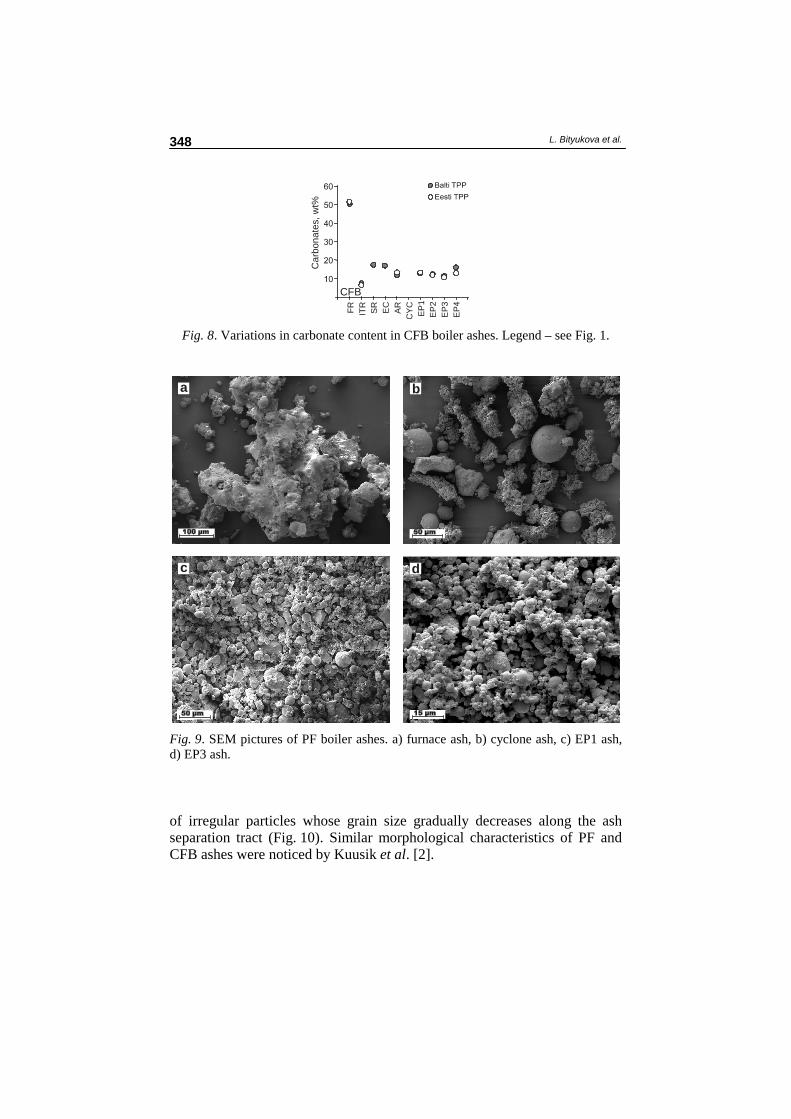
Fig. 8. Variations in carbonate content in CFB boiler ashes. Legend – see Fig. 1.
a
dc
b
Fig. 9. SEM pictures of PF boiler ashes. a) furnace ash, b) cyclone ash, c) EP1 ash, d) EP3 ash.
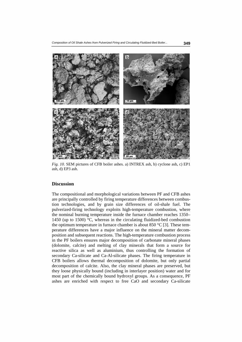
of irregular particles whose grain size gradually decreases along the ash separation tract (Fig. 10). Similar morphological characteristics of PF and CFB ashes were noticed by Kuusik et al. [2].
Composition of Oil Shale Ashes from Pulverized Firing and Circulating Fluidized-Bed Boiler...
349
a
dc
b
Fig. 10. SEM pictures of CFB boiler ashes. a) INTREX ash, b) cyclone ash, c) EP1 ash, d) EP3 ash.
Discussion
The compositional and morphological variations between PF and CFB ashes are principally controlled by firing temperature differences between combus-tion technologies, and by grain size differences of oil-shale fuel. The pulverized-firing technology exploits high-temperature combustion, where the nominal burning temperature inside the furnace chamber reaches 1350–1450 (up to 1500) °C, whereas in the circulating fluidized-bed combustion the optimum temperature in furnace chamber is about 850 °C [3]. These tem-perature differences have a major influence on the mineral matter decom-position and subsequent reactions. The high-temperature combustion process in the PF boilers ensures major decomposition of carbonate mineral phases (dolomite, calcite) and melting of clay minerals that form a source for reactive silica as well as aluminium, thus controlling the formation of secondary Ca-silicate and Ca-Al-silicate phases. The firing temperature in CFB boilers allows thermal decomposition of dolomite, but only partial decomposition of calcite. Also, the clay mineral phases are preserved, but they loose physically bound (including in interlayer position) water and for most part of the chemically bound hydroxyl groups. As a consequence, PF ashes are enriched with respect to free CaO and secondary Ca-silicate
L. Bityukova et al. 350
phases, but CFB ashes contain a higher share of residual mineral phases. A specific characteristic of CFB ashes is the higher concentration of sulphur that is mainly concentrated into the INTREX ash in the form of anhydrite (CaSO4). This phenomenon is caused by nearly complete desulphurization of flue gases by the prolonged contact/reaction of ash particles circulating between combustion chamber and INTREX chamber, which also ensures high decomposition rate of carbonate minerals [17].
According to Ots [3] the proportions of the different ash fractions in an averaged ash flow are: 39.3% bottom-slag ash, 3.1% superheater ash, 4.7% economizer ash, 32.2% cyclone ash and 13.5, 3.1, 0.7% of ash from electro-static precipitators 1, 2 and 3, respectively. Separation of the phases (either secondary or residual) along the boiler gas pass depends mainly on the particle size of the phases. Ash particles, whose free-fall velocity is lower than upward directed flue gas velocity are carried away from the furnace chamber through heat transfer surfaces by flue gas and are consequently separated depending on the boiler units in superheater, economizer, air-pre-heater, cyclon separator or in electrostatic precipitatiors. The coarsest or heavier particles precipitate onto the bottom of the furnace [3]. This separa-tion mechanism suggests that the different firing technologies do not control only phase composition of ash but influence also particle size of the phases. Secondary Ca-silicates, forming at high-temperature conditions in the PF boiler, evidently form large (partially inter-melted?) aggregates, which are concentrated in coarse ash fractions that are removed in the first zones of the ash removal system. Our results show that at lower firing temperatures, in CBF boilers, the secondary Ca-silicate phases exist in the form of discrete and fine particles that are preferentially removed in the electrostatic pre-cipitators. On the contrary, the anhydrite particles in PF ashes are of fine grain size and occur mostly in ash separated by the electrostatic pre-cipitators. In CFB boilers, anhydrite is mostly found in INTREX ash, where anhydrite appears as a shell on unreacted CaO cores [18, 19], thus, forming relatively large particles, which are removed at large part in the INTREX chamber and to somewhat lesser degree in adjacent zones.
Comparison of the phase composition of ashes of the Eesti and Balti TPPs revealed differences in ashes formed at these power plants. The differences in ash composition are particularly seen in the composition of Ca-silicate phases. In the Balti TPP secondary Ca-silicates are represented mainly by β-C2S (belite), merwinite and wollastonite; while in the Eesti TPP also C3S, rankinite, as well as C4AF and akermanite are found.
Earlier mineralogical studies have addressed the qualitative [20] and quantitative [2] composition of ashes sampled at the Eesti TPP. Paat and Traksmaa [19] report only qualitative composition of the two fly ash fractions (cyclone and cloth filter) of the Balti TPP. The difference between ashes from two separate TPPs has not been shown before. The systematic difference in the composition of secondary Ca-bearing phases, which is evident both in PF and CFB ashes, suggests that this variation relates to the
Composition of Oil Shale Ashes from Pulverized Firing and Circulating Fluidized-Bed Boiler...
351
composition/quality of the oil shale fuel used in boilers, not to technological differences.
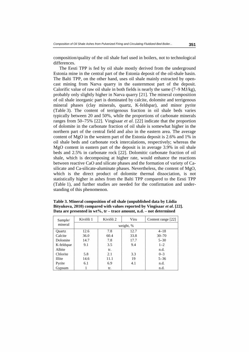
The Eesti TPP is fed by oil shale mostly derived from the underground Estonia mine in the central part of the Estonia deposit of the oil-shale basin. The Balti TPP, on the other hand, uses oil shale mainly extracted by open-cast mining from Narva quarry in the easternmost part of the deposit. Calorific value of raw oil shale in both fields is nearly the same (7–9 MJ/kg), probably only slightly higher in Narva quarry [21]. The mineral composition of oil shale inorganic part is dominated by calcite, dolomite and terrigenous mineral phases (clay minerals, quartz, K-feldspar), and minor pyrite (Table 3). The content of terrigenous fraction in oil shale beds varies typically between 20 and 50%, while the proportions of carbonate minerals ranges from 50–75% [22]. Vingisaar et al. [22] indicate that the proportion of dolomite in the carbonate fraction of oil shale is somewhat higher in the northern part of the central field and also in the eastern area. The average content of MgO in the western part of the Estonia deposit is 2.6% and 1% in oil shale beds and carbonate rock intercalations, respectively; whereas the MgO content in eastern part of the deposit is in average 3.9% in oil shale beds and 2.5% in carbonate rock [22]. Dolomitic carbonate fraction of oil shale, which is decomposing at higher rate, would enhance the reactions between reactive CaO and silicate phases and the formation of variety of Ca-silicate and Ca-silicate-aluminate phases. Nevertheless, the content of MgO, which is the direct product of dolomite thermal dissociation, is not statistically higher in ashes from the Balti TPP compared to the Eesti TPP (Table 1), and further studies are needed for the confirmation and under-standing of this phenomenon.
Table 3. Mineral composition of oil shale (unpublished data by Liidia Bityukova, 2010) compared with values reported by Vingisaar et al. [22]. Data are presented in wt%, tr – trace amount, n.d. – not determined
Kiviõli 1 Kiviõli 2 Viru Content range [22] Sample/ mineral weight, %
Quartz 12.6 7.8 12.7 4–18 Calcite 36.0 60.4 33.8 30–70 Dolomite 14.7 7.8 17.7 5–30 K-feldspar 9.1 3.5 9.4 1–2 Albite tr. n.d. Chlorite 5.8 2.1 3.3 0–3 Illite 14.6 11.1 19 5–36 Pyrite 6.1 6.9 4.1 n.d. Gypsum 1 tr. n.d.
L. Bityukova et al. 352
Conclusions
The composition of oil shale ashes from the pulverized firing (PF) and circulating fluidized-bed boiler combustion (CFB) boilers at the Eesti and Balti TPPs shows a systematic variation in the boiler gas pass depending on the firing technology. PF ashes are dominated by free lime, whose propor-tion decreases from the furnace to the last fields of electrostatic precipitators. Ashes from CFB boilers show more complex variations, and on several occasion different phases change contrary to PF ashes. Comparison of the phase composition of ashes from the same type of boilers in the Eesti and Balti TPPs shows remarkable differences in Ca-silicate phases, which can be interpreted rather by the variation in oil shale fuel used at these TPPs than by combustion technology.
Acknowledgements
Support for this research by the EEA Financial Mechanism and Norwegian Financial Mechanism (Grant EMP-45) is gratefully acknowledged. This research was partly funded by Estonian Target Financed Research Projects SF0140016s09 and SF0180069s08. REFERENCES
1. Bauert, H., Kattai, V. Kukersite oil shale // Geology and Mineral Resources of Estonia / A. Raukas, A. Teedumae (eds.). Tallinn: Estonian Academy Publishers, 1997. P. 313–327.
2. Kuusik, R., Uibo, M., Kirsimäe, K. Characterization of oil shale ashes formed at industrial-scale CFBC boilers // Oil Shale. 2005. Vol. 22, No. 4 S. P. 407–420.
3. Ots, A. Oil Shale Fuel Combustion. – Tallinn, Tallinna Raamatutrükikoda, 2006.
4. Liblik, V., Kaasik, M., Pensa, M., Rätsep, A., Rull, E., Tordik, A. Reduction of sulphur dioxide emissions and transboundary effects of oil shale based energy production // Oil Shale. 2006. Vol. 23, No. 1. P. 29–38.
5. Narva Power Plants. http://www.powerplant.ee/est_05_1.php (Accessed 10 March 2010) [in Estonian].
6. Development Plan of the Estonian Electricity Sector until 2018 www.mkm.ee/ public/ELMAK_EN.pdf.
7. Liiv, S. Oil shale energetics in Estonia // Oil Shale. 2007. Vol. 24, No. 1. P. 1–4. 8. Liira, M., Kirsimäe, K., Kuusik, R., Mõtlep, R. Transformation of calcareous oil-
shale circulating fluidized-bed combustion boiler ashes under wet conditions // Fuel. 2009. Vol. 88, No. 4. P. 712–718.
9. Dilaktorski, N. Theoretical basis for the utilization of the mineral compound of oil-shale in building materials industry // Studies on Building. 1962. Vol. 3. P. 5–45 [in Russian, Summary in English].
Composition of Oil Shale Ashes from Pulverized Firing and Circulating Fluidized-Bed Boiler...
353
10. Kikas, V. Mineral matter of kukersite oil shale and its utilization // Oil Shale. 1988. Vol. 5, No. 1. P. 15–28 [in Russian, Summary in English].
11. Arro, H., Pihu, T., Prikk, A., Rootamm, R., Konist, A. Comparison of ash from PF and CFB boilers and behavior of ash in ash fields. – 20th International Conference on Circulating Fluidized Bed, Xian City, China, May 18–20, 2009.
12. Mõtlep, R., Sild, T., Puura, E., Kirsimäe, K. Composition, diagenetic trans-formation and alkalinity potential of oil shale ash sediments // J. Hazard. Mater. 2010. Vol. 184, No. 1–3. P. 567–573.
13. Hanni, R. Energy and valuable material by-product from firing Estonian oil shale // Waste Manage. 1996. Vol. 16, No. 1–3. P. 97–99.
14. Paat, A. About the mineralogical composition of Estonian oil shale ash // Oil Shale. 2002. Vol. 19, No. 3. P. 321–333.
15. Pets, L., Vaganov, P., Knoth, J., Haldna, Ü., Shwenke, H., Schnier, C., Juga, R. Microelements in oil-shale ash of the Baltic Thermoelectric Power Plant // Oil Shale. Vol. 2, No. 4. P. 379–390 [in Russian, Summary in English].
16. Hotta, A., Uus, M., Parkkonen, R. Enhanced Performance Using CFB Boilers to Fire Oil Shale Compared to PC Technology. – POWER-GEN Europe 2005, Milan, Italy.
17. Pihu, T., Arro, H., Prikk, A., Parve, T., Loosaar, J. Combustion experience of Estonian oil shale in large power plants. – International Conference on Oil Shale: "Recent Trends in Oil Shale", 7–9 November 2006, Amman, Jordan.
18. Trikkel, A., Zevenhoven, R., Kuusik, R. Modelling SO2 capture by Estonian limestones and dolomites // Proc. Est. Acad. Sci. Chem. 2000. Vol. 49, No. 1. P. 53–70.
19. Antony, E. J., Grananstein, D. L. Sulphatation phenomena in fluidized bed combustion systems // Prog. Energ. Combust. 2001. Vol. 27, No. 1. P. 215–256.
20. Paat, A., Traksmaa, R. Investigation of the mineral composition of Estonian oil-shale ash using X-ray diffractometry // Oil Shale. 2002. Vol. 19, No. 4. P. 373–386.
21. Kattai, V., Saadre, T., Savitski, L. Estonian Oil Shale: Geology, Ressurces, Mining Conditions – Tallinn: Estonian Geology Center, 2000. P. 226 [in Estonian, Summary in English].
22. Vingisaar, P., Kattai, V., Utsal, K. The composition of the kukersite in the Baltic Oil Shale Basin // Proc. Est. Acad. Sci. Geol. 1984. Vol. 33, No. 2. P. 55–62 [in Russian, Summary in English].
Presented by A. Ots Received June 28, 2010