composite pressure vessels
DESCRIPTION
IJRET : International Journal of Research in Engineering and Technology is an international peer reviewed, online journal published by eSAT Publishing House for the enhancement of research in various disciplines of Engineering and Technology. The aim and scope of the journal is to provide an academic medium and an important reference for the advancement and dissemination of research results that support high-level learning, teaching and research in the fields of Engineering and Technology. We bring together Scientists, Academician, Field Engineers, Scholars and Students of related fields of Engineering and Technology.TRANSCRIPT
IJRET: International Journal of Research in Engineering and Technology ISSN: 2319-1163
__________________________________________________________________________________________ Volume: 01 Issue: 04 | Dec-2012, Available @ http://www.ijret.org 597
COMPOSITE PRESSURE VESSELS
RAO YARRAPRAGADA K.S.S1, R.KRISHNA MOHAN
2, B.VIJAY KIRAN
3
1,2,3 Associate Professor, Mechanical Department, B.V.C College of Engineering, Andhra Pradesh, India,
[email protected], [email protected], [email protected]
Abstract Cylindrical pressure vessels are widely used for commercial, under water vehicles and in aerospace applications. At present the outer
shells of the pressure vessels are made up of conventional metals like steels and aluminum alloys. The payload performance/ speed/
operating range depends upon the weight. The lower the weight the better the performance, one way of reducing the weight is by
reducing the weight of the shell structure. The use of composite materials improves the performance of the vessel and offers a
significant amount of material savings. Moreover, the stacking sequence is very crucial to the strength of the composite material. This
Project involves various objective functions such as stiffness, buckling load and Weight at each level of optimization. Usually
composite pressure vessels are designed for minimum mass under strength constraints. A graphical analysis is presented to find
optimum fiber orientation for given layer thicknesses. In the present work, an analytical model is developed for the Prediction of the
minimum buckling load with / without stiffener composite shell of continuous angle ply laminas (±45°,±55°,±65°,±75°,±85°) for
investigation. Comparisons are made for two different approaches i.e. the finite element model and the theoretical model. A 3-D finite
element analysis is built using ANSYS-12.0 version software into consideration, for static and buckling analysis on the pressure
vessel.
Index Terms: Composite material, Shells, Fiber orientation, Layer thickness, Stiffeners, Critical Pressure and Buckling
-------------------------------------------------------------------*******---------------------------------------------------------------------
1. INTRODUCTION
Pressure vessels are important because many liquids and gases
must be stored under high pressure. Special emphasis is placed
upon the strength of the vessel to prevent explosions as a
result of rupture. Codes for the safety of such vessels have
been developed that specify the design of the container for
specified conditions. Most pressure vessels are required to
carry only low pressures and thus are constructed of tubes and
sheets rolled to form cylinders. Some pressure vessels must
carry high pressures, however, and the thickness of the vessel
walls must increase in order to provide adequate strength.
Interest in studying of the shell arises from the fifties of
twentieth century. The assemblies, containing thin shells, find
wide use in the modern engineering, especially in ships,
aircraft and spacecraft industry. The shell vibrations and
buckling modes are analyzed by means of numerical methods,
to clarify qualitatively the critical loads and different buckling
modes.
In today‟s aerospace and aircraft industries, structural
efficiency is the main concern. Due to their high specific
strength and light weight, fiber reinforced composites find a
wide range of applications. Light weight compression load
carrying structures form part of all aircraft, and space vehicle
fuel tanks, air cylinders are some of the many applications. In
the present work, design analysis of fiber reinforced multi
layered composite shell, with optimum fiber orientations;
minimum mass under strength constraints for a cylinder with
or without stiffeners under axial loading for static and
buckling analysis on the pressure vessel has been studied.
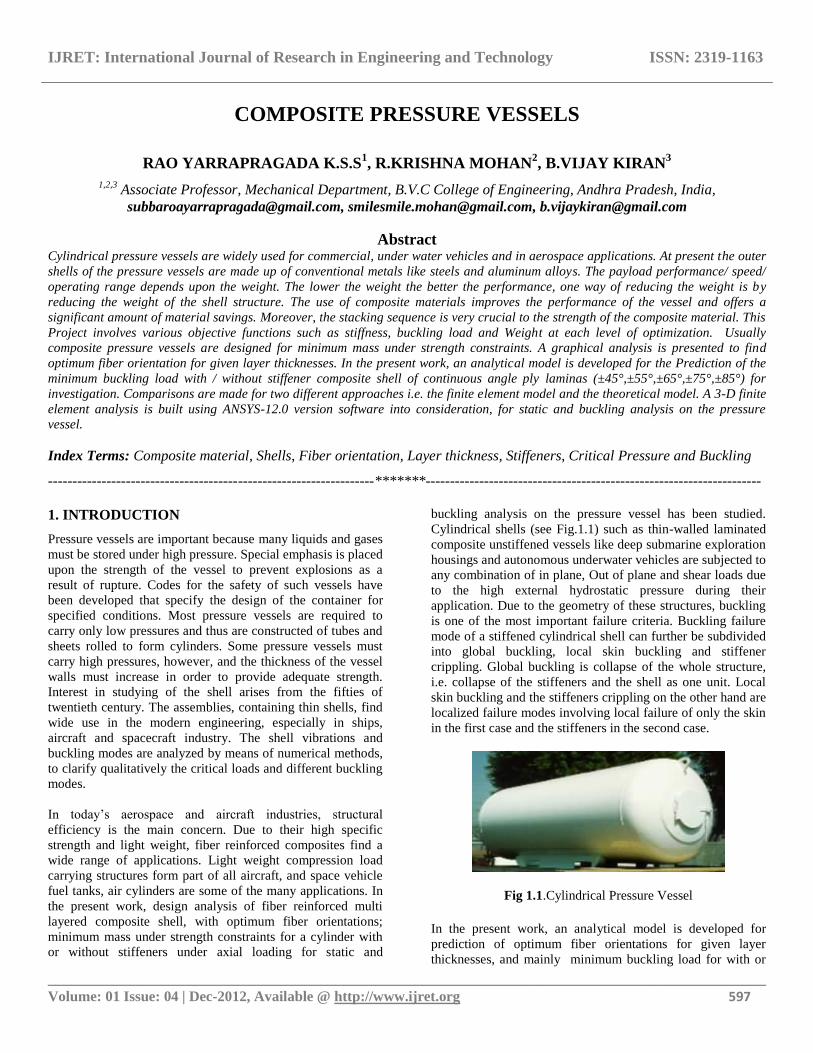
Cylindrical shells (see Fig.1.1) such as thin-walled laminated
composite unstiffened vessels like deep submarine exploration
housings and autonomous underwater vehicles are subjected to
any combination of in plane, Out of plane and shear loads due
to the high external hydrostatic pressure during their
application. Due to the geometry of these structures, buckling
is one of the most important failure criteria. Buckling failure
mode of a stiffened cylindrical shell can further be subdivided
into global buckling, local skin buckling and stiffener
crippling. Global buckling is collapse of the whole structure,
i.e. collapse of the stiffeners and the shell as one unit. Local
skin buckling and the stiffeners crippling on the other hand are
localized failure modes involving local failure of only the skin
in the first case and the stiffeners in the second case.
Fig 1.1.Cylindrical Pressure Vessel
In the present work, an analytical model is developed for
prediction of optimum fiber orientations for given layer
thicknesses, and mainly minimum buckling load for with or
IJRET: International Journal of Research in Engineering and Technology ISSN: 2319-1163
__________________________________________________________________________________________ Volume: 01 Issue: 04 | Dec-2012, Available @ http://www.ijret.org 598
without stiffener composite shell under multilayered
continuous angle-ply loading condition is investigated. The
model developed is more general in the sense that any
configuration of stiffeners, on either one side or both sides of
the shell can be modeled accurately. Stiffened shells having
either symmetrical or unsymmetrical shell laminates can also
be modeled with equal ease using this model.
Grid stiffened cylindrical shells are the shells having a certain
kind of stiffening structures either on inner, outer or both sides
of the shell and significantly increases the load resistance
without much increase in weight. To further reduce the
weight, both the shell and the stiffeners are made using fiber
reinforced polymers. The promising future of stiffened
composite cylinder has in turn led to an extensive research
work in this area.
For the sake of analysis, shell elements (shell 91 & solid 46)
were used and analysis was carried out with the aid of the
commercial package, ANSYS-12.0. Due to the expensive
nature of composite cylinder test specimens, experimentation
could not be performed.
1.1 Introduction to Thin Composite Shells
The shell whose wall thickness is small compared to the radius
of curvature and the corresponding radius of twist is known as
thin shell. Plate and shell structures are used in a lightweight
load bearing structural parts for various modern aerospace,
offshore, nuclear, automotive, and civil engineering structures.
These shells are subjected to compressive loads. In the case of
air crafts, they are subjected to fluctuating flight loads, which
also produce compressive components. These compressive
loads cause buckling of the shell structure. The analysis of
composite shell structures requires consideration of a variety
of failure modes. Often analysis programs cannot predict all
failure modes using a single analysis model, and consequently
structural designers must use a variety of analysis tools. It is
also common that for a given failure mode, it is difficult to
obtain the same result using different programs. There is no
need to argue that composite shells are important in modern
technology.
1.2 Composite Materials
Composites are considered to be combinations of materials
differing in composition or form on a macro scale. The
constituents retain their identities in the composite i.e. they do
not dissolve or otherwise merge completely into each other
although they act in the idea of a composite material is not a
new or recent one concert. In nature, one can find out many
composite materials, for example wood is a fibrous natural
composite (cellulose fibrous in lignin matrix). Bone is yet
another example of natural composites. Our ancestors
invented composite by mixing straw and clay to make bricks.
Straw is fiber reinforcement and clay is the matrix. The first
glass fiber reinforced polymer was developed in 1940. The
origin of distinct discipline of composite materials started in
1960‟s.Extensive research has been done on composite
material since 1965. One difference between laminated
composites and traditional engineering materials is that a
composite‟s response to loads is direction dependent.
Monolithic metals and their alloys can‟t always meet the
demands of today‟s advanced technologies. The composite
materials exhibit high specific strength and high specific
modulus resulting in substantial reduction of weight of the
components, thus improves efficiency, and results in energy
savings. One of the main advantages of composite materials is
the flexibility involved in getting the desired strength and
stiffness in the direction required. Carbon fibers are very
common in high-modulus and high-strength applications.
It is well known that the measured strength of most materials
is much smaller than their theoretical strength because of
presence of imperfections or inherent flaws in the materials.
Flaws in the form of cracks that lies perpendicular to the
direction of load are particularly detrimental to the strength. It
is found that non polymeric materials have higher strength
along their lengths because of small cross sectional fibers, the
flaws are minimized.
In case of polymeric materials, orientation of the molecular
structure is responsible for high strength and stiffness. Fibers
because of their small-sectional dimensions are not directly
usable in engineering applications. They are embedded in
matrix materials to form fibrous composites. The matrix
serves to bind the fibers together; transfer loads to the fibers
and protects them against environmental attack and damage
due to handling. The shell is multi-layered fibrous composite
shell. Each layer or lamina is a single-layer composite and
thus orientation is varied according to design. Each layer is
vary thin (thickness 0.4 mm to 0.7mm) and cannot be directly
used. Several identical or different layers are bonded together
to form a multi-layered composite shell. Each layer may be
differing from another layer in (a) Relative volumes of the
constituent‟s materials (b) Form of the reinforcement. (c)
Orientation of fibers with respect to common reference axes.
Thus the directional properties of the individual layers may be
quite different from each other.
IJRET: International Journal of Research in Engineering and Technology ISSN: 2319-1163
__________________________________________________________________________________________ Volume: 01 Issue: 04 | Dec-2012, Available @ http://www.ijret.org 599
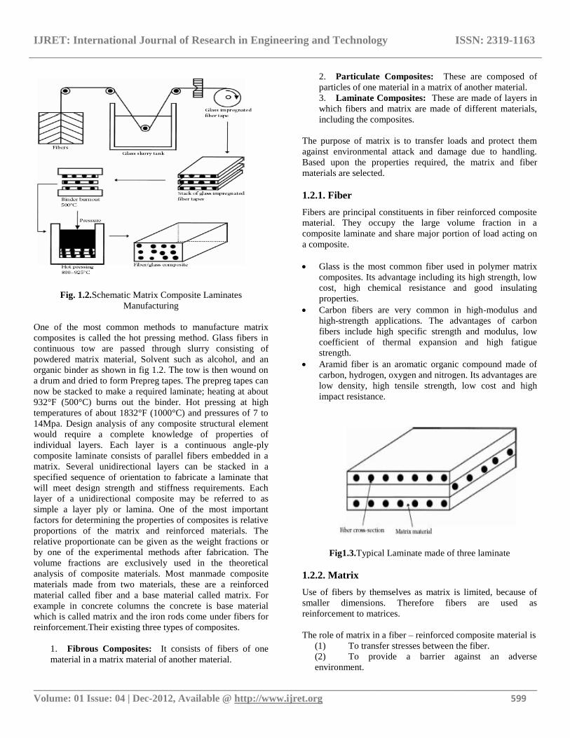
Fig. 1.2.Schematic Matrix Composite Laminates
Manufacturing
One of the most common methods to manufacture matrix
composites is called the hot pressing method. Glass fibers in
continuous tow are passed through slurry consisting of
powdered matrix material, Solvent such as alcohol, and an
organic binder as shown in fig 1.2. The tow is then wound on
a drum and dried to form Prepreg tapes. The prepreg tapes can
now be stacked to make a required laminate; heating at about
932°F (500°C) burns out the binder. Hot pressing at high
temperatures of about 1832°F (1000°C) and pressures of 7 to
14Mpa. Design analysis of any composite structural element
would require a complete knowledge of properties of
individual layers. Each layer is a continuous angle-ply
composite laminate consists of parallel fibers embedded in a
matrix. Several unidirectional layers can be stacked in a
specified sequence of orientation to fabricate a laminate that
will meet design strength and stiffness requirements. Each
layer of a unidirectional composite may be referred to as
simple a layer ply or lamina. One of the most important
factors for determining the properties of composites is relative
proportions of the matrix and reinforced materials. The
relative proportionate can be given as the weight fractions or
by one of the experimental methods after fabrication. The
volume fractions are exclusively used in the theoretical
analysis of composite materials. Most manmade composite
materials made from two materials, these are a reinforced
material called fiber and a base material called matrix. For
example in concrete columns the concrete is base material
which is called matrix and the iron rods come under fibers for
reinforcement.Their existing three types of composites.
1. Fibrous Composites: It consists of fibers of one
material in a matrix material of another material.
2. Particulate Composites: These are composed of
particles of one material in a matrix of another material.
3. Laminate Composites: These are made of layers in
which fibers and matrix are made of different materials,
including the composites.
The purpose of matrix is to transfer loads and protect them
against environmental attack and damage due to handling.
Based upon the properties required, the matrix and fiber
materials are selected.
1.2.1. Fiber
Fibers are principal constituents in fiber reinforced composite
material. They occupy the large volume fraction in a
composite laminate and share major portion of load acting on
a composite.
Glass is the most common fiber used in polymer matrix
composites. Its advantage including its high strength, low
cost, high chemical resistance and good insulating
properties.
Carbon fibers are very common in high-modulus and
high-strength applications. The advantages of carbon
fibers include high specific strength and modulus, low
coefficient of thermal expansion and high fatigue
strength.
Aramid fiber is an aromatic organic compound made of
carbon, hydrogen, oxygen and nitrogen. Its advantages are
low density, high tensile strength, low cost and high
impact resistance.
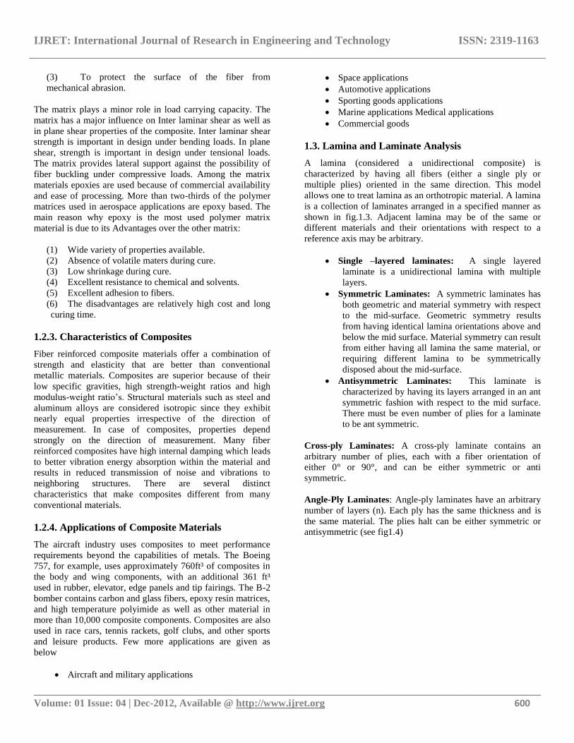
Fig1.3.Typical Laminate made of three laminate
1.2.2. Matrix
Use of fibers by themselves as matrix is limited, because of
smaller dimensions. Therefore fibers are used as
reinforcement to matrices.
The role of matrix in a fiber – reinforced composite material is
(1) To transfer stresses between the fiber.
(2) To provide a barrier against an adverse
environment.
IJRET: International Journal of Research in Engineering and Technology ISSN: 2319-1163
__________________________________________________________________________________________ Volume: 01 Issue: 04 | Dec-2012, Available @ http://www.ijret.org 600
(3) To protect the surface of the fiber from
mechanical abrasion.
The matrix plays a minor role in load carrying capacity. The
matrix has a major influence on Inter laminar shear as well as
in plane shear properties of the composite. Inter laminar shear
strength is important in design under bending loads. In plane
shear, strength is important in design under tensional loads.
The matrix provides lateral support against the possibility of
fiber buckling under compressive loads. Among the matrix
materials epoxies are used because of commercial availability
and ease of processing. More than two-thirds of the polymer
matrices used in aerospace applications are epoxy based. The
main reason why epoxy is the most used polymer matrix
material is due to its Advantages over the other matrix:
(1) Wide variety of properties available.
(2) Absence of volatile maters during cure.
(3) Low shrinkage during cure.
(4) Excellent resistance to chemical and solvents.
(5) Excellent adhesion to fibers.
(6) The disadvantages are relatively high cost and long
curing time.
1.2.3. Characteristics of Composites
Fiber reinforced composite materials offer a combination of
strength and elasticity that are better than conventional
metallic materials. Composites are superior because of their
low specific gravities, high strength-weight ratios and high
modulus-weight ratio‟s. Structural materials such as steel and
aluminum alloys are considered isotropic since they exhibit
nearly equal properties irrespective of the direction of
measurement. In case of composites, properties depend
strongly on the direction of measurement. Many fiber
reinforced composites have high internal damping which leads
to better vibration energy absorption within the material and
results in reduced transmission of noise and vibrations to
neighboring structures. There are several distinct
characteristics that make composites different from many
conventional materials.
1.2.4. Applications of Composite Materials
The aircraft industry uses composites to meet performance
requirements beyond the capabilities of metals. The Boeing
757, for example, uses approximately 760ft³ of composites in
the body and wing components, with an additional 361 ft³
used in rubber, elevator, edge panels and tip fairings. The B-2
bomber contains carbon and glass fibers, epoxy resin matrices,
and high temperature polyimide as well as other material in
more than 10,000 composite components. Composites are also
used in race cars, tennis rackets, golf clubs, and other sports
and leisure products. Few more applications are given as
below
Aircraft and military applications
Space applications
Automotive applications
Sporting goods applications
Marine applications Medical applications
Commercial goods
1.3. Lamina and Laminate Analysis
A lamina (considered a unidirectional composite) is
characterized by having all fibers (either a single ply or
multiple plies) oriented in the same direction. This model
allows one to treat lamina as an orthotropic material. A lamina
is a collection of laminates arranged in a specified manner as
shown in fig.1.3. Adjacent lamina may be of the same or
different materials and their orientations with respect to a
reference axis may be arbitrary.
Single –layered laminates: A single layered
laminate is a unidirectional lamina with multiple
layers.
Symmetric Laminates: A symmetric laminates has
both geometric and material symmetry with respect
to the mid-surface. Geometric symmetry results
from having identical lamina orientations above and
below the mid surface. Material symmetry can result
from either having all lamina the same material, or
requiring different lamina to be symmetrically
disposed about the mid-surface.
Antisymmetric Laminates: This laminate is
characterized by having its layers arranged in an ant
symmetric fashion with respect to the mid surface.
There must be even number of plies for a laminate
to be ant symmetric.
Cross-ply Laminates: A cross-ply laminate contains an
arbitrary number of plies, each with a fiber orientation of
either 0° or 90°, and can be either symmetric or anti
symmetric.
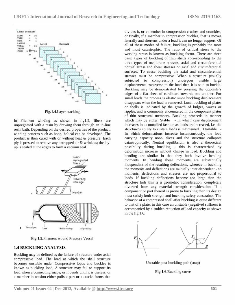
Angle-Ply Laminates: Angle-ply laminates have an arbitrary
number of layers (n). Each ply has the same thickness and is
the same material. The plies halt can be either symmetric or
antisymmetric (see fig1.4)
IJRET: International Journal of Research in Engineering and Technology ISSN: 2319-1163
__________________________________________________________________________________________ Volume: 01 Issue: 04 | Dec-2012, Available @ http://www.ijret.org 601
Fig.1.4.Layer stacking
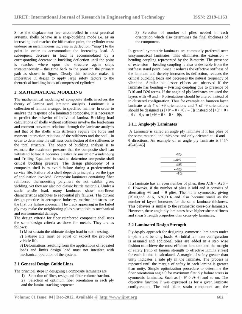
In Filament winding as shown in fig1.5, fibers are
impregnated with a resin by drawing them through an in-line
resin bath, Depending on the desired properties of the product;
winding patterns such as hoop, helical can be developed. The
product is then cured with or without heat & pressure. Each
ply is pressed to remove any entrapped air & wrinkles; the lay-
up is sealed at the edges to form a vacuum seal.
Fig 1.5.Filament wound Pressure Vessel
1.4 BUCKLING ANALYSIS
Buckling may be defined as the failure of structure under axial
compressive load. The load at which the shell structure
becomes unstable under Compressive loads and buckles is
known as buckling load. A structure may fail to support its
load when a connecting snaps, or it bends until it is useless, or
a member in tension either pulls a part or a cracks forms that
divides it, or a member in compression crushes and crumbles,
or finally, if a member in compression buckles, that is moves
laterally and shortens under a load it can no longer support. Of
all of these modes of failure, buckling is probably the most
and most catastrophic. The ratio of critical stress to the
working stress is known as buckling factor. There are three
basic types of buckling of thin shells corresponding to the
three types of membrane stresses, axial and circumferential
normal stress and shear stresses on axial and circumferential
surfaces. To cause buckling the axial and circumferential
stresses must be compressive. When a structure (usually
subjected to compression) undergoes visible large
displacements transverse to the load then it is said to buckle.
Buckling may be demonstrated by pressing the opposite‟s
edges of a flat sheet of cardboard towards one another. For
small loads the process is elastic since buckling displacement
disappears when the load is removed. Local buckling of plates
or shells is indicated by the growth of bulges, waves or
ripples, and is commonly encountered in the component plates
of thin structural members. Buckling proceeds in manner
which may be either: Stable - In which case displacement
increases in a controlled fashion as loads are increased, i.e. the
structure‟s ability to sustain loads is maintained. Unstable -
In which deformations increase instantaneously, the load
carrying capacity nose- dives and the structure collapses
catastrophically. Neutral equilibrium is also a theoretical
possibility during buckling – this is characterized by
deformation increase without change in load. Buckling and
bending are similar in that they both involve bending
moments. In bending these moments are substantially
independent of the resulting deflections, whereas in buckling
the moments and deflections are mutually inter-dependent - so
moments, deflections and stresses are not proportional to
loads. If buckling deflections become too large then the
structure fails this is a geometric consideration, completely
divorced from any material strength consideration. If a
component or part thereof is prone to buckling then its design
must satisfy both strength and buckling safety constraints. The
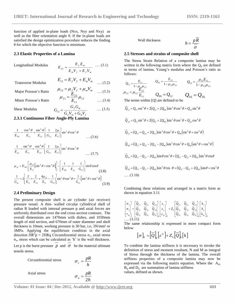
behavior of a compressed shell after buckling is quite different
to that of a plate; in this case an unstable (negative) stiffness is
accompanied by a sudden reduction of load capacity as shown
in the fig 1.6.
Unstable post-buckling path (snap)
Fig.1.6.Buckling curve
IJRET: International Journal of Research in Engineering and Technology ISSN: 2319-1163
__________________________________________________________________________________________ Volume: 01 Issue: 04 | Dec-2012, Available @ http://www.ijret.org 602
Since the displacement are uncontrolled in most practical
systems, shells behave in a snap-buckling mode i.e. as an
increasing load reaches the bifurcation point, the cylinder must
undergo an instantaneous increase in deflection (“snap”) to the
point in order to accommodate the increasing load. A
subsequent decrease in load is accommodated by a
corresponding decrease in buckling deflection until the point
is reached where upon the structure again snaps
instantaneously – this time back to the point on the primary
path as shown in figure. Clearly this behavior makes it
imperative in design to apply large safety factors to the
theoretical buckling loads of compressed cylinders.
2. MATHEMATICAL MODELING
The mathematical modeling of composite shells involves the
theory of lamina and laminate analysis. Laminate is a
collection of lamina arranged in specified manner. In order to
analyze the response of a laminated composite, it is necessary
to predict the behavior of individual lamina. Buckling load
calculations of shells without stiffeners involve the load-strain
and moment-curvature relations through the laminate analysis
and that of the shells with stiffeners require the force and
moment interaction relations of the stiffeners and the shell, in
order to determine the stiffness contribution of the stiffeners to
the total structure. The object of buckling analysis is to
estimate the maximum pressure that the composite shell can
withstand before it becomes elastically unstable “Windenburg
and Trilling Equation” is used to determine composite shell
critical buckling pressure. The design philosophy of a
composite shell is to avoid failure during a predetermined
service life. Failure of a shell depends principally on the type
of application involved. Composite laminates containing fiber
reinforced thermosetting polymers do not exhibit gross
yielding, yet they are also not classic brittle materials. Under a
static tensile load, many laminates show non-linear
characteristics attributes to sequential ply failures. The current
design practice in aerospace industry, marine industries use
the first ply failure approach. The crack appearing in the failed
ply may make the neighboring plies susceptible to mechanical
and environmental damage.
The design criteria for fiber reinforced composite shell uses
the same design criteria as those for metals. They are as
follows:
1) Must sustain the ultimate design load in static testing.
2) Fatigue life must be equal or exceed the projected
vehicle life.
3) Deformations resulting from the applications of repeated
loads and limits design load must not interfere with
mechanical operation of the system.
2.1 General Design Guide Lines
The principal steps in designing a composite laminates are
1) Selection of fiber, resign and fiber volume fraction.
2) Selection of optimum fiber orientation in each ply
and the lamina stacking sequence.
3) Selection of number of plies needed in each
orientation which also determines the final thickness of
the component.
In general symmetric laminates are commonly preferred over
unsymmetrical laminates. This eliminates the extension –
bending coupling represented by the B-matrix. The presence
of extension – bending coupling is also undesirable from the
stiffness stand point. Since it reduces the effective stiffness of
the laminate and thereby increases its deflection, reduces the
critical buckling loads and decreases the natural frequency of
vibration. Similar but lesser effects are observed if the
laminate has bending – twisting coupling due to presence of
D16 and D26 terms. If the angle of ply laminates are used the
layers with +θ and – θ orientations should be altered instead of
in clustered configuration. Thus for example an fourteen layer
laminate with 7 of +θ orientations and 7 of -θ orientations
should be designed as [+θ/ – θ / +θ / – θ]s instead of [+θ/ + θ /
– θ / – θ]s or [+θ/ + θ / – θ / – θ]s .
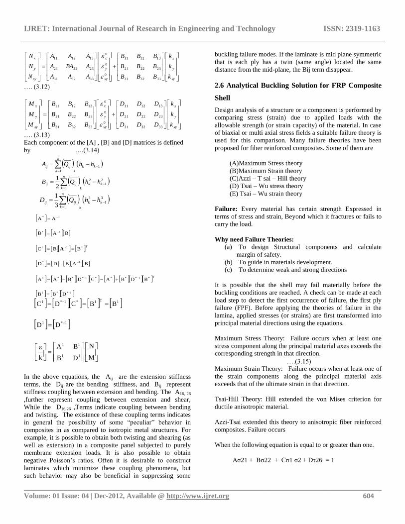
2.1.1 Angle-ply Laminates
A Laminate is called an angle ply laminate if it has plies of
the same material and thickness and only oriented at +θ and –
θ directions. An example of an angle ply laminate is [45/-
45/45/-45]
If a laminate has an even number of plies, then A16 = A26 =
0. However, if the number of plies is odd and it consists of
alternating +θ and – θ plies, Then it is symmetric, giving
[B]=0,and A16, A26,D16 and also become small as the
number of layers increases for the same laminate thickness.
This behavior is similar to the symmetric cross-ply laminates.
However, these angle ply laminates have higher shear stiffness
and shear Strength properties than cross-ply laminates.
2.2 Laminated Design Strength
Ply-by-ply approach for designing symmetric laminates under
in-plane and bending loads. An initial laminate configuration
is assumed and additional plies are added in a step wise
fashion to achieve the most efficient laminate and the margin
of safety (ratio of lamina strength to effective lamina stress)
for each lamina is calculated. A margin of safety greater than
unity indicates a safe ply in the laminate. The process is
repeated until the margin of safety in each lamina is greater
than unity. Simple optimization procedure to determine the
fiber orientation angle θ for maximum first ply failure stress in
symmetric laminates. Such as [- θ/ 0 /+ θ] and so on. The
objective function F was expressed as for a given laminate
configuration. The mid plane strain component are the
IJRET: International Journal of Research in Engineering and Technology ISSN: 2319-1163
__________________________________________________________________________________________ Volume: 01 Issue: 04 | Dec-2012, Available @ http://www.ijret.org 603
function of applied in-plane loads (Nxx, Nyy and Nxy) as
well as the fiber orientation angle θ. If the in-plane loads are
satisfied the design optimization procedure reduces the finding
θ for which the objective function is minimum.
2.3 Elastic Properties of a Lamina
Longitudinal Modulus …. (3.1)
Transverse Modulus …. (3.2)
Major Poisson‟s Ratio …. (3.3)
Minor Poisson‟s Ratio …. (3.4)
Shear Modulus …. (3.5)
2.3.1 Continuous Fiber Angle-Ply Lamina
22
111222
4
11
4
cossin21sincos1
EGEEE XX ….(3.6)
22
111222
4
11
4
cossin21cossin1
EGEEE yy …. (3.7)
cossin111
cossin12
44
11
12
GEEEE
yyXX
XXxy
(3.8)
44
12
22
1211
12
2211
cossin1
cossin1422
21
GGEEEGxy (3.9)
2.4 Preliminary Design
The present composite shell is air cylinder (air receiver)
pressure vessel. A thin- walled circular cylindrical shell of
radius R loaded with internal pressure p and axial forces are
uniformly distributed over the end cross-section contours. The
overall dimensions are 1470mm with dishes, and 1030mm
length of mid section, and 670mm of outer diameter and shell
thickness is 10mm, working pressure is 30 bar, i.e; 3N/mm² or
3MPa. Applying the equilibrium condition in the axial
direction ΠR2p = 2ΠRq Circumferential stress σc, axial stress
σa, stress which can be calculated as „h‟ is the wall thickness.
Let p is the burst pressure p and be the material ultimate
tensile stress.
Circumferential stress
Axial stress
Wall thickness
2.5 Stresses and strains of composite shell
The Stress Strain Relation of a composite lamina may be
written in the following matrix form where the Qij are defined
in terms of lamina, Young‟s modulus and Poisson‟s ratio as
follows:
The terms within [Q] are defined to be
…. (3.10)
Combining these relations and arranged in a matrix form as
shown in equation 3.11
…. (3.11)
The same relationship is expressed in more compact form
below
To combine the lamina stiffness it is necessary to invoke the
definition of stress and moment resultant, N and M as integral
of Stress through the thickness of the lamina. The overall
stiffness properties of a composite lamina may now be
expressed via the following matrix equation. Where the Aij,
Bij and Dij are summation of lamina stiffness
values, defined as shown.
mmff VEVEE 11
mffm
mf
VEVE
EEE
22
mmff VV 12
12
11
2221
E
E
fmmf
mf
VGVG
GGG
12
2112
1111
1
EQ
2112
2222
1
EQ
11
221221
E
E
1266 QQ
kxy
y
x
k
k
kxy
y
x
kxy
y
x
k
k
k
QQQ
QQQ
QQQ
Z
QQQ
QQQ
QQQ
333231
232221
131211
333231
232221
131211
kQZQ kkkk 0
h
pRc
h
pRa
2
Rph
3
662212
3
66121126
3
662211
3
66221116
44
66
22
6612221166
44
66
22
12221112
4
22
22
6612
4
1122
4
22
22
6612
4
1111
cossin2cossin2
cossin2cossin2
cossincossin22
cossincossin2
coscossin22sin
sincossin22cos
QQQQQQQ
QQQQQQQ
QQQQQQ
QQQQQ
QQQQQ
QQQQQ
2112
111212
1
EQ
2616 QQ
IJRET: International Journal of Research in Engineering and Technology ISSN: 2319-1163
__________________________________________________________________________________________ Volume: 01 Issue: 04 | Dec-2012, Available @ http://www.ijret.org 604
xy
y
x
xy
y
x
xy
y
x
k
k
k
BBB
BBB
BBB
AAA
ABAA
AAA
N
N
N
333231
232221
131211
0
0
0
333231
232221
131211
…. (3.12)
xy
y
x
xy
y
x
xy
y
x
k
k
k
DDD
DDD
DDD
BBB
BBB
BBB
M
M
M
333231
232221
131211
0
0
0
333231
232221
131211
…. (3.13)
Each component of the [A] , [B] and [D] matrices is defined
by ….(3.14)
1**1
T*1****1***1
1*
*1*
1*
1*
DBB
BDBACDBAA
BABDD
BBC
BAB
AA
TA
M
N
DB
BA
k
ε
DD
BBCDC
11
11
1*1
1T1*1*1
….(3.15)
In the above equations, the Aij are the extension stiffness
terms, the Dij are the bending stiffness, and Bij represent
stiffness coupling between extension and bending. The A16, 26
,further represent coupling between extension and shear,
While the D16,26 ,Terms indicate coupling between bending
and twisting. The existence of these coupling terms indicates
in general the possibility of some “peculiar” behavior in
composites in as compared to isotropic metal structures. For
example, it is possible to obtain both twisting and shearing (as
well as extension) in a composite panel subjected to purely
membrane extension loads. It is also possible to obtain
negative Poisson‟s ratios. Often it is desirable to construct
laminates which minimize these coupling phenomena, but
such behavior may also be beneficial in suppressing some
buckling failure modes. If the laminate is mid plane symmetric
that is each ply has a twin (same angle) located the same
distance from the mid-plane, the Bij term disappear.
2.6 Analytical Buckling Solution for FRP Composite
Shell
Design analysis of a structure or a component is performed by
comparing stress (strain) due to applied loads with the
allowable strength (or strain capacity) of the material. In case
of biaxial or multi axial stress fields a suitable failure theory is
used for this comparison. Many failure theories have been
proposed for fiber reinforced composites. Some of them are
(A)Maximum Stress theory
(B)Maximum Strain theory
(C)Azzi – T sai – Hill theory
(D) Tsai – Wu stress theory
(E) Tsai – Wu strain theory
Failure: Every material has certain strength Expressed in
terms of stress and strain, Beyond which it fractures or fails to
carry the load.
Why need Failure Theories:
(a) To design Structural components and calculate
margin of safety.
(b) To guide in materials development.
(c) To determine weak and strong directions
It is possible that the shell may fail materially before the
buckling conditions are reached. A check can be made at each
load step to detect the first occurrence of failure, the first ply
failure (FPF). Before applying the theories of failure in the
lamina, applied stresses (or strains) are first transformed into
principal material directions using the equations.
Maximum Stress Theory: Failure occurs when at least one
stress component along the principal material axes exceeds the
corresponding strength in that direction.
Maximum Strain Theory: Failure occurs when at least one of
the strain components along the principal material axis
exceeds that of the ultimate strain in that direction.
Tsai-Hill Theory: Hill extended the von Mises criterion for
ductile anisotropic material.
Azzi-Tsai extended this theory to anisotropic fiber reinforced
composites. Failure occurs
When the following equation is equal to or greater than one.
Aσ21 + Bσ22 + Cσ1 σ2 + Dτ26 = 1
2
1
2
12
1
kk
k
n
k
ijij hhQB
3
1
3
13
1
kk
k
n
k
ijij hhQD
1
1
kk
k
n
k
ijij hhQA
IJRET: International Journal of Research in Engineering and Technology ISSN: 2319-1163
__________________________________________________________________________________________ Volume: 01 Issue: 04 | Dec-2012, Available @ http://www.ijret.org 605
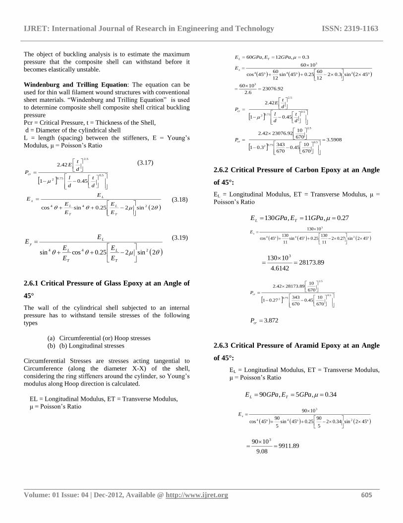
The object of buckling analysis is to estimate the maximum
pressure that the composite shell can withstand before it
becomes elastically unstable.
Windenburg and Trilling Equation: The equation can be
used for thin wall filament wound structures with conventional
sheet materials. “Windenburg and Trilling Equation” is used
to determine composite shell composite shell critical buckling
pressure
Pcr = Critical Pressure, t = Thickness of the Shell,
d = Diameter of the cylindrical shell
L = length (spacing) between the stiffeners, E = Young‟s
Modulus, μ = Poisson‟s Ratio
5.0
75.02
5.2
45.01
42.2
d
t
d
l
d
tE
Pcr
(3.17)
2sin225.0sincos 244
T
L
T
L
L
x
E
E
E
E
EE (3.18)
2sin225.0cossin 244
T
L
T
L
L
y
E
E
E
E
EE
(3.19)
2.6.1 Critical Pressure of Glass Epoxy at an Angle of
45°
The wall of the cylindrical shell subjected to an internal
pressure has to withstand tensile stresses of the following
types
(a) Circumferential (or) Hoop stresses
(b) (b) Longitudinal stresses
Circumferential Stresses are stresses acting tangential to
Circumference (along the diameter X-X) of the shell,
considering the ring stiffeners around the cylinder, so Young‟s
modulus along Hoop direction is calculated.
EL = Longitudinal Modulus, ET = Transverse Modulus,
μ = Poisson‟s Ratio
2.6.2 Critical Pressure of Carbon Epoxy at an Angle
of 45°:
EL = Longitudinal Modulus, ET = Transverse Modulus, μ =
Poisson‟s Ratio
27.0,11,130 GPaEGPaE TL
452sin27.0211
13025.045sin
11
13045cos
10130
244
3
xE
89.281736142.4
10130 3
5.0
75.02
5.2
670
1045.0
670
34327.01
670
1089.2817342.2
crP
872.3crP
2.6.3 Critical Pressure of Aramid Epoxy at an Angle
of 45°:
EL = Longitudinal Modulus, ET = Transverse Modulus,
μ = Poisson‟s Ratio
34.0,5,90 GPaEGPaE TL
452sin34.025
9025.045sin
5
9045cos
1090
244
3
xE
89.991108.9
1090 3
5908.3
670
1045.0
670
3433.01
670
1092.2307642.2
45.01
42.2
92.230766.2
1060
452sin3.0212
6025.045sin
12
6045cos
1060
3.0,12,60
5.075.02
5.2
5.075.02
5.2
3
244
3
cr
cr
x
TL
P
d
t
d
l
d
tE
P
E
GPaEGPaE
IJRET: International Journal of Research in Engineering and Technology ISSN: 2319-1163
__________________________________________________________________________________________ Volume: 01 Issue: 04 | Dec-2012, Available @ http://www.ijret.org 606
5.0
75.02
5.2
670
1045.0
670
34334.01
670
1089.991142.2
crP
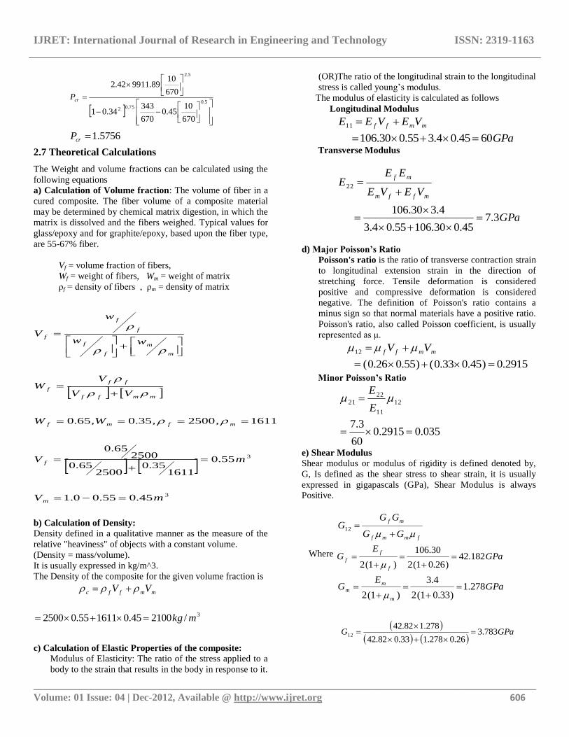
5756.1crP
2.7 Theoretical Calculations
The Weight and volume fractions can be calculated using the
following equations
a) Calculation of Volume fraction: The volume of fiber in a
cured composite. The fiber volume of a composite material
may be determined by chemical matrix digestion, in which the
matrix is dissolved and the fibers weighed. Typical values for
glass/epoxy and for graphite/epoxy, based upon the fiber type,
are 55-67% fiber.
Vf = volume fraction of fibers,
Wf = weight of fibers, Wm = weight of matrix
ρf = density of fibers , ρm = density of matrix
b) Calculation of Density:
Density defined in a qualitative manner as the measure of the
relative "heaviness" of objects with a constant volume.
(Density = mass/volume).
It is usually expressed in kg/m^3.
The Density of the composite for the given volume fraction is
mmffc VV
3/210045.0161155.02500 mkg
c) Calculation of Elastic Properties of the composite: Modulus of Elasticity: The ratio of the stress applied to a
body to the strain that results in the body in response to it.
(OR)The ratio of the longitudinal strain to the longitudinal
stress is called young‟s modulus.
The modulus of elasticity is calculated as follows
Longitudinal Modulus
mmff VEVEE 11
GPa6045.04.355.030.106
Transverse Modulus
mffm
mf
VEVE
EEE
22
GPa3.745.030.10655.04.3
4.330.106
d) Major Poisson’s Ratio
Poisson's ratio is the ratio of transverse contraction strain
to longitudinal extension strain in the direction of
stretching force. Tensile deformation is considered
positive and compressive deformation is considered
negative. The definition of Poisson's ratio contains a
minus sign so that normal materials have a positive ratio.
Poisson's ratio, also called Poisson coefficient, is usually
represented as μ.
mmff VV 12
2915.0)45.033.0()55.026.0(
Minor Poisson’s Ratio
12
11
22
21 E
E
035.02915.060
3.7
e) Shear Modulus
Shear modulus or modulus of rigidity is defined denoted by,
G, Is defined as the shear stress to shear strain, it is usually
expressed in gigapascals (GPa), Shear Modulus is always
Positive.
fmmf
mf
GG
GGG
12
Where GPaE
Gf
f
f 182.42)26.01(2
30.106
)1(2
GPaE
Gm
m
m 278.1)33.01(2
4.3
)1(2
3
3
45.055.00.1
55.0
161135.0
250065.0
250065.0
1611,2500,35.0,65.0
mV
mV
WW
VV
VW
ww
w
V
m
f
mfmf
mmff
ff
f
m
m
f
f
f
f
f
GPaG 783.3
26.0278.133.082.42
278.182.4212
IJRET: International Journal of Research in Engineering and Technology ISSN: 2319-1163
__________________________________________________________________________________________ Volume: 01 Issue: 04 | Dec-2012, Available @ http://www.ijret.org 607
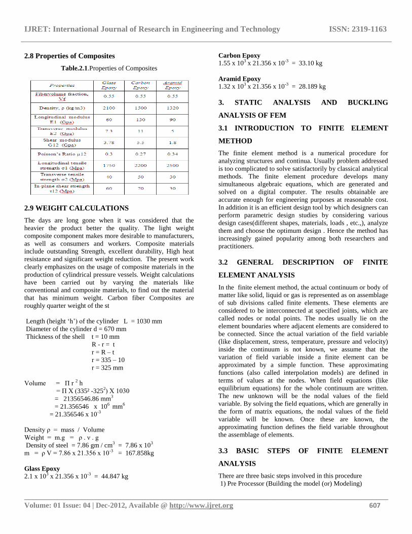
2.8 Properties of Composites
Table.2.1.Properties of Composites
2.9 WEIGHT CALCULATIONS
The days are long gone when it was considered that the
heavier the product better the quality. The light weight
composite component makes more desirable to manufacturers,
as well as consumers and workers. Composite materials
include outstanding Strength, excellent durability, High heat
resistance and significant weight reduction. The present work
clearly emphasizes on the usage of composite materials in the
production of cylindrical pressure vessels. Weight calculations
have been carried out by varying the materials like
conventional and composite materials, to find out the material
that has minimum weight. Carbon fiber Composites are
roughly quarter weight of the st
Length (height „h‟) of the cylinder L = 1030 mm
Diameter of the cylinder d = 670 mm
Thickness of the shell t = 10 mm
R - r = t
r = R – t
r = 335 – 10
r = 325 mm
Volume = Π r 2 h
= Π Χ (335² -3252) Χ 1030
= 21356546.86 mm3
= 21.356546 x 106 mm
6
= 21.356546 x 10⁻³
Density ρ = mass / Volume
Weight = m.g = ρ . ν . g
Density of steel = 7.86 gm / cm3 = 7.86 x 10
3
m = ρ V = 7.86 x 21.356 x 10-3
= 167.858kg
Glass Epoxy
2.1 x 103 x 21.356 x 10
-3 = 44.847 kg
Carbon Epoxy
1.55 x 103 x 21.356 x 10
-3 = 33.10 kg
Aramid Epoxy
1.32 x 103 x 21.356 x 10
-3 = 28.189 kg
3. STATIC ANALYSIS AND BUCKLING
ANALYSIS OF FEM
3.1 INTRODUCTION TO FINITE ELEMENT
METHOD
The finite element method is a numerical procedure for
analyzing structures and continua. Usually problem addressed
is too complicated to solve satisfactorily by classical analytical
methods. The finite element procedure develops many
simultaneous algebraic equations, which are generated and
solved on a digital computer. The results obtainable are
accurate enough for engineering purposes at reasonable cost.
In addition it is an efficient design tool by which designers can
perform parametric design studies by considering various
design cases(different shapes, materials, loads , etc.,), analyze
them and choose the optimum design . Hence the method has
increasingly gained popularity among both researchers and
practitioners.
3.2 GENERAL DESCRIPTION OF FINITE
ELEMENT ANALYSIS
In the finite element method, the actual continuum or body of
matter like solid, liquid or gas is represented as on assemblage
of sub divisions called finite elements. These elements are
considered to be interconnected at specified joints, which are
called nodes or nodal points. The nodes usually lie on the
element boundaries where adjacent elements are considered to
be connected. Since the actual variation of the field variable
(like displacement, stress, temperature, pressure and velocity)
inside the continuum is not known, we assume that the
variation of field variable inside a finite element can be
approximated by a simple function. These approximating
functions (also called interpolation models) are defined in
terms of values at the nodes. When field equations (like
equilibrium equations) for the whole continuum are written.
The new unknown will be the nodal values of the field
variable. By solving the field equations, which are generally in
the form of matrix equations, the nodal values of the field
variable will be known. Once these are known, the
approximating function defines the field variable throughout
the assemblage of elements.
3.3 BASIC STEPS OF FINITE ELEMENT
ANALYSIS
There are three basic steps involved in this procedure
1) Pre Processor (Building the model (or) Modeling)
IJRET: International Journal of Research in Engineering and Technology ISSN: 2319-1163
__________________________________________________________________________________________ Volume: 01 Issue: 04 | Dec-2012, Available @ http://www.ijret.org 608
2) Solution (Applying loads and solving)
3) Post Processor (Reviewing the results)
Preprocessor (defining the problem) The problem is defined through mathematical modeling or
analytical modeling. The formulation of the set of
mathematical equations that models the physical problem
within the scale and accuracy required by the application. The
following steps are involved in preprocessor
• Define key point/lines/ areas/ volumes
• Define element type and material/ geometric
properties
• Mesh lines/ areas / volumes are required.
Solution (assigning loads, constraints and solving) Here the loads (points load, uniformly distribute load, force or
pressure), constraints (translational or rotational) are specified
and finally solve the resulting set of equations.
Post Processor The numerical results in terms of their mathematical and
physical significance are interpreted. In this stage, further
processing and viewing of the results cab be done such as
• List of nodal displacements
• Element forces and moments
• Deflection plots
• Stress contour diagrams
3.4 ELEMENTS USED FOR ANALYSIS
In Ansys (finite element analysis software) different types of
elements are used depending on the problem nature and the
type of analysis to be performed. The element chosen
characterizes among other things, the degree of freedom set
(displacements and/ or rotations, temperatures, etc.), the
characteristic shape of the element (line, quadrilateral, brick,
etc.), whether the element lies in 2-D space or 3 - D space,
response of the system. The elements used in Ansys are
classified as shown in table 4.1 below.
Table.3.1 List of Elements by Classification
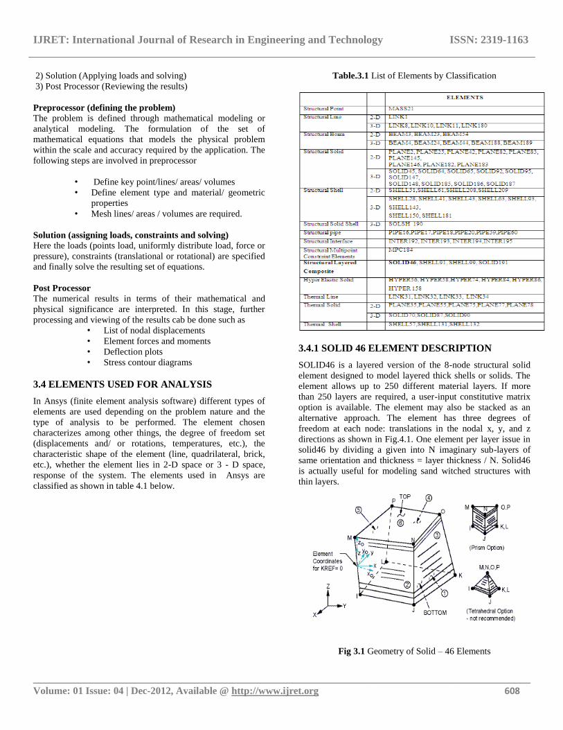
3.4.1 SOLID 46 ELEMENT DESCRIPTION
SOLID46 is a layered version of the 8-node structural solid
element designed to model layered thick shells or solids. The
element allows up to 250 different material layers. If more
than 250 layers are required, a user-input constitutive matrix
option is available. The element may also be stacked as an
alternative approach. The element has three degrees of
freedom at each node: translations in the nodal x, y, and z
directions as shown in Fig.4.1. One element per layer issue in
solid46 by dividing a given into N imaginary sub-layers of
same orientation and thickness = layer thickness / N. Solid46
is actually useful for modeling sand witched structures with
thin layers.
Fig 3.1 Geometry of Solid – 46 Elements
IJRET: International Journal of Research in Engineering and Technology ISSN: 2319-1163
__________________________________________________________________________________________ Volume: 01 Issue: 04 | Dec-2012, Available @ http://www.ijret.org 609
a) Specifying Individual Layer Properties:
The layer configuration is defined layer-by-layer. The bottom
layer is designed as layer 1, and additional layer are stacked
from bottom to top in the positive Z (normal) direction of the
element coordinate system. For each layer the following
properties are specified in the element real constant table.
b) Number of Layers:
The total number of layers must be specified. The properties
of all layers should be entered. If the properties of the layer are
symmetrical about the mid thickness of the element, only half
of properties of the layers, up to and including the middle
layer (if any), need to be entered.
c) Material Properties: The material properties of each layer may be orthotropic in the
plane of the element. The properties of Isotropic/orthotropic
material i.e. elastic modulus, poisons ratio, shear modulus and
density are to be specified. The real constant MAT is used to
define the layer material number instead of the element
material number. The material X direction corresponds to the
local layer X1 direction.
d) Layer Orientation Angle:
The local coordinate system for each layer is defined. The
layer number can arrange from 1 to 250. In this local right-
handed system, the X‟- axis is rotated an angle THETA (in
degrees) from the X-axis towards the element y- axis.
Different layer orientations are possible depending on the
arrangement of laminates of the composite material chosen for
analysis.
e) Layer Thickness:
Each layer of the laminated shell element may have a variable
thickness. The thickness is assumed to vary bilinear over the
area of the layer, with the thickness input at the corner node
locations. If the layer has a constant thickness, all four corner
thickness must be input using positive values. The total
thickness of each shell element must be less than twice the
radius of curvature, and should be less than one-fifth the
radius of curvature.
3.5 ROLE OF FEM IN STRUCTURAL ANALYSIS
Structural analysis is probably the most common application
of the finite element method. The term structural or structure
implies not only civil engineering structures such as ship hulls,
aircraft bodies and machine housings as well as mechanical
components such as pistons, machine parts and tools.
3.5.1 Types Of Structural Analysis
Different types of structural analysis are
• Static Analysis
• Model Analysis
• Harmonic Analysis
• Transient Analysis
• Spectrum Analysis
• Buckling Analysis
• Explicit Dynamic Analysis
3.6 STATIC ANALYSIS
A static analysis calculates the effects of the study loading
conditions on a structure, while ignoring inertia and damping
effects, such as those caused by time varying loads. A static
analysis can however, include steady inertia loads (such as
gravity and rotational velocity), and time varying loads that
can be approximated as static equivalent loads (such as static
equivalent wind and seismic loads commonly defined in many
building codes).
Static analysis is used to determine the displacement, stresses
strains and forces in structural components caused by loads
that do not include significant inertia and damping effects.
Steady loading and response conditions are assumed i.e. the
loads and the structures response are assumed to vary slowly
with respect to time. The kinds of loading that can be applied
in a static analysis include:
• Entirely applied forces and pressures
• Steady static inertial forces (such as gravity (or)
rotational velocity)
• Imposed (non-zero) displacements
• Temperatures (for thermal Strain)
• Fluences (for nuclear swelling)
A static analysis can be either linear or nonlinear. All types of
nonlinearities are allowed- Like large deformations, plasticity,
creep, stress, stiffening contact (gap) elements and hyper
elastic elements.
3.6.1 Overview of Steps in Static Analysis
The procedure of static analysis involves three main steps
• Build the model
• Apply loads and obtain the solution
• Review the results
3.7 BUCKLING ANALYSIS
Buckling analysis is a technique used to determine buckling
loads. Critical loads at which the structure becomes unstable
and buckled.
• Build Model
• Obtain the static solution
• Obtain the eigen value buckling solution
• Expand the solution
• Review the results
Buckling analysis is a technique used to determine buckling
analysis and element type, material properties; boundary
conditions are same as for static analysis except the prestress
effects are to be included.
IJRET: International Journal of Research in Engineering and Technology ISSN: 2319-1163
__________________________________________________________________________________________ Volume: 01 Issue: 04 | Dec-2012, Available @ http://www.ijret.org 610
Structural Analysis is probably the most common application
of the finite element method provides a means of Optimizing
the design with regard to static and buckling load,
deformation , weight and material choice. Finite element
analysis works to ensure accurate results by combining the
designed geometric input with specific boundary condition
information that is provided by process.
3.7.1 Modeling
In ANSYS terminology, the term model generation usually
takes on the narrower meaning of generating the nodes and
elements that represent the spatial volume and connectivity of
the actual system. The ANSYS program offers you the
following approaches to model generation:
3-D model was built for unstiffened and stiffened shell using
CATIA Vr18 software. The modeled shell has the following
properties:
Cylinder diameter 670 mm
Cylinder height 1030
Shell thickness 10 mm
Stiffener Cross section 8 x 150mm
The Thin walled composite cylinder is generated. a cylinder
with stiffeners spaced periodically. It is used for calculating
propagation constant in circumferential directions of the
cylindrical shell subjected to circumferential mode.
3.7.2 MESHING
The Modeled cylinder was imported to ANSYS for meshing;
The solid model was set element attributes, and established
meshing controls, you can then turn the ANSYS program
loose to generate the finite element mesh. By taking care to
meet certain requirements, we can request a "mapped" mesh
containing all quadrilaterals, all triangular, or all brick
elements. Here the shell was meshed using quadrilateral
elements. The mesh size used is 4mm for both shell and the
stiffeners. The mesh size may be changed depending on the
complexity of the problem.
Also increases as the number of elements increases and it
requires powered system to solve the problem. Mesh
generation is one of the most critical aspects of engineering
simulation.
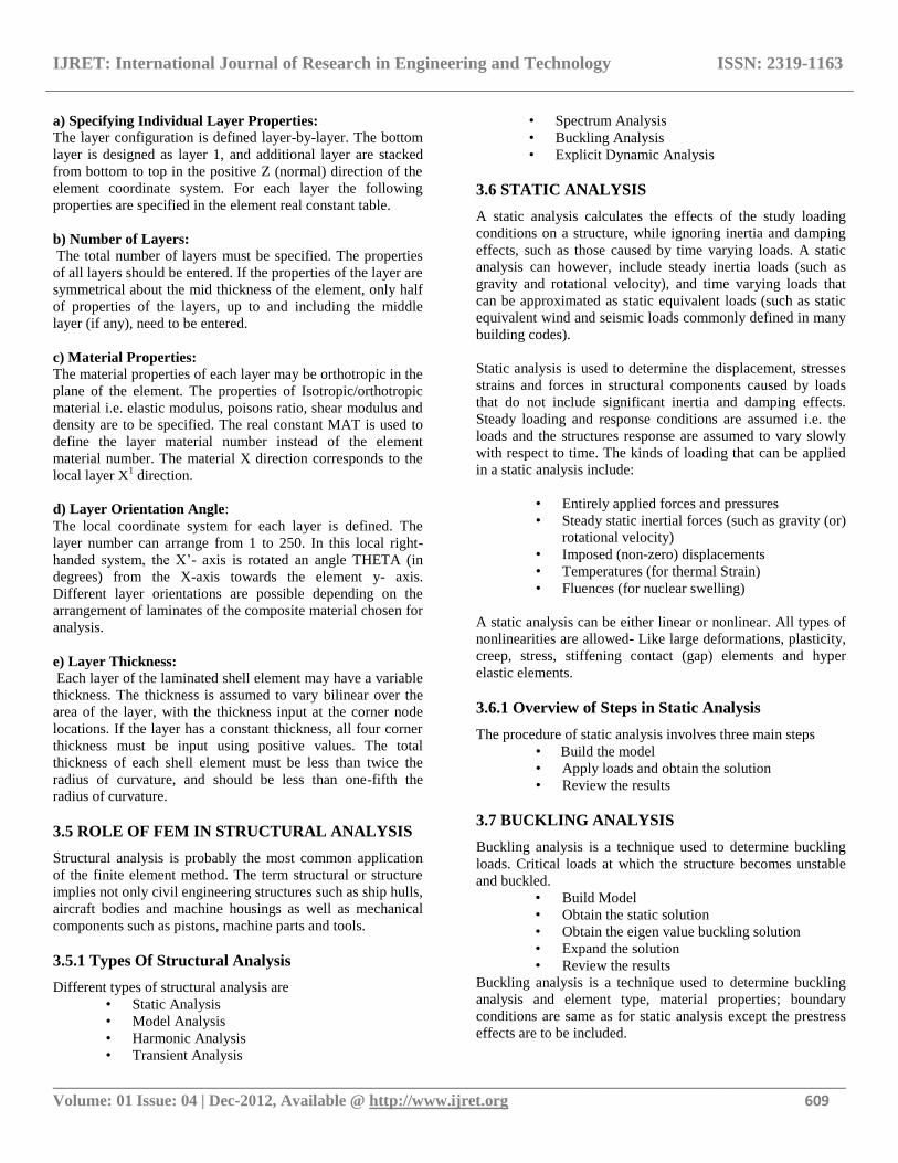
Fig.4.2.Meshed Model
ANSYS meshing technology provides a means to balance
these requirements and obtain the right mesh for each
simulation in the most automated way possible. The modeled
cylinder has a radial symmetry of 45°. Initially one 45° sector
was modeled and then the whole structure was generated using
this primary sector. This can be treated as an axi-symmetric
problem to reduce the complexity of the problem.
a) Nodes:
Nodes are the basic building blocks of elements in a mesh.
Nodes store elevation and other data set values. Nodes can
also be used for building node strings and assigning boundary
conditions. The density of mesh nodes helps determine the
quality of solution data and can be important to model
stability.
b) Mesh Element Types:
Elements are used to describe the area to be modeled.
Elements are formed by joining nodes. The element types
supported vary from model to model. Element types include:
1D elements
Three-node line
Triangular Elements
Three-node linear triangle
Six-node quadratic triangle
Quadratic (order of solution) Elements
Eight-node “serendipity” quadrilateral
Nine-node “Lagrangian” quadrilateral
Water surface and ground elevations are interpolated linearly
within each element based on values at the corner nodes.
Velocity is interpolated using a quadratic approximation
based on values at all the nodes of the element. The
quadrilateral elements use identical linear interpolation
functions, but their quadratic functions differ because of the
presence of an additional node at the center of the nine-node
quadrilateral element.
IJRET: International Journal of Research in Engineering and Technology ISSN: 2319-1163
__________________________________________________________________________________________ Volume: 01 Issue: 04 | Dec-2012, Available @ http://www.ijret.org 611
3.7.3 Boundary Conditions and Loading
The global coordinate system of the composite cylindrical
shell is defined in such a way that the bottom face of the
cylinder lies in the x-y plane and the positive
Z-axis is aligned with the axis of the cylinder. The following
boundary conditions were imposed on the composite
cylindrical shell.
1. The circumferential and radial displacements „v‟
and „w‟ respectively equal to zero at both faces of the
cylinder (at z=0 and z=h, v=w=0).
2. Axial displacement „u‟ is zero at the bottom face of
the cylinder but is non-zero at the top face where the
load is applied (at z=0,u=0 and at z=h, u≠0).
A unit force was applied at the upper rim of the cylinder (z=h)
in buckling analysis.
3.7.4 Solution
Linear buckling analysis in ANSYS finite-element software is
performed in two steps.
1. In the first step a static solution to the composite
cylindrical shell is obtained. In this analysis the
prebuckling stress of the shell is calculated.
2. The second step involves solving the eigenvalue
problem given in the form of Equation. This Equation
takes into consideration the prebuckling stress effect
matrix [S] calculated in the first step.
([K] + λi [S]) {ψ}i = {0}
Where [K] = stiffness matrix
[S] = stress stiffness matrix
λi = ith
eigenvalue (used to multiply the
loads which generated [S])
Ψi = ith eigenvector of displacements.
The „Block Lanczos‟ method was used to extract the
eigenvalues.
The eigenvalues obtained from the buckling analysis are the
minimum buckling loads.
3.7.5 Analysis
Finite elements analysis was performed on a composite shell
without stiffeners having the geometric properties. By
obtaining the minimum deformation at maximum load and
considering that as a best angle to obtain the minimum
buckling load, different analysis were carried out with angle-
ply laminate arrangements, composite materials with different
properties as shown in section 4.9. The observations made on
this analysis are presented in the results and discussions
chapter.
3.8 COMPOSITE MATERIAL PROPERTIES
The properties of the composite materials used in the present
work are given as below
Glass-Epoxy E1 = 60 Gpa
E2 = 7.3 Gpa
G12 = 3.78 Gpa
μ12 = 0.3
Volume fraction Vf = 0.55
Carbon-Epoxy E1 = 130 Gpa
E2 = 11 Gpa
G12 = 5.5 Gpa
μ12 = 0.27
Volume fraction Vf = 0.55
Aramid-Epoxy E1 = 90 Gpa
E2 = 5 Gpa
G12 = 1.8 Gpa
μ12 = 0.34
Volume fraction Vf = 0.55
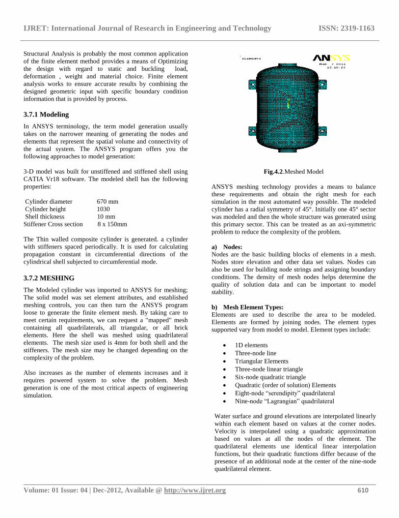
GLASS EPOXY
Stresses and Deformations at 14 Layers with Different
Orientations
Fig.3.5.(a).45° Orientation
IJRET: International Journal of Research in Engineering and Technology ISSN: 2319-1163
__________________________________________________________________________________________ Volume: 01 Issue: 04 | Dec-2012, Available @ http://www.ijret.org 612
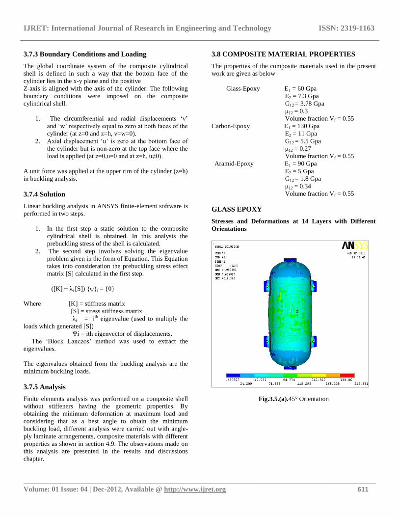
Fig.3.5.(b).55° Orientation
Fig.3.5.(c).65° Orientation
Fig.3.5.(d).75° Orientation
Fig.3.5.(e).85° Orientation
Fig.3.5.Vonmisess stresses of Glass Epoxy for 14 layers
IJRET: International Journal of Research in Engineering and Technology ISSN: 2319-1163
__________________________________________________________________________________________ Volume: 01 Issue: 04 | Dec-2012, Available @ http://www.ijret.org 613
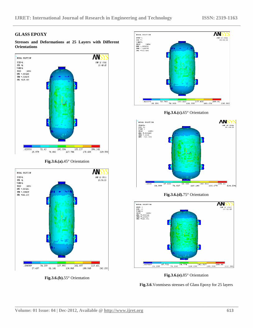
GLASS EPOXY
Stresses and Deformations at 25 Layers with Different
Orientations
Fig.3.6.(a).45° Orientation
Fig.3.6.(b).55° Orientation
Fig.3.6.(c).65° Orientation
Fig.3.6.(d).75° Orientation
Fig.3.6.(e).85° Orientation
Fig.3.6.Vonmisess stresses of Glass Epoxy for 25 layers
IJRET: International Journal of Research in Engineering and Technology ISSN: 2319-1163
__________________________________________________________________________________________ Volume: 01 Issue: 04 | Dec-2012, Available @ http://www.ijret.org 614
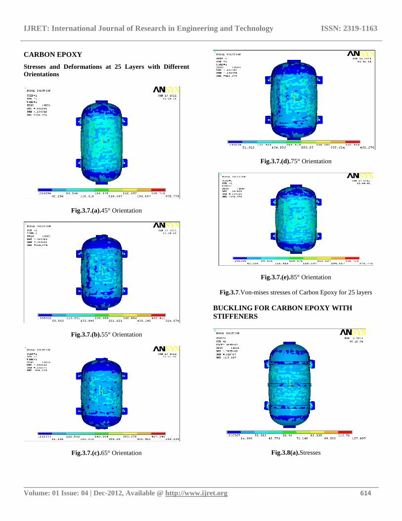
CARBON EPOXY
Stresses and Deformations at 25 Layers with Different
Orientations
Fig.3.7.(a).45° Orientation
Fig.3.7.(b).55° Orientation
Fig.3.7.(c).65° Orientation
Fig.3.7.(d).75° Orientation
Fig.3.7.(e).85° Orientation
Fig.3.7.Von-mises stresses of Carbon Epoxy for 25 layers
BUCKLING FOR CARBON EPOXY WITH
STIFFENERS
Fig.3.8(a).Stresses
IJRET: International Journal of Research in Engineering and Technology ISSN: 2319-1163
__________________________________________________________________________________________ Volume: 01 Issue: 04 | Dec-2012, Available @ http://www.ijret.org 615
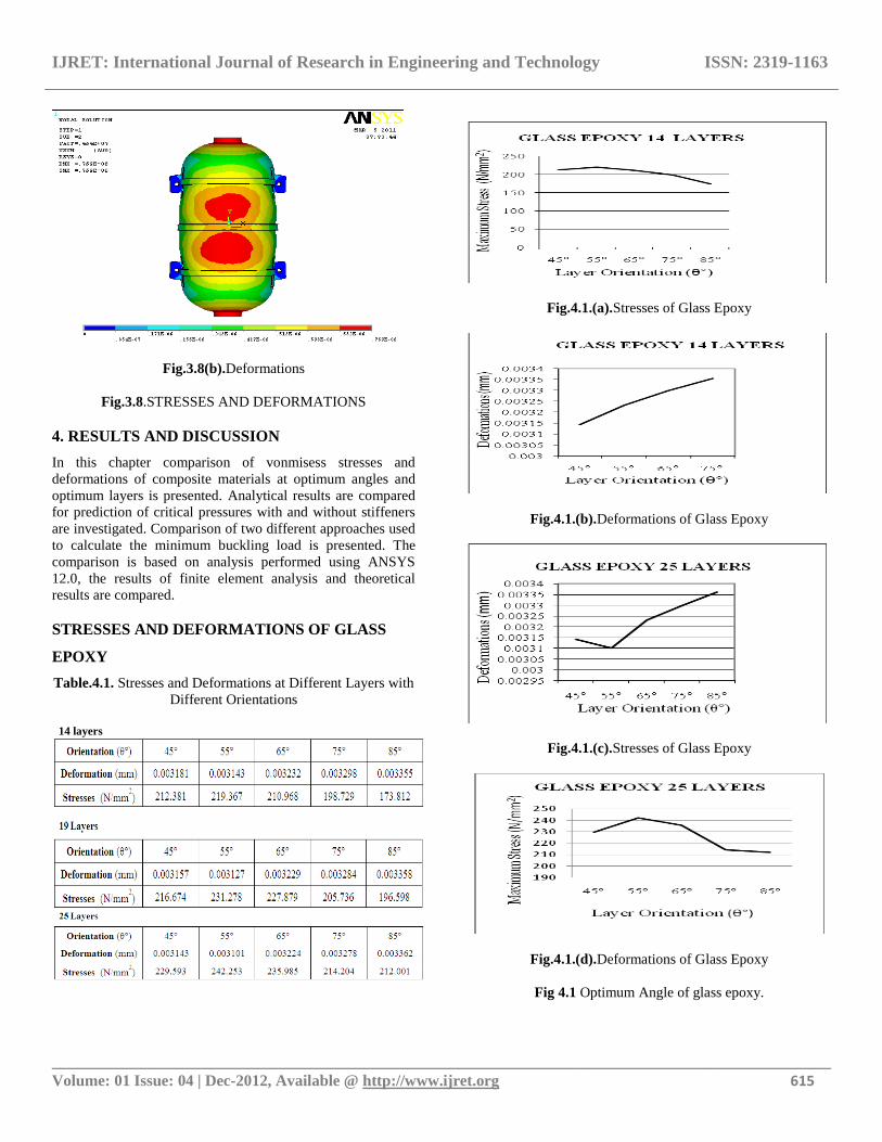
Fig.3.8(b).Deformations
Fig.3.8.STRESSES AND DEFORMATIONS
4. RESULTS AND DISCUSSION
In this chapter comparison of vonmisess stresses and
deformations of composite materials at optimum angles and
optimum layers is presented. Analytical results are compared
for prediction of critical pressures with and without stiffeners
are investigated. Comparison of two different approaches used
to calculate the minimum buckling load is presented. The
comparison is based on analysis performed using ANSYS
12.0, the results of finite element analysis and theoretical
results are compared.
STRESSES AND DEFORMATIONS OF GLASS
EPOXY
Table.4.1. Stresses and Deformations at Different Layers with
Different Orientations
14 layers
Fig.4.1.(a).Stresses of Glass Epoxy
Fig.4.1.(b).Deformations of Glass Epoxy
Fig.4.1.(c).Stresses of Glass Epoxy
Fig.4.1.(d).Deformations of Glass Epoxy
Fig 4.1 Optimum Angle of glass epoxy.
IJRET: International Journal of Research in Engineering and Technology ISSN: 2319-1163
__________________________________________________________________________________________ Volume: 01 Issue: 04 | Dec-2012, Available @ http://www.ijret.org 616
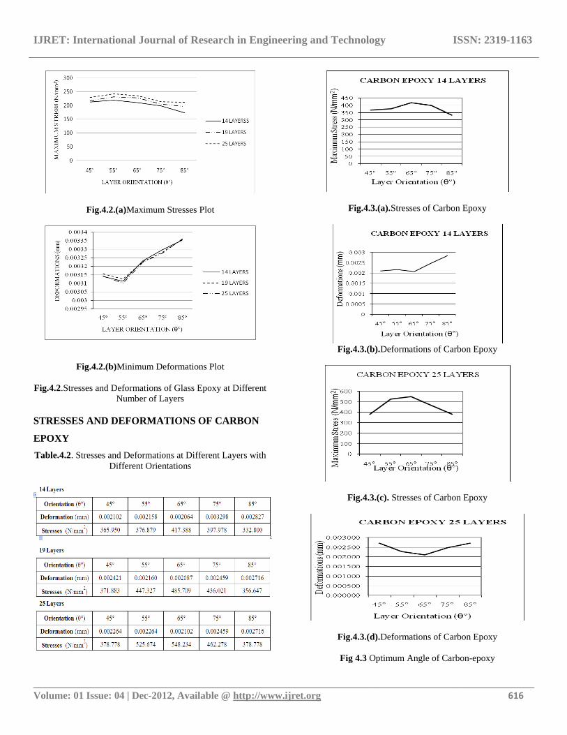
Fig.4.2.(a)Maximum Stresses Plot
Fig.4.2.(b)Minimum Deformations Plot
Fig.4.2.Stresses and Deformations of Glass Epoxy at Different
Number of Layers
STRESSES AND DEFORMATIONS OF CARBON
EPOXY
Table.4.2. Stresses and Deformations at Different Layers with
Different Orientations
Fig.4.3.(a).Stresses of Carbon Epoxy
Fig.4.3.(b).Deformations of Carbon Epoxy
Fig.4.3.(c). Stresses of Carbon Epoxy
Fig.4.3.(d).Deformations of Carbon Epoxy
Fig 4.3 Optimum Angle of Carbon-epoxy
IJRET: International Journal of Research in Engineering and Technology ISSN: 2319-1163
__________________________________________________________________________________________ Volume: 01 Issue: 04 | Dec-2012, Available @ http://www.ijret.org 617
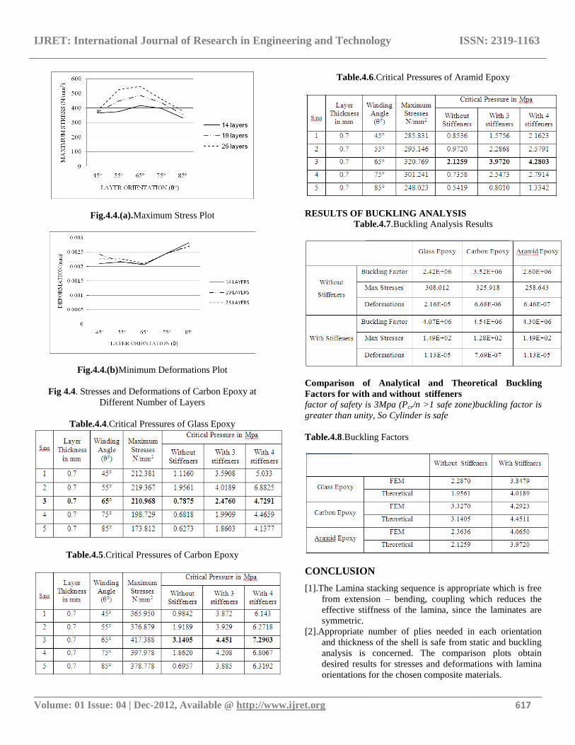
Fig.4.4.(a).Maximum Stress Plot
Fig.4.4.(b)Minimum Deformations Plot
Fig 4.4. Stresses and Deformations of Carbon Epoxy at
Different Number of Layers
Table.4.4.Critical Pressures of Glass Epoxy
Table.4.5.Critical Pressures of Carbon Epoxy
Table.4.6.Critical Pressures of Aramid Epoxy
RESULTS OF BUCKLING ANALYSIS
Table.4.7.Buckling Analysis Results
Comparison of Analytical and Theoretical Buckling
Factors for with and without stiffeners factor of safety is 3Mpa (Pcr/n >1 safe zone)buckling factor is
greater than unity, So Cylinder is safe
Table.4.8.Buckling Factors
CONCLUSION
[1].The Lamina stacking sequence is appropriate which is free
from extension – bending, coupling which reduces the
effective stiffness of the lamina, since the laminates are
symmetric.
[2].Appropriate number of plies needed in each orientation
and thickness of the shell is safe from static and buckling
analysis is concerned. The comparison plots obtain
desired results for stresses and deformations with lamina
orientations for the chosen composite materials.
IJRET: International Journal of Research in Engineering and Technology ISSN: 2319-1163
__________________________________________________________________________________________ Volume: 01 Issue: 04 | Dec-2012, Available @ http://www.ijret.org 618
[3]. The chosen fiber volume fraction Vf = 0.65 and Vm =
0.35 is acceptable to the present FRP shell working at 3
Mpa internal (Air) pressure.
[4].The fiber orientation ±55° for glass epoxy and ±65°angle
for carbon and aramid epoxy is correct which optimum
value is. From the finite element analysis report the
maximum stress obtained in each lamina (for ±55, ±65
degrees winding angle) is less than the allowable working
Strength of the FRP lamina. So shell design is safe.
[5].Numerical calculations, Tables and plots obtained for
critical pressures supports the comparisons of buckling
pressures.
[6].The factor of Safety 3 taken is sufficient for the fiber
reinforced Composite material to overcome material
design and manufacturing defects. The average critical
buckling pressure was obtained from finite element
analysis report is 4.0684N/mm2 which is more than the
maximum working pressure 3N/mm2. Hence the buckling
load factor is greater than the unity. Hence the design is
safe.
[7].Comparison of stiffened and unstiffened composite shell
by both theoretically and analytically, that Analyses
supports the stiffened cylinder has more buckling
resistance than that of the unstiffened one.
[8]. Increase in shell thickness is shown to increase the
buckling resistance of the composite shell. The objective
of the analysis and theoretical report shows that fiber
reinforced composite shell can minimize the weight of the
structure.
REFERENCES
[1] Alexis A. Krikanov., “Composite pressure vessels with
higher stiffeness” 1999 Elsevier science Ltd. Composite
structures, vol-48, pp 119-127 (2000).
[2] S.Adali, E.B. Summers & V.E. Verijenko.,
“Optimization of Laminated Cylindrical pressure
vessels under strength criterion”, Composite structures,
vol-25, pp 305-312 (1993), University of national
Durban 4001, South Africa.
[3] Tae-Uk Kim.,Hvo-Chol Sin., “Optimal design of
composite laminated plates with the discreteness in ply
angles and uncertain in material properties considered”,
Computers and Structures 79, pp 2501-2509, (2001).
[4] Levend Parnas., Nuran Katirei.,“Design of Fiber-
Reinforced Composite pressure vessels under various
loading conditions”, Composite structures 58, pp 83-95
(2002).
[5] Graham J., “preliminary Analysis Techniques for Ring
and Stringer Stiffened Cylindrical Shells,” NASA
report TM-108399, March 1993.
[6] Phillips J.L., Gurdal Z.,“Structural Analysis and
Optimum Design of Geodesically Stiffened Composite
Panels,” NASA Report CCMS-90-05, July 1990.
BIOGRAPHIES:
RAO YARRAPRAGADA K.S.S,
Associate Professor, Hod, Department Of
Mechanical Engineering, B.V.C College Of
Engineering, Rajahmundry,
Email:[email protected]
m Ph.No:7396659639
R.KRISHNA MOHAN, Associate
Professor, Department Of Mechanical
Engineering, B.V.C College Of
Engineering, Rajahmundry,
Email:[email protected]
Ph.No:9704338987
B.VIJAY KIRAN, Assistant Professor,
Department Of Mechanical Engineering,
B.V.C College Of Engineering,
Rajahmundry,
Email:[email protected],
Ph.No:8125887525