complex sequential systems - sabanci univ
TRANSCRIPT
1
VHDLComplex Sequential Systems
EL 310Erkay Savaş
Sabancı University
2
Partitioned Design• Any synchronous sequential system could be
described by an ASM chart.• It does not make much sense to design the
whole system using a single ASM chart. • What makes the design process manageable is
to partition the design in some way.• The most straightforward way to partition a
design is to split it in two:– datapath: consists of components that store and
manipulate data– control: can be designed as a state machine that
controls functioning of those datapath components.
3
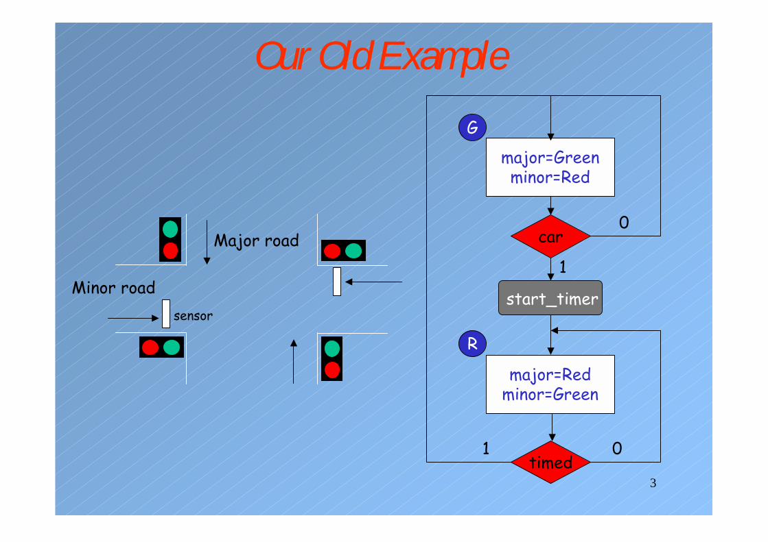
Our Old Example
major=Greenminor=Red
G
major=Redminor=Green
R
car
start_timer
timed
0
0
1
1
Major road
Minor roadsensor
4
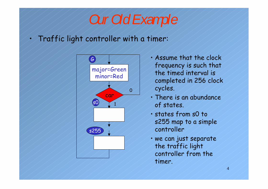
Our Old Example• Traffic light controller with a timer:
major=Greenminor=Red
G
car1s0
s255
0
• Assume that the clock frequency is such that the timed interval is completed in 256 clock cycles.
• There is an abundance of states.
• states from s0 to s255 map to a simple controller
• we can just separate the traffic light controller from the timer.
5
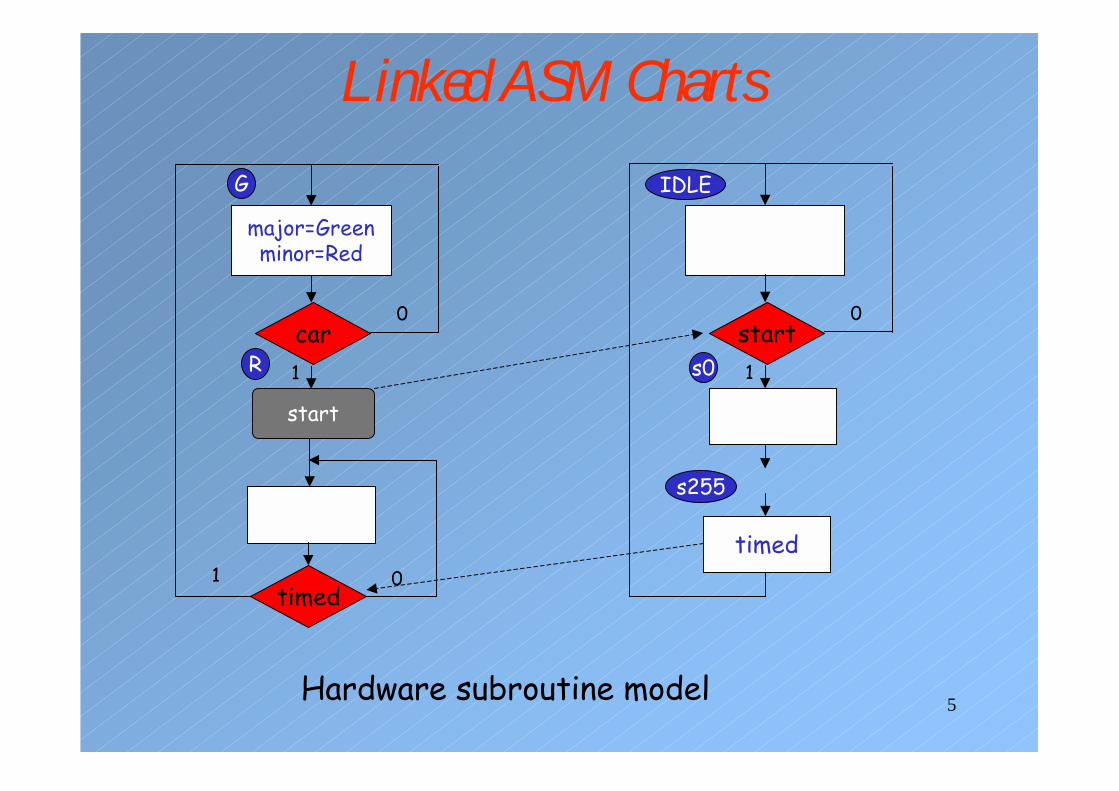
Linked ASM Charts
major=Greenminor=Red
G
car1R
0
timed1 0
start
IDLE
start1
timed
0
s0
s255
Hardware subroutine model

6
Alternative Linked ASM Chart
G
car1
enable
R
0
timed1 0
IDLE
enable1
timed
0
s0
s255
enable
timed
1
0
A conventional counter
7
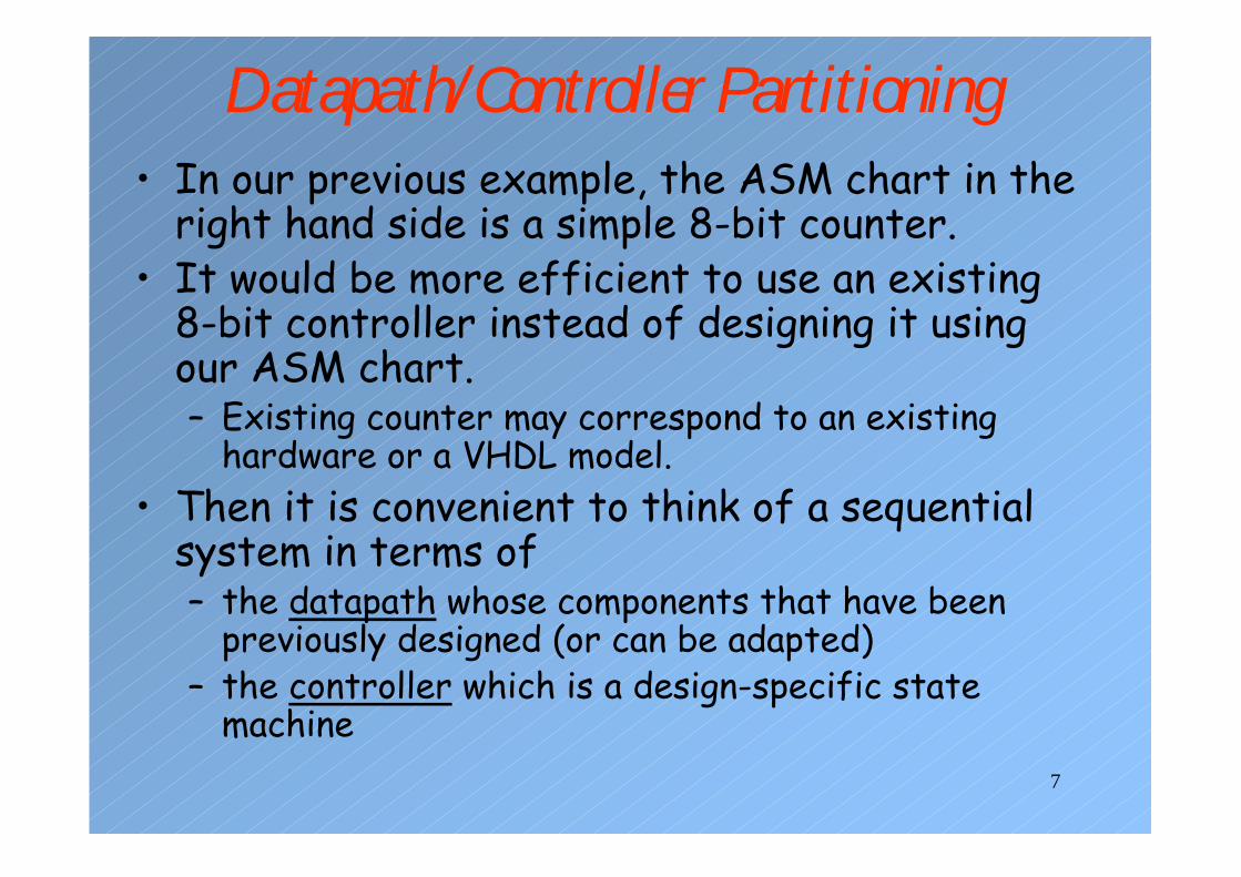
Datapath/Controller Partitioning• In our previous example, the ASM chart in the
right hand side is a simple 8-bit counter.• It would be more efficient to use an existing
8-bit controller instead of designing it using our ASM chart.– Existing counter may correspond to an existing
hardware or a VHDL model.• Then it is convenient to think of a sequential
system in terms of – the datapath whose components that have been
previously designed (or can be adapted)– the controller which is a design-specific state
machine
8
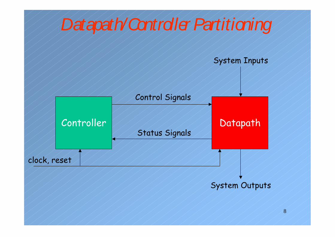
Datapath/Controller Partitioning
Controller Datapath
Control Signals
Status Signals
System Inputs
System Outputs
clock, reset
9
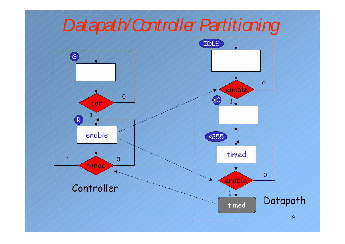
Datapath/Controller Partitioning
G
car1
enable
R
0
timed1 0
IDLE
enable1
timed
0
s0
s255
enable
timed
1
0
ControllerDatapath
10
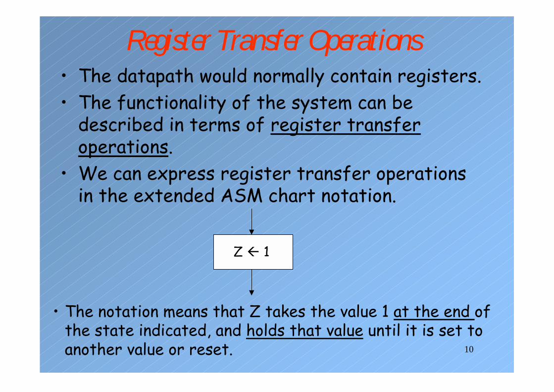
Register Transfer Operations• The datapath would normally contain registers.• The functionality of the system can be
described in terms of register transfer operations.
• We can express register transfer operations in the extended ASM chart notation.
Z � 1
• The notation means that Z takes the value 1 at the end of the state indicated, and holds that value until it is set toanother value or reset.

11
Extended ASM Chart Notation• If Z is reset to 0 and it is only set to 1 in the present
state, the registered output would be implemented as a flip-flop and a multiplexor.
Z � 1Z
1
ENABLEclock
1
0
Z
1clock
ENABLEENABLE
12
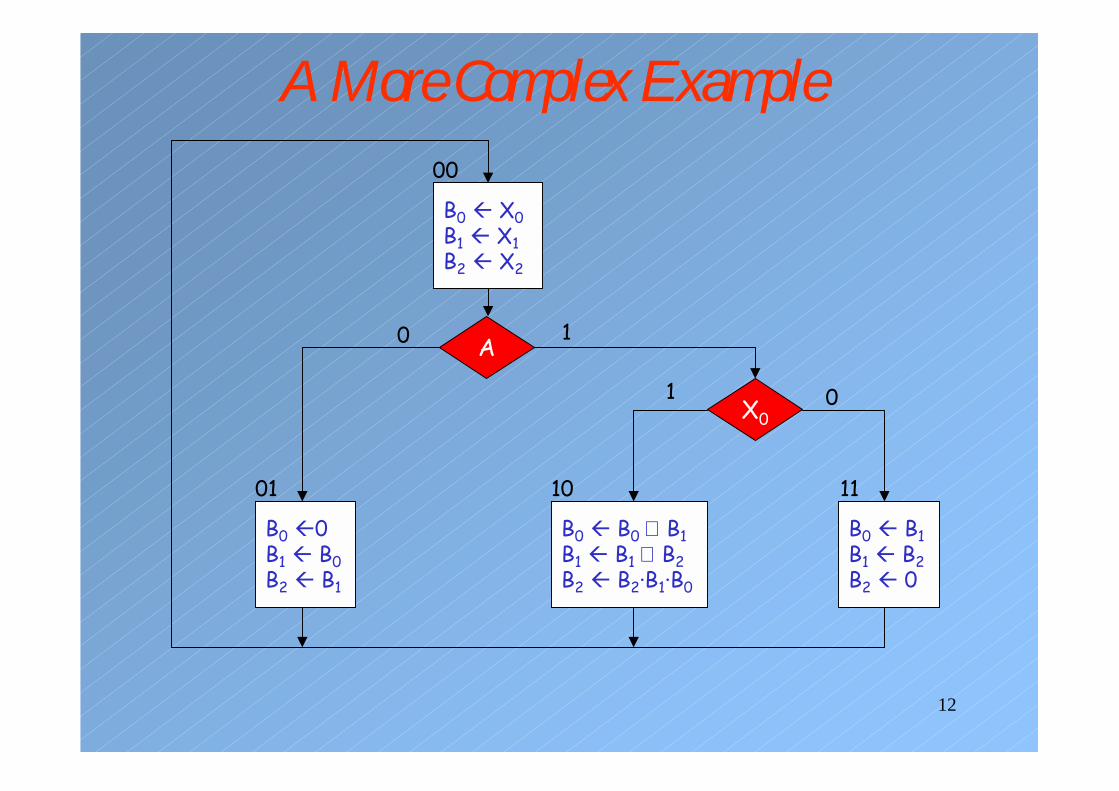
A More Complex Example
B0 � X0B1 � X1B2 � X2
A
B0 �0B1 � B0B2 � B1
B0 � B0 ⊕ B1B1 � B1 ⊕ B2B2 � B2·B1·B0
X0
B0 � B1B1 � B2B2 � 0
0 1
1 0
00
01 10 11
13
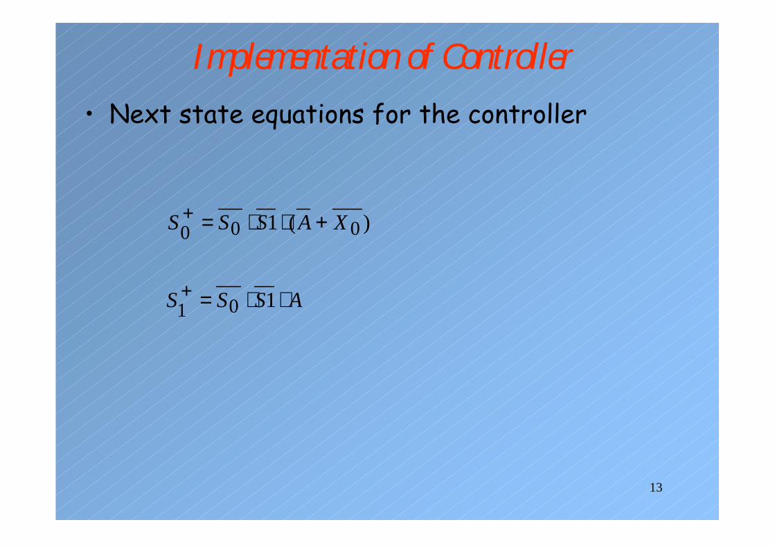
Implementation of Controller• Next state equations for the controller
)(1 000 XASSS +⋅⋅=+
ASSS ⋅⋅=+ 101
14
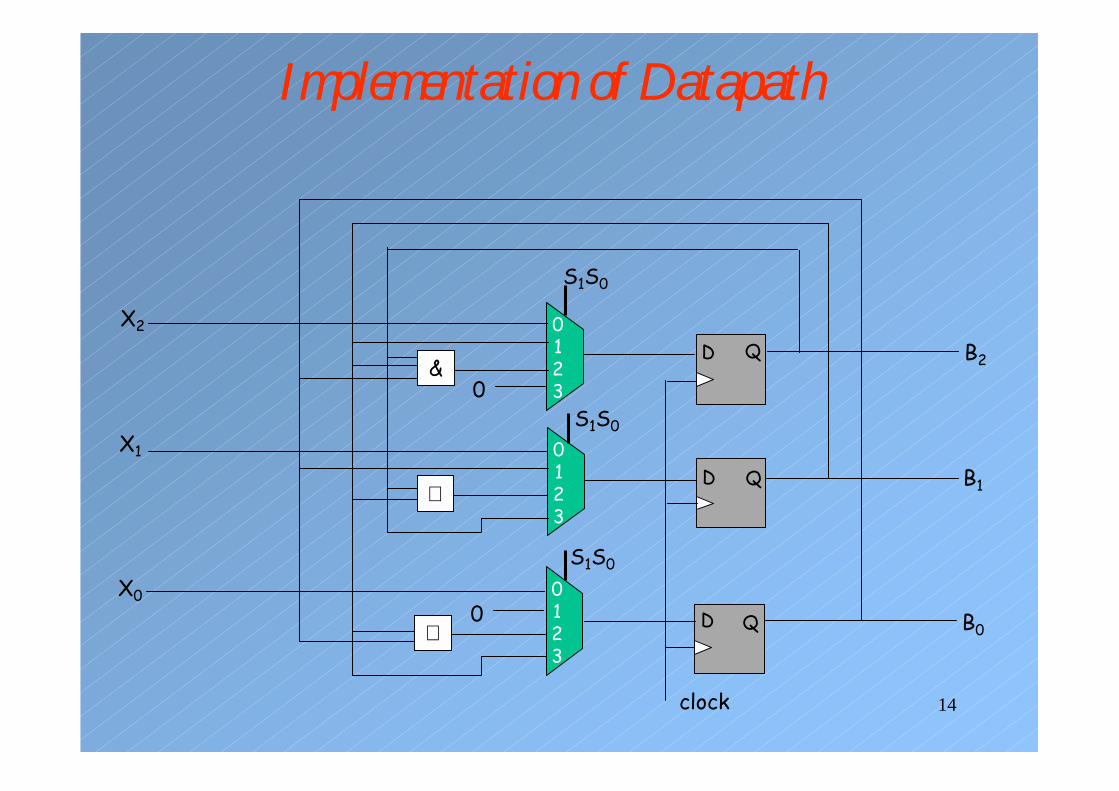
Implementation of Datapath
0123
0123
0123
S1S0
S1S0
S1S0
D
D
D
Q
Q
Q
B2
B1
B0
X2
X1
X0
&
⊕
⊕
0
0
clock
15
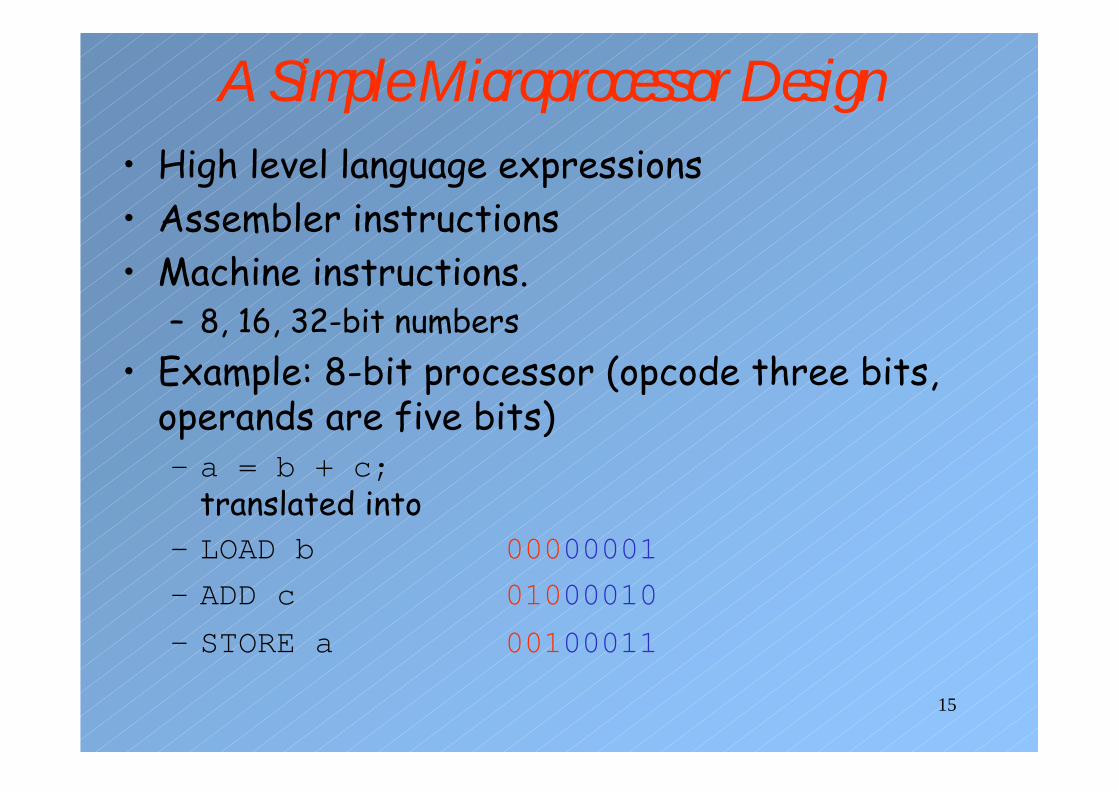
A Simple Microprocessor Design• High level language expressions• Assembler instructions• Machine instructions.
– 8, 16, 32-bit numbers• Example: 8-bit processor (opcode three bits,
operands are five bits)– a = b + c;
translated into– LOAD b 00000001
– ADD c 01000010
– STORE a 00100011

16
A Simple Microprocessor Design• Example
– opcodeLOAD 000ADD 010STORE 001
– addressesa 00001b 00010c 00011
• Datapath/controller partition• controller (a.k.a. sequencer) is a state machine.• Bits of the opcode are input to the controller
– the opcode may be decoded to generate a larger set of inputs to the controller (micro-coding approach)
17
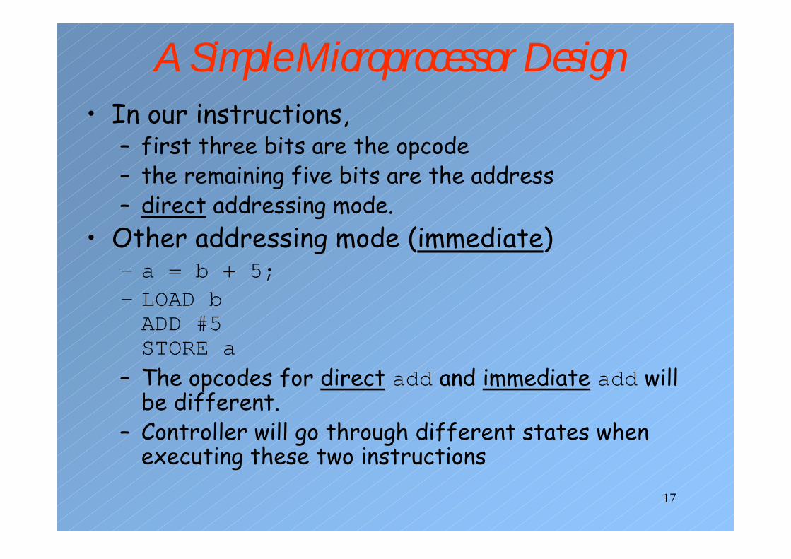
A Simple Microprocessor Design• In our instructions,
– first three bits are the opcode– the remaining five bits are the address– direct addressing mode.
• Other addressing mode (immediate)– a = b + 5;– LOAD bADD #5STORE a
– The opcodes for direct add and immediate add will be different.
– Controller will go through different states when executing these two instructions
18
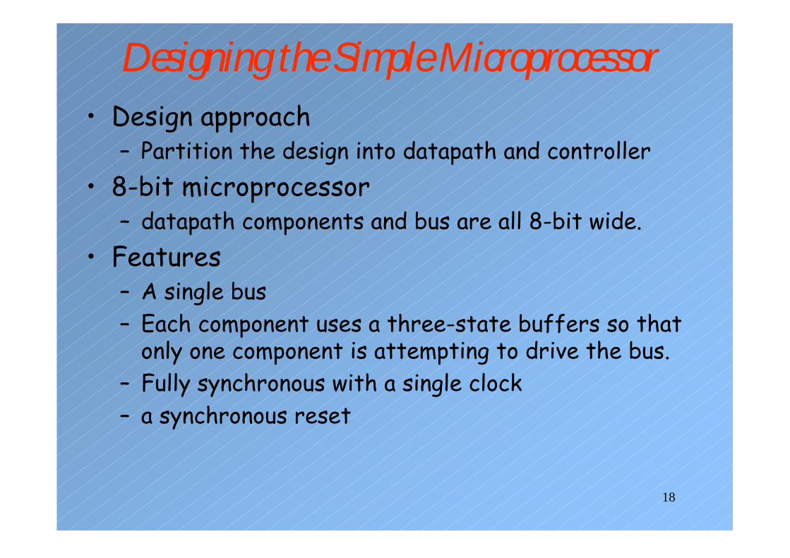
Designing the Simple Microprocessor• Design approach
– Partition the design into datapath and controller• 8-bit microprocessor
– datapath components and bus are all 8-bit wide.• Features
– A single bus– Each component uses a three-state buffers so that
only one component is attempting to drive the bus.– Fully synchronous with a single clock– a synchronous reset
19
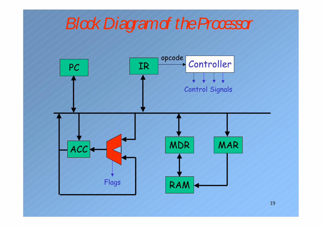
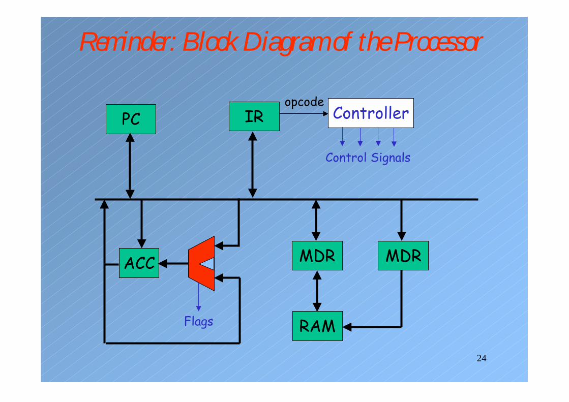
Block Diagram of the Processor
Control Signals
IRPC
ACC
Flags RAM
MDR MAR
Controlleropcode
20
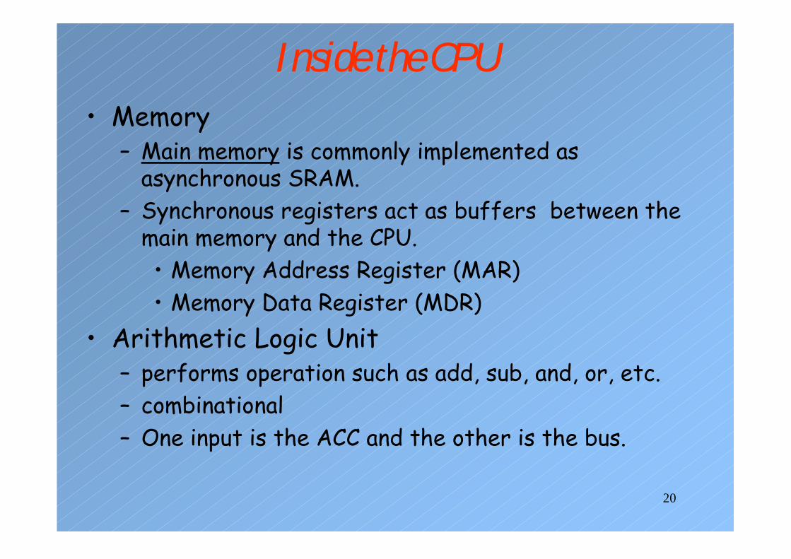
Inside the CPU• Memory
– Main memory is commonly implemented as asynchronous SRAM.
– Synchronous registers act as buffers between the main memory and the CPU.• Memory Address Register (MAR) • Memory Data Register (MDR)
• Arithmetic Logic Unit– performs operation such as add, sub, and, or, etc.– combinational– One input is the ACC and the other is the bus.
21
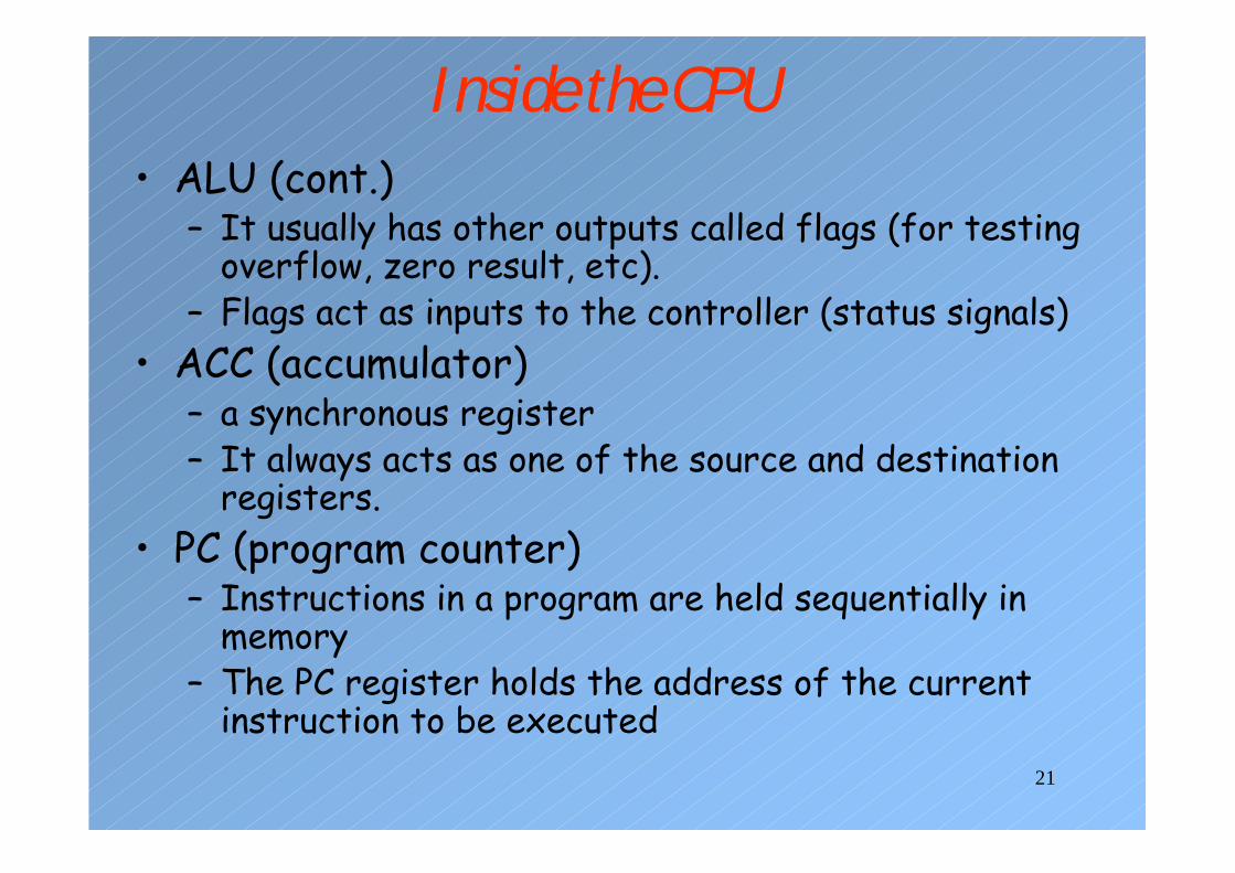
Inside the CPU• ALU (cont.)
– It usually has other outputs called flags (for testing overflow, zero result, etc).
– Flags act as inputs to the controller (status signals)• ACC (accumulator)
– a synchronous register– It always acts as one of the source and destination
registers.• PC (program counter)
– Instructions in a program are held sequentially in memory
– The PC register holds the address of the current instruction to be executed
22
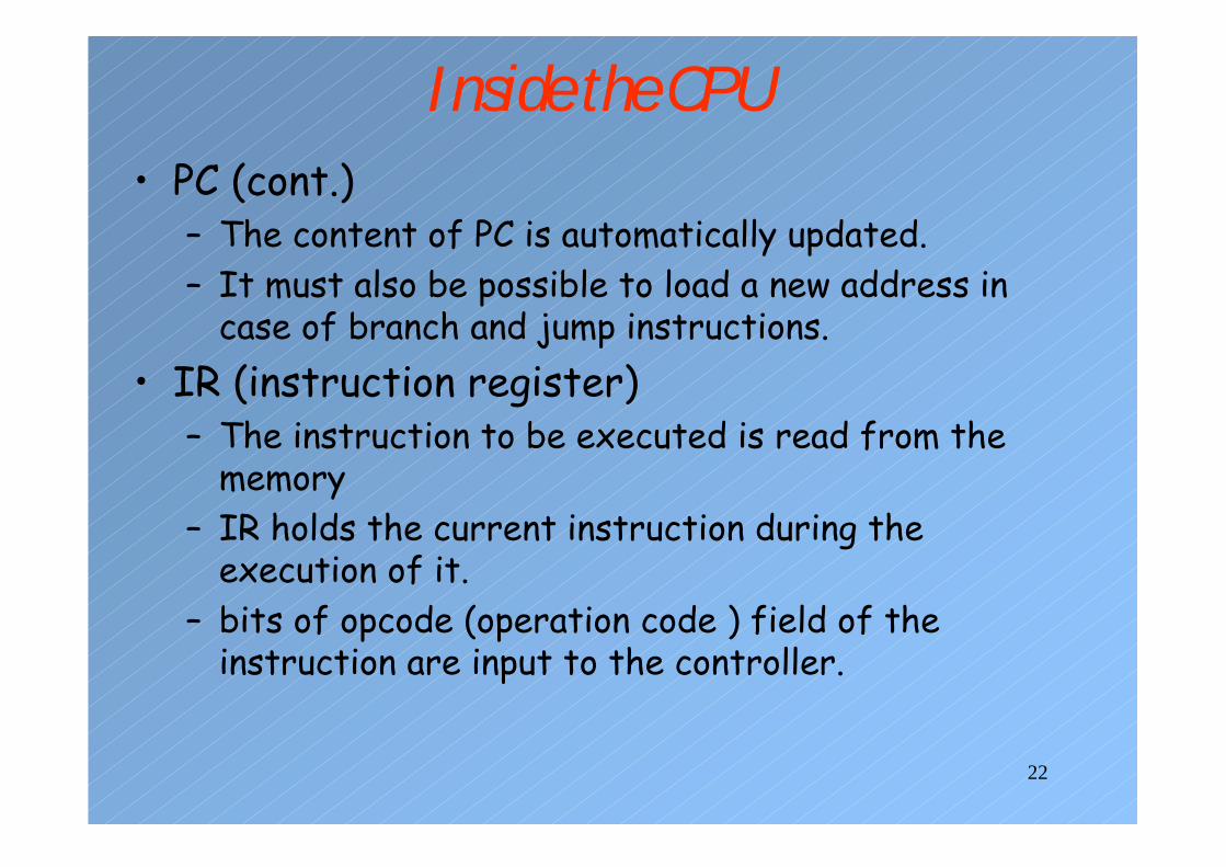
Inside the CPU• PC (cont.)
– The content of PC is automatically updated.– It must also be possible to load a new address in
case of branch and jump instructions.• IR (instruction register)
– The instruction to be executed is read from the memory
– IR holds the current instruction during the execution of it.
– bits of opcode (operation code ) field of the instruction are input to the controller.
23
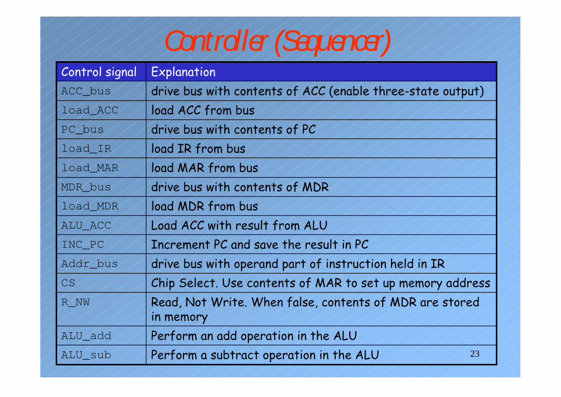
Controller (Sequencer)
Perform a subtract operation in the ALUALU_sub
Perform an add operation in the ALUALU_add
Read, Not Write. When false, contents of MDR are stored in memory
R_NW
Chip Select. Use contents of MAR to set up memory addressCS
drive bus with operand part of instruction held in IRAddr_bus
Increment PC and save the result in PCINC_PC
Load ACC with result from ALUALU_ACC
load MDR from busload_MDR
drive bus with contents of MDRMDR_bus
load MAR from busload_MAR
load IR from busload_IR
drive bus with contents of PCPC_bus
load ACC from busload_ACC
drive bus with contents of ACC (enable three-state output)ACC_bus
ExplanationControl signal
24
Reminder: Block Diagram of the Processor
PC IR Controller
Control Signals
ACC
Flags RAM
MDR MDR
opcode
25
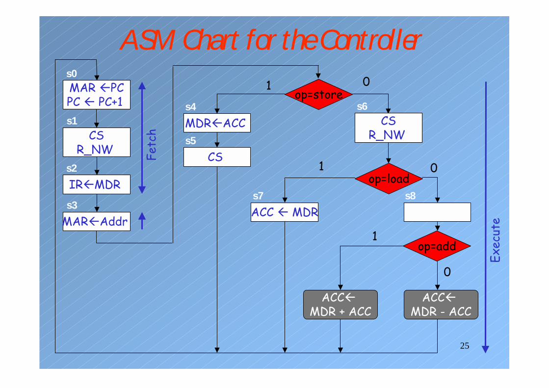
ASM Chart for the Controller MAR �PCPC � PC+1
s0
CSR_NW
s1
IR�MDRs2
op=store
MAR�Addrs3
CS s5
op=load
op=add
Fetc
h
MDR�ACCs4
1
ACC � MDRs7
1
ACC�MDR + ACC
1
CSR_NW
s6
0
s8
0
ACC�MDR - ACC
0
Exec
ute
26
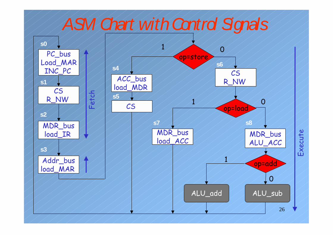
ASM Chart with Control SignalsPC_bus
Load_MARINC_PC
s0
CSR_NW
s1
MDR_busload_IR
s2
op=store
Addr_busload_MAR
s3
CS s5
op=load
op=add
Fetc
hACC_bus
load_MDR
s4
1
MDR_busload_ACC
s7
1
ALU_add
1
CSR_NW
s6
0
ALU_sub
0
Exec
uteMDR_bus
ALU_ACC
0
s8
27
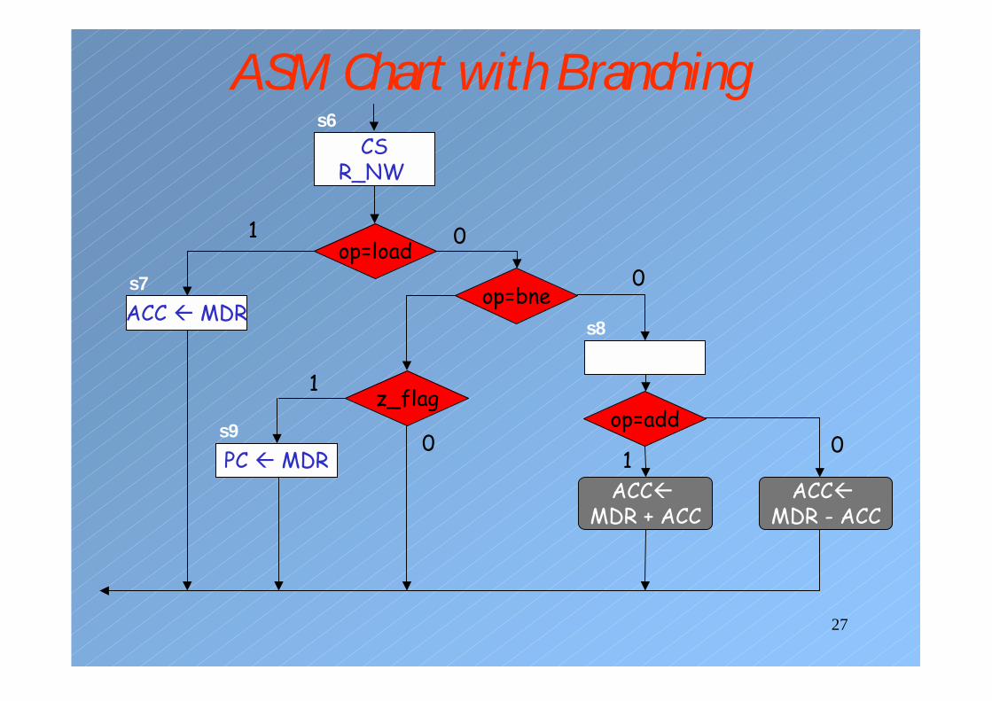
ASM Chart with Branching
op=load
op=add
ACC�MDR + ACC
1
CSR_NW
s6
s8
0
ACC�MDR - ACC
0
ACC � MDRs7
1
op=bne
0
z_flag
PC � MDRs9
1
0

28
Reminder: Block Diagram of the Processor
PC IR Controller
Control Signals
ACC
Flags RAM
MDR MDR
opcode
29
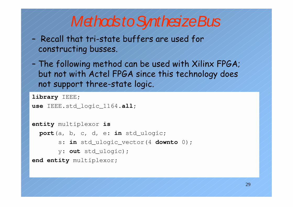
Methods to Synthesize Bus
library IEEE;
use IEEE.std_logic_1164.all;
entity multiplexor is
port(a, b, c, d, e: in std_ulogic;
s: in std_ulogic_vector(4 downto 0);
y: out std_ulogic);
end entity multiplexor;
– Recall that tri-state buffers are used for constructing busses.
– The following method can be used with Xilinx FPGA; but not with Actel FPGA since this technology does not support three-state logic.

30
Methods to Synthesize Busarchitecture version1 of multiplexor is
beginp0: process(s, a, b, c, d, e) isbegin
case s iswhen "00001" => y <= a;when "00010" => y <= b;when "00100" => y <= c;when "01000" => y <= d;when others => y <= e;
end case;end process p0;
end architecture version1;
architecture version2 of multiplexor isbegin
y <= a when s(0) = '1' else 'Z';y <= b when s(1) = '1' else 'Z';y <= c when s(2) = '1' else 'Z';y <= d when s(3) = '1' else 'Z';y <= e when s(4) = '1' else 'Z';
end architecture version2;
31
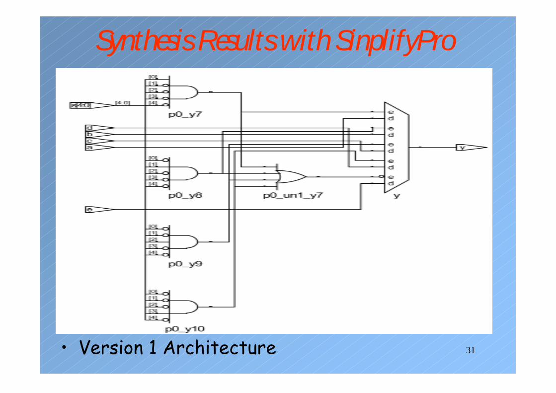
Synthesis Results with SinplifyPro
• Version 1 Architecture
32
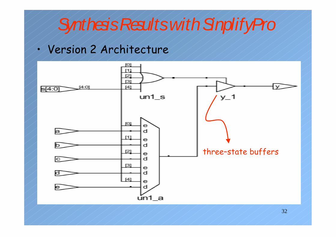
Synthesis Results with SinplifyPro• Version 2 Architecture
three–state buffers
33
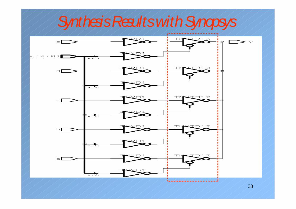
Synthesis Results with Synopsys
34
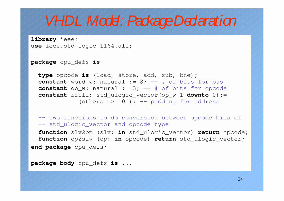
VHDL Model: Package Declarationlibrary ieee;use ieee.std_logic_1164.all;
package cpu_defs is
type opcode is (load, store, add, sub, bne);constant word_w: natural := 8; -- # of bits for busconstant op_w: natural := 3; -- # of bits for opcodeconstant rfill: std_ulogic_vector(op_w-1 downto 0):=
(others => ‘0’); -- padding for address
-- two functions to do conversion between opcode bits of-- std_ulogic_vector and opcode type
function slv2op (slv: in std_ulogic_vector) return opcode;function op2slv (op: in opcode) return std_ulogic_vector;
end package cpu_defs;
package body cpu_defs is ...
35
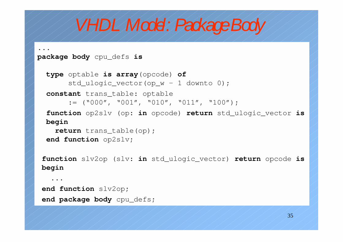
VHDL Model: Package Body...package body cpu_defs is
type optable is array(opcode) ofstd_ulogic_vector(op_w – 1 downto 0);
constant trans_table: optable:= (“000”, “001”, “010”, “011”, “100”);
function op2slv (op: in opcode) return std_ulogic_vector isbeginreturn trans_table(op);
end function op2slv;
function slv2op (slv: in std_ulogic_vector) return opcode isbegin
...
end function slv2op;
end package body cpu_defs;
36
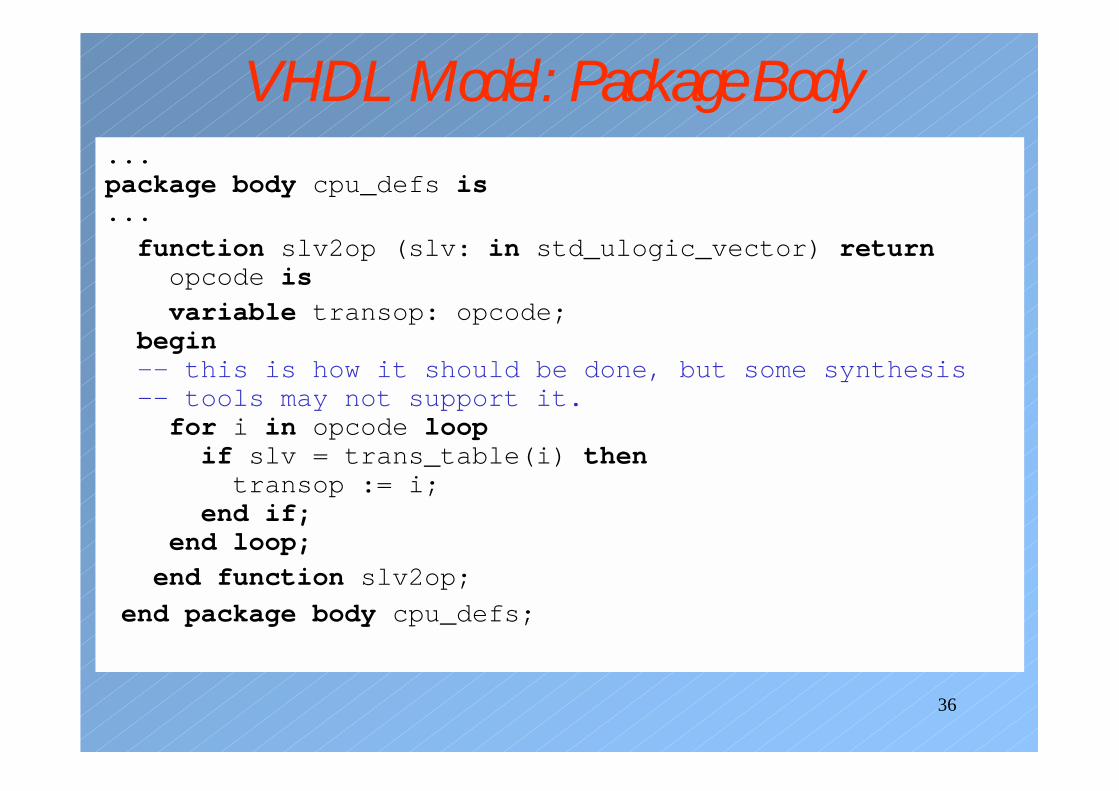
VHDL Model: Package Body...package body cpu_defs is...function slv2op (slv: in std_ulogic_vector) returnopcode is
variable transop: opcode;begin-- this is how it should be done, but some synthesis-- tools may not support it.for i in opcode loopif slv = trans_table(i) thentransop := i;
end if;end loop;
end function slv2op;
end package body cpu_defs;
37
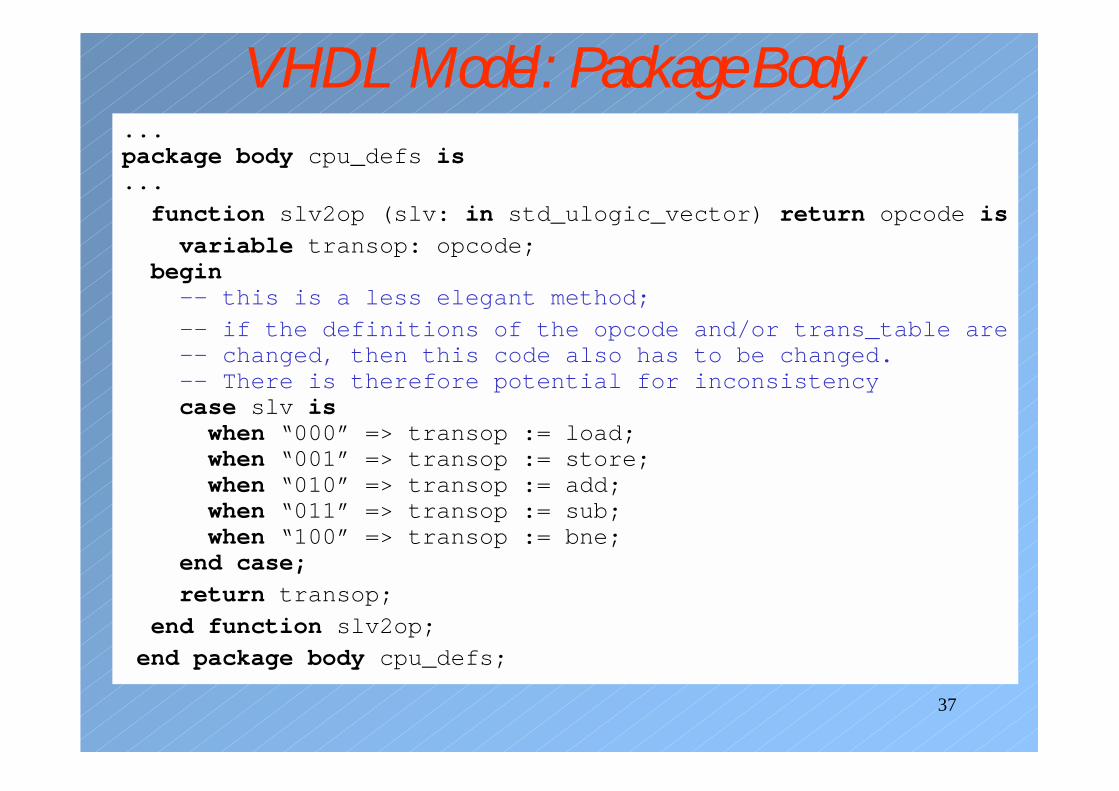
VHDL Model: Package Body...package body cpu_defs is...
function slv2op (slv: in std_ulogic_vector) return opcode is
variable transop: opcode;begin-- this is a less elegant method;
-- if the definitions of the opcode and/or trans_table are-- changed, then this code also has to be changed.-- There is therefore potential for inconsistencycase slv iswhen “000” => transop := load;when “001” => transop := store;when “010” => transop := add;when “011” => transop := sub;when “100” => transop := bne;
end case;
return transop;
end function slv2op;
end package body cpu_defs;
38
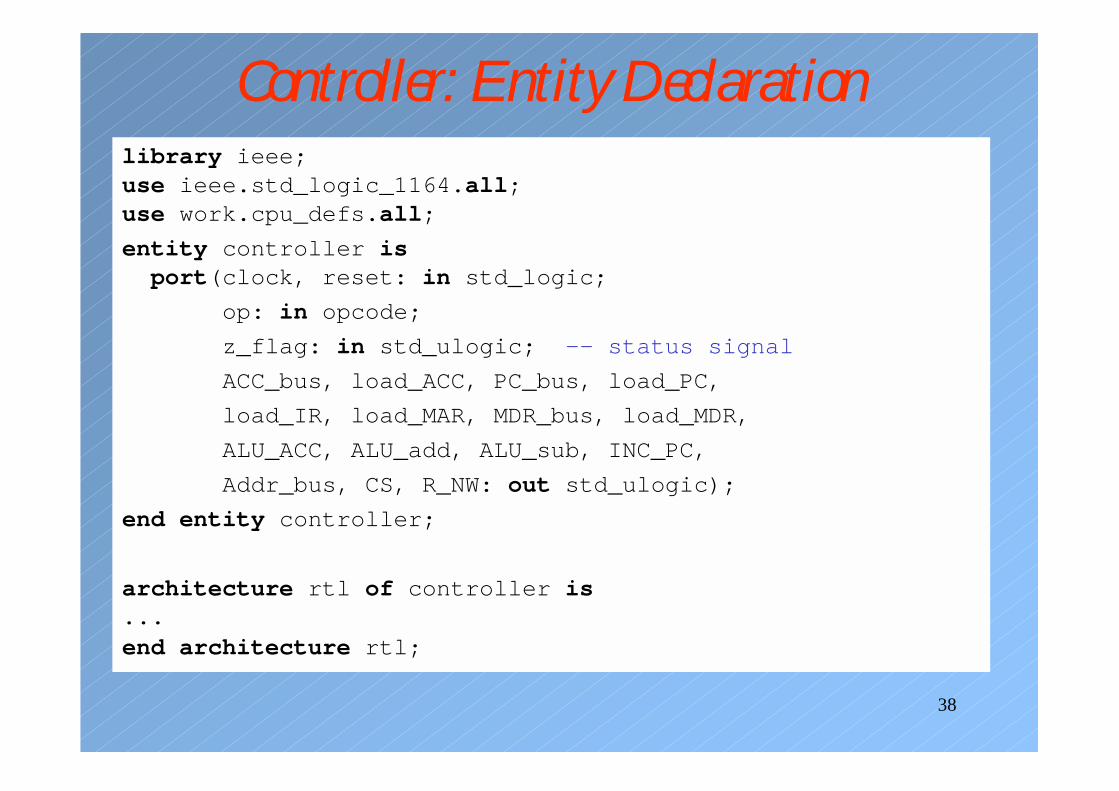
Controller: Entity Declarationlibrary ieee;use ieee.std_logic_1164.all;use work.cpu_defs.all;
entity controller isport(clock, reset: in std_logic;
op: in opcode;
z_flag: in std_ulogic; -- status signal
ACC_bus, load_ACC, PC_bus, load_PC,
load_IR, load_MAR, MDR_bus, load_MDR,
ALU_ACC, ALU_add, ALU_sub, INC_PC,
Addr_bus, CS, R_NW: out std_ulogic);
end entity controller;
architecture rtl of controller is...end architecture rtl;
39
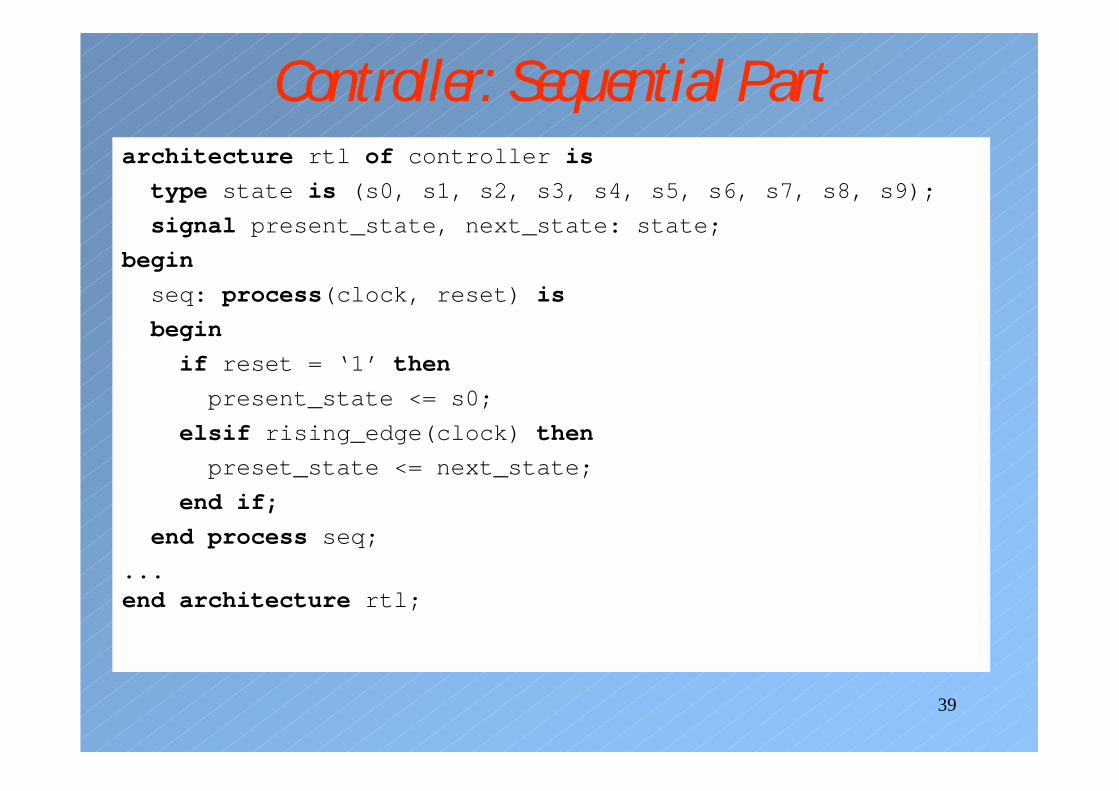
Controller: Sequential Partarchitecture rtl of controller is
type state is (s0, s1, s2, s3, s4, s5, s6, s7, s8, s9);
signal present_state, next_state: state;
begin
seq: process(clock, reset) is
begin
if reset = ‘1’ then
present_state <= s0;
elsif rising_edge(clock) then
preset_state <= next_state;
end if;
end process seq;
...end architecture rtl;
40
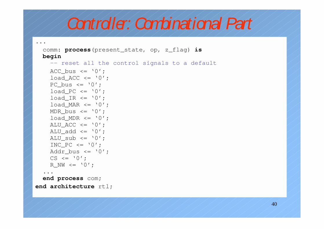
Controller: Combinational Part...
comm: process(present_state, op, z_flag) isbegin
-- reset all the control signals to a default
ACC_bus <= ‘0’;load_ACC <= ‘0’;PC_bus <= ‘0’;load_PC <= ‘0’;load_IR <= ‘0’;load_MAR <= ‘0’;MDR_bus <= ‘0’;load_MDR <= ‘0’;ALU_ACC <= ‘0’;ALU_add <= ‘0’;ALU_sub <= ‘0’;INC_PC <= ‘0’;Addr_bus <= ‘0’;CS <= ‘0’;R_NW <= ‘0’;
...end process com;
end architecture rtl;
41
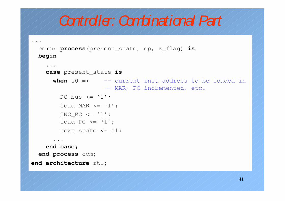
Controller: Combinational Part...
comm: process(present_state, op, z_flag) isbegin
...case present_state is
when s0 => -- current inst address to be loaded in-- MAR, PC incremented, etc.
PC_bus <= ‘1’;
load_MAR <= ‘1’;
INC_PC <= ‘1’;load_PC <= ‘1’;
next_state <= s1;
...end case;
end process com;
end architecture rtl;
42
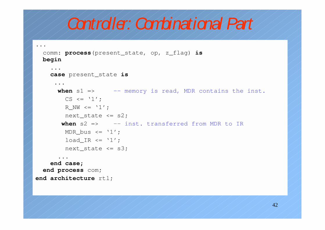
Controller: Combinational Part...
comm: process(present_state, op, z_flag) isbegin
...case present_state is
...
when s1 => -- memory is read, MDR contains the inst.
CS <= ‘1’;
R_NW <= ‘1’;
next_state <= s2;
when s2 => -- inst. transferred from MDR to IR
MDR_bus <= ‘1’;
load_IR <= ‘1’;
next_state <= s3;
...end case;
end process com;
end architecture rtl;
43
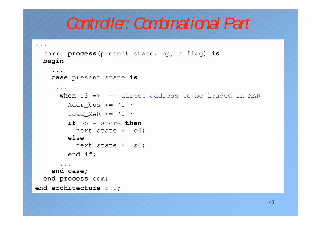
Controller: Combinational Part...
comm: process(present_state, op, z_flag) isbegin
...case present_state is
...
when s3 => -- direct address to be loaded in MAR
Addr_bus <= ‘1’;
load_MAR <= ‘1’;
if op = store thennext_state <= s4;
elsenext_state <= s6;
end if;
...end case;
end process com;
end architecture rtl;
44
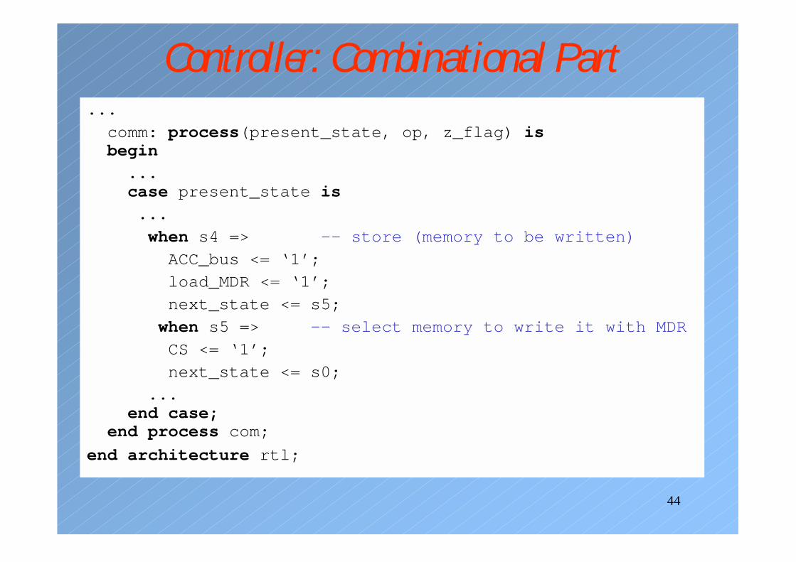
Controller: Combinational Part...
comm: process(present_state, op, z_flag) isbegin
...case present_state is
...
when s4 => -- store (memory to be written)
ACC_bus <= ‘1’;
load_MDR <= ‘1’;
next_state <= s5;
when s5 => -- select memory to write it with MDR
CS <= ‘1’;
next_state <= s0;
...end case;
end process com;
end architecture rtl;
45
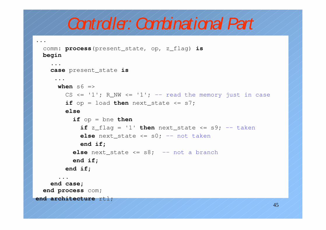
Controller: Combinational Part...
comm: process(present_state, op, z_flag) isbegin
...case present_state is
...
when s6 =>
CS <= '1'; R_NW <= '1'; -- read the memory just in case
if op = load then next_state <= s7;
else
if op = bne then
if z_flag = '1' then next_state <= s9; -- taken
else next_state <= s0; -- not taken
end if;
else next_state <= s8; -- not a branch
end if;
end if;
...end case;
end process com;
end architecture rtl;
46
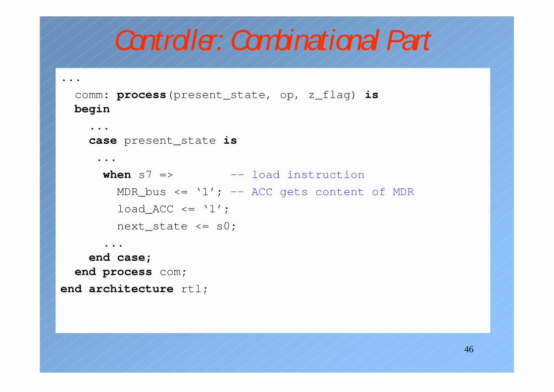
Controller: Combinational Part...
comm: process(present_state, op, z_flag) isbegin
...case present_state is
...
when s7 => -- load instruction
MDR_bus <= ‘1’; -- ACC gets content of MDR
load_ACC <= ‘1’;
next_state <= s0;
...end case;
end process com;
end architecture rtl;
47
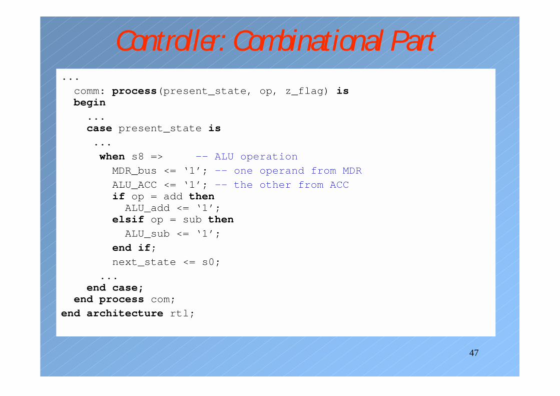
Controller: Combinational Part...
comm: process(present_state, op, z_flag) isbegin
...case present_state is
...
when s8 => -- ALU operation
MDR_bus <= ‘1’; -- one operand from MDR
ALU_ACC <= ‘1’; -- the other from ACCif op = add then
ALU_add <= ‘1’;elsif op = sub then
ALU_sub <= ‘1’;
end if;
next_state <= s0;
...end case;
end process com;
end architecture rtl;
48
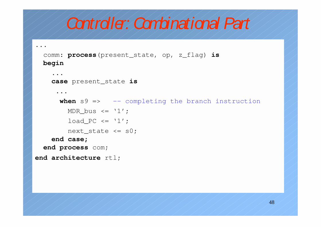
Controller: Combinational Part...
comm: process(present_state, op, z_flag) isbegin
...case present_state is
...
when s9 => -- completing the branch instruction
MDR_bus <= ‘1’;
load_PC <= ‘1’;
next_state <= s0;end case;
end process com;
end architecture rtl;
49
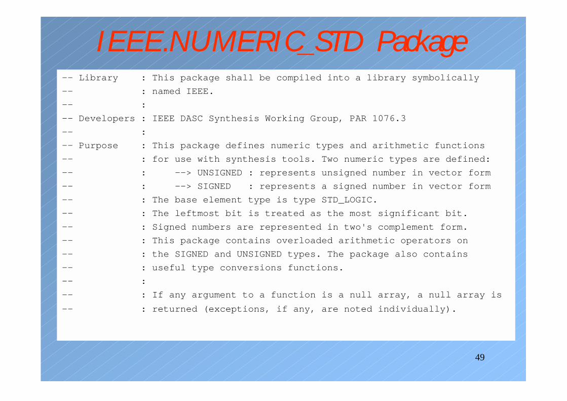
IEEE.NUMERIC_STD Package-- Library : This package shall be compiled into a library symbolically
-- : named IEEE.
-- :
-- Developers : IEEE DASC Synthesis Working Group, PAR 1076.3
-- :
-- Purpose : This package defines numeric types and arithmetic functions
-- : for use with synthesis tools. Two numeric types are defined:
-- : --> UNSIGNED : represents unsigned number in vector form
-- : --> SIGNED : represents a signed number in vector form
-- : The base element type is type STD_LOGIC.
-- : The leftmost bit is treated as the most significant bit.
-- : Signed numbers are represented in two's complement form.
-- : This package contains overloaded arithmetic operators on
-- : the SIGNED and UNSIGNED types. The package also contains
-- : useful type conversions functions.
-- :
-- : If any argument to a function is a null array, a null array is
-- : returned (exceptions, if any, are noted individually).
50
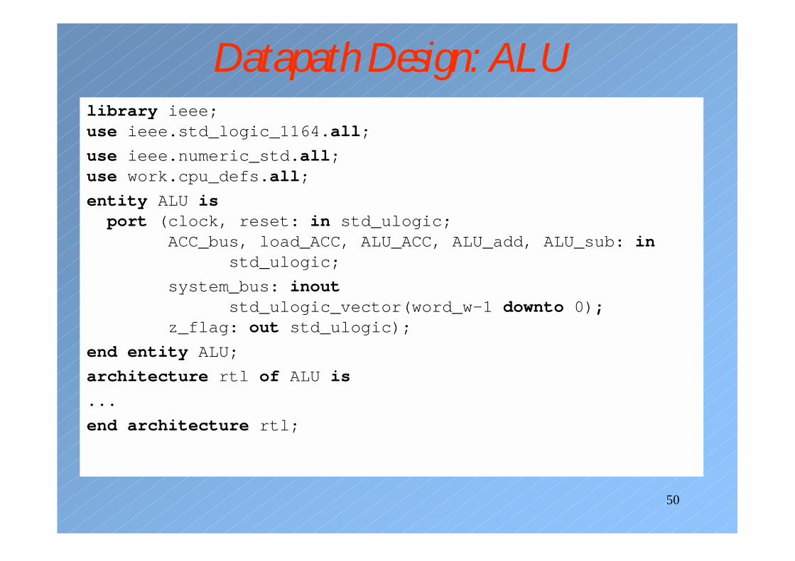
Datapath Design: ALUlibrary ieee;use ieee.std_logic_1164.all;
use ieee.numeric_std.all;use work.cpu_defs.all;
entity ALU isport (clock, reset: in std_ulogic;
ACC_bus, load_ACC, ALU_ACC, ALU_add, ALU_sub: instd_ulogic;
system_bus: inoutstd_ulogic_vector(word_w-1 downto 0);
z_flag: out std_ulogic);
end entity ALU;
architecture rtl of ALU is
...
end architecture rtl;
51
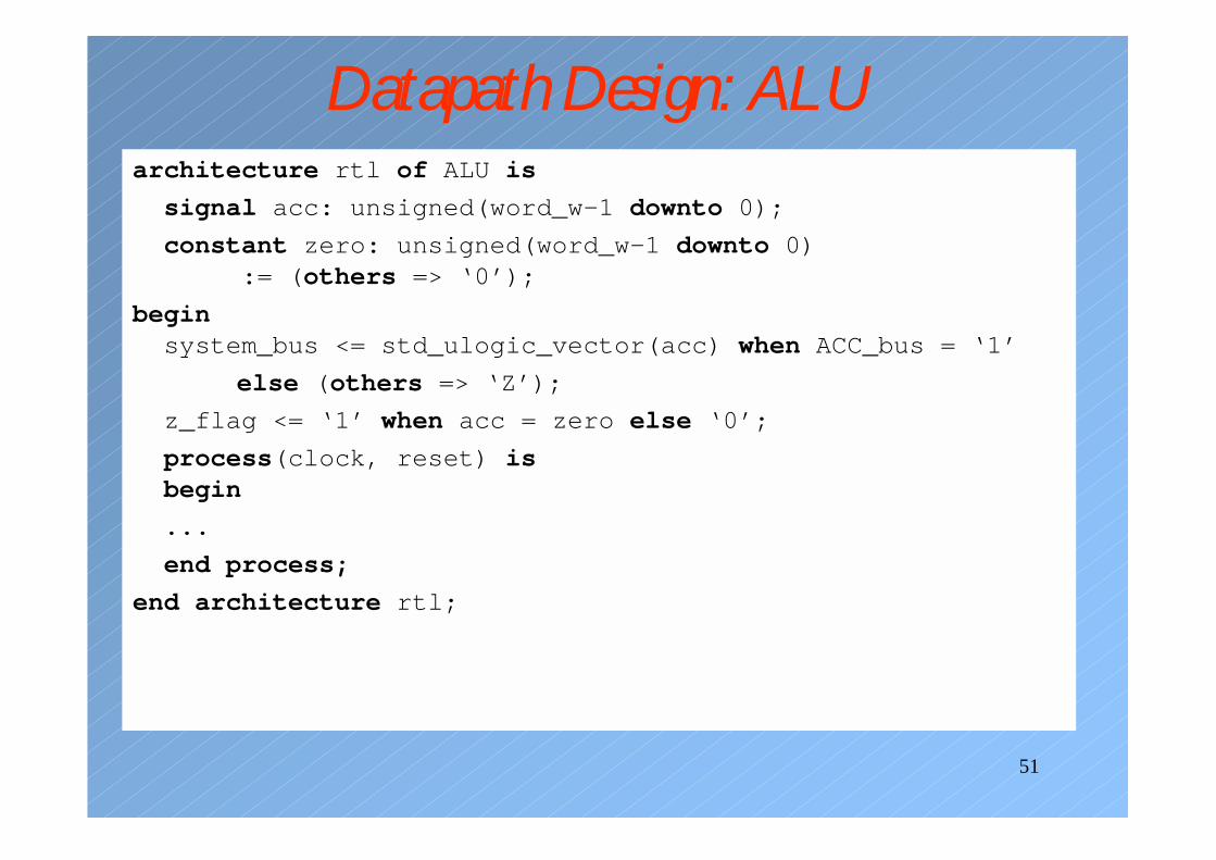
Datapath Design: ALUarchitecture rtl of ALU is
signal acc: unsigned(word_w-1 downto 0);
constant zero: unsigned(word_w-1 downto 0):= (others => ‘0’);
beginsystem_bus <= std_ulogic_vector(acc) when ACC_bus = ‘1’
else (others => ‘Z’);
z_flag <= ‘1’ when acc = zero else ‘0’;
process(clock, reset) isbegin
...
end process;
end architecture rtl;
52
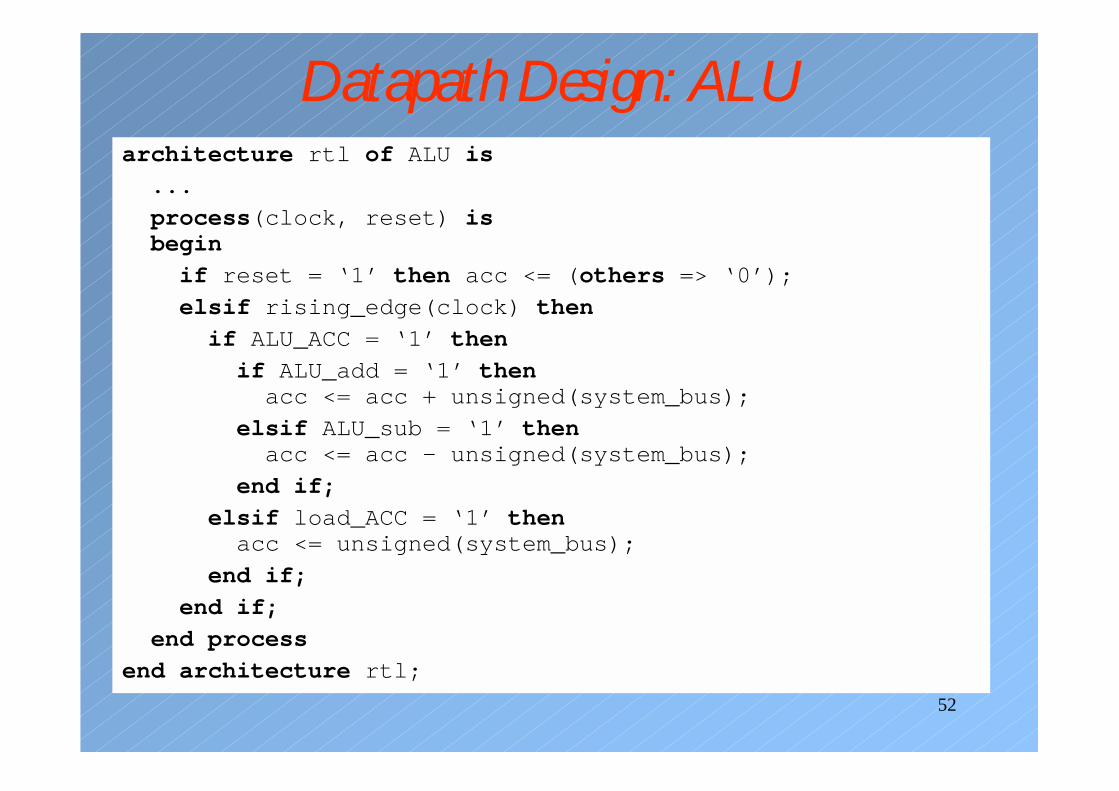
Datapath Design: ALUarchitecture rtl of ALU is
...
process(clock, reset) isbegin
if reset = ‘1’ then acc <= (others => ‘0’);
elsif rising_edge(clock) then
if ALU_ACC = ‘1’ then
if ALU_add = ‘1’ thenacc <= acc + unsigned(system_bus);
elsif ALU_sub = ‘1’ thenacc <= acc - unsigned(system_bus);
end if;
elsif load_ACC = ‘1’ thenacc <= unsigned(system_bus);
end if;
end if;
end process
end architecture rtl;
53
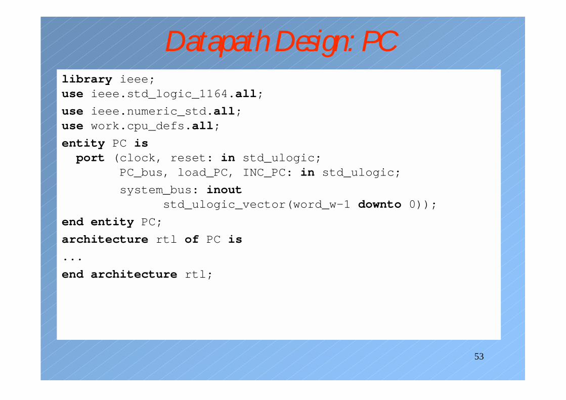
Datapath Design: PClibrary ieee;use ieee.std_logic_1164.all;
use ieee.numeric_std.all;use work.cpu_defs.all;
entity PC isport (clock, reset: in std_ulogic;
PC_bus, load_PC, INC_PC: in std_ulogic;
system_bus: inoutstd_ulogic_vector(word_w-1 downto 0));
end entity PC;
architecture rtl of PC is
...
end architecture rtl;
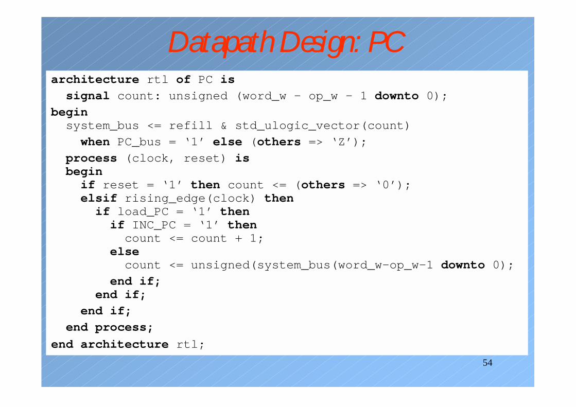
54
Datapath Design: PCarchitecture rtl of PC is
signal count: unsigned (word_w – op_w – 1 downto 0);
beginsystem_bus <= refill & std_ulogic_vector(count)
when PC_bus = ‘1’ else (others => ‘Z’);
process (clock, reset) isbeginif reset = ‘1’ then count <= (others => ‘0’);elsif rising_edge(clock) thenif load_PC = ‘1’ thenif INC_PC = ‘1’ thencount <= count + 1;
elsecount <= unsigned(system_bus(word_w-op_w-1 downto 0);
end if;end if;
end if;
end process;
end architecture rtl;
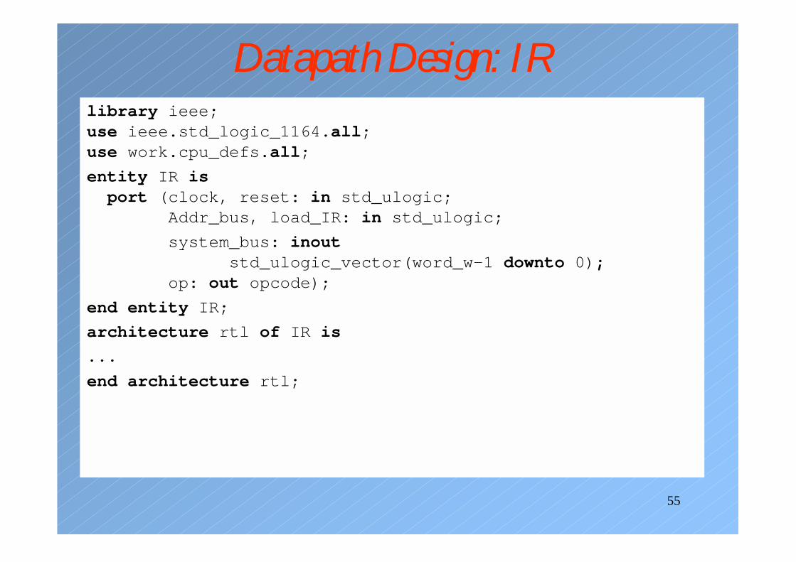
55
Datapath Design: IRlibrary ieee;use ieee.std_logic_1164.all;use work.cpu_defs.all;
entity IR isport (clock, reset: in std_ulogic;
Addr_bus, load_IR: in std_ulogic;
system_bus: inoutstd_ulogic_vector(word_w-1 downto 0);
op: out opcode);
end entity IR;
architecture rtl of IR is
...
end architecture rtl;
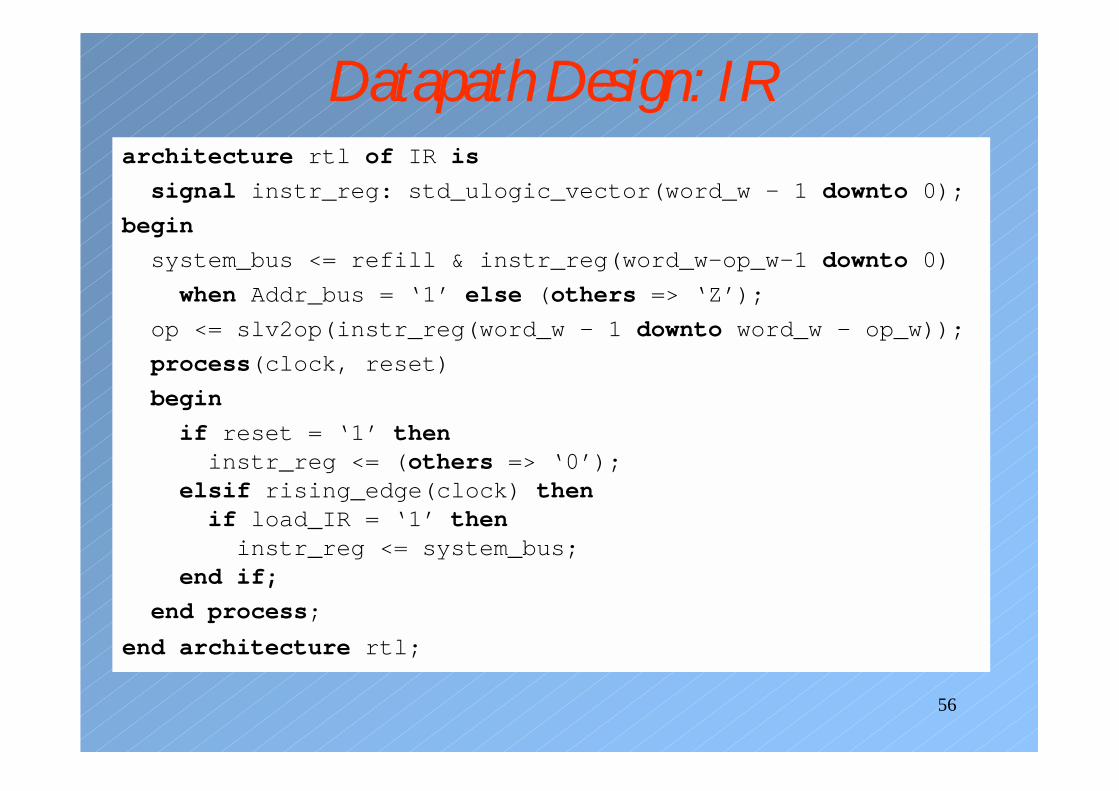
56
Datapath Design: IRarchitecture rtl of IR is
signal instr_reg: std_ulogic_vector(word_w – 1 downto 0);
begin
system_bus <= refill & instr_reg(word_w-op_w-1 downto 0)
when Addr_bus = ‘1’ else (others => ‘Z’);
op <= slv2op(instr_reg(word_w – 1 downto word_w – op_w));
process(clock, reset)
begin
if reset = ‘1’ theninstr_reg <= (others => ‘0’);
elsif rising_edge(clock) thenif load_IR = ‘1’ theninstr_reg <= system_bus;
end if;
end process;
end architecture rtl;
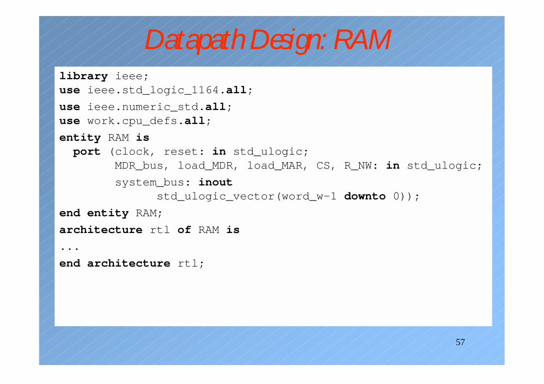
57
Datapath Design: RAMlibrary ieee;use ieee.std_logic_1164.all;
use ieee.numeric_std.all;use work.cpu_defs.all;
entity RAM isport (clock, reset: in std_ulogic;
MDR_bus, load_MDR, load_MAR, CS, R_NW: in std_ulogic;
system_bus: inoutstd_ulogic_vector(word_w-1 downto 0));
end entity RAM;
architecture rtl of RAM is
...
end architecture rtl;
58
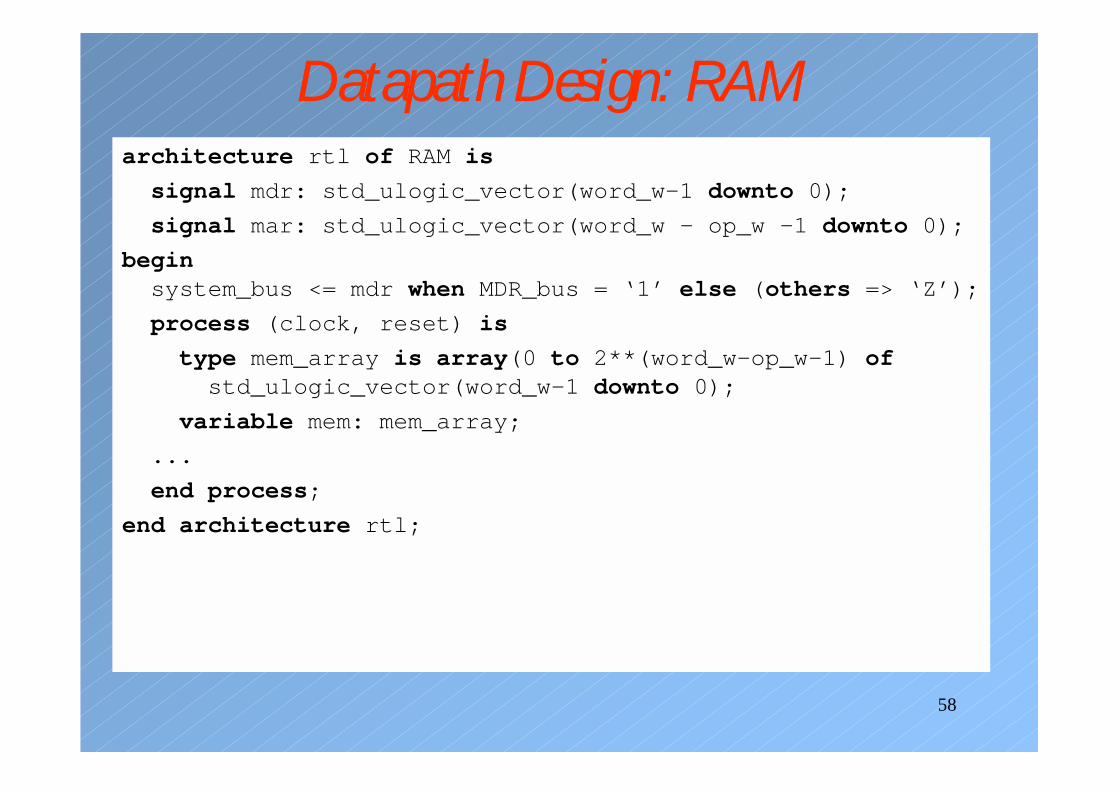
Datapath Design: RAMarchitecture rtl of RAM is
signal mdr: std_ulogic_vector(word_w-1 downto 0);
signal mar: std_ulogic_vector(word_w – op_w -1 downto 0);
beginsystem_bus <= mdr when MDR_bus = ‘1’ else (others => ‘Z’);
process (clock, reset) is
type mem_array is array(0 to 2**(word_w-op_w-1) ofstd_ulogic_vector(word_w-1 downto 0);
variable mem: mem_array;
...
end process;
end architecture rtl;
59
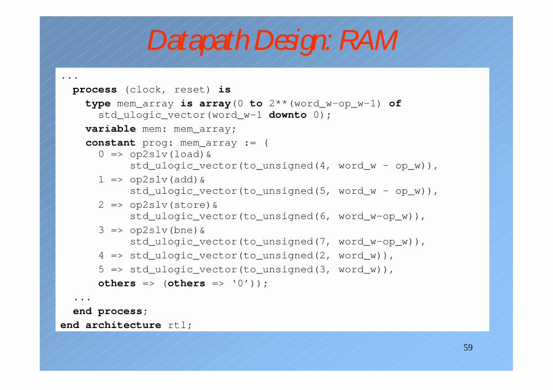
Datapath Design: RAM...
process (clock, reset) is
type mem_array is array(0 to 2**(word_w-op_w-1) ofstd_ulogic_vector(word_w-1 downto 0);
variable mem: mem_array;
constant prog: mem_array := (0 => op2slv(load)&
std_ulogic_vector(to_unsigned(4, word_w - op_w)),
1 => op2slv(add)&std_ulogic_vector(to_unsigned(5, word_w - op_w)),
2 => op2slv(store)&std_ulogic_vector(to_unsigned(6, word_w-op_w)),
3 => op2slv(bne)&std_ulogic_vector(to_unsigned(7, word_w-op_w)),
4 => std_ulogic_vector(to_unsigned(2, word_w)),
5 => std_ulogic_vector(to_unsigned(3, word_w)),
others => (others => ‘0’));
...
end process;
end architecture rtl;
60
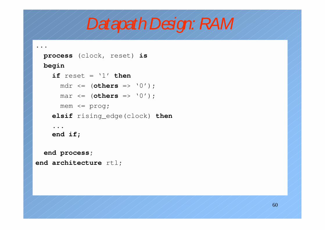
Datapath Design: RAM...
process (clock, reset) is
begin
if reset = ‘1’ then
mdr <= (others => ‘0’);
mar <= (others => ‘0’);
mem <= prog;
elsif rising_edge(clock) then
...end if;
end process;
end architecture rtl;
61
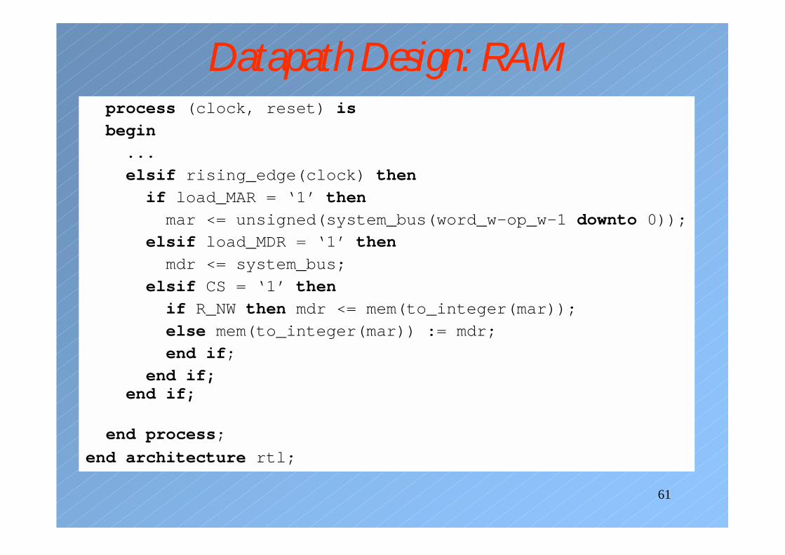
Datapath Design: RAMprocess (clock, reset) is
begin
...
elsif rising_edge(clock) then
if load_MAR = ‘1’ then
mar <= unsigned(system_bus(word_w-op_w-1 downto 0));
elsif load_MDR = ‘1’ then
mdr <= system_bus;
elsif CS = ‘1’ then
if R_NW then mdr <= mem(to_integer(mar));
else mem(to_integer(mar)) := mdr;
end if;
end if;end if;
end process;
end architecture rtl;
62
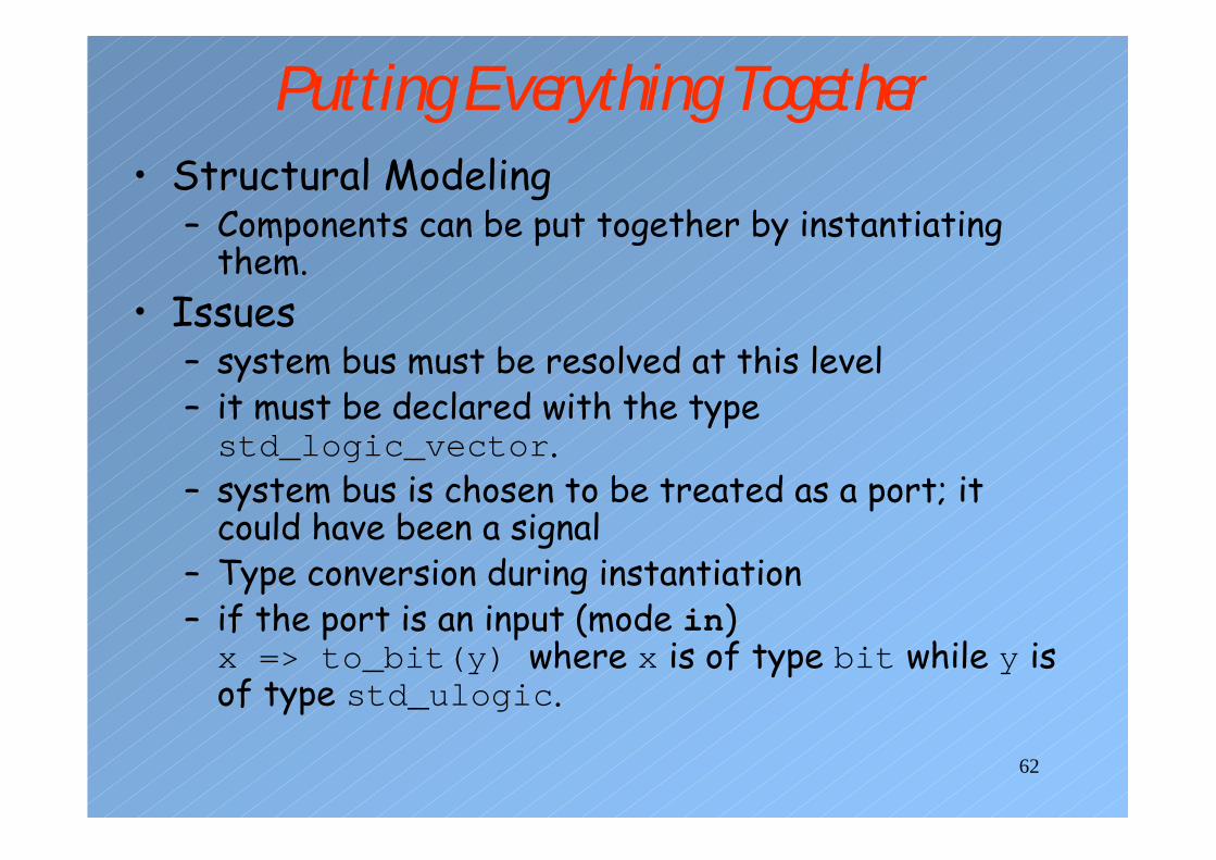
Putting Everything Together• Structural Modeling
– Components can be put together by instantiating them.
• Issues– system bus must be resolved at this level– it must be declared with the type std_logic_vector.
– system bus is chosen to be treated as a port; it could have been a signal
– Type conversion during instantiation– if the port is an input (mode in)x => to_bit(y) where x is of type bit while y is of type std_ulogic.
63
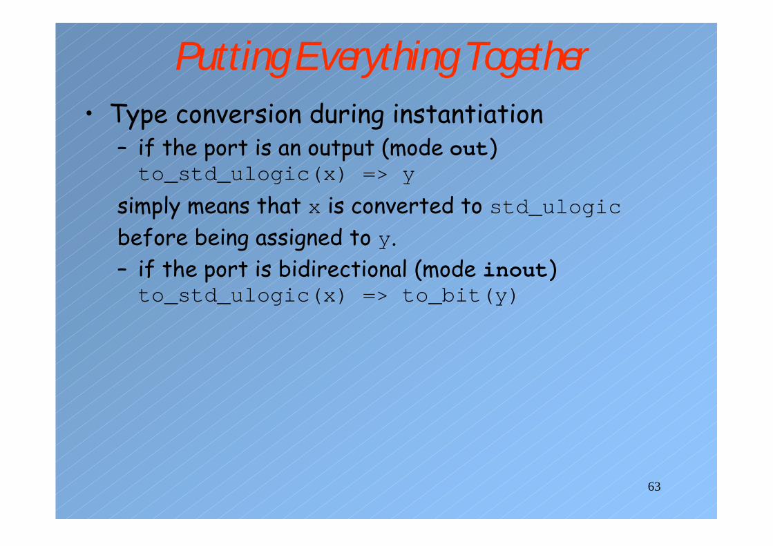
Putting Everything Together• Type conversion during instantiation
– if the port is an output (mode out)to_std_ulogic(x) => y
simply means that x is converted to std_ulogicbefore being assigned to y.– if the port is bidirectional (mode inout)to_std_ulogic(x) => to_bit(y)
64
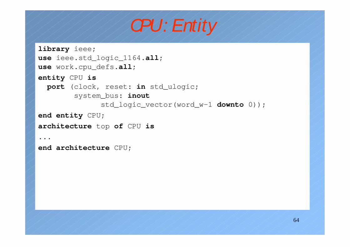
CPU: Entitylibrary ieee;use ieee.std_logic_1164.all;use work.cpu_defs.all;
entity CPU isport (clock, reset: in std_ulogic;
system_bus: inoutstd_logic_vector(word_w-1 downto 0));
end entity CPU;
architecture top of CPU is
...
end architecture CPU;
65
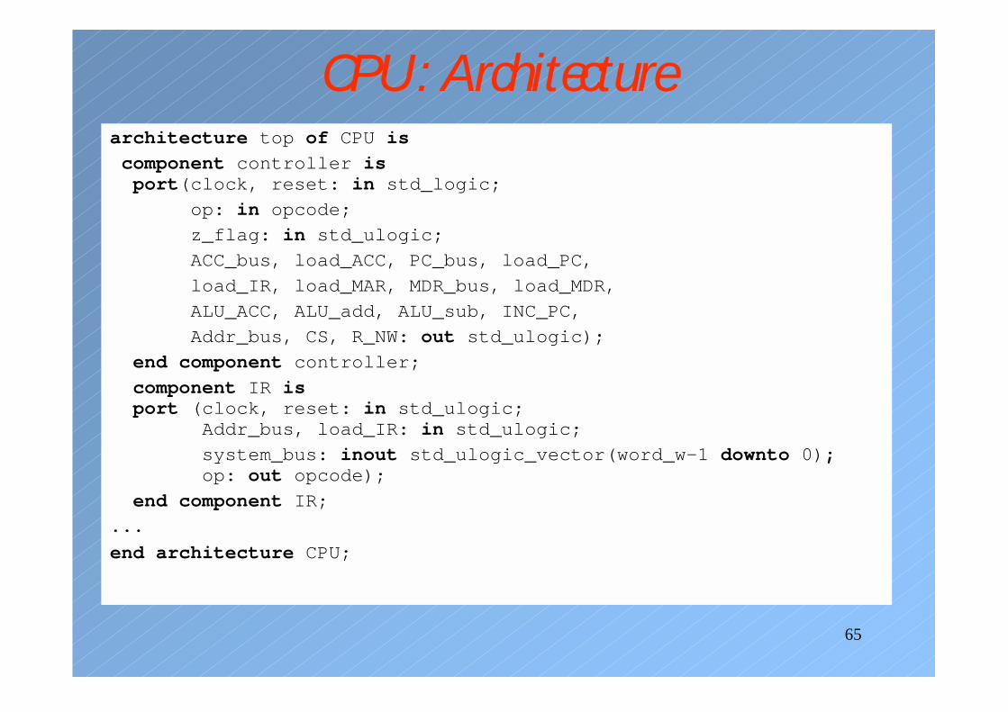
CPU: Architecturearchitecture top of CPU is
component controller isport(clock, reset: in std_logic;
op: in opcode;
z_flag: in std_ulogic;
ACC_bus, load_ACC, PC_bus, load_PC,
load_IR, load_MAR, MDR_bus, load_MDR,
ALU_ACC, ALU_add, ALU_sub, INC_PC,
Addr_bus, CS, R_NW: out std_ulogic);
end component controller;
component IR isport (clock, reset: in std_ulogic;
Addr_bus, load_IR: in std_ulogic;
system_bus: inout std_ulogic_vector(word_w-1 downto 0);op: out opcode);
end component IR;
...
end architecture CPU;
66
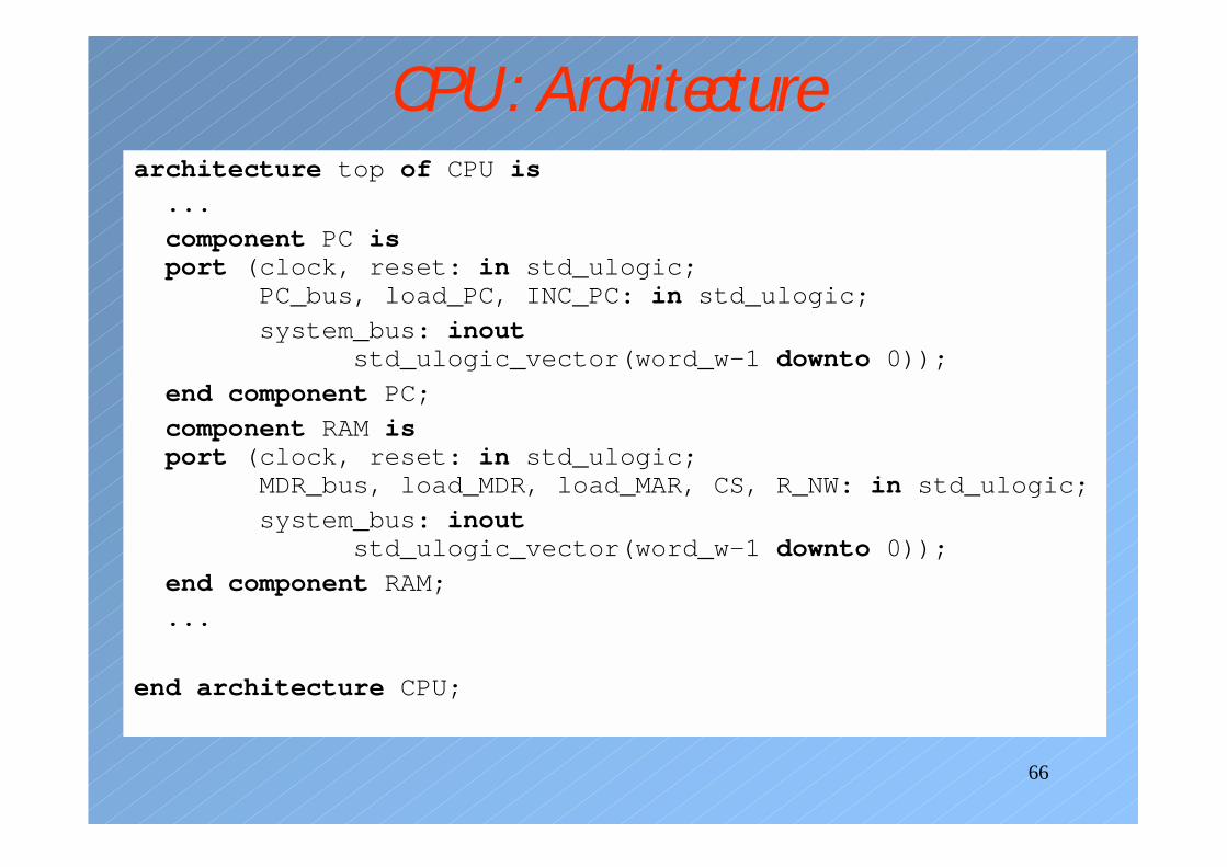
CPU: Architecturearchitecture top of CPU is
...
component PC isport (clock, reset: in std_ulogic;
PC_bus, load_PC, INC_PC: in std_ulogic;
system_bus: inoutstd_ulogic_vector(word_w-1 downto 0));
end component PC;
component RAM isport (clock, reset: in std_ulogic;
MDR_bus, load_MDR, load_MAR, CS, R_NW: in std_ulogic;
system_bus: inoutstd_ulogic_vector(word_w-1 downto 0));
end component RAM;
...
end architecture CPU;
67
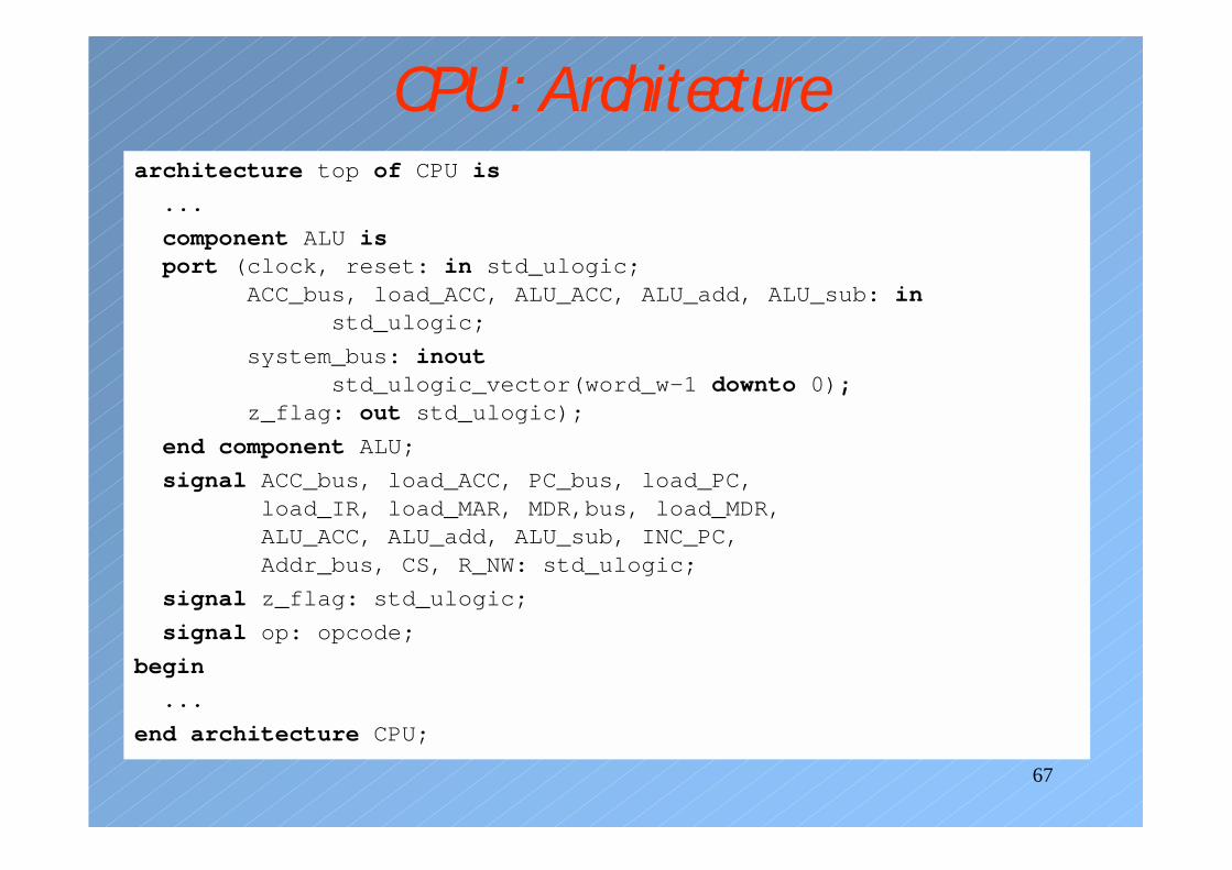
CPU: Architecturearchitecture top of CPU is
...
component ALU isport (clock, reset: in std_ulogic;
ACC_bus, load_ACC, ALU_ACC, ALU_add, ALU_sub: instd_ulogic;
system_bus: inoutstd_ulogic_vector(word_w-1 downto 0);
z_flag: out std_ulogic);
end component ALU;
signal ACC_bus, load_ACC, PC_bus, load_PC,load_IR, load_MAR, MDR,bus, load_MDR,ALU_ACC, ALU_add, ALU_sub, INC_PC,Addr_bus, CS, R_NW: std_ulogic;
signal z_flag: std_ulogic;
signal op: opcode;
begin
...
end architecture CPU;
68
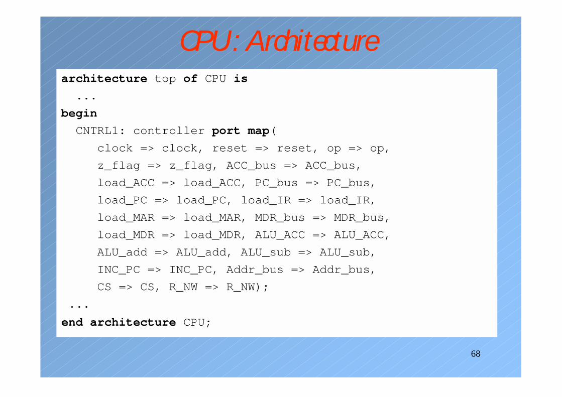
CPU: Architecturearchitecture top of CPU is
...
begin
CNTRL1: controller port map(
clock => clock, reset => reset, op => op,
z_flag => z_flag, ACC_bus => ACC_bus,
load_ACC => load_ACC, PC_bus => PC_bus,
load_PC => load_PC, load_IR => load_IR,
load_MAR => load_MAR, MDR_bus => MDR_bus,
load_MDR => load_MDR, ALU_ACC => ALU_ACC,
ALU_add => ALU_add, ALU_sub => ALU_sub,
INC_PC => INC_PC, Addr_bus => Addr_bus,
CS => CS, R_NW => R_NW);
...
end architecture CPU;
69
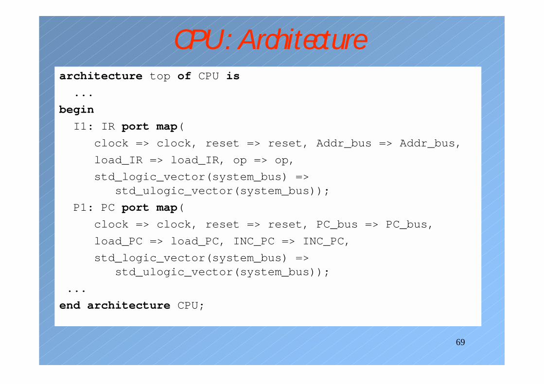
CPU: Architecturearchitecture top of CPU is
...
begin
I1: IR port map(
clock => clock, reset => reset, Addr_bus => Addr_bus,
load_IR => load_IR, op => op,
std_logic_vector(system_bus) =>std_ulogic_vector(system_bus));
P1: PC port map(
clock => clock, reset => reset, PC_bus => PC_bus,
load_PC => load_PC, INC_PC => INC_PC,
std_logic_vector(system_bus) =>std_ulogic_vector(system_bus));
...
end architecture CPU;
70
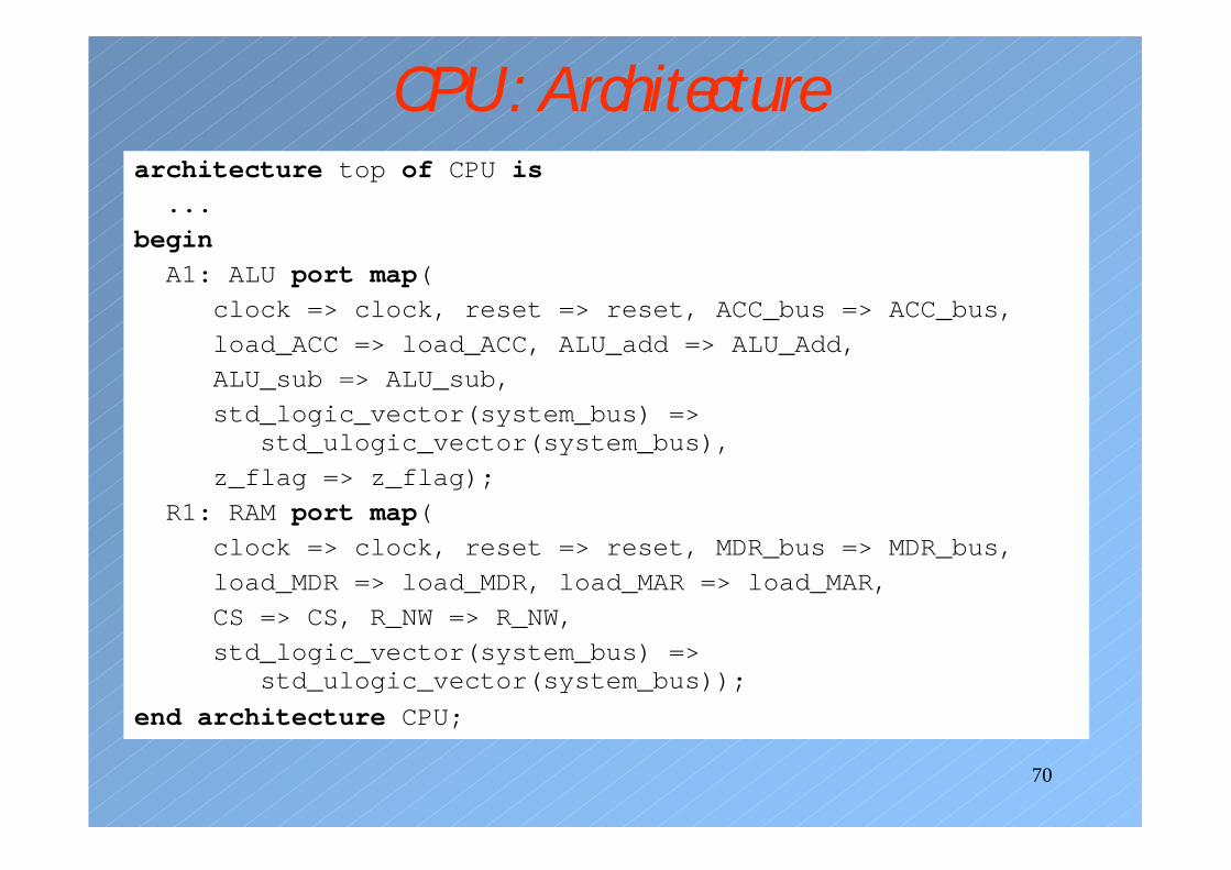
CPU: Architecturearchitecture top of CPU is
...
begin
A1: ALU port map(
clock => clock, reset => reset, ACC_bus => ACC_bus,
load_ACC => load_ACC, ALU_add => ALU_Add,
ALU_sub => ALU_sub,
std_logic_vector(system_bus) =>std_ulogic_vector(system_bus),
z_flag => z_flag);
R1: RAM port map(
clock => clock, reset => reset, MDR_bus => MDR_bus,
load_MDR => load_MDR, load_MAR => load_MAR,
CS => CS, R_NW => R_NW,
std_logic_vector(system_bus) =>std_ulogic_vector(system_bus));
end architecture CPU;
71
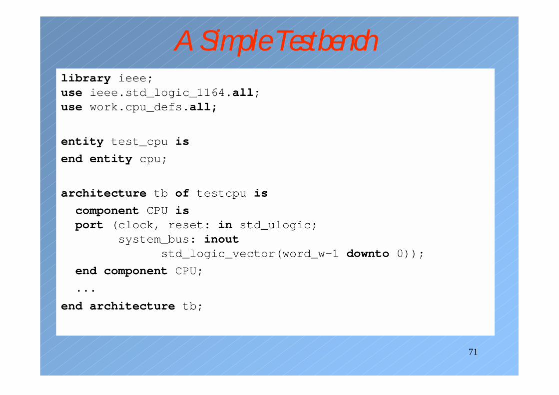
A Simple Testbenchlibrary ieee;use ieee.std_logic_1164.all;use work.cpu_defs.all;
entity test_cpu is
end entity cpu;
architecture tb of testcpu is
component CPU isport (clock, reset: in std_ulogic;
system_bus: inoutstd_logic_vector(word_w-1 downto 0));
end component CPU;
...
end architecture tb;
72
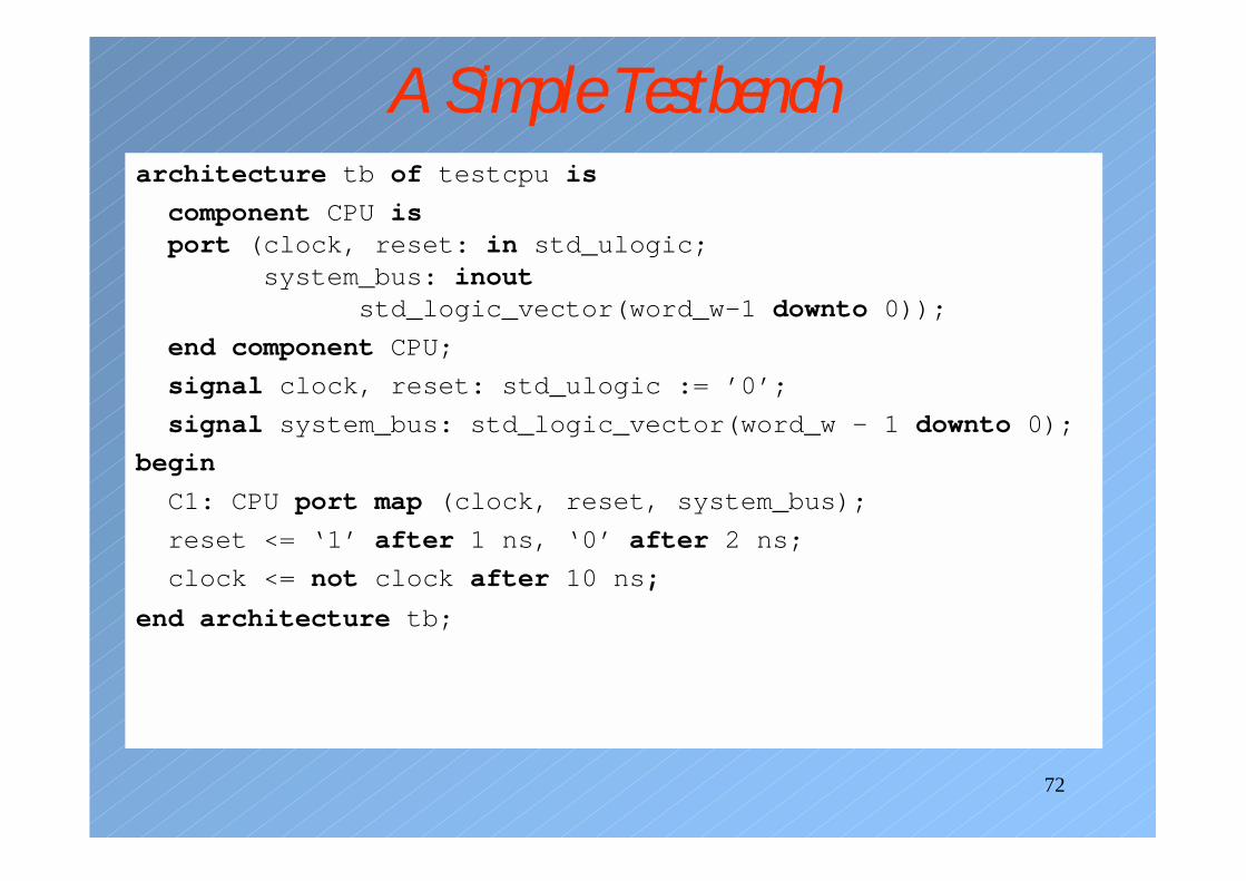
A Simple Testbencharchitecture tb of testcpu is
component CPU isport (clock, reset: in std_ulogic;
system_bus: inoutstd_logic_vector(word_w-1 downto 0));
end component CPU;
signal clock, reset: std_ulogic := ’0’;
signal system_bus: std_logic_vector(word_w – 1 downto 0);
begin
C1: CPU port map (clock, reset, system_bus);
reset <= ‘1’ after 1 ns, ‘0’ after 2 ns;
clock <= not clock after 10 ns;
end architecture tb;
73
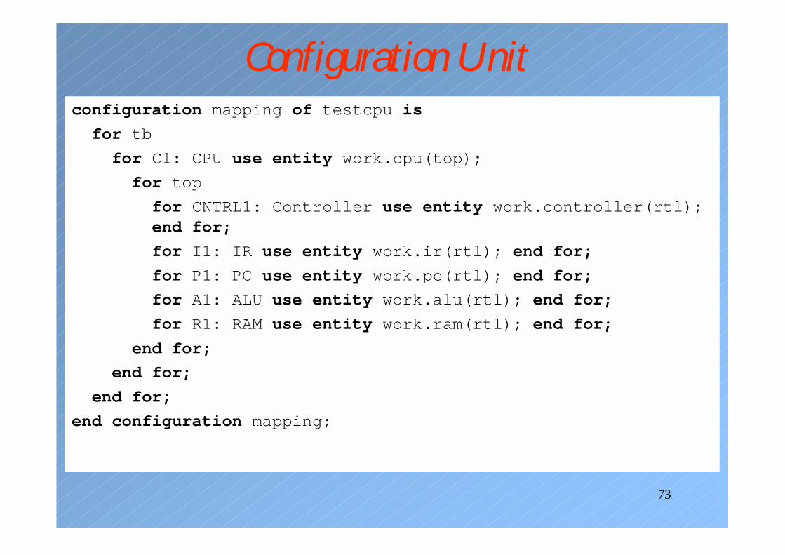
Configuration Unitconfiguration mapping of testcpu is
for tb
for C1: CPU use entity work.cpu(top);
for top
for CNTRL1: Controller use entity work.controller(rtl);end for;
for I1: IR use entity work.ir(rtl); end for;
for P1: PC use entity work.pc(rtl); end for;
for A1: ALU use entity work.alu(rtl); end for;
for R1: RAM use entity work.ram(rtl); end for;
end for;
end for;
end for;
end configuration mapping;