compact product suite · compact product suite compact control builder ac 800m product guide...
TRANSCRIPT

Power and productivity
for a better worldTM
Compact Product SuiteCompact Control Builder AC 800MProduct Guide
Version 6.0


Compact Product SuiteCompact Control Builder AC 800M
Product Guide
Version 6.0

NOTICEThis document contains information about one or more ABB products and may include adescription of or a reference to one or more standards that may be generally relevant tothe ABB products. The presence of any such description of a standard or reference to astandard is not a representation that all of the ABB products referenced in this documentsupport all of the features of the described or referenced standard. In order to determinethe specific features supported by a particular ABB product, the reader should consult theproduct specifications for the particular ABB product.
ABB may have one or more patents or pending patent applications protecting the intel-lectual property in the ABB products described in this document.
The information in this document is subject to change without notice and should not beconstrued as a commitment by ABB. ABB assumes no responsibility for any errors thatmay appear in this document.
In no event shall ABB be liable for direct, indirect, special, incidental or consequentialdamages of any nature or kind arising from the use of this document, nor shall ABB beliable for incidental or consequential damages arising from use of any software or hard-ware described in this document.
This document and parts thereof must not be reproduced or copied without written per-mission from ABB, and the contents thereof must not be imparted to a third party nor usedfor any unauthorized purpose.
The software or hardware described in this document is furnished under a license andmay be used, copied, or disclosed only in accordance with the terms of such license. Thisproduct meets the requirements specified in EMC Directive 2004/108/EC and in Low Volt-age Directive 2006/95/EC.
TRADEMARKSAll rights to copyrights, registered trademarks, and trademarks reside with their respec-tive owners.
Copyright © 2003-2016 by ABB. All rights reserved.
Release: May 2016Document number: 3BSE041586-600 A

3BSE041586-600 A 5
Table of Contents
About This BookIntended Use of This Book................................................................................................9
Target Group...........................................................................................................9
Purpose, Scope and Intended Use ..........................................................................9
New in this Release .........................................................................................................10
Engineering Environment.....................................................................................10
Control and I/O ....................................................................................................13
Section 1 - Key BenefitsCompact Control Builder AC 800M................................................................................17
Compact Control Builder AC 800M ....................................................................18
OPC Server for AC 800M ....................................................................................20
SoftController.......................................................................................................20
Section 2 - Product DescriptionSoftware Overview ..........................................................................................................22
Compact Control Builder AC 800M................................................................................22
Overview .............................................................................................................22
Compact Control Builder AC 800M Functions ...................................................24
Support for IEC 61131-3 Languages ...................................................................25
Testing the Application ........................................................................................26
Downloading to a PLC.........................................................................................26
Multi-user Engineering ........................................................................................27
Alarm and Events Handling .................................................................................27
I/O Connectivity and Communication .................................................................29
Supported ABB I/O Systems and Families ..........................................................36

Table of Contents
6 3BSE041586-600 A
Serial Communication Protocols ......................................................................... 37
Control Network .................................................................................................. 40
Clock Synchronization......................................................................................... 41
Redundancy.......................................................................................................... 41
Backup Media ...................................................................................................... 43
Cold Retain Values............................................................................................... 44
Online Help and Manuals .................................................................................... 44
Additional Software ............................................................................................. 45
OPC Server for AC 800M ............................................................................................... 46
OPC Server Data Access (DA) Part..................................................................... 46
OPC ServerAlarm and Event (AE) Part.............................................................. 47
Section 3 - Technical Data and PerformanceGeneral ............................................................................................................................ 49
Compact Control Builder AC 800M Performance .............................................. 49
OPC Server Performance..................................................................................... 50
Compact Flash Requirements .............................................................................. 50
Secure Digital Requirements ............................................................................... 50
Prerequisites and Requirements ...................................................................................... 51
Compact Control Builder AC 800M.................................................................... 51
OPC Server .......................................................................................................... 51
Not Supported Functions................................................................................................. 52
Section 4 - Ordering and LicensingOrdering Procedure ......................................................................................................... 53
Price Lists Structure ........................................................................................................ 53
Compact Control Builder AC 800M, 3BSE078498............................................. 54
Licensing ......................................................................................................................... 56
Control System Lifecycle Support Program ........................................................ 56
Ordering Example ........................................................................................................... 57
Price List Items .................................................................................................... 57
Appendix A - Control and I/O
Table of Contents
3BSE041586-600 A 7
3BSE041586-600 A 7
Memory and Execution Performance ..............................................................................59
Memory Size ........................................................................................................59
Available Memory................................................................................................61
Execution Performance ........................................................................................63
Spare Memory Needed for Online Changes ........................................................64
Comparing Memory Allocations Made with Different Versions .........................65
Memory Consumption and Execution Times.......................................................66
Hardware and I/O Performance ...................................................................................76
Modulebus Response Time and Load ..................................................................76
Calculation of Scan Time on the Modulebus and CPU Load ..............................76
Calculation of the Modulebus CPU Load ............................................................77
Example Scan Time and Cyclic Load ..................................................................78
ModuleBus Scanning of ABB Drives ..................................................................79
Dynamic Data Exchange S800 I/O Connected via CI854A/B.............................80
S100 I/O Response Time and Load......................................................................82
Drivebus Communication with CI858 Unit .........................................................84
Calculation of I/O Copy Time Estimate for ControlNet with CI865 Unit ...........87
Communication ...............................................................................................................89
IAC and MMS Communication ...........................................................................89
Control Network Clock Synchronization.............................................................93
MasterBus 300 Network.......................................................................................93
INSUM Network ..........................................................................................94
OPC Server for AC 800M ....................................................................................95
Supported Hardware and I/O Families ............................................................................96
PLCs .............................................................................................................96
Adaptors for I/O Types.......................................................................................104
I/O Families........................................................................................................109
Appendix B - FieldbusMODBUS ......................................................................................................................123
MODBUS RTU Master Communication ...........................................................123
MODBUS TCP ..................................................................................................125
PROFIBUS ....................................................................................................................129

Table of Contents
8 3BSE041586-600 A
Network Connection through Communication Interface................................... 129
PROFINET.................................................................................................................... 131
Network Connection through Communication Interface................................... 131
IEC 61850 ..................................................................................................................... 132
Network Connection through Communication Interface................................... 132
EtherNet/IP and DeviceNet ........................................................................................... 142
General .......................................................................................................... 142
EtherNet/IP ........................................................................................................ 143
DeviceNet .......................................................................................................... 144
INDEX

3BSE041586-600 A 9
About This Book
Intended Use of This Book
Target Group
This Product Guide is intended for sales representatives to provide information on Compact Control Builder AC 800M and OPC Server for AC 800M.
Compact Control Builder Release Notes (3BSE033044*) contains additional information.
Purpose, Scope and Intended Use
This book provides details on Compact Control Builder AC 800M and OPC Server for AC 800M.
Section 1, Key Benefits describes key benefits of the Compact Control Builder AC 800M and OPC Server for AC 800M.
Section 2, Product Description describes the Compact Control Builder AC 800M product and some of the components included when purchasing the Compact Control Builder AC 800M.
Section 3, Technical Data and Performance describes hardware and software requirements for operating Compact Control Builder AC 800M.
Section 4, Ordering and Licensing describes the ordering procedure, price list structure and licenses for purchasing the Compact Control Builder AC 800M and OPC Server for AC 800M.
Appendix A, Control and I/O describes the performance and technical data for Control Software, Control Builder key functions, hardware modules and I/O families supported by Compact Control Builder AC 800M.

New in this Release About This Book
10 3BSE041586-600 A
Appendix B, Fieldbus describes the capacity limits and constraints for the application design that need to be considered when using standardized fieldbus protocols to connect field devices to AC 800M.
New in this ReleaseThe Compact Control Builder version 6.0.0 contains new and improved functionality compared to version 5.1.1.
Engineering Environment
Support for new Operating Systems
Version 6.0.0-1 is released to be used with Windows 10.
Version 6.0 is released to be used with Windows 8.1 and Windows Server 2012 R2.
In addition, it can be used with 64-bit Windows 7 SP1 andServer 2008 R2 SP1.
Support for Microsoft Word 2016
Version 6.0 is released to be used with Microsoft Word 2010, 2013 and 2016

About This Book Engineering Environment
3BSE041586-600 A 11
ABB Start Menu
The new ABB Start Menu is used in Windows 8.1 and Windows 10 to display a Windows 7 style start menu for the ABB products. The items on the start menu can be selected and started. The start menu executes only in the desktop environment.
Improved Security
Windows UAC (User Account Control) can now be left turned on (default), and all executables are digitally signed and carry ABB branding and copyright information.
Figure 1. ABB Start Menu

Engineering Environment About This Book
12 3BSE041586-600 A
Multiple Soft Controllers on the same PC
It is now possible to run up to 25 Soft Controllers simultaneously on the same PC. Peer-to-peer communication using IAC is automatically set up between the soft controllers. The Soft Controller panel has been changed so it can be used to administer and monitor the different instances.
Figure 2. Multiple Soft Controllers on the same PC
Diagram Editor
The auto-routing of graphical connections in the Diagram editor has been improved. The diagram layout has been improved reducing the number of crossings, unnecessary bends and long connections. Multiple connections to the same port are handled in a better way, reducing the need for manual adjustments. Additionally there are twenty more enhancements made to the diagram editor, which are described in the Release Notes.
Communication Variable Limits Dialog
A new dialog is added in version 6.0.0-1 for configuring the compiler reaction for unresolved Communication Variables, error or warning, and enabling compilation error if certain limits of number of communication variables have been exceeded.
Simplified Upgrade
This release contains two new stand-alone tools aimed for simplifying an upgrade from earlier releases:
About This Book Control and I/O
3BSE041586-600 A 13
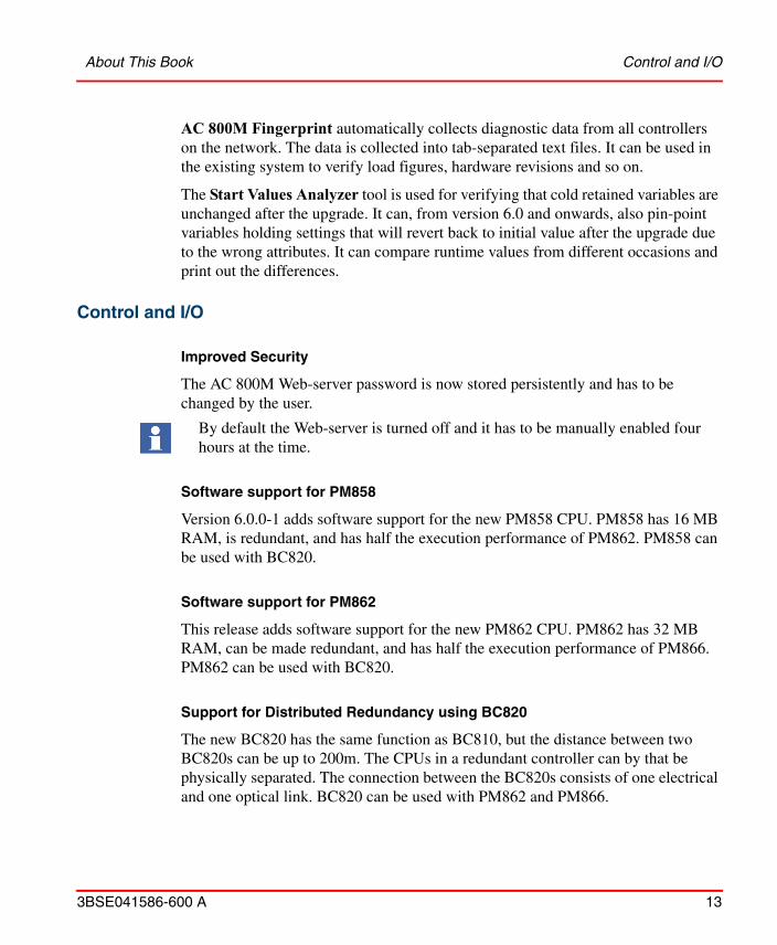
AC 800M Fingerprint automatically collects diagnostic data from all controllers on the network. The data is collected into tab-separated text files. It can be used in the existing system to verify load figures, hardware revisions and so on.
The Start Values Analyzer tool is used for verifying that cold retained variables are unchanged after the upgrade. It can, from version 6.0 and onwards, also pin-point variables holding settings that will revert back to initial value after the upgrade due to the wrong attributes. It can compare runtime values from different occasions and print out the differences.
Control and I/O
Improved Security
The AC 800M Web-server password is now stored persistently and has to be changed by the user.
Software support for PM858
Version 6.0.0-1 adds software support for the new PM858 CPU. PM858 has 16 MB RAM, is redundant, and has half the execution performance of PM862. PM858 can be used with BC820.
Software support for PM862
This release adds software support for the new PM862 CPU. PM862 has 32 MB RAM, can be made redundant, and has half the execution performance of PM866. PM862 can be used with BC820.
Support for Distributed Redundancy using BC820
The new BC820 has the same function as BC810, but the distance between two BC820s can be up to 200m. The CPUs in a redundant controller can by that be physically separated. The connection between the BC820s consists of one electrical and one optical link. BC820 can be used with PM862 and PM866.
By default the Web-server is turned off and it has to be manually enabled four hours at the time.

Control and I/O About This Book
14 3BSE041586-600 A
Support for CI854B
The CI854B is a new PROFIBUS-DP master that replaces CI854A in new installations. CI854B has the same functionality as CI854A and requires the AC 800M controller to be of version 6.0 or later.
Use of Essential Automation Hardware is Identified and Visualized
The AC 800M identifies and visualizes hardware units of type -eA.
Optimized Communication between AC 800M Controller and OPC Server
The MMS communication between the AC 800M controller and OPC Server has been optimized. The length of the telegrams has been extended up to 2.5 times which results in fewer telegrams and lower controller load. The maximum variable transfer rate is almost doubled.
Support for MODBUS RTU Slave
The AC 800M controller can now act as a point-to-point MODBUS RTU slave. The communication takes place via COM3 on the CPU, or via any serial channel on CI853. The same set of Function Codes as with CI867 slave is supported.
Support for 200-AENTR through CI873 EtherNet/IP
The new S200CI873IoHwlib adds support for the S200 I/O adaptor 200-AENTR to be used with CI873.
The new adaptor gives a simple and cost effective upgrade path for directly connected S200 I/O on SattCon 200, SattLine 200, Advant Controller 210, Advant Controller 250 and AC 800C.
200-AENTR has two Ethernet ports with an in-built switch, which means that the adaptors can be daisy-chained to the CI873 using cross-wired Ethernet-cables without the need for external switches.
The release of the 200-AENTR adaptor will be announced separately.

About This Book Control and I/O
3BSE041586-600 A 15
Support for more S100 I/O boards
Version 6.0.0-1 adds software support for the following S100 I/O boards: DSDI 131, DSDI 141, DSDO 120, DSDO 140, DSAI 110, DSAI 135, DSAI 145, DSAI 146, DSAI 151.
Automatic replacement of PROFINET IO devices
The CI871 supports an automatic configuration and restart of a PNIO device in case of device replacement. The configured station name is assigned automatically. No usage of the AC 800M web server is needed. This functionality is available for PNIO devices that have on the one hand active support for LLDP and on the other hand these devices are connected to a switched Ethernet network also having active support for LLDP.
UMC100 with PNQ22 and PROFINET IO
The new hardware library ABBPNQ22CI871HwLib adds support for ABB's universal motor controller UMC100 via CI871.
Acyclic Communication on PROFINET IO
The AC 800M controller now supports acyclic data access with connected PNIO devices.
The IOCommLib library contains the Function Blocks for acyclic read and write of the PROFINET device data. This provides access in the controller to all data of the PNIO device that is not provided via cyclic data.
Modbus RTU Redundancy at Application Level
Version 6.0.0-1 adds support for MODBUS RTU master channel redundancy at application level. A new connect function block, MBConnectR has been added in ModBusCommLib.
Control and I/O About This Book
16 3BSE041586-600 A
Application libraries for analog control
PidCC and PidAdvancedCC have been enhanced to support controller types ‘ClassicERF’ and ‘ClassicERF+D’. PidAdvancedCC has additionally been enhanced for controller type ‘ABBERF’ and ‘ABBERF+D’. These changes affect the following libraries BasicLib, ControlSupportLib, SignalLib, ControlBasicLib, ControlObjectLib, ControlStandardLib, ControlAdvancedLib, ControlExtendedLib, and ControlFuzzyLib.
Maintenance
It is now possible to insert a Backup Media card after a controller crash has occurred in order to save the content of the whole RAM memory. This is valid both for a single/primary PM and a backup PM and requires that the “Autorestart” function has not been enabled (default off). A halted controller without a Backup Media will indicate by fast flashing (10Hz) on the F(ault) LED. Insert a Backup media card and wait for slow flashing (0.5Hz) on the F(ault) LED indicating that the dump is ready and/or press INIT to restart.

3BSE041586-600 A 17
Section 1 Key Benefits
This section is focused on getting you acquainted with the key benefits for the Compact Control Builder AC 800M software products.
Compact Control Builder AC 800MCompact Control Builder AC 800M aims to meet the customers need for a modern industrial PLC solution, capable of handling mid-sized to large applications. Its primary target market is the process automation area, where PLC products are used, however, it can also be used for other application areas.
The Compact Control Builder software product contains the following components:
• Compact Control Builder AC 800M
• OPC Server for AC 800M
• Base Software for SoftControl
These products are delivered out of the box and easy to install, run and maintain. For more information about the Compact Control Builder software product offering, see Price Lists Structure on page 53.

Compact Control Builder AC 800M Section 1 Key Benefits
18 3BSE041586-600 A
Compact Control Builder AC 800M
Compact Control Builder AC 800M adds the following key benefits to the PLC market:
• Programming tool for AC 800M PLCs– Contains a compiler, programming editors, standard libraries for
developing PLC applications and standard hardware types (units) in libraries for hardware configuring.
• Programming environment
– Testing the application off-line.
– Download to PLC via serial communication or Ethernet.
– Online change on applications.
– Cold retain of data (kept at cold start).
– Backup/restore of projects.
• Support for all IEC 61131-3 languages
– Function Block Diagram (FBD), Structured Text (ST), Instruction List (IL), Ladder Diagram (LD), Sequential Function Chart (SFC).
• Extensions to IEC 61131-3 languages
– Function Diagram (FD) and Control Module Diagram (CMD).
• Create/Change/Insert Libraries
– Creating self-defined libraries containing data types, function block types etc. which can be connected to any project.
– Creating self-defined libraries with hardware types.
– When no available hardware library is sufficient, the Device Import Wizard can be used to import a customized hardware type from a device capability description file.
You can import PROFIBUS GSD-files with hardware types for CI854.
You can also import PROFINET GSD files for CI871, and DeviceNet and EtherNet/IP EDS files for CI873.

Section 1 Key Benefits Compact Control Builder AC 800M
3BSE041586-600 A 19
– Various functions and type solutions for simple logic control, device control, loop control, alarm handling etc. packaged as standard libraries.
– The open library structures provide easy access to set-up and connect type solutions into self-defined libraries and/or applications before programming.
• Multi-user engineering
– Project files can be distributed on Compact Control Builder stations (up to 32 stations).
• Redundancy functions
– AC 800M CPU redundancy (using PM858, PM861, PM862, PM864, PM866, or PM891).
– Redundant Control Network on MMS and TCP/IP, using Redundant Network Routing Protocol (RNRP).
– Master and line redundancy (PROFIBUS DP-V1) for AC 800M (CI854 interface module).
– Redundant optical ModuleBus.
• Clock synchronization
– 1 millisecond clock synchronization accuracy between PLC nodes in control network.
– Generating Sequence-Of-Events (SOE), using time stamps for digital I/O with high accuracy.
– System alarm and system event functions.
• ABB Drives support
– ABB Standard Drives.
– ABB Application Drives.

OPC Server for AC 800M Section 1 Key Benefits
20 3BSE041586-600 A
• Interfacing with Satt I/O
– CI865 unit for Satt I/O system (Rack I/O and Series 200 I/O) with the AC 800M PLC platform.
– 200-RACN ControlNet I/O adaptor for rack-based I/O boards.
– 200-ACN unit for 200 I/O units via Satt ControlNet.
• Compact Flash (CF) and Secure Digital (SD/SDHC)
– Store a compiled PLCs configuration, that can be used at restart of the PLC.
OPC Server for AC 800M
OPC server for AC 800M is a stand-alone product that support both Data Access and Alarm/Event traffic from PLCs.
• Stand-alone OPC Server, fully OPC compliant.
– OPC Server DA that handles run-time data.
– OPC Server AE that handles alarm and event from the control system, via the OPC Server to the OPC client.
– OPC Server Online help.
SoftController
• Testing tool for running applications offline.
– SoftController provides reduced engineering and test costs.
– It is a simulation tool that runs with Base Software for SoftControl and is automatically installed together with the Compact Control Builder.
– Up to 25 instances per PC.

3BSE041586-600 A 21
Section 2 Product Description
This section describes the Compact Control Builder AC 800M product and some of the components included when purchasing the Compact Control Builder AC 800M.
The Compact Control Builder is used to configure the AC 800M hardware. The OPC server is used to connect the AC 800M to a HMI or SCADA system.
Compact Control Builder offers amongst other things multi-user engineering and support for redundancy functions (CPU redundancy, RNRP, master and line redundancy with CI854). More information can be found in Compact Control Builder AC 800M Functions on page 24.
The OPC Server runs stand-alone and is fully OPC Data Access and Alarm/Event OPC compliant.
Compact Control Builder AC 800M supports the following CPUs:
• PM851/PM851A
• PM856/PM856A
• PM858
• PM860/PM860A
• PM861/PM861A
• PM862
• PM864/PM864A
• PM866/PM866A
• PM891
• SoftController running on PC

Software Overview Section 2 Product Description
22 3BSE041586-600 A
Software OverviewThe software delivered on the DVD is divided in two parts - the Compact Control Builder AC 800M and OPC Server for AC 800M. While installing Compact Control Builder additional components and services will be installed in the background.
• Compact Control Builder AC 800M
– Base Software for SoftControl
– RNRP
– User Documentation
• OPC Server for AC 800M
Compact Control Builder AC 800MCompact Control Builder AC 800M is a programming tool for creating PLC based control solutions when using the AC 800M as hardware. It works on Windows 7 SP1 64 bit, Windows Server 2008 R2 SP1, Windows 8.1 64 bit, Windows Server 2012 R2 and Windows 10 64 bit.
Overview
Firmware and applications can be downloaded to PLCs using Ethernet or via a direct serial link. Ensure that the IP address of the PLC is configured in Control Builder, communication is set up, and the cables are connected at both ends. An OPC Server for AC 800M can be installed on the same PC as Control Builder (Figure 3) or be installed on a separate PC, typically together with Human Machine Interface (HMI) software.

Section 2 Product Description Overview
3BSE041586-600 A 23
Figure 3. Control Builder and supporting software.
Download from Programming Station
PLC firmware and control applications can be downloaded from a standard PC to PLCs using Ethernet or via a direct serial link (using TK212A cable).
Figure 4. Downloading firmware and/or applications.
PLC Communication
PLCs, programming stations and operator stations communicate with each other through the control network. The control network is used to communicate between Control Builder stations and the PLCs, between HMI and PLCs and also for communication between the PLCs.
Windows 7 SP1 or
Compact Control Builder AC 800MOPC Server for AC 800M(can also be installed stand-alone)
Windows Server 2008 R2 SP1Windows 8.1 or Windows 10 orWindows Server 2012 R2
Standard PC
Control Builder
Control Network
Ethernetor directserial link
PLC
Compact Control Builder AC 800M Functions Section 2 Product Description
24 3BSE041586-600 A
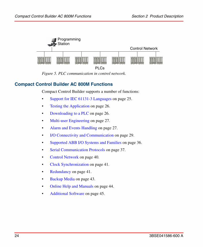
Figure 5. PLC communication in control network.
Compact Control Builder AC 800M Functions
Compact Control Builder supports a number of functions:
• Support for IEC 61131-3 Languages on page 25.
• Testing the Application on page 26.
• Downloading to a PLC on page 26.
• Multi-user Engineering on page 27.
• Alarm and Events Handling on page 27.
• I/O Connectivity and Communication on page 29.
• Supported ABB I/O Systems and Families on page 36.
• Serial Communication Protocols on page 37.
• Control Network on page 40.
• Clock Synchronization on page 41.
• Redundancy on page 41.
• Backup Media on page 43.
• Online Help and Manuals on page 44.
• Additional Software on page 45.
Control Network
ProgrammingStation
PLCs

Section 2 Product Description Support for IEC 61131-3 Languages
3BSE041586-600 A 25
Support for IEC 61131-3 Languages
The IEC 61131-3 standard defines five of the most commonly used programming languages on the market. These are Function Block Diagram (FBD), Structured Text (ST), Instruction List (IL), Ladder Diagram (LD) and Sequential Function Chart (SFC). In addition to these, Control Builder supports creation of logic using Diagrams (which use the Function Diagram (FD) language) and Control Module Diagrams.
Depending on previous experience, programmers often have their own personal preference for a certain language. All the languages have advantages and disadvantages, and no single one of them is suitable for all control tasks.
Table 1. Compact Control Builder programming languages.
Language Function
Function Block Diagram
(FBD)
A graphical language for depicting signal and data flows through function blocks and functions. Function blocks and variables are interconnected graphically, which makes the resulting control diagrams easy to read.
Structured Text (ST) A high-level programming language. ST is highly structured and has a comprehensive range of constructs for assignments, function/function block calls, expressions, conditional statements, iterations, etc.
It is easy to write advanced, compact, but clear ST code, due to its logical and structured layout.
Instruction List (IL) A traditional PLC language. It has a structure similar to simple machine assembler code.
Ladder Diagram (LD) Ladder diagram (LD) is a graphical language based on relay ladder logic.

Testing the Application Section 2 Product Description
26 3BSE041586-600 A
Testing the Application
The Compact Control Builder provides two ways for testing an application, Test mode and simulating an application with the SoftController.
Test Mode
Test mode is normally used for testing smaller parts of an application and without performing a download to the PLC. In Test Mode, Compact Control Builder compiles and executes the code in the local PC similar to the execution on PLC.
SoftController
The Base Software for SoftControl is a software product that comes with the Compact Control Builder installation. It is used for simulating a complete application (with a complete hardware configuration done). But, instead of downloading the application to a PLC, it can be downloaded to the SoftController, thus no need for a real PLC and I/O.
Downloading to a PLC
Firmware
Firmware is the software that provides the basic functionality of the AC 800M PLC. It contains functions like operating system, real-time clock, communication etc. The
Sequential Function Chart
(SFC)
Sequential function chart (SFC) is a graphical language for depicting the sequential behavior of a control program.
Function Diagram (FD) Function Diagram (FD) is a graphical language that allows mixing of functions, function blocks, control modules, and diagrams in one code block and create graphical connections between them.
Table 1. Compact Control Builder programming languages.
Language Function

Section 2 Product Description Multi-user Engineering
3BSE041586-600 A 27
firmware is stored in electrically erasable programmable read-only memory (EEPROM).
The firmware is pre-installed in some of the hardware. The firmware can also be downloaded from Compact Control Builder to CPUs and communication modules either through Ethernet or through Serial Cable. If Ethernet is used as media, the IP address of the PLC must be set before any download. This is carried out with the IP Configuration tool, see also IP Configuration Tool on page 45.
After the firmware is updated, the application program has to be downloaded again and a cold start of the CPU must be performed.
Applications
Applications can be downloaded to the PLC via Ethernet or direct via a serial connection (TK212A cable). An application can be distributed between several PLCs. Parts of the application are then downloaded to different PLCs.
Multi-user Engineering
Compact Control Builder supports multi-user engineering with a maximum of 32 separate Control Builder PCs. In a multi-user configuration all Control Builder PCs and the OPC Server must have access to the common project file(s). This means that a common Project folder must be created on a shared network server.
Alarm and Events Handling
Compact Control Builder handles alarm and events generated internally in the system, a PLC or other hardware unit or in applications.
Alarm and event information is communicated throughout the control network via OPC servers, that is, a number of OPC Server for AC 800M.
Alarm and event handling supports the following.
• Disabling and enabling of alarms
• Acknowledgement and cancellation of alarms
• Filtering of alarms and events
Ensure that the application program in the PLC is removed before downloading the new firmware to the PLC.

Alarm and Events Handling Section 2 Product Description
28 3BSE041586-600 A
• Printing of alarm and event lists on local printer
• System events and alarms
System events and alarms created in PLC can be read and accessed by operators through HMI. The time stamps and attributes are also created in PLCs. The event or alarm has its origin attached to it.
OPC Server
Alarms and events are collected and forwarded by the Alarm and Event (AE) part of the OPC server, see also OPC ServerAlarm and Event (AE) Part on page 47. PLCs then gain access to alarms and events from other PLCs by reading data from the OPC server. Alarm and event information can also be read by other OPC clients.

Section 2 Product Description I/O Connectivity and Communication
3BSE041586-600 A 29
I/O Connectivity and Communication
Control Builder supports a number of fieldbuses and I/O systems. PLCs can be connected to fieldbuses and other I/O systems using adaptors and I/O units belonging to ABB I/O families.
I/O Connectivity
• ModuleBus
ModuleBus is an integrated master unit for S800 I/O. I/O units connected to ModuleBus are divided into clusters. 12 I/O units can be directly connected to the ModuleBus on the AC 800M, while the remaining I/O units have to be connected via I/O-clusters. Up to 7 I/O-clusters can be connected to the ModuleBus. PM851 only allows up to 24 S800 I/O units on ModuleBus (12 local and 12 on cluster 1).
• PROFIBUS DP
Control Builder supports the fieldbus system PROFIBUS DP. It can be connected to PLCs via the CI854 interface module, offering master and built-in line redundancy. Applications access the built-in fieldbus functions through corresponding I/O modules.
• PROFINET IO
PROFINET is a manufacturer-independent Fieldbus standard for applications in manufacturing and process automation. PROFINET technology is described in fixed terms in IEC 61158 and IEC 61784 as an international standard.
PROFINET IO uses Ethernet communication to integrate simple distributed I/O and time-critical applications.
PROFINET IO describes a device model oriented to the PROFIBUS framework, which consists of places of insertion (slots) and groups of I/O channels (subslots). The technical characteristics of the field devices are described by the General Station Description (GSD) on an XML basis. The PROFINET IO engineering is performed in a way familiar to PROFIBUS. The distributed field devices are assigned to the PLCs during configuration.

I/O Connectivity and Communication Section 2 Product Description
30 3BSE041586-600 A
The PROFINET IO is interfaced to the IEC 61131 PLC AC 800M, using the PROFINET IO module CI871.
• DriveBus
The CI858 unit is the communication interface for the DriveBus protocol. ABB Drives and Special I/O units communicate with the AC 800M PLC via the CI858 unit. The CI858 Drive channel can be used to connect up to 24 drives.
• S100 I/O
The CI856 is the AC 800M communication interface for the S100 I/O system The CI856 unit handles the I/O configuration and I/O scanning of up to five S100 I/O racks where each I/O rack can hold up to 20 I/O boards.
• Satt I/O
The CI865 unit is the AC 800M communication interface for Satt I/O. The CI865 unit makes it possible to use older Satt I/O system (Rack I/O and Series 200 I/O) with the PLC.
• INSUM
INSUM (INtegrated System for User-optimized Motor control) is a system for motor and switch gear control and protection from ABB. PLCs can be integrated with INSUM by means of a TCP/IP gateway and a CI857 interface module (Figure 6).
INSUM and Control Network must use separate physical networks.

Section 2 Product Description I/O Connectivity and Communication
3BSE041586-600 A 31
Figure 6. INSUM integration with PLCs.
The TCP/IP gateway connects PLCs to the Local Operating Network (LON) fieldbus. Motor Control Units (MCUs) are grouped into sub-networks accessed through a number of routers.
INSUM applications handle motor and switch gear control. They can also be set to send alarm and event information to a PLC through the TCP/IP gateway.
The INSUM operator station gives direct access to INSUM functions. PLCs also have access to INSUM functions through the function blocks in the INSUM library.
• IEC 61850
The IEC 61850 for Substation Automation System (SAS) defines communication between intelligent Electronic Devices (IED) in the substation and other related equipment. The IEC 61850 standard itself defines the superset of what an IEC 61850 compliant implementation might contain.
TCP/IP Ethernet
PLCs
INSUMTCP/IP gateway
Router RouterRouter Router
Subnet 1 Subnet 2
MCU 1/32
MCU 1/01
LonWorks
Control Network
CI857 CI857
MMI

I/O Connectivity and Communication Section 2 Product Description
32 3BSE041586-600 A
• Advant Fieldbus 100
Advant Fieldbus 100 (AF 100) is a high performance fieldbus, which is used for:
– Communication between Advant Controllers.– Communication between Advant Controllers and S800 I/O Stations,
AC 800M PLCs, AdvaSoft for Windows, and the equipments developed and sold by other ABB companies.
The CI869 communication interface that is attached to the AC 800M PLC provides connectivity to other AC 800M, AC 160 or connectivity server over AF 100. An AC 800M PLC with the communication interface CI869 behaves as an AF 100 station, receiving data from other AF 100 stations/devices. The CI869 has integrated Twisted Pair modems.
• EtherNet/IP and DeviceNet
The Industrial Ethernet Protocol (EtherNet/IP) is an application layer protocol built on the standard TCP/IP protocol suite used to communicate with high-level industrial devices.
DeviceNet is an application layer protocol built on the standard Controller Area Network (CAN). It is used to communicate with low-level industrial devices.
DeviceNet and EtherNet/IP are based on Common Industrial Protocol (CIP) and share all the common aspects of CIP.
The following are the software components implemented in EtherNet/IP:
– CI873 EtherNet/IP Hardware Library (CI873EthernetIPHWLib).
– Device Import Wizard (DIW) to import the EDS files into Control Builder.
The CI873EthernetIPHWLib integrated with AC 800M provides CEX based Communication interface along with three components of CI873 protocol for the Control Builder, PLC, and CEX module CI873.
The CI873EthernetIPHWLib provides the following functionalities:
– Configuring CI873 as EtherNet/IP scanner.
– Class 1 connection to LD 800DN for I/O communication with DeviceNet devices.

Section 2 Product Description I/O Connectivity and Communication
3BSE041586-600 A 33
– System command to change the Run/Idle state of LD 800DN.
– LD 800DN Scanner diagnostics.
– Status supervision of devices.
– Hot swap of CI873, LD 800DN and DeviceNet devices.
– Logging of CI873 messages.
– CI873 Scanner diagnostics.
– CI873 Firmware Upgrade.
The Device Import Wizard (DIW) is an integrated component of the Control Builder. The DIW converts the device description files – EDS files of DeviceNet devices – into Hardware Definition (HWD) files. These unit types can be instantiated in the Hardware tree of Control Builder.
Communication
• IAC
Inter Application Communication (IAC) is defined as the variable communication between applications that use a special category of variables called communication variables. The applications can reside in the same PLC or in a different PLC in the project. IAC is possible within an application also. IAC is supported by the MMS protocol, and it uses an IP based resolution for communication between applications.
IAC is based on the name of the communication variables and the IP address of the controllers to which the applications are downloaded.
• MMS
The MMS protocol defines communication messages transferred between PLCs as well as between engineering stations (such as Compact Control Builder) and the PLC (e.g. downloading an application or reading/writing variables).

I/O Connectivity and Communication Section 2 Product Description
34 3BSE041586-600 A
• MasterBus 300
The MB 300 supports both network redundancy and clock synchronization (with the accuracy offered by MB 300).
• MODBUS TCP
MODBUS is an open industry standard widely spread due to its ease of use. It is a request response protocol and offers services specified by function codes. MODBUS TCP combines the MODBUS RTU with standard Ethernet and universal networking standard TCP. It is an application-layer messaging protocol, positioned at level 7 of the OSI model.
MODBUS TCP communicates via the CI867 communication interface unit. CI867 is a dual channel Ethernet unit; Ch1 and Ch2. Ch1 supports full duplex with 100 Mbps speed and Ch2 supports half duplex with 10 Mbps speed.
Both master and slave functionality are supported. A maximum of 70 slave and 8 master units per CI867 (on Ch1 and Ch2 together) can be used.
Function blocks are used for master communication and access variables is used for slave communication.
A number of MODBUS TCP commands are supported. Protocol functions are accessible through function blocks.
Table 2 describes the protocol commands that are supported by MODBUS TCP.
Note that MasterBus 300 and Control Network must use separate physical networks.

Section 2 Product Description I/O Connectivity and Communication
3BSE041586-600 A 35
• SattBus
SattBus is a network standard for PLC communication. SattBus can be used as a low-cost fieldbus for collection of small amounts of data under hard conditions.
Table 2. Supported MODBUS TCP Protocol Commands
Function code Name Supported in
FC 1 Read coils Master and Slave
FC 2 Read input discreet Master and Slave
FC 3 Read multiple registers Master and Slave
FC 4 Read input register Master and Slave
FC 5 Write coil Master and Slave
FC 6 Write single register Master and Slave
FC 7 Read exception status Master and Slave
FC 8 Diagnostic Master and Slave
FC 15 Force multiple coils Master and Slave
FC 16 Write multiple registers Master and Slave
FC 20 Read file record Master
FC 21 Write file record Master
FC 23 Read Write file record Master
Compact Control Builder supports SattBus on Ethernet only!

Supported ABB I/O Systems and Families Section 2 Product Description
36 3BSE041586-600 A
• Self-defined UDP Communication
The UDP hardware library (UDPHwLib) contains the UDPProtocol hardware type that is used for self-defined UDP communication. The following function block types are available:
– UDPConnect
– UDPWrite
– UDPRead
• Self-defined TCP Communication
The TCP hardware library (TCPHwLib) contains the TCPProtocol hardware type that is used for self-defined TCP communication. The following function block types are available:
– TCPClientConnect
– TCPServerConnect
– TCPWrite
– TCPRead
Supported ABB I/O Systems and Families
Control Builder supports the following common ABB I/O systems and families.
• S800 I/O, a distributed modular I/O system for communication via ModuleBus and PROFIBUS DP.
• S900 I/O, a remote I/O system (for hazardous areas) that can be connected to PLCs via PROFIBUS DP.
• S200 I/O and S200L I/O, two compatible, modular I/O systems. S200 I/O modules can be connected through CI856, or EtherNet/IP CI873, or PROFIBUS DP to PLCs.
• S100 I/O, a rack-based I/O system that can be connected to PLC using the CI856 interface module.
• Satt I/O, makes it possible to use Satt Rack I/O (an older Satt I/O system) connected to PLC using the CI865 communication interface.
Section 2 Product Description Serial Communication Protocols
3BSE041586-600 A 37
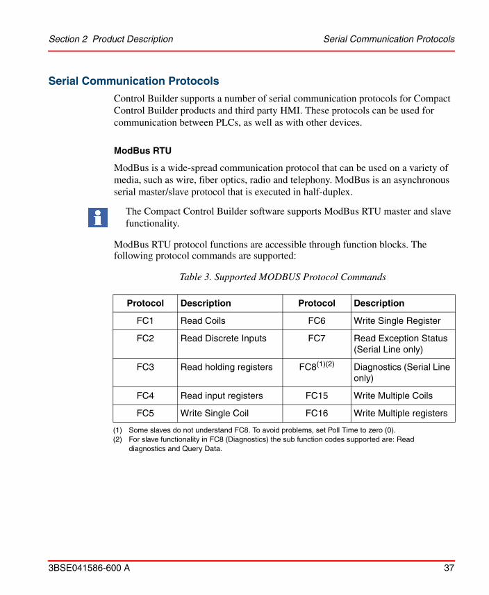
Serial Communication Protocols
Control Builder supports a number of serial communication protocols for Compact Control Builder products and third party HMI. These protocols can be used for communication between PLCs, as well as with other devices.
ModBus RTU
ModBus is a wide-spread communication protocol that can be used on a variety of media, such as wire, fiber optics, radio and telephony. ModBus is an asynchronous serial master/slave protocol that is executed in half-duplex.
ModBus RTU protocol functions are accessible through function blocks. The following protocol commands are supported:
The Compact Control Builder software supports ModBus RTU master and slave functionality.
Table 3. Supported MODBUS Protocol Commands
Protocol Description Protocol Description
FC1 Read Coils FC6 Write Single Register
FC2 Read Discrete Inputs FC7 Read Exception Status (Serial Line only)
FC3 Read holding registers FC8(1)(2)
(1) Some slaves do not understand FC8. To avoid problems, set Poll Time to zero (0).(2) For slave functionality in FC8 (Diagnostics) the sub function codes supported are: Read
diagnostics and Query Data.
Diagnostics (Serial Line only)
FC4 Read input registers FC15 Write Multiple Coils
FC5 Write Single Coil FC16 Write Multiple registers
Serial Communication Protocols Section 2 Product Description
38 3BSE041586-600 A
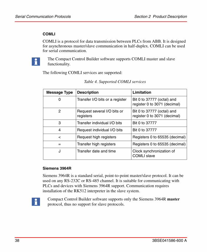
COMLI
COMLI is a protocol for data transmission between PLCs from ABB. It is designed for asynchronous master/slave communication in half-duplex. COMLI can be used for serial communication.
The following COMLI services are supported:
Siemens 3964R
Siemens 3964R is a standard serial, point-to-point master/slave protocol. It can be used on any RS-232C or RS-485 channel. It is suitable for communicating with PLCs and devices with Siemens 3964R support. Communication requires installation of the RK512 interpreter in the slave system.
The Compact Control Builder software supports COMLI master and slave functionality.
Table 4. Supported COMLI services
Message Type Description Limitation
0 Transfer I/O bits or a register Bit 0 to 37777 (octal) and register 0 to 3071 (decimal)
2 Request several I/O bits or registers
Bit 0 to 37777 (octal) and register 0 to 3071 (decimal)
3 Transfer individual I/O bits Bit 0 to 37777
4 Request individual I/O bits Bit 0 to 37777
< Request high registers Registers 0 to 65535 (decimal)
= Transfer high registers Registers 0 to 65535 (decimal)
J Transfer date and time Clock synchronization of COMLI slave
Compact Control Builder software supports only the Siemens 3964R master protocol, thus no support for slave protocols.

Section 2 Product Description Serial Communication Protocols
3BSE041586-600 A 39
The following Siemens 3964R services are supported:
Modem Communication
There are two types of modem that can be used with Control Builder:
• Short-distance modems using PPP, COMLI, Siemens 3964R, ModBus RTU or PROFIBUS DP.
• Dial-up modems using public telephone communications, COMLI is the only protocol for which dial-up modem communication is supported.
Table 5. Supported Siemens 3964R Services
Service Direction Comment
“E” message, data type D AC 800M to Siemens PLC Request for data, register
“E” message, data type E, A, M
AC 800M to Siemens PLC Request for data, byte
“E” message, data type E, A, M
AC 800M to Siemens PLC Request for data, bit
“E” message, data type D, E; A, M
Siemens PLC to AC 800M Answer to request for
data
“A” message, data type D AC 800M to Siemens PLC Transfer of data, register
“A” message, data type D AC 800M to Siemens PLC Transfer of data, bit
“A” message, data type D Siemens PLC to AC 800M Answer to transfer of
data
If COMLI is not used, it is still possible to set up serial modem communication using a phone line. In this case, the communication can be between Control Builder and a PLC, or between an external system and a PLC (using AutoConnect).

Control Network Section 2 Product Description
40 3BSE041586-600 A
There are two main reasons for using modem communication:
1. A need for increasing the maximum length of RS-232C, RS-485 and Ethernet twisted-pair connections.
2. A need for using fiber-optic communication, to eliminate either electromagnetic interference or the risk of intrusion.
Self-defined Serial Protocol
Function blocks in SerialCommLib allow implementation of a personal character oriented protocol on a serial port. It supports writing an application that both controls the characters sent and checks that the correct answer is received by using various checksum algorithms. The serial protocol can only be executed in half duplex. Accordingly it can not send and receive simultaneously. The following function block types are available:
• SerialConnect
• SerialSetup
• SerialWriteWait
• SerialListenReply
• SerialWrite
• SerialListen
A maximum 140 characters is supported. ASCII telegrams are recommended, since binary telegrams are difficult to implement.
Control Network
The recommended alternative for communication with PLCs and other devices, is Control Network, a private IP domain designed for industrial applications. Control Network is based on MMS via Ethernet or PPP on RS-232C.
Routing and redundancy functions are handled by the Redundant Network Routing Protocol (RNRP), an ABB protocol for handling redundancy and for routing between nodes in a control network, see Redundancy on page 41.

Section 2 Product Description Clock Synchronization
3BSE041586-600 A 41
Clock Synchronization
In cases where all PLCs must use the same time, for example when time stamps are useful, clock synchronization is needed. AC 800M supports clock synchronization by five different protocols – CNCP, SNTP, SNTP on CI, MB 300 Clock Sync and MMS Time Service.
CNCP is the normal protocol for clock synchronization on the Control Network. An AC 800M PLC selected as Clock Master multicasts synchronization messages on the network. CNCP is used if relative accuracy is needed, that is, the clocks between all AC 800M PLCs are synchronized with an accuracy of <1ms.
In addition SNTP is used if absolute accuracy of <1ms is needed. SNTP is a standardized protocol that typically is used by AC 800M PLCs that need to be synchronized from an external time server (for example a GPS receiver) which is connected to the Control Network.
SNTP on CI is a protocol that is used by AC 800M PLCs that have communication interfaces that can handle clock synchronization independently (for example, the CI869 that communicates with AF 100).
The AC 800M OPC Server supports the MMS Time Service for small systems where no AC 800M is used for backward compatibility with older products.
MB 300 Clock Sync is a protocol for clock synchronization of Advant/Master products on a MasterBus 300 network.
Redundancy
Control Builder supports the following redundancy functions:
• CPU redundancy for PLC (PM858, PM861, PM862, PM864, PM866, and PM891)
• Network redundancy (RNRP)
• Line redundancy (CI854)
• Master redundancy (CI854A/CI854B)
• Optical ModuleBus redundancy
• CEX-Bus redundancy (using BC810 and BC820)

Redundancy Section 2 Product Description
42 3BSE041586-600 A
CPU Redundancy
PLCs with PM858, PM861, PM862, PM864, PM866 and PM891 processors can be configured for CPU redundancy. Two CPU modules are then run in parallel, one as primary and one as secondary. If the primary CPU fails, the secondary CPU automatically takes over.
Figure 7. Example of a redundant CPU configuration.
Network Redundancy
Network redundancy is based on the Redundant Network Routing Protocol (RNRP). This protocol is an ABB protocol for handling redundancy functions and routing between nodes in a control network. The protocol is designed for rapid detection of network failure and instant switching to alternative paths.
Network redundancy requires two independent IP networks, one primary and one secondary. Whenever the maximum number of lost messages is exceeded, the traffic is switched to the secondary network.
Network redundancy can be implemented in part of the network. Nodes with one connection only must be connected to the primary network.
It is also possible to run a PLC in single CPU mode with PM858, PM861, PM862, PM864, PM866, or PM891.
The maximum number of RNRP nodes in a network area is limited to 50 nodes.
All devices with network redundancy must be connected to both networks. The node number must be identical in both networks.
CEX bus
Redundant network
Dual PLC
PM861PM861
RCU link

Section 2 Product Description Backup Media
3BSE041586-600 A 43
Line Redundancy
Line redundancy support is provided by PROFIBUS DP communication, through dual ports on the CI854 interface module. Line redundancy may be achieved for other communication by adding extra equipment.
Backup Media
The AC 800M PLCs contain a card slot located at the front of the PLC. This card slot supports backup media cards. It is possible to restore the saved configuration data and firmware data from the backup media card to the PLC.
The supported backup media cards for AC 800M PLCs are:
• Compact Flash (CF) card (supported in all AC 800M PLCs except PM891).
• Secure Digital (SD/SDHC) card (supported only in PM891).
The CF/SD memory card helps to store a compiled PLC configuration to the card and then install it into the PLC by inserting the CF/SD card. This makes it easy to distribute new software upgrades to PLCs in different locations which are not networked. The control software is installed without requiring any tool.
Compact Flash
Before downloading the application to CF card, an external Compact Flash Writer must be connected to the USB port of the Control Builder PC, if the PC does not have a built-in card reader. See also Compact Flash Requirements on page 50.
Secure Digital
Before downloading the application to SD card, an external Secure Digital Writer must be connected to the USB port of the Control Builder PC, if the PC does not have a built-in card reader. See also Secure Digital Requirements on page 50.

Cold Retain Values Section 2 Product Description
44 3BSE041586-600 A
Cold Retain Values
The cold retain values saved by Compact Flash/ Secure Digital can either be saved cyclic via settings in the hardware editor or from the code via the function block (SaveColdRetain) located in BasicLib. Either way, these values are only saved on files located on the CF/SD card. These settings do not apply for the cold retain values saved by Control Builder or OPC Server during a download.
Cold Retain Values from a Redundant CPU Configuration
However, you can always save cold retain values via the Tool menu in Control Builder so that your cold retain values will be part of the application and gets loaded to the CF or SD card.
Online Help and Manuals
Online Help
Control Builder has an extensive online help system with context-sensitive (F1) help for objects displayed in the Project Explorer. Online help can also be displayed by clicking Help in dialog boxes or selecting it under the Help menu.
Figure 8. Context-sensitive (F1) help
Customized help can be added for self-defined libraries, applications and components of externally added applications, as well as for non-standard hardware.
If you have a redundant CPU configuration; you cannot save cold retain values cyclic or by the function block.
F1

Section 2 Product Description Additional Software
3BSE041586-600 A 45
Added customized files for user-defined libraries with data types, function block types and control module types as well as for applications are displayed under User Help on the Help menu.
Context-sensitive help on user-defined libraries with hardware and non-standard hardware is available if a help file (HTML or WinHelp file with any file name) is added to the library or to the hardware type.
Online Manuals
User manuals are available from Control Builder AC 800M, in Adobe Acrobat PDF format.
Additional Software
Compact Control Builder AC 800M also contains a number of additional tools and products:
• IP Configuration tool • Serial Firmware Upgrade tool• RNRP tool
IP Configuration Tool
The IP Configuration tool is used to set PLC IP addresses via a direct serial channel. The initial IP address must be set before downloading firmware and applications to the PLC.
Serial Firmware Upgrade Tool
The Serial Firmware Upgrade tool is used to upgrade PLC CPU firmware via a direct serial channel.
RNRP Tool
Wizard for setting up routing between two PC stations on a redundant network.
Serial Firmware Upgrade Tool cannot be used for firmware upgrade of PM891. The firmware upgrade of PM891 can be done using an SD card or from the Remote System dialog in Control Builder.

OPC Server for AC 800M Section 2 Product Description
46 3BSE041586-600 A
OPC Server for AC 800MOPC Server for AC 800M gives OPC clients access to PLC data they subscribe to. The OPC server can also be used to transfer alarm and event information. It consists of two parts:
• Data Access (DA) part
• Alarm and Event (AE) part
The OPC server exposes data to the clients (DA part) and supports the transfer of alarm and event information from attached PLCs to subscribing OPC clients (AE part).
OPC Server Data Access (DA) Part
The Data Access (DA) part of the OPC server gives all OPC clients access to run-time data in PLCs.
The OPC server exposes the following data to OPC clients.
• Variables and parameters used in applications, programs, diagrams, control modules, function blocks, data structures, etc.
• Hardware configurations
• Access variables
It can also be used to store cold retain data.
The OPC server detects the following events and updates data on each.
• A new version of an application and/or a PLC configuration is downloaded.
• A new application (an application that did not previously exist) is downloaded.
• An application is deleted from a PLC.
• One application or several new ones and a PLC configuration are downloaded to a previously empty PLC.
The DA part of OPC Server for AC 800M supports the OPC Data Access 1.0a and OPC Data Access 2.05 standards.

Section 2 Product Description OPC ServerAlarm and Event (AE) Part
3BSE041586-600 A 47
OPC ServerAlarm and Event (AE) Part
The Alarm and Event (AE) part of the OPC server subscribes to alarms and events generated by PLCs and other devices in the control network. All these alarms and events are then stored and made accessible to OPC clients.
The AE part of the OPC server also collects acknowledgements and cancellations of alarms from OPC clients and forwards them to the PLC or device in question. Clients may also disable or enable alarm conditions in PLCs or devices through the OPC server.
The AE part of OPC Server for AC 800M supports the OPC Alarm and Events 1.02 standard.

OPC ServerAlarm and Event (AE) Part Section 2 Product Description
48 3BSE041586-600 A

3BSE041586-600 A 49
Section 3 Technical Data and Performance
This section describes prerequisites and requirements that must be fulfilled, in order for Compact Control Builder AC 800M and OPC Server for AC 800M, to function properly. It also contains a list of functions that, compared to 800xA System with Control Builder Professional, are not included in Compact Control Builder AC 800M.
GeneralThe PLC hardware to be used for Compact Control Builder is AC 800M only.
Firmware can be downloaded to PLC using Ethernet or via a direct serial link. Serial communication between Compact Control Builder and PLC is done by using the TK212A cable.
Compact Control Builder AC 800M Performance
A project in Compact Control Builder can handle up to 1024 applications. Each application can handle 64 programs and 128 diagrams at the most. A maximum of 32 Control Builder PCs can be used together in multi-user environment and up to 32 PLCs can be created and handled within a project.
For information about hardware and I/O, see Appendix A, Control and I/O.
Type solutions for simple logic control, device control, loop control, alarm handling etc. are located in standard libraries. An overview of all standard libraries are described in the manual Extended Control Software, Binary and Analog Handling.
AC 800M High Integrity controllers are not supported, thus SIL (Safety Integrity Level) applications cannot be handled in Compact Control Builder AC 800M.

OPC Server Performance Section 3 Technical Data and Performance
50 3BSE041586-600 A
OPC Server Performance
An OPC Server can handle up to 24 PLCs, while a PLC can handle up to 3 OPC Servers.
Compact Flash Requirements
Compact Flash Writer
• It is typically an external device, and not an onboard PC function.
Compact Flash Card
The following are the specifications required for the CF card used in AC 800M PLCs (PM8xx, except PM891):
• Formatted according to FAT16 or FAT32.
• Minimum read speed – 8MB/second.
• Minimum write speed – 6MB/second.
• Same (or better) ambient temperature operative range compared to the PM8xx that uses the card.
Secure Digital Requirements
Secure Digital Writer
• It is typically an external device, and not an onboard PC function.
Secure Digital Card
The following are the specifications required for the SDSC/SDHC/SDXC card used in AC 800M PLC (PM891):
• Formatted according to FAT32.
• Minimum read speed – 8MB/second.
• Minimum write speed – 6MB/second.
• Same (or better) ambient temperature operative range compared to the PM891 that uses the card.

Section 3 Technical Data and Performance Prerequisites and Requirements
3BSE041586-600 A 51
Prerequisites and Requirements
Compact Control Builder AC 800M
OPC Server
OPC Server for AC 800M requires the following operating system:
• Windows 7 SP1 64 bit or Windows Server 2008 R2 SP1.
• Windows 8.1 64 bit or Windows Server 2012 R2.
• Windows 10 64 bit (from version 6.0.0-1).
The following software requirement must be fulfilled in order for Compact Control Builder AC 800M to function properly. Using other software than recommended may affect performance.
Table 6. Compact Control Builder AC 800M software requirements
Software Requirement
Operating system • Windows 7 SP1 64 bit or Windows Server 2008 R2 SP1.
• Windows 8.1 64 bit or Windows Server 2012 R2.
• Windows 10 64 bit (from version 6.0.0-1)
Printing project documentation Microsoft Word 2010 or 2013 or 2016
Reading online manuals Adobe Reader version 9.0 or later
Not Supported Functions Section 3 Technical Data and Performance
52 3BSE041586-600 A
Not Supported FunctionsCompact Control Builder AC 800M is similar to the 800xA System and Control Builder Professional, with a few exceptions. The Control Builder Professional in 800xA adds the following functions, to the set of functions available in Compact Control Builder:
• Online Upgrade
• Load Evaluate Go
• Batch Handling
• Audit Trail
• Access Management / Privilege handling
• Version and State for User Libraries
• Instance specific initial values
• Reserve mechanisms, that is check-out / check-in
• SFC Viewer
• High Integrity Controller for SIL applications
• CI860 for FF HSE, and CI862 for TRIO I/O
• Information routing via HART protocol

3BSE041586-600 A 53
Section 4 Ordering and Licensing
Ordering ProcedureOne purpose of the Product Guide is to support the sales representatives when ordering Compact Products. The price lists used can all be found in the price book of the Compact Products V6. The price book includes Compact HMI, Compact Control Builder AC 800M, S800 I/O, AC 800M and Panel 800.
Price Lists StructureThe Compact Products offering and related price lists are organized in a price book. This price book consists of the price lists as described in Table 7.
This section is intended for sales representatives. It merely presents internal identity numbers for ABB price books and price lists. If you are not involved in selling Compact Products, please disregard this section completely.

Compact Control Builder AC 800M, 3BSE078498 Section 4 Ordering and Licensing
54 3BSE041586-600 A
Price Book: 3BSE045561 includes the following Price List:
Compact Control Builder AC 800M, 3BSE078498
Table 8 describes the items in the price list for Compact Control Builder AC 800M.
Table 7. Price List
Price List Article No.
Panel 800, Version 6 3BSE070940
Panel 800, Version 5 3BSE043387
AC 800M used for Compact Control 3BSE078500
Compact Control Builder AC 800M 6.0 3BSE078498
S800 I/O used for Compact Control 3BSE078499
Compact HMI 5.1 3BSE064096
Compact HMI 5.1 Expansion 3BSE064097
Compact HMI 5.0 Expansion 3BSE054250
Extended Warranty Time - S800 I/O, S900 I/O, Fieldbus and AC 800M
3BSE049908
Table 8. Items in the price list for Compact Control Builder
Item No. Description Article No.
A040 Media Box with Compact Control Builder AC 800M and OPC server for AC 800M version 6.0
This item can be ordered by users with a valid Automation Sentinel agreement for Compact Control Builder AC 800M or OPC Server for AC 800M.
It includes media and documentation for Compact Control Builder AC 800M and OPC server for AC 800M. No license is included.
3BSE046066R60

Section 4 Ordering and Licensing Compact Control Builder AC 800M, 3BSE078498
3BSE041586-600 A 55
The other price lists in the price book contain selected products that work together with the AC 800M for Compact Control.
Compact Control Builder AC 800M
A110 Compact Control Builder AC 800M 6.0
Product Box including:
- licenses for one Compact Control Builder AC 800M, one OPC Server for AC 800M, and one SoftController.
- DVD with software for Compact Control Builder AC 800M, OPC Server for AC 800M, and SoftController.
- firmware for AC 800M and its communication units.
- manuals as pdf-files.
- a Getting Started manual.
3BSE040360R60
A120 OPC Server for AC 800M 6.0
License for one OPC Server for AC 800M.
3BSE039915R60
User Documentation
H130 Compact Product Suite, Compact Control Builder AC 800M 6.0, Getting Started
3BSE041584-600
H140 Compact Product Suite, Compact Control Builder AC 800M 6.0, Configuration
3BSE040935-600
H150 Compact Product Suite, Compact Control Builder AC 800M 6.0, Planning
3BSE044222-600
H160 Compact Product Suite, Compact Control Builder AC 800M 6.0, Binary and Analog Handling
3BSE041488-600
Table 8. Items in the price list for Compact Control Builder (Continued)

Licensing Section 4 Ordering and Licensing
56 3BSE041586-600 A
LicensingThe software license is delivered as part of selected product package (A110 or A120), see Table 8 for details.
Control System Lifecycle Support Program
Automation Sentinel is the ABB control system lifecycle management program. An introductory trial period to the Automation Sentinel program will be included, at no additional cost, with each new ABB control system software delivery. Please contact your designated Automation Sentinel responsible for any questions or please refer to the Automation Sentinel 3.0 product guide (3BSE047996*) for detailed information on the program and on how to calculate and order Automation Sentinel subscriptions.
Customer Trial Subscription
The customer is entitled to get a 3 months Automation Sentinel trial subscription. This Trial subscription is free of charge and should be requested by customers through the My Control System. The purpose of this trial subscription is to give a chance to the customers (with newly purchased control systems) to try out and to become more familiar with Automation Sentinel. The trial subscription allows the customer to have access to many of the deliverables provided by the Automation Sentinel program.

Section 4 Ordering and Licensing Ordering Example
3BSE041586-600 A 57
Ordering ExampleA system integrator gets an order for a control solution where the end customer requires two PC based HMI and three AC 800M PLCs. The PLCs are configured by two engineers and the end user does not need any PLC configuration functionality. Below are the required items.
System integrator:
• Two Compact Control Builder AC 800M (license is bought by, and kept by the system integrator)
End user:
• Three AC 800M PLCs for Compact Control
• One Compact HMI license including one Server Workplace and one Client Workplace (AC 800M OPC server is included in the HMI server workplace)
Price List Items
1. From the Compact Control Builder AC 800M price list (3BSE078498), order the following items:– Two items A110 (Compact Control Builder AC 800M)
2. The AC 800M PLC items (CPUs, communication interfaces, accessories etc.) can be found in the price list, 3BSE078500.
3. From the Compact HMI price list (3BSE064096), order the following items:– One item A110 (Compact HMI)– One of the items B110, B120 or B130 (depending on number of signals)– One Compact HMI Operator Workplace Client (item D110-D160,
dependent of the size of the server)

Price List Items Section 4 Ordering and Licensing
58 3BSE041586-600 A

3BSE041586-600 A 59
Appendix A Control and I/O
This section presents performance and technical data for Control Software and Control Builder key functions, configuration, and items.
Memory and Execution Performance
Memory Size
Figure 9 shows the memory organization. The total physical memory less the executing firmware is called “Memory size” by the “SystemDiagnostics” function block. This amount of memory is sometimes also called the “heap”.
Late changes might affect performance and/or functionality. For information on late changes and restrictions on the use of the product, please refer to the Release Notes.

Memory Size Appendix A Control and I/O
60 3BSE041586-600 A
The memory usage is also displayed in the Control Builder Heap Utilization dialog which can be displayed for each controller. The available memory is called “Non-Used Heap” and the rest is called “Used Shared Heap”.
Figure 9. The Memory Organization
Available Memory“Non-used heap”
Memory Size “Heap”
Empty Project
Used by Firmware
Executing Firmware
Spare (20-50%)
8-256 MB RAMUsed
Shared Heap
Max Used Shared Heap
Application Memory

Appendix A Control and I/O Available Memory
3BSE041586-600 A 61
Available Memory
The amount of free memory in the controller decreases when the controller has started up, and an empty project has been downloaded from Control Builder M.
The remaining memory is what can be used for application code, and is hereafter referred as to “Available memory”.
The measurement results in Table 9 are made with IAC, but without any configured communication protocols and CEX units. Memory consumptions for used protocols and CEX units have to be added, according to Table 10.
Table 9. Available RAM Memory and Performance in AC 800M Controller (without Protocol Handlers)
ControllerExecution
Performance Factor
Total RAM (kbytes)
Firmware and an Empty Project
(kbytes)
AvailableMemory (kbytes)
PM851 0.5 8192 5963 2228
PM851A 0.5 12288 5973 6314
PM856 0.5 8192 5963 2228
PM856A 0.5 16384 5983 10400
PM858 0.6 16384 9143 7240
PM860 1.0 8192 5963 2228
PM860A 1.0 16384 5979 10404
PM861 1.0 16384 9143 7240
PM861A 1.0 16384 9143 7240
PM862 1.2 32767 14147 18620
PM864 1.5 32767 9165 23602
PM864A 1.5 32767 9165 23602
PM866 2.1 65535 14146 51390
PM866A 2.1 65535 14147 51389
PM891 4.5 262144 53159 208985

Available Memory Appendix A Control and I/O
62 3BSE041586-600 A
Table 10. Memory Consumptions of Protocols and CEX Units
Protocol/CEX Unit
PM864 PM866 PM891
First Unit
(kbytes)
Next Unit
(kbytes)
First Unit
(kbytes)
Next Unit
(kbytes)
First Unit
(kbytes)
Next Unit
(kbytes)
MODBUS RTU 96 14 95 14 84 4
COMLI 72 15 71 15 60 4
S3964R 65 13 63 13 54 4
SerialLib 61 18 60 17 48 6
IAC* 167 NA 174 NA 148 NA
UDP 43 NA 42 NA 35 NA
TCP 53 NA 46 NA 44 NA
CI853 2 4 5 4 5 4
CI854A/B 247 33 247 32 167 14
CI855 94 12 96 11 95 3
CI856 103 13 103 13 97 5
CI857 182 12 178 13 173 4
CI858 62 19 64 19 60 7
CI865 148 73 132 73 140 73
CI867 166 35 169 36 175 33
CI868 174 75 177 74 114 4
CI869 153 64 157 63 97 5
CI871 185 38 190 38 189 29
CI872 208 68 213 67 160 8
CI873 200 101 208 101 155 42
NOTE:*In addition, each communication connection requires about 40 kbytes memory.

Appendix A Control and I/O Execution Performance
3BSE041586-600 A 63
Execution Performance
Cyclic CPU load is calculated as a percentage using the following formula.
Cyclic CPU load (%) = 100*(Total execution time / Total interval time)
Depending on the amount of code and requested task interval times, applications may demand up to 70% of CPU capacity (never more)1; the execution of IEC 61131-3 code is called Cyclic Load. Should an application require more than 70% of CPU capacity, the task scheduler automatically increases the task interval times to re-establish a 70% load.
It is important to consider CPU load if communication handling is vital to the application. Running at the maximum cyclic load will result in poor capacity and response times for peer-to-peer and OPC Server communication.
Communication handling has the lowest priority in a controller. It is therefore important to consider controller CPU load if the communication handling is vital to the application. Running close to 100% total load will result in poor capacity and response times for peer-to-peer and (OPC Server for AC 800M) communication. It is recommended that peak total load will be kept below 100%.
Among the communication protocols, the IAC MMS protocol will be the last to be affected if there is a communication data starvation.
CPU load is also influenced by other factors, such as Modulebus scan interval and the number of modules on Modulebus (AC 800M), or the scanning of ABB Drives.
The PM860/PM860A and PM861/PM861A processor units have the same internal design and the same performance when execution application program.
The PM851/PM851A, PM856/PM856A and PM860/PM860A processor units have the same design. They differ only in performance when executing an application program. The execution time in PM851/PM851A and PM856/PM856A is approximately two times the execution time in PM860/PM860A.
The execution time in PM858 is four times the execution time in PM866.
The execution time in PM862 is two times the execution time in PM866.
1. This is not true if load balancing is set to false. The controller will run until it is forced to stop.
Load balancing can be disabled (see the manual Compact Control Builder Configuration, 3BSE040935*).

Spare Memory Needed for Online Changes Appendix A Control and I/O
64 3BSE041586-600 A
The PM864/PM864A processor unit, in single configuration, has performance data which theoretically peaks at twice the performance compared to the PM860/PM860A. The useful sustained performance improvement is, however, a bit lower and dependent on the actual application program but can be expected to be 10 to 50% compared to PM860/PM860A. The difference in execution performance is dependent on how much CEX bus accesses, and how much communication is running in the controller (both communication running as CEX bus interfaces and communication running on the built in ports on the CPU i.e. ModuleBus, Ethernet and RS-232). CEX bus access and communication decreases execution performance.
In redundant configuration the execution performance is lower than in single configuration (reduction is typically less than 10%). Switch over time from primary controller to backup controller, in redundant configuration, is less than 10 ms.
The PM866 processor unit has performance data which is approximately 1.4 times the performance of PM864/PM864A.
The PM891 processor unit has performance data which is approximately 2 times the performance of PM866.
Spare Memory Needed for Online Changes
As a general rule, an application should never exceed half the size of the available memory. The reason for this is the manner in which applications are updated online.
1. The modifications (the difference between the old and the updated application) are downloaded to the controller memory.
2. A new version of the application is created in controller memory, based on the old application and the modifications.
3. The controller switches from the old to the new application.
4. The old application is deleted.
This technique handles all updates in a controlled and efficient way. Free memory equal to the size of the largest application is required.
If an application comes close to this limit, it should be divided into two parts so that they can be updated separately.

Appendix A Control and I/O Comparing Memory Allocations Made with Different Versions
3BSE041586-600 A 65
One Application in the Controller
There must be spare memory in the available memory in order to be able to make on-line changes shown in the Figure 9. The amount of spare memory must be at least 20% of available memory, and may require up to 50%.
A minimum of 20% spare available memory may be sufficient, depending on a number of factors, such as the complexity of the application and the number of defined alarms.
The function block SystemDiagnostics also presents another figure: the “Maximum used memory”. This figure is presented in actual bytes, and as a percentage of the memory size. This figure is far more useful to look at when determining how close you are to being unable to make on-line changes. Several on-line changes must be made in order to catch the maximum memory need in the controller.
It is still possible to make on-line changes as long as the maximum used memory value is less than 100%.
More than One Application in the Controller
Less spare memory is needed when there is more than one application in the controller.
The on-line changes are done to one application at the time. This means that if changes are done to more than one application in the controller, these changes will not take effect in a synchronized way.
Example: One application requires 50% used memory and 70% maximum used memory. If you split this application into two equally smaller applications, it will still require 50% used memory, but only 60% maximum used memory, since the extra memory needed for the on-line changes will be half.
Comparing Memory Allocations Made with Different Versions
From the discussions above, you can see that the “used memory” value provided by the SystemDiagnostics function block cannot be used to compare different versions.
The function block “SystemDiagnostics” reports used memory based on the memory size, not on the available memory, but the dialog “Heap Utilization” will show the available memory as “Non-Used Heap”.

Memory Consumption and Execution Times Appendix A Control and I/O
66 3BSE041586-600 A
The amount of available memory in the controller varies between versions for a number of reasons, one being the number of functions implemented in the firmware.
Memory Consumption and Execution Times
Memory is reserved for each function block type defined. When another instance is created, the amount of memory reserved for the instance is very small in relation to the type. This means that the memory consumed by the type itself is of great importance.
The following tables show memory consumption and execution time for AC 800M PM864/PM866/PM891 controllers, for a number of common function blocks and control modules.
In the tables the First Object column shows the required memory for the object type and one function block or control module and Next Object column shows the required memory for every further function block or control module.
Table 11. AC 800M Memory Consumption for Function Blocks and Control Modules
Library Object
PM864 PM866 PM891
First Object (kbyte)
Next Object (kbyte)
First Object (kbyte)
Next Object (kbyte)
First Object (kbyte)
Next Object (kbyte)
Function Blocks
AlarmEventLib AlarmCondBasic 4,1 0,6 5,3 0,8 4,3 1,8
AlarmEventLib AlarmCond 5,4 0,9 7,2 1,5 5,7 2,0
ControlBasicLib PidLoop 62,2 5,5 64,1 5,8 54,4 6,3
ControlBasicLib PidLoop3P 64,0 7,5 67,4 6,8 56,7 7,3
ControlBasicLib PidCascadeLoop 75,2 11,4 76,5 13,7 66,8 14,0
ControlBasicLib PidCascadeLoop3P 76,7 14,3 80,5 13,7 70,1 14,2
ControlSimpleLib PidSimpleReal 10,7 1,2 24,1 1,8 10,1 2,2

Appendix A Control and I/O Memory Consumption and Execution Times
3BSE041586-600 A 67
ProcessObjectDriveLib
ACStdDrive 80,7 12,1 93,7 17,2 80,9 16,6
ProcessObjectExtLib Uni 53,5 6,0 66,1 8,7 52,3 9,0
ProcessObjectExtLib Bi 62,0 8,0 59,0 14,2 60,6 12,5
ProcessObjectExtLib MotorUni 63,5 7,6 59,7 11,5 62,0 11,3
ProcessObjectExtLib MotorBi 73,3 9,9 68,2 14,5 71,9 15,4
ProcessObjectExtLib ValveUni 52,8 5,5 47,3 8,1 51,3 8,6
ProcessObjectInsumLib
McuExtended 109,2 25,5 107,4 28,5 112,0 28,5
SignalBasicLib SignalBasicBool 4,4 0,3 3,9 0,5 2,2 1,1
SignalBasicLib SignalBasicInBool 5,6 0,4 4,2 0,7 4,8 1,2
SignalBasicLib SignalBasicInReal 10,6 1,9 9,4 1,9 8,9 1,9
SignalBasicLib SignalBasicOutBool 6,0 1,2 4,3 1,2 2,6 1,2
SignalBasicLib SignalBasicOutReal 6,9 1,6 5,7 1,6 4,8 1,5
SignalBasicLib SignalBasicReal 5,9 1,3 4,1 1,3 4,3 1,4
SignalLib SignalInBool 29,1 2,8 20,8 3,6 26,6 4,2
SignalLib SignalOutBool 28,8 2,7 20,1 3,7 26,0 4,3
SignalLib SignalSimpleInReal 29,0 2,3 20,3 3,3 25,5 3,9
SignalLib SignalInReal 64,0 7,6 55,2 10,6 60,5 10,6
SignalLib SignalSimpleOutReal
17,8 2,0 17,8 2,9 22,1 3,5
SignalLib SignalOutReal 58,9 6,9 52,9 9,0 57,0 9,5
SupervisionBasicLib SDBool 24,4 4,9 24,3 4,9 23,1 5,5
Table 11. AC 800M Memory Consumption for Function Blocks and Control Modules (Continued)
Library Object
PM864 PM866 PM891
First Object (kbyte)
Next Object (kbyte)
First Object (kbyte)
Next Object (kbyte)
First Object (kbyte)
Next Object (kbyte)
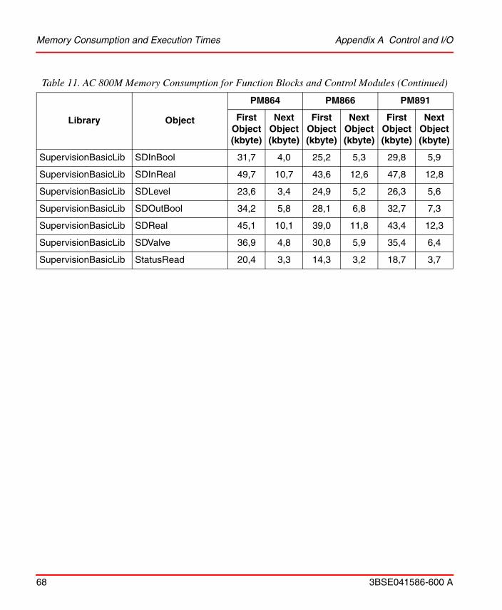
Memory Consumption and Execution Times Appendix A Control and I/O
68 3BSE041586-600 A
SupervisionBasicLib SDInBool 31,7 4,0 25,2 5,3 29,8 5,9
SupervisionBasicLib SDInReal 49,7 10,7 43,6 12,6 47,8 12,8
SupervisionBasicLib SDLevel 23,6 3,4 24,9 5,2 26,3 5,6
SupervisionBasicLib SDOutBool 34,2 5,8 28,1 6,8 32,7 7,3
SupervisionBasicLib SDReal 45,1 10,1 39,0 11,8 43,4 12,3
SupervisionBasicLib SDValve 36,9 4,8 30,8 5,9 35,4 6,4
SupervisionBasicLib StatusRead 20,4 3,3 14,3 3,2 18,7 3,7
Table 11. AC 800M Memory Consumption for Function Blocks and Control Modules (Continued)
Library Object
PM864 PM866 PM891
First Object (kbyte)
Next Object (kbyte)
First Object (kbyte)
Next Object (kbyte)
First Object (kbyte)
Next Object (kbyte)

Appendix A Control and I/O Memory Consumption and Execution Times
3BSE041586-600 A 69
Control Modules
AlarmEventLib AlarmCondBasicM 5,1 1,8 5,8 1,4 12,5 0,9
AlarmEventLib AlarmCondM 6,8 1,1 5,7 0,9 13,3 2,8
ControlAdvancedLib PidAdvancedCC 209,0 23,4 198,3 31,4 199,4 22,9
ControlSolutionLib CascadeLoop 232,8 60,9 229,6 64,3 224,7 58,9
ControlSolutionLib FeedforwardLoop 233,1 43,8 234,6 47,4 214,3 52,3
ControlSolutionLib MidRangeLoop 232,5 44,6 233,6 48,1 218,4 47,7
ControlSolutionLib OverrideLoop 319,0 114,4 318,8 114,5 300,6 113,7
ControlSolutionLib SingleLoop 229,9 36,0 227,4 36,4 205,7 36,0
ControlStandardLib AnalogInCC 20,9 3,6 21,3 3,7 20,1 3,8
ControlStandardLib AnalogOutCC 19,3 3,6 16,2 3,6 14,4 3,8
ControlStandardLib Level2CC 22,6 4,6 21,7 4,7 18,3 4,6
ControlStandardLib Level4CC 30,0 6,5 29,8 6,6 27,6 6,5
ControlStandardLib Level6CC 37,4 8,5 37,5 8,2 35,7 8,1
ControlStandardLib PidCC 109,5 16,0 145,3 16,1 125,5 15,6
ControlStandardLib PidSimpleCC 16,0 2,6 14,1 2,5 12,2 2,6
ControlStandardLib ThreePosCC 42,1 4,2 56,5 4,6 44,4 4,2
ProcessObjectDriveLib
ACStdDriveM 83,3 16,8 118,0 17,8 109,4 16,2
ProcessObjectExtLib UniM 51,7 9,4 90,2 9,3 78,5 9,2
ProcessObjectExtLib BiM 61,0 12,1 96,5 15,8 87,3 12,6
ProcessObjectExtLib MotorUniM 61,9 10,1 63,9 13,4 87,7 10,8
ProcessObjectExtLib MotorBiM 71,4 14,3 106,1 17,6 97,1 14,4
Table 11. AC 800M Memory Consumption for Function Blocks and Control Modules (Continued)
Library Object
PM864 PM866 PM891
First Object (kbyte)
Next Object (kbyte)
First Object (kbyte)
Next Object (kbyte)
First Object (kbyte)
Next Object (kbyte)

Memory Consumption and Execution Times Appendix A Control and I/O
70 3BSE041586-600 A
ProcessObjectExtLib ValveUniM 51,1 8,8 88,2 10,7 77,7 25,6
ProcessObjectInsumLib
McuExtendedM 111,0 28,6 145,4 32,8 138,3 27,8
SignalLib SignalInBoolM 24,8 4,1 24,4 3,7 51,4 4,1
SignalLib SignalOutBoolM 24,4 3,8 24,7 4,4 51,2 3,8
SignalLib SignalInRealM 64,1 10,0 63,9 11,8 90,2 9,9
SignalLib SignalOutRealM 59,1 10,3 62,2 10,3 84,7 10,2
Table 12. AC 800M Execution Time for Function Blocks and Control Modules
Library ObjectPM864
(s)
PM866
(s)
PM891
(s)
Function Blocks
AlarmEventLib AlarmCondBasic 20 15 9
AlarmEventLib AlarmCond 32 23 15
AlarmEventLib ProcessObjectAE 21 15 9
AlarmEventLib SignalAE 31 23 14
AlarmEventLib SimpleEventDetector 38 28 16
BasicLib CTD 8 5 2
BasicLib CTU 8 5 3
BasicLib CTUD 10 8 4
BasicLib ErrorHandler 9 6 3
BasicLib F_Trig 5 4 2
BasicLib ForcedSignals 29 21 12
BasicLib PulseGenerator 8 6 3
BasicLib R_Trig 5 4 2
Table 11. AC 800M Memory Consumption for Function Blocks and Control Modules (Continued)
Library Object
PM864 PM866 PM891
First Object (kbyte)
Next Object (kbyte)
First Object (kbyte)
Next Object (kbyte)
First Object (kbyte)
Next Object (kbyte)

Appendix A Control and I/O Memory Consumption and Execution Times
3BSE041586-600 A 71
BasicLib RS 5 3 2
BasicLib SR 5 4 2
BasicLib SystemDiagnostics 160 445 187
BasicLib TimerD 45 31 15
BasicLib TimerU 34 26 10
BasicLib TOf 8 6 3
BasicLib TOn 8 6 4
BasicLib TP 8 6 3
ControlBasicLib PidLoop 343 244 103
ControlBasicLib PidLoop3P 410 281 113
ControlBasicLib PidCascadeLoop 618 428 179
ControlBasicLib PidCascadeLoop3P 666 486 173
ControlSimplelib PidSimpleReal 71 52 18
ProcessObjBasiclib BiSimple 191 137 81
ProcessObjBasiclib UniSimple 120 85 50
ProcessObjDriveLib ACStdDrive 584 402 217
ProcessObjExtLib Bi 320 248 134
ProcessObjExtLib MotorBi 417 286 166
ProcessObjExtLib MotorUni 311 217 134
ProcessObjExtLib Uni 197 131 87
ProcessObjExtLib ValveUni 205 150 93
ProcessObjInsumLib McuExtended 534 356 226
SignalBasicLib SignalBasicBooI 7 5 2
SignalBasicLib SignalBasicInBooI 7 5 3
SignalBasicLib SignalBasicInReal 79 36 17
SignalBasicLib SignalBasicOutBool 7 5 3
SignalBasicLib SignalBasicOutReal 13 9 4
SignalBasicLib SignalBasicReal 15 12 4
Table 12. AC 800M Execution Time for Function Blocks and Control Modules (Continued)
Library ObjectPM864
(s)
PM866
(s)
PM891
(s)

Memory Consumption and Execution Times Appendix A Control and I/O
72 3BSE041586-600 A
SignalLib SignalBool 55 41 24
SignalLib SignalInBool 46 34 17
SignalLib SignalInReal 210 145 82
SignalLib SignalOutBool 48 33 22
SignalLib SignalOutReal 125 90 52
SignalLib SignalReal 154 112 60
SignalLib SignalSimpleInReal 84 58 34
SignalLib SignalSimpleOutReal 40 30 18
SupervisionBasicLib SDBooI 127 83 49
SupervisionBasicLib SDlnBool 94 65 37
SupervisionBasicLib SDInReal 266 185 109
SupervisionBasicLib SDLevel 77 56 38
SupervisionBasicLib SDOutBool 129 86 49
SupervisionBasicLib SDReal 230 182 74
SupervisionBasicLib SDValve 165 121 66
SupervisionBasicLib StatusRead 35 25 14
Control Modules
AlarmEventLib AlarmCondBasicM 30 21 15
AlarmEventLib AlarmCondM 25 16 10
BasicLib CVAckISP 47 33 20
BasicLib ErrorHandlerM 16 11 5
BasicLib ForcedSignalsM 36 25 15
ControlAdvancedLib PidAdvancedCC 994 722 316
ControlSolutionLib CascadeLoop 2016 1452 709
ControlSolutionLib FeedforwardLoop 1677 1161 546
ControlSolutionLib MidrangeLoop 1505 1066 483
ControlSolutionLib OverrideLoop 3859 2805 1370
Table 12. AC 800M Execution Time for Function Blocks and Control Modules (Continued)
Library ObjectPM864
(s)
PM866
(s)
PM891
(s)

Appendix A Control and I/O Memory Consumption and Execution Times
3BSE041586-600 A 73
ControlSolutionLib SingleLoop 1187 863 406
ControlSolutionLib AnalogInCC 104 78 36
ControlSolutionLib AnalogOutCC 87 62 33
ControlSolutionLib Level2CC 63 46 28
ControlSolutionLib Level4CC 89 64 39
ControlSolutionLib Level6CC 119 96 52
ControlSolutionLib PidCC 595 419 218
ControlSolutionLib PidSimpleCC 110 77 37
ControlSolutionLib ThreePosCC 179 125 59
ProcessObjBasicLib BiSimpleM 205 133 75
ProcessObjBasicLib UniSimpleM 126 97 50
ProcessObjDriveLib ACStdDriveM 594 428 237
ProcessObjExtLib BiM 333 235 141
ProcessObjExtLib MotorBiM 401 306 162
ProcessObjExtLib MotorUniM 318 220 130
ProcessObjExtLib UniM 211 148 97
ProcessObjExtLib ValveUniM 205 145 96
ProcessObjInsumLib McuExtendedM 521 378 238
SignalLib SDLevelAnd4 27 20 10
SignalLib SDLevelBranch4 19 14 7
SignalLib SDLevelM 104 71 45
SignalLib SDLevelOr4 23 16 8
SignalLib SignalBoolCalcInM 70 48 31
SignalLib SignalBoolCalcOutM 87 62 35
SignalLib SignalInBoolM 62 44 24
SignalLib SignalInRealM 246 181 103
SignalLib SignalOutBoolM 67 50 31
Table 12. AC 800M Execution Time for Function Blocks and Control Modules (Continued)
Library ObjectPM864
(s)
PM866
(s)
PM891
(s)

Memory Consumption and Execution Times Appendix A Control and I/O
74 3BSE041586-600 A
SignalLib SignalOutRealM 210 140 88
SignalLib SignalRealCalcInM 228 165 88
SignalLib SignalRealCalcOutM 236 183 97
SignalLib Vote1oo1Q 222 158 80
SignalLib VoteBranch4 41 30 17
SignalLib VotedAnd4 36 27 15
SignalLib VotedBranch4 25 17 10
SignalLib VoteXoo2D 256 179 92
SignalLib VoteXoo3Q 289 186 90
SignalLib VoteXoo8 302 265 103
Table 13. Execution Time for a Number of Standard Operations and Function Calls
Operation/Function Data TypePM864
(s)
PM866
(s)
PM891
(s)
a:= b or c bool 0,7 0,5 0,2
a:= b and c bool 0,6 0,5 0,3
a:= b xor c bool 0,7 0,5 0,2
a := b + c dint 0,6 0,5 0,3
a := b + c real 1,9 1,3 0,2
a := b - c dint 0,6 0,5 0,2
a := b - c real 1,7 1,2 0,2
a := b * c dint 0,6 0,5 0,3
a := b * c real 1,7 1,2 0,3
a := b / c dint 1,0 0,7 0,5
Table 12. AC 800M Execution Time for Function Blocks and Control Modules (Continued)
Library ObjectPM864
(s)
PM866
(s)
PM891
(s)

Appendix A Control and I/O Memory Consumption and Execution Times
3BSE041586-600 A 75
a := b / c real 4,0 2,9 0,6
a:= b <> c dint 0,8 0,6 0,3
a:= b <> c real 1,8 1,3 0,3
a := b string[140] 8,5 6,3 2,8
a := b + c string[10] 17,5 12,0 3,5
a := b + c string[40] 17,8 13,0 2,7
a := b + c string[140] 28,1 20,0 5,8
a := AddSuffix (b + c) string[10] 4,0 3,2 1,4
a := AddSuffix (b + c) string[40] 7,7 5,1 2,4
a := AddSuffix (b + c) string[140] 16,1 12,1 4,1
a := real_to_dint(b) dint 15,4 11,6 1,0
a := dint_to_real(b) real 1,9 1,4 0,3
a := real_to_time(b) time 22,0 15,5 1,5
a := time_to_real(b) real 6,1 4,4 0,8
Table 13. Execution Time for a Number of Standard Operations and Function Calls
Operation/Function Data TypePM864
(s)
PM866
(s)
PM891
(s)
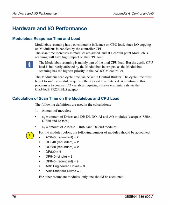
Hardware and I/O Performance Appendix A Control and I/O
76 3BSE041586-600 A
Hardware and I/O Performance
Modulebus Response Time and Load
Modulebus scanning has a considerable influence on CPU load, since I/O copying on Modulebus is handled by the controller CPU. The scan time increases as modules are added, and at a certain point Modulebus scanning will have high impact on the CPU load.
The Modulebus scan cycle time can be set in Control Builder. The cycle time must be set to suit the module requiring the shortest scan interval. A solution to this problem is to connect I/O variables requiring shorter scan intervals via the CI854A/B PROFIBUS adaptor.
Calculation of Scan Time on the Modulebus and CPU Load
The following definitions are used in the calculations:
1. Amount of modules:
• n1 = amount of Drives and DP, DI, DO, AI and AO modules (except AI880A, DI880 and DO880)
• n2 = amount of AI880A, DI880 and DO880 modules
The Modulebus scanning is mainly part of the total CPU load. But the cyclic CPU load is indirectly affected by the Modulebus interrupts, as the Modulebus scanning has the highest priority in the AC 800M controller.
For the modules below, the following number of modules should be accounted:• AO845 (redundant) = 2
• DO840 (redundant) = 2
• DO880 (redundant) = 2
• DP820 = 4
• DP840 (single) = 8
• DP840 (redundant) = 9
• ABB Engineered Drives = 3
• ABB Standard Drives = 2
For other redundant modules, only one should be accounted.

Appendix A Control and I/O Calculation of the Modulebus CPU Load
3BSE041586-600 A 77
2. Scan time for different modules:
t1 = 0.5 ms (scan time for n1)
t2 = 1.3 ms (scan time for n2)
Calculation of Fastest Possible Scan Time
The fastest possible scan time is n1* t1 + n2* t2.
Example:It can never take less than 10 * 0.5 = 5.0 ms to scan 10 I/O modules.
Calculation of the Modulebus CPU Load
The maximum load caused by n1 (non High Integrity I/O) module types:
L1 = 31%
The maximum load caused by n2 (High Integrity I/O) module types:
L2 = 20%
The L1 and L2 values are valid for all AC 800M processor unit types, except for the ones listed below.
PM866, PM862 and PM858: L1= 16% and L2= 10%PM867: L1 = 26% and L2 = 19%PM891: L1 = 10% and L2=7%
The Modulebus scanning causes the following CPU load if the chosen scan cycle time is less or equal to the fastest possible scan time:
Load(fastest) = (n1 / (n1 + n2) * L1 + (n2 / (n1 + n2) * L2)
The following CPU load is caused for other scan cycle times:
Load(chosen) = Fastest Possible Scan Time / Chosen Scan time * Load(fastest)
The Fastest Possible Scan Time to be used in the formula is without the SIL3 addition.

Example Scan Time and Cyclic Load Appendix A Control and I/O
78 3BSE041586-600 A
Example Scan Time and Cyclic Load
Assume that following units are used:
1 AI810: 0.5*1 = 0.5 ms1 redundant DO880: 1.3*2 = 2.6 ms1 redundant DP840: 0.5*9 = 4.5 ms
This means that n1=10 and n2=2, and fastest possible scan cycle time is 8 ms (resolution of 1 ms).
CPU Load will be: (10/12)*31 + (2/12)*20 = 29.16%
Updating Rate of Data to an Application
The rate in milliseconds at which all channels of an I/O module are updated in the controller to be used in the IEC 61131-3 application, as a function of the scan time in milliseconds is as follows:
• For AI, AO and AI843 (except AI880A and other temperature measuring I/O than AI843) the updating time is equal to number of channels divided by two multiplied by the scan time.
• For temperature measuring I/O (except for AI843) the updating time is equal to number of channels multiplied by the scan time.
• For Standard Drives the updating time is equal to scan time.
• For Engineered Drives the updating time is equal to scan time multiplied by 12.
• For DI, DO, DP the updating time is equal to scan time.

Appendix A Control and I/O ModuleBus Scanning of ABB Drives
3BSE041586-600 A 79
ModuleBus Scanning of ABB Drives
Scanning of ABB Drives on Modulebus also influences CPU load.
Modulebus Scanning of ABB Engineered Drives (AC 800M)
Scanning of an engineered Drive is distributed over 3 * 12 scan cycles. Three channels (DDS pairs) are scanned in each scan cycle. The first two are always channels 1 and 2 (i.e. DDS pairs 10/11 and 12/13); the third will be different for each scan cycle.
To scan the three DDS pairs each cycle takes 3 * 0.5 = 1.5 ms. It is not possible to have a scan interval less then 2 ms (=PA controller) / 5 ms =HI controller) for the Modulebus scanner. Thus, for one drive the scan time will be 2 ms.
Example
For four drives, the scan time will be 1.5 ms * 4 = 6.0 ms for the DDS pairs 10/11 and 12/13, and the scan time for the remaining of the DDS pairs will be 1.5 ms * 4 * 12 = 72.0 ms.
ModuleBus Scanning of ABB Standard Drives (AC 800M)
For ABB Standard Drives, all data sets (DDS 1/2 and DDS 3/4) are scanned in each scan cycle. It takes 2 * 0.5 = 1.0 ms to scan a single Standard Drive.
Example
For four ABB Standard Drives the scan time will be 1.0 ms * 4 = 4.0 ms.
Table 14. Scan cycles for ABB Engineered Drives DDS Pair 3
Scan Cycle DDS Pair 3
1, 5, 9 14/15
2, 6, 10 16/17
3, 7 11 18/19
4 20/21
8 22/23
12 24/25

Dynamic Data Exchange S800 I/O Connected via CI854A/B Appendix A Control and I/O
80 3BSE041586-600 A
Dynamic Data Exchange S800 I/O Connected via CI854A/B
The transportation of dynamic data between PROFIBUS-DP/DPV1 master and the S800 I/O modules shown in the Figure 10.
The transportation of dynamic data between PROFIBUS-DP/DPV1 and the ModuleBus is the main task for the Field Communication Interface FCI. The FCI
Figure 10. Transportation of dynamic data between PROFIBUS-DP/DPV1 master and S800 I/O modules.

Appendix A Control and I/O Dynamic Data Exchange S800 I/O Connected via CI854A/B
3BSE041586-600 A 81
has a dedicated memory area where it sends the output values and reads the input values.
The CPU in the FCI performs the rest of the data transportation. It reads output values from the memory and writes to the I/O Modules via the ModuleBus and vice versa.
Data Scanning Principles
The data transfer between PROFIBUS-DP/DPV1 and the ModuleBus (3 and 4 in the figure) is not synchronized. Read and write operations are performed from and to a dual port memory in the FCI.
The ModuleBus data is scanned (read or written) (2 and 5 in the figure) cyclically, depending on the I/O module configuration. On one scan all digital modules, 1/4 of the analog modules and 1/10 of the slow analog modules (modules for temperature measurement) are scanned. It takes 4 scans to read all analog modules and 10 scans to read all slow analog modules.
In a typical configuration with 3 AI, 2 AO, 3 DI and 2 DO modules the data scan time will be 18 ms.
For calculation of the ModuleBus data scanning in the FCI, see S800 I/O User’s Guide Fieldbus Communication Interface PROFIBUS-DP/DPV1 Section 3 Configuration and Chapter Data Scanning.
The internal data scanning (1 and 6 in the figure) on the I/O modules is not synchronized with the ModuleBus data scanning.
Typical data scanning on S800 I/O modules (filter times not included):
Digital modules 1ms.
Analog modules 10ms.
Slow analog modules 1s.
Data scanning on S800 I/O modules see, S800 User’s Guide Module and termination Units Appendix A Specifications.
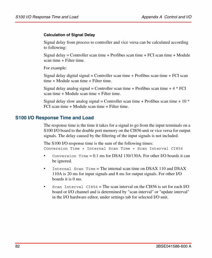
S100 I/O Response Time and Load Appendix A Control and I/O
82 3BSE041586-600 A
Calculation of Signal Delay
Signal delay from process to controller and vice versa can be calculated according to following:
Signal delay = Controller scan time + Profibus scan time + FCI scan time + Module scan time + Filter time.
For example:
Signal delay digital signal = Controller scan time + Profibus scan time + FCI scan time + Module scan time + Filter time.
Signal delay analog signal = Controller scan time + Profibus scan time + 4 * FCI scan time + Module scan time + Filter time.
Signal delay slow analog signal = Controller scan time + Profibus scan time + 10 * FCI scan time + Module scan time + Filter time.
S100 I/O Response Time and Load
The response time is the time it takes for a signal to go from the input terminals on a S100 I/O board to the double port memory on the CI856 unit or vice versa for output signals. The delay caused by the filtering of the input signals is not included.
The S100 I/O response time is the sum of the following times:Conversion Time + Internal Scan Time + Scan Interval CI856
• Conversion Time = 0.1 ms for DSAI 130/130A. For other I/O boards it can be ignored.
• Internal Scan Time = The internal scan time on DSAX 110 and DSAX 110A is 20 ms for input signals and 8 ms for output signals. For other I/O boards it is 0 ms.
• Scan Interval CI856 = The scan interval on the CI856 is set for each I/O board or I/O channel and is determined by "scan interval" or "update interval" in the I/O hardware editor, under settings tab for selected I/O unit.

Appendix A Control and I/O S100 I/O Response Time and Load
3BSE041586-600 A 83
Calculation of CI856 CPU Load
For each I/O board the load on CI856 is calculated as:
BoardLoad = (BaseLoad + N*ChannelLoad)/CycleTime
• BoardLoad = the CPU load on the CI856 caused by the board (unit = percent).• BaseLoad = the base load to handle the board, see Table 15 below.• ChannelLoad = the additional load for each I/O channel used on the board,
see Table 15 below.• N = number of used I/O channels on the board.• CycleTime = the cycle time or update interval set for the board or I/O channel
(unit = 0.1 ms).
To allow scan task overhead and event treatment, the total load from all I/O boards should not exceed 80%.
Table 15. BaseLoad and ChannelLoad of S100 I/O
Board BaseLoad ChannelLoad
DSAI 130/130A 20 125
DSAI 130D, DSAI 133/133A 20 40
DSAO 7 3.5
DSDI 35 0
DSDO 45 0
DSDP 010 12 22
DSDP 170Function Mode = Pulse25
25 30
DSDP 170
Function Mode = Frequency
25 30
DSDP 170Function Mode = Pulse + Frequency
25 61
DSDP 170
Function Mode = Pulse light2513
25 13

Drivebus Communication with CI858 Unit Appendix A Control and I/O
84 3BSE041586-600 A
Drivebus Communication with CI858 Unit
Data transfer on Drivebus is managed through datasets pairs. For standard drives 2 dataset pairs can be used and for Engineered drives up to 8 data set pairs can be defined.
Dataset Priority
Datasets can be given two priorities, High and Normal. High priority datasets are associated with the high priority execution table which is scanned every 2 ms. Normal priority datasets are associated with the normal priority execution table. This table is built-up of several channels (slots). The number of channels depends on the maximum number of normal priority Datasets defined in any drives unit on the bus. Every 2 ms one of the normal priority table channels is scanned.
Example Dataset Priority
If the maximum number of low priority datasets defined in a drives unit on the bus is 6, the normal priority execution table contains 6 channels, each channel is scanned every 12th millisecond (2ms * 6=12ms).
Dataset Pairs
The transfer times for dataset pairs, for example, DS10/DS11, includes transferring the message from the drive to the AC 800M (DS10) and the response message, including return value, back to the drives unit (DS11).
Drivebus (CI858) Response Time and Load
When calculating the response times between drives units and AC 800M on Drivebus the following has to be considered:
• Application task interval time in the host system, that is PM86x.• Dataset execution queue and communication handler in the CI858, • Bus transfer time, including data handling time in the communication ASICs
on the CI858 and in the drives units.• Drives unit application program.

Appendix A Control and I/O Drivebus Communication with CI858 Unit
3BSE041586-600 A 85
Drivebus Response Time Formula
#DS_Channels: Max number of normal priority datasets in one drives unit on the bus.
AC 800M Application Program
Application program: Task interval time
High Priority Datasets
High priority dataset execution queue and communication handler: 2 ms
Drivebus transfer time: 1 ms
Inverter system application program:
DS10/11: 2 msDS12/13: 4 ms(Other DS: 10 - 500 ms)
Normal Prio Datasets
Normal Prio dataset execution queue and communication handler:2 * #DS_Channels
Drivebus transfer time: 1 ms
Inverter system application program:
DS10/11: 2 msDS12/13: 4 msOther DS: 10 - 500 ms
The response time on Drivebus consists of the sum of the following:
TaskInterval + DataSet + DrivebusTransfTime + ApplTime
• TaskInterval = Application task interval
• DataSet = DataSet Execution queue and communication handler
• DrivebusTransfTime = Drivebus transfer time
• ApplTime = Inverter system application time

Drivebus Communication with CI858 Unit Appendix A Control and I/O
86 3BSE041586-600 A
Example
Consider a Drivebus containing five drive units. Each drives unit is using one high priority dataset pair (DS10/DS11). One of the drives units is using five normal priority dataset pairs DS12/DS13 to DS20/DS21. The other drives are using four normal priority dataset pairs DS12/DS13 to DS18/DS19. In the drives units the application program is using an update time of 100 ms for the normal priority datasets.
In the AC 800M the high priority datasets are attached to a high priority application task using a task interval time of 10 ms. The normal priority datasets are attached to a normal priority task using a task interval time of 250 ms.
Table 16. Response Times for each Dataset
DatasetApplication
Task Interval
DataSet Execution Queue and Comm.
Handler
Drivebus Transfer Time
Inverter System Application Time
Response Time (ms)
DS10/DS11 10 2 1 2 15
DS12/DS13 250 2*5 1 4 265
DS14/DS15
250 2*5 1 100 361DS16/DS17
DS16/DS17
DS18/DS19
DS20/DS21

Appendix A Control and I/O Calculation of I/O Copy Time Estimate for ControlNet with CI865 Unit
3BSE041586-600 A 87
Calculation of I/O Copy Time Estimate for ControlNet with CI865 Unit
Each ControlNet node (200-ACN, 200-RACN and CI865) has its own I/O data memory that is asynchronously updated.
Different configurations and parameters, depending on the I/O system type that is used, determine the total I/O update time.
To estimate the maximum time, from I/O point status change until it is processed in the application program, all times from I/O point to Task Interval Time, tti, have to be added according to the formula below.
Remote Series 200 I/O and Rack I/O
The transmission on the ControlNet network, tcn, runs asynchronously with the execution of the application program and the I/O copy cycles on 200-ACN and 200-RACN, and is determined by the network parameters.
tcn for input signals equals the EPR (Expected Package Rate) for the specific node. The EPR is a user definable setting, 5-60ms.
tcn for output signals equals the NUT (Network Update Time) for the specific node. The NUT is a user definable setting, 5-60ms.
Figure 11. I/O Copy Schedule
200-ACNor
200-RACN
PM
CI865 I/O Board
tti tcn tn
I/O Copy Time = tti + tcn+ tn + tf
tf

Calculation of I/O Copy Time Estimate for ControlNet with CI865 Unit Appendix A Control and I/O
88 3BSE041586-600 A
Series 200 I/O
The 200-ACN I/O memory is updated cyclically, asynchronously with the execution of the application program. The node update time, tn, is determined by the number and type of I/O units. The approximate copying times are 0.05ms for digital I/O units and 0.2ms for analogue I/O units. There is an overhead of about 2ms for each cycle.
Example 1:A 200-ACN configured with 8 analogue I/O units gives the following node update time:
tn 2+8*0.2 3.6ms
Example 2:A 200-ACN configured with 8 digital I/O units gives the following node update time:
tn 2+8*0.05 2.4ms
Rack I/O
The 200-RACN I/O memory is updated cyclically, asynchronously with the execution of the application program. The node update time, tn, is determined by the number and types of connected to 200-RACN.
The copying of the analogue input boards is spread out in time due to the relative long copying time. One analogue input board is copied each cycle (for example, if there are three analog input boards, each one of them will be copied every third cycle).
The approximate copying times are 0.14 ms for digital boards and analogue output boards and 1.2 ms for analogue input boards. There is an overhead of about 1ms for each cycle.
Example 1:A 200-RACN is configured with 12 digital boards, 2 analogue output boards and 2 analogue input boards. The node update time, tn, for this rack is calculated according to the following:
One cycle corresponds to: 1+14*0.14+1*1.2 ms 4.2ms
Two cycles are needed to copy all analogue input boards, which gives the total node update time for this node: tn 2*4.2 8.4ms

Appendix A Control and I/O Communication
3BSE041586-600 A 89
Example 2:A 200-RACN is configured with 11 digital boards, 2 analogue output boards and 3 analogue input boards. The node update time, tn, for this rack is calculated according to the following:
One cycle corresponds to: 1+13*0.14+1*1.2 ms 4.0ms
Three cycles are needed to copy all analogue input boards which gives the total node update time for this node: tn 3*4.0 12ms
Filter Time
The I/O filter time, tf has to be added for input boards/units.
Communication
IAC and MMS Communication
Communication performance is affected by bandwidth, message length and cyclic load.
Higher load on the CPU will cause lower throughput in the communication, and lower load will give higher throughput.
The 10 Mbit/s is an ethernet speed which is in balance with the performance of the AC 800M controller. The maximum data flow to and from the software in an AC 800M is less than 10 Mbit/s. This means that the data flow for one AC 800M is not limited due to its ethernet speed of 10 Mbit/s.
In a system with several controllers and PCs a switched network should be used between the nodes. If hubs are used instead of switches the number of connected nodes plays an important role for the throughput of the network and a single node may get an ethernet throughput which is less than the nominal network speed. With switches this is however not the case. Each node gets an ethernet throughput which is more or less independent of the number of connected nodes. This means that the data flow in the complete system is also not limited by AC 800M's ethernet speed of 10 Mbit/s.
The Ethernet standard allows bandwidth transmission at 10 Mb/s, 100 Mb/s (fast Ethernet), and 1000 Mb/s (Gbit Ethernet) and AC 800M supports 10 Mb/s and 100 Mb/s (PM891 only).
IAC and MMS Communication Appendix A Control and I/O
90 3BSE041586-600 A
For networks with several switches ABB recommend to use 100 Mbit/s or 1 Gbit between switches since those ports need to manage data from several nodes to several nodes. 10 Mbit/s should only be used on the ports where AC 800M controllers are connected. Those ports only need to manage data for one node.
The actual communication throughput for a controller thus mainly depends on other factors than the ethernet speed, for example the cycle times of the applications and the CPU load in the controller.
Inter Application Communication (IAC) uses communication variables (CVs). The controller with the application that holds the out communication variable is the Server. The controller with the application that holds the in communication variable is the Client. The communication with IAC is based on cyclic reading only.
Connections Cannot Block Each Other
The controller can handle a number of concurrent communication connections. All connections are handled in a round robin fashion. This means that no connection can block communication for any other connection.
For example this means that it is guaranteed that variable access from one controller to another can always be executed even if a Control Builder is downloading a very large application domain to one of the controllers.
Number of Connections
The controller’s communication stack handles several simultaneous connections. Messages are treated in a round robin fashion that guarantees that no connection is starved, but the transmission rate through the stack decreases slightly with the number of active connections. With 401 or less connections the performance decrease per additional connection is however small. With more than 401 connections the amount of buffers per connection is reduced. This may decrease the performance for the connections substantially more, at least for connections transmitting much data.
1. 20 in PM85x and 100 in PM891.

Appendix A Control and I/O IAC and MMS Communication
3BSE041586-600 A 91
Communication Load
Table 17 shows the execution time for transferring one variable of type dword between two AC 800M controllers using IAC or MMS, server or client. It also tells the resulting cyclic and total load for communicating one dword per second.
The measurements were done by transferring as many dwords as possible in each transaction, that is, IAC = 350 dwords, MMS = 166 dwords.The task interval time was set to 200ms, and the IAC interval time to 100 ms.
Table 17. Load Caused by External IAC and MMS Communication
PM864 PM891
IAC Server, Out variables
Execution time/dword [us] 0.74 0.08
Cyclic load /(dword/sec) [%] 3.5E-05 0.0E+00
Total load /(dword/sec) [%] 4.1E-04 1.4E-04
IAC Client, In variables
Execution time/dword [us] 0.13 0.03
Cyclic load /(dword/sec) [%] 3.2E-06 0.0E+00
Total load /(dword/sec) [%] 1.0E-04 7.9E-06
MMS Server, Read
Execution time/dword [us] 0.00 0.00
Cyclic load /(dword/sec) [%] 0.0E+00 0.0E+00
Total load /(dword/sec) [%] 1.9E-03 6.6E-04
MMS Client, Read
Execution time/dword [us] 0.30 0.00
Cyclic load /(dword/sec) [%] 0.0E+00 0.0E+00
Total load /(dword/sec) [%] 3.9E-03 8.2E-04

IAC and MMS Communication Appendix A Control and I/O
92 3BSE041586-600 A
Communication Throughput at 40% Cyclic Load
Table 18 shows how many dwords an AC 800M can transfer via IAC or MMS, to or from, another controller in case its cyclic load (without communication) is at 40%.
The number of dwords were increased until the controller was considered to be throttled. The criteria for throttling were set to:
• Max. cyclic load
– Controller: 70%
• Numbers of transactions/sec is maximized and does not increase anymore
The measurements were done by transferring as many dwords as possible in each transaction, that is, IAC = 350 dwords, MMS = 166 dwords. The task interval time was set to 200ms, and the IAC interval time to 100 ms.
Defined Cyclic and Total Load in the table are based on measured values, and they are not calculated based on Execution Time
Table 18. External IAC and MMS Communication Throughput at 40% Cyclic Load
PM864 PM891
IAC Server, Out variables
Max no of dwords communicated
4900 10150
Transactions/sec 89 169
Cyclic load [%] 42 41
Total load [%] 71 52
IAC Client, In variables
Max no of dwords communicated
2800 5600
Transactions/sec 45 97
Cyclic load [%] 40 40
Total load [%] 66 49

Appendix A Control and I/O Control Network Clock Synchronization
3BSE041586-600 A 93
Control Network Clock Synchronization
MasterBus 300 Network
The MasterBus 300 network can have maximum 100 nodes on a CI855 in a control area. The maximum performance is 200 data set per second. Switch over time to a redundant bus is 3 seconds.
MMS Server, Read
Max no of dwords communicated
1992 1992
Transactions/sec 62 62
Cyclic load [%] 40 40
Total load [%] 67 50
MMS Client, Read
Max no of dwords communicated
1162 2490
Transactions/sec 37 77
Cyclic load [%] 40 40
Total load [%] 71 55
Table 19. Control Network Clock Synchronization
Type of Clock Synchronization Accuracy per node
High Precision SNTP 1 ms
SNTP 200 ms
CNCP (between AC 800M) 1 ms
MB300 Network 3 ms
Table 18. External IAC and MMS Communication Throughput at 40% Cyclic Load (Continued)
PM864 PM891

INSUM Network Appendix A Control and I/O
94 3BSE041586-600 A
INSUM Network
Table 20. INSUM Design Limitations
Limitation
Limitation type Value Reason
Number of MCUs per controller 128 Execution time for IEC 61131-3 application and system heap memory
Number of MCUs per CI857 128 CPU performance on CI857
Number of Gateways per CI857 2 CPU performance on CI857 and memory on CI857
Number of CI857 per AC 800M 6 CPU performance
Table 21. INSUM Communication Interface CI857 Performance
Response time
Action Result Condition Comments
Start/stop,
- 64 MCUs
- 128 MCUs
5-8 s
15-16.5 s
Five NVs subscribed
per MCU
Time measured inside the IEC 61131-3 application, from the time it sends the first command with INSUMWrite to NVDesState until it receives the last state change with INSUM Receive from NVMotorStateExt.
Stop one MCU due to chain interlock from other MCU
500 ms Task cycle 250 ms, 66 MCUs, five NVs subscribed per MCU
Time measured on electrical state signals on the MCUs from the time the first MCU stop until the second MCU stop.

Appendix A Control and I/O OPC Server for AC 800M
3BSE041586-600 A 95
OPC Server for AC 800M
The OPC Server for AC 800M collects data from controllers via MMS, and makes it available to OPC clients. Performance depends on the amount of MMS traffic between the OPC server and controllers. This, in turn, depends on the number of items and the rate at which the items are updated in the OPC Server. The following information is based on an OPC Server for AC 800M running on a PC with an Intel Xeon®, 2.40 GHz processor and 4Gbyte RAM.
Performance also depends on the controllers ability to provide the OPC server with data. This ability is controller-dependent and is shown in the table below. The table shows how many variables (bool) that can be subscribed to, with an update rate of 1000 ms, from a controller with 50 % cyclic load, and how many MMS telegrams this corresponds to.
The table below tells how long time it takes to write 1000 boolean variables to a controller when the OPC server already subscribes to 1 000, 50 000 and 100 000 variables from that controller.
Table 22. OPC Read Performance
Limitation type Value
Number of subscribed variables in total at 1000 ms update rate 300 000
Maximum OPC Servers for one controller 3
Maximum OPC Clients for one OPC Server 5
Table 23. Controller Response Performance
CPUNumber of subscribed
items (Boolean)Max. number of MMS transactions/second
Total System
Load
Cyclic Load
PM864 40 000 75 89 50
PM866 42 000 82 78 50
PM891 60 000 120 67 50

Supported Hardware and I/O Families Appendix A Control and I/O
96 3BSE041586-600 A
Supported Hardware and I/O Families
PLCs
Figure 12 shows the symbol on the front of a CEX bus unit which indicates support for online replacement.
Table 24. OPC Write Performance
Number of Subscribed Items at 1000 ms requested update rate
Simultaneous Write of 1000 Items
1 000 5 ms
50 000 71 ms
100 000 146 ms
For some hardware units a certain product revision is required, as described in Release Notes.
Figure 12. CEX Symbol
All communication interface units support firmware download by the Control Builder except CI858, which is upgraded with an external tool.

Appendix A Control and I/O PLCs
3BSE041586-600 A 97
Supported AC 800M modules are shown in the Table 25.
Table 25. Supported Modules
Unit DescriptionOnline
Replace-ment
Redun-dancy
Online upgrade(only valid for
Control Builder Professional in
800xA)
Non-redun-dant
Redun-dant
PM851 PLC unit PM851 is a 32-bit, Single Board Computer, which directly connects to the S800 I/O system via ModuleBus (one electrical and one optical) and one communication interface.
PM851 supports a maximum of one CEX bus module.
No No No N/A
PM851A This is a replacement for PM851 having 12 Mbyte RAM in total.
No No No N/A
PM856 PLC unit PM856 is a 32-bit, Single Board Computer, which directly connects to the S800 I/O system via ModuleBus.
PM856 supports a maximum of twelve CEX bus modules.
No No No N/A
PM856A This is a replacement for PM856 having 16 Mbyte RAM in total.
No No No N/A
PM858 PLC unit PM858 (Redundant and Singular) is a high-performance, 32-bit, Single Board Computer, which directly connects to the S800 I/O system via ModuleBus. The unit has one optional Redundancy Control Link for redundant configuration. The PM858 processor unit has performance data which is 0.5 times the performance of PM862. PM858 supports a maximum of twelve CEX bus modules.
Yes Yes No Yes

PLCs Appendix A Control and I/O
98 3BSE041586-600 A
PM860 PLC unit PM860 is a 32-bit, Single Board Computer, which directly connects to the S800 I/O system via ModuleBus. PM860 is twice as fast as PM856 in executing an application program.
PM860 supports a maximum of twelve CEX bus modules.
No No No N/A
PM860A This is a replacement for PM860 having 16 Mbyte RAM in total.
No No No N/A
PM861 PLC unit PM861 (Redundant and Singular) is a 32-bit, Single Board Computer, which directly connects to the S800 I/O system via ModuleBus. The unit has one optional Redundancy Control Link for redundant configuration.
PM861 supports a maximum of twelve CEX bus modules.
Yes1 Yes No Yes
PM861A This is a replacement for PM861 and can use redundant communication units.
Yes1 Yes No Yes
Table 25. Supported Modules (Continued)
Unit DescriptionOnline
Replace-ment
Redun-dancy
Online upgrade(only valid for
Control Builder Professional in
800xA)
Non-redun-dant
Redun-dant

Appendix A Control and I/O PLCs
3BSE041586-600 A 99
PM862 PLC unit PM862 (Redundant and Singular) is a high-performance, 32-bit, Single Board Computer, which directly connects to the S800 I/O system via ModuleBus. The unit has one optional Redundancy Control Link for redundant configuration. The PM862 processor unit has performance data which is approximately 1.2 times the performance of PM861.
PM862 supports a maximum of twelve CEX bus modules.
Yes1 Yes No Yes
PM864 PLC unit PM864 (Redundant and Singular) is a 32-bit, Single Board Computer, which directly connects to the S800 I/O system via ModuleBus. PM864 is 50% faster than PM861 in executing an application program.
PM864 supports a maximum of twelve CEX bus modules.
Yes1 Yes No Yes
PM864A This is a replacement for PM864 and can use redundant communication units.
Yes1 Yes No Yes
Table 25. Supported Modules (Continued)
Unit DescriptionOnline
Replace-ment
Redun-dancy
Online upgrade(only valid for
Control Builder Professional in
800xA)
Non-redun-dant
Redun-dant

PLCs Appendix A Control and I/O
100 3BSE041586-600 A
PM866 PLC unit PM866 (Redundant and Singular) is a high-performance, 32-bit, Single Board Computer, which directly connects to the S800 I/O system via ModuleBus. The unit has one optional Redundancy Control Link for redundant configuration. The PM866 processor unit has performance data which is approximately 1.4 times the performance of PM864.
PM866 supports a maximum of twelve CEX bus modules.
Yes1 Yes No Yes
PM866A This is a replacement for PM866. Yes1 Yes No Yes
PM891 PLC unit PM891 (Redundant and Singular) is a high performance PLC, with four times higher memory than PM866, and about two times faster performance than PM866. PM891 is capable of handling applications with high requirements.
PM891 connects to the S800 I/O system through the optical Modulebus. It can act as a stand-alone Process Controller, or as a PLC performing local control tasks in a control network.
PM891 supports a maximum of twelve CEX bus modules.
Yes1 Yes No Yes
Table 25. Supported Modules (Continued)
Unit DescriptionOnline
Replace-ment
Redun-dancy
Online upgrade(only valid for
Control Builder Professional in
800xA)
Non-redun-dant
Redun-dant

Appendix A Control and I/O PLCs
3BSE041586-600 A 101
BC810 CEX-bus interconnection unit.
BC810 can be used with PM861A, PM862, PM864A, PM865, PM866, PM866A, PM867.
Yes N/A N/A N/A
BC820 CEX-Bus and RCU-Link Interconnection Unit.
BC820 can be used with PM858, PM862, PM866 (PR:F or later), PM866A.
Yes N/A N/A N/A
CI853 The CI853 is the RS-232C serial communication interface unit for the AC 800M. Two possible settings of the serial ports on the CI853 unit are not valid and must not be used. These are 7 data bits, no parity, 1 stop bit or 8 data bits, parity, 2 stop bits.
Yes No Yes2 N/A
CI854 The CI854 unit is the communication interface for PROFIBUS DP/V1 for the AC 800M with redundant PROFIBUS lines and DP/V1 communication. It is a master unit and you can connect up to 124 slaves to the master. However, you cannot connect more than 32 units in one segment.
No No Yes3 N/A
CI854A The CI854A unit is the communication interface for PROFIBUS DP/V1 for the AC 800M with redundant PROFIBUS lines and DP/V1 communication. It is a master unit and you can connect up to 124 slaves to the master. However, you cannot connect more than 32 units in one segment.
Yes Yes Yes 3 Yes4
Table 25. Supported Modules (Continued)
Unit DescriptionOnline
Replace-ment
Redun-dancy
Online upgrade(only valid for
Control Builder Professional in
800xA)
Non-redun-dant
Redun-dant

PLCs Appendix A Control and I/O
102 3BSE041586-600 A
CI854B This is a replacement for CI854A. Yes Yes Yes 3 Yes4
CI855 The CI855 unit is the communication interface for MasterBus 300 for the AC 800M. CI855 houses two Ethernet ports to support MasterBus 300 Network redundancy.
Yes No Yes 2 N/A
CI856 The CI856 is a communication interface for the S100 I/O system for the AC 800M. Up to five S100 I/O racks can be connected to one CI856 where each I/O rack can hold up to 20 I/O boards.
Yes No Yes 3 N/A
CI857 The CI857 unit is the communication interface for INSUM for the AC 800M.
Yes No Yes 5 N/A
CI858 The CI858 unit is the communication interface for ABB Drives using DDCS protocol for the AC 800M.
Yes No Yes3 N/A
CI865 The CI865 is the communication interface to Satt I/O on ControlNet for AC 800M.
Yes No Yes3 N/A
CI867 The CI867 unit is the MODBUS TCP communication interface for the AC 800M. CI867 houses two Ethernet ports. One port supports full duplex with 100 Mbps speed and one port supports half duplex with 10 Mbps speed.
Yes Yes6 Yes2 Yes2
Table 25. Supported Modules (Continued)
Unit DescriptionOnline
Replace-ment
Redun-dancy
Online upgrade(only valid for
Control Builder Professional in
800xA)
Non-redun-dant
Redun-dant

Appendix A Control and I/O PLCs
3BSE041586-600 A 103
CI868 The CI868 unit is the IEC 61850 communication interface for the AC 800M.
Yes No Yes 2,7 N/A
CI869 The CI869 is the AF 100 communication interface for AC 800M.
Yes Yes Yes 2 Yes2
CI871 The CI871 is the PROFINET IO communication interface for the AC 800M.
Yes No Yes 2,3 N/A
CI872 The CI872 is a MOD5 Communication interface on AC 800M that is used to communicate to MOD5 controllers. The CI872 can be used in a AC 800M HI Integrity system.
Yes Yes Yes 2 Yes 2
CI873 The CI873 is the EtherNet/IP and DeviceNet communication interface for AC 800M.
Yes Yes Yes 2 Yes4
NOTES: 1. Online replacement is only supported in a redundant configuration, the unit to replace MUST NOT be energized.2. During an online upgrade, the communication between the communication interface and the connected sub units
are interrupted.3. During an online upgrade, the communication interface sets the outputs of connected I/O units to values specified
by OSP control (Output Set as Predetermined).4. Full support of online upgrade. One of the redundant communication interface units is always active during the
online upgrade process.5. During an online upgrade, CI857 is disconnected from INSUM Gateway and the connected INSUM devices keep
on running with the values they have just before the switch.6. Module redundancy only. It is not possible to get media redundancy by enabling the second Ethernet port (Ch2).7. For CI868 Firmware Upgrade scenarios applicable during Control Builder project migration from earlier versions,
refer to AC 800M IEC 61850 Engineering and Configuration (9ARD171385*) Manual.
Table 25. Supported Modules (Continued)
Unit DescriptionOnline
Replace-ment
Redun-dancy
Online upgrade(only valid for
Control Builder Professional in
800xA)
Non-redun-dant
Redun-dant

Adaptors for I/O Types Appendix A Control and I/O
104 3BSE041586-600 A
Adaptors for I/O Types
Table 26 shows the supported adaptors for I/O types.
Table 26. Adaptors for I/O Types
Adaptor Can be connected to HART1 SOE2
TB820 PM851 and PM851APM856 and PM856APM858PM860 and PM860APM861 and PM861A (Single PLC only)PM862(Single PLC only)PM864 and PM864A(Single PLC only)PM866 and PM866A(Single PLC only)PM891(Single PLC only)
YesYesYesYesYes
Yes
Yes
Yes
Yes
YesYesYesYesYes
Yes
Yes
Yes
Yes
TB840
TB840A
PM851 and PM851APM856 and PM856APM858PM860 and PM860APM861 and PM861APM862PM864 and PM864APM866 and PM866APM891
YesYesYesYesYesYesYesYesYes
YesYesYesYesYesYesYesYesYes
DSBC 173A CI856 No Yes
DSBC 174 CI856 No Yes
DSBC 176 CI856 No Yes
CI801 CI854, CI854A, CI854B Yes No
CI8303 CI854, CI854A, CI854B No No

Appendix A Control and I/O Adaptors for I/O Types
3BSE041586-600 A 105
CI840 CI854, CI854A, CI854B Yes No
CI840A CI854, CI854A, CI854B Yes No
CI920 CI854, CI854A, CI854B Yes No
CI920A CI854, CI854A, CI854B Yes No
200-APB12 CI854, CI854A, CI854B No No
200-ACN CI865 No No
200-AENTR CI873 No No
200-RACN CI865 No No
RPBA-01 CI854, CI854A, CI854B No No
NPBA-12 CI854, CI854A, CI854B No No
FPBA-01 CI854, CI854A, CI854B No No
RETA-02 CI871 No Yes
FENA-11 CI871 No Yes
MNS iS CI871 No Yes
PNQ22 CI871 No Yes
LD800 DN CI873 No No
NOTES:1. Only valid for Control Builder Professional in 800xA.2. OPC Server for AC 800M must be used for alarms and events.3. CI830 is replaced by CI801 in new installations.
Table 26. Adaptors for I/O Types (Continued)
Adaptor Can be connected to HART1 SOE2

Adaptors for I/O Types Appendix A Control and I/O
106 3BSE041586-600 A
Table 27 provides a description of the supported adaptors.
Table 27. Adaptor Description
Adaptor Description
TB820 ModuleBus Modem
TB840
TB840A
ModuleBus Modem, primarily for redundant ModuleBus.
DSBC 173A The DSBC 173A unit is the bus extender slave inserted in the last position of a S100 I/O rack.
DSBC 174 The DSBC 174 unit is the bus extender slave inserted in the last position of a S100 I/O rack.
DSBC 176 The DSBC 176 unit is the bus extender slave inserted in the last position of a S100 I/O rack.
CI801 The CI801 is a remote PROFIBUS DP-V1 adaptor for S800 I/O units. The CI801 does not support redundancy.
The CI801 can handle up to 24 S800 I/O-units. 12 I/O-units can be directly connected to the ModuleBus on the CI801, while the remaining I/O-units have to be connected via I/O-clusters. Up to 7 I/O-clusters can be connected to one CI801, and the numbering of I/O-units connected to a cluster will start with 101 for cluster 1, 201 for cluster 2 and so on.
CI840
CI840A
The CI840(A) is a remote PROFIBUS DP-V1 adaptor for S800 I/O units, with redundancy capabilities. CI840 supports redundant I/O modules.
The CI840(A) can handle up to 24 S800 I/O-units. 12 I/O-units can be directly connected to the ModuleBus on the CI840, while the remaining I/O-units have to be connected via I/O-clusters. Up to 7 I/O-clusters can be connected to one CI840(A), and the numbering of I/O-units connected to a cluster will start with 101 for cluster 1, 201 for cluster 2 and so on.
CI920
CI920A
The CI920(A) is a remote PROFIBUS DP-V1 adaptor for S900 I/O units.

Appendix A Control and I/O Adaptors for I/O Types
3BSE041586-600 A 107
200-APB12 The 200-APB12 unit is a remote PROFIBUS DP slave I/O adaptor for S200 I/O and S200L I/O units. 200-APB12 is connected to the PLC via a PROFIBUS DP/V0 master unit on the PLC system bus. A 200-APB12 unit can have up to eight S200 I/O units. The number of 200-APB12 slaves are, by the DIP switches, limited to 99.
200-ACN The 200-ACN is a remote ControlNet I/O adaptor for Series 200 I/O units. 200-ACN is connected to a PLC via a CI865 communication interface on the PLC system bus. 200-ACN units are used as nodes on the Satt ControlNet fieldbus. Each 200-ACN unit can handle up to eight Series 200 I/O units.
200-AENTR The 200-AENTR is a remote EtherNet/IP I/O adaptor for Series 200 I/O units. 200-AENTR is connected to a PLC via a CI873 communication interface on the PLC system bus. Each 200-AENTR unit can handle up to eight Series 200 I/O units. 200-AENTR has two Ethernet ports with an in built switch, which means that the adaptors can be daisy-chained to the CI873 using cross-wired Ethernet-cables without the need for external switches.
200-RACN The 200-RACN unit is a remote Concurrent adaptor for rack based I/O units. 200-RACN is connected to a PLC via a CI865 communication interface on the PLC system bus. One or several adaptor 200-RACN units are used as nodes. A maximum of eight I/O-racks are supported on the Satt Concurrent fieldbus.
RPBA-01
NPBA-12
FPBA-01
These PROFIBUS-DP adaptor units are an optional device for ABB drives which enables the connection of the drive to a PROFIBUS system. The drive is considered as a slave in the PROFIBUS network. It is possible to:
• give control commands to the drive (Start, Stop, Run enable, etc.)
• feed a motor speed or torque reference to the drive
• give a process actual value or a process reference to the PID controller of the drive
• read status information and actual values from the drive
• change drive parameter values
• reset a drive fault.
Table 27. Adaptor Description (Continued)
Adaptor Description

Adaptors for I/O Types Appendix A Control and I/O
108 3BSE041586-600 A
RETA-02
FENA-11
These Ethernet Adaptor modules are an optional device for ABB drives, which enables the connection of the drive to a PROFINET IO (PNIO) network. The drive is considered as a PNIO device on the PROFINET IO network, and it is compatible with all PNIO controller stations that support PROFINET IO and sub-slots. Through the Ethernet Adaptor module, it is possible to:
• give control commands
• give control commands to the drive (Start, Stop, Run enable, etc.)
• feed a motor speed or torque reference to the drive
• give a process actual value or a process reference to the PID controller of the drive
• read status information and actual values from the drive
• change drive parameter values
• reset a drive fault.
MNS iS ABB MNS iS is a motor control center solution that can be used in PROFINET IO network. MNS iS delivers all the functions for control, protection, and monitoring of motors and motor starters using software and hardware modules for the specific tasks. MLink, one of the interface modules in MNS iS, serves as the serial gateway interface to higher level systems which communicate to all modules through PROFINET IO.
PNQ22 The PNQ22 Ethernet adaptor module provides PROFINET IO connectivity for ABB Universal Motor Controller UMC100 and ABB soft starters PST and PSE. The PNQ22 allows the connection of four devices to PROFINET IO.
LD800 DN The LD 800DN adaptor, which functions as a gateway to connect control level networks with device level networks, provides a router or bridge functionality to connect EtherNet/IP to DeviceNet. The LD 800DN provides centralized data storage for data that is shared between the DeviceNet and Ethernet/IP networks.
Table 27. Adaptor Description (Continued)
Adaptor Description

Appendix A Control and I/O I/O Families
3BSE041586-600 A 109
The following adaptors are supported (Table 28), but only for migration purposes, NOT at new installations.
I/O Families
All I/O units may be replaced in a running system. Table 29 shows the different I/O families.
Table 28. Supported Adaptors for Migration
Adaptor Description
CI830 The unit CI830 is a remote PROFIBUS DP-V0 I/O adaptor for units. CI830 is connected to a PLC via a PROFIBUS DP-V0 master unit on the PLC system bus.
The CI830 can handle up to 24 S800 I/O-units. 12 I/O-units can be directly connected to the ModuleBus on the CI830, while the remaining I/O-units have to be connected via I/O-clusters. Up to 7 I/O-clusters can be connected to one CI830, and the numbering of I/O-units connected to a cluster will start with 101 for cluster 1, 201 for cluster 2 and so on.
CI830 is replaced by CI801 at new installations. CI830 does not have full support for all S800 I/O-types.
Table 29. I/O Families
I/O Family Connects To
S800 I/O PM851, PM851A, PM856, PM856A, PM858, PM860, PM860A, PM861, PM861A, PM862, PM864, PM864A, PM866, PM866A,PM891TB820, TB840, TB840ACI801, CI830, CI840, CI840A
S900 I/O CI920, CI920A
ABB Standard Drives PM851, PM851A, PM856, PM856A, PM858, PM860, PM860A, PM861, PM861A, PM862, PM864, PM864A, PM866, PM866A,PM891TB820, CI801, CI830, CI858, RPBA-01, NPBA-12, FPBA-01, RETA-02, FENA-11

I/O Families Appendix A Control and I/O
110 3BSE041586-600 A
S800 I/O
Table 30 shows the different S800 I/Os support.
ABB Engineered Drives PM851, PM851A, PM856, PM856A, PM858, PM860, PM860A, PM861, PM861A, PM862, PM864, PM864A, PM866, PM866A,PM891TB820, CI858, RPBA-01, NPBA-12, FPBA-01, RETA-02, FENA-11
S100 I/O CI856
S200 I/O, S200L I/O and I/O 200C 200-APB12, 200-ACN, 200-AENTR
Satt Rack I/O 200-RACN
Table 30. S800 I/O
Name Description
AI801 Analog input unit, 8 inputs
AI810 Analog input unit, 8 inputs
AI815 Analog input unit, 8 inputs
AI820 Analog input unit, 4 differential inputs
AI825 Analog input unit, galvanic isolated analog input unit, 4 channels
AI8301 Analog input unit, 8 RTD inputs
AI8352 Analog input unit, 8 TC inputs
AI843 Analog input unit, 8 TC inputs, redundant possibilities
AI845 Analog input unit, 8 inputs, redundant possibilities, HART
AI890 Analog input unit, 8 inputs, Intrinsic Safety interface
AI893 Analog input unit, 8 RTD/TC inputs, Intrinsic Safety interface
Table 29. I/O Families (Continued)
I/O Family Connects To

Appendix A Control and I/O I/O Families
3BSE041586-600 A 111
AI895 Analog input unit, 8 inputs, Intrinsic Safety interface, HART
AO801 Analog output unit, 8 outputs
AO8103 Analog output unit, 8 outputs
AO815 Analog output unit, 8 outputs
AO820 Analog output unit, 4 outputs
AO845 Analog output unit, 8 outputs, redundant possibilities, HART
AO890 Analog output unit, 8 outputs, Intrinsic Safety interface.
AO895 Analog output unit, 8 outputs, Intrinsic Safety interface, HART
DI801 Digital input unit, 16 inputs
DI802 Digital input unit, 8 inputs
DI803 Digital input unit, 8 inputs
DI810 Digital input unit, 16 inputs
DI811 Digital input unit, 16 inputs
DI814 Digital input unit, 16 inputs
DI818 Digital input unit, 32 inputs
DI820 Digital input unit, 8 inputs
DI821 Digital input unit, 8 inputs
DI8254 Digital input unit, 8 channels with event recording (SoE, Sequence of events)
DI828 Digital input unit, 16 inputs
DI8304 Digital input unit, 16 inputs with event recording (SoE, Sequence of events)
DI8314 Digital input unit, 16 inputs with event recording (SoE, Sequence of events)
Table 30. S800 I/O (Continued)
Name Description
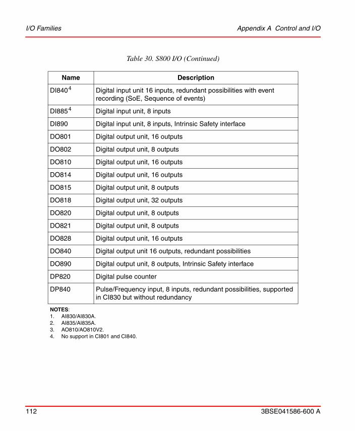
I/O Families Appendix A Control and I/O
112 3BSE041586-600 A
DI8404 Digital input unit 16 inputs, redundant possibilities with event recording (SoE, Sequence of events)
DI8854 Digital input unit, 8 inputs
DI890 Digital input unit, 8 inputs, Intrinsic Safety interface
DO801 Digital output unit, 16 outputs
DO802 Digital output unit, 8 outputs
DO810 Digital output unit, 16 outputs
DO814 Digital output unit, 16 outputs
DO815 Digital output unit, 8 outputs
DO818 Digital output unit, 32 outputs
DO820 Digital output unit, 8 outputs
DO821 Digital output unit, 8 outputs
DO828 Digital output unit, 16 outputs
DO840 Digital output unit 16 outputs, redundant possibilities
DO890 Digital output unit, 8 outputs, Intrinsic Safety interface
DP820 Digital pulse counter
DP840 Pulse/Frequency input, 8 inputs, redundant possibilities, supported in CI830 but without redundancy
NOTES: 1. AI830/AI830A.2. AI835/AI835A.3. AO810/AO810V2.4. No support in CI801 and CI840.
Table 30. S800 I/O (Continued)
Name Description

Appendix A Control and I/O I/O Families
3BSE041586-600 A 113
S900 I/O
Table 31 shows the different S900 I/Os.
Table 31. S900 I/O
Name1 Description
AI910N/S Analog input unit, 4 inputs, 4-20 mA
AI920N/S Analog input unit, 4 inputs, 4-20 mA, isolated
AI921N/S Analog input unit, 4 inputs
AI930N/S Analog input unit, 4 inputs, 4-20 mA, HART
AI931N/S Analog input unit, 4 inputs, 0/4-20 mA, HART
AI950N/S Analog input unit, 4 inputs, temperature sensor
AO910N/S Analog output unit, 4 outputs, 4-20 mA
AO920N2/S Analog output unit, 4 outputs, 4-20 mA, isolated
AO930N/S Analog output unit, 4 outputs, 4-20 mA, HART
AI910 Analog input, 1 x 4 channels, active
AI920 Analog input, 4 x 1 channel
AI930 Analog input, 1 x 4 channels, active, HART
AI931 Analog input, 1 x 4 channels, passive, HART
AI950 Temperature input, 4 x 1 channel, resistor and thermocouple
AO910 Analog output, 1 x 4 channels
AO920 Analog output, 4 x 1 channel (isolated)
AO930 Analog output, 1 x 4 channels, HART
DI920N Digital input unit, 4 inputs, (NAMUR), isolated
DO910N/S Digital output unit, 4 outputs, (for solenoid valves)
DO930N2/S Digital output unit, 4/6 outputs, dry contacts (relay)
DO940N/S Digital output unit, 8 outputs

I/O Families Appendix A Control and I/O
114 3BSE041586-600 A
S100 I/O
Table 32 shows the different S100 I/Os supported by AC 800M.
DO980N/S Digital output unit, 16 outputs
DP910 Frequency input and counter, 2 blocks
DP910N/S Frequency input and pulse counter, 2 inputs
DX910N/S Bidirectional unit, 8 channels, (programmable) for digital input, 8 inputs, NAMUR/dry contacts or digital output, 8 outputs, for low power valves
DO910 Digital output, 4 x 1 channel (Solenoid driver)
DO930 Relay output, 6 x 1 channel
DX910 Digital input/output, 1 x 8 channels
1) Modules referenced without S,B or N in the ending are valid for all three S900 I/O series.2) Available and supported only by N-Series'
Table 32. S100 I/O
Name Description
DSBC 173A1, DSBC 174, DSBC 176
Bus extender slave inserted in the last position of an S100 I/O rack.
DSAI 110 Analog input Unit. 32 channels, resolution 8 bit, Single ended, 0 to ±10 V or 0 to ±20 mA
DSAI 130DSAI 130A
Analog input board, 16 inputs
DSAI 130D Analog input board, 16 inputs with 4 sets of filter times
DSAI 133DSAI 133A
Analog input board, 32 inputs
Table 31. S900 I/O (Continued)
Name1 Description

Appendix A Control and I/O I/O Families
3BSE041586-600 A 115
DSAI 135 Analog input Unit.16 channels, resolution 8 bit, differential, 0 to ±10 V or 0 to ±20 mA.
DSAI 145 Analog input Unit.31 (+ 1 ref.) channels for Pt100, 3-wire, resolution 12 or 13 bits, -100/ +320 or -200/ + 640°C. Galvanic isolation between channel and system.
DSAI 146 Analog input unit. 31 (+ 1 ref.) channels for Pt100, 3-wire, resolution 12 or 13 bits, -100/ +320, -40/+40 or -200/ + 640°C. Galvanic isolation between channel and system.
DSAI 151 14 (+ 2 ref.) channels for Pt100, 4-wire, resolution 12 or 13 bits, -100/ +320, -40/+40 or -200/ + 640°C. Galvanic isolation between channel and system.
DSDI 110, DSDI 110ADSDI110AV1
Digital input board, 14 inputs, 24V
DSDI 115 Digital input board, 32 channels, 24 V
DSDI116 Digital input board, 32 channels, 24 V non-isolated
DSDI 120, DSDI 120ADSDI 120AV1
Digital input board, 32 inputs, 48 V
DSDI 125 Digital input board, 32 channels, 48 V
DSDI 126 Digital input board, 32 channels, 48 V non-isolated
DSDI 131 Digital input unit. 16 channels, 110 VAC/VDC., controlled by scanning or interrupt, pulse extension. Local time tagging of process events. Galvanic isolation between channel and system.
DSDI 141 Digital input unit. 16 channels, 220 VAC/VDC., controlled by scanning or interrupt, pulse extension. Local time tagging of process events. Galvanic isolation between channel and system.
DSDO 110 Digital output board, 32 outputs
Table 32. S100 I/O (Continued)
Name Description
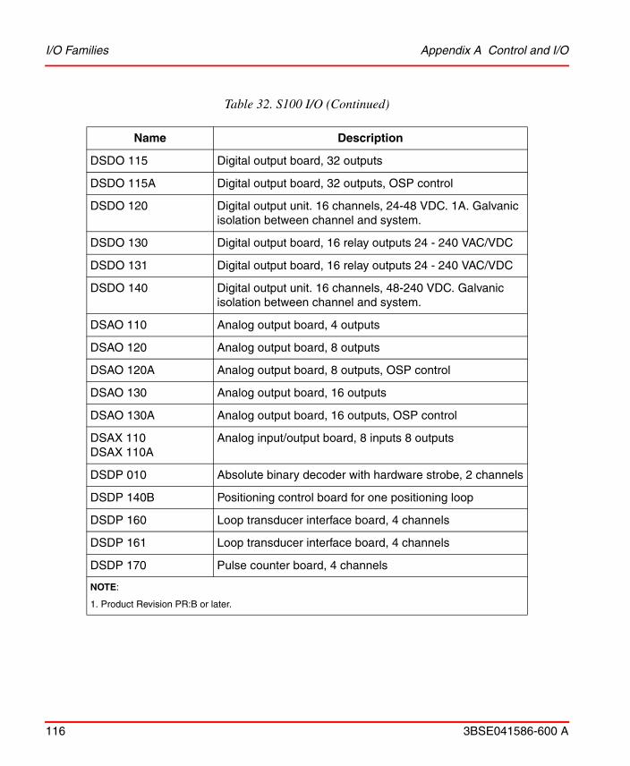
I/O Families Appendix A Control and I/O
116 3BSE041586-600 A
DSDO 115 Digital output board, 32 outputs
DSDO 115A Digital output board, 32 outputs, OSP control
DSDO 120 Digital output unit. 16 channels, 24-48 VDC. 1A. Galvanic isolation between channel and system.
DSDO 130 Digital output board, 16 relay outputs 24 - 240 VAC/VDC
DSDO 131 Digital output board, 16 relay outputs 24 - 240 VAC/VDC
DSDO 140 Digital output unit. 16 channels, 48-240 VDC. Galvanic isolation between channel and system.
DSAO 110 Analog output board, 4 outputs
DSAO 120 Analog output board, 8 outputs
DSAO 120A Analog output board, 8 outputs, OSP control
DSAO 130 Analog output board, 16 outputs
DSAO 130A Analog output board, 16 outputs, OSP control
DSAX 110DSAX 110A
Analog input/output board, 8 inputs 8 outputs
DSDP 010 Absolute binary decoder with hardware strobe, 2 channels
DSDP 140B Positioning control board for one positioning loop
DSDP 160 Loop transducer interface board, 4 channels
DSDP 161 Loop transducer interface board, 4 channels
DSDP 170 Pulse counter board, 4 channels
NOTE:
1. Product Revision PR:B or later.
Table 32. S100 I/O (Continued)
Name Description
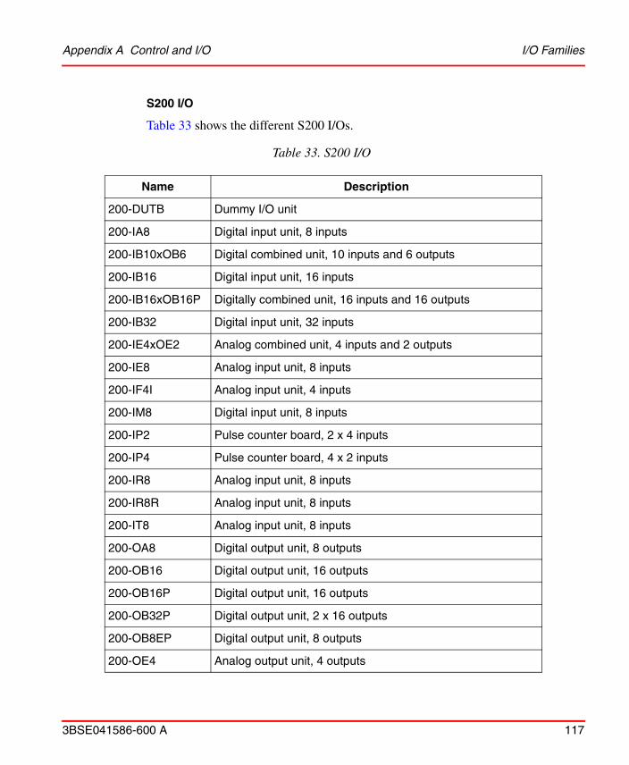
Appendix A Control and I/O I/O Families
3BSE041586-600 A 117
S200 I/O
Table 33 shows the different S200 I/Os.
Table 33. S200 I/O
Name Description
200-DUTB Dummy I/O unit
200-IA8 Digital input unit, 8 inputs
200-IB10xOB6 Digital combined unit, 10 inputs and 6 outputs
200-IB16 Digital input unit, 16 inputs
200-IB16xOB16P Digitally combined unit, 16 inputs and 16 outputs
200-IB32 Digital input unit, 32 inputs
200-IE4xOE2 Analog combined unit, 4 inputs and 2 outputs
200-IE8 Analog input unit, 8 inputs
200-IF4I Analog input unit, 4 inputs
200-IM8 Digital input unit, 8 inputs
200-IP2 Pulse counter board, 2 x 4 inputs
200-IP4 Pulse counter board, 4 x 2 inputs
200-IR8 Analog input unit, 8 inputs
200-IR8R Analog input unit, 8 inputs
200-IT8 Analog input unit, 8 inputs
200-OA8 Digital output unit, 8 outputs
200-OB16 Digital output unit, 16 outputs
200-OB16P Digital output unit, 16 outputs
200-OB32P Digital output unit, 2 x 16 outputs
200-OB8EP Digital output unit, 8 outputs
200-OE4 Analog output unit, 4 outputs
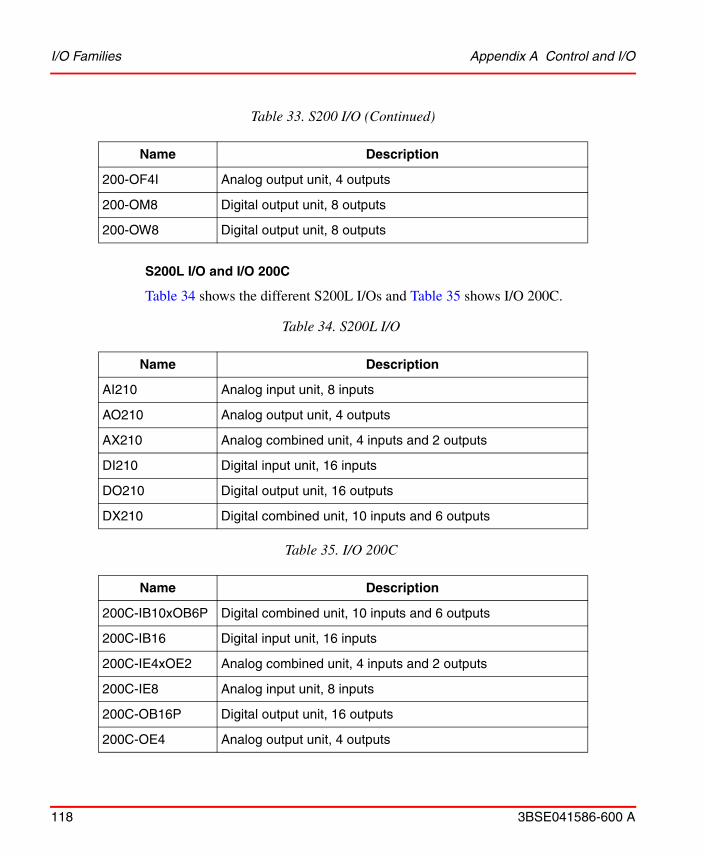
I/O Families Appendix A Control and I/O
118 3BSE041586-600 A
S200L I/O and I/O 200C
Table 34 shows the different S200L I/Os and Table 35 shows I/O 200C.
200-OF4I Analog output unit, 4 outputs
200-OM8 Digital output unit, 8 outputs
200-OW8 Digital output unit, 8 outputs
Table 34. S200L I/O
Name Description
AI210 Analog input unit, 8 inputs
AO210 Analog output unit, 4 outputs
AX210 Analog combined unit, 4 inputs and 2 outputs
DI210 Digital input unit, 16 inputs
DO210 Digital output unit, 16 outputs
DX210 Digital combined unit, 10 inputs and 6 outputs
Table 35. I/O 200C
Name Description
200C-IB10xOB6P Digital combined unit, 10 inputs and 6 outputs
200C-IB16 Digital input unit, 16 inputs
200C-IE4xOE2 Analog combined unit, 4 inputs and 2 outputs
200C-IE8 Analog input unit, 8 inputs
200C-OB16P Digital output unit, 16 outputs
200C-OE4 Analog output unit, 4 outputs
Table 33. S200 I/O (Continued)
Name Description

Appendix A Control and I/O I/O Families
3BSE041586-600 A 119
Satt Rack I/O
Table 36 shows the different Satt Rack I/Os.
Table 36. Satt Rack I/Os
Name Description
IAPG Digital input board with 16 inputs
IDLD Digital input board with 16 inputs
IDP Digital input board with 32 inputs
IDPG Digital input board with 32 inputs
IDN Digital input board with 32 inputs
IDI Digital input board with 32 inputs
PTC Digital input board with 32 inputs
ORG Digital output board with 16 outputs
ORGH Digital output board with 16 outputs
OATG Digital output board with 16 outputs
ODP2 Digital output board with 16 outputs
ODPG2 Digital output board with 16 outputs
ORM Digital output board with 16 outputs
ODP.5 Digital output board with 32 outputs
ODP.8 Digital output board with 32 outputs
ODPG.8 Digital output board with 32 outputs
ODPL.5 Digital output board with 32 outputs
ODPLD Digital output board with 32 outputs
ODN.2 Digital output board with 32 outputs
ODLD.5 Digital output board with 32 outputs
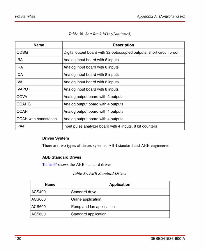
I/O Families Appendix A Control and I/O
120 3BSE041586-600 A
Drives System
There are two types of drives systems, ABB standard and ABB engineered.
ABB Standard Drives
Table 37 shows the ABB standard drives.
ODSG Digital output board with 32 optocoupled outputs, short circuit proof
IBA Analog input board with 8 inputs
IRA Analog input board with 8 inputs
ICA Analog input board with 8 inputs
IVA Analog input board with 8 inputs
IVAPOT Analog input board with 8 inputs
OCVA Analog output board with 2 outputs
OCAHG Analog output board with 4 outputs
OCAH Analog output board with 4 outputs
OCAH with handstation Analog output board with 4 outputs
IPA4 Input pulse analyzer board with 4 inputs, 8 bit counters
Table 37. ABB Standard Drives
Name Application
ACS400 Standard drive
ACS600 Crane application
ACS600 Pump and fan application
ACS600 Standard application
Table 36. Satt Rack I/Os (Continued)
Name Description

Appendix A Control and I/O I/O Families
3BSE041586-600 A 121
ABB Engineered Drives
Table 38 shows the ABB engineered drives.
ACS800 Crane application
ACS800 Pump and fan application
ACS800 Standard application
ACS880 Standard application
DCS400 Standard drive
DCS500 Standard drive
Table 38. ABB Engineered Drives
Name Application
ACS600 IGBT supply (ISU) application
ACS600 System application
ACS600AD Asynchronous drive
ACS600C Cycle converter drive
ACS600SD Synchronous drive
ACS800 IGBT supply (ISU) application
ACS800 System application
ACS880 System application
ACS1000 Standard drive
DCS600 System application
Table 37. ABB Standard Drives (Continued)
Name Application

I/O Families Appendix A Control and I/O
122 3BSE041586-600 A

3BSE041586-600 A 123
Appendix B Fieldbus
The sections of this chapter describe the capacity limits and constraints for the application design that need to be considered when using standardized fieldbus protocols to connect field devices to AC 800M.
MODBUS
MODBUS RTU Master Communication
The table show the maximum transmission rate when CI853 acts as MODBUS RTU master at a base controller load of 50%.
AC 800M
50% Load in the Controller
300 Booleans in Each Telegram
Max Transmission Rate(Total Transactions/second)
PM864A
MBWrite MBRead
1channel
4channels
1channel
4channels
1200 baud
(8 data bits, 1 stop bit, odd parity)
1.0 2.4 2.1 4.8
19200 baud
(8 data bits, 1 stop bit, odd parity)
8.2 24.9 8.9 38.4

MODBUS RTU Master Communication Appendix B Fieldbus
124 3BSE041586-600 A
AC 800M
50% Load in the Controller
300 Booleans in Each Telegram
Max Transmission Rate(Total Transactions/second)
PM866
MBWrite MBRead
1channel
4channels
1channel
4channels
1200 baud
(8 data bits, 1 stop bit, odd parity)
1.0 8.4 1.0 9.1
19200 baud
(8 data bits, 1 stop bit, odd parity)
2.2 21.1 4.8 32.3
AC 800M
50% Load in the Controller
300 Booleans in Each Telegram
Max Transmission Rate(Total Transactions/second)
PM891
MBWrite MBRead
1channel
4channels
1channel
4channels
1200 baud
(8 data bits, 1 stop bit, odd parity)
1.4 2.4 1.2 5.0
19200 baud
(8 data bits, 1 stop bit, odd parity)
9.2 22.2 9.3 37.4

Appendix B Fieldbus MODBUS TCP
3BSE041586-600 A 125
MODBUS TCP
The tables show the maximum transmission rate when CI867 acts as MODBUS TCP master or slave.
Table 39. MODBUS TCP Performance Data. Reading Dint using one CI867 as Master
Number of Slaves Connected and Communicating
Message Length (in Dint)
Total Transactions/s
(Sum of all Slaves)
Average Transaction/Slave1
1 Cyclic read at maximum possible rate is used.
1
task time=100 ms
60 149 149
1
task time=250 ms
60 89 89
5
task time=100 ms
60 158 31
5
task time=250 ms
60 160 33
10
task time=100 ms
60 150 15
10
task time=250 ms
60 160 17
20
task time=100 ms
60 94 6
20
task time=250 ms
60 110 9
30
task time=100 ms
60 97 3
30
task time=250 ms
60 123 4

MODBUS TCP Appendix B Fieldbus
126 3BSE041586-600 A
Table 40. MODBUS TCP Performance Data. Reading Boolean using one CI867 as Master
Number of Slaves Connected and Communicating
Message Length
(in Boolean)
Total Transactions/s
(Sum of all Slaves)
Average Transaction
/Slave1
1
task time=100 ms
60 114 114
1
task time=250 ms
60 104 104
5
task time=100 ms
60 130 26
5
task time=250 ms
60 129 26
10
task time=100 ms
60 113 11
10
task time=250 ms
60 121 12
20
task time=100 ms
60 100 5
20
task time=250 ms
60 141 7
30
task time=100 ms
60 113 3
30
task time=250 ms
60 124 4
1 Cyclic read at maximum possible rate is used.

Appendix B Fieldbus MODBUS TCP
3BSE041586-600 A 127
Table 41. MODBUS TCP Performance.Data. Reading Real using one CI867 as Master
Number of Slaves Connected and Communicating
Message Length
(in Real)
Total Transactions/s
(Sum of all Slaves)
Average Transaction
/Slave1
1
task time=100 ms
60 104 104
1
task time=250 ms
60 95 95
5
task time=100 ms
60 120 24
5
task time=250 ms
60 120 24
1 Cyclic read at maximum possible rate is used.
Table 42. MODBUS TCP Performance Data. Reading Dint using one CI867 as Slave
Number of Masters Connected and Communicating
Number of Data in
Dint
Total Transactions/s
(Sum of all Slaves)
Average Transaction
/Master
1
task time=50 ms
50 20
1
task time=50 ms
100 20
2
task time=50 ms
50 20
2
task time=50 ms
100 20

MODBUS TCP Appendix B Fieldbus
128 3BSE041586-600 A
8
task time=50 ms
50 20
8
task time=50 ms
100 20
Table 43. MODBUS TCP Performance. Data. Reading Boolean using one CI867 as Slave
Number of Masters Connected and Communicating
Number of Data in Boolean
Total Transactions/s
(Sum of all Slaves)
Average Transaction
/Master
1
task time=100 ms
1 10
1
task time=100 ms
525 10
2
task time=100 ms
1 10
2
task time=100 ms
525 10
8
task time=100 ms
1 10
8
task time=100 ms
525 10
Table 42. MODBUS TCP Performance Data. Reading Dint using one CI867 as Slave (Continued)
Number of Masters Connected and Communicating
Number of Data in
Dint
Total Transactions/s
(Sum of all Slaves)
Average Transaction
/Master

Appendix B Fieldbus PROFIBUS
3BSE041586-600 A 129
PROFIBUS
Network Connection through Communication Interface
Communication Interface for PROFIBUS DP: CI854A/B
CI854A/B acts as a PROFIBUS Master only.
For PROFIBUS DP following limits and performance figures need to be taken into account:
Table 44. PROFIBUS and CI854A/B Parameters
Communication Parameter Limits
General Limits Maximum no. of CI854A/B in an AC 800M (CEX Bus)
12 (a redundant pair consumes two of them)
Max. number of nodes per network
126
Max. number of slave nodes supported
124
Reserved node addresses for CI854A/B
0
(1 for redundant CI)
Available node addresses for slaves
2 -125
Supported Baudrates on PROFIBUS
9,6 kbit/s - 12 Mbit/s
Configuration Limits
PROFIBUS DPcyclic communication
Max. length of I/O data for CI854A/B
>1,5 Mbit/s: 4000 byte input and output data
<= 1,5 Mbit/s: no limitation in CI
Performance Limits

Network Connection through Communication Interface Appendix B Fieldbus
130 3BSE041586-600 A
Further features and constraints to be considered during application design:
• S800 I/O connected to CI840 and/or S900 I/O connected to CI920 supports cable redundancy together with slave redundancy.
• S900 (CI920) and S800 (CI840 and CI801) support configuration change (changing the parameters) without disrupting the cyclic data communication.
• If the PROFIBUS master unit, CI854A/B, loses contact with a slave unit, for example due to a disconnected cable, input values are set according to ISP configuration. If the I/O unit does not support ISP, all input values will freeze.
• Reset of PROFIBUS DP master, CI854A/B, and the complete PROFIBUS is done if one of the following bus parameter settings are changed:
– Node address of CI854A/B,
– baud rate.
– highest station address (HSA).
A change of the other bus parameters does not affect the running communication.
PROFIBUS DPcyclic communication
Fastest possible cycle time
1 ms at 12 Mbit/s with one slave supporting 1ms
Typical cycle times 10 – 20 ms at 1,5 Mbit/s
The cycle time on PROFIBUS depends on the baud rate, the sum of I/O data, and the slave timing parameter and is therefore application-specific.
Table 44. PROFIBUS and CI854A/B Parameters
Communication Parameter Limits
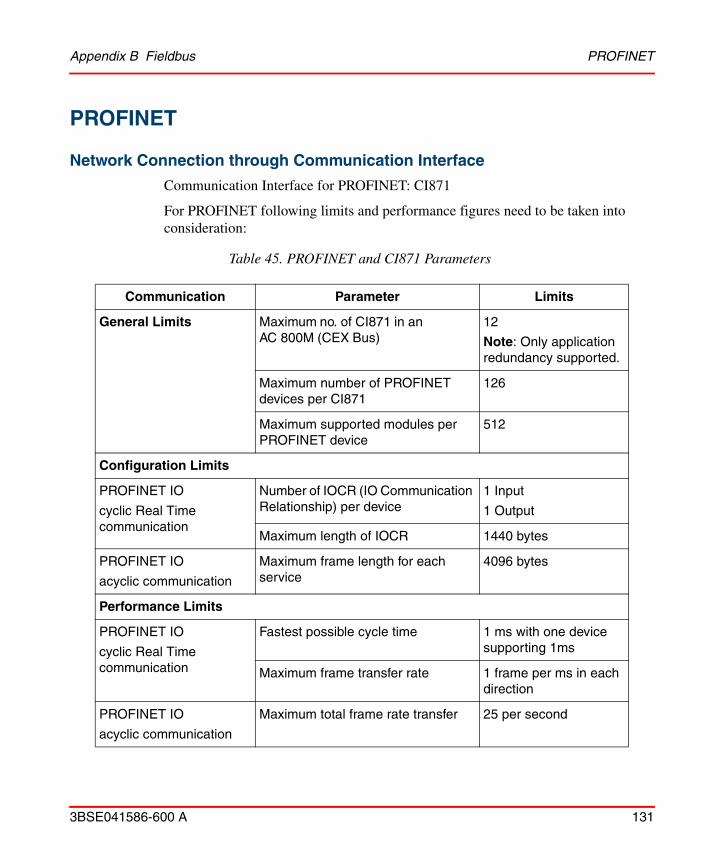
Appendix B Fieldbus PROFINET
3BSE041586-600 A 131
PROFINET
Network Connection through Communication Interface
Communication Interface for PROFINET: CI871
For PROFINET following limits and performance figures need to be taken into consideration:
Table 45. PROFINET and CI871 Parameters
Communication Parameter Limits
General Limits Maximum no. of CI871 in an AC 800M (CEX Bus)
12
Note: Only application redundancy supported.
Maximum number of PROFINET devices per CI871
126
Maximum supported modules per PROFINET device
512
Configuration Limits
PROFINET IO
cyclic Real Time communication
Number of IOCR (IO Communication Relationship) per device
1 Input
1 Output
Maximum length of IOCR 1440 bytes
PROFINET IO
acyclic communication
Maximum frame length for each service
4096 bytes
Performance Limits
PROFINET IO
cyclic Real Time communication
Fastest possible cycle time 1 ms with one device supporting 1ms
Maximum frame transfer rate 1 frame per ms in each direction
PROFINET IO
acyclic communication
Maximum total frame rate transfer 25 per second

IEC 61850 Appendix B Fieldbus
132 3BSE041586-600 A
Examples for typical configurations:
• Example 1: Update times for all devices is configured to 32 ms (default), then up to 32 devices can be connected to CI871.
• Example 2: Update times for all devices is configured to 8 ms, then up to 8 devices can be connected to CI871.
Further features and constraints to be considered during application design:
IEC 61850
Network Connection through Communication Interface
Communication Interface for IEC61850-ED.1: CI868.
CI868 General Configuration Data
CI868 is modeled as an IED with one Access point and supports communicating with other IEDs through IEC 61850 GOOSE as well as IEC 61850 MMS client protocol.
The CI868 IEC 61850 Hardware Library 3.x available in Control Builder, supports CI868 to communicate over IEC 61850 GOOSE and MMS client protocols.
The cycle time on PROFINET depends on the number of devices and Ethernet frames that will be communicated and is therefore application-specific.
The limitation for the CPU load of CI871 is checked by the system during download. If the system detects that there is a CPU overload, then it is indicated in the Compilation Summary window and the download is blocked. The CI871 may not function properly when there is an overload. The user can check the CPU load before and after download by use of the Web Interface. The limit for the CPU load is 100%. Up to that value the CI871 works stable without any problems or restrictions.
PROFINET IO connectivity through CI871 supports application redundancy. That means a second CI871 module needs to be configured separately to communicate the same data with the voting implemented in the controller application.

Appendix B Fieldbus Network Connection through Communication Interface
3BSE041586-600 A 133
Figure 13 illustrates the data modeling in IEC61850 to explain the terms used in the following sections to define the performance and capacity limits with IEC61850 in AC 800M:
Figure 13. Logical Node Data and Communication Model

Network Connection through Communication Interface Appendix B Fieldbus
134 3BSE041586-600 A
For IEC61850 communication with CI868 following limits and performance figures need to be taken into account independent of what communication protocol should be used:
Further features and constraints to be considered during application design:
Table 46. IEC 61850 CI868 General Parameters
Communication Parameter Limits
Maximum no. of CI868 in an AC 800M (CEX Bus)
12
Note: Only application redundancy supported.
Maximum number of LDs under MyIED
10
Maximum number of LNs per
LD
253
Maximum number of Data Objects per Dataset
10
Analog, Integer or Boolean type of
Data objects.
Increasing the number of Data Objects per Dataset would overload CI868.
For more data signals to CI868 from same IED, use additional Datasets
IEC 61850 connectivity through CI868 supports application redundancy. That means a second CI868 module needs to be configured separately to communicate the same data with the voting implemented in the controller application.
The CPU load on CI868 shall be less than 85% for satisfactory performance of CI868 module with all types of communication.

Appendix B Fieldbus Network Connection through Communication Interface
3BSE041586-600 A 135
CI868 Performance for GOOSE Protocol Usage
In addition to the General Configuration Data for CI868 following limits and performance figures need to be taken into account when using the CI868 for GOOSE protocol communication only:
The limits with respect to the IEC61850 data model entities need to be considered already while engineering the Substation Configuration Description (SCD) file with the substation engineering tool.
Table 47. Performance Parameters of CI868 with GOOSE Protocol only
Communication Parameter Limits
Configuration Limits
GOOSE communication Maximum number of IEDs connected per CI868
80
Maximum number of GOOSE Datasets per CI868
150
Subscribed dataset count checked by the IEC 61850 Wizard during engineering
Maximum Number of CI868 Receive Group per IED
254
Each CI868 GOOSE Receive Group constitutes 5
Data Objects.
Each Data Object constitutes the Data
Attributes, for example: stVal / mag.f , q, t
Maximum number of Data
Objects (signals) configured
800
Data Objects of types Analog, Integer, or Boolean.

Network Connection through Communication Interface Appendix B Fieldbus
136 3BSE041586-600 A
CI868 GOOSE Performance Graph
The GOOSE performance of CI868 module is a function of the following parameters:
CI868 Receive
• Number of Static signals configured in scd-file for CI868 Receive. This is the sum of all Data Objects (DO) signals subscribed to CI868 in all Datasets in all IEDs.
• Number of changing signals out of static signals for CI868 Receive. This is the sum of all Data Objects signals subscribed to CI868 changing at a given moment across all IEDs.
CI868 Send
• Number of Static Signals configured in scd-file from CI868 to other IEDs. This is the sum of all Data Objects signals in all Datasets from CI868 to other IEDs.
Performance Limits
GOOSE communication Maximum number of changing
Data Objects Received
160 / sec
Data Objects of types Analog, Integer, or Boolean.
See also CI868 GOOSE Performance Graph
Maximum number of changing
Data Objects Sent
10 / sec
Data Objects of types Analog, Integer, or Boolean.
See also CI868 GOOSE Performance Graph
Table 47. Performance Parameters of CI868 with GOOSE Protocol only (Continued) (Continued)
Communication Parameter Limits

Appendix B Fieldbus Network Connection through Communication Interface
3BSE041586-600 A 137
• Number of changing send signals out of static signals from CI868 to other IEDs. This is the sum of all Data Objects signals changing at a given moment from CI868.
Figure 14 provides the CI868 GOOSE performance for different configurations of Static and Changing Receive signals for operating within optimal load of CI868 CPU (85%).
This chart is applicable for CI868 configured for GOOSE communication.
CI868 Performance for MMS Client Protocol Usage
In addition to the General Configuration Data for CI868 following limits and performance figures need to be taken into account when using the CI868 for MMS protocol communication only:
Figure 14. CI865 GOOSE Performance Chart
The limits with respect to the IEC61850 data model entities need to be considered already while engineering the Substation Configuration Description (SCD) file with the substation engineering tool.

Network Connection through Communication Interface Appendix B Fieldbus
138 3BSE041586-600 A
Further features and constraints to be considered during application design:
• High load on CI868 with MMS signals can be avoided by grouping the frequently changing signals in the same dataset when creating the SCD file.
Table 48. Performance Parameters of CI868 with MMS Client only
Communication Parameter Limits
Configuration Limits
MMS communication Maximum number of IEDs connected per CI868
20
Maximum number of MMS Datasets 150
Subscribed dataset count checked by the IEC 61850 Wizard during engineering
Maximum number of LDs under other IEDs
50
Starting from Position 200 under other IED in
Control Builder hardware tree
Maximum number of Data Objects (signals) configured
1000
Data Objects of types Analog, Integer, or Boolean.
Performance Limits
MMS communication Maximum number of changing
Data Objects Received
80 / sec
Data Objects of types Analog, Integer, or Boolean.
Maximum number of MMS Control Command sent
1 / sec
MMS Control Commands sent from CI868 via
CSWI and XCBR LNs

Appendix B Fieldbus Network Connection through Communication Interface
3BSE041586-600 A 139
For Example: Measurement signals shall be grouped into one dataset, Status signals shall be grouped into another dataset.
MMS performance of CI868 module functions are as follows:
CI868 Receive
• Memory: Number of Static Datasets (sent via RCB (Record Control Block) signals configured in SCD file for CI868 Receive. This is the sum of all Data Objects signals subscribed to CI868 in all Datasets in all IEDs.
• Load: Number of changing DO signals for CI868 Receive. This is the sum of all DO signals subscribed to CI868 changing at a given moment across all IEDs. The number of MMS signals changing in lesser number of Datasets consumes less CI868 load as against the same number of signals changing in more number of datasets.
CI868 Performance for MMS Client and GOOSE Protocol Combined Usage
Following limits and performance figures that are different from the figures given in the respective sections for GOOSE protocol and MMS protocol need to be taken into account in addition when using the CI868 for parallel GOOSE and MMS protocol communication:

Network Connection through Communication Interface Appendix B Fieldbus
140 3BSE041586-600 A
Table 49. Performance Parameters of CI868 with both GOOSE and MMS Client
Communication Parameter Limits
Configuration Limit
MMS & GOOSE communication
MMS & GOOSE communication (Continued)
Maximum number of IEDs connected per CI868
20
Maximum number of
Datasets per CI868 (GOOSE & MMS in total)
150
Subscribed dataset count checked by the IEC 61850 Wizard during engineering
Maximum number of LDs under
other IEDs
50
Starting from Position 200 under other IED in Control Builder hardware tree
Maximum Number of CI868 Receive Group per IED
254
Each CI868 GOOSE Receive Group constitutes 5 Data Objects.
Each Data Object constitutes the Data Attributes, for example: stVal / mag.f , q, t
Maximum number of GOOSE Data Objects (signals) configured
20 Send direction
20 Receive direction Data Objects of types Analog, Integer, or Boolean.
Maximum number of MMS Data Objects (signals) configured
600
Data Objects of types Analog, Integer, or
Boolean.

Appendix B Fieldbus Network Connection through Communication Interface
3BSE041586-600 A 141
Performance Limit
MMS & GOOSE communication
Maximum number of changing MMS Data Objects Received
60 / sec
Data Objects of types Analog, Integer, or Boolean
Maximum number of changing
Data Objects Sent via GOOSE
10 / sec
Data Objects of types Analog, Integer, or Boolean.
Maximum number of changing Data Objects Received via GOOSE
20 / sec
Data Objects of types Analog, Integer, or Boolean.
Maximum number of MMS Control Command sent
1 / sec
MMS Control Commands sent from CI868 via CSWI and XCBR LNs
Table 49. Performance Parameters of CI868 with both GOOSE and MMS Client (Continued)
Communication Parameter Limits

EtherNet/IP and DeviceNet Appendix B Fieldbus
142 3BSE041586-600 A
EtherNet/IP and DeviceNetFor EtherNetIP / DeviceNet configurations with CI873 the following dimensioning guidelines needs to be taken into account.
General
The limitations, with respect to the various devices in general are:
• CI873 can act only as a scanner. It does not accept class 1 and class 3 connections from any other scanner.
• The number of I/O modules that can be connected under Ethernet/IP or DeviceNet device adaptor type device is 63.
• The number of configuration parameters supported per EtherNet/IP or DeviceNet device is 1000.
• The CI873 supports Listen only connection with EtherNet/IP device, provided there is already Exclusive owner connection in the device. The CI873 does not support Redundant owner connections for EtherNet/IP devices.
• The Read only parameter and monitoring parameters in EDS file are not supported in this release.
• The tag based Class 1 information should be there in EDS file for communication with Allen Bradley PLC where Class 3 tag can be added along with Class 1 connection.
• The total number of Input and Output bytes along with channel status bytes should not exceed more than 80Kb per CI873.
• The Configuration assembly size of 200 is supported per EtherNet/IP or DeviceNet device.
• The CI873 supports 20 CIP connections (including Class 1 and Class 3) per EtherNet/IP device. CI873 supports total of 128 connections.
• The CI873 only supports devices which uses EtherNet/IP encapsulation of CIP.
• CI873 does not support PCCC, Modbus encapsulation.
• CI873 supports CH1 Ethernet interface with a speed of 100 Mbps. CH2 is not supported.
• A maximum of 6 non redundant CI873 can be connected to each AC 800M controller.

Appendix B Fieldbus EtherNet/IP
3BSE041586-600 A 143
Performance Data
Typical performance of the CI873 is:
• CI873 can handle a maximum of 10 CIP connections with 10ms RPI.However it can handle a maximum of 128 CIP connections.
• The reaction time of CI873, that is, the time from changed input channel to the time setting an output channel is less than 100ms at a maximum CI873 CPU Load of 80%, provided the data is sent over a connection operating at an RPI of 50ms or less.
• Data throughput of 1000 CIP I/O packets receive/second and 500 CIP I/O Packets sent/second can be achieved at an optimum load of 85%.Each I/O packet can have data size ranging from 4 to 500 bytes.
• Redundancy Switchover time is 120ms for 10 CIP connections operating at 10ms RPI, that is, the time I/O communication stops in primary to the time I/O communication starts in switched primary.
EtherNet/IP
The limitations, with respect to the EtherNet/IP device involved are:
• EtherNet/IP supports three Class 1 connection and three Class 3 tag per Allen Bradley Control Logix PLC. The CI873 supports three Class 3 tags with 100ms cycle time.
• The data transfer, using the Class 3 connection is slower than the Class 1 connection.
• The Class 3 connection is not supported for any EtherNet/IP devices except Allen Bradley Control Logix PLC. The CI873 uses tag based Class 3 to write data to it.
• The maximum number of bytes support for Class 1 read tag is 496 and for Class 3 write tag is 432.
• 1000 bytes per Class 1 connection is supported, for example O->T: 500 and T->O : 500.

DeviceNet Appendix B Fieldbus
144 3BSE041586-600 A
DeviceNet
The limitations, with respect to the LD 800DN linking device (for DeviceNet) are:
• The maximum number of input bytes supported by LD 800DN is 496 bytes. If the total number of input bytes of all DeviceNet slaves configured under the linking device exceeds 496 bytes, download is stopped.
• The maximum number of output bytes supported by LD 800DN is 492 bytes. If the total number of output bytes of all DeviceNet slaves configured under the linking device exceeds 500 bytes, download is stopped.
• A maximum of four LD 800DN linking devices can be connected under one CI873.
• Multiple CI873 cannot listen to same LD 800DN data.
• The maximum number of DeviceNet connections per device is restricted to 5.

3BSE041586-600 A 145
AABB Engineered Drives 79, 110ABB Standard Drives 79, 109AC 800M 49, 97
single CPU mode 42AC 800M Connect
performance 95Alarm and Event
OPC Server 46applications 23, 27
BBC810 101BC820 101
CCI853 62, 101CI854 29, 41, 43, 80, 101, 129CI854A 41, 62, 101CI854B 41, 62, 102CI855 62, 93, 102CI856 36, 62, 82, 102CI857 30, 62, 94, 102CI858 62, 84, 102CI865 30, 62, 102CI867 62, 102CI868 62, 103, 132CI869 62, 103CI871 62, 103, 131CI872 62CI873 62, 103, 142COMLI 38, 62
supported services 38Compact Control Builder
components 17
functions 24key benefits 18price list items 54programming languages 25requirements 51
Compact Flashcold retain values 44writer 43, 50
Compact Products 800price book 54
control network 23CPU redundancy 41 to 42
DData Access
OPC Server 46Device Import Wizard 18diagrams 49download
applications 27firmware 26PLC firmware 23
Eexecution times
functions 75operations 75
FF1 help 44fieldbus communication 36firmware 26
IINSUM 30
INDEX

Index
146 3BSE041586-600 A
Index
146 3BSE041586-600 A
IP Configuration tool 45
Llicensing 56line redundancy 41, 43Local Operating Network 31LON 31
Mmaster redundancy 41MasterBus 300 34MODBUS RTU 62ModBus RTU
master 37MODBUS TCP
Performance 135modem
communication 39dial-up 39short-distance 39
Modulebusscan cycle time 76scanning ABB Engineered Drives 79
Nnetwork redundancy 41 to 42
OOnline help
context-sensitive 44F1 44
OPC ServerAE 20Alarm and Event 46DA 20Data Access 46performance 95
orderingprocedure 53
Pperformance
AC 800M Connect 95Compact Control Builder 49OPC Server 50, 95
PLC communication 23PLC hardware 49PM851 61, 97PM851A 61, 97PM856 61, 97PM856A 61, 97PM858 41, 61, 97PM860 61, 98PM860A 61, 98PM861 41, 61, 98PM861A 61, 98PM862 41, 61, 99PM864 41, 61, 99PM864A 61, 99PM866 21, 41, 61, 100PM866A 61, 100PM891 21, 41, 61, 100price book
Compact Products 800 54PROFIBUS DP-V1 29PROFINET IO
CI871 30GSD 29
ProtocolsPROFINET IO 29
Rredundancy
CPU 41line 43network 42
requirementsCompact Control Builder 51
RNRP 40 to 41RNRP tool 45

Index
3BSE041586-600 A 147
SS100 I/O 30, 110, 114S200 I/O 36, 110, 117S200L I/O 36, 110, 118S3964R 62S800 I/O 36, 109 to 110S900 I/O 36, 109, 113Satt I/O 30SattBus 35Scan cycle
ABB Engineered Drives 79scan cycle time
Modulebus 76scanning
Modulebus 76SDHC 43Secure Digital
cold retain values 44writer 43
Serial Firmware Upgrade tool 45SerialLib 62Siemens 3964R 38
supported services 39SoftController 26Standard Drives 79system events and alarms 28
TTCP 36Test Mode 26
UUDP 36

Index
148 3BSE041586-600 A
Index
148 3BSE041586-600 A


Power and productivityfor a better worldTM
Contact us
Copyright© 2003-2016 ABB.All rights reserved.
3BS
E04
1586
-600
Awww.abb.com/compactproductsuitewww.abb.com/controlsystems