communication networks
DESCRIPTION
Communication Networks. Chapter 3. Types of Communication Networks. Traditional Traditional local area network (LAN) Traditional wide area network (WAN) Higher-speed High-speed local area network (LAN) Metropolitan area network (MAN) High-speed wide area network (WAN). - PowerPoint PPT PresentationTRANSCRIPT
Communication Networks
Chapter 3
Types of Communication Networks Traditional
Traditional local area network (LAN) Traditional wide area network (WAN)
Higher-speed High-speed local area network (LAN) Metropolitan area network (MAN) High-speed wide area network (WAN)

Speed and Distance of Communications Networks
Characteristics of WANs Covers large geographical areas Circuits provided by a common carrier Consists of interconnected switching nodes Traditional WANs provide modest capacity
64000 bps common Business subscribers using T-1 service – 1.544 Mbps common
Higher-speed WANs use optical fiber and transmission technique known as asynchronous transfer mode (ATM) 10s and 100s of Mbps common

Characteristics of LANs Like WAN, LAN interconnects a variety of
devices and provides a means for information exchange among them
Traditional LANs Provide data rates of 1 to 20 Mbps
High-speed LANS Provide data rates of 100 Mbps to 1 Gbps

Differences between LANs and WANs Scope of a LAN is smaller
LAN interconnects devices within a single building or cluster of buildings
LAN usually owned by organization that owns the attached devices For WANs, most of network assets are not
owned by same organization Internal data rate of LAN is much greater
The Need for MANs Traditional point-to-point and switched network
techniques used in WANs are inadequate for growing needs of organizations
Need for high capacity and low costs over large area
MAN provides: Service to customers in metropolitan areas Required capacity Lower cost and greater efficiency than equivalent
service from telephone company

Switching Terms Switching Nodes:
Intermediate switching device that moves data Not concerned with content of data
Stations: End devices that wish to communicate Each station is connected to a switching node
Communications Network: A collection of switching nodes

Switched Network

Observations of Figure 3.3 Some nodes connect only to other nodes (e.g., 5
and 7) Some nodes connect to one or more stations Node-station links usually dedicated point-to-
point links Node-node links usually multiplexed links
Frequency-division multiplexing (FDM) Time-division multiplexing (TDM)
Not a direct link between every node pair

Techniques Used in Switched Networks Circuit switching
Dedicated communications path between two stations
E.g., public telephone network Packet switching
Message is broken into a series of packets Each node determines next leg of transmission
for each packet

Phases of Circuit Switching Circuit establishment
An end to end circuit is established through switching nodes
Information Transfer Information transmitted through the network Data may be analog voice, digitized voice, or binary
data Circuit disconnect
Circuit is terminated Each node deallocates dedicated resources

Characteristics of Circuit Switching Can be inefficient
Channel capacity dedicated for duration of connection Utilization not 100% Delay prior to signal transfer for establishment
Once established, network is transparent to users Information transmitted at fixed data rate with
only propagation delay
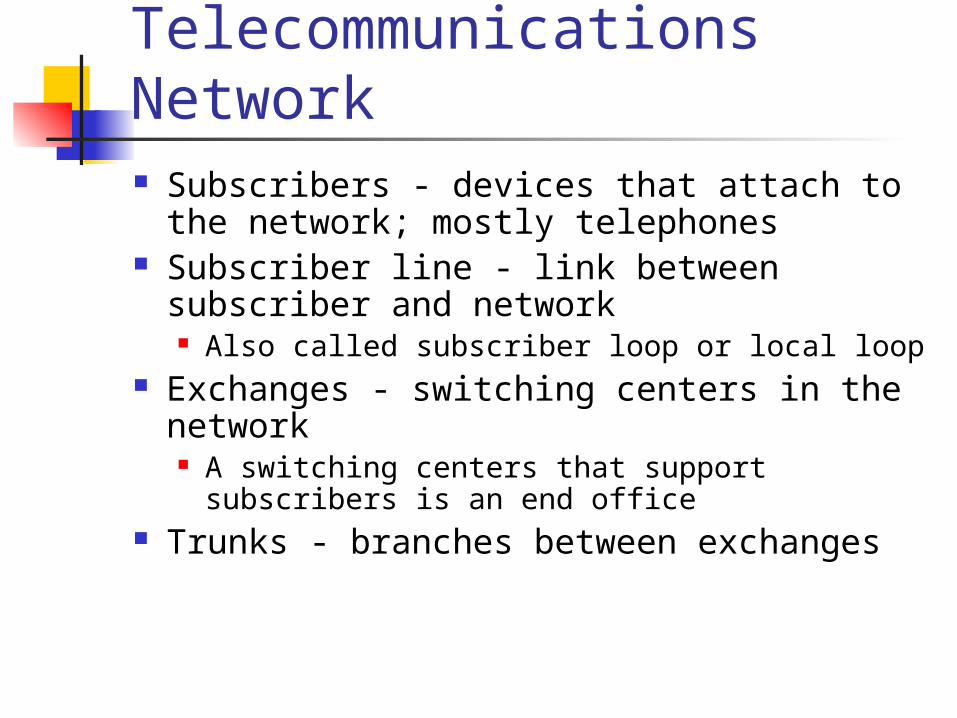
Components of Public Telecommunications Network Subscribers - devices that attach to the network;
mostly telephones Subscriber line - link between subscriber and
network Also called subscriber loop or local loop
Exchanges - switching centers in the network A switching centers that support subscribers is an end
office Trunks - branches between exchanges

How Packet Switching Works Data is transmitted in blocks, called packets Before sending, the message is broken into
a series of packets Typical packet length is 1000 octets (bytes) Packets consists of a portion of data plus a
packet header that includes control information At each node en route, packet is received,
stored briefly and passed to the next node

Packet Switching

Packet Switching

Packet Switching Advantages Line efficiency is greater
Many packets over time can dynamically share the same node to node link
Packet-switching networks can carry out data-rate conversion Two stations with different data rates can exchange
information Unlike circuit-switching networks that block calls
when traffic is heavy, packet-switching still accepts packets, but with increased delivery delay
Priorities can be used

Disadvantages of Packet Switching Each packet switching node introduces a delay Overall packet delay can vary substantially
This is referred to as jitter Caused by differing packet sizes, routes taken and
varying delay in the switches Each packet requires overhead information
Includes destination and sequencing information Reduces communication capacity
More processing required at each node
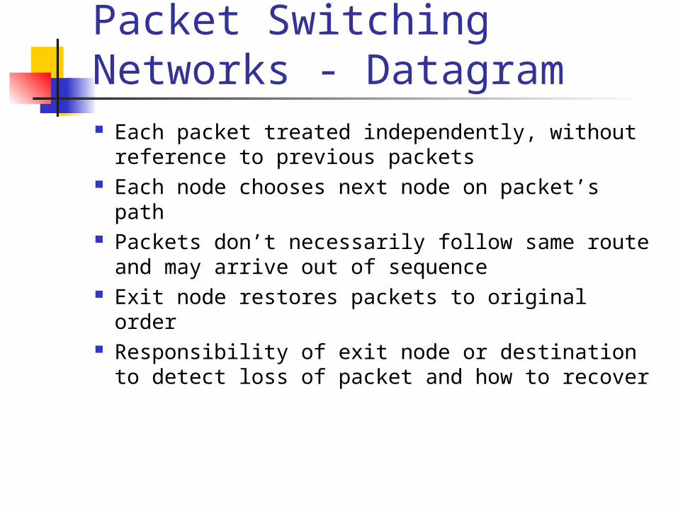
Packet Switching Networks - Datagram Each packet treated independently, without
reference to previous packets Each node chooses next node on packet’s path Packets don’t necessarily follow same route and
may arrive out of sequence Exit node restores packets to original order Responsibility of exit node or destination to detect
loss of packet and how to recover
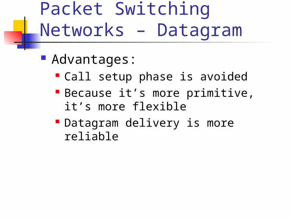
Packet Switching Networks – Datagram Advantages:
Call setup phase is avoided Because it’s more primitive, it’s more flexible Datagram delivery is more reliable

Packet Switching Networks – Virtual Circuit Preplanned route established before packets sent All packets between source and destination follow
this route Routing decision not required by nodes for each
packet Emulates a circuit in a circuit switching network
but is not a dedicated path Packets still buffered at each node and queued for
output over a line

Packet Switching Networks – Virtual Circuit Advantages:
Packets arrive in original order Packets arrive correctly Packets transmitted more rapidly without
routing decisions made at each node
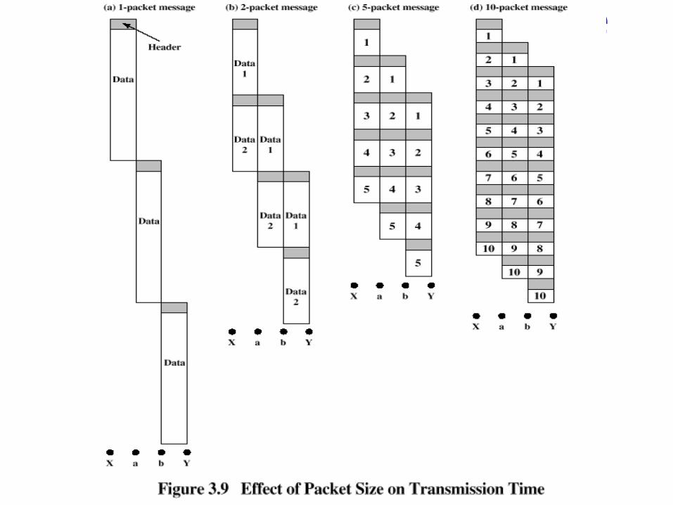
Effect of Packet Size on Transmission
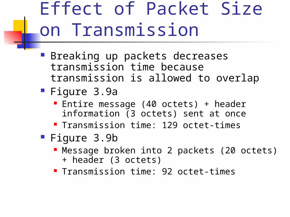
Effect of Packet Size on Transmission Breaking up packets decreases transmission time
because transmission is allowed to overlap Figure 3.9a
Entire message (40 octets) + header information (3 octets) sent at once
Transmission time: 129 octet-times Figure 3.9b
Message broken into 2 packets (20 octets) + header (3 octets)
Transmission time: 92 octet-times

Effect of Packet Size on Transmission Figure 3.9c
Message broken into 5 packets (8 octets) + header (3 octets)
Transmission time: 77 octet-times Figure 3.9d
Making the packets too small, transmission time starts increases
Each packet requires a fixed header; the more packets, the more headers

Asynchronous Transfer Mode (ATM) Also known as cell relay Operates at high data rates Resembles packet switching
Involves transfer of data in discrete chunks, like packet switching
Allows multiple logical connections to be multiplexed over a single physical interface
Minimal error and flow control capabilities reduces overhead processing and size
Fixed-size cells simplify processing at ATM nodes
ATM Terminology Virtual channel connection (VCC)
Logical connection in ATM Basic unit of switching in ATM network Analogous to a virtual circuit in packet switching
networks Exchanges variable-rate, full-duplex flow of fixed-size
cells Virtual path connection (VPC)
Bundle of VCCs that have the same end points

Advantages of Virtual Paths Simplified network architecture Increased network performance and
reliability Reduced processing and short connection
setup time Enhanced network services

Call Establishment

Virtual Channel Connection Uses Between end users
Can carry end-to-end user data or control signaling between two users
Between an end user and a network entity Used for user-to-network control signaling
Between two network entities Used for network traffic management and
routing functions

Virtual Path/Virtual Channel Characteristics Quality of service
Specified by parameters such as cell loss ratio and cell delay variation
Switched and semipermanent virtual channel connections
Cell sequence integrity Traffic parameter negotiation and usage
monitoring Virtual channel identifier restriction within a VPC

ATM Cell Header Format Generic flow control (GFC) – 4 bits, used only in
user-network interface Used to alleviate short-term overload conditions in
network Virtual path identifier (VPI) – 8 bits at the user-
network interface, 12 bits at network-network interface Routing field
Virtual channel identifier (VCI) – 8 bits Used for routing to and from end user

ATM Cell Header Format Payload type (PT) – 3 bits
Indicates type of information in information field
Cell loss priority (CLP) – 1 bit Provides guidance to network in the event of
congestion Header error control (HEC) – 8 bit
Error code

ATM Service Categories Real-time service
Constant bit rate (CBR) Real-time variable bit rate (rt-VBR)
Non-real-time service Non-real-time variable bit rate (nrt-VBR) Available bit rate (ABR) Unspecified bit rate (UBR)
Examples of CBR Applications Videoconferencing Interactive audio (e.g., telephony) Audio/video distribution (e.g., television,
distance learning, pay-per-view) Audio/video retrieval (e.g., video-on-
demand, audio library)

Examples of UBR applications Text/data/image transfer, messaging,
distribution, retrieval Remote terminal (e.g., telecommuting)