commercial uv disinfection system · commercial uv disinfection system installation and user’s...
TRANSCRIPT
IMPORTANT SAFETY INSTRUCTIONSREAD AND FOLLOW ALL INSTRUCTIONS
SAVE THESE INSTRUCTIONS
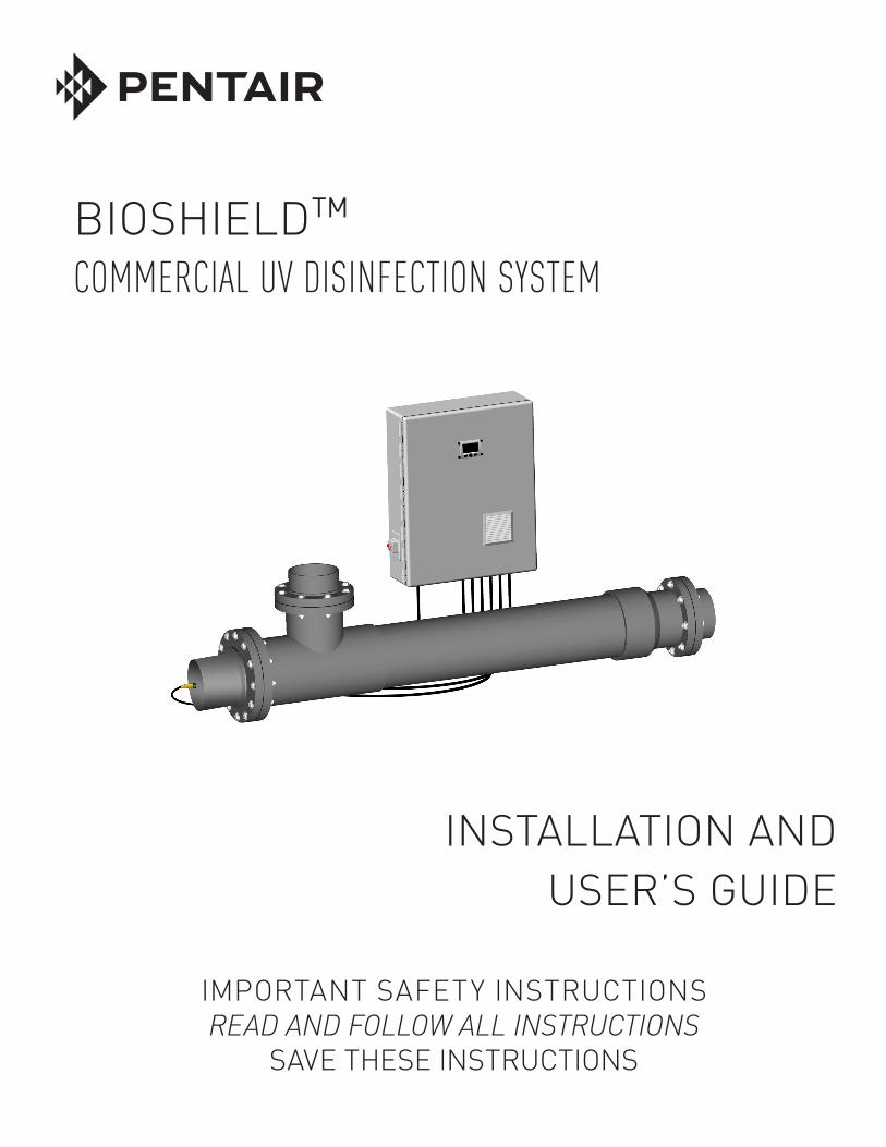
BIOSHIELD™ COMMERCIAL UV DISINFECTION SYSTEM
INSTALLATION ANDUSER’S GUIDE
BIOSHIELD™ Commercial UV Disinfection System Installation and User’s Guide BIOSHIELD™ Commercial UV Disinfection System Installation and User’s Guide
i
P/N CLX-N-MN Rev. A 9/29/14
TABLE OF CONTENTS
Section 9: Commissioning ......................................
Start-Up
Section 10: Operation ..............................................
Microprocessor Control Power Supply OperationMicroprocessor Control Descriptions
Section 11: Maintenance .........................................
Routine InspectionUV Lamp Replacement
UV Lamp RemovalUV Lamp RecyclingUV Lamp Installation
Quartz Sleeve Inspection/Replacement/CleaningQuartz Sleeve RemovalQuartz Sleeve CleaningQuartz Sleeve Installation
UV Vessel CleaningUV Vessel DisassemblyCooling Fan and Filter Mat Replacement/Cleaning
Cooling Fan Filter RemovalCooling Fan Filter CleaningCooling Fan Filter Installation
Section 12: Replacement Parts ...............................
Quartz Sleeve and UV Lamp MatrixReplacement Parts
Section 13: Troubleshooting ....................................
Section 1: Introduction .........................................
General InformationGlossary
Section 2: Health and Safety Precautions ...........
Safety SymbolsSafety InstructionsHazardous Situations and Appropriate Actions
Section 3: UV Disinfection ....................................
What is Ultraviolet LightIntroduction to UV DisinfectionFactors Effecting UV Disinfection
Section 4: System Overview .................................
System FeaturesUV VesselPower Enclosure
Section 5: System Specifications .........................
Dimensions and Electrical SpecificationsWater Flow Rates
Section 6: Installation ............................................
Pre-Installation InspectionUV Vessel InstallationQuartz Sleeve InstallationPower Supply InstallationTemperature and UV Intensity Sensor
Installation
Section 7: Mandatory Water Test ...........................
Section 8: UV Lamp Installation ............................
UV Lamp Installation Lamp Field Safety Cover Installation
1
11
2
223
4
445
6
667
8
89
9
9101113
14
16
17
1719
20
20
21
2122
29
292929303030303232323436363636
37
3738
39
If you have questions about ordering Pentair Commercial Aquatics™ replacement parts and products, please use the following contact information:
CUSTOMER SERVICE / TECHNICAL SUPPORT
Customer Service8 AM to 7 PM — Eastern and Pacific Times
Phone: (800) 831-7133
Fax: (919) 566-8920
Web site
Visit www.pentaircommercial.com

1
General Information
In this manual you will find user information for your Bioshield™ UV Disinfection System. It is an important document for safety guidance, installation, opera tion and maintenance. Read and understand all sections of this Manual before starting the installation or operation of this UV system. Strictly follow this Manual and all safety notes, they are for your own safety.
Custom-made, project specific modifications of the UV system and/or additionally integrated components may result in non-conformity of the system and void the warranty.
The information contained in this manual represents our most recent experiences and technical knowledge. This information does not hold a legally binding promise of certain characteristics or suitability for a specific application. The user of the UV system will be required to perform his/her own verifications and safety measures.
Pentair Commercial Aquatics accepts no responsibility for any problems arising from incorrect installation, lack of routine maintenance as specified in this manual or modifications of the UV system.
Glossary
Term Description
Disinfection The inactivation of harmful microorganisms
End of Useful Lamp Life Recommended time to replace a UV lamp
External On/Off Switch Manually operated switch to isolate the UV System
Fouling Build up of scale in the vessel, sensor or quartz sleeve
Isolation Valve Manually or automatically operated valve(s) used to isolate the UV vessel.
J/m2 Joule per square meter
A Unit of UV Dose 10 J/m2 = 1 mJ/cm2 = 1,000 uWs/cm2
Minimum UV Intensity Required value at end of lamp life (alarm threshold value) to maintain the minimum
UV dose at a given flow rate and a given UV transmission.
nm Nanometer – Light wavelength measurement
Personal Protective Equipment Hard Hat, Safety Glasses, Rubber Gloves, Safety Shoes
Power Supply Enclosure NEMA Type-12 cabinet housing electrical hardware, instruments and Microprocessor
Controller/Monitor
Text Display Screen used to view Microprocessor Controller/Monitor data
UV-C Specific UV area of the light spectrum (200 – 280 nm)
UV Dose Indicates amount of UV light
UV Intensity Indicates the strength of UV light
UV Output Amount of UV light emitted from a UV lamp
UVT Ultraviolet Transmissibility
UV Sensor Sensing-probe installed on the UV vessel to measure UV intensity-UV light wavelength 254nm
UV System Entire UV System that includes the Power Supply Enclosure and UV Vessel
UV Vessel Wet portion of the UV System that generally consists of: quartz sleeve(s), UV lamp(s), stainless steel or polymer vessel, and valve(s)
SECTION ONE INTRODUCTION
BIOSHIELD™ Commercial UV Disinfection System Installation and User’s Guide BIOSHIELD™ Commercial UV Disinfection System Installation and User’s Guide

2
DANGER: If the unit shows any sign of water leakage, immediately unplug it from the power source.
IMPORTANT: READ AND OBSERVE ALL IMPORTANT NOTICES AND LABELS ON THE UNIT. REMOVAL OF PRODUCT LABEL WILL VOID WARRANTY!
DANGER: If the unit falls into the water, DO NOT REACH FOR IT! First unplug it and then retrieve it. If the internal electrical components of the unit get wet, unplug the unit immediately.
IMPORTANT: For your safety the quartz sleeve and/or the UV lamp in this product may have been broken or damaged during shipping. It is ESSENTIAL that the unit be CAREFULLY INSPECTED BEFORE CONNECTING TO ELECTRIC POWER.
Safety Symbols Caution High Voltage
Warning Chemical (Corrosive)
Protective Eye wear (UV Light) Sharp Object
Recycle
Safety Instructions
IMPORTANT SAFETY INSTRUCTIONS PLEASE READ PRIOR TO INSTALLATION AND OPERATION
Strictly follow the instructions within this manual to ensure the health and safety of both, yourself and the UV system. The installation, operation and maintenance of the Bioshield™ UV Disinfection System can only be carried out after reading and understanding the information contained in this manual.
The installation of the UV system must be carried out in accordance with local regulations and codes.
WARNING: Water and electricity can be a dangerous combination. Help us ensure your safety. READ AND FOLLOW ALL SAFETY INSTRUCTIONS.
DANGER: UV lamps and quartz sleeves are fragile and if broken and handled incorrectly may cause serious injury.
WARNING: DO NOT exceed 150 PSI during operation.
DANGER: To avoid possible electric shock special care should be taken since water is employed in the use of the UV System. For each of the following situations, do not attempt repairs yourself. Call Pentair Commercial Aquatics customer service department at
800-831-7133.
DANGER: DO NOT operate this unit if it has a damaged cord or plug, if it is malfunctioning, or if it has been dropped or damaged in any manner.
SECTION TWO HEALTH AND SAFETY PRECAUTIONS
BIOSHIELD™ Commercial UV Disinfection System Installation and User’s Guide BIOSHIELD™ Commercial UV Disinfection System Installation and User’s Guide

3
IMPORTANT: Close supervision is necessary when any appliance is used by or near children, this UV system is no exception.
IMPORTANT: Always unplug the unit from the electrical outlet when it’s not in use, before servicing, cleaning or removing parts. Never yank the cord to pull the plug from the outlet. Grasp
the plug and pull to disconnect.
IMPORTANT: Each UV system is designed for a specific water-pressure. DO NOT use the UV system for any application other than its intended use. The use of attachments not
recommended or sold by Pentair Commercial Aquatics may cause unsafe conditions and possibly void any warranty.
IMPORTANT: Only (3) three wire grounded cables suitable for outdoor use should be used to connect this unit. If joining cables for outdoor use, a suitable watertight cable connector must be used. If an extension cord is necessary, a cord with a proper rating should be used. A cord rated for less ampere or watts than the appliance’s rating may overheat. Care
should be taken to arrange the cord so that it will not be tripped over or pulled. If in doubt consult a qualified electrician.
IMPORTANT: Only operate the UV system when it is properly maintained and in good working order.
IMPORTANT: DO NOT modify the UV system without authorization from Pentair.
DANGER: BLUE-LIGHT HAZARD Ultraviolet light will cause serious damage to your eyes and skin! DO NOT handle or stare at an operating UV lamp. UV lamps become hot during operation, DO NOT handle them during operation.
Hazardous Situations & Appropriate Actions
Situation Location Hazard Actions
Lamp or Quartz Sleeve UV Vessel Burn Isolate UV system from water source, Removal shutdown system using external On/ Off switch and lock-out disconnect from input power source.
Broken Quartz Sleeves/ UV Vessel Sharp Object Handle quartz sleeves and UV lamps UV Lamps with extreme care, wear clean cotton gloves.
UV Lamp UV Vessel Blue-Light Hazard DO NOT operate UV lamps outside the Replacement UV vessel, wear protective eye wear against ultraviolet light.
Drain UV Vessel UV Vessel Pressure Isolate UV system from water source and shutdown system using external On/Off switch and lock-out/disconnect from input power source. Open valves carefully to relieve pressure and drain the UV Vessel.
Vessel Cleaning UV Vessel Corrosive/ Isolate the UV vessel and secure Chemical against unauthorized operation. Wear appropriate protection equipment. No smoking or food allowed.
Electrical Work UV System Electrical Shock Shutdown system using the UV system’s external On/Off switch and lock-out/disconnect from input power source. All electrical work should be carried out by authorized and qualified personnel only.
BIOSHIELD™ Commercial UV Disinfection System Installation and User’s Guide BIOSHIELD™ Commercial UV Disinfection System Installation and User’s Guide

4
What is Ultraviolet Light?Ultraviolet light is a specific section of the Light Spectrum used primarily for germicidal disinfection. It is broken down into four sections: Vacuum UV (100-200 nm), UV-C (200-280 nm), UV-B (280-315 nm) and UV-A (315-400 nm).
Introduction to UV DisinfectionUltraviolet light, used in disinfection, is most effective in the UV-C range, specifically between 240 and 280 nanometers. Input watts (voltage + current) are supplied to the UV lamp creating an electrical arc with the mercury inside the lamp’s glass envelope. This reaction creates the specific range of UV-C light (240-280 nm) required for germicidal disinfection. Achieving successful UV disinfection requires the UV-C light to penetrate a target microorganism’s cell wall/membrane at a specific wavelength (UV Dose) for a specific amount of time (flow-rate).
Ultraviolet disinfection is efficient, economical and environmentally friendly.
Factors Affecting UV DisinfectionTarget Microorganism
Microorganisms vary in type, size and life cycle. Selecting a target microorganism (Algae, Bacteria etc.) and identifying it’s life cycle and established UV Dose are prerequisites for eliminating that particular microorganism.
UV Transmittance
The most critical UV performance factor is “UV Transmittance” (UVT). UV light that is absorbed by substances in the water is unavailable to inactivate waterborne microorganisms. The greater the amount of UV light absorbed by these substances (i.e. low %UVT) the more UV capacity will be required. UV transmittance is not turbidity but rather absorption by both visible particles and non-visible substances. For example: metals in water, especially iron, absorb UV light.
These two graphs demonstrate how a lower %UVT parallels a diminished UV dose when operating our model CLP6780A8 (3 – 260 Watt Amalgam UV lamps) at a flow rate of 150 GPM.
100
95
90
85
80
75
70
65
60
55
50
45
40
35
30
25
20
15
10
5
%UVTµWs/cm² at
End of Lamp Life
151,800
120,800
97,400
79,600
65,900
55,100
46,500
39,600
34,000
29,300
25,400
22,000
19,200
16,700
14,600
12,700
11,000
9,400
7,900
6,400
Total %Loss
0%
-20.42%
-35.84%
-47.56%
-56.59%
-63.70%
-69.37%
-73.91%
-77.60%
-80.70%
-83.27%
-85.51%
-87.35%
-89.00%
-90.38%
-91.63%
-92.75%
-93.81%
-94.80%
-95.78%
160,000
140,000
120,000
100,000
80,000
60,000
40,000
20,000
0100 80 60 40 20 0
%UVT
UV
Do
se:
µW
s/cm
2SECTION THREE UV DISINFECTION
BIOSHIELD™ Commercial UV Disinfection System Installation and User’s Guide BIOSHIELD™ Commercial UV Disinfection System Installation and User’s Guide

5
Quartz Sleeve Condition Materials (dirt, waste, bioflocculant, plant material and scale) all absorb UV light. The more material on the quartz sleeve the greater UV absorption. The result: reduced UV performance. For quartz sleeve cleaning instructions See Page 32.
UV Lamp PerformanceA UV lamp degrades over its operating life thus explaining why Pentair Commercial Aquatics suggests water flow-rates for our Bioshield™ UV Disinfection System based on “end of useful lamp life” performance. Your UV System is designed to utilize its lamp’s UV-C output to their maximum potential and should not be modified. Lamps reaching the end of their useful life should be changed-out. UV lamps that are operated past their “end of useful lamp life” can reduce the ballasts operating efficiency.
Ballast PerformanceThe ballast/power supply must be sized appropriately to the specific “input watt” requirement of the UV lamp. Under-driving the lamp will result in diminished UV-C output while over-driving the lamp will result in reduced “useful lamp life”.
Water Flow RateThe “flow rate” must consider all critical operating criteria for the specific UV system combined with the intended applications percent UV transmissibility (%UVT). Each model UV system and application is unique and therefore must be calculated independently.
UV System DesignYour UV system is designed and manufactured to deliver many years of dependable operation. The UV system is unique and designed to utilize its UV lamp’s output to their maximum potential. We combine critical performance criteria including: UV lamp output, power supply performance and lamp array. We use the Bolton Photosciences “UV CALC Modeling Program” to verify each UV system’s operating capacity. The Bolton Photosciences UV CALC Modeling Program is recognized by the United States Environmental Protection Agency (EPA).
NOTE: Flange mating halves not supplied.
BIOSHIELD™ Commercial UV Disinfection System Installation and User’s Guide BIOSHIELD™ Commercial UV Disinfection System Installation and User’s Guide
6
System Features• Corrosion-Resistant, Heavy-Wall Polymer UV Vessel Construction maximizes durability and operating performance.
• Watertight Design allows for safe operation in wet environments.
• “L Style” Vessel Design maximizes hydraulic efficiency.
• Single-End UV Lamp/Quartz Sleeve removal allows for quick and easy change-outs.
• UV Lamp array utilizes each lamp’s UV-C output to its maximum potential.
• T6 Amalgam “L Glass” (non-ozone emitting) UV Lamps produce a higher UV output than standard output UV Lamps (>80% efficient after 12,000 hours of continual operation).
• Protective Quartz Sleeves thermally protect the UV Lamps, resulting in maximum UV output and safety.
• UL 508A listed Power Supply Enclosure.
• NEMA Type-12 High-Impact, Thermoplastic Enclosure with professionally assembled electrical hardware and instrumentation.
• Microprocessor Controller Power Supply Enclosure.
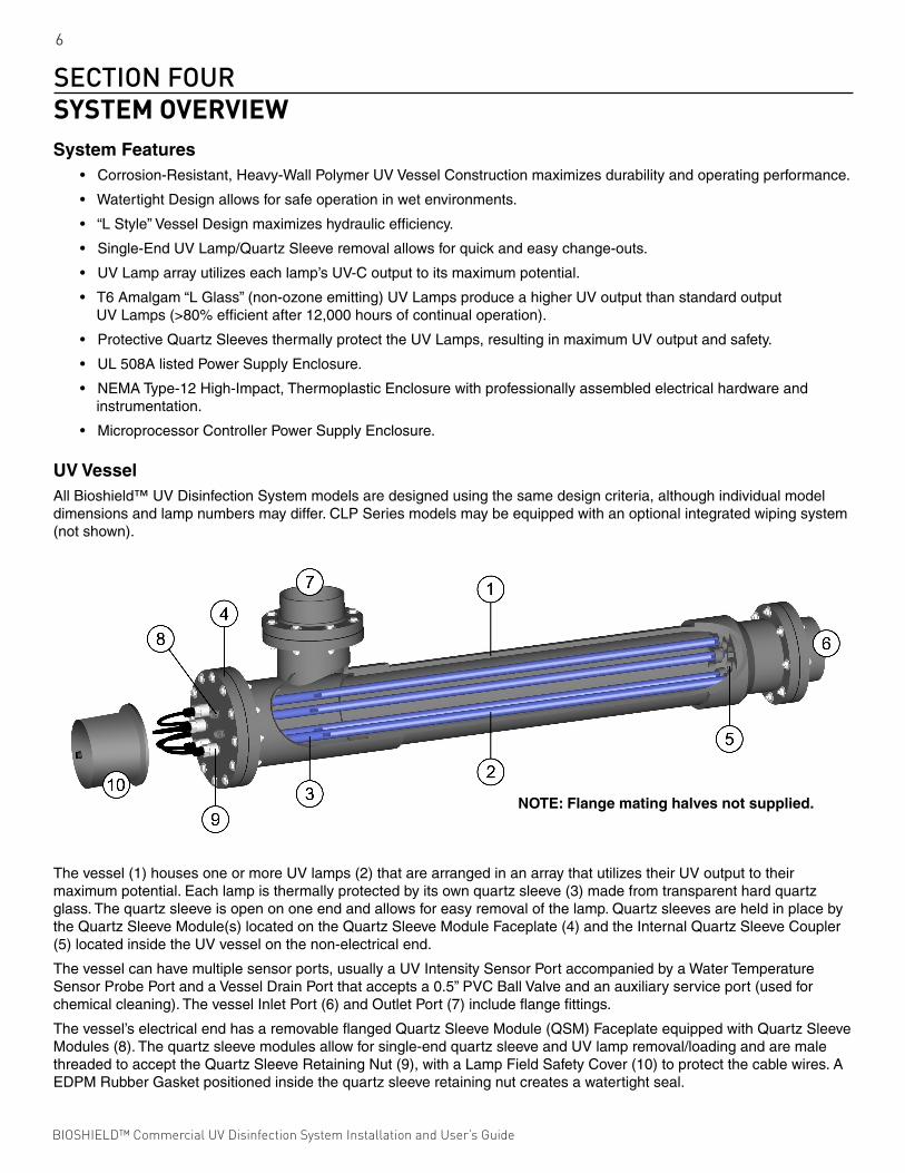
UV VesselAll Bioshield™ UV Disinfection System models are designed using the same design criteria, although individual model dimensions and lamp numbers may differ. CLP Series models may be equipped with an optional integrated wiping system (not shown).
The vessel (1) houses one or more UV lamps (2) that are arranged in an array that utilizes their UV output to their maximum potential. Eac h lamp is thermally protected by its own quartz sleeve (3) made from transparent hard quartz glass. The quartz sleeve is open on one end and allows for easy removal of the lamp. Quartz sleeves are held in place by the Quartz Sleeve Module(s) located on the Quartz Sleeve Module Faceplate (4) and the Internal Quartz Sleeve Coupler (5) located inside the UV vessel on the non-electrical end.
The vessel can have multiple sensor ports, usually a UV Intensity Sensor Port accompanied by a Water Temperature Sensor Probe Port and a Vessel Drain Port that accepts a 0.5” PVC Ball Valve and an auxiliary service port (used for chemical cleaning). The vessel Inlet Port (6) and Outlet Port (7) include flange fittings.
The vessel’s electrical end has a removable flanged Quartz Sleeve Module (QSM) Faceplate equipped with Quartz Sleeve Modules (8). The quartz sleeve modules allow for single-end quartz sleeve and UV lamp removal/loading and are male threaded to accept the Quartz Sleeve Retaining Nut (9), with a Lamp Field Safety Cover (10) to protect the cable wires. A EDPM Rubber Gasket positioned inside the quartz sleeve retaining nut creates a watertight seal.
NOTE: Flange mating halves not supplied.
SECTION FOUR SYSTEM OVERVIEW
BIOSHIELD™ Commercial UV Disinfection System Installation and User’s Guide BIOSHIELD™ Commercial UV Disinfection System Installation and User’s Guide

7
Model #:
No. of Lamps / Part #:
No. of Quartz Sleeves / Part #:
Maximum Design Flow Rate:
UV System Serial #:
Model Description:
Max. Operating Pressure:
Input Power:
Short Circuit Current Rating:Power Supply:
2KVA RMS 277 VAC MAXTYPE #2 ENCLOSURE
/
/
Emperor Aquatics, Inc. - 2229 Sanatoga Station Road, Pottstown, PA. 19464
For Warranty, Repair and Replacement Part Requests: Please call 610–970–0440or e-mail us at [email protected]
WARNING: DO NOT operate this equipment withoutreading and understanding the Operator’s Manual thoroughly.
WARNING: Protect eyes and skin from direct exposure to UV Light.
WARNING: Dangerous Voltage can cause severe or fatal injury. Install this equipment in accordance with all local electricalcodes. Disconnect power before attempting to service unit. See the Operator’s Manual for proper procedures.
WARNING: Ensure that any trapped air is properly relieved from the unit, failure to do so will affect the unit’s performance.DO NOT operate unit in no-flow situations.
CAUTION: This equipment (UV Sterilizer) is designed for supplemental disinfection and should be used with registered orapproved disinfection chemicals to impart residual concentrations.
NOTE: Replace UV lamps after 9,000 hours of continuous operation or as stated in the Operator’s Manual. Replace the QuartzSleeve Seals every 9,000 hours or when replacing the lamps. For reliable performance, use only genuine Emperor Aquatics, Inc.UV lamps and replacement parts.
by
COOLING FANNOTE: CLEAN FILTER MATS REGULARLYTO AVOID OVERHEATING AND DAMAGE.
WARNING: HAZARDOUS VOLTAGE CAN CAUSESEVERE OR FATAL INJURY. MUST BE INSTALLEDACCORDING WITH LOCAL ELECTRICAL CODES.DISCONNECT POWER BEFORE ATTEMPTING TOSERVICE UNIT. SEE INSTRUCTIONS FOR PROPERPROCEDURES.
MAIN DISCONNECT AND BRANCH CIRCUITPROTECTION TO BE PROVIDED BY OTHERS
NOTE: THE TEMP. SENSOR CABLE MUST BE CONNECTEDFOR THE POWER ENCLOSURE TO OPERATE.
1
4
23
97 865
Power EnclosureThe Remote Power Enclosure houses all components used for operation, monitoring and control of the entire Bioshield™ UV Disinfection System (monitoring and control vary depending on model). The power enclosure is designed for remote mounting from the vessel and is equipped with 12’ lamp cables and mounting hardware.
Microprocessor Controller ModelsFeatures:
1. Microprocessor Controller Power Enclosure
2. Liquid Crystal Display Screen
3. Touch Pad Control
4. External On/Off Switch
5. Main Power Cable
6. Temperature Sensor
7. UV Intensity Sensor
8. Lamp Field Safety Cover Cable
9. Lamp/Power Cables
BIOSHIELD™ Commercial UV Disinfection System Installation and User’s Guide BIOSHIELD™ Commercial UV Disinfection System Installation and User’s Guide

8
Above: Bioshield™ UV Disinfection System polymer UV vessel, outfitted with raised flanges (available in all vessel diameters).
Model2Lamps/ Watts
UV-C Spectrum
Output Watts
Amps Max Load @ 120/230 VAC
Max. PSI
Max. Flow Rate@ 90% UVT40 mJ/cm2
(GPM)
Max. Flow Rate@ 90% UVT60 mJ/cm2
(GPM)
CLP41A6-XN 1/130 40 2.1/1.0 150 49 33
CLP42A6-XN 2/130 80 3.9/2.0 150 90 60
CLP43A6-XN 3/130 120 5.8/2.9 150 125 83
CLP43A8-XN 3/130 120 5.8/2.9 150 167 111
CLP44A8-XN 4/130 160 7.5/3.7 150 227 151
CLP45A8-XN 5/130 200 9.4/4.7 150 272 181
CLP46A10-XN 6/130 240 11.2/5.6 120 365 244
CLP47A10-XN 7/130 280 13.3/6.5 120 430 287
CLP47A12-XN 7/130 280 13.3/6.5 90 492 328
CLP48A12-XN 8/130 320 15.0/7.5 90 555 369
CLP61A6-XN 1/320 98 3.2/1.6 150 113 75
CLP62A6-XN 2/320 196 6.0/3.0 150 200 133
CLP63A6-XN 3/320 294 9.0/4.5 150 279 186
CLP63A8-XN 3/320 294 9.0/4.5 150 372 247
CLP64A8-XN 4/320 392 12.0/6.0 150 505 336
CLP65A8-XN 5/320 490 15.0/7.5 150 606 403
CLP66A10-XN 6/320 588 18.0/9.0 120 814 542
CLP67A10-XN 7/320 686 11.01 120 953 638
CLP67A12-XN 7/320 686 11.01 90 1095 729
CLP68A12-XN 8/320 784 13.01 90 1235 823
CLP69A14-XN 9/320 882 14.01 50 1462 974
CLP610A16-XN 10/320 980 16.01 50 1690 1127
CLP611A18-XN 11/320 1,078 17.01 50 1963 1308
CLP612A20-XN 12/320 1,176 19.01 50 2335 1555
Electrical and Flow Specifications
SECTION FIVE SYSTEM SPECIFICATIONS
WATER TEMP. SENSOR PORT
B
WATEROUTLET
PORT
WATERINLETPORT
WATER DRAIN PORT
REMOVABLE HEAD SECTION
C A
QUARTZ SLEEVE/UV LAMP ACCESSPORTS
UV INTENSITY SENSOR PORT
LAMP FIELDSAFETY COVER
BIOSHIELD™ Commercial UV Disinfection System Installation and User’s Guide BIOSHIELD™ Commercial UV Disinfection System Installation and User’s Guide

9
Pre-Installation Inspection
PurposeTo familiarize the installer/operator with the Bioshield™ UV Disinfection System components, to assure proper delivery of all the system’s components and to inspect each component for shipping damages.
FrequencyTo be con ducted prior to installation.
Parts and Required Equipment• Adjustable Wrench or 1.5” Socket• Box Cutter• Hammer/Nail Remover• Flashlight
Procedure
Note: Vessel diameters up to 8” are shipped with their quartz sleeves assembled. Vessel diameters 10” and larger are shipped with their quartz sleeves packaged separately.
Note: UV Lamp(s) are shipped in a separate package either inside the vessel crate or separately.
1. Unpack and inspect vessel for shipping damage. A box cutter or hammer/nail remover may be needed to unpack the UV System.
2. Conduct an internal, visual inspection of models shipped with their quartz sleeves assembled. A flashlight will help with the internal inspection.
The UV System consists of:
• Quartz Sleeve Module (QSM) Faceplate (assembled on Vessel)
• QSM Faceplate Gasket (assembled on Vessel)
• UV Intensity Sensor
• Temperature Sensor
• Quartz Sleeve Retainer Nut (one for each quartz sleeve)
• Quartz Sleeve Gasket (one for each quartz sleeve retainer nut)
• Drain Valve Assembly
• Quartz Sleeve (one for each UV Lamp)
• UV Lamp(s)
• Vessel
• Bolt(s) (assembled on Vessel)
• Nut(s) (assembled on Vessel)
• Washer(s) (assembled on Vessel)
• 4-Pin Connector(s) (attached to lamp cables)
• Lamp Field Safety Cover and Cable
During pre-installation there is a general risk due to load.
Quartz Sleeves and UV Lamps are fragile and potentially dangerous if broken. Handle with care.
NOTE: Flange mating halves not supplied.
SECTION SIXINSTALLATION
BIOSHIELD™ Commercial UV Disinfection System Installation and User’s Guide BIOSHIELD™ Commercial UV Disinfection System Installation and User’s Guide

10
General risk due to load.
General risk due to pressurized piping or UV Vessel.
Quartz Sleeves are fragile and potentially dangerous if broken. Handle with care.
UV Vessel Installation
PurposeProper installation of the UV Vessel achieves expected results and ensures safe operation.
FrequencyRequired with new construction, retro-fit or replacement of outdated equipment.
Parts and Required Equipment• Socket Wrenches• Adjustable Wrenches• Set of Slotted and Phillips Head Screwdrivers• Lifting Equipment with Slings• Vessel Mounting Brackets• Required Isolation Valves• Plumbing Components• Personal Safety Equipment
Procedure
Important: The installation of the UV system must be carried out in accordance with local regulations and codes.
1. Install the UV system after the mechanical filtration. This eliminates debris from entering the vessel and diminishing the unit’s effectiveness, as well as potentially damaging the quartz sleeves and UV lamps.
2. Install inlet and outlet isolation valves (to be supplied by others).
3. Install UV vessel mounting brackets if required (to be supplied by others).
Note: A 46” clearance for CLP4 Series models and a 76” clearance for CLP6 Series models is required for lamp and quartz sleeve removal.
Horizontal Installation
Horizontal installation requires the vessel outlet port to face upwards, allowing trapped air to escape. If installed on a “by-pass filter loop” or isolated using valves, an automatic air bleed system is required. Failure to remove trapped air can result in rupture or heat damage to the vessel.
Vertical Installation
Vertical installation requires the bottom port to be used as the vessel’s inlet and the port closest to the electrical end to be used as the outlet; allowing trapped air to escape. If installed on a “by-pass filter loop” or isolated using valves, an automatic air bleed system is required. Failure to remove trapped air can result in rupture or heat damage to the vessel.
LAMP #1
LAMP #2
LAMP #3
LAMP #4
LAMP #5
LAMP #6
LAMP HOUR METERRESET BUTTON
MAIN POWER
LAMP #1
LAMP #2
LAMP #3
LAMP #4
LAMP #5
LAMP #6
LAMP HOUR METERRESET BUTTON
MAIN POWER
LAMP #1
LAMP #2
LAMP #3
LAMP #4
LAMP #5
LAMP #6
LAMP HOUR METERRESET BUTTON
MAIN POWER
LAMP #1
LAMP #2
LAMP #3
LAMP #4
LAMP #5
LAMP #6
LAMP HOUR METERRESET BUTTON
MAIN POWER
BIOSHIELD™ Commercial UV Disinfection System Installation and User’s Guide BIOSHIELD™ Commercial UV Disinfection System Installation and User’s Guide

11
4. Models equipped with inlet/outlet raised flanges require mating pipe flanges (not included). Depending on port type ordered, further fabrication may be required by the installer.
5. Isolation Valves are necessary for vessel removal and chemical cleaning procedure. It is recommended to install the isolation valves in conjunction with a separate set of, matching size & type, water port connections to the inlet/outlet ports of the vessel. Adding the “double connection” will enable the UV sterilizer to be removed from the filtration loop without shutting the total filtration system down. If this installation arrangement is not possible, install the unit in a way that chemical cleaners or freshwater rinse can be drained completely from the vessel without contaminating the process water.
6. The UV System (models w/ diameters of 10” and larger) may have been shipped without their quartz sleeves installed in the vessel, please install now. See “Quartz Sleeve Installation” below for details.
7. The vessel is equipped with a 0.5” female threaded drain port for installation of the Drain Valve Assembly. Use thread tape on the threads when installing the drain valve assembly.
8. The vessel is equipped with various sensor ports (UV Intensity and Water Temperature Sensors), additional sensor ports may be included depending on the model or options purchased with the UV System. All sensor ports will be labeled on the vessel based on their respective function. Use thread tape on the threads to create a reliable seal with all sensors. Sensors must be threaded into their respective vessel ports prior to connection to the power supply enclosure to avoid sensor damage from cable twisting.
Quartz Sleeve Installation
PurposeTo thermally protect the UV lamp and isolate it from water.
FrequencyQuartz Sleeve(s) are installed after being inspected/cleaned or damaged. Water quality conditions may warrant more fre-quent inspection/cleaning. Fouled quartz sleeves absorb UV light and therefore may reduce the UV intensity.Replace broken quartz sleeve(s).
Parts and Required Equipment• Quartz Sleeve(s)• Quartz Sleeve Retaining Nut Gasket• Adjustable Wrench• Cotton or Silicon Gloves• Personal Safety Equipment
General risk due to electricity.
General risk due to pressurized piping or UV Vessel.
Quartz Sleeves are fragile and potentially dangerous if broken. Handle with care.
Procedure
Note: Use clean cotton or silicon gloves when handling the quartz sleeve(s). Skin oils absorb ultraviolet light and reduce UV intensity.
1. Apply water (wet) or a small amount of water soluble lubricant such as Ideal Industries Clear Glide to the domed-end of the quartz sleeve. Lubricating will aid in inserting the domed-end of the quartz sleeve into the vessel’s internal quartz sleeve coupler.
BIOSHIELD™ Commercial UV Disinfection System Installation and User’s Guide BIOSHIELD™ Commercial UV Disinfection System Installation and User’s Guide

12
2. Carefully slide the quartz sleeve(s) into the Quartz Sleeve Faceplate’s “Quartz Sleeve Module” (QSM) allowing approximately 12” of the quartz sleeve to remain outside the UV vessel.
3. With 12” of the quartz sleeve exposed outside the vessel, carefully place the Quartz Sleeve Rubber Gasket Seal onto the open-end of the quartz sleeve. Apply water or a small amount of water soluble lubricant onto the end of the quartz sleeve, this will act as a lubricant and will allow you to easily slide the Rubber Gasket onto the quartz sleeve.
4. Push the Rubber Gasket onto the quartz sleeve. Position the Gasket approximately 1/2” from the sleeve’s open end.
5. As you push the quartz sleeve into the vessel (through the Quartz Sleeve Module) elevate the domed-end of the quartz sleeve by gently pushing down on the open-end approximately 1/2”. This will help guide the domed-end of the quartz sleeve into its correct Internal Quartz Sleeve Coupler “Port”.
6. Finish sliding the remainder of the quartz sleeve into the vessel until the gasket makes contact with the Quartz Sleeve Module.
As you thread and tighten the Quartz Sleeve Retaining Nut onto the Quartz Sleeve Module the Quartz Sleeve Retaining Nut’s internal lip will automatically set the quartz sleeve in its proper position.
7. Using a 1.5” socket or adjustable wrench, tighten the Quartz Sleeve Retaining Nut until snug (5 ft. • lb. ). Over-tightening can break the Quartz Sleeve Module on the faceplate or the quartz sleeve inside the UV vessel.
8. The quartz sleeve is now properly assembled, you are now ready to perform a Water Test See Page 16.
BIOSHIELD™ Commercial UV Disinfection System Installation and User’s Guide BIOSHIELD™ Commercial UV Disinfection System Installation and User’s Guide
13
Procedure
1. Use the supplied enclosure mounting feet if the Power Supply Enclosure is going to be mounted on a wall.
2. Mount the Power Supply Enclosure close to the UV Vessel so that the lamp cables reach between the Power Supply Enclosure and the UV Vessel. The power supply lamp cables are approximately 10 - 20’ long to provide an adequate routing length from the power supply enclosure to the UV vessel. Keep in mind that the temperature & UV sensors have approximately 12’ long cables, so the power supply should be placed within this length constraint to avoid the additional requirement of sensor extension cables.
3. The Power Supply Enclosure should be mounted so that the controls are visible to the operator. The location used for mounting the Power Supply Enclosure should be as dry and cool as possible.
4. The Power Supply Enclosure should be located in a place that provides sufficient weather protection, in the case of outdoor installation. Sufficient space near the cooling fan’s intake and exhaust must be provided.
5. The Power Supply Enclosure must be supplied with the correct operating voltage (120/230 VAC). Electrical requirement information is located on the Power Supply Enclosure labeling and can be found on Page 8 (Dimensions and Electrical Specifications) of this manual. Failure to supply the UV System with the correct operating voltage can damage the ballasts and other electrical hardware. Use only a well-ground electrical circuit.
6. The UV System is equipped with an equipment-grounding conductor and a grounding plug. The grounding plug must be installed and grounded in accordance with all local codes and ordinances. Improper connection of the equipment-grounding conductor can result in electrocution. Check with a qualified electrician or service personnel if you question whether the equipment is properly grounded.
7. Input power to the Power Supply Enclosure is switched on and off using the enclosure’s External On/Off switch or optional Remote On/Off control.
Power Supply Installation
PurposePower Supply Enclosure is part of the complete Bioshield™ UV Disinfection System.
FrequencyRequired with new construction, retro-fit or replacement of outdated equipment.
Parts and Required Equipment• Set of Slot and Phillips Head Screwdrivers• Adjustable Wrench• Pliers• Wall Struts or Braces• Supplied Enclosure Mounting Hardware• Personal Safety Equipment
General risk due to suspended load.
General risk due to electricity.
General risk due to pressurized piping or UV Vessel.
Note: All UV control enclosures that utilize our microprocessor controls should be mounted with considerations to other devices that emit, or are suspected of emitting, any EMI & RFI noise and that any sensors used in conjunc-tion with our microprocessor controls should use industry standard procedures to avoid EMI & RFI noise issues.
BIOSHIELD™ Commercial UV Disinfection System Installation and User’s Guide BIOSHIELD™ Commercial UV Disinfection System Installation and User’s Guide

14
Remote Main System On/Off Capability (Optional)
A discrete input circuit is provided to allow for Remote On/Off control of the control system. Located inside the main control enclosure there are two terminal blocks (brown). For remote on/off capability these terminals would be wired to an external switch capable of handling your unit’s voltage; for example, 230-volt AC @ 1-amp.
Note: The system is supplied with these terminals jumped together as the default ON setting, to use this option the jumper must be removed and replaced by the user’s own external switch. WARNING: DO NOT SUPPLY ADDITIONAL POWER TO TERMINALS!
Note: Options below MUST be purchased with original equipment.
Main Power Run Confirm Output Signal (Optional)
The system’s main power contactor circuit is equipped with a Main Power Run Confirm Output Voltage Signal Relay (see image for terminal locations and identification) that triggers when the lamp field has been energized.
Note: This Run Confirm relay circuit is intended to be used as a status indicator only, and is NOT currently wired for a load bearing circuit. Please contact Pentair Commercial Aquatics prior to using this relay circuit as anything other than a status indicator. The three terminal block connections (Gray, White, and Orange) for this output feature are located in the inside of the power enclosure.
Gray= Normally-ClosedOrange= Normally-OpenWhite= CommonGray and White = (Open) when the lamp field has been energizedOrange and White = (Closed) when the lamp field has been energized
4-20 Milliamp Output Connection (Optional)
The Red (+) and Black (-) terminal blocks are the 4-20 milliamp contact connections. Use a digital multimeter (set on mA) to view the current output (Red probe to the Red terminal, Black probe to the Black terminal). WARNING: DO NOT SUPPLY ADDITIONAL POWER TO TERMINALS!Note: The Microprocessor Control system’s analog signal must be specified with original purchase. Typically this option is used for UV intensity, but it can also monitor the temperature or flow circuit (if equipped).
Alarm Relays
A discrete output relay circuit (24-VAC/DC 200 milliamp maximum current, normally open “Form A” contact) is provided to allow for alarm enunciation of any of the following monitored conditions: lamp failure, low UV intensity, vessel water over-temperature, enclosure over-temperature, end of lamp life, under/over input voltage alarm and lamp field safety cover. These two yellow terminal blocks are located inside the main control enclosure. The relay will close when any alarm is triggered.
Individual Output Alarm Relay (Optional)
(7) Discrete output relay circuits (200 milliamp, 24VAC/DC MAX, normally Open contact) are provided to allow for alarm enunciation of the following monitored conditions:
Yellow Failsafe that sets on any alarmBlack Lamp statusWhite End of lamp lifeGray UV intensity lowGreen Enclosure over-temp Orange Vessel water over-temp / Sensor Not attachedBlue Input voltage Low or High
These terminal blocks are located inside the main control enclosure. The relay will close when alarm is triggered.
BIOSHIELD™ Commercial UV Disinfection System Installation and User’s Guide BIOSHIELD™ Commercial UV Disinfection System Installation and User’s Guide
15
Individual Output Alarm Relay (Optional)
(7) Discrete output relay circuits (200 milliamp, 24VAC/DC MAX, normally Open contact) are provided to allow for alarm enunciation of the following monitored conditions:
Yellow Failsafe that sets on any alarmBlack Lamp statusWhite End of lamp lifeGray UV intensity lowGreen Enclosure over-temp Orange Vessel water over-temp / Sensor Not attachedBlue Input voltage Low or High
These terminal blocks are located inside the main control enclosure. The relay will close when alarm is triggered.
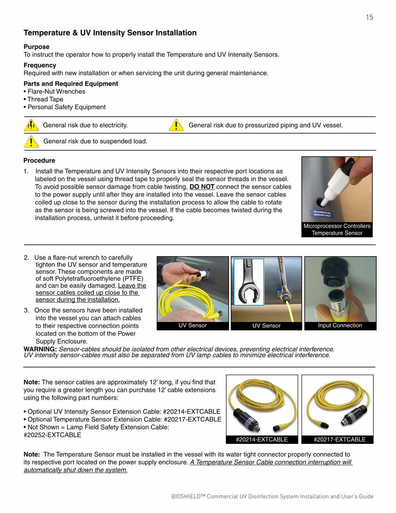
Temperature & UV Intensity Sensor Installation
PurposeTo instruct the operator how to properly install the Temperature and UV Intensity Sensors.
FrequencyRequired with new installation or when servicing the unit during general maintenance.
Parts and Required Equipment• Flare-Nut Wrenches• Thread Tape• Personal Safety Equipment
General risk due to electricity. General risk due to pressurized piping and UV vessel.
General risk due to suspended load.
Note: The sensor cables are approximately 12’ long, if you find that you require a greater length you can purchase 12’ cable extensions using the following part numbers:
• Optional UV Intensity Sensor Extension Cable: #20214-EXTCABLE• Optional Temperature Sensor Extension Cable: #20217-EXTCABLE• Not Shown = Lamp Field Safety Extension Cable: #20252-EXTCABLE
Note: The Temperature Sensor must be installed in the vessel with its water tight connector properly connected to its respective port located on the power supply enclosure. A Temperature Sensor Cable connection interruption will automatically shut down the system.
2. Use a flare-nut wrench to carefully tighten the UV sensor and temperature sensor. These components are made of soft Polytetrafluoroethylene (PTFE) and can be easily damaged. Leave the sensor cables coiled up close to the sensor during the installation.
3. Once the sensors have been installed into the vessel you can attach cables to their respective connection points located on the bottom of the Power Supply Enclosure.
Input Connection
Microprocessor Controllers Temperature Sensor
UV SensorUV Sensor
#20217-EXTCABLE#20214-EXTCABLE
WARNING: Sensor-cables should be isolated from other electrical devices, preventing electrical interference. UV intensity sensor-cables must also be separated from UV lamp cables to minimize electrical interference.
Procedure
1. Install the Temperature and UV Intensity Sensors into their respective port locations as labeled on the vessel using thread tape to properly seal the sensor threads in the vessel. To avoid possible sensor damage from cable twisting, DO NOT connect the sensor cables to the power supply until after they are installed into the vessel. Leave the sensor cables coiled up close to the sensor during the installation process to allow the cable to rotate as the sensor is being screwed into the vessel. If the cable becomes twisted during the installation process, untwist it before proceeding.
BIOSHIELD™ Commercial UV Disinfection System Installation and User’s Guide BIOSHIELD™ Commercial UV Disinfection System Installation and User’s Guide
16
Mandatory Water Test
PurposeThe Mandatory Water Test identifies a potential quartz sleeve assembly seal failure. During normal UV system operation, a quartz sleeve assembly failure can result in extensive damage to the UV lamp, quartz sleeve and ballast.
FrequencyThe Mandatory Water Test must be performed after a quartz sleeve/retaining nut gasket inspection/replacement. Quartz Sleeve inspection/retaining nut gasket replacement must be carried out annually, at minimum.
Parts and Required Equipment• Paper Towels• Personal Safety Equipment
General risk due
UV Lamps are fragile and potentially dangerous if broken. Handle with care.
Procedure
Important: Failure to perform a water test could lead to unsafe conditions and may void your product’s warranties.
1. With the quartz sleeves installed inside the UV vessel, before installation of the UV lamps, perform a water test as explained below. For quartz sleeve removal See Page 30. For installation See Page 11.
2. Thread all sensors into their respective ports on the UV vessel.
3. Place rolled-up paper towels into the Quartz Sleeve Retaining Nuts. During the water test, the paper towels may absorb moisture. The presence of any moisture identifies that a quartz sleeve seal failure (leak) has occurred.
4. Inspect all piping connections to the UV Vessel and confirm that valves are in their correct position prior to start-up.
5. With satisfactory piping and valve inspection, operate the UV system. Allow water to flow through the UV Vessel for no less then fifteen minutes.
6. After fifteen minutes of flowing water through the UV vessel, remove the paper towel from each Quartz Sleeve Retaining Nut and inspect closely for ANY sign of moisture. If leaks are detected, shut the system down and re-install any quartz sleeve with an inadequate seal. For quartz sleeve removal/installation See Page 30-32.
7. If no leaks were detected you are now ready to install the UV Lamp(s). See Page 17.
SECTION SEVENMANDATORY WATER TEST
BIOSHIELD™ Commercial UV Disinfection System Installation and User’s Guide BIOSHIELD™ Commercial UV Disinfection System Installation and User’s Guide

17
1. Remove the white Polytetrafluoroethylene (PTFE) “wire keeping” rings from the UV lamp by carefully cutting it off with wire cutters.
Note: Be careful not to cut the lamp wires!
2. Gently slide the UV Lamp into the Quartz Sleeve Retaining Nut leaving 6” of the UV lamp exposed.
IMPORTANT: INSTALL LAMPS WITH AMALGAM SPOT IN DOWN POSITION!
Note: Lower wattage amalgam lamps contain a single mass of amalgam while higher wattage amalgam lamps contain multiple masses of amalgam.
Procedure
Important: Before installing the UV Lamp(s) a MANDATORY WATER TEST must be performed. See Page 16.
Note: Use clean cotton or silicon gloves when handling the UV lamp(s). Skin oils absorb ultraviolet light and reduce UV intensity. Skin oils may also lead to premature lamp failure.
UV Lamp Installation
PurposeTo instruct the operator how to properly install the UV lamp(s).
FrequencyLamp installation in new unit or lamp replacement change-out (after every 12,000 hours of continual operation).
Parts and Required Equipment• UV Lamp(s)• Wire Cutters• Adjustable Wrenches• Cotton or Silicon Gloves• Personal Safety Equipment
General risk due to electricity.
UV Lamps are fragile and potentially dangerous if broken. Handle with care.
UV SENSORLAMP WIRES
UV LAMP
QUARTZ SLEEVE
UV VESSEL
Note: When installing the lamp into the quartz sleeve position that is monitored by the UV Intensity Sensor, it is important to make sure the lamp wires that run the length of the lamp are not facing the sensor. See diagram, at right for the proper lamp placement.
SECTION EIGHTUV LAMP INSTALLATION
BIOSHIELD™ Commercial UV Disinfection System Installation and User’s Guide BIOSHIELD™ Commercial UV Disinfection System Installation and User’s Guide

18
Note: Each Lamp cable (1) is equipped with a Water Tight Connector (2). This cable adapter is made up of three components: Nut (3), Rubber Gasket (4) and Male-Threaded Body (5).
3. Loosen (not remove) the lamp Water Tight Connector nut (3) to release tension on the lamp cable allowing the cable to slide freely through the adapter. This will allow the male-threaded body (5) portion of the lamp Water Tight Connector to be threaded into the white quartz sleeve retaining nut without twisting the lamp cable (after lamp installation).
4. With the UV lamp installed inside the quartz sleeve and six inches exposed, attached the lamp cable’s stepped 4-Pin Connector on to the four pins of the UV lamp.
5. With the lamp cable/lamp connection complete gently slide the remainder of the lamp w/ cable through the Quartz Sleeve Retaining Nut and into the quartz sleeve. With the lamp now inside the quartz sleeve, gently continue to push the lamp (w/ connected lamp cable) into the quartz sleeve until it stops, then pull out 1/2” of the lamp cable. This will position the lamp properly inside the quartz sleeve avoiding heat damage to the Quartz Sleeve Module Faceplate and Quartz Sleeve Module.
6. With the UV lamp in its correct position inside the quartz sleeve, thread the water tight connector into the Quartz Sleeve Retaining Nut.
7. With the “black” Water Tight Connector threaded into the Quartz Sleeve Retaining Nut, tighten the Cable Adapter Nut (3) to create a watertight seal on the lamp’s cable. Take care not to bend or damage the Water Tight Connector’s “gasket prongs” during this process.
8. The UV lamp is now properly installed.
BIOSHIELD™ Commercial UV Disinfection System Installation and User’s Guide BIOSHIELD™ Commercial UV Disinfection System Installation and User’s Guide

19
Installation of Lamp Field Safety Cover
PurposeTo instruct the operator how to properly install the Lamp Field Safety Cover.
FrequencyRequired anytime the lamp field is accessed.
Parts and Required Equipment• Lamp Field Safety Cover• Pliers• Personal Safety Equipment
General risk due to electricity.
Procedure
1. With the UV lamps and lamp cables installed hand loosen the four Safety Cover Retaining Screws from the QSM Faceplate so they have approximately 3/8” of clearance between the head of the screw and the QSM Faceplate.
3. Once the cover is in place, tighten the four Retaining Screws down until the cover is snugly held in place.
2. The Lamp Field Safety Cover uses a twist-lock attachment method that can only be installed one way. Take the cover assembly with the cable slot facing downward and align the four slotted keyways on the cover’s flange face with the retaining screws on the QSM Faceplate. Then place the cover over the screws and turn counterclockwise to engage the retaining screws.
4. With the cover installed on the vessel, connect the Lamp Field Safety Cover cable that is attached to the power supply to the connector that is located on the end of the Safety Cover.
Note: The Lamp Field Safety Cover must be installed onto the vessel with its respective cable, located on the Power Supply Enclosure, properly connected to its respective port on the Safety Cover. Removing the Lamp Field Safety Cover or the cable connection will automatically shut off the UV system’s lamp field and generate an alarm signal.
BIOSHIELD™ Commercial UV Disinfection System Installation and User’s Guide BIOSHIELD™ Commercial UV Disinfection System Installation and User’s Guide

20
Start-Up
PurposeThis section contains the necessary steps required to prepare the Bioshield™ UV Disinfection System for proper operation.
FrequencyRequired with new construction, retro-fit or replacement of outdated equipment.
Parts and Required Equipment• Personal Safety Equipment
General risk due to pressurized piping and UV Vessel!
General risk due to electricity!
Hydraulic shock (water hammer) may occur as a result of improper use of valve(s) or trapped air inside the vessel. Hydraulic shock and trapped air can damage the vessel.
Trapped air or no-flow situations may damage the vessel and/or the UV lamps due to overheating.
Procedure
1. Confirm that all personnel operating this UV system have thoroughly reviewed these instructions prior to operating.
2. Remove all dirt/debris from power supply enclosure, vessel and installation area resulting from installation activities.
3. Inspect all plumbing connections and immediate plumbing network to ensure safe start-up.
4. Inspect the vessel’s Quartz Sleeve Module Faceplate to ensure proper assembly.
5. Inspect quartz sleeve assemblies (Quartz Sleeve Retaining Nuts) confirming that they are tight.
6. Inspect Power Supply Enclosure, confirm that it has been mounted properly and input power is in accordance with local ordinances and codes.
7. Inspect all sensors ensuring that the probes are properly installed in the vessel and Water Tight Connectors are properly connected to their respective Power Supply Enclosure ports.
8. Verify that a successful Water Test has been completed. See Page 16 for instructions.
SECTION NINECOMMISSIONING
BIOSHIELD™ Commercial UV Disinfection System Installation and User’s Guide BIOSHIELD™ Commercial UV Disinfection System Installation and User’s Guide

21
Microprocessor Controller Power Supply OperationOperation
The operation of the Bioshield™ UV Disinfection System may only be carried out by authorized personnel. The personnel responsible for the operation of this system must read and understand Section 10, Section 2 (Health & Safety Precautions), and strictly comply with all relevant rules for accident prevention and local health and safety regulations.
Check all relevant safety measures before you switch on the UV system.
Microprocessor Controller Power Supply Enclosure
Operating Modes
Generally, the UV system is operated in “LOCAL” mode. An optional, discrete input circuit is provided to allow for either “LOCAL/REMOTE” or “LOCAL” mode. If this option has been ordered there are two terminal blocks (brown) located inside the Power Supply Enclosure. The UV system is supplied with both the brown terminals jumped together as the default “ON” setting. To operate the UV system in the “REMOTE” mode, the “Factory-Installed Jumper” must be removed. Both the brown terminals need to be wired to an external switch (not included) capable of handling 120/230-volt AC @ 1-amp.
Switches
The UV system Power Supply Enclosure is equipped with an External “Main Power” ON/OFF Switch.
With the Main Power ON/OFF Switch in the “On” position, power is supplied to the Microprocessor Controller/Monitor, and the UV lamps.
With the Main Power ON/OFF Switch in the “Off” position, power is cut-off from the entire UV system.
Note: The Main Power Switch must be in the “On” position if the optional Remote On/Off feature is being used.
Microprocessor Controller Power Enclosure
1. Microprocessor Controller Power Enclosure
2. Liquid Crystal Display Screen
3. Touch Pad Control
4. External On/Off Switch
5. Main Power Cable
6. Temperature Sensor
7. UV Intensity Sensor
8. Lamp Field Safety Cover Cable
9. Lamp/Power Cables
The Text Display shows the current operating status of the UV system that includes the following parameters:
• Lamp Operating Status • Lamp Operating Hours
• UV Intensity (UV%) • Voltage Range
• Temperature
Model #:
No. of Lamps / Part #:
No. of Quartz Sleeves / Part #:
Maximum Design Flow Rate:
UV System Serial #:
Model Description:
Max. Operating Pressure:
Input Power:
Short Circuit Current Rating:Power Supply:
2KVA RMS 277 VAC MAXTYPE #2 ENCLOSURE
/
/
Emperor Aquatics, Inc. - 2229 Sanatoga Station Road, Pottstown, PA. 19464
For Warranty, Repair and Replacement Part Requests: Please call 610–970–0440or e-mail us at [email protected]
WARNING: DO NOT operate this equipment withoutreading and understanding the Operator’s Manual thoroughly.
WARNING: Protect eyes and skin from direct exposure to UV Light.
WARNING: Dangerous Voltage can cause severe or fatal injury. Install this equipment in accordance with all local electricalcodes. Disconnect power before attempting to service unit. See the Operator’s Manual for proper procedures.
WARNING: Ensure that any trapped air is properly relieved from the unit, failure to do so will affect the unit’s performance.DO NOT operate unit in no-flow situations.
CAUTION: This equipment (UV Sterilizer) is designed for supplemental disinfection and should be used with registered orapproved disinfection chemicals to impart residual concentrations.
NOTE: Replace UV lamps after 9,000 hours of continuous operation or as stated in the Operator’s Manual. Replace the QuartzSleeve Seals every 9,000 hours or when replacing the lamps. For reliable performance, use only genuine Emperor Aquatics, Inc.UV lamps and replacement parts.
by
COOLING FANNOTE: CLEAN FILTER MATS REGULARLYTO AVOID OVERHEATING AND DAMAGE.
WARNING: HAZARDOUS VOLTAGE CAN CAUSESEVERE OR FATAL INJURY. MUST BE INSTALLEDACCORDING WITH LOCAL ELECTRICAL CODES.DISCONNECT POWER BEFORE ATTEMPTING TOSERVICE UNIT. SEE INSTRUCTIONS FOR PROPERPROCEDURES.
MAIN DISCONNECT AND BRANCH CIRCUITPROTECTION TO BE PROVIDED BY OTHERS
NOTE: THE TEMP. SENSOR CABLE MUST BE CONNECTEDFOR THE POWER ENCLOSURE TO OPERATE.
1
4
23
97 865
SECTION TENOPERATION
BIOSHIELD™ Commercial UV Disinfection System Installation and User’s Guide BIOSHIELD™ Commercial UV Disinfection System Installation and User’s Guide

22Microprocessor Control DescriptionsIncoming AC Voltage MonitorThe Incoming AC Voltage Monitor monitors the input voltage to the UV system. If the value goes outside the acceptable threshold an alarm will be activated. For 120 VAC the threshold parameter is 95 – 140 VAC, for 230 VAC the threshold parameter is 210 – 260 VAC. Your unit’s input voltage parameter is identified on the power supply enclosure and vessel label.
Total Operating Hours MeterThe Total Operating Hours Meter measures in increments of one for each hour the unit is in operation. The hour meter may be reset by the operator using the appropriate SETUP Text Display. The hour meter will roll over at 65,536 hours if not reset prior to reaching this number.
Lamp Status & Lamp Life MonitorThe Lamp Status & Lamp Life Monitor scans all active lamp inputs from 1 to 13 depending on the UV system’s number of lamps. If the Microprocessor Controller detects an inactive lamp an alarm will be activated and the ALARM Text Display will identify which lamp is malfunctioning. The alarm may be reset but will continue to activate every twenty-four (24) hours until the lamp is replaced and the SETUP individual lamp reset is completed.Each lamp is equipped with an individual hour meter, stored in EEPROM for data retention on power removal. At the end of each hour when the “Total Lamp Hour Meter” is incremented, all active lamps will have their individual hours monitored. Each individual lamp’s hours will be monitored for End of Lamp Life (12,000 hours) and a 72 hour recurring alarm will also be set.
Power Supply Enclosure Temperature MonitorThe Power Supply Temperature Monitor uses a temperature sensor mounted inside the UV system’s Power Supply Enclosure that monitors the enclosure’s internal temperature. The temperature monitor is used to protect the UV system’s electronics from overheating, a condition that could damage the unit. The enclosure’s factory-set temperature threshold is 140º F. If the enclosure’s internal temperature reaches 140º F the Microprocessor Controller will shutdown the lamp field and activate an alarm. The Microprocessor Controller must be powered off to reset the system and to restore lamp field operation.
UV Vessel Water Temperature MonitorThe Water Temperature Monitor uses a sensor located on the UV vessel that monitors its internal water temperature. The UV Vessel Water Temperature Monitor is used to protect the vessel from no or low-flow conditions that may allow the lamp field to overheat causing damage to the UV vessel. The UV Vessel Water Temperature Monitor’s factory-set threshold is 120º F and if reached, will cause the Microprocessor Controller to shut down the lamp field and activate an alarm. The Microprocessor Controller must be powered off to reset the system and to restore lamp field operation.Additionally, if the water temperature sensor cable is interrupted/disconnected the entire UV system will shutdown and activate an alarm. The Microprocessor Controller must be powered off to reset the system and to restore lamp field operation.
UV Intensity SensorA UV Intensity Sensor is provided to monitor the quality of the UV energy that is being produced inside the unit’s vessel. The Microprocessor Controller monitoring system displays the UV intensity as a function of percent (0%-100%), this UV intensity measurement is a relative power measurement of the UV energy inside the vessel and not an absolute measurement of UV dose because UV dose is a function of flow, the transmissibility of the water being treated, and the total UV power being applied to the flow path inside the UV vessel. The relative UV intensity (power) must be calibrated in order for the intensity measurement/reading to have any useful meaning. This calibration process is done once the system has been in service for 100 hours, the calibration screen will show a value representing percentage of UV. A button on the screen will allow setting of the 100% reading.
Lamp Field Safety CoverOn all NSF-50 certified units there is a safety cap that covers the lamp’s electrical cables that terminate into the unit’s quartz sleeves. This safety cover must be installed into the vessel with its respective cable properly connected to its respective port located on the power supply enclosure. Removing the Lamp Field Safety Cover or a cable connection interruption will automatically shut off the UV system’s lamp field and generate an alarm signal.
Alarm Relays (standard)A discrete output relay circuit (200 milliamp, normally Open “Form A” contact) is provided to allow for alarm enunciation of any of the following monitored conditions: lamp failure, low UV intensity, vessel water over-temperature, enclosure over-temperature, end of lamp life, under/over input voltage alarm and lamp field safety cover. These two yellow terminal blocks are located inside the main control enclosure. The relay will Close when any alarm is triggered.
4-20 Milliamp Output (Optional)Typically this option is added to the UV intensity circuit, so the UV intensity can be sent to an external recording device. This option can also be added to the temperature circuit or the flow circuit (if equipped). The Red (+) and Black (-) terminal blocks are the 4-20 milliamp contact connections.
Note: This option MUST be purchased with original equipment.
BIOSHIELD™ Commercial UV Disinfection System Installation and User’s Guide BIOSHIELD™ Commercial UV Disinfection System Installation and User’s Guide

23
Operator Text Display
The Microprocessor Controller Text Display is used to present information to the operator as well as serving as a command interface. The microprocessor performs various functions that include intercepting operator commands and updating displayed data. In addition, the software verifies voltage, lamp operation and saves current hours to EEPROM, etc.
Function KeysCommand initiation is performed using the “Function Keys” labeled:Position 1, Position 2 and Position 3.
The “Function Keys“ functions are as follows:
Position 1 = Left Position 2 = Enter Position 3 = Right
Position 1 & 2 (pressed simultaneously) = “Big Left”Position 2 & 3 (pressed simultaneously) = “Big Right”
When using a function key, press and hold down until the desired action occurs. The function key must be released when selecting another key. For example: when pressing the “Enter” function key to move to the SETUP menu, Press and hold “Enter” until the text display begins to change, then let go.
Text Display Contrast AdjustmentYour location will determine the required brightness of the Text Display. Inside the enclosure, on the back of the Text Display, on the printed circuit board, you will find an adjustment potentiometer. Carefully, use a screw driver to adjust display brightness. See image to the right.
Position 1 Position 2 Position 3
Initialize
With the External Power Switch turned “ON”, the text display will be active for a few seconds while background system checks are made. Your unit’s model number, serial number, and microprocessor controller number will display before the main screen loads.
BIOSHIELD™ Commercial UV Disinfection System Installation and User’s Guide BIOSHIELD™ Commercial UV Disinfection System Installation and User’s Guide

24
MAIN UV System Text Display
The “MAIN UV System Text Display” will appear after initialization. On this screen you will see: Total System Operating Hours, Input Voltage, and UV Intensity. Total Hours may be reset and the UV scaling adjusted via the “SETUP” menu. High and Low Input Voltage (95 – 140 VAC or 210 – 260 VAC depending on the specific unit’s control voltage requirements) are preset at the factory and may not be changed.
Press “ENTER” to move to the “SETUP” screen or “RIGHT” to move to the “STATUS” menu.
STATUS Menu Text Display
Four lines of text will appear on the STATUS Menu Text Display. Use the “Right” key to advance the selection arrow (“>”) through the options of the STATUS Menu. Press the “Enter” key to select the desired option. Use the “Left” key to return to the “MAIN UV System Text Display”.
After selecting the desired STATUS Menu option, a brief description will appear on the Text Display. Press the “Left” key to return to the STATUS MENU. Failing to press any “Function Keys” within a couple minutes will automatically revert the Text Display back to the MAIN UV System Screen.
STATUS Menu Text Display Options
Lamp Status
Displays the current On/Off status of lamps 1 through X. 0 = OFF, 1 = ON. For example, a “four lamp” UV system’s lamps are identified on the bottom of the screen in ascending order from right > left. The display example shown here indicates all lamps are in operation, except for lamp 3.
Lamp Hours
Displays the current “total” operating hours of each lamp, six per screen. Each lamp’s status is checked once an hour and “Total” operating hours are incremented by a factor of one. Here, all four lamps show one hour of operation.
UV% Lo Setting
Displays the active UV low set-point as well as the actual UV % intensity. XXX shown here is an operator editable UV% parameter accessible through the SETUP screens. YYY is the actual UV % intensity reading taken from the sensor probe positioned on the UV vessel. The actual UV % intensity (YYY) is updated continuously.
BIOSHIELD™ Commercial UV Disinfection System Installation and User’s Guide BIOSHIELD™ Commercial UV Disinfection System Installation and User’s Guide

25
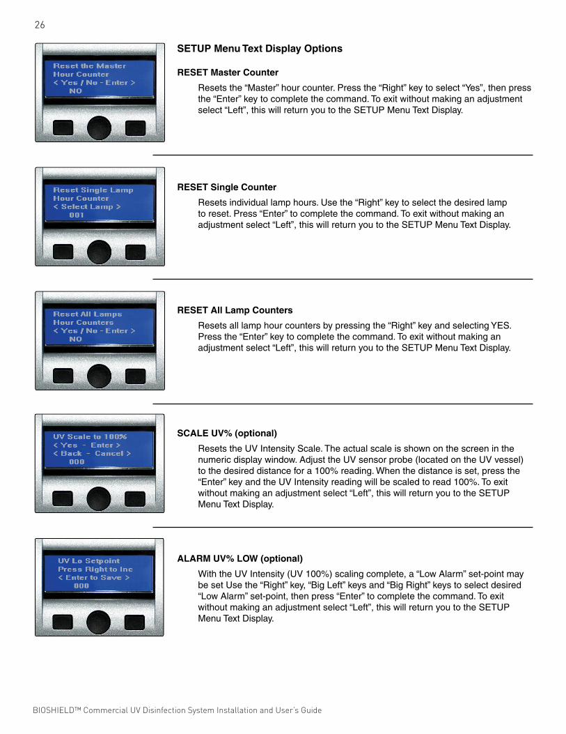
SETUP Menu Text Display
The following options appear on the SETUP Text Display. Four lines of text are viewed on the screen at a given time. Use the “Right” key to advance the arrow (“>”) through the SETUP options. Use the “Enter” key to select the desired SETUP option. Use the “Left” key to return to the MAIN UV System Text Display. Use the “Enter” key to select the desired SETUP option.
SETUP Options
1.) Reset Hour Counter
1A.) Rest Master Counter
1B.) Reset Single Lamp
1C.) Reset All Lamps
2.) Scale UV
3.) Set UV Low Alarm
The following are brief descriptions of SETUP options. Press the “Left” key to return to the SETUP Menu Text Display for list of options. Once the Text Display returns to the SETUP Menu, press the “Left” key again to return to the MAIN UV System Text Display. If a command is not initiated by using either key within a couple of minutes the system will automatically revert to the MAIN UV System Text Display.
Initializing Commands/Settings
Use the “Right” key (“>”) to change increment numbers by a factor of one and change NO to YES and YES to NO. The “Big Left” and “Big Right” arrow keys will increment or decrement numbers by a greater amount. Pressing the “Enter” key will accept your adjustments, then return you to the SETUP Menu Text Display.
Voltage Range
Displays the Factory-set “Low - Hi” Voltage set-points as well as the actual input voltage(YYY/incoming AC voltage). The UV System will not operate properly if operated outside the Voltage set-point range. Damage may incur to ballasts and lamps if the UV System is operated outside of the Voltage set-point range. DO NOT OPERATE THE UV SYSTEM UNDER “OUT OF RANGE” CONDITIONS.
Temperature Hi
Displays the Factory set UV Vessel “Hi Water Temperature” and “Box (Power Sup-ply Enclosure) “Hi Air Temperature” set-points. Both the “actual” vessel’s water and the enclosure’s air temperature (YYY) are displayed.
BIOSHIELD™ Commercial UV Disinfection System Installation and User’s Guide BIOSHIELD™ Commercial UV Disinfection System Installation and User’s Guide
26
SETUP Menu Text Display Options
RESET Master Counter
Resets the “Master” hour counter. Press the “Right” key to select “Yes”, then press the “Enter” key to complete the command. To exit without making an adjustment select “Left”, this will return you to the SETUP Menu Text Display.
RESET Single Counter
Resets individual lamp hours. Use the “Right” key to select the desired lamp to reset. Press “Enter” to complete the command. To exit without making an adjustment select “Left”, this will return you to the SETUP Menu Text Display.
RESET All Lamp Counters
Resets all lamp hour counters by pressing the “Right” key and selecting YES. Press the “Enter” key to complete the command. To exit without making an adjustment select “Left”, this will return you to the SETUP Menu Text Display.
SCALE UV% (optional)
Resets the UV Intensity Scale. The actual scale is shown on the screen in the numeric display window. Adjust the UV sensor probe (located on the UV vessel) to the desired distance for a 100% reading. When the distance is set, press the “Enter” key and the UV Intensity reading will be scaled to read 100%. To exit without making an adjustment select “Left”, this will return you to the SETUP Menu Text Display.
ALARM UV% LOW (optional)
With the UV Intensity (UV 100%) scaling complete, a “Low Alarm” set-point may be set Use the “Right” key, “Big Left” keys and “Big Right” keys to select desired “Low Alarm” set-point, then press “Enter” to complete the command. To exit without making an adjustment select “Left”, this will return you to the SETUP Menu Text Display.
BIOSHIELD™ Commercial UV Disinfection System Installation and User’s Guide BIOSHIELD™ Commercial UV Disinfection System Installation and User’s Guide

27
ALARM Menu Text Display Messages
TEMP Sensor Alarm (optional)
If the water temperature sensor cable is interrupted/disconnected the entire UV system will shutdown and activate an alarm. The Microprocessor Controller must be powered off to reset the system and to restore lamp field operation.
VOLTAGE Over Alarm
Identifies that the actual input voltage has exceeded the Factory “High Voltage” Set-Point. DO NOT OPERATE THE UV SYSTEM WHEN THIS ALARM IS ACTIVATED. HIGH VOLTAGE CAN DAMAGE BALLASTS! This alarm turns off the UV lamp(s) and can only be reset by turning the UV System off briefly, then turning it back on.
VOLTAGE Under Alarm
Identifies that the actual input voltage has fallen below the Factory “Low Voltage” Set-Point. DO NOT OPERATE THE UV SYSTEM WHEN THIS ALARM IS ACTIVATED. LOW VOLTAGE CAN AFFECT UV OUTPUT! This alarm turns off the UV lamp(s) and can only be reset by turning the UV System off briefly, then turning it back on.
ULTRAVIOLET % Under Alarm (optional)
Is activated when UV Intensity has fallen below the operator set “Low” Set-Point. This alarm will re-occur after 5 minutes.
ALARM Menu Text Display
The ALARM Menu Text Display uses a “blinking border” to better alert the operator from a distance. The following ALARM Messages appear on the Text Display. Below, a brief description accompanies each ALARM message.
Upon reaching the ALARM Text Display, pressing the “Right” key will advance the operator through additional ALARM screens if more than one ALARM has been activated. Pressing “Enter” will acknowledge the ALARM which will not re-occur after 5 minutes. If no keys are pressed within a couple of minutes the system will automatically return to the MAIN UV System Text Display. All system checks are conducted from the MAIN UV System Text Display and alarms will not re-display until the MAIN UV System Text Display is active.
BIOSHIELD™ Commercial UV Disinfection System Installation and User’s Guide BIOSHIELD™ Commercial UV Disinfection System Installation and User’s Guide

28
LAMP Failure Alarm
Identifies that a lamp has failed. The failed lamp number is displayed on the screen. The failed lamp should be replaced within 24 hours or the alarm will reactivate. An investigation should be performed to reveal the cause (water-damage, ballast or lamp) of the failure. After replacing the failed lamp the operator must reset the individual lamp hour counter using “RESET Single Counter” on the SETUP Menu Text Display.
Lamp End of Life Alarm
Identifies that the lamp(s) have reached their end of useful lamp life cycle (12,000 hours of continuous operation). Lamps should be replaced at this time as their UV output has degraded below the lamp manufacturer’s suggested minimum. After replacing a lamp the operator must reset the individual lamp hour counter using “Reset Single Counter” or if all lamps are changed out, use “Reset All Lamp Counter” with both of these reset options made on the SETUP Menu Text Display.
Water Temperature OVER Alarm (optional)
Identifies that the water temperature inside the UV vessel has exceeded the FactoryHigh set-point. This alarm, when activated, turns all UV lamps off and can only be reset by turning the UV System off briefly, then turning it back on. This alarm is triggered by over-heating inside the UV vessel that may be a result of an absence of water inside the vessel or identifying a “no-flow” occurrence.
Enclosure Temperature OVER Alarm
Identifies that the interior of the UV System’s Power Enclosure has exceeded the Factory-Set Box/Enclosure Set-point. This alarm, when activated, turns all UV lamps off and can only be reset by turning the UV system off briefly, then turning it back on. This alarm is triggered by the air temperature inside the Power Enclosure exceeding 140º F that may be the result of dirty/clogged air cooling fan filter pads.
UV Lamp Field Off Due to Remote Start or Cover Removal Alarm (optional)
If the cover switch or remote start option is installed on your system the following message will overlay the main screen whenever the cover is off or the remote start is off. This is to alert the user to the reason the lamps may be off and to remind them to replace the cover when completing maintenance.
BIOSHIELD™ Commercial UV Disinfection System Installation and User’s Guide BIOSHIELD™ Commercial UV Disinfection System Installation and User’s Guide

29
Routine Inspection
The following are required routine maintenance actions:
A. Daily inspection of the Bioshield™ UV Disinfection System Power Supply Enclosure control panel to confirm that the unit is operating satisfactorily (lamp operation).
B. Daily visual inspection of the UV vessel and piping for leaks.
C. Monthly inspection for damage/corrosion.
D. Annual vessel interior inspection/cleaning.
E. Biannual quartz sleeve inspection/cleaning.
F. Replace the UV Lamp & Retaining Nut Gasket after 12,000 hours of continual operation.
G. Clean or replace the Cooling Fan Filter Mat monthly, or more frequently in dusty environments.
H. When the lamps are replaced, calibrate the UV Intensity Sensor.
UV Lamp Replacement
Lamp RemovalPurposeTo replace expired UV lamp(s)
FrequencyA complete set of UV lamps must be replaced after 12,000 hours of continual use (manufacturer’s suggested useful lamp life rating) or when the UV Intensity is lower than the Microprocessor Controller threshold value.
Parts and Equipment Required• UV Lamp(s)• Adjustable Wrench• Wire Cutters• Clean Cotton or Silicon Gloves • Personal Safety Equipment
General risk due to pressurized piping and UV vessel!
General risk due to electricity!
DO NOT operate UV Lamp(s) outside of the vessel. UV light may cause severe irritation/damage to eyes and skin.
UV lamp(s) become hot during operation. Handle with care.
UV Lamps are fragile and potentially dangerous if broken. Handle with care.
Procedure
Read and understand this chapter prior to performing lamp change-out
Note: Use clean cotton or silicon gloves when handling the UV lamp(s). Skin oils absorb ultraviolet light and reduce UV intensity. Skin oils may also lead to premature lamp failure.
SECTION ELEVENMAINTENANCE
BIOSHIELD™ Commercial UV Disinfection System Installation and User’s Guide BIOSHIELD™ Commercial UV Disinfection System Installation and User’s Guide
30
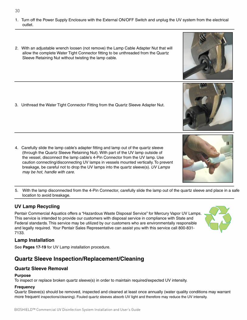
1. Turn off the Power Supply Enclosure with the External ON/OFF Switch and unplug the UV system from the electrical outlet.
2. With an adjustable wrench loosen (not remove) the Lamp Cable Adapter Nut that will allow the complete Water Tight Connector fitting to be unthreaded from the Quartz Sleeve Retaining Nut without twisting the lamp cable.
3. Unthread the Water Tight Connector Fitting from the Quartz Sleeve Adapter Nut.
4. Carefully slide the lamp cable’s adapter fitting and lamp out of the quartz sleeve (through the Quartz Sleeve Retaining Nut). With part of the UV lamp outside of the vessel, disconnect the lamp cable’s 4-Pin Connector from the UV lamp. Use caution connecting/disconnecting UV lamps in vessels mounted vertically. To prevent breakage, be careful not to drop the UV lamps into the quartz sleeve(s). UV Lamps may be hot, handle with care.
5. With the lamp disconnected from the 4-Pin Connector, carefully slide the lamp out of the quartz sleeve and place in a safe location to avoid breakage.
UV Lamp RecyclingPentair Commercial Aquatics offers a “Hazardous Waste Disposal Service” for Mercury Vapor UV Lamps. This service is intended to provide our customers with disposal service in compliance with State and Federal standards. This service may be utilized by our customers who are environmentally responsible and legally required. Your Pentair Sales Representative can assist you with this service call 800-831-7133.
Lamp InstallationSee Pages 17-19 for UV Lamp installation procedure.
Quartz Sleeve Inspection/Replacement/Cleaning
Quartz Sleeve RemovalPurposeTo inspect or replace broken quartz sleeve(s) in order to maintain required/expected UV intensity.
FrequencyQuartz Sleeve(s) should be removed, inspected and cleaned at least once annually (water quality conditions may warrant more frequent inspections/cleaning). Fouled quartz sleeves absorb UV light and therefore may reduce the UV intensity.
BIOSHIELD™ Commercial UV Disinfection System Installation and User’s Guide BIOSHIELD™ Commercial UV Disinfection System Installation and User’s Guide

31
5. With the lamp disconnected from the 4-Pin Connector, carefully slide the lamp out of the quartz sleeve and place in a safe location to avoid breakage.
Parts and Equipment Required• Quartz Sleeve(s)• Quartz Sleeve Retaining Nut Gasket• Adjustable Wrench• Clean Cotton or Silicon Gloves• Personal Safety Equipment
General risk due to pressurized piping and UV vessel!
General risk due to electricity!
Quartz Sleeves are fragile and potentially dangerous if broken. Handle with care.
Procedure
1. Turn off the Power Supply Enclosure with the External ON/OFF Switch and unplug the UV system from the electrical outlet.
2. Drain the vessel completely.
3. Remove UV lamp(s). See Page 29 for instructions.
4. Using a 1.5” socket or an adjustable wrench, unthread the Quartz Sleeve Retaining Nut from the male-threaded Quartz Sleeve Module located on the QSM Faceplate. Once the Quartz Sleeve Retaining Nut is unthreaded the open-end of the quartz sleeve will be exposed.
5. Wearing clean cotton or silicon gloves gently slide the quartz sleeve from the UV vessel. DO NOT use pliers or any tools that may break the quartz sleeve.
6. Remove the Quartz Sleeve Gasket and continue removing the quartz sleeves until all are re moved from the vessel. Place quartz sleeves on a safe, level surface to avoid breakage.
7. Inspect all quartz sleeves for cracks, chips and scaling. If required, clean the quartz sleeve(s). See Page 32 Quartz Sleeve Cleaning. Replace damaged (cracked, chipped) quartz sleeves.
BIOSHIELD™ Commercial UV Disinfection System Installation and User’s Guide BIOSHIELD™ Commercial UV Disinfection System Installation and User’s Guide

32
General risk due to pressurized piping and UV vessel!
General risk due to caustic cleaning agent!
Quartz Sleeves are fragile and potentially dangerous if broken. Handle with care.
First Aid Measures:
In case of skin exposure to cleaning agent remove by washing with soap and water immediately.
In case of eye exposure to cleaning agent wash eyes for several minutes with water and contact a physician immediately.
In case of ingestion of cleaning agent contact physician immediately.
Quartz Sleeve Cleaning
PurposeTo manually check and clean quartz sleeve(s).
FrequencyWhen required, at least once annually.
Parts and Equipment Required• Cleaning Agent (dish detergent, acid cleaning agent based upon phosphoric acid (>25%)• Acid-Proof Bucket• Clean Cloth• Acid-Proof Drop Cloth• Acid-Resistant Gloves• Freshwater• MSDS Sheet• Personal Protective Equipment
Quartz Sleeve InstallationSee Page 11 for quartz sleeve installation procedure.
UV Vessel Cleaning
PurposeOver a period of time, dissolved matter can build up on the surface of the quartz sleeves and the interior of the vessel affecting the efficiency of the UV disinfection process. Due to fouling, the available intensity will decrease continuously (Note: The use of the optional wiping system merely helps to decrease the frequency of the manual cleaning cycle). Please be aware that such a decrease also may be caused by ageing of the UV lamps or changes in the water quality (UV transmission). Repeat of visual inspections of the UV Sensor or of some example quartz sleeves will help to determine the necessary cleaning intervals needed. The removal of this build-up (calcium, etc.) can be carried out with a cleaning pump. A cleaning agent based upon phosphoric acid like citric acid or commercially available cleaners may be used. Materials within the vessel chamber are highly resistant against these chemicals.
Procedure
1. See Page 30 for quartz sleeve removal instructions.
2. Inspect quartz sleeve and clean as needed with a soft, clean cloth and mild dish detergent.
3. For calcium deposits use soporific or muriatic acid to dissolve/clean deposits.
4. Rinse quartz sleeve thoroughly with clean freshwater.
5. See Page 11 for quartz sleeve installation instructions.
BIOSHIELD™ Commercial UV Disinfection System Installation and User’s Guide BIOSHIELD™ Commercial UV Disinfection System Installation and User’s Guide

33
Procedure
1. See Page 30 for quartz sleeve removal instructions.
2. Inspect quartz sleeve and clean as needed with a soft, clean cloth and mild dish detergent.
3. For calcium deposits use soporific or muriatic acid to dissolve/clean deposits.
4. Rinse quartz sleeve thoroughly with clean freshwater.
5. See Page 11 for quartz sleeve installation instructions.
FrequencyWhen necessary.
Parts and Equipment Required• Cleaning Agent (dish detergent, acid cleaning agent based upon phosphoric acid (>25%)• Acid-Resistant Transfer Pump• Acid-Resistant Hose (used to transfer the cleaner from the container to the UV vessel)• Fittings to connect to vessel• Acid-Resistant Bucket • Clean Cloth• Acid-Resistant Drop Cloth• Acid-Resistant Gloves• Freshwater• MSDS Sheet• Personal Safety Equipment
General risk due to pressurized piping and UV vessel.
General risk due to caustic cleaning agent.
Quartz Sleeves and UV lamps are fragile and potentially dangerous if broken. Handle with care.
First Aid Measures: In case of skin exposure to cleaning agent remove by washing with soap and water immediately.
In case of eye exposure to cleaning agent wash eyes for several minutes with water and contact a physician immediately.
In case of ingestion of cleaning agent contact physician immediately.
Procedure
1. With the quartz sleeves still installed in the UV vessel, turn off the Power Supply Enclosure with the External ON/OFF Switch and unplug the UV system from the electrical outlet.
2. Isolate the UV vessel from the water flow using the required isolation valves and drain the vessel completely.
3. Clear the work area and layout protective drop cloths under the UV vessel.
4. Set up the acid transfer pump and attach the acid input hose to the vessel’s water drain valve.
5. Attach an acid return/overflow hose to the UV vessel’s upper auxiliary service port and route it back to the acid-resistant bucket. This will be used as the Acid Overflow Recovery Bucket.
6. With all of the hoses attached to the UV vessel and the acid transfer pump attached to the acid supply container, pump acid into the UV vessel until full.
7. Once the UV vessel has been filled with acid, allow the acid to remain in the vessel for 30 minutes.
8. Disconnect the acid transfer pump’s vessel feed hose from the transfer pump and use this hose to drain the acid from the UV vessel through the vessel’s drain valve and into an acid-resistant bucket.
9. After all of the acid has been drained from the UV vessel and the cleaning procedure completed, rinse the vessel chamber thoroughly to avoid process water from coming in contact with the cleaning agent. The rinse water may be taken from a water tap with the help of a hose and filled and drained through the unit’s drain valve port.
10. Neutralize old cleaning agent with bases, e.g. sodium hydroxide solution, sodium carbonate solution in compliance with all relevant rules for accident prevention and local regulations.
BIOSHIELD™ Commercial UV Disinfection System Installation and User’s Guide BIOSHIELD™ Commercial UV Disinfection System Installation and User’s Guide

34
UV Vessel Disassembly
PurposeTo disassemble the vessel for internal inspection.
FrequencyUV vessel disassembly is only required if a problem has taken place, such as, quartz sleeve breakage. It is recommended that the QSM (Quartz Sleeve Module) Faceplate only be removed if necessary.
Parts and Equipment Required• Adjustable and Torque Wrenches• Socket Wrenches• Clean Cotton or Silicon Gloves• Flashlight• Personal Safety Equipment
General risk due to pressurized piping and UV vessel!
Quartz Sleeves and UV lamps are fragile and potentially dangerous if broken. Handle with care.
Procedure
Important: DO NOT Attempt to remove the QSM Faceplate with the quartz sleeves assembled. ALL lamps and quartz sleeves MUST be removed before disassembling the QSM Faceplate from the UV vessel.
1. Turn off the Power Supply Enclosure with the External ON/OFF Switch and unplug the UV system from the electrical outlet.
2. Redirect water flow from the vessel using isolation valves and drain the vessel completely.
3. Remove UV lamp(s). S ee Page 29 for removal instructions.
4. Remove quartz sleeve(s). See Page 30 removal instructions.
5. With the vessel completely drained and the UV lamps and quartz sleeves removed, loosen the QSM Faceplate bolts in a diametric sequence. Continue until all hardware is removed.
6. With fastening hardware removed, pull the QSM Faceplate from the UV vessel.
7. Clean out the inside of the UV vessel using a mild dish detergent and rinse thoroughly with clean freshwater.
8. Thoroughly clean the mating surfaces of both the QSM Faceplate and the UV Vessel.
Important: Use a new QSM Faceplate Rubber Gasket when re-assembling the faceplate to the vessel.
For replacement parts please refer to Replacement Parts list on Page 37 of this manual.
9. Fit the QSM Faceplate Rubber Gasket onto the alignment posts.
BIOSHIELD™ Commercial UV Disinfection System Installation and User’s Guide BIOSHIELD™ Commercial UV Disinfection System Installation and User’s Guide

35
Important: To properly align the QSM Faceplate, set the #1 lamp position (as stamped on the faceplate, next to the quartz sleeve module) to the 3 O’ Clock position when looking at the QSM Faceplate.
10. With the QSM Faceplate loosely aligned, push the QSM Faceplate, with the rubber gasket, in place onto the vessel. Next, loosely install (finger tight) the supplied stainless steel hardware (bolts/washers/nuts).
11. With the hardware loosely installed (finger tight) fine tune the alignment of the #1 lamp position to the 3 O’ Clock position. To verify proper alignment install the #1 quartz sleeve as outlined on Page 11. The sleeve should go into its respective port on the quartz sleeve coupler on the opposite end of the unit without difficulty. If when installing the sleeve you find it difficult to get the sleeve to engage in its respective port on the quartz sleeve coupler this is an indication that the #1 lamp position is not aligned properly in the 3 O’ Clock position. If this is the case, rotate the QSM Faceplate either clockwise or counterclockwise until the sleeve freely engages its respective port on the quartz sleeve coupler.
12. Once the #1 lamp position is confirmed to be properly aligned, establish uniform pressure over the QSM Faceplate by tightening the bolts in 5 ft. • lb. increments in a diametrically opposed (180º) sequence until the recommended torque is obtained. See recommendations below.
Flange Bolt Torque Recommendations:
0.5” to 1.5” Flange = 12 ft. • lbs. 10” Flange = 64 ft. • lbs.
2.0” to 4.0” Flange = 25 ft. • lbs. 12“ Flange = 95 ft. • lbs.
5.0” Flange = 30 ft. • lbs. 14” to 24” Flange = 40 ft. • lbs.
6.0” to 8.0” Flange = 40 ft. • lbs.
BIOSHIELD™ Commercial UV Disinfection System Installation and User’s Guide BIOSHIELD™ Commercial UV Disinfection System Installation and User’s Guide

36
Cooling Fan Filter Mat Replacement/Cleaning
Cooling Fan Filter Removal
PurposeThe Cooling Fan is equipped with a Filter Mat used to trap airborne particles and dust. This Filter Mat must be routinely inspected and if required, cleaned. A clogged Filter Mat reduces air circulation in and out of the enclosure, potentially allowing electrical hardware to over-heat. If damaged, worn-out or uncleanable replace the Filter Mat.
FrequencyMinimum every six months, but more routine inspections may be required due to increased airborne dirt/dust.
Parts and Equipment Required• Slotted Screwdriver
Procedure1. Remove Cooling Fan cover to access Filter Mat.
2. Remove Cooling Fan Filter Mat
Cooling Fan Filter Cleaning
PurposeTo increase air circulation in and out of the enclosure. If damaged, worn-out or uncleanable replace the Filter Mat. A dirty Filter Mat may cause electronic ballast failure.
FrequencyA minimum of every six months, but more routine inspections may be required due to increased airborne dirt/dust.
Parts and Equipment Required• Compressed Air• Dish Detergent
Procedure
Read and understand this chapter prior to cleaning Cooling Fan Filter Mat.
1. Remove dust from mat by blowing it out with compressed air or washing it out with soap and water.
2. Dry mat, or use new replacement filter mat.
Cooling Fan Filter Installation
PurposeTo install cleaned or new Cooling Fan Filter Mat.
FrequencyA minimum of every six months, but more routine inspections may be required due to increased airborne dirt/dust.
Parts and Equipment Required• Slotted Screwdriver
Procedure
Read and understand this chapter prior to cleaning Cooling Fan Filter Mat.
1. Place Cooling Fan Filter Mat into fan.
2. Replace fan cover.
BIOSHIELD™ Commercial UV Disinfection System Installation and User’s Guide BIOSHIELD™ Commercial UV Disinfection System Installation and User’s Guide

37
Bioshield™ UV Disinfection Systems are available in two sizes. They are: CLP4-Series units using 130 watt amalgam lamps and CLP6-Series units using 320 watt amalgam lamps.
Among these UV System styles, there are variations that include: vessel dimensions, port styles/sizes and controller/monitor options. When contacting us for replacement parts for your UV system, we suggest that you have the UV system’s serial number readily available. The serial number can be found on both the Power Supply Enclosure and UV vessel labels.
Identifying the serial number allows us to process your request/order quickly and accurately.
Quartz Sleeve & UV Lamp MatrixCLP Series UV Systems are available with different size ports and use varying lengths of quartz sleeves. Below we match your
CLP UV System with the correct quartz sleeve and UV lamp.
CLP4 / Amalgam 6” 2” 46.5” FL-QZ177-PL 130 FL-3213-PL CLP4 / Amalgam 6” 3” 46.5” FL-QZ177-PL 130 FL-3213-PL CLP4 / Amalgam 6” 4” 46.5” FL-QZ177-PL 130 FL-3213-PL CLP4 / Amalgam 8” 3” 50.875” FL-QZ180-PL 130 FL-3213-PL CLP4 / Amalgam 8” 4” 50.875” FL-QZ180-PL 130 FL-3213-PL CLP4 / Amalgam 8” 6” 50.875” FL-QZ180-PL 130 FL-3213-PL CLP4 / Amalgam 10” 4” 50.875” FL-QZ180-PL 130 FL-3213-PL CLP4 / Amalgam 10” 6” 50.875” FL-QZ180-PL 130 FL-3213-PL CLP4 / Amalgam 10” 8” 55” FL-QZ187-PL 130 FL-3213-PL CLP6 / Amalgam 6” 2” 75” FL-QZ178-PL 320 FL-2940-PL CLP6 / Amalgam 6” 3” 75” FL-QZ178-PL 320 FL-2940-PL CLP6 / Amalgam 6” 4” 75” FL-QZ178-PL 320 FL-2940-PL CLP6 / Amalgam 8” 3” 75” FL-QZ178-PL 320 FL-2940-PL CLP6 / Amalgam 8” 4” 75” FL-QZ178-PL 320 FL-2940-PL CLP6 / Amalgam 8” 6” 75” FL-QZ178-PL 320 FL-2940-PL CLP6 / Amalgam 10” 4” 75” FL-QZ178-PL 320 FL-2940-PL CLP6 / Amalgam 10” 6” 75” FL-QZ178-PL 320 FL-2940-PL CLP6 / Amalgam 10” 8” 75” FL-QZ178-PL 320 FL-2940-PL CLP6 / Amalgam 12” 6” 75” FL-QZ178-PL 320 FL-2940-PL CLP6 / Amalgam 12” 8” 75” FL-QZ178-PL 320 FL-2940-PL CLP6 / Amalgam 14” 8” 75” FL-QZ178-PL 320 FL-2940-PL CLP6 / Amalgam 14” 10” 75” FL-QZ178-PL 320 FL-2940-PL CLP6 / Amalgam 14” 12” 75” FL-QZ178-PL 320 FL-2940-PL CLP6 / Amalgam 16” 10” 75” FL-QZ178-PL 320 FL-2940-PL CLP6 / Amalgam 16” 12” 75” FL-QZ178-PL 320 FL-2940-PL CLP6 / Amalgam 16” 14” 75” FL-QZ178-PL 320 FL-2940-PL CLP6 / Amalgam 18” 12” 75” FL-QZ178-PL 320 FL-2940-PL CLP6 / Amalgam 18” 14” 75” FL-QZ178-PL 320 FL-2940-PL CLP6 / Amalgam 18” 16” 75” FL-QZ178-PL 320 FL-2940-PL CLP6 / Amalgam 20” 14” 75” FL-QZ178-PL 320 FL-2940-PL CLP6 / Amalgam 20” 16” 75” FL-QZ178-PL 320 FL-2940-PL CLP6 / Amalgam 20” 18” 75” FL-QZ178-PL 320 FL-2940-PL
CLP Series Quartz Sleeve & UV Lamp Matrix UV Lamp Vessel Port Quartz Sleeve Quartz Sleeve UV Lamp CLP Amalgam CLP Series Diameter Size Length Part number Watts Part Number
SECTION TWELVEREPLACEMENT PARTS
BIOSHIELD™ Commercial UV Disinfection System Installation and User’s Guide BIOSHIELD™ Commercial UV Disinfection System Installation and User’s Guide

38
1 2
3 4 5 68
7
9
10
11
1216
13 1415
Replacement Parts1. Quartz Sleeve Module Faceplate.................See supplied assembly drawing that was shipped with the unit or Call w/ Serial Number
2. QSM Faceplate Rubber Gasket...................See supplied assembly drawing that was shipped with the unit or Call w/ Serial Number
3. UV Sensor............................................................................................................................................................20214-PL
4. Optional UV Sensor Extension Cable..................................................................................................................20214-EXTCABLE-PL
5. Temperature Sensor.............................................................................................................................................20217-PL
6. Optional Temperature Sensor Extension Cable...................................................................................................20217-EXTCABLE-PL
7. Quartz Sleeve Retainer Nut.................................................................................................................................CL-QSR-28-PL
8. Quartz Sleeve Gasket..........................................................................................................................................CL28QSRG-10P-PL
9. Drain Valve Assembly...........................................................................................................................................CLP-DVA-1/2-PL
10. Quartz Sleeve......................................................................................................................................................(See page 37)
11. UV Lamp..............................................................................................................................................................(See page 37)
12. UV Vessel.....................................................See supplied assembly drawing that was shipped with the unit or Call w/ Serial Number
13. Bolt...............................................................See supplied assembly drawing that was shipped with the unit or Call w/ Serial Number
14. Nut................................................................See supplied assembly drawing that was shipped with the unit or Call w/ Serial Number
15. Washer.........................................................See supplied assembly drawing that was shipped with the unit or Call w/ Serial Number
16. Lamp Field Safety Cover..............................See supplied assembly drawing that was shipped with the unit or Call w/ Serial Number
BIOSHIELD™ Commercial UV Disinfection System Installation and User’s Guide BIOSHIELD™ Commercial UV Disinfection System Installation and User’s Guide

39
SITUATION INSPECT FOR:
UV system will not function 1. No Input Voltage Available
with the External ON/OFF 2. Temperature Sensor Cable Plug is Interrupted/Defective
Switch in the “On” position 3. Input Voltage is lower than the Factory Set Threshold
UV Lamp does not light 1. Faulty Contact (four-pin connector/lamp pins)
2. Defective Electronic Ballast
3. Defective UV Lamp
4. Water Damage due to Quartz Sleeve Seal Failure
UV Intensity too low 1. Decreased UV Transmissibility
2. UV Lamp reached “End of Life”
3. Quartz Sleeve Fouled
4. Faulty UV Sensor
Enclosure Over-Heating 1. Ambient Temperature above 145º F
2. Defective Thermal Switch
3. Cooling Fan Filter Mat needs to be cleaned
4. Defective Cooling Fan
Quartz Sleeve Seal Failure 1. Cracked/Broken Quartz Sleeve
2. Failed Quartz Sleeve Retaining Nut O-Ring Seal
SECTION THIRTEENTROUBLESHOOTING
BIOSHIELD™ Commercial UV Disinfection System Installation and User’s Guide BIOSHIELD™ Commercial UV Disinfection System Installation and User’s Guide

SPARUS™ 160 Energy Efficient Aquaculture Duty Pump Installation and User’s Guide
NOTES

NOTES

1620 HAWKINS AVE., SANFORD, NC 27330 • (919) 566-800010951 WEST LOS ANGELES AVE., MOORPARK, CA 93021 • (805) 553-5000
WWW.PENTAIRCOMMERCIAL.COM
All Pentair trademarks and logos are owned by Pentair or one of its global affiliates. Pentair Commercial Aquatics™ and Bioshield™ are trademarks and/or registered trademarks of Pentair Water Pool and Spa, Inc. and/or its affiliated companies in the United States and/ or other countries. Unless expressly noted, names and brands of third parties that may be used in this document are not used to indicate an affiliation or endorsement between the owners of these names and brands and Pentair Water Pool and Spa, Inc. Those names and brands may be the trademarks or registered trademarks of those third parties. Because we are continuously improving our products and services, Pentair reserves the right to change specifications without prior notice. Pentair is an equal opportunity employer.
© 2014 Pentair Water Pool and Spa, Inc. All rights reserved. This document is subject to change without notice.
P/N CLX-N-MN REV. A 9/29/14