comfort wiring diagrams control box circuit 48/50a2,a3,a4,a5020-060 50ej500440 6 auxiliary control...
TRANSCRIPT
Manufacturer reserves the right to discontinue, or change at any time, specifications or designs without notice and without incurring obligations.Catalog No. 04-56480002-01 Printed in U.S.A. Form 48/50A-3W Pg 1 508 4-08 Replaces: New
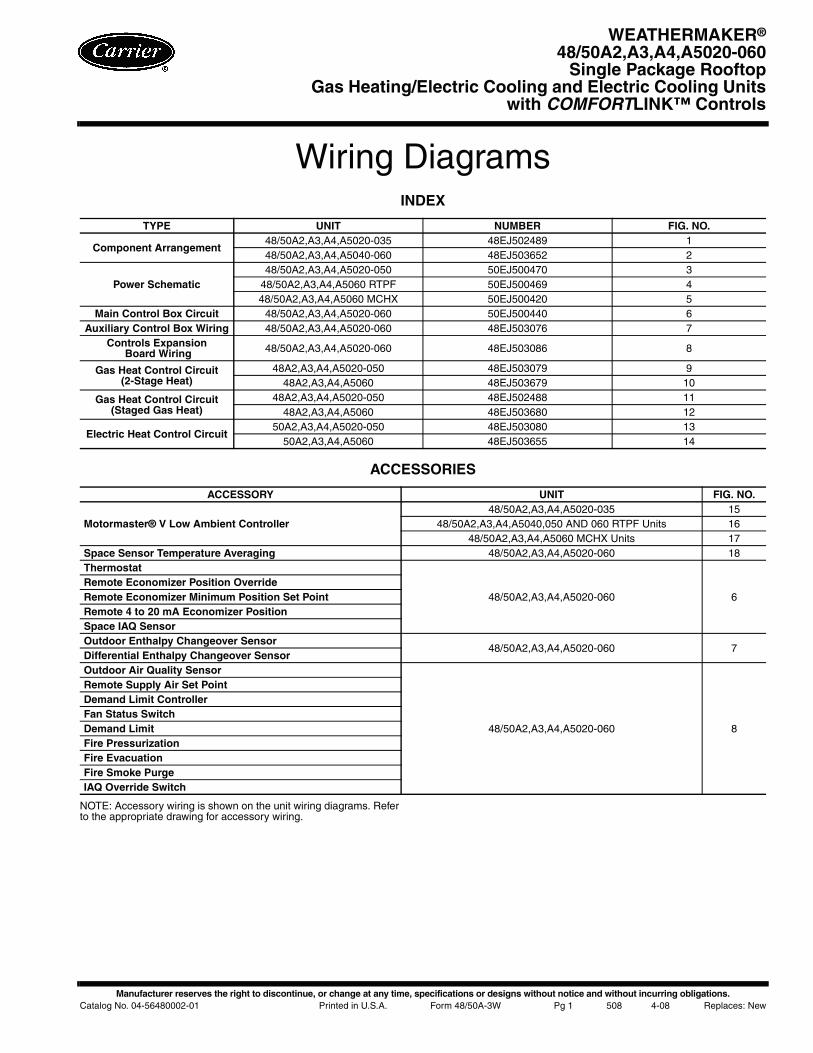
Wiring DiagramsINDEX
ACCESSORIES
NOTE: Accessory wiring is shown on the unit wiring diagrams. Referto the appropriate drawing for accessory wiring.
TYPE UNIT NUMBER FIG. NO.
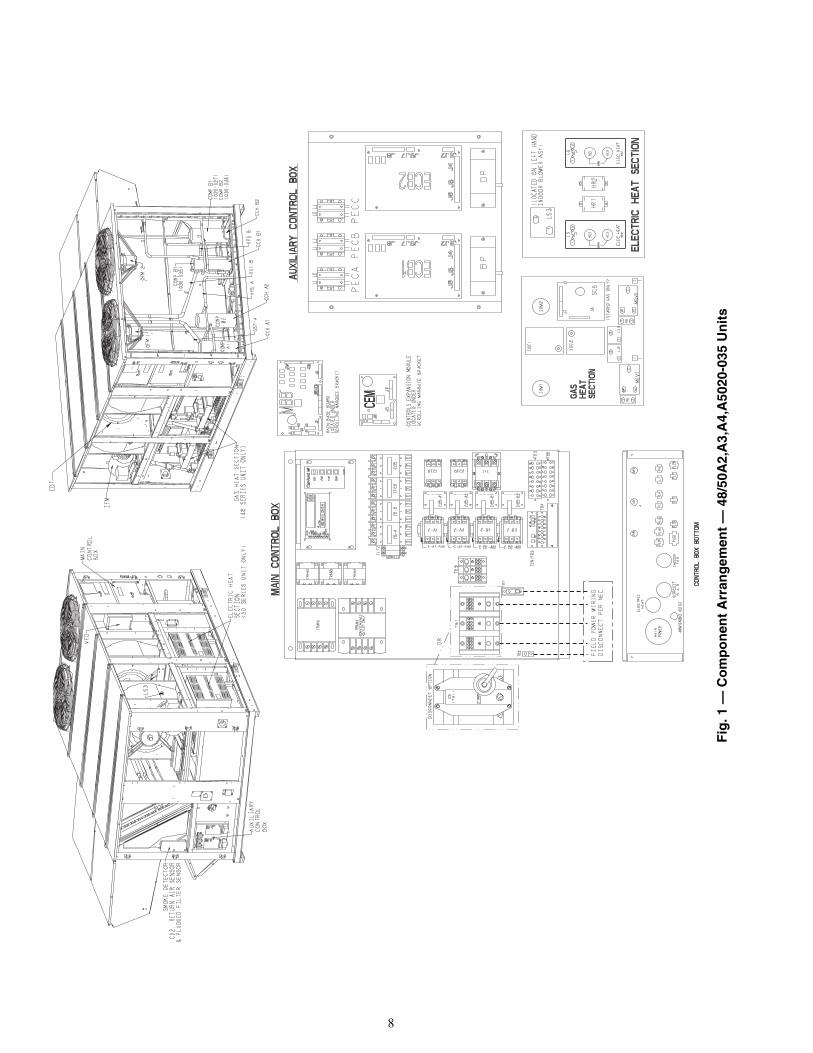
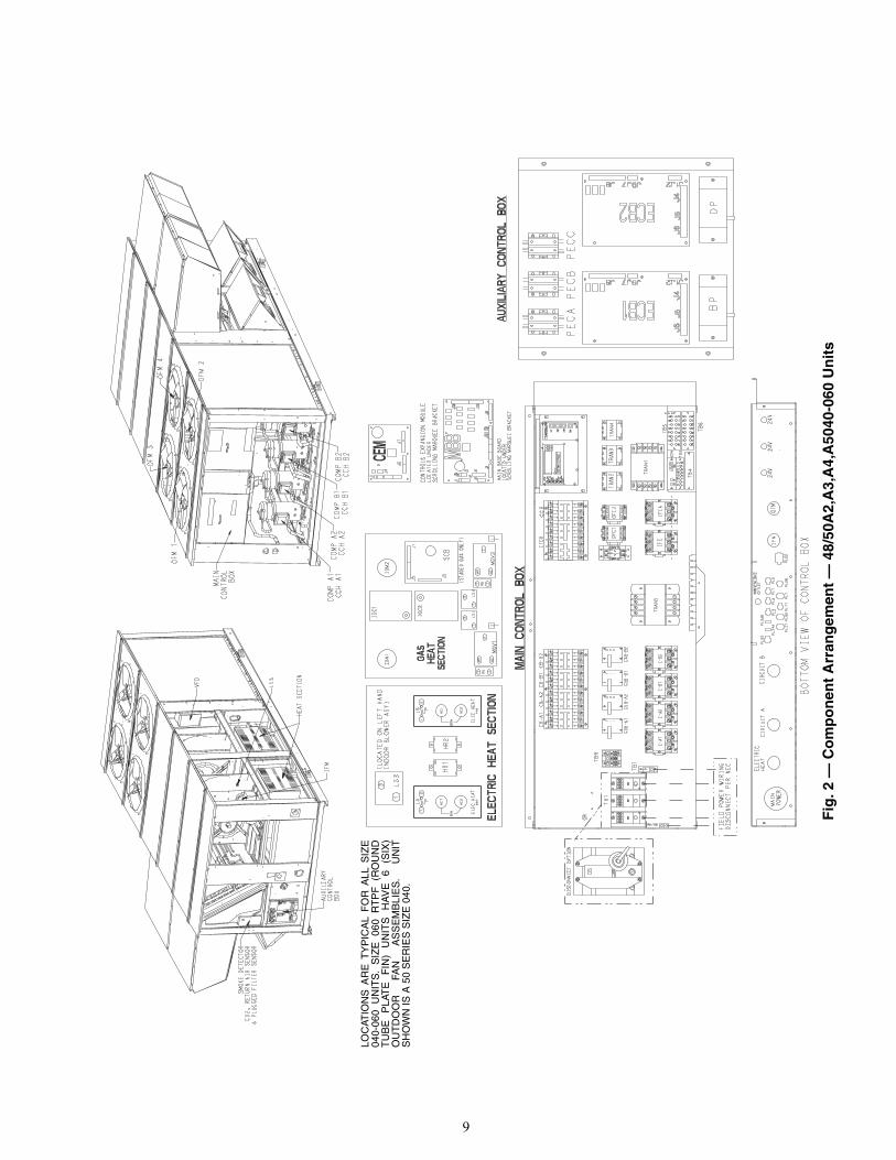
Component Arrangement48/50A2,A3,A4,A5020-035 48EJ502489 148/50A2,A3,A4,A5040-060 48EJ503652 2
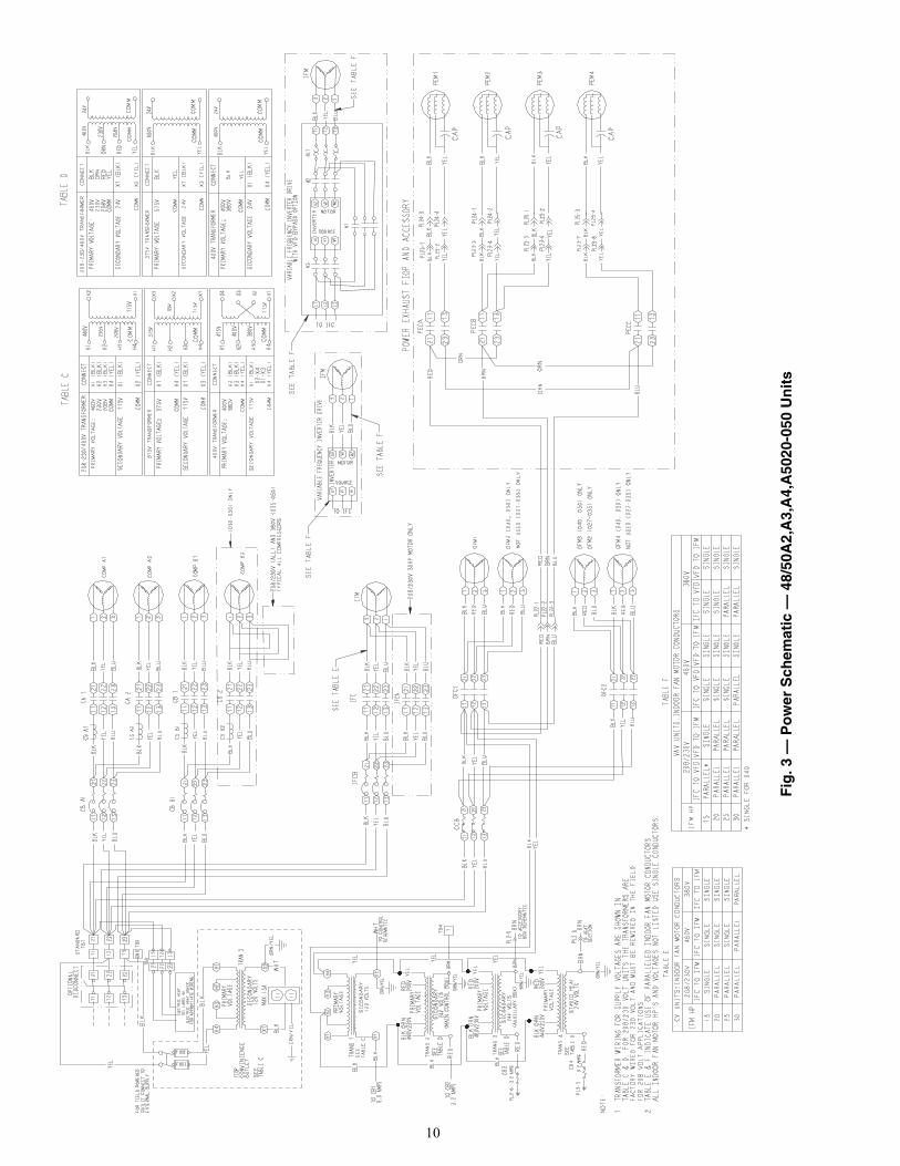
Power Schematic48/50A2,A3,A4,A5020-050 50EJ500470 3
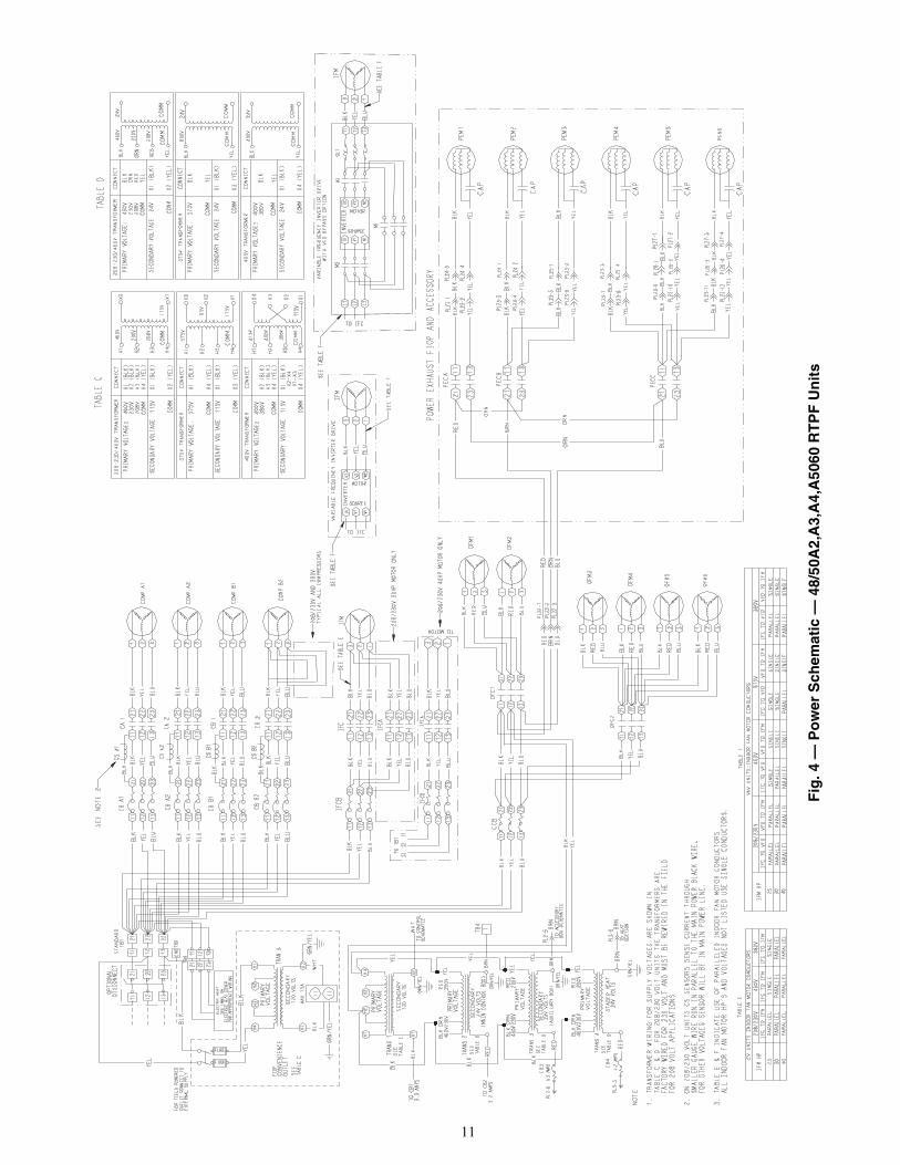
48/50A2,A3,A4,A5060 RTPF 50EJ500469 448/50A2,A3,A4,A5060 MCHX 50EJ500420 5
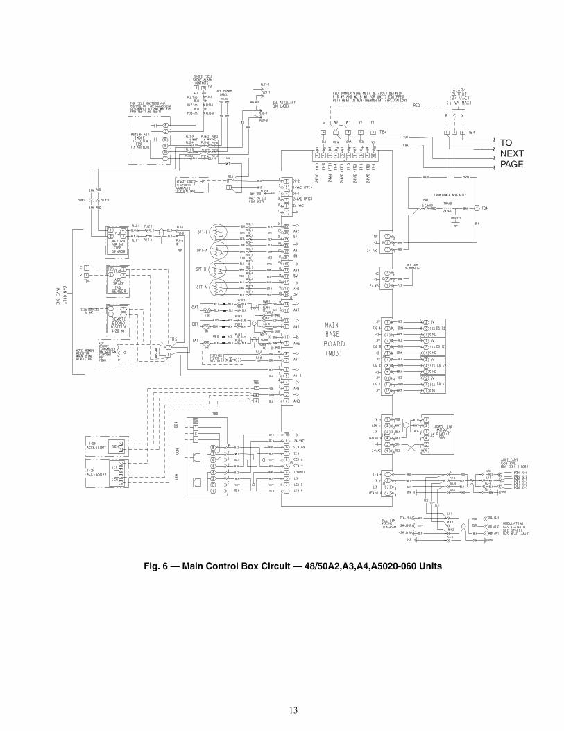
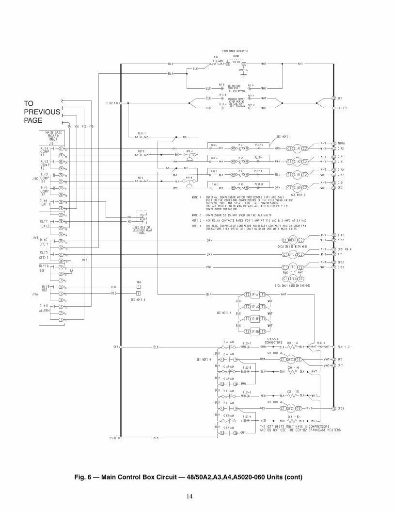
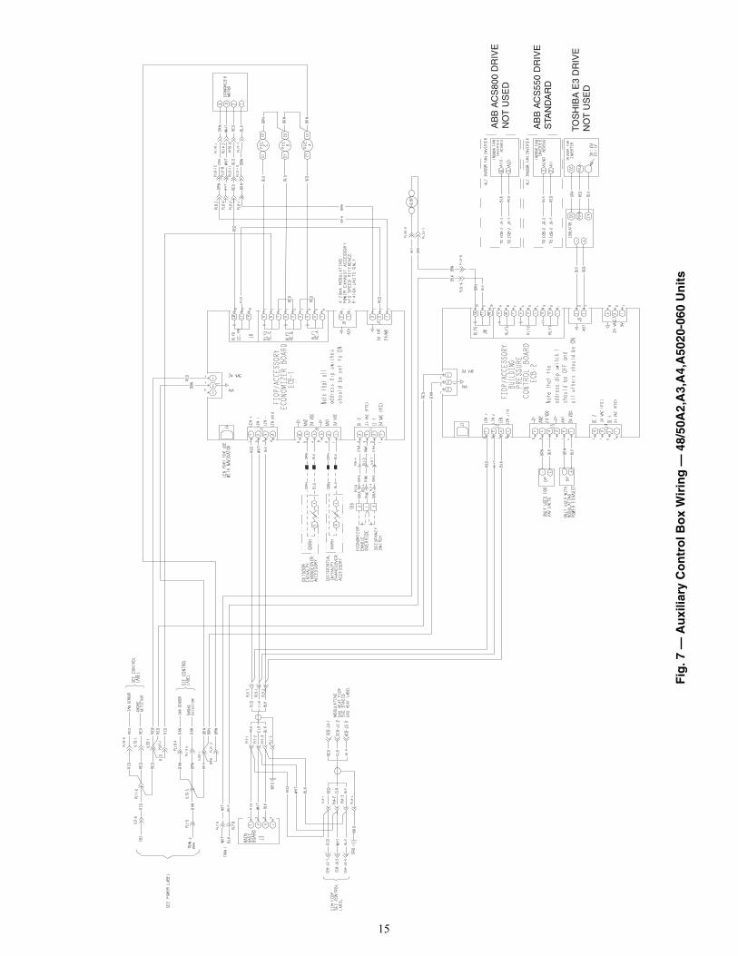
Main Control Box Circuit 48/50A2,A3,A4,A5020-060 50EJ500440 6Auxiliary Control Box Wiring 48/50A2,A3,A4,A5020-060 48EJ503076 7
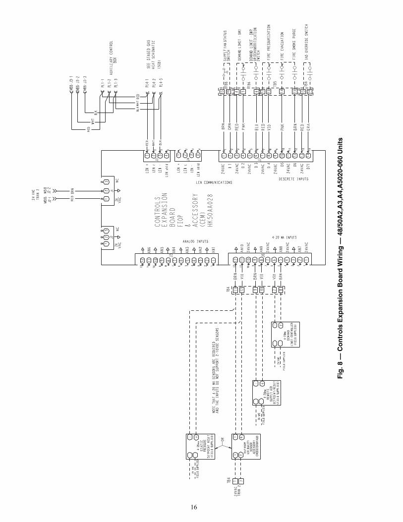
Controls Expansion Board Wiring 48/50A2,A3,A4,A5020-060 48EJ503086 8
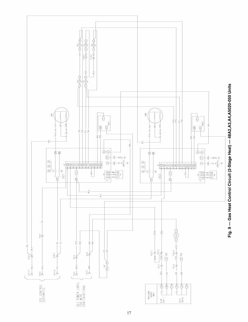
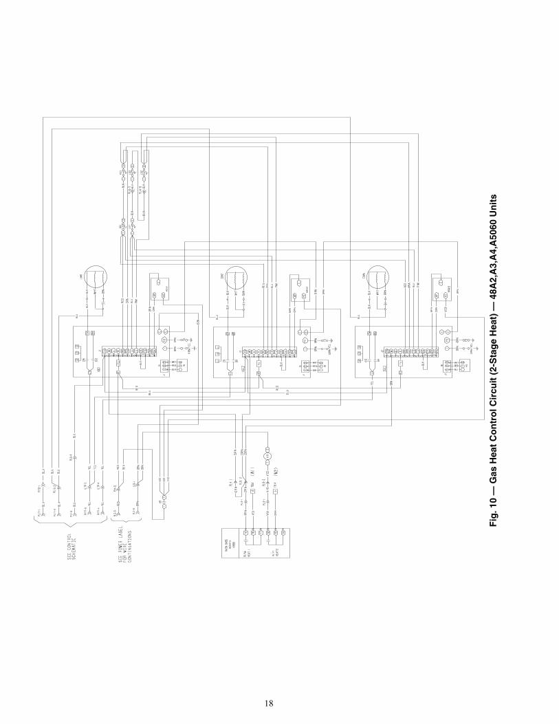
Gas Heat Control Circuit(2-Stage Heat)
48A2,A3,A4,A5020-050 48EJ503079 948A2,A3,A4,A5060 48EJ503679 10
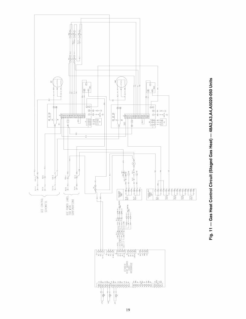
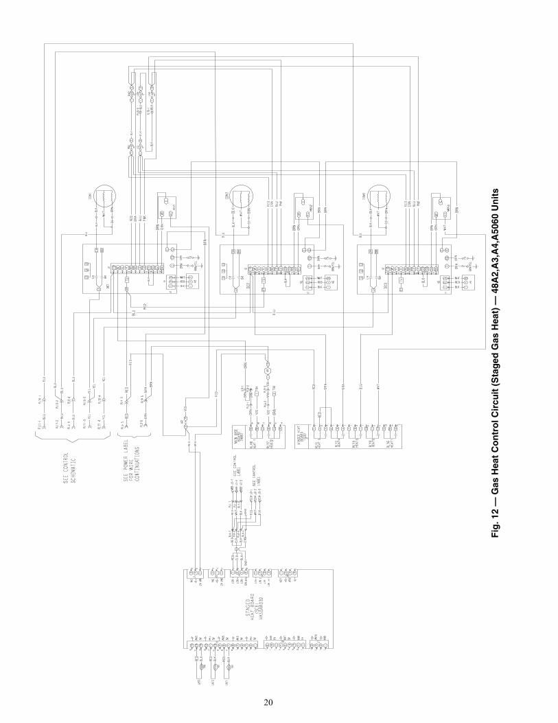
Gas Heat Control Circuit(Staged Gas Heat)
48A2,A3,A4,A5020-050 48EJ502488 1148A2,A3,A4,A5060 48EJ503680 12
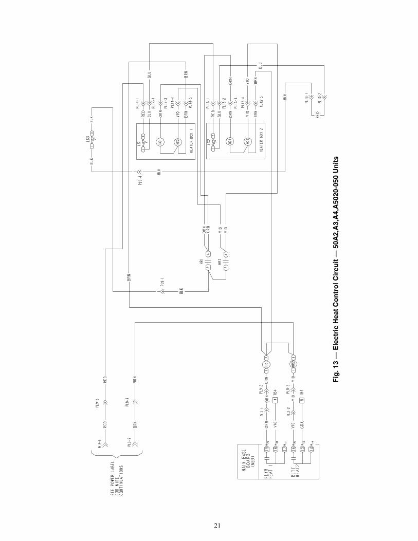
Electric Heat Control Circuit50A2,A3,A4,A5020-050 48EJ503080 13
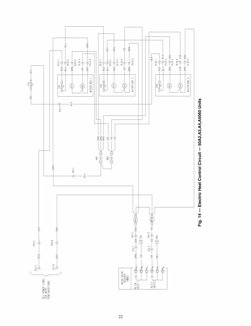
50A2,A3,A4,A5060 48EJ503655 14
ACCESSORY UNIT FIG. NO.
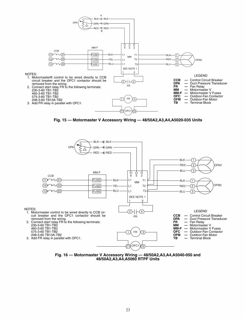
Motormaster® V Low Ambient Controller48/50A2,A3,A4,A5020-035 15
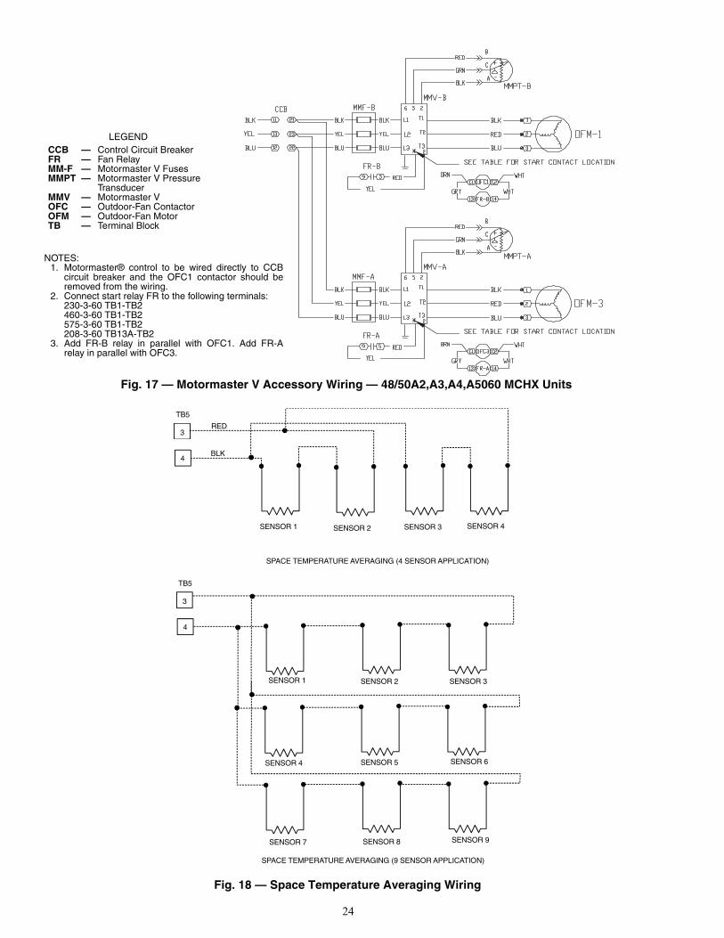
48/50A2,A3,A4,A5040,050 AND 060 RTPF Units 1648/50A2,A3,A4,A5060 MCHX Units 17
Space Sensor Temperature Averaging 48/50A2,A3,A4,A5020-060 18Thermostat
48/50A2,A3,A4,A5020-060 6Remote Economizer Position OverrideRemote Economizer Minimum Position Set PointRemote 4 to 20 mA Economizer PositionSpace IAQ SensorOutdoor Enthalpy Changeover Sensor
48/50A2,A3,A4,A5020-060 7Differential Enthalpy Changeover SensorOutdoor Air Quality Sensor
48/50A2,A3,A4,A5020-060 8
Remote Supply Air Set PointDemand Limit ControllerFan Status SwitchDemand LimitFire PressurizationFire EvacuationFire Smoke PurgeIAQ Override Switch
WEATHERMAKER®
48/50A2,A3,A4,A5020-060Single Package Rooftop
Gas Heating/Electric Cooling and Electric Cooling Unitswith COMFORTLINK™ Controls
2
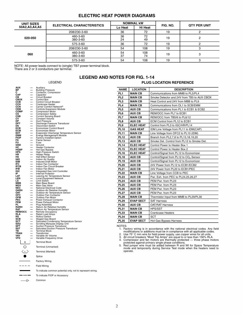
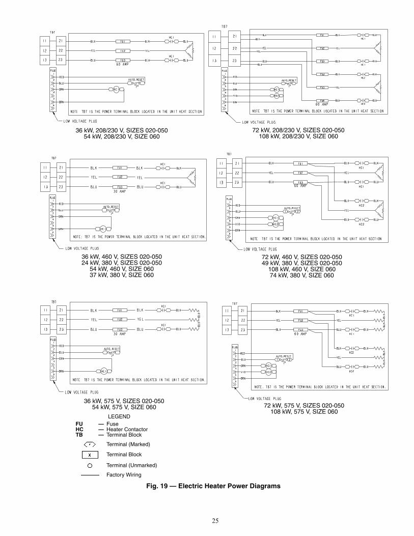
ELECTRIC HEAT POWER DIAGRAMS
NOTE: All power leads connect to (single) TB7 power terminal block.There are 2 or 3 conductors per terminal.
LEGEND AND NOTES FOR FIG. 1-14
UNIT SIZES50A2,A3,A4,A5 ELECTRICAL CHARACTERISTICS
NOMINAL kWFIG. NO. QTY PER UNIT
Lo Heat Hi Heat
020-050
208/230-3-60 36 72 19 2460-3-60380-3-60
3624
7249 19 2
575-3-60 36 72 19 2
060
208/230-3-60 54 108 19 3460-3-60380-3-60
5437
10874 19 3
575-3-60 54 108 19 3
LEGEND
AUX — AuxiliaryBP — Building PressureC — Contactor, CompressorCAP — CapacitorCB — Circuit BreakerCBOX — Control BoxCCB — Control Circuit BreakerCCH — Crankcase HeaterCCN — Carrier Comfort Network®
CEM — Controls Expansion ModuleCOMP — Compressor MotorCS — Compressor SafetyCSB — Current Sensing BoardCV — Constant VolumeDP — Duct PressureDPT — Discharge Pressure TransducerDS — Disconnect SwitchECB — Economizer Control BoardECM — Economizer MotorEDT — Evaporator Discharge Temperature SensorEMM — Energy Management ModuleFIOP — Factory-Installed OptionFS — Flame SensorFU — FuseGND — GroundHC — Heater ContactorHGBP — Hot Gas BypassHPS — High-Pressure SwitchHR — Heater RelayHS — Hall Effect SensorIAQ — Indoor Air QualityIDM — Induced Draft MotorIFC — Indoor Fan ContactorIFCB — Indoor Fan Circuit BreakerIFM — Indoor Fan MotorIGC — Integrated Gas Unit ControllerIP — Internal ProtectorLAT — Leaving Air Temperature SensorLEN — Local Equipment NetworkLS — Limit SwitchMBB — Main Base BoardMGV — Main Gas ValveNEC — National Electrical CodeOARH — Outdoor-Air Relative HumidityOAT — Outdoor-Air Temperature SensorOFC — Outdoor Fan ContactorOFM — Outdoor Fan MotorPEC — Power Exhaust ContactorPEM — Power Exhaust MotorPL — Plug AssemblyRARH — Return Air Relative HumidityRAT — Return Air Temperature SensorREM/OCC — Remote OccupancyRLA — Rated Load AmpsRS — Rollout SwitchSCB — Staged Gas BoardSCT — Saturated Condensing Temperature SensorSDU — Scrolling Marquee Display UnitSPT — Suction Pressure TransducerSST — Saturated Suction Pressure TransducerTB — Terminal BlockTRAN — TransformerVAV — Variable Air VolumeVFD — Variable Frequency Drive
Terminal Block
Terminal (Unmarked)
Terminal (Marked)
Splice
Factory Wiring
Field Wiring
To indicate common potential only, not to represent wiring.
To indicate FIOP or Accessory
Common
PLUG LOCATION REFERENCE
NOTES:1. Factory wiring is in accordance with the national electrical codes. Any field
modifications or additions must be in compliance with all applicable codes.2. Use 75° C min wire for field power supply, use copper wires for all units.3. All circuit breakers “Must Trip Amps” are equal to or less than 156% RLA.4. Compressor and fan motors are thermally protected — three phase motors
protected against primary single phase conditions.5. Red jumper wire must be added between R and WI for Space Temperature
mode and temporarily during Service Test mode when the heaters need tooperate.
NAME LOCATION DESCRIPTIONPL1 MAIN CB Communications from MMB to PL5/PL4PL2 MAIN CB Smoke Detector and 24V from TB5 to AUX CBOXPL3 MAIN CB Heat Control and 24V from MBB to PL9PL4 MAIN CB Communications from OL1 to SCB/EMMPL5 AUX CB Communications from PL1 to ECB1 & ECB2PL6 AUX CB REM/OCC from PL7 to ECB1PL7 MAIN CB REM/OCC from TB5/6 to PL6/12PL8 AUX CB ECM Control from PL12 to ECB1PL9 ELEC HEAT Control from PL3 to IGC/HR/PL14PL10 GAS HEAT IDM Line Voltage from PL11 to IDM(CAP)PL11 MAIN CB Line Voltage from OFC2 to PL10 (IDM)PL12 AUX CB Branch from PL2,7,8 to PL13,18,19,20PL13 AUX CB Smoke Det. Control from PL12 to Smoke Det.PL14 ELEC HEAT Control Power to Heater Box 1PL15 ELEC HEAT Control Power to Heater Box 2PL16 ELEC HEAT Control/Signal from PL12 to EconomizerPL18 AUX CB Control/Signal from PL12 to CO2 SensorPL19 AUX CB Control/Signal from PL12 to EconomizerPL20 AUX CB 24V Power from PL12 to ECB1/ECB2PL21 AUX CB 24V Power from PL20 to ECB1/PECPL22 MAIN CB Line Voltage from CCB to PECPL23 AUX CB Pwr. Exh. from PEC to PL24,25,26,27PL24 AUX CB PEM Pwr. from PL23PL25 AUX CB PEM Pwr. from PL23PL26 AUX CB PEM Pwr. from PL23PL27 AUX CB PEM Pwr. from PL23PL28 MAIN CB Thermistor Input from MMB to PL29/PL30PL29 EVAP SECT SAT HarnessPL30 AUX CB OAT/RAT HarnessPL31 MAIN CB HPS/SSTPL33 MAIN CB Crankcase HeatersPL34 MAIN CB SCTPL35 EVAP SECT Hot Gas Bypass Harness
3
SEQUENCE OF OPERATION
Constant Volume (CV) Units — On power up, thecontrol module will activate the initialization software. Theinitialization software will determine the unit configuration andalso initialize any controls loops and input/output devices. Allalarms and configurations are saved in memory and maintainedduring power outages. All alarms will be maintained inmemory and must be cleared through the scrolling marqueedisplay.
The unit can be configured with two different control types:thermostat control or space temperature sensor control.THERMOSTAT CONTROL — If the unit is equipped with athermostat with Y1, Y2, W1, W2 and G connections, then thecontrol will perform the following sequence.
When terminal G is energized, the indoor fan will turn on.The fan must be running for heating or cooling to occur. If Y1is closed (first stage of cooling is energized), then the unitcontrol will first check the ability to use the economizer. If theeconomizer can be used, then the unit control will modulate thedamper open to maintain the low-load economizer leaving airtemperature set point.
If Y2 closes (second stage of cooling is energized), then theunit control will lower the leaving air temperature set point tothe configured set point. If the economizer cannot satisfy theload, then the compressors will be sequenced on to maintaineither the low or high load temperature set points. If theeconomizer cannot be used or the enable control disables theeconomizer, then the control will sequence the compressorsbased on the Y1 and Y2 signals.
If two-stage control has been selected, then the unit controlwill map the compressors to the Y1 and Y2 inputs (first andsecond stage cooling) as defined in the loading sequence. IfAdaptive mode has been selected, then the control will add andremove compressor stages to maintain the high and lowdemand set points. If Y1 is closed (first stage of coolingenergized), at least one compressor stage will be turned on.
If W1 closes (first stage of heating is energized), then theunit will be in the Heating mode. The economizer will beclosed to the minimum position. If the unit is equipped withgas or electric heat, then the first stage of heat will beenergized. If W2 closes, then the unit control will turn on thesecond stage of heat. If the unit is equipped with a staged gasheat control option, then the W1 and W2 signal will be used tocontrol the gas heat to the configurable low and high heat loadleaving air temperature set points. If the unit is equipped withgas heat, then the integrated gas control (IGC) board will con-trol the operation of the gas heat. See the Gas Heat Unit Opera-tion section for the IGC board sequence of operation.SPACE TEMPERATURE SENSOR CONTROL — If spacetemperature operation has been selected using a T55, T56, orT58 sensor, then a wire jumper must be added between R, W1,and W2. If a remote occupancy control method has beenselected, then the remote occupancy input must first be closedfor the unit to go into heating, vent, or cooling modes. If theinternal timeclock is used, the unit control module determinesthe occupancy state based on the system time schedules.
If Temperature Compensated Start is active, the unit willbe controlled as in the occupied mode. The TemperatureCompensated Start function will start the unit before thescheduled occupied time (as determined by prior operation) tobring the space to the set point temperature when occupiedtime starts. As an example, if the unoccupied set point is 60 F,the occupied set point is 72 F, and the occupied time periodstarts at 8:00 AM, the Temperature Compensated Start functionwill bring on the unit at 7:45 AM (as determined from previousoperation) so the room temperature will be at 72 F when theoccupied time starts.
If the unit has been configured for a pre-occupancy purge,then the control will start the unit in Vent mode prior to theoccupancy time to vent the space. If an IAQ (indoor air quality)sensor is being used and the low IAQ set point is satisfied, thenthe occupancy Purge mode will be terminated.
The set points for heat and cooling are configurable throughthe scrolling marquee display.NOTE: If a T56 sensor is being used, then the slide bar on thesensor can offset the set point by has much as 5 degrees.
If the space temperature rises above the cooling set point,then the unit will go into Cooling mode. If the economizer canbe used, the control will first try to control to the LeavingAir Temperature set point. The set point will depend on thespace temperature. If the temperature is above the LowDemand set point, then the Low Economizer Load DischargeAir Temperature set point will be used. If the temperature isabove the High Load Space Temperature set point, then theHigh Load Leaving Air Temperature set point will be used. Ifthe economizer cannot satisfy the load the compressors willbe sequenced on to maintain either the low or high loadtemperature set points. If the economizer cannot be used or theunit control disables the economizer, then the unit control willsequence the compressors based on the low and high loadspace temperature variables. If two-stage control has beenselected then the control will map the compressors to the lowand high loads as defined in the loading sequence. If Adaptivemode has been selected then the control will add and removecompressors stages to maintain the low and high demandleaving air set points.
If the load goes below the heating space temperature setpoints, the Heating mode will initiate. The economizer will beclosed to the minimum position and (if the unit is equippedwith gas or electric heat) the first stage of heat will beenergized. If the space temperature goes below the High LoadSpace Temperature set point then the control will turn on thesecond stage of heat. If the unit is equipped with a staged gasheat control option then the low load and high load demandsignal will control the Leaving Air Temperature set point andwill turn on heating stages to maintain the Leaving AirTemperature set points.
If the unit is configured for unoccupied free cooling,mechanical cooling, or heating and the room temperature goesabove or below the unoccupied configuration set points, thenthe unit control will turn on free cooling, mechanical cooling,or heat as needed to return room temperature within theunoccupied set points. When in this mode, the economizerdampers will be maintained fully closed or to the minimumunoccupied ventilation set point.
Variable Air Volume Control — On power up, thecontrol module will activate the initialization software. Theinitialization software will determine the unit configuration andalso initialize any control loops and input/output devices. Allalarms and configurations are saved in memory and maintainedduring power outages. All alarms will be maintained inmemory and must be cleared through the scrolling marqueedisplay.
The unit will first determine the mode of operation. If theunit has been configured for space temperature demand thenthe control will determine, based on the configurable set points,if the unit should be in the Heating mode, Vent mode or Cool-ing mode. If the unit is configured for return air temperaturecontrol, then the unit control will start the fan and monitor thereturn air temperature against the configurable set point todetermine if the unit should be in Cooling, Vent or Heatingmode.
4
If the control is connected to a ComfortID™ system, theroom terminals are equipped with microprocessor controls thatgive commands to the base module. If linkage is active, thecontrol module will replace local ComfortLink™ set pointsand occupancy data with linkage supplied data.
If Temperature Compensated Start is active, then the unitcontrol will start the unit in advance of the occupied time topre-cool or heat the space. If the unit is configured to use apre-purge cycle, then the control will start the unit in vent modebased on a pre-start time interval. If an IAQ (indoor air quality)sensor is being used and the low IAQ control point is satisfiedthen the mode will be terminated. The mode terminates whenthe occupied period starts.
If Cooling mode is required, then the controlling set pointwill be the leaving evaporator air temperature set point. If aneconomizer is present and the changeover control allows theeconomizer to be used, then the control will first attempt tocontrol the leaving evaporator air temperature using freecooling. If this cannot satisfy the load then additionalcompressor stages will be turned on to maintain the leaving airtemperature. When both compressors and the economizer arebeing used, the unit control will use the economizer dampers tomaintain better control of the leaving air and to prevent highcompressor cycling. If the economizer cannot be used, then itwill be set to the minimum vent position.
If the unit is equipped with an optional hot gas bypass valve,then the unit control will use hot gas as an additional stage ofcapacity. When the first stage of cooling is required, the unitcontrol will turn on the circuit A compressor and the hot gasbypass valve. When additional cooling is called for, the unitcontrol will turn off the hot gas bypass valve. The valve willalso be used for additional freeze protection of the coils whenlow evaporator refrigerant temperatures are detected using thesuction pressure tranducers.
The unit control will also monitor the supply duct pressureand send a 4 to 20 mA signal to the factory-supplied inverter tocontrol the speed of the fan to maintain the user-configuredsupply duct status pressure. If the ComfortLink control is onthe CCN (Carrier Comfort Network®) system or a buildinglinkage system, then the control also supports static pressurereset based on the needs of the zones.
If the unit has been enabled for occupied heat and if thespace temperature sensor (SPT), return air temperature sensor(RAT), or CCN (in a building linkage system) demand requiresthat the unit be in Heating mode, then the unit control willenergize the electric or gas heat to warm the space. In thismode, the unit control will energize the heat interlock relay(HIR). Note that for the linkage systems the interlock relayconnection is not required. Once the mode is enabled, the unitcontrol will use up to 2 stages of heat to control to the return airtemperature set point. Heating will continue until the returntemperature set point is satisfied. If the unit is configured formorning warm-up and the heating demand is below the setpoint during the first 10 minutes of operation, then the unitcontrol will energize full heating capacity until the return airtemperature set point is satisfied.
Gas Heat Unit Operation — The gas heat units incor-porate 2 (3 on size 060) separate systems to provide gas heat.Each system incorporates its own induced-draft motor,Integrated Gas Control (IGC) board, 2-stage gas valve,manifold, and safeties. The systems are operated in parallel.For example, when there is a call for first stage heat, bothinduced-draft motors operate, both gas valves are energized,and both IGC boards initiate spark. All of the gas heatingcontrol is performed through the IGC boards (located in theheating section).
The MBB (Main Base Board) module board initiates andterminates heating operation and monitors the status of therequirements for indoor fan operation. The fan will becontrolled directly by the MBB board.
When the thermostat or room sensor calls for heating, theMBB board will close heating relays and send power to W oneach of the IGC boards. An LED on the IGC board will be onduring normal operation. A check is made to ensure that therollout switches and limit switches are closed and the induced-draft motors are not running. After the induced-draft motors areenergized and speed is proven with the Hall Effect sensor onthe motor, the ignition activation period begins. The burnerswill ignite within 5 seconds. When ignition occurs the IGCboard will continue to monitor the condition of the rollout andlimit switches, the Hall Effect sensor and the flame sensor.
If the unit is controlled through a room thermostat set forfan auto., 45 seconds after ignition occurs the indoor-fan motorwill be energized and the outdoor-air dampers will open to theirminimum position. If the overtemperature limit opens prior tothe start of the indoor-fan blower, on the next attempt the45-second delay will be shortened to 5 seconds less than thetime from initiation of heat to when the limit tripped. Gas willnot be interrupted to the burners and heating will continue.Once modified, the fan on delay will not change back to45 seconds unless power is reset to the control.
If the unit is controlled through a room sensor, the indoorfan will operate in the occupied mode and the outdoor-airdampers will be at the minimum position. In the unoccupiedmode, the indoor fan will be energized through the IGC boardwith a 45-second delay and the outside-air dampers will moveto the minimum unoccupied set point.
When additional heat is required, the second stage MBBoutput relay closes and initiates power to the second stage of allmain gas valves in all sections. When the demand is satisfied,MBB heat output relays will open and the gas valves closeinterrupting the flow of gas to the main burners.
If the call for stage 1 heat lasts less than 1 minute, theheating cycle will not terminate until 1 minute after W1became active. If the unit is configured for intermittent fan thenthe indoor-fan motor will continue to operate for an additional45 seconds then stop and the outdoor-air dampers will close. Ifthe over temperature limit opens after the indoor motor isstopped within 10 minutes of W1 becoming inactive, on thenext cycle the time will be extended by 15 seconds. Themaximum delay is 3 minutes. Once modified, the fan off delaywill not change back to 45 seconds unless power is reset to thecontrol.
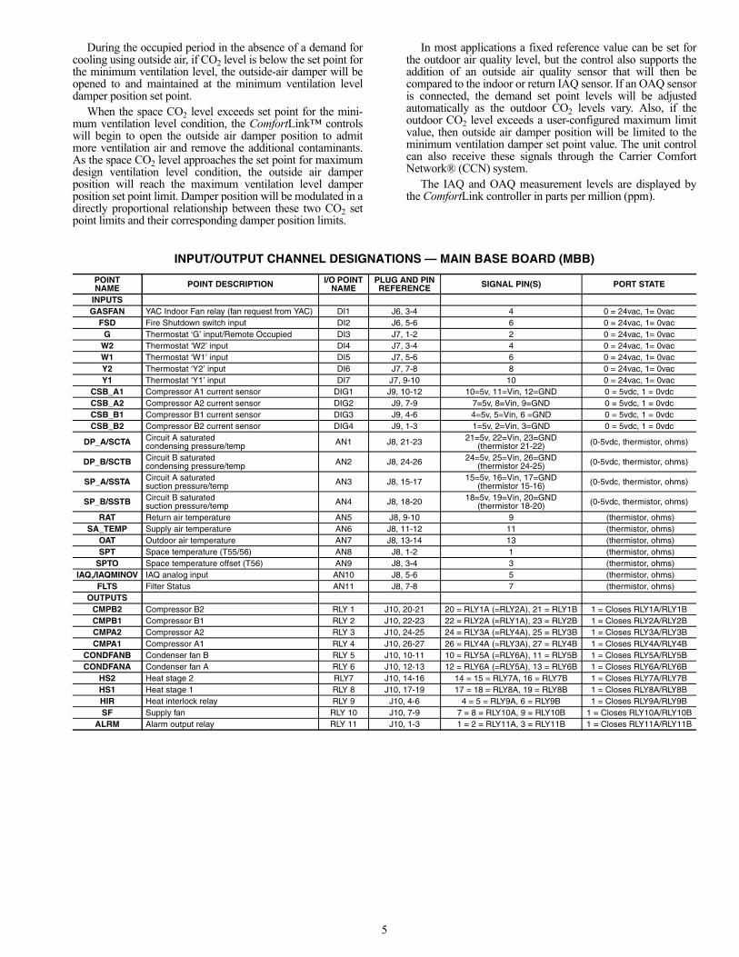
Indoor Air Quality — The indoor air quality (IAQ) func-tion provides a demand-based control for ventilation air quanti-ty, by providing a modulating outside air damper position thatis proportional to space CO2 level. The ventilation damper po-sition is varied between a minimum ventilation level (based oninternal sources of contaminants and CO2 levels other than theeffect of people) and the maximum design ventilation level(determined at maximum populated status in the building).During a less-than-fully populated space period, the CO2 levelwill be lower than maximum design ventilation level at full-load design condition, thus less ventilation air will be required.Reduced quantities of ventilation air will result in reduced op-erating costs. Space CO2 level is monitored and compared touser-configured set points. An accessory CO2 sensor for space(or return duct mounting) is required. The IAQ routine can beenhanced by also installing a sensor for outdoor air quality(OAQ).
5
During the occupied period in the absence of a demand forcooling using outside air, if CO2 level is below the set point forthe minimum ventilation level, the outside-air damper will beopened to and maintained at the minimum ventilation leveldamper position set point.
When the space CO2 level exceeds set point for the mini-mum ventilation level condition, the ComfortLink™ controlswill begin to open the outside air damper position to admitmore ventilation air and remove the additional contaminants.As the space CO2 level approaches the set point for maximumdesign ventilation level condition, the outside air damperposition will reach the maximum ventilation level damperposition set point limit. Damper position will be modulated in adirectly proportional relationship between these two CO2 setpoint limits and their corresponding damper position limits.
In most applications a fixed reference value can be set forthe outdoor air quality level, but the control also supports theaddition of an outside air quality sensor that will then becompared to the indoor or return IAQ sensor. If an OAQ sensoris connected, the demand set point levels will be adjustedautomatically as the outdoor CO2 levels vary. Also, if theoutdoor CO2 level exceeds a user-configured maximum limitvalue, then outside air damper position will be limited to theminimum ventilation damper set point value. The unit controlcan also receive these signals through the Carrier ComfortNetwork® (CCN) system.
The IAQ and OAQ measurement levels are displayed bythe ComfortLink controller in parts per million (ppm).
INPUT/OUTPUT CHANNEL DESIGNATIONS — MAIN BASE BOARD (MBB)
POINT NAME POINT DESCRIPTION I/O POINT
NAMEPLUG AND PIN REFERENCE SIGNAL PIN(S) PORT STATE
INPUTSGASFAN YAC Indoor Fan relay (fan request from YAC) DI1 J6, 3-4 4 0 = 24vac, 1= 0vac
FSD Fire Shutdown switch input DI2 J6, 5-6 6 0 = 24vac, 1= 0vacG Thermostat ‘G’ input/Remote Occupied DI3 J7, 1-2 2 0 = 24vac, 1= 0vac
W2 Thermostat ‘W2’ input DI4 J7, 3-4 4 0 = 24vac, 1= 0vacW1 Thermostat ‘W1’ input DI5 J7, 5-6 6 0 = 24vac, 1= 0vacY2 Thermostat ‘Y2’ input DI6 J7, 7-8 8 0 = 24vac, 1= 0vacY1 Thermostat ‘Y1’ input DI7 J7, 9-10 10 0 = 24vac, 1= 0vac
CSB_A1 Compressor A1 current sensor DIG1 J9, 10-12 10=5v, 11=Vin, 12=GND 0 = 5vdc, 1 = 0vdcCSB_A2 Compressor A2 current sensor DIG2 J9, 7-9 7=5v, 8=Vin, 9=GND 0 = 5vdc, 1 = 0vdcCSB_B1 Compressor B1 current sensor DIG3 J9, 4-6 4=5v, 5=Vin, 6 =GND 0 = 5vdc, 1 = 0vdcCSB_B2 Compressor B2 current sensor DIG4 J9, 1-3 1=5v, 2=Vin, 3=GND 0 = 5vdc, 1 = 0vdc
DP_A/SCTA Circuit A saturated condensing pressure/temp AN1 J8, 21-23 21=5v, 22=Vin, 23=GND
(thermistor 21-22) (0-5vdc, thermistor, ohms)
DP_B/SCTB Circuit B saturated condensing pressure/temp AN2 J8, 24-26 24=5v, 25=Vin, 26=GND
(thermistor 24-25) (0-5vdc, thermistor, ohms)
SP_A/SSTA Circuit A saturated suction pressure/temp AN3 J8, 15-17 15=5v, 16=Vin, 17=GND
(thermistor 15-16) (0-5vdc, thermistor, ohms)
SP_B/SSTB Circuit B saturated suction pressure/temp AN4 J8, 18-20 18=5v, 19=Vin, 20=GND
(thermistor 18-20) (0-5vdc, thermistor, ohms)
RAT Return air temperature AN5 J8, 9-10 9 (thermistor, ohms)SA_TEMP Supply air temperature AN6 J8, 11-12 11 (thermistor, ohms)
OAT Outdoor air temperature AN7 J8, 13-14 13 (thermistor, ohms)SPT Space temperature (T55/56) AN8 J8, 1-2 1 (thermistor, ohms)
SPTO Space temperature offset (T56) AN9 J8, 3-4 3 (thermistor, ohms)IAQ,/IAQMINOV IAQ analog input AN10 J8, 5-6 5 (thermistor, ohms)
FLTS Filter Status AN11 J8, 7-8 7 (thermistor, ohms)OUTPUTS
CMPB2 Compressor B2 RLY 1 J10, 20-21 20 = RLY1A (=RLY2A), 21 = RLY1B 1 = Closes RLY1A/RLY1BCMPB1 Compressor B1 RLY 2 J10, 22-23 22 = RLY2A (=RLY1A), 23 = RLY2B 1 = Closes RLY2A/RLY2BCMPA2 Compressor A2 RLY 3 J10, 24-25 24 = RLY3A (=RLY4A), 25 = RLY3B 1 = Closes RLY3A/RLY3BCMPA1 Compressor A1 RLY 4 J10, 26-27 26 = RLY4A (=RLY3A), 27 = RLY4B 1 = Closes RLY4A/RLY4B
CONDFANB Condenser fan B RLY 5 J10, 10-11 10 = RLY5A (=RLY6A), 11 = RLY5B 1 = Closes RLY5A/RLY5BCONDFANA Condenser fan A RLY 6 J10, 12-13 12 = RLY6A (=RLY5A), 13 = RLY6B 1 = Closes RLY6A/RLY6B
HS2 Heat stage 2 RLY7 J10, 14-16 14 = 15 = RLY7A, 16 = RLY7B 1 = Closes RLY7A/RLY7BHS1 Heat stage 1 RLY 8 J10, 17-19 17 = 18 = RLY8A, 19 = RLY8B 1 = Closes RLY8A/RLY8BHIR Heat interlock relay RLY 9 J10, 4-6 4 = 5 = RLY9A, 6 = RLY9B 1 = Closes RLY9A/RLY9BSF Supply fan RLY 10 J10, 7-9 7 = 8 = RLY10A, 9 = RLY10B 1 = Closes RLY10A/RLY10B
ALRM Alarm output relay RLY 11 J10, 1-3 1 = 2 = RLY11A, 3 = RLY11B 1 = Closes RLY11A/RLY11B
6
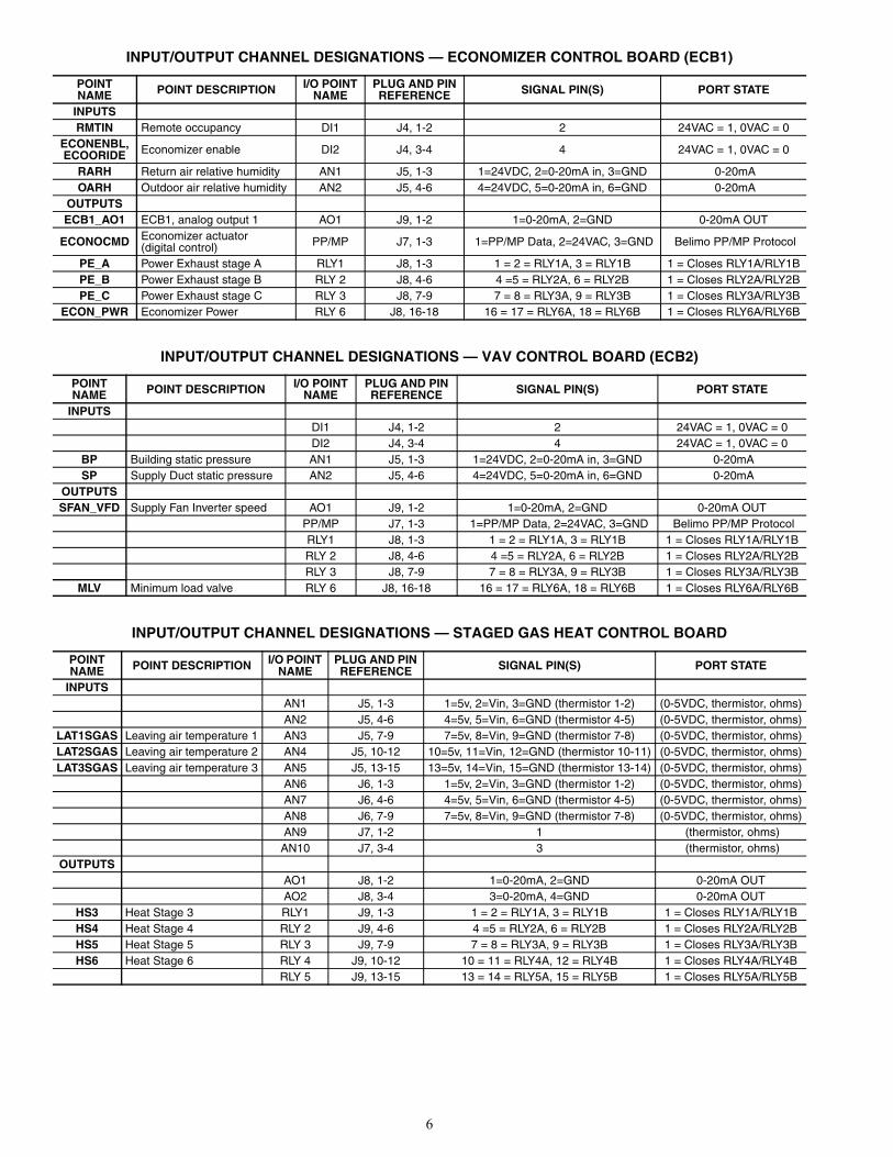
INPUT/OUTPUT CHANNEL DESIGNATIONS — ECONOMIZER CONTROL BOARD (ECB1)
INPUT/OUTPUT CHANNEL DESIGNATIONS — VAV CONTROL BOARD (ECB2)
INPUT/OUTPUT CHANNEL DESIGNATIONS — STAGED GAS HEAT CONTROL BOARD
POINT NAME POINT DESCRIPTION I/O POINT
NAMEPLUG AND PIN REFERENCE SIGNAL PIN(S) PORT STATE
INPUTSRMTIN Remote occupancy DI1 J4, 1-2 2 24VAC = 1, 0VAC = 0
ECONENBL, ECOORIDE Economizer enable DI2 J4, 3-4 4 24VAC = 1, 0VAC = 0
RARH Return air relative humidity AN1 J5, 1-3 1=24VDC, 2=0-20mA in, 3=GND 0-20mAOARH Outdoor air relative humidity AN2 J5, 4-6 4=24VDC, 5=0-20mA in, 6=GND 0-20mA
OUTPUTSECB1_AO1 ECB1, analog output 1 AO1 J9, 1-2 1=0-20mA, 2=GND 0-20mA OUT
ECONOCMD Economizer actuator (digital control) PP/MP J7, 1-3 1=PP/MP Data, 2=24VAC, 3=GND Belimo PP/MP Protocol
PE_A Power Exhaust stage A RLY1 J8, 1-3 1 = 2 = RLY1A, 3 = RLY1B 1 = Closes RLY1A/RLY1BPE_B Power Exhaust stage B RLY 2 J8, 4-6 4 =5 = RLY2A, 6 = RLY2B 1 = Closes RLY2A/RLY2BPE_C Power Exhaust stage C RLY 3 J8, 7-9 7 = 8 = RLY3A, 9 = RLY3B 1 = Closes RLY3A/RLY3B
ECON_PWR Economizer Power RLY 6 J8, 16-18 16 = 17 = RLY6A, 18 = RLY6B 1 = Closes RLY6A/RLY6B
POINT NAME POINT DESCRIPTION I/O POINT
NAMEPLUG AND PIN REFERENCE SIGNAL PIN(S) PORT STATE
INPUTS DI1 J4, 1-2 2 24VAC = 1, 0VAC = 0 DI2 J4, 3-4 4 24VAC = 1, 0VAC = 0
BP Building static pressure AN1 J5, 1-3 1=24VDC, 2=0-20mA in, 3=GND 0-20mASP Supply Duct static pressure AN2 J5, 4-6 4=24VDC, 5=0-20mA in, 6=GND 0-20mA
OUTPUTSSFAN_VFD Supply Fan Inverter speed AO1 J9, 1-2 1=0-20mA, 2=GND 0-20mA OUT
PP/MP J7, 1-3 1=PP/MP Data, 2=24VAC, 3=GND Belimo PP/MP Protocol RLY1 J8, 1-3 1 = 2 = RLY1A, 3 = RLY1B 1 = Closes RLY1A/RLY1B RLY 2 J8, 4-6 4 =5 = RLY2A, 6 = RLY2B 1 = Closes RLY2A/RLY2B RLY 3 J8, 7-9 7 = 8 = RLY3A, 9 = RLY3B 1 = Closes RLY3A/RLY3B
MLV Minimum load valve RLY 6 J8, 16-18 16 = 17 = RLY6A, 18 = RLY6B 1 = Closes RLY6A/RLY6B
POINT NAME POINT DESCRIPTION I/O POINT
NAMEPLUG AND PIN REFERENCE SIGNAL PIN(S) PORT STATE
INPUTS AN1 J5, 1-3 1=5v, 2=Vin, 3=GND (thermistor 1-2) (0-5VDC, thermistor, ohms) AN2 J5, 4-6 4=5v, 5=Vin, 6=GND (thermistor 4-5) (0-5VDC, thermistor, ohms)
LAT1SGAS Leaving air temperature 1 AN3 J5, 7-9 7=5v, 8=Vin, 9=GND (thermistor 7-8) (0-5VDC, thermistor, ohms)LAT2SGAS Leaving air temperature 2 AN4 J5, 10-12 10=5v, 11=Vin, 12=GND (thermistor 10-11) (0-5VDC, thermistor, ohms)LAT3SGAS Leaving air temperature 3 AN5 J5, 13-15 13=5v, 14=Vin, 15=GND (thermistor 13-14) (0-5VDC, thermistor, ohms)
AN6 J6, 1-3 1=5v, 2=Vin, 3=GND (thermistor 1-2) (0-5VDC, thermistor, ohms) AN7 J6, 4-6 4=5v, 5=Vin, 6=GND (thermistor 4-5) (0-5VDC, thermistor, ohms) AN8 J6, 7-9 7=5v, 8=Vin, 9=GND (thermistor 7-8) (0-5VDC, thermistor, ohms) AN9 J7, 1-2 1 (thermistor, ohms) AN10 J7, 3-4 3 (thermistor, ohms)
OUTPUTS AO1 J8, 1-2 1=0-20mA, 2=GND 0-20mA OUT AO2 J8, 3-4 3=0-20mA, 4=GND 0-20mA OUT
HS3 Heat Stage 3 RLY1 J9, 1-3 1 = 2 = RLY1A, 3 = RLY1B 1 = Closes RLY1A/RLY1BHS4 Heat Stage 4 RLY 2 J9, 4-6 4 =5 = RLY2A, 6 = RLY2B 1 = Closes RLY2A/RLY2BHS5 Heat Stage 5 RLY 3 J9, 7-9 7 = 8 = RLY3A, 9 = RLY3B 1 = Closes RLY3A/RLY3BHS6 Heat Stage 6 RLY 4 J9, 10-12 10 = 11 = RLY4A, 12 = RLY4B 1 = Closes RLY4A/RLY4B
RLY 5 J9, 13-15 13 = 14 = RLY5A, 15 = RLY5B 1 = Closes RLY5A/RLY5B
7
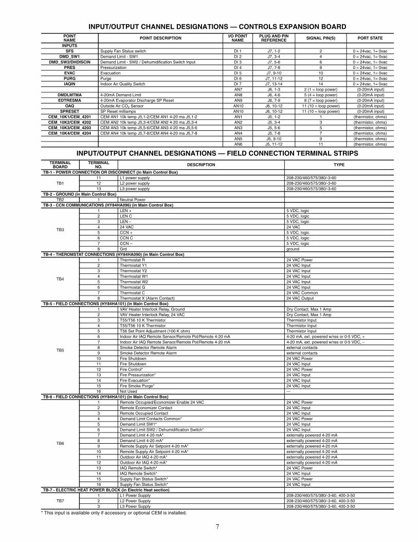
INPUT/OUTPUT CHANNEL DESIGNATIONS — CONTROLS EXPANSION BOARD
INPUT/OUTPUT CHANNEL DESIGNATIONS — FIELD CONNECTION TERMINAL STRIPS
* This input is available only if accessory or optional CEM is installed.
POINT NAME POINT DESCRIPTION I/O POINT
NAMEPLUG AND PIN REFERENCE SIGNAL PIN(S) PORT STATE
INPUTSSFS Supply Fan Status switch DI 1 J7, 1-2 2 0 = 24vac, 1= 0vac
DMD_SW1 Demand Limit - SW1 DI 2 J7, 3-4 4 0 = 24vac, 1= 0vacDMD_SW2/DHDISCIN Demand Limit - SW2 / Dehumidification Switch Input DI 3 J7, 5-6 6 0 = 24vac, 1= 0vac
PRES Pressurization DI 4 J7, 7-8 8 0 = 24vac, 1= 0vacEVAC Evacuation DI 5 J7, 9-10 10 0 = 24vac, 1= 0vacPURG Purge DI 6 J7, 11-12 12 0 = 24vac, 1= 0vacIAQIN Indoor Air Quality Switch DI 7 J7, 13-14 14 0 = 24vac, 1= 0vac
AN7 J6, 1-3 2 (1 = loop power) (0-20mA input)DMDLMTMA 4-20mA Demand Limit AN8 J6, 4-6 5 (4 = loop power) (0-20mA input)EDTRESMA 4-20mA Evaporator Discharge SP Reset AN9 J6, 7-9 8 (7 = loop power) (0-20mA input)
OAQ Outside Air CO2 Sensor AN10 J6, 10-12 11 (10 = loop power) (0-20mA input)SPRESET SP Reset milliamps AN10 J6, 10-12 11 (10 = loop power) (0-20mA input)
CEM_10K1/CEM_4201 CEM AN1 10k temp J5,1-2/CEM AN1 4-20 ma J5,1-2 AN1 J5, 1-2 1 (thermistor, ohms)CEM_10K2/CEM_4202 CEM AN2 10k temp J5,3-4/CEM AN2 4-20 ma J5,3-4 AN2 J5, 3-4 3 (thermistor, ohms)CEM_10K3/CEM_4203 CEM AN3 10k temp J5,5-6/CEM AN3 4-20 ma J5,5-6 AN3 J5, 5-6 5 (thermistor, ohms)CEM_10K4/CEM_4204 CEM AN4 10k temp J5,7-8/CEM AN4 4-20 ma J5,7-8 AN4 J5, 7-8 7 (thermistor, ohms)
AN5 J5, 9-10 9 (thermistor, ohms) AN6 J5, 11-12 11 (thermistor, ohms)
TERMINALBOARD
TERMINALNO. DESCRIPTION TYPE
TB-1 - POWER CONNECTION OR DISCONNECT (in Main Control Box)
TB111 L1 power supply 208-230/460/575/380/-3-6012 L2 power supply 208-230/460/575/380/-3-6013 L3 power supply 208-230/460/575/380/-3-60
TB-2 - GROUND (in Main Control Box)TB2 1 Neutral Power
TB-3 - CCN COMMUNICATIONS (HY84HA096) (in Main Control Box)
TB3
1 LEN + 5 VDC, logic2 LEN C 5 VDC, logic3 LEN – 5 VDC, logic4 24 VAC 24 VAC5 CCN + 5 VDC, logic6 CCN C 5 VDC, logic7 CCN – 5 VDC, logic8 Grd ground
TB-4 - THEROMSTAT CONNECTIONS (HY84HA090) (in Main Control Box)
TB4
1 Thermostat R 24 VAC Power2 Thermostat Y1 24 VAC Input3 Thermostat Y2 24 VAC Input4 Thermostat W1 24 VAC Input5 Thermostat W2 24 VAC Input6 Thermostat G 24 VAC Input7 Thermostat C 24 VAC Common8 Thermostat X (Alarm Contact) 24 VAC Output
TB-5 - FIELD CONNECTIONS (HY84HA101) (in Main Control Box)
TB5
1 VAV Heater Interlock Relay, Ground Dry Contact, Max 1 Amp2 VAV Heater Interlock Relay, 24 VAC Dry Contact, Max 1 Amp3 T55/T56 10 K Thermistor Thermistor Input4 T55/T56 10 K Thermistor Thermistor Input5 T56 Set Point Adjustment (100 K ohm) Thermistor Input6 Indoor Air IAQ Remote Sensor/Remote Pot/Remote 4-20 mA 4-20 mA, ext. powered w/res or 0-5 VDC, +7 Indoor Air IAQ Remote Sensor/Remote Pot/Remote 4-20 mA 4-20 mA, ext. powered w/res or 0-5 VDC, –8 Smoke Detector Remote Alarm external contacts9 Smoke Detector Remote Alarm external contacts
10 Fire Shutdown 24 VAC Power11 Fire Shutdown 24 VAC Input12 Fire Control* 24 VAC Power13 Fire Pressurization* 24 VAC Input14 Fire Evacuation* 24 VAC Input15 Fire Smoke Purge* 24 VAC Input16 Not Used —
TB-6 - FIELD CONNECTIONS (HY84HA101) (in Main Control Box)
TB6
1 Remote Occupied/Economizer Enable 24 VAC 24 VAC Power2 Remote Economizer Contact 24 VAC Input3 Remote Occupied Contact 24 VAC Input4 Demand Limit Contacts Common* 24 VAC Power5 Demand Limit SW1* 24 VAC Input6 Demand Limit SW2 / Dehumidification Switch* 24 VAC Input7 Demand Limit 4-20 mA* externally powered 4-20 mA8 Demand Limit 4-20 mA* externally powered 4-20 mA9 Remote Supply Air Setpoint 4-20 mA* externally powered 4-20 mA
10 Remote Supply Air Setpoint 4-20 mA* externally powered 4-20 mA11 Outdoor Air IAQ 4-20 mA* externally powered 4-20 mA12 Outdoor Air IAQ 4-20 mA* externally powered 4-20 mA13 IAQ Remote Switch* 24 VAC Power14 IAQ Remote Switch* 24 VAC Input15 Supply Fan Status Switch* 24 VAC Power16 Supply Fan Status Switch* 24 VAC Input
TB-7 - ELECTRIC HEAT POWER BLOCK (in Electric Heat section)
TB71 L1 Power Supply 208-230/460/575/380/-3-60, 400-3-502 L2 Power Supply 208-230/460/575/380/-3-60, 400-3-503 L3 Power Supply 208-230/460/575/380/-3-60, 400-3-50
8
Fig
. 1 —
Co
mp
on
ent
Arr
ang
emen
t —
48/
50A
2,A
3,A
4,A
5020
-035
Un
its
a48-8308
9
Fig
. 2 —
Co
mp
on
ent
Arr
ang
emen
t —
48/
50A
2,A
3,A
4,A
5040
-060
Un
its
a48-8309LOC
ATIO
NS
AR
E T
YP
ICA
L F
OR
ALL
SIZ
E04
0-06
0 U
NIT
S.
SIZ
E 0
60 R
TP
F (
RO
UN
DT
UB
E
PLA
TE
F
IN)
UN
ITS
H
AV
E
6 (S
IX)
OU
TD
OO
R
FAN
A
SS
EM
BLI
ES
. U
NIT
SH
OW
N IS
A 5
0 S
ER
IES
SIZ
E 0
40.
10
Fig
. 3 —
Po
wer
Sch
emat
ic —
48/
50A
2,A
3,A
4,A
5020
-050
Un
its
a48-8385
11
Fig
. 4 —
Po
wer
Sch
emat
ic —
48/
50A
2,A
3,A
4,A
5060
RT
PF
Un
its
a48-8386

12
Fig
. 5 —
Po
wer
Sch
emat
ic —
48/
50A
2,A
3,A
4,A
5060
MC
HX
Un
its
a48-8387
13
~~
~~
TONEXTPAGE
Fig. 6 — Main Control Box Circuit — 48/50A2,A3,A4,A5020-060 Units
a48-8388
14
~~
~~
TOPREVIOUSPAGE
a48-8389Fig. 6 — Main Control Box Circuit — 48/50A2,A3,A4,A5020-060 Units (cont)
15
AB
B A
CS
800
DR
IVE
NO
T U
SE
D
AB
B A
CS
550
DR
IVE
STA
ND
AR
D
TOS
HIB
A E
3 D
RIV
EN
OT
US
ED
Fig
. 7 —
Au
xilia
ry C
on
tro
l Bo
x W
irin
g —
48/
50A
2,A
3,A
4,A
5020
-060
Un
its
a48-8390
16
Fig
. 8 —
Co
ntr
ols
Exp
ansi
on
Bo
ard
Wir
ing
— 4
8/50
A2,
A3,
A4,
A50
20-0
60 U
nit
s
a48-8261
17
Fig
. 9 —
Gas
Hea
t C
on
tro
l Cir
cuit
(2-
Sta
ge
Hea
t) —
48A
2,A
3,A
4,A
5020
-050
Un
its
a48-8310
18
Fig
. 10
— G
as H
eat
Co
ntr
ol C
ircu
it (
2-S
tag
e H
eat)
— 4
8A2,
A3,
A4,
A50
60 U
nit
s
a48-8311
19
Fig
. 11
— G
as H
eat
Co
ntr
ol C
ircu
it (
Sta
ged
Gas
Hea
t) —
48A
2,A
3,A
4,A
5020
-050
Un
its
a48-8313
20
Fig
. 12
— G
as H
eat
Co
ntr
ol C
ircu
it (
Sta
ged
Gas
Hea
t) —
48A
2,A
3,A
4,A
5060
Un
its
a48-8315
21
Fig
. 13
— E
lect
ric
Hea
t C
on
tro
l Cir
cuit
— 5
0A2,
A3,
A4,
A50
20-0
50 U
nit
s
a48-8266
22
Fig
. 14
— E
lect
ric
Hea
t C
on
tro
l Cir
cuit
— 5
0A2,
A3,
A4,
A50
60 U
nit
s
a48-8267
23
BLK
23
GRNDPA
RED
BLK
GRN
RED
A
B
6 5 2
L1
L1
L1
T1
T2
T3
SEE NOTE 1
1 2
BLK
YEL
BLU
FUSE
FUSE
FUSE
MM-FCCB
22
2111
12
13
BLK
RED
BLU
1
2
3
OFM2
FR
2 4
FR1 3
C1 C2OFC1
MM
BLK
GRN
RED
BLK
GRN
RED
DPA
MM-F
FUSE
FUSE
FUSE
BLK
YEL
BLU
CCB
11
12
13
21
22
23
2 4
FR
1 2SEE NOTE 1
6 5 2
L1
L1
L1
T1
T2
T3
MM
BLK
RED
BLU
BLK
RED
BLU
1
2
3
1
2
3
OFM1
OFM2
FR1 3
C1 C2OFC1
Fig. 15 — Motormaster V Accessory Wiring — 48/50A2,A3,A4,A5020-035 Units
NOTES:1. Motormaster® control to be wired directly to CCB
circuit breaker and the OFC1 contactor should beremoved from the wiring.
2. Connect start relay FR to the following terminals:230-3-60 TB1-TB2460-3-60 TB1-TB2575-3-60 TB1-TB2208-3-60 TB13A-TB2
3. Add FR relay in parallel with OFC1.
Fig. 16 — Motormaster V Accessory Wiring — 48/50A2,A3,A4,A5040-050 and 48/50A2,A3,A4,A5060 RTPF Units
NOTES:1. Motormaster control to be wired directly to CCB cir-
cuit breaker and the OFC1 contactor should beremoved from the wiring.
2. Connect start relay FR to the following terminals:230-3-60 TB1-TB2460-3-60 TB1-TB2575-3-60 TB1-TB2208-3-60 TB13A-TB2
3. Add FR relay in parallel with OFC1.
LEGENDCCB — Control Circuit BreakerDPA — Duct Pressure TransducerFR — Fan RelayMM — Motormaster VMM-F — Motormaster V FusesOFC — Outdoor-Fan ContactorOFM — Outdoor-Fan MotorTB — Terminal Block
LEGENDCCB — Control Circuit BreakerDPA — Duct Pressure TransducerFR — Fan RelayMM — Motormaster VMM-F — Motormaster V FusesOFC — Outdoor-Fan ContactorOFM — Outdoor-Fan MotorTB — Terminal Block
a48-6690
a48-6691
24
Fig. 18 — Space Temperature Averaging Wiringa48-6693
3
4
RED
BLK
TB5
3
4
TB5
SENSOR 1 SENSOR 2 SENSOR 3 SENSOR 4
SENSOR 1 SENSOR 2 SENSOR 3
SENSOR 4 SENSOR 5 SENSOR 6
SENSOR 7 SENSOR 8 SENSOR 9
SPACE TEMPERATURE AVERAGING (4 SENSOR APPLICATION)
SPACE TEMPERATURE AVERAGING (9 SENSOR APPLICATION)
Fig. 17 — Motormaster V Accessory Wiring — 48/50A2,A3,A4,A5060 MCHX Units
LEGENDCCB — Control Circuit BreakerFR — Fan RelayMM-F — Motormaster V FusesMMPT — Motormaster V Pressure
TransducerMMV — Motormaster VOFC — Outdoor-Fan ContactorOFM — Outdoor-Fan MotorTB — Terminal Block
NOTES:1. Motormaster® control to be wired directly to CCB
circuit breaker and the OFC1 contactor should beremoved from the wiring.
2. Connect start relay FR to the following terminals:230-3-60 TB1-TB2460-3-60 TB1-TB2575-3-60 TB1-TB2208-3-60 TB13A-TB2
3. Add FR-B relay in parallel with OFC1. Add FR-Arelay in parallel with OFC3.
a48-8391
25
36 kW, 208/230 V, SIZES 020-05054 kW, 208/230 V, SIZE 060
72 kW, 208/230 V, SIZES 020-050108 kW, 208/230 V, SIZE 060
36 kW, 460 V, SIZES 020-05024 kW, 380 V, SIZES 020-050
54 kW, 460 V, SIZE 06037 kW, 380 V, SIZE 060
36 kW, 575 V, SIZES 020-05054 kW, 575 V, SIZE 060 72 kW, 575 V, SIZES 020-050
108 kW, 575 V, SIZE 060
Fig. 19 — Electric Heater Power Diagrams
72 kW, 460 V, SIZES 020-05049 kW, 380 V, SIZES 020-050
108 kW, 460 V, SIZE 06074 kW, 380 V, SIZE 060
a48-6694 a48-6695
a48-6696 a48-6697
a48-6698a48-6699
LEGENDFU — FuseHC — Heater ContactorTB — Terminal Block
Terminal (Marked)
Terminal Block
Terminal (Unmarked)
Factory Wiring


Manufacturer reserves the right to discontinue, or change at any time, specifications or designs without notice and without incurring obligations.Catalog No. 04-56480002-01 Printed in U.S.A. Form 48/50A-3W Pg 28 508 4-08 Replaces: New
Copyright 2008 Carrier Corporation