combustion in ci engines & gas...
TRANSCRIPT
Combustion in CI Engines & Gas Turbines
Dr. Md. Zahurul Haq
ProfessorDepartment of Mechanical Engineering
Bangladesh University of Engineering & Technology (BUET)Dhaka-1000, Bangladesh
[email protected]://teacher.buet.ac.bd/zahurul/
ME 401: Internal Combustion Engines
c
Dr. Md. Zahurul Haq (BUET) Combustion in GT & CI Engines ME 401 (2016) 1 / 22
Combustion in CI Engines
Essential Features of CI Combustion
Air alone is compressed in a diesel engine and fuel is injected into
the cylinder towards the end of the combustion stroke.
Liquid fuel, injected at high velocity as one or more jets through
small orifices or nozzles in the injector tip, atomizes into small
drops and penetrates into the combustion chamber. Fuel vaporizes
and mixes with the high-temperature high-pressure cylinder air.
Since the air temperature and pressure are above the fuel’s
ignition point, spontaneous ignition of portions of already-mixed
fuel and air occurs after a delay period of few crank angle degrees.
Cylinder pressure increases as combustion of fuel-air mixture
occurs. Consequent heating and compression of unburned portion
of charge shortens the ignition delay and fuel vaporization time.
Fuel injection continues until desired amount of fuel is injected.
Atomization, vaporization, fuel-air (also burned gases) mixing,
and combustion continues until combustion process is completed.c
Dr. Md. Zahurul Haq (BUET) Combustion in GT & CI Engines ME 401 (2016) 2 / 22
Combustion in CI Engines
T382
c
Dr. Md. Zahurul Haq (BUET) Combustion in GT & CI Engines ME 401 (2016) 3 / 22
Combustion in CI Engines
Since injection commences just before combustion starts, there is
no knock limit resulting from spontaneous ignition of end-gas.
Injection timing is used to control combustion timing and short
ignition delay period is desirable.
Engine torque is varied by varying the amount of fuel injected per
cycle with essentially unchanged air flow. Engine is operated
un-throttled with good part-load efficiency relative to SI engine.
As fuel injection per cycle is increased, problem with air
utilization leads to shoot formation which cannot be burned up
prior to exhaust. Soot formation limits the maximum fuel/air
ratio to values 20% or more lean of stoichiometric and
consequently lower mean effective pressure than SI engine.
Since diesel always operates with lean fuel/air ratios and higher
values of γ(= Cp/CV ) over expansion stroke gives higher
conversion efficiency than SI engine.
c
Dr. Md. Zahurul Haq (BUET) Combustion in GT & CI Engines ME 401 (2016) 4 / 22
Combustion in CI Engines
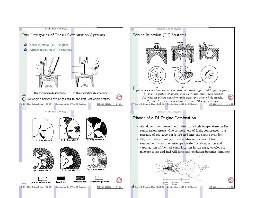
Two Categories of Diesel Combustion Systems
1 Direct-injection (DI) Engines
2 Indirect-injection (IDI) Engines
e742
⊙IDI engine designs are only used in the smallest engine sizes.
c
Dr. Md. Zahurul Haq (BUET) Combustion in GT & CI Engines ME 401 (2016) 5 / 22
Combustion in CI Engines
Direct Injection (DI) Systems
e743
(a) quiescent chamber with multi-hole nozzle typical of larger engines;
(b) bowl-in-piston chamber with swirl and multi-hole nozzle;
(c) bowl-in-piston chamber with swirl and single-hole nozzle.
(b) and (c) used in medium to small DI engine range.c
Dr. Md. Zahurul Haq (BUET) Combustion in GT & CI Engines ME 401 (2016) 6 / 22
Combustion in CI Engines
e744
c
Dr. Md. Zahurul Haq (BUET) Combustion in GT & CI Engines ME 401 (2016) 7 / 22
Combustion in CI Engines
Phases of a DI Engine Combustion
Air alone is compressed and raised to a high temperature on the
compression stroke. One or more jets of fuels, compressed to a
pressure of 100-2000 bar is injected into the engine cylinder.
Physical Delay: Fuel jet disintegrates into a core of fuel
surrounded by a spray envelope created by atomization and
vaporization of fuel. At some location in the spray envelope a
mixture of air and fuel will form and oxidation becomes imminent.
T381
c
Dr. Md. Zahurul Haq (BUET) Combustion in GT & CI Engines ME 401 (2016) 8 / 22
Combustion in CI Engines
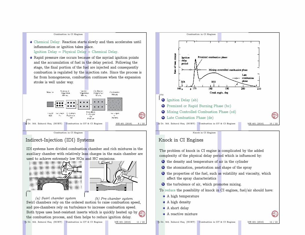
Chemical Delay: Reaction starts slowly and then accelerates until
inflammation or ignition takes place.
Ignition Delay = Physical Delay + Chemical Delay.
Rapid pressure rise occurs because of the myriad ignition points
and the accumulation of fuel in the delay period. Following the
stage, the final portion of the fuel are injected and consequently
combustion is regulated by the injection rate. Since the process is
far from homogeneous, combustion continues when the expansion
stroke is well under way.
e701
c
Dr. Md. Zahurul Haq (BUET) Combustion in GT & CI Engines ME 401 (2016) 9 / 22
Combustion in CI Engines
e741
1 Ignition Delay (ab)
2 Premixed or Rapid Burning Phase (bc)
3 Mixing Controlled Combustion Phase (cd)
4 Late Combustion Phase (de)
c
Dr. Md. Zahurul Haq (BUET) Combustion in GT & CI Engines ME 401 (2016) 10 / 22
Combustion in CI Engines
Indirect-Injection (IDI) Systems
IDI systems have divided combustion chamber and rich mixtures in the
auxiliary chamber with relatively lean charges in the main chamber are
used to achieve extremely low NOx and HC emissions.
e745
(a) Swirl chamber system
e746
(b) Pre-chamber systemSwirl chambers rely on the ordered motion to raise combustion speed,
and pre-chambers rely on turbulence to increase combustion speed.
Both types uses heat-resistant inserts which is quickly heated up by
the combustion process, and then helps to reduce ignition delay.c
Dr. Md. Zahurul Haq (BUET) Combustion in GT & CI Engines ME 401 (2016) 11 / 22
Knock in CI Engines
Knock in CI Engines
The problem of knock in CI engine is complicated by the added
complexity of the physical delay period which is influenced by:
1 the density and temperature of air in the cylinder
2 the atomization, penetration and shape of the spray
3 the properties of the fuel, such as volatility and viscosity, which
affect the spray characteristics
4 the turbulence of air, which promotes mixing.
To reduce the possibility of knock in CI engines, fuel/air should have:
A high temperature
A high density
A short delay
A reactive mixture
c
Dr. Md. Zahurul Haq (BUET) Combustion in GT & CI Engines ME 401 (2016) 12 / 22
Knock in CI Engines
Temperature Factors in Reducing CI Knock
Decreasing the temperature of the initially formed mixture by any of
the following methods will increase the possibility of knock:
Lowering the compression ratio
Lowering the inlet air temperature
Lowering the coolant temperature
Lowering the cylinder and cylinder walls temperature
Advancing or retarding the start of injection⊙
Injection of fuel after TDC will reduce knock (and power) because
of the pressure impact is relieved by the expansion stroke.
c
Dr. Md. Zahurul Haq (BUET) Combustion in GT & CI Engines ME 401 (2016) 13 / 22
Knock in CI Engines
Density Factors in Reducing CI Knock
Decreasing the temperature of the initially formed mixture by any of
the following methods will increase the possibility of knock:
Decreasing the inlet air pressure
Decreasing the compression ratio
Thus raising the compression ratio and supercharging the CI engine,
unlike in the SI engine, tends to reduce knock.
c
Dr. Md. Zahurul Haq (BUET) Combustion in GT & CI Engines ME 401 (2016) 14 / 22
Knock in CI Engines
Time Factors in Reducing CI Knock
Increasing the amount of fuel in the initially formed mixture, or
increasing the time for forming a homogeneous mixture, by any of the
following methods will increase the possibility of knock:
Decreasing the turbulence of the compressed air
Increasing the speed of the engine
Decreasing the injection pressure
Increasing the rate of injection
c
Dr. Md. Zahurul Haq (BUET) Combustion in GT & CI Engines ME 401 (2016) 15 / 22
Knock in CI Engines
Composition Factors in Reducing CI Knock
The possibility of knock in CI engine is decreased by the following
factors:
Raising the cetane rating of the fuel (decreasing chemical delay)
Increasing the volatility of the fuel (decreasing physical delay)
Decreasing the viscosity of the fuel (promoting mixing and
therefore decreasing physical delay).⊙
Fuels with high cetane rating may be undesirable for particular
engine since the rise of combustion may be too gradual. Thus, cetane
rating of 40-60 are usually specified. If the cetane rating is too low,
starting of the engine may be difficult. With high cetane values, the
ignition delay may be too short to allow the adequate mixing of fuel
with air, and incomplete combustion may result.
c
Dr. Md. Zahurul Haq (BUET) Combustion in GT & CI Engines ME 401 (2016) 16 / 22

Knock in CI Engines
e751
c
Dr. Md. Zahurul Haq (BUET) Combustion in GT & CI Engines ME 401 (2016) 17 / 22
Combustion in Gas Turbines
GT Operating Parameters
GT combustors operates at pressures of 3 atm for small engines to
as high as 40 atm for advanced engines. Aircraft engines operate
at compression ratios of 20/1 to 40/1, while stationary units
operate at 10 to 15 atm.
Combustor outlet temperatures are set by the metallurgical
requirements of the turbine blades and range from 1300 to 1700oC
for aircraft turbines and 1000 to 1500oC for stationary turbines.
Combustor inlet temperature depends on the compressor pressure
ratio and ranges from 200 to 500oC. The highest cycle efficiency is
achieved with the highest feasible turbine inlet temperature.
Since the stoichiometric flame temperatures of GT fuels is 2000oC
or more, 100 to 150% excess air is used to cool the combustor liner
to a suitable operating temperature around 800oC.
c
Dr. Md. Zahurul Haq (BUET) Combustion in GT & CI Engines ME 401 (2016) 18 / 22
Combustion in Gas Turbines
e747
c
Dr. Md. Zahurul Haq (BUET) Combustion in GT & CI Engines ME 401 (2016) 19 / 22
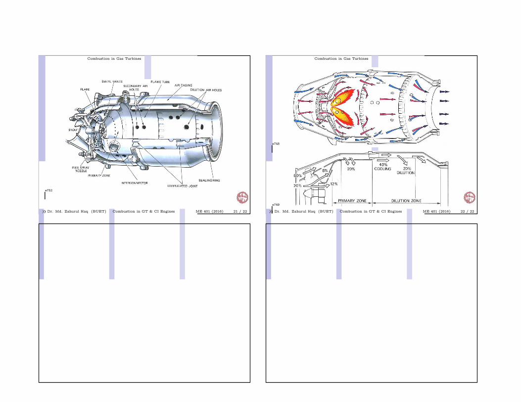
Combustion in Gas Turbines
Combustion in GT
Fuel in GT is burned almost stoichiometrically with 25 to 35% of the
air entering the combustor. The combustion products mix with the
remaining air to arrive at a suitable temperature for the turbine. All
combustors have the following three zones:
1 Recirculation zone: fuel is evaporated and partially burned.
2 Burning zone: fuel air mixture burning is completed.
3 Dilution zone: dilution air is mixed with hot gas.
c
Dr. Md. Zahurul Haq (BUET) Combustion in GT & CI Engines ME 401 (2016) 20 / 22
Combustion in Gas Turbines
e752
c
Dr. Md. Zahurul Haq (BUET) Combustion in GT & CI Engines ME 401 (2016) 21 / 22
Combustion in Gas Turbines
e748
e749
c
Dr. Md. Zahurul Haq (BUET) Combustion in GT & CI Engines ME 401 (2016) 22 / 22