combining color and depth for enhanced image segmentation...
TRANSCRIPT

Vis Comput (2012) 28:1181–1193DOI 10.1007/s00371-011-0667-7
O R I G I NA L A RT I C L E
Combining color and depth for enhanced image segmentationand retargeting
Meir Johnathan Dahan · Nir Chen · Ariel Shamir ·Daniel Cohen-Or
Published online: 29 December 2011© Springer-Verlag 2011
Abstract As depth cameras become more popular, pixeldepth information becomes easier to obtain. This informa-tion can clearly enhance many image processing applica-tions. However, combining depth and color information isnot straightforward as these two signals can have differ-ent noise characteristics, differences in resolution, and theirboundaries do not generally agree. We present a techniquethat combines depth and color image information from realdevices in synergy. In particular, we focus on combiningthem to improve image segmentation. We use color infor-mation to fill and clean depth and use depth to enhance colorimage segmentation. We demonstrate the utility of the com-bined segmentation for extracting layers and present a novelimage retargeting algorithm for layered images.
Keywords Image segmentation · Retargeting · Depth maps
1 Introduction
In recent years we have witnessed a rapid advance in thedevelopment of cameras that capture depth. While this ad-vance has been driven by video gaming, simultaneously ac-quiring depth with photometric imaging has an immense po-tential for a wide range of applications. In particular, having
M.J. Dahan (�) · D. Cohen-OrTel Aviv University, Tel Aviv, Israele-mail: [email protected]
N. Chen · A. ShamirInterdisciplinary Center Herzilya, Herzilya, Israel
N. Chene-mail: [email protected]
A. Shamire-mail: [email protected]
commodity level cameras with depth sensing will consid-erably enhance the performance of image processing anddigital photography applications. However, using data fromsuch cameras may not be straightforward. First, the depthdata spatial resolution does not always match the photo-metric resolution. Second, in many cases the depth imageis incomplete, imperfect, and contains noise. Under theseassumptions, we investigate the potential of combining thetwo modalities to enhance image segmentation, which is thebasis of many image processing applications.
In image segmentation, boundaries between objects inthe scene must be determined. In many cases, the photo-metric (color) image edges correspond to scene edges, i.e.,to discontinuity in depth. However, there are many imageedges created by illumination (e.g., shadows) or textures thatdo not signify object boundaries. Color segmentation usu-ally finds coherent color regions in an image. Real objectsin a scene such as people or animals can contain a vari-ety of colors, but usually not a wide range of depth values.Hence, using depth information can assist the mapping ofcolor-distinct regions to the same object and distinguishingbetween “false” image edges and real object boundaries.
Still, simply using the raw depth information is not suffi-cient. Our key idea is to utilize the information contained inone channel to enhance the other. Therefore, the RGB chan-nel, being more accurate and having higher resolution, can,in turn, assist in enhancing the depth channel by reconstruct-ing missing depth regions and enhancing the correctness ofedges in the depth map.
Combining the two modalities together naively does notnecessarily amount to unambiguous data from which thesegmentation can be extracted. In this paper, we introducea technique that combines the two modalities while increas-ing the agreement between them. We present an end-to-enddepth-color segmentation that provides better results than

1182 M.J. Dahan et al.
Fig. 1 Segmentation and retargeting using depth: (from left to right) color image, depth image and our automatic segmentation using color anddepth overlayed, color image retargeted by 20%, 30%, 40%, and 50%
a direct concatenation of the two (e.g., using mean shiftor clustering). Our technique is initialized by using joint-billateral upsampling of both depth and color and then ap-plying graph cut segmentation based both modalities. Wedemonstrate the technique on depth data which is imperfect,i.e., some regions are missing, there are outliers, and noiseis present. Furthermore, the depth spatial resolution is lowerthan the photometric one, and thus also the registration be-tween the two is imperfect.
In addition, to demonstrate the use of the combined seg-mented image, we present a novel image retargeting algo-rithm. We show how the augmented segmentation allows aqualitatively better solution to the retargeting problem byexploiting the depth information to partially overlap the lay-ers when size is reduced (see Fig. 1). We demonstrate ourtechnique on both synthetic and real depth images.
2 Related work
Depth There are numerous ways for estimating depth inimages, for instance, by using stereo, or multiple views instructure from motion [21]. Zhang et al. [29] introduced amethod of recovering depth from a video sequence and showmany applications; some of the images in this paper wereacquired in this manner. Other works reconstruct depth us-ing video sequences based on the motion between frames[8, 20]. Another possibility to acquire depth is simply to usedepth cameras. Such cameras are becoming a commoditythese days, and their use is widespread. Most examples inthis paper were acquired using a depth camera. However,such depth sensors still have lower resolution than the RGBsensor, and their quality in general is inferior to photometricsensors.
Upsampling Some previous work attempted to deal withthe lower spatial resolution of one modality versus the otherby upsampling one to match the resolution of the other. Kopfet al. [10] introduced the joint bilateral filter for a pair ofcorresponding images. They upsample a low-resolution im-age while respecting the edges of the corresponding high-resolution one. This technique was then improved by using
iterations [16, 27]. Schuon et al. [22] combined several low-resolution depth images to produce a super-resolution im-age.
Except for low spatial resolution, depth imaging is alsosubject to noise, and, due to surface reflection properties,some regions of the surface are completely missing. Thisproblem is often referred to as “depth shadow.” To addressthis issue, Becker et al. [3] use the color channels taken froma camera with a known location. They rely on the assump-tion that similar geometries possess similar colors and in-corporate a patch-based inpainting technique. In our workwe also complete missing color and depth values. We usetechniques such as [12] for layer completion and reconstructthe depth with a multistep joint bilateral depth upsamplingfilter [16].
Segmentation Segmentation is one of the fundamentalproblems in image processing [9]. As we discussed in the in-troduction, the performance of segmentation can be greatlyimproved with the assistance of depth images. Recently,Crabb et al. [6] employed depth imaging to extract fore-ground objects in real time. Their segmentation requires auser-defined threshold depth to separate the foreground fromthe background. The color image is used only to support asmall fraction (1–2%) of the pixels which are not solved bythe depth threshold. Another interesting use of depth is toassist background subtraction in video. In [13] several chan-nels of the depth camera are used and combined with thecolor channel.
Image retargeting To demonstrate the usefulness of ourmethod, we show how it can be utilized for image retar-geting. Techniques such as seam-carving [1, 19], shiftmaps[15], and non-homogeneous warping methods [11, 24, 26]all rely on the ability to automatically detect important re-gions in an image and preserve them under the resizingoperator. If the image is condensed and does not containsmooth or textured areas, these techniques can cause seri-ous artifacts. Using depth layers can assist in such cases byoverlaying parts of the image while resizing. In [7] repeti-tion is used to segment, layer, and rearrange objects in animage closer to our approach, but no depth input is used.For video, Zhang et al. [28] present a video editing system

Combining color and depth for enhanced image segmentation and retargeting 1183
for re-filming visually appealing effects based on the extrac-tion of depth layers from the video. Recently Mansfield etal. [14] exploited the seam carving technique to cause pre-segmented image objects to occlude each other. However,due to the nature of seam carving, distortions are still intro-duced to the carved background image. We show how theaddition of depth information can assist specifically in suchcases, by allowing different parts of the image to overlapin the resized image based on their depth. We compare ourresults to various other techniques using the recent Retar-getMe benchmark [17].
3 Color and depth imaging
Depth cameras provide an image where each pixel containsa measurement of the distance from the camera to the ob-ject visible in that pixel. There are several types of depthdevices such as time-of-flight cameras and projected codedimages. Most depth cameras use IR light for depth acquisi-tion since IR is not visible to the human eye and does notinterfere with the color sensor. The device we use is basedon projected IR Light Coding image and provide a depthresolution of 640 × 480. It is important to note that con-temporary depth sensors are still rather noisy and there aresignificant regions in the image where depth is not accurateor even missing. Moreover, since the depth and color imagesare created and captured with different sensors, the two im-ages are not perfectly aligned and may have different reso-lutions. Specifically, photometric images usually have muchhigher resolution than depth image (see Fig. 1). In our work,we exploit this to enhance the depth resolution.
As a first step, the capturing devices must be calibratedrespectively. We seek the set of camera parameters (loca-tion, rotation, view plane) that best explain the perspec-tive deformation observed from the devices. First, the usermarks several corresponding pairs of points (see Fig. 2).Denote these points as Bdepth = {p1,p2, . . . , pm},BRGB ={q1, q2, . . . , qm} in the color and depth image, respectively.Next, we project every user marked pixel in Bdepth to its 3Dcoordinates using the depth measurement. Denote as A theset of the 3D locations of the points. Then, we retrieve theperspective projection parameters θ by minimizing the L2
distance between the RGB points and the perspective trans-formation Tθ of the corresponding projected depth points(described below). Finally, we apply the transformation Tθ
to all the 3D points to generate a new depth image suiting theview-point of the color image. A more detailed descriptionis provided in the next paragraph.
We use perspective projection transformation as specifiedin [5]. Let a be a 3D point (a ∈ A) and θ = {cx,y,z, θx,y,z,
ex,y,z} the camera parameters. Transformation b = Tθ (a) is
Fig. 2 Camera calibration: The perspective projection parameters areobtained by minimizing the distance between RGB points and the per-spective transformation Tθ of the projected depth points. In the figure,the depth gradients image is superimposed on the color image before(top) and after (bottom) registration. The yellow marked points (qi ) arematched to the green (pi ) by the user. After registration procedure thenew position of the yellow points is marked in red
defined as:
d = Rotθx Rotθy Rotθz [a − c],bx = (dx − ex)(ez/dz),
by = (dy − ey)(ez/dz),
(1)
where, ax,y,z is the point in 3D space that is to be pro-jected, cx,y,z is the location of the camera, θx,y,z is the ro-tation of the camera, ex,y,z is the viewer’s position relativeto the display surface, and bx,y is the 2D projection of a.We search for the depth camera parameters that minimizesminc,θ,e{Σ(Tc,θ,e(ai) − qi)
2}, where qi is the ith element inBRGB, and ai is the corresponding projected 3D location ofpi (in the depth image). Once the camera parameters are ob-tained, we project all depth pixels to 3D space and apply theperspective transformation on all the points.
This calibration process is done once, offline. Since thetwo cameras are close to one another (about 3 cm apart), thesearch domain is relatively small around the depth camera.It requires less than a dozen pairs of points to find theseparameters. However a better estimation is reached as morepairs are given. Even after calibration is done, there are stilldiscrepancies between the two images. In the following wedescribe how we further align the images, enhance the depthimage based on the color image (Sect. 4), and then enhancethe segmentation of the color image based on the enhanceddepth image (Sect. 5).

1184 M.J. Dahan et al.
4 Depth enhancement using color
There are four issues that we address in enhancing the depthimage using color. First, due to various environmental rea-sons, specular reflections, or simply the device range, thereare regions of missing data in the depth image. Second, theaccuracy of the pixels values in the depth image is low, andthe noise level is high. This is true mostly along depth edgesand object boundaries, which is exactly where such infor-mation is most valuable. Third, despite the calibration, thedepth and color images are still not aligned well enough.They are acquired by two close, but not similar, sensors andmay also have differences in their internal camera properties(e.g., focal length). This misalignment leads to small pro-jection differences, even, again, these small errors are morenoticeable especially along edges. Lastly, usually the depth
Fig. 3 Down-sampling the color and depth images and up-samplingthe depth image using multistep joint bilateral up-sampling
image has lower resolution than the color image, and wewould like to up-sample it in a consistent manner.
To account for the above four issues, we apply the follow-ing technique (see Fig. 3). First, we down-sample the high-resolution image to the same resolution as the depth imageand then down-sample both images to a lower resolution.Next, we use joint bilateral up-sampling [16] in two consec-utive steps. The first step is aimed at filling in the missingdepth regions based on the color information, and the sec-ond step aligns the two images while up-sampling the depthto the higher resolution. Together this fills in the missingregions, aligns the depth edges with color image edges, re-moves inaccuracies caused by disparity estimation, and in-creases the accuracy and consistency at depth edges and inareas with high frequencies.
Let I (p) be the RGB color value at pixel location p, andD(p) the corresponding depth at p. To fill in a missing depthregion, we down-scale the depth image and color image by2−4 fraction. In the regions of missing depth data, we cal-culate the average depth value of the region boundary andassign it to all pixels inside the region. Next, we use jointbilateral up-sampling to bring the resolution of the depthimage back to its original resolution while using the colorimage data to assist in filling the correct depth values. Theup-sample filter uses samples from both the high-resolutionand low-resolution images in the range term of the bilateralfilter. The up-sampling is done in multiple stages, refiningthe resolution by a factor of 2 × 2 at each stage. Each up-sampling step is carried according the to following equa-tion:
Dhp =
∑
q∈Ω
wp,qDlq
/ ∑
q∈Ω
wp,q, (2)
Fig. 4 Depth enhancement using multijoint bilateral upsampling.(a) Color image. (b) A close-up view. Note the existence of anedge. (c) Initial depth image with missing depth and rough edges.(d) A close-up view. (e) The missing depth is correctly filled by re-
specting the color edge. (f) Depth image after filling in of the missingdepth. (g) A close-up view. (h) A close-up view. (i) The close up of(h) after the final depth alignment

Combining color and depth for enhanced image segmentation and retargeting 1185
Fig. 5 (a) Calibrated depth image (top) and the enhanced depth im-age (bottom). (b) The depth gradients before (top) and after (bottom)superimposed on the color image. (c) A close up to the superimposedimage
where wp,q = r(Ihp − I l
q), r is a Gaussian range filter kernel,h stands for high-resolution, l is the low resolution, and Ω
is a neighborhood of position p.Since the up-sampling works jointly on both color and
depth data, it changes the values inside the smoothed filledregions to be consistent with their depth boundary val-ues, while preserving existing color edges within the re-gion (Fig. 4(b, e)). However, the up-sampling also changes(smoothes) the values in other regions of the depth image,possibly to superfluous values. Hence, we only use the up-sampled pixel values inside the missing regions and main-tain the original depth in all other regions.
The process described above results in a depth imagewith the original resolution and all missing depth interpo-lated. However, it is still noisy and inconsistent with theoriginal color image (Fig. 4(h)). Therefore, we run the multi-step joint bilateral up-sampling algorithm once more on thenew depth image, but this time only for one or two itera-tions until we reach the original color size. This aligns thedepth with the color image information all over the scene(Fig. 4(i)). The final result (Fig. 5) is a registered depth mapwhich gives a good cue for the depth of pixels in the scenewith no missing data and where color and depth edges arealigned.
5 Segmentation using depth and color
Now that we have two aligned images, a color image I anda depth image D, we present an automatic segmentationmethod using both the color and depth information. Notethat joint segmentation is similar to extracting consistentlayers from the image where each layer (e.g., segment) isaccordant in terms of both color and depth. It is common forreal scene object, such as a person, to contain several differ-ent colors, but a rather small range of depths. Using depthinformation allows one to detect real object boundaries in-stead of just coherent color regions. We therefore initialize
our segmentation with layers based only on depth. Next, in-stead of searching for a single color value for each layer, weuse a probabilistic model (Gaussian Mixture Model) for allcolors in the region. Using this model, we then create the fi-nal segmentation by minimizing a common energy function,
E(X) =∑
p
Ed(xp) + λ∑
p,q
Es(xp, xq), (3)
where p and q are two adjacent pixels, and X : I → L is theassignment of a label to each pixel. This function consists oftwo terms: The data term Ed which assigns each pixel to aspecific label (segment) according to its color and depth andthe smoothness term Es that encourages similar neighboringpixels to belong to the same segment, i.e., have the samelabel.
In practice, we induce the energy over a graph con-structed from the image pixels and solve it using graph-cut [2]. The segmentation gives an assignment of L labelswhere each label l ∈ L defines a unique segment. Since weuse both depth and color information in the energy, thesesegments represent real objects in the scene. “False” colorimage edges have less effect on the segmentation since thedepth information reduces their relative weight. On the otherhand, since color information is used as well, layers withsimilar depths can be separated into objects based on color.
Initialization We initialize the process using mean-shiftsegmentation [4] on the depth image alone. This step defines|L| layers in the depth. These layers are built from objects,parts of objects, and some objects joined together. In ourexperiments, we used between five to seven depth regions.Each region is considered to be the seed for a label l in thesegmentation. Hence, |L| is the number of labels used in thegraph-cut procedure.
For each of the |L| segments, a Gaussian Mixture Model,similar to [18], is fit. We use two Gaussians for each modal-ity: two for the color image pcl(·) and two for the depthimage pdl(·). These models are used to define the distancebetween elements in the definition of the energy function ofthe graph-cut segmentation (see below).
Graph cut We use the regular construction of the graph G:every pixel in the image is a node v in the graph, and we use4-connectivity for the edges e which are called n-links. Ev-ery node v is also connected with edges, which are called t-links, to the terminal nodes tl . Below we give the descriptionof the weights assignment for the n-link and the t-link. Afterthe calculation of a minimum cut on the graph, we are leftwith a labeling assignment for pixels, which leads directlyto a minimization of the energy function defined above. Thetwo types of energy terms fit the two types of edges in thegraph: the smoothness term as the n-link and the data-termas the t-link.

1186 M.J. Dahan et al.
Fig. 6 (a) Color image.(b) Depth image. (c) Automaticsegmentation using depth only.Note that the woman on theright cannot be separated fromthe grass. (d) Automaticsegmentation using color only.No layers created. (e) Automaticsegmentation using color anddepth. As can be seen, the layersin the image are segmented.(f) Mean shift using XY anddepth. (g) Mean shift using XYand RGB. (h) Mean shift usingXY, RGB, and depth.(i) k-means using XY anddepth. (j) k-means using XYand RGB. (k) k-means usingXY, RGB, and depth
Fig. 7 The effectiveness of scribbles when color and depth are con-sidered. Color or depth information alone cannot segment the sceneusing such a small number of scribbles. (a) Top: 2 scribbles; bottom: 11scribbles. (b) Segmentation using depth only. (c) Segmentation usingcolor only. (d) Segmentation using depth and color. Using only color
segmentation, 11 (e, top includes 2 of (a) + 9 more) or 21 (e, bottomincludes 11 of (a) + 10 more) scribbles are required to match the seg-mentation with 2 scribbles (a, top) or 11 scribbles (a, bottom) usingboth color and depth
Data term The t-links, from each tl to each node v, areassigned with weights according to the data term calculatedby both color and depth channels. Formally, we calculate:
Ed(xp) = max(xp · Lcl
p ,α · xp · Ldlp
), (4)
where α is the weight between the color and depth en-ergy. pcl(·) and pdl(·) are the GMM models for each l, forcolor and depth, respectively, Lcl
p = − ln(pcl(Ip)), Ldlp =
− ln(pdl(Dp)), and Ip and Dp are the color and depth im-age values at pixel p, respectively.
We merge the color and depth channels by using the max-imum of their distance to the respective model. This way fit-ting each pixel gives lower energy for a good match. Theactual weights on the t-links are calculated using the nega-tive data term.
Smoothness term The smoothness term is also constructedusing both the color and depth information. The energyweights on the n-links are calculated from the similarity be-tween the two connected nodes. This similarity is calculatedon the color and on the depth separately, and then the fi-nal value assigned to the graph is again the higher valuebetween them, giving stronger weight to the larger simi-larity. Formally, when p and q have the same label, thenEs(xp, xq) = 0, and for pixels p,q that have different la-bels, we define:
Es(xp, xq) = (max
(μ‖Ip − Iq‖, β · ϕ‖Dp − Dq‖))−1
, (5)
where β is the weight between the color and depth energy,and μ = (〈‖Ip − Iq‖〉)−1 and ϕ = (〈‖Dp −Dq‖〉)−1 are the

Combining color and depth for enhanced image segmentation and retargeting 1187
Fig. 8 Manual segmentation comparison: (a, d) The original with scribbles. (b, e) GrowCut segmentation result [23]. (c, f) Our combined depthand color segmentation
Fig. 9 Automatic segmentation using color and depth can also outperform manual segmentation using color alone. Here we compare our automaticsegmentation results (a and d) with GrowCut segmentation result [23] (b and e) using the scribbles shown in (c and f)
expectation operators over the whole color and depth mapimage, respectively.
After running a minimum cut on the graph, each pixel isassigned a label defining its segment. To create more coher-ent layers in the segmentation, we use superpixels defined onthe color image using mean-shift segmentation and apply avoting scheme. The label of each superpixel is determined asthe majority of its pixel assignments. Figure 6 demonstratesthe strength of using both color and depth information forsegmentation rather than using only one of them. Runningon a Pentium 4, 3 GHz with 2 GB memory, on average ittakes around one minute for the joint bilateral upsamplingand 5–10 minutes for the graph-cut depending on the num-ber of layers.
The segmentation can be also applied interactively. Inthis case, instead of the voting scheme, the user marksscribbles to initialize the segmentation. As can be seen inFig. 7, the use of both color and depth can help not onlyfor a better and precise capturing of the object, but alsofor a more convenient scribble processing. When using thescribbles in Fig. 7(a) on the segmentation with both colorand depth, the result, Fig. 7(d), describes the objects in thescene naturally. While the segmentation using only depth(Fig. 7(b)) or only color (Fig. 7(c)) is not sufficient tocapture the objects in a natural way. We have also com-pared our method to the state-of-the-art algorithm such asGrowCut [23]. The combination of depth and color canenhance manual segmentation as demonstrated in Fig. 8.We also illustrate that combining depth and color with nomanual intervention can outperform manual segmentationin Fig. 9.
6 Retargeting using depth
Image retargeting deals mostly with changing the aspect ra-tio of images. This process involves inserting or removingparts from the image either directly (e.g., seam carving orshift-map) or indirectly (i.e., warping the image to a dif-ferent domain). The main difficulty in this process is howto choose the right image parts so as to create a realisticresult with little artifacts. All image retargeting techniqueshave difficulty especially when images contain many details,many foreground objects, and, most specifically, people. Inthis section we show how using the additional informationprovided by image layers can assist to create better retarget-ing results even in such situations.
The key point in a layered image is that it provides anordering on the image parts. This ordering can be utilized toassist image retargeting simply by concealing farthest partsof the image behind closer ones in a realistic manner andwithout distorting these parts. For instance, the basic op-eration for reducing the size of an image would be to re-duce each layer separately (i.e., shift it toward the centerof the image) and then reconstruct the image from the lay-ers. Indeed, by reducing each layer, some farther pixels willbe concealed by closer ones in the resized image (Fig. 10).However, because of shifting, there will be pixels in the re-constructed image with no value at all. These pixels need tobe filled with correct colors from the correct layer.
Assume that after segmentation we have k layers {L1,L2,
. . . ,Lk}. Each layer is assigned an ordinal depth valueτ(Li). This value is usually found by sorting the mean depthvalue of each layer Li . That is, for a layer i closer than layerj , it holds that τ(Li) < τ(Lj ). For simplicity, we will con-sider τ(Li) = i. One exception to this rule is the ground

1188 M.J. Dahan et al.
layer. A layer is considered a ground layer if it touches thebottom of the image and the differences between its mini-mum depth dmin and maximum depth dmax is larger than agiven threshold. The ground layer is always considered atthe back of any layer whose depth is smaller than dmax.
Assume that we need to reduce the width of the imagefrom W to W ′ (height changes are done similarly). Thismeans that we need to reduce the width by a factor ofr = W ′
W. Let ci = (cix, ciy) denote the center of mass of layer
Li . Our first step is to shift each layer by r2 (cix − W
2 ) + W ′2 .
Hence, all layers move uniformly toward the center of theimage. After the shift, pixels that are outside the width W ′are cropped. Inside the new image, several layers may over-lap, meaning that some pixels may contain more than onelayer. The color value of these pixels is defined as the colorof the closest layer. On the other hand, because of the shifts,some pixels will not be covered by any layer (Fig. 11(b)).
Fig. 10 Retargeting using layers: each layer is rearranged in the newsize. This causes holes and missing areas which are inpainted by asso-ciating them to the most likely layer
We call these pixels null pixels as they do not have any colorassociated to them.
Our first attempt at reducing the number of null pixels isto perturb the layers position by up to ±Δ where Δ = 5 pix-els. We use a greedy algorithm (see Algorithm 1) that checksall shifts of each layer individually from back to front, eachtime checking if the number of null pixels are reduced by theshift. If they are reduced, we keep the new layer position andcontinue to the next layer, looping back to the last layer af-ter we reach the front one. We continue in this manner untilthere is no more change (Fig. 11(c)).
To fill in the missing regions that still remain, one coulduse simple inpainting. First, this does not always give sat-isfactory results as the pixels must be filled from the cor-rect layer (see Fig. 12). Second, there are cases where layershave regions that should be filled even if they are not null
Algorithm 1 Layer jittering1: function J = JITTERLAYERS(I = (L1,L2, . . . ,Ln))2: count ← ‖null(I )‖ the number of null pixels3: repeat4: prev_count ← count5: for i = n → 1 do6: for j = −Δ : Δ do7: I ′ = (L1 . . .Li + j . . .Ln)
8: Nj ← ‖null(I ′)‖9: end for
10: Ji = argminj {Nj }11: Li ← Li + Ji
12: end for13: count ← ‖null(I )‖14: until prev_count = count15: return J = (J1, J2, . . . , Jn)
16: end function
Fig. 11 (a) Original and layer image; (b) after shifting the layers; (c) after jittering; and (d) final result after inpainting

Combining color and depth for enhanced image segmentation and retargeting 1189
(see Fig. 14). For instance, some pixels may have a colorobtained by a back layer while they are part of a front ob-ject that was concealed in the original image (see Fig. 13).Yet again, better results are obtained by utilizing the depthinformation. We use the layers from our segmentation al-gorithm to associate the most probable depth layer for eachpixel and use the color information from that layer to inpaintthat pixel. Note that this procedure is done not only for nullpixels, but also for pixels that may contain a wrong colorfrom a background layer.
In the original image, each layer L could be adjacent toseveral different layers. We define B = B(L) as the bound-ary pixels of a layer L that connect to layers in front ofL. B can be segmented into piecewise connect parts Bi =(b1, b2, . . . , bt ) where each bi is the pixel on the boundarythat is adjacent to a single layer (but cannot be expanded).Next, we examine the shape of the underlined borders. As-sume that pixels bi are adjacent to layer L′ that is in frontof layer L. If layer L′ penetrates into layer L (see Fig. 13),then after layer L′ is moved due to retargeting, the pixelsin the penetrated part must be filled by layer L and not by
Fig. 12 (a) Retargeted image before image completion with missingparts (red). (b) Filling the missing parts using [25] completion method.(c) Filling these parts using our layer-coherent image completion. Notespecifically the area between the legs of the girl on the right
any background layer that could be revealed behind it (seeFig. 14). To account for these situations, we calculate theconvex hull for every boundary part bi (see Algorithm 2).Later, in the retargeted image, if the pixels in the convexpart are not covered by any layer in front of L, we fill themby inpainting using layer L itself. This is performed even ifthese pixels are not null pixels.
Lastly, if a region still remains null (unassigned) afterfilling all convex parts of all layers (meaning that it is notinside a convex part of any layer), then we assign it to thelayer with largest boundary adjacent to the region. In prac-tice, we check the designated location, only if it is concealedby frontal layer (Fig. 13(left)) at that relative location. Oth-erwise, it is discarded, and we move on to the next layer inboundary length. In cases where there are no suitable adja-cent layer (see Fig. 12 between the legs of the girl on theright), we assign it to the closest layer behind all the layers
Algorithm 2 Boundary analysis and convexification1: function B = BOUNDARYANALYSIS(I =
(L1,L2, . . . ,Ln))2: for all neighbors (p, q) in I do3: if p ∈ Li, q ∈ Lj , (j > i) then4: Borderi ← Borderi ∪ p
5: end if6: end for7: for i = 1 → n do8: Bi = ∅9: loop and convexify connected sets of pixels
10: for j = 1 → ‖conSet(Borderi )‖ do11: bj = getConSet(Borderi , j )
12: Bi ← Bi ∪ Convex(bj )
13: end for14: end for15: return B = (B1,B2, . . . ,Bn)
16: end function
Fig. 13 Convex filling layers. Left: the red region indicates potentialconcealment by front layers. The blue and yellow regions are commonboundary of the tree layer and frontal layers. Middle: the blue andyellow regions are the intersection of the convex borders with the front
layers designated to be completed. Right: an illustration of layer com-pletion. Note that the image completion is carried out only for missingparts of image and not for each layer

1190 M.J. Dahan et al.
Fig. 14 Filling missing regions by utilizing the color from the correctlayer (left). Nonmissing regions are also filled, such as the dancer handsilhouette on the sign (right)
Algorithm 3 The layer retargeting algorithm1: procedure LAYERRETARGETING(I =
(L1,L2, . . . ,Ln), r)2: for i = 1 → n do3: mi ← avg(Li)
4: si ← (Iwidth
2 − mi)r2
5: Li ← Li + si6: end for7: B ← BoundaryAnalysis(I )8: J ← JitterLayers(I )9: B ← B + J
10: LayerCompletion(I ,B)11: end procedure
12: function LAYERCOMPLETION(I =(L1,L2, . . . ,Ln),B)
13: for i = n → 1 do14: place convex Bi (with value −i) onto Image I ′15: place RGB value layer Li onto image I ′16: end for17: for i = 1 → n do18: Complete regions R ∈ I ′19: with value −i from layer Li
20: end for21: Complete region R ∈ I ′ with no assignment22: Using layer Li with the largest boundary23: end function
surrounding the null region. This layer, again, must be con-cealed at that location (the grass layer in Fig. 12). The fullalgorithm is outlined in Algorithm 3.
Once every pixel has been associated with a layer asdemonstrated in Fig. 11(d), we preform a patch-base imagecompletion technique of [12] to fill in the designated parts.We use the patch base image completion. More results ofour methods for retargeting are shown in Figs. 16 and 17.
Fig. 15 Layer operations. Cloning (left): a user drags and drops a layerto a new location in the image. The layer is scaled and inserted auto-matically utilizing the depth information. Layer transfer (right): a newlayer from a different image replaces a previous one
We also compared our results to some examples from Retar-getMe benchmark [17]. Note that as no depth informationwas available for these images, the layers were separatedmanually. As illustrated in Fig. 18, for images where thereare many condensed details, our retargeting scheme createsbetter results by using overlaps.
7 Limitations and conclusions
We have presented a method that combines two imagemodalities, depth and color, to achieve an enhanced segmen-tation. The two channels differ in resolution, and both con-tain noise and missing pieces. We showed how to carry in-formation from one modality to the other to enhance the seg-mentation of the image into layers. We also demonstrated anovel image retargeting algorithm that utilizes such layeredsegmentation for resizing complex images that are difficultfor previous retargeting algorithms.
Not all images could be separated into discrete layers.Some objects such as trees or hair as well as transparentobjects call for more sophisticated methods of combininglayers. Shadows also create difficulties for good segmen-tation and retargeting. It is possible to use alpha-mattingwhile trying to separate and combine such layers. In thiscase each pixel will have soft assignments to several lay-ers instead of a single one. These situations could be dis-tinguished by utilizing depth information as well: pixelswhere the depth value is not consistent over time can lieon the edges of objects or on fuzzy or transparent objects.Using several images or video may assist in recognizingthese pixels. Our work only begins to explore the oppor-tunities of combining the two modalities. There are alsomany other applications that could benefit from segmen-tation with depth data such as restructuring of recomposi-tion and cloning. As an example, we illustrate restructuringbased on layers in Fig. 15. In the future we would like to ex-plore these extensions both for better classification of multi-ple layers, for extension to video, and for utilizing depth inmore applications.
Combining color and depth for enhanced image segmentation and retargeting 1191
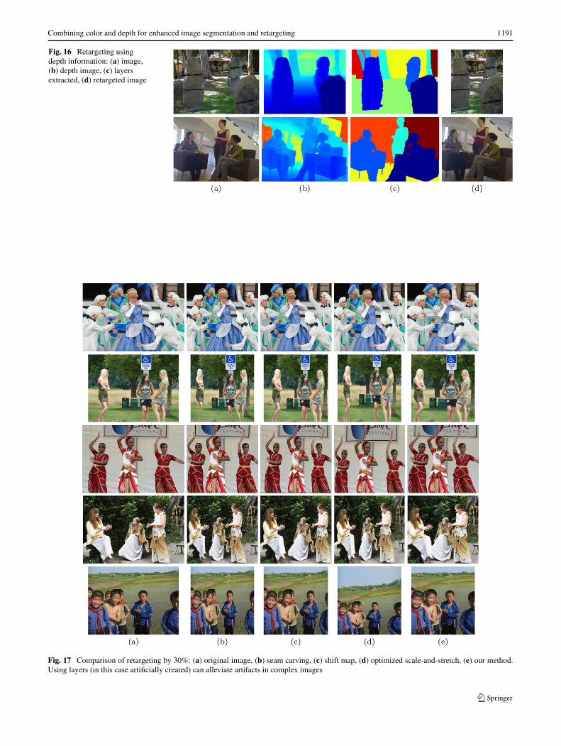
Fig. 16 Retargeting usingdepth information: (a) image,(b) depth image, (c) layersextracted, (d) retargeted image
Fig. 17 Comparison of retargeting by 30%: (a) original image, (b) seam carving, (c) shift map, (d) optimized scale-and-stretch, (e) our method.Using layers (in this case artificially created) can alleviate artifacts in complex images
1192 M.J. Dahan et al.
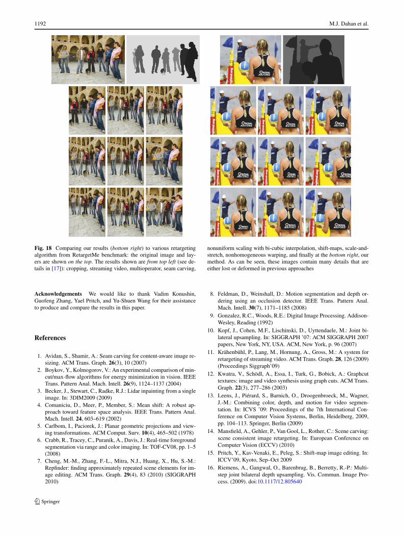
Fig. 18 Comparing our results (bottom right) to various retargetingalgorithm from RetargetMe benchmark: the original image and lay-ers are shown on the top. The results shown are from top left (see de-tails in [17]): cropping, streaming video, multioperator, seam carving,
nonuniform scaling with bi-cubic interpolation, shift-maps, scale-and-stretch, nonhomogeneous warping, and finally at the bottom right, ourmethod. As can be seen, these images contain many details that areeither lost or deformed in previous approaches
Acknowledgements We would like to thank Vadim Konushin,Guofeng Zhang, Yael Pritch, and Yu-Shuen Wang for their assistanceto produce and compare the results in this paper.
References
1. Avidan, S., Shamir, A.: Seam carving for content-aware image re-sizing. ACM Trans. Graph. 26(3), 10 (2007)
2. Boykov, Y., Kolmogorov, V.: An experimental comparison of min-cut/max-flow algorithms for energy minimization in vision. IEEETrans. Pattern Anal. Mach. Intell. 26(9), 1124–1137 (2004)
3. Becker, J., Stewart, C., Radke, R.J.: Lidar inpainting from a singleimage. In: 3DIM2009 (2009)
4. Comaniciu, D., Meer, P., Member, S.: Mean shift: A robust ap-proach toward feature space analysis. IEEE Trans. Pattern Anal.Mach. Intell. 24, 603–619 (2002)
5. Carlbom, I., Paciorek, J.: Planar geometric projections and view-ing transformations. ACM Comput. Surv. 10(4), 465–502 (1978)
6. Crabb, R., Tracey, C., Puranik, A., Davis, J.: Real-time foregroundsegmentation via range and color imaging. In: TOF-CV08, pp. 1–5(2008)
7. Cheng, M.-M., Zhang, F.-L., Mitra, N.J., Huang, X., Hu, S.-M.:Repfinder: finding approximately repeated scene elements for im-age editing. ACM Trans. Graph. 29(4), 83 (2010) (SIGGRAPH2010)
8. Feldman, D., Weinshall, D.: Motion segmentation and depth or-dering using an occlusion detector. IEEE Trans. Pattern Anal.Mach. Intell. 30(7), 1171–1185 (2008)
9. Gonzalez, R.C., Woods, R.E.: Digital Image Processing. Addison-Wesley, Reading (1992)
10. Kopf, J., Cohen, M.F., Lischinski, D., Uyttendaele, M.: Joint bi-lateral upsampling. In: SIGGRAPH ’07: ACM SIGGRAPH 2007papers, New York, NY, USA. ACM, New York, p. 96 (2007)
11. Krähenbühl, P., Lang, M., Hornung, A., Gross, M.: A system forretargeting of streaming video. ACM Trans. Graph. 28, 126 (2009)(Proceedings Siggraph’09)
12. Kwatra, V., Schödl, A., Essa, I., Turk, G., Bobick, A.: Graphcuttextures: image and video synthesis using graph cuts. ACM Trans.Graph. 22(3), 277–286 (2003)
13. Leens, J., Piérard, S., Barnich, O., Droogenbroeck, M., Wagner,J.-M.: Combining color, depth, and motion for video segmen-tation. In: ICVS ’09: Proceedings of the 7th International Con-ference on Computer Vision Systems, Berlin, Heidelberg, 2009,pp. 104–113. Springer, Berlin (2009)
14. Mansfield, A., Gehler, P., Van Gool, L., Rother, C.: Scene carving:scene consistent image retargeting. In: European Conference onComputer Vision (ECCV) (2010)
15. Pritch, Y., Kav-Venaki, E., Peleg, S.: Shift-map image editing. In:ICCV’09, Kyoto, Sep–Oct 2009
16. Riemens, A., Gangwal, O., Barenbrug, B., Berretty, R.-P.: Multi-step joint bilateral depth upsampling. Vis. Commun. Image Pro-cess. (2009). doi:10.1117/12.805640

Combining color and depth for enhanced image segmentation and retargeting 1193
17. Rubinstein, M., Gutierrez, D., Sorkine, O., Shamir, A.: A compar-ative study of image retargeting. ACM Trans. Graph. 29(5), 160(2010) (Proc. SIGGRAPH Asia)
18. Rother, C., Kolmogorov, V., Blake, A.: “grabcut”: interactive fore-ground extraction using iterated graph cuts. ACM Trans. Graph.23(3), 309–314 (2004)
19. Rubinstein, M., Shamir, A., Avidan, S.: Improved seam carvingfor video retargeting. ACM Trans. Graph. (2008) (ProceedingsSIGGRAPH 2008). doi:10.1145/1399504.1360615
20. Smith, P., Drummond, T., Cipolla, R.: Layered motion segmen-tation and depth ordering by tracking edges. IEEE Trans. PatternAnal. Mach. Intell. 26(4), 479–494 (2004)
21. Scharstein, D., Szeliski, R.: A taxonomy and evaluation of densetwo-frame stereo correspondence algorithms. Int. J. Comput. Vis.(2002). doi:10.1145/356893.356896
22. Schuon, S., Theobalt, C., Davis, J., Thrun, S.: High-quality scan-ning using time-of-flight depth superresolution. In: TOF-CV08,pp. 1–7 (2008)
23. Vezhnevets, V.: “GrowCut”—interactive multi-label N-D imagesegmentation by cellular automata, 2005
24. Wolf, L., Guttmann, M., Cohen-Or, D.: Non-homogeneouscontent-driven video-retargeting. In: Proceedings of the EleventhIEEE International Conference on Computer Vision (ICCV-07)(2007)
25. Wexler, Y., Shechtman, E., Irani, M.: Space-time video comple-tion. In: IEEE Computer Society Conference on Computer Visionand Pattern Recognition, vol. 1, pp. 120–127 (2004)
26. Wang, Y.-S., Tai, C.-L., Sorkine, O., Lee, T.-Y.: Optimized scale-and-stretch for image resizing. ACM Trans. Graph. 27(5), 1–8(2008)
27. Yang, Q., Yang, R., Davis, J., Nister, D.: Spatial-depth super res-olution for range images. In: IEEE Computer Society Conferenceon Computer Vision and Pattern Recognition, pp. 1–8 (2007)
28. Zhang, G., Dong, Z., Jia, J., Wan, L., Wong, T.-T., Bao, H.: Refilm-ing with depth-inferred videos. IEEE Trans. Vis. Comput. Graph.15(5), 828–840 (2009)
29. Zhang, G., Jia, J., Wong, T.-T., Bao, H.: Consistent depth mapsrecovery from a video sequence. IEEE Trans. Pattern Anal. Mach.Intell. 974–988 (2009)
Meir Johnathan Dahan is a re-searcher in a leading security com-pany. He received his B.Sc. summacum laude in computer science(2004) from Tel-Hai Academic Col-lege. He received his M.Sc. degreefrom Tel-Aviv University (2010)in the field of computer graphicsand image processing. His main re-search area and interests are imagesynthesis and machine learning, inparticular retargeting, probabilisticalgorithms, and clustering.
Nir Chen received his B.Sc. degreein Computer Science and Mathe-matics from Bar-Ilan University andhis M.Sc. degree cum laude in Com-puter Science at IDC Israel. Nirhas an extensive practical indus-try background with hi-tech com-panies such as National Semicon-ductor and artNet NetCom, wherehe worked as a computer engineer.His main research interests are com-puter graphics and specifically im-age segmentation and retargeting al-gorithms.
Ariel Shamir is an associate Pro-fessor at the school of ComputerScience at the Interdisciplinary Cen-ter in Israel. Prof. Shamir receivedhis Ph.D. in computer science in2000 from the Hebrew Universityin Jerusalem. He spent two years atthe center for computational visu-alization at the University of Texasin Austin. During 2006, he held theposition of visiting scientist at Mit-subishi Electric Research Labs inCambridge MA. Prof. Shamir hasnumerous publications in journalsand international refereed confer-
ences, he has a broad commercial experience working with and con-sulting numerous companies. He is a member of the ACM SIG-GRAPH, IEEE Computer and Eurographics societies.
Daniel Cohen-Or is a professor atthe School of Computer Science.He received his B.Sc. cum laude inboth mathematics and computer sci-ence (1985), an M.Sc. cum laude incomputer science (1986) from Ben-Gurion University, and his Ph.D.degree from the Department ofComputer Science (1991) at StateUniversity of New York at StonyBrook. He received the 2005 Eu-rographics Outstanding TechnicalContributions Award. His researchinterests are in computer graphics,in particular, rendering and model-
ing techniques. His main interest right now is in few areas: image syn-thesis, motion and transformations, shapes and surfaces, and surfacereconstruction.