combined local / global variability & uncertainty in … local / global variability &...
TRANSCRIPT

Combined Local Combined Local / Global/ Global Variability & Uncertainty Variability & Uncertainty in thein the AeroservoelasticityAeroservoelasticity of Composite Aircraftof Composite Aircraft
Presented by Dr. EliPresented by Dr. Eli LivneLivneDepartment of Aeronautics and AstronauticsDepartment of Aeronautics and Astronautics
University of WashingtonUniversity of Washington
AMTAS MeetingAMTAS MeetingEdmonds, WA, 19 October 2006Edmonds, WA, 19 October 2006
2
Contributors• Department of Aeronautics and Astronautics
• Luciano Demasi, post-doctoral research fellow• Andrey Styuart (25%), research scientist, assistant professor temp.• Eli Livne – PI, Professor
• Boeing Commercial, Seattle• James Gordon, Associate Technical Fellow, Flutter Methods Development• Carl Niedermeyer, Manager, 787/747 Flutter Engineering & Methods
Development • Kumar Bhatia, Senior Technical Fellow, Aeroelasticity and Multidisciplinary
Optimization • FAA Technical Monitor
• Peter Shyprykevich, R&D Manager, FAA/Materials & Structures – now retired• Curtis Davies, Program Manager of JAMS, FAA/Materials & Structures
• Other FAA Personnel Involved• Larry Ilcewicz, Chief Scientific and Technical Advisor for Advanced
Composite Materials• Gerry Lakin, FAA Transport Airplane Directorate, Standardization Branch

3
Motivation and Key Issues
Variation (over time) of localStructural characteristics mightlead to a major impact on theGlobal Aeroservoelastic integrityof flight vehicle components.
Uncertainty Propagation: Uncertain Inputs, Uncertain System
V.J.Romero, Sandia National Lab, AIAA Paper 2001-165
Modification of control laws later in an airplane’s service can affect dynamic loads and fatigue life.
Nonlinear structural behavior - example: Limit Cycle Oscillations (LCO) of control surfaces with stability, vibrations, and fatigue consequences.
Sources of uncertainty in composite structures: fabrication, damage, environmental effects, service history, maintenance.
4
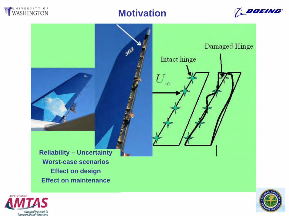
Motivation
Reliability – UncertaintyWorst-case scenarios
Effect on designEffect on maintenance
5
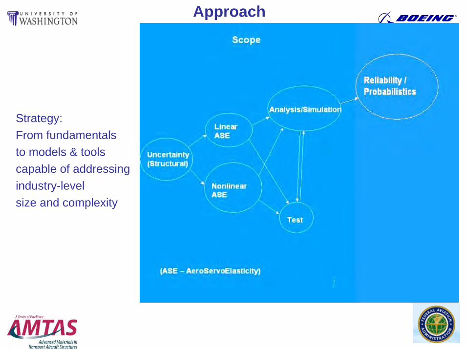
Approach
Strategy: From fundamentals to models & tools capable of addressing industry-level size and complexity

6
Linear Behavior Simulation:Automated forCarrying Out Fast Repetitive Analyses
7
Independently Developed Capability
8
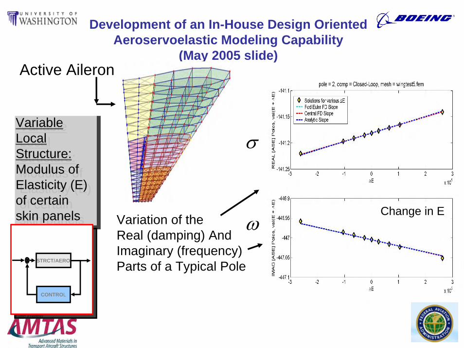
Development of an In-House Design Oriented Aeroservoelastic Modeling Capability
(May 2005 slide)
Variable Local Structure:Modulus of Elasticity (E) of certain skin panels
Variable Local Structure:Modulus of Elasticity (E) of certain skin panels
STRCT/AERO
CONTROL
Active Aileron
Variation of the Real (damping) And Imaginary (frequency) Parts of a Typical Pole
Delta E
σ
ωChange in E
9
Development of an In-House Design OrientedAeroservoelastic Modeling Capability (June 2006)
• Development of the in-house capability continues:• Extensions under development:
– Linear buckling analysis (and sensitivities).– Non-linear structural behavior (local nonlinearities due to damage or
wear, large structural deformations).• Complete control of the simulation software is necessary for:
– Studies of non-standard approximation techniques (used for accelerating the large number of repeated analyses needed to cover structural uncertainties).
– Insight.– Better integration with an array of different commercial packages.– Creating a comprehensive design optimization / reliability assessment
tool that will also allow development of best repair practices and fleet retrofits, if needed.
10
Simulation Array based on Commercial Codes
11
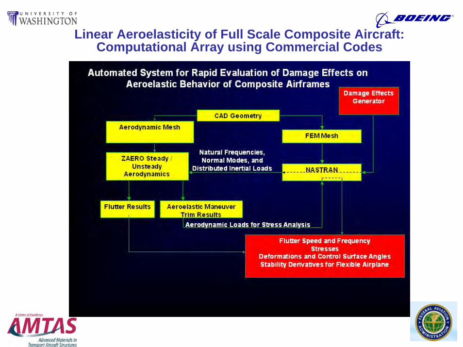
Linear Aeroelasticity of Full Scale Composite Aircraft: Computational Array using Commercial Codes
12
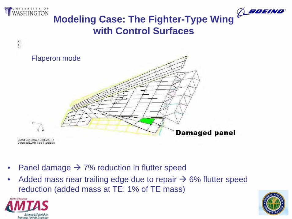
Modeling Case: The Fighter-Type Wing with Control Surfaces
• Panel damage 7% reduction in flutter speed• Added mass near trailing edge due to repair 6% flutter speed
reduction (added mass at TE: 1% of TE mass)
Flaperon mode

13
Case 1. Damaged Panel: Flap (LE)
Damaged Panel

14
0 10 20 30 40 50 60 70 80 90 1000.86
0.88
0.9
0.92
0.94
0.96
0.98
1
Stiffness [%]
Freq
uenc
y [H
z]
ω1/ω1REF
ω2/ω2REF
ω3/ω3REF
ω4/ω4REF
Frequency Behavior vs.
Local Stiffness
0 20 40 60 80 1000.93
0.94
0.95
0.96
0.97
0.98
0.99
1
Stiffness [%]
Nor
mal
ized
Flu
tter S
peed
[m/s
ec]
Flutter Behavior vs.
Local Stiffness
15
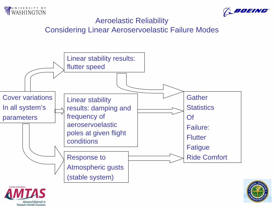
Aeroelastic Reliability Considering Linear Aeroservoelastic Failure Modes
Cover variationsIn all system’sparameters
Linear stability results: flutter speed
Linear stability results: damping and frequency of aeroservoelastic poles at given flight conditions
GatherStatisticsOfFailure: FlutterFatigueRide ComfortResponse to
Atmospheric gusts (stable system)
16
Nonlinear Behavior Simulation:
Automated for Carrying Out Fast Repetitive Analyses
17
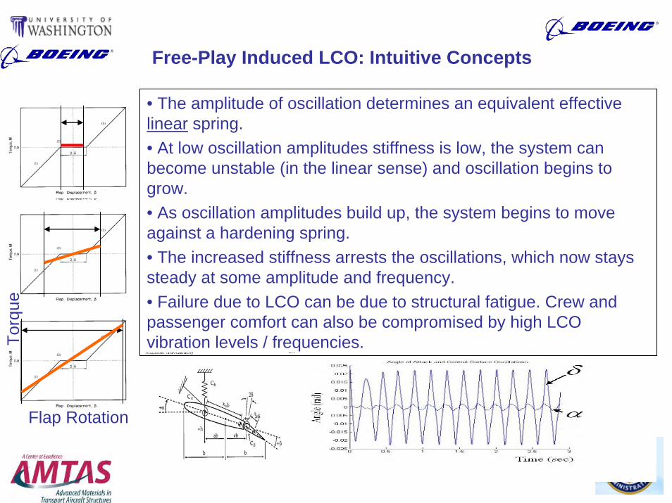
Free-Play Induced LCO: Intuitive Concepts
Torq
ue
Flap Rotation
• The amplitude of oscillation determines an equivalent effective linear spring.• At low oscillation amplitudes stiffness is low, the system can become unstable (in the linear sense) and oscillation begins to grow. • As oscillation amplitudes build up, the system begins to move against a hardening spring. • The increased stiffness arrests the oscillations, which now stays steady at some amplitude and frequency. • Failure due to LCO can be due to structural fatigue. Crew and passenger comfort can also be compromised by high LCO vibration levels / frequencies.
18
LCO Simulation Methods
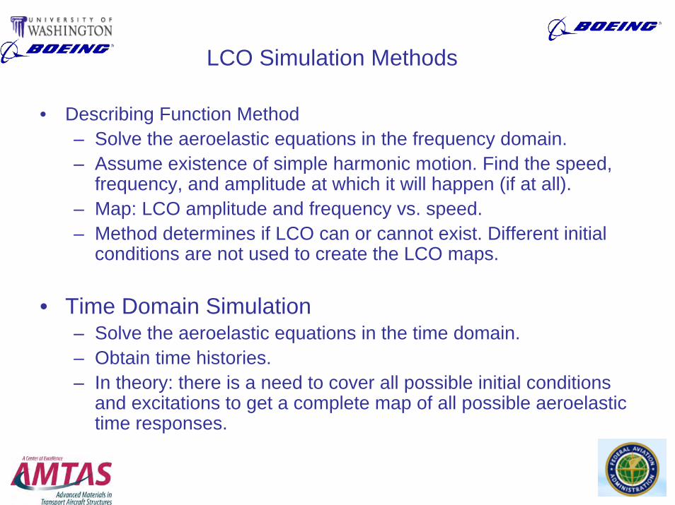
• Describing Function Method– Solve the aeroelastic equations in the frequency domain.– Assume existence of simple harmonic motion. Find the speed,
frequency, and amplitude at which it will happen (if at all).– Map: LCO amplitude and frequency vs. speed.– Method determines if LCO can or cannot exist. Different initial
conditions are not used to create the LCO maps.
• Time Domain Simulation – Solve the aeroelastic equations in the time domain.– Obtain time histories.– In theory: there is a need to cover all possible initial conditions
and excitations to get a complete map of all possible aeroelastic time responses.

19
Aeroelastic Reliability Considering LCO-Related Failure Modes
Cover variationsIn all system’sparameters
LCO results –Describing FunctionMaps
LCO results –Extract amplitudes / frequenciesFrom Time Histories ofResponse to excitation And initial conditions
Assess failureModes: fatigue, Ride comfort,Possibility of Destructive Linear flutter
GatherStatisticsOfFailure
20
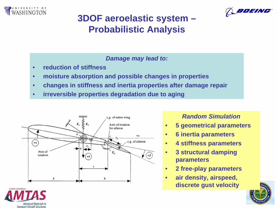
3DOF aeroelastic system –Probabilistic Analysis
Random Simulation• 5 geometrical parameters• 6 inertia parameters• 4 stiffness parameters• 3 structural damping
parameters• 2 free-play parameters• air density, airspeed,
discrete gust velocity
Damage may lead to:• reduction of stiffness• moisture absorption and possible changes in properties • changes in stiffness and inertia properties after damage repair • irreversible properties degradation due to aging
21
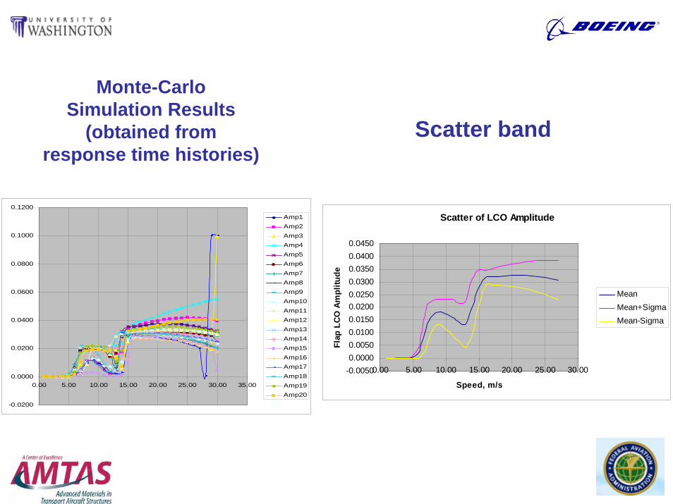
Monte-Carlo Simulation Results
(obtained from response time histories)
-0.0200
0.0000
0.0200
0.0400
0.0600
0.0800
0.1000
0.1200
0.00 5.00 10.00 15.00 20.00 25.00 30.00 35.00
Amp1Amp2Amp3Amp4Amp5Amp6Amp7Amp8Amp9Amp10Amp11Amp12Amp13Amp14Amp15Amp16Amp17Amp18Amp19Amp20
Scatter of LCO Amplitude
-0.00500.00000.00500.01000.01500.02000.02500.03000.03500.04000.0450
0.00 5.00 10.00 15.00 20.00 25.00 30.00
Speed, m/s
Flap
LCO
Am
plitu
de
MeanMean+SigmaMean-Sigma
Scatter band

22
Describing Function Analysis of Multi-Degree of Freedom Aircraft
The step from a simple 3 dofsystem to the case of a complete
passenger airplane

23
Test-Case Aircraft Used for LCO Studies
Note: the test-case aircraft used and conditions tested do not correspond to any actual airplane / service cases
24
Describing Function Analysis of Multi-Degree of Freedom Aircraft
• The step from a simple 3 dof system to the case of a complete passenger airplane makes the problem more complex by orders of magnitude:– Many more modes of vibration must be included in the
aeroelastic analysis in order to capture all global and local motions of importance
– Many limit cycles are possible– Automation of the analysis process is challenging– A major challenge: Automation of probabilistic analysis /
LCO simulations of systems covering large numbers of possible system variations

25
Boeing Test Case Study
• Test case uses representative airplane model with associated real-world complexity
• Test case does not reflect any service configuration / flight conditions
• Test case used freeplay values far in excess of any maximum in-service limits
26
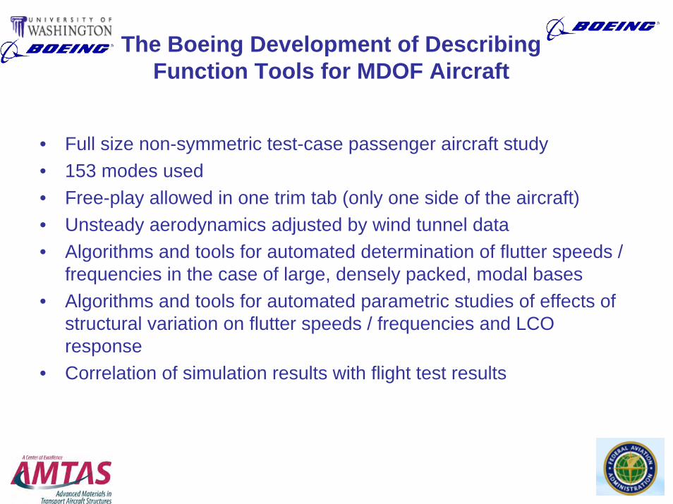
The Boeing Development of Describing Function Tools for MDOF Aircraft
• Full size non-symmetric test-case passenger aircraft study• 153 modes used• Free-play allowed in one trim tab (only one side of the aircraft)• Unsteady aerodynamics adjusted by wind tunnel data• Algorithms and tools for automated determination of flutter speeds /
frequencies in the case of large, densely packed, modal bases• Algorithms and tools for automated parametric studies of effects of
structural variation on flutter speeds / frequencies and LCO response
• Correlation of simulation results with flight test results

27
Development of Experimental Capabilities
• New Modal testing system: arrived and installed.
• Test articles: small composite UAVs & components: nominal and with different types and level of damage.

28
A Probabilistic Approach toAeroservoelastic Reliability Estimation
General

29
The Next Step – Link Statistical Variability Models with Variability and Damage Models of Actual Aircraft
• With capabilities to rapidly find statistics of aeroelastic behavior and failure due to variability of system’s parameters, add:– Models of actual damage types– Information regarding damage variability for actual aircraft in service
• Develop tools for assessing aeroelastic reliability measures
• Use the statistics of the resulting behavior to evaluate aeroelastic reliability
• Use the technology to affect design practices, maintenance procedures, and optimal retrofits
30
Failure types considered
Excessive deformationsFlutter: airspeed exceeds the flutter speed of damaged structureHigh amplitude limit cycle oscillations: the acceptable level of vibrations is exceeded
31
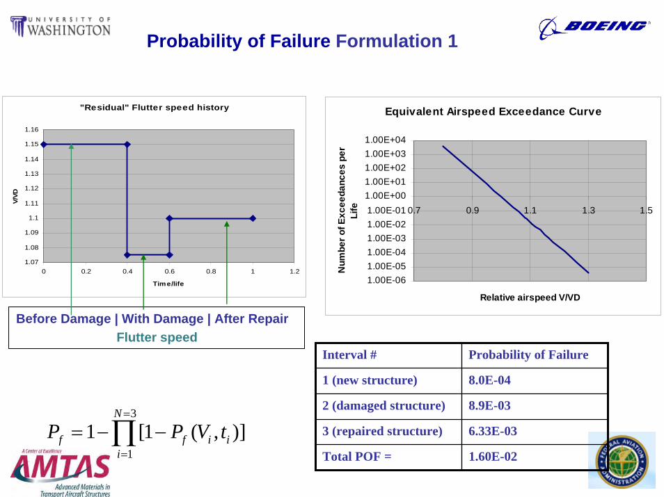
Probability of Failure Formulation 1
3
1
1 [1 ( , )]N
f f i ii
P P V t=
=
= − −∏
Interval # Probability of Failure
1 (new structure) 8.0E-04
2 (damaged structure) 8.9E-03
3 (repaired structure) 6.33E-03
Total POF = 1.60E-02
"Residual" Flutter speed history
1.07
1.08
1.09
1.1
1.11
1.12
1.13
1.14
1.15
1.16
0 0.2 0.4 0.6 0.8 1 1.2
Time/life
V/VD
Before Damage | With Damage | After RepairFlutter speed
Equivalent Airspeed Exceedance Curve
1.00E-061.00E-051.00E-041.00E-031.00E-021.00E-011.00E+001.00E+011.00E+021.00E+031.00E+04
0.7 0.9 1.1 1.3 1.5
Relative airspeed V/VD
Num
ber o
f Exc
eeda
nces
per
Life
32
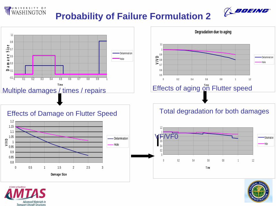
Probability of Failure Formulation 2
-0.1
0.1
0.3
0.5
0.7
0.9
1.1
0 0.1 0.2 0.3 0.4 0.5 0.6 0.7 0.8 0.9 1
Ti me
Dam
age
Size
Delaminat ion
Hole
Degradation vs. Damage Size
0.80.85
0.90.95
11.05
1.11.15
1.2
0 0.5 1 1.5 2 2.5 3
Damage Size
V/VD
Delamination
Hole
Degradation due to aging
0.5
0.6
0.7
0.8
0.9
1
1.1
0 0.2 0.4 0.6 0.8 1 1.2
Ti me
V/VD Delaminat ion
Hole
Combined Damage+Aging
00.20.40.60.8
11.2
0 0.2 0.4 0.6 0.8 1 1.2
T i me
Delamination
Hole
Multiple damages / times / repairs Effects of aging on Flutter speed
Total degradation for both damages
VF/VF0
Effects of Damage on Flutter Speed
33
Probabilistic Model
Combine statistics of flutter speed (due to damage and structural changes, as simulated by the aeroelastic modeling capabilities described here)with statistics of speed excursions.
The methodology is built on:
Lin, K., and Styuart, A., “Probabilistic Approach to Damage Tolerance Design of Aircraft Composite Structures”, AIAA-2006-2156, 47th AIAA/ASME/ASCE/AHS/ASC Structures, Structural Dynamics, and Materials Conference, Newport, Rhode Island, May 1-4, 2006
extended to include Aeroelastic failure modes.
34
Conclusion
• Progress in all major areas of this R&D effort:– Efficient simulation tools for uncertain airframes covering flutter and
LCO constraints– Automated systems for rapid simulations of large number of systems’
variations, needed for probabilistic / reliability analysis– A mix of in-house capabilities (allowing studies non-standard techniques
and flexibility in tools development) and industry-standard commercial capabilities (for improved interaction with industry)
– Experimental capability: Lab is running. Focus: training.– Formulation of a comprehensive approach to the inclusion of aeroelastic
failures in the reliability assessment of composite aircraft, and resulting benefits to both maintenance and design practices.

35
Plans
• Flutter- Continue development of the UW in-house simulation capability
to include buckling (geometric nonlinearity) effects.- Continue development of the integrated NASTRAN / ZAERO
simulation environment: - test using models with complexity representative of real passenger
aircraft, and - improve automation of analysis and computational speed to allow
efficient execution of the large number of simulations needed for probabilistic studies.
- Use sensitivity analysis and approximations to utilize design optimization technology to address issues of reliability and optimal maintenance.

36
Plans
• LCO– Extend time-domain LCO simulation capability to complete
airplanes and their finite element model.– Integrate with probabilistic / reliability analysis.– Continue development of LCO simulation tools for large-scale
aeroelastically complex flight vehicles.– Develop a probabilistic approach to nonlinear LCO problems
using Describing Function simulation techniques.– Design nonlinear small scale models (with different sources of
service life and damage-related nonlinearity), carry out numerical simulations, correlate with structural dynamic tests, and prepare for aeroelastic wind tunnel tests.
37
Plans
• Probabilistics & Reliability– Link structural variation over time and damage modes to
structural stiffness and inertia variations (including statistics).- Develop a comprehensive reliability methodology for composite
airframes (with design and maintenance consequences) covering aeroelastic / aeroservoelastic failure modes.