cold-weather concreting, chapter 14...chapter 14 cold-weather concreting concrete can be placed...
TRANSCRIPT

CHAPTER 14
Cold-Weather Concreting
Concrete can be placed safely without damage fromfreezing throughout the winter months in cold climates ifcertain precautions are taken. Cold weather is defined byACI Committee 306 as a period when for more than 3 suc-cessive days the average daily air temperature dropsbelow 5°C (40°F) and stays below 10°C (50°F) for morethan one-half of any 24 hour period. Under these circum-stances, all materials and equipment needed for adequateprotection and curing must be on hand and ready for usebefore concrete placement is started. Normal concretingpractices can be resumed once the ambient temperature isabove 10°C (50°F) for more than half a day.
During cold weather, the concrete mixture and itstemperature should be adapted to the construction proce-dure and ambient weather conditions. Preparations shouldbe made to protect the concrete; enclosures, windbreaks,portable heaters, insulated forms, and blankets should beready to maintain the concrete temperature (Fig. 14-1).
Forms, reinforcingsteel, and embeddedfixtures must beclear of snow andice at the time
concrete is placed. Thermometers and proper storagefacilities for test cylinders should be available to verify thatprecautions are adequate.
EFFECT OF FREEZING FRESHCONCRETE
Concrete gains very little strength at low temperatures.Freshly mixed concrete must be protected against the dis-ruptive effects of freezing (Fig.14-2) until the degree of sat-uration of the concrete has been sufficiently reduced bythe process of hydration. The time at which this reductionis accomplished corresponds roughly to the time requiredfor the concrete to attain a compressive strength of 3.5MPa (500 psi) (Powers 1962). At normal temperatures andwater-cement ratios less than 0.60, this occurs within thefirst 24 hours after placement. Significant ultimatestrength reductions, up to about 50%, can occur if concreteis frozen within a few hours after placement or before itattains a compressive strength of 3.5 MPa (500 psi)(McNeese 1952). Concrete to be exposed to deicers shouldattain a strength of 28 MPa (4,000 psi) prior to repeatedcycles of freezing and thawing (Klieger 1957).
Concrete that hasbeen frozen just onceat an early age canbe restored to nearlynormal strength byproviding favorablesubsequent curing con-ditions. Such concrete,however, will not be asresistant to weatheringnor as watertight asconcrete that had notbeen frozen. The crit-ical period after whichconcrete is not seri-ously damaged by oneor two freezing cyclesFig. 14-1. When suitable preparations to build enclosures and insulate equipment have been made,
cold weather is no obstacle to concrete construction. (69876, 43464)
239
HOMEPAGE

is dependent upon the concrete ingredients and con-ditions of mixing, placing, curing, and subsequent drying.For example, air-entrained concrete is less susceptibleto damage by early freezing than non-air-entrainedconcrete. See Chapter 8, “Air-Entrained Concrete,” formore information.
STRENGTH GAIN OF CONCRETEAT LOW TEMPERATURES
Temperature affects the rate at which hydration of cementoccurs—low temperatures retard hydration and con-sequently retard the hardening and strength gain ofconcrete.
If concrete is frozen and kept frozen above aboutminus 10°C (14°F), it will gain strength slowly. Below thattemperature, cement hydration and concrete strengthgain cease. Fig. 14-3 illustrates the effect of cool tempera-tures on setting time. Fig. 14-4 illustrates the effects ofcasting temperature on slump. Figs. 14-5 and 14-6 showthe age-compressive strength relationship for concretethat has been cast and cured at various temperatures.Note in Fig. 14-6 that concrete cast and cured at 4°C (40°F)and 13°C (55°F) had relatively low strengths for the firstweek; but after 28 days—when all specimens were moist-cured at 23°C (73°F)—strengths for the 4°C (40°F) and13°C (55°F) concretes grew faster than the 23°C (73°F)concrete and at one year they were slightly higher.
240
Design and Control of Concrete Mixtures � EB001
Fig. 14-2. Closeup view of ice impressions in paste offrozen fresh concrete. The ice crystal formations occur asunhardened concrete freezes. They do not occur inadequately hardened concrete. The disruption of the pastematrix by freezing can cause reduced strength gain andincreased porosity. (44047)
0 10 20 30 40
32 52 72 92200
150
100
50
0
Per
cent
initi
al s
et a
t 23°
C (
73°F
)
Casting temperature, °F
Casting temperature, °C
Cement A Cement B
Mix proportionsheld constant.
0 10 20 30 40
32 52 72 92200
150
100
50
0
Per
cent
fina
l set
at 2
3°C
(73
°F)
Casting temperature, °F
Casting temperature, °C
Cement A Cement B
Mix proportionsheld constant.
Fig. 14-3. Initial set characteristics as a function of castingtemperature (top), and final set characteristics as a functionof casting temperature (bottom) (Burg 1996).
0 10 20 30 40
32 52 72 92250
150
200
100
50
0
Per
cent
slu
mp
at 2
3°C
(73
°F)
Casting temperature, °F
Casting temperature, °C
Cement A Cement B
Mix proportionsheld constant.
Fig. 14-4 Slump characteristics as a function of castingtemperature (Burg 1996).

Higher-early strengths can be achieved through use ofType III high-early-strength cement as illustrated in Fig.14-7. Principal advantages occur during the first 7 days. Ata 4°C (40°F) curing temperature, the advantages of TypeIII cement are more pronounced and persist longer than atthe higher temperature.
HEAT OF HYDRATION
Concrete generates heat during hardening as a result ofthe chemical process by which cement reacts with water toform a hard, stable paste. The heat generated is called heatof hydration; it varies in amount and rate for differentcements. Dimensions of the concrete placement, ambientair temperature, initial concrete temperature, water-cement ratio, admixtures, and the composition, fineness,and amount of cementitious material all affect heat gener-ation and buildup.
Heat of hydration is useful in winter concreting as itcontributes to the heat needed to provide a satisfactorycuring temperature; often without other temporary heatsources, particularly in more massive elements.
Concrete must be delivered at the proper temperatureand account must be taken of the temperature of forms,reinforcing steel, the ground, or other concrete on whichthe fresh concrete is cast. Concrete should not be cast onfrozen concrete or on frozen ground.
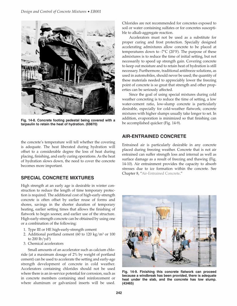
Fig. 14-8 shows a concrete pedestal being coveredwith a tarpaulin just after the concrete was placed.Tarpaulins and insulated blankets are often necessary toretain the heat of hydration more efficiently and keep theconcrete as warm as possible. Thermometer readings of
241
Chapter 14 � Cold-Weather Concreting
140
120
100
80
60
40
20
01 3 7 28 90 365
Age at test, days
Com
pres
sive
str
engt
h, p
erce
nt o
f28
-day
23°
C c
ured
con
cret
e
23°C
(73°
F)
4°C
(40°
F)
13°C
(55°
F)
Mix data:Water to cement ratio = 0.43Air content: 4 to 5%Cement: Type I, 310 kg/m3 (517 lb/yd3)
Curing:Specimens cast and moist-curedat temperature indicated for first28 days. All moist-cured at23°C (73°F) thereafter.
Fig. 14-6. Effect of low temperatures on concrete compres-sive strength at various ages. Note that for this particularmixture made with Type I cement, the best temperature forlong-term strength (1 year) was 13°C (55°F) (Klieger 1958).
40
30
6
5
4
3
2
1
0
20
10
01 3 7 28 90 365
Age at test, days
Com
pres
sive
str
engt
h, M
Pa
Com
pres
sive
str
engt
h, 1
000
psi
23°C
(73°
F)
23°C
(73°F
)
-4°C (25°F)
100%
RH
50%
RH
100% RH
50% RHWater to cement ratio = 0.43Air content: 4 to 5%Cement: Type I, 310 kg/m3 (517 lb/yd3)
Fig. 14-5. Effect of temperature conditions on the strengthdevelopment of concrete. Concrete for the lower curve wascast at 4°C (40°F) and placed immediately in a curing roomat -4°C (25°F). Both concretes received 100% relative-humidity curing for first 28 days followed by 50% relative-humidity curing (Klieger 1958).
50
40
30
20
10
01 3 7 28
Mix data:Water to cement ratio = 0.43, Type I cement = 0.45, Type III cementAir content: 4 to 5%Cement content: 310 kg/m3 (517 lb/yd3)
Com
pres
sive
stre
ngth
, MP
a
Com
pres
sive
stre
ngth
, 100
0 ps
i
7
6
5
4
3
2
1
Type III, mixed and cured at 23°C (73°F)Type I, mixed and cured at 23°C (73°F)Type III, mixed and cured at 4°C (40°F)Type I, mixed and cured at 4°C (40°F)
Age of test, days
Fig. 14-7. Early-age compressive-strength relationships forType I and Type III portland cement concretes mixed andcured at 4°C (40°F) compared to 23°C (73°F) (Klieger 1958).
Chlorides are not recommended for concretes exposed tosoil or water containing sulfates or for concretes suscepti-ble to alkali-aggregate reaction.
Accelerators must not be used as a substitute forproper curing and frost protection. Specially designedaccelerating admixtures allow concrete to be placed attemperatures down to -7°C (20°F). The purpose of theseadmixtures is to reduce the time of initial setting, but notnecessarily to speed up strength gain. Covering concreteto keep out moisture and to retain heat of hydration is stillnecessary. Furthermore, traditional antifreeze solutions, asused in automobiles, should never be used; the quantity ofthese materials needed to appreciably lower the freezingpoint of concrete is so great that strength and other prop-erties can be seriously affected.
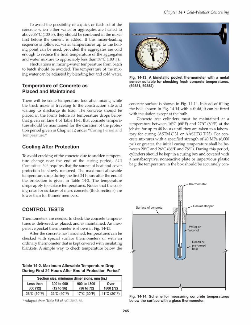
Since the goal of using special mixtures during coldweather concreting is to reduce the time of setting, a lowwater-cement ratio, low-slump concrete is particularlydesirable, especially for cold-weather flatwork; concretemixtures with higher slumps usually take longer to set. Inaddition, evaporation is minimized so that finishing canbe accomplished quicker (Fig. 14-9).
AIR-ENTRAINED CONCRETE
Entrained air is particularly desirable in any concreteplaced during freezing weather. Concrete that is not airentrained can suffer strength loss and internal as well assurface damage as a result of freezing and thawing (Fig.14-10). Air entrainment provides the capacity to absorbstresses due to ice formation within the concrete. SeeChapter 8, “Air-Entrained Concrete.”
the concrete’s temperature will tell whether the coveringis adequate. The heat liberated during hydration willoffset to a considerable degree the loss of heat duringplacing, finishing, and early curing operations. As the heatof hydration slows down, the need to cover the concretebecomes more important.
SPECIAL CONCRETE MIXTURES
High strength at an early age is desirable in winter con-struction to reduce the length of time temporary protec-tion is required. The additional cost of high-early-strengthconcrete is often offset by earlier reuse of forms andshores, savings in the shorter duration of temporaryheating, earlier setting times that allows the finishing offlatwork to begin sooner, and earlier use of the structure.High-early-strength concrete can be obtained by using oneor a combination of the following:
1. Type III or HE high-early-strength cement2. Additional portland cement (60 to 120 kg/m3 or 100
to 200 lb/yd3)3. Chemical accelerators
Small amounts of an accelerator such as calcium chlo-ride (at a maximum dosage of 2% by weight of portlandcement) can be used to accelerate the setting and early-agestrength development of concrete in cold weather.Accelerators containing chlorides should not be usedwhere there is an in-service potential for corrosion, such asin concrete members containing steel reinforcement orwhere aluminum or galvanized inserts will be used.
242
Design and Control of Concrete Mixtures � EB001
Fig. 14-8. Concrete footing pedestal being covered with atarpaulin to retain the heat of hydration. (69870)
Fig. 14-9. Finishing this concrete flatwork can proceedbecause a windbreak has been provided, there is adequateheat under the slab, and the concrete has low slump.(43465)

400
300
200
100
00 10 20 30 40 50 60
Cured normally(never frozen)
Frozen dry
Frozen wet
Per
cent
age
of th
e st
reng
th a
t 7 d
ays
Number of cycles of freezing and thawing
Fig. 14-10. Effect of freezing and thawing on strength ofconcrete that does not contain entrained air (cured 7 daysbefore first freeze) (Powers 1956).
Fig. 14-11. Example of a concrete floor that was saturatedwith rain, snow, or water and then frozen, showing the needfor air entrainment. (69869)
Thickness of sections, mm (in.)Less than 300 to 900 900 to 1800 Over
Line Condition 300 (12) (12 to 36) (36 to 72) 1800 (72)1 Minimum temperature Above -1°C (30°F) 16°C (60°F) 13°C (55°F) 10°C (50°F) 7°C (45°F)
of fresh concrete as2 mixed for weather -18°C to -1°C (0°F to 30°F) 18°C (65°F) 16°C (60°F) 13°C (55°F) 10°C (50°F)
indicated.3 Below -18°C (0°F) 21°C (70°F) 18°C (65°F) 16°C (60°F) 13°C (55°F)
4 Minimum temperature of fresh concrete as placedand maintained.**
13°C (55°F) 10°C (50°F) 7°C (45°F) 5°C (40°F)
Table 14-1. Recommended Concrete Temperature for Cold-Weather Construction—Air-Entrained Concrete*
* Adapted from Table 3.1 of ACI 306R-88.** Placement temperatures listed are for normal-weight concrete. Lower temperatures can be used for lightweight concrete if justified by tests.
For recommended duration of temperatures in Line 4, see Table 14-3.
Air entrainment should always be used for construc-tion during the freezing months. The exception is concretework done under roof where there is no chance that rain,snow, or water from other sources can saturate the concreteand where there is no chance of freezing.
The likelihood of water saturating a concrete floorduring construction is very real. Fig. 14-11 shows con-ditions in the upper story of an apartment building duringwinter construction. Snow fell on the top deck. Whenheaters were used below to warm the deck, the snowmelted. Water ran through floor openings down to a levelthat was not being heated. The water-saturated concretefroze, which caused a strength loss, particularly at the
floor surface. This could also result in greater deflection ofthe floor and a surface that is less wear-resistant than itmight have been.
TEMPERATURE OF CONCRETE
Temperature of Concrete as Mixed
The temperature of fresh concrete as mixed should not beless than shown in Lines 1, 2, or 3 of Table 14-1 for therespective thickness of section. Note that lower concretetemperatures are recommended for more massiveconcrete sections because heat generated during hydra-tion is dissipated less rapidly in heavier sections. Alsonote that at lower ambient air temperatures more heat islost from concrete during transporting and placing; hence,the recommended concrete temperatures as mixed arehigher for colder weather.
243
Chapter 14 � Cold-Weather Concreting

material) can be assumed as 0.925 kJ (0.22 Btu) comparedto 4.187 kJ (1.0 Btu) for water.
Fig. 14-12 shows the effect of temperature of materialson temperature of fresh concrete. The chart is based on theequation
where
temperature in degrees Celsius (Fahrenheit) ofthe fresh concrete
temperature in degrees Celsius(Fahrenheit) of the aggregates, cement, added mixingwater, and free moisture on aggregates, respectively;generally =
mass in kilograms(pounds) of the aggregates, cement, free moisture onaggregates, and mixing water, respectively
If the weighted average temperature of aggregatesand cement is above 0°C (32°F), the proper mixing-watertemperature for the required concrete temperature can beselected from Fig. 14-12. The range of concrete tempera-tures in the chart corresponds with the recommendedvalues given in Lines 1, 2, and 3 of Table 14-1.
M M M Ma c w wa, , , and =
TwaTa
T ,T ,T , Ta c w waand =
T =
T = 0.22 T M T M T M T M
. M M M Ma a c c w w wa wa
a c w wa
+( ) + ++( ) + +0 22
There is little advantage in using fresh concrete at atemperature much above 21°C (70°F). Higher concretetemperatures do not afford proportionately longer protec-tion from freezing because the rate of heat loss is greater.Also, high concrete temperatures are undesirable sincethey increase thermal shrinkage after hardening, requiremore mixing water for the same slump, and contribute tothe possibility of plastic-shrinkage cracking (caused byrapid moisture loss through evaporation). Therefore, thetemperature of the concrete as mixed should not be morethan 5°C (10°F) above the minimums recommended inTable 14-1.
Aggregate Temperature. The temperature of aggregatesvaries with weather and type of storage. Aggregates usu-ally contain frozen lumps and ice when the temperature isbelow freezing. Frozen aggregates must be thawed toavoid pockets of aggregate in the concrete after batching,mixing, and placing. If thawing takes place in the mixer,excessively high water contents in conjunction with thecooling effect due to the ice melting must be avoided.
At temperatures above freezing it is seldom necessaryto heat aggregates, the desired concrete temperature canusually be obtained by heating only the mixing water. Attemperatures below freezing, in addition to heating themixing water, often only the fine aggregate needs to beheated to produce concrete of the required temperature,provided the coarse aggregate is free of frozen lumps.
Three of the most common methods for heatingaggregates are: (1) storing in bins or weigh hoppers heatedby steam coils or live steam; (2) storing in silos heated byhot air or steam coils; and (3) stockpiling over heatedslabs, stem vents or pipes. Although heating aggregatesstored in bins or weigh hoppers is most commonly used,the volume of aggregate that can be heated is often limitedand quickly consumed during production. Circulatingsteam through pipes over which aggregates are stockpiledis a recommended method for heating aggregates.Stockpiles can be covered with tarpaulins to retain anddistribute heat and to prevent formation of ice. Livesteam, preferably at pressures of 500 to 900 kPa (75 to 125psi), can be injected directly into the aggregate pile to heatit, but the resultant variable moisture content in aggre-gates might result in erratic mixing-water control.
On small jobs aggregates can be heated by stockpilingover metal culvert pipes in which fires are maintained.Care should be taken to prevent scorching the aggregates.
Mixing-Water Temperature. Of the ingredients used tomake concrete, mixing water is the easiest and most prac-tical to heat. The mass of aggregates and cement in con-crete is much greater than the mass of water; however,water can store about five times as much heat as cancement and aggregate of the same weight. For cement andaggregates, the average specific heat (that is, heat unitsrequired to raise the temperature 1°C (1°F) per kg (lb) of
244
Design and Control of Concrete Mixtures � EB001
78
70
62
54
46
38
30
0 4 8 12 16 20 24
Mix
ing
wat
er te
mpe
ratu
re, °
C
Mix
ing
wat
er te
mpe
ratu
re, °
F
Weighted average temperature ofaggregates and cement, °C
Weighted average temperature ofaggregates and cement, °F
40 50 60 70180
160
140
120
100
80
8°C(46°F)
12°C(54°F)
16°C(61°F)
20°C(68°F)
24°C(75°F)
Concrete temperature
Mix data:Aggregate = 1360 kg (3000 lb)Moisture in aggregate = 27 kg (60 lb)Added mixing water = 108 kg (240 lb)Portland cement = 256 kg (564 lb)
Fig. 14-12. Temperature of mixing water needed to produceheated concrete of required temperature. Temperatures arebased on the mixture shown but are reasonably accuratefor other typical mixtures.
Section size, minimum dimensions, mm (in.)Less than 300 to 900 900 to 1800 Over300 (12) (12 to 36) (36 to 72) 1800 (72)
28°C (50°F) 22°C (40°F) 17°C (30°F) 11°C (20°F)
Table 14-2. Maximum Allowable Temperature DropDuring First 24 Hours After End of Protection Period*
Fig. 14-13. A bimetallic pocket thermometer with a metalsensor suitable for checking fresh concrete temperatures.(69881, 69882)
Thermometer
Gasket stopper
Water oralcohol
Drilled orpreformedhole
Surface of concrete
Fig. 14-14. Scheme for measuring concrete temperaturesbelow the surface with a glass thermometer.* Adapted from Table 5.5 of ACI 306R-88.
To avoid the possibility of a quick or flash set of theconcrete when either water or aggregates are heated toabove 38°C (100°F), they should be combined in the mixerfirst before the cement is added. If this mixer-loadingsequence is followed, water temperatures up to the boil-ing point can be used, provided the aggregates are coldenough to reduce the final temperature of the aggregatesand water mixture to appreciably less than 38°C (100°F).
Fluctuations in mixing-water temperature from batchto batch should be avoided. The temperature of the mix-ing water can be adjusted by blending hot and cold water.
Temperature of Concrete as Placed and Maintained
There will be some temperature loss after mixing whilethe truck mixer is traveling to the construction site andwaiting to discharge its load. The concrete should beplaced in the forms before its temperature drops belowthat given on Line 4 of Table 14-1; that concrete tempera-ture should be maintained for the duration of the protec-tion period given in Chapter 12 under “Curing Period andTemperature.”
Cooling After Protection
To avoid cracking of the concrete due to sudden tempera-ture change near the end of the curing period, ACICommittee 306 requires that the source of heat and coverprotection be slowly removed. The maximum allowabletemperature drop during the first 24 hours after the end ofthe protection is given in Table 14-2. The temperaturedrops apply to surface temperatures. Notice that the cool-ing rates for surfaces of mass concrete (thick sections) arelower than for thinner members.
CONTROL TESTS
Thermometers are needed to check the concrete tempera-tures as delivered, as placed, and as maintained. An inex-pensive pocket thermometer is shown in Fig. 14-13.
After the concrete has hardened, temperatures can bechecked with special surface thermometers or with anordinary thermometer that is kept covered with insulatingblankets. A simple way to check temperature below the
concrete surface is shown in Fig. 14-14. Instead of fillingthe hole shown in Fig. 14-14 with a fluid, it can be fittedwith insulation except at the bulb.
Concrete test cylinders must be maintained at atemperature between 16°C (60°F) and 27°C (80°F) at thejobsite for up to 48 hours until they are taken to a labora-tory for curing (ASTM C 31 or AASHTO T 23). For con-crete mixtures with a specified strength of 40 MPa (6,000psi) or greater, the initial curing temperature shall be be-tween 20°C and 26°C (68°F and 78°F). During this period,cylinders should be kept in a curing box and covered witha nonabsorptive, nonreactive plate or impervious plasticbag; the temperature in the box should be accurately con-
245
Chapter 14 � Cold-Weather Concreting

CONCRETING ON GROUND
Concreting on ground during cold weather involves someextra effort and expense, but many contractors find that itmore than pays for itself. In winter, the site around thestructure may be frozen rather than a morass of mud. Theconcrete will furnish some if not all of the heat needed forproper curing. Internal concrete temperatures should bemonitored. Insulated blankets or simple enclosures areeasily provided. Embankments are frozen and require lessbracing. With a good start during the winter months,construction gets above the ground before warmerweather arrives.
Placing concrete on the ground involves different pro-cedures from those used at an upper level: (1) the groundmust be thawed before placing concrete; (2) cementhydration will furnish some of the curing heat; (3) con-struction of enclosures is much simpler and use of insu-lating blankets may be sufficient; (4) in the case of a floorslab, a vented heater is required if the area is enclosed; and(5) hydronic heaters can be used to thaw subgrades usinginsulated blankets or to heat enclosures without concernfor carbonation. For more on hydronic heaters, see“Heaters” later in this chapter.
Once cast, footings should be backfilled as soon aspossible with unfrozen fill. Concrete should never beplaced on a frozen subgrade or backfilled with frozen fill;otherwise once they thaw, uneven settlements may occurcausing cracking.
ACI Committee 306 requires that concrete not beplaced on any surface that would lower the temperature ofthe concrete in place below the minimum values shown onLine 4 in Table 14-1. In addition, concrete placement tem-peratures should not be higher than these minimum valuesby more than 11°C (20°F) to reduce rapid moisture loss andthe potential development of plastic shrinkage cracks.
When the subgrade is frozen to a depth of approxi-mately 80 mm (3 inches), the surface region can be thawedby (1) steaming; (2) spreading a layer of hot sand, gravel,or other granular material where the grade elevationsallow it; (3) removing and replacing with unfrozen fill;(4) covering the subgrade with insulation for a few days;or (5) using hydronic heaters under insulated blanketswhich can thaw frozen ground at a rate of 0.3 m (1 ft) per24 hours to a depth up to 3 m (10 ft) (Grochoski 2000).Placing concrete for floor slabs and exposed footingsshould be delayed until the ground thaws and warmssufficiently to ensure that it will not freeze again duringthe protection and curing period.
Slabs can be cast on ground at ambient temperatures aslow as 2°C (35°F) as long as the minimum concrete temper-ature as placed is not less than shown on Line 4 of Table14-1. Although surface temperatures need not be higherthan a few degrees above freezing, they also should prefer-ably not be more than 5°C (10°F) higher than the minimumplacement temperature either. The duration of curingshould not be less than that described in Chapter 12 for the
trolled by a thermostat (Fig. 14-15). When stored in aninsulated curing box outdoors, cylinders are less likelyto be jostled by vibrations than if left on the floor of atrailer. If kept in a trailer where the heat may be turnedoff at night or over a weekend or holiday, the cylinderswould not be at the prescribed curing temperaturesduring this critical period.
In addition to laboratory-cured cylinders, it is usefulto field-cure some test cylinders in order to monitor actualcuring conditions on the job in cold weather. It is some-times difficult to find the right locations for field curing.Differences in the surface to volume ratios between cylin-ders and the structure, in conjunction with differences inmass, make correlating field-cured cylinder strengths toin-place strengths difficult. A preferred location is in aboxout in a floor slab or wall with thermal insulation forcover. When placed on a formwork ledge just below aheated, suspended floor, possible high temperatures therewill not duplicate the average temperature in the slab, northe lowest temperature on top of the slab. Still, field-curedcylinders are more indicative of actual concrete strengththan laboratory-cured cylinders. Particular care should betaken to protect compressive strength test cylinders fromfreezing; their small mass may not generate enough heatof hydration to protect them.
Molds stripped from cylinders after the first 24 ± 8hours must be wrapped tightly in plastic bags or labora-tory curing started immediately. When cylinders arepicked up for delivery to the laboratory, they must bemaintained at a temperature of 16°C (60°F) to 27°C (80°F)until they are placed in the laboratory curing room.
Cast-in-place cylinders (ASTM C 873) and non-destructive testing methods discussed in Chapter 16, aswell as maturity techniques discussed later in this chapter,are helpful in monitoring in-place concrete strength.
246
Design and Control of Concrete Mixtures � EB001
Fig. 14-15. Insulated curing box with thermostat for curingtest cylinders. Heat is supplied by electric rubber heatingmats on the bottom. A wide variety of designs are possiblefor curing boxes. (43463)
appropriate exposure classification. Because of the risk ofsurface imperfections that might occur on exterior concreteplaced in late fall and winter, many concrete contractorschoose to delay concrete placement until spring. By waitinguntil spring, temperatures will be more favorable for ce-ment hydration; this will help generate adequate strengthsalong with sufficient drying so the concrete can resistfreeze-thaw damage.
CONCRETING ABOVEGROUND
Working aboveground in cold weather usually involvesseveral different approaches compared to working atground level:
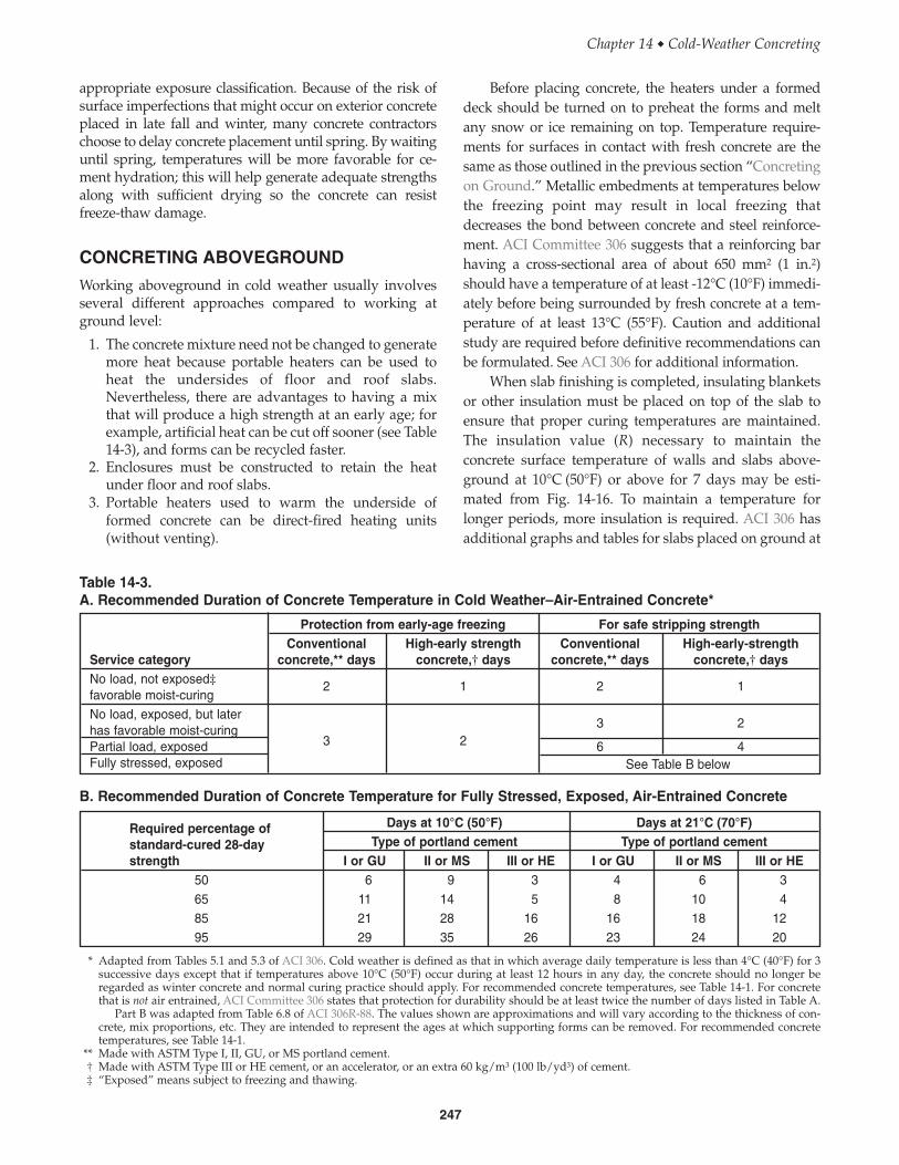
1. The concrete mixture need not be changed to generatemore heat because portable heaters can be used toheat the undersides of floor and roof slabs.Nevertheless, there are advantages to having a mixthat will produce a high strength at an early age; forexample, artificial heat can be cut off sooner (see Table14-3), and forms can be recycled faster.
2. Enclosures must be constructed to retain the heatunder floor and roof slabs.
3. Portable heaters used to warm the underside offormed concrete can be direct-fired heating units(without venting).
Before placing concrete, the heaters under a formeddeck should be turned on to preheat the forms and meltany snow or ice remaining on top. Temperature require-ments for surfaces in contact with fresh concrete are thesame as those outlined in the previous section “Concretingon Ground.” Metallic embedments at temperatures belowthe freezing point may result in local freezing thatdecreases the bond between concrete and steel reinforce-ment. ACI Committee 306 suggests that a reinforcing barhaving a cross-sectional area of about 650 mm2 (1 in.2)should have a temperature of at least -12°C (10°F) immedi-ately before being surrounded by fresh concrete at a tem-perature of at least 13°C (55°F). Caution and additionalstudy are required before definitive recommendations canbe formulated. See ACI 306 for additional information.
When slab finishing is completed, insulating blanketsor other insulation must be placed on top of the slab toensure that proper curing temperatures are maintained.The insulation value (R) necessary to maintain theconcrete surface temperature of walls and slabs above-ground at 10°C (50°F) or above for 7 days may be esti-mated from Fig. 14-16. To maintain a temperature forlonger periods, more insulation is required. ACI 306 hasadditional graphs and tables for slabs placed on ground at
247
Chapter 14 � Cold-Weather Concreting
Protection from early-age freezing For safe stripping strengthConventional High-early strength Conventional High-early-strength
Service category concrete,** days concrete,† days concrete,** days concrete,† daysNo load, not exposed‡favorable moist-curing
2 1 2 1
No load, exposed, but laterhas favorable moist-curing
3 23 2
Partial load, exposed 6 4Fully stressed, exposed See Table B below
Required percentage of Days at 10°C (50°F) Days at 21°C (70°F)
standard-cured 28-day Type of portland cement Type of portland cementstrength I or GU II or MS III or HE I or GU II or MS III or HE
50 6 9 3 4 6 365 11 14 5 8 10 485 21 28 16 16 18 1295 29 35 26 23 24 20
Table 14-3.A. Recommended Duration of Concrete Temperature in Cold Weather–Air-Entrained Concrete*
B. Recommended Duration of Concrete Temperature for Fully Stressed, Exposed, Air-Entrained Concrete
* Adapted from Tables 5.1 and 5.3 of ACI 306. Cold weather is defined as that in which average daily temperature is less than 4°C (40°F) for 3successive days except that if temperatures above 10°C (50°F) occur during at least 12 hours in any day, the concrete should no longer beregarded as winter concrete and normal curing practice should apply. For recommended concrete temperatures, see Table 14-1. For concretethat is not air entrained, ACI Committee 306 states that protection for durability should be at least twice the number of days listed in Table A.
Part B was adapted from Table 6.8 of ACI 306R-88. The values shown are approximations and will vary according to the thickness of con-crete, mix proportions, etc. They are intended to represent the ages at which supporting forms can be removed. For recommended concretetemperatures, see Table 14-1.
** Made with ASTM Type I, II, GU, or MS portland cement.† Made with ASTM Type III or HE cement, or an accelerator, or an extra 60 kg/m3 (100 lb/yd3) of cement.‡ “Exposed” means subject to freezing and thawing.

Corners and edges are particularly vulnerable duringcold weather. As a result, the thickness of insulation forthese areas, especially on columns, should be about threetimes the thickness that is required to maintain the samefor walls or slabs. On the other hand, if the ambienttemperature rises much above the temperature assumedin selecting insulation values, the temperature of theconcrete may become excessive. This increases the proba-bility of thermal shock and cracking when forms areremoved. Temperature readings of insulated concreteshould therefore be taken at regular intervals and shouldnot vary from ambient air temperatures by more than thevalues given in ACI 306. In addition, insulated concretetemperatures should not be allowed to rise much above27°C (80°F). In case of a sudden increase in concrete tem-perature, up to say 35°C (95°F), it may be necessary toremove some of the insulation or loosen the formwork.The maximum temperature differential between the con-crete interior and the concrete surface should be about20°C (35°F) to minimize cracking. The weather forecast
a temperature of 2°C (35°F). Insulation can be selectedbased on R values provided by insulation manufacturersor by using the information in Table 14-4.
When concrete strength development is not deter-mined, a conservative estimate can be made if adequateprotection at the recommended temperature is providedfor the duration of time found in Table 14-3. However, theactual amount of insulation and length of the protectionperiod should be determined from the monitored in-placeconcrete temperature and the desired strength. A correla-tion between curing temperature, curing time, and com-pressive strength can be determined from laboratorytesting of the particular concrete mix used in the field (see“Maturity Concept” discussed later in this chapter). ACI306 states that with a compressive strength of 3.5 MPa (500psi), concrete will normally have sufficient strength toresist early frost damage. If the concrete will be in a satu-rated condition when frozen, the concrete should be prop-erly air entrained and must have developed a compressivestrength of 28 MPa (4000 psi).
248
Design and Control of Concrete Mixtures � EB001
0 12 24 0 12 24 0 12 24
6005004003002001000
50
40
30
20
10
0
-10
-20
-30
-40
-50
-60
R = 0.35 (2)R = 0.35 (2)
R = 0.35 (2)R = 0.70 (4)
R = 0.70 (4)
R = 0.70 (4)
R = 1.06 (6)
R = 1.06 (6)
R = 1.06 (6)
R = 1.41 (8)
R = 1.41 (8)
R = 1.41 (8)
Cement content237 kg/m3
(400 lb/yd3)
Cement content296 kg/m3
(500 lb/yd3)
Cement content356 kg/m3
(600 lb/yd3)
10
5
0
-5
-10
-15
-20
-25
-30
-35
-40
-45
-50
Wall or slab thickness, in.
Wall or slab thickness, mm
Min
imum
am
bien
t tem
pera
ture
, °C
Min
imum
am
bien
t tem
pera
ture
, °F
6005004003002001000 6005004003002001000
Fig. 14-16. Thermal resistance (R) of insulation required to maintain the concrete surface temperature of walls and slabsaboveground at 10°C (50°F) or above for 7 days. Concrete temperature as placed: 10°C (50°F). Maximum wind velocity:24 km/h (15 mph). Note that in order to maintain a certain minimum temperature for a longer period of time, more insulationor a higher R value is required (adapted from ACI 306).

should be checked and appropriate action taken forexpected temperature changes.
Columns and walls should not be cast on foundationsat temperatures below 0°C (32°F) because chilling of con-crete in the bottom of the column or wall will retardstrength development. Concrete should not be placed onany surface that would lower the temperature of the as-placed concrete below the minimum values shown on Line4 in Table 14-1.
ENCLOSURES
Heated enclosures are very effective for protectingconcrete in cold weather, but are probably the most expen-sive too (Fig. 14-17). Enclosures can be of wood, canvastarpaulins, or polyethylene film (Fig. 14-18). Prefabricated,rigid-plastic enclosures are also available. Plastic enclo-
249
Chapter 14 � Cold-Weather Concreting
Table 14-4. Insulation Values of Various Materials
Thermal resistance, R, for10-mm (1-in.) thicknessof material,* (m2 · K)/W
Material Density kg/m3 (lb/ft3) ([°F · hr · ft2]/Btu)Board and SlabsExpanded polyurethane 24 (1.5) 0.438 (6.25)Expanded polystyrene, extruded smooth-skin surface 29 to 56 (1.8 to 3.5) 0.347 (5.0)Expanded polystyrene, extruded cut-cell surface 29 (1.8) 0.277 (4.0)Glass fiber, organic bonded 64 to 144 (4 to 9) 0.277 (4.0)Expanded polystyrene, molded beads 16 (1) 0.247 (3.85)Mineral fiber with resin binder 240 (15) 0.239 (3.45)Mineral fiberboard, wet felted 256 to 272 (16 to 17) 0.204 (2.94)Vegetable fiberboard sheathing 288 (18) 0.182 (2.64)Cellular glass 136 (8.5) 0.201 (2.86)Laminated paperboard 480 (30) 0.139 (2.00)Particle board (low density) 590 (37) 0.128 (1.85)Plywood 545 (34) 0.087 (1.24)
Loose fillWood fiber, soft woods 32 to 56 (2.0 to 3.5) 0.231 (3.33)Perlite (expanded) 80 to 128 (5.0 to 8.0) 0.187 (2.70)Vermiculite (exfoliated) 64 to 96 (4.0 to 6.0) 0.157 (2.27)Vermiculite (exfoliated) 112 to 131 (7.0 to 8.2) 0.148 (2.13)Sawdust or shavings 128 to 240 (8.0 to 15.0) 0.154 (2.22)
Thermal resistance, R, forMaterial thickness thickness of material,*
Material mm (in.) (m2 · K)/W ([°F · hr · ft2]/Btu)Mineral fiber blanket, fibrous form (rock, slag, or glass) 50 to 70 (2 to 2.75) 1.23 (7)
5 to 32 kg/m3 (0.3 to 2 lb/ft3) 75 to 85 (3 to 3.5) 1.90 (11)90 to 165 (5.5 to 6.5) 3.34 (19)
Mineral fiber loose fill (rock, slag, or glass) 95 to 125 (3.75 to 5) 1.90 (11)10 to 32 kg/m3 (0.6 to 2 lb/ft3) 165 to 220 (6.5 to 8.75) 3.34 (19)
190 to 250 (7.5 to 10) 3.87 (22)260 to 350 (10.25 to 13.75) 5.28 (30)
Fig. 14-17. Even in the winter, an outdoor swimming poolcan be constructed if a heated enclosure is used. (43453)
* Values are from ASHRAE Handbook of Fundamentals, American Society of Heating, Refrigerating, and Air-conditioning Engineers, Inc., NewYork, 1977 and 1981.R values are the reciprocal of U values (conductivity).

the minimum required on Line 4 in Table 14-1, additionalinsulating material, or material with a higher R value,should be applied. Corners and edges of concrete are mostvulnerable to freezing. In view of this, temperatures atthese locations should be checked often.
The thermal resistance (R) values for common insu-lating materials are given in Table 14-4. For maximum effi-ciency, insulating materials should be kept dry and inclose contact with concrete or formwork.
Concrete pavements can be protected from coldweather by spreading 300 mm (1 ft) or more of dry strawor hay on the surface for insulation. Tarpaulins, polyeth-ylene film, or waterproof paper should be used as aprotective cover over the straw or hay to make the insula-tion more effective and prevent it from blowing away. Thestraw or hay should be kept dry or its insulation value willdrop considerably.
Stay-in-place insulating concrete forms becamepopular for cold-weather construction in the 1990s (Fig.
sures that admit daylight are the most popular but tempo-rary heat in these enclosures can be an expensive option.
When enclosures are being constructed below a deck,the framework can be extended above the deck to serve asa windbreak. Typically, a height of 2 m (6 ft) will protectconcrete and construction personnel against biting windsthat cause temperature drops and excessive evaporation.Wind breaks could be taller or shorter depending on antic-ipated wind velocities, ambient temperatures, relativehumidity, and concrete placement temperatures.
Enclosures can be made to be moved with flying forms;more often, though, they must be removed so that the windwill not interfere with maneuvering the forms into position.Similarly, enclosures can be built in large panels like gangforms with the windbreak included (Fig. 14-1).
INSULATING MATERIALS
Heat and moisture can be retained in the concrete bycovering it with commercial insulating blankets or battinsulation (Fig. 14-19). The effectiveness of insulation canbe determined by placing a thermometer under it and incontact with the concrete. If the temperature falls below
250
Design and Control of Concrete Mixtures ◆ EB001
Fig. 14-18. (top) Tarpaulin heated enclosure maintains anadequate temperature for proper curing and protection dur-ing severe and prolonged winter weather. (bottom) Poly-ethylene plastic sheets admitting daylight are used to fullyenclose a building frame. The temperature inside is main-tained at 10°C (50°F) with space heaters. (69877, 69878)
Fig. 14-19. Stack of insulating blankets. These blankets trapheat and moisture in the concrete, providing beneficialcuring. (43460)
Fig. 14-20. Insulating concrete forms (ICF) permit con-creting in cold weather. (69699)

14-20). Forms built for repeated use often can be econom-ically insulated with commercial blanket or batt insula-tion. The insulation should have a tough moisture-proofcovering to withstand handling abuse and exposure tothe weather. Rigid insulation can also be used (Fig. 14-21).
Insulating blankets for construction are made of fiber-glass, sponge rubber, open-cell polyurethane foam, vinylfoam, mineral wool, or cellulose fibers. The outer coversare made of canvas, woven polyethylene, or other toughfabrics that will withstand rough handling. The R value fora typical insulating blanket is about 1.2 m2 · °C/W for 50 to70 mm thickness, 7(°F · hr · ft2)/Btu, but since R values arenot marked on the blankets, their effectiveness should bechecked with a thermometer. If necessary, they can be usedin two or three layers to attain the desired insulation.
HEATERS
Three types of heaters are used in cold-weather concreteconstruction: direct fired, indirect fired, and hydronicsystems (Figs. 14-22 to 14-25). Indirect-fired heaters arevented to remove the products of combustion. Where heatis to be supplied to the top of fresh concrete— for example,a floor slab—vented heaters are required. Carbon dioxide
251
Chapter 14 � Cold-Weather Concreting
Fig. 14-21. With air temperatures down to -23°C (-10°F),concrete was cast in this insulated column form made of19-mm (3⁄4-in.) high-density plywood inside, 25-mm (1-in.)rigid polystyrene in the middle, and 13-mm (1⁄2-in.) roughplywood outside. R value: 1.0 m2 · °C/W (5.6 [°F · hr · ft2]/Btu). (43461)
Air,CO,CO2,
Air,CO,CO2,
Airsupply
FlameFan
Air
Air
FlameFan
Air
Air
b) Indirect-fired heater
a) Direct-fired heater
Airsupply
Cleanheated
aironly
Stove pipe vent
Enclosure
Fig. 14-22. Two types of air heaters.
Fig. 14-23. An indirect-fired heater. Notice vent pipe thatcarries combustion gases outside the enclosure. (43459)

(Kauer and Freeman 1955). The result is a soft, chalkysurface that will dust under traffic. Depth and degree ofcarbonation depend on concentration of CO2, curingtemperature, humidity, porosity of the concrete, length ofexposure, and method of curing. Direct-fired heaters,therefore, should not be permitted to heat the air overconcreting operations—at least until 24 hours haveelapsed. In addition, the use of gasoline-powered con-struction equipment should be restricted in enclosuresduring that time. If unvented heaters are used, immediatewet curing or the use of a curing compound will minimizecarbonation.
Carbon monoxide (CO), another product of combus-tion, is not usually a problem unless the heater is usingrecirculated air. Four hours of exposure to 200 parts permillion of CO will produce headaches and nausea. Threehours of exposure to 600 ppm can be fatal. The AmericanNational Standard Safety Requirements for Temporaryand Portable Space Heating Devices and EquipmentUsed in the Construction Industry (ANSI A10.10) limitsconcentrations of CO to 50 ppm at worker breathinglevels. The standard also establishes safety rules for venti-lation and the stability, operation, fueling, and mainte-nance of heaters.
(CO2) in the exhaust must be vented to the outside andprevented from reacting with the fresh concrete(Fig. 14-23). Direct-fired units can be used to heat theenclosed space beneath concrete placed for a floor or aroof deck (Fig. 14-24).
Hydronic systems transfer heat by circulating aglycol/water solution in a closed system of pipes or hoses(see Fig. 14-25). These systems transfer heat more effi-ciently than forced air systems without the negative effectsof exhaust gases and drying of the concrete from air move-ment. The specific heat of water/glycol solutions is morethan six times greater than air. As a result, hydronic heaterscan deliver very large quantities of heat at low temperaturedifferentials of 5°C (10°F) or less between the heat transferhose and the concrete. Cracking and curling induced bytemperature gradients within the concrete are almost elim-inated along with the danger of accidentally overheatingthe concrete and damaging long-term strength gain.
Typical applications for hydronic systems includethawing and preheating subgrades. They are also used tocure elevated and on-grade slabs, walls, foundations, andcolumns. To heat a concrete element, hydronic heatinghoses are usually laid on or hung adjacent to the structureand covered with insulated blankets and sometimes plas-tic sheets. Usually, construction of temporary enclosuresis not necessary. Hydronic systems can be used over areasmuch larger than would be practical to enclose. If aheated enclosure is necessary for other work, hydronichoses can be sacrificed (left under a slab on grade) tomake the slab a radiant heater for the structure builtabove (Grochoski 2000).
Any heater burning a fossil fuel produces carbondioxide (CO2); this gas will combine with calcium hydrox-ide on the surface of fresh concrete to form a weak layer ofcalcium carbonate that interferes with cement hydration
252
Design and Control of Concrete Mixtures ◆ EB001
Fig. 14-24. A direct-fired heater installed through theenclosure, thus using a fresh air supply. (69875)
Fig. 14-25. Hydronic system showing hoses (top) laying onsoil to defrost subgrade and (bottom) warming the formswhile fresh concrete is pumped in. (68345, 68344)

A salamander is an inexpensive combustion heaterwithout a fan that discharges its combustion products intothe surrounding air; heating is accomplished by radiationfrom its metal casing. Salamanders are fueled by coke, oil,wood, or liquid propane. They are but one form of adirect-fired heater. A primary disadvantage of salaman-ders is the high temperature of their metal casing, a defi-nite fire hazard. Salamanders should be placed so thatthey will not overheat formwork or enclosure materials.When placed on floor slabs, they should be elevated toavoid scorching the concrete.
Some heaters burn more than one type of fuel. Theapproximate heat values of fuels are as follows:
No. 1 fuel oil 37,700 kJ/L (135,000 Btu/gal) Kerosene 37,400 kJ/L (134,000 Btu/gal)Gasoline 35,725 kJ/L (128,000 Btu/gal)Liquid-propane gas 25,500 kJ/L (91,500 Btu/gal) Natural gas 37,200 kJ/m3 (1,000 Btu/ft3)
The output rating of a portable heater is usually the heatcontent of the fuel consumed per hour. A rule of thumb isthat about 134,000 kJ are required for each 100 m3 (36,000Btu for 10,000 ft3) of air to develop a 10°C (20°F) tempera-ture rise.
Electricity can also be used to cure concrete in winter.The use of large electric blankets equipped with thermo-stats is one method. The blankets can also be used to thawsubgrades or concrete foundations.
Use of electrical resistance wires that are cast into theconcrete is another method. The power supplied is under50 volts, and from 7.0 to 23.5 MJ (1.5 to 5 kilowatt-hours)of electricity per cubic meter (cubic yard) of concrete isrequired, depending on the circumstances. The methodhas been used in the Montreal, Quebec, area for manyyears. Where electrical resistance wires are used, insula-tion should be included during the initial setting period. Ifinsulation is removed before the recommended time, theconcrete should be covered with an impervious sheet andthe power continued for the required time.
Steam is another source of heat for winter concreting.Live steam can be piped into an enclosure or suppliedthrough radiant heating units. In choosing a heat source, itmust be remembered that the concrete itself supplies heatthrough hydration of cement; this is often enough forcuring needs if the heat can be retained within theconcrete with insulation.
DURATION OF HEATING
After concrete is in place, it should be protected and keptat the recommended temperatures listed on Line 4 ofTable 14-1. These curing temperatures should be main-tained until sufficient strength is gained to withstandexposure to low temperatures, anticipated environment,and construction and service loads. The length of protec-tion required to accomplish this will depend on the
cement type and amount, whether accelerating admix-tures were used, and the loads that must be carried.Recommended minimum periods of protection are givenin Table 14-3. The duration of heating structural concretethat requires the attainment of full service loading beforeforms and shores are removed should be based on theadequacy of in-place compressive strengths rather than anarbitrary time period. If no data are available, a conserva-tive estimate of the length of time for heating and protec-tion can be made using Table 14-3.
Moist Curing
Strength gain stops when moisture required for curing isno longer available. Concrete retained in forms or coveredwith insulation seldom loses enough moisture at 5°C to15°C (40°F to 55°F) to impair curing. However, a positivemeans of providing moist curing is needed to offsetdrying from low wintertime humidities and heaters usedin enclosures during cold weather.
Live steam exhausted into an enclosure around theconcrete is an excellent method of curing because itprovides both heat and moisture. Steam is especially prac-tical in extremely cold weather because the moistureprovided offsets the rapid drying that occurs when verycold air is heated.
Liquid membrane-forming compounds can be usedfor early curing of concrete surfaces within heatedenclosures.
Terminating the Heating Period
Rapid cooling of concrete at the end of the heating periodshould be avoided. Sudden cooling of the concrete surfacewhile the interior is still warm may cause thermal crack-ing, especially in massive sections such as bridge piers,abutments, dams, and large structural members; thuscooling should be gradual. A safe temperature differentialbetween a concrete wall and the ambient air temperaturecan be obtained from ACI 306R-88. The maximum uni-form drop in temperature throughout the first 24 hoursafter the end of protection should not be more than theamounts given in Table 14-2. Gradual cooling can beaccomplished by lowering the heat or by simply shuttingoff the heat and allowing the enclosure to cool to outsideambient air temperature.
FORM REMOVAL AND RESHORING
It is good practice in cold weather to leave forms in placeas long as possible. Even within heated enclosures, formsserve to distribute heat more evenly and help preventdrying and local overheating.
If the curing temperatures listed on Line 4 of Table14-1 are maintained, Table 14-3A can be used to determinethe minimum time in days that vertical support for forms
253
Chapter 14 � Cold-Weather Concreting

With these limitations in mind, the maturity concept hasgained greater acceptance for representing the compres-sive strength of the concrete for removal of shoring oropening a pavement to traffic; but it is no substitute forquality control and proper concreting practices (Malhotra1974 and ACI Committee 347).
To monitor the strength development of concrete inplace using the maturity concept, the following informa-tion must be available:
1. The strength-maturity relationship of the concrete usedin the structure. The results of compressive strengthtests at various ages on a series of cylinders made ofa concrete similar to that used in the structure; thismust be done to develop a strength-maturity curve.These cylinders are cured in a laboratory at 23°C ± 2°C(73°F ± 3°F).
2. A time-temperature record of the concrete in place.Temperature readings are obtained by placing expend-able thermistors or thermocouples at varying depths inthe concrete. The location giving the lowest values pro-vides the series of temperature readings to be used inthe computation (Fig. 14-26).
See ACI 306R-88 for sample calculations using thematurity concept.
should be left in place. Before shores and forms areremoved, fully stressed structural concrete should betested to determine if in-place strengths are adequate,rather than waiting an arbitrary time period. In-placestrengths can be monitored using one of the following:(1) field-cured cylinders (ASTM C 31 or AASHTO T 23);(2) probe penetration tests (ASTM C 803); (3) cast-in-placecylinders (ASTM C 873); (4) pullout testing (ASTM C 900);or (5) maturity testing (ASTM C 1074). Many of these testsare indirect methods of measuring compressive strength;they require correlation in advance with standard cylin-ders before estimates of in-place strengths can be made.
If in-place compressive strengths are not documented,Table 14-3B lists conservative time periods in days toachieve various percentages of the standard laboratory-cured 28-day strength. The engineer issuing project draw-ings and specifications in cooperation with the formworkcontractor must determine what percentage of the designstrength is required (see ACI Committee 306). Side formscan be removed sooner than shoring and temporary false-work (ACI Committee 347).
MATURITY CONCEPT
The maturity concept is based on the principle thatstrength gain in concrete is a function of curing time andtemperature. The maturity concept, as described in ACI306R-88 and ASTM C 1074 can be used to evaluatestrength development when the prescribed curingtemperatures have not been maintained for the requiredtime or when curing temperatures have fluctuated. Theconcept is expressed by the equation:
Metric: M = ∑ (C + 10) ∆t
Inch-Pound Units: M = ∑ (F – 14) ∆twhere
M = maturity factor ∑ = summation C = concrete temperature, degrees CelsiusF = concrete temperature, degrees Fahrenheit∆t = duration of curing at temperature C (F), usually
in hours
The equation is based on the premise that concretegains strength (that is, cement continues to hydrate) attemperatures as low as -10°C (14°F).
Before construction begins, a calibration curve isdrawn plotting the relationship between compressivestrength and the maturity factor for a series of test cylin-ders (of the particular concrete mixture proportions) curedin a laboratory and tested for strength at successive ages.
The maturity concept is not precise and has somelimitations. But, the concept is useful in checking thecuring of concrete and estimating strength in relation totime and temperature. It presumes that all other factorsaffecting concrete strength have been properly controlled.
254
Design and Control of Concrete Mixtures � EB001

REFERENCES
ACI Committee 306, Cold-Weather Concreting, ACI 306R-88, reapproved 1997, American Concrete Institute, Farm-ington Hills, Michigan, 1997, 23 pages.
ACI Committee 347, Guide to Formwork for Concrete, ACI347R-94, reapproved 1999, American Concrete Institute,Farmington Hills, Michigan, 1999, 34 pages.
Brewer, Harold W., General Relation of Heat Flow Factors tothe Unit Weight of Concrete, Development DepartmentBulletin DX114, Portland Cement Association, http://www.portcement.org/pdf_files/DX114.pdf, 1967.
Burg, Ronald G., The Influence of Casting and CuringTemperature on the Properties of Fresh and Hardened Concrete,Research and Development Bulletin RD113, Portland Ce-ment Association, 1996, 20 pages.
Copeland, L. E.; Kantro, D. L.; and Verbeck, George,Chemistry of Hydration of Portland Cement, ResearchDepartment Bulletin RX153, Portland Cement Associa-tion, http://www.portcement.org/pdf_files/RX153.pdf,1960.
Grochoski, Chet, “Cold-Weather Concreting with Hy-dronic Heaters,” Concrete International, American ConcreteInstitute, Farmington Hills, Michigan, April 2000, pages 51to 55.
Kauer, J. A., and Freeman, R. L., “Effect of Carbon Dioxideon Fresh Concrete,” Journal of the American ConcreteInstitute Proceedings, vol. 52, December 1955, pages 447 to454. Discussion: December 1955, Part II, pages 1299 to1304, American Concrete Institute, Farmington Hills,Michigan.
Klieger, Paul, Curing Requirements for Scale Resistance ofConcrete, Research Department Bulletin RX082, PortlandCement Association, http://www.portcement.org/pdf_files/RX082.pdf, 1957.
Klieger, Paul, Effect of Mixing and Curing Temperature onConcrete Strength, Research Department Bulletin RX103,Portland Cement Association, http://www.portcement.org/pdf_files/RX103.pdf, 1958.
Malhotra, V. M., “Maturity Concept and the Estimation ofConcrete Strength: A Review,” Parts I and II, IndianConcrete Journal, vol. 48, Associated Cement Companies,Ltd., Bombay, April and May 1974.
McNeese, D. C., “Early Freezing of Non-Air-EntrainedConcrete,” Journal of the American Concrete InstituteProceedings, vol. 49, American Concrete Institute, Farm-ington Hills, Michigan, December 1952, pages 293 to 300.
NRMCA, Cold Weather Ready Mixed Concrete, PublicationNo. 130, National Ready Mixed Concrete Association,Silver Spring, Maryland, 1968.
255
Chapter 14 � Cold-Weather Concreting
Fig. 14-26. (top) Automatic temperature recorder. (bottom)Thermocouples and wiring at various depths in a caisson.(57368, 57366)

Powers, T. C., Resistance of Concrete to Frost at Early Ages,Research Department Bulletin RX071, Portland CementAssociation, http://www.portcement.org/pdf_files/RX071.pdf, 1956.
Powers, T. C., Prevention of Frost Damage to Green Concrete,Research Department Bulletin RX148, Portland CementAssociation, http://www.portcement.org/pdf_files/RX148.pdf, 1962, 18 pages.
U.S. Bureau of Reclamation, Concrete Manual, 8th ed., U.S.Bureau of Reclamation, Denver, 1981.
256
Design and Control of Concrete Mixtures � EB001