cof (chip-on-film) technology for lcd driver ics using reel-to
TRANSCRIPT
AbstractWe developed a so-called "reel-to-reel method" COF technology using a long carrier tape for the LCD driverpackage. This method enables mass production of COF. We used the ILB (inner lead bonding) technique thatconnects inner leads on a 2-layered tape (glue-less) to Au bumps on an IC chip. COP tape material should becarefully selected with respect to both thermal expansion and heat resistance, because the IC chips areconnected to the tape at a temperature over 400 C. In cooperation with a resin maker, we developed theunderfill material, which enables filling the narrow spaces between the IC chip and the 2-layered chipwithout bubbles. The 2-layered tape also features easy installation onto CR parts and is flexible enough tobend freely. These features offer a promising advantage when this method is applied to compact appliancessuch as cellular phones and PDAs.
IntroductionAt present, TCP (tape carrier package) is widely being used as a package for LCD driver ICs.
Sharp first began using TCP assembly processes for LCDs in1985, and we have developed a number of TCP technologies,becoming a leader in the TCP industry. COF (chip-on-film)was first introduced in 1998 as a replacement for TCP. Sincethe summer of 2000, its use has advanced extremely rapidlywith the evolution of larger color displays for mobile phones,and demand for COF has grown even stronger.
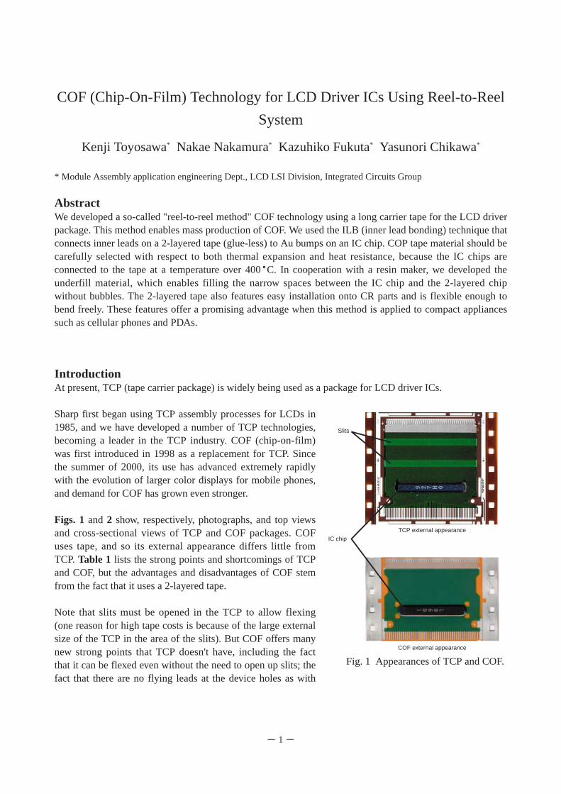
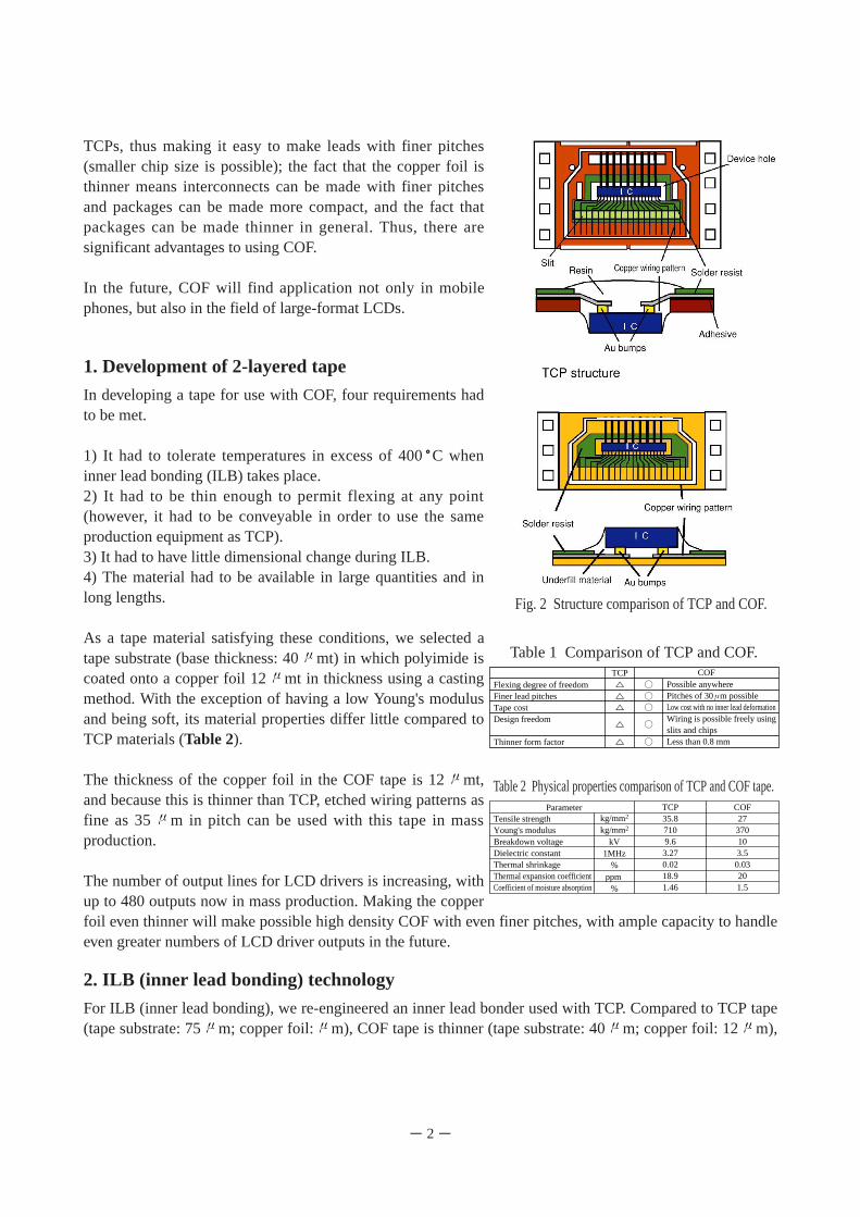
Figs. 1and 2 show, respectively, photographs, and top viewsand cross-sectional views of TCP and COF packages. COFuses tape, and so its external appearance differs little fromTCP. Table 1 lists the strong points and shortcomings of TCPand COF, but the advantages and disadvantages of COF stemfrom the fact that it uses a 2-layered tape.
Note that slits must be opened in the TCP to allow flexing(one reason for high tape costs is because of the large externalsize of the TCP in the area of the slits). But COF offers manynew strong points that TCP doesn't have, including the factthat it can be flexed even without the need to open up slits; thefact that there are no flying leads at the device holes as with
COF (Chip-On-Film) Technology for LCD Driver ICs Using Reel-to-Reel
System
Kenji Toyosawa* Nakae Nakamura* Kazuhiko Fukuta* Yasunori Chikawa*
* Module Assembly application engineering Dept., LCD LSI Division, Integrated Circuits Group
- 1-
Slits
IC chip
TCP external appearance
COF external appearance
Fig. 1 Appearances of TCP and COF.
TCPs, thus making it easy to make leads with finer pitches(smaller chip size is possible); the fact that the copper foil isthinner means interconnects can be made with finer pitchesand packages can be made more compact, and the fact thatpackages can be made thinner in general. Thus, there aresignificant advantages to using COF.
In the future, COF will find application not only in mobilephones, but also in the field of large-format LCDs.
1. Development of 2-layered tape
In developing a tape for use with COF, four requirements hadto be met.
1) It had to tolerate temperatures in excess of 400 C wheninner lead bonding (ILB) takes place.2) It had to be thin enough to permit flexing at any point(however, it had to be conveyable in order to use the sameproduction equipment as TCP). 3) It had to have little dimensional change during ILB.4) The material had to be available in large quantities and inlong lengths.
As a tape material satisfying these conditions, we selected atape substrate (base thickness: 40 mt) in which polyimide iscoated onto a copper foil 12 mt in thickness using a castingmethod. With the exception of having a low Young's modulusand being soft, its material properties differ little compared toTCP materials (Table 2).
The thickness of the copper foil in the COF tape is 12 mt,and because this is thinner than TCP, etched wiring patterns asfine as 35 m in pitch can be used with this tape in massproduction.
The number of output lines for LCD drivers is increasing, withup to 480 outputs now in mass production. Making the copperfoil even thinner will make possible high density COF with even finer pitches, with ample capacity to handleeven greater numbers of LCD driver outputs in the future.
2. ILB (inner lead bonding) technology
For ILB (inner lead bonding), we re-engineered an inner lead bonder used with TCP. Compared to TCP tape(tape substrate: 75 m; copper foil: m), COF tape is thinner (tape substrate: 40 m; copper foil: 12 m),
- 2-
Fig. 2 Structure comparison of TCP and COF.
Flexing degree of freedomFiner lead pitchesTape costDesign freedom
Thinner form factor
TCP COFPossible anywherePitches of 30 m possibleLow cost with no inner lead deformationWiring is possible freely usingslits and chipsLess than 0.8 mm
Table 1 Comparison of TCP and COF.
Tensile strengthYoung's modulusBreakdown voltageDielectric constantThermal shrinkage Thermal expansion coefficientCoefficient of moisture absorption
kg/mm2
kg/mm2
kV1MHz
%ppm
%
COF27
370103.5
0.03201.5
TCP35.87109.6
3.270.0218.91.46
Parameter
Table 2 Physical properties comparison of TCP and COF tape.
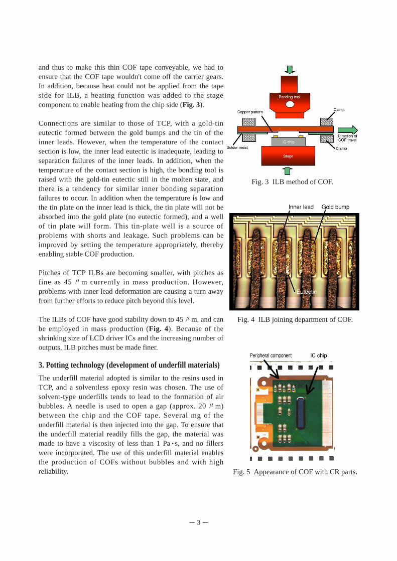
and thus to make this thin COF tape conveyable, we had toensure that the COF tape wouldn't come off the carrier gears.In addition, because heat could not be applied from the tapeside for ILB, a heating function was added to the stagecomponent to enable heating from the chip side (Fig. 3).
Connections are similar to those of TCP, with a gold-tineutectic formed between the gold bumps and the tin of theinner leads. However, when the temperature of the contactsection is low, the inner lead eutectic is inadequate, leading toseparation failures of the inner leads. In addition, when thetemperature of the contact section is high, the bonding tool israised with the gold-tin eutectic still in the molten state, andthere is a tendency for similar inner bonding separationfailures to occur. In addition when the temperature is low andthe tin plate on the inner lead is thick, the tin plate will not beabsorbed into the gold plate (no eutectic formed), and a wellof tin plate will form. This tin-plate well is a source ofproblems with shorts and leakage. Such problems can beimproved by setting the temperature appropriately, therebyenabling stable COF production.
Pitches of TCP ILBs are becoming smaller, with pitches asfine as 45 m currently in mass production. However,problems with inner lead deformation are causing a turn awayfrom further efforts to reduce pitch beyond this level.
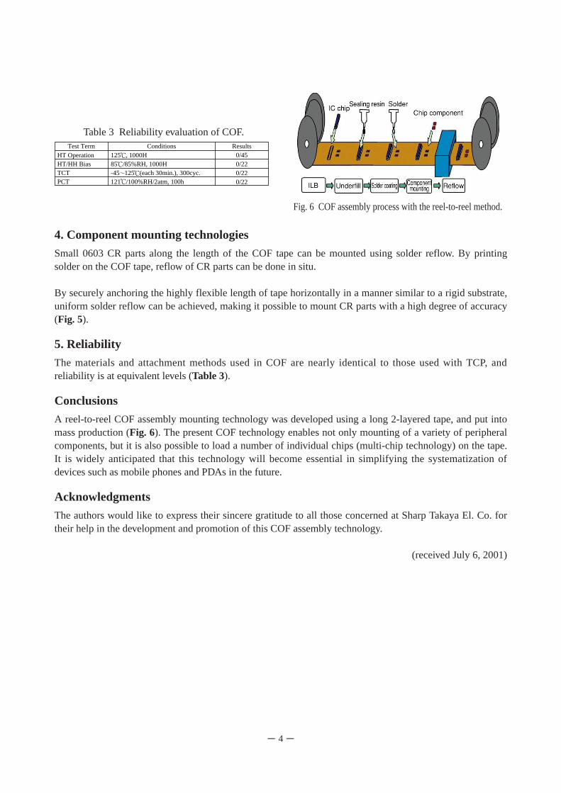
The ILBs of COF have good stability down to 45 m, and canbe employed in mass production (Fig. 4). Because of theshrinking size of LCD driver ICs and the increasing number ofoutputs, ILB pitches must be made finer.
3. Potting technology (development of underfill materials)
The underfill material adopted is similar to the resins used inTCP, and a solventless epoxy resin was chosen. The use ofsolvent-type underfills tends to lead to the formation of airbubbles. A needle is used to open a gap (approx. 20 m)between the chip and the COF tape. Several mg of theunderfill material is then injected into the gap. To ensure thatthe underfill material readily fills the gap, the material wasmade to have a viscosity of less than 1 Pa s, and no fillerswere incorporated. The use of this underfill material enablesthe production of COFs without bubbles and with highreliability.
- 3-
Fig. 3 ILB method of COF.
Fig. 4 ILB joining department of COF.
Fig. 5 Appearance of COF with CR parts.
4. Component mounting technologies
Small 0603 CR parts along the length of the COF tape can be mounted using solder reflow. By printingsolder on the COF tape, reflow of CR parts can be done in situ.
By securely anchoring the highly flexible length of tape horizontally in a manner similar to a rigid substrate,uniform solder reflow can be achieved, making it possible to mount CR parts with a high degree of accuracy(Fig. 5).
5. Reliability
The materials and attachment methods used in COF are nearly identical to those used with TCP, andreliability is at equivalent levels (Table 3).
Conclusions
A reel-to-reel COF assembly mounting technology was developed using a long 2-layered tape, and put intomass production (Fig. 6). The present COF technology enables not only mounting of a variety of peripheralcomponents, but it is also possible to load a number of individual chips (multi-chip technology) on the tape.It is widely anticipated that this technology will become essential in simplifying the systematization ofdevices such as mobile phones and PDAs in the future.
Acknowledgments
The authors would like to express their sincere gratitude to all those concerned at Sharp Takaya El. Co. fortheir help in the development and promotion of this COF assembly technology.
(received July 6, 2001)
- 4-
Fig. 6 COF assembly process with the reel-to-reel method.
HT OperationHT/HH BiasTCTPCT
125 , 1000H85 /85%RH, 1000H-45 125 (each 30min.), 300cyc.121 /100%RH/2atm, 100h
Results0/450/220/220/22
ConditionsTest Term
Table 3 Reliability evaluation of COF.