cockpit acceptance check primo ingresso nel cockpit e ... · cockpit acceptance check primo...
TRANSCRIPT
Cockpit Acceptance Check Primo Ingresso nel Cockpit e Preparazione – PAG 1/2
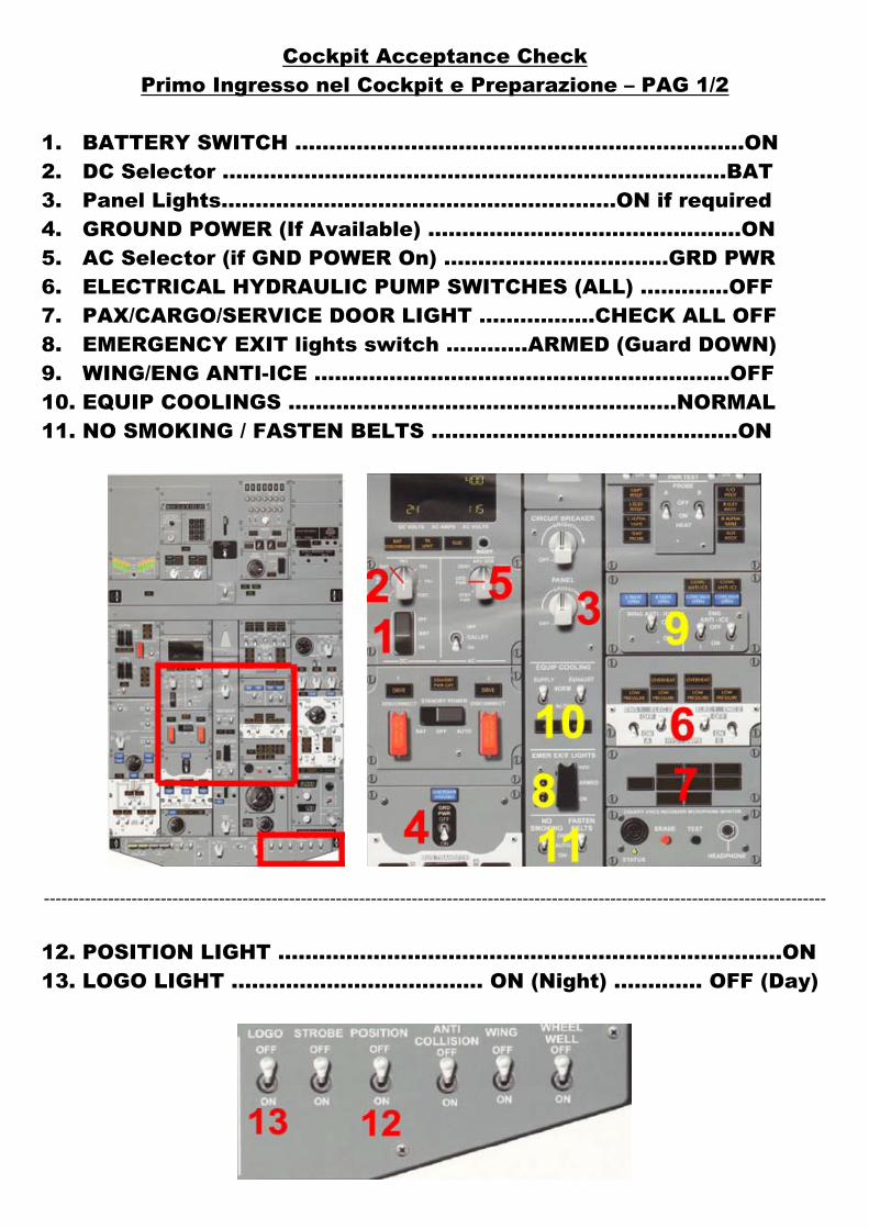
1. BATTERY SWITCH ..................................................................ON 2. DC Selector ……………………..…………………………………..…….BAT 3. Panel Lights..........................................................ON if required 4. GROUND POWER (If Available) ..............................................ON 5. AC Selector (if GND POWER On) …………………………...GRD PWR 6. ELECTRICAL HYDRAULIC PUMP SWITCHES (ALL) …..........OFF 7. PAX/CARGO/SERVICE DOOR LIGHT …….…….…CHECK ALL OFF 8. EMERGENCY EXIT lights switch ………...ARMED (Guard DOWN) 9. WING/ENG ANTI-ICE ………………………….…….……………….….OFF 10. EQUIP COOLINGS ……………………………….….………….…NORMAL 11. NO SMOKING / FASTEN BELTS ....…………..………………..….…ON
--------------------------------------------------------------------------------------------------------------------------------------
12. POSITION LIGHT ……………………………………………..…………………ON 13. LOGO LIGHT ………………………………. ON (Night) …………. OFF (Day)
Cockpit Acceptance Check Primo Ingresso nel Cockpit e Preparazione – PAG 2/2
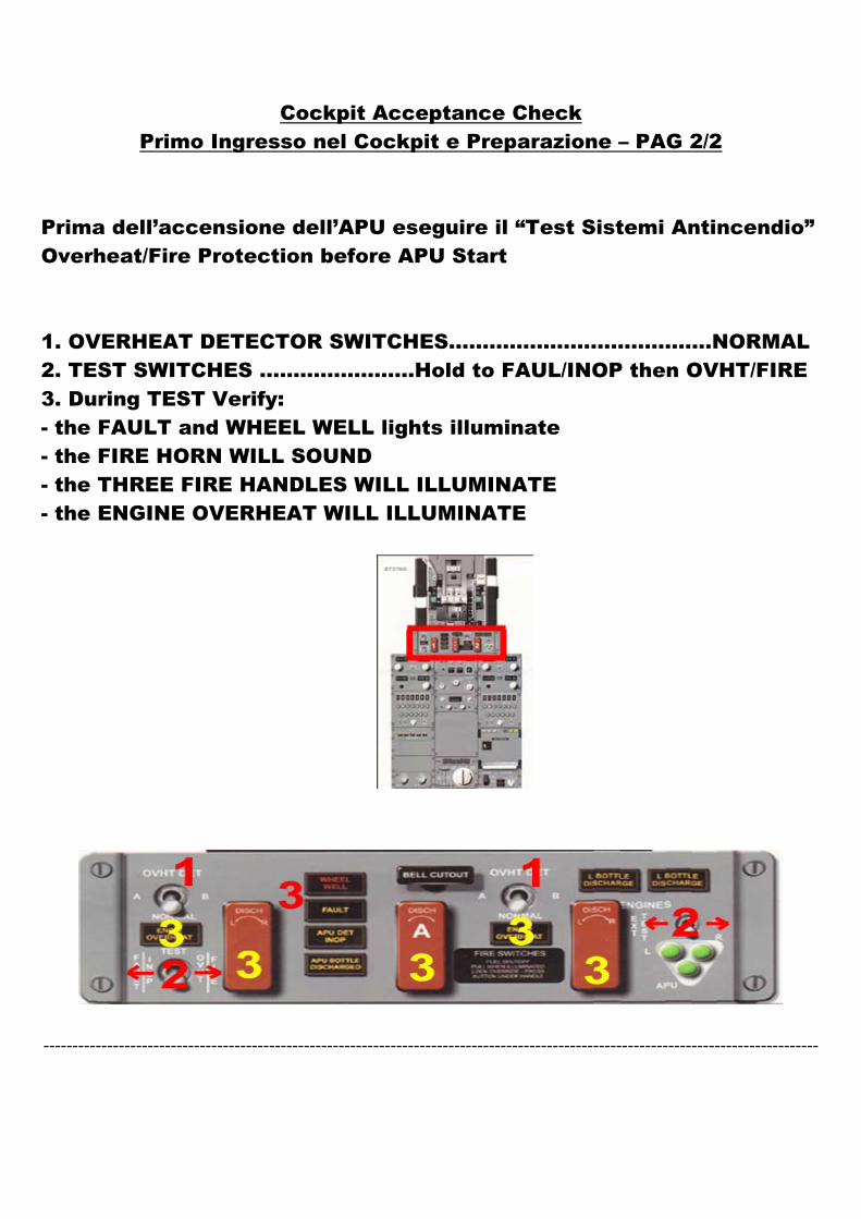
Prima dell’accensione dell’APU eseguire il “Test Sistemi Antincendio” Overheat/Fire Protection before APU Start 1. OVERHEAT DETECTOR SWITCHES…………………………………NORMAL 2. TEST SWITCHES …………..………Hold to FAUL/INOP then OVHT/FIRE 3. During TEST Verify: - the FAULT and WHEEL WELL lights illuminate - the FIRE HORN WILL SOUND - the THREE FIRE HANDLES WILL ILLUMINATE - the ENGINE OVERHEAT WILL ILLUMINATE
--------------------------------------------------------------------------------------------------------------------------------------
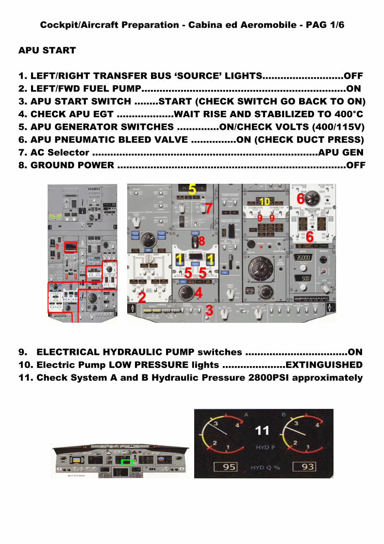
Cockpit/Aircraft Preparation - Cabina ed Aeromobile - PAG 1/6 APU START 1. LEFT/RIGHT TRANSFER BUS ‘SOURCE’ LIGHTS…………………......OFF 2. LEFT/FWD FUEL PUMP…………………………………………………………..ON 3. APU START SWITCH .….…START (CHECK SWITCH GO BACK TO ON) 4. CHECK APU EGT ……………….WAIT RISE AND STABILIZED TO 400°C 5. APU GENERATOR SWITCHES ..………...ON/CHECK VOLTS (400/115V) 6. APU PNEUMATIC BLEED VALVE ……….…..ON (CHECK DUCT PRESS) 7. AC Selector …………………………………………………………………APU GEN 8. GROUND POWER ……………………………………………………………….…OFF
9. ELECTRICAL HYDRAULIC PUMP switches ……….........................ON 10. Electric Pump LOW PRESSURE lights …………..…....EXTINGUISHED 11. Check System A and B Hydraulic Pressure 2800PSI approximately
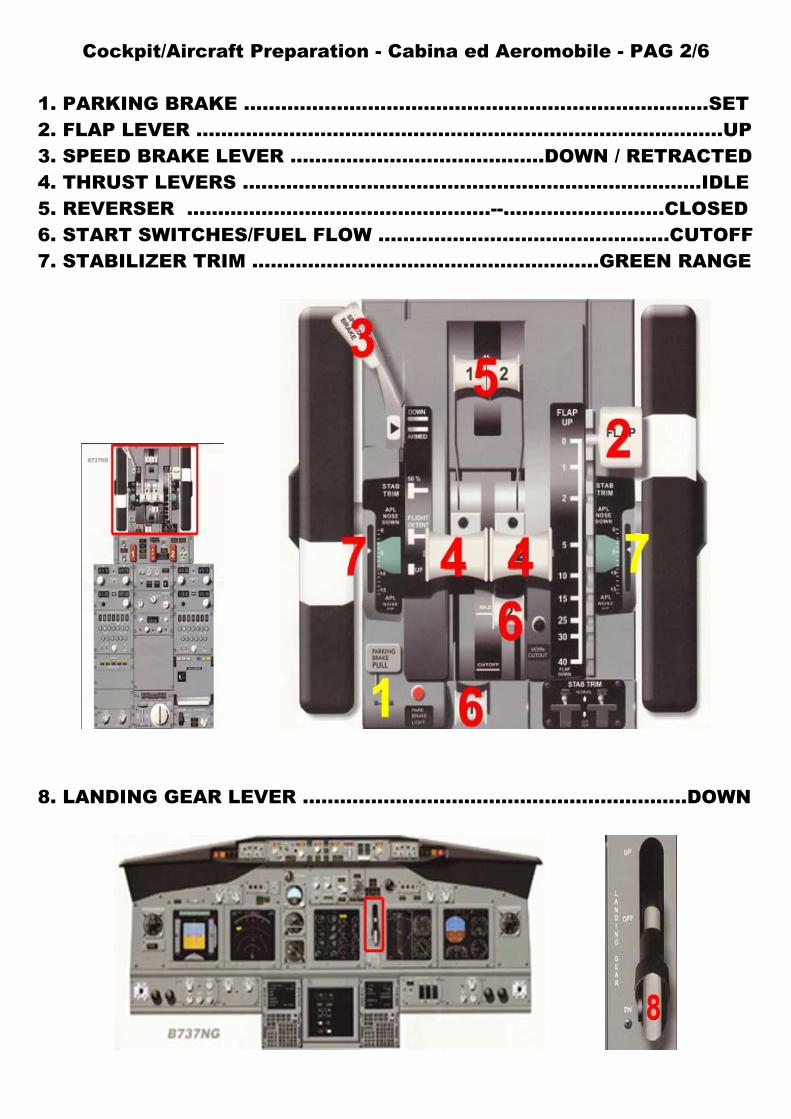
Cockpit/Aircraft Preparation - Cabina ed Aeromobile - PAG 2/6 1. PARKING BRAKE ...........................................................................SET 2. FLAP LEVER .....................................................................................UP 3. SPEED BRAKE LEVER .........................................DOWN / RETRACTED 4. THRUST LEVERS .............................................………………………..IDLE 5. REVERSER ………………………………………….--……………………..CLOSED 6. START SWITCHES/FUEL FLOW ..............................……………..CUTOFF 7. STABILIZER TRIM ...............................................………GREEN RANGE
8. LANDING GEAR LEVER ..............................................................DOWN
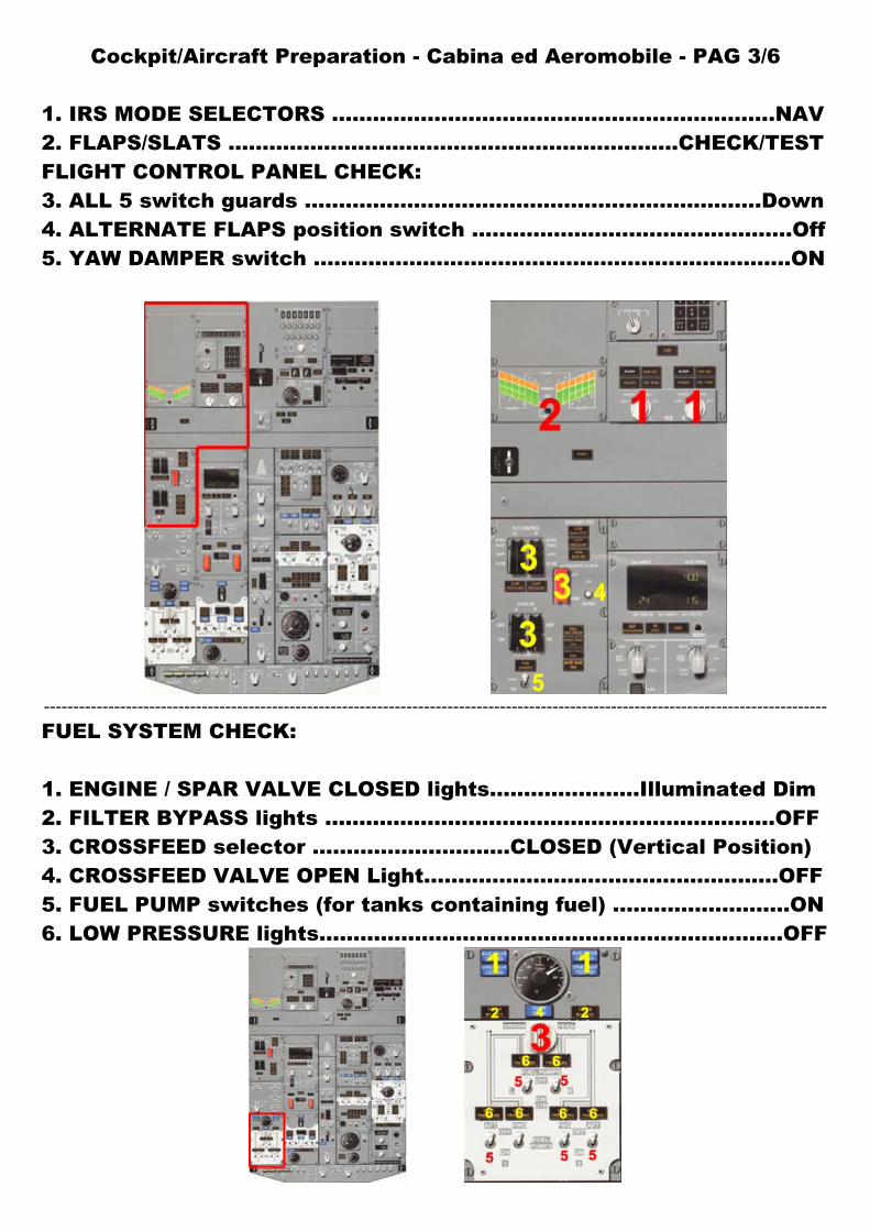
Cockpit/Aircraft Preparation - Cabina ed Aeromobile - PAG 3/6 1. IRS MODE SELECTORS ………………………………………………………..NAV 2. FLAPS/SLATS …………………………………………………………CHECK/TEST FLIGHT CONTROL PANEL CHECK: 3. ALL 5 switch guards .…………………………………………………………Down 4. ALTERNATE FLAPS position switch .…………………..…………………..Off 5. YAW DAMPER switch .………………………………………….………………..ON
--------------------------------------------------------------------------------------------------------------------------------------
FUEL SYSTEM CHECK: 1. ENGINE / SPAR VALVE CLOSED lights…………...…….Illuminated Dim 2. FILTER BYPASS lights …………………………………………………………OFF 3. CROSSFEED selector ……………….……….CLOSED (Vertical Position) 4. CROSSFEED VALVE OPEN Light….…………………………………………OFF 5. FUEL PUMP switches (for tanks containing fuel) ……………..………ON 6. LOW PRESSURE lights…………………………………………………………..OFF
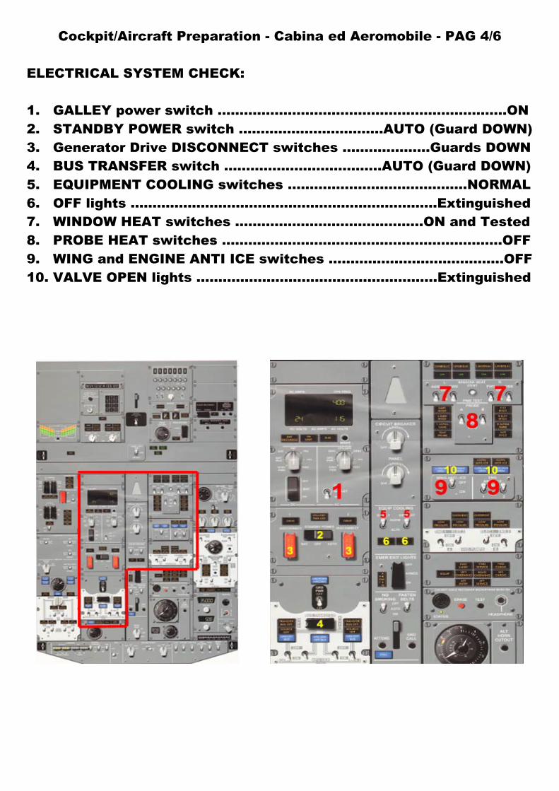
Cockpit/Aircraft Preparation - Cabina ed Aeromobile - PAG 4/6 ELECTRICAL SYSTEM CHECK: 1. GALLEY power switch ………………………….….……………..…………..ON 2. STANDBY POWER switch …………………..……….AUTO (Guard DOWN) 3. Generator Drive DISCONNECT switches ….…...……….Guards DOWN 4. BUS TRANSFER switch ……………………………...AUTO (Guard DOWN) 5. EQUIPMENT COOLING switches .........................................NORMAL 6. OFF lights ......................................................................Extinguished 7. WINDOW HEAT switches ...........................................ON and Tested 8. PROBE HEAT switches ................................................................OFF 9. WING and ENGINE ANTI ICE switches …………….……………………OFF 10. VALVE OPEN lights ……………………………………….………Extinguished
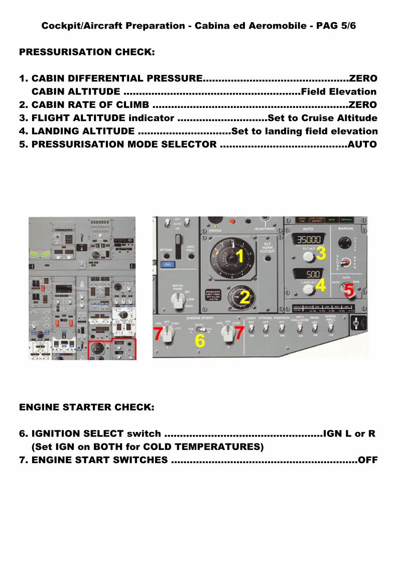
Cockpit/Aircraft Preparation - Cabina ed Aeromobile - PAG 5/6 PRESSURISATION CHECK: 1. CABIN DIFFERENTIAL PRESSURE………………………………………..ZERO CABIN ALTITUDE ……..…………………….…….……………..Field Elevation 2. CABIN RATE OF CLIMB …………………………….………………………..ZERO 3. FLIGHT ALTITUDE indicator ………………………..Set to Cruise Altitude 4. LANDING ALTITUDE ……………………..….Set to landing field elevation 5. PRESSURISATION MODE SELECTOR …………….…………………….AUTO
ENGINE STARTER CHECK: 6. IGNITION SELECT switch ..................................………........IGN L or R (Set IGN on BOTH for COLD TEMPERATURES) 7. ENGINE START SWITCHES ..............................…………..................OFF
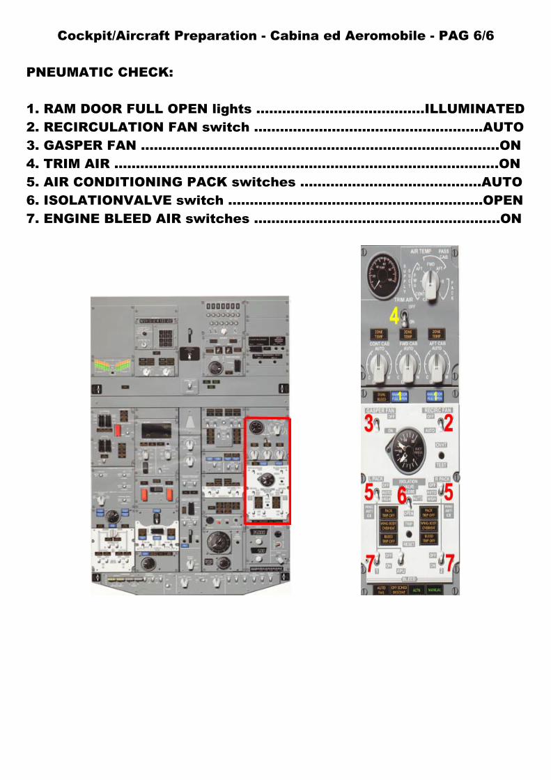
Cockpit/Aircraft Preparation - Cabina ed Aeromobile - PAG 6/6 PNEUMATIC CHECK: 1. RAM DOOR FULL OPEN lights ……………………….………..ILLUMINATED 2. RECIRCULATION FAN switch ...................................……............AUTO 3. GASPER FAN ……………………………………….……………………………….ON 4. TRIM AIR ……………………………………………………………………………..ON 5. AIR CONDITIONING PACK switches ..........................................AUTO 6. ISOLATIONVALVE switch ......................................………….........OPEN 7. ENGINE BLEED AIR switches ...............................…………..............ON
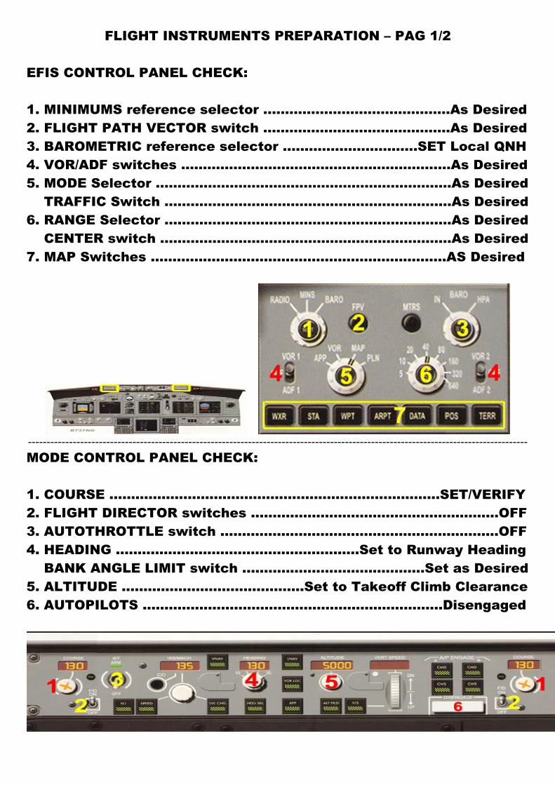
FLIGHT INSTRUMENTS PREPARATION – PAG 1/2
EFIS CONTROL PANEL CHECK: 1. MINIMUMS reference selector ...........................................As Desired 2. FLIGHT PATH VECTOR switch ...........................................As Desired 3. BAROMETRIC reference selector ………………………….SET Local QNH 4. VOR/ADF switches ..............................................................As Desired 5. MODE Selector ....................................................................As Desired TRAFFIC Switch .......................................................………..As Desired 6. RANGE Selector .......................................................………..As Desired CENTER switch .......................................................………...As Desired 7. MAP Switches .......................................................………….AS Desired
--------------------------------------------------------------------------------------------------------------------------------------
MODE CONTROL PANEL CHECK: 1. COURSE ..........................................................……..……….SET/VERIFY 2. FLIGHT DIRECTOR switches .........................................................OFF 3. AUTOTHROTTLE switch ................................................................OFF 4. HEADING ........................................................Set to Runway Heading BANK ANGLE LIMIT switch ..........................................Set as Desired 5. ALTITUDE ..........................................Set to Takeoff Climb Clearance 6. AUTOPILOTS .....................................................................Disengaged
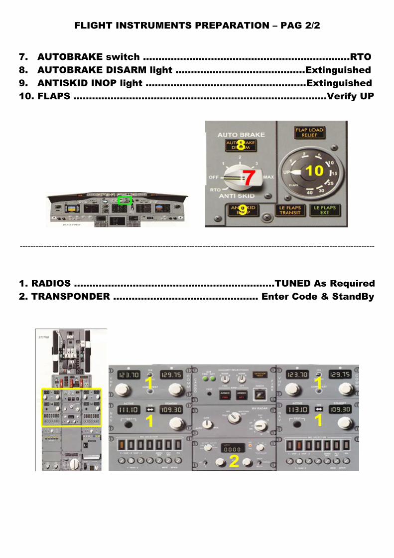
FLIGHT INSTRUMENTS PREPARATION – PAG 2/2
7. AUTOBRAKE switch .................................................……..…….…RTO 8. AUTOBRAKE DISARM light ..........................................Extinguished 9. ANTISKID INOP light ....................................................Extinguished 10. FLAPS ……………………………………………………………………….Verify UP
--------------------------------------------------------------------------------------------------------------------------------------
1. RADIOS ..............................................................…TUNED As Required 2. TRANSPONDER ………………………………..……… Enter Code & StandBy
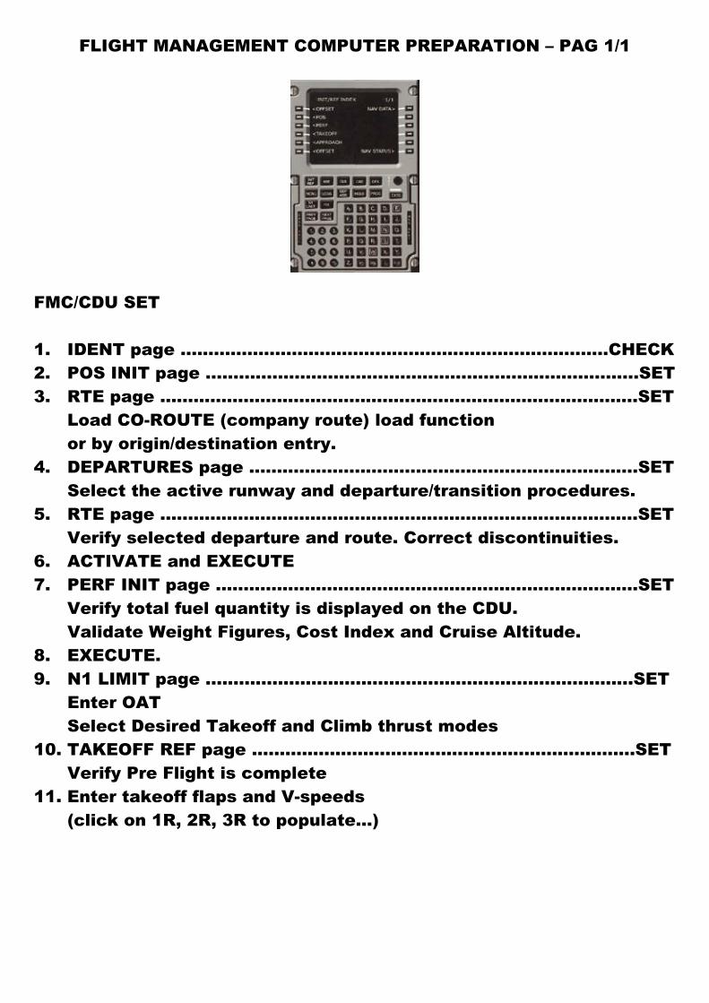
FLIGHT MANAGEMENT COMPUTER PREPARATION – PAG 1/1
FMC/CDU SET 1. IDENT page …………................................................……………..CHECK 2. POS INIT page .........................................................…………………SET 3. RTE page ...............................................................…………………..SET Load CO-ROUTE (company route) load function or by origin/destination entry. 4. DEPARTURES page ........................................................…………..SET Select the active runway and departure/transition procedures. 5. RTE page ..........................................................……………………….SET Verify selected departure and route. Correct discontinuities. 6. ACTIVATE and EXECUTE 7. PERF INIT page .......................................................…………………SET Verify total fuel quantity is displayed on the CDU. Validate Weight Figures, Cost Index and Cruise Altitude. 8. EXECUTE. 9. N1 LIMIT page .........................................................………………..SET Enter OAT Select Desired Takeoff and Climb thrust modes 10. TAKEOFF REF page ........................................................………….SET Verify Pre Flight is complete 11. Enter takeoff flaps and V-speeds (click on 1R, 2R, 3R to populate…)
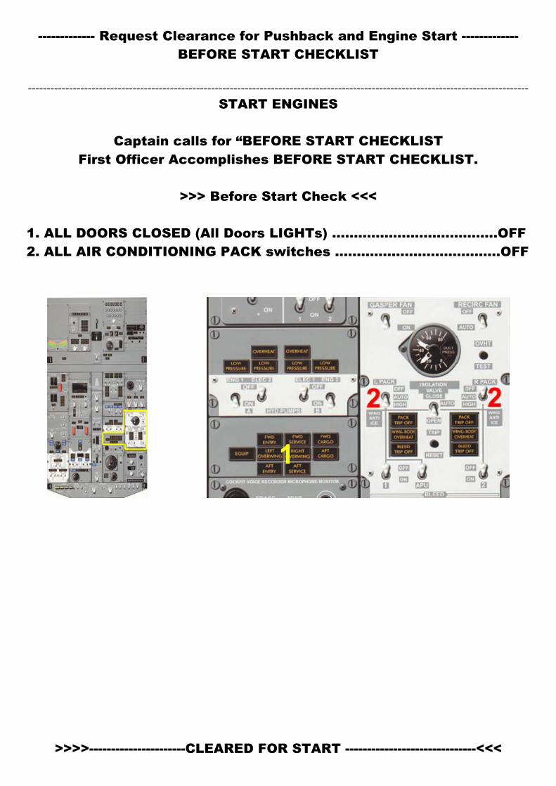
------------- Request Clearance for Pushback and Engine Start ------------- BEFORE START CHECKLIST
--------------------------------------------------------------------------------------------------------------------------------------
START ENGINES
Captain calls for “BEFORE START CHECKLIST First Officer Accomplishes BEFORE START CHECKLIST.
>>> Before Start Check <<<
1. ALL DOORS CLOSED (All Doors LIGHTs) ...........……………..……….OFF 2. ALL AIR CONDITIONING PACK switches ......................................OFF
>>>>----------------------CLEARED FOR START ------------------------------<<<
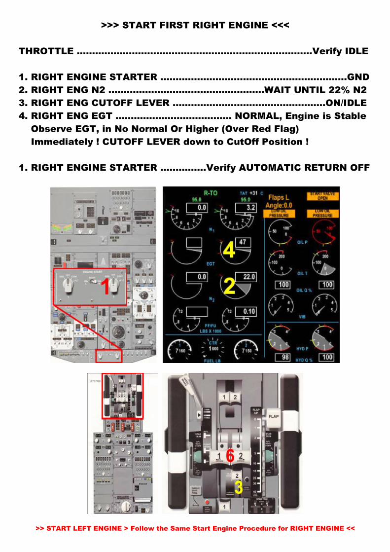
>>> START FIRST RIGHT ENGINE <<<
THROTTLE ………………………………………….……………………….Verify IDLE 1. RIGHT ENGINE STARTER …………………………………………….………GND 2. RIGHT ENG N2 ……………………………………………WAIT UNTIL 22% N2 3. RIGHT ENG CUTOFF LEVER ……………..……………………………ON/IDLE 4. RIGHT ENG EGT …………………………..…… NORMAL, Engine is Stable Observe EGT, in No Normal Or Higher (Over Red Flag) Immediately ! CUTOFF LEVER down to CutOff Position ! 1. RIGHT ENGINE STARTER ……………Verify AUTOMATIC RETURN OFF
>> START LEFT ENGINE > Follow the Same Start Engine Procedure for RIGHT ENGINE <<
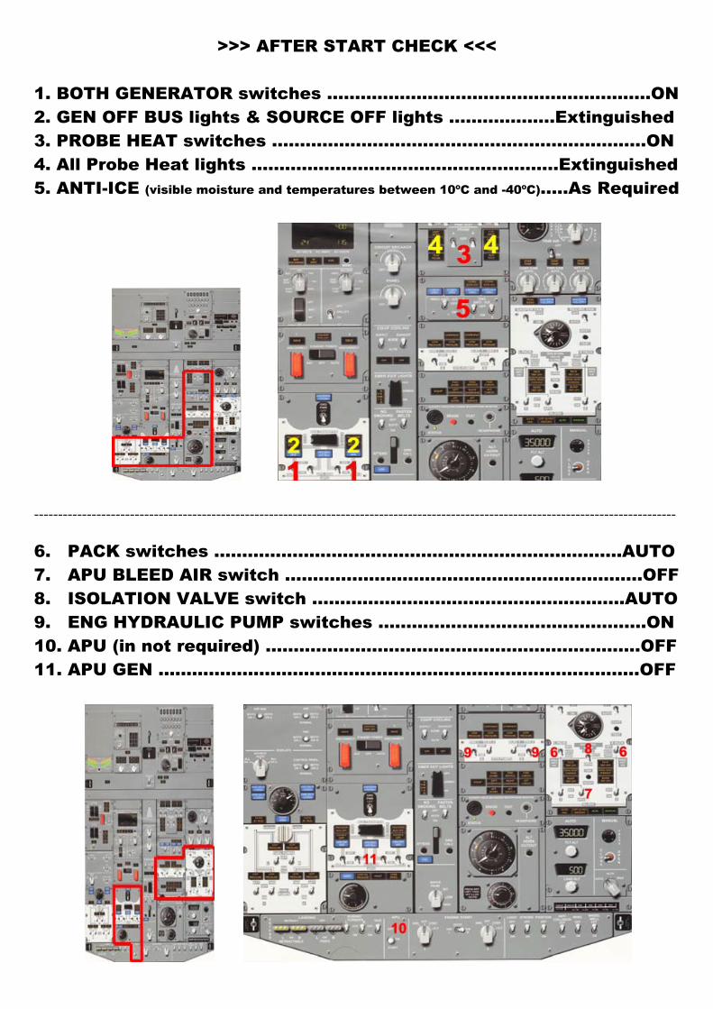
>>> AFTER START CHECK <<<
1. BOTH GENERATOR switches ..........................................................ON 2. GEN OFF BUS lights & SOURCE OFF lights ...................Extinguished 3. PROBE HEAT switches .................................................………………ON 4. All Probe Heat lights .......................................................Extinguished 5. ANTI-ICE (visible moisture and temperatures between 10ºC and -40ºC)…..As Required
--------------------------------------------------------------------------------------------------------------------------------------
6. PACK switches .............................................................…………AUTO 7. APU BLEED AIR switch ........................................................….....OFF 8. ISOLATION VALVE switch ........................................................AUTO 9. ENG HYDRAULIC PUMP switches .........................................…….ON 10. APU (in not required) ………………………………………………………….OFF 11. APU GEN …………………………………………………………………………..OFF
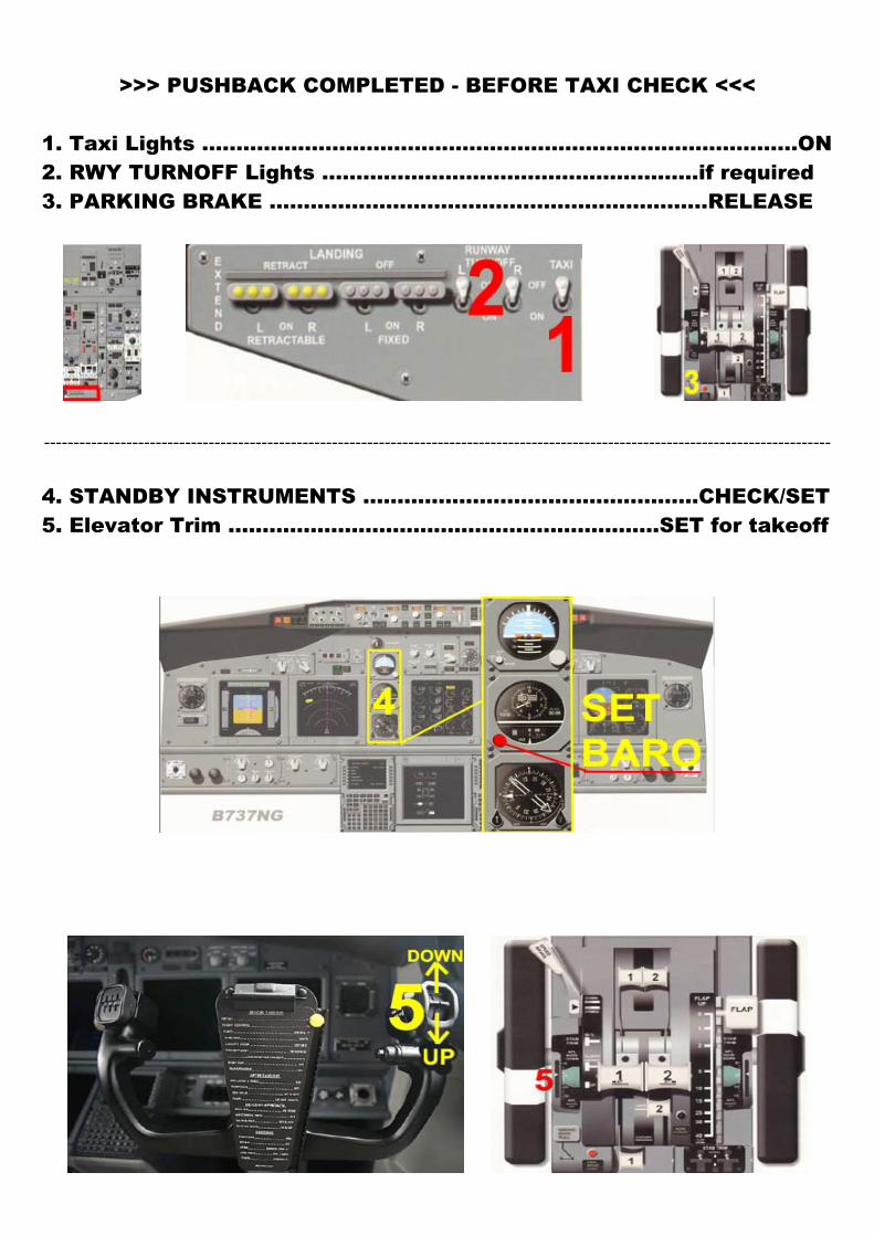
>>> PUSHBACK COMPLETED - BEFORE TAXI CHECK <<<
1. Taxi Lights .......................................................................................ON 2. RWY TURNOFF Lights .......................................................if required 3. PARKING BRAKE ……………………………………………….………RELEASE
--------------------------------------------------------------------------------------------------------------------------------------
4. STANDBY INSTRUMENTS .................................................CHECK/SET 5. Elevator Trim ...............................................................SET for takeoff
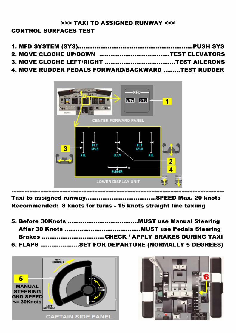
>>> TAXI TO ASSIGNED RUNWAY <<<
CONTROL SURFACES TEST 1. MFD SYSTEM (SYS)……………………………………………………..PUSH SYS 2. MOVE CLOCHE UP/DOWN ………………………………..TEST ELEVATORS 3. MOVE CLOCHE LEFT/RIGHT ………………………………..TEST AILERONS 4. MOVE RUDDER PEDALS FORWARD/BACKWARD ………TEST RUDDER
--------------------------------------------------------------------------------------------------------------------------------------
Taxi to assigned runway......................................SPEED Max. 20 knots Recommended: 8 knots for turns - 15 knots straight line taxiing 5. Before 30Knots ……………………………..…MUST use Manual Steering After 30 Knots …………………………………..MUST use Pedals Steering Brakes …………………………....CHECK / APPLY BRAKES DURING TAXI 6. FLAPS …………………SET FOR DEPARTURE (NORMALLY 5 DEGREES)
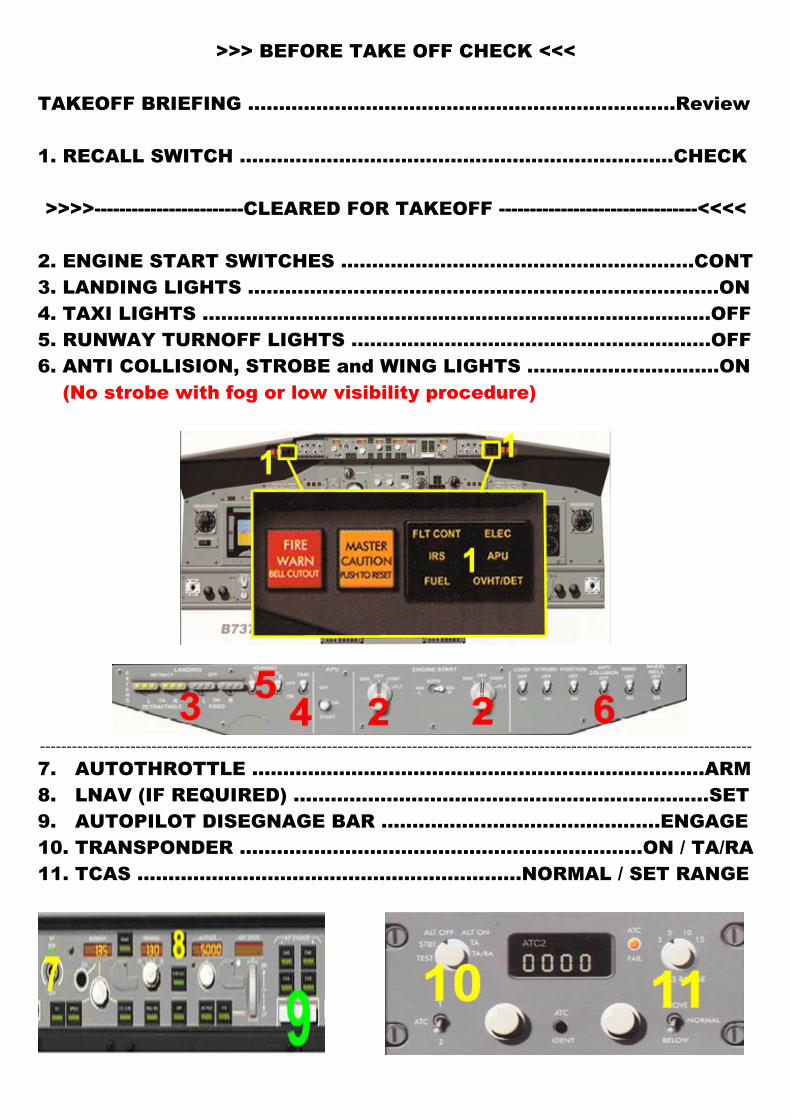
>>> BEFORE TAKE OFF CHECK <<< TAKEOFF BRIEFING ........................................................………….Review 1. RECALL SWITCH ....................................................………………CHECK >>>>------------------------CLEARED FOR TAKEOFF --------------------------------<<<<
2. ENGINE START SWITCHES .................................................……..CONT 3. LANDING LIGHTS ...................................................…………………….ON 4. TAXI LIGHTS ........................................................……………………..OFF 5. RUNWAY TURNOFF LIGHTS ................................……………………..OFF 6. ANTI COLLISION, STROBE and WING LIGHTS …............................ON (No strobe with fog or low visibility procedure)
--------------------------------------------------------------------------------------------------------------------------------------
7. AUTOTHROTTLE ..................................................…………………..ARM 8. LNAV (IF REQUIRED) ………………………………………….…….………..SET 9. AUTOPILOT DISEGNAGE BAR ………………………….…………..ENGAGE 10. TRANSPONDER ………………………………………….…………….ON / TA/RA 11. TCAS ……………………………………………………..NORMAL / SET RANGE
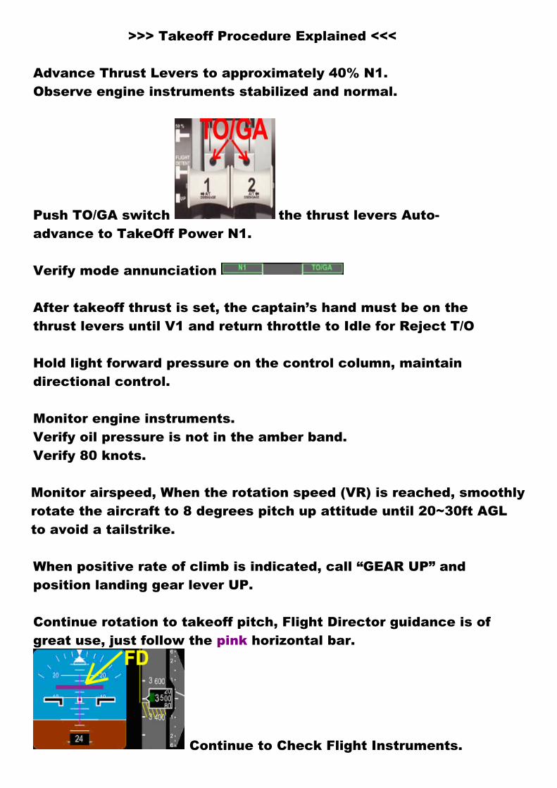
>>> Takeoff Procedure Explained <<< Advance Thrust Levers to approximately 40% N1. Observe engine instruments stabilized and normal.
Push TO/GA switch the thrust levers Auto-advance to TakeOff Power N1. Verify mode annunciation After takeoff thrust is set, the captain’s hand must be on the thrust levers until V1 and return throttle to Idle for Reject T/O Hold light forward pressure on the control column, maintain directional control. Monitor engine instruments. Verify oil pressure is not in the amber band. Verify 80 knots.
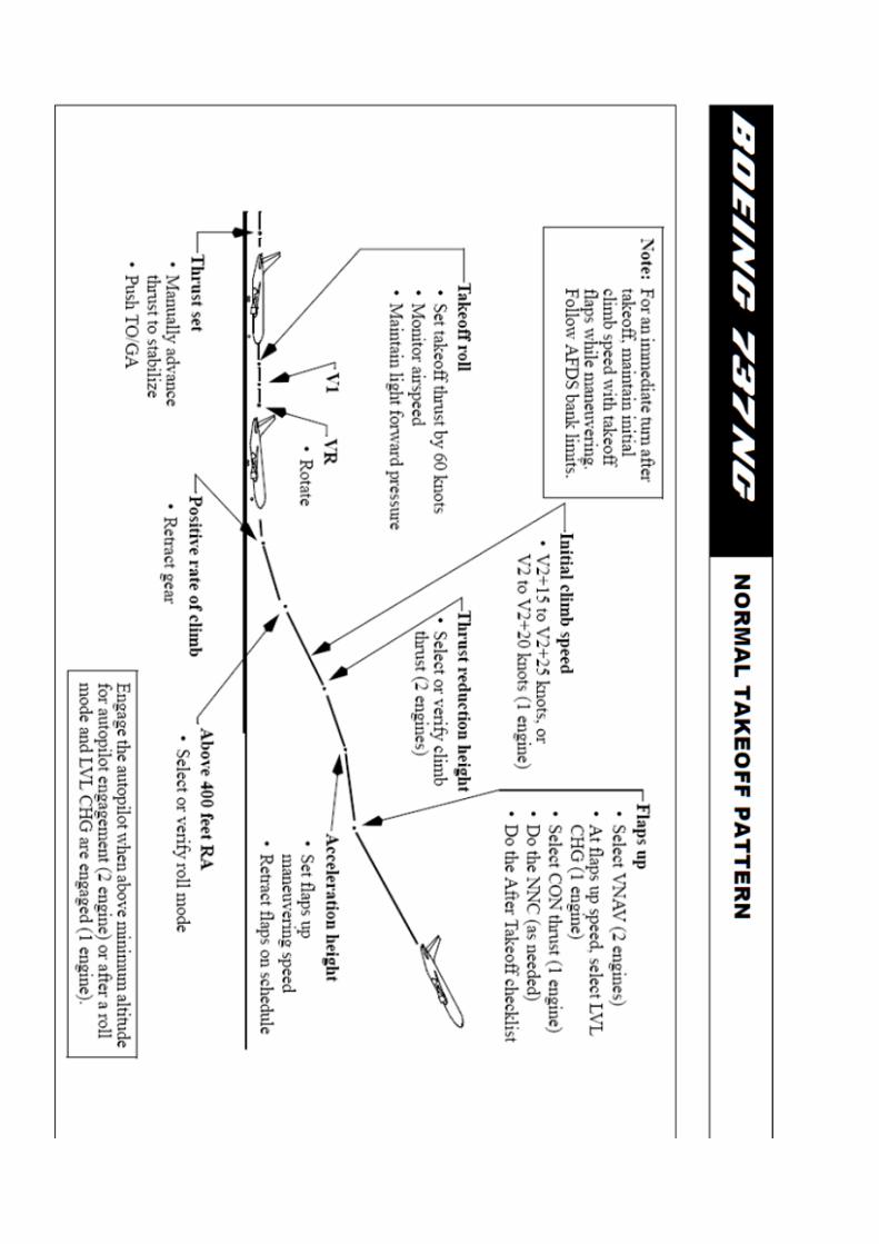
Monitor airspeed, When the rotation speed (VR) is reached, smoothly rotate the aircraft to 8 degrees pitch up attitude until 20~30ft AGL to avoid a tailstrike. When positive rate of climb is indicated, call “GEAR UP” and position landing gear lever UP. Continue rotation to takeoff pitch, Flight Director guidance is of great use, just follow the pink horizontal bar.
Continue to Check Flight Instruments.

>>> After Takeoff Procedure Explained <<<
Maintain a minimum of V2 + 15 knots during initial climb. At light gross weight a higher speed (up to V2 + 25) may be selected. When above minimum altitude for autopilot engagement, you can engage A/P. Verify flight mode annunciation. Above 400 feet, select appropriate roll mode, if required (LNAV, HDG SEL for example).
Verify proper mode annunciation. Above 1,000 feet, set Flaps Up manoeuvring speed. Verify climb thrust is set and proper mode is annunciated. (LVL CHG for example) Above 3,000 feet AGL, (Acceleration Height) Retract Flaps on flap retraction speed schedule and monitor flaps and slats retraction. Engage VNAV or select normal climb speed and verify
annunciation. Perform AFTER TAKEOFF CHECKLIST when flaps are up.
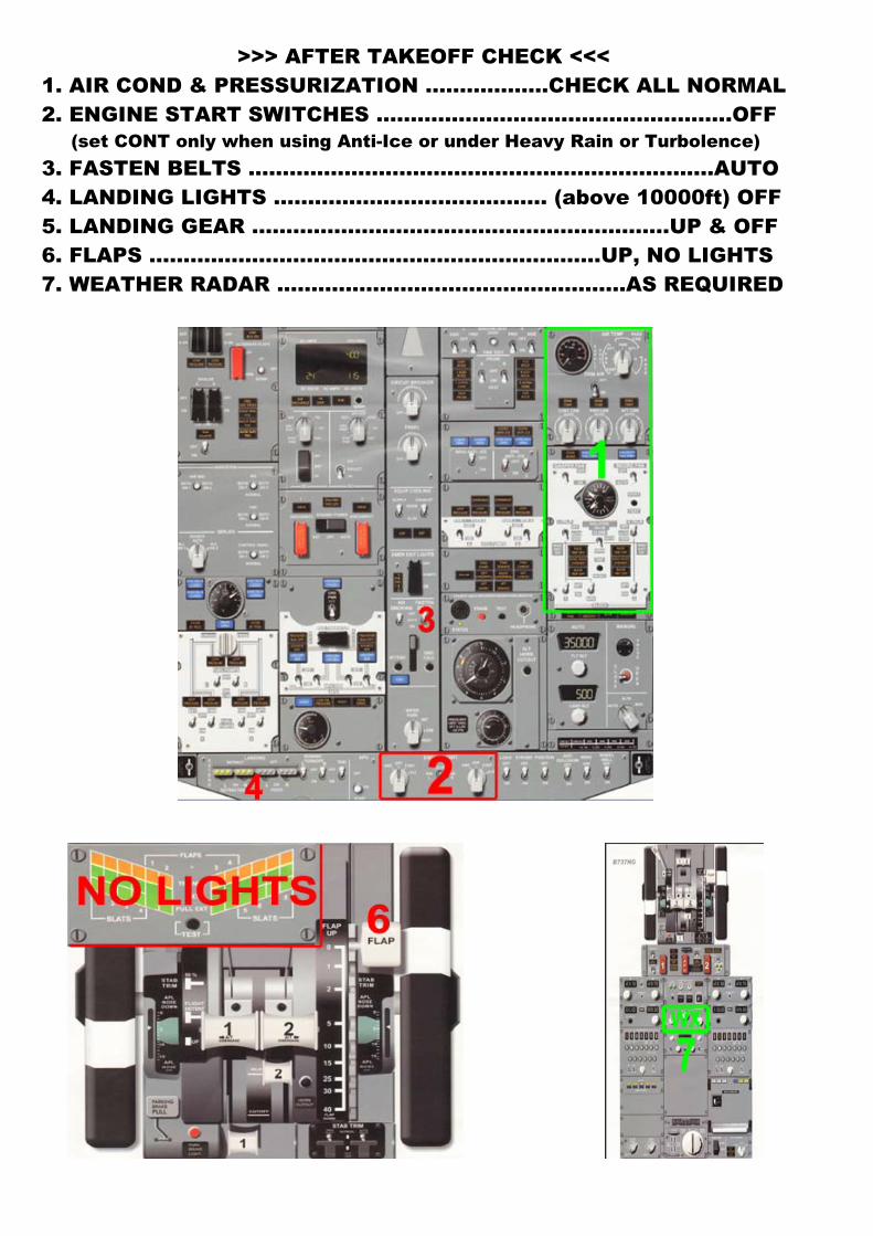
>>> AFTER TAKEOFF CHECK <<< 1. AIR COND & PRESSURIZATION …….………..CHECK ALL NORMAL 2. ENGINE START SWITCHES ……………….…………….……………..OFF
(set CONT only when using Anti-Ice or under Heavy Rain or Turbolence) 3. FASTEN BELTS ………………………………….………….……………AUTO 4. LANDING LIGHTS …………………….…………… (above 10000ft) OFF 5. LANDING GEAR …………………………………………………….UP & OFF 6. FLAPS …………………………………………………………UP, NO LIGHTS 7. WEATHER RADAR ……………………………………..…….AS REQUIRED
>>> Climb and Cruise Procedure Explained <<<
Position landing lights OFF passing through 10,000 feet.
Set altimeters to standard at transition altitude.
Approaching selected FMC cruise altitude, verify level off and proper mode/N1 limit annunciation.
Position center tank fuel pump switches OFF when both pump LOW PRESSURE lights illuminate.
During the last hour of cruise on all extended range (ETOPS) flights, perform Fuel Crossfeed Valve check.
Prior to top of descent, select and verify the planned arrival procedure on the FMC. Set MCP altitude selector for descent. At top of descent point observe descent initiated and verify proper mode annunciation.
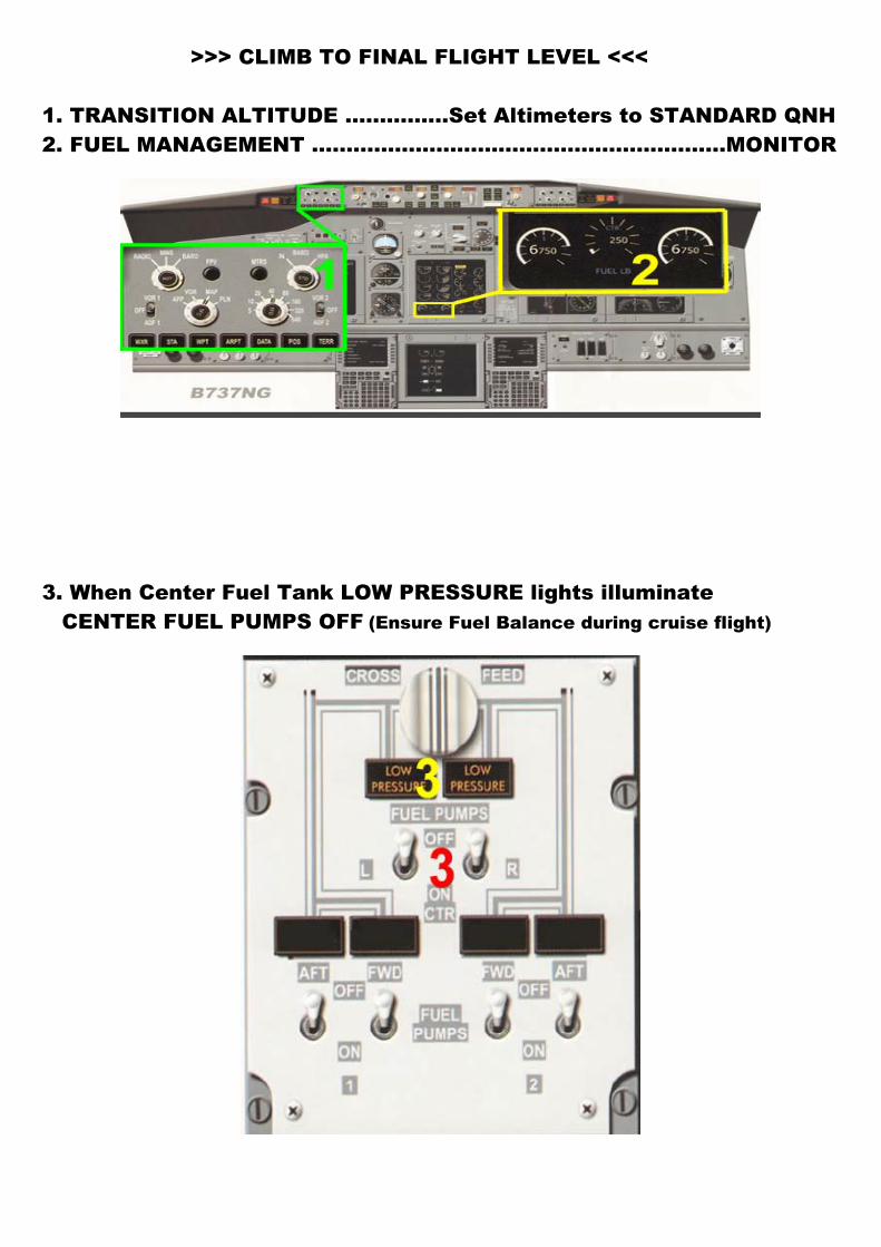
>>> CLIMB TO FINAL FLIGHT LEVEL <<<
1. TRANSITION ALTITUDE …………...Set Altimeters to STANDARD QNH 2. FUEL MANAGEMENT ............................................................MONITOR
3. When Center Fuel Tank LOW PRESSURE lights illuminate CENTER FUEL PUMPS OFF (Ensure Fuel Balance during cruise flight)
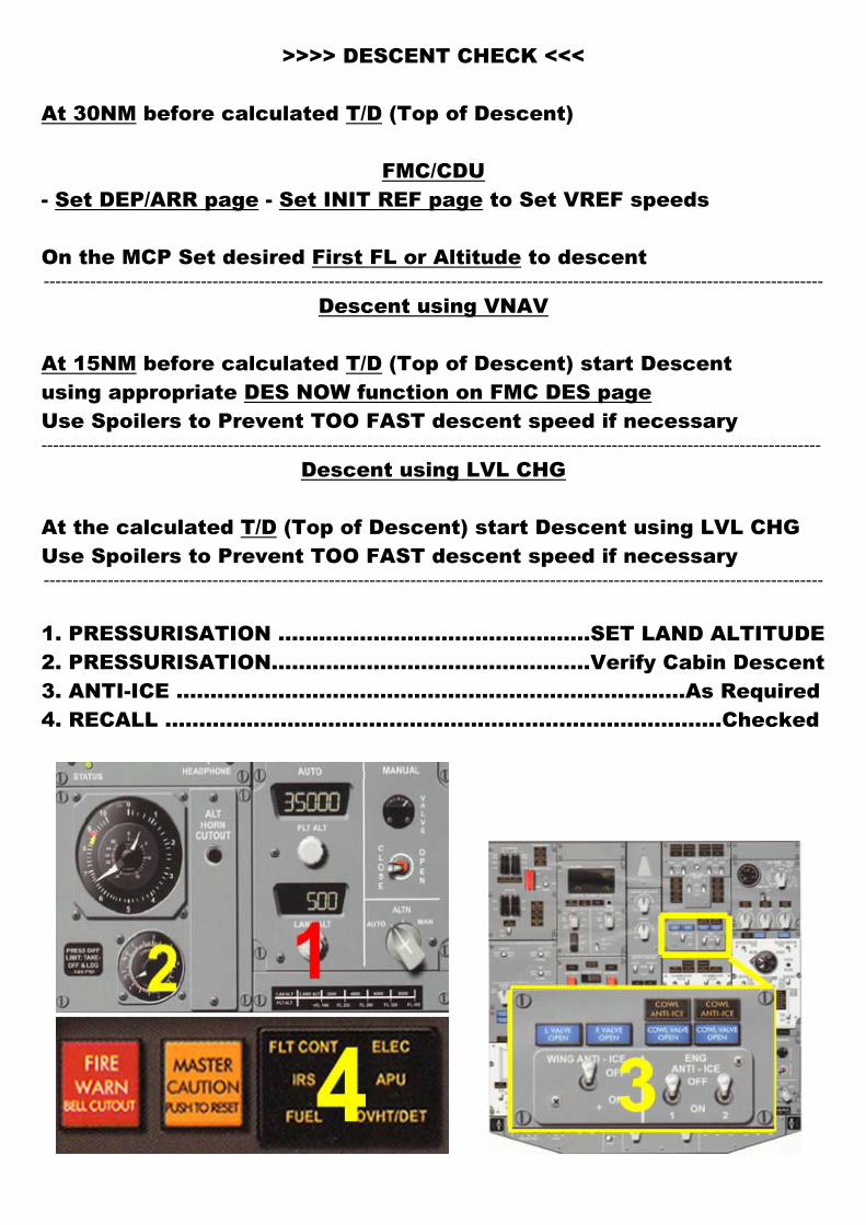
>>>> DESCENT CHECK <<<
At 30NM before calculated T/D (Top of Descent)
FMC/CDU - Set DEP/ARR page - Set INIT REF page to Set VREF speeds
On the MCP Set desired First FL or Altitude to descent --------------------------------------------------------------------------------------------------------------------------------------
Descent using VNAV
At 15NM before calculated T/D (Top of Descent) start Descent using appropriate DES NOW function on FMC DES page Use Spoilers to Prevent TOO FAST descent speed if necessary --------------------------------------------------------------------------------------------------------------------------------------
Descent using LVL CHG At the calculated T/D (Top of Descent) start Descent using LVL CHG Use Spoilers to Prevent TOO FAST descent speed if necessary --------------------------------------------------------------------------------------------------------------------------------------
1. PRESSURISATION …………………..…………………..SET LAND ALTITUDE 2. PRESSURISATION...............................................Verify Cabin Descent 3. ANTI-ICE ...............................………………………..…………...As Required 4. RECALL ……………………………………………..………………………..Checked
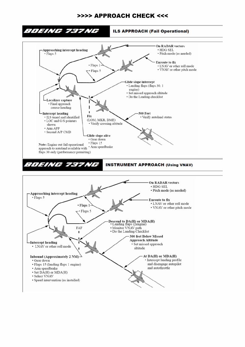
>>>> APPROACH CHECK <<<
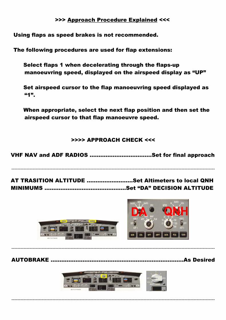
>>> Approach Procedure Explained <<<
Using flaps as speed brakes is not recommended. The following procedures are used for flap extensions:
� Select flaps 1 when decelerating through the flaps-up manoeuvring speed, displayed on the airspeed display as “UP”
� Set airspeed cursor to the flap manoeuvring speed displayed as
“1”. � When appropriate, select the next flap position and then set the
airspeed cursor to that flap manoeuvre speed.
>>>> APPROACH CHECK <<<
VHF NAV and ADF RADIOS ……………....................Set for final approach --------------------------------------------------------------------------------------------------------------------------------------
AT TRASITION ALTITUDE ………..…………...Set Altimeters to local QNH MINIMUMS ...............................……………Set “DA” DECISION ALTITUDE
--------------------------------------------------------------------------------------------------------------------------------------
AUTOBRAKE ........................................................……………….As Desired
--------------------------------------------------------------------------------------------------------------------------------------
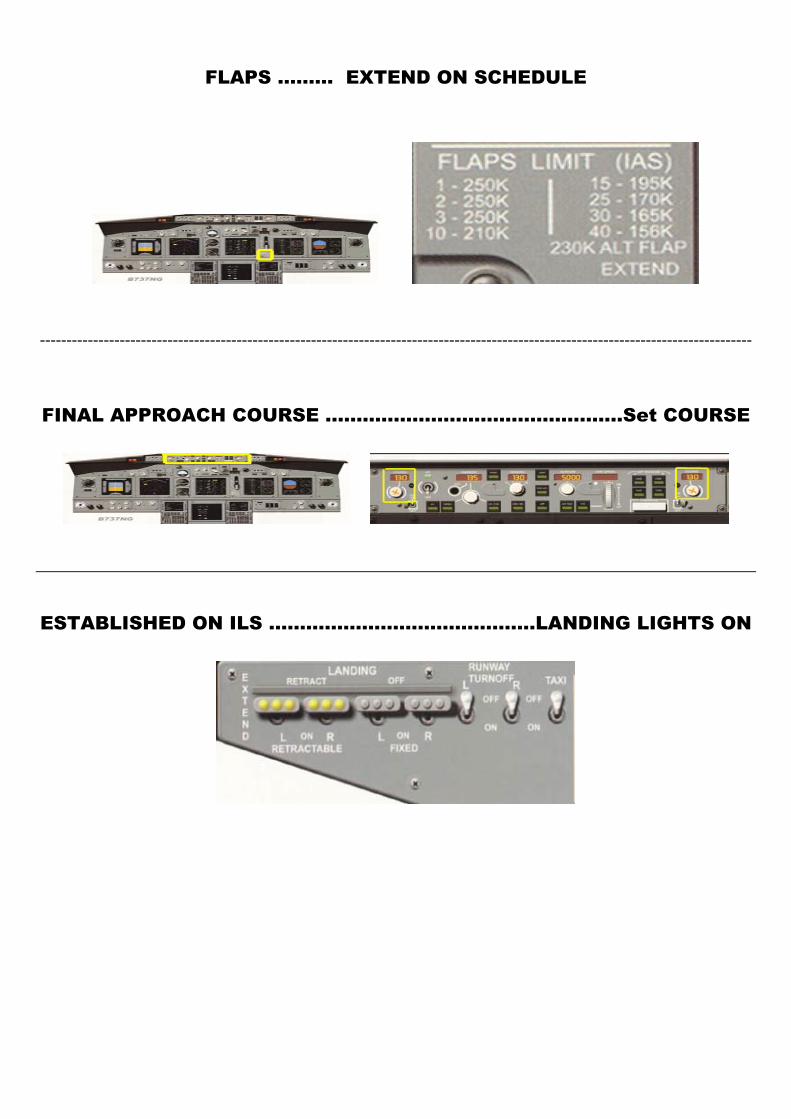
FLAPS ……… EXTEND ON SCHEDULE
--------------------------------------------------------------------------------------------------------------------------------------
FINAL APPROACH COURSE ................................................Set COURSE
ESTABLISHED ON ILS …………………………………….LANDING LIGHTS ON
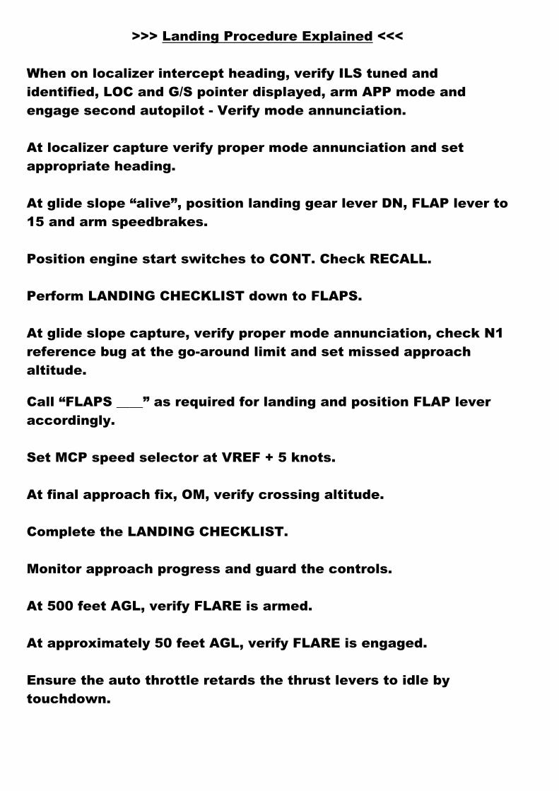
>>> Landing Procedure Explained <<<
When on localizer intercept heading, verify ILS tuned and identified, LOC and G/S pointer displayed, arm APP mode and engage second autopilot - Verify mode annunciation.
At localizer capture verify proper mode annunciation and set appropriate heading.
At glide slope “alive”, position landing gear lever DN, FLAP lever to 15 and arm speedbrakes.
Position engine start switches to CONT. Check RECALL. Perform LANDING CHECKLIST down to FLAPS. At glide slope capture, verify proper mode annunciation, check N1 reference bug at the go-around limit and set missed approach altitude.
Call “FLAPS ____” as required for landing and position FLAP lever accordingly. Set MCP speed selector at VREF + 5 knots. At final approach fix, OM, verify crossing altitude. Complete the LANDING CHECKLIST. Monitor approach progress and guard the controls. At 500 feet AGL, verify FLARE is armed. At approximately 50 feet AGL, verify FLARE is engaged. Ensure the auto throttle retards the thrust levers to idle by touchdown.
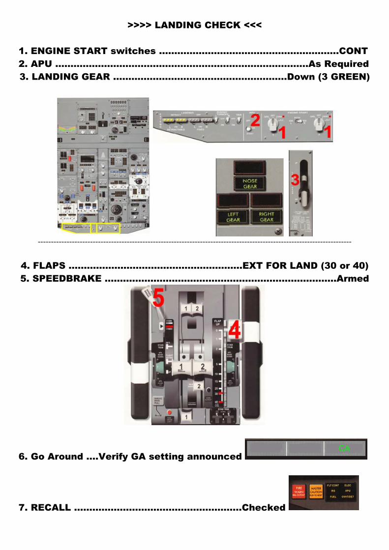
>>>> LANDING CHECK <<< 1. ENGINE START switches ……………………………………..……………CONT 2. APU ………………………………………………………………………..As Required 3. LANDING GEAR ………………………………………………...Down (3 GREEN)
------------------------------------------------------------------------------------------------------------------------
4. FLAPS …………………………………………………EXT FOR LAND (30 or 40) 5. SPEEDBRAKE …………………………………………………..……………..Armed
6. Go Around ….Verify GA setting announced
7. RECALL ……………………..………………………..Checked
>>> Go-Around Procedure Explained <<<
Push TO/GA button switch. Call “FLAPS 15” and position FLAP lever to 15. Confirm rotation to go-around attitude and monitor autopilot. When positive rate of climb is indicated, position landing gear lever UP - Check flight instruments indications. Above 400 feet, select appropriate roll mode and verify proper mode annunciation. Retract flaps on speed schedule. Verify airplane levels off at selected altitude and maintain flaps manoeuvring speed - Accomplish AFTER TAKEOFF checklist. -----------------------------------------------------------------------------------------------------
>>> Landing Roll Procedure Explained <<<
Ensure thrust levers at idle.
Disengage autopilot and control airplane manually. Verify auto throttle disengages automatically.
Verify SPEED BRAKE lever – UP --- Verify proper auto brake operation.
Without delay, apply reverse thrust as required.
At 60 knots, reduce reverse thrust to be at IDLE reverse when reaching taxi speed.
Verify REV indications extinguished.
Prior to taxi speed, disarm, the auto brake and continue manual braking as required.
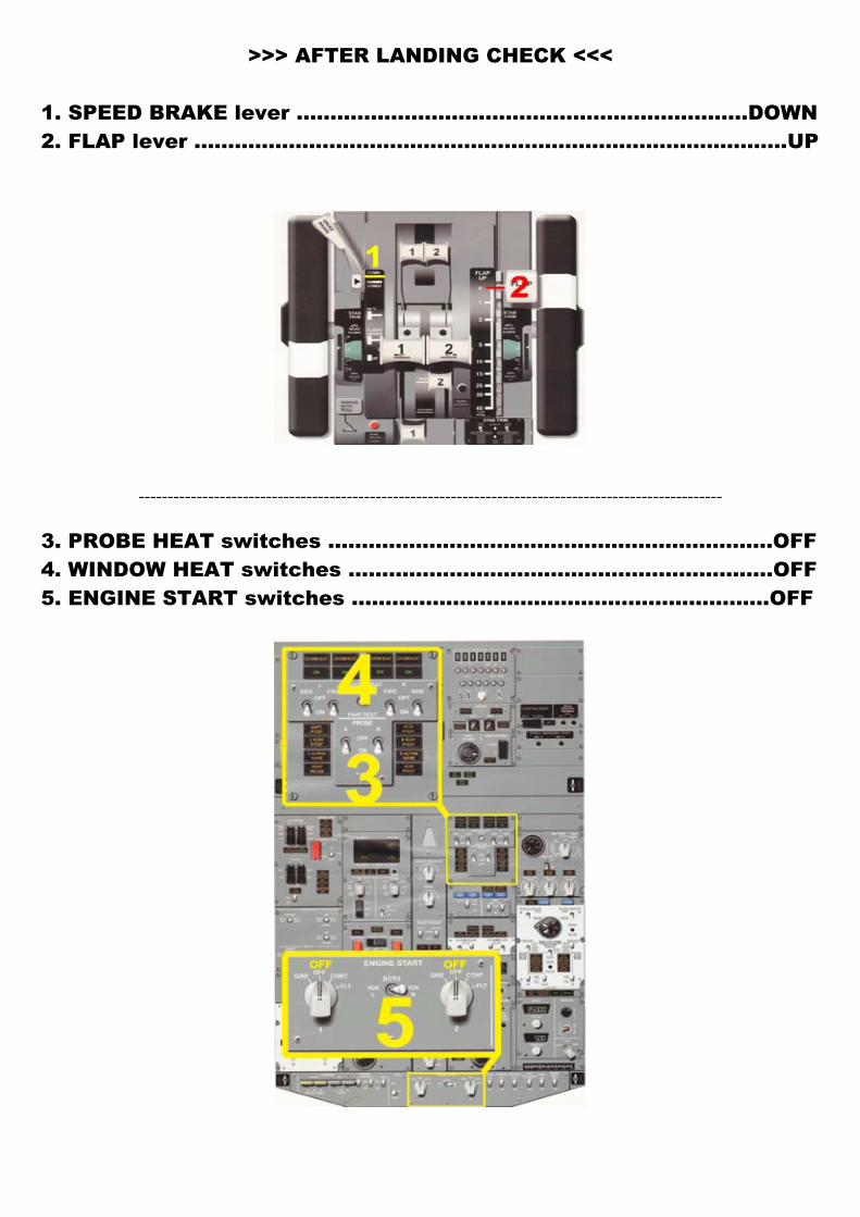
>>> AFTER LANDING CHECK <<< 1. SPEED BRAKE lever ....................................................……………DOWN 2. FLAP lever ..........................................................…………………………UP
-----------------------------------------------------------------------------------------------------
3. PROBE HEAT switches ..............................................………………..OFF 4. WINDOW HEAT switches …………..………………………………………….OFF 5. ENGINE START switches ...............................................……………OFF
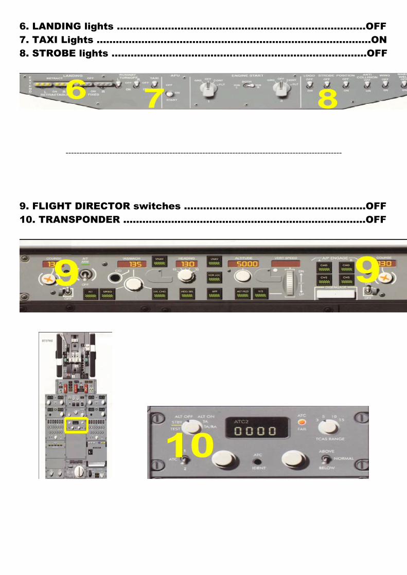
6. LANDING lights ...................................................………………………OFF 7. TAXI Lights ...............................................…………………………………ON 8. STROBE lights .................................................……………………..…..OFF
-----------------------------------------------------------------------------------------------------
9. FLIGHT DIRECTOR switches .............................................…………OFF 10. TRANSPONDER ....................................................……………………OFF
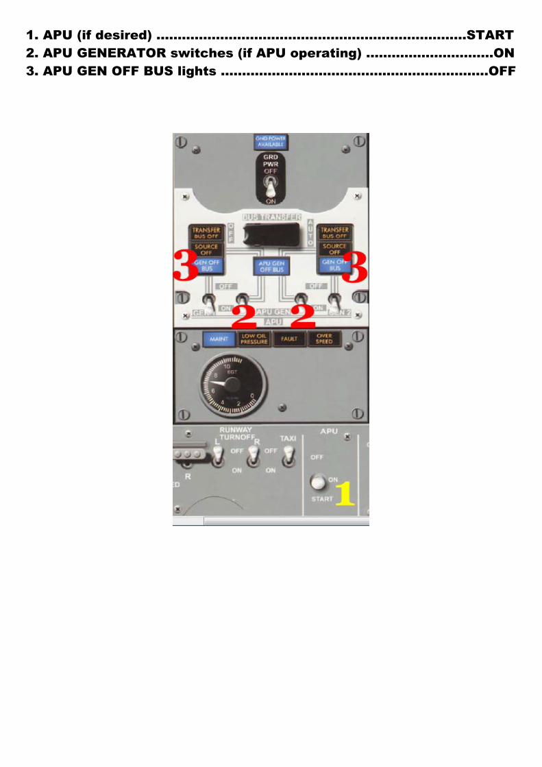
1. APU (if desired) ........................................................……………..START 2. APU GENERATOR switches (if APU operating) ..............................ON 3. APU GEN OFF BUS lights ...............................................................OFF
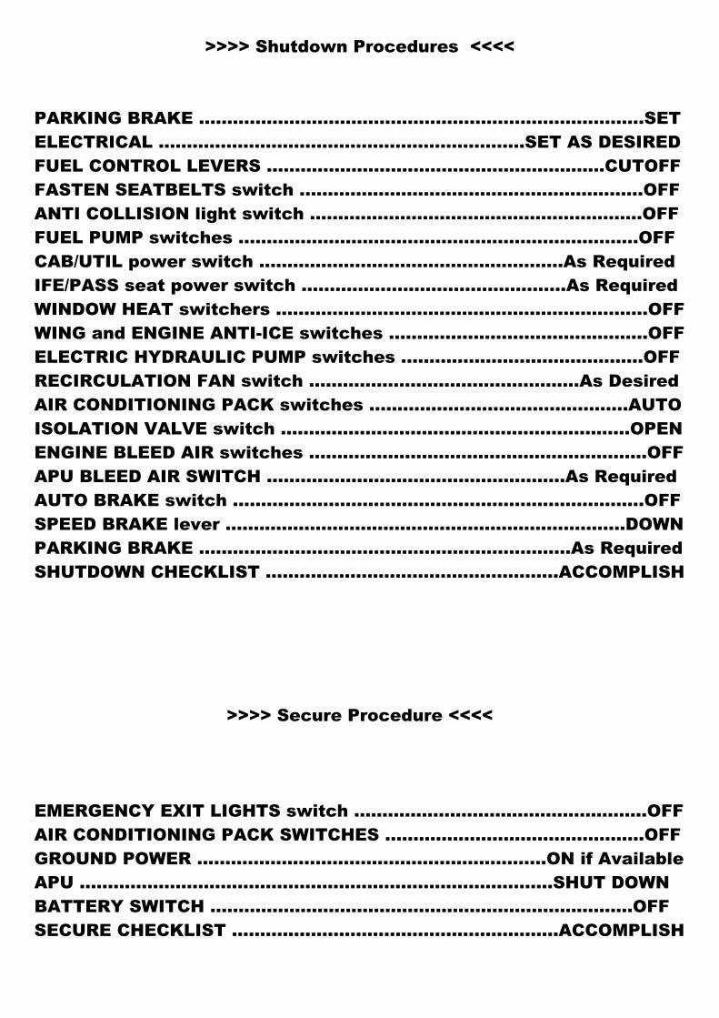
>>>> Shutdown Procedures <<<<
PARKING BRAKE ...................................................……….………………SET ELECTRICAL ...................................................………..…SET AS DESIRED FUEL CONTROL LEVERS ......................................................……CUTOFF FASTEN SEATBELTS switch ...................................................……….OFF ANTI COLLISION light switch ................................................………..OFF FUEL PUMP switches ...........................................……………..………..OFF CAB/UTIL power switch ..............................................……..As Required IFE/PASS seat power switch ...........................................….As Required WINDOW HEAT switchers .........................…………….………….…………OFF WING and ENGINE ANTI-ICE switches ..............................................OFF ELECTRIC HYDRAULIC PUMP switches ...........................................OFF RECIRCULATION FAN switch ................................................As Desired AIR CONDITIONING PACK switches ..............................................AUTO ISOLATION VALVE switch ..............................................................OPEN ENGINE BLEED AIR switches ............................................................OFF APU BLEED AIR SWITCH .....................................................As Required AUTO BRAKE switch .............................…………………………..…………OFF SPEED BRAKE lever ...................................................………………..DOWN PARKING BRAKE ....................................................…………..As Required SHUTDOWN CHECKLIST ....................................................ACCOMPLISH
>>>> Secure Procedure <<<<
EMERGENCY EXIT LIGHTS switch ....................................................OFF AIR CONDITIONING PACK SWITCHES ..............................................OFF GROUND POWER ……………………………………………………..ON if Available APU .............................................................................….…SHUT DOWN BATTERY SWITCH ............................................…………...................OFF SECURE CHECKLIST ..........................................................ACCOMPLISH