co2 transcritical - kysor warren · figure 1.5, figure 1.6, and table 1.1 show the co2...
TRANSCRIPT
CO2MANUAL
INSTALLATIONAND OPERATIONMANUAL
CO2 TRANSCRITICAL
31E08024
2
CO2 TRANSCRITICALBOOSTER SYSTEM
SYSTEMOPERATION
SAFETYMAINTENANCE ANDTROUBLESHOOTING
INSPECTION AND HANDLING
WARRANTY ANDMANUAL DISCLAIMER
SYSTEMINSTALLATION
1 523 7
6
4
1.1. Introduction1.2. System Overview1.3. Primary Components and Subcomponents1.5. Optional Components
0404
0811
303030
313434
131313
1315
36383839
19192020
4244
232323272728 28
5.1. Initiate System Power5.2. CO2 Initial Charging5.3. Start Compressors5.4. Evaporator Temperature Control 5.5. Defrost Operation5.6. Walk-In Door Switches
2.1. General Safety Considerations2.2. On Site Warning Signage2.3. Personal Protective Gear2.4. CO2 Safety and Environmental Characteristics 2.5. Safety Related Components
6.1. General Maintenance Procedures6.2. Alarms6.3. Common Maintenance Actions6.4. Troubleshooting
3.1. Inspection of Materials3.2. Rating plate3.3. Lifting Instructions3.4. Placement of Equipment
7.1. Standard Warranty7.2. Manual Disclaimer
4.1. General4.2. Responsibilities4.3. Field Piping4.4. Testing and Evacuation4.5. Insulation4.6. Labeling Requirements4.7. Electrical
DATA, DEFINITIONSAND ACRONYMS8 46
508.1. Data8.2. Definitions and Acronyms
CO2MANUAL
CO2 TRANSCRITICALBOOSTER SYSTEM
1
4
CO2 TRANSCRITICAL BOOSTER SYSTEM
1.1. INTRODUCTION
This manual provides information for system warranty, inspection, installation, start-up, operation, service and maintenance of Heatcraft CO2 Transcritical Booster Refrigeration Systems along with some general system specifications. See additional specifications required and provided by Heatcraft and the customer. Additional specifications may include:
• Schedule / Legend of Equipment Load and Electrical Requirements
• Configuration Overview and List of Options ordered
• Sequence of Operations
• Specifications of Components
• Specific Piping Diagram
• Site Specific Installation Drawings
The standard warranty and manual disclaimer are located in Section 7.
NOTE
Customer specifications and local codes take precedence over directions contained in this document. Installation and service that do not comply with this manual may lead to poor performance or reliability, and will void the equipment warranty. Changes to the additional specifications (above) that are not approved by Heatcraft will void the warranty of the system. Contact your Heatcraft representative to verify the most current version of this manual.
1.2. SYSTEM OVERVIEW
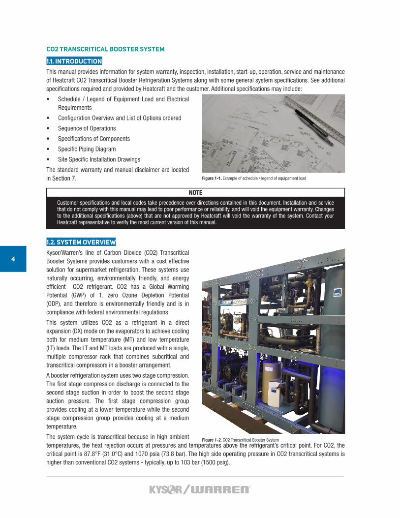
Kysor/Warren’s line of Carbon Dioxide (CO2) Transcritical Booster Systems provides customers with a cost effective solution for supermarket refrigeration. These systems use naturally occurring, environmentally friendly, and energy efficient CO2 refrigerant. CO2 has a Global Warming Potential (GWP) of 1, zero Ozone Depletion Potential (ODP), and therefore is environmentally friendly and is in compliance with federal environmental regulations
This system utilizes CO2 as a refrigerant in a direct expansion (DX) mode on the evaporators to achieve cooling both for medium temperature (MT) and low temperature (LT) loads. The LT and MT loads are produced with a single, multiple compressor rack that combines subcritical and transcritical compressors in a booster arrangement.
A booster refrigeration system uses two stage compression. The first stage compression discharge is connected to the second stage suction in order to boost the second stage suction pressure. The first stage compression group provides cooling at a lower temperature while the second stage compression group provides cooling at a medium temperature.
The system cycle is transcritical because in high ambient temperatures, the heat rejection occurs at pressures and temperatures above the refrigerant’s critical point. For CO2, the critical point is 87.8°F (31.0°C) and 1070 psia (73.8 bar). The high side operating pressure in CO2 transcritical systems is higher than conventional CO2 systems - typically, up to 103 bar (1500 psig).
Figure 1-1. Example of schedule / legend of equipament load
Figure 1-2. CO2 Transcritical Booster System
CO2 TRANSCRITICAL BOOSTER / REFRIGERATION SYSTEM
5
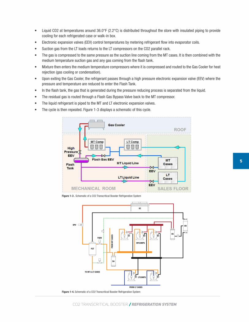
• Liquid CO2 at temperatures around 36.0°F (2.2°C) is distributed throughout the store with insulated piping to provide cooling for each refrigerated case or walk-in box.
• Electronic expansion valves (EEV) control temperatures by metering refrigerant flow into evaporator coils.
• Suction gas from the LT loads returns to the LT compressors on the CO2 parallel rack.
• The gas is compressed to the same pressure as the suction line coming from the MT cases. It is then combined with the medium temperature suction gas and any gas coming from the flash tank.
• Mixture then enters the medium temperature compressors where it is compressed and routed to the Gas Cooler for heat rejection (gas cooling or condensation).
• Upon exiting the Gas Cooler, the refrigerant passes through a high pressure electronic expansion valve (EEV) where the pressure and temperature are reduced to enter the Flash Tank.
• In the flash tank, the gas that is generated during the pressure reducing process is separated from the liquid.
• The residual gas is routed through a Flash Gas Bypass Valve back to the MT compressor.
• The liquid refrigerant is piped to the MT and LT electronic expansion valves.
• The cycle is then repeated. Figure 1-3 displays a schematic of this cycle.
Figure 1-3 . Schematic of a CO2 Transcritical Booster Refrigeration System
Figure 1-4. Schematic of a CO2 Transcritical Booster Refrigeration System
GC
FROM LT CASES
FROM
MT
CASE
S
TO MT & LT CASES
MTCOMPS
OS
ORHPV
FGBV
FGT
SA
LTCOMPS
6
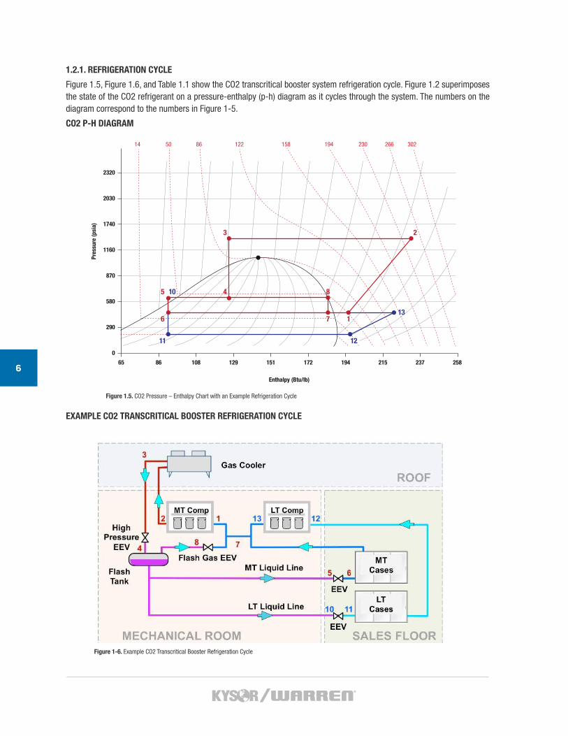
1.2.1. REFRIGERATION CYCLE
Figure 1.5, Figure 1.6, and Table 1.1 show the CO2 transcritical booster system refrigeration cycle. Figure 1.2 superimposes the state of the CO2 refrigerant on a pressure-enthalpy (p-h) diagram as it cycles through the system. The numbers on the diagram correspond to the numbers in Figure 1-5.
CO2 P-H DIAGRAM
EXAMPLE CO2 TRANSCRITICAL BOOSTER REFRIGERATION CYCLE
Figure 1-6. Example CO2 Transcritical Booster Refrigeration Cycle
1211
5 10 4
3 2
6
8
7 113
Pres
sure
(psi
a)
Enthalpy (Btu/lb)
65
0
290
580
870
1160
1740
2030
2320
86 108 129 151 172 194 215 237 258
14 50 86 122 158 194 230 266 302
Figure 1.5. CO2 Pressure – Enthalpy Chart with an Example Refrigeration Cycle

CO2 TRANSCRITICAL BOOSTER / REFRIGERATION SYSTEM
7
1.2.2. EXPLANATION OF CO2 TRANSCRITICAL BOOSTER REFRIGERATION CYCLE
Using the numbers in Figures 1-5 and 1-6, Table 1-1 explains each step.
WORKING AND DESIGN PRESSURES FOR A CO2 TRANSCRITICAL BOOSTER REFRIGERATION SYSTEM
The range of working pressures and design pressures for the system are shown in the Table 1-2.
Description Working Pressure Components Design Pressure
Low side188 to 218 psig (13 to 15 bar)
LT Cases, LT Suction Piping435 psig (30 bar, 28 bar for scroll compressors)
IM Press Stage – MT Suction
377 to 435 psig(26 to 30 bar)
MT Cases, LT Compressors, MT Suction Piping, LT Discharge Piping
652 psig (45 bar, 43 bar for scroll compressors)
IM Press Stage – Liquid Line
493 to 551 psig(34 to 38 bar)
Flash Tank, FGBV, FG EEV, Case EEVs, Liquid Supply Piping
652 psig(45 bar)
High side652 to 1495 psig(45 to 103 bar)
Gas Cooler, HPEV,MT Compressors,MT Discharge Piping
1740 psig(120 bar)
Table 1-2. Working and Design Pressures for a CO2 Transcritical Booster Refrigeration System
Sequence Description
1 to 2 CO2 refrigerant gas gains pressure and heat though the medium temperature (MT) compressor.
2 to 3 CO2 goes through the condenser/gas cooler and loses heat.
3 to 4 The high pressure electronic expansion valve (EEV) causes the refrigerant to loose pressure. The refrigerant is now a mix of gas and liquid.
Flash TankThe flash tank allows the refrigerant to be separated into a gas or a liquid. The liquid is piped to the evapo-rator/cases and the gas is re-routed to the MT compressor.
5 to 6A proportion of the liquid refrigerant is piped to the MT evaporator/cases and loses heat. The EEV reduces its pressure still more.
4-5-10-11A proportion of the liquid refrigerant is piped to the low temperature (LT) evaporator/cases. The EEV reduc-es its pressure still more.
6 to 7 and 11 to 12
In both the LT and the MT evaporators/cases, the liquid refrigerant gains heat, boils and turns into 100% gas.
7-1-2The refrigerant from the MT evaporators/cases mixes with the refrigerant leaving the LT compressor. It then goes through the MT compressor, gaining pressure and heat.
8-7 Vapor from FGT goes through FGBV an enters into the MT compressors.
12-13-7The refrigerant, now 100% gas, is piped to the LT compressor where it gains pressure and heat. When it leaves the MT compressor, it mixes with the refrigerant from the MT evaporator/cases and goes to the MT Compressor.
The cycle then begins again.Table 1-1. The Cycle of the CO2 Transcritical Booster Refrigeration System
8
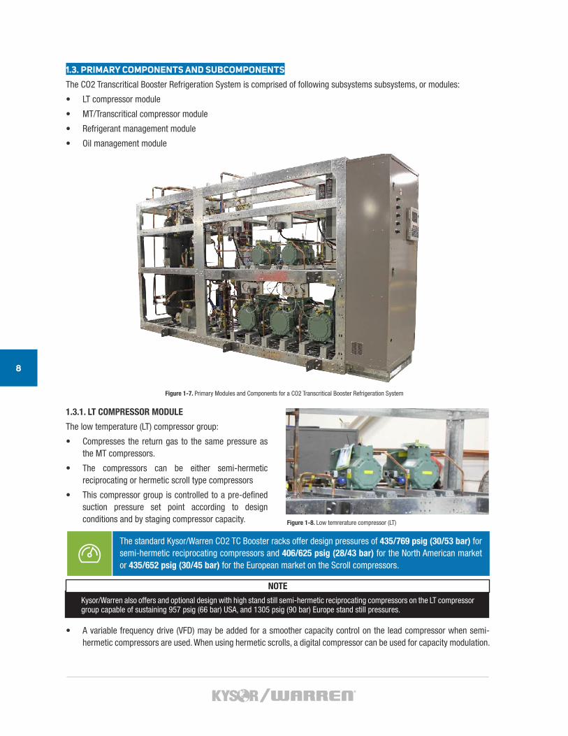
1.3. PRIMARY COMPONENTS AND SUBCOMPONENTS
The CO2 Transcritical Booster Refrigeration System is comprised of following subsystems subsystems, or modules:
• LT compressor module
• MT/Transcritical compressor module
• Refrigerant management module
• Oil management module
1.3.1. LT COMPRESSOR MODULE
The low temperature (LT) compressor group:
• Compresses the return gas to the same pressure as the MT compressors.
• The compressors can be either semi-hermetic reciprocating or hermetic scroll type compressors
• This compressor group is controlled to a pre-defined suction pressure set point according to design conditions and by staging compressor capacity.
• A variable frequency drive (VFD) may be added for a smoother capacity control on the lead compressor when semi-hermetic compressors are used. When using hermetic scrolls, a digital compressor can be used for capacity modulation.
Figure 1-7. Primary Modules and Components for a CO2 Transcritical Booster Refrigeration System
The standard Kysor/Warren CO2 TC Booster racks offer design pressures of 435/769 psig (30/53 bar) for semi-hermetic reciprocating compressors and 406/625 psig (28/43 bar) for the North American market or 435/652 psig (30/45 bar) for the European market on the Scroll compressors.
NOTE
Kysor/Warren also offers and optional design with high stand still semi-hermetic reciprocating compressors on the LT compressor group capable of sustaining 957 psig (66 bar) USA, and 1305 psig (90 bar) Europe stand still pressures.
Figure 1-8. Low temrerature compressor (LT)
CO2 TRANSCRITICAL BOOSTER / REFRIGERATION SYSTEM
9
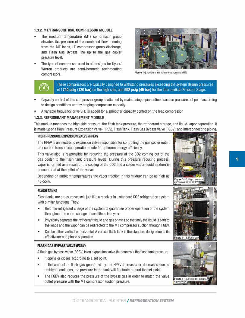
1.3.2. MT/TRANSCRITICAL COMPRESSOR MODULE
• The medium temperature (MT) compressor group elevates the pressure of the combined flows coming from the MT loads, LT compressor group discharge, and Flash Gas Bypass line up to the gas cooler pressure level.
• The type of compressor used in all designs for Kysor/Warren products are semi-hermetic reciprocating compressors.
These compressors are typically designed to withstand pressures exceeding the system design pressures of 1740 psig (120 bar) on the high side, and 652 psig (45 bar) for the Intermediate Pressure Stage.
• Capacity control of this compressor group is attained by maintaining a pre-defined suction pressure set point according to design conditions and by staging compressor capacity.
• A variable frequency drive VFD is added for a smoother capacity control on the lead compressor.
1.3.3. REFRIGERANT MANAGEMENT MODULE
This module manages the high side pressure, the flash tank pressure, the refrigerant storage, and liquid-vapor separation. It is made up of a High Pressure Expansion Valve (HPEV), Flash Tank, Flash Gas Bypass Valve (FGBV), and interconnecting piping.
Figure 1-9. Medium temrerature compressor (MT)
HIGH PRESSURE EXPANSION VALVE (HPEV)
The HPEV is an electronic expansion valve responsible for controlling the gas cooler outlet pressure in transcritical operation mode for optimum energy efficiency.
This valve also is responsible for reducing the pressure of the CO2 coming out of the gas cooler to the flash tank pressure levels. During this pressure reducing process, vapor is formed as a result of the cooling of the CO2 and a colder vapor-liquid mixture is encountered at the outlet of the valve.
Depending on ambient temperatures the vapor fraction in this mixture can be as high as 45-55%.
Figure 1-10. High pressure expansion valve (HPEV)
FLASH TANKS
Flash tanks are pressure vessels just like a receiver in a standard CO2 refrigeration system with similar functions. They:
• Hold the refrigerant charge of the system to guarantee proper operation of the system throughout the entire change of conditions in a year.
• Physically separate the refrigerant liquid and gas phases so that only the liquid is sent to the loads and the vapor can be redirected to the MT compressor suction through FGBV.
• Can be either vertical or horizontal. A vertical flash tank is the standard design due to its effectiveness in phase separation. Figure 1-11. Flash tank
FLASH GAS BYPASS VALVE (FGBV)
A flash gas bypass valve (FGBV) is an expansion valve that controls the flash tank pressure.
• It opens or closes according to a set point.
• If the amount of flash gas generated by the HPEV increases or decreases due to ambient conditions, the pressure in the tank will fluctuate around the set-point.
• The FGBV also reduces the pressure of the bypass gas in order to match the valve outlet pressure with the MT compressor suction pressure.
Figure 1-12. Flash gas bypass valve (FGBV)

10
1.3.4. OIL MANAGEMENT
Oil is essential for the reliability of the compressors in a refrigeration system as well as lubricating seals. As compressors pump refrigerant they also pump a small amount of oil with it. The volume of oil in refrigerant lines and heat exchangers displaces refrigerant volume, and reduces the efficiency of the system. To avoid trapping oil in other parts of the system and depleting the oil level in the compressors, it is important to recover it and properly return it to the compressor crankcase.
The oil management system of Kysor/Warren’s CO2 TC Booster racks includes a common oil separator with electronic oil management at the discharge side of the MT compressors group. Also included in this module are: an oil transfer and pressure reducing valve, an oil reservoir, an oil filter and electronic oil level regulators for replenishing the oil according to the demand by each individual compressor.
A coalescing type oil separator is used to provide very high efficiency, usually above 97%, oil recovery. This oil separator is equipped with an oil level switch, which triggers the opening of the oil transfer and pressure reducing valve. The valve opens when it senses oil at the bottom of the separator and transfers the oil to the reservoir. The oil transfer and pressure reducing valve is a normally closed solenoid valve with a small port to cause the pressure drop from the discharge to the flash tank pressure level.
The oil reservoir is a standard pressure vessel for oil storage and supply to the compressor crankcase. The electronic oil level regulators use a level switch mounted at the sight glass port of the compressor to detect the oil level inside of the compressor. When the oil level falls below the sensor, a solenoid valve opens allowing oil flow to the compressor crankcase.
The oil separator and pressure reducing valve are rated for 1740 psig (120 bar) or more. Downstream of the oil transfer valve, all components are rated for the design pressure of the liquid lines in the system, typically 652 psig (45 bar) except in the special case of high stand still pressure design.
Figure 1-13. Oil reservoir
Figure 1-14. Coalescing oil separator
REMOTE GAS COOLER/CONDENSER
Gas Coolers cool the CO2 refrigerant to near ambient temperature. Above the critical point, CO2 gas does not condense, so there is no phase change. The CO2 remains as a single phase gas from the inlet to the outlet as the temperature is reduced. Gas coolers come in different forms and functions. The most commonly used are air cooled gas coolers. Systems in dry climates could benefit by adding evaporative assisted cooling. The efficiency of any gas cooler varies with the climate. At lower ambient temperatures, when CO2 is below the critical point, a gas cooler operates as a conventional condenser and phase change occurs from vapor to liquid. Figure 1-15. Remote gas cooler/condenser
CO2 TRANSCRITICAL BOOSTER / REFRIGERATION SYSTEM
11PARALLEL COMPRESSION SYSTEM (OPTIONAL)
Parallel compression is an improved cycle configuration of CO2 Transcritical Booster refrigeration systems for warm climates. In this configuration – see Figure 1-6, instead of routing the flash gas to the MT compressors suction, it connects the flash gas bypass line directly to a group of compressors without dropping the pressure through the FGBV.
MT
LT
1.4. OPTIONAL COMPONENTS
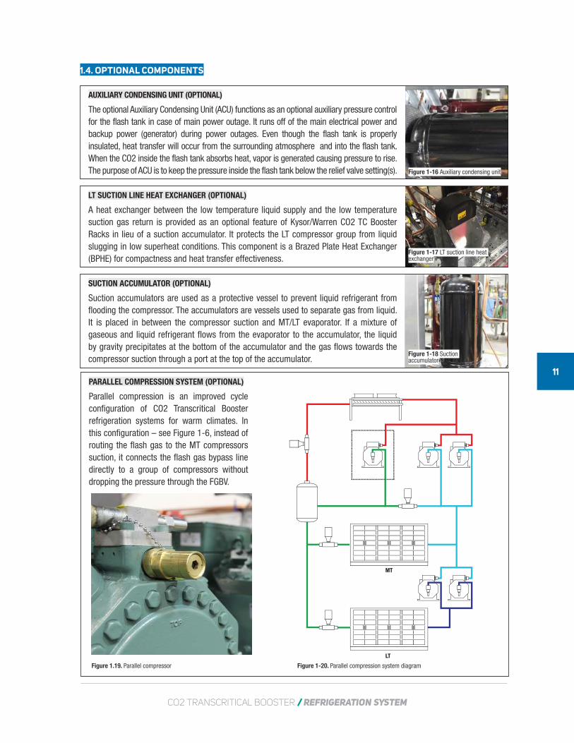
AUXILIARY CONDENSING UNIT (OPTIONAL)
The optional Auxiliary Condensing Unit (ACU) functions as an optional auxiliary pressure control for the flash tank in case of main power outage. It runs off of the main electrical power and backup power (generator) during power outages. Even though the flash tank is properly insulated, heat transfer will occur from the surrounding atmosphere and into the flash tank. When the CO2 inside the flash tank absorbs heat, vapor is generated causing pressure to rise. The purpose of ACU is to keep the pressure inside the flash tank below the relief valve setting(s). Figure 1-16 Auxiliary condensing unit
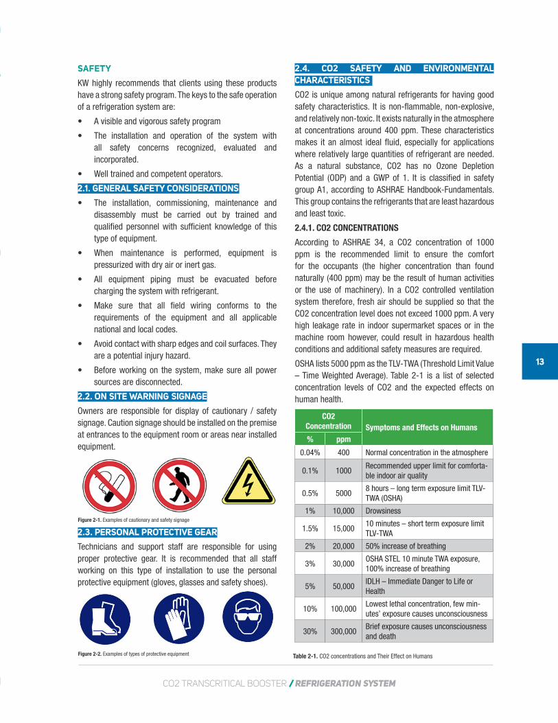
LT SUCTION LINE HEAT EXCHANGER (OPTIONAL)
A heat exchanger between the low temperature liquid supply and the low temperature suction gas return is provided as an optional feature of Kysor/Warren CO2 TC Booster Racks in lieu of a suction accumulator. It protects the LT compressor group from liquid slugging in low superheat conditions. This component is a Brazed Plate Heat Exchanger (BPHE) for compactness and heat transfer effectiveness.
Figure 1-17 LT suction line heat exchanger
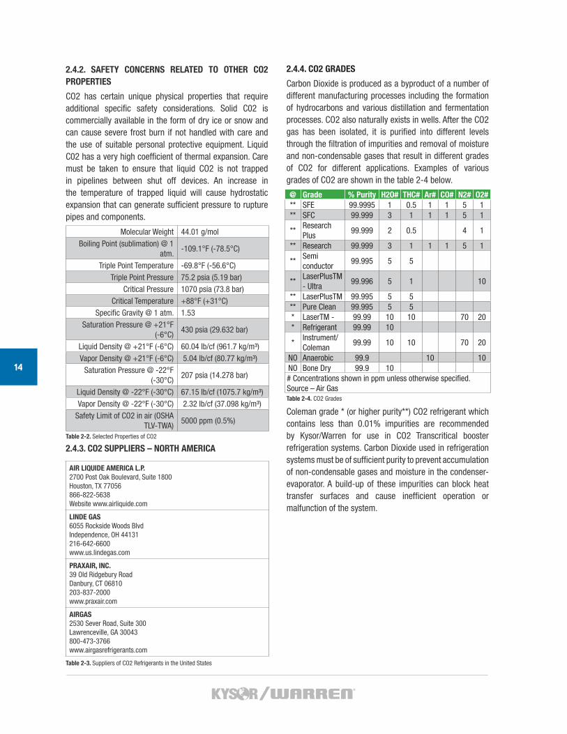
SUCTION ACCUMULATOR (OPTIONAL)
Suction accumulators are used as a protective vessel to prevent liquid refrigerant from flooding the compressor. The accumulators are vessels used to separate gas from liquid. It is placed in between the compressor suction and MT/LT evaporator. If a mixture of gaseous and liquid refrigerant flows from the evaporator to the accumulator, the liquid by gravity precipitates at the bottom of the accumulator and the gas flows towards the compressor suction through a port at the top of the accumulator.
Figure 1-18 Suction accumulator
Figure 1.19. Parallel compressor Figure 1-20. Parallel compression system diagram

CO2MANUAL
SAFETY
2
CO2 TRANSCRITICAL BOOSTER / REFRIGERATION SYSTEM
13
2.4. CO2 SAFETY AND ENVIRONMENTAL CHARACTERISTICS
CO2 is unique among natural refrigerants for having good safety characteristics. It is non-flammable, non-explosive, and relatively non-toxic. It exists naturally in the atmosphere at concentrations around 400 ppm. These characteristics makes it an almost ideal fluid, especially for applications where relatively large quantities of refrigerant are needed. As a natural substance, CO2 has no Ozone Depletion Potential (ODP) and a GWP of 1. It is classified in safety group A1, according to ASHRAE Handbook-Fundamentals. This group contains the refrigerants that are least hazardous and least toxic.
2.4.1. CO2 CONCENTRATIONS
According to ASHRAE 34, a CO2 concentration of 1000 ppm is the recommended limit to ensure the comfort for the occupants (the higher concentration than found naturally (400 ppm) may be the result of human activities or the use of machinery). In a CO2 controlled ventilation system therefore, fresh air should be supplied so that the CO2 concentration level does not exceed 1000 ppm. A very high leakage rate in indoor supermarket spaces or in the machine room however, could result in hazardous health conditions and additional safety measures are required.
OSHA lists 5000 ppm as the TLV-TWA (Threshold Limit Value – Time Weighted Average). Table 2-1 is a list of selected concentration levels of CO2 and the expected effects on human health.
SAFETY
KW highly recommends that clients using these products have a strong safety program. The keys to the safe operation of a refrigeration system are:
• A visible and vigorous safety program
• The installation and operation of the system with all safety concerns recognized, evaluated and incorporated.
• Well trained and competent operators.
2.1. GENERAL SAFETY CONSIDERATIONS
• The installation, commissioning, maintenance and disassembly must be carried out by trained and qualified personnel with sufficient knowledge of this type of equipment.
• When maintenance is performed, equipment is pressurized with dry air or inert gas.
• All equipment piping must be evacuated before charging the system with refrigerant.
• Make sure that all field wiring conforms to the requirements of the equipment and all applicable national and local codes.
• Avoid contact with sharp edges and coil surfaces. They are a potential injury hazard.
• Before working on the system, make sure all power sources are disconnected.
2.2. ON SITE WARNING SIGNAGE
Owners are responsible for display of cautionary / safety signage. Caution signage should be installed on the premise at entrances to the equipment room or areas near installed equipment.
2.3. PERSONAL PROTECTIVE GEAR
Technicians and support staff are responsible for using proper protective gear. It is recommended that all staff working on this type of installation to use the personal protective equipment (gloves, glasses and safety shoes).
Figure 2-2. Examples of types of protective equipment
Figure 2-1. Examples of cautionary and safety signage
CO2Concentration Symptoms and Effects on Humans% ppm
0.04% 400 Normal concentration in the atmosphere
0.1% 1000Recommended upper limit for comforta-ble indoor air quality
0.5% 50008 hours – long term exposure limit TLV-TWA (OSHA)
1% 10,000 Drowsiness
1.5% 15,00010 minutes – short term exposure limit TLV-TWA
2% 20,000 50% increase of breathing
3% 30,000OSHA STEL 10 minute TWA exposure, 100% increase of breathing
5% 50,000IDLH – Immediate Danger to Life or Health
10% 100,000Lowest lethal concentration, few min-utes’ exposure causes unconsciousness
30% 300,000Brief exposure causes unconsciousness and death
Table 2-1. CO2 concentrations and Their Effect on Humans
14
2.4.2. SAFETY CONCERNS RELATED TO OTHER CO2 PROPERTIES
CO2 has certain unique physical properties that require additional specific safety considerations. Solid C02 is commercially available in the form of dry ice or snow and can cause severe frost burn if not handled with care and the use of suitable personal protective equipment. Liquid C02 has a very high coefficient of thermal expansion. Care must be taken to ensure that liquid CO2 is not trapped in pipelines between shut off devices. An increase in the temperature of trapped liquid will cause hydrostatic expansion that can generate sufficient pressure to rupture pipes and components.
2.4.3. CO2 SUPPLIERS – NORTH AMERICA
2.4.4. CO2 GRADES
Carbon Dioxide is produced as a byproduct of a number of different manufacturing processes including the formation of hydrocarbons and various distillation and fermentation processes. CO2 also naturally exists in wells. After the CO2 gas has been isolated, it is purified into different levels through the filtration of impurities and removal of moisture and non-condensable gases that result in different grades of CO2 for different applications. Examples of various grades of CO2 are shown in the table 2-4 below.
Coleman grade * (or higher purity**) CO2 refrigerant which contains less than 0.01% impurities are recommended by Kysor/Warren for use in CO2 Transcritical booster refrigeration systems. Carbon Dioxide used in refrigeration systems must be of sufficient purity to prevent accumulation of non-condensable gases and moisture in the condenser-evaporator. A build-up of these impurities can block heat transfer surfaces and cause inefficient operation or malfunction of the system.
Molecular Weight 44.01 g/molBoiling Point (sublimation) @ 1
atm.-109.1°F (-78.5°C)
Triple Point Temperature -69.8°F (-56.6°C)Triple Point Pressure 75.2 psia (5.19 bar)
Critical Pressure 1070 psia (73.8 bar)Critical Temperature +88°F (+31°C)
Specific Gravity @ 1 atm. 1.53Saturation Pressure @ +21°F
(-6°C)430 psia (29.632 bar)
Liquid Density @ +21°F (-6°C) 60.04 lb/cf (961.7 kg/m³)Vapor Density @ +21°F (-6°C) 5.04 lb/cf (80.77 kg/m³)
Saturation Pressure @ -22°F (-30°C)
207 psia (14.278 bar)
Liquid Density @ -22°F (-30°C) 67.15 lb/cf (1075.7 kg/m³)Vapor Density @ -22°F (-30°C) 2.32 lb/cf (37.098 kg/m³)
Safety Limit of CO2 in air (OSHA TLV-TWA)
5000 ppm (0.5%)
Table 2-2. Selected Properties of CO2
AIR LIQUIDE AMERICA L.P. 2700 Post Oak Boulevard, Suite 1800Houston, TX 77056866-822-5638Website www.airliquide.com
LINDE GAS6055 Rockside Woods BlvdIndependence, OH 44131216-642-6600www.us.lindegas.com
PRAXAIR, INC. 39 Old Ridgebury RoadDanbury, CT 06810203-837-2000www.praxair.com
AIRGAS2530 Sever Road, Suite 300Lawrenceville, GA 30043800-473-3766www.airgasrefrigerants.com
Table 2-3. Suppliers of CO2 Refrigerants in the United States
@ Grade % Purity H2O# THC# Ar# CO# N2# O2#** SFE 99.9995 1 0.5 1 1 5 1** SFC 99.999 3 1 1 1 5 1
**Research Plus
99.999 2 0.5 4 1
** Research 99.999 3 1 1 1 5 1
**Semiconductor
99.995 5 5
**LaserPlusTM - Ultra
99.996 5 1 10
** LaserPlusTM 99.995 5 5** Pure Clean 99.995 5 5* LaserTM - 99.99 10 10 70 20* Refrigerant 99.99 10
*Instrument/Coleman
99.99 10 10 70 20
NO Anaerobic 99.9 10 10NO Bone Dry 99.9 10# Concentrations shown in ppm unless otherwise specified. Source – Air GasTable 2-4. CO2 Grades
CO2 TRANSCRITICAL BOOSTER / REFRIGERATION SYSTEM
15
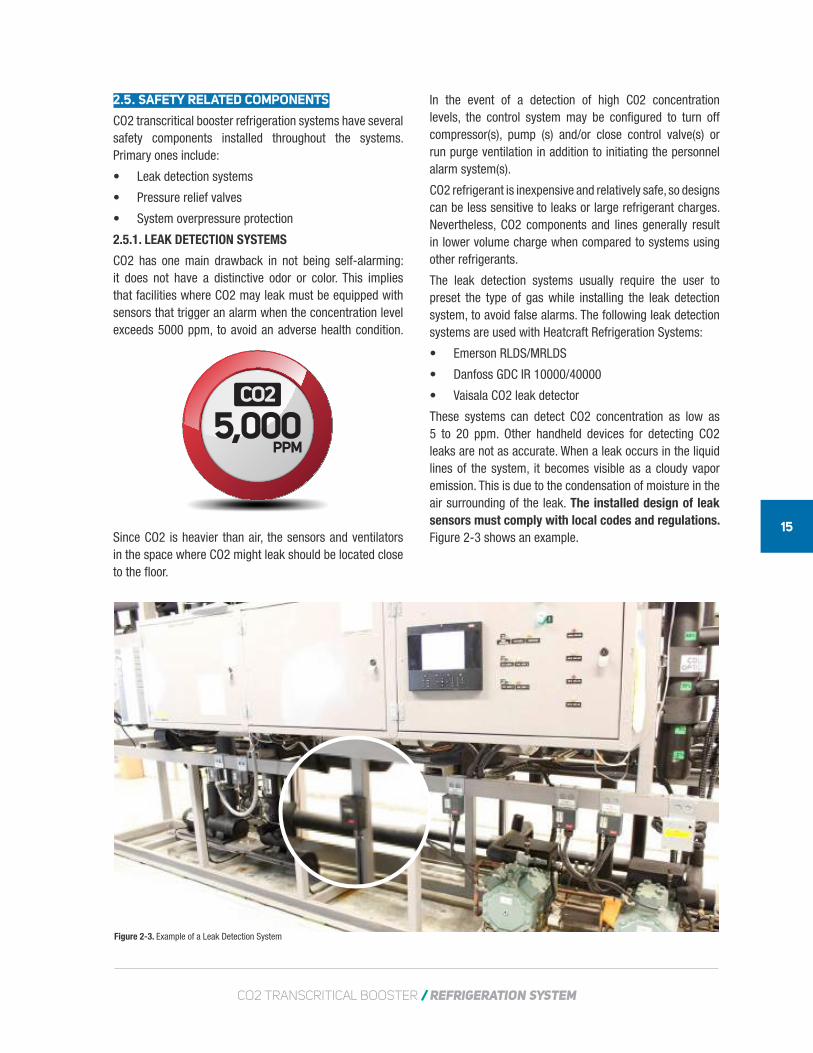
Figure 2-3. Example of a Leak Detection System
2.5. SAFETY RELATED COMPONENTS
CO2 transcritical booster refrigeration systems have several safety components installed throughout the systems. Primary ones include:
• Leak detection systems
• Pressure relief valves
• System overpressure protection
2.5.1. LEAK DETECTION SYSTEMS
CO2 has one main drawback in not being self-alarming: it does not have a distinctive odor or color. This implies that facilities where CO2 may leak must be equipped with sensors that trigger an alarm when the concentration level exceeds 5000 ppm, to avoid an adverse health condition.
Since CO2 is heavier than air, the sensors and ventilators in the space where CO2 might leak should be located close to the floor.
In the event of a detection of high C02 concentration levels, the control system may be configured to turn off compressor(s), pump (s) and/or close control valve(s) or run purge ventilation in addition to initiating the personnel alarm system(s).
CO2 refrigerant is inexpensive and relatively safe, so designs can be less sensitive to leaks or large refrigerant charges. Nevertheless, CO2 components and lines generally result in lower volume charge when compared to systems using other refrigerants.
The leak detection systems usually require the user to preset the type of gas while installing the leak detection system, to avoid false alarms. The following leak detection systems are used with Heatcraft Refrigeration Systems:
• Emerson RLDS/MRLDS
• Danfoss GDC IR 10000/40000
• Vaisala CO2 leak detector
These systems can detect CO2 concentration as low as 5 to 20 ppm. Other handheld devices for detecting CO2 leaks are not as accurate. When a leak occurs in the liquid lines of the system, it becomes visible as a cloudy vapor emission. This is due to the condensation of moisture in the air surrounding of the leak. The installed design of leak sensors must comply with local codes and regulations. Figure 2-3 shows an example.
5,000PPM
CO2
16
2.5.2. PRESSURE RELIEF VALVES (PRV)
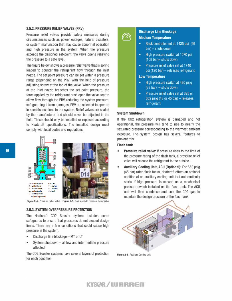
Pressure relief valves provide safety measures during circumstances such as power outages, natural disasters, or system malfunction that may cause abnormal operation and high pressure in the system. When the pressure exceeds the designed set-point, the valve opens relieving the pressure to a safe level.
The figure below shows a pressure relief valve that is spring loaded to counter the refrigerant flow through the inlet nozzle. The set point pressure can be set within a pressure range (depending on the PRV) with the help of pressure adjusting screw at the top of the valve. When the pressure at the inlet nozzle breaches the set point pressure, the force applied by the refrigerant push open the valve seat to allow flow through the PRV, reducing the system pressure, safeguarding it from damages. PRV are selected to operate in specific locations in the system. Relief valves are sealed by the manufacturer and should never be adjusted in the field. These should only be installed or replaced according to Heatcraft specifications. The installed design must comply with local codes and regulations.
2.5.3. SYSTEM OVERPRESSURE PROTECTION
The Heatcraft CO2 Booster system includes some safeguards to ensure that pressures do not exceed design limits. There are a few conditions that could cause high pressure in the system.
• Discharge line blockage – MT or LT
• System shutdown – all low and intermediate pressure affected
The CO2 Booster systems have several layers of protection for each condition.
Discharge Line Blockage
Medium Temperature
• Rack controller set at 1435 psi (99 bar) – shuts down
• High pressure switch at 1570 psi (108 bar)– shuts down
• Pressure relief valve set at 1740 psi (120 bar) – releases refrigerant
Low Temperature
• High pressure switch at 480 psig (33 bar) – shuts down
• Pressure relief valve set at 625 or 652 psig (43 or 45 bar) – releases refrigerant
System Shutdown
If the CO2 refrigeration system is damaged and not operational, the pressure will tend to rise to nearly the saturated pressure corresponding to the warmest ambient exposure. The system design has several features to prevent this.
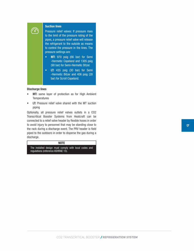
Flash tank
• Pressure relief valve: If pressure rises to the limit of the pressure rating of the flash tank, a pressure relief valve will release the refrigerant to the outside.
• Auxiliary Cooling Unit, ACU (Optional): For 652 psig (45 bar) rated flash tanks, Heatcraft offers an optional addition of an auxiliary cooling unit that automatically starts if high pressure is sensed on a mechanical pressure switch installed on the flash tank. The ACU unit will then condense and cool the CO2 gas to maintain the design pressure of the flash tank.
Figure 2-4 . Pressure Relief Valve Figure 2-5. Dual Manifold Pressure Relief Valve
Figure 2-6 . Auxiliary Cooling Unit
CO2 TRANSCRITICAL BOOSTER / REFRIGERATION SYSTEM
17
Suction lines
Pressure relief valves: If pressure rises to the limit of the pressure rating of the pipes, a pressure relief valve will release the refrigerant to the outside as means to control the pressure in the lines. The pressure settings are:
• MT: 970 psig (66 bar) for Semi -Hermetic Copeland and 1305 psig (90 bar) for Semi-Hermetic Bitzer.
• LT: 435 psig (30 bar) for Semi -Hermetic Bitzer and 406 psig (28 bar) for Scroll Copeland.
Discharge lines
• MT: same layer of protection as for High Ambient Temperatures
• LT: Pressure relief valve shared with the MT suction piping
Optionally, all pressure relief valves outlets in a CO2 Transcritical Booster Systems from Heatcraft can be connected to a relief valve header by flexible hoses in order to avoid injury to personnel that may be standing close to the rack during a discharge event. The PRV header is field piped to the outdoors in order to disperse the gas during a discharge.
NOTE
The installed design must comply with local codes and regulations (reference ASHRAE 15).
CO2MANUAL
INSPECTION ANDPLACEMENT OFMATERIAL
3
CO2 TRANSCRITICAL BOOSTER / REFRIGERATION SYSTEM
19
3. INSPECTION AND PLACEMENT OF MATERIAL
Materials at the construction site should be thoroughly inspected upon unloading for damage, missing parts and serviceability.
3.1 INSPECTION OF MATERIALS
Inspect the CO2 refrigeration system and accessories for damages or shortages before and during unloading.
If there is any damage, notify the carrier immediately and request an inspection. Ensure:
• The delivery receipt is annotated that the equipment was received damaged.
• If damage is not noticeable on receipt, contact the carrier immediately when the damage is discovered.
It is the responsibility of the consignee to file all claims for damage with the transportation company.
3.1.1. ACCESSORIES
Be sure that you receive all items. Accessories may be packaged separately.
Check the packing list against the contents.
All parts are present.
NOTE
If parts are missing, contact the Technical Sales Support (TSS) or the point of contact listed in the packing list.
3.1.2. SYSTEM PRESSURE
Pressure in the system is within specified limits.
NOTE
The system is shipped with a 50 psi holding charge of dry nitrogen. Report lack of or a reduced pressure immediately to the Kysor/Warren technical sales support.
3.1.3. ELECTRICAL
Specifications on electrical rating plate matches on-site power configuration.
3.1.4. COMPATIBILITY OF FIELD INSTALLED MATERIAL
Field installed material meets manufacturer’s specifications.
3.1.5. MATERIALS MEET SPECIFIED PRESSURE RATINGS
Field Installed material meets specified pressure ratings.
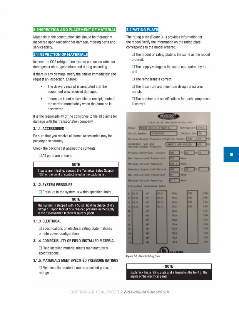
3.2 RATING PLATE
The rating plate (Figure 3-1) provides information for the model. Verify the information on the rating plate corresponds to the model ordered.
The model on rating plate is the same as the model ordered.
The supply voltage is the same as required by the unit.
The refrigerant is correct.
The maximum and minimum design pressures match.
The number and specifications for each compressor is correct.
NOTE
Each rack has a rating plate and a legend on the front or the inside of the electrical panel
Figure 3-1 . Sample Rating Plate
20
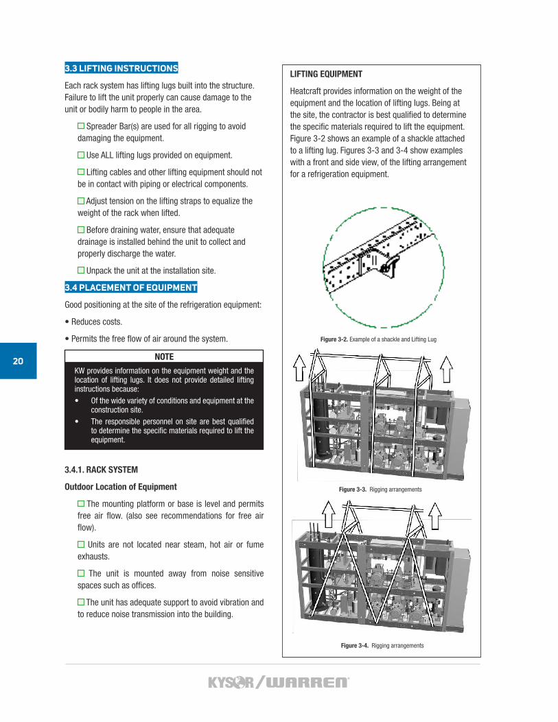
LIFTING EQUIPMENT
Heatcraft provides information on the weight of the equipment and the location of lifting lugs. Being at the site, the contractor is best qualified to determine the specific materials required to lift the equipment. Figure 3-2 shows an example of a shackle attached to a lifting lug. Figures 3-3 and 3-4 show examples with a front and side view, of the lifting arrangement for a refrigeration equipment.
3.3 LIFTING INSTRUCTIONS
Each rack system has lifting lugs built into the structure. Failure to lift the unit properly can cause damage to the unit or bodily harm to people in the area.
Spreader Bar(s) are used for all rigging to avoid damaging the equipment.
Use ALL lifting lugs provided on equipment.
Lifting cables and other lifting equipment should not be in contact with piping or electrical components.
Adjust tension on the lifting straps to equalize the weight of the rack when lifted.
Before draining water, ensure that adequate drainage is installed behind the unit to collect and properly discharge the water.
Unpack the unit at the installation site.
3.4 PLACEMENT OF EQUIPMENT
Good positioning at the site of the refrigeration equipment:
• Reduces costs.
• Permits the free flow of air around the system.
• Reduces vibrations
• Reduces noise transmission
NOTE
KW provides information on the equipment weight and the location of lifting lugs. It does not provide detailed lifting instructions because:• Of the wide variety of conditions and equipment at the
construction site.• The responsible personnel on site are best qualified
to determine the specific materials required to lift the equipment.
3.4.1. RACK SYSTEM
Outdoor Location of Equipment
The mounting platform or base is level and permits free air flow. (also see recommendations for free air flow).
Units are not located near steam, hot air or fume exhausts.
The unit is mounted away from noise sensitive spaces such as offices.
The unit has adequate support to avoid vibration and to reduce noise transmission into the building.
Figure 3-2. Example of a shackle and Lifting Lug
Figure 3-3. Rigging arrangements
Figure 3-4. Rigging arrangements
CO2 TRANSCRITICAL BOOSTER / REFRIGERATION SYSTEM
21
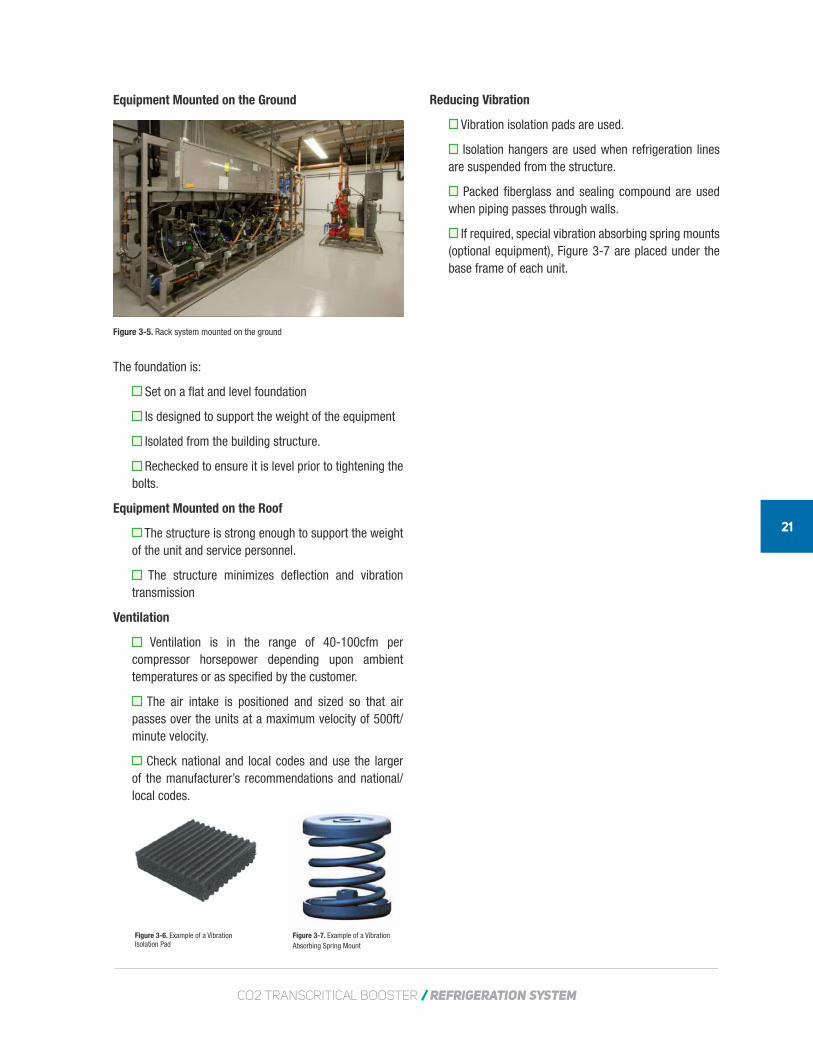
Equipment Mounted on the Ground
The foundation is:
Set on a flat and level foundation
Is designed to support the weight of the equipment
Isolated from the building structure.
Rechecked to ensure it is level prior to tightening the bolts.
Equipment Mounted on the Roof
The structure is strong enough to support the weight of the unit and service personnel.
The structure minimizes deflection and vibration transmission
Ventilation
Ventilation is in the range of 40-100cfm per compressor horsepower depending upon ambient temperatures or as specified by the customer.
The air intake is positioned and sized so that air passes over the units at a maximum velocity of 500ft/minute velocity.
Check national and local codes and use the larger of the manufacturer’s recommendations and national/local codes.
Figure 3-6. Example of a Vibration Isolation Pad
Figure 3-7. Example of a Vibration Absorbing Spring Mount
Reducing Vibration
Vibration isolation pads are used.
Isolation hangers are used when refrigeration lines are suspended from the structure.
Packed fiberglass and sealing compound are used when piping passes through walls.
If required, special vibration absorbing spring mounts (optional equipment), Figure 3-7 are placed under the base frame of each unit.
Figure 3-5. Rack system mounted on the ground

CO2MANUAL
SYSTEMINSTALLATION
4
CO2 TRANSCRITICAL BOOSTER / REFRIGERATION SYSTEM
23
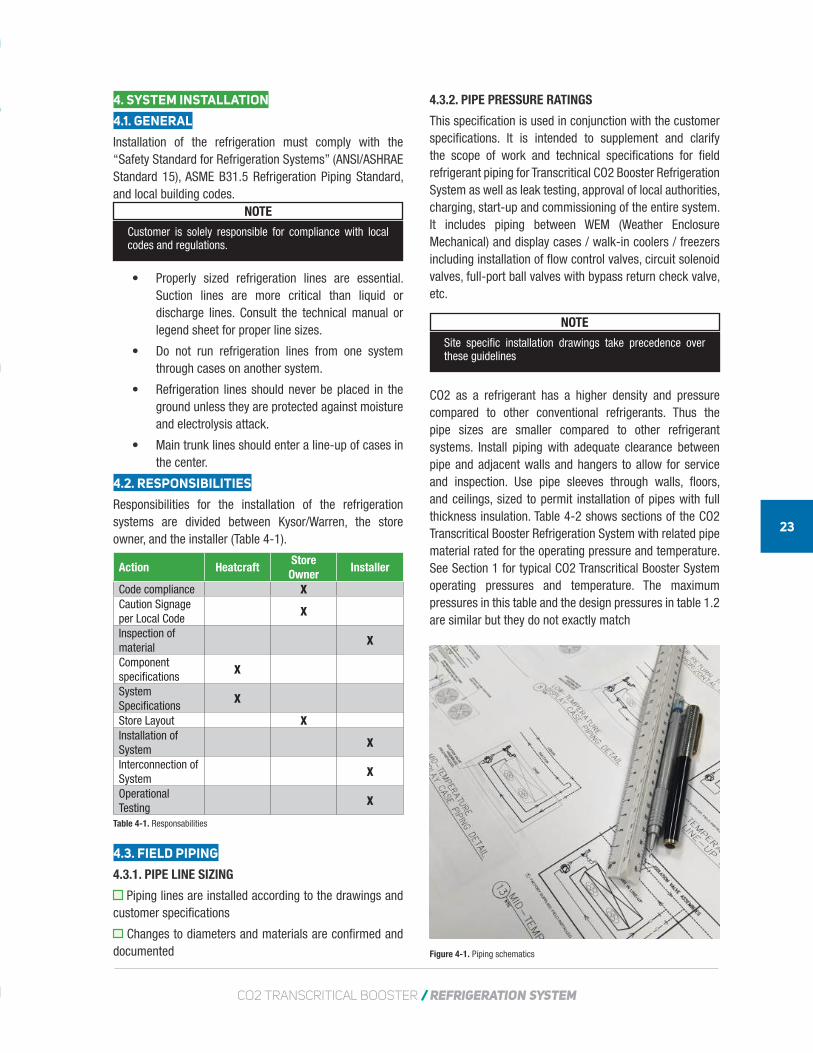
4.3.2. PIPE PRESSURE RATINGS
This specification is used in conjunction with the customer specifications. It is intended to supplement and clarify the scope of work and technical specifications for field refrigerant piping for Transcritical CO2 Booster Refrigeration System as well as leak testing, approval of local authorities, charging, start-up and commissioning of the entire system. It includes piping between WEM (Weather Enclosure Mechanical) and display cases / walk-in coolers / freezers including installation of flow control valves, circuit solenoid valves, full-port ball valves with bypass return check valve, etc.
NOTE
Site specific installation drawings take precedence over these guidelines
CO2 as a refrigerant has a higher density and pressure compared to other conventional refrigerants. Thus the pipe sizes are smaller compared to other refrigerant systems. Install piping with adequate clearance between pipe and adjacent walls and hangers to allow for service and inspection. Use pipe sleeves through walls, floors, and ceilings, sized to permit installation of pipes with full thickness insulation. Table 4-2 shows sections of the CO2 Transcritical Booster Refrigeration System with related pipe material rated for the operating pressure and temperature. See Section 1 for typical CO2 Transcritical Booster System operating pressures and temperature. The maximum pressures in this table and the design pressures in table 1.2 are similar but they do not exactly match
4. SYSTEM INSTALLATION
4.1. GENERAL
Installation of the refrigeration must comply with the “Safety Standard for Refrigeration Systems” (ANSI/ASHRAE Standard 15), ASME B31.5 Refrigeration Piping Standard, and local building codes.
NOTE
Customer is solely responsible for compliance with local codes and regulations.
• Properly sized refrigeration lines are essential. Suction lines are more critical than liquid or discharge lines. Consult the technical manual or legend sheet for proper line sizes.
• Do not run refrigeration lines from one system through cases on another system.
• Refrigeration lines should never be placed in the ground unless they are protected against moisture and electrolysis attack.
• Main trunk lines should enter a line-up of cases in the center.
4.2. RESPONSIBILITIES
Responsibilities for the installation of the refrigeration systems are divided between Kysor/Warren, the store owner, and the installer (Table 4-1).
Action HeatcraftStore Owner
Installer
Code compliance XCaution Signage per Local Code
X
Inspection of material
X
Component specifications
X
System Specifications
X
Store Layout XInstallation of System
X
Interconnection of System
X
Operational Testing
X
4.3. FIELD PIPING
4.3.1. PIPE LINE SIZING
Piping lines are installed according to the drawings and customer specifications
Changes to diameters and materials are confirmed and documented
Table 4-1. Responsabilities
Figure 4-1. Piping schematics
24
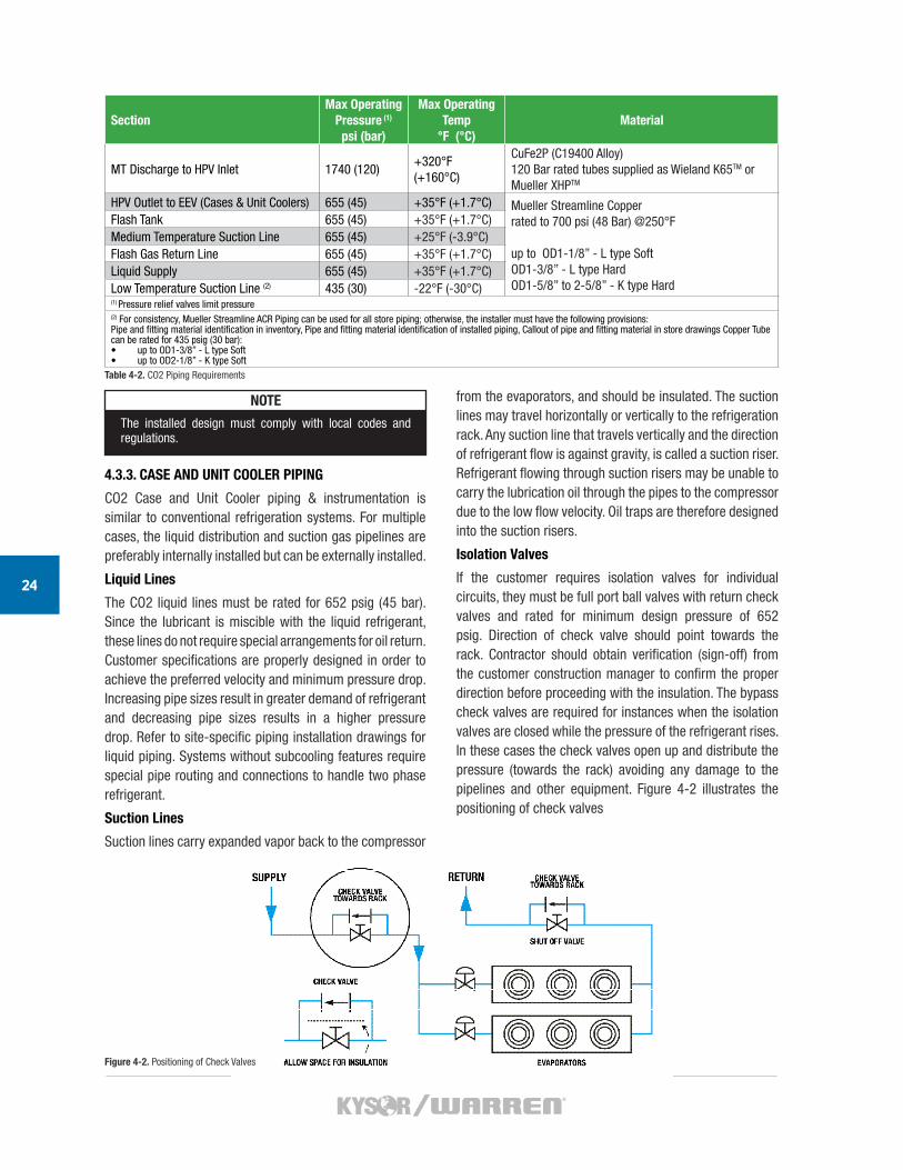
SectionMax Operating
Pressure (1)
psi (bar)
Max Operating Temp
°F (°C)Material
MT Discharge to HPV Inlet 1740 (120)+320°F (+160°C)
CuFe2P (C19400 Alloy)120 Bar rated tubes supplied as Wieland K65TM or Mueller XHPTM
HPV Outlet to EEV (Cases & Unit Coolers) 655 (45) +35°F (+1.7°C) Mueller Streamline Copperrated to 700 psi (48 Bar) @250°F
up to OD1-1/8” - L type SoftOD1-3/8” - L type Hard OD1-5/8” to 2-5/8” - K type Hard
Flash Tank 655 (45) +35°F (+1.7°C)Medium Temperature Suction Line 655 (45) +25°F (-3.9°C)Flash Gas Return Line 655 (45) +35°F (+1.7°C)Liquid Supply 655 (45) +35°F (+1.7°C)Low Temperature Suction Line (2) 435 (30) -22°F (-30°C)(1) Pressure relief valves limit pressure(2) For consistency, Mueller Streamline ACR Piping can be used for all store piping; otherwise, the installer must have the following provisions: Pipe and fitting material identification in inventory, Pipe and fitting material identification of installed piping, Callout of pipe and fitting material in store drawings Copper Tube can be rated for 435 psig (30 bar):• up to OD1-3/8” - L type Soft • up to OD2-1/8” - K type Soft
NOTE
The installed design must comply with local codes and regulations.
4.3.3. CASE AND UNIT COOLER PIPING
CO2 Case and Unit Cooler piping & instrumentation is similar to conventional refrigeration systems. For multiple cases, the liquid distribution and suction gas pipelines are preferably internally installed but can be externally installed.
Liquid Lines
The CO2 liquid lines must be rated for 652 psig (45 bar). Since the lubricant is miscible with the liquid refrigerant, these lines do not require special arrangements for oil return. Customer specifications are properly designed in order to achieve the preferred velocity and minimum pressure drop. Increasing pipe sizes result in greater demand of refrigerant and decreasing pipe sizes results in a higher pressure drop. Refer to site-specific piping installation drawings for liquid piping. Systems without subcooling features require special pipe routing and connections to handle two phase refrigerant.
Suction Lines
Suction lines carry expanded vapor back to the compressor
from the evaporators, and should be insulated. The suction lines may travel horizontally or vertically to the refrigeration rack. Any suction line that travels vertically and the direction of refrigerant flow is against gravity, is called a suction riser. Refrigerant flowing through suction risers may be unable to carry the lubrication oil through the pipes to the compressor due to the low flow velocity. Oil traps are therefore designed into the suction risers.
Isolation Valves
If the customer requires isolation valves for individual circuits, they must be full port ball valves with return check valves and rated for minimum design pressure of 652 psig. Direction of check valve should point towards the rack. Contractor should obtain verification (sign-off) from the customer construction manager to confirm the proper direction before proceeding with the insulation. The bypass check valves are required for instances when the isolation valves are closed while the pressure of the refrigerant rises. In these cases the check valves open up and distribute the pressure (towards the rack) avoiding any damage to the pipelines and other equipment. Figure 4-2 illustrates the positioning of check valves
Table 4-2. CO2 Piping Requirements
Figure 4-2. Positioning of Check Valves
CO2 TRANSCRITICAL BOOSTER / REFRIGERATION SYSTEM
25
Relief Valve Installation
Relief valves should exhaust to exterior locations to comply with ASHRAE 15. Valves must be located and oriented so that they discharge pressurized refrigerant safely and away from personnel. Heatcraft CO2 Booster racks have relief valves along with relief valve headers that comply with ASHRAE 15 standards.
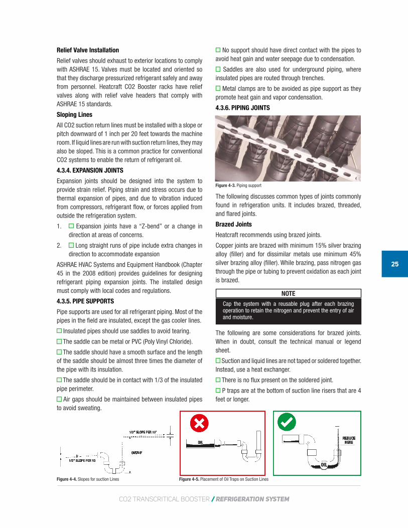
Sloping Lines
All CO2 suction return lines must be installed with a slope or pitch downward of 1 inch per 20 feet towards the machine room. If liquid lines are run with suction return lines, they may also be sloped. This is a common practice for conventional CO2 systems to enable the return of refrigerant oil.
4.3.4. EXPANSION JOINTS
Expansion joints should be designed into the system to provide strain relief. Piping strain and stress occurs due to thermal expansion of pipes, and due to vibration induced from compressors, refrigerant flow, or forces applied from outside the refrigeration system.
1. Expansion joints have a “Z-bend” or a change in direction at areas of concerns.
2. Long straight runs of pipe include extra changes in direction to accommodate expansion
ASHRAE HVAC Systems and Equipment Handbook (Chapter 45 in the 2008 edition) provides guidelines for designing refrigerant piping expansion joints. The installed design must comply with local codes and regulations.
4.3.5. PIPE SUPPORTS
Pipe supports are used for all refrigerant piping. Most of the pipes in the field are insulated, except the gas cooler lines.
Insulated pipes should use saddles to avoid tearing.
The saddle can be metal or PVC (Poly Vinyl Chloride).
The saddle should have a smooth surface and the length of the saddle should be almost three times the diameter of the pipe with its insulation.
The saddle should be in contact with 1/3 of the insulated pipe perimeter.
Air gaps should be maintained between insulated pipes to avoid sweating.
No support should have direct contact with the pipes to avoid heat gain and water seepage due to condensation.
Saddles are also used for underground piping, where insulated pipes are routed through trenches.
Metal clamps are to be avoided as pipe support as they promote heat gain and vapor condensation.
4.3.6. PIPING JOINTS
The following discusses common types of joints commonly found in refrigeration units. It includes brazed, threaded, and flared joints.
Brazed Joints
Heatcraft recommends using brazed joints.
Copper joints are brazed with minimum 15% silver brazing alloy (filler) and for dissimilar metals use minimum 45% silver brazing alloy (filler). While brazing, pass nitrogen gas through the pipe or tubing to prevent oxidation as each joint is brazed.
z NOTE
Cap the system with a reusable plug after each brazing operation to retain the nitrogen and prevent the entry of air and moisture.
The following are some considerations for brazed joints. When in doubt, consult the technical manual or legend sheet.
Suction and liquid lines are not taped or soldered together. Instead, use a heat exchanger.
There is no flux present on the soldered joint.
P traps are at the bottom of suction line risers that are 4 feet or longer.
Figure 4-3. Piping support
Figure 4-4. Slopes for suction Lines Figure 4-5. Placement of Oil Traps on Suction Lines

26
Double “P” traps are present for each 20-foot of riser.
Use long radius ells and avoid 45° ells.
Provide expansion loops in suction lines on systems with hot gas defrost
Flux only the male portion of the connection line never the female portion. Remove the flux after brazing.
NOTE
A suction line trap must be installed at the point where piping changes the direction of refrigerant flow from any horizontal run to an upward vertical run.
Piping should not disrupt or restrict refrigerant flow. Allowing sufficient “play” in the piping system and reducing abrupt changes in refrigerant direction reduces internal stresses and pressure drops. Short radius elbows for example, should be avoided if possible because they increase stress on the piping and cause the refrigerant to lose pressure.
Figure 4-6. Corners support illustration.
Figure 4-7. Corners support illustration.
Contractors install piping supports based on the plans and industrial standards. Straight lengths of piping for example below, must be supported at each end and have additional supports not more than every 8 feet. Cushioned clamps and pipe supports should be used to prevent contact between pipes.
Figure 4-8. Corners must be supported and cannot be left free to pivot around 1-2
Threaded Joints
Threaded joints have a greater likelihood of leaking than brazed joints. When using threaded joints in CO2 systems, high pressure sealant is required. For low and IM pressure, Loctite 545 is recommended for sealing threaded joints. For high operation pressure (above 652 psig), the threads are wrapped 3-4 times with Teflon tape; then Loctite 277 Threadlocker is applied over the tape before the threads are engaged.
Flared Joints
Heatcraft does not recommend flare joints.
CO2 TRANSCRITICAL BOOSTER / REFRIGERATION SYSTEM
27
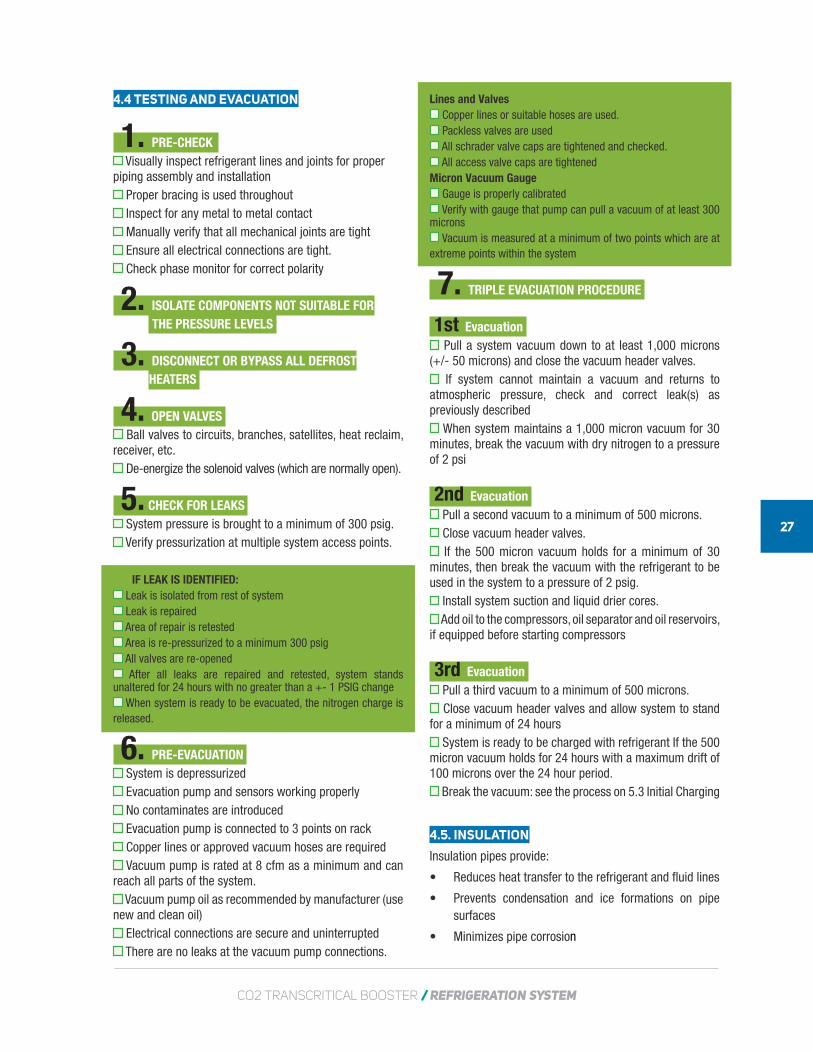
4.4 TESTING AND EVACUATION
1. PRE-CHECK Visually inspect refrigerant lines and joints for proper
piping assembly and installation Proper bracing is used throughout Inspect for any metal to metal contact Manually verify that all mechanical joints are tight Ensure all electrical connections are tight. Check phase monitor for correct polarity
2. ISOLATE COMPONENTS NOT SUITABLE FOR THE PRESSURE LEVELS
3. DISCONNECT OR BYPASS ALL DEFROSTHEATERS
4. OPEN VALVES Ball valves to circuits, branches, satellites, heat reclaim,
receiver, etc. De-energize the solenoid valves (which are normally open).
5. CHECK FOR LEAKS System pressure is brought to a minimum of 300 psig. Verify pressurization at multiple system access points.
IF LEAK IS IDENTIFIED: Leak is isolated from rest of system Leak is repaired Area of repair is retested Area is re-pressurized to a minimum 300 psig All valves are re-opened After all leaks are repaired and retested, system stands
unaltered for 24 hours with no greater than a +- 1 PSIG change When system is ready to be evacuated, the nitrogen charge is
released.
6. PRE-EVACUATION System is depressurized Evacuation pump and sensors working properly No contaminates are introduced Evacuation pump is connected to 3 points on rack Copper lines or approved vacuum hoses are required Vacuum pump is rated at 8 cfm as a minimum and can
reach all parts of the system. Vacuum pump oil as recommended by manufacturer (use
new and clean oil) Electrical connections are secure and uninterrupted There are no leaks at the vacuum pump connections.
Lines and Valves Copper lines or suitable hoses are used. Packless valves are used All schrader valve caps are tightened and checked. All access valve caps are tightened
Micron Vacuum Gauge Gauge is properly calibrated Verify with gauge that pump can pull a vacuum of at least 300
microns Vacuum is measured at a minimum of two points which are at
extreme points within the system
7. TRIPLE EVACUATION PROCEDURE
1st Evacuation Pull a system vacuum down to at least 1,000 microns
(+/- 50 microns) and close the vacuum header valves. If system cannot maintain a vacuum and returns to
atmospheric pressure, check and correct leak(s) as previously described
When system maintains a 1,000 micron vacuum for 30 minutes, break the vacuum with dry nitrogen to a pressure of 2 psi
2nd Evacuation Pull a second vacuum to a minimum of 500 microns. Close vacuum header valves. If the 500 micron vacuum holds for a minimum of 30
minutes, then break the vacuum with the refrigerant to be used in the system to a pressure of 2 psig.
Install system suction and liquid drier cores. Add oil to the compressors, oil separator and oil reservoirs,
if equipped before starting compressors
3rd Evacuation Pull a third vacuum to a minimum of 500 microns. Close vacuum header valves and allow system to stand
for a minimum of 24 hours System is ready to be charged with refrigerant If the 500
micron vacuum holds for 24 hours with a maximum drift of 100 microns over the 24 hour period.
Break the vacuum: see the process on 5.3 Initial Charging
4.5. INSULATION
Insulation pipes provide:
• Reduces heat transfer to the refrigerant and fluid lines
• Prevents condensation and ice formations on pipe surfaces
• Minimizes pipe corrosion
28Armacell LLC7600 Oakwood St. Ext. - Mebane, NC 27302919-304-3846 / www.armacell.com
K-Flex100 Nomaco Drive - Youngsville, NC 27596800-765-6475 / www.kflexusa.com
Table 4-4. Recommended Elastomeric Insulation Suppliers
Figure 4-5 Example labels on piping
Figure 4-9. Other examples of labels on piping
Brimar Industries64 Outwater Lane - Garfield, NJ 07026800-274-6271 / www.brimar.com
Seton20 Thompson Road - Branford, CT 06405800-243-6624 / www.seton.com
Table 4-6 Pipe label suppliers
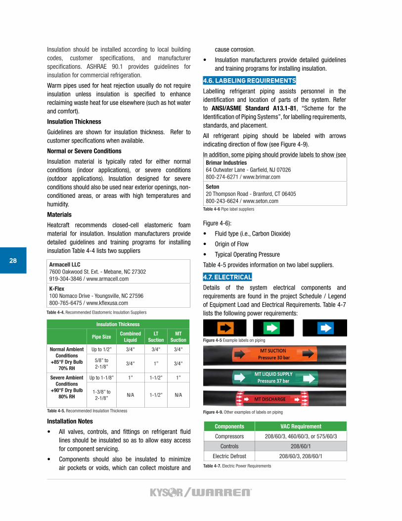
Components VAC Requirement
Compressors 208/60/3, 460/60/3, or 575/60/3
Controls 208/60/1
Electric Defrost 208/60/3, 208/60/1
Table 4-7. Electric Power Requirements
Insulation should be installed according to local building codes, customer specifications, and manufacturer specifications. ASHRAE 90.1 provides guidelines for insulation for commercial refrigeration.
Warm pipes used for heat rejection usually do not require insulation unless insulation is specified to enhance reclaiming waste heat for use elsewhere (such as hot water and comfort).
Insulation Thickness
Guidelines are shown for insulation thickness. Refer to customer specifications when available.
Normal or Severe Conditions
Insulation material is typically rated for either normal conditions (indoor applications), or severe conditions (outdoor applications). Insulation designed for severe conditions should also be used near exterior openings, non-conditioned areas, or areas with high temperatures and humidity.
Materials
Heatcraft recommends closed-cell elastomeric foam material for insulation. Insulation manufacturers provide detailed guidelines and training programs for installing insulation Table 4-4 lists two suppliers
Installation Notes
• All valves, controls, and fittings on refrigerant fluid lines should be insulated so as to allow easy access for component servicing.
• Components should also be insulated to minimize air pockets or voids, which can collect moisture and
cause corrosion.
• Insulation manufacturers provide detailed guidelines and training programs for installing insulation.
4.6. LABELING REQUIREMENTS
Labelling refrigerant piping assists personnel in the identification and location of parts of the system. Refer to ANSI/ASME Standard A13.1-81, “Scheme for the Identification of Piping Systems”, for labelling requirements, standards, and placement.
All refrigerant piping should be labeled with arrows indicating direction of flow (see Figure 4-9).
In addition, some piping should provide labels to show (see
Figure 4-6):
• Fluid type (i.e., Carbon Dioxide)
• Origin of Flow
• Typical Operating Pressure
Table 4-5 provides information on two label suppliers.
4.7. ELECTRICAL
Details of the system electrical components and requirements are found in the project Schedule / Legend of Equipment Load and Electrical Requirements. Table 4-7 lists the following power requirements:
Insulation Thickness
Pipe SizeCombined
LiquidLT
SuctionMT
Suction
Normal Ambient Conditions
+85°F Dry Bulb 70% RH
Up to 1/2” 3/4" 3/4" 3/4"
5/8” to 2-1/8”
3/4" 1” 3/4"
Severe Ambient Conditions
+90°F Dry Bulb 80% RH
Up to 1-1/8” 1” 1-1/2” 1”
1-3/8” to 2-1/8”
N/A 1-1/2” N/A
Table 4-5. Recommended Insulation Thickness
CO2MANUAL
SYSTEMOPERATION
5
30
5. SYSTEM OPERATION
Once the system installation is complete, all piping has been evacuated to specification, and all equipment is powered-up and ready to operate; the initial startup of the CO2 Transcritical System is done with the following steps – the numbers correspond to the subsections:
5.1. INITIATE SYSTEM POWER
5.2. EVAPORATOR TEMPERATURE CONTROL
5.3. CO2 INITIAL CHARGING
5.3.1. Oil Charge
5.3.2. CO2 Vapor Charge
5.4. START COMPRESSORS
5.4.1. Start ACU (optional)
5.4.2. Controls/Instrumentation Check
5.4.3. Liquid CO2 Charge to Flash Tank
5.4.4. Start MT compressors
5.4.5. Pull Down MT Cases & Walk-ins
5.4.6. Start LT compressors
5.4.7. Pull down LT Cases & Walk-ins
5.5. DEFROST SETUP
5.6. WALK-IN DOOR SWITCHES
5.1. INITIATE SYSTEM POWER
Prior to charging the system or starting compressors, confirm that
Power has been turned on to each subsystem
Control Panel is energized
Panel switches are set with compressor OFF
Check operation of cooling fans
Gas Cooler Fans Operating
Case Fans Operating
Initial checks for equipment has been completed according to manufacturer’s recommendations
Control System is installed and programmed according the System SOO setpoints
Controls, gauges, and thermometers are displaying temperatures and pressures (Check values expected without refrigeration system operating)
5.2. EVAPORATOR TEMPERATURE CONTROL
Verify temperature sensor locations indicated by the controller.
Validate temperature readings on the controller with a
known temperature source. This is done using the “ice bath” method, or using a calibrated thermometer.
NOTE
Some adjustment may be required on controller settings.
5.3. CO2 INITIAL CHARGING
5.3.1. REQUIRED EQUIPMENT AND MATERIALS
The following materials are needed to charge the system. The refrigeration installation contractor is responsible for having these materials. See information on CO2 grades and suppliers and suppliers discussed in Section 2.
CO2 Vapor Cylinders
Instrument or Coleman Grade CO2 vapor to break vacuum and pressurize the system to 150 psig. Tanks are stored at room temperature; dispensing cold refrigerant is limited.
CO2 Liquid Cylinders (w/dip tube)
Instrument or Coleman Grade CO2 for remainder of charge – reference refrigeration legend for estimated charge
Charging Hoses
• 3/8” hose recommended for faster charging
• Rated for 1740 psig working pressure
Manifold Gauges
Rated for 900 psig working pressure
CGA-320 Adapter Fitting
CO2 cylinders (liquid and vapor) have CGA-320 fittings. An adaptor is required to connect the CO2 cylinder to a flare connection on charging hoses for liquid charging.
Filter/Dryer
Use on the charging port for both liquid and vapor charging. Provide one core for about every 600lb. CO2
Refrigerant Scale
Measures the quantity and rate of CO2 charging from the cylinders. The scale needs to be rugged enough for the weight and handling of the cylinders.
POE Oil
To fill oil reservoir and compressor crankcases; Oil should be purchased directly from the CO2 Compressor manufacturer.
• BITZER CO2 compressors use POE oil – BSE85K
• Emerson Copeland CO2 Compressors use POE Oil – EMKARATE RL68HB
Manual Oil Pump
CO2 TRANSCRITICAL BOOSTER / REFRIGERATION SYSTEM
31
5.3.2. OIL CHARGE (NEED TO BE DONE BETWEEN 2ND AND 3RD EVACUATION)
Oil Charge to the Oil Reservoir
Confirm that oil is compatible with compressors
Close valves to isolate oil reservoir
Fill reservoir with oil 50%
Open valve between oil reservoir and compressors
Oil Charge to Compressors
Check that compressor oil is at the proper level
Confirm that the compressor crankcase heaters are energized for 24h before start up
NOTE
Oil is typically provided with the compressors. Oil level requirement may vary with compressor manufacturer. Crankcase heater must be operating to warm the oil prior to starting the compressor.
5.3.3. CHARGE THE CO2 VAPOR
The vacuum is broken with a vapor CO2 charge only. Liquid CO2 will form into solids potentially causing damage to the equipment.
Break the vacuum with vapor CO2 to 150 psig
Leave all valves open - complete system and piping distribution network with vapor charge
Close compressor suction and discharge valves.
Continue charging vapor CO2 to 150 psig
Check that any rack gauges and control pressures read 150 psig
VAPOR CHARGING
As vapor is drawn from the CO2 cylinders, pressure and temperature inside the cylinder will decrease. Frosting on the bottom exterior of the cylinder is evidence that some CO2 liquid evaporated inside. The reduction in pressure also causes a slower flow rate of vapor into the system. Once the flow from the cylinder has slowed to a low level, the cold cylinder should be disconnected and allowed to warm (see Warming CO2 Cylinders below). After the cylinder warms, additional CO2 can be removed. In the meantime, another warm tank can be connected to the system to continue the charging process. A typical full 100 lb. cylinder contains approximately 50 lbs. of useable CO2 that can be charged into the system. On the first attempt, 20-25 lbs. of CO2 vapor can typically be obtained from the cylinder before reaching a low-temperature/pressure of the tank.
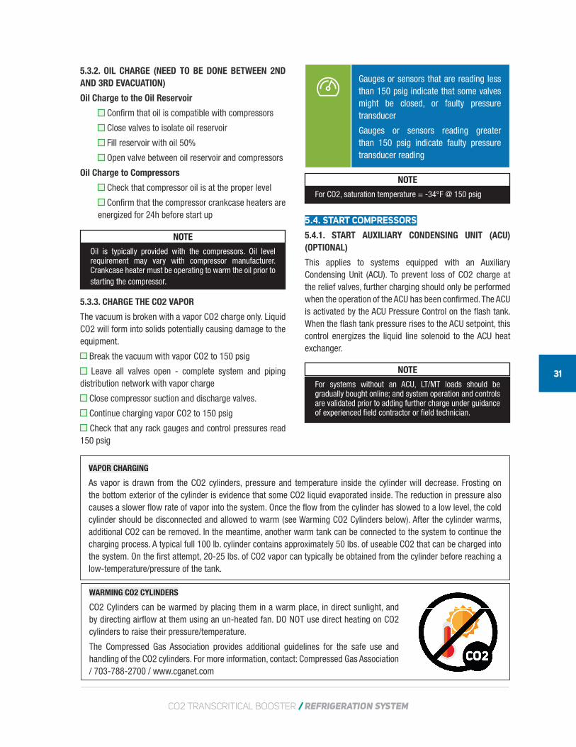
WARMING CO2 CYLINDERS
CO2 Cylinders can be warmed by placing them in a warm place, in direct sunlight, and by directing airflow at them using an un-heated fan. DO NOT use direct heating on CO2 cylinders to raise their pressure/temperature.
The Compressed Gas Association provides additional guidelines for the safe use and handling of the CO2 cylinders. For more information, contact: Compressed Gas Association / 703-788-2700 / www.cganet.com
Gauges or sensors that are reading less than 150 psig indicate that some valves might be closed, or faulty pressure transducer
Gauges or sensors reading greater than 150 psig indicate faulty pressure transducer reading
NOTE
For CO2, saturation temperature = -34°F @ 150 psig
5.4. START COMPRESSORS
5.4.1. START AUXILIARY CONDENSING UNIT (ACU) (OPTIONAL)
This applies to systems equipped with an Auxiliary Condensing Unit (ACU). To prevent loss of CO2 charge at the relief valves, further charging should only be performed when the operation of the ACU has been confirmed. The ACU is activated by the ACU Pressure Control on the flash tank. When the flash tank pressure rises to the ACU setpoint, this control energizes the liquid line solenoid to the ACU heat exchanger.
NOTE
For systems without an ACU, LT/MT loads should be gradually bought online; and system operation and controls are validated prior to adding further charge under guidance of experienced field contractor or field technician.
32
Check ACU Pressure Control setpoint
Power up ACU by temporarily lowering the ACU Pressure Control setpoint until it closes
Confirm that ACU compressor and fans are running
Return ACU Pressure Control to its proper setpoint. The switch should open and the ACU compressor will cycle off on its low pressure control
5.3.2. CONTROLS/INSTRUMENTATION CHECK
SOO (Sequence of Operation) is provided for individual systems. The SOO provides general information for programming of controls and various alarms.
Mechanical Pressure Switches
Confirm that mechanical switches are operating properly. All pressure controls should be adjusted until they actuate and it is verified that the desired result is achieved. The controls should then be set to their proper setpoints (reference SOO).
MT and LT Compressor High Pressure Controls – reference SOO for setpoints
Tag or Label preset MT and LT Mechanical High Pressure Cut-off Switches
MT and LT Compressor and/or Suction Group Low Pressure Controls – reference SOO for setpoints
Tag or Label preset MT and LT Mechanical Low Pressure Cut-off Switches
ACU Pressure Control – 500 psig cut-in / 450 psig cut-out
Tag or Label preset ACU Mechanical Control Switch – ACU optional
Pressure & Temperature Sensors
Check that all pressure and temperature sensors are calibrated and providing accurate readings at the controller
Cases
Gas Cooler Outlet
Walk-ins
Flash Tank
Rack System (reference SOO)
Oil Supply
Gas Cooler (reference SOO)
LT Suction
MT Suction
LT Discharge
LT Discharge
Heat Reclaim Outlet (if applicable)
Parallel Suction (if applicable)
Outside Air Temperature/Humidity
Oil Separator Outlet Pressure (if applicable)
Flash Tank Level Indicator (if applicable)
Digital Input Verification
Check that all digital inputs are reading open or closed as expected. Exercise each component as possible and verify the results at the proper input point.
Phase Loss Monitor
Compressor Proofs
Compressor Fails
VFD Faults
Oil Separator Level Switch
Flash Tank Level Switches
Relay Output Verification
All relay outputs should be exercised and the proper results verified.
Compressor Runs
VFD Bypasses (when provided)
Oil Separator Dump Valve
Hot Gas Dump Valve
Liquid Injection Valve
Gas Cooler Bypass Valve
Subcooler Expansion Valve (Temperature and Pressure Control)
Subcooler Expansion Valve (Superheat Control)
Analog Output Verification
All analog outputs should be exercised and proper results verified.
MT1 Compressor Speed Reference
Parallel Compressor Speed Reference (if applicable)
LT1 Compressor Speed Reference (if applicable)
Gas Cooler Fan Speed Reference
High Pressure Regulator Valve (HPV)
Flash Gas Bypass Valve (FGV)
Heat Reclaim Regulator Valves (if applicable)
VFD Set-up Verification
CO2 TRANSCRITICAL BOOSTER / REFRIGERATION SYSTEM
33
Verify all Control Setpoints.
MT/LT/Parallel Suction Pressure Targets
Gas Cooler Outlet Temperature Differential Target (Supercritical)
Flash Gas Pressure Target
Oil Separator Dump Valve
Hot Gas Dump Valve
Liquid Injection Valve
Gas Cooler Bypass Valve
Subcooler Expansion Valve (Temp Control)
Subcooler Expansion Valve (Superheat Control)
Electrical Connections
Connections to the display cases and walk-in freezers have been completed and proper operation of lights, fans, and anti-sweat heaters has been established.
Connections to the display cases and walk-in freezers are completed
Verify the operation of lights
Verify the operation of fans
Verify the operation of anti-sweat heaters
5.4.3. LIQUID CO2 CHARGE TO FLASH TANK
Safety Precaution Note: Charging CO2 refrigerant increases pressure in the system. For systems with an ACU, check that backup power and Auxiliary Cooling Systems are working properly to maintain safe pressures in the event of power outage or abnormal conditions. Otherwise loss of charge and/or damage to equipment could occur.
Close the main CO2 liquid line valve
When ACU is NOT present:
Close the isolation valves on all lines connected to flash tank
Position PRV change over valve to pump-down position
When ACU is present:
Manually turn on ACU
Check that compressor is running, fan is turning, and unit is cooling
Check that EEVs at cases and walk-ins are also in the closed position
Purge air from refrigerant tank supply hoses before attaching to the flash tank
Fill liquid CO2 directly to the flash tank
Adjust the flow of CO2 refrigerant by adjusting the valve on the refrigerant tank
Typical tanks should fully release in approximately 5 minutes (releasing CO2 refrigerant too quickly may cause some solids to form in the valves resulting in sputtering)
Check design specification for initial charge level
Do not exceed the second sight glass (~50%) during charging
Frost should form on the base of the refrigerant tank when the tank is close to empty
Check to purge air from hoses when adding new refrigerant tank(s)
Change the core of the filter drier on the charging port for every 500 lbs. of refrigerant added.
5.4.4. START MT COMPRESSORS
NOTE
Groups of case piping circuits can be designated to start sequentially to allow easier troubleshooting during startup. A system controller is typically used to manage the operation of the various circuits.
MT Compressors should already be powered on in “stand-by” mode
Change panel switch for compressors from OFF to ON
Turn on case controllers for the first section of MT loads to be started
Slowly open main CO2 liquid line valve(s) to the MT loads
When ACU is NOT present:
Open isolation valve between HPEV and Flash Tank
Open isolation valve between FGBV and Flash Tank
MT compressors begin running and pulling down case pressures and temperatures.
Add CO2 Liquid Charge to maintain the flash tank level just above first site glass (no more than 25%) after cases are running at operating temperatures.
5.3.5. PULL DOWN MT CASES & WALK-INS
Confirm that MT Cases and Walk-Ins are meeting the required temperatures
5.4.6. START LT COMPRESSORS
Open main CO2 liquid line valve(s) to the LT loads
34
LT Compressors should already be powered on in “stand-by” mode
Change panel switch for compressors from OFF to ON
Turn on case controllers for the first section of LT loads to be started (Never start at full load)
Slowly open main CO2 liquid line valve(s) to the LT loads
LT compressors begin running and pulling down case pressures and temperatures.
Add CO2 Liquid Charge to maintain flash tank level (see note below) after cases are running at operating temperatures.
NOTE
CO2 Charge Capacity - The CO2 Flash tank has sufficient volume for various operating conditions. The final charge should be checked when the system is stable, and when the cases and walk ins are pulled down to their set-point temperatures.
5.4.7. PULL DOWN LT CASES & WALK-INS
Continue bringing all cases and walk-ins online and adjusting charge as needed
Confirm that LT Cases and Walk-Ins are meeting the required temperatures
5.5. DEFROST OPERATION
The standard system defrost design is off cycle and electric defrost. Defrost should be programmed to operate with 10% to 20% of system load/capacity at a time. This ensures that the system has sufficient cooling capacity to maintain the temperature of the system while recovering after defrost periods. Defrosting CO2 evaporators is similar to conventional systems. Defrosting the evaporators is accomplished in three sequential stages, referred to as operating modes:
• Pumpdown Mode
• Heating Mode
• Drip Mode
The controller can be programmed to start and manage the defrost modes based on routine time periods, or based on temperature set-points.
NOTE
Reference the SOO for additional controller details.
1. Pumpdown (10-12 minutes duration)
The controller initiates pumpdown mode, the first defrost stage. During this stage, the evaporator circuit (or evaporator) solenoid valve (or EEV) is
closed preventing refrigerant from flowing to the evaporator(s). The evaporator fans run while any liquid CO2 refrigerant remaining in the evaporator continues to boil into vapor.
2. Heating (45-60 minutes maximum)
After the pumpdown period, electric heaters are turned on to melt accumulated ice on the evaporators. Evaporator fans are always off during the heating stage. The heater power is typically terminated when the evaporator temperature reaches a temperature set-point. The set-point is based on a temperature sensor located at the center of case evaporators, or at the U bend on walk-ins. The heater may also be terminated based on a set maximum (fail safe) time period. Circuits with various size cases should also have a defrost Klixon and relay installed to individual smaller cases to avoid over-heating.
3. Drip Mode (10 minutes)
After the heating stage is complete, condensate continues to drip off the evaporator to the drain of the case or walk-in. The heater and fans are off during this stage. After Drip mode, the system resumes normal operation, with the evaporator cooling the load back to the set temperature.
5.6. WALK-IN DOOR SWITCHES
Door switches should be installed to freezers (LT) only, and set to cut-off fans during door openings. Door switches are wired to the system controller where door openings are recorded. Extended door openings set an alarm at the controller.
CO2MANUAL
MAINTENANCE ANDTROUBLESHOOTING
6
36
MAINTENANCE AND TROUBLESHOOTING
6.1. GENERAL MAINTENANCE PROCEDURES
Proper maintenance is critical to long term reliability and efficiency. For more detailed maintenance procedures, refer to the maintenance schedule or requirements for the specific system. The following are some general maintenance procedures.
6.1.1. INITIAL STARTUP
Operators should be especially careful during initial startup procedures. The following are some recommended maintenance steps to take during initial startup.
Change all filters and driers by end of first week of startup
If filters are dirty, repeat in 7 days
After 90 days:
Change the filter driers
Remove the suction line filter core
Replace oil coalescing media
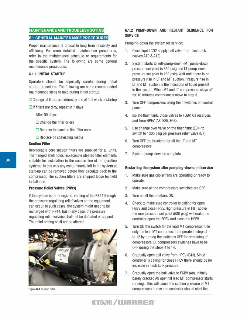
Suction Filter
Replaceable core suction filters are supplied for all units. The flanged shell holds replaceable pleated filter elements suitable for installation in the suction line of refrigeration systems. In this way any contaminants left in the system at start-up can be removed before they circulate back to the compressor. The suction filters are shipped loose for field installation.
Pressure Relief Valves (PRVs)
If the system is de-energized, venting of the R744 through the pressure-regulating relief valves on the equipment can occur. In such cases, the system might need to be recharged with R744, but in any case, the pressure regulating relief valve(s) shall not be defeated or capped. The relief setting shall not be altered.
6.1.2 PUMP-DOWN AND RESTART SEQUENCE FOR SERVICE
Pumping-down the system for service:
1. Close liquid CO2 supply ball valve from flash tank (valves A10 & A12).
2. System starts to self-pump-down (MT pump-down pressure set point is 350 psig and LT pump-down pressure set point is 160 psig).Wait until there is no pressure rise in LT and MT suction. Pressure rise in LT and MT suction is the indication of liquid present in the system. When MT and LT compressors stays off for 10 minutes continuously move to step 3.
3. Turn OFF compressors using their switches on control panel.
4. Isolate flash tank. Close valves to FGBV, Oil reservoir, and from HPEV (A8, E35, E43).
5. Use change over valve on the flash tank (E34) to switch to 1305 psig psi pressure relief valve (D7)
6. Turn OFF the breakers for all the LT and MT compressors
7. System pump-down is complete.
Restarting the system after pumping-down and service
1. Make sure gas cooler fans are operating or ready to operate.
2. Make sure all the compressors switches are OFF
3. Turn on all the breakers ON.
4. Check to make sure controller is calling for open FGBV and close HPEV. High pressure in FGT above the max pressure set point (580 psig) will make the controller open the FGBV and close the HPEV.
5. Turn ON the switch for the lead MT compressor. Use only the lead MT compressor to operate in steps 4 to 12 by turning the switches OFF for remaining of compressors. LT compressors switches have to be OFF during the steps 4 to 14.
6. Gradually open ball valve from HPEV (E43). Since controller is calling for close HPEV there should be no increase in flash tank pressure.
7. Gradually open the ball valve to FGBV (A8). Initially barely cracked A8 open till lead MT compressor starts running. This will cause the suction pressure of MT compressors to rise and controller should start the Figure 6-1. Suction Filter.
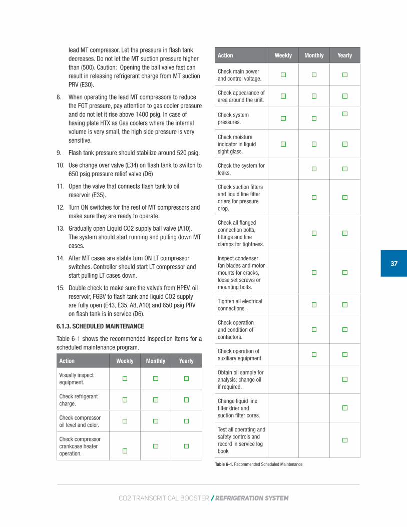
CO2 TRANSCRITICAL BOOSTER / REFRIGERATION SYSTEM
37
Action Weekly Monthly Yearly
Visually inspect equipment.
Check refrigerant charge.
Check compressor oil level and color.
Check compressor crankcase heater operation.
Action Weekly Monthly Yearly
Table 6-1. Recommended Scheduled Maintenance
lead MT compressor. Let the pressure in flash tank decreases. Do not let the MT suction pressure higher than (500). Caution: Opening the ball valve fast can result in releasing refrigerant charge from MT suction PRV (E30).
8. When operating the lead MT compressors to reduce the FGT pressure, pay attention to gas cooler pressure and do not let it rise above 1400 psig. In case of having plate HTX as Gas coolers where the internal volume is very small, the high side pressure is very sensitive.
9. Flash tank pressure should stabilize around 520 psig.
10. Use change over valve (E34) on flash tank to switch to 650 psig pressure relief valve (D6)
11. Open the valve that connects flash tank to oil reservoir (E35).
12. Turn ON switches for the rest of MT compressors and make sure they are ready to operate.
13. Gradually open Liquid CO2 supply ball valve (A10). The system should start running and pulling down MT cases.
14. After MT cases are stable turn ON LT compressor switches. Controller should start LT compressor and start pulling LT cases down.
15. Double check to make sure the valves from HPEV, oil reservoir, FGBV to flash tank and liquid CO2 supply are fully open (E43, E35, A8, A10) and 650 psig PRV on flash tank is in service (D6).
6.1.3. SCHEDULED MAINTENANCE
Table 6-1 shows the recommended inspection items for a scheduled maintenance program.
Check main power and control voltage.
Check appearance of area around the unit.
Check system pressures.
Check moisture indicator in liquid sight glass.
Check the system for leaks.
Check suction filters and liquid line filter driers for pressure drop.
Check all flanged connection bolts, fittings and line clamps for tightness.
Inspect condenser fan blades and motor mounts for cracks, loose set screws or mounting bolts.
Tighten all electrical connections.
Check operation and condition of contactors.
Check operation of auxiliary equipment.
Obtain oil sample for analysis; change oil if required.
Change liquid line filter drier and suction filter cores.
Test all operating and safety controls and record in service log book
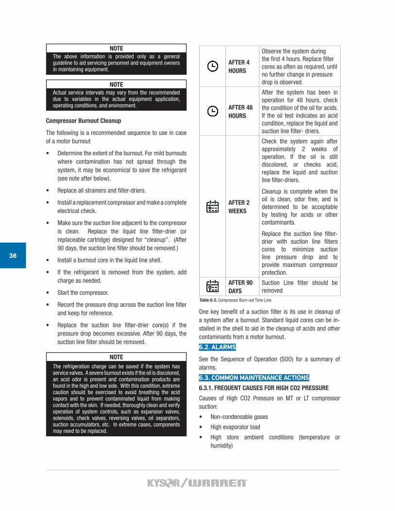
38
NOTEThe above information is provided only as a general guideline to aid servicing personnel and equipment owners in maintaining equipment.
NOTEActual service intervals may vary from the recommended due to variables in the actual equipment application, operating conditions, and environment.
Compressor Burnout Cleanup
The following is a recommended sequence to use in case of a motor burnout
• Determine the extent of the burnout. For mild burnouts where contamination has not spread through the system, it may be economical to save the refrigerant (see note after below).
• Replace all strainers and filter-driers.
• Install a replacement compressor and make a complete electrical check.
• Make sure the suction line adjacent to the compressor is clean. Replace the liquid line filter-drier (or replaceable cartridge) designed for “cleanup”. (After 90 days, the suction line filter should be removed.)
• Install a burnout core in the liquid line shell.
• If the refrigerant is removed from the system, add charge as needed.
• Start the compressor.
• Record the pressure drop across the suction line filter and keep for reference.
• Replace the suction line filter-drier core(s) if the pressure drop becomes excessive. After 90 days, the suction line filter should be removed.
NOTEThe refrigeration charge can be saved if the system has service valves. A severe burnout exists if the oil is discolored, an acid odor is present and contamination products are found in the high and low side. With this condition, extreme caution should be exercised to avoid breathing the acid vapors and to prevent contaminated liquid from making contact with the skin. If needed, thoroughly clean and verify operation of system controls, such as expansion valves, solenoids, check valves, reversing valves, oil separators, suction accumulators, etc. In extreme cases, components may need to be replaced.
AFTER 4 HOURS
Observe the system during the first 4 hours. Replace filter cores as often as required, until no further change in pressure drop is observed.
AFTER 48 HOURS
After the system has been in operation for 48 hours, check the condition of the oil for acids. If the oil test indicates an acid condition, replace the liquid and suction line filter- driers.
AFTER 2 WEEKS
Check the system again after approximately 2 weeks of operation. If the oil is still discolored, or checks acid, replace the liquid and suction line filter-driers.
Cleanup is complete when the oil is clean, odor free, and is determined to be acceptable by testing for acids or other contaminants.
Replace the suction line filter-drier with suction line filters cores to minimize suction line pressure drop and to provide maximum compressor protection.
AFTER 90 DAYS
Suction Line filter should be removed
One key benefit of a suction filter is its use in cleanup of a system after a burnout. Standard liquid cores can be in- stalled in the shell to aid in the cleanup of acids and other contaminants from a motor burnout.
6.2. ALARMS
See the Sequence of Operation (SOO) for a summary of alarms.
6.3. COMMON MAINTENANCE ACTIONS
6.3.1. FREQUENT CAUSES FOR HIGH CO2 PRESSURE
Causes of High CO2 Pressure on MT or LT compressor suction:
• Non-condensable gases
• High evaporator load
• High store ambient conditions (temperature or humidity)
Table 6-2. Compressor Burn-out Time Line
CO2 TRANSCRITICAL BOOSTER / REFRIGERATION SYSTEM
39
• LT compressor group stopped (LT compressor suction only)
• MT compressors tripped (MT compressor suction only)
6.3.2. EVACUATING NON-CONDENSABLE GASES
Non-condensable gases are prevented by:
• Following proper evacuation steps
• Purging refrigerant lines during charging process
• Ensuring that valves are never opened such that a vacuum is created in the piping.
6.3.3. PREPARATION FOR PIPING REPAIRS
Use the following steps for the maintenance of piping or for replacing in-line components:
1. Close upper isolation valves first to allow liquid to drain downward
2. Use CO2 Gas from a 200-300 psig cylinder to push remaining liquid into adjoining piping if needed.
3. Close isolation valves to cases and walk-in freezers and manually start a defrost cycle to boil remaining CO2 liquid from the evaporators
4. Continue to remove liquid keeping piping pressures above 100 psig
5. When all liquid is removed, vapor CO2 can be released safely through a hose to a well-ventilated space or outside the work area.
6. Keep CO2 gas cylinder attached to the system when possible with regulator set to 10 psig to prevent any air entering the piping.
7. Conduct repairs or replace parts
8. Before restarting the system, evacuate the piping according to customer specifications. (See section 0 Testing and Evacuation).
9. Break vacuum with CO2 vapor, and pressurize the piping to 150 psig.
10. Return isolation valves to the open (or normal operating) position.
6.3.4. SYSTEM SHUT DOWN
The CO2 system should be pumped down before turning off the rack to prevent loss of CO2 through the relief valves. Use the following steps to turn off the CO2 TC Booster Rack
LT Pumpdown: Close the LT liquid supply ball valve allowing the compressors to continue running, in order to pumpdown the CO2 refrigerant at the system LT side. CO2 refrigerant will flow to the flash tank.
MT Pumpdown: Close the main liquid supply valve at the outlet of the flash tank, and allow the compressors to continue running, in order to pumpdown the CO2 refrigerant at the system MT side. CO2 refrigerant will continue to flow to the flash tank. MT compressors will cycle off at the low suction pressure setpoint. The compressor crankcase heaters will automatically turn on as the compressors cycle off.
With ACU Option: As an option, systems are equipped with an ACU to maintain CO2 temperature and pressure to prevent venting CO2 refrigerant from the system. The ACU is set to a slightly higher operating pressure so it doesn’t run during normal operation.
Without ACU Option: Systems without ACU are designed with a high pressure flash tank. For these systems, all refrigerant is pumped down during service, and isolated from the system by closing the FGT liquid lines. If the ACU is not operating, the system will eventually warm up and vent CO2 refrigerant
Refrigerant: CO2 refrigerant charge should be verified and possibly added to normal level after restarting the system
6.4. TROUBLESHOOTING
Refrigeration systems are complex and run constantly. Problems have to be quickly corrected or expensive produce will be ruined.
Troubleshooting is a logical and systematic search for the source of a problem in order to correct the problem and make the system operational again in a minimal amount of time.
When troubleshooting a system, it is important to have a systematic approach to collecting and analyzing data. Table 6-3 is an example of a general troubleshooting process.
NOTETable 6-3 is an example only. Operators should develop a troubleshooting methodology for their own specific equipment.
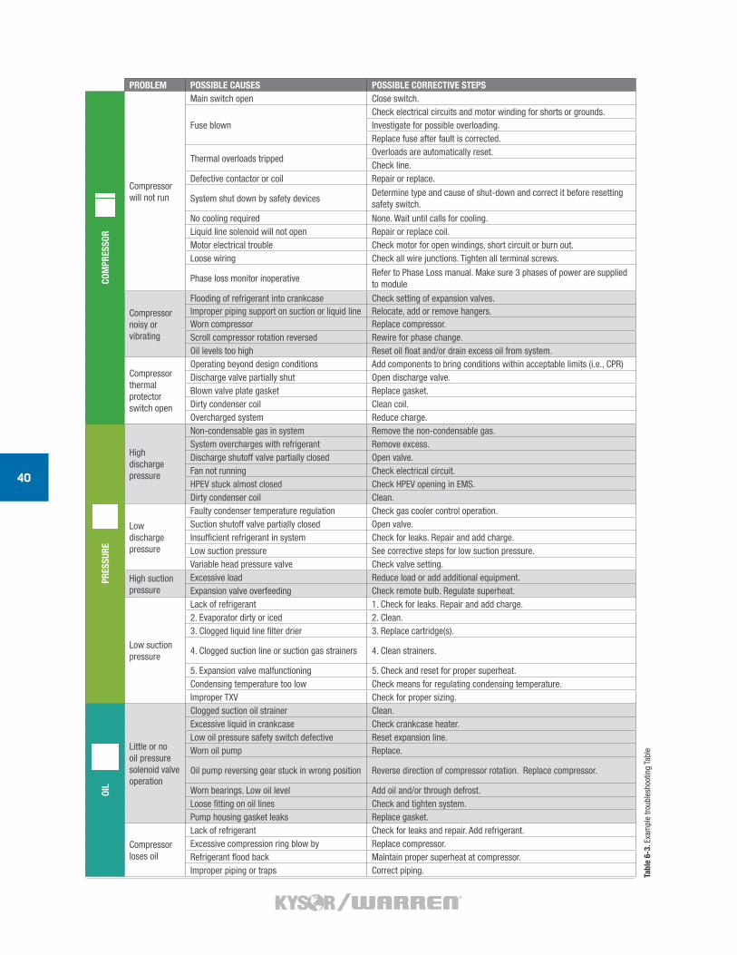
40
Tabl
e 6-
3. E
xam
ple
troub
lesh
ootin
g Ta
ble
PROBLEM POSSIBLE CAUSES POSSIBLE CORRECTIVE STEPS
COM
PRES
SOR
Compressor will not run
Main switch open Close switch.
Fuse blownCheck electrical circuits and motor winding for shorts or grounds.Investigate for possible overloading.Replace fuse after fault is corrected.
Thermal overloads trippedOverloads are automatically reset.Check line.
Defective contactor or coil Repair or replace.
System shut down by safety devicesDetermine type and cause of shut-down and correct it before resetting safety switch.
No cooling required None. Wait until calls for cooling.Liquid line solenoid will not open Repair or replace coil.Motor electrical trouble Check motor for open windings, short circuit or burn out.Loose wiring Check all wire junctions. Tighten all terminal screws.
Phase loss monitor inoperativeRefer to Phase Loss manual. Make sure 3 phases of power are supplied to module
Compressor noisy or vibrating
Flooding of refrigerant into crankcase Check setting of expansion valves.Improper piping support on suction or liquid line Relocate, add or remove hangers.Worn compressor Replace compressor.Scroll compressor rotation reversed Rewire for phase change.Oil levels too high Reset oil float and/or drain excess oil from system.
Compressor thermal protector switch open
Operating beyond design conditions Add components to bring conditions within acceptable limits (i.e., CPR)Discharge valve partially shut Open discharge valve.Blown valve plate gasket Replace gasket.Dirty condenser coil Clean coil.Overcharged system Reduce charge.
PRES
SURE
High discharge pressure
Non-condensable gas in system Remove the non-condensable gas.System overcharges with refrigerant Remove excess.Discharge shutoff valve partially closed Open valve.Fan not running Check electrical circuit.HPEV stuck almost closed Check HPEV opening in EMS.Dirty condenser coil Clean.
Low discharge pressure
Faulty condenser temperature regulation Check gas cooler control operation.Suction shutoff valve partially closed Open valve.Insufficient refrigerant in system Check for leaks. Repair and add charge.Low suction pressure See corrective steps for low suction pressure.Variable head pressure valve Check valve setting.
High suction pressure
Excessive load Reduce load or add additional equipment.Expansion valve overfeeding Check remote bulb. Regulate superheat.
Low suction pressure
Lack of refrigerant 1. Check for leaks. Repair and add charge.2. Evaporator dirty or iced 2. Clean.3. Clogged liquid line filter drier 3. Replace cartridge(s).
4. Clogged suction line or suction gas strainers 4. Clean strainers.
5. Expansion valve malfunctioning 5. Check and reset for proper superheat.Condensing temperature too low Check means for regulating condensing temperature.Improper TXV Check for proper sizing.
OIL
Little or no oil pressure solenoid valve operation
Clogged suction oil strainer Clean.Excessive liquid in crankcase Check crankcase heater.Low oil pressure safety switch defective Reset expansion line.Worn oil pump Replace.
Oil pump reversing gear stuck in wrong position Reverse direction of compressor rotation. Replace compressor.
Worn bearings. Low oil level Add oil and/or through defrost.Loose fitting on oil lines Check and tighten system.Pump housing gasket leaks Replace gasket.
Compressor loses oil
Lack of refrigerant Check for leaks and repair. Add refrigerant.Excessive compression ring blow by Replace compressor.Refrigerant flood back Maintain proper superheat at compressor.Improper piping or traps Correct piping.
CO2MANUAL
WARRANTY ANDMANUAL DISCLAIMER
7
42
STANDARD WARRANTY AND MANUAL DISCLAIMER
7.1. STANDARD WARRANTY
This appendix contains the KWs standard warranty for its products and a disclaimer for this manual.
Seller warrants to its direct purchasers that Products, including Service Parts, shall be of a merchantable quality, free of defects in material or workmanship, under normal use and service for a period of one (1) year from date of original equipment start-up, or eighteen (18) months from date of shipment by Seller, whichever first occurs. This warranty runs to only the original purchaser of equipment or part. Any Products covered by this warranty found to Seller’s satisfaction to be defective upon examination at Seller’s factory will at Seller’s option, be repaired or replaced and returned to Buyer via lowest common carrier FOB seller’s point of shipment. This is buyer’s sole and exclusive remedy and, except as provided in the next sentence, seller’s sole and exclusive liability in connection with the warranty. Or Seller may at its option grant Buyer a credit for the purchase price of the defective Product. Buyer must prepay all costs for transportation of Products to Seller’s factory.
Seller shall have no liability for expenses incurred for repairs made by Buyer except by prior, written authorization. Any claim under this warranty shall be made to Seller in writing within the warranty period above, otherwise such claim shall be deemed waived. Seller shall have no warranty obligation whatsoever if its products have been subjected to alteration, misuse, negligence, free chemicals in system, corrosive atmosphere, accident, or if operation is contrary to Seller’s or manufacturer’s recommendations, or if the serial number has been altered, defaced, or removed.
This warranty is in lieu of all other warranties, expressed, implied or statutory, including, but not limited to any warranty of merchantability or fitness, and all other obligations or liabilities of seller are hereby disclaimed.
WARRANTY NOTES
This equipment is designed to operate properly and produce rated capacity when installed in accordance with accepted industry standards. Failure to meet the following conditions may result in voiding of the system warranty:
1. System piping must be installed following industry standards for good piping practices (see details later in this document).
2. Inert gas (dry nitrogen) must be charged into piping during welding.
3. System must be thoroughly leak checked and evacuated before initial charging. High vacuum gauge capable of reading microns is mandatory--Dials indicating pressure gauges are not acceptable.
4. Power supply to system must meet the following conditions:
• Voltage for 208/230 not less than 195 volts or more than 253 volts.
• All other voltages must not exceed +/- 10% of nameplate ratings.
• Phase imbalance not to exceed 2%.
5. All controls and safety switch circuits properly connected per wiring diagram.
6. Factory installed wiring must not be changed without written factory approval.
THIS WARRANTY SHALL NOT APPLY:
1. BULBS: Light bulbs, fluorescent lamp tubes and LEDs are not covered by any warranty for length of life or for any type of breakage.
2. To the condensing unit used with refrigerated equipment unless same was sold and shipped by Seller
3. When this equipment or any part thereof is damaged by accident, fire, flood act of God, alteration, abuse, misuse, tampering, when the original model and serial number plate has been altered, defaced, or removed or used other than the recommended application by Seller.
4. When this equipment or any part thereof is subject to operation on low, high or improper voltages. Low and high voltage is defined as more than a 5% drop below or 10% higher than name plate voltage ratings.
NOTEProper field supply voltage to the equipment is the responsibility of the owner (end user).
5. When this equipment or any part thereof is damaged, or when operation is impaired, due to failure to follow installation manual.
NOTEProper field supply voltage to the equipment is the responsibility of the owner (end user).
6. To equipment with final destinations unknown to seller as indicated on the original sales order.
7. To labor cost for repair or replacement of parts.
8. To special or expedited freight or shipping charges or to customs duties to any country.
9. If the Warranty holder fails to comply with all the provisions, terms and conditions of this Warranty.
10. Parts replaced under this Warranty are warranted only through the remainder of the original Warranty.
11. Extended Service Agreements are provided by a third party not affiliated with Seller. The services provided by the third party are subject to the terms and conditions of the Extended Service Agreements and Seller is not responsible for those services or the third party’s performance of its obligations.
It is expressly understood and agreed that seller shall not be liable to buyer, or any customer of buyer, for indirect, special, incidental, consequential or punitive damages, including loss of profits, additional labor costs, loss of refrigerants or food product, or any injury to person or property caused by defective material or parts or for any delay or misperformance in the performance due to causes beyond its control or for any
CO2 TRANSCRITICAL BOOSTER / REFRIGERATION SYSTEM
43
expenses incurred by reason of the use or misuse by buyer or third parties of the products. Seller’s maximum liability for direct damages is limited to the amo”unt paid by the buyer for the particular item of equipment or part involved.
NOTEIn the constant effort to improve our products, we reserve the right to change at any time specifications, design, or prices without incurring obligation.
COMPRESSOR WARRANTY
Compressor replacements or exchanges shall be made through the nearest authorized wholesaler of the compressor manufacturer (not at Seller’s factory) and no freight shall be allowed for transportation of the compressor to and from the wholesaler. The replacement compressor shall be identical to the model of the compressor being replaced
Additional charges which may be incurred throughout the substitution of other than identical replacements are not covered by this warranty. An optional, non-assignable, three (3) or four (4) year extended compressor warranty may be purchased within the boundaries of the United States of America, its territories and possessions, and Canada. With this extended compressor warranty, replacements are administered by an authorized compressor distributor only. Replacements within the first year of the warranty are available through the distributor, the second through fifth years, the purchaser must submit a proof-of-purchase of a compressor and supply it to Heatcraft Warranty Claims for reimbursement.
PARTS WARRANTY POLICY
The following procedures are in accordance with the Heatcraft standard one-year warranty, which covers any part to be free of defects under normal use and service for one year from the date of installation. (Not to exceed one year and 30 days from the date of original shipment from the factory.)
In Warranty/Non-Warranty Parts Replacement
When ordering Warranty replacement part(s), the following information must be furnished to the Parts Department via phone, or e-mail with purchase orders provided by Fax or e-mail only.
1. Full name and address of Company
2. Name and phone number of person ordering parts
3. Model number
4. Serial number
5. Factory order number
6. Description of parts desired
7. Original date of installation
8. Reason for replacement
9. Complete shipping address
10. Purchase order number
If the order is for a replacement still in warranty a Purchase Order Number will be required from the contractor placing the order. We will then issue a Return Material Authorization Tag (RMA) that will be sent to the firm or contractor who has ordered the part.
NOTEAll warranty replacements are shipped pre-paid fob shipping point. The warranty in effect for parts does not cover the cost of special freight terms – i.E. Ups next day, air freight, etc.
Warranty of Replacement Parts
Parts will be covered for the balance of the manufacturer’s standard equipment warranty or 90 days from the date of shipment of the replacement part, whichever is longer.
If the order is for a replacement still in warranty a Purchase Order Number will be required from the contractor placing the order. We will then issue a Return Material Authorization Tag (RMA) that will be sent to the firm or contractor who has ordered the part.
NOTEAll warranty replacements are shipped pre-paid fob shipping point. The warranty in effect for parts does not cover the cost of special freight terms – i.E. Ups next day, air freight, etc.
Purchase Parts Locally
If you require an emergency Warranty replacement and you have to purchase the parts from a local supply house,
Heatcraft will accept the return of the original part for replacement only. Should the locally purchased part(s) fail, it must be returned to the local supplier for replacement, repair or credit.
Return Authorization Procedure
When in-warranty replacement parts are shipped with the service order stating “warranty replacement, return replaced material within (45) forty-five days of shipping date or invoice will be rendered and payable”, return is required. Credits will not be issued for parts returned after (45) forty-five days.
WORK AUTHORIZATION PROCESS FOR WARRANTY LABOR
All warranty labor claims must be approved in advance be an authorized Heatcraft associate. Note: Only Technical Support associates and company officers are authorized to approve warranty labor. If labor is approved, the payee will be issued a written work authorization. All invoices submitted without a written work authorization are subject to denial. The following information is required before the issuance of a written work authorization:
• Store name
• Store address
• Model number (all involved), Serial number (all involved)
• Complete description of issues and corrections to be made
• A “Not to exceed” estimate for repairs
In case of after hour’s emergency, you must contact the Technical Support Department at the beginning of the next business day.
44
Phone (800) 866-5596. Same info as above is still required.
The written work authorizations must be included with all invoices. Only written authorizations will be considered. E-mail approvals from authorized Heatcraft associates are approved and should be included with invoices.
All invoices containing warranty parts not obtained from Heatcraft Service Parts Department must be accompanied by the wholesaler’s invoice for reimbursement or will be replaced through the Heatcraft Service Parts Department. (Heatcraft will pay only wholesale cost of parts if not supplied by Heatcraft). All defective parts must be returned to Heatcraft if so requested. (See Parts Warranty Policy)
Labor to change DOA compressors will be paid only with a teardown report from the compressor manufacturer, submitted with the invoice. (Note: Compressor must be factory defective as described in teardown report, before labor will be paid). Teardown reports have to be requested at the time of warranty exchange from an authorized wholesaler.
All model and serial numbers must be included on your invoice, (for all equipment serviced). For compressor warranty, the model and serial number of the unit the compressor was located and the model and serial number of the compressors – both old and new – must be included.
All invoices must be billed to Heatcraft first party. Heatcraft will not pay third party invoices. Emailed invoices and scans of backup are preferred and may speed processing.
Invoices submitted after 30 days from date when work was done will be subject to denial. Invoices submitted after 60 days from the date when work was done will be denied.
If you receive a notice requesting more information, (i.e. model, serial number, etc.), you will have an additional 30 days to respond. If a response is not received within 30 days, the invoice will be denied.
All warranties of the equipment are subject to standard manufacturer’s warranty and terms and conditions of the sale. Any exception to the standard warranty policies must be specifically agreed to in writing by Heatcraft prior to the date of sale.
All invoices must be billed to Heatcraft, Attn: Technical Support Coordinator, 5201 Transport Boulevard, Columbus, GA 31907-8944. Phone (800) 866-5596.
Labor to replace parts damaged in transit (shipping damage) must be noted on the shipping bill before any labor charges will be considered for payment.
7.2. MANUAL DISCLAIMER
No warranties - This Manual is provided “as is” without any representations or warranties, express or implied. Heatcraft makes no representations or warranties in relation to this Manual or the information and materials provided herein. Although we make a reasonable effort to include accurate and up to date information, without prejudice to the generality of this paragraph, Heatcraft does not warrant that the information in this Manual is complete, true, accurate or non-misleading. The Heatcraft CO2 System Manual is provided solely for informational purposes. You
should not act upon information without consulting Heatcraft, a distributor, subsidiary or appropriate professional.
Limitations of liability - Heatcraft will not be liable to you (whether under the law of contract, the law of torts or otherwise) in relation to the contents of, or use of, or otherwise in connection with, this Manual:
• to the extent that this Manual is provided free-of-charge, for any direct loss;
• for any indirect, special or consequential loss; or
• for any business losses, loss of revenue, income, profits or anticipated savings, loss of contracts or business relationships, or loss of reputation or goodwill.
These limitations of liability apply even if Heatcraft has been expressly advised of the potential loss.
NOTEInstallation and maintenance to be performed only by qualified personnel whoare familiar with local codes and regulations, and experienced with this type of equipment. Sharp edges and coil surfaces are a potential injury hazard. Avoid contact with them.
WARNINGThere may be more than one source of electrical current in this unit. do not service before disconnecting all power supplies.
WARNINGAll pertinent electrical codes and regulations must be strictly followed.any deviations from these requirements will be strictly the responsibility of the installer.
CO2MANUAL
DATA, DEFINITIONSAND ACRONYMS
8
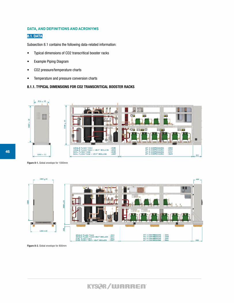
46
DATA, AND DEFINITIONS AND ACRONYMS
8.1. DATA
Subsection 8.1 contains the following data-related information:
• Typical dimensions of CO2 transcritical booster racks
• Example Piping Diagram
• CO2 pressure/temperature charts
• Temperature and pressure conversion charts
8.1.1. TYPICAL DIMENSIONS FOR CO2 TRANSCRITICAL BOOSTER RACKS
Figure 8-1. Global envelope for 1000mm
Figure 8-2. Global envelope for 800mm
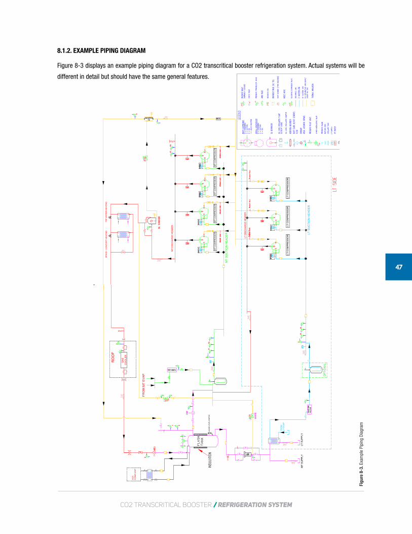
CO2 TRANSCRITICAL BOOSTER / REFRIGERATION SYSTEM
47
8.1.2. EXAMPLE PIPING DIAGRAM
Figure 8-3 displays an example piping diagram for a CO2 transcritical booster refrigeration system. Actual systems will be
different in detail but should have the same general features.
G
ASC
OO
LER
RO
OF
AU
XC
ON
D U
NIT
LIQ
UID
LE
VE
L SW
ITC
H
FRO
M M
T EV
AP
LT S
UPP
LY
FRO
MLT
EV
AP
MT
SUPP
LY
MT
DIS
CH
AR
GE
HEA
DER
MT
SU
CTI
ON
HEA
DER
LT D
ISC
HA
RG
E H
EAD
ER
TAP
WA
TER
HEA
TIN
GS
PAC
E /
CO
MFO
RT
HEA
TIN
G
LT S
UC
TIO
N H
EAD
ER
LT C
OM
PRE
SSO
R
MT
CO
MP
RE
SSO
R
LT C
OM
PRE
SSO
RLT
CO
MPR
ESS
OR
MT
CO
MP
RE
SSO
RM
T C
OM
PR
ESS
OR
MT
CO
MP
RE
SSO
R
Figu
re 8
-3. E
xam
ple
Pipi
ng D
iagr
am
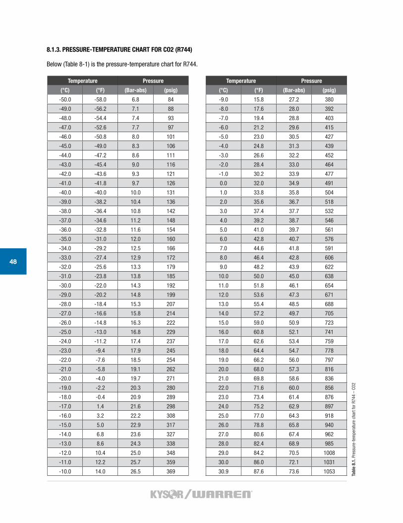
48
8.1.3. PRESSURE-TEMPERATURE CHART FOR CO2 (R744)
Below (Table 8-1) is the pressure-temperature chart for R744.
Temperature Pressure
(°C) (°F) (Bar-abs) (psig)
-50.0 -58.0 6.8 84
-49.0 -56.2 7.1 88
-48.0 -54.4 7.4 93
-47.0 -52.6 7.7 97
-46.0 -50.8 8.0 101
-45.0 -49.0 8.3 106
-44.0 -47.2 8.6 111
-43.0 -45.4 9.0 116
-42.0 -43.6 9.3 121
-41.0 -41.8 9.7 126
-40.0 -40.0 10.0 131
-39.0 -38.2 10.4 136
-38.0 -36.4 10.8 142
-37.0 -34.6 11.2 148
-36.0 -32.8 11.6 154
-35.0 -31.0 12.0 160
-34.0 -29.2 12.5 166
-33.0 -27.4 12.9 172
-32.0 -25.6 13.3 179
-31.0 -23.8 13.8 185
-30.0 -22.0 14.3 192
-29.0 -20.2 14.8 199
-28.0 -18.4 15.3 207
-27.0 -16.6 15.8 214
-26.0 -14.8 16.3 222
-25.0 -13.0 16.8 229
-24.0 -11.2 17.4 237
-23.0 -9.4 17.9 245
-22.0 -7.6 18.5 254
-21.0 -5.8 19.1 262
-20.0 -4.0 19.7 271
-19.0 -2.2 20.3 280
-18.0 -0.4 20.9 289
-17.0 1.4 21.6 298
-16.0 3.2 22.2 308
-15.0 5.0 22.9 317
-14.0 6.8 23.6 327
-13.0 8.6 24.3 338
-12.0 10.4 25.0 348
-11.0 12.2 25.7 359
-10.0 14.0 26.5 369
Temperature Pressure
(°C) (°F) (Bar-abs) (psig)
-9.0 15.8 27.2 380
-8.0 17.6 28.0 392
-7.0 19.4 28.8 403
-6.0 21.2 29.6 415
-5.0 23.0 30.5 427
-4.0 24.8 31.3 439
-3.0 26.6 32.2 452
-2.0 28.4 33.0 464
-1.0 30.2 33.9 477
0.0 32.0 34.9 491
1.0 33.8 35.8 504
2.0 35.6 36.7 518
3.0 37.4 37.7 532
4.0 39.2 38.7 546
5.0 41.0 39.7 561
6.0 42.8 40.7 576
7.0 44.6 41.8 591
8.0 46.4 42.8 606
9.0 48.2 43.9 622
10.0 50.0 45.0 638
11.0 51.8 46.1 654
12.0 53.6 47.3 671
13.0 55.4 48.5 688
14.0 57.2 49.7 705
15.0 59.0 50.9 723
16.0 60.8 52.1 741
17.0 62.6 53.4 759
18.0 64.4 54.7 778
19.0 66.2 56.0 797
20.0 68.0 57.3 816
21.0 69.8 58.6 836
22.0 71.6 60.0 856
23.0 73.4 61.4 876
24.0 75.2 62.9 897
25.0 77.0 64.3 918
26.0 78.8 65.8 940
27.0 80.6 67.4 962
28.0 82.4 68.9 985
29.0 84.2 70.5 1008
30.0 86.0 72.1 1031
30.9 87.6 73.6 1053 Tabl
e 8.
1. P
ress
ure-
tem
pera
ture
cha
rt fo
r R74
4 –
CO2
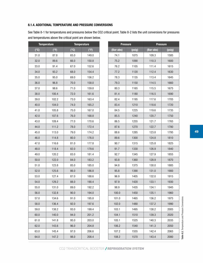
CO2 TRANSCRITICAL BOOSTER / REFRIGERATION SYSTEM
49
8.1.4. ADDITIONAL TEMPERATURE AND PRESSURE CONVERSIONS
See Table 8-1 for temperatures and pressures below the CO2 critical point. Table 8-2 lists the unit conversions for pressures
and temperatures above the critical point are shown below.
Temperature Temperature
(°C) (°F) (°C) (°F)
31.0 87.8 65.0 149.0
32.0 89.6 66.0 150.8
33.0 91.4 67.0 152.6
34.0 93.2 68.0 154.4
35.0 95.0 69.0 156.2
36.0 96.8 70.0 158.0
37.0 98.6 71.0 159.8
38.0 100.4 72.0 161.6
39.0 102.2 73.0 163.4
40.0 104.0 74.0 165.2
41.0 105.8 75.0 167.0
42.0 107.6 76.0 168.8
43.0 109.4 77.0 170.6
44.0 111.2 78.0 172.4
45.0 113.0 79.0 174.2
46.0 114.8 80.0 176.0
47.0 116.6 81.0 177.8
48.0 118.4 82.0 179.6
49.0 120.2 83.0 181.4
50.0 122.0 84.0 183.2
51.0 123.8 85.0 185.0
52.0 125.6 86.0 186.8
53.0 127.4 87.0 188.6
54.0 129.2 88.0 190.4
55.0 131.0 89.0 192.2
56.0 132.8 90.0 194.0
57.0 134.6 91.0 195.8
58.0 136.4 92.0 197.6
59.0 138.2 93.0 199.4
60.0 140.0 94.0 201.2
61.0 141.8 95.0 203.0
62.0 143.6 96.0 204.8
63.0 145.4 97.0 206.6
64.0 147.2 98.0 208.4
Pressure Pressure
(Bar-abs) (psig) (Bar-abs) (psig)
74.1 1075 109.3 1585
75.2 1090 110.3 1600
76.2 1105 111.4 1615
77.2 1120 112.4 1630
78.3 1135 113.4 1645
79.3 1150 114.5 1660
80.3 1165 115.5 1675
81.4 1180 116.5 1690
82.4 1195 117.6 1705
83.4 1210 118.6 1720
84.5 1225 119.6 1735
85.5 1240 120.7 1750
86.5 1255 121.7 1765
87.6 1270 122.7 1780
88.6 1285 123.8 1795
89.6 1300 124.8 1810
90.7 1315 125.8 1825
91.7 1330 126.9 1840
92.7 1345 127.9 1855
93.8 1360 128.9 1870
94.8 1375 130.0 1885
95.8 1390 131.0 1900
96.9 1405 132.0 1915
97.9 1420 133.1 1930
98.9 1435 134.1 1945
100.0 1450 135.1 1960
101.0 1465 136.2 1975
102.0 1480 137.2 1990
103.1 1495 138.2 2005
104.1 1510 139.3 2020
105.1 1525 140.3 2035
106.2 1540 141.3 2050
107.2 1555 142.4 2065
108.2 1570 143.4 2080
Tabl
e 8.
2. T
empe
ratu
re a
nd P
ress
ure
Conv
ersi
ons
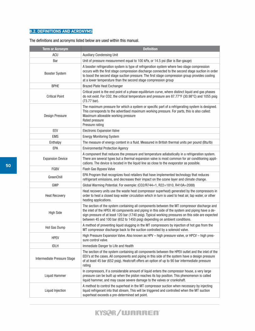
50
8.2. DEFINITIONS AND ACRONYMS
The definitions and acronyms listed below are used within this manual.
Term or Acronym Definition
ACU Auxiliary Condensing Unit
Bar Unit of pressure measurement equal to 100 kPa, or 14.5 psi (Bar is Bar-gauge)
Booster System
A booster refrigeration system is type of refrigeration system where two stage compression occurs with the first stage compression discharge connected to the second stage suction in order to boost the second stage suction pressure. The first stage compression group provides cooling at a lower temperature than the second stage compression group
BPHE Brazed Plate Heat Exchanger
Critical PointCritical point is the end point of a phase equilibrium curve, where distinct liquid and gas phases do not exist. For CO2, the critical temperature and pressure are 87.77°F (30.98°C) and 1055 psig (73.77 bar).
Design Pressure
The maximum pressure for which a system or specific part of a refrigerating system is designed. This corresponds to the advertised maximum working pressure. For parts, this is also called:Maximum allowable working pressureRated pressurePressure rating
EEV Electronic Expansion Valve
EMS Energy Monitoring System
Enthalpy The measure of energy content in a fluid. Measured in British thermal units per pound (Btu/lb)
EPA Environmental Protection Agency
Expansion DeviceA component that reduces the pressure and temperature adiabatically in a refrigeration system. There are several types but a thermal expansion valve is most common for air conditioning appli-cations. The device is located in the liquid line as close to the evaporator as possible.
FGBV Flash Gas Bypass Valve
GreenChillEPA Program that recognizes food retailers that have implemented technology that reduces refrigerant emissions, and decreases their impact on the ozone layer and climate change.
GWP Global Warming Potential. For exemple: (CO2/R744=1, R22=1810, R410A=2088)
Heat RecoveryHeat recovery units use the waste heat (compressor superheat) generated by the compressors in order to heat a closed loop water circulation which in turn is used to heat air, tap water, or other heating applications.
High Side
The section of the system containing all components between the MT compressor discharge and the inlet of the HPEV. All components and piping in this side of the system and piping have a de-sign pressure of at least 120 bar (1740 psig). Typical working pressures on this side are expected between 45 and 100 bar (652 to 1450 psig) depending on ambient conditions.
Hot Gas Dump A method of preventing liquid slugging in the MT compressors by injection of hot gas from the MT compressor discharge back to the suction controlled by a solenoid valve.
HPEVHigh Pressure Expansion Valve. Also known as HPV – high pressure valve, or HPCV – high pres-sure control valve.
IDLH Immediate Danger to Life and Health
Intermediate Pressure Stage
The section of the system containing all components between the HPEV outlet and the inlet of the EEV’s at the cases. All components and piping in this side of the system have a design pressure of at least 45 bar (652 psig). Heatcraft offers an option of up to 90 bar intermediate pressure rating
Liquid HammerIn compressors, if a considerable amount of liquid enters the compressor house, a very large pressure can be built up when the piston reaches its top position. This phenomenon is called liquid hammer, and may cause severe damage to the valves or crankshaft.
Liquid InjectionA method to control the superheat in the MT compressor suction when necessary by injecting liquid refrigerant into that stream. This will be triggered and controlled when the MT suction superheat exceeds a pre-determined set point.
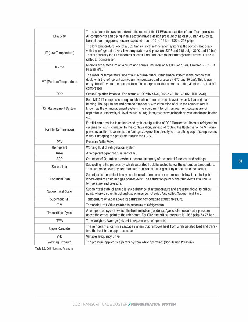
CO2 TRANSCRITICAL BOOSTER / REFRIGERATION SYSTEM
51
Low Side The section of the system between the outlet of the LT EEVs and suction of the LT compressors. All components and piping in this section have a design pressure of at least 30 bar (435 psig). Normal operating pressures are expected around 13 to 15 bar (188 to 218 psig).
LT (Low Temperature)
The low temperature side of a CO2 trans-critical refrigeration system is the portion that deals with the refrigerant at very low temperature and pressure, 22°F and 218 psig ( 30°C and 15 bar). This is generally the LT evaporator suction lines. The compressor that operates at the LT side is called LT compressor.
MicronMicrons are a measure of vacuum and equals I milliTorr or 1/1,000 of a Torr. 1 micron = 0.1333 Pascals (Pa).
MT (Medium Temperature)
The medium temperature side of a CO2 trans-critical refrigeration system is the portion that deals with the refrigerant at medium temperature and pressure (-6°C and 30 bar). This is gen-erally the MT evaporator suction lines. The compressor that operates at the MT side is called MT compressor.
ODP Ozone Depletion Potential. For exemple: (CO2/R744=0, R134a=0, R22=0.055, R410A=0)
Oil Management System
Both MT & LT compressors require lubrication to run in order to avoid wear & tear and over-heating. The equipment and protocol that deals with circulation of oil in the compressors is known as the oil management system. The equipment for oil management systems are oil separator, oil reservoir, oil level switch, oil regulator, respective solenoid valves, crankcase heater, etc.
Parallel Compression
Parallel compression is an improved cycle configuration of CO2 Transcritical Booster refrigeration systems for warm climates. In this configuration, instead of routing the flash gas to the MT com-pressors suction, it connects the flash gas bypass line directly to a parallel group of compressors without dropping the pressure through the FGBV.
PRV Pressure Relief Valve
Refrigerant Working fluid of refrigeration system
Riser A refrigerant pipe that runs vertically.
SOO Sequence of Operation provides a general summary of the control functions and settings.
SubcoolingSubcooling is the process by which saturated liquid is cooled below the saturation temperature. This can be achieved by heat transfer from cold suction gas or by a dedicated evaporator.
Subcritical StateSubcritical state of fluid is any substance at a temperature or pressure below its critical point, where distinct liquid and gas phases exist. The saturation point of the fluid exists at a unique temperature and pressure.
Supercritical StateSupercritical state of a fluid is any substance at a temperature and pressure above its critical point, where distinct liquid and gas phases do not exist. Also called Supercritical Fluid.
Superheat, SH Temperature of vapor above its saturation temperature at that pressure.
TLV Threshold Limit Value (related to exposure to refrigerants)
Transcritical CycleA refrigeration cycle in which the heat rejection (condenser/gas cooler) occurs at a pressure above the critical point of the refrigerant. For CO2, the critical pressure is 1055 psig (73.77 bar).
TWA Time Weighted Average (related to exposure to refrigerants)
Upper CascadeThe refrigerant circuit in a cascade system that removes heat from a refrigerated load and trans-fers the heat to the upper-cascade
VFD Variable Frequency Drive
Working Pressure The pressure applied to a part or system while operating. (See Design Pressure)
Table 8.3. Definitions and Acronyms
5201 Transport Blvd. • Columbus, GA 31907Toll-Free: 800.866.5596 • Phone: 706.568.1514www.kysorwarren.com
KW-IOM
-8024_09/21/2017