cms muon system overview
TRANSCRIPT
Nuclear Instruments and Methods in Physics Research A 408 (1998) 274—282
CMS muon system overview
Pierluigi Zotto*
Dipartimento di Fisica, Politecnico di Milano, and INFN, Sezione di Padova, Via F. Marzolo, 8, 35131 Padova, Italy
For the CMS Collaboration
Abstract
A complete description of the CMS muon detector is given. Results of the research and development studies on thechamber prototypes and on the trigger strategy are reported. ( 1998 Elsevier Science B.V. All rights reserved.
1. Introduction
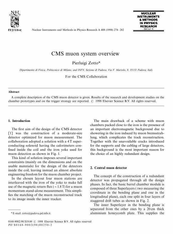
The first aim of the design of the CMS detector[1] was the construction of a moderate-sizedetector optimized for muon measurement. Thecollaboration adopted a solution with a 4T super-conducting solenoid having the calorimeters con-fined inside the coil and the iron yoke used formuon detection as shown in Fig. 1.
This kind of solution imposes several importantconstraints (mainly on the dimensions and on theusable materials) for the design of the detectorsinside the coil, leaving instead an almost absoluteengineering freedom for the muon chamber project.
In the chosen layout four muon stations areinterleaved with the iron of the yoke to make fulluse of the magnetic return flux (&1.8T) for a muonmomentum stand-alone measurement. This simpli-fies the matching of the muon reconstructed trackto its image inside the inner tracker.
*E-mail: [email protected].
The main drawback of a scheme with muonchambers packed close to the iron is the presence ofan important electromagnetic background due toshowering in the iron induced by muon bremsstrah-lung, which complicates the track reconstruction.Together with the unavoidable cracks introducedfor the supports and the cabling of large detectors,this background is the most important reason forthe choice of an highly redundant design.
2. Central muon detector
The concept of the construction of a redundantdetector was propagated through all the designphases. In fact, the basic barrel chamber module iscomposed of three Superlayers ( two measuring thecoordinate in the bending plane and one in thelongitudinal plane), each one split in four layers ofstaggered drift tubes as shown in Fig. 2.
The inner Superlayer in the bending plane isseparated from the other ones by a 20 cm thickaluminium honeycomb plate. This supplies the
0168-9002/98/$19.00 ( 1998 Elsevier Science B.V. All rights reservedPII S 0 1 6 8 - 9 0 0 2 ( 9 8 ) 0 0 2 5 0 - 2
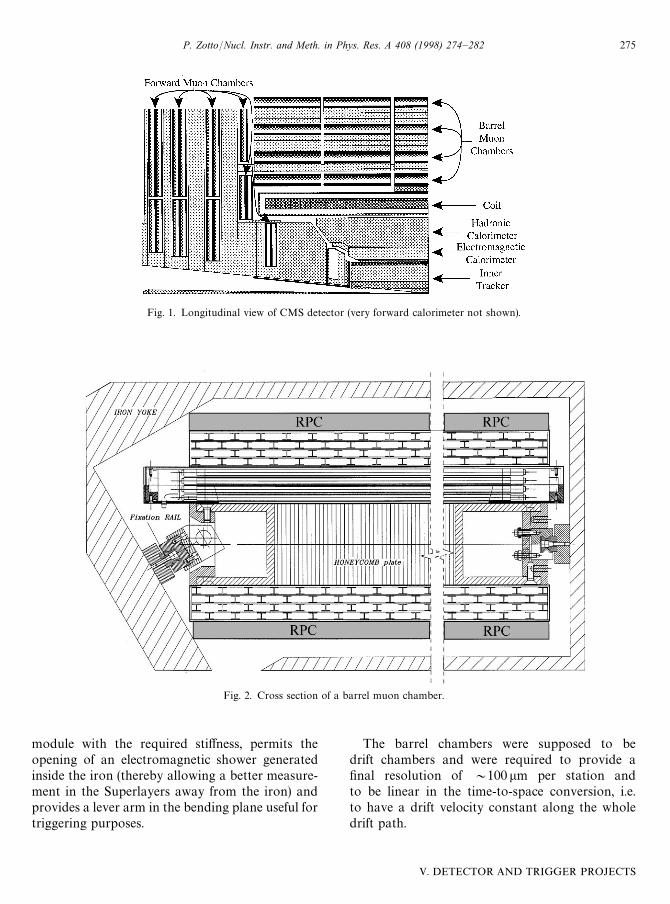
Fig. 1. Longitudinal view of CMS detector (very forward calorimeter not shown).
Fig. 2. Cross section of a barrel muon chamber.
module with the required stiffness, permits theopening of an electromagnetic shower generatedinside the iron (thereby allowing a better measure-ment in the Superlayers away from the iron) andprovides a lever arm in the bending plane useful fortriggering purposes.
The barrel chambers were supposed to bedrift chambers and were required to provide afinal resolution of &100 lm per station andto be linear in the time-to-space conversion, i.e.to have a drift velocity constant along the wholedrift path.
P. Zotto/Nucl. Instr. and Meth. in Phys. Res. A 408 (1998) 274—282 275
V. DETECTOR AND TRIGGER PROJECTS
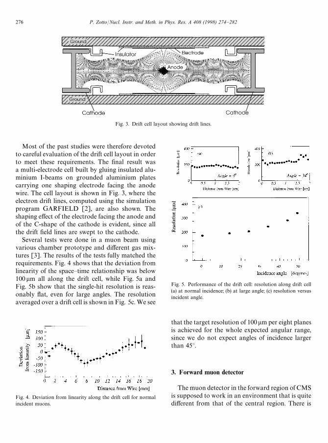
Fig. 3. Drift cell layout showing drift lines.
Most of the past studies were therefore devotedto careful evaluation of the drift cell layout in orderto meet these requirements. The final result wasa multi-electrode cell built by gluing insulated alu-minium I-beams on grounded aluminium platescarrying one shaping electrode facing the anodewire. The cell layout is shown in Fig. 3, where theelectron drift lines, computed using the simulationprogram GARFIELD [2], are also shown. Theshaping effect of the electrode facing the anode andof the C-shape of the cathode is evident, since allthe drift field lines are swept to the cathode.
Several tests were done in a muon beam usingvarious chamber prototype and different gas mix-tures [3]. The results of the tests fully matched therequirements. Fig. 4 shows that the deviation fromlinearity of the space—time relationship was below100lm all along the drift cell, while Fig. 5a andFig. 5b show that the single-hit resolution is reas-onably flat, even for large angles. The resolutionaveraged over a drift cell is shown in Fig. 5c. We see
Fig. 4. Deviation from linearity along the drift cell for normalincident muons.
Fig. 5. Performance of the drift cell: resolution along drift cell(a) at normal incidence; (b) at large angle; (c) resolution versusincident angle.
that the target resolution of 100lm per eight planesis achieved for the whole expected angular range,since we do not expect angles of incidence largerthan 45°.
3. Forward muon detector
The muon detector in the forward region of CMSis supposed to work in an environment that is quitedifferent from that of the central region. There is
276 P. Zotto/Nucl. Instr. and Meth. in Phys. Res. A 408 (1998) 274—282

Fig. 6. Sketch of a forward muon chamber.
a much higher occupancy (growing from fewHz/cm2 to more than 100 Hz/cm2) and the cham-bers are immersed inside a sizeable magnetic field.
The natural choice for a detector operating withgood performance in such a delicate environment ismultiwire proportional chambers. The resolutionrequirement for the detector is again &100lm perstation) to assure a reasonably good stand-alonemomentum measurement. This resolution can beachieved only by using segmented cathode analogreadout.
A sketch of a chamber is shown in Fig. 6, wherewe notice that the readout strips are radial to allowa direct precise measurement of u. The wires areread out in groups in order to reduce the number ofreadout channels and therefore provide a coarsemeasurement of the radial coordinate. Redundancyis obtained by building a chamber as the composi-tion of six staggered layers of wires. The occupancycan be reduced only by using relatively small cham-bers. Therefore, the acceptance requirements implythe superposition of the chambers along their edgesto reduce the dead areas caused by the supportingframes, producing the wheel-like detector drawn inFig. 7.
The innermost chamber is placed inside the full4 T field. Hence the magnetic field distortion effecton proportional chambers is no longer negligible.But, since the field is constant, the distorsion can becompensated by tilting the wires by the Lorentzangle value (a
L"25° for the foreseen gas mixture).
Several prototypes of the endcap chambers wereexposed to muon test beams [4]. The single-hitmeasured resolution as a function of the distancefrom the strip edge is reported in Fig. 8a, where the
Fig. 7. Arrangement of the chambers of the forward muon de-tector (iron yoke not shown).
usual dependence of strip measurement on the par-ticle crossing point is evident. However, staggeringof the planes assures that some high-resolutionmeasurement is always available for every track.Hence, once the six hits are averaged using theirproper resolution, the target global resolution persix planes can be achieved. The degradation of thesingle hit resolution with respect to the muon trackinclination, shown in Fig. 8b, is large, but tolerable.
4. Detector performance
The CMS muon detector merges different de-tector techniques operating in different environ-ments and with different requirements. A glanceinto the overall detector performance is thereforerequired. The important parameter is the muonmomentum resolution. The two detectors werecarefully simulated in order to correctly reproducetest beam data and a Kalman filter algorithm fortrack reconstruction was implemented in the offi-cial simulation program. The overall performanceof the muon detector is given in Fig. 9, where themomentum resolution obtained using the muon
P. Zotto/Nucl. Instr. and Meth. in Phys. Res. A 408 (1998) 274—282 277
V. DETECTOR AND TRIGGER PROJECTS
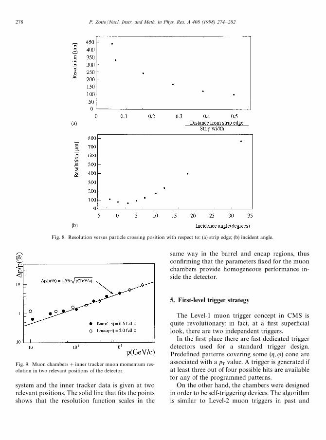
Fig. 8. Resolution versus particle crossing position with respect to: (a) strip edge; (b) incident angle.
Fig. 9. Muon chambers#inner tracker muon momentum res-olution in two relevant positions of the detector.
system and the inner tracker data is given at tworelevant positions. The solid line that fits the pointsshows that the resolution function scales in the
same way in the barrel and encap regions, thusconfirming that the parameters fixed for the muonchambers provide homogeneous performance in-side the detector.
5. First-level trigger strategy
The Level-1 muon trigger concept in CMS isquite revolutionary: in fact, at a first superficiallook, there are two independent triggers.
In the first place there are fast dedicated triggerdetectors used for a standard trigger design.Predefined patterns covering some (g, u) cone areassociated with a p
Tvalue. A trigger is generated if
at least three out of four possible hits are availablefor any of the programmed patterns.
On the other hand, the chambers were designedin order to be self-triggering devices. The algorithmis similar to Level-2 muon triggers in past and
278 P. Zotto/Nucl. Instr. and Meth. in Phys. Res. A 408 (1998) 274—282
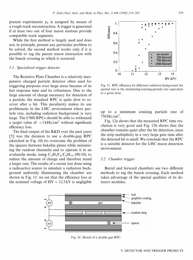
Fig. 10. Sketch of a double gap RPC.
present experiments: pT
is assigned by means ofa rough track reconstruction. A trigger is generatedif at least two out of four muon stations providecompatible track segments.
While the first method is largely used and doesnot, in principle, present any particular problem tobe solved, the second method works only if it ispossible to tag the parent muon interaction withthe bunch crossing in which it occurred.
5.1. Specialized trigger detector
The Resistive Plate Chamber is a relatively inex-pensive charged particle detector often used fortriggering purposes over large areas because of itsfast response time and its robustness. Due to thelarge amount of charge necessary for detection ofa particle, the standard RPC is quite slow to re-cover after a hit. This peculiarity makes its useproblematic in the LHC environment where par-ticle rate, including radiation background, is verylarge. The CMS RPCs should be able to withstanda target value of &1kHz/cm2 without significantefficiency loss.
The final output of the R&D over the past years[5] was the decision to use a double-gap RPC(sketched in Fig. 10) (to overcome the problem ofthe spacers between bakelite plates while minimiz-ing the readout channels) and to operate it in anavalanche mode, using C
2H
2F4/C
4H
10(90/10), to
reduce the amount of charge and therefore standa larger rate. The results of a recent test done usinga radioactive source to simulate a radiation back-ground uniformly illuminating the chamber areshown in Fig. 11: we see that the efficiency loss atthe nominal voltage of HV"12.5kV is negligible
Fig. 11. RPC efficiency for differenct radiation background: thequoted rate is the minimizing-ionizing-particle rate equivalentto a given dose.
up to a minimum ionizing particle rate of750Hz/cm2.
Fig. 12a shows that the measured RPC time res-olution is very good and Fig. 12b shows that thechamber remains quiet after the hit detection, sincethe strip multiplicity in a very large gate time afterthe detected hit is small. We conclude that the RPCis a suitable detector for the LHC muon detectionenvironment.
5.2. Chamber trigger
Barrel and forward chambers use two differentmethods to tag the bunch crossing. Each methodtakes advantage of the special qualities of its de-tector modules.
P. Zotto/Nucl. Instr. and Meth. in Phys. Res. A 408 (1998) 274—282 279
V. DETECTOR AND TRIGGER PROJECTS

Fig. 12. RPC detection quality: (a) time resolution, (b) strip multiplicity in 250ns gate. The small number of hit strips is an indicationthat after-pulses are not generated from the initial avalanche.
Fig. 13. Illustration of a generalized mean-timer method.
5.2.1. Barrel detector algorithmWe have seen that the drift chambers are com-
posed of Superlayers made of groups of four stag-gered layers of drift tubes packed together. Thisdesign assures the redundancy needed in the de-tector, but it was also chosen on purpose to allowthe parent bunch crossing identification in thetrigger.
The bunch crossing is detected using a generaliz-ed mean-timer method, whose principle is shown inFig. 13. The sketch on the left-hand side showsa particle crossing a group of four tubes andgenerating four drift times. The one on the right-hand side shows a group of four shift registers eachone associated to a drift cell. The signals generatedin each cell are shifted in the register: the four hitsare always aligned at a fixed time, ¹
MAX, equal to
the maximum drift time in the cell after the muoncrossing time, thus uniquely identifying the parentbunch crossing. The track inclination and the
crossing position can be determined by the shifttimes, t
4"¹
MAX!t
$, giving a rough track
measurement.The actual algorithm is described elsewhere [6]
and ASIC prototypes were recently produced andtested. The bunch crossing tagging efficiency meas-ured using the prototypes is shown in Fig. 14 asa function of the incident angle for a sample of drifttimes patterns provided by generating single muonsinside the detector with full background simula-tion.
5.2.2. Endcap detector algorithmIn the proportional chambers a trigger track
candidate is recognized every time at least four outof six precise coordinate hits (strips) in a module arealigned along a straight line. Timing is very bad inthis projection, but the timing of the associatedcoarse coordinates (wires) is instead quite good,owing to the relatively short drift time (&40 ns) and
280 P. Zotto/Nucl. Instr. and Meth. in Phys. Res. A 408 (1998) 274—282
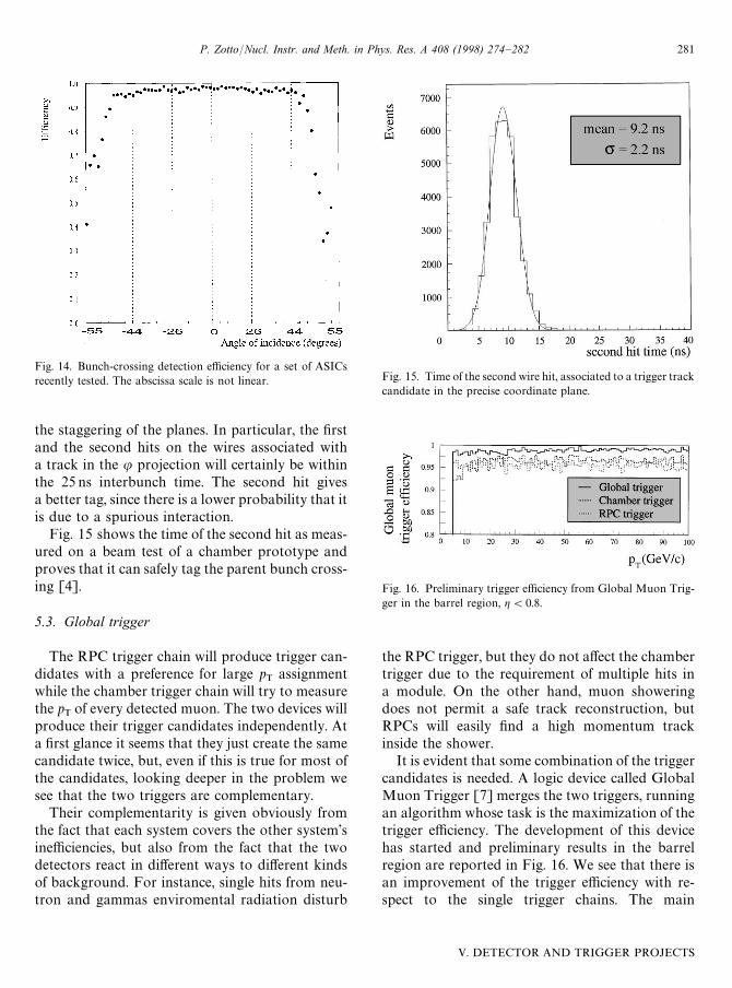
Fig. 14. Bunch-crossing detection efficiency for a set of ASICsrecently tested. The abscissa scale is not linear.
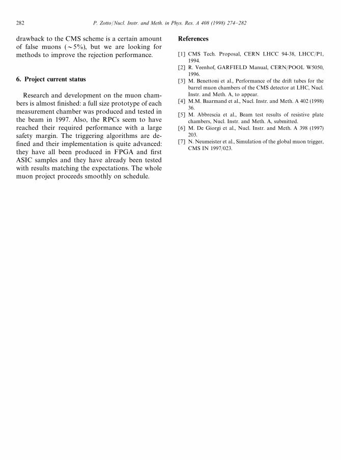
the staggering of the planes. In particular, the firstand the second hits on the wires associated witha track in the u projection will certainly be withinthe 25 ns interbunch time. The second hit givesa better tag, since there is a lower probability that itis due to a spurious interaction.
Fig. 15 shows the time of the second hit as meas-ured on a beam test of a chamber prototype andproves that it can safely tag the parent bunch cross-ing [4].
5.3. Global trigger
The RPC trigger chain will produce trigger can-didates with a preference for large p
Tassignment
while the chamber trigger chain will try to measurethe p
Tof every detected muon. The two devices will
produce their trigger candidates independently. Ata first glance it seems that they just create the samecandidate twice, but, even if this is true for most ofthe candidates, looking deeper in the problem wesee that the two triggers are complementary.
Their complementarity is given obviously fromthe fact that each system covers the other system’sinefficiencies, but also from the fact that the twodetectors react in different ways to different kindsof background. For instance, single hits from neu-tron and gammas enviromental radiation disturb
Fig. 15. Time of the second wire hit, associated to a trigger trackcandidate in the precise coordinate plane.
Fig. 16. Preliminary trigger efficiency from Global Muon Trig-ger in the barrel region, g(0.8.
the RPC trigger, but they do not affect the chambertrigger due to the requirement of multiple hits ina module. On the other hand, muon showeringdoes not permit a safe track reconstruction, butRPCs will easily find a high momentum trackinside the shower.
It is evident that some combination of the triggercandidates is needed. A logic device called GlobalMuon Trigger [7] merges the two triggers, runningan algorithm whose task is the maximization of thetrigger efficiency. The development of this devicehas started and preliminary results in the barrelregion are reported in Fig. 16. We see that there isan improvement of the trigger efficiency with re-spect to the single trigger chains. The main
P. Zotto/Nucl. Instr. and Meth. in Phys. Res. A 408 (1998) 274—282 281
V. DETECTOR AND TRIGGER PROJECTS
drawback to the CMS scheme is a certain amountof false muons (&5%), but we are looking formethods to improve the rejection performance.
6. Project current status
Research and development on the muon cham-bers is almost finished: a full size prototype of eachmeasurement chamber was produced and tested inthe beam in 1997. Also, the RPCs seem to havereached their required performance with a largesafety margin. The triggering algorithms are de-fined and their implementation is quite advanced:they have all been produced in FPGA and firstASIC samples and they have already been testedwith results matching the expectations. The wholemuon project proceeds smoothly on schedule.
References
[1] CMS Tech. Proposal, CERN LHCC 94-38, LHCC/P1,1994.
[2] R. Veenhof, GARFIELD Manual, CERN/POOL W5050,1996.
[3] M. Benettoni et al., Performance of the drift tubes for thebarrel muon chambers of the CMS detector at LHC, Nucl.Instr. and Meth. A, to appear.
[4] M.M. Baarmand et al., Nucl. Instr. and Meth. A 402 (1998)36.
[5] M. Abbrescia et al., Beam test results of resistive platechambers, Nucl. Instr. and Meth. A, submitted.
[6] M. De Giorgi et al., Nucl. Instr. and Meth. A 398 (1997)203.
[7] N. Neumeister et al., Simulation of the global muon trigger,CMS IN 1997/023.
282 P. Zotto/Nucl. Instr. and Meth. in Phys. Res. A 408 (1998) 274—282