closed-loop oscillating heat-pipe with check valves (clohp/cvs) air-preheater for reducing relative...
TRANSCRIPT
APPLIED
Applied Energy 84 (2007) 363–373
www.elsevier.com/locate/apenergy
ENERGY
Closed-loop oscillating heat-pipe with checkvalves (CLOHP/CVs) air-preheater for
reducing relative humidity in drying systems
P. Meena *, S. Rittidech, N. Poomsa-ad
Faculty of Engineering, Mahasarakham University, Thailand
Accepted 9 September 2006Available online 8 December 2006
Abstract
A CLOHP/CV air-preheater has been used for recovering the waste heat from the drying cycle.The CLOHP/CV heat-exchanger consisted of copper tubes 3.58 m long and internal diameter0.002 m. The evaporator and condenser sections were 0.19 m long, the adiabatic sections 0.08 mlong, the hot air velocity was 0.5, 0.75 or 1.0 m/s with the hot air temperature 50, 60 or 70 �C,and the relative humidity was 100%. The working fluid was R134a with a filling ratio of 50%.The hot-air temperature increased from 50 to 70 �C; the heat-transfer rate increased slightly. Thevelocity increase from 0.5 0.75, to 1.0 m/s led to the heat-transfer rate slightly decreasing. The veloc-ity increase from 0.5 to 1 m/s led to a slight decrease in effectiveness. As the hot-air temperatureincreases from 50 to 70 �C, the effectiveness slightly increased; and the relative humidity was reducedto the range 54–72% from 89% to 100%. The CLOHP/CV air-preheater can reduce the relativehumidity and achieve energy thrift.� 2006 Elsevier Ltd. All rights reserved.
Keywords: Closed-loop oscillating heat-pipe; Check valves; Air-preheater; Relative humidity; Heat recovery;Drying system
0306-2619/$ - see front matter � 2006 Elsevier Ltd. All rights reserved.
doi:10.1016/j.apenergy.2006.09.009
* Corresponding author. Tel.: +66 43 754316; fax: +66 43 754316.E-mail address: [email protected] (P. Meena).
Nomenclature
A area (m2)Bo bond number, Di g ql�qv
r
� �� �12ð�Þ
Cp specific heat at constant pressure (J/kg.k)Cv number of check valve (-)D diameter (m)Fr Froude number,
Q2m
q2v h2
fgDi5gð�Þ
g gravitational acceleration (m/s2)hfg latent heat of vaporization (kJ/kg)Ja Jacob number,
hfg
CplT vð�Þ
Ku Kutateladze number, qhfgqvðqgðql�qvÞ=q2vÞ1=4
� �ð�Þ
k thermal conductivity (W/m K)L length (m)Prv Prandtl number of vapour
Cpvlvkv
� ð�Þ
Q heat-transfer rate (W)q heat flux (W/m2)Rcv Ratio of check valves to number of the capillary tube (-)RH relative humidity (%)T temperature (�C)V velocity (m/s)We Weber number, Q2
m
qvhfgDi3rð�Þ
Greek symbols
l viscosity (Pa s)q density (kg/m3)r surface tension (N/m)
Subscripts
c colde evaporatori inside, inletl liquido outlett totalv vapour
364 P. Meena et al. / Applied Energy 84 (2007) 363–373
1. Introduction
The aim of the dryer is to reduce the moisture content of a product. Traditionally, theapplication of a heat-pipe air-preheater to the dryer is unable to use its waste heat. Theapplication of a closed-looped oscillating heat-pipe with check valves (CLOHP/CVs) air-preheater for relative-humidity (RH) control in drying systems has many advantages,e.g. large quantities of heat are transported through a small cross-section area. The
P. Meena et al. / Applied Energy 84 (2007) 363–373 365
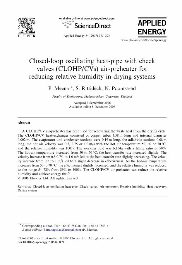
CLOHP/CV is a very effective heat-transfer device: it has a simple structure and fastthermal-response [1,2]. The CLOHP/CV consists of a long capillary tube bent into manyturns and the evaporator section, adiabatic section, and condenser sections are located atthese turns, with the ends joined to form a closed loop. The system incorporates one ormore direction-control one-way check-valves in the loop, so that the working fluid cancirculate in the specified direction only. Miyazaki et al. [3] studied the oscillating heat-pipe with check valves. It was found the CHOHP/CV has a high-efficiency heat-transfer.Pipatpaiboon et al. [4] studied the effects of inclination angle, working fluid and numberof check vales on the characteristics of the heat-transfer in a closed-looped oscillatingheat-pipe with check valves. The CLOHP/CV equipped with 2 check valves, had thehighest heat-transfer [4]. Pipatpaiboon [5] studied the correlation of heat-transfer of aclosed-looped oscillating heat-pipe with the number of check valves (CLOHP/CV). Rit-tidech et al. [6] studied the closed-ended oscillating heat-pipe (CEOHP) air-preheater forachieving energy thrift in a dryer. Wu et al. [7] studied the application of heat-pipeexchangers for humidity control in air-conditioning systems. This type of heat exchangercan be an advantageous replacement for a conventional reheat-coil, resulting in energysavings and enhancing the cooling capability of the cooling coils with little or no exter-nal energy needed.
The use of a CLOHP/CV as an air pre-heater is widely accepted as a heat-transferdevice for high heat-loads [1]. Nevertheless, improvements of the heat-pipe air-preheaterfor the dryer are needed. They should incorporate one or more direction-control one-way check values in the loop, so that the working fluid can circulate in the specified direc-tion only in shown Fig. 1.
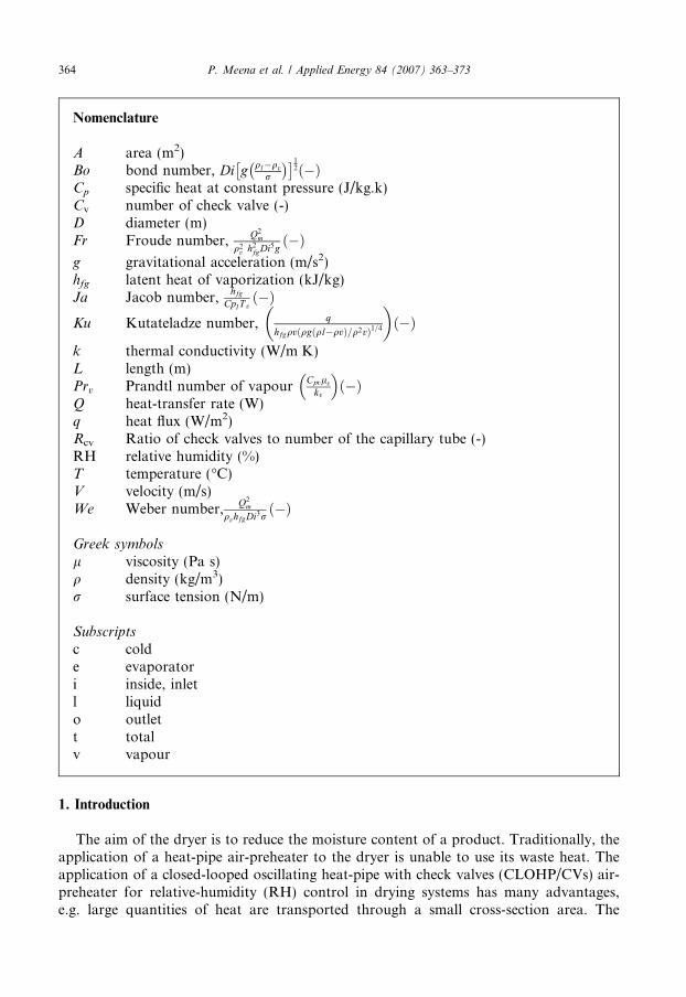
2. The check valve
This is a floating-type valve that consists of a stainless-steel ball and copper tube, inwhich a ball stopper and conical valve seat are provided at either end. The ball can movefreely between the ball stopper and the valve seat as shown in Fig. 2.
Fig. 1. Closed-loop oscillating heat-pipe with check valves (CLOHP/CVs).
Fig. 2. The check valve.
366 P. Meena et al. / Applied Energy 84 (2007) 363–373
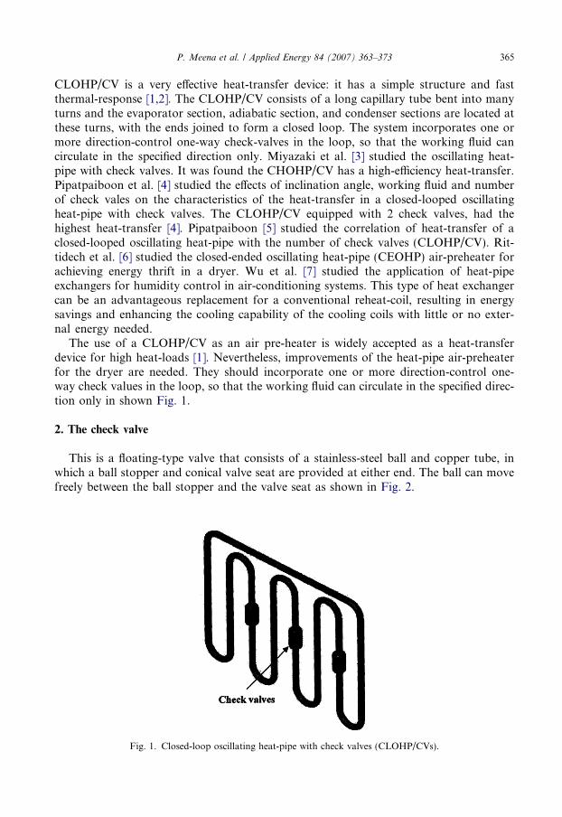
3. The conventional drying-cycle
The basic principle of the drying process is that fresh air was heated (by an electric hea-ter). Then the hot air moves though the product in the chamber. The heat is transferred tothe product for reducing moisture as shown in Fig. 3.
4. Design of the CLOHP/CV air-preheater system
The maximum heat-transfer rate, Qmax, of the heat-pipe heat-exchanger for the dryingsystem is
Qmax ¼ CminðT hi � T ciÞ ð1Þand
Cmin ¼ qVACp
Fig. 3. The conventional drying cycle.
P. Meena et al. / Applied Energy 84 (2007) 363–373 367
The inner diameter of the CLOHP/CV was calculated by Meazawa et al. [2] as
Dmax 6 2
ffiffiffiffiffiffiffiffir
q1g
rð2Þ
The type of working fluid that is appropriate for the operation temperatures wasselected.
The working temperature for the drying system was chosen.The heat-transfer rate (Qmax) was calculated from the expressions for KU90; Le, Lc and
Lt are specified for the duct size for the dryer.The velocity is either 0.5, 0.75 or 1.0 m/sThe values of Bo, Frv, Ja, Pr, Rcv, We, qv, q1 and Le/Di are calculated and the heat flux
of the CLOHP/CV air-preheater is determined by the correlation equation (3) taken from[5]. The standard deviation of this equation is ±30%.
Ku90 ¼ 0:004 B02:2Fr1:42Ja1:2Pr1:02 qvql
� �0:98
R1:4cv We0:8 Le
Di
� �0:5" #0:107
ð3Þ
The heat-transfer rate, Q90, for the vertical heat-pipe is calculated from Ku90, and trans-lated to the heat flux (q) via
Q90 ¼ ðAq90Þ ð4Þ
KU90 indicates the ratio of heat flux through the CLOHP/CV to the critical heat-fluxof the working fluid. It shows whether the obtained heat fluxes of a CLOHP/CV ex-ceeds than the critical heat-flux of the working fluid or not, i.e. whether or not thereis pool boiling of the working liquid in the evaporator section of the CLOHP/CV.Bo indicates the ratio of buoyancy force to surface tension force of the working fluid.If Bo > 1, nucleate boiling occurs in the heat pipe. Fr, i.e. the inertial force divided bygravitational force, is used in momentum transfer in general, and open-channel flowand wave and surface behaviour calculations in particular. Ja is the latent heat dividedby the specific heat at constant pressure. Pr indicates the ratio of momentum diffusivityto the thermal diffusivity of the vapour slug. If its value is very low, the vapour slugwill be able to transfer the thermal energy to the condenser section relatively efficiently.Therefore, the value of Ku90 or heat flux will be high. The vapour-phase density to theliquid-phase density (qv/ql) of the working fluid dictates the working pressure of theworking fluid within the CEOHP. Rcv indicates the number of check valves to the num-ber of turns of the CLOHP/CV. We is the ratio of the inertial force to the surface-ten-sion force. Le/Di defines the size of the CLOHP/CV. For example, if the value of Le/Di
is very high, then the tube would be large and the evaporator section would be short.Because of the boiling phenomenon, the value of Ku90 or heat flux would be high. Ifthe value of Le/Di is very low, then the tube would be small and the evaporator sectionwould be long. Because the boiling phenomenon within this type of tube will be akin tothe boiling phenomenon in a confined channel, the value of KU90 or heat flux will below.
Values of some of these parameters are shown in Table 1.The effectiveness (E) of the CLOHP/CV air-preheater is defined as the ratio of the
actual heat-transfer rate for an air-preheater heat-exchanger to the maximum possibleheat-transfer rate.
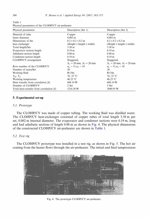
Table 1Physical parameters of the CLOHP/CV air-preheater
Physical parameters Description (Set 1) Description (Set 2)
Material of tube Copper CopperInner diameter 0.002 m 0.002 mDimensions of the 0.2 · 0.2 · 0.2 m 0.2 · 0.2 · 0.2 mheat exchanger (Height · length · width) (Height · length · width)Total length/Set 3.58 m 3.58 mEvaporator section length 0.19 m 0.19 mAdiabatic-section length 0.08 m 0.08 mCondenser-section length 0.19 m 0.19 mCLOHP/CV arrangement Staggered, Staggered,
SL = 20 mm, ST = 20 mm SL = 20 mm, ST = 20 mmRow number of the CLOHP/CV nL = 11,nT = 10 nL = 11,nT = 10Number of turns/Set 20 20Working fluid R134a R134aThi, Tci 70, 25 �C 70, 25 �CWorking temperature 46.25 �C 46.25 �CHeat transfer from correlation [4] 608.19 W 608.19 WNumber of CLOHP/CV 2 Set 5 SetTotal heat-transfer from correlation [4] 1216.38 W 3040.95 W
368 P. Meena et al. / Applied Energy 84 (2007) 363–373
5. Experimental set-up
5.1. Prototype
The CLOHP/CV was made of copper tubing. The working fluid was distilled water.The CLOHP/CV heat-exchanger consisted of copper tubes of total length 3.58 m perset, 0.002 m internal diameter. The evaporator and condenser sections were 0.19 m, longand had adiabatic sections of length 0.08 m as shown in Fig. 4. The physical dimensionsof the constructed CLOHP/CV air-preheater are shown in Table 1.
5.2. Test rig
The CLOHP/CV prototype was installed in a test rig, as shown in Fig. 5. The hot aircoming from the heater flows through the air-preheater. The initial and final temperatures
Fig. 4. The prototype CLOHP/CV air-preheater.
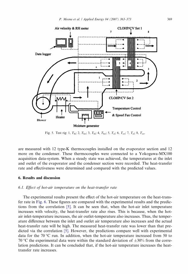
Fig. 5. Test rig: 1, Thi; 2, Tho; 3, Thi; 4, Tho; 5, Tci; 6, Tco; 7, Tci; 8, Tco.
P. Meena et al. / Applied Energy 84 (2007) 363–373 369
are measured with 12 type-K thermocouples installed on the evaporator section and 12more on the condenser. These thermocouples were connected to a Yokogawa-MX100acquisition data-system. When a steady state was achieved, the temperatures at the inletand outlet of the evaporator and the condenser section were recorded. The heat-transferrate and effectiveness were determined and compared with the predicted values.
6. Results and discussion
6.1. Effect of hot-air temperature on the heat-transfer rate
The experimental results present the effect of the hot-air temperature on the heat-trans-fer rate in Fig. 6. These figures are compared with the experimental results and the predic-tions from the correlation [5]. It can be seen that, when the hot-air inlet temperatureincreases with velocity, the heat-transfer rate also rises. This is because, when the hot-air inlet-temperature increases, the air outlet-temperature also increases. Thus, the temper-ature difference between the inlet and outlet air temperature also increases and the actualheat-transfer rate will be high. The measured heat-transfer rate was lower than that pre-dicted via the correlation [5]. However, the predictions compare well with experimentaldata for the 70 �C run. In addition, when the hot-air temperature increased from 50 to70 �C the experimental data were within the standard deviation of ±30% from the corre-lation predictions. It can be concluded that, if the hot-air temperature increases the heat-transfer rate increases.
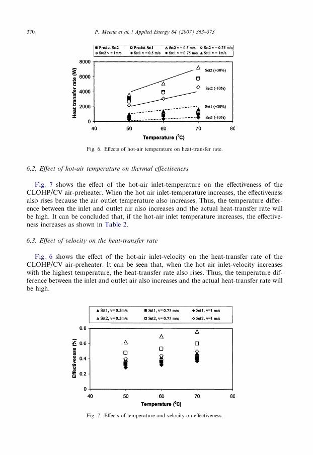
Fig. 6. Effects of hot-air temperature on heat-transfer rate.
370 P. Meena et al. / Applied Energy 84 (2007) 363–373
6.2. Effect of hot-air temperature on thermal effectiveness
Fig. 7 shows the effect of the hot-air inlet-temperature on the effectiveness of theCLOHP/CV air-preheater. When the hot air inlet-temperature increases, the effectivenessalso rises because the air outlet temperature also increases. Thus, the temperature differ-ence between the inlet and outlet air also increases and the actual heat-transfer rate willbe high. It can be concluded that, if the hot-air inlet temperature increases, the effective-ness increases as shown in Table 2.
6.3. Effect of velocity on the heat-transfer rate
Fig. 6 shows the effect of the hot-air inlet-velocity on the heat-transfer rate of theCLOHP/CV air-preheater. It can be seen that, when the hot air inlet-velocity increaseswith the highest temperature, the heat-transfer rate also rises. Thus, the temperature dif-ference between the inlet and outlet air also increases and the actual heat-transfer rate willbe high.
Fig. 7. Effects of temperature and velocity on effectiveness.
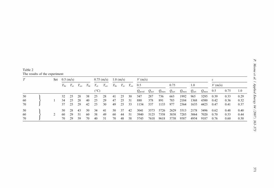
Table 2The results of the experiment
T Set 0.5 (m/s) 0.75 (m/s) 1.0 (m/s) V (m/s) e
Thi Tci Tco Thi Tci Tco Thi Tci Tco 0.5 0.75 1.0 V (m/s)
(�C) Qprod Qact Qmax Qact Qmax Qact Qmax 0.5 0.75 1.0
509=;
32 25 28 38 25 28 41 25 30 547 287 736 663 1992 965 3295 0.39 0.33 0.2960 1 34 25 28 40 25 29 47 25 31 880 378 891 783 2184 1368 4300 0.42 0.36 0.3270 37 25 29 42 25 30 49 25 33 1154 537 1133 977 2364 1635 4425 0.47 0.41 0.37
509=;
50 28 43 50 34 41 50 37 42 3041 3573 5726 2629 5513 2178 5496 0.62 0.48 0.4060 2 60 29 51 60 38 49 60 44 51 3940 5125 7358 3838 7285 3064 7020 0.70 0.53 0.4470 70 29 59 70 40 51 70 48 58 5745 7618 9618 5738 9587 4954 9187 0.76 0.60 0.50
P.
Meen
aet
al.
/A
pp
liedE
nerg
y8
4(
20
07
)3
63
–3
73
371
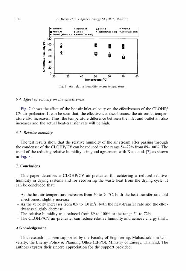
Fig. 8. Air relative humidity versus temperature.
372 P. Meena et al. / Applied Energy 84 (2007) 363–373
6.4. Effect of velocity on the effectiveness
Fig. 7 shows the effect of the hot air inlet-velocity on the effectiveness of the CLOHP/CV air-preheater. It can be seen that, the effectiveness rises because the air outlet temper-ature also increases. Thus, the temperature difference between the inlet and outlet air alsoincreases and the actual heat-transfer rate will be high.
6.5. Relative humidity
The test results show that the relative humidity of the air stream after passing throughthe condenser of the CLOHP/CV can be reduced to the range 54–72% from 89–100%. Thetrend of the reducing relative humidity is in good agreement with Xiao et al. [7], as shownin Fig. 8.
7. Conclusions
This paper describes a CLOHP/CV air-preheater for achieving a reduced relative-humidity in drying systems and for recovering the waste heat from the drying cycle. Itcan be concluded that:
– As the hot-air temperature increases from 50 to 70 �C, both the heat-transfer rate andeffectiveness slightly increase.
– As the velocity increases from 0.5 to 1.0 m/s, both the heat-transfer rate and the effec-tiveness slightly decrease.
– The relative humidity was reduced from 89 to 100% to the range 54 to 72%– The CLOHP/CV air-preheater can reduce relative humidity and achieve energy thrift.
Acknowledgement
This research has been supported by the Faculty of Engineering, Mahasarakham Uni-versity, the Energy Policy & Planning Office (EPPO), Ministry of Energy, Thailand. Theauthors express their sincere appreciation for the support provided.
P. Meena et al. / Applied Energy 84 (2007) 363–373 373
References
[1] Akachi H, Polasek F, Stulc P. Pulsating heat-pipe. In: Proc. of the 5th International heat-pipe symposium,Melbourne, Australia, 1996. p. 208–17.
[2] Meazawa S, Gi K, Minamisawa A, Akachi H. Thermal performance of a capillary-tube thermosyphon. In:Proc. of the 9th International heat-pipe conference, vol. 2, Albuquerque, USA, New Mexico, 1996. p. 791–5.
[3] Miyazaki Y, Polasek F, Akachi H. Oscillating heat-pipe with check valves. In: Proc. of the 6th Internationalheat-pipe symposium, Chiang Mai, Thailand, 2000. p. 389–93.
[4] Pipatpaiboon N. Effect of inclination angle, working fluid and number of check valves on the characteristics ofheat-transfer in a closed-looped oscillating heat-pipe with check valves (CLOHP/CVs). In: Proc. of 1stInternational seminar on heat-pipe and heat-recovery systems, Kuala Lumpur, Malaysia, 2004. p. 83–7.
[5] Pipatpaiboon N. Correlation for predicting heat transfer of a closed-looped oscillating heat-pipe with checkvalves (CLOHP/CVs). Master thesis, Energy Technology. Faculty of Engineering of MahasarakhamUniversity, Thailand, 2005.
[6] Rittidech S, Dangeton W, Soponronnarit S. Closed-ended oscillating heat-pipe (CEOHP) air-preheater forenergy thrift in a dryer. Appl Energ 2005;81:198–208.
[7] Wu XP, Johnson P, Akbarzadeh A. Application of heat-pipe exchangers for humidity control in an air-conditioning system. Appl Therm Eng 1997;6:561–8.