closed-double-magnetic circuit for a long-stroke horizontal electromagnetic vibration exciter
TRANSCRIPT

IEEE TRANSACTIONS ON MAGNETICS, VOL. 49, NO. 8, AUGUST 2013 4865
Closed-Double-Magnetic Circuit for a Long-Stroke HorizontalElectromagnetic Vibration Exciter
Wen He , Chunyu Wang , Mei Yu , Runjie Shen , and Shushi Jia
The State Key Laboratory of Fluid Power Transmission and Control, Zhejiang Province Key Laboratory of AdvancedManufacturing Technology, Zhejiang University, Hangzhou 310027, China
National Institute of Metrology, Beijing 100013, ChinaDepartment of Control Science and Engineering, Tongji University, Shanghai 201804, China
A novel closed-double-magnetic circuit (CDMC) was presented to achieve high and uniform magnetic flux density (MFD) in the longair gap (LAG) of a long-stroke horizontal electromagnetic vibration exciter. First, the normal single-magnetic circuit (SMC) and theproposed CDMC were modeled by lumped element circuit using equivalent circuit principle, analyzed theoretically by the Kirchhoff’slaw and the superposition theorem. The comparison between the two circuits shows that the CDMC can have more intensive and moreuniformMFD in the LAG. To strengthen the uniformity of theMFD in the LAG, the improved CDMCwith uneven air gap and its designmethod were proposed theoretically. Thereafter, the uneven air gap structure expressed as a three-line-segment form was presented andits optimization was also conducted based on a finite element model referring to a prototype of a one-meter-stroke horizontal electro-magnetic vibration excite. Then, the magnetic flux leakage of the magnetic circuits and the influence of slits in the outer magnetic yokefor practical application was also analyzed with the finite element method (FEM). The simulation demonstrates that the CDMC withoptimal air gap can further improve the uniformity of the MFD in the LAG. In addition, it is also indicated that the CDMC has less fluxleakage than the SMC and the influence of slits can be negligible. Finally, the experiment on the prototype also verifies the effectivenessof proposed CDMC with optimal air gap.
Index Terms—Air gap, closed-double-magnetic circuit (CDMC), long stroke, optimization, vibration exciter.
I. INTRODUCTION
N EW requirements for the lower limit frequency of vibra-tion sensors are constantly updated with the development
of aeronautics, astronautics, earthquake prediction, mineral ex-ploration, etc. More and more sensors that work at an ultralowfrequency (ULF) (lower than 0.1 Hz) or even at the zero fre-quency are used. Therefore, it is a challenge to construct theULF vibration calibration system with high signal-to-noise ratio(SNR) and low output distortion in the ULF range [1]. As weknow, the acceleration amplitude would decay as the frequencybecomes lower, and the attenuation is proportional to the squareof the frequency or at a rate of 12 dB/octave [2]. So it is impor-tant to develop a long-stroke vibration exciter for realizing highSNR output in the ULF vibration calibration system. An electro-dynamic vibration exciter with a double stroke was proposed in[3]. Two sets of single-magnetic circuits (SMCs) and armatureswere adopted as the left and right driving system that worked al-ternately, which could cause crossover distortion of the output.In addition, the flux leakage is high due to the open magneticcircuit, which will affect the normal property of sensors to becalibrated. Linear motors can also generate the vibration at alower frequency and have sometimes been adopted to establishULF vibration calibration system in recent years [4], [5]. Butlinear motors available in the market have no requirement onthe accuracy of the output waveform but on the position accu-racy and acceleration ability. As far as linear motors available
Manuscript received May 16, 2012; revised July 31, 2012; accepted October05, 2012. Date of publication October 18, 2012; date of current version July 23,2013. Corresponding author: W. He (e-mail: [email protected]).Color versions of one or more of the figures in this paper are available online
at http://ieeexplore.ieee.org.Digital Object Identifier 10.1109/TMAG.2012.2225109
in the market are concerned, their distortion of the output wave-form is higher. So they are not suitable to be used in the standardvibration calibration system. Other linear motion devices, basedon a rotary servomotor with a set of high precision lead screwor synchronous belt and pulley, are also not suitable due to themore serious harmonic vibration noise. Therefore, a long-strokehorizontal electromagnetic vibration exciter (LSVE) should bespecially designed for the ULF vibration calibration system. Ac-cording to the structure of normal electromagnetic vibration ex-citers, one of the key technologies in the LSVE is to achieve theuniform and high magnetic flux density (MFD) in the long airgap (LAG) with low flux leakage. But there is little informationon this issue in the literature. Here a novel closed-double-mag-netic circuit (CDMC) is proposed, which could meet this re-quirement. Meanwhile, the flux leakage is low since the mag-netic circuit is closed.Due to the strong nonlinearity of the magnetic materials and
the inevitable flux leakage, it is difficult and complex to describethe magnetic field accurately with an analytical method [6]. Toinvestigate the performance of proposed CDMC, the lumpedparameter model (LPM) [7]–[10] based on the circuit equiv-alent principle is established, and analyzed theoretically withKirchhoff’s law and the superposition theorem. Furthermore,theMFD in the LAG is simulated with the finite element method(FEM) [7], [11]–[13], and an improved CDMC with uneven airgap is proposed and optimized to improve the uniformity of theMFD in the LAG. In addition, the influence of the slits in outermagnetic yoke for practical application is also analyzed. Finally,the optimal CDMC is verified by the experiment based on thedeveloped one-meter-stroke horizontal electromagnetic vibra-tion exciter.
II. STRUCTURE OF CLOSED DOUBLE-MAGNETIC CIRCUIT
The CDMC contains two permanent magnets (PMs), an innermagnetic yoke and an outer magnetic yoke. The longitudinal
0018-9464/$31.00 © 2012 IEEE
4866 IEEE TRANSACTIONS ON MAGNETICS, VOL. 49, NO. 8, AUGUST 2013
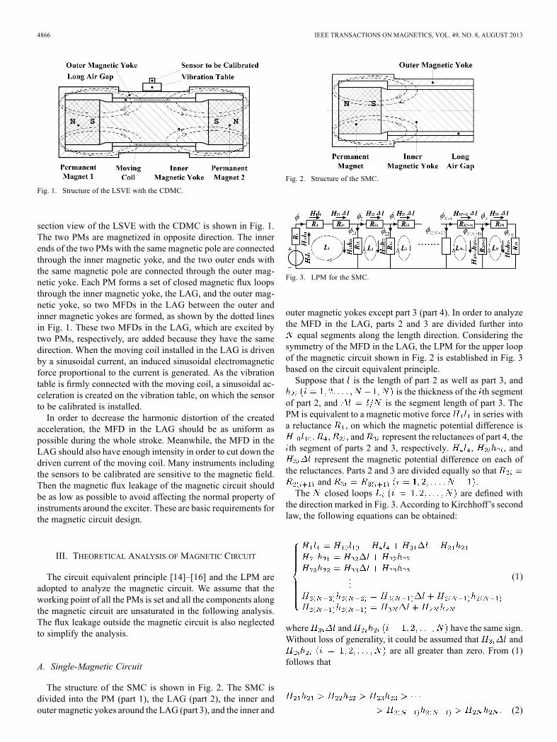
Fig. 1. Structure of the LSVE with the CDMC.
section view of the LSVE with the CDMC is shown in Fig. 1.The two PMs are magnetized in opposite direction. The innerends of the two PMs with the same magnetic pole are connectedthrough the inner magnetic yoke, and the two outer ends withthe same magnetic pole are connected through the outer mag-netic yoke. Each PM forms a set of closed magnetic flux loopsthrough the inner magnetic yoke, the LAG, and the outer mag-netic yoke, so two MFDs in the LAG between the outer andinner magnetic yokes are formed, as shown by the dotted linesin Fig. 1. These two MFDs in the LAG, which are excited bytwo PMs, respectively, are added because they have the samedirection. When the moving coil installed in the LAG is drivenby a sinusoidal current, an induced sinusoidal electromagneticforce proportional to the current is generated. As the vibrationtable is firmly connected with the moving coil, a sinusoidal ac-celeration is created on the vibration table, on which the sensorto be calibrated is installed.In order to decrease the harmonic distortion of the created
acceleration, the MFD in the LAG should be as uniform aspossible during the whole stroke. Meanwhile, the MFD in theLAG should also have enough intensity in order to cut down thedriven current of the moving coil. Many instruments includingthe sensors to be calibrated are sensitive to the magnetic field.Then the magnetic flux leakage of the magnetic circuit shouldbe as low as possible to avoid affecting the normal property ofinstruments around the exciter. These are basic requirements forthe magnetic circuit design.
III. THEORETICAL ANALYSIS OF MAGNETIC CIRCUIT
The circuit equivalent principle [14]–[16] and the LPM areadopted to analyze the magnetic circuit. We assume that theworking point of all the PMs is set and all the components alongthe magnetic circuit are unsaturated in the following analysis.The flux leakage outside the magnetic circuit is also neglectedto simplify the analysis.
A. Single-Magnetic Circuit
The structure of the SMC is shown in Fig. 2. The SMC isdivided into the PM (part 1), the LAG (part 2), the inner andouter magnetic yokes around the LAG (part 3), and the inner and
Fig. 2. Structure of the SMC.
Fig. 3. LPM for the SMC.
outer magnetic yokes except part 3 (part 4). In order to analyzethe MFD in the LAG, parts 2 and 3 are divided further intoequal segments along the length direction. Considering the
symmetry of the MFD in the LAG, the LPM for the upper loopof the magnetic circuit shown in Fig. 2 is established in Fig. 3based on the circuit equivalent principle.Suppose that is the length of part 2 as well as part 3, and
is the thickness of the th segmentof part 2, and is the segment length of part 3. ThePM is equivalent to a magnetic motive force in series witha reluctance , on which the magnetic potential difference is
. , , and represent the reluctances of part 4, theth segment of parts 2 and 3, respectively. , , and
represent the magnetic potential difference on each ofthe reluctances. Parts 2 and 3 are divided equally so that
and .The closed loops are defined with
the direction marked in Fig. 3. According to Kirchhoff’s secondlaw, the following equations can be obtained:
...(1)
where and have the same sign.Without loss of generality, it could be assumed that and
are all greater than zero. From (1)follows that
(2)

HE et al.: CDMC FOR LONG-STROKE HORIZONTAL ELECTROMAGNETIC VIBRATION EXCITER 4867
Assume that is themagnetic flux passingthrough the th segment of part 3. According to Kirchhoff’s firstlaw,
(3)
where is the magnetic flux passing through the th segmentof part 2. Similarly, since and havethe same sign and it is reasonable that they are assumed to begreater than zero, it can be concluded from (3) that
. Due to the fact thatfrom Ohm’s law,
(4)
So according to (1),
(5)
It is assumed that the thickness is uniform along the LAG,that is to say, . Therelationship between the MFD of the th segment of part 2
and the corresponding magnetic field strengthcan be expressed as [17]
(6)
where is the permeability of the air. Then, according to (2)and (5),
(7)
and
(8)It is clear that the MFD in the LAG and its variance ratio alldecrease when measured away from the PM along the lengthdirection, which will cause nonuniform MFD in the LAG.
B. Closed-Double-Magnetic Circuit
The structure of a CDMC has been shown in Fig. 1. As theSMC, the CDMC is divided into PM 1 and PM 2 (part 1), theLAG (part 2), the inner and outer magnetic yokes around theLAG (part 3), and the inner and outer magnetic yokes exceptpart 3 (Part 4). Part 2 is divided further into equal segments,each of which could be equivalent to the reluctances
. Considering the bilateral symmetry of the CDMC,part 3 is divided further into equal segments with thesame division method as that in the SMC, the length of whichis and the reluctance of which is
. The LPM for the upper loop of the magneticcircuit in Fig. 1 is established in Fig. 4(a) based on the circuitequivalent principle.As mentioned in Section III-A, PM is equivalent
to a magnetic motive force in series with a reluctance, on which the magnetic potential difference is .
and are the reluctances of part 4 on the PM 1 side and PM2 side, respectively, on which the magnetic potential differenceare and .
Fig. 4. LPM for the CDMC. (a) LPM where two PMs act synchronously. (b)LPM where only PM 1 acts. (c) LPM where only PM 2 acts.
According to the superposition theorem, the magnetic poten-tial difference and the magnetic flux in every branch of Fig. 4(a)could be presented as the sum of those in Fig. 4(b) and (c)where only PM 1 or PM 2 acts, respectively. Under the in-dependent action of PM , the magnetic poten-tial differences on the reluctances , , , and are
, , , and , respectively, and themagnetic potential differences of and
are and , respectively.Considering the model in Fig. 4(b), it can be regarded as an
LPM for an SMC in Fig. 3. Assume that the thickness is uniformalong the LAG, that is to say, , andbased on the analysis in Section III-A, it can be inferred that
(9)
and
(10)
where is the MFD of the th segment ofpart 2 under the independent action of PM 1. The distribution oftheMFD in the LAG of Fig. 4(b) along the length direction awayfrom PM 1 can be expressed as curve in Fig. 5, which has adecreasing value and variance ratio. is theposition of the th segment of part 2 along the length direction.Similarly, we can obtain that the distribution of the MFD
in the LAG of Fig. 4(c) along the length direction away fromPM 2 can be expressed as curve in Fig. 5, where
is the MFD of the th segment of part 2 under theindependent action of PM 2.Considering the symmetry of the CDMC,
(11)
According to the superposition theorem, the MFD in the thsegment of part 2 under the combined action
of PM 1 and PM 2 can be expressed as
(12)

4868 IEEE TRANSACTIONS ON MAGNETICS, VOL. 49, NO. 8, AUGUST 2013
Fig. 5. Theoretical distribution of the MFD in the LAG along the lengthdirection.
So the distribution of the MFD in the LAG of Fig. 4(a) along thelength direction can be expressed as curve in Fig. 5, which hasa basin shape.Considering that curves or are actually a distribution
of the MFD in the LAG of the SMC, it could be found that theMFD in the LAG of the CDMC has better uniformity and higherintensity than that in the LAG of the SMC when comparingwith or .
C. Improved Closed-Double-Magnetic Circuit
As shown in Fig. 5, theMFD in the LAG of the CDMC,whichis higher at the two ends and lower in the middle of the LAG, isstill not as uniform as we expect. So it is significant to furtherimprove the uniformity of the MFD in the LAG.According to (2) and (5), which are the results of the
SMC in Section III-A, it can be inferred thatin Section III-B and its vari-
ance ratios both decrease along the length direction awayfrom PM . So distributions of inFig. 4(b) and in Fig. 4(c) alongthe length direction of the LAG have the same change trendas curves and in Fig. 5, respectively. According to thesuperposition theorem, in Fig. 4(a)can be expressed as the sum of and . Then,the distribution of along the length direction also has abasin shape, similar as curve in Fig. 5. Assume thatvaries as
(13)
where has a basin-shape variation with . Now assume thatvaries as
(14)
where is a constant . Then
(15)
It means that stays constant along the LAG. According to(6), also keeps constant because is a constant. Therefore,
Fig. 6. Structure of the improved CDMC.
the MFD in the LAG is uniform along the length direction whenthe thickness of the LAG has a basin shape whose function isexpressed in (14).Considering the feasibility of manufacturing, the outline of
the inner magnetic yoke is designed as the three-segment-lineshape to simulate the basin shape of the LAG, which consistsof a horizontal line in the middle and two slant lines on the twosides, as schematically shown in Fig. 6. In the figure, is the fulllength of the interested LAG, and is the length of the middlehorizontal line and is the thickness of the air gap at the end ofthe interested LAG. The optimal and could be selected torealize the best uniformity of the MFD in the LAG.
IV. SIMULATION ANALYSIS OF MAGNETIC CIRCUIT
To verify the above analysis, the finite element ANSYS [18]program is applied to calculate the MFD in the LAG of the SMCand CDMC based on the parameters for designing the prototypeof a one-meter-stroke horizontal electromagnetic vibration ex-citer. In the simulation, the LAG, the PM (PM 1 and 2), and theinner and outer magnetic yokes are defined as the materials ofthe air whose relative permeability is 1, the permanent magnet(Al–Ni–Co) whose coercive force is 60 000 A/m, andcurve is shown in Fig. 7(a), and the pure iron whosecurve is shown in Fig. 7(b), respectively. Besides, it is assumedthat the magnetic circuit structure has been designed prelimi-narily to avoid saturation [11].
A. Single-Magnetic Circuit
Considering the axis symmetry of the structure, the modelmay be simplified to be 2-D planar, as shown in Fig. 8(a). Totake account of the flux leakage outside the magnetic circuit,an air area with the size of three times as large as the corre-sponding structure is established as area I in Fig. 8(a). The el-ement PLANE53 is adopted in the simulation. Considering thereal size of the moving coil and the stroke of the LSVE, set thethickness of the LAG as 0.012 m and the interested length as1.4 m. The simulation is shown in Fig. 8.The distribution of magnetic lines of flux is shown as one set
of closed loops in Fig. 8(a). TheMFD at the half thickness of theLAG with the interested length from point to point inFig. 8(a) is selected to evaluate the performance of the MFD inthe LAG of the SMC. The MFD along line away fromthe PM is shown as the dotted line in Fig. 8(c), whose shapeagrees with the analysis in Section III-A.

HE et al.: CDMC FOR LONG-STROKE HORIZONTAL ELECTROMAGNETIC VIBRATION EXCITER 4869
Fig. 7. Material property for the FEM. (a) curve of the PM. (b)curve of pure iron.
Assume that the average MFD and the nonuniformityof the MFD in the LAG are defined as
(16)
and
100% (17)
where is the distribution of theMFD along line in theLAG shown in Fig. 8(c), and and are the maximumand the minimum among . Then, all the indicators of theMFD in the LAG of the SMC are calculated and listed in Table I.The nonuniformity of the MFD in the LAG is 120.9%,which is too high to be acceptable. Meanwhile, the is alsolow for the LSVE.The MFL density along the structure boundary [that is
line ABCDEF in Fig. 8(a)] is calculated as the dotted line inFig. 8(d), which shows that the MFL density at the end of theSMC is extremely high (0.052 T) due to the open magneticcircuit. The relative MFL is defined as the ratio ofthe maximum MFL density (or the maximum MFD in area I)
to the average MFD in the LAG. The lowerthe relative MFL is, the higher efficiency of the structure is. Allthe indicators of the SMC are listed in Table II.
Fig. 8. Simulation for the SMC and improved CDMC. (a) Magnetic flux plotof the SMC. (b) Magnetic flux plot of the CDMC. (c) Flux density distributionin the LAG along the length direction. (d) Distribution of the MFL density alongthe structure boundary.
TABLE IMFD IN THE LAG
TABLE IIMFL OF THE SMC AND THE CDMC

4870 IEEE TRANSACTIONS ON MAGNETICS, VOL. 49, NO. 8, AUGUST 2013
Fig. 9. Influence of (0–1.4 m) and (0.012–0.032 m) on the nonuniformityof the MFD in the LAG of the improved CDMC.
B. CDMC and Its Optimization
Just as in Section IV-A, a simplified 2-D planar model forthe improved CDMC shown in Fig. 6 with varying and isestablished as shown in Fig. 8(b), and air area I is established asthe flux leakage area. The element PLANE 53 is also adoptedfor the simulation. To improve the uniformity of the MFD inthe LAG, and are selected as the parameters to be optimized[19]–[21]. The variation range of is set to be 0–1.4 m, whilethe variation range of is set to be 0.012–0.032 m to avoid themagnetic saturation. Besides, the thickness of the air gap in themiddle even range is set to be 0.012 m, same as the thicknessof the LAG in the SMC analyzed in Section IV-A. Similarly,the MFD along in Fig. 8(b) (0.006 m away from the innerdiameter of the outer magnetic yoke) with the same interestedlength of 1.4 m is selected to evaluate the performance of theimproved CDMC with different and .Especially, when 0.012 m and 1.4 m, the structure
turns to be the CDMC with even air gap (original CDMC asdiscussed in Section III-B). Then, the distribution of the mag-netic flux is calculated as shown in Fig. 8(b), which has twosets of closed loops induced by PM 1 and PM 2, respectively.The distribution of the MFD along shown in Fig. 8(c) hasa basin shape and agrees with the result in Section III-B. Thecorresponding , , , and are comparativelylisted in Table I. It is clear that has almost doubled with thedriving of two PMs compared with that in the SMC, which re-flects the superposition theorem, but the uniformity of the mag-netic field in the LAG has been improved greatlyWhen increases from 0.012 to 0.032 m and decreases
from 1.4 to 0 m, the nonuniformity of the MFD in theLAG could be calculated for every y, and . So a curved sur-face could be drawn as shown in Fig. 9. It is found that there is avalley point on the surface, which is located at 1.00 m and
0.018 m. In this situation, the improved CDMC is defined,of which the MFD distribution in the LAG is shown in Fig. 8(c).Its indicators are listed in Table I, among which andare 0.117 T and 9.00%, respectively. The results show that theuniformity of the MFD in the LAG has been greatly improvedbut the average MFD only has a negligible decrease com-pared with that of the original CDMC.The MFL of the improved CDMC with optimal and is
evaluated. The MFL density along the structure boundary [that
Fig. 10. Cross section of the 3-D improved CDMC with slits.
Fig. 11. MFD in the 3-D improved CDMC with slits (unit: T).
is line A B C D E F G H in Fig. 8(b)] is drawn in Fig. 8(d),which shows that only the area near the shoulders of the outermagnetic yoke has higher MFL density, but it is still much lowerthan the maximum MFL density of the SMC. and
are listed in Table II contrastively with those of the SMC,which shows that of the improved CDMC is muchlower since the magnetic circuit is closed. Besides, is alsomuch smaller, which indicates the higher efficiency of the im-proved CDMC.
C. Influence of Slits in the Outer Magnetic YokeIn the practical application, the slits are needed on the two
sides of the outer magnetic yoke for the connection betweenthe moving coil and the vibration table, as shown in Fig. 10(where the dimension of the air gap has been enlarged to presentthe structure clearly), which destroys the axis symmetry of thestructure. To exam their influence on the MFD inside and out-side the LAG, a 3-D model for the improved CDMC with slits(CDMCS) in the outer magnetic yoke is established with thecross section shown in Fig. 10. To decrease the influence of slits,the width of slits is designed to be as small as possible and theouter magnetic yoke is designed to be unsaturated. The width ofthe slits is now designed as 0.04 m and the uneven LAG size isthe same as the optimization result in Section IV-B. The elementSolid96 is adopted. Then, the MFDs in the whole structure arecalculated as shown in Fig. 11 (1/4 part of the structure and thewhole outside air region are moved). Assume that is a circleat the middle thickness of the LAG in the cross section , whichis located at the middle length of the LAG; the MFD alongis shown in Fig. 12(a). It can be found that the MFD along thecircumferential direction is uniform except the slits range where
HE et al.: CDMC FOR LONG-STROKE HORIZONTAL ELECTROMAGNETIC VIBRATION EXCITER 4871
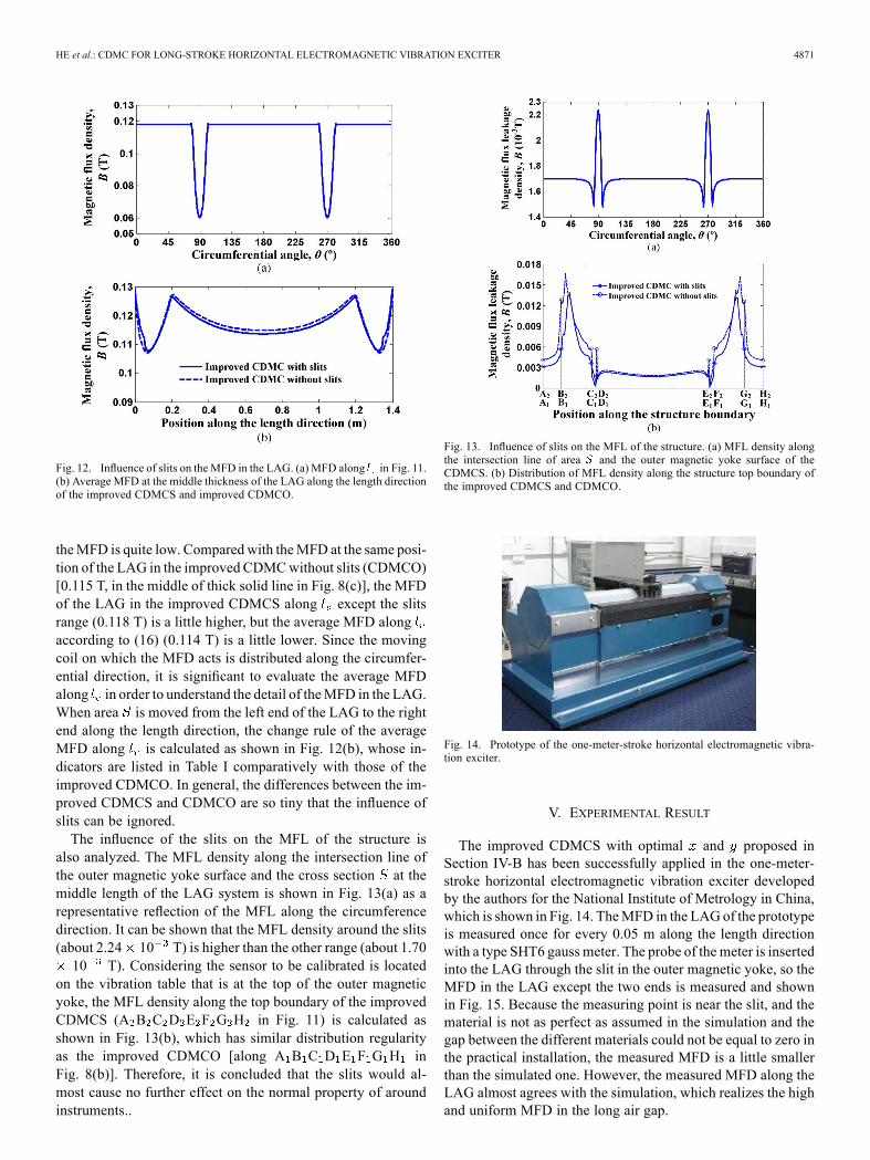
Fig. 12. Influence of slits on the MFD in the LAG. (a) MFD along in Fig. 11.(b) Average MFD at the middle thickness of the LAG along the length directionof the improved CDMCS and improved CDMCO.
theMFD is quite low. Compared with theMFD at the same posi-tion of the LAG in the improved CDMCwithout slits (CDMCO)[0.115 T, in the middle of thick solid line in Fig. 8(c)], the MFDof the LAG in the improved CDMCS along except the slitsrange (0.118 T) is a little higher, but the average MFD alongaccording to (16) (0.114 T) is a little lower. Since the movingcoil on which the MFD acts is distributed along the circumfer-ential direction, it is significant to evaluate the average MFDalong in order to understand the detail of theMFD in the LAG.When area is moved from the left end of the LAG to the rightend along the length direction, the change rule of the averageMFD along is calculated as shown in Fig. 12(b), whose in-dicators are listed in Table I comparatively with those of theimproved CDMCO. In general, the differences between the im-proved CDMCS and CDMCO are so tiny that the influence ofslits can be ignored.The influence of the slits on the MFL of the structure is
also analyzed. The MFL density along the intersection line ofthe outer magnetic yoke surface and the cross section at themiddle length of the LAG system is shown in Fig. 13(a) as arepresentative reflection of the MFL along the circumferencedirection. It can be shown that the MFL density around the slits(about 2.24 10 T) is higher than the other range (about 1.7010 T). Considering the sensor to be calibrated is located
on the vibration table that is at the top of the outer magneticyoke, the MFL density along the top boundary of the improvedCDMCS (A B C D E F G H in Fig. 11) is calculated asshown in Fig. 13(b), which has similar distribution regularityas the improved CDMCO [along A B C D E F G H inFig. 8(b)]. Therefore, it is concluded that the slits would al-most cause no further effect on the normal property of aroundinstruments..
Fig. 13. Influence of slits on the MFL of the structure. (a) MFL density alongthe intersection line of area and the outer magnetic yoke surface of theCDMCS. (b) Distribution of MFL density along the structure top boundary ofthe improved CDMCS and CDMCO.
Fig. 14. Prototype of the one-meter-stroke horizontal electromagnetic vibra-tion exciter.
V. EXPERIMENTAL RESULT
The improved CDMCS with optimal and proposed inSection IV-B has been successfully applied in the one-meter-stroke horizontal electromagnetic vibration exciter developedby the authors for the National Institute of Metrology in China,which is shown in Fig. 14. TheMFD in the LAGof the prototypeis measured once for every 0.05 m along the length directionwith a type SHT6 gauss meter. The probe of the meter is insertedinto the LAG through the slit in the outer magnetic yoke, so theMFD in the LAG except the two ends is measured and shownin Fig. 15. Because the measuring point is near the slit, and thematerial is not as perfect as assumed in the simulation and thegap between the different materials could not be equal to zero inthe practical installation, the measured MFD is a little smallerthan the simulated one. However, the measured MFD along theLAG almost agrees with the simulation, which realizes the highand uniform MFD in the long air gap.

4872 IEEE TRANSACTIONS ON MAGNETICS, VOL. 49, NO. 8, AUGUST 2013
Fig. 15 Experiment of MFD in the LAG of improved CDMC with slits.
VI. CONCLUSION
A CDMC used for a long-stroke horizontal electromagneticvibration exciter is presented and analyzed in this paper. Basedon the theoretical analysis and the simulation, it can be con-cluded that the CDMC realizes more intensive and more uni-form MFD in the long air gap than routine SMC does, but haslower flux leakage. In addition, an optimized CDMC which hasoptimal uneven air gap can further improve the uniformity of theMFD in the long air gap without decreasing the average MFD.The slits in the outer magnetic yoke of the CDMC for prac-tical application have little influence on the MFD in the longair gap. The MFD in the long air gap is further verified on theone-meter-stroke horizontal electromagnetic vibration exciterdeveloped by the authors for the National Institute of Metrologyin China, which matches the simulation quite well.
ACKNOWLEDGMENT
This work was supported by the Science Fund for CreativeResearch Groups of National Natural Science Foundation ofChina (51221004), the Zhejiang Provincial Science Fund forDistinguishedYoung Scholars (LR12E05001) in China, the KeyScience and Technology Innovation Team Program of ZhejiangProvince in China (2009R50008), the Qianjiang Talent Programof Zhejiang Province in China (2009R10026), and the programfor New Century Excellent Talents at the University of China(NCET-08-0494).
REFERENCES
[1] G. P. Ripper, R. S. Dias, and G. A. Garcia, “Primary accelerometercalibration problems due to vibration exciters,”Measurement, vol. 42,no. 9, pp. 1363–1369, 2009.
[2] M. Mende and H. Nicklich, “Calibration of very low frequencyaccelerometers—A challenging task,” Sound Vib., vol. 45, no. 5, pp.14–17, 2011.
[3] Y. Shu, Q. Yang, and L. Lou, “Electrodynamic vibration exciter withdouble stroke,” Chinese Patent 200620020706.5, 2007.
[4] G. P. Ripper, D. B. Teixeira, C. D. Ferreira, and R. S. Dias, “A newsystem for comparison calibration of vibration transducers at low fre-quencies,” presented at the XIX IMEKOWorld Congr. Fundam. Appl.Metrol., Lisbon, Portugal, Sep. 6–11, 2009.
[5] Z. Fu, Y. Zhiwei, Z. Ming, and S. Baoku, “Nonlinear compensationcontrol scheme for acceleration distortion of low-frequency linear vi-bration table system,” Electr. Mach. Control, vol. 14, no. 7, pp. 91–98,2010.
[6] Z. Q. Zhu, D. Howe, and C. C. Chan, “Improved analytical modelfor predicting the magnetic field distribution in brushless permanent-magnet machines,” IEEE Trans. Magn., vol. 38, no. 1, pp. 229–238,Jan. 2002.
[7] J. P. Wang, D. K. Lieu, W. L. Lorimer, and A. Hartman, “Comparisonof lumped parameter and finite element magnetic modeling in a brush-less DC motor,” IEEE Trans. Magn., vol. 33, no. 5, pp. 4092–4094,Sep. 1997.
[8] C. Mi, M. Filippa, and W. Liu, “Analytical method for predictingthe air-gap flux of interior-type permanent-magnet machines,” IEEETrans. Magn., vol. 40, no. 1, pp. 50–58, Jan. 2004.
[9] Z. Q. Zhu, Y. Pang, D. Howe, S. Iwasaki, R. Deodhar, and A. Pride,“Analysis of electromagnetic performance of flux-switching perma-nent-magnet machines by nonlinear adaptive lumped parameter mag-netic circuit model,” IEEE Trans. Magn., vol. 41, no. 11, pp. 112–120,Nov. 2005.
[10] L. Zhu, S. Z. Jiang, Z. Q. Zhu, and C. C. Chen, “Analytical modeling ofopen circuit air-gap field distributions in multisegment and multilayerinterior permanent-magnet machines,” IEEE Trans. Magn., vol. 45, no.8, pp. 3121–3130, Aug. 2009.
[11] Y. B. Tang, Y. G. Chen, B. H. Teng, H. Fu, H. X. Li, and M. J. Tu,“Design of a permanent magnetic circuit with air-gap in a magneticrefrigerator,” IEEE Trans. Magn., vol. 40, no. 3, pp. 1597–1600, May2004.
[12] L.-D. Liao, P. C.-P. Chao, J.-T. Chen, W.-D. Chen, W.-H. Hsu, C.-W.Chiu, and C.-T. Lin, “A miniaturized electromagnetic generator withplanar coils and its energy harvest circuit,” IEEE Trans. Magn., vol.45, no. 10, pp. 4621–4627, Oct. 2009.
[13] S. Suzuki, Y. Kawase, T. Yamaguchi, S. Toyama, S. Kakami, K. Hirata,and T. Ota, “Dynamic analysis of circuit breaker with oil dashpot usingmultimesh modification method,” IEEE Trans. Magn., vol. 47, no. 5,pp. 1002–1005, May 2011.
[14] S.-Ghalavand, V.-Zadeh, and Lsfahani, “An improved magneticequivalent circuit model for iron-core linear permanent-magnet syn-chronous motors,” IEEE Trans. Magn., vol. 46, no. 1, pp. 112–120,Jan. 2010.
[15] Y. Liu, M. Zhang, Y. Zhu, J. Yang, and B. Chen, “Optimization ofvoice coil motor to enhance dynamic response based on an improvedmagnetic equivalent circuit model,” IEEE Trans. Magn., vol. 47, no. 9,pp. 2247–2251, Sep. 2011.
[16] M. Amrhein and P. T. Krein, “Magnetic equivalent circuit simulationsof electrical machines for design purpose,” in Proc. IEEE Electr. ShipTechnol. Symp., 2007, pp. 254–260.
[17] W. Zehua, C. Zhizhong, and H. Zhengdong, College Physics, 2nd ed.Hangzhou, China: Zhejiang Univ. Press, 2001, vol. 2, pp. 186–188.
[18] ANSYS Inc., Theory Reference, ANSYS Release 9.0.[19] S.-B. Yoon, J. Hur, Y.-D. Chun, and D.-S. Hyun, “Shape optimiza-
tion of solenoid actuator using the finite element method and numer-ical optimization technique,” IEEE Trans. Magn., vol. 33, no. 5, pp.4140–4142, Sep. 1997.
[20] F. Bancel and G. Lemarquand, “Three-dimensional analytical opti-mization of permanent magnets alternated structure,” IEEE Trans.Magn., vol. 34, no. 1, pp. 242–247, Jan. 1998.
[21] S. Lim, T. Yamada, S. Min, and S. Nishiwaki, “Topology optimizationof a magnetic actuator based on a level set and phase-field approach,”IEEE Trans. Magn., vol. 47, no. 5, pp. 1318–1321, May 2011.