clean coal technology - national energy technology … library/research/coal/major... · table 12...
TRANSCRIPT
1
Clean Coal Technology
DOE/NETL – 2004/1207
Tampa Electric Integrated Gasification
Combined-Cycle Project
A DOE Assessment
August 2004
U. S. Department of Energy
Office of Fossil Energy
National Energy Technology Laboratory

2
Disclaimer
This report was prepared as an account of work sponsored by an agency of the United States Government. Neither the United States Government nor any agency thereof, nor any of their employees, makes any warranty, express or implied, or assumes any legal liability or responsibility for the accuracy, completeness, or usefulness of any information, apparatus, product, or process disclosed, or represents that its use would not infringe privately owned rights. Reference therein to any specific commercial product, process, or service by trade name, trademark, manufacturer, or otherwise does not necessarily constitute or imply its endorsement, recommendation, or favoring by the United States Government or any agency thereof. The view and opinions of authors expressed therein do not necessarily state or reflect those of the United States Government or any agency thereof.
3
Table of Contents
Disclaimer......................................................................................................................................2
Table of Contents ..........................................................................................................................3
List of Tables.................................................................................................................................6
List of Figures................................................................................................................................6
Executive Summary.......................................................................................................................7
I. Introduction .............................................................................................................................12
II. Project/Process Description ....................................................................................................13
A. Project Description............................................................................................................. 13
B. Need for the Technology Demonstration ........................................................................... 13
C. Potential of the Technology ............................................................................................... 14
D. Technology Description ..................................................................................................... 14
1. Coal Receiving and Storage......................................................................................... 14
2. Slurry Preparation ........................................................................................................ 17
3. Air Separation Unit ...................................................................................................... 17
4. Texaco Gasifier............................................................................................................ 19
5. Syngas Cleanup............................................................................................................ 22
6. Acid Gas Removal ....................................................................................................... 22
7. Sulfuric Acid Plant....................................................................................................... 23
8. Slag, Fly ash, Brine, and Process Water Handling ...................................................... 24
9. Power Block................................................................................................................. 27
a. Combustion Turbine.................................................................................................. 27
b. Heat Recovery Steam Generator ............................................................................... 28
c. Steam Turbine ........................................................................................................... 28
E. Project Objective and Statement of Work .......................................................................... 30
III. Review of Technical and Environmental Performance.........................................................31
A. Technical Results ............................................................................................................... 31
1. Fuel Analyses............................................................................................................... 31
2. Clean Syngas Analysis................................................................................................. 35
3. Slag Analysis ............................................................................................................... 35
a. Ash Mineral Analysis ................................................................................................ 37
4
b. Loss on Ignition......................................................................................................... 37
c. Contaminants in Surface Moisture ............................................................................ 37
4. Sulfuric Acid................................................................................................................ 37
5. Brine............................................................................................................................. 38
6. System Availability...................................................................................................... 38
7. Effect of Operating Variables on Results .................................................................... 40
a. Slurry Preparation...................................................................................................... 41
b. Carbon Conversion and Gasifier Refractory Liner Life............................................ 41
c. Effect of Refractory Liner Quality ............................................................................ 42
d. Effect of Burner Design ............................................................................................ 43
e. Effect of Recycling Fly ash ....................................................................................... 43
f. Results with Pittsburgh No. 8 Seam Coals ................................................................ 44
g. Results with Illinois Basin Coal ................................................................................ 44
h. Results with Petroleum Coke Blends ........................................................................ 45
B. Environmental Performance............................................................................................... 46
1. Air Emissions............................................................................................................... 46
a. Stack Emissions......................................................................................................... 46
b. Particulate, VOC, and CO Emissions........................................................................ 47
2. Fugitive Emissions....................................................................................................... 47
3. Liquid Wastes .............................................................................................................. 47
4. Solid Waste .................................................................................................................. 47
IV. Market Review ......................................................................................................................48
A. Market Size/Commercialization......................................................................................... 48
B. Economics .......................................................................................................................... 50
1. Capital Costs ................................................................................................................ 50
a. Capital Cost Adjustments .......................................................................................... 51
2. Operating Costs............................................................................................................ 53
a. Fuel ............................................................................................................................ 53
b. Labor ......................................................................................................................... 53
c. Other Operating Costs ............................................................................................... 54
3. Estimated Cost of Electricity for a 500 MWe Plant .................................................... 54
V. Conclusions ...........................................................................................................................56

5
Acronyms and Abbreviations ......................................................................................................57
References ...................................................................................................................................59
Bibliography ................................................................................................................................60
6
List of Tables
Table 1 Fuels Gasified During Tampa IGCC Project ............................................................ 32
Table 2 Days of Operation on Individual Fuels..................................................................... 33
Table 3 Analyses of Coals Gasified During Tampa IGCC Project........................................ 34
Table 4 Syngas Composition ................................................................................................ 35
Table 5 Slag Composition...................................................................................................... 36
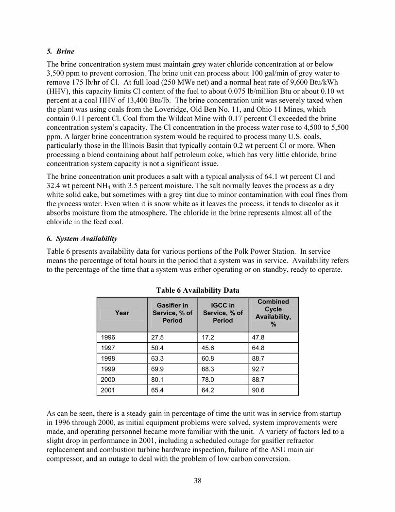
Table 6 Availability Data......................................................................................................... 38
Table 7 Subsystem Availability ............................................................................................ 40
Table 8 IGCC Output and Gasifier Utilization Data.............................................................. 40
Table 9 Typical Energy Balance.............................................................................................. 41
Table 10 Stack Emissions ...................................................................................................... 47
Table 11 Polk Unit 1 IGCC Capital Cost.............................................................................. 50
Table 12 Adjustments to Capital Costs for a New Plant Based on Lessons Learned............ 51
Table 13 Other Variable Annual Operating Costs ................................................................... 54
Table 14 Basis for Economic Evaluation................................................................................. 55
Table 15 Economics* of Power Generation (500 MWe Plant) ............................................. 55
List of Figures
Figure 1 Schematic of the Tampa Electric IGCC Project ........................................................ 16
Figure 2 Flow Diagram of Air Separation Unit ....................................................................... 18
Figure 3 Flow Diagram of Texaco Gasifier ............................................................................. 20
Figure 4 Flow Diagram of Syngas Cooling System................................................................. 22
Figure 5 Flow Diagram of Sulfuric Acid Plant........................................................................ 24
Figure 6 Slag, Fly Ash, Brine, and Process Water Handling................................................... 26
Figure 7 Flow Diagram of Heat Recovery Steam Generator and Steam Turbine ................... 29
Figure 8 Gasifier Liner Life vs. Carbon Conversion ............................................................... 43
Figure 9 Liner Performance with Pittsburgh Seam Coal from Various Mines........................ 44
Figure 10 Liner Performance with Illinois Basin Coal from Various Mines........................... 45
Figure 11 Liner Performance with Coal/Petroleum Coke Blends ........................................... 46
Figure 12 Cumulative World Synthesis Gas Capacity............................................................. 48
7
Executive Summary
The U.S. Department of Energy’s (DOE) Clean Coal Technology (CCT) program seeks to offer the energy marketplace more efficient and environmentally benign coal utilization technology options by demonstrating these technologies in industrial settings. This document is a DOE post-project assessment (PPA) of a project selected in CCT Round III, the Tampa Electric Integrated Gasification Combined-Cycle Project. DOE provided 49 percent of the $303.3 million project funding under the cooperative agreement. Tampa Electric Company (TECO) expended additional funds that were not covered by the cooperative agreement1.
Operation of the unit, which is sited at TECO’s Polk Power Station near Tampa, Florida, commenced in September 1996. Since completion of the project, TECO has continued to operate the IGCC facility for the production and sale of electricity. Other team members were Texaco Development Corporation2, gasification technology provider, General Electric Corporation, combined-cycle technology provider, Air Products and Chemicals, Inc., air separation unit provider, Monsanto Enviro-Chem Systems, Inc., sulfuric acid plant provider, and Bechtel Power Corporation, the architect engineer.
The nominal 250 MWe (net) capacity demonstration facility is Unit 1 of the Polk Power Plant, a new station located near Mulberry in south central Polk County, Florida. The power station uses an oxygen-blown, entrained-flow, Texaco coal gasifier integrated with gas clean-up and a highly efficient combined cycle to generate electricity with significantly lower SO2, NOX, and particulate emissions than most existing coal-fired power plants. The power plant achieved “first fire” of the gasification system on schedule in July 1996.
Because it is cheap and abundant, coal is an obvious choice as a fuel for the production of electric power in the U.S. However, if coal is to continue its dominant role, ways must be found to improve the efficiency and environmental performance of coal-fired units. One promising approach is IGCC technology. Not only are IGCC plants more efficient, but gasification technology converts the sulfur in the coal to H2S, which is much easier to remove than SO2. In addition, because gasification generates CO2 in a high-pressure fuel-gas stream, it provides the opportunity to relatively easily recover some of the CO2 for potential sequestration. The TECO project provided an essential step in proving the technical and economic viability of IGCC technology and achieving general acceptance among potential users.
IGCC efficiency of over 40 percent is potentially achievable with advanced turbines and other developments, such as hot gas cleanup. Although a hot gas cleanup system was installed to treat a portion of the synthesis gas (syngas) in the Tampa IGCC project, cold flow tests showed that the design sorbent had insufficient attrition resistance, and this prevented the hot gas cleanup system from being tested. Other factors, such as lower than expected carbon conversion in the gasifier, stress cracking in some of the high temperature heat recovery exchangers which necessitated their removal, a slight capacity deficiency of the air separation unit, and gasifier operation at a lower than optimum temperature for carbon conversion to increase refractory life, 1 Additional project cost overruns were funded 100% by the participant for a total project funding of $609.9 million. 2 In October 2001, Texaco merged with Chevron to form the ChevronTexaco Corporation. In May 2004, ChevronTexaco announced plans to sell its gasification technology to GE Energy.
8
also reduced efficiency. Thus, the full potential of this technology was not demonstrated, and the efficiency achieved of about 35.4 percent (HHV) was somewhat below the design efficiency of 38.6 percent (HHV). Nevertheless, the ability to operate a large gasifier to produce syngas to fuel a combustion turbine is a major achievement.
In the Tampa Electric IGCC project, a coal/water slurry and oxygen are reacted at high temperature and pressure in a Texaco gasifier to produce a medium-Btu syngas. The syngas, along with entrained fly ash, flows through a radiant heat exchanger and then to a high temperature convective heat-recovery unit, which cools the gas while generating high-pressure steam. The cooled gas is water washed for particulate removal. A hydrolysis unit converts any COS in the syngas into H2S. After amine scrubbing, the clean syngas is reheated and sent to the power block for combined cycle power generation. Molten slag flows out the bottom of the gasifier and is quenched and solidified in a water-filled sump. H2S from the amine scrubber is converted to sulfuric acid.
The power block is a General Electric supplied combined cycle system, adapted for syngas fuel operation, consisting of a Frame 7FA Combustion Turbine, capable of firing both No. 2 fuel oil and syngas, and associated generator; a condensing steam turbine and associated generator; and a three-pressure, unfired heat recovery steam generator (HRSG).
Coal from eleven U.S. mines was gasified at Polk Power Station during the five-year demonstration period. Six other fuels were gasified in combination with one another or in various blends with coal from one of the eleven mines. The main reason for testing so many fuels and fuel blends was to identify the fuel which resulted in the lowest cost of electricity. Each fuel or blend provided new insights into IGCC operation and helped demonstrate fuel flexibility.
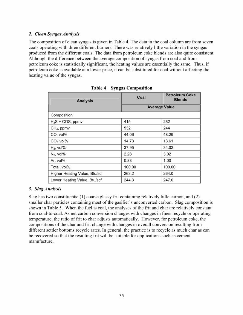
There was relatively little variation in the syngas produced from the different coals; data from petroleum coke blends is also quite consistent. Although there are statistically significant differences between the syngas from coal and from petroleum coke, the heating values are essentially the same. Thus, if petroleum coke is available at a lower price, it can be substituted for coal without affecting the heating value of the syngas.
Typically, petroleum coke is relatively inexpensive, on a dollars per Btu basis, compared to coal. However, petroleum coke usually has more sulfur than the Polk sulfur removal and recovery system was designed to handle (the environmental permit limits feedstock sulfur to 3.5 percent), so it is necessary to blend petroleum coke with coal with lower sulfur content. A further benefit of blending is that coal ash serves as a flux for vanadium in the petroleum coke.
There was a steady gain in the percentage of time the unit was in service from startup in 1996 through 2000, as initial equipment problems were solved, system improvements were made, and operating personnel became more familiar with the unit. A variety of factors led to a slight drop in performance in 2001, including a scheduled outage for gasifier refractor replacement and combustion turbine hardware inspection, failure of the ASU main air compressor, and an outage to deal with the problem of low carbon conversion.
Because every fuel performs differently in the slurry preparation system, full-scale operation, together with experience, is needed to determine how to best prepare slurry from a particular fuel. Because Polk’s air separation unit has a limited supply of oxygen, a high slurry concentration is essential to produce enough syngas for base load operation. Some fuels require
9
an additive to lower viscosity so that high concentration slurries will flow through screens and pump suction piping. Other slurries require an additive to prevent fuel particles from settling in lines and agitated tanks. Slurries made from some fuels also require pH adjustment to minimize erosion/corrosion.
Since fly ash with high carbon content cannot be sold, high carbon conversion is important for efficiency and to minimize fly ash disposal costs. High conversion at high slurry concentration and low operating temperature is ideal, since this extends the gasifier refractory liner life and minimizes oxygen requirement. Minimizing oxygen consumption is particularly important at Polk, since the oxygen supply is limited. Fly ash containing unconverted carbon can be recycled to the gasifier to reduce its carbon content, but this increases the oxygen requirement, since it degrades the quality of the slurry fed to the gasifier. With 100 percent coal, recycling fly ash appears to have only a slight positive impact on overall efficiency, since the energy recovered from the recycled fly ash is offset to a large extent by the incremental auxiliary power to produce the additional oxygen required. With petroleum coke in the fuel blend, the impact of recycle on overall efficiency is greater, since the recycled material has higher carbon content and there is more of it. Because of the problem with low carbon conversion, Texaco cooperated in making several burner design modifications. However, these modifications did not have any statistically significant effect on gasifier performance.
Recycling fly ash increases overall carbon conversion and oxygen consumption. For some coals, recycle causes a significant drop in per-pass carbon conversion, which further increases the oxygen requirement, but for other coals, per-pass conversion improves with recycle, which partially mitigates the additional oxygen requirement. There seem to be several competing factors at work, such as changes in the oxygen/carbon ratio, slag volume, and reactivity of the recycled material. It is likely that the relative importance of these factors changes among fuels in a way that is not as yet fully understood. Thus, a test feeding the design coal is important in establishing a design basis for a new plant.
The Tampa Electric facility achieved compliance with all federal and state regulatory requirements for air, water, and solid waste emissions. Air emissions of SO2, NOX, and particulates, as well as volatile organic compounds (VOCs) and CO, were well below the required permit limits. Polk’s NOX emissions are a fraction of those from conventional coal-fired power plants equipped with low-NOX combustion systems and well within the permitted limit of 0.9 lb/MWh. Particulate emissions are about 5 percent of those from conventional coal-fired power plants equipped with electrostatic precipitators.
The primary solid wastes produced are slag and ammonium chloride salt. Slag produced by the process is a vitrified granular solid that is nonleachable and classified as non-hazardous by the EPA. Slag has commercial applications, such as a sandblasting material, an aggregate in concrete, a roofing material, industrial filler, in road construction, and as a building material. Ammonium chloride salt from the brine concentration system is sent to a landfill, but potential markets are being investigated.
Total worldwide syngas capacity in 2002 was about 43,000 megawatts (thermal). Of the installed capacity, a little more than half is coal, or petroleum-coke-based. There has been a significant increase in gasification activity in the past decade. The impetus for this growth is the increased costs for environmental compliance with conventional pulverized coal-fired units, the drive to improve efficiency, the availability of low-cost alternative feedstocks, and the need to
10
utilize indigenous coal in areas without access to natural gas. The maturation of gasification technologies through completion of several large-scale demonstration projects has made this technology a popular and viable alternative to conventional combustion technology.
Indications are that many new domestic gasification projects will be refinery-based, utilizing petroleum coke and other low-cost refinery by-products to produce power, steam, hydrogen, and chemicals for the refinery, as well as additional power for internal use or export. The Tampa Electric CCT project has developed data to permit evaluation of these applications through a petroleum coke test program. Because of excellent environmental performance, the demonstrated technology should be well suited to refinery-based applications utilizing petroleum coke in areas that have been declared as non-compliant for one or more air emissions. TECO Power Services is in the process of commercializing IGCC technology as part of the Cooperative Agreement with the U.S. Department of Energy.
Capital cost, based on Polk’s actual cost escalated to mid-year 2001 and incorporating all the lessons learned at Polk, is about $1,650/kW for a 250 MWe (net) plant. This cost is relatively high, but not surprising given site specific factors at Polk, most of which tend to increase costs, particularly the relative scarcity of water, the inability to discharge any waste water, and the high ambient temperature and relative humidity. A direct capital cost as low as $1,300/kW may be projected for a larger plant in a more favorable situation.
The largest annual operating cost is for fuel, and the vast majority of this cost is for coal/petroleum coke for the gasifier. The only other fuel consumed during normal operation is a small amount of propane for the flare pilot light. Propane is also used to heat the gasifier and sulfuric acid plant during cold startups, and a small amount is used to maintain sulfuric acid plant catalyst bed and decomposition furnace heat during brief outages prior to hot restarts. Although the combustion turbine may be operated on distillate fuel when the gasifier is unavailable, the only allowance for this in the economic analysis is to keep the combustion turbines running during brief syngas interruptions. In addition to fuel, other operating costs include salaries, fringe benefits, catalyst, chemicals, and maintenance. Slag handling and disposal costs are not included. The estimated cost of electricity is 5.9 cents/kWh on a current-dollar basis and 4.6 cents/kWh on a constant-dollar basis for a 500 MWe plant with an estimated investment of $780 million. It was assumed that supplemental fuel was burned 2 percent of the on-stream time.
This project demonstrated the technical feasibility of commercial-scale IGCC technology. Since startup in September 1996, the plant has met its objective of generating low-cost electricity in a safe, reliable, and environmentally acceptable manner. On September 30, 2001, Polk Power Station completed its fifth year of commercial operation. The plant continues to operate base loaded as a key part of Tampa Electric Company’s generation fleet.
The facility demonstrated its ability to operate on a wide variety of coals. However, coal properties, such as sulfur content, chlorine content, and ash level and composition, affect performance. Therefore, in designing a new plant, actual operating data on the design coal are crucial to avoiding problems, such as insufficient sulfur or chloride handling capacity.
The most significant problem encountered in this project was the lower than expected carbon conversion in the gasifier, which required recycling fly ash to the gasifier to increase carbon conversion and reduce the carbon content of the fly ash. However, recycling fly ash increased

11
oxygen requirement. Improvements in carbon conversion would significantly advance this technology. The inability to operate the hot gas cleanup system due to not having an attrition resistant sorbent prevented gathering data on this potential efficiency improving technology.
Approximately fifty-fifty blends of petroleum coke and coal work well. The low chlorine content of the coke allows use of high chlorine content coal, while lower sulfur coals can compensate for the typically high sulfur in the petroleum coke. In addition, the ash in the coal acts as a fluxing agent for the vanadium in the coke.
Overall, this was a successful project that demonstrated that an IGCC power plant can be successfully built and operated. It also provided much valuable information that will permit the design and operation of more efficient IGCC systems in the future.
12
I. Introduction
The U.S. Department of Energy’s (DOE) Clean Coal Technology (CCT) program seeks to offer the energy marketplace more efficient and environmentally benign coal utilization technology options by demonstrating these technologies in industrial settings. This document is a DOE post-project assessment (PPA) of a project selected in CCT Round III, the Tampa Electric Integrated Gasification Combined-Cycle Project, initially described in a Report to Congress [DOE, 1991].
Integrated Gasification Combined Cycle (IGCC) is a method for increasing efficiency and decreasing pollutant emissions from coal-fired power generation facilities. The desire to demonstrate the use of IGCC for the economical and environmentally friendly production of electricity prompted Tampa Electric Company (TECO) to submit a proposal to DOE. In March 1991, TECO entered into a cooperative agreement with DOE to conduct this project. DOE provided 49 percent of the $303.3 million project funding under the cooperative agreement. TECO expended additional funds that were not covered by the cooperative agreement3.
Operation of the unit, which is sited at TECO’s Polk Power Station near Tampa, Florida, commenced in September 1996. Although the CCT project was completed in October 2001, TECO continues to operate the IGCC facility for the production and sale of electricity. The independent evaluation contained herein is based primarily on information from TECO’s Final Report [Tampa Electric Company, 2002], as well as other references cited.
3 Additional project cost overruns were funded 100 percent by the participant, for a total project funding of $609.9 million.
13
II. Project/Process Description
A. Project Description
TECO (the Participant) is an investor owned electric utility, headquartered in Tampa, Florida. TECO is the principal wholly owned subsidiary of TECO Energy, Inc., an energy related holding company. Another subsidiary of TECO Energy, TECO Power Services Corporation (TPS), which owns and operates several natural gas and coal-fired power plants, provided project management services to Polk Power Station during the design, construction, and startup phases. Other team members were Texaco Development Corporation4, gasification technology provider, General Electric Corporation, combined-cycle technology provider, Air Products and Chemicals, Inc., air separation unit provider, Monsanto Enviro-Chem Systems, Inc., sulfuric acid plant provider, and Bechtel Power Corporation, the architect engineer.
The demonstration facility is Unit 1 of the Polk Power Plant, a new station located near Mulberry, in south central Polk County, Florida. The 4,300-acre site is about 45 miles southeast of Tampa and 17 miles south of Lakeland, in the heart of central Florida’s phosphate mining region. The Polk site is on a tract of land that had been previously mined for phosphate rock and was redeveloped and revegetated by TECO for this project. Polk Power Station is a nominal 250 MWe (net) IGCC power plant. The power station uses an oxygen-blown, entrained-flow, coal gasifier integrated with gas clean-up systems and a highly efficient combined cycle to generate electricity with significantly lower SO2, NOX, and particulate emissions than most existing coal-fired power plants.
The project was selected under Round III of DOE’s Clean Coal Technology Program in December 1989, based on an air-blown gasifier to be located at a site near Tallahassee, Florida. After selection, the project was revised to incorporate newer, more efficient, oxygen-blown gasification and combined cycle technology at a relocated site. An independent site selection committee consisting of community representatives selected the current site, an abandoned phosphate mine in southwestern Polk County, Florida. The DOE Cooperative Agreement, originally awarded in March 1991, was modified in March 1992 to incorporate these changes. Detailed design began in April 1993, and site work began in August 1994. The power plant achieved first fire of the gasification system on schedule in July 1996. The unit was placed into commercial operation on September 30, 1996.
B. Need for the Technology Demonstration
Because it is cheap and abundant, coal is an obvious choice as a fuel for the production of electric power in the U.S. However, if coal is to continue its dominant role, ways must be found to improve efficiency and environmental performance of coal-fired units. One promising approach is IGCC technology. Not only are IGCC plants more efficient, but gasification technology converts the sulfur in the coal into H2S, which is much easier to remove than SO2. In addition, because gasification generates CO2 in a high-pressure fuel-gas stream, it provides the 4 In October 2001, Texaco merged with Chevron to form the ChevronTexaco Corporation. In May 2004, ChevronTexaco announced plans to sell its gasification technology to GE Energy.
14
opportunity to relatively easily recover some of the CO2 for sequestration, should future regulations require that this be done. However, because IGCC is a relatively new concept and involves technology with which most power producers are unfamiliar, many producers are not willing to take the financial risks associated with implementing IGCC. Therefore, demonstration projects, such as the TECO project, are essential for proving the technical and economic viability of IGCC technology and achieving general acceptance among potential users.
C. Potential of the Technology
IGCC holds great promise for improving the efficiency of electric power production from coal while simultaneously reducing pollutant emissions. An efficiency of over 40 percent (HHV) is potentially achievable with advanced turbines and other developments, such as hot gas cleanup. Although a hot gas cleanup system was installed to treat a portion of the synthesis gas (syngas) in the Tampa IGCC project, cold flow tests showed that the design sorbent had insufficient attrition resistance, and this prevented the hot gas cleanup system from being tested. Other factors, such as lower than expected carbon conversion in the gasifier, stress cracking in some of the high temperature exchangers which necessitated their removal, a slight capacity deficiency of the air separation unit, and operating the gasifier at a lower temperature than optimum for carbon conversion to increase refractory liner life, also reduced efficiency. Thus, the full potential of this technology was not demonstrated, and the efficiency achieved of about 35.4 percent (HHV) was somewhat below the design efficiency of 38.6 percent (HHV). Nevertheless, the ability to operate a large gasifier to produce syngas to fuel a combustion turbine is a major achievement. This technology also has the potential to recover sulfur in the fuel as a useful by-product (elemental sulfur or sulfuric acid) rather than a sludge that has to be disposed of in a landfill. The potential also exists to sell the slag produced in the gasifier for a variety of uses.
D. Technology Description
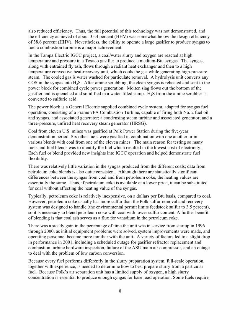
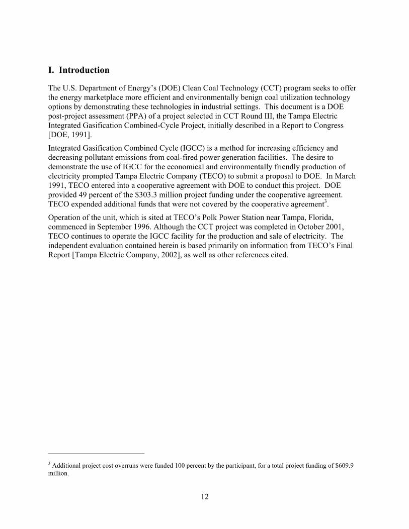
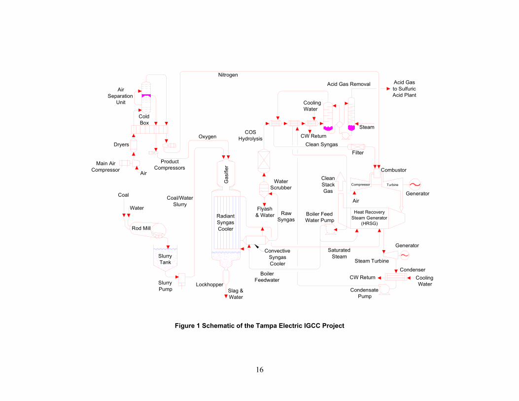
Figure 1 presents a schematic diagram of the Tampa Electric IGCC project. A coal/water slurry and oxygen are reacted at high temperature and pressure in a Texaco gasifier to produce a medium-Btu syngas. The syngas, along with entrained fly ash, flows through a radiant heat exchanger and then to a high temperature convective heat-recovery unit, which cools the gas while generating high-pressure steam. The cooled gas is water washed for particulate removal. A hydrolysis unit converts any COS in the syngas into H2S. After amine scrubbing, the clean syngas is reheated and sent to the power block for combined cycle power generation. Molten slag flows out the bottom of the gasifier and is quenched and solidified in a water-filled sump. Major system components are discussed in more detail in the following sections.
1. Coal Receiving and Storage
Coal is received by barge at TECO’s Big Bend Station coal yard. The coal is typically transported to the Polk Plant in covered, bottom-dump, tandem trailers, each with a 26-ton payload (95 trucks per day are required at full operating rate). At the Polk Station, the trucks off-load into an above-grade unloading hopper in a covered unloading structure. The top of the hopper contains sprays that control dust emissions. Belt feeders transfer coal from the hopper onto an enclosed 400 ton/hr unloading conveyor, which transports the coal to two 5,000 ton storage silos. A dust collection system at the top of the silos controls dust. Each silo is equipped

15
with a 400 ton/hr reclaim feeder and reclaim conveyor to deliver the coal to the 200 ton surge bin at the top of the coal grinding structure.
16
Water
Coal
Dryers
AirSeparation
Unit
Nitrogen
Acid Gas Removal Acid Gas to SulfuricAcid Plant
CoolingWater
CW ReturnClean Syngas
Steam
Filter
Combustor
GeneratorAir
CleanStackGas
Boiler FeedWater Pump
Heat RecoverySteam Generator
(HRSG)
Compressor Turbine
OxygenCOS
Hydrolysis
Water Scrubber
Flyash& Water Raw
Syngas
Generator
CondenserCoolingWater
CW Return
Condensate Pump
Steam Turbine
BoilerFeedwater
SaturatedSteam
ConvectiveSyngasCooler
LockhopperSlag &Water
Air
SlurryPump
Rod Mill
SlurryTank
RadiantSyngasCoolerG
asifi
er
Coal/WaterSlurry
ProductCompressors
ColdBox
Main AirCompressor
Figure 1 Schematic of the Tampa Electric IGCC Project
17
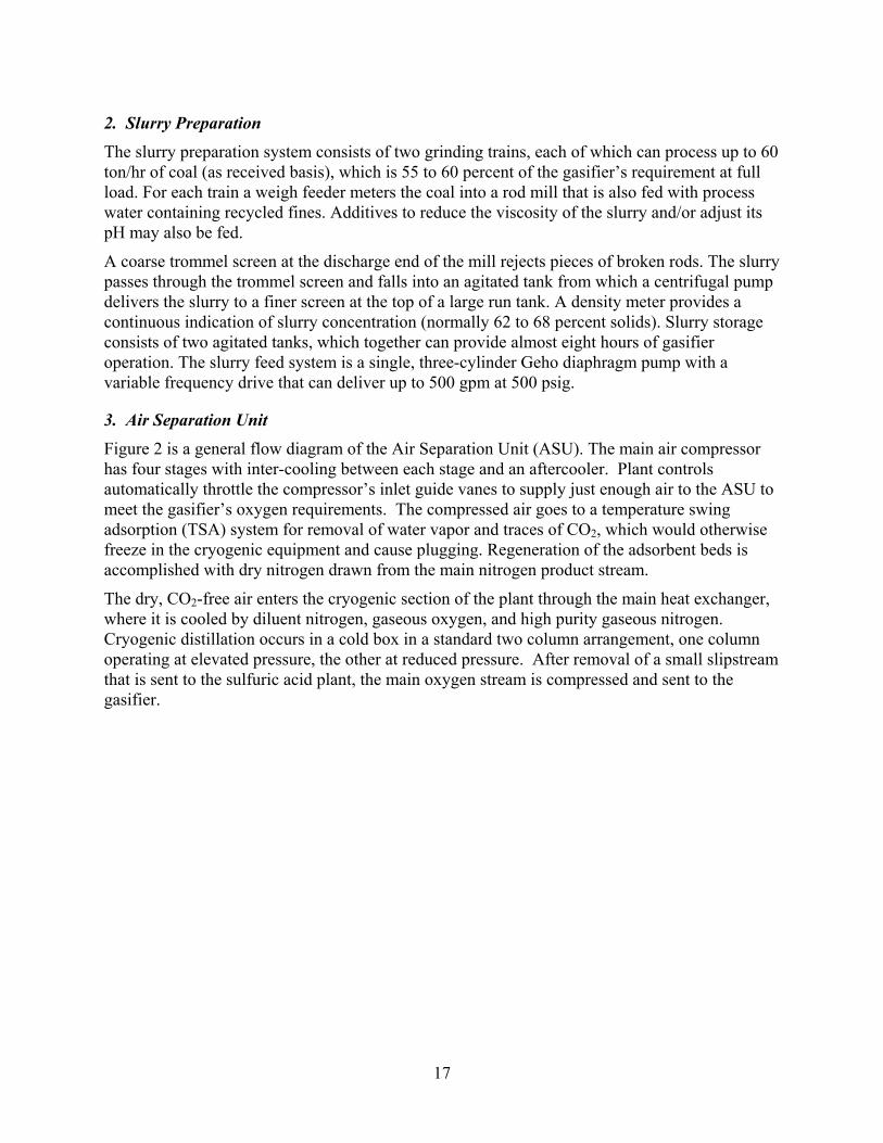
2. Slurry Preparation
The slurry preparation system consists of two grinding trains, each of which can process up to 60 ton/hr of coal (as received basis), which is 55 to 60 percent of the gasifier’s requirement at full load. For each train a weigh feeder meters the coal into a rod mill that is also fed with process water containing recycled fines. Additives to reduce the viscosity of the slurry and/or adjust its pH may also be fed.
A coarse trommel screen at the discharge end of the mill rejects pieces of broken rods. The slurry passes through the trommel screen and falls into an agitated tank from which a centrifugal pump delivers the slurry to a finer screen at the top of a large run tank. A density meter provides a continuous indication of slurry concentration (normally 62 to 68 percent solids). Slurry storage consists of two agitated tanks, which together can provide almost eight hours of gasifier operation. The slurry feed system is a single, three-cylinder Geho diaphragm pump with a variable frequency drive that can deliver up to 500 gpm at 500 psig.
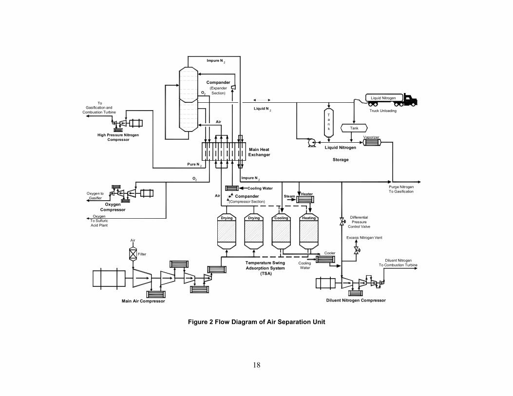
3. Air Separation Unit
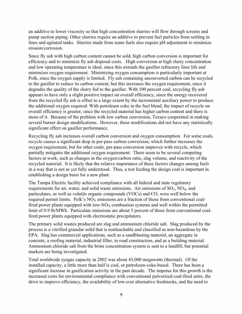
Figure 2 is a general flow diagram of the Air Separation Unit (ASU). The main air compressor has four stages with inter-cooling between each stage and an aftercooler. Plant controls automatically throttle the compressor’s inlet guide vanes to supply just enough air to the ASU to meet the gasifier’s oxygen requirements. The compressed air goes to a temperature swing adsorption (TSA) system for removal of water vapor and traces of CO2, which would otherwise freeze in the cryogenic equipment and cause plugging. Regeneration of the adsorbent beds is accomplished with dry nitrogen drawn from the main nitrogen product stream.
The dry, CO2-free air enters the cryogenic section of the plant through the main heat exchanger, where it is cooled by diluent nitrogen, gaseous oxygen, and high purity gaseous nitrogen. Cryogenic distillation occurs in a cold box in a standard two column arrangement, one column operating at elevated pressure, the other at reduced pressure. After removal of a small slipstream that is sent to the sulfuric acid plant, the main oxygen stream is compressed and sent to the gasifier.
18
Vaporizer
Liquid Nitrogen
Truck UnloadingTank Tank
Liquid Nitrogen
Storage
Purge NitrogenTo Gasification
Liquid N 2
Impure N 2
Compander(ExpanderSection)O2
Air
Main HeatExchanger
Impure N 2
ToGasification and
Combustion Turbine
High Pressure NitrogenCompressor
Pure N 2
O2
AirOxygen toGasifier
OxygenCompressor
OxygenTo SulfuricAcid Plant
Cooling WaterHeaterSteamCompander
(Compressor Section)
HeatingCoolingDryingDrying
Main Air Compressor
Filter
Air
Temperature SwingAdsorption System
(TSA)
CoolingWater
Cooler
DifferentialPressure
Control Valve
Excess Nitrogen Vent
Diluent NitrogenTo Combustion Turbine
Diluent Nitrogen Compressor
Figure 2 Flow Diagram of Air Separation Unit
19
Diluent nitrogen gas is the largest product stream and normally contains about 1.5 percent oxygen. Some nitrogen is extracted for purging and blanketing in the gasification plant, and additional gas is drawn off for regeneration of the TSA unit, but this gas is returned to maximize diluent nitrogen recovery. The nitrogen compressor delivers nitrogen to the combustion turbine for NOx abatement and power augmentation. High-pressure nitrogen (at a purity of 50 ppm O2) is continuously withdrawn for purges and equipment blanketing in the power block’s fuel transfer system and for purges, blanketing, and sootblowing in the gasification plant.
The plant also produces a small stream of liquid nitrogen, which is stored in two liquid nitrogen tanks and used during ASU outages to supply low pressure purge nitrogen to the gasification plant. Liquid nitrogen is also pumped into the columns for faster ASU plant startup. A liquid nitrogen truck unloading facility enables recharging the tanks during extended ASU outages.
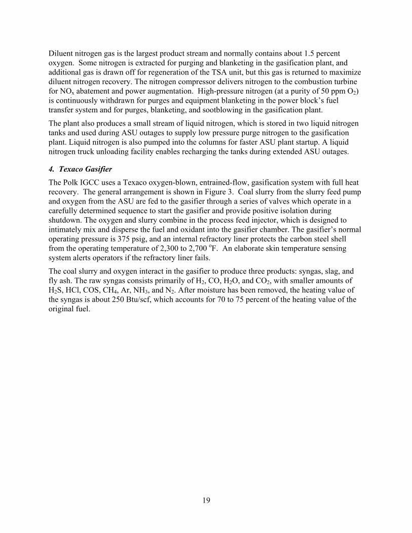
4. Texaco Gasifier
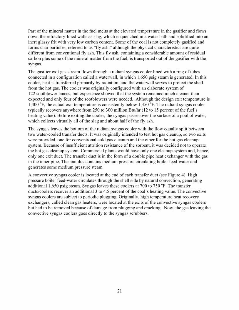
The Polk IGCC uses a Texaco oxygen-blown, entrained-flow, gasification system with full heat recovery. The general arrangement is shown in Figure 3. Coal slurry from the slurry feed pump and oxygen from the ASU are fed to the gasifier through a series of valves which operate in a carefully determined sequence to start the gasifier and provide positive isolation during shutdown. The oxygen and slurry combine in the process feed injector, which is designed to intimately mix and disperse the fuel and oxidant into the gasifier chamber. The gasifier’s normal operating pressure is 375 psig, and an internal refractory liner protects the carbon steel shell from the operating temperature of 2,300 to 2,700 oF. An elaborate skin temperature sensing system alerts operators if the refractory liner fails.
The coal slurry and oxygen interact in the gasifier to produce three products: syngas, slag, and fly ash. The raw syngas consists primarily of H2, CO, H2O, and CO2, with smaller amounts of H2S, HCl, COS, CH4, Ar, NH3, and N2. After moisture has been removed, the heating value of the syngas is about 250 Btu/scf, which accounts for 70 to 75 percent of the heating value of the original fuel.
20
Figure 3 Flow Diagram of Texaco Gasifier
21
Part of the mineral matter in the fuel melts at the elevated temperature in the gasifier and flows down the refractory-lined walls as slag, which is quenched in a water bath and solidified into an inert glassy frit with very low carbon content. Some of the coal is not completely gasified and forms char particles, referred to as “fly ash,” although the physical characteristics are quite different from conventional fly ash. This fly ash, containing a considerable amount of residual carbon plus some of the mineral matter from the fuel, is transported out of the gasifier with the syngas.
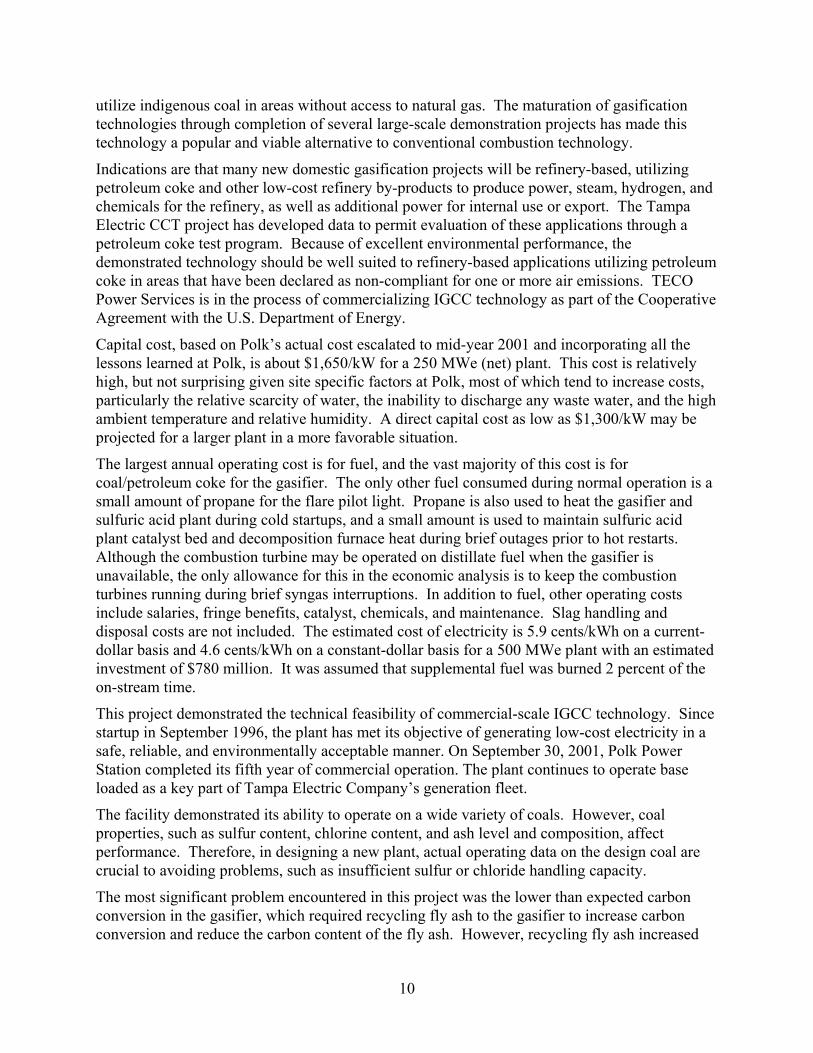
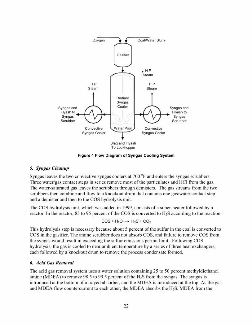
The gasifier exit gas stream flows through a radiant syngas cooler lined with a ring of tubes connected in a configuration called a waterwall, in which 1,650 psig steam is generated. In this cooler, heat is transferred primarily by radiation, and the waterwall serves to protect the shell from the hot gas. The cooler was originally configured with an elaborate system of 122 sootblower lances, but experience showed that the system remained much cleaner than expected and only four of the sootblowers were needed. Although the design exit temperature is 1,400 oF, the actual exit temperature is consistently below 1,350 oF. The radiant syngas cooler typically recovers anywhere from 250 to 300 million Btu/hr (12 to 15 percent of the fuel’s heating value). Before exiting the cooler, the syngas passes over the surface of a pool of water, which collects virtually all of the slag and about half of the fly ash.
The syngas leaves the bottom of the radiant syngas cooler with the flow equally split between two water-cooled transfer ducts. It was originally intended to test hot gas cleanup, so two exits were provided, one for conventional cold gas cleanup and the other for the hot gas cleanup system. Because of insufficient attrition resistance of the sorbent, it was decided not to operate the hot gas cleanup system. Commercial plants would have only one cleanup system and, hence, only one exit duct. The transfer duct is in the form of a double pipe heat exchanger with the gas in the inner pipe. The annulus contains medium pressure circulating boiler feed-water and generates some medium pressure steam.
A convective syngas cooler is located at the end of each transfer duct (see Figure 4). High pressure boiler feed-water circulates through the shell side by natural convection, generating additional 1,650 psig steam. Syngas leaves these coolers at 700 to 750 oF. The transfer ducts/coolers recover an additional 3 to 4.5 percent of the coal’s heating value. The convective syngas coolers are subject to periodic plugging. Originally, high temperature heat recovery exchangers, called clean gas heaters, were located at the exits of the convective syngas coolers but had to be removed because of damage from plugging and cracking. Now, the gas leaving the convective syngas coolers goes directly to the syngas scrubbers.
22
Syngas andFlyash toSyngas
Scrubber
Syngas andFlyash toSyngas
Scrubber
H P Steam
H P Steam
H P Steam
ConvectiveSyngas Cooler
ConvectiveSyngas Cooler
Slag and FlyashTo Lockhopper
RadiantSyngasCooler
Gasifier
Oxygen Coal/Water Slurry
Water Pool
Figure 4 Flow Diagram of Syngas Cooling System
5. Syngas Cleanup
Syngas leaves the two convective syngas coolers at 700 oF and enters the syngas scrubbers. Three water/gas contact steps in series remove most of the particulates and HCl from the gas. The water-saturated gas leaves the scrubbers through demisters. The gas streams from the two scrubbers then combine and flow to a knockout drum that contains one gas/water contact step and a demister and then to the COS hydrolysis unit.
The COS hydrolysis unit, which was added in 1999, consists of a super-heater followed by a reactor. In the reactor, 85 to 95 percent of the COS is converted to H2S according to the reaction:
COS + H2O → H2S + CO2
This hydrolysis step is necessary because about 5 percent of the sulfur in the coal is converted to COS in the gasifier. The amine scrubber does not absorb COS, and failure to remove COS from the syngas would result in exceeding the sulfur emissions permit limit. Following COS hydrolysis, the gas is cooled to near ambient temperature by a series of three heat exchangers, each followed by a knockout drum to remove the process condensate formed.
6. Acid Gas Removal
The acid gas removal system uses a water solution containing 25 to 50 percent methyldiethanol amine (MDEA) to remove 98.5 to 99.5 percent of the H2S from the syngas. The syngas is introduced at the bottom of a trayed absorber, and the MDEA is introduced at the top. As the gas and MDEA flow countercurrent to each other, the MDEA absorbs the H2S. MDEA from the
23
bottom of the absorber flows to the top of the stripper, another trayed column, where the solvent is heated to release the H2S. The hot solvent from the bottom of the stripper is cooled first by preheating the incoming MDEA and then with cooling water. The cooled MDEA flows to a storage tank from which it is pumped back to the absorber. The H2S-containing stripper-overhead gas is sent to the sulfuric acid plant.
MDEA also removes CO2 from the syngas. This is undesirable because the CO2 helps the combustion turbine by increasing power output and efficiency and reducing flame temperature for NOX abatement, and high CO2 removal increases the volume of the acid gas stream to the sulfuric acid plant. A solvent’s preferential removal of H2S over CO2 is referred to as H2S selectivity. At Polk, testing has indicated that the independent variables impacting selectivity are solvent circulation rate, MDEA concentration in the circulating solvent, contact time between the solvent and gas, and absorber temperature. The high solvent circulation rate required for high selectivity increases low pressure steam consumption in the stripper, which reduces overall cycle efficiency.
Trace compounds in the syngas, mostly formic acid vapor produced in the COS hydrolysis unit, react with MDEA to form heat stable salts that, unlike the complex formed with H2S, cannot be regenerated by heating. If not removed, these salts eventually tie up all the MDEA, making it ineffective for H2S removal. An ion exchange unit was installed to regenerate the heat stable salts.
The clean syngas from the MDEA absorber passes through a knockout drum with a demister to remove solvent mist. The gas is then heated in the clean gas pre-heater and passed through a 10 micron cartridge filter and a strainer immediately upstream of the combustion turbine’s fuel control valves to prevent particulates from entering the turbine.
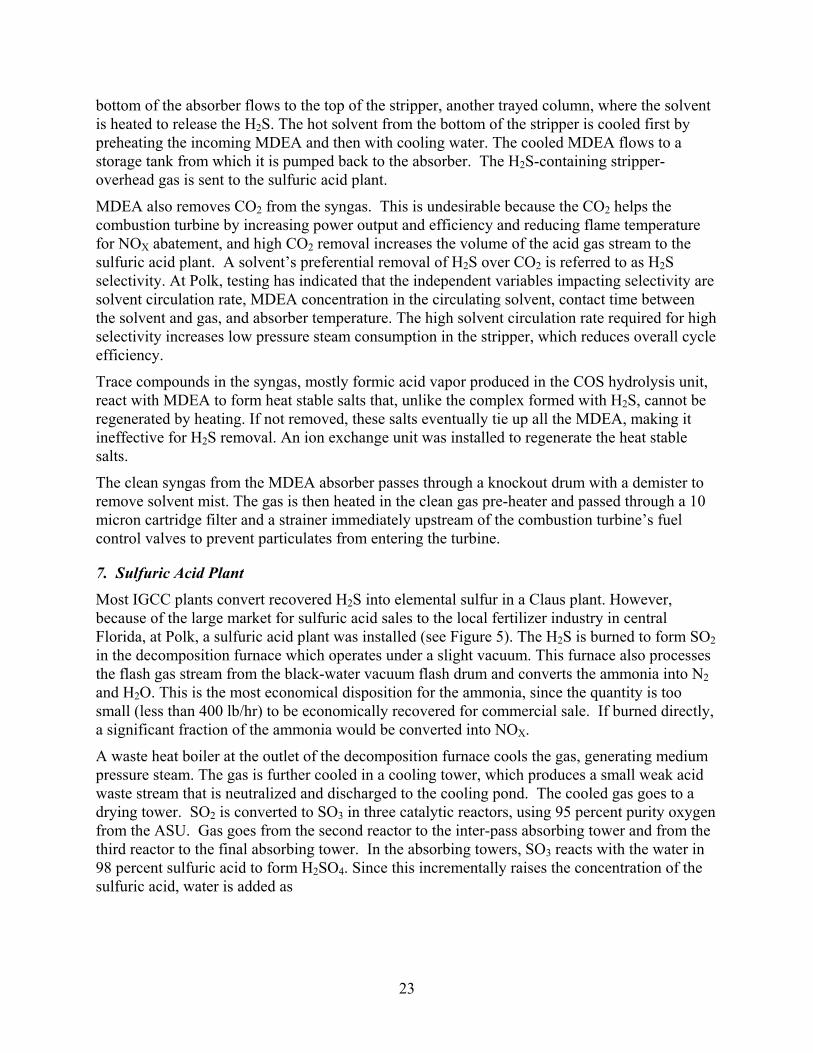
7. Sulfuric Acid Plant
Most IGCC plants convert recovered H2S into elemental sulfur in a Claus plant. However, because of the large market for sulfuric acid sales to the local fertilizer industry in central Florida, at Polk, a sulfuric acid plant was installed (see Figure 5). The H2S is burned to form SO2 in the decomposition furnace which operates under a slight vacuum. This furnace also processes the flash gas stream from the black-water vacuum flash drum and converts the ammonia into N2 and H2O. This is the most economical disposition for the ammonia, since the quantity is too small (less than 400 lb/hr) to be economically recovered for commercial sale. If burned directly, a significant fraction of the ammonia would be converted into NOX.
A waste heat boiler at the outlet of the decomposition furnace cools the gas, generating medium pressure steam. The gas is further cooled in a cooling tower, which produces a small weak acid waste stream that is neutralized and discharged to the cooling pond. The cooled gas goes to a drying tower. SO2 is converted to SO3 in three catalytic reactors, using 95 percent purity oxygen from the ASU. Gas goes from the second reactor to the inter-pass absorbing tower and from the third reactor to the final absorbing tower. In the absorbing towers, SO3 reacts with the water in 98 percent sulfuric acid to form H2SO4. Since this incrementally raises the concentration of the sulfuric acid, water is added as
24
Figure 5 Flow Diagram of Sulfuric Acid Plant
required to maintain a concentration of 98.5 percent. Polk produces 200 ton/day of sulfuric acid when operating with fuels containing 3.5 percent sulfur (dry basis). The sulfuric acid plant is very efficient, converting over 99.5 percent of the incoming H2S into H2SO4. The tail gas from the final absorbing tower, containing 150 to 250 ppm SO2, is discharged through a dedicated stack.
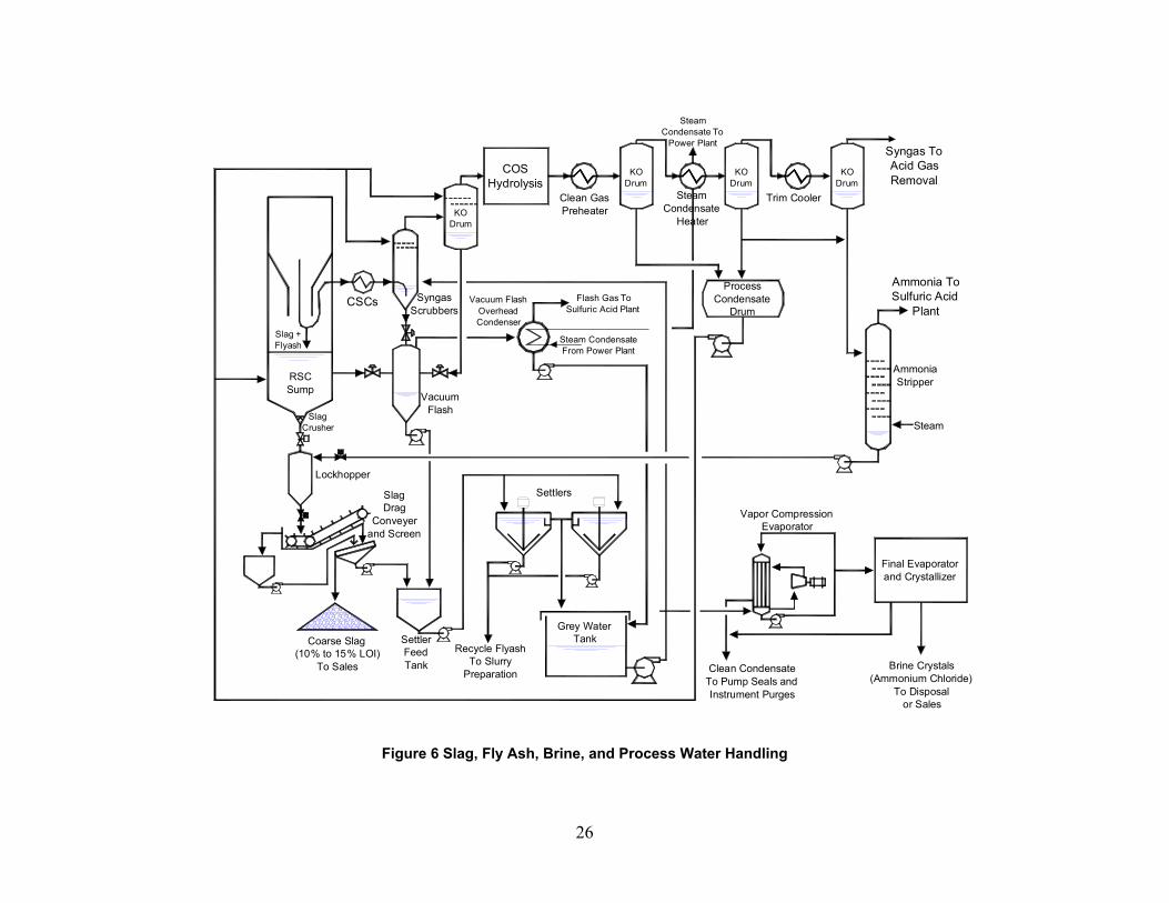
8. Slag, Fly ash, Brine, and Process Water Handling
Figure 6 shows the major slag, fly ash, brine, and process water streams. As the syngas makes a sharp turn at the bottom of the radiant syngas cooler (RSC), all of the slag and about 40 percent of the fly ash from the gasifier separate and fall into a water pool, referred to as the RSC sump. Makeup to the sump is particulate- and chloride-free process condensate from the low temperature gas cooling section of the gasification plant. A steady blowdown stream from the
Waste HeatBoiler
DecompositionFurnace
Vacuum Flash Gas
Main Acid Gas
Ammonia Gas
SteamDrum
Gas CoolingTower
Weak Acid
Cooling Water
Cooling Water
Acid Tank
InterpassAbsorbing
Tower
FinalAbsorbing
Tower
TailGas
Stack
1st Reactor
2nd Reactor
3rd ReactorCompressor
Oxygen
DryingTower
Air
Economized Boiler Feedwater
MP (420 psig) Steam
Strong Acid98% H SO2 4

25
sump, known as black water because it contains a significant amount of fly ash, goes to a vacuum flash system.
The slag and the fly ash picked up in the sump settle and pass through a slag crusher en route to a lockhopper. The lockhopper discharges 3 to 4 times per hour to a drag flight conveyor. As the lockhopper dumps, it is flushed with stripped condensate (process condensate from which most of the ammonia has been removed by steam stripping). Since chloride and ammonia render slag unmarketable, only streams free of chloride and relatively free of ammonia are used as makeup to the sump and lockhopper.
The drag flight conveyor deposits the slag and fly ash onto a washed screen. The coarse material from the screen (glassy slag), containing 10 to 15 percent combustible material when coal is the feedstock, has been sold to the cement industry. The water and the fine solids that pass through the screen (fly ash containing 30 percent carbon or more) constitute black water that is pumped to the settler feed tank.
The 60 percent of the fly ash from the gasifier that isn’t collected in the sump travels with the syngas through the convective syngas coolers to the syngas scrubbers, where fly ash and HCl are removed by intimate contact with water. The black water blowdown streams from the two scrubbers enter the vacuum flash drum, along with the sump black water stream. The major make-up water stream to the syngas scrubbers is grey water (black water from which the particulates have settled). A small process condensate stream performs a final polishing in trays at the top of the scrubber to improve removal of particulates and chlorides from the syngas. The syngas leaves the scrubbers at 330 oF and 350 psig, saturated with water vapor.
26
CSCs
VacuumFlash
SlagCrusher
Slag +Flyash
RSCSump
Lockhopper
SlagDrag
Conveyerand Screen
Coarse Slag(10% to 15% LOI)
To Sales
SettlerFeedTank
Settlers
Recycle FlyashTo Slurry
Preparation
Grey WaterTank
Vapor CompressionEvaporator
Final Evaporatorand Crystallizer
Clean CondensateTo Pump Seals andInstrument Purges
Brine Crystals(Ammonium Chloride)
To Disposalor Sales
KODrum
KODrum
KODrum
KODrum
Steam CondensateFrom Power Plant
COSHydrolysis
Clean GasPreheater
SteamCondensate To
Power Plant
SteamCondensate
Heater
Trim Cooler
Syngas ToAcid Gas Removal
Ammonia ToSulfuric Acid
Plant
AmmoniaStripper
Steam
Process Condensate
DrumFlash Gas To
Sulfuric Acid PlantVacuum Flash
OverheadCondenser
SyngasScrubbers
Figure 6 Slag, Fly Ash, Brine, and Process Water Handling
27
Four black water streams feed the vacuum flash drum, which operates at a pressure of 7.5 psia: the sump blowdown, a blowdown stream from each of the two scrubbers, and the blowdown from the knockout drum before the COS hydrolysis unit. The flashed steam is condensed by preheating steam turbine condensate. A vacuum pump delivers the non-condensable gases, mostly CO2, to the sulfuric acid plant. The vacuum flash drum bottom stream is pumped to the settler feed tank, where it is mixed with the black water from the coarse slag screen. The black water from the settler feed tank, containing 5 to 10 percent solids, is distributed to two gravity settlers. The settlers concentrate the fly ash into bottom streams that are normally sent to the slurry preparation area for recycling to the gasifier.
The settler overflow streams are relatively particulate free. Most of the grey water is recycled to the syngas scrubbers, but a side-stream is sent to the brine concentration system. This prevents dissolved solids, particularly chlorides, from building up in the grey water to a concentration that would become corrosive. The brine concentration system consists of two main steps, first a vapor compression cycle, where most of the water is efficiently evaporated and, second, a final evaporation and crystal removal step. The condensate is returned to the process for pump seals and instrument tap flushes. The salt, mostly ammonium chloride produced at a rate of about 20 tons/month, is presently sent to a landfill, but potential markets are being investigated.
The final part of the process water system is process condensate. The syngas from the scrubbers contains slightly over 30 percent water vapor, most of which condenses when the temperature is reduced to near ambient. This condensed water is referred to as process condensate. The process condensate from the higher temperature exchangers contains very little ammonia. It is sent to the scrubbers and knockout drum for particulate removal and to the sump as makeup via the process condensate drum. The process condensate from the cooler exchangers contains most of the ammonia produced in the gasifier. It is routed to the ammonia stripper, where steam stripping removes the ammonia. The ammonia gas flows to the sulfuric acid plant for conversion to nitrogen gas plus water vapor. The ammonia stripper bottom is referred to as stripped condensate and is used to flush the lockhopper.
9. Power Block
The power plant is a General Electric combined cycle adapted for syngas fuel operation. GE provided the engineering, manufacture, and supply of the following equipment:
One Frame 7FA Single Shaft Combustion Turbine with 7221 Multi Nozzle Quiet Combustors, capable of firing No. 2 fuel oil as well as syngas, and associated 229,741 KVA hydrogen cooled generator One tandem compound, double flow condensing steam turbine with one uncontrolled extraction and associated 156,471 KVA hydrogen cooled generator One three-pressure, unfired Heat Recovery Steam Generator (HRSG) with integral deaerator (fabricated by Vogt under contract to GE)
a. Combustion Turbine
Filtered ambient air, at a rate of 3 million pounds per hour (40 million scf/hr), enters the combustion turbine compressor. The compressor is a multi-stage, axial machine that requires approximately 200,000 shaft horsepower, making it by far the largest “auxiliary” power
28
consumer in the facility. Most of the air is used for fuel combustion, but a significant fraction is diverted to cooling the turbine, after which it joins the combustion products.
The fuel for the combustion turbine is clean superheated syngas. Diluent nitrogen from the air separation plant is used for NOX abatement (by lowering combustion temperature) and power augmentation when firing syngas. The combustion turbine’s startup and backup fuel is low sulfur No. 2 distillate oil. When firing distillate fuel, NOX emissions are controlled by de-mineralized water injection.
The combustion products, mixed with the air used to cool the combustion turbine, pass through the expansion turbine and produce approximately 475,000 shaft horsepower. Of this, 200,000 HP is consumed by the compressor; 257,000 HP is used by the hydrogen-cooled generator to produce 192 MW; and the rest is consumed by generator and bearing losses. The exhaust gas leaves the final turbine stage at 1,066 oF through an exhaust plenum into the HRSG.
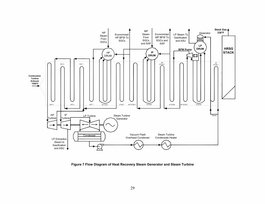
b. Heat Recovery Steam Generator
The HRSG recovers heat from the combustion turbine exhaust to preheat boiler feedwater (BFW) and to produce and superheat steam for the generation of additional power in the steam turbine. The HRSG is a three-pressure level, reheat, natural circulation design. Its configuration, along with that of the steam turbine, is shown in Figure 7. The 1,066 oF combustion turbine exhaust gas enters the superheater and reheater sections of the HRSG, which heat the high pressure (HP) and intermediate pressure (IP) steam to 1,000 oF.
Next is the HP evaporator which generates 165,000 lb/hr of 1,415 psig steam. This is 25 to 30 percent of the HP steam produced in the plant. The syngas cooler HP steam flows into the HRSG HP drum. A small IP steam superheater is next, followed by the hottest HP economizer, which finishes preheating boiler feedwater for the HRSG HP evaporator and the syngas coolers.
The IP evaporator generates about 50,000 lb/hr of 370 psig steam. The gasification plant’s IP steam, which is generated at 420 psig, flows to the HRSG IP drum and the HRSG superheaters and turbine. The IP evaporator is followed by three economizer sections that preheat HP and IP boiler feedwater.
Next, low pressure (LP) steam is generated in the LP evaporator for the air separation plant and the gasification plant. Finally, BFW is preheated in the last HRSG section for additional heat recovery. The temperature of the exhaust gas to the stack is typically anywhere from 310 to 340 oF.
c. Steam Turbine
The steam turbine configuration is shown on Figure 7. It is a double flow reheat unit with low pressure crossover extraction. The steam turbine generator is designed specifically for highly efficient combined cycle operation with nominal turbine inlet conditions of approximately 1,450 psig
29
HPDRUM
LP TurbineHP Turbine
IP Turbine
Steam TurbineGenerator
CondenserLP Extraction
Steam toGasification
and ASU
Vacuum FlashOverhead Condenser
Steam TurbineCondensate Heater
SHT 3 SHT 2 SHT 1 HP EVAP IP SHT HP ECON 3 IP EVAP IP ECON HP ECON 1 IP EVAP
RHT 2 RHT 1HP
ECON 2HP
ECON 1
IPDRUM
LPDRUM
HPSteamFromSGCs
EconomizedHP BFW To
SGCs
MPSteamFromSGCs
and SAP
EconomizedMP BFW To SGCs and
SAP
LP Steam ToGasification
and ASU
DeaeratorStack Gas
330°F
HRSGSTACK
BFW Pump
Bypass
CombustionTurbineExhaust1066°F
Figure 7 Flow Diagram of Heat Recovery Steam Generator and Steam Turbine
30
and 1,000 oF with 1,000 oF reheat inlet temperature. Output during normal full load operation on syngas fuel is 120 to 135 MWe, depending on ambient temperature and steam production and consumption in the gasification plant. The outlet from the last stage of the turbine is condensed by heat exchange with circulating water from the plant cooling water reservoir.
E. Project Objective and Statement of Work
According to the statement of work, the objective of this demonstration project was to design, construct, and operate a 250 MWe IGCC system which is potentially capable of providing high performance, cost competitive, environmentally compliant electric power from coal. Another objective was to develop data which will demonstrate that, compared to existing and future conventional coal-burning power plants, such an IGCC system can be the technology of choice for coal utilization because significant reductions of SO2 and NOX emissions can be achieved. As a further objective, the integrated performance was expected to demonstrate the reliability, cost effectiveness, and overall efficiency of the IGCC system.
The work for the project was divided into three phases:
Phase 1 -- Design and Permitting Phase 2 -- Procurement, Construction, and Start-up Phase 3 -- Operation and Data Collection
This PPA is mainly concerned with Phase 3 and only incidentally deals with Phases 1 and 2.
The Participant was responsible for providing or obtaining all services, licenses, permits, and agreements necessary to ensure the availability of operating and performance data and for providing or obtaining all facilities necessary for the design, fabrication, procurement, installation, construction, start-up, and operation of the IGCC system. The Participant was also responsible for developing a detailed study comparing hot and cold syngas cleanup systems for a Texaco-based IGCC system. However, because the hot gas cleanup system did not operate, it was not possible to conduct this study, and the statement of work made allowance for deleting this study in the event of technical failure of the hot gas cleanup system. The participant was also required to test five coals or coal blends during the first three years of operation.
31
III. Review of Technical and Environmental Performance
A. Technical Results
1. Fuel Analyses
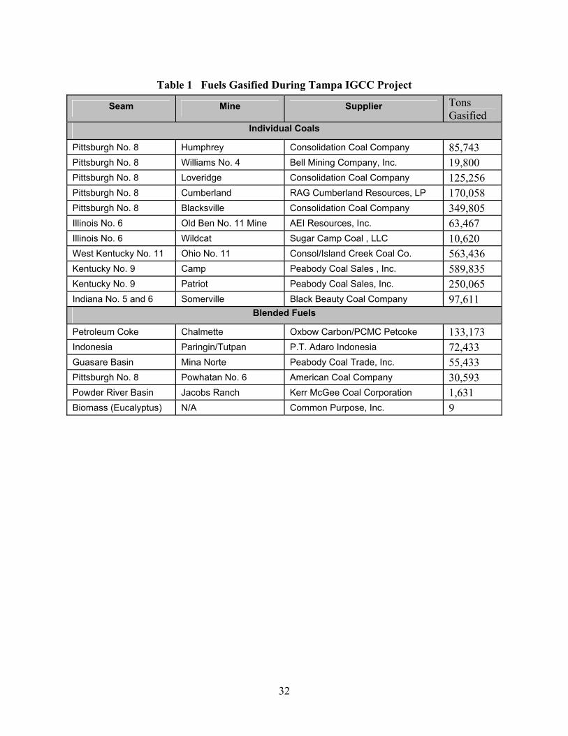
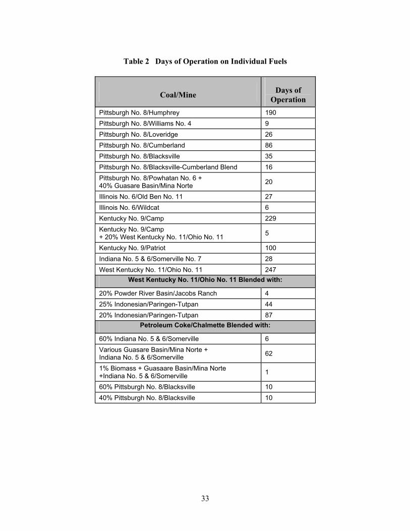
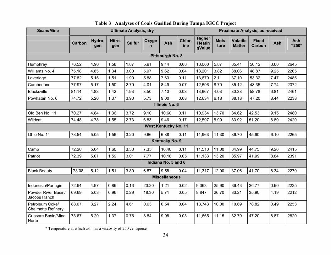
Coal from eleven U.S. mines was gasified at Polk Power Station during the five year demonstration period. Six other fuels were gasified in combination with one another or in various blends with coal from one of the eleven mines. The fuels gasified and tonnages of each are identified in Table 1. Table 2 shows how long each fuel was fed, and fuel analyses are shown in Table 3. The main reason for testing so many fuels and fuel blends was to identify the fuel which resulted in the lowest cost of electricity. Another reason for changing coals was that two coals that performed well became unavailable due to mine closures. Some coals or blends simply bridged a gap created by temporary inventory shortfalls. Also, the DOE Cooperative Agreement included a requirement to test four coals. Regardless of the reason it was used, each fuel or blend provided new insights into IGCC operation and helped demonstrate fuel flexibility.
Evaluating a potential fuel includes quantifying its impact on processing cost. The cost impact of some fuel characteristics, such as sulfur and chlorine content, are relatively easy to determine. Although the effect of other factors, such as carbon conversion and gasifier refractory liner life, can be estimated from a chemical analysis, effects can only truly be determined by full scale operation, as successfully demonstrated in this project.
32
Table 1 Fuels Gasified During Tampa IGCC Project
Seam Mine Supplier Tons Gasified
Individual Coals
Pittsburgh No. 8 Humphrey Consolidation Coal Company 85,743 Pittsburgh No. 8 Williams No. 4 Bell Mining Company, Inc. 19,800 Pittsburgh No. 8 Loveridge Consolidation Coal Company 125,256 Pittsburgh No. 8 Cumberland RAG Cumberland Resources, LP 170,058 Pittsburgh No. 8 Blacksville Consolidation Coal Company 349,805 Illinois No. 6 Old Ben No. 11 Mine AEI Resources, Inc. 63,467 Illinois No. 6 Wildcat Sugar Camp Coal , LLC 10,620 West Kentucky No. 11 Ohio No. 11 Consol/Island Creek Coal Co. 563,436 Kentucky No. 9 Camp Peabody Coal Sales , Inc. 589,835 Kentucky No. 9 Patriot Peabody Coal Sales, Inc. 250,065 Indiana No. 5 and 6 Somerville Black Beauty Coal Company 97,611
Blended Fuels
Petroleum Coke Chalmette Oxbow Carbon/PCMC Petcoke 133,173 Indonesia Paringin/Tutpan P.T. Adaro Indonesia 72,433 Guasare Basin Mina Norte Peabody Coal Trade, Inc. 55,433 Pittsburgh No. 8 Powhatan No. 6 American Coal Company 30,593 Powder River Basin Jacobs Ranch Kerr McGee Coal Corporation 1,631 Biomass (Eucalyptus) N/A Common Purpose, Inc. 9
33
Table 2 Days of Operation on Individual Fuels
Coal/Mine Days of Operation
Pittsburgh No. 8/Humphrey 190 Pittsburgh No. 8/Williams No. 4 9 Pittsburgh No. 8/Loveridge 26 Pittsburgh No. 8/Cumberland 86 Pittsburgh No. 8/Blacksville 35 Pittsburgh No. 8/Blacksville-Cumberland Blend 16 Pittsburgh No. 8/Powhatan No. 6 + 40% Guasare Basin/Mina Norte 20
Illinois No. 6/Old Ben No. 11 27 Illinois No. 6/Wildcat 6 Kentucky No. 9/Camp 229 Kentucky No. 9/Camp + 20% West Kentucky No. 11/Ohio No. 11 5
Kentucky No. 9/Patriot 100 Indiana No. 5 & 6/Somerville No. 7 28 West Kentucky No. 11/Ohio No. 11 247
West Kentucky No. 11/Ohio No. 11 Blended with:
20% Powder River Basin/Jacobs Ranch 4 25% Indonesian/Paringen-Tutpan 44 20% Indonesian/Paringen-Tutpan 87
Petroleum Coke/Chalmette Blended with:
60% Indiana No. 5 & 6/Somerville 6 Various Guasare Basin/Mina Norte + Indiana No. 5 & 6/Somerville 62
1% Biomass + Guasaare Basin/Mina Norte +Indiana No. 5 & 6/Somerville 1
60% Pittsburgh No. 8/Blacksville 10 40% Pittsburgh No. 8/Blacksville 10
34
Table 3 Analyses of Coals Gasified During Tampa IGCC Project Seam/Mine Ultimate Analysis, dry Proximate Analysis, as received
Carbon Hydro-gen
Nitro-gen Sulfur Oxyge
n Ash Chlor-ine
Higher HeatingValue
Mois-ture
VolatileMatter
Fixed Carbon Ash Ash
T250*
Pittsburgh No. 8
Humphrey 76.52 4.90 1.58 1.87 5.91 9.14 0.08 13,060 5.87 35.41 50.12 8.60 2645 Williams No. 4 75.18 4.85 1.34 3.00 5.97 9.62 0.04 13,201 3.82 38.06 48.87 9.25 2205 Loveridge 77.82 5.15 1.51 1.90 5.88 7.63 0.11 13,670 2.11 37.10 53.32 7.47 2485 Cumberland 77.97 5.17 1.50 2.79 4.01 8.49 0.07 12,696 8.79 35.12 48.35 7.74 2372 Blacksville 81.14 4.83 1.42 1.93 3.50 7.10 0.08 13,667 4.03 30.38 58.78 6.81 2461 Powhatan No. 6 74.72 5.20 1.37 3.90 5.73 9.00 0.08 12,634 6.18 38.18 47.20 8.44 2238
Illinois No. 6
Old Ben No. 11 70.27 4.84 1.36 3.72 9.10 10.60 0.11 10,934 13.70 34.62 42.53 9.15 2480 Wildcat 74.48 4.78 1.55 2.73 6.83 9.46 0.17 12,597 5.99 33.92 51.20 8.89 2420
West Kentucky No. 11
Ohio No. 11 73.54 5.05 1.56 3.20 9.66 6.88 0.11 11,963 11.30 36.70 45.90 6.10 2265 Kentucky No. 9
Camp 72.20 5.04 1.60 3.30 7.35 10.40 0.11 11,510 11.00 34.99 44.75 9.26 2415 Patriot 72.39 5.01 1.59 3.01 7.77 10.18 0.05 11,133 13.20 35.97 41.99 8.84 2391
Indiana No. 5 and 6
Black Beauty 73.08 5.12 1.51 3.80 6.87 9.58 0.04 11,317 12.90 37.06 41.70 8.34 2279 Miscellaneous
Indonesia/Paringin 72.64 4.97 0.86 0.13 20.20 1.21 0.02 9,363 25.90 36.43 36.77 0.90 2235 Powder River Basin/ Jacobs Ranch
69.69 5.03 0.96 0.29 18.30 5.71 0.05 8,847 26.70 33.21 35.90 4.19 2212
Petroleum Coke/ Chalmette Refinery
88.67 3.27 2.24 4.61 0.63 0.54 0.04 13,743 10.00 10.69 78.82 0.49 2253
Guasare Basin/Mina Norte
73.67 5.20 1.37 0.76 8.84 9.98 0.03 11,665 11.15 32.79 47.20 8.87 2820
* Temperature at which ash has a viscosity of 250 centipoise
35
2. Clean Syngas Analysis
The composition of clean syngas is given in Table 4. The data in the coal column are from seven coals operating with three different burners. There was relatively little variation in the syngas produced from the different coals. The data from petroleum coke blends are also quite consistent. Although the difference between the average composition of syngas from coal and from petroleum coke is statistically significant, the heating values are essentially the same. Thus, if petroleum coke is available at a lower price, it can be substituted for coal without affecting the heating value of the syngas.
Table 4 Syngas Composition
Coal Petroleum Coke Blends Analysis
Average Value
Composition H2S + COS, ppmv 415 282 CH4, ppmv 532 244 CO, vol% 44.06 48.29 CO2, vol% 14.73 13.61 H2, vol% 37.95 34.02 N2, vol% 2.28 3.02 Ar, vol% 0.88 1.00 Total, vol% 100.00 100.00 Higher Heating Value, Btu/scf 263.2 264.0 Lower Heating Value, Btu/scf 244.3 247.0
3. Slag Analysis
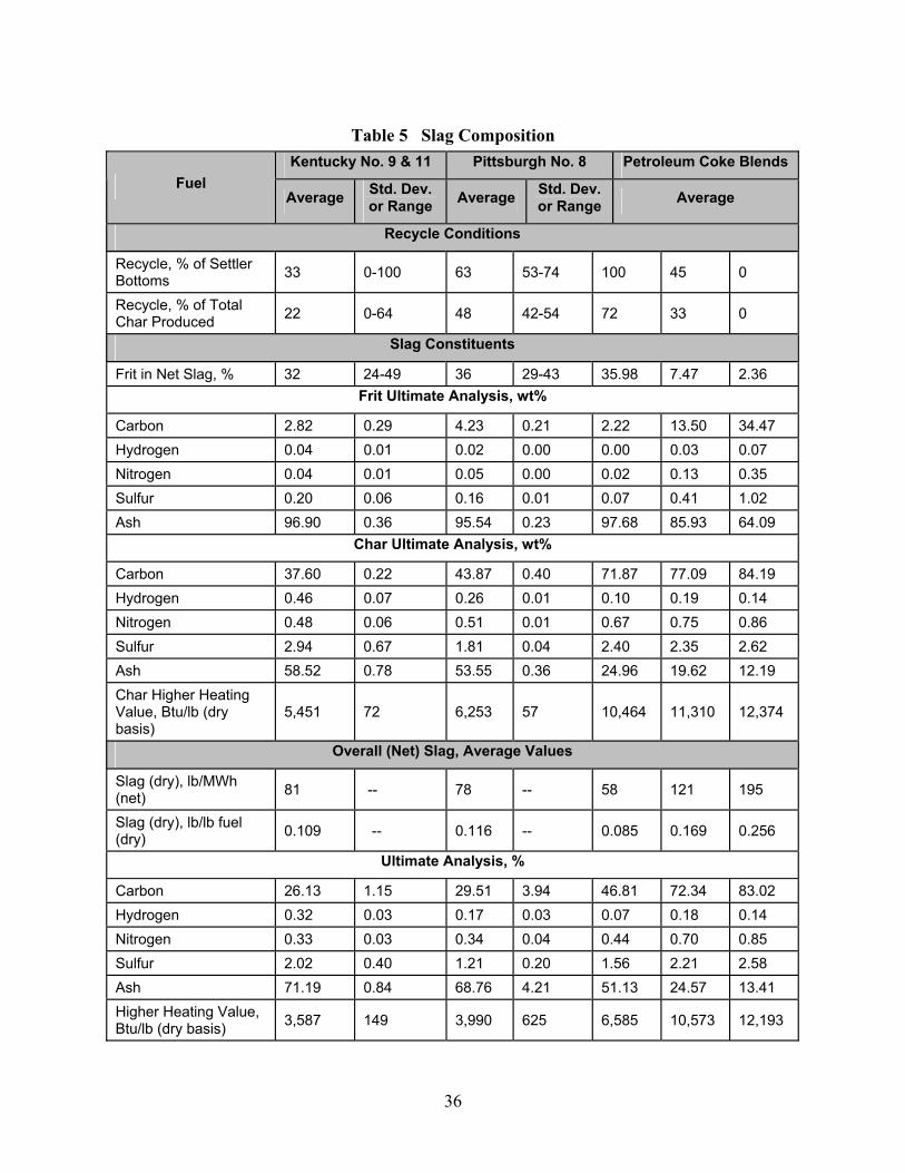
Slag has two constituents: (1) coarse glassy frit containing relatively little carbon, and (2) smaller char particles containing most of the gasifier’s unconverted carbon. Slag composition is shown in Table 5. When the fuel is coal, the analyses of the frit and char are relatively constant from coal-to-coal. As net carbon conversion changes with changes in fines recycle or operating temperature, the ratio of frit to char adjusts automatically. However, for petroleum coke, the compositions of the char and frit change with changes in overall conversion resulting from different settler bottoms recycle rates. In general, the practice is to recycle as much char as can be recovered so that the resulting frit will be suitable for applications such as cement manufacture.
36
Table 5 Slag Composition Kentucky No. 9 & 11 Pittsburgh No. 8 Petroleum Coke Blends
Fuel Average Std. Dev.
or Range Average Std. Dev. or Range Average
Recycle Conditions
Recycle, % of Settler Bottoms 33 0-100 63 53-74 100 45 0
Recycle, % of Total Char Produced 22 0-64 48 42-54 72 33 0
Slag Constituents
Frit in Net Slag, % 32 24-49 36 29-43 35.98 7.47 2.36 Frit Ultimate Analysis, wt%
Carbon 2.82 0.29 4.23 0.21 2.22 13.50 34.47 Hydrogen 0.04 0.01 0.02 0.00 0.00 0.03 0.07 Nitrogen 0.04 0.01 0.05 0.00 0.02 0.13 0.35 Sulfur 0.20 0.06 0.16 0.01 0.07 0.41 1.02 Ash 96.90 0.36 95.54 0.23 97.68 85.93 64.09
Char Ultimate Analysis, wt%
Carbon 37.60 0.22 43.87 0.40 71.87 77.09 84.19 Hydrogen 0.46 0.07 0.26 0.01 0.10 0.19 0.14 Nitrogen 0.48 0.06 0.51 0.01 0.67 0.75 0.86 Sulfur 2.94 0.67 1.81 0.04 2.40 2.35 2.62 Ash 58.52 0.78 53.55 0.36 24.96 19.62 12.19 Char Higher Heating Value, Btu/lb (dry basis)
5,451 72 6,253 57 10,464 11,310 12,374
Overall (Net) Slag, Average Values
Slag (dry), lb/MWh (net) 81 -- 78 -- 58 121 195
Slag (dry), lb/lb fuel (dry) 0.109 -- 0.116 -- 0.085 0.169 0.256
Ultimate Analysis, %
Carbon 26.13 1.15 29.51 3.94 46.81 72.34 83.02 Hydrogen 0.32 0.03 0.17 0.03 0.07 0.18 0.14 Nitrogen 0.33 0.03 0.34 0.04 0.44 0.70 0.85 Sulfur 2.02 0.40 1.21 0.20 1.56 2.21 2.58 Ash 71.19 0.84 68.76 4.21 51.13 24.57 13.41 Higher Heating Value, Btu/lb (dry basis) 3,587 149 3,990 625 6,585 10,573 12,193
37
a. Ash Mineral Analysis
The slag’s ash mineral analysis almost exactly reflects that of the feed with the following exceptions.
The chlorine in the fuel is converted to HCl in the gasifier and ends up in the process water instead of in the slag. The ultimate fate of a significant fraction of the mercury and smaller fractions of a few other volatile trace elements, such as arsenic, is not certain. Chromium from the gasifier’s refractory liner is found in the frit. The chromium content of the frit is 100 to 1,500 ppm higher than that of the fuel’s ash. Testing has verified that the chromium is not in the form of potentially hazardous Chromium VI.
b. Loss on Ignition
Loss on ignition (LOI) is a measure of the non-ash constituents of the slag (C, H, O, N, and S). A low LOI value is required for virtually all non-fuel end uses of slag, such as for cement and blasting grit. The glassy frit is generally suitable for such applications after most of the char is removed. On the other hand, the char has a high LOI value. High LOI makes the char more suitable for recycling to the gasifier. Table 5 shows the average ultimate analyses and heating value of slag from Kentucky and Pittsburgh seam coals and from petroleum coke blends.
c. Contaminants in Surface Moisture
If no special effort is made to dry or dewater the slag, it will retain approximately 30 wt percent surface moisture. In Polk’s original configuration, this moisture consisted of grey or black water containing up to 3,500 ppm chloride and approximately an equal amount of ammonia. These make the frit unsuitable for end-use applications. The chloride is corrosive in end products, such as cement, and the ammonia content was high enough that odor was objectionable. Consequently, the plant was reconfigured so only stripped process condensate contacts the frit. Process condensate contains virtually no chloride, and stripping reduces its ammonia content to less than 500 ppm so the ammonia odor is barely detectable in the slag. This reduced the concentration of contaminates by over an order of magnitude, making the frit suitable for some end uses.
4. Sulfuric Acid
The sulfur removal system demonstrated the capability to meet the permitted SO2 emission level of 357 lb/hr year round while processing fuels with sulfur content up to 3.5 wt percent or about 5.0 lb SO2/million Btu. The sulfuric acid produced averaged 98.3 wt percent H2SO4 and 1.7 wt percent H2O. Typical contaminants were 12 ppm iron and 20 ppm of substances reducing KMnO4 (predominantly SO2 and some NOX dissolved in the acid). The acid is well suited for use in the local fertilizer industry. However, that market experiences periods of weakness, so equipment to produce an acid suitable for sale for water treatment is being commissioned. Those specifications require slightly weaker acid (93 percent) with lower SO2.
38
5. Brine
The brine concentration system must maintain grey water chloride concentration at or below 3,500 ppm to prevent corrosion. The brine unit can process about 100 gal/min of grey water to remove 175 lb/hr of Cl. At full load (250 MWe net) and a normal heat rate of 9,600 Btu/kWh (HHV), this capacity limits Cl content of the fuel to about 0.075 lb/million Btu or about 0.10 wt percent at a coal HHV of 13,400 Btu/lb. The brine concentration unit was severely taxed when the plant was using coals from the Loveridge, Old Ben No. 11, and Ohio 11 Mines, which contain 0.11 percent Cl. Coal from the Wildcat Mine with 0.17 percent Cl exceeded the brine concentration system’s capacity. The Cl concentration in the process water rose to 4,500 to 5,500 ppm. A larger brine concentration system would be required to process many U.S. coals, particularly those in the Illinois Basin that typically contain 0.2 wt percent Cl or more. When processing a blend containing about half petroleum coke, which has very little chloride, brine concentration system capacity is not a significant issue.
The brine concentration unit produces a salt with a typical analysis of 64.1 wt percent Cl and 32.4 wt percent NH4 with 3.5 percent moisture. The salt normally leaves the process as a dry white solid cake, but sometimes with a grey tint due to minor contamination with coal fines from the process water. Even when it is snow white as it leaves the process, it tends to discolor as it absorbs moisture from the atmosphere. The chloride in the brine represents almost all of the chloride in the feed coal.
6. System Availability
Table 6 presents availability data for various portions of the Polk Power Station. In service means the percentage of total hours in the period that a system was in service. Availability refers to the percentage of the time that a system was either operating or on standby, ready to operate.
Table 6 Availability Data
Year Gasifier in
Service, % of Period
IGCC in Service, % of
Period
Combined Cycle
Availability, %
1996 27.5 17.2 47.8 1997 50.4 45.6 64.8 1998 63.3 60.8 88.7 1999 69.9 68.3 92.7 2000 80.1 78.0 88.7 2001 65.4 64.2 90.6
As can be seen, there is a steady gain in percentage of time the unit was in service from startup in 1996 through 2000, as initial equipment problems were solved, system improvements were made, and operating personnel became more familiar with the unit. A variety of factors led to a slight drop in performance in 2001, including a scheduled outage for gasifier refractor replacement and combustion turbine hardware inspection, failure of the ASU main air compressor, and an outage to deal with the problem of low carbon conversion.

39
Subsystem availability is shown in Table 7. Gasification showed the lowest availability of the three main plant sections, but an availability of 84 to 89 percent is very reasonable, considering all the failure modes that can result in a forced outage. Both the ASU and the power block showed somewhat lower availabilities than would be expected for these units, particularly the ASU, which should be proven technology. Table 8 shows additional gasifier statistics. From 1998 through the end of the project, the IGCC output factor and the gasifier utilization factor have been over 95 percent.
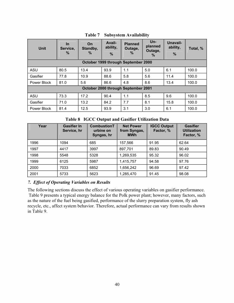
40
Table 7 Subsystem Availability
Unit In
Service, %
On Standby,
%
Avail-ability,
%
Planned Outage,
%
Un-planned Outage,
%
Unavail-ability,
% Total, %
October 1999 through September 2000
ASU 80.5 13.4 93.9 1.1 5.0 6.1 100.0 Gasifier 77.8 10.9 88.6 5.8 5.6 11.4 100.0 Power Block 81.0 5.6 86.6 4.8 8.6 13.4 100.0
October 2000 through September 2001
ASU 73.3 17.2 90.4 1.1 8.5 9.6 100.0 Gasifier 71.0 13.2 84.2 7.7 8.1 15.8 100.0 Power Block 81.4 12.5 93.9 3.1 3.0 6.1 100.0
Table 8 IGCC Output and Gasifier Utilization Data Year Gasifier In
Service, hr CombustionT
urbine on Syngas, hr
Net Power from Syngas,
MWh
IGCC Output Factor, %
Gasifier Utilization Factor, %
1996 1094 685 157,566 91.95 62.64 1997 4417 3997 897,701 89.83 90.49 1998 5548 5328 1,269,535 95.32 96.02 1999 6125 5987 1,415,757 94.58 97.76 2000 7033 6852 1,656,242 96.69 97.42 2001 5733 5623 1,285,470 91.45 98.08
7. Effect of Operating Variables on Results
The following sections discuss the effect of various operating variables on gasifier performance. Table 9 presents a typical energy balance for the Polk power plant; however, many factors, such as the nature of the fuel being gasified, performance of the slurry preparation system, fly ash recycle, etc., affect system behavior. Therefore, actual performance can vary from results shown in Table 9.

41
Table 9 Typical Energy Balance Item Energy Flow, million Btu/hr
In
Coal Higher Heating Value 2,430 Out
Slag and Fly ash 69 Cooling Water 248 Radiation and Unaccounted Losses 129 Steam Condenser 752 HRSG Stack 372 Net Power 860 Total Out 2,430 Efficiency, % 35.4
a. Slurry Preparation
Because every fuel performs differently in the slurry preparation system, full scale operation, together with experience, is needed to determine how to best prepare slurry from a particular fuel. Because Polk has a limited supply of oxygen, a high slurry concentration is essential to produce enough syngas for base load operation. Some fuels require an additive to lower viscosity so that high concentration slurries will flow through screens and pump suction piping. Other slurries require an additive to prevent fuel particles from settling in lines and agitated tanks. Slurries made from some fuels also require pH adjustment to minimize erosion/corrosion. Both a 50 percent caustic solution and anhydrous ammonia have been used to control pH (target value is about 8.0), but caustic is preferred.
b. Carbon Conversion and Gasifier Refractory Liner Life
High carbon conversion is important for efficiency and to minimize fly ash disposal costs. (Fly ash with high carbon content cannot be sold.) High conversion at high slurry concentration and low operating temperature would be ideal, since this would extend the gasifier refractory liner life and minimize the oxygen requirement. Minimizing oxygen consumption is particularly important at Polk, since the oxygen supply is limited. Fly ash containing unconverted carbon can be recycled to the gasifier to reduce its carbon content, but this increases the oxygen requirement, since it degrades the quality of the slurry fed to the gasifier. When the fresh feed is 100 percent coal, recycling fly ash appears to have only a slight positive impact on overall efficiency, since the energy recovered from the recycled fly ash is offset to a large extent by the incremental auxiliary power to produce the additional oxygen required. With petroleum coke in the fuel blend, the impact of recycle on overall efficiency is greater, since there is more recycled material and it has higher carbon content.
Although carbon conversion and refractory liner life for specific slurry can be estimated as a function of gasifier operating temperature, a full scale test is needed to determine these parameters at sufficient accuracy to develop the most cost-effective plant design. The Polk gasifier was the largest Texaco gasifier built as of the time it was constructed, so it was not
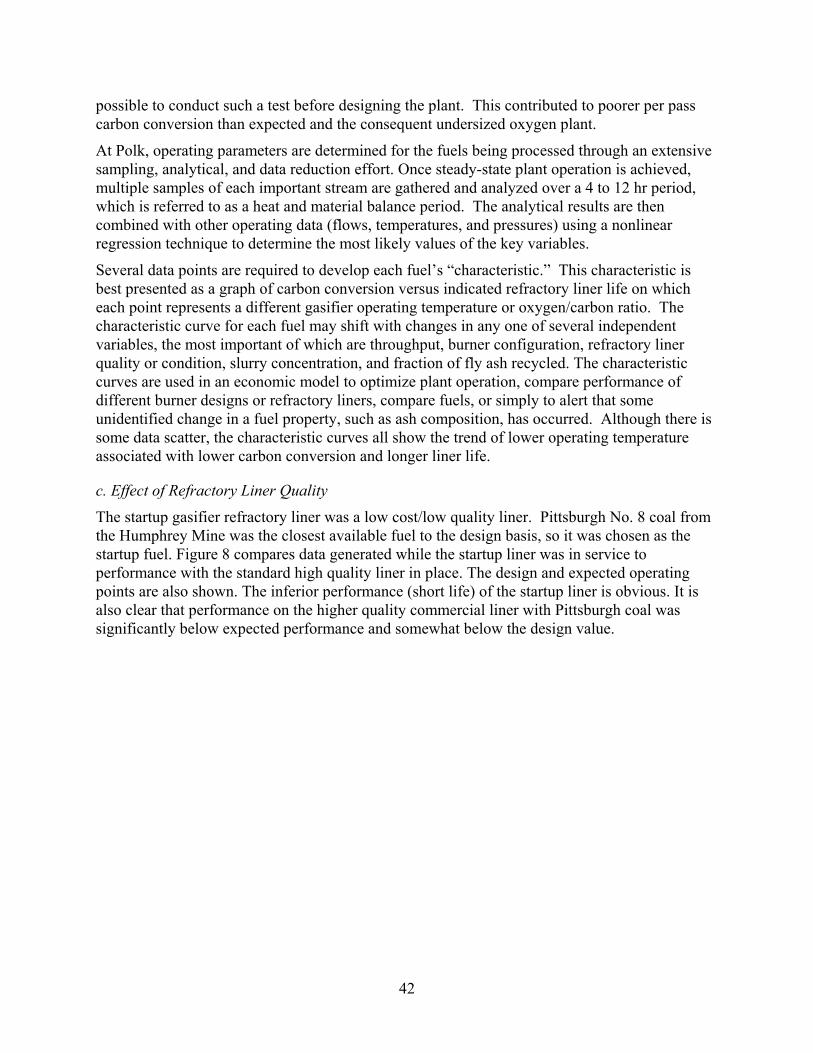
42
possible to conduct such a test before designing the plant. This contributed to poorer per pass carbon conversion than expected and the consequent undersized oxygen plant.
At Polk, operating parameters are determined for the fuels being processed through an extensive sampling, analytical, and data reduction effort. Once steady-state plant operation is achieved, multiple samples of each important stream are gathered and analyzed over a 4 to 12 hr period, which is referred to as a heat and material balance period. The analytical results are then combined with other operating data (flows, temperatures, and pressures) using a nonlinear regression technique to determine the most likely values of the key variables.
Several data points are required to develop each fuel’s “characteristic.” This characteristic is best presented as a graph of carbon conversion versus indicated refractory liner life on which each point represents a different gasifier operating temperature or oxygen/carbon ratio. The characteristic curve for each fuel may shift with changes in any one of several independent variables, the most important of which are throughput, burner configuration, refractory liner quality or condition, slurry concentration, and fraction of fly ash recycled. The characteristic curves are used in an economic model to optimize plant operation, compare performance of different burner designs or refractory liners, compare fuels, or simply to alert that some unidentified change in a fuel property, such as ash composition, has occurred. Although there is some data scatter, the characteristic curves all show the trend of lower operating temperature associated with lower carbon conversion and longer liner life.
c. Effect of Refractory Liner Quality
The startup gasifier refractory liner was a low cost/low quality liner. Pittsburgh No. 8 coal from the Humphrey Mine was the closest available fuel to the design basis, so it was chosen as the startup fuel. Figure 8 compares data generated while the startup liner was in service to performance with the standard high quality liner in place. The design and expected operating points are also shown. The inferior performance (short life) of the startup liner is obvious. It is also clear that performance on the higher quality commercial liner with Pittsburgh coal was significantly below expected performance and somewhat below the design value.
43
94
95
96
97
98
99
0 10 20 30 40 50
Liner Life, months
Car
bon
Con
vers
ion,
% p
er p
ass
Startup Liner
Commercial Liner
Design Point
Expected Operation
Figure 8 Gasifier Liner Life vs. Carbon Conversion
d. Effect of Burner Design
Because of the problem with low carbon conversion, Texaco cooperated in making several minor burner design modifications. However, these modifications did not have any statistically significant effect on gasifier performance. In early 1999, two radically different burner configurations were tested while processing a blend of West Kentucky No. 11 and Indonesian coals. However, neither design was better than the standard burner design. In mid-2001, a third test burner was installed during operation on a blend of 40 to 50 percent petroleum coke with Indiana No. 5 and 6 (Somerville Mine) and Guesare Basin (Mina Norte Mine) coals. Results with this burner were mixed, and a definitive conclusion concerning its benefit could not be reached.
e. Effect of Recycling Fly ash
Recycling fly ash increases overall carbon conversion and oxygen consumption. For West Kentucky No. 11 coal, recycle causes a significant drop in per-pass carbon conversion, which further increases the oxygen requirement. However, for a 40 to 55 percent petroleum coke blend with Indiana No. 5 and 6 (Somerville Mine) and Guesare Basin (Mina Norte Mine) coals, per-pass conversion improves with recycle, which partially mitigates the additional oxygen requirement. There seem to be several competing factors at work, such as changes in the oxygen/carbon ratio, slag volume, and reactivity of the recycled material. It is likely that the relative importance of these factors changes among fuels in a way that is not as yet fully understood. Thus, a test feeding the design coal is important in establishing a design basis for a new plant.

44
f. Results with Pittsburgh No. 8 Seam Coals
Five coals from the Pittsburgh No. 8 seam were processed (see Figure 9). Only the Humphrey Mine data were without recycle, with 30 to 75 percent of the settler bottoms fly ash being recycled to slurry preparation for the other coals. Humphrey Mine (the startup coal) and Loveridge Mine coals both performed reasonably well, within about 1 percent of design conversion at a two year liner life. For coals from the Bell, Blacksville, and Cumberland mines, carbon conversion was almost 4 percent lower than design when running at conditions that would produce a two year liner life. In general, results from Pittsburgh seam coal should fall somewhere in the area between the two trend lines shown on Figure 9.
g. Results with Illinois Basin Coal
Performance of Illinois Basin coal is shown in Figure 10. The data are all from operations with at least 30 percent fly ash recycle, but results without recycle were similar. All data points were with the standard burner, except for the Patriot Mine coal that used Test Burner No. 3, which may have contributed to its superior performance. Performance of the Old Ben No. 11 Mine coal was also excellent, but its high chloride content would require a larger brine concentration system. Coals from the Wildcat, Somerville, and Camp Mines all appear to be capable of a 95.5 to 96 percent per-pass carbon conversion with a two year liner life. West Kentucky No. 11 coal has a carbon conversion about 1 percent lower for the same liner life. Most coals from the Illinois Basin would be expected to fall somewhere in the area between the two trend lines on Figure 10.
91
92
93
94
95
96
97
98
0 10 20 30 40 50
Liner Life, months
Car
bon
Con
vers
ion,
% p
er p
ass
HumphreyBellLoveridgeBlacksvilleCumberland
Figure 9 Liner Performance with Pittsburgh Seam Coal from Various Mines
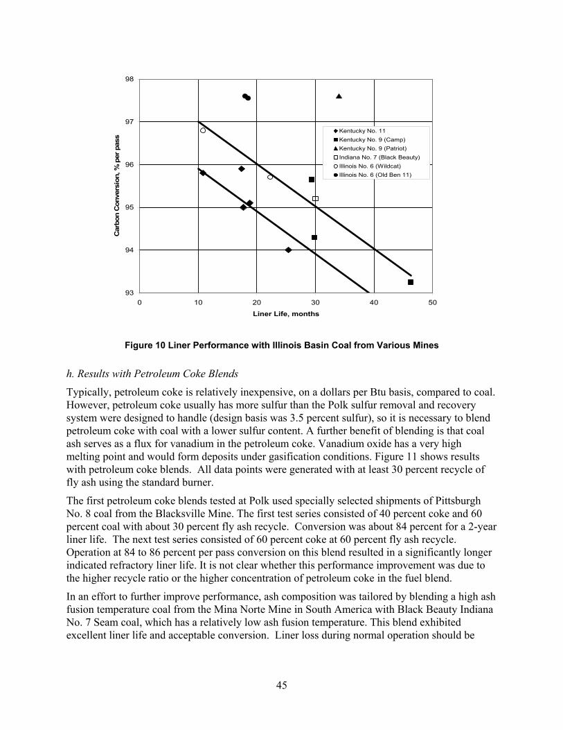
45
Figure 10 Liner Performance with Illinois Basin Coal from Various Mines
h. Results with Petroleum Coke Blends
Typically, petroleum coke is relatively inexpensive, on a dollars per Btu basis, compared to coal. However, petroleum coke usually has more sulfur than the Polk sulfur removal and recovery system were designed to handle (design basis was 3.5 percent sulfur), so it is necessary to blend petroleum coke with coal with a lower sulfur content. A further benefit of blending is that coal ash serves as a flux for vanadium in the petroleum coke. Vanadium oxide has a very high melting point and would form deposits under gasification conditions. Figure 11 shows results with petroleum coke blends. All data points were generated with at least 30 percent recycle of fly ash using the standard burner.
The first petroleum coke blends tested at Polk used specially selected shipments of Pittsburgh No. 8 coal from the Blacksville Mine. The first test series consisted of 40 percent coke and 60 percent coal with about 30 percent fly ash recycle. Conversion was about 84 percent for a 2-year liner life. The next test series consisted of 60 percent coke at 60 percent fly ash recycle. Operation at 84 to 86 percent per pass conversion on this blend resulted in a significantly longer indicated refractory liner life. It is not clear whether this performance improvement was due to the higher recycle ratio or the higher concentration of petroleum coke in the fuel blend.
In an effort to further improve performance, ash composition was tailored by blending a high ash fusion temperature coal from the Mina Norte Mine in South America with Black Beauty Indiana No. 7 Seam coal, which has a relatively low ash fusion temperature. This blend exhibited excellent liner life and acceptable conversion. Liner loss during normal operation should be
93
94
95
96
97
98
0 10 20 30 40 50
Liner Life, months
Car
bon
Con
vers
ion,
% p
er p
ass
Kentucky No. 11Kentucky No. 9 (Camp)Kentucky No. 9 (Patriot)Indiana No. 7 (Black Beauty)Illinois No. 6 (Wildcat)Illinois No. 6 (Old Ben 11)
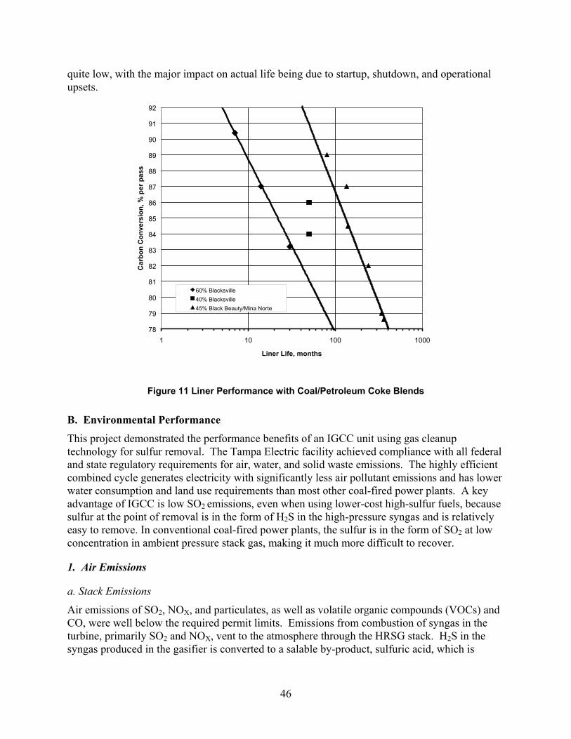
46
quite low, with the major impact on actual life being due to startup, shutdown, and operational upsets.
78
79
80
81
82
83
84
85
86
87
88
89
90
91
92
1 10 100 1000
Liner Life, months
Car
bon
Con
vers
ion,
% p
er p
ass
60% Blacksville40% Blacksville45% Black Beauty/Mina Norte
Figure 11 Liner Performance with Coal/Petroleum Coke Blends
B. Environmental Performance
This project demonstrated the performance benefits of an IGCC unit using gas cleanup technology for sulfur removal. The Tampa Electric facility achieved compliance with all federal and state regulatory requirements for air, water, and solid waste emissions. The highly efficient combined cycle generates electricity with significantly less air pollutant emissions and has lower water consumption and land use requirements than most other coal-fired power plants. A key advantage of IGCC is low SO2 emissions, even when using lower-cost high-sulfur fuels, because sulfur at the point of removal is in the form of H2S in the high-pressure syngas and is relatively easy to remove. In conventional coal-fired power plants, the sulfur is in the form of SO2 at low concentration in ambient pressure stack gas, making it much more difficult to recover.
1. Air Emissions
a. Stack Emissions
Air emissions of SO2, NOX, and particulates, as well as volatile organic compounds (VOCs) and CO, were well below the required permit limits. Emissions from combustion of syngas in the turbine, primarily SO2 and NOX, vent to the atmosphere through the HRSG stack. H2S in the syngas produced in the gasifier is converted to a salable by-product, sulfuric acid, which is
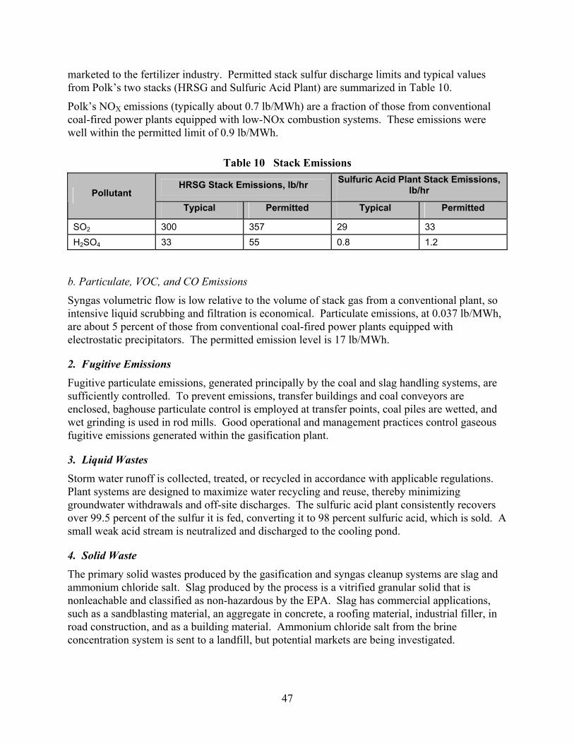
47
marketed to the fertilizer industry. Permitted stack sulfur discharge limits and typical values from Polk’s two stacks (HRSG and Sulfuric Acid Plant) are summarized in Table 10.
Polk’s NOX emissions (typically about 0.7 lb/MWh) are a fraction of those from conventional coal-fired power plants equipped with low-NOx combustion systems. These emissions were well within the permitted limit of 0.9 lb/MWh.
Table 10 Stack Emissions
HRSG Stack Emissions, lb/hr Sulfuric Acid Plant Stack Emissions, lb/hr Pollutant
Typical Permitted Typical Permitted
SO2 300 357 29 33 H2SO4 33 55 0.8 1.2
b. Particulate, VOC, and CO Emissions
Syngas volumetric flow is low relative to the volume of stack gas from a conventional plant, so intensive liquid scrubbing and filtration is economical. Particulate emissions, at 0.037 lb/MWh, are about 5 percent of those from conventional coal-fired power plants equipped with electrostatic precipitators. The permitted emission level is 17 lb/MWh.
2. Fugitive Emissions
Fugitive particulate emissions, generated principally by the coal and slag handling systems, are sufficiently controlled. To prevent emissions, transfer buildings and coal conveyors are enclosed, baghouse particulate control is employed at transfer points, coal piles are wetted, and wet grinding is used in rod mills. Good operational and management practices control gaseous fugitive emissions generated within the gasification plant.
3. Liquid Wastes
Storm water runoff is collected, treated, or recycled in accordance with applicable regulations. Plant systems are designed to maximize water recycling and reuse, thereby minimizing groundwater withdrawals and off-site discharges. The sulfuric acid plant consistently recovers over 99.5 percent of the sulfur it is fed, converting it to 98 percent sulfuric acid, which is sold. A small weak acid stream is neutralized and discharged to the cooling pond.
4. Solid Waste
The primary solid wastes produced by the gasification and syngas cleanup systems are slag and ammonium chloride salt. Slag produced by the process is a vitrified granular solid that is nonleachable and classified as non-hazardous by the EPA. Slag has commercial applications, such as a sandblasting material, an aggregate in concrete, a roofing material, industrial filler, in road construction, and as a building material. Ammonium chloride salt from the brine concentration system is sent to a landfill, but potential markets are being investigated.
48
IV. Market Review
A. Market Size/Commercialization
Figure 12 shows that the total worldwide syngas capacity in 2002 was about 43,000 megawatts (thermal) [Childress, 2002]. This includes gasification projects on all fuels (natural gas, coal, petroleum coke, and biomass) and producing all products (power, hydrogen, heat, and chemicals). Of the installed capacity, a little more than half is coal, or petroleum-coke-based. The figure shows that there has been a significant increase in gasification activity in the past decade with even more growth projected over the next few years. The majority of the recent increase in gasification capacity is fueled by coal or petroleum coke.
Figure 12 Cumulative World Synthesis Gas Capacity
The impetus for this growth is the increased costs for environmental compliance with conventional PC-fired units, the drive to improve efficiency, the availability of low-cost alternative feedstocks, and the need to utilize indigenous coal in areas without access to natural gas. The maturation of gasification technologies through completion of several large-scale demonstration projects has made this technology a popular and viable alternative to conventional combustion technology.
In addition to generating power, the IGCC concept can also be modified to produce value-added chemicals or transportation fuels from coal by chemical processing of the syngas produced, as opposed to using the gas to drive a combustion turbine. It’s possible that the near-term market niche for IGCC lies not just in the production of electricity, but in the generation of multiple products, where electricity, steam, and chemicals are economically bundled as products from a fully integrated complex.
49
General Electric (GE) [Todd, 1998] has reported that there are about 5,000 MW of gasification projects for power generation that have proceeded to the point of placing orders for combustion turbines. Many of these projects include co-production facilities for production of hydrogen and/or chemicals. GE also stated that it is in discussions with various refiners, developers, and others about projects totaling another 50,000 MW. This indicates a significant market for gasification technology in the near future, bolstered by trends of rising energy prices and tightening environmental controls.
Indications are that many new domestic gasification projects will be refinery-based, utilizing petroleum coke and other low-cost refinery by-products to produce power, steam, hydrogen, and chemicals for the refinery and additional power for internal use or export. The TECO CCT project has developed data to permit evaluation of these applications through a petroleum coke test program at the Polk facility. Because of excellent environmental performance, the demonstrated technology should be well suited to refinery-based applications utilizing petroleum coke in areas that have been declared as non-compliant for one or more air emissions. TECO Power Services is in the process of commercializing IGCC technology as part of the Cooperative Agreement with DOE.
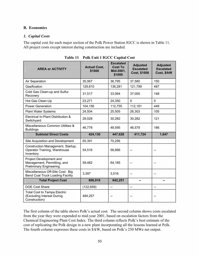
50
B. Economics
1. Capital Costs
The capital cost for each major section of the Polk Power Station IGCC is shown in Table 11. All project costs except interest during construction are included.
Table 11 Polk Unit 1 IGCC Capital Cost
AREA or ACTIVITY Actual Cost, $1000
Escalated Cost To
Mid-2001, $1000
Adjusted Escalated
Cost, $1000
Adjusted Escalated Cost, $/kW
Air Separation 35,067 36,795 37,580 150 Gasification 129,810 136,281 121,799 487 Cold Gas Clean-up and Sulfur Recovery 31,517 33,064 37,000 148
Hot Gas Clean-Up 23,271 24,350 0 0 Power Generation 104,156 112,755 112,181 449 Plant Water Systems 24,504 25,505 26,303 105 Electrical In-Plant Distribution & Switchyard 29,028 30,282 30,282 121
Miscellaneous Common Utilities & Buildings 46,778 48,595 46,579 186
Subtotal Direct Costs 424,130 447,628 411,724 1,647
Site Acquisition and Development 65,391 70,256 Construction Management, Startup, Operator Training, Warehouse Inventory
54,516 56,666 -- --
Project Development and Management, Permitting, and Preliminary Engineering
59,482 64,185 -- --
Miscellaneous Off-Site Cost: Big Bend Coal Truck Loading Facility 3,397 3,516 -- --
Total Project Cost 606,916 642,251 -- --
DOE Cost Share (122,659) -- -- -- Total Cost to Tampa Electric (Excluding Interest During Construction)
484,257 -- -- --
The first column of the table shows Polk’s actual cost. The second column shows costs escalated from the year they were expended to mid-year 2001, based on escalation factors from the Chemical Engineering Plant Cost Index. The third column reflects Polk’s best estimate of the cost of replicating the Polk design in a new plant incorporating all the lessons learned at Polk. The fourth column expresses these costs in $/kW, based on Polk’s 250 MWe net output.
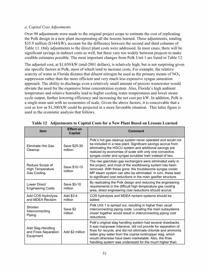
51
a. Capital Cost Adjustments
Over 90 adjustments were made to the original project scope to estimate the cost of replicating the Polk design in a new plant incorporating all the lessons learned. These adjustments, totaling $35.9 million ($144/kW), account for the difference between the second and third columns of Table 11. Only adjustments to the direct plant costs were addressed. In most cases, there will be significant savings in indirect costs as well, but these vary too widely between projects to make credible estimates possible. The most important changes from Polk Unit 1 are listed in Table 12.
The adjusted cost, at $1,650/kW (mid-2001 dollars), is relatively high, but is not surprising given site specific factors at Polk, most of which tend to increase costs. For example, the relative scarcity of water in Florida dictates that diluent nitrogen be used as the primary means of NOX suppression rather than the more efficient and very much less expensive syngas saturation approach. The ability to discharge even a relatively small amount of process wastewater would obviate the need for the expensive brine concentration system. Also, Florida’s high ambient temperature and relative humidity lead to higher cooling water temperatures and lower steam cycle output, further lowering efficiency and increasing the net cost per kW. In addition, Polk is a single-train unit with no economies of scale. Given the above factors, it is conceivable that a cost as low as $1,300/kW could be projected in a more favorable situation. This latter figure is used in the economic analysis that follows.
Table 12 Adjustments to Capital Costs for a New Plant Based on Lessons Learned
Item Effect on Capital Comment
Eliminate Hot Gas Cleanup
Save $25-30 million
Polk’s hot gas cleanup system never operated and would not be included in a new plant. Significant savings accrue from eliminating the HGCU system and additional savings are realized by economies of scale with only one convective syngas cooler and syngas scrubber train instead of two.
Reduce Scope of High Temperature Gas Cooling
Save $10-15 million
The raw gas/clean gas exchangers were eliminated early in the project, and most of the sootblowing system has been removed. With these gone, the troublesome syngas cooler MP steam system can also be eliminated. In turn, these lead to significant cost reductions in the main gasifier structure.
Lower Direct Engineering Costs
Save $5-10 million
By replicating the Polk design and reducing the engineering requirements in the difficult high temperature gas cooling area, direct engineering cost reductions should accrue.
Add COS Hydrolysis and MDEA Reclaim
Add $3-4 million
COS hydrolysis and MDEA reclaim systems should be added.
Shorten Interconnecting Piping
Save $2 million
Polk Unit 1 is spread out, resulting in higher than usual interconnecting piping costs. Locating the main subsystems closer together would result in interconnecting piping cost reductions.
Add Slag Handling and Fines Separation Equipment
Add $2 million
Polk’s original slag handling system had several drawbacks. It was manpower intensive, did not provide for separation of fines for recycle, and did not eliminate chloride and ammonia laden grey water from the coarse lockhopper slag, which would otherwise have been marketable. Also, the fines handling system was undersized for the much higher than

52
Item Effect on Capital Comment
design fines production.
Add Syngas Saturator
Add $1.5 million
More diluent is needed than is available at Polk to meet future NOX emission limits. A syngas saturator is a good way of providing this supplemental diluent while efficiently recovering the low level waste heat that became available when the raw gas/clean gas exchangers were removed.
Delete Water Wash Column
Save $1 million
Polk’s original design incorporated a water wash column to remove contaminates which would form heat stable salts with MDEA. Extensive testing has shown that the water wash column is ineffective at removing these contaminates and that an ion exchange system to regenerate the heat stable salts is less expensive.
Increase Main Air Compressor Capacity Add $500,000
A modest increase in the ASU’s main air compressor capacity would provide sufficient oxygen year round to fully load the combustion turbine, even while recycling sufficient fines so that the slag would be marketable.
Upgrade Materials in Slurry Service Add $500,000 Improved materials and coatings in the slurry preparation
system would significantly reduce equipment failures.
Delete Fines Filter Save $500,000
Off-site disposal of the fines produced by the Texaco gasifier is prohibitively expensive for Polk, and encumbering landfills with tons of material containing significant heating value is not appropriate. Recycling the fines as concentrated slurry from the settler bottoms to the slurry preparation system is Polk’s current practice. This is a better alternative than producing a filter cake for disposal using the fines filter.
Modify Syngas Scrubber Design Add $400,000
Polk’s syngas scrubbers have a persistent problem with water entrainment when operating at design conditions. This has created some safety issues and other problems downstream. Modifications to eliminate this problem could require substantially increasing the size of the vessel.
Separate MDEA Acid Gas From Ammonia Gas
Add $400,000 Line plugging occurs wherever ammonia gas combines with acid gas. In a new plant, these streams should be completely separated.
Rust-Resistant Coatings for Main Air Compressor Components
Add $300,000
Most ASUs operate continuously, but in an IGCC plant they are likely to start and stop more frequently. This promotes the formation and exfoliation of rust particles from the carbon steel piping and main air compressor components. The rust particles plug the fins of intercoolers and after-coolers, destroying their effectiveness and increasing pressure drop. Coatings can eliminate this problem.
Other Changes Add $4 million
Other changes individually cost relatively little. Some of these other adjustments are additions and some deletions, but their net effect is to add approximately $4 million to capital costs.
Total Save $30-45 million Total estimated reduction from the Polk Station facility costs.
53
2. Operating Costs
To take advantage of economies of scale, the following economic analysis is based on a plant size of 500 MWe (net). Also, to reduce coal price, the plant is assumed to be situated at a mine mouth. Operating costs are adjusted from values reported for Tampa’s Polk Power Station.
a. Fuel
The highest annual cost element is fuel, and the vast majority of this cost is for coal/petroleum coke for the gasifier. At an energy requirement of 4,417 million Btu/hr and an 80 percent on-stream factor, the energy required is 30.95 x 10¹² Btu/yr. At a cost of $1.00/106 Btu, annual coal cost is $30.95 million. The only other fuel consumed during normal operation is 40 gal/day of propane (91,000 Btu/gal) for the flare pilot light. Since the flare is almost always lit, this requires 14,600 gal/yr.
Propane and distillate fuel are consumed during gasifier startup and after gasifier shutdown. The combustion turbine’s startup and back-up fuel is low sulfur distillate. Minimum consumption would provide low load combustion turbine operation for one or two hours during gasifier light-off and line-out, and another one or two hours after gasifier shutdown. It would also typically be kept running during brief outages prior to gasifier hot restarts. The combustion turbines would consume about 100,000 lb of distillate per hour at low load operation or about 1,850 million Btu/hr. Assuming the combustion turbines operated on supplemental fuel 2 percent of the time, the cost of supplemental fuel for this purpose was estimated at $1,440,000/yr. (Although the combustion turbine may be operated on distillate fuel when the gasifier is unavailable, no allowance for long term operation of the combustion turbine on distillate is included in this analysis.)
The auxiliary boiler is also used to generate steam for regeneration of the ASU air dryers for extended operation, while it cools down before gasifier light-off and for operation to provide purge nitrogen for several hours following gasifier shutdown. An average of 87,500 lb (1,600 million Btu) is consumed during each gasifier cold startup and shutdown for an extended period.
Propane is used to heat the gasifier and sulfuric acid plant during cold startups, and a small amount is used to maintain sulfuric acid plant catalyst bed and decomposition furnace heat during brief outages prior to hot restarts. Normally, 2,000 gallons of propane (182 million Btu) is consumed during a hot restart and 16,000 gallons (1,450 million Btu) during a cold startup. The cost of all these uses is small compared to other costs and is estimated at $100,000/yr. Total fuel cost (coal plus supplemental fuel) is estimated to be $32.49 million/yr.
b. Labor
The Polk station is staffed by five operating and maintenance teams, each team consisting of ten multi-skilled process specialists who operate the unit and perform and supervise the maintenance work. Supporting the teams are a six-person engineering staff, nine specialists, a three person laboratory staff, and ten administrative and management personnel for a total of 78 people. It is estimated that a 500 MWe plant would require a team of 100 people. At an average rate of $40/hr for 2080 hr per person per year, labor costs are $8.32 million/yr.
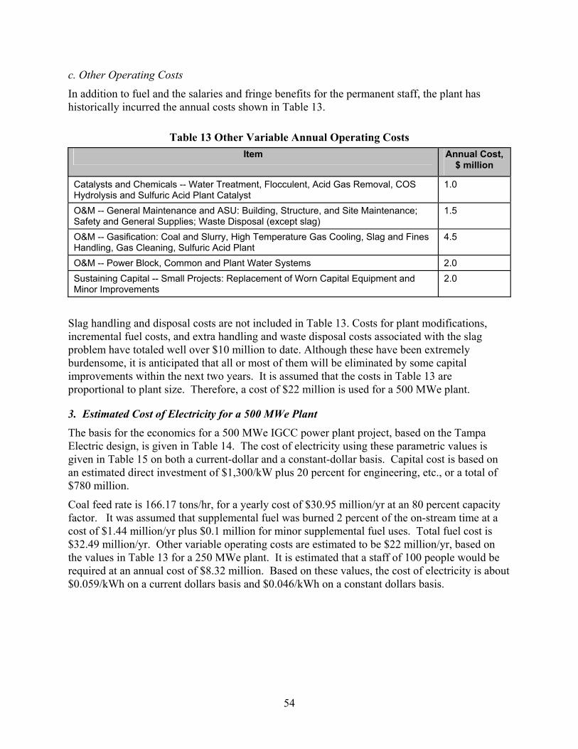
54
c. Other Operating Costs
In addition to fuel and the salaries and fringe benefits for the permanent staff, the plant has historically incurred the annual costs shown in Table 13.
Table 13 Other Variable Annual Operating Costs Item Annual Cost,
$ million
Catalysts and Chemicals -- Water Treatment, Flocculent, Acid Gas Removal, COS Hydrolysis and Sulfuric Acid Plant Catalyst
1.0
O&M -- General Maintenance and ASU: Building, Structure, and Site Maintenance; Safety and General Supplies; Waste Disposal (except slag)
1.5
O&M -- Gasification: Coal and Slurry, High Temperature Gas Cooling, Slag and Fines Handling, Gas Cleaning, Sulfuric Acid Plant
4.5
O&M -- Power Block, Common and Plant Water Systems 2.0 Sustaining Capital -- Small Projects: Replacement of Worn Capital Equipment and Minor Improvements
2.0
Slag handling and disposal costs are not included in Table 13. Costs for plant modifications, incremental fuel costs, and extra handling and waste disposal costs associated with the slag problem have totaled well over $10 million to date. Although these have been extremely burdensome, it is anticipated that all or most of them will be eliminated by some capital improvements within the next two years. It is assumed that the costs in Table 13 are proportional to plant size. Therefore, a cost of $22 million is used for a 500 MWe plant.
3. Estimated Cost of Electricity for a 500 MWe Plant
The basis for the economics for a 500 MWe IGCC power plant project, based on the Tampa Electric design, is given in Table 14. The cost of electricity using these parametric values is given in Table 15 on both a current-dollar and a constant-dollar basis. Capital cost is based on an estimated direct investment of $1,300/kW plus 20 percent for engineering, etc., or a total of $780 million.
Coal feed rate is 166.17 tons/hr, for a yearly cost of $30.95 million/yr at an 80 percent capacity factor. It was assumed that supplemental fuel was burned 2 percent of the on-stream time at a cost of $1.44 million/yr plus $0.1 million for minor supplemental fuel uses. Total fuel cost is $32.49 million/yr. Other variable operating costs are estimated to be $22 million/yr, based on the values in Table 13 for a 250 MWe plant. It is estimated that a staff of 100 people would be required at an annual cost of $8.32 million. Based on these values, the cost of electricity is about $0.059/kWh on a current dollars basis and $0.046/kWh on a constant dollars basis.
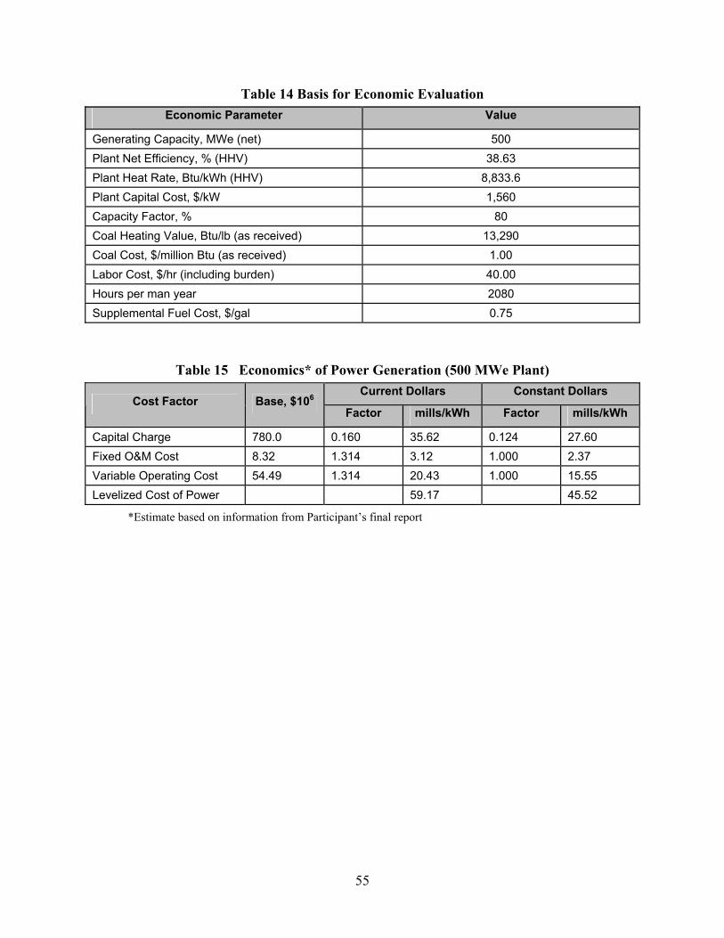
55
Table 14 Basis for Economic Evaluation Economic Parameter Value
Generating Capacity, MWe (net) 500 Plant Net Efficiency, % (HHV) 38.63 Plant Heat Rate, Btu/kWh (HHV) 8,833.6 Plant Capital Cost, $/kW 1,560 Capacity Factor, % 80 Coal Heating Value, Btu/lb (as received) 13,290 Coal Cost, $/million Btu (as received) 1.00 Labor Cost, $/hr (including burden) 40.00 Hours per man year 2080 Supplemental Fuel Cost, $/gal 0.75
Table 15 Economics* of Power Generation (500 MWe Plant) Current Dollars Constant Dollars
Cost Factor Base, $106 Factor mills/kWh Factor mills/kWh
Capital Charge 780.0 0.160 35.62 0.124 27.60 Fixed O&M Cost 8.32 1.314 3.12 1.000 2.37 Variable Operating Cost 54.49 1.314 20.43 1.000 15.55 Levelized Cost of Power 59.17 45.52
*Estimate based on information from Participant’s final report
56
V. Conclusions
This project achieved its main goal of successfully designing, constructing and operating a 250 MWe IGCC system that is potentially capable of providing high performance, cost competitive, environmentally compliant electric power from coal. Since startup in September 1996, the plant has met its objective of generating low-cost electricity in a safe, reliable, and environmentally acceptable manner. On September 30, 2001, Polk Power Station completed its fifth year of commercial operation. The plant continues to operate base loaded as a key part of Tampa Electric Company’s generation fleet.
The facility demonstrated its ability to operate on a wide variety of coals. However, coal properties, such as sulfur content, chlorine content, and ash level and composition, affect performance. Therefore, in designing a new plant, actual operating data on the design coal is crucial to avoiding problems, such as insufficient sulfur or chloride handling capacity.
The most significant problem encountered in this project was the lower than expected carbon conversion in the gasifier, which required recycling fly ash to the gasifier and increased oxygen requirements. Because of the effect of low carbon conversion on performance, the project did not quite meet its objective of demonstrating improved overall efficiency and cost effectiveness compared to conventional coal-fired power plants. Once the low carbon conversion problem is overcome, the improved efficiency will significantly advance this technology and demonstrate IGCC’s superiority to conventional technology.
A missed opportunity resulted from the inability to operate the hot gas cleanup system due to the fact that the design sorbent did not demonstrate sufficient attrition resistance. Hot gas cleanup offers significant potential for improving the efficiency of IGCC. SO2, NOX, particulates, VOCs, and CO were all well below required permit limits. Thus, the project met the goal of demonstrating that IGCC should be the choice for coal-fired power plants because of significant reductions in pollutant emissions.
Approximately fifty-fifty blends of petroleum coke and coal work well. The low chlorine content of the coke allows use of high chlorine content coal, while lower sulfur coals can compensate for the typically high sulfur in the petroleum coke. In addition, the ash in the coal acts as a fluxing agent for the vanadium in the coke.
Overall, this was a successful project that demonstrated that an IGCC power plant can be successfully built and operated. It also provided much valuable information that will permit the design and operation of more efficient IGCC systems in the future.

57
Acronyms and Abbreviations
Ar Argon
ASU Air Separation Unit
BFW boiler feedwater
Btu British thermal unit
Btu/hr British thermal unit per hour
Btu/kWh British thermal unit per kilowatt hour
Btu/lb British thermal unit per pound
Btu/scf British thermal unit per standard cubic feet
Btu/yr British thermal unit per year
CCT clean coal technology
CH4 methane
CO carbon monoxide
CO2 carbon dioxide
COS carbonyl sulfide
DOE U.S. Department of Energy
EPA Environmental Protection Agency
gal/day gallon per day
gal/yr gallon per year
GE General Electric
gpm gallon per minute
H2 hydrogen
H2O water
H2S hydrogen sulfide
H2SO4 sulfuric acid
HCl hydrochloric acid
HHV higher heating value
HP high pressure
HP horsepower
HRSG heat recovery steam generator
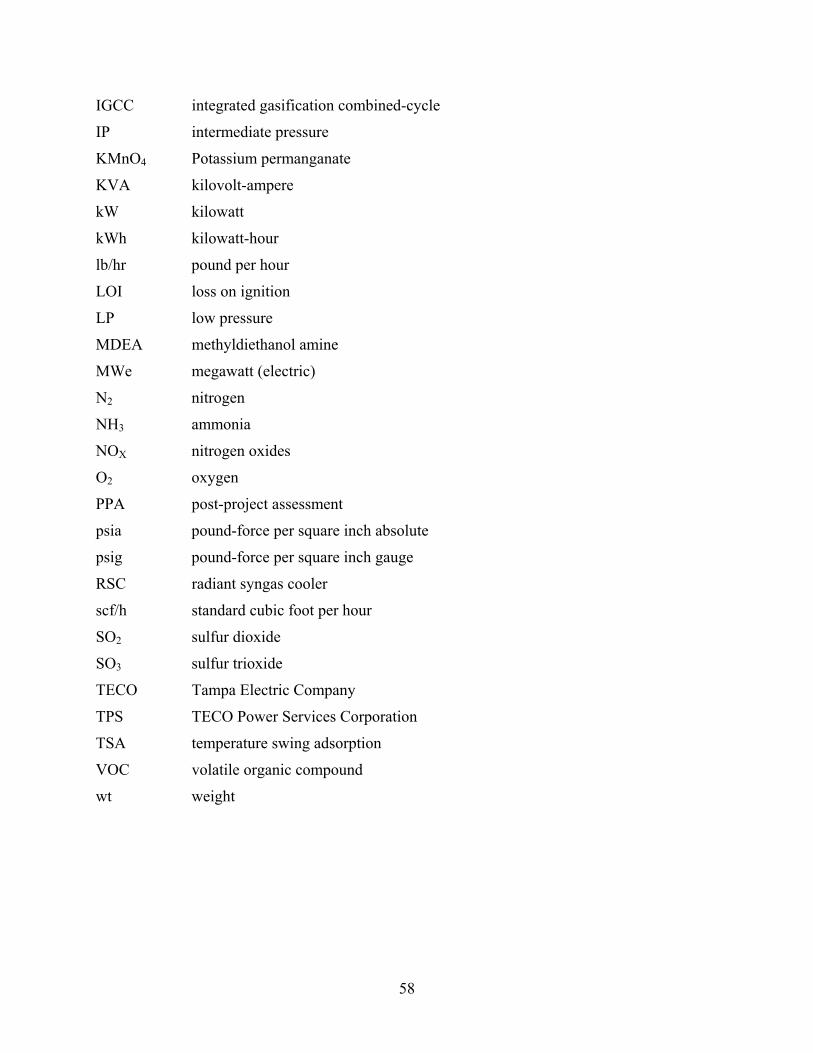
58
IGCC integrated gasification combined-cycle
IP intermediate pressure
KMnO4 Potassium permanganate
KVA kilovolt-ampere
kW kilowatt
kWh kilowatt-hour
lb/hr pound per hour
LOI loss on ignition
LP low pressure
MDEA methyldiethanol amine
MWe megawatt (electric)
N2 nitrogen
NH3 ammonia
NOX nitrogen oxides
O2 oxygen
PPA post-project assessment
psia pound-force per square inch absolute
psig pound-force per square inch gauge
RSC radiant syngas cooler
scf/h standard cubic foot per hour
SO2 sulfur dioxide
SO3 sulfur trioxide
TECO Tampa Electric Company
TPS TECO Power Services Corporation
TSA temperature swing adsorption
VOC volatile organic compound
wt weight
59
References
Childress, James. “World & U.S. Gasification Industry Trends.” Gasification Technologies Workshop. Washington, D.C. Oct 2002.
Tampa Electric Company. Jul 1996. Final Public Design Report. DE-FC21-91MC2736346 Tampa Electric Company, Tampa Electric Polk Power Station Integrated Gasification Combined
Cycle Project, Final Technical Report. Aug 2002. Todd, Doug. “New Markets for CCTs,” Sixth Clean Coal Technology Conference. Reno, NV.
Apr 1998. U.S. Department of Energy, Comprehensive Report to Congress--Clean Coal Technology
Program--Air-Blown Integrated Gasification Combined Cycle Demonstration Project, Jan 1991.
.
60
Bibliography
Jenkins, S.D., “Status of Tampa Electric Company IGCC Project.” First Annual Clean Coal Technology Conference. Cleveland, OH, Nov 1992.
McDaniel, J.E. and C.A. Shelnut. “Tampa Electric Company Polk Power Station IGCC Project:
Project Status.” Seventh Clean Coal Technology Conference. Knoxville, TN. Jun 1999. McDaniel, J.E. and C.A. Shelnut. “Tampa Electric Company Polk Power Station IGCC Project:
Project Status.” Sixth Annual Clean Coal Technology Conference. Reno, NV. May 1998. Pless, D.E. “Polk Station Update.” Third Annual Clean Coal Technology Conference. Chicago,
IL. Sep 1994. Pless, D.E. “Status Update, Polk Power Station.” Fourth Annual Clean Coal Technology
Conference. Denver, CO. Sep 1995. Pless, D.E. “Tampa Electric Company: Integrated Gasification Combined-Cycle System.”
Second Annual Clean Coal Technology Conference. Atlanta, GA., Sep 1993. Tampa Electric Company, Tampa Electric Company Polk Power Station Unit No. 1 Preliminary
Public Design Report, Jun 1994. U.S. Department of Energy, Tampa Electric Integrated Gasification Combined-Cycle Project,
Clean Coal Technology Topical Report Number 6, Oct 1996. U.S. Department of Energy, Tampa Electric Integrated Gasification Combined Cycle-Project:
An Update, Clean Coal Technology Topical Report Number 19, Jul 2000. U.S. Environmental Protection Agency. Jun 1994. Final Environmental Impact Statement,
Tampa Electric Company-Polk Power Station. EPA 904/9-94-002(b).