cld-ap15 rev 0 led luminaire design guide - cree.com · led luminaire design guide introduction...
TRANSCRIPT

11
ApplicAtion note
Copyright © 2007-2016 Cree, Inc. All rights reserved. The information in this document is subject to change without notice. Cree® and XLamp® are registered trademarks and the Cree logo is a trademark of Cree, Inc. Other trademarks, product and company names are the property of their respective owners and do not imply specific product and/or vendor endorsement, sponsorship or association. This document is provided for informational purposes only and is not a warranty or a specification. For product specifications, please see the data sheets available at www.cree.com. For warranty information, please contact Cree Sales at [email protected].
Cree, Inc.4600 Silicon Drive
Durham, NC 27703USA Tel: +1.919.313.5300
ww
w.c
ree.
co
m/X
lam
pC
LD-A
P15 r
ev 0e
LED Luminaire Design Guide
IntroDuctIon
This application note provides guidelines for the process of
designing high-power LeDs into luminaires. This document
uses an indoor luminaire design as an example, but the process
described can be applied to the design of any LeD luminaire.
Lighting-class LeDs are now available that deliver the
brightness, efficacy, lifetime, color temperatures, and white-
point stability required for general illumination. As a result, these
LeDs are being designed into most general lighting applications,
including roadway, parking area, and indoor directional lighting.
LeD-based luminaires reduce total-cost-of-ownership (TCO) in
these applications through maintenance avoidance (since LeDs
last much longer than traditional lamps) and reduced energy
costs.
There are over 20 billion light fixtures using incandescent,
halogen, or fluorescent lamps worldwide. Many of these fixtures
are being used for directional light applications but are based
on lamps that put out light in all directions. The United States
Department of energy (DOe) states that recessed downlights
are the most common installed luminaire type in new residential
tabLE of contEnts
Introduction .................................................................................... 1
Design Approach ............................................................................ 2
Design Process .............................................................................. 3
1. Define Lighting Requirements ............................................. 4
2. Define Design Goals ............................................................. 5
3. Estimate Efficiencies of the Optical, Thermal & Electrical
Systems ................................................................................ 6
4. Calculate Number of LeDs Needed ..................................... 9
5. Consider All Design Possibilities & Choose the Best .......10
6. Final Steps ..........................................................................14
Where to Get Help ........................................................................15
22
Copyright © 2007-2016 Cree, Inc. All rights reserved. The information in this document is subject to change without notice. Cree® and XLamp® are registered trademarks and the Cree logo is a trademark of Cree, Inc. Other trademarks, product and company names are the property of their respective owners and do not imply specific product and/or vendor endorsement, sponsorship or association. This document is provided for informational purposes only and is not a warranty or a specification. For product specifications, please see the data sheets available at www.cree.com. For warranty information, please contact Cree Sales at [email protected]. 2
LED LuminairE DEsign guiDE
construction.1 In addition, the DOE reports that downlights using non-reflector lamps are typically only 50% efficient, meaning half the light
produced by the lamp is wasted inside the fixture.
In contrast, lighting-class LEDs offer efficient, directional light that lasts at least 50,000 hours. Indoor luminaires designed to take
advantage of all the benefits of lighting-class LEDs can:
• Exceed the efficacy of any incandescent and halogen luminaire.
• Match the performance of even the best CFL (compact fluorescent) recessed downlights.
• Provide a lifetime five to fifty times longer than these lamps before requiring maintenance.
• Reduce the environmental impact of light: no mercury, less power-plant pollution, and less landfill waste.
DEsIGn approach
Luminaires or Lamps?
Designing LeDs into general illumination requires a choice between designing either a complete luminaire based on LeDs or an LeD-based
lamp meant to install into an existing fixture. Generally, a complete luminaire design will have better optical, thermal and electrical
performance than the retrofit lamp, since the existing fixture does not constrain the design. It is up to the designer to decide whether the
total system performance of a new luminaire or the convenience of a retrofit lamp is more important in the target application.
target Existing Luminaires
If the target application is better served by creating a new LeD luminaire, then designing the luminaire’s light output to match or exceed
an existing luminaire has several advantages. First, an existing design is already optimized to target a known application, and can provide
guidance for setting the design goals around light output, cost, and operating environment. Second, an existing design is already in an
accepted form factor. Switching to the LeD luminaire is easier for the end user if the form factors are the same.
Unfortunately, some LED luminaire manufacturers are misreporting or inflating claims of LED luminaire efficacy and lifetime characteristics.
The lighting industry saw similar problems during the early years of CFL replacement bulbs. The lack of industry standards and wide
variations in early product quality delayed the adoption of CFL technology for many years. The United States Department of energy is
aware that the same standards and quality problems may exist with early LeD luminaires and that these problems may delay the adoption
of LeD light in a similar fashion. In response, it launched the DOe SSL Commercial Product Testing Program (CPTP) to test the claims of
LED-luminaire makers. This program anonymously tests LED-based luminaires for the following four characteristics:
• Luminaire light output (lumens)
• Luminaire efficacy (lumens per watt)
• Correlated color temperaure (degrees Kelvin)
• Color-rendering index
DOe’s CPTP sets a good precedent for LeD luminaire design by focusing on the usable light output of a luminaire — not just the light
output of the light source.
1 U.S. Department of Energy, Energy Efficiency and Renewable Energy. LED Application Series: Recessed Downlights.

33
Copyright © 2007-2016 Cree, Inc. All rights reserved. The information in this document is subject to change without notice. Cree® and XLamp® are registered trademarks and the Cree logo is a trademark of Cree, Inc. Other trademarks, product and company names are the property of their respective owners and do not imply specific product and/or vendor endorsement, sponsorship or association. This document is provided for informational purposes only and is not a warranty or a specification. For product specifications, please see the data sheets available at www.cree.com. For warranty information, please contact Cree Sales at [email protected]. 3
LED LuminairE DEsign guiDE
the Idea of a Lamp May be outdated
The long lifetime of LeD light may make the idea of a lamp
outdated. Lighting-class LeDs do not fail catastrophically like
light bulbs. Instead, they can provide at least 50,000 hours
of useful lifetime before they gracefully degrade below 70%
of their initial light output (also called lumen maintenance).
That’s equal to 5.7 years if left on continuously!
However, in most lighting situations, the lights are switched
off regularly. This off period can extend the lifetime of the
LeD well past three decades, as shown in Chart 1 (at right).
After the years it will take for an LeD luminaire to “burn out,”
LED lighting technology will be brighter, more efficient, and
probably offer TCO savings over the older LeD luminaire.
chart 1: What 50,000 hours means in practical terms
Keep in mind how much environmental impact was avoided over that 50,000 hours of LED luminaire lifetime:
• At least 25 fewer incandescent bulbs were sent to landfills AND five times less energy used. (About 50% of power in the United
States comes from burning coal, which releases mercury into the air.)
• Or, at least 5 fewer CFL bulbs containing mercury sent for disposal.
As mentioned previously, maintenance avoidance is an important benefit for LED luminaires. Therefore, designing the LED luminaire to
deliver maximum lifetime and provide TCO savings is an excellent strategy to overcome the hurdle of the higher initial cost of LeD-based
luminaires.
DEsIGn procEss
Table 1 lists a general process for designing high-power LeDs into a luminaire. The rest of the document walks through these design steps
in order. To better illustrate these design concepts, this document includes example calculations for an LeD luminaire meant to replace a
23-W CFL downlight. This design process is repeatable for all kinds of luminaires and not just the example included.

44
Copyright © 2007-2016 Cree, Inc. All rights reserved. The information in this document is subject to change without notice. Cree® and XLamp® are registered trademarks and the Cree logo is a trademark of Cree, Inc. Other trademarks, product and company names are the property of their respective owners and do not imply specific product and/or vendor endorsement, sponsorship or association. This document is provided for informational purposes only and is not a warranty or a specification. For product specifications, please see the data sheets available at www.cree.com. For warranty information, please contact Cree Sales at [email protected]. 4
LED LuminairE DEsign guiDE
table 1: process for designing high-power LEDs into luminaires
step Explanation
1. Define lighting requirements • The design goals should be based either on an existing fixture’s performance or on the application’s lighting requirements.
2. Define design goals• Specify design goals, which will be based on the application’s lighting requirements.• The designer should specify any other goals that will influence the design, such as special optical
requirements or being able to withstand high temperatures.
3. Estimate efficiencies of the optical, thermal & electrical systems
• Design goals will place constraints on the optical, thermal and electrical systems.• Good estimations of efficiencies of each system can be made based on these constraints.• The combination of lighting goals and system effiiciencies will drive the number of LEDs needed in
the luminaire.
4. Calculate the number of LeDs needed • Based on the design goals and estimated losses, the designer can calculate the number of LEDs needed to meet the design goals.
5. Consider all design possibilities and choose the best• As with any design, there are many different ways to best achieve the design goals.• LED lighting is still a new field, so assumptions that work for conventional lighting sources may not
apply to LeD lighting design.
6. Complete final steps
• Complete circuit board layout.• Test design choices by building a prototype luminaire.• Make sure the design achieves all the design goals.• Use the prototype design to further refine the luminaire design.• record observations and ideas for improvement.
1. DEfInE LIGhtInG rEquIrEMEnts
The LeD luminaire must meet or exceed the lighting requirements for the target application. Therefore, the lighting requirements must be
defined before establishing the design goals. For some applications, there are existing lighting standards that will define the requirements
directly. For other applications, a good approach is to characterize an existing luminaire.
Table 2 (right) lists important characteristics to
consider when characterizing an existing luminaire.
The light output and power characteristics are always
critical, while other characteristics may or may not be
important, depending on the application.
All lighting companies can provide data files or
documentation that detail the “critical” characteristics
for each of their fixtures. The “potentially important”
characteristics are more subjective or may not be
listed in the manufacturer’s documentation. In this
case, it is up to the designer to characterize the existing
luminaire.
Figure 1 illustrates the critical characteristics for
the example CFL downlight. Table 3 shows the full
characterization of the existing luminaire.
table 2: Important characteristics of target luminaire
Importance characteristic units
Critical
Luminous flux lumens (lm)
Illuminance distribution footcandles (fc)
electrical power consumption watts (W)
Potentially Important
Luminaire aesthetics
Price
Lifetime hours
Operating temperatures °C
Operating humidity % RH
Color temperaure K
CrI
Manufacturability
ease of installation
Form factor

55
Copyright © 2007-2016 Cree, Inc. All rights reserved. The information in this document is subject to change without notice. Cree® and XLamp® are registered trademarks and the Cree logo is a trademark of Cree, Inc. Other trademarks, product and company names are the property of their respective owners and do not imply specific product and/or vendor endorsement, sponsorship or association. This document is provided for informational purposes only and is not a warranty or a specification. For product specifications, please see the data sheets available at www.cree.com. For warranty information, please contact Cree Sales at [email protected]. 5
LED LuminairE DEsign guiDE
figure 1: critical characteristics for example cfL downlight
table 3: Example cfL downlight characterization
part characteristic unit Value
Lamp
Technology CFL
Light output lm 1,500
Power W 23
Efficacy lm/W 65
Lifetime hrs 10,000
Average selling price US $6
Fixture
Coefficient of utilization (CU) % 54
Light output lm 810
Power (excluding ballast) W 23
Efficacy lm/W 35
ASP US $20
2. DEfInE DEsIGn GoaLs
With the lighting requirements defined, the design goals for the LED luminaire can be set. Just as when defining the lighting requirements,
the critical design goals will be related to light output and power consumption. Make sure to include other design goals that may also be
important for the target application, including operating environment, bill-of-materials (BOM) cost, and lifetime.
Table 4 lists the design goals for the example LeD luminaire.

66
Copyright © 2007-2016 Cree, Inc. All rights reserved. The information in this document is subject to change without notice. Cree® and XLamp® are registered trademarks and the Cree logo is a trademark of Cree, Inc. Other trademarks, product and company names are the property of their respective owners and do not imply specific product and/or vendor endorsement, sponsorship or association. This document is provided for informational purposes only and is not a warranty or a specification. For product specifications, please see the data sheets available at www.cree.com. For warranty information, please contact Cree Sales at [email protected]. 6
LED LuminairE DEsign guiDE
table 4: Design goals for cfL downlight-replacement luminaire
characteristic unit Goal notes
Light output lm 810
Illuminance distribution fc Same shape as target; matching or better illuminance
Power (excluding driver) W 23
Efficacy lm/W 35
Lifetime hours 50,000
CCT K 4,000
CrI 75
Circular opening in 6
Maximum ambient temp. °C 55 Commercial building with vented ceilings
High volume BOM cost US $50
3. EstIMatE EffIcIEncIEs of thE optIcaL, thErMaL & ELEctrIcaL systEMs
One of the most important parameters in the design process is how many LeDs are required to meet the design goals. The rest of the
design decisions revolve around the number of LeDs, since it directly impacts the light output, power consumption, and cost of the
luminaire.
It is tempting to calculate the number of LEDs by looking at the typical luminous flux listed on an LED’s data sheet and divide the target
lumens from the design goals by that number. However, this approach is too simplified and will lead to a design that will not meet the
application’s lighting requirements.
An LED’s luminous flux depends on a variety of factors, including drive current and junction temperature. To accurately calculate the
necessary number of LEDs, the inefficiencies of the optical, thermal and electrical systems must be estimated first. Personal experience
with previous prototypes, or the example numbers provided in this document, can serve as a guide to estimate these losses. This section
walks through the process of estimating these system losses.
Optical System Efficiency
Optical system efficacy is estimated by examining light loss. There are two main sources of light loss to estimate:
1. secondary optics
Secondary optics are any optical system that is not part of the LeD itself, such as a lens or diffuser placed over the LeD. The losses
associated with secondary optics vary depending on the particular element used. Typical optical efficiency through each secondary
optical element is between 85% and 90%.
2. Light Loss Within the fixture
Fixture light loss occurs when light rays from the light source strike the fixture housing before hitting the target. Some light is
absorbed by the fixture housing, while some is reflected back into the fixture. The efficiency of the fixture is dictated by placement of
the light source, the shape of the fixture housing, and materials used in the fixture housing. As Figure 2 shows, the directional nature
of LED light enables much higher fixture efficiencies than is possible with omni-directional light sources.

77
Copyright © 2007-2016 Cree, Inc. All rights reserved. The information in this document is subject to change without notice. Cree® and XLamp® are registered trademarks and the Cree logo is a trademark of Cree, Inc. Other trademarks, product and company names are the property of their respective owners and do not imply specific product and/or vendor endorsement, sponsorship or association. This document is provided for informational purposes only and is not a warranty or a specification. For product specifications, please see the data sheets available at www.cree.com. For warranty information, please contact Cree Sales at [email protected]. 7
LED LuminairE DEsign guiDE
Light source Light-Source Efficacy Coefficient of Utilization Fixture Efficacy
CFL
65 lm/W 54% 35 lm/W
XLamp® Xr-eNeutral White LeD
58 lm/W 77% 44 lm/W
figure 2: Comparison of CFL & LED coefficient of utilization
For the example luminaire, there will only be secondary optics loss if the luminaire requires secondary optics. The main purpose of
secondary optics is to change the light output pattern of the LeD. Chart 2 compares the beam angle of the Cree XLamp Xr-e LeD to the
light output pattern of the target fixture. The beam angle of the bare LED is similar enough to the target fixture that no secondary optic is
required. Therefore, there is no optical loss due to secondary optics for the example luminaire.
chart 2: Light ouput vs. angle for CFL fixture & XLamp XR-E LED
Angle XR-E Angle CFL-90 8.56 -90 0 0-89 8.76 -87.5 0 0-88 9.11 -85 0 0-87 10.04 -82.5 0 0-86 9.86 -80 0 0-85 9.00 -77.5 0 0-84 7.68 -75 0 0-83 6.15 -72.5 0 0-82 5.29 -70 0.001353 0.135318-81 5.10 -67.5 0.001353 0.135318-80 5.20 -65 0.001353 0.135318-79 5.39 -62.5 0.002706 0.270636-78 5.61 -60 0.014885 1.488498-77 5.78 -57.5 0.071719 7.171854-76 5.93 -55 0.171854 17.18539-75 6.06 -52.5 0.243572 24.35724-74 6.24 -50 0.285521 28.5521-73 6.45 -47.5 0.326116 32.61164-72 6.58 -45 0.372124 37.21245-71 6.67 -42.5 0.423545 42.35453-70 6.80 -40 0.477673 47.76725-69 6.92 -37.5 0.530447 53.04465-68 6.92 -35 0.579161 57.9161-67 6.93 -32.5 0.62111 62.11096-66 7.00 -30 0.661705 66.1705-65 7.05 -27.5 0.703654 70.36536-64 7.11 -25 0.746955 74.69553-63 7.24 -22.5 0.784844 78.48444-62 7.47 -20 0.82544 82.54398-61 8.02 -17.5 0.875507 87.55074-60 9.09 -15 0.926928 92.69283-59 10.51 -12.5 0.972936 97.29364-58 12.40 -10 1 100-57 14.64 -7.5 0.993234 99.32341-56 17.23 -5 0.971583 97.15832-55 19.95 -2.5 0.948579 94.85792
0
50
100
-100 -50 0 50 100
Rela
tive
Inte
nsity
(%)
Angle (º)
XLamp XR-E LED CFL Fixture

88
Copyright © 2007-2016 Cree, Inc. All rights reserved. The information in this document is subject to change without notice. Cree® and XLamp® are registered trademarks and the Cree logo is a trademark of Cree, Inc. Other trademarks, product and company names are the property of their respective owners and do not imply specific product and/or vendor endorsement, sponsorship or association. This document is provided for informational purposes only and is not a warranty or a specification. For product specifications, please see the data sheets available at www.cree.com. For warranty information, please contact Cree Sales at [email protected]. 8
LED LuminairE DEsign guiDE
To calculate fixture loss for the CFL example, we assumed 85% reflectivity for the fixture reflector cup and that 60% of the light will hit the
reflector cup. Therefore, the optical efficiency will be:
thermal Loss
LEDs will decrease in relative flux output as junction temperature (Tj) rises. Most LED data sheets list typical luminous flux at Tj = 25 °C,
while most LED applications use higher junction temperatures. When using Tj > 25 °C, the luminous flux must be derated from the value
listed on the LeD’s data sheet.
LeD data sheets include a chart showing the relative light output versus junction temperature, such as the one shown in Chart 3 (right) for
XLamp XR-E white LEDs. By choosing either a specific relative light output or a specific junction temperature, this graph shows the value
for the other characteristic.
For the CFL example, this luminaire is only designed for
commercial buildings with vented ceilings. Based on
the listed design goals, this design will prioritize light
output, efficacy and lifetime.
XLamp XR-E LEDs are rated to provide an average of 70%
lumen maintenance after 50,000 hours, provided the
junction temperature is kept at 80 °C or lower. Therefore,
the appropriate maximum junction temperature for the
CFL example is 80 °C. This corresponds to a minimum
relative luminous flux of 85%, as shown in Chart 3.
This 85% relative luminous flux is the thermal efficacy
estimate for the example luminaire.
Optical Efficiency = (100% x 40%) + (85% x 60%)
Optical Efficiency = 91%
chart 3: Example relative intensity vs junction temperature graph for XLamp XR-E white LED
0%
10%
20%
30%
40%
50%
60%
70%
80%
90%
100%
25 50 75 100 125 150Junction Temperature (°C)
Re
lati
ve P
ho
tme
tric
Ou
tpu
t
(80ºC, 85%)
99
Copyright © 2007-2016 Cree, Inc. All rights reserved. The information in this document is subject to change without notice. Cree® and XLamp® are registered trademarks and the Cree logo is a trademark of Cree, Inc. Other trademarks, product and company names are the property of their respective owners and do not imply specific product and/or vendor endorsement, sponsorship or association. This document is provided for informational purposes only and is not a warranty or a specification. For product specifications, please see the data sheets available at www.cree.com. For warranty information, please contact Cree Sales at [email protected]. 9
LED LuminairE DEsign guiDE
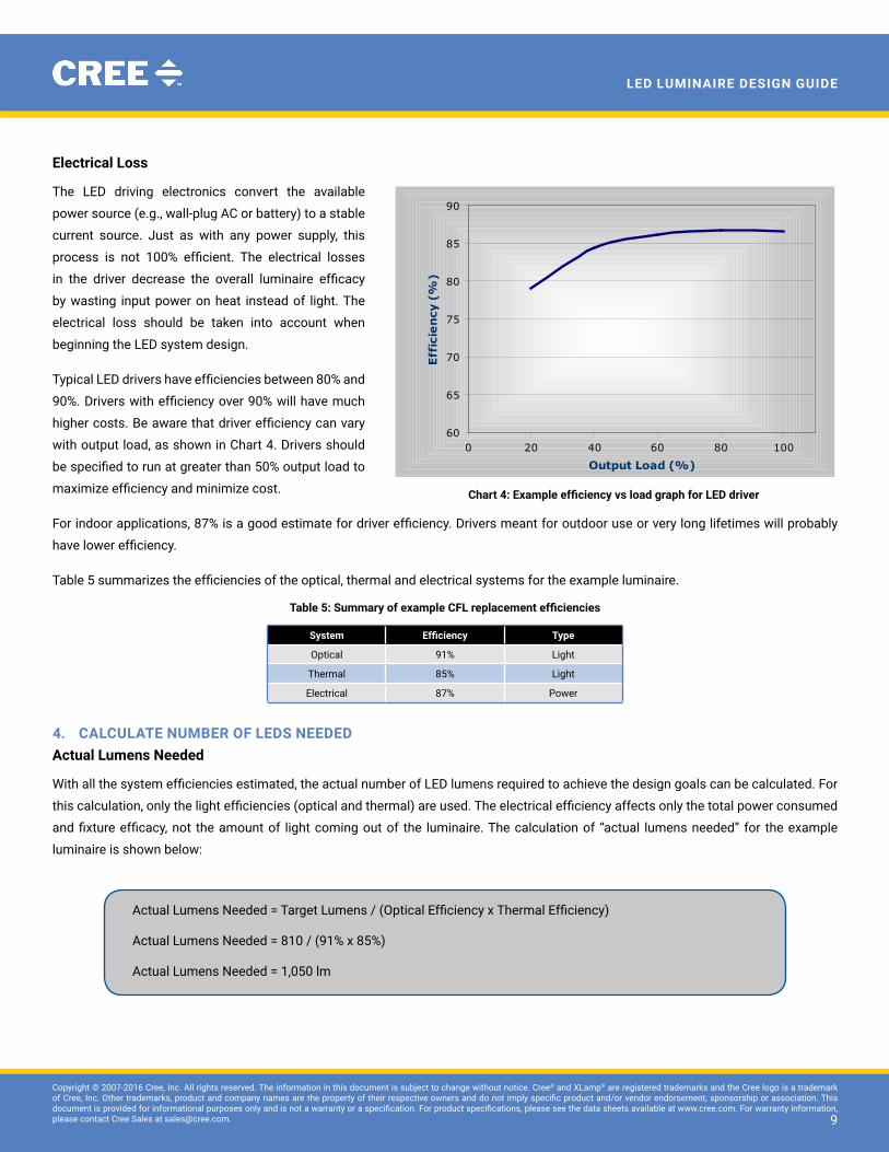
Electrical Loss
The LeD driving electronics convert the available
power source (e.g., wall-plug AC or battery) to a stable
current source. Just as with any power supply, this
process is not 100% efficient. The electrical losses
in the driver decrease the overall luminaire efficacy
by wasting input power on heat instead of light. The
electrical loss should be taken into account when
beginning the LeD system design.
Typical LED drivers have efficiencies between 80% and
90%. Drivers with efficiency over 90% will have much
higher costs. Be aware that driver efficiency can vary
with output load, as shown in Chart 4. Drivers should
be specified to run at greater than 50% output load to
maximize efficiency and minimize cost.
For indoor applications, 87% is a good estimate for driver efficiency. Drivers meant for outdoor use or very long lifetimes will probably
have lower efficiency.
Table 5 summarizes the efficiencies of the optical, thermal and electrical systems for the example luminaire.
table 5: Summary of example CFL replacement efficiencies
system Efficiency type
Optical 91% Light
Thermal 85% Light
electrical 87% Power
4. caLcuLatE nuMbEr of LEDs nEEDEDactual Lumens needed
With all the system efficiencies estimated, the actual number of LED lumens required to achieve the design goals can be calculated. For
this calculation, only the light efficiencies (optical and thermal) are used. The electrical efficiency affects only the total power consumed
and fixture efficacy, not the amount of light coming out of the luminaire. The calculation of “actual lumens needed” for the example
luminaire is shown below:
60
65
70
75
80
85
90
0 20 40 60 80 100
Output Load (%)
Eff
icie
ncy
(%
)
chart 4: Example efficiency vs load graph for LED driver
Actual Lumens Needed = Target Lumens / (Optical Efficiency x Thermal Efficiency)
Actual Lumens Needed = 810 / (91% x 85%)
Actual Lumens Needed = 1,050 lm

1010
Copyright © 2007-2016 Cree, Inc. All rights reserved. The information in this document is subject to change without notice. Cree® and XLamp® are registered trademarks and the Cree logo is a trademark of Cree, Inc. Other trademarks, product and company names are the property of their respective owners and do not imply specific product and/or vendor endorsement, sponsorship or association. This document is provided for informational purposes only and is not a warranty or a specification. For product specifications, please see the data sheets available at www.cree.com. For warranty information, please contact Cree Sales at [email protected]. 10
LED LuminairE DEsign guiDE
operating current
Another decision to be made is what operating current to use for the LeDs. Operating current plays an important role in determining the
efficacy and lifetime of the LED luminaire. Increasing the operating current will result in more light output from each LED, thus reducing
the number of LEDs needed. However, increasing operating current also has several drawbacks, shown in Table 6. Depending on the
application, these drawbacks may be acceptable trade-offs for the higher per-LeD lumen output.
For the example luminaire, lifetime and efficacy are top priority design goals. The luminaire will run at the minimum operating current
listed on the XLamp XR-E LED data sheet (350 mA) to maximize LED efficacy and lifetime.
table 6: Drawbacks of high operating current in LED luminaires
Drawback Explanation
Reduced efficacy Higher operating current reduces the efficacy of current generation power LEDs. In general, the size of the power supply will increase as operating current increases, since it takes more power to generate the same number of lumens.
reduced maximum ambient temperature or Decreased lifetime
Higher current will increase the temperature difference between the LED junction and the LED’s thermal path. In practical terms, since the maximum junction temperature is already decided, this reduces the maximum ambient temperature for the luminaire.
If instead of lowered maximum ambient temperature, the maximum junction temperature is raised, the LeD will degrade in light output faster over its operational life.
number of LEDs
After deciding on operating current, the lumen output of each LeD can be calculated. Since the thermal loss of the LeD has already been
taken into account through the actual-lumens-needed calculation, the numbers specified in LED-supplier documentation can be used
directly without further interpretation.
For this calculation, it is important to use the minimum flux listed for your LED order code and not the typical number on the data sheet.
Most LED companies sell to minimum flux ranges. By designing against this minimum number, you are ensuring that all luminaires made
with that LeD order code meet the target requirements.
The example luminaire will use XLamp XR-E LEDs at 4000 K CCT with minimum luminous flux of 67.2 (P2 flux bin) @ 350 mA. The number
of LeDs is calculated below.
5. consIDEr aLL DEsIGn possIbILItIEs & choosE thE bEst
With the number of LeDs calculated, consider all the possibilities to accomplish the design goals. Since each LeD is a small light source
and has a much longer lifetime than traditional light sources, LeDs can be integrated into luminaires with new and unusual design
elements. Designers can take full advantage of LeD light’s directionality and wide variety of available secondary optics to create original
designs.
Number of LEDs = Actual Lumens Needed / Lumens per LED
Number of LEDs = 1,050 lm / 67.2 lm
Number of LEDs = 16 LEDs

1111
Copyright © 2007-2016 Cree, Inc. All rights reserved. The information in this document is subject to change without notice. Cree® and XLamp® are registered trademarks and the Cree logo is a trademark of Cree, Inc. Other trademarks, product and company names are the property of their respective owners and do not imply specific product and/or vendor endorsement, sponsorship or association. This document is provided for informational purposes only and is not a warranty or a specification. For product specifications, please see the data sheets available at www.cree.com. For warranty information, please contact Cree Sales at [email protected]. 11
LED LuminairE DEsign guiDE
At the same time, keep in mind that there are many different regulations that constrain the design choices. Providing a comprehensive
list of worldwide standards applicable to LeD luminaires is beyond the scope of this document, but Table 7 gives examples of regulations
that will apply in some portions of the world.
table 7: Example standards that pertain to LED lighting
type of standard Example standards for Lighting
EMI(Electro-Magnetic Interference)
• FCC CFr Title 47 Part 15• eN61000• eN55015
Safety • UL 1310, Class 2• UL 48
Efficiency • California Title 24, Part 6, of the California Code of Regulations: California’s Energy Efficiency Standards for Residential and Nonresidential Buildings
The rest of this section explains three design options for each system of our example LED luminaire: optical, thermal and electrical. For
each system, guidelines for choosing the best option are provided.
optical system options
1. Bare LEDs & existing lamp reflector
As discussed earlier, the beam angle of the existing CFL fixture and the LEDs are very similar. So, one available option is to use no
secondary optics. This option provides the lowest cost and lowest optical loss for the system. Using fewer components and less
labor makes the luminaire easier and cheaper to assemble.
The drawback is the multiple-source shadow effect, explained on the next page. Also, if the light distribution of the LED is significantly
different than the target luminaire’s distribution, then this option is not available.
2. LEDs with secondary optics & existing lamp reflector
Secondary optics are optical elements used in addition to the LeD’s primary optic to shape the LeD’s light output. The general types
of secondary optics are reflecting (where light is reflected off a surface) or refracting (where light is bent through a refractive material,
usually glass or plastic). Secondary optics are available either by buying a standard, off-the-shelf part or by designing a custom optic
through ray-trace simulation with an optical source model.
By using a secondary optic per LED, the beam angle of each LED can be customized to provide the exact light output pattern
necessary. For instance, the beam angle of each LeD can be narrowed to make the luminaire optimized for spot lighting instead of
general lighting.
There are several drawbacks to this approach. First, the luminaire will have higher cost because of additional components and more
complicated assembly. Second, since the optics are attached to each LeD, there may still be multiple-source shadowing. Finally, the
secondary optics will reduce the optical system efficacy.
3. Bare LEDs, existing lamp reflector & diffuser
Instead of using one optic per LED, a diffuser can be used over the entire LED array to spread the light. The benefits of this approach
are a wider beam angle than is possible with the bare LeDs and eliminating the multiple-source shadow effect.

1212
Copyright © 2007-2016 Cree, Inc. All rights reserved. The information in this document is subject to change without notice. Cree® and XLamp® are registered trademarks and the Cree logo is a trademark of Cree, Inc. Other trademarks, product and company names are the property of their respective owners and do not imply specific product and/or vendor endorsement, sponsorship or association. This document is provided for informational purposes only and is not a warranty or a specification. For product specifications, please see the data sheets available at www.cree.com. For warranty information, please contact Cree Sales at [email protected]. 12
LED LuminairE DEsign guiDE
As with Option 2, the drawbacks are higher cost and reduced optical system efficacy. This is also not an option if the light distribution
must be narrower than the bare LeD, since diffusers can only spread light, not collect it.
Illuminance distribution, the multiple-source shadow effect, and aesthetics will usually drive the decisions on the optical system. Option 2
is the only option if the light output must be narrower than the bare LED. If not, Option 1 is better in terms of cost, efficacy and brightness.
However, both Options 1 and 2 will exhibit the multiple-source shadow effect.
Also, users looking up at Options 1 and 2 will notice each individual LeD. Users of Option 3 will see only a diffuse, uniform light source.
thermal system options
1. Existing fixture housing
The lowest-cost option is to reuse the fixture housing of an existing design as the housing and heat sink for the LED luminaire.
Obviously, this is not an option for new luminaire designs. Also, most existing housings are made of steel, which is a poor thermal
conductor. Generally, a steel housing will be a bad choice for a heat sink.
2. off-the-shelf heat sink
Another option is to buy an off-the-shelf heat sink. This heat sink will be a proven design and come with full specifications from the
manufacturer.
Multiple-source shadow Effect
Multiple-source shadow effect is a phenomenon where an object placed between multiple light sources and a surface will create multiple shadows. Most people have seen multiple light bulbs mounted above a sink in a bathroom. If you have noticed multiple shadows of yourself on the wall behind you, then you have seen the multiple-source shadow effect.
LeDs placed close together create multiple shadows that are close together. The appearance of these close shadows may be undesirable in the target application. It is the designer’s job to determine how important the multiple shadow effect is for the target application and whether it is worth additional optical loss to add a diffuser to minimize this effect.
b = ( a x L2 ) / L1
a = LED spacing
b = Shadow spacing
L1 = Distance between LED & object
L2 = Distance between object & surface

1313
Copyright © 2007-2016 Cree, Inc. All rights reserved. The information in this document is subject to change without notice. Cree® and XLamp® are registered trademarks and the Cree logo is a trademark of Cree, Inc. Other trademarks, product and company names are the property of their respective owners and do not imply specific product and/or vendor endorsement, sponsorship or association. This document is provided for informational purposes only and is not a warranty or a specification. For product specifications, please see the data sheets available at www.cree.com. For warranty information, please contact Cree Sales at [email protected]. 13
LED LuminairE DEsign guiDE
However, it may not be optimized in performance, size or shape for the target application.
3. custom heat sink
A custom solution provides the best opportunity to optimize the heat sink for the application but has several drawbacks.
This option requires the designer to have access to thermal simulation software or access to a third party with thermal design
expertise. Tooling and manufacturing fees may drive the per-unit cost of the custom heat sink higher than an off-the-shelf design.
Target luminaire cost, available heat sink development time, and target maximum ambient temperature will usually drive the decisions for
the thermal system. In general, Option 2 is better for situations where low cost is more important than maximum ambient temperature.
Option 3 is better when maximum ambient temperature is more important (e.g., outdoor lighting or indoor lighting in unconditioned
spaces).
The example LED luminaire will use an off-the-shelf heat sink with a thermal resistance of 0.47 °C/W. With the heat sink thermal resistance
value, the maximum ambient temperature can be calculated with the following formula:
Tj = Ta + ( Rth b-a x Ptotal ) + ( Rth j-sp x PLeD ) Tj = LED junction temperatureTa = Ambient temperaturerth b-a = Heat sink thermal resistance PLeD = Single LED power consumption = (Operating current) x (Typical Vf @ Operating current)Ptotal = Total power consumption = (# LEDs) x PLeD
rth j-sp = LED package thermal resistance
Example luminaire values:Tj MAX = 80 °Crth b-a = 0.47 °C/WPLeD = 0.35 A x 3.3 V = 1.155 WPtotal = 16 x 1.155 W = 18.48 Wrth j-sp = 8 °C/WTa MAX = Tj MAX – ( rth b-a x Ptotal ) – ( rth j-sp x PLeD )Ta MAX = 80 °C – ( 0.47 °C/W x 18.48 W ) – ( 8 °C/W x 1.155 W )Ta MAX = 80 °C – 8.6856 °C – 9.24 °CTa MAX = 62 °C
A maximum ambient temperature of 62 °C for the example luminaire is acceptable for this indoor application. For an operating environment needing higher maximum ambient temperature, either the maximum junction temperature should be raised (which may impact lifetime) or the thermal system (rth b-a) improved (e.g., better heat sink).

1414
Copyright © 2007-2016 Cree, Inc. All rights reserved. The information in this document is subject to change without notice. Cree® and XLamp® are registered trademarks and the Cree logo is a trademark of Cree, Inc. Other trademarks, product and company names are the property of their respective owners and do not imply specific product and/or vendor endorsement, sponsorship or association. This document is provided for informational purposes only and is not a warranty or a specification. For product specifications, please see the data sheets available at www.cree.com. For warranty information, please contact Cree Sales at [email protected]. 14
LED LuminairE DEsign guiDE
Electrical system options
1. off-the-shelf LED driver
An existing LeD driver will provide the quickest design time, since it is already available and will come with a reference circuit design.
All parts will be tested for EMI and safety regulations and will typically have the lowest per-unit cost in volume.
The drawbacks are that existing LED driver efficiencies are typically in the mid-80% range. Lifetime and operating temperatures may
also be an issue, depending on the vendor and the application.
2. next-generation LED driver
As LeD lighting is gaining in popularity, more semiconductor companies are turning their attention to optimizing LeD driver designs.
Another option is to partner with one of these companies on the next generation of LED drivers, which will have higher efficiencies
and full regulatory approval.
However, waiting for the product development may delay the development of the LED luminaire. Also, smaller companies may not be
able to work together with a driver company on an unreleased product.
3. custom design
As with thermal design, a fully customized electrical system is an option. While it may be possible to get a higher efficacy than by
using an off-the-shelf part, there are many potential drawbacks.
The burden of development and regulatory approval is now on the designer. even after development, the per-unit cost may be higher
than an existing solution. Also, keep in mind that driver companies will continue to develop more efficient and cheaper drivers during
the LeD luminaire development period.
Available development resources and target efficiency will usually drive the decisions for the electrical system. In today’s high-power
LED environment, improvements in the overall luminaire efficacy are driven more by the LEDs themselves and not the drivers. It may be
advantageous to get a product out sooner rather than trying to wait until the electrical design is perfect.
6. fInaL stEps
Once the design decisions have been made, Table 8 details the final steps to build and evaluate a prototype luminaire.
table 8: final steps in LED luminaire design
step Explanation
Board layout• Complete the circuit board layout.• Choose board material (FR4 vs. MCPCB) based on thermal and cost constraints.• Keep in mind how the layout and positioning of parts will affect the light output and thermal flow of the luminaire.
Build a prototype• Building one prototype (or several) is a valuable way to validate the design.• verify that the optical, thermal and electrical systems perform as they should.• Test how easy the unit is to assemble.
Test prototype against design goals • Test the prototype to make sure it achieves all the design goals.• Testing can be done either internally or externally by a contracted luminaire-measuring company.
Finalize design & BOM • Make final changes to the design (if any) based on the new information learned from analyzing the prototype.• Document the final design and bill of materials.
Draw conclusions• How could the existing design be improved if a different design choice was made? • Are all of the original design goals still applicable, or are some less important than they seemed initially?• Are there other applications that would benefit from LED light?
1515
Copyright © 2007-2016 Cree, Inc. All rights reserved. The information in this document is subject to change without notice. Cree® and XLamp® are registered trademarks and the Cree logo is a trademark of Cree, Inc. Other trademarks, product and company names are the property of their respective owners and do not imply specific product and/or vendor endorsement, sponsorship or association. This document is provided for informational purposes only and is not a warranty or a specification. For product specifications, please see the data sheets available at www.cree.com. For warranty information, please contact Cree Sales at [email protected]. 15
LED LuminairE DEsign guiDE
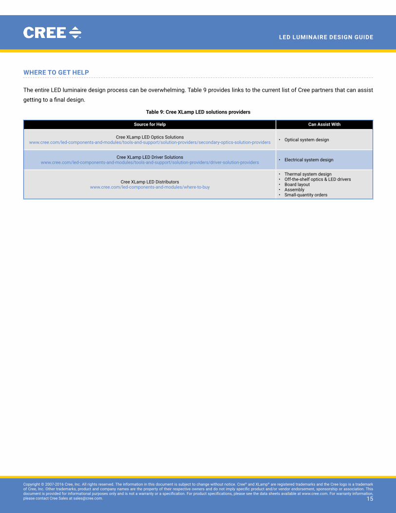
WhErE to GEt hELp
The entire LeD luminaire design process can be overwhelming. Table 9 provides links to the current list of Cree partners that can assist
getting to a final design.
table 9: Cree XLamp LED solutions providers
source for help can assist With
Cree XLamp LeD Optics Solutionswww.cree.com/led-components-and-modules/tools-and-support/solution-providers/secondary-optics-solution-providers • Optical system design
Cree XLamp LeD Driver Solutionswww.cree.com/led-components-and-modules/tools-and-support/solution-providers/driver-solution-providers • electrical system design
Cree XLamp LeD Distributorswww.cree.com/led-components-and-modules/where-to-buy
• Thermal system design• Off-the-shelf optics & LED drivers• Board layout• Assembly• Small-quantity orders