cisco unified wireless technology and architecture...2-3 enterprise mobility 7.3 design guide...
TRANSCRIPT

OL-14435-01
C H A P T E R 2
Cisco Unified Wireless Technology and ArchitectureThis chapter discusses the key design and operational considerations associated with the deployment of enterprise Cisco Unified Wireless Networks.
This chapter discusses:
• CAPWAP
• Core components
• Functional grouping of components
• Roaming
• Broadcast and multicast handling
• Design considerations
• Operation and maintenance
Much of the material in this chapter is explained in more detail in later chapters of this design guide. For more information on Cisco Unified Wireless technology, see the Cisco white paper on deployment strategies related to the Cisco 5500 Series Wireless LAN Controller at:
http://www.cisco.com/en/US/products/ps10315/prod_white_papers_list.html
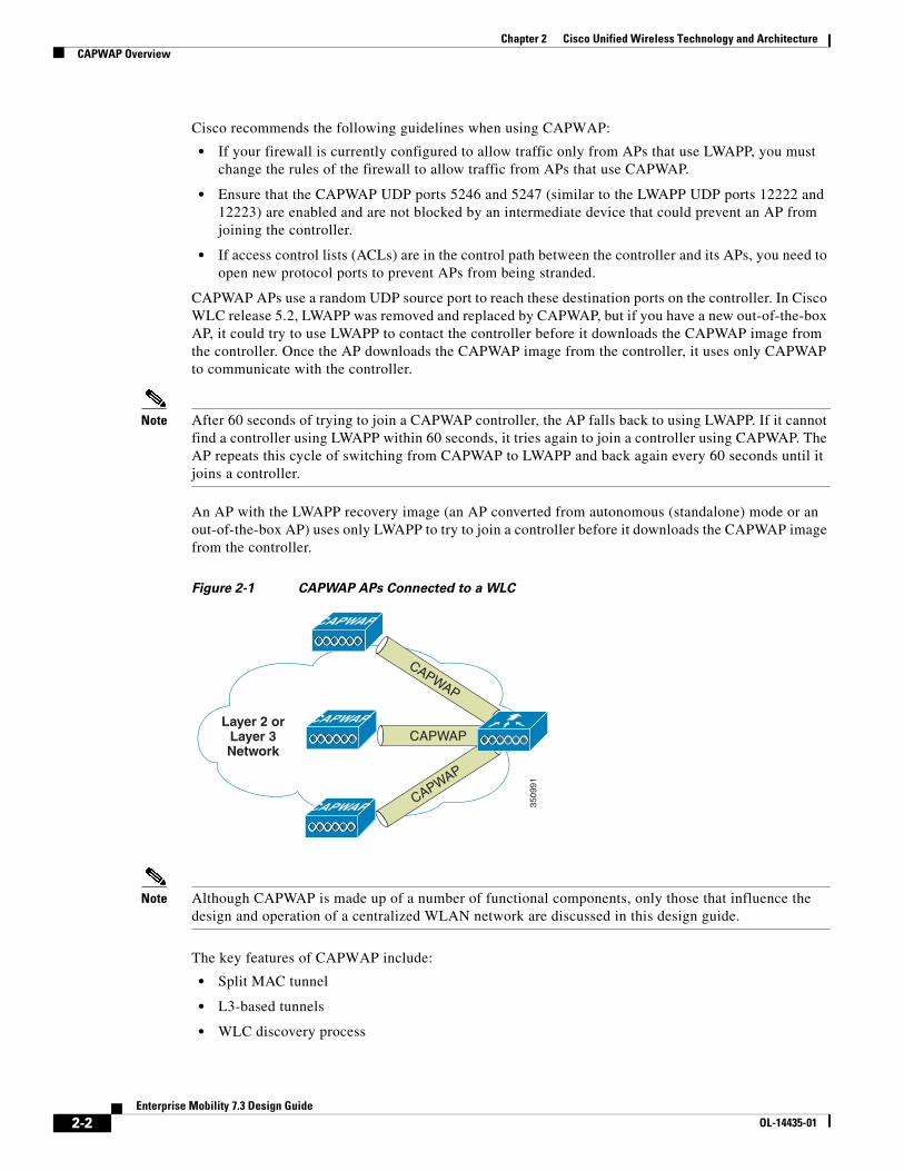
CAPWAP OverviewControl and Provisioning of Wireless Access Points (CAPWAP) is the underlying protocol used in the Cisco Centralized WLAN Architecture (functional architecture of the Cisco Unified Wireless Network solution). CAPWAP provides for the configuration and management of WLANs, in addition to managing two-way tunneling traffic with WLAN clients to a centralized WLAN controller (WLC). Figure 2-1 shows a high-level diagram of a basic centralized WLAN deployment, where CAPWAP APs connect to a WLC by way of CAPWAP.
You can deploy CAPWAP controllers and LWAPP controllers on the same network. The CAPWAP-enabled software allows APs to join either a controller that runs CAPWAP or LWAPP. The only exception is the Cisco Aironet 1140 Series AP, which supports only CAPWAP and therefore joins only controllers that run CAPWAP. For example, an 1130 series AP can join a controller that runs either CAPWAP or LWAPP whereas an Aironet 1140 Series AP can join only a controller that runs CAPWAP.
2-1Enterprise Mobility 7.3 Design Guide
Chapter 2 Cisco Unified Wireless Technology and ArchitectureCAPWAP Overview
Cisco recommends the following guidelines when using CAPWAP:
• If your firewall is currently configured to allow traffic only from APs that use LWAPP, you must change the rules of the firewall to allow traffic from APs that use CAPWAP.
• Ensure that the CAPWAP UDP ports 5246 and 5247 (similar to the LWAPP UDP ports 12222 and 12223) are enabled and are not blocked by an intermediate device that could prevent an AP from joining the controller.
• If access control lists (ACLs) are in the control path between the controller and its APs, you need to open new protocol ports to prevent APs from being stranded.
CAPWAP APs use a random UDP source port to reach these destination ports on the controller. In Cisco WLC release 5.2, LWAPP was removed and replaced by CAPWAP, but if you have a new out-of-the-box AP, it could try to use LWAPP to contact the controller before it downloads the CAPWAP image from the controller. Once the AP downloads the CAPWAP image from the controller, it uses only CAPWAP to communicate with the controller.
Note After 60 seconds of trying to join a CAPWAP controller, the AP falls back to using LWAPP. If it cannot find a controller using LWAPP within 60 seconds, it tries again to join a controller using CAPWAP. The AP repeats this cycle of switching from CAPWAP to LWAPP and back again every 60 seconds until it joins a controller.
An AP with the LWAPP recovery image (an AP converted from autonomous (standalone) mode or an out-of-the-box AP) uses only LWAPP to try to join a controller before it downloads the CAPWAP image from the controller.
Figure 2-1 CAPWAP APs Connected to a WLC
Note Although CAPWAP is made up of a number of functional components, only those that influence the design and operation of a centralized WLAN network are discussed in this design guide.
The key features of CAPWAP include:
• Split MAC tunnel
• L3-based tunnels
• WLC discovery process
3509
91
CAPWAPCAPWAP
CAPWAP
CAPWAP
CAPWAP
Layer 2 orLayer 3Network
CAPWAP
2-2Enterprise Mobility 7.3 Design Guide
OL-14435-01

Chapter 2 Cisco Unified Wireless Technology and ArchitectureCAPWAP Overview
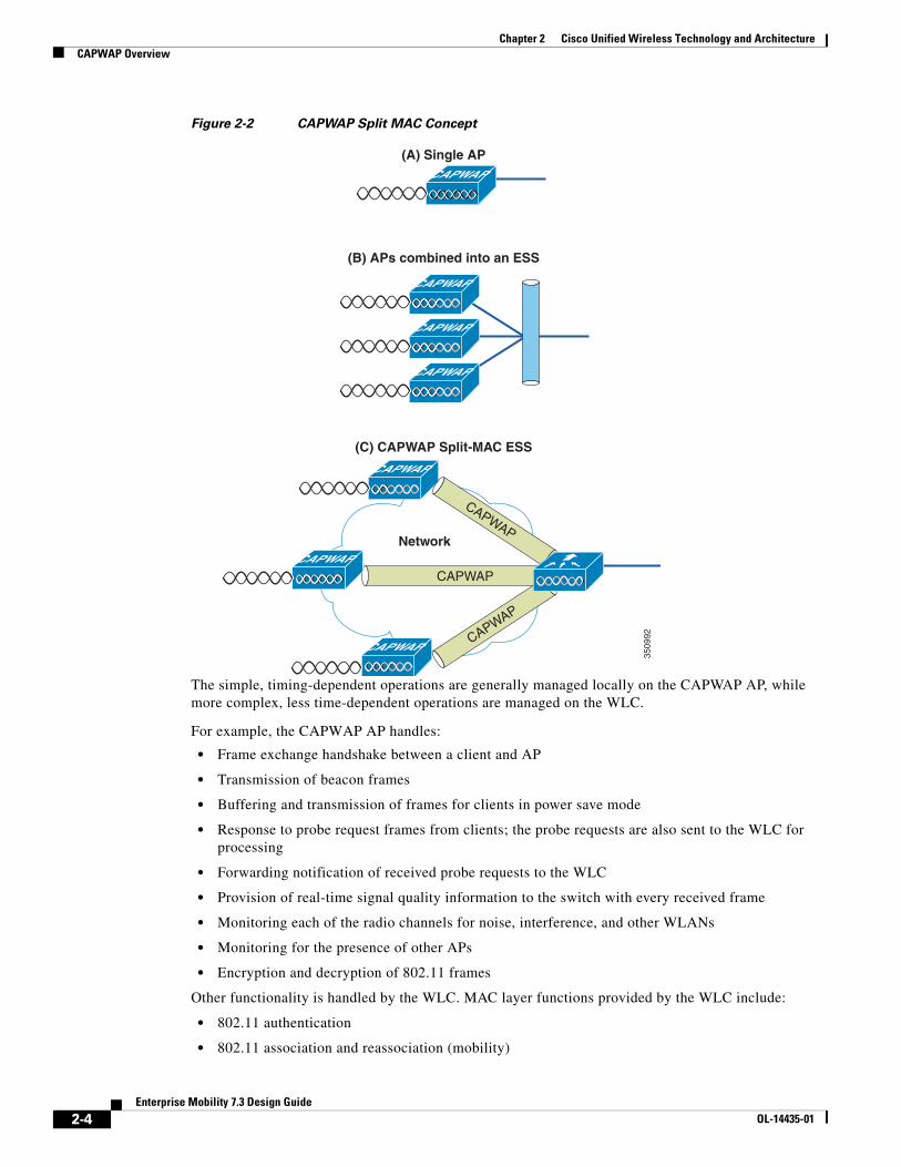
Split MACA key component of CAPWAP is the concept of a split MAC, where part of the 802.11 protocol operation is managed by the CAPWAP AP, while the remaining parts are managed by the WLC. Figure 2-2 is a diagram showing the split MAC concept.
A generic 802.11 AP, at the simplest level as shown in Figure 2-2(A), is nothing more than an 802.11 MAC-layer radio that bridges WLAN clients to a wired network based on association to a Basic Service Set Identifier (BSSID). The 802.11 standard extends the single AP concept (above) to allow multiple APs to provide an extended service set (ESS), as shown in Figure 2-2(B), where multiple APs use the same ESS identifier (ESSID, commonly referred to as an SSID) to allow a WLAN client to connect to a common network by way of more than one AP.
The CAPWAP split MAC concept takes all of the functions normally performed by individual APs and distributes them between two functional components: a CAPWAP AP and a WLC. The two are linked across a network by the CAPWAP protocol and together provide equivalent radio/bridging services in a manner that is simpler to deploy and manage than individual APs.
Note Although split MAC facilitates Layer 2 connectivity between the WLAN clients and the wired interface of the WLC, this does not mean that the CAPWAP tunnel will pass all traffic. The WLC forwards only IP EtherType frames, and its default behavior is to not forward broadcast and multicast traffic. This is important to keep in mind when considering multicast and broadcast requirements in a WLAN deployment.
2-3Enterprise Mobility 7.3 Design Guide
OL-14435-01
Chapter 2 Cisco Unified Wireless Technology and ArchitectureCAPWAP Overview
Figure 2-2 CAPWAP Split MAC Concept
The simple, timing-dependent operations are generally managed locally on the CAPWAP AP, while more complex, less time-dependent operations are managed on the WLC.
For example, the CAPWAP AP handles:
• Frame exchange handshake between a client and AP
• Transmission of beacon frames
• Buffering and transmission of frames for clients in power save mode
• Response to probe request frames from clients; the probe requests are also sent to the WLC for processing
• Forwarding notification of received probe requests to the WLC
• Provision of real-time signal quality information to the switch with every received frame
• Monitoring each of the radio channels for noise, interference, and other WLANs
• Monitoring for the presence of other APs
• Encryption and decryption of 802.11 frames
Other functionality is handled by the WLC. MAC layer functions provided by the WLC include:
• 802.11 authentication
• 802.11 association and reassociation (mobility)
(B) APs combined into an ESS
3509
92
CAPWAP
CAPWAP
CAPWAP
CAPWAP
CAPWAP
CAPWAP
Network
(C) CAPWAP Split-MAC ESS
CAPWAP
CAPWAP
CAPWAP
CAPWAP(A) Single AP
2-4Enterprise Mobility 7.3 Design Guide
OL-14435-01
Chapter 2 Cisco Unified Wireless Technology and ArchitectureCAPWAP Overview
• 802.11 frame translation and bridging
• 802.1X/EAP/RADIUS processing
• Termination of 802.11 traffic on a wired interface, except in the case of REAP and H-REAP configured APs, which are discussed later in this design guide
A CAPWAP tunnel supports two categories of traffic:
• CAPWAP control messages—Used to convey control, configuration, and management information between the WLC and APs
• Wireless client data encapsulation—Transports Layer 2 wireless client traffic in IP EtherType encapsulated packets from the AP to the WLC
When encapsulated client traffic reaches the WLC, it is mapped to a corresponding virtual LAN (VLAN) interface/port at the WLC. This interface mapping is defined as part of the WLAN configuration settings on the WLC. The interface mapping is usually static, but a WLAN client can be dynamically mapped to a specific VLAN based on parameters sent by an upstream AAA server upon successful EAP authentication. In addition to the VLAN assignment, other WLAN configuration parameters include:
• SSID
• Operational state
• Authentication and security method
• QoS
Layer 3 TunnelsCisco recommends using the Layer 3 CAPWAP tunnel type. This method uses IP UDP packets to facilitate communication between the CAPWAP AP and the WLC. Layer 3 CAPWAP is able to perform fragmentation and reassembly of tunnel packets. This allows client traffic to make use of a full 1500 byte MTU and not have to adjust for any tunnel overhead.
Note In order to optimize the fragmentation and reassembly process, the number of fragments that the WLC or AP expect to receive is limited. The ideal supported MTU size for deploying the Cisco Unified Wireless Network is 1500 bytes, but the solution operates successfully over networks where the MTU is as small as 500 bytes.
The figures below are of Layer 3 CAPWAP packet captures used to illustrate CAPWAP operation. The sample decodes were captured using a Wireshark packet analyzer.
Note By default, Wireshark does not decode Cisco CAPWAP packets correctly. Correct this in the Wireshark configuration window by selecting the SWAP Frame Control option under the Protocol Preferences tab.
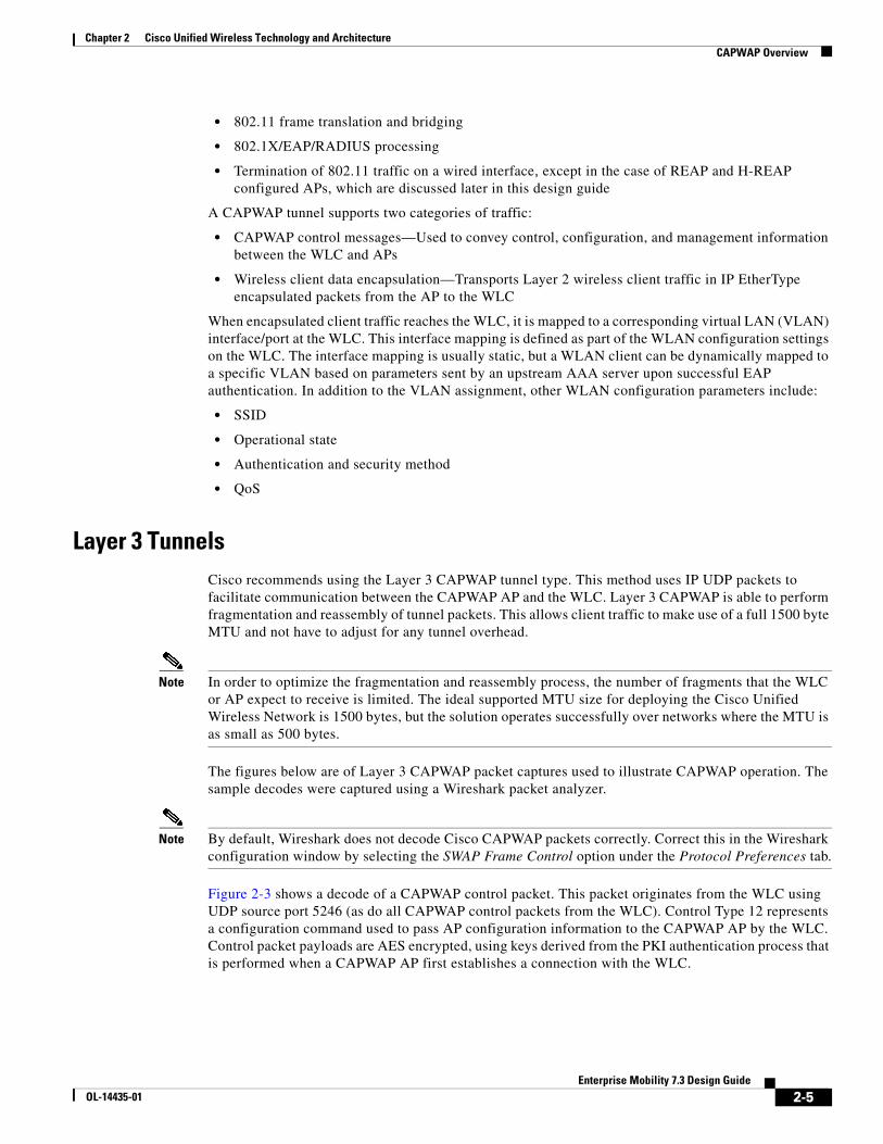
Figure 2-3 shows a decode of a CAPWAP control packet. This packet originates from the WLC using UDP source port 5246 (as do all CAPWAP control packets from the WLC). Control Type 12 represents a configuration command used to pass AP configuration information to the CAPWAP AP by the WLC. Control packet payloads are AES encrypted, using keys derived from the PKI authentication process that is performed when a CAPWAP AP first establishes a connection with the WLC.
2-5Enterprise Mobility 7.3 Design Guide
OL-14435-01
Chapter 2 Cisco Unified Wireless Technology and ArchitectureCAPWAP Overview
Figure 2-3 CAPWAP Control Packet
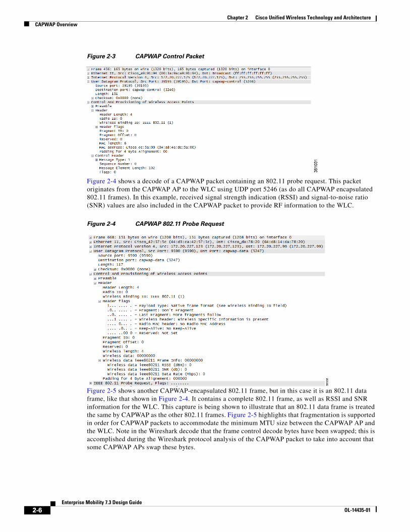
Figure 2-4 shows a decode of a CAPWAP packet containing an 802.11 probe request. This packet originates from the CAPWAP AP to the WLC using UDP port 5246 (as do all CAPWAP encapsulated 802.11 frames). In this example, received signal strength indication (RSSI) and signal-to-noise ratio (SNR) values are also included in the CAPWAP packet to provide RF information to the WLC.
Figure 2-4 CAPWAP 802.11 Probe Request
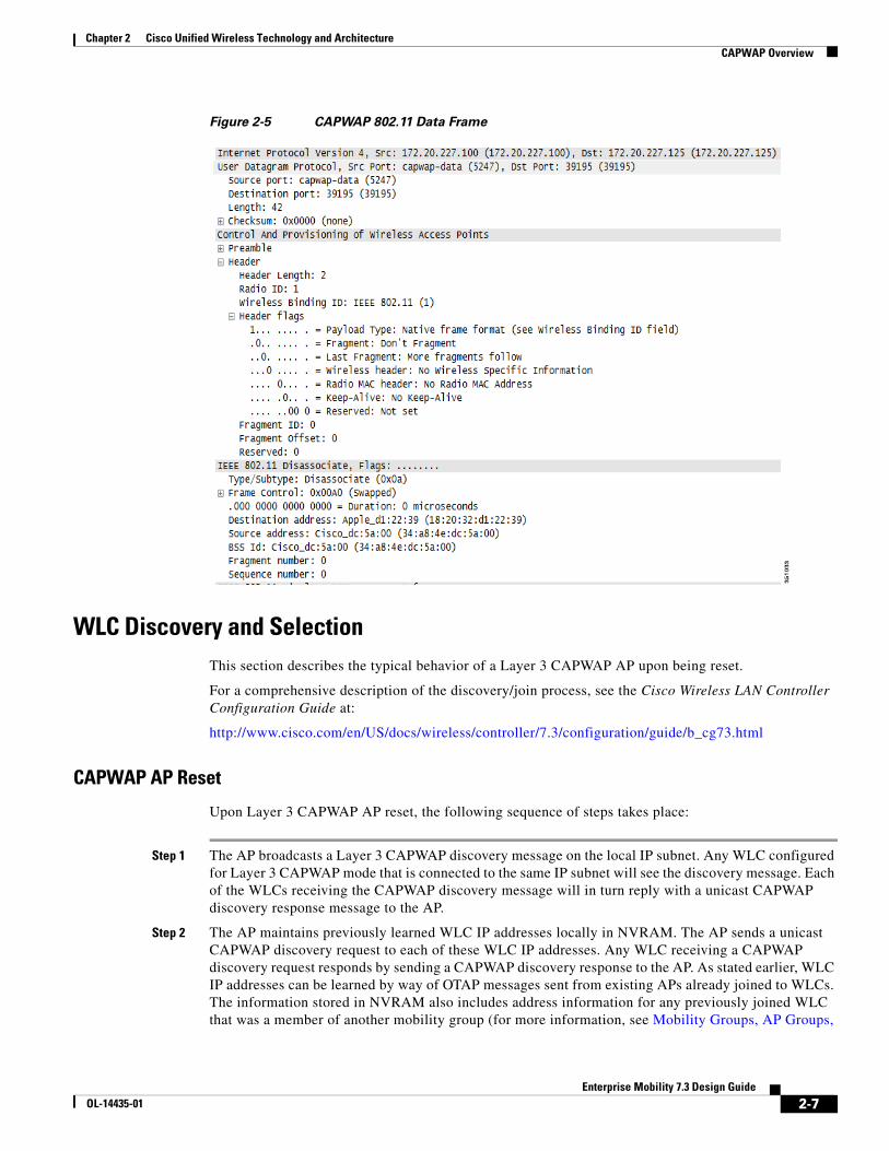
Figure 2-5 shows another CAPWAP-encapsulated 802.11 frame, but in this case it is an 802.11 data frame, like that shown in Figure 2-4. It contains a complete 802.11 frame, as well as RSSI and SNR information for the WLC. This capture is being shown to illustrate that an 802.11 data frame is treated the same by CAPWAP as the other 802.11 frames. Figure 2-5 highlights that fragmentation is supported in order for CAPWAP packets to accommodate the minimum MTU size between the CAPWAP AP and the WLC. Note in the Wireshark decode that the frame control decode bytes have been swapped; this is accomplished during the Wireshark protocol analysis of the CAPWAP packet to take into account that some CAPWAP APs swap these bytes.
2-6Enterprise Mobility 7.3 Design Guide
OL-14435-01
Chapter 2 Cisco Unified Wireless Technology and ArchitectureCAPWAP Overview
Figure 2-5 CAPWAP 802.11 Data Frame
WLC Discovery and SelectionThis section describes the typical behavior of a Layer 3 CAPWAP AP upon being reset.
For a comprehensive description of the discovery/join process, see the Cisco Wireless LAN Controller Configuration Guide at:
http://www.cisco.com/en/US/docs/wireless/controller/7.3/configuration/guide/b_cg73.html
CAPWAP AP Reset
Upon Layer 3 CAPWAP AP reset, the following sequence of steps takes place:
Step 1 The AP broadcasts a Layer 3 CAPWAP discovery message on the local IP subnet. Any WLC configured for Layer 3 CAPWAP mode that is connected to the same IP subnet will see the discovery message. Each of the WLCs receiving the CAPWAP discovery message will in turn reply with a unicast CAPWAP discovery response message to the AP.
Step 2 The AP maintains previously learned WLC IP addresses locally in NVRAM. The AP sends a unicast CAPWAP discovery request to each of these WLC IP addresses. Any WLC receiving a CAPWAP discovery request responds by sending a CAPWAP discovery response to the AP. As stated earlier, WLC IP addresses can be learned by way of OTAP messages sent from existing APs already joined to WLCs. The information stored in NVRAM also includes address information for any previously joined WLC that was a member of another mobility group (for more information, see Mobility Groups, AP Groups,
2-7Enterprise Mobility 7.3 Design Guide
OL-14435-01
Chapter 2 Cisco Unified Wireless Technology and ArchitectureCore Components
and RF Groups, page 2-12).
Step 3 DHCP servers can be programmed to return WLC IP addresses using vendor-specific DHCP options. When programmed, Option 43 is used in a DHCP offer to advertise WLC addresses to CAPWAP APs. When an AP receives its IP address by way of DHCP, it checks for WLC IP address information in the Option 43 field of the DHCP offer. The AP sends a unicast CAPWAP discovery message to each WLC listed in the DHCP Option 43. WLCs receiving the CAPWAP discovery request messages unicast a CAPWAP discovery response to the AP.
Step 4 Without the Option 43 information, the AP attempts to resolve the DNS name CISCO-CAPWAP-CONTROLLER.localdomain. If the AP is able to resolve this, it sends a unicast CAPWAP discovery message to each IP address returned in the DNS reply. As described above, each WLC that receives a CAPWAP discovery request message replies with a unicast CAPWAP discovery response to the AP.
Step 5 If, after Steps 1 through 4 no CAPWAP discovery response is received, the AP resets and restarts the search algorithm.
Typically, either the DHCP or DNS discovery mechanism is used to provide one or more seed WLC addresses and then a subsequent WLC discovery response provides a full list of WLC mobility group members.
A CAPWAP AP is normally configured with a list of up to three WLCs that represent preferred WLCs. If these WLCs become unavailable or are over-subscribed, the AP chooses another WLC from the list of WLCs learned in the discover response that is the least-loaded WLC.
Core ComponentsThe core components that make up the Cisco Unified Wireless Network solution are the Cisco Prime Infrastructure formally known as wireless control system (WCS) and network control system (NCS), wireless LAN controllers (WLCs), CAPWAP APs, and the Cisco Mobility Services Engine (MSEs). This section describes product options for Cisco Prime Infrastructure, WLCs, and APs (for information on MSEs, see Chapter 11, “Cisco Mobility Services Engine.”).
Cisco Wireless LAN ControllersFor convenience, this document refers to all Cisco Unified Wireless Network controllers as WLCs due to the general uniformity and commonality of features across all of the Cisco WLC platforms.
The following summarizes the various Cisco WLCs and their features:
• Cisco 2504 WLC—The 2504 controller works in conjunction with Cisco APs and Cisco Prime Infrastructure to provide system-wide wireless LAN functions. As a component of the Cisco Unified Wireless Network, the 2504 controller provides real-time communication between wireless APs and other devices to deliver centralized security policies, guest access, Wireless Intrusion Prevention System (WIPS), context-aware (location), award-winning RF management, quality of services for mobility services such as voice and video, and OEAP support for the teleworker solution.
Cisco 2504 WLCs support up to 50 APs in increments of five APs with a minimum of five APs, making it a cost-effective solution for retail, enterprise branches, and small and medium-sized businesses. The 2504 WLC comes with four Gigabit Ethernet ports.
2-8Enterprise Mobility 7.3 Design Guide
OL-14435-01
Chapter 2 Cisco Unified Wireless Technology and ArchitectureCore Components
• Cisco 5508 WLC—The 5508 controller provides real-time communication between Cisco Aironet AP, the Cisco Prime Infrastructure, and the Cisco Mobility Services Engine. It delivers centralized security policies, wireless intrusion prevention system (IPS) capabilities, RF management, and quality of service (QoS). To help ensure an exceptional end-user experience on the wireless network, the Cisco 5500 Series provides a variety of capabilities:
– Integrated CleanAir technology protects 802.11n performance by enabling a self-healing, self-optimizing wireless network.
– Cisco ClientLink technology optimizes mixed-client network capacity by helping ensure that 802.11a/g and 802.11n clients operate at the best possible rates.
– The Cisco Identity Services Engine provides a single, centralized point of management across wired and wireless networks. Enterprises can adapt to the exponential growth in mobile smartphones, tablets, and laptops by providing secure and relevant access for employees, guests, and contractors.
• Cisco Wireless Services Module 2 (WiSM-2)—A WLC module that is designed specifically for the Cisco Catalyst 6500 switch series. It supports up to 1000 APs per module. Depending on the 6500 platform, multiple WISM-2s can be installed to offer significant scaling capabilities. The WISM-2 appears as a single aggregated link interface on the 6500 that can be configured as a dot1 trunk to provide connection into the 6500 backplane. This is ideal for large buildings or campuses.
• Cisco Virtual Wireless Controller (vWLC)– The Virtual Wireless Controller provides real-time, centralized communications between Cisco Aironet Access Points, the Cisco Prime Infrastructure, and the Cisco Mobility Services Engine. Designed for organizations with virtualization initiatives, and for small to medium enterprise deployments, the Virtual Wireless Controller offers:
– Centralized wireless network visibility and control for up to 200 branch locations
– Ability for IT managers to configure, manage, and troubleshoot up to 200 access points and 3000 clients via FlexConnect
– Secure guest access, rogue detection for Payment Card Industry (PCI) compliance, and in-branch (locally switched) Wi-Fi voice and video
– Reliable connectivity with the Cisco FlexConnect solution for branch network
– Protection of access points connected to remote controllers from branch WAN failures; wireless clients remain connected with access to local resources
• Cisco 7500 WLC– The 7500 Series Controller provides the visibility and control needed to manage thousands of wireless branches from a single location. The controller’s features are as follows:
– Provides a cost-effective solution that does not require a local controller at each branch location.
– Consolidated, remote management allows scaled and consistent control over thousands of branches.
– Delivers secure, centralized policy management of distributed guest and employee access.
– Helps ensure business continuity in each local branch through resiliency over WAN failures.
– Efficient networking with local switching of data traffic allows WAN optimization and QoS policies without requiring tunneling across the WAN.
• Cisco 8500 WLC– The 8500 Series Controller provides real-time, centralized communications between Cisco Aironet Access Points, the Cisco Prime Infrastructure, and the Cisco Mobility Services Engine. Designed for service provider and large campus deployments, the 8500 Series Controller offers:
– The industry's largest scalability in a single rack-unit space (1RU); a centralized touch point for up to 6000 access points, 64,000 clients, and 6000 branch locations
2-9Enterprise Mobility 7.3 Design Guide
OL-14435-01

Chapter 2 Cisco Unified Wireless Technology and ArchitectureCore Components
– High speed with 10 Gigabit Ethernet connectivity support: Two 10 Gigabit Ethernet ports for redundancy
– High-Availability with sub-second access point stateful fail-over ensuring SSIDs are highly available and minimal impact to wireless clients
– High resiliency with redundant dual power supplies
Table 2-1 summarizes the available Cisco WLCs.
Table 2-1 Summary of Cisco WLCs
Cisco Access PointsWithin the Cisco Unified Wireless Network there are two categories of Cisco APs: autonomous and CAPWAP APs. This section describes the various models of CAPWAP APs that are available.
Note Cisco 1500 series MESH APs are mentioned briefly below but this design guide does not address wireless MESH applications or MESH deployment guidelines. For information about the Cisco MESH solution see: Cisco Mesh Networking Solution Deployment Guide, http://www.cisco.com/en/US/docs/wireless/technology/mesh/7.3/design/guide/Mesh.html.
CAPWAP APs
Table 2-2 summarizes the available Cisco CAPWAP APs.
Table 2-2 Summary of CAPWAP APs
2-10Enterprise Mobility 7.3 Design Guide
OL-14435-01

Chapter 2 Cisco Unified Wireless Technology and ArchitectureCore Components
Cisco Prime InfrastructureCisco Prime Infrastructure provides a single integrated solution for comprehensive life cycle management of the wired/wireless access, campus, and branch networks, and rich visibility into end-user connectivity and application performance assurance issues. Cisco Prime Infrastructure accelerates the rollout of new services, secure access and management of mobile devices, making “Bring Your Own Device” (BYOD) a reality for corporate IT. Tightly coupling client awareness with application performance visibility and network control, Cisco Prime Infrastructure helps ensure uncompromising end-user quality of experience. Deep integration with the Cisco Identity Services Engine (ISE) further extends this visibility across security and policy-related problems, presenting a complete view of client access issues with a clear path to solving them.
Cisco Prime Infrastructure is organized into a life cycle workflow that includes the following high-level task areas:
• Design—The design phase focuses on the overall design of feature or device patterns or templates. The design area is where you create reusable design patterns such as configuration templates. Cisco Prime Infrastructure provides predefined templates, but you can also create your own. These patterns and templates are intended for use in the deployment phase of the life cycle.
• Deploy—The deployment phase focuses on deploying previously defined designs or templates into your network. The deploy area is where you specify how to deploy features, making use of the templates created in the design phase. The deploy phase allows you to push configurations defined in your templates to one or many devices.
• Operate—The Operate area is where you monitor your network on a daily basis, as well as perform other day-to-day or ad hoc operations relating to network device inventory and configuration management. The Operate tab contains dashboards, the Device Work Center, and the tools you need for day-to-day monitoring, troubleshooting, maintenance, and operations.
2-11Enterprise Mobility 7.3 Design Guide
OL-14435-01

Chapter 2 Cisco Unified Wireless Technology and ArchitectureMobility Groups, AP Groups, and RF Groups
• Report—Cisco Prime Infrastructure also provides reports that you can use to monitor the system and network health as well as troubleshoot problems. The Cisco Prime Infrastructure Report Launchpad provides report access and scheduling for all types of reporting functions.
• Administration—The Administration area is where you specify system configuration settings, manage access control, and specify data collection settings.
Mobility Groups, AP Groups, and RF GroupsWithin the Cisco Unified Wireless Network there are three important group concepts:
• Mobility groups
• AP groups
• RF groups
The following sections describe the purpose and application of these groups within the Cisco Unified Wireless Network.
Mobility GroupsA mobility group is a group of WLCs that together, act as a single virtual WLC by sharing essential end-client, AP, and RF information. A given WLC within a mobility group is able to make decisions based on data received from other members of the entire mobility group, rather than relying solely on the information learned from its own directly connected APs and clients.
A mobility group forms a mesh of authenticated tunnels between member WLCs, thereby allowing any WLC to directly contact another WLCs within the group, as shown in Figure 2-6.
Figure 2-6 WLC Mobility Group
3509
93
CAPWAP
CAPWAP CAPWAP
WLC
WLC
WLCWLC
Network
Mobility Group
2-12Enterprise Mobility 7.3 Design Guide
OL-14435-01
Chapter 2 Cisco Unified Wireless Technology and ArchitectureMobility Groups, AP Groups, and RF Groups
Mobility Group DefinitionCreating a mobility group is simple and well documented. However, there are a few important considerations to keep in mind:
• Up to 24 regular WLCs (Cisco 2500, 5508, WiSM-2, 7500, 8500, virtual WLC, WLCM2 series) can be in a single mobility group. You can configure up to 24 Wireless Services Module (WISM-2) blades in one mobility group. Therefore, up to a maximum of 24000 APs are supported in a single mobility group. An enterprise can consist of more WLCs and APs, but they must be configured as members of another mobility group.
• With WLC release 5.1, up to 72 WLCs can be in a single mobility group with up to 72000 APs (1000 APs per WLC).
• The WLCs do not have to be of the same model/type to be a member of a mobility group. A group can be comprised of any combination of Cisco 2500 Series controller, Cisco Flex 7500, Cisco 5500 Series Controller, Virtual Controller, 8500 series, WiSM-2, Cisco Wireless Controller Software for SRE, or Cisco Wireless LAN Controller Module but they should all be running the same software version. Although mobility groups can function with software differences between devices, Cisco strongly recommends you use a common software version to ensure feature and functional parity across a unified wireless deployment.
• A mobility group requires all WLCs in the group to use the same virtual IP address.
• Each WLC must use the same mobility domain name (group name) and be defined as a peer in each others Static Mobility Members list.
• For a wireless client to roam seamlessly between mobility group members (WLCs), a given WLAN SSID and security configuration must be configured identically across all WLCs comprising the mobility group.
Mobility Group Application
Mobility groups are used to help facilitate seamless client roaming between APs that are joined to different WLCs. The primary purpose of a mobility group is to create a virtual WLAN domain (across multiple WLCs) in order to provide a comprehensive view of a wireless coverage area. The use of mobility groups are beneficial only when a deployment comprises of overlapping coverage established by two or more APs that are connected to different WLCs. A mobility group is of no benefit when two APs, associated with different WLCs, are in different physical locations with no overlapping (contiguous) coverage between them (for example, campus and branch or between two or more buildings within a campus).
Mobility Group—Exceptions
The Cisco Unified Wireless Network solution offers network administrators the ability to define static mobility tunnel (auto anchor) relationships between an anchor WLC and other WLCs in the network. This option, among other things, is used when deploying wireless guest access services.
If the auto anchor feature is used, no more than 71 WLCs can be mapped to a designated anchor WLC. Foreign WLCs do not, by virtue of being connected to the auto anchor, establish mobility relationships between each other. The anchor WLC must have a static mobility group member entry defined for each foreign WLC where a static mobility tunnel is needed. The same is true for each foreign WLC where a static mobility tunnel is being configured; the anchor WLC must be defined as a static mobility group member in the foreign WLC.
2-13Enterprise Mobility 7.3 Design Guide
OL-14435-01
Chapter 2 Cisco Unified Wireless Technology and ArchitectureMobility Groups, AP Groups, and RF Groups
A WLC can be member of only one mobility group for the purpose of supporting dynamic inter-controller client roaming. A WLC that is configured as an auto anchor does not have to be in the same mobility group as the foreign WLCs. It is possible for a WLC to be a member of one mobility group while at the same time, act as an auto anchor for a WLAN originating from foreign WLCs that are members of other mobility groups.
For a discussion on mobility anchor configuration, see Chapter 10, “Cisco Unified Wireless Network Guest Access Services.”
AP GroupsIn typical deployment scenarios, each WLAN is mapped to a single dynamic interface per WLC. However, consider a deployment scenario where there is a 5508 WLC licensed to support maximum number of 500 APs. Now consider a scenario where 25 users are associated to each AP. That would result in 12,500 users sharing a single VLAN. Some customer designs might require substantially smaller subnet sizes. One way to deal with this is to break up the WLAN into multiple segments. The Cisco AP grouping feature allows a single WLAN to be supported across multiple dynamic interfaces (VLANs) on a WLC. This is done by taking a group of APs and mapping them to a specific dynamic interface. APs can be grouped logically by employee workgroup or physically by location. Figure 2-7 illustrates the use of AP groups based on site-specific VLANs.
Note AP groups do not allow multicast roaming across group boundaries. For more information, see Chapter 6, “Cisco Unified Wireless Multicast Design”.
2-14Enterprise Mobility 7.3 Design Guide
OL-14435-01

Chapter 2 Cisco Unified Wireless Technology and ArchitectureMobility Groups, AP Groups, and RF Groups
Figure 2-7 AP Groups and Site-Specific VLANS
As shown in Figure 2-7, there are three dynamic interfaces configured, each mapping to a site-specific VLAN (VLAN 61, 62, and 63). Each site-specific VLAN and associated APs are mapped to the same WLAN SSID using the AP grouping feature. A corporate user associating to the WLAN on an AP in the AP group corresponding to VLAN 61 is assigned an IP address on the VLAN 61 IP subnet. Likewise, a corporate user associating to the WLAN on an AP in the AP group corresponding to VLAN 62 is assigned an IP address on the VLAN 62 IP subnet and so on. Roaming between the site-specific VLANs is handled internally by the WLC as a Layer 3 roaming event and because of this the wireless LAN client maintains its original IP address.
RF GroupsRF groups, also known as RF domains, represent another important deployment consideration. An RF group is a cluster of WLCs that collectively coordinate and calculate their dynamic radio resource management (RRM) settings based on 802.11 PHY type (for example, 802.11b/g and 802.11a).
An RF group exists for each 802.11 PHY type. Grouping WLCs into RF domains allows the solution’s dynamic RRM algorithms to scale beyond a single WLC, thereby allowing RRM for a given RF domain to extend between floors, buildings, and even across campuses. RF Groups and RRM is discussed in more detail in Chapter 3, “WLAN RF Design Considerations,” but can be summarized as follows:
3509
94
CAPWAP
CAPWAP
CAPWAP
CAPWAP
CAPWAP
CAPWAP
Single SSID secureSpanning Campus
AP Group:VLAN 61
AP Group:VLAN 63
AP Group:VLAN 62
VLAN 61 VLAN 63VLAN 62
2-15Enterprise Mobility 7.3 Design Guide
OL-14435-01
Chapter 2 Cisco Unified Wireless Technology and ArchitectureRoaming
• CAPWAP APs periodically send out neighbor messages over the air that includes the WLC IP address and a hashed message integrity check (MIC) derived from a timestamp and the BSSID of the AP.
• The hashing algorithm uses a shared secret (the RF Group Name) that is configured on the WLC and is pushed out to each AP. APs sharing the same secret are able to validate messages from each other using the MIC. When APs belonging to other WLCs hear validated neighbor messages at a signal strength of -80 dBm or stronger, their WLCs dynamically become members of the RF group.
• Members of an RF group elect an RF domain leader to maintain a master power and channel scheme for the RF group.
• The RF group leader analyzes real-time radio data collected by the system and calculates a master power and channel plan.
• The RRM algorithms attempt to:
– Achieve a uniform (optimal) signal strength of -65 dBm across all APs
– Avoid 802.11 co-channel interference and contention
– Avoid non-802.11 interference.
• The RRM algorithms employ dampening calculations to minimize system-wide dynamic changes. The end result is dynamically calculated, near-optimal power and channel planning that is responsive to an ever changing RF environment.
• The RF group leader and members exchange RRM messages at a specified update interval, which is 600 seconds by default. Between update intervals the RF group leader sends keep alive messages to each of the RF group members and collects real-time RF data. Note that the maximum number of WLCs per RF group is 20.
RoamingMobility, or roaming, is the ability of a wireless LAN client to maintain its association seamlessly from one AP to another securely and with as little latency as possible. This section explains how mobility works when controllers are included in a wireless network.
When a wireless client associates and authenticates to an AP, the controller places an entry for that client in its client database. This entry includes the client MAC and IP addresses, security context and associations, quality of service (QoS) contexts, the WLAN, SSID and the associated AP. The controller uses this information to forward frames and manage traffic to and from the wireless client. Figure 2-8 shows a wireless client that roams from one AP to another when both APs are joined to the same controller.
2-16Enterprise Mobility 7.3 Design Guide
OL-14435-01
Chapter 2 Cisco Unified Wireless Technology and ArchitectureRoaming
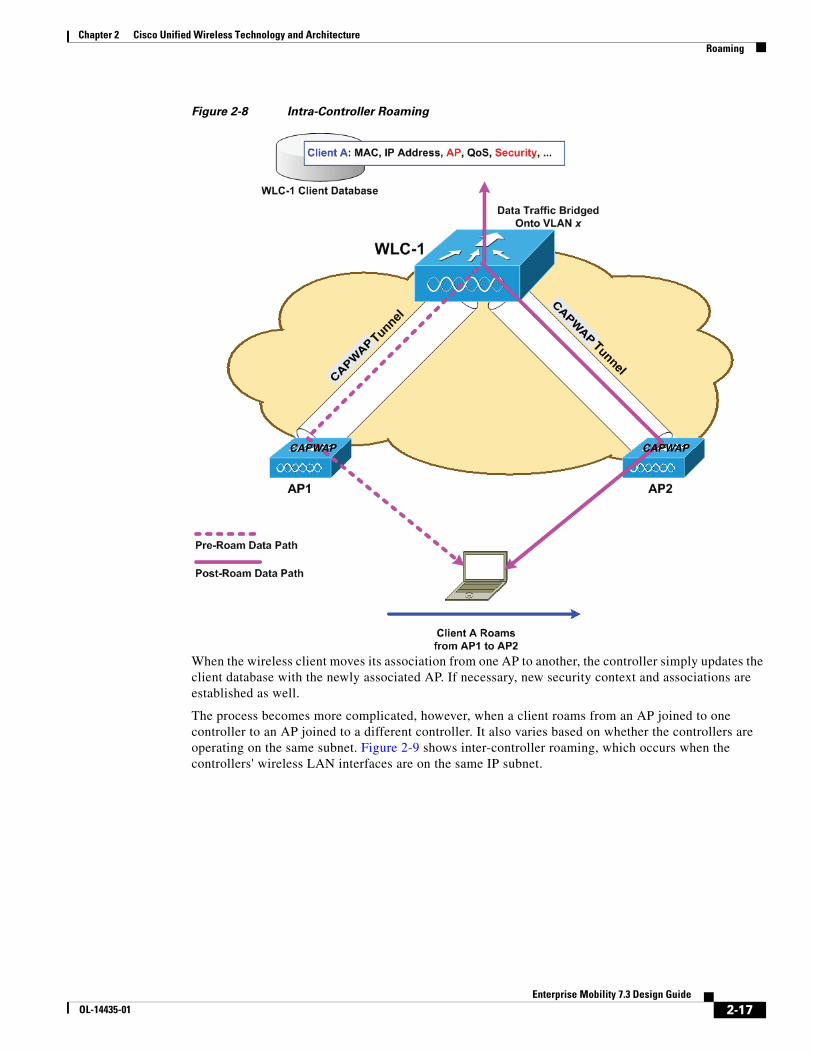
Figure 2-8 Intra-Controller Roaming
When the wireless client moves its association from one AP to another, the controller simply updates the client database with the newly associated AP. If necessary, new security context and associations are established as well.
The process becomes more complicated, however, when a client roams from an AP joined to one controller to an AP joined to a different controller. It also varies based on whether the controllers are operating on the same subnet. Figure 2-9 shows inter-controller roaming, which occurs when the controllers' wireless LAN interfaces are on the same IP subnet.
CAPW
AP
CAPW
AP
CAPWAPCAPWAP
2-17Enterprise Mobility 7.3 Design Guide
OL-14435-01

Chapter 2 Cisco Unified Wireless Technology and ArchitectureRoaming
Figure 2-9 Inter-Controller Roaming
When the client associates to an AP joined to a new controller, the new controller exchanges mobility messages with the original controller, and the client database entry is moved to the new controller. New security context and associations are established if necessary, and the client database entry is updated for the new AP. This process remains transparent to the user.
Note All clients configured with 802.1X/Wi-Fi Protected Access (WPA) security complete a full authentication in order to comply with the IEEE standard.
Figure 2-10 shows inter-subnet roaming, which occurs when the controllers' wireless LAN interfaces are on different IP subnets.
CAPW
AP
CAPW
AP
CAPWAPCAPWAP
2-18Enterprise Mobility 7.3 Design Guide
OL-14435-01
Chapter 2 Cisco Unified Wireless Technology and ArchitectureBroadcast and Multicast on the WLC
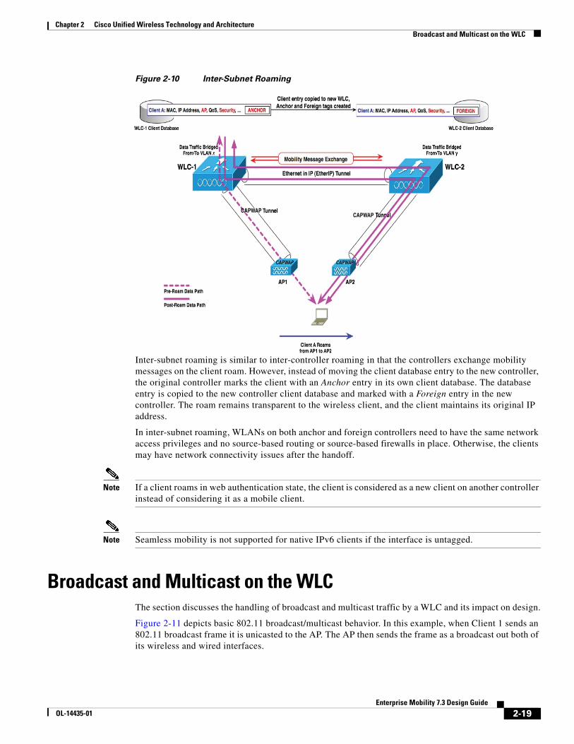
Figure 2-10 Inter-Subnet Roaming
Inter-subnet roaming is similar to inter-controller roaming in that the controllers exchange mobility messages on the client roam. However, instead of moving the client database entry to the new controller, the original controller marks the client with an Anchor entry in its own client database. The database entry is copied to the new controller client database and marked with a Foreign entry in the new controller. The roam remains transparent to the wireless client, and the client maintains its original IP address.
In inter-subnet roaming, WLANs on both anchor and foreign controllers need to have the same network access privileges and no source-based routing or source-based firewalls in place. Otherwise, the clients may have network connectivity issues after the handoff.
Note If a client roams in web authentication state, the client is considered as a new client on another controller instead of considering it as a mobile client.
Note Seamless mobility is not supported for native IPv6 clients if the interface is untagged.
Broadcast and Multicast on the WLCThe section discusses the handling of broadcast and multicast traffic by a WLC and its impact on design.
Figure 2-11 depicts basic 802.11 broadcast/multicast behavior. In this example, when Client 1 sends an 802.11 broadcast frame it is unicasted to the AP. The AP then sends the frame as a broadcast out both of its wireless and wired interfaces.
CAPWAPCAPWAP
CAPWAP CAPWAP
2-19Enterprise Mobility 7.3 Design Guide
OL-14435-01

Chapter 2 Cisco Unified Wireless Technology and ArchitectureBroadcast and Multicast on the WLC
Figure 2-11802.11 Broadcast/Multicast
If there are other APs on the same wired VLAN as the AP, as shown in Figure 2-11, they forward the wired broadcast packet out their wireless interface.
The WLC CAPWAP split MAC method treats broadcast traffic differently, as shown in Figure 2-14. In this case, when a broadcast packet is sent by a client, the AP/WLC does not forward it back out the WLAN, and only a subset of all possible broadcast messages are forwarded out a given WLAN's wired interface at the WLC.
Figure 2-12Default WLC Broadcast Behavior
Note Which protocols are forwarded under which situations is discussed in the following section.
WLC Broadcast and Multicast DetailsBroadcast and multicast traffic often require special treatment within a WLAN network because of the additional load placed on the WLAN as a result of this traffic having to be sent at the lowest common bit rate. This is done to ensure that all associated wireless devices are able to receive the broadcast/multicast information.
1906
89
Client1
ACK
SA=Client1 MAC DA=FFFF:FFFF:FFFF BSSID
SA=Client1 MACDA=FFFF:FFFF:FFFFBSSID
AssociatedClients
SA=Client1 MAC DA=FFFF:FFFF:FFFF
SA=Client1 MACDA=FFFF:FFFF:FFFF
SA=Client1 MACDA=FFFF:FFFF:FFFF
3509
95
Client1
ACK
SA=Client1 MAC DA=FFFF:FFFF:FFFF BSSID
SA=Client1 MACDA=FFFF:FFFF:FFFFBSSID
AssociatedClients
SA=Client1 MAC DA=FFFF:FFFF:FFFF
CAPWAP
CAPWAP
CAPWAP
2-20Enterprise Mobility 7.3 Design Guide
OL-14435-01
Chapter 2 Cisco Unified Wireless Technology and ArchitectureBroadcast and Multicast on the WLC
The default behavior of the WLC is to block broadcast and multicast traffic from being sent out the WLAN to other wireless client devices. The WLC can do this without impacting client operation because most IP clients do not send broadcast/multicast type traffic for any reason other than to obtain network information (DHCP).
DHCP
The WLC acts as a DHCP relay agent for associated WLAN clients. The WLC unicasts client DHCP requests to a locally configured or upstream DHCP server except during Layer 3 client roaming (discussed in more detail below). DHCP server definitions are configured for each dynamic interface, which in turn is associated with one or more WLANs. DHCP relay requests are forwarded by way of the dynamic interfaces using the source IP address of a given dynamic interface. Because the WLC knows which DHCP server to use for a given interface/WLAN, there is no need to broadcast client DHCP requests out its wired and wireless interfaces.
This method accomplishes the following:
• It eliminates the need for DHCP requests to be broadcasted beyond the WLC.
• The WLC becomes part of the DHCP process, thereby allowing it to learn the MAC/IP address relationships of connected WLAN clients, which in turn allows the WLC to enforce DHCP policies and mitigate against IP spoofing or denial-of-service (DoS) attacks.
VideoStream
The VideoStream feature makes the IP multicast stream delivery reliable over the air, by converting the broadcast frame over the air to a unicast frame. Each VideoStream client acknowledges receiving a video IP multicast stream. VideoStream is supported on al Cisco APs.
The following are the recommended guidelines for configuring VideoStream on the controller:
• The AP1100 and AP1200 do not support the reliable multicast feature.
• Ensure that the multicast feature is enabled. Cisco recommends configuring IP multicast on the controller with multicast-multicast mode.
• Check for the IP address on the client device. The device should have an IP address from the respective VLAN.
• Verify that the AP has joined the controllers.
• Ensure that the clients are able to associate to the configured WLAN at 802.11a/n speed.
Other Broadcast and Multicast TrafficAs mentioned earlier, the WLC (by default) does not forward broadcasts or multicasts toward the wireless users. If multicast forwarding is explicitly enabled, as described in Chapter 6, “Cisco Unified Wireless Multicast Design,” steps should be taken to minimize the multicast traffic generated on those interfaces that the WLC connects to.
All normal precautions should be taken to limit the multicast address groups explicitly supported by a WLAN. When multicast is enabled, it is global in nature, meaning it is enabled for every WLAN configured regardless if multicast is needed by that WLAN or not. The Cisco Unified Wireless Network solution is not able to distinguish between data link layer and network layer multicast traffic, nor is the WLC capable of filtering specific multicast traffic. Therefore, the following additional steps should be considered:
2-21Enterprise Mobility 7.3 Design Guide
OL-14435-01

Chapter 2 Cisco Unified Wireless Technology and ArchitectureDesign Considerations
• Disable CDP on interfaces connecting to WLCs.
• Port filter incoming CDP and HSRP traffic on VLANs connecting to the WLCs.
• Keep in mind that multicast is enabled for all WLANs on the WLC, including the guest WLAN; therefore multicast security including link layer multicast security must be considered.
Design ConsiderationsFor Cisco Unified Wireless Network deployments, the primary design considerations are WLC location and AP and WLC connectivity. This section will briefly discuss these topics and make general recommendations where appropriate.
WLC LocationThe Cisco Unified Wireless Network solution allows you to locate the WLCs in a distributed or centralized deployment, as described in the following sections.
Distributed WLC Deployment
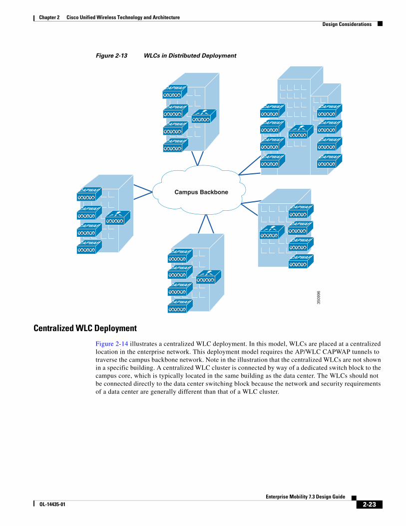
Figure 2-13 illustrates a distributed WLC deployment. In this model the WLCs are located throughout the campus network, typically on a per building basis, to manage the APs that are resident in the given building. The WLCs are connected to the campus network using the distribution routers within the building. In this scenario the CAPWAP tunnels, between APs and the WLC, typically stay within the building.
Each of the distributed WLCs could be configured as a separate RF group and Mobility group, so long as the WLAN coverage is not overlapping between buildings.
2-22Enterprise Mobility 7.3 Design Guide
OL-14435-01
Chapter 2 Cisco Unified Wireless Technology and ArchitectureDesign Considerations
Figure 2-13 WLCs in Distributed Deployment
Centralized WLC Deployment
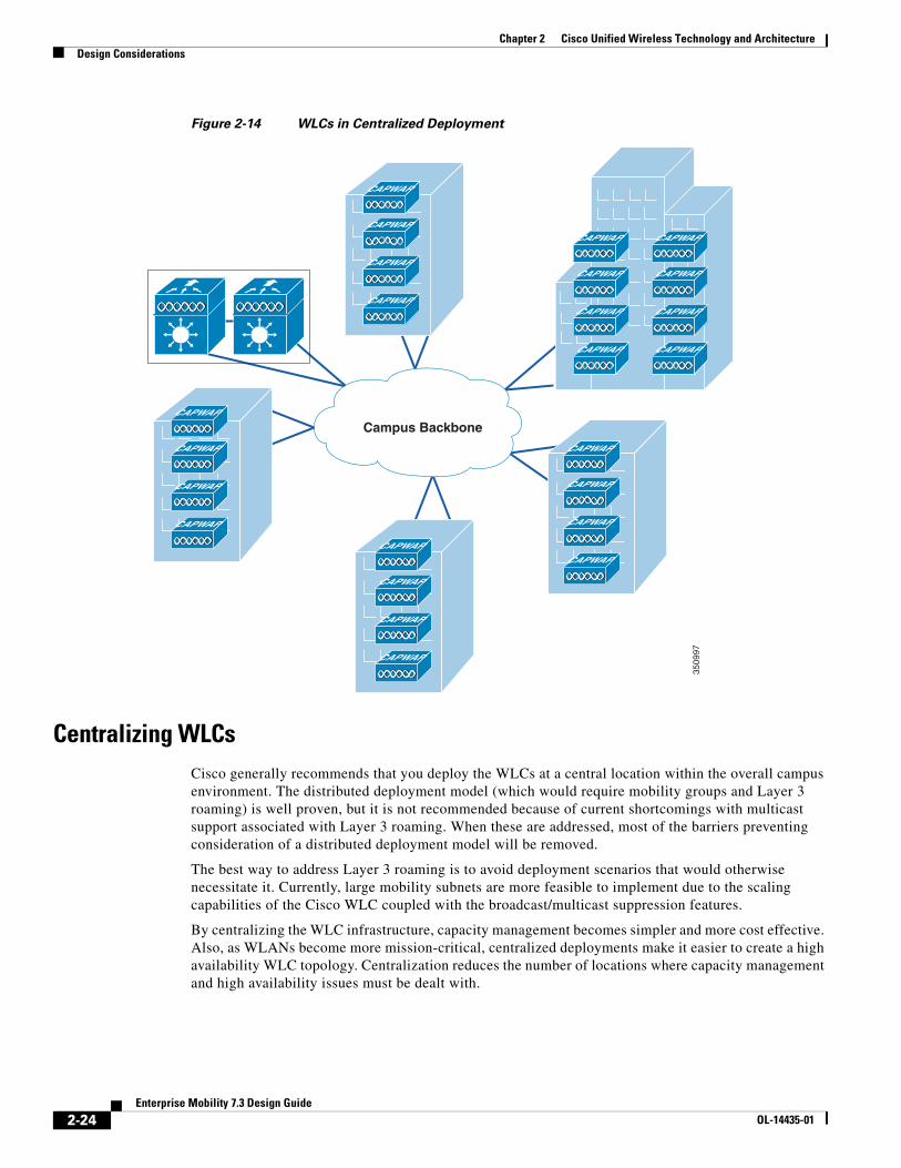
Figure 2-14 illustrates a centralized WLC deployment. In this model, WLCs are placed at a centralized location in the enterprise network. This deployment model requires the AP/WLC CAPWAP tunnels to traverse the campus backbone network. Note in the illustration that the centralized WLCs are not shown in a specific building. A centralized WLC cluster is connected by way of a dedicated switch block to the campus core, which is typically located in the same building as the data center. The WLCs should not be connected directly to the data center switching block because the network and security requirements of a data center are generally different than that of a WLC cluster.
3509
96
CAPWAP
CAPWAP
CAPWAP
CAPWAP
CAPWAP
CAPWAP
CAPWAP
CAPWAP
CAPWAP
CAPWAP
CAPWAP
CAPWAP
CAPWAP
CAPWAP
CAPWAP
CAPWAP
CAPWAP
CAPWAP
CAPWAP
CAPWAP
CAPWAP
Campus Backbone
CAPWAP
CAPWAP
CAPWAP
2-23Enterprise Mobility 7.3 Design Guide
OL-14435-01
Chapter 2 Cisco Unified Wireless Technology and ArchitectureDesign Considerations
Figure 2-14 WLCs in Centralized Deployment
Centralizing WLCsCisco generally recommends that you deploy the WLCs at a central location within the overall campus environment. The distributed deployment model (which would require mobility groups and Layer 3 roaming) is well proven, but it is not recommended because of current shortcomings with multicast support associated with Layer 3 roaming. When these are addressed, most of the barriers preventing consideration of a distributed deployment model will be removed.
The best way to address Layer 3 roaming is to avoid deployment scenarios that would otherwise necessitate it. Currently, large mobility subnets are more feasible to implement due to the scaling capabilities of the Cisco WLC coupled with the broadcast/multicast suppression features.
By centralizing the WLC infrastructure, capacity management becomes simpler and more cost effective. Also, as WLANs become more mission-critical, centralized deployments make it easier to create a high availability WLC topology. Centralization reduces the number of locations where capacity management and high availability issues must be dealt with.
3509
97
CAPWAP
CAPWAP
CAPWAP
CAPWAP
CAPWAP
CAPWAP
CAPWAP
CAPWAP
CAPWAP
CAPWAP
CAPWAP
CAPWAP
CAPWAP
CAPWAP
CAPWAP
CAPWAP
CAPWAP
CAPWAP
CAPWAP
CAPWAP
CAPWAP
CAPWAP
CAPWAP
CAPWAP
Campus Backbone
2-24Enterprise Mobility 7.3 Design Guide
OL-14435-01

Chapter 2 Cisco Unified Wireless Technology and ArchitectureDesign Considerations
The same principle applies when integrating the WLC with other infrastructure components. Centralized WLCs minimize the number of integration points and integration devices. For example, if a decision is made to implement an inline security device such as a NAC appliance, the centralized WLC will have one integration point whereas a distributed solution will have ’n’ integration points (where n equals the number of locations where WLCs are deployed).
In summary, a centralized WLC deployment is the preferred and recommended method. When planning any centralized WLC deployment, consideration must be given to the protection of the wired network infrastructure that directly connects to the WLC. This is because the WLC essentially attaches an access network at a location within the overall enterprise topology that would not otherwise be exposed to an access network and its associated vulnerabilities. Therefore, all security considerations normally associated with an access layer network device must be considered. For example, in a WISM-2-based deployment, features such as DoS protection and traffic storm protection should be considered because of the large-scale role the WISM-2 plays in providing diverse WLAN services to large numbers of end users while at the same time being directly connected to the backplane of a core multi-layer, multi-function Catalyst 6500 switching platform.
Distributed WLC Network ConnectivityA Layer 3 connected WLC, as shown in Figure 2-15 (in this case a Cisco 3750G), allows the WLAN-related software and configuration to be isolated to a single device and connects to the distribution layer using the same routing configuration as access layer routing devices.
Figure 2-15 Layer 3 Connected WLC
Traffic Load and Wired Network PerformanceWhen deploying a Cisco Unified Wireless Network solution, topics of discussion often include:
Clients
Audio Data Audio Data
3510
03
Layer 3
CAPWAP CAPWAP
2-25Enterprise Mobility 7.3 Design Guide
OL-14435-01
Chapter 2 Cisco Unified Wireless Technology and ArchitectureDesign Considerations
• CAPWAP traffic impact/load across the wired backbone.
• Minimum performance requirements to support a unified wireless deployment.
• Relative benefits of a distributed versus centralized WLC deployment in the context of traffic load on the network.
In examining the impact of the CAPWAP traffic in relation to overall network traffic volume, there are three main points to consider:
• Volume of CAPWAP control traffic
• Overhead introduced by tunneling
• Traffic engineering
Volume of CAPWAP Control Traffic
The volume of traffic associated with CAPWAP control can vary depending on the actual state of the network. For example, traffic volume is usually higher during a software upgrade or WLC reboot situations. Traffic studies have found that the average load CAPWAP control traffic places on the network is approximately 0.35 Kbps. In most campuses, this would be considered negligible and would be of no consequence when considering a centralized deployment model over a distributed one.
Overhead Introduced by Tunneling
A CAPWAP tunnel adds 44 bytes to a typical IP packet to and from a WLAN client. Given that average packets sizes found on typical enterprises are approximately 300 bytes, this represents an overhead of approximately 15 percent. In most campuses, this overhead would be considered negligible and again would be of no consequence when considering a centralized deployment model over a distributed one.
Traffic Engineering
Any WLAN traffic that is tunneled to a centralized WLC is then routed from the location of the WLC to its end destination in the network. Depending on the distance of the tunnel and location of the WLC, WLAN client traffic might not otherwise follow an optimal path to a given destination. In the case of a traditional access topology or distributed WLC deployment, client traffic enters the network at the edge and is optimally routed from that point based on destination address.
The longer tunnels and potentially inefficient traffic flows associated with a centralized deployment model can be partially mitigated by positioning the WLCs in that part of the network where most of the client traffic is destined (for example, a data center). Given the fact that most enterprise client traffic goes to servers in the data center and the enterprise backbone network is of low latency, any overhead associated with inefficient traffic flow would be negligible and would be of no consequence when considering a centralized deployment model over a distributed one.
For most enterprises, the introduction of a WLAN does not result in the introduction of new applications, at least not immediately. Therefore, the addition of a Cisco Unified Wireless Network alone is not likely to have a significant impact on the volume of campus backbone traffic.
2-26Enterprise Mobility 7.3 Design Guide
OL-14435-01

Chapter 2 Cisco Unified Wireless Technology and ArchitectureOperation and Maintenance
AP ConnectivityAPs should be on different subnets from the end users (802.11 clients). This is consistent with general best-practice guidelines that specify that infrastructure management interfaces should be on a separate subnet from end users. Additionally, Cisco recommends that Catalyst Integrated Security Features (CISF) be enabled on the CAPWAP AP switch ports to provide additional protection to the WLAN infrastructure. (FlexConnect AP connectivity is discussed in Chapter 7, “FlexConnect.”)
DHCP is generally the recommended method for AP address assignment, because it provides a simple mechanism for providing current WLC address information for ease of deployment. A static IP address can be assigned to APs, but requires more planning and individual configuration. Only APs with console ports permit static IP address configuration.
In order to effectively offer WLAN QoS within the Cisco Unified Wireless Network, QoS should also be enabled throughout the wired network that provides connectivity between CAPWAP APs and the WLCs.
Operation and MaintenanceThis section focuses on general deployment considerations and recommendations for easy operation and maintenance of a Cisco Unified Wireless Network deployment.
WLC Discovery
The different WLC discovery mechanisms for APs (discussed earlier) make initial deployment of CAPWAP APs very simple. Options include:
• Staging (priming) CAPWAP APs in advance using a WLC in a controlled environment
• Deploying them right out of the box by using one of the auto discovery mechanisms (DHCP or DNS)
Although auto discovery is highly useful, a network administrator will generally want to be able to control which WLC an AP will join once it is connected to the network for the first time. Subsequently, an administrator will want to define which WLC will be the primary for a given AP during normal operation in addition to configuring secondary and tertiary WLCs for backup purposes.
AP DistributionIn a typical initial WLAN deployment, the APs automatically distribute themselves across the available WLCs based on the load of each WLC. Although this process makes for an easy deployment, there are a number of operational reasons not to use the auto distribution method.
APs in the same physical location should be joined to the same WLC. This makes it easier for general management, operations and maintenance, allowing staff to control the impact that various operational tasks will have on a given location, and to be able to quickly associate WLAN issues with specific WLCs, whether it be roaming within a WLC, or roaming between WLCs.
The elements used to control AP distribution across multiple WLCs are:
• Primary, secondary, and tertiary WLC names—Each AP can be configured with a primary, secondary, and tertiary WLC name, which in turn determines the first three WLCs in the mobility group that the AP will prefer to join regardless of the load variations across WLCs in the mobility group.
2-27Enterprise Mobility 7.3 Design Guide
OL-14435-01
Chapter 2 Cisco Unified Wireless Technology and ArchitectureOperation and Maintenance
• Master WLC—When an AP joins a WLC for the first time in a mobility group, it is not yet configured with a preferred primary, secondary, and tertiary WLC; therefore, it will be eligible to partner with any WLC (within the mobility group) depending upon the perceived WLC load. If a WLC is configured as a master WLC, all APs without primary, secondary, and tertiary WLC definitions will join with the master WLC. This allows operations staff to easily find newly joined APs and control when they go into production by defining the primary, secondary, and tertiary WLCs name parameters.
2-28Enterprise Mobility 7.3 Design Guide
OL-14435-01