cisco ucs scale-up solution for sap hana - cisco - · pdf filecisco ucs scale-up solution for...
TRANSCRIPT
© 2016 Cisco and/or its affiliates. All rights reserved. This document is Cisco Public. Page 1 of 81
White Paper
Cisco UCS Scale-Up Solution for SAP HANA
Design and Deploy a SAP HANA Single-Node Solution Based on Standalone
Cisco UCS C460 M4 Rack Servers with SLES 11 SAP SP4
August 2016
© 2016 Cisco and/or its affiliates. All rights reserved. This document is Cisco Public. Page 2 of 81
Contents
Solution Overview Introduction Audience Purpose of This Document Solution Summary
Infrastructure Overview Cisco UCS C460 M4 Rack Server Physical Components Power Cabling Network Components
Solution Design SAP HANA System Hardware Requirements for the SAP HANA Database
Deployment Hardware and Software Configuration Guidelines
Preparing the SAP HANA Scale-Up Node Configuring the Cisco Integrated Management Controller Configuring RAID Installing the Operating System
Installing SAP HANA Important SAP Notes SAP HANA Post-Installation Checkup Tuning the SAP HANA Performance Parameters
Monitoring and Maintenance Operations Hardware Monitoring and Maintenance Upgrading the BIOS and Firmware on the Cisco UCS C460 M4 Monitoring the Operating System Maintaining the Operating System SAP HANA Operation and Maintenance
For More Information
Appendix: Solution Variables Used for This Document
© 2016 Cisco and/or its affiliates. All rights reserved. This document is Cisco Public. Page 3 of 81
Executive Summary
Organizations in every industry are generating and using more data than ever before: from customer transactions
and supplier delivery considerations to real-time user-consumption statistics. Without reliable infrastructure that can
store, process, and analyze big data sets in real time, companies are unable to use this information to their
advantage. The Cisco® Scale-Up Solution for SAP HANA with the Cisco Unified Computing System
™ (Cisco UCS)
using the Cisco UCS C460 M4 Rack Server helps companies more easily harness information and make better
business decisions that let them stay ahead of the competition. Our solutions help improve access to all your data
to accelerate business decision making with policy-based, simplified management; lower deployment risk; and
reduced total cost of ownership (TCO). Our innovations help enable you to unlock the intelligence in your data and
interpret it with a new dimension of context and insight to help you gain a sustainable, competitive business
advantage.
The Cisco solution for SAP HANA with the Cisco UCS C460 M4 rack-mount server provides a robust platform for
SAP HANA workloads in a single node.
Solution Overview
Introduction
The Cisco UCS C460 M4 scale-up solution provides prevalidated, ready-to-deploy infrastructure, reducing the time
and complexity involved in configuring and validating a traditional data center deployment. The reference
architecture detailed in this document highlights the resiliency and ease of deployment of a SAP HANA solution.
SAP HANA is SAP’s implementation of in-memory database technology. The SAP HANA database takes
advantage of low-cost main memory (RAM), faster access, and data-processing capabilities of multicore
processors to provide better performance for analytical and transactional applications. SAP HANA offers a multiple-
engine, query-processing environment that supports relational data (with both row- and column-oriented physical
representations in a hybrid engine) as well as a graph and text processing for semistructured and unstructured
data management within the same system. As an appliance, SAP HANA combines software components from SAP
optimized for certified hardware. However, this solution has a preconfigured hardware setup and preinstalled
software package that is dedicated to SAP HANA. In 2013, SAP introduced the SAP HANA Tailored Datacenter
Integration (TDI) option. TDI offers a more open and flexible way to integrate SAP HANA into the data center by
reusing existing enterprise storage hardware, thereby reducing hardware costs. With the introduction of SAP HANA
TDI for shared infrastructure, the Cisco UCS Integrated Infrastructure solution provides the advantages of an
integrated computing, storage, and network stack and the programmability of Cisco UCS. The TDI option enables
organizations to run multiple SAP HANA production systems on a shared infrastructure. It also enables customers
to run SAP application servers and SAP HANA database hosted on the same infrastructure.
For more information about SAP HANA, see the SAP help portal: http://help.sap.com/hana/.
Audience
The intended audience for this document includes sales engineers, field consultants, professional services staff, IT
managers, partner engineers, and customers deploying the Cisco solution for SAP HANA. External references are
provided wherever applicable, but readers are expected to be familiar with the technology, infrastructure, and
database security policies of the customer installation.
© 2016 Cisco and/or its affiliates. All rights reserved. This document is Cisco Public. Page 4 of 81
Purpose of This Document
This document describes the steps required to deploy and configure a Cisco data center solution for SAP HANA.
This document showcases one of the variants of Cisco’s solution for SAP HANA. Although readers of this
document are expected to have sufficient knowledge to install and configure the products used, configuration
details that are important to the deployment of this solution are provided in this Whitepaper.
Solution Summary
The Cisco Scale-Up Solution for SAP HANA is based on the Cisco UCS C460 M4 Rack Server. Tables 1, 2, and 3
summarize the server specifications and show proposed disk configurations for the SAP HANA use case.
Table 1. Overview of Cisco UCS C460 M4 Server Configuration
CPU Specification 2.20-GHz Intel® Xeon
® processor E7-8890 v4 CPU (Quantity: 2 or 4)
Analytics SAP Business Suite on SAP HANA (SoH)
Possible Memory Configurations ● 16-GB DDR4: Quantity 8 (128 GB)
● 16-GB DDR4: Quantity 16 (256 GB)
● 16-GB DDR4: Quantity 32 (512 GB)
● 16-GB DDR4: Quantity 48 (768 GB)
● 16-GB DDR4: Quantity 64 (1 TB)
● 16-GB DDR4: Quantity 96 (1.5 TB)
● 16-GB DDR4: Quantity 8 (128 GB)
● 16-GB DDR4: Quantity 16 (256 GB)
● 16-GB DDR4: Quantity 32 (512 GB)
● 16-GB DDR4: Quantity 48 (768 GB)
● 16-GB DDR4: Quantity 64 (1 TB)
● 16-GB DDR4: Quantity 96 (1.5 TB)
● 32-GB DDR4: Quantity 64 (2 TB)
● 32-GB DDR4: Quantity 96 (3 TB)
● 64-GB DDR4: Quantity 64 (4 TB)
Hard-Disk Drive (HDD) Type and Quantity 1.6-TB solid-state disk (SSD) drive: Quantity 12
BIOS C460M4.2.0.11.22.02062016063 or higher
Cisco Integrated Management Controller (IMC) Firmware
Version 2.0(11.203) or higher
LSI MegaRAID Controller Cisco 12-GB SAS modular RAID controller
Network Card Cisco UCS Virtual Interface Card (VIC) 1225: Quantity 2
For 10-Gbps connectivity:
● Onboard Intel 1 Gigabit Ethernet controller: Quantity 2
● Onboard Intel 10BASE-T Ethernet controller: Quantity 2
Power Supply Redundant power supplies: Quantity 4
Table 2. Cisco UCS C460 M4 Proposed Disk Layout
Disk Disk Type Drive Group RAID Level Virtual Drive
Slot (1 through 12) SSD DG0 5 VD0
Table 3. Cisco UCS C460 M4 Proposed Disk Configuration
Drives Used RAID Type Used for File System
12 x 1.6-TB SSD drives RAID 5 Operating system ext3
Data file system XFS
Log file system XFS
SAP Hana shared file system XFS
© 2016 Cisco and/or its affiliates. All rights reserved. This document is Cisco Public. Page 5 of 81
Infrastructure Overview
Cisco UCS C460 M4 Rack Server
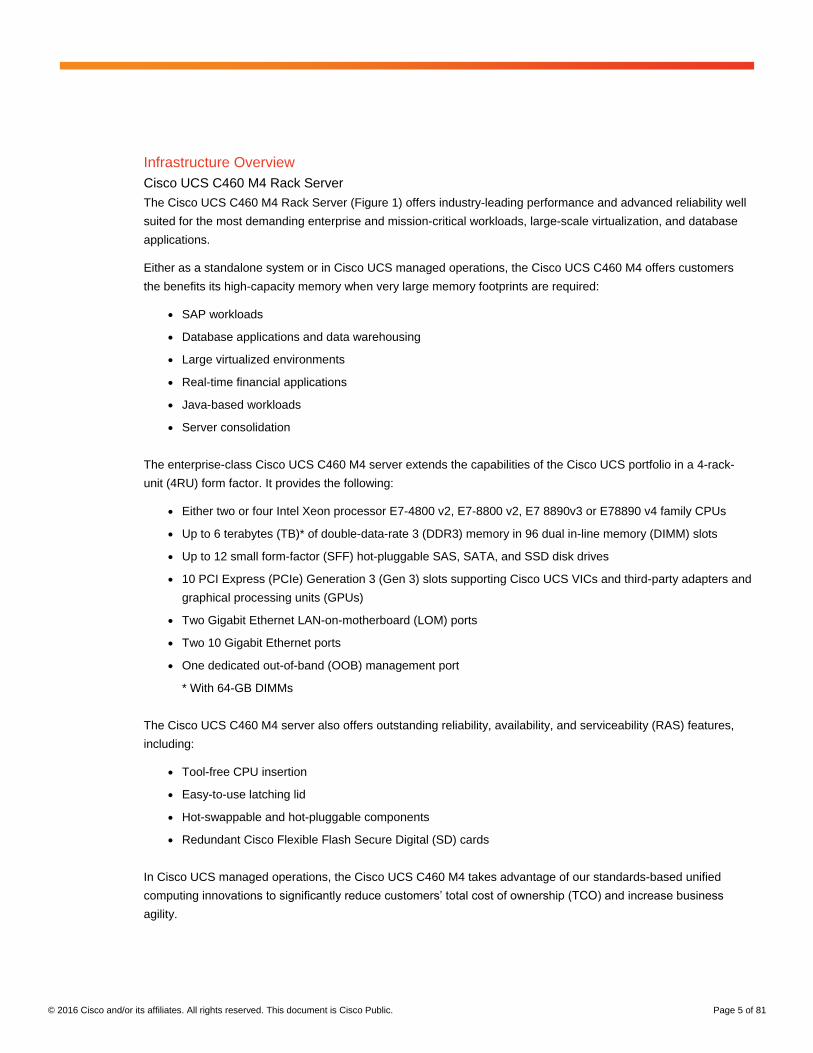
The Cisco UCS C460 M4 Rack Server (Figure 1) offers industry-leading performance and advanced reliability well
suited for the most demanding enterprise and mission-critical workloads, large-scale virtualization, and database
applications.
Either as a standalone system or in Cisco UCS managed operations, the Cisco UCS C460 M4 offers customers
the benefits its high-capacity memory when very large memory footprints are required:
● SAP workloads
● Database applications and data warehousing
● Large virtualized environments
● Real-time financial applications
● Java-based workloads
● Server consolidation
The enterprise-class Cisco UCS C460 M4 server extends the capabilities of the Cisco UCS portfolio in a 4-rack-
unit (4RU) form factor. It provides the following:
● Either two or four Intel Xeon processor E7-4800 v2, E7-8800 v2, E7 8890v3 or E78890 v4 family CPUs
● Up to 6 terabytes (TB)* of double-data-rate 3 (DDR3) memory in 96 dual in-line memory (DIMM) slots
● Up to 12 small form-factor (SFF) hot-pluggable SAS, SATA, and SSD disk drives
● 10 PCI Express (PCIe) Generation 3 (Gen 3) slots supporting Cisco UCS VICs and third-party adapters and
graphical processing units (GPUs)
● Two Gigabit Ethernet LAN-on-motherboard (LOM) ports
● Two 10 Gigabit Ethernet ports
● One dedicated out-of-band (OOB) management port
* With 64-GB DIMMs
The Cisco UCS C460 M4 server also offers outstanding reliability, availability, and serviceability (RAS) features,
including:
● Tool-free CPU insertion
● Easy-to-use latching lid
● Hot-swappable and hot-pluggable components
● Redundant Cisco Flexible Flash Secure Digital (SD) cards
In Cisco UCS managed operations, the Cisco UCS C460 M4 takes advantage of our standards-based unified
computing innovations to significantly reduce customers’ total cost of ownership (TCO) and increase business
agility.
© 2016 Cisco and/or its affiliates. All rights reserved. This document is Cisco Public. Page 6 of 81
Figure 1. Cisco UCS C460 M4 Rack Server
Physical Components
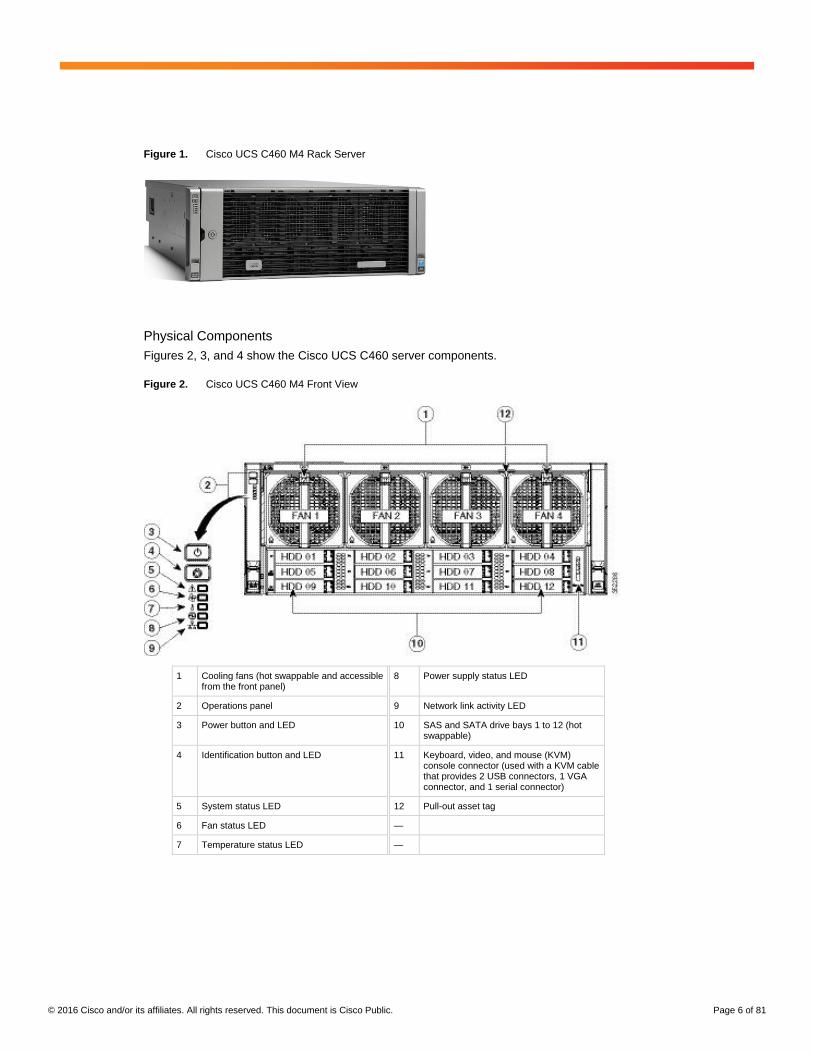
Figures 2, 3, and 4 show the Cisco UCS C460 server components.
Figure 2. Cisco UCS C460 M4 Front View
1 Cooling fans (hot swappable and accessible from the front panel)
8 Power supply status LED
2 Operations panel 9 Network link activity LED
3 Power button and LED 10 SAS and SATA drive bays 1 to 12 (hot swappable)
4 Identification button and LED 11 Keyboard, video, and mouse (KVM) console connector (used with a KVM cable that provides 2 USB connectors, 1 VGA connector, and 1 serial connector)
5 System status LED 12 Pull-out asset tag
6 Fan status LED —
7 Temperature status LED —
© 2016 Cisco and/or its affiliates. All rights reserved. This document is Cisco Public. Page 7 of 81
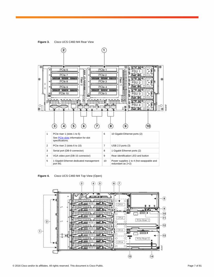
Figure 3. Cisco UCS C460 M4 Rear View
1 PCIe riser 1 (slots 1 to 5)
See PCIe slots information for slot specifications.
6 10 Gigabit Ethernet ports (2)
2 PCIe riser 2 (slots 6 to 10) 7 USB 2.0 ports (3)
3 Serial port (DB-9 connector) 8 1 Gigabit Ethernet ports (2)
4 VGA video port (DB-15 connector) 9 Rear identification LED and button
5 1 Gigabit Ethernet dedicated management port M1
10 Power supplies 1 to 4 (hot swappable and redundant as 2+2)
Figure 4. Cisco UCS C460 M4 Top View (Open)
© 2016 Cisco and/or its affiliates. All rights reserved. This document is Cisco Public. Page 8 of 81
1 PCIe riser 1 (slots 1 to 5)
See PCIe slots information for slot specifications.
6 10 Gigabit Ethernet ports (2)
2 PCIe riser 2 (slots 6 to 10) 7 USB 2.0 ports (3)
3 Serial port (DB-9 connector) 8 1 Gigabit Ethernet ports (2)
4 VGA video port (DB-15 connector) 9 Rear identification LED and button
5 1 Gigabit Ethernet dedicated management port M1
10 Power supplies 1 to 4 (hot swappable and redundant as 2+2)
Power Cabling
The standard power supply setup is 1+1. Therefore, both power supplies must be connected to one grid, and the
server tolerates the failure of one power supply. However, a grid failure is not protected.
To protect against a grid failure, each power supply must be connected to a completely separate grid connection.
This setup is the preferred installation and is recommended to the customer.
Network Components
The Cisco UCS C460 server is equipped with a management board for remote management over the network. This
board includes virtual KVM access at the hardware level.
The M1 interface must be connected to the console network at the customer’s location.
The server is also equipped with four onboard network interfaces. For this appliance, the following interfaces were
used:
● Two 1 Gigabit Ethernet interfaces (number 8 in Figure 3) are available for management access.
● Two Cisco VICs are available in this rack-mounted server for application access.
The VIC that comes with the Cisco UCS C460 M4 server can be configured to provide multiple virtual network
interface cards (vNICs) as needed by the implemented use case.
Cisco UCS VIC 1225
The Cisco UCS VIC 1225 option was used in the validation system and is also used an example in this document.
However other VICs, such as the Cisco UCS VIC 1285 or 1385 are also supported and the configuration principles
will remain the same.
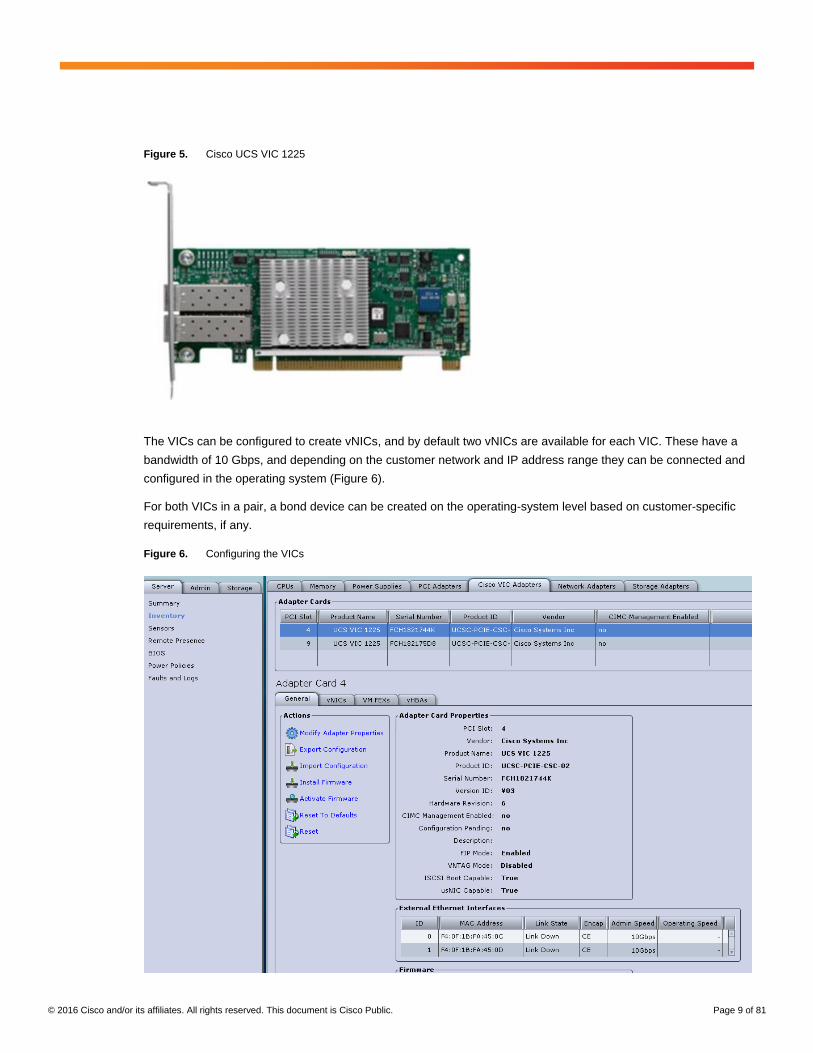
A Cisco innovation, the Cisco UCS VIC 1225 (Figure 5) is a dual-port Enhanced Small Form-Factor Pluggable
(SFP+) 10 Gigabit Ethernet and Fibre Channel over Ethernet (FCoE)–capable PCIe card designed exclusively for
Cisco UCS C-Series Rack Servers. The VIC 1225 lets you create multiple vNICs (up to 128) on the converged
network adapter (CNA). This feature allows complete I/O configurations to be provisioned in both virtualized and
nonvirtualized environments using just-in-time provisioning, providing tremendous system flexibility and allowing
consolidation of multiple physical adapters. System security and manageability is improved by providing network
policy and security visibility and portability all the way to the virtual machines.
© 2016 Cisco and/or its affiliates. All rights reserved. This document is Cisco Public. Page 9 of 81
Figure 5. Cisco UCS VIC 1225
The VICs can be configured to create vNICs, and by default two vNICs are available for each VIC. These have a
bandwidth of 10 Gbps, and depending on the customer network and IP address range they can be connected and
configured in the operating system (Figure 6).
For both VICs in a pair, a bond device can be created on the operating-system level based on customer-specific
requirements, if any.
Figure 6. Configuring the VICs
© 2016 Cisco and/or its affiliates. All rights reserved. This document is Cisco Public. Page 10 of 81
Solution Design
This section describes the SAP HANA system requirements defined by SAP and the architecture of the Cisco UCS
solution for SAP HANA.
SAP HANA System
An SAP HANA scale-up system on a single server is the simplest of the installation types. It is possible to run an
SAP HANA system entirely on one host and then scale the system up as needed. All data and processes are
located on the same server and can be accessed locally. The network requirements for this option are at least one
1 Gigabit Ethernet access network and one 10 Gigabit Ethernet storage network.
Hardware Requirements for the SAP HANA Database
SAP defines hardware and software requirements for running SAP HANA systems. For latest information on the
CPU and Memory configuration supported for SAP HANA please refer
https://global.sap.com/community/ebook/2014-09-02-hana-hardware/enEN/index.html
Note: This document does not cover the updated information published by SAP. Additional information is
available at http://saphana.com.
File System Layout
Figure 7 shows the file system layout and the required storage sizes for installing and operating SAP HANA. When
installing SAP HANA on a host, specify the mount point for the installation binaries (/hana/shared/<sid>), data files
(/hana/data/<sid>), and log files (/hana/log/<sid>), where sid is the instance identifier of the SAP HANA installation.
Figure 7. Proposed Disk Layout with Partition Mapping
The storage size for the file system is based on the amount of memory on the SAP HANA host.

© 2016 Cisco and/or its affiliates. All rights reserved. This document is Cisco Public. Page 11 of 81
The following shows sample file system sizes for a single-node system with 3 TB of memory:
● /hana/shared: 1 x memory (3 TB)
● /hana/data: 3 x memory (9 TB)
● /hana/log: 1 x memory (512 GB)*
* For solutions based on the Intel Xeon processor E7-88x0 v4 CPU, the size of the log volume must be as
follows:
◦ Half of the server memory for systems ≤ 256 GB of memory
◦ Minimum of 512 GB for systems with ≥ 512 GB of memory
Operating System
SAP HANA supports the following operating systems:
● SUSE Linux Enterprise Server (SLES) for SAP applications
● Red Hat Enterprise Linux (RHEL) for SAP HANA
Note: This document provides Installation steps for SLES 11 for SAP SP4.
Deployment Hardware and Software
Configuration Guidelines
This section is intended to enable you to fully configure the customer environment. In this process, various steps
require you to insert customer-specific naming conventions, IP addresses, and VLAN schemes, as well as to
record appropriate MAC addresses. Table 4 lists the configuration variables that are used throughout this
document. This table can be completed based on the specific site variables and used in implementing the
configuration steps presented in this document.
Table 4. Configuration Variables
Variable Description Customer Implementation Value
<<var_cimc_ip_address>> Cisco UCS C460 M4 server’s IMC IP address
<<var_cimc_ip_netmask>> Cisco UCS C460 M4 server’s IMC network netmask
<<var_cimc_gateway_ip>> Cisco UCS C460 M4 server’s IMC network gateway IP address
<<var_raid5_vd_name>> Name for virtual drive VD0 during RAID configuration
<<var_hostname.domain>> SAP HANA node’s fully qualified domain name (FQDN)
<<var_sys_root-pw>> SAP HANA node’s root password
<<var_lvm_vg_name>> SAP HANA node’s OS logical volume management (LVM) volume group name
<<var_mgmt_ip_address>> SAP HANA node’s management and administration IP address
<<var_mgmt_nw_netmask>> SAP HANA node’s management network netmask
<<var_mgmt_gateway_ip>> Cisco UCS C460 M4 server’s management and administration network gateway IP address
<<var_mgmt_netmask_prefix>> Netmask prefix in Classless Inter-Domain Routing (CIDR) notation
© 2016 Cisco and/or its affiliates. All rights reserved. This document is Cisco Public. Page 12 of 81
Preparing the SAP HANA Scale-Up Node
Configuring the Cisco Integrated Management Controller
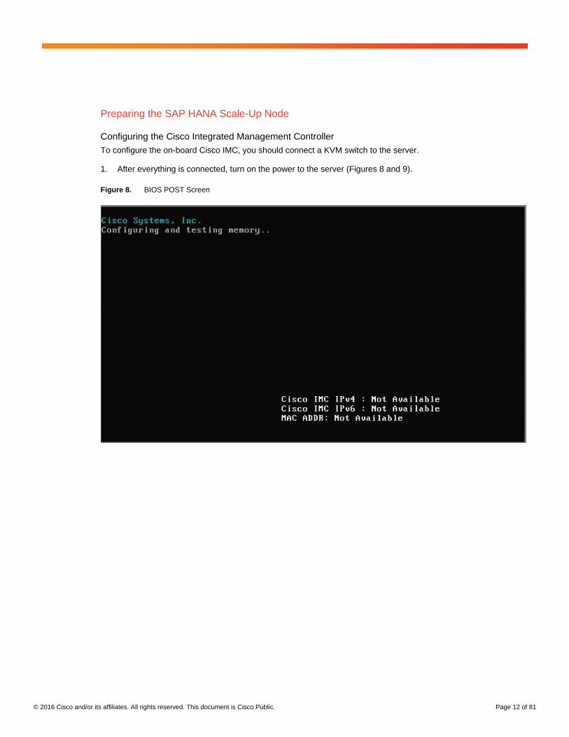
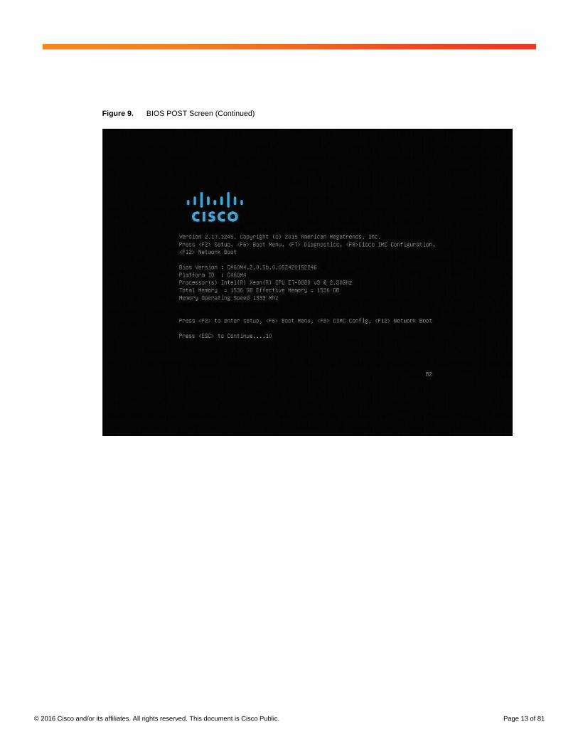
To configure the on-board Cisco IMC, you should connect a KVM switch to the server.
1. After everything is connected, turn on the power to the server (Figures 8 and 9).
Figure 8. BIOS POST Screen
© 2016 Cisco and/or its affiliates. All rights reserved. This document is Cisco Public. Page 13 of 81
Figure 9. BIOS POST Screen (Continued)
© 2016 Cisco and/or its affiliates. All rights reserved. This document is Cisco Public. Page 14 of 81
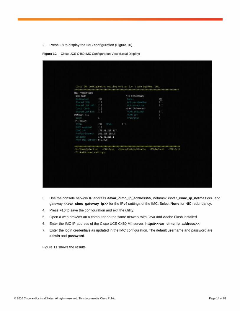
2. Press F8 to display the IMC configuration (Figure 10).
Figure 10. Cisco UCS C460 IMC Configuration View (Local Display)
3. Use the console network IP address <<var_cimc_ip_address>>, netmask <<var_cimc_ip_netmask>>, and
gateway <<var_cimc_gateway_ip>> for the IPv4 settings of the IMC. Select None for NIC redundancy.
4. Press F10 to save the configuration and exit the utility.
5. Open a web browser on a computer on the same network with Java and Adobe Flash installed.
6. Enter the IMC IP address of the Cisco UCS C460 M4 server: http://<<var_cimc_ip_address>>.
7. Enter the login credentials as updated in the IMC configuration. The default username and password are
admin and password.
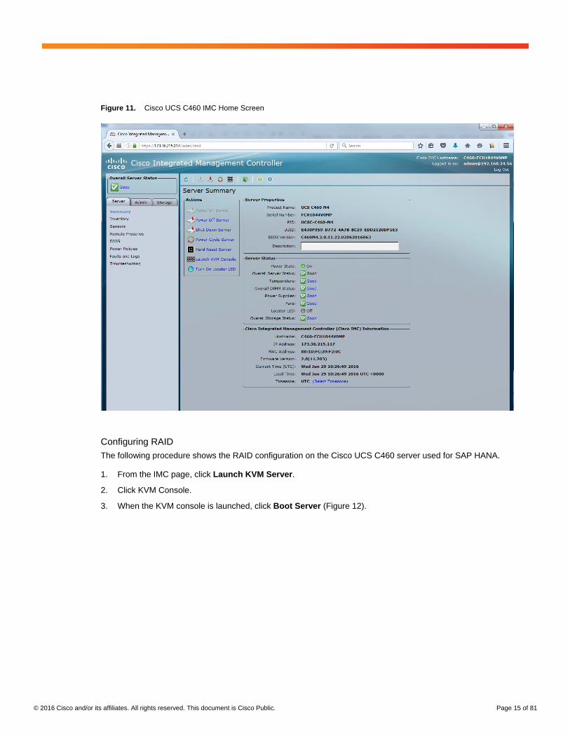
Figure 11 shows the results.
© 2016 Cisco and/or its affiliates. All rights reserved. This document is Cisco Public. Page 15 of 81
Figure 11. Cisco UCS C460 IMC Home Screen
Configuring RAID
The following procedure shows the RAID configuration on the Cisco UCS C460 server used for SAP HANA.
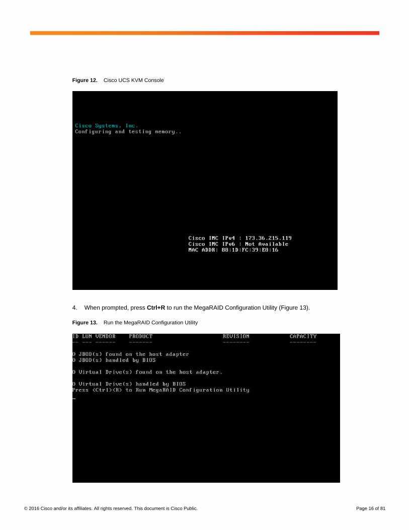
1. From the IMC page, click Launch KVM Server.
2. Click KVM Console.
3. When the KVM console is launched, click Boot Server (Figure 12).
© 2016 Cisco and/or its affiliates. All rights reserved. This document is Cisco Public. Page 16 of 81
Figure 12. Cisco UCS KVM Console
4. When prompted, press Ctrl+R to run the MegaRAID Configuration Utility (Figure 13).
Figure 13. Run the MegaRAID Configuration Utility
© 2016 Cisco and/or its affiliates. All rights reserved. This document is Cisco Public. Page 17 of 81
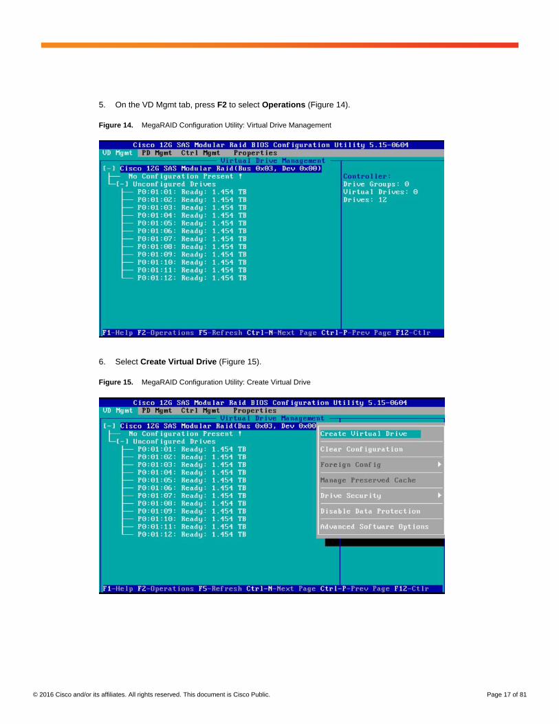
5. On the VD Mgmt tab, press F2 to select Operations (Figure 14).
Figure 14. MegaRAID Configuration Utility: Virtual Drive Management
6. Select Create Virtual Drive (Figure 15).
Figure 15. MegaRAID Configuration Utility: Create Virtual Drive
© 2016 Cisco and/or its affiliates. All rights reserved. This document is Cisco Public. Page 18 of 81
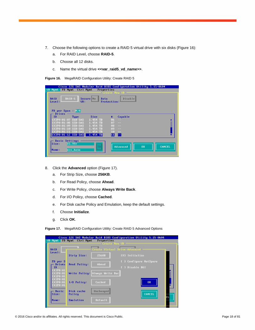
7. Choose the following options to create a RAID 5 virtual drive with six disks (Figure 16):
a. For RAID Level, choose RAID-5.
b. Choose all 12 disks.
c. Name the virtual drive <<var_raid5_vd_name>>.
Figure 16. MegaRAID Configuration Utility: Create RAID 5
8. Click the Advanced option (Figure 17).
a. For Strip Size, choose 256KB.
b. For Read Policy, choose Ahead.
c. For Write Policy, choose Always Write Back.
d. For I/O Policy, choose Cached.
e. For Disk cache Policy and Emulation, keep the default settings.
f. Choose Initialize.
g. Click OK.
Figure 17. MegaRAID Configuration Utility: Create RAID 5 Advanced Options
© 2016 Cisco and/or its affiliates. All rights reserved. This document is Cisco Public. Page 19 of 81
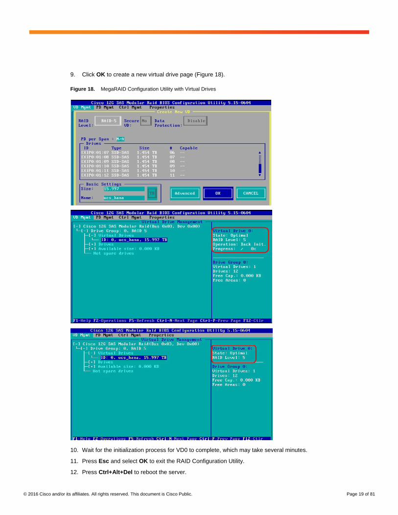
9. Click OK to create a new virtual drive page (Figure 18).
Figure 18. MegaRAID Configuration Utility with Virtual Drives
10. Wait for the initialization process for VD0 to complete, which may take several minutes.
11. Press Esc and select OK to exit the RAID Configuration Utility.
12. Press Ctrl+Alt+Del to reboot the server.
© 2016 Cisco and/or its affiliates. All rights reserved. This document is Cisco Public. Page 20 of 81
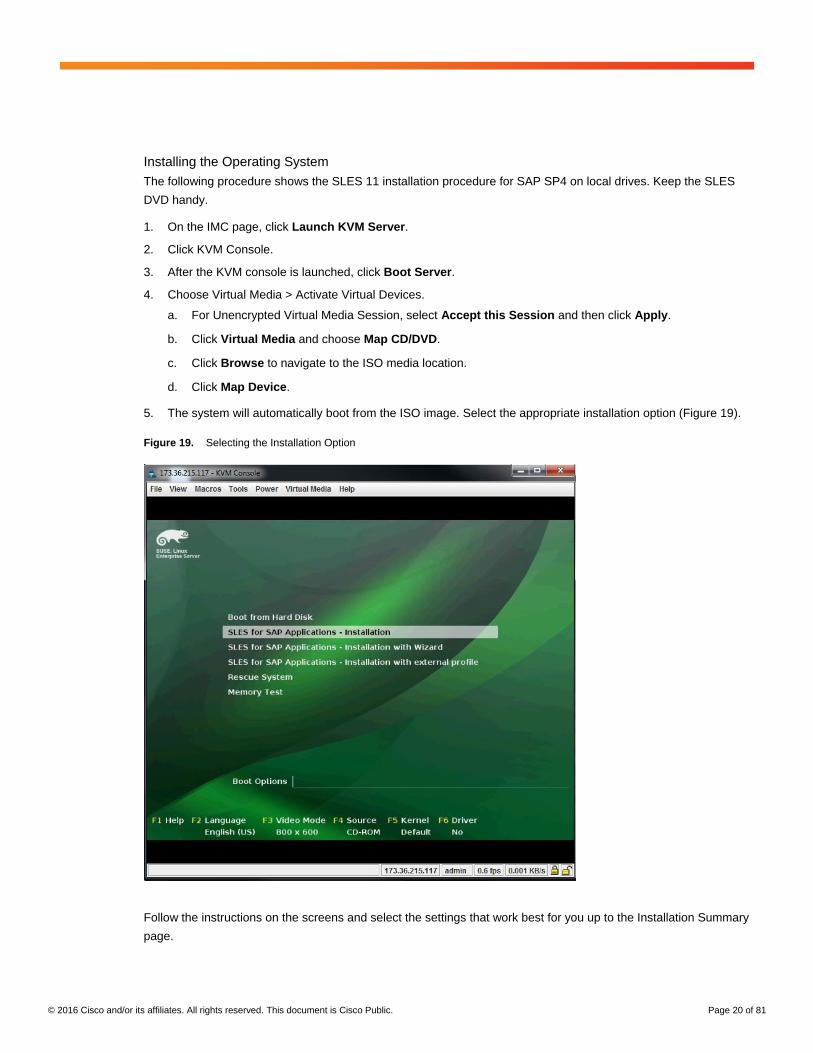
Installing the Operating System
The following procedure shows the SLES 11 installation procedure for SAP SP4 on local drives. Keep the SLES
DVD handy.
1. On the IMC page, click Launch KVM Server.
2. Click KVM Console.
3. After the KVM console is launched, click Boot Server.
4. Choose Virtual Media > Activate Virtual Devices.
a. For Unencrypted Virtual Media Session, select Accept this Session and then click Apply.
b. Click Virtual Media and choose Map CD/DVD.
c. Click Browse to navigate to the ISO media location.
d. Click Map Device.
5. The system will automatically boot from the ISO image. Select the appropriate installation option (Figure 19).
Figure 19. Selecting the Installation Option
Follow the instructions on the screens and select the settings that work best for you up to the Installation Summary
page.

© 2016 Cisco and/or its affiliates. All rights reserved. This document is Cisco Public. Page 21 of 81
The best way to interact with the system is through keyboard shortcuts. Notice that some letters are underlined: for
example, I Agree and Next.
You can use the ALT key together with the letter that is underlined to activate this option or to move to the next
screen. As shown on the next screen, ALT+A marks the checkbox to agree to the license terms, and ALT+N takes
you to the next screen.
6. On the Welcome screen, select Agree to license terms and click Next.
7. On the Media Check page, click Next to skip the media check.
8. For Installation Mode, select New Installation.
9. For Clock and Time Zone, choose the appropriate time zone and select Hardware clock set to UTC.
10. For Server Base Scenario, select Physical Machine.
11. For Installation Settings, click Change and select Partitioning (Figure 20).
Figure 20. Selecting the Installation Settings
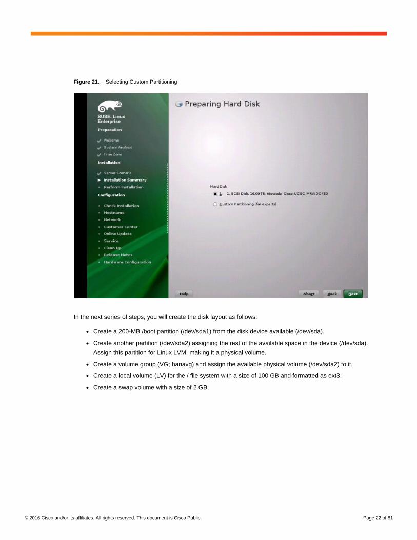
12. For Preparing Hard Disk, select Custom Partitioning (Figure 21).
© 2016 Cisco and/or its affiliates. All rights reserved. This document is Cisco Public. Page 22 of 81
Figure 21. Selecting Custom Partitioning
In the next series of steps, you will create the disk layout as follows:
● Create a 200-MB /boot partition (/dev/sda1) from the disk device available (/dev/sda).
● Create another partition (/dev/sda2) assigning the rest of the available space in the device (/dev/sda).
Assign this partition for Linux LVM, making it a physical volume.
● Create a volume group (VG; hanavg) and assign the available physical volume (/dev/sda2) to it.
● Create a local volume (LV) for the / file system with a size of 100 GB and formatted as ext3.
● Create a swap volume with a size of 2 GB.
© 2016 Cisco and/or its affiliates. All rights reserved. This document is Cisco Public. Page 23 of 81
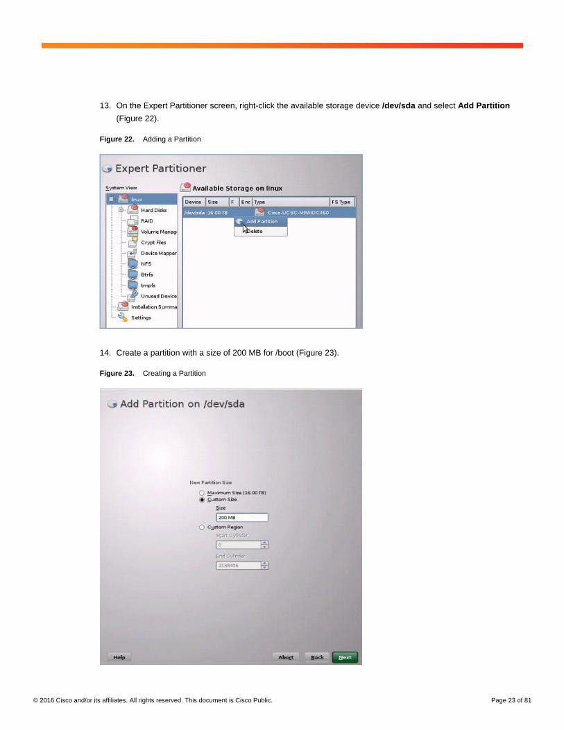
13. On the Expert Partitioner screen, right-click the available storage device /dev/sda and select Add Partition
(Figure 22).
Figure 22. Adding a Partition
14. Create a partition with a size of 200 MB for /boot (Figure 23).
Figure 23. Creating a Partition
© 2016 Cisco and/or its affiliates. All rights reserved. This document is Cisco Public. Page 24 of 81
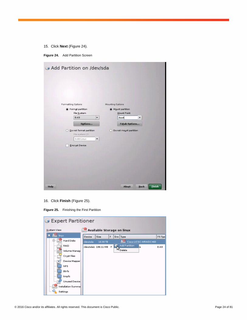
15. Click Next (Figure 24).
Figure 24. Add Partition Screen
16. Click Finish (Figure 25).
Figure 25. Finishing the First Partition
© 2016 Cisco and/or its affiliates. All rights reserved. This document is Cisco Public. Page 25 of 81
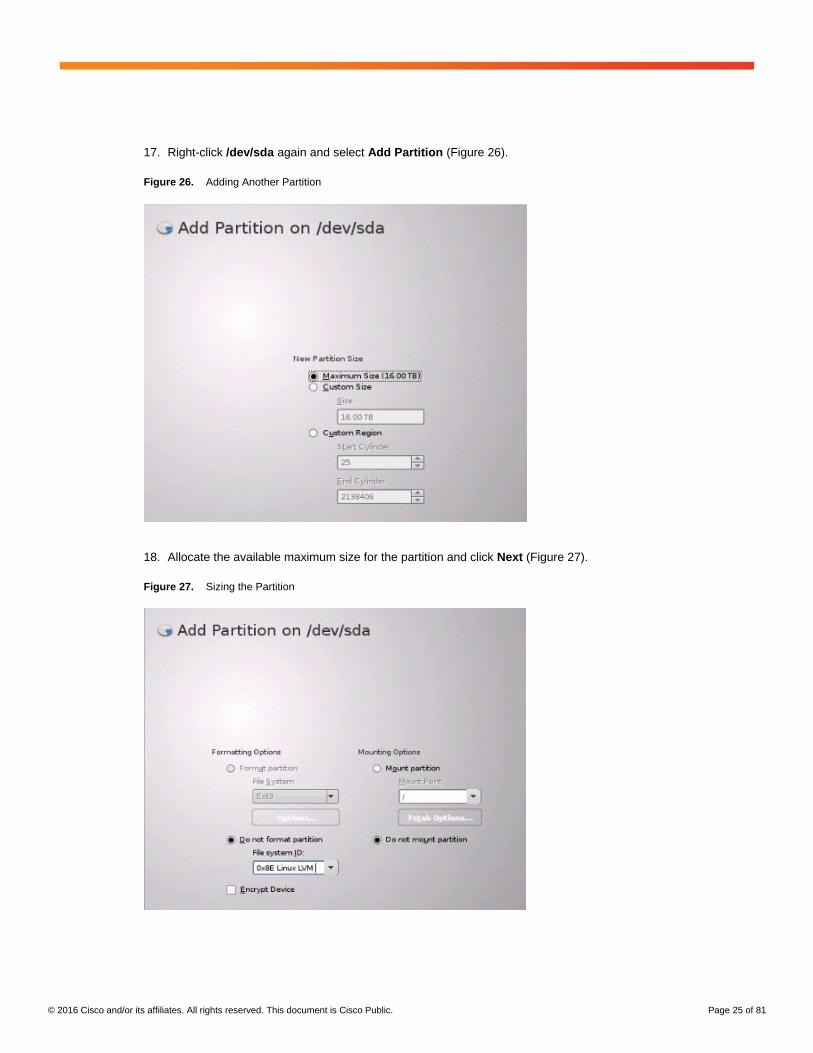
17. Right-click /dev/sda again and select Add Partition (Figure 26).
Figure 26. Adding Another Partition
18. Allocate the available maximum size for the partition and click Next (Figure 27).
Figure 27. Sizing the Partition
© 2016 Cisco and/or its affiliates. All rights reserved. This document is Cisco Public. Page 26 of 81
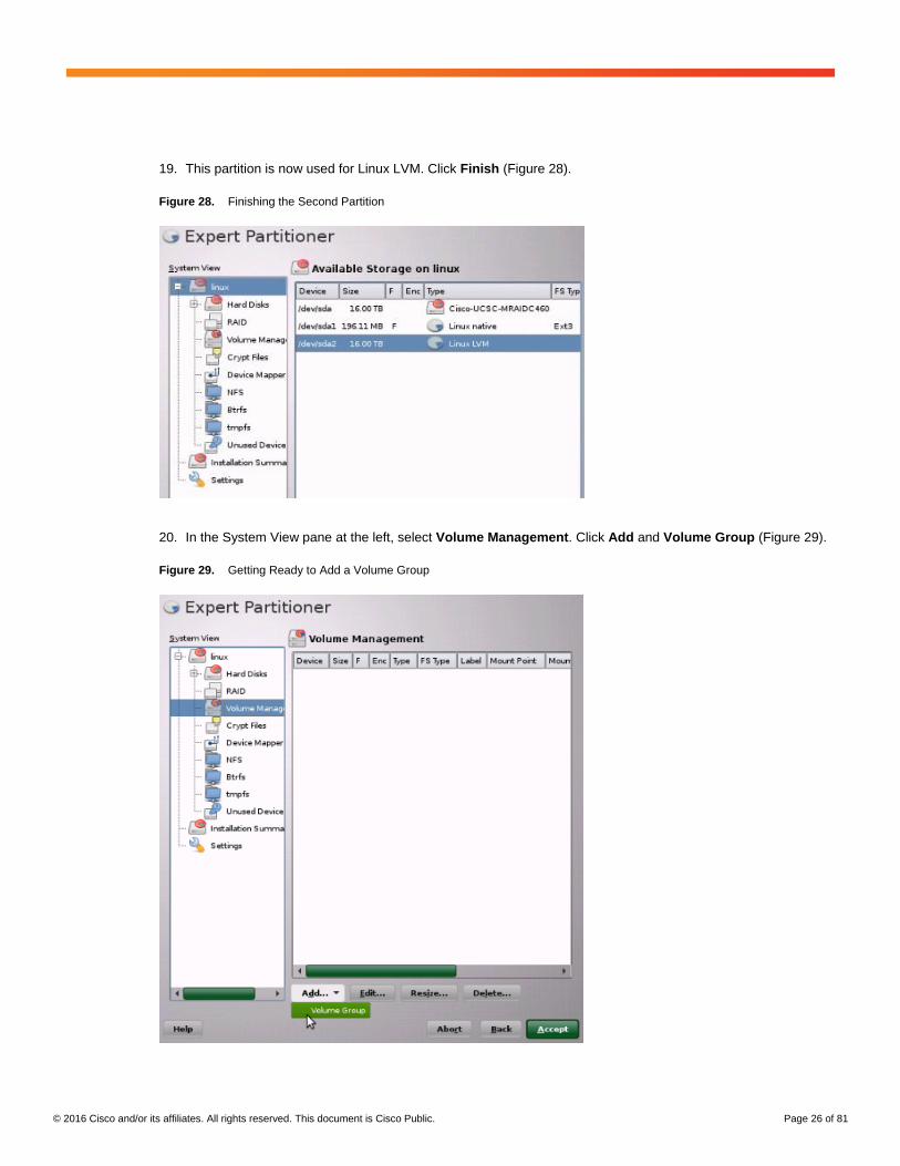
19. This partition is now used for Linux LVM. Click Finish (Figure 28).
Figure 28. Finishing the Second Partition
20. In the System View pane at the left, select Volume Management. Click Add and Volume Group (Figure 29).
Figure 29. Getting Ready to Add a Volume Group
© 2016 Cisco and/or its affiliates. All rights reserved. This document is Cisco Public. Page 27 of 81
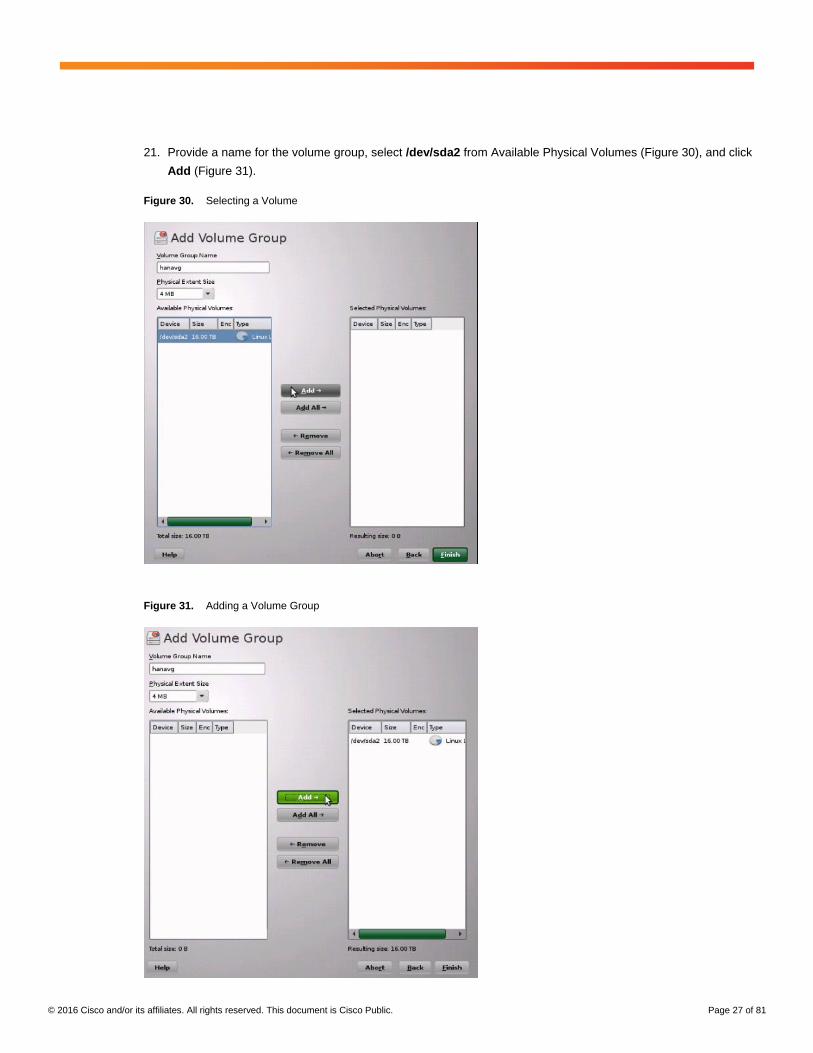
21. Provide a name for the volume group, select /dev/sda2 from Available Physical Volumes (Figure 30), and click
Add (Figure 31).
Figure 30. Selecting a Volume
Figure 31. Adding a Volume Group
© 2016 Cisco and/or its affiliates. All rights reserved. This document is Cisco Public. Page 28 of 81
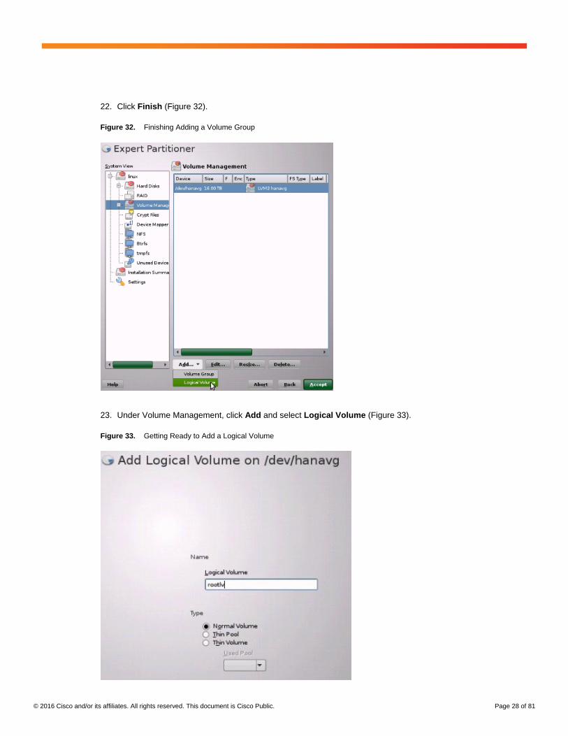
22. Click Finish (Figure 32).
Figure 32. Finishing Adding a Volume Group
23. Under Volume Management, click Add and select Logical Volume (Figure 33).
Figure 33. Getting Ready to Add a Logical Volume
© 2016 Cisco and/or its affiliates. All rights reserved. This document is Cisco Public. Page 29 of 81
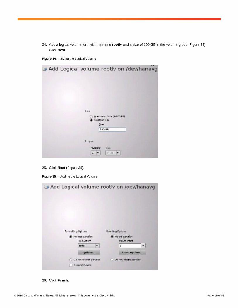
24. Add a logical volume for / with the name rootlv and a size of 100 GB in the volume group (Figure 34).
Click Next.
Figure 34. Sizing the Logical Volume
25. Click Next (Figure 35).
Figure 35. Adding the Logical Volume
26. Click Finish.
© 2016 Cisco and/or its affiliates. All rights reserved. This document is Cisco Public. Page 30 of 81
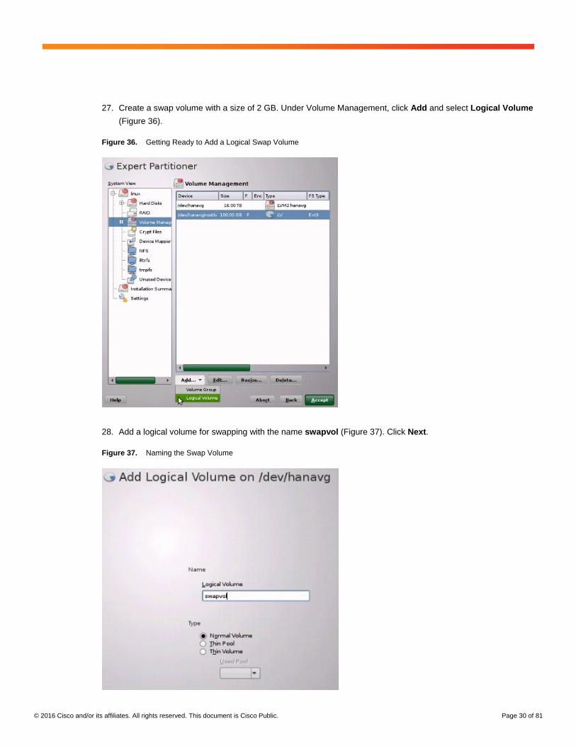
27. Create a swap volume with a size of 2 GB. Under Volume Management, click Add and select Logical Volume
(Figure 36).
Figure 36. Getting Ready to Add a Logical Swap Volume
28. Add a logical volume for swapping with the name swapvol (Figure 37). Click Next.
Figure 37. Naming the Swap Volume
© 2016 Cisco and/or its affiliates. All rights reserved. This document is Cisco Public. Page 31 of 81
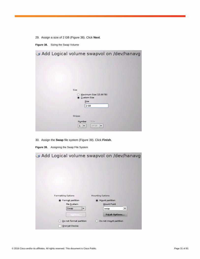
29. Assign a size of 2 GB (Figure 38). Click Next.
Figure 38. Sizing the Swap Volume
30. Assign the Swap file system (Figure 39). Click Finish.
Figure 39. Assigning the Swap File System
© 2016 Cisco and/or its affiliates. All rights reserved. This document is Cisco Public. Page 32 of 81
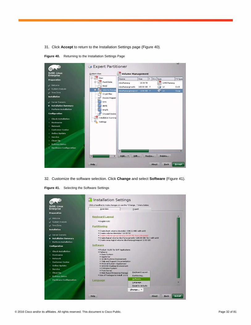
31. Click Accept to return to the Installation Settings page (Figure 40).
Figure 40. Returning to the Installation Settings Page
32. Customize the software selection. Click Change and select Software (Figure 41).
Figure 41. Selecting the Software Settings
© 2016 Cisco and/or its affiliates. All rights reserved. This document is Cisco Public. Page 33 of 81
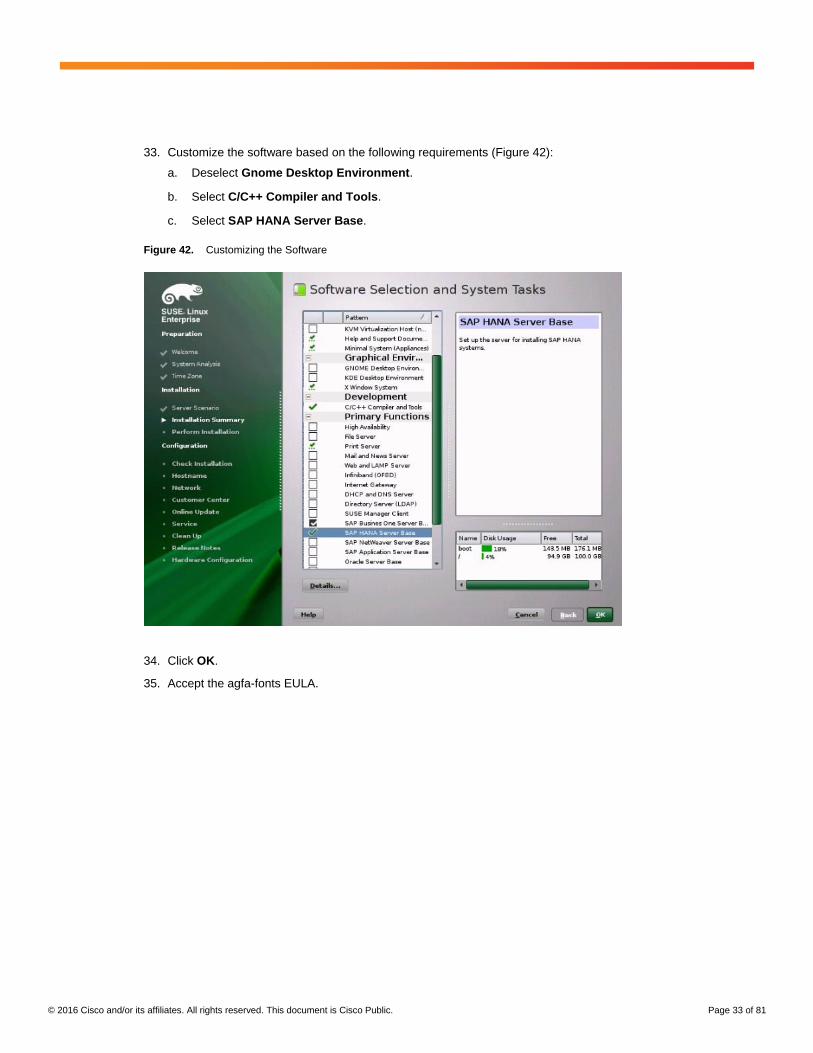
33. Customize the software based on the following requirements (Figure 42):
a. Deselect Gnome Desktop Environment.
b. Select C/C++ Compiler and Tools.
c. Select SAP HANA Server Base.
Figure 42. Customizing the Software
34. Click OK.
35. Accept the agfa-fonts EULA.
© 2016 Cisco and/or its affiliates. All rights reserved. This document is Cisco Public. Page 34 of 81
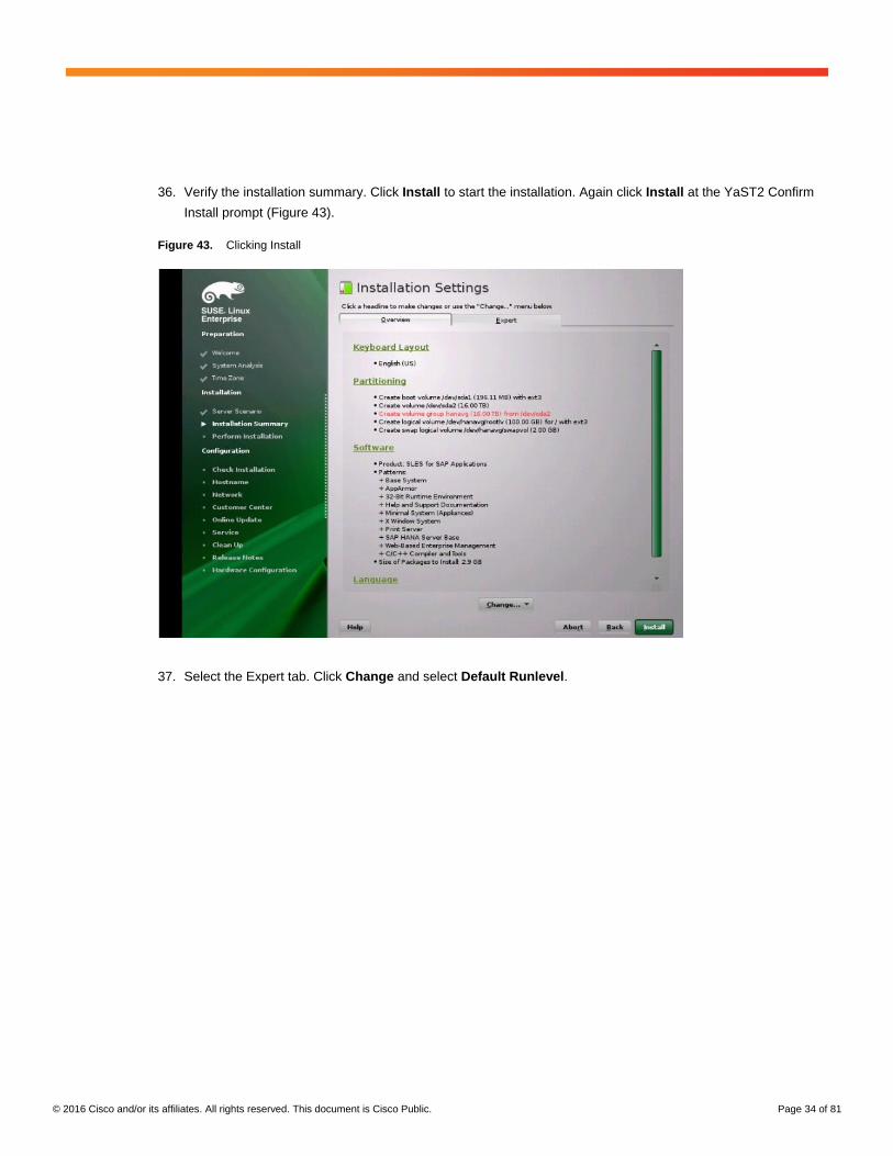
36. Verify the installation summary. Click Install to start the installation. Again click Install at the YaST2 Confirm
Install prompt (Figure 43).
Figure 43. Clicking Install
37. Select the Expert tab. Click Change and select Default Runlevel.
© 2016 Cisco and/or its affiliates. All rights reserved. This document is Cisco Public. Page 35 of 81
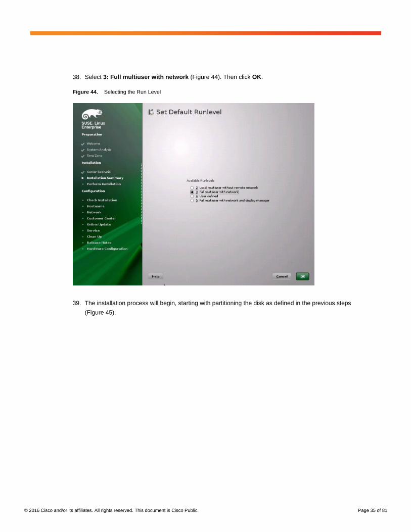
38. Select 3: Full multiuser with network (Figure 44). Then click OK.
Figure 44. Selecting the Run Level
39. The installation process will begin, starting with partitioning the disk as defined in the previous steps
(Figure 45).
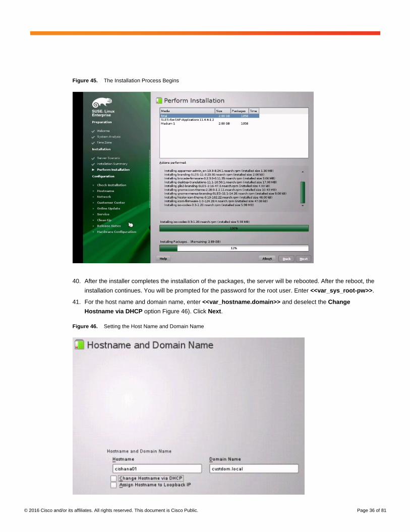
© 2016 Cisco and/or its affiliates. All rights reserved. This document is Cisco Public. Page 36 of 81
Figure 45. The Installation Process Begins
40. After the installer completes the installation of the packages, the server will be rebooted. After the reboot, the
installation continues. You will be prompted for the password for the root user. Enter <<var_sys_root-pw>>.
41. For the host name and domain name, enter <<var_hostname.domain>> and deselect the Change
Hostname via DHCP option Figure 46). Click Next.
Figure 46. Setting the Host Name and Domain Name
© 2016 Cisco and/or its affiliates. All rights reserved. This document is Cisco Public. Page 37 of 81
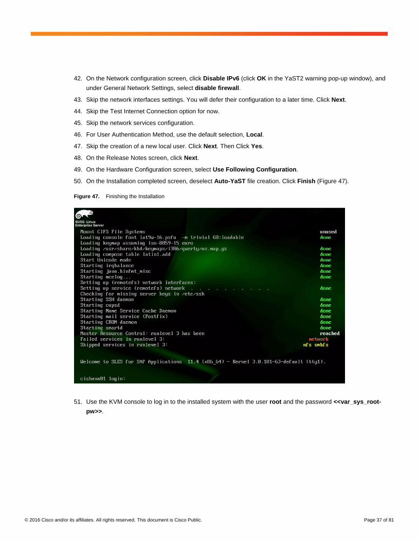
42. On the Network configuration screen, click Disable IPv6 (click OK in the YaST2 warning pop-up window), and
under General Network Settings, select disable firewall.
43. Skip the network interfaces settings. You will defer their configuration to a later time. Click Next.
44. Skip the Test Internet Connection option for now.
45. Skip the network services configuration.
46. For User Authentication Method, use the default selection, Local.
47. Skip the creation of a new local user. Click Next. Then Click Yes.
48. On the Release Notes screen, click Next.
49. On the Hardware Configuration screen, select Use Following Configuration.
50. On the Installation completed screen, deselect Auto-YaST file creation. Click Finish (Figure 47).
Figure 47. Finishing the Installation
51. Use the KVM console to log in to the installed system with the user root and the password <<var_sys_root-
pw>>.
© 2016 Cisco and/or its affiliates. All rights reserved. This document is Cisco Public. Page 38 of 81
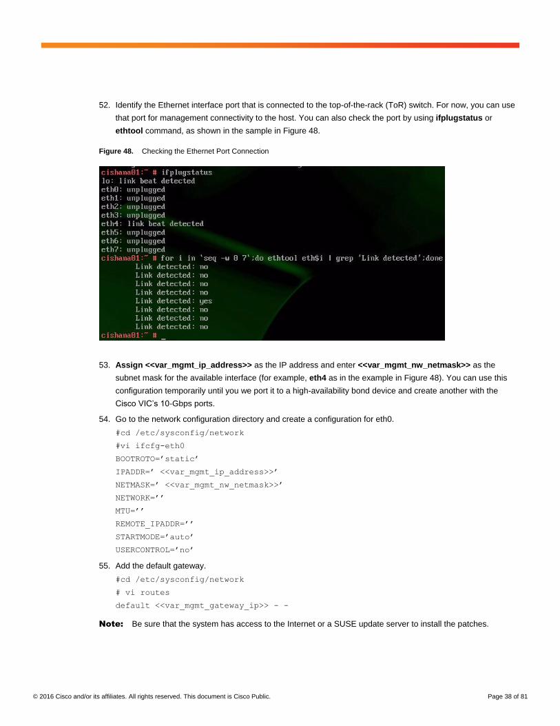
52. Identify the Ethernet interface port that is connected to the top-of-the-rack (ToR) switch. For now, you can use
that port for management connectivity to the host. You can also check the port by using ifplugstatus or
ethtool command, as shown in the sample in Figure 48.
Figure 48. Checking the Ethernet Port Connection
53. Assign <<var_mgmt_ip_address>> as the IP address and enter <<var_mgmt_nw_netmask>> as the
subnet mask for the available interface (for example, eth4 as in the example in Figure 48). You can use this
configuration temporarily until you we port it to a high-availability bond device and create another with the
Cisco VIC’s 10-Gbps ports.
54. Go to the network configuration directory and create a configuration for eth0.
#cd /etc/sysconfig/network
#vi ifcfg-eth0
BOOTROTO=’static’
IPADDR=’ <<var_mgmt_ip_address>>’
NETMASK=’ <<var_mgmt_nw_netmask>>’
NETWORK=’’
MTU=’’
REMOTE_IPADDR=’’
STARTMODE=’auto’
USERCONTROL=’no’
55. Add the default gateway.
#cd /etc/sysconfig/network
# vi routes
default <<var_mgmt_gateway_ip>> - -
Note: Be sure that the system has access to the Internet or a SUSE update server to install the patches.
© 2016 Cisco and/or its affiliates. All rights reserved. This document is Cisco Public. Page 39 of 81
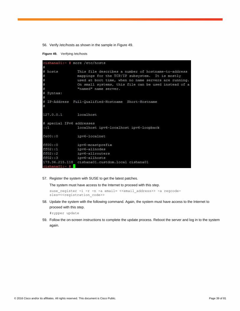
56. Verify /etc/hosts as shown in the sample in Figure 49.
Figure 49. Verifying /etc/hosts
57. Register the system with SUSE to get the latest patches.
The system must have access to the Internet to proceed with this step.
suse_register -i -r -n -a email= <<email_address>> -a regcode-
sles=<<registration_code>>
58. Update the system with the following command. Again, the system must have access to the Internet to
proceed with this step.
#zypper update
59. Follow the on-screen instructions to complete the update process. Reboot the server and log in to the system
again.
© 2016 Cisco and/or its affiliates. All rights reserved. This document is Cisco Public. Page 40 of 81
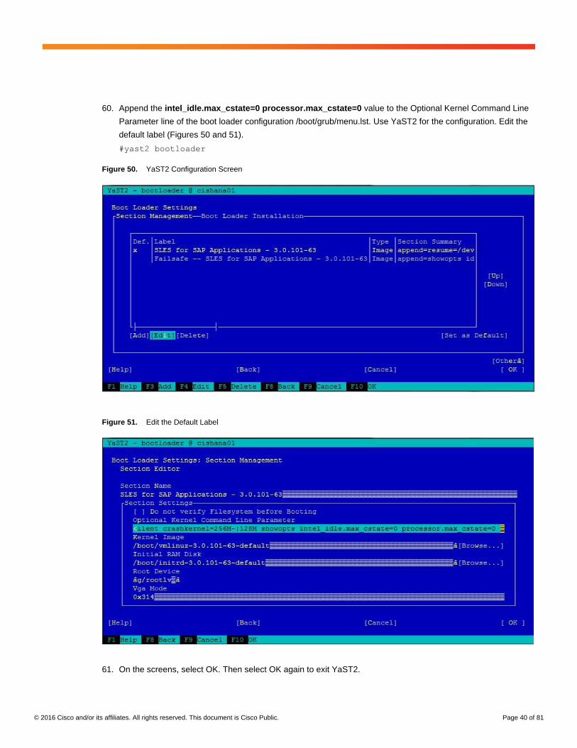
60. Append the intel_idle.max_cstate=0 processor.max_cstate=0 value to the Optional Kernel Command Line
Parameter line of the boot loader configuration /boot/grub/menu.lst. Use YaST2 for the configuration. Edit the
default label (Figures 50 and 51).
#yast2 bootloader
Figure 50. YaST2 Configuration Screen
Figure 51. Edit the Default Label
61. On the screens, select OK. Then select OK again to exit YaST2.
© 2016 Cisco and/or its affiliates. All rights reserved. This document is Cisco Public. Page 41 of 81
62. Create a file /etc/init.d/after.local with the contents in the following steps. Set the permissions of this file to at
least 755:
echo "Setting the CPU Speed to PERFORMANCE for SAP HANA SAP Note 1824819"
/usr/bin/cpupower frequency-set -g performance 2>&1
echo never > /sys/kernel/mm/transparent_hugepage/enabled
63. Configure the Network Time Protocol (NTP).
#vi /etc/ntp.conf
...
server <<var_global_ntp_server_ip>>
fudge <<var_global_ntp_server_ip>> stratum 10
...
#servie ntp restart
64. Reboot the server.
#reboot
Configuring Bonding for High Availability
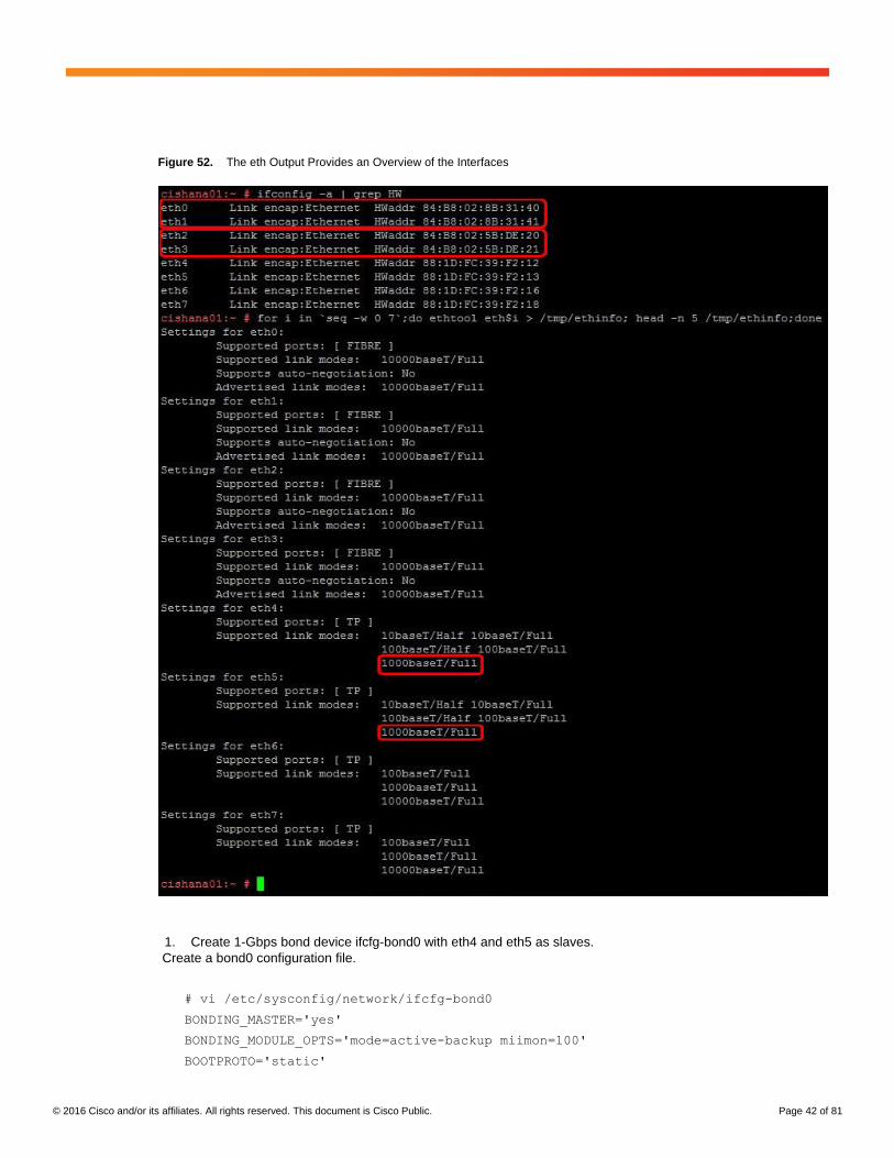
To configure a bond for high availability, first view the Ethernet interfaces available in the system.
By examining the hardware and MAC addresses of the interfaces using the ifconfig command and the properties
using ethtool, you can clearly differentiate the interfaces for the two dual-port Cisco UCS VIC 1225 adapters
installed in the server as well as the onboard 1-Gbps interface (Figure 52).
A bond configured with two 1-Gbps ports can be used for the administration, management, and access networks,
and a bond configured with two ports, using one port from each dual-port VIC, can be used for a backup network.
Additional interfaces can be configured on the VICs based on needs.
In the example in Figure 52, the ethtool output for the interfaces showing Fibre Channel support and 10-Gbps
indicates that eth0 through eth4 are VIC ports. In addition, a close observation of their MAC addresses reveals that
eth0 and eth1 and that eth2 and eth3 are ports on the same VICs (in both cases, the last octet of the MAC address
differs).
So for high availability, eth0 and eth2 is one possible slave pair for creating a 10-Gbps bond device.
Likewise, 1-Gbps interfaces eth4 and eth5 are potential slave interfaces for a 1-Gbps bond device.
In this section, you will manually create at least these two bond interfaces.
Note: In SLES, use of YaST is recommended. It provides an easier wizardlike approach for creation of bond
devices. For ease of implementation, this section provides steps for manually configuring YaST.
© 2016 Cisco and/or its affiliates. All rights reserved. This document is Cisco Public. Page 42 of 81
Figure 52. The eth Output Provides an Overview of the Interfaces
1. Create 1-Gbps bond device ifcfg-bond0 with eth4 and eth5 as slaves.
Create a bond0 configuration file.
# vi /etc/sysconfig/network/ifcfg-bond0
BONDING_MASTER='yes'
BONDING_MODULE_OPTS='mode=active-backup miimon=100'
BOOTPROTO='static'
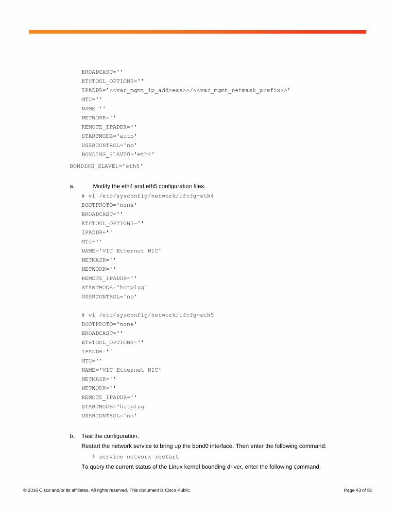
© 2016 Cisco and/or its affiliates. All rights reserved. This document is Cisco Public. Page 43 of 81
BROADCAST=''
ETHTOOL_OPTIONS=''
IPADDR=’<<var_mgmt_ip_address>>/<<var_mgmt_netmask_prefix>>’
MTU=''
NAME=''
NETWORK=''
REMOTE_IPADDR=''
STARTMODE='auto'
USERCONTROL='no'
BONDING_SLAVE0='eth4'
BONDING_SLAVE1='eth5'
a. Modify the eth4 and eth5 configuration files.
# vi /etc/sysconfig/network/ifcfg-eth4
BOOTPROTO='none'
BROADCAST=''
ETHTOOL_OPTIONS=''
IPADDR=''
MTU=''
NAME='VIC Ethernet NIC'
NETMASK=''
NETWORK=''
REMOTE_IPADDR=''
STARTMODE='hotplug'
USERCONTROL='no'
# vi /etc/sysconfig/network/ifcfg-eth5
BOOTPROTO='none'
BROADCAST=''
ETHTOOL_OPTIONS=''
IPADDR=''
MTU=''
NAME='VIC Ethernet NIC'
NETMASK=''
NETWORK=''
REMOTE_IPADDR=''
STARTMODE='hotplug'
USERCONTROL='no'
b. Test the configuration.
Restart the network service to bring up the bond0 interface. Then enter the following command:
# service network restart
To query the current status of the Linux kernel bounding driver, enter the following command:
© 2016 Cisco and/or its affiliates. All rights reserved. This document is Cisco Public. Page 44 of 81
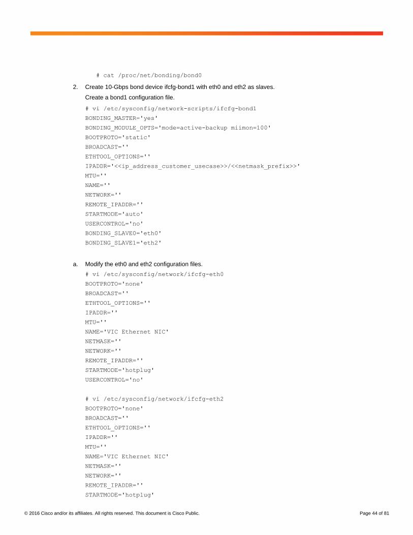
# cat /proc/net/bonding/bond0
2. Create 10-Gbps bond device ifcfg-bond1 with eth0 and eth2 as slaves.
Create a bond1 configuration file.
# vi /etc/sysconfig/network-scripts/ifcfg-bond1
BONDING_MASTER='yes'
BONDING_MODULE_OPTS='mode=active-backup miimon=100'
BOOTPROTO='static'
BROADCAST=''
ETHTOOL_OPTIONS=''
IPADDR='<<ip_address_customer_usecase>>/<<netmask_prefix>>'
MTU=''
NAME=''
NETWORK=''
REMOTE_IPADDR=''
STARTMODE='auto'
USERCONTROL='no'
BONDING_SLAVE0='eth0'
BONDING_SLAVE1='eth2'
a. Modify the eth0 and eth2 configuration files.
# vi /etc/sysconfig/network/ifcfg-eth0
BOOTPROTO='none'
BROADCAST=''
ETHTOOL_OPTIONS=''
IPADDR=''
MTU=''
NAME='VIC Ethernet NIC'
NETMASK=''
NETWORK=''
REMOTE_IPADDR=''
STARTMODE='hotplug'
USERCONTROL='no'
# vi /etc/sysconfig/network/ifcfg-eth2
BOOTPROTO='none'
BROADCAST=''
ETHTOOL_OPTIONS=''
IPADDR=''
MTU=''
NAME='VIC Ethernet NIC'
NETMASK=''
NETWORK=''
REMOTE_IPADDR=''
STARTMODE='hotplug'
© 2016 Cisco and/or its affiliates. All rights reserved. This document is Cisco Public. Page 45 of 81
USERCONTROL='no'
b. Test the configuration.
Restart the networking service to bring up the bond0 interface. Enter the following command:
# service network restart
To query the current status of Linux kernel bounding driver, enter the following command:
# cat /proc/net/bonding/bond1
Preparing SAP HANA Data, Log, and Shared File Systems
To prepare the file systems, you start by carving out logical volumes for the data, log, and HANA shared files. Then
you create the file systems. Then you update /etc/fstab and mount the volumes.
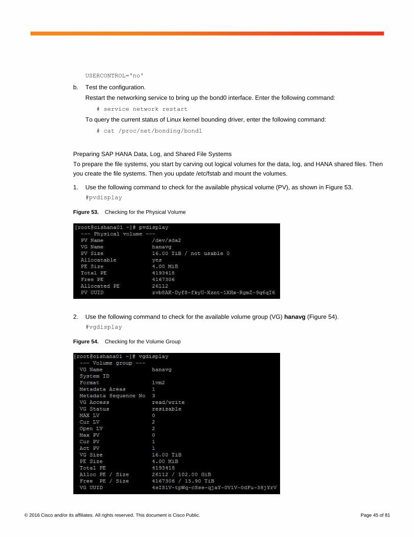
1. Use the following command to check for the available physical volume (PV), as shown in Figure 53.
#pvdisplay
Figure 53. Checking for the Physical Volume
2. Use the following command to check for the available volume group (VG) hanavg (Figure 54).
#vgdisplay
Figure 54. Checking for the Volume Group
© 2016 Cisco and/or its affiliates. All rights reserved. This document is Cisco Public. Page 46 of 81
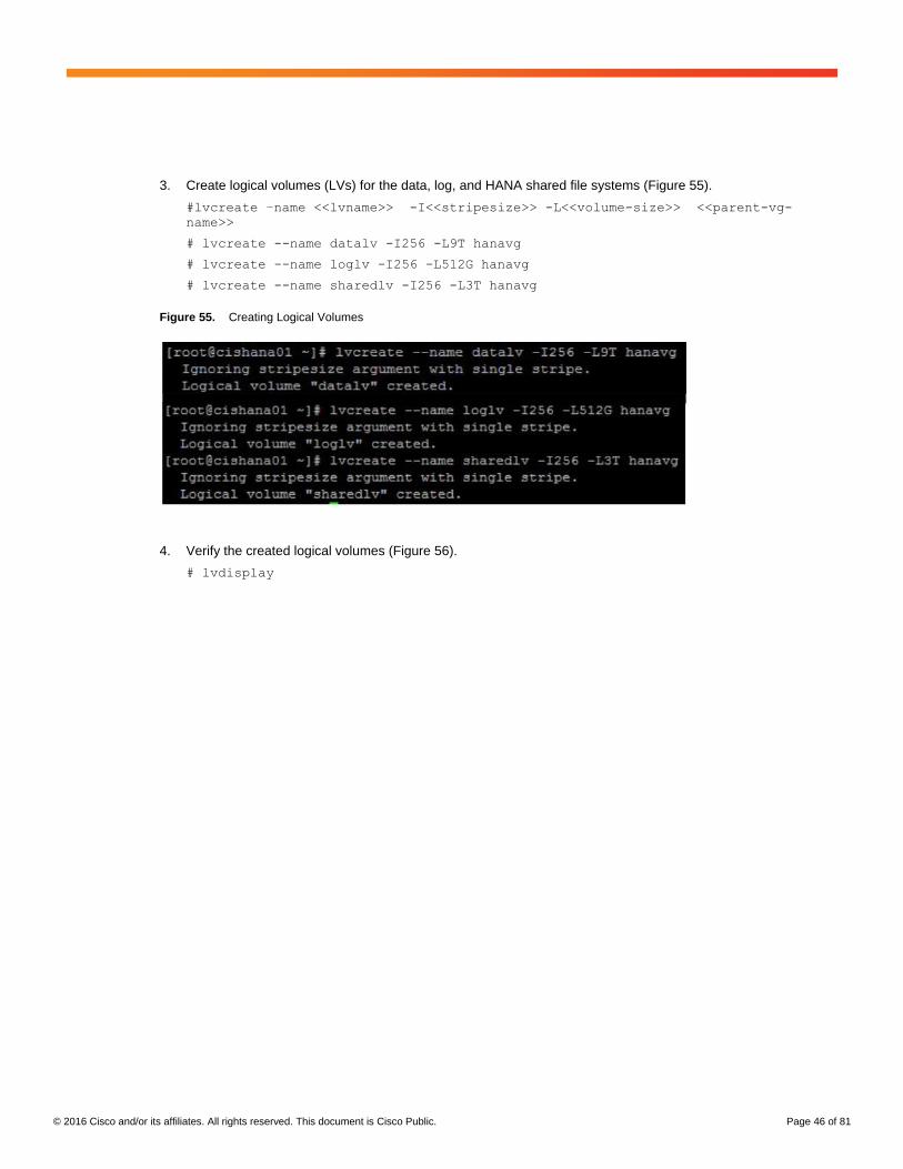
3. Create logical volumes (LVs) for the data, log, and HANA shared file systems (Figure 55).
#lvcreate –name <<lvname>> -I<<stripesize>> -L<<volume-size>> <<parent-vg-
name>>
# lvcreate --name datalv -I256 -L9T hanavg
# lvcreate --name loglv -I256 -L512G hanavg
# lvcreate --name sharedlv -I256 -L3T hanavg
Figure 55. Creating Logical Volumes
4. Verify the created logical volumes (Figure 56).
# lvdisplay
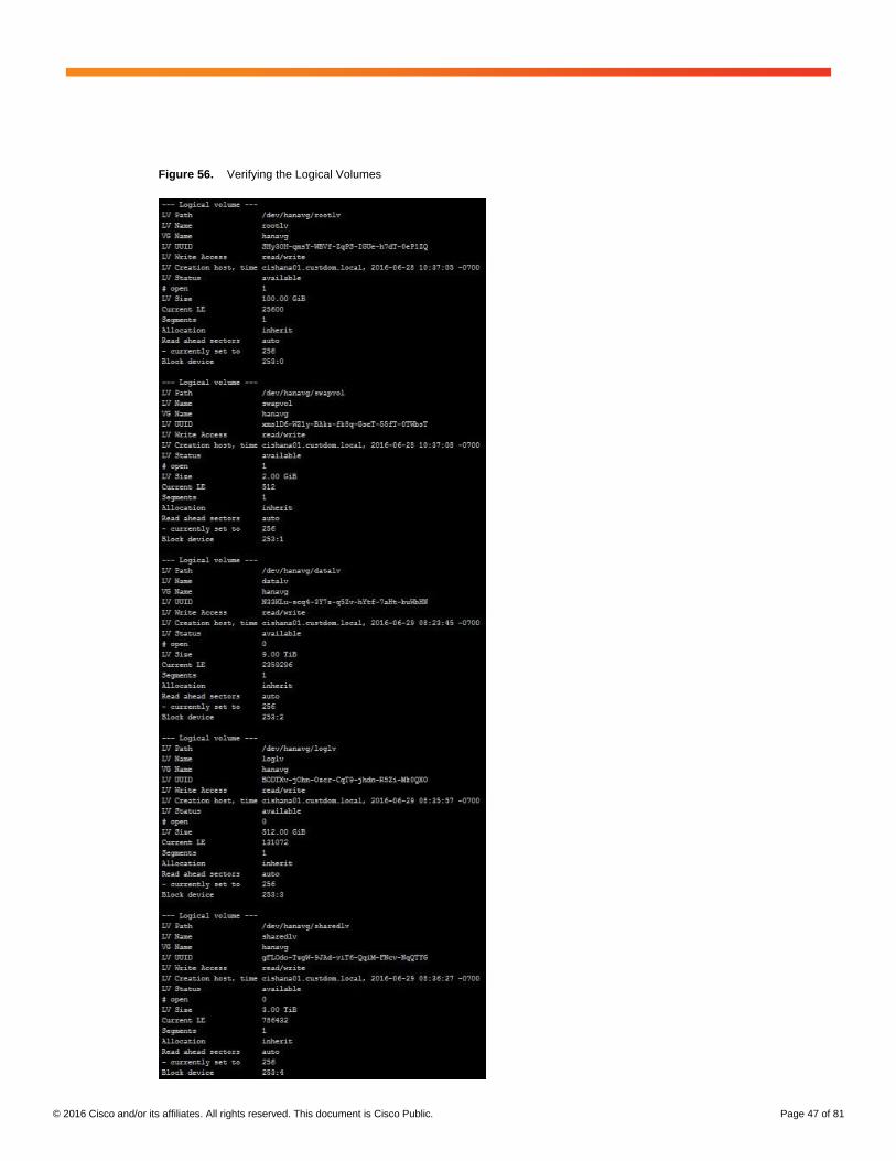
© 2016 Cisco and/or its affiliates. All rights reserved. This document is Cisco Public. Page 47 of 81
Figure 56. Verifying the Logical Volumes
© 2016 Cisco and/or its affiliates. All rights reserved. This document is Cisco Public. Page 48 of 81
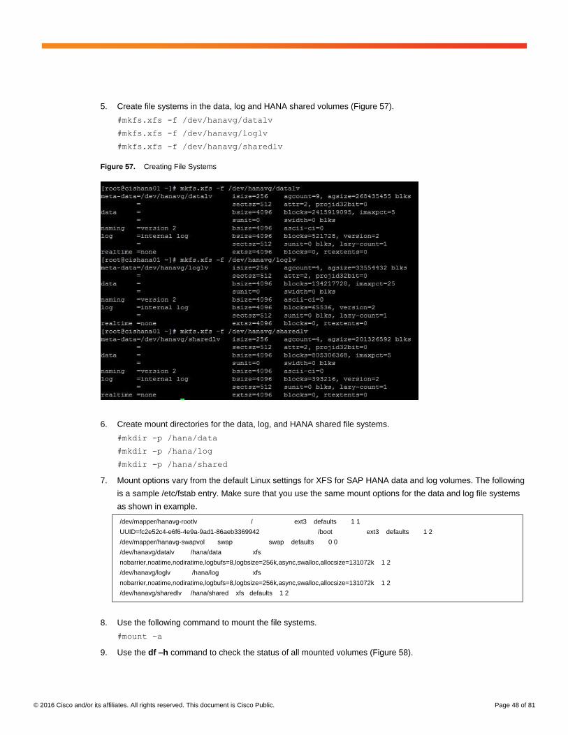
5. Create file systems in the data, log and HANA shared volumes (Figure 57).
#mkfs.xfs -f /dev/hanavg/datalv
#mkfs.xfs -f /dev/hanavg/loglv
#mkfs.xfs -f /dev/hanavg/sharedlv
Figure 57. Creating File Systems
6. Create mount directories for the data, log, and HANA shared file systems.
#mkdir -p /hana/data
#mkdir -p /hana/log
#mkdir -p /hana/shared
7. Mount options vary from the default Linux settings for XFS for SAP HANA data and log volumes. The following
is a sample /etc/fstab entry. Make sure that you use the same mount options for the data and log file systems
as shown in example.
/dev/mapper/hanavg-rootlv / ext3 defaults 1 1
UUID=fc2e52c4-e6f6-4e9a-9ad1-86aeb3369942 /boot ext3 defaults 1 2
/dev/mapper/hanavg-swapvol swap swap defaults 0 0
/dev/hanavg/datalv /hana/data xfs
nobarrier,noatime,nodiratime,logbufs=8,logbsize=256k,async,swalloc,allocsize=131072k 1 2
/dev/hanavg/loglv /hana/log xfs
nobarrier,noatime,nodiratime,logbufs=8,logbsize=256k,async,swalloc,allocsize=131072k 1 2
/dev/hanavg/sharedlv /hana/shared xfs defaults 1 2
8. Use the following command to mount the file systems.
#mount -a
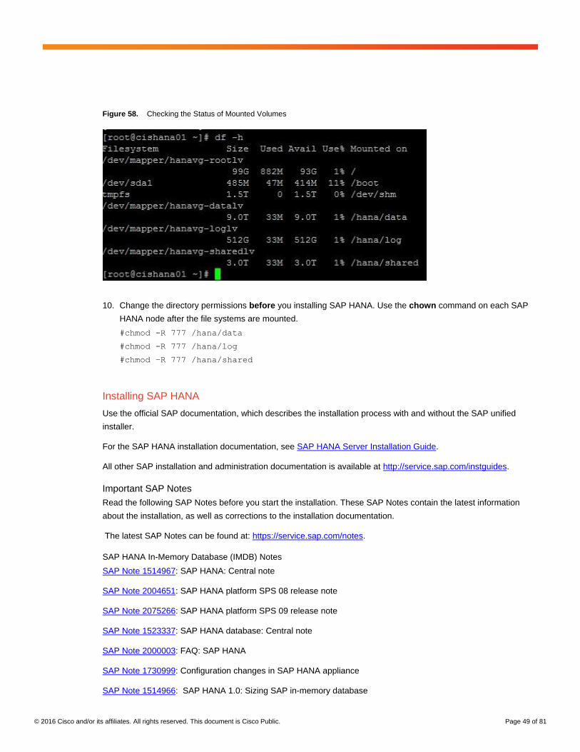
9. Use the df –h command to check the status of all mounted volumes (Figure 58).
© 2016 Cisco and/or its affiliates. All rights reserved. This document is Cisco Public. Page 49 of 81
Figure 58. Checking the Status of Mounted Volumes
10. Change the directory permissions before you installing SAP HANA. Use the chown command on each SAP
HANA node after the file systems are mounted.
#chmod -R 777 /hana/data
#chmod -R 777 /hana/log
#chmod –R 777 /hana/shared
Installing SAP HANA
Use the official SAP documentation, which describes the installation process with and without the SAP unified
installer.
For the SAP HANA installation documentation, see SAP HANA Server Installation Guide.
All other SAP installation and administration documentation is available at http://service.sap.com/instguides.
Important SAP Notes
Read the following SAP Notes before you start the installation. These SAP Notes contain the latest information
about the installation, as well as corrections to the installation documentation.
The latest SAP Notes can be found at: https://service.sap.com/notes.
SAP HANA In-Memory Database (IMDB) Notes
SAP Note 1514967: SAP HANA: Central note
SAP Note 2004651: SAP HANA platform SPS 08 release note
SAP Note 2075266: SAP HANA platform SPS 09 release note
SAP Note 1523337: SAP HANA database: Central note
SAP Note 2000003: FAQ: SAP HANA
SAP Note 1730999: Configuration changes in SAP HANA appliance
SAP Note 1514966: SAP HANA 1.0: Sizing SAP in-memory database
© 2016 Cisco and/or its affiliates. All rights reserved. This document is Cisco Public. Page 50 of 81
SAP Note 1780950: Connection problems due to host name resolution
SAP Note 1780950: SAP HANA SPS 06: Network setup for external communication
SAP Note 1743225: SAP HANA: Potential failure of connections with scale-out nodes
SAP Note 1755396: Released disaster tolerant (DT) solutions for SAP HANA with disk replication
SAP Note 1890444: HANA system slow due to CPU power save mode
SAP Note 1681092: Support for multiple SAP HANA databases on a single SAP HANA appliance
SAP Note 1514966: SAP HANA: Sizing the SAP HANA database
SAP Note 1637145: SAP BW on HANA: Sizing the SAP HANA database
SAP Note 1793345: Sizing for Suite on HANA
Linux Notes
SAP Note 2235581: SAP HANA: Supported operating systems
SAP Note 1944799: SAP HANA guidelines for the SLES operating system
SAP Note 1824819: SAP HANA Database: Recommended OS settings for SLES 11 and SLES 4 SAP SP2
SAP Note 1731000: Nonrecommended configuration changes
SAP Note 1557506: Linux paging improvements
SAP Note 1310037: SUSE Linux Enterprise Server 11 installation notes
SAP Note 1726839: SAP HANA database: Potential crash when using XFS file system
SAP Note 1740136: SAP HANA: Wrong mount option may lead to corrupt persistency
SAP Note 1829651: Time-zone settings in SAP HANA scale-out landscapes
SAP Application Notes
SAP Note 1658845: SAP HANA database hardware check
SAP Note 1637145: SAP BW on SAP HANA: Sizing SAP in-memory database
SAP Note 1661202: Support for multiple applications on SAP HANA
SAP Note 1681092: Support for multiple SAP HANA databases on one SAP HANA appliance (also known as
Multi SID)
SAP Note 1577128: Supported clients for SAP HANA 1.0
SAP Note 1808450: Homogenous system landscape for on SAP BW on SAP HANA
SAP Note 1976729: Application component hierarchy for SAP HANA
SAP Note 1927949: Standard behavior for SAP logon tickets
SAP Note 1577128: Supported clients for SAP HANA
© 2016 Cisco and/or its affiliates. All rights reserved. This document is Cisco Public. Page 51 of 81
Third-Party Software Notes
SAP Note 1730928: Using external software in an SAP HANA appliance
SAP Note 1730929: Using external tools in an SAP HANA appliance
SAP Note 1730930: Using antivirus software in an SAP HANA appliance
SAP Note 1730932: Using backup tools with Backint for SAP HANA
SAP HANA Virtualization Notes
SAP Note 1788665: SAP HANA running on VMware vSphere virtual machines
SAP HANA Post-Installation Checkup
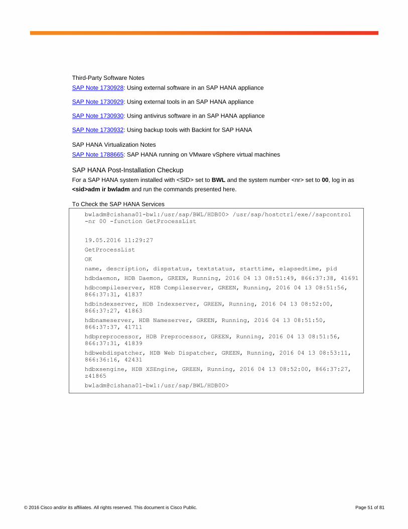
For a SAP HANA system installed with <SID> set to BWL and the system number <nr> set to 00, log in as
<sid>adm ir bwladm and run the commands presented here.
To Check the SAP HANA Services
bwladm@cishana01-bwl:/usr/sap/BWL/HDB00> /usr/sap/hostctrl/exe//sapcontrol
-nr 00 -function GetProcessList
19.05.2016 11:29:27
GetProcessList
OK
name, description, dispstatus, textstatus, starttime, elapsedtime, pid
hdbdaemon, HDB Daemon, GREEN, Running, 2016 04 13 08:51:49, 866:37:38, 41691
hdbcompileserver, HDB Compileserver, GREEN, Running, 2016 04 13 08:51:56,
866:37:31, 41837
hdbindexserver, HDB Indexserver, GREEN, Running, 2016 04 13 08:52:00,
866:37:27, 41863
hdbnameserver, HDB Nameserver, GREEN, Running, 2016 04 13 08:51:50,
866:37:37, 41711
hdbpreprocessor, HDB Preprocessor, GREEN, Running, 2016 04 13 08:51:56,
866:37:31, 41839
hdbwebdispatcher, HDB Web Dispatcher, GREEN, Running, 2016 04 13 08:53:11,
866:36:16, 42431
hdbxsengine, HDB XSEngine, GREEN, Running, 2016 04 13 08:52:00, 866:37:27,
z41865
bwladm@cishana01-bwl:/usr/sap/BWL/HDB00>
© 2016 Cisco and/or its affiliates. All rights reserved. This document is Cisco Public. Page 52 of 81
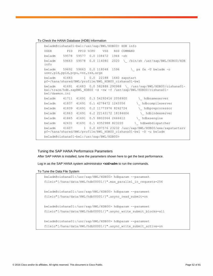
To Check the HANA Database (HDB) Information
bwladm@cishana01-bwl:/usr/sap/BWL/HDB00> HDB info
USER PID PPID %CPU VSZ RSS COMMAND
bwladm 59578 59577 0.0 108472 1944 -sh
bwladm 59663 59578 0.0 114080 2020 \_ /bin/sh /usr/sap/BWL/HDB00/HDB
info
bwladm 59692 59663 0.0 118048 1596 \_ ps fx -U bwladm -o
user,pid,ppid,pcpu,vsz,rss,args
bwladm 41683 1 0.0 22188 1640 sapstart
pf=/hana/shared/BWL/profile/BWL_HDB00_cishana01-bwl
bwladm 41691 41683 0.0 582888 290988 \_ /usr/sap/BWL/HDB00/cishana01-
bwl/trace/hdb.sapBWL_HDB00 -d -nw -f /usr/sap/BWL/HDB00/cishana01-
bwl/daemon.ini
bwladm 41711 41691 0.3 54292416 2058900 \_ hdbnameserver
bwladm 41837 41691 0.1 4278472 1243356 \_ hdbcompileserver
bwladm 41839 41691 0.2 11773976 8262724 \_ hdbpreprocessor
bwladm 41863 41691 6.2 22143172 18184604 \_ hdbindexserver
bwladm 41865 41691 0.5 8802064 2446612 \_ hdbxsengine
bwladm 42431 41691 0.1 4352988 823220 \_ hdbwebdispatcher
bwladm 41607 1 0.0 497576 23232 /usr/sap/BWL/HDB00/exe/sapstartsrv
pf=/hana/shared/BWL/profile/BWL_HDB00_cishana01-bwl -D -u bwladm
bwladm@cishana01-bwl:/usr/sap/BWL/HDB00>
Tuning the SAP HANA Performance Parameters
After SAP HANA is installed, tune the parameters shown here to get the best performance.
Log in as the SAP HANA system administrator <sid>adm to run the commands.
To Tune the Data File System
bwladm@cishana01:/usr/sap/HWL/HDB00> hdbparam --paramset
fileio"[/hana/data/HWL/hdb00001/]".max_parallel_io_requests=256
bwladm@cishana01:/usr/sap/HWL/HDB00> hdbparam --paramset
fileio"[/hana/data/HWL/hdb00001/]".async_read_submit=on
bwladm@cishana01:/usr/sap/HWL/HDB00> hdbparam --paramset
fileio"[/hana/data/HWL/hdb00001/]".async_write_submit_blocks=all
bwladm@cishana01:/usr/sap/HWL/HDB00> hdbparam --paramset
fileio"[/hana/data/HWL/hdb00001/]".async_write_submit_active=on
© 2016 Cisco and/or its affiliates. All rights reserved. This document is Cisco Public. Page 53 of 81
To Tune the Log File System
bwladm@cishana01:/usr/sap/HWL/HDB00> hdbparam --paramset
fileio"[/hana/log/HWL/hdb00001/]".async_read_submit=on
bwladm@cishana01:/usr/sap/HWL/HDB00> hdbparam --paramset
fileio"[/hana/log/HWL/hdb00001/]".async_write_submit_blocks=all
bwladm@cishana01:/usr/sap/HWL/HDB00> hdbparam --paramset
fileio"[/hana/log/HWL/hdb00001/]".async_write_submit_active=on
Monitoring and Maintenance Operations
Hardware Monitoring and Maintenance
This section discusses hardware monitoring and maintenance tasks.
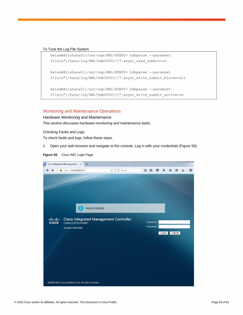
Checking Faults and Logs
To check faults and logs, follow these steps.
1. Open your web browser and navigate to the console. Log in with your credentials (Figure 59).
Figure 59. Cisco IMC Login Page
© 2016 Cisco and/or its affiliates. All rights reserved. This document is Cisco Public. Page 54 of 81
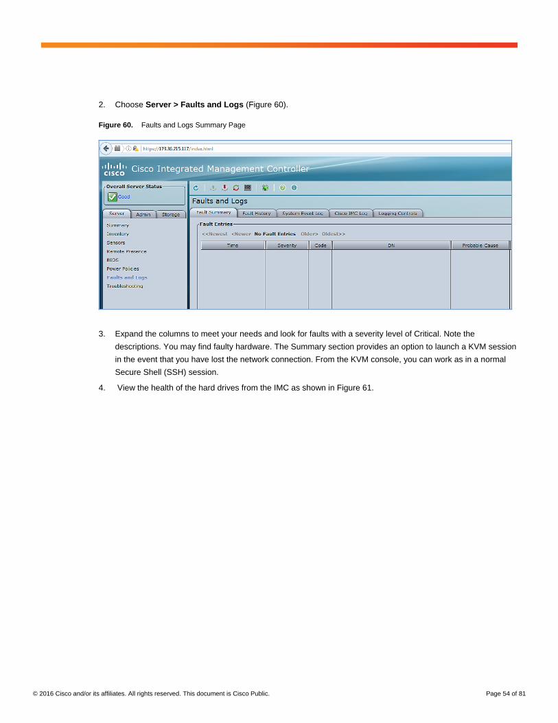
2. Choose Server > Faults and Logs (Figure 60).
Figure 60. Faults and Logs Summary Page
3. Expand the columns to meet your needs and look for faults with a severity level of Critical. Note the
descriptions. You may find faulty hardware. The Summary section provides an option to launch a KVM session
in the event that you have lost the network connection. From the KVM console, you can work as in a normal
Secure Shell (SSH) session.
4. View the health of the hard drives from the IMC as shown in Figure 61.
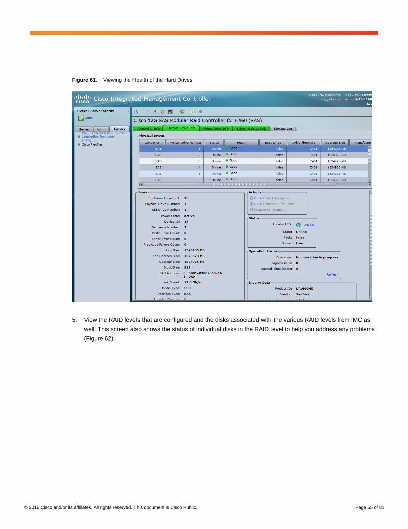
© 2016 Cisco and/or its affiliates. All rights reserved. This document is Cisco Public. Page 55 of 81
Figure 61. Viewing the Health of the Hard Drives
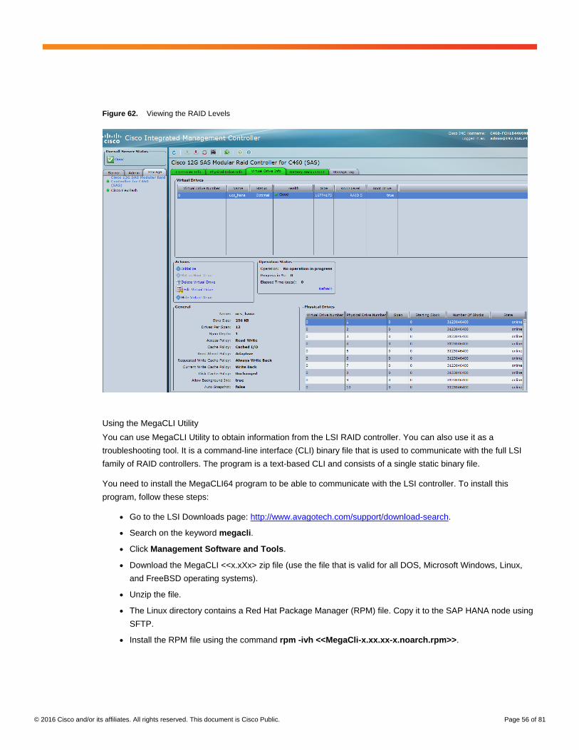
5. View the RAID levels that are configured and the disks associated with the various RAID levels from IMC as
well. This screen also shows the status of individual disks in the RAID level to help you address any problems
(Figure 62).
© 2016 Cisco and/or its affiliates. All rights reserved. This document is Cisco Public. Page 56 of 81
Figure 62. Viewing the RAID Levels
Using the MegaCLI Utility
You can use MegaCLI Utility to obtain information from the LSI RAID controller. You can also use it as a
troubleshooting tool. It is a command-line interface (CLI) binary file that is used to communicate with the full LSI
family of RAID controllers. The program is a text-based CLI and consists of a single static binary file.
You need to install the MegaCLI64 program to be able to communicate with the LSI controller. To install this
program, follow these steps:
● Go to the LSI Downloads page: http://www.avagotech.com/support/download-search.
● Search on the keyword megacli.
● Click Management Software and Tools.
● Download the MegaCLI <<x.xXx> zip file (use the file that is valid for all DOS, Microsoft Windows, Linux,
and FreeBSD operating systems).
● Unzip the file.
● The Linux directory contains a Red Hat Package Manager (RPM) file. Copy it to the SAP HANA node using
SFTP.
● Install the RPM file using the command rpm -ivh <<MegaCli-x.xx.xx-x.noarch.rpm>>.
© 2016 Cisco and/or its affiliates. All rights reserved. This document is Cisco Public. Page 57 of 81
[root@cishana01 ~]# rpm -ivh MegaCli-8.07.14-1.noarch.rpm
Preparing...
########################################### [100%]
1:MegaCli
########################################### [100%]
[root@cishana01 ~]# cd /opt/MegaRAID/MegaCli
[root@cishana01 MegaCli]# ll
total 3228
-rw-r--r--. 1 root root 0 Jul 4 22:28 install.log
lrwxrwxrwx. 1 root root 48 Jul 4 22:28 libstorelibir-2.so ->
/opt/MegaRAID/MegaCli/libstorelibir-2.so.14.07-0
-rwx------. 1 root root 540512 Dec 16 2013 libstorelibir-2.so.14.07-
0
-rwxr-xr-x. 1 root root 2720320 Dec 16 2013 MegaCli64
-rw-r--r--. 1 root root 32369 Jul 4 22:35 MegaSAS.log
Replacing a Failed Hard Drive
The monitoring tasks may reveal a hard-drive failure. In addition, the color of the LED in the faulty hard drive will
change from green to amber. To replace or install a hot-pluggable hard drive, follow the steps presented here
(Figure 63).
1. Remove the drive that you are replacing or remove a blank panel from an empty bay.
a. Press the release button on the face of the hard drive.
b. Grasp the ejector lever and pull the hard drive tray out of the slot.
c. If you are replacing an existing drive, remove the four drive tray screws that secure the drive to the tray and
then lift the drive out of the tray.
2. Install a new drive.
a. Place a new hard drive in the empty drive tray and replace the four drive-tray screws.
b. Insert the drive tray into the empty drive bay.
c. Push the tray into the slot until the drive connectors are fully seated in the backplane.
d. Press the ejector lever flat to lock the drive and tray in place.
© 2016 Cisco and/or its affiliates. All rights reserved. This document is Cisco Public. Page 58 of 81
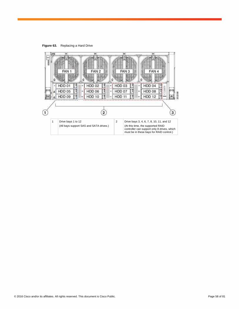
Figure 63. Replacing a Hard Drive
1 Drive bays 1 to 12
(All bays support SAS and SATA drives.)
2 Drive bays 3, 4, 6, 7, 8, 10, 11, and 12
(At this time, the supported RAID controller can support only 8 drives, which must be in these bays for RAID control.)
© 2016 Cisco and/or its affiliates. All rights reserved. This document is Cisco Public. Page 59 of 81
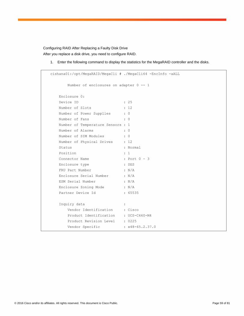
Configuring RAID After Replacing a Faulty Disk Drive
After you replace a disk drive, you need to configure RAID.
1. Enter the following command to display the statistics for the MegaRAID controller and the disks.
cishana01:/opt/MegaRAID/MegaCli # ./MegaCli64 -EncInfo -aALL
Number of enclosures on adapter 0 -- 1
Enclosure 0:
Device ID : 25
Number of Slots : 12
Number of Power Supplies : 0
Number of Fans : 0
Number of Temperature Sensors : 1
Number of Alarms : 0
Number of SIM Modules : 0
Number of Physical Drives : 12
Status : Normal
Position : 1
Connector Name : Port 0 - 3
Enclosure type : SES
FRU Part Number : N/A
Enclosure Serial Number : N/A
ESM Serial Number : N/A
Enclosure Zoning Mode : N/A
Partner Device Id : 65535
Inquiry data :
Vendor Identification : Cisco
Product Identification : UCS-C460-M4
Product Revision Level : 0225
Vendor Specific : x48-65.2.37.0
© 2016 Cisco and/or its affiliates. All rights reserved. This document is Cisco Public. Page 60 of 81
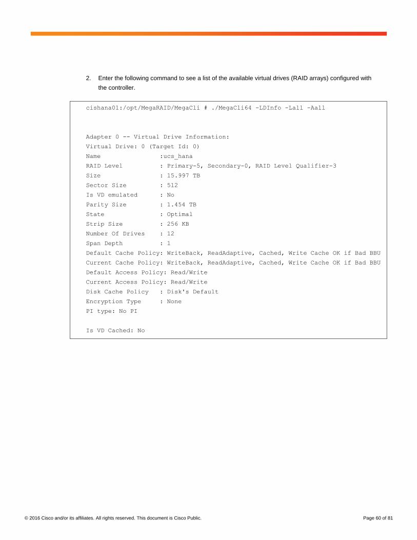
2. Enter the following command to see a list of the available virtual drives (RAID arrays) configured with
the controller.
cishana01:/opt/MegaRAID/MegaCli # ./MegaCli64 -LDInfo -Lall -Aall
Adapter 0 -- Virtual Drive Information:
Virtual Drive: 0 (Target Id: 0)
Name :ucs_hana
RAID Level : Primary-5, Secondary-0, RAID Level Qualifier-3
Size : 15.997 TB
Sector Size : 512
Is VD emulated : No
Parity Size : 1.454 TB
State : Optimal
Strip Size : 256 KB
Number Of Drives : 12
Span Depth : 1
Default Cache Policy: WriteBack, ReadAdaptive, Cached, Write Cache OK if Bad BBU
Current Cache Policy: WriteBack, ReadAdaptive, Cached, Write Cache OK if Bad BBU
Default Access Policy: Read/Write
Current Access Policy: Read/Write
Disk Cache Policy : Disk's Default
Encryption Type : None
PI type: No PI
Is VD Cached: No
© 2016 Cisco and/or its affiliates. All rights reserved. This document is Cisco Public. Page 61 of 81
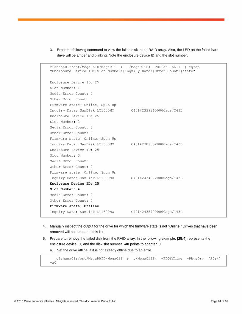
3. Enter the following command to view the failed disk in the RAID array. Also, the LED on the failed hard
drive will be amber and blinking. Note the enclosure device ID and the slot number.
cishana01:/opt/MegaRAID/MegaCli # ./MegaCli64 -PDList –aAll | egrep
"Enclosure Device ID:|Slot Number:|Inquiry Data:|Error Count:|state"
Enclosure Device ID: 25
Slot Number: 1
Media Error Count: 0
Other Error Count: 0
Firmware state: Online, Spun Up
Inquiry Data: SanDisk LT1600MO C401423398600000ags/T43L
Enclosure Device ID: 25
Slot Number: 2
Media Error Count: 0
Other Error Count: 0
Firmware state: Online, Spun Up
Inquiry Data: SanDisk LT1600MO C401423813520000ags/T43L
Enclosure Device ID: 25
Slot Number: 3
Media Error Count: 0
Other Error Count: 0
Firmware state: Online, Spun Up
Inquiry Data: SanDisk LT1600MO C401424343720000ags/T43L
Enclosure Device ID: 25
Slot Number: 4
Media Error Count: 0
Other Error Count: 0
Firmware state: Offline
Inquiry Data: SanDisk LT1600MO C401424357000000ags/T43L
4. Manually inspect the output for the drive for which the firmware state is not “Online.” Drives that have been
removed will not appear in this list.
5. Prepare to remove the failed disk from the RAID array. In the following example, [25:4] represents the
enclosure device ID, and the disk slot number -a0 points to adapter 0.
a. Set the drive offline, if it is not already offline due to an error.
cishana01:/opt/MegaRAID/MegaCli # ./MegaCli64 -PDOffline -PhysDrv [25:4]
–a0
© 2016 Cisco and/or its affiliates. All rights reserved. This document is Cisco Public. Page 62 of 81
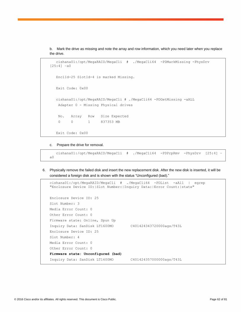
b. Mark the drive as missing and note the array and row information, which you need later when you replace
the drive.
cishana01:/opt/MegaRAID/MegaCli # ./MegaCli64 -PDMarkMissing -PhysDrv
[25:4] –a0
EnclId-25 SlotId-4 is marked Missing.
Exit Code: 0x00
cishana01:/opt/MegaRAID/MegaCli # ./MegaCli64 -PDGetMissing -aALL
Adapter 0 - Missing Physical drives
No. Array Row Size Expected
0 0 1 837353 MB
Exit Code: 0x00
c. Prepare the drive for removal.
cishana01:/opt/MegaRAID/MegaCli # ./MegaCli64 -PDPrpRmv -PhysDrv [25:4] –
a0
6. Physically remove the failed disk and insert the new replacement disk. After the new disk is inserted, it will be
considered a foreign disk and is shown with the status “Unconfigured (bad).”
cishana01:/opt/MegaRAID/MegaCli # ./MegaCli64 -PDList -aAll | egrep
"Enclosure Device ID:|Slot Number:|Inquiry Data:|Error Count:|state"
Enclosure Device ID: 25
Slot Number: 3
Media Error Count: 0
Other Error Count: 0
Firmware state: Online, Spun Up
Inquiry Data: SanDisk LT1600MO C401424343720000ags/T43L
Enclosure Device ID: 25
Slot Number: 4
Media Error Count: 0
Other Error Count: 0
Firmware state: Unconfigured (bad)
Inquiry Data: SanDisk LT1600MO C401424357000000ags/T43L
© 2016 Cisco and/or its affiliates. All rights reserved. This document is Cisco Public. Page 63 of 81
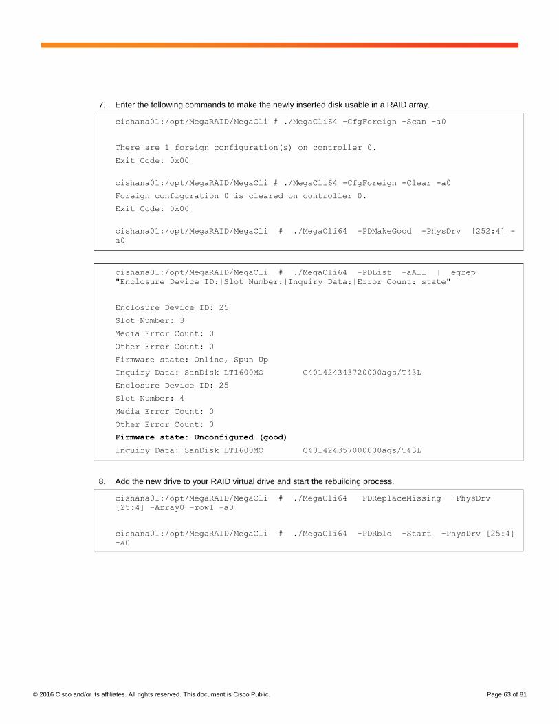
7. Enter the following commands to make the newly inserted disk usable in a RAID array.
cishana01:/opt/MegaRAID/MegaCli # ./MegaCli64 -CfgForeign -Scan -a0
There are 1 foreign configuration(s) on controller 0.
Exit Code: 0x00
cishana01:/opt/MegaRAID/MegaCli # ./MegaCli64 -CfgForeign -Clear -a0
Foreign configuration 0 is cleared on controller 0.
Exit Code: 0x00
cishana01:/opt/MegaRAID/MegaCli # ./MegaCli64 -PDMakeGood -PhysDrv [252:4] -
a0
cishana01:/opt/MegaRAID/MegaCli # ./MegaCli64 -PDList -aAll | egrep
"Enclosure Device ID:|Slot Number:|Inquiry Data:|Error Count:|state"
Enclosure Device ID: 25
Slot Number: 3
Media Error Count: 0
Other Error Count: 0
Firmware state: Online, Spun Up
Inquiry Data: SanDisk LT1600MO C401424343720000ags/T43L
Enclosure Device ID: 25
Slot Number: 4
Media Error Count: 0
Other Error Count: 0
Firmware state: Unconfigured (good)
Inquiry Data: SanDisk LT1600MO C401424357000000ags/T43L
8. Add the new drive to your RAID virtual drive and start the rebuilding process.
cishana01:/opt/MegaRAID/MegaCli # ./MegaCli64 -PDReplaceMissing -PhysDrv
[25:4] –Array0 –row1 –a0
cishana01:/opt/MegaRAID/MegaCli # ./MegaCli64 -PDRbld -Start -PhysDrv [25:4]
–a0
© 2016 Cisco and/or its affiliates. All rights reserved. This document is Cisco Public. Page 64 of 81
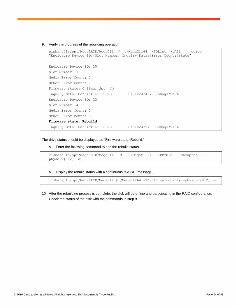
9. Verify the progress of the rebuilding operation.
cishana01:/opt/MegaRAID/MegaCli # ./MegaCli64 -PDList -aAll | egrep
"Enclosure Device ID:|Slot Number:|Inquiry Data:|Error Count:|state"
Enclosure Device ID: 25
Slot Number: 3
Media Error Count: 0
Other Error Count: 0
Firmware state: Online, Spun Up
Inquiry Data: SanDisk LT1600MO C401424343720000ags/T43L
Enclosure Device ID: 25
Slot Number: 4
Media Error Count: 0
Other Error Count: 0
Firmware state: Rebuild
Inquiry Data: SanDisk LT1600MO C401424357000000ags/T43L
The drive status should be displayed as “Firmware state: Rebuild.”
a. Enter the following command to see the rebuild status.
cishana01:/opt/MegaRAID/MegaCli # ./MegaCli64 -PDrbld -showprog -
physdrv[9:2] –a0
b. Display the rebuild status with a continuous text GUI message.
cishana01:/opt/MegaRAID/MegaCli #./MegaCli64 -PDrbld -progdsply -physdrv[9:2] –a0
10. After the rebuilding process is complete, the disk will be online and participating in the RAID configuration.
Check the status of the disk with the commands in step 9.
© 2016 Cisco and/or its affiliates. All rights reserved. This document is Cisco Public. Page 65 of 81
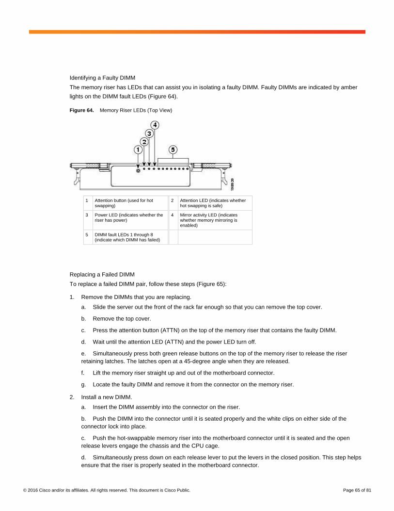
Identifying a Faulty DIMM
The memory riser has LEDs that can assist you in isolating a faulty DIMM. Faulty DIMMs are indicated by amber
lights on the DIMM fault LEDs (Figure 64).
Figure 64. Memory Riser LEDs (Top View)
1 Attention button (used for hot swapping)
2 Attention LED (indicates whether hot swapping is safe)
3 Power LED (indicates whether the riser has power)
4 Mirror activity LED (indicates whether memory mirroring is enabled)
5 DIMM fault LEDs 1 through 8 (indicate which DIMM has failed)
Replacing a Failed DIMM
To replace a failed DIMM pair, follow these steps (Figure 65):
1. Remove the DIMMs that you are replacing.
a. Slide the server out the front of the rack far enough so that you can remove the top cover.
b. Remove the top cover.
c. Press the attention button (ATTN) on the top of the memory riser that contains the faulty DIMM.
d. Wait until the attention LED (ATTN) and the power LED turn off.
e. Simultaneously press both green release buttons on the top of the memory riser to release the riser
retaining latches. The latches open at a 45-degree angle when they are released.
f. Lift the memory riser straight up and out of the motherboard connector.
g. Locate the faulty DIMM and remove it from the connector on the memory riser.
2. Install a new DIMM.
a. Insert the DIMM assembly into the connector on the riser.
b. Push the DIMM into the connector until it is seated properly and the white clips on either side of the
connector lock into place.
c. Push the hot-swappable memory riser into the motherboard connector until it is seated and the open
release levers engage the chassis and the CPU cage.
d. Simultaneously press down on each release lever to put the levers in the closed position. This step helps
ensure that the riser is properly seated in the motherboard connector.
© 2016 Cisco and/or its affiliates. All rights reserved. This document is Cisco Public. Page 66 of 81
e. Press the attention button on the top of the memory riser. Then wait until the attention LED turns off.
f. Replace the top cover.
g. Replace the server in the rack and replace any cables.
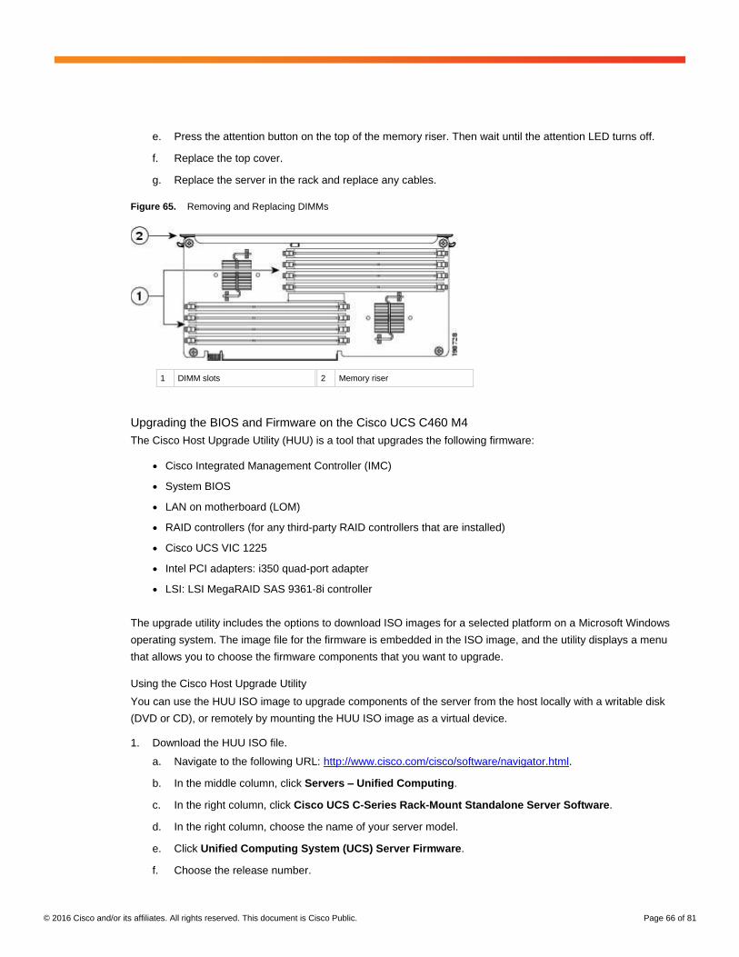
Figure 65. Removing and Replacing DIMMs
1 DIMM slots 2 Memory riser
Upgrading the BIOS and Firmware on the Cisco UCS C460 M4
The Cisco Host Upgrade Utility (HUU) is a tool that upgrades the following firmware:
● Cisco Integrated Management Controller (IMC)
● System BIOS
● LAN on motherboard (LOM)
● RAID controllers (for any third-party RAID controllers that are installed)
● Cisco UCS VIC 1225
● Intel PCI adapters: i350 quad-port adapter
● LSI: LSI MegaRAID SAS 9361-8i controller
The upgrade utility includes the options to download ISO images for a selected platform on a Microsoft Windows
operating system. The image file for the firmware is embedded in the ISO image, and the utility displays a menu
that allows you to choose the firmware components that you want to upgrade.
Using the Cisco Host Upgrade Utility
You can use the HUU ISO image to upgrade components of the server from the host locally with a writable disk
(DVD or CD), or remotely by mounting the HUU ISO image as a virtual device.
1. Download the HUU ISO file.
a. Navigate to the following URL: http://www.cisco.com/cisco/software/navigator.html.
b. In the middle column, click Servers – Unified Computing.
c. In the right column, click Cisco UCS C-Series Rack-Mount Standalone Server Software.
d. In the right column, choose the name of your server model.
e. Click Unified Computing System (UCS) Server Firmware.
f. Choose the release number.

© 2016 Cisco and/or its affiliates. All rights reserved. This document is Cisco Public. Page 67 of 81
g. Click Download Now to download the ucs-server platform-huu-version_number.iso file.
h. Verify the information on the next page. Then click Proceed With Download.
i. Continue through the subsequent screens to accept the license agreement and browse to the location
where you want to save the file.
2. If you want to prepare the ISO image for a local upgrade, complete this step; otherwise, go to step 3.
a. Copy the ISO image onto a writable disk (DVD, USB flash drive, or CD).
b. Connect a VGA monitor and USB keyboard to the Cisco UCS C-Series server.
c. Insert the disk into the DVD drive of the Cisco UCS C-Series server.
d. Proceed to step 4.
3. Prepare the ISO image for a remote upgrade using the KVM console.
a. Use a browser to connect to the IMC GUI software on the server that you are upgrading.
b. In the address field of the browser, enter the IMC IP address for that server; then enter your username
and password.
c. On the toolbar, click Launch KVM Console to launch the KVM console.
d. On the KVM console, click Virtual Media.
e. Click Add Image and click the ucs-server-name-huu-version_number.iso file.
f. In the Client View area, in the Mapped column, select the check box for the ISO file that you added and
then wait for the mapping process to complete.
g. After the ISO file appears as a mapped remote device, proceed to step 4.
4. Boot the server and press F6 when you are prompted to open the Boot Menu screen.
5. On the Boot Menu screen, choose the prepared ISO image:
● For a local upgrade, choose the physical CD/DVD device and then press Enter.
● For a remote upgrade, choose Cisco vKVM-Mapped vDVD1.22 and press Enter.
The server boots from the selected device.
6. After the HUU boots, the Cisco End-User License Agreement (EULA) appears. Read the EULA and select one
of the following:
● Select “I Agree” to accept the license agreement and proceed with the update.
● Select “I Disagree” to cancel the update process.
After you accept the EULA, the HUU window appears with a list of all the components that are available for
updating.
7. If you want to update all the listed components, click Update all.
8. If you want update specific components from the list, choose the components that you want to update.
9. Click Update.
Note: You should update the BIOS each time that you update the IMC firmware. You also should update the
IMC each time you update the BIOS firmware. If you update the IMC firmware, after successfully completing the
update, reboot the server to activate the new firmware.
© 2016 Cisco and/or its affiliates. All rights reserved. This document is Cisco Public. Page 68 of 81
This step initiates the update process, and the status of the update process is displayed in the Update Status
column. You can also view a more detailed log of a series of activities and statuses involved in updating the
firmware in the Execution Logs section.
10. Reboot the server and click Verify Last Update to verify if the update was successfully completed.
This action compares the previously updated firmware version for each component that was updated using the
HUU with the current version of the firmware on the components and provides the status of the update.
11. If you want to save the update status log files for later use, click Save Logs.
Log files that contain a detailed status of the update are saved to an external USB device that is connected to
the server physically or through the KVM virtual media.
Note: If an error occurs while the firmware is being updated, you are prompted to save the error log. Click Save
Logs to save the log to an externally connected USB device. This log can be used to identify the cause of the error
and perform troubleshooting.
12. Click Exit to exit from the HUU.
Monitoring the Operating System
You can install monitoring agents, such as Tivoli, on the SAP HANA nodes to integrate the Cisco and SAP HANA
solution into a central enterprise monitoring tool.
Also, the syslog-ng daemon can be configured to send log messages to the existing central log host available on
the customer infrastructure.
Maintaining the Operating System
The customer is responsible for implementing security updates and patches, adding software components, and
changing OS settings that may be requested by SAP for future releases of SAP HANA or that may be required by
SUSE to help ensure system security and stability. See the related SAP OSs notes for required OS settings.
This section describes how to update the OS and the implications of updating OS components. It is not meant to
replace the Linux administration documentation.
Prerequisites
Whenever you change the OS or parts of the OS such as drivers and kernel parameters, be sure that you have at
least a backup copy of your SAP HANA system, preferably not stored on the appliance. You also should check the
related OS notes or Cisco support channels for additional information.
Some changes may require a reboot and should be applied when SAP HANA is shut down.
Updating the OS and Kernel
Not all updates and patches update the OS kernel. But if a kernel update is necessary, you need to take specific
precautions. During the entire update process, SAP HANA must be shut down.
These are the general steps for updating the kernel:
● Perform these tasks before updating the kernel:
◦ Stop SAP HANA and back up the existing log area (in case the device causes a problem and needs to be
recreated).
◦ Unmount /hana/log and cleaning /etc/fstab.
© 2016 Cisco and/or its affiliates. All rights reserved. This document is Cisco Public. Page 69 of 81
● Update the kernel using YaST (or a manual procedure).
● Perform these tasks after updating the kernel:
◦ Check the GRUB file and boot sector (menu.lst).
◦ Reboot and check /etc/fstab.
The following steps present the tasks in more detail.
1. Back up the SAP HANA log area.
a. Stop SAP HANA. Then move to the log area and back up the HANA log partition.
cishana01 :~ # cd /hana/log
cishana01 :/hana/log # find . –xdev | cpio –oav > /backup/hana.log.cpio
b. If the backup partition has enough room, choose it. Otherwise, choose an appropriate location for the
backup.
2. Unmount /hana/log.
cishana01 :~ #umount /hana/log
Updating SUSE and the Kernel Online
You can update the operating system and kernel either through YaST or manually.
Option 1: Using YaST
You can update the OS online using YaST. This method will update all OS components; a kernel update may also
be included.
1. Set up a proxy service, if necessary, so that the appliance can reach the Internet.
cishana07:~ # cd /etc/sysconfig/
cishana07:/etc/sysconfig # vi proxy
PROXY_ENABLED="yes"
HTTP_PROXY="http://<COMPANY.COM>:8080"
HTTPS_PROXY="http://<COMPANY.COM>::8080"
FTP_PROXY="http://<COMPANY.COM>::8080"
2. Start YaST and choose Software > Online Update (Figure 66).
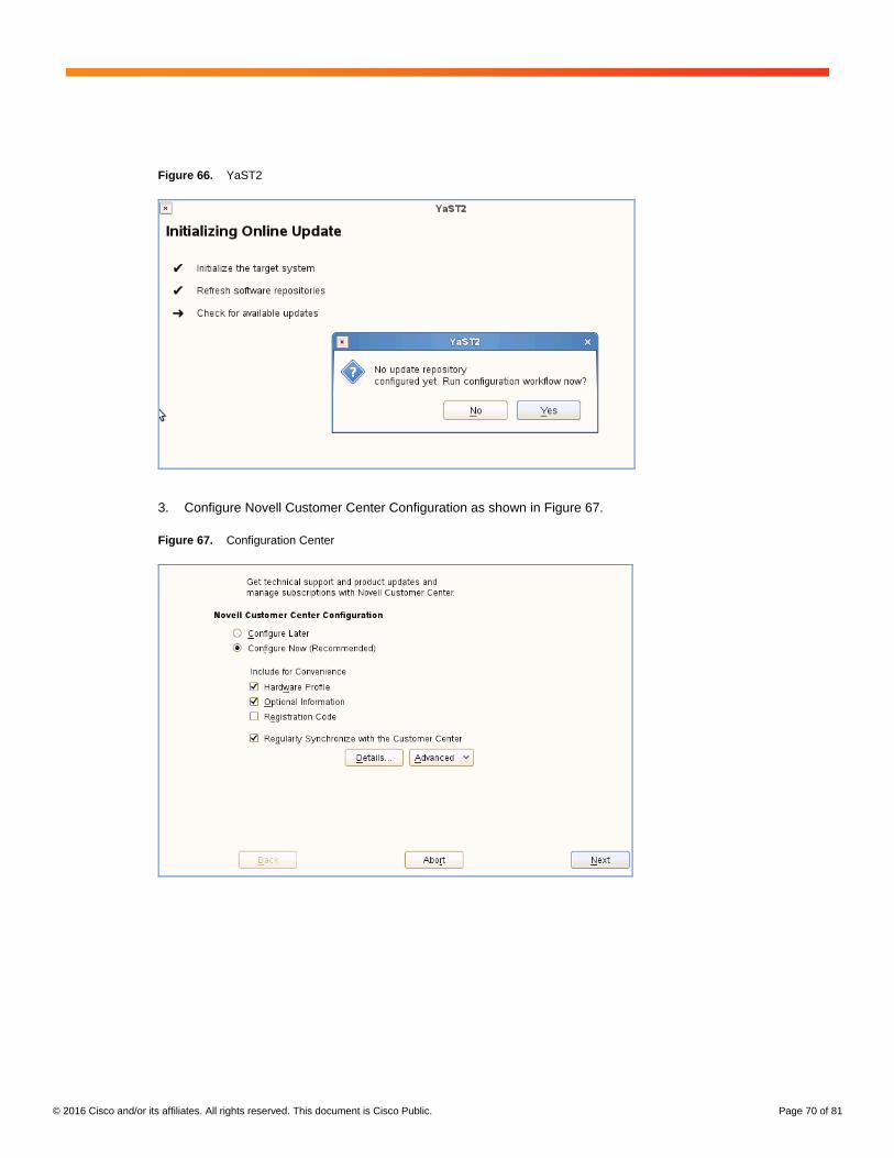
© 2016 Cisco and/or its affiliates. All rights reserved. This document is Cisco Public. Page 70 of 81
Figure 66. YaST2
3. Configure Novell Customer Center Configuration as shown in Figure 67.
Figure 67. Configuration Center
© 2016 Cisco and/or its affiliates. All rights reserved. This document is Cisco Public. Page 71 of 81
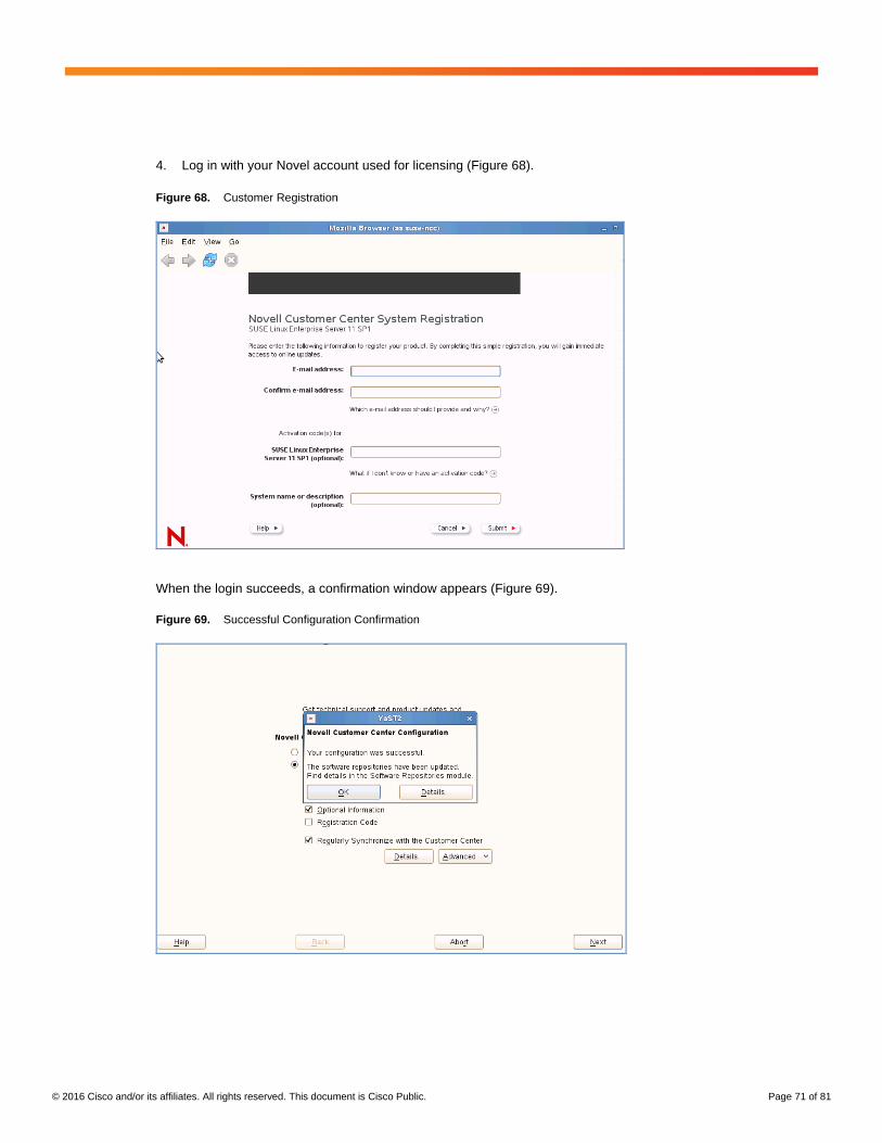
4. Log in with your Novel account used for licensing (Figure 68).
Figure 68. Customer Registration
When the login succeeds, a confirmation window appears (Figure 69).
Figure 69. Successful Configuration Confirmation
© 2016 Cisco and/or its affiliates. All rights reserved. This document is Cisco Public. Page 72 of 81
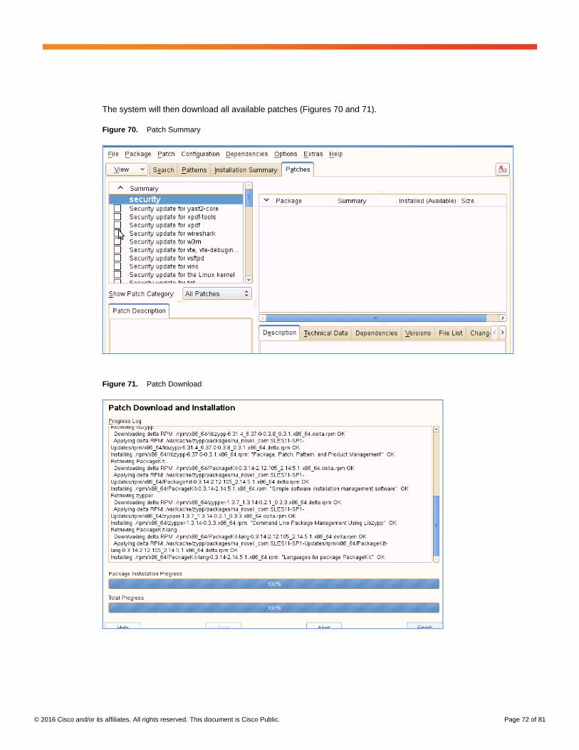
The system will then download all available patches (Figures 70 and 71).
Figure 70. Patch Summary
Figure 71. Patch Download
© 2016 Cisco and/or its affiliates. All rights reserved. This document is Cisco Public. Page 73 of 81
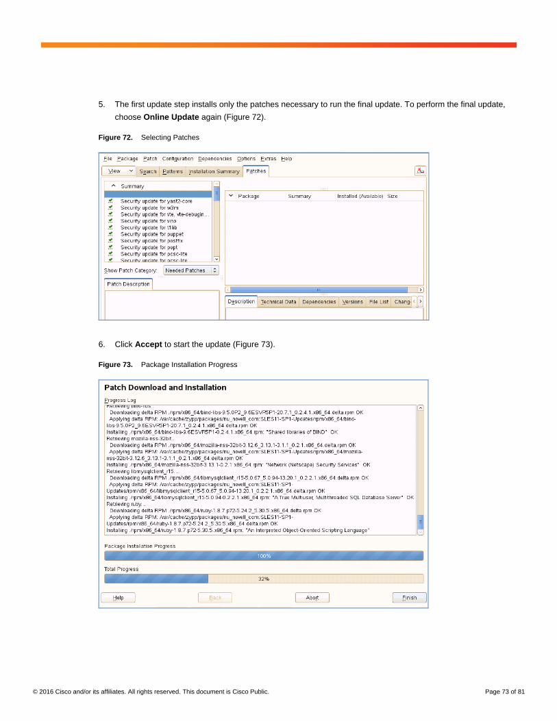
5. The first update step installs only the patches necessary to run the final update. To perform the final update,
choose Online Update again (Figure 72).
Figure 72. Selecting Patches
6. Click Accept to start the update (Figure 73).
Figure 73. Package Installation Progress
© 2016 Cisco and/or its affiliates. All rights reserved. This document is Cisco Public. Page 74 of 81
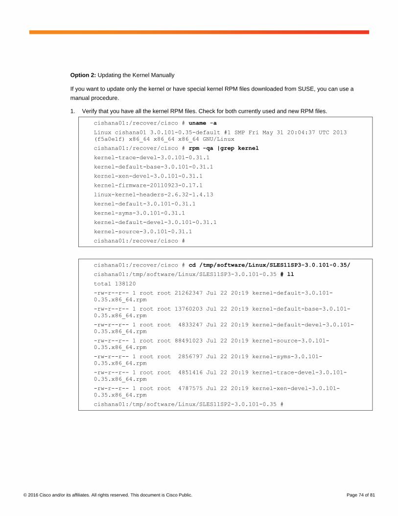
Option 2: Updating the Kernel Manually
If you want to update only the kernel or have special kernel RPM files downloaded from SUSE, you can use a
manual procedure.
1. Verify that you have all the kernel RPM files. Check for both currently used and new RPM files.
cishana01:/recover/cisco # uname -a
Linux cishana01 3.0.101-0.35-default #1 SMP Fri May 31 20:04:37 UTC 2013
(f5a0e1f) x86_64 x86_64 x86_64 GNU/Linux
cishana01:/recover/cisco # rpm -qa |grep kernel
kernel-trace-devel-3.0.101-0.31.1
kernel-default-base-3.0.101-0.31.1
kernel-xen-devel-3.0.101-0.31.1
kernel-firmware-20110923-0.17.1
linux-kernel-headers-2.6.32-1.4.13
kernel-default-3.0.101-0.31.1
kernel-syms-3.0.101-0.31.1
kernel-default-devel-3.0.101-0.31.1
kernel-source-3.0.101-0.31.1
cishana01:/recover/cisco #
cishana01:/recover/cisco # cd /tmp/software/Linux/SLES11SP3-3.0.101-0.35/
cishana01:/tmp/software/Linux/SLES11SP3-3.0.101-0.35 # ll
total 138120
-rw-r--r-- 1 root root 21262347 Jul 22 20:19 kernel-default-3.0.101-
0.35.x86_64.rpm
-rw-r--r-- 1 root root 13760203 Jul 22 20:19 kernel-default-base-3.0.101-
0.35.x86_64.rpm
-rw-r--r-- 1 root root 4833247 Jul 22 20:19 kernel-default-devel-3.0.101-
0.35.x86_64.rpm
-rw-r--r-- 1 root root 88491023 Jul 22 20:19 kernel-source-3.0.101-
0.35.x86_64.rpm
-rw-r--r-- 1 root root 2856797 Jul 22 20:19 kernel-syms-3.0.101-
0.35.x86_64.rpm
-rw-r--r-- 1 root root 4851416 Jul 22 20:19 kernel-trace-devel-3.0.101-
0.35.x86_64.rpm
-rw-r--r-- 1 root root 4787575 Jul 22 20:19 kernel-xen-devel-3.0.101-
0.35.x86_64.rpm
cishana01:/tmp/software/Linux/SLES11SP2-3.0.101-0.35 #
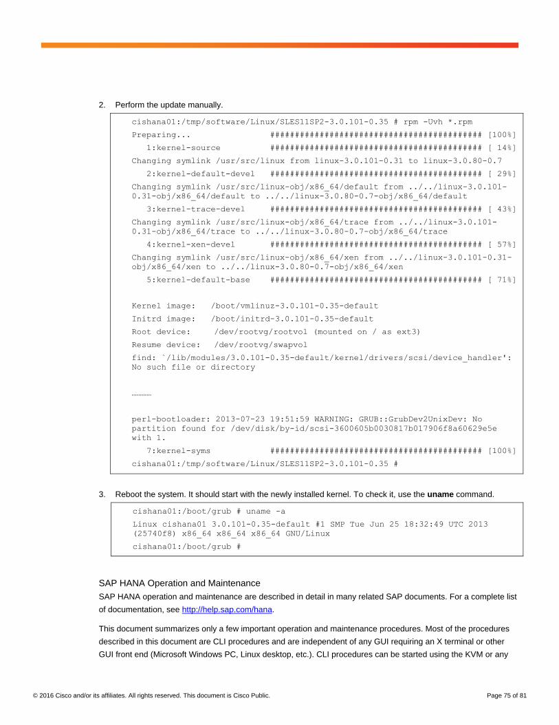
© 2016 Cisco and/or its affiliates. All rights reserved. This document is Cisco Public. Page 75 of 81
2. Perform the update manually.
cishana01:/tmp/software/Linux/SLES11SP2-3.0.101-0.35 # rpm -Uvh *.rpm
Preparing... ########################################### [100%]
1:kernel-source ########################################### [ 14%]
Changing symlink /usr/src/linux from linux-3.0.101-0.31 to linux-3.0.80-0.7
2:kernel-default-devel ########################################### [ 29%]
Changing symlink /usr/src/linux-obj/x86_64/default from ../../linux-3.0.101-
0.31-obj/x86_64/default to ../../linux-3.0.80-0.7-obj/x86_64/default
3:kernel-trace-devel ########################################### [ 43%]
Changing symlink /usr/src/linux-obj/x86_64/trace from ../../linux-3.0.101-
0.31-obj/x86_64/trace to ../../linux-3.0.80-0.7-obj/x86_64/trace
4:kernel-xen-devel ########################################### [ 57%]
Changing symlink /usr/src/linux-obj/x86_64/xen from ../../linux-3.0.101-0.31-
obj/x86_64/xen to ../../linux-3.0.80-0.7-obj/x86_64/xen
5:kernel-default-base ########################################### [ 71%]
Kernel image: /boot/vmlinuz-3.0.101-0.35-default
Initrd image: /boot/initrd-3.0.101-0.35-default
Root device: /dev/rootvg/rootvol (mounted on / as ext3)
Resume device: /dev/rootvg/swapvol
find: `/lib/modules/3.0.101-0.35-default/kernel/drivers/scsi/device_handler':
No such file or directory
…………
perl-bootloader: 2013-07-23 19:51:59 WARNING: GRUB::GrubDev2UnixDev: No
partition found for /dev/disk/by-id/scsi-3600605b0030817b017906f8a60629e5e
with 1.
7:kernel-syms ########################################### [100%]
cishana01:/tmp/software/Linux/SLES11SP2-3.0.101-0.35 #
3. Reboot the system. It should start with the newly installed kernel. To check it, use the uname command.
cishana01:/boot/grub # uname -a
Linux cishana01 3.0.101-0.35-default #1 SMP Tue Jun 25 18:32:49 UTC 2013
(25740f8) x86_64 x86_64 x86_64 GNU/Linux
cishana01:/boot/grub #
SAP HANA Operation and Maintenance
SAP HANA operation and maintenance are described in detail in many related SAP documents. For a complete list
of documentation, see http://help.sap.com/hana.
This document summarizes only a few important operation and maintenance procedures. Most of the procedures
described in this document are CLI procedures and are independent of any GUI requiring an X terminal or other
GUI front end (Microsoft Windows PC, Linux desktop, etc.). CLI procedures can be started using the KVM or any
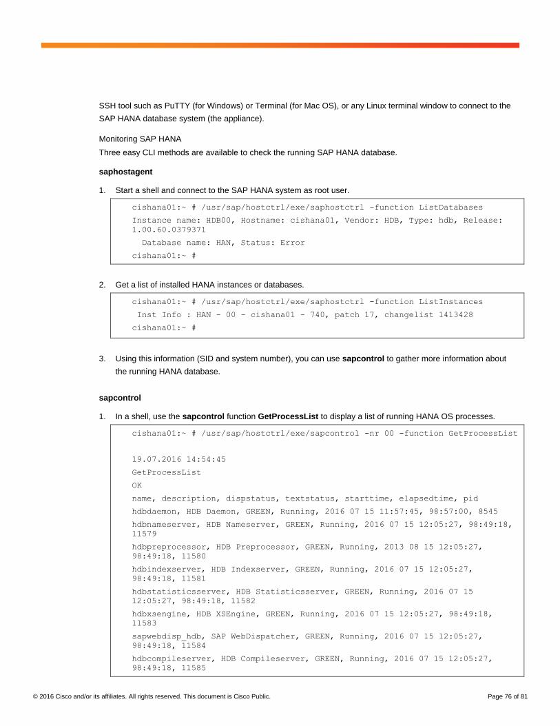
© 2016 Cisco and/or its affiliates. All rights reserved. This document is Cisco Public. Page 76 of 81
SSH tool such as PuTTY (for Windows) or Terminal (for Mac OS), or any Linux terminal window to connect to the
SAP HANA database system (the appliance).
Monitoring SAP HANA
Three easy CLI methods are available to check the running SAP HANA database.
saphostagent
1. Start a shell and connect to the SAP HANA system as root user.
cishana01:~ # /usr/sap/hostctrl/exe/saphostctrl -function ListDatabases
Instance name: HDB00, Hostname: cishana01, Vendor: HDB, Type: hdb, Release:
1.00.60.0379371
Database name: HAN, Status: Error
cishana01:~ #
2. Get a list of installed HANA instances or databases.
cishana01:~ # /usr/sap/hostctrl/exe/saphostctrl -function ListInstances
Inst Info : HAN - 00 - cishana01 - 740, patch 17, changelist 1413428
cishana01:~ #
3. Using this information (SID and system number), you can use sapcontrol to gather more information about
the running HANA database.
sapcontrol
1. In a shell, use the sapcontrol function GetProcessList to display a list of running HANA OS processes.
cishana01:~ # /usr/sap/hostctrl/exe/sapcontrol -nr 00 -function GetProcessList
19.07.2016 14:54:45
GetProcessList
OK
name, description, dispstatus, textstatus, starttime, elapsedtime, pid
hdbdaemon, HDB Daemon, GREEN, Running, 2016 07 15 11:57:45, 98:57:00, 8545
hdbnameserver, HDB Nameserver, GREEN, Running, 2016 07 15 12:05:27, 98:49:18,
11579
hdbpreprocessor, HDB Preprocessor, GREEN, Running, 2013 08 15 12:05:27,
98:49:18, 11580
hdbindexserver, HDB Indexserver, GREEN, Running, 2016 07 15 12:05:27,
98:49:18, 11581
hdbstatisticsserver, HDB Statisticsserver, GREEN, Running, 2016 07 15
12:05:27, 98:49:18, 11582
hdbxsengine, HDB XSEngine, GREEN, Running, 2016 07 15 12:05:27, 98:49:18,
11583
sapwebdisp_hdb, SAP WebDispatcher, GREEN, Running, 2016 07 15 12:05:27,
98:49:18, 11584
hdbcompileserver, HDB Compileserver, GREEN, Running, 2016 07 15 12:05:27,
98:49:18, 11585
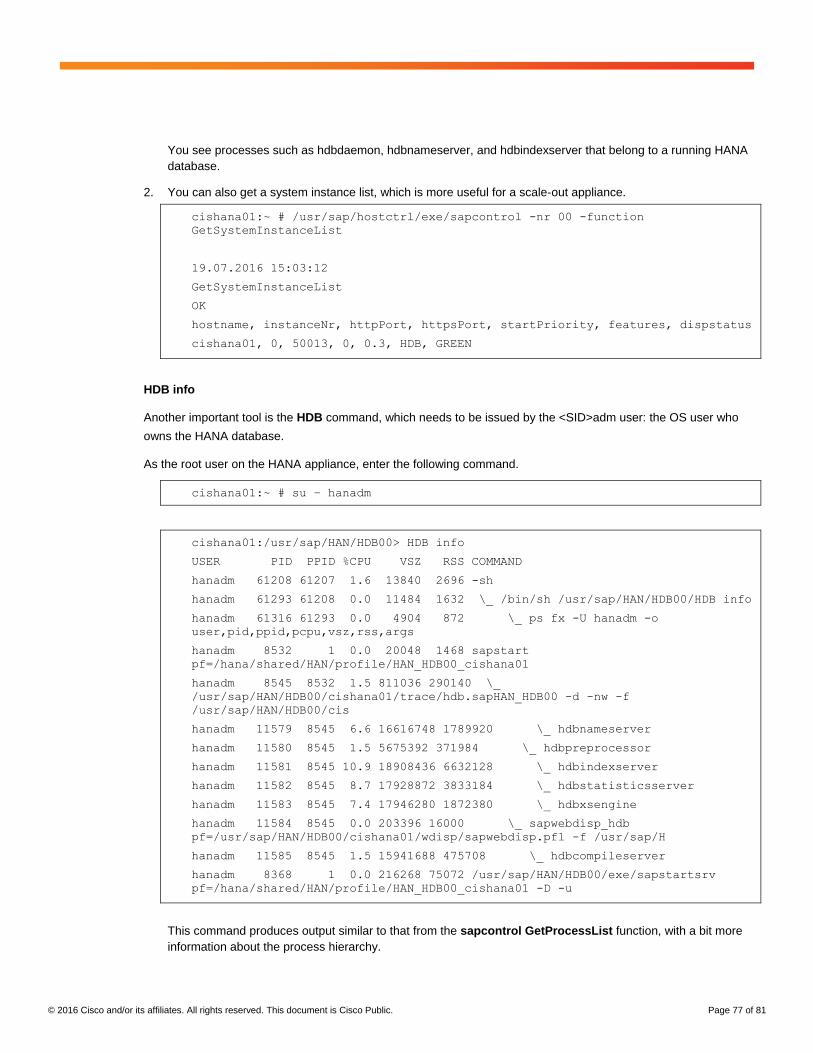
© 2016 Cisco and/or its affiliates. All rights reserved. This document is Cisco Public. Page 77 of 81
You see processes such as hdbdaemon, hdbnameserver, and hdbindexserver that belong to a running HANA
database.
2. You can also get a system instance list, which is more useful for a scale-out appliance.
cishana01:~ # /usr/sap/hostctrl/exe/sapcontrol -nr 00 -function
GetSystemInstanceList
19.07.2016 15:03:12
GetSystemInstanceList
OK
hostname, instanceNr, httpPort, httpsPort, startPriority, features, dispstatus
cishana01, 0, 50013, 0, 0.3, HDB, GREEN
HDB info
Another important tool is the HDB command, which needs to be issued by the <SID>adm user: the OS user who
owns the HANA database.
As the root user on the HANA appliance, enter the following command.
cishana01:~ # su – hanadm
cishana01:/usr/sap/HAN/HDB00> HDB info
USER PID PPID %CPU VSZ RSS COMMAND
hanadm 61208 61207 1.6 13840 2696 -sh
hanadm 61293 61208 0.0 11484 1632 \_ /bin/sh /usr/sap/HAN/HDB00/HDB info
hanadm 61316 61293 0.0 4904 872 \_ ps fx -U hanadm -o
user,pid,ppid,pcpu,vsz,rss,args
hanadm 8532 1 0.0 20048 1468 sapstart
pf=/hana/shared/HAN/profile/HAN_HDB00_cishana01
hanadm 8545 8532 1.5 811036 290140 \_
/usr/sap/HAN/HDB00/cishana01/trace/hdb.sapHAN_HDB00 -d -nw -f
/usr/sap/HAN/HDB00/cis
hanadm 11579 8545 6.6 16616748 1789920 \_ hdbnameserver
hanadm 11580 8545 1.5 5675392 371984 \_ hdbpreprocessor
hanadm 11581 8545 10.9 18908436 6632128 \_ hdbindexserver
hanadm 11582 8545 8.7 17928872 3833184 \_ hdbstatisticsserver
hanadm 11583 8545 7.4 17946280 1872380 \_ hdbxsengine
hanadm 11584 8545 0.0 203396 16000 \_ sapwebdisp_hdb
pf=/usr/sap/HAN/HDB00/cishana01/wdisp/sapwebdisp.pfl -f /usr/sap/H
hanadm 11585 8545 1.5 15941688 475708 \_ hdbcompileserver
hanadm 8368 1 0.0 216268 75072 /usr/sap/HAN/HDB00/exe/sapstartsrv
pf=/hana/shared/HAN/profile/HAN_HDB00_cishana01 -D -u
This command produces output similar to that from the sapcontrol GetProcessList function, with a bit more
information about the process hierarchy.
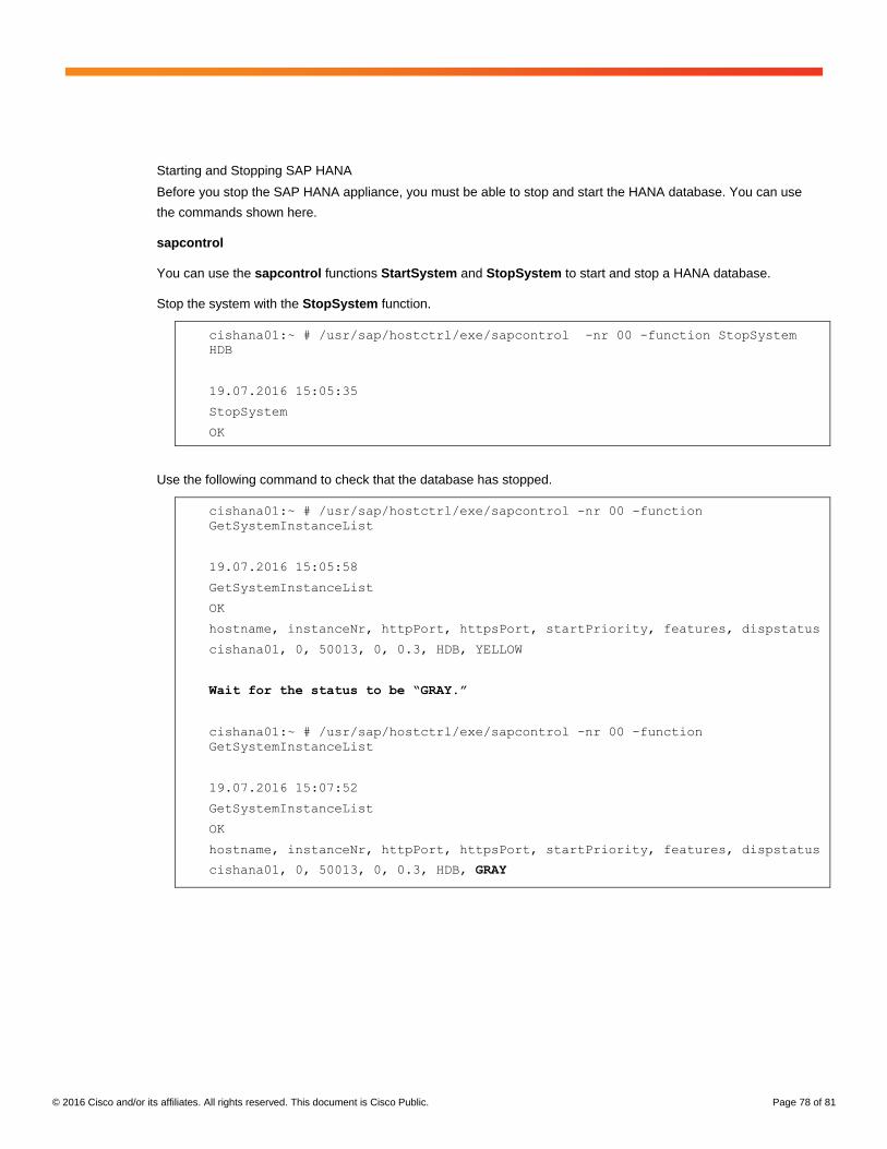
© 2016 Cisco and/or its affiliates. All rights reserved. This document is Cisco Public. Page 78 of 81
Starting and Stopping SAP HANA
Before you stop the SAP HANA appliance, you must be able to stop and start the HANA database. You can use
the commands shown here.
sapcontrol
You can use the sapcontrol functions StartSystem and StopSystem to start and stop a HANA database.
Stop the system with the StopSystem function.
cishana01:~ # /usr/sap/hostctrl/exe/sapcontrol -nr 00 -function StopSystem
HDB
19.07.2016 15:05:35
StopSystem
OK
Use the following command to check that the database has stopped.
cishana01:~ # /usr/sap/hostctrl/exe/sapcontrol -nr 00 -function
GetSystemInstanceList
19.07.2016 15:05:58
GetSystemInstanceList
OK
hostname, instanceNr, httpPort, httpsPort, startPriority, features, dispstatus
cishana01, 0, 50013, 0, 0.3, HDB, YELLOW
Wait for the status to be “GRAY.”
cishana01:~ # /usr/sap/hostctrl/exe/sapcontrol -nr 00 -function
GetSystemInstanceList
19.07.2016 15:07:52
GetSystemInstanceList
OK
hostname, instanceNr, httpPort, httpsPort, startPriority, features, dispstatus
cishana01, 0, 50013, 0, 0.3, HDB, GRAY
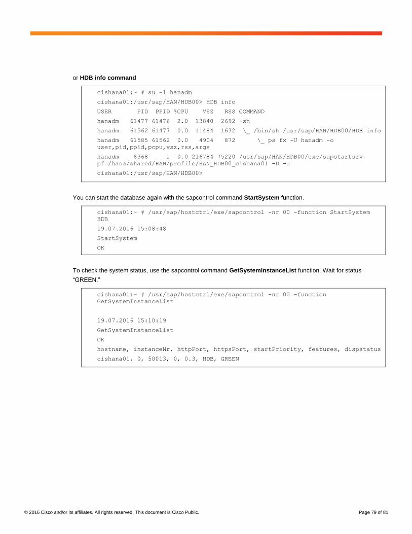
© 2016 Cisco and/or its affiliates. All rights reserved. This document is Cisco Public. Page 79 of 81
or HDB info command
cishana01:~ # su -l hanadm
cishana01:/usr/sap/HAN/HDB00> HDB info
USER PID PPID %CPU VSZ RSS COMMAND
hanadm 61477 61476 2.0 13840 2692 -sh
hanadm 61562 61477 0.0 11484 1632 \_ /bin/sh /usr/sap/HAN/HDB00/HDB info
hanadm 61585 61562 0.0 4904 872 \_ ps fx -U hanadm -o
user,pid,ppid,pcpu,vsz,rss,args
hanadm 8368 1 0.0 216784 75220 /usr/sap/HAN/HDB00/exe/sapstartsrv
pf=/hana/shared/HAN/profile/HAN_HDB00_cishana01 -D -u
cishana01:/usr/sap/HAN/HDB00>
You can start the database again with the sapcontrol command StartSystem function.
cishana01:~ # /usr/sap/hostctrl/exe/sapcontrol -nr 00 -function StartSystem
HDB
19.07.2016 15:08:48
StartSystem
OK
To check the system status, use the sapcontrol command GetSystemInstanceList function. Wait for status
“GREEN.”
cishana01:~ # /usr/sap/hostctrl/exe/sapcontrol -nr 00 -function
GetSystemInstanceList
19.07.2016 15:10:19
GetSystemInstanceList
OK
hostname, instanceNr, httpPort, httpsPort, startPriority, features, dispstatus
cishana01, 0, 50013, 0, 0.3, HDB, GREEN
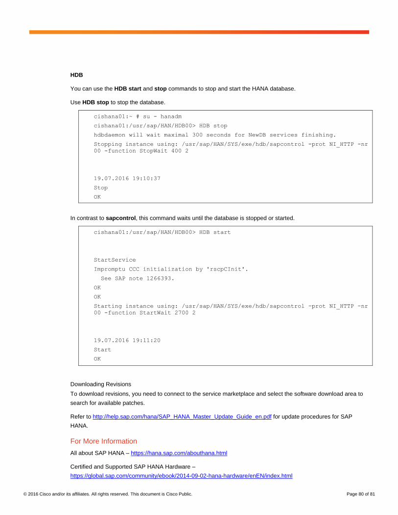
© 2016 Cisco and/or its affiliates. All rights reserved. This document is Cisco Public. Page 80 of 81
HDB
You can use the HDB start and stop commands to stop and start the HANA database.
Use HDB stop to stop the database.
cishana01:~ # su - hanadm
cishana01:/usr/sap/HAN/HDB00> HDB stop
hdbdaemon will wait maximal 300 seconds for NewDB services finishing.
Stopping instance using: /usr/sap/HAN/SYS/exe/hdb/sapcontrol -prot NI_HTTP -nr
00 -function StopWait 400 2
19.07.2016 19:10:37
Stop
OK
In contrast to sapcontrol, this command waits until the database is stopped or started.
cishana01:/usr/sap/HAN/HDB00> HDB start
StartService
Impromptu CCC initialization by 'rscpCInit'.
See SAP note 1266393.
OK
OK
Starting instance using: /usr/sap/HAN/SYS/exe/hdb/sapcontrol -prot NI_HTTP -nr
00 -function StartWait 2700 2
19.07.2016 19:11:20
Start
OK
Downloading Revisions
To download revisions, you need to connect to the service marketplace and select the software download area to
search for available patches.
Refer to http://help.sap.com/hana/SAP_HANA_Master_Update_Guide_en.pdf for update procedures for SAP
HANA.
For More Information
All about SAP HANA – https://hana.sap.com/abouthana.html
Certified and Supported SAP HANA Hardware –
https://global.sap.com/community/ebook/2014-09-02-hana-hardware/enEN/index.html
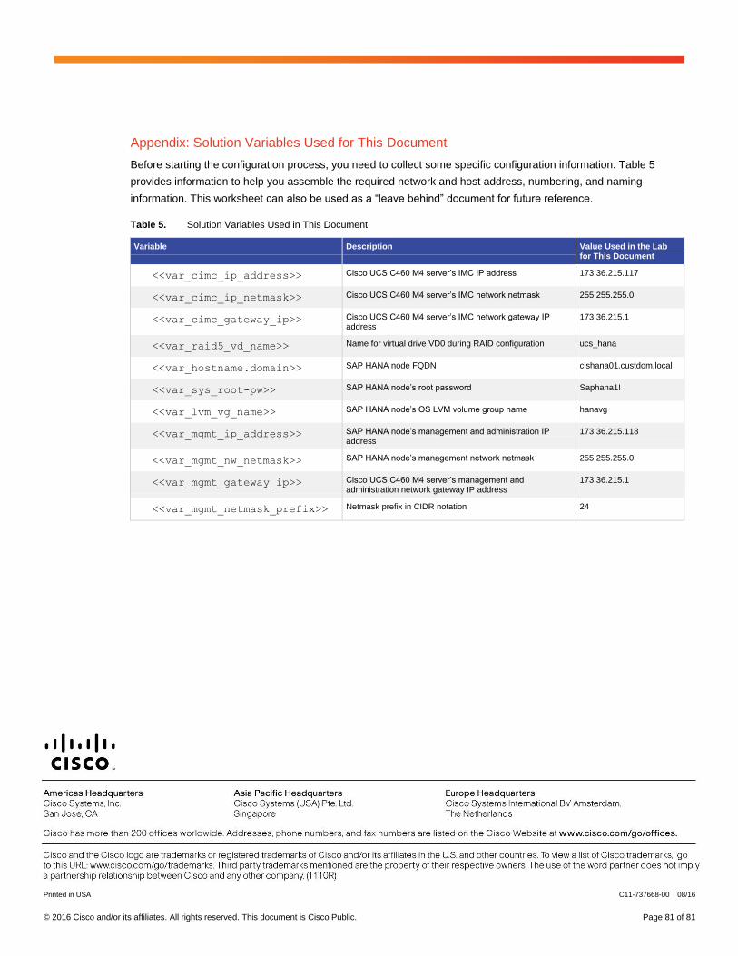
© 2016 Cisco and/or its affiliates. All rights reserved. This document is Cisco Public. Page 81 of 81
Appendix: Solution Variables Used for This Document
Before starting the configuration process, you need to collect some specific configuration information. Table 5
provides information to help you assemble the required network and host address, numbering, and naming
information. This worksheet can also be used as a “leave behind” document for future reference.
Table 5. Solution Variables Used in This Document
Variable Description Value Used in the Lab for This Document
<<var_cimc_ip_address>> Cisco UCS C460 M4 server’s IMC IP address 173.36.215.117
<<var_cimc_ip_netmask>> Cisco UCS C460 M4 server’s IMC network netmask 255.255.255.0
<<var_cimc_gateway_ip>> Cisco UCS C460 M4 server’s IMC network gateway IP address
173.36.215.1
<<var_raid5_vd_name>> Name for virtual drive VD0 during RAID configuration ucs_hana
<<var_hostname.domain>> SAP HANA node FQDN cishana01.custdom.local
<<var_sys_root-pw>> SAP HANA node’s root password Saphana1!
<<var_lvm_vg_name>> SAP HANA node’s OS LVM volume group name hanavg
<<var_mgmt_ip_address>> SAP HANA node’s management and administration IP address
173.36.215.118
<<var_mgmt_nw_netmask>> SAP HANA node’s management network netmask 255.255.255.0
<<var_mgmt_gateway_ip>> Cisco UCS C460 M4 server’s management and administration network gateway IP address
173.36.215.1
<<var_mgmt_netmask_prefix>> Netmask prefix in CIDR notation 24
Printed in USA C11-737668-00 08/16