cisco ucs performance manager getting started guide ... · cisco ucs performance manager getting...
TRANSCRIPT

Cisco UCS Performance Manager Getting Started Guide First Published: February 2017Release 2.0.3
Americas HeadquartersCisco Systems, Inc.170 West Tasman DriveSan Jose, CA 95134-1706USAhttp://www.cisco.comTel: 408 526-4000 800 553-NETS (6387)Fax: 408 527-0883

THE SPECIFICATIONS AND INFORMATION REGARDING THE PRODUCTS IN THIS MANUAL ARE SUBJECT TO CHANGE WITHOUT NOTICE. ALL STATEMENTS,INFORMATION, AND RECOMMENDATIONS IN THIS MANUAL ARE BELIEVED TO BE ACCURATE BUT ARE PRESENTED WITHOUT WARRANTY OF ANY KIND,EXPRESS OR IMPLIED. USERS MUST TAKE FULL RESPONSIBILITY FOR THEIR APPLICATION OF ANY PRODUCTS.
THE SOFTWARE LICENSE AND LIMITED WARRANTY FOR THE ACCOMPANYING PRODUCT ARE SET FORTH IN THE INFORMATION PACKET THAT SHIPPED WITHTHE PRODUCT AND ARE INCORPORATED HEREIN BY THIS REFERENCE. IF YOU ARE UNABLE TO LOCATE THE SOFTWARE LICENSE OR LIMITED WARRANTY,CONTACT YOUR CISCO REPRESENTATIVE FOR A COPY.
The Cisco implementation of TCP header compression is an adaptation of a program developed by the University of California, Berkeley (UCB) as part of UCB's public domain versionof the UNIX operating system. All rights reserved. Copyright © 1981, Regents of the University of California.
NOTWITHSTANDINGANYOTHERWARRANTYHEREIN, ALL DOCUMENT FILES AND SOFTWAREOF THESE SUPPLIERS ARE PROVIDED “AS IS"WITH ALL FAULTS.CISCO AND THE ABOVE-NAMED SUPPLIERS DISCLAIM ALL WARRANTIES, EXPRESSED OR IMPLIED, INCLUDING, WITHOUT LIMITATION, THOSE OFMERCHANTABILITY, FITNESS FORA PARTICULAR PURPOSEANDNONINFRINGEMENTORARISING FROMACOURSEOFDEALING, USAGE, OR TRADE PRACTICE.
IN NO EVENT SHALL CISCO OR ITS SUPPLIERS BE LIABLE FOR ANY INDIRECT, SPECIAL, CONSEQUENTIAL, OR INCIDENTAL DAMAGES, INCLUDING, WITHOUTLIMITATION, LOST PROFITS OR LOSS OR DAMAGE TO DATA ARISING OUT OF THE USE OR INABILITY TO USE THIS MANUAL, EVEN IF CISCO OR ITS SUPPLIERSHAVE BEEN ADVISED OF THE POSSIBILITY OF SUCH DAMAGES.
Cisco and the Cisco logo are trademarks or registered trademarks of Cisco and/or its affiliates in the U.S. and other countries. To view a list of Cisco trademarks, go to this URL: http://www.cisco.com/go/trademarks. Third-party trademarks mentioned are the property of their respective owners. The use of the word partner does not imply a partnershiprelationship between Cisco and any other company. (1110R)
Any Internet Protocol (IP) addresses used in this document are not intended to be actual addresses. Any examples, command display output, and figures included in the document are shownfor illustrative purposes only. Any use of actual IP addresses in illustrative content is unintentional and coincidental.
© 2014-2017 Cisco Systems, Inc. All rights reserved.
3
ContentsPreface.................................................................................................................................. 4
Chapter 1: Welcome to Cisco UCS Performance Manager.............................5Preparing Network Devices............................................................................................................................................ 5Preparing Storage Devices...............................................................................................................................................6Preparing Server Devices.................................................................................................................................................7Preparing Hypervisor Devices........................................................................................................................................ 8
Chapter 2: Enabling access to browser interfaces..........................................9Creating public endpoints................................................................................................................................................9Configuring name resolution for virtual hosts.......................................................................................................... 18
Chapter 3: Setting up Cisco UCS Performance Manager.............................20Accepting the License Agreement............................................................................................................................... 20Providing a license key...................................................................................................................................................21Setting up Users.............................................................................................................................................................. 22Adding UCS Centrals..................................................................................................................................................... 22Adding UCS Domains................................................................................................................................................... 23Adding Infrastructure Devices..................................................................................................................................... 25Setup SMTP..................................................................................................................................................................... 28
Appendix: Preparing Windows Systems........................................................29
Cisco UCS Performance Manager Getting Started Guide
4
PrefaceCisco UCS Performance Manager Getting Started Guide provides instructions for configuring Cisco UCS PerformanceManager Express and Cisco UCS Performance Manager after installation. If you have not yet installed Cisco UCSPerformance Manager, follow the instructions in the Cisco UCS Performance Manager Installation Guide before using thisguide.
■ Cisco UCS Performance Manager Express provides monitoring for Cisco UCS Central, Cisco UCS Domains,Linux and Microsoft Windows servers, hypervisor servers, and Control Center.
■ Cisco UCS Performance Manager provides monitoring for Cisco UCS Central, Cisco UCS Domains, Linux andMicrosoft Windows servers, hypervisor servers, network devices, storage devices, and Control Center.
For convenience, this document uses "Cisco UCS Performance Manager" generically, and notes explicitly anydifferences between the two licenses.
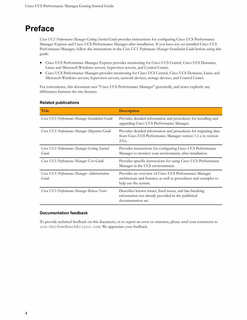
Related publications
Title Description
Cisco UCS Performance Manager Installation Guide Provides detailed information and procedures for installing andupgrading Cisco UCS Performance Manager.
Cisco UCS Performance Manager Migration Guide Provides detailed information and procedures for migrating datafrom Cisco UCS Performance Manager version 1.1.x to version2.0.x.
Cisco UCS Performance Manager Getting StartedGuide
Provides instructions for configuring Cisco UCS PerformanceManager to monitor your environment, after installation.
Cisco UCS Performance Manager User Guide Provides specific instructions for using Cisco UCS PerformanceManager in the UCS environnment.
Cisco UCS Performance Manager AdministrationGuide
Provides an overview of Cisco UCS Performance Managerarchitecture and features, as well as procedures and examples tohelp use the system.
Cisco UCS Performance Manager Release Notes Describes known issues, fixed issues, and late-breakinginformation not already provided in the publisheddocumentation set.
Documentation feedback
To provide technical feedback on this document, or to report an error or omission, please send your comments [email protected]. We appreciate your feedback.
Welcome to Cisco UCS Performance Manager
5
Welcome to Cisco UCS PerformanceManager 1
Once Cisco UCS Performance Manager is installed, the Cisco UCS Performance Manager Setup Wizard guidesyou through the process of accepting the EULA, providing your license key, defining users, setting up UCS Centraldevices, setting up UCS domains, adding infrastructure devices, and setting up an SMTP host for email generation.
Cisco UCS Performance Manager uses standard management APIs to collect performance data, so no proprietaryagents are installed on infrastructure devices. However, Cisco recommends that you review the following sections,and verify that the devices to monitor are ready to respond to requests for data.
Preparing Network Devices
Note If your license is Cisco UCS Performance Manager Express, skip this topic.
Cisco UCS Performance Manager uses SNMP to provide customized or generalized support for many Ciscoproducts.
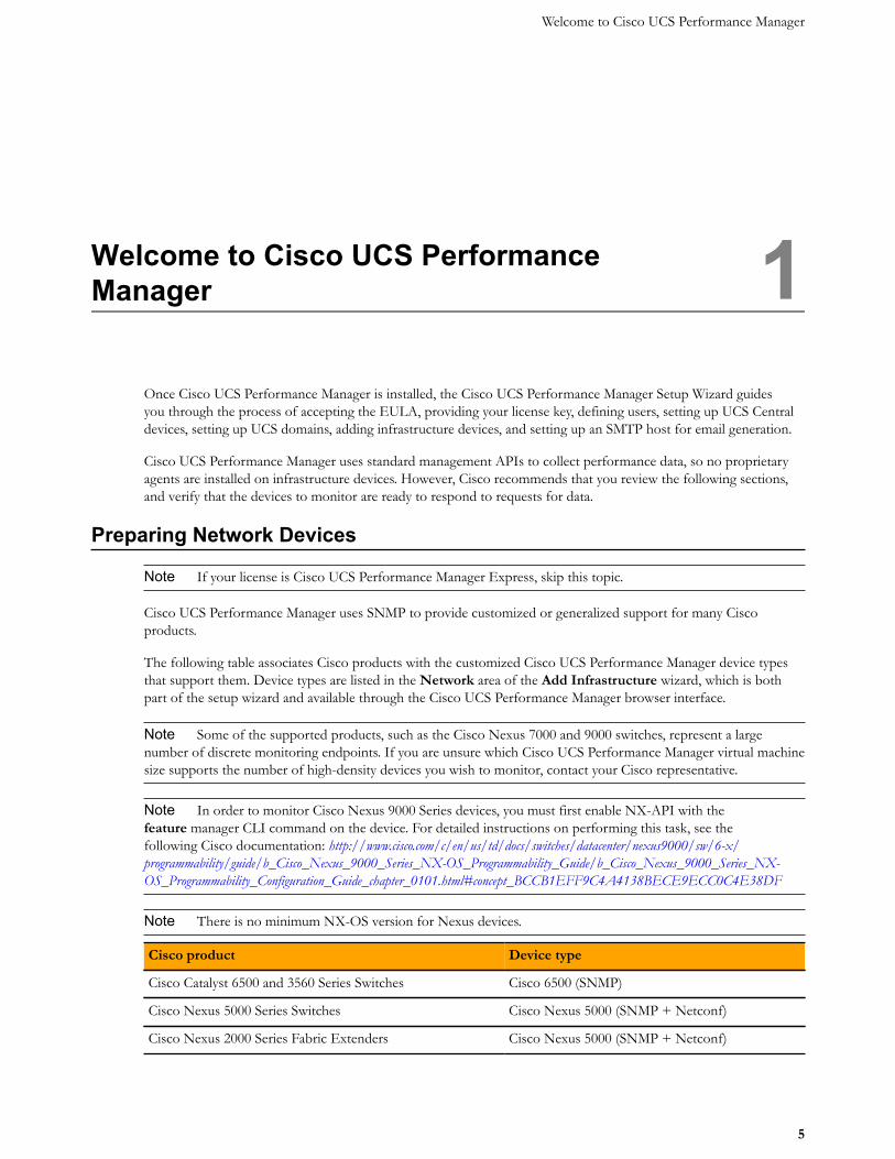
The following table associates Cisco products with the customized Cisco UCS Performance Manager device typesthat support them. Device types are listed in the Network area of the Add Infrastructure wizard, which is bothpart of the setup wizard and available through the Cisco UCS Performance Manager browser interface.
Note Some of the supported products, such as the Cisco Nexus 7000 and 9000 switches, represent a largenumber of discrete monitoring endpoints. If you are unsure which Cisco UCS Performance Manager virtual machinesize supports the number of high-density devices you wish to monitor, contact your Cisco representative.
Note In order to monitor Cisco Nexus 9000 Series devices, you must first enable NX-API with thefeature manager CLI command on the device. For detailed instructions on performing this task, see thefollowing Cisco documentation: http://www.cisco.com/c/en/us/td/docs/switches/datacenter/nexus9000/sw/6-x/programmability/guide/b_Cisco_Nexus_9000_Series_NX-OS_Programmability_Guide/b_Cisco_Nexus_9000_Series_NX-OS_Programmability_Configuration_Guide_chapter_0101.html#concept_BCCB1EFF9C4A4138BECE9ECC0C4E38DF
Note There is no minimum NX-OS version for Nexus devices.
Cisco product Device type
Cisco Catalyst 6500 and 3560 Series Switches Cisco 6500 (SNMP)
Cisco Nexus 5000 Series Switches Cisco Nexus 5000 (SNMP + Netconf)
Cisco Nexus 2000 Series Fabric Extenders Cisco Nexus 5000 (SNMP + Netconf)
Cisco UCS Performance Manager Getting Started Guide
6
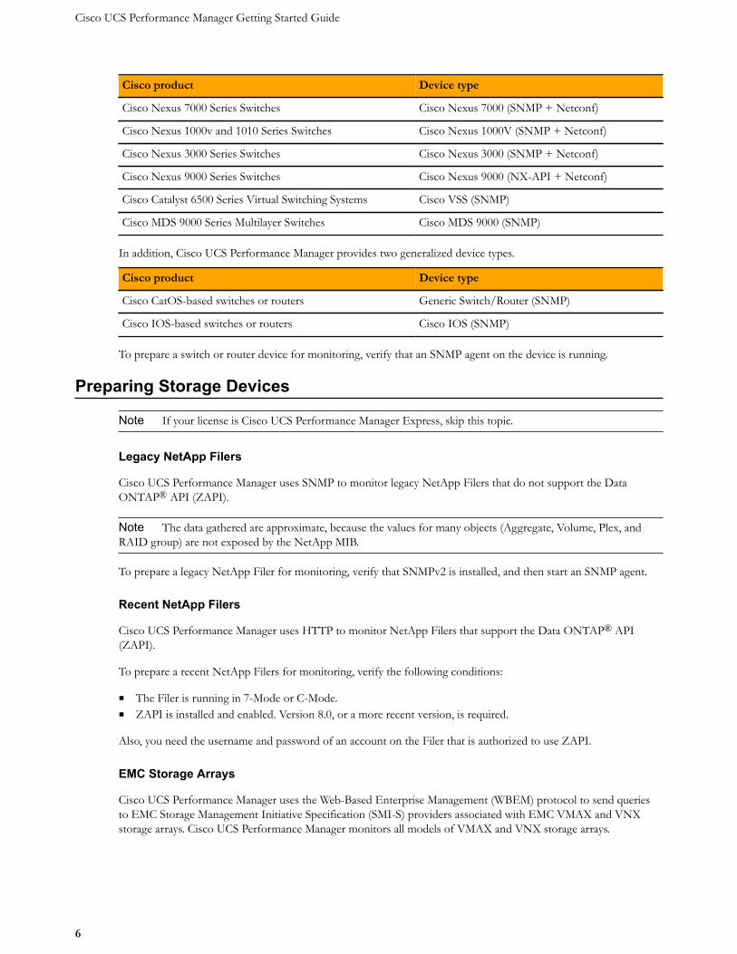
Cisco product Device type
Cisco Nexus 7000 Series Switches Cisco Nexus 7000 (SNMP + Netconf)
Cisco Nexus 1000v and 1010 Series Switches Cisco Nexus 1000V (SNMP + Netconf)
Cisco Nexus 3000 Series Switches Cisco Nexus 3000 (SNMP + Netconf)
Cisco Nexus 9000 Series Switches Cisco Nexus 9000 (NX-API + Netconf)
Cisco Catalyst 6500 Series Virtual Switching Systems Cisco VSS (SNMP)
Cisco MDS 9000 Series Multilayer Switches Cisco MDS 9000 (SNMP)
In addition, Cisco UCS Performance Manager provides two generalized device types.
Cisco product Device type
Cisco CatOS-based switches or routers Generic Switch/Router (SNMP)
Cisco IOS-based switches or routers Cisco IOS (SNMP)
To prepare a switch or router device for monitoring, verify that an SNMP agent on the device is running.
Preparing Storage Devices
Note If your license is Cisco UCS Performance Manager Express, skip this topic.
Legacy NetApp Filers
Cisco UCS Performance Manager uses SNMP to monitor legacy NetApp Filers that do not support the DataONTAP® API (ZAPI).
Note The data gathered are approximate, because the values for many objects (Aggregate, Volume, Plex, andRAID group) are not exposed by the NetApp MIB.
To prepare a legacy NetApp Filer for monitoring, verify that SNMPv2 is installed, and then start an SNMP agent.
Recent NetApp Filers
Cisco UCS Performance Manager uses HTTP to monitor NetApp Filers that support the Data ONTAP® API(ZAPI).
To prepare a recent NetApp Filers for monitoring, verify the following conditions:
■ The Filer is running in 7-Mode or C-Mode.■ ZAPI is installed and enabled. Version 8.0, or a more recent version, is required.
Also, you need the username and password of an account on the Filer that is authorized to use ZAPI.
EMC Storage Arrays
Cisco UCS Performance Manager uses the Web-Based Enterprise Management (WBEM) protocol to send queriesto EMC Storage Management Initiative Specification (SMI-S) providers associated with EMC VMAX and VNXstorage arrays. Cisco UCS Performance Manager monitors all models of VMAX and VNX storage arrays.
Welcome to Cisco UCS Performance Manager
7
To prepare EMC arrays for monitoring, verify that at least one EMC SMI-S provider is running for each typeof array to monitor. (The VMAX and VNX data models are different.) In addition, you need the followinginformation:
■ The username and password of a user account that is authorized to collect data on each SMI-S provider.■ The IP address of each SMI-S provider.■ The port number at which each SMI-S provider listens for requests.■ Whether or not to use SSL.
Cisco recommends verifying that an SMI-S provider is responding to requests before adding it to Cisco UCSPerformance Manager. SMI-S provider version 4.6 has been certified for this version of Cisco UCS PerformanceManager. SMI-S provider version 8.1 is not currently supported.
Note Many of the graphs for components types of EMC arrays display NaN when statistics logging is disabledon the EMC device. The logging feature has a low default timeout value, and must be set to a higher value or turnedon again periodically.
Verifying an SMI-S provider
To perform this procedure, you need a Linux host that has a network path to the SMI-S providers of the arrays tomonitor.
Note Do not perform this procedure on the Cisco UCS Performance Manager host.
Perform this procedure to verify that the SMI-S providers associated with EMC arrays are configured correctly, andare responding to WBEM queries from command line tools.
1 Log in to a Linux host as root, or as a user with superuser privileges.2 Install a WBEM command-line interface package, such as wbemcli.3 Verify the SMI-S provider. Replace the variables with values that are valid in your environment.
wbemcli IP-Address:Port -u admin -p 'Password' -n root/emc --no-sslei('EMC_DiskDrive')
The expected result is a list of Disk Drive classes.
Preparing Server Devices
Linux Servers
Cisco UCS Performance Manager uses SNMP or SSH to monitor Linux servers.
To prepare a Linux server for SNMP monitoring, install an SNMP package on the server (for example, Net-SNMP)and start the agent.
To prepare a Linux server for SSH monitoring, install an SSH server package (for example, OpenSSH) and startthe SSH daemon. Also, obtain the username and password of a user account on the server that has standard userprivileges (root privileges are not required).
Windows Servers
Cisco UCS Performance Manager uses SNMP or WinRM to monitor the following Microsoft Windows systems:
■ Microsoft Windows Server 2012 and 2012 R2
Cisco UCS Performance Manager Getting Started Guide
8
■ Microsoft Windows Server 2008 R2
To prepare a Windows system for SNMP monitoring, start the SNMP service.
To prepare a Windows system for WinRM monitoring, refer to the appendix, "Preparing Windows Systems."
Preparing Hypervisor Devices
vSphere EndPoint
Cisco UCS Performance Manager uses SOAP to monitor VMware vSphere servers running vSphere 4.1, 5.0, 5.1,5.5, or 6.0.
To prepare a VMware vSphere server for monitoring, verify the software version, and obtain the username andpassword of an account on the server that is authorized to use the vSphere API and determine whether or not touse SSL.
Microsoft Hyper-V
Cisco UCS Performance Manager uses WinRM to monitor the following Microsoft Hyper-V systems:
■ Microsoft Hyper-V Server 2012 and 2012 R2■ Microsoft Hyper-V Server 2008 and 2008 R2
To prepare a Hyper-V Server for WinRM monitoring, refer to the appendix, "Preparing Windows Systems."
Enabling access to browser interfaces
9
Enabling access to browser interfaces 2Control Center and Cisco UCS Performance Manager have independent browser interfaces served by independentweb servers. Both web servers are configured to use SSL/TLS communications.
The Control Center web server listens at the hostname of the Control Center master host and port 50443. For aControl Center master host with the fully-qualified domain name (FQDN) cc-master.example.com, thehostname URL is https://cc-master:50443. As always, you may substitute an IP address for the hostnameportion of the URL.
The Cisco UCS Performance Manager web server listens at a port public endpoint and a virtual host public endpoint.
■ The default port public endpoint is the hostname of the Control Center master host and port 443. For the FQDNcc-master.example.com, the URL of the default port public endpoint is https://cc-master. Ifthe Control Center master host has more than one network interface, you can configure additional port publicendpoints with different hostnames. Also, you can disable SSL/TLS communications for a port public endpoint,if desired.
To use a port public endpoint to gain access to the Cisco UCS Performance Manager browser interface, noadditional network name resolution entries are required. The default entries for the network interface(s) of theControl Center master host are sufficient.
■ The default virtual host public endpoint is the text ucspm prepended to the hostname of the Control Center masterhost and port 50443. For the FQDN cc-master.example.com, the URL of the default virtual host publicendpoint is https://ucspm.cc-master:50443. You can change the name of the default virtual hostand configure additional virtual host public endpoints, if desired.
To use a virtual host public endpoint to gain access to the Cisco UCS Performance Manager browser interface,you must add name resolution entries for the virtual host to the DNS servers in your environment or to thehosts files of individual client systems.
The following sections provide additional information about public endpoints, and instructions for creating publicendpoints and for configuring virtual host name resolution.
Creating public endpointsThis section decribes how to create a port public endpoint and a virtual host public endpoint. The following tableoutlines the process for each.
Port public endpoint Virtual host public endpoint
1 Create the endpoint 1 Create the endpoint
Cisco UCS Performance Manager Getting Started Guide
10
Port public endpoint Virtual host public endpoint
2 Configure the Zope service 2 Configure the Zope service3 Configure virtual host name resolution
To change an existing public endpoint, create a new endpoint and then delete the existing endpoint.
Note Virtual host public endpoints must use SSL/TLS communications. Port public endpoints can communicatewith or without SSL/TLS.
Creating a port public endpointUse this procedure to create a new port public endpoint. Port public endpoints can communicate with or withoutSSL/TLS.
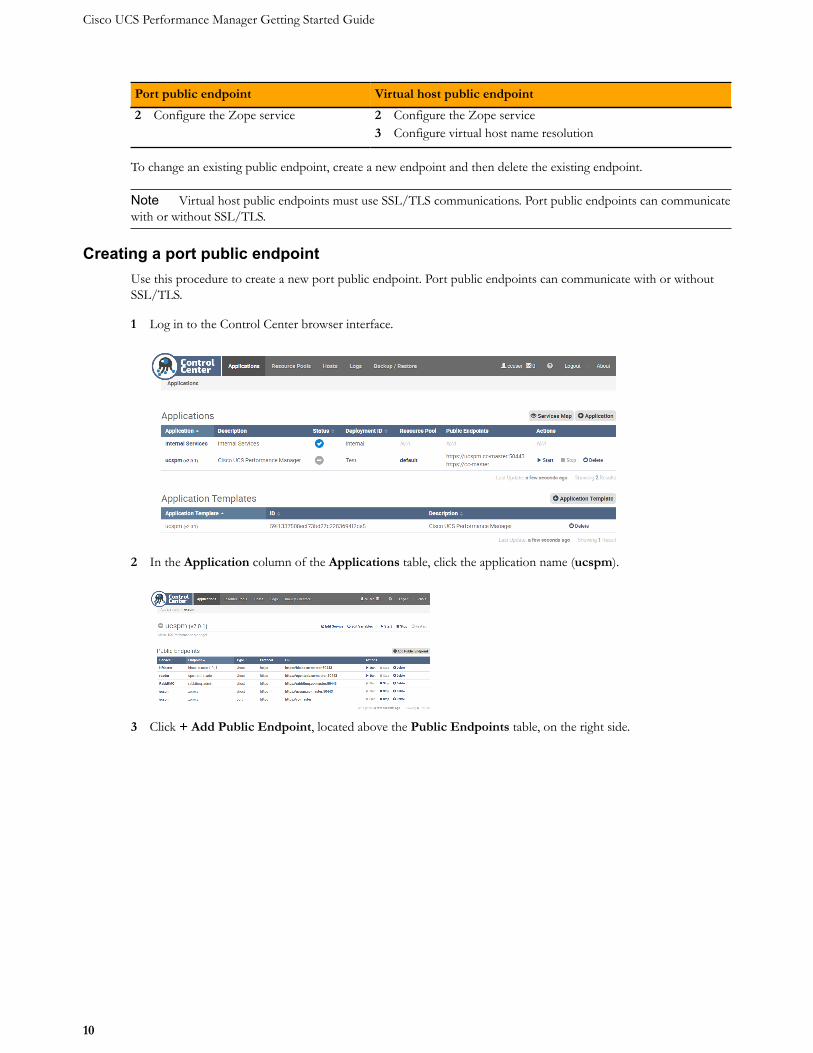
1 Log in to the Control Center browser interface.
2 In the Application column of the Applications table, click the application name (ucspm).
3 Click + Add Public Endpoint, located above the Public Endpoints table, on the right side.
Enabling access to browser interfaces
11
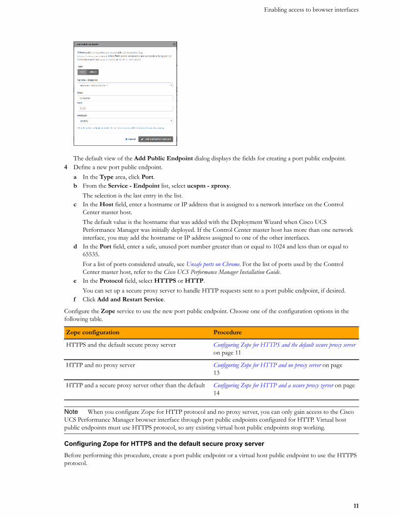
The default view of the Add Public Endpoint dialog displays the fields for creating a port public endpoint.4 Define a new port public endpoint.
a In the Type area, click Port.b From the Service - Endpoint list, select ucspm - zproxy.
The selection is the last entry in the list.c In the Host field, enter a hostname or IP address that is assigned to a network interface on the Control
Center master host.The default value is the hostname that was added with the Deployment Wizard when Cisco UCSPerformance Manager was initially deployed. If the Control Center master host has more than one networkinterface, you may add the hostname or IP address assigned to one of the other interfaces.
d In the Port field, enter a safe, unused port number greater than or equal to 1024 and less than or equal to65535.For a list of ports considered unsafe, see Unsafe ports on Chrome. For the list of ports used by the ControlCenter master host, refer to the Cisco UCS Performance Manager Installation Guide.
e In the Protocol field, select HTTPS or HTTP.You can set up a secure proxy server to handle HTTP requests sent to a port public endpoint, if desired.
f Click Add and Restart Service.
Configure the Zope service to use the new port public endpoint. Choose one of the configuration options in thefollowing table.
Zope configuration Procedure
HTTPS and the default secure proxy server Configuring Zope for HTTPS and the default secure proxy serveron page 11
HTTP and no proxy server Configuring Zope for HTTP and no proxy server on page13
HTTP and a secure proxy server other than the default Configuring Zope for HTTP and a secure proxy zerver on page14
Note When you configure Zope for HTTP protocol and no proxy server, you can only gain access to the CiscoUCS Performance Manager browser interface through port public endpoints configured for HTTP. Virtual hostpublic endpoints must use HTTPS protocol, so any existing virtual host public endpoints stop working.
Configuring Zope for HTTPS and the default secure proxy serverBefore performing this procedure, create a port public endpoint or a virtual host public endpoint to use the HTTPSprotocol.
Cisco UCS Performance Manager Getting Started Guide
12
Use this procedure to configure the Zope service for SSL/TLS communications and the secure proxy server that isincluded in Cisco UCS Performance Manager.
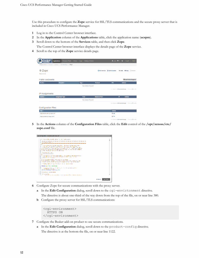
1 Log in to the Control Center browser interface.2 In the Application column of the Applications table, click the application name (ucspm).3 Scroll down to the bottom of the Services table, and then click Zope.
The Control Center browser interface displays the details page of the Zope service.4 Scroll to the top of the Zope service details page.
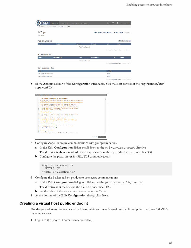
5 In the Actions column of the Configuration Files table, click the Edit control of the /opt/zenoss/etc/zope.conf file.
6 Configure Zope for secure communications with the proxy server.a In the Edit Configuration dialog, scroll down to the cgi-envirtonment directive.
The directive is about one-third of the way down from the top of the file, on or near line 380.b Configure the proxy server for SSL/TLS communications:
<cgi-environment> HTTPS ON</cgi-environment>
7 Configure the Beaker add-on product to use secure communications.a In the Edit Configuration dialog, scroll down to the product-config directive.
The directive is at the bottom the file, on or near line 1122.
Enabling access to browser interfaces
13
b Set the value of the session.secure key to True.8 At the bottom of the Edit Configuration dialog, click Save.
Next steps:
■ If you created a port public endpoint before performing this procedure, the endpoint is ready to use.■ If you created a virtual host public endpoint before performing this procedure, proceed to Configuring name
resolution for virtual hosts on page 18.
Configuring Zope for HTTP and no proxy serverBefore performing this procedure, create a port public endpoint to use the HTTP protocol. For more information,see Creating a port public endpoint on page 10.
Use this procedure to configure the Zope service for insecure communications with Cisco UCS PerformanceManager browser interface clients.
Note When you configure Zope for insecure communications, any existing virtual host public endpoints stopworking.
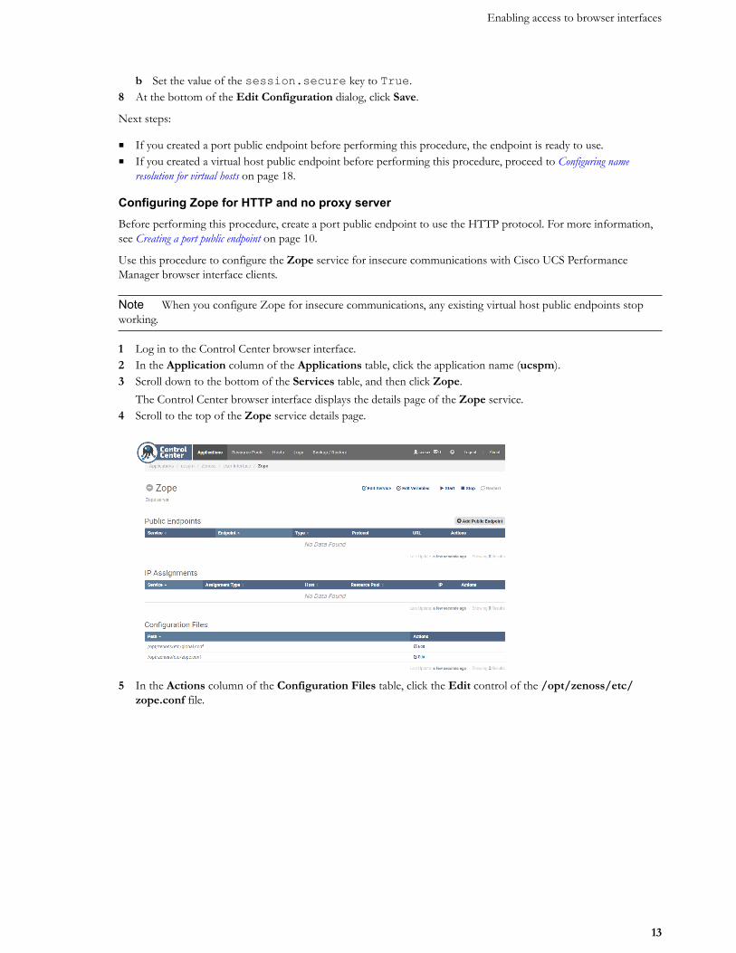
1 Log in to the Control Center browser interface.2 In the Application column of the Applications table, click the application name (ucspm).3 Scroll down to the bottom of the Services table, and then click Zope.
The Control Center browser interface displays the details page of the Zope service.4 Scroll to the top of the Zope service details page.
5 In the Actions column of the Configuration Files table, click the Edit control of the /opt/zenoss/etc/zope.conf file.
Cisco UCS Performance Manager Getting Started Guide
14
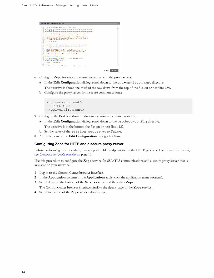
6 Configure Zope for insecure communications with the proxy server.a In the Edit Configuration dialog, scroll down to the cgi-envirtonment directive.
The directive is about one-third of the way down from the top of the file, on or near line 380.b Configure the proxy server for insecure communications:
<cgi-environment> HTTPS OFF</cgi-environment>
7 Configure the Beaker add-on product to use insecure communications.a In the Edit Configuration dialog, scroll down to the product-config directive.
The directive is at the bottom the file, on or near line 1122.b Set the value of the session.secure key to False.
8 At the bottom of the Edit Configuration dialog, click Save.
Configuring Zope for HTTP and a secure proxy zerverBefore performing this procedure, create a port public endpoint to use the HTTP protocol. For more information,see Creating a port public endpoint on page 10.
Use this procedure to configure the Zope service for SSL/TLS communications and a secure proxy server that isavailable on your network.
1 Log in to the Control Center browser interface.2 In the Application column of the Applications table, click the application name (ucspm).3 Scroll down to the bottom of the Services table, and then click Zope.
The Control Center browser interface displays the details page of the Zope service.4 Scroll to the top of the Zope service details page.
Enabling access to browser interfaces
15
5 In the Actions column of the Configuration Files table, click the Edit control of the /opt/zenoss/etc/zope.conf file.
6 Configure Zope for secure communications with your proxy server.a In the Edit Configuration dialog, scroll down to the cgi-envirtonment directive.
The directive is about one-third of the way down from the top of the file, on or near line 380.b Configure the proxy server for SSL/TLS communications:
<cgi-environment> HTTPS ON</cgi-environment>
7 Configure the Beaker add-on product to use secure communications.a In the Edit Configuration dialog, scroll down to the product-config directive.
The directive is at the bottom the file, on or near line 1122.b Set the value of the session.secure key to True.
8 At the bottom of the Edit Configuration dialog, click Save.
Creating a virtual host public endpointUse this procedure to create a new virtual host public endpoint. Virtual host public endpoints must use SSL/TLScommunications.
1 Log in to the Control Center browser interface.
Cisco UCS Performance Manager Getting Started Guide
16
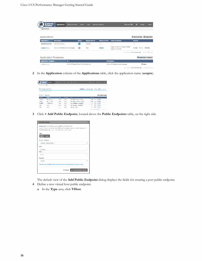
2 In the Application column of the Applications table, click the application name (ucspm).
3 Click + Add Public Endpoint, located above the Public Endpoints table, on the right side.
The default view of the Add Public Endpoint dialog displays the fields for creating a port public endpoint.4 Define a new virtual host public endpoint.
a In the Type area, click VHost.
Enabling access to browser interfaces
17
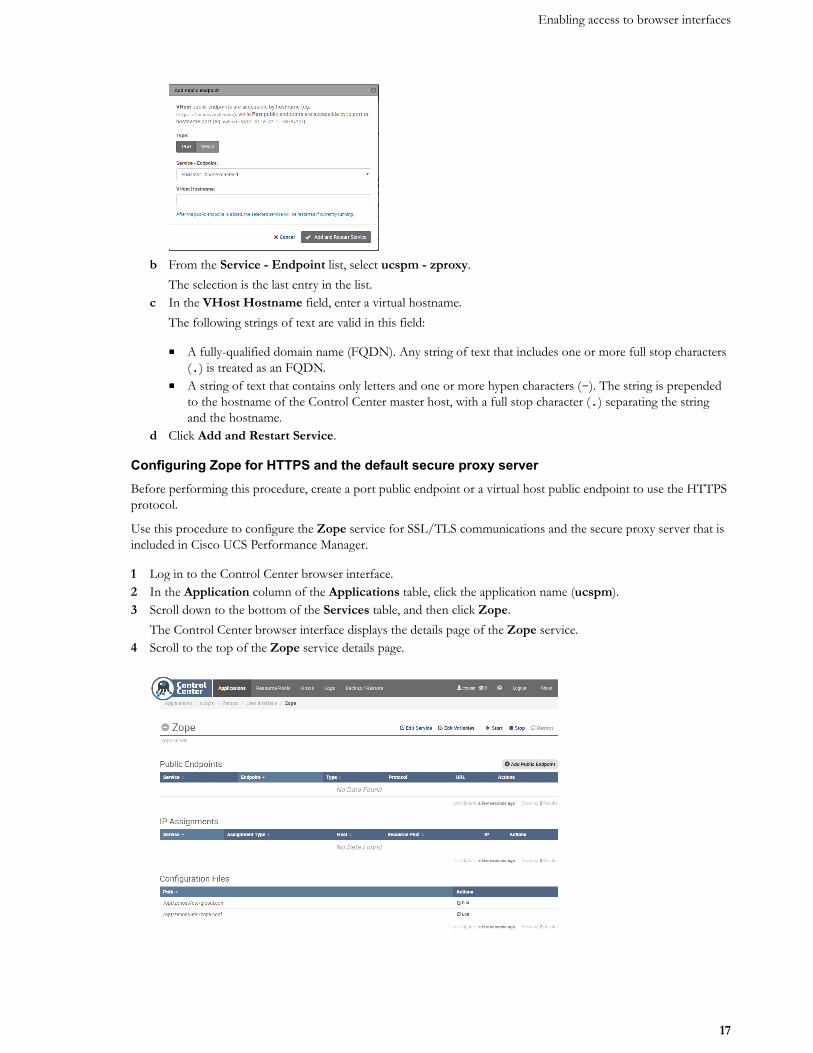
b From the Service - Endpoint list, select ucspm - zproxy.The selection is the last entry in the list.
c In the VHost Hostname field, enter a virtual hostname.The following strings of text are valid in this field:
■ A fully-qualified domain name (FQDN). Any string of text that includes one or more full stop characters(.) is treated as an FQDN.
■ A string of text that contains only letters and one or more hypen characters (-). The string is prependedto the hostname of the Control Center master host, with a full stop character (.) separating the stringand the hostname.
d Click Add and Restart Service.
Configuring Zope for HTTPS and the default secure proxy serverBefore performing this procedure, create a port public endpoint or a virtual host public endpoint to use the HTTPSprotocol.
Use this procedure to configure the Zope service for SSL/TLS communications and the secure proxy server that isincluded in Cisco UCS Performance Manager.
1 Log in to the Control Center browser interface.2 In the Application column of the Applications table, click the application name (ucspm).3 Scroll down to the bottom of the Services table, and then click Zope.
The Control Center browser interface displays the details page of the Zope service.4 Scroll to the top of the Zope service details page.
Cisco UCS Performance Manager Getting Started Guide
18
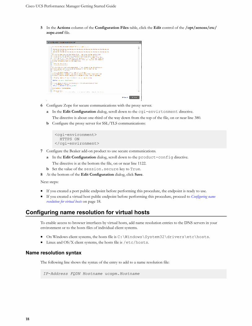
5 In the Actions column of the Configuration Files table, click the Edit control of the /opt/zenoss/etc/zope.conf file.
6 Configure Zope for secure communications with the proxy server.a In the Edit Configuration dialog, scroll down to the cgi-envirtonment directive.
The directive is about one-third of the way down from the top of the file, on or near line 380.b Configure the proxy server for SSL/TLS communications:
<cgi-environment> HTTPS ON</cgi-environment>
7 Configure the Beaker add-on product to use secure communications.a In the Edit Configuration dialog, scroll down to the product-config directive.
The directive is at the bottom the file, on or near line 1122.b Set the value of the session.secure key to True.
8 At the bottom of the Edit Configuration dialog, click Save.
Next steps:
■ If you created a port public endpoint before performing this procedure, the endpoint is ready to use.■ If you created a virtual host public endpoint before performing this procedure, proceed to Configuring name
resolution for virtual hosts on page 18.
Configuring name resolution for virtual hostsTo enable access to browser interfaces by virtual hosts, add name resolution entries to the DNS servers in yourenvironment or to the hosts files of individual client systems.
■ On Windows client systems, the hosts file is C:\Windows\System32\drivers\etc\hosts.■ Linux and OS/X client systems, the hosts file is /etc/hosts.
Name resolution syntax
The following line shows the syntax of the entry to add to a name resolution file:
IP-Address FQDN Hostname ucspm.Hostname
Enabling access to browser interfaces
19
For example, the following entry identifies a Control Center master host at IP address 192.0.2.12, hostnamecc-master, in the example.com domain.
192.0.2.12 cc-master.example.com cc-master ucspm.cc-master
Configuring name resolution on a Windows 7 systemTo perform this procedure, you need Windows Administrator privileges.
1 Log in to the Windows 7 system as a user with Administrator privileges.2 From the Start menu, highlight All Programs > Accessories > Notepad.3 Right click, and then select Run as administrator.4 From the Notepad File menu, select Open.5 In the File name field of the Open window, enter C:\Windows\System32\drivers\etc\hosts.6 Add a name resolution entry to the end of the file.
For more information, see Name resolution syntax on page 18.7 Save the file, and then exit Notepad.
Configuring name resolution on a Linux or OS/X systemTo perform this procedure, you need superuser privileges on the client system.
1 Log in to the client system as root or as a user with sudo privileges.2 Open the /etc/hosts file in a text editor.3 Add a name resolution entry to the end of the file.
For more information, see Name resolution syntax on page 18.4 Save the file, and then close the editor.
Cisco UCS Performance Manager Getting Started Guide
20
Setting up Cisco UCS PerformanceManager 3
This chapter describes how to use the Cisco UCS Performance Manager Setup Wizard to accept the end-user licenseagreement, to provide your license key, define users and passwords, to set up UCS Central and UCS Domains, toadd additional infrastructure, and to set up SMTP.
The Setup Wizard runs the first time you log in to the Cisco UCS Performance Manager browser interface. (Formore information about supported browsers and client operating systems, see Preface on page 4.)
To open the Cisco UCS Performance Manager browser interface, navigate to the port public endpoint or virtualhost public endpoint that was defined previously. For more information, see Enabling access to browser interfaces on page9.
Note The Setup Wizard times out after 20 minutes if you have not completed it. To start it again, close itsbrowser window or tab, and then log in again.
To complete the Setup Wizard, you need the following items:
■ Authorization to accept the Cisco UCS Performance Manager end-user license agreement on behalf of yourorganization.
■ A password for the default administrative account (admin).■ A username and password for one additional administrative account.■ The license key for your product (Cisco UCS Performance Manager Express or Cisco UCS Performance
Manager). To obtain a license key, contact your Cisco representative.■ The hostnames or IP addresses of UCS Central and UCS Domains in your environment. In addition, you need
the username and password of an account on each server that is authorized for read access to the resources youplan to monitor.
The Setup Wizard includes the Add Infrastructure page as the final step. The step is optional, and the AddInfrastructure page is a standard part of the Cisco UCS Performance Manager interface, so you can use it at anytime.
Accepting the License AgreementPerform this procedure after installing Cisco UCS Performance Manager on a virtual machine, and starting it inControl Center.
1 In a web browser, navigate to the login page of the Cisco UCS Performance Manager interface.Cisco UCS Performance Manager redirects the first login attempt to the Setup page, which includes the EndUser License Agreement (EULA) dialog.
Setting up Cisco UCS Performance Manager
21
Note If you are not able to resolve the host name, check your DNS server or add an entry to the hosts fileon the client machine. For more information, see Enabling access to browser interfaces on page 9.
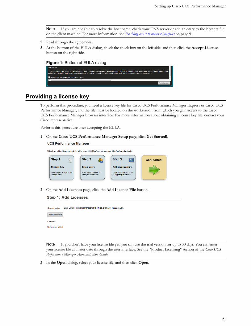
2 Read through the agreement.3 At the bottom of the EULA dialog, check the check box on the left side, and then click the Accept License
button on the right side.
Figure 1: Bottom of EULA dialog
Providing a license keyTo perform this procedure, you need a license key file for Cisco UCS Performance Manager Express or Cisco UCSPerformance Manager, and the file must be located on the workstation from which you gain access to the CiscoUCS Performance Manager browser interface. For more information about obtaining a license key file, contact yourCisco representative.
Perform this procedure after accepting the EULA.
1 On the Cisco UCS Performance Manager Setup page, click Get Started!.
2 On the Add Licenses page, click the Add License File button.
Note If you don't have your license file yet, you can use the trial version for up to 30 days. You can enteryour license file at a later date through the user interface. See the "Product Licensing" section of the Cisco UCSPerformance Manager Administration Guide
3 In the Open dialog, select your license file, and then click Open.
Cisco UCS Performance Manager Getting Started Guide
22
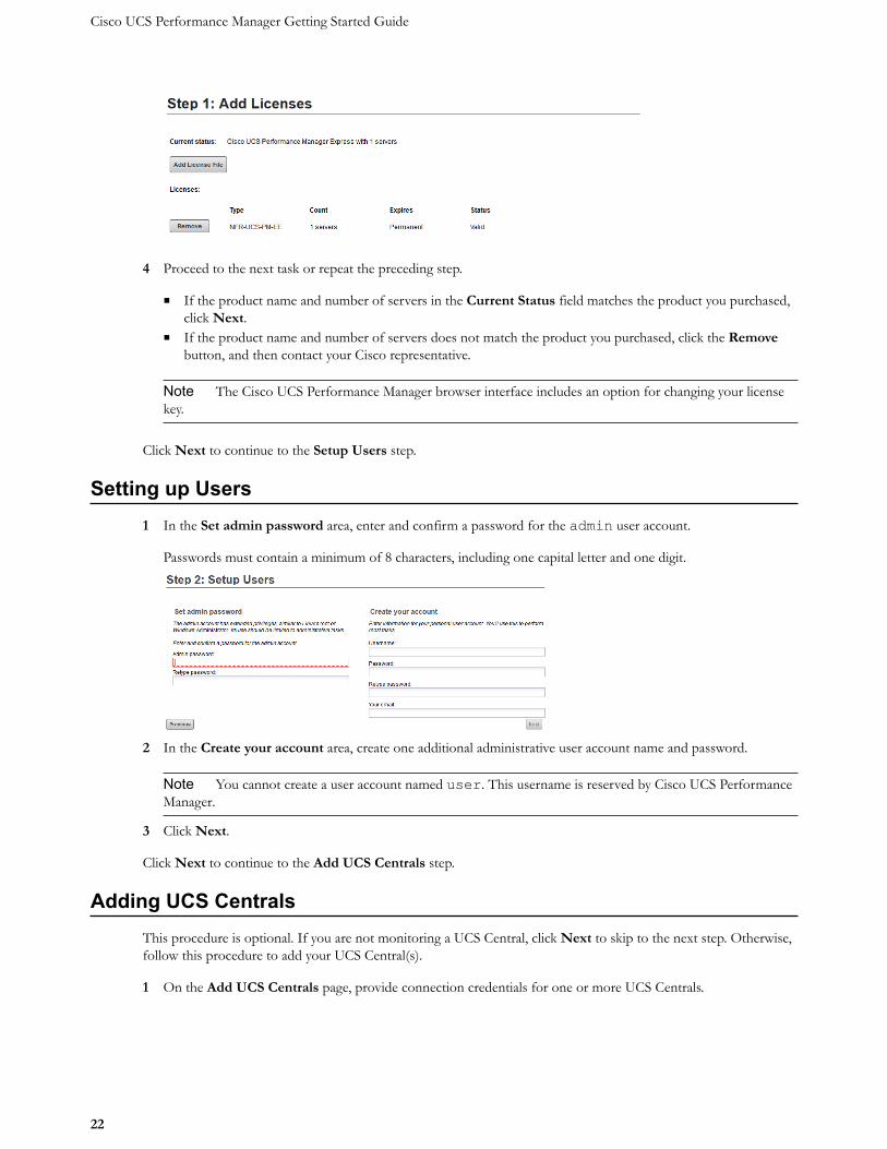
4 Proceed to the next task or repeat the preceding step.
■ If the product name and number of servers in the Current Status field matches the product you purchased,click Next.
■ If the product name and number of servers does not match the product you purchased, click the Removebutton, and then contact your Cisco representative.
Note The Cisco UCS Performance Manager browser interface includes an option for changing your licensekey.
Click Next to continue to the Setup Users step.
Setting up Users1 In the Set admin password area, enter and confirm a password for the admin user account.
Passwords must contain a minimum of 8 characters, including one capital letter and one digit.
2 In the Create your account area, create one additional administrative user account name and password.
Note You cannot create a user account named user. This username is reserved by Cisco UCS PerformanceManager.
3 Click Next.
Click Next to continue to the Add UCS Centrals step.
Adding UCS CentralsThis procedure is optional. If you are not monitoring a UCS Central, click Next to skip to the next step. Otherwise,follow this procedure to add your UCS Central(s).
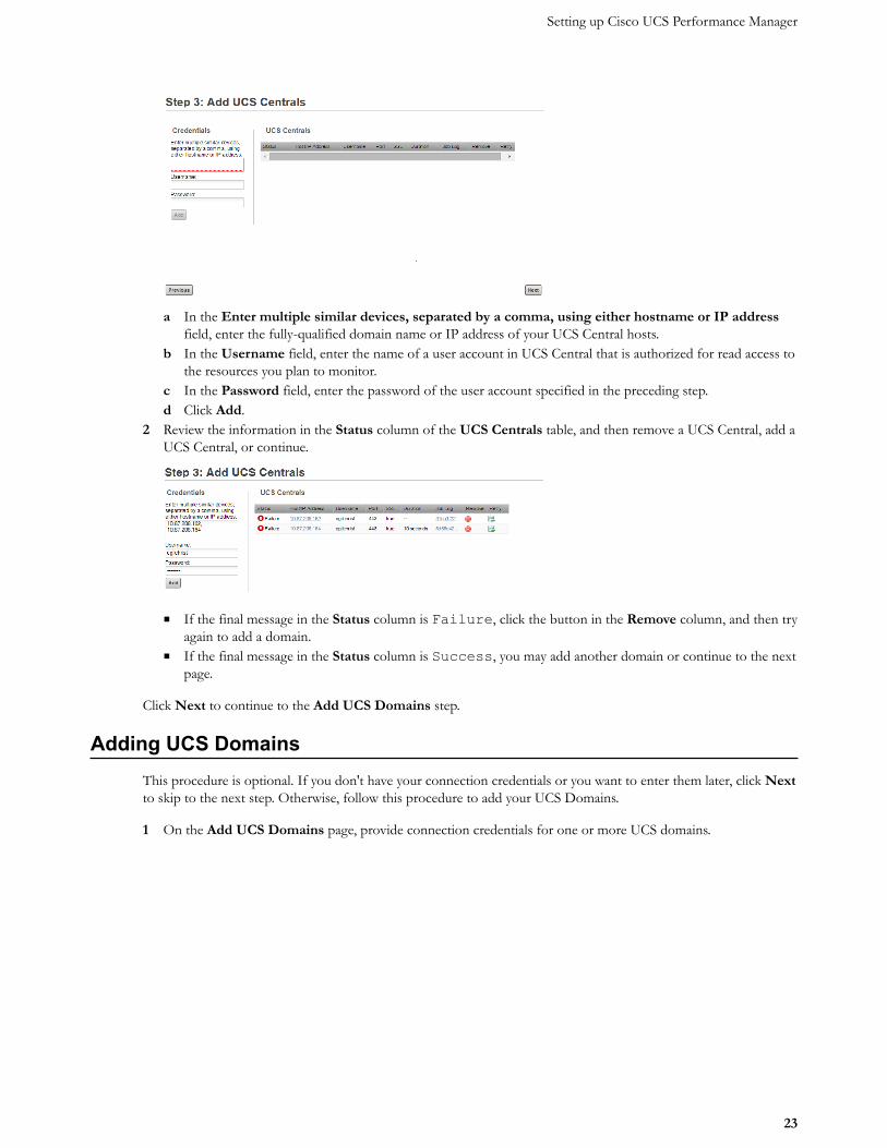
1 On the Add UCS Centrals page, provide connection credentials for one or more UCS Centrals.
Setting up Cisco UCS Performance Manager
23
a In the Enter multiple similar devices, separated by a comma, using either hostname or IP addressfield, enter the fully-qualified domain name or IP address of your UCS Central hosts.
b In the Username field, enter the name of a user account in UCS Central that is authorized for read access tothe resources you plan to monitor.
c In the Password field, enter the password of the user account specified in the preceding step.d Click Add.
2 Review the information in the Status column of the UCS Centrals table, and then remove a UCS Central, add aUCS Central, or continue.
■ If the final message in the Status column is Failure, click the button in the Remove column, and then tryagain to add a domain.
■ If the final message in the Status column is Success, you may add another domain or continue to the nextpage.
Click Next to continue to the Add UCS Domains step.
Adding UCS DomainsThis procedure is optional. If you don't have your connection credentials or you want to enter them later, click Nextto skip to the next step. Otherwise, follow this procedure to add your UCS Domains.
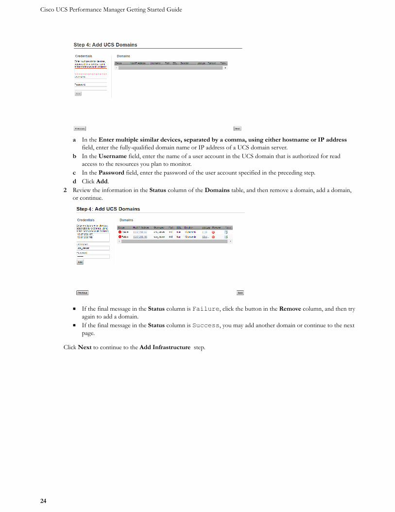
1 On the Add UCS Domains page, provide connection credentials for one or more UCS domains.
Cisco UCS Performance Manager Getting Started Guide
24
a In the Enter multiple similar devices, separated by a comma, using either hostname or IP addressfield, enter the fully-qualified domain name or IP address of a UCS domain server.
b In the Username field, enter the name of a user account in the UCS domain that is authorized for readaccess to the resources you plan to monitor.
c In the Password field, enter the password of the user account specified in the preceding step.d Click Add.
2 Review the information in the Status column of the Domains table, and then remove a domain, add a domain,or continue.
■ If the final message in the Status column is Failure, click the button in the Remove column, and then tryagain to add a domain.
■ If the final message in the Status column is Success, you may add another domain or continue to the nextpage.
Click Next to continue to the Add Infrastructure step.
Setting up Cisco UCS Performance Manager
25
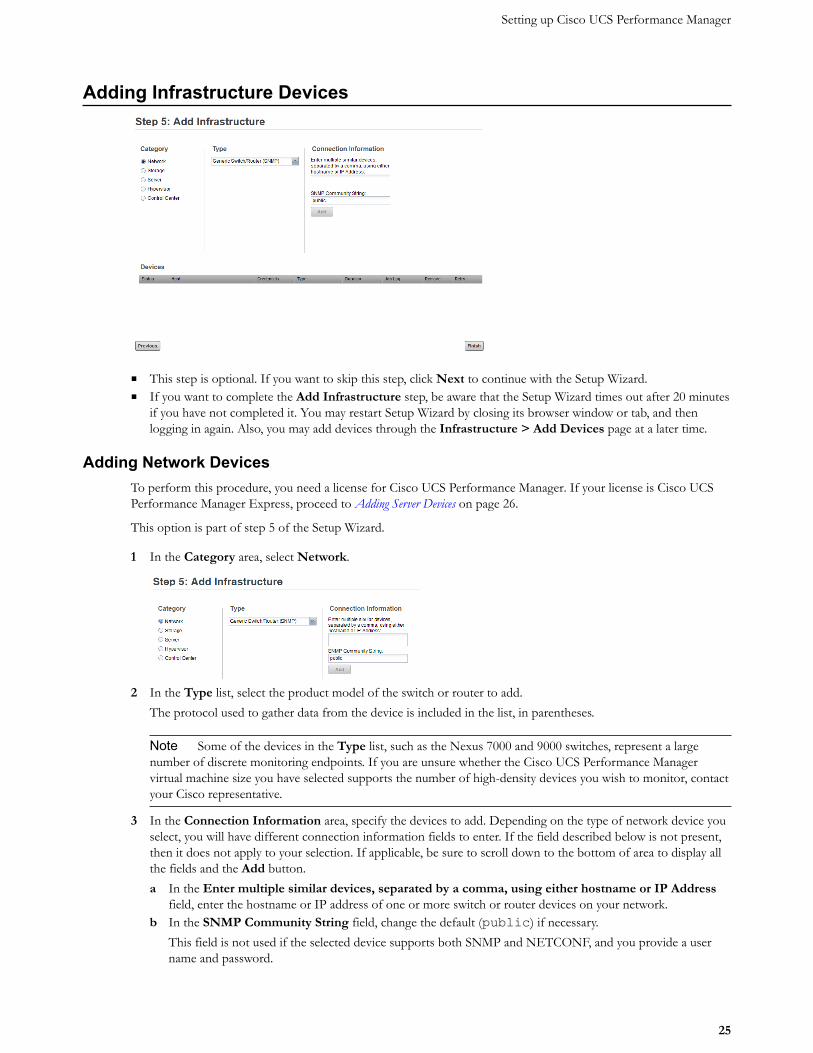
Adding Infrastructure Devices
■ This step is optional. If you want to skip this step, click Next to continue with the Setup Wizard.■ If you want to complete the Add Infrastructure step, be aware that the Setup Wizard times out after 20 minutes
if you have not completed it. You may restart Setup Wizard by closing its browser window or tab, and thenlogging in again. Also, you may add devices through the Infrastructure > Add Devices page at a later time.
Adding Network DevicesTo perform this procedure, you need a license for Cisco UCS Performance Manager. If your license is Cisco UCSPerformance Manager Express, proceed to Adding Server Devices on page 26.
This option is part of step 5 of the Setup Wizard.
1 In the Category area, select Network.
2 In the Type list, select the product model of the switch or router to add.The protocol used to gather data from the device is included in the list, in parentheses.
Note Some of the devices in the Type list, such as the Nexus 7000 and 9000 switches, represent a largenumber of discrete monitoring endpoints. If you are unsure whether the Cisco UCS Performance Managervirtual machine size you have selected supports the number of high-density devices you wish to monitor, contactyour Cisco representative.
3 In the Connection Information area, specify the devices to add. Depending on the type of network device youselect, you will have different connection information fields to enter. If the field described below is not present,then it does not apply to your selection. If applicable, be sure to scroll down to the bottom of area to display allthe fields and the Add button.a In the Enter multiple similar devices, separated by a comma, using either hostname or IP Address
field, enter the hostname or IP address of one or more switch or router devices on your network.b In the SNMP Community String field, change the default (public) if necessary.
This field is not used if the selected device supports both SNMP and NETCONF, and you provide a username and password.
Cisco UCS Performance Manager Getting Started Guide
26
c In the Username or Netconf Username field, enter the name of a user account on the device.d In the Password or Netconf Password field, enter the password of the user account specified in the
previous field.e Click Add.
If you are finished adding network devices, click Next.
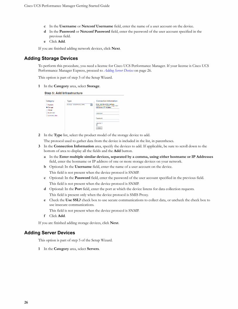
Adding Storage DevicesTo perform this procedure, you need a license for Cisco UCS Performance Manager. If your license is Cisco UCSPerformance Manager Express, proceed to Adding Server Devices on page 26.
This option is part of step 5 of the Setup Wizard.
1 In the Category area, select Storage.
2 In the Type list, select the product model of the storage device to add.The protocol used to gather data from the device is included in the list, in parentheses.
3 In the Connection Information area, specify the devices to add. If applicable, be sure to scroll down to thebottom of area to display all the fields and the Add button.a In the Enter multiple similar devices, separated by a comma, using either hostname or IP Addresses
field, enter the hostname or IP address of one or more storage devices on your network.b Optional: In the Username field, enter the name of a user account on the device.
This field is not present when the device protocol is SNMP.c Optional: In the Password field, enter the password of the user account specified in the previous field.
This field is not present when the device protocol is SNMP.d Optional: In the Port field, enter the port at which the device listens for data collection requests.
This field is present only when the device protocol is SMIS Proxy.e Check the Use SSL? check box to use secure communications to collect data, or uncheck the check box to
use insecure communications.This field is not present when the device protocol is SNMP.
f Click Add.
If you are finished adding storage devices, click Next.
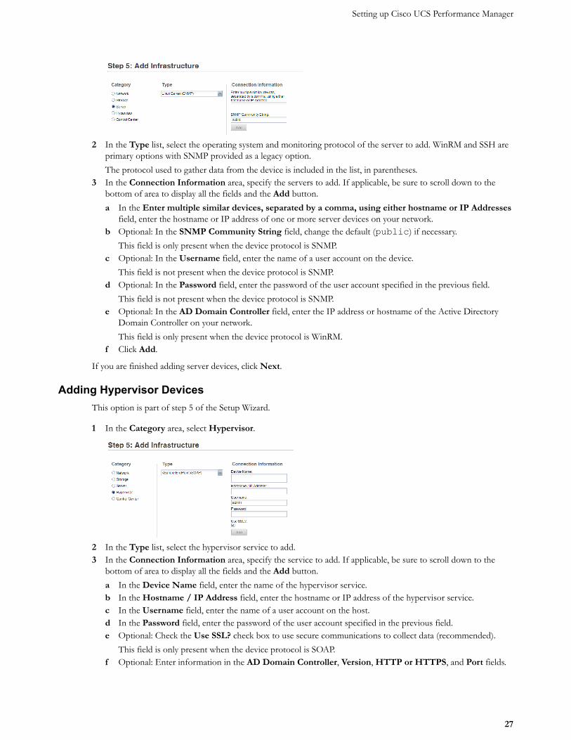
Adding Server DevicesThis option is part of step 5 of the Setup Wizard.
1 In the Category area, select Servers.
Setting up Cisco UCS Performance Manager
27
2 In the Type list, select the operating system and monitoring protocol of the server to add. WinRM and SSH areprimary options with SNMP provided as a legacy option.The protocol used to gather data from the device is included in the list, in parentheses.
3 In the Connection Information area, specify the servers to add. If applicable, be sure to scroll down to thebottom of area to display all the fields and the Add button.a In the Enter multiple similar devices, separated by a comma, using either hostname or IP Addresses
field, enter the hostname or IP address of one or more server devices on your network.b Optional: In the SNMP Community String field, change the default (public) if necessary.
This field is only present when the device protocol is SNMP.c Optional: In the Username field, enter the name of a user account on the device.
This field is not present when the device protocol is SNMP.d Optional: In the Password field, enter the password of the user account specified in the previous field.
This field is not present when the device protocol is SNMP.e Optional: In the AD Domain Controller field, enter the IP address or hostname of the Active Directory
Domain Controller on your network.This field is only present when the device protocol is WinRM.
f Click Add.
If you are finished adding server devices, click Next.
Adding Hypervisor DevicesThis option is part of step 5 of the Setup Wizard.
1 In the Category area, select Hypervisor.
2 In the Type list, select the hypervisor service to add.3 In the Connection Information area, specify the service to add. If applicable, be sure to scroll down to the
bottom of area to display all the fields and the Add button.a In the Device Name field, enter the name of the hypervisor service.b In the Hostname / IP Address field, enter the hostname or IP address of the hypervisor service.c In the Username field, enter the name of a user account on the host.d In the Password field, enter the password of the user account specified in the previous field.e Optional: Check the Use SSL? check box to use secure communications to collect data (recommended).
This field is only present when the device protocol is SOAP.f Optional: Enter information in the AD Domain Controller, Version, HTTP or HTTPS, and Port fields.
Cisco UCS Performance Manager Getting Started Guide
28
These fields are only present when the device protocol is WinRM.g Click Add.
If you are finished adding hypervisor devices, click Next.
Adding Control Center
The Control Center is the internal application management and orchestration system for Cisco UCS PerformanceManager. It is automatically added as a managed resource so that you can see the internal components and theirperformance data. You do not have to add the Control Center on the Add Infrastructure Wizard. Click Next tocontinue with the Setup Wizard. You can always add more devices at a later date. See the "Adding, Discovering andModeling Devices" chapter in the Cisco UCS Performance Manager Administration Guide.
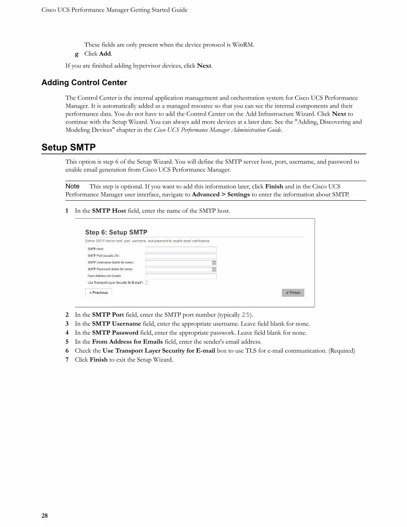
Setup SMTPThis option is step 6 of the Setup Wizard. You will define the SMTP server host, port, username, and password toenable email generation from Cisco UCS Performance Manager.
Note This step is optional. If you want to add this information later, click Finish and in the Cisco UCSPerformance Manager user interface, navigate to Advanced > Settings to enter the information about SMTP.
1 In the SMTP Host field, enter the name of the SMTP host.
2 In the SMTP Port field, enter the SMTP port number (typically 25).3 In the SMTP Username field, enter the appropriate username. Leave field blank for none.4 In the SMTP Password field, enter the appropriate passwork. Leave field blank for none.5 In the From Address for Emails field, enter the sender's email address.6 Check the Use Transport Layer Security for E-mail box to use TLS for e-mail communication. (Required)7 Click Finish to exit the Setup Wizard.
29
Appendix: Preparing Windows Systems This appendix includes procedures for preparing Microsoft Windows Server 2012 R2, 2012, and 2008R2 for monitoring in Cisco UCS Performance Manager. The procedures are standardized around a low security configuration using local system credentials, rather than domain credentials, and no encryption of credentials or payload. This scenario provides a good base configuration for ease of setup and testing, but in production the use of a single domain service for authentication simplifies administration. The use of a domain service account requires the use of Kerberos to encrypt credentials, which improves security. Security can be improved further still by configuring WinRM to encrypt its payload using SSL. Each section of this document includes these additional configurations for administrators who need to implement them. These higher security configurations are recommended in production environments.
About Windows Authentication for WinRM Monitoring Cisco UCS Performance Manager must authenticate to the Windows systems it will monitor using either local system or Windows domain credentials. The Windows user account used for WinRM authentication must have specific permissions granted on each Windows system to be monitored. By default, Windows Administrator accounts already have the necessary permissions, but best practices dictate that Administrator accounts not be used for purposes such as WinRM monitoring. Instead, a dedicated User account (a “service account”) should be created specifically for the purpose of WinRM monitoring with only the necessary permissions granted to the account.
Instead of manually editing the necessary permissions, a Windows PowerShell®, hereafter referred to as PowerShell, script can be used to modify the necessary permissions in a single step. For convenience, Cisco provides a sample script that modifies the permissions necessary for an example service. The script is available at the following Zenoss GitHub location: https://github.com/zenoss/microsoft.tools/blob/develop/lpu/zenoss-lpu.ps1. The file can be edited as necessary to suit specific production environments.
Note: The sample script includes two lines that must be located and deleted before the functions in the script will execute. These lines have been deliberately included to encourage administrators to thoroughly review the script before deploying it to ensure (i) that administrators fully understand the functions it performs and (ii) they have made any necessary edits before deploying it.
The relevant sections below describe methods to configure Windows system permissions using a PowerShell script such as zenoss-lpu.ps1 that has been tailored to a specific environment.
Windows Server 2012 & 2012 R2 The following sections describe how to configure Windows Server 2012 and Windows Server 2012 R2.
Note: Windows 2012 R2 is specifically called out only when there is a difference in method between the two Windows server versions.
30
Configuring Windows Server 2012 Using Group Policy (Basic Authentication, no Encryption)
Note: This configuration uses a local user account on each monitored Windows system for authentication instead of a domain account. The local user account must be present on each system before Cisco UCS Performance Manager can monitor it.
1. Log on to a domain controller as a user with 'Domain Admin' privileges. 2. On Server 2012 (non R2), press the Windows key on the keyboard to display the Start screen, then click
the Group Policy Management tile. 3. On Server 2012 R2, press the Windows key on the keyboard to display the Start screen, then click
Server Manager. Click Tools in the upper right, then choose Group Policy Management. 4. Navigate to your target domain in the tree at the left:
i. Expand the section for the domain Forest you want to edit. ii. Expand Domains.
iii. Expand your target domain.
5. Right-click Group Policy Objects and select New. In the form that displays:
i. Enter a name for your new Group Policy Object, for example, WinRM_Monitoring. ii. Leave "(none)" in the Source Starter GPO field.
iii. Click OK to save and exit the form.
6. Select your new Group Domain Policy Object, WinRM_Monitoring, for example. 7. Right click your new Group Domain Policy Object and select Edit to open the Group Policy
Management Editor. 8. Expand the Computer Configuration section of the tree and navigate the tree to:
Policies\Administrative Templates:Policy...\Windows
Components\Windows Remote Management(WinRM)
9. Enable remote server management:
i. Click on WinRM Service to access the WinRM Service Group Policy settings in the right pane. ii. Double-click the Allow remote server management through WinRM property.
iii. Click the Enabled radio button. iv. Place an asterisk as a wildcard (' * ') in the IPv4 filer and IPv6 fields or specify a range of IP
addresses for WinRM to listen on. v. Click OK at the bottom to submit the form.
10. Enable authentication:
i. Double-click the Allow Basic authentication property in the right pane. ii. Select the Enabled radio button.
iii. Click OK at the bottom to submit the form.
11. Specify unencrypted traffic:
i. Double-click the Allow unencrypted traffic property. ii. Select the Enabled radio button.
iii. Click OK at the bottom to submit the form.
12. Select Windows Remote Shell in the left pane to set its Group Policy settings. This is located in the

31
group policy tree in the following location (which might be located right below WinRM service in the tree):
Computer Configuration\Policies\Administrative Templates\Windows
Components\Windows Remote Shell
13. Configure remote shell access:
i. In the right pane, double-click Allow Remote Shell Access. ii. Select the Enabled radio button.
iii. Click OK at the bottom to submit the form.
14. Configure shell processes:
i. In the right pane, double-click Specify maximum number of processes per Shell. ii. Select the Enabled radio button.
iii. Enter the value 2,000,000,000 (without commas or spaces) in the MaxProcessPerShell field. iv. Click OK at the bottom to submit the form.
15. Configure the number of remote shells:
i. In the right pane, double-click Specify maximum number of remote shells per user. ii. Select the Enabled radio button.
iii. Enter the value 2,000,000,000 (without commas or spaces) in the MaxShellsPerUser field. iv. Click OK at the bottom to submit the form.
16. Configure shell timeout value:
i. In the Right pane, double-click Specify Shell Timeout. ii. Select the Enabled radio button.
iii. Enter the value 7,200,000 (without commas or spaces) in the ShellTimeOut field. iv. Click OK at the bottom to submit the form.
32
Windows Server 2012: Configuring Firewall Group Policies
WinRM listens on port 5985 when data payload encryption is not used and on port 5986 when encryption is used. Additionally, ICMP (ping) requests must be enabled because Cisco UCS Performance Manager uses them as a source of availability monitoring.
The appropriate port must be opened on the firewalls of monitored servers. You can use Group Policy to open the required ports on all servers across the organization.
1. In the Group Policy Manager Editor, navigate to:
Computer Configuration\Policies\Windows Settings\Security Settings\Windows
Firewall with Advanced Security\Windows Firewall with Advanced Security -
LDAP;...\Inbound Rules
2. Create a new Inbound Rules policy for Windows Remote Management:
i. Right click Inbound Rules in the left pane. ii. Select New Rule...
iii. Select the Predefined radio button. iv. Select Windows Remote Management from the drop down list. v. Click Next.
vi. Ensure that all items in the list are checked. vii. Click Next.
viii. Ensure that the Allow the connection radio button is selected. ix. Click Finish.
3. Create a new Inbound Rules policy for Echo Request ICMP (ping) requests:
i. Right click Inbound Rules in the left pane. ii. Select New Rule...
iii. Select the Predefined radio button. iv. Select File and Printer Sharing from the drop down list. v. Click Next.
vi. Ensure the check boxes for the following items are selected:
File and Printer Sharing (Echo Request-ICPMv4-IN)
File and Printer Sharing (Echo Request-ICPMv6-IN) You can de-select any additional check boxes unless you require them specifically.
vii. Click Next. viii. Ensure that the Allow the connection radio button is selected.
ix. Click Finish.
4. Exit the Group Policy Management Editor:
Select File > Exit
5. Link your new GPO to one or more Organizational Units (OU) containing servers to which you wish to have the policies applied. Alternatively, you can apply the policies to all Windows servers in the domain by linking the new GPO to the domain itself. To link the GPO to the domain, complete the following process.
Note: Substitute a specific OU for the domain if you want to link only to a subset of servers.
i. Right-click your domain in the left pane of the Group Policy Management window. ii. Choose Link an Existing GPO...
iii. Select your new GPO, WinRM_Monitoring for example, from the list that displays.

33
iv. Click OK to complete the process.
6. Exit the Group Policy Management window:
Select File > Exit
7. Before adding servers to Cisco UCS Performance Manager for monitoring, wait a sufficient amount of time for Group Policy to automatically refresh on the server(s). Alternatively, you can manually refresh Group Policy from the command prompt of target servers using this command:
gpupdate /force
34
Windows Server 2012: Configuring Windows Credentials in Cisco UCS Performance Manager
When one or more servers are ready for addition to Cisco UCS Performance Manager, perform the following steps within the Cisco UCS Performance Manager web interface. If the same user account name was created on each server, the following procedure will specify it for all servers in the device class:
1. Navigate to the Infrastructure page.
2. Select the Server/Microsoft/Windows device class.
3. Click the Details icon.
4. Click Configuration Properties in the left pane.
5. In the right pane, set the configuration properties for zWinRMUser and zWinRMPassword, supplying the appropriate Windows credentials.
Note: For ease of setup and testing, the local Administrator account can be used in test environments. For production environments, the use of a less privileged service account is recommended. See the section above titled About Windows Authentication for WinRM Monitoring for more on WinRM authentication.
To configure Windows to allow monitoring using a non-Administrator service account, see the section below titled Windows Server 2012: Configuring a WinRM Service Account on Individual Windows Systems or the section titled Windows Server 2012: Group Policy Deployment of a PowerShell Script for Service Account Configuration.
6. Click See All.
7. Add windows servers using the web interface or ZenBatchload.
Note: If the user names and passwords used on servers are different, each server must be added and its individual zWinRMUser and zWinRMPassword configuration properties must be set. Perform the following steps to add the server information:
i. Add the server to the Server/Microsoft/Windows device class, but opt out of modeling the device when adding as follows:
If you are adding via the web interface, leave the Model Device: box unchecked.
If you are adding through the zenbatchload command, be sure the device has the --nomodel flag set.
ii. When the device displays in the device list, click on its name. iii. Click on Configuration Properties in the left pane, and set the configuration properties for
zWinRMUser and zWinRMPassword, supplying the appropriate Windows credentials. iv. Model the device by clicking the Action Wheel (gear-shaped) icon in the lower left and select
Model Device...
35
Windows Server 2012: Improving Security by Using a Domain Service Account & Encrypting Credentials with Kerberos
Note: When switching from the use of local system accounts for authentication to a single domain service account, the use of Kerberos to encrypt credentials is mandatory.
The Kerberos authentication process requires an available ticket granting server. In the Microsoft Active Directory (AD) environment the AD Server also acts as the Key Distribution Center (KDC). The zWinKDC configuration property in Cisco UCS Performance Manager must be set to the IP address of the AD Server. Each collector used to monitor Windows servers must be able to send Kerberos packets to this server. To specify the ticket granting server in Cisco UCS Performance Manager, perform the following steps:
1. In the Cisco UCS Performance Manager web UI, navigate to the Infrastructure page. 2. Select the Server/Microsoft/Windows device class in the left pane. 3. Click the Details icon. 4. Click Configuration Properties in the left pane. 5. Edit the configuration property in the right pane for zWinKDC. Double click zWinKDC and specify the IP
address of your Active Directory Server. 6. Edit the value for zWinRMUser name to be the complete domain name of the user, for example,
Note: A zWinRMUser name value in the form of user@domain is the trigger for Cisco UCS Performance Manager to (i) use a domain account rather than a local system account and (ii) to use Kerberos encryption for credentials. When the value of zWinRMUser name takes the form of user[only] instead of user@domain, Cisco UCS Performance Manager will use a local user account on the system being monitored.
Note: For ease of setup and testing, the local Administrator account might be preferable to use in test environments. For production environments, the use of a less privileged service account is recommended. See the section above titled About Windows Authentication for WinRM Monitoring for more on WinRM authentication.
To configure Windows to allow monitoring using a non-Administrator service account, see the section below titled Windows Server 2012: Configuring a WinRM Service Account on Individual Windows Systems or the section titled Windows Server 2012: Group Policy Deployment of a PowerShell Script for Service Account Configuration.
Note: The Cisco UCS Performance Manager server and collectors must be able to resolve the target server's pointer records (PTR) to their Active Directory fully qualified domain name. Administrators can meet this requirement by using one of three methods:
i. Configuring the Cisco UCS Performance Manager server to access the Windows DNS server for its DNS resolutions.
ii. Manually entering PTR records for each server in to the /etc/hosts file.
For example, the server r2d2.example.com at the IP address 77.77.77.77 has the following PTR record:
77.77.77.77 r2d2.example.com
36
iii. Using the zWinRMServerName property as follows: Specify the monitored server's name with the zWinRMServerName property field.
Note: The zWinRMServerName property should only be used in conjunction with domain authentication when the DNS PTR record for a monitored server's managed IP address does not resolve to the name by which the server is known in Active Directory. For example, if myserver1 is known as myserver1.ad.example.com by Active Directory and is being managed by IP address 192.51.100.21, but IP address 192.51.100.21
resolves to www.example.com, you must set the zWinRMServerName property to myserver1.ad.example.com for domain authentication to work.
If many Windows servers in your environment do not have DNS PTR records that match Active Directory, it is recommended that you:
set the monitored device's name to be the fully-qualified Active Directory name in Cisco UCS Performance Manager
set zWinRMServerName to ${here/titleOrId} at the
/Server/Microsoft/Windows device class.
This method avoids setting the zWinRMServerName property on every device.
We recommend that you leave the zWinRMServerName property blank if local authentication is used, or DNS PTR records match the Active Directory listings. The result is that Cisco UCS Performance Manager does not have to rely on DNS resolution while monitoring and
it avoids the additional overhead of configuring the zWinRMServerName properties.
Note: You can add custom Kerberos configurations if your settings differ from the default settings used by UCS Performance Manager. To use a custom configuration file, place it in the /opt/zenoss/var/krb5/config directory. You must be using Kerberos 5 release 1.10 or higher. For more information, see http://wiki.zenoss.org/ZenPack:Microsoft_Windows
37
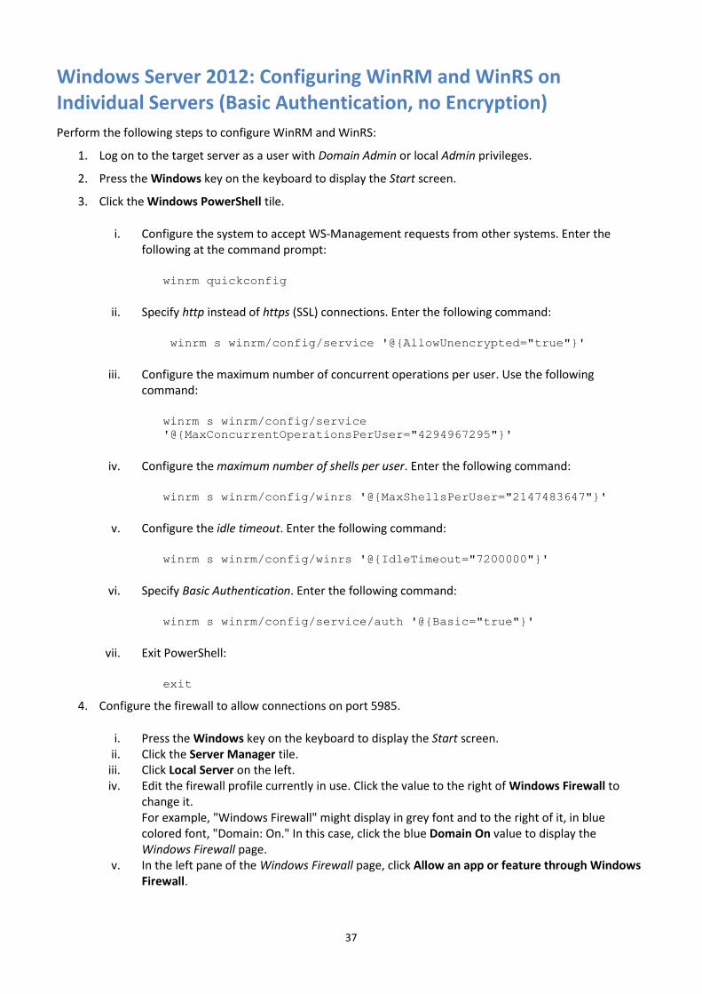
Windows Server 2012: Configuring WinRM and WinRS on Individual Servers (Basic Authentication, no Encryption)
Perform the following steps to configure WinRM and WinRS:
1. Log on to the target server as a user with Domain Admin or local Admin privileges.
2. Press the Windows key on the keyboard to display the Start screen.
3. Click the Windows PowerShell tile.
i. Configure the system to accept WS-Management requests from other systems. Enter the following at the command prompt:
winrm quickconfig
ii. Specify http instead of https (SSL) connections. Enter the following command:
winrm s winrm/config/service '@{AllowUnencrypted="true"}'
iii. Configure the maximum number of concurrent operations per user. Use the following command:
winrm s winrm/config/service
'@{MaxConcurrentOperationsPerUser="4294967295"}'
iv. Configure the maximum number of shells per user. Enter the following command:
winrm s winrm/config/winrs '@{MaxShellsPerUser="2147483647"}'
v. Configure the idle timeout. Enter the following command:
winrm s winrm/config/winrs '@{IdleTimeout="7200000"}'
vi. Specify Basic Authentication. Enter the following command:
winrm s winrm/config/service/auth '@{Basic="true"}'
vii. Exit PowerShell:
exit
4. Configure the firewall to allow connections on port 5985.
i. Press the Windows key on the keyboard to display the Start screen. ii. Click the Server Manager tile.
iii. Click Local Server on the left. iv. Edit the firewall profile currently in use. Click the value to the right of Windows Firewall to
change it. For example, "Windows Firewall" might display in grey font and to the right of it, in blue colored font, "Domain: On." In this case, click the blue Domain On value to display the Windows Firewall page.
v. In the left pane of the Windows Firewall page, click Allow an app or feature through Windows Firewall.
38
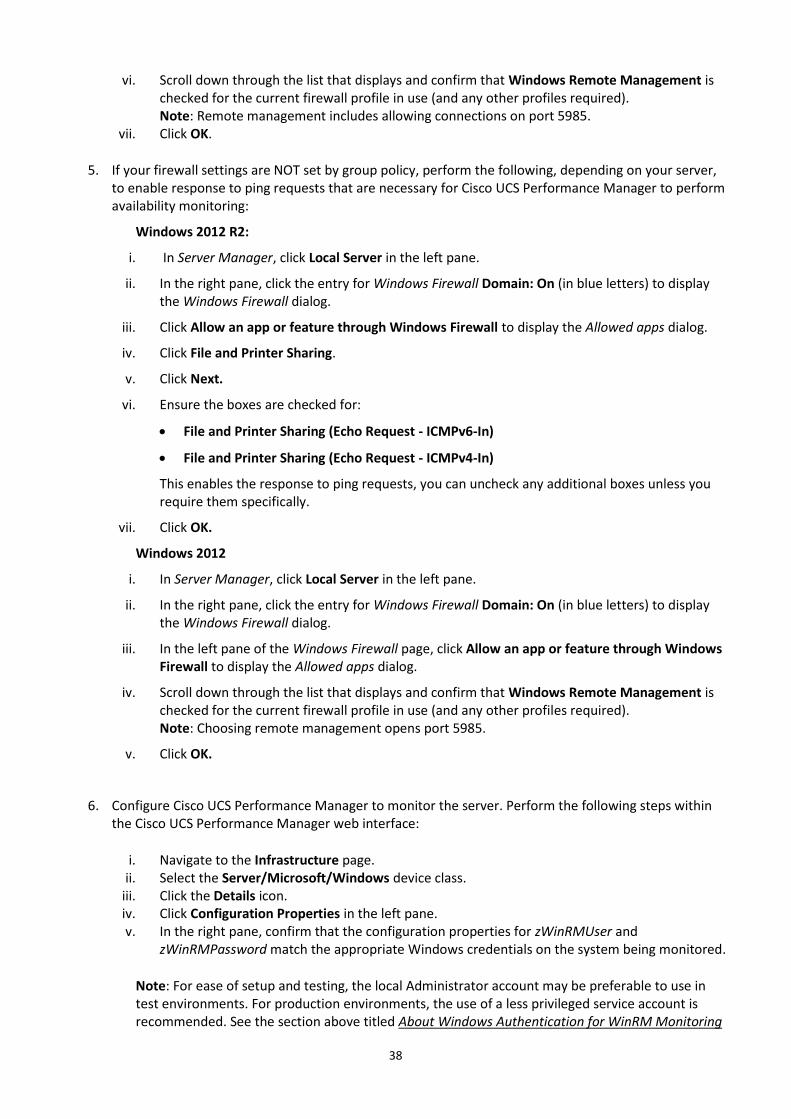
vi. Scroll down through the list that displays and confirm that Windows Remote Management is checked for the current firewall profile in use (and any other profiles required). Note: Remote management includes allowing connections on port 5985.
vii. Click OK.
5. If your firewall settings are NOT set by group policy, perform the following, depending on your server, to enable response to ping requests that are necessary for Cisco UCS Performance Manager to perform availability monitoring:
Windows 2012 R2:
i. In Server Manager, click Local Server in the left pane.
ii. In the right pane, click the entry for Windows Firewall Domain: On (in blue letters) to display the Windows Firewall dialog.
iii. Click Allow an app or feature through Windows Firewall to display the Allowed apps dialog.
iv. Click File and Printer Sharing.
v. Click Next.
vi. Ensure the boxes are checked for:
File and Printer Sharing (Echo Request - ICMPv6-In)
File and Printer Sharing (Echo Request - ICMPv4-In)
This enables the response to ping requests, you can uncheck any additional boxes unless you require them specifically.
vii. Click OK.
Windows 2012
i. In Server Manager, click Local Server in the left pane.
ii. In the right pane, click the entry for Windows Firewall Domain: On (in blue letters) to display the Windows Firewall dialog.
iii. In the left pane of the Windows Firewall page, click Allow an app or feature through Windows Firewall to display the Allowed apps dialog.
iv. Scroll down through the list that displays and confirm that Windows Remote Management is checked for the current firewall profile in use (and any other profiles required). Note: Choosing remote management opens port 5985.
v. Click OK.
6. Configure Cisco UCS Performance Manager to monitor the server. Perform the following steps within the Cisco UCS Performance Manager web interface:
i. Navigate to the Infrastructure page. ii. Select the Server/Microsoft/Windows device class.
iii. Click the Details icon. iv. Click Configuration Properties in the left pane. v. In the right pane, confirm that the configuration properties for zWinRMUser and
zWinRMPassword match the appropriate Windows credentials on the system being monitored.
Note: For ease of setup and testing, the local Administrator account may be preferable to use in test environments. For production environments, the use of a less privileged service account is recommended. See the section above titled About Windows Authentication for WinRM Monitoring
39
for more on WinRM authentication.
To configure Windows to allow monitoring using a non-Administrator service account, see the section below titled Windows Server 2012: Configuring a WinRM Service Account on Individual Windows Systems or the section titled Windows Server 2012: Group Policy Deployment of a PowerShell Script for Service Account Configuration.
If the credentials listed are correct, click See All and add the server to Cisco UCS Performance Manager.
vi. If the credentials listed are not appropriate to the target server, the server must be added and the server's individual zWinRMUser and zWinRMPassword configuration properties must be set. Perform the following steps to add the server information:
a. Add the server to the Server/Microsoft/Windows device class, but opt out of modeling the device when adding it:
If you are adding via the web interface, leave the Model Device: box unchecked.
If you are adding via the zenbatchload command, be sure the device has the --nomodel flag set.
b. When the device displays in the device list, click on its name. c. Click on Configuration Properties, and set the configuration properties for
zWinRMUser and zWinRMPassword, supplying the appropriate Windows credentials. d. Model the device by clicking the Action Wheel (gear-shaped) icon in the lower left and
select Model Device...
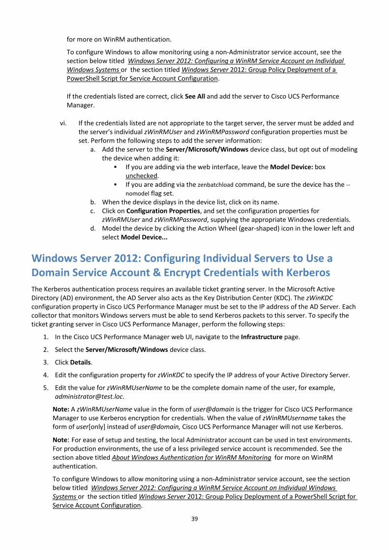
Windows Server 2012: Configuring Individual Servers to Use a Domain Service Account & Encrypt Credentials with Kerberos
The Kerberos authentication process requires an available ticket granting server. In the Microsoft Active Directory (AD) environment, the AD Server also acts as the Key Distribution Center (KDC). The zWinKDC configuration property in Cisco UCS Performance Manager must be set to the IP address of the AD Server. Each collector that monitors Windows servers must be able to send Kerberos packets to this server. To specify the ticket granting server in Cisco UCS Performance Manager, perform the following steps:
1. In the Cisco UCS Performance Manager web UI, navigate to the Infrastructure page.
2. Select the Server/Microsoft/Windows device class.
3. Click Details.
4. Edit the configuration property for zWinKDC to specify the IP address of your Active Directory Server.
5. Edit the value for zWinRMUserName to be the complete domain name of the user, for example, [email protected].
Note: A zWinRMUserName value in the form of user@domain is the trigger for Cisco UCS Performance Manager to use Kerberos encryption for credentials. When the value of zWinRMUsername takes the form of user[only] instead of user@domain, Cisco UCS Performance Manager will not use Kerberos.
Note: For ease of setup and testing, the local Administrator account can be used in test environments. For production environments, the use of a less privileged service account is recommended. See the section above titled About Windows Authentication for WinRM Monitoring for more on WinRM authentication.
To configure Windows to allow monitoring using a non-Administrator service account, see the section below titled Windows Server 2012: Configuring a WinRM Service Account on Individual Windows Systems or the section titled Windows Server 2012: Group Policy Deployment of a PowerShell Script for Service Account Configuration.
40
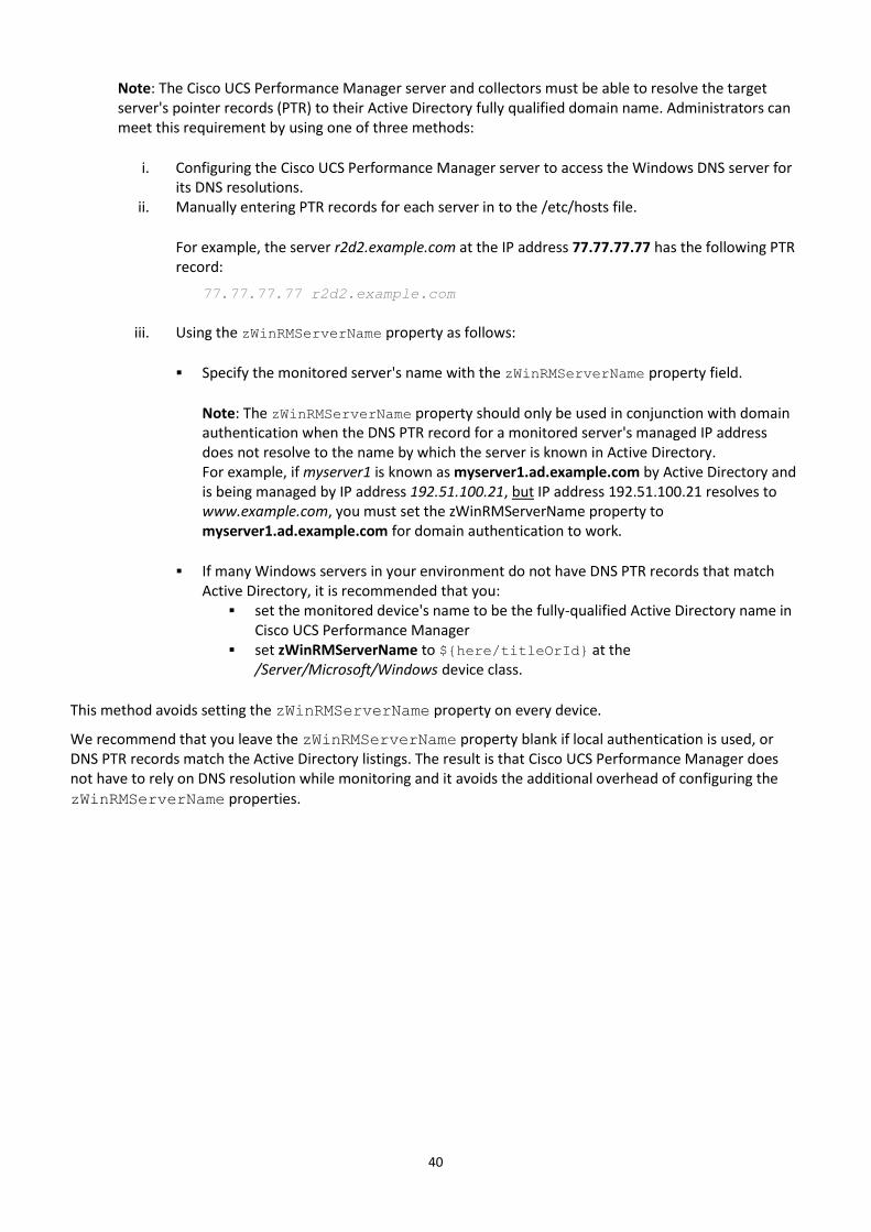
Note: The Cisco UCS Performance Manager server and collectors must be able to resolve the target server's pointer records (PTR) to their Active Directory fully qualified domain name. Administrators can meet this requirement by using one of three methods:
i. Configuring the Cisco UCS Performance Manager server to access the Windows DNS server for its DNS resolutions.
ii. Manually entering PTR records for each server in to the /etc/hosts file.
For example, the server r2d2.example.com at the IP address 77.77.77.77 has the following PTR record:
77.77.77.77 r2d2.example.com
iii. Using the zWinRMServerName property as follows:
Specify the monitored server's name with the zWinRMServerName property field.
Note: The zWinRMServerName property should only be used in conjunction with domain authentication when the DNS PTR record for a monitored server's managed IP address does not resolve to the name by which the server is known in Active Directory. For example, if myserver1 is known as myserver1.ad.example.com by Active Directory and is being managed by IP address 192.51.100.21, but IP address 192.51.100.21 resolves to www.example.com, you must set the zWinRMServerName property to myserver1.ad.example.com for domain authentication to work.
If many Windows servers in your environment do not have DNS PTR records that match Active Directory, it is recommended that you:
set the monitored device's name to be the fully-qualified Active Directory name in Cisco UCS Performance Manager
set zWinRMServerName to ${here/titleOrId} at the /Server/Microsoft/Windows device class.
This method avoids setting the zWinRMServerName property on every device.
We recommend that you leave the zWinRMServerName property blank if local authentication is used, or DNS PTR records match the Active Directory listings. The result is that Cisco UCS Performance Manager does not have to rely on DNS resolution while monitoring and it avoids the additional overhead of configuring the
zWinRMServerName properties.
41
Windows Server 2012: Improving Individual Server Security - Specify SSL for WinRM & WinRS
To successfully encrypt the payload between Cisco UCS Performance Manager and Windows clients, you must install a Server Authentication certificate on each monitored server. Log on to your Certificate Authority server as a user with Administrator privileges to create a Certificate Template for use in creating each server's certificate. This step only needs to be completed once because the new Certificate Template is then used repeatedly to create each server's certificate. In the following steps, the standard Web Server Certificate Template is duplicated to create a new Certificate Template.
1. Press the Windows key on the keyboard to display the Start screen.
2. Click the Windows PowerShell tile.
3. Launch the Microsoft Management Console (mmc). Enter the following command:
mmc
Within the mmc create the duplicate template:
i. Click the File menu, and select Add/Remove Snap-in... to display the Add or Remove Snap-ins dialog.
ii. From the list on the left, select Certificate Templates. Note: If the Certificate Templates option does not display in the list, you must add the CA role to your server.
iii. Click the Add> button in the middle of the window to add it to the Selected snap-ins list on the right.
iv. Click OK. v. Click on Certificate Templates ([server name]) in the window on the left to display the full list
of Certificate Templates. vi. Scroll down the list and locate Web Server.
vii. Right click the Web Server template and select Duplicate Template to display the Properties of New Template window.
viii. Select the Request Handling tab, and check the box next to Allow private key to be exported. ix. Select the General tab and specify a value for Template display name. x. Select the Security tab and add the certificate authority computer account to the template
with at minimum Enroll permissions. xi. Click OK to save the changes and exit the Properties of New Template window.
4. In the mmc, configure the Certificate Template:
i. Click the File menu. ii. Select Add/Remove Snap-in...
iii. From the list on the left, select Certification Authority. iv. Click the Add> button in the middle of the window to add it to the Selected snap-ins list on the
right. If a window titled Certification Authority displays:
a. Select the radio button next to Local computer under This snap-in will always manage: b. Click Finish. c. Click OK.
v. Expand the list under Certification Authority (Local) and the list under your server name. vi. Right click Certificate Templates in the list under your server name.
vii. Select New => Certificate Template to Issue. viii. In the Enable Certificate Templates window, select the new template you created in the
42
previous steps. ix. Click OK. x. Exit the mmc:
Select File > Exit
Creating a Certificate for Each Server
In the following steps, use the new certificate template to create a certificate for each server you want to monitor using SSL encryption. These steps are repeated for each server.
1. If necessary, launch the Microsoft Management Console (mmc). Press the Windows key on the keyboard to display the Start screen.
2. Click the Windows PowerShell tile.
3. Launch the Microsoft Management Console (mmc) with the following command:
mmc
In the mmc:
i. Click the File menu. ii. Select Add/Remove Snap-in...
iii. From the list on the left, select Certificates. iv. Click the Add> button in the middle of the window to add it to the Selected snap-ins list on the
right. v. In the Certificates snap-in window, select Compute account under This snap-in will always
manage certificates for: vi. Click Next (or Finish if your using an existing mmc console).
vii. Click Local computer under This snap-in will always manage: if you are presented with the Select Computer dialogue (which occurs if opening a new mmc console).
viii. Click Finish. ix. Click OK.
4. Request and enroll the new certificate. In the Certificate mmc:
i. Navigate to Console Root > Certificates (Local Computer) > Personal > Certificates.
ii. Select Action in the menus at the top of the mmc to display the drop down list.
iii. Select All Tasks > Request New Certificate.
iv. Click Next to display the next window with Active Directory Enrollment Policy highlighted.
v. Click Next.
vi. Place a check mark in the box next to your copied certificate template and click the link to launch the Properties edit window.
a. In the Subject tab, choose Common name from the Type: drop-down of the Subject name field. Enter the fully qualified domain name of the server to be monitored (for example, mytestmachine.mynetwork.com) in the Value: field.
b. Click Add.
c. If desired, enter additional identification information, including the organization, street address, etc., in the same manner.
d. Select the General tab and populate the friendly name field.
vii. Click OK.
43
viii. Click Enroll.
ix. Click Finish.
5. Expand the tree under Certificates.
6. Expand the tree under Personal.
7. Click on Certificates to highlight it and display a list of certificates on the right.
8. Right click the new certificate and select All Tasks.
i. Select Export. ii. In the Certificate Export Wizard window, click Next.
iii. Select the radio button next to Yes, export the private key. iv. Click Next.
9. On the next page:
i. Verify that the radio button next to Personal Identification Exchange - PKCS #12 (.pfx) is selected.
ii. Verify that the checkbox next to Include all certificates in the certification path if possible is checked.
iii. Click Next.
10. On the Security page of the wizard:
i. Check the box next to Password. ii. Create a password to secure the private key.
iii. Click Next.
11. On the File to Export page:
i. Select a destination for the key export. ii. Create a file name.
iii. Click Save iv. Click Next.
12. On the Completing the Certificate Export Wizard page, click Finish.
13. Click OK to close the Certificate Export Wizard.
14. Move or copy the exported certificate to the target (monitored) server.
Installing the Certificate on the Target Computer
1. On the target computer, launch the Microsoft Management Console (mmc) with the following command:
mmc
2. In the mmc:
i. Click the File menu. ii. Select Add/Remove Snap-in...
iii. From the list on the left, select Certificates. iv. Click the Add> button in the middle of the window to add it to the Selected snap-ins list on the
right. v. In the Certificates snap-in window, select Computer account under This snap-in will always

44
manage certificates for:. vi. Click Next.
vii. On the Select a computer page, click the radio button next to Local computer. viii. Click Finish.
ix. Click OK on the Add or Remove Snap-ins page.
Importing the Certificate
1. In the mmc console, expand the Certificates (Local Computer) branch of the tree.
2. Right click Personal.
3. Select All Tasks => Import.
4. On the first page of the Certificate Import Wizard, click Next.
5. On the File to import page:
i. Click Browse. ii. Navigate to the location of the certificate copied to the target system above.
iii. Select the file. Note: You might need to change the file type in the file browser window to Personal Information Exchange for the file to display.
iv. Select the certificate file. v. Click Open.
vi. Click Next.
6. On the Private key protection page:
i. Enter the password for the key. ii. Verify that the checkboxes for Include all Extended Properties and Mark this key as
exportable are selected. iii. Click Next.
7. On the Certificate Store page:
i. Select the radio button next to Place all certificates in the following store. ii. Verify that Personal appears in the field for Certificate Store.
iii. Click Next.
8. On the Completing the Certificate Import Wizard page, click Finish.
9. Click OK to exit the Certificate Wizard.
Verifying the Details and Copying the Thumbprint
1. In the mmc console:
i. Expand the Certificates (Local Computer) branch of the tree. ii. Expand Personal.
iii. Click on Certificates. iv. Double click on the certificate to view its details.
2. In the General tab of the Certificate window:
i. Verify that the hostname is correct for the target server. ii. Select the Details tab
45
iii. Scroll down to Thumbprint in the Field list. iv. Click on Thumbprint. v. Copy the thumbprint from the lower window for use in later steps.
3. If the server has not been previously configured for monitoring using WinRM, complete the steps listed above in the section Windows Server 2012: Configuring WinRM and WinRS on Individual Servers (Basic Authentication, no Encryption) on page 37 and omit the step that specifies SSL not be used. Substitute the steps in the following section, Configuring the Firewall (below) for firewall configuration. If the server has previously been configured for monitoring but without using SSL, proceed directly to the section, Configuring the Firewall (below).
Configuring the Firewall
1. Configure the firewall to allow connections on port 5986 on individual servers. If desired, use these instructions to instead modify a Group Policy object (for example as directed in Page 4 of this document) to make the change on large numbers of servers.
i. Press the Windows key on the keyboard to display the Start screen. ii. Click the Server Manager tile.
iii. Click Local Server on the left. iv. Edit the Firewall profile currently in use. Click the value to the right of Windows Firewall to
change the value. For example, you might see Windows Firewall in grey font and to the right of it, in blue font, Domain: On. In this case, click the blue Domain On value.
v. Click on Advanced Settings on the left.
2. In the Windows Firewall with Advanced Security window:
i. Click on Inbound Rules on the left. ii. Click on New Rule... on the far right under Actions.
3. In the New Inbound Rule Wizard window:
i. Select the radio button next to Port. ii. Click Next.
iii. Verify that the radio buttons next to TCP and Specific local ports are selected. iv. Enter the value 5986 in the field for Specific local ports. v. Click Next.
vi. On the next page, verify that the radio button next to Allow the connection is selected. vii. Click Next.
viii. On the next page, select the firewall profiles for which the rule should apply. ix. Click Next. x. On the next page, give the rule a name.
xi. Click Finish.
Creating the WinRM Listener Using SSL
1. Press the Windows key on the keyboard to display the Start screen.
2. Click the Windows PowerShell tile.
3. At the PowerShell command line, type the following command, substituting your values for the certificate thumbprint and serverfqdn (server fully qualified domain name of the monitoring server):
46
winrm create
winrm/config/Listener?Address=*+Transport=HTTPS '@{Hostname="[serverfqdn]";C
ertificateThumbprint="[thumbprint]"}'
for example: winrm create winrm/config/Listener?Address=*+Transport=HTTPS '@{Hostname="
mytestmachine.mynetwork.com";CertificateThumbprint="07bfff656edab6d9b4dd27f02
0f768f54fee5eb8"}'
Note: The thumbprint value must be entered without the spaces displayed in the Detail tab of the Certificate information window. For example, the displayed value: 07 bf ff 65 6e da … must be entered as: 07bfff656eda…
4. Specify https (SSL) instead of http connections. Enter the following command:
winrm s winrm/config/service '@{AllowUnencrypted="false"}'
Note: If this is already controlled through a policy, an error displays. In that case, modify the appropriate GPO. The instructions on Page 2 of this document can be used as a guide.
Adding the Server to Cisco UCS Performance Manager
In the Cisco UCS Performance Manager web UI:
1. Navigate to the Infrastructure page.
2. If the server has not yet been added to Cisco UCS Performance Manager, add it the Server/Microsoft/Windows device class and opt out of modeling.
3. Click on the name of the target (monitored) server (or on the Server/Microsoft/Windows device class if you would like these changes to apply to all Windows servers).
4. Click on Configuration Properties.
5. Edit the configuration property for zWinScheme to be https.
6. Edit the value for zWinRMPort to be 5986.
7. Verify that the values for zWinRMUser and zWinRMPassword are correct. Correct means the appropriate Windows credentials. Edit as necessary.
8. To verify that all settings are correct, model the device. Click the Action Wheel (gear-shaped) icon in the lower left and select Model Device...
47
Windows Server 2012: Configuring a WinRM Service Account on Individual Windows Systems
See the section above titled About Windows Authentication for WinRM Monitoring if necessary for more background on Windows permissions requirements when monitoring with WinRM.
Note: You cannot create a local service account if the machine is configured as a domain controller (AD DS) because the local users and groups options no longer exist in that configuration. There are no local accounts on a domain controller, only domain accounts.
Complete the following steps on each non-domain controller server to configure your service account:
1. Add a new local user for use as a service account: i. Open Server Manager.
ii. Click on Tools in the upper right and select Computer Management from the menu that displays.
iii. In the left pane of the Computer Management window, expand Local Users and Groups. iv. Right click on User and select New User from the menu that displays. v. Complete the New User form. Uncheck User must change password at next logon and check (if
desired) the Password never expires box. vi. Click Create.
vii. Click Close to exit the New User form. 2. Copy your permissions configuration script, for example an edited version of the zenoss-lpu.ps1 script,
to the target server. 3. Run the PowerShell Script:
i. Press the Windows key on the keyboard to display the Start screen. ii. Click the Windows PowerShell tile.
iii. Run your service account configuration script by typing the full path to the script in the command line, then appending the script with the -u option and the name of your service account. For example, if you are using an edited version of the zenoss-lpu.ps1 script and your service account is named “benny,” enter the command at the PowerShell prompt:
C:\tmp\zenoss-lpu-ps1 –u benny
Note: depending on the security policies enforced on your server, you might encounter an error such as:
File C:\tmp\zenoss-lpu-ps1 cannot be loaded because running scripts is
disabled on this system…..
If you encounter this error, you can bypass the security restrictions for this script by including the –executionpolicy bypass option, for example:
Powershell -executionpolicy bypass -file C:\tmp\zenoss-lpu.ps1 -u benny
48
Windows Server 2012: Group Policy Deployment of a PowerShell Script for Service Account Configuration
Refer to the section above titled About Windows Authentication for WinRM Monitoring for background on service account requirements.
Prerequisites for Configuring a Service Account
The prerequisites for configuring a service account include:
Creation of a domain user account for use as the service account.
Completion of the appropriate preparatory sections.
Creating the Domain User (Service) Account
Perform the following to create a new domain user (service) account, if necessary:
1. Log on to an Active Directory server for the domain. 2. Open Server Manager and click Tools in the upper right. 3. Select Active Directory Users and Computers from the drop-down list. 4. In the left pane of the Active Directory Users and Computers window, find and expand your domain, for
example, doctest.loc. 5. Right-click Users and select New > User 6. In the New Object – User window, provide a First name and a User logon name, zenny for example. 7. Verify the domain field has the correct domain identification. For example, @doctest.loc 8. Click Next to display the password dialog for the new user. 9. In the Password fields, enter and verify the new user password. 10. Uncheck the User must change password at next logon. 11. Check the option for Password never expires. We recommend this option to prevent issues later on
because your new domain user (zenny in this example) never logs on as a human user. 12. Click Next. 13. Click Finish. Your new user, zenny for example, displays in the list of users for the domain.
Completing Preparatory Sections
The following procedure assumes that you have completed the following preparatory sections:
Windows Server 2012: Configuring Firewall Group Policies
Note: This method of deploying a PowerShell script across a large group of Windows systems is most likely to be employed in combination with the use of a single domain service account for WinRM authentication. The use of a domain service account mandates the use of Kerberos to encrypt credentials. See the relevant section in this document for instructions on configuring a domain service account and Kerberos if you have not already:
Windows Server 2012: Improving Security
PowerShell Script Deployment
Perform the following procedure to create a new GPO and to deploy the PowerShell script.
1. Create your service account configuration script (or edit, as appropriate, the sample script referenced above in the section titled About Windows Authentication for WinRM Monitoring).
2. Copy the script (for example “zenoss-lpu.ps1”) to a Netlogon folder such as
\\yourdomain\SYSVOL\yourdomain\scripts
3. Open Group Policy Management, from the Server Manager console:
49
Click Tools in the upper right, and then choose Group Policy Management.
4. Create a new policy. i. In the left pane, navigate to:
Forest: yourdomain > Domains > yourdomain > Group Policy Objects
ii. Right click Group Policy Objects iii. Select New to display the NEW GPO dialog. iv. Name your policy, for example: zenoss_lpu v. Click OK to save and exit the New Policy window.
5. Edit your new policy.
i. In the left pane, navigate to your new Group Policy Object. For example:
Forest: yourdomain > Domains > yourdomain > Group Policy Objects > zenoss_lpu
ii. Right click the policy and select Edit to display the Group Policy Management Editor. iii. In the left pane of the Group Policy Management window, navigate to:
Computer Configuration\Policies\Windows Settings\Scripts (Startup/Shutdown)
iv. Click Scripts (Startup/Shutdown). v. In the right pane (Scripts (Startup/Shutdown), double-click Startup to launch the Startup
Properties dialog. vi. In the Startup Properties dialog box, select the PowerShell Scripts tab.
vii. Click Add to display the Add a Script dialog box: a. Specify the script name and path. In the Script Name field, enter the path to the script,
or click Browse to locate the script file. Note: Scripts should be located in the Netlogon shared folder on the domain controller. For example: \\yourdomain\SYSVOL\yourdomain\scripts
b. Select the zenoss-lpu.ps1 PowerShell script. c. Click Open. d. In the Script Parameters box, enter -u yourusername@yourdomain for a domain user
or -u yourusername for basic authentication of a local computer account user. Note: Basic authentication relies on local computer accounts. To successfully authenticate to any particular computer, you must have a local account on that machine.
e. Click OK to save the information and exit the Add a Script window.
If you have multiple scripts and want them to run in a particular order, use the Up and Down buttons in the Startup Properties window to set their run order.
f. Click OK to exit the Startup Properties window. 6. Exit the Local Group Policy Editor:
File > Exit
7. Link your new GPO to one or more Organizational Units (OU) containing servers to which you want to have the policies applied. Alternatively, you can apply the policies to all Windows servers in the domain by linking the new GPO to the domain itself. To link the GPO to the domain, complete the following process.
Note: Substitute a specific OU for the domain if you want to link only to a subset of servers.
i. Right-click your domain in the left pane of the Group Policy Management window. ii. Choose Link an Existing GPO...

50
iii. Select your new GPO from the list that displays. iv. Click OK to complete the process.
8. Exit the Group Policy Management window:
File > Exit
9. Manually refresh Group Policy from the command prompt of target servers:
gpupdate /force
10. Reboot your member servers to have the script run for the first time.
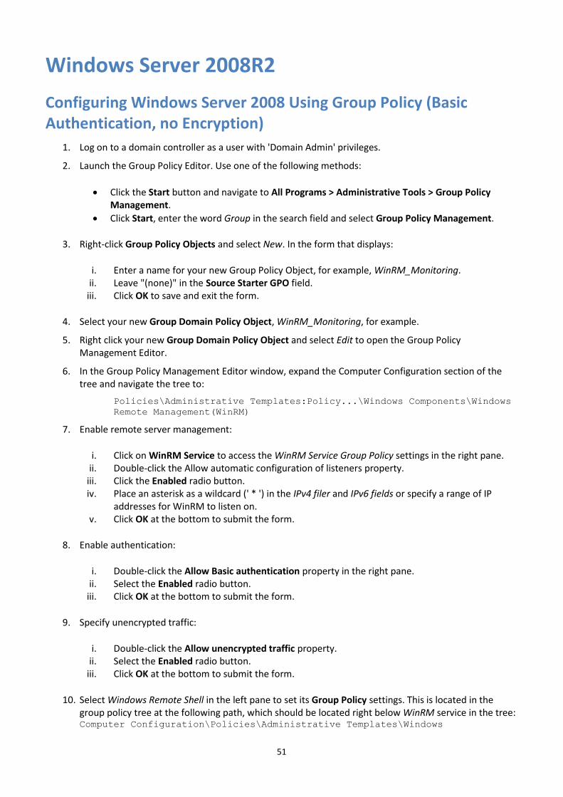
51
Windows Server 2008R2
Configuring Windows Server 2008 Using Group Policy (Basic Authentication, no Encryption)
1. Log on to a domain controller as a user with 'Domain Admin' privileges.
2. Launch the Group Policy Editor. Use one of the following methods:
Click the Start button and navigate to All Programs > Administrative Tools > Group Policy Management.
Click Start, enter the word Group in the search field and select Group Policy Management.
3. Right-click Group Policy Objects and select New. In the form that displays:
i. Enter a name for your new Group Policy Object, for example, WinRM_Monitoring. ii. Leave "(none)" in the Source Starter GPO field.
iii. Click OK to save and exit the form.
4. Select your new Group Domain Policy Object, WinRM_Monitoring, for example.
5. Right click your new Group Domain Policy Object and select Edit to open the Group Policy Management Editor.
6. In the Group Policy Management Editor window, expand the Computer Configuration section of the tree and navigate the tree to:
Policies\Administrative Templates:Policy...\Windows Components\Windows
Remote Management(WinRM)
7. Enable remote server management:
i. Click on WinRM Service to access the WinRM Service Group Policy settings in the right pane. ii. Double-click the Allow automatic configuration of listeners property.
iii. Click the Enabled radio button. iv. Place an asterisk as a wildcard (' * ') in the IPv4 filer and IPv6 fields or specify a range of IP
addresses for WinRM to listen on. v. Click OK at the bottom to submit the form.
8. Enable authentication:
i. Double-click the Allow Basic authentication property in the right pane. ii. Select the Enabled radio button.
iii. Click OK at the bottom to submit the form.
9. Specify unencrypted traffic:
i. Double-click the Allow unencrypted traffic property. ii. Select the Enabled radio button.
iii. Click OK at the bottom to submit the form.
10. Select Windows Remote Shell in the left pane to set its Group Policy settings. This is located in the group policy tree at the following path, which should be located right below WinRM service in the tree: Computer Configuration\Policies\Administrative Templates\Windows

52
Components\Windows Remote Shell
11. Configure remote shell access:
i. In the right pane, double-click Allow Remote Shell Access. ii. Select the Enabled radio button.
iii. Click OK at the bottom to submit the form.
12. Configure shell processes:
i. In the right pane, double-click Specify maximum number of processes per Shell. ii. Select the Enabled radio button.
iii. Enter the value 2,000,000,000 (without commas or spaces) in the MaxProcessesPerShell field.
iv. Click OK at the bottom to submit the form.
13. Configure the number of remote shells:
i. In the right pane, double-click Specify maximum number of remote shells per user. ii. Select the Enabled radio button.
iii. Enter the value 2,000,000,000 (without commas or spaces) in the MaxShellsPerUser field. iv. Click OK at the bottom to submit the form.
14. Configure the shell timeout value:
i. In the Right pane, double-click Specify Shell Timeout. ii. Select the Enabled radio button.
iii. Enter the value 7,200,000 (without commas or spaces) in the ShellTimeOut field. iv. Click OK at the bottom to submit the form.
Windows 2008: Configuring Firewall Group Policies
Windows firewall must allow incoming ICMP (ping) requests. Additionally, WinRM listens on port 5985 when SSL is not used and on port 5986 when SSL is used. These ports must be opened on the firewalls of monitored servers. You can use Group Policy to open these ports on all servers across the organization.
In the Group Policy Management Editor, navigate to:
Computer Configuration\Policies\Windows Settings\Security Settings\Windows
Firewall with Advanced Security\Windows Firewall with Advanced Security -
LDAP;...\Inbound Rules
1. Create a new Inbound Rules policy:
i. Right click Inbound Rules in the left pane. ii. Select New Rule... to display the New Inbound Rule Wizard
iii. Select the Predefined radio button in the right pane. iv. Select Windows Remote Management from the drop down list. v. Click Next.
vi. Ensure that all items in the list are checked. vii. Click Next.
viii. Ensure that the Allow the connection radio button is selected. ix. Click Finish.
2. Exit the Group Policy Management Editor: Select File > Exit
3. Link your new GPO to one or more Organizational Units (OU) containing servers to which you want to
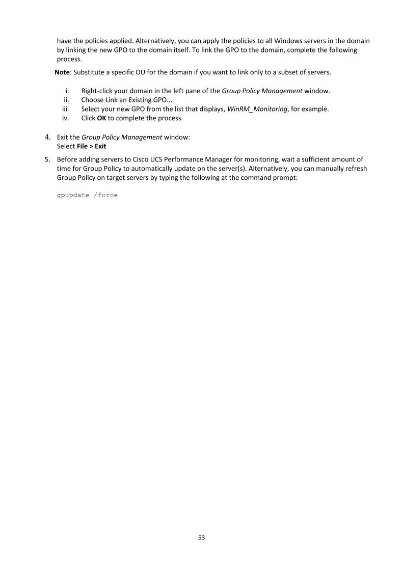
53
have the policies applied. Alternatively, you can apply the policies to all Windows servers in the domain by linking the new GPO to the domain itself. To link the GPO to the domain, complete the following process.
Note: Substitute a specific OU for the domain if you want to link only to a subset of servers.
i. Right-click your domain in the left pane of the Group Policy Management window. ii. Choose Link an Existing GPO...
iii. Select your new GPO from the list that displays, WinRM_Monitoring, for example. iv. Click OK to complete the process.
4. Exit the Group Policy Management window: Select File > Exit
5. Before adding servers to Cisco UCS Performance Manager for monitoring, wait a sufficient amount of time for Group Policy to automatically update on the server(s). Alternatively, you can manually refresh Group Policy on target servers by typing the following at the command prompt: gpupdate /force
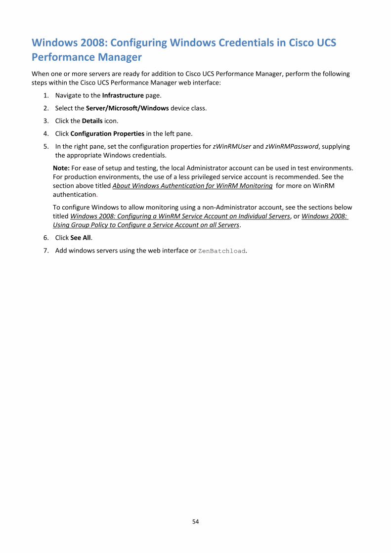
54
Windows 2008: Configuring Windows Credentials in Cisco UCS Performance Manager
When one or more servers are ready for addition to Cisco UCS Performance Manager, perform the following steps within the Cisco UCS Performance Manager web interface:
1. Navigate to the Infrastructure page.
2. Select the Server/Microsoft/Windows device class.
3. Click the Details icon.
4. Click Configuration Properties in the left pane.
5. In the right pane, set the configuration properties for zWinRMUser and zWinRMPassword, supplying the appropriate Windows credentials.
Note: For ease of setup and testing, the local Administrator account can be used in test environments. For production environments, the use of a less privileged service account is recommended. See the section above titled About Windows Authentication for WinRM Monitoring for more on WinRM authentication.
To configure Windows to allow monitoring using a non-Administrator account, see the sections below titled Windows 2008: Configuring a WinRM Service Account on Individual Servers, or Windows 2008: Using Group Policy to Configure a Service Account on all Servers.
6. Click See All.
7. Add windows servers using the web interface or ZenBatchload.
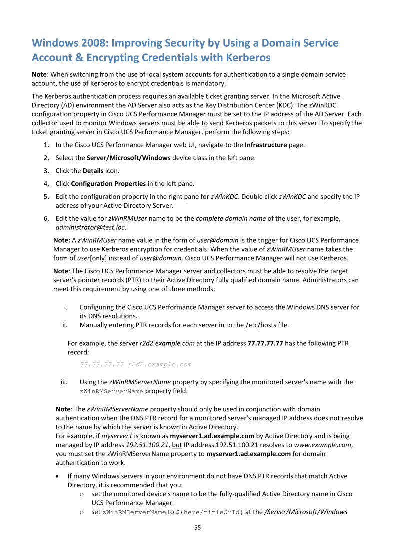
55
Windows 2008: Improving Security by Using a Domain Service Account & Encrypting Credentials with Kerberos
Note: When switching from the use of local system accounts for authentication to a single domain service account, the use of Kerberos to encrypt credentials is mandatory.
The Kerberos authentication process requires an available ticket granting server. In the Microsoft Active Directory (AD) environment the AD Server also acts as the Key Distribution Center (KDC). The zWinKDC configuration property in Cisco UCS Performance Manager must be set to the IP address of the AD Server. Each collector used to monitor Windows servers must be able to send Kerberos packets to this server. To specify the ticket granting server in Cisco UCS Performance Manager, perform the following steps:
1. In the Cisco UCS Performance Manager web UI, navigate to the Infrastructure page.
2. Select the Server/Microsoft/Windows device class in the left pane.
3. Click the Details icon.
4. Click Configuration Properties in the left pane.
5. Edit the configuration property in the right pane for zWinKDC. Double click zWinKDC and specify the IP address of your Active Directory Server.
6. Edit the value for zWinRMUser name to be the complete domain name of the user, for example, [email protected].
Note: A zWinRMUser name value in the form of user@domain is the trigger for Cisco UCS Performance Manager to use Kerberos encryption for credentials. When the value of zWinRMUser name takes the form of user[only] instead of user@domain, Cisco UCS Performance Manager will not use Kerberos.
Note: The Cisco UCS Performance Manager server and collectors must be able to resolve the target server's pointer records (PTR) to their Active Directory fully qualified domain name. Administrators can meet this requirement by using one of three methods:
i. Configuring the Cisco UCS Performance Manager server to access the Windows DNS server for its DNS resolutions.
ii. Manually entering PTR records for each server in to the /etc/hosts file.
For example, the server r2d2.example.com at the IP address 77.77.77.77 has the following PTR record:
77.77.77.77 r2d2.example.com
iii. Using the zWinRMServerName property by specifying the monitored server's name with the zWinRMServerName property field.
Note: The zWinRMServerName property should only be used in conjunction with domain authentication when the DNS PTR record for a monitored server's managed IP address does not resolve to the name by which the server is known in Active Directory. For example, if myserver1 is known as myserver1.ad.example.com by Active Directory and is being managed by IP address 192.51.100.21, but IP address 192.51.100.21 resolves to www.example.com, you must set the zWinRMServerName property to myserver1.ad.example.com for domain authentication to work.
If many Windows servers in your environment do not have DNS PTR records that match Active Directory, it is recommended that you:
o set the monitored device's name to be the fully-qualified Active Directory name in Cisco UCS Performance Manager.
o set zWinRMServerName to ${here/titleOrId} at the /Server/Microsoft/Windows

56
device class.
This method avoids setting the zWinRMServerName property on every device.
We recommend that you leave the zWinRMServerName property blank if local authentication is used, or DNS PTR records match the Active Directory listings. The result is that Cisco UCS Performance Manager does not have to rely on DNS resolution while monitoring and it avoids the additional overhead of configuring the zWinRMServerName properties.
Note: You can add custom Kerberos configurations if your settings differ from the default settings used by UCS Performance Manager. To use a custom configuration file, place it in the /opt/zenoss/var/krb5/config directory. You must be using Kerberos 5 release 1.10 or higher. For more information, see http://wiki.zenoss.org/ZenPack:Microsoft_Windows
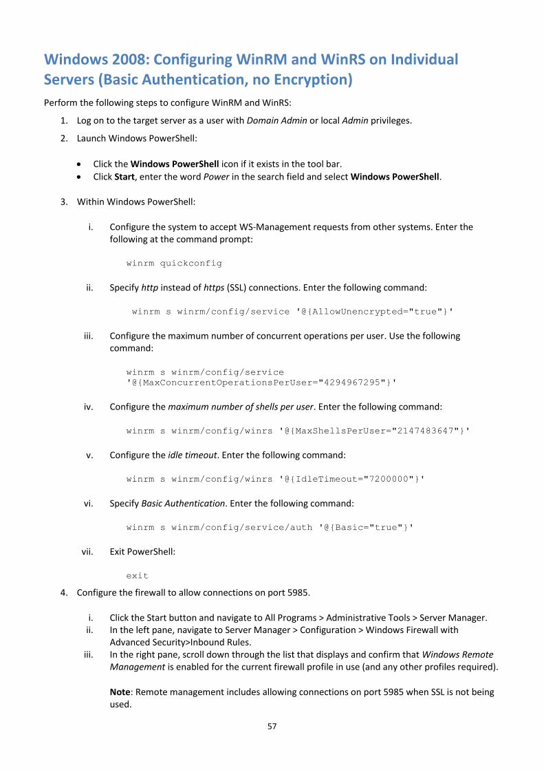
57
Windows 2008: Configuring WinRM and WinRS on Individual Servers (Basic Authentication, no Encryption)
Perform the following steps to configure WinRM and WinRS:
1. Log on to the target server as a user with Domain Admin or local Admin privileges.
2. Launch Windows PowerShell:
Click the Windows PowerShell icon if it exists in the tool bar.
Click Start, enter the word Power in the search field and select Windows PowerShell.
3. Within Windows PowerShell:
i. Configure the system to accept WS-Management requests from other systems. Enter the following at the command prompt:
winrm quickconfig
ii. Specify http instead of https (SSL) connections. Enter the following command:
winrm s winrm/config/service '@{AllowUnencrypted="true"}'
iii. Configure the maximum number of concurrent operations per user. Use the following command:
winrm s winrm/config/service
'@{MaxConcurrentOperationsPerUser="4294967295"}'
iv. Configure the maximum number of shells per user. Enter the following command:
winrm s winrm/config/winrs '@{MaxShellsPerUser="2147483647"}'
v. Configure the idle timeout. Enter the following command:
winrm s winrm/config/winrs '@{IdleTimeout="7200000"}'
vi. Specify Basic Authentication. Enter the following command:
winrm s winrm/config/service/auth '@{Basic="true"}'
vii. Exit PowerShell:
exit
4. Configure the firewall to allow connections on port 5985.
i. Click the Start button and navigate to All Programs > Administrative Tools > Server Manager. ii. In the left pane, navigate to Server Manager > Configuration > Windows Firewall with
Advanced Security>Inbound Rules. iii. In the right pane, scroll down through the list that displays and confirm that Windows Remote
Management is enabled for the current firewall profile in use (and any other profiles required).
Note: Remote management includes allowing connections on port 5985 when SSL is not being used.
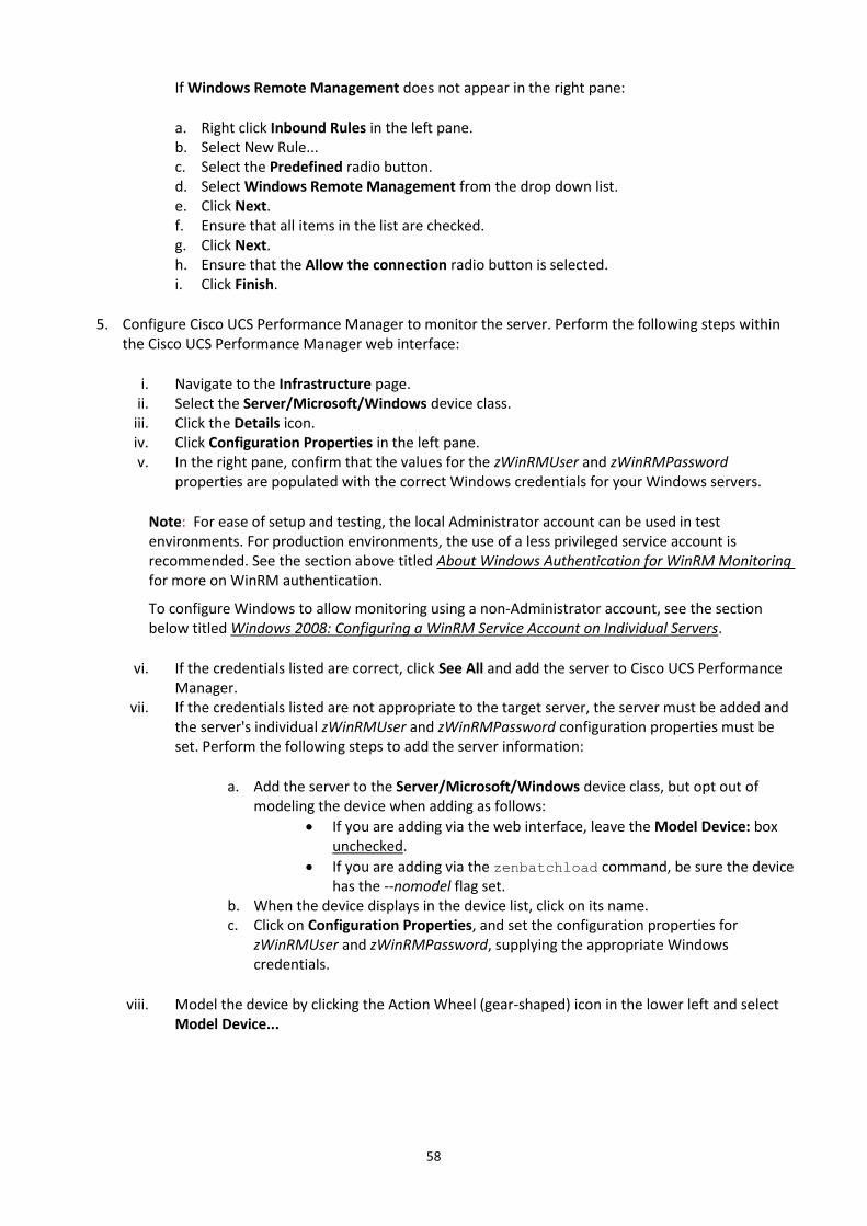
58
If Windows Remote Management does not appear in the right pane:
a. Right click Inbound Rules in the left pane. b. Select New Rule... c. Select the Predefined radio button. d. Select Windows Remote Management from the drop down list. e. Click Next. f. Ensure that all items in the list are checked. g. Click Next. h. Ensure that the Allow the connection radio button is selected. i. Click Finish.
5. Configure Cisco UCS Performance Manager to monitor the server. Perform the following steps within the Cisco UCS Performance Manager web interface:
i. Navigate to the Infrastructure page. ii. Select the Server/Microsoft/Windows device class.
iii. Click the Details icon. iv. Click Configuration Properties in the left pane. v. In the right pane, confirm that the values for the zWinRMUser and zWinRMPassword
properties are populated with the correct Windows credentials for your Windows servers.
Note: For ease of setup and testing, the local Administrator account can be used in test environments. For production environments, the use of a less privileged service account is recommended. See the section above titled About Windows Authentication for WinRM Monitoring for more on WinRM authentication.
To configure Windows to allow monitoring using a non-Administrator account, see the section below titled Windows 2008: Configuring a WinRM Service Account on Individual Servers.
vi. If the credentials listed are correct, click See All and add the server to Cisco UCS Performance Manager.
vii. If the credentials listed are not appropriate to the target server, the server must be added and the server's individual zWinRMUser and zWinRMPassword configuration properties must be set. Perform the following steps to add the server information:
a. Add the server to the Server/Microsoft/Windows device class, but opt out of modeling the device when adding as follows:
If you are adding via the web interface, leave the Model Device: box unchecked.
If you are adding via the zenbatchload command, be sure the device has the --nomodel flag set.
b. When the device displays in the device list, click on its name. c. Click on Configuration Properties, and set the configuration properties for
zWinRMUser and zWinRMPassword, supplying the appropriate Windows credentials.
viii. Model the device by clicking the Action Wheel (gear-shaped) icon in the lower left and select Model Device...
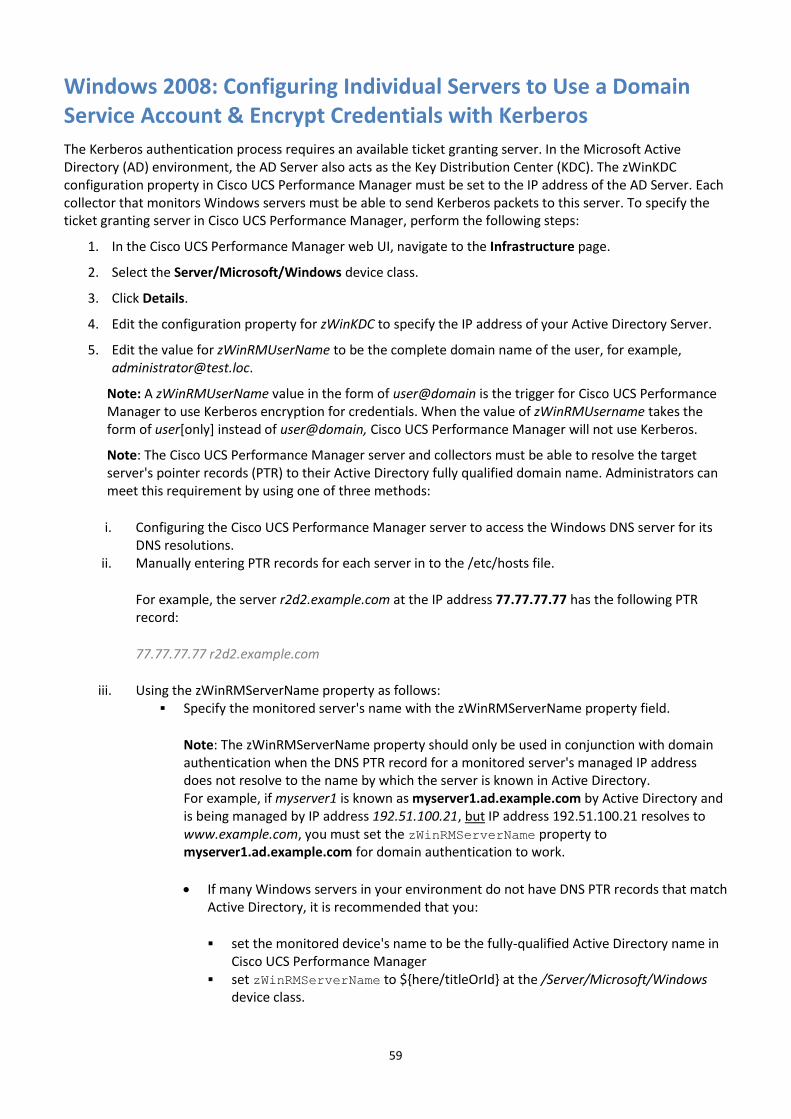
59
Windows 2008: Configuring Individual Servers to Use a Domain Service Account & Encrypt Credentials with Kerberos
The Kerberos authentication process requires an available ticket granting server. In the Microsoft Active Directory (AD) environment, the AD Server also acts as the Key Distribution Center (KDC). The zWinKDC configuration property in Cisco UCS Performance Manager must be set to the IP address of the AD Server. Each collector that monitors Windows servers must be able to send Kerberos packets to this server. To specify the ticket granting server in Cisco UCS Performance Manager, perform the following steps:
1. In the Cisco UCS Performance Manager web UI, navigate to the Infrastructure page.
2. Select the Server/Microsoft/Windows device class.
3. Click Details.
4. Edit the configuration property for zWinKDC to specify the IP address of your Active Directory Server.
5. Edit the value for zWinRMUserName to be the complete domain name of the user, for example, [email protected].
Note: A zWinRMUserName value in the form of user@domain is the trigger for Cisco UCS Performance Manager to use Kerberos encryption for credentials. When the value of zWinRMUsername takes the form of user[only] instead of user@domain, Cisco UCS Performance Manager will not use Kerberos.
Note: The Cisco UCS Performance Manager server and collectors must be able to resolve the target server's pointer records (PTR) to their Active Directory fully qualified domain name. Administrators can meet this requirement by using one of three methods:
i. Configuring the Cisco UCS Performance Manager server to access the Windows DNS server for its DNS resolutions.
ii. Manually entering PTR records for each server in to the /etc/hosts file.
For example, the server r2d2.example.com at the IP address 77.77.77.77 has the following PTR record:
77.77.77.77 r2d2.example.com
iii. Using the zWinRMServerName property as follows: Specify the monitored server's name with the zWinRMServerName property field.
Note: The zWinRMServerName property should only be used in conjunction with domain authentication when the DNS PTR record for a monitored server's managed IP address does not resolve to the name by which the server is known in Active Directory. For example, if myserver1 is known as myserver1.ad.example.com by Active Directory and is being managed by IP address 192.51.100.21, but IP address 192.51.100.21 resolves to www.example.com, you must set the zWinRMServerName property to myserver1.ad.example.com for domain authentication to work.
If many Windows servers in your environment do not have DNS PTR records that match Active Directory, it is recommended that you:
set the monitored device's name to be the fully-qualified Active Directory name in Cisco UCS Performance Manager
set zWinRMServerName to ${here/titleOrId} at the /Server/Microsoft/Windows device class.

60
This method avoids setting the zWinRMServerName property on every device.
We recommend that you leave the zWinRMServerName property blank if local authentication is used, or DNS PTR records match the Active Directory listings. The result is that Cisco UCS Performance Manager does not have to rely on DNS resolution while monitoring and it avoids the additional overhead of configuring the zWinRMServerName properties.
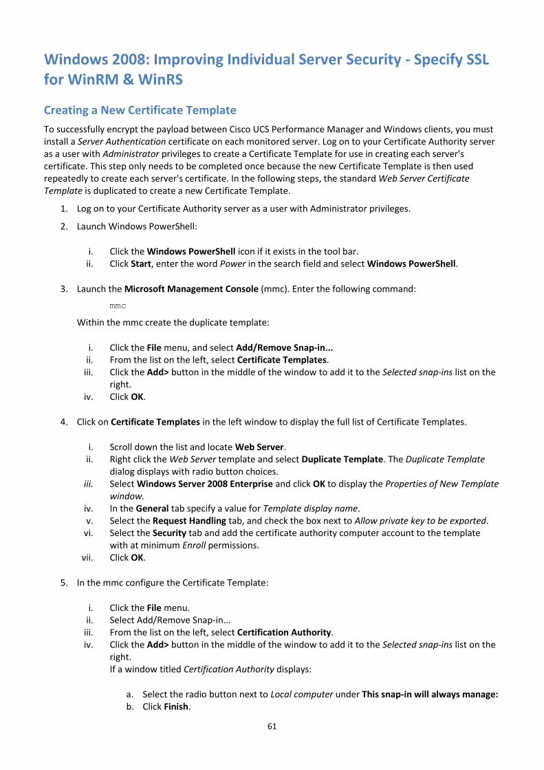
61
Windows 2008: Improving Individual Server Security - Specify SSL for WinRM & WinRS
Creating a New Certificate Template
To successfully encrypt the payload between Cisco UCS Performance Manager and Windows clients, you must install a Server Authentication certificate on each monitored server. Log on to your Certificate Authority server as a user with Administrator privileges to create a Certificate Template for use in creating each server's certificate. This step only needs to be completed once because the new Certificate Template is then used repeatedly to create each server's certificate. In the following steps, the standard Web Server Certificate Template is duplicated to create a new Certificate Template.
1. Log on to your Certificate Authority server as a user with Administrator privileges.
2. Launch Windows PowerShell:
i. Click the Windows PowerShell icon if it exists in the tool bar. ii. Click Start, enter the word Power in the search field and select Windows PowerShell.
3. Launch the Microsoft Management Console (mmc). Enter the following command:
mmc
Within the mmc create the duplicate template:
i. Click the File menu, and select Add/Remove Snap-in... ii. From the list on the left, select Certificate Templates.
iii. Click the Add> button in the middle of the window to add it to the Selected snap-ins list on the right.
iv. Click OK.
4. Click on Certificate Templates in the left window to display the full list of Certificate Templates.
i. Scroll down the list and locate Web Server. ii. Right click the Web Server template and select Duplicate Template. The Duplicate Template
dialog displays with radio button choices. iii. Select Windows Server 2008 Enterprise and click OK to display the Properties of New Template
window. iv. In the General tab specify a value for Template display name. v. Select the Request Handling tab, and check the box next to Allow private key to be exported.
vi. Select the Security tab and add the certificate authority computer account to the template with at minimum Enroll permissions.
vii. Click OK.
5. In the mmc configure the Certificate Template:
i. Click the File menu. ii. Select Add/Remove Snap-in...
iii. From the list on the left, select Certification Authority. iv. Click the Add> button in the middle of the window to add it to the Selected snap-ins list on the
right. If a window titled Certification Authority displays:
a. Select the radio button next to Local computer under This snap-in will always manage: b. Click Finish.
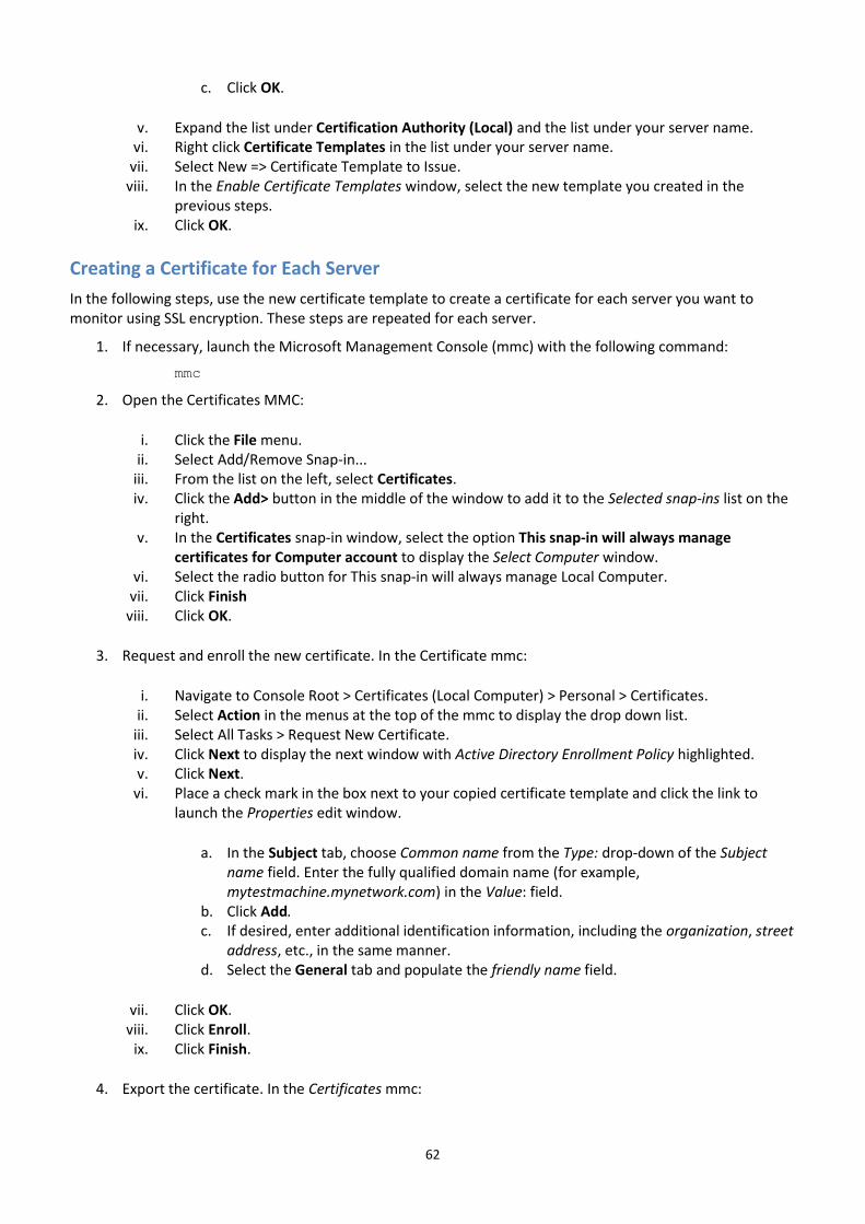
62
c. Click OK.
v. Expand the list under Certification Authority (Local) and the list under your server name. vi. Right click Certificate Templates in the list under your server name.
vii. Select New => Certificate Template to Issue. viii. In the Enable Certificate Templates window, select the new template you created in the
previous steps. ix. Click OK.
Creating a Certificate for Each Server
In the following steps, use the new certificate template to create a certificate for each server you want to monitor using SSL encryption. These steps are repeated for each server.
1. If necessary, launch the Microsoft Management Console (mmc) with the following command:
mmc
2. Open the Certificates MMC:
i. Click the File menu. ii. Select Add/Remove Snap-in...
iii. From the list on the left, select Certificates. iv. Click the Add> button in the middle of the window to add it to the Selected snap-ins list on the
right. v. In the Certificates snap-in window, select the option This snap-in will always manage
certificates for Computer account to display the Select Computer window. vi. Select the radio button for This snap-in will always manage Local Computer.
vii. Click Finish viii. Click OK.
3. Request and enroll the new certificate. In the Certificate mmc:
i. Navigate to Console Root > Certificates (Local Computer) > Personal > Certificates. ii. Select Action in the menus at the top of the mmc to display the drop down list.
iii. Select All Tasks > Request New Certificate. iv. Click Next to display the next window with Active Directory Enrollment Policy highlighted. v. Click Next.
vi. Place a check mark in the box next to your copied certificate template and click the link to launch the Properties edit window.
a. In the Subject tab, choose Common name from the Type: drop-down of the Subject name field. Enter the fully qualified domain name (for example, mytestmachine.mynetwork.com) in the Value: field.
b. Click Add. c. If desired, enter additional identification information, including the organization, street
address, etc., in the same manner. d. Select the General tab and populate the friendly name field.
vii. Click OK. viii. Click Enroll.
ix. Click Finish.
4. Export the certificate. In the Certificates mmc:
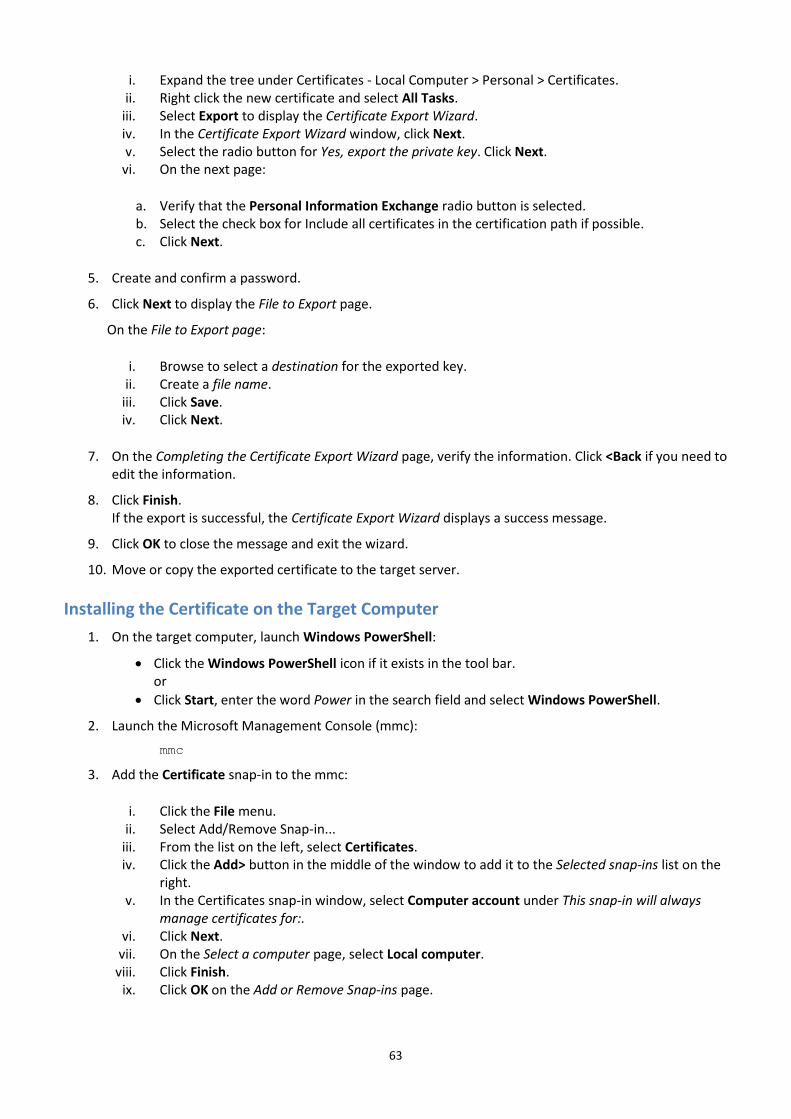
63
i. Expand the tree under Certificates - Local Computer > Personal > Certificates. ii. Right click the new certificate and select All Tasks.
iii. Select Export to display the Certificate Export Wizard. iv. In the Certificate Export Wizard window, click Next. v. Select the radio button for Yes, export the private key. Click Next.
vi. On the next page:
a. Verify that the Personal Information Exchange radio button is selected. b. Select the check box for Include all certificates in the certification path if possible. c. Click Next.
5. Create and confirm a password.
6. Click Next to display the File to Export page.
On the File to Export page:
i. Browse to select a destination for the exported key. ii. Create a file name.
iii. Click Save. iv. Click Next.
7. On the Completing the Certificate Export Wizard page, verify the information. Click <Back if you need to edit the information.
8. Click Finish. If the export is successful, the Certificate Export Wizard displays a success message.
9. Click OK to close the message and exit the wizard.
10. Move or copy the exported certificate to the target server.
Installing the Certificate on the Target Computer
1. On the target computer, launch Windows PowerShell:
Click the Windows PowerShell icon if it exists in the tool bar. or
Click Start, enter the word Power in the search field and select Windows PowerShell.
2. Launch the Microsoft Management Console (mmc):
mmc
3. Add the Certificate snap-in to the mmc:
i. Click the File menu. ii. Select Add/Remove Snap-in...
iii. From the list on the left, select Certificates. iv. Click the Add> button in the middle of the window to add it to the Selected snap-ins list on the
right. v. In the Certificates snap-in window, select Computer account under This snap-in will always
manage certificates for:. vi. Click Next.
vii. On the Select a computer page, select Local computer. viii. Click Finish.
ix. Click OK on the Add or Remove Snap-ins page.

64
Importing the Certificate
1. In the mmc console, expand the Certificates (Local Computer) branch of the tree.
2. Highlight and right click Personal.
3. Select All Tasks => Import to launch the Certificate Import Wizard.
4. On the first page of the Certificate Import Wizard, click Next.
5. On the File to import page:,
i. Click Browse. ii. Navigate to the location of the certificate file you copied to the target system and select the
file. Note: If your file name does not display, change the file type in the file browser window to Personal Information Exchange.
iii. Click Open. iv. Click Next to display the Private key protection page.
6. On the Private key protection page:
i. Enter the password for the key. ii. Verify that the checkboxes for Mark this key as exportable and Include all Extended Properties
are selected. iii. Click Next. to display the Certificate Store page.
7. On the Certificate Store page:
i. Select Place all certificates in the following store. ii. Verify that Personal appears in the field for Certificate Store.
iii. Click Next to display the Completing the Certificate Import Wizard page.
8. On the Completing the Certificate Import Wizard page, verify the certificate information.
9. Click Finish to exit the wizard. If the export is successful, The Certificate Export Wizard displays a success message.
10. Click OK to close the message and exit the wizard.
Verifying the Details and Copying the Thumbprint
1. If necessary, launch the mmc with the Certificate snap-in. In the mmc console:
i. Expand the Certificates (Local Computer) branch of the tree. ii. Expand Personal.
iii. Click on Certificates. iv. Double click on the certificate in the right pane to launch the Certificate window and view its
details.
2. Copy the thumbprint. In the General tab of the Certificate window:
i. Verify that the hostname is the correct fully qualified domain name for the target server. ii. Select the Details tab
iii. Scroll down to Thumbprint in the Field list.
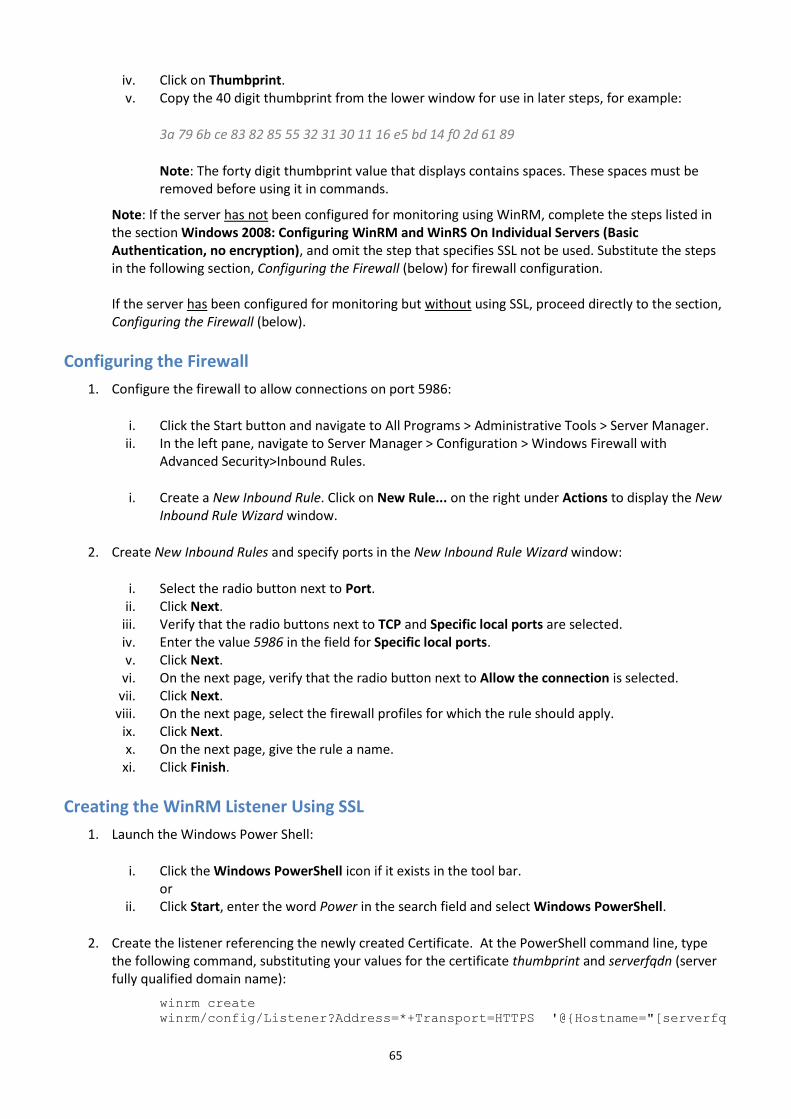
65
iv. Click on Thumbprint.v. Copy the 40 digit thumbprint from the lower window for use in later steps, for example:
3a 79 6b ce 83 82 85 55 32 31 30 11 16 e5 bd 14 f0 2d 61 89
Note: The forty digit thumbprint value that displays contains spaces. These spaces must be removed before using it in commands.
Note: If the server has not been configured for monitoring using WinRM, complete the steps listed in the section Windows 2008: Configuring WinRM and WinRS On Individual Servers (Basic Authentication, no encryption), and omit the step that specifies SSL not be used. Substitute the steps in the following section, Configuring the Firewall (below) for firewall configuration.
If the server has been configured for monitoring but without using SSL, proceed directly to the section, Configuring the Firewall (below).
Configuring the Firewall
1. Configure the firewall to allow connections on port 5986:
i. Click the Start button and navigate to All Programs > Administrative Tools > Server Manager.ii. In the left pane, navigate to Server Manager > Configuration > Windows Firewall with
Advanced Security>Inbound Rules.
i. Create a New Inbound Rule. Click on New Rule... on the right under Actions to display the NewInbound Rule Wizard window.
2. Create New Inbound Rules and specify ports in the New Inbound Rule Wizard window:
i. Select the radio button next to Port.ii. Click Next.
iii. Verify that the radio buttons next to TCP and Specific local ports are selected.iv. Enter the value 5986 in the field for Specific local ports.v. Click Next.
vi. On the next page, verify that the radio button next to Allow the connection is selected.vii. Click Next.
viii. On the next page, select the firewall profiles for which the rule should apply.ix. Click Next.x. On the next page, give the rule a name.
xi. Click Finish.
Creating the WinRM Listener Using SSL
1. Launch the Windows Power Shell:
i. Click the Windows PowerShell icon if it exists in the tool bar.or
ii. Click Start, enter the word Power in the search field and select Windows PowerShell.
2. Create the listener referencing the newly created Certificate. At the PowerShell command line, typethe following command, substituting your values for the certificate thumbprint and serverfqdn (serverfully qualified domain name):
winrm create
winrm/config/Listener?Address=*+Transport=HTTPS '@{Hostname="[serverfq
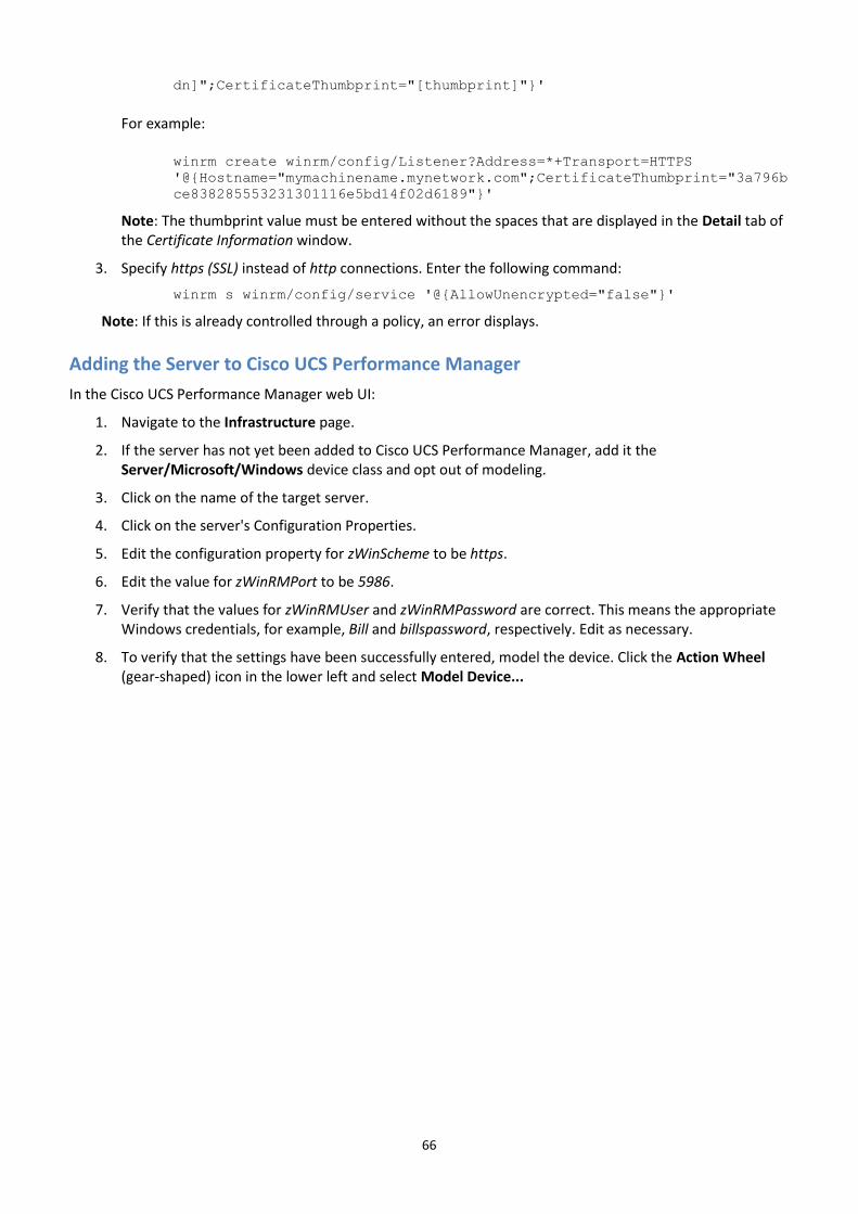
66
dn]";CertificateThumbprint="[thumbprint]"}'
For example:
winrm create winrm/config/Listener?Address=*+Transport=HTTPS
'@{Hostname="mymachinename.mynetwork.com";CertificateThumbprint="3a796b
ce838285553231301116e5bd14f02d6189"}'
Note: The thumbprint value must be entered without the spaces that are displayed in the Detail tab of the Certificate Information window.
3. Specify https (SSL) instead of http connections. Enter the following command:
winrm s winrm/config/service '@{AllowUnencrypted="false"}'
Note: If this is already controlled through a policy, an error displays.
Adding the Server to Cisco UCS Performance Manager
In the Cisco UCS Performance Manager web UI:
1. Navigate to the Infrastructure page.
2. If the server has not yet been added to Cisco UCS Performance Manager, add it the Server/Microsoft/Windows device class and opt out of modeling.
3. Click on the name of the target server.
4. Click on the server's Configuration Properties.
5. Edit the configuration property for zWinScheme to be https.
6. Edit the value for zWinRMPort to be 5986.
7. Verify that the values for zWinRMUser and zWinRMPassword are correct. This means the appropriate Windows credentials, for example, Bill and billspassword, respectively. Edit as necessary.
8. To verify that the settings have been successfully entered, model the device. Click the Action Wheel (gear-shaped) icon in the lower left and select Model Device...
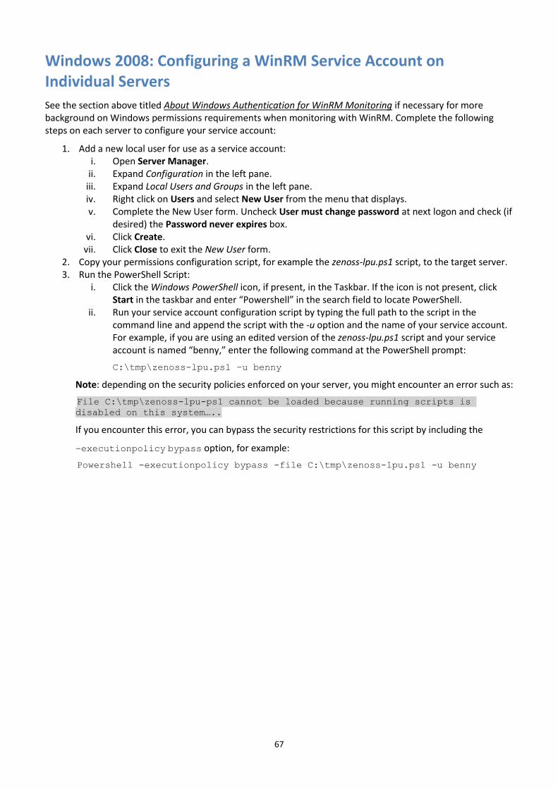
67
Windows 2008: Configuring a WinRM Service Account on Individual Servers
See the section above titled About Windows Authentication for WinRM Monitoring if necessary for more background on Windows permissions requirements when monitoring with WinRM. Complete the following steps on each server to configure your service account:
1. Add a new local user for use as a service account: i. Open Server Manager.
ii. Expand Configuration in the left pane. iii. Expand Local Users and Groups in the left pane. iv. Right click on Users and select New User from the menu that displays. v. Complete the New User form. Uncheck User must change password at next logon and check (if
desired) the Password never expires box. vi. Click Create.
vii. Click Close to exit the New User form. 2. Copy your permissions configuration script, for example the zenoss-lpu.ps1 script, to the target server. 3. Run the PowerShell Script:
i. Click the Windows PowerShell icon, if present, in the Taskbar. If the icon is not present, click Start in the taskbar and enter “Powershell” in the search field to locate PowerShell.
ii. Run your service account configuration script by typing the full path to the script in the command line and append the script with the -u option and the name of your service account. For example, if you are using an edited version of the zenoss-lpu.ps1 script and your service account is named “benny,” enter the following command at the PowerShell prompt:
C:\tmp\zenoss-lpu.ps1 –u benny
Note: depending on the security policies enforced on your server, you might encounter an error such as:
File C:\tmp\zenoss-lpu-ps1 cannot be loaded because running scripts is
disabled on this system…..
If you encounter this error, you can bypass the security restrictions for this script by including the
–executionpolicy bypass option, for example:
Powershell -executionpolicy bypass -file C:\tmp\zenoss-lpu.ps1 -u benny
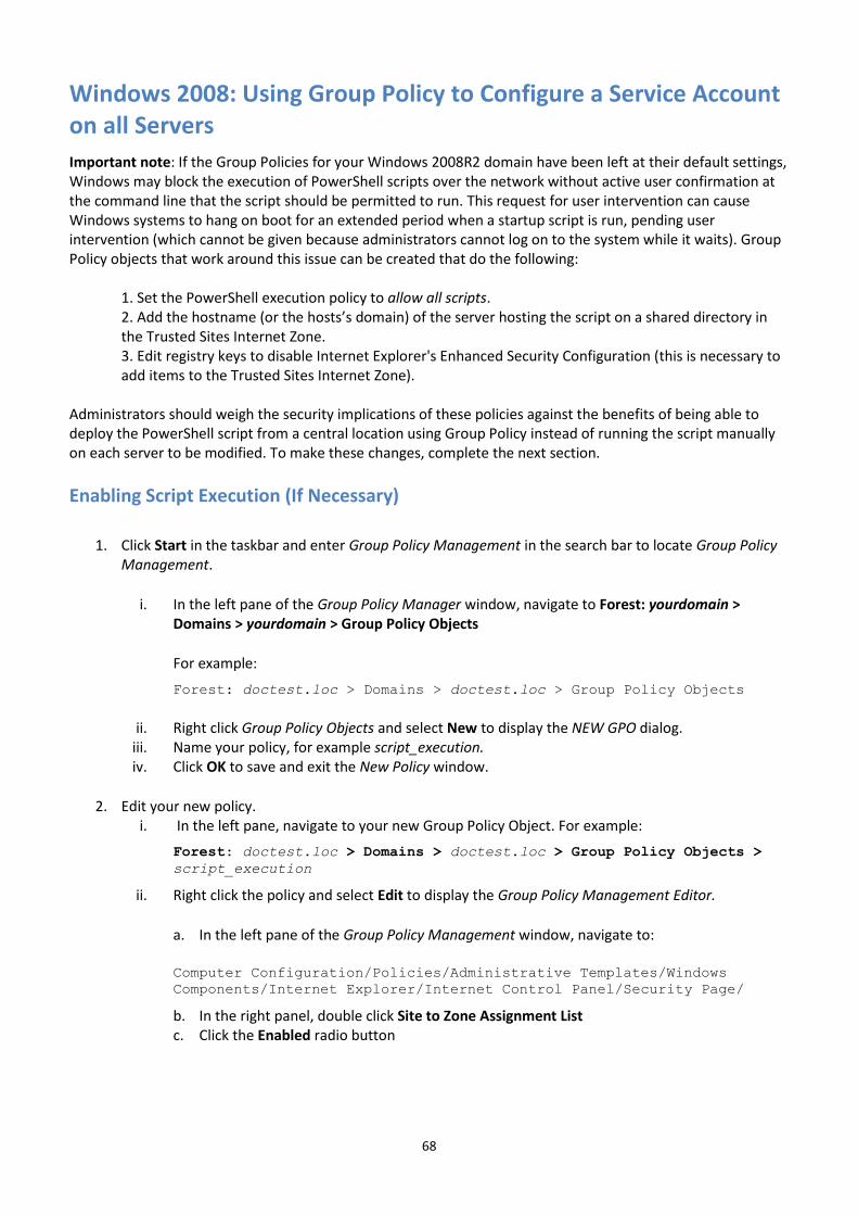
68
Windows 2008: Using Group Policy to Configure a Service Account on all Servers
Important note: If the Group Policies for your Windows 2008R2 domain have been left at their default settings, Windows may block the execution of PowerShell scripts over the network without active user confirmation at the command line that the script should be permitted to run. This request for user intervention can cause Windows systems to hang on boot for an extended period when a startup script is run, pending user intervention (which cannot be given because administrators cannot log on to the system while it waits). Group Policy objects that work around this issue can be created that do the following:
1. Set the PowerShell execution policy to allow all scripts. 2. Add the hostname (or the hosts’s domain) of the server hosting the script on a shared directory in the Trusted Sites Internet Zone. 3. Edit registry keys to disable Internet Explorer's Enhanced Security Configuration (this is necessary to add items to the Trusted Sites Internet Zone).
Administrators should weigh the security implications of these policies against the benefits of being able to deploy the PowerShell script from a central location using Group Policy instead of running the script manually on each server to be modified. To make these changes, complete the next section.
Enabling Script Execution (If Necessary)
1. Click Start in the taskbar and enter Group Policy Management in the search bar to locate Group Policy
Management.
i. In the left pane of the Group Policy Manager window, navigate to Forest: yourdomain > Domains > yourdomain > Group Policy Objects
For example:
Forest: doctest.loc > Domains > doctest.loc > Group Policy Objects
ii. Right click Group Policy Objects and select New to display the NEW GPO dialog. iii. Name your policy, for example script_execution. iv. Click OK to save and exit the New Policy window.
2. Edit your new policy. i. In the left pane, navigate to your new Group Policy Object. For example:
Forest: doctest.loc > Domains > doctest.loc > Group Policy Objects >
script_execution
ii. Right click the policy and select Edit to display the Group Policy Management Editor.
a. In the left pane of the Group Policy Management window, navigate to:
Computer Configuration/Policies/Administrative Templates/Windows
Components/Internet Explorer/Internet Control Panel/Security Page/
b. In the right panel, double click Site to Zone Assignment List c. Click the Enabled radio button
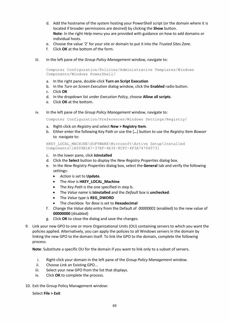
69
d. Add the hostname of the system hosting your PowerShell script (or the domain where it is located if broader permissions are desired) by clicking the Show button. Note: In the right Help menu you are provided with guidance on how to add domains or individual hosts.
e. Choose the value ‘2’ for your site or domain to put it into the Trusted Sites Zone. f. Click OK at the bottom of the form.
iii. In the left pane of the Group Policy Management window, navigate to:
Computer Configuration/Policies/Administrative Templates/Windows
Components/Windows PowerShell/
a. In the right pane, double-click Turn on Script Execution b. In the Turn on Screen Execution dialog window, click the Enabled radio button. c. Click OK d. In the dropdown list under Execution Policy, choose Allow all scripts. e. Click OK at the bottom.
iv. In the left pane of the Group Policy Management window, navigate to:
Computer Configuration/Preferences/Windows Settings/Registry/
a. Right-click on Registry and select New > Registry Item. b. Either enter the following Key Path or use the […] button to use the Registry Item Bowser
to navigate to:
HKEY_LOCAL_MACHINE\SOFTWARE\Microsoft\Active Setup\Installed
Components\{A509B1A7-37EF-4b3f-8CFC-4F3A74704073}
c. In the lower pane, click IsInstalled d. Click the Select button to display the New Registry Properties dialog box. e. In the New Registry Properties dialog box, select the General tab and verify the following
settings:
Action is set to Update.
The Hive is HKEY_LOCAL_Machine
The Key Path is the one specified in step b.
The Value name is IsInstalled and the Default box is unchecked.
The Value type is REG_DWORD
The checkbox for Base is set to Hexadecimal f. Change the Value data entry from the Default of 00000001 (enabled) to the new value of
00000000 (disabled) g. Click OK to close the dialog and save the changes.
9. Link your new GPO to one or more Organizational Units (OU) containing servers to which you want the policies applied. Alternatively, you can apply the policies to all Windows servers in the domain by linking the new GPO to the domain itself. To link the GPO to the domain, complete the following process.
Note: Substitute a specific OU for the domain if you want to link only to a subset of servers.
i. Right-click your domain in the left pane of the Group Policy Management window. ii. Choose Link an Existing GPO...
iii. Select your new GPO from the list that displays. iv. Click OK to complete the process.
10. Exit the Group Policy Management window:
Select File > Exit
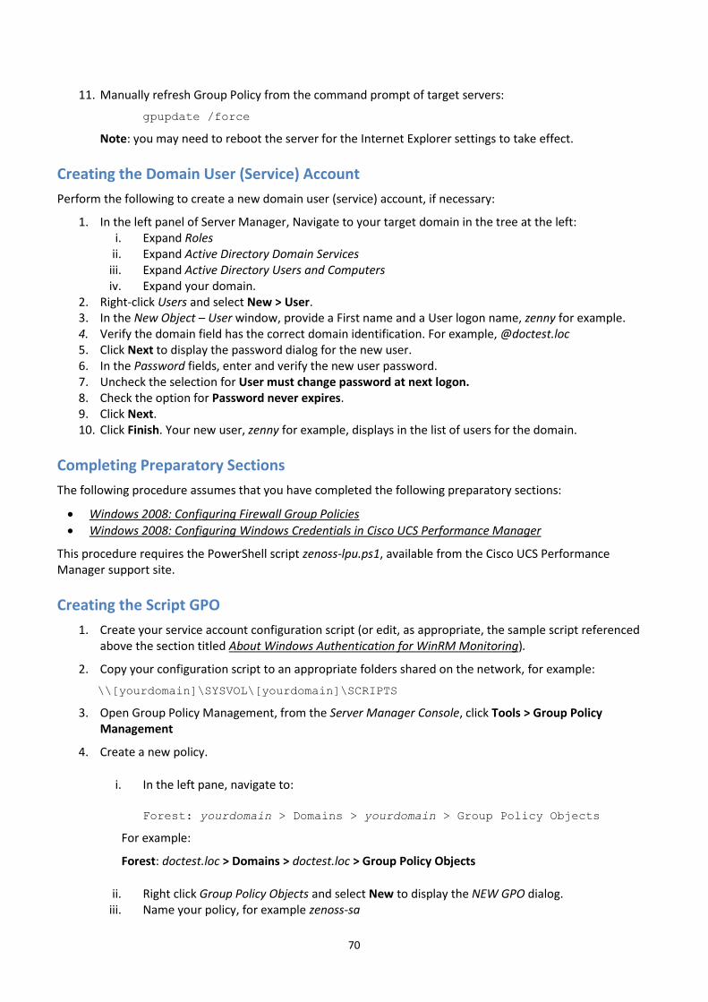
70
11. Manually refresh Group Policy from the command prompt of target servers:
gpupdate /force
Note: you may need to reboot the server for the Internet Explorer settings to take effect.
Creating the Domain User (Service) Account
Perform the following to create a new domain user (service) account, if necessary:
1. In the left panel of Server Manager, Navigate to your target domain in the tree at the left:i. Expand Roles
ii. Expand Active Directory Domain Servicesiii. Expand Active Directory Users and Computersiv. Expand your domain.
2. Right-click Users and select New > User.3. In the New Object – User window, provide a First name and a User logon name, zenny for example.4. Verify the domain field has the correct domain identification. For example, @doctest.loc5. Click Next to display the password dialog for the new user.6. In the Password fields, enter and verify the new user password.7. Uncheck the selection for User must change password at next logon.8. Check the option for Password never expires.9. Click Next.10. Click Finish. Your new user, zenny for example, displays in the list of users for the domain.
Completing Preparatory Sections
The following procedure assumes that you have completed the following preparatory sections:
Windows 2008: Configuring Firewall Group Policies
Windows 2008: Configuring Windows Credentials in Cisco UCS Performance Manager
This procedure requires the PowerShell script zenoss-lpu.ps1, available from the Cisco UCS Performance Manager support site.
Creating the Script GPO
1. Create your service account configuration script (or edit, as appropriate, the sample script referencedabove the section titled About Windows Authentication for WinRM Monitoring).
2. Copy your configuration script to an appropriate folders shared on the network, for example:
\\[yourdomain]\SYSVOL\[yourdomain]\SCRIPTS
3. Open Group Policy Management, from the Server Manager Console, click Tools > Group PolicyManagement
4. Create a new policy.
i. In the left pane, navigate to:
Forest: yourdomain > Domains > yourdomain > Group Policy Objects
For example:
Forest: doctest.loc > Domains > doctest.loc > Group Policy Objects
ii. Right click Group Policy Objects and select New to display the NEW GPO dialog.iii. Name your policy, for example zenoss-sa

71
iv. Click OK to save and exit the New Policy window.
5. Edit your new policy. In the left pane, navigate to your new Group Policy Object. For example:
Forest: doctest.loc > Domains > doctest.loc > Group Policy Objects > zenoss-sa
i. Right click the policy and select Edit to display the Group Policy Management Editor. ii. In the left pane of the Group Policy Management window, navigate to:
Computer Configuration\Policies\Windows Settings\Scripts
(Startup/Shutdown)
iii. Click Scripts (Startup/Shutdown). iv. In the right pane (Scripts (Startup/Shutdown), double-click Startup to launch the Startup
Properties dialog. v. In the Startup Properties dialog box, select the PowerShell Scripts tab.
vi. Click Add to display the Add a Script dialog box:
a. Specify the script name and path. In the Script Name field, enter the path to the script, or click Browse to locate the script file you copied in step 2 above.
b. Select the script and click Open.
c. In the Script Parameters box, enter the domain logon information for your service account
user in the form of: -u yourusername@yourdomain for a domain user or -u yourusername for a local user.
d. Click OK to save the information and exit the Add a Script window.
e. If you have multiple scripts and want them to run in a particular order, use the Up and
Down buttons in the Startup Properties window to set their run order.
f. Click OK to exit the Startup Properties window.
6. Exit the Local Group Policy Editor:
File > Exit
7. Link your new GPO to one or more Organizational Units (OU) containing servers to which you want the policies applied. Alternatively, you can apply the policies to all Windows servers in the domain by linking the new GPO to the domain itself. To link the GPO to the domain, complete the following process.
Note: Substitute a specific OU for the domain if you want to link only to a subset of servers.
i. Right-click your domain in the left pane of the Group Policy Management window. ii. Choose Link an Existing GPO...
iii. Select your new GPO from the list that displays. iv. Click OK to complete the process.
8. Exit the Group Policy Management window:
Select File > Exit

72
9. Manually refresh Group Policy from the command prompt of target servers:
gpupdate /force
10. Reboot your member servers to pick up the script changes.
ID: 2050.16.343