cisco ucs manager cli configuration guide, release 2 · cisco ucs manager cli configuration guide,...
TRANSCRIPT

Cisco UCS Manager CLI Configuration Guide, Release 2.1First Published: November 14, 2012
Last Modified: February 16, 2015
Americas HeadquartersCisco Systems, Inc.170 West Tasman DriveSan Jose, CA 95134-1706USAhttp://www.cisco.comTel: 408 526-4000 800 553-NETS (6387)Fax: 408 527-0883
Text Part Number: OL-28302-04
THE SPECIFICATIONS AND INFORMATION REGARDING THE PRODUCTS IN THIS MANUAL ARE SUBJECT TO CHANGE WITHOUT NOTICE. ALL STATEMENTS,INFORMATION, AND RECOMMENDATIONS IN THIS MANUAL ARE BELIEVED TO BE ACCURATE BUT ARE PRESENTED WITHOUT WARRANTY OF ANY KIND,EXPRESS OR IMPLIED. USERS MUST TAKE FULL RESPONSIBILITY FOR THEIR APPLICATION OF ANY PRODUCTS.
THE SOFTWARE LICENSE AND LIMITEDWARRANTY FOR THE ACCOMPANYING PRODUCT ARE SET FORTH IN THE INFORMATION PACKET THAT SHIPPED WITHTHE PRODUCT AND ARE INCORPORATED HEREIN BY THIS REFERENCE. IF YOU ARE UNABLE TO LOCATE THE SOFTWARE LICENSE OR LIMITED WARRANTY,CONTACT YOUR CISCO REPRESENTATIVE FOR A COPY.
The Cisco implementation of TCP header compression is an adaptation of a program developed by the University of California, Berkeley (UCB) as part of UCB's public domain versionof the UNIX operating system. All rights reserved. Copyright © 1981, Regents of the University of California.
NOTWITHSTANDINGANYOTHERWARRANTYHEREIN, ALL DOCUMENT FILES AND SOFTWARE OF THESE SUPPLIERS ARE PROVIDED “AS IS"WITH ALL FAULTS.CISCO AND THE ABOVE-NAMED SUPPLIERS DISCLAIM ALL WARRANTIES, EXPRESSED OR IMPLIED, INCLUDING, WITHOUT LIMITATION, THOSE OFMERCHANTABILITY, FITNESS FORA PARTICULAR PURPOSEANDNONINFRINGEMENTORARISING FROMACOURSEOFDEALING, USAGE, OR TRADE PRACTICE.
IN NO EVENT SHALL CISCO OR ITS SUPPLIERS BE LIABLE FOR ANY INDIRECT, SPECIAL, CONSEQUENTIAL, OR INCIDENTAL DAMAGES, INCLUDING, WITHOUTLIMITATION, LOST PROFITS OR LOSS OR DAMAGE TO DATA ARISING OUT OF THE USE OR INABILITY TO USE THIS MANUAL, EVEN IF CISCO OR ITS SUPPLIERSHAVE BEEN ADVISED OF THE POSSIBILITY OF SUCH DAMAGES.
Any Internet Protocol (IP) addresses and phone numbers used in this document are not intended to be actual addresses and phone numbers. Any examples, command display output, networktopology diagrams, and other figures included in the document are shown for illustrative purposes only. Any use of actual IP addresses or phone numbers in illustrative content is unintentionaland coincidental.
Cisco and the Cisco logo are trademarks or registered trademarks of Cisco and/or its affiliates in the U.S. and other countries. To view a list of Cisco trademarks, go to this URL: http://www.cisco.com/go/trademarks. Third-party trademarks mentioned are the property of their respective owners. The use of the word partner does not imply a partnershiprelationship between Cisco and any other company. (1110R)
© 2012-2015 Cisco Systems, Inc. All rights reserved.
C O N T E N T S
P r e f a c e Preface xxxiii
Audience xxxiii
Conventions xxxiii
Related Cisco UCS Documentation xxxv
Documentation Feedback xxxv
P A R T I Introduction 1
C H A P T E R 1 New and Changed Information 3
New and Changed Information for this Release 3
C H A P T E R 2 Overview of Cisco Unified Computing System 9
About Cisco Unified Computing System 9
Unified Fabric 10
Fibre Channel over Ethernet 11
Link-Level Flow Control 11
Priority Flow Control 11
Server Architecture and Connectivity 12
Overview of Service Profiles 12
Network Connectivity through Service Profiles 12
Configuration through Service Profiles 12
Service Profiles that Override Server Identity 13
Service Profiles that Inherit Server Identity 14
Service Profile Templates 15
Policies 15
Pools 15
Traffic Management 16
Cisco UCS Manager CLI Configuration Guide, Release 2.1 OL-28302-04 iii
Oversubscription 16
Oversubscription Considerations 16
Guidelines for Estimating Oversubscription 17
Pinning 18
Pinning Server Traffic to Server Ports 18
Guidelines for Pinning 19
Quality of Service 20
System Classes 20
Quality of Service Policy 21
Flow Control Policy 21
Opt-In Features 21
Stateless Computing 21
Multitenancy 22
Virtualization in Cisco UCS 23
Overview of Virtualization 23
Overview of Cisco Virtual Machine Fabric Extender 24
Virtualization with Network Interface Cards and Converged Network Adapters 24
Virtualization with a Virtual Interface Card Adapter 24
C H A P T E R 3 Overview of Cisco UCS Manager 25
About Cisco UCS Manager 25
Tasks You Can Perform in Cisco UCS Manager 26
Tasks You Cannot Perform in Cisco UCS Manager 28
Cisco UCS Manager in a High Availability Environment 28
C H A P T E R 4 Overview of Cisco UCS Manager CLI 29
Managed Objects 29
Command Modes 29
Object Commands 31
Complete a Command 32
Command History 32
Committing, Discarding, and Viewing Pending Commands 32
Online Help for the CLI 33
CLI Session Limits 33
Web Session Limits 33
Cisco UCS Manager CLI Configuration Guide, Release 2.1iv OL-28302-04
Contents
Setting the Web Session Limit for Cisco UCS Manager from the CLI 34
Pre-Login Banner 34
Creating the Pre-Login Banner 34
Modifying the Pre-Login Banner 35
Deleting the Pre-Login Banner 36
P A R T I I System Configuration 37
C H A P T E R 5 Configuring the Fabric Interconnects 39
Initial System Setup 39
Setup Mode 40
System Configuration Type 40
Management Port IP Address 40
Performing an Initial System Setup for a Standalone Configuration 41
Initial System Setup for a Cluster Configuration 43
Performing an Initial System Setup for the First Fabric Interconnect 43
Performing an Initial System Setup for the Second Fabric Interconnect 45
Enabling a Standalone Fabric Interconnect for Cluster Configuration 46
Changing the System Name 47
Changing the Management Subnet of a Cluster 47
Ethernet Switching Mode 48
Configuring Ethernet Switching Mode 49
Fibre Channel Switching Mode 50
Configuring Fibre Channel Switching Mode 50
C H A P T E R 6 Configuring Ports and Port Channels 53
Server and Uplink Ports on the 6100 Series Fabric Interconnect 53
Unified Ports on the 6200 Series Fabric Interconnect 54
Port Modes 55
Port Types 55
Beacon LEDs for Unified Ports 56
Guidelines for Configuring Unified Ports 56
Cautions and Guidelines for Configuring Unified Uplink Ports and Unified Storage
Ports 57
Effect of Port Mode Changes on Data Traffic 58
Cisco UCS Manager CLI Configuration Guide, Release 2.1 OL-28302-04 v
Contents
Configuring the Port Mode 59
Configuring the Beacon LEDs for Unified Ports 61
Server Ports 62
Configuring a Server Port 62
Unconfiguring a Server Port 62
Uplink Ethernet Ports 63
Configuring an Uplink Ethernet Port 63
Unconfiguring an Uplink Ethernet Port 64
Appliance Ports 64
Configuring an Appliance Port 64
Assigning a Target MAC Address to an Appliance Port or Appliance Port Channel 66
Creating an Appliance Port 67
Mapping an Appliance Port to a Community VLAN 68
Unconfiguring an Appliance Port 69
FCoE Uplink Ports 69
Configuring a FCoE Uplink Port 70
Unconfiguring a FCoE Uplink Port 70
Viewing FCoE Uplink Ports 71
Unified Storage Ports 71
Configuring a Unified Storage Port 72
Unified Uplink Ports 73
Configuring a Unified Uplink Port 73
FCoE and Fibre Channel Storage Ports 74
Configuring a Fibre Channel Storage or FCoE Port 74
Unconfiguring a Fibre Channel Storage or FCoE Port 74
Restoring a Fibre Channel Storage Port Back to an Uplink Fibre Channel Port 75
Uplink Ethernet Port Channels 75
Configuring an Uplink Ethernet Port Channel 76
Unconfiguring an Uplink Ethernet Port Channel 76
Adding a Member Port to an Uplink Ethernet Port Channel 77
Deleting a Member Port from an Uplink Ethernet Port Channel 78
Appliance Port Channels 78
Configuring an Appliance Port Channel 78
Unconfiguring an Appliance Port Channel 80
Enabling or Disabling an Appliance Port Channel 81
Cisco UCS Manager CLI Configuration Guide, Release 2.1vi OL-28302-04
Contents
Adding a Member Port to an Appliance Port Channel 81
Deleting a Member Port from an Appliance Port Channel 82
Fibre Channel Port Channels 82
Configuring a Fibre Channel Port Channel 83
Unconfiguring a Fibre Channel Port Channel 84
Enabling or Disabling a Fibre Channel Port Channel 84
Adding a Member Port to a Fibre Channel Port Channel 85
Deleting a Member Port from a Fibre Channel Port Channel 85
FCoE Port Channels 86
Configuring a FCoE Port Channel 86
Adding a Member Port to a FCoE Uplink Port Channel 87
Unified Uplink Port Channel 87
Configuring a Unified Uplink Port Channel 88
Adapter Port Channels 88
Viewing Adapter Port Channels 89
Fabric Port Channels 89
Cabling Considerations for Fabric Port Channels 90
Configuring a Fabric Port Channel 90
Viewing Fabric Port Channels 91
Enabling or Disabling a Fabric Port Channel Member Port 91
C H A P T E R 7 Configuring Communication Services 93
Communication Services 93
Configuring CIM XML 94
Configuring HTTP 95
Unconfiguring HTTP 96
Configuring HTTPS 96
Certificates, Key Rings, and Trusted Points 96
Creating a Key Ring 97
Regenerating the Default Key Ring 97
Creating a Certificate Request for a Key Ring 98
Creating a Certificate Request for a Key Ring with Basic Options 98
Creating a Certificate Request for a Key Ring with Advanced Options 99
Creating a Trusted Point 101
Importing a Certificate into a Key Ring 102
Cisco UCS Manager CLI Configuration Guide, Release 2.1 OL-28302-04 vii
Contents
Configuring HTTPS 103
Deleting a Key Ring 104
Deleting a Trusted Point 105
Unconfiguring HTTPS 105
Enabling HTTP Redirection 106
Configuring SNMP 106
Information about SNMP 106
SNMP Functional Overview 106
SNMP Notifications 107
SNMP Security Levels and Privileges 107
Supported Combinations of SNMP Security Models and Levels 108
SNMPv3 Security Features 109
SNMP Support in Cisco UCS 109
Enabling SNMP and Configuring SNMP Properties 110
Creating an SNMP Trap 111
Deleting an SNMP Trap 112
Creating an SNMPv3 User 112
Deleting an SNMPv3 User 113
Enabling Telnet 114
Disabling Communication Services 114
C H A P T E R 8 Configuring Authentication 117
Authentication Services 117
Guidelines and Recommendations for Remote Authentication Providers 118
User Attributes in Remote Authentication Providers 118
LDAP Group Rule 120
Nested LDAP Groups 120
Configuring LDAP Providers 120
Configuring Properties for LDAP Providers 120
Creating an LDAP Provider 121
Changing the LDAP Group Rule for an LDAP Provider 125
Deleting an LDAP Provider 126
LDAP Group Mapping 126
Creating an LDAP Group Map 127
Deleting an LDAP Group Map 128
Cisco UCS Manager CLI Configuration Guide, Release 2.1viii OL-28302-04
Contents
Configuring RADIUS Providers 128
Configuring Properties for RADIUS Providers 128
Creating a RADIUS Provider 129
Deleting a RADIUS Provider 131
Configuring TACACS+ Providers 131
Configuring Properties for TACACS+ Providers 131
Creating a TACACS+ Provider 132
Deleting a TACACS+ Provider 133
Configuring Multiple Authentication Systems 134
Multiple Authentication Systems 134
Provider Groups 135
Creating an LDAP Provider Group 135
Deleting an LDAP Provider Group 136
Creating a RADIUS Provider Group 137
Deleting a RADIUS Provider Group 138
Creating a TACACS Provider Group 138
Deleting a TACACS Provider Group 139
Authentication Domains 140
Creating an Authentication Domain 140
Selecting a Primary Authentication Service 142
Selecting the Console Authentication Service 142
Selecting the Default Authentication Service 143
Role Policy for Remote Users 144
Configuring the Role Policy for Remote Users 144
C H A P T E R 9 Configuring Organizations 147
Organizations in a Multitenancy Environment 147
Hierarchical Name Resolution in a Multi-Tenancy Environment 148
Configuring an Organization Under the Root Organization 150
Configuring an Organization Under an Organization that is not Root 150
Deleting an Organization 151
C H A P T E R 1 0 Configuring Role-Based Access Control 153
Role-Based Access Control 153
User Accounts for Cisco UCS 153
Cisco UCS Manager CLI Configuration Guide, Release 2.1 OL-28302-04 ix
Contents
Guidelines for Cisco UCS Usernames 154
Reserved Words: Locally Authenticated User Accounts 155
Guidelines for Cisco UCS Passwords 156
Web Session Limits for User Accounts 156
User Roles 156
Default User Roles 157
Reserved Words: User Roles 158
Privileges 158
User Locales 160
Configuring User Roles 161
Creating a User Role 161
Adding Privileges to a User Role 162
Replacing Privileges for a User Role 162
Removing Privileges from a User Role 163
Deleting a User Role 163
Configuring Locales 164
Creating a Locale 164
Assigning an Organization to a Locale 164
Deleting an Organization from a Locale 165
Deleting a Locale 166
Configuring Locally Authenticated User Accounts 166
Creating a User Account 166
Enabling the Password Strength Check for Locally Authenticated Users 168
Setting Web Session Limits for User Accounts 169
Assigning a Role to a User Account 169
Assigning a Locale to a User Account 170
Removing a Role from a User Account 171
Removing a Locale from a User Account 171
Enabling or Disabling a User Account 172
Clearing the Password History for a Locally Authenticated User 173
Deleting a User Account 173
Password Profile for Locally Authenticated Users 174
Configuring the Maximum Number of Password Changes for a Change Interval 175
Configuring a No Change Interval for Passwords 176
Configuring the Password History Count 176
Cisco UCS Manager CLI Configuration Guide, Release 2.1x OL-28302-04
Contents
Monitoring User Sessions 177
C H A P T E R 1 1 Configuring DNS Servers 179
DNS Servers in Cisco UCS 179
Configuring a DNS Server 179
Deleting a DNS Server 180
C H A P T E R 1 2 Configuring System-Related Policies 181
Configuring the Chassis/FEX Discovery Policy 181
Chassis/FEX Discovery Policy 181
Configuring the Chassis/FEX Discovery Policy 184
Configuring the Chassis Connectivity Policy 185
Chassis Connectivity Policy 185
Configuring a Chassis Connectivity Policy 186
Configuring the Rack Server Discovery Policy 187
Rack Server Discovery Policy 187
Configuring the Rack Server Discovery Policy 187
Configuring the Aging Time for the MAC Address Table 188
Aging Time for the MAC Address Table 188
Configuring the Aging Time for the MAC Address Table 188
C H A P T E R 1 3 Managing Licenses 189
Licenses 189
Obtaining the Host ID for a Fabric Interconnect 190
Obtaining a License 191
Installing a License 192
Viewing the Licenses Installed on a Fabric Interconnect 192
Viewing License Usage for a Fabric Interconnect 193
Uninstalling a License 195
C H A P T E R 1 4 Managing Virtual Interfaces 197
Virtual Interfaces 197
Virtual Interface Subscription Management and Error Handling 197
C H A P T E R 1 5 Registering Cisco UCS Domains with Cisco UCS Central 199
Cisco UCS Manager CLI Configuration Guide, Release 2.1 OL-28302-04 xi
Contents
Registration of Cisco UCS Domains 199
Policy Resolution between Cisco UCS Manager and Cisco UCS Central 200
Registering a Cisco UCS Domain with Cisco UCS Central 201
Configuring Policy Resolution between Cisco UCS Manager and Cisco UCS Central 202
Unregistering a Cisco UCS Domain from Cisco UCS Central 203
P A R T I I I Network Configuration 205
C H A P T E R 1 6 Configuring VLANs 207
Named VLANs 207
Private VLANs 208
VLAN Port Limitations 209
Configuring Named VLANs 210
Creating a Named VLAN Accessible to Both Fabric Interconnects (Uplink Ethernet
Mode) 210
Creating a Named VLAN Accessible to Both Fabric Interconnects (Ethernet Storage
Mode) 211
Creating a Named VLAN Accessible to One Fabric Interconnect (Uplink Ethernet
Mode) 212
Creating a Named VLAN Accessible to One Fabric Interconnect (Ethernet Storage
Mode) 213
Deleting a Named VLAN 214
Configuring Private VLANs 215
Creating a Primary VLAN for a Private VLAN (Accessible to Both Fabric
Interconnects) 215
Creating a Primary VLAN for a Private VLAN (Accessible to One Fabric
Interconnect) 216
Creating a Secondary VLAN for a Private VLAN (Accessible to Both Fabric
Interconnects) 216
Creating a Secondary VLAN for a Private VLAN (Accessible to One Fabric
Interconnect) 217
Viewing the VLAN Port Count 218
VLAN Port Count Optimization 219
Enabling Port VLAN Count Optimization 219
Disabling Port VLAN Count Optimization 219
Cisco UCS Manager CLI Configuration Guide, Release 2.1xii OL-28302-04
Contents
Viewing the Port VLAN Count Optimization Groups 220
VLAN Groups 220
Creating a VLAN Group 221
Deleting a VLAN Group 221
Viewing VLAN Groups 222
VLAN Permissions 222
Creating VLAN Permissions 223
Deleting a VLAN Permission 223
Viewing VLAN Permissions 224
C H A P T E R 1 7 Configuring LAN Pin Groups 225
LAN Pin Groups 225
Configuring a LAN Pin Group 225
C H A P T E R 1 8 Configuring MAC Pools 227
MAC Pools 227
Creating a MAC Pool 227
Deleting a MAC Pool 229
C H A P T E R 1 9 Configuring Quality of Service 231
Quality of Service 231
Configuring System Classes 231
System Classes 231
Configuring a System Class 232
Disabling a System Class 233
Configuring Quality of Service Policies 234
Quality of Service Policy 234
Configuring a QoS Policy 234
Deleting a QoS Policy 236
Configuring Flow Control Policies 237
Flow Control Policy 237
Configuring a Flow Control Policy 237
Deleting a Flow Control Policy 238
C H A P T E R 2 0 Configuring Network-Related Policies 241
Cisco UCS Manager CLI Configuration Guide, Release 2.1 OL-28302-04 xiii
Contents
Configuring vNIC Templates 241
vNIC Template 241
Configuring a vNIC Template 242
Deleting a vNIC Template 244
Configuring Ethernet Adapter Policies 244
Ethernet and Fibre Channel Adapter Policies 244
Configuring an Ethernet Adapter Policy 245
Configuring an Ethernet Adapter Policy to Enable eNIC Support for MRQS on Linux
Operating Systems 247
Deleting an Ethernet Adapter Policy 247
Configuring the Default vNIC Behavior Policy 248
Default vNIC Behavior Policy 248
Configuring a Default vNIC Behavior Policy 248
Configuring LAN Connectivity Policies 249
LAN and SAN Connectivity Policies 249
Privileges Required for LAN and SAN Connectivity Policies 249
Interactions between Service Profiles and Connectivity Policies 250
Creating a LAN Connectivity Policy 250
Creating a vNIC for a LAN Connectivity Policy 251
Deleting a vNIC from a LAN Connectivity Policy 253
Creating an iSCSI vNIC for a LAN Connectivity Policy 254
Deleting an iSCSI vNIC from a LAN Connectivity Policy 256
Deleting a LAN Connectivity Policy 256
Configuring Network Control Policies 257
Network Control Policy 257
Configuring a Network Control Policy 258
Deleting a Network Control Policy 259
Configuring Multicast Policies 259
Multicast Policy 259
Creating a Multicast Policy 260
Configuring IGMP Snooping Parameters 260
Modifying Multicast Policy Parameters 261
Assigning a VLAN Multicast Policy 262
Deleting a Multicast Policy 263
Cisco UCS Manager CLI Configuration Guide, Release 2.1xiv OL-28302-04
Contents
C H A P T E R 2 1 Configuring Upstream Disjoint Layer-2 Networks 265
Upstream Disjoint Layer-2 Networks 265
Guidelines for Configuring Upstream Disjoint L2 Networks 266
Pinning Considerations for Upstream Disjoint L2 Networks 267
Configuring Cisco UCS for Upstream Disjoint L2 Networks 269
Assigning Ports and Port Channels to VLANs 270
Removing Ports and Port Channels from VLANs 270
Viewing Ports and Port Channels Assigned to VLANs 271
P A R T I V Storage Configuration 273
C H A P T E R 2 2 Configuring Named VSANs 275
Named VSANs 275
Fibre Channel Uplink Trunking for Named VSANs 276
Guidelines and Recommendations for VSANs 276
Creating a Named VSAN Accessible to Both Fabric Interconnects (Fibre Channel Uplink
Mode) 278
Creating a Named VSAN Accessible to Both Fabric Interconnects (Fibre Channel Storage
Mode) 279
Creating a Named VSAN Accessible to One Fabric Interconnect (Fibre Channel Uplink
Mode) 280
Creating a Named VSAN Accessible to One Fabric Interconnect (Fibre Channel Storage
Mode) 281
Deleting a Named VSAN 282
Changing the VLAN ID for the FCoE Native VLAN for a Named VSAN 283
Changing the VLAN ID for the FCoE Native VLAN for a Storage VSAN 283
Enabling or Disabling Fibre Channel Uplink Trunking 284
C H A P T E R 2 3 Configuring SAN Pin Groups 285
SAN Pin Groups 285
Configuring a SAN Pin Group 285
Configuring a FCoE Pin Group 286
C H A P T E R 2 4 Configuring WWN Pools 289
Cisco UCS Manager CLI Configuration Guide, Release 2.1 OL-28302-04 xv
Contents
WWN Pools 289
Creating a WWN Pool 290
Deleting a WWN Pool 292
C H A P T E R 2 5 Configuring Storage-Related Policies 295
Configuring vHBA Templates 295
vHBA Template 295
Configuring a vHBA Template 295
Deleting a vHBA Template 297
Configuring Fibre Channel Adapter Policies 297
Ethernet and Fibre Channel Adapter Policies 297
Configuring a Fibre Channel Adapter Policy 298
Deleting a Fibre Channel Adapter Policy 300
Configuring the Default vHBA Behavior Policy 300
Default vHBA Behavior Policy 300
Configuring a Default vHBA Behavior Policy 301
Configuring SAN Connectivity Policies 301
LAN and SAN Connectivity Policies 301
Privileges Required for LAN and SAN Connectivity Policies 302
Interactions between Service Profiles and Connectivity Policies 302
Creating a SAN Connectivity Policy 302
Creating a vHBA for a SAN Connectivity Policy 304
Deleting a vHBA from a SAN Connectivity Policy 306
Creating an Initiator Group for a SAN Connectivity Policy 306
Deleting an Initiator Group from a SAN Connectivity Policy 309
Deleting a SAN Connectivity Policy 310
C H A P T E R 2 6 Configuring Fibre Channel Zoning 311
Information About Fibre Channel Zoning 311
Information About Zones 311
Information About Zone Sets 312
Support for Fibre Channel Zoning in Cisco UCS Manager 312
Cisco UCS Manager-Based Fibre Channel Zoning 312
vHBA Initiator Groups 313
Fibre Channel Storage Connection Policy 313
Cisco UCS Manager CLI Configuration Guide, Release 2.1xvi OL-28302-04
Contents
Fibre Channel Active Zone Set Configuration 313
Switch-Based Fibre Channel Zoning 314
Guidelines and recommendations for Cisco UCS Manager-Based Fibre Channel Zoning 314
Configuring Fibre Channel Zoning in Cisco UCS 314
Removing Unmanaged Zones from a VSAN Accessible to Both Fabric Interconnects 315
Removing Unmanaged Zones from a VSAN Accessible to One Fabric Interconnect 316
Configuring Fibre Channel Storage Connection Policies 317
Creating a Fibre Channel Storage Connection Policy 317
Deleting a Fibre Channel Storage Connection Policy 318
C H A P T E R 2 7 Configuring FlexFlash SD Card Support 321
FlexFlash Secure Digital Card Support 321
Limitations Related to FlexFlash 322
Enabling FlexFlash SD Card Support 322
P A R T V Server Configuration 325
C H A P T E R 2 8 Configuring Server-Related Pools 327
Server Pool Configuration 327
Server Pools 327
Creating a Server Pool 327
Deleting a Server Pool 328
UUID Suffix Pool Configuration 329
UUID Suffix Pools 329
Creating a UUID Suffix Pool 329
Deleting a UUID Suffix Pool 330
IP Pool Configuration 331
IP Pools 331
Creating an IP Pool 331
Adding a Block to an IP Pool 333
Deleting a Block from an IP Pool 333
Deleting an IP Pool 334
C H A P T E R 2 9 Setting the Management IP Address 337
Management IP Address 337
Cisco UCS Manager CLI Configuration Guide, Release 2.1 OL-28302-04 xvii
Contents
Configuring the Management IP Address on a Blade Server 338
Configuring a Blade Server to Use a Static IP Address 338
Configuring a Blade Server to Use the Management IP Pool 339
Configuring the Management IP Address on a Rack Server 339
Configuring a Rack Server to Use a Static IP Address 339
Configuring a Rack Server to Use the Management IP Pool 340
Setting the Management IP Address on a Service Profile or Service Profile Template 341
Configuring the Management IP Pool 342
Management IP Pool 342
Configuring an IP Address Block for the Management IP Pool 342
Deleting an IP Address Block from the Management IP Pool 343
C H A P T E R 3 0 Configuring Server-Related Policies 345
Configuring BIOS Settings 345
Server BIOS Settings 345
Main BIOS Settings 346
Processor BIOS Settings 347
Intel Directed I/O BIOS Settings 352
RAS Memory BIOS Settings 354
Serial Port BIOS Settings 356
USB BIOS Settings 356
PCI Configuration BIOS Settings 357
Boot Options BIOS Settings 358
Server Management BIOS Settings 359
BIOS Policy 364
Default BIOS Settings 364
Creating a BIOS Policy 364
Modifying BIOS Defaults 365
Viewing the Actual BIOS Settings for a Server 367
Configuring IPMI Access Profiles 368
IPMI Access Profile 368
Configuring an IPMI Access Profile 368
Deleting an IPMI Access Profile 369
Adding an Endpoint User to an IPMI Access Profile 370
Deleting an Endpoint User from an IPMI Access Profile 371
Cisco UCS Manager CLI Configuration Guide, Release 2.1xviii OL-28302-04
Contents
Configuring Local Disk Configuration Policies 371
Local Disk Configuration Policy 371
Guidelines for all Local Disk Configuration Policies 372
Guidelines for Local Disk Configuration Policies Configured for RAID 372
Creating a Local Disk Configuration Policy 374
Viewing a Local Disk Configuration Policy 375
Deleting a Local Disk Configuration Policy 376
Configuring Scrub Policies 377
Scrub Policy 377
Creating a Scrub Policy 377
Deleting a Scrub Policy 378
Configuring Serial over LAN Policies 379
Serial over LAN Policy 379
Configuring a Serial over LAN Policy 379
Viewing a Serial over LAN Policy 380
Deleting a Serial over LAN Policy 380
Configuring Server Autoconfiguration Policies 381
Server Autoconfiguration Policy 381
Configuring a Server Autoconfiguration Policy 381
Deleting a Server Autoconfiguration Policy 382
Configuring Server Discovery Policies 383
Server Discovery Policy 383
Configuring a Server Discovery Policy 383
Deleting a Server Discovery Policy 384
Configuring Server Inheritance Policies 385
Server Inheritance Policy 385
Configuring a Server Inheritance Policy 385
Deleting a Server Inheritance Policy 386
Configuring Server Pool Policies 386
Server Pool Policy 386
Configuring a Server Pool Policy 387
Deleting a Server Pool Policy 387
Configuring Server Pool Policy Qualifications 388
Server Pool Policy Qualifications 388
Creating a Server Pool Policy Qualification 389
Cisco UCS Manager CLI Configuration Guide, Release 2.1 OL-28302-04 xix
Contents
Deleting a Server Pool Policy Qualification 389
Creating an Adapter Qualification 390
Deleting an Adapter Qualification 391
Configuring a Chassis Qualification 392
Deleting a Chassis Qualification 392
Creating a CPU Qualification 393
Deleting a CPU Qualification 394
Creating a Power Group Qualification 395
Deleting a Power Group Qualification 395
Creating a Memory Qualification 396
Deleting a Memory Qualification 397
Creating a Physical Qualification 397
Deleting a Physical Qualification 398
Creating a Storage Qualification 399
Deleting a Storage Qualification 400
Configuring vNIC/vHBA Placement Policies 400
vNIC/vHBA Placement Policies 400
vCon to Adapter Placement 401
vCon to Adapter Placement for N20-B6620-2 and N20-B6625-2 Blade
Servers 401
vCon to Adapter Placement for All Other Supported Servers 402
vNIC/vHBA to vCon Assignment 403
Configuring a vNIC/vHBA Placement Policy 405
Deleting a vNIC/vHBA Placement Policy 407
Explicitly Assigning a vNIC to a vCon 407
Explicitly Assigning a vHBA to a vCon 408
Placing Static vNICs Before Dynamic vNICs 409
C H A P T E R 3 1 Configuring Server Boot 413
Boot Policy 413
Creating a Boot Policy 414
SAN Boot 415
Configuring a SAN Boot for a Boot Policy 416
iSCSI Boot 418
iSCSI Boot Process 418
Cisco UCS Manager CLI Configuration Guide, Release 2.1xx OL-28302-04
Contents
iSCSI Boot Guidelines and Prerequisites 419
Initiator IQN Configuration 420
Enabling MPIO on Windows 420
Configuring iSCSI Boot 421
Creating an iSCSI Adapter Policy 422
Deleting an iSCSI Adapter Policy 424
Creating an Authentication Profile 424
Deleting an Authentication Profile 425
Adding a Block of IP Addresses to the Initiator Pool 426
Deleting a Block of IP Addresses from the Initiator Pool 427
Creating an iSCSI Boot Policy 427
Deleting iSCSI Devices from a Boot Policy 430
Setting an Initiator IQN at the Service Profile Level 430
Creating an iSCSI vNIC in a Service Profile 431
Deleting an iSCSI vNIC from a Service Profile 433
Creating an iSCSI Initiator that Boots Using a Static IP Address 433
Deleting the Static IP Address Boot Parameters from an iSCSI Initiator 435
Creating an iSCSI Initiator that Boots Using an IP Address from an IP Pool 435
Deleting the IP Pool Boot Parameter from an iSCSI Initiator 437
Creating an iSCSI Initiator that Boots Using DHCP 437
Deleting the DHCP Boot Parameter from an iSCSI Initiator 438
IQN Pools 439
Creating an IQN Pool 440
Adding a Block to an IQN Pool 441
Deleting a Block from an IQN Pool 442
Deleting an IQN Pool 442
Viewing IQN Pool Usage 443
Creating an iSCSI Static Target 444
Deleting an iSCSI Static Target 446
Creating an iSCSI Auto Target 447
Deleting an iSCSI Auto Target 448
Verifying iSCSI Boot 449
LAN Boot 449
Configuring a LAN Boot for a Boot Policy 449
Local Disk Boot 450
Cisco UCS Manager CLI Configuration Guide, Release 2.1 OL-28302-04 xxi
Contents
Configuring a Local Disk Boot for a Boot Policy 451
Virtual Media Boot 452
Configuring a Virtual Media Boot for a Boot Policy 452
Deleting a Boot Policy 453
C H A P T E R 3 2 Deferring Deployment of Service Profile Updates 455
Deferred Deployment of Service Profiles 455
Deferred Deployment Schedules 456
Maintenance Policy 456
Pending Activities 457
Guidelines and Limitations for Deferred Deployment 457
Configuring Schedules 458
Creating a Schedule 458
Creating a One Time Occurrence for a Schedule 459
Creating a Recurring Occurrence for a Schedule 460
Deleting a One Time Occurrence from a Schedule 461
Deleting a Recurring Occurrence from a Schedule 462
Deleting a Schedule 462
Configuring Maintenance Policies 463
Creating a Maintenance Policy 463
Deleting a Maintenance Policy 464
Managing Pending Activities 464
Viewing Pending Activities 464
Deploying a Service Profile Change Waiting for User Acknowledgement 465
Deploying a Scheduled Service Profile Change Immediately 465
C H A P T E R 3 3 Configuring Service Profiles 467
Service Profiles that Override Server Identity 467
Service Profiles that Inherit Server Identity 468
Guidelines and Recommendations for Service Profiles 468
Service Profile Templates 469
Creating a Service Profile Template 470
Creating a Service Profile Instance from a Service Profile Template 473
Creating a Hardware-Based Service Profile 474
Configuring a vNIC for a Service Profile 477
Cisco UCS Manager CLI Configuration Guide, Release 2.1xxii OL-28302-04
Contents
Configuring a vHBA for a Service Profile 479
Configuring a Local Disk for a Service Profile 480
Configuring Serial over LAN for a Service Profile 482
Service Profile Boot Definition Configuration 483
Configuring a Boot Definition for a Service Profile 483
Configuring a LAN Boot for a Service Profile Boot Definition 484
Configuring a Storage Boot for a Service Profile Boot Definition 485
Configuring a Virtual Media Boot for a Service Profile Boot Definition 486
Deleting a Boot Definition for a Service Profile 487
Configuring Fibre Channel Zoning for a Service Profile 488
Configuring a vHBA Initiator Group with an Existing Storage Connection Policy 488
Configuring a vHBA Initiator Group with a local Storage Connection Policy
Definition 489
Service Profiles and Service Profile Template Management 490
Associating a Service Profile with a Blade Server or Server Pool 490
Associating a Service Profile with a Rack Server 491
Disassociating a Service Profile from a Server or Server Pool 492
Renaming a Service Profile 492
Resetting the UUID Assigned to a Service Profile from a Pool in a Service Profile
Template 493
Resetting the MAC Address Assigned to a vNIC from a Pool in a Service Profile
Template 494
Resetting the WWPN Assigned to a vHBA from a Pool in a Service Profile Template 495
C H A P T E R 3 4 Managing Power in Cisco UCS 497
Power Management in Cisco UCS 497
Rack Server Power Management 497
Power Management Precautions 497
Configuring the Power Policy 498
Power Policy 498
Configuring the Power Policy 498
Configuring the Global Cap Policy 499
Global Cap Policy 499
Configuring the Global Cap Policy 499
Configuring Policy-Driven Chassis Group Power Capping 499
Cisco UCS Manager CLI Configuration Guide, Release 2.1 OL-28302-04 xxiii
Contents
Policy-Driven Chassis Group Power Capping 499
Power Groups 500
Creating a Power Group 501
Deleting a Power Group 502
Power Control Policy 502
Creating a Power Control Policy 503
Deleting a Power Control Policy 503
Configuring Manual Blade-Level Power Capping 504
Manual Blade-Level Power Capping 504
Setting the Blade-Level Power Cap for a Server 504
Viewing the Blade-Level Power Cap 505
P A R T V I System Management 507
C H A P T E R 3 5 Managing Time Zones 509
Time Zones 509
Setting the Time Zone 509
Adding an NTP Server 511
Deleting an NTP Server 512
Setting the System Clock Manually 512
C H A P T E R 3 6 Managing the Chassis 513
Guidelines for Removing and Decommissioning Chassis 513
Acknowledging a Chassis 514
Decommissioning a Chassis 514
Removing a Chassis 515
Recommissioning a Chassis 515
Renumbering a Chassis 516
Toggling the Locator LED 518
Turning On the Locator LED for a Chassis 518
Turning Off the Locator LED for a Chassis 518
C H A P T E R 3 7 Managing Blade Servers 519
Blade Server Management 519
Guidelines for Removing and Decommissioning Blade Servers 520
Cisco UCS Manager CLI Configuration Guide, Release 2.1xxiv OL-28302-04
Contents
Recommendations for Avoiding Unexpected Server Power Changes 520
Booting a Blade Server 521
Shutting Down a Blade Server 522
Power Cycling a Blade Server 523
Performing a Hard Reset on a Blade Server 523
Acknowledging a Blade Server 524
Removing a Blade Server from a Chassis 524
Decommissioning a Blade Server 525
Turning On the Locator LED for a Blade Server 525
Turning Off the Locator LED for a Blade Server 526
Resetting the CMOS for a Blade Server 526
Resetting the CIMC for a Blade Server 527
Recovering the Corrupt BIOS on a Blade Server 527
Issuing an NMI from a Blade Server 528
Health LED Alarms 529
Viewing Health LED Status 529
C H A P T E R 3 8 Managing Rack-Mount Servers 531
Rack-Mount Server Management 531
Guidelines for Removing and Decommissioning Rack-Mount Servers 532
Recommendations for Avoiding Unexpected Server Power Changes 532
Booting a Rack-Mount Server 533
Shutting Down a Rack-Mount Server 534
Power Cycling a Rack-Mount Server 535
Performing a Hard Reset on a Rack-Mount Server 535
Acknowledging a Rack-Mount Server 536
Decommissioning a Rack-Mount Server 536
Renumbering a Rack-Mount Server 537
Removing a Rack-Mount Server 538
Turning On the Locator LED for a Rack-Mount Server 539
Turning Off the Locator LED for a Rack-Mount Server 539
Resetting the CMOS for a Rack-Mount Server 540
Resetting the CIMC for a Rack-Mount Server 540
Recovering the Corrupt BIOS on a Rack-Mount Server 541
Showing the Status for a Rack-Mount Server 541
Cisco UCS Manager CLI Configuration Guide, Release 2.1 OL-28302-04 xxv
Contents
Issuing an NMI from a Rack-Mount Server 542
C H A P T E R 3 9 CIMC Session Management 543
CIMC Session Management 543
Viewing the CIMC Sessions Opened by the Local Users 544
Viewing the CIMC Sessions Opened by the Remote Users 545
Viewing the CIMC Sessions Opened by an IPMI User 546
Clearing the CIMC Sessions of a Server 546
Clearing All CIMC Sessions Opened by a Local User 547
Clearing All CIMC Sessions Opened by a Remote User 548
Clearing a Specific CIMC Session Opened by a Local User 548
Clearing a Specific CIMC Session Opened by a Remote User 549
Clearing a CIMC Session Opened by an IPMI User 549
C H A P T E R 4 0 Managing the I/O Modules 551
I/O Module Management in Cisco UCS Manager GUI 551
Resetting the I/O Module 551
C H A P T E R 4 1 Backing Up and Restoring the Configuration 553
Backup and Export Configuration 553
Backup Types 553
Considerations and Recommendations for Backup Operations 554
Scheduled Backups 555
Full State Backup Policy 555
All Configuration Export Policy 555
Import Configuration 555
Import Methods 556
System Restore 556
Required User Role for Backup and Import Operations 556
Configuring Backup Operations 557
Creating a Backup Operation 557
Running a Backup Operation 558
Modifying a Backup Operation 558
Deleting a Backup Operation 561
Configuring Scheduled Backups 561
Cisco UCS Manager CLI Configuration Guide, Release 2.1xxvi OL-28302-04
Contents
Configuring the Full State Backup Policy 561
Configuring the All Configuration Export Policy 563
Configuring Import Operations 564
Creating an Import Operation 564
Running an Import Operation 566
Modifying an Import Operation 566
Deleting an Import Operation 568
Restoring the Configuration for a Fabric Interconnect 568
Erasing the Configuration 570
C H A P T E R 4 2 Recovering a Lost Password 571
Password Recovery for the Admin Account 571
Determining the Leadership Role of a Fabric Interconnect 572
Recovering the Admin Account Password in a Standalone Configuration 572
Recovering the Admin Account Password in a Cluster Configuration 573
P A R T V I I System Monitoring 577
C H A P T E R 4 3 Monitoring Traffic 579
Traffic Monitoring 579
Guidelines and Recommendations for Traffic Monitoring 580
Creating an Ethernet Traffic Monitoring Session 581
Creating a Fibre Channel Traffic Monitoring Session 582
Adding Traffic Sources to a Monitoring Session 583
Adding an Uplink Source Port to a Monitoring Session 583
Adding a vNIC or vHBA Source to a Monitoring Session 584
Adding a VLAN or VSAN Source to a Monitoring Session 586
Adding a Storage Port Source to a Monitoring Session 587
Activating a Traffic Monitoring Session 588
Deleting a Traffic Monitoring Session 589
C H A P T E R 4 4 Monitoring Hardware 591
Monitoring Fan Modules 591
Monitoring Management Interfaces 593
Management Interfaces Monitoring Policy 593
Cisco UCS Manager CLI Configuration Guide, Release 2.1 OL-28302-04 xxvii
Contents
Configuring the Management Interfaces Monitoring Policy 594
Server Disk Drive Monitoring 595
Support for Disk Drive Monitoring 596
Prerequisites for Disk Drive Monitoring 596
Viewing the Status of a Disk Drive 597
Interpreting the Status of a Monitored Disk Drive 597
Managing Transportable Flash Module and Supercapacitor 598
TFM and Supercap Guidelines and Limitations 599
Monitoring RAID Battery Status 599
C H A P T E R 4 5 Configuring Statistics-Related Policies 601
Configuring Statistics Collection Policies 601
Statistics Collection Policy 601
Configuring a Statistics Collection Policy 602
Configuring Statistics Threshold Policies 602
Statistics Threshold Policy 602
Server and Server Component Statistics Threshold Policy Configuration 603
Configuring a Server and Server Component Statistics Threshold Policy 603
Deleting a Server and Server Component Statistics Threshold Policy 604
Configuring a Server and Server Component Statistics Threshold Policy Class 604
Deleting a Server and Server Component Statistics Threshold Policy Class 606
Uplink Ethernet Port Statistics Threshold Policy Configuration 606
Configuring an Uplink Ethernet Port Statistics Threshold Policy 606
Configuring an Uplink Ethernet Port Statistics Threshold Policy Class 607
Deleting an Uplink Ethernet Port Statistics Threshold Policy Class 609
Server Port, Chassis, and Fabric Interconnect Statistics Threshold Policy
Configuration 609
Configuring a Server Port, Chassis, and Fabric Interconnect Statistics Threshold
Policy 609
Configuring a Server Port, Chassis, and Fabric Interconnect Statistics Threshold
Policy Class 610
Deleting a Server Port, Chassis, and Fabric Interconnect Statistics Threshold Policy
Class 612
Fibre Channel Port Statistics Threshold Policy Configuration 612
Configuring a Fibre Channel Port Statistics Threshold Policy 612
Cisco UCS Manager CLI Configuration Guide, Release 2.1xxviii OL-28302-04
Contents

Configuring a Fibre Channel Port Statistics Threshold Policy Class 613
Deleting an Uplink Fibre Channel Port Statistics Threshold Policy Class 615
C H A P T E R 4 6 Configuring Call Home 617
Call Home 617
Call Home Considerations and Guidelines 619
Cisco UCS Faults and Call Home Severity Levels 620
Cisco Smart Call Home 621
Configuring Call Home 622
Disabling Call Home 624
Enabling Call Home 624
Configuring System Inventory Messages 625
Configuring System Inventory Messages 625
Sending a System Inventory Message 625
Configuring Call Home Profiles 626
Call Home Profiles 626
Call Home Alert Groups 627
Configuring a Call Home Profile 627
Deleting a Call Home Profile 629
Sending a Test Call Home Alert 630
Configuring Call Home Policies 630
Call Home Policies 630
Configuring a Call Home Policy 631
Disabling a Call Home Policy 631
Enabling a Call Home Policy 632
Deleting a Call Home Policy 633
Example: Configuring Call Home for Smart Call Home 633
Configuring Smart Call Home 633
Configuring the Default Cisco TAC-1 Profile 635
Configuring a System Inventory Message for Smart Call Home 636
Registering Smart Call Home 637
C H A P T E R 4 7 Managing the System Event Log 639
System Event Log 639
Viewing the System Event Log for a Server 640
Cisco UCS Manager CLI Configuration Guide, Release 2.1 OL-28302-04 xxix
Contents
Viewing the System Event Log for an Individual Server 640
Viewing the System Event Log for All of the Servers in a Chassis 640
Configuring the SEL Policy 641
Backing Up the System Event Log for a Server 643
Backing Up the System Event Log for an Individual Server 643
Backing Up the System Event Log for All of the Servers in a Chassis 643
Clearing the System Event Log for a Server 644
Clearing the System Event Log for an Individual Server 644
Clearing the System Event Log for All of the Servers in a Chassis 644
C H A P T E R 4 8 Configuring Settings for Faults, Events, and Logs 647
Configuring Settings for the Fault Collection Policy 647
Global Fault Policy 647
Configuring the Fault Collection Policy 648
Configuring Fault Suppression 649
Fault Suppression 649
Configuring Fault Suppression for a Chassis 650
Configuring Fault Suppression Tasks for a Chassis Using a Fixed Time
Interval 650
Configuring Fault Suppression Tasks for a Chassis Using a Schedule 651
Deleting Fault Suppression Tasks for a Chassis 652
Modifying Fault Suppression Tasks for a Chassis 653
Viewing Suppressed Faults and Fault Suppression Tasks for a Chassis 654
Configuring Fault Suppression for an I/O Module 655
Configuring Fault Suppression Tasks for an IOM Using a Fixed Time Interval 655
Configuring Fault Suppression Tasks for an IOM Using a Schedule 657
Deleting Fault Suppression Tasks for an IOM 658
Modifying Fault Suppression Tasks for an IOM 658
Viewing Suppressed Faults and Fault Suppression Tasks for an IOM 660
Configuring Fault Suppression for a FEX 661
Configuring Fault Suppression Tasks for a FEX Using a Fixed Time Interval 661
Configuring Fault Suppression Tasks for a FEX Using a Schedule 663
Deleting Fault Suppression Tasks for a FEX 664
Modifying Fault Suppression Tasks for a FEX 664
Viewing Suppressed Faults and Fault Suppression Tasks for a FEX 666
Cisco UCS Manager CLI Configuration Guide, Release 2.1xxx OL-28302-04
Contents
Configuring Fault Suppression for a Server 666
Configuring Fault Suppression Tasks for a Server Using a Fixed Time Interval 666
Configuring Fault Suppression Tasks for a Server using a Schedule 667
Deleting Fault Suppression Tasks for a Server 668
Modifying Fault Suppression Tasks for a Server 669
Viewing Suppressed Faults and Fault Suppression Tasks for a Server 670
Configuring Fault Suppression for a Service Profile 671
Configuring Fault Suppression Tasks for a Service Profile Using a Fixed Time
Interval 671
Configuring Fault Suppression Tasks for a Service Profile Using a Schedule 672
Deleting Fault Suppression Tasks for a Service Profile 673
Modifying Fault Suppression Tasks for a Service Profile 674
Viewing Suppressed Faults and Fault Suppression Tasks for a Service Profile 676
Configuring Fault Suppression for an Organization 677
Configuring Fault Suppression Tasks for an Organization Using a Fixed Time
Interval 677
Configuring Fault Suppression Tasks for an Organization Using a Schedule 678
Deleting Fault Suppression Tasks for an Organization 678
Modifying Fault Suppression Tasks for an Organization 679
Viewing Suppressed Faults and Fault Suppression Tasks for an Organization 680
Configuring Settings for the Core File Exporter 681
Core File Exporter 681
Configuring the Core File Exporter 681
Disabling the Core File Exporter 682
Configuring the Syslog 682
Viewing Audit Logs 684
Configuring the Log File Exporter 685
Log File Exporter 685
Exporting Log Files to a Remote Server 686
Cisco UCS Manager CLI Configuration Guide, Release 2.1 OL-28302-04 xxxi
Contents

Cisco UCS Manager CLI Configuration Guide, Release 2.1xxxii OL-28302-04
Contents
Preface
This preface includes the following sections:
• Audience, page xxxiii
• Conventions, page xxxiii
• Related Cisco UCS Documentation, page xxxv
• Documentation Feedback, page xxxv
AudienceThis guide is intended primarily for data center administrators with responsibilities and expertise in one ormore of the following:
• Server administration
• Storage administration
• Network administration
• Network security
ConventionsIndicationText Type
GUI elements such as tab titles, area names, and field labels appear in this font.
Main titles such as window, dialog box, and wizard titles appear in this font.
GUI elements
Document titles appear in this font.Document titles
In a Text-based User Interface, text the system displays appears in this font.TUI elements
Terminal sessions and information that the system displays appear in thisfont.
System output
Cisco UCS Manager CLI Configuration Guide, Release 2.1 OL-28302-04 xxxiii
IndicationText Type
CLI command keywords appear in this font.
Variables in a CLI command appear in this font.
CLI commands
Elements in square brackets are optional.[ ]
Required alternative keywords are grouped in braces and separated by verticalbars.
{x | y | z}
Optional alternative keywords are grouped in brackets and separated by verticalbars.
[x | y | z]
A nonquoted set of characters. Do not use quotation marks around the string orthe string will include the quotation marks.
string
Nonprinting characters such as passwords are in angle brackets.< >
Default responses to system prompts are in square brackets.[ ]
An exclamation point (!) or a pound sign (#) at the beginning of a line of codeindicates a comment line.
!, #
Means reader take note. Notes contain helpful suggestions or references to material not covered in thedocument.
Note
Means the following information will help you solve a problem. The tips information might not betroubleshooting or even an action, but could be useful information, similar to a Timesaver.
Tip
Means reader be careful. In this situation, you might perform an action that could result in equipmentdamage or loss of data.
Caution
Means the described action saves time. You can save time by performing the action described in theparagraph.
Timesaver
Cisco UCS Manager CLI Configuration Guide, Release 2.1xxxiv OL-28302-04
PrefaceConventions
IMPORTANT SAFETY INSTRUCTIONS
This warning symbol means danger. You are in a situation that could cause bodily injury. Before youwork on any equipment, be aware of the hazards involved with electrical circuitry and be familiar withstandard practices for preventing accidents. Use the statement number provided at the end of each warningto locate its translation in the translated safety warnings that accompanied this device.
SAVE THESE INSTRUCTIONS
Warning
Related Cisco UCS DocumentationDocumentation Roadmaps
For a complete list of all B-Series documentation, see theCiscoUCS B-Series Servers Documentation Roadmapavailable at the following URL: http://www.cisco.com/go/unifiedcomputing/b-series-doc.
For a complete list of all C-Series documentation, see theCiscoUCSC-Series Servers Documentation Roadmapavailable at the following URL: http://www.cisco.com/go/unifiedcomputing/c-series-doc.
Other Documentation Resources
An ISO file containing all B and C-Series documents is available at the following URL: http://www.cisco.com/cisco/software/type.html?mdfid=283853163&flowid=25821. From this page, click Unified ComputingSystem (UCS) Documentation Roadmap Bundle.
The ISO file is updated after every major documentation release.
Follow Cisco UCS Docs on Twitter to receive document update notifications.
Documentation FeedbackTo provide technical feedback on this document, or to report an error or omission, please send your commentsto [email protected]. We appreciate your feedback.
Cisco UCS Manager CLI Configuration Guide, Release 2.1 OL-28302-04 xxxv
PrefaceRelated Cisco UCS Documentation

Cisco UCS Manager CLI Configuration Guide, Release 2.1xxxvi OL-28302-04
PrefaceDocumentation Feedback
P A R T IIntroduction• New and Changed Information, page 3
• Overview of Cisco Unified Computing System, page 9
• Overview of Cisco UCS Manager, page 25
• Overview of Cisco UCS Manager CLI, page 29

C H A P T E R 1New and Changed Information
This chapter includes the following sections:
• New and Changed Information for this Release, page 3
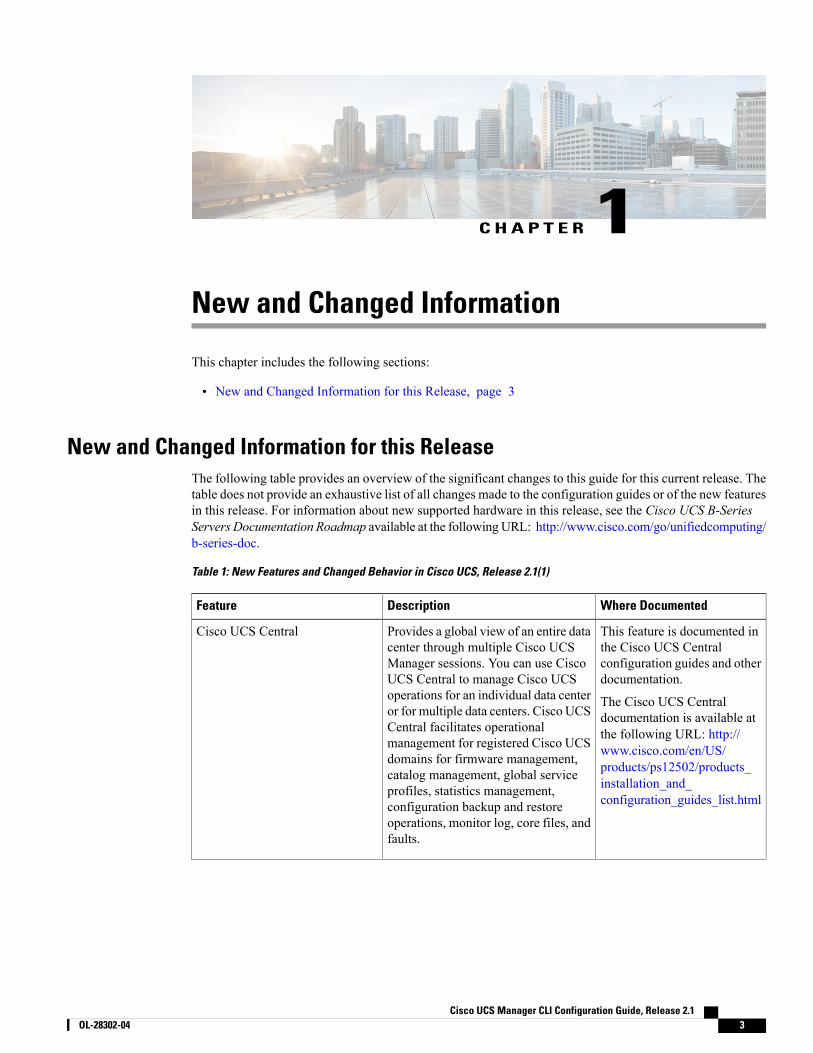
New and Changed Information for this ReleaseThe following table provides an overview of the significant changes to this guide for this current release. Thetable does not provide an exhaustive list of all changes made to the configuration guides or of the new featuresin this release. For information about new supported hardware in this release, see the Cisco UCS B-SeriesServers Documentation Roadmap available at the followingURL: http://www.cisco.com/go/unifiedcomputing/b-series-doc.
Table 1: New Features and Changed Behavior in Cisco UCS, Release 2.1(1)
Where DocumentedDescriptionFeature
This feature is documented inthe Cisco UCS Centralconfiguration guides and otherdocumentation.
The Cisco UCS Centraldocumentation is available atthe following URL: http://www.cisco.com/en/US/products/ps12502/products_installation_and_configuration_guides_list.html
Provides a global view of an entire datacenter through multiple Cisco UCSManager sessions. You can use CiscoUCS Central to manage Cisco UCSoperations for an individual data centeror for multiple data centers. Cisco UCSCentral facilitates operationalmanagement for registered Cisco UCSdomains for firmware management,catalog management, global serviceprofiles, statistics management,configuration backup and restoreoperations, monitor log, core files, andfaults.
Cisco UCS Central
Cisco UCS Manager CLI Configuration Guide, Release 2.1 OL-28302-04 3
Where DocumentedDescriptionFeature
This feature is documented inCisco UCS C-Series ServerIntegration with Cisco UCSManager 2.1.
The C-Series integration guidescan be found here: http://www.cisco.com/en/US/partner/products/ps11736/products_installation_and_configuration_guides_list.html
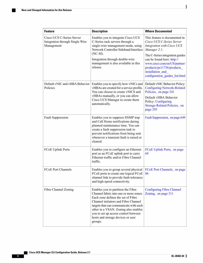
Enables you to integrate Cisco UCSC-Series rack servers through asingle-wire management mode, usingNetwork Controller Sideband Interface(NC-SI).
Integration through double-wiremanagement is also available in thisrelease.
Cisco UCS C-Series ServerIntegration through Single WireManagement
Default vNICBehavior Policy:Configuring Network-RelatedPolicies, on page 241
Default vHBA BehaviorPolicy: ConfiguringStorage-Related Policies, onpage 295
Enables you to specify how vNICs andvHBAs are created for a service profile.You can choose to create vNICS andvHBAs manually, or you can allowCisco UCS Manager to create themautomatically.
Default vNIC and vHBABehaviorPolicies
Fault Suppression, on page 649Enables you to suppress SNMP trapand Call Home notifications duringplanned maintenance time. You cancreate a fault suppression task toprevent notifications from being sentwhenever a transient fault is raised orcleared.
Fault Suppression
FCoE Uplink Ports, on page69
Enables you to configure an Ethernetport as an FCoE uplink port to carryEthernet traffic and/or Fibre Channeltraffic.
FCoE Uplink Ports
FCoE Port Channels, on page86
Enables you to group several physicalFCoE ports to create one logical FCoEchannel link to provide fault-toleranceand high-speed connectivity.
FCoE Port Channels
Configuring Fibre ChannelZoning, on page 311
Enables you to partition the FibreChannel fabric into one or more zones.Each zone defines the set of FibreChannel initiators and Fibre Channeltargets that can communicate with eachother in a VSAN. Zoning also enablesyou to set up access control betweenhosts and storage devices or usergroups.
Fibre Channel Zoning
Cisco UCS Manager CLI Configuration Guide, Release 2.14 OL-28302-04
New and Changed Information for this Release
Where DocumentedDescriptionFeature
This feature is documented inthe following configurationguides:
• Cisco UCS B-SeriesFirmware GUIConfiguration Guide
• Cisco UCS B-SeriesFirmware CLIConfiguration Guide
The firmware configurationguides can be found here: http://www.cisco.com/en/US/products/ps10281/products_installation_and_configuration_guides_list.html
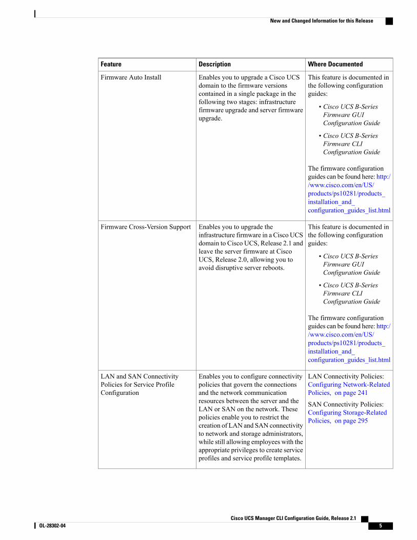
Enables you to upgrade a Cisco UCSdomain to the firmware versionscontained in a single package in thefollowing two stages: infrastructurefirmware upgrade and server firmwareupgrade.
Firmware Auto Install
This feature is documented inthe following configurationguides:
• Cisco UCS B-SeriesFirmware GUIConfiguration Guide
• Cisco UCS B-SeriesFirmware CLIConfiguration Guide
The firmware configurationguides can be found here: http://www.cisco.com/en/US/products/ps10281/products_installation_and_configuration_guides_list.html
Enables you to upgrade theinfrastructure firmware in a Cisco UCSdomain to Cisco UCS, Release 2.1 andleave the server firmware at CiscoUCS, Release 2.0, allowing you toavoid disruptive server reboots.
Firmware Cross-Version Support
LAN Connectivity Policies:Configuring Network-RelatedPolicies, on page 241
SAN Connectivity Policies:Configuring Storage-RelatedPolicies, on page 295
Enables you to configure connectivitypolicies that govern the connectionsand the network communicationresources between the server and theLAN or SAN on the network. Thesepolicies enable you to restrict thecreation of LAN and SAN connectivityto network and storage administrators,while still allowing employees with theappropriate privileges to create serviceprofiles and service profile templates.
LAN and SAN ConnectivityPolicies for Service ProfileConfiguration
Cisco UCS Manager CLI Configuration Guide, Release 2.1 OL-28302-04 5
New and Changed Information for this Release
Where DocumentedDescriptionFeature
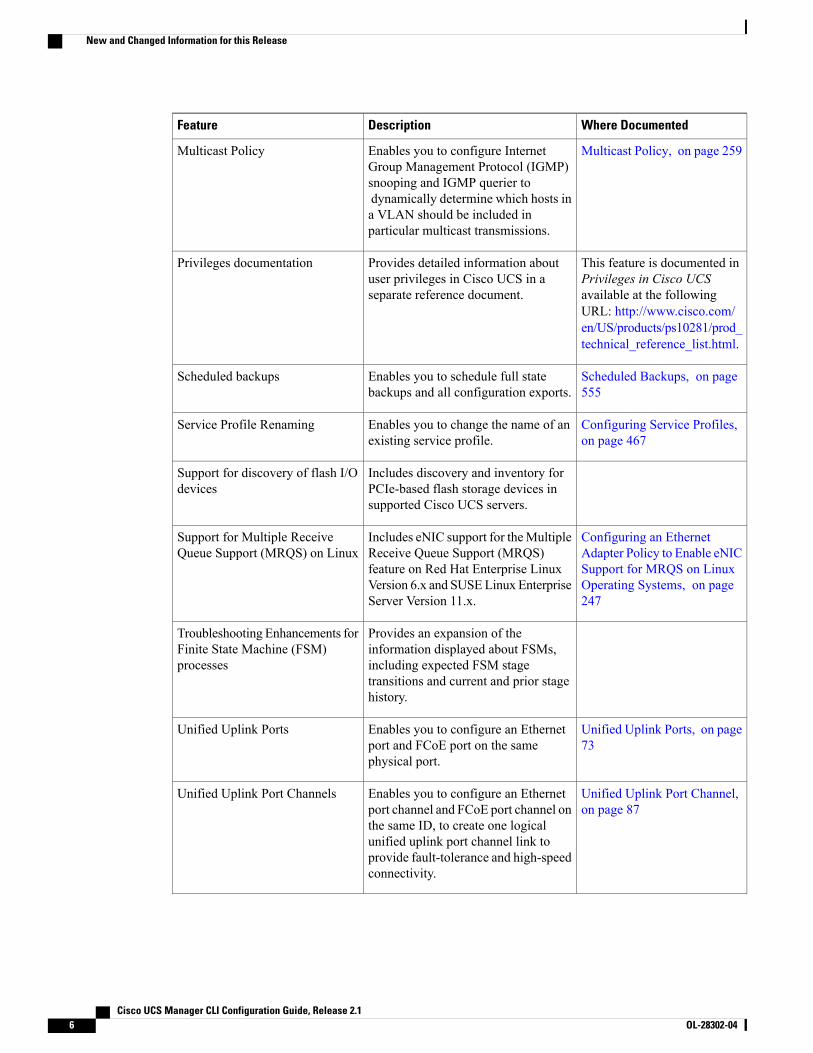
Multicast Policy, on page 259Enables you to configure InternetGroup Management Protocol (IGMP)snooping and IGMP querier todynamically determine which hosts ina VLAN should be included inparticular multicast transmissions.
Multicast Policy
This feature is documented inPrivileges in Cisco UCSavailable at the followingURL: http://www.cisco.com/en/US/products/ps10281/prod_technical_reference_list.html.
Provides detailed information aboutuser privileges in Cisco UCS in aseparate reference document.
Privileges documentation
Scheduled Backups, on page555
Enables you to schedule full statebackups and all configuration exports.
Scheduled backups
Configuring Service Profiles,on page 467
Enables you to change the name of anexisting service profile.
Service Profile Renaming
Includes discovery and inventory forPCIe-based flash storage devices insupported Cisco UCS servers.
Support for discovery of flash I/Odevices
Configuring an EthernetAdapter Policy to Enable eNICSupport for MRQS on LinuxOperating Systems, on page247
Includes eNIC support for theMultipleReceive Queue Support (MRQS)feature on Red Hat Enterprise LinuxVersion 6.x and SUSELinux EnterpriseServer Version 11.x.
Support for Multiple ReceiveQueue Support (MRQS) on Linux
Provides an expansion of theinformation displayed about FSMs,including expected FSM stagetransitions and current and prior stagehistory.
Troubleshooting Enhancements forFinite State Machine (FSM)processes
Unified Uplink Ports, on page73
Enables you to configure an Ethernetport and FCoE port on the samephysical port.
Unified Uplink Ports
Unified Uplink Port Channel,on page 87
Enables you to configure an Ethernetport channel and FCoE port channel onthe same ID, to create one logicalunified uplink port channel link toprovide fault-tolerance and high-speedconnectivity.
Unified Uplink Port Channels
Cisco UCS Manager CLI Configuration Guide, Release 2.16 OL-28302-04
New and Changed Information for this Release
Where DocumentedDescriptionFeature
Unified Storage Ports, on page71
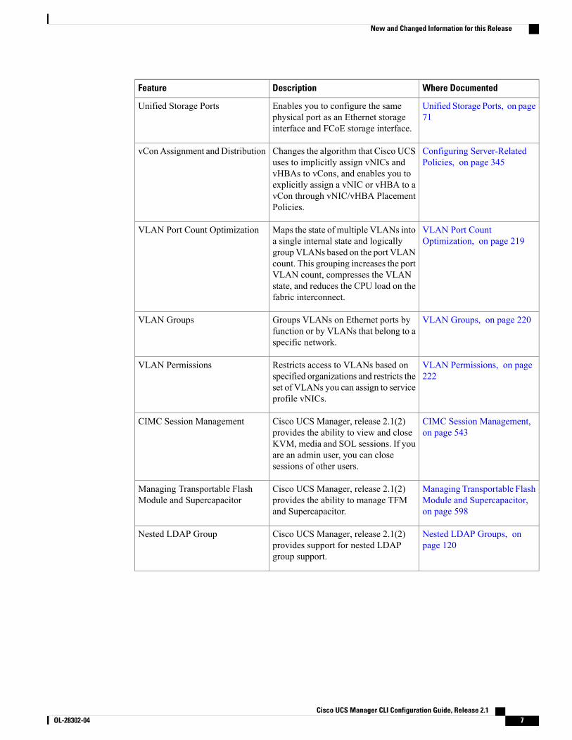
Enables you to configure the samephysical port as an Ethernet storageinterface and FCoE storage interface.
Unified Storage Ports
Configuring Server-RelatedPolicies, on page 345
Changes the algorithm that Cisco UCSuses to implicitly assign vNICs andvHBAs to vCons, and enables you toexplicitly assign a vNIC or vHBA to avCon through vNIC/vHBA PlacementPolicies.
vConAssignment and Distribution
VLAN Port CountOptimization, on page 219
Maps the state of multiple VLANs intoa single internal state and logicallygroupVLANs based on the port VLANcount. This grouping increases the portVLAN count, compresses the VLANstate, and reduces the CPU load on thefabric interconnect.
VLAN Port Count Optimization
VLAN Groups, on page 220Groups VLANs on Ethernet ports byfunction or by VLANs that belong to aspecific network.
VLAN Groups
VLAN Permissions, on page222
Restricts access to VLANs based onspecified organizations and restricts theset of VLANs you can assign to serviceprofile vNICs.
VLAN Permissions
CIMC Session Management,on page 543
Cisco UCS Manager, release 2.1(2)provides the ability to view and closeKVM, media and SOL sessions. If youare an admin user, you can closesessions of other users.
CIMC Session Management
Managing Transportable FlashModule and Supercapacitor,on page 598
Cisco UCS Manager, release 2.1(2)provides the ability to manage TFMand Supercapacitor.
Managing Transportable FlashModule and Supercapacitor
Nested LDAP Groups, onpage 120
Cisco UCS Manager, release 2.1(2)provides support for nested LDAPgroup support.
Nested LDAP Group
Cisco UCS Manager CLI Configuration Guide, Release 2.1 OL-28302-04 7
New and Changed Information for this Release

Where DocumentedDescriptionFeature
This feature is documented inthe following configurationguides:
• Cisco UCS ManagerVM-FEX for Hyper-VGUI ConfigurationGuide
• Cisco UCS ManagerVM-FEX for Hyper-VCLI ConfigurationGuide
The VM-FEX configurationguides can be found here: http://www.cisco.com/en/US/products/ps10281/products_installation_and_configuration_guides_list.html
Cisco VirtualMachine Fabric Extender(VM-FEX) for Hyper-V providesmanagement integration and networkcommunication between Cisco UCSManager and VMware vCenter.
VM-FEX Integration for Hyper-VSRIOV
This feature is documented inthe following configurationguides:
• Cisco UCS ManagerVM-FEX for KVM GUIConfiguration Guide
• Cisco UCS ManagerVM-FEX for KVM CLIConfiguration Guide
The VM-FEX configurationguides can be found here: http://www.cisco.com/en/US/products/ps10281/products_installation_and_configuration_guides_list.html
Includes enhancements and significantimprovements to the functionality ofCisco VirtualMachine Fabric Extender(VM-FEX) for KVM, which providesexternal switching for virtual machinesrunning on a KVM Linux-basedhypervisor in a Cisco UCS domain.
VM-FEX Integration for KVM(Red Hat Linux) SRIOV
Cisco UCS Manager CLI Configuration Guide, Release 2.18 OL-28302-04
New and Changed Information for this Release
C H A P T E R 2Overview of Cisco Unified Computing System
This chapter includes the following sections:
• About Cisco Unified Computing System , page 9
• Unified Fabric, page 10
• Server Architecture and Connectivity, page 12
• Traffic Management, page 16
• Opt-In Features, page 21
• Virtualization in Cisco UCS , page 23
About Cisco Unified Computing SystemCisco Unified Computing System (Cisco UCS) fuses access layer networking and servers. Thishigh-performance, next-generation server system provides a data center with a high degree of workload agilityand scalability.
The hardware and software components support Cisco's unified fabric, which runs multiple types of datacenter traffic over a single converged network adapter.
Architectural Simplification
The simplified architecture of Cisco UCS reduces the number of required devices and centralizes switchingresources. By eliminating switching inside a chassis, network access-layer fragmentation is significantlyreduced.
Cisco UCS implements Cisco unified fabric within racks and groups of racks, supporting Ethernet and FibreChannel protocols over 10 Gigabit Cisco Data Center Ethernet and Fibre Channel over Ethernet (FCoE) links.
This radical simplification reduces the number of switches, cables, adapters, and management points by upto two-thirds. All devices in a Cisco UCS domain remain under a single management domain, which remainshighly available through the use of redundant components.
Cisco UCS Manager CLI Configuration Guide, Release 2.1 OL-28302-04 9
High Availability
The management and data plane of Cisco UCS is designed for high availability and redundant access layerfabric interconnects. In addition, Cisco UCS supports existing high availability and disaster recovery solutionsfor the data center, such as data replication and application-level clustering technologies.
Scalability
A single Cisco UCS domain supports multiple chassis and their servers, all of which are administered throughone CiscoUCSManager. Formore detailed information about the scalability, speak to your Cisco representative.
Flexibility
ACisco UCS domain allows you to quickly align computing resources in the data center with rapidly changingbusiness requirements. This built-in flexibility is determined by whether you choose to fully implement thestateless computing feature.
Pools of servers and other system resources can be applied as necessary to respond to workload fluctuations,support new applications, scale existing software and business services, and accommodate both scheduledand unscheduled downtime. Server identity can be abstracted into a mobile service profile that can be movedfrom server to server with minimal downtime and no need for additional network configuration.
With this level of flexibility, you can quickly and easily scale server capacity without having to change theserver identity or reconfigure the server, LAN, or SAN. During a maintenance window, you can quickly dothe following:
• Deploy new servers to meet unexpected workload demand and rebalance resources and traffic.
• Shut down an application, such as a database management system, on one server and then boot it upagain on another server with increased I/O capacity and memory resources.
Optimized for Server Virtualization
Cisco UCS has been optimized to implement VM-FEX technology. This technology provides improvedsupport for server virtualization, including better policy-based configuration and security, conformance witha company's operational model, and accommodation for VMware's VMotion.
Unified FabricWith unified fabric, multiple types of data center traffic can run over a single Data Center Ethernet (DCE)network. Instead of having a series of different host bus adapters (HBAs) and network interface cards (NICs)present in a server, unified fabric uses a single converged network adapter. This type of adapter can carryLAN and SAN traffic on the same cable.
Cisco UCS uses Fibre Channel over Ethernet (FCoE) to carry Fibre Channel and Ethernet traffic on the samephysical Ethernet connection between the fabric interconnect and the server. This connection terminates at aconverged network adapter on the server, and the unified fabric terminates on the uplink ports of the fabricinterconnect. On the core network, the LAN and SAN traffic remains separated. Cisco UCS does not requirethat you implement unified fabric across the data center.
The converged network adapter presents an Ethernet interface and Fibre Channel interface to the operatingsystem. At the server, the operating system is not aware of the FCoE encapsulation because it sees a standardFibre Channel HBA.
Cisco UCS Manager CLI Configuration Guide, Release 2.110 OL-28302-04
Unified Fabric
At the fabric interconnect, the server-facing Ethernet port receives the Ethernet and Fibre Channel traffic. Thefabric interconnect (using Ethertype to differentiate the frames) separates the two traffic types. Ethernet framesand Fibre Channel frames are switched to their respective uplink interfaces.
Fibre Channel over EthernetCisco UCS leverages Fibre Channel over Ethernet (FCoE) standard protocol to deliver Fibre Channel. Theupper Fibre Channel layers are unchanged, so the Fibre Channel operational model is maintained. FCoEnetwork management and configuration is similar to a native Fibre Channel network.
FCoE encapsulates Fibre Channel traffic over a physical Ethernet link. FCoE is encapsulated over Ethernetwith the use of a dedicated Ethertype, 0x8906, so that FCoE traffic and standard Ethernet traffic can be carriedon the same link. FCoE has been standardized by the ANSI T11 Standards Committee.
Fibre Channel traffic requires a lossless transport layer. Instead of the buffer-to-buffer credit system used bynative Fibre Channel, FCoE depends upon the Ethernet link to implement lossless service.
Ethernet links on the fabric interconnect provide twomechanisms to ensure lossless transport for FCoE traffic:
• Link-level flow control
• Priority flow control
Link-Level Flow Control
IEEE 802.3x link-level flow control allows a congested receiver to signal the endpoint to pause data transmissionfor a short time. This link-level flow control pauses all traffic on the link.
The transmit and receive directions are separately configurable. By default, link-level flow control is disabledfor both directions.
On each Ethernet interface, the fabric interconnect can enable either priority flow control or link-level flowcontrol (but not both).
Priority Flow Control
The priority flow control (PFC) feature applies pause functionality to specific classes of traffic on the Ethernetlink. For example, PFC can provide lossless service for the FCoE traffic, and best-effort service for the standardEthernet traffic. PFC can provide different levels of service to specific classes of Ethernet traffic (using IEEE802.1p traffic classes).
PFC decides whether to apply pause based on the IEEE 802.1p CoS value. When the fabric interconnectenables PFC, it configures the connected adapter to apply the pause functionality to packets with specific CoSvalues.
By default, the fabric interconnect negotiates to enable the PFC capability. If the negotiation succeeds, PFCis enabled and link-level flow control remains disabled (regardless of its configuration settings). If the PFCnegotiation fails, you can either force PFC to be enabled on the interface or you can enable IEEE 802.xlink-level flow control.
Cisco UCS Manager CLI Configuration Guide, Release 2.1 OL-28302-04 11
Unified Fabric
Server Architecture and Connectivity
Overview of Service ProfilesService profiles are the central concept of Cisco UCS. Each service profile serves a specific purpose: ensuringthat the associated server hardware has the configuration required to support the applications it will host.
The service profile maintains configuration information about the server hardware, interfaces, fabricconnectivity, and server and network identity. This information is stored in a format that you can managethrough Cisco UCSManager. All service profiles are centrally managed and stored in a database on the fabricinterconnect.
Every server must be associated with a service profile.
At any given time, each server can be associated with only one service profile. Similarly, each serviceprofile can be associated with only one server at a time.
Important
After you associate a service profile with a server, the server is ready to have an operating system andapplications installed, and you can use the service profile to review the configuration of the server. If theserver associated with a service profile fails, the service profile does not automatically fail over to anotherserver.
When a service profile is disassociated from a server, the identity and connectivity information for the serveris reset to factory defaults.
Network Connectivity through Service Profiles
Each service profile specifies the LAN and SAN network connections for the server through the Cisco UCSinfrastructure and out to the external network. You do not need to manually configure the network connectionsfor Cisco UCS servers and other components. All network configuration is performed through the serviceprofile.
When you associate a service profile with a server, the Cisco UCS internal fabric is configured with theinformation in the service profile. If the profile was previously associated with a different server, the networkinfrastructure reconfigures to support identical network connectivity to the new server.
Configuration through Service Profiles
A service profile can take advantage of resource pools and policies to handle server and connectivityconfiguration.
Hardware Components Configured by Service Profiles
When a service profile is associated with a server, the following components are configured according to thedata in the profile:
• Server, including BIOS and CIMC
• Adapters
• Fabric interconnects
Cisco UCS Manager CLI Configuration Guide, Release 2.112 OL-28302-04
Server Architecture and Connectivity
You do not need to configure these hardware components directly.
Server Identity Management through Service Profiles
You can use the network and device identities burned into the server hardware at manufacture or you can useidentities that you specify in the associated service profile either directly or through identity pools, such asMAC, WWN, and UUID.
The following are examples of configuration information that you can include in a service profile:
• Profile name and description
• Unique server identity (UUID)
• LAN connectivity attributes, such as the MAC address
• SAN connectivity attributes, such as the WWN
Operational Aspects configured by Service Profiles
You can configure some of the operational functions for a server in a service profile, such as the following:
• Firmware packages and versions
• Operating system boot order and configuration
• IPMI and KVM access
vNIC Configuration by Service Profiles
A vNIC is a virtualized network interface that is configured on a physical network adapter and appears to bea physical NIC to the operating system of the server. The type of adapter in the system determines how manyvNICs you can create. For example, a converged network adapter has two NICs, which means you can createa maximum of two vNICs for each adapter.
A vNIC communicates over Ethernet and handles LAN traffic. At a minimum, each vNIC must be configuredwith a name and with fabric and network connectivity.
vHBA Configuration by Service Profiles
A vHBA is a virtualized host bus adapter that is configured on a physical network adapter and appears to bea physical HBA to the operating system of the server. The type of adapter in the system determines how manyvHBAs you can create. For example, a converged network adapter has two HBAs, which means you cancreate a maximum of two vHBAs for each of those adapters. In contrast, a network interface card does nothave any HBAs, which means you cannot create any vHBAs for those adapters.
A vHBA communicates over FCoE and handles SAN traffic. At a minimum, each vHBA must be configuredwith a name and fabric connectivity.
Service Profiles that Override Server Identity
This type of service profile provides the maximum amount of flexibility and control. This profile allows youto override the identity values that are on the server at the time of association and use the resource pools andpolicies set up in Cisco UCS Manager to automate some administration tasks.
You can disassociate this service profile from one server and then associate it with another server. Thisre-association can be done either manually or through an automated server pool policy. The burned-in settings,
Cisco UCS Manager CLI Configuration Guide, Release 2.1 OL-28302-04 13
Server Architecture and Connectivity
such as UUID and MAC address, on the new server are overwritten with the configuration in the serviceprofile. As a result, the change in server is transparent to your network. You do not need to reconfigure anycomponent or application on your network to begin using the new server.
This profile allows you to take advantage of and manage system resources through resource pools and policies,such as the following:
• Virtualized identity information, including pools of MAC addresses, WWN addresses, and UUIDs
• Ethernet and Fibre Channel adapter profile policies
• Firmware package policies
• Operating system boot order policies
Unless the service profile contains power management policies, a server pool qualification policy, or anotherpolicy that requires a specific hardware configuration, the profile can be used for any type of server in theCisco UCS domain.
You can associate these service profiles with either a rack-mount server or a blade server. The ability tomigrate the service profile depends upon whether you choose to restrict migration of the service profile.
If you choose not to restrict migration, Cisco UCS Manager does not perform any compatibility checkson the new server before migrating the existing service profile. If the hardware of both servers are notsimilar, the association might fail.
Note
Service Profiles that Inherit Server Identity
This hardware-based service profile is the simplest to use and create. This profile uses the default values inthe server and mimics the management of a rack-mounted server. It is tied to a specific server and cannot bemoved or migrated to another server.
You do not need to create pools or configuration policies to use this service profile.
This service profile inherits and applies the identity and configuration information that is present at the timeof association, such as the following:
• MAC addresses for the two NICs
• For a converged network adapter or a virtual interface card, the WWN addresses for the two HBAs
• BIOS versions
• Server UUID
The server identity and configuration information inherited through this service profile may not be thevalues burned into the server hardware at manufacture if those values were changed before this profile isassociated with the server.
Important
Cisco UCS Manager CLI Configuration Guide, Release 2.114 OL-28302-04
Server Architecture and Connectivity
Service Profile Templates
With a service profile template, you can quickly create several service profiles with the same basic parameters,such as the number of vNICs and vHBAs, and with identity information drawn from the same pools.
If you need only one service profile with similar values to an existing service profile, you can clone aservice profile in the Cisco UCS Manager GUI.
Tip
For example, if you need several service profiles with similar values to configure servers to host databasesoftware, you can create a service profile template, either manually or from an existing service profile. Youthen use the template to create the service profiles.
Cisco UCS supports the following types of service profile templates:
Initial template
Service profiles created from an initial template inherit all the properties of the template. Service profilescreated from an initial service profile template are bound to the template. However, changes to theinitial template do not automatically propagate to the bound service profiles. If you want to propagatechanges to bound service profiles, unbind and rebind the service profile to the initial template.
Updating template
Service profiles created from an updating template inherit all the properties of the template and remainconnected to the template. Any changes to the template automatically update the service profiles createdfrom the template.
PoliciesPolicies determine how Cisco UCS components will act in specific circumstances. You can create multipleinstances of most policies. For example, you might want different boot policies, so that some servers can PXEboot, some can SAN boot, and others can boot from local storage.
Policies allow separation of functions within the system. A subject matter expert can define policies that areused in a service profile, which is created by someone without that subject matter expertise. For example, aLAN administrator can create adapter policies and quality of service policies for the system. These policiescan then be used in a service profile that is created by someone who has limited or no subject matter expertisewith LAN administration.
You can create and use two types of policies in Cisco UCS Manager:
• Configuration policies that configure the servers and other components
• Operational policies that control certain management, monitoring, and access control functions
PoolsPools are collections of identities, or physical or logical resources, that are available in the system. All poolsincrease the flexibility of service profiles and allow you to centrally manage your system resources.
You can use pools to segment unconfigured servers or available ranges of server identity information intogroupings that make sense for the data center. For example, if you create a pool of unconfigured servers with
Cisco UCS Manager CLI Configuration Guide, Release 2.1 OL-28302-04 15
Server Architecture and Connectivity
similar characteristics and include that pool in a service profile, you can use a policy to associate that serviceprofile with an available, unconfigured server.
If you pool identifying information, such as MAC addresses, you can preassign ranges for servers that hostspecific applications. For example, you can configure all database servers within the same range of MACaddresses, UUIDs, and WWNs.
Domain Pools
Domain Pools are defined locally in a Cisco UCS domain, and can only be used in that Cisco UCS domain.
Global Pools
Global Pools are defined in Cisco UCS Central, and can be shared between Cisco UCS domains. If a CiscoUCS domain is registered with Cisco UCS Central, you can assign Global Pools in Cisco UCS Manager.
Traffic Management
OversubscriptionOversubscription occurs when multiple network devices are connected to the same fabric interconnect port.This practice optimizes fabric interconnect use, since ports rarely run at maximum speed for any length oftime. As a result, when configured correctly, oversubscription allows you to take advantage of unusedbandwidth. However, incorrectly configured oversubscription can result in contention for bandwidth and alower quality of service to all services that use the oversubscribed port.
For example, oversubscription can occur if four servers share a single uplink port, and all four servers attemptto send data at a cumulative rate higher than available bandwidth of uplink port.
Oversubscription Considerations
The following elements can impact how you configure oversubscription in a Cisco UCS domain:
Ratio of Server-Facing Ports to Uplink Ports
You need to know what how many server-facing ports and uplink ports are in the system, because that ratiocan impact performance. For example, if your system has twenty ports that can communicate down to theservers and only two ports that can communicate up to the network, your uplink ports will be oversubscribed.In this situation, the amount of traffic created by the servers can also affect performance.
Number of Uplink Ports from Fabric Interconnect to Network
You can choose to add more uplink ports between the Cisco UCS fabric interconnect and the upper layers ofthe LAN to increase bandwidth. In Cisco UCS, you must have at least one uplink port per fabric interconnectto ensure that all servers andNICs to have access to the LAN. The number of LAN uplinks should be determinedby the aggregate bandwidth needed by all Cisco UCS servers.
For the 6100 series fabric interconnects, Fibre Channel uplink ports are available on the expansion slots only.You must add more expansion slots to increase number of available Fibre Channel uplinks. Ethernet uplinkports can exist on the fixed slot and on expansion slots.
Cisco UCS Manager CLI Configuration Guide, Release 2.116 OL-28302-04
Traffic Management
For the 6200 series fabric interconnects running Cisco UCSManager, version 2.0 and higher, Ethernet uplinkports and Fibre Channel uplink ports are both configurable on the base module, as well as on the expansionmodule.
For example, if you have two Cisco UCS 5100 series chassis that are fully populated with half width CiscoUCS B200-M1 servers, you have 16 servers. In a cluster configuration, with one LAN uplink per fabricinterconnect, these 16 servers share 20GbE of LAN bandwidth. If more capacity is needed, more uplinks fromthe fabric interconnect should be added. We recommend that you have symmetric configuration of the uplinkin cluster configurations. In the same example, if 4 uplinks are used in each fabric interconnect, the 16 serversare sharing 80 GB of bandwidth, so each has approximately 5 GB of capacity. When multiple uplinks areused on a Cisco UCS fabric interconnect the network design team should consider using a port channel tomake best use of the capacity.
Number of Uplink Ports from I/O Module to Fabric Interconnect
You can choose to add more bandwidth between I/O module and fabric interconnect by using more uplinkports and increasing the number of cables. In Cisco UCS, you can have one, two, or four cables connectinga I/O module to a Cisco UCS 6100 series fabric interconnect. You can have up to eight cables if you'reconnecting a 2208 I/O module and a 6248 fabric interconnect. The number of cables determines the numberof active uplink ports and the oversubscription ratio.
Number of Active Links from Server to Fabric Interconnect
The amount of non-oversubscribed bandwidth available to each server depends on the number of I/O modulesused and the number of cables used to connect those I/O modules to the fabric interconnects. Having a secondI/O module in place provides additional bandwidth and redundancy to the servers. This level of flexibility indesign ensures that you can provide anywhere from 80 Gbps (two I/O modules with four links each) to 10Gbps (one I/O module with one link) to the chassis.
With 80 Gbps to the chassis, each half-width server in the Cisco UCS domain can get up to 10 Gbps in anon-oversubscribed configuration, with an ability to use up to 20 Gbps with 2:1 oversubscription.
Guidelines for Estimating Oversubscription
When you estimate the optimal oversubscription ratio for a fabric interconnect port, consider the followingguidelines:
Cost/Performance Slider
The prioritization of cost and performance is different for each data center and has a direct impact on theconfiguration of oversubscription. When you plan hardware usage for oversubscription, you need to knowwhere the data center is located on this slider. For example, oversubscription can be minimized if the datacenter is more concerned with performance than cost. However, cost is a significant factor in most data centers,and oversubscription requires careful planning.
Bandwidth Usage
The estimated bandwidth that you expect each server to actually use is important when you determine theassignment of each server to a fabric interconnect port and, as a result, the oversubscription ratio of the ports.For oversubscription, you must consider how many GBs of traffic the server will consume on average, theratio of configured bandwidth to used bandwidth, and the times when high bandwidth use will occur.
Cisco UCS Manager CLI Configuration Guide, Release 2.1 OL-28302-04 17
Traffic Management
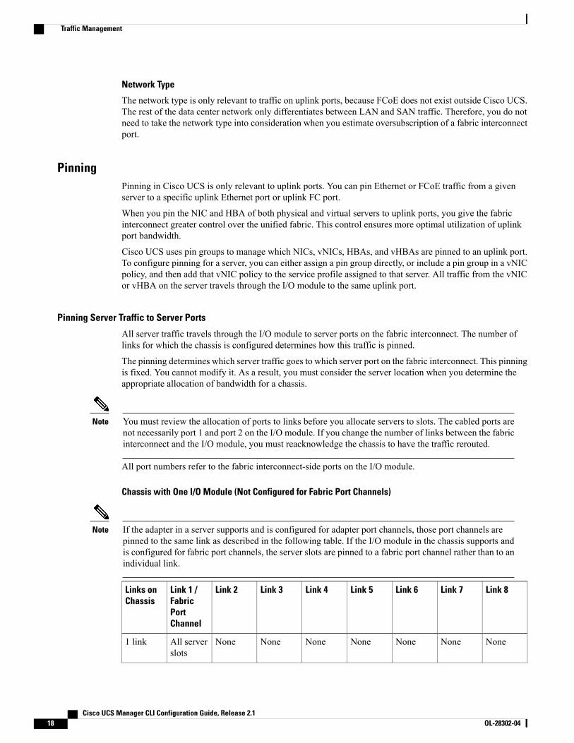
Network Type
The network type is only relevant to traffic on uplink ports, because FCoE does not exist outside Cisco UCS.The rest of the data center network only differentiates between LAN and SAN traffic. Therefore, you do notneed to take the network type into consideration when you estimate oversubscription of a fabric interconnectport.
PinningPinning in Cisco UCS is only relevant to uplink ports. You can pin Ethernet or FCoE traffic from a givenserver to a specific uplink Ethernet port or uplink FC port.
When you pin the NIC and HBA of both physical and virtual servers to uplink ports, you give the fabricinterconnect greater control over the unified fabric. This control ensures more optimal utilization of uplinkport bandwidth.
Cisco UCS uses pin groups to manage which NICs, vNICs, HBAs, and vHBAs are pinned to an uplink port.To configure pinning for a server, you can either assign a pin group directly, or include a pin group in a vNICpolicy, and then add that vNIC policy to the service profile assigned to that server. All traffic from the vNICor vHBA on the server travels through the I/O module to the same uplink port.
Pinning Server Traffic to Server Ports
All server traffic travels through the I/O module to server ports on the fabric interconnect. The number oflinks for which the chassis is configured determines how this traffic is pinned.
The pinning determines which server traffic goes to which server port on the fabric interconnect. This pinningis fixed. You cannot modify it. As a result, you must consider the server location when you determine theappropriate allocation of bandwidth for a chassis.
You must review the allocation of ports to links before you allocate servers to slots. The cabled ports arenot necessarily port 1 and port 2 on the I/O module. If you change the number of links between the fabricinterconnect and the I/O module, you must reacknowledge the chassis to have the traffic rerouted.
Note
All port numbers refer to the fabric interconnect-side ports on the I/O module.
Chassis with One I/O Module (Not Configured for Fabric Port Channels)
If the adapter in a server supports and is configured for adapter port channels, those port channels arepinned to the same link as described in the following table. If the I/O module in the chassis supports andis configured for fabric port channels, the server slots are pinned to a fabric port channel rather than to anindividual link.
Note
Link 8Link 7Link 6Link 5Link 4Link 3Link 2Link 1 /FabricPortChannel
Links onChassis
NoneNoneNoneNoneNoneNoneNoneAll serverslots
1 link
Cisco UCS Manager CLI Configuration Guide, Release 2.118 OL-28302-04
Traffic Management
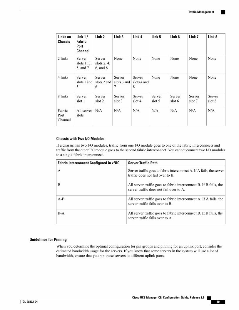
Link 8Link 7Link 6Link 5Link 4Link 3Link 2Link 1 /FabricPortChannel
Links onChassis
NoneNoneNoneNoneNoneNoneServerslots 2, 4,6, and 8
Serverslots 1, 3,5, and 7
2 links
NoneNoneNoneNoneServerslots 4 and8
Serverslots 3 and7
Serverslots 2 and6
Serverslots 1 and5
4 links
Serverslot 8
Serverslot 7
Serverslot 6
Serverslot 5
Serverslot 4
Serverslot 3
Serverslot 2
Serverslot 1
8 links
N/AN/AN/AN/AN/AN/AN/AAll serverslots
FabricPortChannel
Chassis with Two I/O Modules
If a chassis has two I/O modules, traffic from one I/O module goes to one of the fabric interconnects andtraffic from the other I/O module goes to the second fabric interconnect. You cannot connect two I/O modulesto a single fabric interconnect.
Server Traffic PathFabric Interconnect Configured in vNIC
Server traffic goes to fabric interconnect A. If A fails, the servertraffic does not fail over to B.
A
All server traffic goes to fabric interconnect B. If B fails, theserver traffic does not fail over to A.
B
All server traffic goes to fabric interconnect A. If A fails, theserver traffic fails over to B.
A-B
All server traffic goes to fabric interconnect B. If B fails, theserver traffic fails over to A.
B-A
Guidelines for Pinning
When you determine the optimal configuration for pin groups and pinning for an uplink port, consider theestimated bandwidth usage for the servers. If you know that some servers in the system will use a lot ofbandwidth, ensure that you pin these servers to different uplink ports.
Cisco UCS Manager CLI Configuration Guide, Release 2.1 OL-28302-04 19
Traffic Management
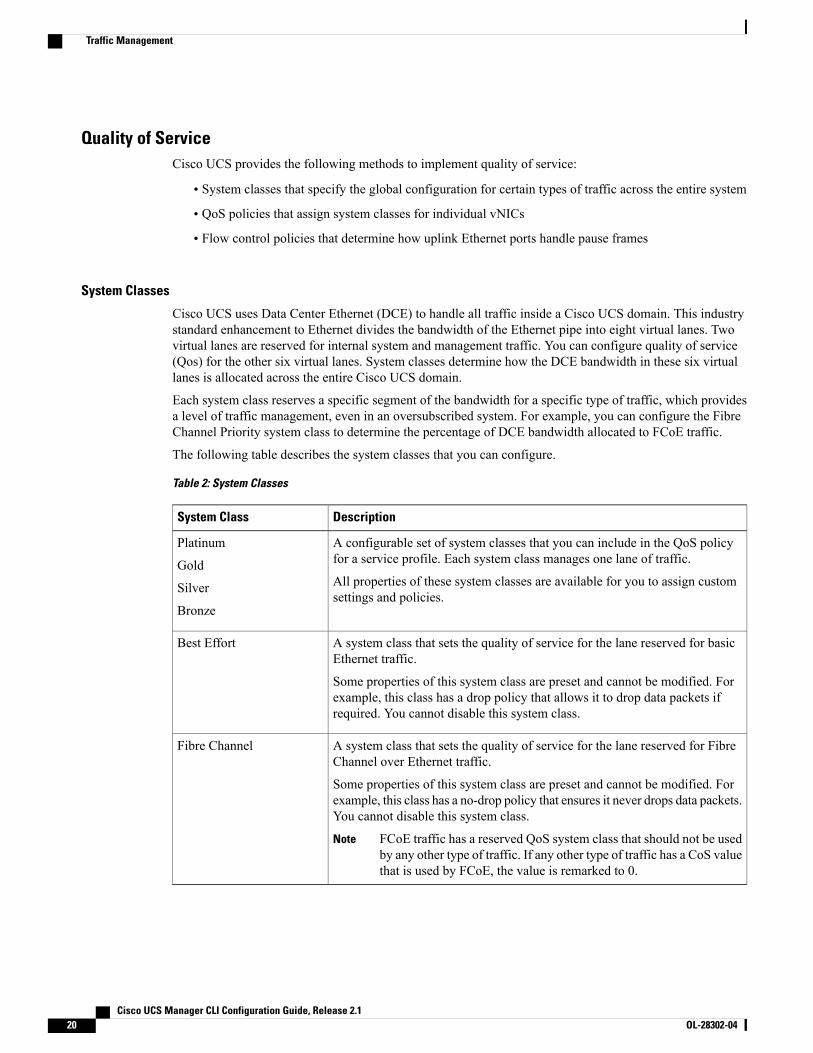
Quality of ServiceCisco UCS provides the following methods to implement quality of service:
• System classes that specify the global configuration for certain types of traffic across the entire system
• QoS policies that assign system classes for individual vNICs
• Flow control policies that determine how uplink Ethernet ports handle pause frames
System Classes
Cisco UCS uses Data Center Ethernet (DCE) to handle all traffic inside a Cisco UCS domain. This industrystandard enhancement to Ethernet divides the bandwidth of the Ethernet pipe into eight virtual lanes. Twovirtual lanes are reserved for internal system and management traffic. You can configure quality of service(Qos) for the other six virtual lanes. System classes determine how the DCE bandwidth in these six virtuallanes is allocated across the entire Cisco UCS domain.
Each system class reserves a specific segment of the bandwidth for a specific type of traffic, which providesa level of traffic management, even in an oversubscribed system. For example, you can configure the FibreChannel Priority system class to determine the percentage of DCE bandwidth allocated to FCoE traffic.
The following table describes the system classes that you can configure.
Table 2: System Classes
DescriptionSystem Class
A configurable set of system classes that you can include in the QoS policyfor a service profile. Each system class manages one lane of traffic.
All properties of these system classes are available for you to assign customsettings and policies.
Platinum
Gold
Silver
Bronze
A system class that sets the quality of service for the lane reserved for basicEthernet traffic.
Some properties of this system class are preset and cannot be modified. Forexample, this class has a drop policy that allows it to drop data packets ifrequired. You cannot disable this system class.
Best Effort
A system class that sets the quality of service for the lane reserved for FibreChannel over Ethernet traffic.
Some properties of this system class are preset and cannot be modified. Forexample, this class has a no-drop policy that ensures it never drops data packets.You cannot disable this system class.
FCoE traffic has a reserved QoS system class that should not be usedby any other type of traffic. If any other type of traffic has a CoS valuethat is used by FCoE, the value is remarked to 0.
Note
Fibre Channel
Cisco UCS Manager CLI Configuration Guide, Release 2.120 OL-28302-04
Traffic Management
Quality of Service Policy
A quality of service (QoS) policy assigns a system class to the outgoing traffic for a vNIC or vHBA. Thissystem class determines the quality of service for that traffic. For certain adapters, you can also specifyadditional controls on the outgoing traffic, such as burst and rate.
You must include a QoS policy in a vNIC policy or vHBA policy and then include that policy in a serviceprofile to configure the vNIC or vHBA.
Flow Control Policy
Flow control policies determine whether the uplink Ethernet ports in a Cisco UCS domain send and receiveIEEE 802.3x pause frames when the receive buffer for a port fills. These pause frames request that thetransmitting port stop sending data for a few milliseconds until the buffer clears.
For flow control to work between a LAN port and an uplink Ethernet port, you must enable the correspondingreceive and send flow control parameters for both ports. For Cisco UCS, the flow control policies configurethese parameters.
When you enable the send function, the uplink Ethernet port sends a pause request to the network port if theincoming packet rate becomes too high. The pause remains in effect for a few milliseconds before traffic isreset to normal levels. If you enable the receive function, the uplink Ethernet port honors all pause requestsfrom the network port. All traffic is halted on that uplink port until the network port cancels the pause request.
Because you assign the flow control policy to the port, changes to the policy have an immediate effect on howthe port reacts to a pause frame or a full receive buffer.
Opt-In FeaturesEach Cisco UCS domain is licensed for all functionality. Depending upon how the system is configured, youcan decide to opt in to some features or opt out of them for easier integration into existing environment. If aprocess change happens, you can change your system configuration and include one or both of the opt-infeatures.
The opt-in features are as follows:
• Stateless computing, which takes advantage of mobile service profiles with pools and policies whereeach component, such as a server or an adapter, is stateless.
• Multi-tenancy, which uses organizations and role-based access control to divide the system into smallerlogical segments.
Stateless ComputingStateless computing allows you to use a service profile to apply the personality of one server to a differentserver in the same Cisco UCS domain. The personality of the server includes the elements that identify thatserver and make it unique in the Cisco UCS domain. If you change any of these elements, the server couldlose its ability to access, use, or even achieve booted status.
The elements that make up a server's personality include the following:
• Firmware versions
• UUID (used for server identification)
Cisco UCS Manager CLI Configuration Guide, Release 2.1 OL-28302-04 21
Opt-In Features
• MAC address (used for LAN connectivity)
•World Wide Names (used for SAN connectivity)
• Boot settings
Stateless computing creates a dynamic server environment with highly flexible servers. Every physical serverin a Cisco UCS domain remains anonymous until you associate a service profile with it, then the server getsthe identity configured in the service profile. If you no longer need a business service on that server, you canshut it down, disassociate the service profile, and then associate another service profile to create a differentidentity for the same physical server. The "new" server can then host another business service.
To take full advantage of the flexibility of statelessness, the optional local disks on the servers should onlybe used for swap or temp space and not to store operating system or application data.
You can choose to fully implement stateless computing for all physical servers in a Cisco UCS domain, tonot have any stateless servers, or to have a mix of the two types.
If You Opt In to Stateless Computing
Each physical server in the Cisco UCS domain is defined through a service profile. Any server can be usedto host one set of applications, then reassigned to another set of applications or business services, if requiredby the needs of the data center.
You create service profiles that point to policies and pools of resources that are defined in the Cisco UCSdomain. The server pools, WWN pools, and MAC pools ensure that all unassigned resources are availableon an as-needed basis. For example, if a physical server fails, you can immediately assign the service profileto another server. Because the service profile provides the new server with the same identity as the originalserver, including WWN and MAC address, the rest of the data center infrastructure sees it as the same serverand you do not need to make any configuration changes in the LAN or SAN.
If You Opt Out of Stateless Computing
Each server in the Cisco UCS domain is treated as a traditional rack mount server.
You create service profiles that inherit the identify information burned into the hardware and use these profilesto configure LAN or SAN connectivity for the server. However, if the server hardware fails, you cannotreassign the service profile to a new server.
MultitenancyMultitenancy allows you to divide the large physical infrastructure of an Cisco UCS domain into logicalentities known as organizations. As a result, you can achieve a logical isolation between organizations withoutproviding a dedicated physical infrastructure for each organization.
You can assign unique resources to each tenant through the related organization, in the multitenant environment.These resources can include different policies, pools, and quality of service definitions. You can also implementlocales to assign or restrict user privileges and roles by organization, if you do not want all users to haveaccess to all organizations.
If you set up a multitenant environment, all organizations are hierarchical. The top-level organization is alwaysroot. The policies and pools that you create in root are system-wide and are available to all organizations inthe system. However, any policies and pools created in other organizations are only available to organizationsthat are above it in the same hierarchy. For example, if a system has organizations named Finance and HRthat are not in the same hierarchy, Finance cannot use any policies in the HR organization, and HR cannot
Cisco UCS Manager CLI Configuration Guide, Release 2.122 OL-28302-04
Opt-In Features
access any policies in the Finance organization. However, both Finance and HR can use policies and poolsin the root organization.
If you create organizations in a multitenant environment, you can also set up one or more of the followingfor each organization or for a suborganization in the same hierarchy:
• Resource pools
• Policies
• Service profiles
• Service profile templates
If You Opt In to Multitenancy
Each Cisco UCS domain is divided into several distinct organizations. The types of organizations you createin a multitenancy implementation depends upon the business needs of the company. Examples includeorganizations that represent the following:
• Enterprise groups or divisions within a company, such as marketing, finance, engineering, or humanresources
• Different customers or name service domains, for service providers
You can create locales to ensure that users have access only to those organizations that they are authorizedto administer.
If You Opt Out of Multitenancy
The Cisco UCS domain remains a single logical entity with everything in the root organization. All policiesand resource pools can be assigned to any server in the Cisco UCS domain.
Virtualization in Cisco UCS
Overview of VirtualizationVirtualization allows you to create multiple Virtual Machines (VMs) to run in isolation, side by side on thesame physical machine.
Each virtual machine has its own set of virtual hardware (RAM, CPU, NIC) upon which an operating systemand fully configured applications are loaded. The operating system sees a consistent, normalized set of hardwareregardless of the actual physical hardware components.
In a virtual machine, both hardware and software are encapsulated in a single file for rapid provisioning andmoving between physical servers. You can move a virtual machine, within seconds, from one physical serverto another for zero-downtime maintenance and continuous workload consolidation.
The virtual hardware makes it possible for many servers, each running in an independent virtual machine, torun on a single physical server. The advantages of virtualization include better use of computing resources,greater server density, and seamless server migration.
Cisco UCS Manager CLI Configuration Guide, Release 2.1 OL-28302-04 23
Virtualization in Cisco UCS
Overview of Cisco Virtual Machine Fabric ExtenderA virtualized server implementation consists of one or more VMs that run as guests on a single physical server.The guest VMs are hosted and managed by a software layer called the hypervisor or virtual machine manager(VMM). Typically, the hypervisor presents a virtual network interface to each VM and performs Layer 2switching of traffic from a VM to other local VMs or to another interface to the external network.
Working with a Cisco virtual interface card (VIC) adapter, the Cisco Virtual Machine Fabric Extender(VM-FEX) bypasses software-based switching of VM traffic by the hypervisor for external hardware-basedswitching in the fabric interconnect. This method reduces the load on the server CPU, provides faster switching,and enables you to apply a rich set of network management features to local and remote traffic.
VM-FEX extends the IEEE 802.1Qbh port extender architecture to the VMs by providing each VM interfacewith a virtual Peripheral Component Interconnect Express (PCIe) device and a virtual port on a switch. Thissolution allows precise rate limiting and quality of service (QoS) guarantees on the VM interface.
Virtualization with Network Interface Cards and Converged Network AdaptersNetwork interface card (NIC) and converged network adapters support virtualized environments with thestandard VMware integrationwith ESX installed on the server and all virtual machinemanagement performedthrough the VC.
Portability of Virtual Machines
If you implement service profiles you retain the ability to easily move a server identity from one server toanother. After you image the new server, the ESX treats that server as if it were the original.
Communication between Virtual Machines on the Same Server
These adapters implement the standard communications between virtual machines on the same server. If anESX host includes multiple virtual machines, all communications must go through the virtual switch on theserver.
If the system uses the native VMware drivers, the virtual switch is out of the network administrator's domainand is not subject to any network policies. As a result, for example, QoS policies on the network are notapplied to any data packets traveling from VM1 to VM2 through the virtual switch.
If the system includes another virtual switch, such as the Nexus 1000, that virtual switch is subject to thenetwork policies configured on that switch by the network administrator.
Virtualization with a Virtual Interface Card AdapterA Cisco VIC adapter, such as the Cisco UCS M81KR Virtual Interface Card, is a converged network adapter(CNA) that is designed for both single-OS and VM-based deployments. The VIC adapter supports static ordynamic virtualized interfaces, which includes up to 128 virtual network interface cards (vNICs).
VIC adapters support VM-FEX to provide hardware-based switching of traffic to and from virtual machineinterfaces.
Cisco UCS Manager CLI Configuration Guide, Release 2.124 OL-28302-04
Virtualization in Cisco UCS
C H A P T E R 3Overview of Cisco UCS Manager
This chapter includes the following sections:
• About Cisco UCS Manager , page 25
• Tasks You Can Perform in Cisco UCS Manager , page 26
• Tasks You Cannot Perform in Cisco UCS Manager , page 28
• Cisco UCS Manager in a High Availability Environment, page 28
About Cisco UCS ManagerCisco UCS Manager is the management system for all components in a Cisco UCS domain. Cisco UCSManager runs within the fabric interconnect. You can use any of the interfaces available with this managementservice to access, configure, administer, and monitor the network and server resources for all chassis connectedto the fabric interconnect.
Multiple Management Interfaces
Cisco UCS Manager includes the following interfaces you can use to manage a Cisco UCS domain:
• Cisco UCS Manager GUI
• Cisco UCS Manager CLI
• XML API
• KVM
• IPMI
Almost all tasks can be performed in any of the interfaces, and the results of tasks performed in one interfaceare automatically displayed in another.
However, you cannot do the following:
• Use Cisco UCS Manager GUI to invoke Cisco UCS Manager CLI.
• View the results of a command invoked through Cisco UCSManager CLI in Cisco UCSManager GUI.
• Generate CLI output from Cisco UCS Manager GUI.
Cisco UCS Manager CLI Configuration Guide, Release 2.1 OL-28302-04 25
Centralized Management
Cisco UCS Manager centralizes the management of resources and devices, rather than using multiplemanagement points. This centralized management includes management of the following devices in a CiscoUCS domain:
• Fabric interconnects.
• Software switches for virtual servers.
• Power and environmental management for chassis and servers.
• Configuration and firmware updates for server network interfaces (Ethernet NICs and converged networkadapters).
• Firmware and BIOS settings for servers.
Support for Virtual and Physical Servers
Cisco UCS Manager abstracts server state information—including server identity, I/O configuration, MACaddresses and World Wide Names, firmware revision, and network profiles—into a service profile. You canapply the service profile to any server resource in the system, providing the same flexibility and support tophysical servers, virtual servers, and virtual machines connected to a virtual device provided by a VIC adapter.
Role-Based Administration and Multi-Tenancy Support
Cisco UCS Manager supports flexibly defined roles so that data centers can use the same best practices withwhich they manage discrete servers, storage, and networks to operate a Cisco UCS domain. You can createuser roles with privileges that reflect user responsibilities in the data center. For example, you can create thefollowing:
• Server administrator roles with control over server-related configurations.
• Storage administrator roles with control over tasks related to the SAN.
• Network administrator roles with control over tasks related to the LAN.
Cisco UCS is multi-tenancy ready, exposing primitives that allow systems management software using theAPI to get controlled access to Cisco UCS resources. In a multi-tenancy environment, Cisco UCS Managerenables you to create locales for user roles that can limit the scope of a user to a particular organization.
Tasks You Can Perform in Cisco UCS ManagerYou can use Cisco UCS Manager to perform management tasks for all physical and virtual devices within aCisco UCS domain.
Cisco UCS Hardware Management
You can use Cisco UCSManager to manage all hardware within a Cisco UCS domain, including the following:
• Chassis
• Servers
• Fabric interconnects
• Fans
Cisco UCS Manager CLI Configuration Guide, Release 2.126 OL-28302-04
Tasks You Can Perform in Cisco UCS Manager
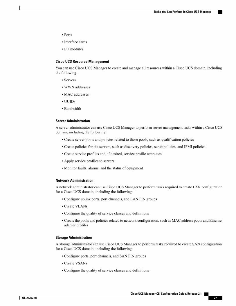
• Ports
• Interface cards
• I/O modules
Cisco UCS Resource Management
You can use Cisco UCS Manager to create and manage all resources within a Cisco UCS domain, includingthe following:
• Servers
•WWN addresses
• MAC addresses
• UUIDs
• Bandwidth
Server Administration
A server administrator can use Cisco UCSManager to perform server management tasks within a Cisco UCSdomain, including the following:
• Create server pools and policies related to those pools, such as qualification policies
• Create policies for the servers, such as discovery policies, scrub policies, and IPMI policies
• Create service profiles and, if desired, service profile templates
• Apply service profiles to servers
• Monitor faults, alarms, and the status of equipment
Network Administration
A network administrator can use Cisco UCS Manager to perform tasks required to create LAN configurationfor a Cisco UCS domain, including the following:
• Configure uplink ports, port channels, and LAN PIN groups
• Create VLANs
• Configure the quality of service classes and definitions
• Create the pools and policies related to network configuration, such as MAC address pools and Ethernetadapter profiles
Storage Administration
A storage administrator can use Cisco UCS Manager to perform tasks required to create SAN configurationfor a Cisco UCS domain, including the following:
• Configure ports, port channels, and SAN PIN groups
• Create VSANs
• Configure the quality of service classes and definitions
Cisco UCS Manager CLI Configuration Guide, Release 2.1 OL-28302-04 27
Tasks You Can Perform in Cisco UCS Manager
• Create the pools and policies related to the network configuration, such asWWNpools and Fibre Channeladapter profiles
Tasks You Cannot Perform in Cisco UCS ManagerYou cannot use Cisco UCS Manager to perform certain system management tasks that are not specificallyrelated to device management within a Cisco UCS domain.
No Cross-System Management
You cannot use Cisco UCS Manager to manage systems or devices that are outside the Cisco UCS domainwhere Cisco UCS Manager is located. For example, you cannot manage heterogeneous environments, suchas non-Cisco UCS x86 systems, SPARC systems, or PowerPC systems.
No Operating System or Application Provisioning or Management
CiscoUCSManager provisions servers and, as a result, exists below the operating system on a server. Therefore,you cannot use it to provision or manage operating systems or applications on servers. For example, youcannot do the following:
• Deploy an OS, such as Windows or Linux
• Deploy patches for software, such as an OS or an application
• Install base software components, such as anti-virus software, monitoring agents, or backup clients
• Install software applications, such as databases, application server software, or web servers
• Perform operator actions, including restarting an Oracle database, restarting printer queues, or handlingnon-Cisco UCS user accounts
• Configure or manage external storage on the SAN or NAS storage
Cisco UCS Manager in a High Availability EnvironmentIn a high availability environment with two fabric interconnects, you can run a separate instance of CiscoUCS Manager on each fabric interconnect. The Cisco UCS Manager on the primary fabric interconnect actsas the primary management instance, and the Cisco UCS Manager on the other fabric interconnect is thesubordinate management instance.
The two instances of Cisco UCS Manager communicate across a private network between the L1 and L2Ethernet ports on the fabric interconnects. Configuration and status information is communicated across thisprivate network to ensure that all management information is replicated. This ongoing communication ensuresthat the management information for Cisco UCS persists even if the primary fabric interconnect fails. Inaddition, the "floating" management IP address that runs on the primary Cisco UCSManager ensures a smoothtransition in the event of a failover to the subordinate fabric interconnect.
Cisco UCS Manager CLI Configuration Guide, Release 2.128 OL-28302-04
Tasks You Cannot Perform in Cisco UCS Manager
C H A P T E R 4Overview of Cisco UCS Manager CLI
This chapter includes the following sections:
• Managed Objects, page 29
• Command Modes, page 29
• Object Commands, page 31
• Complete a Command, page 32
• Command History, page 32
• Committing, Discarding, and Viewing Pending Commands, page 32
• Online Help for the CLI, page 33
• CLI Session Limits, page 33
• Web Session Limits, page 33
• Pre-Login Banner, page 34
Managed ObjectsCisco UCS uses a managed object model, where managed objects are abstract representations of physical orlogical entities that can be managed. For example, servers, chassis, I/O cards, and processors are physicalentities represented as managed objects, and resource pools, user roles, service profiles, and policies are logicalentities represented as managed objects.
Managed objects may have one or more associated properties that can be configured.
Command ModesThe CLI is organized into a hierarchy of command modes, with the EXECmode being the highest-level modeof the hierarchy. Higher-level modes branch into lower-level modes. You use create, enter, and scopecommands to move from higher-level modes to modes in the next lower level , and you use the exit commandto move up one level in the mode hierarchy.
Cisco UCS Manager CLI Configuration Guide, Release 2.1 OL-28302-04 29
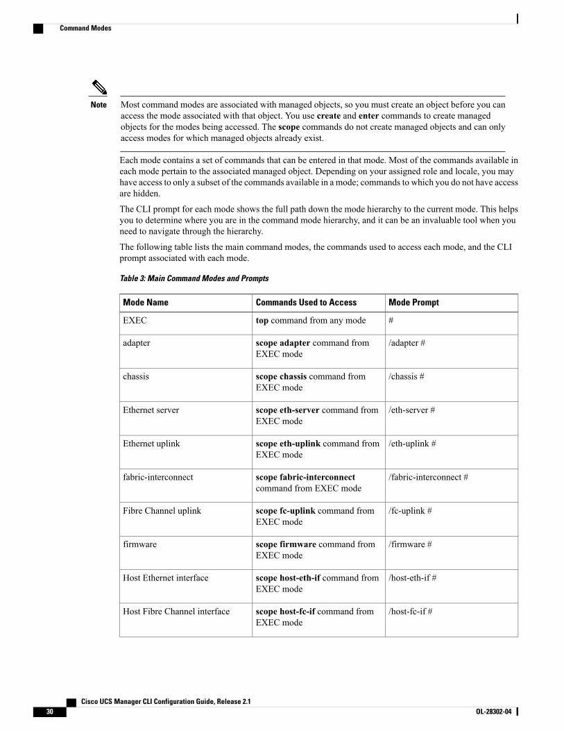
Most command modes are associated with managed objects, so you must create an object before you canaccess the mode associated with that object. You use create and enter commands to create managedobjects for the modes being accessed. The scope commands do not create managed objects and can onlyaccess modes for which managed objects already exist.
Note
Each mode contains a set of commands that can be entered in that mode. Most of the commands available ineach mode pertain to the associated managed object. Depending on your assigned role and locale, you mayhave access to only a subset of the commands available in a mode; commands to which you do not have accessare hidden.
The CLI prompt for each mode shows the full path down the mode hierarchy to the current mode. This helpsyou to determine where you are in the command mode hierarchy, and it can be an invaluable tool when youneed to navigate through the hierarchy.
The following table lists the main command modes, the commands used to access each mode, and the CLIprompt associated with each mode.
Table 3: Main Command Modes and Prompts
Mode PromptCommands Used to AccessMode Name
#top command from any modeEXEC
/adapter #scope adapter command fromEXEC mode
adapter
/chassis #scope chassis command fromEXEC mode
chassis
/eth-server #scope eth-server command fromEXEC mode
Ethernet server
/eth-uplink #scope eth-uplink command fromEXEC mode
Ethernet uplink
/fabric-interconnect #scope fabric-interconnectcommand from EXEC mode
fabric-interconnect
/fc-uplink #scope fc-uplink command fromEXEC mode
Fibre Channel uplink
/firmware #scope firmware command fromEXEC mode
firmware
/host-eth-if #scope host-eth-if command fromEXEC mode
Host Ethernet interface
/host-fc-if #scope host-fc-if command fromEXEC mode
Host Fibre Channel interface
Cisco UCS Manager CLI Configuration Guide, Release 2.130 OL-28302-04
Command Modes
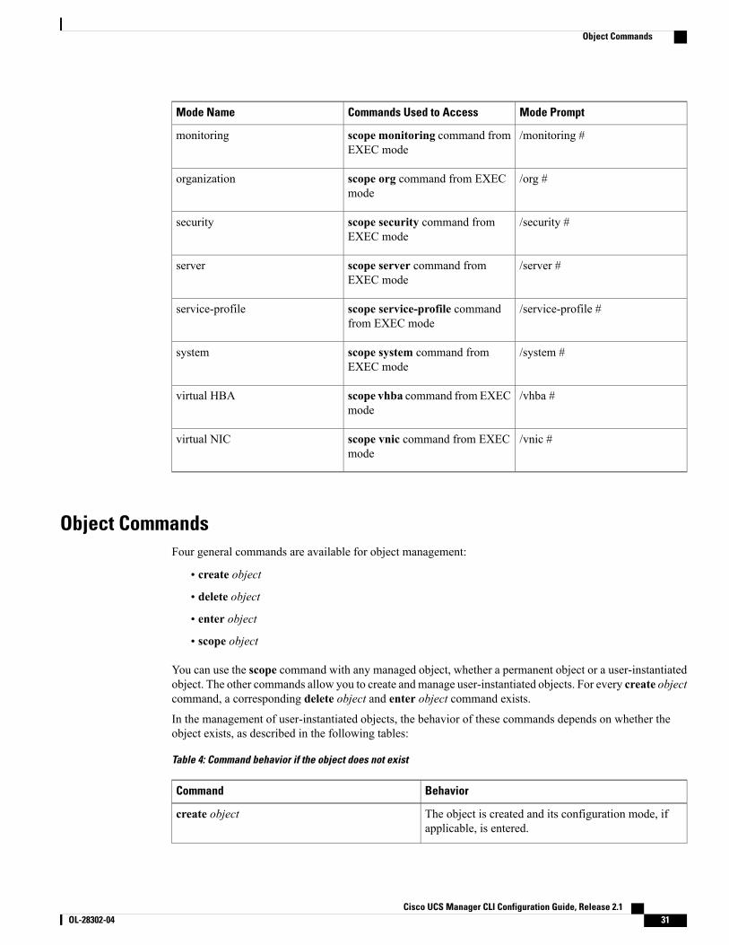
Mode PromptCommands Used to AccessMode Name
/monitoring #scope monitoring command fromEXEC mode
monitoring
/org #scope org command from EXECmode
organization
/security #scope security command fromEXEC mode
security
/server #scope server command fromEXEC mode
server
/service-profile #scope service-profile commandfrom EXEC mode
service-profile
/system #scope system command fromEXEC mode
system
/vhba #scope vhba command from EXECmode
virtual HBA
/vnic #scope vnic command from EXECmode
virtual NIC
Object CommandsFour general commands are available for object management:
• create object
• delete object
• enter object
• scope object
You can use the scope command with any managed object, whether a permanent object or a user-instantiatedobject. The other commands allow you to create andmanage user-instantiated objects. For every create objectcommand, a corresponding delete object and enter object command exists.
In the management of user-instantiated objects, the behavior of these commands depends on whether theobject exists, as described in the following tables:
Table 4: Command behavior if the object does not exist
BehaviorCommand
The object is created and its configuration mode, ifapplicable, is entered.
create object
Cisco UCS Manager CLI Configuration Guide, Release 2.1 OL-28302-04 31
Object Commands
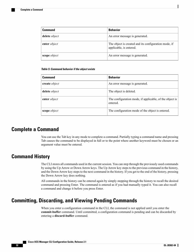
BehaviorCommand
An error message is generated.delete object
The object is created and its configuration mode, ifapplicable, is entered.
enter object
An error message is generated.scope object
Table 5: Command behavior if the object exists
BehaviorCommand
An error message is generated.create object
The object is deleted.delete object
The configuration mode, if applicable, of the object isentered.
enter object
The configuration mode of the object is entered.scope object
Complete a CommandYou can use the Tab key in any mode to complete a command. Partially typing a command name and pressingTab causes the command to be displayed in full or to the point where another keyword must be chosen or anargument value must be entered.
Command HistoryThe CLI stores all commands used in the current session. You can step through the previously used commandsby using the Up Arrow or DownArrow keys. The Up Arrow key steps to the previous command in the history,and the DownArrow key steps to the next command in the history. If you get to the end of the history, pressingthe Down Arrow key does nothing.
All commands in the history can be entered again by simply stepping through the history to recall the desiredcommand and pressing Enter. The command is entered as if you had manually typed it. You can also recalla command and change it before you press Enter.
Committing, Discarding, and Viewing Pending CommandsWhen you enter a configuration command in the CLI, the command is not applied until you enter thecommit-buffer command. Until committed, a configuration command is pending and can be discarded byentering a discard-buffer command.
Cisco UCS Manager CLI Configuration Guide, Release 2.132 OL-28302-04
Complete a Command
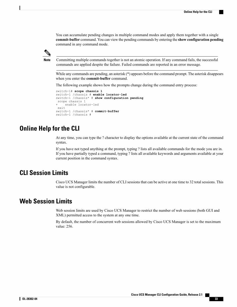
You can accumulate pending changes in multiple command modes and apply them together with a singlecommit-buffer command. You can view the pending commands by entering the show configuration pendingcommand in any command mode.
Committing multiple commands together is not an atomic operation. If any command fails, the successfulcommands are applied despite the failure. Failed commands are reported in an error message.
Note
While any commands are pending, an asterisk (*) appears before the command prompt. The asterisk disappearswhen you enter the commit-buffer command.
The following example shows how the prompts change during the command entry process:switch-1# scope chassis 1switch-1 /chassis # enable locator-ledswitch-1 /chassis* # show configuration pendingscope chassis 1+ enable locator-ledexitswitch-1 /chassis* # commit-bufferswitch-1 /chassis #
Online Help for the CLIAt any time, you can type the ? character to display the options available at the current state of the commandsyntax.
If you have not typed anything at the prompt, typing ? lists all available commands for the mode you are in.If you have partially typed a command, typing ? lists all available keywords and arguments available at yourcurrent position in the command syntax.
CLI Session LimitsCisco UCSManager limits the number of CLI sessions that can be active at one time to 32 total sessions. Thisvalue is not configurable.
Web Session LimitsWeb session limits are used by Cisco UCS Manager to restrict the number of web sessions (both GUI andXML) permitted access to the system at any one time.
By default, the number of concurrent web sessions allowed by Cisco UCS Manager is set to the maximumvalue: 256.
Cisco UCS Manager CLI Configuration Guide, Release 2.1 OL-28302-04 33
Online Help for the CLI
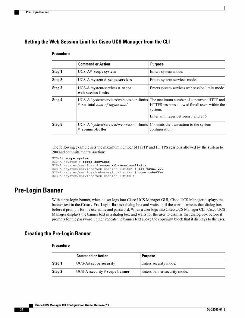
Setting the Web Session Limit for Cisco UCS Manager from the CLI
Procedure
PurposeCommand or Action
Enters system mode.UCS-A# scope systemStep 1
Enters system services mode.UCS-A /system # scope servicesStep 2
Enters system services web session limits mode.UCS-A /system/services # scopeweb-session-limits
Step 3
Themaximum number of concurrent HTTP andHTTPS sessions allowed for all users within thesystem.
UCS-A /system/services/web-session-limits# set total num-of-logins-total
Step 4
Enter an integer between 1 and 256.
Commits the transaction to the systemconfiguration.
UCS-A /system/services/web-session-limits# commit-buffer
Step 5
The following example sets the maximum number of HTTP and HTTPS sessions allowed by the system to200 and commits the transaction:UCS-A# scope systemUCS-A /system # scope servicesUCS-A /system/services # scope web-session-limitsUCS-A /system/services/web-session-limits* # set total 200UCS-A /system/services/web-session-limits* # commit-bufferUCS-A /system/services/web-session-limits #
Pre-Login BannerWith a pre-login banner, when a user logs into Cisco UCS Manager GUI, Cisco UCS Manager displays thebanner text in the Create Pre-Login Banner dialog box and waits until the user dismisses that dialog boxbefore it prompts for the username and password. When a user logs into Cisco UCSManager CLI, Cisco UCSManager displays the banner text in a dialog box and waits for the user to dismiss that dialog box before itprompts for the password. It then repeats the banner text above the copyright block that it displays to the user.
Creating the Pre-Login Banner
Procedure
PurposeCommand or Action
Enters security mode.UCS-A# scope securityStep 1
Enters banner security mode.UCS-A /security # scope bannerStep 2
Cisco UCS Manager CLI Configuration Guide, Release 2.134 OL-28302-04
Pre-Login Banner
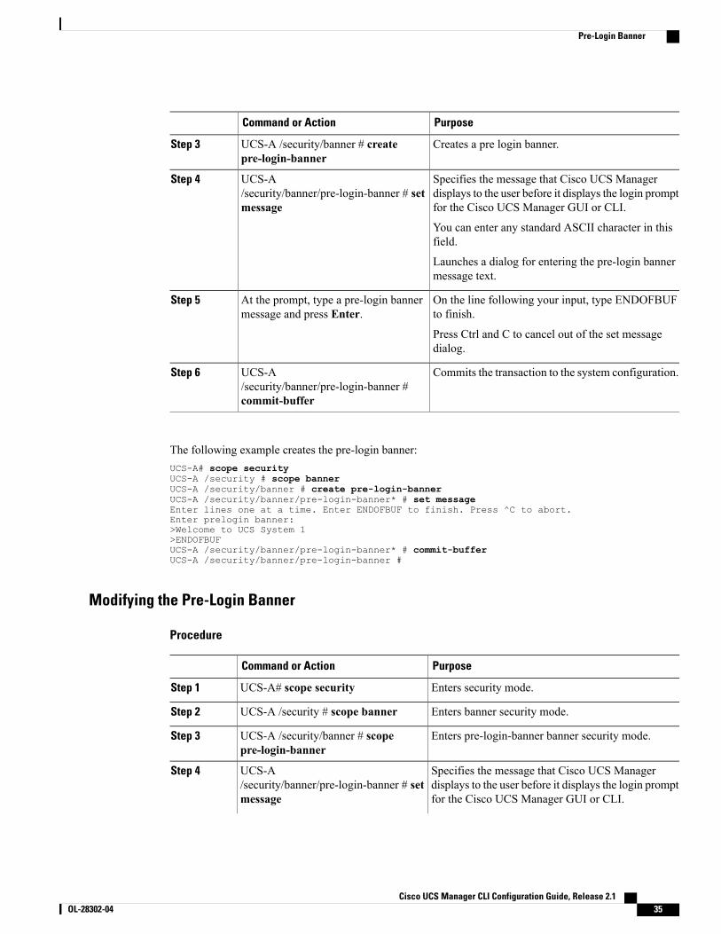
PurposeCommand or Action
Creates a pre login banner.UCS-A /security/banner # createpre-login-banner
Step 3
Specifies the message that Cisco UCS Managerdisplays to the user before it displays the login promptfor the Cisco UCS Manager GUI or CLI.
UCS-A/security/banner/pre-login-banner # setmessage
Step 4
You can enter any standard ASCII character in thisfield.
Launches a dialog for entering the pre-login bannermessage text.
On the line following your input, type ENDOFBUFto finish.
At the prompt, type a pre-login bannermessage and press Enter.
Step 5
Press Ctrl and C to cancel out of the set messagedialog.
Commits the transaction to the system configuration.UCS-A/security/banner/pre-login-banner #commit-buffer
Step 6
The following example creates the pre-login banner:UCS-A# scope securityUCS-A /security # scope bannerUCS-A /security/banner # create pre-login-bannerUCS-A /security/banner/pre-login-banner* # set messageEnter lines one at a time. Enter ENDOFBUF to finish. Press ^C to abort.Enter prelogin banner:>Welcome to UCS System 1>ENDOFBUFUCS-A /security/banner/pre-login-banner* # commit-bufferUCS-A /security/banner/pre-login-banner #
Modifying the Pre-Login Banner
Procedure
PurposeCommand or Action
Enters security mode.UCS-A# scope securityStep 1
Enters banner security mode.UCS-A /security # scope bannerStep 2
Enters pre-login-banner banner security mode.UCS-A /security/banner # scopepre-login-banner
Step 3
Specifies the message that Cisco UCS Managerdisplays to the user before it displays the login promptfor the Cisco UCS Manager GUI or CLI.
UCS-A/security/banner/pre-login-banner # setmessage
Step 4
Cisco UCS Manager CLI Configuration Guide, Release 2.1 OL-28302-04 35
Pre-Login Banner
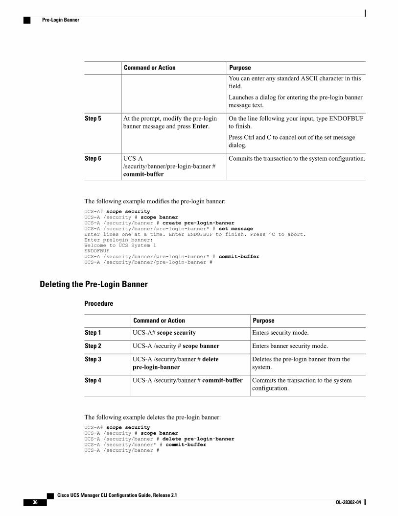
PurposeCommand or Action
You can enter any standard ASCII character in thisfield.
Launches a dialog for entering the pre-login bannermessage text.
On the line following your input, type ENDOFBUFto finish.
At the prompt, modify the pre-loginbanner message and press Enter.
Step 5
Press Ctrl and C to cancel out of the set messagedialog.
Commits the transaction to the system configuration.UCS-A/security/banner/pre-login-banner #commit-buffer
Step 6
The following example modifies the pre-login banner:UCS-A# scope securityUCS-A /security # scope bannerUCS-A /security/banner # create pre-login-bannerUCS-A /security/banner/pre-login-banner* # set messageEnter lines one at a time. Enter ENDOFBUF to finish. Press ^C to abort.Enter prelogin banner:Welcome to UCS System 1ENDOFBUFUCS-A /security/banner/pre-login-banner* # commit-bufferUCS-A /security/banner/pre-login-banner #
Deleting the Pre-Login Banner
Procedure
PurposeCommand or Action
Enters security mode.UCS-A# scope securityStep 1
Enters banner security mode.UCS-A /security # scope bannerStep 2
Deletes the pre-login banner from thesystem.
UCS-A /security/banner # deletepre-login-banner
Step 3
Commits the transaction to the systemconfiguration.
UCS-A /security/banner # commit-bufferStep 4
The following example deletes the pre-login banner:UCS-A# scope securityUCS-A /security # scope bannerUCS-A /security/banner # delete pre-login-bannerUCS-A /security/banner* # commit-bufferUCS-A /security/banner #
Cisco UCS Manager CLI Configuration Guide, Release 2.136 OL-28302-04
Pre-Login Banner
P A R T IISystem Configuration• Configuring the Fabric Interconnects, page 39
• Configuring Ports and Port Channels, page 53
• Configuring Communication Services, page 93
• Configuring Authentication, page 117
• Configuring Organizations, page 147
• Configuring Role-Based Access Control, page 153
• Configuring DNS Servers, page 179
• Configuring System-Related Policies, page 181
• Managing Licenses, page 189
• Managing Virtual Interfaces, page 197
• Registering Cisco UCS Domains with Cisco UCS Central, page 199

C H A P T E R 5Configuring the Fabric Interconnects
This chapter includes the following sections:
• Initial System Setup, page 39
• Performing an Initial System Setup for a Standalone Configuration, page 41
• Initial System Setup for a Cluster Configuration, page 43
• Enabling a Standalone Fabric Interconnect for Cluster Configuration, page 46
• Changing the System Name, page 47
• Changing the Management Subnet of a Cluster, page 47
• Ethernet Switching Mode, page 48
• Configuring Ethernet Switching Mode, page 49
• Fibre Channel Switching Mode, page 50
• Configuring Fibre Channel Switching Mode, page 50
Initial System SetupThe first time that you access a fabric interconnect in a Cisco UCS domain, a setup wizard prompts you forthe following information required to configure the system:
• Installation method (GUI or CLI)
• Setup mode (restore from full system backup or initial setup)
• System configuration type (standalone or cluster configuration)
• System name
• Admin password
• Management port IP address and subnet mask
• Default gateway IP address
• DNS Server IP address
Cisco UCS Manager CLI Configuration Guide, Release 2.1 OL-28302-04 39
• Default domain name
Setup ModeYou can choose to either restore the system configuration from an existing backup file, or manually set upthe system by going through the Setup wizard. If you choose to restore the system, the backup file must bereachable from the management network.
System Configuration TypeYou can configure a Cisco UCS domain to use a single fabric interconnect in a standalone configuration orto use a redundant pair of fabric interconnects in a cluster configuration.
A cluster configuration provides high availability. If one fabric interconnect becomes unavailable, the othertakes over. Only one management port (Mgmt0) connection is required to support a cluster configuration;however, both Mgmt0 ports should be connected to provide link-level redundancy.
In addition, a cluster configuration actively enhances failover recovery time for redundant virtual interface(VIF) connections. When an adapter has an active VIF connection to one fabric interconnect and a standbyVIF connection to the second, the learned MAC addresses of the active VIF are replicated but not installedon the second fabric interconnect. If the active VIF fails, the second fabric interconnect installs the replicatedMAC addresses and broadcasts them to the network through gratuitous ARP messages, shortening theswitchover time.
The cluster configuration provides redundancy only for the management plane. Data redundancy isdependent on the user configuration and might require a third-party tool to support data redundancy.
Note
To use the cluster configuration, you must directly connect the two fabric interconnects together using Ethernetcables between the L1 (L1-to-L1) and L2 (L2-to-L2) high-availability ports, with no other fabric interconnectsin between. Also you can connect the fabric interconnects directly through a patch panel to allow the twofabric interconnects to continuously monitor the status of each other and quickly know when one has failed.
Both fabric interconnects in a cluster configuration must go through the initial setup process. You must enablethe first fabric interconnect that you set up for a cluster configuration. When you set up the second fabricinterconnect, it detects the first fabric interconnect as a peer fabric interconnect in the cluster.
For more information, see to the Cisco UCS 6100 Series Fabric Interconnect Hardware Installation Guide.
Management Port IP AddressIn a standalone configuration, you must specify only one IP address and the subnet mask for the singlemanagement port on the fabric interconnect.
In a cluster configuration, you must specify the following three IP addresses in the same subnet:
• Management port IP address for fabric interconnect A
• Management port IP address for fabric interconnect B
• Cluster IP address
Cisco UCS Manager CLI Configuration Guide, Release 2.140 OL-28302-04
Initial System Setup
Performing an Initial System Setup for a Standalone Configuration
Before You Begin
1 Verify the following physical connections on the fabric interconnect:
• The console port is physically connected to a computer terminal or console server
• The management Ethernet port (mgmt0) is connected to an external hub, switch, or router
For more information, refer to the Cisco UCS Hardware Installation Guide for your fabric interconnect.
2 Verify that the console port parameters on the computer terminal (or console server) attached to the consoleport are as follows:
• 9600 baud
• 8 data bits
• No parity
• 1 stop bit
3 Collect the following information that you will need to supply during the initial setup:
• System name.
• Password for the admin account. Choose a strong password that meets the guidelines for Cisco UCSManager passwords. This password cannot be blank.
• Management port IP address and subnet mask.
• Default gateway IP address.
• DNS server IP address (optional).
• Domain name for the system (optional).
Procedure
Step 1 Connect to the console port.Step 2 Power on the fabric interconnect.
Cisco UCS Manager CLI Configuration Guide, Release 2.1 OL-28302-04 41
Performing an Initial System Setup for a Standalone Configuration
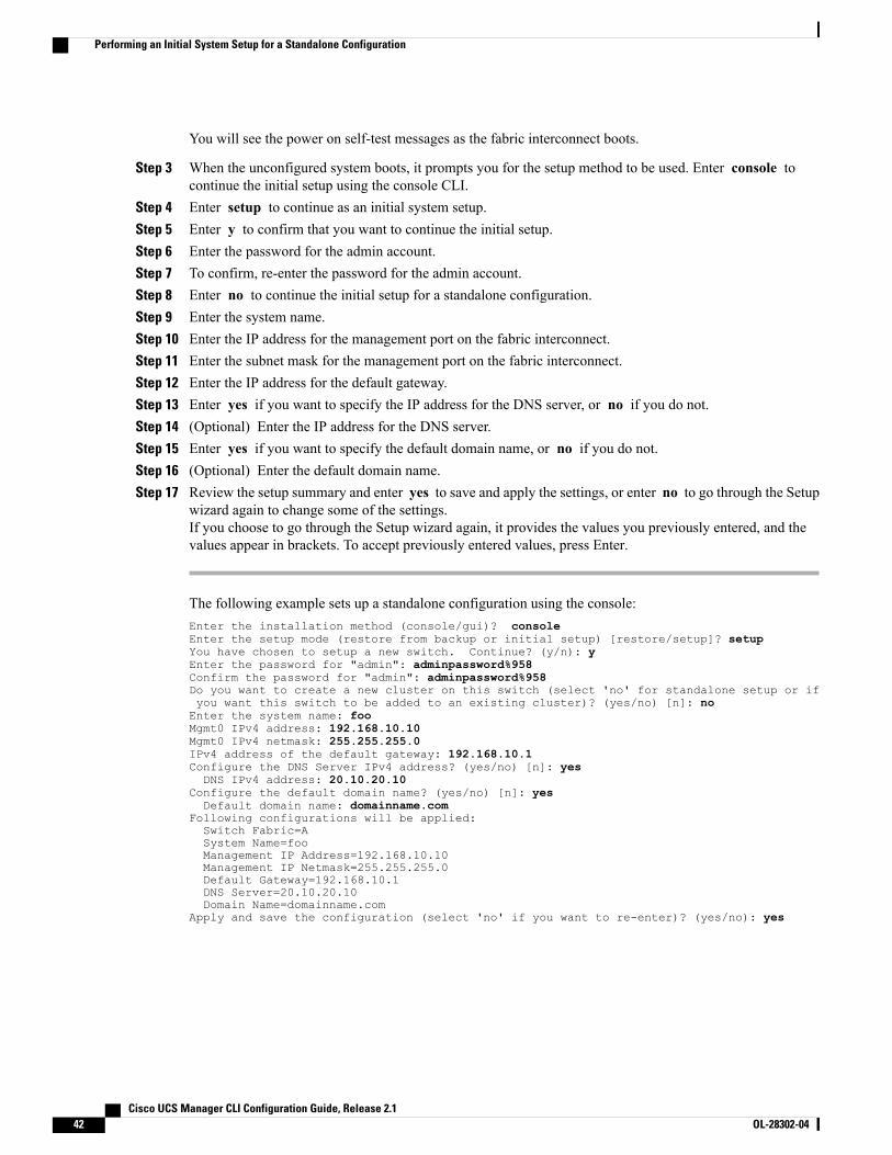
You will see the power on self-test messages as the fabric interconnect boots.
Step 3 When the unconfigured system boots, it prompts you for the setup method to be used. Enter console tocontinue the initial setup using the console CLI.
Step 4 Enter setup to continue as an initial system setup.Step 5 Enter y to confirm that you want to continue the initial setup.Step 6 Enter the password for the admin account.Step 7 To confirm, re-enter the password for the admin account.Step 8 Enter no to continue the initial setup for a standalone configuration.Step 9 Enter the system name.Step 10 Enter the IP address for the management port on the fabric interconnect.Step 11 Enter the subnet mask for the management port on the fabric interconnect.Step 12 Enter the IP address for the default gateway.Step 13 Enter yes if you want to specify the IP address for the DNS server, or no if you do not.Step 14 (Optional) Enter the IP address for the DNS server.Step 15 Enter yes if you want to specify the default domain name, or no if you do not.Step 16 (Optional) Enter the default domain name.Step 17 Review the setup summary and enter yes to save and apply the settings, or enter no to go through the Setup
wizard again to change some of the settings.If you choose to go through the Setup wizard again, it provides the values you previously entered, and thevalues appear in brackets. To accept previously entered values, press Enter.
The following example sets up a standalone configuration using the console:Enter the installation method (console/gui)? consoleEnter the setup mode (restore from backup or initial setup) [restore/setup]? setupYou have chosen to setup a new switch. Continue? (y/n): yEnter the password for "admin": adminpassword%958Confirm the password for "admin": adminpassword%958Do you want to create a new cluster on this switch (select 'no' for standalone setup or ifyou want this switch to be added to an existing cluster)? (yes/no) [n]: noEnter the system name: fooMgmt0 IPv4 address: 192.168.10.10Mgmt0 IPv4 netmask: 255.255.255.0IPv4 address of the default gateway: 192.168.10.1Configure the DNS Server IPv4 address? (yes/no) [n]: yesDNS IPv4 address: 20.10.20.10
Configure the default domain name? (yes/no) [n]: yesDefault domain name: domainname.com
Following configurations will be applied:Switch Fabric=ASystem Name=fooManagement IP Address=192.168.10.10Management IP Netmask=255.255.255.0Default Gateway=192.168.10.1DNS Server=20.10.20.10Domain Name=domainname.com
Apply and save the configuration (select 'no' if you want to re-enter)? (yes/no): yes
Cisco UCS Manager CLI Configuration Guide, Release 2.142 OL-28302-04
Performing an Initial System Setup for a Standalone Configuration
Initial System Setup for a Cluster Configuration
Performing an Initial System Setup for the First Fabric Interconnect
Before You Begin
1 Verify the following physical connections on the fabric interconnect:
• A console port on the first fabric interconnect is physically connected to a computer terminal orconsole server
• The management Ethernet port (mgmt0) is connected to an external hub, switch, or router
• The L1 ports on both fabric interconnects are directly connected to each other
• The L2 ports on both fabric interconnects are directly connected to each other
For more information, refer to the Cisco UCS Hardware Installation Guide for your fabric interconnect.
2 Verify that the console port parameters on the computer terminal (or console server) attached to the consoleport are as follows:
• 9600 baud
• 8 data bits
• No parity
• 1 stop bit
3 Collect the following information that you will need to supply during the initial setup:
• System name.
• Password for the admin account. Choose a strong password that meets the guidelines for Cisco UCSManager passwords. This password cannot be blank.
• Three static IP addresses: two for the management port on both fabric interconnects (one per fabricinterconnect) and one for the cluster IP address used by Cisco UCS Manager.
• Subnet mask for the three static IP addresses.
• Default gateway IP address.
• DNS server IP address (optional).
• Domain name for the system (optional).
Procedure
Step 1 Connect to the console port.Step 2 Power on the fabric interconnect.
Cisco UCS Manager CLI Configuration Guide, Release 2.1 OL-28302-04 43
Initial System Setup for a Cluster Configuration
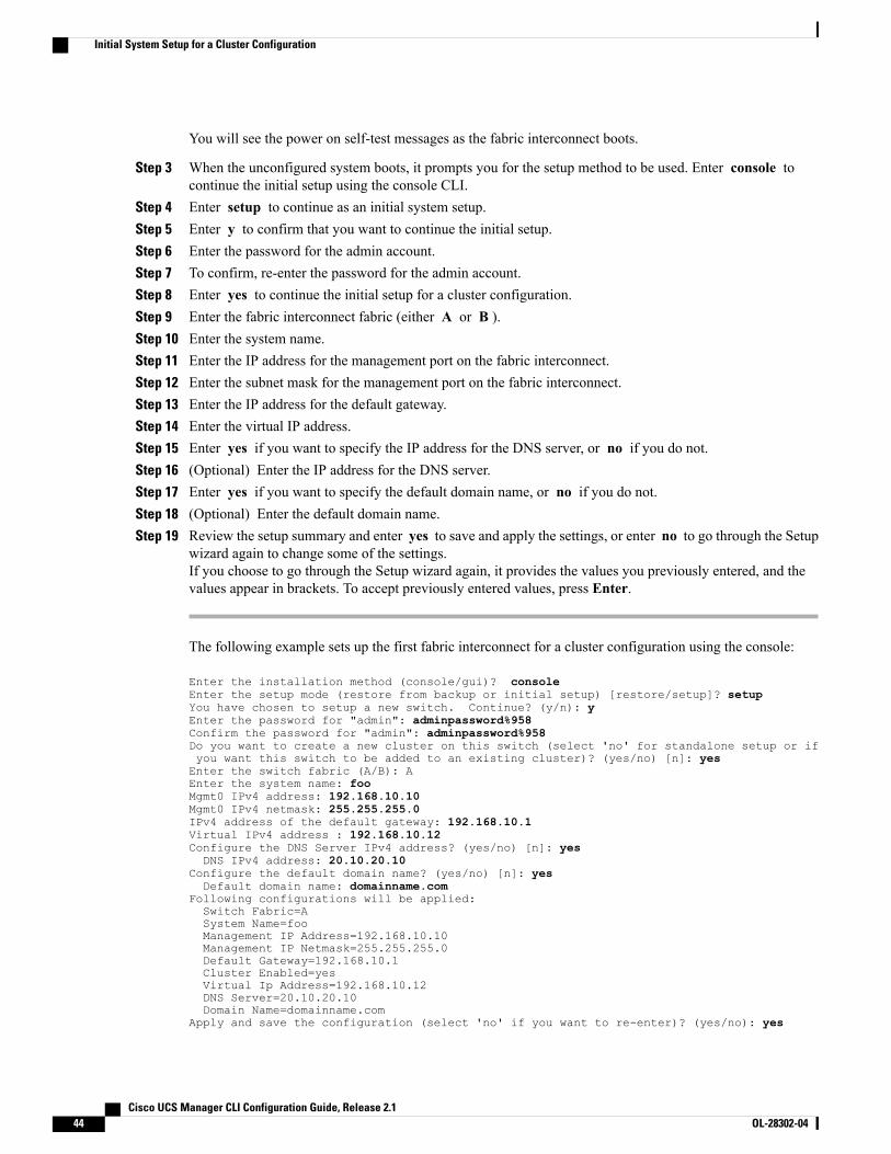
You will see the power on self-test messages as the fabric interconnect boots.
Step 3 When the unconfigured system boots, it prompts you for the setup method to be used. Enter console tocontinue the initial setup using the console CLI.
Step 4 Enter setup to continue as an initial system setup.Step 5 Enter y to confirm that you want to continue the initial setup.Step 6 Enter the password for the admin account.Step 7 To confirm, re-enter the password for the admin account.Step 8 Enter yes to continue the initial setup for a cluster configuration.Step 9 Enter the fabric interconnect fabric (either A or B ).Step 10 Enter the system name.Step 11 Enter the IP address for the management port on the fabric interconnect.Step 12 Enter the subnet mask for the management port on the fabric interconnect.Step 13 Enter the IP address for the default gateway.Step 14 Enter the virtual IP address.Step 15 Enter yes if you want to specify the IP address for the DNS server, or no if you do not.Step 16 (Optional) Enter the IP address for the DNS server.Step 17 Enter yes if you want to specify the default domain name, or no if you do not.Step 18 (Optional) Enter the default domain name.Step 19 Review the setup summary and enter yes to save and apply the settings, or enter no to go through the Setup
wizard again to change some of the settings.If you choose to go through the Setup wizard again, it provides the values you previously entered, and thevalues appear in brackets. To accept previously entered values, press Enter.
The following example sets up the first fabric interconnect for a cluster configuration using the console:
Enter the installation method (console/gui)? consoleEnter the setup mode (restore from backup or initial setup) [restore/setup]? setupYou have chosen to setup a new switch. Continue? (y/n): yEnter the password for "admin": adminpassword%958Confirm the password for "admin": adminpassword%958Do you want to create a new cluster on this switch (select 'no' for standalone setup or ifyou want this switch to be added to an existing cluster)? (yes/no) [n]: yesEnter the switch fabric (A/B): AEnter the system name: fooMgmt0 IPv4 address: 192.168.10.10Mgmt0 IPv4 netmask: 255.255.255.0IPv4 address of the default gateway: 192.168.10.1Virtual IPv4 address : 192.168.10.12Configure the DNS Server IPv4 address? (yes/no) [n]: yesDNS IPv4 address: 20.10.20.10
Configure the default domain name? (yes/no) [n]: yesDefault domain name: domainname.com
Following configurations will be applied:Switch Fabric=ASystem Name=fooManagement IP Address=192.168.10.10Management IP Netmask=255.255.255.0Default Gateway=192.168.10.1Cluster Enabled=yesVirtual Ip Address=192.168.10.12DNS Server=20.10.20.10Domain Name=domainname.com
Apply and save the configuration (select 'no' if you want to re-enter)? (yes/no): yes
Cisco UCS Manager CLI Configuration Guide, Release 2.144 OL-28302-04
Initial System Setup for a Cluster Configuration
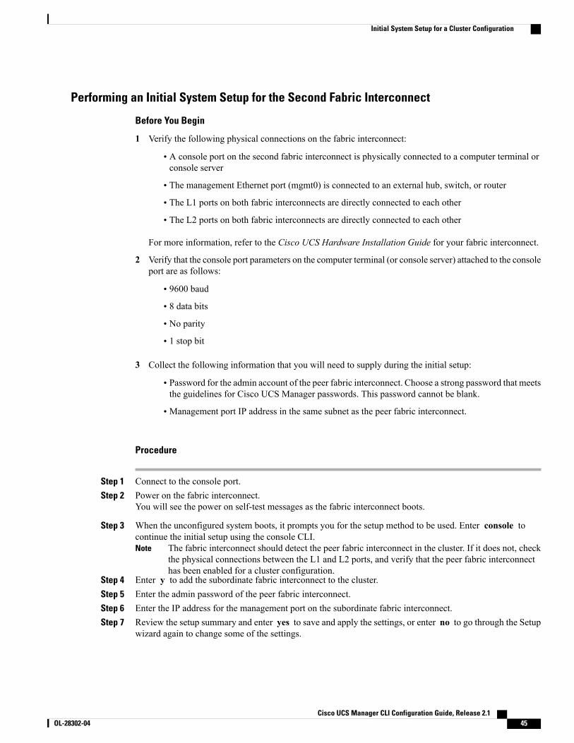
Performing an Initial System Setup for the Second Fabric Interconnect
Before You Begin
1 Verify the following physical connections on the fabric interconnect:
• A console port on the second fabric interconnect is physically connected to a computer terminal orconsole server
• The management Ethernet port (mgmt0) is connected to an external hub, switch, or router
• The L1 ports on both fabric interconnects are directly connected to each other
• The L2 ports on both fabric interconnects are directly connected to each other
For more information, refer to the Cisco UCS Hardware Installation Guide for your fabric interconnect.
2 Verify that the console port parameters on the computer terminal (or console server) attached to the consoleport are as follows:
• 9600 baud
• 8 data bits
• No parity
• 1 stop bit
3 Collect the following information that you will need to supply during the initial setup:
• Password for the admin account of the peer fabric interconnect. Choose a strong password that meetsthe guidelines for Cisco UCS Manager passwords. This password cannot be blank.
• Management port IP address in the same subnet as the peer fabric interconnect.
Procedure
Step 1 Connect to the console port.Step 2 Power on the fabric interconnect.
You will see the power on self-test messages as the fabric interconnect boots.
Step 3 When the unconfigured system boots, it prompts you for the setup method to be used. Enter console tocontinue the initial setup using the console CLI.
The fabric interconnect should detect the peer fabric interconnect in the cluster. If it does not, checkthe physical connections between the L1 and L2 ports, and verify that the peer fabric interconnecthas been enabled for a cluster configuration.
Note
Step 4 Enter y to add the subordinate fabric interconnect to the cluster.Step 5 Enter the admin password of the peer fabric interconnect.Step 6 Enter the IP address for the management port on the subordinate fabric interconnect.Step 7 Review the setup summary and enter yes to save and apply the settings, or enter no to go through the Setup
wizard again to change some of the settings.
Cisco UCS Manager CLI Configuration Guide, Release 2.1 OL-28302-04 45
Initial System Setup for a Cluster Configuration
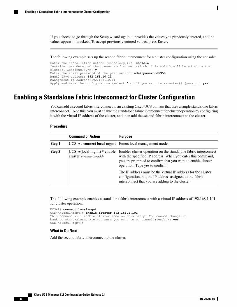
If you choose to go through the Setup wizard again, it provides the values you previously entered, and thevalues appear in brackets. To accept previously entered values, press Enter.
The following example sets up the second fabric interconnect for a cluster configuration using the console:Enter the installation method (console/gui)? consoleInstaller has detected the presence of a peer switch. This switch will be added to thecluster. Continue?[y/n] yEnter the admin password of the peer switch: adminpassword%958Mgmt0 IPv4 address: 192.168.10.11Management Ip Address=192.168.10.11Apply and save the configuration (select 'no' if you want to re-enter)? (yes/no): yes
Enabling a Standalone Fabric Interconnect for Cluster ConfigurationYou can add a second fabric interconnect to an existing Cisco UCS domain that uses a single standalone fabricinterconnect. To do this, youmust enable the standalone fabric interconnect for cluster operation by configuringit with the virtual IP address of the cluster, and then add the second fabric interconnect to the cluster.
Procedure
PurposeCommand or Action
Enters local management mode.UCS-A# connect local-mgmtStep 1
Enables cluster operation on the standalone fabric interconnectwith the specified IP address. When you enter this command,
UCS-A(local-mgmt) # enablecluster virtual-ip-addr
Step 2
you are prompted to confirm that you want to enable clusteroperation. Type yes to confirm.
The IP address must be the virtual IP address for the clusterconfiguration, not the IP address assigned to the fabricinterconnect that you are adding to the cluster.
The following example enables a standalone fabric interconnect with a virtual IP address of 192.168.1.101for cluster operation:UCS-A# connect local-mgmtUCS-A(local-mgmt)# enable cluster 192.168.1.101This command will enable cluster mode on this setup. You cannot change itback to stand-alone. Are you sure you want to continue? (yes/no): yesUCS-A(local-mgmt)#
What to Do Next
Add the second fabric interconnect to the cluster.
Cisco UCS Manager CLI Configuration Guide, Release 2.146 OL-28302-04
Enabling a Standalone Fabric Interconnect for Cluster Configuration
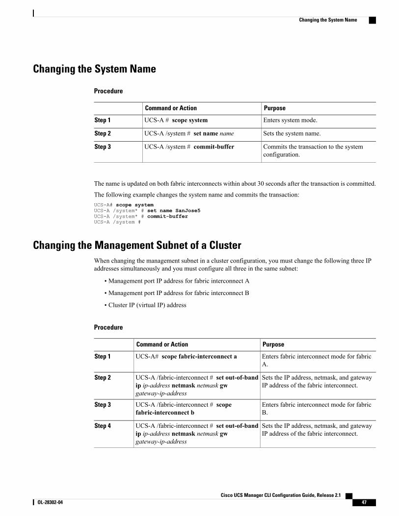
Changing the System Name
Procedure
PurposeCommand or Action
Enters system mode.UCS-A # scope systemStep 1
Sets the system name.UCS-A /system # set name nameStep 2
Commits the transaction to the systemconfiguration.
UCS-A /system # commit-bufferStep 3
The name is updated on both fabric interconnects within about 30 seconds after the transaction is committed.
The following example changes the system name and commits the transaction:UCS-A# scope systemUCS-A /system* # set name SanJose5UCS-A /system* # commit-bufferUCS-A /system #
Changing the Management Subnet of a ClusterWhen changing the management subnet in a cluster configuration, you must change the following three IPaddresses simultaneously and you must configure all three in the same subnet:
• Management port IP address for fabric interconnect A
• Management port IP address for fabric interconnect B
• Cluster IP (virtual IP) address
Procedure
PurposeCommand or Action
Enters fabric interconnect mode for fabricA.
UCS-A# scope fabric-interconnect aStep 1
Sets the IP address, netmask, and gatewayIP address of the fabric interconnect.
UCS-A /fabric-interconnect # set out-of-bandip ip-address netmask netmask gwgateway-ip-address
Step 2
Enters fabric interconnect mode for fabricB.
UCS-A /fabric-interconnect # scopefabric-interconnect b
Step 3
Sets the IP address, netmask, and gatewayIP address of the fabric interconnect.
UCS-A /fabric-interconnect # set out-of-bandip ip-address netmask netmask gwgateway-ip-address
Step 4
Cisco UCS Manager CLI Configuration Guide, Release 2.1 OL-28302-04 47
Changing the System Name
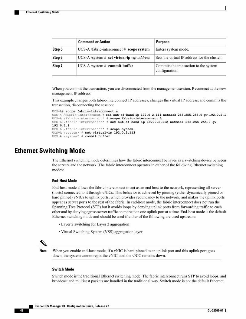
PurposeCommand or Action
Enters system mode.UCS-A /fabric-interconnect # scope systemStep 5
Sets the virtual IP address for the cluster.UCS-A /system # set virtual-ip vip-addressStep 6
Commits the transaction to the systemconfiguration.
UCS-A /system # commit-bufferStep 7
When you commit the transaction, you are disconnected from the management session. Reconnect at the newmanagement IP address.
This example changes both fabric-interconnect IP addresses, changes the virtual IP address, and commits thetransaction, disconnecting the session:UCS-A# scope fabric-interconnect aUCS-A /fabric-interconnect # set out-of-band ip 192.0.2.111 netmask 255.255.255.0 gw 192.0.2.1UCS-A /fabric-interconnect* # scope fabric-interconnect bUCS-A /fabric-interconnect* # set out-of-band ip 192.0.2.112 netmask 255.255.255.0 gw192.0.2.1UCS-A /fabric-interconnect* # scope systemUCS-A /system* # set virtual-ip 192.0.2.113UCS-A /system* # commit-buffer
Ethernet Switching ModeThe Ethernet switching mode determines how the fabric interconnect behaves as a switching device betweenthe servers and the network. The fabric interconnect operates in either of the following Ethernet switchingmodes:
End-Host Mode
End-host mode allows the fabric interconnect to act as an end host to the network, representing all server(hosts) connected to it through vNICs. This behavior is achieved by pinning (either dynamically pinned orhard pinned) vNICs to uplink ports, which provides redundancy to the network, and makes the uplink portsappear as server ports to the rest of the fabric. In end-host mode, the fabric interconnect does not run theSpanning Tree Protocol (STP) but it avoids loops by denying uplink ports from forwarding traffic to eachother and by denying egress server traffic on more than one uplink port at a time. End-host mode is the defaultEthernet switching mode and should be used if either of the following are used upstream:
• Layer 2 switching for Layer 2 aggregation
• Virtual Switching System (VSS) aggregation layer
When you enable end-host mode, if a vNIC is hard pinned to an uplink port and this uplink port goesdown, the system cannot repin the vNIC, and the vNIC remains down.
Note
Switch Mode
Switch mode is the traditional Ethernet switching mode. The fabric interconnect runs STP to avoid loops, andbroadcast and multicast packets are handled in the traditional way. Switch mode is not the default Ethernet
Cisco UCS Manager CLI Configuration Guide, Release 2.148 OL-28302-04
Ethernet Switching Mode
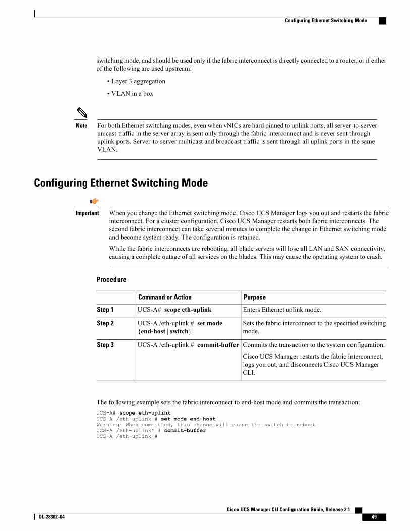
switching mode, and should be used only if the fabric interconnect is directly connected to a router, or if eitherof the following are used upstream:
• Layer 3 aggregation
• VLAN in a box
For both Ethernet switching modes, even when vNICs are hard pinned to uplink ports, all server-to-serverunicast traffic in the server array is sent only through the fabric interconnect and is never sent throughuplink ports. Server-to-server multicast and broadcast traffic is sent through all uplink ports in the sameVLAN.
Note
Configuring Ethernet Switching Mode
When you change the Ethernet switching mode, Cisco UCS Manager logs you out and restarts the fabricinterconnect. For a cluster configuration, Cisco UCS Manager restarts both fabric interconnects. Thesecond fabric interconnect can take several minutes to complete the change in Ethernet switching modeand become system ready. The configuration is retained.
While the fabric interconnects are rebooting, all blade servers will lose all LAN and SAN connectivity,causing a complete outage of all services on the blades. This may cause the operating system to crash.
Important
Procedure
PurposeCommand or Action
Enters Ethernet uplink mode.UCS-A# scope eth-uplinkStep 1
Sets the fabric interconnect to the specified switchingmode.
UCS-A /eth-uplink # set mode{end-host | switch}
Step 2
Commits the transaction to the system configuration.UCS-A /eth-uplink # commit-bufferStep 3
Cisco UCS Manager restarts the fabric interconnect,logs you out, and disconnects Cisco UCS ManagerCLI.
The following example sets the fabric interconnect to end-host mode and commits the transaction:UCS-A# scope eth-uplinkUCS-A /eth-uplink # set mode end-hostWarning: When committed, this change will cause the switch to rebootUCS-A /eth-uplink* # commit-bufferUCS-A /eth-uplink #
Cisco UCS Manager CLI Configuration Guide, Release 2.1 OL-28302-04 49
Configuring Ethernet Switching Mode
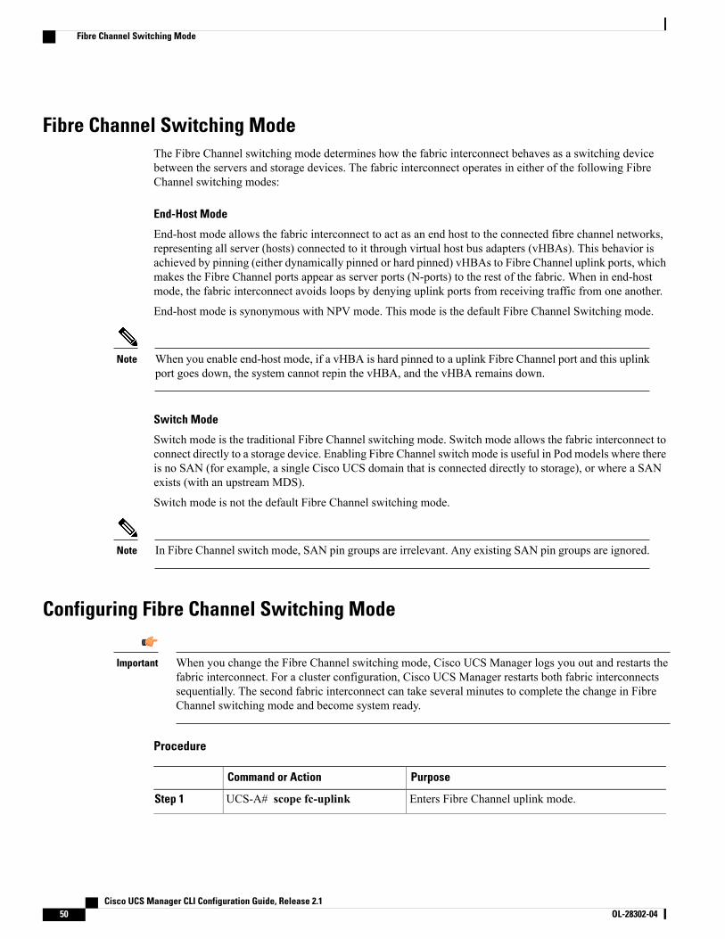
Fibre Channel Switching ModeThe Fibre Channel switching mode determines how the fabric interconnect behaves as a switching devicebetween the servers and storage devices. The fabric interconnect operates in either of the following FibreChannel switching modes:
End-Host Mode
End-host mode allows the fabric interconnect to act as an end host to the connected fibre channel networks,representing all server (hosts) connected to it through virtual host bus adapters (vHBAs). This behavior isachieved by pinning (either dynamically pinned or hard pinned) vHBAs to Fibre Channel uplink ports, whichmakes the Fibre Channel ports appear as server ports (N-ports) to the rest of the fabric. When in end-hostmode, the fabric interconnect avoids loops by denying uplink ports from receiving traffic from one another.
End-host mode is synonymous with NPV mode. This mode is the default Fibre Channel Switching mode.
When you enable end-host mode, if a vHBA is hard pinned to a uplink Fibre Channel port and this uplinkport goes down, the system cannot repin the vHBA, and the vHBA remains down.
Note
Switch Mode
Switch mode is the traditional Fibre Channel switching mode. Switch mode allows the fabric interconnect toconnect directly to a storage device. Enabling Fibre Channel switch mode is useful in Pod models where thereis no SAN (for example, a single Cisco UCS domain that is connected directly to storage), or where a SANexists (with an upstream MDS).
Switch mode is not the default Fibre Channel switching mode.
In Fibre Channel switch mode, SAN pin groups are irrelevant. Any existing SAN pin groups are ignored.Note
Configuring Fibre Channel Switching Mode
When you change the Fibre Channel switching mode, Cisco UCS Manager logs you out and restarts thefabric interconnect. For a cluster configuration, Cisco UCS Manager restarts both fabric interconnectssequentially. The second fabric interconnect can take several minutes to complete the change in FibreChannel switching mode and become system ready.
Important
Procedure
PurposeCommand or Action
Enters Fibre Channel uplink mode.UCS-A# scope fc-uplinkStep 1
Cisco UCS Manager CLI Configuration Guide, Release 2.150 OL-28302-04
Fibre Channel Switching Mode
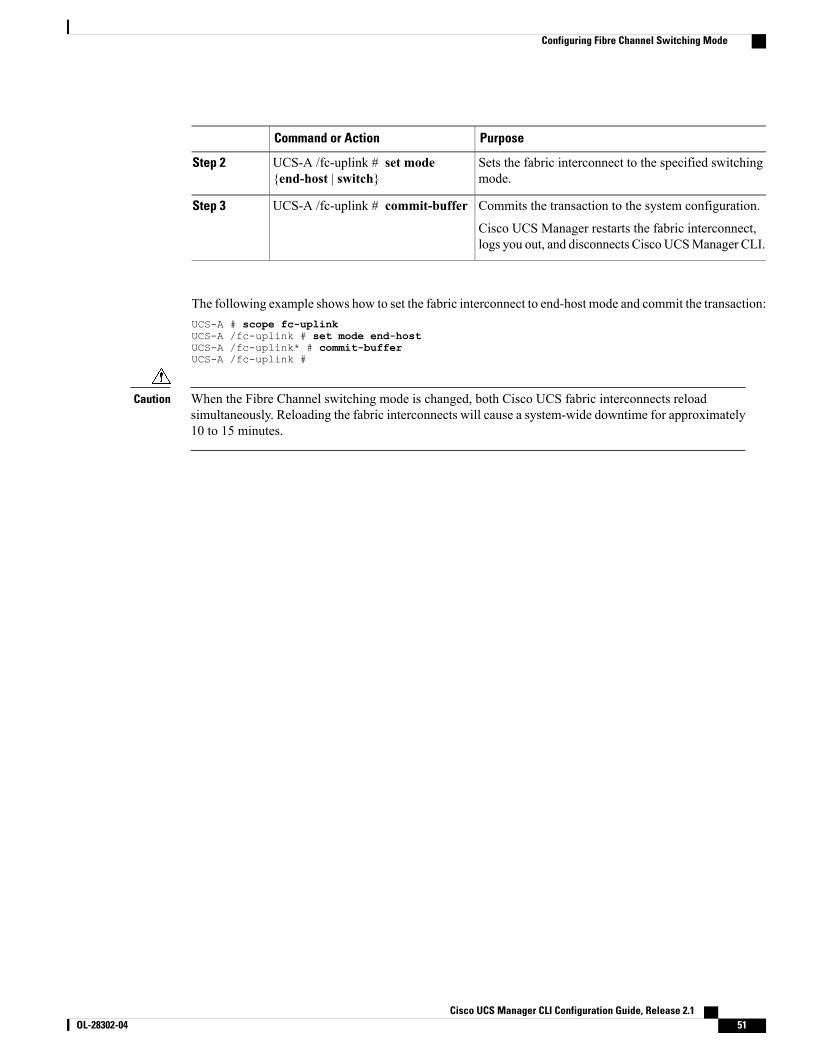
PurposeCommand or Action
Sets the fabric interconnect to the specified switchingmode.
UCS-A /fc-uplink # set mode{end-host | switch}
Step 2
Commits the transaction to the system configuration.UCS-A /fc-uplink # commit-bufferStep 3
Cisco UCS Manager restarts the fabric interconnect,logs you out, and disconnects CiscoUCSManager CLI.
The following example shows how to set the fabric interconnect to end-host mode and commit the transaction:UCS-A # scope fc-uplinkUCS-A /fc-uplink # set mode end-hostUCS-A /fc-uplink* # commit-bufferUCS-A /fc-uplink #
When the Fibre Channel switching mode is changed, both Cisco UCS fabric interconnects reloadsimultaneously. Reloading the fabric interconnects will cause a system-wide downtime for approximately10 to 15 minutes.
Caution
Cisco UCS Manager CLI Configuration Guide, Release 2.1 OL-28302-04 51
Configuring Fibre Channel Switching Mode

Cisco UCS Manager CLI Configuration Guide, Release 2.152 OL-28302-04
Configuring Fibre Channel Switching Mode
C H A P T E R 6Configuring Ports and Port Channels
This chapter includes the following sections:
• Server and Uplink Ports on the 6100 Series Fabric Interconnect, page 53
• Unified Ports on the 6200 Series Fabric Interconnect, page 54
• Server Ports, page 62
• Uplink Ethernet Ports, page 63
• Appliance Ports, page 64
• FCoE Uplink Ports, page 69
• Unified Storage Ports, page 71
• Unified Uplink Ports, page 73
• FCoE and Fibre Channel Storage Ports, page 74
• Uplink Ethernet Port Channels, page 75
• Appliance Port Channels, page 78
• Fibre Channel Port Channels, page 82
• FCoE Port Channels, page 86
• Unified Uplink Port Channel, page 87
• Adapter Port Channels, page 88
• Fabric Port Channels, page 89
Server and Uplink Ports on the 6100 Series Fabric InterconnectEach Cisco UCS 6200 Series Fabric Interconnect has a set of ports in a fixed port module that you can configureas either server ports or uplink Ethernet ports. These ports are not reserved. They cannot be used by a CiscoUCS domain until you configure them. You can add expansion modules to increase the number of uplinkports on the fabric interconnect or to add uplink Fibre Channel ports to the fabric interconnect.
Cisco UCS Manager CLI Configuration Guide, Release 2.1 OL-28302-04 53
When you configure a port on a fabric interconnect, the administrative state is automatically set to enabled.If the port is connected to another device, this may cause traffic disruption. You can disable the port afterit has been configured.
Note
You need to create LAN pin groups and SAN pin groups to pin traffic from servers to an uplink port.
Ports on the Cisco UCS 6200 Series Fabric Interconnect are not unified. For more information on UnifiedPorts, see Unified Ports on the 6200 Series Fabric Interconnect.
Note
Each fabric interconnect can include the following port types:
Server Ports
Server ports handle data traffic between the fabric interconnect and the adapter cards on the servers.
You can only configure server ports on the fixed port module. Expansion modules do not include serverports.
Uplink Ethernet Ports
Uplink Ethernet ports handle Ethernet traffic between the fabric interconnect and the next layer of thenetwork. All network-bound Ethernet traffic is pinned to one of these ports.
By default, Ethernet ports are unconfigured. However, you can configure them to function in thefollowing ways:
• Uplink
• FCoE
• Appliance
You can configure uplink Ethernet ports on either the fixed module or an expansion module.
Uplink Fibre Channel Ports
Uplink Fibre Channel ports handle FCoE traffic between the fabric interconnect and the next layer ofthe storage area network. All network-bound FCoE traffic is pinned to one of these ports.
By default, Fibre Channel ports are uplink. However, you can configure them to function as FibreChannel storage ports. This is useful in cases where CiscoUCS requires a connection to a Direct-AttachedStorage (DAS) device.
You can only configure uplink Fibre Channel ports on an expansion module. The fixed module doesnot include uplink Fibre Channel ports.
Unified Ports on the 6200 Series Fabric InterconnectUnified ports are ports on the Cisco UCS 6200 Series Fabric Interconnect that can be configured to carryeither Ethernet or Fibre Channel traffic. These ports are not reserved. They cannot be used by a Cisco UCSdomain until you configure them.
Cisco UCS Manager CLI Configuration Guide, Release 2.154 OL-28302-04
Unified Ports on the 6200 Series Fabric Interconnect
When you configure a port on a fabric interconnect, the administrative state is automatically set to enabled.If the port is connected to another device, this may cause traffic disruption. You can disable the port afterit has been configured.
Note
Configurable beacon LEDs indicate which unified ports are configured for the selected port mode.
Port ModesThe port mode determines whether a unified port on the fabric interconnect is configured to carry Ethernetor Fibre Channel traffic. The port mode is not automatically discovered by the fabric interconnect; it isconfigured in Cisco UCS Manager.
Changing the port mode results in the existing port configuration being deleted and replaced by a new logicalport. Any objects associated with that port configuration, such as VLANs and VSANS, are removed. Thereis no restriction on the number of times the port mode can be changed for a unified port.
Port TypesThe port type defines the type of traffic carried over a unified port connection.
All of the port types listed are configurable on both the fixed and expansion module, including server ports,which are not configurable on the 6100 series fabric interconnect expansion module, but are configurable onthe 6200 series fabric interconnect expansion module.
By default, unified ports changed to Ethernet port mode are set to uplink Ethernet port type. unified portschanged to Fibre Channel port mode are set to the Fibre Channel uplink port type. Fibre Channel ports cannotbe unconfigured.
Changing the port type does not require a reboot.
When the port mode is set to Ethernet, you can configure the following port types:
• Server ports
• Ethernet uplink ports
• Ethernet port channel members
• FCoE ports
• Appliance ports
• Appliance port channel members
• SPAN destination ports
• SPAN source ports
For SPAN source ports, configure one of the port types and then configure the port asSPAN source.
Note
When the port mode is set to Fibre Channel, you can configure the following port types:
Cisco UCS Manager CLI Configuration Guide, Release 2.1 OL-28302-04 55
Unified Ports on the 6200 Series Fabric Interconnect
• Fibre Channel uplink ports
• Fibre Channel port channel members
• Fibre Channel storage ports
• FCoE Uplink ports
• SPAN destination ports
• SPAN source ports
For SPAN source ports, configure one of the port types and then configure the port asSPAN source.
Note
Beacon LEDs for Unified PortsEach port on the 6200 series fabric interconnect has a corresponding beacon LED. When the Beacon LEDproperty is configured, the beacon LEDs illuminate, showing you which ports are configured in a given portmode.
The Beacon LED property can be configured to show you which ports are grouped in one port mode: eitherEthernet or Fibre Channel. By default, the Beacon LED property is set to Off.
For unified ports on the expansion module, the Beacon LED property may be reset to the default value ofOff during expansion module reboot.
Note
Guidelines for Configuring Unified PortsConsider the following guidelines and restrictions when configuring unified ports:
Hardware and Software Requirements
Unified ports are supported on the 6200 series fabric interconnect with Cisco UCS Manager, version 2.0.
Unified ports are not supported on 6100 series fabric interconnects, even if they are running Cisco UCSManager, version 2.0.
Port Mode Placement
Because the Cisco UCS Manager GUI interface uses a slider to configure the port mode for unified ports ona fixed or expansion module, it automatically enforces the following restrictions which limits how port modescan be assigned to unified ports. When using the Cisco UCS Manager CLI interface, these restrictions areenforced when you commit the transaction to the system configuration. If the port mode configuration violatesany of the following restrictions, the Cisco UCS Manager CLI displays an error:
• Ethernet ports must be grouped together in a block. For each module (fixed or expansion), the Ethernetport block must start with the first port and end with an even numbered port.
Cisco UCS Manager CLI Configuration Guide, Release 2.156 OL-28302-04
Unified Ports on the 6200 Series Fabric Interconnect
• Fibre Channel ports must be grouped together in a block. For each module (fixed or expansion), the firstport in the Fibre Channel port block must follow the last Ethernet port and extend to include the rest ofthe ports in the module. For configurations that include only Fibre Channel ports, the Fibre Channelblock must start with the first port on the fixed or expansion module.
• Alternating Ethernet and Fibre Channel ports is not supported on a single module.
Example of a valid configuration—Might include unified ports 1–16 on the fixed module configured inEthernet port mode and ports 17–32 in Fibre Channel port mode. On the expansionmodule you could configureports 1–4 in Ethernet port mode and then configure ports 5–16 in Fibre Channel mode. The rule about alternatingEthernet and Fibre Channel port types is not violated because this port arrangement complies with the ruleson each individual module.
Example of an invalid configuration—Might include a block of Fibre Channel ports starting with port 16.Because each block of ports has to start with an odd-numbered port, you would have to start the block withport 17.
The total number of uplink Ethernet ports and uplink Ethernet port channel members that can be configuredon each fabric interconnect is limited to 31. This limitation includes uplink Ethernet ports and uplinkEthernet port channel members configured on the expansion module.
Note
Special Considerations for UCS Manager CLI Users
Because the Cisco UCSManager CLI does not validate port mode changes until you commit the buffer to thesystem configuration, it is easy to violate the grouping restrictions if you attempt to commit the buffer beforecreating at least two new interfaces. To prevent errors, we recommend that you wait to commit your changesto the system configuration until you have created new interfaces for all of the unified ports changing fromone port mode to another.
Commiting the buffer before configuring multiple interfaces will result in an error, but you do not need tostart over. You can continue to configure unified ports until the configuration satisfies the aforementionedrequirements.
Cautions and Guidelines for Configuring Unified Uplink Ports and Unified Storage PortsThe following are cautions and guidelines to follow while working with unified uplink ports and unifiedstorage ports:
• In an unified uplink port, if you enable one component as a SPAN source, the other component willautomatically become a SPAN source.
If you create or delete a SPAN source under the Ethernet uplink port, Cisco UCSManagerautomatically creates pr deletes a SPAN source under the FCoE uplink port. The samehappens with you create a SPAN source on the FCOE uplink port.
Note
• You must configure a non default native vlan on FcoE and unified uplink ports. This VLAN is not usedfor any traffic. Cisco UCS Manager will reuse an existing fcoe-storage-native-vlan for this purpose.This fcoe-storage-native-vlan will be used as native VLAN on FCoE and unified uplinks.
Cisco UCS Manager CLI Configuration Guide, Release 2.1 OL-28302-04 57
Unified Ports on the 6200 Series Fabric Interconnect
• In an unified uplink port, if you do not specify a non default VLAN for the Ethernet uplink port thefcoe-storage-native-vlan will be assigned as the native VLAN on the unified uplink port. If the Ethernetport has a non default native VLAN specified as native VLAN, this will be assigned as the native VLANfor unified uplink port.
•When you create or delete a member port under an Ethernet port channel, Cisco UCS Managerautomatically creates or deletes the member port under FCoE port channel. The same happens whenyou create or delete a member port in FCoE port channel.
•When you configure an Ethernet port as a standalone port, such as server port, Ethernet uplink, FCoEuplink or FCoE storage and make it as a member port for an Ethernet or FCOE port channel, Cisco UCSManager automatically makes this port as a member of both Ethernet and FCoE port channels.
•When you remove the membership for a member port from being a member of server uplink, Ethernetuplink, FCoE uplink or FCoE storage, Cisco UCS Manager deletes the corresponding members portsfrom Ethernet port channel and FCoE port channel and creates a new standalone port.
• If you downgrade Cisco UCS Manager from release 2.1 to any of the prior releases, all unified uplinkports and port channels will be converted to Ethernet ports and Ethernet port channels when the downgradeis complete. Similarly, all the unified storage ports will be converted to appliance ports.
• For unified uplink ports and unified storage ports, when you create two interfaces, only once license ischecked out. As long as either interface is enabled, the license remains checked out. The license will bereleased only if both the interfaces are disabled for a unified uplink port or a unified storage port.
• Cisco UCS 6100 series fabric interconnect switch can only support 1VF or 1VF-PO facing samedownstream NPV switch.
Effect of Port Mode Changes on Data TrafficPort mode changes can cause an interruption to the data traffic for the Cisco UCS domain. The length of theinterruption and the traffic that is affected depend upon the configuration of the Cisco UCS domain and themodule on which you made the port mode changes.
To minimize the traffic disruption during system changes, form a Fibre Channel uplink port-channel acrossthe fixed and expansion modules.
Tip
Impact of Port Mode Changes on an Expansion Module
After you make port mode changes on an expansion module, the module reboots. All traffic through ports onthe expansion module is interrupted for approximately one minute while the module reboots.
Impact of Port Mode Changes on the Fixed Module in a Cluster Configuration
A cluster configuration has two fabric interconnects. After you make port changes to the fixed module, thefabric interconnect reboots. The impact on the data traffic depends upon whether or not you have configuredthe server vNICs to failover to the other fabric interconnect when one fails.
If you change the port modes on the expansion module of one fabric interconnect and then wait for that toreboot before changing the port modes on the second fabric interconnect, the following occurs:
•With server vNIC failover, traffic fails over to the other fabric interconnect and no interruption occurs.
Cisco UCS Manager CLI Configuration Guide, Release 2.158 OL-28302-04
Unified Ports on the 6200 Series Fabric Interconnect
•Without server vNIC failover, all data traffic through the fabric interconnect on which you changed theport modes is interrupted for approximately eight minutes while the fabric interconnect reboots.
However, if you change the port modes on the fixed modules of both fabric interconnects simultaneously, alldata traffic through the fabric interconnects are interrupted for approximately eight minutes while the fabricinterconnects reboot.
Impact of Port Mode Changes on the Fixed Module in a Standalone Configuration
A standalone configuration has only one fabric interconnect. After you make port changes to the fixed module,the fabric interconnect reboots. All data traffic through the fabric interconnect is interrupted for approximatelyeight minutes while the fabric interconnect reboots.
Configuring the Port Mode
Changing the port mode on either module can cause an interruption in data traffic because changes to thefixed module require a reboot of the fabric interconnect and changes on an expansion module require areboot of that module.
If the Cisco UCS domain has a cluster configuration that is set up for high availability and servers withservice profiles that are configured for failover, traffic fails over to the other fabric interconnect and datatraffic is not interrupted when the port mode is changed on the fixed module.
Caution
In the Cisco UCS Manager CLI, there are no new commands to support Unified Ports. Instead, you changethe port mode by scoping to the mode for the desired port type and then creating a new interface. When youcreate a new interface for an already configured slot ID and port ID, UCS Manager deletes the previouslyconfigured interface and creates a new one. If a port mode change is required because you configure a portthat previously operated in Ethernet port mode to a port type in Fibre Channel port mode, UCSManager notesthe change.
Procedure
PurposeCommand or Action
Enters the specified port type mode for one of the following porttypes:
UCS-A# scope port-type-modeStep 1
eth-server
For configuring server ports.
eth-storage
For configuring Ethernet storage ports and Ethernet storageport channels.
eth-traffic-mon
For configuring Ethernet SPAN ports.
Cisco UCS Manager CLI Configuration Guide, Release 2.1 OL-28302-04 59
Unified Ports on the 6200 Series Fabric Interconnect
PurposeCommand or Action
eth-uplink
For configuring Ethernet uplink ports.
fc-storage
For configuring Fibre Channel storage ports.
fc-traffic-mon
For configuring Fibre Channel SPAN ports.
fc-uplink
For configuring Fibre Channel uplink ports and FibreChannel uplink port channels.
Enters the specified port type mode for the specified fabric.UCS-A /port-type-mode # scopefabric {a | b}
Step 2
Creates an interface for the specified port type.UCS-A /port-type-mode/fabric# create interface slot-idport-id
Step 3
If you are changing the port type from Ethernet port mode to FibreChannel port mode, or vice-versa, the following warning appears:
Warning: This operation will change the port mode (from
Ethernet to FC or vice-versa). When committed, this
change will require the module to restart.
There are several restrictions that govern how Ethernet and FibreChannel ports can be arranged on a fixed or expansion module.
Create new interfaces for otherports belonging to the Ethernetor Fibre Channel port block.
Step 4
Among other restrictions, it is required that you change ports ingroups of two. Violating any of the restrictions outlined in theGuidelines for Configuring Unified Ports section will result in anerror.
Commits the transaction to the system configuration.UCS-A/port-type-mode/fabric/interface# commit-buffer
Step 5
Depending upon the module for which you configured the port modes, data traffic for the Cisco UCS domainis interrupted as follows:
• Fixed module—The fabric interconnect reboots. All data traffic through that fabric interconnect isinterrupted. In a cluster configuration that provides high availability and includes servers with vNICsthat are configured for failover, traffic fails over to the other fabric interconnect and no interruptionoccurs. Changing the port mode for both sides at once results in both fabric interconnects rebootingsimultaneously and a complete loss of traffic until both fabric interconnects are brought back up.
It takes about 8 minutes for the fixed module to reboot.
Cisco UCS Manager CLI Configuration Guide, Release 2.160 OL-28302-04
Unified Ports on the 6200 Series Fabric Interconnect
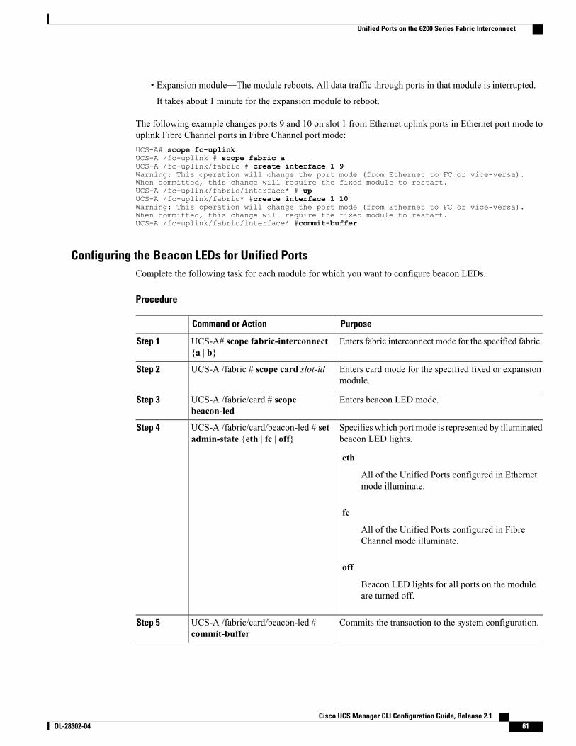
• Expansion module—The module reboots. All data traffic through ports in that module is interrupted.
It takes about 1 minute for the expansion module to reboot.
The following example changes ports 9 and 10 on slot 1 from Ethernet uplink ports in Ethernet port mode touplink Fibre Channel ports in Fibre Channel port mode:UCS-A# scope fc-uplinkUCS-A /fc-uplink # scope fabric aUCS-A /fc-uplink/fabric # create interface 1 9Warning: This operation will change the port mode (from Ethernet to FC or vice-versa).When committed, this change will require the fixed module to restart.UCS-A /fc-uplink/fabric/interface* # upUCS-A /fc-uplink/fabric* #create interface 1 10Warning: This operation will change the port mode (from Ethernet to FC or vice-versa).When committed, this change will require the fixed module to restart.UCS-A /fc-uplink/fabric/interface* #commit-buffer
Configuring the Beacon LEDs for Unified PortsComplete the following task for each module for which you want to configure beacon LEDs.
Procedure
PurposeCommand or Action
Enters fabric interconnect mode for the specified fabric.UCS-A# scope fabric-interconnect{a | b}
Step 1
Enters card mode for the specified fixed or expansionmodule.
UCS-A /fabric # scope card slot-idStep 2
Enters beacon LED mode.UCS-A /fabric/card # scopebeacon-led
Step 3
Specifies which port mode is represented by illuminatedbeacon LED lights.
UCS-A /fabric/card/beacon-led # setadmin-state {eth | fc | off}
Step 4
eth
All of the Unified Ports configured in Ethernetmode illuminate.
fc
All of the Unified Ports configured in FibreChannel mode illuminate.
off
Beacon LED lights for all ports on the moduleare turned off.
Commits the transaction to the system configuration.UCS-A /fabric/card/beacon-led #commit-buffer
Step 5
Cisco UCS Manager CLI Configuration Guide, Release 2.1 OL-28302-04 61
Unified Ports on the 6200 Series Fabric Interconnect
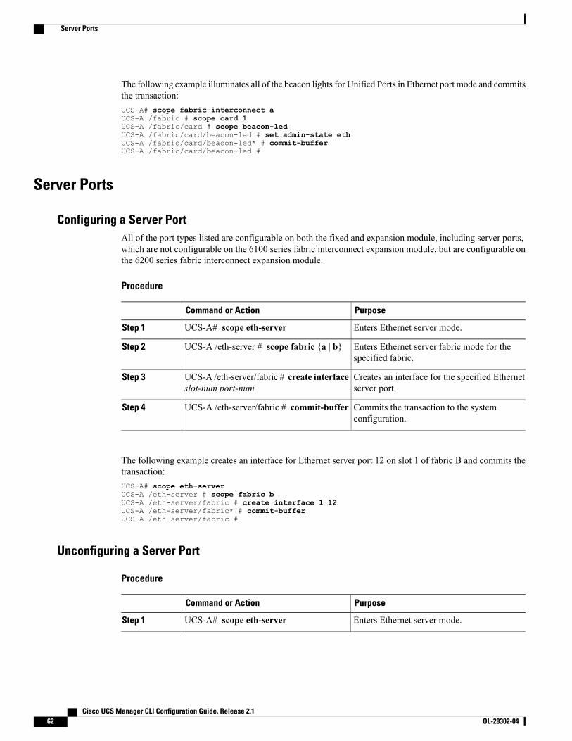
The following example illuminates all of the beacon lights for Unified Ports in Ethernet port mode and commitsthe transaction:UCS-A# scope fabric-interconnect aUCS-A /fabric # scope card 1UCS-A /fabric/card # scope beacon-ledUCS-A /fabric/card/beacon-led # set admin-state ethUCS-A /fabric/card/beacon-led* # commit-bufferUCS-A /fabric/card/beacon-led #
Server Ports
Configuring a Server PortAll of the port types listed are configurable on both the fixed and expansion module, including server ports,which are not configurable on the 6100 series fabric interconnect expansion module, but are configurable onthe 6200 series fabric interconnect expansion module.
Procedure
PurposeCommand or Action
Enters Ethernet server mode.UCS-A# scope eth-serverStep 1
Enters Ethernet server fabric mode for thespecified fabric.
UCS-A /eth-server # scope fabric {a | b}Step 2
Creates an interface for the specified Ethernetserver port.
UCS-A /eth-server/fabric # create interfaceslot-num port-num
Step 3
Commits the transaction to the systemconfiguration.
UCS-A /eth-server/fabric # commit-bufferStep 4
The following example creates an interface for Ethernet server port 12 on slot 1 of fabric B and commits thetransaction:UCS-A# scope eth-serverUCS-A /eth-server # scope fabric bUCS-A /eth-server/fabric # create interface 1 12UCS-A /eth-server/fabric* # commit-bufferUCS-A /eth-server/fabric #
Unconfiguring a Server Port
Procedure
PurposeCommand or Action
Enters Ethernet server mode.UCS-A# scope eth-serverStep 1
Cisco UCS Manager CLI Configuration Guide, Release 2.162 OL-28302-04
Server Ports

PurposeCommand or Action
Enters Ethernet server fabric mode for thespecified fabric.
UCS-A /eth-server # scope fabric {a | b}Step 2
Deletes the interface for the specified Ethernetserver port.
UCS-A /eth-server/fabric # delete interfaceslot-num port-num
Step 3
Commits the transaction to the systemconfiguration.
UCS-A /eth-server/fabric # commit-bufferStep 4
The following example unconfigures Ethernet server port 12 on slot 1 of fabric B and commits the transaction:UCS-A# scope eth-serverUCS-A /eth-server # scope fabric bUCS-A /eth-server/fabric # delete interface 1 12UCS-A /eth-server/fabric* # commit-bufferUCS-A /eth-server/fabric #
Uplink Ethernet Ports
Configuring an Uplink Ethernet PortYou can configure uplink Ethernet ports on either the fixed module or an expansion module.
Procedure
PurposeCommand or Action
Enters Ethernet uplink mode.UCS-A# scope eth-uplinkStep 1
Enters Ethernet uplink fabric mode for the specifiedfabric.
UCS-A /eth-uplink # scope fabric {a| b}
Step 2
Creates an interface for the specified Ethernet uplinkport.
UCS-A /eth-uplink/fabric # createinterface slot-num port-num
Step 3
(Optional)Sets the speed for the specified Ethernet uplink port.
For the 6100 series fabric interconnects, theadmin speed is only configurable for the firsteight ports on a 20-port fabric interconnectand the first 16 ports on a 40-port fabricinterconnect.
Note
UCS-A /eth-uplink/fabric # set speed{10gbps | 1gbps}
Step 4
Commits the transaction to the system configuration.UCS-A /eth-uplink/fabric #commit-buffer
Step 5
Cisco UCS Manager CLI Configuration Guide, Release 2.1 OL-28302-04 63
Uplink Ethernet Ports
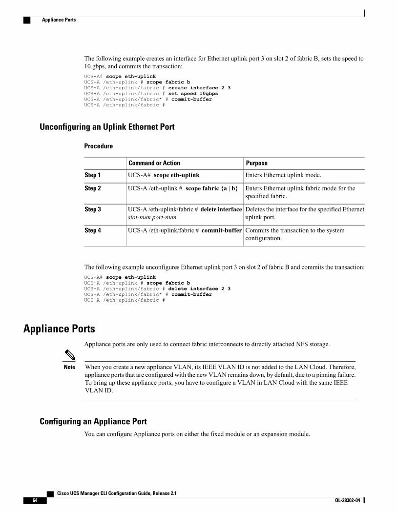
The following example creates an interface for Ethernet uplink port 3 on slot 2 of fabric B, sets the speed to10 gbps, and commits the transaction:UCS-A# scope eth-uplinkUCS-A /eth-uplink # scope fabric bUCS-A /eth-uplink/fabric # create interface 2 3UCS-A /eth-uplink/fabric # set speed 10gbpsUCS-A /eth-uplink/fabric* # commit-bufferUCS-A /eth-uplink/fabric #
Unconfiguring an Uplink Ethernet Port
Procedure
PurposeCommand or Action
Enters Ethernet uplink mode.UCS-A# scope eth-uplinkStep 1
Enters Ethernet uplink fabric mode for thespecified fabric.
UCS-A /eth-uplink # scope fabric {a | b}Step 2
Deletes the interface for the specified Ethernetuplink port.
UCS-A /eth-uplink/fabric # delete interfaceslot-num port-num
Step 3
Commits the transaction to the systemconfiguration.
UCS-A /eth-uplink/fabric # commit-bufferStep 4
The following example unconfigures Ethernet uplink port 3 on slot 2 of fabric B and commits the transaction:UCS-A# scope eth-uplinkUCS-A /eth-uplink # scope fabric bUCS-A /eth-uplink/fabric # delete interface 2 3UCS-A /eth-uplink/fabric* # commit-bufferUCS-A /eth-uplink/fabric #
Appliance PortsAppliance ports are only used to connect fabric interconnects to directly attached NFS storage.
When you create a new appliance VLAN, its IEEE VLAN ID is not added to the LAN Cloud. Therefore,appliance ports that are configured with the newVLAN remains down, by default, due to a pinning failure.To bring up these appliance ports, you have to configure a VLAN in LAN Cloud with the same IEEEVLAN ID.
Note
Configuring an Appliance PortYou can configure Appliance ports on either the fixed module or an expansion module.
Cisco UCS Manager CLI Configuration Guide, Release 2.164 OL-28302-04
Appliance Ports
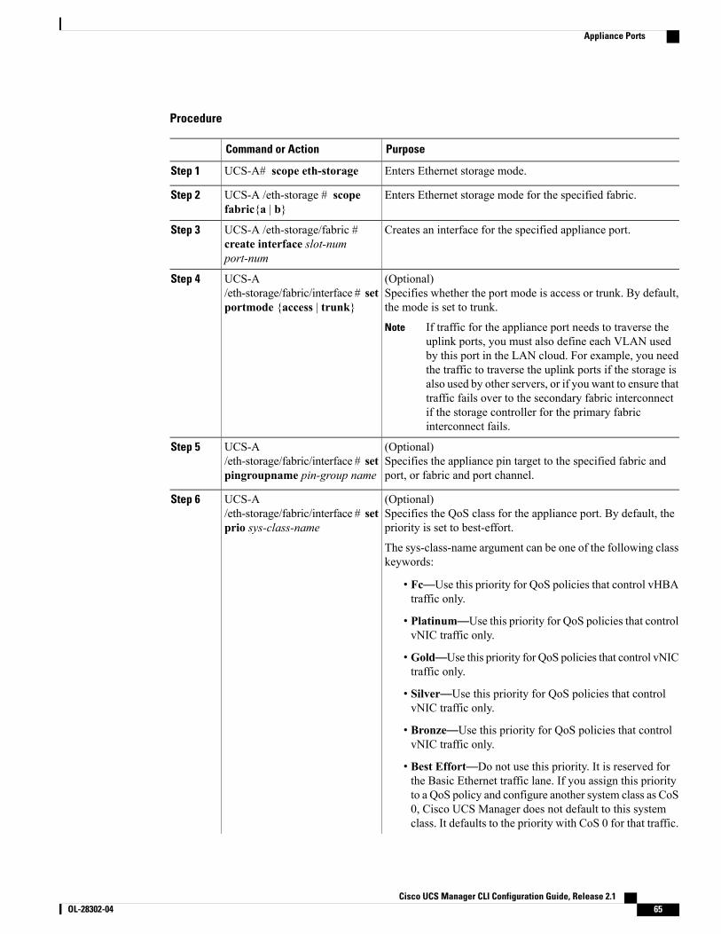
Procedure
PurposeCommand or Action
Enters Ethernet storage mode.UCS-A# scope eth-storageStep 1
Enters Ethernet storage mode for the specified fabric.UCS-A /eth-storage # scopefabric{a | b}
Step 2
Creates an interface for the specified appliance port.UCS-A /eth-storage/fabric #create interface slot-numport-num
Step 3
(Optional)Specifies whether the port mode is access or trunk. By default,the mode is set to trunk.
UCS-A/eth-storage/fabric/interface # setportmode {access | trunk}
Step 4
If traffic for the appliance port needs to traverse theuplink ports, you must also define each VLAN usedby this port in the LAN cloud. For example, you needthe traffic to traverse the uplink ports if the storage isalso used by other servers, or if you want to ensure thattraffic fails over to the secondary fabric interconnectif the storage controller for the primary fabricinterconnect fails.
Note
(Optional)Specifies the appliance pin target to the specified fabric andport, or fabric and port channel.
UCS-A/eth-storage/fabric/interface # setpingroupname pin-group name
Step 5
(Optional)Specifies the QoS class for the appliance port. By default, thepriority is set to best-effort.
UCS-A/eth-storage/fabric/interface # setprio sys-class-name
Step 6
The sys-class-name argument can be one of the following classkeywords:
• Fc—Use this priority for QoS policies that control vHBAtraffic only.
• Platinum—Use this priority for QoS policies that controlvNIC traffic only.
• Gold—Use this priority for QoS policies that control vNICtraffic only.
• Silver—Use this priority for QoS policies that controlvNIC traffic only.
• Bronze—Use this priority for QoS policies that controlvNIC traffic only.
• Best Effort—Do not use this priority. It is reserved forthe Basic Ethernet traffic lane. If you assign this priorityto a QoS policy and configure another system class as CoS0, Cisco UCS Manager does not default to this systemclass. It defaults to the priority with CoS 0 for that traffic.
Cisco UCS Manager CLI Configuration Guide, Release 2.1 OL-28302-04 65
Appliance Ports
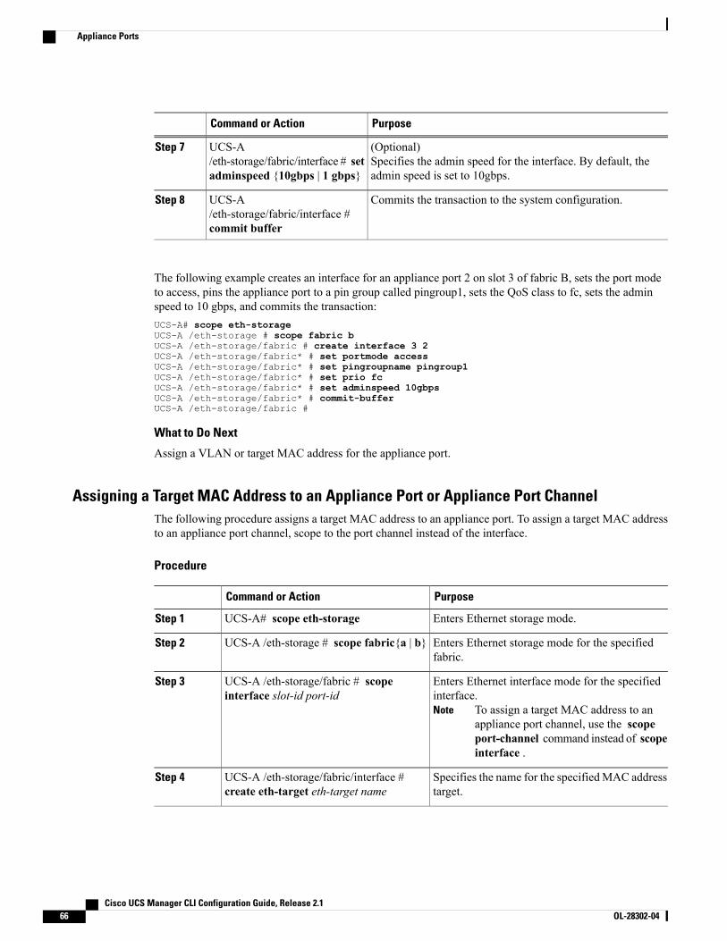
PurposeCommand or Action
(Optional)Specifies the admin speed for the interface. By default, theadmin speed is set to 10gbps.
UCS-A/eth-storage/fabric/interface # setadminspeed {10gbps | 1 gbps}
Step 7
Commits the transaction to the system configuration.UCS-A/eth-storage/fabric/interface #commit buffer
Step 8
The following example creates an interface for an appliance port 2 on slot 3 of fabric B, sets the port modeto access, pins the appliance port to a pin group called pingroup1, sets the QoS class to fc, sets the adminspeed to 10 gbps, and commits the transaction:UCS-A# scope eth-storageUCS-A /eth-storage # scope fabric bUCS-A /eth-storage/fabric # create interface 3 2UCS-A /eth-storage/fabric* # set portmode accessUCS-A /eth-storage/fabric* # set pingroupname pingroup1UCS-A /eth-storage/fabric* # set prio fcUCS-A /eth-storage/fabric* # set adminspeed 10gbpsUCS-A /eth-storage/fabric* # commit-bufferUCS-A /eth-storage/fabric #
What to Do Next
Assign a VLAN or target MAC address for the appliance port.
Assigning a Target MAC Address to an Appliance Port or Appliance Port ChannelThe following procedure assigns a target MAC address to an appliance port. To assign a target MAC addressto an appliance port channel, scope to the port channel instead of the interface.
Procedure
PurposeCommand or Action
Enters Ethernet storage mode.UCS-A# scope eth-storageStep 1
Enters Ethernet storage mode for the specifiedfabric.
UCS-A /eth-storage # scope fabric{a | b}Step 2
Enters Ethernet interface mode for the specifiedinterface.
To assign a target MAC address to anappliance port channel, use the scopeport-channel command instead of scopeinterface .
Note
UCS-A /eth-storage/fabric # scopeinterface slot-id port-id
Step 3
Specifies the name for the specifiedMAC addresstarget.
UCS-A /eth-storage/fabric/interface #create eth-target eth-target name
Step 4
Cisco UCS Manager CLI Configuration Guide, Release 2.166 OL-28302-04
Appliance Ports
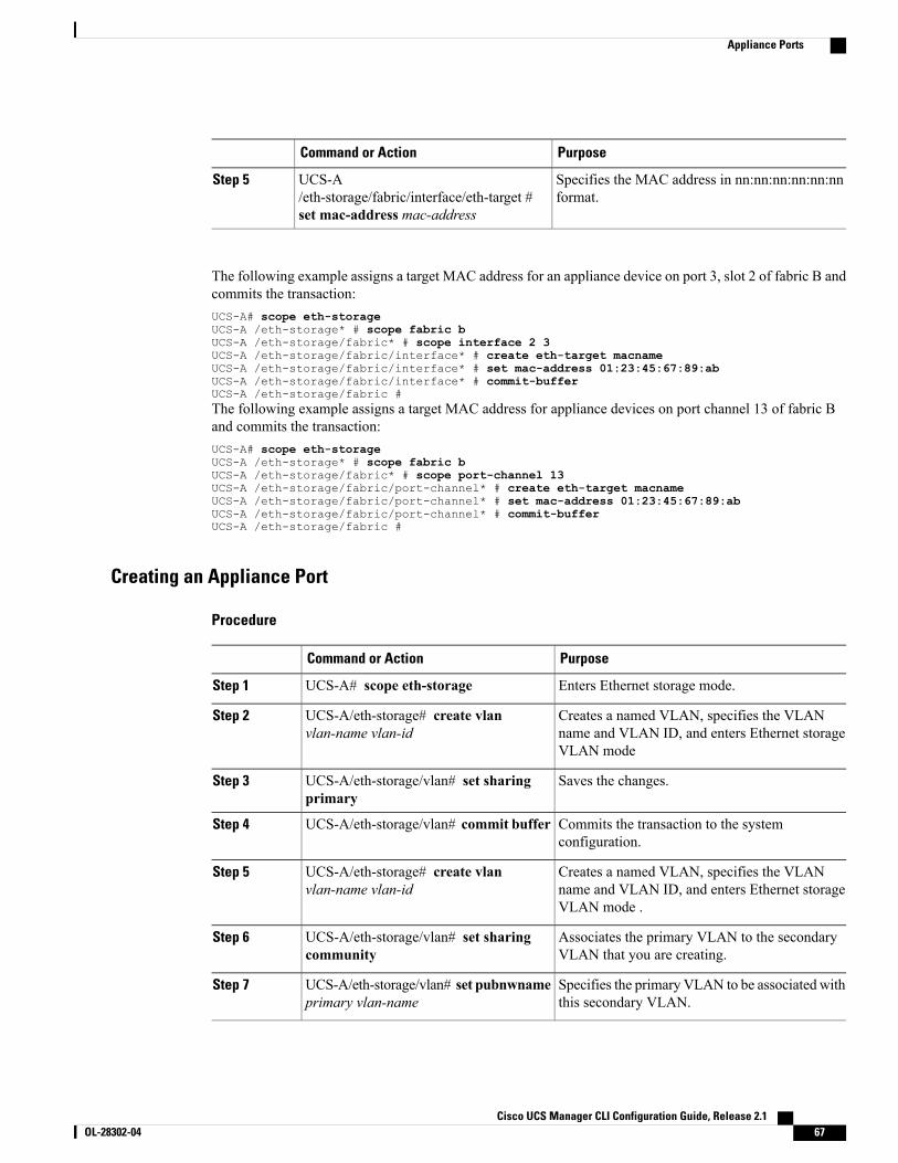
PurposeCommand or Action
Specifies the MAC address in nn:nn:nn:nn:nn:nnformat.
UCS-A/eth-storage/fabric/interface/eth-target #set mac-address mac-address
Step 5
The following example assigns a target MAC address for an appliance device on port 3, slot 2 of fabric B andcommits the transaction:UCS-A# scope eth-storageUCS-A /eth-storage* # scope fabric bUCS-A /eth-storage/fabric* # scope interface 2 3UCS-A /eth-storage/fabric/interface* # create eth-target macnameUCS-A /eth-storage/fabric/interface* # set mac-address 01:23:45:67:89:abUCS-A /eth-storage/fabric/interface* # commit-bufferUCS-A /eth-storage/fabric #The following example assigns a target MAC address for appliance devices on port channel 13 of fabric Band commits the transaction:UCS-A# scope eth-storageUCS-A /eth-storage* # scope fabric bUCS-A /eth-storage/fabric* # scope port-channel 13UCS-A /eth-storage/fabric/port-channel* # create eth-target macnameUCS-A /eth-storage/fabric/port-channel* # set mac-address 01:23:45:67:89:abUCS-A /eth-storage/fabric/port-channel* # commit-bufferUCS-A /eth-storage/fabric #
Creating an Appliance Port
Procedure
PurposeCommand or Action
Enters Ethernet storage mode.UCS-A# scope eth-storageStep 1
Creates a named VLAN, specifies the VLANname and VLAN ID, and enters Ethernet storageVLAN mode
UCS-A/eth-storage# create vlanvlan-name vlan-id
Step 2
Saves the changes.UCS-A/eth-storage/vlan# set sharingprimary
Step 3
Commits the transaction to the systemconfiguration.
UCS-A/eth-storage/vlan# commit bufferStep 4
Creates a named VLAN, specifies the VLANname and VLAN ID, and enters Ethernet storageVLAN mode .
UCS-A/eth-storage# create vlanvlan-name vlan-id
Step 5
Associates the primary VLAN to the secondaryVLAN that you are creating.
UCS-A/eth-storage/vlan# set sharingcommunity
Step 6
Specifies the primary VLAN to be associated withthis secondary VLAN.
UCS-A/eth-storage/vlan# set pubnwnameprimary vlan-name
Step 7
Cisco UCS Manager CLI Configuration Guide, Release 2.1 OL-28302-04 67
Appliance Ports
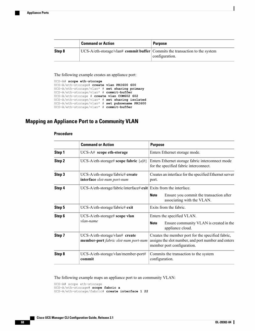
PurposeCommand or Action
Commits the transaction to the systemconfiguration.
UCS-A/eth-storage/vlan# commit bufferStep 8
The following example creates an appliance port:UCS-A# scope eth-storageUCS-A/eth-storage# create vlan PRI600 600UCS-A/eth-storage/vlan* # set sharing primaryUCS-A/eth-storage/vlan* # commit-bufferUCS-A/eth-storage # create vlan COM602 602UCS-A/eth-storage/vlan* # set sharing isolatedUCS-A/eth-storage/vlan* # set pubnwname PRI600UCS-A/eth-storage/vlan* # commit-buffer
Mapping an Appliance Port to a Community VLAN
Procedure
PurposeCommand or Action
Enters Ethernet storage mode.UCS-A# scope eth-storageStep 1
Enters Ethernet storage fabric interconnect modefor the specified fabric interconnect.
UCS-A/eth-storage# scope fabric {a|b}Step 2
Creates an interface for the specified Ethernet serverport.
UCS-A/eth-storage/fabric# createinterface slot-num port-num
Step 3
Exits from the interface.UCS-A/eth-storage/fabric/interface# exitStep 4
Ensure you commit the transaction afterassociating with the VLAN.
Note
Exits from the fabric.UCS-A/eth-storage/fabric# exitStep 5
Enters the specified VLAN.UCS-A/eth-storage# scope vlanvlan-name
Step 6
Ensure community VLAN is created in theappliance cloud.
Note
Creates the member port for the specified fabric,assigns the slot number, and port number and entersmember port configuration.
UCS-A/eth-storage/vlan# createmember-port fabric slot-num port-num
Step 7
Commits the transaction to the systemconfiguration.
UCS-A/eth-storage/vlan/member-port#commit
Step 8
The following example maps an appliance port to an community VLAN:UCS-A# scope eth-storageUCS-A/eth-storage# scope fabric aUCS-A/eth-storage/fabric# create interface 1 22
Cisco UCS Manager CLI Configuration Guide, Release 2.168 OL-28302-04
Appliance Ports
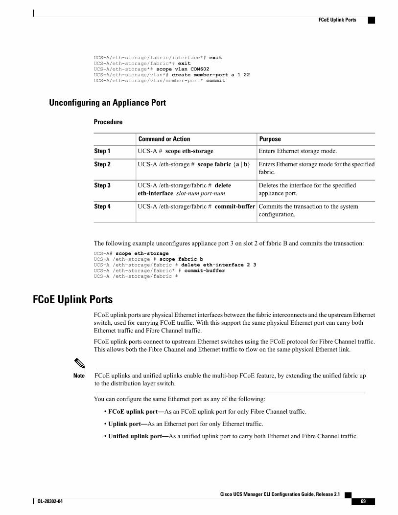
UCS-A/eth-storage/fabric/interface*# exitUCS-A/eth-storage/fabric*# exitUCS-A/eth-storage*# scope vlan COM602UCS-A/eth-storage/vlan*# create member-port a 1 22UCS-A/eth-storage/vlan/member-port* commit
Unconfiguring an Appliance Port
Procedure
PurposeCommand or Action
Enters Ethernet storage mode.UCS-A # scope eth-storageStep 1
Enters Ethernet storagemode for the specifiedfabric.
UCS-A /eth-storage # scope fabric {a | b}Step 2
Deletes the interface for the specifiedappliance port.
UCS-A /eth-storage/fabric # deleteeth-interface slot-num port-num
Step 3
Commits the transaction to the systemconfiguration.
UCS-A /eth-storage/fabric # commit-bufferStep 4
The following example unconfigures appliance port 3 on slot 2 of fabric B and commits the transaction:UCS-A# scope eth-storageUCS-A /eth-storage # scope fabric bUCS-A /eth-storage/fabric # delete eth-interface 2 3UCS-A /eth-storage/fabric* # commit-bufferUCS-A /eth-storage/fabric #
FCoE Uplink PortsFCoE uplink ports are physical Ethernet interfaces between the fabric interconnects and the upstream Ethernetswitch, used for carrying FCoE traffic. With this support the same physical Ethernet port can carry bothEthernet traffic and Fibre Channel traffic.
FCoE uplink ports connect to upstream Ethernet switches using the FCoE protocol for Fibre Channel traffic.This allows both the Fibre Channel and Ethernet traffic to flow on the same physical Ethernet link.
FCoE uplinks and unified uplinks enable the multi-hop FCoE feature, by extending the unified fabric upto the distribution layer switch.
Note
You can configure the same Ethernet port as any of the following:
• FCoE uplink port—As an FCoE uplink port for only Fibre Channel traffic.
• Uplink port—As an Ethernet port for only Ethernet traffic.
• Unified uplink port—As a unified uplink port to carry both Ethernet and Fibre Channel traffic.
Cisco UCS Manager CLI Configuration Guide, Release 2.1 OL-28302-04 69
FCoE Uplink Ports
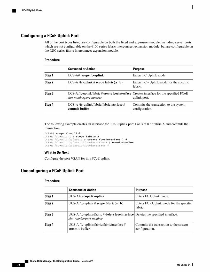
Configuring a FCoE Uplink PortAll of the port types listed are configurable on both the fixed and expansion module, including server ports,which are not configurable on the 6100 series fabric interconnect expansion module, but are configurable onthe 6200 series fabric interconnect expansion module.
Procedure
PurposeCommand or Action
Enters FC Uplink mode.UCS-A# scope fc-uplinkStep 1
Enters FC - Uplink mode for the specificfabric.
UCS-A /fc-uplink # scope fabric{a | b}Step 2
Creates interface for the specified FCoEuplink port.
UCS-A /fc-uplink/fabric # create fcoeinterfaceslot-numberport-number
Step 3
Commits the transaction to the systemconfiguration.
UCS-A /fc-uplink/fabric/fabricinterface #commit-buffer
Step 4
The following example creates an interface for FCoE uplink port 1 on slot 8 of fabric A and commits thetransaction:UCS-A# scope fc-uplinkUCS-A /fc-uplink # scope fabric aUCS-A /fc-uplink/fabric # create fcoeinterface 1 8UCS-A /fc-uplink/fabric/fcoeinterface* # commit-bufferUCS-A /fc-uplink/fabric/fcoeinterface #
What to Do Next
Configure the port VSAN for this FCoE uplink.
Unconfiguring a FCoE Uplink Port
Procedure
PurposeCommand or Action
Enters FC Uplink mode.UCS-A# scope fc-uplinkStep 1
Enters FC - Uplink mode for the specificfabric.
UCS-A /fc-uplink # scope fabric{a | b}Step 2
Deletes the specified interface.UCS-A /fc-uplink/fabric # delete fcoeinterfaceslot-numberport-number
Step 3
Commits the transaction to the systemconfiguration.
UCS-A /fc-uplink/fabric/fabricinterface #commit-buffer
Step 4
Cisco UCS Manager CLI Configuration Guide, Release 2.170 OL-28302-04
FCoE Uplink Ports
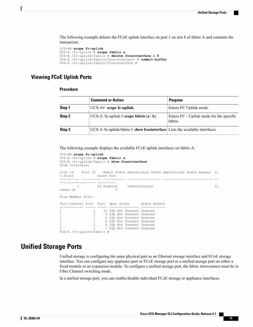
The following example deletes the FCoE uplink interface on port 1 on slot 8 of fabric A and commits thetransaction:UCS-A# scope fc-uplinkUCS-A /fc-uplink # scope fabric aUCS-A /fc-uplink/fabric # delete fcoeinterface 1 8UCS-A /fc-uplink/fabric/fcoeinterface* # commit-bufferUCS-A /fc-uplink/fabric/fcoeinterface #
Viewing FCoE Uplink Ports
Procedure
PurposeCommand or Action
Enters FC Uplink mode.UCS-A# scope fc-uplinkStep 1
Enters FC - Uplink mode for the specificfabric.
UCS-A /fc-uplink # scope fabric{a | b}Step 2
Lists the available interfaces.UCS-A /fc-uplink/fabric # show fcoeinterfaceStep 3
The following example displays the available FCoE uplink interfaces on fabric A:UCS-A# scope fc-uplinkUCS-A /fc-uplink # scope fabric aUCS-A /fc-uplink/fabric # show fcoeinterfaceFCoE Interface:
Slot Id Port Id Admin State Operational State Operational State Reason Lic State Grace Prd---------- ---------- ----------- ----------------- ------------------------- -------------------- ---------
1 26 Enabled Indeterminate License Ok 0
Fcoe Member Port:
Port-channel Slot Port Oper State State Reason------------ ----- ----- --------------- ------------1 1 10 Sfp Not Present Unknown1 1 3 Sfp Not Present Unknown1 1 4 Sfp Not Present Unknown1 1 6 Sfp Not Present Unknown1 1 8 Sfp Not Present Unknown2 1 7 Sfp Not Present UnknownUCS-A /fc-uplink/fabric #
Unified Storage PortsUnified storage is configuring the same physical port as an Ethernet storage interface and FCoE storageinterface. You can configure any appliance port or FCoE storage port as a unified storage port on either afixed module or an expansion module. To configure a unified storage port, the fabric interconnect must be inFibre Channel switching mode.
In a unified storage port, you can enable/disable individual FCoE storage or appliance interfaces.
Cisco UCS Manager CLI Configuration Guide, Release 2.1 OL-28302-04 71
Unified Storage Ports
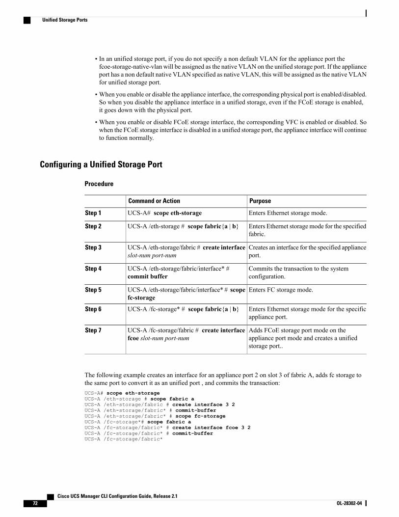
• In an unified storage port, if you do not specify a non default VLAN for the appliance port thefcoe-storage-native-vlan will be assigned as the native VLAN on the unified storage port. If the applianceport has a non default native VLAN specified as native VLAN, this will be assigned as the native VLANfor unified storage port.
•When you enable or disable the appliance interface, the corresponding physical port is enabled/disabled.So when you disable the appliance interface in a unified storage, even if the FCoE storage is enabled,it goes down with the physical port.
•When you enable or disable FCoE storage interface, the corresponding VFC is enabled or disabled. Sowhen the FCoE storage interface is disabled in a unified storage port, the appliance interface will continueto function normally.
Configuring a Unified Storage Port
Procedure
PurposeCommand or Action
Enters Ethernet storage mode.UCS-A# scope eth-storageStep 1
Enters Ethernet storage mode for the specifiedfabric.
UCS-A /eth-storage # scope fabric{a | b}Step 2
Creates an interface for the specified applianceport.
UCS-A /eth-storage/fabric # create interfaceslot-num port-num
Step 3
Commits the transaction to the systemconfiguration.
UCS-A /eth-storage/fabric/interface* #commit buffer
Step 4
Enters FC storage mode.UCS-A /eth-storage/fabric/interface* # scopefc-storage
Step 5
Enters Ethernet storage mode for the specificappliance port.
UCS-A /fc-storage* # scope fabric{a | b}Step 6
Adds FCoE storage port mode on theappliance port mode and creates a unifiedstorage port..
UCS-A /fc-storage/fabric # create interfacefcoe slot-num port-num
Step 7
The following example creates an interface for an appliance port 2 on slot 3 of fabric A, adds fc storage tothe same port to convert it as an unified port , and commits the transaction:UCS-A# scope eth-storageUCS-A /eth-storage # scope fabric aUCS-A /eth-storage/fabric # create interface 3 2UCS-A /eth-storage/fabric* # commit-bufferUCS-A /eth-storage/fabric* # scope fc-storageUCS-A /fc-storage*# scope fabric aUCS-A /fc-storage/fabric* # create interface fcoe 3 2UCS-A /fc-storage/fabric* # commit-bufferUCS-A /fc-storage/fabric*
Cisco UCS Manager CLI Configuration Guide, Release 2.172 OL-28302-04
Unified Storage Ports
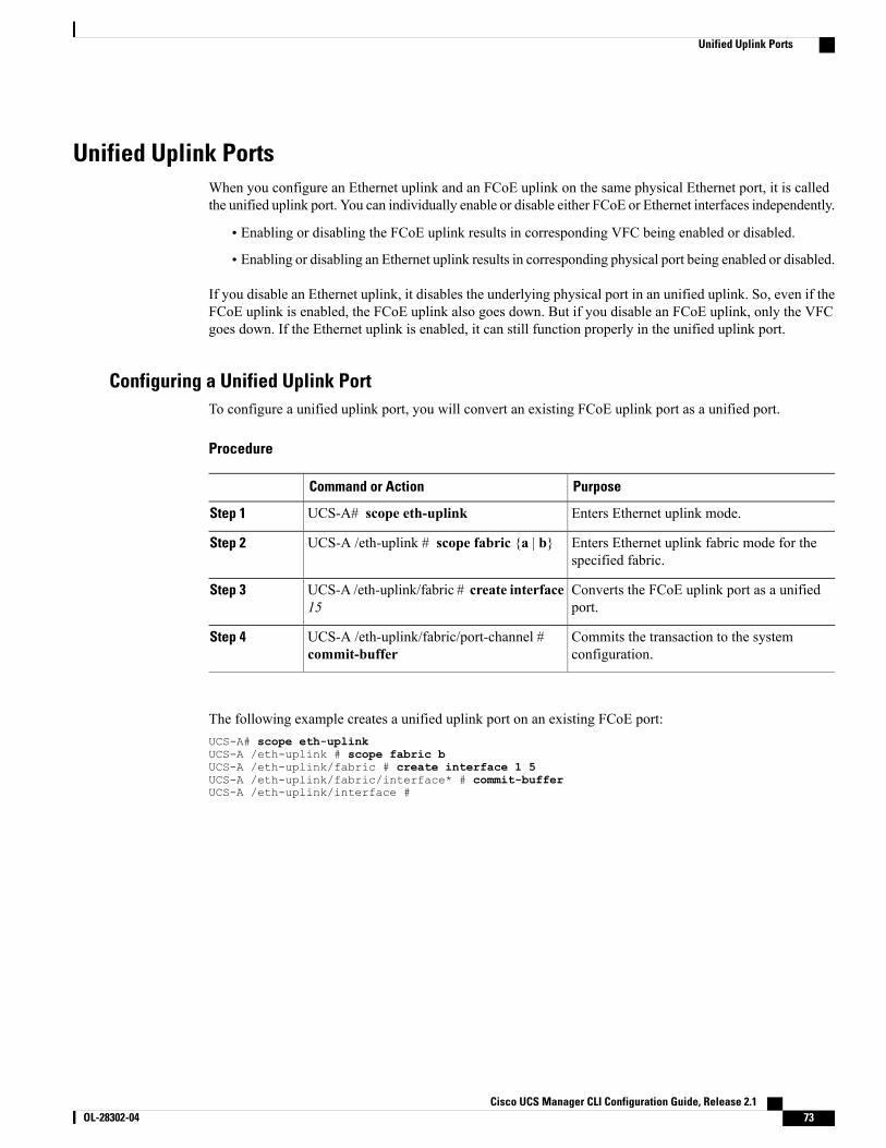
Unified Uplink PortsWhen you configure an Ethernet uplink and an FCoE uplink on the same physical Ethernet port, it is calledthe unified uplink port. You can individually enable or disable either FCoE or Ethernet interfaces independently.
• Enabling or disabling the FCoE uplink results in corresponding VFC being enabled or disabled.
• Enabling or disabling an Ethernet uplink results in corresponding physical port being enabled or disabled.
If you disable an Ethernet uplink, it disables the underlying physical port in an unified uplink. So, even if theFCoE uplink is enabled, the FCoE uplink also goes down. But if you disable an FCoE uplink, only the VFCgoes down. If the Ethernet uplink is enabled, it can still function properly in the unified uplink port.
Configuring a Unified Uplink PortTo configure a unified uplink port, you will convert an existing FCoE uplink port as a unified port.
Procedure
PurposeCommand or Action
Enters Ethernet uplink mode.UCS-A# scope eth-uplinkStep 1
Enters Ethernet uplink fabric mode for thespecified fabric.
UCS-A /eth-uplink # scope fabric {a | b}Step 2
Converts the FCoE uplink port as a unifiedport.
UCS-A /eth-uplink/fabric # create interface15
Step 3
Commits the transaction to the systemconfiguration.
UCS-A /eth-uplink/fabric/port-channel #commit-buffer
Step 4
The following example creates a unified uplink port on an existing FCoE port:UCS-A# scope eth-uplinkUCS-A /eth-uplink # scope fabric bUCS-A /eth-uplink/fabric # create interface 1 5UCS-A /eth-uplink/fabric/interface* # commit-bufferUCS-A /eth-uplink/interface #
Cisco UCS Manager CLI Configuration Guide, Release 2.1 OL-28302-04 73
Unified Uplink Ports
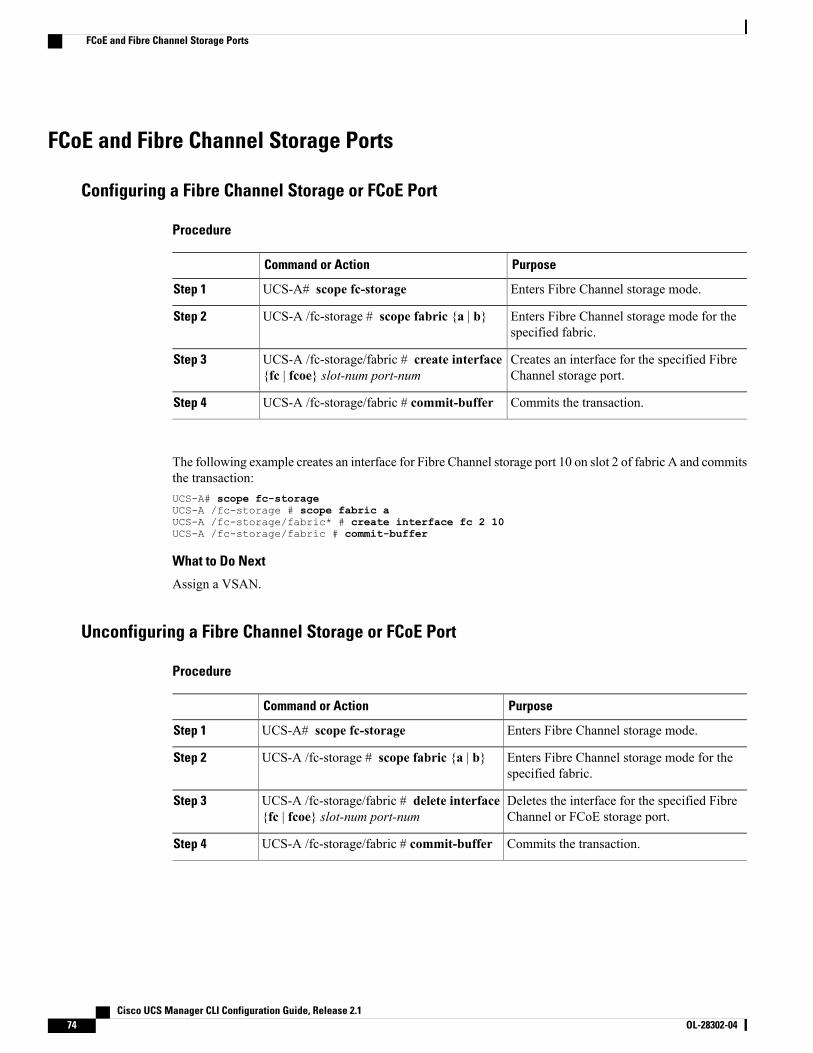
FCoE and Fibre Channel Storage Ports
Configuring a Fibre Channel Storage or FCoE Port
Procedure
PurposeCommand or Action
Enters Fibre Channel storage mode.UCS-A# scope fc-storageStep 1
Enters Fibre Channel storage mode for thespecified fabric.
UCS-A /fc-storage # scope fabric {a | b}Step 2
Creates an interface for the specified FibreChannel storage port.
UCS-A /fc-storage/fabric # create interface{fc | fcoe} slot-num port-num
Step 3
Commits the transaction.UCS-A /fc-storage/fabric # commit-bufferStep 4
The following example creates an interface for Fibre Channel storage port 10 on slot 2 of fabric A and commitsthe transaction:UCS-A# scope fc-storageUCS-A /fc-storage # scope fabric aUCS-A /fc-storage/fabric* # create interface fc 2 10UCS-A /fc-storage/fabric # commit-buffer
What to Do Next
Assign a VSAN.
Unconfiguring a Fibre Channel Storage or FCoE Port
Procedure
PurposeCommand or Action
Enters Fibre Channel storage mode.UCS-A# scope fc-storageStep 1
Enters Fibre Channel storage mode for thespecified fabric.
UCS-A /fc-storage # scope fabric {a | b}Step 2
Deletes the interface for the specified FibreChannel or FCoE storage port.
UCS-A /fc-storage/fabric # delete interface{fc | fcoe} slot-num port-num
Step 3
Commits the transaction.UCS-A /fc-storage/fabric # commit-bufferStep 4
Cisco UCS Manager CLI Configuration Guide, Release 2.174 OL-28302-04
FCoE and Fibre Channel Storage Ports
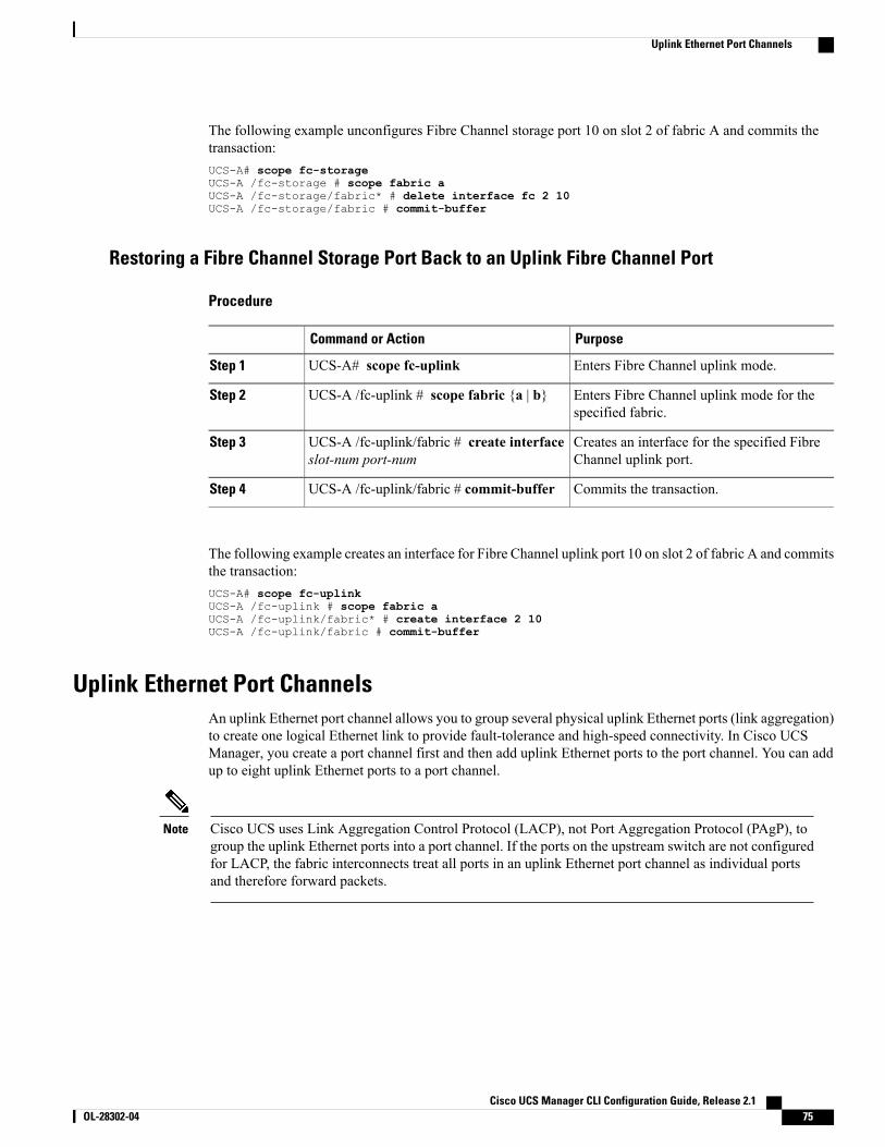
The following example unconfigures Fibre Channel storage port 10 on slot 2 of fabric A and commits thetransaction:UCS-A# scope fc-storageUCS-A /fc-storage # scope fabric aUCS-A /fc-storage/fabric* # delete interface fc 2 10UCS-A /fc-storage/fabric # commit-buffer
Restoring a Fibre Channel Storage Port Back to an Uplink Fibre Channel Port
Procedure
PurposeCommand or Action
Enters Fibre Channel uplink mode.UCS-A# scope fc-uplinkStep 1
Enters Fibre Channel uplink mode for thespecified fabric.
UCS-A /fc-uplink # scope fabric {a | b}Step 2
Creates an interface for the specified FibreChannel uplink port.
UCS-A /fc-uplink/fabric # create interfaceslot-num port-num
Step 3
Commits the transaction.UCS-A /fc-uplink/fabric # commit-bufferStep 4
The following example creates an interface for Fibre Channel uplink port 10 on slot 2 of fabric A and commitsthe transaction:UCS-A# scope fc-uplinkUCS-A /fc-uplink # scope fabric aUCS-A /fc-uplink/fabric* # create interface 2 10UCS-A /fc-uplink/fabric # commit-buffer
Uplink Ethernet Port ChannelsAn uplink Ethernet port channel allows you to group several physical uplink Ethernet ports (link aggregation)to create one logical Ethernet link to provide fault-tolerance and high-speed connectivity. In Cisco UCSManager, you create a port channel first and then add uplink Ethernet ports to the port channel. You can addup to eight uplink Ethernet ports to a port channel.
Cisco UCS uses Link Aggregation Control Protocol (LACP), not Port Aggregation Protocol (PAgP), togroup the uplink Ethernet ports into a port channel. If the ports on the upstream switch are not configuredfor LACP, the fabric interconnects treat all ports in an uplink Ethernet port channel as individual portsand therefore forward packets.
Note
Cisco UCS Manager CLI Configuration Guide, Release 2.1 OL-28302-04 75
Uplink Ethernet Port Channels
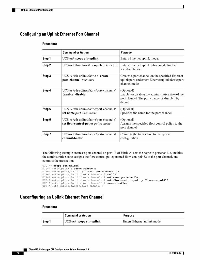
Configuring an Uplink Ethernet Port Channel
Procedure
PurposeCommand or Action
Enters Ethernet uplink mode.UCS-A# scope eth-uplinkStep 1
Enters Ethernet uplink fabric mode for thespecified fabric.
UCS-A /eth-uplink # scope fabric {a | b }Step 2
Creates a port channel on the specified Ethernetuplink port, and enters Ethernet uplink fabric portchannel mode.
UCS-A /eth-uplink/fabric # createport-channel port-num
Step 3
(Optional)Enables or disables the administrative state of theport channel. The port channel is disabled bydefault.
UCS-A /eth-uplink/fabric/port-channel #{enable | disable}
Step 4
(Optional)Specifies the name for the port channel.
UCS-A /eth-uplink/fabric/port-channel #set name port-chan-name
Step 5
(Optional)Assigns the specified flow control policy to theport channel.
UCS-A /eth-uplink/fabric/port-channel #set flow-control-policy policy-name
Step 6
Commits the transaction to the systemconfiguration.
UCS-A /eth-uplink/fabric/port-channel #commit-buffer
Step 7
The following example creates a port channel on port 13 of fabric A, sets the name to portchan13a, enablesthe administrative state, assigns the flow control policy named flow-con-pol432 to the port channel, andcommits the transaction:UCS-A# scope eth-uplinkUCS-A /eth-uplink # scope fabric aUCS-A /eth-uplink/fabric # create port-channel 13UCS-A /eth-uplink/fabric/port-channel* # enableUCS-A /eth-uplink/fabric/port-channel* # set name portchan13aUCS-A /eth-uplink/fabric/port-channel* # set flow-control-policy flow-con-pol432UCS-A /eth-uplink/fabric/port-channel* # commit-bufferUCS-A /eth-uplink/fabric/port-channel #
Unconfiguring an Uplink Ethernet Port Channel
Procedure
PurposeCommand or Action
Enters Ethernet uplink mode.UCS-A# scope eth-uplinkStep 1
Cisco UCS Manager CLI Configuration Guide, Release 2.176 OL-28302-04
Uplink Ethernet Port Channels
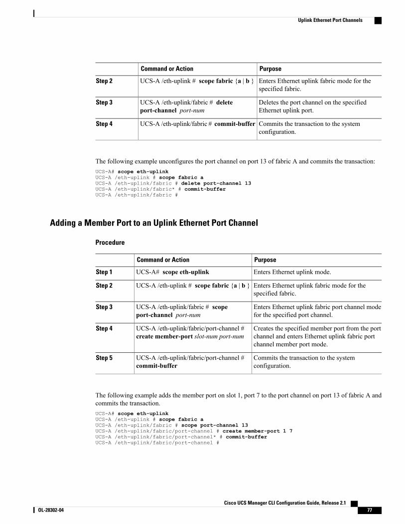
PurposeCommand or Action
Enters Ethernet uplink fabric mode for thespecified fabric.
UCS-A /eth-uplink # scope fabric {a | b }Step 2
Deletes the port channel on the specifiedEthernet uplink port.
UCS-A /eth-uplink/fabric # deleteport-channel port-num
Step 3
Commits the transaction to the systemconfiguration.
UCS-A /eth-uplink/fabric # commit-bufferStep 4
The following example unconfigures the port channel on port 13 of fabric A and commits the transaction:UCS-A# scope eth-uplinkUCS-A /eth-uplink # scope fabric aUCS-A /eth-uplink/fabric # delete port-channel 13UCS-A /eth-uplink/fabric* # commit-bufferUCS-A /eth-uplink/fabric #
Adding a Member Port to an Uplink Ethernet Port Channel
Procedure
PurposeCommand or Action
Enters Ethernet uplink mode.UCS-A# scope eth-uplinkStep 1
Enters Ethernet uplink fabric mode for thespecified fabric.
UCS-A /eth-uplink # scope fabric {a | b }Step 2
Enters Ethernet uplink fabric port channel modefor the specified port channel.
UCS-A /eth-uplink/fabric # scopeport-channel port-num
Step 3
Creates the specified member port from the portchannel and enters Ethernet uplink fabric portchannel member port mode.
UCS-A /eth-uplink/fabric/port-channel #create member-port slot-num port-num
Step 4
Commits the transaction to the systemconfiguration.
UCS-A /eth-uplink/fabric/port-channel #commit-buffer
Step 5
The following example adds the member port on slot 1, port 7 to the port channel on port 13 of fabric A andcommits the transaction.UCS-A# scope eth-uplinkUCS-A /eth-uplink # scope fabric aUCS-A /eth-uplink/fabric # scope port-channel 13UCS-A /eth-uplink/fabric/port-channel # create member-port 1 7UCS-A /eth-uplink/fabric/port-channel* # commit-bufferUCS-A /eth-uplink/fabric/port-channel #
Cisco UCS Manager CLI Configuration Guide, Release 2.1 OL-28302-04 77
Uplink Ethernet Port Channels
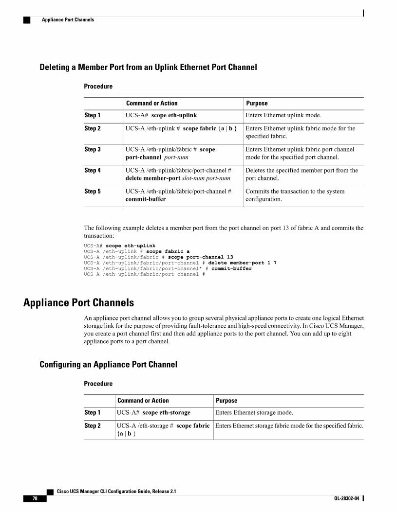
Deleting a Member Port from an Uplink Ethernet Port Channel
Procedure
PurposeCommand or Action
Enters Ethernet uplink mode.UCS-A# scope eth-uplinkStep 1
Enters Ethernet uplink fabric mode for thespecified fabric.
UCS-A /eth-uplink # scope fabric {a | b }Step 2
Enters Ethernet uplink fabric port channelmode for the specified port channel.
UCS-A /eth-uplink/fabric # scopeport-channel port-num
Step 3
Deletes the specified member port from theport channel.
UCS-A /eth-uplink/fabric/port-channel #delete member-port slot-num port-num
Step 4
Commits the transaction to the systemconfiguration.
UCS-A /eth-uplink/fabric/port-channel #commit-buffer
Step 5
The following example deletes a member port from the port channel on port 13 of fabric A and commits thetransaction:UCS-A# scope eth-uplinkUCS-A /eth-uplink # scope fabric aUCS-A /eth-uplink/fabric # scope port-channel 13UCS-A /eth-uplink/fabric/port-channel # delete member-port 1 7UCS-A /eth-uplink/fabric/port-channel* # commit-bufferUCS-A /eth-uplink/fabric/port-channel #
Appliance Port ChannelsAn appliance port channel allows you to group several physical appliance ports to create one logical Ethernetstorage link for the purpose of providing fault-tolerance and high-speed connectivity. In Cisco UCSManager,you create a port channel first and then add appliance ports to the port channel. You can add up to eightappliance ports to a port channel.
Configuring an Appliance Port Channel
Procedure
PurposeCommand or Action
Enters Ethernet storage mode.UCS-A# scope eth-storageStep 1
Enters Ethernet storage fabric mode for the specified fabric.UCS-A /eth-storage # scope fabric{a | b }
Step 2
Cisco UCS Manager CLI Configuration Guide, Release 2.178 OL-28302-04
Appliance Port Channels
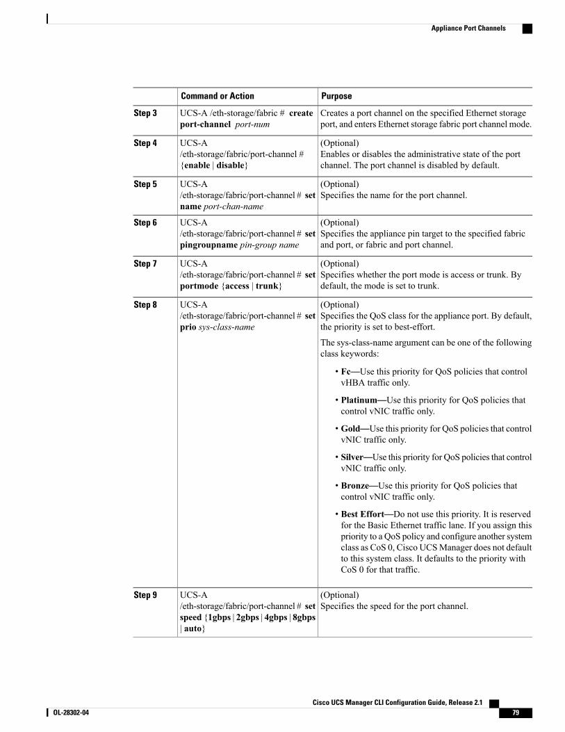
PurposeCommand or Action
Creates a port channel on the specified Ethernet storageport, and enters Ethernet storage fabric port channel mode.
UCS-A /eth-storage/fabric # createport-channel port-num
Step 3
(Optional)Enables or disables the administrative state of the portchannel. The port channel is disabled by default.
UCS-A/eth-storage/fabric/port-channel #{enable | disable}
Step 4
(Optional)Specifies the name for the port channel.
UCS-A/eth-storage/fabric/port-channel # setname port-chan-name
Step 5
(Optional)Specifies the appliance pin target to the specified fabricand port, or fabric and port channel.
UCS-A/eth-storage/fabric/port-channel # setpingroupname pin-group name
Step 6
(Optional)Specifies whether the port mode is access or trunk. Bydefault, the mode is set to trunk.
UCS-A/eth-storage/fabric/port-channel # setportmode {access | trunk}
Step 7
(Optional)Specifies the QoS class for the appliance port. By default,the priority is set to best-effort.
UCS-A/eth-storage/fabric/port-channel # setprio sys-class-name
Step 8
The sys-class-name argument can be one of the followingclass keywords:
• Fc—Use this priority for QoS policies that controlvHBA traffic only.
• Platinum—Use this priority for QoS policies thatcontrol vNIC traffic only.
• Gold—Use this priority for QoS policies that controlvNIC traffic only.
• Silver—Use this priority for QoS policies that controlvNIC traffic only.
• Bronze—Use this priority for QoS policies thatcontrol vNIC traffic only.
• Best Effort—Do not use this priority. It is reservedfor the Basic Ethernet traffic lane. If you assign thispriority to a QoS policy and configure another systemclass as CoS 0, Cisco UCSManager does not defaultto this system class. It defaults to the priority withCoS 0 for that traffic.
(Optional)Specifies the speed for the port channel.
UCS-A/eth-storage/fabric/port-channel # setspeed {1gbps | 2gbps | 4gbps | 8gbps| auto}
Step 9
Cisco UCS Manager CLI Configuration Guide, Release 2.1 OL-28302-04 79
Appliance Port Channels
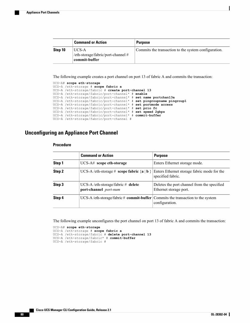
PurposeCommand or Action
Commits the transaction to the system configuration.UCS-A/eth-storage/fabric/port-channel #commit-buffer
Step 10
The following example creates a port channel on port 13 of fabric A and commits the transaction:UCS-A# scope eth-storageUCS-A /eth-storage # scope fabric aUCS-A /eth-storage/fabric # create port-channel 13UCS-A /eth-storage/fabric/port-channel* # enableUCS-A /eth-storage/fabric/port-channel* # set name portchan13aUCS-A /eth-storage/fabric/port-channel* # set pingroupname pingroup1UCS-A /eth-storage/fabric/port-channel* # set portmode accessUCS-A /eth-storage/fabric/port-channel* # set prio fcUCS-A /eth-storage/fabric/port-channel* # set speed 2gbpsUCS-A /eth-storage/fabric/port-channel* # commit-bufferUCS-A /eth-storage/fabric/port-channel #
Unconfiguring an Appliance Port Channel
Procedure
PurposeCommand or Action
Enters Ethernet storage mode.UCS-A# scope eth-storageStep 1
Enters Ethernet storage fabric mode for thespecified fabric.
UCS-A /eth-storage # scope fabric {a | b }Step 2
Deletes the port channel from the specifiedEthernet storage port.
UCS-A /eth-storage/fabric # deleteport-channel port-num
Step 3
Commits the transaction to the systemconfiguration.
UCS-A /eth-storage/fabric # commit-bufferStep 4
The following example unconfigures the port channel on port 13 of fabric A and commits the transaction:UCS-A# scope eth-storageUCS-A /eth-storage # scope fabric aUCS-A /eth-storage/fabric # delete port-channel 13UCS-A /eth-storage/fabric* # commit-bufferUCS-A /eth-storage/fabric #
Cisco UCS Manager CLI Configuration Guide, Release 2.180 OL-28302-04
Appliance Port Channels
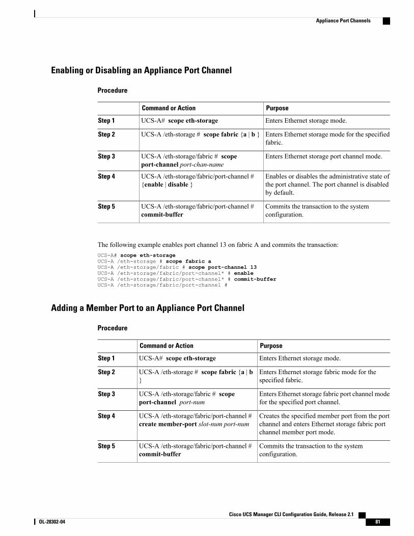
Enabling or Disabling an Appliance Port Channel
Procedure
PurposeCommand or Action
Enters Ethernet storage mode.UCS-A# scope eth-storageStep 1
Enters Ethernet storage mode for the specifiedfabric.
UCS-A /eth-storage # scope fabric {a | b }Step 2
Enters Ethernet storage port channel mode.UCS-A /eth-storage/fabric # scopeport-channel port-chan-name
Step 3
Enables or disables the administrative state ofthe port channel. The port channel is disabledby default.
UCS-A /eth-storage/fabric/port-channel #{enable | disable }
Step 4
Commits the transaction to the systemconfiguration.
UCS-A /eth-storage/fabric/port-channel #commit-buffer
Step 5
The following example enables port channel 13 on fabric A and commits the transaction:UCS-A# scope eth-storageUCS-A /eth-storage # scope fabric aUCS-A /eth-storage/fabric # scope port-channel 13UCS-A /eth-storage/fabric/port-channel* # enableUCS-A /eth-storage/fabric/port-channel* # commit-bufferUCS-A /eth-storage/fabric/port-channel #
Adding a Member Port to an Appliance Port Channel
Procedure
PurposeCommand or Action
Enters Ethernet storage mode.UCS-A# scope eth-storageStep 1
Enters Ethernet storage fabric mode for thespecified fabric.
UCS-A /eth-storage # scope fabric {a | b}
Step 2
Enters Ethernet storage fabric port channel modefor the specified port channel.
UCS-A /eth-storage/fabric # scopeport-channel port-num
Step 3
Creates the specified member port from the portchannel and enters Ethernet storage fabric portchannel member port mode.
UCS-A /eth-storage/fabric/port-channel #create member-port slot-num port-num
Step 4
Commits the transaction to the systemconfiguration.
UCS-A /eth-storage/fabric/port-channel #commit-buffer
Step 5
Cisco UCS Manager CLI Configuration Guide, Release 2.1 OL-28302-04 81
Appliance Port Channels

The following example adds the member port on slot 1, port 7 to the port channel on port 13 of fabric A andcommits the transaction.UCS-A# scope eth-storageUCS-A /eth-storage # scope fabric aUCS-A /eth-storage/fabric # scope port-channel 13UCS-A /eth-storage/fabric/port-channel # create member-port 1 7UCS-A /eth-storage/fabric/port-channel* # commit-bufferUCS-A /eth-storage/fabric/port-channel #
Deleting a Member Port from an Appliance Port Channel
Procedure
PurposeCommand or Action
Enters Ethernet storage mode.UCS-A# scope eth-storageStep 1
Enters Ethernet storage fabric mode for thespecified fabric.
UCS-A /eth-storage # scope fabric {a | b }Step 2
Enters Ethernet storage fabric port channelmode for the specified port channel.
UCS-A /eth-storage/fabric # scopeport-channel port-num
Step 3
Deletes the specified member port from theport channel.
UCS-A /eth-storage/fabric/port-channel #delete member-port slot-num port-num
Step 4
Commits the transaction to the systemconfiguration.
UCS-A /eth-storage/fabric/port-channel #commit-buffer
Step 5
The following example deletes a member port from the port channel on port 13 of fabric A and commits thetransaction:UCS-A# scope eth-storageUCS-A /eth-storage # scope fabric aUCS-A /eth-storage/fabric # scope port-channel 13UCS-A /eth-storage/fabric/port-channel # delete member-port 1 7UCS-A /eth-storage/fabric/port-channel* # commit-bufferUCS-A /eth-storage/fabric/port-channel #
Fibre Channel Port ChannelsA Fibre Channel port channel allows you to group several physical Fibre Channel ports (link aggregation) tocreate one logical Fibre Channel link to provide fault-tolerance and high-speed connectivity. In Cisco UCSManager, you create a port channel first and then add Fibre Channel ports to the port channel.
You can create up to four Fibre Channel port channels in each Cisco UCS domain. Each Fibre Channel portchannel can include a maximum of 16 uplink Fibre Channel ports.
Cisco UCS Manager CLI Configuration Guide, Release 2.182 OL-28302-04
Fibre Channel Port Channels
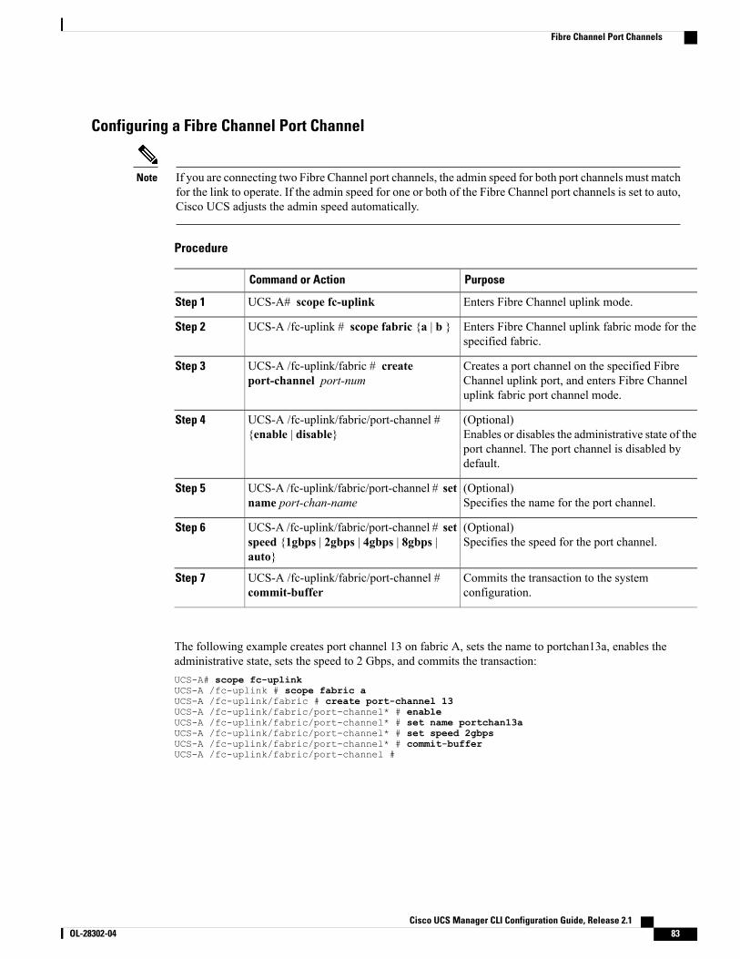
Configuring a Fibre Channel Port Channel
If you are connecting two Fibre Channel port channels, the admin speed for both port channels must matchfor the link to operate. If the admin speed for one or both of the Fibre Channel port channels is set to auto,Cisco UCS adjusts the admin speed automatically.
Note
Procedure
PurposeCommand or Action
Enters Fibre Channel uplink mode.UCS-A# scope fc-uplinkStep 1
Enters Fibre Channel uplink fabric mode for thespecified fabric.
UCS-A /fc-uplink # scope fabric {a | b }Step 2
Creates a port channel on the specified FibreChannel uplink port, and enters Fibre Channeluplink fabric port channel mode.
UCS-A /fc-uplink/fabric # createport-channel port-num
Step 3
(Optional)Enables or disables the administrative state of theport channel. The port channel is disabled bydefault.
UCS-A /fc-uplink/fabric/port-channel #{enable | disable}
Step 4
(Optional)Specifies the name for the port channel.
UCS-A /fc-uplink/fabric/port-channel # setname port-chan-name
Step 5
(Optional)Specifies the speed for the port channel.
UCS-A /fc-uplink/fabric/port-channel # setspeed {1gbps | 2gbps | 4gbps | 8gbps |auto}
Step 6
Commits the transaction to the systemconfiguration.
UCS-A /fc-uplink/fabric/port-channel #commit-buffer
Step 7
The following example creates port channel 13 on fabric A, sets the name to portchan13a, enables theadministrative state, sets the speed to 2 Gbps, and commits the transaction:UCS-A# scope fc-uplinkUCS-A /fc-uplink # scope fabric aUCS-A /fc-uplink/fabric # create port-channel 13UCS-A /fc-uplink/fabric/port-channel* # enableUCS-A /fc-uplink/fabric/port-channel* # set name portchan13aUCS-A /fc-uplink/fabric/port-channel* # set speed 2gbpsUCS-A /fc-uplink/fabric/port-channel* # commit-bufferUCS-A /fc-uplink/fabric/port-channel #
Cisco UCS Manager CLI Configuration Guide, Release 2.1 OL-28302-04 83
Fibre Channel Port Channels
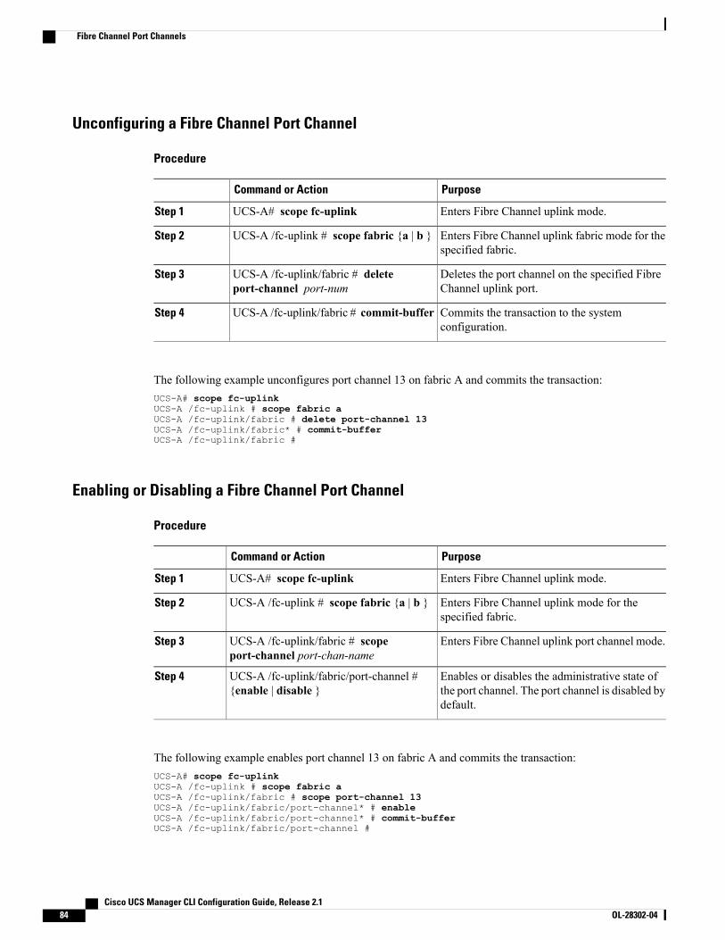
Unconfiguring a Fibre Channel Port Channel
Procedure
PurposeCommand or Action
Enters Fibre Channel uplink mode.UCS-A# scope fc-uplinkStep 1
Enters Fibre Channel uplink fabric mode for thespecified fabric.
UCS-A /fc-uplink # scope fabric {a | b }Step 2
Deletes the port channel on the specified FibreChannel uplink port.
UCS-A /fc-uplink/fabric # deleteport-channel port-num
Step 3
Commits the transaction to the systemconfiguration.
UCS-A /fc-uplink/fabric # commit-bufferStep 4
The following example unconfigures port channel 13 on fabric A and commits the transaction:UCS-A# scope fc-uplinkUCS-A /fc-uplink # scope fabric aUCS-A /fc-uplink/fabric # delete port-channel 13UCS-A /fc-uplink/fabric* # commit-bufferUCS-A /fc-uplink/fabric #
Enabling or Disabling a Fibre Channel Port Channel
Procedure
PurposeCommand or Action
Enters Fibre Channel uplink mode.UCS-A# scope fc-uplinkStep 1
Enters Fibre Channel uplink mode for thespecified fabric.
UCS-A /fc-uplink # scope fabric {a | b }Step 2
Enters Fibre Channel uplink port channel mode.UCS-A /fc-uplink/fabric # scopeport-channel port-chan-name
Step 3
Enables or disables the administrative state ofthe port channel. The port channel is disabled bydefault.
UCS-A /fc-uplink/fabric/port-channel #{enable | disable }
Step 4
The following example enables port channel 13 on fabric A and commits the transaction:UCS-A# scope fc-uplinkUCS-A /fc-uplink # scope fabric aUCS-A /fc-uplink/fabric # scope port-channel 13UCS-A /fc-uplink/fabric/port-channel* # enableUCS-A /fc-uplink/fabric/port-channel* # commit-bufferUCS-A /fc-uplink/fabric/port-channel #
Cisco UCS Manager CLI Configuration Guide, Release 2.184 OL-28302-04
Fibre Channel Port Channels

Adding a Member Port to a Fibre Channel Port Channel
Procedure
PurposeCommand or Action
Enters Fibre Channel uplink mode.UCS-A# scope fc-uplinkStep 1
Enters Fibre Channel uplink fabric mode for thespecified fabric.
UCS-A /fc-uplink # scope fabric {a | b }Step 2
Enters Fibre Channel uplink fabric port channelmode for the specified port channel.
UCS-A /fc-uplink/fabric # scopeport-channel port-num
Step 3
Creates the specified member port from the portchannel and enters Fibre Channel uplink fabricport channel member port mode.
UCS-A /fc-uplink/fabric/port-channel #create member-port slot-num port-num
Step 4
Commits the transaction to the systemconfiguration.
UCS-A /fc-uplink/fabric/port-channel #commit-buffer
Step 5
The following example adds the member port on slot 1, port 7 to port channel 13 on fabric A and commitsthe transaction.UCS-A# scope fc-uplinkUCS-A /fc-uplink # scope fabric aUCS-A /fc-uplink/fabric # scope port-channel 13UCS-A /fc-uplink/fabric # create member-port 1 7UCS-A /fc-uplink/fabric/port-channel* # commit-bufferUCS-A /fc-uplink/fabric/port-channel #
Deleting a Member Port from a Fibre Channel Port Channel
Procedure
PurposeCommand or Action
Enters Fibre Channel uplink mode.UCS-A# scope fc-uplinkStep 1
Enters Fibre Channel uplink fabric mode forthe specified fabric.
UCS-A /fc-uplink # scope fabric {a | b}Step 2
Enters Fibre Channel uplink fabric port channelmode for the specified port channel.
UCS-A /fc-uplink/fabric # scopeport-channel port-num
Step 3
Deletes the specified member port from the portchannel.
UCS-A /fc-uplink/fabric/port-channel #delete member-port slot-num port-num
Step 4
Commits the transaction to the systemconfiguration.
UCS-A /fc-uplink/fabric/port-channel #commit-buffer
Step 5
Cisco UCS Manager CLI Configuration Guide, Release 2.1 OL-28302-04 85
Fibre Channel Port Channels
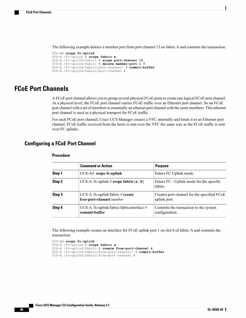
The following example deletes a member port from port channel 13 on fabric A and commits the transaction:UCS-A# scope fc-uplinkUCS-A /fc-uplink # scope fabric aUCS-A /fc-uplink/fabric # scope port-channel 13UCS-A /fc-uplink/fabric # delete member-port 1 7UCS-A /fc-uplink/fabric/port-channel* # commit-bufferUCS-A /fc-uplink/fabric/port-channel #
FCoE Port ChannelsAFCoE port channel allows you to group several physical FCoE ports to create one logical FCoE port channel.At a physical level, the FCoE port channel carries FCoE traffic over an Ethernet port channel. So an FCoEport channel with a set of members is essentially an ethernet port channel with the samemembers. This ethernetport channel is used as a physical transport for FCoE traffic.
For each FCoE port channel, Cisco UCS Manager creates a VFC internally and binds it to an Ethernet portchannel. FCoE traffic received from the hosts is sent over the VFC the same way as the FCoE traffic is sentover FC uplinks.
Configuring a FCoE Port Channel
Procedure
PurposeCommand or Action
Enters FC Uplink mode.UCS-A# scope fc-uplinkStep 1
Enters FC - Uplink mode for the specificfabric.
UCS-A /fc-uplink # scope fabric{a | b}Step 2
Creates port channel for the specified FCoEuplink port.
UCS-A /fc-uplink/fabric # createfcoe-port-channel number
Step 3
Commits the transaction to the systemconfiguration.
UCS-A /fc-uplink/fabric/fabricinterface #commit-buffer
Step 4
The following example creates an interface for FCoE uplink port 1 on slot 8 of fabric A and commits thetransaction:UCS-A# scope fc-uplinkUCS-A /fc-uplink # scope fabric aUCS-A /fc-uplink/fabric # create fcoe-port-channel 4UCS-A /fc-uplink/fabric/fcoe-port-channel* # commit-bufferUCS-A /fc-uplink/fabric/fcoe-port-channel #
Cisco UCS Manager CLI Configuration Guide, Release 2.186 OL-28302-04
FCoE Port Channels
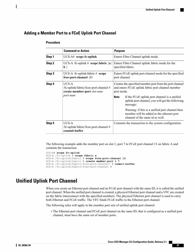
Adding a Member Port to a FCoE Uplink Port Channel
Procedure
PurposeCommand or Action
Enters Fibre Channel uplink mode.UCS-A# scope fc-uplinkStep 1
Enters Fibre Channel uplink fabric mode for thespecified fabric.
UCS-A /fc-uplink # scope fabric {a |b }
Step 2
Enters FCoE uplink port channel mode for the specifiedport channel.
UCS-A /fc-uplink/fabric # scopefcoe-port-channel ID
Step 3
Creates the specified member port from the port channeland enters FCoE uplink fabric port channel memberport mode.
UCS-A/fc-uplink/fabric/fcoe-port-channel #create member-port slot-numport-num
Step 4
If the FCoE uplink port channel is a unifieduplink port channel, you will get the followingmessage:
Warning: if this is a unified port channel thenmember will be added to the ethernet portchannel of the same id as well.
Note
Commits the transaction to the system configuration.UCS-A/fc-uplink/fabric/fcoe-port-channel #commit-buffer
Step 5
The following example adds the member port on slot 1, port 7 to FCoE port channel 13 on fabric A andcommits the transaction.UCS-A# scope fc-uplinkUCS-A /fc-uplink # scope fabric aUCS-A /fc-uplink/fabric # scope fcoe-port-channel 13UCS-A /fc-uplink/fabric # create member-port 1 7UCS-A /fc-uplink/fabric/fcoe-port-channel* # commit-bufferUCS-A /fc-uplink/fabric/fcoe-port-channel #
Unified Uplink Port ChannelWhen you create an Ethernet port channel and an FCoE port channel with the same ID, it is called the unifiedport channel. When the unified port channel is created, a physical Ethernet port channel and a VFC are createdon the fabric interconnect with the specified members. The physical Ethernet port channel is used to carryboth Ethernet and FCoE traffic. The VFC binds FCoE traffic to the Ethernet port channel.
The following rules will apply to the member port sets of unified uplink port channel:
• The Ethernet port channel and FCoE port channel on the same ID, that is configured as a unified portchannel, must have the same set of member ports.
Cisco UCS Manager CLI Configuration Guide, Release 2.1 OL-28302-04 87
Unified Uplink Port Channel
•When you add a member port channel to the Ethernet port channel, Cisco UCS Manager adds the sameport channel to FCoE port channel as well. Similarly adding a member to FCoE port channel adds themember port to Ethernet port channel.
•When you delete a member port from one of the port channels, Cisco UCSManager automatically deletesthe member port from the other port channel.
If you disable an Ethernet uplink port channel, it disables the underlying physical port channel in an unifieduplink port channel. So, even if the FCoE uplink is enabled, the FCoE uplink port channel also goes down.But if you disable an FCoE uplink port channel, only the VFC goes down. If the Ethernet uplink port channelis enabled, it can still function properly in the unified uplink port channel.
Configuring a Unified Uplink Port ChannelTo configure a unified uplink port channel, you will convert an existing FCoE uplink port channel as a unifiedport channel.
Procedure
PurposeCommand or Action
Enters Ethernet uplink mode.UCS-A# scope eth-uplinkStep 1
Enters Ethernet uplink fabric mode for thespecified fabric.
UCS-A /eth-uplink # scope fabric {a | b}Step 2
Creates a port channel for the specifiedEthernet uplink port.
UCS-A /eth-uplink/fabric # createport-channel ID
Step 3
Commits the transaction to the systemconfiguration.
UCS-A /eth-uplink/fabric/port-channel #commit-buffer
Step 4
The following example creates a unified uplink port channel on an existing FCoE port channel:UCS-A# scope eth-uplinkUCS-A /eth-uplink # scope fabric bUCS-A /eth-uplink/fabric # create port-channel 2UCS-A /eth-uplink/fabric/port-channel* # commit-bufferUCS-A /eth-uplink/fabric #
Adapter Port ChannelsAn adapter port channel groups all the physical links from a Cisco UCS Virtual Interface Card (VIC) to anIOM into one logical link.
Adapter port channels are created and managed internally by Cisco UCS Manager when it detects that thecorrect hardware is present. Adapter port channels cannot be configured manually. Adapter port channels areviewable using the Cisco UCS Manager GUI or Cisco UCS Manager CLI
Cisco UCS Manager CLI Configuration Guide, Release 2.188 OL-28302-04
Adapter Port Channels
Viewing Adapter Port Channels
Procedure
PurposeCommand or Action
Enters Ethernet server mode.UCS-A# scope eth-serverStep 1
Enters Ethernet server fabric mode for thespecified fabric.
UCS-A /eth-server # scope fabric {a | b}Step 2
Displays fabric port channels on the specifiedfabric interconnect.
UCS-A /eth-server/fabric # showhost-port-channel [detail | expand]
Step 3
This following example shows how to display information on host port channels within a fabric in the Ethernetserver mode:UCS-A # scope eth-serverUCS-A /eth-server # scope fabric aUCS-A /eth-server/fabric # show host-port-channel
Host Port channel:
Port Channel ID Chassis ID Admin State Oper State State Reason--------------- ---------- ----------- ---------- -------------1125 2 Enabled Up
UCS-A /eth-server/fabric #
Fabric Port ChannelsFabric port channels allow you to group several of the physical links from an IOM to a fabric interconnectinto one logical link for redundancy and bandwidth sharing. As long as one link in the fabric port channelremains active, the fabric port channel continues to operate.
If the correct hardware is connected, fabric port channels are created by Cisco UCSManager in the followingways:
• During chassis discovery according to the settings configured in the chassis discovery policy.
• After chassis discovery according to the settings configured in the chassis connectivity policy for aspecific chassis.
For each IOM there is a single fabric port channel. Each uplink connecting an IOM to a fabric interconnectcan be configured as a discrete link or included in the port channel, but an uplink cannot belong to more thanone fabric port channel. For example, if a chassis with two IOMs is discovered and the chassis discoverypolicy is configured to create fabric port channels, Cisco UCS Manager creates two separate fabric portchannels: one for the uplinks connecting IOM-1 and another for the uplinks connecting IOM-2. No otherchassis can join these fabric port channels. Similarly, uplinks belonging to the fabric port channel for IOM-1cannot join the fabric port channel for IOM-2.
Cisco UCS Manager CLI Configuration Guide, Release 2.1 OL-28302-04 89
Fabric Port Channels
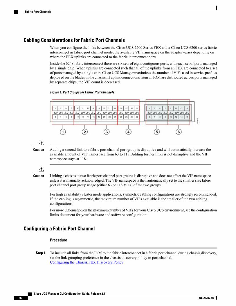
Cabling Considerations for Fabric Port ChannelsWhen you configure the links between the Cisco UCS 2200 Series FEX and a Cisco UCS 6200 series fabricinterconnect in fabric port channel mode, the available VIF namespace on the adapter varies depending onwhere the FEX uplinks are connected to the fabric interconnect ports.
Inside the 6248 fabric interconnect there are six sets of eight contiguous ports, with each set of ports managedby a single chip. When uplinks are connected such that all of the uplinks from an FEX are connected to a setof ports managed by a single chip, Cisco UCSManager maximizes the number of VIFs used in service profilesdeployed on the blades in the chassis. If uplink connections from an IOM are distributed across ports managedby separate chips, the VIF count is decreased.
Figure 1: Port Groups for Fabric Port Channels
Adding a second link to a fabric port channel port group is disruptive and will automatically increase theavailable amount of VIF namespace from 63 to 118. Adding further links is not disruptive and the VIFnamespace stays at 118.
Caution
Linking a chassis to two fabric port channel port groups is disruptive and does not affect the VIF namespaceunless it is manually acknowledged. The VIF namespace is then automatically set to the smaller size fabricport channel port group usage (either 63 or 118 VIFs) of the two groups.
Caution
For high availability cluster mode applications, symmetric cabling configurations are strongly recommended.If the cabling is asymmetric, the maximum number of VIFs available is the smaller of the two cablingconfigurations.
For more information on themaximum number of VIFs for your Cisco UCS environment, see the configurationlimits document for your hardware and software configuration.
Configuring a Fabric Port Channel
Procedure
Step 1 To include all links from the IOM to the fabric interconnect in a fabric port channel during chassis discovery,set the link grouping preference in the chassis discovery policy to port channel.Configuring the Chassis/FEX Discovery Policy
Cisco UCS Manager CLI Configuration Guide, Release 2.190 OL-28302-04
Fabric Port Channels
Step 2 To include links from individual chassis in a fabric port channel during chassis discovery, set the link groupingpreference in the chassis connectivity policy to port channel.Configuring a Chassis Connectivity Policy
Step 3 After chassis discovery, enable or disable additional fabric port channel member ports.Enabling or Disabling a Fabric Port Channel Member Port
What to Do Next
To add or remove chassis links from a fabric port channel after making a change to the chassis discoverypolicy or the chassis connectivity policy, reacknowledge the chassis. Chassis reacknowledgement is notrequired to enable or disable chassis member ports from a fabric port channel
Viewing Fabric Port Channels
Procedure
PurposeCommand or Action
Enters Ethernet server mode.UCS-A# scope eth-serverStep 1
Enters Ethernet server fabric mode for thespecified fabric.
UCS-A /eth-server # scope fabric {a | b}Step 2
Displays fabric port channels on the specifiedfabric interconnect.
UCS-A /eth-server/fabric # showfabric-port-channel [detail | expand]
Step 3
The following example displays information about configured fabric port channels on fabric interconnect A:UCS-A# scope eth-serverUCS-A /eth-server # scope fabric aUCS-A /eth-server/fabric # show fabric-port-channelFabric Port Channel:
Port Channel Id Chassis Id Admin State Oper State State Reason--------------- ---------- ----------- ---------------- ------------
1025 1 Enabled Failed No operational members1026 2 Enabled Up
UCS-A /eth-server/fabric #
Enabling or Disabling a Fabric Port Channel Member Port
Procedure
PurposeCommand or Action
Enters Ethernet server mode.UCS-A# scope eth-serverStep 1
Cisco UCS Manager CLI Configuration Guide, Release 2.1 OL-28302-04 91
Fabric Port Channels
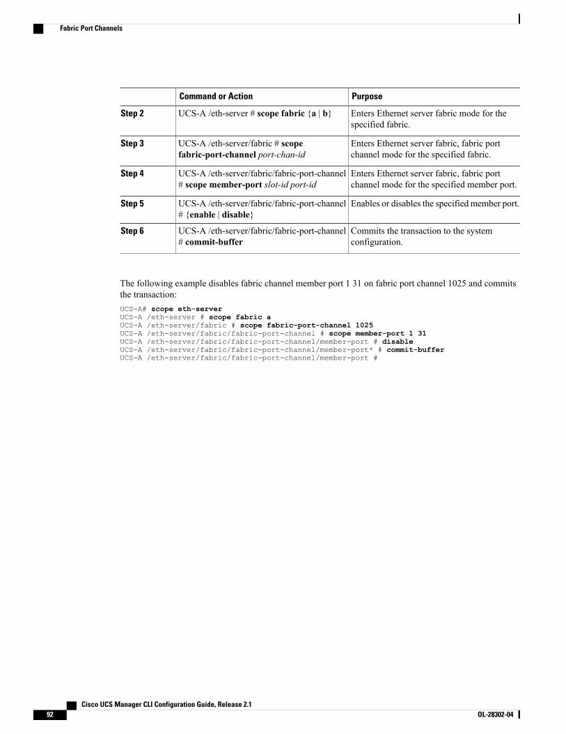
PurposeCommand or Action
Enters Ethernet server fabric mode for thespecified fabric.
UCS-A /eth-server # scope fabric {a | b}Step 2
Enters Ethernet server fabric, fabric portchannel mode for the specified fabric.
UCS-A /eth-server/fabric # scopefabric-port-channel port-chan-id
Step 3
Enters Ethernet server fabric, fabric portchannel mode for the specified member port.
UCS-A /eth-server/fabric/fabric-port-channel# scope member-port slot-id port-id
Step 4
Enables or disables the specified member port.UCS-A /eth-server/fabric/fabric-port-channel# {enable | disable}
Step 5
Commits the transaction to the systemconfiguration.
UCS-A /eth-server/fabric/fabric-port-channel# commit-buffer
Step 6
The following example disables fabric channel member port 1 31 on fabric port channel 1025 and commitsthe transaction:UCS-A# scope eth-serverUCS-A /eth-server # scope fabric aUCS-A /eth-server/fabric # scope fabric-port-channel 1025UCS-A /eth-server/fabric/fabric-port-channel # scope member-port 1 31UCS-A /eth-server/fabric/fabric-port-channel/member-port # disableUCS-A /eth-server/fabric/fabric-port-channel/member-port* # commit-bufferUCS-A /eth-server/fabric/fabric-port-channel/member-port #
Cisco UCS Manager CLI Configuration Guide, Release 2.192 OL-28302-04
Fabric Port Channels
C H A P T E R 7Configuring Communication Services
This chapter includes the following sections:
• Communication Services, page 93
• Configuring CIM XML, page 94
• Configuring HTTP, page 95
• Unconfiguring HTTP, page 96
• Configuring HTTPS, page 96
• Enabling HTTP Redirection, page 106
• Configuring SNMP, page 106
• Enabling Telnet, page 114
• Disabling Communication Services, page 114
Communication ServicesYou can use the following communication services to interface third-party applications with Cisco UCS:
DescriptionCommunication Service
This service is disabled by default and is only available in read-only mode. Thedefault port is 5988.
This common information model is one of the standards defined by theDistributed Management Task Force.
CIM XML
Cisco UCS Manager CLI Configuration Guide, Release 2.1 OL-28302-04 93
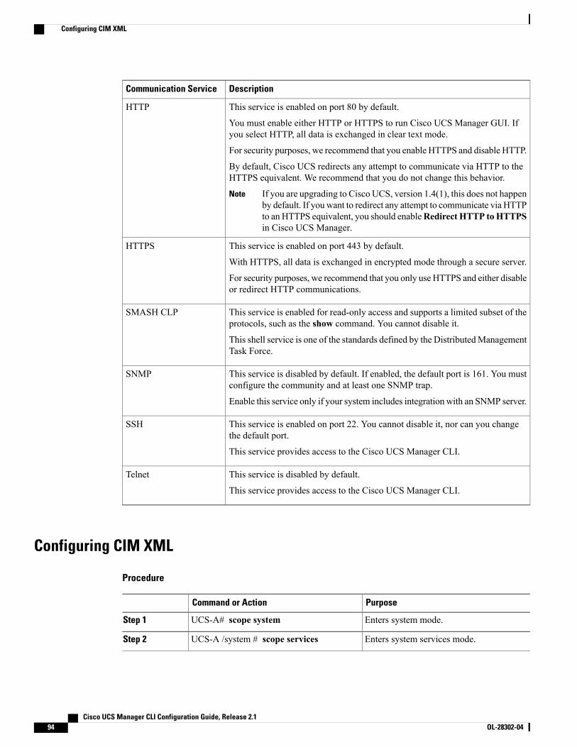
DescriptionCommunication Service
This service is enabled on port 80 by default.
You must enable either HTTP or HTTPS to run Cisco UCS Manager GUI. Ifyou select HTTP, all data is exchanged in clear text mode.
For security purposes, we recommend that you enable HTTPS and disable HTTP.
By default, Cisco UCS redirects any attempt to communicate via HTTP to theHTTPS equivalent. We recommend that you do not change this behavior.
If you are upgrading to Cisco UCS, version 1.4(1), this does not happenby default. If you want to redirect any attempt to communicate via HTTPto an HTTPS equivalent, you should enableRedirect HTTP toHTTPSin Cisco UCS Manager.
Note
HTTP
This service is enabled on port 443 by default.
With HTTPS, all data is exchanged in encrypted mode through a secure server.
For security purposes, we recommend that you only use HTTPS and either disableor redirect HTTP communications.
HTTPS
This service is enabled for read-only access and supports a limited subset of theprotocols, such as the show command. You cannot disable it.
This shell service is one of the standards defined by the DistributedManagementTask Force.
SMASH CLP
This service is disabled by default. If enabled, the default port is 161. You mustconfigure the community and at least one SNMP trap.
Enable this service only if your system includes integration with an SNMP server.
SNMP
This service is enabled on port 22. You cannot disable it, nor can you changethe default port.
This service provides access to the Cisco UCS Manager CLI.
SSH
This service is disabled by default.
This service provides access to the Cisco UCS Manager CLI.
Telnet
Configuring CIM XML
Procedure
PurposeCommand or Action
Enters system mode.UCS-A# scope systemStep 1
Enters system services mode.UCS-A /system # scope servicesStep 2
Cisco UCS Manager CLI Configuration Guide, Release 2.194 OL-28302-04
Configuring CIM XML
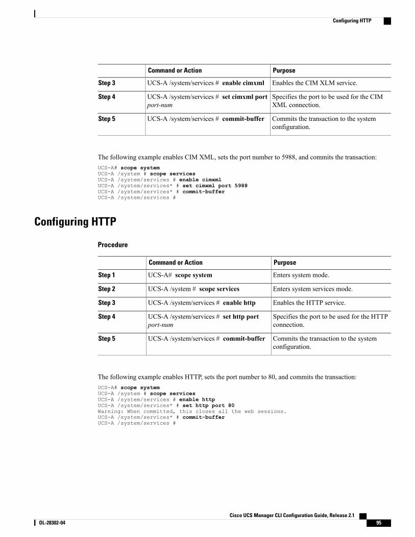
PurposeCommand or Action
Enables the CIM XLM service.UCS-A /system/services # enable cimxmlStep 3
Specifies the port to be used for the CIMXML connection.
UCS-A /system/services # set cimxml portport-num
Step 4
Commits the transaction to the systemconfiguration.
UCS-A /system/services # commit-bufferStep 5
The following example enables CIM XML, sets the port number to 5988, and commits the transaction:UCS-A# scope systemUCS-A /system # scope servicesUCS-A /system/services # enable cimxmlUCS-A /system/services* # set cimxml port 5988UCS-A /system/services* # commit-bufferUCS-A /system/services #
Configuring HTTP
Procedure
PurposeCommand or Action
Enters system mode.UCS-A# scope systemStep 1
Enters system services mode.UCS-A /system # scope servicesStep 2
Enables the HTTP service.UCS-A /system/services # enable httpStep 3
Specifies the port to be used for the HTTPconnection.
UCS-A /system/services # set http portport-num
Step 4
Commits the transaction to the systemconfiguration.
UCS-A /system/services # commit-bufferStep 5
The following example enables HTTP, sets the port number to 80, and commits the transaction:UCS-A# scope systemUCS-A /system # scope servicesUCS-A /system/services # enable httpUCS-A /system/services* # set http port 80Warning: When committed, this closes all the web sessions.UCS-A /system/services* # commit-bufferUCS-A /system/services #
Cisco UCS Manager CLI Configuration Guide, Release 2.1 OL-28302-04 95
Configuring HTTP
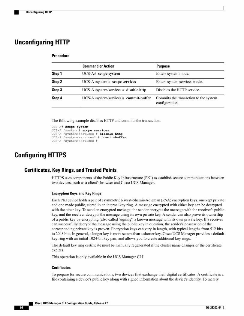
Unconfiguring HTTP
Procedure
PurposeCommand or Action
Enters system mode.UCS-A# scope systemStep 1
Enters system services mode.UCS-A /system # scope servicesStep 2
Disables the HTTP service.UCS-A /system/services # disable httpStep 3
Commits the transaction to the systemconfiguration.
UCS-A /system/services # commit-bufferStep 4
The following example disables HTTP and commits the transaction:UCS-A# scope systemUCS-A /system # scope servicesUCS-A /system/services # disable httpUCS-A /system/services* # commit-bufferUCS-A /system/services #
Configuring HTTPS
Certificates, Key Rings, and Trusted PointsHTTPS uses components of the Public Key Infrastructure (PKI) to establish secure communications betweentwo devices, such as a client's browser and Cisco UCS Manager.
Encryption Keys and Key Rings
Each PKI device holds a pair of asymmetric Rivest-Shamir-Adleman (RSA) encryption keys, one kept privateand one made public, stored in an internal key ring. A message encrypted with either key can be decryptedwith the other key. To send an encrypted message, the sender encrypts the message with the receiver's publickey, and the receiver decrypts the message using its own private key. A sender can also prove its ownershipof a public key by encrypting (also called 'signing') a known message with its own private key. If a receivercan successfully decrypt the message using the public key in question, the sender's possession of thecorresponding private key is proven. Encryption keys can vary in length, with typical lengths from 512 bitsto 2048 bits. In general, a longer key is more secure than a shorter key. Cisco UCSManager provides a defaultkey ring with an initial 1024-bit key pair, and allows you to create additional key rings.
The default key ring certificate must be manually regenerated if the cluster name changes or the certificateexpires.
This operation is only available in the UCS Manager CLI.
Certificates
To prepare for secure communications, two devices first exchange their digital certificates. A certificate is afile containing a device's public key along with signed information about the device's identity. To merely
Cisco UCS Manager CLI Configuration Guide, Release 2.196 OL-28302-04
Unconfiguring HTTP
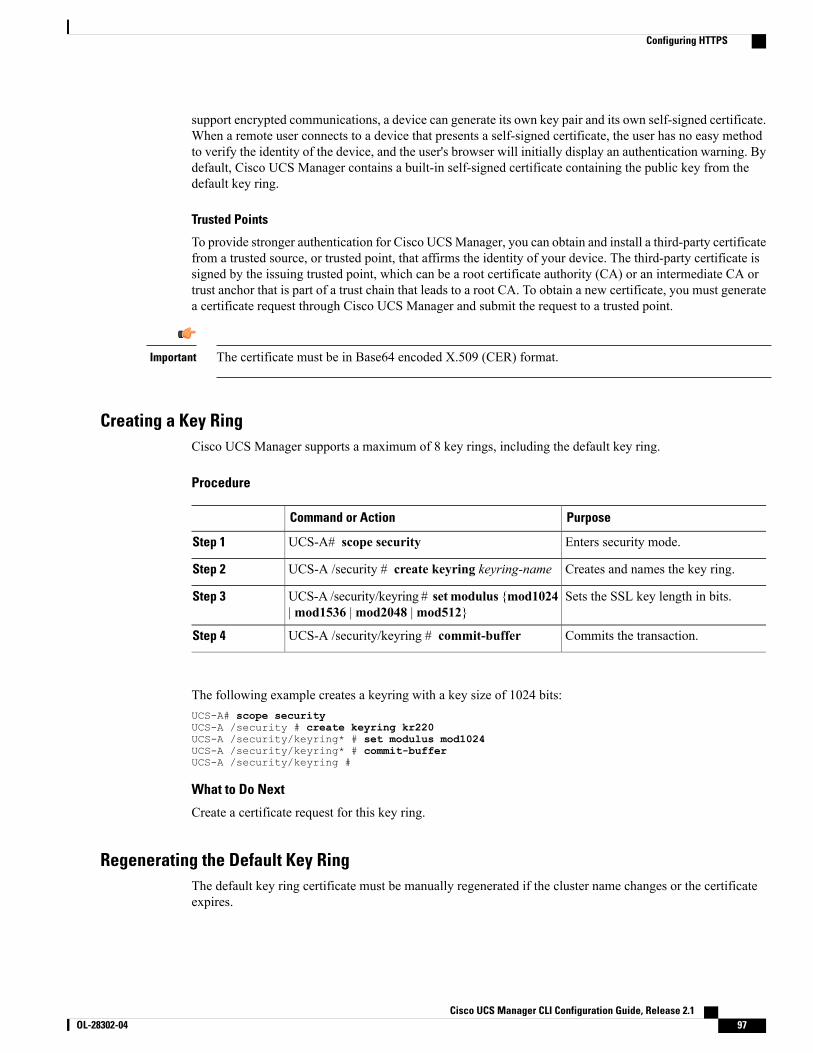
support encrypted communications, a device can generate its own key pair and its own self-signed certificate.When a remote user connects to a device that presents a self-signed certificate, the user has no easy methodto verify the identity of the device, and the user's browser will initially display an authentication warning. Bydefault, Cisco UCS Manager contains a built-in self-signed certificate containing the public key from thedefault key ring.
Trusted Points
To provide stronger authentication for Cisco UCSManager, you can obtain and install a third-party certificatefrom a trusted source, or trusted point, that affirms the identity of your device. The third-party certificate issigned by the issuing trusted point, which can be a root certificate authority (CA) or an intermediate CA ortrust anchor that is part of a trust chain that leads to a root CA. To obtain a new certificate, you must generatea certificate request through Cisco UCS Manager and submit the request to a trusted point.
The certificate must be in Base64 encoded X.509 (CER) format.Important
Creating a Key RingCisco UCS Manager supports a maximum of 8 key rings, including the default key ring.
Procedure
PurposeCommand or Action
Enters security mode.UCS-A# scope securityStep 1
Creates and names the key ring.UCS-A /security # create keyring keyring-nameStep 2
Sets the SSL key length in bits.UCS-A /security/keyring # setmodulus {mod1024|mod1536 |mod2048 |mod512}
Step 3
Commits the transaction.UCS-A /security/keyring # commit-bufferStep 4
The following example creates a keyring with a key size of 1024 bits:UCS-A# scope securityUCS-A /security # create keyring kr220UCS-A /security/keyring* # set modulus mod1024UCS-A /security/keyring* # commit-bufferUCS-A /security/keyring #
What to Do Next
Create a certificate request for this key ring.
Regenerating the Default Key RingThe default key ring certificate must be manually regenerated if the cluster name changes or the certificateexpires.
Cisco UCS Manager CLI Configuration Guide, Release 2.1 OL-28302-04 97
Configuring HTTPS
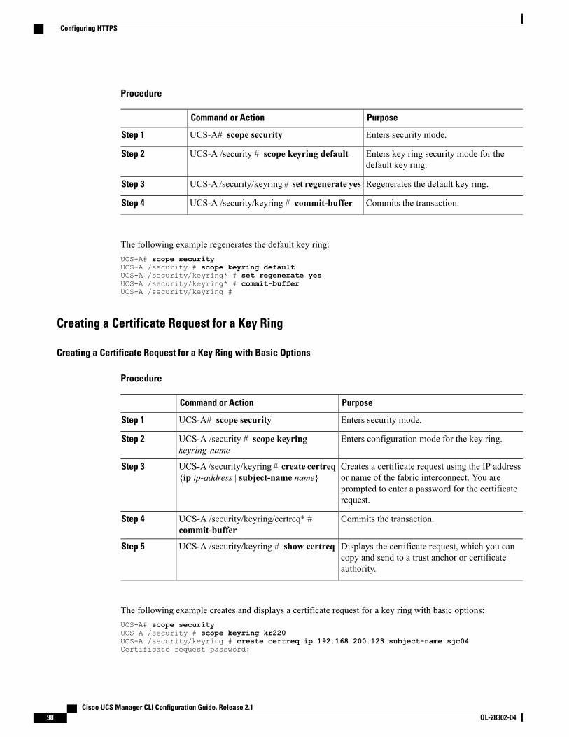
Procedure
PurposeCommand or Action
Enters security mode.UCS-A# scope securityStep 1
Enters key ring security mode for thedefault key ring.
UCS-A /security # scope keyring defaultStep 2
Regenerates the default key ring.UCS-A /security/keyring # set regenerate yesStep 3
Commits the transaction.UCS-A /security/keyring # commit-bufferStep 4
The following example regenerates the default key ring:UCS-A# scope securityUCS-A /security # scope keyring defaultUCS-A /security/keyring* # set regenerate yesUCS-A /security/keyring* # commit-bufferUCS-A /security/keyring #
Creating a Certificate Request for a Key Ring
Creating a Certificate Request for a Key Ring with Basic Options
Procedure
PurposeCommand or Action
Enters security mode.UCS-A# scope securityStep 1
Enters configuration mode for the key ring.UCS-A /security # scope keyringkeyring-name
Step 2
Creates a certificate request using the IP addressor name of the fabric interconnect. You are
UCS-A /security/keyring # create certreq{ip ip-address | subject-name name}
Step 3
prompted to enter a password for the certificaterequest.
Commits the transaction.UCS-A /security/keyring/certreq* #commit-buffer
Step 4
Displays the certificate request, which you cancopy and send to a trust anchor or certificateauthority.
UCS-A /security/keyring # show certreqStep 5
The following example creates and displays a certificate request for a key ring with basic options:UCS-A# scope securityUCS-A /security # scope keyring kr220UCS-A /security/keyring # create certreq ip 192.168.200.123 subject-name sjc04Certificate request password:
Cisco UCS Manager CLI Configuration Guide, Release 2.198 OL-28302-04
Configuring HTTPS
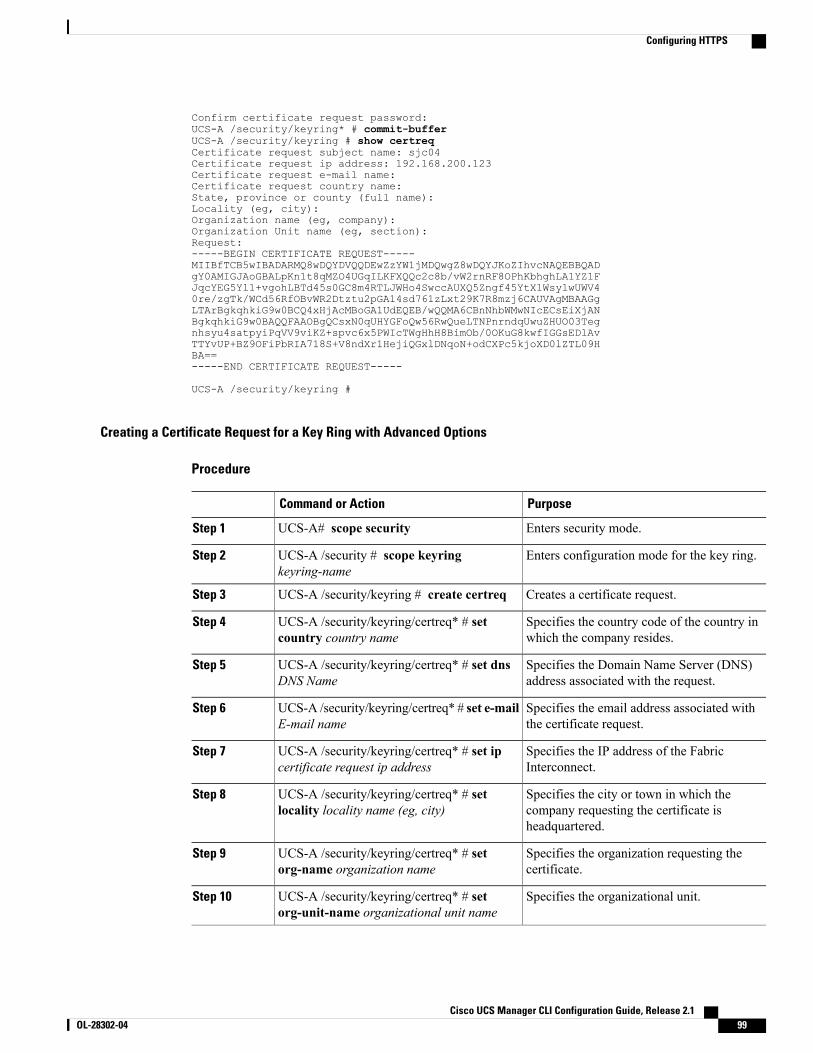
Confirm certificate request password:UCS-A /security/keyring* # commit-bufferUCS-A /security/keyring # show certreqCertificate request subject name: sjc04Certificate request ip address: 192.168.200.123Certificate request e-mail name:Certificate request country name:State, province or county (full name):Locality (eg, city):Organization name (eg, company):Organization Unit name (eg, section):Request:-----BEGIN CERTIFICATE REQUEST-----MIIBfTCB5wIBADARMQ8wDQYDVQQDEwZzYW1jMDQwgZ8wDQYJKoZIhvcNAQEBBQADgY0AMIGJAoGBALpKn1t8qMZO4UGqILKFXQQc2c8b/vW2rnRF8OPhKbhghLA1YZ1FJqcYEG5Yl1+vgohLBTd45s0GC8m4RTLJWHo4SwccAUXQ5Zngf45YtX1WsylwUWV40re/zgTk/WCd56RfOBvWR2Dtztu2pGA14sd761zLxt29K7R8mzj6CAUVAgMBAAGgLTArBgkqhkiG9w0BCQ4xHjAcMBoGA1UdEQEB/wQQMA6CBnNhbWMwNIcECsEiXjANBgkqhkiG9w0BAQQFAAOBgQCsxN0qUHYGFoQw56RwQueLTNPnrndqUwuZHUO03Tegnhsyu4satpyiPqVV9viKZ+spvc6x5PWIcTWgHhH8BimOb/0OKuG8kwfIGGsEDlAvTTYvUP+BZ9OFiPbRIA718S+V8ndXr1HejiQGxlDNqoN+odCXPc5kjoXD0lZTL09HBA==-----END CERTIFICATE REQUEST-----
UCS-A /security/keyring #
Creating a Certificate Request for a Key Ring with Advanced Options
Procedure
PurposeCommand or Action
Enters security mode.UCS-A# scope securityStep 1
Enters configuration mode for the key ring.UCS-A /security # scope keyringkeyring-name
Step 2
Creates a certificate request.UCS-A /security/keyring # create certreqStep 3
Specifies the country code of the country inwhich the company resides.
UCS-A /security/keyring/certreq* # setcountry country name
Step 4
Specifies the Domain Name Server (DNS)address associated with the request.
UCS-A /security/keyring/certreq* # set dnsDNS Name
Step 5
Specifies the email address associated withthe certificate request.
UCS-A /security/keyring/certreq* # set e-mailE-mail name
Step 6
Specifies the IP address of the FabricInterconnect.
UCS-A /security/keyring/certreq* # set ipcertificate request ip address
Step 7
Specifies the city or town in which thecompany requesting the certificate isheadquartered.
UCS-A /security/keyring/certreq* # setlocality locality name (eg, city)
Step 8
Specifies the organization requesting thecertificate.
UCS-A /security/keyring/certreq* # setorg-name organization name
Step 9
Specifies the organizational unit.UCS-A /security/keyring/certreq* # setorg-unit-name organizational unit name
Step 10
Cisco UCS Manager CLI Configuration Guide, Release 2.1 OL-28302-04 99
Configuring HTTPS
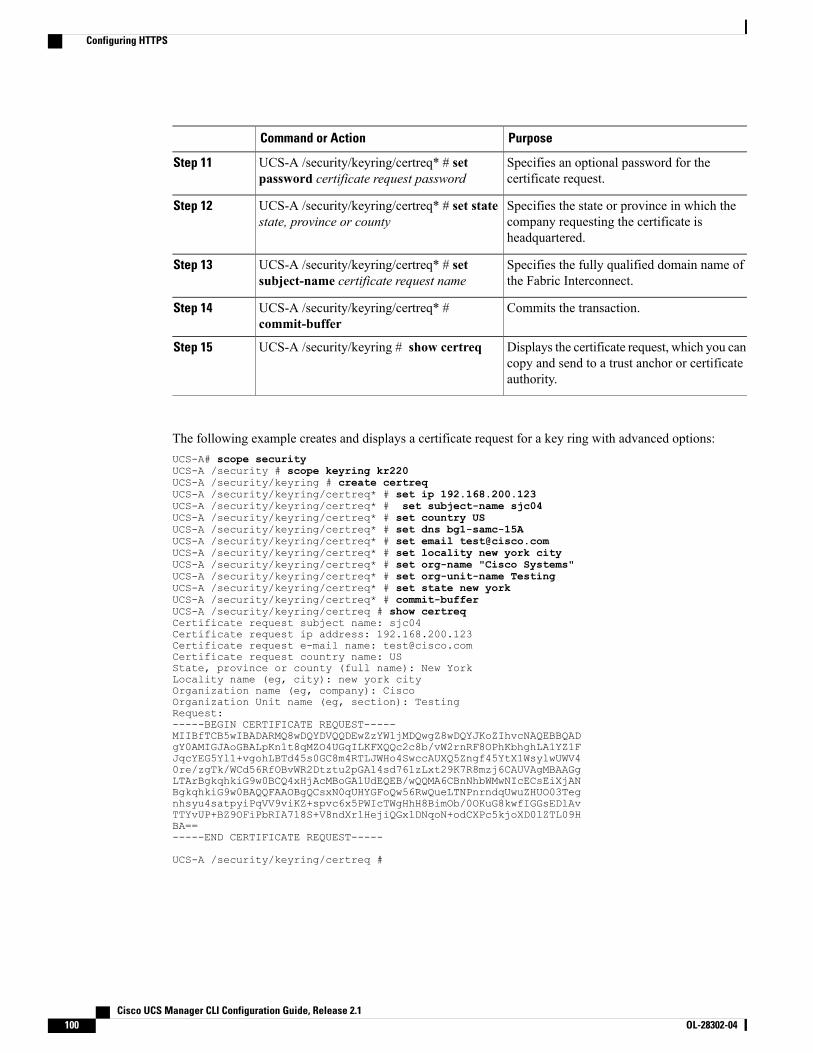
PurposeCommand or Action
Specifies an optional password for thecertificate request.
UCS-A /security/keyring/certreq* # setpassword certificate request password
Step 11
Specifies the state or province in which thecompany requesting the certificate isheadquartered.
UCS-A /security/keyring/certreq* # set statestate, province or county
Step 12
Specifies the fully qualified domain name ofthe Fabric Interconnect.
UCS-A /security/keyring/certreq* # setsubject-name certificate request name
Step 13
Commits the transaction.UCS-A /security/keyring/certreq* #commit-buffer
Step 14
Displays the certificate request, which you cancopy and send to a trust anchor or certificateauthority.
UCS-A /security/keyring # show certreqStep 15
The following example creates and displays a certificate request for a key ring with advanced options:UCS-A# scope securityUCS-A /security # scope keyring kr220UCS-A /security/keyring # create certreqUCS-A /security/keyring/certreq* # set ip 192.168.200.123UCS-A /security/keyring/certreq* # set subject-name sjc04UCS-A /security/keyring/certreq* # set country USUCS-A /security/keyring/certreq* # set dns bg1-samc-15AUCS-A /security/keyring/certreq* # set email [email protected] /security/keyring/certreq* # set locality new york cityUCS-A /security/keyring/certreq* # set org-name "Cisco Systems"UCS-A /security/keyring/certreq* # set org-unit-name TestingUCS-A /security/keyring/certreq* # set state new yorkUCS-A /security/keyring/certreq* # commit-bufferUCS-A /security/keyring/certreq # show certreqCertificate request subject name: sjc04Certificate request ip address: 192.168.200.123Certificate request e-mail name: [email protected] request country name: USState, province or county (full name): New YorkLocality name (eg, city): new york cityOrganization name (eg, company): CiscoOrganization Unit name (eg, section): TestingRequest:-----BEGIN CERTIFICATE REQUEST-----MIIBfTCB5wIBADARMQ8wDQYDVQQDEwZzYW1jMDQwgZ8wDQYJKoZIhvcNAQEBBQADgY0AMIGJAoGBALpKn1t8qMZO4UGqILKFXQQc2c8b/vW2rnRF8OPhKbhghLA1YZ1FJqcYEG5Yl1+vgohLBTd45s0GC8m4RTLJWHo4SwccAUXQ5Zngf45YtX1WsylwUWV40re/zgTk/WCd56RfOBvWR2Dtztu2pGA14sd761zLxt29K7R8mzj6CAUVAgMBAAGgLTArBgkqhkiG9w0BCQ4xHjAcMBoGA1UdEQEB/wQQMA6CBnNhbWMwNIcECsEiXjANBgkqhkiG9w0BAQQFAAOBgQCsxN0qUHYGFoQw56RwQueLTNPnrndqUwuZHUO03Tegnhsyu4satpyiPqVV9viKZ+spvc6x5PWIcTWgHhH8BimOb/0OKuG8kwfIGGsEDlAvTTYvUP+BZ9OFiPbRIA718S+V8ndXr1HejiQGxlDNqoN+odCXPc5kjoXD0lZTL09HBA==-----END CERTIFICATE REQUEST-----
UCS-A /security/keyring/certreq #
Cisco UCS Manager CLI Configuration Guide, Release 2.1100 OL-28302-04
Configuring HTTPS

What to Do Next
• Copy the text of the certificate request, including the BEGIN and END lines, and save it in a file. Sendthe file with the certificate request to a trust anchor or certificate authority to obtain a certificate for thekey ring.
• Create a trusted point and set the certificate chain for the certificate of trust received from the trustanchor.
Creating a Trusted Point
Procedure
PurposeCommand or Action
Enters security mode.UCS-A# scope securityStep 1
Creates and names a trusted point.UCS-A /security # create trustpointname
Step 2
Specifies certificate information for this trusted point.UCS-A /security/trustpoint # setcertchain [ certchain ]
Step 3
If you do not specify certificate information in thecommand, you are prompted to enter a certificate or a listof trustpoints defining a certification path to the rootcertificate authority (CA). On the next line following yourinput, type ENDOFBUF to finish.
The certificate must be in Base64 encodedX.509 (CER) format.
Important
Commits the transaction.UCS-A /security/trustpoint #commit-buffer
Step 4
The following example creates a trusted point and provides a certificate for the trusted point:UCS-A# scope securityUCS-A /security # create trustpoint tPoint10UCS-A /security/trustpoint* # set certchainEnter lines one at a time. Enter ENDOFBUF to finish. Press ^C to abort.Trustpoint Certificate Chain:> -----BEGIN CERTIFICATE-----> MIIDMDCCApmgAwIBAgIBADANBgkqhkiG9w0BAQQFADB0MQswCQYDVQQGEwJVUzEL> BxMMU2FuIEpvc2UsIENBMRUwEwYDVQQKEwxFeGFtcGxlIEluYy4xEzARBgNVBAsT> ClRlc3QgR3JvdXAxGTAXBgNVBAMTEHRlc3QuZXhhbXBsZS5jb20xHzAdBgkqhkiG> 9w0BCQEWEHVzZXJAZXhhbXBsZS5jb20wgZ8wDQYJKoZIhvcNAQEBBQADgY0AMIGJ> AoGBAMZw4nTepNIDhVzb0j7Z2Je4xAG56zmSHRMQeOGHemdh66u2/XAoLx7YCcYU> ZgAMivyCsKgb/6CjQtsofvtrmC/eAehuK3/SINv7wd6Vv2pBt6ZpXgD4VBNKONDl> GMbkPayVlQjbG4MD2dx2+H8EH3LMtdZrgKvPxPTE+bF5wZVNAgMBAAGgJTAjBgkq> hkiG9w0BCQcxFhMUQSBjaGFsbGVuZ2UgcGFzc3dvcmQwDQYJKoZIhvcNAQEFBQAD> gYEAG61CaJoJaVMhzCl903O6Mg51zq1zXcz75+VFj2I6rH9asckCld3mkOVx5gJU> Ptt5CVQpNgNLdvbDPSsXretysOhqHmp9+CLv8FDuy1CDYfuaLtvlWvfhevskV0j6> jtcEMyZ+f7+3yh421ido3nO4MIGeBgNVHSMEgZYwgZOAFLlNjtcEMyZ+f7+3yh42> 1ido3nO4oXikdjB0MQswCQYDVQQGEwJVUzELMAkGA1UECBMCQ0ExFDASBgNVBAcT> C1NhbnRhIENsYXJhMRswGQYDVQQKExJOdW92YSBTeXN0ZW1zIEluYy4xFDASBgNV> BAsTC0VuZ2luZWVyaW5nMQ8wDQYDVQQDEwZ0ZXN0Q0GCAQAwDAYDVR0TBAUwAwEB> /zANBgkqhkiG9w0BAQQFAAOBgQAhWaRwXNR6B4g6Lsnr+fptHv+WVhB5fKqGQqXc> wR4pYiO4z42/j9Ijenh75tCKMhW51az8copP1EBmOcyuhf5C6vasrenn1ddkkYt4
Cisco UCS Manager CLI Configuration Guide, Release 2.1 OL-28302-04 101
Configuring HTTPS
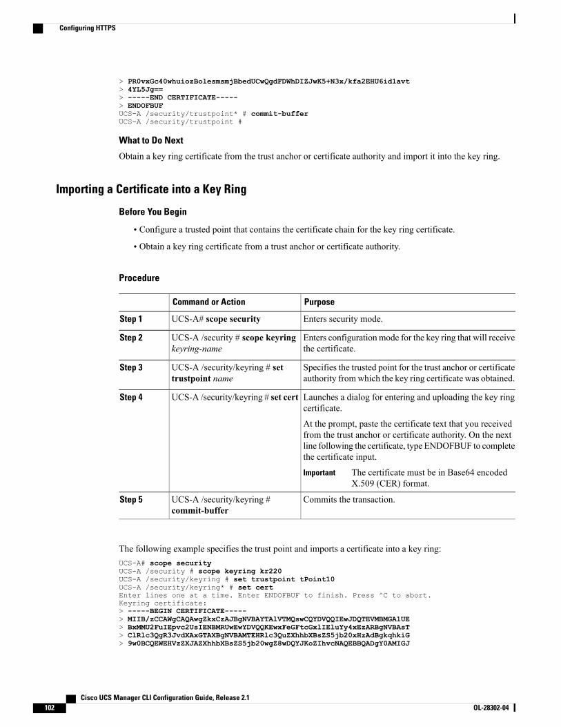
> PR0vxGc40whuiozBolesmsmjBbedUCwQgdFDWhDIZJwK5+N3x/kfa2EHU6id1avt> 4YL5Jg==> -----END CERTIFICATE-----> ENDOFBUFUCS-A /security/trustpoint* # commit-bufferUCS-A /security/trustpoint #
What to Do Next
Obtain a key ring certificate from the trust anchor or certificate authority and import it into the key ring.
Importing a Certificate into a Key Ring
Before You Begin
• Configure a trusted point that contains the certificate chain for the key ring certificate.
• Obtain a key ring certificate from a trust anchor or certificate authority.
Procedure
PurposeCommand or Action
Enters security mode.UCS-A# scope securityStep 1
Enters configuration mode for the key ring that will receivethe certificate.
UCS-A /security # scope keyringkeyring-name
Step 2
Specifies the trusted point for the trust anchor or certificateauthority fromwhich the key ring certificate was obtained.
UCS-A /security/keyring # settrustpoint name
Step 3
Launches a dialog for entering and uploading the key ringcertificate.
UCS-A /security/keyring # set certStep 4
At the prompt, paste the certificate text that you receivedfrom the trust anchor or certificate authority. On the nextline following the certificate, type ENDOFBUF to completethe certificate input.
The certificate must be in Base64 encodedX.509 (CER) format.
Important
Commits the transaction.UCS-A /security/keyring #commit-buffer
Step 5
The following example specifies the trust point and imports a certificate into a key ring:UCS-A# scope securityUCS-A /security # scope keyring kr220UCS-A /security/keyring # set trustpoint tPoint10UCS-A /security/keyring* # set certEnter lines one at a time. Enter ENDOFBUF to finish. Press ^C to abort.Keyring certificate:> -----BEGIN CERTIFICATE-----> MIIB/zCCAWgCAQAwgZkxCzAJBgNVBAYTAlVTMQswCQYDVQQIEwJDQTEVMBMGA1UE> BxMMU2FuIEpvc2UsIENBMRUwEwYDVQQKEwxFeGFtcGxlIEluYy4xEzARBgNVBAsT> ClRlc3QgR3JvdXAxGTAXBgNVBAMTEHRlc3QuZXhhbXBsZS5jb20xHzAdBgkqhkiG> 9w0BCQEWEHVzZXJAZXhhbXBsZS5jb20wgZ8wDQYJKoZIhvcNAQEBBQADgY0AMIGJ
Cisco UCS Manager CLI Configuration Guide, Release 2.1102 OL-28302-04
Configuring HTTPS
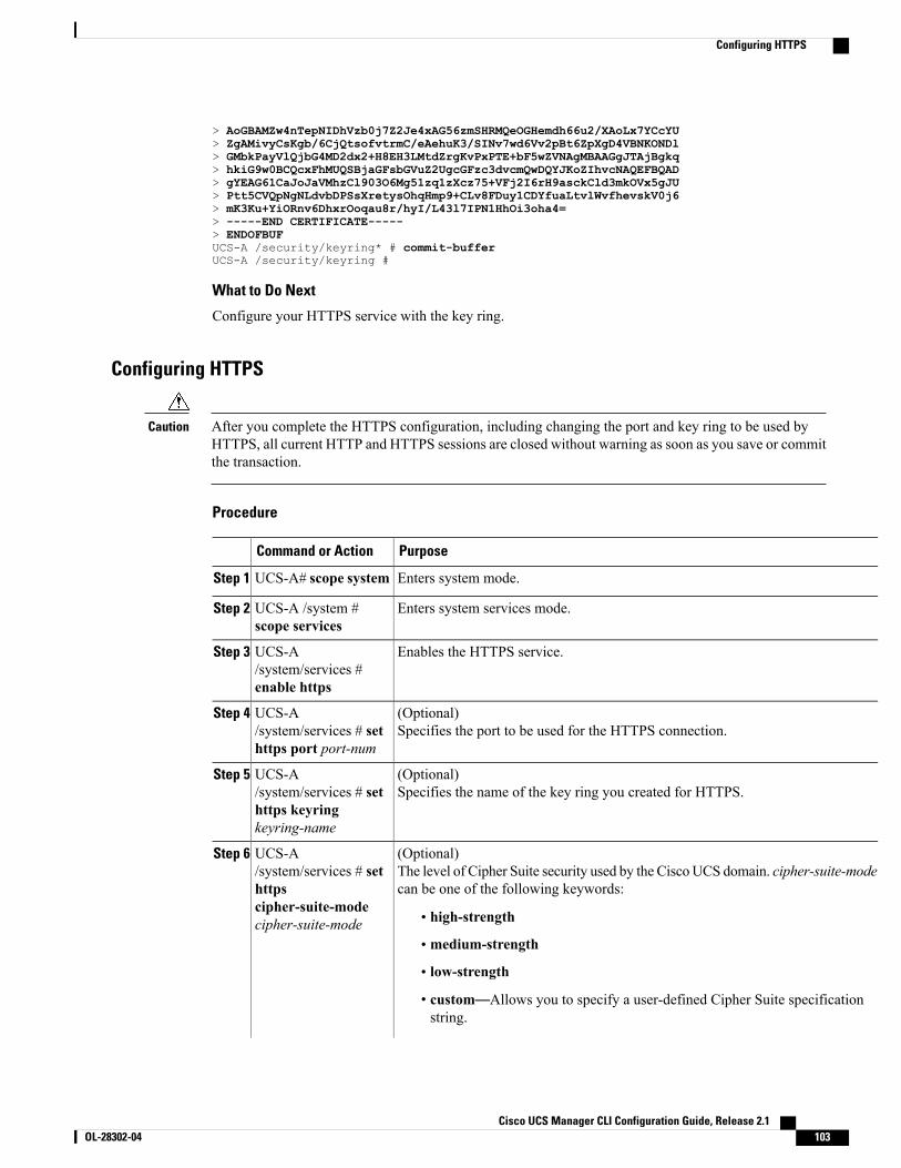
> AoGBAMZw4nTepNIDhVzb0j7Z2Je4xAG56zmSHRMQeOGHemdh66u2/XAoLx7YCcYU> ZgAMivyCsKgb/6CjQtsofvtrmC/eAehuK3/SINv7wd6Vv2pBt6ZpXgD4VBNKONDl> GMbkPayVlQjbG4MD2dx2+H8EH3LMtdZrgKvPxPTE+bF5wZVNAgMBAAGgJTAjBgkq> hkiG9w0BCQcxFhMUQSBjaGFsbGVuZ2UgcGFzc3dvcmQwDQYJKoZIhvcNAQEFBQAD> gYEAG61CaJoJaVMhzCl903O6Mg51zq1zXcz75+VFj2I6rH9asckCld3mkOVx5gJU> Ptt5CVQpNgNLdvbDPSsXretysOhqHmp9+CLv8FDuy1CDYfuaLtvlWvfhevskV0j6> mK3Ku+YiORnv6DhxrOoqau8r/hyI/L43l7IPN1HhOi3oha4=> -----END CERTIFICATE-----> ENDOFBUFUCS-A /security/keyring* # commit-bufferUCS-A /security/keyring #
What to Do Next
Configure your HTTPS service with the key ring.
Configuring HTTPS
After you complete the HTTPS configuration, including changing the port and key ring to be used byHTTPS, all current HTTP and HTTPS sessions are closed without warning as soon as you save or committhe transaction.
Caution
Procedure
PurposeCommand or Action
Enters system mode.UCS-A# scope systemStep 1
Enters system services mode.UCS-A /system #scope services
Step 2
Enables the HTTPS service.UCS-A/system/services #enable https
Step 3
(Optional)Specifies the port to be used for the HTTPS connection.
UCS-A/system/services # sethttps port port-num
Step 4
(Optional)Specifies the name of the key ring you created for HTTPS.
UCS-A/system/services # sethttps keyringkeyring-name
Step 5
(Optional)The level of Cipher Suite security used by the CiscoUCS domain. cipher-suite-modecan be one of the following keywords:
UCS-A/system/services # sethttps
Step 6
cipher-suite-modecipher-suite-mode • high-strength
• medium-strength
• low-strength
• custom—Allows you to specify a user-defined Cipher Suite specificationstring.
Cisco UCS Manager CLI Configuration Guide, Release 2.1 OL-28302-04 103
Configuring HTTPS

PurposeCommand or Action
(Optional)Specifies a custom level of Cipher Suite security for this Cisco UCS domain ifcipher-suite-mode is set to custom.
UCS-A/system/services # sethttps cipher-suitecipher-suite-spec-string
Step 7
cipher-suite-spec-string can contain up to 256 characters and must conform to theOpenSSL Cipher Suite specifications. You cannot use any spaces or specialcharacters except ! (exclamation point), + (plus sign), - (hyphen), and : (colon).For details, see http://httpd.apache.org/docs/2.0/mod/mod_ssl.html#sslciphersuite..
For example, the medium strength specification string Cisco UCS Manager usesas the default is:ALL:!ADH:!EXPORT56:!LOW:RC4+RSA:+HIGH:+MEDIUM:+EXP:+eNULL
This option is ignored if cipher-suite-mode is set to anything other thancustom.
Note
Commits the transaction to the system configuration.UCS-A/system/services #commit-buffer
Step 8
The following example enables HTTPS, sets the port number to 443, sets the key ring name to kring7984,sets the Cipher Suite security level to high, and commits the transaction:UCS-A# scope systemUCS-A /system # scope servicesUCS-A /system/services # enable httpsUCS-A /system/services* # set https port 443Warning: When committed, this closes all the web sessions.UCS-A /system/services* # set https keyring kring7984UCS-A /system/services* # set https cipher-suite-mode highUCS-A /system/services* # commit-bufferUCS-A /system/services #
Deleting a Key Ring
Procedure
PurposeCommand or Action
Enters security mode.UCS-A# scope securityStep 1
Deletes the named key ring.UCS-A /security # delete keyring nameStep 2
Commits the transaction.UCS-A /security # commit-bufferStep 3
The following example deletes a key ring:UCS-A# scope securityUCS-A /security # delete keyring key10UCS-A /security* # commit-bufferUCS-A /security #
Cisco UCS Manager CLI Configuration Guide, Release 2.1104 OL-28302-04
Configuring HTTPS
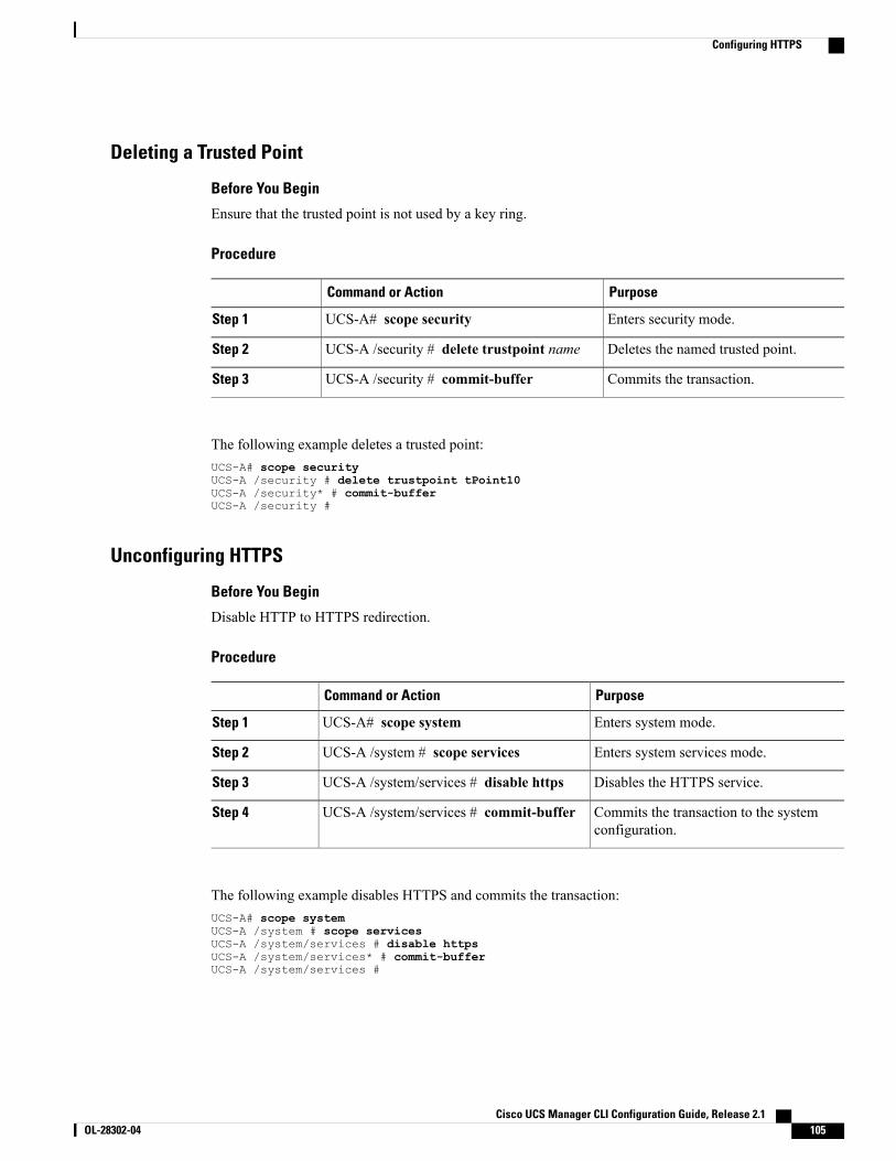
Deleting a Trusted Point
Before You Begin
Ensure that the trusted point is not used by a key ring.
Procedure
PurposeCommand or Action
Enters security mode.UCS-A# scope securityStep 1
Deletes the named trusted point.UCS-A /security # delete trustpoint nameStep 2
Commits the transaction.UCS-A /security # commit-bufferStep 3
The following example deletes a trusted point:UCS-A# scope securityUCS-A /security # delete trustpoint tPoint10UCS-A /security* # commit-bufferUCS-A /security #
Unconfiguring HTTPS
Before You Begin
Disable HTTP to HTTPS redirection.
Procedure
PurposeCommand or Action
Enters system mode.UCS-A# scope systemStep 1
Enters system services mode.UCS-A /system # scope servicesStep 2
Disables the HTTPS service.UCS-A /system/services # disable httpsStep 3
Commits the transaction to the systemconfiguration.
UCS-A /system/services # commit-bufferStep 4
The following example disables HTTPS and commits the transaction:UCS-A# scope systemUCS-A /system # scope servicesUCS-A /system/services # disable httpsUCS-A /system/services* # commit-bufferUCS-A /system/services #
Cisco UCS Manager CLI Configuration Guide, Release 2.1 OL-28302-04 105
Configuring HTTPS
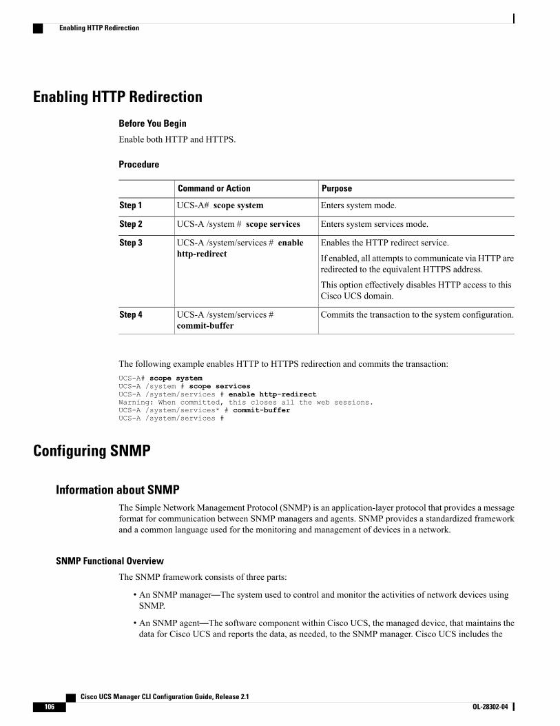
Enabling HTTP Redirection
Before You Begin
Enable both HTTP and HTTPS.
Procedure
PurposeCommand or Action
Enters system mode.UCS-A# scope systemStep 1
Enters system services mode.UCS-A /system # scope servicesStep 2
Enables the HTTP redirect service.UCS-A /system/services # enablehttp-redirect
Step 3
If enabled, all attempts to communicate via HTTP areredirected to the equivalent HTTPS address.
This option effectively disables HTTP access to thisCisco UCS domain.
Commits the transaction to the system configuration.UCS-A /system/services #commit-buffer
Step 4
The following example enables HTTP to HTTPS redirection and commits the transaction:UCS-A# scope systemUCS-A /system # scope servicesUCS-A /system/services # enable http-redirectWarning: When committed, this closes all the web sessions.UCS-A /system/services* # commit-bufferUCS-A /system/services #
Configuring SNMP
Information about SNMPThe Simple Network Management Protocol (SNMP) is an application-layer protocol that provides a messageformat for communication between SNMP managers and agents. SNMP provides a standardized frameworkand a common language used for the monitoring and management of devices in a network.
SNMP Functional Overview
The SNMP framework consists of three parts:
• An SNMP manager—The system used to control and monitor the activities of network devices usingSNMP.
• An SNMP agent—The software component within Cisco UCS, the managed device, that maintains thedata for Cisco UCS and reports the data, as needed, to the SNMP manager. Cisco UCS includes the
Cisco UCS Manager CLI Configuration Guide, Release 2.1106 OL-28302-04
Enabling HTTP Redirection
agent and a collection of MIBs. To enable the SNMP agent and create the relationship between themanager and agent, enable and configure SNMP in Cisco UCS Manager.
• A managed information base (MIB)—The collection of managed objects on the SNMP agent. CiscoUCS release 1.4(1) and higher support a larger number of MIBs than earlier releases.
CiscoUCS supports SNMPv1, SNMPv2c and SNMPv3. Both SNMPv1 and SNMPv2c use a community-basedform of security. SNMP is defined in the following:
• RFC 3410 (http://tools.ietf.org/html/rfc3410)
• RFC 3411 (http://tools.ietf.org/html/rfc3411)
• RFC 3412 (http://tools.ietf.org/html/rfc3412)
• RFC 3413 (http://tools.ietf.org/html/rfc3413)
• RFC 3414 (http://tools.ietf.org/html/rfc3414)
• RFC 3415 (http://tools.ietf.org/html/rfc3415)
• RFC 3416 (http://tools.ietf.org/html/rfc3416)
• RFC 3417 (http://tools.ietf.org/html/rfc3417)
• RFC 3418 (http://tools.ietf.org/html/rfc3418)
• RFC 3584 (http://tools.ietf.org/html/rfc3584)
SNMP Notifications
A key feature of SNMP is the ability to generate notifications from an SNMP agent. These notifications donot require that requests be sent from the SNMP manager. Notifications can indicate improper userauthentication, restarts, the closing of a connection, loss of connection to a neighbor router, or other significantevents.
Cisco UCS Manager generates SNMP notifications as either traps or informs. Traps are less reliable thaninforms because the SNMP manager does not send any acknowledgment when it receives a trap, and CiscoUCS Manager cannot determine if the trap was received. An SNMP manager that receives an inform requestacknowledges the message with an SNMP response protocol data unit (PDU). If the Cisco UCS Managerdoes not receive the PDU, it can send the inform request again.
SNMP Security Levels and Privileges
SNMPv1, SNMPv2c, and SNMPv3 each represent a different security model. The security model combineswith the selected security level to determine the security mechanism applied when the SNMP message isprocessed.
The security level determines the privileges required to view the message associated with an SNMP trap. Theprivilege level determines whether the message needs to be protected from disclosure or authenticated. Thesupported security level depends upon which security model is implemented. SNMP security levels supportone or more of the following privileges:
• noAuthNoPriv—No authentication or encryption
• authNoPriv—Authentication but no encryption
Cisco UCS Manager CLI Configuration Guide, Release 2.1 OL-28302-04 107
Configuring SNMP
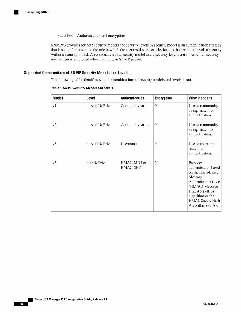
• authPriv—Authentication and encryption
SNMPv3 provides for both security models and security levels. A security model is an authentication strategythat is set up for a user and the role in which the user resides. A security level is the permitted level of securitywithin a security model. A combination of a security model and a security level determines which securitymechanism is employed when handling an SNMP packet.
Supported Combinations of SNMP Security Models and Levels
The following table identifies what the combinations of security models and levels mean.
Table 6: SNMP Security Models and Levels
What HappensEncryptionAuthenticationLevelModel
Uses a communitystring match forauthentication.
NoCommunity stringnoAuthNoPrivv1
Uses a communitystring match forauthentication.
NoCommunity stringnoAuthNoPrivv2c
Uses a usernamematch forauthentication.
NoUsernamenoAuthNoPrivv3
Providesauthentication basedon the Hash-BasedMessageAuthenticationCode(HMAC) MessageDigest 5 (MD5)algorithm or theHMACSecureHashAlgorithm (SHA).
NoHMAC-MD5 orHMAC-SHA
authNoPrivv3
Cisco UCS Manager CLI Configuration Guide, Release 2.1108 OL-28302-04
Configuring SNMP
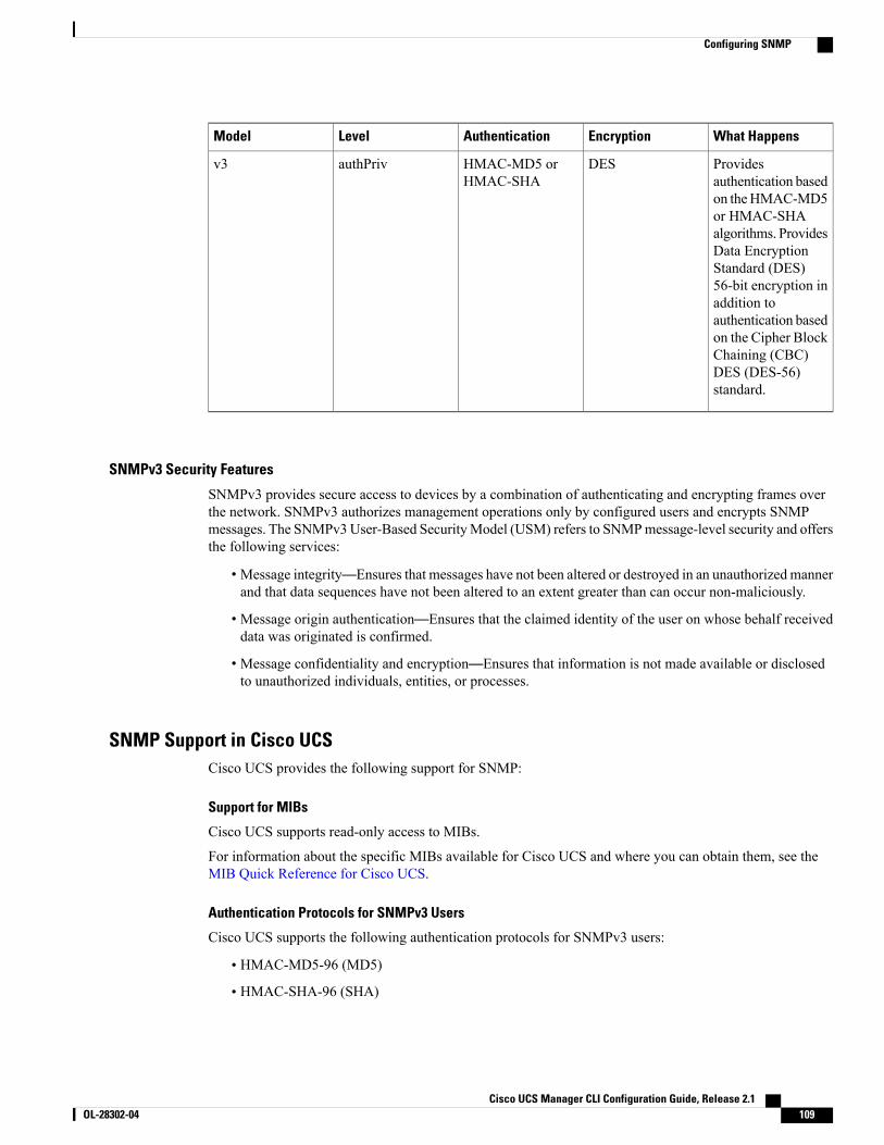
What HappensEncryptionAuthenticationLevelModel
Providesauthentication basedon theHMAC-MD5or HMAC-SHAalgorithms. ProvidesData EncryptionStandard (DES)56-bit encryption inaddition toauthentication basedon the Cipher BlockChaining (CBC)DES (DES-56)standard.
DESHMAC-MD5 orHMAC-SHA
authPrivv3
SNMPv3 Security Features
SNMPv3 provides secure access to devices by a combination of authenticating and encrypting frames overthe network. SNMPv3 authorizes management operations only by configured users and encrypts SNMPmessages. The SNMPv3User-Based SecurityModel (USM) refers to SNMPmessage-level security and offersthe following services:
• Message integrity—Ensures that messages have not been altered or destroyed in an unauthorized mannerand that data sequences have not been altered to an extent greater than can occur non-maliciously.
• Message origin authentication—Ensures that the claimed identity of the user on whose behalf receiveddata was originated is confirmed.
• Message confidentiality and encryption—Ensures that information is not made available or disclosedto unauthorized individuals, entities, or processes.
SNMP Support in Cisco UCSCisco UCS provides the following support for SNMP:
Support for MIBs
Cisco UCS supports read-only access to MIBs.
For information about the specific MIBs available for Cisco UCS and where you can obtain them, see theMIB Quick Reference for Cisco UCS.
Authentication Protocols for SNMPv3 Users
Cisco UCS supports the following authentication protocols for SNMPv3 users:
• HMAC-MD5-96 (MD5)
• HMAC-SHA-96 (SHA)
Cisco UCS Manager CLI Configuration Guide, Release 2.1 OL-28302-04 109
Configuring SNMP
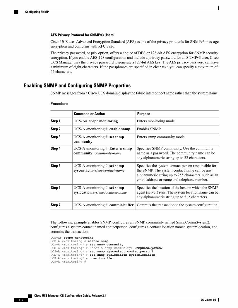
AES Privacy Protocol for SNMPv3 Users
Cisco UCS uses Advanced Encryption Standard (AES) as one of the privacy protocols for SNMPv3 messageencryption and conforms with RFC 3826.
The privacy password, or priv option, offers a choice of DES or 128-bit AES encryption for SNMP securityencryption. If you enable AES-128 configuration and include a privacy password for an SNMPv3 user, CiscoUCSManager uses the privacy password to generate a 128-bit AES key. The AES privacy password can havea minimum of eight characters. If the passphrases are specified in clear text, you can specify a maximum of64 characters.
Enabling SNMP and Configuring SNMP PropertiesSNMPmessages from a Cisco UCS domain display the fabric interconnect name rather than the system name.
Procedure
PurposeCommand or Action
Enters monitoring mode.UCS-A# scope monitoringStep 1
Enables SNMP.UCS-A /monitoring # enable snmpStep 2
Enters snmp community mode.UCS-A /monitoring # set snmpcommunity
Step 3
Specifies SNMP community. Use the communityname as a password. The community name can beany alphanumeric string up to 32 characters.
UCS-A /monitoring # Enter a snmpcommunity: community-name
Step 4
Specifies the system contact person responsible forthe SNMP. The system contact name can be any
UCS-A /monitoring # set snmpsyscontact system-contact-name
Step 5
alphanumeric string up to 255 characters, such as anemail address or name and telephone number.
Specifies the location of the host on which the SNMPagent (server) runs. The system location name can beany alphanumeric string up to 512 characters.
UCS-A /monitoring # set snmpsyslocation system-location-name
Step 6
Commits the transaction to the system configuration.UCS-A /monitoring # commit-bufferStep 7
The following example enables SNMP, configures an SNMP community named SnmpCommSystem2,configures a system contact named contactperson, configures a contact location named systemlocation, andcommits the transaction:UCS-A# scope monitoringUCS-A /monitoring # enable snmpUCS-A /monitoring* # set snmp communityUCS-A /monitoring* # Enter a snmp community: SnmpCommSystem2UCS-A /monitoring* # set snmp syscontact contactperson1UCS-A /monitoring* # set snmp syslocation systemlocationUCS-A /monitoring* # commit-bufferUCS-A /monitoring #
Cisco UCS Manager CLI Configuration Guide, Release 2.1110 OL-28302-04
Configuring SNMP
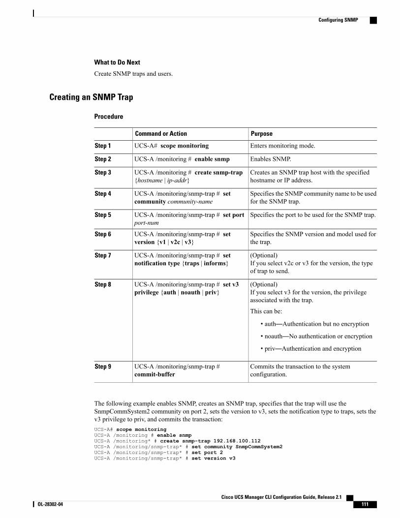
What to Do Next
Create SNMP traps and users.
Creating an SNMP Trap
Procedure
PurposeCommand or Action
Enters monitoring mode.UCS-A# scope monitoringStep 1
Enables SNMP.UCS-A /monitoring # enable snmpStep 2
Creates an SNMP trap host with the specifiedhostname or IP address.
UCS-A /monitoring # create snmp-trap{hostname | ip-addr}
Step 3
Specifies the SNMP community name to be usedfor the SNMP trap.
UCS-A /monitoring/snmp-trap # setcommunity community-name
Step 4
Specifies the port to be used for the SNMP trap.UCS-A /monitoring/snmp-trap # set portport-num
Step 5
Specifies the SNMP version and model used forthe trap.
UCS-A /monitoring/snmp-trap # setversion {v1 | v2c | v3}
Step 6
(Optional)If you select v2c or v3 for the version, the typeof trap to send.
UCS-A /monitoring/snmp-trap # setnotification type {traps | informs}
Step 7
(Optional)If you select v3 for the version, the privilegeassociated with the trap.
UCS-A /monitoring/snmp-trap # set v3privilege {auth | noauth | priv}
Step 8
This can be:
• auth—Authentication but no encryption
• noauth—No authentication or encryption
• priv—Authentication and encryption
Commits the transaction to the systemconfiguration.
UCS-A /monitoring/snmp-trap #commit-buffer
Step 9
The following example enables SNMP, creates an SNMP trap, specifies that the trap will use theSnmpCommSystem2 community on port 2, sets the version to v3, sets the notification type to traps, sets thev3 privilege to priv, and commits the transaction:UCS-A# scope monitoringUCS-A /monitoring # enable snmpUCS-A /monitoring* # create snmp-trap 192.168.100.112UCS-A /monitoring/snmp-trap* # set community SnmpCommSystem2UCS-A /monitoring/snmp-trap* # set port 2UCS-A /monitoring/snmp-trap* # set version v3
Cisco UCS Manager CLI Configuration Guide, Release 2.1 OL-28302-04 111
Configuring SNMP
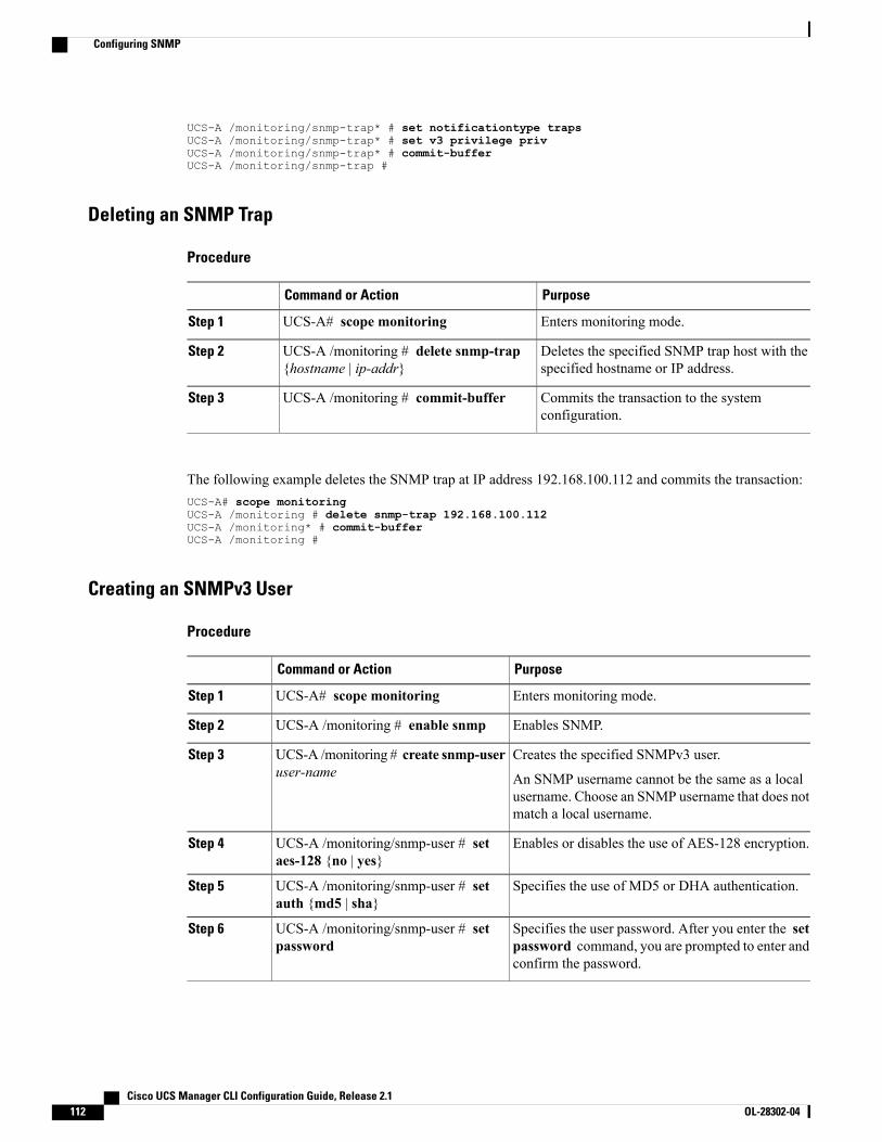
UCS-A /monitoring/snmp-trap* # set notificationtype trapsUCS-A /monitoring/snmp-trap* # set v3 privilege privUCS-A /monitoring/snmp-trap* # commit-bufferUCS-A /monitoring/snmp-trap #
Deleting an SNMP Trap
Procedure
PurposeCommand or Action
Enters monitoring mode.UCS-A# scope monitoringStep 1
Deletes the specified SNMP trap host with thespecified hostname or IP address.
UCS-A /monitoring # delete snmp-trap{hostname | ip-addr}
Step 2
Commits the transaction to the systemconfiguration.
UCS-A /monitoring # commit-bufferStep 3
The following example deletes the SNMP trap at IP address 192.168.100.112 and commits the transaction:UCS-A# scope monitoringUCS-A /monitoring # delete snmp-trap 192.168.100.112UCS-A /monitoring* # commit-bufferUCS-A /monitoring #
Creating an SNMPv3 User
Procedure
PurposeCommand or Action
Enters monitoring mode.UCS-A# scope monitoringStep 1
Enables SNMP.UCS-A /monitoring # enable snmpStep 2
Creates the specified SNMPv3 user.UCS-A /monitoring # create snmp-useruser-name
Step 3
An SNMP username cannot be the same as a localusername. Choose an SNMP username that does notmatch a local username.
Enables or disables the use of AES-128 encryption.UCS-A /monitoring/snmp-user # setaes-128 {no | yes}
Step 4
Specifies the use of MD5 or DHA authentication.UCS-A /monitoring/snmp-user # setauth {md5 | sha}
Step 5
Specifies the user password. After you enter the setpassword command, you are prompted to enter andconfirm the password.
UCS-A /monitoring/snmp-user # setpassword
Step 6
Cisco UCS Manager CLI Configuration Guide, Release 2.1112 OL-28302-04
Configuring SNMP
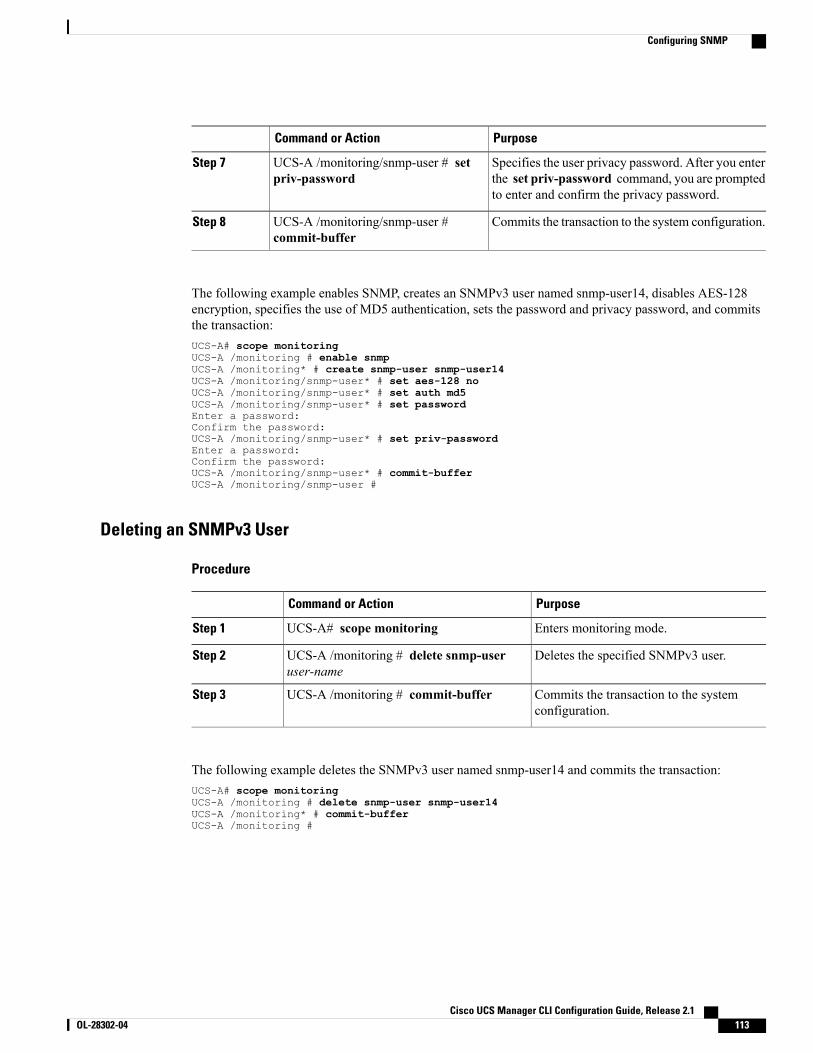
PurposeCommand or Action
Specifies the user privacy password. After you enterthe set priv-password command, you are promptedto enter and confirm the privacy password.
UCS-A /monitoring/snmp-user # setpriv-password
Step 7
Commits the transaction to the system configuration.UCS-A /monitoring/snmp-user #commit-buffer
Step 8
The following example enables SNMP, creates an SNMPv3 user named snmp-user14, disables AES-128encryption, specifies the use of MD5 authentication, sets the password and privacy password, and commitsthe transaction:UCS-A# scope monitoringUCS-A /monitoring # enable snmpUCS-A /monitoring* # create snmp-user snmp-user14UCS-A /monitoring/snmp-user* # set aes-128 noUCS-A /monitoring/snmp-user* # set auth md5UCS-A /monitoring/snmp-user* # set passwordEnter a password:Confirm the password:UCS-A /monitoring/snmp-user* # set priv-passwordEnter a password:Confirm the password:UCS-A /monitoring/snmp-user* # commit-bufferUCS-A /monitoring/snmp-user #
Deleting an SNMPv3 User
Procedure
PurposeCommand or Action
Enters monitoring mode.UCS-A# scope monitoringStep 1
Deletes the specified SNMPv3 user.UCS-A /monitoring # delete snmp-useruser-name
Step 2
Commits the transaction to the systemconfiguration.
UCS-A /monitoring # commit-bufferStep 3
The following example deletes the SNMPv3 user named snmp-user14 and commits the transaction:UCS-A# scope monitoringUCS-A /monitoring # delete snmp-user snmp-user14UCS-A /monitoring* # commit-bufferUCS-A /monitoring #
Cisco UCS Manager CLI Configuration Guide, Release 2.1 OL-28302-04 113
Configuring SNMP
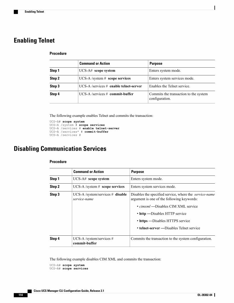
Enabling Telnet
Procedure
PurposeCommand or Action
Enters system mode.UCS-A# scope systemStep 1
Enters system services mode.UCS-A /system # scope servicesStep 2
Enables the Telnet service.UCS-A /services # enable telnet-serverStep 3
Commits the transaction to the systemconfiguration.
UCS-A /services # commit-bufferStep 4
The following example enables Telnet and commits the transaction:UCS-A# scope systemUCS-A /system # scope servicesUCS-A /services # enable telnet-serverUCS-A /services* # commit-bufferUCS-A /services #
Disabling Communication Services
Procedure
PurposeCommand or Action
Enters system mode.UCS-A# scope systemStep 1
Enters system services mode.UCS-A /system # scope servicesStep 2
Disables the specified service, where the service-nameargument is one of the following keywords:
UCS-A /system/services # disableservice-name
Step 3
• cimxml—Disables CIM XML service
• http—Disables HTTP service
• https—Disables HTTPS service
• telnet-server—Disables Telnet service
Commits the transaction to the system configuration.UCS-A /system/services #commit-buffer
Step 4
The following example disables CIM XML and commits the transaction:UCS-A# scope systemUCS-A# scope services
Cisco UCS Manager CLI Configuration Guide, Release 2.1114 OL-28302-04
Enabling Telnet

UCS-A /system/services # disable cimxmlUCS-A /system/services* # commit-bufferUCS-A /system/services #
Cisco UCS Manager CLI Configuration Guide, Release 2.1 OL-28302-04 115
Disabling Communication Services

Cisco UCS Manager CLI Configuration Guide, Release 2.1116 OL-28302-04
Disabling Communication Services
C H A P T E R 8Configuring Authentication
This chapter includes the following sections:
• Authentication Services, page 117
• Guidelines and Recommendations for Remote Authentication Providers, page 118
• User Attributes in Remote Authentication Providers, page 118
• LDAP Group Rule, page 120
• Nested LDAP Groups, page 120
• Configuring LDAP Providers, page 120
• Configuring RADIUS Providers, page 128
• Configuring TACACS+ Providers, page 131
• Configuring Multiple Authentication Systems, page 134
• Selecting a Primary Authentication Service, page 142
Authentication ServicesCisco UCS supports two methods to authenticate user logins:
• Through user accounts local to Cisco UCS Manager
• Remotely through one of the following protocols:
◦LDAP
◦RADIUS
◦TACACS+
Cisco UCS Manager CLI Configuration Guide, Release 2.1 OL-28302-04 117
Guidelines and Recommendations for Remote Authentication ProvidersIf a system is configured for one of the supported remote authentication services, you must create a providerfor that service to ensure that Cisco UCSManager can communicate with it. In addition, you need to be awareof the following guidelines that impact user authorization:
User Accounts in Remote Authentication Services
User accounts can exist locally in Cisco UCS Manager or in the remote authentication server.
The temporary sessions for users who log in through remote authentication services can be viewed throughCisco UCS Manager GUI or Cisco UCS Manager CLI.
User Roles in Remote Authentication Services
If you create user accounts in the remote authentication server, you must ensure that the accounts include theroles those users require for working in Cisco UCS Manager and that the names of those roles match thenames used in Cisco UCS Manager. Depending on the role policy, a user may not be allowed to log in or willbe granted only read-only privileges.
User Attributes in Remote Authentication ProvidersFor RADIUS and TACACS+ configurations, you must configure a user attribute for Cisco UCS in each remoteauthentication provider through which users log in to Cisco UCS Manager. This user attribute holds the rolesand locales assigned to each user.
This step is not required for LDAP configurations that use LDAP Group Mapping to assign roles andlocales.
Note
When a user logs in, Cisco UCS Manager does the following:
1 Queries the remote authentication service.
2 Validates the user.
3 If the user is validated, checks for the roles and locales assigned to that user.
The following table contains a comparison of the user attribute requirements for the remote authenticationproviders supported by Cisco UCS.
Cisco UCS Manager CLI Configuration Guide, Release 2.1118 OL-28302-04
Guidelines and Recommendations for Remote Authentication Providers
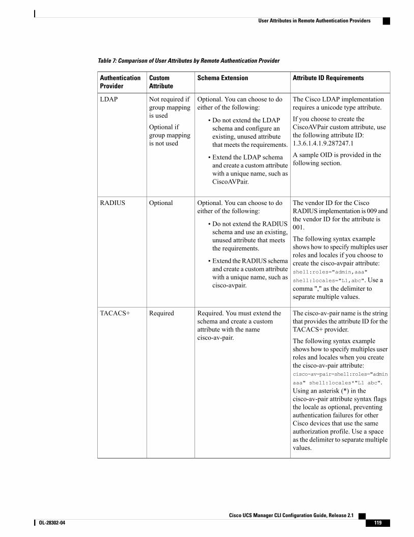
Table 7: Comparison of User Attributes by Remote Authentication Provider
Attribute ID RequirementsSchema ExtensionCustomAttribute
AuthenticationProvider
The Cisco LDAP implementationrequires a unicode type attribute.
If you choose to create theCiscoAVPair custom attribute, usethe following attribute ID:1.3.6.1.4.1.9.287247.1
A sample OID is provided in thefollowing section.
Optional. You can choose to doeither of the following:
• Do not extend the LDAPschema and configure anexisting, unused attributethat meets the requirements.
• Extend the LDAP schemaand create a custom attributewith a unique name, such asCiscoAVPair.
Not required ifgroup mappingis used
Optional ifgroup mappingis not used
LDAP
The vendor ID for the CiscoRADIUS implementation is 009 andthe vendor ID for the attribute is001.
The following syntax exampleshows how to specify multiples userroles and locales if you choose tocreate the cisco-avpair attribute:shell:roles="admin,aaa"
shell:locales="L1,abc". Use acomma "," as the delimiter toseparate multiple values.
Optional. You can choose to doeither of the following:
• Do not extend the RADIUSschema and use an existing,unused attribute that meetsthe requirements.
• Extend the RADIUS schemaand create a custom attributewith a unique name, such ascisco-avpair.
OptionalRADIUS
The cisco-av-pair name is the stringthat provides the attribute ID for theTACACS+ provider.
The following syntax exampleshows how to specify multiples userroles and locales when you createthe cisco-av-pair attribute:cisco-av-pair=shell:roles="admin
aaa" shell:locales*"L1 abc".Using an asterisk (*) in thecisco-av-pair attribute syntax flagsthe locale as optional, preventingauthentication failures for otherCisco devices that use the sameauthorization profile. Use a spaceas the delimiter to separate multiplevalues.
Required. You must extend theschema and create a customattribute with the namecisco-av-pair.
RequiredTACACS+
Cisco UCS Manager CLI Configuration Guide, Release 2.1 OL-28302-04 119
User Attributes in Remote Authentication Providers
Sample OID for LDAP User Attribute
The following is a sample OID for a custom CiscoAVPair attribute:
CN=CiscoAVPair,CN=Schema,CN=Configuration,CN=XobjectClass: topobjectClass: attributeSchemacn: CiscoAVPairdistinguishedName: CN=CiscoAVPair,CN=Schema,CN=Configuration,CN=XinstanceType: 0x4uSNCreated: 26318654attributeID: 1.3.6.1.4.1.9.287247.1attributeSyntax: 2.5.5.12isSingleValued: TRUEshowInAdvancedViewOnly: TRUEadminDisplayName: CiscoAVPairadminDescription: UCS User Authorization FieldoMSyntax: 64lDAPDisplayName: CiscoAVPairname: CiscoAVPairobjectCategory: CN=Attribute-Schema,CN=Schema,CN=Configuration,CN=X
LDAP Group RuleThe LDAP group rule is used to determine whether Cisco UCS should use LDAP groups when assigning userroles and locales to a remote user.
Nested LDAP GroupsBeginning with Cisco UCS Manager release 2.1(2), you can search LDAP groups that are nested withinanother group defined in an LDAP group map. With this new capability, you do not always need to createsubgroups in a group map in Cisco UCS Manager.
Nested LDAP search support is supported only for Microsoft Active Directory servers. The supportedversions are Microsoft Windows 2003 SP3, Microsoft Windows 2008 R2, and Microsoft Windows 2012.
Note
Using the LDAP nesting feature, you can add an LDAP group as a member of another group and nest groupsto consolidate member accounts and reduce the replication of traffic.
Be default, user rights are inherited when you nest an LDAP group within another group. For example, if youmake Group_1 a member of Group_2, the users in Group_1 will have the same permissions as the membersof Group_2. You can then search users that are members of Group_1 by choosing only Group_2 in the LDAPgroup map, instead of having to seach Group_1 and Group_2 separately.
Configuring LDAP Providers
Configuring Properties for LDAP ProvidersThe properties that you configure in this task are the default settings for all provider connections of this typedefined in Cisco UCS Manager. If an individual provider includes a setting for any of these properties, CiscoUCS uses that setting and ignores the default setting.
Cisco UCS Manager CLI Configuration Guide, Release 2.1120 OL-28302-04
LDAP Group Rule
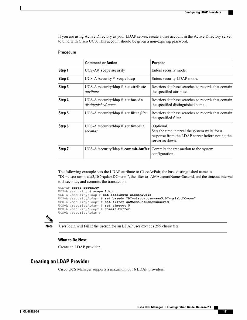
If you are using Active Directory as your LDAP server, create a user account in the Active Directory serverto bind with Cisco UCS. This account should be given a non-expiring password.
Procedure
PurposeCommand or Action
Enters security mode.UCS-A# scope securityStep 1
Enters security LDAP mode.UCS-A /security # scope ldapStep 2
Restricts database searches to records that containthe specified attribute.
UCS-A /security/ldap # set attributeattribute
Step 3
Restricts database searches to records that containthe specified distinguished name.
UCS-A /security/ldap # set basedndistinguished-name
Step 4
Restricts database searches to records that containthe specified filter.
UCS-A /security/ldap # set filter filterStep 5
(Optional)Sets the time interval the system waits for aresponse from the LDAP server before noting theserver as down.
UCS-A /security/ldap # set timeoutseconds
Step 6
Commits the transaction to the systemconfiguration.
UCS-A /security/ldap # commit-bufferStep 7
The following example sets the LDAP attribute to CiscoAvPair, the base distinguished name to"DC=cisco-ucsm-aaa3,DC=qalab,DC=com", the filter to sAMAccountName=$userid, and the timeout intervalto 5 seconds, and commits the transaction:UCS-A# scope securityUCS-A /security # scope ldapUCS-A /security/ldap # set attribute CiscoAvPairUCS-A /security/ldap* # set basedn "DC=cisco-ucsm-aaa3,DC=qalab,DC=com"UCS-A /security/ldap* # set filter sAMAccountName=$useridUCS-A /security/ldap* # set timeout 5UCS-A /security/ldap* # commit-bufferUCS-A /security/ldap #
User login will fail if the userdn for an LDAP user exceeds 255 characters.Note
What to Do Next
Create an LDAP provider.
Creating an LDAP ProviderCisco UCS Manager supports a maximum of 16 LDAP providers.
Cisco UCS Manager CLI Configuration Guide, Release 2.1 OL-28302-04 121
Configuring LDAP Providers

Before You Begin
If you are using Active Directory as your LDAP server, create a user account in the Active Directory serverto bind with Cisco UCS. This account should be given a non-expiring password.
• In the LDAP server, perform one of the following configurations:
◦Configure LDAP groups. LDAP groups contain user role and locale information.
◦Configure users with the attribute that holds the user role and locale information for Cisco UCSManager. You can choose whether to extend the LDAP schema for this attribute. If you do notwant to extend the schema, use an existing LDAP attribute to hold the Cisco UCS user roles andlocales. If you prefer to extend the schema, create a custom attribute, such as the CiscoAVPairattribute.
The Cisco LDAP implementation requires a unicode type attribute.
If you choose to create the CiscoAVPair custom attribute, use the following attribute ID:1.3.6.1.4.1.9.287247.1
◦For a cluster configuration, add the management port IPv4 or IPv6 addresses for both fabricinterconnects. This configuration ensures that remote users can continue to log in if the first fabricinterconnect fails and the system fails over to the second fabric interconnect. All login requestsare sourced from these IP addresses, not the virtual IPv4 or IPv6 address used by Cisco UCSManager.
• If you want to use secure communications, create a trusted point containing the certificate of the rootcertificate authority (CA) of the LDAP server in Cisco UCS Manager.
Procedure
PurposeCommand or Action
Enters security mode.UCS-A# scope securityStep 1
Enters security LDAP mode.UCS-A /security # scopeldap
Step 2
Creates an LDAP server instance and enters security LDAP servermode. If SSL is enabled, the server-name , typically an IP address
UCS-A /security/ldap #create server server-name
Step 3
or FQDN, must exactly match a Common Name (CN) in the LDAPserver's security certificate. Unless an IP address is specified, a DNSserver must be configured in Cisco UCS Manager.
(Optional)An LDAP attribute that stores the values for the user roles and locales.This property is always a name-value pair. The system queries theuser record for the value that matches this attribute name.
UCS-A /security/ldap/server# set attribute attr-name
Step 4
If you do not want to extend your LDAP schema, you can configurean existing, unused LDAP attribute with the Cisco UCS roles andlocales. Alternatively, you can create an attribute named CiscoAVPairin the remote authentication service with the following attribute ID:1.3.6.1.4.1.9.287247.1
Cisco UCS Manager CLI Configuration Guide, Release 2.1122 OL-28302-04
Configuring LDAP Providers
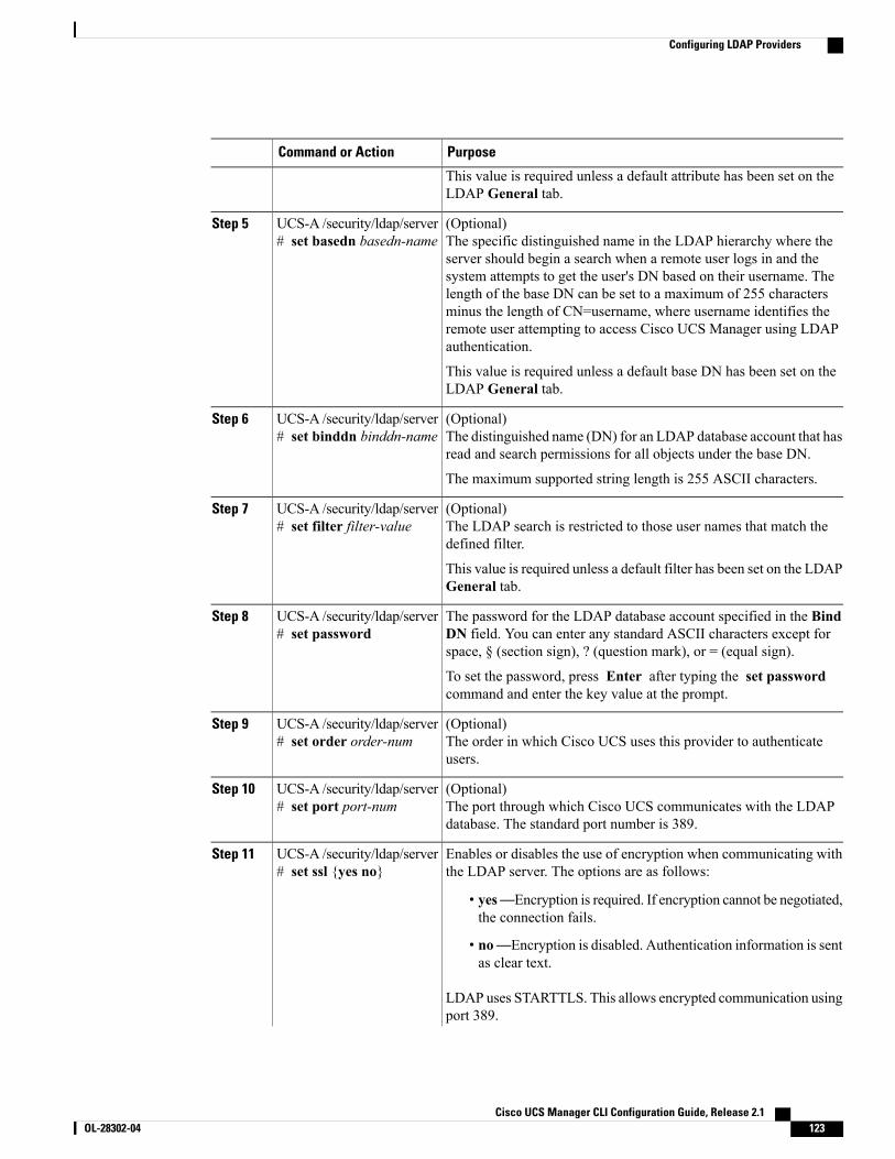
PurposeCommand or Action
This value is required unless a default attribute has been set on theLDAP General tab.
(Optional)The specific distinguished name in the LDAP hierarchy where theserver should begin a search when a remote user logs in and the
UCS-A /security/ldap/server# set basedn basedn-name
Step 5
system attempts to get the user's DN based on their username. Thelength of the base DN can be set to a maximum of 255 charactersminus the length of CN=username, where username identifies theremote user attempting to access Cisco UCS Manager using LDAPauthentication.
This value is required unless a default base DN has been set on theLDAP General tab.
(Optional)The distinguished name (DN) for an LDAP database account that hasread and search permissions for all objects under the base DN.
UCS-A /security/ldap/server# set binddn binddn-name
Step 6
The maximum supported string length is 255 ASCII characters.
(Optional)The LDAP search is restricted to those user names that match thedefined filter.
UCS-A /security/ldap/server# set filter filter-value
Step 7
This value is required unless a default filter has been set on the LDAPGeneral tab.
The password for the LDAP database account specified in the BindDN field. You can enter any standard ASCII characters except forspace, § (section sign), ? (question mark), or = (equal sign).
UCS-A /security/ldap/server# set password
Step 8
To set the password, press Enter after typing the set passwordcommand and enter the key value at the prompt.
(Optional)The order in which Cisco UCS uses this provider to authenticateusers.
UCS-A /security/ldap/server# set order order-num
Step 9
(Optional)The port through which Cisco UCS communicates with the LDAPdatabase. The standard port number is 389.
UCS-A /security/ldap/server# set port port-num
Step 10
Enables or disables the use of encryption when communicating withthe LDAP server. The options are as follows:
UCS-A /security/ldap/server# set ssl {yes no}
Step 11
• yes—Encryption is required. If encryption cannot be negotiated,the connection fails.
• no—Encryption is disabled. Authentication information is sentas clear text.
LDAP uses STARTTLS. This allows encrypted communication usingport 389.
Cisco UCS Manager CLI Configuration Guide, Release 2.1 OL-28302-04 123
Configuring LDAP Providers
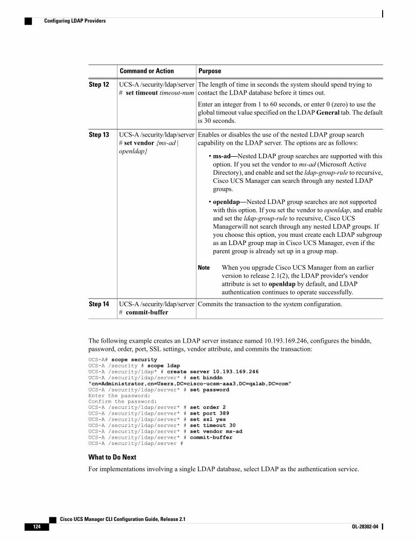
PurposeCommand or Action
The length of time in seconds the system should spend trying tocontact the LDAP database before it times out.
UCS-A /security/ldap/server# set timeout timeout-num
Step 12
Enter an integer from 1 to 60 seconds, or enter 0 (zero) to use theglobal timeout value specified on the LDAPGeneral tab. The defaultis 30 seconds.
Enables or disables the use of the nested LDAP group searchcapability on the LDAP server. The options are as follows:
UCS-A /security/ldap/server# set vendor {ms-ad |openldap}
Step 13
• ms-ad—Nested LDAP group searches are supported with thisoption. If you set the vendor to ms-ad (Microsoft ActiveDirectory), and enable and set the ldap-group-rule to recursive,Cisco UCS Manager can search through any nested LDAPgroups.
• openldap—Nested LDAP group searches are not supportedwith this option. If you set the vendor to openldap, and enableand set the ldap-group-rule to recursive, Cisco UCSManagerwill not search through any nested LDAP groups. Ifyou choose this option, you must create each LDAP subgroupas an LDAP group map in Cisco UCS Manager, even if theparent group is already set up in a group map.
When you upgrade Cisco UCS Manager from an earlierversion to release 2.1(2), the LDAP provider's vendorattribute is set to openldap by default, and LDAPauthentication continues to operate successfully.
Note
Commits the transaction to the system configuration.UCS-A /security/ldap/server# commit-buffer
Step 14
The following example creates an LDAP server instance named 10.193.169.246, configures the binddn,password, order, port, SSL settings, vendor attribute, and commits the transaction:UCS-A# scope securityUCS-A /security # scope ldapUCS-A /security/ldap* # create server 10.193.169.246UCS-A /security/ldap/server* # set binddn"cn=Administrator,cn=Users,DC=cisco-ucsm-aaa3,DC=qalab,DC=com"UCS-A /security/ldap/server* # set passwordEnter the password:Confirm the password:UCS-A /security/ldap/server* # set order 2UCS-A /security/ldap/server* # set port 389UCS-A /security/ldap/server* # set ssl yesUCS-A /security/ldap/server* # set timeout 30UCS-A /security/ldap/server* # set vendor ms-adUCS-A /security/ldap/server* # commit-bufferUCS-A /security/ldap/server #
What to Do Next
For implementations involving a single LDAP database, select LDAP as the authentication service.
Cisco UCS Manager CLI Configuration Guide, Release 2.1124 OL-28302-04
Configuring LDAP Providers
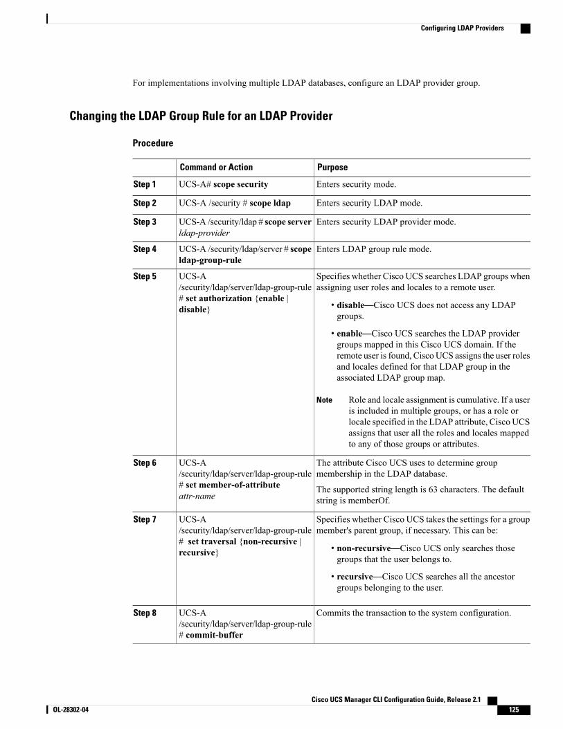
For implementations involving multiple LDAP databases, configure an LDAP provider group.
Changing the LDAP Group Rule for an LDAP Provider
Procedure
PurposeCommand or Action
Enters security mode.UCS-A# scope securityStep 1
Enters security LDAP mode.UCS-A /security # scope ldapStep 2
Enters security LDAP provider mode.UCS-A /security/ldap # scope serverldap-provider
Step 3
Enters LDAP group rule mode.UCS-A /security/ldap/server # scopeldap-group-rule
Step 4
Specifies whether Cisco UCS searches LDAP groups whenassigning user roles and locales to a remote user.
UCS-A/security/ldap/server/ldap-group-rule
Step 5
# set authorization {enable |disable} • disable—Cisco UCS does not access any LDAP
groups.
• enable—Cisco UCS searches the LDAP providergroups mapped in this Cisco UCS domain. If theremote user is found, Cisco UCS assigns the user rolesand locales defined for that LDAP group in theassociated LDAP group map.
Role and locale assignment is cumulative. If a useris included in multiple groups, or has a role orlocale specified in the LDAP attribute, Cisco UCSassigns that user all the roles and locales mappedto any of those groups or attributes.
Note
The attribute Cisco UCS uses to determine groupmembership in the LDAP database.
UCS-A/security/ldap/server/ldap-group-rule
Step 6
# set member-of-attributeattr-name
The supported string length is 63 characters. The defaultstring is memberOf.
Specifies whether Cisco UCS takes the settings for a groupmember's parent group, if necessary. This can be:
UCS-A/security/ldap/server/ldap-group-rule
Step 7
# set traversal {non-recursive |recursive} • non-recursive—Cisco UCS only searches those
groups that the user belongs to.
• recursive—Cisco UCS searches all the ancestorgroups belonging to the user.
Commits the transaction to the system configuration.UCS-A/security/ldap/server/ldap-group-rule# commit-buffer
Step 8
Cisco UCS Manager CLI Configuration Guide, Release 2.1 OL-28302-04 125
Configuring LDAP Providers
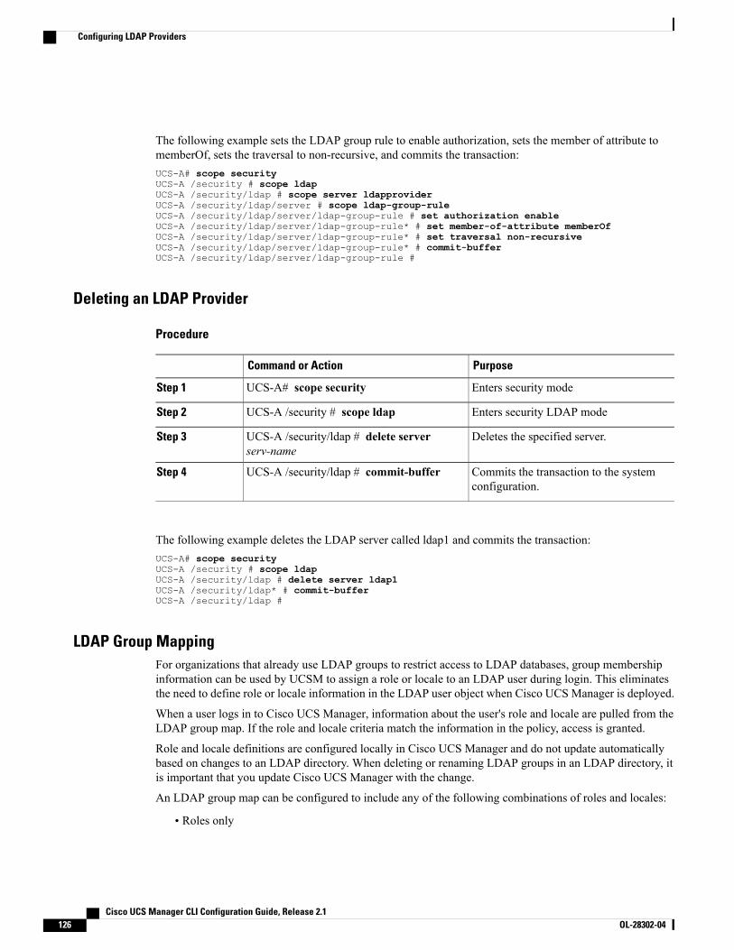
The following example sets the LDAP group rule to enable authorization, sets the member of attribute tomemberOf, sets the traversal to non-recursive, and commits the transaction:UCS-A# scope securityUCS-A /security # scope ldapUCS-A /security/ldap # scope server ldapproviderUCS-A /security/ldap/server # scope ldap-group-ruleUCS-A /security/ldap/server/ldap-group-rule # set authorization enableUCS-A /security/ldap/server/ldap-group-rule* # set member-of-attribute memberOfUCS-A /security/ldap/server/ldap-group-rule* # set traversal non-recursiveUCS-A /security/ldap/server/ldap-group-rule* # commit-bufferUCS-A /security/ldap/server/ldap-group-rule #
Deleting an LDAP Provider
Procedure
PurposeCommand or Action
Enters security modeUCS-A# scope securityStep 1
Enters security LDAP modeUCS-A /security # scope ldapStep 2
Deletes the specified server.UCS-A /security/ldap # delete serverserv-name
Step 3
Commits the transaction to the systemconfiguration.
UCS-A /security/ldap # commit-bufferStep 4
The following example deletes the LDAP server called ldap1 and commits the transaction:UCS-A# scope securityUCS-A /security # scope ldapUCS-A /security/ldap # delete server ldap1UCS-A /security/ldap* # commit-bufferUCS-A /security/ldap #
LDAP Group MappingFor organizations that already use LDAP groups to restrict access to LDAP databases, group membershipinformation can be used by UCSM to assign a role or locale to an LDAP user during login. This eliminatesthe need to define role or locale information in the LDAP user object when Cisco UCS Manager is deployed.
When a user logs in to Cisco UCS Manager, information about the user's role and locale are pulled from theLDAP group map. If the role and locale criteria match the information in the policy, access is granted.
Role and locale definitions are configured locally in Cisco UCS Manager and do not update automaticallybased on changes to an LDAP directory. When deleting or renaming LDAP groups in an LDAP directory, itis important that you update Cisco UCS Manager with the change.
An LDAP group map can be configured to include any of the following combinations of roles and locales:
• Roles only
Cisco UCS Manager CLI Configuration Guide, Release 2.1126 OL-28302-04
Configuring LDAP Providers
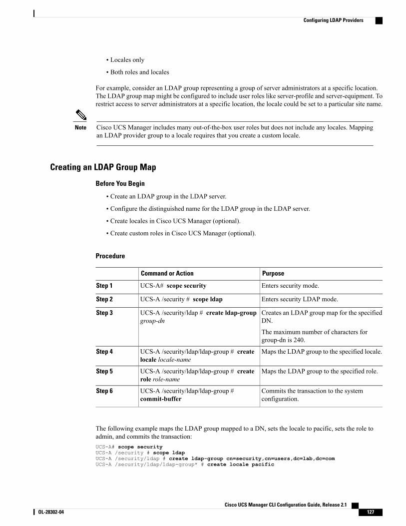
• Locales only
• Both roles and locales
For example, consider an LDAP group representing a group of server administrators at a specific location.The LDAP group map might be configured to include user roles like server-profile and server-equipment. Torestrict access to server administrators at a specific location, the locale could be set to a particular site name.
Cisco UCS Manager includes many out-of-the-box user roles but does not include any locales. Mappingan LDAP provider group to a locale requires that you create a custom locale.
Note
Creating an LDAP Group Map
Before You Begin
• Create an LDAP group in the LDAP server.
• Configure the distinguished name for the LDAP group in the LDAP server.
• Create locales in Cisco UCS Manager (optional).
• Create custom roles in Cisco UCS Manager (optional).
Procedure
PurposeCommand or Action
Enters security mode.UCS-A# scope securityStep 1
Enters security LDAP mode.UCS-A /security # scope ldapStep 2
Creates an LDAP group map for the specifiedDN.
UCS-A /security/ldap # create ldap-groupgroup-dn
Step 3
The maximum number of characters forgroup-dn is 240.
Maps the LDAP group to the specified locale.UCS-A /security/ldap/ldap-group # createlocale locale-name
Step 4
Maps the LDAP group to the specified role.UCS-A /security/ldap/ldap-group # createrole role-name
Step 5
Commits the transaction to the systemconfiguration.
UCS-A /security/ldap/ldap-group #commit-buffer
Step 6
The following example maps the LDAP group mapped to a DN, sets the locale to pacific, sets the role toadmin, and commits the transaction:UCS-A# scope securityUCS-A /security # scope ldapUCS-A /security/ldap # create ldap-group cn=security,cn=users,dc=lab,dc=comUCS-A /security/ldap/ldap-group* # create locale pacific
Cisco UCS Manager CLI Configuration Guide, Release 2.1 OL-28302-04 127
Configuring LDAP Providers
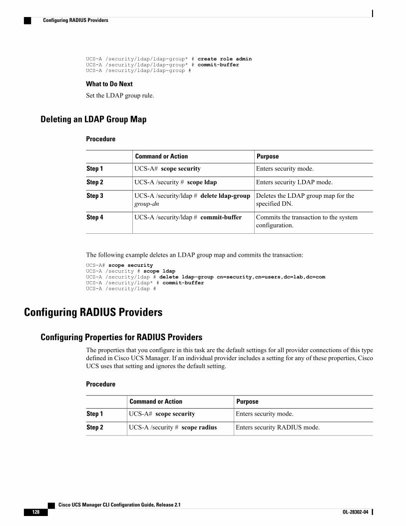
UCS-A /security/ldap/ldap-group* # create role adminUCS-A /security/ldap/ldap-group* # commit-bufferUCS-A /security/ldap/ldap-group #
What to Do Next
Set the LDAP group rule.
Deleting an LDAP Group Map
Procedure
PurposeCommand or Action
Enters security mode.UCS-A# scope securityStep 1
Enters security LDAP mode.UCS-A /security # scope ldapStep 2
Deletes the LDAP group map for thespecified DN.
UCS-A /security/ldap # delete ldap-groupgroup-dn
Step 3
Commits the transaction to the systemconfiguration.
UCS-A /security/ldap # commit-bufferStep 4
The following example deletes an LDAP group map and commits the transaction:UCS-A# scope securityUCS-A /security # scope ldapUCS-A /security/ldap # delete ldap-group cn=security,cn=users,dc=lab,dc=comUCS-A /security/ldap* # commit-bufferUCS-A /security/ldap #
Configuring RADIUS Providers
Configuring Properties for RADIUS ProvidersThe properties that you configure in this task are the default settings for all provider connections of this typedefined in Cisco UCS Manager. If an individual provider includes a setting for any of these properties, CiscoUCS uses that setting and ignores the default setting.
Procedure
PurposeCommand or Action
Enters security mode.UCS-A# scope securityStep 1
Enters security RADIUS mode.UCS-A /security # scope radiusStep 2
Cisco UCS Manager CLI Configuration Guide, Release 2.1128 OL-28302-04
Configuring RADIUS Providers
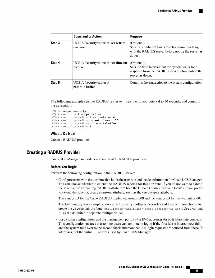
PurposeCommand or Action
(Optional)Sets the number of times to retry communicatingwith the RADIUS server before noting the server asdown.
UCS-A /security/radius # set retriesretry-num
Step 3
(Optional)Sets the time interval that the system waits for aresponse from the RADIUS server before noting theserver as down.
UCS-A /security/radius # set timeoutseconds
Step 4
Commits the transaction to the system configuration.UCS-A /security/radius #commit-buffer
Step 5
The following example sets the RADIUS retries to 4, sets the timeout interval to 30 seconds, and commitsthe transaction:UCS-A# scope securityUCS-A /security # scope radiusUCS-A /security/radius # set retries 4UCS-A /security/radius* # set timeout 30UCS-A /security/radius* # commit-bufferUCS-A /security/radius #
What to Do Next
Create a RADIUS provider.
Creating a RADIUS ProviderCisco UCS Manager supports a maximum of 16 RADIUS providers.
Before You Begin
Perform the following configuration in the RADIUS server:
• Configure users with the attribute that holds the user role and locale information for Cisco UCSManager.You can choose whether to extend the RADIUS schema for this attribute. If you do not want to extendthe schema, use an existing RADIUS attribute to hold the Cisco UCS user roles and locales. If you preferto extend the schema, create a custom attribute, such as the cisco-avpair attribute.
The vendor ID for the Cisco RADIUS implementation is 009 and the vendor ID for the attribute is 001.
The following syntax example shows how to specify multiples user roles and locales if you choose tocreate the cisco-avpair attribute: shell:roles="admin,aaa" shell:locales="L1,abc". Use a comma"," as the delimiter to separate multiple values.
• For a cluster configuration, add the management port IPv4 or IPv6 addresses for both fabric interconnects.This configuration ensures that remote users can continue to log in if the first fabric interconnect failsand the system fails over to the second fabric interconnect. All login requests are sourced from these IPaddresses, not the virtual IP address used by Cisco UCS Manager.
Cisco UCS Manager CLI Configuration Guide, Release 2.1 OL-28302-04 129
Configuring RADIUS Providers
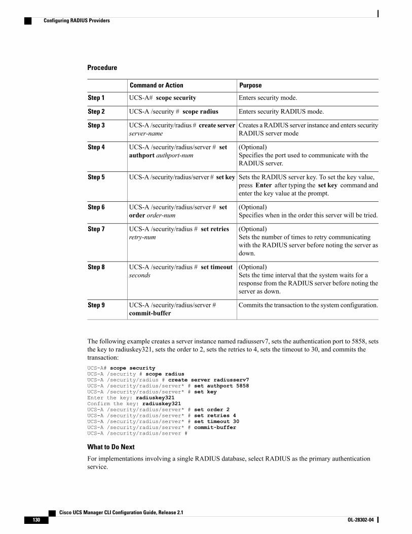
Procedure
PurposeCommand or Action
Enters security mode.UCS-A# scope securityStep 1
Enters security RADIUS mode.UCS-A /security # scope radiusStep 2
Creates a RADIUS server instance and enters securityRADIUS server mode
UCS-A /security/radius # create serverserver-name
Step 3
(Optional)Specifies the port used to communicate with theRADIUS server.
UCS-A /security/radius/server # setauthport authport-num
Step 4
Sets the RADIUS server key. To set the key value,press Enter after typing the set key command andenter the key value at the prompt.
UCS-A /security/radius/server # set keyStep 5
(Optional)Specifies when in the order this server will be tried.
UCS-A /security/radius/server # setorder order-num
Step 6
(Optional)Sets the number of times to retry communicatingwith the RADIUS server before noting the server asdown.
UCS-A /security/radius # set retriesretry-num
Step 7
(Optional)Sets the time interval that the system waits for aresponse from the RADIUS server before noting theserver as down.
UCS-A /security/radius # set timeoutseconds
Step 8
Commits the transaction to the system configuration.UCS-A /security/radius/server #commit-buffer
Step 9
The following example creates a server instance named radiusserv7, sets the authentication port to 5858, setsthe key to radiuskey321, sets the order to 2, sets the retries to 4, sets the timeout to 30, and commits thetransaction:UCS-A# scope securityUCS-A /security # scope radiusUCS-A /security/radius # create server radiusserv7UCS-A /security/radius/server* # set authport 5858UCS-A /security/radius/server* # set keyEnter the key: radiuskey321Confirm the key: radiuskey321UCS-A /security/radius/server* # set order 2UCS-A /security/radius/server* # set retries 4UCS-A /security/radius/server* # set timeout 30UCS-A /security/radius/server* # commit-bufferUCS-A /security/radius/server #
What to Do Next
For implementations involving a single RADIUS database, select RADIUS as the primary authenticationservice.
Cisco UCS Manager CLI Configuration Guide, Release 2.1130 OL-28302-04
Configuring RADIUS Providers
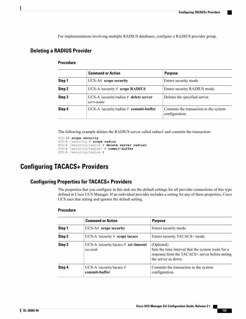
For implementations involving multiple RADIUS databases, configure a RADIUS provider group.
Deleting a RADIUS Provider
Procedure
PurposeCommand or Action
Enters security mode.UCS-A# scope securityStep 1
Enters security RADIUS mode.UCS-A /security # scope RADIUSStep 2
Deletes the specified server.UCS-A /security/radius # delete serverserv-name
Step 3
Commits the transaction to the systemconfiguration.
UCS-A /security/radius # commit-bufferStep 4
The following example deletes the RADIUS server called radius1 and commits the transaction:UCS-A# scope securityUCS-A /security # scope radiusUCS-A /security/radius # delete server radius1UCS-A /security/radius* # commit-bufferUCS-A /security/radius #
Configuring TACACS+ Providers
Configuring Properties for TACACS+ ProvidersThe properties that you configure in this task are the default settings for all provider connections of this typedefined in Cisco UCS Manager. If an individual provider includes a setting for any of these properties, CiscoUCS uses that setting and ignores the default setting.
Procedure
PurposeCommand or Action
Enters security mode.UCS-A# scope securityStep 1
Enters security TACACS+ mode.UCS-A /security # scope tacacsStep 2
(Optional)Sets the time interval that the system waits for aresponse from the TACACS+ server before notingthe server as down.
UCS-A /security/tacacs # set timeoutseconds
Step 3
Commits the transaction to the systemconfiguration.
UCS-A /security/tacacs #commit-buffer
Step 4
Cisco UCS Manager CLI Configuration Guide, Release 2.1 OL-28302-04 131
Configuring TACACS+ Providers
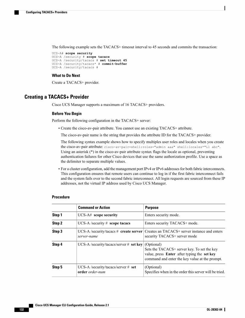
The following example sets the TACACS+ timeout interval to 45 seconds and commits the transaction:UCS-A# scope securityUCS-A /security # scope tacacsUCS-A /security/tacacs # set timeout 45UCS-A /security/tacacs* # commit-bufferUCS-A /security/tacacs #
What to Do Next
Create a TACACS+ provider.
Creating a TACACS+ ProviderCisco UCS Manager supports a maximum of 16 TACACS+ providers.
Before You Begin
Perform the following configuration in the TACACS+ server:
• Create the cisco-av-pair attribute. You cannot use an existing TACACS+ attribute.The cisco-av-pair name is the string that provides the attribute ID for the TACACS+ provider.
The following syntax example shows how to specify multiples user roles and locales when you createthe cisco-av-pair attribute: cisco-av-pair=shell:roles="admin aaa" shell:locales*"L1 abc".Using an asterisk (*) in the cisco-av-pair attribute syntax flags the locale as optional, preventingauthentication failures for other Cisco devices that use the same authorization profile. Use a space asthe delimiter to separate multiple values.
• For a cluster configuration, add the management port IPv4 or IPv6 addresses for both fabric interconnects.This configuration ensures that remote users can continue to log in if the first fabric interconnect failsand the system fails over to the second fabric interconnect. All login requests are sourced from these IPaddresses, not the virtual IP address used by Cisco UCS Manager.
Procedure
PurposeCommand or Action
Enters security mode.UCS-A# scope securityStep 1
Enters security TACACS+ mode.UCS-A /security # scope tacacsStep 2
Creates an TACACS+ server instance and enterssecurity TACACS+ server mode
UCS-A /security/tacacs # create serverserver-name
Step 3
(Optional)Sets the TACACS+ server key. To set the keyvalue, press Enter after typing the set keycommand and enter the key value at the prompt.
UCS-A /security/tacacs/server # set keyStep 4
(Optional)Specifies when in the order this server will be tried.
UCS-A /security/tacacs/server # setorder order-num
Step 5
Cisco UCS Manager CLI Configuration Guide, Release 2.1132 OL-28302-04
Configuring TACACS+ Providers
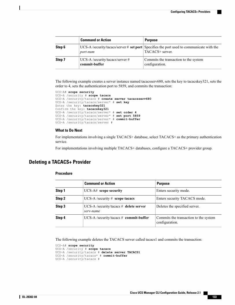
PurposeCommand or Action
Specifies the port used to communicate with theTACACS+ server.
UCS-A /security/tacacs/server # set portport-num
Step 6
Commits the transaction to the systemconfiguration.
UCS-A /security/tacacs/server #commit-buffer
Step 7
The following example creates a server instance named tacacsserv680, sets the key to tacacskey321, sets theorder to 4, sets the authentication port to 5859, and commits the transaction:UCS-A# scope securityUCS-A /security # scope tacacsUCS-A /security/tacacs # create server tacacsserv680UCS-A /security/tacacs/server* # set keyEnter the key: tacacskey321Confirm the key: tacacskey321UCS-A /security/tacacs/server* # set order 4UCS-A /security/tacacs/server* # set port 5859UCS-A /security/tacacs/server* # commit-bufferUCS-A /security/tacacs/server #
What to Do Next
For implementations involving a single TACACS+ database, select TACACS+ as the primary authenticationservice.
For implementations involving multiple TACACS+ databases, configure a TACACS+ provider group.
Deleting a TACACS+ Provider
Procedure
PurposeCommand or Action
Enters security mode.UCS-A# scope securityStep 1
Enters security TACACS mode.UCS-A /security # scope tacacsStep 2
Deletes the specified server.UCS-A /security/tacacs # delete serverserv-name
Step 3
Commits the transaction to the systemconfiguration.
UCS-A /security/tacacs # commit-bufferStep 4
The following example deletes the TACACS server called tacacs1 and commits the transaction:UCS-A# scope securityUCS-A /security # scope tacacsUCS-A /security/tacacs # delete server TACACS1UCS-A /security/tacacs* # commit-bufferUCS-A /security/tacacs #
Cisco UCS Manager CLI Configuration Guide, Release 2.1 OL-28302-04 133
Configuring TACACS+ Providers
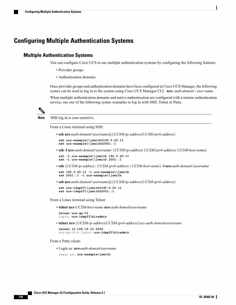
Configuring Multiple Authentication Systems
Multiple Authentication SystemsYou can configure Cisco UCS to use multiple authentication systems by configuring the following features:
• Provider groups
• Authentication domains
Once provider groups and authentication domains have been configured in Cisco UCSManager, the followingsyntax can be used to log in to the system using Cisco UCS Manager CLI: ucs: auth-domain \ user-name .
When multiple authentication domains and native authentication are configured with a remote authenticationservice, use one of the following syntax examples to log in with SSH, Telnet or Putty.
SSH log in is case-sensitive.Note
From a Linux terminal using SSH:
• ssh ucs-auth-domain\\username@{UCSM-ip-address|UCMS-ipv6-address}ssh ucs-example\\[email protected] ucs-example\\jsmith@2001::1
• ssh -l ucs-auth-domain\\username {UCSM-ip-address| UCSM-ipv6-address| UCSM-host-name}ssh -l ucs-example\\jsmith 192.0.20.11ssh -l ucs-example\\jsmith 2001::1
• ssh {UCSM-ip-address | UCSM-ipv6-address | UCSM-host-name} -l ucs-auth-domain\\usernamessh 192.0.20.11 -l ucs-example\\jsmithssh 2001::1 -l ucs-example\\jsmith
• ssh ucs-auth-domain\\username@{UCSM-ip-address|UCSM-ipv6-address}ssh ucs-ldap23\\[email protected] ucs-ldap23\\jsmith@2001::1
From a Linux terminal using Telnet:
• telnet ucs-UCSM-host-name ucs-auth-domain\usernametelnet ucs-qa-10login: ucs-ldap23\blradmin
• telnet ucs-{UCSM-ip-address|UCSM-ipv6-address}ucs-auth-domain\usernametelnet 10.106.19.12 2052ucs-qa-10-A login: ucs-ldap23\blradmin
From a Putty client:
• Login as: ucs-auth-domain\usernameLogin as: ucs-example\jsmith
Cisco UCS Manager CLI Configuration Guide, Release 2.1134 OL-28302-04
Configuring Multiple Authentication Systems
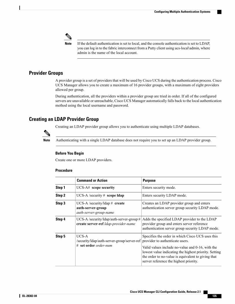
If the default authentication is set to local, and the console authentication is set to LDAP,you can log in to the fabric interconnect from a Putty client using ucs-local\admin, whereadmin is the name of the local account.
Note
Provider GroupsA provider group is a set of providers that will be used by Cisco UCS during the authentication process. CiscoUCS Manager allows you to create a maximum of 16 provider groups, with a maximum of eight providersallowed per group.
During authentication, all the providers within a provider group are tried in order. If all of the configuredservers are unavailable or unreachable, Cisco UCSManager automatically falls back to the local authenticationmethod using the local username and password.
Creating an LDAP Provider GroupCreating an LDAP provider group allows you to authenticate using multiple LDAP databases.
Authenticating with a single LDAP database does not require you to set up an LDAP provider group.Note
Before You Begin
Create one or more LDAP providers.
Procedure
PurposeCommand or Action
Enters security mode.UCS-A# scope securityStep 1
Enters security LDAP mode.UCS-A /security # scope ldapStep 2
Creates an LDAP provider group and entersauthentication server group security LDAP mode.
UCS-A /security/ldap # createauth-server-groupauth-server-group-name
Step 3
Adds the specified LDAP provider to the LDAPprovider group and enters server referenceauthentication server group security LDAP mode.
UCS-A /security/ldap/auth-server-group #create server-ref ldap-provider-name
Step 4
Specifies the order in which Cisco UCS uses thisprovider to authenticate users.
UCS-A/security/ldap/auth-server-group/server-ref# set order order-num
Step 5
Valid values include no-value and 0-16, with thelowest value indicating the highest priority. Settingthe order to no-value is equivalent to giving thatserver reference the highest priority.
Cisco UCS Manager CLI Configuration Guide, Release 2.1 OL-28302-04 135
Configuring Multiple Authentication Systems
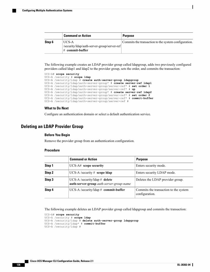
PurposeCommand or Action
Commits the transaction to the system configuration.UCS-A/security/ldap/auth-server-group/server-ref# commit-buffer
Step 6
The following example creates an LDAP provider group called ldapgroup, adds two previously configuredproviders called ldap1 and ldap2 to the provider group, sets the order, and commits the transaction:UCS-A# scope securityUCS-A /security # scope ldapUCS-A /security/ldap # create auth-server-group ldapgroupUCS-A /security/ldap/auth-server-group* # create server-ref ldap1UCS-A /security/ldap/auth-server-group/server-ref* # set order 1UCS-A /security/ldap/auth-server-group/server-ref* # upUCS-A /security/ldap/auth-server-group* # create server-ref ldap2UCS-A /security/ldap/auth-server-group/server-ref* # set order 2UCS-A /security/ldap/auth-server-group/server-ref* # commit-bufferUCS-A /security/ldap/auth-server-group/server-ref #
What to Do Next
Configure an authentication domain or select a default authentication service.
Deleting an LDAP Provider Group
Before You Begin
Remove the provider group from an authentication configuration.
Procedure
PurposeCommand or Action
Enters security mode.UCS-A# scope securityStep 1
Enters security LDAP mode.UCS-A /security # scope ldapStep 2
Deletes the LDAP provider group.UCS-A /security/ldap # deleteauth-server-group auth-server-group-name
Step 3
Commits the transaction to the systemconfiguration.
UCS-A /security/ldap # commit-bufferStep 4
The following example deletes an LDAP provider group called ldapgroup and commits the transaction:UCS-A# scope securityUCS-A /security # scope ldapUCS-A /security/ldap # delete auth-server-group ldapgroupUCS-A /security/ldap* # commit-bufferUCS-A /security/ldap #
Cisco UCS Manager CLI Configuration Guide, Release 2.1136 OL-28302-04
Configuring Multiple Authentication Systems
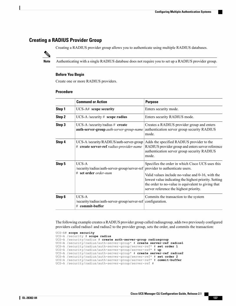
Creating a RADIUS Provider GroupCreating a RADIUS provider group allows you to authenticate using multiple RADIUS databases.
Authenticating with a single RADIUS database does not require you to set up a RADIUS provider group.Note
Before You Begin
Create one or more RADIUS providers.
Procedure
PurposeCommand or Action
Enters security mode.UCS-A# scope securityStep 1
Enters security RADIUS mode.UCS-A /security # scope radiusStep 2
Creates a RADIUS provider group and entersauthentication server group security RADIUSmode.
UCS-A /security/radius # createauth-server-group auth-server-group-name
Step 3
Adds the specified RADIUS provider to theRADIUS provider group and enters server reference
UCS-A /security/RADIUS/auth-server-group# create server-ref radius-provider-name
Step 4
authentication server group security RADIUSmode.
Specifies the order in which Cisco UCS uses thisprovider to authenticate users.
UCS-A/security/radius/auth-server-group/server-ref# set order order-num
Step 5
Valid values include no-value and 0-16, with thelowest value indicating the highest priority. Settingthe order to no-value is equivalent to giving thatserver reference the highest priority.
Commits the transaction to the systemconfiguration.
UCS-A/security/radius/auth-server-group/server-ref# commit-buffer
Step 6
The following example creates a RADIUS provider group called radiusgroup, adds two previously configuredproviders called radius1 and radius2 to the provider group, sets the order, and commits the transaction:UCS-A# scope securityUCS-A /security # scope radiusUCS-A /security/radius # create auth-server-group radiusgroupUCS-A /security/radius/auth-server-group* # create server-ref radius1UCS-A /security/radius/auth-server-group/server-ref* # set order 1UCS-A /security/radius/auth-server-group/server-ref* # upUCS-A /security/radius/auth-server-group* # create server-ref radius2UCS-A /security/radius/auth-server-group/server-ref* # set order 2UCS-A /security/radius/auth-server-group/server-ref* # commit-bufferUCS-A /security/radius/auth-server-group/server-ref #
Cisco UCS Manager CLI Configuration Guide, Release 2.1 OL-28302-04 137
Configuring Multiple Authentication Systems

What to Do Next
Configure an authentication domain or select a default authentication service.
Deleting a RADIUS Provider GroupRemove the provider group from an authentication configuration.
Procedure
PurposeCommand or Action
Enters security mode.UCS-A# scope securityStep 1
Enters security RADIUS mode.UCS-A /security # scope radiusStep 2
Deletes the RADIUS provider group.UCS-A /security/radius # deleteauth-server-group auth-server-group-name
Step 3
Commits the transaction to the systemconfiguration.
UCS-A /security/radius # commit-bufferStep 4
The following example deletes a RADIUS provider group called radiusgroup and commits the transaction:UCS-A# scope securityUCS-A /security # scope radiusUCS-A /security/radius # delete auth-server-group radiusgroupUCS-A /security/radius* # commit-bufferUCS-A /security/radius #
Creating a TACACS Provider GroupCreating a TACACS+ provider group allows you to authenticate using multiple TACACS+ databases.
Authenticating with a single TACACS+ database does not require you to set up a TACACS+ providergroup.
Note
Before You Begin
Create a TACACS provider.
Procedure
PurposeCommand or Action
Enters security mode.UCS-A# scope securityStep 1
Enters security TACACS mode.UCS-A /security # scope tacacsStep 2
Cisco UCS Manager CLI Configuration Guide, Release 2.1138 OL-28302-04
Configuring Multiple Authentication Systems
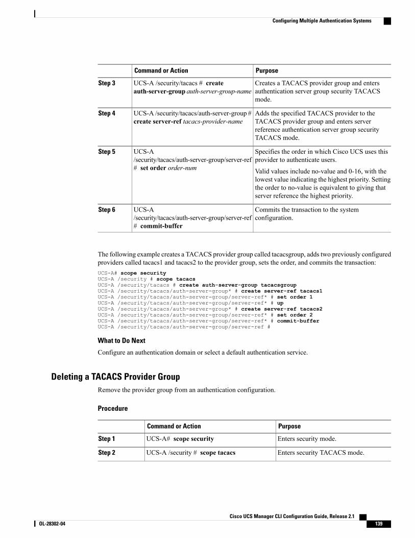
PurposeCommand or Action
Creates a TACACS provider group and entersauthentication server group security TACACSmode.
UCS-A /security/tacacs # createauth-server-group auth-server-group-name
Step 3
Adds the specified TACACS provider to theTACACS provider group and enters server
UCS-A /security/tacacs/auth-server-group #create server-ref tacacs-provider-name
Step 4
reference authentication server group securityTACACS mode.
Specifies the order in which Cisco UCS uses thisprovider to authenticate users.
UCS-A/security/tacacs/auth-server-group/server-ref# set order order-num
Step 5
Valid values include no-value and 0-16, with thelowest value indicating the highest priority. Settingthe order to no-value is equivalent to giving thatserver reference the highest priority.
Commits the transaction to the systemconfiguration.
UCS-A/security/tacacs/auth-server-group/server-ref# commit-buffer
Step 6
The following example creates a TACACS provider group called tacacsgroup, adds two previously configuredproviders called tacacs1 and tacacs2 to the provider group, sets the order, and commits the transaction:UCS-A# scope securityUCS-A /security # scope tacacsUCS-A /security/tacacs # create auth-server-group tacacsgroupUCS-A /security/tacacs/auth-server-group* # create server-ref tacacs1UCS-A /security/tacacs/auth-server-group/server-ref* # set order 1UCS-A /security/tacacs/auth-server-group/server-ref* # upUCS-A /security/tacacs/auth-server-group* # create server-ref tacacs2UCS-A /security/tacacs/auth-server-group/server-ref* # set order 2UCS-A /security/tacacs/auth-server-group/server-ref* # commit-bufferUCS-A /security/tacacs/auth-server-group/server-ref #
What to Do Next
Configure an authentication domain or select a default authentication service.
Deleting a TACACS Provider GroupRemove the provider group from an authentication configuration.
Procedure
PurposeCommand or Action
Enters security mode.UCS-A# scope securityStep 1
Enters security TACACS mode.UCS-A /security # scope tacacsStep 2
Cisco UCS Manager CLI Configuration Guide, Release 2.1 OL-28302-04 139
Configuring Multiple Authentication Systems
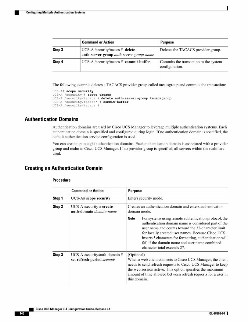
PurposeCommand or Action
Deletes the TACACS provider group.UCS-A /security/tacacs # deleteauth-server-group auth-server-group-name
Step 3
Commits the transaction to the systemconfiguration.
UCS-A /security/tacacs # commit-bufferStep 4
The following example deletes a TACACS provider group called tacacsgroup and commits the transaction:UCS-A# scope securityUCS-A /security # scope tacacsUCS-A /security/tacacs # delete auth-server-group tacacsgroupUCS-A /security/tacacs* # commit-bufferUCS-A /security/tacacs #
Authentication DomainsAuthentication domains are used by Cisco UCS Manager to leverage multiple authentication systems. Eachauthentication domain is specified and configured during login. If no authentication domain is specified, thedefault authentication service configuration is used.
You can create up to eight authentication domains. Each authentication domain is associated with a providergroup and realm in Cisco UCS Manager. If no provider group is specified, all servers within the realm areused.
Creating an Authentication Domain
Procedure
PurposeCommand or Action
Enters security mode.UCS-A# scope securityStep 1
Creates an authentication domain and enters authenticationdomain mode.
UCS-A /security # createauth-domain domain-name
Step 2
For systems using remote authentication protocol, theauthentication domain name is considered part of theuser name and counts toward the 32-character limitfor locally created user names. Because Cisco UCSinserts 5 characters for formatting, authentication willfail if the domain name and user name combinedcharacter total exceeds 27.
Note
(Optional)When a web client connects to Cisco UCSManager, the clientneeds to send refresh requests to Cisco UCS Manager to keep
UCS-A /security/auth-domain #set refresh-period seconds
Step 3
the web session active. This option specifies the maximumamount of time allowed between refresh requests for a user inthis domain.
Cisco UCS Manager CLI Configuration Guide, Release 2.1140 OL-28302-04
Configuring Multiple Authentication Systems
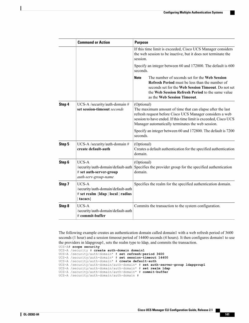
PurposeCommand or Action
If this time limit is exceeded, Cisco UCS Manager considersthe web session to be inactive, but it does not terminate thesession.
Specify an integer between 60 and 172800. The default is 600seconds.
The number of seconds set for theWeb SessionRefresh Period must be less than the number ofseconds set for theWeb Session Timeout. Do not settheWeb Session Refresh Period to the same valueas theWeb Session Timeout.
Note
(Optional)The maximum amount of time that can elapse after the lastrefresh request before Cisco UCS Manager considers a web
UCS-A /security/auth-domain #set session-timeout seconds
Step 4
session to have ended. If this time limit is exceeded, Cisco UCSManager automatically terminates the web session.
Specify an integer between 60 and 172800. The default is 7200seconds.
(Optional)Creates a default authentication for the specified authenticationdomain.
UCS-A /security/auth-domain #create default-auth
Step 5
(Optional)Specifies the provider group for the specified authenticationdomain.
UCS-A/security/auth-domain/default-auth# set auth-server-groupauth-serv-group-name
Step 6
Specifies the realm for the specified authentication domain.UCS-A/security/auth-domain/default-auth
Step 7
# set realm {ldap | local | radius| tacacs}
Commits the transaction to the system configuration.UCS-A/security/auth-domain/default-auth# commit-buffer
Step 8
The following example creates an authentication domain called domain1 with a web refresh period of 3600seconds (1 hour) and a session timeout period of 14400 seconds (4 hours). It then configures domain1 to usethe providers in ldapgroup1, sets the realm type to ldap, and commits the transaction.UCS-A# scope securityUCS-A /security # create auth-domain domain1UCS-A /security/auth-domain* # set refresh-period 3600UCS-A /security/auth-domain* # set session-timeout 14400UCS-A /security/auth-domain* # create default-authUCS-A /security/auth-domain/auth-domain* # set auth-server-group ldapgroup1UCS-A /security/auth-domain/auth-domain* # set realm ldapUCS-A /security/auth-domain/auth-domain* # commit-bufferUCS-A /security/auth-domain/auth-domain #
Cisco UCS Manager CLI Configuration Guide, Release 2.1 OL-28302-04 141
Configuring Multiple Authentication Systems
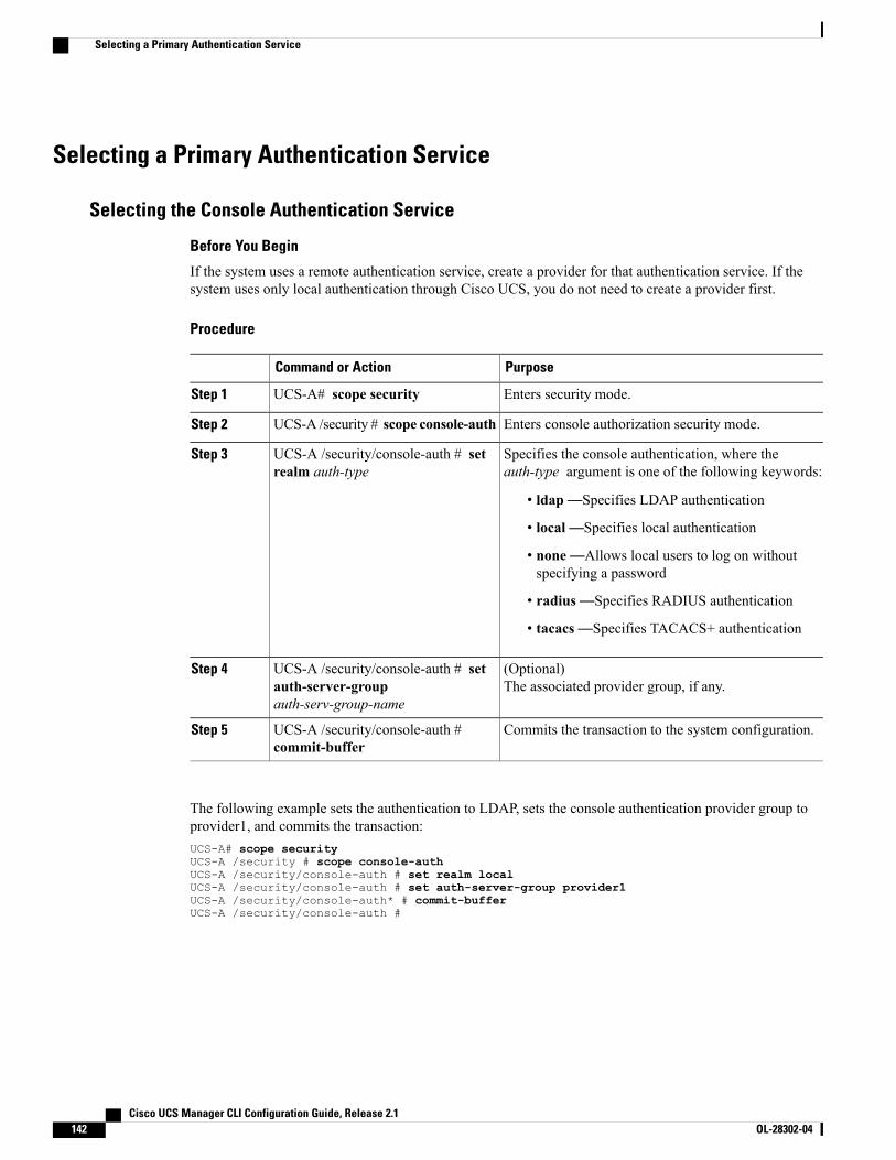
Selecting a Primary Authentication Service
Selecting the Console Authentication Service
Before You Begin
If the system uses a remote authentication service, create a provider for that authentication service. If thesystem uses only local authentication through Cisco UCS, you do not need to create a provider first.
Procedure
PurposeCommand or Action
Enters security mode.UCS-A# scope securityStep 1
Enters console authorization security mode.UCS-A /security # scope console-authStep 2
Specifies the console authentication, where theauth-type argument is one of the following keywords:
UCS-A /security/console-auth # setrealm auth-type
Step 3
• ldap—Specifies LDAP authentication
• local—Specifies local authentication
• none—Allows local users to log on withoutspecifying a password
• radius—Specifies RADIUS authentication
• tacacs—Specifies TACACS+ authentication
(Optional)The associated provider group, if any.
UCS-A /security/console-auth # setauth-server-groupauth-serv-group-name
Step 4
Commits the transaction to the system configuration.UCS-A /security/console-auth #commit-buffer
Step 5
The following example sets the authentication to LDAP, sets the console authentication provider group toprovider1, and commits the transaction:UCS-A# scope securityUCS-A /security # scope console-authUCS-A /security/console-auth # set realm localUCS-A /security/console-auth # set auth-server-group provider1UCS-A /security/console-auth* # commit-bufferUCS-A /security/console-auth #
Cisco UCS Manager CLI Configuration Guide, Release 2.1142 OL-28302-04
Selecting a Primary Authentication Service
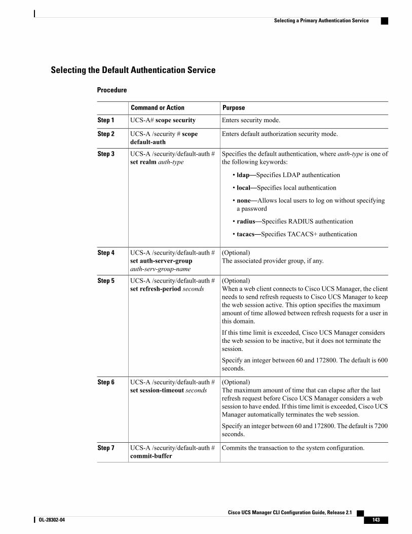
Selecting the Default Authentication Service
Procedure
PurposeCommand or Action
Enters security mode.UCS-A# scope securityStep 1
Enters default authorization security mode.UCS-A /security # scopedefault-auth
Step 2
Specifies the default authentication, where auth-type is one ofthe following keywords:
UCS-A /security/default-auth #set realm auth-type
Step 3
• ldap—Specifies LDAP authentication
• local—Specifies local authentication
• none—Allows local users to log on without specifyinga password
• radius—Specifies RADIUS authentication
• tacacs—Specifies TACACS+ authentication
(Optional)The associated provider group, if any.
UCS-A /security/default-auth #set auth-server-groupauth-serv-group-name
Step 4
(Optional)When a web client connects to Cisco UCSManager, the clientneeds to send refresh requests to Cisco UCS Manager to keep
UCS-A /security/default-auth #set refresh-period seconds
Step 5
the web session active. This option specifies the maximumamount of time allowed between refresh requests for a user inthis domain.
If this time limit is exceeded, Cisco UCS Manager considersthe web session to be inactive, but it does not terminate thesession.
Specify an integer between 60 and 172800. The default is 600seconds.
(Optional)The maximum amount of time that can elapse after the lastrefresh request before Cisco UCS Manager considers a web
UCS-A /security/default-auth #set session-timeout seconds
Step 6
session to have ended. If this time limit is exceeded, Cisco UCSManager automatically terminates the web session.
Specify an integer between 60 and 172800. The default is 7200seconds.
Commits the transaction to the system configuration.UCS-A /security/default-auth #commit-buffer
Step 7
Cisco UCS Manager CLI Configuration Guide, Release 2.1 OL-28302-04 143
Selecting a Primary Authentication Service
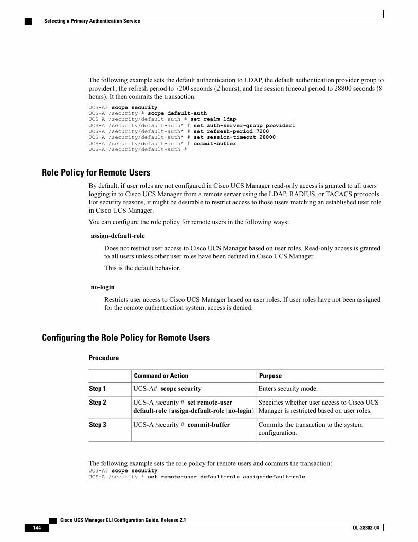
The following example sets the default authentication to LDAP, the default authentication provider group toprovider1, the refresh period to 7200 seconds (2 hours), and the session timeout period to 28800 seconds (8hours). It then commits the transaction.UCS-A# scope securityUCS-A /security # scope default-authUCS-A /security/default-auth # set realm ldapUCS-A /security/default-auth* # set auth-server-group provider1UCS-A /security/default-auth* # set refresh-period 7200UCS-A /security/default-auth* # set session-timeout 28800UCS-A /security/default-auth* # commit-bufferUCS-A /security/default-auth #
Role Policy for Remote UsersBy default, if user roles are not configured in Cisco UCS Manager read-only access is granted to all userslogging in to Cisco UCS Manager from a remote server using the LDAP, RADIUS, or TACACS protocols.For security reasons, it might be desirable to restrict access to those users matching an established user rolein Cisco UCS Manager.
You can configure the role policy for remote users in the following ways:
assign-default-role
Does not restrict user access to Cisco UCS Manager based on user roles. Read-only access is grantedto all users unless other user roles have been defined in Cisco UCS Manager.
This is the default behavior.
no-login
Restricts user access to Cisco UCS Manager based on user roles. If user roles have not been assignedfor the remote authentication system, access is denied.
Configuring the Role Policy for Remote Users
Procedure
PurposeCommand or Action
Enters security mode.UCS-A# scope securityStep 1
Specifies whether user access to Cisco UCSManager is restricted based on user roles.
UCS-A /security # set remote-userdefault-role {assign-default-role | no-login}
Step 2
Commits the transaction to the systemconfiguration.
UCS-A /security # commit-bufferStep 3
The following example sets the role policy for remote users and commits the transaction:UCS-A# scope securityUCS-A /security # set remote-user default-role assign-default-role
Cisco UCS Manager CLI Configuration Guide, Release 2.1144 OL-28302-04
Selecting a Primary Authentication Service

UCS-A /security* # commit-bufferUCS-A /security #
Cisco UCS Manager CLI Configuration Guide, Release 2.1 OL-28302-04 145
Selecting a Primary Authentication Service

Cisco UCS Manager CLI Configuration Guide, Release 2.1146 OL-28302-04
Selecting a Primary Authentication Service
C H A P T E R 9Configuring Organizations
This chapter includes the following sections:
• Organizations in a Multitenancy Environment, page 147
• Hierarchical Name Resolution in a Multi-Tenancy Environment, page 148
• Configuring an Organization Under the Root Organization, page 150
• Configuring an Organization Under an Organization that is not Root, page 150
• Deleting an Organization, page 151
Organizations in a Multitenancy EnvironmentMultitenancy allows you to divide the large physical infrastructure of an Cisco UCS domain into logicalentities known as organizations. As a result, you can achieve a logical isolation between organizations withoutproviding a dedicated physical infrastructure for each organization.
You can assign unique resources to each tenant through the related organization, in the multitenant environment.These resources can include different policies, pools, and quality of service definitions. You can also implementlocales to assign or restrict user privileges and roles by organization, if you do not want all users to haveaccess to all organizations.
If you set up a multitenant environment, all organizations are hierarchical. The top-level organization is alwaysroot. The policies and pools that you create in root are system-wide and are available to all organizations inthe system. However, any policies and pools created in other organizations are only available to organizationsthat are above it in the same hierarchy. For example, if a system has organizations named Finance and HRthat are not in the same hierarchy, Finance cannot use any policies in the HR organization, and HR cannotaccess any policies in the Finance organization. However, both Finance and HR can use policies and poolsin the root organization.
If you create organizations in a multitenant environment, you can also set up one or more of the followingfor each organization or for a suborganization in the same hierarchy:
• Resource pools
• Policies
• Service profiles
Cisco UCS Manager CLI Configuration Guide, Release 2.1 OL-28302-04 147
• Service profile templates
The root organization is always the top level organization.
Hierarchical Name Resolution in a Multi-Tenancy EnvironmentIn a multi-tenant environment, Cisco UCS uses the hierarchy of an organization to resolve the names ofpolicies and resource pools. When Cisco UCSManager searches for details of a policy or a resource assignedto a pool, the following occurs:
1 Cisco UCSManager checks for policies and pools with the specified namewithin the organization assignedto the service profile or policy.
2 If a policy is found or an available resource is inside a pool, Cisco UCS Manager uses that policy orresource. If the pool does not have any available resources at the local level, Cisco UCS Manager movesup in the hierarchy to the parent organization and searches for a pool with the same name. Cisco UCSManager repeats this step until the search reaches the root organization.
3 If the search reaches the root organization and has not found an available resource or policy, Cisco UCSManager returns to the local organization and begins to search for a default policy or available resourcein the default pool.
4 If an applicable default policy or available resource in a default pool is found, Cisco UCS Manager usesthat policy or resource. If the pool does not have any available resources, Cisco UCS Manager moves upin the hierarchy to the parent organization and searches for a default pool. Cisco UCS Manager repeatsthis step until the search reaches the root organization.
5 If Cisco UCS Manager cannot find an applicable policy or available resource in the hierarchy, it returnsan allocation error.
Example: Server Pool Name Resolution in a Single-Level Hierarchy
In this example, all organizations are at the same level below the root organization. For example, a serviceprovider creates separate organizations for each customer. In this configuration, organizations only have accessto the policies and resource pools assigned to that organization and to the root organization.
In this example, a service profile in the XYZcustomer organization is configured to use servers from theXYZcustomer server pool. When resource pools and policies are assigned to the service profile, the followingoccurs:
1 Cisco UCS Manager checks for an available server in the XYZcustomer server pool.
2 If the XYZcustomer server pool has an available server, Cisco UCS Manager associates that server withthe service profile and discontinues the search. If the pool does not have an available server, Cisco UCSManager checks the root organization for a server pool with the same name.
3 If the root organization includes an XYZcustomer server pool and that pool has an available server, CiscoUCS Manager associates that server with the service profile and discontinues the search. If the pool doesnot have an available server, Cisco UCS Manager returns to the XYZcustomer organization to check thedefault server pool.
4 If the default pool in the XYZcustomer organization has an available server, Cisco UCSManager associatesthat server with the service profile and discontinues the search. If the default pool does not have an availableserver, Cisco UCS Manager checks the default server pool in the root organization.
Cisco UCS Manager CLI Configuration Guide, Release 2.1148 OL-28302-04
Hierarchical Name Resolution in a Multi-Tenancy Environment
5 If the default server pool in the root organization has an available server, Cisco UCS Manager associatesthat server with the service profile and discontinues the search. If the default pool does not have an availableserver, Cisco UCS Manager returns an allocation error.
Example: Server Pool Name Resolution in a Multi-Level Hierarchy
In this example, each organization includes at least one suborganization. For example, a company could createorganizations for each major division in the company and for subdivisions of those divisions. In thisconfiguration, each organization has access to its local policies and resource pools and to the resource poolsin the parent hierarchy.
In this example, the Finance organization includes two sub-organizations, AccountsPayable andAccountsReceivable. A service profile in the AccountsPayable organization is configured to use servers fromthe AP server pool. When resource pools and policies are assigned to the service profile, the following occurs:
1 Cisco UCS Manager checks for an available server in the AP server pool defined in the service profile.
2 If the AP server pool has an available server, Cisco UCS Manager associates that server with the serviceprofile and discontinues the search. If the pool does not have an available server, Cisco UCS Managermoves one level up the hierarchy and checks the Finance organization for a pool with the same name.
3 If the Finance organization includes a pool with the same name and that pool has an available server, CiscoUCS Manager associates that server with the service profile and discontinues the search. If the pool doesnot have an available server, Cisco UCSManager moves one level up in the hierarchy and checks the rootorganization for a pool with the same name.
4 If the root organization includes a pool with the same name and that pool has an available server, CiscoUCS Manager associates that server with the service profile and discontinues the search. If the pool doesnot have an available server, Cisco UCS Manager returns to the AccountsPayable organization to checkthe default server pool.
5 If the default pool in the AccountsPayable organization has an available server, Cisco UCS Managerassociates that server with the service profile and discontinues the search. If the default pool does not havean available server, Cisco UCSManager moves one level up in the hierarchy and checks the default serverpool in the Finance organization.
6 If the default pool in the Finance organization has an available server, Cisco UCSManager associates thatserver with the service profile and discontinues the search. If the default pool does not have an availableserver, Cisco UCS Manager moves one level up in the hierarchy and checks the default server pool in theroot organization.
7 If the default server pool in the root organization has an available server, Cisco UCS Manager associatesthat server with the service profile and discontinues the search. If the default pool does not have an availableserver, Cisco UCS Manager returns an allocation error.
Cisco UCS Manager CLI Configuration Guide, Release 2.1 OL-28302-04 149
Hierarchical Name Resolution in a Multi-Tenancy Environment
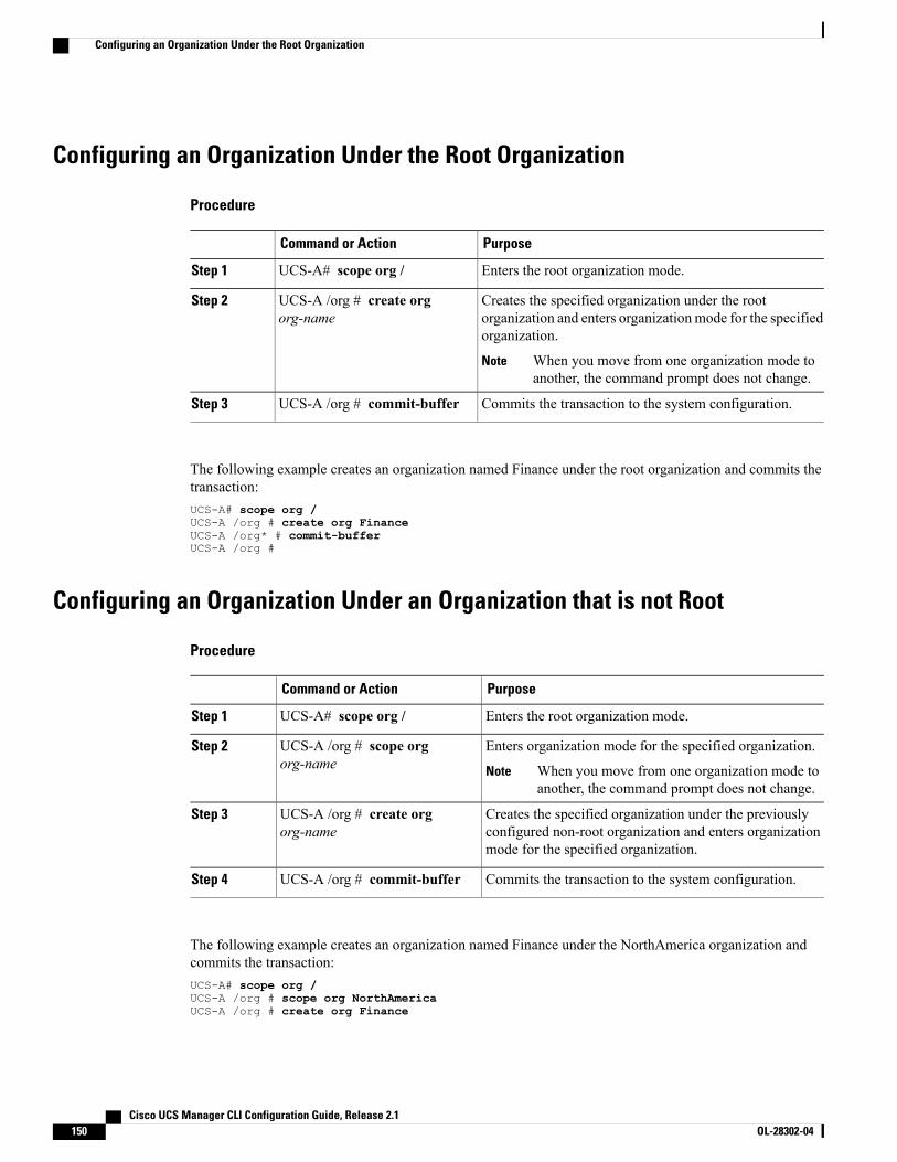
Configuring an Organization Under the Root Organization
Procedure
PurposeCommand or Action
Enters the root organization mode.UCS-A# scope org /Step 1
Creates the specified organization under the rootorganization and enters organizationmode for the specifiedorganization.
UCS-A /org # create orgorg-name
Step 2
When you move from one organization mode toanother, the command prompt does not change.
Note
Commits the transaction to the system configuration.UCS-A /org # commit-bufferStep 3
The following example creates an organization named Finance under the root organization and commits thetransaction:UCS-A# scope org /UCS-A /org # create org FinanceUCS-A /org* # commit-bufferUCS-A /org #
Configuring an Organization Under an Organization that is not Root
Procedure
PurposeCommand or Action
Enters the root organization mode.UCS-A# scope org /Step 1
Enters organization mode for the specified organization.UCS-A /org # scope orgorg-name
Step 2
When you move from one organization mode toanother, the command prompt does not change.
Note
Creates the specified organization under the previouslyconfigured non-root organization and enters organizationmode for the specified organization.
UCS-A /org # create orgorg-name
Step 3
Commits the transaction to the system configuration.UCS-A /org # commit-bufferStep 4
The following example creates an organization named Finance under the NorthAmerica organization andcommits the transaction:UCS-A# scope org /UCS-A /org # scope org NorthAmericaUCS-A /org # create org Finance
Cisco UCS Manager CLI Configuration Guide, Release 2.1150 OL-28302-04
Configuring an Organization Under the Root Organization

UCS-A /org* # commit-bufferUCS-A /org #
Deleting an Organization
Procedure
PurposeCommand or Action
Enters the root organization mode.UCS-A# scope org /Step 1
Deletes the specified organization.UCS-A /org # delete org org-nameStep 2
Commits the transaction to the systemconfiguration.
UCS-A /org # commit-bufferStep 3
The following example deletes the organization under the root organization named Finance and commits thetransaction:UCS-A# scope org /UCS-A /org # delete org FinanceUCS-A /org* # commit-bufferUCS-A /org #
Cisco UCS Manager CLI Configuration Guide, Release 2.1 OL-28302-04 151
Deleting an Organization

Cisco UCS Manager CLI Configuration Guide, Release 2.1152 OL-28302-04
Deleting an Organization
C H A P T E R 10Configuring Role-Based Access Control
This chapter includes the following sections:
• Role-Based Access Control, page 153
• User Accounts for Cisco UCS , page 153
• User Roles, page 156
• User Locales, page 160
• Configuring User Roles, page 161
• Configuring Locales, page 164
• Configuring Locally Authenticated User Accounts, page 166
• Password Profile for Locally Authenticated Users, page 174
• Monitoring User Sessions, page 177
Role-Based Access ControlRole-Based Access Control (RBAC) is a method of restricting or authorizing system access for users basedon user roles and locales. A role defines the privileges of a user in the system and the locale defines theorganizations (domains) that a user is allowed access. Because users are not directly assigned privileges,management of individual user privileges is simply a matter of assigning the appropriate roles and locales.
A user is granted write access to desired system resources only if the assigned role grants the access privilegesand the assigned locale allows access. For example, a user with the Server Administrator role in the Engineeringorganization could update server configurations in the Engineering organization but could not update serverconfigurations in the Finance organization unless the locales assigned to the user include the Financeorganization.
User Accounts for Cisco UCSUser accounts are used to access the system. Up to 48 local user accounts can be configured in each CiscoUCS Manager domain. Each user account must have a unique username and password.
Cisco UCS Manager CLI Configuration Guide, Release 2.1 OL-28302-04 153
A user account can be set with an SSH public key. The public key can be set in either of the two formats:OpenSSH or SECSH.
Admin Account
Each Cisco UCS domain has an admin account. The admin account is a default user account and cannot bemodified or deleted. This account is the system administrator or superuser account and has full privileges.There is no default password assigned to the admin account; you must choose the password during the initialsystem setup.
The admin account is always active and does not expire. You cannot configure the admin account as inactive.
Locally Authenticated User Accounts
A locally authenticated user account is authenticated directly through the fabric interconnect and can beenabled or disabled by anyone with admin or aaa privileges. Once a local user account is disabled, the usercannot log in. Configuration details for disabled local user accounts are not deleted by the database. If youre-enable a disabled local user account, the account becomes active again with the existing configuration,including username and password.
Remotely Authenticated User Accounts
A remotely authenticated user account is any user account that is authenticated through LDAP, RADIUS, orTACACS+.
If a user maintains a local user account and a remote user account simultaneously, the roles defined in thelocal user account override those maintained in the remote user account.
Expiration of User Accounts
User accounts can be configured to expire at a predefined time. When the expiration time is reached, the useraccount is disabled.
By default, user accounts do not expire.
After you configure a user account with an expiration date, you cannot reconfigure the account to notexpire. You can, however, configure the account with the latest expiration date available.
Note
Guidelines for Cisco UCS UsernamesThe username is also used as the login ID for Cisco UCS Manager. When you assign login IDs to Cisco UCSuser accounts, consider the following guidelines and restrictions:
• The login ID can contain between 1 and 32 characters, including the following:
◦Any alphabetic character
◦Any digit
◦_ (underscore)
◦- (dash)
◦. (dot)
Cisco UCS Manager CLI Configuration Guide, Release 2.1154 OL-28302-04
User Accounts for Cisco UCS
• The login ID must be unique within Cisco UCS Manager.
• The login ID must start with an alphabetic character. It cannot start with a number or a special character,such as an underscore.
• The login ID is case-sensitive.
• You cannot create an all-numeric login ID.
• After you create a user account, you cannot change the login ID. You must delete the user account andcreate a new one.
Reserved Words: Locally Authenticated User AccountsThe following words cannot be used when creating a local user account in Cisco UCS.
• root
• bin
• daemon
• adm
• lp
• sync
• shutdown
• halt
• news
• uucp
• operator
• games
• gopher
• nobody
• nscd
• mailnull
• rpcuser
• rpc
• mtsuser
• ftpuser
• ftp
• man
• sys
Cisco UCS Manager CLI Configuration Guide, Release 2.1 OL-28302-04 155
User Accounts for Cisco UCS
• samdme
• debug
Guidelines for Cisco UCS PasswordsA password is required for each locally authenticated user account. A user with admin or aaa privileges canconfigure Cisco UCS Manager to perform a password strength check on user passwords. If the passwordstrength check is enabled, each user must have a strong password.
Cisco recommends that each user have a strong password. If you enable the password strength check forlocally authenticated users, Cisco UCS Manager rejects any password that does not meet the followingrequirements:
• Must contain a minimum of 8 characters and a maximum of 80 characters.
• Must contain at least three of the following:
◦Lower case letters
◦Upper case letters
◦Digits
◦Special characters
• Must not contain a character that is repeated more than 3 times consecutively, such as aaabbb.
• Must not be identical to the username or the reverse of the username.
• Must pass a password dictionary check. For example, the password must not be based on a standarddictionary word.
• Must not contain the following symbols: $ (dollar sign), ? (question mark), and = (equals sign).
• Should not be blank for local user and admin accounts.
Web Session Limits for User AccountsWeb session limits are used by Cisco UCS Manager to restrict the number of web sessions (both GUI andXML) a given user account is permitted to access at any one time.
Each Cisco UCS Manager domain supports a maximum of 32 concurrent web sessions per user and 256 totaluser sessions. By default, the number of concurrent web sessions allowed by Cisco UCSManager is set to 32per user, but this value can be configured up to the system maximum of 256.
User RolesUser roles contain one or more privileges that define the operations that are allowed for a user. One or moreroles can be assigned to each user. Users with multiple roles have the combined privileges of all assignedroles. For example, if Role1 has storage-related privileges, and Role2 has server-related privileges, users withRole1 and Role2 have both storage-related and server-related privileges.
A Cisco UCS domain can contain up to 48 user roles, including the default user roles. Any user roles configuredafter the first 48 will be accepted, but will be inactive with faults raised.
Cisco UCS Manager CLI Configuration Guide, Release 2.1156 OL-28302-04
User Roles
All roles include read access to all configuration settings in the Cisco UCS domain. Users with read-onlyroles cannot modify the system state.
Roles can be created, modified to add new or remove existing privileges, or deleted. When a role is modified,the new privileges are applied to all users that have that role. Privilege assignment is not restricted to theprivileges defined for the default roles. That is, you can use a custom set of privileges to create a unique role.For example, the default Server Administrator and Storage Administrator roles have a different set of privileges,but a new Server and Storage Administrator role can be created that combines the privileges of both roles.
If a role is deleted after it has been assigned to users, it is also deleted from those user accounts.
User profiles on AAA servers (RADIUS or TACACS+) should be modified to add the roles correspondingto the privileges granted to that user. The attribute is used to store the role information. The AAA serversreturn this attribute with the request and parse it to get the roles. LDAP servers return the roles in the userprofile attributes.
If a local user account and a remote user account have the same username, any roles assigned to the remoteuser are overridden by those assigned to the local user.
Note
Default User RolesThe system contains the following default user roles:
AAA Administrator
Read-and-write access to users, roles, and AAA configuration. Read access to the rest of the system.
Administrator
Complete read-and-write access to the entire system. The default admin account is assigned this roleby default and it cannot be changed.
Facility Manager
Read-and-write access to power management operations through the power-mgmt privilege. Readaccess to the rest of the system.
Network Administrator
Read-and-write access to fabric interconnect infrastructure and network security operations. Read accessto the rest of the system.
Operations
Read-and-write access to systems logs, including the syslog servers, and faults. Read access to the restof the system.
Read-Only
Read-only access to system configuration with no privileges to modify the system state.
Cisco UCS Manager CLI Configuration Guide, Release 2.1 OL-28302-04 157
User Roles
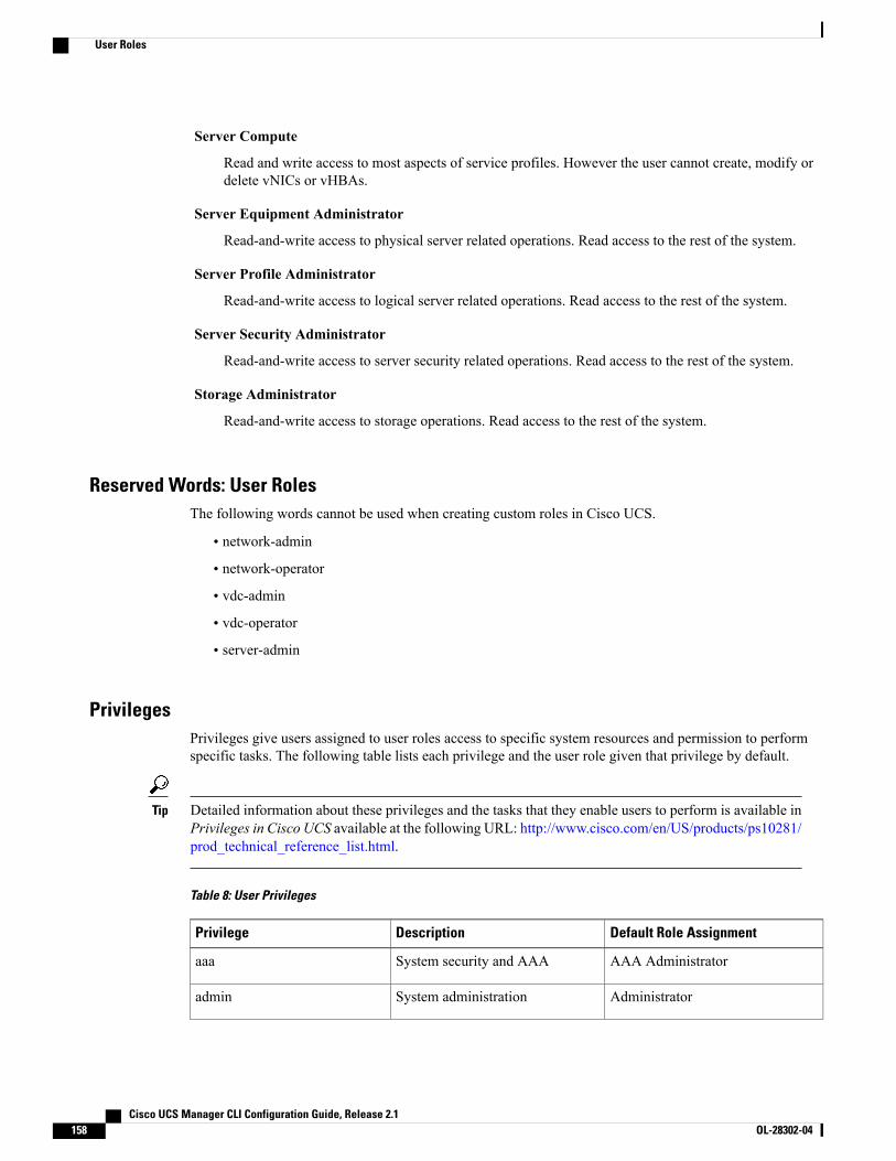
Server Compute
Read and write access to most aspects of service profiles. However the user cannot create, modify ordelete vNICs or vHBAs.
Server Equipment Administrator
Read-and-write access to physical server related operations. Read access to the rest of the system.
Server Profile Administrator
Read-and-write access to logical server related operations. Read access to the rest of the system.
Server Security Administrator
Read-and-write access to server security related operations. Read access to the rest of the system.
Storage Administrator
Read-and-write access to storage operations. Read access to the rest of the system.
Reserved Words: User RolesThe following words cannot be used when creating custom roles in Cisco UCS.
• network-admin
• network-operator
• vdc-admin
• vdc-operator
• server-admin
PrivilegesPrivileges give users assigned to user roles access to specific system resources and permission to performspecific tasks. The following table lists each privilege and the user role given that privilege by default.
Detailed information about these privileges and the tasks that they enable users to perform is available inPrivileges in Cisco UCS available at the following URL: http://www.cisco.com/en/US/products/ps10281/prod_technical_reference_list.html.
Tip
Table 8: User Privileges
Default Role AssignmentDescriptionPrivilege
AAA AdministratorSystem security and AAAaaa
AdministratorSystem administrationadmin
Cisco UCS Manager CLI Configuration Guide, Release 2.1158 OL-28302-04
User Roles
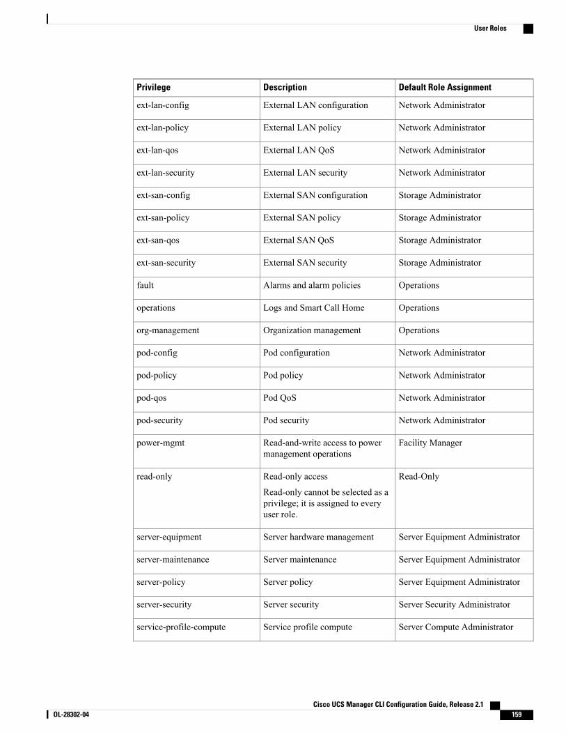
Default Role AssignmentDescriptionPrivilege
Network AdministratorExternal LAN configurationext-lan-config
Network AdministratorExternal LAN policyext-lan-policy
Network AdministratorExternal LAN QoSext-lan-qos
Network AdministratorExternal LAN securityext-lan-security
Storage AdministratorExternal SAN configurationext-san-config
Storage AdministratorExternal SAN policyext-san-policy
Storage AdministratorExternal SAN QoSext-san-qos
Storage AdministratorExternal SAN securityext-san-security
OperationsAlarms and alarm policiesfault
OperationsLogs and Smart Call Homeoperations
OperationsOrganization managementorg-management
Network AdministratorPod configurationpod-config
Network AdministratorPod policypod-policy
Network AdministratorPod QoSpod-qos
Network AdministratorPod securitypod-security
Facility ManagerRead-and-write access to powermanagement operations
power-mgmt
Read-OnlyRead-only access
Read-only cannot be selected as aprivilege; it is assigned to everyuser role.
read-only
Server Equipment AdministratorServer hardware managementserver-equipment
Server Equipment AdministratorServer maintenanceserver-maintenance
Server Equipment AdministratorServer policyserver-policy
Server Security AdministratorServer securityserver-security
Server Compute AdministratorService profile computeservice-profile-compute
Cisco UCS Manager CLI Configuration Guide, Release 2.1 OL-28302-04 159
User Roles

Default Role AssignmentDescriptionPrivilege
Server Profile AdministratorService profile configurationservice-profile-config
Server Profile AdministratorService profile configuration policyservice-profile-config-policy
Server Profile AdministratorService profile end point accessservice-profile-ext-access
Network AdministratorService profile networkservice-profile-network
Network AdministratorService profile network policyservice-profile-network-policy
Network AdministratorService profile QoSservice-profile-qos
Network AdministratorService profile QoS policyservice-profile-qos-policy
Server Security AdministratorService profile securityservice-profile-security
Server Security AdministratorService profile security policyservice-profile-security-policy
Server Profile AdministratorService profile server managementservice-profile-server
Server Profile AdministratorService profile consumerservice-profile-server-oper
Server Security AdministratorService profile pool policyservice-profile-server-policy
Storage AdministratorService profile storageservice-profile-storage
Storage AdministratorService profile storage policyservice-profile-storage-policy
User LocalesA user can be assigned one or more locales. Each locale defines one or more organizations (domains) the useris allowed access, and access would be limited to the organizations specified in the locale. One exception tothis rule is a locale without any organizations, which gives unrestricted access to system resources in allorganizations.
A Cisco UCS domain can contain up to 48 user locales. Any user locales configured after the first 48 will beaccepted, but will be inactive with faults raised.
Users with admin or aaa privileges can assign organizations to the locale of other users. The assignment oforganizations is restricted to only those in the locale of the user assigning the organizations. For example, ifa locale contains only the Engineering organization then a user assigned that locale can only assign theEngineering organization to other users.
Cisco UCS Manager CLI Configuration Guide, Release 2.1160 OL-28302-04
User Locales
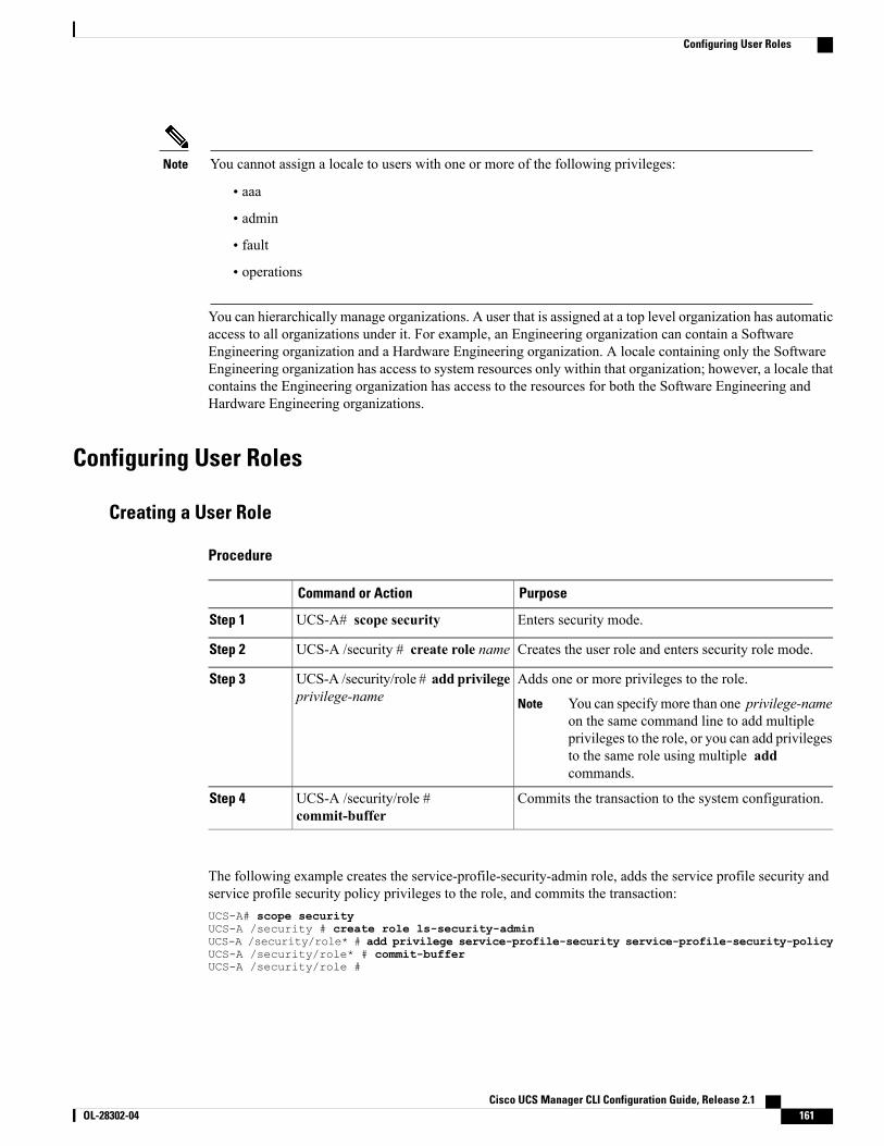
You cannot assign a locale to users with one or more of the following privileges:Note
• aaa
• admin
• fault
• operations
You can hierarchically manage organizations. A user that is assigned at a top level organization has automaticaccess to all organizations under it. For example, an Engineering organization can contain a SoftwareEngineering organization and a Hardware Engineering organization. A locale containing only the SoftwareEngineering organization has access to system resources only within that organization; however, a locale thatcontains the Engineering organization has access to the resources for both the Software Engineering andHardware Engineering organizations.
Configuring User Roles
Creating a User Role
Procedure
PurposeCommand or Action
Enters security mode.UCS-A# scope securityStep 1
Creates the user role and enters security role mode.UCS-A /security # create role nameStep 2
Adds one or more privileges to the role.UCS-A /security/role # add privilegeprivilege-name
Step 3
You can specify more than one privilege-nameon the same command line to add multipleprivileges to the role, or you can add privilegesto the same role using multiple addcommands.
Note
Commits the transaction to the system configuration.UCS-A /security/role #commit-buffer
Step 4
The following example creates the service-profile-security-admin role, adds the service profile security andservice profile security policy privileges to the role, and commits the transaction:UCS-A# scope securityUCS-A /security # create role ls-security-adminUCS-A /security/role* # add privilege service-profile-security service-profile-security-policyUCS-A /security/role* # commit-bufferUCS-A /security/role #
Cisco UCS Manager CLI Configuration Guide, Release 2.1 OL-28302-04 161
Configuring User Roles
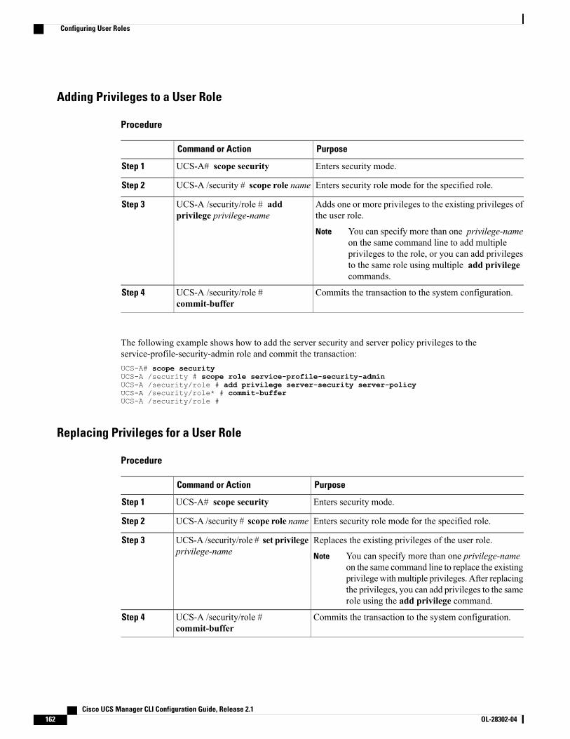
Adding Privileges to a User Role
Procedure
PurposeCommand or Action
Enters security mode.UCS-A# scope securityStep 1
Enters security role mode for the specified role.UCS-A /security # scope role nameStep 2
Adds one or more privileges to the existing privileges ofthe user role.
UCS-A /security/role # addprivilege privilege-name
Step 3
You can specify more than one privilege-nameon the same command line to add multipleprivileges to the role, or you can add privilegesto the same role using multiple add privilegecommands.
Note
Commits the transaction to the system configuration.UCS-A /security/role #commit-buffer
Step 4
The following example shows how to add the server security and server policy privileges to theservice-profile-security-admin role and commit the transaction:UCS-A# scope securityUCS-A /security # scope role service-profile-security-adminUCS-A /security/role # add privilege server-security server-policyUCS-A /security/role* # commit-bufferUCS-A /security/role #
Replacing Privileges for a User Role
Procedure
PurposeCommand or Action
Enters security mode.UCS-A# scope securityStep 1
Enters security role mode for the specified role.UCS-A /security # scope role nameStep 2
Replaces the existing privileges of the user role.UCS-A /security/role # set privilegeprivilege-name
Step 3
You can specify more than one privilege-nameon the same command line to replace the existingprivilegewithmultiple privileges. After replacingthe privileges, you can add privileges to the samerole using the add privilege command.
Note
Commits the transaction to the system configuration.UCS-A /security/role #commit-buffer
Step 4
Cisco UCS Manager CLI Configuration Guide, Release 2.1162 OL-28302-04
Configuring User Roles
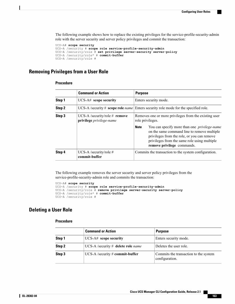
The following example shows how to replace the existing privileges for the service-profile-security-adminrole with the server security and server policy privileges and commit the transaction:UCS-A# scope securityUCS-A /security # scope role service-profile-security-adminUCS-A /security/role # set privilege server-security server-policyUCS-A /security/role* # commit-bufferUCS-A /security/role #
Removing Privileges from a User Role
Procedure
PurposeCommand or Action
Enters security mode.UCS-A# scope securityStep 1
Enters security role mode for the specified role.UCS-A /security # scope role nameStep 2
Removes one or more privileges from the existing userrole privileges.
UCS-A /security/role # removeprivilege privilege-name
Step 3
You can specify more than one privilege-nameon the same command line to remove multipleprivileges from the role, or you can removeprivileges from the same role using multipleremove privilege commands.
Note
Commits the transaction to the system configuration.UCS-A /security/role #commit-buffer
Step 4
The following example removes the server security and server policy privileges from theservice-profile-security-admin role and commits the transaction:UCS-A# scope securityUCS-A /security # scope role service-profile-security-adminUCS-A /security/role # remove privilege server-security server-policyUCS-A /security/role* # commit-bufferUCS-A /security/role #
Deleting a User Role
Procedure
PurposeCommand or Action
Enters security mode.UCS-A# scope securityStep 1
Deletes the user role.UCS-A /security # delete role nameStep 2
Commits the transaction to the systemconfiguration.
UCS-A /security # commit-bufferStep 3
Cisco UCS Manager CLI Configuration Guide, Release 2.1 OL-28302-04 163
Configuring User Roles
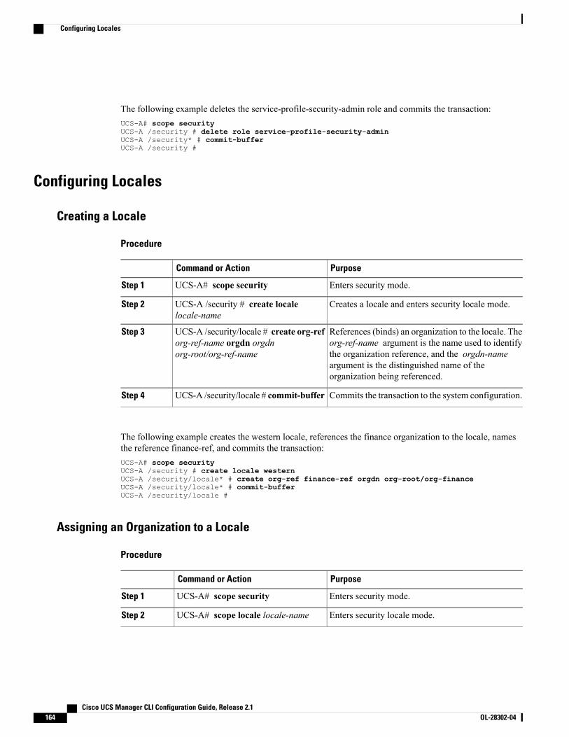
The following example deletes the service-profile-security-admin role and commits the transaction:UCS-A# scope securityUCS-A /security # delete role service-profile-security-adminUCS-A /security* # commit-bufferUCS-A /security #
Configuring Locales
Creating a Locale
Procedure
PurposeCommand or Action
Enters security mode.UCS-A# scope securityStep 1
Creates a locale and enters security locale mode.UCS-A /security # create localelocale-name
Step 2
References (binds) an organization to the locale. Theorg-ref-name argument is the name used to identify
UCS-A /security/locale # create org-reforg-ref-name orgdn orgdnorg-root/org-ref-name
Step 3
the organization reference, and the orgdn-nameargument is the distinguished name of theorganization being referenced.
Commits the transaction to the system configuration.UCS-A /security/locale # commit-bufferStep 4
The following example creates the western locale, references the finance organization to the locale, namesthe reference finance-ref, and commits the transaction:UCS-A# scope securityUCS-A /security # create locale westernUCS-A /security/locale* # create org-ref finance-ref orgdn org-root/org-financeUCS-A /security/locale* # commit-bufferUCS-A /security/locale #
Assigning an Organization to a Locale
Procedure
PurposeCommand or Action
Enters security mode.UCS-A# scope securityStep 1
Enters security locale mode.UCS-A# scope locale locale-nameStep 2
Cisco UCS Manager CLI Configuration Guide, Release 2.1164 OL-28302-04
Configuring Locales
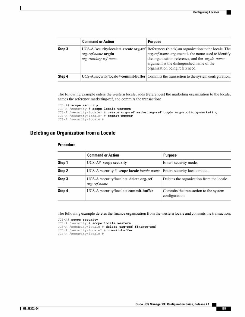
PurposeCommand or Action
References (binds) an organization to the locale. Theorg-ref-name argument is the name used to identify
UCS-A /security/locale # create org-reforg-ref-name orgdnorg-root/org-ref-name
Step 3
the organization reference, and the orgdn-nameargument is the distinguished name of theorganization being referenced.
Commits the transaction to the system configuration.UCS-A /security/locale # commit-bufferStep 4
The following example enters the western locale, adds (references) the marketing organization to the locale,names the reference marketing-ref, and commits the transaction:UCS-A# scope securityUCS-A /security # scope locale westernUCS-A /security/locale* # create org-ref marketing-ref orgdn org-root/org-marketingUCS-A /security/locale* # commit-bufferUCS-A /security/locale #
Deleting an Organization from a Locale
Procedure
PurposeCommand or Action
Enters security mode.UCS-A# scope securityStep 1
Enters security locale mode.UCS-A /security # scope locale locale-nameStep 2
Deletes the organization from the locale.UCS-A /security/locale # delete org-reforg-ref-name
Step 3
Commits the transaction to the systemconfiguration.
UCS-A /security/locale # commit-bufferStep 4
The following example deletes the finance organization from the western locale and commits the transaction:UCS-A# scope securityUCS-A /security # scope locale westernUCS-A /security/locale # delete org-ref finance-refUCS-A /security/locale* # commit-bufferUCS-A /security/locale #
Cisco UCS Manager CLI Configuration Guide, Release 2.1 OL-28302-04 165
Configuring Locales
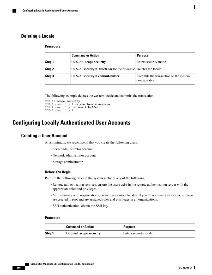
Deleting a Locale
Procedure
PurposeCommand or Action
Enters security mode.UCS-A# scope securityStep 1
Deletes the locale.UCS-A /security # delete locale locale-nameStep 2
Commits the transaction to the systemconfiguration.
UCS-A /security # commit-bufferStep 3
The following example deletes the western locale and commits the transaction:UCS-A# scope securityUCS-A /security # delete locale westernUCS-A /security* # commit-bufferUCS-A /security #
Configuring Locally Authenticated User Accounts
Creating a User AccountAt a minimum, we recommend that you create the following users:
• Server administrator account
• Network administrator account
• Storage administrator
Before You Begin
Perform the following tasks, if the system includes any of the following:
• Remote authentication services, ensure the users exist in the remote authentication server with theappropriate roles and privileges.
• Multi-tenancy with organizations, create one or more locales. If you do not have any locales, all usersare created in root and are assigned roles and privileges in all organizations.
• SSH authentication, obtain the SSH key.
Procedure
PurposeCommand or Action
Enters security mode.UCS-A# scope securityStep 1
Cisco UCS Manager CLI Configuration Guide, Release 2.1166 OL-28302-04
Configuring Locally Authenticated User Accounts
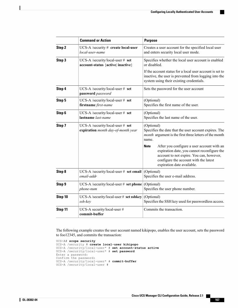
PurposeCommand or Action
Creates a user account for the specified local userand enters security local user mode.
UCS-A /security # create local-userlocal-user-name
Step 2
Specifies whether the local user account is enabledor disabled.
UCS-A /security/local-user # setaccount-status {active| inactive}
Step 3
If the account status for a local user account is set toinactive, the user is prevented from logging into thesystem using their existing credentials.
Sets the password for the user accountUCS-A /security/local-user # setpassword password
Step 4
(Optional)Specifies the first name of the user.
UCS-A /security/local-user # setfirstname first-name
Step 5
(Optional)Specifies the last name of the user.
UCS-A /security/local-user # setlastname last-name
Step 6
(Optional)Specifies the date that the user account expires. Themonth argument is the first three letters of the monthname.
UCS-A /security/local-user # setexpiration month day-of-month year
Step 7
After you configure a user account with anexpiration date, you cannot reconfigure theaccount to not expire. You can, however,configure the account with the latestexpiration date available.
Note
(Optional)Specifies the user e-mail address.
UCS-A /security/local-user # set emailemail-addr
Step 8
(Optional)Specifies the user phone number.
UCS-A /security/local-user # set phonephone-num
Step 9
(Optional)Specifies the SSH key used for passwordless access.
UCS-A /security/local-user # set sshkeyssh-key
Step 10
Commits the transaction.UCS-A security/local-user #commit-buffer
Step 11
The following example creates the user account named kikipopo, enables the user account, sets the passwordto foo12345, and commits the transaction:UCS-A# scope securityUCS-A /security # create local-user kikipopoUCS-A /security/local-user* # set account-status activeUCS-A /security/local-user* # set passwordEnter a password:Confirm the password:UCS-A /security/local-user* # commit-bufferUCS-A /security/local-user #
Cisco UCS Manager CLI Configuration Guide, Release 2.1 OL-28302-04 167
Configuring Locally Authenticated User Accounts
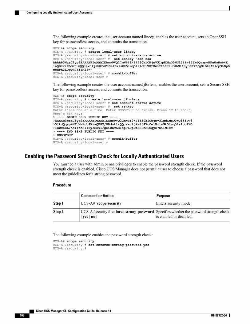
The following example creates the user account named lincey, enables the user account, sets an OpenSSHkey for passwordless access, and commits the transaction.UCS-A# scope securityUCS-A /security # create local-user linceyUCS-A /security/local-user* # set account-status activeUCS-A /security/local-user* # set sshkey "ssh-rsaAAAAB3NzaC1yc2EAAAABIwAAAIEAuo9VQ2CmWBI9/S1f30klCWjnV3lgdXMzO0WUl5iPw85lkdQqap+NFuNmHcb4KiaQB8X/PDdmtlxQQcawclj+k8f4VcOelBxlsGk5luq5ls1ob1VOIEwcKEL/h5lrdbNlI8y3SS9I/gGiBZ9ARlop9LDpDm8HPh2LOgyH7Ei1MI8="UCS-A /security/local-user* # commit-bufferUCS-A /security/local-user #
The following example creates the user account named jforlenz, enables the user account, sets a Secure SSHkey for passwordless access, and commits the transaction.UCS-A# scope securityUCS-A /security # create local-user jforlenzUCS-A /security/local-user* # set account-status activeUCS-A /security/local-user* # set sshkeyEnter lines one at a time. Enter ENDOFBUF to finish. Press ^C to abort.User's SSH key:> ---- BEGIN SSH2 PUBLIC KEY ---->AAAAB3NzaC1yc2EAAAABIwAAAIEAuo9VQ2CmWBI9/S1f30klCWjnV3lgdXMzO0WUl5iPw8>5lkdQqap+NFuNmHcb4KiaQB8X/PDdmtlxQQcawclj+k8f4VcOelBxlsGk5luq5ls1ob1VO>IEwcKEL/h5lrdbNlI8y3SS9I/gGiBZ9ARlop9LDpDm8HPh2LOgyH7Ei1MI8=> ---- END SSH2 PUBLIC KEY ----> ENDOFBUFUCS-A /security/local-user* # commit-bufferUCS-A /security/local-user #
Enabling the Password Strength Check for Locally Authenticated UsersYou must be a user with admin or aaa privileges to enable the password strength check. If the passwordstrength check is enabled, Cisco UCS Manager does not permit a user to choose a password that does notmeet the guidelines for a strong password.
Procedure
PurposeCommand or Action
Enters security mode.UCS-A# scope securityStep 1
Specifies whether the password strength checkis enabled or disabled.
UCS-A /security # enforce-strong-password{yes | no}
Step 2
The following example enables the password strength check:UCS-A# scope securityUCS-A /security # set enforce-strong-password yesUCS-A /security #
Cisco UCS Manager CLI Configuration Guide, Release 2.1168 OL-28302-04
Configuring Locally Authenticated User Accounts
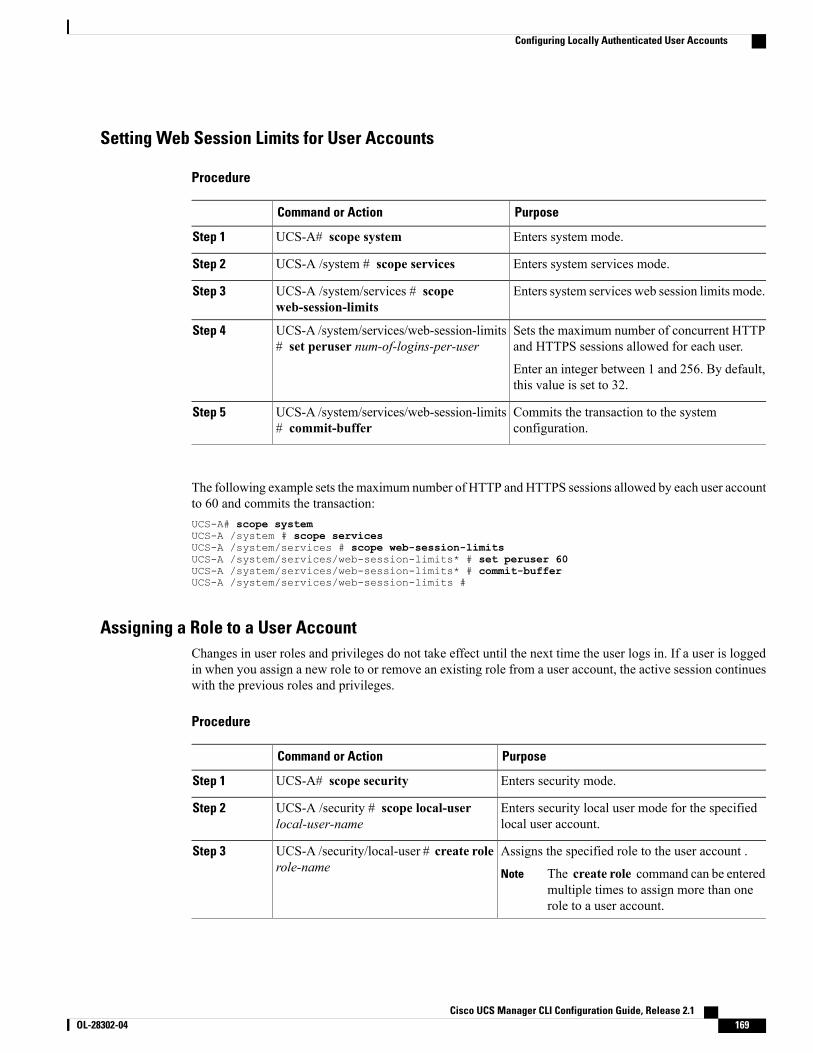
Setting Web Session Limits for User Accounts
Procedure
PurposeCommand or Action
Enters system mode.UCS-A# scope systemStep 1
Enters system services mode.UCS-A /system # scope servicesStep 2
Enters system services web session limits mode.UCS-A /system/services # scopeweb-session-limits
Step 3
Sets the maximum number of concurrent HTTPand HTTPS sessions allowed for each user.
UCS-A /system/services/web-session-limits# set peruser num-of-logins-per-user
Step 4
Enter an integer between 1 and 256. By default,this value is set to 32.
Commits the transaction to the systemconfiguration.
UCS-A /system/services/web-session-limits# commit-buffer
Step 5
The following example sets the maximum number of HTTP and HTTPS sessions allowed by each user accountto 60 and commits the transaction:UCS-A# scope systemUCS-A /system # scope servicesUCS-A /system/services # scope web-session-limitsUCS-A /system/services/web-session-limits* # set peruser 60UCS-A /system/services/web-session-limits* # commit-bufferUCS-A /system/services/web-session-limits #
Assigning a Role to a User AccountChanges in user roles and privileges do not take effect until the next time the user logs in. If a user is loggedin when you assign a new role to or remove an existing role from a user account, the active session continueswith the previous roles and privileges.
Procedure
PurposeCommand or Action
Enters security mode.UCS-A# scope securityStep 1
Enters security local user mode for the specifiedlocal user account.
UCS-A /security # scope local-userlocal-user-name
Step 2
Assigns the specified role to the user account .UCS-A /security/local-user # create rolerole-name
Step 3
The create role command can be enteredmultiple times to assign more than onerole to a user account.
Note
Cisco UCS Manager CLI Configuration Guide, Release 2.1 OL-28302-04 169
Configuring Locally Authenticated User Accounts
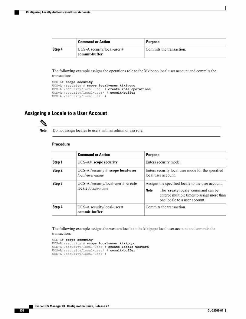
PurposeCommand or Action
Commits the transaction.UCS-A security/local-user #commit-buffer
Step 4
The following example assigns the operations role to the kikipopo local user account and commits thetransaction:UCS-A# scope securityUCS-A /security # scope local-user kikipopoUCS-A /security/local-user # create role operationsUCS-A /security/local-user* # commit-bufferUCS-A /security/local-user #
Assigning a Locale to a User Account
Do not assign locales to users with an admin or aaa role.Note
Procedure
PurposeCommand or Action
Enters security mode.UCS-A# scope securityStep 1
Enters security local user mode for the specifiedlocal user account.
UCS-A /security # scope local-userlocal-user-name
Step 2
Assigns the specified locale to the user account.UCS-A /security/local-user # createlocale locale-name
Step 3
The create locale command can beenteredmultiple times to assign more thanone locale to a user account.
Note
Commits the transaction.UCS-A security/local-user #commit-buffer
Step 4
The following example assigns the western locale to the kikipopo local user account and commits thetransaction:UCS-A# scope securityUCS-A /security # scope local-user kikipopoUCS-A /security/local-user # create locale westernUCS-A /security/local-user* # commit-bufferUCS-A /security/local-user #
Cisco UCS Manager CLI Configuration Guide, Release 2.1170 OL-28302-04
Configuring Locally Authenticated User Accounts
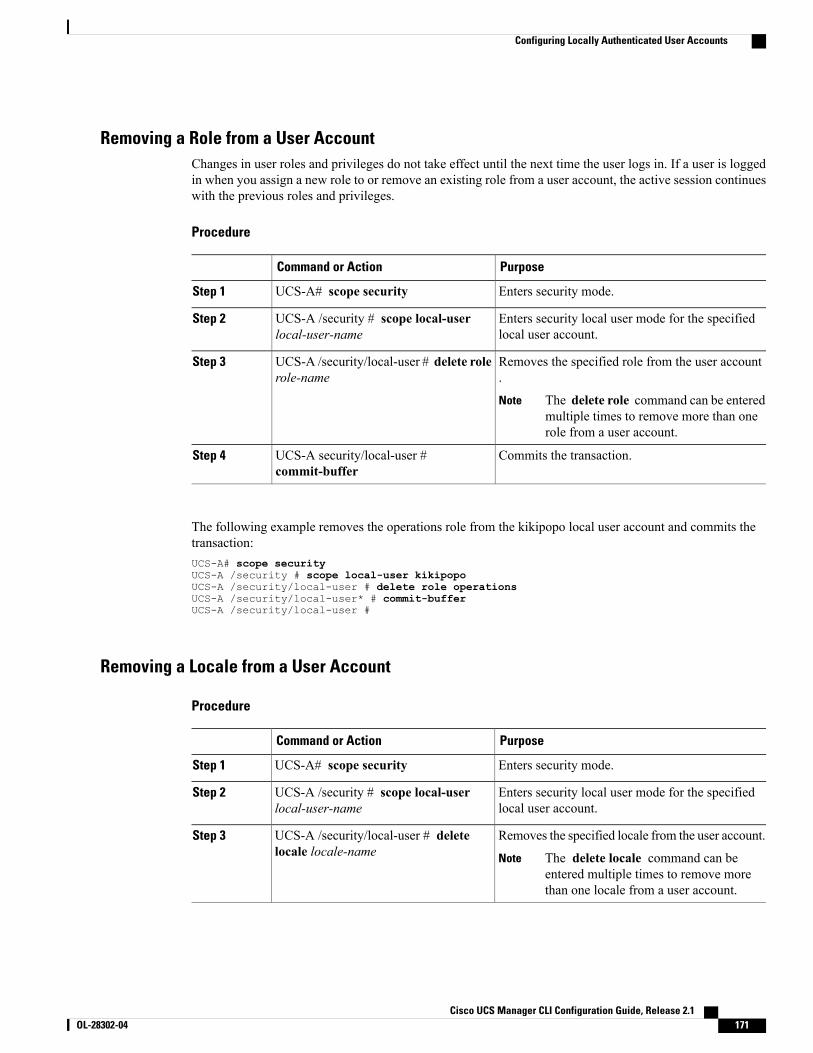
Removing a Role from a User AccountChanges in user roles and privileges do not take effect until the next time the user logs in. If a user is loggedin when you assign a new role to or remove an existing role from a user account, the active session continueswith the previous roles and privileges.
Procedure
PurposeCommand or Action
Enters security mode.UCS-A# scope securityStep 1
Enters security local user mode for the specifiedlocal user account.
UCS-A /security # scope local-userlocal-user-name
Step 2
Removes the specified role from the user account.
UCS-A /security/local-user # delete rolerole-name
Step 3
The delete role command can be enteredmultiple times to remove more than onerole from a user account.
Note
Commits the transaction.UCS-A security/local-user #commit-buffer
Step 4
The following example removes the operations role from the kikipopo local user account and commits thetransaction:UCS-A# scope securityUCS-A /security # scope local-user kikipopoUCS-A /security/local-user # delete role operationsUCS-A /security/local-user* # commit-bufferUCS-A /security/local-user #
Removing a Locale from a User Account
Procedure
PurposeCommand or Action
Enters security mode.UCS-A# scope securityStep 1
Enters security local user mode for the specifiedlocal user account.
UCS-A /security # scope local-userlocal-user-name
Step 2
Removes the specified locale from the user account.UCS-A /security/local-user # deletelocale locale-name
Step 3
The delete locale command can beentered multiple times to remove morethan one locale from a user account.
Note
Cisco UCS Manager CLI Configuration Guide, Release 2.1 OL-28302-04 171
Configuring Locally Authenticated User Accounts

PurposeCommand or Action
Commits the transaction.UCS-A security/local-user #commit-buffer
Step 4
The following example removes the western locale from the kikipopo local user account and commits thetransaction:UCS-A# scope securityUCS-A /security # scope local-user kikipopoUCS-A /security/local-user # delete locale westernUCS-A /security/local-user* # commit-bufferUCS-A /security/local-user #
Enabling or Disabling a User AccountYou must be a user with admin or aaa privileges to enable or disable a local user account.
Before You Begin
Create a local user account.
Procedure
PurposeCommand or Action
Enters security mode.UCS-A# scope securityStep 1
Enters local-user security mode.UCS-A /security # scope local-userStep 2
Specifies whether the local user account is enabled ordisabled.
UCS-A /security/local-user # setaccount-status {active | inactive}
Step 3
The admin user account is always set to active. It cannotbe modified.
If you set the account status to inactive, theconfiguration is not deleted from the database.
Note
The following example enables a local user account called accounting:UCS-A# scope securityUCS-A /security # scope local-user accountingUCS-A /security/local-user # set account-status active
Cisco UCS Manager CLI Configuration Guide, Release 2.1172 OL-28302-04
Configuring Locally Authenticated User Accounts
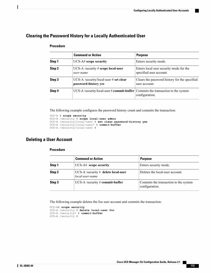
Clearing the Password History for a Locally Authenticated User
Procedure
PurposeCommand or Action
Enters security mode.UCS-A# scope securityStep 1
Enters local user security mode for thespecified user account.
UCS-A /security # scope local-useruser-name
Step 2
Clears the password history for the specifieduser account.
UCS-A /security/local-user # set clearpassword-history yes
Step 3
Commits the transaction to the systemconfiguration.
UCS-A /security/local-user # commit-bufferStep 4
The following example configures the password history count and commits the transaction:UCS-A # scope securityUCS-A /security # scope local-user adminUCS-A /security/local-user # set clear password-history yesUCS-A /security/local-user* # commit-bufferUCS-A /security/local-user #
Deleting a User Account
Procedure
PurposeCommand or Action
Enters security mode.UCS-A# scope securityStep 1
Deletes the local-user account.UCS-A /security # delete local-userlocal-user-name
Step 2
Commits the transaction to the systemconfiguration.
UCS-A /security # commit-bufferStep 3
The following example deletes the foo user account and commits the transaction:UCS-A# scope securityUCS-A /security # delete local-user fooUCS-A /security* # commit-bufferUCS-A /security #
Cisco UCS Manager CLI Configuration Guide, Release 2.1 OL-28302-04 173
Configuring Locally Authenticated User Accounts
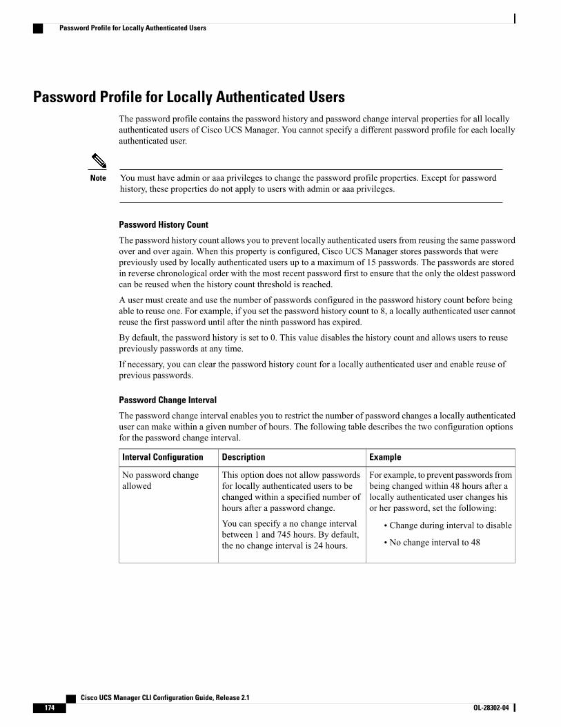
Password Profile for Locally Authenticated UsersThe password profile contains the password history and password change interval properties for all locallyauthenticated users of Cisco UCS Manager. You cannot specify a different password profile for each locallyauthenticated user.
You must have admin or aaa privileges to change the password profile properties. Except for passwordhistory, these properties do not apply to users with admin or aaa privileges.
Note
Password History Count
The password history count allows you to prevent locally authenticated users from reusing the same passwordover and over again. When this property is configured, Cisco UCS Manager stores passwords that werepreviously used by locally authenticated users up to a maximum of 15 passwords. The passwords are storedin reverse chronological order with the most recent password first to ensure that the only the oldest passwordcan be reused when the history count threshold is reached.
A user must create and use the number of passwords configured in the password history count before beingable to reuse one. For example, if you set the password history count to 8, a locally authenticated user cannotreuse the first password until after the ninth password has expired.
By default, the password history is set to 0. This value disables the history count and allows users to reusepreviously passwords at any time.
If necessary, you can clear the password history count for a locally authenticated user and enable reuse ofprevious passwords.
Password Change Interval
The password change interval enables you to restrict the number of password changes a locally authenticateduser can make within a given number of hours. The following table describes the two configuration optionsfor the password change interval.
ExampleDescriptionInterval Configuration
For example, to prevent passwords frombeing changed within 48 hours after alocally authenticated user changes hisor her password, set the following:
• Change during interval to disable
• No change interval to 48
This option does not allow passwordsfor locally authenticated users to bechanged within a specified number ofhours after a password change.
You can specify a no change intervalbetween 1 and 745 hours. By default,the no change interval is 24 hours.
No password changeallowed
Cisco UCS Manager CLI Configuration Guide, Release 2.1174 OL-28302-04
Password Profile for Locally Authenticated Users
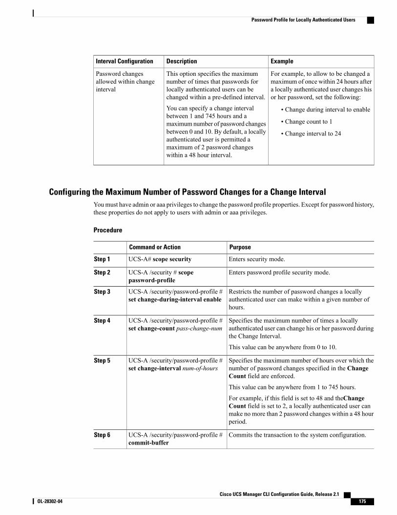
ExampleDescriptionInterval Configuration
For example, to allow to be changed amaximum of once within 24 hours aftera locally authenticated user changes hisor her password, set the following:
• Change during interval to enable
• Change count to 1
• Change interval to 24
This option specifies the maximumnumber of times that passwords forlocally authenticated users can bechanged within a pre-defined interval.
You can specify a change intervalbetween 1 and 745 hours and amaximumnumber of password changesbetween 0 and 10. By default, a locallyauthenticated user is permitted amaximum of 2 password changeswithin a 48 hour interval.
Password changesallowed within changeinterval
Configuring the Maximum Number of Password Changes for a Change IntervalYoumust have admin or aaa privileges to change the password profile properties. Except for password history,these properties do not apply to users with admin or aaa privileges.
Procedure
PurposeCommand or Action
Enters security mode.UCS-A# scope securityStep 1
Enters password profile security mode.UCS-A /security # scopepassword-profile
Step 2
Restricts the number of password changes a locallyauthenticated user can make within a given number ofhours.
UCS-A /security/password-profile #set change-during-interval enable
Step 3
Specifies the maximum number of times a locallyauthenticated user can change his or her password duringthe Change Interval.
UCS-A /security/password-profile #set change-count pass-change-num
Step 4
This value can be anywhere from 0 to 10.
Specifies the maximum number of hours over which thenumber of password changes specified in the ChangeCount field are enforced.
UCS-A /security/password-profile #set change-interval num-of-hours
Step 5
This value can be anywhere from 1 to 745 hours.
For example, if this field is set to 48 and theChangeCount field is set to 2, a locally authenticated user canmake no more than 2 password changes within a 48 hourperiod.
Commits the transaction to the system configuration.UCS-A /security/password-profile #commit-buffer
Step 6
Cisco UCS Manager CLI Configuration Guide, Release 2.1 OL-28302-04 175
Password Profile for Locally Authenticated Users
The following example enables the change during interval option, sets the change count to 5, sets the changeinterval to 72 hours, and commits the transaction:UCS-A # scope securityUCS-A /security # scope password-profileUCS-A /security/password-profile # set change-during-interval enableUCS-A /security/password-profile* # set change-count 5UCS-A /security/password-profile* # set change-interval 72UCS-A /security/password-profile* # commit-bufferUCS-A /security/password-profile #
Configuring a No Change Interval for PasswordsYoumust have admin or aaa privileges to change the password profile properties. Except for password history,these properties do not apply to users with admin or aaa privileges.
Procedure
PurposeCommand or Action
Enters security mode.UCS-A# scope securityStep 1
Enters password profile security mode.UCS-A /security # scopepassword-profile
Step 2
Disables the change during interval feature.UCS-A /security/password-profile # setchange-during-interval disable
Step 3
Specifies the minimum number of hours that alocally authenticated user must wait before changinga newly created password.
UCS-A /security/password-profile # setno-change-interval min-num-hours
Step 4
This value can be anywhere from 1 to 745 hours.
This interval is ignored if the Change DuringInterval property is not set to Disable.
Commits the transaction to the system configuration.UCS-A /security/password-profile #commit-buffer
Step 5
The following example disables the change during interval option, sets the no change interval to 72 hours,and commits the transaction:UCS-A # scope securityUCS-A /security # scope password-profileUCS-A /security/password-profile # set change-during-interval disableUCS-A /security/password-profile* # set no-change-interval 72UCS-A /security/password-profile* # commit-bufferUCS-A /security/password-profile #
Configuring the Password History CountYou must have admin or aaa privileges to change the password profile properties.
Cisco UCS Manager CLI Configuration Guide, Release 2.1176 OL-28302-04
Password Profile for Locally Authenticated Users

Procedure
PurposeCommand or Action
Enters security mode.UCS-A# scope securityStep 1
Enters password profile security mode.UCS-A /security # scopepassword-profile
Step 2
Specifies the number of unique passwords that a locallyauthenticated user must create before that user can reusea previously used password
UCS-A /security/password-profile #set history-count num-of-passwords
Step 3
This value can be anywhere from 0 to 15.
By default, the History Count field is set to 0, whichdisables the history count and allows users to reusepreviously used passwords at any time.
Commits the transaction to the system configuration.UCS-A /security/password-profile #commit-buffer
Step 4
The following example configures the password history count and commits the transaction:UCS-A # scope securityUCS-A /security # scope password-profileUCS-A /security/password-profile # set history-count 5UCS-A /security/password-profile* # commit-bufferUCS-A /security/password-profile #
Monitoring User Sessions
Procedure
PurposeCommand or Action
Enters security mode.UCS-A# scope securityStep 1
Displays session information for all users logged into the system. An asterisk (*) next to the session IDdenotes the current login session.
UCS-A /security # show user-session{local | remote} [detail]
Step 2
The following example lists all local users logged in to the system. The asterisk indicates which session is thecurrent login session.UCS-A# scope securityUCS-A /security # show user-session localSession Id User Host Login Time--------------- --------------- -------------------- ----------pts_25_1_31264* steve 192.168.100.111 2009-05-09T14:06:59ttyS0_1_3532 jeff console 2009-05-02T15:11:08web_25277_A faye 192.168.100.112 2009-05-15T22:11:25
Cisco UCS Manager CLI Configuration Guide, Release 2.1 OL-28302-04 177
Monitoring User Sessions

The following example displays detailed information on all local users logged in to the system:UCS-A# scope securityUCS-A /security # show user-session local detailSession Id pts_25_1_31264:
Fabric Id: ATerm: pts/25User: steveHost: 64.101.53.93Pid: 31264Login Time: 2009-05-09T14:06:59
Session Id ttyS0_1_3532:Fabric Id: ATerm: ttyS0User: jeffHost: consolePid: 3532Login Time: 2009-05-02T15:11:08
Session Id web_25277_A:Fabric Id: ATerm: web_25277User: fayeHost: 192.168.100.112Pid: 3518Login Time: 2009-05-15T22:11:25
Cisco UCS Manager CLI Configuration Guide, Release 2.1178 OL-28302-04
Monitoring User Sessions
C H A P T E R 11Configuring DNS Servers
This chapter includes the following sections:
• DNS Servers in Cisco UCS , page 179
• Configuring a DNS Server, page 179
• Deleting a DNS Server, page 180
DNS Servers in Cisco UCSYou need to specify an external DNS server for each Cisco UCS domain to use if the system requires nameresolution of hostnames. For example, you cannot use a name such as www.cisco.comwhen you are configuringa setting on a fabric interconnect if you do not configure a DNS server. You would need to use the IP addressof the server. You can configure up to four DNS servers for each Cisco UCS domain.
When you configure multiple DNS servers, the system searches for the servers only in any random order.If a local management command requires DNS server lookup, it can only search for three DNS servers inrandom order.
Note
Configuring a DNS Server
Procedure
PurposeCommand or Action
Enters system mode.UCS-A# scope systemStep 1
Enters system services mode.UCS-A /system # scope servicesStep 2
Configures the system to use the DNS serverwith the specified IP address.
UCS-A /system/services # create dnsip-addr
Step 3
Cisco UCS Manager CLI Configuration Guide, Release 2.1 OL-28302-04 179
PurposeCommand or Action
Commits the transaction to the systemconfiguration.
UCS-A /system/services # commit-bufferStep 4
The following example configures a DNS server with the IP address 192.168.200.105 and commits thetransaction:UCS-A# scope systemUCS-A /system # scope servicesUCS-A /system/services # create dns 192.168.200.105UCS-A /system/services* # commit-bufferUCS-A /system/services #
Deleting a DNS Server
Procedure
PurposeCommand or Action
Enters system mode.UCS-A# scope systemStep 1
Enters system services mode.UCS-A /system # scope servicesStep 2
Deletes the NTP server with the specified IPaddress.
UCS-A /system/services # delete dnsip-addr
Step 3
Commits the transaction to the systemconfiguration.
UCS-A /system/services # commit-bufferStep 4
The following example deletes the DNS server with the IP address 192.168.200.105 and commits thetransaction:UCS-A# scope systemUCS-A /system # scope servicesUCS-A /system/services # delete dns 192.168.200.105UCS-A /system/services* # commit-bufferUCS-A /system/services #
Cisco UCS Manager CLI Configuration Guide, Release 2.1180 OL-28302-04
Deleting a DNS Server
C H A P T E R 12Configuring System-Related Policies
This chapter includes the following sections:
• Configuring the Chassis/FEX Discovery Policy, page 181
• Configuring the Chassis Connectivity Policy, page 185
• Configuring the Rack Server Discovery Policy, page 187
• Configuring the Aging Time for the MAC Address Table, page 188
Configuring the Chassis/FEX Discovery Policy
Chassis/FEX Discovery PolicyThe chassis/FEX discovery policy determines how the system reacts when you add a new chassis or FEX.Cisco UCSManager uses the settings in the chassis/FEX discovery policy to determine the minimum thresholdfor the number of links between the chassis or FEX and the fabric interconnect and whether to group linksfrom the IOM to the fabric interconnect in a fabric port channel.
Chassis Links
If you have a Cisco UCS domain that has some of the chassis wired with 1 link, some with 2 links, some with4 links, and some with 8 links we recommend that you configure the chassis/FEX discovery policy for theminimum number links in the domain so that Cisco UCS Manager can discover all chassis.
If you want to establish highest available chassis connectivity in a Cisco UCS domain where FabricInterconnect is connected to different types of IO Modules supporting different max number of uplinks,select platform max value. Setting platform max would ensure that Cisco UCS Manager would discoverthe chassis including the connections and servers onlywhenmaximum supported IOMuplinks are connectedper IO Module.
Tip
After the initial discovery, you must reacknowledge the chassis that are wired for a greater number of linksand Cisco UCS Manager configures the chassis to use all available links.
Cisco UCS Manager CLI Configuration Guide, Release 2.1 OL-28302-04 181
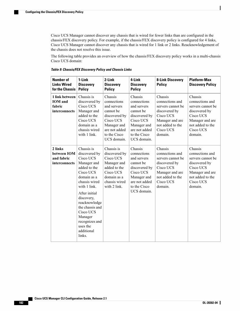
Cisco UCS Manager cannot discover any chassis that is wired for fewer links than are configured in thechassis/FEX discovery policy. For example, if the chassis/FEX discovery policy is configured for 4 links,Cisco UCS Manager cannot discover any chassis that is wired for 1 link or 2 links. Reacknowledgement ofthe chassis does not resolve this issue.
The following table provides an overview of how the chassis/FEX discovery policy works in a multi-chassisCisco UCS domain:
Table 9: Chassis/FEX Discovery Policy and Chassis Links
Platform-MaxDiscovery Policy
8-Link DiscoveryPolicy
4-LinkDiscoveryPolicy
2-LinkDiscoveryPolicy
1-LinkDiscoveryPolicy
Number ofLinks Wiredfor the Chassis
Chassisconnections andservers cannot bediscovered byCisco UCSManager and arenot added to theCisco UCSdomain.
Chassisconnections andservers cannot bediscovered byCisco UCSManager and arenot added to theCisco UCSdomain.
Chassisconnectionsand serverscannot bediscovered byCisco UCSManager andare not addedto the CiscoUCS domain.
Chassisconnectionsand serverscannot bediscovered byCisco UCSManager andare not addedto the CiscoUCS domain.
Chassis isdiscovered byCisco UCSManager andadded to theCisco UCSdomain as achassis wiredwith 1 link.
1 link betweenIOM andfabricinterconnects
Chassisconnections andservers cannot bediscovered byCisco UCSManager and arenot added to theCisco UCSdomain.
Chassisconnections andservers cannot bediscovered byCisco UCSManager and arenot added to theCisco UCSdomain.
Chassisconnectionsand serverscannot bediscovered byCisco UCSManager andare not addedto the CiscoUCS domain.
Chassis isdiscovered byCisco UCSManager andadded to theCisco UCSdomain as achassis wiredwith 2 link.
Chassis isdiscovered byCisco UCSManager andadded to theCisco UCSdomain as achassis wiredwith 1 link.
After initialdiscovery,reacknowledgethe chassis andCisco UCSManagerrecognizes anduses theadditionallinks.
2 linksbetween IOMand fabricinterconnects
Cisco UCS Manager CLI Configuration Guide, Release 2.1182 OL-28302-04
Configuring the Chassis/FEX Discovery Policy
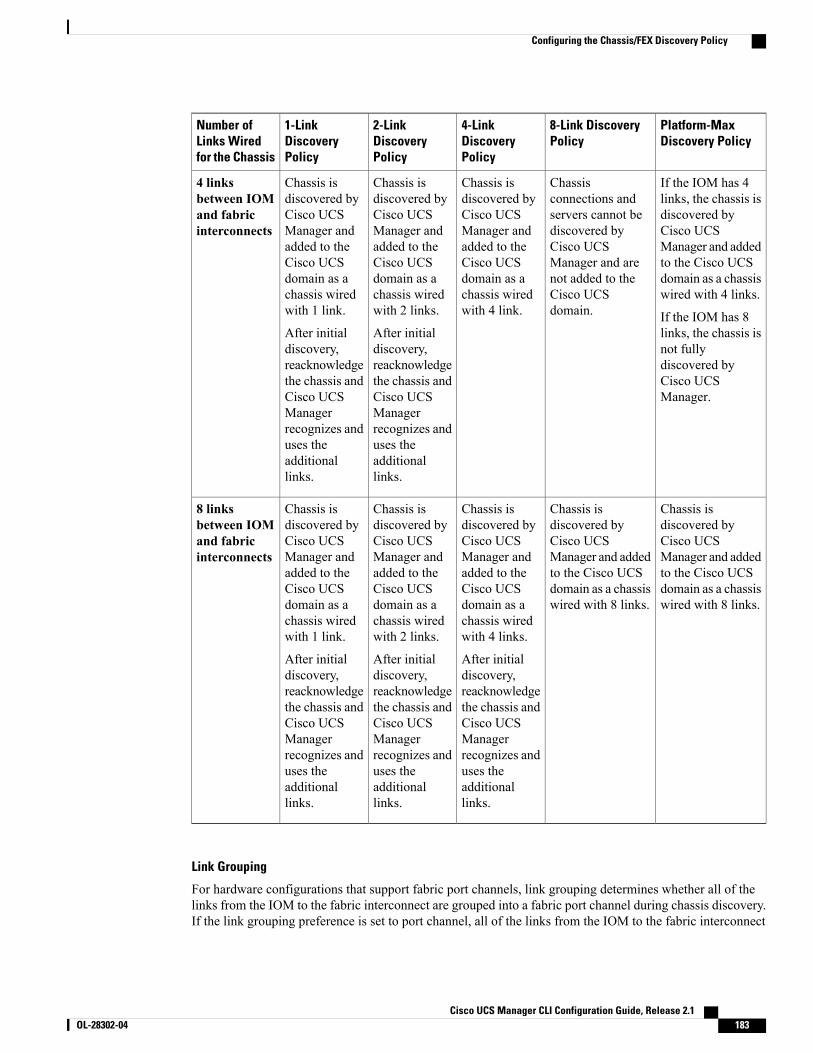
Platform-MaxDiscovery Policy
8-Link DiscoveryPolicy
4-LinkDiscoveryPolicy
2-LinkDiscoveryPolicy
1-LinkDiscoveryPolicy
Number ofLinks Wiredfor the Chassis
If the IOM has 4links, the chassis isdiscovered byCisco UCSManager and addedto the Cisco UCSdomain as a chassiswired with 4 links.
If the IOM has 8links, the chassis isnot fullydiscovered byCisco UCSManager.
Chassisconnections andservers cannot bediscovered byCisco UCSManager and arenot added to theCisco UCSdomain.
Chassis isdiscovered byCisco UCSManager andadded to theCisco UCSdomain as achassis wiredwith 4 link.
Chassis isdiscovered byCisco UCSManager andadded to theCisco UCSdomain as achassis wiredwith 2 links.
After initialdiscovery,reacknowledgethe chassis andCisco UCSManagerrecognizes anduses theadditionallinks.
Chassis isdiscovered byCisco UCSManager andadded to theCisco UCSdomain as achassis wiredwith 1 link.
After initialdiscovery,reacknowledgethe chassis andCisco UCSManagerrecognizes anduses theadditionallinks.
4 linksbetween IOMand fabricinterconnects
Chassis isdiscovered byCisco UCSManager and addedto the Cisco UCSdomain as a chassiswired with 8 links.
Chassis isdiscovered byCisco UCSManager and addedto the Cisco UCSdomain as a chassiswired with 8 links.
Chassis isdiscovered byCisco UCSManager andadded to theCisco UCSdomain as achassis wiredwith 4 links.
After initialdiscovery,reacknowledgethe chassis andCisco UCSManagerrecognizes anduses theadditionallinks.
Chassis isdiscovered byCisco UCSManager andadded to theCisco UCSdomain as achassis wiredwith 2 links.
After initialdiscovery,reacknowledgethe chassis andCisco UCSManagerrecognizes anduses theadditionallinks.
Chassis isdiscovered byCisco UCSManager andadded to theCisco UCSdomain as achassis wiredwith 1 link.
After initialdiscovery,reacknowledgethe chassis andCisco UCSManagerrecognizes anduses theadditionallinks.
8 linksbetween IOMand fabricinterconnects
Link Grouping
For hardware configurations that support fabric port channels, link grouping determines whether all of thelinks from the IOM to the fabric interconnect are grouped into a fabric port channel during chassis discovery.If the link grouping preference is set to port channel, all of the links from the IOM to the fabric interconnect
Cisco UCS Manager CLI Configuration Guide, Release 2.1 OL-28302-04 183
Configuring the Chassis/FEX Discovery Policy
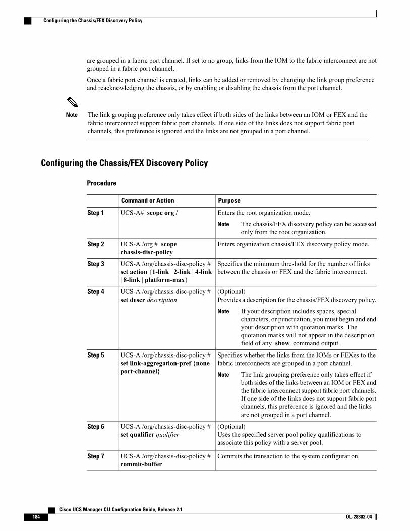
are grouped in a fabric port channel. If set to no group, links from the IOM to the fabric interconnect are notgrouped in a fabric port channel.
Once a fabric port channel is created, links can be added or removed by changing the link group preferenceand reacknowledging the chassis, or by enabling or disabling the chassis from the port channel.
The link grouping preference only takes effect if both sides of the links between an IOM or FEX and thefabric interconnect support fabric port channels. If one side of the links does not support fabric portchannels, this preference is ignored and the links are not grouped in a port channel.
Note
Configuring the Chassis/FEX Discovery Policy
Procedure
PurposeCommand or Action
Enters the root organization mode.UCS-A# scope org /Step 1
The chassis/FEX discovery policy can be accessedonly from the root organization.
Note
Enters organization chassis/FEX discovery policy mode.UCS-A /org # scopechassis-disc-policy
Step 2
Specifies the minimum threshold for the number of linksbetween the chassis or FEX and the fabric interconnect.
UCS-A /org/chassis-disc-policy #set action {1-link | 2-link | 4-link| 8-link | platform-max}
Step 3
(Optional)Provides a description for the chassis/FEX discovery policy.
UCS-A /org/chassis-disc-policy #set descr description
Step 4
If your description includes spaces, specialcharacters, or punctuation, you must begin and endyour description with quotation marks. Thequotation marks will not appear in the descriptionfield of any show command output.
Note
Specifies whether the links from the IOMs or FEXes to thefabric interconnects are grouped in a port channel.
UCS-A /org/chassis-disc-policy #set link-aggregation-pref {none |port-channel}
Step 5
The link grouping preference only takes effect ifboth sides of the links between an IOM or FEX andthe fabric interconnect support fabric port channels.If one side of the links does not support fabric portchannels, this preference is ignored and the linksare not grouped in a port channel.
Note
(Optional)Uses the specified server pool policy qualifications toassociate this policy with a server pool.
UCS-A /org/chassis-disc-policy #set qualifier qualifier
Step 6
Commits the transaction to the system configuration.UCS-A /org/chassis-disc-policy #commit-buffer
Step 7
Cisco UCS Manager CLI Configuration Guide, Release 2.1184 OL-28302-04
Configuring the Chassis/FEX Discovery Policy
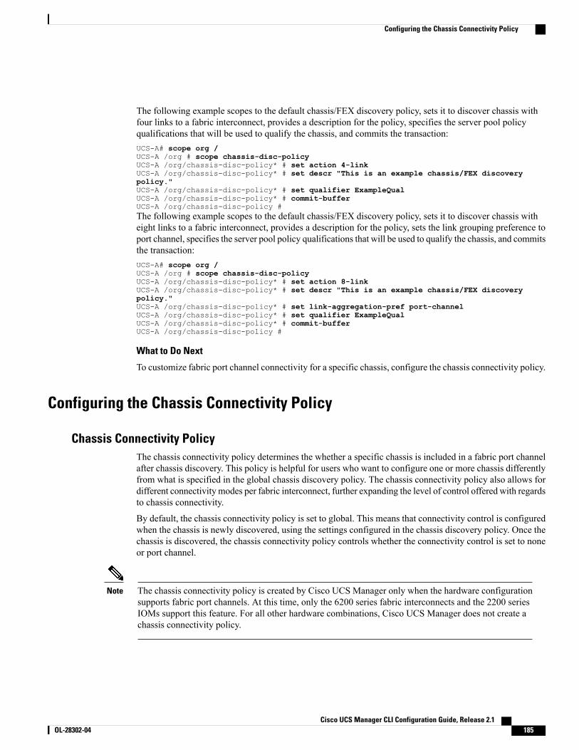
The following example scopes to the default chassis/FEX discovery policy, sets it to discover chassis withfour links to a fabric interconnect, provides a description for the policy, specifies the server pool policyqualifications that will be used to qualify the chassis, and commits the transaction:UCS-A# scope org /UCS-A /org # scope chassis-disc-policyUCS-A /org/chassis-disc-policy* # set action 4-linkUCS-A /org/chassis-disc-policy* # set descr "This is an example chassis/FEX discoverypolicy."UCS-A /org/chassis-disc-policy* # set qualifier ExampleQualUCS-A /org/chassis-disc-policy* # commit-bufferUCS-A /org/chassis-disc-policy #The following example scopes to the default chassis/FEX discovery policy, sets it to discover chassis witheight links to a fabric interconnect, provides a description for the policy, sets the link grouping preference toport channel, specifies the server pool policy qualifications that will be used to qualify the chassis, and commitsthe transaction:UCS-A# scope org /UCS-A /org # scope chassis-disc-policyUCS-A /org/chassis-disc-policy* # set action 8-linkUCS-A /org/chassis-disc-policy* # set descr "This is an example chassis/FEX discoverypolicy."UCS-A /org/chassis-disc-policy* # set link-aggregation-pref port-channelUCS-A /org/chassis-disc-policy* # set qualifier ExampleQualUCS-A /org/chassis-disc-policy* # commit-bufferUCS-A /org/chassis-disc-policy #
What to Do Next
To customize fabric port channel connectivity for a specific chassis, configure the chassis connectivity policy.
Configuring the Chassis Connectivity Policy
Chassis Connectivity PolicyThe chassis connectivity policy determines the whether a specific chassis is included in a fabric port channelafter chassis discovery. This policy is helpful for users who want to configure one or more chassis differentlyfrom what is specified in the global chassis discovery policy. The chassis connectivity policy also allows fordifferent connectivity modes per fabric interconnect, further expanding the level of control offered with regardsto chassis connectivity.
By default, the chassis connectivity policy is set to global. This means that connectivity control is configuredwhen the chassis is newly discovered, using the settings configured in the chassis discovery policy. Once thechassis is discovered, the chassis connectivity policy controls whether the connectivity control is set to noneor port channel.
The chassis connectivity policy is created by Cisco UCS Manager only when the hardware configurationsupports fabric port channels. At this time, only the 6200 series fabric interconnects and the 2200 seriesIOMs support this feature. For all other hardware combinations, Cisco UCS Manager does not create achassis connectivity policy.
Note
Cisco UCS Manager CLI Configuration Guide, Release 2.1 OL-28302-04 185
Configuring the Chassis Connectivity Policy
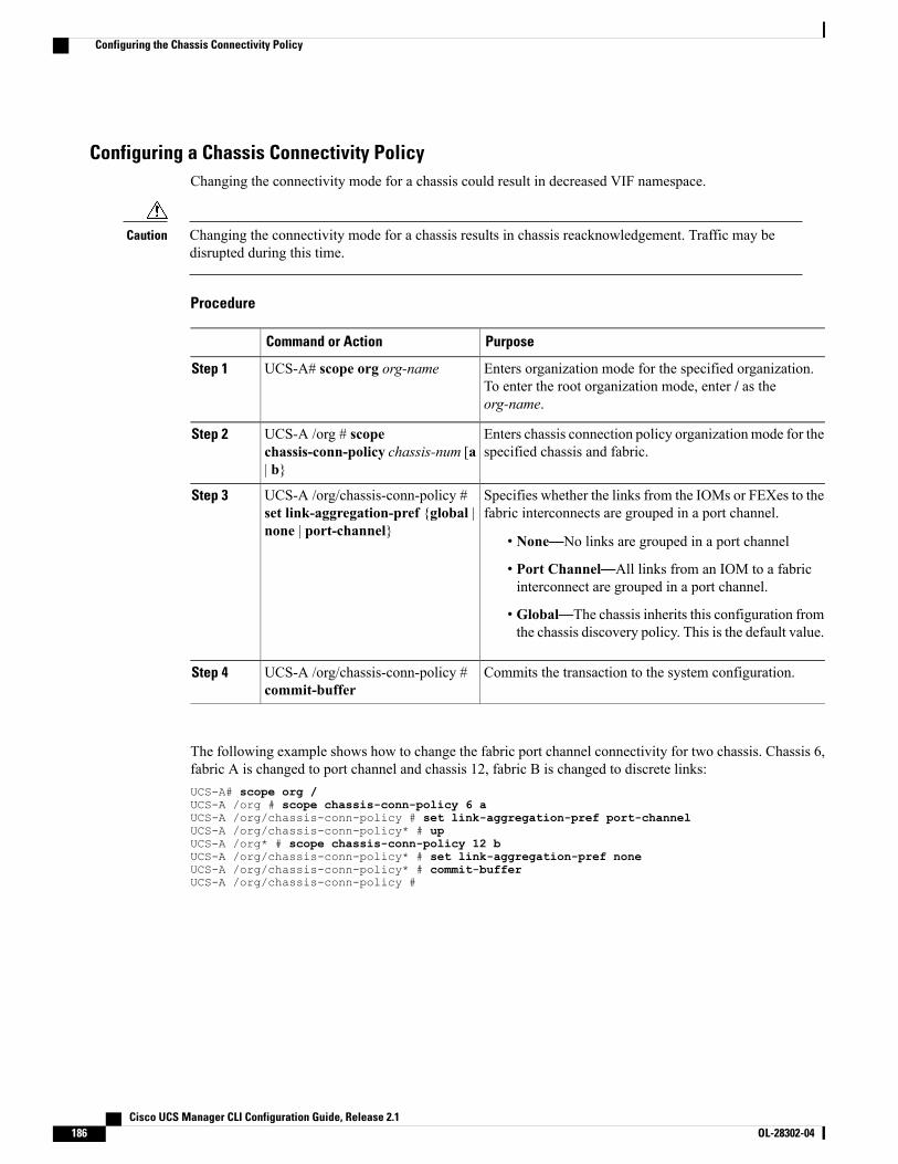
Configuring a Chassis Connectivity PolicyChanging the connectivity mode for a chassis could result in decreased VIF namespace.
Changing the connectivity mode for a chassis results in chassis reacknowledgement. Traffic may bedisrupted during this time.
Caution
Procedure
PurposeCommand or Action
Enters organization mode for the specified organization.To enter the root organization mode, enter / as theorg-name.
UCS-A# scope org org-nameStep 1
Enters chassis connection policy organizationmode for thespecified chassis and fabric.
UCS-A /org # scopechassis-conn-policy chassis-num [a| b}
Step 2
Specifies whether the links from the IOMs or FEXes to thefabric interconnects are grouped in a port channel.
UCS-A /org/chassis-conn-policy #set link-aggregation-pref {global |none | port-channel}
Step 3
• None—No links are grouped in a port channel
• Port Channel—All links from an IOM to a fabricinterconnect are grouped in a port channel.
• Global—The chassis inherits this configuration fromthe chassis discovery policy. This is the default value.
Commits the transaction to the system configuration.UCS-A /org/chassis-conn-policy #commit-buffer
Step 4
The following example shows how to change the fabric port channel connectivity for two chassis. Chassis 6,fabric A is changed to port channel and chassis 12, fabric B is changed to discrete links:UCS-A# scope org /UCS-A /org # scope chassis-conn-policy 6 aUCS-A /org/chassis-conn-policy # set link-aggregation-pref port-channelUCS-A /org/chassis-conn-policy* # upUCS-A /org* # scope chassis-conn-policy 12 bUCS-A /org/chassis-conn-policy* # set link-aggregation-pref noneUCS-A /org/chassis-conn-policy* # commit-bufferUCS-A /org/chassis-conn-policy #
Cisco UCS Manager CLI Configuration Guide, Release 2.1186 OL-28302-04
Configuring the Chassis Connectivity Policy
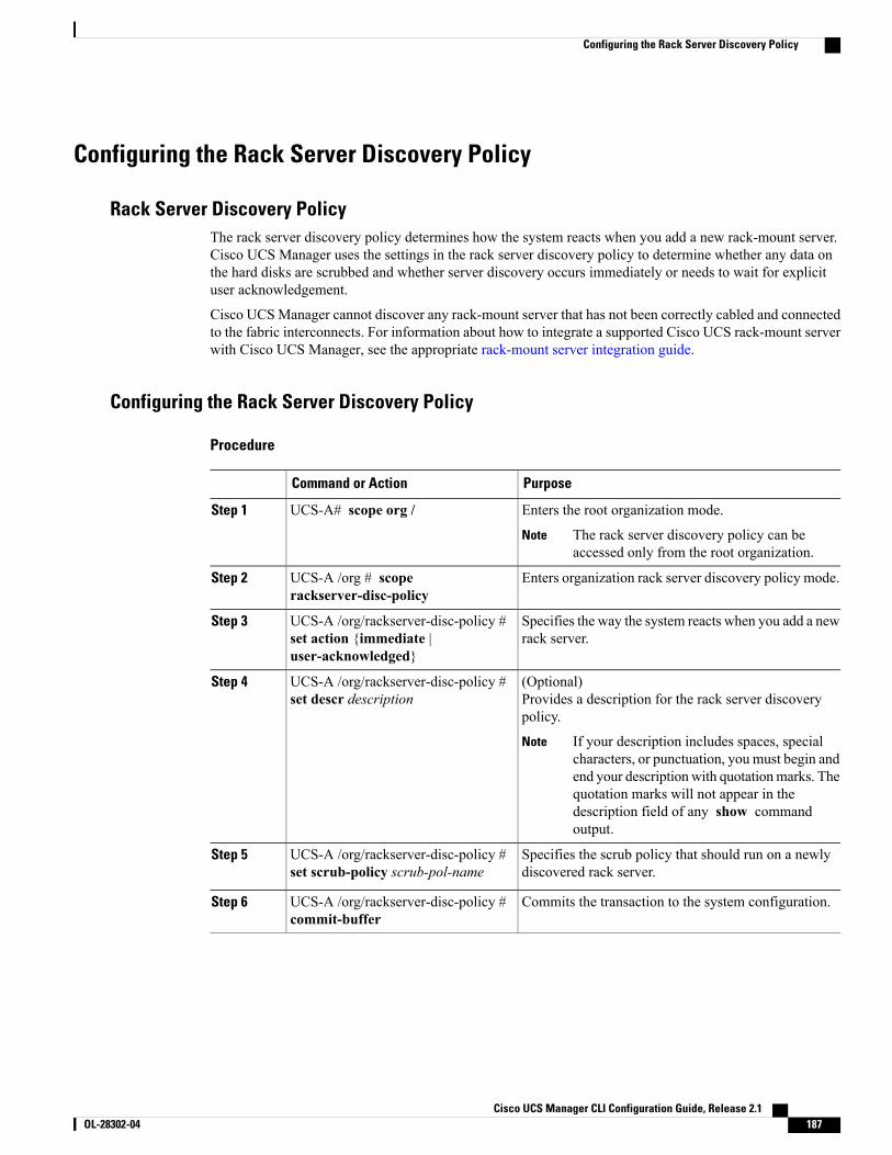
Configuring the Rack Server Discovery Policy
Rack Server Discovery PolicyThe rack server discovery policy determines how the system reacts when you add a new rack-mount server.Cisco UCS Manager uses the settings in the rack server discovery policy to determine whether any data onthe hard disks are scrubbed and whether server discovery occurs immediately or needs to wait for explicituser acknowledgement.
Cisco UCSManager cannot discover any rack-mount server that has not been correctly cabled and connectedto the fabric interconnects. For information about how to integrate a supported Cisco UCS rack-mount serverwith Cisco UCS Manager, see the appropriate rack-mount server integration guide.
Configuring the Rack Server Discovery Policy
Procedure
PurposeCommand or Action
Enters the root organization mode.UCS-A# scope org /Step 1
The rack server discovery policy can beaccessed only from the root organization.
Note
Enters organization rack server discovery policy mode.UCS-A /org # scoperackserver-disc-policy
Step 2
Specifies the way the system reacts when you add a newrack server.
UCS-A /org/rackserver-disc-policy #set action {immediate |user-acknowledged}
Step 3
(Optional)Provides a description for the rack server discoverypolicy.
UCS-A /org/rackserver-disc-policy #set descr description
Step 4
If your description includes spaces, specialcharacters, or punctuation, you must begin andend your description with quotationmarks. Thequotation marks will not appear in thedescription field of any show commandoutput.
Note
Specifies the scrub policy that should run on a newlydiscovered rack server.
UCS-A /org/rackserver-disc-policy #set scrub-policy scrub-pol-name
Step 5
Commits the transaction to the system configuration.UCS-A /org/rackserver-disc-policy #commit-buffer
Step 6
Cisco UCS Manager CLI Configuration Guide, Release 2.1 OL-28302-04 187
Configuring the Rack Server Discovery Policy
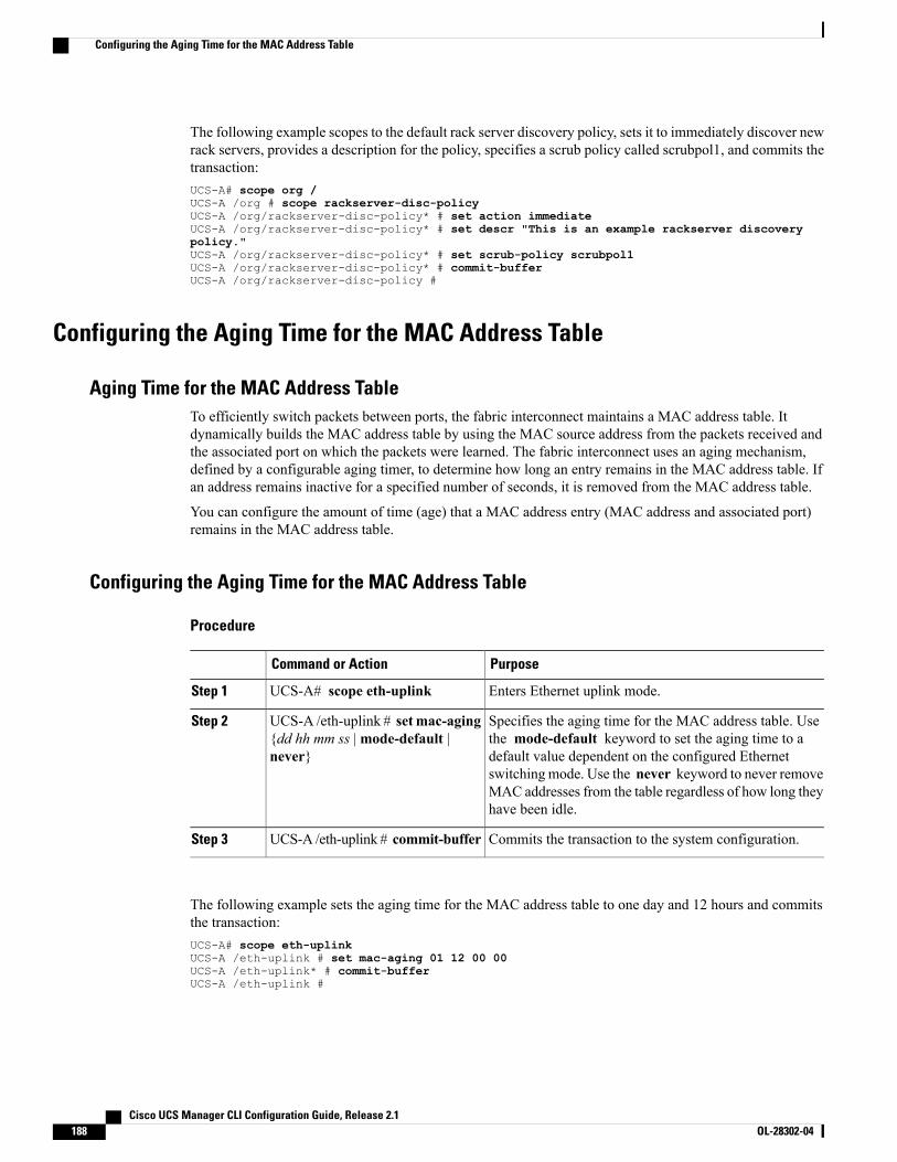
The following example scopes to the default rack server discovery policy, sets it to immediately discover newrack servers, provides a description for the policy, specifies a scrub policy called scrubpol1, and commits thetransaction:UCS-A# scope org /UCS-A /org # scope rackserver-disc-policyUCS-A /org/rackserver-disc-policy* # set action immediateUCS-A /org/rackserver-disc-policy* # set descr "This is an example rackserver discoverypolicy."UCS-A /org/rackserver-disc-policy* # set scrub-policy scrubpol1UCS-A /org/rackserver-disc-policy* # commit-bufferUCS-A /org/rackserver-disc-policy #
Configuring the Aging Time for the MAC Address Table
Aging Time for the MAC Address TableTo efficiently switch packets between ports, the fabric interconnect maintains a MAC address table. Itdynamically builds the MAC address table by using the MAC source address from the packets received andthe associated port on which the packets were learned. The fabric interconnect uses an aging mechanism,defined by a configurable aging timer, to determine how long an entry remains in the MAC address table. Ifan address remains inactive for a specified number of seconds, it is removed from the MAC address table.
You can configure the amount of time (age) that a MAC address entry (MAC address and associated port)remains in the MAC address table.
Configuring the Aging Time for the MAC Address Table
Procedure
PurposeCommand or Action
Enters Ethernet uplink mode.UCS-A# scope eth-uplinkStep 1
Specifies the aging time for the MAC address table. Usethe mode-default keyword to set the aging time to a
UCS-A /eth-uplink # setmac-aging{dd hh mm ss |mode-default |never}
Step 2
default value dependent on the configured Ethernetswitching mode. Use the never keyword to never removeMAC addresses from the table regardless of how long theyhave been idle.
Commits the transaction to the system configuration.UCS-A /eth-uplink # commit-bufferStep 3
The following example sets the aging time for the MAC address table to one day and 12 hours and commitsthe transaction:UCS-A# scope eth-uplinkUCS-A /eth-uplink # set mac-aging 01 12 00 00UCS-A /eth-uplink* # commit-bufferUCS-A /eth-uplink #
Cisco UCS Manager CLI Configuration Guide, Release 2.1188 OL-28302-04
Configuring the Aging Time for the MAC Address Table
C H A P T E R 13Managing Licenses
This chapter includes the following sections:
• Licenses, page 189
• Obtaining the Host ID for a Fabric Interconnect, page 190
• Obtaining a License, page 191
• Installing a License, page 192
• Viewing the Licenses Installed on a Fabric Interconnect, page 192
• Viewing License Usage for a Fabric Interconnect, page 193
• Uninstalling a License, page 195
LicensesEach Cisco UCS fabric interconnect comes with several port licenses that are factory installed and shippedwith the hardware. Fabric interconnects can be purchased fully licensed or partially licensed. Additionallicenses can also be purchased after delivery.
At a minimum, each fabric interconnect ships with the following counted licenses pre-installed:
• Cisco UCS 6120XP fabric interconnect—pre-installed licenses for the first eight Ethernet ports enabledin Cisco UCS Manager and any Fibre Channel ports on expansion modules
• Cisco UCS 6140XP fabric interconnect—pre-installed licenses for the first sixteen Ethernet ports enabledin Cisco UCS Manager and any Fibre Channel ports on expansion modules
• Cisco UCS 6248 fabric interconnect—pre-installed licenses for the first twelve unified ports enabled inCisco UCS Manager. Expansion modules come with eight licenses that can be used on the expansionmodule or the base module.
• Cisco UCS 6296 fabric interconnect—pre-installed licenses for the first eighteen unified ports enabledin Cisco UCSManager. Expansion modules come with eight licenses that can be used on the expansionmodule or the base module.
Cisco UCS Manager CLI Configuration Guide, Release 2.1 OL-28302-04 189
The eight default licenses that come with a 6200 series fabric interconnect expansion module can be usedto enable ports on the base module, but will travel with the expansion module if it is removed. Uponremoval of an expansion module, any default expansion module licenses being used by the base moduleare removed from the ports on the base module, resulting in unlicensed ports.
Note
Port licenses are not bound to physical ports. When you disable a licensed port, that license is then retainedfor use with the next enabled port. If you want to use additional fixed ports, you must purchase and installlicenses for those ports.
Licenses are not portable across product generations. Licenses purchased for 6100 series fabric interconnectscannot be used to enable ports on 6200 series fabric interconnects or vice-versa.
Important
Grace Period
If you attempt to use a port that does not have an installed license, Cisco UCS initiates a 120 day grace period.The grace period is measured from the first use of the port without a license and is paused when a valid licensefile is installed. The amount of time used in the grace period is retained by the system.
Each physical port has its own grace period. Initiating the grace period on a single port does not initiatethe grace period for all ports.
Note
If a licensed port is unconfigured, that license is transferred to a port functioning within a grace period. Ifmultiple ports are acting within grace periods, the license is moved to the port whose grace period is closestto expiring.
High Availability Configurations
To avoid inconsistencies during failover, we recommend that both fabric interconnects in the cluster have thesame number of ports licensed. If symmetry is not maintained and failover occurs, Cisco UCS enables themissing licenses and initiates the grace period for each port being used on the failover node.
Obtaining the Host ID for a Fabric InterconnectThe host ID is also known as the serial number.
Procedure
PurposeCommand or Action
Enters license mode.UCS-A# scope licenseStep 1
Obtains the host ID or serial number for the fabricinterconnect.
UCS-A /license # showserver-host-id
Step 2
Use the entire host ID that displays after theequal (=) sign.
Tip
Cisco UCS Manager CLI Configuration Guide, Release 2.1190 OL-28302-04
Obtaining the Host ID for a Fabric Interconnect
PurposeCommand or Action
The following example obtains the host ID for a fabric interconnect:
UCS-A# scope licenseUCS-A /license # show server-host-idServer host id:
Scope Host Id----- -------A VDH=SSI12121212B VDH=SSI13131313
UCS-A /license #
What to Do Next
Obtain the required licenses from Cisco.
Obtaining a License
This process may change after the release of this document. If one or more of these steps no longer applies,contact your Cisco representative for information on how to obtain a license file.
Note
Before You Begin
Obtain the following:
• Host ID or serial number for the fabric interconnect
• Claim certificate or other proof of purchase document for the fabric interconnect or expansion module
Procedure
Step 1 Obtain the product authorization key (PAK) from the claim certificate or other proof of purchase document.Step 2 Locate the website URL in the claim certificate or proof of purchase document.Step 3 Access the website URL for the fabric interconnect and enter the serial number and the PAK.
Cisco sends you the license file by email. The license file is digitally signed to authorize use on only therequested fabric interconnect. The requested features are also enabled once Cisco UCSManager accesses thelicense file.
What to Do Next
Install the license on the fabric interconnect.
Cisco UCS Manager CLI Configuration Guide, Release 2.1 OL-28302-04 191
Obtaining a License
Installing a License
In a cluster setup, we recommend that you download and install licenses to both fabric interconnects inmatching pairs. An individual license is only downloaded to the fabric interconnect that is used to initiatethe download.
Note
Before You Begin
Obtain the required licenses from Cisco.
Procedure
PurposeCommand or Action
Enters license mode.UCS-A# scope licenseStep 1
Downloads the license from its source location. For thefrom-filesystem: argument, use one of the followingsyntaxes:
UCS-A /license # download licensefrom-filesystem
Step 2
• ftp:// server-ip-addr
• scp:// username@server-ip-addr
• sftp:// username@server-ip-addr
• tftp:// server-ip-addr : port-num
Installs the license.UCS-A /license # install filelicense_filename
Step 3
The following example uses FTP to download and install a license:UCS-A # scope licenseUCS-A /license # download license ftp://192.168.10.10/license/port9.licUCS-A /license # install file port9.licUCS-A /license #
Viewing the Licenses Installed on a Fabric Interconnect
Procedure
PurposeCommand or Action
Enters license mode.UCS-A# scope licenseStep 1
Cisco UCS Manager CLI Configuration Guide, Release 2.1192 OL-28302-04
Installing a License
PurposeCommand or Action
Displays the licenses installed on the fabricinterconnect with the level of detail specified inthe command.
UCS-A /license # show file[license_filename | detail]
Step 2
The following example displays the full details for the licenses installed on a fabric interconnect:
UCS-A# scope licenseUCS-A /license # show file detail
License file: UCSFEAT20100928112305377.licId: 1212121212121212Version: 1.0Scope: AState: InstalledFeaturesFeature Name: ETH_PORT_ACTIVATION_PKGVendor: ciscoVersion: 1.0Quantity: 24Lines
Line Id: 1Type: IncrementExpiry Date: NeverPak:Quantity: 24Signature: B10101010101
License file: UCSFEAT20100928112332175.licId: 1313131313131313Version: 1.0Scope: BState: InstalledFeaturesFeature Name: ETH_PORT_ACTIVATION_PKGVendor: ciscoVersion: 1.0Quantity: 24Lines
Line Id: 1Type: IncrementExpiry Date: NeverPak:Quantity: 24Signature: F302020202020
UCS-A /license #
Viewing License Usage for a Fabric Interconnect
Procedure
PurposeCommand orAction
Enters license mode.UCS-A# scopelicense
Step 1
Cisco UCS Manager CLI Configuration Guide, Release 2.1 OL-28302-04 193
Viewing License Usage for a Fabric Interconnect
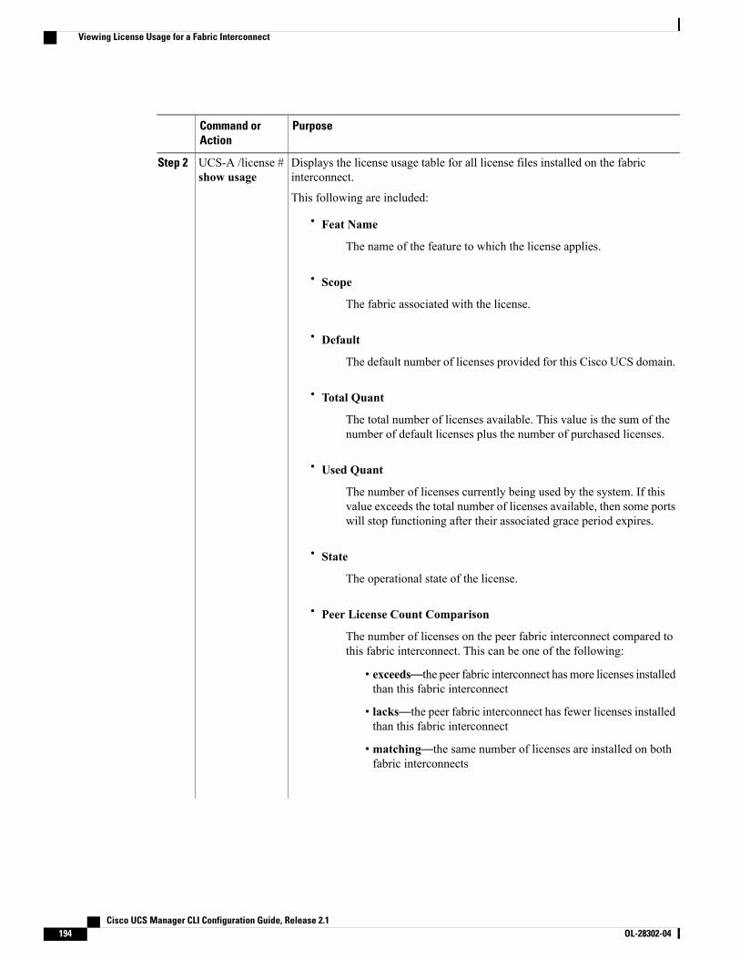
PurposeCommand orAction
Displays the license usage table for all license files installed on the fabricinterconnect.
UCS-A /license #show usage
Step 2
This following are included:
• Feat Name
The name of the feature to which the license applies.
• Scope
The fabric associated with the license.
• Default
The default number of licenses provided for this Cisco UCS domain.
• Total Quant
The total number of licenses available. This value is the sum of thenumber of default licenses plus the number of purchased licenses.
• Used Quant
The number of licenses currently being used by the system. If thisvalue exceeds the total number of licenses available, then some portswill stop functioning after their associated grace period expires.
• State
The operational state of the license.
• Peer License Count Comparison
The number of licenses on the peer fabric interconnect compared tothis fabric interconnect. This can be one of the following:
• exceeds—the peer fabric interconnect hasmore licenses installedthan this fabric interconnect
• lacks—the peer fabric interconnect has fewer licenses installedthan this fabric interconnect
• matching—the same number of licenses are installed on bothfabric interconnects
Cisco UCS Manager CLI Configuration Guide, Release 2.1194 OL-28302-04
Viewing License Usage for a Fabric Interconnect
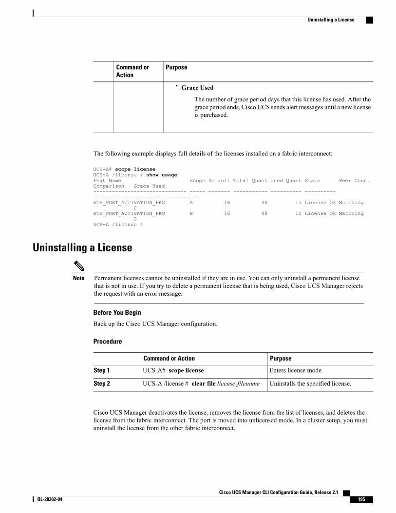
PurposeCommand orAction
• Grace Used
The number of grace period days that this license has used. After thegrace period ends, Cisco UCS sends alert messages until a new licenseis purchased.
The following example displays full details of the licenses installed on a fabric interconnect:
UCS-A# scope licenseUCS-A /license # show usageFeat Name Scope Default Total Quant Used Quant State Peer CountComparison Grace Used------------------------------ ----- ------- ----------- ---------- --------------------------------- ----------ETH_PORT_ACTIVATION_PKG A 16 40 11 License Ok Matching
0ETH_PORT_ACTIVATION_PKG B 16 40 11 License Ok Matching
0UCS-A /license #
Uninstalling a License
Permanent licenses cannot be uninstalled if they are in use. You can only uninstall a permanent licensethat is not in use. If you try to delete a permanent license that is being used, Cisco UCS Manager rejectsthe request with an error message.
Note
Before You Begin
Back up the Cisco UCS Manager configuration.
Procedure
PurposeCommand or Action
Enters license mode.UCS-A# scope licenseStep 1
Uninstalls the specified license.UCS-A /license # clear file license-filenameStep 2
Cisco UCS Manager deactivates the license, removes the license from the list of licenses, and deletes thelicense from the fabric interconnect. The port is moved into unlicensed mode. In a cluster setup, you mustuninstall the license from the other fabric interconnect.
Cisco UCS Manager CLI Configuration Guide, Release 2.1 OL-28302-04 195
Uninstalling a License
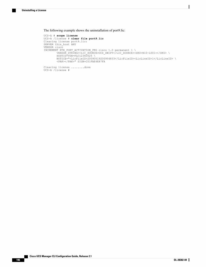
The following example shows the uninstallation of port9.lic:UCS-A # scope licenseUCS-A /license # clear file port9.licClearing license port9.lic:SERVER this_host ANYVENDOR ciscoINCREMENT ETH_PORT_ACTIVATION_PKG cisco 1.0 permanent 1 \
VENDOR_STRING=<LIC_SOURCE>UCS_SWIFT</LIC_SOURCE><SKU>N10-L001=</SKU> \HOSTID=VDH=FLC12360025 \NOTICE="<LicFileID>20090519200954833</LicFileID><LicLineID>1</LicLineID> \<PAK></PAK>" SIGN=C01FAE4E87FA
Clearing license ........doneUCS-A /license #
Cisco UCS Manager CLI Configuration Guide, Release 2.1196 OL-28302-04
Uninstalling a License
C H A P T E R 14Managing Virtual Interfaces
This chapter includes the following sections:
• Virtual Interfaces, page 197
• Virtual Interface Subscription Management and Error Handling, page 197
Virtual InterfacesIn a blade server environment, the number of vNICs and vHBAs configurable for a service profile is determinedby adapter capability and the amount of virtual interface (VIF) namespace available on the adapter. In CiscoUCS, portions of VIF namespace are allotted in chunks called VIFs. Depending on your hardware, themaxiumum number of VIFs are allocated on a predefined, per-port basis.The maximum number of VIFs varies based on hardware capability and port connectivity. For each configuredvNIC or vHBA, one or two VIFs are allocated. Stand-alone vNICs and vHBAs use one VIF and failovervNICs and vHBAs use two.
The following variables affect the number of VIFs available to a blade server, and therefore, howmany vNICsand vHBAs you can configure for a service profile.
• Maximum number of VIFs supported on your fabric interconnect
• How the fabric interconnects are cabled
• If your fabric interconnect and IOM are configured in fabric port channel mode
For more information about the maximum number of VIFs supported by your hardware configuration, seeCisco UCS 6100 and 6200 Series Configuration Limits for Cisco UCS Manager for your software release.
Virtual Interface Subscription Management and Error HandlingFor fabric interconnects grouped in a port-channel, changes to the way you connect the fabric interconnect tothe I/O module could result in a drastic change to the number of VIFs available to a blade server. To help youtrack the effect of these changes, Cisco UCS Manager maintains the following metrics:
• Maximum number of VIFs supported by hardware
• Connectivity type
Cisco UCS Manager CLI Configuration Guide, Release 2.1 OL-28302-04 197
If you change your configuration in a way that decreases the number of VIFs available to a blade, UCSManager will display a warning and ask you if you want to proceed. This includes several scenarios, includingtimes where adding or moving a connection decreases the number of VIFs.
Cisco UCS Manager CLI Configuration Guide, Release 2.1198 OL-28302-04
Virtual Interface Subscription Management and Error Handling
C H A P T E R 15Registering Cisco UCS Domains with Cisco UCSCentral
This chapter includes the following sections:
• Registration of Cisco UCS Domains, page 199
• Policy Resolution between Cisco UCS Manager and Cisco UCS Central, page 200
• Registering a Cisco UCS Domain with Cisco UCS Central, page 201
• Configuring Policy Resolution between Cisco UCS Manager and Cisco UCS Central, page 202
• Unregistering a Cisco UCS Domain from Cisco UCS Central, page 203
Registration of Cisco UCS DomainsYou can have Cisco UCS Central manage some or all of the Cisco UCS domains in your data center.
If you want to have Cisco UCS Central manage a Cisco UCS domain, you need to register that domain. Whenyou register, you need to choose which types of policies and other configurations, such as backups andfirmware, will be managed by Cisco UCS Central and which by Cisco UCS Manager. You can have CiscoUCS Central manage the same types of policies and configurations for all registered Cisco UCS domains oryou can choose to have different settings for each registered Cisco UCS domain.
Before you register a Cisco UCS domain with Cisco UCS Central, do the following:
• Configure an NTP server and the correct time zone in both Cisco UCSManager and Cisco UCS Centralto ensure that they are in sync. If the time and date in the Cisco UCS domain and Cisco UCS Centralare out of sync, the registration might fail.
• Obtain the hostname or IP address of Cisco UCS Central
• Obtain the shared secret that you configured when you deployed Cisco UCS Central
Cisco UCS Manager CLI Configuration Guide, Release 2.1 OL-28302-04 199
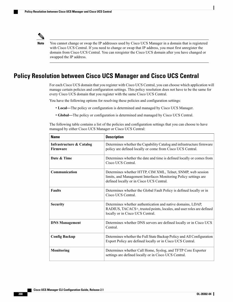
You cannot change or swap the IP addresses used by Cisco UCS Manager in a domain that is registeredwith Cisco UCS Central. If you need to change or swap that IP address, you must first unregister thedomain from Cisco UCS Central. You can reregister the Cisco UCS domain after you have changed orswapped the IP address.
Note
Policy Resolution between Cisco UCS Manager and Cisco UCS CentralFor each Cisco UCS domain that you register with Cisco UCS Central, you can choose which application willmanage certain policies and configuration settings. This policy resolution does not have to be the same forevery Cisco UCS domain that you register with the same Cisco UCS Central.
You have the following options for resolving these policies and configuration settings:
• Local—The policy or configuration is determined and managed by Cisco UCS Manager.
• Global—The policy or configuration is determined and managed by Cisco UCS Central.
The following table contains a list of the policies and configuration settings that you can choose to havemanaged by either Cisco UCS Manager or Cisco UCS Central:
DescriptionName
Determines whether the Capability Catalog and infrastructure firmwarepolicy are defined locally or come from Cisco UCS Central.
Infrastructure & CatalogFirmware
Determines whether the date and time is defined locally or comes fromCisco UCS Central.
Date & Time
Determines whether HTTP, CIM XML, Telnet, SNMP, web sessionlimits, and Management Interfaces Monitoring Policy settings aredefined locally or in Cisco UCS Central.
Communication
Determines whether the Global Fault Policy is defined locally or inCisco UCS Central.
Faults
Determines whether authentication and native domains, LDAP,RADIUS, TACACS+, trusted points, locales, and user roles are definedlocally or in Cisco UCS Central.
Security
Determines whether DNS servers are defined locally or in Cisco UCSCentral.
DNS Management
Determines whether the Full State Backup Policy and All ConfigurationExport Policy are defined locally or in Cisco UCS Central.
Config Backup
Determines whether Call Home, Syslog, and TFTP Core Exportersettings are defined locally or in Cisco UCS Central.
Monitoring
Cisco UCS Manager CLI Configuration Guide, Release 2.1200 OL-28302-04
Policy Resolution between Cisco UCS Manager and Cisco UCS Central
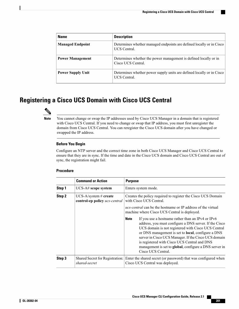
DescriptionName
Determines whether managed endpoints are defined locally or in CiscoUCS Central.
Managed Endpoint
Determines whether the power management is defined locally or inCisco UCS Central.
Power Management
Determines whether power supply units are defined locally or in CiscoUCS Central.
Power Supply Unit
Registering a Cisco UCS Domain with Cisco UCS Central
You cannot change or swap the IP addresses used by Cisco UCS Manager in a domain that is registeredwith Cisco UCS Central. If you need to change or swap that IP address, you must first unregister thedomain from Cisco UCS Central. You can reregister the Cisco UCS domain after you have changed orswapped the IP address.
Note
Before You Begin
Configure an NTP server and the correct time zone in both Cisco UCS Manager and Cisco UCS Central toensure that they are in sync. If the time and date in the Cisco UCS domain and Cisco UCS Central are out ofsync, the registration might fail.
Procedure
PurposeCommand or Action
Enters system mode.UCS-A# scope systemStep 1
Creates the policy required to register the Cisco UCS Domainwith Cisco UCS Central.
UCS-A/system # createcontrol-ep policy ucs-central
Step 2
ucs-central can be the hostname or IP address of the virtualmachine where Cisco UCS Central is deployed.
If you use a hostname rather than an IPv4 or IPv6address, you must configure a DNS server. If the CiscoUCS domain is not registered with Cisco UCS Centralor DNS management is set to local, configure a DNSserver in Cisco UCSManager. If the Cisco UCS domainis registered with Cisco UCS Central and DNSmanagement is set to global, configure a DNS server inCisco UCS Central.
Note
Enter the shared secret (or password) that was configured whenCisco UCS Central was deployed.
Shared Secret for Registration:shared-secret
Step 3
Cisco UCS Manager CLI Configuration Guide, Release 2.1 OL-28302-04 201
Registering a Cisco UCS Domain with Cisco UCS Central
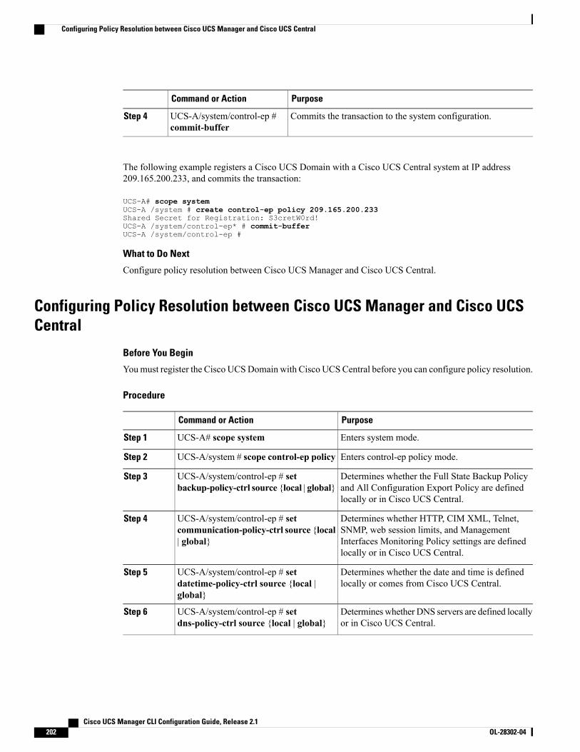
PurposeCommand or Action
Commits the transaction to the system configuration.UCS-A/system/control-ep #commit-buffer
Step 4
The following example registers a Cisco UCS Domain with a Cisco UCS Central system at IP address209.165.200.233, and commits the transaction:
UCS-A# scope systemUCS-A /system # create control-ep policy 209.165.200.233Shared Secret for Registration: S3cretW0rd!UCS-A /system/control-ep* # commit-bufferUCS-A /system/control-ep #
What to Do Next
Configure policy resolution between Cisco UCS Manager and Cisco UCS Central.
Configuring Policy Resolution between Cisco UCS Manager and Cisco UCSCentral
Before You Begin
Youmust register the Cisco UCSDomain with Cisco UCSCentral before you can configure policy resolution.
Procedure
PurposeCommand or Action
Enters system mode.UCS-A# scope systemStep 1
Enters control-ep policy mode.UCS-A/system # scope control-ep policyStep 2
Determines whether the Full State Backup Policyand All Configuration Export Policy are definedlocally or in Cisco UCS Central.
UCS-A/system/control-ep # setbackup-policy-ctrl source {local | global}
Step 3
Determines whether HTTP, CIM XML, Telnet,SNMP, web session limits, and Management
UCS-A/system/control-ep # setcommunication-policy-ctrl source {local| global}
Step 4
Interfaces Monitoring Policy settings are definedlocally or in Cisco UCS Central.
Determines whether the date and time is definedlocally or comes from Cisco UCS Central.
UCS-A/system/control-ep # setdatetime-policy-ctrl source {local |global}
Step 5
Determineswhether DNS servers are defined locallyor in Cisco UCS Central.
UCS-A/system/control-ep # setdns-policy-ctrl source {local | global}
Step 6
Cisco UCS Manager CLI Configuration Guide, Release 2.1202 OL-28302-04
Configuring Policy Resolution between Cisco UCS Manager and Cisco UCS Central
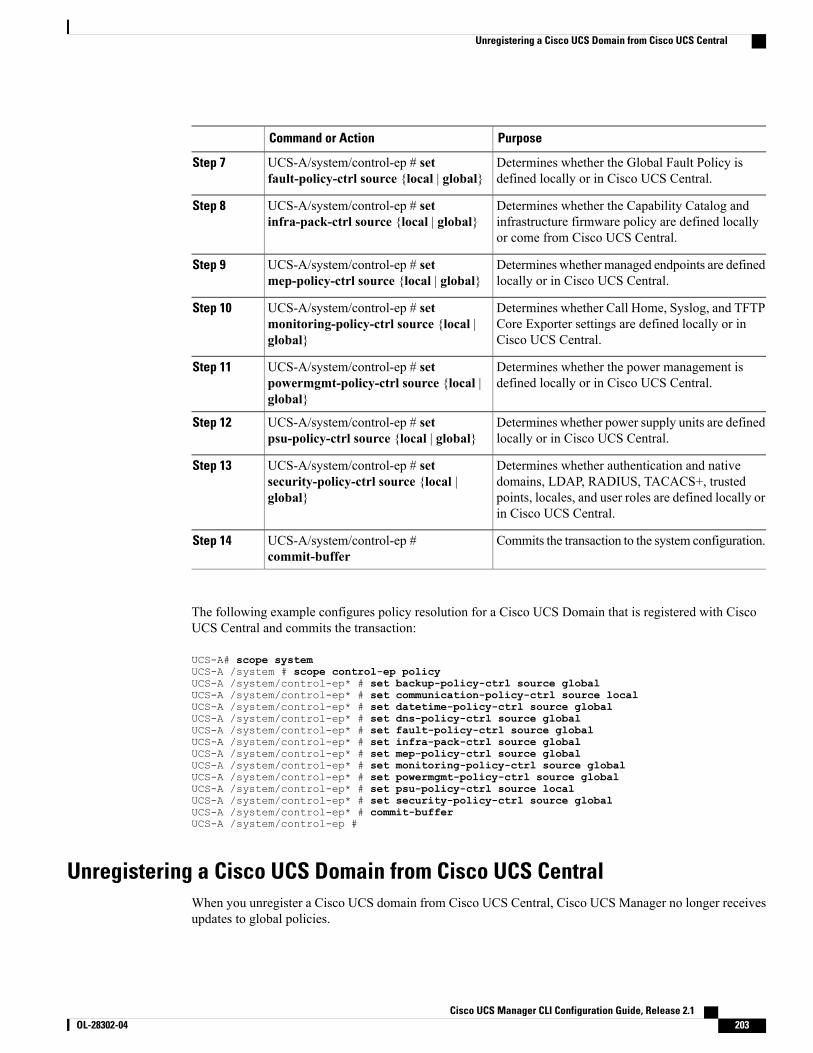
PurposeCommand or Action
Determines whether the Global Fault Policy isdefined locally or in Cisco UCS Central.
UCS-A/system/control-ep # setfault-policy-ctrl source {local | global}
Step 7
Determines whether the Capability Catalog andinfrastructure firmware policy are defined locallyor come from Cisco UCS Central.
UCS-A/system/control-ep # setinfra-pack-ctrl source {local | global}
Step 8
Determines whether managed endpoints are definedlocally or in Cisco UCS Central.
UCS-A/system/control-ep # setmep-policy-ctrl source {local | global}
Step 9
Determines whether Call Home, Syslog, and TFTPCore Exporter settings are defined locally or inCisco UCS Central.
UCS-A/system/control-ep # setmonitoring-policy-ctrl source {local |global}
Step 10
Determines whether the power management isdefined locally or in Cisco UCS Central.
UCS-A/system/control-ep # setpowermgmt-policy-ctrl source {local |global}
Step 11
Determines whether power supply units are definedlocally or in Cisco UCS Central.
UCS-A/system/control-ep # setpsu-policy-ctrl source {local | global}
Step 12
Determines whether authentication and nativedomains, LDAP, RADIUS, TACACS+, trusted
UCS-A/system/control-ep # setsecurity-policy-ctrl source {local |global}
Step 13
points, locales, and user roles are defined locally orin Cisco UCS Central.
Commits the transaction to the system configuration.UCS-A/system/control-ep #commit-buffer
Step 14
The following example configures policy resolution for a Cisco UCS Domain that is registered with CiscoUCS Central and commits the transaction:
UCS-A# scope systemUCS-A /system # scope control-ep policyUCS-A /system/control-ep* # set backup-policy-ctrl source globalUCS-A /system/control-ep* # set communication-policy-ctrl source localUCS-A /system/control-ep* # set datetime-policy-ctrl source globalUCS-A /system/control-ep* # set dns-policy-ctrl source globalUCS-A /system/control-ep* # set fault-policy-ctrl source globalUCS-A /system/control-ep* # set infra-pack-ctrl source globalUCS-A /system/control-ep* # set mep-policy-ctrl source globalUCS-A /system/control-ep* # set monitoring-policy-ctrl source globalUCS-A /system/control-ep* # set powermgmt-policy-ctrl source globalUCS-A /system/control-ep* # set psu-policy-ctrl source localUCS-A /system/control-ep* # set security-policy-ctrl source globalUCS-A /system/control-ep* # commit-bufferUCS-A /system/control-ep #
Unregistering a Cisco UCS Domain from Cisco UCS CentralWhen you unregister a Cisco UCS domain from Cisco UCS Central, Cisco UCS Manager no longer receivesupdates to global policies.
Cisco UCS Manager CLI Configuration Guide, Release 2.1 OL-28302-04 203
Unregistering a Cisco UCS Domain from Cisco UCS Central
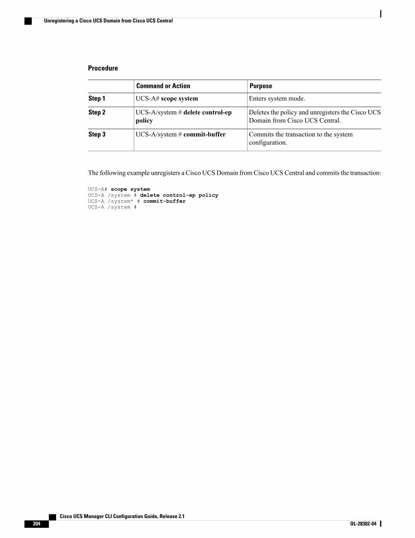
Procedure
PurposeCommand or Action
Enters system mode.UCS-A# scope systemStep 1
Deletes the policy and unregisters the Cisco UCSDomain from Cisco UCS Central.
UCS-A/system # delete control-eppolicy
Step 2
Commits the transaction to the systemconfiguration.
UCS-A/system # commit-bufferStep 3
The following example unregisters a Cisco UCSDomain fromCisco UCSCentral and commits the transaction:
UCS-A# scope systemUCS-A /system # delete control-ep policyUCS-A /system* # commit-bufferUCS-A /system #
Cisco UCS Manager CLI Configuration Guide, Release 2.1204 OL-28302-04
Unregistering a Cisco UCS Domain from Cisco UCS Central
P A R T IIINetwork Configuration• Configuring VLANs, page 207
• Configuring LAN Pin Groups, page 225
• Configuring MAC Pools, page 227
• Configuring Quality of Service, page 231
• Configuring Network-Related Policies, page 241
• Configuring Upstream Disjoint Layer-2 Networks, page 265

C H A P T E R 16Configuring VLANs
This chapter includes the following sections:
• Named VLANs, page 207
• Private VLANs, page 208
• VLAN Port Limitations, page 209
• Configuring Named VLANs, page 210
• Configuring Private VLANs, page 215
• Viewing the VLAN Port Count, page 218
• VLAN Port Count Optimization, page 219
• VLAN Groups, page 220
• VLAN Permissions, page 222
Named VLANsA named VLAN creates a connection to a specific external LAN. The VLAN isolates traffic to that externalLAN, including broadcast traffic.
The name that you assign to a VLAN ID adds a layer of abstraction that allows you to globally update allservers associated with service profiles that use the named VLAN. You do not need to reconfigure the serversindividually to maintain communication with the external LAN.
You can create more than one named VLAN with the same VLAN ID. For example, if servers that hostbusiness services for HR and Finance need to access the same external LAN, you can create VLANs namedHR and Finance with the same VLAN ID. Then, if the network is reconfigured and Finance is assigned to adifferent LAN, you only have to change the VLAN ID for the named VLAN for Finance.
In a cluster configuration, you can configure a named VLAN to be accessible only to one fabric interconnector to both fabric interconnects.
Cisco UCS Manager CLI Configuration Guide, Release 2.1 OL-28302-04 207
Guidelines for VLAN IDs
You cannot create VLANs with IDs from 3968 to 4047. This range of VLAN IDs is reserved.
VLANs in the LAN cloud and FCoE VLANs in the SAN cloud must have different IDs. Using the sameID for a VLAN and an FCoE VLAN in a VSAN results in a critical fault and traffic disruption for allvNICs and uplink ports using that VLAN. Ethernet traffic is dropped on any VLAN which has an ID thatoverlaps with an FCoE VLAN ID.
Important
VLAN 4048 is user configurable. However, Cisco UCS Manager uses VLAN 4048 for the following defaultvalues. If you want to assign 4048 to a VLAN, you must reconfigure these values:
• After an upgrade to Cisco UCS, Release 2.0—The FCoE storage port native VLAN uses VLAN 4048by default. If the default FCoE VSAN was set to use VLAN 1 before the upgrade, you must change itto a VLAN ID that is not used or reserved. For example, consider changing the default to 4049 if thatVLAN ID is not in use.
• After a fresh install of Cisco UCS, Release 2.0—The FCoE VLAN for the default VSAN uses VLAN4048 by default. The FCoE storage port native VLAN uses VLAN 4049.
The VLAN name is case sensitive.
Private VLANsA private VLAN (PVLAN) partitions the Ethernet broadcast domain of a VLAN into subdomains and allowsyou to isolate some ports. Each subdomain in a PVLAN includes a primary VLAN and one or more secondaryVLANs. All secondary VLANs in a PVLAN must share the same primary VLAN. The secondary VLAN IDdifferentiates one subdomain from another.
Isolated VLANs
All secondary VLANs in a Cisco UCS domain must be isolated VLANs. Cisco UCS does not supportcommunity VLANs.
You cannot configure an isolated VLAN to be used together with a regular VLAN.Note
Ports on Isolated VLANs
Communications on an isolated VLAN can only use the associated port in the primary VLAN. These portsare isolated ports and are not configurable in Cisco UCS Manager. If the primary VLAN includes multiplesecondary VLANs, those isolated VLANs cannot communicate directly with each other.
An isolated port is a host port that belongs to an isolated secondary VLAN. This port has complete isolationfrom other ports within the same private VLAN domain. PVLANs block all traffic to isolated ports excepttraffic from promiscuous ports. Traffic received from an isolated port is forwarded only to promiscuous ports.You can have more than one isolated port in a specified isolated VLAN. Each port is completely isolated fromall other ports in the isolated VLAN.
Cisco UCS Manager CLI Configuration Guide, Release 2.1208 OL-28302-04
Private VLANs
Guidelines for Uplink Ports
When you create PVLANs, be aware of the following guidelines:
• The uplink Ethernet port channel cannot be in promiscuous mode.
• Each primary VLAN can have only one isolated VLAN.
• VIFs on VNTAG adapters can have only one isolated VLAN.
Guidelines for VLAN IDs
You cannot create VLANs with IDs from 3968 to 4047. This range of VLAN IDs is reserved.
VLANs in the LAN cloud and FCoE VLANs in the SAN cloud must have different IDs. Using the sameID for a VLAN and an FCoE VLAN in a VSAN results in a critical fault and traffic disruption for allvNICs and uplink ports using that VLAN. Ethernet traffic is dropped on any VLAN which has an ID thatoverlaps with an FCoE VLAN ID.
Important
VLAN 4048 is user configurable. However, Cisco UCS Manager uses VLAN 4048 for the following defaultvalues. If you want to assign 4048 to a VLAN, you must reconfigure these values:
• After an upgrade to Cisco UCS, Release 2.0—The FCoE storage port native VLAN uses VLAN 4048by default. If the default FCoE VSAN was set to use VLAN 1 before the upgrade, you must change itto a VLAN ID that is not used or reserved. For example, consider changing the default to 4049 if thatVLAN ID is not in use.
• After a fresh install of Cisco UCS, Release 2.0—The FCoE VLAN for the default VSAN uses VLAN4048 by default. The FCoE storage port native VLAN uses VLAN 4049.
The VLAN name is case sensitive.
VLAN Port LimitationsCiscoUCSManager limits the number of VLAN port instances that can be configured under border and serverdomains on a fabric interconnect to 6000.
Types of Ports Included in the VLAN Port Count
The following types of ports are counted in the VLAN port calculation:
• Border uplink Ethernet ports
• Border uplink Ether-channel member ports
• FCoE ports in a SAN cloud
• Ethernet ports in a NAS cloud
• Static and dynamic vNICs created through service profiles
• VM vNICs created as part of a port profile in a hypervisor in hypervisor domain
Based on the number of VLANs configured for these ports, Cisco UCSManager keeps track of the cumulativecount of VLAN port instances and enforces the VLAN port limit during validation. Cisco UCS Manager
Cisco UCS Manager CLI Configuration Guide, Release 2.1 OL-28302-04 209
VLAN Port Limitations
reserves some pre-defined VLAN port resources for control traffic. These include management VLANsconfigured under HIF and NIF ports.
VLAN Port Limit Enforcement
Cisco UCS Manager validates VLAN port availability during the following operations.
• Configuring and unconfiguring border ports and border port channels
• Adding or removing VLANs from a cloud
• Configuring or unconfiguring SAN or NAS ports
• Associating or disassociating service profiles that contain configuration changes
• Configuring or unconfiguring VLANs under vNICs or vHBAs
• Upon receiving creation or deleting notifications from a VMWare vNIC, from an ESX hypervisor
This is outside the control of Cisco UCS ManagerNote
• Fabric interconnect reboot
• Cisco UCS Manager upgrade or downgrade
Cisco UCSManager strictly enforces the VLAN port limit on service profile operations. If Cisco UCSManagerdetects that you have exceeded the VLAN port limit service profile configuration will fail during deployment.
Exceeding the VLAN port count in a border domain is less disruptive.When the VLAN port count is exceededin a border domainCisco UCS Manager changes the allocation status to Exceeded. In order to change thestatus back to Available, you should complete one of the following actions:
• Unconfigure one or more border ports
• Remove VLANs from the LAN cloud
• Unconfigure one or more vNICs or vHBAs
Configuring Named VLANs
Creating a Named VLAN Accessible to Both Fabric Interconnects (Uplink Ethernet Mode)
You cannot create VLANs with IDs from 3968 to 4047. This range of VLAN IDs is reserved.
VLANs in the LAN cloud and FCoE VLANs in the SAN cloud must have different IDs. Using the sameID for a VLAN and an FCoE VLAN in a VSAN results in a critical fault and traffic disruption for allvNICs and uplink ports using that VLAN. Ethernet traffic is dropped on any VLAN which has an ID thatoverlaps with an FCoE VLAN ID.
Important
Cisco UCS Manager CLI Configuration Guide, Release 2.1210 OL-28302-04
Configuring Named VLANs
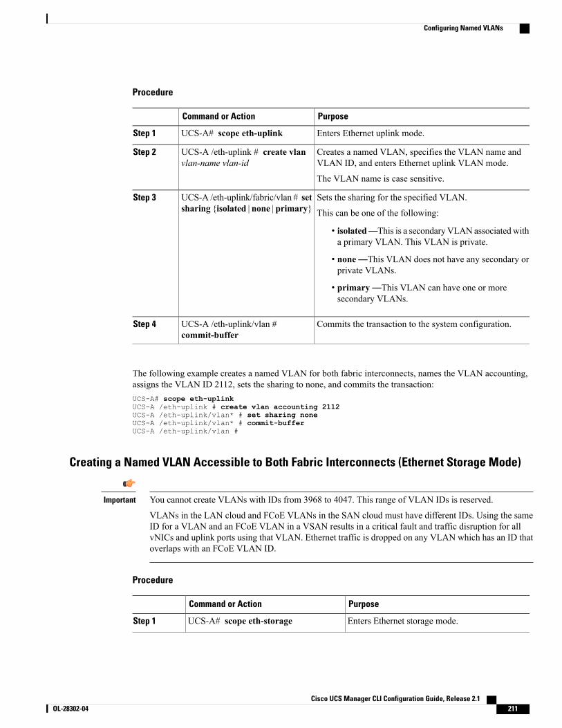
Procedure
PurposeCommand or Action
Enters Ethernet uplink mode.UCS-A# scope eth-uplinkStep 1
Creates a named VLAN, specifies the VLAN name andVLAN ID, and enters Ethernet uplink VLAN mode.
UCS-A /eth-uplink # create vlanvlan-name vlan-id
Step 2
The VLAN name is case sensitive.
Sets the sharing for the specified VLAN.UCS-A /eth-uplink/fabric/vlan # setsharing {isolated | none | primary}
Step 3
This can be one of the following:
• isolated—This is a secondary VLAN associated witha primary VLAN. This VLAN is private.
• none—This VLAN does not have any secondary orprivate VLANs.
• primary—This VLAN can have one or moresecondary VLANs.
Commits the transaction to the system configuration.UCS-A /eth-uplink/vlan #commit-buffer
Step 4
The following example creates a named VLAN for both fabric interconnects, names the VLAN accounting,assigns the VLAN ID 2112, sets the sharing to none, and commits the transaction:UCS-A# scope eth-uplinkUCS-A /eth-uplink # create vlan accounting 2112UCS-A /eth-uplink/vlan* # set sharing noneUCS-A /eth-uplink/vlan* # commit-bufferUCS-A /eth-uplink/vlan #
Creating a Named VLAN Accessible to Both Fabric Interconnects (Ethernet Storage Mode)
You cannot create VLANs with IDs from 3968 to 4047. This range of VLAN IDs is reserved.
VLANs in the LAN cloud and FCoE VLANs in the SAN cloud must have different IDs. Using the sameID for a VLAN and an FCoE VLAN in a VSAN results in a critical fault and traffic disruption for allvNICs and uplink ports using that VLAN. Ethernet traffic is dropped on any VLAN which has an ID thatoverlaps with an FCoE VLAN ID.
Important
Procedure
PurposeCommand or Action
Enters Ethernet storage mode.UCS-A# scope eth-storageStep 1
Cisco UCS Manager CLI Configuration Guide, Release 2.1 OL-28302-04 211
Configuring Named VLANs
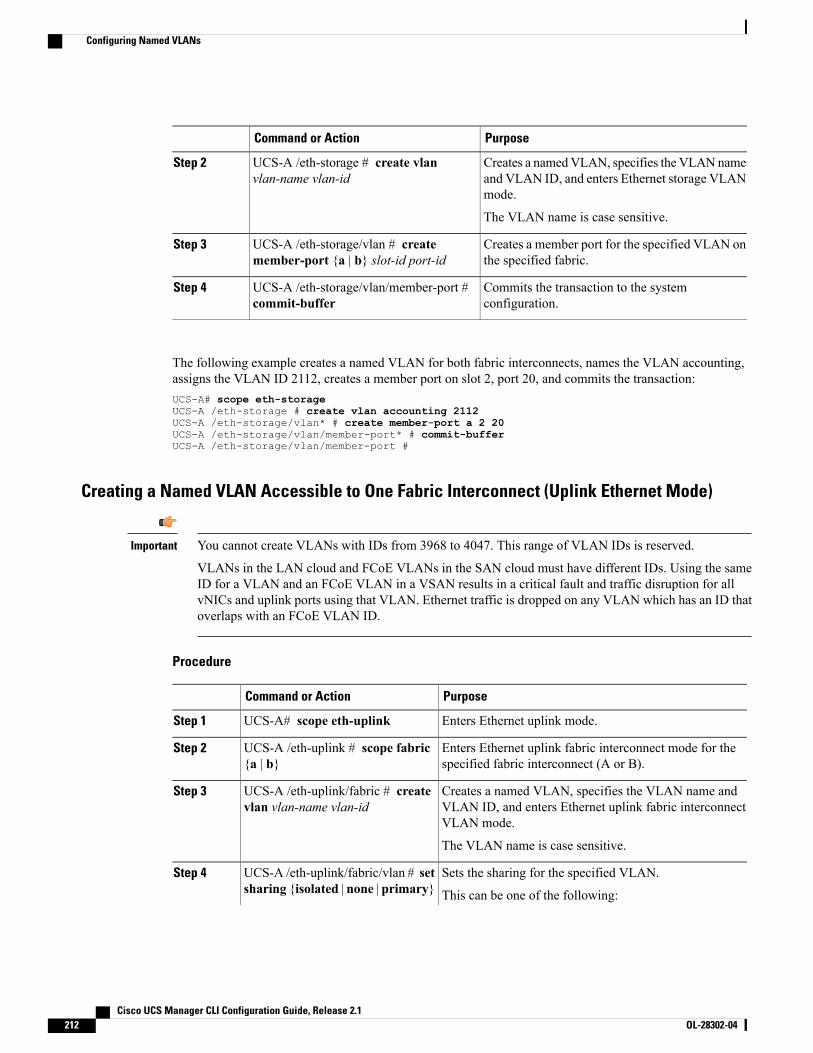
PurposeCommand or Action
Creates a namedVLAN, specifies the VLANnameand VLAN ID, and enters Ethernet storage VLANmode.
UCS-A /eth-storage # create vlanvlan-name vlan-id
Step 2
The VLAN name is case sensitive.
Creates a member port for the specified VLAN onthe specified fabric.
UCS-A /eth-storage/vlan # createmember-port {a | b} slot-id port-id
Step 3
Commits the transaction to the systemconfiguration.
UCS-A /eth-storage/vlan/member-port #commit-buffer
Step 4
The following example creates a named VLAN for both fabric interconnects, names the VLAN accounting,assigns the VLAN ID 2112, creates a member port on slot 2, port 20, and commits the transaction:UCS-A# scope eth-storageUCS-A /eth-storage # create vlan accounting 2112UCS-A /eth-storage/vlan* # create member-port a 2 20UCS-A /eth-storage/vlan/member-port* # commit-bufferUCS-A /eth-storage/vlan/member-port #
Creating a Named VLAN Accessible to One Fabric Interconnect (Uplink Ethernet Mode)
You cannot create VLANs with IDs from 3968 to 4047. This range of VLAN IDs is reserved.
VLANs in the LAN cloud and FCoE VLANs in the SAN cloud must have different IDs. Using the sameID for a VLAN and an FCoE VLAN in a VSAN results in a critical fault and traffic disruption for allvNICs and uplink ports using that VLAN. Ethernet traffic is dropped on any VLAN which has an ID thatoverlaps with an FCoE VLAN ID.
Important
Procedure
PurposeCommand or Action
Enters Ethernet uplink mode.UCS-A# scope eth-uplinkStep 1
Enters Ethernet uplink fabric interconnect mode for thespecified fabric interconnect (A or B).
UCS-A /eth-uplink # scope fabric{a | b}
Step 2
Creates a named VLAN, specifies the VLAN name andVLAN ID, and enters Ethernet uplink fabric interconnectVLAN mode.
UCS-A /eth-uplink/fabric # createvlan vlan-name vlan-id
Step 3
The VLAN name is case sensitive.
Sets the sharing for the specified VLAN.UCS-A /eth-uplink/fabric/vlan # setsharing {isolated | none | primary}
Step 4
This can be one of the following:
Cisco UCS Manager CLI Configuration Guide, Release 2.1212 OL-28302-04
Configuring Named VLANs
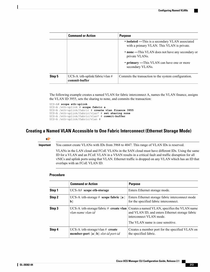
PurposeCommand or Action
• isolated—This is a secondary VLAN associatedwith a primary VLAN. This VLAN is private.
• none—This VLAN does not have any secondary orprivate VLANs.
• primary—This VLAN can have one or moresecondary VLANs.
Commits the transaction to the system configuration.UCS-A /eth-uplink/fabric/vlan #commit-buffer
Step 5
The following example creates a named VLAN for fabric interconnect A, names the VLAN finance, assignsthe VLAN ID 3955, sets the sharing to none, and commits the transaction:UCS-A# scope eth-uplinkUCS-A /eth-uplink # scope fabric aUCS-A /eth-uplink/fabric # create vlan finance 3955UCS-A /eth-uplink/fabric/vlan* # set sharing noneUCS-A /eth-uplink/fabric/vlan* # commit-bufferUCS-A /eth-uplink/fabric/vlan #
Creating a Named VLAN Accessible to One Fabric Interconnect (Ethernet Storage Mode)
You cannot create VLANs with IDs from 3968 to 4047. This range of VLAN IDs is reserved.
VLANs in the LAN cloud and FCoE VLANs in the SAN cloud must have different IDs. Using the sameID for a VLAN and an FCoE VLAN in a VSAN results in a critical fault and traffic disruption for allvNICs and uplink ports using that VLAN. Ethernet traffic is dropped on any VLAN which has an ID thatoverlaps with an FCoE VLAN ID.
Important
Procedure
PurposeCommand or Action
Enters Ethernet storage mode.UCS-A# scope eth-storageStep 1
Enters Ethernet storage fabric interconnect modefor the specified fabric interconnect.
UCS-A /eth-storage # scope fabric {a |b}
Step 2
Creates a named VLAN, specifies the VLAN nameand VLAN ID, and enters Ethernet storage fabricinterconnect VLAN mode.
UCS-A /eth-storage/fabric # create vlanvlan-name vlan-id
Step 3
The VLAN name is case sensitive.
Creates a member port for the specified VLAN onthe specified fabric.
UCS-A /eth-storage/vlan # createmember-port {a | b} slot-id port-id
Step 4
Cisco UCS Manager CLI Configuration Guide, Release 2.1 OL-28302-04 213
Configuring Named VLANs
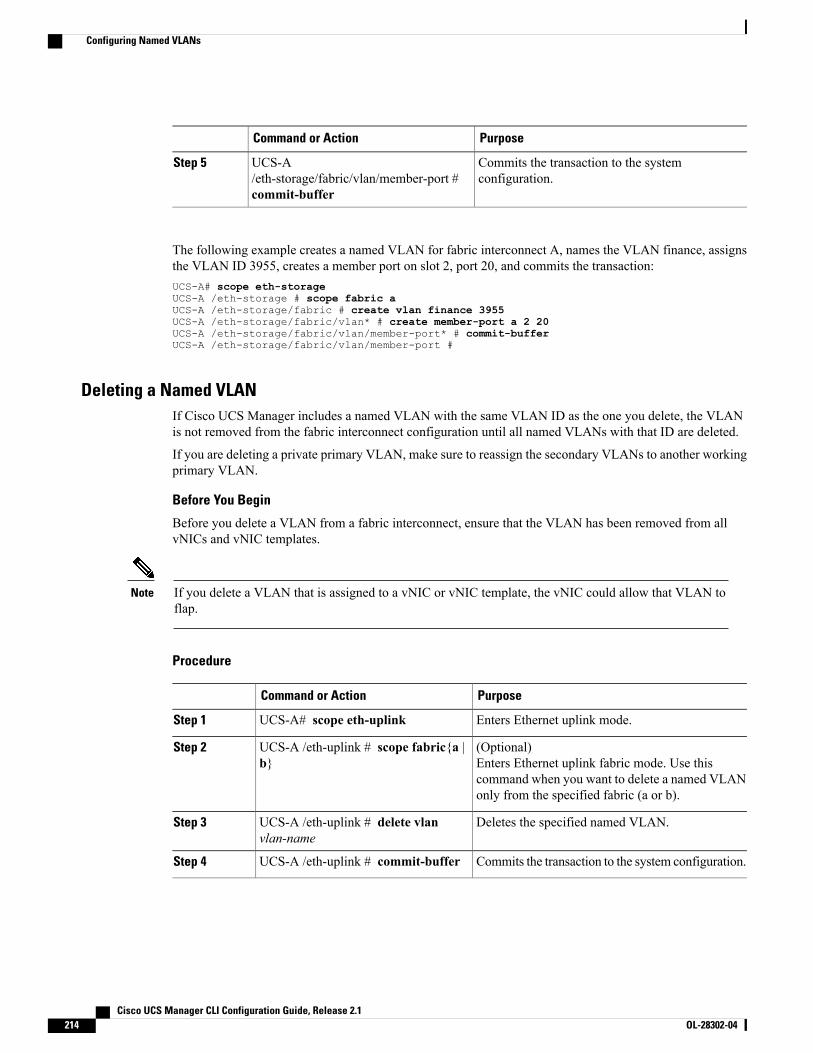
PurposeCommand or Action
Commits the transaction to the systemconfiguration.
UCS-A/eth-storage/fabric/vlan/member-port #commit-buffer
Step 5
The following example creates a named VLAN for fabric interconnect A, names the VLAN finance, assignsthe VLAN ID 3955, creates a member port on slot 2, port 20, and commits the transaction:UCS-A# scope eth-storageUCS-A /eth-storage # scope fabric aUCS-A /eth-storage/fabric # create vlan finance 3955UCS-A /eth-storage/fabric/vlan* # create member-port a 2 20UCS-A /eth-storage/fabric/vlan/member-port* # commit-bufferUCS-A /eth-storage/fabric/vlan/member-port #
Deleting a Named VLANIf Cisco UCS Manager includes a named VLAN with the same VLAN ID as the one you delete, the VLANis not removed from the fabric interconnect configuration until all named VLANs with that ID are deleted.
If you are deleting a private primary VLAN, make sure to reassign the secondary VLANs to another workingprimary VLAN.
Before You Begin
Before you delete a VLAN from a fabric interconnect, ensure that the VLAN has been removed from allvNICs and vNIC templates.
If you delete a VLAN that is assigned to a vNIC or vNIC template, the vNIC could allow that VLAN toflap.
Note
Procedure
PurposeCommand or Action
Enters Ethernet uplink mode.UCS-A# scope eth-uplinkStep 1
(Optional)Enters Ethernet uplink fabric mode. Use thiscommand when you want to delete a named VLANonly from the specified fabric (a or b).
UCS-A /eth-uplink # scope fabric{a |b}
Step 2
Deletes the specified named VLAN.UCS-A /eth-uplink # delete vlanvlan-name
Step 3
Commits the transaction to the system configuration.UCS-A /eth-uplink # commit-bufferStep 4
Cisco UCS Manager CLI Configuration Guide, Release 2.1214 OL-28302-04
Configuring Named VLANs
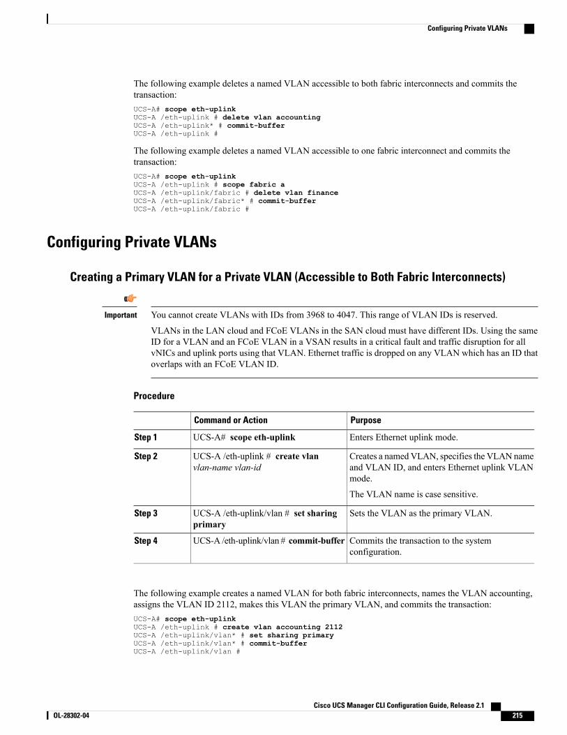
The following example deletes a named VLAN accessible to both fabric interconnects and commits thetransaction:UCS-A# scope eth-uplinkUCS-A /eth-uplink # delete vlan accountingUCS-A /eth-uplink* # commit-bufferUCS-A /eth-uplink #
The following example deletes a named VLAN accessible to one fabric interconnect and commits thetransaction:UCS-A# scope eth-uplinkUCS-A /eth-uplink # scope fabric aUCS-A /eth-uplink/fabric # delete vlan financeUCS-A /eth-uplink/fabric* # commit-bufferUCS-A /eth-uplink/fabric #
Configuring Private VLANs
Creating a Primary VLAN for a Private VLAN (Accessible to Both Fabric Interconnects)
You cannot create VLANs with IDs from 3968 to 4047. This range of VLAN IDs is reserved.
VLANs in the LAN cloud and FCoE VLANs in the SAN cloud must have different IDs. Using the sameID for a VLAN and an FCoE VLAN in a VSAN results in a critical fault and traffic disruption for allvNICs and uplink ports using that VLAN. Ethernet traffic is dropped on any VLAN which has an ID thatoverlaps with an FCoE VLAN ID.
Important
Procedure
PurposeCommand or Action
Enters Ethernet uplink mode.UCS-A# scope eth-uplinkStep 1
Creates a namedVLAN, specifies the VLAN nameand VLAN ID, and enters Ethernet uplink VLANmode.
UCS-A /eth-uplink # create vlanvlan-name vlan-id
Step 2
The VLAN name is case sensitive.
Sets the VLAN as the primary VLAN.UCS-A /eth-uplink/vlan # set sharingprimary
Step 3
Commits the transaction to the systemconfiguration.
UCS-A /eth-uplink/vlan # commit-bufferStep 4
The following example creates a named VLAN for both fabric interconnects, names the VLAN accounting,assigns the VLAN ID 2112, makes this VLAN the primary VLAN, and commits the transaction:UCS-A# scope eth-uplinkUCS-A /eth-uplink # create vlan accounting 2112UCS-A /eth-uplink/vlan* # set sharing primaryUCS-A /eth-uplink/vlan* # commit-bufferUCS-A /eth-uplink/vlan #
Cisco UCS Manager CLI Configuration Guide, Release 2.1 OL-28302-04 215
Configuring Private VLANs
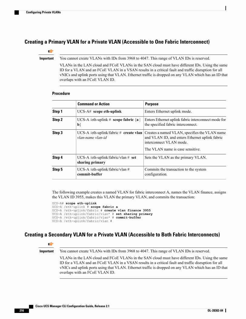
Creating a Primary VLAN for a Private VLAN (Accessible to One Fabric Interconnect)
You cannot create VLANs with IDs from 3968 to 4047. This range of VLAN IDs is reserved.
VLANs in the LAN cloud and FCoE VLANs in the SAN cloud must have different IDs. Using the sameID for a VLAN and an FCoE VLAN in a VSAN results in a critical fault and traffic disruption for allvNICs and uplink ports using that VLAN. Ethernet traffic is dropped on any VLAN which has an ID thatoverlaps with an FCoE VLAN ID.
Important
Procedure
PurposeCommand or Action
Enters Ethernet uplink mode.UCS-A# scope eth-uplinkStep 1
Enters Ethernet uplink fabric interconnect mode forthe specified fabric interconnect.
UCS-A /eth-uplink # scope fabric {a |b}
Step 2
Creates a named VLAN, specifies the VLAN nameand VLAN ID, and enters Ethernet uplink fabricinterconnect VLAN mode.
UCS-A /eth-uplink/fabric # create vlanvlan-name vlan-id
Step 3
The VLAN name is case sensitive.
Sets the VLAN as the primary VLAN.UCS-A /eth-uplink/fabric/vlan # setsharing primary
Step 4
Commits the transaction to the systemconfiguration.
UCS-A /eth-uplink/fabric/vlan #commit-buffer
Step 5
The following example creates a named VLAN for fabric interconnect A, names the VLAN finance, assignsthe VLAN ID 3955, makes this VLAN the primary VLAN, and commits the transaction:UCS-A# scope eth-uplinkUCS-A /eth-uplink # scope fabric aUCS-A /eth-uplink/fabric # create vlan finance 3955UCS-A /eth-uplink/fabric/vlan* # set sharing primaryUCS-A /eth-uplink/fabric/vlan* # commit-bufferUCS-A /eth-uplink/fabric/vlan #
Creating a Secondary VLAN for a Private VLAN (Accessible to Both Fabric Interconnects)
You cannot create VLANs with IDs from 3968 to 4047. This range of VLAN IDs is reserved.
VLANs in the LAN cloud and FCoE VLANs in the SAN cloud must have different IDs. Using the sameID for a VLAN and an FCoE VLAN in a VSAN results in a critical fault and traffic disruption for allvNICs and uplink ports using that VLAN. Ethernet traffic is dropped on any VLAN which has an ID thatoverlaps with an FCoE VLAN ID.
Important
Cisco UCS Manager CLI Configuration Guide, Release 2.1216 OL-28302-04
Configuring Private VLANs
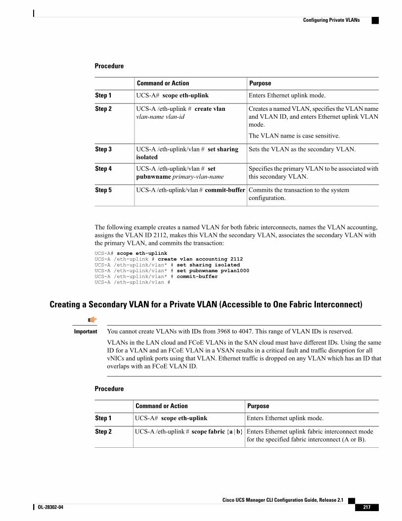
Procedure
PurposeCommand or Action
Enters Ethernet uplink mode.UCS-A# scope eth-uplinkStep 1
Creates a namedVLAN, specifies the VLANnameand VLAN ID, and enters Ethernet uplink VLANmode.
UCS-A /eth-uplink # create vlanvlan-name vlan-id
Step 2
The VLAN name is case sensitive.
Sets the VLAN as the secondary VLAN.UCS-A /eth-uplink/vlan # set sharingisolated
Step 3
Specifies the primary VLAN to be associated withthis secondary VLAN.
UCS-A /eth-uplink/vlan # setpubnwname primary-vlan-name
Step 4
Commits the transaction to the systemconfiguration.
UCS-A /eth-uplink/vlan # commit-bufferStep 5
The following example creates a named VLAN for both fabric interconnects, names the VLAN accounting,assigns the VLAN ID 2112, makes this VLAN the secondary VLAN, associates the secondary VLAN withthe primary VLAN, and commits the transaction:UCS-A# scope eth-uplinkUCS-A /eth-uplink # create vlan accounting 2112UCS-A /eth-uplink/vlan* # set sharing isolatedUCS-A /eth-uplink/vlan* # set pubnwname pvlan1000UCS-A /eth-uplink/vlan* # commit-bufferUCS-A /eth-uplink/vlan #
Creating a Secondary VLAN for a Private VLAN (Accessible to One Fabric Interconnect)
You cannot create VLANs with IDs from 3968 to 4047. This range of VLAN IDs is reserved.
VLANs in the LAN cloud and FCoE VLANs in the SAN cloud must have different IDs. Using the sameID for a VLAN and an FCoE VLAN in a VSAN results in a critical fault and traffic disruption for allvNICs and uplink ports using that VLAN. Ethernet traffic is dropped on any VLAN which has an ID thatoverlaps with an FCoE VLAN ID.
Important
Procedure
PurposeCommand or Action
Enters Ethernet uplink mode.UCS-A# scope eth-uplinkStep 1
Enters Ethernet uplink fabric interconnect modefor the specified fabric interconnect (A or B).
UCS-A /eth-uplink # scope fabric {a | b}Step 2
Cisco UCS Manager CLI Configuration Guide, Release 2.1 OL-28302-04 217
Configuring Private VLANs
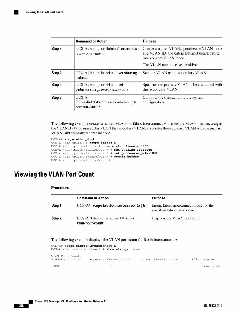
PurposeCommand or Action
Creates a namedVLAN, specifies the VLANnameand VLAN ID, and enters Ethernet uplink fabricinterconnect VLAN mode.
UCS-A /eth-uplink/fabric # create vlanvlan-name vlan-id
Step 3
The VLAN name is case sensitive.
Sets the VLAN as the secondary VLAN.UCS-A /eth-uplink/vlan # set sharingisolated
Step 4
Specifies the primary VLAN to be associated withthis secondary VLAN.
UCS-A /eth-uplink/vlan # setpubnwname primary-vlan-name
Step 5
Commits the transaction to the systemconfiguration.
UCS-A/eth-uplink/fabric/vlan/member-port #commit-buffer
Step 6
The following example creates a named VLAN for fabric interconnect A, names the VLAN finance, assignsthe VLAN ID 3955, makes this VLAN the secondary VLAN, associates the secondary VLANwith the primaryVLAN, and commits the transaction:UCS-A# scope eth-uplinkUCS-A /eth-uplink # scope fabric aUCS-A /eth-uplink/fabric # create vlan finance 3955UCS-A /eth-uplink/fabric/vlan* # set sharing isolatedUCS-A /eth-uplink/fabric/vlan* # set pubnwname pvlan1000UCS-A /eth-uplink/fabric/vlan* # commit-bufferUCS-A /eth-uplink/fabric/vlan #
Viewing the VLAN Port Count
Procedure
PurposeCommand or Action
Enters fabric interconnect mode for thespecified fabric interconnect.
UCS-A# scope fabric-interconnect {a | b}Step 1
Displays the VLAN port count.UCS-A /fabric-interconnect # showvlan-port-count
Step 2
The following example displays the VLAN port count for fabric interconnect A:UCS-A# scope fabric-interconnect aUCS-A /fabric-interconnect # show vlan-port-count
VLAN-Port Count:VLAN-Port Limit Access VLAN-Port Count Border VLAN-Port Count Alloc Status---------- --------------- ---------------- ----------6000 3 0 Available
Cisco UCS Manager CLI Configuration Guide, Release 2.1218 OL-28302-04
Viewing the VLAN Port Count
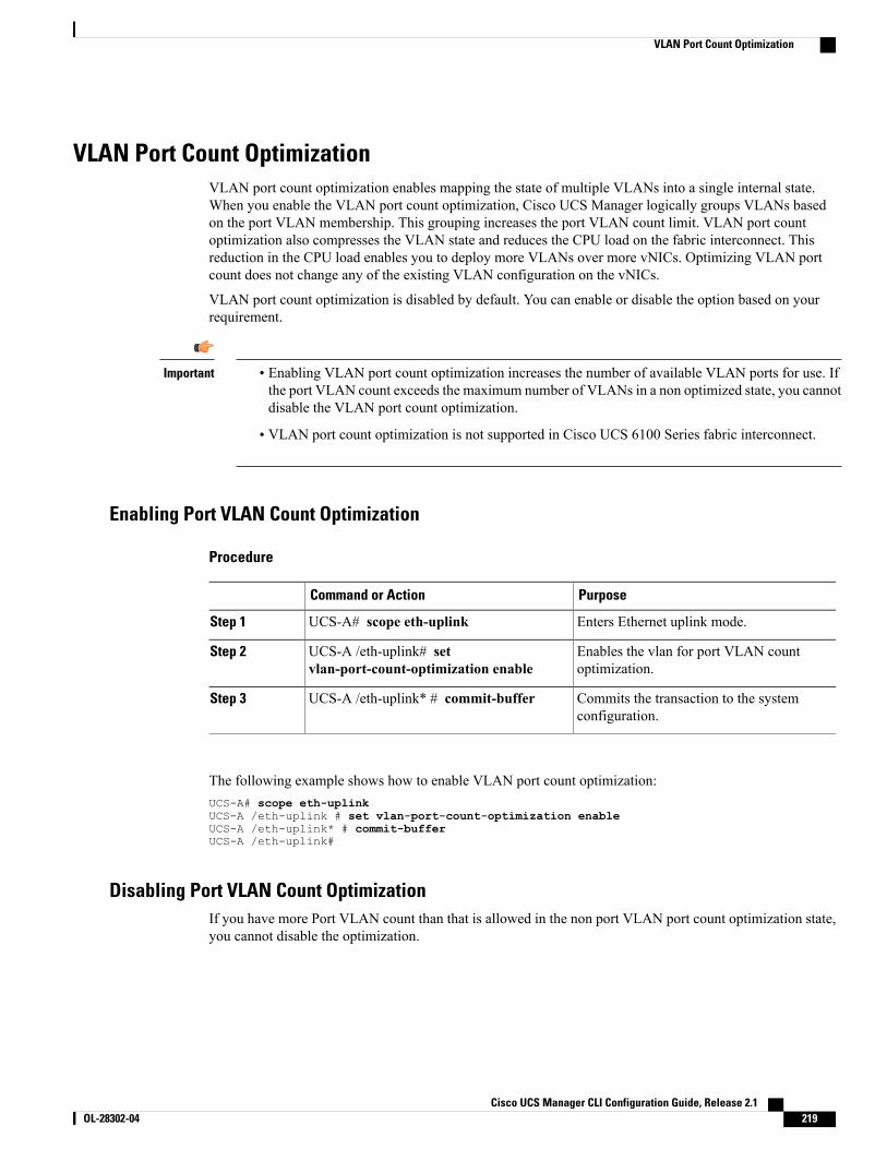
VLAN Port Count OptimizationVLAN port count optimization enables mapping the state of multiple VLANs into a single internal state.When you enable the VLAN port count optimization, Cisco UCS Manager logically groups VLANs basedon the port VLAN membership. This grouping increases the port VLAN count limit. VLAN port countoptimization also compresses the VLAN state and reduces the CPU load on the fabric interconnect. Thisreduction in the CPU load enables you to deploy more VLANs over more vNICs. Optimizing VLAN portcount does not change any of the existing VLAN configuration on the vNICs.
VLAN port count optimization is disabled by default. You can enable or disable the option based on yourrequirement.
Important • Enabling VLAN port count optimization increases the number of available VLAN ports for use. Ifthe port VLAN count exceeds the maximum number of VLANs in a non optimized state, you cannotdisable the VLAN port count optimization.
• VLAN port count optimization is not supported in Cisco UCS 6100 Series fabric interconnect.
Enabling Port VLAN Count Optimization
Procedure
PurposeCommand or Action
Enters Ethernet uplink mode.UCS-A# scope eth-uplinkStep 1
Enables the vlan for port VLAN countoptimization.
UCS-A /eth-uplink# setvlan-port-count-optimization enable
Step 2
Commits the transaction to the systemconfiguration.
UCS-A /eth-uplink* # commit-bufferStep 3
The following example shows how to enable VLAN port count optimization:UCS-A# scope eth-uplinkUCS-A /eth-uplink # set vlan-port-count-optimization enableUCS-A /eth-uplink* # commit-bufferUCS-A /eth-uplink#
Disabling Port VLAN Count OptimizationIf you have more Port VLAN count than that is allowed in the non port VLAN port count optimization state,you cannot disable the optimization.
Cisco UCS Manager CLI Configuration Guide, Release 2.1 OL-28302-04 219
VLAN Port Count Optimization
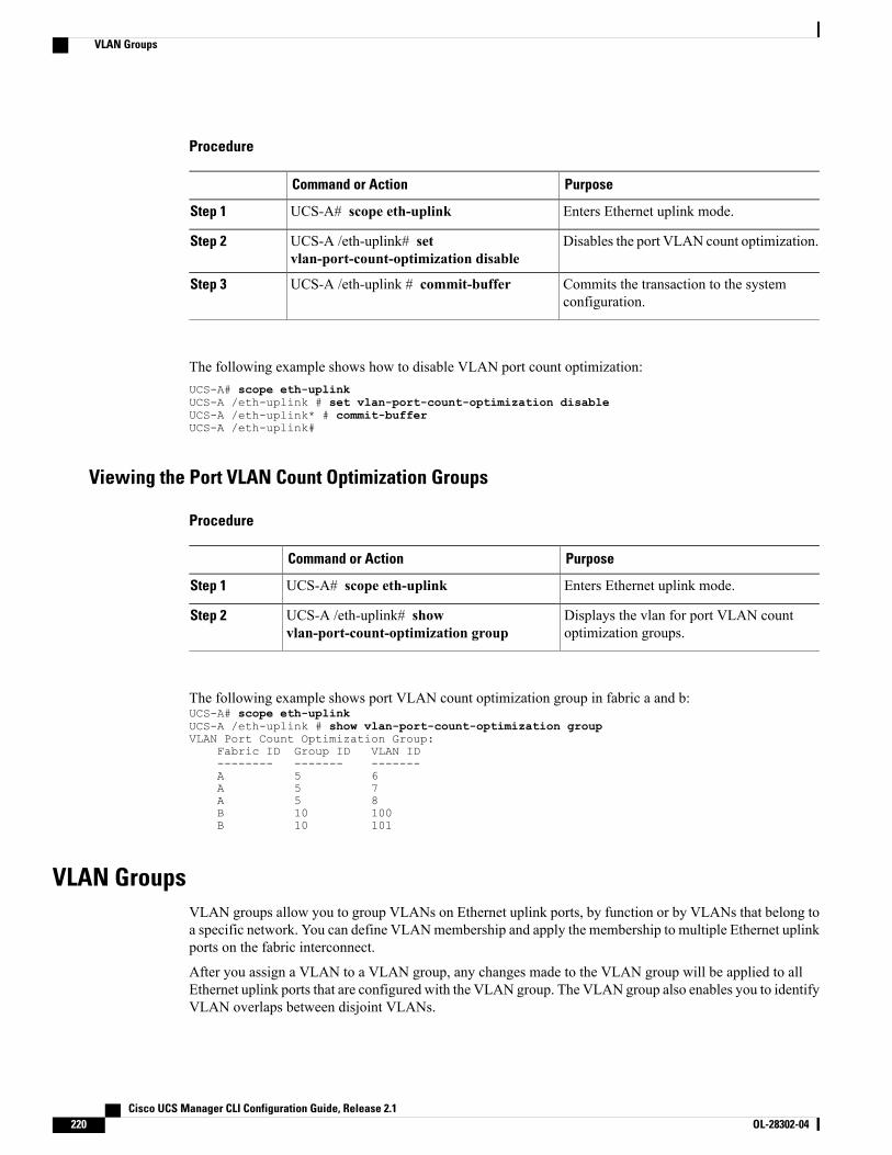
Procedure
PurposeCommand or Action
Enters Ethernet uplink mode.UCS-A# scope eth-uplinkStep 1
Disables the port VLAN count optimization.UCS-A /eth-uplink# setvlan-port-count-optimization disable
Step 2
Commits the transaction to the systemconfiguration.
UCS-A /eth-uplink # commit-bufferStep 3
The following example shows how to disable VLAN port count optimization:UCS-A# scope eth-uplinkUCS-A /eth-uplink # set vlan-port-count-optimization disableUCS-A /eth-uplink* # commit-bufferUCS-A /eth-uplink#
Viewing the Port VLAN Count Optimization Groups
Procedure
PurposeCommand or Action
Enters Ethernet uplink mode.UCS-A# scope eth-uplinkStep 1
Displays the vlan for port VLAN countoptimization groups.
UCS-A /eth-uplink# showvlan-port-count-optimization group
Step 2
The following example shows port VLAN count optimization group in fabric a and b:UCS-A# scope eth-uplinkUCS-A /eth-uplink # show vlan-port-count-optimization groupVLAN Port Count Optimization Group:
Fabric ID Group ID VLAN ID-------- ------- -------A 5 6A 5 7A 5 8B 10 100B 10 101
VLAN GroupsVLAN groups allow you to group VLANs on Ethernet uplink ports, by function or by VLANs that belong toa specific network. You can define VLANmembership and apply the membership to multiple Ethernet uplinkports on the fabric interconnect.
After you assign a VLAN to a VLAN group, any changes made to the VLAN group will be applied to allEthernet uplink ports that are configured with the VLAN group. The VLAN group also enables you to identifyVLAN overlaps between disjoint VLANs.
Cisco UCS Manager CLI Configuration Guide, Release 2.1220 OL-28302-04
VLAN Groups
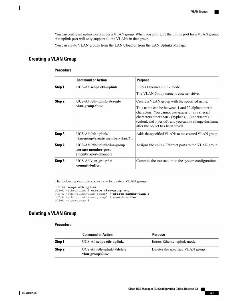
You can configure uplink ports under a VLAN group. When you configure the uplink port for a VLAN group,that uplink port will only support all the VLANs in that group.
You can create VLAN groups from the LAN Cloud or from the LAN Uplinks Manager.
Creating a VLAN Group
Procedure
PurposeCommand or Action
Enters Ethernet uplink mode.UCS-A# scope eth-uplink.Step 1
The VLAN Group name is case sensitive.
Create a VLAN group with the specified name.UCS-A# /eth-uplink/ #createvlan-groupName .
Step 2
This name can be between 1 and 32 alphanumericcharacters. You cannot use spaces or any specialcharacters other than - (hyphen), _ (underscore), :(colon), and . (period), and you cannot change this nameafter the object has been saved.
Adds the specified VLANs to the created VLAN group.UCS-A# /eth-uplink/vlan-group#create member-vlanID .
Step 3
Assigns the uplink Ethernet ports to the VLAN group.UCS-A# /eth-uplink/vlan-group#create member-port[member-port-channel] .
Step 4
Commits the transaction to the system configuration.UCS-A#/vlan-group* #commit-buffer.
Step 5
The following example shows how to create a VLAN group:UCS-A# scope eth-uplinkUCS-A /eth-uplink # create vlan-group engUCS-A /eth-uplink/vlan-group* # create member-vlan 3UCS-A /eth-uplink/vlan-group* # commit-bufferUCS-A /vlan-group #
Deleting a VLAN Group
Procedure
PurposeCommand or Action
Enters Ethernet uplink mode.UCS-A# scope eth-uplink.Step 1
Deletes the specified VLAN group.UCS-A# /eth-uplink/ #deletevlan-groupName .
Step 2
Cisco UCS Manager CLI Configuration Guide, Release 2.1 OL-28302-04 221
VLAN Groups
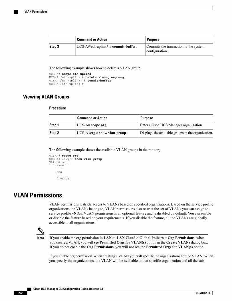
PurposeCommand or Action
Commits the transaction to the systemconfiguration.
UCS-A#/eth-uplink* # commit-buffer.Step 3
The following example shows how to delete a VLAN group:UCS-A# scope eth-uplinkUCS-A /eth-uplink # delete vlan-group engUCS-A /eth-uplink* # commit-bufferUCS-A /eth-uplink #
Viewing VLAN Groups
Procedure
PurposeCommand or Action
Enters Cisco UCS Manager organization.UCS-A# scope orgStep 1
Displays the available groups in the organization.UCS-A /org # show vlan-groupStep 2
The following example shows the available VLAN groups in the root org:UCS-A# scope orgUCS-A# /org/# show vlan-groupVLAN Group:
Name----enghrfinance
VLAN PermissionsVLAN permissions restricts access to VLANs based on specified organizations. Based on the service profileorganizations the VLANs belong to, VLAN permissions also restrict the set of VLANs you can assign toservice profile vNICs. VLAN permissions is an optional feature and is disabled by default. You can enableor disable the feature based on your requirements. If you disable the feature, all the VLANs are globallyaccessible to all organizations.
If you enable the org permission in LAN > LAN Cloud > Global Policies > Org Permissions, whenyou create a VLAN, you will see Permitted Orgs for VLAN(s) option in theCreate VLANs dialog box.If you do not enable the Org Permissions, you will not see the Permitted Orgs for VLAN(s) option.
Note
If you enable org permission, when creating a VLAN you will specify the organizations for the VLAN.Whenyou specify the organizations, the VLAN will be available to that specific organization and all the sub
Cisco UCS Manager CLI Configuration Guide, Release 2.1222 OL-28302-04
VLAN Permissions
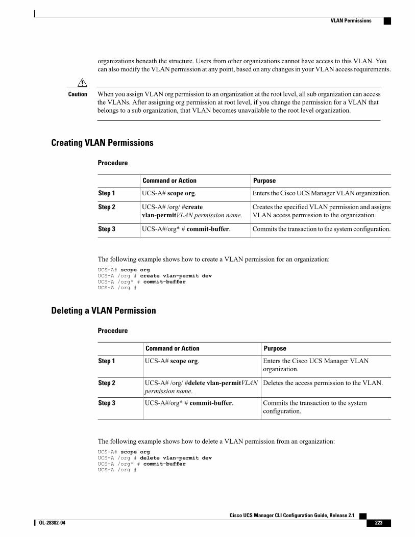
organizations beneath the structure. Users from other organizations cannot have access to this VLAN. Youcan alsomodify the VLAN permission at any point, based on any changes in your VLAN access requirements.
When you assign VLAN org permission to an organization at the root level, all sub organization can accessthe VLANs. After assigning org permission at root level, if you change the permission for a VLAN thatbelongs to a sub organization, that VLAN becomes unavailable to the root level organization.
Caution
Creating VLAN Permissions
Procedure
PurposeCommand or Action
Enters the CiscoUCSManager VLAN organization.UCS-A# scope org.Step 1
Creates the specified VLAN permission and assignsVLAN access permission to the organization.
UCS-A# /org/ #createvlan-permitVLAN permission name.
Step 2
Commits the transaction to the system configuration.UCS-A#/org* # commit-buffer.Step 3
The following example shows how to create a VLAN permission for an organization:UCS-A# scope orgUCS-A /org # create vlan-permit devUCS-A /org* # commit-bufferUCS-A /org #
Deleting a VLAN Permission
Procedure
PurposeCommand or Action
Enters the Cisco UCS Manager VLANorganization.
UCS-A# scope org.Step 1
Deletes the access permission to the VLAN.UCS-A# /org/ #delete vlan-permitVLANpermission name.
Step 2
Commits the transaction to the systemconfiguration.
UCS-A#/org* # commit-buffer.Step 3
The following example shows how to delete a VLAN permission from an organization:UCS-A# scope orgUCS-A /org # delete vlan-permit devUCS-A /org* # commit-bufferUCS-A /org #
Cisco UCS Manager CLI Configuration Guide, Release 2.1 OL-28302-04 223
VLAN Permissions
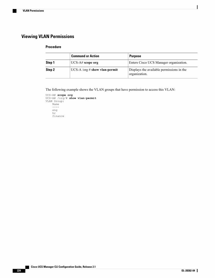
Viewing VLAN Permissions
Procedure
PurposeCommand or Action
Enters Cisco UCS Manager organization.UCS-A# scope orgStep 1
Displays the available permissions in theorganization.
UCS-A /org # show vlan-permitStep 2
The following example shows the VLAN groups that have permission to access this VLAN:UCS-A# scope orgUCS-A# /org/# show vlan-permitVLAN Group:
Name----enghrfinance
Cisco UCS Manager CLI Configuration Guide, Release 2.1224 OL-28302-04
VLAN Permissions
C H A P T E R 17Configuring LAN Pin Groups
This chapter includes the following sections:
• LAN Pin Groups, page 225
• Configuring a LAN Pin Group, page 225
LAN Pin GroupsCisco UCS uses LAN pin groups to pin Ethernet traffic from a vNIC on a server to an uplink Ethernet portor port channel on the fabric interconnect. You can use this pinning to manage the distribution of traffic fromthe servers.
To configure pinning for a server, you must include the LAN pin group in a vNIC policy. The vNIC policyis then included in the service profile assigned to that server. All traffic from the vNIC travels through theI/O module to the specified uplink Ethernet port.
If you do not assign a pin group to a server interface through a vNIC policy, Cisco UCSManager choosesan uplink Ethernet port or port channel for traffic from that server interface dynamically. This choice isnot permanent. A different uplink Ethernet port or port channel may be used for traffic from that serverinterface after an interface flap or a server reboot.
If an uplink is part of a LAN pin group, the uplink is not necessarily reserved for only that LAN pin group.Other vNIC's policies that do not specify a LAN pin group can use the uplink as a dynamic uplink.
Note
Configuring a LAN Pin GroupIn a system with two fabric interconnects, you can associate the pin group with only one fabric interconnector with both fabric interconnects.
Before You Begin
Configure the ports and port channels with which you want to configure the pin group. You can only includeports and port channels configured as uplink ports in a LAN pin group.
Cisco UCS Manager CLI Configuration Guide, Release 2.1 OL-28302-04 225
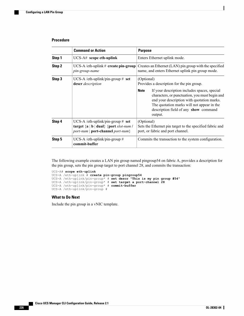
Procedure
PurposeCommand or Action
Enters Ethernet uplink mode.UCS-A# scope eth-uplinkStep 1
Creates an Ethernet (LAN) pin group with the specifiedname, and enters Ethernet uplink pin group mode.
UCS-A /eth-uplink # create pin-grouppin-group-name
Step 2
(Optional)Provides a description for the pin group.
UCS-A /eth-uplink/pin-group # setdescr description
Step 3
If your description includes spaces, specialcharacters, or punctuation, youmust begin andend your description with quotation marks.The quotation marks will not appear in thedescription field of any show commandoutput.
Note
(Optional)Sets the Ethernet pin target to the specified fabric andport, or fabric and port channel.
UCS-A /eth-uplink/pin-group # settarget {a | b | dual} {port slot-num /port-num | port-channel port-num}
Step 4
Commits the transaction to the system configuration.UCS-A /eth-uplink/pin-group #commit-buffer
Step 5
The following example creates a LAN pin group named pingroup54 on fabric A, provides a description forthe pin group, sets the pin group target to port channel 28, and commits the transaction:UCS-A# scope eth-uplinkUCS-A /eth-uplink # create pin-group pingroup54UCS-A /eth-uplink/pin-group* # set descr "This is my pin group #54"UCS-A /eth-uplink/pin-group* # set target a port-channel 28UCS-A /eth-uplink/pin-group* # commit-bufferUCS-A /eth-uplink/pin-group #
What to Do Next
Include the pin group in a vNIC template.
Cisco UCS Manager CLI Configuration Guide, Release 2.1226 OL-28302-04
Configuring a LAN Pin Group
C H A P T E R 18Configuring MAC Pools
This chapter includes the following sections:
• MAC Pools, page 227
• Creating a MAC Pool, page 227
• Deleting a MAC Pool, page 229
MAC PoolsA MAC pool is a collection of network identities, or MAC addresses, that are unique in their Layer 2environment and are available to be assigned to vNICs on a server. If you use MAC pools in service profiles,you do not have to manually configure theMAC addresses to be used by the server associated with the serviceprofile.
In a system that implements multitenancy, you can use the organizational hierarchy to ensure that MAC poolscan be used only by specific applications or business services. Cisco UCS uses the name resolution policy toassign MAC addresses from the pool.
To assign a MAC address to a server, you must include the MAC pool in a vNIC policy. The vNIC policy isthen included in the service profile assigned to that server.
You can specify your own MAC addresses or use a group of MAC addresses provided by Cisco.
Creating a MAC Pool
Procedure
PurposeCommand or Action
Enters organization mode for the specified organization. To enterthe root organization mode, enter / as the org-name.
UCS-A# scope org org-nameStep 1
Creates a MAC pool with the specified name, and entersorganization MAC pool mode.
UCS-A /org # createmac-pool mac-pool-name
Step 2
Cisco UCS Manager CLI Configuration Guide, Release 2.1 OL-28302-04 227
PurposeCommand or Action
This name can be between 1 and 32 alphanumeric characters. Youcannot use spaces or any special characters other than - (hyphen),_ (underscore), : (colon), and . (period), and you cannot changethis name after the object has been saved.
(Optional)Provides a description for the MAC pool.
UCS-A /org/mac-pool # setdescr description
Step 3
If your description includes spaces, special characters, orpunctuation, you must begin and end your descriptionwith quotationmarks. The quotationmarks will not appearin the description field of any show command output.
Note
This can be one of the following:UCS-A /org/mac-pool # setassignmentorder {default |sequential}
Step 4
• default—CiscoUCSManager selects a random identity fromthe pool.
• sequential—CiscoUCSManager selects the lowest availableidentity from the pool.
Creates a block (range) ofMAC addresses, and enters organizationMAC pool block mode. You must specify the first and last MAC
UCS-A /org/mac-pool #create block first-mac-addrlast-mac-addr
Step 5
addresses in the address range using the form nn:nn:nn:nn:nn:nn,with the addresses separated by a space.
A MAC pool can contain more than one MAC addressblock. To create multiple MAC address blocks, you mustenter multiple create block commands from organizationMAC pool mode.
Note
Commits the transaction to the system configuration.UCS-A /org/mac-pool #commit-buffer
Step 6
The following example shows how to create a MAC pool named pool37, provide a description for the pool,define a MAC address block by specifying the first and last MAC addresses in the block, and commit thetransaction:UCS-A# scope org /UCS-A /org # create mac-pool pool37UCS-A /org/mac-pool* # set descr "This is my MAC pool"UCS-A /org/mac-pool* # create block 00:A0:D7:42:00:01 00:A0:D7:42:01:00UCS-A /org/mac-pool/block* # commit-bufferUCS-A /org/mac-pool/block #
What to Do Next
Include the MAC pool in a vNIC template.
Cisco UCS Manager CLI Configuration Guide, Release 2.1228 OL-28302-04
Creating a MAC Pool
Deleting a MAC PoolIf you delete a pool, Cisco UCS Manager does not reallocate any addresses from that pool that have beenassigned to vNICs or vHBAs. All assigned addresses from a deleted pool remain with the vNIC or vHBA towhich they are assigned until one of the following occurs:
• The associated service profiles are deleted.
• The vNIC or vHBA to which the address is assigned is deleted.
• The vNIC or vHBA is assigned to a different pool.
Procedure
PurposeCommand or Action
Enters organization mode for the specifiedorganization. To enter the root organization mode,enter / as the org-name.
UCS-A# scope org org-nameStep 1
Deletes the specified MAC pool.UCS-A /org # delete mac-poolpool-name
Step 2
Commits the transaction to the system configuration.UCS-A /org # commit-bufferStep 3
The following example shows how to delete the MAC pool named pool4 and commit the transaction:UCS-A# scope org /UCS-A /org # delete mac-pool pool4UCS-A /org* # commit-bufferUCS-A /org #
Cisco UCS Manager CLI Configuration Guide, Release 2.1 OL-28302-04 229
Deleting a MAC Pool

Cisco UCS Manager CLI Configuration Guide, Release 2.1230 OL-28302-04
Deleting a MAC Pool
C H A P T E R 19Configuring Quality of Service
This chapter includes the following sections:
• Quality of Service, page 231
• Configuring System Classes, page 231
• Configuring Quality of Service Policies, page 234
• Configuring Flow Control Policies, page 237
Quality of ServiceCisco UCS provides the following methods to implement quality of service:
• System classes that specify the global configuration for certain types of traffic across the entire system
• QoS policies that assign system classes for individual vNICs
• Flow control policies that determine how uplink Ethernet ports handle pause frames
Configuring System Classes
System ClassesCisco UCS uses Data Center Ethernet (DCE) to handle all traffic inside a Cisco UCS domain. This industrystandard enhancement to Ethernet divides the bandwidth of the Ethernet pipe into eight virtual lanes. Twovirtual lanes are reserved for internal system and management traffic. You can configure quality of service(Qos) for the other six virtual lanes. System classes determine how the DCE bandwidth in these six virtuallanes is allocated across the entire Cisco UCS domain.
Each system class reserves a specific segment of the bandwidth for a specific type of traffic, which providesa level of traffic management, even in an oversubscribed system. For example, you can configure the FibreChannel Priority system class to determine the percentage of DCE bandwidth allocated to FCoE traffic.
The following table describes the system classes that you can configure.
Cisco UCS Manager CLI Configuration Guide, Release 2.1 OL-28302-04 231
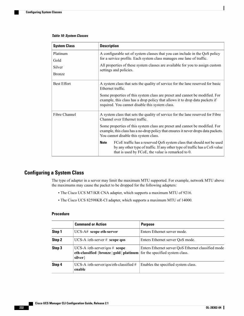
Table 10: System Classes
DescriptionSystem Class
A configurable set of system classes that you can include in the QoS policyfor a service profile. Each system class manages one lane of traffic.
All properties of these system classes are available for you to assign customsettings and policies.
Platinum
Gold
Silver
Bronze
A system class that sets the quality of service for the lane reserved for basicEthernet traffic.
Some properties of this system class are preset and cannot be modified. Forexample, this class has a drop policy that allows it to drop data packets ifrequired. You cannot disable this system class.
Best Effort
A system class that sets the quality of service for the lane reserved for FibreChannel over Ethernet traffic.
Some properties of this system class are preset and cannot be modified. Forexample, this class has a no-drop policy that ensures it never drops data packets.You cannot disable this system class.
FCoE traffic has a reserved QoS system class that should not be usedby any other type of traffic. If any other type of traffic has a CoS valuethat is used by FCoE, the value is remarked to 0.
Note
Fibre Channel
Configuring a System ClassThe type of adapter in a server may limit the maximum MTU supported. For example, network MTU abovethe maximums may cause the packet to be dropped for the following adapters:
• The Cisco UCS M71KR CNA adapter, which supports a maximum MTU of 9216.
• The Cisco UCS 82598KR-CI adapter, which supports a maximum MTU of 14000.
Procedure
PurposeCommand or Action
Enters Ethernet server mode.UCS-A# scope eth-serverStep 1
Enters Ethernet server QoS mode.UCS-A /eth-server # scope qosStep 2
Enters Ethernet server QoS Ethernet classified modefor the specified system class.
UCS-A /eth-server/qos # scopeeth-classified {bronze | gold | platinumsilver}
Step 3
Enables the specified system class.UCS-A /eth-server/qos/eth-classified #enable
Step 4
Cisco UCS Manager CLI Configuration Guide, Release 2.1232 OL-28302-04
Configuring System Classes
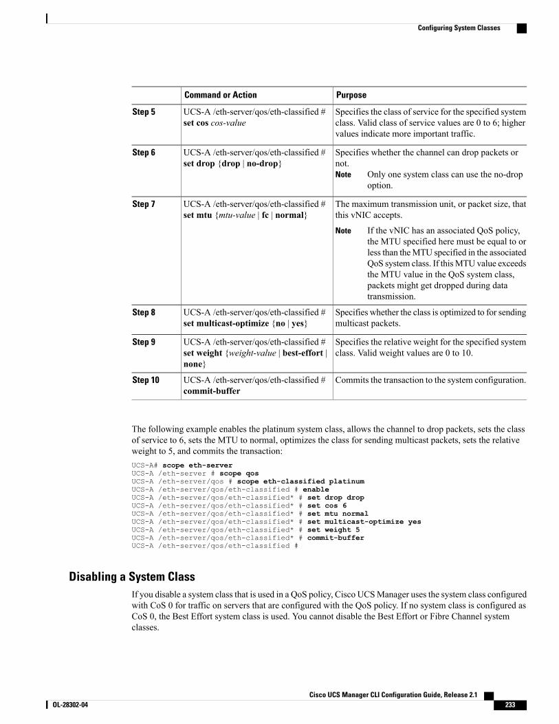
PurposeCommand or Action
Specifies the class of service for the specified systemclass. Valid class of service values are 0 to 6; highervalues indicate more important traffic.
UCS-A /eth-server/qos/eth-classified #set cos cos-value
Step 5
Specifies whether the channel can drop packets ornot.
Only one system class can use the no-dropoption.
Note
UCS-A /eth-server/qos/eth-classified #set drop {drop | no-drop}
Step 6
The maximum transmission unit, or packet size, thatthis vNIC accepts.
UCS-A /eth-server/qos/eth-classified #set mtu {mtu-value | fc | normal}
Step 7
If the vNIC has an associated QoS policy,the MTU specified here must be equal to orless than theMTU specified in the associatedQoS system class. If thisMTU value exceedsthe MTU value in the QoS system class,packets might get dropped during datatransmission.
Note
Specifies whether the class is optimized to for sendingmulticast packets.
UCS-A /eth-server/qos/eth-classified #set multicast-optimize {no | yes}
Step 8
Specifies the relative weight for the specified systemclass. Valid weight values are 0 to 10.
UCS-A /eth-server/qos/eth-classified #set weight {weight-value | best-effort |none}
Step 9
Commits the transaction to the system configuration.UCS-A /eth-server/qos/eth-classified #commit-buffer
Step 10
The following example enables the platinum system class, allows the channel to drop packets, sets the classof service to 6, sets the MTU to normal, optimizes the class for sending multicast packets, sets the relativeweight to 5, and commits the transaction:UCS-A# scope eth-serverUCS-A /eth-server # scope qosUCS-A /eth-server/qos # scope eth-classified platinumUCS-A /eth-server/qos/eth-classified # enableUCS-A /eth-server/qos/eth-classified* # set drop dropUCS-A /eth-server/qos/eth-classified* # set cos 6UCS-A /eth-server/qos/eth-classified* # set mtu normalUCS-A /eth-server/qos/eth-classified* # set multicast-optimize yesUCS-A /eth-server/qos/eth-classified* # set weight 5UCS-A /eth-server/qos/eth-classified* # commit-bufferUCS-A /eth-server/qos/eth-classified #
Disabling a System ClassIf you disable a system class that is used in a QoS policy, Cisco UCSManager uses the system class configuredwith CoS 0 for traffic on servers that are configured with the QoS policy. If no system class is configured asCoS 0, the Best Effort system class is used. You cannot disable the Best Effort or Fibre Channel systemclasses.
Cisco UCS Manager CLI Configuration Guide, Release 2.1 OL-28302-04 233
Configuring System Classes

Procedure
PurposeCommand or Action
Enters Ethernet server mode.UCS-A# scope eth-serverStep 1
Enters Ethernet server QoS mode.UCS-A /eth-server # scope qosStep 2
Enters Ethernet server QoS Ethernet classifiedmode for the specified system class.
UCS-A /eth-server/qos # scope eth-classified{bronze | gold | platinum silver}
Step 3
Disables the specified system class.UCS-A /eth-server/qos/eth-classified # disableStep 4
Commits the transaction to the systemconfiguration.
UCS-A /eth-server/qos/eth-classified #commit-buffer
Step 5
The following example disables the platinum system class and commits the transaction:UCS-A# scope eth-serverUCS-A /eth-server # scope qosUCS-A /eth-server/qos # scope eth-classified platinumUCS-A /eth-server/qos/eth-classified # disableUCS-A /eth-server/qos/eth-classified* # commit-bufferUCS-A /eth-server/qos/eth-classified #
Configuring Quality of Service Policies
Quality of Service PolicyA quality of service (QoS) policy assigns a system class to the outgoing traffic for a vNIC or vHBA. Thissystem class determines the quality of service for that traffic. For certain adapters, you can also specifyadditional controls on the outgoing traffic, such as burst and rate.
You must include a QoS policy in a vNIC policy or vHBA policy and then include that policy in a serviceprofile to configure the vNIC or vHBA.
Configuring a QoS Policy
Procedure
PurposeCommand or Action
Enters org mode for the specified organization. To enter the defaultorg mode, type / as the org-name .
Switch-A# scope orgorg-name
Step 1
Creates the specified QoS policy, and enters org QoS policy mode.Switch-A /org # createqos-policy policy-name
Step 2
Cisco UCS Manager CLI Configuration Guide, Release 2.1234 OL-28302-04
Configuring Quality of Service Policies
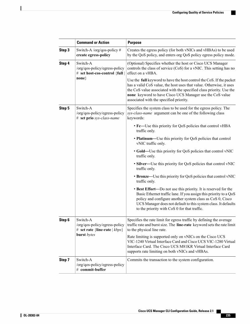
PurposeCommand or Action
Creates the egress policy (for both vNICs and vHBAs) to be usedby the QoS policy, and enters org QoS policy egress policy mode.
Switch-A /org/qos-policy #create egress-policy
Step 3
(Optional) Specifies whether the host or Cisco UCS Managercontrols the class of service (CoS) for a vNIC. This setting has noeffect on a vHBA.
Switch-A/org/qos-policy/egress-policy# set host-cos-control {full |none}
Step 4
Use the full keyword to have the host control the CoS. If the packethas a valid CoS value, the host uses that value. Otherwise, it usesthe CoS value associated with the specified class priority. Use thenone keyword to have Cisco UCS Manager use the CoS valueassociated with the specified priority.
Specifies the system class to be used for the egress policy. Thesys-class-name argument can be one of the following classkeywords:
Switch-A/org/qos-policy/egress-policy# set prio sys-class-name
Step 5
• Fc—Use this priority for QoS policies that control vHBAtraffic only.
• Platinum—Use this priority for QoS policies that controlvNIC traffic only.
• Gold—Use this priority for QoS policies that control vNICtraffic only.
• Silver—Use this priority for QoS policies that control vNICtraffic only.
• Bronze—Use this priority for QoS policies that control vNICtraffic only.
• Best Effort—Do not use this priority. It is reserved for theBasic Ethernet traffic lane. If you assign this priority to a QoSpolicy and configure another system class as CoS 0, CiscoUCSManager does not default to this system class. It defaultsto the priority with CoS 0 for that traffic.
Specifies the rate limit for egress traffic by defining the averagetraffic rate and burst size. The line-rate keyword sets the rate limitto the physical line rate.
Switch-A/org/qos-policy/egress-policy# set rate {line-rate | kbps}burst bytes
Step 6
Rate limiting is supported only on vNICs on the Cisco UCSVIC-1240 Virtual Interface Card and Cisco UCS VIC-1280 VirtualInterface Card. The Cisco UCS M81KR Virtual Interface Cardsupports rate limiting on both vNICs and vHBAs.
Commits the transaction to the system configuration.Switch-A/org/qos-policy/egress-policy# commit-buffer
Step 7
Cisco UCS Manager CLI Configuration Guide, Release 2.1 OL-28302-04 235
Configuring Quality of Service Policies
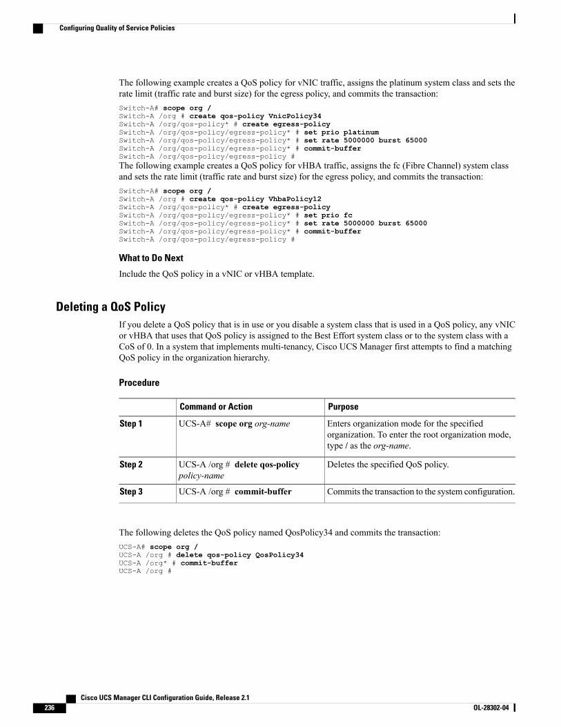
The following example creates a QoS policy for vNIC traffic, assigns the platinum system class and sets therate limit (traffic rate and burst size) for the egress policy, and commits the transaction:Switch-A# scope org /Switch-A /org # create qos-policy VnicPolicy34Switch-A /org/qos-policy* # create egress-policySwitch-A /org/qos-policy/egress-policy* # set prio platinumSwitch-A /org/qos-policy/egress-policy* # set rate 5000000 burst 65000Switch-A /org/qos-policy/egress-policy* # commit-bufferSwitch-A /org/qos-policy/egress-policy #The following example creates a QoS policy for vHBA traffic, assigns the fc (Fibre Channel) system classand sets the rate limit (traffic rate and burst size) for the egress policy, and commits the transaction:Switch-A# scope org /Switch-A /org # create qos-policy VhbaPolicy12Switch-A /org/qos-policy* # create egress-policySwitch-A /org/qos-policy/egress-policy* # set prio fcSwitch-A /org/qos-policy/egress-policy* # set rate 5000000 burst 65000Switch-A /org/qos-policy/egress-policy* # commit-bufferSwitch-A /org/qos-policy/egress-policy #
What to Do Next
Include the QoS policy in a vNIC or vHBA template.
Deleting a QoS PolicyIf you delete a QoS policy that is in use or you disable a system class that is used in a QoS policy, any vNICor vHBA that uses that QoS policy is assigned to the Best Effort system class or to the system class with aCoS of 0. In a system that implements multi-tenancy, Cisco UCS Manager first attempts to find a matchingQoS policy in the organization hierarchy.
Procedure
PurposeCommand or Action
Enters organization mode for the specifiedorganization. To enter the root organization mode,type / as the org-name.
UCS-A# scope org org-nameStep 1
Deletes the specified QoS policy.UCS-A /org # delete qos-policypolicy-name
Step 2
Commits the transaction to the system configuration.UCS-A /org # commit-bufferStep 3
The following deletes the QoS policy named QosPolicy34 and commits the transaction:UCS-A# scope org /UCS-A /org # delete qos-policy QosPolicy34UCS-A /org* # commit-bufferUCS-A /org #
Cisco UCS Manager CLI Configuration Guide, Release 2.1236 OL-28302-04
Configuring Quality of Service Policies
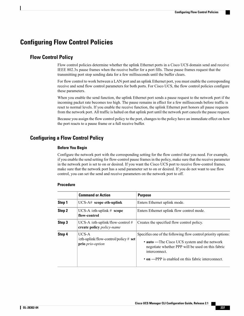
Configuring Flow Control Policies
Flow Control PolicyFlow control policies determine whether the uplink Ethernet ports in a Cisco UCS domain send and receiveIEEE 802.3x pause frames when the receive buffer for a port fills. These pause frames request that thetransmitting port stop sending data for a few milliseconds until the buffer clears.
For flow control to work between a LAN port and an uplink Ethernet port, you must enable the correspondingreceive and send flow control parameters for both ports. For Cisco UCS, the flow control policies configurethese parameters.
When you enable the send function, the uplink Ethernet port sends a pause request to the network port if theincoming packet rate becomes too high. The pause remains in effect for a few milliseconds before traffic isreset to normal levels. If you enable the receive function, the uplink Ethernet port honors all pause requestsfrom the network port. All traffic is halted on that uplink port until the network port cancels the pause request.
Because you assign the flow control policy to the port, changes to the policy have an immediate effect on howthe port reacts to a pause frame or a full receive buffer.
Configuring a Flow Control Policy
Before You Begin
Configure the network port with the corresponding setting for the flow control that you need. For example,if you enable the send setting for flow-control pause frames in the policy, make sure that the receive parameterin the network port is set to on or desired. If you want the Cisco UCS port to receive flow-control frames,make sure that the network port has a send parameter set to on or desired. If you do not want to use flowcontrol, you can set the send and receive parameters on the network port to off.
Procedure
PurposeCommand or Action
Enters Ethernet uplink mode.UCS-A# scope eth-uplinkStep 1
Enters Ethernet uplink flow control mode.UCS-A /eth-uplink # scopeflow-control
Step 2
Creates the specified flow control policy.UCS-A /eth-uplink/flow-control #create policy policy-name
Step 3
Specifies one of the following flow control priority options:UCS-A/eth-uplink/flow-control/policy # setprio prio-option
Step 4
• auto—The Cisco UCS system and the networknegotiate whether PPP will be used on this fabricinterconnect.
• on—PPP is enabled on this fabric interconnect.
Cisco UCS Manager CLI Configuration Guide, Release 2.1 OL-28302-04 237
Configuring Flow Control Policies
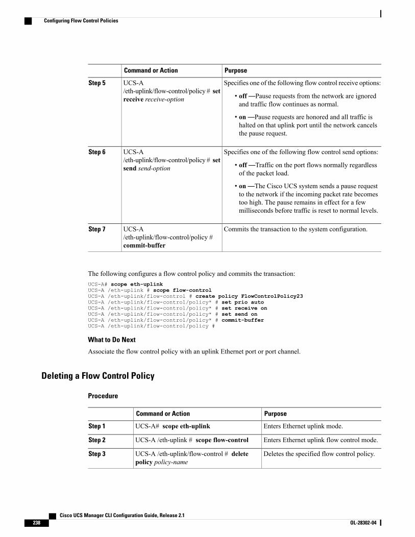
PurposeCommand or Action
Specifies one of the following flow control receive options:UCS-A/eth-uplink/flow-control/policy # setreceive receive-option
Step 5
• off—Pause requests from the network are ignoredand traffic flow continues as normal.
• on—Pause requests are honored and all traffic ishalted on that uplink port until the network cancelsthe pause request.
Specifies one of the following flow control send options:UCS-A/eth-uplink/flow-control/policy # setsend send-option
Step 6
• off—Traffic on the port flows normally regardlessof the packet load.
• on—The Cisco UCS system sends a pause requestto the network if the incoming packet rate becomestoo high. The pause remains in effect for a fewmilliseconds before traffic is reset to normal levels.
Commits the transaction to the system configuration.UCS-A/eth-uplink/flow-control/policy #commit-buffer
Step 7
The following configures a flow control policy and commits the transaction:UCS-A# scope eth-uplinkUCS-A /eth-uplink # scope flow-controlUCS-A /eth-uplink/flow-control # create policy FlowControlPolicy23UCS-A /eth-uplink/flow-control/policy* # set prio autoUCS-A /eth-uplink/flow-control/policy* # set receive onUCS-A /eth-uplink/flow-control/policy* # set send onUCS-A /eth-uplink/flow-control/policy* # commit-bufferUCS-A /eth-uplink/flow-control/policy #
What to Do Next
Associate the flow control policy with an uplink Ethernet port or port channel.
Deleting a Flow Control Policy
Procedure
PurposeCommand or Action
Enters Ethernet uplink mode.UCS-A# scope eth-uplinkStep 1
Enters Ethernet uplink flow control mode.UCS-A /eth-uplink # scope flow-controlStep 2
Deletes the specified flow control policy.UCS-A /eth-uplink/flow-control # deletepolicy policy-name
Step 3
Cisco UCS Manager CLI Configuration Guide, Release 2.1238 OL-28302-04
Configuring Flow Control Policies
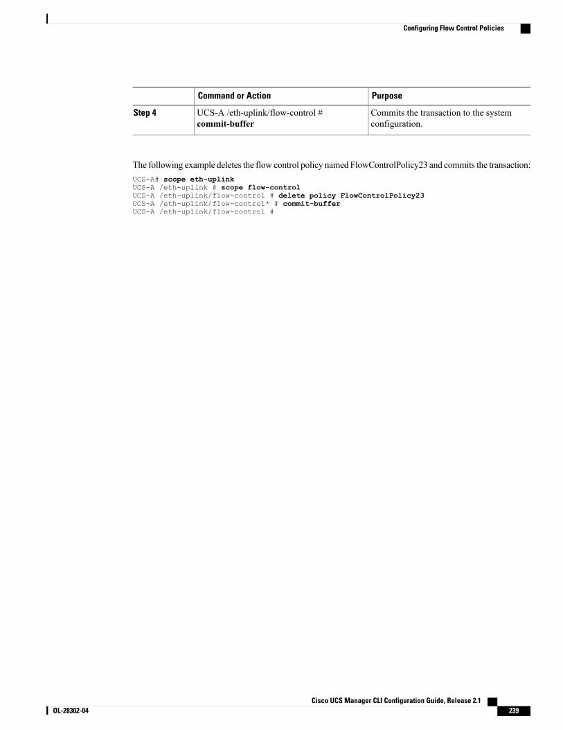
PurposeCommand or Action
Commits the transaction to the systemconfiguration.
UCS-A /eth-uplink/flow-control #commit-buffer
Step 4
The following example deletes the flow control policy named FlowControlPolicy23 and commits the transaction:UCS-A# scope eth-uplinkUCS-A /eth-uplink # scope flow-controlUCS-A /eth-uplink/flow-control # delete policy FlowControlPolicy23UCS-A /eth-uplink/flow-control* # commit-bufferUCS-A /eth-uplink/flow-control #
Cisco UCS Manager CLI Configuration Guide, Release 2.1 OL-28302-04 239
Configuring Flow Control Policies

Cisco UCS Manager CLI Configuration Guide, Release 2.1240 OL-28302-04
Configuring Flow Control Policies
C H A P T E R 20Configuring Network-Related Policies
This chapter includes the following sections:
• Configuring vNIC Templates, page 241
• Configuring Ethernet Adapter Policies, page 244
• Configuring the Default vNIC Behavior Policy, page 248
• Configuring LAN Connectivity Policies, page 249
• Configuring Network Control Policies, page 257
• Configuring Multicast Policies, page 259
Configuring vNIC Templates
vNIC TemplateThis policy defines how a vNIC on a server connects to the LAN. This policy is also referred to as a vNICLAN connectivity policy.
Cisco UCSManager does not automatically create a VM-FEX port profile with the correct settings when youcreate a vNIC template. If you want to create a VM-FEX port profile, you must configure the target of thevNIC template as a VM.
You need to include this policy in a service profile for it to take effect.
If your server has two Emulex or QLogic NICs (Cisco UCS CNA M71KR-E or Cisco UCS CNAM71KR-Q), youmust configure vNIC policies for both adapters in your service profile to get a user-definedMAC address for both NICs. If you do not configure policies for both NICs, Windows still detects bothof them in the PCI bus. Then because the second eth is not part of your service profile, Windows assignsit a hardware MAC address. If you then move the service profile to a different server, Windows seesadditional NICs because one NIC did not have a user-defined MAC address.
Note
Cisco UCS Manager CLI Configuration Guide, Release 2.1 OL-28302-04 241
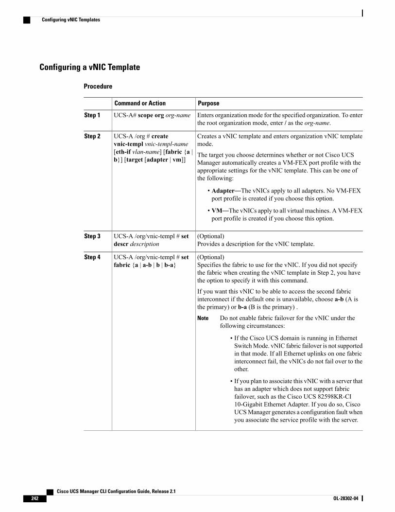
Configuring a vNIC Template
Procedure
PurposeCommand or Action
Enters organization mode for the specified organization. To enterthe root organization mode, enter / as the org-name.
UCS-A# scope org org-nameStep 1
Creates a vNIC template and enters organization vNIC templatemode.
UCS-A /org # createvnic-templ vnic-templ-name
Step 2
[eth-if vlan-name] [fabric {a |b}] [target [adapter | vm]]
The target you choose determines whether or not Cisco UCSManager automatically creates a VM-FEX port profile with theappropriate settings for the vNIC template. This can be one ofthe following:
• Adapter—The vNICs apply to all adapters. No VM-FEXport profile is created if you choose this option.
• VM—The vNICs apply to all virtual machines. AVM-FEXport profile is created if you choose this option.
(Optional)Provides a description for the vNIC template.
UCS-A /org/vnic-templ # setdescr description
Step 3
(Optional)Specifies the fabric to use for the vNIC. If you did not specifythe fabric when creating the vNIC template in Step 2, you havethe option to specify it with this command.
UCS-A /org/vnic-templ # setfabric {a | a-b | b | b-a}
Step 4
If you want this vNIC to be able to access the second fabricinterconnect if the default one is unavailable, choose a-b (A isthe primary) or b-a (B is the primary) .
Do not enable fabric failover for the vNIC under thefollowing circumstances:
Note
• If the Cisco UCS domain is running in EthernetSwitchMode. vNIC fabric failover is not supportedin that mode. If all Ethernet uplinks on one fabricinterconnect fail, the vNICs do not fail over to theother.
• If you plan to associate this vNICwith a server thathas an adapter which does not support fabricfailover, such as the Cisco UCS 82598KR-CI10-Gigabit Ethernet Adapter. If you do so, CiscoUCSManager generates a configuration fault whenyou associate the service profile with the server.
Cisco UCS Manager CLI Configuration Guide, Release 2.1242 OL-28302-04
Configuring vNIC Templates
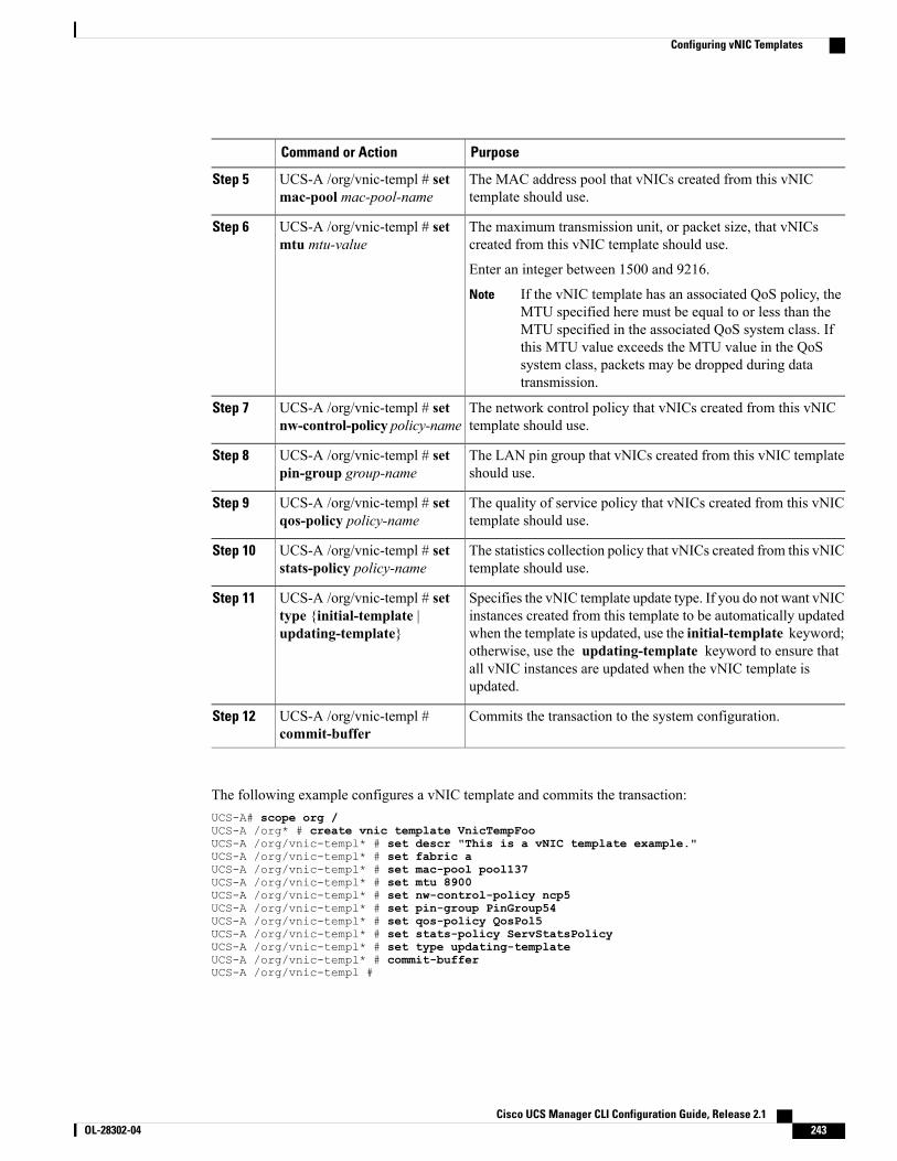
PurposeCommand or Action
The MAC address pool that vNICs created from this vNICtemplate should use.
UCS-A /org/vnic-templ # setmac-pool mac-pool-name
Step 5
The maximum transmission unit, or packet size, that vNICscreated from this vNIC template should use.
UCS-A /org/vnic-templ # setmtu mtu-value
Step 6
Enter an integer between 1500 and 9216.
If the vNIC template has an associated QoS policy, theMTU specified here must be equal to or less than theMTU specified in the associated QoS system class. Ifthis MTU value exceeds the MTU value in the QoSsystem class, packets may be dropped during datatransmission.
Note
The network control policy that vNICs created from this vNICtemplate should use.
UCS-A /org/vnic-templ # setnw-control-policy policy-name
Step 7
The LAN pin group that vNICs created from this vNIC templateshould use.
UCS-A /org/vnic-templ # setpin-group group-name
Step 8
The quality of service policy that vNICs created from this vNICtemplate should use.
UCS-A /org/vnic-templ # setqos-policy policy-name
Step 9
The statistics collection policy that vNICs created from this vNICtemplate should use.
UCS-A /org/vnic-templ # setstats-policy policy-name
Step 10
Specifies the vNIC template update type. If you do not want vNICinstances created from this template to be automatically updated
UCS-A /org/vnic-templ # settype {initial-template |updating-template}
Step 11
when the template is updated, use the initial-template keyword;otherwise, use the updating-template keyword to ensure thatall vNIC instances are updated when the vNIC template isupdated.
Commits the transaction to the system configuration.UCS-A /org/vnic-templ #commit-buffer
Step 12
The following example configures a vNIC template and commits the transaction:UCS-A# scope org /UCS-A /org* # create vnic template VnicTempFooUCS-A /org/vnic-templ* # set descr "This is a vNIC template example."UCS-A /org/vnic-templ* # set fabric aUCS-A /org/vnic-templ* # set mac-pool pool137UCS-A /org/vnic-templ* # set mtu 8900UCS-A /org/vnic-templ* # set nw-control-policy ncp5UCS-A /org/vnic-templ* # set pin-group PinGroup54UCS-A /org/vnic-templ* # set qos-policy QosPol5UCS-A /org/vnic-templ* # set stats-policy ServStatsPolicyUCS-A /org/vnic-templ* # set type updating-templateUCS-A /org/vnic-templ* # commit-bufferUCS-A /org/vnic-templ #
Cisco UCS Manager CLI Configuration Guide, Release 2.1 OL-28302-04 243
Configuring vNIC Templates
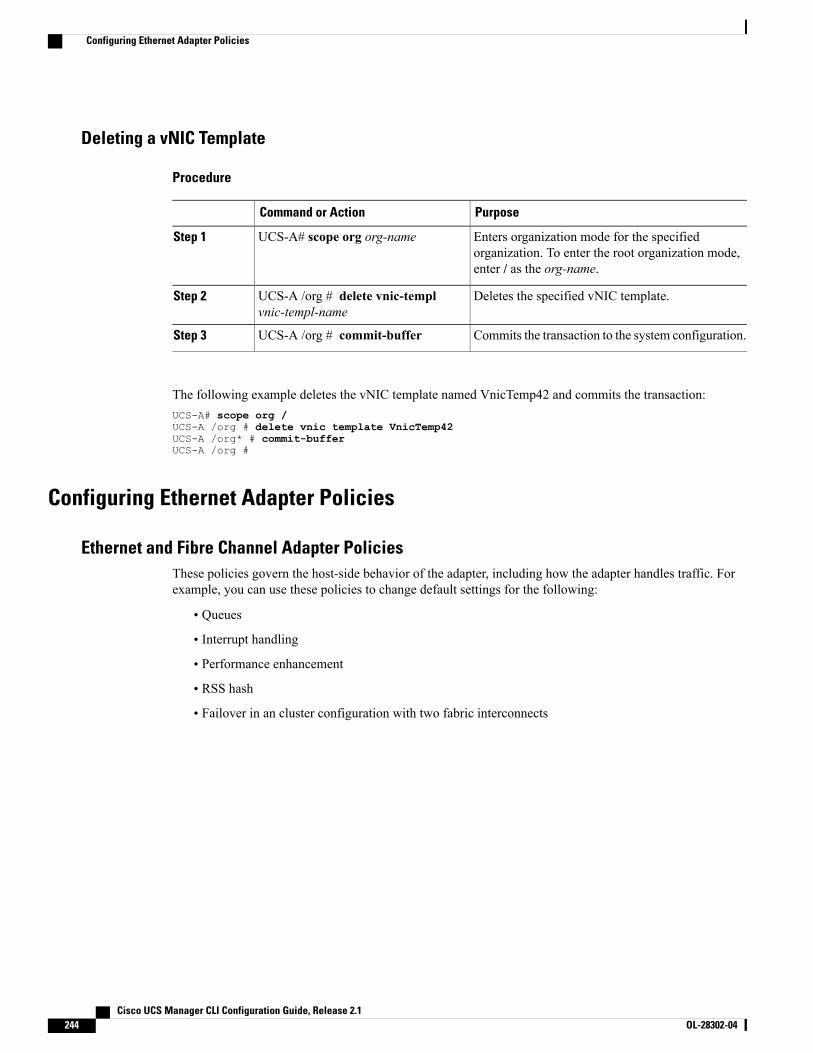
Deleting a vNIC Template
Procedure
PurposeCommand or Action
Enters organization mode for the specifiedorganization. To enter the root organization mode,enter / as the org-name.
UCS-A# scope org org-nameStep 1
Deletes the specified vNIC template.UCS-A /org # delete vnic-templvnic-templ-name
Step 2
Commits the transaction to the system configuration.UCS-A /org # commit-bufferStep 3
The following example deletes the vNIC template named VnicTemp42 and commits the transaction:UCS-A# scope org /UCS-A /org # delete vnic template VnicTemp42UCS-A /org* # commit-bufferUCS-A /org #
Configuring Ethernet Adapter Policies
Ethernet and Fibre Channel Adapter PoliciesThese policies govern the host-side behavior of the adapter, including how the adapter handles traffic. Forexample, you can use these policies to change default settings for the following:
• Queues
• Interrupt handling
• Performance enhancement
• RSS hash
• Failover in an cluster configuration with two fabric interconnects
Cisco UCS Manager CLI Configuration Guide, Release 2.1244 OL-28302-04
Configuring Ethernet Adapter Policies
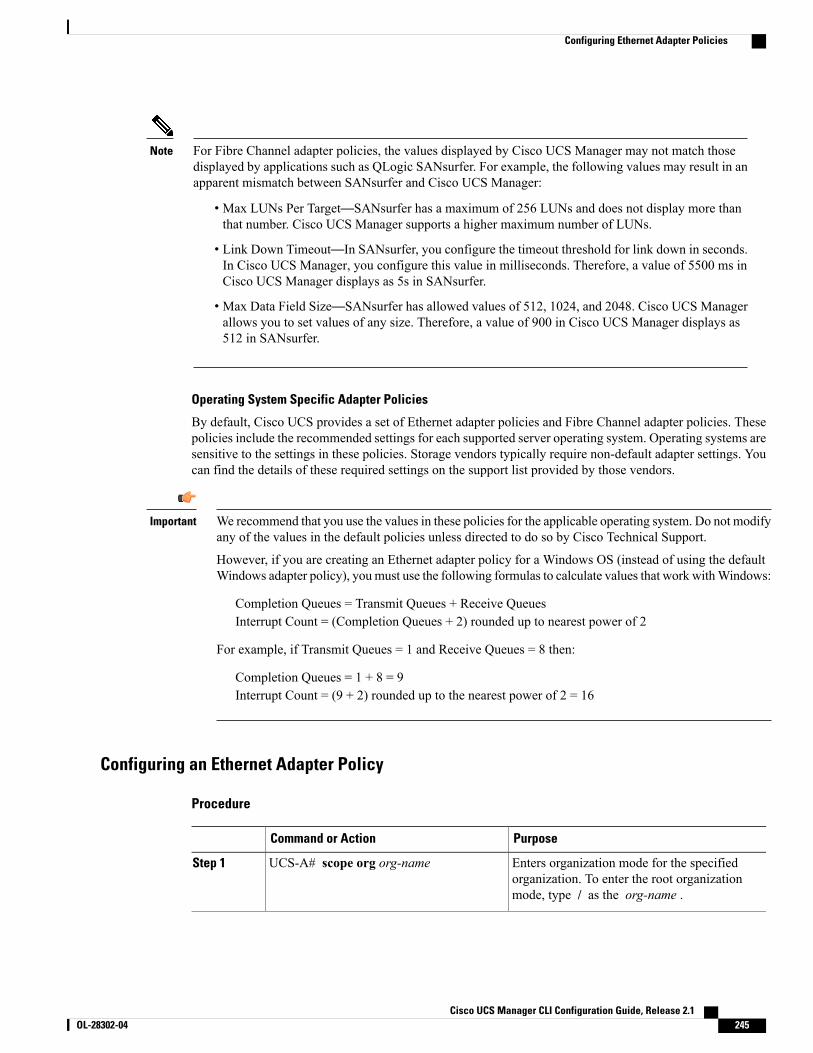
For Fibre Channel adapter policies, the values displayed by Cisco UCS Manager may not match thosedisplayed by applications such as QLogic SANsurfer. For example, the following values may result in anapparent mismatch between SANsurfer and Cisco UCS Manager:
Note
• Max LUNs Per Target—SANsurfer has a maximum of 256 LUNs and does not display more thanthat number. Cisco UCS Manager supports a higher maximum number of LUNs.
• Link Down Timeout—In SANsurfer, you configure the timeout threshold for link down in seconds.In Cisco UCS Manager, you configure this value in milliseconds. Therefore, a value of 5500 ms inCisco UCS Manager displays as 5s in SANsurfer.
• Max Data Field Size—SANsurfer has allowed values of 512, 1024, and 2048. Cisco UCS Managerallows you to set values of any size. Therefore, a value of 900 in Cisco UCS Manager displays as512 in SANsurfer.
Operating System Specific Adapter Policies
By default, Cisco UCS provides a set of Ethernet adapter policies and Fibre Channel adapter policies. Thesepolicies include the recommended settings for each supported server operating system. Operating systems aresensitive to the settings in these policies. Storage vendors typically require non-default adapter settings. Youcan find the details of these required settings on the support list provided by those vendors.
We recommend that you use the values in these policies for the applicable operating system. Do not modifyany of the values in the default policies unless directed to do so by Cisco Technical Support.
However, if you are creating an Ethernet adapter policy for a Windows OS (instead of using the defaultWindows adapter policy), youmust use the following formulas to calculate values that work withWindows:
Important
Completion Queues = Transmit Queues + Receive QueuesInterrupt Count = (Completion Queues + 2) rounded up to nearest power of 2
For example, if Transmit Queues = 1 and Receive Queues = 8 then:
Completion Queues = 1 + 8 = 9Interrupt Count = (9 + 2) rounded up to the nearest power of 2 = 16
Configuring an Ethernet Adapter Policy
Procedure
PurposeCommand or Action
Enters organization mode for the specifiedorganization. To enter the root organizationmode, type / as the org-name .
UCS-A# scope org org-nameStep 1
Cisco UCS Manager CLI Configuration Guide, Release 2.1 OL-28302-04 245
Configuring Ethernet Adapter Policies
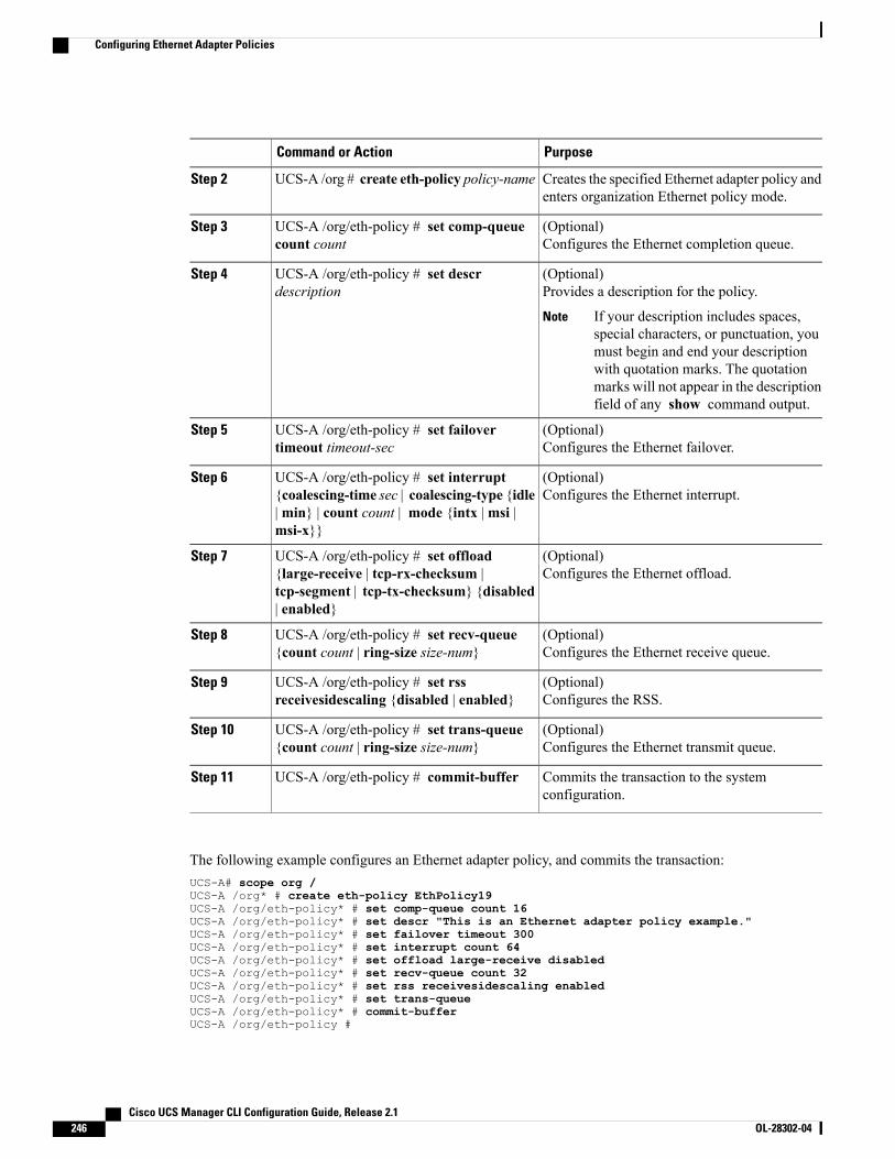
PurposeCommand or Action
Creates the specified Ethernet adapter policy andenters organization Ethernet policy mode.
UCS-A /org # create eth-policy policy-nameStep 2
(Optional)Configures the Ethernet completion queue.
UCS-A /org/eth-policy # set comp-queuecount count
Step 3
(Optional)Provides a description for the policy.
UCS-A /org/eth-policy # set descrdescription
Step 4
If your description includes spaces,special characters, or punctuation, youmust begin and end your descriptionwith quotation marks. The quotationmarks will not appear in the descriptionfield of any show command output.
Note
(Optional)Configures the Ethernet failover.
UCS-A /org/eth-policy # set failovertimeout timeout-sec
Step 5
(Optional)Configures the Ethernet interrupt.
UCS-A /org/eth-policy # set interrupt{coalescing-time sec | coalescing-type {idle|min} | count count | mode {intx |msi |msi-x}}
Step 6
(Optional)Configures the Ethernet offload.
UCS-A /org/eth-policy # set offload{large-receive | tcp-rx-checksum |tcp-segment | tcp-tx-checksum} {disabled| enabled}
Step 7
(Optional)Configures the Ethernet receive queue.
UCS-A /org/eth-policy # set recv-queue{count count | ring-size size-num}
Step 8
(Optional)Configures the RSS.
UCS-A /org/eth-policy # set rssreceivesidescaling {disabled | enabled}
Step 9
(Optional)Configures the Ethernet transmit queue.
UCS-A /org/eth-policy # set trans-queue{count count | ring-size size-num}
Step 10
Commits the transaction to the systemconfiguration.
UCS-A /org/eth-policy # commit-bufferStep 11
The following example configures an Ethernet adapter policy, and commits the transaction:UCS-A# scope org /UCS-A /org* # create eth-policy EthPolicy19UCS-A /org/eth-policy* # set comp-queue count 16UCS-A /org/eth-policy* # set descr "This is an Ethernet adapter policy example."UCS-A /org/eth-policy* # set failover timeout 300UCS-A /org/eth-policy* # set interrupt count 64UCS-A /org/eth-policy* # set offload large-receive disabledUCS-A /org/eth-policy* # set recv-queue count 32UCS-A /org/eth-policy* # set rss receivesidescaling enabledUCS-A /org/eth-policy* # set trans-queueUCS-A /org/eth-policy* # commit-bufferUCS-A /org/eth-policy #
Cisco UCS Manager CLI Configuration Guide, Release 2.1246 OL-28302-04
Configuring Ethernet Adapter Policies

Configuring an Ethernet Adapter Policy to Enable eNIC Support for MRQS on Linux OperatingSystems
Cisco UCSManager includes eNIC support for the Multiple Receive Queue Support (MRQS) feature on RedHat Enterprise Linux Version 6.x and SUSE Linux Enterprise Server Version 11.x.
Procedure
Step 1 Create an Ethernet adapter policy.Use the following parameters when creating the Ethernet adapter policy:
• Transmit Queues = 1
• Receive Queues = n (up to 8)
• Completion Queues = # of Transmit Queues + # of Receive Queues
• Interrupts = # Completion Queues + 2
• Receive Side Scaling (RSS) = Enabled
• Interrupt Mode = Msi-X
See Creating an Ethernet Adapter Policy.
Step 2 Install an eNIC driver Version 2.1.1.35 or later.See Cisco UCS Virtual Interface Card Drivers for Linux Installation Guide.
Step 3 Reboot the server
Deleting an Ethernet Adapter Policy
Procedure
PurposeCommand or Action
Enters organization mode for the specifiedorganization. To enter the root organization mode,type / as the org-name .
UCS-A# scope org org-nameStep 1
Deletes the specified Ethernet adapter policy.UCS-A /org # delete eth-policypolicy-name
Step 2
Commits the transaction to the system configuration.UCS-A /org # commit-bufferStep 3
The following example deletes the Ethernet adapter policy named EthPolicy19 and commits the transaction:UCS-A# scope org /UCS-A /org # delete eth-policy EthPolicy19
Cisco UCS Manager CLI Configuration Guide, Release 2.1 OL-28302-04 247
Configuring Ethernet Adapter Policies
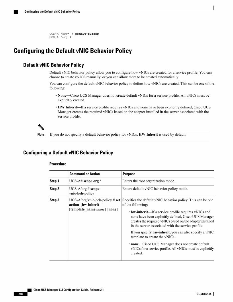
UCS-A /org* # commit-bufferUCS-A /org #
Configuring the Default vNIC Behavior Policy
Default vNIC Behavior PolicyDefault vNIC behavior policy allow you to configure how vNICs are created for a service profile. You canchoose to create vNICS manually, or you can allow them to be created automatically
You can configure the default vNIC behavior policy to define how vNICs are created. This can be one of thefollowing:
• None—Cisco UCS Manager does not create default vNICs for a service profile. All vNICs must beexplicitly created.
• HW Inherit—If a service profile requires vNICs and none have been explicitly defined, Cisco UCSManager creates the required vNICs based on the adapter installed in the server associated with theservice profile.
If you do not specify a default behavior policy for vNICs, HW Inherit is used by default.Note
Configuring a Default vNIC Behavior Policy
Procedure
PurposeCommand or Action
Enters the root organization mode.UCS-A# scope org /Step 1
Enters default vNIC behavior policy mode.UCS-A/org # scopevnic-beh-policy
Step 2
Specifies the default vNIC behavior policy. This can be oneof the following:
UCS-A/org/vnic-beh-policy # setaction {hw-inherit[template_name name] | none}
Step 3
• hw-inherit—If a service profile requires vNICs andnone have been explicitly defined, Cisco UCSManagercreates the required vNICs based on the adapter installedin the server associated with the service profile.
If you specify hw-inherit, you can also specify a vNICtemplate to create the vNICs.
• none—Cisco UCS Manager does not create defaultvNICs for a service profile. All vNICsmust be explicitlycreated.
Cisco UCS Manager CLI Configuration Guide, Release 2.1248 OL-28302-04
Configuring the Default vNIC Behavior Policy

PurposeCommand or Action
Commits the transaction to the system configuration.UCS-A/org/vnic-beh-policy #commit-buffer
Step 4
This example shows how to set the default vNIC behavior policy to hw-inherit:UCS-A # scope org /UCS-A/org # scope vnic-beh-policyUCS-A/org/vnic-beh-policy # set action hw-inheritUCS-A/org/vnic-beh-policy* # commit-bufferUCS-A/org/vnic-beh-policy #
Configuring LAN Connectivity Policies
LAN and SAN Connectivity PoliciesConnectivity policies determine the connections and the network communication resources between the serverand the LAN or SAN on the network. These policies use pools to assignMAC addresses,WWNs, andWWPNsto servers and to identify the vNICs and vHBAs that the servers use to communicate with the network.
We do not recommend that you use static IDs in connectivity policies, because these policies are includedin service profiles and service profile templates and can be used to configure multiple servers.
Note
Privileges Required for LAN and SAN Connectivity PoliciesConnectivity policies enable users without network or storage privileges to create and modify service profilesand service profile templates with network and storage connections. However, users must have the appropriatenetwork and storage privileges to create connectivity policies.
Privileges Required to Create Connectivity Policies
Connectivity policies require the same privileges as other network and storage configurations. For example,you must have at least one of the following privileges to create connectivity policies:
• admin—Can create LAN and SAN connectivity policies
• ls-server—Can create LAN and SAN connectivity policies
• ls-network—Can create LAN connectivity policies
• ls-storage—Can create SAN connectivity policies
Privileges Required to Add Connectivity Policies to Service Profiles
After the connectivity policies have been created, a user with ls-compute privileges can include them in aservice profile or service profile template. However, a user with only ls-compute privileges cannot createconnectivity policies.
Cisco UCS Manager CLI Configuration Guide, Release 2.1 OL-28302-04 249
Configuring LAN Connectivity Policies
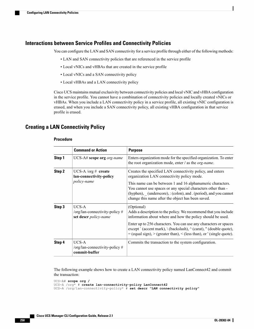
Interactions between Service Profiles and Connectivity PoliciesYou can configure the LAN and SAN connectivity for a service profile through either of the followingmethods:
• LAN and SAN connectivity policies that are referenced in the service profile
• Local vNICs and vHBAs that are created in the service profile
• Local vNICs and a SAN connectivity policy
• Local vHBAs and a LAN connectivity policy
CiscoUCSmaintainsmutual exclusivity between connectivity policies and local vNIC and vHBA configurationin the service profile. You cannot have a combination of connectivity policies and locally created vNICs orvHBAs. When you include a LAN connectivity policy in a service profile, all existing vNIC configuration iserased, and when you include a SAN connectivity policy, all existing vHBA configuration in that serviceprofile is erased.
Creating a LAN Connectivity Policy
Procedure
PurposeCommand or Action
Enters organization mode for the specified organization. To enterthe root organization mode, enter / as the org-name.
UCS-A# scope org org-nameStep 1
Creates the specified LAN connectivity policy, and entersorganization LAN connectivity policy mode.
UCS-A /org # createlan-connectivity-policypolicy-name
Step 2
This name can be between 1 and 16 alphanumeric characters.You cannot use spaces or any special characters other than -(hyphen), _ (underscore), : (colon), and . (period), and you cannotchange this name after the object has been saved.
(Optional)Adds a description to the policy.We recommend that you includeinformation about where and how the policy should be used.
UCS-A/org/lan-connectivity-policy #set descr policy-name
Step 3
Enter up to 256 characters. You can use any characters or spacesexcept ` (accent mark), \ (backslash), ^ (carat), " (double quote),= (equal sign), > (greater than), < (less than), or ' (single quote).
Commits the transaction to the system configuration.UCS-A/org/lan-connectivity-policy #commit-buffer
Step 4
The following example shows how to create a LAN connectivity policy named LanConnect42 and committhe transaction:UCS-A# scope org /UCS-A /org* # create lan-connectivity-policy LanConnect42UCS-A /org/lan-connectivity-policy* # set descr "LAN connectivity policy"
Cisco UCS Manager CLI Configuration Guide, Release 2.1250 OL-28302-04
Configuring LAN Connectivity Policies
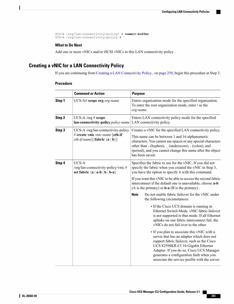
UCS-A /org/lan-connectivity-policy* # commit-bufferUCS-A /org/lan-connectivity-policy #
What to Do Next
Add one or more vNICs and/or iSCSI vNICs to this LAN connectivity policy.
Creating a vNIC for a LAN Connectivity PolicyIf you are continuing from Creating a LAN Connectivity Policy, on page 250, begin this procedure at Step 3.
Procedure
PurposeCommand or Action
Enters organization mode for the specified organization.To enter the root organization mode, enter / as theorg-name.
UCS-A# scope org org-nameStep 1
Enters LAN connectivity policy mode for the specifiedLAN connectivity policy.
UCS-A /org # scopelan-connectivity-policy policy-name
Step 2
Creates a vNIC for the specified LAN connectivity policy.UCS-A /org/lan-connectivity-policy# create vnic vnic-name [eth-ifeth-if-name] [fabric {a | b}]
Step 3
This name can be between 1 and 16 alphanumericcharacters. You cannot use spaces or any special charactersother than - (hyphen), _ (underscore), : (colon), and .(period), and you cannot change this name after the objecthas been saved.
Specifies the fabric to use for the vNIC. If you did notspecify the fabric when you created the vNIC in Step 3,you have the option to specify it with this command.
UCS-A/org/lan-connectivity-policy/vnic #set fabric {a | a-b | b | b-a}
Step 4
If you want this vNIC to be able to access the second fabricinterconnect if the default one is unavailable, choose a-b(A is the primary) or b-a (B is the primary) .
Do not enable fabric failover for the vNIC underthe following circumstances:
Note
• If the Cisco UCS domain is running inEthernet Switch Mode. vNIC fabric failoveris not supported in that mode. If all Ethernetuplinks on one fabric interconnect fail, thevNICs do not fail over to the other.
• If you plan to associate this vNIC with aserver that has an adapter which does notsupport fabric failover, such as the CiscoUCS 82598KR-CI 10-Gigabit EthernetAdapter. If you do so, Cisco UCS Managergenerates a configuration fault when youassociate the service profile with the server.
Cisco UCS Manager CLI Configuration Guide, Release 2.1 OL-28302-04 251
Configuring LAN Connectivity Policies
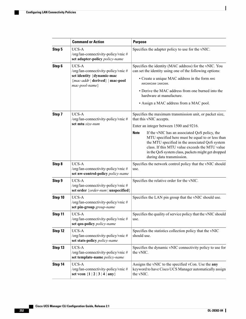
PurposeCommand or Action
Specifies the adapter policy to use for the vNIC.UCS-A/org/lan-connectivity-policy/vnic #set adapter-policy policy-name
Step 5
Specifies the identity (MAC address) for the vNIC. Youcan set the identity using one of the following options:
UCS-A/org/lan-connectivity-policy/vnic #
Step 6
set identity {dynamic-mac• Create a unique MAC address in the form nn:nn:nn:nn :nn:nn.
{mac-addr | derived} |mac-poolmac-pool-name}
• Derive the MAC address from one burned into thehardware at manufacture.
• Assign a MAC address from a MAC pool.
Specifies the maximum transmission unit, or packet size,that this vNIC accepts.
UCS-A/org/lan-connectivity-policy/vnic #set mtu size-num
Step 7
Enter an integer between 1500 and 9216.
If the vNIC has an associated QoS policy, theMTU specified here must be equal to or less thanthe MTU specified in the associated QoS systemclass. If this MTU value exceeds the MTU valuein the QoS system class, packets might get droppedduring data transmission.
Note
Specifies the network control policy that the vNIC shoulduse.
UCS-A/org/lan-connectivity-policy/vnic #set nw-control-policy policy-name
Step 8
Specifies the relative order for the vNIC.UCS-A/org/lan-connectivity-policy/vnic #set order {order-num | unspecified}
Step 9
Specifies the LAN pin group that the vNIC should use.UCS-A/org/lan-connectivity-policy/vnic #set pin-group group-name
Step 10
Specifies the quality of service policy that the vNIC shoulduse.
UCS-A/org/lan-connectivity-policy/vnic #set qos-policy policy-name
Step 11
Specifies the statistics collection policy that the vNICshould use.
UCS-A/org/lan-connectivity-policy/vnic #set stats-policy policy-name
Step 12
Specifies the dynamic vNIC connectivity policy to use forthe vNIC.
UCS-A/org/lan-connectivity-policy/vnic #set template-name policy-name
Step 13
Assigns the vNIC to the specified vCon. Use the anykeyword to have Cisco UCSManager automatically assignthe vNIC.
UCS-A/org/lan-connectivity-policy/vnic #set vcon {1 | 2 | 3 | 4 | any}
Step 14
Cisco UCS Manager CLI Configuration Guide, Release 2.1252 OL-28302-04
Configuring LAN Connectivity Policies
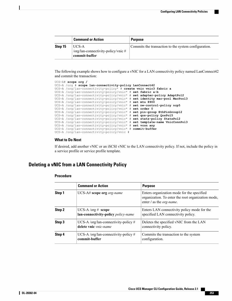
PurposeCommand or Action
Commits the transaction to the system configuration.UCS-A/org/lan-connectivity-policy/vnic #commit-buffer
Step 15
The following example shows how to configure a vNIC for a LAN connectivity policy named LanConnect42and commit the transaction:UCS-A# scope org /UCS-A /org # scope lan-connectivity-policy LanConnect42UCS-A /org/lan-connectivity-policy* # create vnic vnic3 fabric aUCS-A /org/lan-connectivity-policy/vnic* # set fabric a-bUCS-A /org/lan-connectivity-policy/vnic* # set adapter-policy AdaptPol2UCS-A /org/lan-connectivity-policy/vnic* # set identity mac-pool MacPool3UCS-A /org/lan-connectivity-policy/vnic* # set mtu 8900UCS-A /org/lan-connectivity-policy/vnic* # set nw-control-policy ncp5UCS-A /org/lan-connectivity-policy/vnic* # set order 0UCS-A /org/lan-connectivity-policy/vnic* # set pin-group EthPinGroup12UCS-A /org/lan-connectivity-policy/vnic* # set qos-policy QosPol5UCS-A /org/lan-connectivity-policy/vnic* # set stats-policy StatsPol2UCS-A /org/lan-connectivity-policy/vnic* # set template-name VnicConnPol3UCS-A /org/lan-connectivity-policy/vnic* # set vcon anyUCS-A /org/lan-connectivity-policy/vnic* # commit-bufferUCS-A /org/lan-connectivity-policy/vnic #
What to Do Next
If desired, add another vNIC or an iSCSI vNIC to the LAN connectivity policy. If not, include the policy ina service profile or service profile template.
Deleting a vNIC from a LAN Connectivity Policy
Procedure
PurposeCommand or Action
Enters organization mode for the specifiedorganization. To enter the root organization mode,enter / as the org-name.
UCS-A# scope org org-nameStep 1
Enters LAN connectivity policy mode for thespecified LAN connectivity policy.
UCS-A /org # scopelan-connectivity-policy policy-name
Step 2
Deletes the specified vNIC from the LANconnectivity policy.
UCS-A /org/lan-connectivity-policy #delete vnic vnic-name
Step 3
Commits the transaction to the systemconfiguration.
UCS-A /org/lan-connectivity-policy #commit-buffer
Step 4
Cisco UCS Manager CLI Configuration Guide, Release 2.1 OL-28302-04 253
Configuring LAN Connectivity Policies
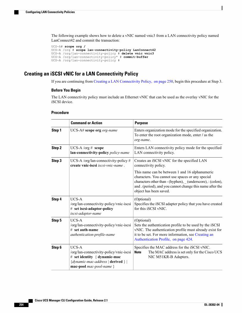
The following example shows how to delete a vNIC named vnic3 from a LAN connectivity policy namedLanConnect42 and commit the transaction:UCS-A# scope org /UCS-A /org # scope lan-connectivity-policy LanConnect42UCS-A /org/lan-connectivity-policy # delete vnic vnic3UCS-A /org/lan-connectivity-policy* # commit-bufferUCS-A /org/lan-connectivity-policy #
Creating an iSCSI vNIC for a LAN Connectivity PolicyIf you are continuing from Creating a LAN Connectivity Policy, on page 250, begin this procedure at Step 3.
Before You Begin
The LAN connectivity policy must include an Ethernet vNIC that can be used as the overlay vNIC for theiSCSI device.
Procedure
PurposeCommand or Action
Enters organization mode for the specified organization.To enter the root organization mode, enter / as theorg-name.
UCS-A# scope org org-nameStep 1
Enters LAN connectivity policy mode for the specifiedLAN connectivity policy.
UCS-A /org # scopelan-connectivity-policy policy-name
Step 2
Creates an iSCSI vNIC for the specified LANconnectivity policy.
UCS-A /org/lan-connectivity-policy #create vnic-iscsi iscsi-vnic-name .
Step 3
This name can be between 1 and 16 alphanumericcharacters. You cannot use spaces or any specialcharacters other than - (hyphen), _ (underscore), : (colon),and . (period), and you cannot change this name after theobject has been saved.
(Optional)Specifies the iSCSI adapter policy that you have createdfor this iSCSI vNIC.
UCS-A/org/lan-connectivity-policy/vnic-iscsi# set iscsi-adaptor-policyiscsi-adaptor-name
Step 4
(Optional)Sets the authentication profile to be used by the iSCSIvNIC. The authentication profile must already exist for
UCS-A/org/lan-connectivity-policy/vnic-iscsi# set auth-nameauthentication-profile-name
Step 5
it to be set. For more information, see Creating anAuthentication Profile, on page 424.
Specifies the MAC address for the iSCSI vNIC.TheMAC address is set only for the Cisco UCSNIC M51KR-B Adapters.
NoteUCS-A/org/lan-connectivity-policy/vnic-iscsi# set identity { dynamic-mac{dynamic-mac-address | derived } |mac-pool mac-pool-name }
Step 6
Cisco UCS Manager CLI Configuration Guide, Release 2.1254 OL-28302-04
Configuring LAN Connectivity Policies
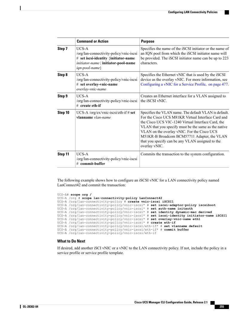
PurposeCommand or Action
Specifies the name of the iSCSI initiator or the name ofan IQN pool from which the iSCSI initiator name will
UCS-A/org/lan-connectivity-policy/vnic-iscsi
Step 7
be provided. The iSCSI initiator name can be up to 223characters.
# set iscsi-identity {initiator-nameinitiator-name | initiator-pool-nameiqn-pool-name}
Specifies the Ethernet vNIC that is used by the iSCSIdevice as the overlay vNIC. For more information, seeConfiguring a vNIC for a Service Profile, on page 477.
UCS-A/org/lan-connectivity-policy/vnic-iscsi# set overlay-vnic-nameoverlay-vnic-name
Step 8
Creates an Ethernet interface for a VLAN assigned tothe iSCSI vNIC.
UCS-A/org/lan-connectivity-policy/vnic-iscsi# create eth-if
Step 9
Specifies the VLAN name. The default VLAN is default.For the Cisco UCS M81KR Virtual Interface Card and
UCS-A /org/ex/vnic-iscsi/eth-if # setvlanname vlan-name
Step 10
the Cisco UCS VIC-1240 Virtual Interface Card, theVLAN that you specify must be the same as the nativeVLAN on the overlay vNIC. For the Cisco UCSM51KR-B Broadcom BCM57711 Adapter, the VLANthat you specify can be any VLAN assigned to theoverlay vNIC.
Commits the transaction to the system configuration.UCS-A/org/lan-connectivity-policy/vnic-iscsi# commit-buffer
Step 11
The following example shows how to configure an iSCSI vNIC for a LAN connectivity policy namedLanConnect42 and commit the transaction:
UCS-A# scope org /UCS-A /org # scope lan-connectivity-policy LanConnect42UCS-A /org/lan-connectivity-policy # create vnic-iscsi iSCSI1UCS-A /org/lan-connectivity-policy/vnic-iscsi* # set iscsi-adaptor-policy iscsibootUCS-A /org/lan-connectivity-policy/vnic-iscsi* # set auth-name initauthUCS-A /org/lan-connectivity-policy/vnic-iscsi* # set identity dynamic-mac derivedUCS-A /org/lan-connectivity-policy/vnic-iscsi* # set iscsi-identity initiator-name iSCSI1UCS-A /org/lan-connectivity-policy/vnic-iscsi* # set overlay-vnic-name eth1UCS-A /org/lan-connectivity-policy/vnic-iscsi* # create eth-ifUCS-A /org/lan-connectivity-policy/vnic-iscsi/eth-if* # set vlanname defaultUCS-A /org/lan-connectivity-policy/vnic-iscsi/eth-if* # commit bufferUCS-A /org/lan-connectivity-policy/vnic-iscsi/eth-if
What to Do Next
If desired, add another iSCI vNIC or a vNIC to the LAN connectivity policy. If not, include the policy in aservice profile or service profile template.
Cisco UCS Manager CLI Configuration Guide, Release 2.1 OL-28302-04 255
Configuring LAN Connectivity Policies
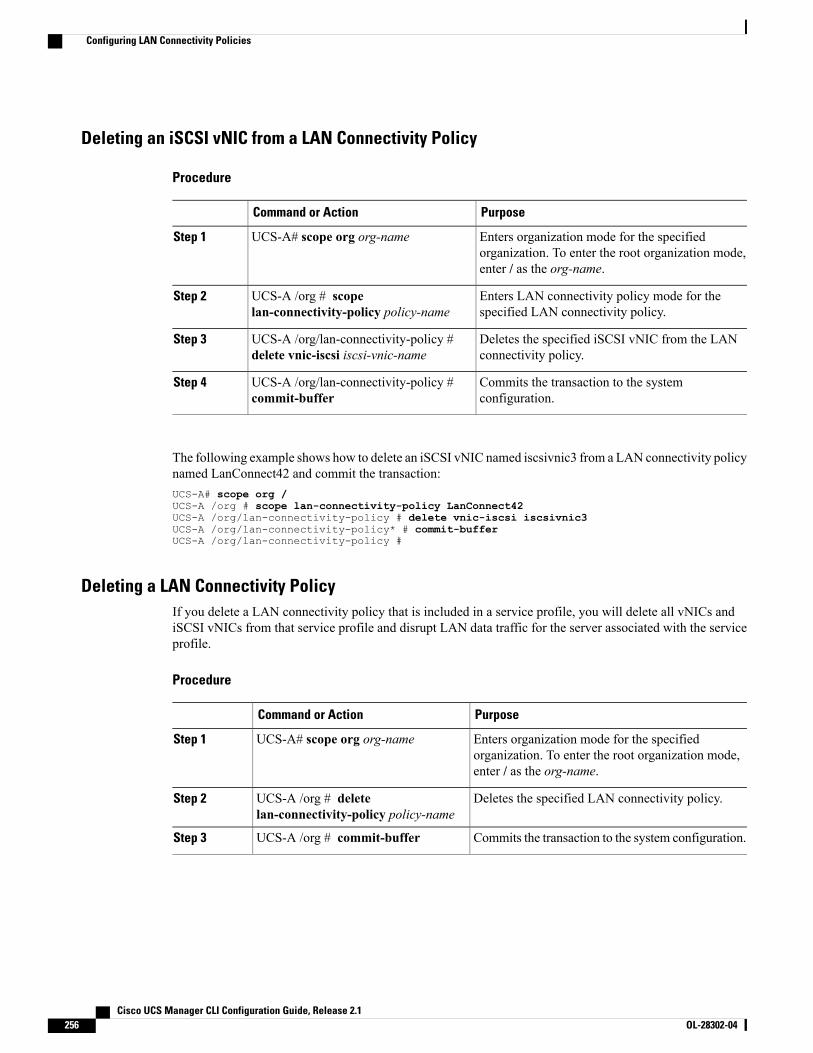
Deleting an iSCSI vNIC from a LAN Connectivity Policy
Procedure
PurposeCommand or Action
Enters organization mode for the specifiedorganization. To enter the root organization mode,enter / as the org-name.
UCS-A# scope org org-nameStep 1
Enters LAN connectivity policy mode for thespecified LAN connectivity policy.
UCS-A /org # scopelan-connectivity-policy policy-name
Step 2
Deletes the specified iSCSI vNIC from the LANconnectivity policy.
UCS-A /org/lan-connectivity-policy #delete vnic-iscsi iscsi-vnic-name
Step 3
Commits the transaction to the systemconfiguration.
UCS-A /org/lan-connectivity-policy #commit-buffer
Step 4
The following example shows how to delete an iSCSI vNIC named iscsivnic3 from a LAN connectivity policynamed LanConnect42 and commit the transaction:UCS-A# scope org /UCS-A /org # scope lan-connectivity-policy LanConnect42UCS-A /org/lan-connectivity-policy # delete vnic-iscsi iscsivnic3UCS-A /org/lan-connectivity-policy* # commit-bufferUCS-A /org/lan-connectivity-policy #
Deleting a LAN Connectivity PolicyIf you delete a LAN connectivity policy that is included in a service profile, you will delete all vNICs andiSCSI vNICs from that service profile and disrupt LAN data traffic for the server associated with the serviceprofile.
Procedure
PurposeCommand or Action
Enters organization mode for the specifiedorganization. To enter the root organization mode,enter / as the org-name.
UCS-A# scope org org-nameStep 1
Deletes the specified LAN connectivity policy.UCS-A /org # deletelan-connectivity-policy policy-name
Step 2
Commits the transaction to the system configuration.UCS-A /org # commit-bufferStep 3
Cisco UCS Manager CLI Configuration Guide, Release 2.1256 OL-28302-04
Configuring LAN Connectivity Policies
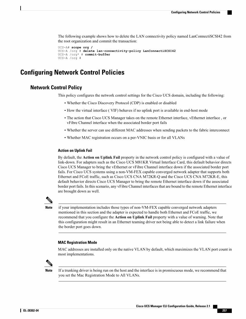
The following example shows how to delete the LAN connectivity policy named LanConnectiSCSI42 fromthe root organization and commit the transaction:UCS-A# scope org /UCS-A /org # delete lan-connectivity-policy LanConnectiSCSI42UCS-A /org* # commit-bufferUCS-A /org #
Configuring Network Control Policies
Network Control PolicyThis policy configures the network control settings for the Cisco UCS domain, including the following:
•Whether the Cisco Discovery Protocol (CDP) is enabled or disabled
• How the virtual interface ( VIF) behaves if no uplink port is available in end-host mode
• The action that Cisco UCS Manager takes on the remote Ethernet interface, vEthernet interface , orvFibre Channel interface when the associated border port fails
•Whether the server can use different MAC addresses when sending packets to the fabric interconnect
•Whether MAC registration occurs on a per-VNIC basis or for all VLANs
Action on Uplink Fail
By default, the Action on Uplink Fail property in the network control policy is configured with a value oflink-down. For adapters such as the Cisco UCS M81KR Virtual Interface Card, this default behavior directsCisco UCS Manager to bring the vEthernet or vFibre Channel interface down if the associated border portfails. For Cisco UCS systems using a non-VM-FEX capable converged network adapter that supports bothEthernet and FCoE traffic, such as Cisco UCS CNA M72KR-Q and the Cisco UCS CNA M72KR-E, thisdefault behavior directs Cisco UCS Manager to bring the remote Ethernet interface down if the associatedborder port fails. In this scenario, any vFibre Channel interfaces that are bound to the remote Ethernet interfaceare brought down as well.
if your implementation includes those types of non-VM-FEX capable converged network adaptersmentioned in this section and the adapter is expected to handle both Ethernet and FCoE traffic, werecommend that you configure the Action on Uplink Fail property with a value of warning. Note thatthis configuration might result in an Ethernet teaming driver not being able to detect a link failure whenthe border port goes down.
Note
MAC Registration Mode
MAC addresses are installed only on the native VLAN by default, which maximizes the VLAN port count inmost implementations.
If a trunking driver is being run on the host and the interface is in promiscuous mode, we recommend thatyou set the Mac Registration Mode to All VLANs.
Note
Cisco UCS Manager CLI Configuration Guide, Release 2.1 OL-28302-04 257
Configuring Network Control Policies
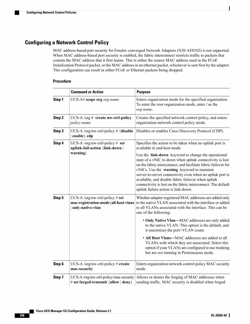
Configuring a Network Control PolicyMAC address-based port security for Emulex converged Network Adapters (N20-AE0102) is not supported.When MAC address-based port security is enabled, the fabric interconnect restricts traffic to packets thatcontain the MAC address that it first learns. This is either the source MAC address used in the FCoEInitialization Protocol packet, or theMAC address in an ethernet packet, whichever is sent first by the adaptor.This configuration can result in either FCoE or Ethernet packets being dropped.
Procedure
PurposeCommand or Action
Enters organization mode for the specified organization.To enter the root organization mode, enter / as theorg-name.
UCS-A# scope org org-nameStep 1
Creates the specified network control policy, and entersorganization network control policy mode.
UCS-A /org # create nw-ctrl-policypolicy-name
Step 2
Disables or enables Cisco Discovery Protocol (CDP).UCS-A /org/nw-ctrl-policy # {disable| enable} cdp
Step 3
Specifies the action to be taken when no uplink port isavailable in end-host mode.
UCS-A /org/nw-ctrl-policy # setuplink-fail-action {link-down |warning}
Step 4
Use the link-down keyword to change the operationalstate of a vNIC to down when uplink connectivity is loston the fabric interconnect, and facilitate fabric failover forvNICs. Use the warning keyword to maintainserver-to-server connectivity even when no uplink port isavailable, and disable fabric failover when uplinkconnectivity is lost on the fabric interconnect. The defaultuplink failure action is link-down.
Whether adapter-registeredMAC addresses are added onlyto the native VLAN associated with the interface or added
UCS-A /org/nw-ctrl-policy # setmac-registration-mode{all-host-vlans| only-native-vlan
Step 5
to all VLANs associated with the interface. This can beone of the following:
• Only Native Vlan—MAC addresses are only addedto the native VLAN. This option is the default, andit maximizes the port+VLAN count.
• All Host Vlans—MAC addresses are added to allVLANs with which they are associated. Select thisoption if your VLANs are configured to use trunkingbut are not running in Promiscuous mode.
Enters organization network control policyMAC securitymode
UCS-A /org/nw-ctrl-policy # createmac-security
Step 6
Allows or denies the forging of MAC addresses whensending traffic. MAC security is disabled when forged
UCS-A /org/nw-ctrl-policy/mac-security# set forged-transmit {allow | deny}
Step 7
Cisco UCS Manager CLI Configuration Guide, Release 2.1258 OL-28302-04
Configuring Network Control Policies
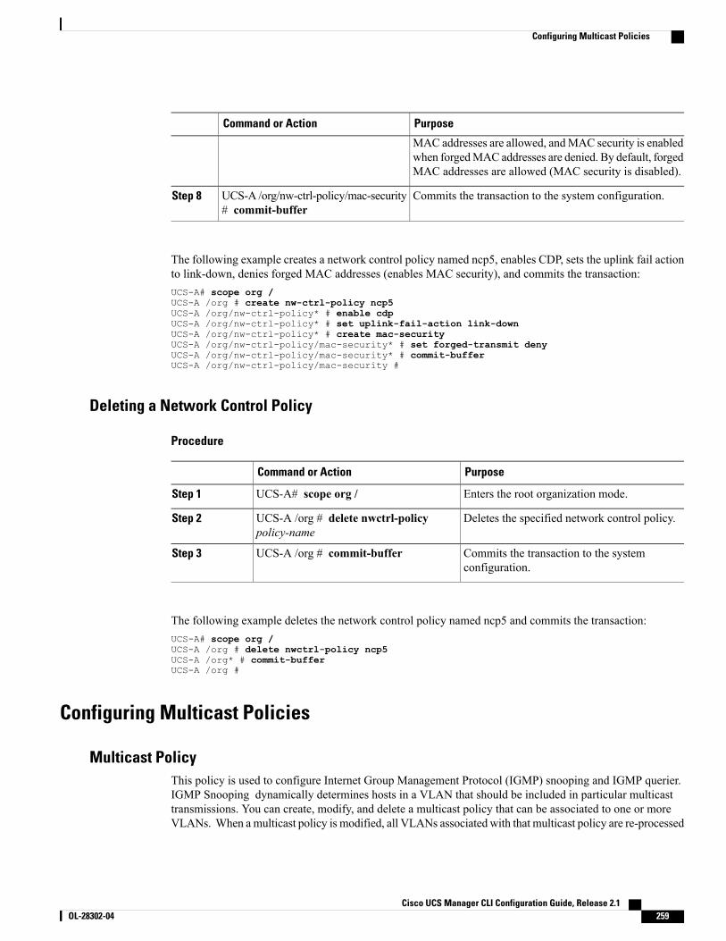
PurposeCommand or Action
MAC addresses are allowed, andMAC security is enabledwhen forgedMAC addresses are denied. By default, forgedMAC addresses are allowed (MAC security is disabled).
Commits the transaction to the system configuration.UCS-A /org/nw-ctrl-policy/mac-security# commit-buffer
Step 8
The following example creates a network control policy named ncp5, enables CDP, sets the uplink fail actionto link-down, denies forged MAC addresses (enables MAC security), and commits the transaction:UCS-A# scope org /UCS-A /org # create nw-ctrl-policy ncp5UCS-A /org/nw-ctrl-policy* # enable cdpUCS-A /org/nw-ctrl-policy* # set uplink-fail-action link-downUCS-A /org/nw-ctrl-policy* # create mac-securityUCS-A /org/nw-ctrl-policy/mac-security* # set forged-transmit denyUCS-A /org/nw-ctrl-policy/mac-security* # commit-bufferUCS-A /org/nw-ctrl-policy/mac-security #
Deleting a Network Control Policy
Procedure
PurposeCommand or Action
Enters the root organization mode.UCS-A# scope org /Step 1
Deletes the specified network control policy.UCS-A /org # delete nwctrl-policypolicy-name
Step 2
Commits the transaction to the systemconfiguration.
UCS-A /org # commit-bufferStep 3
The following example deletes the network control policy named ncp5 and commits the transaction:UCS-A# scope org /UCS-A /org # delete nwctrl-policy ncp5UCS-A /org* # commit-bufferUCS-A /org #
Configuring Multicast Policies
Multicast PolicyThis policy is used to configure Internet Group Management Protocol (IGMP) snooping and IGMP querier.IGMP Snooping dynamically determines hosts in a VLAN that should be included in particular multicasttransmissions. You can create, modify, and delete a multicast policy that can be associated to one or moreVLANs. When amulticast policy is modified, all VLANs associated with that multicast policy are re-processed
Cisco UCS Manager CLI Configuration Guide, Release 2.1 OL-28302-04 259
Configuring Multicast Policies
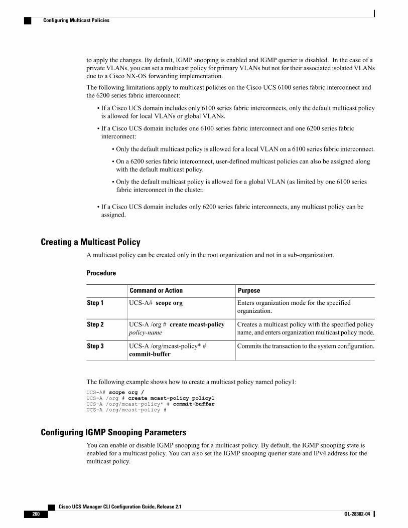
to apply the changes. By default, IGMP snooping is enabled and IGMP querier is disabled. In the case of aprivate VLANs, you can set a multicast policy for primary VLANs but not for their associated isolated VLANsdue to a Cisco NX-OS forwarding implementation.
The following limitations apply to multicast policies on the Cisco UCS 6100 series fabric interconnect andthe 6200 series fabric interconnect:
• If a Cisco UCS domain includes only 6100 series fabric interconnects, only the default multicast policyis allowed for local VLANs or global VLANs.
• If a Cisco UCS domain includes one 6100 series fabric interconnect and one 6200 series fabricinterconnect:
• Only the default multicast policy is allowed for a local VLAN on a 6100 series fabric interconnect.
• On a 6200 series fabric interconnect, user-defined multicast policies can also be assigned alongwith the default multicast policy.
• Only the default multicast policy is allowed for a global VLAN (as limited by one 6100 seriesfabric interconnect in the cluster.
• If a Cisco UCS domain includes only 6200 series fabric interconnects, any multicast policy can beassigned.
Creating a Multicast PolicyA multicast policy can be created only in the root organization and not in a sub-organization.
Procedure
PurposeCommand or Action
Enters organization mode for the specifiedorganization.
UCS-A# scope orgStep 1
Creates a multicast policy with the specified policyname, and enters organizationmulticast policymode.
UCS-A /org # create mcast-policypolicy-name
Step 2
Commits the transaction to the system configuration.UCS-A /org/mcast-policy* #commit-buffer
Step 3
The following example shows how to create a multicast policy named policy1:UCS-A# scope org /UCS-A /org # create mcast-policy policy1UCS-A /org/mcast-policy* # commit-bufferUCS-A /org/mcast-policy #
Configuring IGMP Snooping ParametersYou can enable or disable IGMP snooping for a multicast policy. By default, the IGMP snooping state isenabled for a multicast policy. You can also set the IGMP snooping querier state and IPv4 address for themulticast policy.
Cisco UCS Manager CLI Configuration Guide, Release 2.1260 OL-28302-04
Configuring Multicast Policies
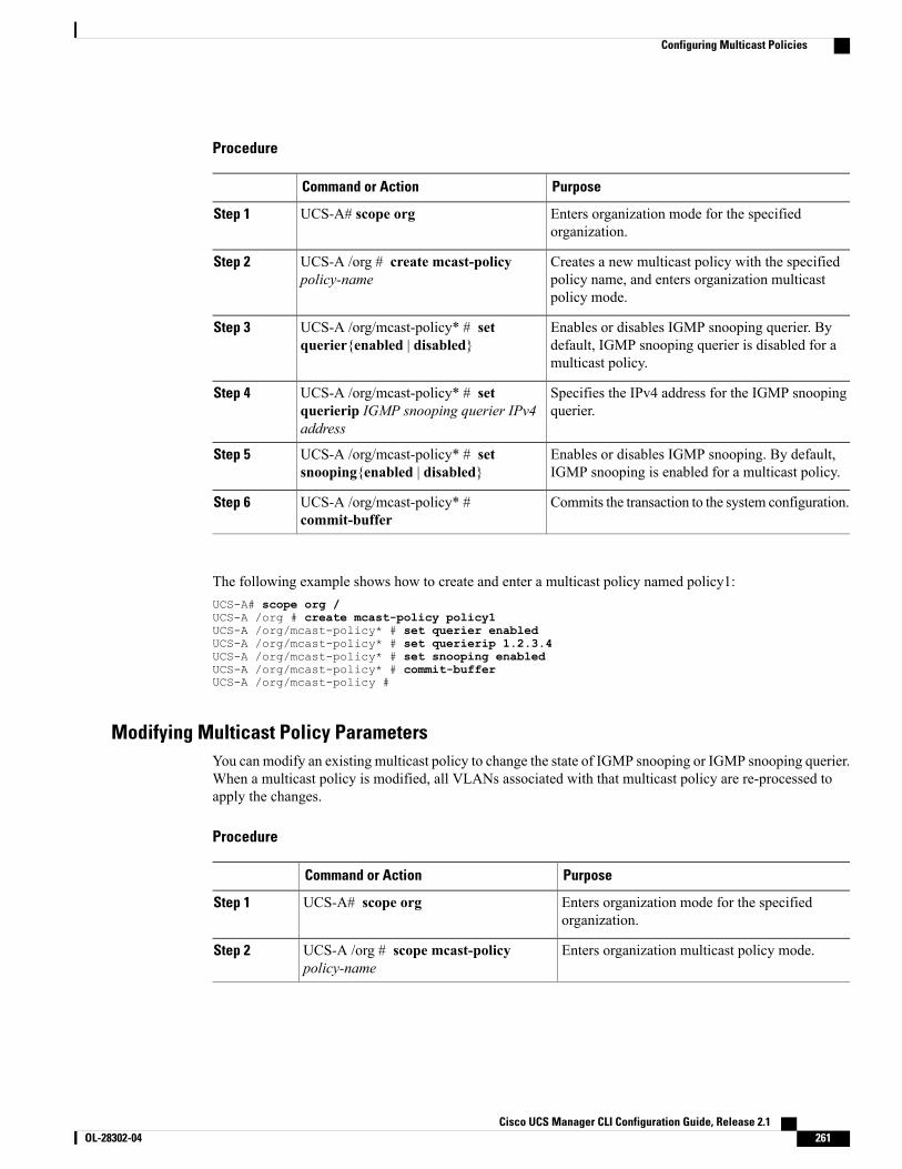
Procedure
PurposeCommand or Action
Enters organization mode for the specifiedorganization.
UCS-A# scope orgStep 1
Creates a new multicast policy with the specifiedpolicy name, and enters organization multicastpolicy mode.
UCS-A /org # create mcast-policypolicy-name
Step 2
Enables or disables IGMP snooping querier. Bydefault, IGMP snooping querier is disabled for amulticast policy.
UCS-A /org/mcast-policy* # setquerier{enabled | disabled}
Step 3
Specifies the IPv4 address for the IGMP snoopingquerier.
UCS-A /org/mcast-policy* # setquerierip IGMP snooping querier IPv4address
Step 4
Enables or disables IGMP snooping. By default,IGMP snooping is enabled for a multicast policy.
UCS-A /org/mcast-policy* # setsnooping{enabled | disabled}
Step 5
Commits the transaction to the system configuration.UCS-A /org/mcast-policy* #commit-buffer
Step 6
The following example shows how to create and enter a multicast policy named policy1:UCS-A# scope org /UCS-A /org # create mcast-policy policy1UCS-A /org/mcast-policy* # set querier enabledUCS-A /org/mcast-policy* # set querierip 1.2.3.4UCS-A /org/mcast-policy* # set snooping enabledUCS-A /org/mcast-policy* # commit-bufferUCS-A /org/mcast-policy #
Modifying Multicast Policy ParametersYou can modify an existing multicast policy to change the state of IGMP snooping or IGMP snooping querier.When a multicast policy is modified, all VLANs associated with that multicast policy are re-processed toapply the changes.
Procedure
PurposeCommand or Action
Enters organization mode for the specifiedorganization.
UCS-A# scope orgStep 1
Enters organization multicast policy mode.UCS-A /org # scope mcast-policypolicy-name
Step 2
Cisco UCS Manager CLI Configuration Guide, Release 2.1 OL-28302-04 261
Configuring Multicast Policies
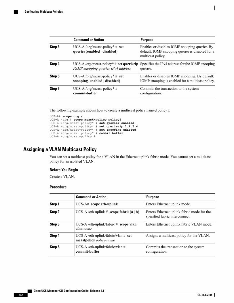
PurposeCommand or Action
Enables or disables IGMP snooping querier. Bydefault, IGMP snooping querier is disabled for amulticast policy.
UCS-A /org/mcast-policy* # setquerier{enabled | disabled}
Step 3
Specifies the IPv4 address for the IGMP snoopingquerier.
UCS-A /org/mcast-policy* # set querieripIGMP snooping querier IPv4 address
Step 4
Enables or disables IGMP snooping. By default,IGMP snooping is enabled for a multicast policy.
UCS-A /org/mcast-policy* # setsnooping{enabled | disabled}
Step 5
Commits the transaction to the systemconfiguration.
UCS-A /org/mcast-policy* #commit-buffer
Step 6
The following example shows how to create a multicast policy named policy1:UCS-A# scope org /UCS-A /org # scope mcast-policy policy1UCS-A /org/mcast-policy* # set querier enabledUCS-A /org/mcast-policy* # set querierip 1.2.3.4UCS-A /org/mcast-policy* # set snooping enabledUCS-A /org/mcast-policy* # commit-bufferUCS-A /org/mcast-policy #
Assigning a VLAN Multicast PolicyYou can set a multicast policy for a VLAN in the Ethernet uplink fabric mode. You cannot set a multicastpolicy for an isolated VLAN.
Before You Begin
Create a VLAN.
Procedure
PurposeCommand or Action
Enters Ethernet uplink mode.UCS-A# scope eth-uplinkStep 1
Enters Ethernet uplink fabric mode for thespecified fabric interconnect.
UCS-A /eth-uplink # scope fabric{a | b}Step 2
Enters Ethernet uplink fabric VLAN mode.UCS-A /eth-uplink/fabric # scope vlanvlan-name
Step 3
Assigns a multicast policy for the VLAN.UCS-A /eth-uplink/fabric/vlan # setmcastpolicy policy-name
Step 4
Commits the transaction to the systemconfiguration.
UCS-A /eth-uplink/fabric/vlan #commit-buffer
Step 5
Cisco UCS Manager CLI Configuration Guide, Release 2.1262 OL-28302-04
Configuring Multicast Policies
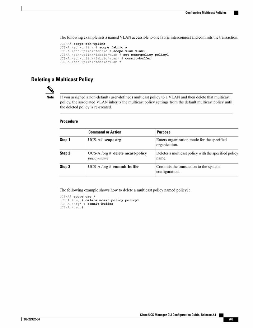
The following example sets a named VLAN accessible to one fabric interconnect and commits the transaction:UCS-A# scope eth-uplinkUCS-A /eth-uplink # scope fabric aUCS-A /eth-uplink/fabric # scope vlan vlan1UCS-A /eth-uplink/fabric/vlan # set mcastpolicy policy1UCS-A /eth-uplink/fabric/vlan* # commit-bufferUCS-A /eth-uplink/fabric/vlan #
Deleting a Multicast Policy
If you assigned a non-default (user-defined) multicast policy to a VLAN and then delete that multicastpolicy, the associated VLAN inherits the multicast policy settings from the default multicast policy untilthe deleted policy is re-created.
Note
Procedure
PurposeCommand or Action
Enters organization mode for the specifiedorganization.
UCS-A# scope orgStep 1
Deletes a multicast policy with the specified policyname.
UCS-A /org # delete mcast-policypolicy-name
Step 2
Commits the transaction to the systemconfiguration.
UCS-A /org # commit-bufferStep 3
The following example shows how to delete a multicast policy named policy1:UCS-A# scope org /UCS-A /org # delete mcast-policy policy1UCS-A /org* # commit-bufferUCS-A /org #
Cisco UCS Manager CLI Configuration Guide, Release 2.1 OL-28302-04 263
Configuring Multicast Policies

Cisco UCS Manager CLI Configuration Guide, Release 2.1264 OL-28302-04
Configuring Multicast Policies
C H A P T E R 21Configuring Upstream Disjoint Layer-2 Networks
This chapter includes the following sections:
• Upstream Disjoint Layer-2 Networks, page 265
• Guidelines for Configuring Upstream Disjoint L2 Networks, page 266
• Pinning Considerations for Upstream Disjoint L2 Networks, page 267
• Configuring Cisco UCS for Upstream Disjoint L2 Networks, page 269
• Assigning Ports and Port Channels to VLANs, page 270
• Removing Ports and Port Channels from VLANs , page 270
• Viewing Ports and Port Channels Assigned to VLANs, page 271
Upstream Disjoint Layer-2 NetworksUpstream disjoint layer-2 networks (disjoint L2 networks) are required if you have two or more Ethernet“clouds” that never connect, but must be accessed by servers or virtual machines located in the same CiscoUCS domain. For example, you could configure disjoint L2 networks if you require one of the following:
• Servers or virtual machines to access a public network and a backup network
• In a multi-tenant system, servers or virtual machines for more than one customer are located in the sameCisco UCS domain and need to access the L2 networks for both customers.
By default, data traffic in Cisco UCS works on a principle of mutual inclusion. All traffic for all VLANsand upstream networks travels along all uplink ports and port channels. If you have upgraded from arelease that does not support upstream disjoint layer-2 networks, you must assign the appropriate uplinkinterfaces to your VLANs, or traffic for those VLANs continues to flow along all uplink ports and portchannels.
Note
The configuration for disjoint L2 networks works on a principle of selective exclusion. Traffic for a VLANthat is designated as part of a disjoint network can only travel along an uplink Ethernet port or port channelthat is specifically assigned to that VLAN, and is selectively excluded from all other uplink ports and portchannels. However, traffic for VLANs that are not specifically assigned to an uplink Ethernet port or port
Cisco UCS Manager CLI Configuration Guide, Release 2.1 OL-28302-04 265
channel can still travel on all uplink ports or port channels, including those that carry traffic for the disjointL2 networks.
In Cisco UCS, the VLAN represents the upstream disjoint L2 network. When you design your networktopology for disjoint L2 networks, you must assign uplink interfaces to VLANs not the reverse.
For information about the maximum number of supported upstream disjoint L2 networks, see Cisco UCS6100 and 6200 Series Configuration Limits for Cisco UCS Manager, Release 2.0.
Guidelines for Configuring Upstream Disjoint L2 NetworksWhen you plan your configuration for upstream disjoint L2 networks, consider the following:
Ethernet Switching Mode Must Be End-Host Mode
Cisco UCS only supports disjoint L2 networks when the Ethernet switching mode of the fabric interconnectsis configured for end-host mode. You cannot connect to disjoint L2 networks if the Ethernet switching modeof the fabric interconnects is switch mode.
Symmetrical Configuration Is Recommended for High Availability
If a Cisco UCS domain is configured for high availability with two fabric interconnects, we recommend thatboth fabric interconnects are configured with the same set of VLANs.
VLAN Validity Criteria Are the Same for Uplink Ethernet Ports and Port Channels
The VLAN used for the disjoint L2 networks must be configured and assigned to an uplink Ethernet port oruplink Ethernet port channel. If the port or port channel does not include the VLAN, Cisco UCS Managerconsiders the VLAN invalid and does the following:
• Displays a configuration warning in the Status Details area for the server.
• Ignores the configuration for the port or port channel and drops all traffic for that VLAN.
The validity criteria are the same for uplink Ethernet ports and uplink Ethernet port channels. Cisco UCSManager does not differentiate between the two.
Note
Overlapping VLANs Are Not Supported
Cisco UCS does not support overlapping VLANs in disjoint L2 networks. You must ensure that each VLANonly connects to one upstream disjoint L2 domain.
Each vNIC Can Only Communicate with One Disjoint L2 Network
A vNIC can only communicate with one disjoint L2 network. If a server needs to communicate with multipledisjoint L2 networks, you must configure a vNIC for each of those networks.
To communicate with more than two disjoint L2 networks, a server must have a Cisco VIC adapter thatsupports more than two vNICs.
Cisco UCS Manager CLI Configuration Guide, Release 2.1266 OL-28302-04
Guidelines for Configuring Upstream Disjoint L2 Networks

Appliance Port Must Be Configured with the Same VLAN as Uplink Ethernet Port or Port Channel
For an appliance port to communicate with a disjoint L2 network, you must ensure that at least one uplinkEthernet port or port channel is in the same network and is therefore assigned to the same VLANs that areused by the appliance port. If Cisco UCS Manager cannot identify an uplink Ethernet port or port channelthat includes all VLANs that carry traffic for an appliance port, the appliance port experiences a pinning failureand goes down.
For example, a Cisco UCS domain includes a global VLAN named vlan500 with an ID of 500. vlan500 iscreated as a global VLAN on the uplink Ethernet port. However, Cisco UCSManager does not propagate thisVLAN to appliance ports. To configure an appliance port with vlan500, you must create another VLAN namedvlan500 with an ID of 500 for the appliance port. You can create this duplicate VLAN in the Appliancesnode on the LAN tab of the Cisco UCS Manager GUI or the eth-storage scope in the Cisco UCS ManagerCLI. If you are prompted to check for VLAN Overlap, accept the overlap and Cisco UCS Manager createsthe duplicate VLAN for the appliance port.
Default VLAN 1 Cannot Be Configured Explicitly on an Uplink Ethernet Port or Port Channel
Cisco UCS Manager implicitly assigns default VLAN 1 to all uplink ports and port channels. Even if you donot configure any other VLANs, Cisco UCS uses default VLAN 1 to handle data traffic for all uplink portsand port channels.
After you configure VLANs in a Cisco UCS domain, default VLAN 1 remains implicitly on all uplinkports and port channels. You cannot explicitly assign default VLAN 1 to an uplink port or port channel,nor can you remove it from an uplink port or port channel.
Note
If you attempt to assign default VLAN 1 to a specific port or port channel, Cisco UCS Manager raises anUpdate Failed fault.
Therefore, if you configure a Cisco UCS domain for disjoint L2 networks, do not configure any vNICs withdefault VLAN 1 unless you want all data traffic for that server to be carried on all uplink Ethernet ports andport channels and sent to all upstream networks.
VLANs for Both FIs Must be Concurrently Assigned
When you assign a port to a global VLAN, the VLAN is removed from all of the ports that are not explicitlyassigned to the VLAN on both fabric interconnects. The ports on both FIs must be configured at the sametime. If the ports are only configured on the first FI, traffic on the second FI will be disrupted.
Pinning Considerations for Upstream Disjoint L2 NetworksCommunication with an upstream disjoint L2 network requires that you ensure that the pinning is properlyconfigured. Whether you implement soft pinning or hard pinning, a VLAN membership mismatch causestraffic for one or more VLANs to be dropped.
Soft Pinning
Soft pinning is the default behavior in Cisco UCS. If you plan to implement soft pinning, you do not need tocreate LAN pin groups to specify a pin target for a vNIC. Instead, Cisco UCS Manager pins the vNIC to anuplink Ethernet port or port channel according to VLAN membership criteria.
Cisco UCS Manager CLI Configuration Guide, Release 2.1 OL-28302-04 267
Pinning Considerations for Upstream Disjoint L2 Networks
With soft pinning, Cisco UCS Manager validates data traffic from a vNIC against the VLAN membership ofall uplink Ethernet ports and port channels. If you have configured disjoint L2 networks, Cisco UCSManagermust be able to find an uplink Ethernet port or port channel that is assigned to all VLANS on the vNIC. If nouplink Ethernet port or port channel is configured with all VLANs on the vNIC, Cisco UCS Manager doesthe following:
• Brings the link down.
• Drops the traffic for all of the VLANs on the vNIC.
• Raises the following faults:
◦Link Down
◦VIF Down
Cisco UCS Manager does not raise a fault or warning about the VLAN configuration.
For example, a vNIC on a server is configured with VLANs 101, 102, and 103. Interface 1/3 is assigned onlyto VLAN 102. Interfaces 1/1 and 1/2 are not explicitly assigned to a VLAN, which makes them available fortraffic on VLANs 101 and 103. As a result of this configuration, the Cisco UCS domain does not include aborder port interface that can carry traffic for all three VLANS for which the vNIC is configured. As a result,Cisco UCS Manager brings down the vNIC, drops traffic for all three VLANs on the vNIC, and raises theLink Down and VIF Down faults.
Hard Pinning
Hard pinning occurs when you use LAN pin groups to specify the pinning target for the traffic intended forthe disjoint L2 networks. In turn, the uplink Ethernet port or port channel that is the pinning target must beconfigured to communicate with the appropriate disjoint L2 network.
With hard pinning, Cisco UCS Manager validates data traffic from a vNIC against the VLAN membershipof all uplink Ethernet ports and port channels, and validates the LAN pin group configuration to ensure itincludes the VLAN and the uplink Ethernet port or port channel. If the validation fails at any point, CiscoUCS Manager does the following:
• Raises a Pinning VLAN Mismatch fault with a severity of Warning.
• Drops traffic for the VLAN.
• Does not bring the link down, so that traffic for other VLANs can continue to flow along it.
For example, if you want to configure hard pinning for an upstream disjoint L2 network that uses VLAN 177,do the following:
• Create a LAN pin group with the uplink Ethernet port or port channel that carries the traffic for thedisjoint L2 network.
• Configure at least one vNIC in the service profile with VLAN 177 and the LAN pin group.
• Assign VLAN 177 to an uplink Ethernet port or port channel included in the LAN pin group
If the configuration fails at any of these three points, then Cisco UCS Manager warns for a VLAN mismatchfor VLAN 177 and drops the traffic for that VLAN only.
Cisco UCS Manager CLI Configuration Guide, Release 2.1268 OL-28302-04
Pinning Considerations for Upstream Disjoint L2 Networks
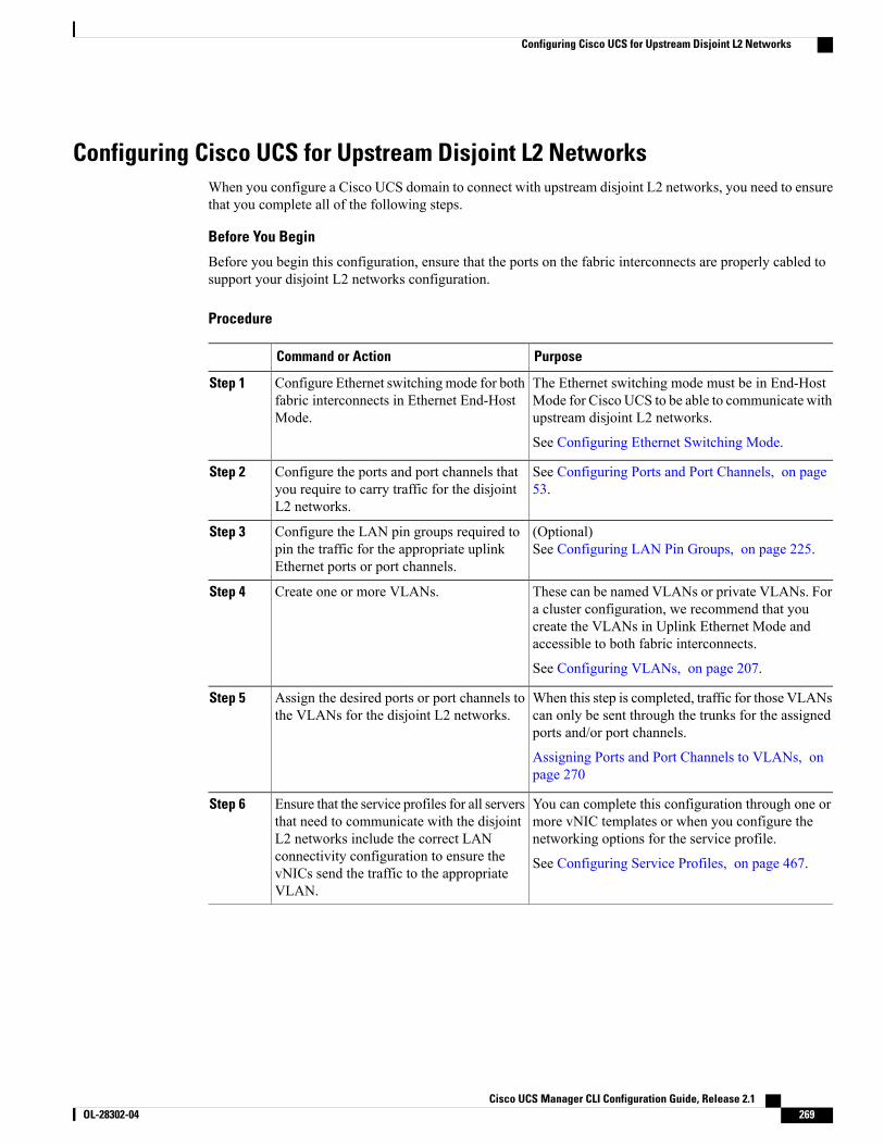
Configuring Cisco UCS for Upstream Disjoint L2 NetworksWhen you configure a Cisco UCS domain to connect with upstream disjoint L2 networks, you need to ensurethat you complete all of the following steps.
Before You Begin
Before you begin this configuration, ensure that the ports on the fabric interconnects are properly cabled tosupport your disjoint L2 networks configuration.
Procedure
PurposeCommand or Action
The Ethernet switching mode must be in End-HostMode for Cisco UCS to be able to communicate withupstream disjoint L2 networks.
Configure Ethernet switchingmode for bothfabric interconnects in Ethernet End-HostMode.
Step 1
See Configuring Ethernet Switching Mode.
See Configuring Ports and Port Channels, on page53.
Configure the ports and port channels thatyou require to carry traffic for the disjointL2 networks.
Step 2
(Optional)See Configuring LAN Pin Groups, on page 225.
Configure the LAN pin groups required topin the traffic for the appropriate uplinkEthernet ports or port channels.
Step 3
These can be named VLANs or private VLANs. Fora cluster configuration, we recommend that you
Create one or more VLANs.Step 4
create the VLANs in Uplink Ethernet Mode andaccessible to both fabric interconnects.
See Configuring VLANs, on page 207.
When this step is completed, traffic for those VLANscan only be sent through the trunks for the assignedports and/or port channels.
Assign the desired ports or port channels tothe VLANs for the disjoint L2 networks.
Step 5
Assigning Ports and Port Channels to VLANs, onpage 270
You can complete this configuration through one ormore vNIC templates or when you configure thenetworking options for the service profile.
Ensure that the service profiles for all serversthat need to communicate with the disjointL2 networks include the correct LAN
Step 6
connectivity configuration to ensure the See Configuring Service Profiles, on page 467.vNICs send the traffic to the appropriateVLAN.
Cisco UCS Manager CLI Configuration Guide, Release 2.1 OL-28302-04 269
Configuring Cisco UCS for Upstream Disjoint L2 Networks
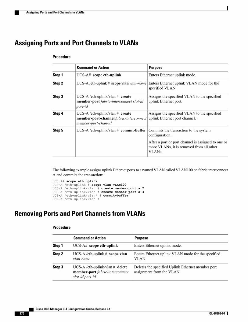
Assigning Ports and Port Channels to VLANs
Procedure
PurposeCommand or Action
Enters Ethernet uplink mode.UCS-A# scope eth-uplinkStep 1
Enters Ethernet uplink VLAN mode for thespecified VLAN.
UCS-A /eth-uplink # scope vlan vlan-nameStep 2
Assigns the specified VLAN to the specifieduplink Ethernet port.
UCS-A /eth-uplink/vlan # createmember-port fabric-interconnect slot-idport-id
Step 3
Assigns the specified VLAN to the specifieduplink Ethernet port channel.
UCS-A /eth-uplink/vlan # createmember-port-channel fabric-interconnectmember-port-chan-id
Step 4
Commits the transaction to the systemconfiguration.
UCS-A /eth-uplink/vlan # commit-bufferStep 5
After a port or port channel is assigned to one ormore VLANs, it is removed from all otherVLANs.
The following example assigns uplink Ethernet ports to a namedVLAN calledVLAN100 on fabric interconnectA and commits the transaction:UCS-A# scope eth-uplinkUCS-A /eth-uplink # scope vlan VLAN100UCS-A /eth-uplink/vlan # create member-port a 2UCS-A /eth-uplink/vlan # create member-port a 4UCS-A /eth-uplink/vlan* # commit-bufferUCS-A /eth-uplink/vlan #
Removing Ports and Port Channels from VLANs
Procedure
PurposeCommand or Action
Enters Ethernet uplink mode.UCS-A# scope eth-uplinkStep 1
Enters Ethernet uplink VLAN mode for the specifiedVLAN.
UCS-A /eth-uplink # scope vlanvlan-name
Step 2
Deletes the specified Uplink Ethernet member portassignment from the VLAN.
UCS-A /eth-uplink/vlan # deletemember-port fabric-interconnectslot-id port-id
Step 3
Cisco UCS Manager CLI Configuration Guide, Release 2.1270 OL-28302-04
Assigning Ports and Port Channels to VLANs
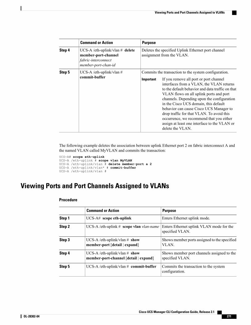
PurposeCommand or Action
Deletes the specified Uplink Ethernet port channelassignment from the VLAN.
UCS-A /eth-uplink/vlan # deletemember-port-channelfabric-interconnectmember-port-chan-id
Step 4
Commits the transaction to the system configuration.UCS-A /eth-uplink/vlan #commit-buffer
Step 5
If you remove all port or port channelinterfaces from a VLAN, the VLAN returnsto the default behavior and data traffic on thatVLAN flows on all uplink ports and portchannels. Depending upon the configurationin the Cisco UCS domain, this defaultbehavior can cause Cisco UCS Manager todrop traffic for that VLAN. To avoid thisoccurrence, we recommend that you eitherassign at least one interface to the VLAN ordelete the VLAN.
Important
The following example deletes the association between uplink Ethernet port 2 on fabric interconnect A andthe named VLAN called MyVLAN and commits the transaction:UCS-A# scope eth-uplinkUCS-A /eth-uplink # scope vlan MyVLANUCS-A /eth-uplink/vlan # delete member-port a 2UCS-A /eth-uplink/vlan* # commit-bufferUCS-A /eth-uplink/vlan #
Viewing Ports and Port Channels Assigned to VLANs
Procedure
PurposeCommand or Action
Enters Ethernet uplink mode.UCS-A# scope eth-uplinkStep 1
Enters Ethernet uplink VLAN mode for thespecified VLAN.
UCS-A /eth-uplink # scope vlan vlan-nameStep 2
Showsmember ports assigned to the specifiedVLAN.
UCS-A /eth-uplink/vlan # showmember-port [detail | expand]
Step 3
Shows member port channels assigned to thespecified VLAN.
UCS-A /eth-uplink/vlan # showmember-port-channel [detail | expand]
Step 4
Commits the transaction to the systemconfiguration.
UCS-A /eth-uplink/vlan # commit-bufferStep 5
Cisco UCS Manager CLI Configuration Guide, Release 2.1 OL-28302-04 271
Viewing Ports and Port Channels Assigned to VLANs
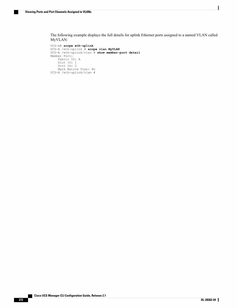
The following example displays the full details for uplink Ethernet ports assigned to a named VLAN calledMyVLAN:UCS-A# scope eth-uplinkUCS-A /eth-uplink # scope vlan MyVLANUCS-A /eth-uplink/vlan # show member-port detailMember Port:
Fabric ID: ASlot ID: 1Port ID: 2Mark Native Vlan: No
UCS-A /eth-uplink/vlan #
Cisco UCS Manager CLI Configuration Guide, Release 2.1272 OL-28302-04
Viewing Ports and Port Channels Assigned to VLANs
P A R T IVStorage Configuration• Configuring Named VSANs, page 275
• Configuring SAN Pin Groups, page 285
• Configuring WWN Pools, page 289
• Configuring Storage-Related Policies, page 295
• Configuring Fibre Channel Zoning, page 311
• Configuring FlexFlash SD Card Support, page 321

C H A P T E R 22Configuring Named VSANs
This chapter includes the following sections:
• Named VSANs, page 275
• Fibre Channel Uplink Trunking for Named VSANs, page 276
• Guidelines and Recommendations for VSANs, page 276
• Creating a Named VSAN Accessible to Both Fabric Interconnects (Fibre Channel Uplink Mode), page278
• Creating a Named VSANAccessible to Both Fabric Interconnects (Fibre Channel StorageMode), page279
• Creating a Named VSAN Accessible to One Fabric Interconnect (Fibre Channel Uplink Mode), page280
• Creating a Named VSAN Accessible to One Fabric Interconnect (Fibre Channel Storage Mode), page281
• Deleting a Named VSAN, page 282
• Changing the VLAN ID for the FCoE Native VLAN for a Named VSAN, page 283
• Changing the VLAN ID for the FCoE Native VLAN for a Storage VSAN, page 283
• Enabling or Disabling Fibre Channel Uplink Trunking, page 284
Named VSANsA named VSAN creates a connection to a specific external SAN. The VSAN isolates traffic to that externalSAN, including broadcast traffic. The traffic on one named VSAN knows that the traffic on another namedVSAN exists, but cannot read or access that traffic.
Like a named VLAN, the name that you assign to a VSAN ID adds a layer of abstraction that allows you toglobally update all servers associated with service profiles that use the named VSAN. You do not need toreconfigure the servers individually to maintain communication with the external SAN. You can create morethan one named VSAN with the same VSAN ID.
Cisco UCS Manager CLI Configuration Guide, Release 2.1 OL-28302-04 275
Named VSANs in Cluster Configurations
In a cluster configuration, a named VSAN can be configured to be accessible only to the Fibre Channel uplinkports on one fabric interconnect or to the Fibre Channel uplink ports on both fabric interconnects.
Named VSANs and the FCoE VLAN ID
You must configure each named VSAN with an FCoE VLAN ID. This property determines which VLAN isused for transporting the VSAN and its Fibre Channel packets.
For FIP-capable, converged network adapters, such as the Cisco UCS CNA M72KR-Q and the Cisco UCSCNAM72KR-E, the named VSAN must be configured with a named VLAN that is not the native VLAN forthe FCoE VLAN ID. This configuration ensures that FCoE traffic can pass through these adapters.
In the following sample configuration, a service profile with a vNIC and vHBAmapped to fabric A is associatedwith a server that has FIP capable, converged network adapters:
• The vNIC is configured to use VLAN 10.
• VLAN 10 is also designated as the native VLAN for the vNIC.
• The vHBA is configured to use VSAN 2.
• Therefore, VSAN 2 cannot be configured with VLAN 10 as the FCoE VLAN ID. VSAN 2 can bemapped to any other VLAN configured on fabric A.
Fibre Channel Uplink Trunking for Named VSANsYou can configure Fibre Channel uplink trunking for the named VSANs on each fabric interconnect. If youenable trunking on a fabric interconnect, all named VSANs in a Cisco UCS domain are allowed on all FibreChannel uplink ports on that fabric interconnect.
Guidelines and Recommendations for VSANsThe following guidelines and recommendations apply to all named VSANs, including storage VSANs.
VSAN 4079 is a Reserved VSAN ID
Do not configure a VSAN as 4079. This VSAN is reserved and cannot be used in either FC switch mode orFC end-host mode.
If you create a named VSAN with ID 4079, Cisco UCS Manager marks that VSAN with an error and raisesa fault.
Reserved VSAN Range for Named VSANs in FC Switch Mode
If you plan to use FC switch mode in a Cisco UCS domain, do not configure VSANs with an ID in the rangefrom 3040 to 4078.
VSANs in that range are not operational if the fabric interconnects are configured to operate in FC switchmode. Cisco UCS Manager marks that VSAN with an error and raises a fault.
Cisco UCS Manager CLI Configuration Guide, Release 2.1276 OL-28302-04
Fibre Channel Uplink Trunking for Named VSANs
Reserved VSAN Range for Named VSANs in FC End-Host Mode
If you plan to use FC end-host mode in a Cisco UCS domain, do not configure VSANs with an ID in the rangefrom 3840 to 4079.
VSANs in that range are not operational if the following conditions exist in a Cisco UCS domain:
• The fabric interconnects are configured to operate in FC end-host mode.
• The Cisco UCS domain is configured with Fibre Channel trunking or SAN port channels.
If these configurations exist, Cisco UCS Manager does the following:
1 Renders all VSANs with an ID in the range from 3840 to 4079 non-operational.
2 Raises a fault against the non-operational VSANs.
3 Transfers all non-operational VSANs to the default VSAN.
4 Transfers all vHBAs associated with the non-operational VSANs to the default VSAN.
If you disable Fibre Channel trunking and delete any existing SAN port channels, Cisco UCSManager returnsall VSANs in the range from 3840 to 4078 to an operational state and restores any associated vHBAs backto those VSANs.
Range Restrictions for Named VSAN IDs in FC Switch Mode
If you plan to use FC switch mode in a Cisco UCS domain, do not configure VSANs in the range from 3040to 4078.
When a fabric interconnect operating in FC switchmode is connected toMDS as the upstream switch, VSANsconfigured in Cisco UCS Manager in the range from 3040 to 4078 and assigned as port VSANs cannot becreated in MDS. This configuration results in a possible port VSAN mismatch.
Guidelines for FCoE VLAN IDs
FCoE VLANs in the SAN cloud and VLANs in the LAN cloud must have different IDs. Using the sameID for an FCoE VLAN in a VSAN and a VLAN results in a critical fault and traffic disruption for allvNICs and uplink ports using that FCoE VLAN. Ethernet traffic is dropped on any VLAN which has anID that overlaps with an FCoE VLAN ID.
Note
VLAN 4048 is user configurable. However, Cisco UCS Manager uses VLAN 4048 for the following defaultvalues. If you want to assign 4048 to a VLAN, you must reconfigure these values:
• After an upgrade to Cisco UCS, Release 2.0—The FCoE storage port native VLAN uses VLAN 4048by default. If the default FCoE VSAN was set to use VLAN 1 before the upgrade, you must change itto a VLAN ID that is not used or reserved. For example, consider changing the default to 4049 if thatVLAN ID is not in use.
• After a fresh install of Cisco UCS, Release 2.0—The FCoE VLAN for the default VSAN uses VLAN4048 by default. The FCoE storage port native VLAN uses VLAN 4049.
Cisco UCS Manager CLI Configuration Guide, Release 2.1 OL-28302-04 277
Guidelines and Recommendations for VSANs
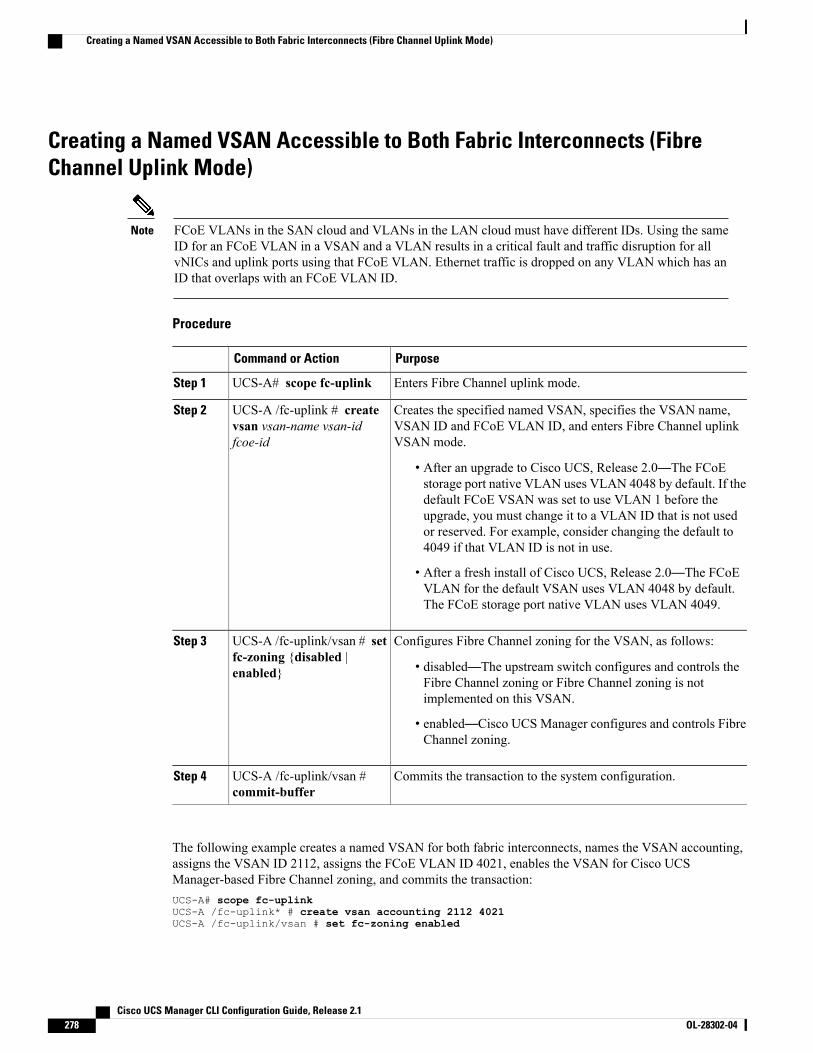
Creating a Named VSAN Accessible to Both Fabric Interconnects (FibreChannel Uplink Mode)
FCoE VLANs in the SAN cloud and VLANs in the LAN cloud must have different IDs. Using the sameID for an FCoE VLAN in a VSAN and a VLAN results in a critical fault and traffic disruption for allvNICs and uplink ports using that FCoE VLAN. Ethernet traffic is dropped on any VLAN which has anID that overlaps with an FCoE VLAN ID.
Note
Procedure
PurposeCommand or Action
Enters Fibre Channel uplink mode.UCS-A# scope fc-uplinkStep 1
Creates the specified named VSAN, specifies the VSAN name,VSAN ID and FCoE VLAN ID, and enters Fibre Channel uplinkVSAN mode.
UCS-A /fc-uplink # createvsan vsan-name vsan-idfcoe-id
Step 2
• After an upgrade to Cisco UCS, Release 2.0—The FCoEstorage port native VLAN uses VLAN 4048 by default. If thedefault FCoE VSAN was set to use VLAN 1 before theupgrade, you must change it to a VLAN ID that is not usedor reserved. For example, consider changing the default to4049 if that VLAN ID is not in use.
• After a fresh install of Cisco UCS, Release 2.0—The FCoEVLAN for the default VSAN uses VLAN 4048 by default.The FCoE storage port native VLAN uses VLAN 4049.
Configures Fibre Channel zoning for the VSAN, as follows:UCS-A /fc-uplink/vsan # setfc-zoning {disabled |enabled}
Step 3
• disabled—The upstream switch configures and controls theFibre Channel zoning or Fibre Channel zoning is notimplemented on this VSAN.
• enabled—Cisco UCS Manager configures and controls FibreChannel zoning.
Commits the transaction to the system configuration.UCS-A /fc-uplink/vsan #commit-buffer
Step 4
The following example creates a named VSAN for both fabric interconnects, names the VSAN accounting,assigns the VSAN ID 2112, assigns the FCoE VLAN ID 4021, enables the VSAN for Cisco UCSManager-based Fibre Channel zoning, and commits the transaction:UCS-A# scope fc-uplinkUCS-A /fc-uplink* # create vsan accounting 2112 4021UCS-A /fc-uplink/vsan # set fc-zoning enabled
Cisco UCS Manager CLI Configuration Guide, Release 2.1278 OL-28302-04
Creating a Named VSAN Accessible to Both Fabric Interconnects (Fibre Channel Uplink Mode)
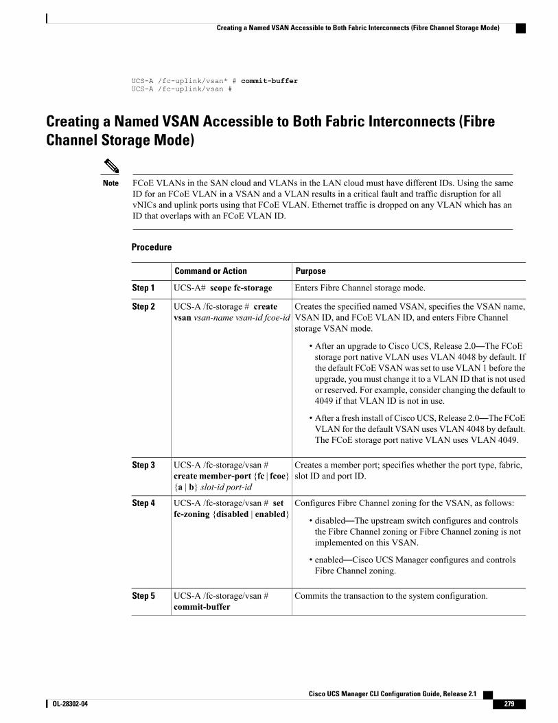
UCS-A /fc-uplink/vsan* # commit-bufferUCS-A /fc-uplink/vsan #
Creating a Named VSAN Accessible to Both Fabric Interconnects (FibreChannel Storage Mode)
FCoE VLANs in the SAN cloud and VLANs in the LAN cloud must have different IDs. Using the sameID for an FCoE VLAN in a VSAN and a VLAN results in a critical fault and traffic disruption for allvNICs and uplink ports using that FCoE VLAN. Ethernet traffic is dropped on any VLAN which has anID that overlaps with an FCoE VLAN ID.
Note
Procedure
PurposeCommand or Action
Enters Fibre Channel storage mode.UCS-A# scope fc-storageStep 1
Creates the specified named VSAN, specifies the VSAN name,VSAN ID, and FCoE VLAN ID, and enters Fibre Channelstorage VSAN mode.
UCS-A /fc-storage # createvsan vsan-name vsan-id fcoe-id
Step 2
• After an upgrade to Cisco UCS, Release 2.0—The FCoEstorage port native VLAN uses VLAN 4048 by default. Ifthe default FCoE VSANwas set to use VLAN 1 before theupgrade, you must change it to a VLAN ID that is not usedor reserved. For example, consider changing the default to4049 if that VLAN ID is not in use.
• After a fresh install of Cisco UCS, Release 2.0—The FCoEVLAN for the default VSAN uses VLAN 4048 by default.The FCoE storage port native VLAN uses VLAN 4049.
Creates a member port; specifies whether the port type, fabric,slot ID and port ID.
UCS-A /fc-storage/vsan #create member-port {fc | fcoe}{a | b} slot-id port-id
Step 3
Configures Fibre Channel zoning for the VSAN, as follows:UCS-A /fc-storage/vsan # setfc-zoning {disabled | enabled}
Step 4
• disabled—The upstream switch configures and controlsthe Fibre Channel zoning or Fibre Channel zoning is notimplemented on this VSAN.
• enabled—Cisco UCS Manager configures and controlsFibre Channel zoning.
Commits the transaction to the system configuration.UCS-A /fc-storage/vsan #commit-buffer
Step 5
Cisco UCS Manager CLI Configuration Guide, Release 2.1 OL-28302-04 279
Creating a Named VSAN Accessible to Both Fabric Interconnects (Fibre Channel Storage Mode)
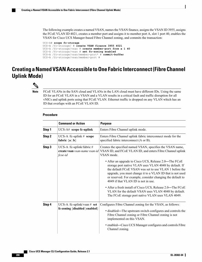
The following example creates a named VSAN, names the VSAN finance, assigns the VSAN ID 3955, assignsthe FCoE VLAN ID 4021, creates a member port and assigns it to member port A, slot 1 port 40, enables theVSAN for Cisco UCS Manager-based Fibre Channel zoning, and commits the transaction:UCS-A# scope fc-storageUCS-A /fc-storage/ # create VSAN finance 3955 4021UCS-A /fc-storage/vsan # create member-port fcoe a 1 40UCS-A /fc-storage/vsan # set fc-zoning enabledUCS-A /fc-storage/vsan/member-port* # commit-bufferUCS-A /fc-storage/vsan/member-port #
Creating a Named VSAN Accessible to One Fabric Interconnect (Fibre ChannelUplink Mode)
FCoE VLANs in the SAN cloud and VLANs in the LAN cloud must have different IDs. Using the sameID for an FCoE VLAN in a VSAN and a VLAN results in a critical fault and traffic disruption for allvNICs and uplink ports using that FCoE VLAN. Ethernet traffic is dropped on any VLAN which has anID that overlaps with an FCoE VLAN ID.
Note
Procedure
PurposeCommand or Action
Enters Fibre Channel uplink mode.UCS-A# scope fc-uplinkStep 1
Enters Fibre Channel uplink fabric interconnect mode for thespecified fabric interconnect (A or B).
UCS-A /fc-uplink # scopefabric {a | b}
Step 2
Creates the specified named VSAN, specifies the VSAN name,VSAN ID, and FCoE VLAN ID, and enters Fibre Channel uplinkVSAN mode.
UCS-A /fc-uplink/fabric #create vsan vsan-name vsan-idfcoe-id
Step 3
• After an upgrade to Cisco UCS, Release 2.0—The FCoEstorage port native VLAN uses VLAN 4048 by default. Ifthe default FCoE VSAN was set to use VLAN 1 before theupgrade, you must change it to a VLAN ID that is not usedor reserved. For example, consider changing the default to4049 if that VLAN ID is not in use.
• After a fresh install of Cisco UCS, Release 2.0—The FCoEVLAN for the default VSAN uses VLAN 4048 by default.The FCoE storage port native VLAN uses VLAN 4049.
Configures Fibre Channel zoning for the VSAN, as follows:UCS-A /fc-uplink/vsan # setfc-zoning {disabled | enabled}
Step 4
• disabled—The upstream switch configures and controls theFibre Channel zoning or Fibre Channel zoning is notimplemented on this VSAN.
• enabled—CiscoUCSManager configures and controls FibreChannel zoning.
Cisco UCS Manager CLI Configuration Guide, Release 2.1280 OL-28302-04
Creating a Named VSAN Accessible to One Fabric Interconnect (Fibre Channel Uplink Mode)
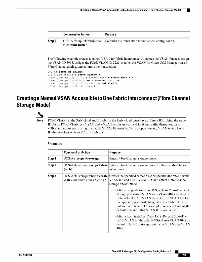
PurposeCommand or Action
Commits the transaction to the system configuration.UCS-A /fc-uplink/fabric/vsan# commit-buffer
Step 5
The following example creates a named VSAN for fabric interconnect A, names the VSAN finance, assignsthe VSAN ID 3955, assigns the FCoE VLAN ID 2221, enables the VSAN for Cisco UCS Manager-basedFibre Channel zoning, and commits the transaction:UCS-A# scope fc-uplinkUCS-A /fc-uplink # scope fabric aUCS-A /fc-uplink/fabric # create vsan finance 3955 2221UCS-A /fc-uplink/vsan # set fc-zoning enabledUCS-A /fc-uplink/fabric/vsan* # commit-bufferUCS-A /fc-uplink/fabric/vsan #
Creating a Named VSAN Accessible to One Fabric Interconnect (Fibre ChannelStorage Mode)
FCoE VLANs in the SAN cloud and VLANs in the LAN cloud must have different IDs. Using the sameID for an FCoE VLAN in a VSAN and a VLAN results in a critical fault and traffic disruption for allvNICs and uplink ports using that FCoE VLAN. Ethernet traffic is dropped on any VLAN which has anID that overlaps with an FCoE VLAN ID.
Note
Procedure
PurposeCommand or Action
Enters Fibre Channel storage mode.UCS-A# scope fc-storageStep 1
Enters Fibre Channel storage mode for the specified fabricinterconnect.
UCS-A /fc-storage # scope fabric{a | b}
Step 2
Creates the specified namedVSAN, specifies the VSAN name,VSAN ID, and FCoE VLAN ID, and enters Fibre Channelstorage VSAN mode.
UCS-A /fc-storage/fabric # createvsan vsan-name vsan-id fcoe-id
Step 3
• After an upgrade to Cisco UCS, Release 2.0—The FCoEstorage port native VLAN uses VLAN 4048 by default.If the default FCoEVSANwas set to use VLAN 1 beforethe upgrade, you must change it to a VLAN ID that isnot used or reserved. For example, consider changing thedefault to 4049 if that VLAN ID is not in use.
• After a fresh install of Cisco UCS, Release 2.0—TheFCoEVLAN for the default VSAN uses VLAN 4048 bydefault. The FCoE storage port native VLAN uses VLAN4049.
Cisco UCS Manager CLI Configuration Guide, Release 2.1 OL-28302-04 281
Creating a Named VSAN Accessible to One Fabric Interconnect (Fibre Channel Storage Mode)
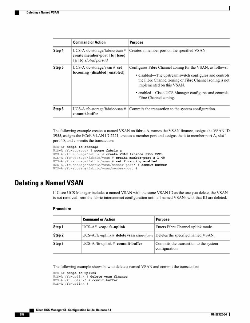
PurposeCommand or Action
Creates a member port on the specified VSAN.UCS-A /fc-storage/fabric/vsan #create member-port {fc | fcoe}{a | b} slot-id port-id
Step 4
Configures Fibre Channel zoning for the VSAN, as follows:UCS-A /fc-storage/vsan # setfc-zoning {disabled | enabled}
Step 5
• disabled—The upstream switch configures and controlsthe Fibre Channel zoning or Fibre Channel zoning is notimplemented on this VSAN.
• enabled—Cisco UCS Manager configures and controlsFibre Channel zoning.
Commits the transaction to the system configuration.UCS-A /fc-storage/fabric/vsan #commit-buffer
Step 6
The following example creates a named VSAN on fabric A, names the VSAN finance, assigns the VSAN ID3955, assigns the FCoE VLAN ID 2221, creates a member port and assigns the it to member port A, slot 1port 40, and commits the transaction:UCS-A# scope fc-storageUCS-A /fc-storage/ # scope fabric aUCS-A /fc-storage/fabric # create VSAN finance 3955 2221UCS-A /fc-storage/fabric/vsan # create member-port a 1 40UCS-A /fc-storage/fabric/vsan # set fc-zoning enabledUCS-A /fc-storage/fabric/vsan/member-port* # commit-bufferUCS-A /fc-storage/fabric/vsan/member-port #
Deleting a Named VSANIf Cisco UCS Manager includes a named VSAN with the same VSAN ID as the one you delete, the VSANis not removed from the fabric interconnect configuration until all named VSANs with that ID are deleted.
Procedure
PurposeCommand or Action
Enters Fibre Channel uplink mode.UCS-A# scope fc-uplinkStep 1
Deletes the specified named VSAN.UCS-A /fc-uplink # delete vsan vsan-nameStep 2
Commits the transaction to the systemconfiguration.
UCS-A /fc-uplink # commit-bufferStep 3
The following example shows how to delete a named VSAN and commit the transaction:UCS-A# scope fc-uplinkUCS-A /fc-uplink # delete vsan financeUCS-A /fc-uplink* # commit-bufferUCS-A /fc-uplink #
Cisco UCS Manager CLI Configuration Guide, Release 2.1282 OL-28302-04
Deleting a Named VSAN
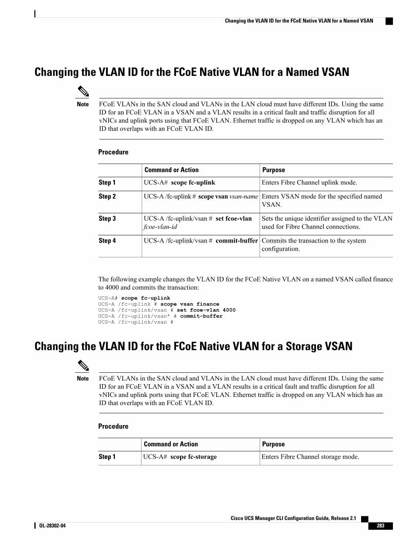
Changing the VLAN ID for the FCoE Native VLAN for a Named VSAN
FCoE VLANs in the SAN cloud and VLANs in the LAN cloud must have different IDs. Using the sameID for an FCoE VLAN in a VSAN and a VLAN results in a critical fault and traffic disruption for allvNICs and uplink ports using that FCoE VLAN. Ethernet traffic is dropped on any VLAN which has anID that overlaps with an FCoE VLAN ID.
Note
Procedure
PurposeCommand or Action
Enters Fibre Channel uplink mode.UCS-A# scope fc-uplinkStep 1
Enters VSAN mode for the specified namedVSAN.
UCS-A /fc-uplink # scope vsan vsan-nameStep 2
Sets the unique identifier assigned to the VLANused for Fibre Channel connections.
UCS-A /fc-uplink/vsan # set fcoe-vlanfcoe-vlan-id
Step 3
Commits the transaction to the systemconfiguration.
UCS-A /fc-uplink/vsan # commit-bufferStep 4
The following example changes the VLAN ID for the FCoE Native VLAN on a named VSAN called financeto 4000 and commits the transaction:UCS-A# scope fc-uplinkUCS-A /fc-uplink # scope vsan financeUCS-A /fc-uplink/vsan # set fcoe-vlan 4000UCS-A /fc-uplink/vsan* # commit-bufferUCS-A /fc-uplink/vsan #
Changing the VLAN ID for the FCoE Native VLAN for a Storage VSAN
FCoE VLANs in the SAN cloud and VLANs in the LAN cloud must have different IDs. Using the sameID for an FCoE VLAN in a VSAN and a VLAN results in a critical fault and traffic disruption for allvNICs and uplink ports using that FCoE VLAN. Ethernet traffic is dropped on any VLAN which has anID that overlaps with an FCoE VLAN ID.
Note
Procedure
PurposeCommand or Action
Enters Fibre Channel storage mode.UCS-A# scope fc-storageStep 1
Cisco UCS Manager CLI Configuration Guide, Release 2.1 OL-28302-04 283
Changing the VLAN ID for the FCoE Native VLAN for a Named VSAN
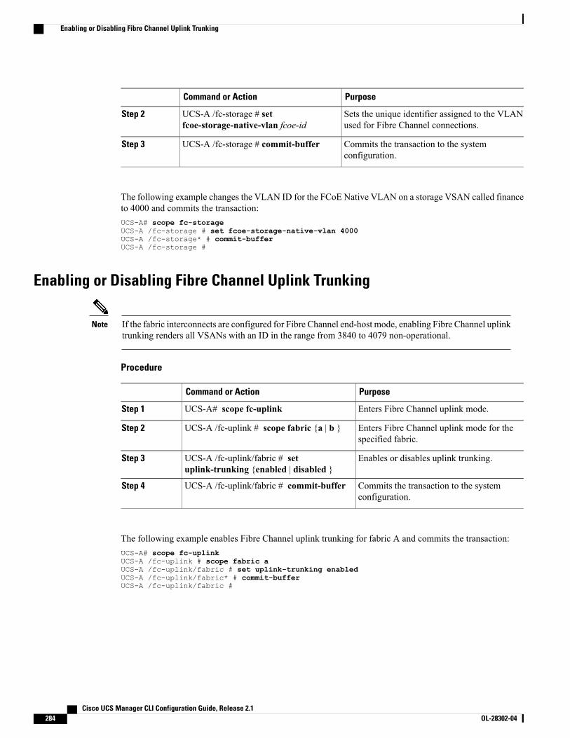
PurposeCommand or Action
Sets the unique identifier assigned to the VLANused for Fibre Channel connections.
UCS-A /fc-storage # setfcoe-storage-native-vlan fcoe-id
Step 2
Commits the transaction to the systemconfiguration.
UCS-A /fc-storage # commit-bufferStep 3
The following example changes the VLAN ID for the FCoE Native VLAN on a storage VSAN called financeto 4000 and commits the transaction:UCS-A# scope fc-storageUCS-A /fc-storage # set fcoe-storage-native-vlan 4000UCS-A /fc-storage* # commit-bufferUCS-A /fc-storage #
Enabling or Disabling Fibre Channel Uplink Trunking
If the fabric interconnects are configured for Fibre Channel end-host mode, enabling Fibre Channel uplinktrunking renders all VSANs with an ID in the range from 3840 to 4079 non-operational.
Note
Procedure
PurposeCommand or Action
Enters Fibre Channel uplink mode.UCS-A# scope fc-uplinkStep 1
Enters Fibre Channel uplink mode for thespecified fabric.
UCS-A /fc-uplink # scope fabric {a | b }Step 2
Enables or disables uplink trunking.UCS-A /fc-uplink/fabric # setuplink-trunking {enabled | disabled }
Step 3
Commits the transaction to the systemconfiguration.
UCS-A /fc-uplink/fabric # commit-bufferStep 4
The following example enables Fibre Channel uplink trunking for fabric A and commits the transaction:UCS-A# scope fc-uplinkUCS-A /fc-uplink # scope fabric aUCS-A /fc-uplink/fabric # set uplink-trunking enabledUCS-A /fc-uplink/fabric* # commit-bufferUCS-A /fc-uplink/fabric #
Cisco UCS Manager CLI Configuration Guide, Release 2.1284 OL-28302-04
Enabling or Disabling Fibre Channel Uplink Trunking
C H A P T E R 23Configuring SAN Pin Groups
This chapter includes the following sections:
• SAN Pin Groups, page 285
• Configuring a SAN Pin Group, page 285
• Configuring a FCoE Pin Group, page 286
SAN Pin GroupsCisco UCS uses SAN pin groups to pin Fibre Channel traffic from a vHBA on a server to an uplink FibreChannel port on the fabric interconnect. You can use this pinning to manage the distribution of traffic fromthe servers.
In Fibre Channel switch mode, SAN pin groups are irrelevant. Any existing SAN pin groups will beignored.
Note
To configure pinning for a server, you must include the SAN pin group in a vHBA policy. The vHBA policyis then included in the service profile assigned to that server. All traffic from the vHBA will travel throughthe I/O module to the specified uplink Fibre Channel port.
You can assign the same pin group to multiple vHBA policies. As a result, you do not need to manually pinthe traffic for each vHBA.
Changing the target interface for an existing SAN pin group disrupts traffic for all vHBAs which use thatpin group. The fabric interconnect performs a log in and log out for the Fibre Channel protocols to re-pinthe traffic.
Important
Configuring a SAN Pin GroupIn a system with two fabric interconnects, you can associate the pin group with only one fabric interconnector with both fabric interconnects.
Cisco UCS Manager CLI Configuration Guide, Release 2.1 OL-28302-04 285

Procedure
PurposeCommand or Action
Enters Fibre Channel uplink mode.UCS-A# scope fc-uplinkStep 1
Creates a Fibre Channel (SAN) pin group with thespecified name, and enters Fibre Channel uplink pingroup mode.
UCS-A /fc-uplink # create pin-grouppin-group-name
Step 2
(Optional)Provides a description for the pin group.
UCS-A /fc-uplink/pin-group # setdescr description
Step 3
If your description includes spaces, specialcharacters, or punctuation, you must begin andend your description with quotation marks. Thequotation marks will not appear in thedescription field of any show commandoutput.
Note
(Optional)Sets the Fibre Channel pin target to the specified fabricand port.
UCS-A /fc-uplink/pin-group # settarget {a | b | dual} port slot-num /port-num
Step 4
Commits the transaction to the system configuration.UCS-A /fc-uplink/pin-group #commit-buffer
Step 5
The following example creates a SAN pin group named fcpingroup12, provides a description for the pingroup, sets the pin group target to slot 2, port 1, and commits the transaction:UCS-A# scope fc-uplinkUCS-A /fc-uplink # create pin-group fcpingroup12UCS-A /fc-uplink/pin-group* # set descr "This is my pin group #12"UCS-A /fc-uplink/pin-group* # set target a port 2/1UCS-A /fc-uplink/pin-group* # commit-bufferUCS-A /fc-uplink/pin-group #
What to Do Next
Include the pin group in a vHBA template.
Configuring a FCoE Pin GroupYou can create a FCoE pin group, and specify the FCoE uplink port as the pin group target.
Procedure
PurposeCommand or Action
Enters FC uplink mode.UCS-A# scope fc-uplinkStep 1
Cisco UCS Manager CLI Configuration Guide, Release 2.1286 OL-28302-04
Configuring a FCoE Pin Group
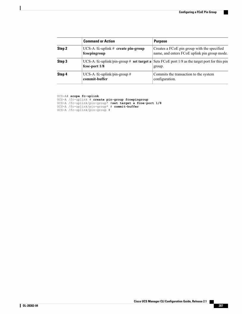
PurposeCommand or Action
Creates a FCoE pin group with the specifiedname, and enters FCoE uplink pin group mode.
UCS-A /fc-uplink # create pin-groupfcoepingroup
Step 2
Sets FCoE port 1/8 as the target port for this pingroup.
UCS-A /fc-uplink/pin-group # set target afcoe-port 1/8
Step 3
Commits the transaction to the systemconfiguration.
UCS-A /fc-uplink/pin-group #commit-buffer
Step 4
UCS-A# scope fc-uplinkUCS-A /fc-uplink # create pin-group fcoepingroupUCS-A /fc-uplink/pin-group* #set target a fcoe-port 1/8UCS-A /fc-uplink/pin-group* # commit-bufferUCS-A /fc-uplink/pin-group #
Cisco UCS Manager CLI Configuration Guide, Release 2.1 OL-28302-04 287
Configuring a FCoE Pin Group

Cisco UCS Manager CLI Configuration Guide, Release 2.1288 OL-28302-04
Configuring a FCoE Pin Group
C H A P T E R 24Configuring WWN Pools
This chapter includes the following sections:
• WWN Pools, page 289
• Creating a WWN Pool, page 290
• Deleting a WWN Pool, page 292
WWN PoolsAWorld Wide Name (WWN) pool is a collection of WWNs for use by the Fibre Channel vHBAs in a CiscoUCS domain. You create separate pools for the following:
•WW node names assigned to the vHBA
•WW port names assigned to the vHBA
• Both WW node names and WW port names
A WWN pool can include only WWNNs or WWPNs in the ranges from 20:00:00:00:00:00:00:00 to20:FF:FF:FF:FF:FF:FF:FF or from 50:00:00:00:00:00:00:00 to 5F:FF:FF:FF:FF:FF:FF:FF. All otherWWN ranges are reserved. To ensure the uniqueness of the Cisco UCSWWNNs andWWPNs in the SANfabric, we recommend that you use the following WWN prefix for all blocks in a pool:20:00:00:25:B5:XX:XX:XX
Important
If you use WWN pools in service profiles, you do not have to manually configure the WWNs that will beused by the server associated with the service profile. In a system that implements multi-tenancy, you can usea WWN pool to control the WWNs used by each organization.
You assign WWNs to pools in blocks.
WWNN Pools
AWWNN pool is a WWN pool that contains only WW node names. If you include a pool of WWNNs in aservice profile, the associated server is assigned a WWNN from that pool.
Cisco UCS Manager CLI Configuration Guide, Release 2.1 OL-28302-04 289
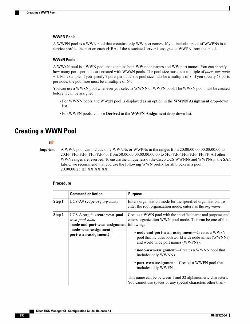
WWPN Pools
AWWPN pool is a WWN pool that contains only WW port names. If you include a pool of WWPNs in aservice profile, the port on each vHBA of the associated server is assigned a WWPN from that pool.
WWxN Pools
AWWxN pool is a WWN pool that contains both WW node names and WW port names. You can specifyhow many ports per node are created with WWxN pools. The pool size must be a multiple of ports-per-node+ 1. For example, if you specify 7 ports per node, the pool size must be a multiple of 8. If you specify 63 portsper node, the pool size must be a multiple of 64.
You can use aWWxN pool whenever you select a WWNN orWWPN pool. TheWWxN pool must be createdbefore it can be assigned.
• For WWNN pools, the WWxN pool is displayed as an option in theWWNN Assignment drop-downlist.
• For WWPN pools, choose Derived in theWWPN Assignment drop-down list.
Creating a WWN Pool
AWWN pool can include only WWNNs or WWPNs in the ranges from 20:00:00:00:00:00:00:00 to20:FF:FF:FF:FF:FF:FF:FF or from 50:00:00:00:00:00:00:00 to 5F:FF:FF:FF:FF:FF:FF:FF. All otherWWN ranges are reserved. To ensure the uniqueness of the Cisco UCSWWNNs andWWPNs in the SANfabric, we recommend that you use the following WWN prefix for all blocks in a pool:20:00:00:25:B5:XX:XX:XX
Important
Procedure
PurposeCommand or Action
Enters organization mode for the specified organization. Toenter the root organization mode, enter / as the org-name.
UCS-A# scope org org-nameStep 1
Creates aWWN pool with the specified name and purpose, andenters organization WWN pool mode. This can be one of thefollowing:
UCS-A /org # create wwn-poolwwn-pool-name{node-and-port-wwn-assignment
Step 2
| node-wwn-assignment |port-wwn-assignment} • node-and-port-wwn-assignment—Creates a WWxN
pool that includes both world wide node names (WWNNs)and world wide port names (WWPNs).
• node-wwn-assignment—Creates a WWNN pool thatincludes only WWNNs.
• port-wwn-assignment—Creates a WWPN pool thatincludes only WWPNs.
This name can be between 1 and 32 alphanumeric characters.You cannot use spaces or any special characters other than -
Cisco UCS Manager CLI Configuration Guide, Release 2.1290 OL-28302-04
Creating a WWN Pool
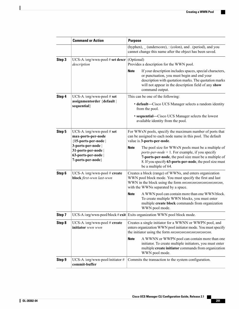
PurposeCommand or Action
(hyphen), _ (underscore), : (colon), and . (period), and youcannot change this name after the object has been saved.
(Optional)Provides a description for the WWN pool.
UCS-A /org/wwn-pool # set descrdescription
Step 3
If your description includes spaces, special characters,or punctuation, you must begin and end yourdescription with quotation marks. The quotation markswill not appear in the description field of any showcommand output.
Note
This can be one of the following:UCS-A /org/wwn-pool # setassignmentorder {default |sequential}
Step 4
• default—Cisco UCS Manager selects a random identityfrom the pool.
• sequential—Cisco UCS Manager selects the lowestavailable identity from the pool.
For WWxN pools, specify the maximum number of ports thatcan be assigned to each node name in this pool. The defaultvalue is 3-ports-per-node.
UCS-A /org/wwn-pool # setmax-ports-per-node{15-ports-per-node |
Step 5
3-ports-per-node | The pool size for WWxN pools must be a multiple ofports-per-node + 1. For example, if you specify7-ports-per-node, the pool size must be a multiple of8. If you specify 63-ports-per-node, the pool size mustbe a multiple of 64.
Note31-ports-per-node |63-ports-per-node |7-ports-per-node}
Creates a block (range) of WWNs, and enters organizationWWN pool block mode. You must specify the first and last
UCS-A /org/wwn-pool # createblock first-wwn last-wwn
Step 6
WWN in the block using the form nn:nn:nn:nn:nn:nn:nn:nn,with the WWNs separated by a space.
AWWNpool can containmore than oneWWNblock.To create multiple WWN blocks, you must entermultiple create block commands from organizationWWN pool mode.
Note
Exits organization WWN pool block mode.UCS-A /org/wwn-pool/block # exitStep 7
Creates a single initiator for a WWNN or WWPN pool, andenters organizationWWNpool initiator mode. Youmust specifythe initiator using the form nn:nn:nn:nn:nn:nn:nn:nn.
UCS-A /org/wwn-pool # createinitiator wwn wwn
Step 8
AWWNN or WWPN pool can contain more than oneinitiator. To create multiple initiators, you must entermultiple create initiator commands from organizationWWN pool mode.
Note
Commits the transaction to the system configuration.UCS-A /org/wwn-pool/initiator #commit-buffer
Step 9
Cisco UCS Manager CLI Configuration Guide, Release 2.1 OL-28302-04 291
Creating a WWN Pool
The following example shows how to create a WWNN pool named sanpool, provide a description for thepool, specify a block of WWNs and an initiator to be used for the pool, and commit the transaction:UCS-A# scope org /UCS-A /org # create wwn-pool sanpool node-wwn-assignmentUCS-A /org/wwn-pool* # set descr "This is my WWNN pool"UCS-A /org/wwn-pool* # create block 20:00:00:25:B5:00:00:00 20:00:00:25:B5:00:00:01UCS-A /org/wwn-pool/block* # exitUCS-A /org/wwn-pool* # create initiator 23:00:00:05:AD:1E:02:00UCS-A /org/wwn-pool/initiator* # commit-bufferUCS-A /org/wwn-pool/initiator #
The following example shows how to create aWWxN pool named sanpool, provide a description for the pool,specify seven ports per node, specify a block of eightWWNs to be used for the pool, and commit the transaction:UCS-A# scope org /UCS-A /org # create wwn-pool sanpool node-and-port-wwn-assignmentUCS-A /org/wwn-pool* # set descr "This is my WWxN pool"UCS-A /org/wwn-pool* # set max-ports-per-node 7-ports-per-nodeUCS-A /org/wwn-pool* # create block 20:00:00:25:B5:00:00:00 20:00:00:25:B5:00:00:08UCS-A /org/wwn-pool/block* # commit-bufferUCS-A /org/wwn-pool/block #
What to Do Next
• Include the WWPN pool in a vHBA template.
• Include the WWNN pool in a service profile and/or template.
• Include the WWxN pool in a service profile and/or template.
Deleting a WWN PoolIf you delete a pool, Cisco UCS Manager does not reallocate any addresses from that pool that have beenassigned to vNICs or vHBAs. All assigned addresses from a deleted pool remain with the vNIC or vHBA towhich they are assigned until one of the following occurs:
• The associated service profiles are deleted.
• The vNIC or vHBA to which the address is assigned is deleted.
• The vNIC or vHBA is assigned to a different pool.
Procedure
PurposeCommand or Action
Enters organization mode for the specifiedorganization. To enter the root organization mode,enter / as the org-name.
UCS-A# scope org org-nameStep 1
Deletes the specified WWN pool.UCS-A /org # delete wwn-poolpool-name
Step 2
Commits the transaction to the system configuration.UCS-A /org # commit-bufferStep 3
Cisco UCS Manager CLI Configuration Guide, Release 2.1292 OL-28302-04
Deleting a WWN Pool

The following example shows how to delete the WWN pool named pool4 and commit the transaction:UCS-A# scope org /UCS-A /org # delete wwn-pool pool4UCS-A /org* # commit-bufferUCS-A /org #
Cisco UCS Manager CLI Configuration Guide, Release 2.1 OL-28302-04 293
Deleting a WWN Pool

Cisco UCS Manager CLI Configuration Guide, Release 2.1294 OL-28302-04
Deleting a WWN Pool
C H A P T E R 25Configuring Storage-Related Policies
This chapter includes the following sections:
• Configuring vHBA Templates, page 295
• Configuring Fibre Channel Adapter Policies, page 297
• Configuring the Default vHBA Behavior Policy, page 300
• Configuring SAN Connectivity Policies, page 301
Configuring vHBA Templates
vHBA TemplateThis template is a policy that defines how a vHBA on a server connects to the SAN. It is also referred to asa vHBA SAN connectivity template.
You must include this policy in a service profile for it to take effect.
Configuring a vHBA Template
Procedure
PurposeCommand or Action
Enters organization mode for the specified organization.To enter the root organization mode, type / as theorg-name .
UCS-A# scope org org-nameStep 1
Creates a vHBA template and enters organization vHBAtemplate mode.
UCS-A /org # create vhba-templvhba-templ-name [fabric {a | b}][fc-if vsan-name]
Step 2
Cisco UCS Manager CLI Configuration Guide, Release 2.1 OL-28302-04 295
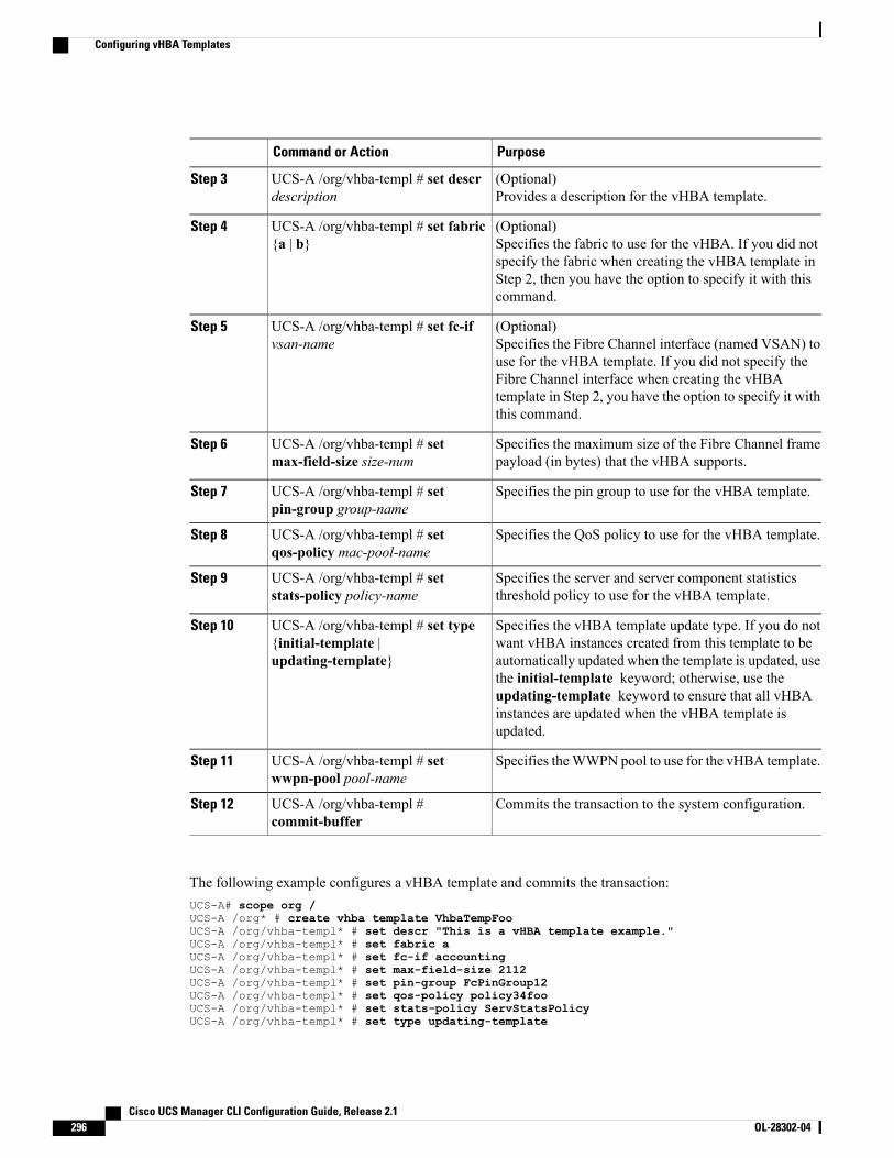
PurposeCommand or Action
(Optional)Provides a description for the vHBA template.
UCS-A /org/vhba-templ # set descrdescription
Step 3
(Optional)Specifies the fabric to use for the vHBA. If you did notspecify the fabric when creating the vHBA template in
UCS-A /org/vhba-templ # set fabric{a | b}
Step 4
Step 2, then you have the option to specify it with thiscommand.
(Optional)Specifies the Fibre Channel interface (named VSAN) touse for the vHBA template. If you did not specify the
UCS-A /org/vhba-templ # set fc-ifvsan-name
Step 5
Fibre Channel interface when creating the vHBAtemplate in Step 2, you have the option to specify it withthis command.
Specifies the maximum size of the Fibre Channel framepayload (in bytes) that the vHBA supports.
UCS-A /org/vhba-templ # setmax-field-size size-num
Step 6
Specifies the pin group to use for the vHBA template.UCS-A /org/vhba-templ # setpin-group group-name
Step 7
Specifies the QoS policy to use for the vHBA template.UCS-A /org/vhba-templ # setqos-policy mac-pool-name
Step 8
Specifies the server and server component statisticsthreshold policy to use for the vHBA template.
UCS-A /org/vhba-templ # setstats-policy policy-name
Step 9
Specifies the vHBA template update type. If you do notwant vHBA instances created from this template to be
UCS-A /org/vhba-templ # set type{initial-template |updating-template}
Step 10
automatically updated when the template is updated, usethe initial-template keyword; otherwise, use theupdating-template keyword to ensure that all vHBAinstances are updated when the vHBA template isupdated.
Specifies theWWPN pool to use for the vHBA template.UCS-A /org/vhba-templ # setwwpn-pool pool-name
Step 11
Commits the transaction to the system configuration.UCS-A /org/vhba-templ #commit-buffer
Step 12
The following example configures a vHBA template and commits the transaction:UCS-A# scope org /UCS-A /org* # create vhba template VhbaTempFooUCS-A /org/vhba-templ* # set descr "This is a vHBA template example."UCS-A /org/vhba-templ* # set fabric aUCS-A /org/vhba-templ* # set fc-if accountingUCS-A /org/vhba-templ* # set max-field-size 2112UCS-A /org/vhba-templ* # set pin-group FcPinGroup12UCS-A /org/vhba-templ* # set qos-policy policy34fooUCS-A /org/vhba-templ* # set stats-policy ServStatsPolicyUCS-A /org/vhba-templ* # set type updating-template
Cisco UCS Manager CLI Configuration Guide, Release 2.1296 OL-28302-04
Configuring vHBA Templates
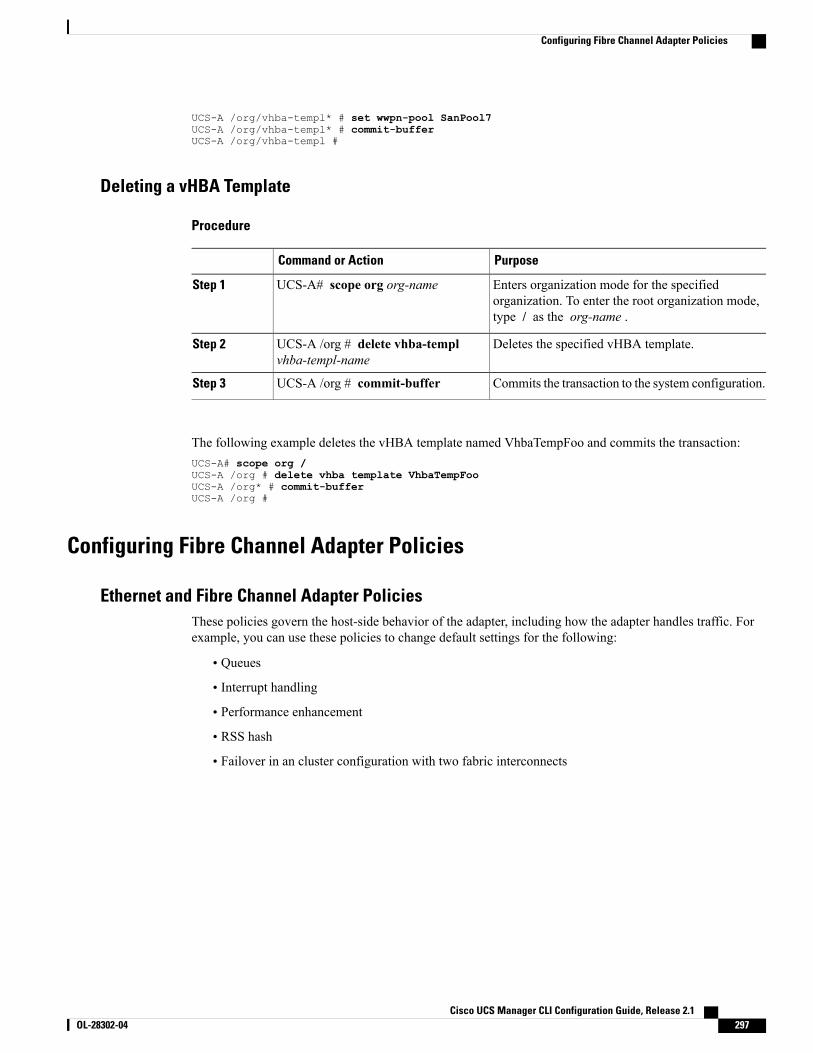
UCS-A /org/vhba-templ* # set wwpn-pool SanPool7UCS-A /org/vhba-templ* # commit-bufferUCS-A /org/vhba-templ #
Deleting a vHBA Template
Procedure
PurposeCommand or Action
Enters organization mode for the specifiedorganization. To enter the root organization mode,type / as the org-name .
UCS-A# scope org org-nameStep 1
Deletes the specified vHBA template.UCS-A /org # delete vhba-templvhba-templ-name
Step 2
Commits the transaction to the system configuration.UCS-A /org # commit-bufferStep 3
The following example deletes the vHBA template named VhbaTempFoo and commits the transaction:UCS-A# scope org /UCS-A /org # delete vhba template VhbaTempFooUCS-A /org* # commit-bufferUCS-A /org #
Configuring Fibre Channel Adapter Policies
Ethernet and Fibre Channel Adapter PoliciesThese policies govern the host-side behavior of the adapter, including how the adapter handles traffic. Forexample, you can use these policies to change default settings for the following:
• Queues
• Interrupt handling
• Performance enhancement
• RSS hash
• Failover in an cluster configuration with two fabric interconnects
Cisco UCS Manager CLI Configuration Guide, Release 2.1 OL-28302-04 297
Configuring Fibre Channel Adapter Policies
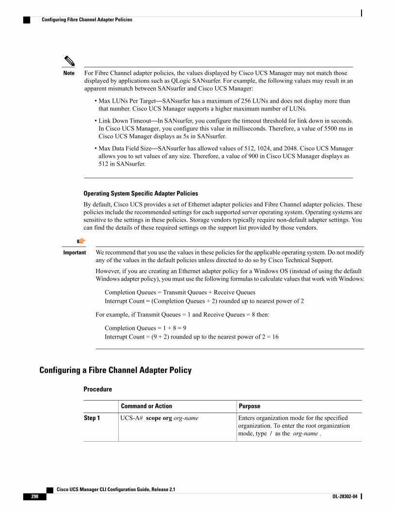
For Fibre Channel adapter policies, the values displayed by Cisco UCS Manager may not match thosedisplayed by applications such as QLogic SANsurfer. For example, the following values may result in anapparent mismatch between SANsurfer and Cisco UCS Manager:
Note
• Max LUNs Per Target—SANsurfer has a maximum of 256 LUNs and does not display more thanthat number. Cisco UCS Manager supports a higher maximum number of LUNs.
• Link Down Timeout—In SANsurfer, you configure the timeout threshold for link down in seconds.In Cisco UCS Manager, you configure this value in milliseconds. Therefore, a value of 5500 ms inCisco UCS Manager displays as 5s in SANsurfer.
• Max Data Field Size—SANsurfer has allowed values of 512, 1024, and 2048. Cisco UCS Managerallows you to set values of any size. Therefore, a value of 900 in Cisco UCS Manager displays as512 in SANsurfer.
Operating System Specific Adapter Policies
By default, Cisco UCS provides a set of Ethernet adapter policies and Fibre Channel adapter policies. Thesepolicies include the recommended settings for each supported server operating system. Operating systems aresensitive to the settings in these policies. Storage vendors typically require non-default adapter settings. Youcan find the details of these required settings on the support list provided by those vendors.
We recommend that you use the values in these policies for the applicable operating system. Do not modifyany of the values in the default policies unless directed to do so by Cisco Technical Support.
However, if you are creating an Ethernet adapter policy for a Windows OS (instead of using the defaultWindows adapter policy), youmust use the following formulas to calculate values that work withWindows:
Important
Completion Queues = Transmit Queues + Receive QueuesInterrupt Count = (Completion Queues + 2) rounded up to nearest power of 2
For example, if Transmit Queues = 1 and Receive Queues = 8 then:
Completion Queues = 1 + 8 = 9Interrupt Count = (9 + 2) rounded up to the nearest power of 2 = 16
Configuring a Fibre Channel Adapter Policy
Procedure
PurposeCommand or Action
Enters organization mode for the specifiedorganization. To enter the root organizationmode, type / as the org-name .
UCS-A# scope org org-nameStep 1
Cisco UCS Manager CLI Configuration Guide, Release 2.1298 OL-28302-04
Configuring Fibre Channel Adapter Policies
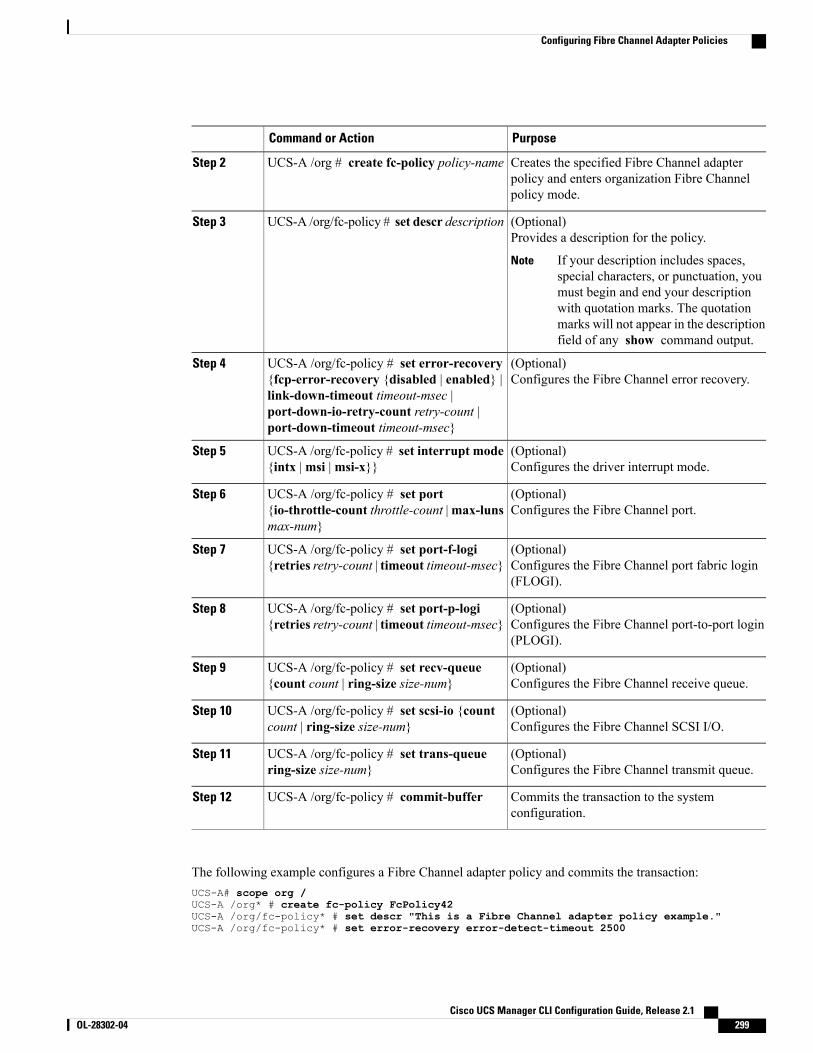
PurposeCommand or Action
Creates the specified Fibre Channel adapterpolicy and enters organization Fibre Channelpolicy mode.
UCS-A /org # create fc-policy policy-nameStep 2
(Optional)Provides a description for the policy.
UCS-A /org/fc-policy # set descr descriptionStep 3
If your description includes spaces,special characters, or punctuation, youmust begin and end your descriptionwith quotation marks. The quotationmarks will not appear in the descriptionfield of any show command output.
Note
(Optional)Configures the Fibre Channel error recovery.
UCS-A /org/fc-policy # set error-recovery{fcp-error-recovery {disabled | enabled} |link-down-timeout timeout-msec |
Step 4
port-down-io-retry-count retry-count |port-down-timeout timeout-msec}
(Optional)Configures the driver interrupt mode.
UCS-A /org/fc-policy # set interrupt mode{intx |msi |msi-x}}
Step 5
(Optional)Configures the Fibre Channel port.
UCS-A /org/fc-policy # set port{io-throttle-count throttle-count |max-lunsmax-num}
Step 6
(Optional)Configures the Fibre Channel port fabric login(FLOGI).
UCS-A /org/fc-policy # set port-f-logi{retries retry-count | timeout timeout-msec}
Step 7
(Optional)Configures the Fibre Channel port-to-port login(PLOGI).
UCS-A /org/fc-policy # set port-p-logi{retries retry-count | timeout timeout-msec}
Step 8
(Optional)Configures the Fibre Channel receive queue.
UCS-A /org/fc-policy # set recv-queue{count count | ring-size size-num}
Step 9
(Optional)Configures the Fibre Channel SCSI I/O.
UCS-A /org/fc-policy # set scsi-io {countcount | ring-size size-num}
Step 10
(Optional)Configures the Fibre Channel transmit queue.
UCS-A /org/fc-policy # set trans-queuering-size size-num}
Step 11
Commits the transaction to the systemconfiguration.
UCS-A /org/fc-policy # commit-bufferStep 12
The following example configures a Fibre Channel adapter policy and commits the transaction:UCS-A# scope org /UCS-A /org* # create fc-policy FcPolicy42UCS-A /org/fc-policy* # set descr "This is a Fibre Channel adapter policy example."UCS-A /org/fc-policy* # set error-recovery error-detect-timeout 2500
Cisco UCS Manager CLI Configuration Guide, Release 2.1 OL-28302-04 299
Configuring Fibre Channel Adapter Policies
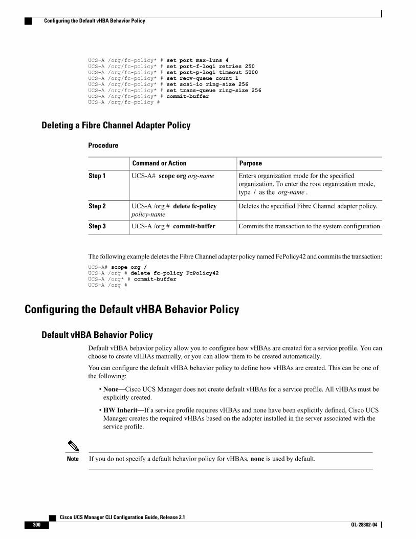
UCS-A /org/fc-policy* # set port max-luns 4UCS-A /org/fc-policy* # set port-f-logi retries 250UCS-A /org/fc-policy* # set port-p-logi timeout 5000UCS-A /org/fc-policy* # set recv-queue count 1UCS-A /org/fc-policy* # set scsi-io ring-size 256UCS-A /org/fc-policy* # set trans-queue ring-size 256UCS-A /org/fc-policy* # commit-bufferUCS-A /org/fc-policy #
Deleting a Fibre Channel Adapter Policy
Procedure
PurposeCommand or Action
Enters organization mode for the specifiedorganization. To enter the root organization mode,type / as the org-name .
UCS-A# scope org org-nameStep 1
Deletes the specified Fibre Channel adapter policy.UCS-A /org # delete fc-policypolicy-name
Step 2
Commits the transaction to the system configuration.UCS-A /org # commit-bufferStep 3
The following example deletes the Fibre Channel adapter policy named FcPolicy42 and commits the transaction:UCS-A# scope org /UCS-A /org # delete fc-policy FcPolicy42UCS-A /org* # commit-bufferUCS-A /org #
Configuring the Default vHBA Behavior Policy
Default vHBA Behavior PolicyDefault vHBA behavior policy allow you to configure how vHBAs are created for a service profile. You canchoose to create vHBAs manually, or you can allow them to be created automatically.
You can configure the default vHBA behavior policy to define how vHBAs are created. This can be one ofthe following:
• None—Cisco UCS Manager does not create default vHBAs for a service profile. All vHBAs must beexplicitly created.
• HW Inherit—If a service profile requires vHBAs and none have been explicitly defined, Cisco UCSManager creates the required vHBAs based on the adapter installed in the server associated with theservice profile.
If you do not specify a default behavior policy for vHBAs, none is used by default.Note
Cisco UCS Manager CLI Configuration Guide, Release 2.1300 OL-28302-04
Configuring the Default vHBA Behavior Policy
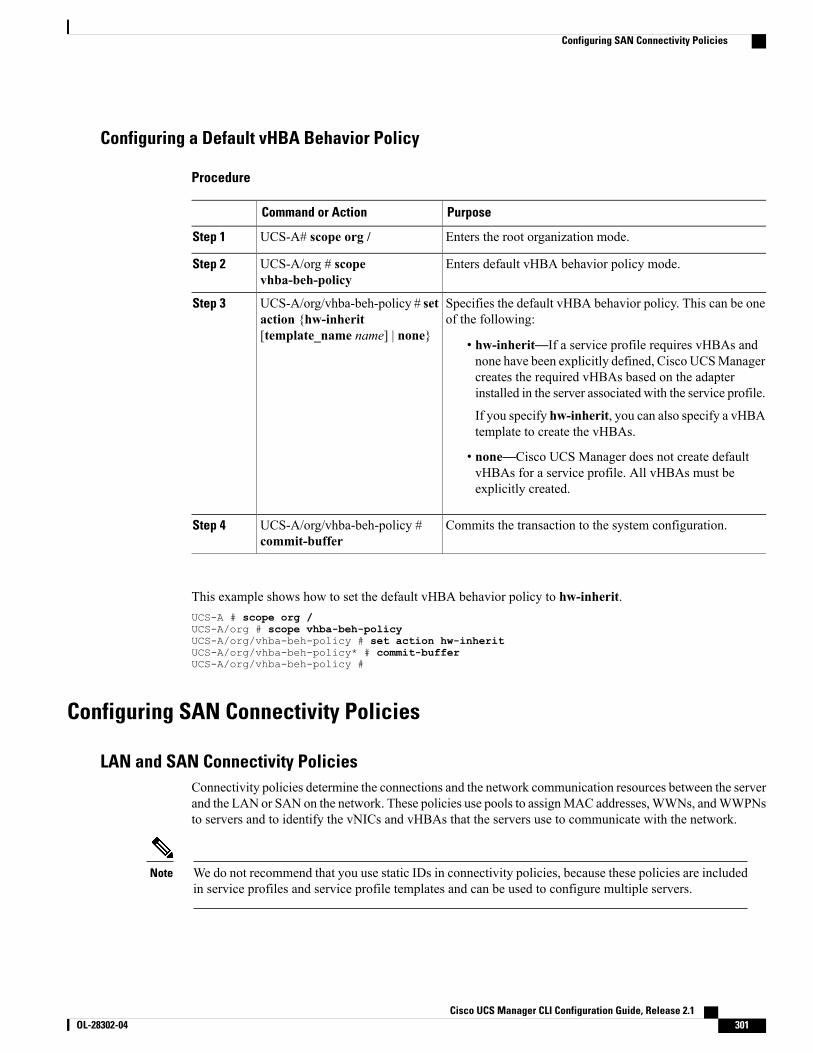
Configuring a Default vHBA Behavior Policy
Procedure
PurposeCommand or Action
Enters the root organization mode.UCS-A# scope org /Step 1
Enters default vHBA behavior policy mode.UCS-A/org # scopevhba-beh-policy
Step 2
Specifies the default vHBA behavior policy. This can be oneof the following:
UCS-A/org/vhba-beh-policy # setaction {hw-inherit[template_name name] | none}
Step 3
• hw-inherit—If a service profile requires vHBAs andnone have been explicitly defined, Cisco UCSManagercreates the required vHBAs based on the adapterinstalled in the server associated with the service profile.
If you specify hw-inherit, you can also specify a vHBAtemplate to create the vHBAs.
• none—Cisco UCS Manager does not create defaultvHBAs for a service profile. All vHBAs must beexplicitly created.
Commits the transaction to the system configuration.UCS-A/org/vhba-beh-policy #commit-buffer
Step 4
This example shows how to set the default vHBA behavior policy to hw-inherit.UCS-A # scope org /UCS-A/org # scope vhba-beh-policyUCS-A/org/vhba-beh-policy # set action hw-inheritUCS-A/org/vhba-beh-policy* # commit-bufferUCS-A/org/vhba-beh-policy #
Configuring SAN Connectivity Policies
LAN and SAN Connectivity PoliciesConnectivity policies determine the connections and the network communication resources between the serverand the LAN or SAN on the network. These policies use pools to assignMAC addresses,WWNs, andWWPNsto servers and to identify the vNICs and vHBAs that the servers use to communicate with the network.
We do not recommend that you use static IDs in connectivity policies, because these policies are includedin service profiles and service profile templates and can be used to configure multiple servers.
Note
Cisco UCS Manager CLI Configuration Guide, Release 2.1 OL-28302-04 301
Configuring SAN Connectivity Policies
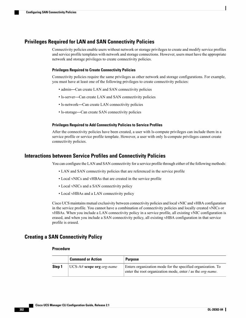
Privileges Required for LAN and SAN Connectivity PoliciesConnectivity policies enable users without network or storage privileges to create and modify service profilesand service profile templates with network and storage connections. However, users must have the appropriatenetwork and storage privileges to create connectivity policies.
Privileges Required to Create Connectivity Policies
Connectivity policies require the same privileges as other network and storage configurations. For example,you must have at least one of the following privileges to create connectivity policies:
• admin—Can create LAN and SAN connectivity policies
• ls-server—Can create LAN and SAN connectivity policies
• ls-network—Can create LAN connectivity policies
• ls-storage—Can create SAN connectivity policies
Privileges Required to Add Connectivity Policies to Service Profiles
After the connectivity policies have been created, a user with ls-compute privileges can include them in aservice profile or service profile template. However, a user with only ls-compute privileges cannot createconnectivity policies.
Interactions between Service Profiles and Connectivity PoliciesYou can configure the LAN and SAN connectivity for a service profile through either of the followingmethods:
• LAN and SAN connectivity policies that are referenced in the service profile
• Local vNICs and vHBAs that are created in the service profile
• Local vNICs and a SAN connectivity policy
• Local vHBAs and a LAN connectivity policy
CiscoUCSmaintainsmutual exclusivity between connectivity policies and local vNIC and vHBA configurationin the service profile. You cannot have a combination of connectivity policies and locally created vNICs orvHBAs. When you include a LAN connectivity policy in a service profile, all existing vNIC configuration iserased, and when you include a SAN connectivity policy, all existing vHBA configuration in that serviceprofile is erased.
Creating a SAN Connectivity Policy
Procedure
PurposeCommand or Action
Enters organization mode for the specified organization. Toenter the root organization mode, enter / as the org-name.
UCS-A# scope org org-nameStep 1
Cisco UCS Manager CLI Configuration Guide, Release 2.1302 OL-28302-04
Configuring SAN Connectivity Policies
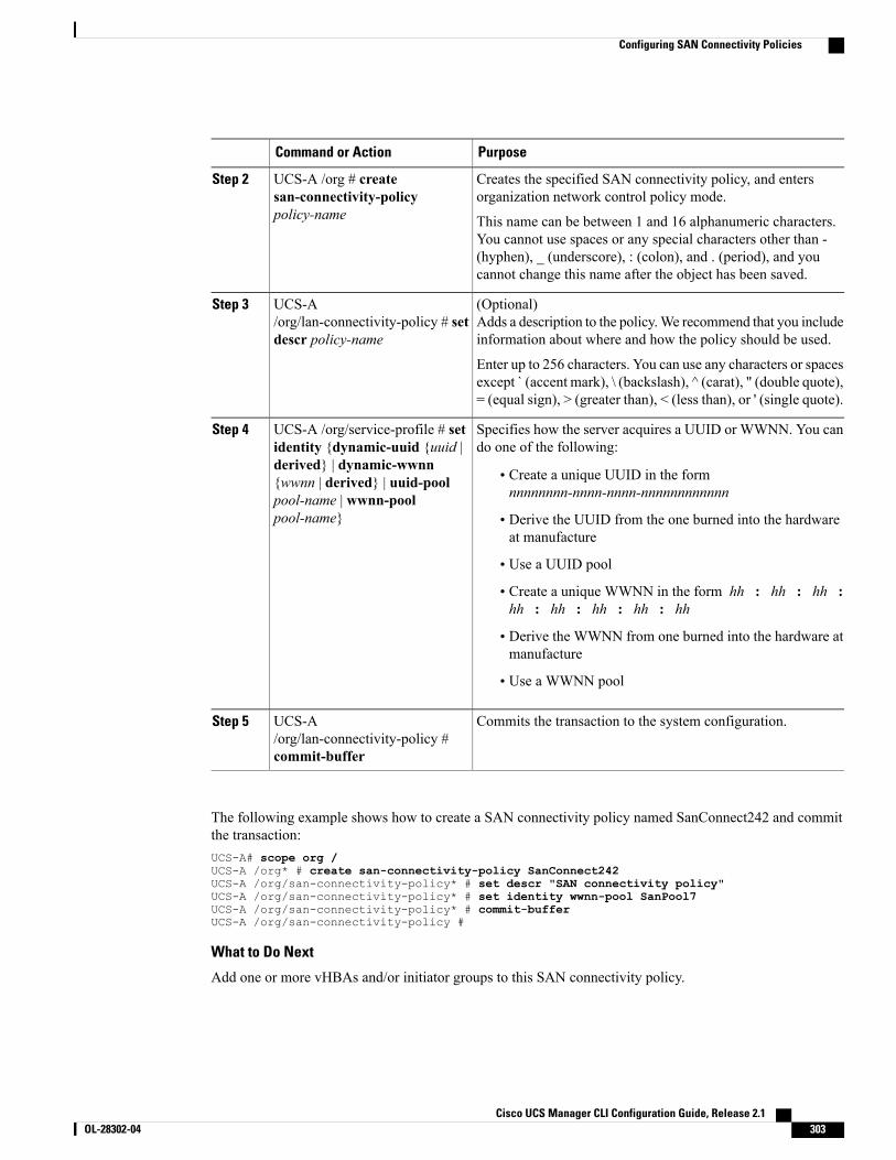
PurposeCommand or Action
Creates the specified SAN connectivity policy, and entersorganization network control policy mode.
UCS-A /org # createsan-connectivity-policypolicy-name
Step 2
This name can be between 1 and 16 alphanumeric characters.You cannot use spaces or any special characters other than -(hyphen), _ (underscore), : (colon), and . (period), and youcannot change this name after the object has been saved.
(Optional)Adds a description to the policy.We recommend that you includeinformation about where and how the policy should be used.
UCS-A/org/lan-connectivity-policy # setdescr policy-name
Step 3
Enter up to 256 characters. You can use any characters or spacesexcept ` (accent mark), \ (backslash), ^ (carat), " (double quote),= (equal sign), > (greater than), < (less than), or ' (single quote).
Specifies how the server acquires a UUID or WWNN. You cando one of the following:
UCS-A /org/service-profile # setidentity {dynamic-uuid {uuid |
Step 4
derived} | dynamic-wwnn• Create a unique UUID in the formnnnnnnnn-nnnn-nnnn-nnnnnnnnnnnn
{wwnn | derived} | uuid-poolpool-name | wwnn-poolpool-name} • Derive the UUID from the one burned into the hardware
at manufacture
• Use a UUID pool
• Create a unique WWNN in the form hh : hh : hh :hh : hh : hh : hh : hh
• Derive the WWNN from one burned into the hardware atmanufacture
• Use a WWNN pool
Commits the transaction to the system configuration.UCS-A/org/lan-connectivity-policy #commit-buffer
Step 5
The following example shows how to create a SAN connectivity policy named SanConnect242 and committhe transaction:UCS-A# scope org /UCS-A /org* # create san-connectivity-policy SanConnect242UCS-A /org/san-connectivity-policy* # set descr "SAN connectivity policy"UCS-A /org/san-connectivity-policy* # set identity wwnn-pool SanPool7UCS-A /org/san-connectivity-policy* # commit-bufferUCS-A /org/san-connectivity-policy #
What to Do Next
Add one or more vHBAs and/or initiator groups to this SAN connectivity policy.
Cisco UCS Manager CLI Configuration Guide, Release 2.1 OL-28302-04 303
Configuring SAN Connectivity Policies
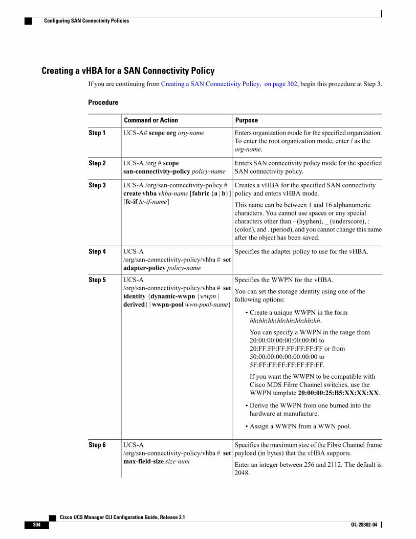
Creating a vHBA for a SAN Connectivity PolicyIf you are continuing from Creating a SAN Connectivity Policy, on page 302, begin this procedure at Step 3.
Procedure
PurposeCommand or Action
Enters organizationmode for the specified organization.To enter the root organization mode, enter / as theorg-name.
UCS-A# scope org org-nameStep 1
Enters SAN connectivity policy mode for the specifiedSAN connectivity policy.
UCS-A /org # scopesan-connectivity-policy policy-name
Step 2
Creates a vHBA for the specified SAN connectivitypolicy and enters vHBA mode.
UCS-A /org/san-connectivity-policy #create vhba vhba-name [fabric {a | b}][fc-if fc-if-name]
Step 3
This name can be between 1 and 16 alphanumericcharacters. You cannot use spaces or any specialcharacters other than - (hyphen), _ (underscore), :(colon), and . (period), and you cannot change this nameafter the object has been saved.
Specifies the adapter policy to use for the vHBA.UCS-A/org/san-connectivity-policy/vhba # setadapter-policy policy-name
Step 4
Specifies the WWPN for the vHBA.UCS-A/org/san-connectivity-policy/vhba # set
Step 5
You can set the storage identity using one of thefollowing options:identity {dynamic-wwpn {wwpn |
derived} |wwpn-poolwwn-pool-name}• Create a unique WWPN in the formhh:hh:hh:hh:hh:hh:hh:hh.
You can specify a WWPN in the range from20:00:00:00:00:00:00:00 to20:FF:FF:FF:FF:FF:FF:FF or from50:00:00:00:00:00:00:00 to5F:FF:FF:FF:FF:FF:FF:FF.
If you want the WWPN to be compatible withCisco MDS Fibre Channel switches, use theWWPN template 20:00:00:25:B5:XX:XX:XX.
• Derive the WWPN from one burned into thehardware at manufacture.
• Assign a WWPN from a WWN pool.
Specifies the maximum size of the Fibre Channel framepayload (in bytes) that the vHBA supports.
UCS-A/org/san-connectivity-policy/vhba # setmax-field-size size-num
Step 6
Enter an integer between 256 and 2112. The default is2048.
Cisco UCS Manager CLI Configuration Guide, Release 2.1304 OL-28302-04
Configuring SAN Connectivity Policies
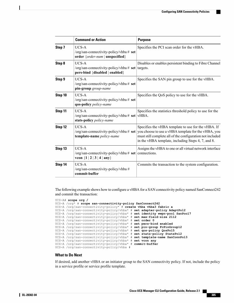
PurposeCommand or Action
Specifies the PCI scan order for the vHBA.UCS-A/org/san-connectivity-policy/vhba # setorder {order-num | unspecified}
Step 7
Disables or enables persistent binding to Fibre Channeltargets.
UCS-A/org/san-connectivity-policy/vhba # setpers-bind {disabled | enabled}
Step 8
Specifies the SAN pin group to use for the vHBA.UCS-A/org/san-connectivity-policy/vhba # setpin-group group-name
Step 9
Specifies the QoS policy to use for the vHBA.UCS-A/org/san-connectivity-policy/vhba # setqos-policy policy-name
Step 10
Specifies the statistics threshold policy to use for thevHBA.
UCS-A/org/san-connectivity-policy/vhba # setstats-policy policy-name
Step 11
Specifies the vHBA template to use for the vHBA. Ifyou choose to use a vHBA template for the vHBA, you
UCS-A/org/san-connectivity-policy/vhba # settemplate-name policy-name
Step 12
must still complete all of the configuration not includedin the vHBA template, including Steps 4, 7, and 8.
Assigns the vHBA to one or all virtual network interfaceconnections.
UCS-A/org/san-connectivity-policy/vhba # setvcon {1 | 2 | 3 | 4 | any}
Step 13
Commits the transaction to the system configuration.UCS-A/org/san-connectivity-policy/vhba #commit-buffer
Step 14
The following example shows how to configure a vHBA for a SAN connectivity policy named SanConnect242and commit the transaction:UCS-A# scope org /UCS-A /org* # scope san-connectivity-policy SanConnect242UCS-A /org/san-connectivity-policy* # create vhba vhba3 fabric aUCS-A /org/san-connectivity-policy/vhba* # set adapter-policy AdaptPol2UCS-A /org/san-connectivity-policy/vhba* # set identity wwpn-pool SanPool7UCS-A /org/san-connectivity-policy/vhba* # set max-field-size 2112UCS-A /org/san-connectivity-policy/vhba* # set order 0UCS-A /org/san-connectivity-policy/vhba* # set pers-bind enabledUCS-A /org/san-connectivity-policy/vhba* # set pin-group FcPinGroup12UCS-A /org/san-connectivity-policy/vhba* # set qos-policy QosPol5UCS-A /org/san-connectivity-policy/vhba* # set stats-policy StatsPol2UCS-A /org/san-connectivity-policy/vhba* # set template-name SanConnPol3UCS-A /org/san-connectivity-policy/vhba* # set vcon anyUCS-A /org/san-connectivity-policy/vhba* # commit-bufferUCS-A /org/san-connectivity-policy/vhba #
What to Do Next
If desired, add another vHBA or an initiator group to the SAN connectivity policy. If not, include the policyin a service profile or service profile template.
Cisco UCS Manager CLI Configuration Guide, Release 2.1 OL-28302-04 305
Configuring SAN Connectivity Policies
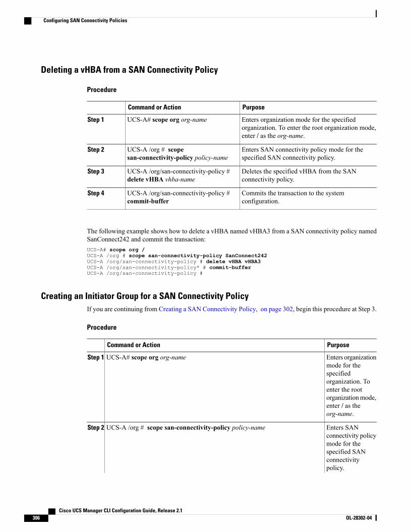
Deleting a vHBA from a SAN Connectivity Policy
Procedure
PurposeCommand or Action
Enters organization mode for the specifiedorganization. To enter the root organization mode,enter / as the org-name.
UCS-A# scope org org-nameStep 1
Enters SAN connectivity policy mode for thespecified SAN connectivity policy.
UCS-A /org # scopesan-connectivity-policy policy-name
Step 2
Deletes the specified vHBA from the SANconnectivity policy.
UCS-A /org/san-connectivity-policy #delete vHBA vhba-name
Step 3
Commits the transaction to the systemconfiguration.
UCS-A /org/san-connectivity-policy #commit-buffer
Step 4
The following example shows how to delete a vHBA named vHBA3 from a SAN connectivity policy namedSanConnect242 and commit the transaction:UCS-A# scope org /UCS-A /org # scope san-connectivity-policy SanConnect242UCS-A /org/san-connectivity-policy # delete vHBA vHBA3UCS-A /org/san-connectivity-policy* # commit-bufferUCS-A /org/san-connectivity-policy #
Creating an Initiator Group for a SAN Connectivity PolicyIf you are continuing from Creating a SAN Connectivity Policy, on page 302, begin this procedure at Step 3.
Procedure
PurposeCommand or Action
Enters organizationmode for the
UCS-A# scope org org-nameStep 1
specifiedorganization. Toenter the rootorganizationmode,enter / as theorg-name.
Enters SANconnectivity policy
UCS-A /org # scope san-connectivity-policy policy-nameStep 2
mode for thespecified SANconnectivitypolicy.
Cisco UCS Manager CLI Configuration Guide, Release 2.1306 OL-28302-04
Configuring SAN Connectivity Policies
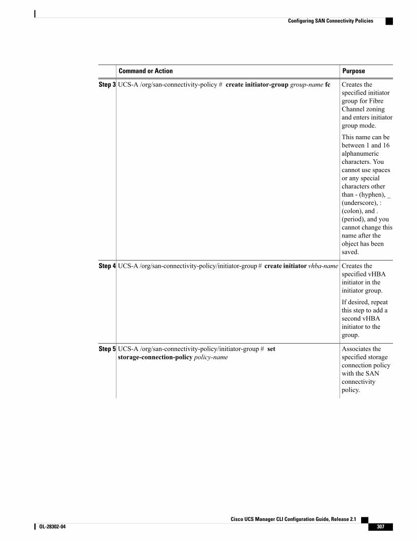
PurposeCommand or Action
Creates thespecified initiator
UCS-A /org/san-connectivity-policy # create initiator-group group-name fcStep 3
group for FibreChannel zoningand enters initiatorgroup mode.
This name can bebetween 1 and 16alphanumericcharacters. Youcannot use spacesor any specialcharacters otherthan - (hyphen), _(underscore), :(colon), and .(period), and youcannot change thisname after theobject has beensaved.
Creates thespecified vHBA
UCS-A /org/san-connectivity-policy/initiator-group # create initiator vhba-nameStep 4
initiator in theinitiator group.
If desired, repeatthis step to add asecond vHBAinitiator to thegroup.
Associates thespecified storage
UCS-A /org/san-connectivity-policy/initiator-group # setstorage-connection-policy policy-name
Step 5
connection policywith the SANconnectivitypolicy.
Cisco UCS Manager CLI Configuration Guide, Release 2.1 OL-28302-04 307
Configuring SAN Connectivity Policies
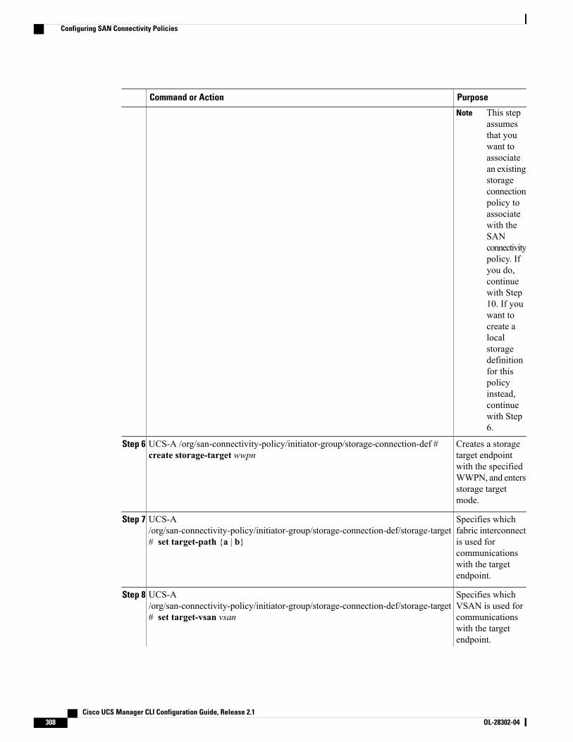
PurposeCommand or Action
This stepassumesthat youwant toassociatean existingstorageconnectionpolicy toassociatewith theSANconnectivitypolicy. Ifyou do,continuewith Step10. If youwant tocreate alocalstoragedefinitionfor thispolicyinstead,continuewith Step6.
Note
Creates a storagetarget endpoint
UCS-A /org/san-connectivity-policy/initiator-group/storage-connection-def #create storage-target wwpn
Step 6
with the specifiedWWPN, and entersstorage targetmode.
Specifies whichfabric interconnect
UCS-A/org/san-connectivity-policy/initiator-group/storage-connection-def/storage-target# set target-path {a | b}
Step 7
is used forcommunicationswith the targetendpoint.
Specifies whichVSAN is used for
UCS-A/org/san-connectivity-policy/initiator-group/storage-connection-def/storage-target# set target-vsan vsan
Step 8
communicationswith the targetendpoint.
Cisco UCS Manager CLI Configuration Guide, Release 2.1308 OL-28302-04
Configuring SAN Connectivity Policies
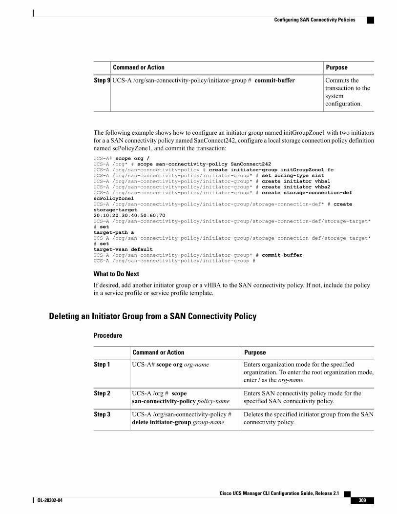
PurposeCommand or Action
Commits thetransaction to the
UCS-A /org/san-connectivity-policy/initiator-group # commit-bufferStep 9
systemconfiguration.
The following example shows how to configure an initiator group named initGroupZone1 with two initiatorsfor a a SAN connectivity policy named SanConnect242, configure a local storage connection policy definitionnamed scPolicyZone1, and commit the transaction:UCS-A# scope org /UCS-A /org* # scope san-connectivity-policy SanConnect242UCS-A /org/san-connectivity-policy # create initiator-group initGroupZone1 fcUCS-A /org/san-connectivity-policy/initiator-group* # set zoning-type sistUCS-A /org/san-connectivity-policy/initiator-group* # create initiator vhba1UCS-A /org/san-connectivity-policy/initiator-group* # create initiator vhba2UCS-A /org/san-connectivity-policy/initiator-group* # create storage-connection-defscPolicyZone1UCS-A /org/san-connectivity-policy/initiator-group/storage-connection-def* # createstorage-target20:10:20:30:40:50:60:70UCS-A /org/san-connectivity-policy/initiator-group/storage-connection-def/storage-target*# settarget-path aUCS-A /org/san-connectivity-policy/initiator-group/storage-connection-def/storage-target*# settarget-vsan defaultUCS-A /org/san-connectivity-policy/initiator-group* # commit-bufferUCS-A /org/san-connectivity-policy/initiator-group #
What to Do Next
If desired, add another initiator group or a vHBA to the SAN connectivity policy. If not, include the policyin a service profile or service profile template.
Deleting an Initiator Group from a SAN Connectivity Policy
Procedure
PurposeCommand or Action
Enters organization mode for the specifiedorganization. To enter the root organization mode,enter / as the org-name.
UCS-A# scope org org-nameStep 1
Enters SAN connectivity policy mode for thespecified SAN connectivity policy.
UCS-A /org # scopesan-connectivity-policy policy-name
Step 2
Deletes the specified initiator group from the SANconnectivity policy.
UCS-A /org/san-connectivity-policy #delete initiator-group group-name
Step 3
Cisco UCS Manager CLI Configuration Guide, Release 2.1 OL-28302-04 309
Configuring SAN Connectivity Policies
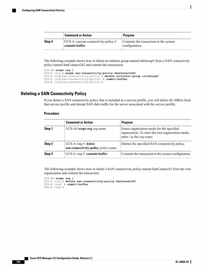
PurposeCommand or Action
Commits the transaction to the systemconfiguration.
UCS-A /org/san-connectivity-policy #commit-buffer
Step 4
The following example shows how to delete an initiator group named initGroup3 from a SAN connectivitypolicy named SanConnect242 and commit the transaction:UCS-A# scope org /UCS-A /org # scope san-connectivity-policy SanConnect242UCS-A /org/san-connectivity-policy # delete initiator-group initGroup3UCS-A /org/san-connectivity-policy* # commit-bufferUCS-A /org/san-connectivity-policy #
Deleting a SAN Connectivity PolicyIf you delete a SAN connectivity policy that is included in a service profile, you will delete all vHBAs fromthat service profile and disrupt SAN data traffic for the server associated with the service profile.
Procedure
PurposeCommand or Action
Enters organization mode for the specifiedorganization. To enter the root organization mode,enter / as the org-name.
UCS-A# scope org org-nameStep 1
Deletes the specified SAN connectivity policy.UCS-A /org # deletesan-connectivity-policy policy-name
Step 2
Commits the transaction to the system configuration.UCS-A /org # commit-bufferStep 3
The following example shows how to delete a SAN connectivity policy named SanConnect52 from the rootorganization and commit the transaction:UCS-A# scope org /UCS-A /org # delete san-connectivity-policy SanConnect52UCS-A /org* # commit-bufferUCS-A /org #
Cisco UCS Manager CLI Configuration Guide, Release 2.1310 OL-28302-04
Configuring SAN Connectivity Policies
C H A P T E R 26Configuring Fibre Channel Zoning
This chapter includes the following sections:
• Information About Fibre Channel Zoning, page 311
• Support for Fibre Channel Zoning in Cisco UCS Manager, page 312
• Guidelines and recommendations for Cisco UCS Manager-Based Fibre Channel Zoning, page 314
• Configuring Fibre Channel Zoning in Cisco UCS, page 314
• Removing Unmanaged Zones from a VSAN Accessible to Both Fabric Interconnects, page 315
• Removing Unmanaged Zones from a VSAN Accessible to One Fabric Interconnect, page 316
• Configuring Fibre Channel Storage Connection Policies, page 317
Information About Fibre Channel ZoningFibre Channel zoning allows you to partition the Fibre Channel fabric into one or more zones. Each zonedefines the set of Fibre Channel initiators and Fibre Channel targets that can communicate with each other ina VSAN. Zoning also enables you to set up access control between hosts and storage devices or user groups.
The access and data traffic control provided by zoning does the following:
• Enhances SAN network security
• Helps prevent data loss or corruption
• Reduces performance issues
Information About ZonesA zone consists of multiple zone members and has the following characteristics:
• Members in a zone can access each other; members in different zones cannot access each other.
• Zones can vary in size.
• Devices can belong to more than one zone.
Cisco UCS Manager CLI Configuration Guide, Release 2.1 OL-28302-04 311
• A physical fabric can have a maximum of 8,000 zones.
Information About Zone SetsEach zone set consists of one or more zones. You can use zone sets to enforce access control within the FibreChannel fabric. In addition, zone sets provide you with the following advantages:
• Only one zone set can be active at any time.
• All zones in a zone set can be activated or deactivated as a single entity across all switches in the fabric.
• A zone can be a member of more than one zone set.
• A switch in a zone can have a maximum of 500 zone sets.
Support for Fibre Channel Zoning in Cisco UCS ManagerCisco UCS Manager supports switch-based Fibre Channel zoning and Cisco UCS Manager-based FibreChannel zoning. You cannot configure a combination of zoning types in the same Cisco UCS domain. Youcan configure a Cisco UCS domain with one of the following types of zoning:
• No zoning
• Cisco UCS Manager-based Fibre Channel zoning—This configuration combines direct attach storagewith local zoning. Fibre Channel or FCoE storage is directly connected to the fabric interconnects andzoning is performed in Cisco UCSManager, using Cisco UCS local zoning. Any existing Fibre Channelor FCoE uplink connections need to be disabled. Cisco UCS does not currently support active FibreChannel or FCoE uplink connections coexisting with the utilization of the UCS Local Zoning feature.
• Switch-based Fibre Channel zoning—This configuration combines direct attach storage with uplinkzoning. The Fibre Channel or FCoE storage is directly connected to the fabric interconnects and zoningis performed externally to the Cisco UCS domain through an MDS or Nexus 5000 switch. Thisconfiguration does not support local zoning in the Cisco UCS domain.
Zoning is configured on a per-VSAN basis. You cannot enable zoning at the fabric level.Note
Cisco UCS Manager-Based Fibre Channel ZoningWith Cisco UCSManager-based zoning, Cisco UCSManager controls the Fibre Channel zoning configurationfor the Cisco UCS domain, including creating and activating zones for all VSANs that you set up with thistype of zoning. This type of zoning is also know as local zoning or direct attach storage with local zoning.
You cannot implement Cisco UCSManager-based zoning if the VSAN is also configured to communicatewith a VSAN on an upstream switch and includes Fibre Channel or FCoE uplink ports.
Note
Cisco UCS Manager CLI Configuration Guide, Release 2.1312 OL-28302-04
Support for Fibre Channel Zoning in Cisco UCS Manager
Supported Fibre Channel Zoning Modes
Cisco UCS Manager-based zoning supports the following types of zoning:
• Single initiator single target—Cisco UCS Manager automatically creates one zone for each vHBA andstorage port pair. Each zone has two members. We recommend that you configure this type of zoningunless you expect the number of zones to exceed the maximum supported.
• Single initiator multiple targets—Cisco UCS Manager automatically creates one zone for each vHBA.We recommend that you configure this type of zoning if you expect the number of zones to reach orexceed the maximum supported.
vHBA Initiator Groups
vHBA initiator groups determine the Fibre Channel zoning configuration for all vHBAs in a service profile.Cisco UCS Manager does not include any default vHBA initiator groups. You must create vHBA initiatorgroups in any service profile that is to be assigned to servers included in a zone.
The configuration in a vHBA initiator group determines the following:
• The vHBAs included in the initiator group, which are sometimes referred to as vHBA initiators.
• A Fibre Channel storage connection policy, which includes the associated VSAN and the Fibre Channeltarget ports on the storage array.
• The type of Fibre Channel zoning to be configured for the vHBAs included in the group.
Fibre Channel Storage Connection Policy
The Fibre Channel storage connection policy contains a collection of target storage ports on storage arraysthat you use to configure Cisco UCS Manager-based Fibre Channel zoning. You can create this policyunderneath an organization or an initiator group.
The storage arrays in these zones must be directly connected to the fabric interconnects. The target storageports on these arrays that you include in the Fibre Channel storage connection policy can be either FibreChannel storage ports or FCoE storage ports. You use theWWN of a port to add it to the policy and to identifythe port for the Fibre Channel zone.
Cisco UCS Manager does not create default Fibre Channel storage.Note
Fibre Channel Active Zone Set Configuration
In each VSAN that has been enabled for Fibre Channel zoning, Cisco UCSManager automatically configuresone zone set and multiple zones. The zone membership specifies the set of initiators and targets that areallowed to communicate with each other. Cisco UCS Manager automatically activates that zone set.
Cisco UCSManager processes the user-configured vHBA initiator groups and their associated Fibre Channelstorage connection policy to determine the desired connectivity between Fibre Channel initiators and targets.Cisco UCS Manager uses the following information to build pair-wise zone membership between initiatorsand targets:
• The port WWNs of the vHBA initiators derived from the vHBA initiator groups.
Cisco UCS Manager CLI Configuration Guide, Release 2.1 OL-28302-04 313
Support for Fibre Channel Zoning in Cisco UCS Manager
• The port WWNs of the storage array derived from the storage connection policy.
Switch-Based Fibre Channel ZoningWith switch-based zoning, a Cisco UCS domain inherits the zoning configuration from the upstream switch.You cannot configure or view information about your zoning configuration in Cisco UCSManager. You haveto disable zoning on a VSAN in Cisco UCS Manager to use switch-based zoning for that VSAN.
Guidelines and recommendations for Cisco UCS Manager-Based Fibre ChannelZoning
When you plan your configuration for Fibre Channel zoning, consider the following guidelines andrecommendations:
Fibre Channel Switching Mode Must Be Switch Mode for Cisco UCS Manager Configurations
If you want Cisco UCS Manager to handle Fibre Channel zoning, the fabric interconnects must be in FibreChannel Switch mode. You cannot configure Fibre Channel zoning in End-Host mode.
Symmetrical Configuration Is Recommended for High Availability
If a Cisco UCS domain is configured for high availability with two fabric interconnects, we recommend thatboth fabric interconnects are configured with the same set of VSANs.
Configuring Fibre Channel Zoning in Cisco UCS
This procedure provides a high level overview of the steps required to configure a Cisco UCS domain forFibre Channel zoning that is controlled by Cisco UCS Manager. You must ensure that you complete allof the following steps.
Note
Procedure
PurposeCommand or Action
If you have not already done so, disconnect thefabric interconnects in the Cisco UCS domain
Step 1
from any external Fibre Channel switches, suchas an MDS.
This functionality is not currently available in theCisco UCSManager GUI. Youmust perform thisstep in the Cisco UCS Manager CLI.
If the Cisco UCS domain still includes zonesthat were managed by the external FibreChannel switch, run theclear-unmanaged-fc-zone-all command onevery affected VSAN to remove those zones.
Step 2
Cisco UCS Manager CLI Configuration Guide, Release 2.1314 OL-28302-04
Guidelines and recommendations for Cisco UCS Manager-Based Fibre Channel Zoning
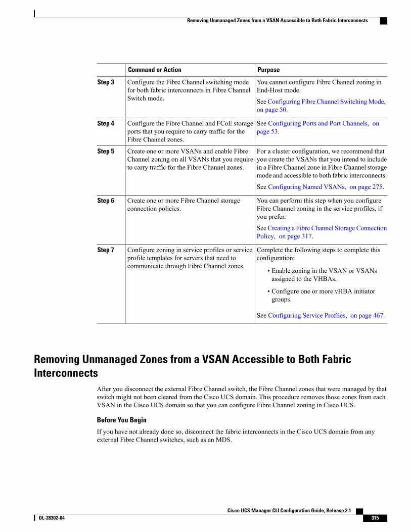
PurposeCommand or Action
You cannot configure Fibre Channel zoning inEnd-Host mode.
Configure the Fibre Channel switching modefor both fabric interconnects in Fibre ChannelSwitch mode.
Step 3
See Configuring Fibre Channel SwitchingMode,on page 50.
See Configuring Ports and Port Channels, onpage 53.
Configure the Fibre Channel and FCoE storageports that you require to carry traffic for theFibre Channel zones.
Step 4
For a cluster configuration, we recommend thatyou create the VSANs that you intend to include
Create one or more VSANs and enable FibreChannel zoning on all VSANs that you requireto carry traffic for the Fibre Channel zones.
Step 5
in a Fibre Channel zone in Fibre Channel storagemode and accessible to both fabric interconnects.
See Configuring Named VSANs, on page 275.
You can perform this step when you configureFibre Channel zoning in the service profiles, ifyou prefer.
Create one or more Fibre Channel storageconnection policies.
Step 6
See Creating a Fibre Channel Storage ConnectionPolicy, on page 317.
Complete the following steps to complete thisconfiguration:
Configure zoning in service profiles or serviceprofile templates for servers that need tocommunicate through Fibre Channel zones.
Step 7
• Enable zoning in the VSAN or VSANsassigned to the VHBAs.
• Configure one or more vHBA initiatorgroups.
See Configuring Service Profiles, on page 467.
Removing Unmanaged Zones from a VSAN Accessible to Both FabricInterconnects
After you disconnect the external Fibre Channel switch, the Fibre Channel zones that were managed by thatswitch might not been cleared from the Cisco UCS domain. This procedure removes those zones from eachVSAN in the Cisco UCS domain so that you can configure Fibre Channel zoning in Cisco UCS.
Before You Begin
If you have not already done so, disconnect the fabric interconnects in the Cisco UCS domain from anyexternal Fibre Channel switches, such as an MDS.
Cisco UCS Manager CLI Configuration Guide, Release 2.1 OL-28302-04 315
Removing Unmanaged Zones from a VSAN Accessible to Both Fabric Interconnects
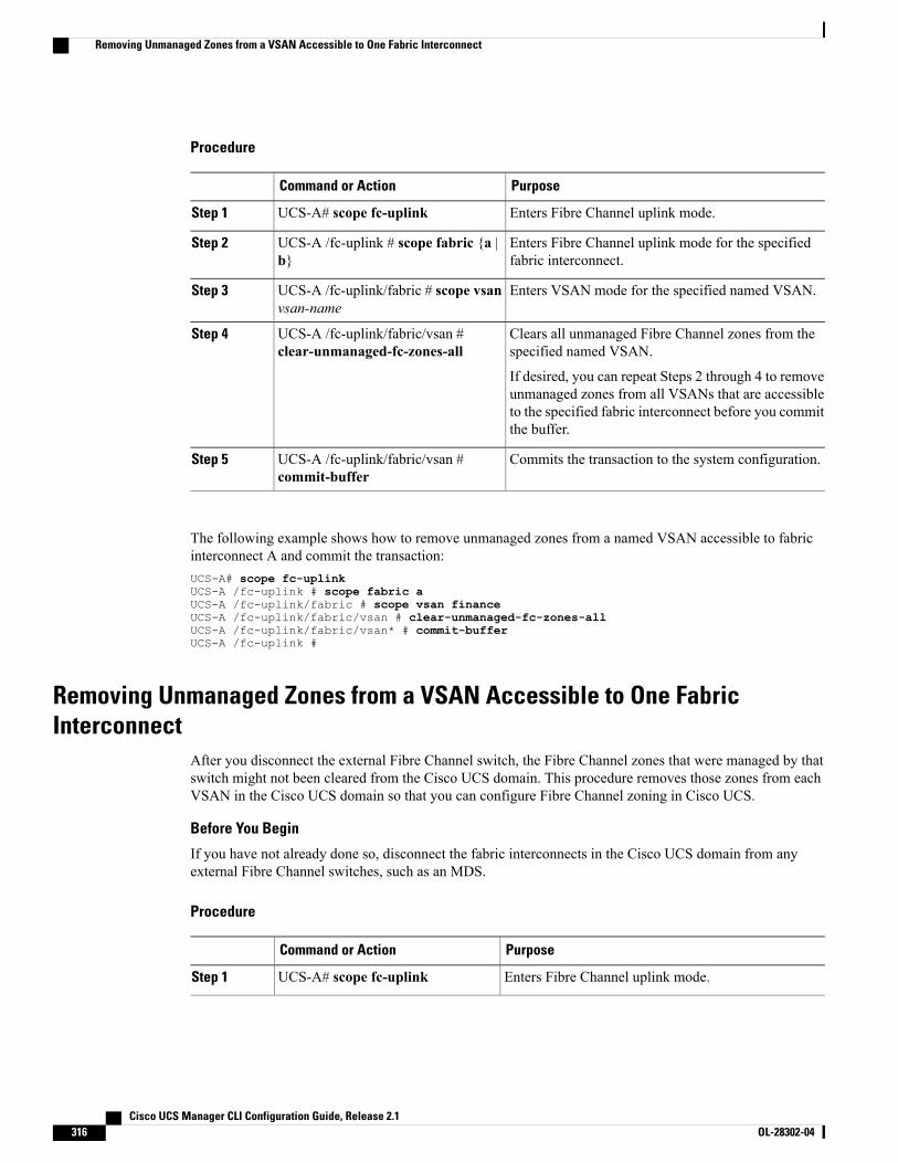
Procedure
PurposeCommand or Action
Enters Fibre Channel uplink mode.UCS-A# scope fc-uplinkStep 1
Enters Fibre Channel uplink mode for the specifiedfabric interconnect.
UCS-A /fc-uplink # scope fabric {a |b}
Step 2
Enters VSAN mode for the specified named VSAN.UCS-A /fc-uplink/fabric # scope vsanvsan-name
Step 3
Clears all unmanaged Fibre Channel zones from thespecified named VSAN.
UCS-A /fc-uplink/fabric/vsan #clear-unmanaged-fc-zones-all
Step 4
If desired, you can repeat Steps 2 through 4 to removeunmanaged zones from all VSANs that are accessibleto the specified fabric interconnect before you committhe buffer.
Commits the transaction to the system configuration.UCS-A /fc-uplink/fabric/vsan #commit-buffer
Step 5
The following example shows how to remove unmanaged zones from a named VSAN accessible to fabricinterconnect A and commit the transaction:UCS-A# scope fc-uplinkUCS-A /fc-uplink # scope fabric aUCS-A /fc-uplink/fabric # scope vsan financeUCS-A /fc-uplink/fabric/vsan # clear-unmanaged-fc-zones-allUCS-A /fc-uplink/fabric/vsan* # commit-bufferUCS-A /fc-uplink #
Removing Unmanaged Zones from a VSAN Accessible to One FabricInterconnect
After you disconnect the external Fibre Channel switch, the Fibre Channel zones that were managed by thatswitch might not been cleared from the Cisco UCS domain. This procedure removes those zones from eachVSAN in the Cisco UCS domain so that you can configure Fibre Channel zoning in Cisco UCS.
Before You Begin
If you have not already done so, disconnect the fabric interconnects in the Cisco UCS domain from anyexternal Fibre Channel switches, such as an MDS.
Procedure
PurposeCommand or Action
Enters Fibre Channel uplink mode.UCS-A# scope fc-uplinkStep 1
Cisco UCS Manager CLI Configuration Guide, Release 2.1316 OL-28302-04
Removing Unmanaged Zones from a VSAN Accessible to One Fabric Interconnect

PurposeCommand or Action
Enters VSAN mode for the specified named VSAN.UCS-A /fc-uplink # scope vsanvsan-name
Step 2
Clears all unmanaged Fibre Channel zones from thespecified named VSAN.
UCS-A /fc-uplink/vsan #clear-unmanaged-fc-zones-all
Step 3
If desired, you can repeat steps 2 and 3 to removeunmanaged zones from all VSANs that are accessibleto both fabric interconnects before you commit thebuffer.
Commits the transaction to the system configuration.UCS-A /fc-uplink/vsan #commit-buffer
Step 4
The following example shows how to remove unmanaged zones from a named VSAN and commit thetransaction:UCS-A# scope fc-uplinkUCS-A /fc-uplink # scope vsan financeUCS-A /fc-uplink/vsan # clear-unmanaged-fc-zones-allUCS-A /fc-uplink/vsan* # commit-bufferUCS-A /fc-uplink #
Configuring Fibre Channel Storage Connection Policies
Creating a Fibre Channel Storage Connection Policy
Procedure
PurposeCommand or Action
Enters organization mode for the specifiedorganization. To enter the root organization mode,enter / as the org-name.
UCS-A# scope org org-nameStep 1
Creates a storage connection policywith the specifiedpolicy name, and enters organization storageconnection policy mode.
UCS-A /org # createstorage-connection-policy policy-name
Step 2
UCS-A /org # set zoning-type {none | simt| sist}
Step 3 • None—CiscoUCSManager does not configureFibre Channel zoning.
• Single Initiator Single Target—Cisco UCSManager automatically creates one zone foreach vHBA and storage port pair. Each zonehas two members. We recommend that youconfigure this type of zoning unless you expectthe number of zones to exceed the maximumsupported.
Cisco UCS Manager CLI Configuration Guide, Release 2.1 OL-28302-04 317
Configuring Fibre Channel Storage Connection Policies
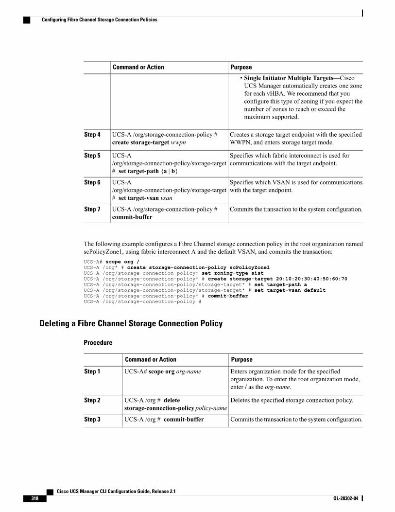
PurposeCommand or Action
• Single Initiator Multiple Targets—CiscoUCS Manager automatically creates one zonefor each vHBA. We recommend that youconfigure this type of zoning if you expect thenumber of zones to reach or exceed themaximum supported.
Creates a storage target endpoint with the specifiedWWPN, and enters storage target mode.
UCS-A /org/storage-connection-policy #create storage-target wwpn
Step 4
Specifies which fabric interconnect is used forcommunications with the target endpoint.
UCS-A/org/storage-connection-policy/storage-target# set target-path {a | b}
Step 5
Specifies which VSAN is used for communicationswith the target endpoint.
UCS-A/org/storage-connection-policy/storage-target# set target-vsan vsan
Step 6
Commits the transaction to the system configuration.UCS-A /org/storage-connection-policy #commit-buffer
Step 7
The following example configures a Fibre Channel storage connection policy in the root organization namedscPolicyZone1, using fabric interconnect A and the default VSAN, and commits the transaction:UCS-A# scope org /UCS-A /org* # create storage-connection-policy scPolicyZone1UCS-A /org/storage-connection-policy* set zoning-type sistUCS-A /org/storage-connection-policy* # create storage-target 20:10:20:30:40:50:60:70UCS-A /org/storage-connection-policy/storage-target* # set target-path aUCS-A /org/storage-connection-policy/storage-target* # set target-vsan defaultUCS-A /org/storage-connection-policy* # commit-bufferUCS-A /org/storage-connection-policy #
Deleting a Fibre Channel Storage Connection Policy
Procedure
PurposeCommand or Action
Enters organization mode for the specifiedorganization. To enter the root organization mode,enter / as the org-name.
UCS-A# scope org org-nameStep 1
Deletes the specified storage connection policy.UCS-A /org # deletestorage-connection-policy policy-name
Step 2
Commits the transaction to the system configuration.UCS-A /org # commit-bufferStep 3
Cisco UCS Manager CLI Configuration Guide, Release 2.1318 OL-28302-04
Configuring Fibre Channel Storage Connection Policies

The following example deletes the storage connection policy named scPolicyZone1 from the root organizationand commits the transaction:UCS-A# scope org /UCS-A /org # delete san-connectivity-policy scPolicyZone1UCS-A /org* # commit-bufferUCS-A /org #
Cisco UCS Manager CLI Configuration Guide, Release 2.1 OL-28302-04 319
Configuring Fibre Channel Storage Connection Policies

Cisco UCS Manager CLI Configuration Guide, Release 2.1320 OL-28302-04
Configuring Fibre Channel Storage Connection Policies
C H A P T E R 27Configuring FlexFlash SD Card Support
This chapter includes the following sections:
• FlexFlash Secure Digital Card Support, page 321
FlexFlash Secure Digital Card Support
Overview
FlexFlash is the Secure Digital (SD)-based local flash storage support Cisco has introduced in its newer CiscoUCS blade and rack servers. The FlexFlash controller has two SD card slots, only one of which can be usedat a time. If both slots are populated, both cards should be the same size, but only the card in slot 1 will beusable.
The only supported SD card size is 16GB.Note
Cisco UCS Manager does not support the use of an SD card from a rack server in a blade server, or theuse of an SD card from a blade server in a rack server. Switching SD cards from one server type to theother might result in data loss from the SD card.
Important
FlexFlash in Supported B-Series and C-Series Servers
The FlexFlash SD cards shipped with supported B-series servers only have an HV partition. Those shippedwith supported C-series rack servers have four partitions; HV, HUU, SCU, and Drivers. When the FlexFlashcontroller is enabled for either a B-series or C-series server, Cisco UCS Manager will show only the HVpartition, as a USB drive, to both the BIOS and the host operating system.
In order to manually boot from the HV partition, Local Disk should be present in the boot policy used in theService Profile, and be launched from the BIOS boot menu (F6).
Cisco UCS Manager CLI Configuration Guide, Release 2.1 OL-28302-04 321

FlexFlash in Disk Policies and Service Profiles
FlexFlash is disabled by default in Cisco UCS servers. It can be enabled in a local disk policy used in a serviceprofile. When FlexFlash is enabled in a local disk policy, and a server is capable of supporting SD cards, theFlexFlash controller will be enabled during service profile deployment. If a server is not capable of supportingSD cards or has an older CIMC version, the service profile association will fail.
If you disable the FlexFlash option in a supported server, a host reboot will be triggered and a reboot warningmessage displayed. The FlexFlash controller will also be disabled as part of a related service profiledisassociation.
Limitations Related to FlexFlashThe following are the known limitations related to FlexFlash SD cards in this release of Cisco UCSManager:
• If FlexFlash is enabled and the boot policy contains Local Disk, SAN Boot, or iSCSI Boot, then theboot order cannot be determined. You should disable FlexFlash before using any of these boot options,and enable it after bootup is complete.
• Cisco UCS hardware information and inventory data about the controller and SD cards is not collected.
• Monitoring of the controller and SD card status or health is not supported. In the case of a failure of aFlexFlash controller or SD card, no faults or errors will be displayed in Cisco UCS Manager.
• Formatting of the SD cards is not supported.
• Booting from SD cards using the Cisco UCS Manager Boot Policy is not supported.
• After you update and activate the CIMC firmware, you must power cycle the server to update theFlexFlash controller firmware.
Enabling FlexFlash SD Card SupportThis procedure describes how to enable FlexFlash support in a local disk policy.
Procedure
PurposeCommand or Action
Enters the organization configuration mode forthe organization name you enter.
UCS-A #scope org {/ | org-name)Step 1
Enters the local disk policy configuration modefor the policy name you enter.
UCS-A /org # scope local-disk-config-policypolicy-name
Step 2
Enables FlexFlash SD card support in the localdisk policy.
UCS-A /org/local-disk-config-policy # setflexflash-state enable
Step 3
Commits the transaction to the system.UCS-A /org/local-disk-config-policy #commit-buffer
Step 4
Cisco UCS Manager CLI Configuration Guide, Release 2.1322 OL-28302-04
FlexFlash Secure Digital Card Support

The following example scopes to the root organization, then to the default local disk configuration policy,sets the FlexFlash SD card support to enabled, and commits the transaction to the system:UCS-A# scope org/UCS-A /org # scope local-disk-config-policy defaultUCS-A /org/local-disk-config-policy set flexflash-state enableUCS-A /org/local-disk-config-policy #* commit-bufferUCS-A /org/local-disk-config-policy #
Cisco UCS Manager CLI Configuration Guide, Release 2.1 OL-28302-04 323
FlexFlash Secure Digital Card Support

Cisco UCS Manager CLI Configuration Guide, Release 2.1324 OL-28302-04
FlexFlash Secure Digital Card Support
P A R T VServer Configuration• Configuring Server-Related Pools, page 327
• Setting the Management IP Address, page 337
• Configuring Server-Related Policies, page 345
• Configuring Server Boot, page 413
• Deferring Deployment of Service Profile Updates, page 455
• Configuring Service Profiles, page 467
• Managing Power in Cisco UCS, page 497

C H A P T E R 28Configuring Server-Related Pools
This chapter includes the following sections:
• Server Pool Configuration, page 327
• UUID Suffix Pool Configuration, page 329
• IP Pool Configuration, page 331
Server Pool Configuration
Server PoolsA server pool contains a set of servers. These servers typically share the same characteristics. Thosecharacteristics can be their location in the chassis, or an attribute such as server type, amount of memory,local storage, type of CPU, or local drive configuration. You can manually assign a server to a server pool,or use server pool policies and server pool policy qualifications to automate the assignment.
If your system implements multitenancy through organizations, you can designate one or more server poolsto be used by a specific organization. For example, a pool that includes all servers with two CPUs could beassigned to theMarketing organization, while all servers with 64 GBmemory could be assigned to the Financeorganization.
A server pool can include servers from any chassis in the system. A given server can belong to multiple serverpools.
Creating a Server Pool
Procedure
PurposeCommand or Action
Enters organization mode for the specified organization.To enter the root organization mode, type / as theorg-name.
UCS-A# scope org org-nameStep 1
Cisco UCS Manager CLI Configuration Guide, Release 2.1 OL-28302-04 327
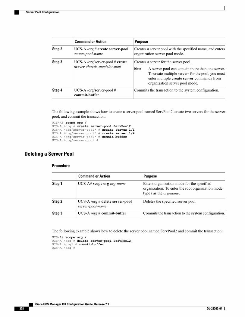
PurposeCommand or Action
Creates a server pool with the specified name, and entersorganization server pool mode.
UCS-A /org # create server-poolserver-pool-name
Step 2
Creates a server for the server pool.UCS-A /org/server-pool # createserver chassis-num/slot-num
Step 3
A server pool can contain more than one server.To create multiple servers for the pool, you mustenter multiple create server commands fromorganization server pool mode.
Note
Commits the transaction to the system configuration.UCS-A /org/server-pool #commit-buffer
Step 4
The following example shows how to create a server pool named ServPool2, create two servers for the serverpool, and commit the transaction:UCS-A# scope org /UCS-A /org # create server-pool ServPool2UCS-A /org/server-pool* # create server 1/1UCS-A /org/server-pool* # create server 1/4UCS-A /org/server-pool* # commit-bufferUCS-A /org/server-pool #
Deleting a Server Pool
Procedure
PurposeCommand or Action
Enters organization mode for the specifiedorganization. To enter the root organization mode,type / as the org-name.
UCS-A# scope org org-nameStep 1
Deletes the specified server pool.UCS-A /org # delete server-poolserver-pool-name
Step 2
Commits the transaction to the system configuration.UCS-A /org # commit-bufferStep 3
The following example shows how to delete the server pool named ServPool2 and commit the transaction:UCS-A# scope org /UCS-A /org # delete server-pool ServPool2UCS-A /org* # commit-bufferUCS-A /org #
Cisco UCS Manager CLI Configuration Guide, Release 2.1328 OL-28302-04
Server Pool Configuration
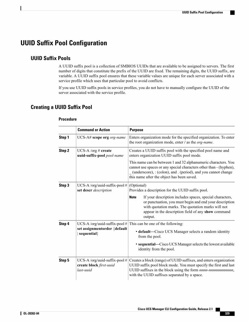
UUID Suffix Pool Configuration
UUID Suffix PoolsA UUID suffix pool is a collection of SMBIOS UUIDs that are available to be assigned to servers. The firstnumber of digits that constitute the prefix of the UUID are fixed. The remaining digits, the UUID suffix, arevariable. A UUID suffix pool ensures that these variable values are unique for each server associated with aservice profile which uses that particular pool to avoid conflicts.
If you use UUID suffix pools in service profiles, you do not have to manually configure the UUID of theserver associated with the service profile.
Creating a UUID Suffix Pool
Procedure
PurposeCommand or Action
Enters organization mode for the specified organization. To enterthe root organization mode, enter / as the org-name.
UCS-A# scope org org-nameStep 1
Creates a UUID suffix pool with the specified pool name andenters organization UUID suffix pool mode.
UCS-A /org # createuuid-suffix-pool pool-name
Step 2
This name can be between 1 and 32 alphanumeric characters. Youcannot use spaces or any special characters other than - (hyphen),_ (underscore), : (colon), and . (period), and you cannot changethis name after the object has been saved.
(Optional)Provides a description for the UUID suffix pool.
UCS-A /org/uuid-suffix-pool #set descr description
Step 3
If your description includes spaces, special characters,or punctuation, you must begin and end your descriptionwith quotation marks. The quotation marks will notappear in the description field of any show commandoutput.
Note
This can be one of the following:UCS-A /org/uuid-suffix-pool #set assignmentorder {default| sequential}
Step 4
• default—Cisco UCS Manager selects a random identityfrom the pool.
• sequential—CiscoUCSManager selects the lowest availableidentity from the pool.
Creates a block (range) of UUID suffixes, and enters organizationUUID suffix pool block mode. You must specify the first and last
UCS-A /org/uuid-suffix-pool #create block first-uuidlast-uuid
Step 5
UUID suffixes in the block using the form nnnn-nnnnnnnnnnnn,with the UUID suffixes separated by a space.
Cisco UCS Manager CLI Configuration Guide, Release 2.1 OL-28302-04 329
UUID Suffix Pool Configuration
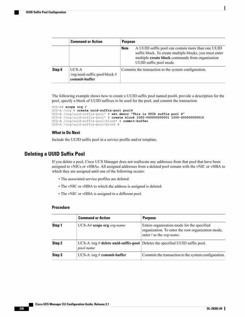
PurposeCommand or Action
A UUID suffix pool can contain more than one UUIDsuffix block. To create multiple blocks, you must entermultiple create block commands from organizationUUID suffix pool mode.
Note
Commits the transaction to the system configuration.UCS-A/org/uuid-suffix-pool/block #commit-buffer
Step 6
The following example shows how to create a UUID suffix pool named pool4, provide a description for thepool, specify a block of UUID suffixes to be used for the pool, and commit the transaction:UCS-A# scope org /UCS-A /org # create uuid-suffix-pool pool4UCS-A /org/uuid-suffix-pool* # set descr "This is UUID suffix pool 4"UCS-A /org/uuid-suffix-pool* # create block 1000-000000000001 1000-000000000010UCS-A /org/uuid-suffix-pool/block* # commit-bufferUCS-A /org/uuid-suffix-pool/block #
What to Do Next
Include the UUID suffix pool in a service profile and/or template.
Deleting a UUID Suffix PoolIf you delete a pool, Cisco UCS Manager does not reallocate any addresses from that pool that have beenassigned to vNICs or vHBAs. All assigned addresses from a deleted pool remain with the vNIC or vHBA towhich they are assigned until one of the following occurs:
• The associated service profiles are deleted.
• The vNIC or vHBA to which the address is assigned is deleted.
• The vNIC or vHBA is assigned to a different pool.
Procedure
PurposeCommand or Action
Enters organization mode for the specifiedorganization. To enter the root organization mode,enter / as the org-name.
UCS-A# scope org org-nameStep 1
Deletes the specified UUID suffix pool.UCS-A /org # delete uuid-suffix-poolpool-name
Step 2
Commits the transaction to the system configuration.UCS-A /org # commit-bufferStep 3
Cisco UCS Manager CLI Configuration Guide, Release 2.1330 OL-28302-04
UUID Suffix Pool Configuration
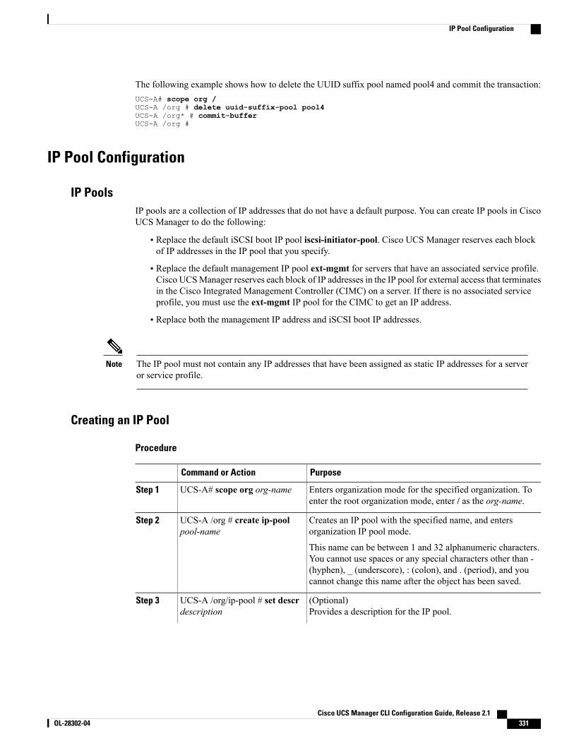
The following example shows how to delete the UUID suffix pool named pool4 and commit the transaction:UCS-A# scope org /UCS-A /org # delete uuid-suffix-pool pool4UCS-A /org* # commit-bufferUCS-A /org #
IP Pool Configuration
IP PoolsIP pools are a collection of IP addresses that do not have a default purpose. You can create IP pools in CiscoUCS Manager to do the following:
• Replace the default iSCSI boot IP pool iscsi-initiator-pool. Cisco UCS Manager reserves each blockof IP addresses in the IP pool that you specify.
• Replace the default management IP pool ext-mgmt for servers that have an associated service profile.Cisco UCSManager reserves each block of IP addresses in the IP pool for external access that terminatesin the Cisco Integrated Management Controller (CIMC) on a server. If there is no associated serviceprofile, you must use the ext-mgmt IP pool for the CIMC to get an IP address.
• Replace both the management IP address and iSCSI boot IP addresses.
The IP pool must not contain any IP addresses that have been assigned as static IP addresses for a serveror service profile.
Note
Creating an IP Pool
Procedure
PurposeCommand or Action
Enters organization mode for the specified organization. Toenter the root organization mode, enter / as the org-name.
UCS-A# scope org org-nameStep 1
Creates an IP pool with the specified name, and entersorganization IP pool mode.
UCS-A /org # create ip-poolpool-name
Step 2
This name can be between 1 and 32 alphanumeric characters.You cannot use spaces or any special characters other than -(hyphen), _ (underscore), : (colon), and . (period), and youcannot change this name after the object has been saved.
(Optional)Provides a description for the IP pool.
UCS-A /org/ip-pool # set descrdescription
Step 3
Cisco UCS Manager CLI Configuration Guide, Release 2.1 OL-28302-04 331
IP Pool Configuration
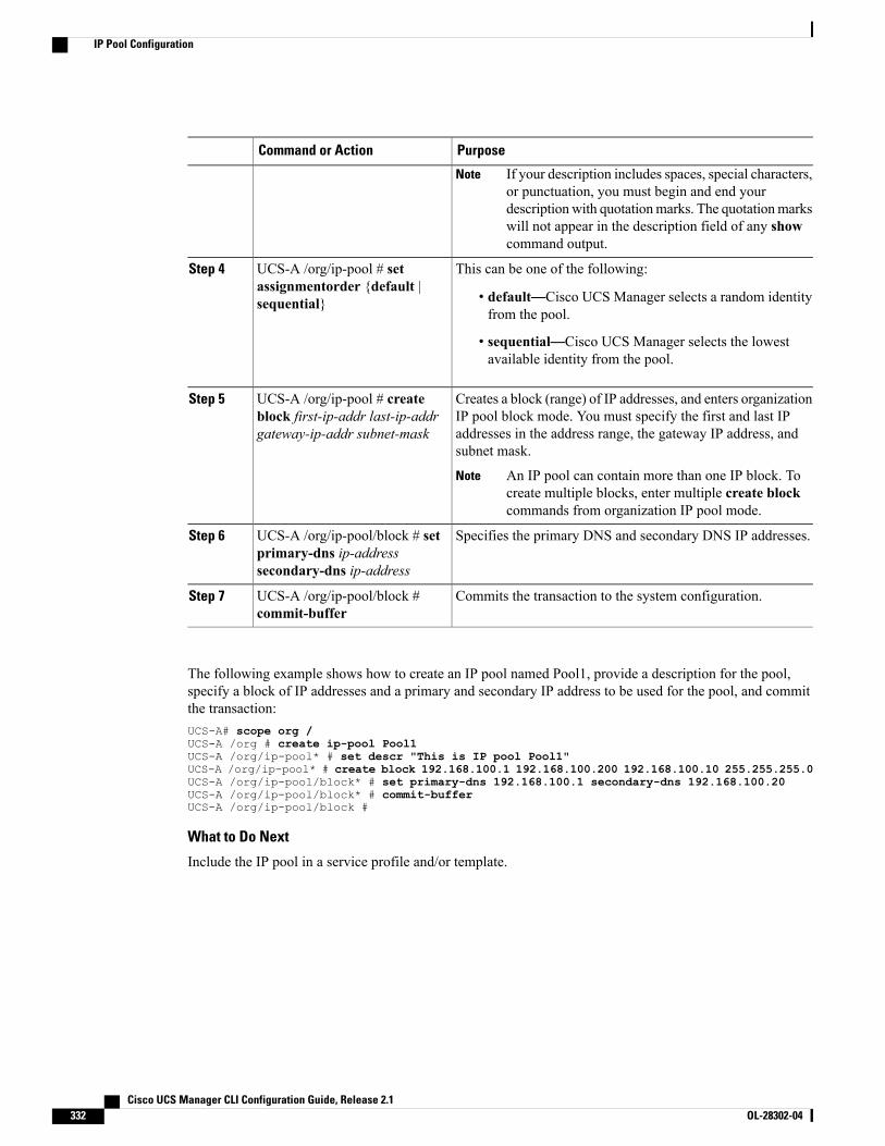
PurposeCommand or Action
If your description includes spaces, special characters,or punctuation, you must begin and end yourdescriptionwith quotationmarks. The quotationmarkswill not appear in the description field of any showcommand output.
Note
This can be one of the following:UCS-A /org/ip-pool # setassignmentorder {default |sequential}
Step 4
• default—Cisco UCS Manager selects a random identityfrom the pool.
• sequential—Cisco UCS Manager selects the lowestavailable identity from the pool.
Creates a block (range) of IP addresses, and enters organizationIP pool block mode. You must specify the first and last IP
UCS-A /org/ip-pool # createblock first-ip-addr last-ip-addrgateway-ip-addr subnet-mask
Step 5
addresses in the address range, the gateway IP address, andsubnet mask.
An IP pool can contain more than one IP block. Tocreate multiple blocks, enter multiple create blockcommands from organization IP pool mode.
Note
Specifies the primary DNS and secondary DNS IP addresses.UCS-A /org/ip-pool/block # setprimary-dns ip-addresssecondary-dns ip-address
Step 6
Commits the transaction to the system configuration.UCS-A /org/ip-pool/block #commit-buffer
Step 7
The following example shows how to create an IP pool named Pool1, provide a description for the pool,specify a block of IP addresses and a primary and secondary IP address to be used for the pool, and committhe transaction:UCS-A# scope org /UCS-A /org # create ip-pool Pool1UCS-A /org/ip-pool* # set descr "This is IP pool Pool1"UCS-A /org/ip-pool* # create block 192.168.100.1 192.168.100.200 192.168.100.10 255.255.255.0UCS-A /org/ip-pool/block* # set primary-dns 192.168.100.1 secondary-dns 192.168.100.20UCS-A /org/ip-pool/block* # commit-bufferUCS-A /org/ip-pool/block #
What to Do Next
Include the IP pool in a service profile and/or template.
Cisco UCS Manager CLI Configuration Guide, Release 2.1332 OL-28302-04
IP Pool Configuration
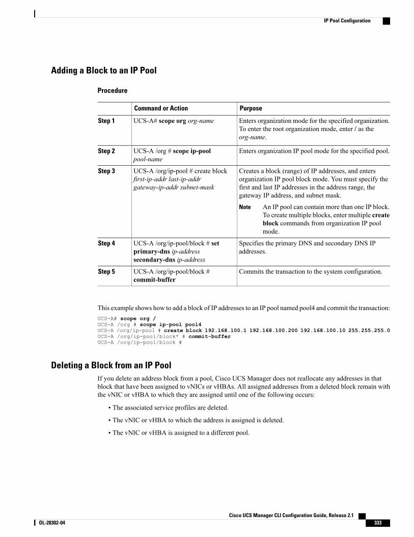
Adding a Block to an IP Pool
Procedure
PurposeCommand or Action
Enters organization mode for the specified organization.To enter the root organization mode, enter / as theorg-name.
UCS-A# scope org org-nameStep 1
Enters organization IP pool mode for the specified pool.UCS-A /org # scope ip-poolpool-name
Step 2
Creates a block (range) of IP addresses, and entersorganization IP pool block mode. You must specify the
UCS-A /org/ip-pool # create blockfirst-ip-addr last-ip-addrgateway-ip-addr subnet-mask
Step 3
first and last IP addresses in the address range, thegateway IP address, and subnet mask.
An IP pool can contain more than one IP block.To create multiple blocks, enter multiple createblock commands from organization IP poolmode.
Note
Specifies the primary DNS and secondary DNS IPaddresses.
UCS-A /org/ip-pool/block # setprimary-dns ip-addresssecondary-dns ip-address
Step 4
Commits the transaction to the system configuration.UCS-A /org/ip-pool/block #commit-buffer
Step 5
This example shows how to add a block of IP addresses to an IP pool named pool4 and commit the transaction:UCS-A# scope org /UCS-A /org # scope ip-pool pool4UCS-A /org/ip-pool # create block 192.168.100.1 192.168.100.200 192.168.100.10 255.255.255.0UCS-A /org/ip-pool/block* # commit-bufferUCS-A /org/ip-pool/block #
Deleting a Block from an IP PoolIf you delete an address block from a pool, Cisco UCS Manager does not reallocate any addresses in thatblock that have been assigned to vNICs or vHBAs. All assigned addresses from a deleted block remain withthe vNIC or vHBA to which they are assigned until one of the following occurs:
• The associated service profiles are deleted.
• The vNIC or vHBA to which the address is assigned is deleted.
• The vNIC or vHBA is assigned to a different pool.
Cisco UCS Manager CLI Configuration Guide, Release 2.1 OL-28302-04 333
IP Pool Configuration
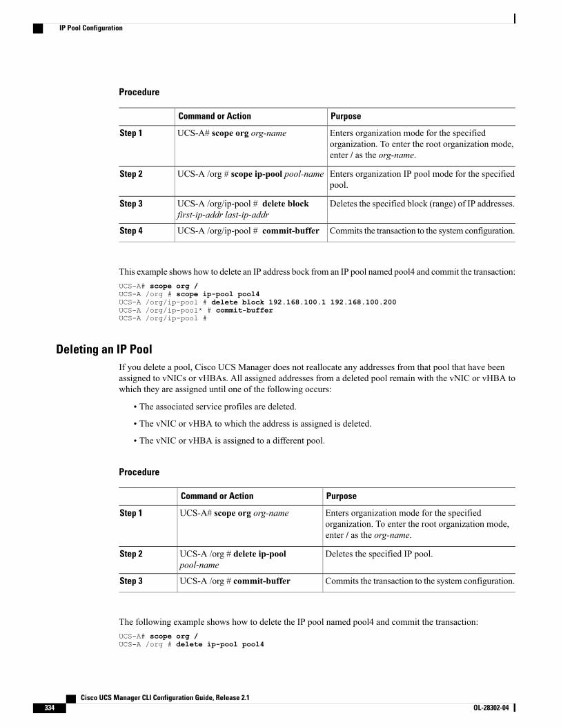
Procedure
PurposeCommand or Action
Enters organization mode for the specifiedorganization. To enter the root organization mode,enter / as the org-name.
UCS-A# scope org org-nameStep 1
Enters organization IP pool mode for the specifiedpool.
UCS-A /org # scope ip-pool pool-nameStep 2
Deletes the specified block (range) of IP addresses.UCS-A /org/ip-pool # delete blockfirst-ip-addr last-ip-addr
Step 3
Commits the transaction to the system configuration.UCS-A /org/ip-pool # commit-bufferStep 4
This example shows how to delete an IP address bock from an IP pool named pool4 and commit the transaction:UCS-A# scope org /UCS-A /org # scope ip-pool pool4UCS-A /org/ip-pool # delete block 192.168.100.1 192.168.100.200UCS-A /org/ip-pool* # commit-bufferUCS-A /org/ip-pool #
Deleting an IP PoolIf you delete a pool, Cisco UCS Manager does not reallocate any addresses from that pool that have beenassigned to vNICs or vHBAs. All assigned addresses from a deleted pool remain with the vNIC or vHBA towhich they are assigned until one of the following occurs:
• The associated service profiles are deleted.
• The vNIC or vHBA to which the address is assigned is deleted.
• The vNIC or vHBA is assigned to a different pool.
Procedure
PurposeCommand or Action
Enters organization mode for the specifiedorganization. To enter the root organization mode,enter / as the org-name.
UCS-A# scope org org-nameStep 1
Deletes the specified IP pool.UCS-A /org # delete ip-poolpool-name
Step 2
Commits the transaction to the system configuration.UCS-A /org # commit-bufferStep 3
The following example shows how to delete the IP pool named pool4 and commit the transaction:UCS-A# scope org /UCS-A /org # delete ip-pool pool4
Cisco UCS Manager CLI Configuration Guide, Release 2.1334 OL-28302-04
IP Pool Configuration

UCS-A /org* # commit-bufferUCS-A /org #
Cisco UCS Manager CLI Configuration Guide, Release 2.1 OL-28302-04 335
IP Pool Configuration

Cisco UCS Manager CLI Configuration Guide, Release 2.1336 OL-28302-04
IP Pool Configuration
C H A P T E R 29Setting the Management IP Address
This chapter includes the following sections:
• Management IP Address, page 337
• Configuring the Management IP Address on a Blade Server, page 338
• Configuring the Management IP Address on a Rack Server, page 339
• Setting the Management IP Address on a Service Profile or Service Profile Template, page 341
• Configuring the Management IP Pool, page 342
Management IP AddressEach server in a Cisco UCS domain must have a management IP address assigned to its Cisco IntegratedManagement Controller (CIMC) or to the service profile associated with the server. Cisco UCSManager usesthis IP address for external access that terminates in the CIMC. This external access can be through one ofthe following:
• KVM console
• Serial over LAN
• An IPMI tool
The management IP address used to access the CIMC on a server can be one of the following:
• A static IPv4 address assigned directly to the server.
• A static IPv4 address assigned to a service profile. You cannot configure a service profile template witha static IP address.
• An IP address drawn from the management IP address pool and assigned to a service profile or serviceprofile template.
You can assign a management IP address to each CIMC on the server and to the service profile associatedwith the server. If you do so, you must use different IP addresses for each of them.
Cisco UCS Manager CLI Configuration Guide, Release 2.1 OL-28302-04 337

You cannot assign a static IP address to a server or service profile if that IP address has already beenassigned to a server or service profile in the Cisco UCS domain. If you attempt to do so, Cisco UCSManager warns you that the IP address is already in use and rejects the configuration.
Note
A management IP address that is assigned to a service profile moves with the service profile. If a KVM orSoL session is active when you migrate the service profile to another server, Cisco UCS Manager terminatesthat session and does not restart it after the migration is completed. You configure this IP address when youcreate or modify a service profile.
Configuring the Management IP Address on a Blade Server
Configuring a Blade Server to Use a Static IP Address
Procedure
PurposeCommand or Action
Enters chassis server mode for the specifiedserver.
UCS-A# scope server chassis-id / blade-idStep 1
Enters chassis server CIMC mode.UCS-A /chassis/server # scope cimcStep 2
Creates a static management IP address forthe specified server.
UCS-A /chassis/server/cimc # createext-static-ip
Step 3
Specifies the static IPv4 address to beassigned to the server.
UCS-A /chassis/server/cimc/ext-static-ip # setaddr ip-addr
Step 4
Specifies the default gateway that the IPaddress should use.
UCS-A /chassis/server/cimc/ext-static-ip # setdefault-gw ip-addr
Step 5
Specifies the subnet mask for the IP address.UCS-A /chassis/server/cimc/ext-static-ip # setsubnet ip-addr
Step 6
Commits the transaction to the systemconfiguration.
UCS-A /chassis/server/cimc/ext-static-ip #commit-buffer
Step 7
The following example configures a static management IP address for chassis 1 server 1, sets the static IPv4address, sets the default gateway, sets the subnet mask, and commits the transaction:UCS-A# scope server 1/1UCS-A /chassis/server # scope cimcUCS-A /chassis/server/cimc # create ext-static-ipUCS-A /chassis/server/cimc/ext-static-ip* # set addr 192.168.10.10UCS-A /chassis/server/cimc/ext-static-ip* # set default-gw 192.168.10.1UCS-A /chassis/server/cimc/ext-static-ip* # set subnet 255.255.255.0UCS-A /chassis/server/cimc/ext-static-ip* # commit-bufferUCS-A /chassis/server/cimc/ext-static-ip #
Cisco UCS Manager CLI Configuration Guide, Release 2.1338 OL-28302-04
Configuring the Management IP Address on a Blade Server
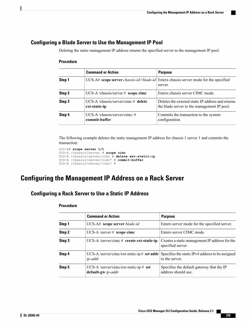
Configuring a Blade Server to Use the Management IP PoolDeleting the static management IP address returns the specified server to the management IP pool.
Procedure
PurposeCommand or Action
Enters chassis server mode for the specifiedserver.
UCS-A# scope server chassis-id / blade-idStep 1
Enters chassis server CIMC mode.UCS-A /chassis/server # scope cimcStep 2
Deletes the external static IP address and returnsthe blade server to the management IP pool.
UCS-A /chassis/server/cimc # deleteext-static-ip
Step 3
Commits the transaction to the systemconfiguration.
UCS-A /chassis/server/cimc/ #commit-buffer
Step 4
The following example deletes the static management IP address for chassis 1 server 1 and commits thetransaction:UCS-A# scope server 1/1UCS-A /chassis/server # scope cimcUCS-A /chassis/server/cimc # delete ext-static-ipUCS-A /chassis/server/cimc* # commit-bufferUCS-A /chassis/server/cimc/ #
Configuring the Management IP Address on a Rack Server
Configuring a Rack Server to Use a Static IP Address
Procedure
PurposeCommand or Action
Enters server mode for the specified server.UCS-A# scope server blade-idStep 1
Enters server CIMC mode.UCS-A /server # scope cimcStep 2
Creates a static management IP address for thespecified server.
UCS-A /server/cimc # create ext-static-ipStep 3
Specifies the static IPv4 address to be assignedto the server.
UCS-A /server/cimc/ext-static-ip # set addrip-addr
Step 4
Specifies the default gateway that the IPaddress should use.
UCS-A /server/cimc/ext-static-ip # setdefault-gw ip-addr
Step 5
Cisco UCS Manager CLI Configuration Guide, Release 2.1 OL-28302-04 339
Configuring the Management IP Address on a Rack Server
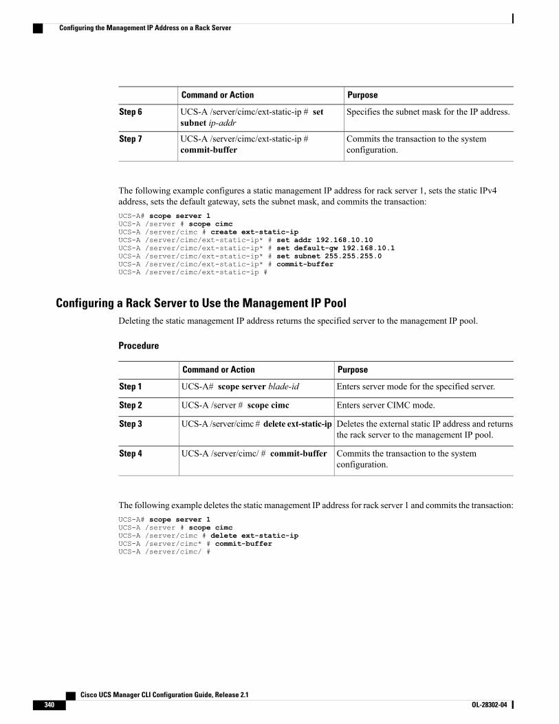
PurposeCommand or Action
Specifies the subnet mask for the IP address.UCS-A /server/cimc/ext-static-ip # setsubnet ip-addr
Step 6
Commits the transaction to the systemconfiguration.
UCS-A /server/cimc/ext-static-ip #commit-buffer
Step 7
The following example configures a static management IP address for rack server 1, sets the static IPv4address, sets the default gateway, sets the subnet mask, and commits the transaction:UCS-A# scope server 1UCS-A /server # scope cimcUCS-A /server/cimc # create ext-static-ipUCS-A /server/cimc/ext-static-ip* # set addr 192.168.10.10UCS-A /server/cimc/ext-static-ip* # set default-gw 192.168.10.1UCS-A /server/cimc/ext-static-ip* # set subnet 255.255.255.0UCS-A /server/cimc/ext-static-ip* # commit-bufferUCS-A /server/cimc/ext-static-ip #
Configuring a Rack Server to Use the Management IP PoolDeleting the static management IP address returns the specified server to the management IP pool.
Procedure
PurposeCommand or Action
Enters server mode for the specified server.UCS-A# scope server blade-idStep 1
Enters server CIMC mode.UCS-A /server # scope cimcStep 2
Deletes the external static IP address and returnsthe rack server to the management IP pool.
UCS-A /server/cimc # delete ext-static-ipStep 3
Commits the transaction to the systemconfiguration.
UCS-A /server/cimc/ # commit-bufferStep 4
The following example deletes the static management IP address for rack server 1 and commits the transaction:UCS-A# scope server 1UCS-A /server # scope cimcUCS-A /server/cimc # delete ext-static-ipUCS-A /server/cimc* # commit-bufferUCS-A /server/cimc/ #
Cisco UCS Manager CLI Configuration Guide, Release 2.1340 OL-28302-04
Configuring the Management IP Address on a Rack Server
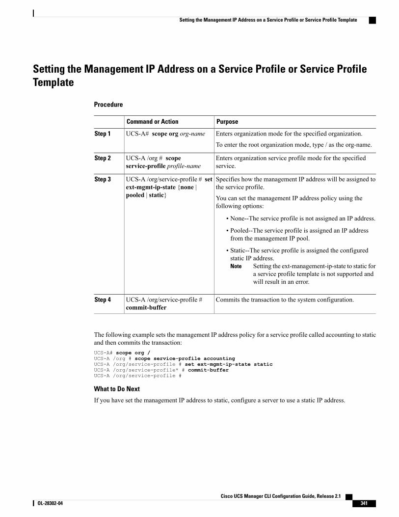
Setting the Management IP Address on a Service Profile or Service ProfileTemplate
Procedure
PurposeCommand or Action
Enters organization mode for the specified organization.UCS-A# scope org org-nameStep 1
To enter the root organization mode, type / as the org-name.
Enters organization service profile mode for the specifiedservice.
UCS-A /org # scopeservice-profile profile-name
Step 2
Specifies how the management IP address will be assigned tothe service profile.
UCS-A /org/service-profile # setext-mgmt-ip-state {none |pooled | static}
Step 3
You can set the management IP address policy using thefollowing options:
• None--The service profile is not assigned an IP address.
• Pooled--The service profile is assigned an IP addressfrom the management IP pool.
• Static--The service profile is assigned the configuredstatic IP address.
Setting the ext-management-ip-state to static fora service profile template is not supported andwill result in an error.
Note
Commits the transaction to the system configuration.UCS-A /org/service-profile #commit-buffer
Step 4
The following example sets the management IP address policy for a service profile called accounting to staticand then commits the transaction:UCS-A# scope org /UCS-A /org # scope service-profile accountingUCS-A /org/service-profile # set ext-mgmt-ip-state staticUCS-A /org/service-profile* # commit-bufferUCS-A /org/service-profile #
What to Do Next
If you have set the management IP address to static, configure a server to use a static IP address.
Cisco UCS Manager CLI Configuration Guide, Release 2.1 OL-28302-04 341
Setting the Management IP Address on a Service Profile or Service Profile Template
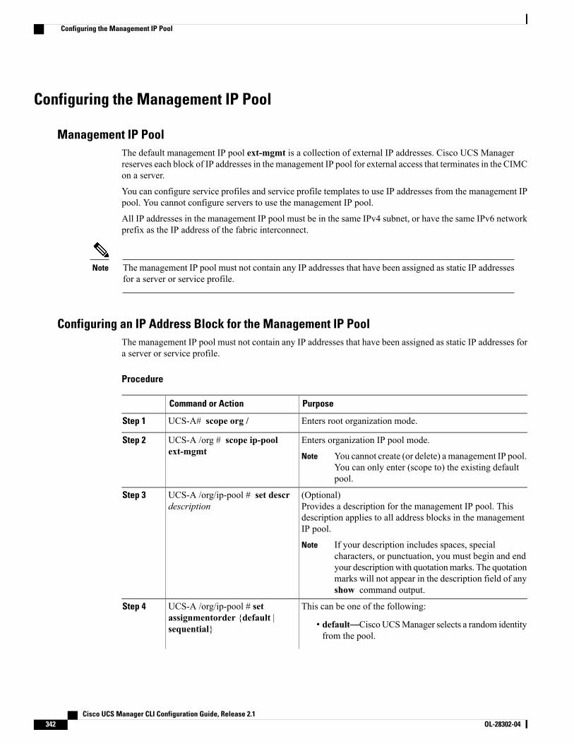
Configuring the Management IP Pool
Management IP PoolThe default management IP pool ext-mgmt is a collection of external IP addresses. Cisco UCS Managerreserves each block of IP addresses in the management IP pool for external access that terminates in the CIMCon a server.
You can configure service profiles and service profile templates to use IP addresses from the management IPpool. You cannot configure servers to use the management IP pool.
All IP addresses in the management IP pool must be in the same IPv4 subnet, or have the same IPv6 networkprefix as the IP address of the fabric interconnect.
The management IP pool must not contain any IP addresses that have been assigned as static IP addressesfor a server or service profile.
Note
Configuring an IP Address Block for the Management IP PoolThe management IP pool must not contain any IP addresses that have been assigned as static IP addresses fora server or service profile.
Procedure
PurposeCommand or Action
Enters root organization mode.UCS-A# scope org /Step 1
Enters organization IP pool mode.UCS-A /org # scope ip-poolext-mgmt
Step 2
You cannot create (or delete) a management IP pool.You can only enter (scope to) the existing defaultpool.
Note
(Optional)Provides a description for the management IP pool. Thisdescription applies to all address blocks in the managementIP pool.
UCS-A /org/ip-pool # set descrdescription
Step 3
If your description includes spaces, specialcharacters, or punctuation, you must begin and endyour descriptionwith quotationmarks. The quotationmarks will not appear in the description field of anyshow command output.
Note
This can be one of the following:UCS-A /org/ip-pool # setassignmentorder {default |sequential}
Step 4
• default—Cisco UCSManager selects a random identityfrom the pool.
Cisco UCS Manager CLI Configuration Guide, Release 2.1342 OL-28302-04
Configuring the Management IP Pool
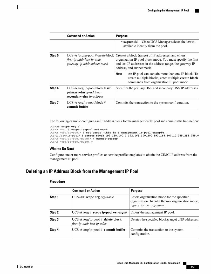
PurposeCommand or Action
• sequential—Cisco UCS Manager selects the lowestavailable identity from the pool.
Creates a block (range) of IP addresses, and entersorganization IP pool block mode. You must specify the first
UCS-A /org/ip-pool # create blockfirst-ip-addr last-ip-addrgateway-ip-addr subnet-mask
Step 5
and last IP addresses in the address range, the gateway IPaddress, and subnet mask.
An IP pool can contain more than one IP block. Tocreate multiple blocks, enter multiple create blockcommands from organization IP pool mode.
Note
Specifies the primary DNS and secondary DNS IP addresses.UCS-A /org/ip-pool/block # setprimary-dns ip-addresssecondary-dns ip-address
Step 6
Commits the transaction to the system configuration.UCS-A /org/ip-pool/block #commit-buffer
Step 7
The following example configures an IP address block for themanagement IP pool and commits the transaction:UCS-A# scope org /UCS-A /org # scope ip-pool ext-mgmtUCS-A /org/ip-pool* # set descr "This is a management IP pool example."UCS-A /org/ip-pool* # create block 192.168.100.1 192.168.100.200 192.168.100.10 255.255.255.0UCS-A /org/ip-pool/block* # commit-bufferUCS-A /org/ip-pool/block #
What to Do Next
Configure one or more service profiles or service profile templates to obtain the CIMC IP address from themanagement IP pool.
Deleting an IP Address Block from the Management IP Pool
Procedure
PurposeCommand or Action
Enters organization mode for the specifiedorganization. To enter the root organization mode,type / as the org-name .
UCS-A# scope org org-nameStep 1
Enters the management IP pool.UCS-A /org # scope ip-pool ext-mgmtStep 2
Deletes the specified block (range) of IP addresses.UCS-A /org/ip-pool # delete blockfirst-ip-addr last-ip-addr
Step 3
Commits the transaction to the systemconfiguration.
UCS-A /org/ip-pool # commit-bufferStep 4
Cisco UCS Manager CLI Configuration Guide, Release 2.1 OL-28302-04 343
Configuring the Management IP Pool
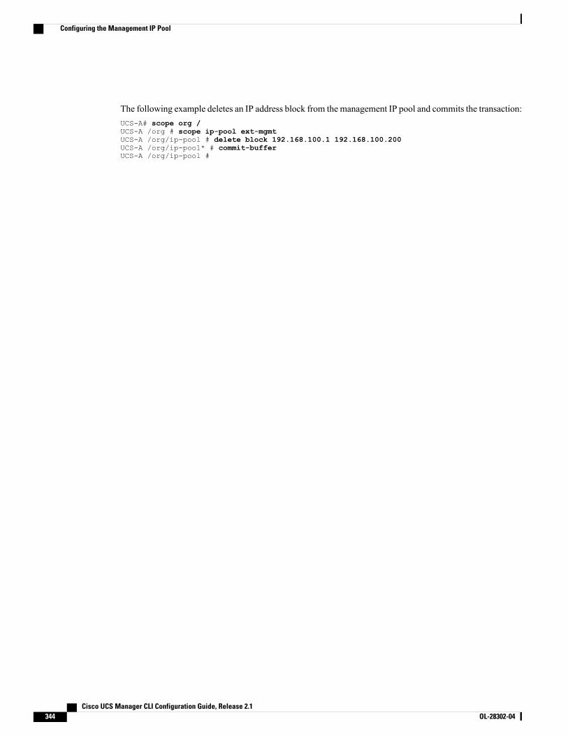
The following example deletes an IP address block from the management IP pool and commits the transaction:UCS-A# scope org /UCS-A /org # scope ip-pool ext-mgmtUCS-A /org/ip-pool # delete block 192.168.100.1 192.168.100.200UCS-A /org/ip-pool* # commit-bufferUCS-A /org/ip-pool #
Cisco UCS Manager CLI Configuration Guide, Release 2.1344 OL-28302-04
Configuring the Management IP Pool
C H A P T E R 30Configuring Server-Related Policies
This chapter includes the following sections:
• Configuring BIOS Settings, page 345
• Configuring IPMI Access Profiles, page 368
• Configuring Local Disk Configuration Policies, page 371
• Configuring Scrub Policies, page 377
• Configuring Serial over LAN Policies, page 379
• Configuring Server Autoconfiguration Policies, page 381
• Configuring Server Discovery Policies, page 383
• Configuring Server Inheritance Policies, page 385
• Configuring Server Pool Policies, page 386
• Configuring Server Pool Policy Qualifications, page 388
• Configuring vNIC/vHBA Placement Policies, page 400
Configuring BIOS Settings
Server BIOS SettingsCisco UCS provides two methods for making global modifications to the BIOS settings on servers in an CiscoUCS domain. You can create one or more BIOS policies that include a specific grouping of BIOS settingsthat match the needs of a server or set of servers, or you can use the default BIOS settings for a specific serverplatform.
Both the BIOS policy and the default BIOS settings for a server platform enable you to fine tune the BIOSsettings for a server managed by Cisco UCS Manager.
Depending upon the needs of the data center, you can configure BIOS policies for some service profiles anduse the BIOS defaults in other service profiles in the same Cisco UCS domain, or you can use only one ofthem. You can also use Cisco UCS Manager to view the actual BIOS settings on a server and determinewhether they are meeting current needs.
Cisco UCS Manager CLI Configuration Guide, Release 2.1 OL-28302-04 345
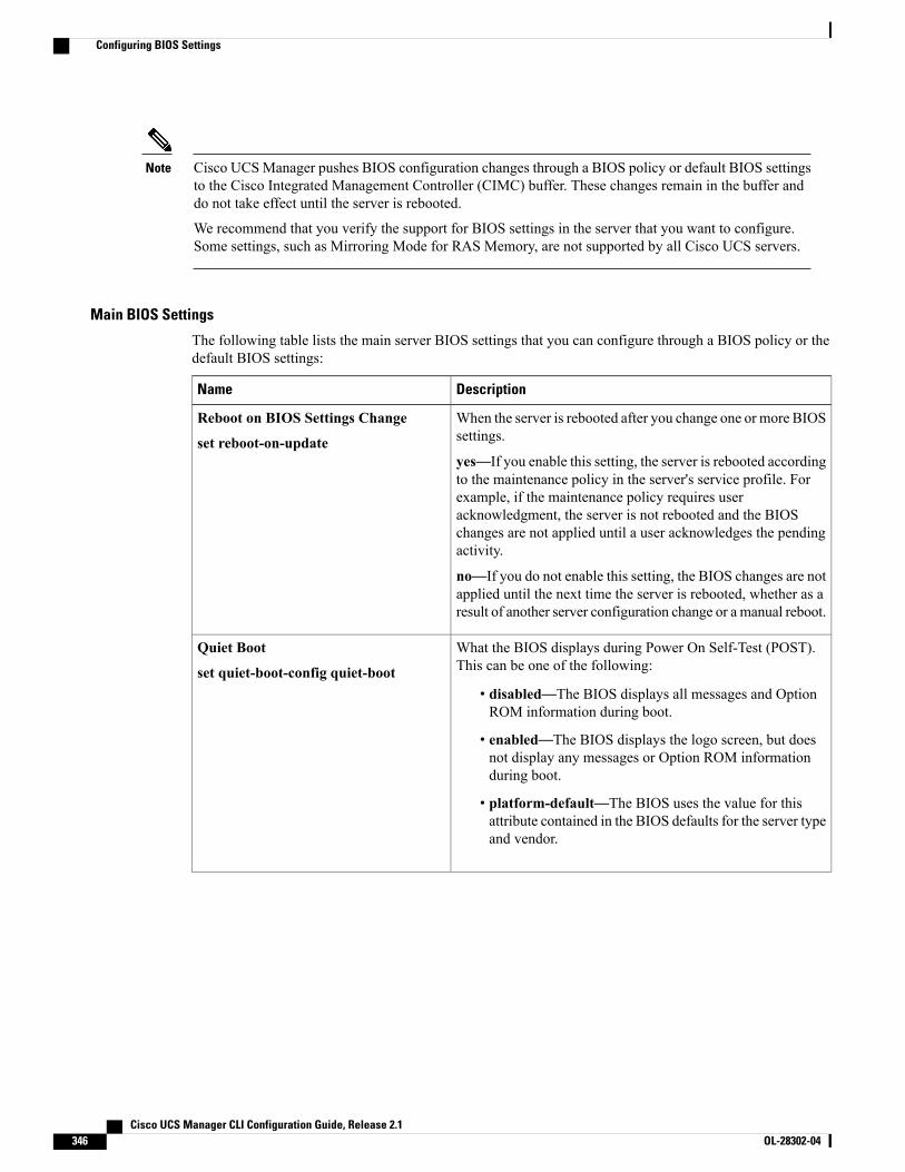
Cisco UCSManager pushes BIOS configuration changes through a BIOS policy or default BIOS settingsto the Cisco Integrated Management Controller (CIMC) buffer. These changes remain in the buffer anddo not take effect until the server is rebooted.
We recommend that you verify the support for BIOS settings in the server that you want to configure.Some settings, such as Mirroring Mode for RAS Memory, are not supported by all Cisco UCS servers.
Note
Main BIOS Settings
The following table lists the main server BIOS settings that you can configure through a BIOS policy or thedefault BIOS settings:
DescriptionName
When the server is rebooted after you change one or more BIOSsettings.
yes—If you enable this setting, the server is rebooted accordingto the maintenance policy in the server's service profile. Forexample, if the maintenance policy requires useracknowledgment, the server is not rebooted and the BIOSchanges are not applied until a user acknowledges the pendingactivity.
no—If you do not enable this setting, the BIOS changes are notapplied until the next time the server is rebooted, whether as aresult of another server configuration change or a manual reboot.
Reboot on BIOS Settings Change
set reboot-on-update
What the BIOS displays during Power On Self-Test (POST).This can be one of the following:
• disabled—The BIOS displays all messages and OptionROM information during boot.
• enabled—The BIOS displays the logo screen, but doesnot display any messages or Option ROM informationduring boot.
• platform-default—The BIOS uses the value for thisattribute contained in the BIOS defaults for the server typeand vendor.
Quiet Boot
set quiet-boot-config quiet-boot
Cisco UCS Manager CLI Configuration Guide, Release 2.1346 OL-28302-04
Configuring BIOS Settings
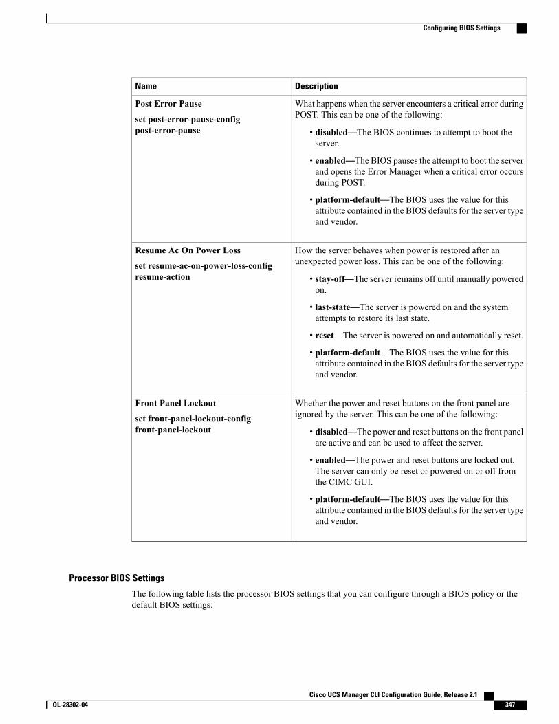
DescriptionName
What happens when the server encounters a critical error duringPOST. This can be one of the following:
• disabled—The BIOS continues to attempt to boot theserver.
• enabled—The BIOS pauses the attempt to boot the serverand opens the Error Manager when a critical error occursduring POST.
• platform-default—The BIOS uses the value for thisattribute contained in the BIOS defaults for the server typeand vendor.
Post Error Pause
set post-error-pause-configpost-error-pause
How the server behaves when power is restored after anunexpected power loss. This can be one of the following:
• stay-off—The server remains off until manually poweredon.
• last-state—The server is powered on and the systemattempts to restore its last state.
• reset—The server is powered on and automatically reset.
• platform-default—The BIOS uses the value for thisattribute contained in the BIOS defaults for the server typeand vendor.
Resume Ac On Power Loss
set resume-ac-on-power-loss-configresume-action
Whether the power and reset buttons on the front panel areignored by the server. This can be one of the following:
• disabled—The power and reset buttons on the front panelare active and can be used to affect the server.
• enabled—The power and reset buttons are locked out.The server can only be reset or powered on or off fromthe CIMC GUI.
• platform-default—The BIOS uses the value for thisattribute contained in the BIOS defaults for the server typeand vendor.
Front Panel Lockout
set front-panel-lockout-configfront-panel-lockout
Processor BIOS Settings
The following table lists the processor BIOS settings that you can configure through a BIOS policy or thedefault BIOS settings:
Cisco UCS Manager CLI Configuration Guide, Release 2.1 OL-28302-04 347
Configuring BIOS Settings
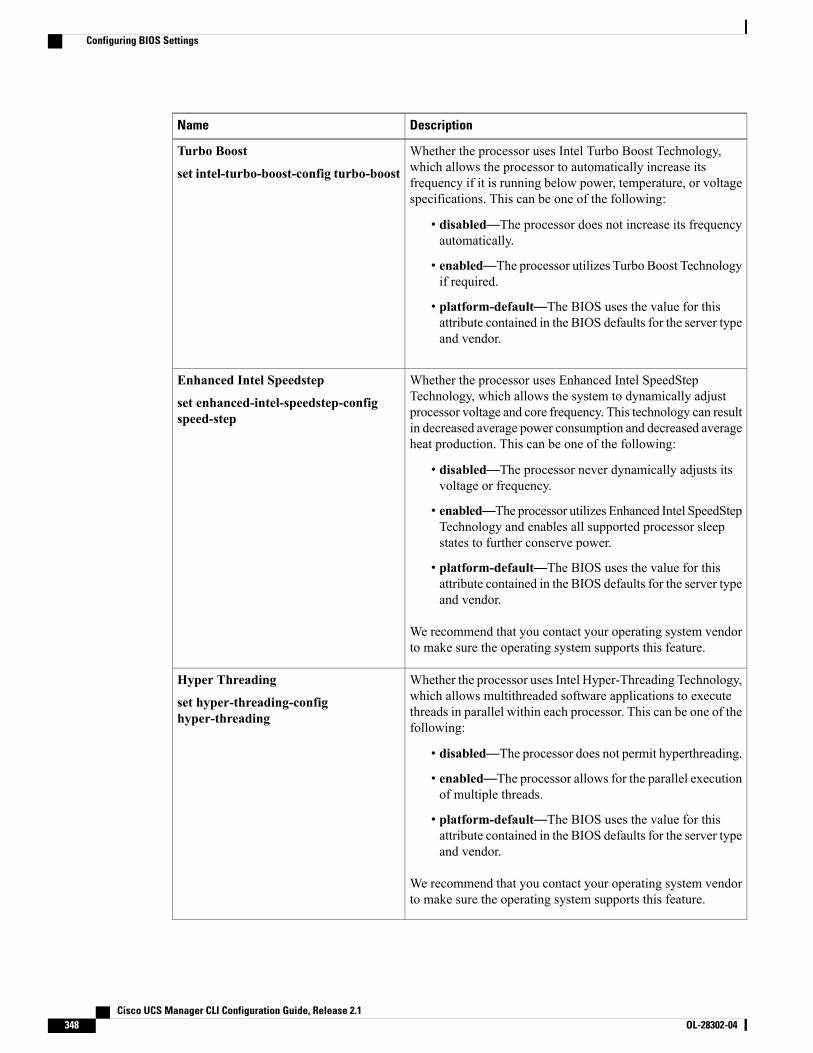
DescriptionName
Whether the processor uses Intel Turbo Boost Technology,which allows the processor to automatically increase itsfrequency if it is running below power, temperature, or voltagespecifications. This can be one of the following:
• disabled—The processor does not increase its frequencyautomatically.
• enabled—The processor utilizes Turbo Boost Technologyif required.
• platform-default—The BIOS uses the value for thisattribute contained in the BIOS defaults for the server typeand vendor.
Turbo Boost
set intel-turbo-boost-config turbo-boost
Whether the processor uses Enhanced Intel SpeedStepTechnology, which allows the system to dynamically adjustprocessor voltage and core frequency. This technology can resultin decreased average power consumption and decreased averageheat production. This can be one of the following:
• disabled—The processor never dynamically adjusts itsvoltage or frequency.
• enabled—The processor utilizes Enhanced Intel SpeedStepTechnology and enables all supported processor sleepstates to further conserve power.
• platform-default—The BIOS uses the value for thisattribute contained in the BIOS defaults for the server typeand vendor.
We recommend that you contact your operating system vendorto make sure the operating system supports this feature.
Enhanced Intel Speedstep
set enhanced-intel-speedstep-configspeed-step
Whether the processor uses Intel Hyper-Threading Technology,which allows multithreaded software applications to executethreads in parallel within each processor. This can be one of thefollowing:
• disabled—The processor does not permit hyperthreading.
• enabled—The processor allows for the parallel executionof multiple threads.
• platform-default—The BIOS uses the value for thisattribute contained in the BIOS defaults for the server typeand vendor.
We recommend that you contact your operating system vendorto make sure the operating system supports this feature.
Hyper Threading
set hyper-threading-confighyper-threading
Cisco UCS Manager CLI Configuration Guide, Release 2.1348 OL-28302-04
Configuring BIOS Settings
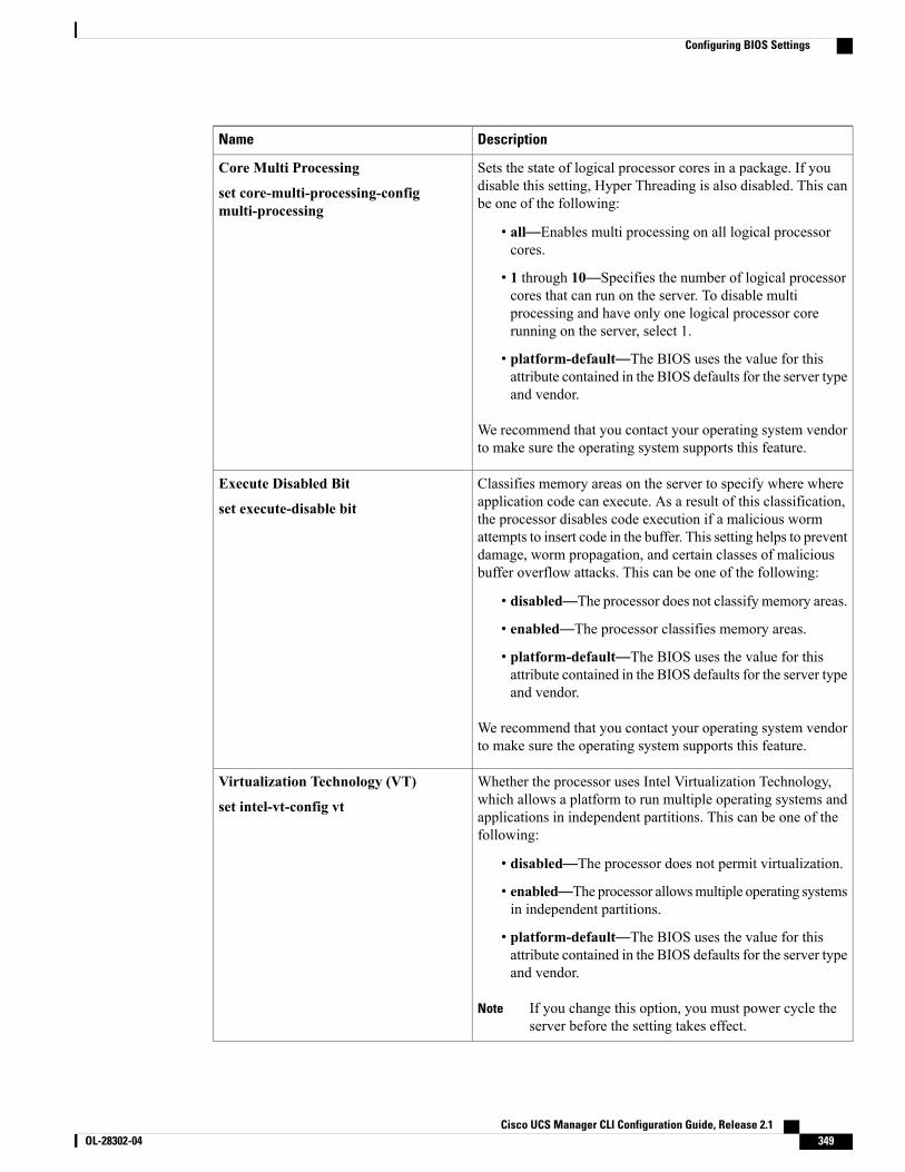
DescriptionName
Sets the state of logical processor cores in a package. If youdisable this setting, Hyper Threading is also disabled. This canbe one of the following:
• all—Enables multi processing on all logical processorcores.
• 1 through 10—Specifies the number of logical processorcores that can run on the server. To disable multiprocessing and have only one logical processor corerunning on the server, select 1.
• platform-default—The BIOS uses the value for thisattribute contained in the BIOS defaults for the server typeand vendor.
We recommend that you contact your operating system vendorto make sure the operating system supports this feature.
Core Multi Processing
set core-multi-processing-configmulti-processing
Classifies memory areas on the server to specify where whereapplication code can execute. As a result of this classification,the processor disables code execution if a malicious wormattempts to insert code in the buffer. This setting helps to preventdamage, worm propagation, and certain classes of maliciousbuffer overflow attacks. This can be one of the following:
• disabled—The processor does not classify memory areas.
• enabled—The processor classifies memory areas.
• platform-default—The BIOS uses the value for thisattribute contained in the BIOS defaults for the server typeand vendor.
We recommend that you contact your operating system vendorto make sure the operating system supports this feature.
Execute Disabled Bit
set execute-disable bit
Whether the processor uses Intel Virtualization Technology,which allows a platform to run multiple operating systems andapplications in independent partitions. This can be one of thefollowing:
• disabled—The processor does not permit virtualization.
• enabled—The processor allowsmultiple operating systemsin independent partitions.
• platform-default—The BIOS uses the value for thisattribute contained in the BIOS defaults for the server typeand vendor.
If you change this option, you must power cycle theserver before the setting takes effect.
Note
Virtualization Technology (VT)
set intel-vt-config vt
Cisco UCS Manager CLI Configuration Guide, Release 2.1 OL-28302-04 349
Configuring BIOS Settings
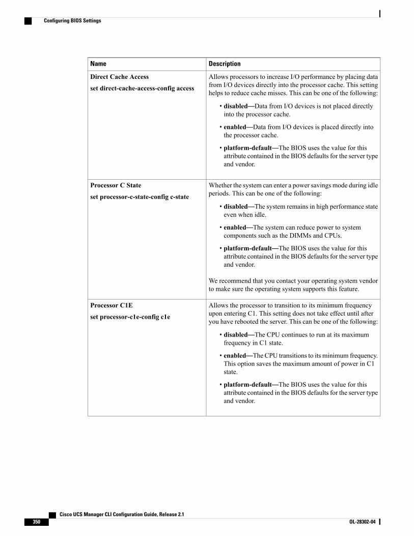
DescriptionName
Allows processors to increase I/O performance by placing datafrom I/O devices directly into the processor cache. This settinghelps to reduce cache misses. This can be one of the following:
• disabled—Data from I/O devices is not placed directlyinto the processor cache.
• enabled—Data from I/O devices is placed directly intothe processor cache.
• platform-default—The BIOS uses the value for thisattribute contained in the BIOS defaults for the server typeand vendor.
Direct Cache Access
set direct-cache-access-config access
Whether the system can enter a power savings mode during idleperiods. This can be one of the following:
• disabled—The system remains in high performance stateeven when idle.
• enabled—The system can reduce power to systemcomponents such as the DIMMs and CPUs.
• platform-default—The BIOS uses the value for thisattribute contained in the BIOS defaults for the server typeand vendor.
We recommend that you contact your operating system vendorto make sure the operating system supports this feature.
Processor C State
set processor-c-state-config c-state
Allows the processor to transition to its minimum frequencyupon entering C1. This setting does not take effect until afteryou have rebooted the server. This can be one of the following:
• disabled—The CPU continues to run at its maximumfrequency in C1 state.
• enabled—The CPU transitions to its minimum frequency.This option saves the maximum amount of power in C1state.
• platform-default—The BIOS uses the value for thisattribute contained in the BIOS defaults for the server typeand vendor.
Processor C1E
set processor-c1e-config c1e
Cisco UCS Manager CLI Configuration Guide, Release 2.1350 OL-28302-04
Configuring BIOS Settings
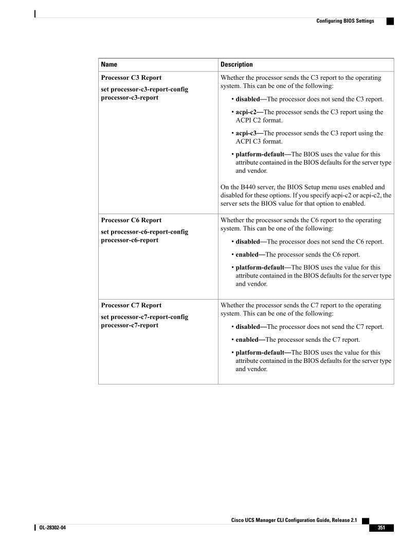
DescriptionName
Whether the processor sends the C3 report to the operatingsystem. This can be one of the following:
• disabled—The processor does not send the C3 report.
• acpi-c2—The processor sends the C3 report using theACPI C2 format.
• acpi-c3—The processor sends the C3 report using theACPI C3 format.
• platform-default—The BIOS uses the value for thisattribute contained in the BIOS defaults for the server typeand vendor.
On the B440 server, the BIOS Setup menu uses enabled anddisabled for these options. If you specify acpi-c2 or acpi-c2, theserver sets the BIOS value for that option to enabled.
Processor C3 Report
set processor-c3-report-configprocessor-c3-report
Whether the processor sends the C6 report to the operatingsystem. This can be one of the following:
• disabled—The processor does not send the C6 report.
• enabled—The processor sends the C6 report.
• platform-default—The BIOS uses the value for thisattribute contained in the BIOS defaults for the server typeand vendor.
Processor C6 Report
set processor-c6-report-configprocessor-c6-report
Whether the processor sends the C7 report to the operatingsystem. This can be one of the following:
• disabled—The processor does not send the C7 report.
• enabled—The processor sends the C7 report.
• platform-default—The BIOS uses the value for thisattribute contained in the BIOS defaults for the server typeand vendor.
Processor C7 Report
set processor-c7-report-configprocessor-c7-report
Cisco UCS Manager CLI Configuration Guide, Release 2.1 OL-28302-04 351
Configuring BIOS Settings
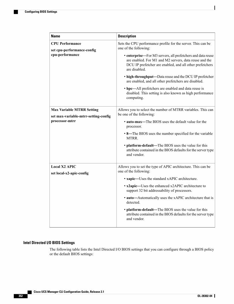
DescriptionName
Sets the CPU performance profile for the server. This can beone of the following:
• enterprise—ForM3 servers, all prefetchers and data reuseare enabled. For M1 and M2 servers, data reuse and theDCU IP prefetcher are enabled, and all other prefetchersare disabled.
• high-throughput—Data reuse and the DCU IP prefetcherare enabled, and all other prefetchers are disabled.
• hpc—All prefetchers are enabled and data reuse isdisabled. This setting is also known as high performancecomputing.
CPU Performance
set cpu-performance-configcpu-performance
Allows you to select the number of MTRR variables. This canbe one of the following:
• auto-max—The BIOS uses the default value for theprocessor.
• 8—The BIOS uses the number specified for the variableMTRR.
• platform-default—The BIOS uses the value for thisattribute contained in the BIOS defaults for the server typeand vendor.
Max Variable MTRR Setting
set max-variable-mtrr-setting-configprocessor-mtrr
Allows you to set the type of APIC architecture. This can beone of the following:
• xapic—Uses the standard xAPIC architecture.
• x2apic—Uses the enhanced x2APIC architecture tosupport 32 bit addressability of processors.
• auto—Automatically uses the xAPIC architecture that isdetected.
• platform-default—The BIOS uses the value for thisattribute contained in the BIOS defaults for the server typeand vendor.
Local X2 APIC
set local-x2-apic-config
Intel Directed I/O BIOS Settings
The following table lists the Intel Directed I/O BIOS settings that you can configure through a BIOS policyor the default BIOS settings:
Cisco UCS Manager CLI Configuration Guide, Release 2.1352 OL-28302-04
Configuring BIOS Settings

DescriptionName
Whether the processor uses Intel Virtualization Technology forDirected I/O (VT-d). This can be one of the following:
• disabled—The processor does not use virtualizationtechnology.
• enabled—The processor uses virtualization technology.
• platform-default—The BIOS uses the value for thisattribute contained in the BIOS defaults for the server typeand vendor.
This option must be enabled if you want to change anyof the other Intel Directed I/O BIOS settings.
Note
VT for Directed IO
set intel-vt-directed-io-config vtd
Whether the processor supports Intel VT-d Interrupt Remapping.This can be one of the following:
• disabled—The processor does not support remapping.
• enabled—The processor uses VT-d Interrupt Remappingas required.
• platform-default—The BIOS uses the value for thisattribute contained in the BIOS defaults for the server typeand vendor.
Interrupt Remap
set intel-vt-directed-io-configinterrupt-remapping
Whether the processor supports Intel VT-d Coherency. This canbe one of the following:
• disabled—The processor does not support coherency.
• enabled—The processor usesVT-dCoherency as required.
• platform-default—The BIOS uses the value for thisattribute contained in the BIOS defaults for the server typeand vendor.
Coherency Support
set intel-vt-directed-io-configcoherency-support
Whether the processor supports Intel VT-d Address TranslationServices (ATS). This can be one of the following:
• disabled—The processor does not support ATS.
• enabled—The processor uses VT-d ATS as required.
• platform-default—The BIOS uses the value for thisattribute contained in the BIOS defaults for the server typeand vendor.
ATS Support
set intel-vt-directed-io-config ats-support
Cisco UCS Manager CLI Configuration Guide, Release 2.1 OL-28302-04 353
Configuring BIOS Settings

DescriptionName
Whether the processor supports Intel VT-d Pass-through DMA.This can be one of the following:
• disabled—The processor does not support pass-throughDMA.
• enabled—The processor uses VT-d Pass-through DMAas required.
• platform-default—The BIOS uses the value for thisattribute contained in the BIOS defaults for the server typeand vendor.
Pass Through DMA Support
set intel-vt-directed-io-configpassthrough-dma
RAS Memory BIOS Settings
The following table lists the RAS memory BIOS settings that you can configure through a BIOS policy orthe default BIOS settings:
DescriptionName
How the memory reliability, availability, and serviceability(RAS) is configured for the server. This can be one of thefollowing:
• maximum performance—System performance isoptimized.
• mirroring—System reliability is optimized by using halfthe system memory as backup.
• lockstep—If the DIMM pairs in the server have anidentical type, size, and organization and are populatedacross the SMI channels, you can enable lockstep modeto minimize memory access latency and provide betterperformance. Lockstep is enabled by default for B440servers.
• platform-default—The BIOS uses the value for thisattribute contained in the BIOS defaults for the server typeand vendor.
Memory RAS Config
set memory-ras-config ras-config
Cisco UCS Manager CLI Configuration Guide, Release 2.1354 OL-28302-04
Configuring BIOS Settings
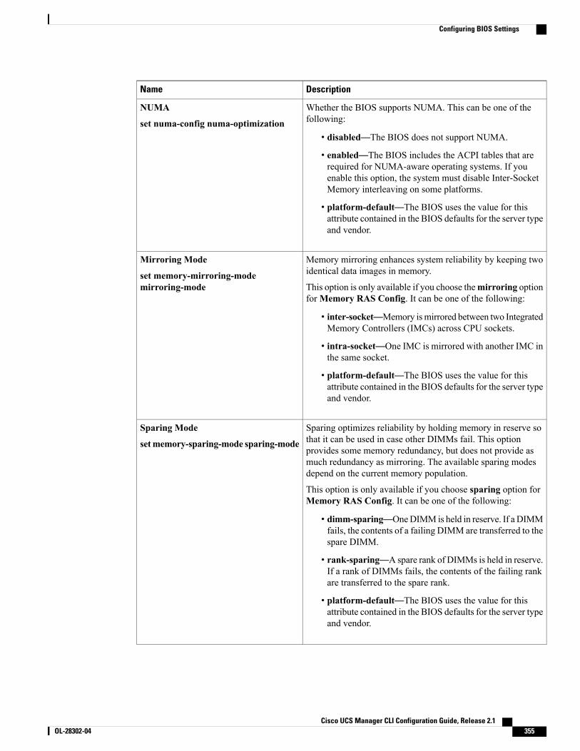
DescriptionName
Whether the BIOS supports NUMA. This can be one of thefollowing:
• disabled—The BIOS does not support NUMA.
• enabled—The BIOS includes the ACPI tables that arerequired for NUMA-aware operating systems. If youenable this option, the system must disable Inter-SocketMemory interleaving on some platforms.
• platform-default—The BIOS uses the value for thisattribute contained in the BIOS defaults for the server typeand vendor.
NUMA
set numa-config numa-optimization
Memory mirroring enhances system reliability by keeping twoidentical data images in memory.
This option is only available if you choose themirroring optionforMemory RAS Config. It can be one of the following:
• inter-socket—Memory ismirrored between two IntegratedMemory Controllers (IMCs) across CPU sockets.
• intra-socket—One IMC is mirrored with another IMC inthe same socket.
• platform-default—The BIOS uses the value for thisattribute contained in the BIOS defaults for the server typeand vendor.
Mirroring Mode
set memory-mirroring-modemirroring-mode
Sparing optimizes reliability by holding memory in reserve sothat it can be used in case other DIMMs fail. This optionprovides some memory redundancy, but does not provide asmuch redundancy as mirroring. The available sparing modesdepend on the current memory population.
This option is only available if you choose sparing option forMemory RAS Config. It can be one of the following:
• dimm-sparing—OneDIMM is held in reserve. If a DIMMfails, the contents of a failing DIMM are transferred to thespare DIMM.
• rank-sparing—A spare rank of DIMMs is held in reserve.If a rank of DIMMs fails, the contents of the failing rankare transferred to the spare rank.
• platform-default—The BIOS uses the value for thisattribute contained in the BIOS defaults for the server typeand vendor.
Sparing Mode
setmemory-sparing-mode sparing-mode
Cisco UCS Manager CLI Configuration Guide, Release 2.1 OL-28302-04 355
Configuring BIOS Settings
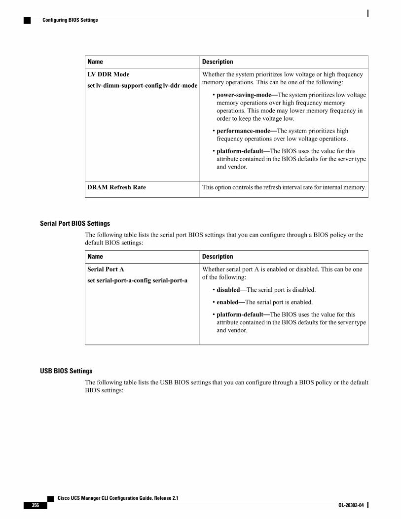
DescriptionName
Whether the system prioritizes low voltage or high frequencymemory operations. This can be one of the following:
• power-saving-mode—The system prioritizes low voltagememory operations over high frequency memoryoperations. This mode may lower memory frequency inorder to keep the voltage low.
• performance-mode—The system prioritizes highfrequency operations over low voltage operations.
• platform-default—The BIOS uses the value for thisattribute contained in the BIOS defaults for the server typeand vendor.
LV DDR Mode
set lv-dimm-support-config lv-ddr-mode
This option controls the refresh interval rate for internal memory.DRAM Refresh Rate
Serial Port BIOS Settings
The following table lists the serial port BIOS settings that you can configure through a BIOS policy or thedefault BIOS settings:
DescriptionName
Whether serial port A is enabled or disabled. This can be oneof the following:
• disabled—The serial port is disabled.
• enabled—The serial port is enabled.
• platform-default—The BIOS uses the value for thisattribute contained in the BIOS defaults for the server typeand vendor.
Serial Port A
set serial-port-a-config serial-port-a
USB BIOS Settings
The following table lists the USB BIOS settings that you can configure through a BIOS policy or the defaultBIOS settings:
Cisco UCS Manager CLI Configuration Guide, Release 2.1356 OL-28302-04
Configuring BIOS Settings
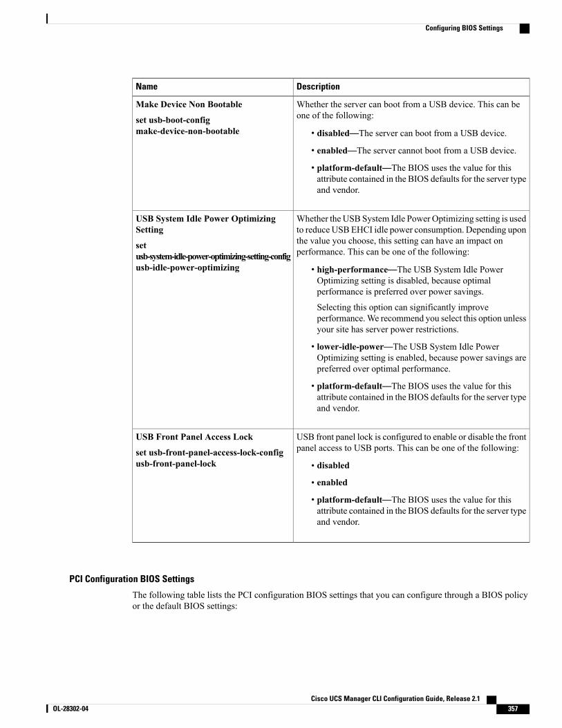
DescriptionName
Whether the server can boot from a USB device. This can beone of the following:
• disabled—The server can boot from a USB device.
• enabled—The server cannot boot from a USB device.
• platform-default—The BIOS uses the value for thisattribute contained in the BIOS defaults for the server typeand vendor.
Make Device Non Bootable
set usb-boot-configmake-device-non-bootable
Whether the USB System Idle Power Optimizing setting is usedto reduce USBEHCI idle power consumption. Depending uponthe value you choose, this setting can have an impact onperformance. This can be one of the following:
• high-performance—The USB System Idle PowerOptimizing setting is disabled, because optimalperformance is preferred over power savings.
Selecting this option can significantly improveperformance.We recommend you select this option unlessyour site has server power restrictions.
• lower-idle-power—The USB System Idle PowerOptimizing setting is enabled, because power savings arepreferred over optimal performance.
• platform-default—The BIOS uses the value for thisattribute contained in the BIOS defaults for the server typeand vendor.
USB System Idle Power OptimizingSetting
setusb-system-idle-power-optimizing-setting-configusb-idle-power-optimizing
USB front panel lock is configured to enable or disable the frontpanel access to USB ports. This can be one of the following:
• disabled
• enabled
• platform-default—The BIOS uses the value for thisattribute contained in the BIOS defaults for the server typeand vendor.
USB Front Panel Access Lock
set usb-front-panel-access-lock-configusb-front-panel-lock
PCI Configuration BIOS Settings
The following table lists the PCI configuration BIOS settings that you can configure through a BIOS policyor the default BIOS settings:
Cisco UCS Manager CLI Configuration Guide, Release 2.1 OL-28302-04 357
Configuring BIOS Settings
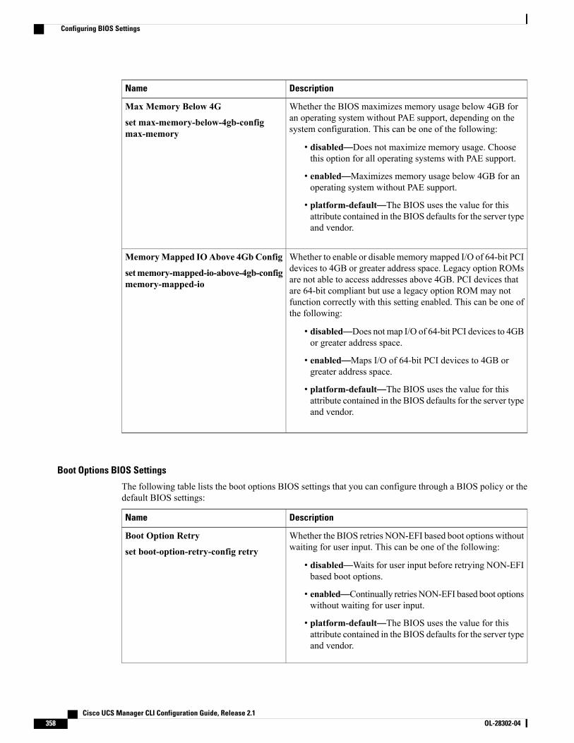
DescriptionName
Whether the BIOS maximizes memory usage below 4GB foran operating system without PAE support, depending on thesystem configuration. This can be one of the following:
• disabled—Does not maximize memory usage. Choosethis option for all operating systems with PAE support.
• enabled—Maximizes memory usage below 4GB for anoperating system without PAE support.
• platform-default—The BIOS uses the value for thisattribute contained in the BIOS defaults for the server typeand vendor.
Max Memory Below 4G
set max-memory-below-4gb-configmax-memory
Whether to enable or disable memorymapped I/O of 64-bit PCIdevices to 4GB or greater address space. Legacy option ROMsare not able to access addresses above 4GB. PCI devices thatare 64-bit compliant but use a legacy option ROM may notfunction correctly with this setting enabled. This can be one ofthe following:
• disabled—Does not map I/O of 64-bit PCI devices to 4GBor greater address space.
• enabled—Maps I/O of 64-bit PCI devices to 4GB orgreater address space.
• platform-default—The BIOS uses the value for thisattribute contained in the BIOS defaults for the server typeand vendor.
MemoryMapped IOAbove 4GbConfig
setmemory-mapped-io-above-4gb-configmemory-mapped-io
Boot Options BIOS Settings
The following table lists the boot options BIOS settings that you can configure through a BIOS policy or thedefault BIOS settings:
DescriptionName
Whether the BIOS retries NON-EFI based boot options withoutwaiting for user input. This can be one of the following:
• disabled—Waits for user input before retrying NON-EFIbased boot options.
• enabled—Continually retriesNON-EFI based boot optionswithout waiting for user input.
• platform-default—The BIOS uses the value for thisattribute contained in the BIOS defaults for the server typeand vendor.
Boot Option Retry
set boot-option-retry-config retry
Cisco UCS Manager CLI Configuration Guide, Release 2.1358 OL-28302-04
Configuring BIOS Settings
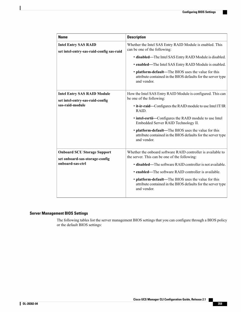
DescriptionName
Whether the Intel SAS Entry RAID Module is enabled. Thiscan be one of the following:
• disabled—The Intel SAS Entry RAIDModule is disabled.
• enabled—The Intel SAS Entry RAIDModule is enabled.
• platform-default—The BIOS uses the value for thisattribute contained in the BIOS defaults for the server typeand vendor.
Intel Entry SAS RAID
set intel-entry-sas-raid-config sas-raid
How the Intel SAS Entry RAIDModule is configured. This canbe one of the following:
• it-ir-raid—Configures the RAIDmodule to use Intel IT/IRRAID.
• intel-esrtii—Configures the RAID module to use IntelEmbedded Server RAID Technology II.
• platform-default—The BIOS uses the value for thisattribute contained in the BIOS defaults for the server typeand vendor.
Intel Entry SAS RAID Module
set intel-entry-sas-raid-configsas-raid-module
Whether the onboard software RAID controller is available tothe server. This can be one of the following:
• disabled—The software RAID controller is not available.
• enabled—The software RAID controller is available.
• platform-default—The BIOS uses the value for thisattribute contained in the BIOS defaults for the server typeand vendor.
Onboard SCU Storage Support
set onboard-sas-storage-configonboard-sas-ctrl
Server Management BIOS Settings
The following tables list the server management BIOS settings that you can configure through a BIOS policyor the default BIOS settings:
Cisco UCS Manager CLI Configuration Guide, Release 2.1 OL-28302-04 359
Configuring BIOS Settings
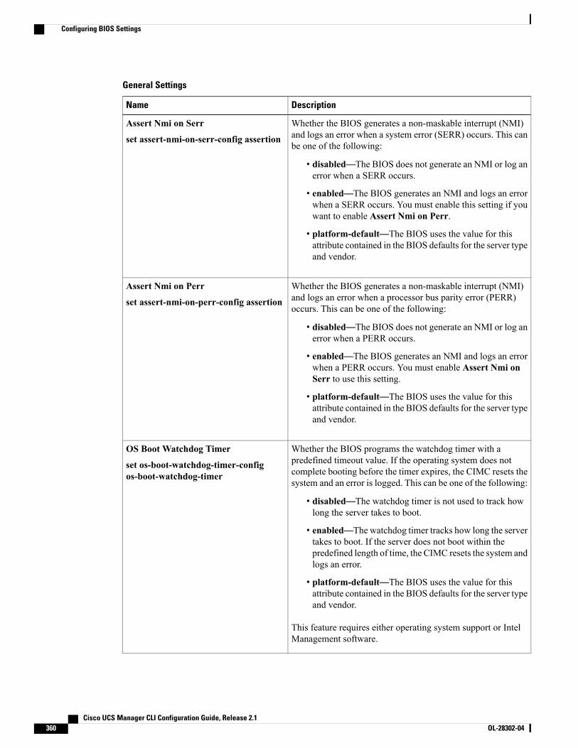
General Settings
DescriptionName
Whether the BIOS generates a non-maskable interrupt (NMI)and logs an error when a system error (SERR) occurs. This canbe one of the following:
• disabled—The BIOS does not generate an NMI or log anerror when a SERR occurs.
• enabled—The BIOS generates an NMI and logs an errorwhen a SERR occurs. You must enable this setting if youwant to enable Assert Nmi on Perr.
• platform-default—The BIOS uses the value for thisattribute contained in the BIOS defaults for the server typeand vendor.
Assert Nmi on Serr
set assert-nmi-on-serr-config assertion
Whether the BIOS generates a non-maskable interrupt (NMI)and logs an error when a processor bus parity error (PERR)occurs. This can be one of the following:
• disabled—The BIOS does not generate an NMI or log anerror when a PERR occurs.
• enabled—The BIOS generates an NMI and logs an errorwhen a PERR occurs. You must enable Assert Nmi onSerr to use this setting.
• platform-default—The BIOS uses the value for thisattribute contained in the BIOS defaults for the server typeand vendor.
Assert Nmi on Perr
set assert-nmi-on-perr-config assertion
Whether the BIOS programs the watchdog timer with apredefined timeout value. If the operating system does notcomplete booting before the timer expires, the CIMC resets thesystem and an error is logged. This can be one of the following:
• disabled—The watchdog timer is not used to track howlong the server takes to boot.
• enabled—The watchdog timer tracks how long the servertakes to boot. If the server does not boot within thepredefined length of time, the CIMC resets the system andlogs an error.
• platform-default—The BIOS uses the value for thisattribute contained in the BIOS defaults for the server typeand vendor.
This feature requires either operating system support or IntelManagement software.
OS Boot Watchdog Timer
set os-boot-watchdog-timer-configos-boot-watchdog-timer
Cisco UCS Manager CLI Configuration Guide, Release 2.1360 OL-28302-04
Configuring BIOS Settings
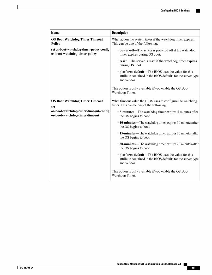
DescriptionName
What action the system takes if the watchdog timer expires.This can be one of the following:
• power-off—The server is powered off if the watchdogtimer expires during OS boot.
• reset—The server is reset if the watchdog timer expiresduring OS boot.
• platform-default—The BIOS uses the value for thisattribute contained in the BIOS defaults for the server typeand vendor.
This option is only available if you enable the OS BootWatchdog Timer.
OS Boot Watchdog Timer TimeoutPolicy
set os-boot-watchdog-timer-policy-configos-boot-watchdog-timer-policy
What timeout value the BIOS uses to configure the watchdogtimer. This can be one of the following:
• 5-minutes—The watchdog timer expires 5 minutes afterthe OS begins to boot.
• 10-minutes—Thewatchdog timer expires 10minutes afterthe OS begins to boot.
• 15-minutes—Thewatchdog timer expires 15minutes afterthe OS begins to boot.
• 20-minutes—Thewatchdog timer expires 20minutes afterthe OS begins to boot.
• platform-default—The BIOS uses the value for thisattribute contained in the BIOS defaults for the server typeand vendor.
This option is only available if you enable the OS BootWatchdog Timer.
OS Boot Watchdog Timer Timeout
setos-boot-watchdog-timer-timeout-configos-boot-watchdog-timer-timeout
Cisco UCS Manager CLI Configuration Guide, Release 2.1 OL-28302-04 361
Configuring BIOS Settings
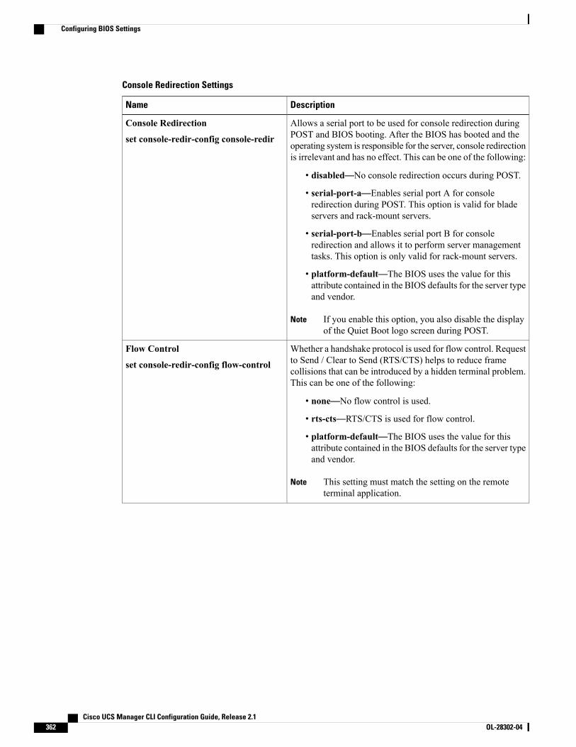
Console Redirection Settings
DescriptionName
Allows a serial port to be used for console redirection duringPOST and BIOS booting. After the BIOS has booted and theoperating system is responsible for the server, console redirectionis irrelevant and has no effect. This can be one of the following:
• disabled—No console redirection occurs during POST.
• serial-port-a—Enables serial port A for consoleredirection during POST. This option is valid for bladeservers and rack-mount servers.
• serial-port-b—Enables serial port B for consoleredirection and allows it to perform server managementtasks. This option is only valid for rack-mount servers.
• platform-default—The BIOS uses the value for thisattribute contained in the BIOS defaults for the server typeand vendor.
If you enable this option, you also disable the displayof the Quiet Boot logo screen during POST.
Note
Console Redirection
set console-redir-config console-redir
Whether a handshake protocol is used for flow control. Requestto Send / Clear to Send (RTS/CTS) helps to reduce framecollisions that can be introduced by a hidden terminal problem.This can be one of the following:
• none—No flow control is used.
• rts-cts—RTS/CTS is used for flow control.
• platform-default—The BIOS uses the value for thisattribute contained in the BIOS defaults for the server typeand vendor.
This setting must match the setting on the remoteterminal application.
Note
Flow Control
set console-redir-config flow-control
Cisco UCS Manager CLI Configuration Guide, Release 2.1362 OL-28302-04
Configuring BIOS Settings
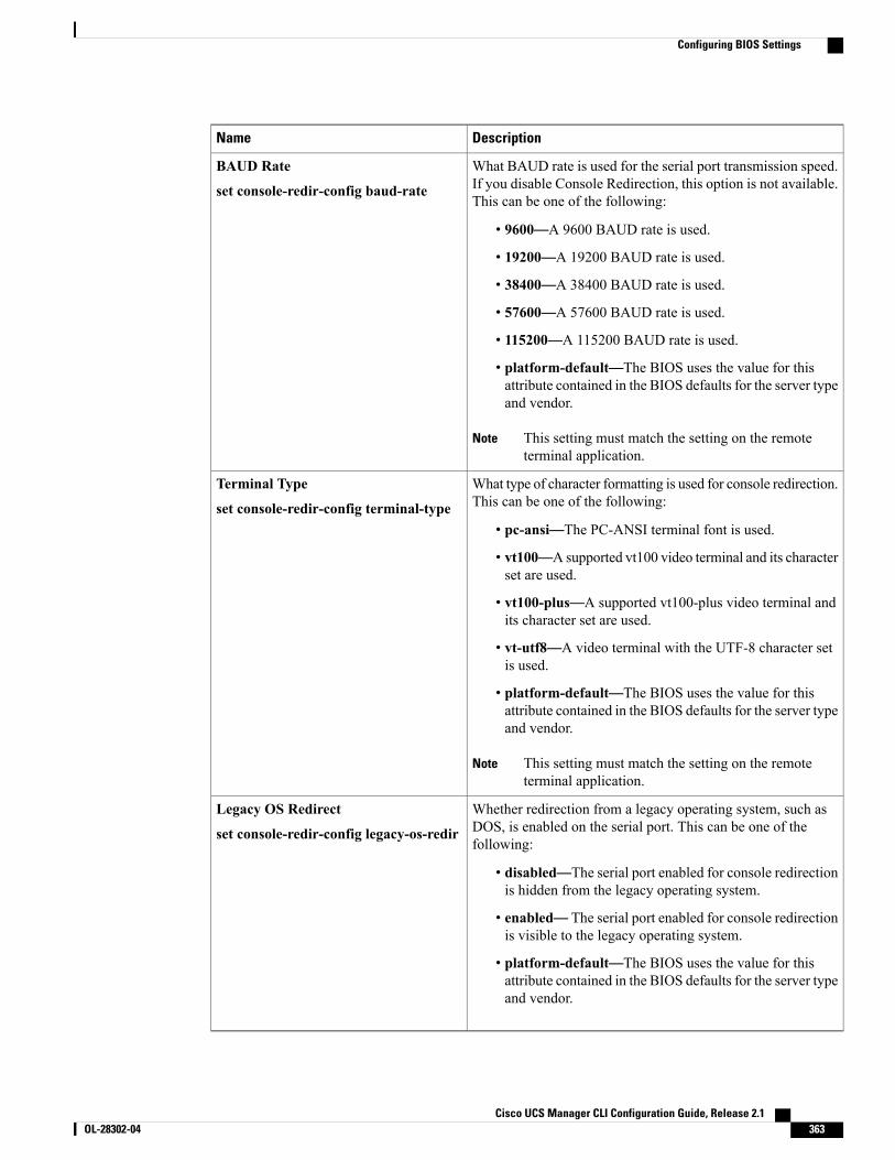
DescriptionName
What BAUD rate is used for the serial port transmission speed.If you disable Console Redirection, this option is not available.This can be one of the following:
• 9600—A 9600 BAUD rate is used.
• 19200—A 19200 BAUD rate is used.
• 38400—A 38400 BAUD rate is used.
• 57600—A 57600 BAUD rate is used.
• 115200—A 115200 BAUD rate is used.
• platform-default—The BIOS uses the value for thisattribute contained in the BIOS defaults for the server typeand vendor.
This setting must match the setting on the remoteterminal application.
Note
BAUD Rate
set console-redir-config baud-rate
What type of character formatting is used for console redirection.This can be one of the following:
• pc-ansi—The PC-ANSI terminal font is used.
• vt100—A supported vt100 video terminal and its characterset are used.
• vt100-plus—A supported vt100-plus video terminal andits character set are used.
• vt-utf8—A video terminal with the UTF-8 character setis used.
• platform-default—The BIOS uses the value for thisattribute contained in the BIOS defaults for the server typeand vendor.
This setting must match the setting on the remoteterminal application.
Note
Terminal Type
set console-redir-config terminal-type
Whether redirection from a legacy operating system, such asDOS, is enabled on the serial port. This can be one of thefollowing:
• disabled—The serial port enabled for console redirectionis hidden from the legacy operating system.
• enabled— The serial port enabled for console redirectionis visible to the legacy operating system.
• platform-default—The BIOS uses the value for thisattribute contained in the BIOS defaults for the server typeand vendor.
Legacy OS Redirect
set console-redir-config legacy-os-redir
Cisco UCS Manager CLI Configuration Guide, Release 2.1 OL-28302-04 363
Configuring BIOS Settings
BIOS PolicyThe BIOS policy is a policy that automates the configuration of BIOS settings for a server or group of servers.You can create global BIOS policies available to all servers in the root organization, or you can create BIOSpolicies in sub-organizations that are only available to that hierarchy.
To use a BIOS policy, do the following:
1 Create the BIOS policy in Cisco UCS Manager.
2 Assign the BIOS policy to one or more service profiles.
3 Associate the service profile with a server.
During service profile association, Cisco UCS Manager modifies the BIOS settings on the server to matchthe configuration in the BIOS policy. If you do not create and assign a BIOS policy to a service profile, theserver uses the default BIOS settings for that server platform.
Default BIOS SettingsCisco UCS Manager includes a set of default BIOS settings for each type of server supported by Cisco UCS.The default BIOS settings are available only in the root organization and are global. Only one set of defaultBIOS settings can exist for each server platform supported by Cisco UCS. You can modify the default BIOSsettings, but you cannot create an additional set of default BIOS settings.
Each set of default BIOS settings are designed for a particular type of supported server and are applied to allservers of that specific type which do not have a BIOS policy included in their service profiles.
Unless a Cisco UCS implementation has specific needs that are not met by the server-specific settings, werecommend that you use the default BIOS settings that are designed for each type of server in the Cisco UCSdomain.
Cisco UCS Manager applies these server platform-specific BIOS settings as follows:
• The service profile associated with a server does not include a BIOS policy.
• The BIOS policy is configured with the platform-default option for a specific setting.
You can modify the default BIOS settings provided by Cisco UCS Manager. However, any changes to thedefault BIOS settings apply to all servers of that particular type or platform. If you want to modify the BIOSsettings for only certain servers, we recommend that you use a BIOS policy.
Creating a BIOS Policy
Cisco UCSManager pushes BIOS configuration changes through a BIOS policy or default BIOS settingsto the Cisco Integrated Management Controller (CIMC) buffer. These changes remain in the buffer anddo not take effect until the server is rebooted.
We recommend that you verify the support for BIOS settings in the server that you want to configure.Some settings, such as Mirroring Mode for RAS Memory, are not supported by all Cisco UCS servers.
Note
Cisco UCS Manager CLI Configuration Guide, Release 2.1364 OL-28302-04
Configuring BIOS Settings
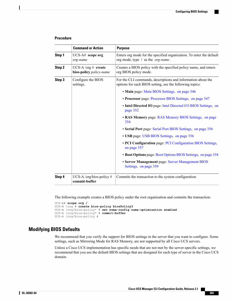
Procedure
PurposeCommand or Action
Enters org mode for the specified organization. To enter the defaultorg mode, type / as the org-name .
UCS-A# scope orgorg-name
Step 1
Creates a BIOS policy with the specified policy name, and entersorg BIOS policy mode.
UCS-A /org # createbios-policy policy-name
Step 2
For the CLI commands, descriptions and information about theoptions for each BIOS setting, see the following topics:
Configure the BIOSsettings.
Step 3
•Main page: Main BIOS Settings, on page 346
• Processor page: Processor BIOS Settings, on page 347
• Intel Directed IO page: Intel Directed I/O BIOS Settings, onpage 352
• RAS Memory page: RAS Memory BIOS Settings, on page354
• Serial Port page: Serial Port BIOS Settings, on page 356
• USB page: USB BIOS Settings, on page 356
• PCI Configuration page: PCI Configuration BIOS Settings,on page 357
• Boot Options page: Boot Options BIOS Settings, on page 358
• Server Management page: Server Management BIOSSettings, on page 359
Commits the transaction to the system configuration.UCS-A /org/bios-policy #commit-buffer
Step 4
The following example creates a BIOS policy under the root organization and commits the transaction:UCS-A# scope org /UCS-A /org # create bios-policy biosPolicy3UCS-A /org/bios-policy* # set numa-config numa-optimization enabledUCS-A /org/bios-policy* # commit-bufferUCS-A /org/bios-policy #
Modifying BIOS DefaultsWe recommend that you verify the support for BIOS settings in the server that you want to configure. Somesettings, such as Mirroring Mode for RAS Memory, are not supported by all Cisco UCS servers.
Unless a Cisco UCS implementation has specific needs that are not met by the server-specific settings, werecommend that you use the default BIOS settings that are designed for each type of server in the Cisco UCSdomain.
Cisco UCS Manager CLI Configuration Guide, Release 2.1 OL-28302-04 365
Configuring BIOS Settings
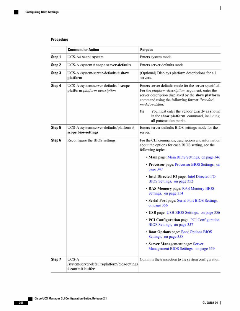
Procedure
PurposeCommand or Action
Enters system mode.UCS-A# scope systemStep 1
Enters server defaults mode.UCS-A /system # scope server-defaultsStep 2
(Optional) Displays platform descriptions for allservers.
UCS-A /system/server-defaults # showplatform
Step 3
Enters server defaults mode for the server specified.For the platform-description argument, enter the
UCS-A /system/server-defaults # scopeplatform platform-description
Step 4
server description displayed by the show platformcommand using the following format: "vendor"model revision.
You must enter the vendor exactly as shownin the show platform command, includingall punctuation marks.
Tip
Enters server defaults BIOS settings mode for theserver.
UCS-A /system/server-defaults/platform #scope bios-settings
Step 5
For the CLI commands, descriptions and informationabout the options for each BIOS setting, see thefollowing topics:
Reconfigure the BIOS settings.Step 6
•Main page: Main BIOS Settings, on page 346
• Processor page: Processor BIOS Settings, onpage 347
• Intel Directed IO page: Intel Directed I/OBIOS Settings, on page 352
• RAS Memory page: RAS Memory BIOSSettings, on page 354
• Serial Port page: Serial Port BIOS Settings,on page 356
• USB page: USB BIOS Settings, on page 356
• PCI Configuration page: PCI ConfigurationBIOS Settings, on page 357
• Boot Options page: Boot Options BIOSSettings, on page 358
• Server Management page: ServerManagement BIOS Settings, on page 359
Commits the transaction to the system configuration.UCS-A/system/server-defaults/platform/bios-settings# commit-buffer
Step 7
Cisco UCS Manager CLI Configuration Guide, Release 2.1366 OL-28302-04
Configuring BIOS Settings
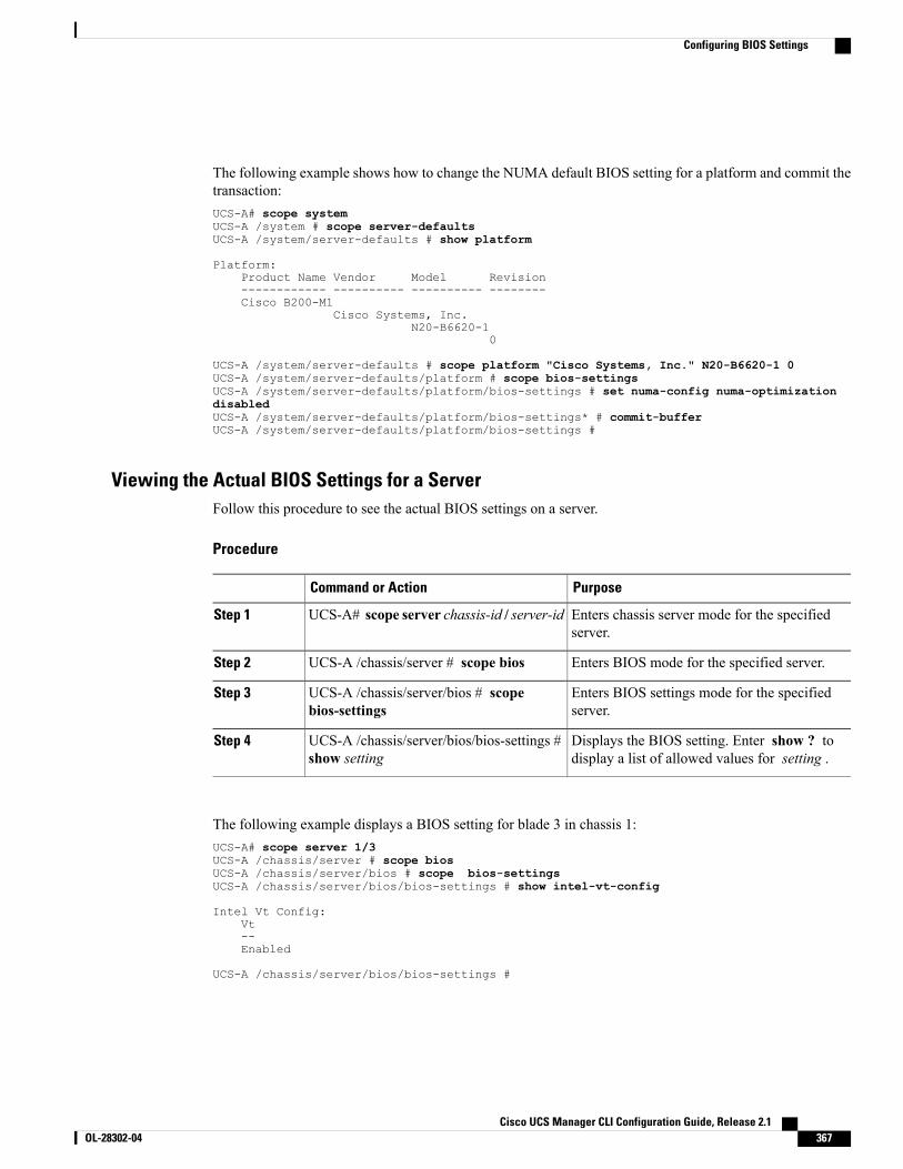
The following example shows how to change the NUMA default BIOS setting for a platform and commit thetransaction:UCS-A# scope systemUCS-A /system # scope server-defaultsUCS-A /system/server-defaults # show platform
Platform:Product Name Vendor Model Revision------------ ---------- ---------- --------Cisco B200-M1
Cisco Systems, Inc.N20-B6620-1
0
UCS-A /system/server-defaults # scope platform "Cisco Systems, Inc." N20-B6620-1 0UCS-A /system/server-defaults/platform # scope bios-settingsUCS-A /system/server-defaults/platform/bios-settings # set numa-config numa-optimizationdisabledUCS-A /system/server-defaults/platform/bios-settings* # commit-bufferUCS-A /system/server-defaults/platform/bios-settings #
Viewing the Actual BIOS Settings for a ServerFollow this procedure to see the actual BIOS settings on a server.
Procedure
PurposeCommand or Action
Enters chassis server mode for the specifiedserver.
UCS-A# scope server chassis-id / server-idStep 1
Enters BIOS mode for the specified server.UCS-A /chassis/server # scope biosStep 2
Enters BIOS settings mode for the specifiedserver.
UCS-A /chassis/server/bios # scopebios-settings
Step 3
Displays the BIOS setting. Enter show ? todisplay a list of allowed values for setting .
UCS-A /chassis/server/bios/bios-settings #show setting
Step 4
The following example displays a BIOS setting for blade 3 in chassis 1:UCS-A# scope server 1/3UCS-A /chassis/server # scope biosUCS-A /chassis/server/bios # scope bios-settingsUCS-A /chassis/server/bios/bios-settings # show intel-vt-config
Intel Vt Config:Vt--Enabled
UCS-A /chassis/server/bios/bios-settings #
Cisco UCS Manager CLI Configuration Guide, Release 2.1 OL-28302-04 367
Configuring BIOS Settings
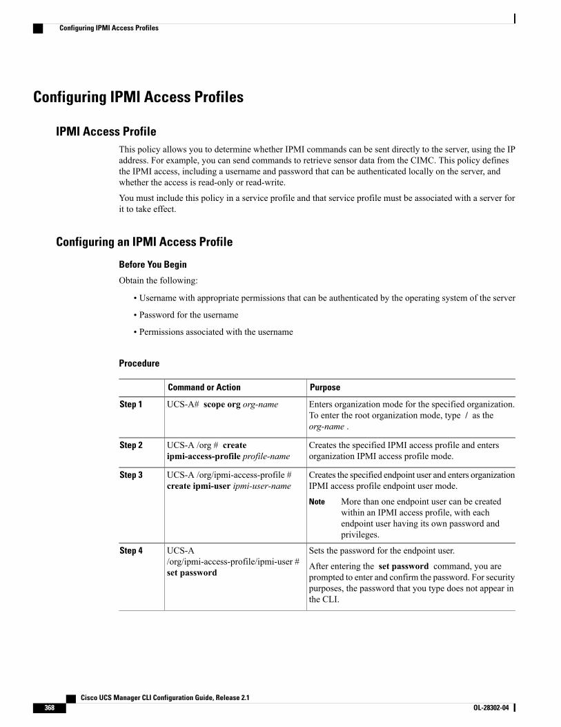
Configuring IPMI Access Profiles
IPMI Access ProfileThis policy allows you to determine whether IPMI commands can be sent directly to the server, using the IPaddress. For example, you can send commands to retrieve sensor data from the CIMC. This policy definesthe IPMI access, including a username and password that can be authenticated locally on the server, andwhether the access is read-only or read-write.
You must include this policy in a service profile and that service profile must be associated with a server forit to take effect.
Configuring an IPMI Access Profile
Before You Begin
Obtain the following:
• Username with appropriate permissions that can be authenticated by the operating system of the server
• Password for the username
• Permissions associated with the username
Procedure
PurposeCommand or Action
Enters organization mode for the specified organization.To enter the root organization mode, type / as theorg-name .
UCS-A# scope org org-nameStep 1
Creates the specified IPMI access profile and entersorganization IPMI access profile mode.
UCS-A /org # createipmi-access-profile profile-name
Step 2
Creates the specified endpoint user and enters organizationIPMI access profile endpoint user mode.
UCS-A /org/ipmi-access-profile #create ipmi-user ipmi-user-name
Step 3
More than one endpoint user can be createdwithin an IPMI access profile, with eachendpoint user having its own password andprivileges.
Note
Sets the password for the endpoint user.UCS-A/org/ipmi-access-profile/ipmi-user #set password
Step 4
After entering the set password command, you areprompted to enter and confirm the password. For securitypurposes, the password that you type does not appear inthe CLI.
Cisco UCS Manager CLI Configuration Guide, Release 2.1368 OL-28302-04
Configuring IPMI Access Profiles
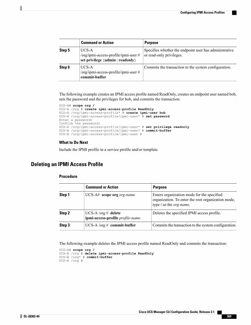
PurposeCommand or Action
Specifies whether the endpoint user has administrativeor read-only privileges.
UCS-A/org/ipmi-access-profile/ipmi-user #set privilege {admin | readonly}
Step 5
Commits the transaction to the system configuration.UCS-A/org/ipmi-access-profile/ipmi-user #commit-buffer
Step 6
The following example creates an IPMI access profile named ReadOnly, creates an endpoint user named bob,sets the password and the privileges for bob, and commits the transaction:UCS-A# scope org /UCS-A /org # create ipmi-access-profile ReadOnlyUCS-A /org/ipmi-access-profile* # create ipmi-user bobUCS-A /org/ipmi-access-profile/ipmi-user* # set passwordEnter a password:Confirm the password:UCS-A /org/ipmi-access-profile/ipmi-user* # set privilege readonlyUCS-A /org/ipmi-access-profile/ipmi-user* # commit-bufferUCS-A /org/ipmi-access-profile/ipmi-user #
What to Do Next
Include the IPMI profile in a service profile and/or template.
Deleting an IPMI Access Profile
Procedure
PurposeCommand or Action
Enters organization mode for the specifiedorganization. To enter the root organization mode,type / as the org-name.
UCS-A# scope org org-nameStep 1
Deletes the specified IPMI access profile.UCS-A /org # deleteipmi-access-profile profile-name
Step 2
Commits the transaction to the system configuration.UCS-A /org # commit-bufferStep 3
The following example deletes the IPMI access profile named ReadOnly and commits the transaction:UCS-A# scope org /UCS-A /org # delete ipmi-access-profile ReadOnlyUCS-A /org* # commit-bufferUCS-A /org #
Cisco UCS Manager CLI Configuration Guide, Release 2.1 OL-28302-04 369
Configuring IPMI Access Profiles
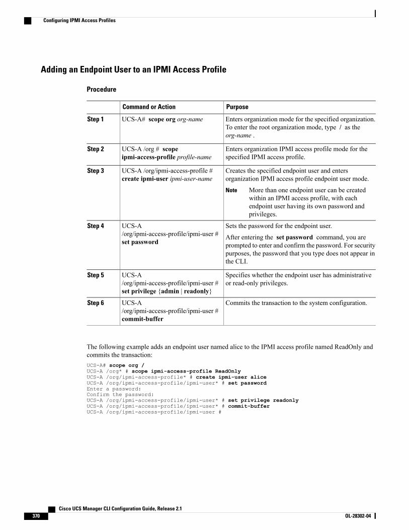
Adding an Endpoint User to an IPMI Access Profile
Procedure
PurposeCommand or Action
Enters organization mode for the specified organization.To enter the root organization mode, type / as theorg-name .
UCS-A# scope org org-nameStep 1
Enters organization IPMI access profile mode for thespecified IPMI access profile.
UCS-A /org # scopeipmi-access-profile profile-name
Step 2
Creates the specified endpoint user and entersorganization IPMI access profile endpoint user mode.
UCS-A /org/ipmi-access-profile #create ipmi-user ipmi-user-name
Step 3
More than one endpoint user can be createdwithin an IPMI access profile, with eachendpoint user having its own password andprivileges.
Note
Sets the password for the endpoint user.UCS-A/org/ipmi-access-profile/ipmi-user #set password
Step 4
After entering the set password command, you areprompted to enter and confirm the password. For securitypurposes, the password that you type does not appear inthe CLI.
Specifies whether the endpoint user has administrativeor read-only privileges.
UCS-A/org/ipmi-access-profile/ipmi-user #set privilege {admin | readonly}
Step 5
Commits the transaction to the system configuration.UCS-A/org/ipmi-access-profile/ipmi-user #commit-buffer
Step 6
The following example adds an endpoint user named alice to the IPMI access profile named ReadOnly andcommits the transaction:UCS-A# scope org /UCS-A /org* # scope ipmi-access-profile ReadOnlyUCS-A /org/ipmi-access-profile* # create ipmi-user aliceUCS-A /org/ipmi-access-profile/ipmi-user* # set passwordEnter a password:Confirm the password:UCS-A /org/ipmi-access-profile/ipmi-user* # set privilege readonlyUCS-A /org/ipmi-access-profile/ipmi-user* # commit-bufferUCS-A /org/ipmi-access-profile/ipmi-user #
Cisco UCS Manager CLI Configuration Guide, Release 2.1370 OL-28302-04
Configuring IPMI Access Profiles
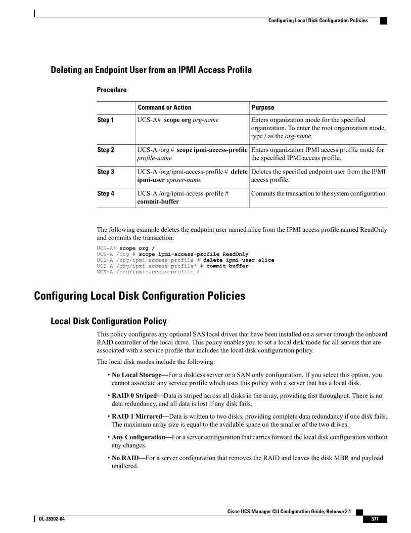
Deleting an Endpoint User from an IPMI Access Profile
Procedure
PurposeCommand or Action
Enters organization mode for the specifiedorganization. To enter the root organization mode,type / as the org-name.
UCS-A# scope org org-nameStep 1
Enters organization IPMI access profile mode forthe specified IPMI access profile.
UCS-A /org # scope ipmi-access-profileprofile-name
Step 2
Deletes the specified endpoint user from the IPMIaccess profile.
UCS-A /org/ipmi-access-profile # deleteipmi-user epuser-name
Step 3
Commits the transaction to the system configuration.UCS-A /org/ipmi-access-profile #commit-buffer
Step 4
The following example deletes the endpoint user named alice from the IPMI access profile named ReadOnlyand commits the transaction:UCS-A# scope org /UCS-A /org # scope ipmi-access-profile ReadOnlyUCS-A /org/ipmi-access-profile # delete ipmi-user aliceUCS-A /org/ipmi-access-profile* # commit-bufferUCS-A /org/ipmi-access-profile #
Configuring Local Disk Configuration Policies
Local Disk Configuration PolicyThis policy configures any optional SAS local drives that have been installed on a server through the onboardRAID controller of the local drive. This policy enables you to set a local disk mode for all servers that areassociated with a service profile that includes the local disk configuration policy.
The local disk modes include the following:
• No Local Storage—For a diskless server or a SAN only configuration. If you select this option, youcannot associate any service profile which uses this policy with a server that has a local disk.
• RAID 0 Striped—Data is striped across all disks in the array, providing fast throughput. There is nodata redundancy, and all data is lost if any disk fails.
• RAID 1Mirrored—Data is written to two disks, providing complete data redundancy if one disk fails.The maximum array size is equal to the available space on the smaller of the two drives.
• AnyConfiguration—For a server configuration that carries forward the local disk configuration withoutany changes.
• No RAID—For a server configuration that removes the RAID and leaves the disk MBR and payloadunaltered.
Cisco UCS Manager CLI Configuration Guide, Release 2.1 OL-28302-04 371
Configuring Local Disk Configuration Policies

If you choose No RAID and you apply this policy to a server that already has an operating system withRAID storage configured, the system does not remove the disk contents. Therefore, there may be novisible differences on the server after you apply theNoRAIDmode. This can lead to a mismatch betweenthe RAID configuration in the policy and the actual disk configuration shown in the Inventory > Storagetab for the server.
To make sure that any previous RAID configuration information is removed from a disk, apply a scrubpolicy that removes all disk information after you apply the No RAID configuration mode.
• RAID 5 Striped Parity—Data is striped across all disks in the array. Part of the capacity of each diskstores parity information that can be used to reconstruct data if a disk fails. RAID 5 provides good datathroughput for applications with high read request rates.
• RAID 6 Striped Dual Parity—Data is striped across all disks in the array and two parity disks are usedto provide protection against the failure of up to two physical disks. In each row of data blocks, two setsof parity data are stored.
• RAID10 Mirrored and Striped— RAID 10 uses mirrored pairs of disks to provide complete dataredundancy and high throughput rates.
You must include this policy in a service profile and that service profile must be associated with a server forthe policy to take effect.
Guidelines for all Local Disk Configuration PoliciesBefore you create a local disk configuration policy, consider the following guidelines:
No Mixed HDDs and SSDs
Do not include HDDs and SSDs in a single server or RAID configuration.
Do Not Assign a Service Profile with the Default Local Disk Configuration Policy from a B200 M1 or M2 to aB200 M3
Due to the differences in the RAID/JBOD support provided by the storage controllers of B200 M1 and M2servers and those of the B200 M3 server, you cannot assign or re-assign a service profile that includes thedefault local disk configuration policy from a B200M1 or M2 server to a B200 M3 server. The default localdisk configuration policy includes those with Any Configuration or JBOD configuration.
JBOD Mode Support
Only B200 M1, B200 M2, B200 M3, B250 M1, B250 M2 and B22 M3 blade servers support the JBODmode for local disks.
Note
Guidelines for Local Disk Configuration Policies Configured for RAID
Do Not Use the Any Configuration Mode on Servers with MegaRAID Storage Controllers
If a blade server or rack-mount server in a Cisco UCS domain includes a MegaRAID storage controller, donot configure the local disk configuration policy in the service profile for that server with the Any
Cisco UCS Manager CLI Configuration Guide, Release 2.1372 OL-28302-04
Configuring Local Disk Configuration Policies
Configuration mode. If you use this mode for servers with a MegaRAID storage controller, the installer forthe operating system cannot detect any local storage on the server.
If you want to install an operating system on local storage on a server with a MegaRAID storage controller,you must configure the local disk configuration policy with a mode that creates a RAID LUN (RAID volume)on the server.
Server May Not Boot After RAID1 Cluster Migration if Any Configuration Mode Specified in Service Profile
After RAID1 clusters are migrated, you need to associate a service profile with the server. If the local diskconfiguration policy in the service profile is configured with Any Configuration mode rather than RAID1,the RAID LUN remains in "inactive" state during and after association. As a result, the server cannot boot.
To avoid this issue, ensure that the service profile you associate with the server contains the identical localdisk configuration policy as the original service profile before the migration and does not include the AnyConfiguration mode.
Configure RAID Settings in Local Disk Configuration Policy for Servers with MegaRAID Storage Controllers
If a blade server or integrated rack-mount server has a MegaRAID controller, you must configure RAIDsettings for the drives in the Local Disk Configuration policy included in the service profile for that server.
If you do not configure your RAID LUNs before installing the OS, disk discovery failures might occur duringthe installation and you might see error messages such as “No Device Found.”
Do Not Use JBOD Mode on Servers with MegaRAID Storage Controllers
Do not configure or use JBODmode or JBOD operations on any blade server or integrated rack-mount serverwith a MegaRAID storage controllers. JBOD mode and operations are not intended for nor are they fullyfunctional on these servers.
Maximum of One RAID Volume and One RAID Controller in Integrated Rack-Mount Servers
A rack-mount server that has been integrated with Cisco UCS Manager can have a maximum of one RAIDvolume irrespective of how many hard drives are present on the server.
All the local hard drives in an integrated rack-mount server must be connected to only one RAID Controller.Integration with Cisco UCS Manager does not support the connection of local hard drives to multiple RAIDControllers in a single rack-mount server. We therefore recommend that you request a single RAID Controllerconfiguration when you order rack-mount servers to be integrated with Cisco UCS Manager.
In addition, do not use third party tools to create multiple RAID LUNs on rack-mount servers. Cisco UCSManager does not support that configuration.
Maximum of One RAID Volume and One RAID Controller in Blade Servers
A blade server can have a maximum of one RAID volume irrespective of how many drives are present in theserver. All the local hard drives must be connected to only one RAID controller. For example, a B200 M3server has an LSI controller and an Intel Patsburg controller, but only the LSI controller can be used as aRAID controller.
In addition, do not use third party tools to create multiple RAID LUNs on blade servers. Cisco UCSManagerdoes not support that configuration.
Cisco UCS Manager CLI Configuration Guide, Release 2.1 OL-28302-04 373
Configuring Local Disk Configuration Policies
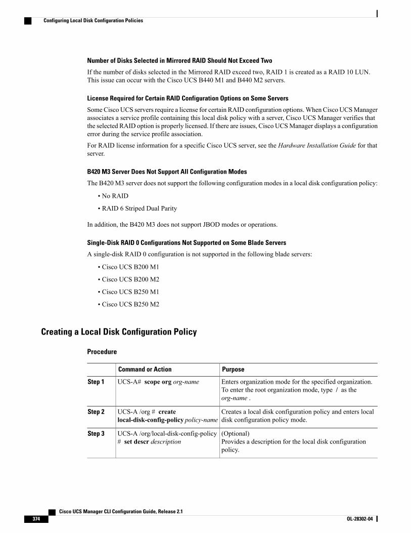
Number of Disks Selected in Mirrored RAID Should Not Exceed Two
If the number of disks selected in the Mirrored RAID exceed two, RAID 1 is created as a RAID 10 LUN.This issue can occur with the Cisco UCS B440 M1 and B440 M2 servers.
License Required for Certain RAID Configuration Options on Some Servers
Some Cisco UCS servers require a license for certain RAID configuration options.When Cisco UCSManagerassociates a service profile containing this local disk policy with a server, Cisco UCS Manager verifies thatthe selected RAID option is properly licensed. If there are issues, Cisco UCSManager displays a configurationerror during the service profile association.
For RAID license information for a specific Cisco UCS server, see the Hardware Installation Guide for thatserver.
B420 M3 Server Does Not Support All Configuration Modes
The B420 M3 server does not support the following configuration modes in a local disk configuration policy:
• No RAID
• RAID 6 Striped Dual Parity
In addition, the B420 M3 does not support JBOD modes or operations.
Single-Disk RAID 0 Configurations Not Supported on Some Blade Servers
A single-disk RAID 0 configuration is not supported in the following blade servers:
• Cisco UCS B200 M1
• Cisco UCS B200 M2
• Cisco UCS B250 M1
• Cisco UCS B250 M2
Creating a Local Disk Configuration Policy
Procedure
PurposeCommand or Action
Enters organization mode for the specified organization.To enter the root organization mode, type / as theorg-name .
UCS-A# scope org org-nameStep 1
Creates a local disk configuration policy and enters localdisk configuration policy mode.
UCS-A /org # createlocal-disk-config-policy policy-name
Step 2
(Optional)Provides a description for the local disk configurationpolicy.
UCS-A /org/local-disk-config-policy# set descr description
Step 3
Cisco UCS Manager CLI Configuration Guide, Release 2.1374 OL-28302-04
Configuring Local Disk Configuration Policies

PurposeCommand or Action
Specifies the mode for the local disk configuration policy.UCS-A /org/local-disk-config-policy# set mode {any-configuration |
Step 4
no-local-storage | no-raid |raid-0-striped | raid-1-mirrored |raid-5-striped-parity |raid-6-striped-dual-parity |raid-10-mirrored-and-striped}
Specifies whether the server retains the configuration inthe local disk configuration policy even if the server isdisassociated from the service profile.
UCS-A /org/local-disk-config-policy# set protect {yes | no}
Step 5
Protect Configuration becomes non-functionalif one or more disks in the server are defectiveor faulty.
Caution
When a service profile is disassociated from a server anda new service profile associated, the setting for the ProtectConfiguration property in the new service profile takesprecedence and overwrites the setting in the previous serviceprofile.
If you disassociate the server from a service profilewith this option enabled and then associate it witha new service profile that includes a local diskconfiguration policy with different properties, theserver returns a configuration mismatch error andthe association fails.
Note
Commits the transaction to the system configuration.UCS-A /org/local-disk-config-policy# commit-buffer
Step 6
The following example configures a local disk configuration policy and commits the transaction:UCS-A# scope org /UCS-A /org # create local-disk-config-policy DiskPolicy7UCS-A /org/local-disk-config-policy* # set mode raid-1-mirroredUCS-A /org/local-disk-config-policy* # set protect yesUCS-A /org/local-disk-config-policy* # commit-bufferUCS-A /org/local-disk-config-policy #
Viewing a Local Disk Configuration Policy
Procedure
PurposeCommand or Action
Enters organization mode for the specified organization. To enterthe root organization mode, type / as the org-name .
UCS-A# scope org org-nameStep 1
Cisco UCS Manager CLI Configuration Guide, Release 2.1 OL-28302-04 375
Configuring Local Disk Configuration Policies
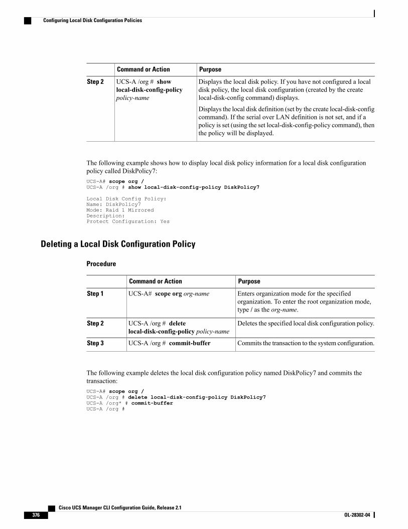
PurposeCommand or Action
Displays the local disk policy. If you have not configured a localdisk policy, the local disk configuration (created by the createlocal-disk-config command) displays.
UCS-A /org # showlocal-disk-config-policypolicy-name
Step 2
Displays the local disk definition (set by the create local-disk-configcommand). If the serial over LAN definition is not set, and if apolicy is set (using the set local-disk-config-policy command), thenthe policy will be displayed.
The following example shows how to display local disk policy information for a local disk configurationpolicy called DiskPolicy7:UCS-A# scope org /UCS-A /org # show local-disk-config-policy DiskPolicy7
Local Disk Config Policy:Name: DiskPolicy7Mode: Raid 1 MirroredDescription:Protect Configuration: Yes
Deleting a Local Disk Configuration Policy
Procedure
PurposeCommand or Action
Enters organization mode for the specifiedorganization. To enter the root organization mode,type / as the org-name.
UCS-A# scope org org-nameStep 1
Deletes the specified local disk configuration policy.UCS-A /org # deletelocal-disk-config-policy policy-name
Step 2
Commits the transaction to the system configuration.UCS-A /org # commit-bufferStep 3
The following example deletes the local disk configuration policy named DiskPolicy7 and commits thetransaction:UCS-A# scope org /UCS-A /org # delete local-disk-config-policy DiskPolicy7UCS-A /org* # commit-bufferUCS-A /org #
Cisco UCS Manager CLI Configuration Guide, Release 2.1376 OL-28302-04
Configuring Local Disk Configuration Policies
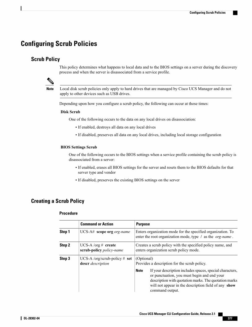
Configuring Scrub Policies
Scrub PolicyThis policy determines what happens to local data and to the BIOS settings on a server during the discoveryprocess and when the server is disassociated from a service profile.
Local disk scrub policies only apply to hard drives that are managed by Cisco UCS Manager and do notapply to other devices such as USB drives.
Note
Depending upon how you configure a scrub policy, the following can occur at those times:
Disk Scrub
One of the following occurs to the data on any local drives on disassociation:
• If enabled, destroys all data on any local drives
• If disabled, preserves all data on any local drives, including local storage configuration
BIOS Settings Scrub
One of the following occurs to the BIOS settings when a service profile containing the scrub policy isdisassociated from a server:
• If enabled, erases all BIOS settings for the server and resets them to the BIOS defaults for thatserver type and vendor
• If disabled, preserves the existing BIOS settings on the server
Creating a Scrub Policy
Procedure
PurposeCommand or Action
Enters organization mode for the specified organization. Toenter the root organization mode, type / as the org-name .
UCS-A# scope org org-nameStep 1
Creates a scrub policy with the specified policy name, andenters organization scrub policy mode.
UCS-A /org # createscrub-policy policy-name
Step 2
(Optional)Provides a description for the scrub policy.
UCS-A /org/scrub-policy # setdescr description
Step 3
If your description includes spaces, special characters,or punctuation, you must begin and end yourdescriptionwith quotationmarks. The quotationmarkswill not appear in the description field of any showcommand output.
Note
Cisco UCS Manager CLI Configuration Guide, Release 2.1 OL-28302-04 377
Configuring Scrub Policies
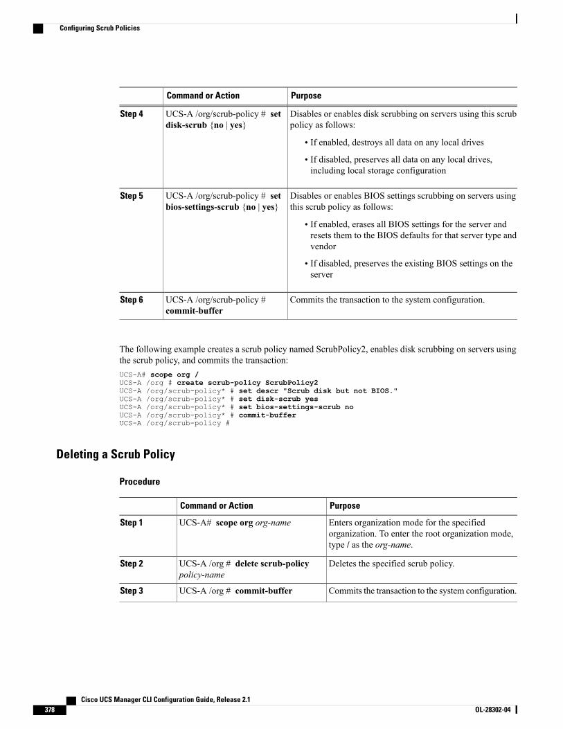
PurposeCommand or Action
Disables or enables disk scrubbing on servers using this scrubpolicy as follows:
UCS-A /org/scrub-policy # setdisk-scrub {no | yes}
Step 4
• If enabled, destroys all data on any local drives
• If disabled, preserves all data on any local drives,including local storage configuration
Disables or enables BIOS settings scrubbing on servers usingthis scrub policy as follows:
UCS-A /org/scrub-policy # setbios-settings-scrub {no | yes}
Step 5
• If enabled, erases all BIOS settings for the server andresets them to the BIOS defaults for that server type andvendor
• If disabled, preserves the existing BIOS settings on theserver
Commits the transaction to the system configuration.UCS-A /org/scrub-policy #commit-buffer
Step 6
The following example creates a scrub policy named ScrubPolicy2, enables disk scrubbing on servers usingthe scrub policy, and commits the transaction:UCS-A# scope org /UCS-A /org # create scrub-policy ScrubPolicy2UCS-A /org/scrub-policy* # set descr "Scrub disk but not BIOS."UCS-A /org/scrub-policy* # set disk-scrub yesUCS-A /org/scrub-policy* # set bios-settings-scrub noUCS-A /org/scrub-policy* # commit-bufferUCS-A /org/scrub-policy #
Deleting a Scrub Policy
Procedure
PurposeCommand or Action
Enters organization mode for the specifiedorganization. To enter the root organization mode,type / as the org-name.
UCS-A# scope org org-nameStep 1
Deletes the specified scrub policy.UCS-A /org # delete scrub-policypolicy-name
Step 2
Commits the transaction to the system configuration.UCS-A /org # commit-bufferStep 3
Cisco UCS Manager CLI Configuration Guide, Release 2.1378 OL-28302-04
Configuring Scrub Policies
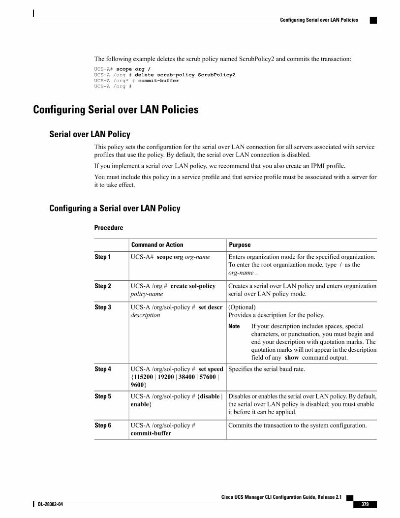
The following example deletes the scrub policy named ScrubPolicy2 and commits the transaction:UCS-A# scope org /UCS-A /org # delete scrub-policy ScrubPolicy2UCS-A /org* # commit-bufferUCS-A /org #
Configuring Serial over LAN Policies
Serial over LAN PolicyThis policy sets the configuration for the serial over LAN connection for all servers associated with serviceprofiles that use the policy. By default, the serial over LAN connection is disabled.
If you implement a serial over LAN policy, we recommend that you also create an IPMI profile.
You must include this policy in a service profile and that service profile must be associated with a server forit to take effect.
Configuring a Serial over LAN Policy
Procedure
PurposeCommand or Action
Enters organization mode for the specified organization.To enter the root organization mode, type / as theorg-name .
UCS-A# scope org org-nameStep 1
Creates a serial over LAN policy and enters organizationserial over LAN policy mode.
UCS-A /org # create sol-policypolicy-name
Step 2
(Optional)Provides a description for the policy.
UCS-A /org/sol-policy # set descrdescription
Step 3
If your description includes spaces, specialcharacters, or punctuation, you must begin andend your description with quotation marks. Thequotationmarks will not appear in the descriptionfield of any show command output.
Note
Specifies the serial baud rate.UCS-A /org/sol-policy # set speed{115200 | 19200 | 38400 | 57600 |9600}
Step 4
Disables or enables the serial over LAN policy. By default,the serial over LAN policy is disabled; you must enableit before it can be applied.
UCS-A /org/sol-policy # {disable |enable}
Step 5
Commits the transaction to the system configuration.UCS-A /org/sol-policy #commit-buffer
Step 6
Cisco UCS Manager CLI Configuration Guide, Release 2.1 OL-28302-04 379
Configuring Serial over LAN Policies
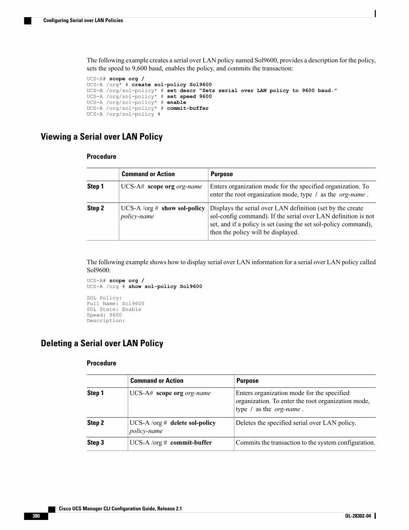
The following example creates a serial over LAN policy named Sol9600, provides a description for the policy,sets the speed to 9,600 baud, enables the policy, and commits the transaction:UCS-A# scope org /UCS-A /org* # create sol-policy Sol9600UCS-A /org/sol-policy* # set descr "Sets serial over LAN policy to 9600 baud."UCS-A /org/sol-policy* # set speed 9600UCS-A /org/sol-policy* # enableUCS-A /org/sol-policy* # commit-bufferUCS-A /org/sol-policy #
Viewing a Serial over LAN Policy
Procedure
PurposeCommand or Action
Enters organization mode for the specified organization. Toenter the root organization mode, type / as the org-name .
UCS-A# scope org org-nameStep 1
Displays the serial over LAN definition (set by the createsol-config command). If the serial over LAN definition is not
UCS-A /org # show sol-policypolicy-name
Step 2
set, and if a policy is set (using the set sol-policy command),then the policy will be displayed.
The following example shows how to display serial over LAN information for a serial over LAN policy calledSol9600:UCS-A# scope org /UCS-A /org # show sol-policy Sol9600
SOL Policy:Full Name: Sol9600SOL State: EnableSpeed: 9600Description:
Deleting a Serial over LAN Policy
Procedure
PurposeCommand or Action
Enters organization mode for the specifiedorganization. To enter the root organization mode,type / as the org-name .
UCS-A# scope org org-nameStep 1
Deletes the specified serial over LAN policy.UCS-A /org # delete sol-policypolicy-name
Step 2
Commits the transaction to the system configuration.UCS-A /org # commit-bufferStep 3
Cisco UCS Manager CLI Configuration Guide, Release 2.1380 OL-28302-04
Configuring Serial over LAN Policies
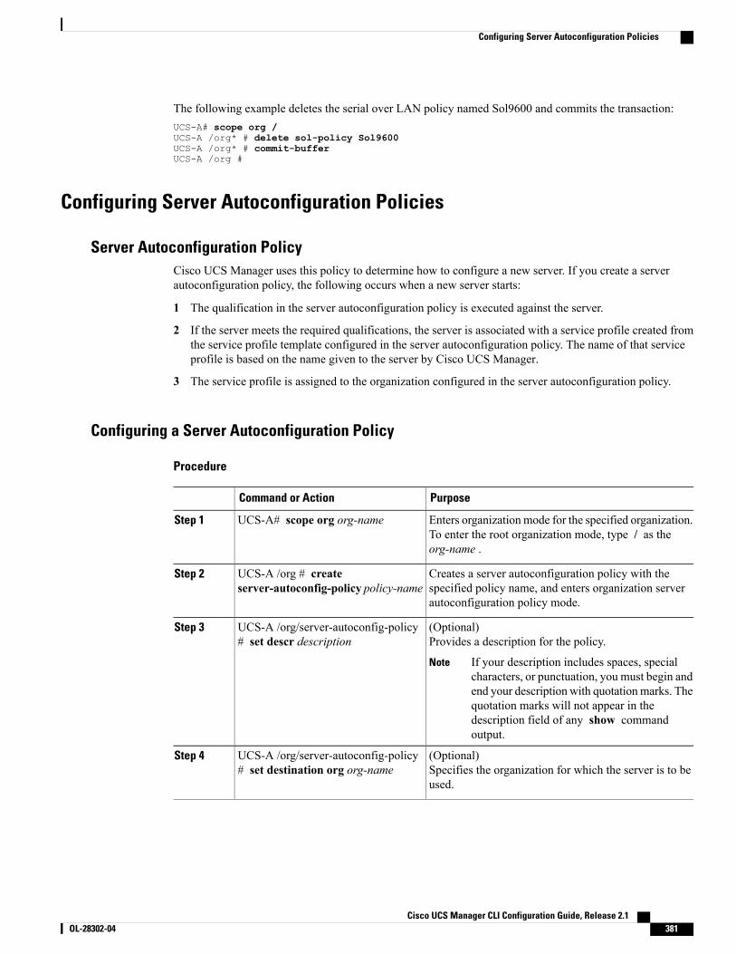
The following example deletes the serial over LAN policy named Sol9600 and commits the transaction:UCS-A# scope org /UCS-A /org* # delete sol-policy Sol9600UCS-A /org* # commit-bufferUCS-A /org #
Configuring Server Autoconfiguration Policies
Server Autoconfiguration PolicyCisco UCS Manager uses this policy to determine how to configure a new server. If you create a serverautoconfiguration policy, the following occurs when a new server starts:
1 The qualification in the server autoconfiguration policy is executed against the server.
2 If the server meets the required qualifications, the server is associated with a service profile created fromthe service profile template configured in the server autoconfiguration policy. The name of that serviceprofile is based on the name given to the server by Cisco UCS Manager.
3 The service profile is assigned to the organization configured in the server autoconfiguration policy.
Configuring a Server Autoconfiguration Policy
Procedure
PurposeCommand or Action
Enters organization mode for the specified organization.To enter the root organization mode, type / as theorg-name .
UCS-A# scope org org-nameStep 1
Creates a server autoconfiguration policy with thespecified policy name, and enters organization serverautoconfiguration policy mode.
UCS-A /org # createserver-autoconfig-policy policy-name
Step 2
(Optional)Provides a description for the policy.
UCS-A /org/server-autoconfig-policy# set descr description
Step 3
If your description includes spaces, specialcharacters, or punctuation, you must begin andend your description with quotationmarks. Thequotation marks will not appear in thedescription field of any show commandoutput.
Note
(Optional)Specifies the organization for which the server is to beused.
UCS-A /org/server-autoconfig-policy# set destination org org-name
Step 4
Cisco UCS Manager CLI Configuration Guide, Release 2.1 OL-28302-04 381
Configuring Server Autoconfiguration Policies

PurposeCommand or Action
(Optional)Specifies server pool policy qualification to use forqualifying the server.
UCS-A /org/server-autoconfig-policy# set qualifier server-qual-name
Step 5
(Optional)Specifies a service profile template to use for creatinga service profile instance for the server.
UCS-A /org/server-autoconfig-policy# set template profile-name
Step 6
Commits the transaction to the system configuration.UCS-A /org/server-autoconfig-policy# commit-buffer
Step 7
The following example creates a server autoconfiguration policy named AutoConfigFinance, provides adescription for the policy, specifies finance as the destination organization, ServPoolQual22 as the server poolpolicy qualification, and ServTemp2 as the service profile template, and commits the transaction:UCS-A# scope org /UCS-A /org* # create server-autoconfig-policy AutoConfigFinanceUCS-A /org/server-autoconfig-policy* # set descr "Server Autoconfiguration Policy forFinance"UCS-A /org/server-autoconfig-policy* # set destination org financeUCS-A /org/server-autoconfig-policy* # set qualifier ServPoolQual22UCS-A /org/server-autoconfig-policy* # set template ServTemp2UCS-A /org/server-autoconfig-policy* # commit-bufferUCS-A /org/server-autoconfig-policy #
Deleting a Server Autoconfiguration Policy
Procedure
PurposeCommand or Action
Enters organization mode for the specifiedorganization. To enter the root organization mode,type / as the org-name .
UCS-A# scope org org-nameStep 1
Deletes the specified server autoconfiguration policy.UCS-A /org # deleteserver-autoconfig-policy policy-name
Step 2
Commits the transaction to the system configuration.UCS-A /org # commit-bufferStep 3
The following example deletes the server autoconfiguration policy named AutoConfigFinance and commitsthe transaction:UCS-A# scope org /UCS-A /org* # delete server-autoconfig-policy AutoConfigFinanceUCS-A /org* # commit-bufferUCS-A /org #
Cisco UCS Manager CLI Configuration Guide, Release 2.1382 OL-28302-04
Configuring Server Autoconfiguration Policies
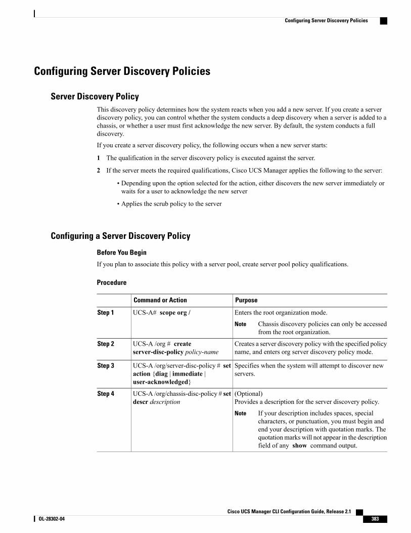
Configuring Server Discovery Policies
Server Discovery PolicyThis discovery policy determines how the system reacts when you add a new server. If you create a serverdiscovery policy, you can control whether the system conducts a deep discovery when a server is added to achassis, or whether a user must first acknowledge the new server. By default, the system conducts a fulldiscovery.
If you create a server discovery policy, the following occurs when a new server starts:
1 The qualification in the server discovery policy is executed against the server.
2 If the server meets the required qualifications, Cisco UCS Manager applies the following to the server:
• Depending upon the option selected for the action, either discovers the new server immediately orwaits for a user to acknowledge the new server
• Applies the scrub policy to the server
Configuring a Server Discovery Policy
Before You Begin
If you plan to associate this policy with a server pool, create server pool policy qualifications.
Procedure
PurposeCommand or Action
Enters the root organization mode.UCS-A# scope org /Step 1
Chassis discovery policies can only be accessedfrom the root organization.
Note
Creates a server discovery policy with the specified policyname, and enters org server discovery policy mode.
UCS-A /org # createserver-disc-policy policy-name
Step 2
Specifies when the system will attempt to discover newservers.
UCS-A /org/server-disc-policy # setaction {diag | immediate |user-acknowledged}
Step 3
(Optional)Provides a description for the server discovery policy.
UCS-A /org/chassis-disc-policy # setdescr description
Step 4
If your description includes spaces, specialcharacters, or punctuation, you must begin andend your description with quotation marks. Thequotationmarks will not appear in the descriptionfield of any show command output.
Note
Cisco UCS Manager CLI Configuration Guide, Release 2.1 OL-28302-04 383
Configuring Server Discovery Policies
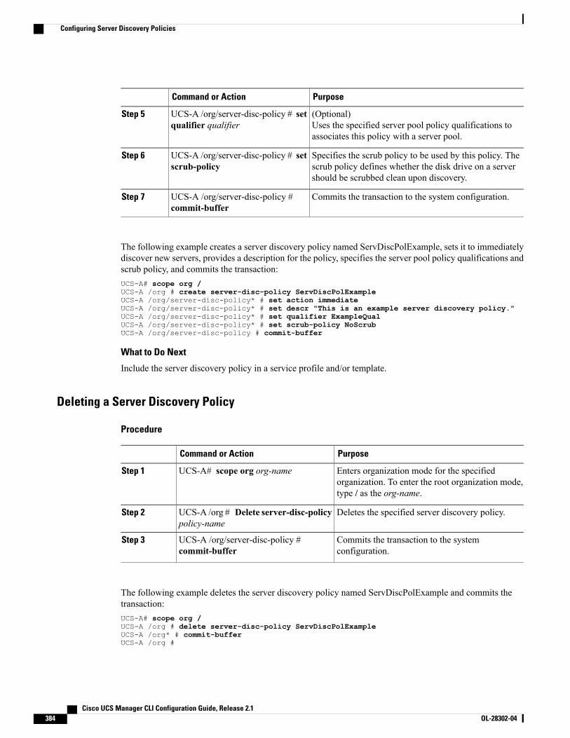
PurposeCommand or Action
(Optional)Uses the specified server pool policy qualifications toassociates this policy with a server pool.
UCS-A /org/server-disc-policy # setqualifier qualifier
Step 5
Specifies the scrub policy to be used by this policy. Thescrub policy defines whether the disk drive on a servershould be scrubbed clean upon discovery.
UCS-A /org/server-disc-policy # setscrub-policy
Step 6
Commits the transaction to the system configuration.UCS-A /org/server-disc-policy #commit-buffer
Step 7
The following example creates a server discovery policy named ServDiscPolExample, sets it to immediatelydiscover new servers, provides a description for the policy, specifies the server pool policy qualifications andscrub policy, and commits the transaction:UCS-A# scope org /UCS-A /org # create server-disc-policy ServDiscPolExampleUCS-A /org/server-disc-policy* # set action immediateUCS-A /org/server-disc-policy* # set descr "This is an example server discovery policy."UCS-A /org/server-disc-policy* # set qualifier ExampleQualUCS-A /org/server-disc-policy* # set scrub-policy NoScrubUCS-A /org/server-disc-policy # commit-buffer
What to Do Next
Include the server discovery policy in a service profile and/or template.
Deleting a Server Discovery Policy
Procedure
PurposeCommand or Action
Enters organization mode for the specifiedorganization. To enter the root organization mode,type / as the org-name.
UCS-A# scope org org-nameStep 1
Deletes the specified server discovery policy.UCS-A /org # Delete server-disc-policypolicy-name
Step 2
Commits the transaction to the systemconfiguration.
UCS-A /org/server-disc-policy #commit-buffer
Step 3
The following example deletes the server discovery policy named ServDiscPolExample and commits thetransaction:UCS-A# scope org /UCS-A /org # delete server-disc-policy ServDiscPolExampleUCS-A /org* # commit-bufferUCS-A /org #
Cisco UCS Manager CLI Configuration Guide, Release 2.1384 OL-28302-04
Configuring Server Discovery Policies
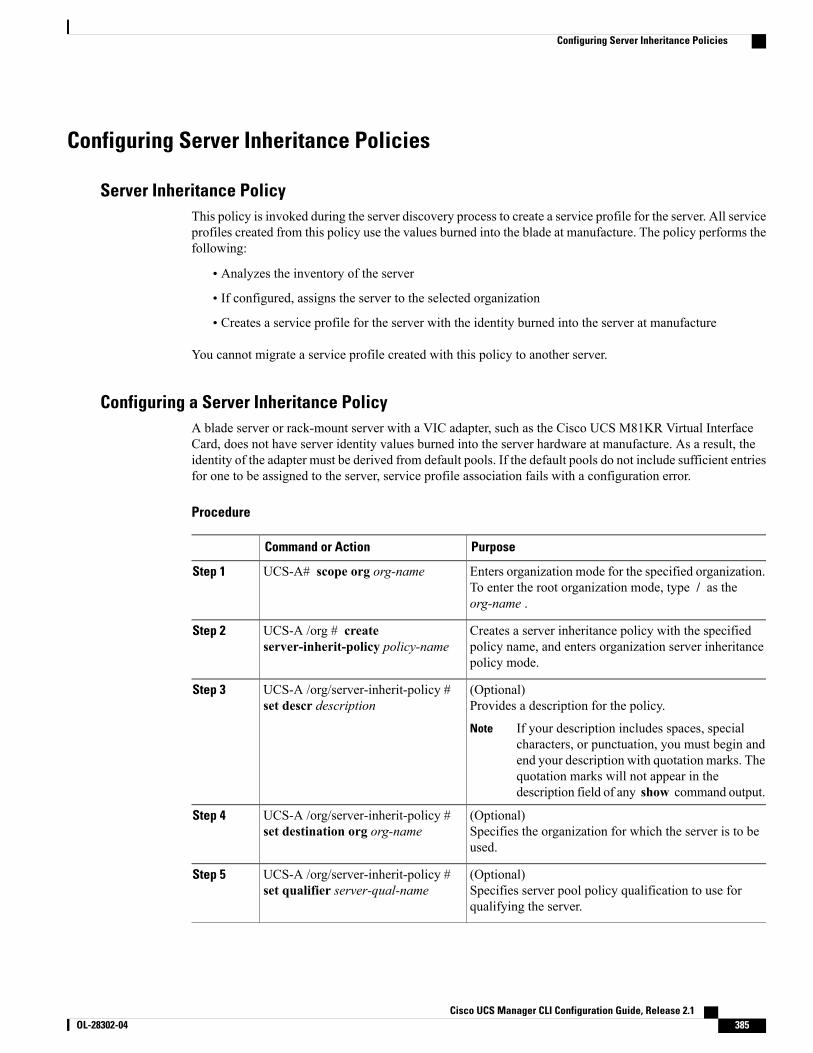
Configuring Server Inheritance Policies
Server Inheritance PolicyThis policy is invoked during the server discovery process to create a service profile for the server. All serviceprofiles created from this policy use the values burned into the blade at manufacture. The policy performs thefollowing:
• Analyzes the inventory of the server
• If configured, assigns the server to the selected organization
• Creates a service profile for the server with the identity burned into the server at manufacture
You cannot migrate a service profile created with this policy to another server.
Configuring a Server Inheritance PolicyA blade server or rack-mount server with a VIC adapter, such as the Cisco UCS M81KR Virtual InterfaceCard, does not have server identity values burned into the server hardware at manufacture. As a result, theidentity of the adapter must be derived from default pools. If the default pools do not include sufficient entriesfor one to be assigned to the server, service profile association fails with a configuration error.
Procedure
PurposeCommand or Action
Enters organization mode for the specified organization.To enter the root organization mode, type / as theorg-name .
UCS-A# scope org org-nameStep 1
Creates a server inheritance policy with the specifiedpolicy name, and enters organization server inheritancepolicy mode.
UCS-A /org # createserver-inherit-policy policy-name
Step 2
(Optional)Provides a description for the policy.
UCS-A /org/server-inherit-policy #set descr description
Step 3
If your description includes spaces, specialcharacters, or punctuation, you must begin andend your description with quotation marks. Thequotation marks will not appear in thedescription field of any show command output.
Note
(Optional)Specifies the organization for which the server is to beused.
UCS-A /org/server-inherit-policy #set destination org org-name
Step 4
(Optional)Specifies server pool policy qualification to use forqualifying the server.
UCS-A /org/server-inherit-policy #set qualifier server-qual-name
Step 5
Cisco UCS Manager CLI Configuration Guide, Release 2.1 OL-28302-04 385
Configuring Server Inheritance Policies
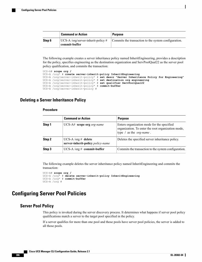
PurposeCommand or Action
Commits the transaction to the system configuration.UCS-A /org/server-inherit-policy #commit-buffer
Step 6
The following example creates a server inheritance policy named InheritEngineering, provides a descriptionfor the policy, specifies engineering as the destination organization and ServPoolQual22 as the server poolpolicy qualification, and commits the transaction:UCS-A# scope org /UCS-A /org* # create server-inherit-policy InheritEngineeringUCS-A /org/server-inherit-policy* # set descr "Server Inheritance Policy for Engineering"UCS-A /org/server-inherit-policy* # set destination org engineeringUCS-A /org/server-inherit-policy* # set qualifier ServPoolQual22UCS-A /org/server-inherit-policy* # commit-bufferUCS-A /org/server-inherit-policy #
Deleting a Server Inheritance Policy
Procedure
PurposeCommand or Action
Enters organization mode for the specifiedorganization. To enter the root organization mode,type / as the org-name .
UCS-A# scope org org-nameStep 1
Deletes the specified server inheritance policy.UCS-A /org # deleteserver-inherit-policy policy-name
Step 2
Commits the transaction to the system configuration.UCS-A /org # commit-bufferStep 3
The following example deletes the server inheritance policy named InheritEngineering and commits thetransaction:UCS-A# scope org /UCS-A /org* # delete server-inherit-policy InheritEngineeringUCS-A /org* # commit-bufferUCS-A /org #
Configuring Server Pool Policies
Server Pool PolicyThis policy is invoked during the server discovery process. It determines what happens if server pool policyqualifications match a server to the target pool specified in the policy.
If a server qualifies for more than one pool and those pools have server pool policies, the server is added toall those pools.
Cisco UCS Manager CLI Configuration Guide, Release 2.1386 OL-28302-04
Configuring Server Pool Policies
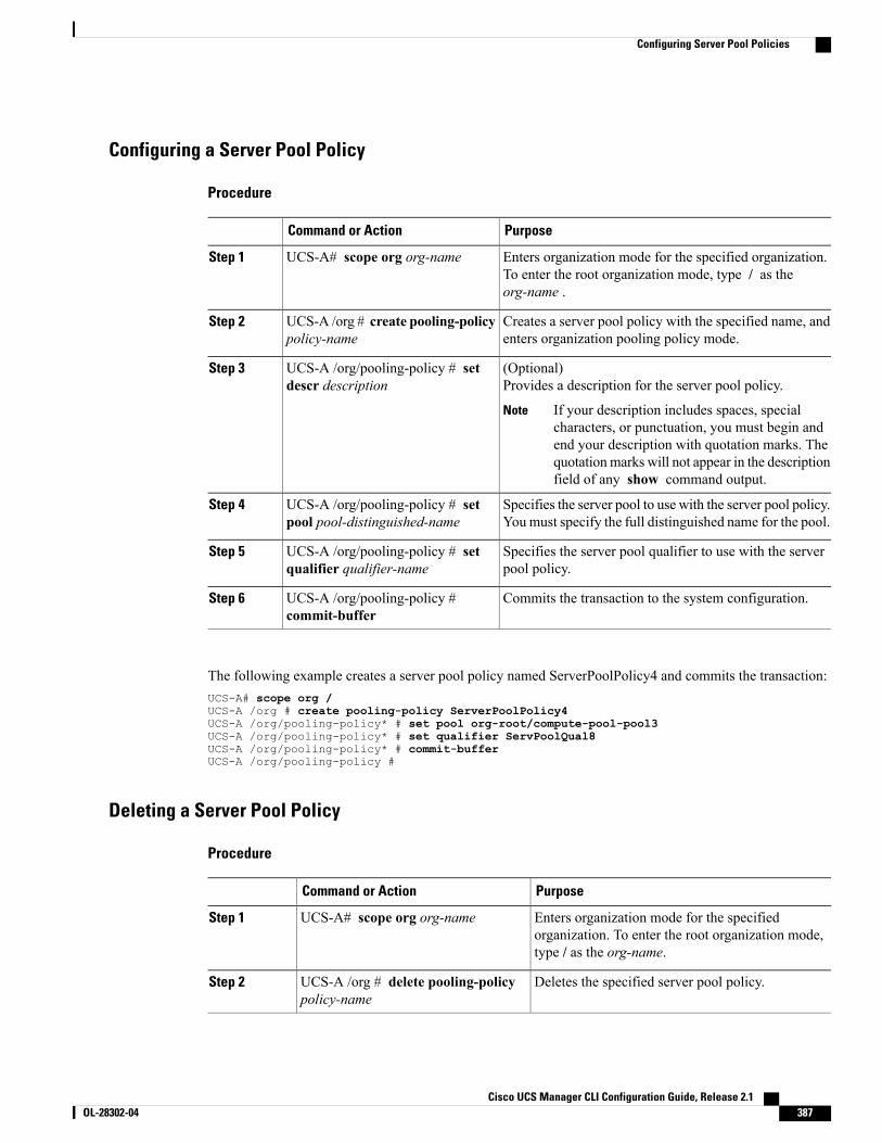
Configuring a Server Pool Policy
Procedure
PurposeCommand or Action
Enters organization mode for the specified organization.To enter the root organization mode, type / as theorg-name .
UCS-A# scope org org-nameStep 1
Creates a server pool policy with the specified name, andenters organization pooling policy mode.
UCS-A /org # create pooling-policypolicy-name
Step 2
(Optional)Provides a description for the server pool policy.
UCS-A /org/pooling-policy # setdescr description
Step 3
If your description includes spaces, specialcharacters, or punctuation, you must begin andend your description with quotation marks. Thequotationmarks will not appear in the descriptionfield of any show command output.
Note
Specifies the server pool to use with the server pool policy.Youmust specify the full distinguished name for the pool.
UCS-A /org/pooling-policy # setpool pool-distinguished-name
Step 4
Specifies the server pool qualifier to use with the serverpool policy.
UCS-A /org/pooling-policy # setqualifier qualifier-name
Step 5
Commits the transaction to the system configuration.UCS-A /org/pooling-policy #commit-buffer
Step 6
The following example creates a server pool policy named ServerPoolPolicy4 and commits the transaction:UCS-A# scope org /UCS-A /org # create pooling-policy ServerPoolPolicy4UCS-A /org/pooling-policy* # set pool org-root/compute-pool-pool3UCS-A /org/pooling-policy* # set qualifier ServPoolQual8UCS-A /org/pooling-policy* # commit-bufferUCS-A /org/pooling-policy #
Deleting a Server Pool Policy
Procedure
PurposeCommand or Action
Enters organization mode for the specifiedorganization. To enter the root organization mode,type / as the org-name.
UCS-A# scope org org-nameStep 1
Deletes the specified server pool policy.UCS-A /org # delete pooling-policypolicy-name
Step 2
Cisco UCS Manager CLI Configuration Guide, Release 2.1 OL-28302-04 387
Configuring Server Pool Policies
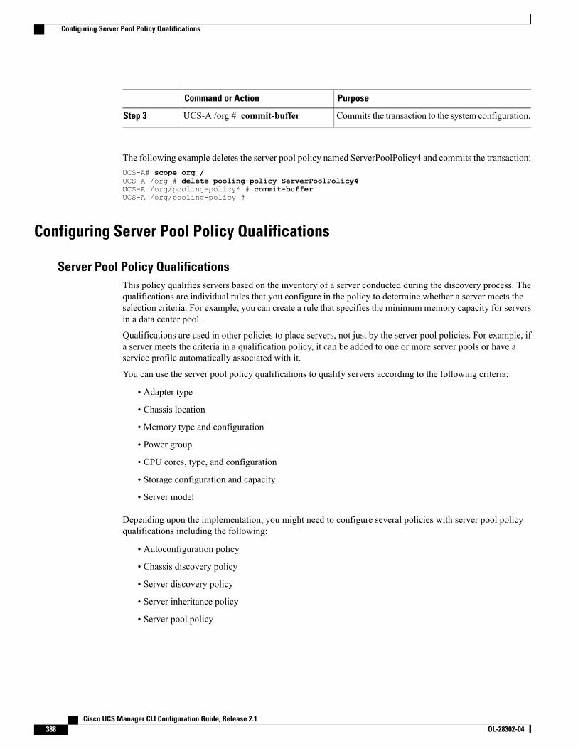
PurposeCommand or Action
Commits the transaction to the system configuration.UCS-A /org # commit-bufferStep 3
The following example deletes the server pool policy named ServerPoolPolicy4 and commits the transaction:UCS-A# scope org /UCS-A /org # delete pooling-policy ServerPoolPolicy4UCS-A /org/pooling-policy* # commit-bufferUCS-A /org/pooling-policy #
Configuring Server Pool Policy Qualifications
Server Pool Policy QualificationsThis policy qualifies servers based on the inventory of a server conducted during the discovery process. Thequalifications are individual rules that you configure in the policy to determine whether a server meets theselection criteria. For example, you can create a rule that specifies the minimum memory capacity for serversin a data center pool.
Qualifications are used in other policies to place servers, not just by the server pool policies. For example, ifa server meets the criteria in a qualification policy, it can be added to one or more server pools or have aservice profile automatically associated with it.
You can use the server pool policy qualifications to qualify servers according to the following criteria:
• Adapter type
• Chassis location
• Memory type and configuration
• Power group
• CPU cores, type, and configuration
• Storage configuration and capacity
• Server model
Depending upon the implementation, you might need to configure several policies with server pool policyqualifications including the following:
• Autoconfiguration policy
• Chassis discovery policy
• Server discovery policy
• Server inheritance policy
• Server pool policy
Cisco UCS Manager CLI Configuration Guide, Release 2.1388 OL-28302-04
Configuring Server Pool Policy Qualifications
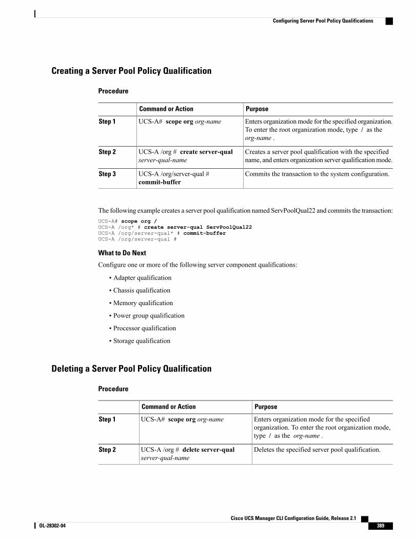
Creating a Server Pool Policy Qualification
Procedure
PurposeCommand or Action
Enters organizationmode for the specified organization.To enter the root organization mode, type / as theorg-name .
UCS-A# scope org org-nameStep 1
Creates a server pool qualification with the specifiedname, and enters organization server qualificationmode.
UCS-A /org # create server-qualserver-qual-name
Step 2
Commits the transaction to the system configuration.UCS-A /org/server-qual #commit-buffer
Step 3
The following example creates a server pool qualification named ServPoolQual22 and commits the transaction:UCS-A# scope org /UCS-A /org* # create server-qual ServPoolQual22UCS-A /org/server-qual* # commit-bufferUCS-A /org/server-qual #
What to Do Next
Configure one or more of the following server component qualifications:
• Adapter qualification
• Chassis qualification
• Memory qualification
• Power group qualification
• Processor qualification
• Storage qualification
Deleting a Server Pool Policy Qualification
Procedure
PurposeCommand or Action
Enters organization mode for the specifiedorganization. To enter the root organization mode,type / as the org-name .
UCS-A# scope org org-nameStep 1
Deletes the specified server pool qualification.UCS-A /org # delete server-qualserver-qual-name
Step 2
Cisco UCS Manager CLI Configuration Guide, Release 2.1 OL-28302-04 389
Configuring Server Pool Policy Qualifications
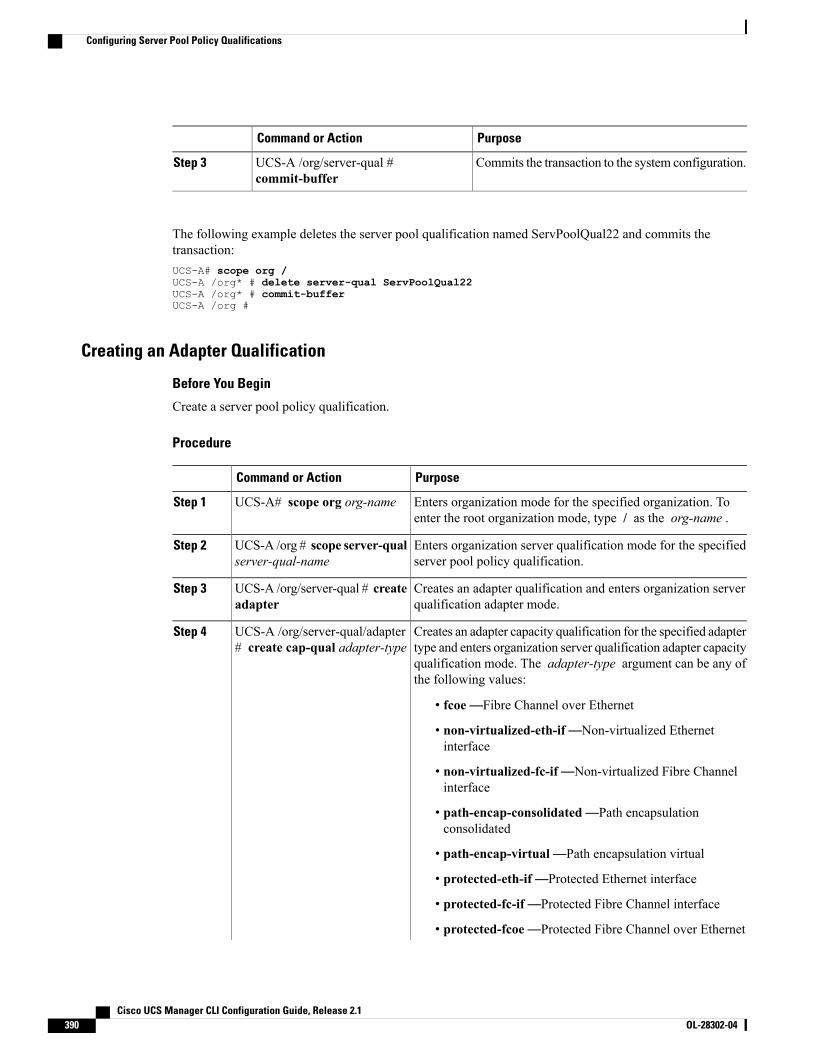
PurposeCommand or Action
Commits the transaction to the system configuration.UCS-A /org/server-qual #commit-buffer
Step 3
The following example deletes the server pool qualification named ServPoolQual22 and commits thetransaction:UCS-A# scope org /UCS-A /org* # delete server-qual ServPoolQual22UCS-A /org* # commit-bufferUCS-A /org #
Creating an Adapter Qualification
Before You Begin
Create a server pool policy qualification.
Procedure
PurposeCommand or Action
Enters organization mode for the specified organization. Toenter the root organization mode, type / as the org-name .
UCS-A# scope org org-nameStep 1
Enters organization server qualification mode for the specifiedserver pool policy qualification.
UCS-A /org # scope server-qualserver-qual-name
Step 2
Creates an adapter qualification and enters organization serverqualification adapter mode.
UCS-A /org/server-qual # createadapter
Step 3
Creates an adapter capacity qualification for the specified adaptertype and enters organization server qualification adapter capacity
UCS-A /org/server-qual/adapter# create cap-qual adapter-type
Step 4
qualification mode. The adapter-type argument can be any ofthe following values:
• fcoe—Fibre Channel over Ethernet
• non-virtualized-eth-if—Non-virtualized Ethernetinterface
• non-virtualized-fc-if—Non-virtualized Fibre Channelinterface
• path-encap-consolidated—Path encapsulationconsolidated
• path-encap-virtual—Path encapsulation virtual
• protected-eth-if—Protected Ethernet interface
• protected-fc-if—Protected Fibre Channel interface
• protected-fcoe—Protected Fibre Channel over Ethernet
Cisco UCS Manager CLI Configuration Guide, Release 2.1390 OL-28302-04
Configuring Server Pool Policy Qualifications
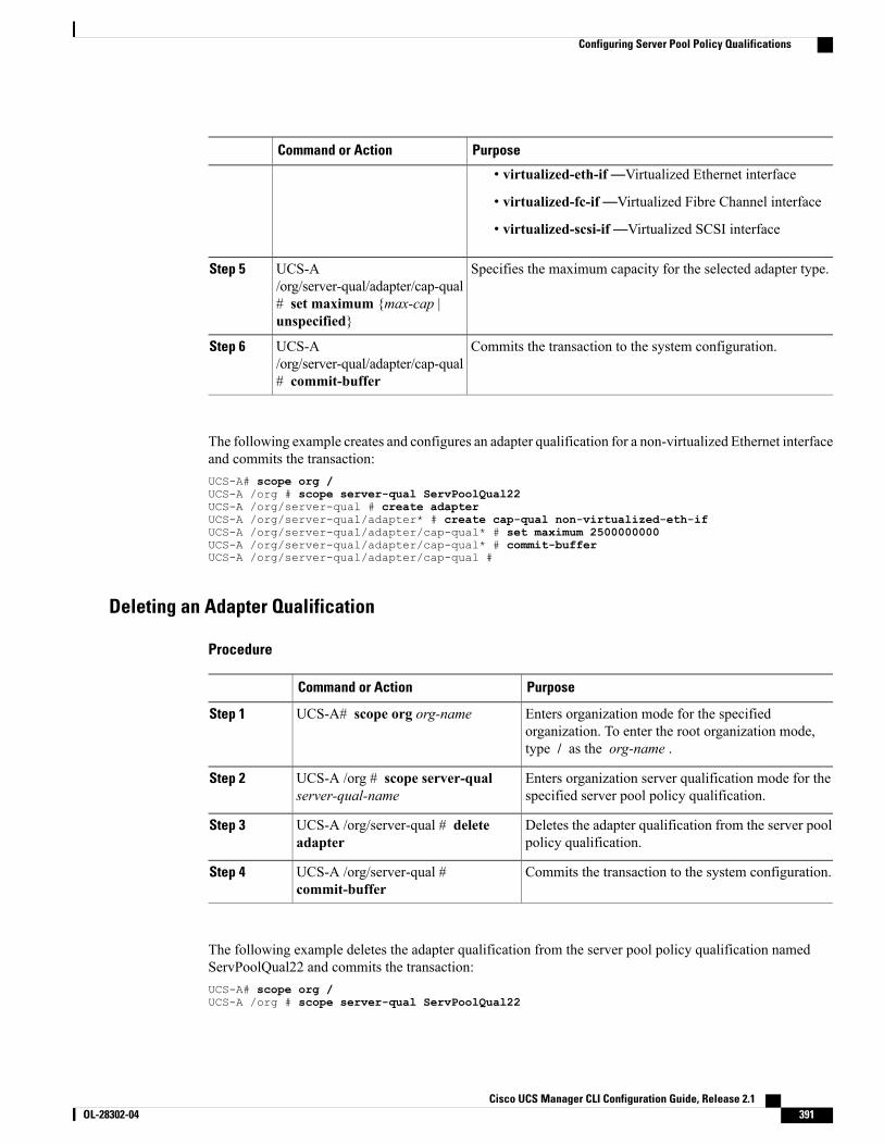
PurposeCommand or Action
• virtualized-eth-if—Virtualized Ethernet interface
• virtualized-fc-if—Virtualized Fibre Channel interface
• virtualized-scsi-if—Virtualized SCSI interface
Specifies the maximum capacity for the selected adapter type.UCS-A/org/server-qual/adapter/cap-qual
Step 5
# set maximum {max-cap |unspecified}
Commits the transaction to the system configuration.UCS-A/org/server-qual/adapter/cap-qual# commit-buffer
Step 6
The following example creates and configures an adapter qualification for a non-virtualized Ethernet interfaceand commits the transaction:UCS-A# scope org /UCS-A /org # scope server-qual ServPoolQual22UCS-A /org/server-qual # create adapterUCS-A /org/server-qual/adapter* # create cap-qual non-virtualized-eth-ifUCS-A /org/server-qual/adapter/cap-qual* # set maximum 2500000000UCS-A /org/server-qual/adapter/cap-qual* # commit-bufferUCS-A /org/server-qual/adapter/cap-qual #
Deleting an Adapter Qualification
Procedure
PurposeCommand or Action
Enters organization mode for the specifiedorganization. To enter the root organization mode,type / as the org-name .
UCS-A# scope org org-nameStep 1
Enters organization server qualification mode for thespecified server pool policy qualification.
UCS-A /org # scope server-qualserver-qual-name
Step 2
Deletes the adapter qualification from the server poolpolicy qualification.
UCS-A /org/server-qual # deleteadapter
Step 3
Commits the transaction to the system configuration.UCS-A /org/server-qual #commit-buffer
Step 4
The following example deletes the adapter qualification from the server pool policy qualification namedServPoolQual22 and commits the transaction:UCS-A# scope org /UCS-A /org # scope server-qual ServPoolQual22
Cisco UCS Manager CLI Configuration Guide, Release 2.1 OL-28302-04 391
Configuring Server Pool Policy Qualifications
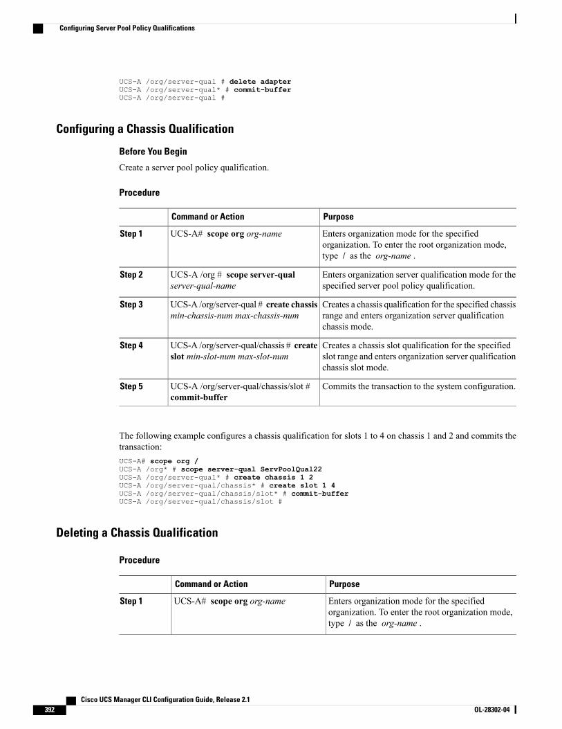
UCS-A /org/server-qual # delete adapterUCS-A /org/server-qual* # commit-bufferUCS-A /org/server-qual #
Configuring a Chassis Qualification
Before You Begin
Create a server pool policy qualification.
Procedure
PurposeCommand or Action
Enters organization mode for the specifiedorganization. To enter the root organization mode,type / as the org-name .
UCS-A# scope org org-nameStep 1
Enters organization server qualification mode for thespecified server pool policy qualification.
UCS-A /org # scope server-qualserver-qual-name
Step 2
Creates a chassis qualification for the specified chassisrange and enters organization server qualificationchassis mode.
UCS-A /org/server-qual # create chassismin-chassis-num max-chassis-num
Step 3
Creates a chassis slot qualification for the specifiedslot range and enters organization server qualificationchassis slot mode.
UCS-A /org/server-qual/chassis # createslot min-slot-num max-slot-num
Step 4
Commits the transaction to the system configuration.UCS-A /org/server-qual/chassis/slot #commit-buffer
Step 5
The following example configures a chassis qualification for slots 1 to 4 on chassis 1 and 2 and commits thetransaction:UCS-A# scope org /UCS-A /org* # scope server-qual ServPoolQual22UCS-A /org/server-qual* # create chassis 1 2UCS-A /org/server-qual/chassis* # create slot 1 4UCS-A /org/server-qual/chassis/slot* # commit-bufferUCS-A /org/server-qual/chassis/slot #
Deleting a Chassis Qualification
Procedure
PurposeCommand or Action
Enters organization mode for the specifiedorganization. To enter the root organization mode,type / as the org-name .
UCS-A# scope org org-nameStep 1
Cisco UCS Manager CLI Configuration Guide, Release 2.1392 OL-28302-04
Configuring Server Pool Policy Qualifications
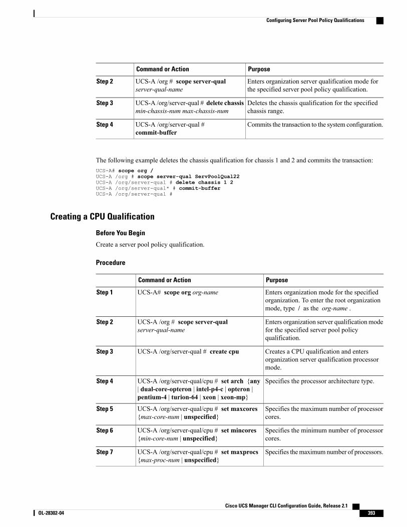
PurposeCommand or Action
Enters organization server qualification mode forthe specified server pool policy qualification.
UCS-A /org # scope server-qualserver-qual-name
Step 2
Deletes the chassis qualification for the specifiedchassis range.
UCS-A /org/server-qual # delete chassismin-chassis-num max-chassis-num
Step 3
Commits the transaction to the system configuration.UCS-A /org/server-qual #commit-buffer
Step 4
The following example deletes the chassis qualification for chassis 1 and 2 and commits the transaction:UCS-A# scope org /UCS-A /org # scope server-qual ServPoolQual22UCS-A /org/server-qual # delete chassis 1 2UCS-A /org/server-qual* # commit-bufferUCS-A /org/server-qual #
Creating a CPU Qualification
Before You Begin
Create a server pool policy qualification.
Procedure
PurposeCommand or Action
Enters organization mode for the specifiedorganization. To enter the root organizationmode, type / as the org-name .
UCS-A# scope org org-nameStep 1
Enters organization server qualificationmodefor the specified server pool policyqualification.
UCS-A /org # scope server-qualserver-qual-name
Step 2
Creates a CPU qualification and entersorganization server qualification processormode.
UCS-A /org/server-qual # create cpuStep 3
Specifies the processor architecture type.UCS-A /org/server-qual/cpu # set arch {any| dual-core-opteron | intel-p4-c | opteron |pentium-4 | turion-64 | xeon | xeon-mp}
Step 4
Specifies the maximum number of processorcores.
UCS-A /org/server-qual/cpu # set maxcores{max-core-num | unspecified}
Step 5
Specifies the minimum number of processorcores.
UCS-A /org/server-qual/cpu # set mincores{min-core-num | unspecified}
Step 6
Specifies themaximumnumber of processors.UCS-A /org/server-qual/cpu # set maxprocs{max-proc-num | unspecified}
Step 7
Cisco UCS Manager CLI Configuration Guide, Release 2.1 OL-28302-04 393
Configuring Server Pool Policy Qualifications
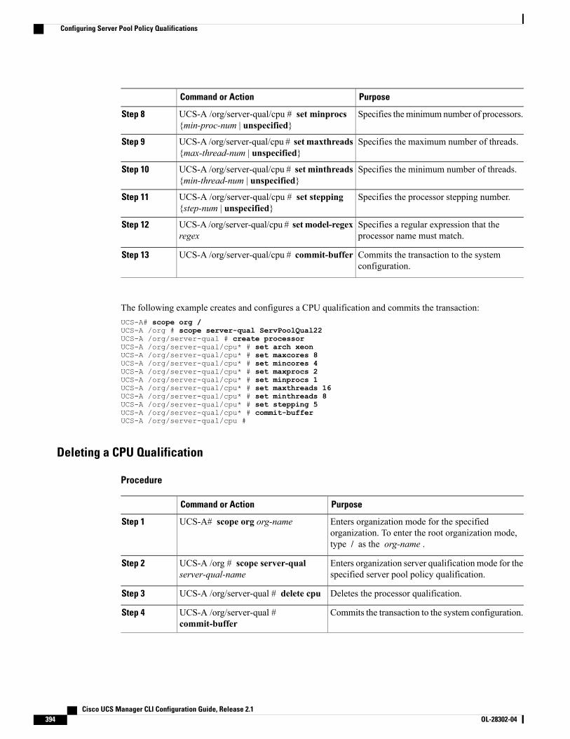
PurposeCommand or Action
Specifies theminimum number of processors.UCS-A /org/server-qual/cpu # set minprocs{min-proc-num | unspecified}
Step 8
Specifies the maximum number of threads.UCS-A /org/server-qual/cpu # set maxthreads{max-thread-num | unspecified}
Step 9
Specifies the minimum number of threads.UCS-A /org/server-qual/cpu # set minthreads{min-thread-num | unspecified}
Step 10
Specifies the processor stepping number.UCS-A /org/server-qual/cpu # set stepping{step-num | unspecified}
Step 11
Specifies a regular expression that theprocessor name must match.
UCS-A /org/server-qual/cpu # set model-regexregex
Step 12
Commits the transaction to the systemconfiguration.
UCS-A /org/server-qual/cpu # commit-bufferStep 13
The following example creates and configures a CPU qualification and commits the transaction:UCS-A# scope org /UCS-A /org # scope server-qual ServPoolQual22UCS-A /org/server-qual # create processorUCS-A /org/server-qual/cpu* # set arch xeonUCS-A /org/server-qual/cpu* # set maxcores 8UCS-A /org/server-qual/cpu* # set mincores 4UCS-A /org/server-qual/cpu* # set maxprocs 2UCS-A /org/server-qual/cpu* # set minprocs 1UCS-A /org/server-qual/cpu* # set maxthreads 16UCS-A /org/server-qual/cpu* # set minthreads 8UCS-A /org/server-qual/cpu* # set stepping 5UCS-A /org/server-qual/cpu* # commit-bufferUCS-A /org/server-qual/cpu #
Deleting a CPU Qualification
Procedure
PurposeCommand or Action
Enters organization mode for the specifiedorganization. To enter the root organization mode,type / as the org-name .
UCS-A# scope org org-nameStep 1
Enters organization server qualification mode for thespecified server pool policy qualification.
UCS-A /org # scope server-qualserver-qual-name
Step 2
Deletes the processor qualification.UCS-A /org/server-qual # delete cpuStep 3
Commits the transaction to the system configuration.UCS-A /org/server-qual #commit-buffer
Step 4
Cisco UCS Manager CLI Configuration Guide, Release 2.1394 OL-28302-04
Configuring Server Pool Policy Qualifications
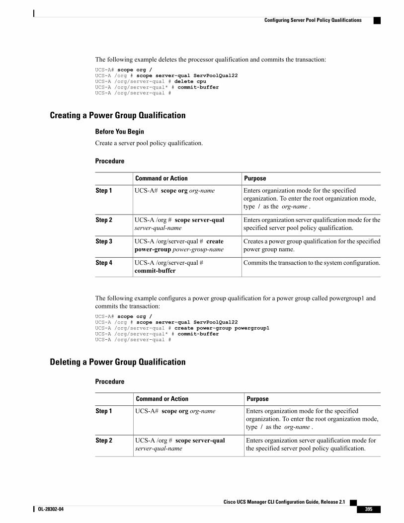
The following example deletes the processor qualification and commits the transaction:UCS-A# scope org /UCS-A /org # scope server-qual ServPoolQual22UCS-A /org/server-qual # delete cpuUCS-A /org/server-qual* # commit-bufferUCS-A /org/server-qual #
Creating a Power Group Qualification
Before You Begin
Create a server pool policy qualification.
Procedure
PurposeCommand or Action
Enters organization mode for the specifiedorganization. To enter the root organization mode,type / as the org-name .
UCS-A# scope org org-nameStep 1
Enters organization server qualification mode for thespecified server pool policy qualification.
UCS-A /org # scope server-qualserver-qual-name
Step 2
Creates a power group qualification for the specifiedpower group name.
UCS-A /org/server-qual # createpower-group power-group-name
Step 3
Commits the transaction to the system configuration.UCS-A /org/server-qual #commit-buffer
Step 4
The following example configures a power group qualification for a power group called powergroup1 andcommits the transaction:UCS-A# scope org /UCS-A /org # scope server-qual ServPoolQual22UCS-A /org/server-qual # create power-group powergroup1UCS-A /org/server-qual* # commit-bufferUCS-A /org/server-qual #
Deleting a Power Group Qualification
Procedure
PurposeCommand or Action
Enters organization mode for the specifiedorganization. To enter the root organization mode,type / as the org-name .
UCS-A# scope org org-nameStep 1
Enters organization server qualification mode forthe specified server pool policy qualification.
UCS-A /org # scope server-qualserver-qual-name
Step 2
Cisco UCS Manager CLI Configuration Guide, Release 2.1 OL-28302-04 395
Configuring Server Pool Policy Qualifications
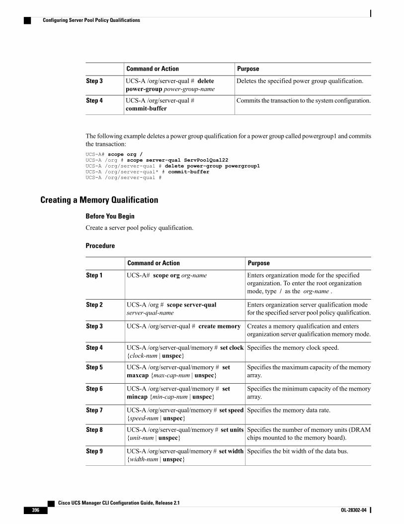
PurposeCommand or Action
Deletes the specified power group qualification.UCS-A /org/server-qual # deletepower-group power-group-name
Step 3
Commits the transaction to the system configuration.UCS-A /org/server-qual #commit-buffer
Step 4
The following example deletes a power group qualification for a power group called powergroup1 and commitsthe transaction:UCS-A# scope org /UCS-A /org # scope server-qual ServPoolQual22UCS-A /org/server-qual # delete power-group powergroup1UCS-A /org/server-qual* # commit-bufferUCS-A /org/server-qual #
Creating a Memory Qualification
Before You Begin
Create a server pool policy qualification.
Procedure
PurposeCommand or Action
Enters organization mode for the specifiedorganization. To enter the root organizationmode, type / as the org-name .
UCS-A# scope org org-nameStep 1
Enters organization server qualification modefor the specified server pool policy qualification.
UCS-A /org # scope server-qualserver-qual-name
Step 2
Creates a memory qualification and entersorganization server qualificationmemorymode.
UCS-A /org/server-qual # create memoryStep 3
Specifies the memory clock speed.UCS-A /org/server-qual/memory # set clock{clock-num | unspec}
Step 4
Specifies the maximum capacity of the memoryarray.
UCS-A /org/server-qual/memory # setmaxcap {max-cap-num | unspec}
Step 5
Specifies the minimum capacity of the memoryarray.
UCS-A /org/server-qual/memory # setmincap {min-cap-num | unspec}
Step 6
Specifies the memory data rate.UCS-A /org/server-qual/memory # set speed{speed-num | unspec}
Step 7
Specifies the number of memory units (DRAMchips mounted to the memory board).
UCS-A /org/server-qual/memory # set units{unit-num | unspec}
Step 8
Specifies the bit width of the data bus.UCS-A /org/server-qual/memory # set width{width-num | unspec}
Step 9
Cisco UCS Manager CLI Configuration Guide, Release 2.1396 OL-28302-04
Configuring Server Pool Policy Qualifications
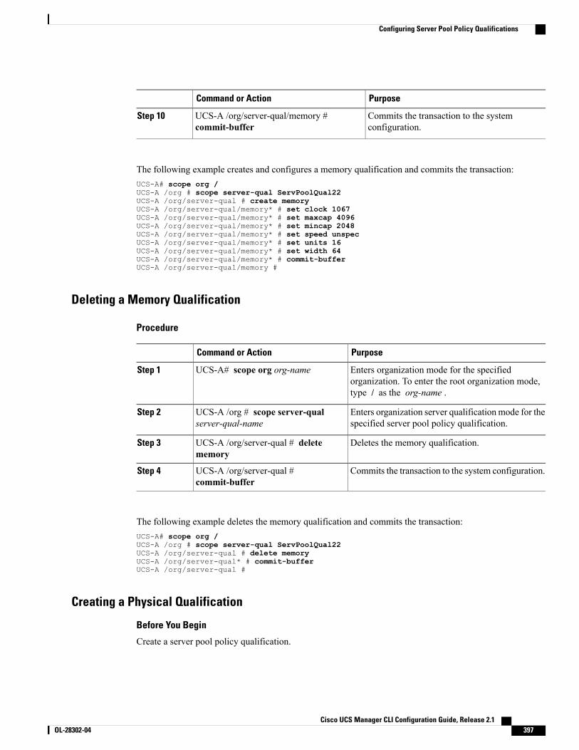
PurposeCommand or Action
Commits the transaction to the systemconfiguration.
UCS-A /org/server-qual/memory #commit-buffer
Step 10
The following example creates and configures a memory qualification and commits the transaction:UCS-A# scope org /UCS-A /org # scope server-qual ServPoolQual22UCS-A /org/server-qual # create memoryUCS-A /org/server-qual/memory* # set clock 1067UCS-A /org/server-qual/memory* # set maxcap 4096UCS-A /org/server-qual/memory* # set mincap 2048UCS-A /org/server-qual/memory* # set speed unspecUCS-A /org/server-qual/memory* # set units 16UCS-A /org/server-qual/memory* # set width 64UCS-A /org/server-qual/memory* # commit-bufferUCS-A /org/server-qual/memory #
Deleting a Memory Qualification
Procedure
PurposeCommand or Action
Enters organization mode for the specifiedorganization. To enter the root organization mode,type / as the org-name .
UCS-A# scope org org-nameStep 1
Enters organization server qualificationmode for thespecified server pool policy qualification.
UCS-A /org # scope server-qualserver-qual-name
Step 2
Deletes the memory qualification.UCS-A /org/server-qual # deletememory
Step 3
Commits the transaction to the system configuration.UCS-A /org/server-qual #commit-buffer
Step 4
The following example deletes the memory qualification and commits the transaction:UCS-A# scope org /UCS-A /org # scope server-qual ServPoolQual22UCS-A /org/server-qual # delete memoryUCS-A /org/server-qual* # commit-bufferUCS-A /org/server-qual #
Creating a Physical Qualification
Before You Begin
Create a server pool policy qualification.
Cisco UCS Manager CLI Configuration Guide, Release 2.1 OL-28302-04 397
Configuring Server Pool Policy Qualifications
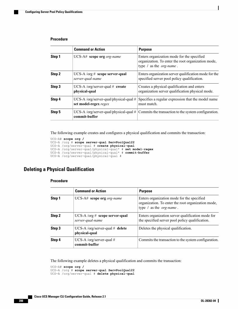
Procedure
PurposeCommand or Action
Enters organization mode for the specifiedorganization. To enter the root organization mode,type / as the org-name .
UCS-A# scope org org-nameStep 1
Enters organization server qualificationmode for thespecified server pool policy qualification.
UCS-A /org # scope server-qualserver-qual-name
Step 2
Creates a physical qualification and entersorganization server qualification physical mode.
UCS-A /org/server-qual # createphysical-qual
Step 3
Specifies a regular expression that the model namemust match.
UCS-A /org/server-qual/physical-qual #set model-regex regex
Step 4
Commits the transaction to the system configuration.UCS-A /org/server-qual/physical-qual #commit-buffer
Step 5
The following example creates and configures a physical qualification and commits the transaction:UCS-A# scope org /UCS-A /org # scope server-qual ServPoolQual22UCS-A /org/server-qual # create physical-qualUCS-A /org/server-qual/physical-qual* # set model-regexUCS-A /org/server-qual/physical-qual* # commit-bufferUCS-A /org/server-qual/physical-qual #
Deleting a Physical Qualification
Procedure
PurposeCommand or Action
Enters organization mode for the specifiedorganization. To enter the root organization mode,type / as the org-name .
UCS-A# scope org org-nameStep 1
Enters organization server qualification mode forthe specified server pool policy qualification.
UCS-A /org # scope server-qualserver-qual-name
Step 2
Deletes the physical qualification.UCS-A /org/server-qual # deletephysical-qual
Step 3
Commits the transaction to the system configuration.UCS-A /org/server-qual #commit-buffer
Step 4
The following example deletes a physical qualification and commits the transaction:UCS-A# scope org /UCS-A /org # scope server-qual ServPoolQual22UCS-A /org/server-qual # delete physical-qual
Cisco UCS Manager CLI Configuration Guide, Release 2.1398 OL-28302-04
Configuring Server Pool Policy Qualifications
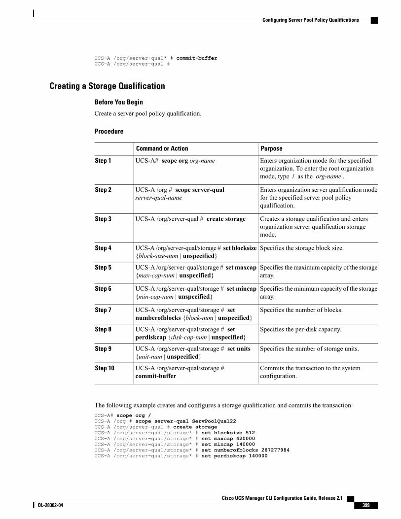
UCS-A /org/server-qual* # commit-bufferUCS-A /org/server-qual #
Creating a Storage Qualification
Before You Begin
Create a server pool policy qualification.
Procedure
PurposeCommand or Action
Enters organization mode for the specifiedorganization. To enter the root organizationmode, type / as the org-name .
UCS-A# scope org org-nameStep 1
Enters organization server qualification modefor the specified server pool policyqualification.
UCS-A /org # scope server-qualserver-qual-name
Step 2
Creates a storage qualification and entersorganization server qualification storagemode.
UCS-A /org/server-qual # create storageStep 3
Specifies the storage block size.UCS-A /org/server-qual/storage # set blocksize{block-size-num | unspecified}
Step 4
Specifies themaximum capacity of the storagearray.
UCS-A /org/server-qual/storage # set maxcap{max-cap-num | unspecified}
Step 5
Specifies the minimum capacity of the storagearray.
UCS-A /org/server-qual/storage # set mincap{min-cap-num | unspecified}
Step 6
Specifies the number of blocks.UCS-A /org/server-qual/storage # setnumberofblocks {block-num | unspecified}
Step 7
Specifies the per-disk capacity.UCS-A /org/server-qual/storage # setperdiskcap {disk-cap-num | unspecified}
Step 8
Specifies the number of storage units.UCS-A /org/server-qual/storage # set units{unit-num | unspecified}
Step 9
Commits the transaction to the systemconfiguration.
UCS-A /org/server-qual/storage #commit-buffer
Step 10
The following example creates and configures a storage qualification and commits the transaction:UCS-A# scope org /UCS-A /org # scope server-qual ServPoolQual22UCS-A /org/server-qual # create storageUCS-A /org/server-qual/storage* # set blocksize 512UCS-A /org/server-qual/storage* # set maxcap 420000UCS-A /org/server-qual/storage* # set mincap 140000UCS-A /org/server-qual/storage* # set numberofblocks 287277984UCS-A /org/server-qual/storage* # set perdiskcap 140000
Cisco UCS Manager CLI Configuration Guide, Release 2.1 OL-28302-04 399
Configuring Server Pool Policy Qualifications
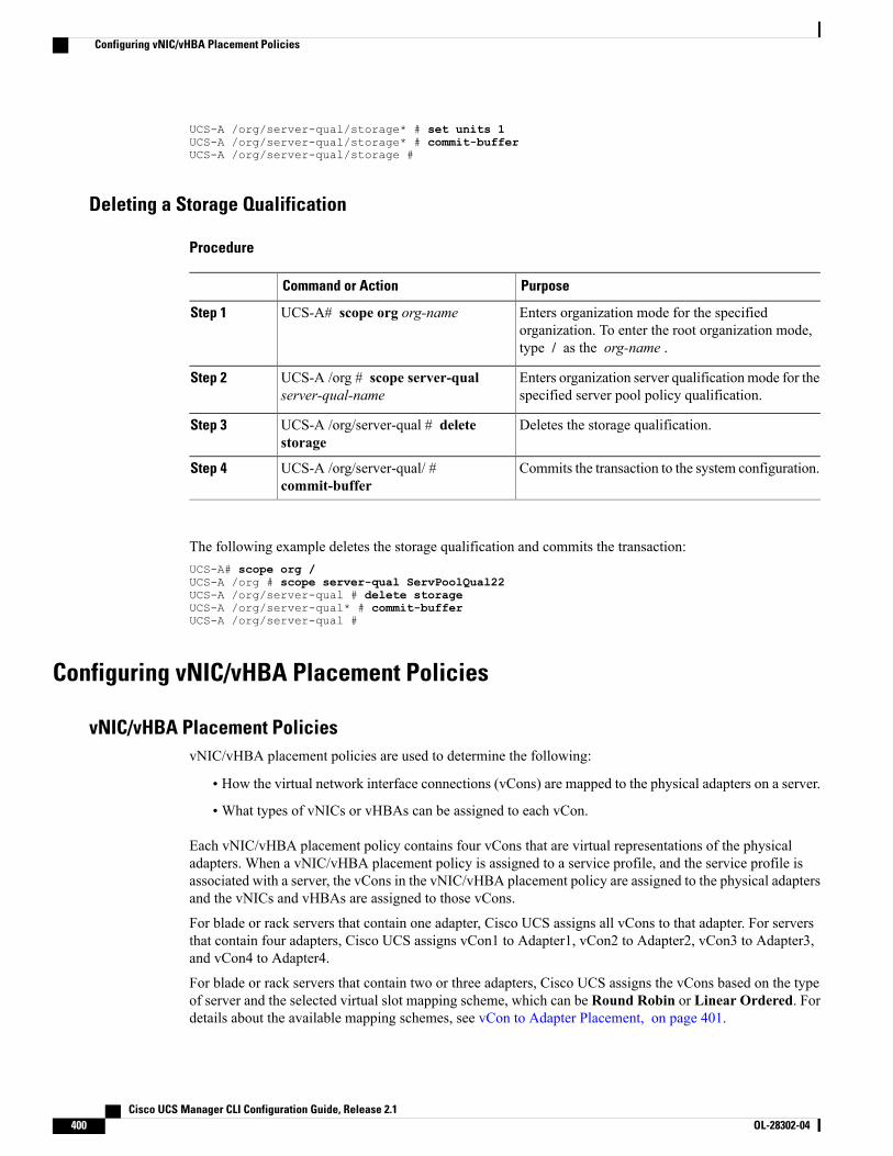
UCS-A /org/server-qual/storage* # set units 1UCS-A /org/server-qual/storage* # commit-bufferUCS-A /org/server-qual/storage #
Deleting a Storage Qualification
Procedure
PurposeCommand or Action
Enters organization mode for the specifiedorganization. To enter the root organization mode,type / as the org-name .
UCS-A# scope org org-nameStep 1
Enters organization server qualificationmode for thespecified server pool policy qualification.
UCS-A /org # scope server-qualserver-qual-name
Step 2
Deletes the storage qualification.UCS-A /org/server-qual # deletestorage
Step 3
Commits the transaction to the system configuration.UCS-A /org/server-qual/ #commit-buffer
Step 4
The following example deletes the storage qualification and commits the transaction:UCS-A# scope org /UCS-A /org # scope server-qual ServPoolQual22UCS-A /org/server-qual # delete storageUCS-A /org/server-qual* # commit-bufferUCS-A /org/server-qual #
Configuring vNIC/vHBA Placement Policies
vNIC/vHBA Placement PoliciesvNIC/vHBA placement policies are used to determine the following:
• How the virtual network interface connections (vCons) are mapped to the physical adapters on a server.
•What types of vNICs or vHBAs can be assigned to each vCon.
Each vNIC/vHBA placement policy contains four vCons that are virtual representations of the physicaladapters. When a vNIC/vHBA placement policy is assigned to a service profile, and the service profile isassociated with a server, the vCons in the vNIC/vHBA placement policy are assigned to the physical adaptersand the vNICs and vHBAs are assigned to those vCons.
For blade or rack servers that contain one adapter, Cisco UCS assigns all vCons to that adapter. For serversthat contain four adapters, Cisco UCS assigns vCon1 to Adapter1, vCon2 to Adapter2, vCon3 to Adapter3,and vCon4 to Adapter4.
For blade or rack servers that contain two or three adapters, Cisco UCS assigns the vCons based on the typeof server and the selected virtual slot mapping scheme, which can be Round Robin or Linear Ordered. Fordetails about the available mapping schemes, see vCon to Adapter Placement, on page 401.
Cisco UCS Manager CLI Configuration Guide, Release 2.1400 OL-28302-04
Configuring vNIC/vHBA Placement Policies
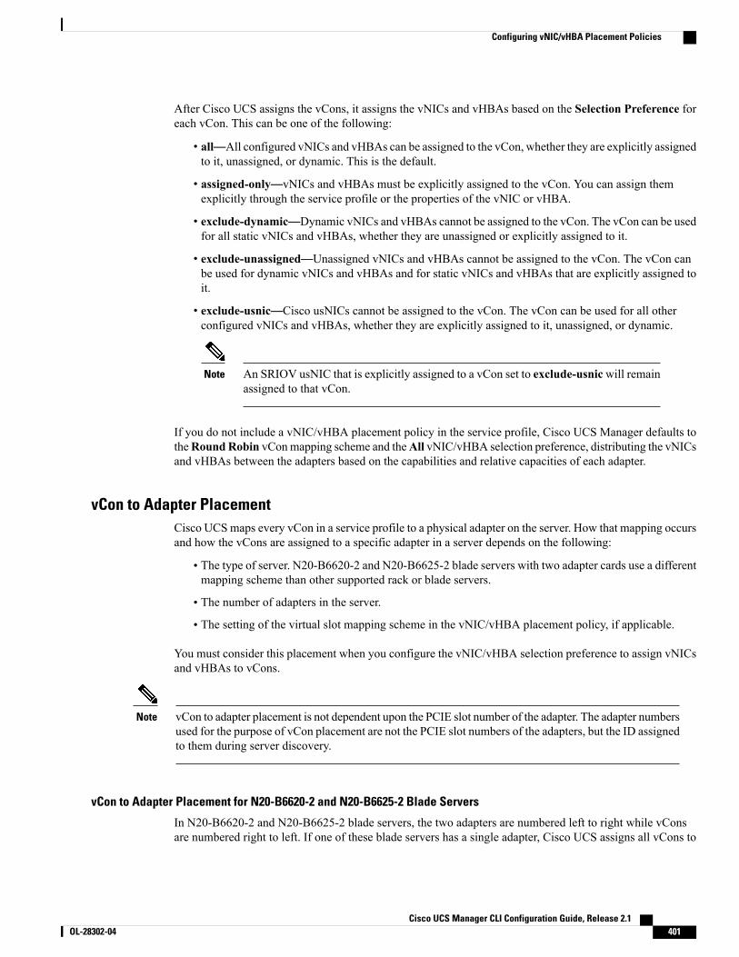
After Cisco UCS assigns the vCons, it assigns the vNICs and vHBAs based on the Selection Preference foreach vCon. This can be one of the following:
• all—All configured vNICs and vHBAs can be assigned to the vCon, whether they are explicitly assignedto it, unassigned, or dynamic. This is the default.
• assigned-only—vNICs and vHBAs must be explicitly assigned to the vCon. You can assign themexplicitly through the service profile or the properties of the vNIC or vHBA.
• exclude-dynamic—Dynamic vNICs and vHBAs cannot be assigned to the vCon. The vCon can be usedfor all static vNICs and vHBAs, whether they are unassigned or explicitly assigned to it.
• exclude-unassigned—Unassigned vNICs and vHBAs cannot be assigned to the vCon. The vCon canbe used for dynamic vNICs and vHBAs and for static vNICs and vHBAs that are explicitly assigned toit.
• exclude-usnic—Cisco usNICs cannot be assigned to the vCon. The vCon can be used for all otherconfigured vNICs and vHBAs, whether they are explicitly assigned to it, unassigned, or dynamic.
An SRIOV usNIC that is explicitly assigned to a vCon set to exclude-usnicwill remainassigned to that vCon.
Note
If you do not include a vNIC/vHBA placement policy in the service profile, Cisco UCS Manager defaults totheRoundRobin vConmapping scheme and theAll vNIC/vHBA selection preference, distributing the vNICsand vHBAs between the adapters based on the capabilities and relative capacities of each adapter.
vCon to Adapter PlacementCisco UCSmaps every vCon in a service profile to a physical adapter on the server. How that mapping occursand how the vCons are assigned to a specific adapter in a server depends on the following:
• The type of server. N20-B6620-2 and N20-B6625-2 blade servers with two adapter cards use a differentmapping scheme than other supported rack or blade servers.
• The number of adapters in the server.
• The setting of the virtual slot mapping scheme in the vNIC/vHBA placement policy, if applicable.
You must consider this placement when you configure the vNIC/vHBA selection preference to assign vNICsand vHBAs to vCons.
vCon to adapter placement is not dependent upon the PCIE slot number of the adapter. The adapter numbersused for the purpose of vCon placement are not the PCIE slot numbers of the adapters, but the ID assignedto them during server discovery.
Note
vCon to Adapter Placement for N20-B6620-2 and N20-B6625-2 Blade Servers
In N20-B6620-2 and N20-B6625-2 blade servers, the two adapters are numbered left to right while vConsare numbered right to left. If one of these blade servers has a single adapter, Cisco UCS assigns all vCons to
Cisco UCS Manager CLI Configuration Guide, Release 2.1 OL-28302-04 401
Configuring vNIC/vHBA Placement Policies
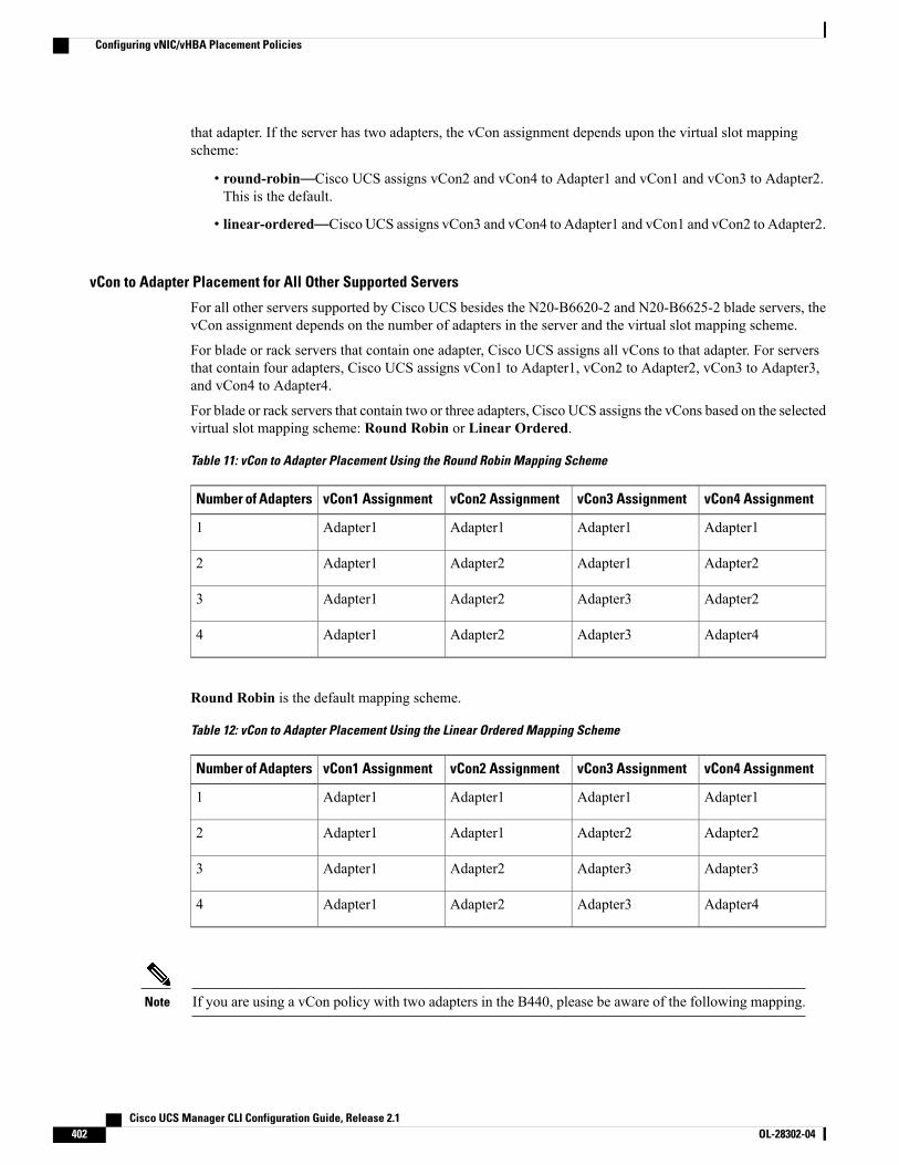
that adapter. If the server has two adapters, the vCon assignment depends upon the virtual slot mappingscheme:
• round-robin—Cisco UCS assigns vCon2 and vCon4 to Adapter1 and vCon1 and vCon3 to Adapter2.This is the default.
• linear-ordered—Cisco UCS assigns vCon3 and vCon4 to Adapter1 and vCon1 and vCon2 to Adapter2.
vCon to Adapter Placement for All Other Supported Servers
For all other servers supported by Cisco UCS besides the N20-B6620-2 and N20-B6625-2 blade servers, thevCon assignment depends on the number of adapters in the server and the virtual slot mapping scheme.
For blade or rack servers that contain one adapter, Cisco UCS assigns all vCons to that adapter. For serversthat contain four adapters, Cisco UCS assigns vCon1 to Adapter1, vCon2 to Adapter2, vCon3 to Adapter3,and vCon4 to Adapter4.
For blade or rack servers that contain two or three adapters, Cisco UCS assigns the vCons based on the selectedvirtual slot mapping scheme: Round Robin or Linear Ordered.
Table 11: vCon to Adapter Placement Using the Round Robin Mapping Scheme
vCon4 AssignmentvCon3 AssignmentvCon2 AssignmentvCon1 AssignmentNumber of Adapters
Adapter1Adapter1Adapter1Adapter11
Adapter2Adapter1Adapter2Adapter12
Adapter2Adapter3Adapter2Adapter13
Adapter4Adapter3Adapter2Adapter14
Round Robin is the default mapping scheme.
Table 12: vCon to Adapter Placement Using the Linear Ordered Mapping Scheme
vCon4 AssignmentvCon3 AssignmentvCon2 AssignmentvCon1 AssignmentNumber of Adapters
Adapter1Adapter1Adapter1Adapter11
Adapter2Adapter2Adapter1Adapter12
Adapter3Adapter3Adapter2Adapter13
Adapter4Adapter3Adapter2Adapter14
If you are using a vCon policy with two adapters in the B440, please be aware of the following mapping.Note
Cisco UCS Manager CLI Configuration Guide, Release 2.1402 OL-28302-04
Configuring vNIC/vHBA Placement Policies
• vCon 2 to adapter 1 maps first
• vCon 1 to adapter 2 maps second
vNIC/vHBA to vCon AssignmentCisco UCSManager provides two options for assigning vNICs and vHBAs to vCons through the vNIC/vHBAplacement policy: explicit assignment and implicit assignment.
Explicit Assignment of vNICs and vHBAs
With explicit assignment, you specify the vCon and, therefore, the adapter to which a vNIC or vHBA isassigned. Use this assignment option when you need to determine how the vNICs and vHBAs are distributedbetween the adapters on a server.
To configure a vCon and the associated vNICs and vHBAs for explicit assignment, do the following:
• Set the vCon configuration to any of the available options. You can configure the vCons through avNIC/vHBA placement policy or in the service profile associated with the server. If a vCon is configuredfor All, you can still explicitly assign a vNIC or vHBA to that vCon.
• Assign the vNICs and vHBAs to a vCon. You canmake this assignment through the virtual host interfaceplacement properties of the vNIC or vHBA or in the service profile associated with the server.
If you attempt to assign a vNIC or vHBA to a vCon that is not configured for that type of vNIC or vHBA,Cisco UCS Manager displays a message advising you of the configuration error.
During service profile association, Cisco UCSManager validates the configured placement of the vNICs andvHBAs against the number and capabilities of the physical adapters in the server before assigning the vNICsand vHBAs according to the configuration in the policy. Load distribution is based upon the explicit assignmentsto the vCons and adapters configured in this policy.
If the adapters do not support the assignment of one or more vNICs or vHBAs, Cisco UCS Manager raises afault against the service profile.
Implicit Assignment of vNICs and vHBAs
With implicit assignment, Cisco UCS Manager determines the vCon and, therefore, the adapter to which avNIC or vHBA is assigned according to the capability of the adapters and their relative capacity. Use thisassignment option if the adapter to which a vNIC or vHBA is assigned is not important to your systemconfiguration.
To configure a vCon for implicit assignment, do the following:
• Set the vCon configuration to All, Exclude Dynamic, or Exclude Unassigned. You can configure thevCons through a vNIC/vHBA placement policy or in the service profile associated with the server.
• Do not set the vCon configuration to Assigned Only. Implicit assignment cannot be performed withthis setting.
• Do not assign any vNICs or vHBAs to a vCon.
During service profile association, Cisco UCS Manager verifies the number and capabilities of the physicaladapters in the server and assigns the vNICs and vHBAs accordingly. Load distribution is based upon thecapabilities of the adapters, and placement of the vNICs and vHBAs is performed according to the actual
Cisco UCS Manager CLI Configuration Guide, Release 2.1 OL-28302-04 403
Configuring vNIC/vHBA Placement Policies
order determined by the system. For example, if one adapter can accommodate more vNICs than another, thatadapter is assigned more vNICs.
If the adapters cannot support the number of vNICs and vHBAs configured for that server, Cisco UCSManagerraises a fault against the service profile.
Implicit Assignment of vNICs in a Dual Adapter Environment
When you use implicit vNIC assignment for a dual slot server with an adapter card in each slot, Cisco UCSManager typically assigns the vNICs/vHBAs as follows:
• If the server has the same adapter in both slots, Cisco UCSManager assigns half the vNICs and half thevHBAs to each adapter.
• If the server has one non-VIC adapter and one VIC adapter, Cisco UCS Manager assigns two vNICsand two vHBAs to the non-VIC adapter and the remaining vNICs and vHBAs to the VIC adapter.
• If the server has two different VIC adapters, Cisco UCS Manager assigns the vNICs and vHBAsproportionally, based on the relative capabilities of the two adapters.
The following examples show how Cisco UCS Manager would typically assign the vNICs and vHBAs withdifferent combinations of supported adapter cards:
• If you want to configure four vNICs and the server contains two Cisco UCS M51KR-B BroadcomBCM57711 adapters (with two vNICs each), Cisco UCS Manager assigns two vNICs to each adapter.
• If you want to configure 50 vNICs and the server contains a Cisco UCS CNA M72KR-E adapter (2vNICs) and a Cisco UCS M81KR Virtual Interface Card adapter (128 vNICs), Cisco UCS Managerassigns two vNICs to the Cisco UCS CNAM72KR-E adapter and 48 vNICs to the Cisco UCS M81KRVirtual Interface Card adapter.
• If you want to configure 150 vNICs and the server contains a Cisco UCSM81KRVirtual Interface Cardadapter (128 vNICs) and a Cisco UCS VIC-1240 Virtual Interface Card adapter (256 vNICs), CiscoUCS Manager assigns 50 vNICs to the Cisco UCS M81KR Virtual Interface Card adapter and 100vNICs to the Cisco UCS VIC-1240 Virtual Interface Card adapter.
Exceptions to this implicit assignment occur if you configure the vNICs for fabric failover and if youconfigure dynamic vNICs for the server.
Note
For a configuration that includes vNIC fabric failover where one adapter does not support vNIC failover,Cisco UCSManager implicitly assigns all vNICs that have fabric failover enabled to the adapter that supportsthem. If the configuration includes only vNICs that are configured for fabric failover, no vNICs are implicitlyassigned to the adapter that does not support them. If some vNICs are configured for fabric failover and someare not, Cisco UCS Manager assigns all failover vNICs to the adapter that supports them and a minimum ofone nonfailover vNIC to the adapter that does not support them, according to the ratio above.
For a configuration that includes dynamic vNICs, the same implicit assignment would occur. Cisco UCSManager assigns all dynamic vNICs to the adapter that supports them. However, with a combination ofdynamic vNICs and static vNICs, at least one static vNIC is assigned to the adapter that does not supportdynamic vNICs.
Cisco UCS Manager CLI Configuration Guide, Release 2.1404 OL-28302-04
Configuring vNIC/vHBA Placement Policies
Configuring a vNIC/vHBA Placement Policy
Procedure
PurposeCommand or Action
Enters organization mode for the specified organization. To enter the rootorganization mode, type / as the org-name.
UCS-A# scope orgorg-name
Step 1
Creates the specified vNIC/vHBA placement profile and enters organizationvcon policy mode.
UCS-A /org # createvcon-policypolicy-name
Step 2
(Optional)Provides a description for the vNIC/vHBA Placement Profile.
UCS-A /org/vcon-policy# set descr description
Step 3
Enter up to 256 characters. You can use any characters or spaces except `(accent mark), \ (backslash), ^ (carat), " (double quote), = (equal sign), >(greater than), < (less than), or ' (single quote).
If your description includes spaces, special characters, orpunctuation, you must begin and end your description withquotation marks. The quotation marks will not appear in thedescription field of any show command output.
Note
(Optional)For blade or rack servers that contain one adapter, Cisco UCS assigns allvCons to that adapter. For servers that contain four adapters, Cisco UCS
UCS-A /org/vcon-policy# set mapping-scheme{round-robin |linear-ordered}
Step 4
assigns vCon1 to Adapter1, vCon2 to Adapter2, vCon3 to Adapter3, andvCon4 to Adapter4.
For blade or rack servers that contain two or three adapters, Cisco UCSassigns the vCons based on the selected virtual slot mapping scheme. Thiscan be one of the following:
• round-robin— In a server with two adapter cards, Cisco UCS assignsvCon1 and vCon3 to Adapter1, then assigns vCon2 and vCon4 toAdapter2.
In a server with three adapter cards, Cisco UCS assigns vCon1 toAdapter1, vCon2 and vCon4 to Adapter2, and vCon3 to Adapter3.
This is the default scheme.
• linear-ordered— In a server with two adapter cards, Cisco UCSassigns vCon1 and vCon2 to Adapter1, then assigns vCon3 and vCon4to Adapter2.
In a server with three adapter cards, Cisco UCS assigns vCon1 toAdapter1 and vCon2 to Adapter2, then assigns vCon3 and vCon4 toAdapter3.
In N20-B6620-2 and N20-B6625-2 blade servers, the two adapters arenumbered left to right while vCons are numbered right to left. If one ofthese blade servers has a single adapter, Cisco UCS assigns all vCons to
Cisco UCS Manager CLI Configuration Guide, Release 2.1 OL-28302-04 405
Configuring vNIC/vHBA Placement Policies
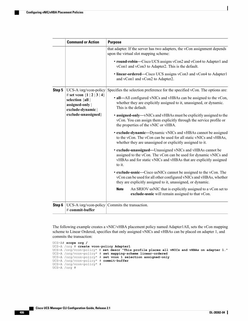
PurposeCommand or Action
that adapter. If the server has two adapters, the vCon assignment dependsupon the virtual slot mapping scheme:
• round-robin—Cisco UCS assigns vCon2 and vCon4 to Adapter1 andvCon1 and vCon3 to Adapter2. This is the default.
• linear-ordered—Cisco UCS assigns vCon3 and vCon4 to Adapter1and vCon1 and vCon2 to Adapter2.
Specifies the selection preference for the specified vCon. The options are:UCS-A /org/vcon-policy# set vcon {1 | 2 | 3 | 4}
Step 5
• all—All configured vNICs and vHBAs can be assigned to the vCon,whether they are explicitly assigned to it, unassigned, or dynamic.This is the default.
selection {all |assigned-only |exclude-dynamic |exclude-unassigned} • assigned-only—vNICs and vHBAsmust be explicitly assigned to the
vCon. You can assign them explicitly through the service profile orthe properties of the vNIC or vHBA.
• exclude-dynamic—Dynamic vNICs and vHBAs cannot be assignedto the vCon. The vCon can be used for all static vNICs and vHBAs,whether they are unassigned or explicitly assigned to it.
• exclude-unassigned—Unassigned vNICs and vHBAs cannot beassigned to the vCon. The vCon can be used for dynamic vNICs andvHBAs and for static vNICs and vHBAs that are explicitly assignedto it.
• exclude-usnic—Cisco usNICs cannot be assigned to the vCon. ThevCon can be used for all other configured vNICs and vHBAs, whetherthey are explicitly assigned to it, unassigned, or dynamic.
An SRIOV usNIC that is explicitly assigned to a vCon set toexclude-usnic will remain assigned to that vCon.
Note
Commits the transaction.UCS-A /org/vcon-policy# commit-buffer
Step 6
The following example creates a vNIC/vHBA placement policy named Adapter1All, sets the vCon mappingscheme to Linear Ordered, specifies that only assigned vNICs and vHBAs can be placed on adapter 1, andcommits the transaction:UCS-A# scope org /UCS-A /org # create vcon-policy Adapter1UCS-A /org/vcon-policy* # set descr "This profile places all vNICs and vHBAs on adapter 1."UCS-A /org/vcon-policy* # set mapping-scheme linear-orderedUCS-A /org/vcon-policy* # set vcon 1 selection assigned-onlyUCS-A /org/vcon-policy* # commit-bufferUCS-A /org/vcon-policy* #UCS-A /org #
Cisco UCS Manager CLI Configuration Guide, Release 2.1406 OL-28302-04
Configuring vNIC/vHBA Placement Policies
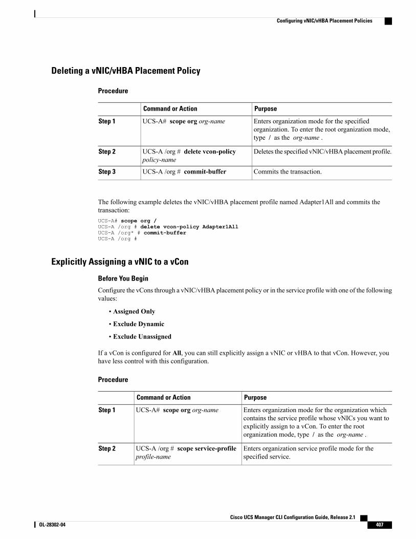
Deleting a vNIC/vHBA Placement Policy
Procedure
PurposeCommand or Action
Enters organization mode for the specifiedorganization. To enter the root organization mode,type / as the org-name .
UCS-A# scope org org-nameStep 1
Deletes the specified vNIC/vHBAplacement profile.UCS-A /org # delete vcon-policypolicy-name
Step 2
Commits the transaction.UCS-A /org # commit-bufferStep 3
The following example deletes the vNIC/vHBA placement profile named Adapter1All and commits thetransaction:UCS-A# scope org /UCS-A /org # delete vcon-policy Adapter1AllUCS-A /org* # commit-bufferUCS-A /org #
Explicitly Assigning a vNIC to a vCon
Before You Begin
Configure the vCons through a vNIC/vHBA placement policy or in the service profile with one of the followingvalues:
• Assigned Only
• Exclude Dynamic
• Exclude Unassigned
If a vCon is configured for All, you can still explicitly assign a vNIC or vHBA to that vCon. However, youhave less control with this configuration.
Procedure
PurposeCommand or Action
Enters organization mode for the organization whichcontains the service profile whose vNICs you want to
UCS-A# scope org org-nameStep 1
explicitly assign to a vCon. To enter the rootorganization mode, type / as the org-name .
Enters organization service profile mode for thespecified service.
UCS-A /org # scope service-profileprofile-name
Step 2
Cisco UCS Manager CLI Configuration Guide, Release 2.1 OL-28302-04 407
Configuring vNIC/vHBA Placement Policies
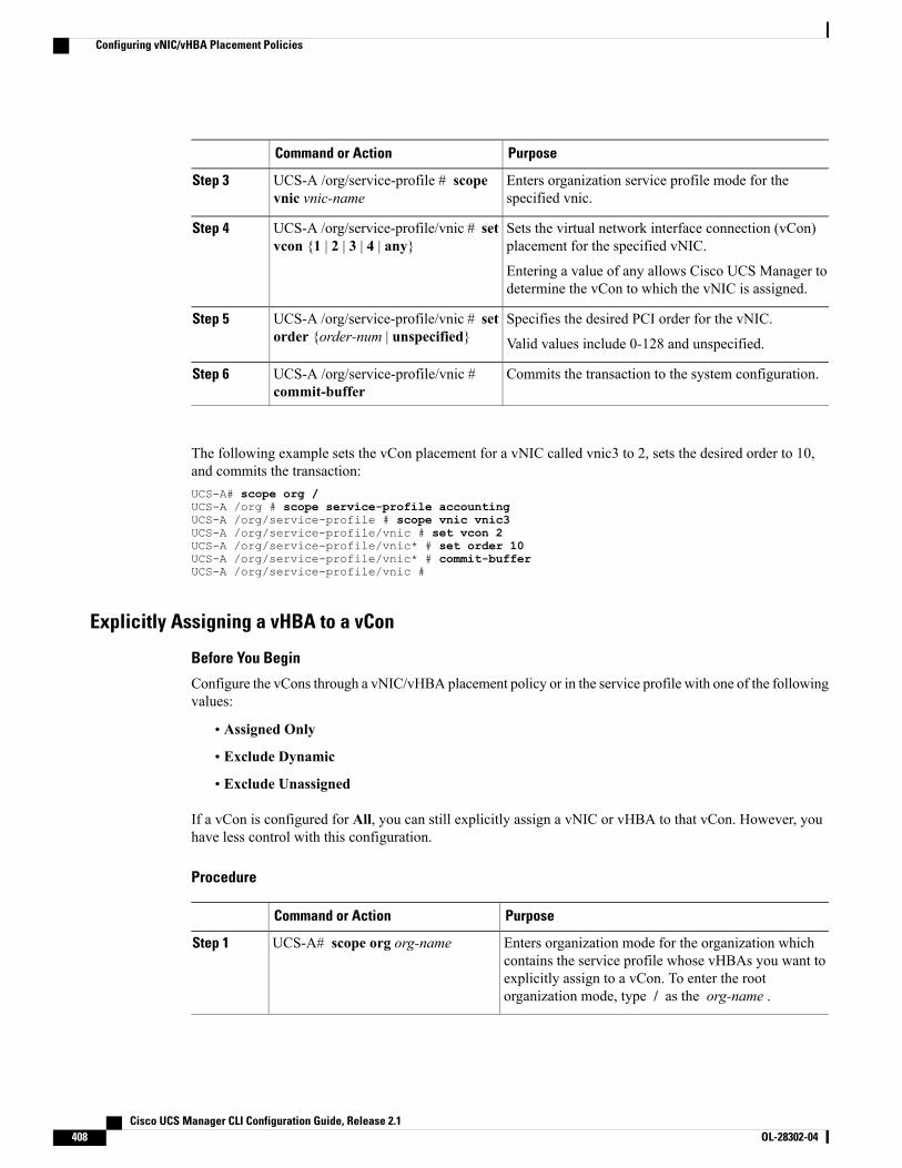
PurposeCommand or Action
Enters organization service profile mode for thespecified vnic.
UCS-A /org/service-profile # scopevnic vnic-name
Step 3
Sets the virtual network interface connection (vCon)placement for the specified vNIC.
UCS-A /org/service-profile/vnic # setvcon {1 | 2 | 3 | 4 | any}
Step 4
Entering a value of any allows Cisco UCS Manager todetermine the vCon to which the vNIC is assigned.
Specifies the desired PCI order for the vNIC.UCS-A /org/service-profile/vnic # setorder {order-num | unspecified}
Step 5
Valid values include 0-128 and unspecified.
Commits the transaction to the system configuration.UCS-A /org/service-profile/vnic #commit-buffer
Step 6
The following example sets the vCon placement for a vNIC called vnic3 to 2, sets the desired order to 10,and commits the transaction:UCS-A# scope org /UCS-A /org # scope service-profile accountingUCS-A /org/service-profile # scope vnic vnic3UCS-A /org/service-profile/vnic # set vcon 2UCS-A /org/service-profile/vnic* # set order 10UCS-A /org/service-profile/vnic* # commit-bufferUCS-A /org/service-profile/vnic #
Explicitly Assigning a vHBA to a vCon
Before You Begin
Configure the vCons through a vNIC/vHBA placement policy or in the service profile with one of the followingvalues:
• Assigned Only
• Exclude Dynamic
• Exclude Unassigned
If a vCon is configured for All, you can still explicitly assign a vNIC or vHBA to that vCon. However, youhave less control with this configuration.
Procedure
PurposeCommand or Action
Enters organization mode for the organization whichcontains the service profile whose vHBAs you want to
UCS-A# scope org org-nameStep 1
explicitly assign to a vCon. To enter the rootorganization mode, type / as the org-name .
Cisco UCS Manager CLI Configuration Guide, Release 2.1408 OL-28302-04
Configuring vNIC/vHBA Placement Policies
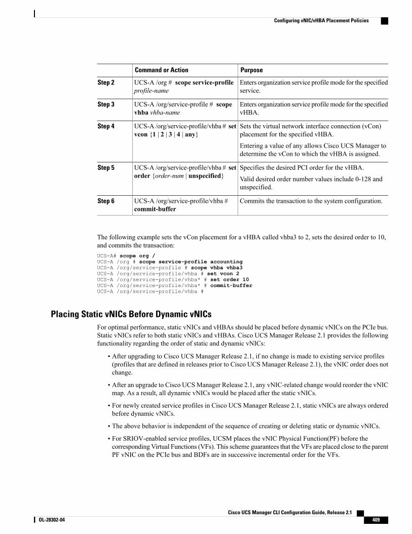
PurposeCommand or Action
Enters organization service profile mode for the specifiedservice.
UCS-A /org # scope service-profileprofile-name
Step 2
Enters organization service profile mode for the specifiedvHBA.
UCS-A /org/service-profile # scopevhba vhba-name
Step 3
Sets the virtual network interface connection (vCon)placement for the specified vHBA.
UCS-A /org/service-profile/vhba # setvcon {1 | 2 | 3 | 4 | any}
Step 4
Entering a value of any allows Cisco UCS Manager todetermine the vCon to which the vHBA is assigned.
Specifies the desired PCI order for the vHBA.UCS-A /org/service-profile/vhba # setorder {order-num | unspecified}
Step 5
Valid desired order number values include 0-128 andunspecified.
Commits the transaction to the system configuration.UCS-A /org/service-profile/vhba #commit-buffer
Step 6
The following example sets the vCon placement for a vHBA called vhba3 to 2, sets the desired order to 10,and commits the transaction:UCS-A# scope org /UCS-A /org # scope service-profile accountingUCS-A /org/service-profile # scope vhba vhba3UCS-A /org/service-profile/vhba # set vcon 2UCS-A /org/service-profile/vhba* # set order 10UCS-A /org/service-profile/vhba* # commit-bufferUCS-A /org/service-profile/vhba #
Placing Static vNICs Before Dynamic vNICsFor optimal performance, static vNICs and vHBAs should be placed before dynamic vNICs on the PCIe bus.Static vNICs refer to both static vNICs and vHBAs. Cisco UCS Manager Release 2.1 provides the followingfunctionality regarding the order of static and dynamic vNICs:
• After upgrading to Cisco UCS Manager Release 2.1, if no change is made to existing service profiles(profiles that are defined in releases prior to Cisco UCS Manager Release 2.1), the vNIC order does notchange.
• After an upgrade to Cisco UCSManager Release 2.1, any vNIC-related change would reorder the vNICmap. As a result, all dynamic vNICs would be placed after the static vNICs.
• For newly created service profiles in Cisco UCS Manager Release 2.1, static vNICs are always orderedbefore dynamic vNICs.
• The above behavior is independent of the sequence of creating or deleting static or dynamic vNICs.
• For SRIOV-enabled service profiles, UCSM places the vNIC Physical Function(PF) before thecorresponding Virtual Functions (VFs). This scheme guarantees that the VFs are placed close to the parentPF vNIC on the PCIe bus and BDFs are in successive incremental order for the VFs.
Cisco UCS Manager CLI Configuration Guide, Release 2.1 OL-28302-04 409
Configuring vNIC/vHBA Placement Policies
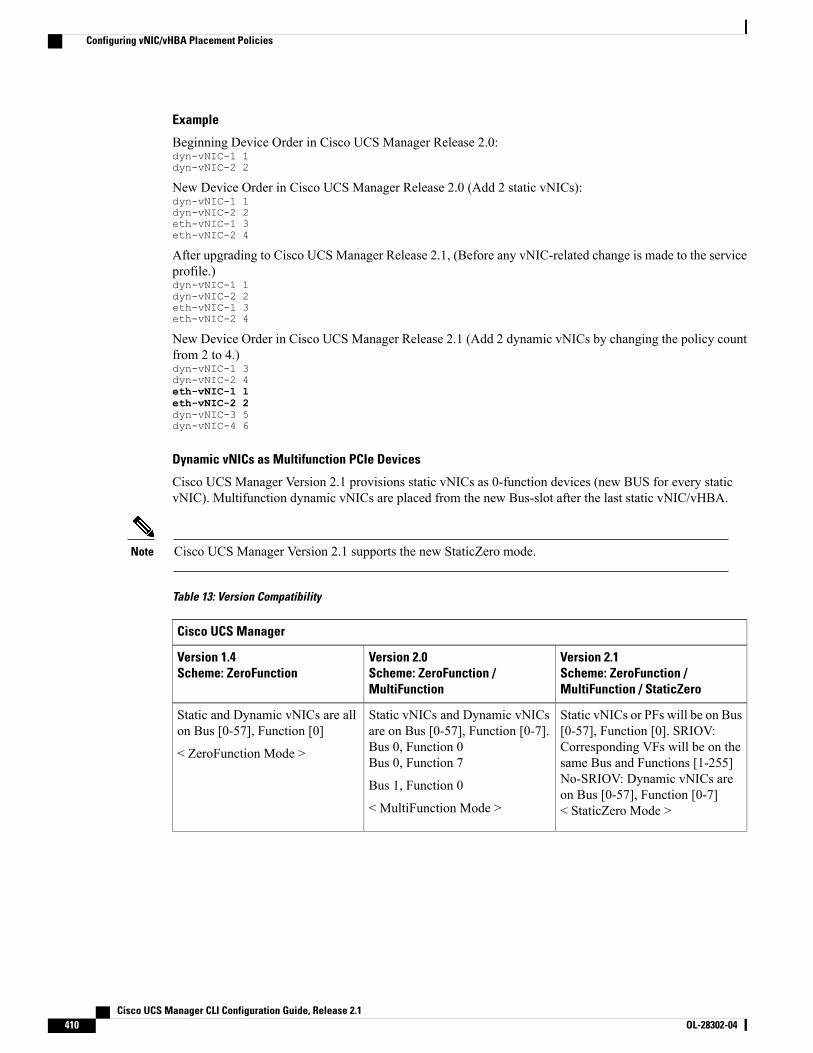
Example
Beginning Device Order in Cisco UCS Manager Release 2.0:dyn-vNIC-1 1dyn-vNIC-2 2
New Device Order in Cisco UCS Manager Release 2.0 (Add 2 static vNICs):dyn-vNIC-1 1dyn-vNIC-2 2eth-vNIC-1 3eth-vNIC-2 4
After upgrading to Cisco UCS Manager Release 2.1, (Before any vNIC-related change is made to the serviceprofile.)dyn-vNIC-1 1dyn-vNIC-2 2eth-vNIC-1 3eth-vNIC-2 4
New Device Order in Cisco UCS Manager Release 2.1 (Add 2 dynamic vNICs by changing the policy countfrom 2 to 4.)dyn-vNIC-1 3dyn-vNIC-2 4eth-vNIC-1 1eth-vNIC-2 2dyn-vNIC-3 5dyn-vNIC-4 6
Dynamic vNICs as Multifunction PCIe Devices
Cisco UCS Manager Version 2.1 provisions static vNICs as 0-function devices (new BUS for every staticvNIC). Multifunction dynamic vNICs are placed from the new Bus-slot after the last static vNIC/vHBA.
Cisco UCS Manager Version 2.1 supports the new StaticZero mode.Note
Table 13: Version Compatibility
Cisco UCS Manager
Version 2.1Scheme: ZeroFunction /MultiFunction / StaticZero
Version 2.0Scheme: ZeroFunction /MultiFunction
Version 1.4Scheme: ZeroFunction
Static vNICs or PFs will be on Bus[0-57], Function [0]. SRIOV:Corresponding VFs will be on thesame Bus and Functions [1-255]No-SRIOV: Dynamic vNICs areon Bus [0-57], Function [0-7]< StaticZero Mode >
Static vNICs and Dynamic vNICsare on Bus [0-57], Function [0-7].Bus 0, Function 0Bus 0, Function 7
Bus 1, Function 0
< MultiFunction Mode >
Static and Dynamic vNICs are allon Bus [0-57], Function [0]
< ZeroFunction Mode >
Cisco UCS Manager CLI Configuration Guide, Release 2.1410 OL-28302-04
Configuring vNIC/vHBA Placement Policies
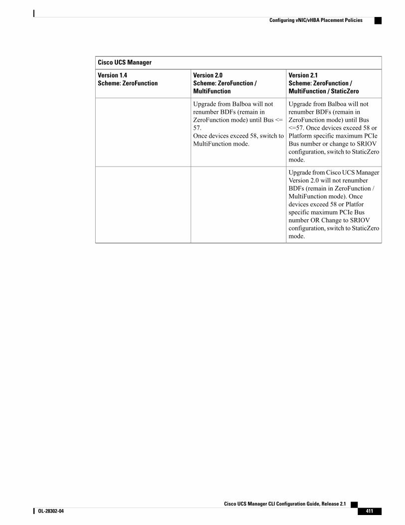
Cisco UCS Manager
Version 2.1Scheme: ZeroFunction /MultiFunction / StaticZero
Version 2.0Scheme: ZeroFunction /MultiFunction
Version 1.4Scheme: ZeroFunction
Upgrade from Balboa will notrenumber BDFs (remain inZeroFunction mode) until Bus<=57. Once devices exceed 58 orPlatform specific maximum PCIeBus number or change to SRIOVconfiguration, switch to StaticZeromode.
Upgrade from Balboa will notrenumber BDFs (remain inZeroFunction mode) until Bus <=57.Once devices exceed 58, switch toMultiFunction mode.
Upgrade fromCiscoUCSManagerVersion 2.0 will not renumberBDFs (remain in ZeroFunction /MultiFunction mode). Oncedevices exceed 58 or Platforspecific maximum PCIe Busnumber OR Change to SRIOVconfiguration, switch to StaticZeromode.
Cisco UCS Manager CLI Configuration Guide, Release 2.1 OL-28302-04 411
Configuring vNIC/vHBA Placement Policies

Cisco UCS Manager CLI Configuration Guide, Release 2.1412 OL-28302-04
Configuring vNIC/vHBA Placement Policies
C H A P T E R 31Configuring Server Boot
This chapter includes the following sections:
• Boot Policy, page 413
• Creating a Boot Policy, page 414
• SAN Boot, page 415
• iSCSI Boot, page 418
• LAN Boot, page 449
• Local Disk Boot, page 450
• Virtual Media Boot, page 452
• Deleting a Boot Policy, page 453
Boot PolicyThe boot policy determines the following:
• Configuration of the boot device
• Location from which the server boots
• Order in which boot devices are invoked
For example, you can choose to have associated servers boot from a local device, such as a local disk orCD-ROM (VMedia), or you can select a SAN boot or a LAN (PXE) boot.
You must include this policy in a service profile, and that service profile must be associated with a server forit to take effect. If you do not include a boot policy in a service profile, the server uses the default settings inthe BIOS to determine the boot order.
Changes to a boot policy might be propagated to all servers created with an updating service profiletemplate that includes that boot policy. Reassociation of the service profile with the server to rewrite theboot order information in the BIOS is automatically triggered.
Note
Cisco UCS Manager CLI Configuration Guide, Release 2.1 OL-28302-04 413
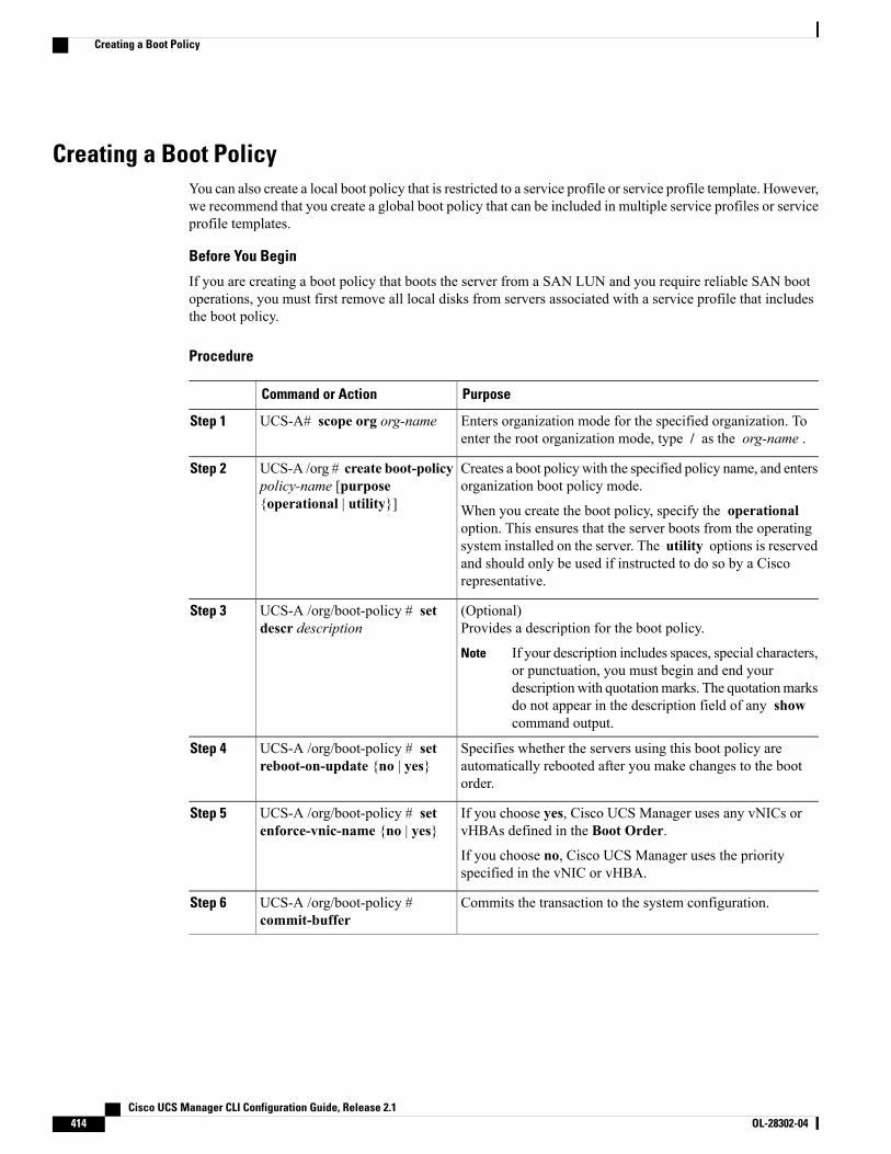
Creating a Boot PolicyYou can also create a local boot policy that is restricted to a service profile or service profile template. However,we recommend that you create a global boot policy that can be included in multiple service profiles or serviceprofile templates.
Before You Begin
If you are creating a boot policy that boots the server from a SAN LUN and you require reliable SAN bootoperations, you must first remove all local disks from servers associated with a service profile that includesthe boot policy.
Procedure
PurposeCommand or Action
Enters organization mode for the specified organization. Toenter the root organization mode, type / as the org-name .
UCS-A# scope org org-nameStep 1
Creates a boot policy with the specified policy name, and entersorganization boot policy mode.
UCS-A /org # create boot-policypolicy-name [purpose{operational | utility}]
Step 2
When you create the boot policy, specify the operationaloption. This ensures that the server boots from the operatingsystem installed on the server. The utility options is reservedand should only be used if instructed to do so by a Ciscorepresentative.
(Optional)Provides a description for the boot policy.
UCS-A /org/boot-policy # setdescr description
Step 3
If your description includes spaces, special characters,or punctuation, you must begin and end yourdescriptionwith quotationmarks. The quotationmarksdo not appear in the description field of any showcommand output.
Note
Specifies whether the servers using this boot policy areautomatically rebooted after you make changes to the bootorder.
UCS-A /org/boot-policy # setreboot-on-update {no | yes}
Step 4
If you choose yes, Cisco UCS Manager uses any vNICs orvHBAs defined in the Boot Order.
UCS-A /org/boot-policy # setenforce-vnic-name {no | yes}
Step 5
If you choose no, Cisco UCS Manager uses the priorityspecified in the vNIC or vHBA.
Commits the transaction to the system configuration.UCS-A /org/boot-policy #commit-buffer
Step 6
Cisco UCS Manager CLI Configuration Guide, Release 2.1414 OL-28302-04
Creating a Boot Policy
The following example creates a boot policy named boot-policy-LAN, provides a description for the bootpolicy, specifies that servers using this policy will not be automatically rebooted when the boot order ischanged, and commits the transaction:UCS-A# scope org /UCS-A /org* # create boot-policy boot-policy-LAN purpose operationalUCS-A /org/boot-policy* # set descr "Boot policy that boots from the LAN."UCS-A /org/boot-policy* # set reboot-on-update noUCS-A /org/boot-policy* # commit-bufferUCS-A /org/boot-policy #
What to Do Next
Configure one or more of the following boot options for the boot policy and set their boot order:
• LAN Boot—Boots from a centralized provisioning server. It is frequently used to install operatingsystems on a server from that server.
If you choose the LAN Boot option, continue to Configuring a LAN Boot for a Boot Policy, on page449.
• Storage Boot— Boots from an operating system image on the SAN. You can specify a primary and asecondary SAN boot. If the primary boot fails, the server attempts to boot from the secondary.
We recommend that you use a SAN boot, because it offers the most service profile mobility within thesystem. If you boot from the SAN, when you move a service profile from one server to another, the newserver boots from exactly the same operating system image. Therefore, the new server appears to beexactly the same server to the network.
If you choose the Storage Boot option, continue to Configuring a SAN Boot for a Boot Policy, on page416.
• Virtual Media Boot—Mimics the insertion of a physical CD into a server. It is typically used tomanually install operating systems on a server.
If you choose the Virtual Media boot option, continue to Configuring a Virtual Media Boot for a BootPolicy, on page 452.
If you configure a local disk and a SAN LUN for the boot order storage type and the operating system orlogical volume manager (LVM) is configured incorrectly, the server might boot from the local disk ratherthan the SAN LUN.
For example, on a server with Red Hat Linux installed, where the LVM is configured with default LVnames and the boot order is configured with a SAN LUN and a local disk, Linux reports that there aretwo LVs with the same name and boots from the LV with the lowest SCSI ID, which could be the localdisk.
Tip
Include the boot policy in a service profile and/or template.
SAN BootYou can configure a boot policy to boot one or more servers from an operating system image on the SAN.The boot policy can include a primary and a secondary SAN boot. If the primary boot fails, the server attemptsto boot from the secondary.
Cisco UCS Manager CLI Configuration Guide, Release 2.1 OL-28302-04 415
SAN Boot
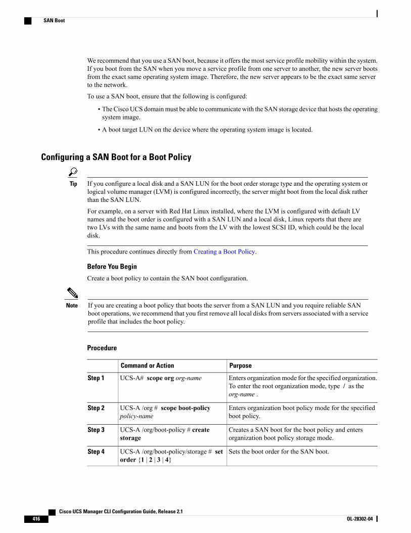
We recommend that you use a SAN boot, because it offers the most service profile mobility within the system.If you boot from the SAN when you move a service profile from one server to another, the new server bootsfrom the exact same operating system image. Therefore, the new server appears to be the exact same serverto the network.
To use a SAN boot, ensure that the following is configured:
• The Cisco UCS domainmust be able to communicate with the SAN storage device that hosts the operatingsystem image.
• A boot target LUN on the device where the operating system image is located.
Configuring a SAN Boot for a Boot Policy
If you configure a local disk and a SAN LUN for the boot order storage type and the operating system orlogical volume manager (LVM) is configured incorrectly, the server might boot from the local disk ratherthan the SAN LUN.
For example, on a server with Red Hat Linux installed, where the LVM is configured with default LVnames and the boot order is configured with a SAN LUN and a local disk, Linux reports that there aretwo LVs with the same name and boots from the LV with the lowest SCSI ID, which could be the localdisk.
Tip
This procedure continues directly from Creating a Boot Policy.
Before You Begin
Create a boot policy to contain the SAN boot configuration.
If you are creating a boot policy that boots the server from a SAN LUN and you require reliable SANboot operations, we recommend that you first remove all local disks from servers associated with a serviceprofile that includes the boot policy.
Note
Procedure
PurposeCommand or Action
Enters organizationmode for the specified organization.To enter the root organization mode, type / as theorg-name .
UCS-A# scope org org-nameStep 1
Enters organization boot policy mode for the specifiedboot policy.
UCS-A /org # scope boot-policypolicy-name
Step 2
Creates a SAN boot for the boot policy and entersorganization boot policy storage mode.
UCS-A /org/boot-policy # createstorage
Step 3
Sets the boot order for the SAN boot.UCS-A /org/boot-policy/storage # setorder {1 | 2 | 3 | 4}
Step 4
Cisco UCS Manager CLI Configuration Guide, Release 2.1416 OL-28302-04
SAN Boot
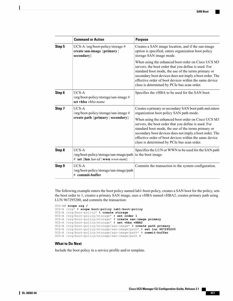
PurposeCommand or Action
Creates a SAN image location, and if the san-imageoption is specified, enters organization boot policystorage SAN image mode.
UCS-A /org/boot-policy/storage #create san-image {primary |secondary}
Step 5
When using the enhanced boot order on Cisco UCS M3servers, the boot order that you define is used. Forstandard boot mode, the use of the terms primary orsecondary boot devices does not imply a boot order. Theeffective order of boot devices within the same deviceclass is determined by PCIe bus scan order.
Specifies the vHBA to be used for the SAN boot.UCS-A/org/boot-policy/storage/san-image #set vhba vhba-name
Step 6
Creates a primary or secondary SAN boot path and entersorganization boot policy SAN path mode.
UCS-A/org/boot-policy/storage/san-image #create path {primary | secondary}
Step 7
When using the enhanced boot order on Cisco UCS M3servers, the boot order that you define is used. Forstandard boot mode, the use of the terms primary orsecondary boot devices does not imply a boot order. Theeffective order of boot devices within the same deviceclass is determined by PCIe bus scan order.
Specifies the LUN orWWN to be used for the SAN pathto the boot image.
UCS-A/org/boot-policy/storage/san-image/path# set {lun lun-id | wwn wwn-num}
Step 8
Commits the transaction to the system configuration.UCS-A/org/boot-policy/storage/san-image/path# commit-buffer
Step 9
The following example enters the boot policy named lab1-boot-policy, creates a SAN boot for the policy, setsthe boot order to 1, creates a primary SAN image, uses a vHBA named vHBA2, creates primary path usingLUN 967295200, and commits the transaction:UCS-A# scope org /UCS-A /org* # scope boot-policy lab1-boot-policyUCS-A /org/boot-policy* # create storageUCS-A /org/boot-policy/storage* # set order 1UCS-A /org/boot-policy/storage* # create san-image primaryUCS-A /org/boot-policy/storage* # set vhba vHBA2UCS-A /org/boot-policy/storage/san-image* # create path primaryUCS-A /org/boot-policy/storage/san-image/path* # set lun 967295200UCS-A /org/boot-policy/storage/san-image/path* # commit-bufferUCS-A /org/boot-policy/storage/san-image/path #
What to Do Next
Include the boot policy in a service profile and/or template.
Cisco UCS Manager CLI Configuration Guide, Release 2.1 OL-28302-04 417
SAN Boot
iSCSI BootiSCSI boot enables a server to boot its operating system from an iSCSI target machine located remotely overa network.
iSCSI boot is supported on the following Cisco UCS hardware:
• Cisco UCS server blades that have the Cisco UCS M51KR-B Broadcom BCM57711 network adapterand use the default MAC address provided by Broadcom.
• Cisco UCS M81KR Virtual Interface Card
• Cisco UCS VIC-1240 Virtual Interface Card
• Cisco UCS VIC-1280 Virtual Interface Card
There are prerequisites that must be met before you configure iSCSI boot. For a list of these prerequisites,see iSCSI Boot Guidelines and Prerequisites, on page 419.
For a high-level procedure for implementing iSCSI boot, see Configuring iSCSI Boot, on page 421.
iSCSI Boot ProcessCisco UCS Manager uses the iSCSI vNIC and iSCSI boot information created for the service profile in theassociation process to program the adapter, located on the server. After the adapter is programmed, the serverreboots with the latest service profile values. After the power on self-test (POST), the adapter attempts toinitialize using these service profile values. If the adapter can use the values and log in to its specified target,the adapter initializes and posts an iSCSI Boot Firmware Table (iBFT) to the host memory and a valid bootableLUN to the system BIOS. The iBFT that is posted to the host memory contains the initiator and targetconfiguration that is programmed on the primary iSCSI VNIC.
Previously, the host would see only one of the boot paths configured, depending on which path completedthe LUN discovery first, and would boot from that path. Now, when there are two iSCSI boot vNICsconfigured, the host will see both of the boot paths. So for multipath configurations, a single IQN needsto be configured on both the boot vNICs If there are different IQNs configured on the boot vNICs on ahost, the host will boot with the IQN that is configured on the boot vNIC with the lower PCI order.
Note
The next step, which is the installation of the operating system (OS), requires an OS that is iBFT capable.During installation of the OS, the OS installer scans the host memory for the iBFT table and uses the informationin the iBFT to discover the boot device and create an iSCSI path to the target LUN. In some OS's a NIC driveris required to complete this path. If this step is successful, the OS installer finds the iSCSI target LUN onwhich to install the OS.
The iBFT works at the OS installation software level and might not work with HBA mode (also knownas TCP offload).Whether iBFTworks with HBAmode depends on the OS capabilities during installation.Also, for a server that includes a Cisco UCSM51KR-BBroadcomBCM57711 adapter, the iBFT normallyworks at a maximum transmission unit (MTU) size of 1500, regardless of the MTU jumbo configuration.If the OS supports HBA mode, you might need to set HBA mode, dual-fabric support, and jumbo MTUsize after the iSCSI installation process.
Note
Cisco UCS Manager CLI Configuration Guide, Release 2.1418 OL-28302-04
iSCSI Boot
iSCSI Boot Guidelines and PrerequisitesThese guidelines and prerequisites must be met before configuring iSCSI boot:
• After the iSCSI boot policies have been created, a user with ls-compute privileges can include them ina service profile or service profile template. However, a user with only ls-compute privileges cannotcreate iSCSI boot policies.
• To set up iSCSI boot from a Windows 2008 server where the second vNIC (failover vNIC) must bootfrom an iSCSI LUN, consult Microsoft Knowledge Base Article 976042. Microsoft has a known issuewhere Windows might fail to boot from an iSCSI drive or cause a bugcheck error if the networkinghardware is changed. To work around this issue, follow the resolution recommended by Microsoft.
• The storage array must be licensed for iSCSI boot and the array side LUN masking must be properlyconfigured.
• Two IP addresses must be determined, one for each iSCSI initiator. If possible, the IP addresses shouldbe on the same subnet as the storage array. The IP addresses are assigned statically or dynamically usingthe Dynamic Host Configuration Protocol (DHCP).
• You cannot configure boot parameters in the Global boot policy. Instead, after configuring bootparameters, you need to include the boot policy in the appropriate service profile.
• The operating system (OS) must be iSCSI Boot Firmware Table (iBFT) compatible.
• For Cisco UCS M51KR-B Broadcom BCM57711 network adapters:
◦Servers that use iSCSI boot must contain the Cisco UCSM51KR-BBroadcomBCM57711 networkadapter. For information on installing or replacing an adapter card, see the Cisco UCS B250Extended Memory Blade Server Installation and Service Note. The service note is accessible fromthe Cisco UCS B-Series Servers Documentation Roadmap at http://www.cisco.com/go/unifiedcomputing/b-series-doc.
◦Set the MAC addresses on the iSCSI device.
◦If you are using the DHCP Vendor ID (Option 43), configure the MAC address of an iSCSI devicein /etc/dhcpd.conf.
◦HBA mode (also known as TCP offload) and the boot to target setting are supported. However,only Windows OS supports HBA mode during installation.
◦Before installing the OS, disable the boot to target setting in the iSCSI adapter policy, then afterinstalling the OS, reenable the boot to target setting.
Each time you change an adapter policy setting, the adapter reboots to apply the newsetting.
Note
◦When installing the OS on the iSCSI target, the iSCSI target must be ordered before the devicewhere the OS image resides. For example, if you are installing the OS on the iSCSI target from aCD, the boot order should be the iSCSI target and then the CD.
◦After the server has been iSCSI booted, do not modify the Initiator Name, Target name, LUN,iSCSI device IP, or Netmask/gateway using the Broadcom tool.
Cisco UCS Manager CLI Configuration Guide, Release 2.1 OL-28302-04 419
iSCSI Boot
◦Do not interrupt the POST (power on self-test) process or the Cisco UCS M51KR-B BroadcomBCM57711 network adapter will fail to initialize.
• For Cisco UCS M81KR Virtual Interface Card and Cisco UCS VIC-1240 Virtual Interface Card:
• Do not set MAC addresses on the iSCSI device.
• HBA mode and the boot to target setting are not supported.
•When installing the OS on the iSCSI target, the iSCSI target must be ordered after the device wherethe OS image resides. For example, if you are installing the OS on the iSCSI target from a CD,the boot order should be the CD and then the iSCSI target.
• If you are using the DHCP Vendor ID (Option 43), the MAC address of the overlay vNIC needsto be configured in /etc/dhcpd.conf.
• After the server has been iSCSI booted, do not modify the IP details of the overlay vNIC.
• The VMware ESX/ESXi operating system does not support storing a core dump file to an iSCSI boottarget LUN. Dump files must be written to a local disk.
Initiator IQN ConfigurationCisco UCS uses the following rules to determine the initiator IQN for an adapter iSCSI vNIC at the time aservice profile is associated with a physical server:
• An initiator IQN at the service profile level and at the iSCSI vNIC level cannot be used together in aservice profile.
• If an initiator IQN is specified at the service profile level, all of the adaptor iSCSI vNICs are configuredto use the same initiator IQN, except in the case of DHCP Option 43, where the initiator IQN is set toempty on the adapter iSCSI vNIC.
•When an initiator IQN is set at the iSCSI vNIC level, the initiator IQN at the service profile level isremoved, if one is present.
• If there are two iSCSI vNIC in a service profile and only one of them has the initiator IQN set, the secondone is configured with the default IQN pool. You can change this configuration later. The only exceptionis if DHCP Option 43 is configured. In this case, the initiator IQN on the second iSCSI vNIC is removedduring service profile association.
Enabling MPIO on Windows
If you change the networking hardware, Windows may fail to boot from an iSCSI drive. For moreinformation, see Microsoft support Article ID: 976042.
Note
Before You Begin
The server on which you enable MPIO must have a Cisco VIC driver.
If there are multiple paths configured to the boot LUN, only one path should be enabled when the LUN isinstalled.
Cisco UCS Manager CLI Configuration Guide, Release 2.1420 OL-28302-04
iSCSI Boot
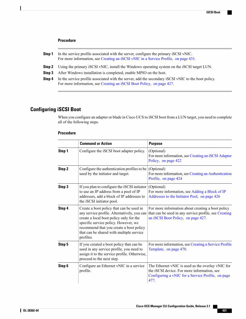
Procedure
Step 1 In the service profile associated with the server, configure the primary iSCSI vNIC.For more information, see Creating an iSCSI vNIC in a Service Profile, on page 431.
Step 2 Using the primary iSCSI vNIC, install the Windows operating system on the iSCSI target LUN.Step 3 After Windows installation is completed, enable MPIO on the host.Step 4 In the service profile associated with the server, add the secondary iSCSI vNIC to the boot policy.
For more information, see Creating an iSCSI Boot Policy, on page 427.
Configuring iSCSI BootWhen you configure an adapter or blade in Cisco UCS to iSCSI boot from a LUN target, you need to completeall of the following steps.
Procedure
PurposeCommand or Action
(Optional)For more information, see Creating an iSCSI AdapterPolicy, on page 422
Configure the iSCSI boot adapter policy.Step 1
(Optional)For more information, see Creating anAuthenticationProfile, on page 424
Configure the authentication profiles to beused by the initiator and target.
Step 2
(Optional)For more information, see Adding a Block of IPAddresses to the Initiator Pool, on page 426
If you plan to configure the iSCSI initiatorto use an IP address from a pool of IPaddresses, add a block of IP addresses tothe iSCSI initiator pool.
Step 3
For more information about creating a boot policythat can be used in any service profile, see Creatingan iSCSI Boot Policy, on page 427.
Create a boot policy that can be used inany service profile. Alternatively, you cancreate a local boot policy only for thespecific service policy. However, we
Step 4
recommend that you create a boot policythat can be shared with multiple serviceprofiles.
For more information, see Creating a Service ProfileTemplate, on page 470.
If you created a boot policy that can beused in any service profile, you need toassign it to the service profile. Otherwise,proceed to the next step.
Step 5
The Ethernet vNIC is used as the overlay vNIC forthe iSCSI device. For more information, see
Configure an Ethernet vNIC in a serviceprofile.
Step 6
Configuring a vNIC for a Service Profile, on page477.
Cisco UCS Manager CLI Configuration Guide, Release 2.1 OL-28302-04 421
iSCSI Boot
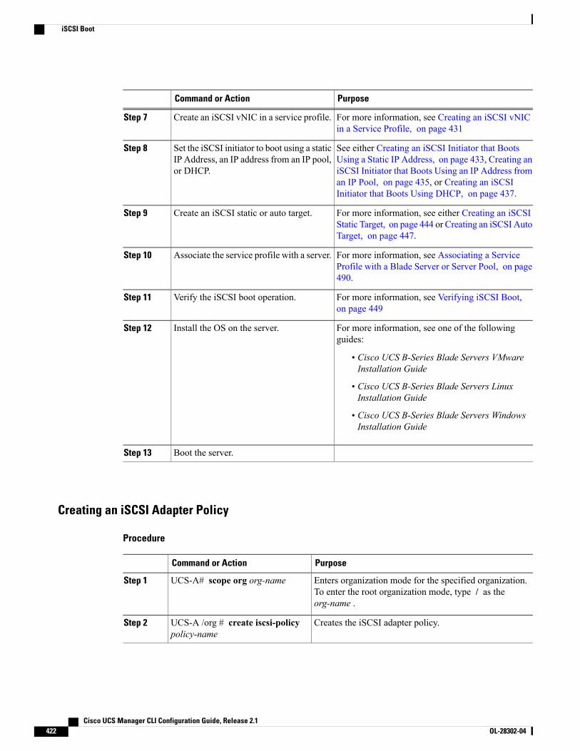
PurposeCommand or Action
For more information, see Creating an iSCSI vNICin a Service Profile, on page 431
Create an iSCSI vNIC in a service profile.Step 7
See either Creating an iSCSI Initiator that BootsUsing a Static IP Address, on page 433, Creating an
Set the iSCSI initiator to boot using a staticIP Address, an IP address from an IP pool,or DHCP.
Step 8
iSCSI Initiator that Boots Using an IP Address froman IP Pool, on page 435, or Creating an iSCSIInitiator that Boots Using DHCP, on page 437.
For more information, see either Creating an iSCSIStatic Target, on page 444 or Creating an iSCSI AutoTarget, on page 447.
Create an iSCSI static or auto target.Step 9
For more information, see Associating a ServiceProfile with a Blade Server or Server Pool, on page490.
Associate the service profile with a server.Step 10
For more information, see Verifying iSCSI Boot,on page 449
Verify the iSCSI boot operation.Step 11
For more information, see one of the followingguides:
Install the OS on the server.Step 12
• Cisco UCS B-Series Blade Servers VMwareInstallation Guide
• Cisco UCS B-Series Blade Servers LinuxInstallation Guide
• Cisco UCS B-Series Blade Servers WindowsInstallation Guide
Boot the server.Step 13
Creating an iSCSI Adapter Policy
Procedure
PurposeCommand or Action
Enters organization mode for the specified organization.To enter the root organization mode, type / as theorg-name .
UCS-A# scope org org-nameStep 1
Creates the iSCSI adapter policy.UCS-A /org # create iscsi-policypolicy-name
Step 2
Cisco UCS Manager CLI Configuration Guide, Release 2.1422 OL-28302-04
iSCSI Boot

PurposeCommand or Action
(Optional)Provides a description for the iSCSI adapter policy.
UCS-A /org/iscsi-policy # set descrdescription
Step 3
The number of seconds to wait until Cisco UCS assumesthat the initial login has failed and the iSCSI adapter isunavailable.
UCS-A /org/iscsi-policy # setiscsi-protocol-itemconnection-timeout timeout-secs
Step 4
Enter an integer between 0 and 255. If you enter 0, CiscoUCS uses the value set in the adapter firmware (default:15 seconds).
The number of seconds to wait before the initiator assumesthat the DHCP server is unavailable.
UCS-A /org/iscsi-policy # setiscsi-protocol-item dhcp-timeouttimeout-secs
Step 5
Enter an integer between 60 and 300 (default: 60 seconds).
The number of times to retry the connection in case of afailure during iSCSI LUN discovery.
UCS-A /org/iscsi-policy # setiscsi-protocol-itemlun-busy-retry-count num
Step 6
Enter an integer between 0 and 60. If you enter 0, CiscoUCS uses the value set in the adapter firmware (default:15 seconds).
Specifies whether to apply a TCP timestamp. With thissetting, transmitted packets are given a time stamp of when
UCS-A /org/iscsi-policy # setiscsi-protocol-item tcp-time-stamp{no | yes}
Step 7
the packet was sent so that the packet's round-trip time canbe calculated, when needed. This setting applies only toCisco UCS M51KR-B Broadcom BCM57711 adapters.
Specifies whether to enable HBA mode.UCS-A /org/iscsi-policy # setiscsi-protocol-item hbamode {no |yes}
Step 8
This option should only be enabled for servers with theCisco UCS NIC M51KR-B adapter running the Windowsoperating system.
Specifies whether to boot from the iSCSI target.UCS-A /org/iscsi-policy # setiscsi-protocol-itemboottotarget {no| yes}
Step 9
This option only applies to servers with the Cisco UCSNIC M51KR-B adapter. It should be disabled until youhave installed an operating system on the server.
Commits the transaction to the system configuration.UCS-A /org/iscsi-policy #commit-buffer
Step 10
The following example shows how to create an iSCSI adapter policy called iscsiboot, set the connectiontimeout, DHCP timeout, and LUN busy retry count, apply a TCP timestamp, and commit the transaction:UCS-A# scope org /UCS-A /org # create iscsi-policy iscsibootUCS-A /org/iscsi-policy* # set iscsi-protocol-item connection-timeout 60UCS-A /org/iscsi-policy* # set iscsi-protocol-item dhcp-timeout 200UCS-A /org/iscsi-policy* # set iscsi-protocol-item lun-busy-retry-count 5UCS-A /org/iscsi-policy* # set iscsi-protocol-item tcp-time-stamp yesUCS-A /org/iscsi-policy* # set iscsi-protocol-item hbamode yesUCS-A /org/iscsi-policy* # set iscsi-protocol-item boottotarget yes
Cisco UCS Manager CLI Configuration Guide, Release 2.1 OL-28302-04 423
iSCSI Boot
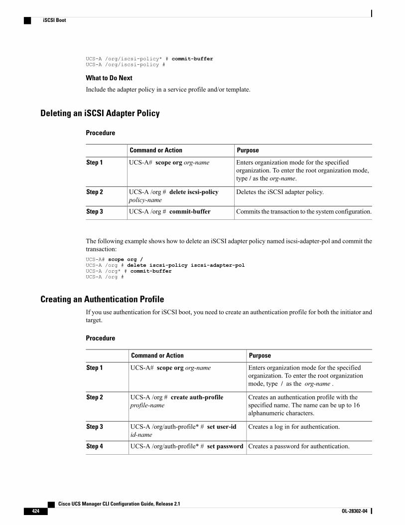
UCS-A /org/iscsi-policy* # commit-bufferUCS-A /org/iscsi-policy #
What to Do Next
Include the adapter policy in a service profile and/or template.
Deleting an iSCSI Adapter Policy
Procedure
PurposeCommand or Action
Enters organization mode for the specifiedorganization. To enter the root organization mode,type / as the org-name.
UCS-A# scope org org-nameStep 1
Deletes the iSCSI adapter policy.UCS-A /org # delete iscsi-policypolicy-name
Step 2
Commits the transaction to the system configuration.UCS-A /org # commit-bufferStep 3
The following example shows how to delete an iSCSI adapter policy named iscsi-adapter-pol and commit thetransaction:UCS-A# scope org /UCS-A /org # delete iscsi-policy iscsi-adapter-polUCS-A /org* # commit-bufferUCS-A /org #
Creating an Authentication ProfileIf you use authentication for iSCSI boot, you need to create an authentication profile for both the initiator andtarget.
Procedure
PurposeCommand or Action
Enters organization mode for the specifiedorganization. To enter the root organizationmode, type / as the org-name .
UCS-A# scope org org-nameStep 1
Creates an authentication profile with thespecified name. The name can be up to 16alphanumeric characters.
UCS-A /org # create auth-profileprofile-name
Step 2
Creates a log in for authentication.UCS-A /org/auth-profile* # set user-idid-name
Step 3
Creates a password for authentication.UCS-A /org/auth-profile* # set passwordStep 4
Cisco UCS Manager CLI Configuration Guide, Release 2.1424 OL-28302-04
iSCSI Boot
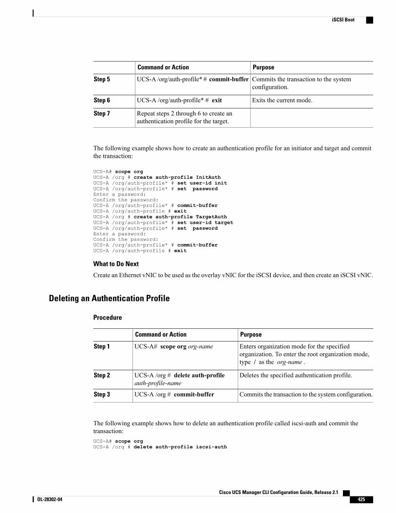
PurposeCommand or Action
Commits the transaction to the systemconfiguration.
UCS-A /org/auth-profile* # commit-bufferStep 5
Exits the current mode.UCS-A /org/auth-profile* # exitStep 6
Repeat steps 2 through 6 to create anauthentication profile for the target.
Step 7
The following example shows how to create an authentication profile for an initiator and target and committhe transaction:
UCS-A# scope orgUCS-A /org # create auth-profile InitAuthUCS-A /org/auth-profile* # set user-id initUCS-A /org/auth-profile* # set passwordEnter a password:Confirm the password:UCS-A /org/auth-profile* # commit-bufferUCS-A /org/auth-profile # exitUCS-A /org # create auth-profile TargetAuthUCS-A /org/auth-profile* # set user-id targetUCS-A /org/auth-profile* # set passwordEnter a password:Confirm the password:UCS-A /org/auth-profile* # commit-bufferUCS-A /org/auth-profile # exit
What to Do Next
Create an Ethernet vNIC to be used as the overlay vNIC for the iSCSI device, and then create an iSCSI vNIC.
Deleting an Authentication Profile
Procedure
PurposeCommand or Action
Enters organization mode for the specifiedorganization. To enter the root organization mode,type / as the org-name .
UCS-A# scope org org-nameStep 1
Deletes the specified authentication profile.UCS-A /org # delete auth-profileauth-profile-name
Step 2
Commits the transaction to the system configuration.UCS-A /org # commit-bufferStep 3
The following example shows how to delete an authentication profile called iscsi-auth and commit thetransaction:UCS-A# scope orgUCS-A /org # delete auth-profile iscsi-auth
Cisco UCS Manager CLI Configuration Guide, Release 2.1 OL-28302-04 425
iSCSI Boot

UCS-A /org* # commit-bufferUCS-A /org #
Adding a Block of IP Addresses to the Initiator PoolYou can create a group of IP addresses to be used for iSCSI boot. Cisco UCS Manager reserves the block ofIP addresses you specify.
The IP pool must not contain any IP addresses that have been assigned as static IP addresses for a server orservice profile.
Procedure
PurposeCommand or Action
Enters organizationmode for the specified organization.To enter the root organization mode, enter / as theorg-name.
UCS-A# scope org org-nameStep 1
Enters the mode to specify an iSCSI initiator pool.UCS-A /org# scope ip-pooliscsi-initiator-pool
Step 2
(Optional)Provides a description for the IP pool.
UCS-A /org/ip-pool # set descrdescription
Step 3
If your description includes spaces, specialcharacters, or punctuation, you must begin andend your description with quotation marks. Thequotation marks will not appear in thedescription field of any show command output.
Note
This can be one of the following:UCS-A /org/ip-pool # setassignmentorder {default |sequential}
Step 4
• default—Cisco UCS Manager selects a randomidentity from the pool.
• sequential—CiscoUCSManager selects the lowestavailable identity from the pool.
Creates a block of IP addresses for the iSCSI initiator.UCS-A /org/ip-pool# create blockfrom_ip_address to_ip_addressdefault_gateway subnet_mask
Step 5
(Optional)Shows the block of IP addresses that you have created.
UCS-A/org/ip-pool/block# showdetail expand
Step 6
Commits the transaction to the system configuration.UCS-A /org/ip-pool/block #commit-buffer
Step 7
The following example shows how to create an IP initiator pool for the iSCSI vNIC and commit the transaction:
UCS-A # scope org /UCS-A /org # scope ip-pool iscsi-initiator-poolUCS-A /org/ip-pool # create block 40.40.40.10 40.40.40.50 40.40.40.1 255.0.0.0UCS-A /org/ip-pool/block # show detail expand
Cisco UCS Manager CLI Configuration Guide, Release 2.1426 OL-28302-04
iSCSI Boot
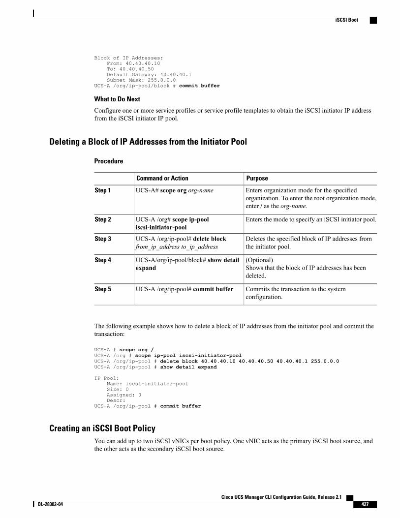
Block of IP Addresses:From: 40.40.40.10To: 40.40.40.50Default Gateway: 40.40.40.1Subnet Mask: 255.0.0.0
UCS-A /org/ip-pool/block # commit buffer
What to Do Next
Configure one or more service profiles or service profile templates to obtain the iSCSI initiator IP addressfrom the iSCSI initiator IP pool.
Deleting a Block of IP Addresses from the Initiator Pool
Procedure
PurposeCommand or Action
Enters organization mode for the specifiedorganization. To enter the root organization mode,enter / as the org-name.
UCS-A# scope org org-nameStep 1
Enters the mode to specify an iSCSI initiator pool.UCS-A /org# scope ip-pooliscsi-initiator-pool
Step 2
Deletes the specified block of IP addresses fromthe initiator pool.
UCS-A /org/ip-pool# delete blockfrom_ip_address to_ip_address
Step 3
(Optional)Shows that the block of IP addresses has beendeleted.
UCS-A/org/ip-pool/block# show detailexpand
Step 4
Commits the transaction to the systemconfiguration.
UCS-A /org/ip-pool# commit bufferStep 5
The following example shows how to delete a block of IP addresses from the initiator pool and commit thetransaction:
UCS-A # scope org /UCS-A /org # scope ip-pool iscsi-initiator-poolUCS-A /org/ip-pool # delete block 40.40.40.10 40.40.40.50 40.40.40.1 255.0.0.0UCS-A /org/ip-pool # show detail expand
IP Pool:Name: iscsi-initiator-poolSize: 0Assigned: 0Descr:
UCS-A /org/ip-pool # commit buffer
Creating an iSCSI Boot PolicyYou can add up to two iSCSI vNICs per boot policy. One vNIC acts as the primary iSCSI boot source, andthe other acts as the secondary iSCSI boot source.
Cisco UCS Manager CLI Configuration Guide, Release 2.1 OL-28302-04 427
iSCSI Boot
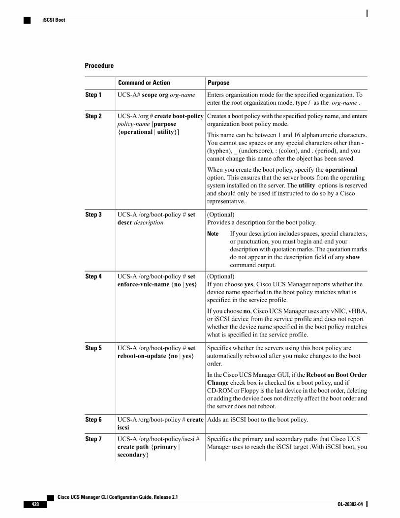
Procedure
PurposeCommand or Action
Enters organization mode for the specified organization. Toenter the root organization mode, type / as the org-name .
UCS-A# scope org org-nameStep 1
Creates a boot policy with the specified policy name, and entersorganization boot policy mode.
UCS-A /org # create boot-policypolicy-name [purpose{operational | utility}]
Step 2
This name can be between 1 and 16 alphanumeric characters.You cannot use spaces or any special characters other than -(hyphen), _ (underscore), : (colon), and . (period), and youcannot change this name after the object has been saved.
When you create the boot policy, specify the operationaloption. This ensures that the server boots from the operatingsystem installed on the server. The utility options is reservedand should only be used if instructed to do so by a Ciscorepresentative.
(Optional)Provides a description for the boot policy.
UCS-A /org/boot-policy # setdescr description
Step 3
If your description includes spaces, special characters,or punctuation, you must begin and end yourdescriptionwith quotationmarks. The quotationmarksdo not appear in the description field of any showcommand output.
Note
(Optional)If you choose yes, Cisco UCS Manager reports whether thedevice name specified in the boot policy matches what isspecified in the service profile.
UCS-A /org/boot-policy # setenforce-vnic-name {no | yes}
Step 4
If you choose no, Cisco UCSManager uses any vNIC, vHBA,or iSCSI device from the service profile and does not reportwhether the device name specified in the boot policy matcheswhat is specified in the service profile.
Specifies whether the servers using this boot policy areautomatically rebooted after you make changes to the bootorder.
UCS-A /org/boot-policy # setreboot-on-update {no | yes}
Step 5
In the Cisco UCSManager GUI, if theReboot on BootOrderChange check box is checked for a boot policy, and ifCD-ROMor Floppy is the last device in the boot order, deletingor adding the device does not directly affect the boot order andthe server does not reboot.
Adds an iSCSI boot to the boot policy.UCS-A /org/boot-policy # createiscsi
Step 6
Specifies the primary and secondary paths that Cisco UCSManager uses to reach the iSCSI target .With iSCSI boot, you
UCS-A /org/boot-policy/iscsi #create path {primary |secondary}
Step 7
Cisco UCS Manager CLI Configuration Guide, Release 2.1428 OL-28302-04
iSCSI Boot
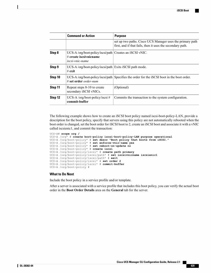
PurposeCommand or Action
set up two paths. Cisco UCS Manager uses the primary pathfirst, and if that fails, then it uses the secondary path.
Creates an iSCSI vNIC.UCS-A /org/boot-policy/iscsi/path# create iscsivnicnameiscsi-vnic-name
Step 8
Exits iSCSI path mode.UCS-A /org/boot-policy/iscsi/path# exit
Step 9
Specifies the order for the iSCSI boot in the boot order.UCS-A /org/boot-policy/iscsi/path# set order order-num
Step 10
(Optional)Repeat steps 8-10 to createsecondary iSCSI vNICs.
Step 11
Commits the transaction to the system configuration.UCS-A /org/boot-policy/iscsi #commit-buffer
Step 12
The following example shows how to create an iSCSI boot policy named iscsi-boot-policy-LAN, provide adescription for the boot policy, specify that servers using this policy are not automatically rebooted when theboot order is changed, set the boot order for iSCSI boot to 2, create an iSCSI boot and associate it with a vNICcalled iscsienic1, and commit the transaction:UCS-A# scope org /UCS-A /org* # create boot-policy iscsi-boot-policy-LAN purpose operationalUCS-A /org/boot-policy* # set descr "Boot policy that boots from iSCSI."UCS-A /org/boot-policy* # set enforce-vnic-name yesUCS-A /org/boot-policy* # set reboot-on-update noUCS-A /org/boot-policy* # create iscsiUCS-A /org/boot-policy/iscsi* # create path primaryUCS-A /org/boot-policy/iscsi/path* # set iscsivnicname iscsienic1UCS-A /org/boot-policy/iscsi/path* # exitUCS-A /org/boot-policy/iscsi* # set order 2UCS-A /org/boot-policy/iscsi* # commit-bufferUCS-A /org/boot-policy #
What to Do Next
Include the boot policy in a service profile and/or template.
After a server is associated with a service profile that includes this boot policy, you can verify the actual bootorder in the Boot Order Details area on the General tab for the server.
Cisco UCS Manager CLI Configuration Guide, Release 2.1 OL-28302-04 429
iSCSI Boot
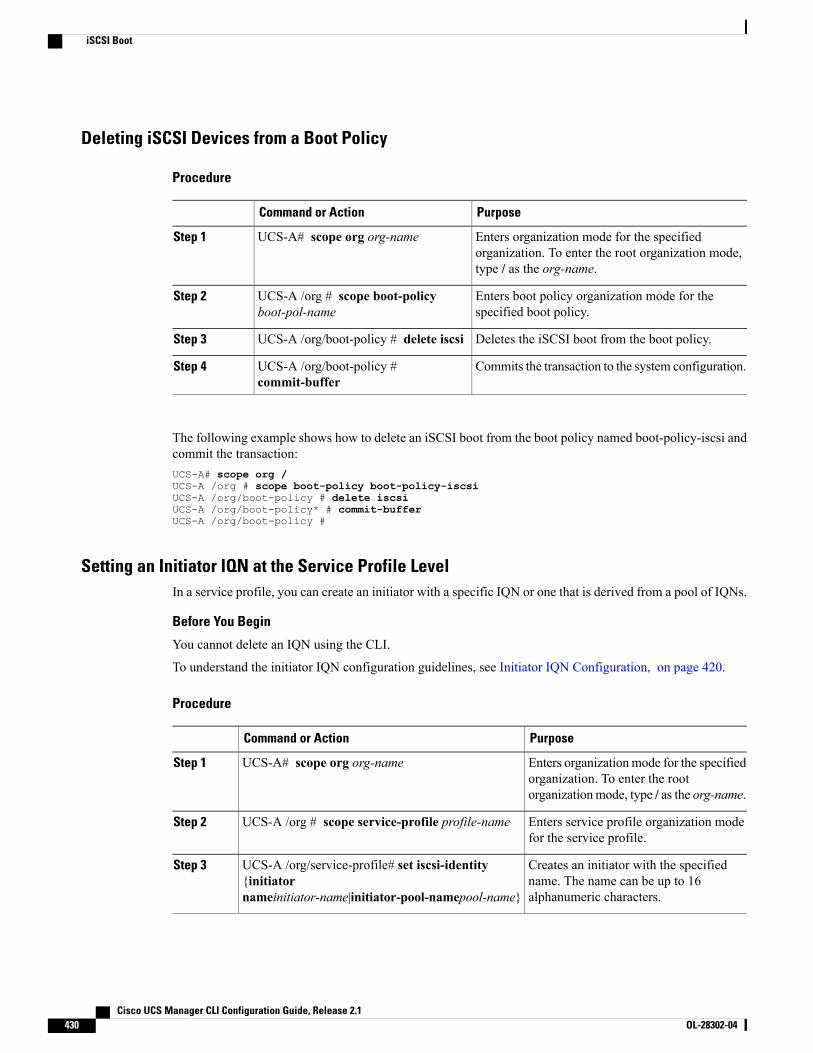
Deleting iSCSI Devices from a Boot Policy
Procedure
PurposeCommand or Action
Enters organization mode for the specifiedorganization. To enter the root organization mode,type / as the org-name.
UCS-A# scope org org-nameStep 1
Enters boot policy organization mode for thespecified boot policy.
UCS-A /org # scope boot-policyboot-pol-name
Step 2
Deletes the iSCSI boot from the boot policy.UCS-A /org/boot-policy # delete iscsiStep 3
Commits the transaction to the system configuration.UCS-A /org/boot-policy #commit-buffer
Step 4
The following example shows how to delete an iSCSI boot from the boot policy named boot-policy-iscsi andcommit the transaction:UCS-A# scope org /UCS-A /org # scope boot-policy boot-policy-iscsiUCS-A /org/boot-policy # delete iscsiUCS-A /org/boot-policy* # commit-bufferUCS-A /org/boot-policy #
Setting an Initiator IQN at the Service Profile LevelIn a service profile, you can create an initiator with a specific IQN or one that is derived from a pool of IQNs.
Before You Begin
You cannot delete an IQN using the CLI.
To understand the initiator IQN configuration guidelines, see Initiator IQN Configuration, on page 420.
Procedure
PurposeCommand or Action
Enters organizationmode for the specifiedorganization. To enter the rootorganizationmode, type / as the org-name.
UCS-A# scope org org-nameStep 1
Enters service profile organization modefor the service profile.
UCS-A /org # scope service-profile profile-nameStep 2
Creates an initiator with the specifiedname. The name can be up to 16alphanumeric characters.
UCS-A /org/service-profile# set iscsi-identity{initiatornameinitiator-name|initiator-pool-namepool-name}
Step 3
Cisco UCS Manager CLI Configuration Guide, Release 2.1430 OL-28302-04
iSCSI Boot
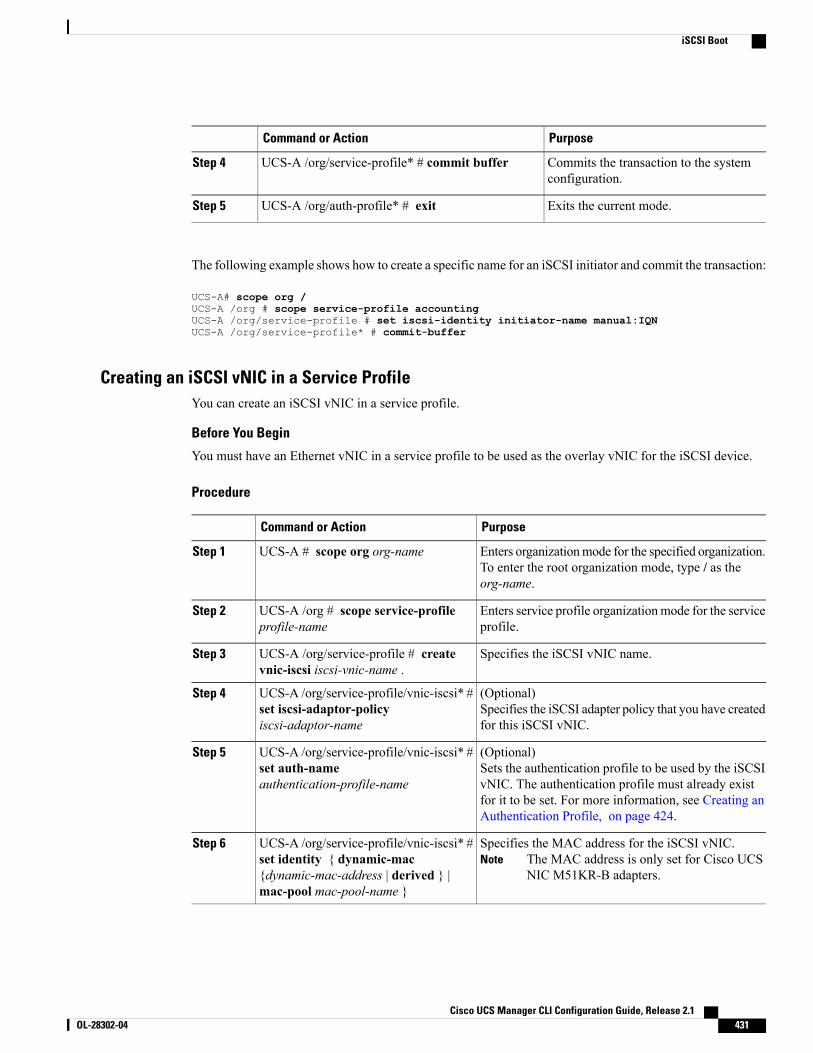
PurposeCommand or Action
Commits the transaction to the systemconfiguration.
UCS-A /org/service-profile* # commit bufferStep 4
Exits the current mode.UCS-A /org/auth-profile* # exitStep 5
The following example shows how to create a specific name for an iSCSI initiator and commit the transaction:
UCS-A# scope org /UCS-A /org # scope service-profile accountingUCS-A /org/service-profile # set iscsi-identity initiator-name manual:IQNUCS-A /org/service-profile* # commit-buffer
Creating an iSCSI vNIC in a Service ProfileYou can create an iSCSI vNIC in a service profile.
Before You Begin
You must have an Ethernet vNIC in a service profile to be used as the overlay vNIC for the iSCSI device.
Procedure
PurposeCommand or Action
Enters organizationmode for the specified organization.To enter the root organization mode, type / as theorg-name.
UCS-A # scope org org-nameStep 1
Enters service profile organizationmode for the serviceprofile.
UCS-A /org # scope service-profileprofile-name
Step 2
Specifies the iSCSI vNIC name.UCS-A /org/service-profile # createvnic-iscsi iscsi-vnic-name .
Step 3
(Optional)Specifies the iSCSI adapter policy that you have createdfor this iSCSI vNIC.
UCS-A /org/service-profile/vnic-iscsi* #set iscsi-adaptor-policyiscsi-adaptor-name
Step 4
(Optional)Sets the authentication profile to be used by the iSCSIvNIC. The authentication profile must already exist
UCS-A /org/service-profile/vnic-iscsi* #set auth-nameauthentication-profile-name
Step 5
for it to be set. For more information, see Creating anAuthentication Profile, on page 424.
Specifies the MAC address for the iSCSI vNIC.The MAC address is only set for Cisco UCSNIC M51KR-B adapters.
NoteUCS-A /org/service-profile/vnic-iscsi* #set identity { dynamic-mac{dynamic-mac-address | derived } |mac-pool mac-pool-name }
Step 6
Cisco UCS Manager CLI Configuration Guide, Release 2.1 OL-28302-04 431
iSCSI Boot
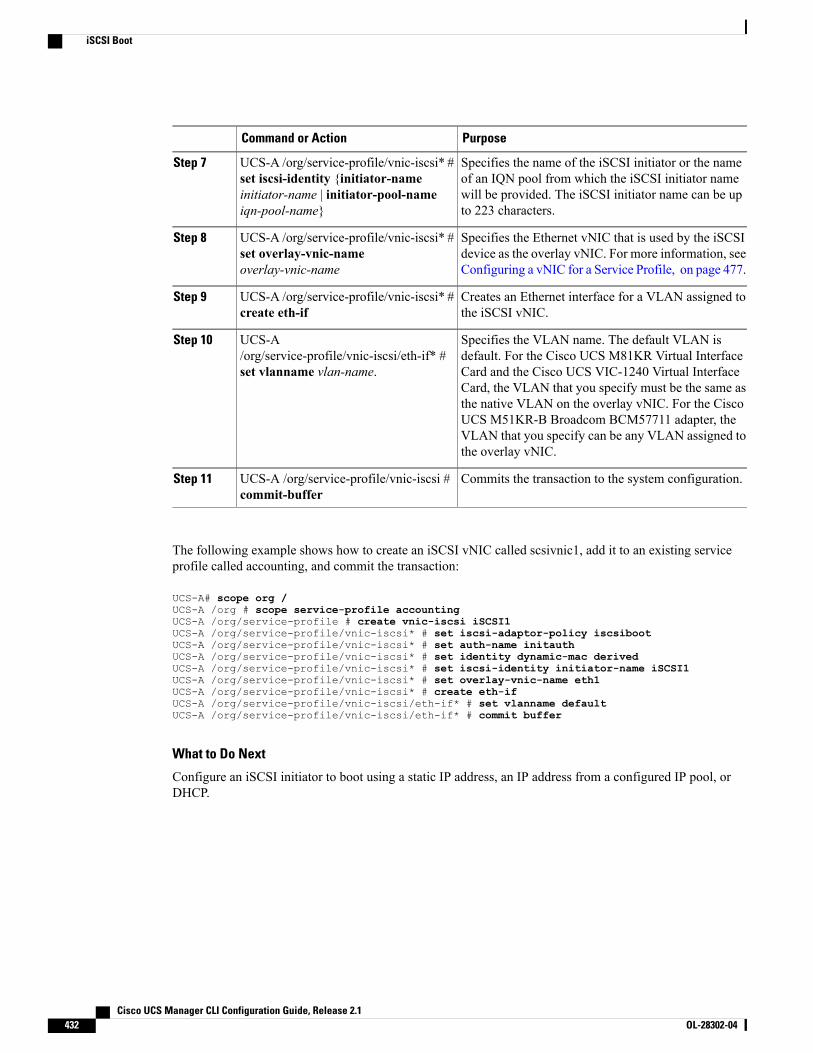
PurposeCommand or Action
Specifies the name of the iSCSI initiator or the nameof an IQN pool from which the iSCSI initiator name
UCS-A /org/service-profile/vnic-iscsi* #set iscsi-identity {initiator-name
Step 7
will be provided. The iSCSI initiator name can be upto 223 characters.
initiator-name | initiator-pool-nameiqn-pool-name}
Specifies the Ethernet vNIC that is used by the iSCSIdevice as the overlay vNIC. For more information, seeConfiguring a vNIC for a Service Profile, on page 477.
UCS-A /org/service-profile/vnic-iscsi* #set overlay-vnic-nameoverlay-vnic-name
Step 8
Creates an Ethernet interface for a VLAN assigned tothe iSCSI vNIC.
UCS-A /org/service-profile/vnic-iscsi* #create eth-if
Step 9
Specifies the VLAN name. The default VLAN isdefault. For the Cisco UCS M81KR Virtual Interface
UCS-A/org/service-profile/vnic-iscsi/eth-if* #set vlanname vlan-name.
Step 10
Card and the Cisco UCS VIC-1240 Virtual InterfaceCard, the VLAN that you specify must be the same asthe native VLAN on the overlay vNIC. For the CiscoUCS M51KR-B Broadcom BCM57711 adapter, theVLAN that you specify can be any VLAN assigned tothe overlay vNIC.
Commits the transaction to the system configuration.UCS-A /org/service-profile/vnic-iscsi #commit-buffer
Step 11
The following example shows how to create an iSCSI vNIC called scsivnic1, add it to an existing serviceprofile called accounting, and commit the transaction:
UCS-A# scope org /UCS-A /org # scope service-profile accountingUCS-A /org/service-profile # create vnic-iscsi iSCSI1UCS-A /org/service-profile/vnic-iscsi* # set iscsi-adaptor-policy iscsibootUCS-A /org/service-profile/vnic-iscsi* # set auth-name initauthUCS-A /org/service-profile/vnic-iscsi* # set identity dynamic-mac derivedUCS-A /org/service-profile/vnic-iscsi* # set iscsi-identity initiator-name iSCSI1UCS-A /org/service-profile/vnic-iscsi* # set overlay-vnic-name eth1UCS-A /org/service-profile/vnic-iscsi* # create eth-ifUCS-A /org/service-profile/vnic-iscsi/eth-if* # set vlanname defaultUCS-A /org/service-profile/vnic-iscsi/eth-if* # commit buffer
What to Do Next
Configure an iSCSI initiator to boot using a static IP address, an IP address from a configured IP pool, orDHCP.
Cisco UCS Manager CLI Configuration Guide, Release 2.1432 OL-28302-04
iSCSI Boot
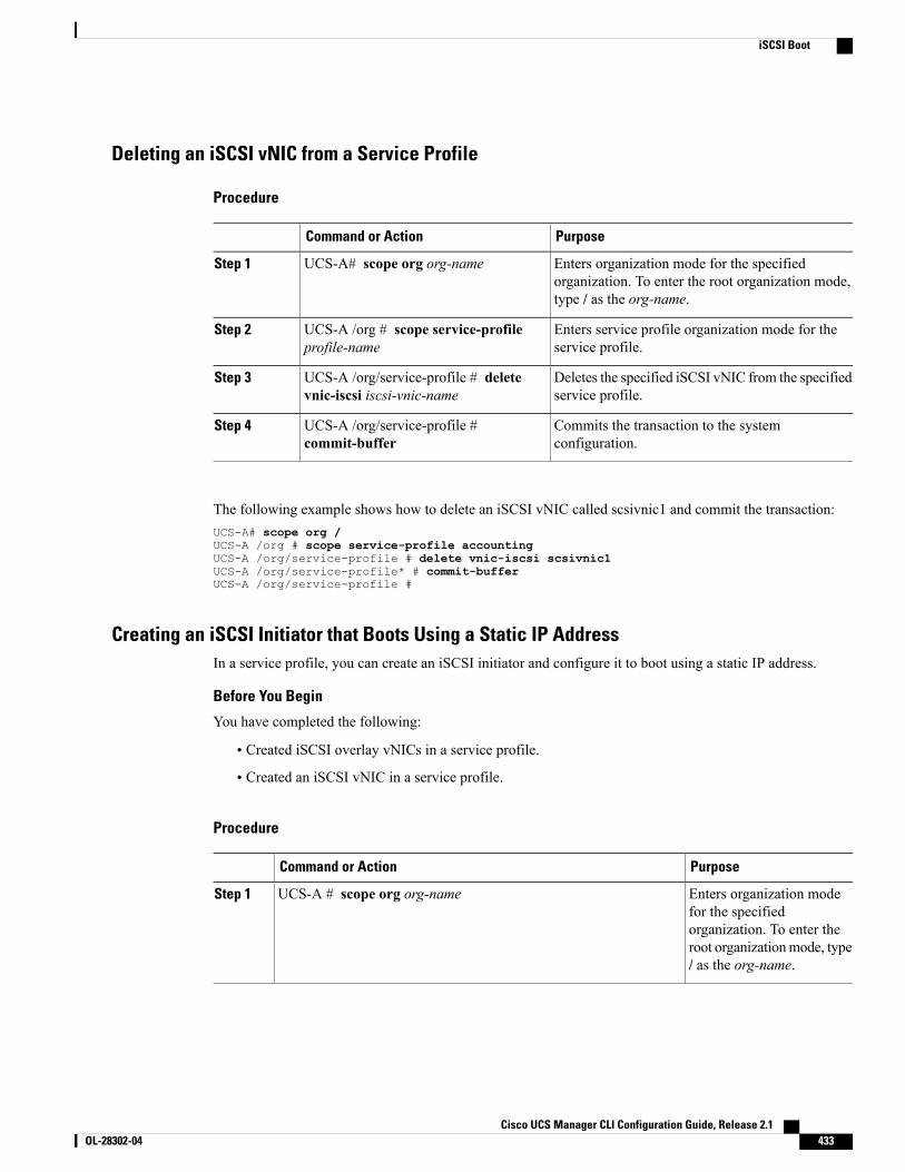
Deleting an iSCSI vNIC from a Service Profile
Procedure
PurposeCommand or Action
Enters organization mode for the specifiedorganization. To enter the root organization mode,type / as the org-name.
UCS-A# scope org org-nameStep 1
Enters service profile organization mode for theservice profile.
UCS-A /org # scope service-profileprofile-name
Step 2
Deletes the specified iSCSI vNIC from the specifiedservice profile.
UCS-A /org/service-profile # deletevnic-iscsi iscsi-vnic-name
Step 3
Commits the transaction to the systemconfiguration.
UCS-A /org/service-profile #commit-buffer
Step 4
The following example shows how to delete an iSCSI vNIC called scsivnic1 and commit the transaction:UCS-A# scope org /UCS-A /org # scope service-profile accountingUCS-A /org/service-profile # delete vnic-iscsi scsivnic1UCS-A /org/service-profile* # commit-bufferUCS-A /org/service-profile #
Creating an iSCSI Initiator that Boots Using a Static IP AddressIn a service profile, you can create an iSCSI initiator and configure it to boot using a static IP address.
Before You Begin
You have completed the following:
• Created iSCSI overlay vNICs in a service profile.
• Created an iSCSI vNIC in a service profile.
Procedure
PurposeCommand or Action
Enters organization modefor the specified
UCS-A # scope org org-nameStep 1
organization. To enter theroot organizationmode, type/ as the org-name.
Cisco UCS Manager CLI Configuration Guide, Release 2.1 OL-28302-04 433
iSCSI Boot
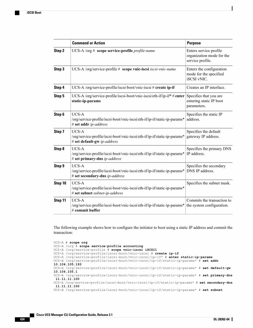
PurposeCommand or Action
Enters service profileorganization mode for theservice profile.
UCS-A /org # scope service-profile profile-nameStep 2
Enters the configurationmode for the specifiediSCSI vNIC.
UCS-A /org/service-profile # scope vnic-iscsi iscsi-vnic-nameStep 3
Creates an IP interface.UCS-A /org/service-profile/iscsi-boot/vnic-iscsi # create ip-ifStep 4
Specifies that you areentering static IP bootparameters.
UCS-A /org/service-profile/iscsi-boot/vnic-iscsi/eth-if/ip-if* # enterstatic-ip-params
Step 5
Specifies the static IPaddress.
UCS-A/org/service-profile/iscsi-boot/vnic-iscsi/eth-if/ip-if/static-ip-params*# set addr ip-address
Step 6
Specifies the defaultgateway IP address.
UCS-A/org/service-profile/iscsi-boot/vnic-iscsi/eth-if/ip-if/static-ip-params*# set default-gw ip-address
Step 7
Specifies the primary DNSIP address.
UCS-A/org/service-profile/iscsi-boot/vnic-iscsi/eth-if/ip-if/static-ip-params*# set primary-dns ip-address
Step 8
Specifies the secondaryDNS IP address.
UCS-A/org/service-profile/iscsi-boot/vnic-iscsi/eth-if/ip-if/static-ip-params*# set secondary-dns ip-address
Step 9
Specifies the subnet mask.UCS-A/org/service-profile/iscsi-boot/vnic-iscsi/eth-if/ip-if/static-ip-params*# set subnet subnet-ip-address
Step 10
Commits the transaction tothe system configuration.
UCS-A/org/service-profile/iscsi-boot/vnic-iscsi/eth-if/ip-if/static-ip-params*# commit buffer
Step 11
The following example shows how to configure the initiator to boot using a static IP address and commit thetransaction:
UCS-A # scope orgUCS-A /org # scope service-profile accountingUCS-A /org/service-profile # scope vnic-iscsi iSCSI1UCS-A /org/service-profile/iscsi-boot/vnic-iscsi # create ip-ifUCS-A /org/service-profile/iscsi-boot/vnic-iscsi/ip-if* # enter static-ip-paramsUCS-A /org/service-profile/iscsi-boot/vnic-iscsi/ip-if/static-ip-params* # set addr10.104.105.193UCS-A /org/service-profile/iscsi-boot/vnic-iscsi/ip-if/static-ip-params* # set default-gw10.104.105.1UCS-A /org/service-profile/iscsi-boot/vnic-iscsi/ip-if/static-ip-params* # set primary-dns11.11.11.100UCS-A /org/service-profile/iscsi-boot/vnic-iscsi/ip-if/static-ip-params* # set secondary-dns11.11.11.100UCS-A /org/service-profile/iscsi-boot/vnic-iscsi/ip-if/static-ip-params* # set subnet
Cisco UCS Manager CLI Configuration Guide, Release 2.1434 OL-28302-04
iSCSI Boot
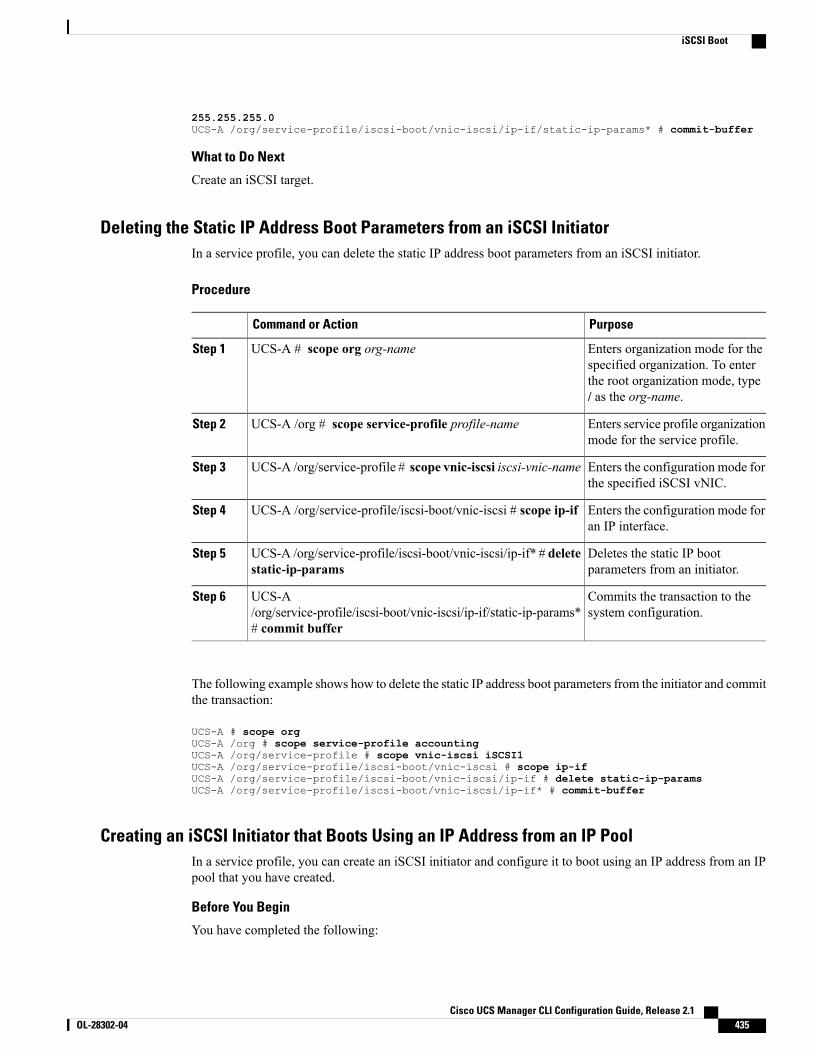
255.255.255.0UCS-A /org/service-profile/iscsi-boot/vnic-iscsi/ip-if/static-ip-params* # commit-buffer
What to Do Next
Create an iSCSI target.
Deleting the Static IP Address Boot Parameters from an iSCSI InitiatorIn a service profile, you can delete the static IP address boot parameters from an iSCSI initiator.
Procedure
PurposeCommand or Action
Enters organization mode for thespecified organization. To enter
UCS-A # scope org org-nameStep 1
the root organization mode, type/ as the org-name.
Enters service profile organizationmode for the service profile.
UCS-A /org # scope service-profile profile-nameStep 2
Enters the configuration mode forthe specified iSCSI vNIC.
UCS-A /org/service-profile # scope vnic-iscsi iscsi-vnic-nameStep 3
Enters the configuration mode foran IP interface.
UCS-A /org/service-profile/iscsi-boot/vnic-iscsi # scope ip-ifStep 4
Deletes the static IP bootparameters from an initiator.
UCS-A /org/service-profile/iscsi-boot/vnic-iscsi/ip-if* # deletestatic-ip-params
Step 5
Commits the transaction to thesystem configuration.
UCS-A/org/service-profile/iscsi-boot/vnic-iscsi/ip-if/static-ip-params*# commit buffer
Step 6
The following example shows how to delete the static IP address boot parameters from the initiator and committhe transaction:
UCS-A # scope orgUCS-A /org # scope service-profile accountingUCS-A /org/service-profile # scope vnic-iscsi iSCSI1UCS-A /org/service-profile/iscsi-boot/vnic-iscsi # scope ip-ifUCS-A /org/service-profile/iscsi-boot/vnic-iscsi/ip-if # delete static-ip-paramsUCS-A /org/service-profile/iscsi-boot/vnic-iscsi/ip-if* # commit-buffer
Creating an iSCSI Initiator that Boots Using an IP Address from an IP PoolIn a service profile, you can create an iSCSI initiator and configure it to boot using an IP address from an IPpool that you have created.
Before You Begin
You have completed the following:
Cisco UCS Manager CLI Configuration Guide, Release 2.1 OL-28302-04 435
iSCSI Boot
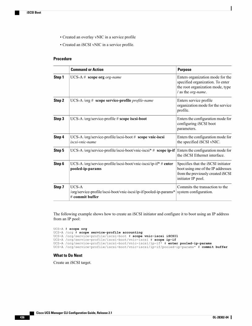
• Created an overlay vNIC in a service profile
• Created an iSCSI vNIC in a service profile.
Procedure
PurposeCommand or Action
Enters organization mode for thespecified organization. To enter
UCS-A # scope org org-nameStep 1
the root organization mode, type/ as the org-name.
Enters service profileorganization mode for the serviceprofile.
UCS-A /org # scope service-profile profile-nameStep 2
Enters the configurationmode forconfiguring iSCSI bootparameters.
UCS-A /org/service-profile # scope iscsi-bootStep 3
Enters the configurationmode forthe specified iSCSI vNIC.
UCS-A /org/service-profile/iscsi-boot # scope vnic-iscsiiscsi-vnic-name
Step 4
Enters the configurationmode forthe iSCSI Ethernet interface.
UCS-A /org/service-profile/iscsi-boot/vnic-iscsi* # scope ip-ifStep 5
Specifies that the iSCSI initiatorboot using one of the IP addresses
UCS-A /org/service-profile/iscsi-boot/vnic-iscsi/ip-if* # enterpooled-ip-params
Step 6
from the previously created iSCSIinitiator IP pool.
Commits the transaction to thesystem configuration.
UCS-A/org/service-profile/iscsi-boot/vnic-iscsi/ip-if/pooled-ip-params*# commit buffer
Step 7
The following example shows how to create an iSCSI initiator and configure it to boot using an IP addressfrom an IP pool:
UCS-A # scope orgUCS-A /org # scope service-profile accountingUCS-A /org/service-profile/iscsi-boot # scope vnic-iscsi iSCSI1UCS-A /org/service-profile/iscsi-boot/vnic-iscsi # scope ip-ifUCS-A /org/service-profile/iscsi-boot/vnic-iscsi/ip-if* # enter pooled-ip-paramsUCS-A /org/service-profile/iscsi-boot/vnic-iscsi/ip-if/pooled-ip-params* # commit buffer
What to Do Next
Create an iSCSI target.
Cisco UCS Manager CLI Configuration Guide, Release 2.1436 OL-28302-04
iSCSI Boot
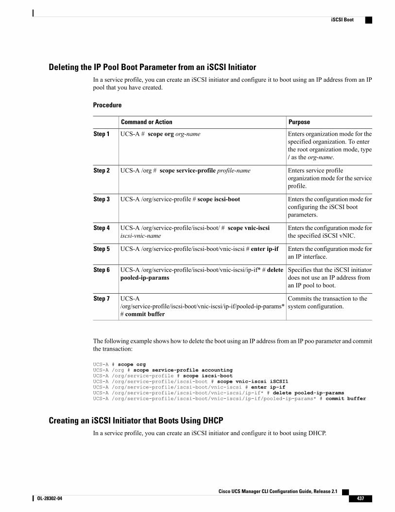
Deleting the IP Pool Boot Parameter from an iSCSI InitiatorIn a service profile, you can create an iSCSI initiator and configure it to boot using an IP address from an IPpool that you have created.
Procedure
PurposeCommand or Action
Enters organization mode for thespecified organization. To enter
UCS-A # scope org org-nameStep 1
the root organization mode, type/ as the org-name.
Enters service profileorganizationmode for the serviceprofile.
UCS-A /org # scope service-profile profile-nameStep 2
Enters the configurationmode forconfiguring the iSCSI bootparameters.
UCS-A /org/service-profile # scope iscsi-bootStep 3
Enters the configurationmode forthe specified iSCSI vNIC.
UCS-A /org/service-profile/iscsi-boot/ # scope vnic-iscsiiscsi-vnic-name
Step 4
Enters the configurationmode foran IP interface.
UCS-A /org/service-profile/iscsi-boot/vnic-iscsi # enter ip-ifStep 5
Specifies that the iSCSI initiatordoes not use an IP address froman IP pool to boot.
UCS-A /org/service-profile/iscsi-boot/vnic-iscsi/ip-if* # deletepooled-ip-params
Step 6
Commits the transaction to thesystem configuration.
UCS-A/org/service-profile/iscsi-boot/vnic-iscsi/ip-if/pooled-ip-params*# commit buffer
Step 7
The following example shows how to delete the boot using an IP address from an IP poo parameter and committhe transaction:
UCS-A # scope orgUCS-A /org # scope service-profile accountingUCS-A /org/service-profile # scope iscsi-bootUCS-A /org/service-profile/iscsi-boot # scope vnic-iscsi iSCSI1UCS-A /org/service-profile/iscsi-boot/vnic-iscsi # enter ip-ifUCS-A /org/service-profile/iscsi-boot/vnic-iscsi/ip-if* # delete pooled-ip-paramsUCS-A /org/service-profile/iscsi-boot/vnic-iscsi/ip-if/pooled-ip-params* # commit buffer
Creating an iSCSI Initiator that Boots Using DHCPIn a service profile, you can create an iSCSI initiator and configure it to boot using DHCP.
Cisco UCS Manager CLI Configuration Guide, Release 2.1 OL-28302-04 437
iSCSI Boot
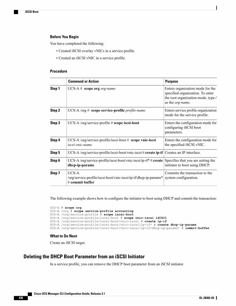
Before You Begin
You have completed the following:
• Created iSCSI overlay vNICs in a service profile.
• Created an iSCSI vNIC in a service profile.
Procedure
PurposeCommand or Action
Enters organization mode for thespecified organization. To enter
UCS-A # scope org org-nameStep 1
the root organization mode, type /as the org-name.
Enters service profile organizationmode for the service profile.
UCS-A /org # scope service-profile profile-nameStep 2
Enters the configuration mode forconfiguring iSCSI bootparameters.
UCS-A /org/service-profile # scope iscsi-bootStep 3
Enters the configuration mode forthe specified iSCSI vNIC.
UCS-A /org/service-profile/iscsi-boot # scope vnic-iscsiiscsi-vnic-name
Step 4
Creates an IP interface.UCS-A /org/service-profile/iscsi-boot/vnic-iscsi # create ip-ifStep 5
Specifies that you are setting theinitiator to boot using DHCP.
UCS-A /org/service-profile/iscsi-boot/vnic-iscsi/ip-if* # createdhcp-ip-params
Step 6
Commits the transaction to thesystem configuration.
UCS-A/org/service-profile/iscsi-boot/vnic-iscsi/ip-if/dhcp-ip-params*# commit buffer
Step 7
The following example shows how to configure the initiator to boot using DHCP and commit the transaction:
UCS-A # scope orgUCS-A /org # scope service-profile accountingUCS-A /org/service-profile # scope iscsi-bootUCS-A /org/service-profile/iscsi-boot # scope vnic-iscsi iSCSI1UCS-A /org/service-profile/iscsi-boot/vnic-iscsi # create ip-ifUCS-A /org/service-profile/iscsi-boot/vnic-iscsi/ip-if* # create dhcp-ip-paramsUCS-A /org/service-profile/iscsi-boot/vnic-iscsi/ip-if/dhcp-ip-params* # commit-buffer
What to Do Next
Create an iSCSI target.
Deleting the DHCP Boot Parameter from an iSCSI InitiatorIn a service profile, you can remove the DHCP boot parameter from an iSCSI initiator.
Cisco UCS Manager CLI Configuration Guide, Release 2.1438 OL-28302-04
iSCSI Boot
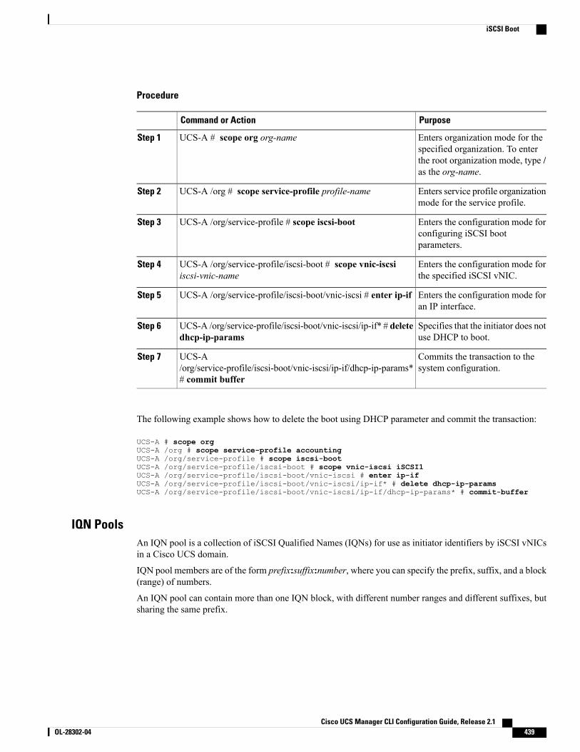
Procedure
PurposeCommand or Action
Enters organization mode for thespecified organization. To enter
UCS-A # scope org org-nameStep 1
the root organization mode, type /as the org-name.
Enters service profile organizationmode for the service profile.
UCS-A /org # scope service-profile profile-nameStep 2
Enters the configuration mode forconfiguring iSCSI bootparameters.
UCS-A /org/service-profile # scope iscsi-bootStep 3
Enters the configuration mode forthe specified iSCSI vNIC.
UCS-A /org/service-profile/iscsi-boot # scope vnic-iscsiiscsi-vnic-name
Step 4
Enters the configuration mode foran IP interface.
UCS-A /org/service-profile/iscsi-boot/vnic-iscsi # enter ip-ifStep 5
Specifies that the initiator does notuse DHCP to boot.
UCS-A /org/service-profile/iscsi-boot/vnic-iscsi/ip-if* # deletedhcp-ip-params
Step 6
Commits the transaction to thesystem configuration.
UCS-A/org/service-profile/iscsi-boot/vnic-iscsi/ip-if/dhcp-ip-params*# commit buffer
Step 7
The following example shows how to delete the boot using DHCP parameter and commit the transaction:
UCS-A # scope orgUCS-A /org # scope service-profile accountingUCS-A /org/service-profile # scope iscsi-bootUCS-A /org/service-profile/iscsi-boot # scope vnic-iscsi iSCSI1UCS-A /org/service-profile/iscsi-boot/vnic-iscsi # enter ip-ifUCS-A /org/service-profile/iscsi-boot/vnic-iscsi/ip-if* # delete dhcp-ip-paramsUCS-A /org/service-profile/iscsi-boot/vnic-iscsi/ip-if/dhcp-ip-params* # commit-buffer
IQN PoolsAn IQN pool is a collection of iSCSI Qualified Names (IQNs) for use as initiator identifiers by iSCSI vNICsin a Cisco UCS domain.
IQN pool members are of the form prefix:suffix:number, where you can specify the prefix, suffix, and a block(range) of numbers.
An IQN pool can contain more than one IQN block, with different number ranges and different suffixes, butsharing the same prefix.
Cisco UCS Manager CLI Configuration Guide, Release 2.1 OL-28302-04 439
iSCSI Boot
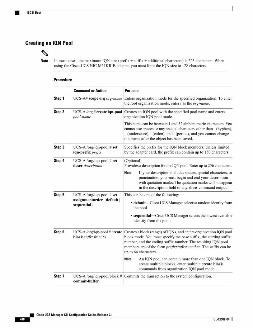
Creating an IQN Pool
In most cases, the maximum IQN size (prefix + suffix + additional characters) is 223 characters. Whenusing the Cisco UCS NIC M51KR-B adapter, you must limit the IQN size to 128 characters.
Note
Procedure
PurposeCommand or Action
Enters organization mode for the specified organization. To enterthe root organization mode, enter / as the org-name.
UCS-A# scope org org-nameStep 1
Creates an IQN pool with the specified pool name and entersorganization IQN pool mode.
UCS-A /org # create iqn-poolpool-name
Step 2
This name can be between 1 and 32 alphanumeric characters. Youcannot use spaces or any special characters other than - (hyphen),_ (underscore), : (colon), and . (period), and you cannot changethis name after the object has been saved.
Specifies the prefix for the IQN block members. Unless limitedby the adapter card, the prefix can contain up to 150 characters.
UCS-A /org/iqn-pool # setiqn-prefix prefix
Step 3
(Optional)Provides a description for the IQN pool. Enter up to 256 characters.
UCS-A /org/iqn-pool # setdescr description
Step 4
If your description includes spaces, special characters, orpunctuation, you must begin and end your descriptionwith quotationmarks. The quotationmarks will not appearin the description field of any show command output.
Note
This can be one of the following:UCS-A /org/iqn-pool # setassignmentorder {default |sequential}
Step 5
• default—CiscoUCSManager selects a random identity fromthe pool.
• sequential—CiscoUCSManager selects the lowest availableidentity from the pool.
Creates a block (range) of IQNs, and enters organization IQN poolblock mode. You must specify the base suffix, the starting suffix
UCS-A /org/iqn-pool # createblock suffix from to
Step 6
number, and the ending suffix number. The resulting IQN poolmembers are of the form prefix:suffix:number. The suffix can beup to 64 characters.
An IQN pool can contain more than one IQN block. Tocreate multiple blocks, enter multiple create blockcommands from organization IQN pool mode.
Note
Commits the transaction to the system configuration.UCS-A /org/iqn-pool/block #commit-buffer
Step 7
Cisco UCS Manager CLI Configuration Guide, Release 2.1440 OL-28302-04
iSCSI Boot
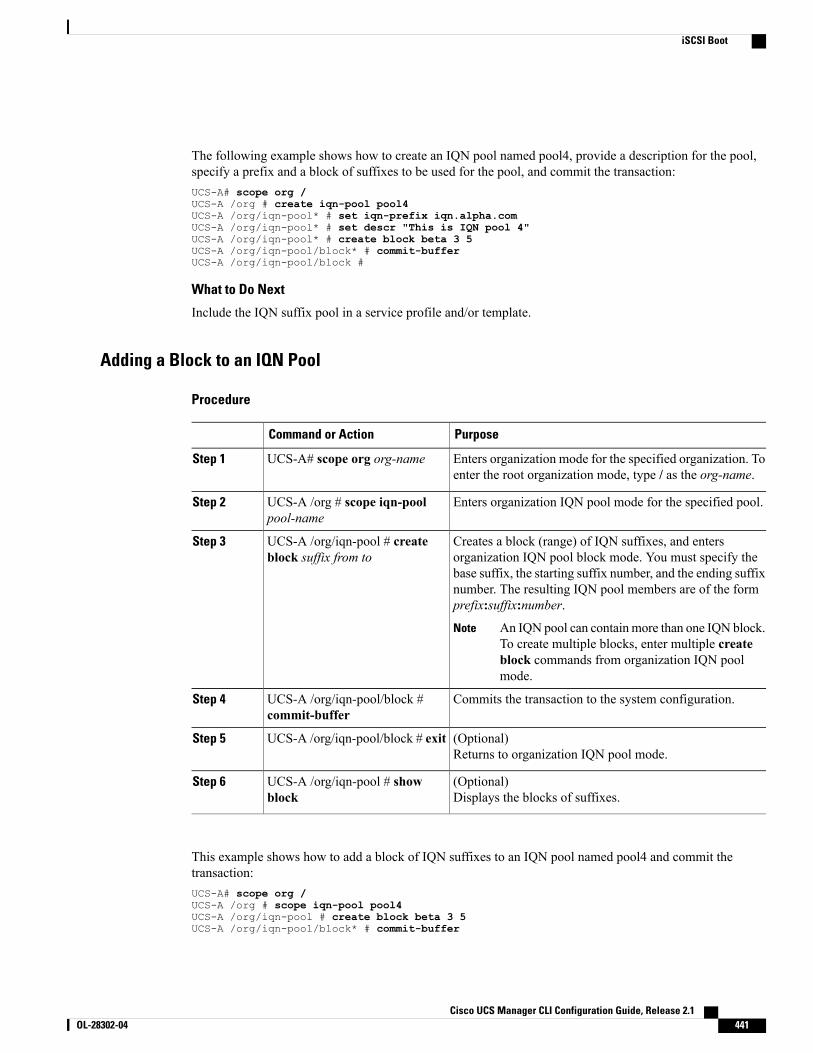
The following example shows how to create an IQN pool named pool4, provide a description for the pool,specify a prefix and a block of suffixes to be used for the pool, and commit the transaction:UCS-A# scope org /UCS-A /org # create iqn-pool pool4UCS-A /org/iqn-pool* # set iqn-prefix iqn.alpha.comUCS-A /org/iqn-pool* # set descr "This is IQN pool 4"UCS-A /org/iqn-pool* # create block beta 3 5UCS-A /org/iqn-pool/block* # commit-bufferUCS-A /org/iqn-pool/block #
What to Do Next
Include the IQN suffix pool in a service profile and/or template.
Adding a Block to an IQN Pool
Procedure
PurposeCommand or Action
Enters organization mode for the specified organization. Toenter the root organization mode, type / as the org-name.
UCS-A# scope org org-nameStep 1
Enters organization IQN pool mode for the specified pool.UCS-A /org # scope iqn-poolpool-name
Step 2
Creates a block (range) of IQN suffixes, and entersorganization IQN pool block mode. You must specify the
UCS-A /org/iqn-pool # createblock suffix from to
Step 3
base suffix, the starting suffix number, and the ending suffixnumber. The resulting IQN pool members are of the formprefix:suffix:number.
An IQN pool can containmore than one IQN block.To create multiple blocks, enter multiple createblock commands from organization IQN poolmode.
Note
Commits the transaction to the system configuration.UCS-A /org/iqn-pool/block #commit-buffer
Step 4
(Optional)Returns to organization IQN pool mode.
UCS-A /org/iqn-pool/block # exitStep 5
(Optional)Displays the blocks of suffixes.
UCS-A /org/iqn-pool # showblock
Step 6
This example shows how to add a block of IQN suffixes to an IQN pool named pool4 and commit thetransaction:UCS-A# scope org /UCS-A /org # scope iqn-pool pool4UCS-A /org/iqn-pool # create block beta 3 5UCS-A /org/iqn-pool/block* # commit-buffer
Cisco UCS Manager CLI Configuration Guide, Release 2.1 OL-28302-04 441
iSCSI Boot
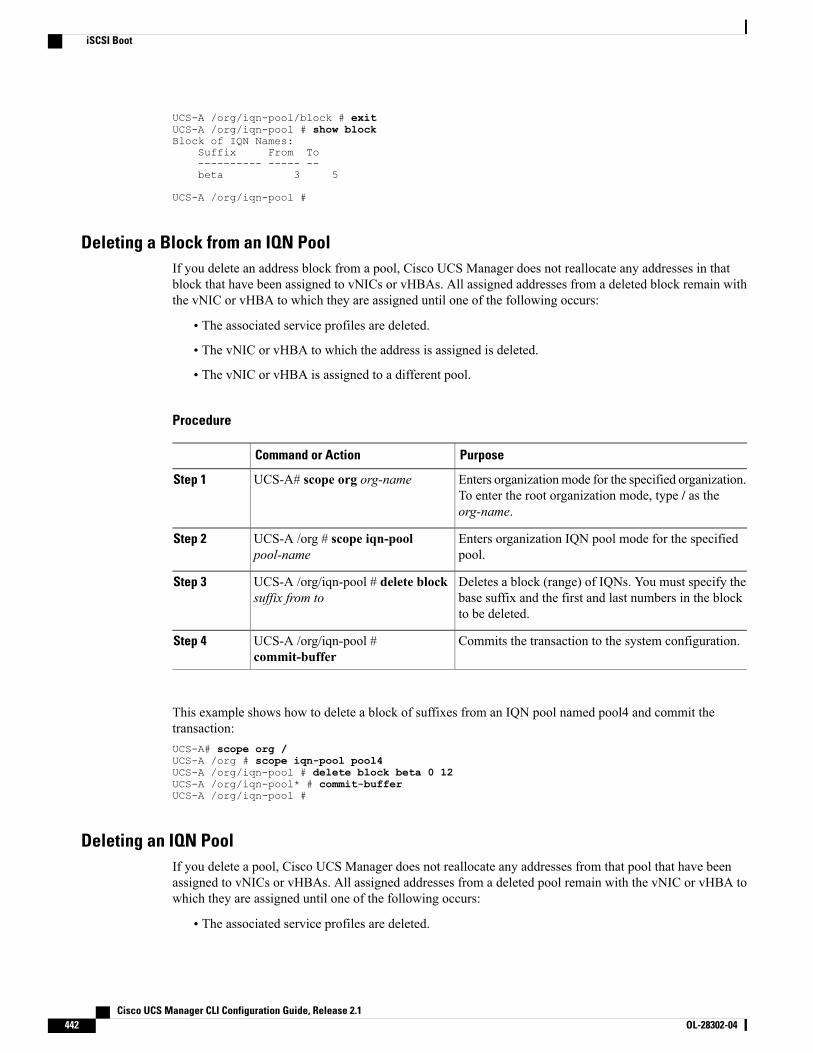
UCS-A /org/iqn-pool/block # exitUCS-A /org/iqn-pool # show blockBlock of IQN Names:
Suffix From To---------- ----- --beta 3 5
UCS-A /org/iqn-pool #
Deleting a Block from an IQN PoolIf you delete an address block from a pool, Cisco UCS Manager does not reallocate any addresses in thatblock that have been assigned to vNICs or vHBAs. All assigned addresses from a deleted block remain withthe vNIC or vHBA to which they are assigned until one of the following occurs:
• The associated service profiles are deleted.
• The vNIC or vHBA to which the address is assigned is deleted.
• The vNIC or vHBA is assigned to a different pool.
Procedure
PurposeCommand or Action
Enters organizationmode for the specified organization.To enter the root organization mode, type / as theorg-name.
UCS-A# scope org org-nameStep 1
Enters organization IQN pool mode for the specifiedpool.
UCS-A /org # scope iqn-poolpool-name
Step 2
Deletes a block (range) of IQNs. You must specify thebase suffix and the first and last numbers in the blockto be deleted.
UCS-A /org/iqn-pool # delete blocksuffix from to
Step 3
Commits the transaction to the system configuration.UCS-A /org/iqn-pool #commit-buffer
Step 4
This example shows how to delete a block of suffixes from an IQN pool named pool4 and commit thetransaction:UCS-A# scope org /UCS-A /org # scope iqn-pool pool4UCS-A /org/iqn-pool # delete block beta 0 12UCS-A /org/iqn-pool* # commit-bufferUCS-A /org/iqn-pool #
Deleting an IQN PoolIf you delete a pool, Cisco UCS Manager does not reallocate any addresses from that pool that have beenassigned to vNICs or vHBAs. All assigned addresses from a deleted pool remain with the vNIC or vHBA towhich they are assigned until one of the following occurs:
• The associated service profiles are deleted.
Cisco UCS Manager CLI Configuration Guide, Release 2.1442 OL-28302-04
iSCSI Boot
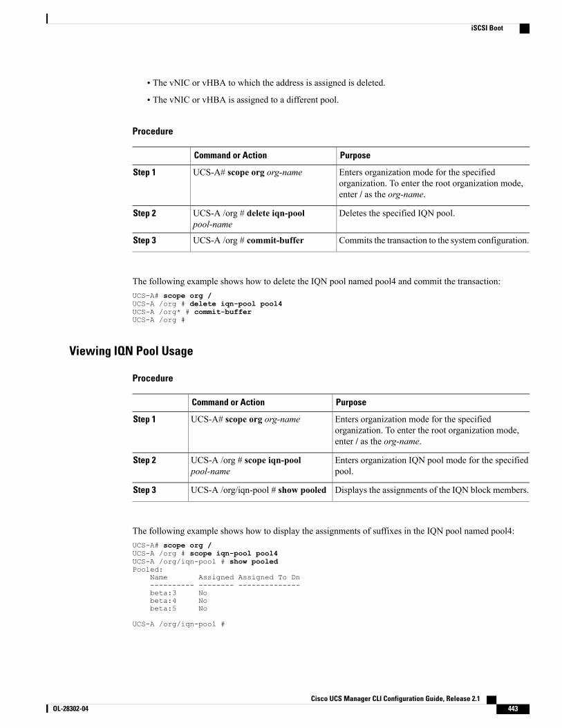
• The vNIC or vHBA to which the address is assigned is deleted.
• The vNIC or vHBA is assigned to a different pool.
Procedure
PurposeCommand or Action
Enters organization mode for the specifiedorganization. To enter the root organization mode,enter / as the org-name.
UCS-A# scope org org-nameStep 1
Deletes the specified IQN pool.UCS-A /org # delete iqn-poolpool-name
Step 2
Commits the transaction to the system configuration.UCS-A /org # commit-bufferStep 3
The following example shows how to delete the IQN pool named pool4 and commit the transaction:UCS-A# scope org /UCS-A /org # delete iqn-pool pool4UCS-A /org* # commit-bufferUCS-A /org #
Viewing IQN Pool Usage
Procedure
PurposeCommand or Action
Enters organization mode for the specifiedorganization. To enter the root organization mode,enter / as the org-name.
UCS-A# scope org org-nameStep 1
Enters organization IQN pool mode for the specifiedpool.
UCS-A /org # scope iqn-poolpool-name
Step 2
Displays the assignments of the IQN block members.UCS-A /org/iqn-pool # show pooledStep 3
The following example shows how to display the assignments of suffixes in the IQN pool named pool4:UCS-A# scope org /UCS-A /org # scope iqn-pool pool4UCS-A /org/iqn-pool # show pooledPooled:
Name Assigned Assigned To Dn---------- -------- --------------beta:3 Nobeta:4 Nobeta:5 No
UCS-A /org/iqn-pool #
Cisco UCS Manager CLI Configuration Guide, Release 2.1 OL-28302-04 443
iSCSI Boot
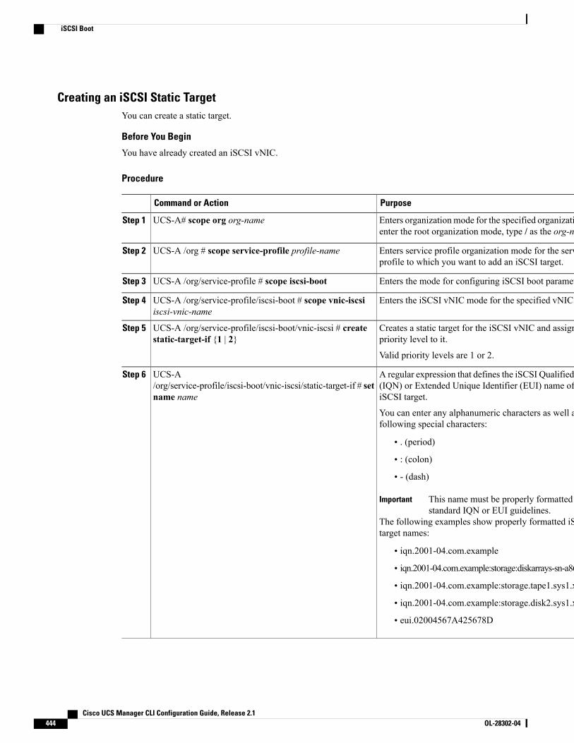
Creating an iSCSI Static TargetYou can create a static target.
Before You Begin
You have already created an iSCSI vNIC.
Procedure
PurposeCommand or Action
Enters organizationmode for the specified organization. Toenter the root organization mode, type / as the org-name.
UCS-A# scope org org-nameStep 1
Enters service profile organization mode for the serviceprofile to which you want to add an iSCSI target.
UCS-A /org # scope service-profile profile-nameStep 2
Enters the mode for configuring iSCSI boot parameters.UCS-A /org/service-profile # scope iscsi-bootStep 3
Enters the iSCSI vNIC mode for the specified vNIC name.UCS-A /org/service-profile/iscsi-boot # scope vnic-iscsiiscsi-vnic-name
Step 4
Creates a static target for the iSCSI vNIC and assigns apriority level to it.
UCS-A /org/service-profile/iscsi-boot/vnic-iscsi # createstatic-target-if {1 | 2}
Step 5
Valid priority levels are 1 or 2.
A regular expression that defines the iSCSI Qualified Name(IQN) or Extended Unique Identifier (EUI) name of theiSCSI target.
UCS-A/org/service-profile/iscsi-boot/vnic-iscsi/static-target-if # setname name
Step 6
You can enter any alphanumeric characters as well as thefollowing special characters:
• . (period)
• : (colon)
• - (dash)
This name must be properly formatted usingstandard IQN or EUI guidelines.
Important
The following examples show properly formatted iSCSItarget names:
• iqn.2001-04.com.example
• iqn.2001-04.com.example:storage:diskarrays-sn-a8675309
• iqn.2001-04.com.example:storage.tape1.sys1.xyz
• iqn.2001-04.com.example:storage.disk2.sys1.xyz
• eui.02004567A425678D
Cisco UCS Manager CLI Configuration Guide, Release 2.1444 OL-28302-04
iSCSI Boot

PurposeCommand or Action
The port associated with the iSCSI target.UCS-A/org/service-profile/iscsi-boot/vnic-iscsi/static-target-if # setport port-num
Step 7
Enter an integer between 1 and 65535. The default is 3260.
(Optional)If you need the target to authenticate itself and have set upan authentication profile, you need to specify the name ofauthentication profile.
UCS-A/org/service-profile/iscsi-boot/vnic-iscsi/static-target-if # setauth-name auth-profile
Step 8
The name of the associated iSCSI authentication profile.
The IPv4 address assigned to the iSCSI target.UCS-A/org/service-profile/iscsi-boot/vnic-iscsi/static-target-if # setipaddress ipv4-address
Step 9
Creates the LUN that corresponds to the location of theinterface.
UCS-A/org/service-profile/iscsi-boot/vnic-iscsi/static-target-if #create lun
Step 10
Specifies the target LUN id. Valid values are from 0 to65535.
UCS-A/org/service-profile/iscsi-boot/vnic-iscsi/static-target-if/lun*# set id id-number
Step 11
Exits the current configuration mode.UCS-A/org/service-profile/iscsi-boot/vnic-iscsi/static-target-if/lun*# exit
Step 12
Exits the current configuration mode.UCS-A/org/service-profile/iscsi-boot/vnic-iscsi/static-target-if #exit
Step 13
Commits the transaction to the system configuration.UCS-A /org/service-profile/iscsi-boot/vnic-iscsi #commit-buffer
Step 14
(Optional)Repeat steps 5 through 14 to create a second static target.Step 15
The following example shows how to create two iSCSI static target interfaces and commit the transaction:UCS-A # scope org testUCS-A /org # scope service-profile accountingUCS-A /org/service-profile # scope iscsi-bootUCS-A /org/service-profile/iscsi-boot # scope vnic-iscsi iSCSI1UCS-A /org/service-profile/iscsi-boot/vnic-iscsi # create static-target-if 1UCS-A /org/service-profile/iscsi-boot/vnic-iscsi/static-target-if* # set name statictarget1UCS-A /org/service-profile/iscsi-boot/vnic-iscsi/static-target-if* # set port 3260UCS-A /org/service-profile/iscsi-boot/vnic-iscsi/static-target-if* # set auth-nameauthprofile1UCS-A /org/service-profile/iscsi-boot/vnic-iscsi/static-target-if* # set ip-address192.168.10.10UCS-A /org/service-profile/iscsi-boot/vnic-iscsi/static-target-if* # create lunUCS-A /org/service-profile/iscsi-boot/vnic-iscsi/static-target-if/lun* # set id 1UCS-A /org/service-profile/iscsi-boot/vnic-iscsi/static-target-if/lun* # exitUCS-A /org/service-profile/iscsi-boot/vnic-iscsi/static-target-if* # exitUCS-A /org/service-profile/iscsi-boot/vnic-iscsi # commit-bufferUCS-A /org/service-profile/iscsi-boot/vnic-iscsi # create static-target-if 2UCS-A /org/service-profile/iscsi-boot/vnic-iscsi/static-target-if* # set ipaddress192.168.10.11UCS-A /org/service-profile/iscsi-boot/vnic-iscsi/static-target-if* # set name statictarget2
Cisco UCS Manager CLI Configuration Guide, Release 2.1 OL-28302-04 445
iSCSI Boot
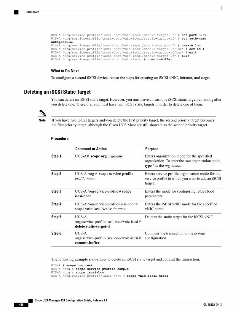
UCS-A /org/service-profile/iscsi-boot/vnic-iscsi/static-target-if* # set port 3260UCS-A /org/service-profile/iscsi-boot/vnic-iscsi/static-target-if* # set auth-nameauthprofile1UCS-A /org/service-profile/iscsi-boot/vnic-iscsi/static-target-if* # create lunUCS-A /org/service-profile/iscsi-boot/vnic-iscsi/static-target-if/lun* # set id 1UCS-A /org/service-profile/iscsi-boot/vnic-iscsi/static-target-if/lun* # exitUCS-A /org/service-profile/iscsi-boot/vnic-iscsi/static-target-if* # exitUCS-A /org/service-profile/iscsi-boot/vnic-iscsi # commit-buffer
What to Do Next
To configure a second iSCSI device, repeat the steps for creating an iSCSI vNIC, initiator, and target.
Deleting an iSCSI Static TargetYou can delete an iSCSI static target. However, you must have at least one iSCSI static target remaining afteryou delete one. Therefore, you must have two iSCSI static targets in order to delete one of them.
If you have two iSCSI targets and you delete the first priority target, the second priority target becomesthe first priority target, although the Cisco UCS Manager still shows it as the second priority target.
Note
Procedure
PurposeCommand or Action
Enters organization mode for the specifiedorganization. To enter the root organizationmode,type / as the org-name.
UCS-A# scope org org-nameStep 1
Enters service profile organization mode for theservice profile to which you want to add an iSCSItarget.
UCS-A /org # scope service-profileprofile-name
Step 2
Enters the mode for configuring iSCSI bootparameters.
UCS-A /org/service-profile # scopeiscsi-boot
Step 3
Enters the iSCSI vNIC mode for the specifiedvNIC name.
UCS-A /org/service-profile/iscsi-boot #scope vnic-iscsi iscsi-vnic-name
Step 4
Deletes the static target for the iSCSI vNIC.UCS-A/org/service-profile/iscsi-boot/vnic-iscsi #delete static-target-if
Step 5
Commits the transaction to the systemconfiguration.
UCS-A/org/service-profile/iscsi-boot/vnic-iscsi #commit-buffer
Step 6
The following example shows how to delete an iSCSI static target and commit the transaction:UCS-A # scope org testUCS-A /org # scope service-profile sampleUCS-A /org # scope iscsi-bootUCS-A /org/service-profile/iscsi-boot # scope vnic-iscsi trial
Cisco UCS Manager CLI Configuration Guide, Release 2.1446 OL-28302-04
iSCSI Boot
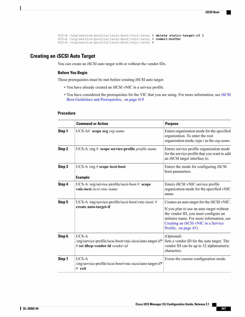
UCS-A /org/service-profile/iscsi-boot/vnic-iscsi # delete static-target-if 1UCS-A /org/service-profile/iscsi-boot/vnic-iscsi # commit-bufferUCS-A /org/service-profile/iscsi-boot/vnic-iscsi #
Creating an iSCSI Auto TargetYou can create an iSCSI auto target with or without the vendor IDs.
Before You Begin
These prerequisites must be met before creating iSCSI auto target:
• You have already created an iSCSI vNIC in a service profile.
• You have considered the prerequisites for the VIC that you are using. For more information, see iSCSIBoot Guidelines and Prerequisites, on page 419
Procedure
PurposeCommand or Action
Enters organizationmode for the specifiedorganization. To enter the rootorganizationmode, type / as the org-name.
UCS-A# scope org org-nameStep 1
Enters service profile organization modefor the service profile that you want to addan iSCSI target interface to.
UCS-A /org # scope service-profile profile-nameStep 2
Enters the mode for configuring iSCSIboot parameters.
UCS-A /org # scope iscsi-boot
Example:
Step 3
Enters iSCSI vNIC service profileorganization mode for the specified vNICname.
UCS-A /org/service-profile/iscsi-boot # scopevnic-iscsi iscsi-vnic-name
Step 4
Creates an auto target for the iSCSI vNIC.UCS-A /org/service-profile/iscsi-boot/vnic-iscsi/ #create auto-target-if
Step 5
If you plan to use an auto target withoutthe vendor ID, you must configure aninitiator name. For more information, seeCreating an iSCSI vNIC in a ServiceProfile, on page 431.
(Optional)Sets a vendor ID for the auto target. Thevendor ID can be up to 32 alphanumericcharacters.
UCS-A/org/service-profile/iscsi-boot/vnic-iscsi/auto-target-if*# set dhcp-vendor-id vendor-id
Step 6
Exists the current configuration mode.UCS-A/org/service-profile/iscsi-boot/vnic-iscsi/auto-target-if*# exit
Step 7
Cisco UCS Manager CLI Configuration Guide, Release 2.1 OL-28302-04 447
iSCSI Boot
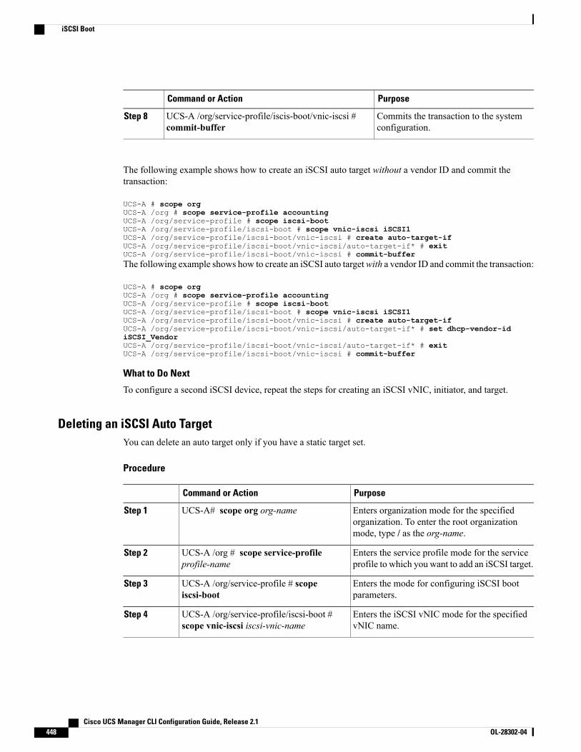
PurposeCommand or Action
Commits the transaction to the systemconfiguration.
UCS-A /org/service-profile/iscis-boot/vnic-iscsi #commit-buffer
Step 8
The following example shows how to create an iSCSI auto target without a vendor ID and commit thetransaction:
UCS-A # scope orgUCS-A /org # scope service-profile accountingUCS-A /org/service-profile # scope iscsi-bootUCS-A /org/service-profile/iscsi-boot # scope vnic-iscsi iSCSI1UCS-A /org/service-profile/iscsi-boot/vnic-iscsi # create auto-target-ifUCS-A /org/service-profile/iscsi-boot/vnic-iscsi/auto-target-if* # exitUCS-A /org/service-profile/iscsi-boot/vnic-iscsi # commit-bufferThe following example shows how to create an iSCSI auto targetwith a vendor ID and commit the transaction:
UCS-A # scope orgUCS-A /org # scope service-profile accountingUCS-A /org/service-profile # scope iscsi-bootUCS-A /org/service-profile/iscsi-boot # scope vnic-iscsi iSCSI1UCS-A /org/service-profile/iscsi-boot/vnic-iscsi # create auto-target-ifUCS-A /org/service-profile/iscsi-boot/vnic-iscsi/auto-target-if* # set dhcp-vendor-idiSCSI_VendorUCS-A /org/service-profile/iscsi-boot/vnic-iscsi/auto-target-if* # exitUCS-A /org/service-profile/iscsi-boot/vnic-iscsi # commit-buffer
What to Do Next
To configure a second iSCSI device, repeat the steps for creating an iSCSI vNIC, initiator, and target.
Deleting an iSCSI Auto TargetYou can delete an auto target only if you have a static target set.
Procedure
PurposeCommand or Action
Enters organization mode for the specifiedorganization. To enter the root organizationmode, type / as the org-name.
UCS-A# scope org org-nameStep 1
Enters the service profile mode for the serviceprofile to which you want to add an iSCSI target.
UCS-A /org # scope service-profileprofile-name
Step 2
Enters the mode for configuring iSCSI bootparameters.
UCS-A /org/service-profile # scopeiscsi-boot
Step 3
Enters the iSCSI vNIC mode for the specifiedvNIC name.
UCS-A /org/service-profile/iscsi-boot #scope vnic-iscsi iscsi-vnic-name
Step 4
Cisco UCS Manager CLI Configuration Guide, Release 2.1448 OL-28302-04
iSCSI Boot
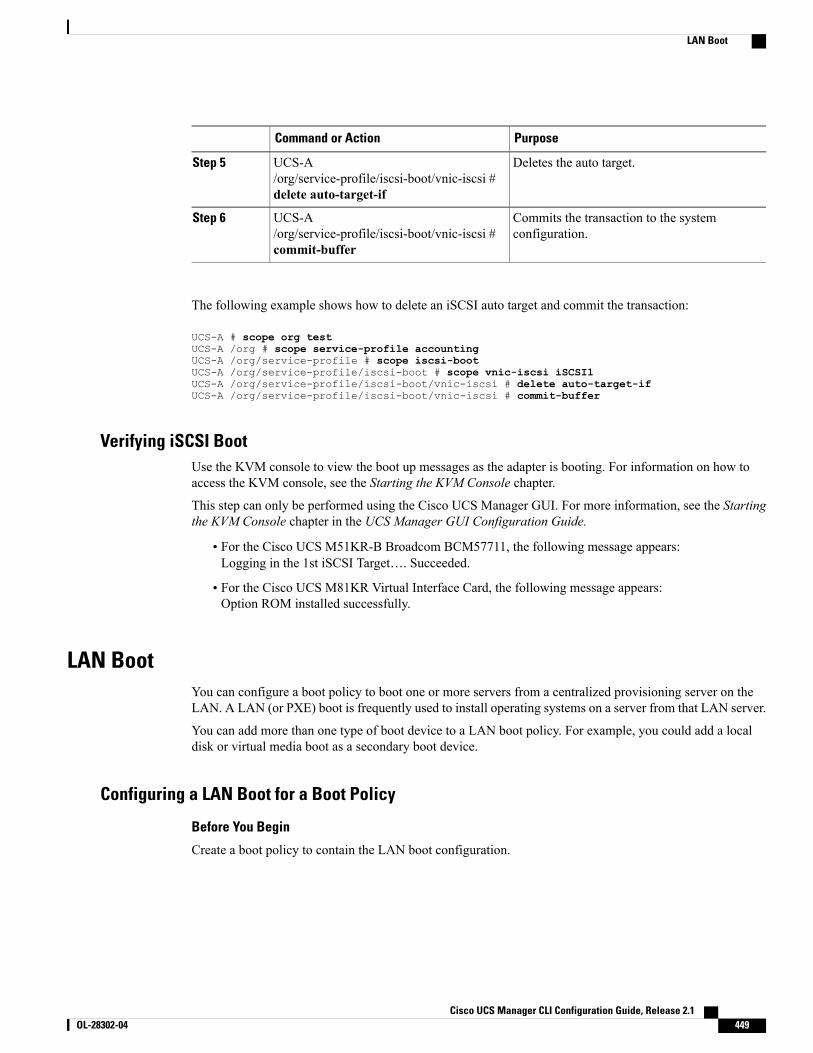
PurposeCommand or Action
Deletes the auto target.UCS-A/org/service-profile/iscsi-boot/vnic-iscsi #delete auto-target-if
Step 5
Commits the transaction to the systemconfiguration.
UCS-A/org/service-profile/iscsi-boot/vnic-iscsi #commit-buffer
Step 6
The following example shows how to delete an iSCSI auto target and commit the transaction:
UCS-A # scope org testUCS-A /org # scope service-profile accountingUCS-A /org/service-profile # scope iscsi-bootUCS-A /org/service-profile/iscsi-boot # scope vnic-iscsi iSCSI1UCS-A /org/service-profile/iscsi-boot/vnic-iscsi # delete auto-target-ifUCS-A /org/service-profile/iscsi-boot/vnic-iscsi # commit-buffer
Verifying iSCSI BootUse the KVM console to view the boot up messages as the adapter is booting. For information on how toaccess the KVM console, see the Starting the KVM Console chapter.
This step can only be performed using the Cisco UCS Manager GUI. For more information, see the Startingthe KVM Console chapter in the UCS Manager GUI Configuration Guide.
• For the Cisco UCS M51KR-B Broadcom BCM57711, the following message appears:Logging in the 1st iSCSI Target…. Succeeded.
• For the Cisco UCS M81KR Virtual Interface Card, the following message appears:Option ROM installed successfully.
LAN BootYou can configure a boot policy to boot one or more servers from a centralized provisioning server on theLAN. A LAN (or PXE) boot is frequently used to install operating systems on a server from that LAN server.
You can add more than one type of boot device to a LAN boot policy. For example, you could add a localdisk or virtual media boot as a secondary boot device.
Configuring a LAN Boot for a Boot Policy
Before You Begin
Create a boot policy to contain the LAN boot configuration.
Cisco UCS Manager CLI Configuration Guide, Release 2.1 OL-28302-04 449
LAN Boot
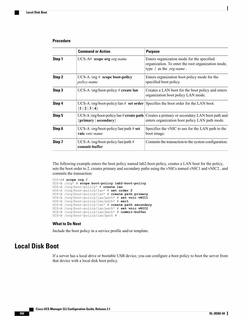
Procedure
PurposeCommand or Action
Enters organization mode for the specifiedorganization. To enter the root organization mode,type / as the org-name .
UCS-A# scope org org-nameStep 1
Enters organization boot policy mode for thespecified boot policy.
UCS-A /org # scope boot-policypolicy-name
Step 2
Creates a LAN boot for the boot policy and entersorganization boot policy LAN mode.
UCS-A /org/boot-policy # create lanStep 3
Specifies the boot order for the LAN boot.UCS-A /org/boot-policy/lan # set order{1 | 2 | 3 | 4}
Step 4
Creates a primary or secondary LAN boot path andenters organization boot policy LAN path mode.
UCS-A /org/boot-policy/lan # create path{primary | secondary}
Step 5
Specifies the vNIC to use for the LAN path to theboot image.
UCS-A /org/boot-policy/lan/path # setvnic vnic-name
Step 6
Commits the transaction to the system configuration.UCS-A /org/boot-policy/lan/path #commit-buffer
Step 7
The following example enters the boot policy named lab2-boot-policy, creates a LAN boot for the policy,sets the boot order to 2, creates primary and secondary paths using the vNICs named vNIC1 and vNIC2 , andcommits the transaction:UCS-A# scope org /UCS-A /org* # scope boot-policy lab2-boot-policyUCS-A /org/boot-policy* # create lanUCS-A /org/boot-policy/lan* # set order 2UCS-A /org/boot-policy/lan* # create path primaryUCS-A /org/boot-policy/lan/path* # set vnic vNIC1UCS-A /org/boot-policy/lan/path* # exitUCS-A /org/boot-policy/lan* # create path secondaryUCS-A /org/boot-policy/lan/path* # set vnic vNIC2UCS-A /org/boot-policy/lan/path* # commit-bufferUCS-A /org/boot-policy/lan/path #
What to Do Next
Include the boot policy in a service profile and/or template.
Local Disk BootIf a server has a local drive or bootable USB device, you can configure a boot policy to boot the server fromthat device with a local disk boot policy.
Cisco UCS Manager CLI Configuration Guide, Release 2.1450 OL-28302-04
Local Disk Boot
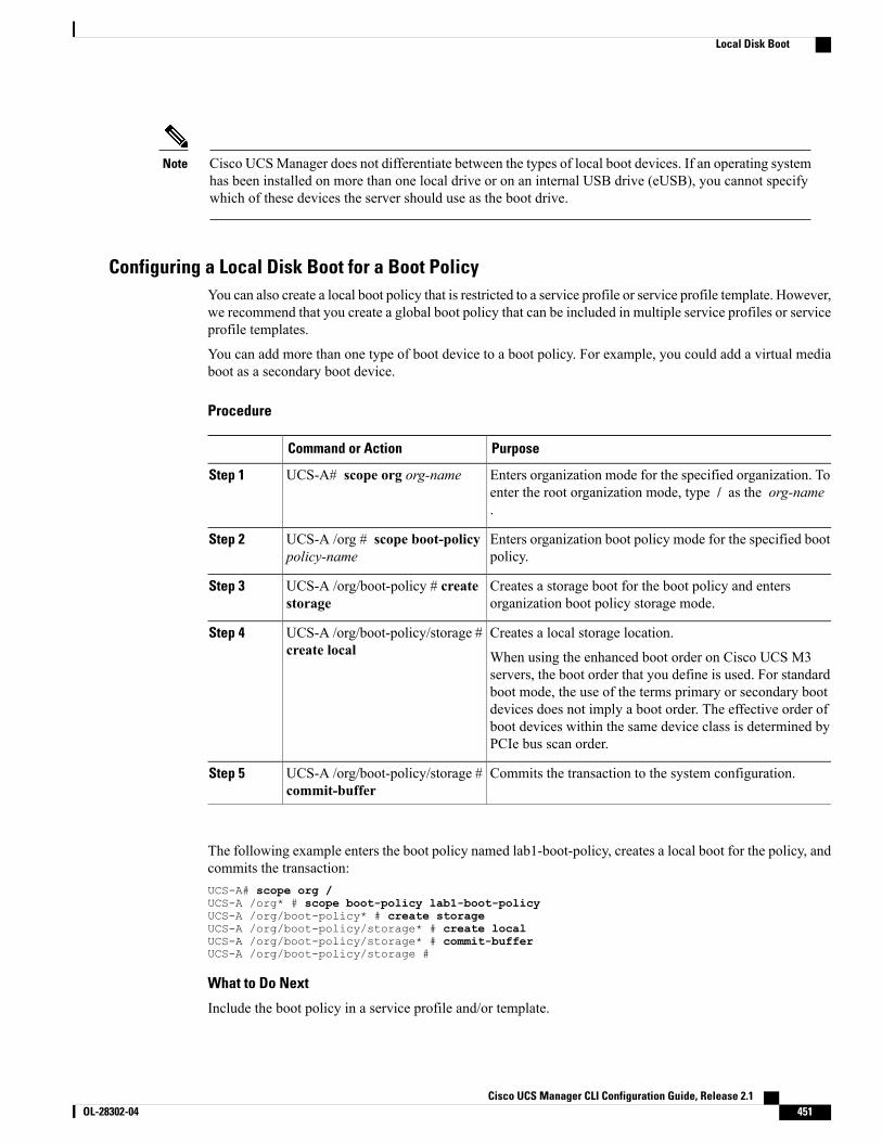
Cisco UCSManager does not differentiate between the types of local boot devices. If an operating systemhas been installed on more than one local drive or on an internal USB drive (eUSB), you cannot specifywhich of these devices the server should use as the boot drive.
Note
Configuring a Local Disk Boot for a Boot PolicyYou can also create a local boot policy that is restricted to a service profile or service profile template. However,we recommend that you create a global boot policy that can be included in multiple service profiles or serviceprofile templates.
You can add more than one type of boot device to a boot policy. For example, you could add a virtual mediaboot as a secondary boot device.
Procedure
PurposeCommand or Action
Enters organization mode for the specified organization. Toenter the root organization mode, type / as the org-name.
UCS-A# scope org org-nameStep 1
Enters organization boot policy mode for the specified bootpolicy.
UCS-A /org # scope boot-policypolicy-name
Step 2
Creates a storage boot for the boot policy and entersorganization boot policy storage mode.
UCS-A /org/boot-policy # createstorage
Step 3
Creates a local storage location.UCS-A /org/boot-policy/storage #create local
Step 4
When using the enhanced boot order on Cisco UCS M3servers, the boot order that you define is used. For standardboot mode, the use of the terms primary or secondary bootdevices does not imply a boot order. The effective order ofboot devices within the same device class is determined byPCIe bus scan order.
Commits the transaction to the system configuration.UCS-A /org/boot-policy/storage #commit-buffer
Step 5
The following example enters the boot policy named lab1-boot-policy, creates a local boot for the policy, andcommits the transaction:UCS-A# scope org /UCS-A /org* # scope boot-policy lab1-boot-policyUCS-A /org/boot-policy* # create storageUCS-A /org/boot-policy/storage* # create localUCS-A /org/boot-policy/storage* # commit-bufferUCS-A /org/boot-policy/storage #
What to Do Next
Include the boot policy in a service profile and/or template.
Cisco UCS Manager CLI Configuration Guide, Release 2.1 OL-28302-04 451
Local Disk Boot
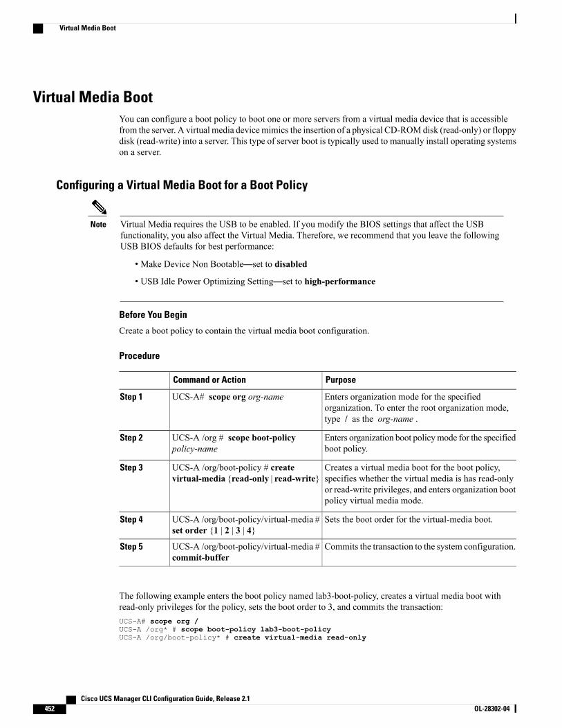
Virtual Media BootYou can configure a boot policy to boot one or more servers from a virtual media device that is accessiblefrom the server. A virtual media device mimics the insertion of a physical CD-ROMdisk (read-only) or floppydisk (read-write) into a server. This type of server boot is typically used to manually install operating systemson a server.
Configuring a Virtual Media Boot for a Boot Policy
Virtual Media requires the USB to be enabled. If you modify the BIOS settings that affect the USBfunctionality, you also affect the Virtual Media. Therefore, we recommend that you leave the followingUSB BIOS defaults for best performance:
Note
• Make Device Non Bootable—set to disabled
• USB Idle Power Optimizing Setting—set to high-performance
Before You Begin
Create a boot policy to contain the virtual media boot configuration.
Procedure
PurposeCommand or Action
Enters organization mode for the specifiedorganization. To enter the root organization mode,type / as the org-name .
UCS-A# scope org org-nameStep 1
Enters organization boot policymode for the specifiedboot policy.
UCS-A /org # scope boot-policypolicy-name
Step 2
Creates a virtual media boot for the boot policy,specifies whether the virtual media is has read-only
UCS-A /org/boot-policy # createvirtual-media {read-only | read-write}
Step 3
or read-write privileges, and enters organization bootpolicy virtual media mode.
Sets the boot order for the virtual-media boot.UCS-A /org/boot-policy/virtual-media #set order {1 | 2 | 3 | 4}
Step 4
Commits the transaction to the system configuration.UCS-A /org/boot-policy/virtual-media #commit-buffer
Step 5
The following example enters the boot policy named lab3-boot-policy, creates a virtual media boot withread-only privileges for the policy, sets the boot order to 3, and commits the transaction:UCS-A# scope org /UCS-A /org* # scope boot-policy lab3-boot-policyUCS-A /org/boot-policy* # create virtual-media read-only
Cisco UCS Manager CLI Configuration Guide, Release 2.1452 OL-28302-04
Virtual Media Boot
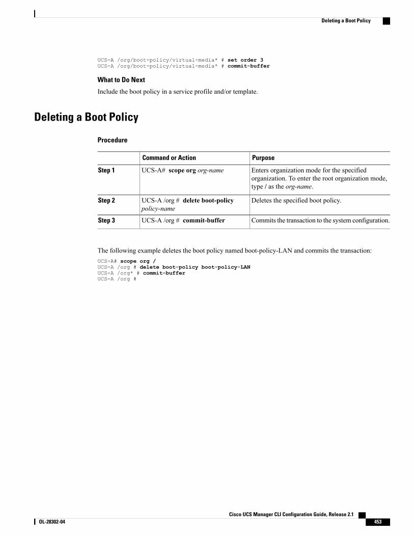
UCS-A /org/boot-policy/virtual-media* # set order 3UCS-A /org/boot-policy/virtual-media* # commit-buffer
What to Do Next
Include the boot policy in a service profile and/or template.
Deleting a Boot Policy
Procedure
PurposeCommand or Action
Enters organization mode for the specifiedorganization. To enter the root organization mode,type / as the org-name.
UCS-A# scope org org-nameStep 1
Deletes the specified boot policy.UCS-A /org # delete boot-policypolicy-name
Step 2
Commits the transaction to the system configuration.UCS-A /org # commit-bufferStep 3
The following example deletes the boot policy named boot-policy-LAN and commits the transaction:UCS-A# scope org /UCS-A /org # delete boot-policy boot-policy-LANUCS-A /org* # commit-bufferUCS-A /org #
Cisco UCS Manager CLI Configuration Guide, Release 2.1 OL-28302-04 453
Deleting a Boot Policy

Cisco UCS Manager CLI Configuration Guide, Release 2.1454 OL-28302-04
Deleting a Boot Policy
C H A P T E R 32Deferring Deployment of Service Profile Updates
This chapter includes the following sections:
• Deferred Deployment of Service Profiles, page 455
• Configuring Schedules, page 458
• Configuring Maintenance Policies, page 463
• Managing Pending Activities, page 464
Deferred Deployment of Service ProfilesSomemodifications to a service profile or to an updating service profile template can be disruptive and requirea reboot of the server. You can, however, configure deferred deployment to control when those disruptiveconfiguration changes are implemented. For example, you can choose to deploy the service profile changesimmediately or have them deployed during a specified maintenance window. You can also choose whetheror not a service profile deployment requires explicit user acknowledgement.
Deferred deployment is available for all configuration changes that occur through the association of a serviceprofile with a server. These configuration changes can be prompted by a change to a service profile, to a policythat is included in a service profile, or to an updating service profile template. For example, you can defer theupgrade and activation of firmware through host firmware packages and management firmware packages,such as server BIOS, RAID controller, host HBA, and network adapters. However, you cannot defer the directdeployment of firmware images for components that do not use either of the firmware packages, such as CiscoUCS Manager, fabric interconnects, and I/O modules.
Deferred deployment is not available for the following actions which require the reboot of a server:
• Initial association of a service profile with a server
• Final disassociation of a service profile from a server, without associating the service profile with adifferent server
• Decommissioning a server
• Reacknowledging a server
• Resetting a server
Cisco UCS Manager CLI Configuration Guide, Release 2.1 OL-28302-04 455
If you want to defer the deployment of service profile changes, you must configure one or more maintenancepolicies and configure each service profile with a maintenance policy. If you want to define the time periodwhen the deployment should occur, you also need to create at least one schedule with one or more recurringoccurrences or one time occurrences, and include that schedule in a maintenance policy.
Deferred Deployment SchedulesA schedule contains a set of occurrences. These occurrences can be one time only or can recur at a specifiedtime and day each week. The options defined in the occurrence, such as the duration of the occurrence or themaximum number of tasks to be run, determine whether a service profile change is deployed. For example,if a change cannot be deployed during a given maintenance window because the maximum duration or numberof tasks has been reached, that deployment is carried over to the next maintenance window.
Each schedule checks periodically to see whether the Cisco UCS domain has entered one or more maintenancewindows. If it has, the schedule executes the deployments that are eligible according to the constraints specifiedin the maintenance policy
A schedule contains one or more occurrences, which determine the maintenance windows associated withthat schedule. An occurrence can be one of the following:
One Time Occurrence
One time occurrences define a single maintenance window. These windows continue until the maximumduration of the window or the maximum number of tasks that can be run in the window has beenreached.
Recurring Occurrence
Recurring occurrences define a series of maintenance windows. These windows continue until themaximum number of tasks or the end of the day specified in the occurrence has been reached.
Maintenance PolicyAmaintenance policy determines how Cisco UCSManager reacts when a change that requires a server rebootis made to a service profile associated with a server or to an updating service profile bound to one or moreservice profiles.
Themaintenance policy specifies howCiscoUCSManager deploys the service profile changes. The deploymentcan occur in one of the following ways:
• Immediately
•When acknowledged by a user with admin privileges
• Automatically at the time specified in a schedule
If the maintenance policy is configured to deploy the change during a scheduled maintenance window, thepolicy must include a valid schedule. The schedule deploys the changes in the first available maintenancewindow.
Cisco UCS Manager CLI Configuration Guide, Release 2.1456 OL-28302-04
Deferred Deployment of Service Profiles
A maintenance policy only prevents an immediate server reboot when a configuration change is made toan associated service profile. However, a maintenance policy does not prevent the following actions fromtaking place right away:
Note
• Deleting an associated service profile from the system
• Disassociating a server profile from a server
• Directly installing a firmware upgrade without using a service policy
• Resetting the server
Pending ActivitiesIf you configure deferred deployment in a Cisco UCS domain, Cisco UCS Manager enables you to view allpending activities. You can see activities that are waiting for user acknowledgement and those that have beenscheduled.
If a Cisco UCS domain has pending activities, Cisco UCS Manager GUI notifies users with admin privilegeswhen they log in.
Cisco UCS Manager displays information about all pending activities, including the following:
• Name of the service profile to be deployed and associated with a server
• Server affected by the deployment
• Disruption caused by the deployment
• Change performed by the deployment
You cannot specify the maintenance window in which a specific pending activity is applied to the server.The maintenance window depends upon how many activities are pending and which maintenance policyis assigned to the service profile. However, any user with admin privileges can manually initiate a pendingactivity and reboot the server immediately, whether it is waiting for user acknowledgment or for amaintenance window.
Note
Guidelines and Limitations for Deferred Deployment
Cannot Undo All Changes to Service Profiles or Service Profile Templates
If you cancel a pending change, Cisco UCS Manager attempts to roll back the change without rebooting theserver. However, for complex changes, Cisco UCS Manager may have to reboot the server a second time toroll back the change. For example, if you delete a vNIC, Cisco UCS Manager reboots the server accordingto the maintenance policy included in the service profile. You cannot cancel this reboot and change, even ifyou restore the original vNIC in the service profile. Instead, CiscoUCSManager schedules a second deploymentand reboot of the server.
Cisco UCS Manager CLI Configuration Guide, Release 2.1 OL-28302-04 457
Deferred Deployment of Service Profiles
Association of Service Profile Can Exceed Boundaries of Maintenance Window
After Cisco UCSManager begins the association of the service profile, the scheduler and maintenance policydo not have any control over the procedure. If the service profile association does not complete within theallotted maintenance window, the process continues until it is completed. For example, this can occur if theassociation does not complete in time because of retried stages or other issues.
Cannot Specify Order of Pending Activities
Scheduled deployments run in parallel and independently. You cannot specify the order in which thedeployments occur. You also cannot make the deployment of one service profile change dependent upon thecompletion of another.
Cannot Perform Partial Deployment of Pending Activity
Cisco UCSManager applies all changes made to a service profile in the scheduled maintenance window. Youcannot make several changes to a service profile at the same time and then have those changes be spreadacross several maintenance windows. When Cisco UCS Manager deploys the service profile changes, itupdates the service profile to match the most recent configuration in the database.
Configuring Schedules
Creating a Schedule
Procedure
PurposeCommand or Action
Enters system mode.UCS-A# scope systemStep 1
Creates a scheduler and enters schedulermode.
UCS-A /system # create schedulersched-name
Step 2
Commits the transaction to the systemconfiguration.
UCS-A /system/scheduler # commit-bufferStep 3
The following example creates a scheduler called maintenancesched and commits the transaction:UCS-A# scope systemUCS-A /system # create scheduler maintenanceschedUCS-A /system/scheduler* # commit-bufferUCS-A /system/scheduler #
What to Do Next
Create a one time occurrence or recurring occurrence for the schedule.
Cisco UCS Manager CLI Configuration Guide, Release 2.1458 OL-28302-04
Configuring Schedules
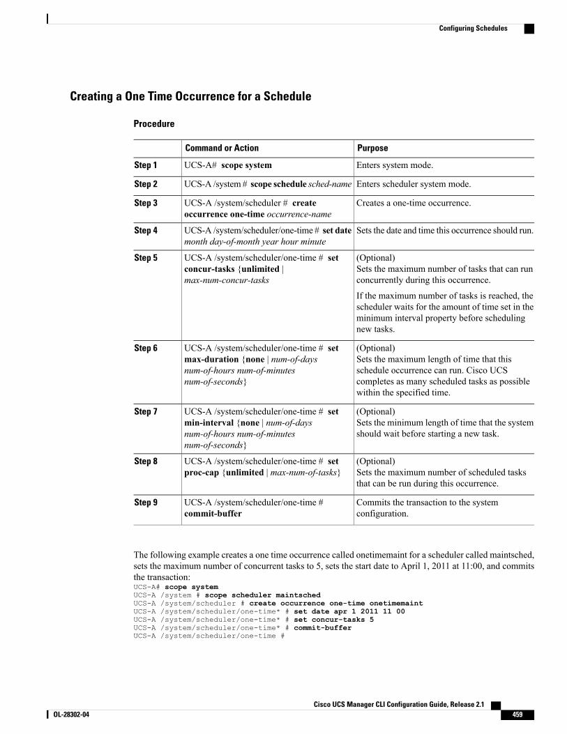
Creating a One Time Occurrence for a Schedule
Procedure
PurposeCommand or Action
Enters system mode.UCS-A# scope systemStep 1
Enters scheduler system mode.UCS-A /system # scope schedule sched-nameStep 2
Creates a one-time occurrence.UCS-A /system/scheduler # createoccurrence one-time occurrence-name
Step 3
Sets the date and time this occurrence should run.UCS-A /system/scheduler/one-time # set datemonth day-of-month year hour minute
Step 4
(Optional)Sets the maximum number of tasks that can runconcurrently during this occurrence.
UCS-A /system/scheduler/one-time # setconcur-tasks {unlimited |max-num-concur-tasks
Step 5
If the maximum number of tasks is reached, thescheduler waits for the amount of time set in theminimum interval property before schedulingnew tasks.
(Optional)Sets the maximum length of time that thisschedule occurrence can run. Cisco UCS
UCS-A /system/scheduler/one-time # setmax-duration {none | num-of-daysnum-of-hours num-of-minutesnum-of-seconds}
Step 6
completes as many scheduled tasks as possiblewithin the specified time.
(Optional)Sets the minimum length of time that the systemshould wait before starting a new task.
UCS-A /system/scheduler/one-time # setmin-interval {none | num-of-daysnum-of-hours num-of-minutesnum-of-seconds}
Step 7
(Optional)Sets the maximum number of scheduled tasksthat can be run during this occurrence.
UCS-A /system/scheduler/one-time # setproc-cap {unlimited | max-num-of-tasks}
Step 8
Commits the transaction to the systemconfiguration.
UCS-A /system/scheduler/one-time #commit-buffer
Step 9
The following example creates a one time occurrence called onetimemaint for a scheduler called maintsched,sets the maximum number of concurrent tasks to 5, sets the start date to April 1, 2011 at 11:00, and commitsthe transaction:UCS-A# scope systemUCS-A /system # scope scheduler maintschedUCS-A /system/scheduler # create occurrence one-time onetimemaintUCS-A /system/scheduler/one-time* # set date apr 1 2011 11 00UCS-A /system/scheduler/one-time* # set concur-tasks 5UCS-A /system/scheduler/one-time* # commit-bufferUCS-A /system/scheduler/one-time #
Cisco UCS Manager CLI Configuration Guide, Release 2.1 OL-28302-04 459
Configuring Schedules
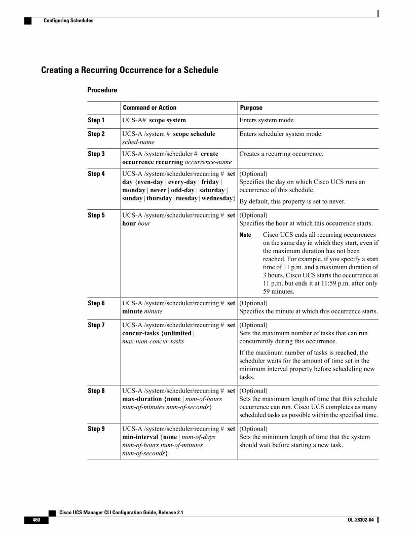
Creating a Recurring Occurrence for a Schedule
Procedure
PurposeCommand or Action
Enters system mode.UCS-A# scope systemStep 1
Enters scheduler system mode.UCS-A /system # scope schedulesched-name
Step 2
Creates a recurring occurrence.UCS-A /system/scheduler # createoccurrence recurring occurrence-name
Step 3
(Optional)Specifies the day on which Cisco UCS runs anoccurrence of this schedule.
UCS-A /system/scheduler/recurring # setday {even-day | every-day | friday |monday | never | odd-day | saturday |sunday | thursday | tuesday |wednesday}
Step 4
By default, this property is set to never.
(Optional)Specifies the hour at which this occurrence starts.
UCS-A /system/scheduler/recurring # sethour hour
Step 5
Cisco UCS ends all recurring occurrenceson the same day in which they start, even ifthe maximum duration has not beenreached. For example, if you specify a starttime of 11 p.m. and a maximum duration of3 hours, Cisco UCS starts the occurrence at11 p.m. but ends it at 11:59 p.m. after only59 minutes.
Note
(Optional)Specifies the minute at which this occurrence starts.
UCS-A /system/scheduler/recurring # setminute minute
Step 6
(Optional)Sets the maximum number of tasks that can runconcurrently during this occurrence.
UCS-A /system/scheduler/recurring # setconcur-tasks {unlimited |max-num-concur-tasks
Step 7
If the maximum number of tasks is reached, thescheduler waits for the amount of time set in theminimum interval property before scheduling newtasks.
(Optional)Sets the maximum length of time that this scheduleoccurrence can run. Cisco UCS completes as manyscheduled tasks as possible within the specified time.
UCS-A /system/scheduler/recurring # setmax-duration {none | num-of-hoursnum-of-minutes num-of-seconds}
Step 8
(Optional)Sets the minimum length of time that the systemshould wait before starting a new task.
UCS-A /system/scheduler/recurring # setmin-interval {none | num-of-daysnum-of-hours num-of-minutesnum-of-seconds}
Step 9
Cisco UCS Manager CLI Configuration Guide, Release 2.1460 OL-28302-04
Configuring Schedules
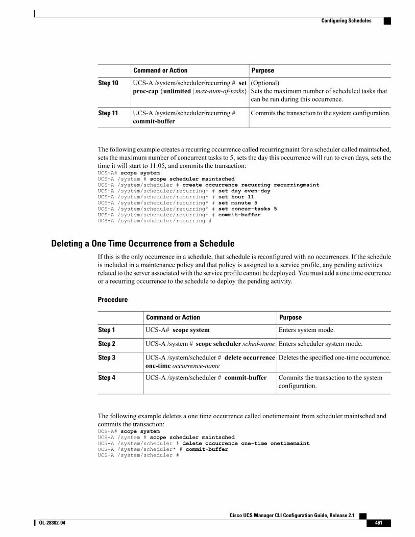
PurposeCommand or Action
(Optional)Sets the maximum number of scheduled tasks thatcan be run during this occurrence.
UCS-A /system/scheduler/recurring # setproc-cap {unlimited | max-num-of-tasks}
Step 10
Commits the transaction to the system configuration.UCS-A /system/scheduler/recurring #commit-buffer
Step 11
The following example creates a recurring occurrence called recurringmaint for a scheduler called maintsched,sets the maximum number of concurrent tasks to 5, sets the day this occurrence will run to even days, sets thetime it will start to 11:05, and commits the transaction:UCS-A# scope systemUCS-A /system # scope scheduler maintschedUCS-A /system/scheduler # create occurrence recurring recurringmaintUCS-A /system/scheduler/recurring* # set day even-dayUCS-A /system/scheduler/recurring* # set hour 11UCS-A /system/scheduler/recurring* # set minute 5UCS-A /system/scheduler/recurring* # set concur-tasks 5UCS-A /system/scheduler/recurring* # commit-bufferUCS-A /system/scheduler/recurring #
Deleting a One Time Occurrence from a ScheduleIf this is the only occurrence in a schedule, that schedule is reconfigured with no occurrences. If the scheduleis included in a maintenance policy and that policy is assigned to a service profile, any pending activitiesrelated to the server associated with the service profile cannot be deployed. Youmust add a one time ocurrenceor a recurring occurrence to the schedule to deploy the pending activity.
Procedure
PurposeCommand or Action
Enters system mode.UCS-A# scope systemStep 1
Enters scheduler system mode.UCS-A /system # scope scheduler sched-nameStep 2
Deletes the specified one-time occurrence.UCS-A /system/scheduler # delete occurrenceone-time occurrence-name
Step 3
Commits the transaction to the systemconfiguration.
UCS-A /system/scheduler # commit-bufferStep 4
The following example deletes a one time occurrence called onetimemaint from scheduler maintsched andcommits the transaction:UCS-A# scope systemUCS-A /system # scope scheduler maintschedUCS-A /system/scheduler # delete occurrence one-time onetimemaintUCS-A /system/scheduler* # commit-bufferUCS-A /system/scheduler #
Cisco UCS Manager CLI Configuration Guide, Release 2.1 OL-28302-04 461
Configuring Schedules
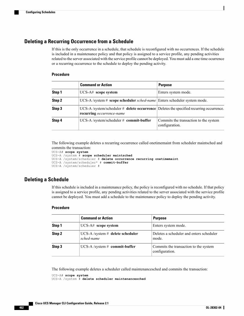
Deleting a Recurring Occurrence from a ScheduleIf this is the only occurrence in a schedule, that schedule is reconfigured with no occurrences. If the scheduleis included in a maintenance policy and that policy is assigned to a service profile, any pending activitiesrelated to the server associated with the service profile cannot be deployed. Youmust add a one time ocurrenceor a recurring occurrence to the schedule to deploy the pending activity.
Procedure
PurposeCommand or Action
Enters system mode.UCS-A# scope systemStep 1
Enters scheduler system mode.UCS-A /system # scope scheduler sched-nameStep 2
Deletes the specified recurring occurrence.UCS-A /system/scheduler # delete occurrencerecurring occurrence-name
Step 3
Commits the transaction to the systemconfiguration.
UCS-A /system/scheduler # commit-bufferStep 4
The following example deletes a recurring occurrence called onetimemaint from scheduler maintsched andcommits the transaction:UCS-A# scope systemUCS-A /system # scope scheduler maintschedUCS-A /system/scheduler # delete occurrence recurring onetimemaintUCS-A /system/scheduler* # commit-bufferUCS-A /system/scheduler #
Deleting a ScheduleIf this schedule is included in a maintenance policy, the policy is reconfigured with no schedule. If that policyis assigned to a service profile, any pending activities related to the server associated with the service profilecannot be deployed. You must add a schedule to the maintenance policy to deploy the pending activity.
Procedure
PurposeCommand or Action
Enters system mode.UCS-A# scope systemStep 1
Deletes a scheduler and enters schedulermode.
UCS-A /system # delete schedulersched-name
Step 2
Commits the transaction to the systemconfiguration.
UCS-A /system # commit-bufferStep 3
The following example deletes a scheduler called maintenancesched and commits the transaction:UCS-A# scope systemUCS-A /system # delete scheduler maintenancesched
Cisco UCS Manager CLI Configuration Guide, Release 2.1462 OL-28302-04
Configuring Schedules
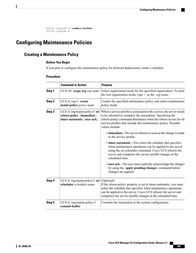
UCS-A /system* # commit-bufferUCS-A /system #
Configuring Maintenance Policies
Creating a Maintenance Policy
Before You Begin
If you plan to configure this maintenance policy for deferred deployment, create a schedule.
Procedure
PurposeCommand or Action
Enters organization mode for the specified organization. To enterthe root organization mode, type / as the org-name .
UCS-A# scope org org-nameStep 1
Creates the specified maintenance policy and enters maintenancepolicy mode.
UCS-A /org # createmaint-policy policy-name
Step 2
When a service profile is associated with a server, the server needsto be rebooted to complete the association. Specifying the
UCS-A /org/maint-policy # setreboot-policy {immediate |timer-automatic | user-ack}
Step 3
reboot-policy command determines when the reboot occurs for allservice profiles that include this maintenance policy. Possiblevalues include:
• immediate--The server reboots as soon as the change is madeto the service profile.
• timer-automatic --You select the schedule that specifieswhen maintenance operations can be applied to the serverusing the set scheduler command. Cisco UCS reboots theserver and completes the service profile changes at thescheduled time.
• user-ack --The user must explicitly acknowledge the changesby using the apply pending-changes command beforechanges are applied.
(Optional)If the reboot-policy property is set to timer-automatic, you mustselect the schedule that specifies when maintenance operations
UCS-A /org/maint-policy # setscheduler scheduler-name
Step 4
can be applied to the server. Cisco UCS reboots the server andcompletes the service profile changes at the scheduled time.
Commits the transaction to the system configuration.UCS-A /org/maint-policy #commit-buffer
Step 5
Cisco UCS Manager CLI Configuration Guide, Release 2.1 OL-28302-04 463
Configuring Maintenance Policies
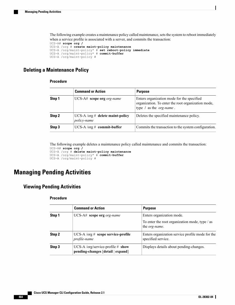
The following example creates a maintenance policy called maintenance, sets the system to reboot immediatelywhen a service profile is associated with a server, and commits the transaction:UCS-A# scope org /UCS-A /org # create maint-policy maintenanceUCS-A /org/maint-policy* # set reboot-policy immediateUCS-A /org/maint-policy* # commit-bufferUCS-A /org/maint-policy #
Deleting a Maintenance Policy
Procedure
PurposeCommand or Action
Enters organization mode for the specifiedorganization. To enter the root organization mode,type / as the org-name .
UCS-A# scope org org-nameStep 1
Deletes the specified maintenance policy.UCS-A /org # delete maint-policypolicy-name
Step 2
Commits the transaction to the system configuration.UCS-A /org # commit-bufferStep 3
The following example deletes a maintenance policy called maintenance and commits the transaction:UCS-A# scope org /UCS-A /org # delete maint-policy maintenanceUCS-A /org/maint-policy* # commit-bufferUCS-A /org/maint-policy #
Managing Pending Activities
Viewing Pending Activities
Procedure
PurposeCommand or Action
Enters organization mode.UCS-A# scope org org-nameStep 1
To enter the root organization mode, type / asthe org-name.
Enters organization service profile mode for thespecified service.
UCS-A /org # scope service-profileprofile-name
Step 2
Displays details about pending-changes.UCS-A /org/service-profile # showpending-changes [detail | expand]
Step 3
Cisco UCS Manager CLI Configuration Guide, Release 2.1464 OL-28302-04
Managing Pending Activities
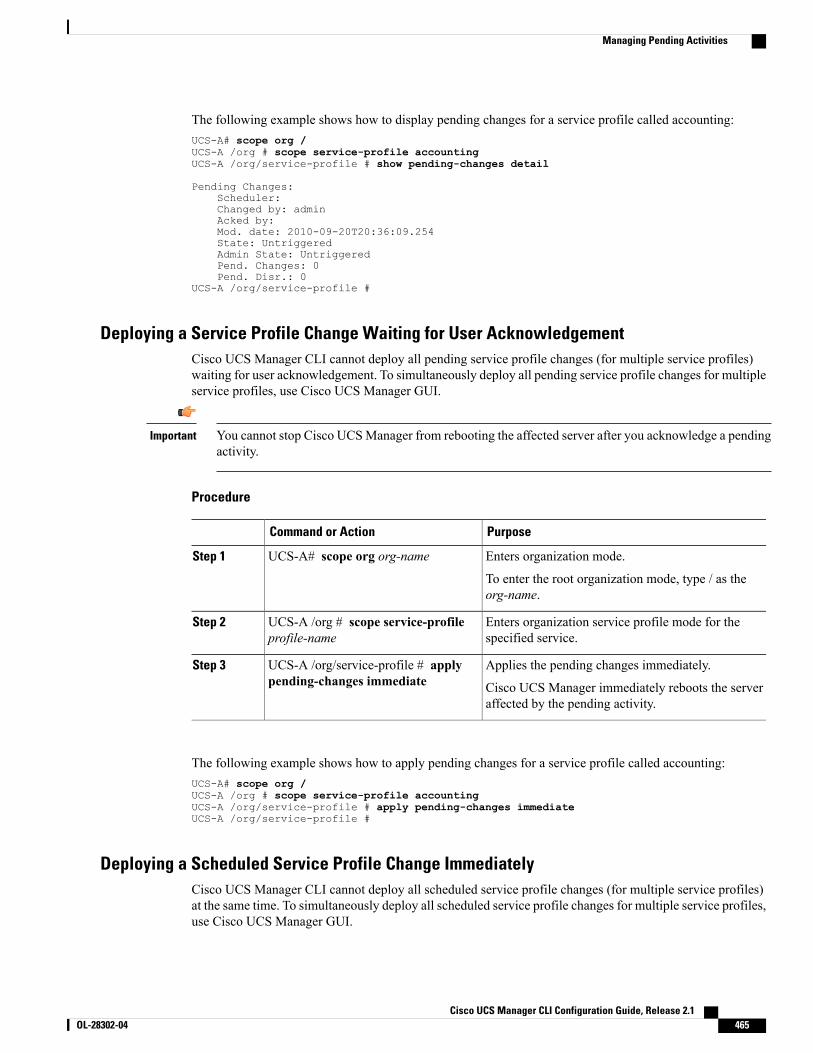
The following example shows how to display pending changes for a service profile called accounting:UCS-A# scope org /UCS-A /org # scope service-profile accountingUCS-A /org/service-profile # show pending-changes detail
Pending Changes:Scheduler:Changed by: adminAcked by:Mod. date: 2010-09-20T20:36:09.254State: UntriggeredAdmin State: UntriggeredPend. Changes: 0Pend. Disr.: 0
UCS-A /org/service-profile #
Deploying a Service Profile Change Waiting for User AcknowledgementCisco UCS Manager CLI cannot deploy all pending service profile changes (for multiple service profiles)waiting for user acknowledgement. To simultaneously deploy all pending service profile changes for multipleservice profiles, use Cisco UCS Manager GUI.
You cannot stop Cisco UCSManager from rebooting the affected server after you acknowledge a pendingactivity.
Important
Procedure
PurposeCommand or Action
Enters organization mode.UCS-A# scope org org-nameStep 1
To enter the root organization mode, type / as theorg-name.
Enters organization service profile mode for thespecified service.
UCS-A /org # scope service-profileprofile-name
Step 2
Applies the pending changes immediately.UCS-A /org/service-profile # applypending-changes immediate
Step 3
Cisco UCS Manager immediately reboots the serveraffected by the pending activity.
The following example shows how to apply pending changes for a service profile called accounting:UCS-A# scope org /UCS-A /org # scope service-profile accountingUCS-A /org/service-profile # apply pending-changes immediateUCS-A /org/service-profile #
Deploying a Scheduled Service Profile Change ImmediatelyCisco UCS Manager CLI cannot deploy all scheduled service profile changes (for multiple service profiles)at the same time. To simultaneously deploy all scheduled service profile changes for multiple service profiles,use Cisco UCS Manager GUI.
Cisco UCS Manager CLI Configuration Guide, Release 2.1 OL-28302-04 465
Managing Pending Activities
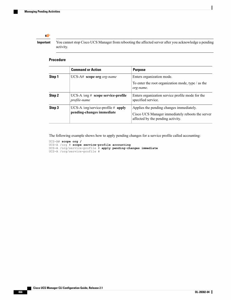
You cannot stop Cisco UCSManager from rebooting the affected server after you acknowledge a pendingactivity.
Important
Procedure
PurposeCommand or Action
Enters organization mode.UCS-A# scope org org-nameStep 1
To enter the root organization mode, type / as theorg-name.
Enters organization service profile mode for thespecified service.
UCS-A /org # scope service-profileprofile-name
Step 2
Applies the pending changes immediately.UCS-A /org/service-profile # applypending-changes immediate
Step 3
Cisco UCS Manager immediately reboots the serveraffected by the pending activity.
The following example shows how to apply pending changes for a service profile called accounting:UCS-A# scope org /UCS-A /org # scope service-profile accountingUCS-A /org/service-profile # apply pending-changes immediateUCS-A /org/service-profile #
Cisco UCS Manager CLI Configuration Guide, Release 2.1466 OL-28302-04
Managing Pending Activities
C H A P T E R 33Configuring Service Profiles
This chapter includes the following sections:
• Service Profiles that Override Server Identity, page 467
• Service Profiles that Inherit Server Identity, page 468
• Guidelines and Recommendations for Service Profiles, page 468
• Service Profile Templates, page 469
• Creating a Hardware-Based Service Profile, page 474
• Configuring a vNIC for a Service Profile, page 477
• Configuring a vHBA for a Service Profile, page 479
• Configuring a Local Disk for a Service Profile, page 480
• Configuring Serial over LAN for a Service Profile, page 482
• Service Profile Boot Definition Configuration, page 483
• Configuring Fibre Channel Zoning for a Service Profile, page 488
• Service Profiles and Service Profile Template Management, page 490
Service Profiles that Override Server IdentityThis type of service profile provides the maximum amount of flexibility and control. This profile allows youto override the identity values that are on the server at the time of association and use the resource pools andpolicies set up in Cisco UCS Manager to automate some administration tasks.
You can disassociate this service profile from one server and then associate it with another server. Thisre-association can be done either manually or through an automated server pool policy. The burned-in settings,such as UUID and MAC address, on the new server are overwritten with the configuration in the serviceprofile. As a result, the change in server is transparent to your network. You do not need to reconfigure anycomponent or application on your network to begin using the new server.
This profile allows you to take advantage of and manage system resources through resource pools and policies,such as the following:
Cisco UCS Manager CLI Configuration Guide, Release 2.1 OL-28302-04 467
• Virtualized identity information, including pools of MAC addresses, WWN addresses, and UUIDs
• Ethernet and Fibre Channel adapter profile policies
• Firmware package policies
• Operating system boot order policies
Unless the service profile contains power management policies, a server pool qualification policy, or anotherpolicy that requires a specific hardware configuration, the profile can be used for any type of server in theCisco UCS domain.
You can associate these service profiles with either a rack-mount server or a blade server. The ability tomigrate the service profile depends upon whether you choose to restrict migration of the service profile.
If you choose not to restrict migration, Cisco UCS Manager does not perform any compatibility checkson the new server before migrating the existing service profile. If the hardware of both servers are notsimilar, the association might fail.
Note
Service Profiles that Inherit Server IdentityThis hardware-based service profile is the simplest to use and create. This profile uses the default values inthe server and mimics the management of a rack-mounted server. It is tied to a specific server and cannot bemoved or migrated to another server.
You do not need to create pools or configuration policies to use this service profile.
This service profile inherits and applies the identity and configuration information that is present at the timeof association, such as the following:
• MAC addresses for the two NICs
• For a converged network adapter or a virtual interface card, the WWN addresses for the two HBAs
• BIOS versions
• Server UUID
The server identity and configuration information inherited through this service profile may not be thevalues burned into the server hardware at manufacture if those values were changed before this profile isassociated with the server.
Important
Guidelines and Recommendations for Service ProfilesIn addition to any guidelines or recommendations that are specific to policies and pools included in serviceprofiles and service profile templates, such as the local disk configuration policy, you need to be aware of thefollowing guidelines and recommendations that impact the ability to associate a service profile with a server:
Cisco UCS Manager CLI Configuration Guide, Release 2.1468 OL-28302-04
Service Profiles that Inherit Server Identity
Limit to the Number of vNICs that Can Be Configured on a Rack-Mount Server
You can configure up to 56 vNICs per supported adapter, such as the Cisco UCS P81E Virtual Interface Card(N2XX-ACPCI01), on any rack-mount server that is integrated with Cisco UCS Manager.
No Power Capping Support for Rack-Mount Servers
Power capping is not supported for rack servers. If you include a power control policy in a service profile thatis associated with a rack-mount server, the policy is not implemented.
QoS Policy Guidelines for vNICs
You can only assign a QoS policy to a vNIC if the priority setting for that policy is not set to fc, whichrepresents the Fibre Channel system class. You can configure the priority for the QoS policy with any othersystem class.
QoS Policy Guidelines for vHBAs
You can only assign a QoS policy to a vHBA if the priority setting for that policy is set to fc, which representsthe Fibre Channel system class.
The Host Control setting for a QoS policy applies to vNICs only. It has no effect on a vHBA.
Service Profile TemplatesWith a service profile template, you can quickly create several service profiles with the same basic parameters,such as the number of vNICs and vHBAs, and with identity information drawn from the same pools.
If you need only one service profile with similar values to an existing service profile, you can clone aservice profile in the Cisco UCS Manager GUI.
Tip
For example, if you need several service profiles with similar values to configure servers to host databasesoftware, you can create a service profile template, either manually or from an existing service profile. Youthen use the template to create the service profiles.
Cisco UCS supports the following types of service profile templates:
Initial template
Service profiles created from an initial template inherit all the properties of the template. Service profilescreated from an initial service profile template are bound to the template. However, changes to theinitial template do not automatically propagate to the bound service profiles. If you want to propagatechanges to bound service profiles, unbind and rebind the service profile to the initial template.
Updating template
Service profiles created from an updating template inherit all the properties of the template and remainconnected to the template. Any changes to the template automatically update the service profiles createdfrom the template.
Cisco UCS Manager CLI Configuration Guide, Release 2.1 OL-28302-04 469
Service Profile Templates
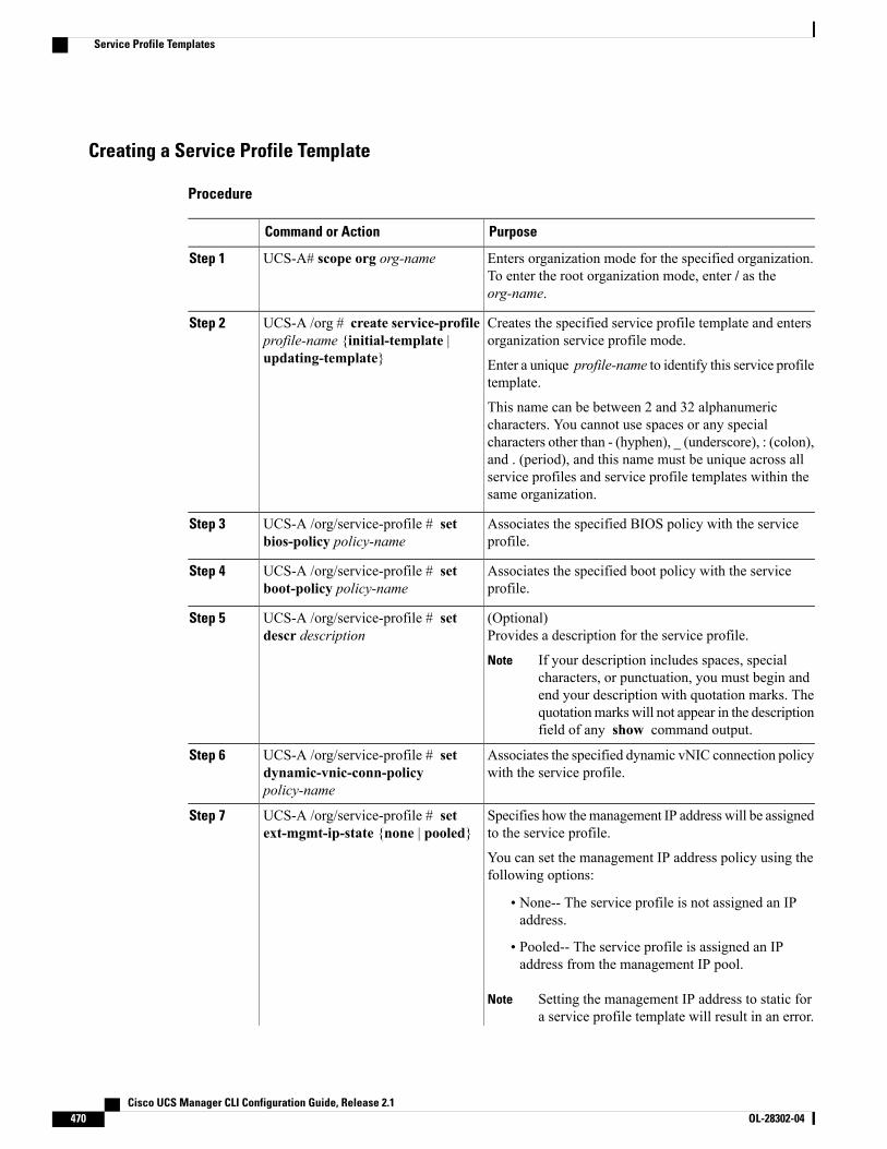
Creating a Service Profile Template
Procedure
PurposeCommand or Action
Enters organization mode for the specified organization.To enter the root organization mode, enter / as theorg-name.
UCS-A# scope org org-nameStep 1
Creates the specified service profile template and entersorganization service profile mode.
UCS-A /org # create service-profileprofile-name {initial-template |updating-template}
Step 2
Enter a unique profile-name to identify this service profiletemplate.
This name can be between 2 and 32 alphanumericcharacters. You cannot use spaces or any specialcharacters other than - (hyphen), _ (underscore), : (colon),and . (period), and this name must be unique across allservice profiles and service profile templates within thesame organization.
Associates the specified BIOS policy with the serviceprofile.
UCS-A /org/service-profile # setbios-policy policy-name
Step 3
Associates the specified boot policy with the serviceprofile.
UCS-A /org/service-profile # setboot-policy policy-name
Step 4
(Optional)Provides a description for the service profile.
UCS-A /org/service-profile # setdescr description
Step 5
If your description includes spaces, specialcharacters, or punctuation, you must begin andend your description with quotation marks. Thequotationmarks will not appear in the descriptionfield of any show command output.
Note
Associates the specified dynamic vNIC connection policywith the service profile.
UCS-A /org/service-profile # setdynamic-vnic-conn-policypolicy-name
Step 6
Specifies how themanagement IP address will be assignedto the service profile.
UCS-A /org/service-profile # setext-mgmt-ip-state {none | pooled}
Step 7
You can set the management IP address policy using thefollowing options:
• None-- The service profile is not assigned an IPaddress.
• Pooled-- The service profile is assigned an IPaddress from the management IP pool.
Setting the management IP address to static fora service profile template will result in an error.
Note
Cisco UCS Manager CLI Configuration Guide, Release 2.1470 OL-28302-04
Service Profile Templates
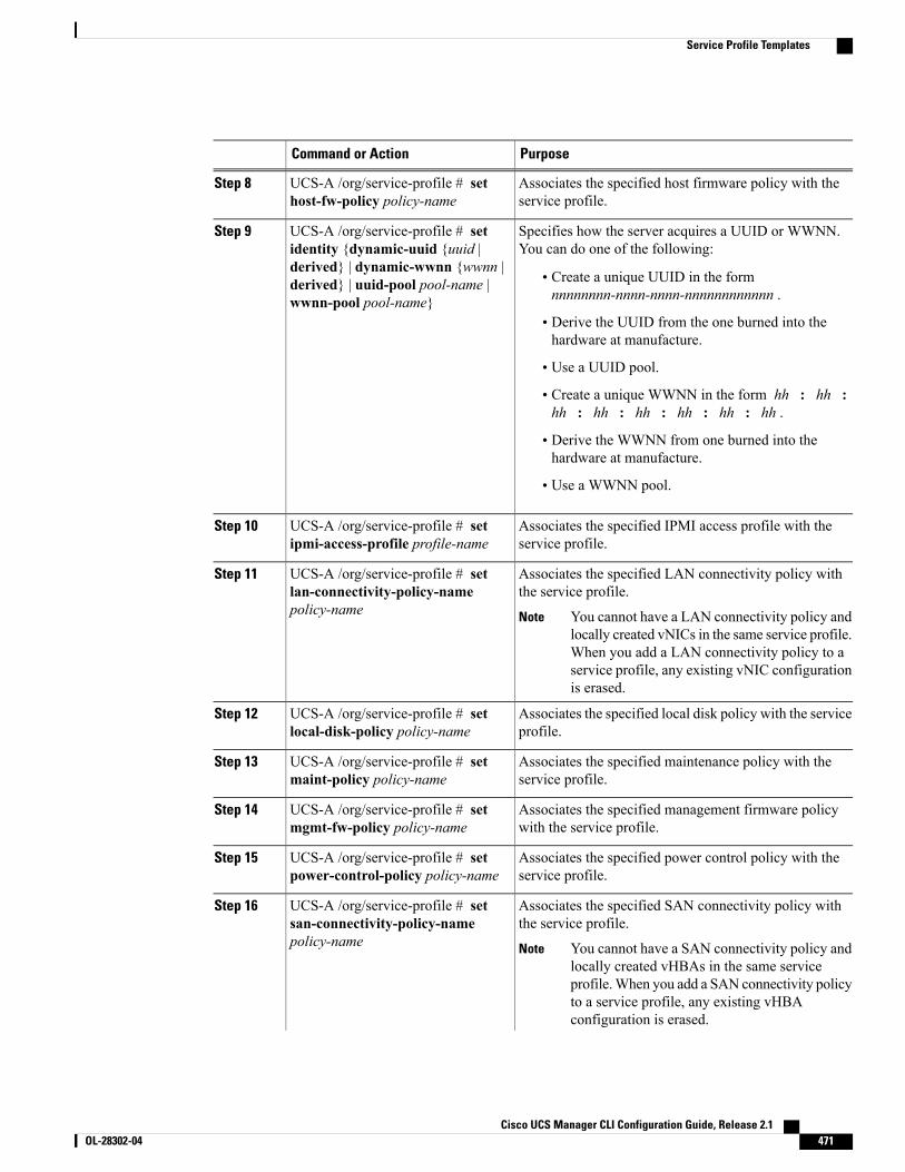
PurposeCommand or Action
Associates the specified host firmware policy with theservice profile.
UCS-A /org/service-profile # sethost-fw-policy policy-name
Step 8
Specifies how the server acquires a UUID or WWNN.You can do one of the following:
UCS-A /org/service-profile # setidentity {dynamic-uuid {uuid |
Step 9
derived} | dynamic-wwnn {wwnn |• Create a unique UUID in the formnnnnnnnn-nnnn-nnnn-nnnnnnnnnnnn .
derived} | uuid-pool pool-name |wwnn-pool pool-name}
• Derive the UUID from the one burned into thehardware at manufacture.
• Use a UUID pool.
• Create a unique WWNN in the form hh : hh :hh : hh : hh : hh : hh : hh .
• Derive the WWNN from one burned into thehardware at manufacture.
• Use a WWNN pool.
Associates the specified IPMI access profile with theservice profile.
UCS-A /org/service-profile # setipmi-access-profile profile-name
Step 10
Associates the specified LAN connectivity policy withthe service profile.
UCS-A /org/service-profile # setlan-connectivity-policy-namepolicy-name
Step 11
You cannot have a LAN connectivity policy andlocally created vNICs in the same service profile.When you add a LAN connectivity policy to aservice profile, any existing vNIC configurationis erased.
Note
Associates the specified local disk policy with the serviceprofile.
UCS-A /org/service-profile # setlocal-disk-policy policy-name
Step 12
Associates the specified maintenance policy with theservice profile.
UCS-A /org/service-profile # setmaint-policy policy-name
Step 13
Associates the specified management firmware policywith the service profile.
UCS-A /org/service-profile # setmgmt-fw-policy policy-name
Step 14
Associates the specified power control policy with theservice profile.
UCS-A /org/service-profile # setpower-control-policy policy-name
Step 15
Associates the specified SAN connectivity policy withthe service profile.
UCS-A /org/service-profile # setsan-connectivity-policy-namepolicy-name
Step 16
You cannot have a SAN connectivity policy andlocally created vHBAs in the same serviceprofile.When you add a SAN connectivity policyto a service profile, any existing vHBAconfiguration is erased.
Note
Cisco UCS Manager CLI Configuration Guide, Release 2.1 OL-28302-04 471
Service Profile Templates
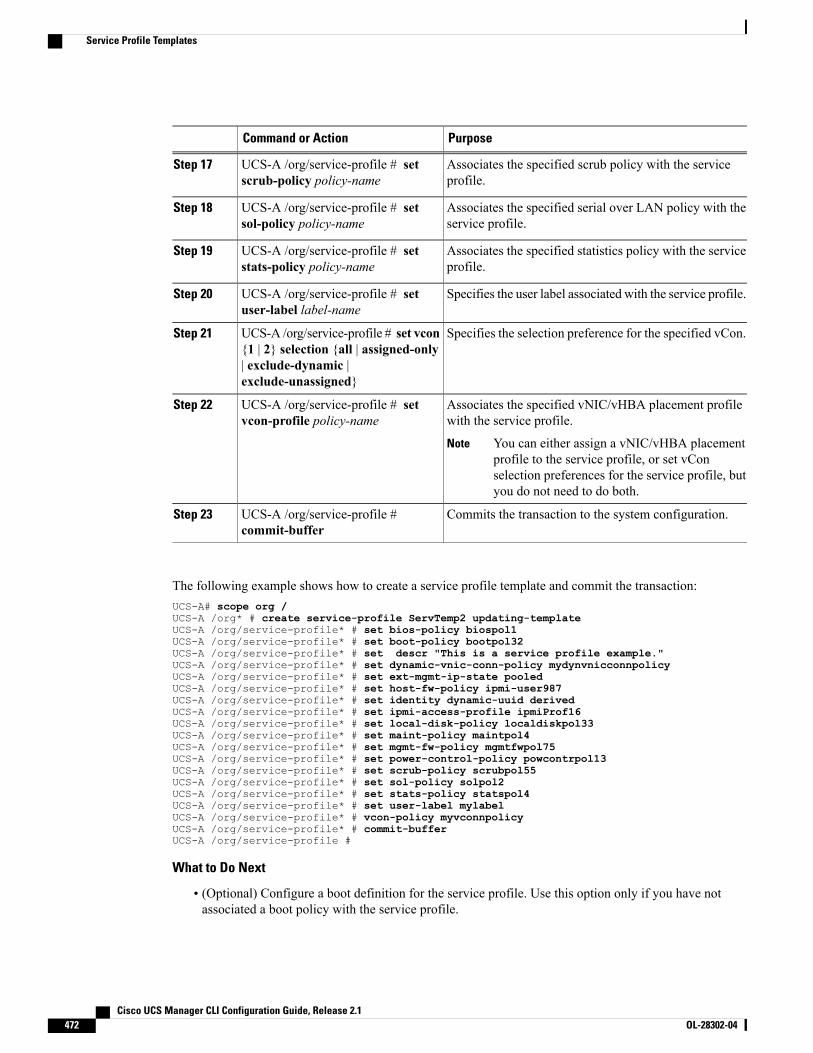
PurposeCommand or Action
Associates the specified scrub policy with the serviceprofile.
UCS-A /org/service-profile # setscrub-policy policy-name
Step 17
Associates the specified serial over LAN policy with theservice profile.
UCS-A /org/service-profile # setsol-policy policy-name
Step 18
Associates the specified statistics policy with the serviceprofile.
UCS-A /org/service-profile # setstats-policy policy-name
Step 19
Specifies the user label associated with the service profile.UCS-A /org/service-profile # setuser-label label-name
Step 20
Specifies the selection preference for the specified vCon.UCS-A /org/service-profile # set vcon{1 | 2} selection {all | assigned-only
Step 21
| exclude-dynamic |exclude-unassigned}
Associates the specified vNIC/vHBA placement profilewith the service profile.
UCS-A /org/service-profile # setvcon-profile policy-name
Step 22
You can either assign a vNIC/vHBA placementprofile to the service profile, or set vConselection preferences for the service profile, butyou do not need to do both.
Note
Commits the transaction to the system configuration.UCS-A /org/service-profile #commit-buffer
Step 23
The following example shows how to create a service profile template and commit the transaction:UCS-A# scope org /UCS-A /org* # create service-profile ServTemp2 updating-templateUCS-A /org/service-profile* # set bios-policy biospol1UCS-A /org/service-profile* # set boot-policy bootpol32UCS-A /org/service-profile* # set descr "This is a service profile example."UCS-A /org/service-profile* # set dynamic-vnic-conn-policy mydynvnicconnpolicyUCS-A /org/service-profile* # set ext-mgmt-ip-state pooledUCS-A /org/service-profile* # set host-fw-policy ipmi-user987UCS-A /org/service-profile* # set identity dynamic-uuid derivedUCS-A /org/service-profile* # set ipmi-access-profile ipmiProf16UCS-A /org/service-profile* # set local-disk-policy localdiskpol33UCS-A /org/service-profile* # set maint-policy maintpol4UCS-A /org/service-profile* # set mgmt-fw-policy mgmtfwpol75UCS-A /org/service-profile* # set power-control-policy powcontrpol13UCS-A /org/service-profile* # set scrub-policy scrubpol55UCS-A /org/service-profile* # set sol-policy solpol2UCS-A /org/service-profile* # set stats-policy statspol4UCS-A /org/service-profile* # set user-label mylabelUCS-A /org/service-profile* # vcon-policy myvconnpolicyUCS-A /org/service-profile* # commit-bufferUCS-A /org/service-profile #
What to Do Next
• (Optional) Configure a boot definition for the service profile. Use this option only if you have notassociated a boot policy with the service profile.
Cisco UCS Manager CLI Configuration Guide, Release 2.1472 OL-28302-04
Service Profile Templates

• Create a service profile instance from the service profile template.
Creating a Service Profile Instance from a Service Profile Template
Before You Begin
Verify that there is a service profile template from which to create a service profile instance.
Procedure
PurposeCommand or Action
Enters organization mode for the specified organization. Toenter the root organization mode, type / as the org-name .
UCS-A# scope org org-nameStep 1
Creates the specified service profile instance and entersorganization service profile mode.
UCS-A /org # createservice-profile profile-nameinstance
Step 2
Enter a unique profile-name to identify this service profiletemplate.
This name can be between 2 and 32 alphanumeric characters.You cannot use spaces or any special characters other than -(hyphen), _ (underscore), : (colon), and . (period), and this namemust be unique across all service profiles and service profiletemplates within the same organization.
Specifies the source service profile template to apply to theservice profile instance. All configuration settings from the
UCS-A /org/service-profile #set src-templ-nameprofile-name
Step 3
service profile template will be applied to the service profileinstance.
Commits the transaction to the system configuration.UCS-A /org/service-profile #commit-buffer
Step 4
The following example creates a service profile instance named ServProf34, applies the service profile templatenamed ServTemp2, and commits the transaction:UCS-A# scope org /UCS-A /org* # create service-profile ServProf34 instanceUCS-A /org/service-profile* # set src-templ-name ServTemp2UCS-A /org/service-profile* # commit-bufferUCS-A /org/service-profile #
What to Do Next
Associate the service profile to a server, rack server, or server pool.
Cisco UCS Manager CLI Configuration Guide, Release 2.1 OL-28302-04 473
Service Profile Templates
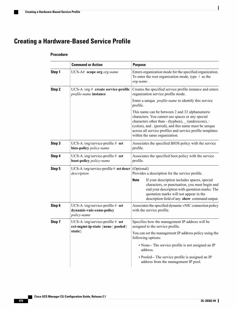
Creating a Hardware-Based Service Profile
Procedure
PurposeCommand or Action
Enters organizationmode for the specified organization.To enter the root organization mode, type / as theorg-name .
UCS-A# scope org org-nameStep 1
Creates the specified service profile instance and entersorganization service profile mode.
UCS-A /org # create service-profileprofile-name instance
Step 2
Enter a unique profile-name to identify this serviceprofile.
This name can be between 2 and 32 alphanumericcharacters. You cannot use spaces or any specialcharacters other than - (hyphen), _ (underscore), :(colon), and . (period), and this name must be uniqueacross all service profiles and service profile templateswithin the same organization.
Associates the specified BIOS policy with the serviceprofile.
UCS-A /org/service-profile # setbios-policy policy-name
Step 3
Associates the specified boot policy with the serviceprofile.
UCS-A /org/service-profile # setboot-policy policy-name
Step 4
(Optional)Provides a description for the service profile.
UCS-A /org/service-profile # set descrdescription
Step 5
If your description includes spaces, specialcharacters, or punctuation, you must begin andend your description with quotation marks. Thequotation marks will not appear in thedescription field of any show command output.
Note
Associates the specified dynamic vNIC connection policywith the service profile.
UCS-A /org/service-profile # setdynamic-vnic-conn-policypolicy-name
Step 6
Specifies how the management IP address will beassigned to the service profile.
UCS-A /org/service-profile # setext-mgmt-ip-state {none | pooled |static}
Step 7
You can set the management IP address policy using thefollowing options:
• None-- The service profile is not assigned an IPaddress.
• Pooled-- The service profile is assigned an IPaddress from the management IP pool.
Cisco UCS Manager CLI Configuration Guide, Release 2.1474 OL-28302-04
Creating a Hardware-Based Service Profile
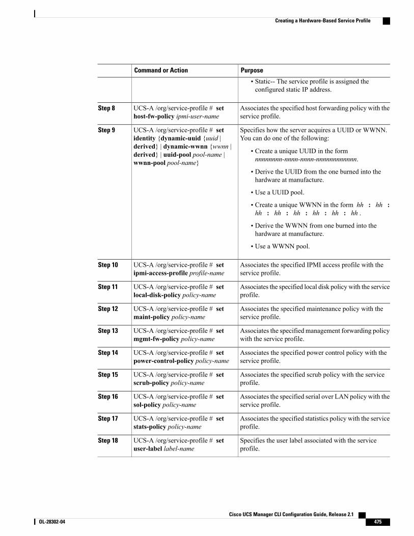
PurposeCommand or Action
• Static-- The service profile is assigned theconfigured static IP address.
Associates the specified host forwarding policy with theservice profile.
UCS-A /org/service-profile # sethost-fw-policy ipmi-user-name
Step 8
Specifies how the server acquires a UUID or WWNN.You can do one of the following:
UCS-A /org/service-profile # setidentity {dynamic-uuid {uuid |
Step 9
derived} | dynamic-wwnn {wwnn |• Create a unique UUID in the formnnnnnnnn-nnnn-nnnn-nnnnnnnnnnnn.
derived} | uuid-pool pool-name |wwnn-pool pool-name}
• Derive the UUID from the one burned into thehardware at manufacture.
• Use a UUID pool.
• Create a unique WWNN in the form hh : hh :hh : hh : hh : hh : hh : hh .
• Derive the WWNN from one burned into thehardware at manufacture.
• Use a WWNN pool.
Associates the specified IPMI access profile with theservice profile.
UCS-A /org/service-profile # setipmi-access-profile profile-name
Step 10
Associates the specified local disk policy with the serviceprofile.
UCS-A /org/service-profile # setlocal-disk-policy policy-name
Step 11
Associates the specified maintenance policy with theservice profile.
UCS-A /org/service-profile # setmaint-policy policy-name
Step 12
Associates the specified management forwarding policywith the service profile.
UCS-A /org/service-profile # setmgmt-fw-policy policy-name
Step 13
Associates the specified power control policy with theservice profile.
UCS-A /org/service-profile # setpower-control-policy policy-name
Step 14
Associates the specified scrub policy with the serviceprofile.
UCS-A /org/service-profile # setscrub-policy policy-name
Step 15
Associates the specified serial over LAN policy with theservice profile.
UCS-A /org/service-profile # setsol-policy policy-name
Step 16
Associates the specified statistics policy with the serviceprofile.
UCS-A /org/service-profile # setstats-policy policy-name
Step 17
Specifies the user label associated with the serviceprofile.
UCS-A /org/service-profile # setuser-label label-name
Step 18
Cisco UCS Manager CLI Configuration Guide, Release 2.1 OL-28302-04 475
Creating a Hardware-Based Service Profile
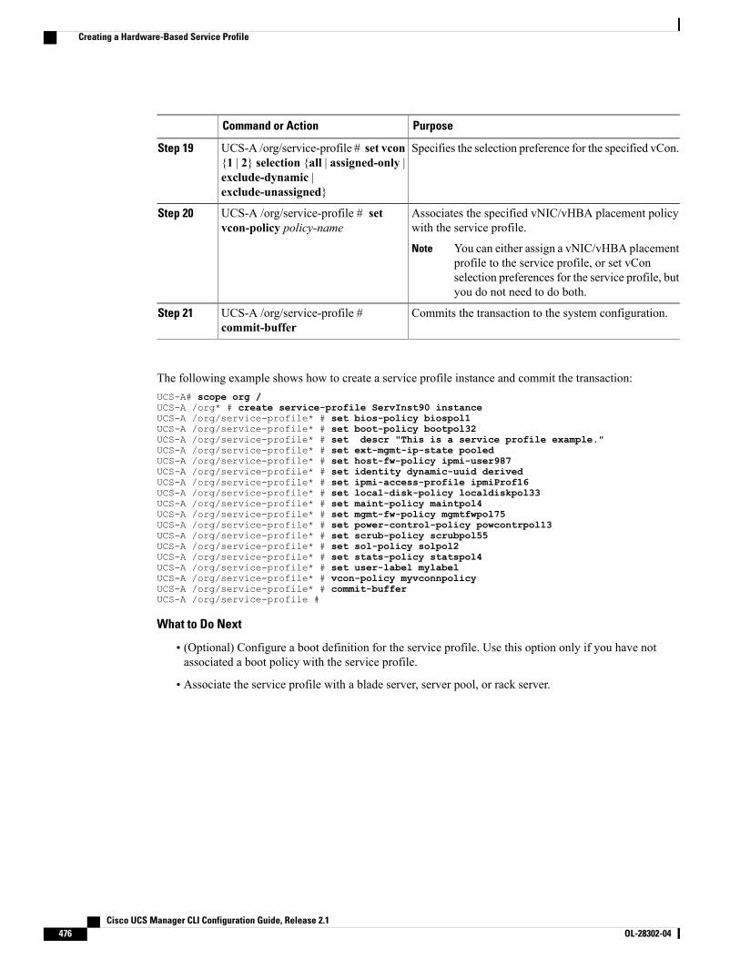
PurposeCommand or Action
Specifies the selection preference for the specified vCon.UCS-A /org/service-profile # set vcon{1 | 2} selection {all | assigned-only |
Step 19
exclude-dynamic |exclude-unassigned}
Associates the specified vNIC/vHBA placement policywith the service profile.
UCS-A /org/service-profile # setvcon-policy policy-name
Step 20
You can either assign a vNIC/vHBA placementprofile to the service profile, or set vConselection preferences for the service profile, butyou do not need to do both.
Note
Commits the transaction to the system configuration.UCS-A /org/service-profile #commit-buffer
Step 21
The following example shows how to create a service profile instance and commit the transaction:UCS-A# scope org /UCS-A /org* # create service-profile ServInst90 instanceUCS-A /org/service-profile* # set bios-policy biospol1UCS-A /org/service-profile* # set boot-policy bootpol32UCS-A /org/service-profile* # set descr "This is a service profile example."UCS-A /org/service-profile* # set ext-mgmt-ip-state pooledUCS-A /org/service-profile* # set host-fw-policy ipmi-user987UCS-A /org/service-profile* # set identity dynamic-uuid derivedUCS-A /org/service-profile* # set ipmi-access-profile ipmiProf16UCS-A /org/service-profile* # set local-disk-policy localdiskpol33UCS-A /org/service-profile* # set maint-policy maintpol4UCS-A /org/service-profile* # set mgmt-fw-policy mgmtfwpol75UCS-A /org/service-profile* # set power-control-policy powcontrpol13UCS-A /org/service-profile* # set scrub-policy scrubpol55UCS-A /org/service-profile* # set sol-policy solpol2UCS-A /org/service-profile* # set stats-policy statspol4UCS-A /org/service-profile* # set user-label mylabelUCS-A /org/service-profile* # vcon-policy myvconnpolicyUCS-A /org/service-profile* # commit-bufferUCS-A /org/service-profile #
What to Do Next
• (Optional) Configure a boot definition for the service profile. Use this option only if you have notassociated a boot policy with the service profile.
• Associate the service profile with a blade server, server pool, or rack server.
Cisco UCS Manager CLI Configuration Guide, Release 2.1476 OL-28302-04
Creating a Hardware-Based Service Profile
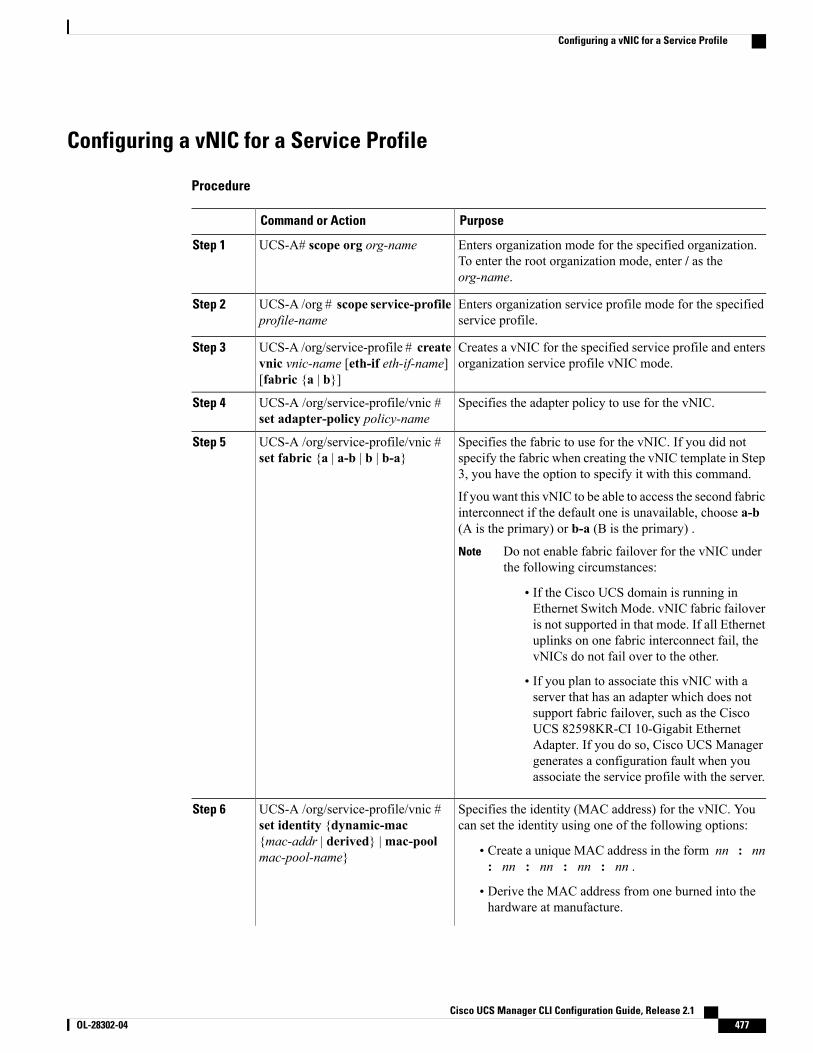
Configuring a vNIC for a Service Profile
Procedure
PurposeCommand or Action
Enters organization mode for the specified organization.To enter the root organization mode, enter / as theorg-name.
UCS-A# scope org org-nameStep 1
Enters organization service profile mode for the specifiedservice profile.
UCS-A /org # scope service-profileprofile-name
Step 2
Creates a vNIC for the specified service profile and entersorganization service profile vNIC mode.
UCS-A /org/service-profile # createvnic vnic-name [eth-if eth-if-name][fabric {a | b}]
Step 3
Specifies the adapter policy to use for the vNIC.UCS-A /org/service-profile/vnic #set adapter-policy policy-name
Step 4
Specifies the fabric to use for the vNIC. If you did notspecify the fabric when creating the vNIC template in Step3, you have the option to specify it with this command.
UCS-A /org/service-profile/vnic #set fabric {a | a-b | b | b-a}
Step 5
If you want this vNIC to be able to access the second fabricinterconnect if the default one is unavailable, choose a-b(A is the primary) or b-a (B is the primary) .
Do not enable fabric failover for the vNIC underthe following circumstances:
Note
• If the Cisco UCS domain is running inEthernet Switch Mode. vNIC fabric failoveris not supported in that mode. If all Ethernetuplinks on one fabric interconnect fail, thevNICs do not fail over to the other.
• If you plan to associate this vNIC with aserver that has an adapter which does notsupport fabric failover, such as the CiscoUCS 82598KR-CI 10-Gigabit EthernetAdapter. If you do so, Cisco UCS Managergenerates a configuration fault when youassociate the service profile with the server.
Specifies the identity (MAC address) for the vNIC. Youcan set the identity using one of the following options:
UCS-A /org/service-profile/vnic #set identity {dynamic-mac
Step 6
{mac-addr | derived} |mac-poolmac-pool-name} • Create a unique MAC address in the form nn : nn
: nn : nn : nn : nn .
• Derive the MAC address from one burned into thehardware at manufacture.
Cisco UCS Manager CLI Configuration Guide, Release 2.1 OL-28302-04 477
Configuring a vNIC for a Service Profile
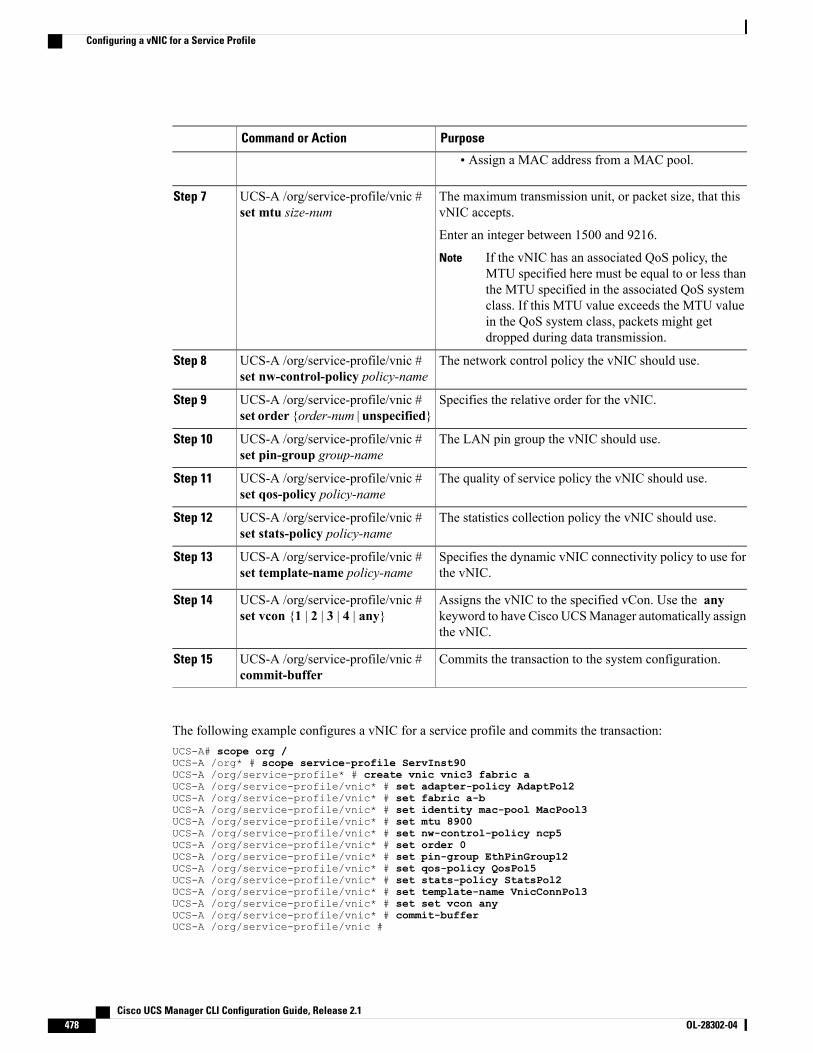
PurposeCommand or Action
• Assign a MAC address from a MAC pool.
The maximum transmission unit, or packet size, that thisvNIC accepts.
UCS-A /org/service-profile/vnic #set mtu size-num
Step 7
Enter an integer between 1500 and 9216.
If the vNIC has an associated QoS policy, theMTU specified here must be equal to or less thanthe MTU specified in the associated QoS systemclass. If this MTU value exceeds the MTU valuein the QoS system class, packets might getdropped during data transmission.
Note
The network control policy the vNIC should use.UCS-A /org/service-profile/vnic #set nw-control-policy policy-name
Step 8
Specifies the relative order for the vNIC.UCS-A /org/service-profile/vnic #set order {order-num | unspecified}
Step 9
The LAN pin group the vNIC should use.UCS-A /org/service-profile/vnic #set pin-group group-name
Step 10
The quality of service policy the vNIC should use.UCS-A /org/service-profile/vnic #set qos-policy policy-name
Step 11
The statistics collection policy the vNIC should use.UCS-A /org/service-profile/vnic #set stats-policy policy-name
Step 12
Specifies the dynamic vNIC connectivity policy to use forthe vNIC.
UCS-A /org/service-profile/vnic #set template-name policy-name
Step 13
Assigns the vNIC to the specified vCon. Use the anykeyword to have Cisco UCSManager automatically assignthe vNIC.
UCS-A /org/service-profile/vnic #set vcon {1 | 2 | 3 | 4 | any}
Step 14
Commits the transaction to the system configuration.UCS-A /org/service-profile/vnic #commit-buffer
Step 15
The following example configures a vNIC for a service profile and commits the transaction:UCS-A# scope org /UCS-A /org* # scope service-profile ServInst90UCS-A /org/service-profile* # create vnic vnic3 fabric aUCS-A /org/service-profile/vnic* # set adapter-policy AdaptPol2UCS-A /org/service-profile/vnic* # set fabric a-bUCS-A /org/service-profile/vnic* # set identity mac-pool MacPool3UCS-A /org/service-profile/vnic* # set mtu 8900UCS-A /org/service-profile/vnic* # set nw-control-policy ncp5UCS-A /org/service-profile/vnic* # set order 0UCS-A /org/service-profile/vnic* # set pin-group EthPinGroup12UCS-A /org/service-profile/vnic* # set qos-policy QosPol5UCS-A /org/service-profile/vnic* # set stats-policy StatsPol2UCS-A /org/service-profile/vnic* # set template-name VnicConnPol3UCS-A /org/service-profile/vnic* # set set vcon anyUCS-A /org/service-profile/vnic* # commit-bufferUCS-A /org/service-profile/vnic #
Cisco UCS Manager CLI Configuration Guide, Release 2.1478 OL-28302-04
Configuring a vNIC for a Service Profile
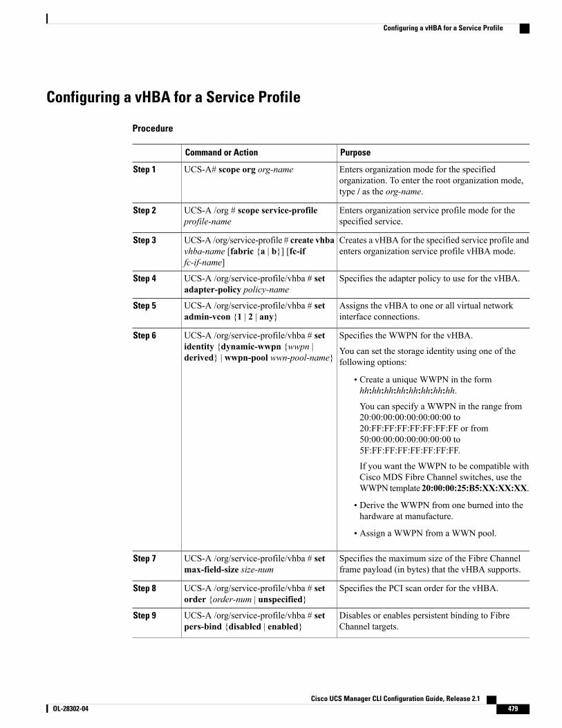
Configuring a vHBA for a Service Profile
Procedure
PurposeCommand or Action
Enters organization mode for the specifiedorganization. To enter the root organization mode,type / as the org-name.
UCS-A# scope org org-nameStep 1
Enters organization service profile mode for thespecified service.
UCS-A /org # scope service-profileprofile-name
Step 2
Creates a vHBA for the specified service profile andenters organization service profile vHBA mode.
UCS-A /org/service-profile # create vhbavhba-name [fabric {a | b}] [fc-iffc-if-name]
Step 3
Specifies the adapter policy to use for the vHBA.UCS-A /org/service-profile/vhba # setadapter-policy policy-name
Step 4
Assigns the vHBA to one or all virtual networkinterface connections.
UCS-A /org/service-profile/vhba # setadmin-vcon {1 | 2 | any}
Step 5
Specifies the WWPN for the vHBA.UCS-A /org/service-profile/vhba # setidentity {dynamic-wwpn {wwpn |derived} | wwpn-pool wwn-pool-name}
Step 6
You can set the storage identity using one of thefollowing options:
• Create a unique WWPN in the formhh:hh:hh:hh:hh:hh:hh:hh.
You can specify a WWPN in the range from20:00:00:00:00:00:00:00 to20:FF:FF:FF:FF:FF:FF:FF or from50:00:00:00:00:00:00:00 to5F:FF:FF:FF:FF:FF:FF:FF.
If you want the WWPN to be compatible withCisco MDS Fibre Channel switches, use theWWPN template 20:00:00:25:B5:XX:XX:XX.
• Derive the WWPN from one burned into thehardware at manufacture.
• Assign a WWPN from a WWN pool.
Specifies the maximum size of the Fibre Channelframe payload (in bytes) that the vHBA supports.
UCS-A /org/service-profile/vhba # setmax-field-size size-num
Step 7
Specifies the PCI scan order for the vHBA.UCS-A /org/service-profile/vhba # setorder {order-num | unspecified}
Step 8
Disables or enables persistent binding to FibreChannel targets.
UCS-A /org/service-profile/vhba # setpers-bind {disabled | enabled}
Step 9
Cisco UCS Manager CLI Configuration Guide, Release 2.1 OL-28302-04 479
Configuring a vHBA for a Service Profile

PurposeCommand or Action
Specifies the SAN pin group to use for the vHBA.UCS-A /org/service-profile/vhba # setpin-group group-name
Step 10
Specifies the QoS policy to use for the vHBA.UCS-A /org/service-profile/vhba # setqos-policy policy-name
Step 11
Specifies the statistics threshold policy to use for thevHBA.
UCS-A /org/service-profile/vhba # setstats-policy policy-name
Step 12
Specifies the vHBA template to use for the vHBA.UCS-A /org/service-profile/vhba # settemplate-name policy-name
Step 13
Commits the transaction to the system configuration.UCS-A /org/service-profile/vhba #commit-buffer
Step 14
The following example configures a vHBA for a service profile and commits the transaction:UCS-A# scope org /UCS-A /org* # scope service-profile ServInst90UCS-A /org/service-profile* # create vhba vhba3 fabric bUCS-A /org/service-profile/vhba* # set adapter-policy AdaptPol2UCS-A /org/service-profile/vhba* # set admin-vcon anyUCS-A /org/service-profile/vhba* # set identity wwpn-pool SanPool7UCS-A /org/service-profile/vhba* # set max-field-size 2112UCS-A /org/service-profile/vhba* # set order 0UCS-A /org/service-profile/vhba* # set pers-bind enabledUCS-A /org/service-profile/vhba* # set pin-group FcPinGroup12UCS-A /org/service-profile/vhba* # set qos-policy QosPol5UCS-A /org/service-profile/vhba* # set stats-policy StatsPol2UCS-A /org/service-profile/vhba* # set template-name SanConnPol3UCS-A /org/service-profile/vhba* # commit-bufferUCS-A /org/service-profile/vhba #
Configuring a Local Disk for a Service Profile
Procedure
PurposeCommand or Action
Enters organization mode for the specifiedorganization. To enter the root organizationmode, type / as the org-name.
UCS-A# scope org org-nameStep 1
Enters organization service profile mode forthe specified service profile.
UCS-A /org # scope service-profileprofile-name
Step 2
Creates a local disk configuration for theservice profile and enters organization serviceprofile local disk configuration mode.
UCS-A /org/service-profile # createlocal-disk-config
Step 3
Cisco UCS Manager CLI Configuration Guide, Release 2.1480 OL-28302-04
Configuring a Local Disk for a Service Profile
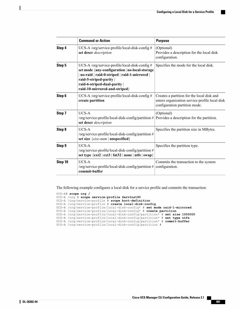
PurposeCommand or Action
(Optional)Provides a description for the local diskconfiguration.
UCS-A /org/service-profile/local-disk-config #set descr description
Step 4
Specifies the mode for the local disk.UCS-A /org/service-profile/local-disk-config #set mode {any-configuration | no-local-storage
Step 5
| no-raid | raid-0-striped | raid-1-mirrored |raid-5-striped-parity |raid-6-striped-dual-parity |raid-10-mirrored-and-striped}
Creates a partition for the local disk andenters organization service profile local diskconfiguration partition mode.
UCS-A /org/service-profile/local-disk-config #create partition
Step 6
(Optional)Provides a description for the partition.
UCS-A/org/service-profile/local-disk-config/partition #set descr description
Step 7
Specifies the partition size in MBytes.UCS-A/org/service-profile/local-disk-config/partition #set size {size-num | unspecified}
Step 8
Specifies the partition type.UCS-A/org/service-profile/local-disk-config/partition #set type {ext2 | ext3 | fat32 | none | ntfs | swap}
Step 9
Commits the transaction to the systemconfiguration.
UCS-A/org/service-profile/local-disk-config/partition #commit-buffer
Step 10
The following example configures a local disk for a service profile and commits the transaction:UCS-A# scope org /UCS-A /org # scope service-profile ServInst90UCS-A /org/service-profile # scope boot-definitionUCS-A /org/service-profile # create local-disk-configUCS-A /org/service-profile/local-disk-config* # set mode raid-1-mirroredUCS-A /org/service-profile/local-disk-config* # create partitionUCS-A /org/service-profile/local-disk-config/partition* # set size 1000000UCS-A /org/service-profile/local-disk-config/partition* # set type ntfsUCS-A /org/service-profile/local-disk-config/partition* # commit-bufferUCS-A /org/service-profile/local-disk-config/partition #
Cisco UCS Manager CLI Configuration Guide, Release 2.1 OL-28302-04 481
Configuring a Local Disk for a Service Profile
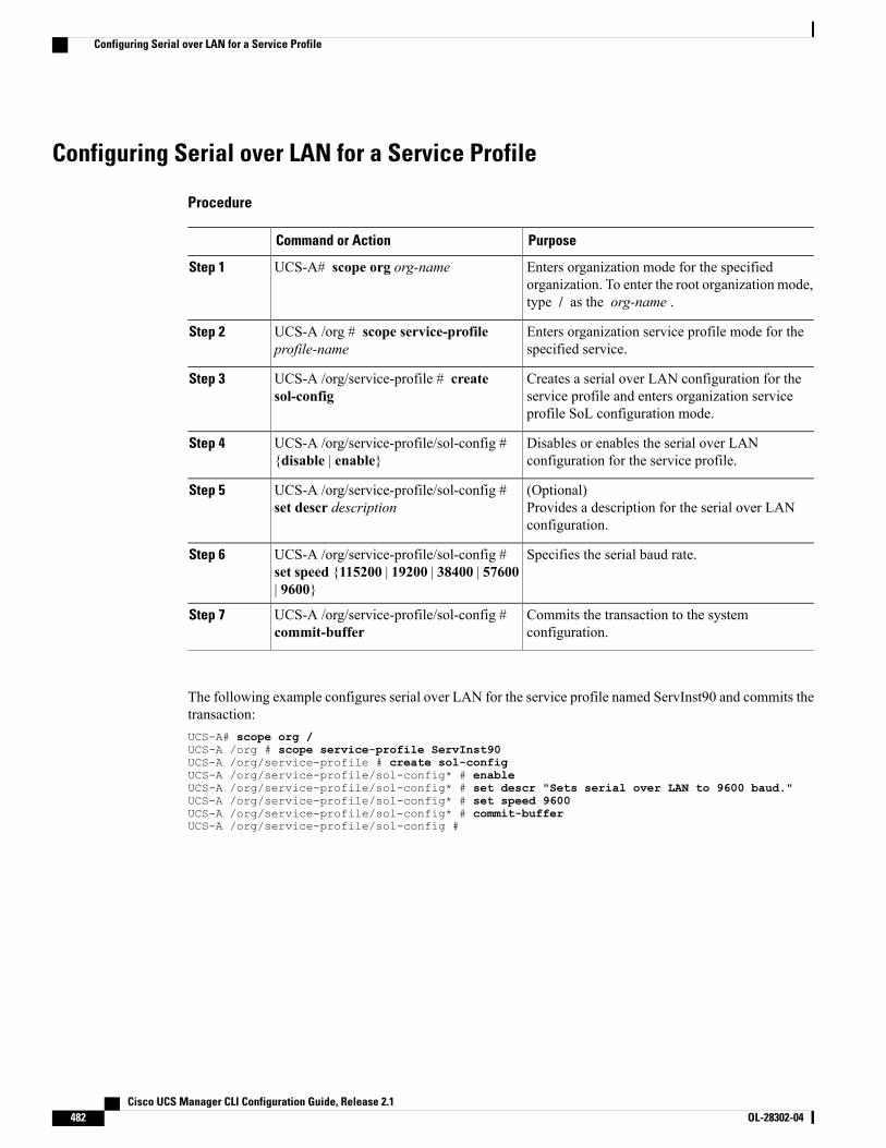
Configuring Serial over LAN for a Service Profile
Procedure
PurposeCommand or Action
Enters organization mode for the specifiedorganization. To enter the root organization mode,type / as the org-name .
UCS-A# scope org org-nameStep 1
Enters organization service profile mode for thespecified service.
UCS-A /org # scope service-profileprofile-name
Step 2
Creates a serial over LAN configuration for theservice profile and enters organization serviceprofile SoL configuration mode.
UCS-A /org/service-profile # createsol-config
Step 3
Disables or enables the serial over LANconfiguration for the service profile.
UCS-A /org/service-profile/sol-config #{disable | enable}
Step 4
(Optional)Provides a description for the serial over LANconfiguration.
UCS-A /org/service-profile/sol-config #set descr description
Step 5
Specifies the serial baud rate.UCS-A /org/service-profile/sol-config #set speed {115200 | 19200 | 38400 | 57600| 9600}
Step 6
Commits the transaction to the systemconfiguration.
UCS-A /org/service-profile/sol-config #commit-buffer
Step 7
The following example configures serial over LAN for the service profile named ServInst90 and commits thetransaction:UCS-A# scope org /UCS-A /org # scope service-profile ServInst90UCS-A /org/service-profile # create sol-configUCS-A /org/service-profile/sol-config* # enableUCS-A /org/service-profile/sol-config* # set descr "Sets serial over LAN to 9600 baud."UCS-A /org/service-profile/sol-config* # set speed 9600UCS-A /org/service-profile/sol-config* # commit-bufferUCS-A /org/service-profile/sol-config #
Cisco UCS Manager CLI Configuration Guide, Release 2.1482 OL-28302-04
Configuring Serial over LAN for a Service Profile
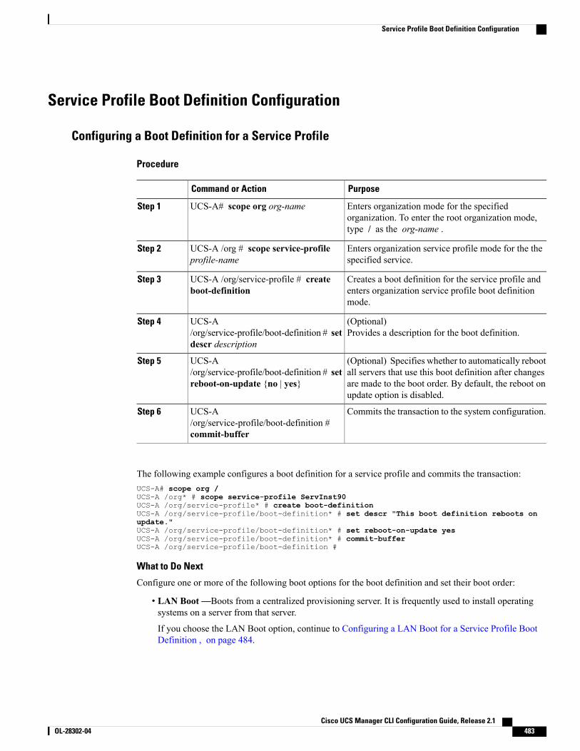
Service Profile Boot Definition Configuration
Configuring a Boot Definition for a Service Profile
Procedure
PurposeCommand or Action
Enters organization mode for the specifiedorganization. To enter the root organization mode,type / as the org-name .
UCS-A# scope org org-nameStep 1
Enters organization service profile mode for the thespecified service.
UCS-A /org # scope service-profileprofile-name
Step 2
Creates a boot definition for the service profile andenters organization service profile boot definitionmode.
UCS-A /org/service-profile # createboot-definition
Step 3
(Optional)Provides a description for the boot definition.
UCS-A/org/service-profile/boot-definition # setdescr description
Step 4
(Optional) Specifies whether to automatically rebootall servers that use this boot definition after changes
UCS-A/org/service-profile/boot-definition # setreboot-on-update {no | yes}
Step 5
are made to the boot order. By default, the reboot onupdate option is disabled.
Commits the transaction to the system configuration.UCS-A/org/service-profile/boot-definition #commit-buffer
Step 6
The following example configures a boot definition for a service profile and commits the transaction:UCS-A# scope org /UCS-A /org* # scope service-profile ServInst90UCS-A /org/service-profile* # create boot-definitionUCS-A /org/service-profile/boot-definition* # set descr "This boot definition reboots onupdate."UCS-A /org/service-profile/boot-definition* # set reboot-on-update yesUCS-A /org/service-profile/boot-definition* # commit-bufferUCS-A /org/service-profile/boot-definition #
What to Do Next
Configure one or more of the following boot options for the boot definition and set their boot order:
• LAN Boot—Boots from a centralized provisioning server. It is frequently used to install operatingsystems on a server from that server.
If you choose the LAN Boot option, continue to Configuring a LAN Boot for a Service Profile BootDefinition , on page 484.
Cisco UCS Manager CLI Configuration Guide, Release 2.1 OL-28302-04 483
Service Profile Boot Definition Configuration
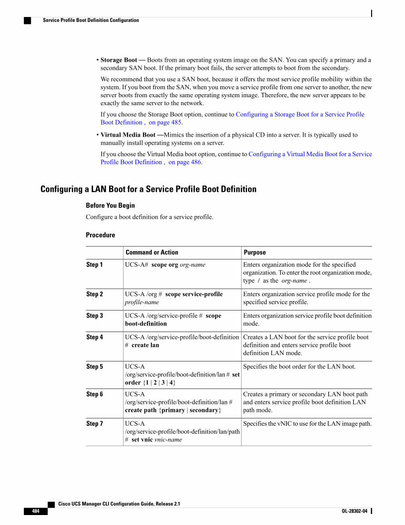
• Storage Boot— Boots from an operating system image on the SAN. You can specify a primary and asecondary SAN boot. If the primary boot fails, the server attempts to boot from the secondary.
We recommend that you use a SAN boot, because it offers the most service profile mobility within thesystem. If you boot from the SAN, when you move a service profile from one server to another, the newserver boots from exactly the same operating system image. Therefore, the new server appears to beexactly the same server to the network.
If you choose the Storage Boot option, continue to Configuring a Storage Boot for a Service ProfileBoot Definition , on page 485.
• Virtual Media Boot—Mimics the insertion of a physical CD into a server. It is typically used tomanually install operating systems on a server.
If you choose the Virtual Media boot option, continue to Configuring a Virtual Media Boot for a ServiceProfile Boot Definition , on page 486.
Configuring a LAN Boot for a Service Profile Boot Definition
Before You Begin
Configure a boot definition for a service profile.
Procedure
PurposeCommand or Action
Enters organization mode for the specifiedorganization. To enter the root organizationmode,type / as the org-name .
UCS-A# scope org org-nameStep 1
Enters organization service profile mode for thespecified service profile.
UCS-A /org # scope service-profileprofile-name
Step 2
Enters organization service profile boot definitionmode.
UCS-A /org/service-profile # scopeboot-definition
Step 3
Creates a LAN boot for the service profile bootdefinition and enters service profile bootdefinition LAN mode.
UCS-A /org/service-profile/boot-definition# create lan
Step 4
Specifies the boot order for the LAN boot.UCS-A/org/service-profile/boot-definition/lan # setorder {1 | 2 | 3 | 4}
Step 5
Creates a primary or secondary LAN boot pathand enters service profile boot definition LANpath mode.
UCS-A/org/service-profile/boot-definition/lan #create path {primary | secondary}
Step 6
Specifies the vNIC to use for the LAN image path.UCS-A/org/service-profile/boot-definition/lan/path# set vnic vnic-name
Step 7
Cisco UCS Manager CLI Configuration Guide, Release 2.1484 OL-28302-04
Service Profile Boot Definition Configuration
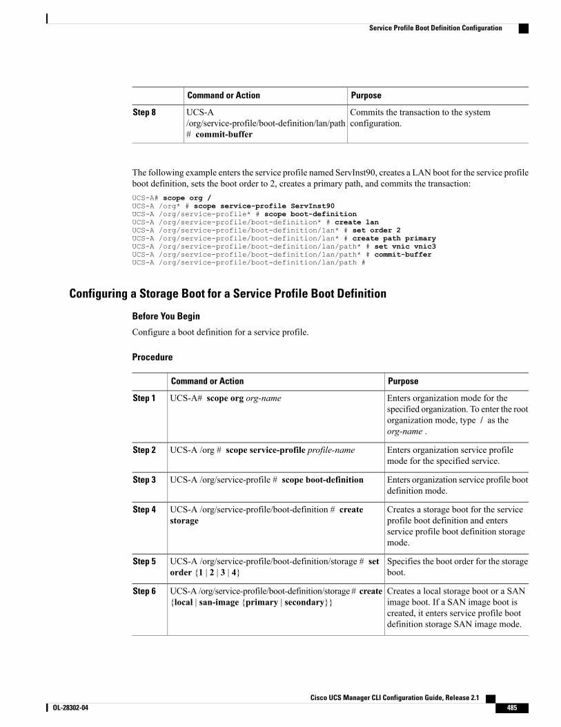
PurposeCommand or Action
Commits the transaction to the systemconfiguration.
UCS-A/org/service-profile/boot-definition/lan/path# commit-buffer
Step 8
The following example enters the service profile named ServInst90, creates a LAN boot for the service profileboot definition, sets the boot order to 2, creates a primary path, and commits the transaction:UCS-A# scope org /UCS-A /org* # scope service-profile ServInst90UCS-A /org/service-profile* # scope boot-definitionUCS-A /org/service-profile/boot-definition* # create lanUCS-A /org/service-profile/boot-definition/lan* # set order 2UCS-A /org/service-profile/boot-definition/lan* # create path primaryUCS-A /org/service-profile/boot-definition/lan/path* # set vnic vnic3UCS-A /org/service-profile/boot-definition/lan/path* # commit-bufferUCS-A /org/service-profile/boot-definition/lan/path #
Configuring a Storage Boot for a Service Profile Boot Definition
Before You Begin
Configure a boot definition for a service profile.
Procedure
PurposeCommand or Action
Enters organization mode for thespecified organization. To enter the root
UCS-A# scope org org-nameStep 1
organization mode, type / as theorg-name .
Enters organization service profilemode for the specified service.
UCS-A /org # scope service-profile profile-nameStep 2
Enters organization service profile bootdefinition mode.
UCS-A /org/service-profile # scope boot-definitionStep 3
Creates a storage boot for the serviceprofile boot definition and enters
UCS-A /org/service-profile/boot-definition # createstorage
Step 4
service profile boot definition storagemode.
Specifies the boot order for the storageboot.
UCS-A /org/service-profile/boot-definition/storage # setorder {1 | 2 | 3 | 4}
Step 5
Creates a local storage boot or a SANimage boot. If a SAN image boot is
UCS-A /org/service-profile/boot-definition/storage # create{local | san-image {primary | secondary}}
Step 6
created, it enters service profile bootdefinition storage SAN image mode.
Cisco UCS Manager CLI Configuration Guide, Release 2.1 OL-28302-04 485
Service Profile Boot Definition Configuration
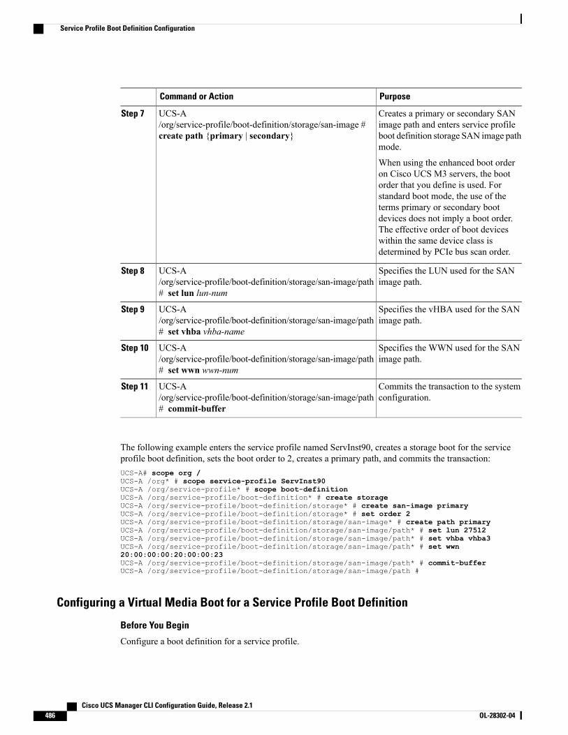
PurposeCommand or Action
Creates a primary or secondary SANimage path and enters service profile
UCS-A/org/service-profile/boot-definition/storage/san-image #create path {primary | secondary}
Step 7
boot definition storage SAN image pathmode.
When using the enhanced boot orderon Cisco UCS M3 servers, the bootorder that you define is used. Forstandard boot mode, the use of theterms primary or secondary bootdevices does not imply a boot order.The effective order of boot deviceswithin the same device class isdetermined by PCIe bus scan order.
Specifies the LUN used for the SANimage path.
UCS-A/org/service-profile/boot-definition/storage/san-image/path# set lun lun-num
Step 8
Specifies the vHBA used for the SANimage path.
UCS-A/org/service-profile/boot-definition/storage/san-image/path# set vhba vhba-name
Step 9
Specifies the WWN used for the SANimage path.
UCS-A/org/service-profile/boot-definition/storage/san-image/path# set wwn wwn-num
Step 10
Commits the transaction to the systemconfiguration.
UCS-A/org/service-profile/boot-definition/storage/san-image/path# commit-buffer
Step 11
The following example enters the service profile named ServInst90, creates a storage boot for the serviceprofile boot definition, sets the boot order to 2, creates a primary path, and commits the transaction:UCS-A# scope org /UCS-A /org* # scope service-profile ServInst90UCS-A /org/service-profile* # scope boot-definitionUCS-A /org/service-profile/boot-definition* # create storageUCS-A /org/service-profile/boot-definition/storage* # create san-image primaryUCS-A /org/service-profile/boot-definition/storage* # set order 2UCS-A /org/service-profile/boot-definition/storage/san-image* # create path primaryUCS-A /org/service-profile/boot-definition/storage/san-image/path* # set lun 27512UCS-A /org/service-profile/boot-definition/storage/san-image/path* # set vhba vhba3UCS-A /org/service-profile/boot-definition/storage/san-image/path* # set wwn20:00:00:00:20:00:00:23UCS-A /org/service-profile/boot-definition/storage/san-image/path* # commit-bufferUCS-A /org/service-profile/boot-definition/storage/san-image/path #
Configuring a Virtual Media Boot for a Service Profile Boot Definition
Before You Begin
Configure a boot definition for a service profile.
Cisco UCS Manager CLI Configuration Guide, Release 2.1486 OL-28302-04
Service Profile Boot Definition Configuration

Procedure
PurposeCommand or Action
Enters organization mode for the specifiedorganization. To enter the root organizationmode, type / as the org-name .
UCS-A# scope org org-nameStep 1
Enters organization service profile mode forthe specified service.
UCS-A /org # scope service-profileprofile-name
Step 2
Enters organization service profile bootdefinition mode.
UCS-A /org/service-profile # scopeboot-definition
Step 3
Creates a read-only or read-write virtual mediaboot for the service profile boot definition and
UCS-A /org/service-profile/boot-definition #create virtual-media {read-only | read-write}
Step 4
enters service profile boot definition virtualmedia mode.
Specifies the boot order for the virtual mediaboot.
UCS-A/org/service-profile/boot-definition/virtual-media# set order {1 | 2 | 3 | 4}
Step 5
Commits the transaction to the systemconfiguration.
UCS-A/org/service-profile/boot-definition/virtual-media# commit-buffer
Step 6
The following example enters the service profile named ServInst90, creates a virtual media boot with read-onlyprivileges for the service profile boot definition, sets the boot order to 3, and commits the transaction:UCS-A# scope org /UCS-A /org* # scope service-profile ServInst90UCS-A /org/service-profile* # scope boot-definitionUCS-A /org/service-profile/boot-definition* # create virtual-media read-onlyUCS-A /org/service-profile/boot-definition/virtual-media* # set order 1UCS-A /org/service-profile/boot-definition/virtual-media* # commit-bufferUCS-A /org/service-profile/boot-definition/virtual-media #
Deleting a Boot Definition for a Service Profile
Procedure
PurposeCommand or Action
Enters organization mode for the specifiedorganization. To enter the root organization mode,type / as the org-name.
UCS-A# scope org org-nameStep 1
Enters organization service profile mode for the thespecified service.
UCS-A /org # scope service-profileprofile-name
Step 2
Cisco UCS Manager CLI Configuration Guide, Release 2.1 OL-28302-04 487
Service Profile Boot Definition Configuration
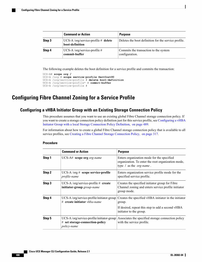
PurposeCommand or Action
Deletes the boot definition for the service profile.UCS-A /org/service-profile # deleteboot-definition
Step 3
Commits the transaction to the systemconfiguration.
UCS-A /org/service-profile #commit-buffer
Step 4
The following example deletes the boot definition for a service profile and commits the transaction:UCS-A# scope org /UCS-A /org # scope service-profile ServInst90UCS-A /org/service-profile # delete boot-definitionUCS-A /org/service-profile* # commit-bufferUCS-A /org/service-profile #
Configuring Fibre Channel Zoning for a Service Profile
Configuring a vHBA Initiator Group with an Existing Storage Connection PolicyThis procedure assumes that you want to use an existing global Fibre Channel storage connection policy. Ifyou want to create a storage connection policy definition just for this service profile, see Configuring a vHBAInitiator Group with a local Storage Connection Policy Definition, on page 489.
For information about how to create a global Fibre Channel storage connection policy that is available to allservice profiles, see Creating a Fibre Channel Storage Connection Policy, on page 317.
Procedure
PurposeCommand or Action
Enters organization mode for the specifiedorganization. To enter the root organization mode,type / as the org-name .
UCS-A# scope org org-nameStep 1
Enters organization service profile mode for thespecified service profile.
UCS-A /org # scope service-profileprofile-name
Step 2
Creates the specified initiator group for FibreChannel zoning and enters service profile initiatorgroup mode.
UCS-A /org/service-profile # createinitiator-group group-name
Step 3
Creates the specified vHBA initiator in the initiatorgroup.
UCS-A /org/service-profile/initiator-group# create initiator vhba-name
Step 4
If desired, repeat this step to add a second vHBAinitiator to the group.
Associates the specified storage connection policywith the service profile.
UCS-A /org/service-profile/initiator-group# set storage-connection-policypolicy-name
Step 5
Cisco UCS Manager CLI Configuration Guide, Release 2.1488 OL-28302-04
Configuring Fibre Channel Zoning for a Service Profile
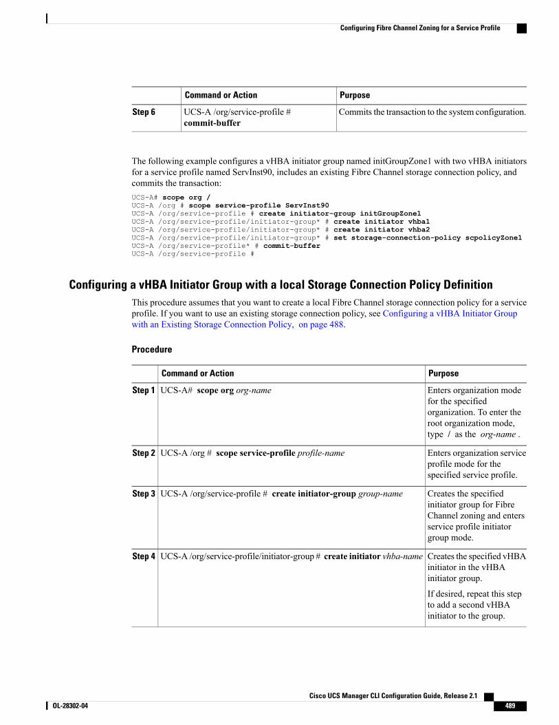
PurposeCommand or Action
Commits the transaction to the system configuration.UCS-A /org/service-profile #commit-buffer
Step 6
The following example configures a vHBA initiator group named initGroupZone1 with two vHBA initiatorsfor a service profile named ServInst90, includes an existing Fibre Channel storage connection policy, andcommits the transaction:UCS-A# scope org /UCS-A /org # scope service-profile ServInst90UCS-A /org/service-profile # create initiator-group initGroupZone1UCS-A /org/service-profile/initiator-group* # create initiator vhba1UCS-A /org/service-profile/initiator-group* # create initiator vhba2UCS-A /org/service-profile/initiator-group* # set storage-connection-policy scpolicyZone1UCS-A /org/service-profile* # commit-bufferUCS-A /org/service-profile #
Configuring a vHBA Initiator Group with a local Storage Connection Policy DefinitionThis procedure assumes that you want to create a local Fibre Channel storage connection policy for a serviceprofile. If you want to use an existing storage connection policy, see Configuring a vHBA Initiator Groupwith an Existing Storage Connection Policy, on page 488.
Procedure
PurposeCommand or Action
Enters organization modefor the specified
UCS-A# scope org org-nameStep 1
organization. To enter theroot organization mode,type / as the org-name .
Enters organization serviceprofile mode for thespecified service profile.
UCS-A /org # scope service-profile profile-nameStep 2
Creates the specifiedinitiator group for Fibre
UCS-A /org/service-profile # create initiator-group group-nameStep 3
Channel zoning and entersservice profile initiatorgroup mode.
Creates the specified vHBAinitiator in the vHBAinitiator group.
UCS-A /org/service-profile/initiator-group # create initiator vhba-nameStep 4
If desired, repeat this stepto add a second vHBAinitiator to the group.
Cisco UCS Manager CLI Configuration Guide, Release 2.1 OL-28302-04 489
Configuring Fibre Channel Zoning for a Service Profile
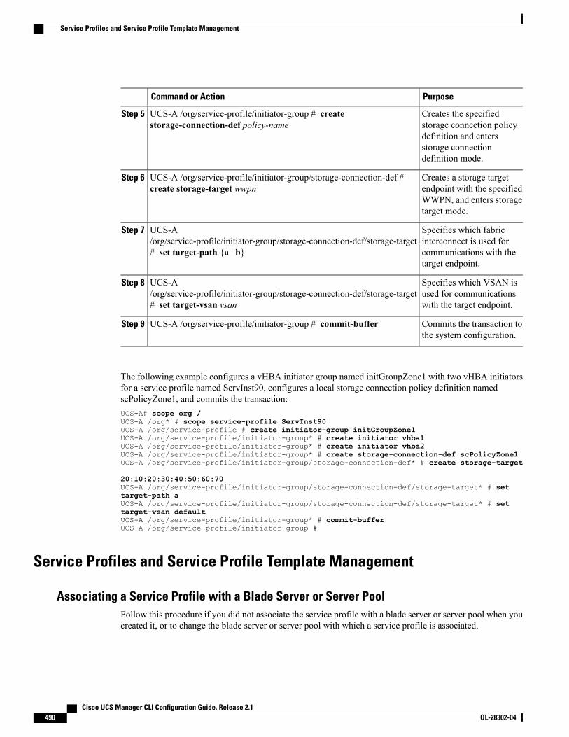
PurposeCommand or Action
Creates the specifiedstorage connection policy
UCS-A /org/service-profile/initiator-group # createstorage-connection-def policy-name
Step 5
definition and entersstorage connectiondefinition mode.
Creates a storage targetendpoint with the specified
UCS-A /org/service-profile/initiator-group/storage-connection-def #create storage-target wwpn
Step 6
WWPN, and enters storagetarget mode.
Specifies which fabricinterconnect is used for
UCS-A/org/service-profile/initiator-group/storage-connection-def/storage-target# set target-path {a | b}
Step 7
communications with thetarget endpoint.
Specifies which VSAN isused for communicationswith the target endpoint.
UCS-A/org/service-profile/initiator-group/storage-connection-def/storage-target# set target-vsan vsan
Step 8
Commits the transaction tothe system configuration.
UCS-A /org/service-profile/initiator-group # commit-bufferStep 9
The following example configures a vHBA initiator group named initGroupZone1 with two vHBA initiatorsfor a service profile named ServInst90, configures a local storage connection policy definition namedscPolicyZone1, and commits the transaction:UCS-A# scope org /UCS-A /org* # scope service-profile ServInst90UCS-A /org/service-profile # create initiator-group initGroupZone1UCS-A /org/service-profile/initiator-group* # create initiator vhba1UCS-A /org/service-profile/initiator-group* # create initiator vhba2UCS-A /org/service-profile/initiator-group* # create storage-connection-def scPolicyZone1UCS-A /org/service-profile/initiator-group/storage-connection-def* # create storage-target
20:10:20:30:40:50:60:70UCS-A /org/service-profile/initiator-group/storage-connection-def/storage-target* # settarget-path aUCS-A /org/service-profile/initiator-group/storage-connection-def/storage-target* # settarget-vsan defaultUCS-A /org/service-profile/initiator-group* # commit-bufferUCS-A /org/service-profile/initiator-group #
Service Profiles and Service Profile Template Management
Associating a Service Profile with a Blade Server or Server PoolFollow this procedure if you did not associate the service profile with a blade server or server pool when youcreated it, or to change the blade server or server pool with which a service profile is associated.
Cisco UCS Manager CLI Configuration Guide, Release 2.1490 OL-28302-04
Service Profiles and Service Profile Template Management
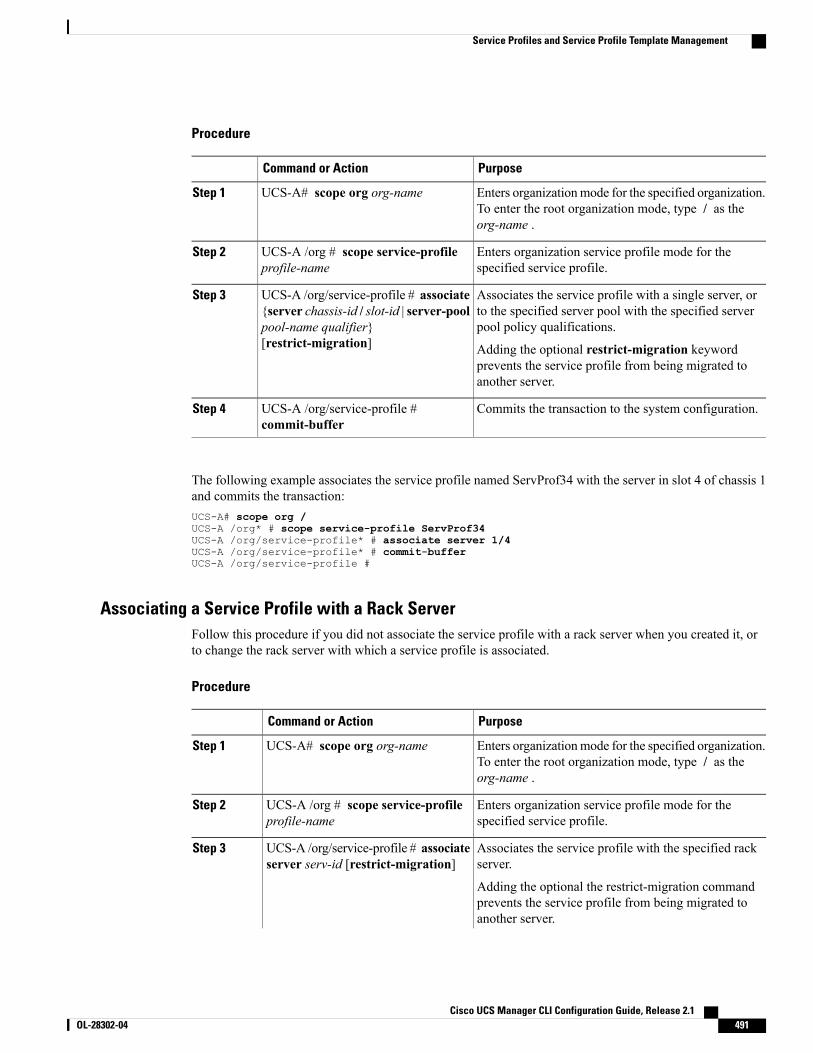
Procedure
PurposeCommand or Action
Enters organizationmode for the specified organization.To enter the root organization mode, type / as theorg-name .
UCS-A# scope org org-nameStep 1
Enters organization service profile mode for thespecified service profile.
UCS-A /org # scope service-profileprofile-name
Step 2
Associates the service profile with a single server, orto the specified server pool with the specified serverpool policy qualifications.
UCS-A /org/service-profile # associate{server chassis-id / slot-id | server-poolpool-name qualifier}[restrict-migration]
Step 3
Adding the optional restrict-migration keywordprevents the service profile from being migrated toanother server.
Commits the transaction to the system configuration.UCS-A /org/service-profile #commit-buffer
Step 4
The following example associates the service profile named ServProf34 with the server in slot 4 of chassis 1and commits the transaction:UCS-A# scope org /UCS-A /org* # scope service-profile ServProf34UCS-A /org/service-profile* # associate server 1/4UCS-A /org/service-profile* # commit-bufferUCS-A /org/service-profile #
Associating a Service Profile with a Rack ServerFollow this procedure if you did not associate the service profile with a rack server when you created it, orto change the rack server with which a service profile is associated.
Procedure
PurposeCommand or Action
Enters organizationmode for the specified organization.To enter the root organization mode, type / as theorg-name .
UCS-A# scope org org-nameStep 1
Enters organization service profile mode for thespecified service profile.
UCS-A /org # scope service-profileprofile-name
Step 2
Associates the service profile with the specified rackserver.
UCS-A /org/service-profile # associateserver serv-id [restrict-migration]
Step 3
Adding the optional the restrict-migration commandprevents the service profile from being migrated toanother server.
Cisco UCS Manager CLI Configuration Guide, Release 2.1 OL-28302-04 491
Service Profiles and Service Profile Template Management

PurposeCommand or Action
Commits the transaction to the system configuration.UCS-A /org/service-profile #commit-buffer
Step 4
The following example associates the service profile named ServProf34 with the rack server 1 and commitsthe transaction:UCS-A# scope org /UCS-A /org* # scope service-profile ServProf34UCS-A /org/service-profile* # associate server 1UCS-A /org/service-profile* # commit-bufferUCS-A /org/service-profile #
Disassociating a Service Profile from a Server or Server PoolThis procedure covers disassociating a service profile from a blade server, rack server, or server pool.
Procedure
PurposeCommand or Action
Enters organization mode for the specifiedorganization. To enter the root organization mode,type / as the org-name.
UCS-A# scope org org-nameStep 1
Enters organization service profile mode for thespecified service profile.
UCS-A /org # scope service-profileprofile-name
Step 2
Disassociates the service profile from the server orserver pool.
UCS-A /org/service-profile #disassociate
Step 3
Commits the transaction to the system configuration.UCS-A /org/service-profile #commit-buffer
Step 4
The following example disassociates the service profile named ServProf34 from the server to which it wasassociated and commits the transaction:UCS-A# scope org /UCS-A /org* # scope service-profile ServProf34UCS-A /org/service-profile # disassociateUCS-A /org/service-profile* # commit-bufferUCS-A /org/service-profile #
Renaming a Service ProfileWhen you rename a service profile, the following occurs:
• Event logs and audit logs that reference the previous name for the service profile are retained under thatname.
• A new audit record is created to log the rename operation.
Cisco UCS Manager CLI Configuration Guide, Release 2.1492 OL-28302-04
Service Profiles and Service Profile Template Management
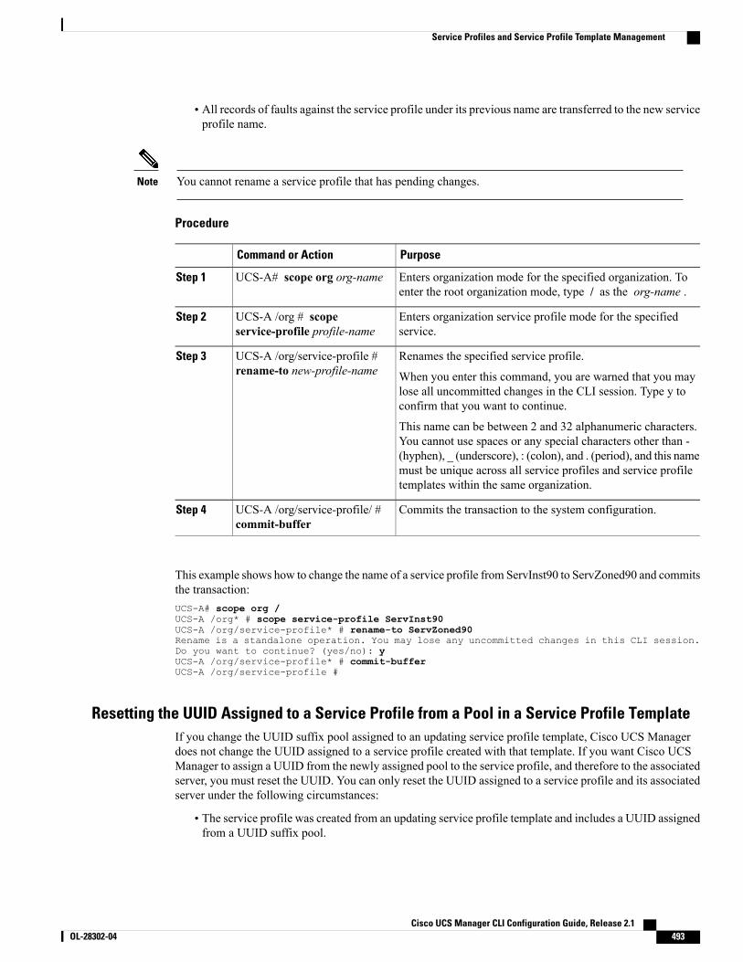
• All records of faults against the service profile under its previous name are transferred to the new serviceprofile name.
You cannot rename a service profile that has pending changes.Note
Procedure
PurposeCommand or Action
Enters organization mode for the specified organization. Toenter the root organization mode, type / as the org-name .
UCS-A# scope org org-nameStep 1
Enters organization service profile mode for the specifiedservice.
UCS-A /org # scopeservice-profile profile-name
Step 2
Renames the specified service profile.UCS-A /org/service-profile #rename-to new-profile-name
Step 3
When you enter this command, you are warned that you maylose all uncommitted changes in the CLI session. Type y toconfirm that you want to continue.
This name can be between 2 and 32 alphanumeric characters.You cannot use spaces or any special characters other than -(hyphen), _ (underscore), : (colon), and . (period), and this namemust be unique across all service profiles and service profiletemplates within the same organization.
Commits the transaction to the system configuration.UCS-A /org/service-profile/ #commit-buffer
Step 4
This example shows how to change the name of a service profile from ServInst90 to ServZoned90 and commitsthe transaction:UCS-A# scope org /UCS-A /org* # scope service-profile ServInst90UCS-A /org/service-profile* # rename-to ServZoned90Rename is a standalone operation. You may lose any uncommitted changes in this CLI session.Do you want to continue? (yes/no): yUCS-A /org/service-profile* # commit-bufferUCS-A /org/service-profile #
Resetting the UUID Assigned to a Service Profile from a Pool in a Service Profile TemplateIf you change the UUID suffix pool assigned to an updating service profile template, Cisco UCS Managerdoes not change the UUID assigned to a service profile created with that template. If you want Cisco UCSManager to assign a UUID from the newly assigned pool to the service profile, and therefore to the associatedserver, you must reset the UUID. You can only reset the UUID assigned to a service profile and its associatedserver under the following circumstances:
• The service profile was created from an updating service profile template and includes a UUID assignedfrom a UUID suffix pool.
Cisco UCS Manager CLI Configuration Guide, Release 2.1 OL-28302-04 493
Service Profiles and Service Profile Template Management
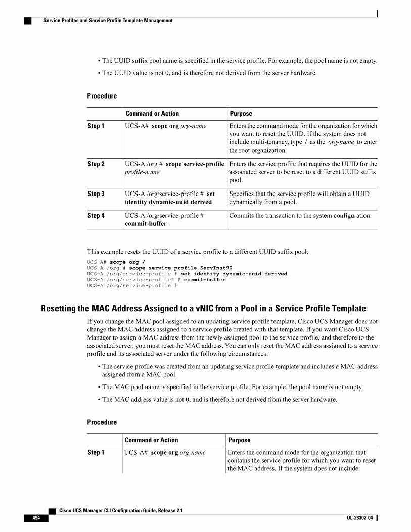
• The UUID suffix pool name is specified in the service profile. For example, the pool name is not empty.
• The UUID value is not 0, and is therefore not derived from the server hardware.
Procedure
PurposeCommand or Action
Enters the commandmode for the organization for whichyou want to reset the UUID. If the system does not
UCS-A# scope org org-nameStep 1
include multi-tenancy, type / as the org-name to enterthe root organization.
Enters the service profile that requires the UUID for theassociated server to be reset to a different UUID suffixpool.
UCS-A /org # scope service-profileprofile-name
Step 2
Specifies that the service profile will obtain a UUIDdynamically from a pool.
UCS-A /org/service-profile # setidentity dynamic-uuid derived
Step 3
Commits the transaction to the system configuration.UCS-A /org/service-profile #commit-buffer
Step 4
This example resets the UUID of a service profile to a different UUID suffix pool:UCS-A# scope org /UCS-A /org # scope service-profile ServInst90UCS-A /org/service-profile # set identity dynamic-uuid derivedUCS-A /org/service-profile* # commit-bufferUCS-A /org/service-profile #
Resetting the MAC Address Assigned to a vNIC from a Pool in a Service Profile TemplateIf you change the MAC pool assigned to an updating service profile template, Cisco UCS Manager does notchange the MAC address assigned to a service profile created with that template. If you want Cisco UCSManager to assign a MAC address from the newly assigned pool to the service profile, and therefore to theassociated server, you must reset the MAC address. You can only reset the MAC address assigned to a serviceprofile and its associated server under the following circumstances:
• The service profile was created from an updating service profile template and includes a MAC addressassigned from a MAC pool.
• The MAC pool name is specified in the service profile. For example, the pool name is not empty.
• The MAC address value is not 0, and is therefore not derived from the server hardware.
Procedure
PurposeCommand or Action
Enters the command mode for the organization thatcontains the service profile for which you want to reset
UCS-A# scope org org-nameStep 1
the MAC address. If the system does not include
Cisco UCS Manager CLI Configuration Guide, Release 2.1494 OL-28302-04
Service Profiles and Service Profile Template Management
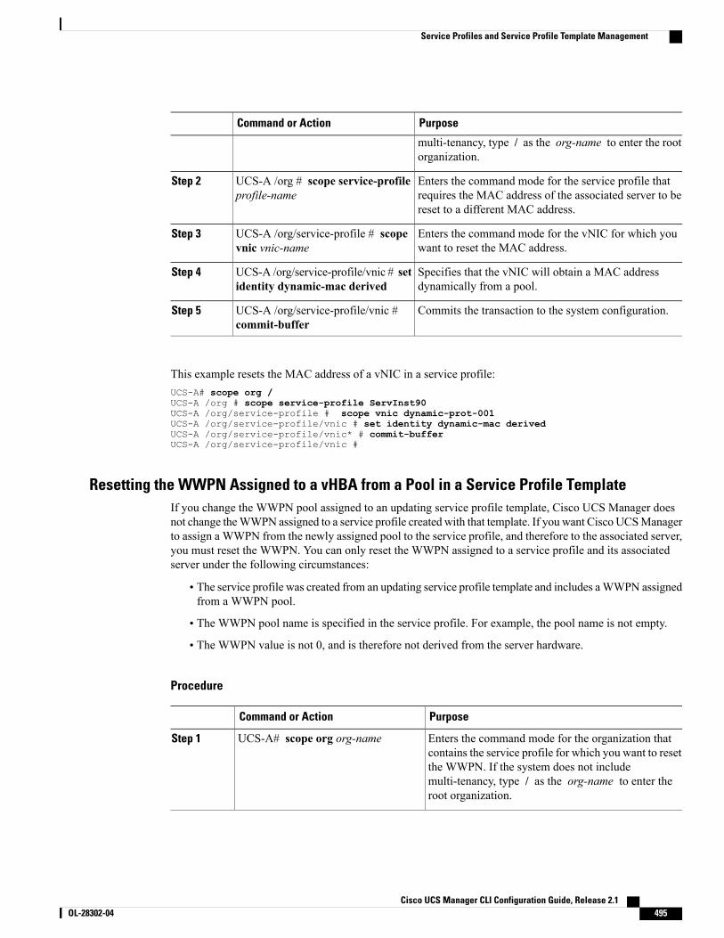
PurposeCommand or Action
multi-tenancy, type / as the org-name to enter the rootorganization.
Enters the command mode for the service profile thatrequires the MAC address of the associated server to bereset to a different MAC address.
UCS-A /org # scope service-profileprofile-name
Step 2
Enters the command mode for the vNIC for which youwant to reset the MAC address.
UCS-A /org/service-profile # scopevnic vnic-name
Step 3
Specifies that the vNIC will obtain a MAC addressdynamically from a pool.
UCS-A /org/service-profile/vnic # setidentity dynamic-mac derived
Step 4
Commits the transaction to the system configuration.UCS-A /org/service-profile/vnic #commit-buffer
Step 5
This example resets the MAC address of a vNIC in a service profile:UCS-A# scope org /UCS-A /org # scope service-profile ServInst90UCS-A /org/service-profile # scope vnic dynamic-prot-001UCS-A /org/service-profile/vnic # set identity dynamic-mac derivedUCS-A /org/service-profile/vnic* # commit-bufferUCS-A /org/service-profile/vnic #
Resetting the WWPN Assigned to a vHBA from a Pool in a Service Profile TemplateIf you change the WWPN pool assigned to an updating service profile template, Cisco UCS Manager doesnot change theWWPN assigned to a service profile created with that template. If you want Cisco UCSManagerto assign a WWPN from the newly assigned pool to the service profile, and therefore to the associated server,you must reset the WWPN. You can only reset the WWPN assigned to a service profile and its associatedserver under the following circumstances:
• The service profile was created from an updating service profile template and includes aWWPN assignedfrom a WWPN pool.
• The WWPN pool name is specified in the service profile. For example, the pool name is not empty.
• The WWPN value is not 0, and is therefore not derived from the server hardware.
Procedure
PurposeCommand or Action
Enters the command mode for the organization thatcontains the service profile for which you want to reset
UCS-A# scope org org-nameStep 1
the WWPN. If the system does not includemulti-tenancy, type / as the org-name to enter theroot organization.
Cisco UCS Manager CLI Configuration Guide, Release 2.1 OL-28302-04 495
Service Profiles and Service Profile Template Management
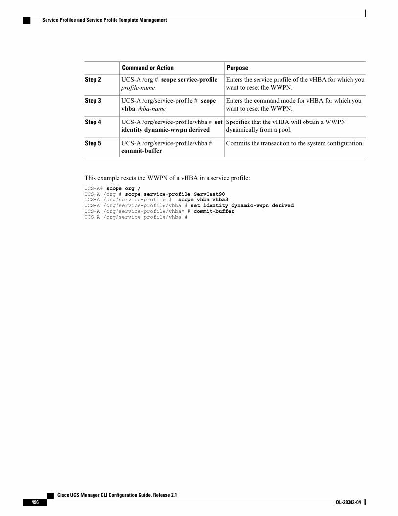
PurposeCommand or Action
Enters the service profile of the vHBA for which youwant to reset the WWPN.
UCS-A /org # scope service-profileprofile-name
Step 2
Enters the command mode for vHBA for which youwant to reset the WWPN.
UCS-A /org/service-profile # scopevhba vhba-name
Step 3
Specifies that the vHBA will obtain a WWPNdynamically from a pool.
UCS-A /org/service-profile/vhba # setidentity dynamic-wwpn derived
Step 4
Commits the transaction to the system configuration.UCS-A /org/service-profile/vhba #commit-buffer
Step 5
This example resets the WWPN of a vHBA in a service profile:UCS-A# scope org /UCS-A /org # scope service-profile ServInst90UCS-A /org/service-profile # scope vhba vhba3UCS-A /org/service-profile/vhba # set identity dynamic-wwpn derivedUCS-A /org/service-profile/vhba* # commit-bufferUCS-A /org/service-profile/vhba #
Cisco UCS Manager CLI Configuration Guide, Release 2.1496 OL-28302-04
Service Profiles and Service Profile Template Management
C H A P T E R 34Managing Power in Cisco UCS
This chapter includes the following sections:
• Power Management in Cisco UCS , page 497
• Rack Server Power Management, page 497
• Power Management Precautions, page 497
• Configuring the Power Policy, page 498
• Configuring the Global Cap Policy, page 499
• Configuring Policy-Driven Chassis Group Power Capping, page 499
• Configuring Manual Blade-Level Power Capping, page 504
Power Management in Cisco UCSYou can manage power through Cisco UCS Manager by configuring any of the following features:
• Power supply redundancy for all chassis in a Cisco UCS domain
• Policy-driven chassis-level power capping
• Manual blade-level power capping
Rack Server Power ManagementPower capping is not supported for rack servers.
Power Management PrecautionsIf the CIMC is reset, the power monitoring functions of Cisco UCS become briefly unavailable for as longas it takes for the CIMC to reboot. While this usually only takes 20 seconds, there is a possibility that the peakpower cap could be exceeded during that time. To avoid exceeding the configured power cap in a very lowpower-capped environment, consider staggering the rebooting or activation of CIMCs.
Cisco UCS Manager CLI Configuration Guide, Release 2.1 OL-28302-04 497
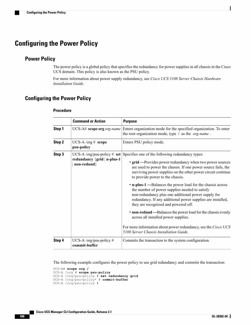
Configuring the Power Policy
Power PolicyThe power policy is a global policy that specifies the redundancy for power supplies in all chassis in the CiscoUCS domain. This policy is also known as the PSU policy.
For more information about power supply redundancy, see Cisco UCS 5108 Server Chassis HardwareInstallation Guide.
Configuring the Power Policy
Procedure
PurposeCommand or Action
Enters organization mode for the specified organization. To enterthe root organization mode, type / as the org-name .
UCS-A# scope org org-nameStep 1
Enters PSU policy mode.UCS-A /org # scopepsu-policy
Step 2
Specifies one of the following redundancy types:UCS-A /org/psu-policy # setredundancy {grid | n-plus-1| non-redund}
Step 3
• grid—Provides power redundancy when two power sourcesare used to power the chassis. If one power source fails, thesurviving power supplies on the other power circuit continueto provide power to the chassis.
• n-plus-1—Balances the power load for the chassis acrossthe number of power supplies needed to satisfynon-redundancy plus one additional power supply forredundancy. If any additional power supplies are installed,they are recognized and powered off.
• non-redund—Balances the power load for the chassis evenlyacross all installed power supplies.
For more information about power redundancy, see theCisco UCS5108 Server Chassis Installation Guide.
Commits the transaction to the system configuration.UCS-A /org/psu-policy #commit-buffer
Step 4
The following example configures the power policy to use grid redundancy and commits the transaction:UCS-A# scope org /UCS-A /org # scope psu-policyUCS-A /org/psu-policy # set redundancy gridUCS-A /org/psu-policy* # commit-bufferUCS-A /org/psu-policy #
Cisco UCS Manager CLI Configuration Guide, Release 2.1498 OL-28302-04
Configuring the Power Policy
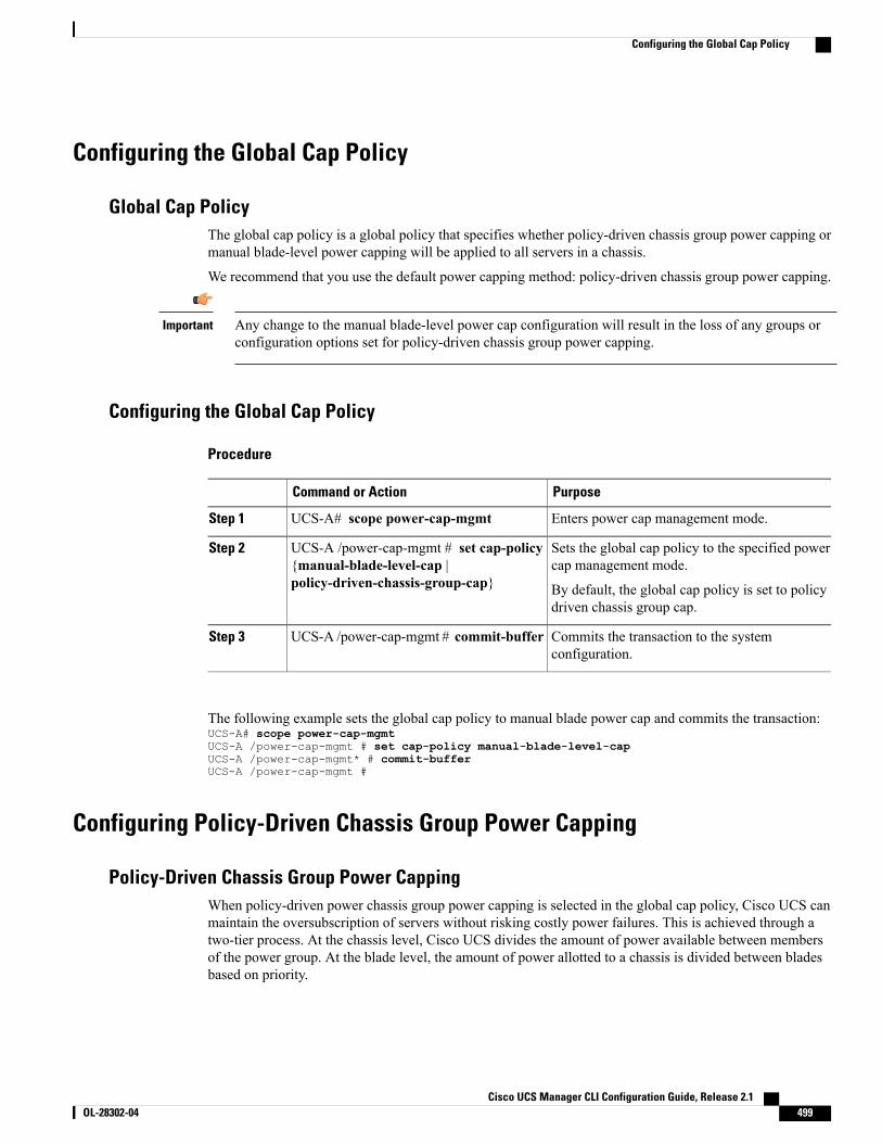
Configuring the Global Cap Policy
Global Cap PolicyThe global cap policy is a global policy that specifies whether policy-driven chassis group power capping ormanual blade-level power capping will be applied to all servers in a chassis.
We recommend that you use the default power capping method: policy-driven chassis group power capping.
Any change to the manual blade-level power cap configuration will result in the loss of any groups orconfiguration options set for policy-driven chassis group power capping.
Important
Configuring the Global Cap Policy
Procedure
PurposeCommand or Action
Enters power cap management mode.UCS-A# scope power-cap-mgmtStep 1
Sets the global cap policy to the specified powercap management mode.
UCS-A /power-cap-mgmt # set cap-policy{manual-blade-level-cap |policy-driven-chassis-group-cap}
Step 2
By default, the global cap policy is set to policydriven chassis group cap.
Commits the transaction to the systemconfiguration.
UCS-A /power-cap-mgmt # commit-bufferStep 3
The following example sets the global cap policy to manual blade power cap and commits the transaction:UCS-A# scope power-cap-mgmtUCS-A /power-cap-mgmt # set cap-policy manual-blade-level-capUCS-A /power-cap-mgmt* # commit-bufferUCS-A /power-cap-mgmt #
Configuring Policy-Driven Chassis Group Power Capping
Policy-Driven Chassis Group Power CappingWhen policy-driven power chassis group power capping is selected in the global cap policy, Cisco UCS canmaintain the oversubscription of servers without risking costly power failures. This is achieved through atwo-tier process. At the chassis level, Cisco UCS divides the amount of power available between membersof the power group. At the blade level, the amount of power allotted to a chassis is divided between bladesbased on priority.
Cisco UCS Manager CLI Configuration Guide, Release 2.1 OL-28302-04 499
Configuring the Global Cap Policy
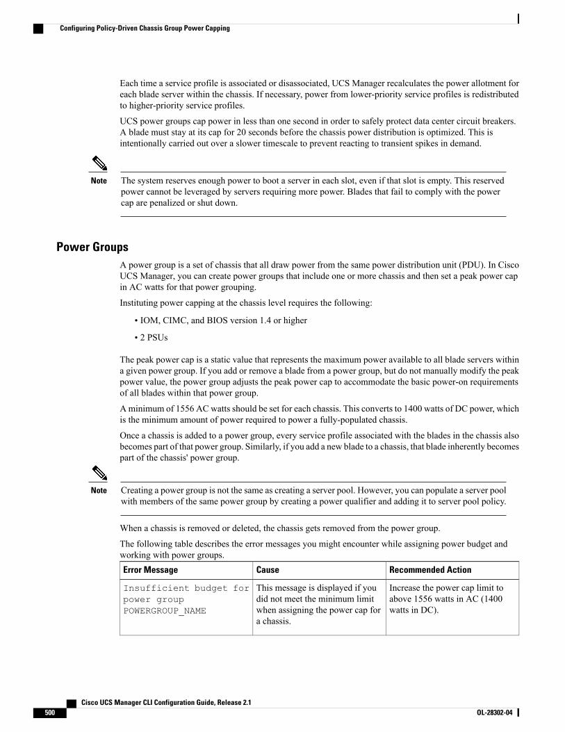
Each time a service profile is associated or disassociated, UCS Manager recalculates the power allotment foreach blade server within the chassis. If necessary, power from lower-priority service profiles is redistributedto higher-priority service profiles.
UCS power groups cap power in less than one second in order to safely protect data center circuit breakers.A blade must stay at its cap for 20 seconds before the chassis power distribution is optimized. This isintentionally carried out over a slower timescale to prevent reacting to transient spikes in demand.
The system reserves enough power to boot a server in each slot, even if that slot is empty. This reservedpower cannot be leveraged by servers requiring more power. Blades that fail to comply with the powercap are penalized or shut down.
Note
Power GroupsA power group is a set of chassis that all draw power from the same power distribution unit (PDU). In CiscoUCS Manager, you can create power groups that include one or more chassis and then set a peak power capin AC watts for that power grouping.
Instituting power capping at the chassis level requires the following:
• IOM, CIMC, and BIOS version 1.4 or higher
• 2 PSUs
The peak power cap is a static value that represents the maximum power available to all blade servers withina given power group. If you add or remove a blade from a power group, but do not manually modify the peakpower value, the power group adjusts the peak power cap to accommodate the basic power-on requirementsof all blades within that power group.
A minimum of 1556 ACwatts should be set for each chassis. This converts to 1400 watts of DC power, whichis the minimum amount of power required to power a fully-populated chassis.
Once a chassis is added to a power group, every service profile associated with the blades in the chassis alsobecomes part of that power group. Similarly, if you add a new blade to a chassis, that blade inherently becomespart of the chassis' power group.
Creating a power group is not the same as creating a server pool. However, you can populate a server poolwith members of the same power group by creating a power qualifier and adding it to server pool policy.
Note
When a chassis is removed or deleted, the chassis gets removed from the power group.
The following table describes the error messages you might encounter while assigning power budget andworking with power groups.
Recommended ActionCauseError Message
Increase the power cap limit toabove 1556 watts in AC (1400watts in DC).
This message is displayed if youdid not meet the minimum limitwhen assigning the power cap fora chassis.
Insufficient budget forpower groupPOWERGROUP_NAME
Cisco UCS Manager CLI Configuration Guide, Release 2.1500 OL-28302-04
Configuring Policy-Driven Chassis Group Power Capping
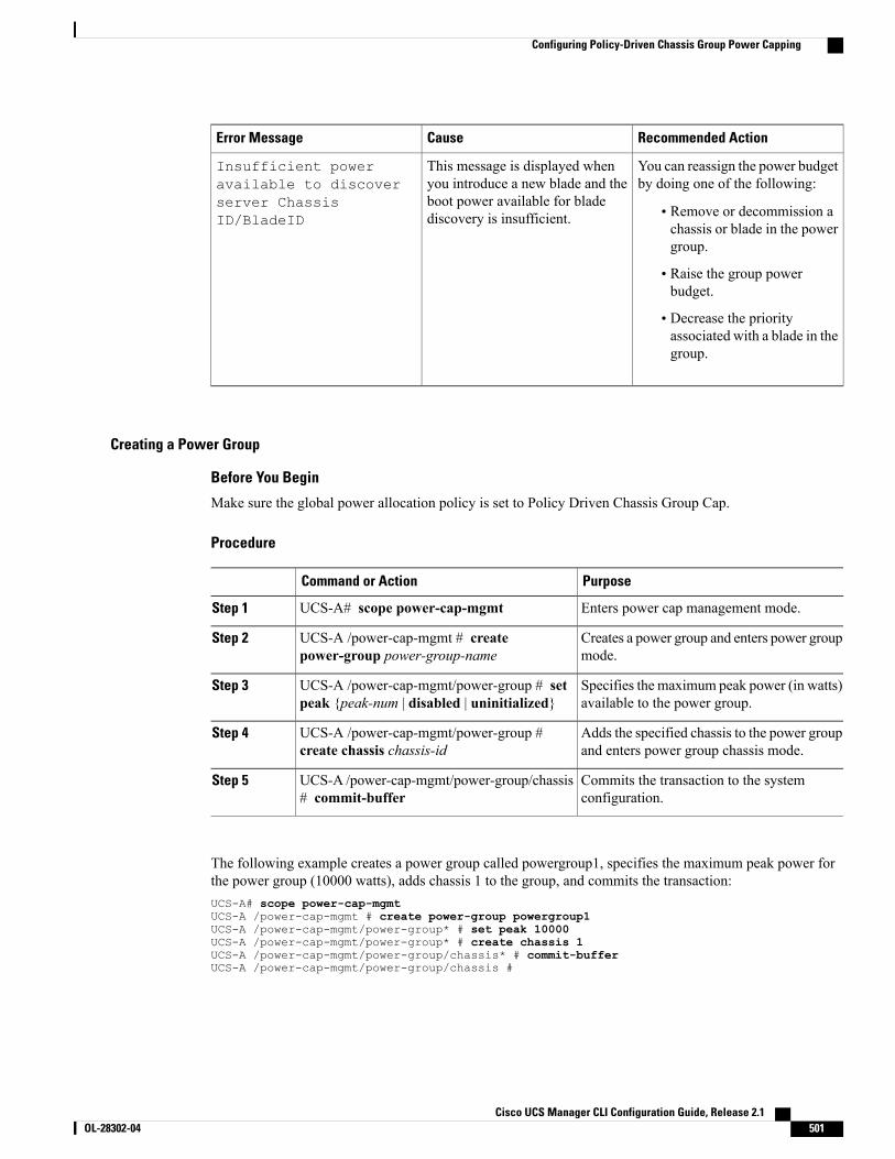
Recommended ActionCauseError Message
You can reassign the power budgetby doing one of the following:
• Remove or decommission achassis or blade in the powergroup.
• Raise the group powerbudget.
• Decrease the priorityassociated with a blade in thegroup.
This message is displayed whenyou introduce a new blade and theboot power available for bladediscovery is insufficient.
Insufficient poweravailable to discoverserver ChassisID/BladeID
Creating a Power Group
Before You Begin
Make sure the global power allocation policy is set to Policy Driven Chassis Group Cap.
Procedure
PurposeCommand or Action
Enters power cap management mode.UCS-A# scope power-cap-mgmtStep 1
Creates a power group and enters power groupmode.
UCS-A /power-cap-mgmt # createpower-group power-group-name
Step 2
Specifies the maximum peak power (in watts)available to the power group.
UCS-A /power-cap-mgmt/power-group # setpeak {peak-num | disabled | uninitialized}
Step 3
Adds the specified chassis to the power groupand enters power group chassis mode.
UCS-A /power-cap-mgmt/power-group #create chassis chassis-id
Step 4
Commits the transaction to the systemconfiguration.
UCS-A /power-cap-mgmt/power-group/chassis# commit-buffer
Step 5
The following example creates a power group called powergroup1, specifies the maximum peak power forthe power group (10000 watts), adds chassis 1 to the group, and commits the transaction:UCS-A# scope power-cap-mgmtUCS-A /power-cap-mgmt # create power-group powergroup1UCS-A /power-cap-mgmt/power-group* # set peak 10000UCS-A /power-cap-mgmt/power-group* # create chassis 1UCS-A /power-cap-mgmt/power-group/chassis* # commit-bufferUCS-A /power-cap-mgmt/power-group/chassis #
Cisco UCS Manager CLI Configuration Guide, Release 2.1 OL-28302-04 501
Configuring Policy-Driven Chassis Group Power Capping
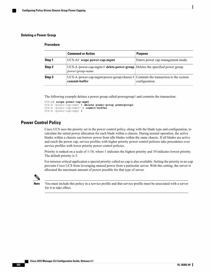
Deleting a Power Group
Procedure
PurposeCommand or Action
Enters power cap management mode.UCS-A# scope power-cap-mgmtStep 1
Deletes the specified power group.UCS-A /power-cap-mgmt # delete power-grouppower-group-name
Step 2
Commits the transaction to the systemconfiguration.
UCS-A /power-cap-mgmt/power-group/chassis #commit-buffer
Step 3
The following example deletes a power group called powergroup1 and commits the transaction:UCS-A# scope power-cap-mgmtUCS-A /power-cap-mgmt # delete power-group powergroup1UCS-A /power-cap-mgmt* # commit-bufferUCS-A /power-cap-mgmt #
Power Control PolicyCisco UCS uses the priority set in the power control policy, along with the blade type and configuration, tocalculate the initial power allocation for each blade within a chassis. During normal operation, the activeblades within a chassis can borrow power from idle blades within the same chassis. If all blades are activeand reach the power cap, service profiles with higher priority power control policies take precedence overservice profiles with lower priority power control policies.
Priority is ranked on a scale of 1-10, where 1 indicates the highest priority and 10 indicates lowest priority.The default priority is 5.
For mission-critical application a special priority called no-cap is also available. Setting the priority to no-capprevents Cisco UCS from leveraging unused power from a particular server. With this setting, the server isallocated the maximum amount of power possible for that type of server.
You must include this policy in a service profile and that service profile must be associated with a serverfor it to take effect.
Note
Cisco UCS Manager CLI Configuration Guide, Release 2.1502 OL-28302-04
Configuring Policy-Driven Chassis Group Power Capping
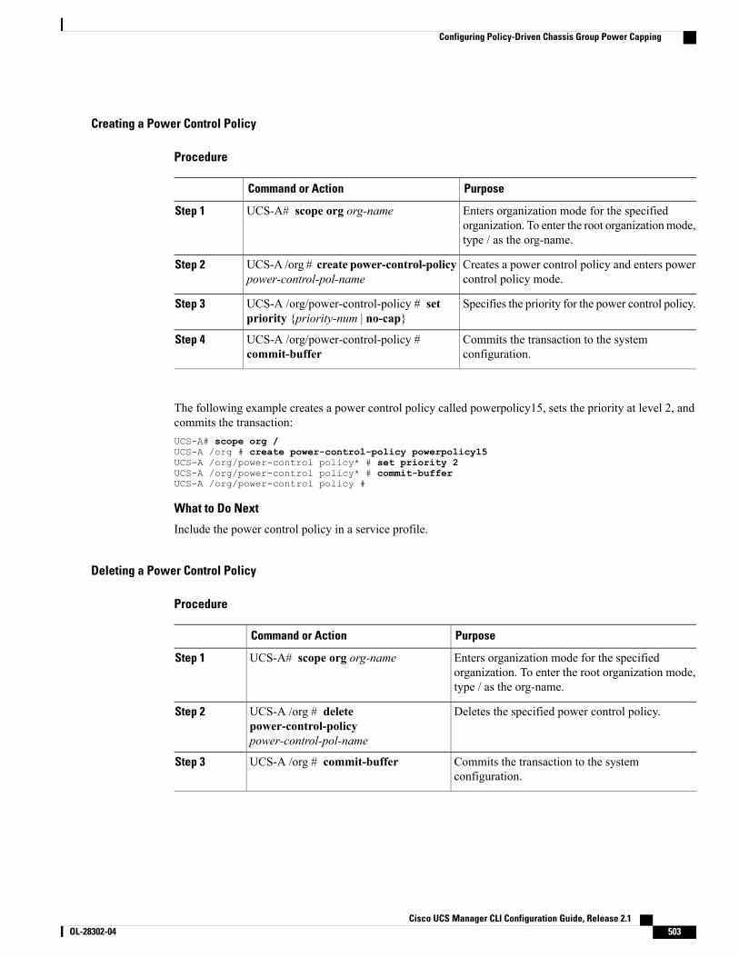
Creating a Power Control Policy
Procedure
PurposeCommand or Action
Enters organization mode for the specifiedorganization. To enter the root organizationmode,type / as the org-name.
UCS-A# scope org org-nameStep 1
Creates a power control policy and enters powercontrol policy mode.
UCS-A /org # create power-control-policypower-control-pol-name
Step 2
Specifies the priority for the power control policy.UCS-A /org/power-control-policy # setpriority {priority-num | no-cap}
Step 3
Commits the transaction to the systemconfiguration.
UCS-A /org/power-control-policy #commit-buffer
Step 4
The following example creates a power control policy called powerpolicy15, sets the priority at level 2, andcommits the transaction:UCS-A# scope org /UCS-A /org # create power-control-policy powerpolicy15UCS-A /org/power-control policy* # set priority 2UCS-A /org/power-control policy* # commit-bufferUCS-A /org/power-control policy #
What to Do Next
Include the power control policy in a service profile.
Deleting a Power Control Policy
Procedure
PurposeCommand or Action
Enters organization mode for the specifiedorganization. To enter the root organization mode,type / as the org-name.
UCS-A# scope org org-nameStep 1
Deletes the specified power control policy.UCS-A /org # deletepower-control-policypower-control-pol-name
Step 2
Commits the transaction to the systemconfiguration.
UCS-A /org # commit-bufferStep 3
Cisco UCS Manager CLI Configuration Guide, Release 2.1 OL-28302-04 503
Configuring Policy-Driven Chassis Group Power Capping
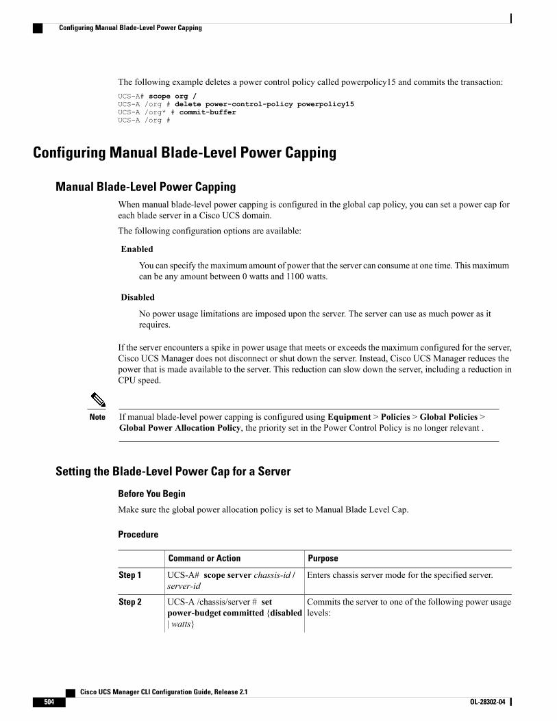
The following example deletes a power control policy called powerpolicy15 and commits the transaction:UCS-A# scope org /UCS-A /org # delete power-control-policy powerpolicy15UCS-A /org* # commit-bufferUCS-A /org #
Configuring Manual Blade-Level Power Capping
Manual Blade-Level Power CappingWhen manual blade-level power capping is configured in the global cap policy, you can set a power cap foreach blade server in a Cisco UCS domain.
The following configuration options are available:
Enabled
You can specify the maximum amount of power that the server can consume at one time. This maximumcan be any amount between 0 watts and 1100 watts.
Disabled
No power usage limitations are imposed upon the server. The server can use as much power as itrequires.
If the server encounters a spike in power usage that meets or exceeds the maximum configured for the server,Cisco UCS Manager does not disconnect or shut down the server. Instead, Cisco UCS Manager reduces thepower that is made available to the server. This reduction can slow down the server, including a reduction inCPU speed.
If manual blade-level power capping is configured using Equipment > Policies > Global Policies >Global Power Allocation Policy, the priority set in the Power Control Policy is no longer relevant .
Note
Setting the Blade-Level Power Cap for a Server
Before You Begin
Make sure the global power allocation policy is set to Manual Blade Level Cap.
Procedure
PurposeCommand or Action
Enters chassis server mode for the specified server.UCS-A# scope server chassis-id /server-id
Step 1
Commits the server to one of the following power usagelevels:
UCS-A /chassis/server # setpower-budget committed {disabled| watts}
Step 2
Cisco UCS Manager CLI Configuration Guide, Release 2.1504 OL-28302-04
Configuring Manual Blade-Level Power Capping
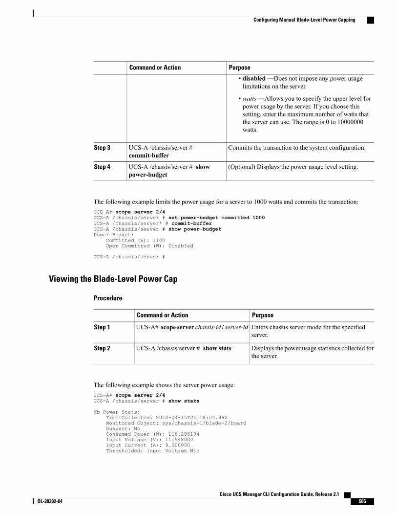
PurposeCommand or Action
• disabled—Does not impose any power usagelimitations on the server.
• watts—Allows you to specify the upper level forpower usage by the server. If you choose thissetting, enter the maximum number of watts thatthe server can use. The range is 0 to 10000000watts.
Commits the transaction to the system configuration.UCS-A /chassis/server #commit-buffer
Step 3
(Optional) Displays the power usage level setting.UCS-A /chassis/server # showpower-budget
Step 4
The following example limits the power usage for a server to 1000 watts and commits the transaction:UCS-A# scope server 2/4UCS-A /chassis/server # set power-budget committed 1000UCS-A /chassis/server* # commit-bufferUCS-A /chassis/server # show power-budgetPower Budget:
Committed (W): 1100Oper Committed (W): Disabled
UCS-A /chassis/server #
Viewing the Blade-Level Power Cap
Procedure
PurposeCommand or Action
Enters chassis server mode for the specifiedserver.
UCS-A# scope server chassis-id / server-idStep 1
Displays the power usage statistics collected forthe server.
UCS-A /chassis/server # show statsStep 2
The following example shows the server power usage:UCS-A# scope server 2/4UCS-A /chassis/server # show stats
Mb Power Stats:Time Collected: 2010-04-15T21:18:04.992Monitored Object: sys/chassis-1/blade-2/boardSuspect: NoConsumed Power (W): 118.285194Input Voltage (V): 11.948000Input Current (A): 9.900000Thresholded: Input Voltage Min
Cisco UCS Manager CLI Configuration Guide, Release 2.1 OL-28302-04 505
Configuring Manual Blade-Level Power Capping

UCS-A /chassis/server #
Cisco UCS Manager CLI Configuration Guide, Release 2.1506 OL-28302-04
Configuring Manual Blade-Level Power Capping
P A R T VISystem Management• Managing Time Zones, page 509
• Managing the Chassis, page 513
• Managing Blade Servers, page 519
• Managing Rack-Mount Servers, page 531
• CIMC Session Management, page 543
• Managing the I/O Modules, page 551
• Backing Up and Restoring the Configuration, page 553
• Recovering a Lost Password, page 571


C H A P T E R 35Managing Time Zones
This chapter includes the following sections:
• Time Zones, page 509
• Setting the Time Zone, page 509
• Adding an NTP Server, page 511
• Deleting an NTP Server, page 512
• Setting the System Clock Manually, page 512
Time ZonesCisco UCS requires a domain-specific time zone setting and an NTP server to ensure the correct time displayin Cisco UCS Manager. If you do not configure both of these settings in a Cisco UCS domain, the time doesnot display correctly.
Setting the Time Zone
Procedure
PurposeCommand or Action
Enters system mode.UCS-A# scope systemStep 1
Enters system services mode.UCS-A /system # scope servicesStep 2
At this point, you are prompted to enter a numbercorresponding to your continent, country, and time zone
UCS-A /system/services # settimezone
Step 3
region. Enter the appropriate information at eachprompt.
When you have finished specifying the locationinformation, you are prompted to confirm that the
Cisco UCS Manager CLI Configuration Guide, Release 2.1 OL-28302-04 509

PurposeCommand or Action
correct time zone information is being set. Enter 1 (yes)to confirm, or 2 (no) to cancel the operation.
Commits the transaction to the system configuration.UCS-A /system/services #commit-buffer
Step 4
Enters system mode.UCS-A /system/services # exitStep 5
Enters EXEC mode.UCS-A /system/services # exitStep 6
Displays the configured timezone.UCS-A /system/services # showtimezone
Step 7
The following example configures the time zone to the Pacific time zone region, commits the transaction, anddisplays the configured time zone:UCS-A# scope systemUCS-A /system # scope servicesUCS-A /system/services # set timezonePlease identify a location so that time zone rules can be set correctly.Please select a continent or ocean.1) Africa 4) Arctic Ocean 7) Australia 10) Pacific Ocean2) Americas 5) Asia 8) Europe3) Antarctica 6) Atlantic Ocean 9) Indian Ocean#? Artic oceanPlease enter a number in range.#? 2Please select a country.1) Anguilla 18) Ecuador 35) Paraguay2) Antigua & Barbuda 19) El Salvador 36) Peru3) Argentina 20) French Guiana 37) Puerto Rico4) Aruba 21) Greenland 38) St Kitts & Nevis5) Bahamas 22) Grenada 39) St Lucia6) Barbados 23) Guadeloupe 40) St Pierre & Miquelon7) Belize 24) Guatemala 41) St Vincent8) Bolivia 25) Guyana 42) Suriname9) Brazil 26) Haiti 43) Trinidad & Tobago10) Canada 27) Honduras 44) Turks & Caicos Is11) Cayman Islands 28) Jamaica 45) United States12) Chile 29) Martinique 46) Uruguay13) Colombia 30) Mexico 47) Venezuela14) Costa Rica 31) Montserrat 48) Virgin Islands (UK)15) Cuba 32) Netherlands Antilles 49) Virgin Islands (US)16) Dominica 33) Nicaragua17) Dominican Republic 34) Panama#? 45Please select one of the following time zone regions.1) Eastern Time2) Eastern Time - Michigan - most locations3) Eastern Time - Kentucky - Louisville area4) Eastern Time - Kentucky - Wayne County5) Eastern Standard Time - Indiana - most locations6) Eastern Standard Time - Indiana - Crawford County7) Eastern Standard Time - Indiana - Starke County8) Eastern Standard Time - Indiana - Switzerland County9) Central Time10) Central Time - Michigan - Wisconsin border11) Central Time - North Dakota - Oliver County12) Mountain Time13) Mountain Time - south Idaho & east Oregon14) Mountain Time - Navajo15) Mountain Standard Time - Arizona16) Pacific Time
Cisco UCS Manager CLI Configuration Guide, Release 2.1510 OL-28302-04
Setting the Time Zone
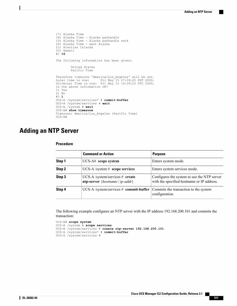
17) Alaska Time18) Alaska Time - Alaska panhandle19) Alaska Time - Alaska panhandle neck20) Alaska Time - west Alaska21) Aleutian Islands22) Hawaii#? 16
The following information has been given:
United StatesPacific Time
Therefore timezone 'America/Los_Angeles' will be set.Local time is now: Fri May 15 07:39:25 PDT 2009.Universal Time is now: Fri May 15 14:39:25 UTC 2009.Is the above information OK?1) Yes2) No#? 1UCS-A /system/services* # commit-bufferUCS-A /system/services # exitUCS-A /system # exitUCS-A# show timezoneTimezone: America/Los_Angeles (Pacific Time)UCS-A#
Adding an NTP Server
Procedure
PurposeCommand or Action
Enters system mode.UCS-A# scope systemStep 1
Enters system services mode.UCS-A /system # scope servicesStep 2
Configures the system to use the NTP serverwith the specified hostname or IP address.
UCS-A /system/services # createntp-server {hostname | ip-addr}
Step 3
Commits the transaction to the systemconfiguration.
UCS-A /system/services # commit-bufferStep 4
The following example configures an NTP server with the IP address 192.168.200.101 and commits thetransaction:UCS-A# scope systemUCS-A /system # scope servicesUCS-A /system/services # create ntp-server 192.168.200.101UCS-A /system/services* # commit-bufferUCS-A /system/services #
Cisco UCS Manager CLI Configuration Guide, Release 2.1 OL-28302-04 511
Adding an NTP Server
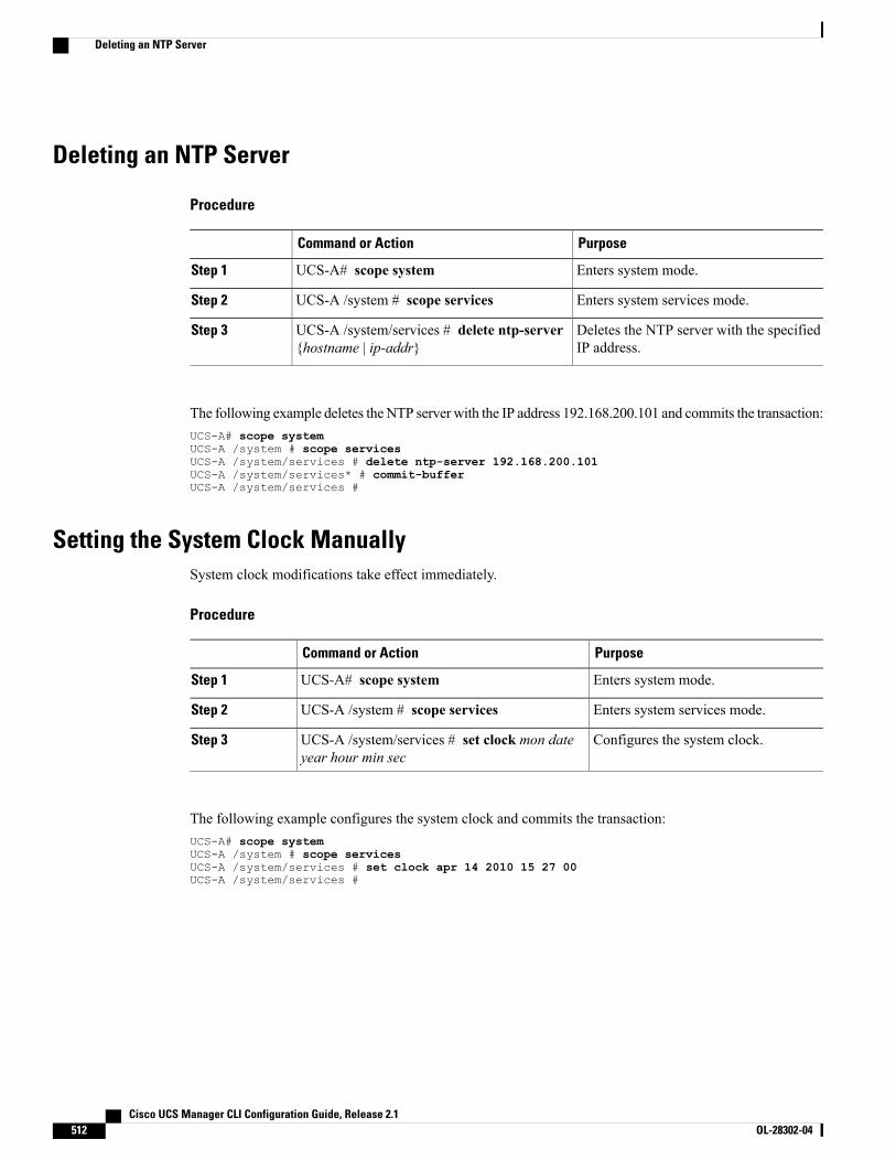
Deleting an NTP Server
Procedure
PurposeCommand or Action
Enters system mode.UCS-A# scope systemStep 1
Enters system services mode.UCS-A /system # scope servicesStep 2
Deletes the NTP server with the specifiedIP address.
UCS-A /system/services # delete ntp-server{hostname | ip-addr}
Step 3
The following example deletes the NTP server with the IP address 192.168.200.101 and commits the transaction:UCS-A# scope systemUCS-A /system # scope servicesUCS-A /system/services # delete ntp-server 192.168.200.101UCS-A /system/services* # commit-bufferUCS-A /system/services #
Setting the System Clock ManuallySystem clock modifications take effect immediately.
Procedure
PurposeCommand or Action
Enters system mode.UCS-A# scope systemStep 1
Enters system services mode.UCS-A /system # scope servicesStep 2
Configures the system clock.UCS-A /system/services # set clock mon dateyear hour min sec
Step 3
The following example configures the system clock and commits the transaction:UCS-A# scope systemUCS-A /system # scope servicesUCS-A /system/services # set clock apr 14 2010 15 27 00UCS-A /system/services #
Cisco UCS Manager CLI Configuration Guide, Release 2.1512 OL-28302-04
Deleting an NTP Server
C H A P T E R 36Managing the Chassis
This chapter includes the following sections:
• Guidelines for Removing and Decommissioning Chassis, page 513
• Acknowledging a Chassis, page 514
• Decommissioning a Chassis, page 514
• Removing a Chassis, page 515
• Recommissioning a Chassis, page 515
• Renumbering a Chassis, page 516
• Toggling the Locator LED, page 518
Guidelines for Removing and Decommissioning ChassisConsider the following guidelines when deciding whether to remove or decommission a chassis using CiscoUCS Manager:
Decommissioning a Chassis
Decommissioning is performed when a chassis is physically present and connected but you want to temporarilyremove it from the configuration. Because it is expected that a decommissioned chassis will be eventuallyrecommissioned, a portion of the chassis' information is retained by Cisco UCS Manager for future use.
Removing a Chassis
Removing is performed when you physically remove a chassis from the system. Once the physical removalof the chassis is completed, the configuration for that chassis can be removed in Cisco UCS Manager.
You cannot remove a chassis from Cisco UCS Manager if it is physically present and connected.Note
If you need to add a removed chassis back to the configuration, it must be reconnected and then rediscovered.During rediscovery Cisco UCS Manager will assign the chassis a new ID that may be different from ID thatit held before.
Cisco UCS Manager CLI Configuration Guide, Release 2.1 OL-28302-04 513
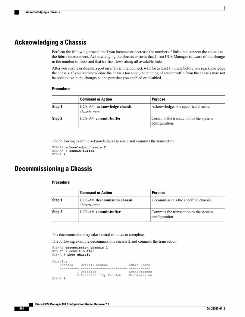
Acknowledging a ChassisPerform the following procedure if you increase or decrease the number of links that connect the chassis tothe fabric interconnect. Acknowledging the chassis ensures that Cisco UCS Manager is aware of the changein the number of links and that traffics flows along all available links.
After you enable or disable a port on a fabric interconnect, wait for at least 1 minute before you reacknowledgethe chassis. If you reacknowledge the chassis too soon, the pinning of server traffic from the chassis may notbe updated with the changes to the port that you enabled or disabled.
Procedure
PurposeCommand or Action
Acknowledges the specified chassis.UCS-A# acknowledge chassischassis-num
Step 1
Commits the transaction to the systemconfiguration.
UCS-A# commit-bufferStep 2
The following example acknowledges chassis 2 and commits the transaction:UCS-A# acknowledge chassis 2UCS-A* # commit-bufferUCS-A #
Decommissioning a Chassis
Procedure
PurposeCommand or Action
Decommissions the specified chassis.UCS-A# decommission chassischassis-num
Step 1
Commits the transaction to the systemconfiguration.
UCS-A# commit-bufferStep 2
The decommission may take several minutes to complete.
The following example decommissions chassis 2 and commits the transaction:UCS-A# decommission chassis 2UCS-A* # commit-bufferUCS-A # show chassis
Chassis:Chassis Overall Status Admin State---------- ------------------------ -----------
1 Operable Acknowledged2 Accessibility Problem Decommission
UCS-A #
Cisco UCS Manager CLI Configuration Guide, Release 2.1514 OL-28302-04
Acknowledging a Chassis
Removing a Chassis
Before You Begin
Physically remove the chassis before performing the following procedure.
Procedure
PurposeCommand or Action
Removes the specified chassis.UCS-A# remove chassis chassis-numStep 1
Commits the transaction to the systemconfiguration.
UCS-A# commit-bufferStep 2
The removal may take several minutes to complete.
The following example removes chassis 2 and commits the transaction:UCS-A# remove chassis 2UCS-A* # commit-bufferUCS-A #
Recommissioning a ChassisThis procedure returns the chassis to the configuration and applies the chassis discovery policy to the chassis.After this procedure, you can access the chassis and any servers in it.
Before You Begin
Collect the following information about the chassis to be recommissioned:
• Vendor name
• Model name
• Serial number
Procedure
PurposeCommand or Action
Recommissions the specified chassis.UCS-A# recommission chassis vendor-namemodel-name serial-num
Step 1
Commits the transaction to the systemconfiguration.
UCS-A# commit-bufferStep 2
Cisco UCS Manager CLI Configuration Guide, Release 2.1 OL-28302-04 515
Removing a Chassis
The following example recommissions a Cisco UCS 5108 chassis and commits the transaction:UCS-A# show chassis
Chassis:Chassis Overall Status Admin State---------- ------------------------ -----------
1 Accessibility Problem Decommission
UCS-A# recommission chassis "Cisco Systems Inc" "N20-C6508" FOX1252GNNNUCS-A* # commit-bufferUCS-A #
Renumbering a Chassis
You cannot renumber a blade server through Cisco UCS Manager. The ID assigned to a blade server isdetermined by its physical slot in the chassis. To renumber a blade server, you must physically move theserver to a different slot in the chassis.
Note
Before You Begin
If you are swapping IDs between chassis, you must first decommission both chassis and then wait for thechassis decommission FSM to complete before proceeding with the renumbering steps.
Procedure
PurposeCommand or Action
Displays information about your chassis.UCS-A# show chassis inventoryStep 1
Verify that the chassis inventorydoes not include the following:
Step 2 • The chassis you want to renumber
• A chassis with the number you want to use
If either of these chassis are listed in the chassis inventory,decommission those chassis. You must wait until thedecommission FSM is complete and the chassis are notlisted in the chassis inventory before continuing. This mighttake several minutes.
To see which chassis have been decommissioned, issue theshow chassis decommissioned command.
Recommissions and renumbers the specified chassis.UCS-A# recommission chassisvendor-name model-nameserial-num [chassis-num]
Step 3
Commits the transaction to the system configuration.UCS-A# commit-bufferStep 4
Cisco UCS Manager CLI Configuration Guide, Release 2.1516 OL-28302-04
Renumbering a Chassis
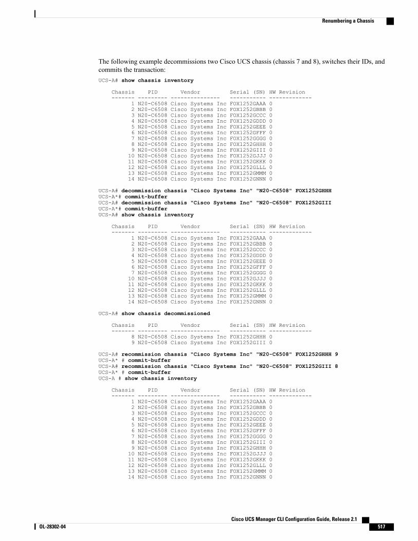
The following example decommissions two Cisco UCS chassis (chassis 7 and 8), switches their IDs, andcommits the transaction:UCS-A# show chassis inventory
Chassis PID Vendor Serial (SN) HW Revision------- --------- --------------- ----------- -------------
1 N20-C6508 Cisco Systems Inc FOX1252GAAA 02 N20-C6508 Cisco Systems Inc FOX1252GBBB 03 N20-C6508 Cisco Systems Inc FOX1252GCCC 04 N20-C6508 Cisco Systems Inc FOX1252GDDD 05 N20-C6508 Cisco Systems Inc FOX1252GEEE 06 N20-C6508 Cisco Systems Inc FOX1252GFFF 07 N20-C6508 Cisco Systems Inc FOX1252GGGG 08 N20-C6508 Cisco Systems Inc FOX1252GHHH 09 N20-C6508 Cisco Systems Inc FOX1252GIII 010 N20-C6508 Cisco Systems Inc FOX1252GJJJ 011 N20-C6508 Cisco Systems Inc FOX1252GKKK 012 N20-C6508 Cisco Systems Inc FOX1252GLLL 013 N20-C6508 Cisco Systems Inc FOX1252GMMM 014 N20-C6508 Cisco Systems Inc FOX1252GNNN 0
UCS-A# decommission chassis "Cisco Systems Inc" "N20-C6508" FOX1252GHHHUCS-A*# commit-bufferUCS-A# decommission chassis "Cisco Systems Inc" "N20-C6508" FOX1252GIIIUCS-A*# commit-bufferUCS-A# show chassis inventory
Chassis PID Vendor Serial (SN) HW Revision------- --------- --------------- ----------- -------------
1 N20-C6508 Cisco Systems Inc FOX1252GAAA 02 N20-C6508 Cisco Systems Inc FOX1252GBBB 03 N20-C6508 Cisco Systems Inc FOX1252GCCC 04 N20-C6508 Cisco Systems Inc FOX1252GDDD 05 N20-C6508 Cisco Systems Inc FOX1252GEEE 06 N20-C6508 Cisco Systems Inc FOX1252GFFF 07 N20-C6508 Cisco Systems Inc FOX1252GGGG 010 N20-C6508 Cisco Systems Inc FOX1252GJJJ 011 N20-C6508 Cisco Systems Inc FOX1252GKKK 012 N20-C6508 Cisco Systems Inc FOX1252GLLL 013 N20-C6508 Cisco Systems Inc FOX1252GMMM 014 N20-C6508 Cisco Systems Inc FOX1252GNNN 0
UCS-A# show chassis decommissioned
Chassis PID Vendor Serial (SN) HW Revision------- --------- --------------- ----------- -------------
8 N20-C6508 Cisco Systems Inc FOX1252GHHH 09 N20-C6508 Cisco Systems Inc FOX1252GIII 0
UCS-A# recommission chassis "Cisco Systems Inc" "N20-C6508" FOX1252GHHH 9UCS-A* # commit-bufferUCS-A# recommission chassis "Cisco Systems Inc" "N20-C6508" FOX1252GIII 8UCS-A* # commit-bufferUCS-A # show chassis inventory
Chassis PID Vendor Serial (SN) HW Revision------- --------- --------------- ----------- -------------
1 N20-C6508 Cisco Systems Inc FOX1252GAAA 02 N20-C6508 Cisco Systems Inc FOX1252GBBB 03 N20-C6508 Cisco Systems Inc FOX1252GCCC 04 N20-C6508 Cisco Systems Inc FOX1252GDDD 05 N20-C6508 Cisco Systems Inc FOX1252GEEE 06 N20-C6508 Cisco Systems Inc FOX1252GFFF 07 N20-C6508 Cisco Systems Inc FOX1252GGGG 08 N20-C6508 Cisco Systems Inc FOX1252GIII 09 N20-C6508 Cisco Systems Inc FOX1252GHHH 010 N20-C6508 Cisco Systems Inc FOX1252GJJJ 011 N20-C6508 Cisco Systems Inc FOX1252GKKK 012 N20-C6508 Cisco Systems Inc FOX1252GLLL 013 N20-C6508 Cisco Systems Inc FOX1252GMMM 014 N20-C6508 Cisco Systems Inc FOX1252GNNN 0
Cisco UCS Manager CLI Configuration Guide, Release 2.1 OL-28302-04 517
Renumbering a Chassis

Toggling the Locator LED
Turning On the Locator LED for a Chassis
Procedure
PurposeCommand or Action
Enters chassis mode for the specified chassis.UCS-A# scope chassis chassis-numStep 1
Turns on the chassis locator LED.UCS-A /chassis # enable locator-ledStep 2
Commits the transaction to the systemconfiguration.
UCS-A /chassis # commit-bufferStep 3
The following example turns on the locator LED for chassis 2 and commits the transaction:UCS-A# scope chassis 2UCS-A /chassis # enable locator-ledUCS-A /chassis* # commit-bufferUCS-A /chassis #
Turning Off the Locator LED for a Chassis
Procedure
PurposeCommand or Action
Enters chassis mode for the specified chassis.UCS-A# scope chassis chassis-numStep 1
Turns off the chassis locator LED.UCS-A /chassis # disable locator-ledStep 2
Commits the transaction to the systemconfiguration.
UCS-A /chassis # commit-bufferStep 3
The following example turns off the locator LED for chassis 2 and commits the transaction:UCS-A# scope chassis 2UCS-A /chassis # disable locator-ledUCS-A /chassis* # commit-bufferUCS-A /chassis #
Cisco UCS Manager CLI Configuration Guide, Release 2.1518 OL-28302-04
Toggling the Locator LED
C H A P T E R 37Managing Blade Servers
This chapter includes the following sections:
• Blade Server Management, page 519
• Guidelines for Removing and Decommissioning Blade Servers, page 520
• Recommendations for Avoiding Unexpected Server Power Changes, page 520
• Booting a Blade Server, page 521
• Shutting Down a Blade Server, page 522
• Power Cycling a Blade Server, page 523
• Performing a Hard Reset on a Blade Server, page 523
• Acknowledging a Blade Server, page 524
• Removing a Blade Server from a Chassis, page 524
• Decommissioning a Blade Server, page 525
• Turning On the Locator LED for a Blade Server, page 525
• Turning Off the Locator LED for a Blade Server, page 526
• Resetting the CMOS for a Blade Server, page 526
• Resetting the CIMC for a Blade Server, page 527
• Recovering the Corrupt BIOS on a Blade Server, page 527
• Issuing an NMI from a Blade Server, page 528
• Health LED Alarms, page 529
• Viewing Health LED Status, page 529
Blade Server ManagementYou can manage and monitor all blade servers in a Cisco UCS domain through Cisco UCS Manager. Someblade server management tasks, such as changes to the power state, can be performed from the server andservice profile.
Cisco UCS Manager CLI Configuration Guide, Release 2.1 OL-28302-04 519
The remaining management tasks can only be performed on the server.
If a blade server slot in a chassis is empty, Cisco UCS Manager provides information, errors, and faults forthat slot. You can also reacknowledge the slot to resolve server mismatch errors and to have Cisco UCSManager rediscover the blade server in the slot.
Guidelines for Removing and Decommissioning Blade ServersConsider the following guidelines when deciding whether to remove or decommission a blade server usingCisco UCS Manager:
Decommissioning a Blade Server
Decommissioning is performed when a blade server is physically present and connected but you want totemporarily remove it from the configuration. Because it is expected that a decommissioned blade server willbe eventually recommissioned, a portion of the server's information is retained by Cisco UCS Manager forfuture use.
Removing a Blade Server
Removing is performed when you physically remove a blade server from the server by disconnecting it fromthe chassis. You cannot remove a blade server from Cisco UCS Manager if it is physically present andconnected to a chassis. Once the physical removal of the blade server is completed, the configuration for thatblade server can be removed in Cisco UCS Manager.
During removal, active links to the blade server are disabled, all entries from databases are removed, and theserver is automatically removed from any server pools that it was assigned to during discovery.
Only those servers added to a server pool automatically during discovery will be removed automatically.Servers that have been manually added to a server pool have to be removed manually.
Note
If you need to add a removed blade server back to the configuration, it must be reconnected and thenrediscovered.When a server is reintroduced to Cisco UCSManager it is treated like a new server and is subjectto the deep discovery process. For this reason, it's possible that Cisco UCS Manager will assign the server anew ID that may be different from the ID that it held before.
Recommendations for Avoiding Unexpected Server Power ChangesIf a server is not associated with a service profile, you can use any available means to change the server powerstate, including the physical Power or Reset buttons on the server.
If a server is associated with, or assigned to, a service profile, you should only use the following methods tochange the server power state:
• In Cisco UCS Manager GUI, go to the General tab for the server or the service profile associated withthe server and select Boot Server or Shutdown Server from the Actions area.
• In Cisco UCSManager CLI, scope to the server or the service profile associated with the server and usethe power up or power down commands.
Cisco UCS Manager CLI Configuration Guide, Release 2.1520 OL-28302-04
Guidelines for Removing and Decommissioning Blade Servers
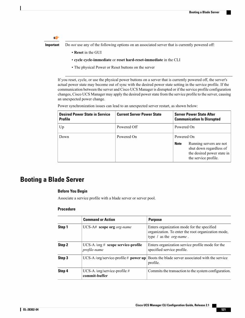
Do not use any of the following options on an associated server that is currently powered off:Important
• Reset in the GUI
• cycle cycle-immediate or reset hard-reset-immediate in the CLI
• The physical Power or Reset buttons on the server
If you reset, cycle, or use the physical power buttons on a server that is currently powered off, the server'sactual power state may become out of sync with the desired power state setting in the service profile. If thecommunication between the server and Cisco UCSManager is disrupted or if the service profile configurationchanges, Cisco UCSManager may apply the desired power state from the service profile to the server, causingan unexpected power change.
Power synchronization issues can lead to an unexpected server restart, as shown below:
Server Power State AfterCommunication Is Disrupted
Current Server Power StateDesired Power State in ServiceProfile
Powered OnPowered OffUp
Powered On
Running servers are notshut down regardless ofthe desired power state inthe service profile.
Note
Powered OnDown
Booting a Blade Server
Before You Begin
Associate a service profile with a blade server or server pool.
Procedure
PurposeCommand or Action
Enters organization mode for the specifiedorganization. To enter the root organization mode,type / as the org-name .
UCS-A# scope org org-nameStep 1
Enters organization service profile mode for thespecified service profile.
UCS-A /org # scope service-profileprofile-name
Step 2
Boots the blade server associated with the serviceprofile.
UCS-A /org/service-profile # power upStep 3
Commits the transaction to the system configuration.UCS-A /org/service-profile #commit-buffer
Step 4
Cisco UCS Manager CLI Configuration Guide, Release 2.1 OL-28302-04 521
Booting a Blade Server
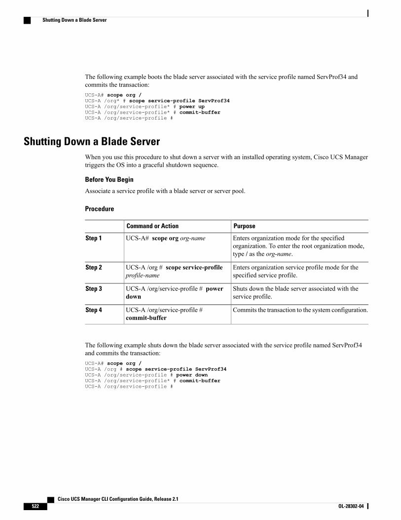
The following example boots the blade server associated with the service profile named ServProf34 andcommits the transaction:UCS-A# scope org /UCS-A /org* # scope service-profile ServProf34UCS-A /org/service-profile* # power upUCS-A /org/service-profile* # commit-bufferUCS-A /org/service-profile #
Shutting Down a Blade ServerWhen you use this procedure to shut down a server with an installed operating system, Cisco UCS Managertriggers the OS into a graceful shutdown sequence.
Before You Begin
Associate a service profile with a blade server or server pool.
Procedure
PurposeCommand or Action
Enters organization mode for the specifiedorganization. To enter the root organization mode,type / as the org-name.
UCS-A# scope org org-nameStep 1
Enters organization service profile mode for thespecified service profile.
UCS-A /org # scope service-profileprofile-name
Step 2
Shuts down the blade server associated with theservice profile.
UCS-A /org/service-profile # powerdown
Step 3
Commits the transaction to the system configuration.UCS-A /org/service-profile #commit-buffer
Step 4
The following example shuts down the blade server associated with the service profile named ServProf34and commits the transaction:UCS-A# scope org /UCS-A /org # scope service-profile ServProf34UCS-A /org/service-profile # power downUCS-A /org/service-profile* # commit-bufferUCS-A /org/service-profile #
Cisco UCS Manager CLI Configuration Guide, Release 2.1522 OL-28302-04
Shutting Down a Blade Server
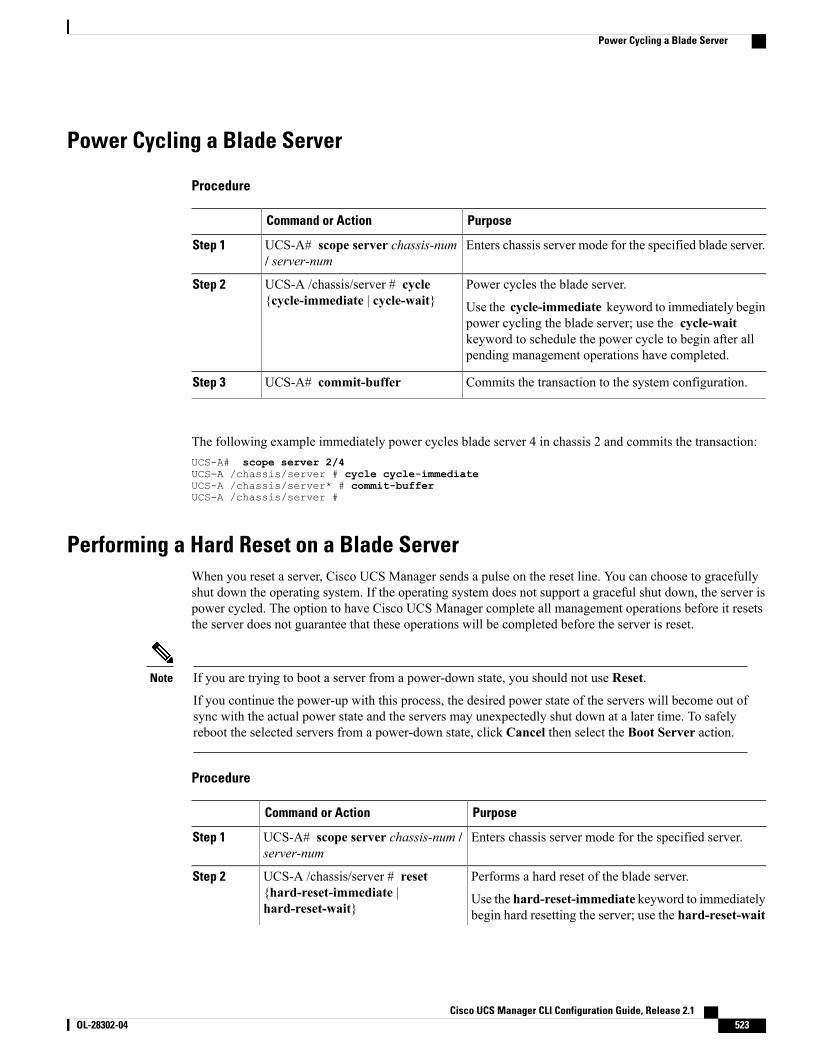
Power Cycling a Blade Server
Procedure
PurposeCommand or Action
Enters chassis server mode for the specified blade server.UCS-A# scope server chassis-num/ server-num
Step 1
Power cycles the blade server.UCS-A /chassis/server # cycle{cycle-immediate | cycle-wait}
Step 2
Use the cycle-immediate keyword to immediately beginpower cycling the blade server; use the cycle-waitkeyword to schedule the power cycle to begin after allpending management operations have completed.
Commits the transaction to the system configuration.UCS-A# commit-bufferStep 3
The following example immediately power cycles blade server 4 in chassis 2 and commits the transaction:UCS-A# scope server 2/4UCS-A /chassis/server # cycle cycle-immediateUCS-A /chassis/server* # commit-bufferUCS-A /chassis/server #
Performing a Hard Reset on a Blade ServerWhen you reset a server, Cisco UCS Manager sends a pulse on the reset line. You can choose to gracefullyshut down the operating system. If the operating system does not support a graceful shut down, the server ispower cycled. The option to have Cisco UCS Manager complete all management operations before it resetsthe server does not guarantee that these operations will be completed before the server is reset.
If you are trying to boot a server from a power-down state, you should not use Reset.
If you continue the power-up with this process, the desired power state of the servers will become out ofsync with the actual power state and the servers may unexpectedly shut down at a later time. To safelyreboot the selected servers from a power-down state, click Cancel then select the Boot Server action.
Note
Procedure
PurposeCommand or Action
Enters chassis server mode for the specified server.UCS-A# scope server chassis-num /server-num
Step 1
Performs a hard reset of the blade server.UCS-A /chassis/server # reset{hard-reset-immediate |hard-reset-wait}
Step 2
Use the hard-reset-immediate keyword to immediatelybegin hard resetting the server; use the hard-reset-wait
Cisco UCS Manager CLI Configuration Guide, Release 2.1 OL-28302-04 523
Power Cycling a Blade Server
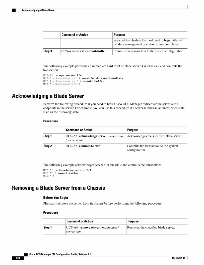
PurposeCommand or Action
keyword to schedule the hard reset to begin after allpending management operations have completed.
Commits the transaction to the system configuration.UCS-A /server # commit-bufferStep 3
The following example performs an immediate hard reset of blade server 4 in chassis 2 and commits thetransaction:UCS-A# scope server 2/4UCS-A /chassis/server # reset hard-reset-immediateUCS-A /chassis/server* # commit-bufferUCS-A /chassis/server #
Acknowledging a Blade ServerPerform the following procedure if you need to have Cisco UCS Manager rediscover the server and allendpoints in the server. For example, you can use this procedure if a server is stuck in an unexpected state,such as the discovery state.
Procedure
PurposeCommand or Action
Acknowledges the specified blade server.UCS-A# acknowledge server chassis-num/ server-num
Step 1
Commits the transaction to the systemconfiguration.
UCS-A# commit-bufferStep 2
The following example acknowledges server 4 in chassis 2 and commits the transaction:UCS-A# acknowledge server 2/4UCS-A* # commit-bufferUCS-A #
Removing a Blade Server from a Chassis
Before You Begin
Physically remove the server from its chassis before performing the following procedure.
Procedure
PurposeCommand or Action
Removes the specified blade server.UCS-A# remove server chassis-num /server-num
Step 1
Cisco UCS Manager CLI Configuration Guide, Release 2.1524 OL-28302-04
Acknowledging a Blade Server
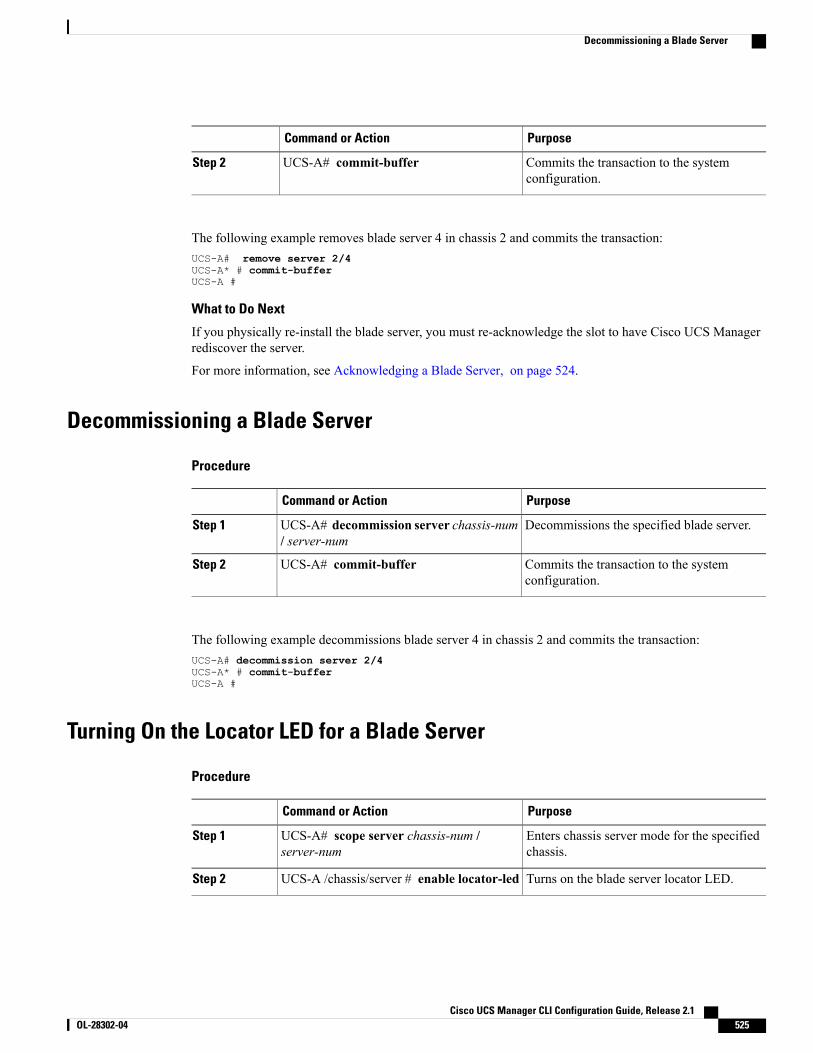
PurposeCommand or Action
Commits the transaction to the systemconfiguration.
UCS-A# commit-bufferStep 2
The following example removes blade server 4 in chassis 2 and commits the transaction:UCS-A# remove server 2/4UCS-A* # commit-bufferUCS-A #
What to Do Next
If you physically re-install the blade server, you must re-acknowledge the slot to have Cisco UCS Managerrediscover the server.
For more information, see Acknowledging a Blade Server, on page 524.
Decommissioning a Blade Server
Procedure
PurposeCommand or Action
Decommissions the specified blade server.UCS-A# decommission server chassis-num/ server-num
Step 1
Commits the transaction to the systemconfiguration.
UCS-A# commit-bufferStep 2
The following example decommissions blade server 4 in chassis 2 and commits the transaction:UCS-A# decommission server 2/4UCS-A* # commit-bufferUCS-A #
Turning On the Locator LED for a Blade Server
Procedure
PurposeCommand or Action
Enters chassis server mode for the specifiedchassis.
UCS-A# scope server chassis-num /server-num
Step 1
Turns on the blade server locator LED.UCS-A /chassis/server # enable locator-ledStep 2
Cisco UCS Manager CLI Configuration Guide, Release 2.1 OL-28302-04 525
Decommissioning a Blade Server
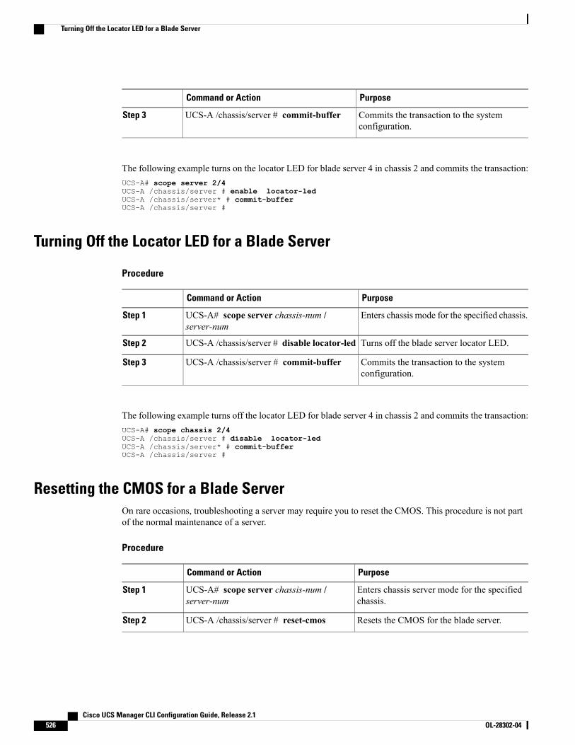
PurposeCommand or Action
Commits the transaction to the systemconfiguration.
UCS-A /chassis/server # commit-bufferStep 3
The following example turns on the locator LED for blade server 4 in chassis 2 and commits the transaction:UCS-A# scope server 2/4UCS-A /chassis/server # enable locator-ledUCS-A /chassis/server* # commit-bufferUCS-A /chassis/server #
Turning Off the Locator LED for a Blade Server
Procedure
PurposeCommand or Action
Enters chassis mode for the specified chassis.UCS-A# scope server chassis-num /server-num
Step 1
Turns off the blade server locator LED.UCS-A /chassis/server # disable locator-ledStep 2
Commits the transaction to the systemconfiguration.
UCS-A /chassis/server # commit-bufferStep 3
The following example turns off the locator LED for blade server 4 in chassis 2 and commits the transaction:UCS-A# scope chassis 2/4UCS-A /chassis/server # disable locator-ledUCS-A /chassis/server* # commit-bufferUCS-A /chassis/server #
Resetting the CMOS for a Blade ServerOn rare occasions, troubleshooting a server may require you to reset the CMOS. This procedure is not partof the normal maintenance of a server.
Procedure
PurposeCommand or Action
Enters chassis server mode for the specifiedchassis.
UCS-A# scope server chassis-num /server-num
Step 1
Resets the CMOS for the blade server.UCS-A /chassis/server # reset-cmosStep 2
Cisco UCS Manager CLI Configuration Guide, Release 2.1526 OL-28302-04
Turning Off the Locator LED for a Blade Server
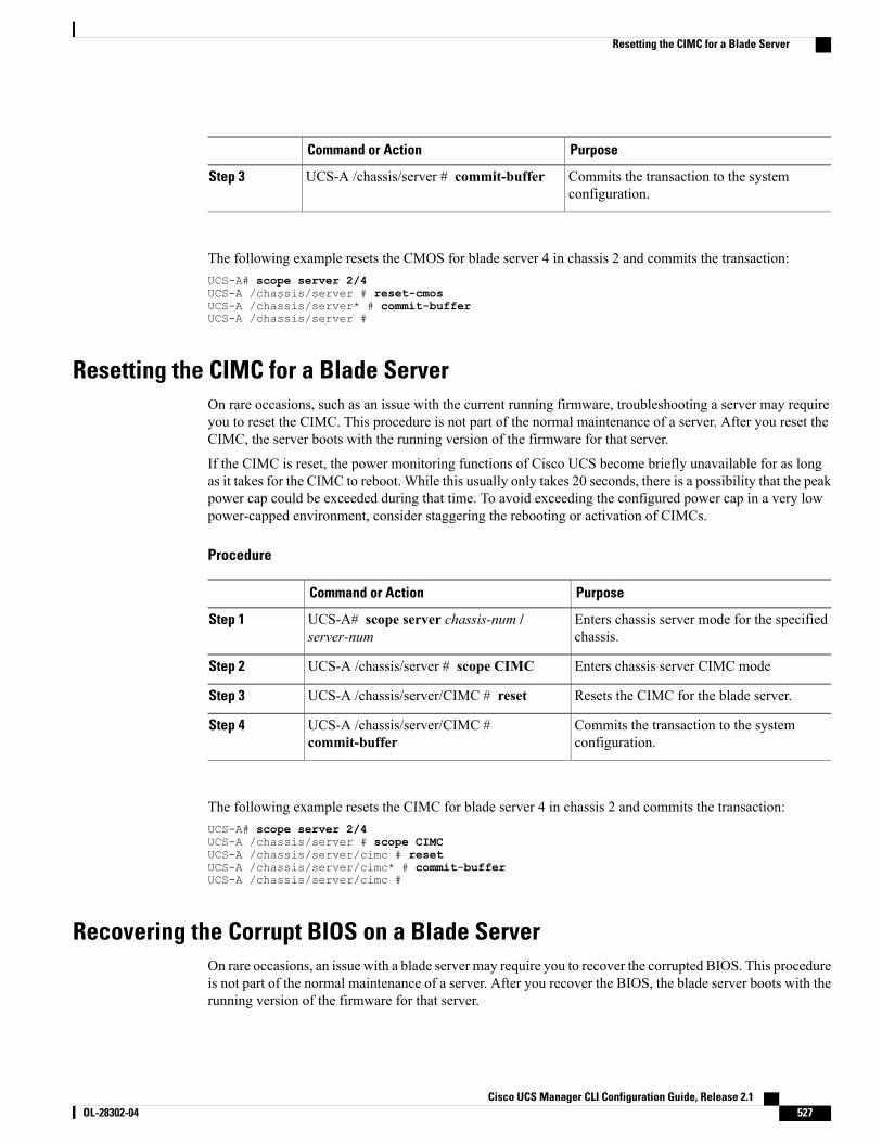
PurposeCommand or Action
Commits the transaction to the systemconfiguration.
UCS-A /chassis/server # commit-bufferStep 3
The following example resets the CMOS for blade server 4 in chassis 2 and commits the transaction:UCS-A# scope server 2/4UCS-A /chassis/server # reset-cmosUCS-A /chassis/server* # commit-bufferUCS-A /chassis/server #
Resetting the CIMC for a Blade ServerOn rare occasions, such as an issue with the current running firmware, troubleshooting a server may requireyou to reset the CIMC. This procedure is not part of the normal maintenance of a server. After you reset theCIMC, the server boots with the running version of the firmware for that server.
If the CIMC is reset, the power monitoring functions of Cisco UCS become briefly unavailable for as longas it takes for the CIMC to reboot. While this usually only takes 20 seconds, there is a possibility that the peakpower cap could be exceeded during that time. To avoid exceeding the configured power cap in a very lowpower-capped environment, consider staggering the rebooting or activation of CIMCs.
Procedure
PurposeCommand or Action
Enters chassis server mode for the specifiedchassis.
UCS-A# scope server chassis-num /server-num
Step 1
Enters chassis server CIMC modeUCS-A /chassis/server # scope CIMCStep 2
Resets the CIMC for the blade server.UCS-A /chassis/server/CIMC # resetStep 3
Commits the transaction to the systemconfiguration.
UCS-A /chassis/server/CIMC #commit-buffer
Step 4
The following example resets the CIMC for blade server 4 in chassis 2 and commits the transaction:UCS-A# scope server 2/4UCS-A /chassis/server # scope CIMCUCS-A /chassis/server/cimc # resetUCS-A /chassis/server/cimc* # commit-bufferUCS-A /chassis/server/cimc #
Recovering the Corrupt BIOS on a Blade ServerOn rare occasions, an issue with a blade server may require you to recover the corrupted BIOS. This procedureis not part of the normal maintenance of a server. After you recover the BIOS, the blade server boots with therunning version of the firmware for that server.
Cisco UCS Manager CLI Configuration Guide, Release 2.1 OL-28302-04 527
Resetting the CIMC for a Blade Server
Before You Begin
Remove all attached or mapped USB storage from a server before you attempt to recover the corrupt BIOSon that server. If an external USB drive is attached or mapped from vMedia to the server, BIOS recoveryfails.
Important
Procedure
PurposeCommand or Action
Enters chassis server mode for the specifiedblade server in the specified chassis.
UCS-A# scope server chassis-id / server-idStep 1
Loads and activates the specified BIOS version.UCS-A /chassis/server # recover-biosversion
Step 2
Commits the transaction.UCS-A /chassis/server # commit-bufferStep 3
The following example shows how to recover the BIOS:UCS-A# scope server 1/7UCS-A /chassis/server # recover-bios S5500.0044.0.3.1.010620101125UCS-A /chassis/server* # commit-bufferUCS-A /chassis/server #
Issuing an NMI from a Blade ServerPerform the following procedure if the system remains unresponsive and you need Cisco UCS Manager toissue a Non Maskable Interrupt (NMI) to the BIOS or operating system from the CIMC. This action createsa core dump or stack trace, depending on the operating system installed on the server.
Procedure
PurposeCommand or Action
Enters server mode for the specifiedserver.
UCS-A# scope server [chassis-num/server-num |dynamic-uuid]
Step 1
UCS-A /chassis/server # diagnostic-interruptStep 2
Commits any pending transactions.UCS-A /chassis/server* # commit-bufferStep 3
The following example sends an NMI from server 4 in chassis 2 and commits the transaction:UCS-A# scope server 2/4UCS-A /chassis/server # diagnostic-interruptUCS-A /chassis/server* # commit-bufferUCS-A /chassis/server #
Cisco UCS Manager CLI Configuration Guide, Release 2.1528 OL-28302-04
Issuing an NMI from a Blade Server
Health LED AlarmsThe blade health LED is located on the front of each Cisco UCS B-Series blade server. Cisco UCS Managerallows you to view the sensor faults that cause the blade health LED to change color from green to amber orblinking amber.
The health LED alarms display the following information:
DescriptionName
The severity of the alarm. This can be one of the following:
• Critical—The blade health LED is blinking amber.
• Minor—The blade health LED is amber.
Severity column
A brief description of the alarm.Description column
The ID of the sensor the triggered the alarm.Sensor ID column
The name of the sensor that triggered the alarm.Sensor Name column
Viewing Health LED Status
Procedure
PurposeCommand or Action
Enters chassis server mode for the specifiedserver.
UCS-A# scope server chassis-id / blade-idStep 1
Displays the health LED and sensor alarms forthe selected server.
UCS-A /chassis/server # show health-ledexpand
Step 2
The following example shows how to display the health LED status and sensor alarms for chassis 1 server 1:UCS-A# scope server 1/1UCS-A /chassis/server # show health-ledHealth LED:
Severity: MinorReason:: P0V75_STBY:Voltage Threshold Crossed;TEMP_SENS_FRONT:Temperature Threshold
Crossed;Color: AmberOper State:: On
Sensor Alarm:Severity: MinorSensor ID: 7Sensor Name: P0V75_STBYAlarm Desc: Voltage Threshold Crossed
Severity: Minor
Cisco UCS Manager CLI Configuration Guide, Release 2.1 OL-28302-04 529
Health LED Alarms

Sensor ID: 76Sensor Name: TEMP_SENS_FRONTAlarm Desc: Temperature Threshold Crossed
Severity: MinorSensor ID: 91Sensor Name: DDR3_P1_D2_TMPAlarm Desc: Temperature Threshold Crossed
UCS-A /chassis/server #
Cisco UCS Manager CLI Configuration Guide, Release 2.1530 OL-28302-04
Viewing Health LED Status
C H A P T E R 38Managing Rack-Mount Servers
This chapter includes the following sections:
• Rack-Mount Server Management, page 531
• Guidelines for Removing and Decommissioning Rack-Mount Servers, page 532
• Recommendations for Avoiding Unexpected Server Power Changes, page 532
• Booting a Rack-Mount Server, page 533
• Shutting Down a Rack-Mount Server, page 534
• Power Cycling a Rack-Mount Server, page 535
• Performing a Hard Reset on a Rack-Mount Server, page 535
• Acknowledging a Rack-Mount Server, page 536
• Decommissioning a Rack-Mount Server, page 536
• Renumbering a Rack-Mount Server, page 537
• Removing a Rack-Mount Server, page 538
• Turning On the Locator LED for a Rack-Mount Server, page 539
• Turning Off the Locator LED for a Rack-Mount Server, page 539
• Resetting the CMOS for a Rack-Mount Server, page 540
• Resetting the CIMC for a Rack-Mount Server, page 540
• Recovering the Corrupt BIOS on a Rack-Mount Server, page 541
• Showing the Status for a Rack-Mount Server, page 541
• Issuing an NMI from a Rack-Mount Server, page 542
Rack-Mount Server ManagementYou can manage and monitor all rack-mount servers that have been integrated with a Cisco UCS domainthrough Cisco UCSManager. All management and monitoring features are supported for rack-mount serversexcept power capping. Some rack-mount server management tasks, such as changes to the power state, can
Cisco UCS Manager CLI Configuration Guide, Release 2.1 OL-28302-04 531
be performed from both the server and service profile. The remainingmanagement tasks can only be performedon the server.
Cisco UCSManager provides information, errors, and faults for each rack-mount server that it has discovered.
For information about how to integrate a supported CiscoUCS rack-mount server with CiscoUCSManager,see the Cisco UCS C-series server integration guide for your Cisco UCS Manager release.
Tip
Guidelines for Removing and Decommissioning Rack-Mount ServersConsider the following guidelines when deciding whether to remove or decommission a rack-mount serverusing Cisco UCS Manager:
Decommissioning a Rack-Mount server
Decommissioning is performed when a rack-mount server is physically present and connected but you wantto temporarily remove it from the configuration. Because it is expected that a decommissioned rack-mountserver will be eventually recommissioned, a portion of the server's information is retained by Cisco UCSManager for future use.
Removing a Rack-Mount server
Removing is performed when you physically remove the server from the system by disconnecting therack-mount server from the fabric extender. You cannot remove a rack-mount server fromCisco UCSManagerif it is physically present and connected to the fabric extender. Once the rack-mount server is disconnected,the configuration for that rack-mount server can be removed in Cisco UCS Manager.
During removal, management interfaces are disconnected, all entries from databases are removed, and theserver is automatically removed from any server pools that it was assigned to during discovery.
Only those servers added to a server pool automatically during discovery will be removed automatically.Servers that have been manually added to a server pool have to be removed manually.
Note
If you need to add a removed rack-mount server back to the configuration, it must be reconnected and thenrediscovered.When a server is reintroduced to Cisco UCSManager it is treated like a new server and is subjectto the deep discovery process. For this reason, it's possible that Cisco UCS Manager will assign the server anew ID that may be different from the ID that it held before.
Recommendations for Avoiding Unexpected Server Power ChangesIf a server is not associated with a service profile, you can use any available means to change the server powerstate, including the physical Power or Reset buttons on the server.
If a server is associated with, or assigned to, a service profile, you should only use the following methods tochange the server power state:
• In Cisco UCS Manager GUI, go to the General tab for the server or the service profile associated withthe server and select Boot Server or Shutdown Server from the Actions area.
Cisco UCS Manager CLI Configuration Guide, Release 2.1532 OL-28302-04
Guidelines for Removing and Decommissioning Rack-Mount Servers
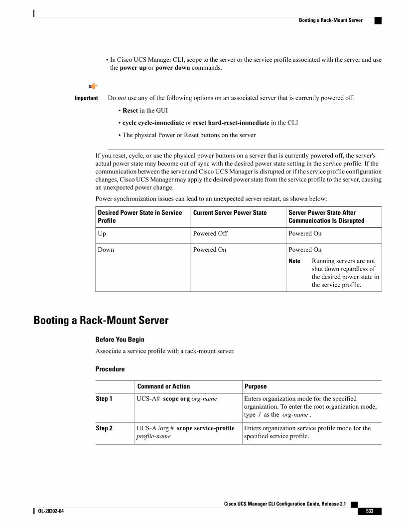
• In Cisco UCSManager CLI, scope to the server or the service profile associated with the server and usethe power up or power down commands.
Do not use any of the following options on an associated server that is currently powered off:Important
• Reset in the GUI
• cycle cycle-immediate or reset hard-reset-immediate in the CLI
• The physical Power or Reset buttons on the server
If you reset, cycle, or use the physical power buttons on a server that is currently powered off, the server'sactual power state may become out of sync with the desired power state setting in the service profile. If thecommunication between the server and Cisco UCSManager is disrupted or if the service profile configurationchanges, Cisco UCSManager may apply the desired power state from the service profile to the server, causingan unexpected power change.
Power synchronization issues can lead to an unexpected server restart, as shown below:
Server Power State AfterCommunication Is Disrupted
Current Server Power StateDesired Power State in ServiceProfile
Powered OnPowered OffUp
Powered On
Running servers are notshut down regardless ofthe desired power state inthe service profile.
Note
Powered OnDown
Booting a Rack-Mount Server
Before You Begin
Associate a service profile with a rack-mount server.
Procedure
PurposeCommand or Action
Enters organization mode for the specifiedorganization. To enter the root organization mode,type / as the org-name .
UCS-A# scope org org-nameStep 1
Enters organization service profile mode for thespecified service profile.
UCS-A /org # scope service-profileprofile-name
Step 2
Cisco UCS Manager CLI Configuration Guide, Release 2.1 OL-28302-04 533
Booting a Rack-Mount Server

PurposeCommand or Action
Boots the rack-mount server associated with theservice profile.
UCS-A /org/service-profile # powerup
Step 3
Commits the transaction to the system configuration.UCS-A /org/service-profile #commit-buffer
Step 4
The following example boots the rack-mount server associated with the service profile named ServProf34and commits the transaction:UCS-A# scope org /UCS-A /org* # scope service-profile ServProf34UCS-A /org/service-profile # power upUCS-A /org/service-profile* # commit-bufferUCS-A /org/service-profile #
Shutting Down a Rack-Mount ServerWhen you use this procedure to shut down a server with an installed operating system, Cisco UCS Managertriggers the OS into a graceful shutdown sequence.
Before You Begin
Associate a service profile with a rack-mount server.
Procedure
PurposeCommand or Action
Enters organization mode for the specifiedorganization. To enter the root organization mode,type / as the org-name.
UCS-A# scope org org-nameStep 1
Enters organization service profile mode for thespecified service profile.
UCS-A /org # scope service-profileprofile-name
Step 2
Shuts down the rack-mount server associated withthe service profile.
UCS-A /org/service-profile # powerdown
Step 3
Commits the transaction to the system configuration.UCS-A /org/service-profile #commit-buffer
Step 4
The following example shuts down the rack-mount server associated with the service profile named ServProf34and commits the transaction:UCS-A# scope org /UCS-A /org # scope service-profile ServProf34UCS-A /org/service-profile # power downUCS-A /org/service-profile* # commit-bufferUCS-A /org/service-profile #
Cisco UCS Manager CLI Configuration Guide, Release 2.1534 OL-28302-04
Shutting Down a Rack-Mount Server
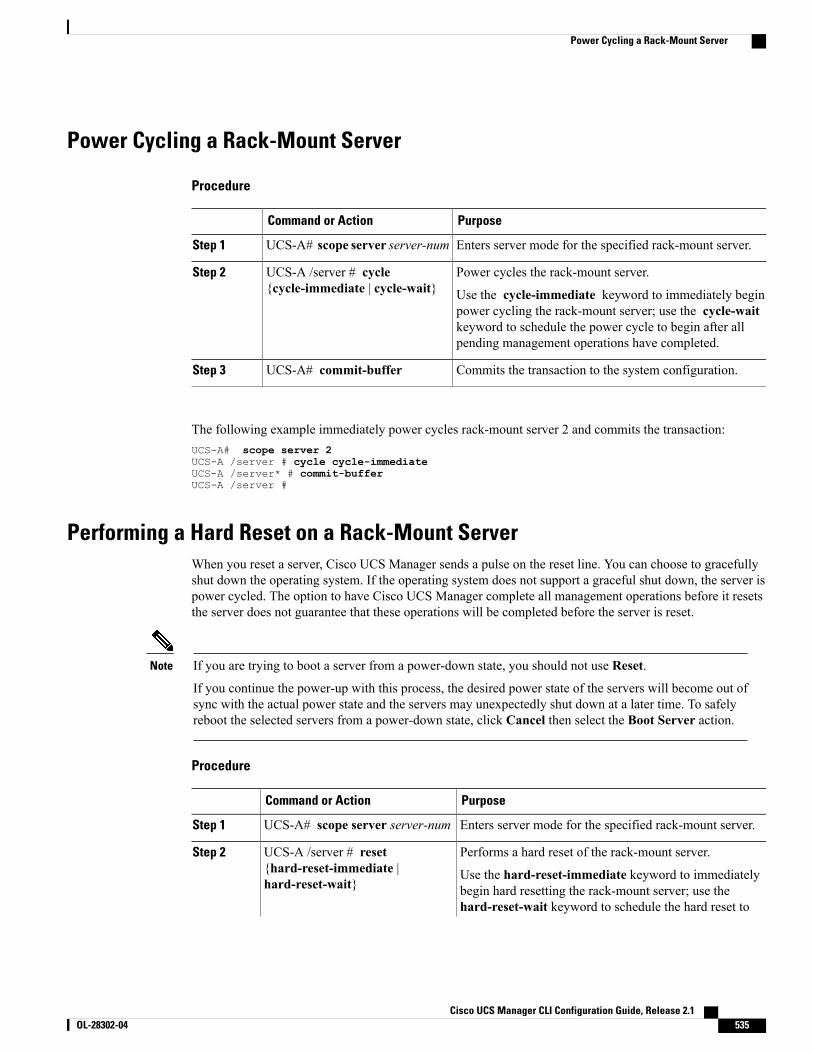
Power Cycling a Rack-Mount Server
Procedure
PurposeCommand or Action
Enters server mode for the specified rack-mount server.UCS-A# scope server server-numStep 1
Power cycles the rack-mount server.UCS-A /server # cycle{cycle-immediate | cycle-wait}
Step 2
Use the cycle-immediate keyword to immediately beginpower cycling the rack-mount server; use the cycle-waitkeyword to schedule the power cycle to begin after allpending management operations have completed.
Commits the transaction to the system configuration.UCS-A# commit-bufferStep 3
The following example immediately power cycles rack-mount server 2 and commits the transaction:UCS-A# scope server 2UCS-A /server # cycle cycle-immediateUCS-A /server* # commit-bufferUCS-A /server #
Performing a Hard Reset on a Rack-Mount ServerWhen you reset a server, Cisco UCS Manager sends a pulse on the reset line. You can choose to gracefullyshut down the operating system. If the operating system does not support a graceful shut down, the server ispower cycled. The option to have Cisco UCS Manager complete all management operations before it resetsthe server does not guarantee that these operations will be completed before the server is reset.
If you are trying to boot a server from a power-down state, you should not use Reset.
If you continue the power-up with this process, the desired power state of the servers will become out ofsync with the actual power state and the servers may unexpectedly shut down at a later time. To safelyreboot the selected servers from a power-down state, click Cancel then select the Boot Server action.
Note
Procedure
PurposeCommand or Action
Enters server mode for the specified rack-mount server.UCS-A# scope server server-numStep 1
Performs a hard reset of the rack-mount server.UCS-A /server # reset{hard-reset-immediate |hard-reset-wait}
Step 2
Use the hard-reset-immediate keyword to immediatelybegin hard resetting the rack-mount server; use thehard-reset-wait keyword to schedule the hard reset to
Cisco UCS Manager CLI Configuration Guide, Release 2.1 OL-28302-04 535
Power Cycling a Rack-Mount Server
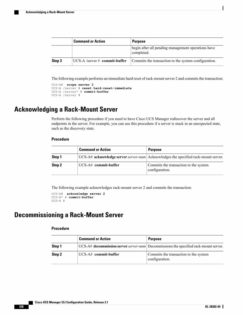
PurposeCommand or Action
begin after all pending management operations havecompleted.
Commits the transaction to the system configuration.UCS-A /server # commit-bufferStep 3
The following example performs an immediate hard reset of rack-mount server 2 and commits the transaction:UCS-A# scope server 2UCS-A /server # reset hard-reset-immediateUCS-A /server* # commit-bufferUCS-A /server #
Acknowledging a Rack-Mount ServerPerform the following procedure if you need to have Cisco UCS Manager rediscover the server and allendpoints in the server. For example, you can use this procedure if a server is stuck in an unexpected state,such as the discovery state.
Procedure
PurposeCommand or Action
Acknowledges the specified rack-mount server.UCS-A# acknowledge server server-numStep 1
Commits the transaction to the systemconfiguration.
UCS-A# commit-bufferStep 2
The following example acknowledges rack-mount server 2 and commits the transaction:UCS-A# acknowledge server 2UCS-A* # commit-bufferUCS-A #
Decommissioning a Rack-Mount Server
Procedure
PurposeCommand or Action
Decommissions the specified rack-mount server.UCS-A# decommission server server-numStep 1
Commits the transaction to the systemconfiguration.
UCS-A# commit-bufferStep 2
Cisco UCS Manager CLI Configuration Guide, Release 2.1536 OL-28302-04
Acknowledging a Rack-Mount Server
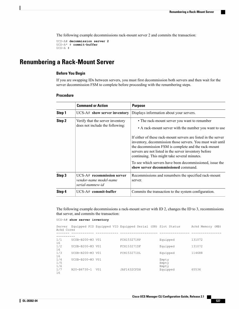
The following example decommissions rack-mount server 2 and commits the transaction:UCS-A# decommission server 2UCS-A* # commit-bufferUCS-A #
Renumbering a Rack-Mount Server
Before You Begin
If you are swapping IDs between servers, you must first decommission both servers and then wait for theserver decommission FSM to complete before proceeding with the renumbering steps.
Procedure
PurposeCommand or Action
Displays information about your servers.UCS-A# show server inventoryStep 1
Verify that the server inventorydoes not include the following:
Step 2 • The rack-mount server you want to renumber
• A rack-mount server with the number you want to use
If either of these rack-mount servers are listed in the serverinventory, decommission those servers. You must wait untilthe decommission FSM is complete and the rack-mountservers are not listed in the server inventory beforecontinuing. This might take several minutes.
To see which servers have been decommissioned, issue theshow server decommissioned command.
Recommissions and renumbers the specified rack-mountserver.
UCS-A# recommission servervendor-name model-nameserial-numnew-id
Step 3
Commits the transaction to the system configuration.UCS-A# commit-bufferStep 4
The following example decommissions a rack-mount server with ID 2, changes the ID to 3, recommissionsthat server, and commits the transaction:UCS-A# show server inventory
Server Equipped PID Equipped VID Equipped Serial (SN) Slot Status Ackd Memory (MB)Ackd Cores------- ------------ ------------ -------------------- ---------------- --------------------------1/1 UCSB-B200-M3 V01 FCH1532718P Equipped 131072161/2 UCSB-B200-M3 V01 FCH153271DF Equipped 131072161/3 UCSB-B200-M3 V01 FCH153271DL Equipped 114688161/4 UCSB-B200-M3 V01 Empty1/5 Empty1/6 Empty1/7 N20-B6730-1 V01 JAF1432CFDH Equipped 6553616
Cisco UCS Manager CLI Configuration Guide, Release 2.1 OL-28302-04 537
Renumbering a Rack-Mount Server
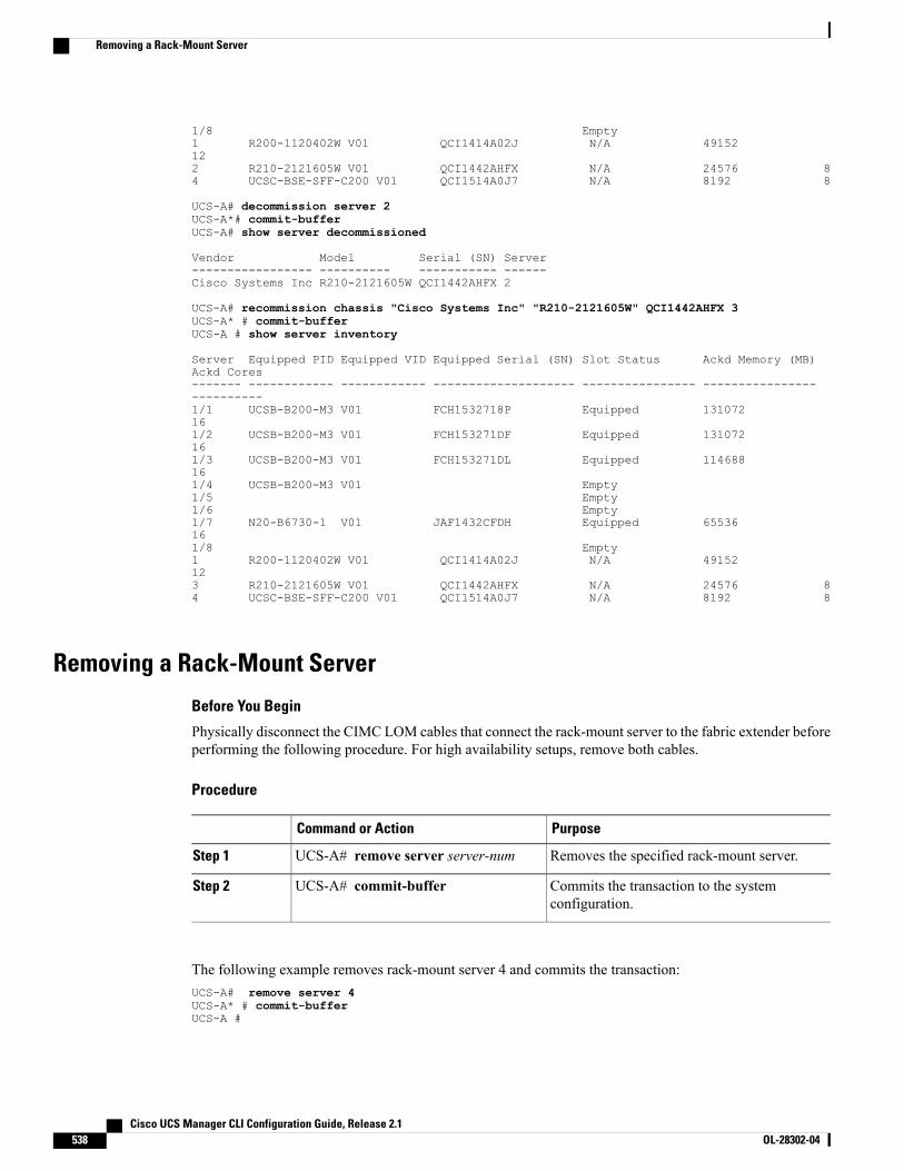
1/8 Empty1 R200-1120402W V01 QCI1414A02J N/A 49152122 R210-2121605W V01 QCI1442AHFX N/A 24576 84 UCSC-BSE-SFF-C200 V01 QCI1514A0J7 N/A 8192 8
UCS-A# decommission server 2UCS-A*# commit-bufferUCS-A# show server decommissioned
Vendor Model Serial (SN) Server----------------- ---------- ----------- ------Cisco Systems Inc R210-2121605W QCI1442AHFX 2
UCS-A# recommission chassis "Cisco Systems Inc" "R210-2121605W" QCI1442AHFX 3UCS-A* # commit-bufferUCS-A # show server inventory
Server Equipped PID Equipped VID Equipped Serial (SN) Slot Status Ackd Memory (MB)Ackd Cores------- ------------ ------------ -------------------- ---------------- --------------------------1/1 UCSB-B200-M3 V01 FCH1532718P Equipped 131072161/2 UCSB-B200-M3 V01 FCH153271DF Equipped 131072161/3 UCSB-B200-M3 V01 FCH153271DL Equipped 114688161/4 UCSB-B200-M3 V01 Empty1/5 Empty1/6 Empty1/7 N20-B6730-1 V01 JAF1432CFDH Equipped 65536161/8 Empty1 R200-1120402W V01 QCI1414A02J N/A 49152123 R210-2121605W V01 QCI1442AHFX N/A 24576 84 UCSC-BSE-SFF-C200 V01 QCI1514A0J7 N/A 8192 8
Removing a Rack-Mount Server
Before You Begin
Physically disconnect the CIMC LOM cables that connect the rack-mount server to the fabric extender beforeperforming the following procedure. For high availability setups, remove both cables.
Procedure
PurposeCommand or Action
Removes the specified rack-mount server.UCS-A# remove server server-numStep 1
Commits the transaction to the systemconfiguration.
UCS-A# commit-bufferStep 2
The following example removes rack-mount server 4 and commits the transaction:UCS-A# remove server 4UCS-A* # commit-bufferUCS-A #
Cisco UCS Manager CLI Configuration Guide, Release 2.1538 OL-28302-04
Removing a Rack-Mount Server
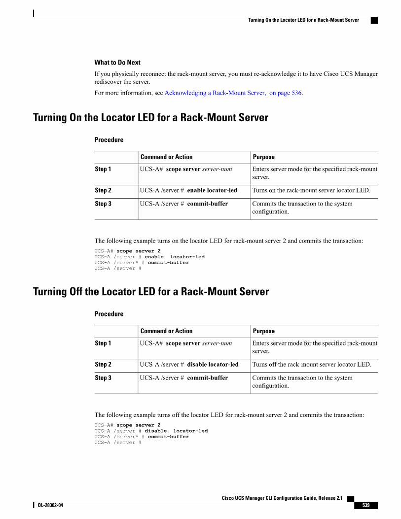
What to Do Next
If you physically reconnect the rack-mount server, you must re-acknowledge it to have Cisco UCS Managerrediscover the server.
For more information, see Acknowledging a Rack-Mount Server, on page 536.
Turning On the Locator LED for a Rack-Mount Server
Procedure
PurposeCommand or Action
Enters server mode for the specified rack-mountserver.
UCS-A# scope server server-numStep 1
Turns on the rack-mount server locator LED.UCS-A /server # enable locator-ledStep 2
Commits the transaction to the systemconfiguration.
UCS-A /server # commit-bufferStep 3
The following example turns on the locator LED for rack-mount server 2 and commits the transaction:UCS-A# scope server 2UCS-A /server # enable locator-ledUCS-A /server* # commit-bufferUCS-A /server #
Turning Off the Locator LED for a Rack-Mount Server
Procedure
PurposeCommand or Action
Enters server mode for the specified rack-mountserver.
UCS-A# scope server server-numStep 1
Turns off the rack-mount server locator LED.UCS-A /server # disable locator-ledStep 2
Commits the transaction to the systemconfiguration.
UCS-A /server # commit-bufferStep 3
The following example turns off the locator LED for rack-mount server 2 and commits the transaction:UCS-A# scope server 2UCS-A /server # disable locator-ledUCS-A /server* # commit-bufferUCS-A /server #
Cisco UCS Manager CLI Configuration Guide, Release 2.1 OL-28302-04 539
Turning On the Locator LED for a Rack-Mount Server

Resetting the CMOS for a Rack-Mount ServerOn rare occasions, troubleshooting a server may require you to reset the CMOS. This procedure is not partof the normal maintenance of a server.
Procedure
PurposeCommand or Action
Enters server mode for the rack-mount server.UCS-A# scope server server-numStep 1
Resets the CMOS for the rack-mount server.UCS-A /server # reset-cmosStep 2
Commits the transaction to the systemconfiguration.
UCS-A /server # commit-bufferStep 3
The following example resets the CMOS for rack-mount server 2 and commits the transaction:UCS-A# scope server 2UCS-A /server # reset-cmosUCS-A /server* # commit-bufferUCS-A /server #
Resetting the CIMC for a Rack-Mount ServerOn rare occasions, such as an issue with the current running firmware, troubleshooting a server may requireyou to reset the CIMC. This procedure is not part of the normal maintenance of a server. After you reset theCIMC, the server boots with the running version of the firmware for that server.
Procedure
PurposeCommand or Action
Enters server mode for the specified rack-mountserver.
UCS-A# scope server server-numStep 1
Enters server CIMC modeUCS-A /server # scope CIMCStep 2
Resets the CIMC for the rack-mount server.UCS-A /server/CIMC # resetStep 3
Commits the transaction to the systemconfiguration.
UCS-A /server/CIMC # commit-bufferStep 4
The following example resets the CIMC for rack-mount server 2 and commits the transaction:UCS-A# scope server 2UCS-A /server # scope CIMCUCS-A /server/cimc # resetUCS-A /server/cimc* # commit-bufferUCS-A /server/cimc #
Cisco UCS Manager CLI Configuration Guide, Release 2.1540 OL-28302-04
Resetting the CMOS for a Rack-Mount Server
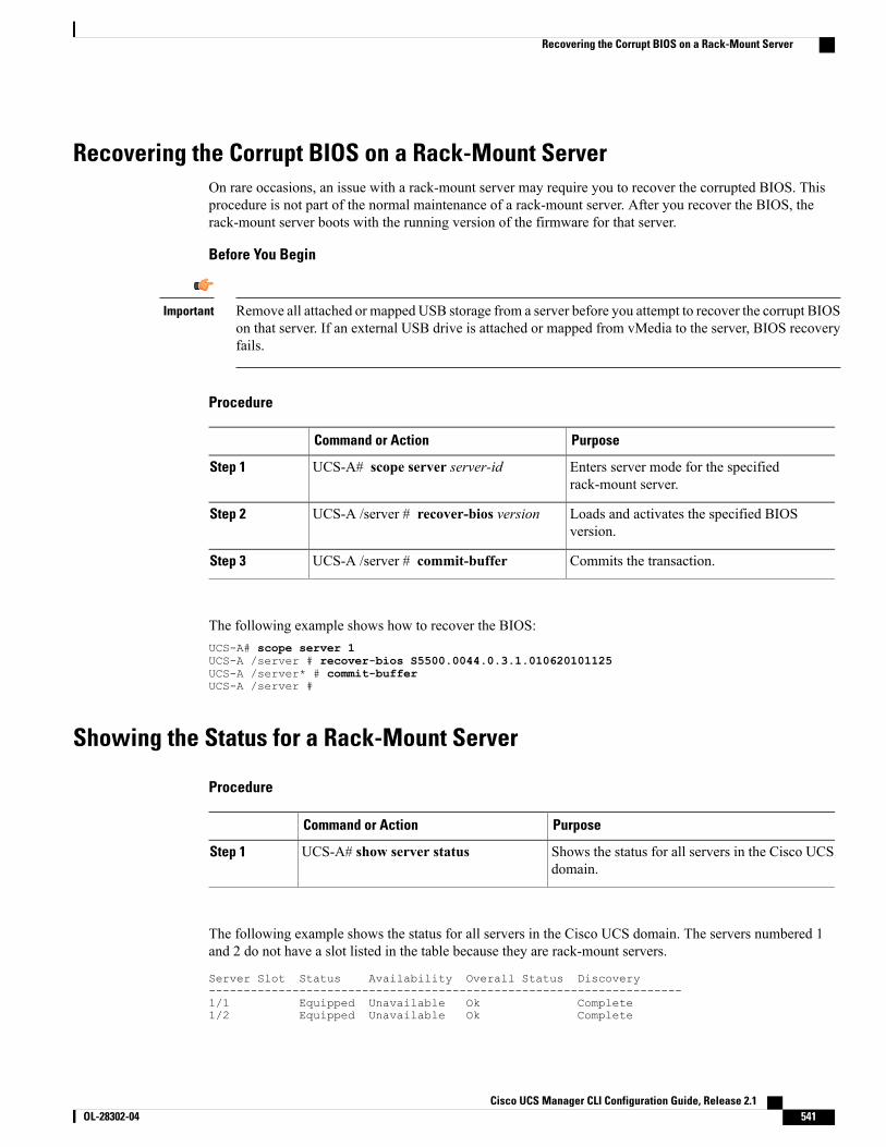
Recovering the Corrupt BIOS on a Rack-Mount ServerOn rare occasions, an issue with a rack-mount server may require you to recover the corrupted BIOS. Thisprocedure is not part of the normal maintenance of a rack-mount server. After you recover the BIOS, therack-mount server boots with the running version of the firmware for that server.
Before You Begin
Remove all attached or mapped USB storage from a server before you attempt to recover the corrupt BIOSon that server. If an external USB drive is attached or mapped from vMedia to the server, BIOS recoveryfails.
Important
Procedure
PurposeCommand or Action
Enters server mode for the specifiedrack-mount server.
UCS-A# scope server server-idStep 1
Loads and activates the specified BIOSversion.
UCS-A /server # recover-bios versionStep 2
Commits the transaction.UCS-A /server # commit-bufferStep 3
The following example shows how to recover the BIOS:UCS-A# scope server 1UCS-A /server # recover-bios S5500.0044.0.3.1.010620101125UCS-A /server* # commit-bufferUCS-A /server #
Showing the Status for a Rack-Mount Server
Procedure
PurposeCommand or Action
Shows the status for all servers in the Cisco UCSdomain.
UCS-A# show server statusStep 1
The following example shows the status for all servers in the Cisco UCS domain. The servers numbered 1and 2 do not have a slot listed in the table because they are rack-mount servers.
Server Slot Status Availability Overall Status Discovery--------------------------------------------------------------------1/1 Equipped Unavailable Ok Complete1/2 Equipped Unavailable Ok Complete
Cisco UCS Manager CLI Configuration Guide, Release 2.1 OL-28302-04 541
Recovering the Corrupt BIOS on a Rack-Mount Server
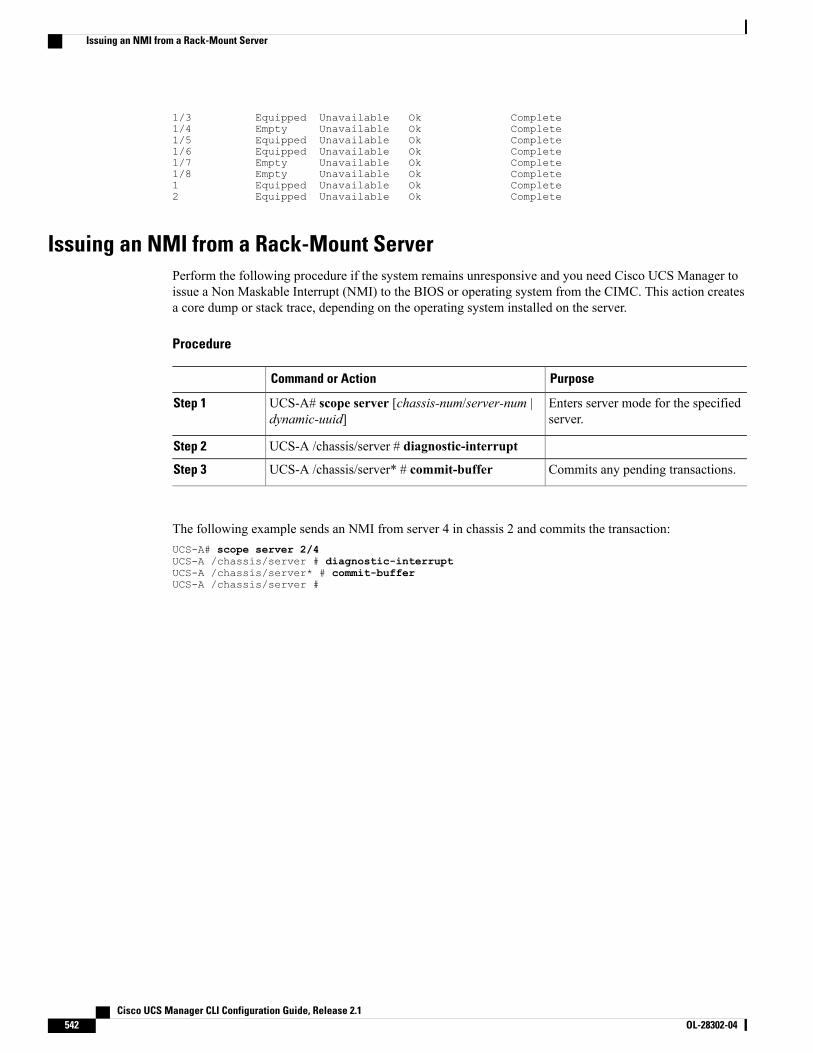
1/3 Equipped Unavailable Ok Complete1/4 Empty Unavailable Ok Complete1/5 Equipped Unavailable Ok Complete1/6 Equipped Unavailable Ok Complete1/7 Empty Unavailable Ok Complete1/8 Empty Unavailable Ok Complete1 Equipped Unavailable Ok Complete2 Equipped Unavailable Ok Complete
Issuing an NMI from a Rack-Mount ServerPerform the following procedure if the system remains unresponsive and you need Cisco UCS Manager toissue a Non Maskable Interrupt (NMI) to the BIOS or operating system from the CIMC. This action createsa core dump or stack trace, depending on the operating system installed on the server.
Procedure
PurposeCommand or Action
Enters server mode for the specifiedserver.
UCS-A# scope server [chassis-num/server-num |dynamic-uuid]
Step 1
UCS-A /chassis/server # diagnostic-interruptStep 2
Commits any pending transactions.UCS-A /chassis/server* # commit-bufferStep 3
The following example sends an NMI from server 4 in chassis 2 and commits the transaction:UCS-A# scope server 2/4UCS-A /chassis/server # diagnostic-interruptUCS-A /chassis/server* # commit-bufferUCS-A /chassis/server #
Cisco UCS Manager CLI Configuration Guide, Release 2.1542 OL-28302-04
Issuing an NMI from a Rack-Mount Server
C H A P T E R 39CIMC Session Management
This chapter includes the following sections:
• CIMC Session Management, page 543
CIMC Session ManagementYou can view and close anyKVM, vMedia, and SOL sessions in CiscoUCSManager. If you have administratorprivileges, you can discontinue the KVM, vMedia, and SoL sessions of any user. . Cisco IntegratedManagementController (CIMC) provides session information to Cisco UCS Manager. When Cisco UCS Manager gets anevent from CIMC, it updates its session table and displays the information to all users.
The session information consists of:
• Name—The name of the user who launched the session.
• Session ID—The ID associated with the session. The format of the session ID for blades is [uniqueidentifier] _ [chassis id] _ [Blade id]. The format of the session ID for racks is [unique identifier] _ 0 _[Rack id].
• Type of session—KVM, vMedia, or SoL.
• Privilege level of the user—Read-Write, Read Only, or Granted.
• Administrative state—Active or Inactive. The value is active if the session is active. The value is inactiveif the session terminate command has been issued but the session has not been terminated. This situationoccurs when FSM of the server is in progress with another operation or when the connectivity to CIMCis lost.
• Source Address—The IP address of the computer from which the session was opened.
• Service Profile—The service profile associated with the session. The service profile attribute value fora CIMC session is displayed only if the session is opened on an IP address that is provided from theservice profile.
• Server—The name of the server associated with the session.
• Login time—The date and time the session started.
• Last Update Time—The last time the session information was updated by CIMC.
Cisco UCS Manager CLI Configuration Guide, Release 2.1 OL-28302-04 543
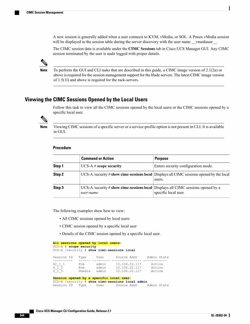
A new session is generally added when a user connects to KVM, vMedia, or SOL. A Pnuos vMedia sessionwill be displayed in the session table during the server discovery with the user name __vmediausr__.
The CIMC session data is available under the CIMC Sessions tab in Cisco UCS Manager GUI. Any CIMCsession terminated by the user is audit logged with proper details.
To perform the GUI and CLI tasks that are described in this guide, a CIMC image version of 2.1(2a) orabove is required for the session management support for the blade servers. The latest CIMC image versionof 1.5(1l) and above is required for the rack-servers.
Note
Viewing the CIMC Sessions Opened by the Local UsersFollow this task to view all the CIMC sessions opened by the local users or the CIMC sessions opened by aspecific local user.
Viewing CIMC sessions of a specific server or a service-profile option is not present in CLI. It is availablein GUI.
Note
Procedure
PurposeCommand or Action
Enters security configuration mode.UCS-A # scope securityStep 1
Displays all CIMC sessions opened by the localusers.
UCS-A /security # show cimc-sessions localStep 2
Displays all CIMC sessions opened by aspecific local user.
UCS-A /security # show cimc-sessions localuser-name
Step 3
The following examples show how to view:
• All CIMC sessions opened by local users
• CIMC session opened by a specific local user
• Details of the CIMC session opened by a specific local user.
All sessions opened by local users:UCS-A # scope securityUCS-A /security # show cimc-sessions local
Session ID Type User Source Addr Admin State---------- ------ --------- --------------- ------------42_1_1 Kvm admin 10.106.22.117 Active4_1_5 Kvm admin 10.106.22.117 Active5_1_5 Vmedia admin 10.106.22.117 Active
Session opened by a specific local user:UCS-A /security # show cimc-sessions local adminSession ID Type User Source Addr Admin State
Cisco UCS Manager CLI Configuration Guide, Release 2.1544 OL-28302-04
CIMC Session Management
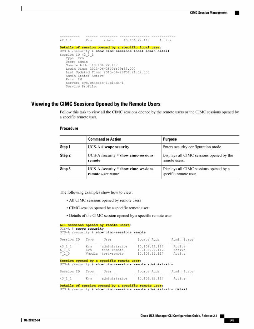
---------- ------ --------- --------------- ------------42_1_1 Kvm admin 10.106.22.117 Active
Details of session opened by a specific local user:UCS-A /security # show cimc-sessions local admin detailSession ID 42_1_1
Type: KvmUser: adminSource Addr: 10.106.22.117Login Time: 2013-06-28T06:09:53.000Last Updated Time: 2013-06-28T06:21:52.000Admin State: ActivePriv: RWServer: sys/chassis-1/blade-1Service Profile:
Viewing the CIMC Sessions Opened by the Remote UsersFollow this task to view all the CIMC sessions opened by the remote users or the CIMC sessions opened bya specific remote user.
Procedure
PurposeCommand or Action
Enters security configuration mode.UCS-A # scope securityStep 1
Displays all CIMC sessions opened by theremote users.
UCS-A /security # show cimc-sessionsremote
Step 2
Displays all CIMC sessions opened by aspecific remote user.
UCS-A /security # show cimc-sessionsremote user-name
Step 3
The following examples show how to view:
• All CIMC sessions opened by remote users
• CIMC session opened by a specific remote user
• Details of the CIMC session opened by a specific remote user.
All sessions opened by remote users:UCS-A # scope securityUCS-A /security # show cimc-sessions remote
Session ID Type User Source Addr Admin State---------- ------ --------- --------------- ------------43_1_1 Kvm administrator 10.106.22.117 Active6_1_5 Kvm test-remote 10.106.22.117 Active7_1_5 Vmedia test-remote 10.106.22.117 Active
Session opened by a specific remote user:UCS-A /security # show cimc-sessions remote administrator
Session ID Type User Source Addr Admin State---------- ------ --------- --------------- ------------43_1_1 Kvm administrator 10.106.22.117 Active
Details of session opened by a specific remote user:UCS-A /security # show cimc-sessions remote administrator detail
Cisco UCS Manager CLI Configuration Guide, Release 2.1 OL-28302-04 545
CIMC Session Management
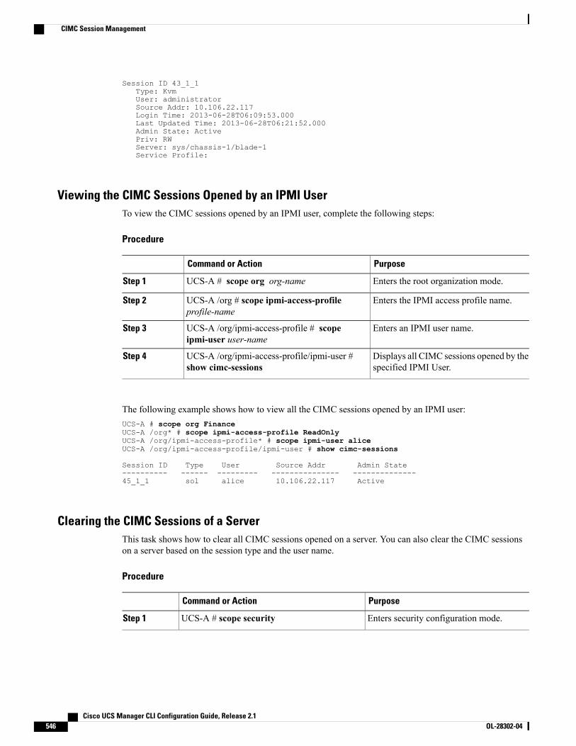
Session ID 43_1_1Type: KvmUser: administratorSource Addr: 10.106.22.117Login Time: 2013-06-28T06:09:53.000Last Updated Time: 2013-06-28T06:21:52.000Admin State: ActivePriv: RWServer: sys/chassis-1/blade-1Service Profile:
Viewing the CIMC Sessions Opened by an IPMI UserTo view the CIMC sessions opened by an IPMI user, complete the following steps:
Procedure
PurposeCommand or Action
Enters the root organization mode.UCS-A # scope org org-nameStep 1
Enters the IPMI access profile name.UCS-A /org # scope ipmi-access-profileprofile-name
Step 2
Enters an IPMI user name.UCS-A /org/ipmi-access-profile # scopeipmi-user user-name
Step 3
Displays all CIMC sessions opened by thespecified IPMI User.
UCS-A /org/ipmi-access-profile/ipmi-user #show cimc-sessions
Step 4
The following example shows how to view all the CIMC sessions opened by an IPMI user:UCS-A # scope org FinanceUCS-A /org* # scope ipmi-access-profile ReadOnlyUCS-A /org/ipmi-access-profile* # scope ipmi-user aliceUCS-A /org/ipmi-access-profile/ipmi-user # show cimc-sessions
Session ID Type User Source Addr Admin State---------- ------ --------- --------------- --------------45_1_1 sol alice 10.106.22.117 Active
Clearing the CIMC Sessions of a ServerThis task shows how to clear all CIMC sessions opened on a server. You can also clear the CIMC sessionson a server based on the session type and the user name.
Procedure
PurposeCommand or Action
Enters security configuration mode.UCS-A # scope securityStep 1
Cisco UCS Manager CLI Configuration Guide, Release 2.1546 OL-28302-04
CIMC Session Management
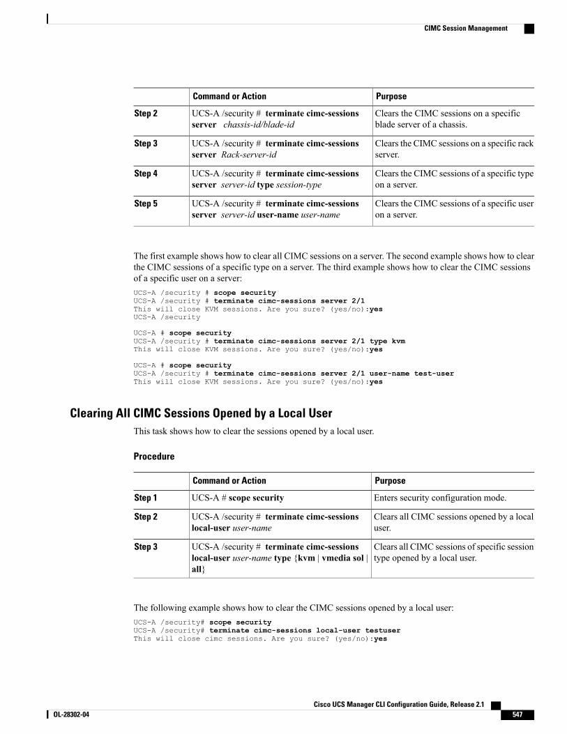
PurposeCommand or Action
Clears the CIMC sessions on a specificblade server of a chassis.
UCS-A /security # terminate cimc-sessionsserver chassis-id/blade-id
Step 2
Clears the CIMC sessions on a specific rackserver.
UCS-A /security # terminate cimc-sessionsserver Rack-server-id
Step 3
Clears the CIMC sessions of a specific typeon a server.
UCS-A /security # terminate cimc-sessionsserver server-id type session-type
Step 4
Clears the CIMC sessions of a specific useron a server.
UCS-A /security # terminate cimc-sessionsserver server-id user-name user-name
Step 5
The first example shows how to clear all CIMC sessions on a server. The second example shows how to clearthe CIMC sessions of a specific type on a server. The third example shows how to clear the CIMC sessionsof a specific user on a server:UCS-A /security # scope securityUCS-A /security # terminate cimc-sessions server 2/1This will close KVM sessions. Are you sure? (yes/no):yesUCS-A /security
UCS-A # scope securityUCS-A /security # terminate cimc-sessions server 2/1 type kvmThis will close KVM sessions. Are you sure? (yes/no):yes
UCS-A # scope securityUCS-A /security # terminate cimc-sessions server 2/1 user-name test-userThis will close KVM sessions. Are you sure? (yes/no):yes
Clearing All CIMC Sessions Opened by a Local UserThis task shows how to clear the sessions opened by a local user.
Procedure
PurposeCommand or Action
Enters security configuration mode.UCS-A # scope securityStep 1
Clears all CIMC sessions opened by a localuser.
UCS-A /security # terminate cimc-sessionslocal-user user-name
Step 2
Clears all CIMC sessions of specific sessiontype opened by a local user.
UCS-A /security # terminate cimc-sessionslocal-user user-name type {kvm | vmedia sol |all}
Step 3
The following example shows how to clear the CIMC sessions opened by a local user:UCS-A /security# scope securityUCS-A /security# terminate cimc-sessions local-user testuserThis will close cimc sessions. Are you sure? (yes/no):yes
Cisco UCS Manager CLI Configuration Guide, Release 2.1 OL-28302-04 547
CIMC Session Management
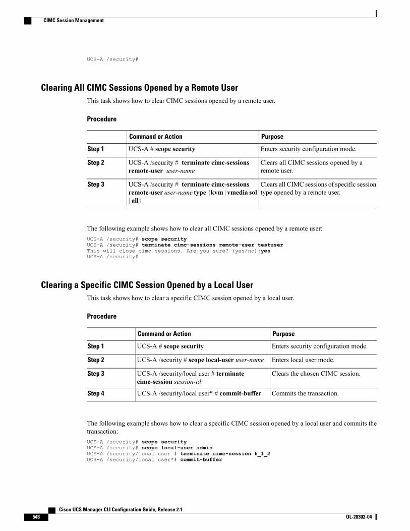
UCS-A /security#
Clearing All CIMC Sessions Opened by a Remote UserThis task shows how to clear CIMC sessions opened by a remote user.
Procedure
PurposeCommand or Action
Enters security configuration mode.UCS-A # scope securityStep 1
Clears all CIMC sessions opened by aremote user.
UCS-A /security # terminate cimc-sessionsremote-user user-name
Step 2
Clears all CIMC sessions of specific sessiontype opened by a remote user.
UCS-A /security # terminate cimc-sessionsremote-user user-name type {kvm | vmedia sol| all}
Step 3
The following example shows how to clear all CIMC sessions opened by a remote user:UCS-A /security# scope securityUCS-A /security# terminate cimc-sessions remote-user testuserThis will close cimc sessions. Are you sure? (yes/no):yesUCS-A /security#
Clearing a Specific CIMC Session Opened by a Local UserThis task shows how to clear a specific CIMC session opened by a local user.
Procedure
PurposeCommand or Action
Enters security configuration mode.UCS-A # scope securityStep 1
Enters local user mode.UCS-A /security # scope local-user user-nameStep 2
Clears the chosen CIMC session.UCS-A /security/local user # terminatecimc-session session-id
Step 3
Commits the transaction.UCS-A /security/local user* # commit-bufferStep 4
The following example shows how to clear a specific CIMC session opened by a local user and commits thetransaction:UCS-A /security# scope securityUCS-A /security# scope local-user adminUCS-A /security/local user # terminate cimc-session 6_1_2UCS-A /security/local user*# commit-buffer
Cisco UCS Manager CLI Configuration Guide, Release 2.1548 OL-28302-04
CIMC Session Management
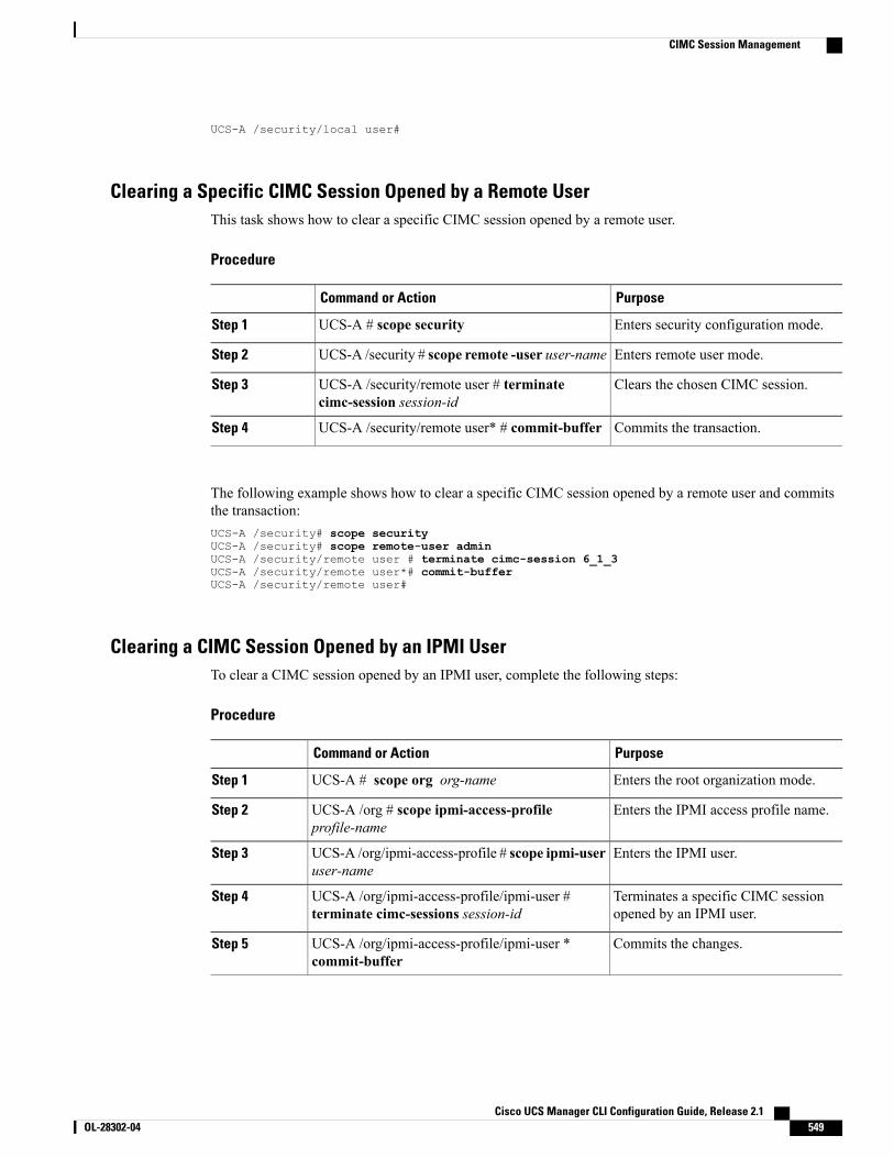
UCS-A /security/local user#
Clearing a Specific CIMC Session Opened by a Remote UserThis task shows how to clear a specific CIMC session opened by a remote user.
Procedure
PurposeCommand or Action
Enters security configuration mode.UCS-A # scope securityStep 1
Enters remote user mode.UCS-A /security # scope remote -user user-nameStep 2
Clears the chosen CIMC session.UCS-A /security/remote user # terminatecimc-session session-id
Step 3
Commits the transaction.UCS-A /security/remote user* # commit-bufferStep 4
The following example shows how to clear a specific CIMC session opened by a remote user and commitsthe transaction:UCS-A /security# scope securityUCS-A /security# scope remote-user adminUCS-A /security/remote user # terminate cimc-session 6_1_3UCS-A /security/remote user*# commit-bufferUCS-A /security/remote user#
Clearing a CIMC Session Opened by an IPMI UserTo clear a CIMC session opened by an IPMI user, complete the following steps:
Procedure
PurposeCommand or Action
Enters the root organization mode.UCS-A # scope org org-nameStep 1
Enters the IPMI access profile name.UCS-A /org # scope ipmi-access-profileprofile-name
Step 2
Enters the IPMI user.UCS-A /org/ipmi-access-profile # scope ipmi-useruser-name
Step 3
Terminates a specific CIMC sessionopened by an IPMI user.
UCS-A /org/ipmi-access-profile/ipmi-user #terminate cimc-sessions session-id
Step 4
Commits the changes.UCS-A /org/ipmi-access-profile/ipmi-user *commit-buffer
Step 5
Cisco UCS Manager CLI Configuration Guide, Release 2.1 OL-28302-04 549
CIMC Session Management
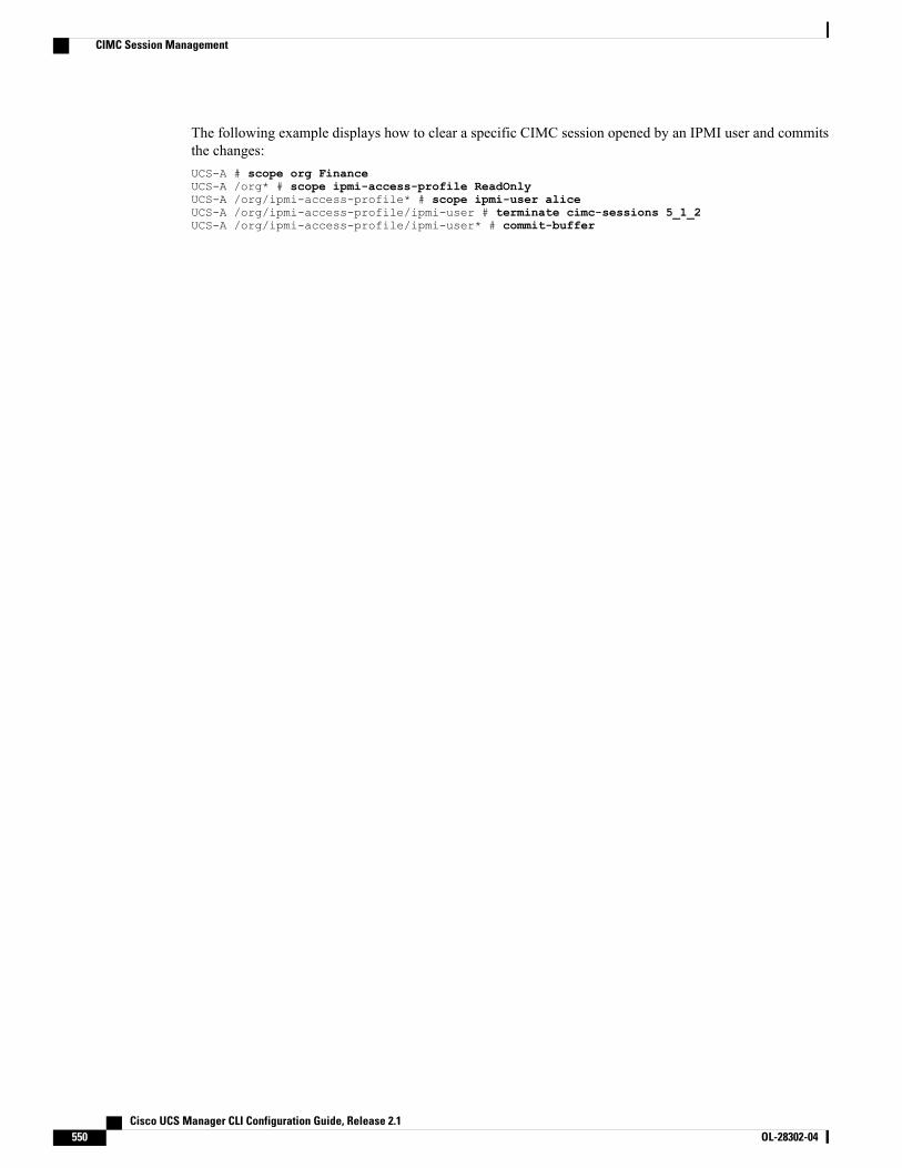
The following example displays how to clear a specific CIMC session opened by an IPMI user and commitsthe changes:UCS-A # scope org FinanceUCS-A /org* # scope ipmi-access-profile ReadOnlyUCS-A /org/ipmi-access-profile* # scope ipmi-user aliceUCS-A /org/ipmi-access-profile/ipmi-user # terminate cimc-sessions 5_1_2UCS-A /org/ipmi-access-profile/ipmi-user* # commit-buffer
Cisco UCS Manager CLI Configuration Guide, Release 2.1550 OL-28302-04
CIMC Session Management
C H A P T E R 40Managing the I/O Modules
This chapter includes the following sections:
• I/O Module Management in Cisco UCS Manager GUI , page 551
• Resetting the I/O Module, page 551
I/O Module Management in Cisco UCS Manager GUIYou can manage and monitor all I/O modules in a Cisco UCS domain through Cisco UCS Manager GUI.
Resetting the I/O Module
Procedure
PurposeCommand or Action
Enters chassis mode for the specified chassis.UCS-A# scope chassis chassis-numStep 1
Enters chassis IOM mode for the specifiedIOM.
UCS-A /chassis # scope iom {a b}Step 2
Resets the IOM.UCS-A /chassis/iom # resetStep 3
Commits the transaction to the systemconfiguration.
UCS-A /chassis/iom # commit-bufferStep 4
The following example resets the IOM on fabric A and commits the transaction:UCS-A# scope chassis 1UCS-A /chassis # scope iom aUCS-A /chassis/iom # resetUCS-A /chassis/iom* # commit-bufferUCS-A /chassis/iom #
Cisco UCS Manager CLI Configuration Guide, Release 2.1 OL-28302-04 551

Cisco UCS Manager CLI Configuration Guide, Release 2.1552 OL-28302-04
Resetting the I/O Module

C H A P T E R 41Backing Up and Restoring the Configuration
This chapter includes the following sections:
• Backup and Export Configuration, page 553
• Backup Types, page 553
• Considerations and Recommendations for Backup Operations, page 554
• Import Configuration, page 555
• Import Methods, page 556
• System Restore, page 556
• Required User Role for Backup and Import Operations, page 556
• Configuring Backup Operations, page 557
• Configuring Scheduled Backups, page 561
• Configuring Import Operations, page 564
• Restoring the Configuration for a Fabric Interconnect, page 568
• Erasing the Configuration, page 570
Backup and Export ConfigurationWhen you perform a backup through Cisco UCS Manager, you take a snapshot of all or part of the systemconfiguration and export the file to a location on your network. You cannot use Cisco UCS Manager to backup data on the servers.
You can perform a backup while the system is up and running. The backup operation only saves informationfrom the management plane. It does not have any impact on the server or network traffic.
Backup TypesYou can perform one or more of the following types of backups through Cisco UCS Central:
Cisco UCS Manager CLI Configuration Guide, Release 2.1 OL-28302-04 553
• Full state—A binary file that includes a snapshot of the entire system. You can use the file generatedfrom this backup to restore the system during disaster recovery. This file can restore or rebuild theconfiguration on the original fabric interconnect, or recreate the configuration on a different fabricinterconnect. You cannot use this file for an import.
You can only use a full state backup file to restore a system that is running the sameversion as the system from which the backup file was exported.
Note
• All configuration—An XML file that includes all system and logical configuration settings. You canuse the file generated from this backup to import these configuration settings to the original fabricinterconnect or to a different fabric interconnect. You cannot use this file for a system restore. This filedoes not include passwords for locally authenticated users.
• System configuration—AnXML file that includes all system configuration settings such as usernames,roles, and locales. You can use the file generated from this backup to import these configuration settingsto the original fabric interconnect or to a different fabric interconnect. You cannot use this file for asystem restore.
• Logical configuration—An XML file that includes all logical configuration settings such as serviceprofiles, VLANs, VSANs, pools, and policies. You can use the file generated from this backup to importthese configuration settings to the original fabric interconnect or to a different fabric interconnect. Youcannot use this file for a system restore.
Considerations and Recommendations for Backup OperationsBefore you create a backup operation, consider the following:
Backup Locations
The backup location is the destination or folder on the network where you want Cisco UCS Managerto export the backup file. You can maintain only one backup operation for each location where youplan to save a backup file.
Potential to Overwrite Backup Files
If you rerun a backup operation without changing the filename, Cisco UCS Manager overwrites theexisting file on the server. To avoid overwriting existing backup files, change the filename in the backupoperation or copy the existing file to another location.
Multiple Types of Backups
You can run and export more than one type of backup to the same location. You need to change thebackup type before you rerun the backup operation. We recommend that you change the filename foreasier identification of the backup type and to avoid overwriting the existing backup file.
Scheduled Backups
You can create a backup operation in advance and leave the admin state disabled until you are readyto run the backup. Cisco UCS Manager does not run the backup operation, save, or export theconfiguration file until you set the admin state of the backup operation to enabled.
Cisco UCS Manager CLI Configuration Guide, Release 2.1554 OL-28302-04
Considerations and Recommendations for Backup Operations
Incremental Backups
You cannot perform incremental backups of Cisco UCS Manager.
Encryption of Full State Backups
Full state backups are encrypted so that passwords and other sensitive information are not exported asclear text.
Scheduled BackupsYou can configure policies in Cisco UCS to schedule the following types of backups:
• Full state
• All configuration
You cannot schedule any other type of backup.
Full State Backup Policy
The full state backup policy allows you to schedule regular full state backups of a snapshot of the entiresystem. You can choose whether to configure the full state backup to occur on a daily, weekly, or biweeklybasis.
Cisco UCS Manager maintains a maximum number of backup files on the remote server. The maxfilesparameter is used when Cisco UCS Manager is registered with Cisco UCS Central. The maxfiles parameteris user configurable on Cisco UCS Central and controls the number of backup files stored on Cisco UCSCentral.
If Cisco UCS Manager is not registered with Cisco UCS Central, and the user is storing backup files on aremote backup server, the backup files are not managed by Cisco UCS Manager. The remote machine serveradministrator must monitor the disk usage and rotate the backup files to create space for new backup files.
All Configuration Export Policy
The all configuration backup policy allows you to schedule a regular backup and export of all system andlogical configuration settings. This backup does not include passwords for locally authenticated users. Youcan choose whether to configure the all configuration backup to occur on a daily, weekly, or bi-weekly basis.
Cisco UCSmaintains a maximum number of backup files on the remote server.When that number is exceeded,Cisco UCS overwrites the oldest backup file.
Import ConfigurationYou can import any configuration file that was exported from Cisco UCS. The file does not need to have beenexported from the same Cisco UCS.
The import function is available for all configuration, system configuration, and logical configuration files.You can perform an import while the system is up and running. An import operation modifies informationon the management plane only. Some modifications caused by an import operation, such as a change to avNIC assigned to a server, can cause a server reboot or other operations that disrupt traffic.
Cisco UCS Manager CLI Configuration Guide, Release 2.1 OL-28302-04 555
Import Configuration
You cannot schedule an import operation. You can, however, create an import operation in advance and leavethe admin state disabled until you are ready to run the import.Cisco UCS will not run the import operation onthe configuration file until you set the admin state to enabled.
You can maintain only one import operation for each location where you saved a configuration backup file.
When you import configuration from Release 2.1(1) or later to an earlier release, the server firmware maybe upgraded or downgraded automatically when the corresponding service profiles use the default hostfirmware pack. You can, however, modify the Service Profiles to use non-default host firmware beforeyou import the configuration.
Important
Import MethodsYou can use one of the following methods to import and update a system configuration through Cisco UCS:
•Merge—The information in the imported configuration file is compared with the existing configurationinformation. If there are conflicts, the import operation overwrites the information on the Cisco UCSdomain with the information in the import configuration file.
• Replace—The current configuration information is replaced with the information in the importedconfiguration file one object at a time.
System RestoreYou can use the restore function for disaster recovery.
You can restore a system configuration from any full state backup file that was exported from Cisco UCS.The file does not need to have been exported from Cisco UCS on the system that you are restoring. Whenrestoring using a backup file that was exported from a different system, we strongly recommend that you usea system with the same or similar system configuration and hardware, including fabric interconnects, servers,adapters, and I/O module or FEX connectivity. Mismatched hardware and/or system configuration can leadto the restored system not fully functioning. If there is a mismatch between the I/O module links or serverson the two systems, acknowledge the chassis and/or servers after the restore operation.
The restore function is only available for a full state backup file. You cannot import a full state backup file.You perform a restore through the initial system setup.
You can only use a full state backup file to restore a system that is running the same version as the systemfrom which the backup file was exported.
Note
Required User Role for Backup and Import OperationsYou must have a user account that includes the admin role to create and run backup and import operations.
Cisco UCS Manager CLI Configuration Guide, Release 2.1556 OL-28302-04
Import Methods
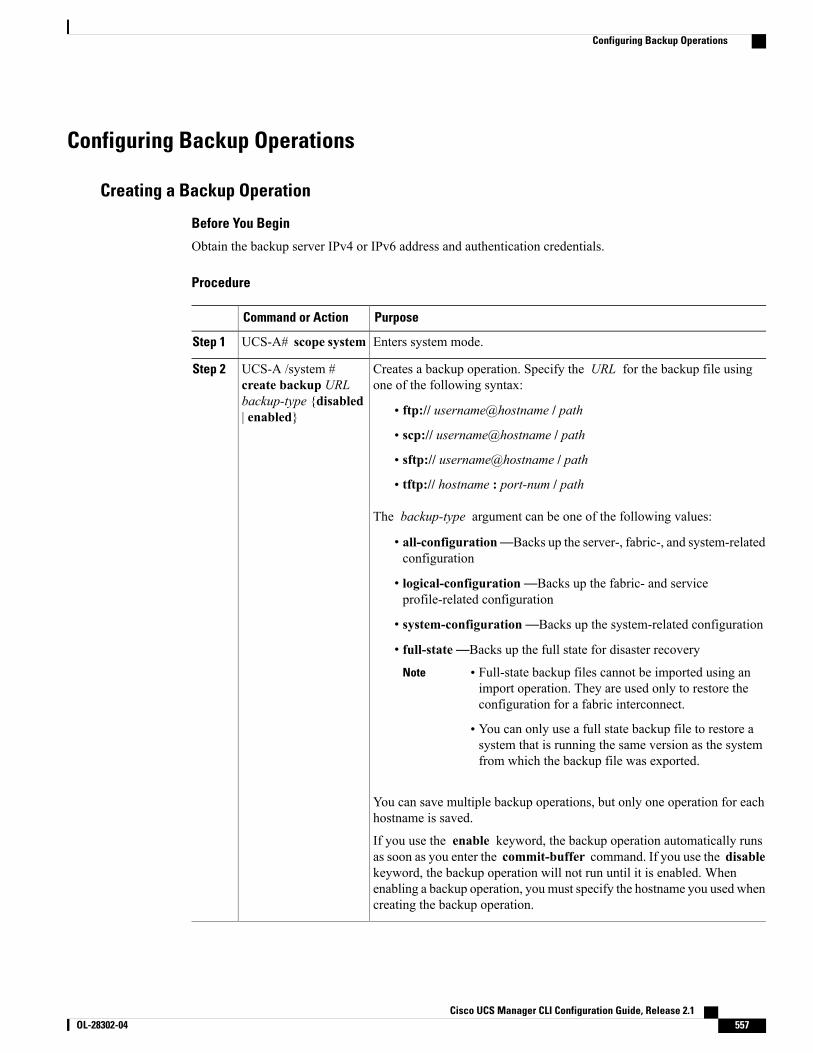
Configuring Backup Operations
Creating a Backup Operation
Before You Begin
Obtain the backup server IPv4 or IPv6 address and authentication credentials.
Procedure
PurposeCommand or Action
Enters system mode.UCS-A# scope systemStep 1
Creates a backup operation. Specify the URL for the backup file usingone of the following syntax:
UCS-A /system #create backup URL
Step 2
backup-type {disabled| enabled} • ftp:// username@hostname / path
• scp:// username@hostname / path
• sftp:// username@hostname / path
• tftp:// hostname : port-num / path
The backup-type argument can be one of the following values:
• all-configuration—Backs up the server-, fabric-, and system-relatedconfiguration
• logical-configuration—Backs up the fabric- and serviceprofile-related configuration
• system-configuration—Backs up the system-related configuration
• full-state—Backs up the full state for disaster recovery
Note • Full-state backup files cannot be imported using animport operation. They are used only to restore theconfiguration for a fabric interconnect.
• You can only use a full state backup file to restore asystem that is running the same version as the systemfrom which the backup file was exported.
You can save multiple backup operations, but only one operation for eachhostname is saved.
If you use the enable keyword, the backup operation automatically runsas soon as you enter the commit-buffer command. If you use the disablekeyword, the backup operation will not run until it is enabled. Whenenabling a backup operation, youmust specify the hostname you used whencreating the backup operation.
Cisco UCS Manager CLI Configuration Guide, Release 2.1 OL-28302-04 557
Configuring Backup Operations
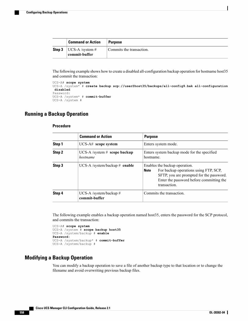
PurposeCommand or Action
Commits the transaction.UCS-A /system #commit-buffer
Step 3
The following example shows how to create a disabled all-configuration backup operation for hostname host35and commit the transaction:UCS-A# scope systemUCS-A /system* # create backup scp://user@host35/backups/all-config9.bak all-configurationdisabledPassword:UCS-A /system* # commit-bufferUCS-A /system #
Running a Backup Operation
Procedure
PurposeCommand or Action
Enters system mode.UCS-A# scope systemStep 1
Enters system backup mode for the specifiedhostname.
UCS-A /system # scope backuphostname
Step 2
Enables the backup operation.For backup operations using FTP, SCP,SFTP, you are prompted for the password.Enter the password before committing thetransaction.
NoteUCS-A /system/backup # enableStep 3
Commits the transaction.UCS-A /system/backup #commit-buffer
Step 4
The following example enables a backup operation named host35, enters the password for the SCP protocol,and commits the transaction:UCS-A# scope systemUCS-A /system # scope backup host35UCS-A /system/backup # enablePassword:UCS-A /system/backup* # commit-bufferUCS-A /system/backup #
Modifying a Backup OperationYou can modify a backup operation to save a file of another backup type to that location or to change thefilename and avoid overwriting previous backup files.
Cisco UCS Manager CLI Configuration Guide, Release 2.1558 OL-28302-04
Configuring Backup Operations
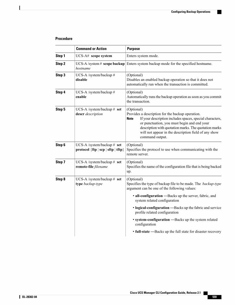
Procedure
PurposeCommand or Action
Enters system mode.UCS-A# scope systemStep 1
Enters system backup mode for the specified hostname.UCS-A /system # scope backuphostname
Step 2
(Optional)Disables an enabled backup operation so that it does notautomatically run when the transaction is committed.
UCS-A /system/backup #disable
Step 3
(Optional)Automatically runs the backup operation as soon as you committhe transaction.
UCS-A /system/backup #enable
Step 4
(Optional)Provides a description for the backup operation.
If your description includes spaces, special characters,or punctuation, you must begin and end yourdescriptionwith quotationmarks. The quotationmarkswill not appear in the description field of any showcommand output.
Note
UCS-A /system/backup # setdescr description
Step 5
(Optional)Specifies the protocol to use when communicating with theremote server.
UCS-A /system/backup # setprotocol {ftp | scp | sftp | tftp}
Step 6
(Optional)Specifies the name of the configuration file that is being backedup.
UCS-A /system/backup # setremote-file filename
Step 7
(Optional)Specifies the type of backup file to be made. The backup-typeargument can be one of the following values:
UCS-A /system/backup # settype backup-type
Step 8
• all-configuration—Backs up the server, fabric, andsystem related configuration
• logical-configuration—Backs up the fabric and serviceprofile related configuration
• system-configuration—Backs up the system relatedconfiguration
• full-state—Backs up the full state for disaster recovery
Cisco UCS Manager CLI Configuration Guide, Release 2.1 OL-28302-04 559
Configuring Backup Operations
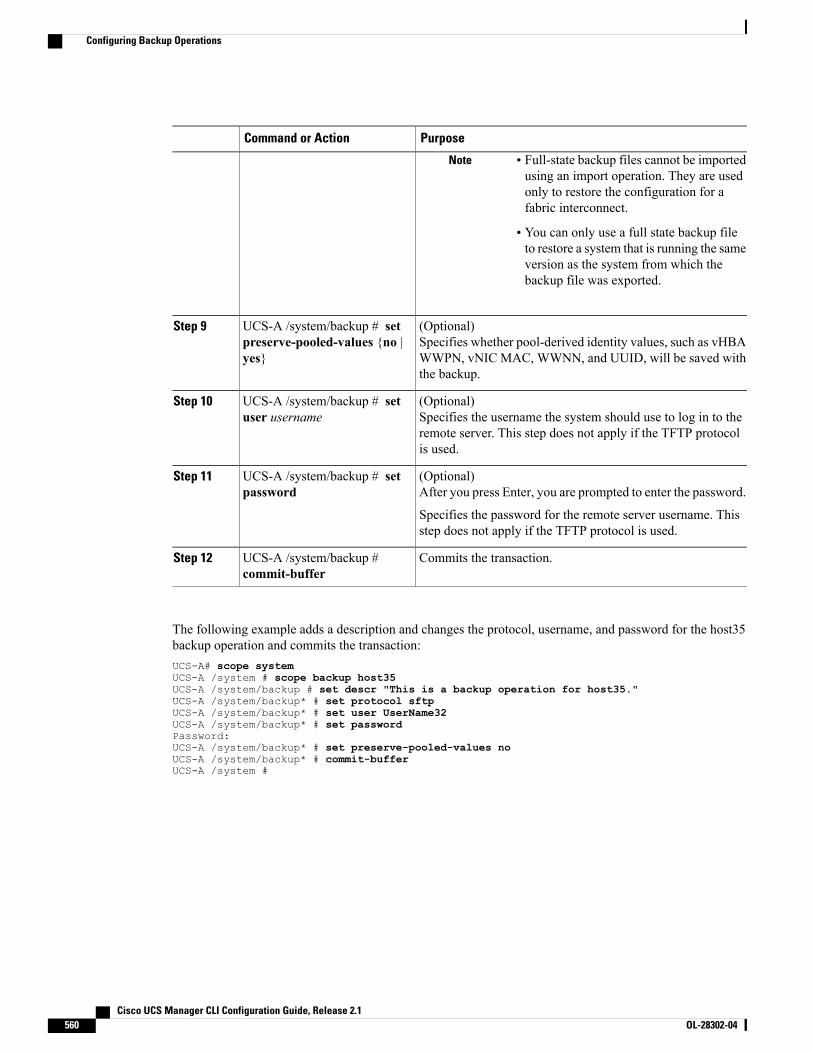
PurposeCommand or Action
Note • Full-state backup files cannot be importedusing an import operation. They are usedonly to restore the configuration for afabric interconnect.
• You can only use a full state backup fileto restore a system that is running the sameversion as the system from which thebackup file was exported.
(Optional)Specifies whether pool-derived identity values, such as vHBAWWPN, vNIC MAC, WWNN, and UUID, will be saved withthe backup.
UCS-A /system/backup # setpreserve-pooled-values {no |yes}
Step 9
(Optional)Specifies the username the system should use to log in to theremote server. This step does not apply if the TFTP protocolis used.
UCS-A /system/backup # setuser username
Step 10
(Optional)After you press Enter, you are prompted to enter the password.
UCS-A /system/backup # setpassword
Step 11
Specifies the password for the remote server username. Thisstep does not apply if the TFTP protocol is used.
Commits the transaction.UCS-A /system/backup #commit-buffer
Step 12
The following example adds a description and changes the protocol, username, and password for the host35backup operation and commits the transaction:UCS-A# scope systemUCS-A /system # scope backup host35UCS-A /system/backup # set descr "This is a backup operation for host35."UCS-A /system/backup* # set protocol sftpUCS-A /system/backup* # set user UserName32UCS-A /system/backup* # set passwordPassword:UCS-A /system/backup* # set preserve-pooled-values noUCS-A /system/backup* # commit-bufferUCS-A /system #
Cisco UCS Manager CLI Configuration Guide, Release 2.1560 OL-28302-04
Configuring Backup Operations
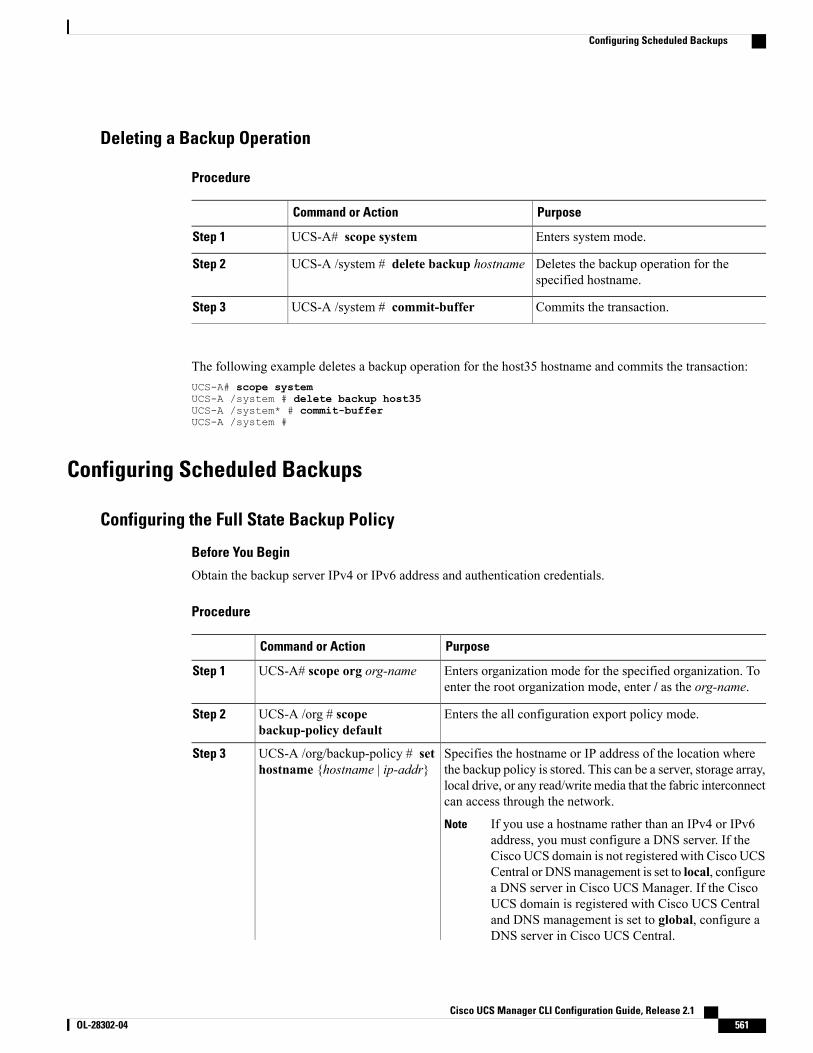
Deleting a Backup Operation
Procedure
PurposeCommand or Action
Enters system mode.UCS-A# scope systemStep 1
Deletes the backup operation for thespecified hostname.
UCS-A /system # delete backup hostnameStep 2
Commits the transaction.UCS-A /system # commit-bufferStep 3
The following example deletes a backup operation for the host35 hostname and commits the transaction:UCS-A# scope systemUCS-A /system # delete backup host35UCS-A /system* # commit-bufferUCS-A /system #
Configuring Scheduled Backups
Configuring the Full State Backup Policy
Before You Begin
Obtain the backup server IPv4 or IPv6 address and authentication credentials.
Procedure
PurposeCommand or Action
Enters organization mode for the specified organization. Toenter the root organization mode, enter / as the org-name.
UCS-A# scope org org-nameStep 1
Enters the all configuration export policy mode.UCS-A /org # scopebackup-policy default
Step 2
Specifies the hostname or IP address of the location wherethe backup policy is stored. This can be a server, storage array,
UCS-A /org/backup-policy # sethostname {hostname | ip-addr}
Step 3
local drive, or any read/write media that the fabric interconnectcan access through the network.
If you use a hostname rather than an IPv4 or IPv6address, you must configure a DNS server. If theCisco UCS domain is not registered with Cisco UCSCentral or DNSmanagement is set to local, configurea DNS server in Cisco UCS Manager. If the CiscoUCS domain is registered with Cisco UCS Centraland DNS management is set to global, configure aDNS server in Cisco UCS Central.
Note
Cisco UCS Manager CLI Configuration Guide, Release 2.1 OL-28302-04 561
Configuring Scheduled Backups
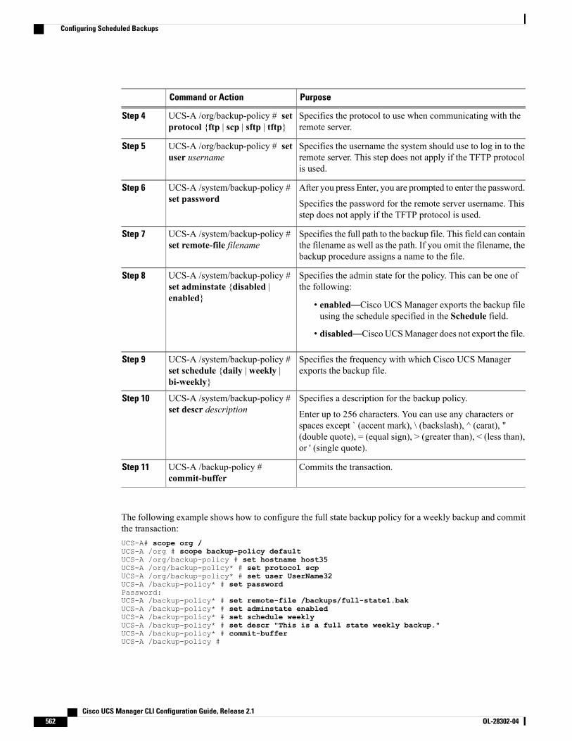
PurposeCommand or Action
Specifies the protocol to use when communicating with theremote server.
UCS-A /org/backup-policy # setprotocol {ftp | scp | sftp | tftp}
Step 4
Specifies the username the system should use to log in to theremote server. This step does not apply if the TFTP protocolis used.
UCS-A /org/backup-policy # setuser username
Step 5
After you press Enter, you are prompted to enter the password.UCS-A /system/backup-policy #set password
Step 6
Specifies the password for the remote server username. Thisstep does not apply if the TFTP protocol is used.
Specifies the full path to the backup file. This field can containthe filename as well as the path. If you omit the filename, thebackup procedure assigns a name to the file.
UCS-A /system/backup-policy #set remote-file filename
Step 7
Specifies the admin state for the policy. This can be one ofthe following:
UCS-A /system/backup-policy #set adminstate {disabled |enabled}
Step 8
• enabled—Cisco UCS Manager exports the backup fileusing the schedule specified in the Schedule field.
• disabled—Cisco UCSManager does not export the file.
Specifies the frequency with which Cisco UCS Managerexports the backup file.
UCS-A /system/backup-policy #set schedule {daily | weekly |bi-weekly}
Step 9
Specifies a description for the backup policy.UCS-A /system/backup-policy #set descr description
Step 10
Enter up to 256 characters. You can use any characters orspaces except ` (accent mark), \ (backslash), ^ (carat), "(double quote), = (equal sign), > (greater than), < (less than),or ' (single quote).
Commits the transaction.UCS-A /backup-policy #commit-buffer
Step 11
The following example shows how to configure the full state backup policy for a weekly backup and committhe transaction:UCS-A# scope org /UCS-A /org # scope backup-policy defaultUCS-A /org/backup-policy # set hostname host35UCS-A /org/backup-policy* # set protocol scpUCS-A /org/backup-policy* # set user UserName32UCS-A /backup-policy* # set passwordPassword:UCS-A /backup-policy* # set remote-file /backups/full-state1.bakUCS-A /backup-policy* # set adminstate enabledUCS-A /backup-policy* # set schedule weeklyUCS-A /backup-policy* # set descr "This is a full state weekly backup."UCS-A /backup-policy* # commit-bufferUCS-A /backup-policy #
Cisco UCS Manager CLI Configuration Guide, Release 2.1562 OL-28302-04
Configuring Scheduled Backups
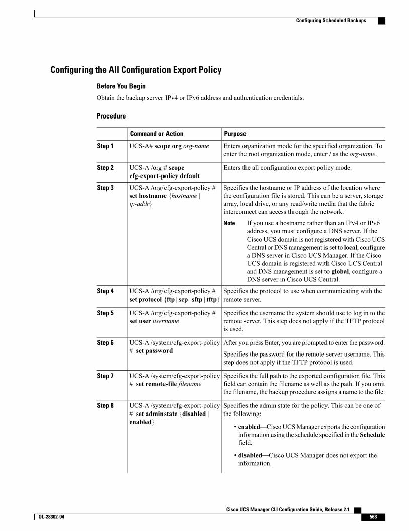
Configuring the All Configuration Export Policy
Before You Begin
Obtain the backup server IPv4 or IPv6 address and authentication credentials.
Procedure
PurposeCommand or Action
Enters organization mode for the specified organization. Toenter the root organization mode, enter / as the org-name.
UCS-A# scope org org-nameStep 1
Enters the all configuration export policy mode.UCS-A /org # scopecfg-export-policy default
Step 2
Specifies the hostname or IP address of the location wherethe configuration file is stored. This can be a server, storage
UCS-A /org/cfg-export-policy #set hostname {hostname |ip-addr}
Step 3
array, local drive, or any read/write media that the fabricinterconnect can access through the network.
If you use a hostname rather than an IPv4 or IPv6address, you must configure a DNS server. If theCisco UCS domain is not registered with Cisco UCSCentral or DNSmanagement is set to local, configurea DNS server in Cisco UCS Manager. If the CiscoUCS domain is registered with Cisco UCS Centraland DNS management is set to global, configure aDNS server in Cisco UCS Central.
Note
Specifies the protocol to use when communicating with theremote server.
UCS-A /org/cfg-export-policy #set protocol {ftp | scp | sftp | tftp}
Step 4
Specifies the username the system should use to log in to theremote server. This step does not apply if the TFTP protocolis used.
UCS-A /org/cfg-export-policy #set user username
Step 5
After you press Enter, you are prompted to enter the password.UCS-A /system/cfg-export-policy# set password
Step 6
Specifies the password for the remote server username. Thisstep does not apply if the TFTP protocol is used.
Specifies the full path to the exported configuration file. Thisfield can contain the filename as well as the path. If you omitthe filename, the backup procedure assigns a name to the file.
UCS-A /system/cfg-export-policy# set remote-file filename
Step 7
Specifies the admin state for the policy. This can be one ofthe following:
UCS-A /system/cfg-export-policy# set adminstate {disabled |enabled}
Step 8
• enabled—CiscoUCSManager exports the configurationinformation using the schedule specified in the Schedulefield.
• disabled—Cisco UCS Manager does not export theinformation.
Cisco UCS Manager CLI Configuration Guide, Release 2.1 OL-28302-04 563
Configuring Scheduled Backups
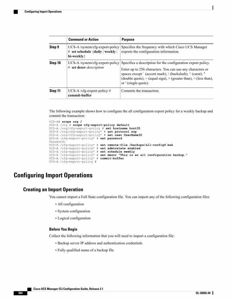
PurposeCommand or Action
Specifies the frequency with which Cisco UCS Managerexports the configuration information.
UCS-A /system/cfg-export-policy# set schedule {daily | weekly |bi-weekly}
Step 9
Specifies a description for the configuration export policy.UCS-A /system/cfg-export-policy# set descr description
Step 10
Enter up to 256 characters. You can use any characters orspaces except ` (accent mark), \ (backslash), ^ (carat), "(double quote), = (equal sign), > (greater than), < (less than),or ' (single quote).
Commits the transaction.UCS-A /cfg-export-policy #commit-buffer
Step 11
The following example shows how to configure the all configuration export policy for a weekly backup andcommit the transaction:UCS-A# scope org /UCS-A /org # scope cfg-export-policy defaultUCS-A /org/cfg-export-policy # set hostname host35UCS-A /org/cfg-export-policy* # set protocol scpUCS-A /org/cfg-export-policy* # set user UserName32UCS-A /cfg-export-policy* # set passwordPassword:UCS-A /cfg-export-policy* # set remote-file /backups/all-config9.bakUCS-A /cfg-export-policy* # set adminstate enabledUCS-A /cfg-export-policy* # set schedule weeklyUCS-A /cfg-export-policy* # set descr "This is an all configuration backup."UCS-A /cfg-export-policy* # commit-bufferUCS-A /cfg-export-policy #
Configuring Import Operations
Creating an Import OperationYou cannot import a Full State configuration file. You can import any of the following configuration files:
• All configuration
• System configuration
• Logical configuration
Before You Begin
Collect the following information that you will need to import a configuration file:
• Backup server IP address and authentication credentials
• Fully qualified name of a backup file
Cisco UCS Manager CLI Configuration Guide, Release 2.1564 OL-28302-04
Configuring Import Operations
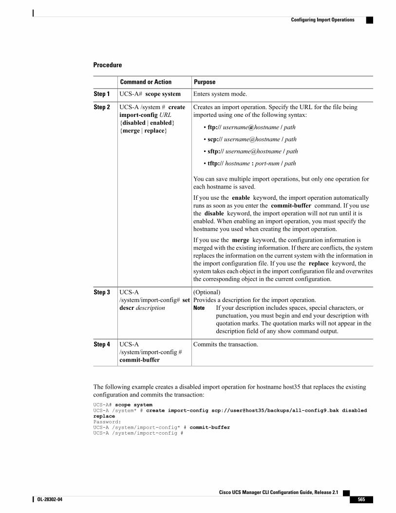
Procedure
PurposeCommand or Action
Enters system mode.UCS-A# scope systemStep 1
Creates an import operation. Specify the URL for the file beingimported using one of the following syntax:
UCS-A /system # createimport-config URL
Step 2
{disabled | enabled}{merge | replace} • ftp:// username@hostname / path
• scp:// username@hostname / path
• sftp:// username@hostname / path
• tftp:// hostname : port-num / path
You can save multiple import operations, but only one operation foreach hostname is saved.
If you use the enable keyword, the import operation automaticallyruns as soon as you enter the commit-buffer command. If you usethe disable keyword, the import operation will not run until it isenabled. When enabling an import operation, you must specify thehostname you used when creating the import operation.
If you use the merge keyword, the configuration information ismerged with the existing information. If there are conflicts, the systemreplaces the information on the current system with the information inthe import configuration file. If you use the replace keyword, thesystem takes each object in the import configuration file and overwritesthe corresponding object in the current configuration.
(Optional)Provides a description for the import operation.
If your description includes spaces, special characters, orpunctuation, you must begin and end your description withquotation marks. The quotation marks will not appear in thedescription field of any show command output.
Note
UCS-A/system/import-config# setdescr description
Step 3
Commits the transaction.UCS-A/system/import-config #commit-buffer
Step 4
The following example creates a disabled import operation for hostname host35 that replaces the existingconfiguration and commits the transaction:UCS-A# scope systemUCS-A /system* # create import-config scp://user@host35/backups/all-config9.bak disabledreplacePassword:UCS-A /system/import-config* # commit-bufferUCS-A /system/import-config #
Cisco UCS Manager CLI Configuration Guide, Release 2.1 OL-28302-04 565
Configuring Import Operations
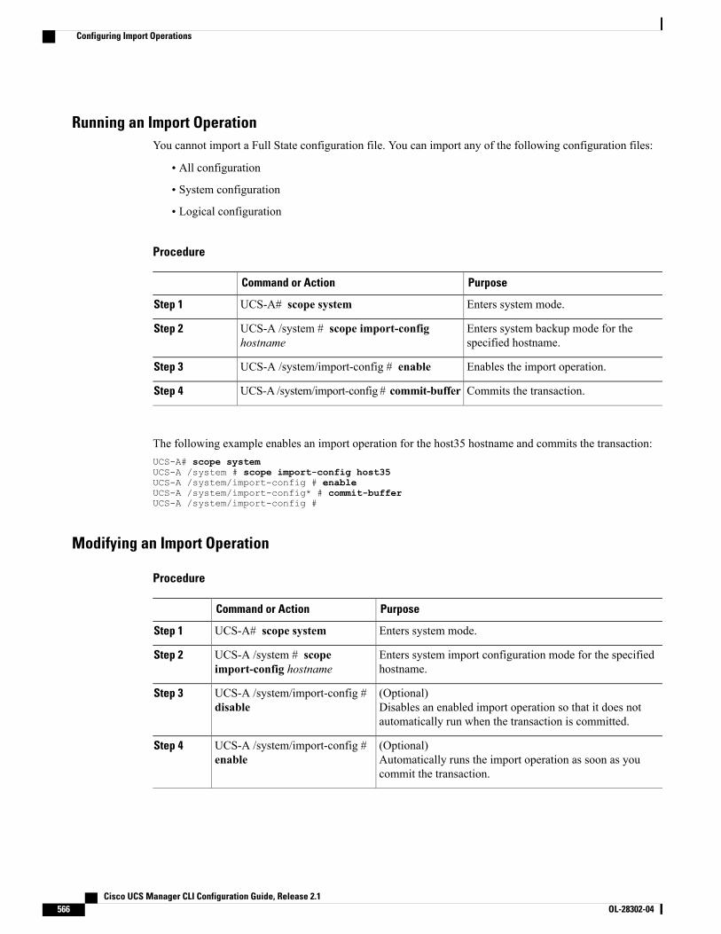
Running an Import OperationYou cannot import a Full State configuration file. You can import any of the following configuration files:
• All configuration
• System configuration
• Logical configuration
Procedure
PurposeCommand or Action
Enters system mode.UCS-A# scope systemStep 1
Enters system backup mode for thespecified hostname.
UCS-A /system # scope import-confighostname
Step 2
Enables the import operation.UCS-A /system/import-config # enableStep 3
Commits the transaction.UCS-A /system/import-config # commit-bufferStep 4
The following example enables an import operation for the host35 hostname and commits the transaction:UCS-A# scope systemUCS-A /system # scope import-config host35UCS-A /system/import-config # enableUCS-A /system/import-config* # commit-bufferUCS-A /system/import-config #
Modifying an Import Operation
Procedure
PurposeCommand or Action
Enters system mode.UCS-A# scope systemStep 1
Enters system import configuration mode for the specifiedhostname.
UCS-A /system # scopeimport-config hostname
Step 2
(Optional)Disables an enabled import operation so that it does notautomatically run when the transaction is committed.
UCS-A /system/import-config #disable
Step 3
(Optional)Automatically runs the import operation as soon as youcommit the transaction.
UCS-A /system/import-config #enable
Step 4
Cisco UCS Manager CLI Configuration Guide, Release 2.1566 OL-28302-04
Configuring Import Operations
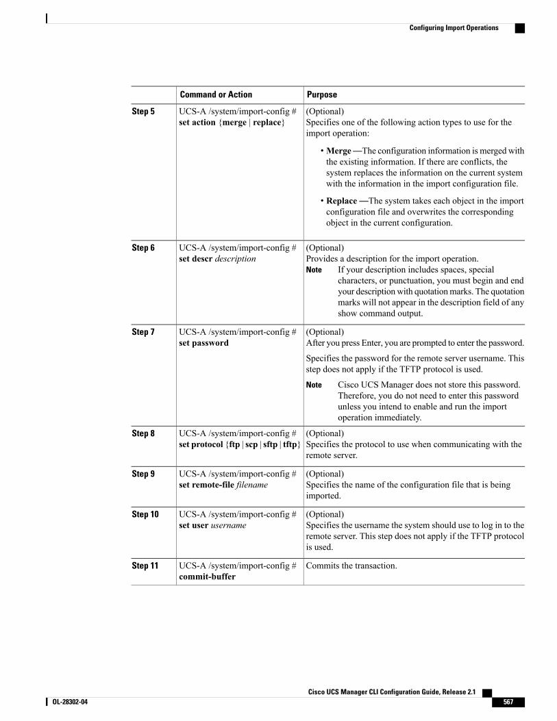
PurposeCommand or Action
(Optional)Specifies one of the following action types to use for theimport operation:
UCS-A /system/import-config #set action {merge | replace}
Step 5
•Merge—The configuration information is merged withthe existing information. If there are conflicts, thesystem replaces the information on the current systemwith the information in the import configuration file.
• Replace—The system takes each object in the importconfiguration file and overwrites the correspondingobject in the current configuration.
(Optional)Provides a description for the import operation.
If your description includes spaces, specialcharacters, or punctuation, you must begin and endyour descriptionwith quotationmarks. The quotationmarks will not appear in the description field of anyshow command output.
Note
UCS-A /system/import-config #set descr description
Step 6
(Optional)After you press Enter, you are prompted to enter the password.
UCS-A /system/import-config #set password
Step 7
Specifies the password for the remote server username. Thisstep does not apply if the TFTP protocol is used.
Cisco UCS Manager does not store this password.Therefore, you do not need to enter this passwordunless you intend to enable and run the importoperation immediately.
Note
(Optional)Specifies the protocol to use when communicating with theremote server.
UCS-A /system/import-config #set protocol {ftp | scp | sftp | tftp}
Step 8
(Optional)Specifies the name of the configuration file that is beingimported.
UCS-A /system/import-config #set remote-file filename
Step 9
(Optional)Specifies the username the system should use to log in to theremote server. This step does not apply if the TFTP protocolis used.
UCS-A /system/import-config #set user username
Step 10
Commits the transaction.UCS-A /system/import-config #commit-buffer
Step 11
Cisco UCS Manager CLI Configuration Guide, Release 2.1 OL-28302-04 567
Configuring Import Operations

The following example adds a description, changes the password, protocol and username for the host35 importoperation, and commits the transaction:UCS-A# scope systemUCS-A /system # scope import-config host35UCS-A /system/import-config # set descr "This is an import operation for host35."UCS-A /system/import-config* # set passwordPassword:UCS-A /system/import-config* # set protocol sftpUCS-A /system/import-config* # set user jforlenz32UCS-A /system/import-config* # commit-bufferUCS-A /system/import-config #
Deleting an Import Operation
Procedure
PurposeCommand or Action
Enters system mode.UCS-A# scope systemStep 1
Deletes the import operation for thespecified hostname.
UCS-A /system # delete import-confighostname
Step 2
Commits the transaction.UCS-A /system # commit-bufferStep 3
The following example deletes the import operation for the host35 hostname and commits the transaction:UCS-A# scope systemUCS-A /system # delete import-config host35UCS-A /system* # commit-bufferUCS-A /system #
Restoring the Configuration for a Fabric Interconnect
Before You Begin
Collect the following information that you will need to restore the system configuration:
• Fabric interconnect management port IPv4 address and subnet mask, or IPv6 address and prefix
• Default gateway IPv4 or IPv6 address
• Backup server IPv4 or IPv6 address and authentication credentials
• Fully qualified name of a Full State backup file
You must have access to a Full State configuration file to perform a system restore. Youcannot perform a system restore with any other type of configuration or backup file.
Note
Cisco UCS Manager CLI Configuration Guide, Release 2.1568 OL-28302-04
Restoring the Configuration for a Fabric Interconnect
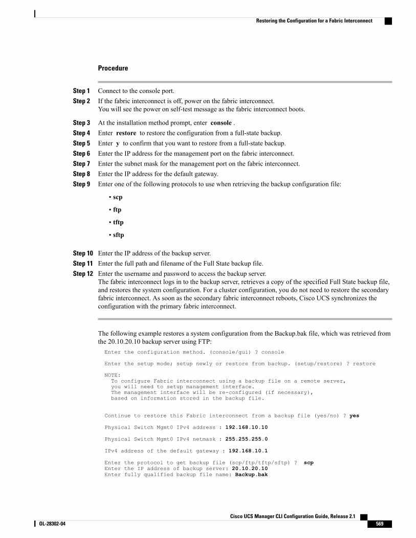
Procedure
Step 1 Connect to the console port.Step 2 If the fabric interconnect is off, power on the fabric interconnect.
You will see the power on self-test message as the fabric interconnect boots.
Step 3 At the installation method prompt, enter console .Step 4 Enter restore to restore the configuration from a full-state backup.Step 5 Enter y to confirm that you want to restore from a full-state backup.Step 6 Enter the IP address for the management port on the fabric interconnect.Step 7 Enter the subnet mask for the management port on the fabric interconnect.Step 8 Enter the IP address for the default gateway.Step 9 Enter one of the following protocols to use when retrieving the backup configuration file:
• scp
• ftp
• tftp
• sftp
Step 10 Enter the IP address of the backup server.Step 11 Enter the full path and filename of the Full State backup file.Step 12 Enter the username and password to access the backup server.
The fabric interconnect logs in to the backup server, retrieves a copy of the specified Full State backup file,and restores the system configuration. For a cluster configuration, you do not need to restore the secondaryfabric interconnect. As soon as the secondary fabric interconnect reboots, Cisco UCS synchronizes theconfiguration with the primary fabric interconnect.
The following example restores a system configuration from the Backup.bak file, which was retrieved fromthe 20.10.20.10 backup server using FTP:Enter the configuration method. (console/gui) ? console
Enter the setup mode; setup newly or restore from backup. (setup/restore) ? restore
NOTE:To configure Fabric interconnect using a backup file on a remote server,you will need to setup management interface.The management interface will be re-configured (if necessary),based on information stored in the backup file.
Continue to restore this Fabric interconnect from a backup file (yes/no) ? yes
Physical Switch Mgmt0 IPv4 address : 192.168.10.10
Physical Switch Mgmt0 IPv4 netmask : 255.255.255.0
IPv4 address of the default gateway : 192.168.10.1
Enter the protocol to get backup file (scp/ftp/tftp/sftp) ? scpEnter the IP address of backup server: 20.10.20.10Enter fully qualified backup file name: Backup.bak
Cisco UCS Manager CLI Configuration Guide, Release 2.1 OL-28302-04 569
Restoring the Configuration for a Fabric Interconnect
Enter user ID: userEnter password:Retrieved backup configuration file.
Configuration file - Ok
Cisco UCS 6100 Series Fabric InterconnectUCS-A login:
Erasing the Configuration
You should erase the configuration only when it is necessary. Erasing the configuration completely removesthe configuration and reboots the system in an unconfigured state. You must then either restore theconfiguration from a backup file or perform an initial system setup.
Caution
Procedure
PurposeCommand or Action
Enters the local management CLI.UCS-A# connect local-mgmtStep 1
Erases the configuration.UCS-A(local-mgmt)# eraseconfiguration
Step 2
You are prompted to confirm that you want to erase theconfiguration. Entering yes erases the configuration andreboots the system in an unconfigured state.
The following example erases the configuration:UCS-A# connect local-mgmtUCS-A(local-mgmt)# erase configurationAll UCS configurations will be erased and system will reboot. Are you sure? (yes/no): yes
Cisco UCS Manager CLI Configuration Guide, Release 2.1570 OL-28302-04
Erasing the Configuration
C H A P T E R 42Recovering a Lost Password
This chapter includes the following sections:
• Password Recovery for the Admin Account, page 571
• Determining the Leadership Role of a Fabric Interconnect, page 572
• Recovering the Admin Account Password in a Standalone Configuration, page 572
• Recovering the Admin Account Password in a Cluster Configuration, page 573
Password Recovery for the Admin AccountThe admin account is the system administrator or superuser account. If an administrator loses the passwordto this account, you can have a serious security issue. As a result, the procedure to recover the password forthe admin account requires you to power cycle all fabric interconnects in a Cisco UCS domain.
When you recover the password for the admin account, you actually change the password for that account.You cannot retrieve the original password for that account.
You can reset the password for all other local accounts through Cisco UCS Manager. However, you must login to Cisco UCS Manager with an account that includes aaa or admin privileges.
This procedure requires you to power down all fabric interconnects in a Cisco UCS domain. As a result,all data transmission in the Cisco UCS domain is stopped until you restart the fabric interconnects.
Caution
Cisco UCS Manager CLI Configuration Guide, Release 2.1 OL-28302-04 571
Determining the Leadership Role of a Fabric Interconnect
Procedure
PurposeCommand or Action
Displays the operational state and leadership role forboth fabric interconnects in a cluster.
UCS-A# show cluster stateStep 1
The following example displays the leadership role for both fabric interconnects in a cluster, where fabricinterconnect A has the primary role and fabric interconnect B has the subordinate role:UCS-A# show cluster stateCluster Id: 0x4432f72a371511de-0xb97c000de1b1ada4
A: UP, PRIMARYB: UP, SUBORDINATE
HA READY
Recovering the Admin Account Password in a Standalone ConfigurationThis procedure will help you to recover the password that you set for the admin account when you performedan initial system setup on the fabric interconnect. The admin account is the system administrator or superuseraccount.
Before You Begin
1 Physically connect the console port on the fabric interconnect to a computer terminal or console server
2 Determine the running versions of the following firmware:
• The firmware kernel version on the fabric interconnect
• The firmware system version
To find this information, you can log in with any user account on the Cisco UCS domain.Tip
Procedure
Step 1 Connect to the console port.Step 2 Power cycle the fabric interconnect:
a) Turn off the power to the fabric interconnect.b) Turn on the power to the fabric interconnect.
Step 3 In the console, press one of the following key combinations as it boots to get the loader prompt:
Cisco UCS Manager CLI Configuration Guide, Release 2.1572 OL-28302-04
Determining the Leadership Role of a Fabric Interconnect
• Ctrl+l
• Ctrl+Shift+r
You may need to press the selected key combination multiple times before your screen displays the loaderprompt.
Step 4 Boot the kernel firmware version on the fabric interconnect.loader >boot /installables/switch/kernel_firmware_version
Example:loader >boot /installables/switch/ucs-6100-k9-kickstart.4.1.3.N2.1.0.11.gbin
Step 5 Enter config terminal mode.Fabric(boot)#config terminal
Step 6 Reset the admin password.Fabric(boot)(config)#admin-passwordpassword
Choose a strong password that includes at least one capital letter and one number. The password cannot beblank.
The new password displays in clear text mode.
Step 7 Exit config terminal mode and return to the boot prompt.Step 8 Boot the system firmware version on the fabric interconnect.
Fabric(boot)#load /installables/switch/system_firmware_version
Example:Fabric(boot)#load /installables/switch/ucs-6100-k9-system.4.1.3.N2.1.0.211.bin
Step 9 After the system image loads, log in to Cisco UCS Manager.
Recovering the Admin Account Password in a Cluster ConfigurationThis procedure will help you to recover the password that you set for the admin account when you performedan initial system setup on the fabric interconnects. The admin account is the system administrator or superuseraccount.
Cisco UCS Manager CLI Configuration Guide, Release 2.1 OL-28302-04 573
Recovering the Admin Account Password in a Cluster Configuration
Before You Begin
1 Physically connect a console port on one of the fabric interconnects to a computer terminal or consoleserver
2 Obtain the following information:
• The firmware kernel version on the fabric interconnect
• The firmware system version
•Which fabric interconnect has the primary leadership role and which is the subordinate
To find this information, you can log in with any user account on the Cisco UCS domain.Tip
Procedure
Step 1 Connect to the console port.Step 2 For the subordinate fabric interconnect:
a) Turn off the power to the fabric interconnect.b) Turn on the power to the fabric interconnect.c) In the console, press one of the following key combinations as it boots to get the loader prompt:
• Ctrl+l
• Ctrl+Shift+r
Youmay need to press the selected key combinationmultiple times before your screen displays the loaderprompt.
Step 3 Power cycle the primary fabric interconnect:a) Turn off the power to the fabric interconnect.b) Turn on the power to the fabric interconnect.
Step 4 In the console, press one of the following key combinations as it boots to get the loader prompt:
• Ctrl+l
• Ctrl+Shift+r
You may need to press the selected key combination multiple times before your screen displays the loaderprompt.
Step 5 Boot the kernel firmware version on the primary fabric interconnect.loader > boot /installables/switch/kernel_firmware_version
Cisco UCS Manager CLI Configuration Guide, Release 2.1574 OL-28302-04
Recovering the Admin Account Password in a Cluster Configuration
Example:loader > boot /installables/switch/ucs-6100-k9-kickstart.4.1.3.N2.1.0.11.gbin
Step 6 Enter config terminal mode.Fabric(boot)# config terminal
Step 7 Reset the admin password.Fabric(boot)(config)# admin-password password
Choose a strong password that includes at least one capital letter and one number. The password cannot beblank.
The new password displays in clear text mode.
Step 8 Exit config terminal mode and return to the boot prompt.Step 9 Boot the system firmware version on the primary fabric interconnect.
Fabric(boot)# load /installables/switch/system_firmware_version
Example:Fabric(boot)# load /installables/switch/ucs-6100-k9-system.4.1.3.N2.1.0.211.bin
Step 10 After the system image loads, log in to Cisco UCS Manager.Step 11 In the console for the subordinate fabric interconnect, do the following to bring it up:
a) Boot the kernel firmware version on the subordinate fabric interconnect.loader > boot /installables/switch/kernel_firmware_version
b) Boot the system firmware version on the subordinate fabric interconnect.Fabric(boot)# load /installables/switch/system_firmware_version
Cisco UCS Manager CLI Configuration Guide, Release 2.1 OL-28302-04 575
Recovering the Admin Account Password in a Cluster Configuration

Cisco UCS Manager CLI Configuration Guide, Release 2.1576 OL-28302-04
Recovering the Admin Account Password in a Cluster Configuration
P A R T VIISystem Monitoring• Monitoring Traffic, page 579
• Monitoring Hardware, page 591
• Configuring Statistics-Related Policies, page 601
• Configuring Call Home, page 617
• Managing the System Event Log, page 639
• Configuring Settings for Faults, Events, and Logs, page 647

C H A P T E R 43Monitoring Traffic
This chapter includes the following sections:
• Traffic Monitoring, page 579
• Guidelines and Recommendations for Traffic Monitoring, page 580
• Creating an Ethernet Traffic Monitoring Session, page 581
• Creating a Fibre Channel Traffic Monitoring Session, page 582
• Adding Traffic Sources to a Monitoring Session, page 583
• Activating a Traffic Monitoring Session, page 588
• Deleting a Traffic Monitoring Session, page 589
Traffic MonitoringTraffic monitoring copies traffic from one or more sources and sends the copied traffic to a dedicated destinationport for analysis by a network analyzer. This feature is also known as Switched Port Analyzer (SPAN).
You can monitor or use SPAN on port channels only for ingress traffic.Important
Type of Session
When you create a traffic monitoring session, you can choose either an Ethernet or Fibre Channel destinationport to receive the traffic. The type of destination port determines the type of session, which in turn determinesthe types of available traffic sources. For an Ethernet traffic monitoring session, the destination port must bean unconfigured physical port. For a Fibre Channel traffic monitoring session, the destination port must be aFibre Channel uplink port.
Traffic Sources
An Ethernet traffic monitoring session can monitor any of the following traffic sources:
• Uplink Ethernet port
Cisco UCS Manager CLI Configuration Guide, Release 2.1 OL-28302-04 579
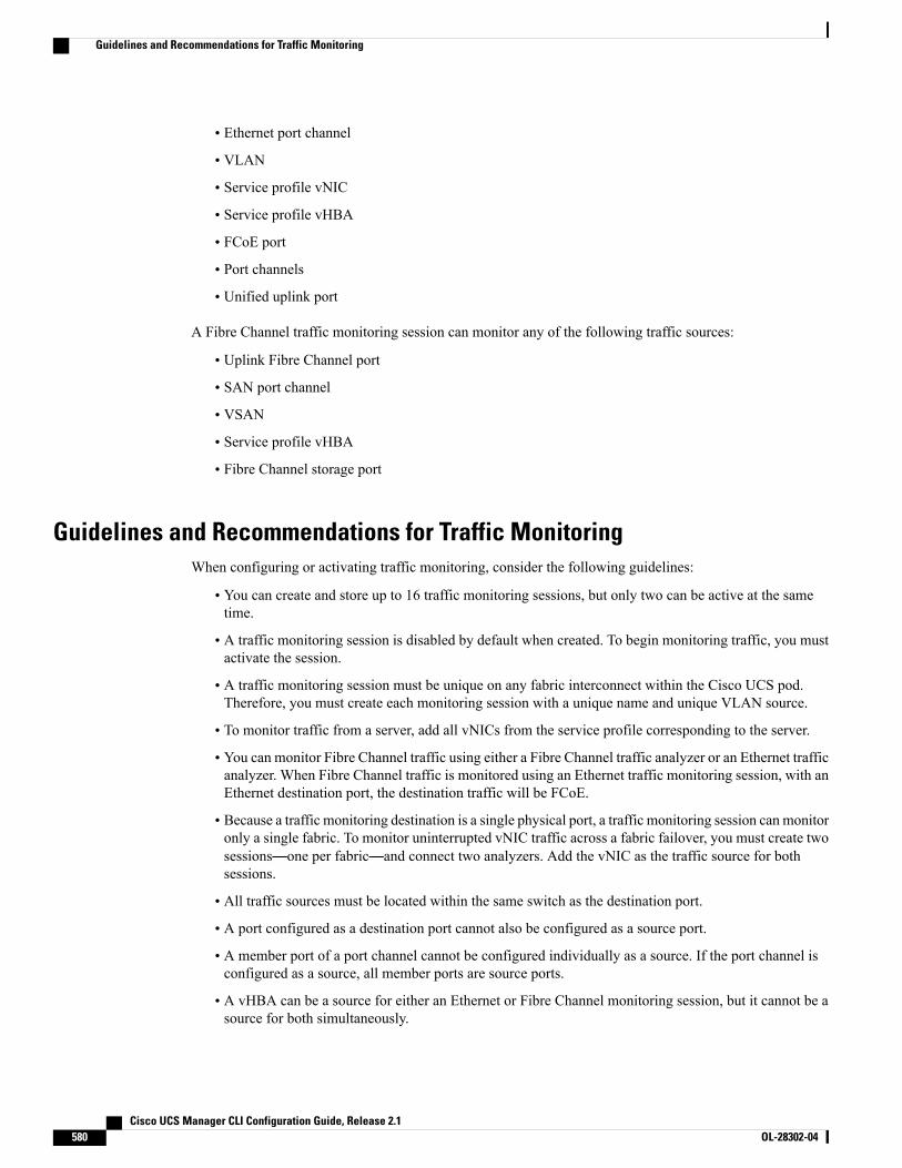
• Ethernet port channel
• VLAN
• Service profile vNIC
• Service profile vHBA
• FCoE port
• Port channels
• Unified uplink port
A Fibre Channel traffic monitoring session can monitor any of the following traffic sources:
• Uplink Fibre Channel port
• SAN port channel
• VSAN
• Service profile vHBA
• Fibre Channel storage port
Guidelines and Recommendations for Traffic MonitoringWhen configuring or activating traffic monitoring, consider the following guidelines:
• You can create and store up to 16 traffic monitoring sessions, but only two can be active at the sametime.
• A traffic monitoring session is disabled by default when created. To begin monitoring traffic, you mustactivate the session.
• A traffic monitoring session must be unique on any fabric interconnect within the Cisco UCS pod.Therefore, you must create each monitoring session with a unique name and unique VLAN source.
• To monitor traffic from a server, add all vNICs from the service profile corresponding to the server.
• You can monitor Fibre Channel traffic using either a Fibre Channel traffic analyzer or an Ethernet trafficanalyzer. When Fibre Channel traffic is monitored using an Ethernet traffic monitoring session, with anEthernet destination port, the destination traffic will be FCoE.
• Because a traffic monitoring destination is a single physical port, a traffic monitoring session can monitoronly a single fabric. To monitor uninterrupted vNIC traffic across a fabric failover, you must create twosessions—one per fabric—and connect two analyzers. Add the vNIC as the traffic source for bothsessions.
• All traffic sources must be located within the same switch as the destination port.
• A port configured as a destination port cannot also be configured as a source port.
• A member port of a port channel cannot be configured individually as a source. If the port channel isconfigured as a source, all member ports are source ports.
• A vHBA can be a source for either an Ethernet or Fibre Channel monitoring session, but it cannot be asource for both simultaneously.
Cisco UCS Manager CLI Configuration Guide, Release 2.1580 OL-28302-04
Guidelines and Recommendations for Traffic Monitoring
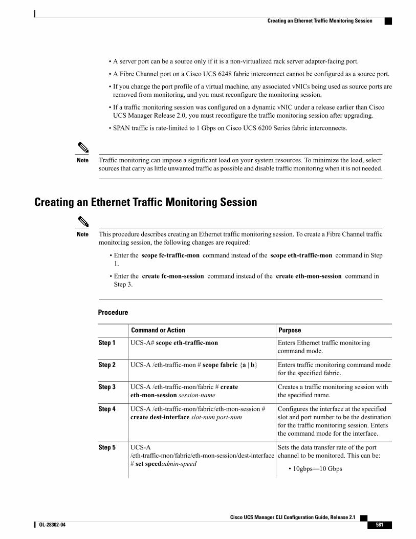
• A server port can be a source only if it is a non-virtualized rack server adapter-facing port.
• A Fibre Channel port on a Cisco UCS 6248 fabric interconnect cannot be configured as a source port.
• If you change the port profile of a virtual machine, any associated vNICs being used as source ports areremoved from monitoring, and you must reconfigure the monitoring session.
• If a traffic monitoring session was configured on a dynamic vNIC under a release earlier than CiscoUCS Manager Release 2.0, you must reconfigure the traffic monitoring session after upgrading.
• SPAN traffic is rate-limited to 1 Gbps on Cisco UCS 6200 Series fabric interconnects.
Traffic monitoring can impose a significant load on your system resources. To minimize the load, selectsources that carry as little unwanted traffic as possible and disable traffic monitoring when it is not needed.
Note
Creating an Ethernet Traffic Monitoring Session
This procedure describes creating an Ethernet traffic monitoring session. To create a Fibre Channel trafficmonitoring session, the following changes are required:
Note
• Enter the scope fc-traffic-mon command instead of the scope eth-traffic-mon command in Step1.
• Enter the create fc-mon-session command instead of the create eth-mon-session command inStep 3.
Procedure
PurposeCommand or Action
Enters Ethernet traffic monitoringcommand mode.
UCS-A# scope eth-traffic-monStep 1
Enters traffic monitoring command modefor the specified fabric.
UCS-A /eth-traffic-mon # scope fabric {a | b}Step 2
Creates a traffic monitoring session withthe specified name.
UCS-A /eth-traffic-mon/fabric # createeth-mon-session session-name
Step 3
Configures the interface at the specifiedslot and port number to be the destination
UCS-A /eth-traffic-mon/fabric/eth-mon-session #create dest-interface slot-num port-num
Step 4
for the traffic monitoring session. Entersthe command mode for the interface.
Sets the data transfer rate of the portchannel to be monitored. This can be:
UCS-A/eth-traffic-mon/fabric/eth-mon-session/dest-interface# set speedadmin-speed
Step 5
• 10gbps—10 Gbps
Cisco UCS Manager CLI Configuration Guide, Release 2.1 OL-28302-04 581
Creating an Ethernet Traffic Monitoring Session
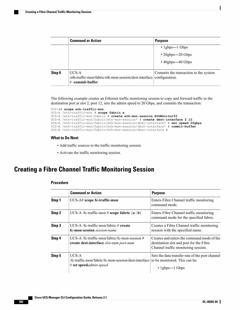
PurposeCommand or Action
• 1gbps—1 Gbps
• 20gbps—20 Gbps
• 40gbps—40 Gbps
Commits the transaction to the systemconfiguration.
UCS-A/eth-traffic-mon/fabric/eth-mon-session/dest-interface# commit-buffer
Step 6
The following example creates an Ethernet traffic monitoring session to copy and forward traffic to thedestination port at slot 2, port 12, sets the admin speed to 20 Gbps, and commits the transaction:UCS-A# scope eth-traffic-monUCS-A /eth-traffic-mon # scope fabric aUCS-A /eth-traffic-mon/fabric # create eth-mon-session EthMonitor33UCS-A /eth-traffic-mon/fabric/eth-mon-session* # create dest-interface 2 12UCS-A /eth-traffic-mon/fabric/eth-mon-session/dest-interface* # set speed 20gbpsUCS-A /eth-traffic-mon/fabric/eth-mon-session/dest-interface* # commit-bufferUCS-A /eth-traffic-mon/fabric/eth-mon-session/dest-interface #
What to Do Next
• Add traffic sources to the traffic monitoring session.
• Activate the traffic monitoring session.
Creating a Fibre Channel Traffic Monitoring Session
Procedure
PurposeCommand or Action
Enters Fibre Channel traffic monitoringcommand mode.
UCS-A# scope fc-traffic-monStep 1
Enters Fibre Channel traffic monitoringcommand mode for the specified fabric.
UCS-A /fc-traffic-mon # scope fabric {a | b}Step 2
Creates a Fibre Channel traffic monitoringsession with the specified name.
UCS-A /fc-traffic-mon/fabric # createfc-mon-session session-name
Step 3
Creates and enters the commandmode of thedestination slot and port for the FibreChannel traffic monitoring session.
UCS-A /fc-traffic-mon/fabric/fc-mon-session #create dest-interface slot-num port-num
Step 4
Sets the data transfer rate of the port channelto be monitored. This can be:
UCS-A/fc-traffic-mon/fabric/fc-mon-session/dest-interface# set speedadmin-speed
Step 5
• 1gbps—1 Gbps
Cisco UCS Manager CLI Configuration Guide, Release 2.1582 OL-28302-04
Creating a Fibre Channel Traffic Monitoring Session
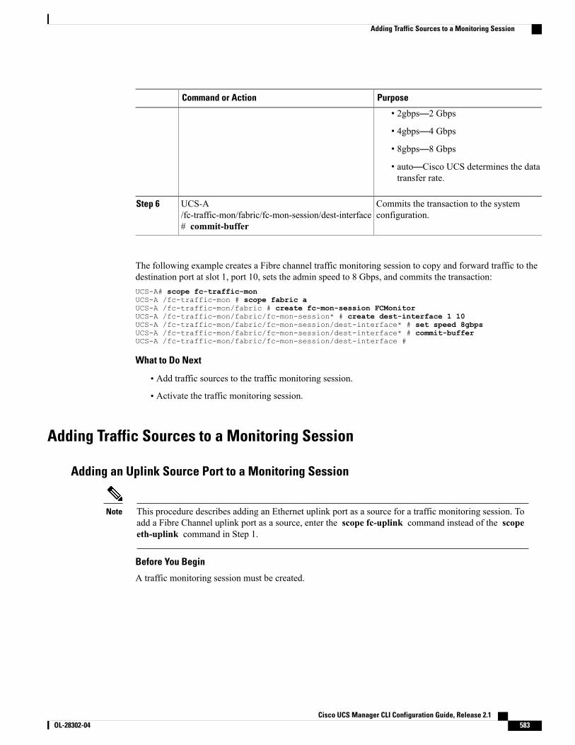
PurposeCommand or Action
• 2gbps—2 Gbps
• 4gbps—4 Gbps
• 8gbps—8 Gbps
• auto—Cisco UCS determines the datatransfer rate.
Commits the transaction to the systemconfiguration.
UCS-A/fc-traffic-mon/fabric/fc-mon-session/dest-interface# commit-buffer
Step 6
The following example creates a Fibre channel traffic monitoring session to copy and forward traffic to thedestination port at slot 1, port 10, sets the admin speed to 8 Gbps, and commits the transaction:UCS-A# scope fc-traffic-monUCS-A /fc-traffic-mon # scope fabric aUCS-A /fc-traffic-mon/fabric # create fc-mon-session FCMonitorUCS-A /fc-traffic-mon/fabric/fc-mon-session* # create dest-interface 1 10UCS-A /fc-traffic-mon/fabric/fc-mon-session/dest-interface* # set speed 8gbpsUCS-A /fc-traffic-mon/fabric/fc-mon-session/dest-interface* # commit-bufferUCS-A /fc-traffic-mon/fabric/fc-mon-session/dest-interface #
What to Do Next
• Add traffic sources to the traffic monitoring session.
• Activate the traffic monitoring session.
Adding Traffic Sources to a Monitoring Session
Adding an Uplink Source Port to a Monitoring Session
This procedure describes adding an Ethernet uplink port as a source for a traffic monitoring session. Toadd a Fibre Channel uplink port as a source, enter the scope fc-uplink command instead of the scopeeth-uplink command in Step 1.
Note
Before You Begin
A traffic monitoring session must be created.
Cisco UCS Manager CLI Configuration Guide, Release 2.1 OL-28302-04 583
Adding Traffic Sources to a Monitoring Session
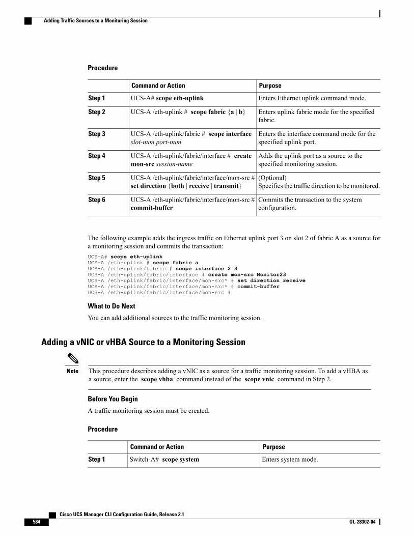
Procedure
PurposeCommand or Action
Enters Ethernet uplink command mode.UCS-A# scope eth-uplinkStep 1
Enters uplink fabric mode for the specifiedfabric.
UCS-A /eth-uplink # scope fabric {a | b}Step 2
Enters the interface command mode for thespecified uplink port.
UCS-A /eth-uplink/fabric # scope interfaceslot-num port-num
Step 3
Adds the uplink port as a source to thespecified monitoring session.
UCS-A /eth-uplink/fabric/interface # createmon-src session-name
Step 4
(Optional)Specifies the traffic direction to be monitored.
UCS-A /eth-uplink/fabric/interface/mon-src #set direction {both | receive | transmit}
Step 5
Commits the transaction to the systemconfiguration.
UCS-A /eth-uplink/fabric/interface/mon-src #commit-buffer
Step 6
The following example adds the ingress traffic on Ethernet uplink port 3 on slot 2 of fabric A as a source fora monitoring session and commits the transaction:UCS-A# scope eth-uplinkUCS-A /eth-uplink # scope fabric aUCS-A /eth-uplink/fabric # scope interface 2 3UCS-A /eth-uplink/fabric/interface # create mon-src Monitor23UCS-A /eth-uplink/fabric/interface/mon-src* # set direction receiveUCS-A /eth-uplink/fabric/interface/mon-src* # commit-bufferUCS-A /eth-uplink/fabric/interface/mon-src #
What to Do Next
You can add additional sources to the traffic monitoring session.
Adding a vNIC or vHBA Source to a Monitoring Session
This procedure describes adding a vNIC as a source for a traffic monitoring session. To add a vHBA asa source, enter the scope vhba command instead of the scope vnic command in Step 2.
Note
Before You Begin
A traffic monitoring session must be created.
Procedure
PurposeCommand or Action
Enters system mode.Switch-A# scope systemStep 1
Cisco UCS Manager CLI Configuration Guide, Release 2.1584 OL-28302-04
Adding Traffic Sources to a Monitoring Session
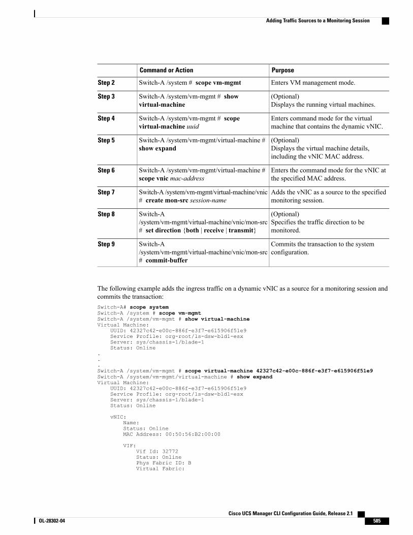
PurposeCommand or Action
Enters VM management mode.Switch-A /system # scope vm-mgmtStep 2
(Optional)Displays the running virtual machines.
Switch-A /system/vm-mgmt # showvirtual-machine
Step 3
Enters command mode for the virtualmachine that contains the dynamic vNIC.
Switch-A /system/vm-mgmt # scopevirtual-machine uuid
Step 4
(Optional)Displays the virtual machine details,including the vNIC MAC address.
Switch-A /system/vm-mgmt/virtual-machine #show expand
Step 5
Enters the command mode for the vNIC atthe specified MAC address.
Switch-A /system/vm-mgmt/virtual-machine #scope vnic mac-address
Step 6
Adds the vNIC as a source to the specifiedmonitoring session.
Switch-A /system/vm-mgmt/virtual-machine/vnic# create mon-src session-name
Step 7
(Optional)Specifies the traffic direction to bemonitored.
Switch-A/system/vm-mgmt/virtual-machine/vnic/mon-src# set direction {both | receive | transmit}
Step 8
Commits the transaction to the systemconfiguration.
Switch-A/system/vm-mgmt/virtual-machine/vnic/mon-src# commit-buffer
Step 9
The following example adds the ingress traffic on a dynamic vNIC as a source for a monitoring session andcommits the transaction:Switch-A# scope systemSwitch-A /system # scope vm-mgmtSwitch-A /system/vm-mgmt # show virtual-machineVirtual Machine:
UUID: 42327c42-e00c-886f-e3f7-e615906f51e9Service Profile: org-root/ls-dsw-bld1-esxServer: sys/chassis-1/blade-1Status: Online
.
.
.Switch-A /system/vm-mgmt # scope virtual-machine 42327c42-e00c-886f-e3f7-e615906f51e9Switch-A /system/vm-mgmt/virtual-machine # show expandVirtual Machine:
UUID: 42327c42-e00c-886f-e3f7-e615906f51e9Service Profile: org-root/ls-dsw-bld1-esxServer: sys/chassis-1/blade-1Status: Online
vNIC:Name:Status: OnlineMAC Address: 00:50:56:B2:00:00
VIF:Vif Id: 32772Status: OnlinePhys Fabric ID: BVirtual Fabric:
Cisco UCS Manager CLI Configuration Guide, Release 2.1 OL-28302-04 585
Adding Traffic Sources to a Monitoring Session
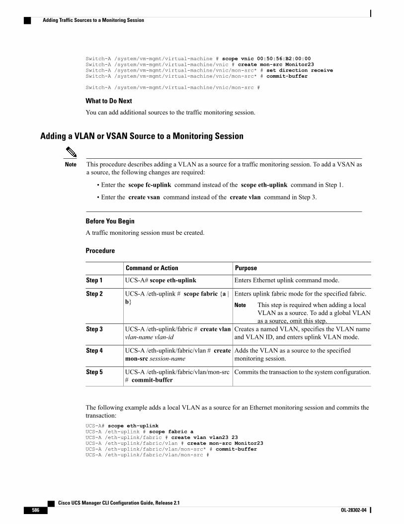
Switch-A /system/vm-mgmt/virtual-machine # scope vnic 00:50:56:B2:00:00Switch-A /system/vm-mgmt/virtual-machine/vnic # create mon-src Monitor23Switch-A /system/vm-mgmt/virtual-machine/vnic/mon-src* # set direction receiveSwitch-A /system/vm-mgmt/virtual-machine/vnic/mon-src* # commit-buffer
Switch-A /system/vm-mgmt/virtual-machine/vnic/mon-src #
What to Do Next
You can add additional sources to the traffic monitoring session.
Adding a VLAN or VSAN Source to a Monitoring Session
This procedure describes adding a VLAN as a source for a traffic monitoring session. To add a VSAN asa source, the following changes are required:
Note
• Enter the scope fc-uplink command instead of the scope eth-uplink command in Step 1.
• Enter the create vsan command instead of the create vlan command in Step 3.
Before You Begin
A traffic monitoring session must be created.
Procedure
PurposeCommand or Action
Enters Ethernet uplink command mode.UCS-A# scope eth-uplinkStep 1
Enters uplink fabric mode for the specified fabric.UCS-A /eth-uplink # scope fabric {a |b}
Step 2
This step is required when adding a localVLAN as a source. To add a global VLANas a source, omit this step.
Note
Creates a named VLAN, specifies the VLAN nameand VLAN ID, and enters uplink VLAN mode.
UCS-A /eth-uplink/fabric # create vlanvlan-name vlan-id
Step 3
Adds the VLAN as a source to the specifiedmonitoring session.
UCS-A /eth-uplink/fabric/vlan # createmon-src session-name
Step 4
Commits the transaction to the system configuration.UCS-A /eth-uplink/fabric/vlan/mon-src# commit-buffer
Step 5
The following example adds a local VLAN as a source for an Ethernet monitoring session and commits thetransaction:UCS-A# scope eth-uplinkUCS-A /eth-uplink # scope fabric aUCS-A /eth-uplink/fabric # create vlan vlan23 23UCS-A /eth-uplink/fabric/vlan # create mon-src Monitor23UCS-A /eth-uplink/fabric/vlan/mon-src* # commit-bufferUCS-A /eth-uplink/fabric/vlan/mon-src #
Cisco UCS Manager CLI Configuration Guide, Release 2.1586 OL-28302-04
Adding Traffic Sources to a Monitoring Session
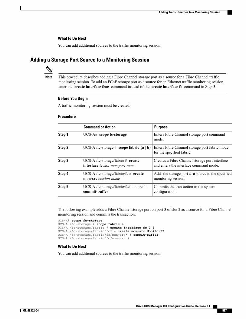
What to Do Next
You can add additional sources to the traffic monitoring session.
Adding a Storage Port Source to a Monitoring Session
This procedure describes adding a Fibre Channel storage port as a source for a Fibre Channel trafficmonitoring session. To add an FCoE storage port as a source for an Ethernet traffic monitoring session,enter the create interface fcoe command instead of the create interface fc command in Step 3.
Note
Before You Begin
A traffic monitoring session must be created.
Procedure
PurposeCommand or Action
Enters Fibre Channel storage port commandmode.
UCS-A# scope fc-storageStep 1
Enters Fibre Channel storage port fabric modefor the specified fabric.
UCS-A /fc-storage # scope fabric {a | b}Step 2
Creates a Fibre Channel storage port interfaceand enters the interface command mode.
UCS-A /fc-storage/fabric # createinterface fc slot-num port-num
Step 3
Adds the storage port as a source to the specifiedmonitoring session.
UCS-A /fc-storage/fabric/fc # createmon-src session-name
Step 4
Commits the transaction to the systemconfiguration.
UCS-A /fc-storage/fabric/fc/mon-src #commit-buffer
Step 5
The following example adds a Fibre Channel storage port on port 3 of slot 2 as a source for a Fibre Channelmonitoring session and commits the transaction:UCS-A# scope fc-storageUCS-A /fc-storage # scope fabric aUCS-A /fc-storage/fabric # create interface fc 2 3UCS-A /fc-storage/fabric/fc* # create mon-src Monitor23UCS-A /fc-storage/fabric/fc/mon-src* # commit-bufferUCS-A /fc-storage/fabric/fc/mon-src #
What to Do Next
You can add additional sources to the traffic monitoring session.
Cisco UCS Manager CLI Configuration Guide, Release 2.1 OL-28302-04 587
Adding Traffic Sources to a Monitoring Session
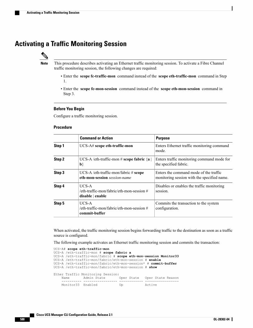
Activating a Traffic Monitoring Session
This procedure describes activating an Ethernet traffic monitoring session. To activate a Fibre Channeltraffic monitoring session, the following changes are required:
Note
• Enter the scope fc-traffic-mon command instead of the scope eth-traffic-mon command in Step1.
• Enter the scope fc-mon-session command instead of the scope eth-mon-session command inStep 3.
Before You Begin
Configure a traffic monitoring session.
Procedure
PurposeCommand or Action
Enters Ethernet traffic monitoring commandmode.
UCS-A# scope eth-traffic-monStep 1
Enters traffic monitoring command mode forthe specified fabric.
UCS-A /eth-traffic-mon # scope fabric {a |b}
Step 2
Enters the command mode of the trafficmonitoring session with the specified name.
UCS-A /eth-traffic-mon/fabric # scopeeth-mon-session session-name
Step 3
Disables or enables the traffic monitoringsession.
UCS-A/eth-traffic-mon/fabric/eth-mon-session #disable | enable
Step 4
Commits the transaction to the systemconfiguration.
UCS-A/eth-traffic-mon/fabric/eth-mon-session #commit-buffer
Step 5
When activated, the traffic monitoring session begins forwarding traffic to the destination as soon as a trafficsource is configured.
The following example activates an Ethernet traffic monitoring session and commits the transaction:UCS-A# scope eth-traffic-monUCS-A /eth-traffic-mon # scope fabric aUCS-A /eth-traffic-mon/fabric # scope eth-mon-session Monitor33UCS-A /eth-traffic-mon/fabric/eth-mon-session # enableUCS-A /eth-traffic-mon/fabric/eth-mon-session* # commit-bufferUCS-A /eth-traffic-mon/fabric/eth-mon-session # show
Ether Traffic Monitoring Session:Name Admin State Oper State Oper State Reason---------- ----------------- ------------ -----------------Monitor33 Enabled Up Active
Cisco UCS Manager CLI Configuration Guide, Release 2.1588 OL-28302-04
Activating a Traffic Monitoring Session
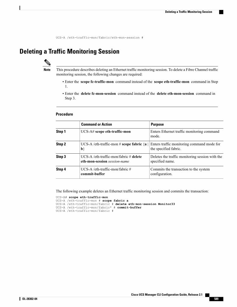
UCS-A /eth-traffic-mon/fabric/eth-mon-session #
Deleting a Traffic Monitoring Session
This procedure describes deleting an Ethernet traffic monitoring session. To delete a Fibre Channel trafficmonitoring session, the following changes are required:
Note
• Enter the scope fc-traffic-mon command instead of the scope eth-traffic-mon command in Step1.
• Enter the delete fc-mon-session command instead of the delete eth-mon-session command inStep 3.
Procedure
PurposeCommand or Action
Enters Ethernet traffic monitoring commandmode.
UCS-A# scope eth-traffic-monStep 1
Enters traffic monitoring command mode forthe specified fabric.
UCS-A /eth-traffic-mon # scope fabric {a |b}
Step 2
Deletes the traffic monitoring session with thespecified name.
UCS-A /eth-traffic-mon/fabric # deleteeth-mon-session session-name
Step 3
Commits the transaction to the systemconfiguration.
UCS-A /eth-traffic-mon/fabric #commit-buffer
Step 4
The following example deletes an Ethernet traffic monitoring session and commits the transaction:UCS-A# scope eth-traffic-monUCS-A /eth-traffic-mon # scope fabric aUCS-A /eth-traffic-mon/fabric # delete eth-mon-session Monitor33UCS-A /eth-traffic-mon/fabric* # commit-bufferUCS-A /eth-traffic-mon/fabric #
Cisco UCS Manager CLI Configuration Guide, Release 2.1 OL-28302-04 589
Deleting a Traffic Monitoring Session

Cisco UCS Manager CLI Configuration Guide, Release 2.1590 OL-28302-04
Deleting a Traffic Monitoring Session
C H A P T E R 44Monitoring Hardware
This chapter includes the following sections:
• Monitoring Fan Modules, page 591
• Monitoring Management Interfaces, page 593
• Server Disk Drive Monitoring, page 595
• Managing Transportable Flash Module and Supercapacitor, page 598
Monitoring Fan Modules
Procedure
PurposeCommand or Action
Enters chassis mode for the specified chassis.UCS-A# scope chassis chassis-numStep 1
Displays the environment status for all fans within thechassis.
UCS-A /chassis # show environmentfan
Step 2
This includes the following information:
• Overall status
• Operability
• Power state
• Thermal status
• Threshold status
• Voltage status
Enters fan module chassis mode for the specified fanmodule.
UCS-A /chassis # scope fan-moduletray-num module-num
Step 3
Each chassis contains one tray, so the traynumber in this command is always 1.
Note
Cisco UCS Manager CLI Configuration Guide, Release 2.1 OL-28302-04 591
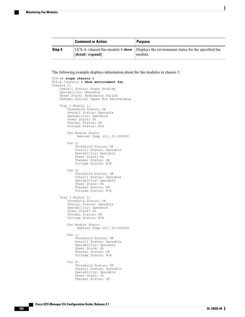
PurposeCommand or Action
Displays the environment status for the specified fanmodule.
UCS-A /chassis/fan-module # show[detail | expand]
Step 4
The following example displays information about the fan modules in chassis 1:UCS-A# scope chassis 1UCS-A /chassis # show environment fanChassis 1:
Overall Status: Power ProblemOperability: OperablePower State: Redundancy FailedThermal Status: Upper Non Recoverable
Tray 1 Module 1:Threshold Status: OKOverall Status: OperableOperability: OperablePower State: OnThermal Status: OKVoltage Status: N/A
Fan Module Stats:Ambient Temp (C): 25.000000
Fan 1:Threshold Status: OKOverall Status: OperableOperability: OperablePower State: OnThermal Status: OKVoltage Status: N/A
Fan 2:Threshold Status: OKOverall Status: OperableOperability: OperablePower State: OnThermal Status: OKVoltage Status: N/A
Tray 1 Module 2:Threshold Status: OKOverall Status: OperableOperability: OperablePower State: OnThermal Status: OKVoltage Status: N/A
Fan Module Stats:Ambient Temp (C): 24.000000
Fan 1:Threshold Status: OKOverall Status: OperableOperability: OperablePower State: OnThermal Status: OKVoltage Status: N/A
Fan 2:Threshold Status: OKOverall Status: OperableOperability: OperablePower State: OnThermal Status: OK
Cisco UCS Manager CLI Configuration Guide, Release 2.1592 OL-28302-04
Monitoring Fan Modules
Voltage Status: N/A
The following example displays information about fan module 2 in chassis 1:UCS-A# scope chassis 1UCS-A /chassis # scope fan-module 1 2UCS-A /chassis/fan-module # show detailFan Module:
Tray: 1Module: 2Overall Status: OperableOperability: OperableThreshold Status: OKPower State: OnPresence: EquippedThermal Status: OKProduct Name: Fan Module for UCS 5108 Blade Server ChassisPID: N20-FAN5VID: V01Vendor: Cisco Systems IncSerial (SN): NWG14350B6NHW Revision: 0Mfg Date: 1997-04-01T08:41:00.000
Monitoring Management Interfaces
Management Interfaces Monitoring PolicyThis policy defines how the mgmt0 Ethernet interface on the fabric interconnect should be monitored. If CiscoUCS detects a management interface failure, a failure report is generated. If the configured number of failurereports is reached, the system assumes that the management interface is unavailable and generates a fault. Bydefault, the management interfaces monitoring policy is disabled.
If the affected management interface belongs to a fabric interconnect which is the managing instance, CiscoUCS confirms that the subordinate fabric interconnect's status is up, that there are no current failure reportslogged against it, and then modifies the managing instance for the endpoints.
If the affected fabric interconnect is currently the primary inside of a high availability setup, a failover of themanagement plane is triggered. The data plane is not affected by this failover.
You can set the following properties related to monitoring the management interface:
• Type of mechanism used to monitor the management interface.
• Interval at which the management interface's status is monitored.
• Maximum number of monitoring attempts that can fail before the system assumes that the managementis unavailable and generates a fault message.
In the event of a management interface failure on a fabric interconnect, the managing instance may notchange if one of the following occurs:
Important
• A path to the endpoint through the subordinate fabric interconnect does not exist.
• The management interface for the subordinate fabric interconnect has failed.
• The path to the endpoint through the subordinate fabric interconnect has failed.
Cisco UCS Manager CLI Configuration Guide, Release 2.1 OL-28302-04 593
Monitoring Management Interfaces

Configuring the Management Interfaces Monitoring Policy
Procedure
Step 1 Enter monitoring mode.UCS-A# scope monitoring
Step 2 Enable or disable the management interfaces monitoring policy.UCS-A /monitoring # set mgmt-if-mon-policy admin-state {enabled | disabled}
Step 3 Specify the number of seconds that the system should wait between data recordings.UCS-A /monitoring # set mgmt-if-mon-policy poll-interval
Enter an integer between 90 and 300.
Step 4 Specify the maximum number of monitoring attempts that can fail before the system assumes that themanagement interface is unavailable and generates a fault message.UCS-A /monitoring # set mgmt-if-mon-policy max-fail-reports num-mon-attempts
Enter an integer between 2 and 5.
Step 5 Specify the monitoring mechanism that you want the system to use.UCS-A /monitoring # set mgmt-if-mon-policy monitor-mechanism {mii-status | ping-arp-targets |ping-gateway
• mii-status—The system monitors the availability of the Media Independent Interface (MII).
• ping-arp-targets—The system pings designated targets using the Address Resolution Protocol (ARP).
• ping-gateway—The system pings the default gateway address specified for this Cisco UCS domain inthe management interface.
Step 6 If you selectedmii-status as your monitoring mechanism, configure the following properties:a) Specify the number of seconds that the system should wait before requesting another response from the
MII if a previous attempt fails.UCS-A /monitoring # set mgmt-if-mon-policy mii-retry-interval num-seconds
Enter an integer between 3 and 10.
b) Specify the number of times that the system polls the MII until the system assumes that the interface isunavailable.UCS-A /monitoring # set mgmt-if-mon-policy mii-retry-count num-retries
Enter an integer between 1 and 3.
Step 7 If you selected ping-arp-targets as your monitoring mechanism, configure the following properties:a) Specify the first IP address the system pings.
UCS-A /monitoring # set mgmt-if-mon-policy arp-target1 ip-addr
Type 0.0.0.0 for an IPv4 address to remove the ARP target or :: for an IPv6 address to remove the N-disctarget.
b) Specify the second IP address the system pings.UCS-A /monitoring # set mgmt-if-mon-policy arp-target2 ip-addr
Cisco UCS Manager CLI Configuration Guide, Release 2.1594 OL-28302-04
Monitoring Management Interfaces
Type 0.0.0.0 for an IPv4 address to remove the ARP target or :: for an IPv6 address to remove the N-disctarget.
c) Specify the third IP address the system pings.UCS-A /monitoring # set mgmt-if-mon-policy arp-target3 ip-addr
Type 0.0.0.0 for an IPv4 address to remove the ARP target or :: for an IPv6 address to remove the N-disctarget.
d) Specify the number of ARP requests to send to the target IP addresses.UCS-A /monitoring # set mgmt-if-mon-policy arp-requests num-requests
Enter an integer between 1 and 5.
e) Specify the number of seconds to wait for responses from the ARP targets before the system assumes thatthey are unavailable.UCS-A /monitoring # set mgmt-if-mon-policy arp-deadline num-seconds
Enter a number between 5 and 15.
Step 8 If you selected ping-gateway as your monitoring mechanism, configure the following properties:a) Specify the number of times the system should ping the gateway.
UCS-A /monitoring # set mgmt-if-mon-policy ping-requests
Enter an integer between 1 and 5.
b) Specify the number of seconds to wait for a response from the gateway until the system assumes that theaddress is unavailable.UCS-A /monitoring # set mgmt-if-mon-policy ping-deadline
Enter an integer between 5 and 15.
Step 9 Commit the transaction to the system configuration.UCS-A /monitoring # commit-buffer
The following example creates a monitoring interface management policy using the Media IndependentInterface (MII) monitoring mechanism and commits the transaction:UCS-A# scope monitoringUCS-A /monitoring # set mgmt-if-mon-policy admin-state enabledUCS-A /monitoring* # set mgmt-if-mon-policy poll-interval 250UCS-A /monitoring* # set mgmt-if-mon-policy max-fail-reports 2UCS-A /monitoring* # set mgmt-if-mon-policy monitor-mechanism set mii-statusUCS-A /monitoring* # set mgmt-if-mon-policy mii-retry-count 3UCS-A /monitoring* # set mgmt-if-mon-policy mii-retry-interval 7UCS-A /monitoring* # commit-bufferUCS-A /monitoring #
Server Disk Drive MonitoringThe disk drive monitoring for Cisco UCS provides Cisco UCS Manager with blade-resident disk drive statusfor supported blade servers in a Cisco UCS domain. Disk drive monitoring provides a unidirectional faultsignal from the LSI firmware to Cisco UCS Manager to provide status information.
The following server and firmware components gather, send, and aggregate information about the disk drivestatus in a server:
Cisco UCS Manager CLI Configuration Guide, Release 2.1 OL-28302-04 595
Server Disk Drive Monitoring
• Physical presence sensor—Determines whether the disk drive is inserted in the server drive bay.
• Physical fault sensor—Determines the operability status reported by the LSI storage controller firmwarefor the disk drive.
• IPMI disk drive fault and presence sensors—Sends the sensor results to Cisco UCS Manager.
• Disk drive fault LED control and associated IPMI sensors—Controls disk drive fault LED states (on/off)and relays the states to Cisco UCS Manager.
Support for Disk Drive MonitoringDisk drive monitoring only supports certain blade servers and a specific LSI storage controller firmware level.
Supported Cisco UCS Servers
Through Cisco UCS Manager, you can monitor disk drives for the following servers:
• B200 M1/M2 blade server
• B250 M1/M2 blade server
Cisco UCS Manager cannot monitor disk drives in any other blade server or rack-mount server.
Disk DriveMonitoring behavior and the CIMC sensor values are not consistent with the storage controllerreported device status across various UCS servers. This is observed during various operations such asremoving or inserting a storage device, or during rebuild operations.
Note
Storage Controller Firmware Level
The storage controller on a supported server must have LSI 1064E firmware.
Cisco UCSManager cannot monitor disk drives in servers with a different level of storage controller firmware.
Prerequisites for Disk Drive MonitoringIn addition to the supported servers and storage controller firmware version, you must ensure that the followingprerequisites have been met for disk drive monitoring to provide useful status information:
• The drive must be inserted in the server drive bay.
• The server must be powered on.
• The server must have completed discovery.
• The results of the BIOS POST complete must be TRUE.
Cisco UCS Manager CLI Configuration Guide, Release 2.1596 OL-28302-04
Server Disk Drive Monitoring
Viewing the Status of a Disk Drive
Procedure
PurposeCommand or Action
Enters chassis mode for the specifiedchassis.
UCS-A# scope chassis chassis-numStep 1
Enters server chassis mode.UCS-A /chassis # scope server server-numStep 2
Enters RAID controller server chassismode.
UCS-A /chassis/server # scope raid-controllerraid-contr-id {sas | sata}
Step 3
UCS-A /chassis/server/raid-controller # showlocal-disk [local-disk-id | detail | expand]
Step 4
The following example shows the status of a disk drive:UCS-A# scope chassis 1UCS-A /chassis # scope server 6UCS-A /chassis/server # scope raid-controller 1 sasUCS-A /chassis/server/raid-controller # show local-disk 1
Local Disk:ID: 1Block Size: 512Blocks: 60545024Size (MB): 29563Operability: OperablePresence: Equipped
Interpreting the Status of a Monitored Disk DriveCisco UCS Manager displays the following properties for each monitored disk drive:
• Operability—The operational state of the disk drive.
• Presence—The presence of the disk drive, and whether it can be detected in the server drive bay, regardlessof its operational state.
You need to look at both properties to determine the status of the monitored disk drive. The following tableshows the likely interpretations of the property values.
InterpretationPresence StatusOperability Status
No fault condition. The disk drive is in the serverand can be used.
EquippedOperable
Cisco UCS Manager CLI Configuration Guide, Release 2.1 OL-28302-04 597
Server Disk Drive Monitoring
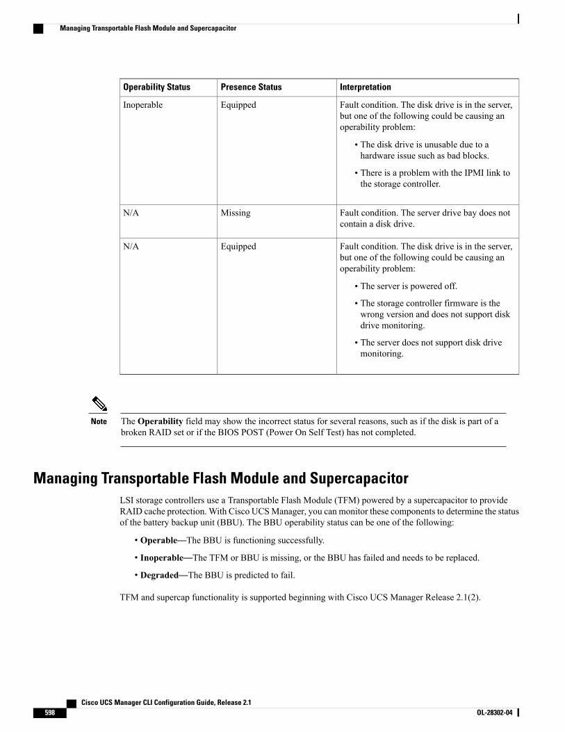
InterpretationPresence StatusOperability Status
Fault condition. The disk drive is in the server,but one of the following could be causing anoperability problem:
• The disk drive is unusable due to ahardware issue such as bad blocks.
• There is a problem with the IPMI link tothe storage controller.
EquippedInoperable
Fault condition. The server drive bay does notcontain a disk drive.
MissingN/A
Fault condition. The disk drive is in the server,but one of the following could be causing anoperability problem:
• The server is powered off.
• The storage controller firmware is thewrong version and does not support diskdrive monitoring.
• The server does not support disk drivemonitoring.
EquippedN/A
The Operability field may show the incorrect status for several reasons, such as if the disk is part of abroken RAID set or if the BIOS POST (Power On Self Test) has not completed.
Note
Managing Transportable Flash Module and SupercapacitorLSI storage controllers use a Transportable Flash Module (TFM) powered by a supercapacitor to provideRAID cache protection. With Cisco UCSManager, you can monitor these components to determine the statusof the battery backup unit (BBU). The BBU operability status can be one of the following:
• Operable—The BBU is functioning successfully.
• Inoperable—The TFM or BBU is missing, or the BBU has failed and needs to be replaced.
• Degraded—The BBU is predicted to fail.
TFM and supercap functionality is supported beginning with Cisco UCS Manager Release 2.1(2).
Cisco UCS Manager CLI Configuration Guide, Release 2.1598 OL-28302-04
Managing Transportable Flash Module and Supercapacitor
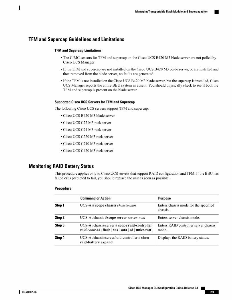
TFM and Supercap Guidelines and Limitations
TFM and Supercap Limitations
• The CIMC sensors for TFM and supercap on the Cisco UCS B420 M3 blade server are not polled byCisco UCS Manager.
• If the TFM and supercap are not installed on the Cisco UCS B420 M3 blade server, or are installed andthen removed from the blade server, no faults are generated.
• If the TFM is not installed on the Cisco UCS B420 M3 blade server, but the supercap is installed, CiscoUCS Manager reports the entire BBU system as absent. You should physically check to see if both theTFM and supercap is present on the blade server.
Supported Cisco UCS Servers for TFM and Supercap
The following Cisco UCS servers support TFM and supercap:
• Cisco UCS B420 M3 blade server
• Cisco UCS C22 M3 rack server
• Cisco UCS C24 M3 rack server
• Cisco UCS C220 M3 rack server
• Cisco UCS C240 M3 rack server
• Cisco UCS C420 M3 rack server
Monitoring RAID Battery StatusThis procedure applies only to Cisco UCS servers that support RAID configuration and TFM. If the BBU hasfailed or is predicted to fail, you should replace the unit as soon as possible.
Procedure
PurposeCommand or Action
Enters chassis mode for the specifiedchassis.
UCS-A # scope chassis chassis-numStep 1
Enters server chassis mode.UCS-A /chassis #scope server server-numStep 2
Enters RAID controller server chassismode.
UCS-A /chassis/server # scope raid-controllerraid-contr-id {flash | sas | sata | sd | unknown}
Step 3
Displays the RAID battery status.UCS-A /chassis/server/raid-controller # showraid-battery expand
Step 4
Cisco UCS Manager CLI Configuration Guide, Release 2.1 OL-28302-04 599
Managing Transportable Flash Module and Supercapacitor
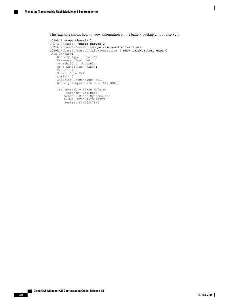
This example shows how to view information on the battery backup unit of a server:UCS-A # scope chassis 1UCS-A /chassis #scope server 3UCS-A /chassis/server #scope raid-controller 1 sasUCS-A /chassis/server/raid-controller # show raid-battery expandRAID Battery:
Battery Type: SupercapPresence: EquippedOperability: OperableOper Qualifier Reason:Vendor: LSIModel: SuperCaPSerial: 0Capacity Percentage: FullBattery Temperature (C): 54.000000
Transportable Flash Module:Presence: EquippedVendor: Cisco Systems IncModel: UCSB-RAID-1GBFMSerial: FCH164279W6
Cisco UCS Manager CLI Configuration Guide, Release 2.1600 OL-28302-04
Managing Transportable Flash Module and Supercapacitor
C H A P T E R 45Configuring Statistics-Related Policies
This chapter includes the following sections:
• Configuring Statistics Collection Policies, page 601
• Configuring Statistics Threshold Policies, page 602
Configuring Statistics Collection Policies
Statistics Collection PolicyA statistics collection policy defines how frequently statistics are to be collected (collection interval) and howfrequently the statistics are to be reported (reporting interval). Reporting intervals are longer than collectionintervals so that multiple statistical data points can be collected during the reporting interval, which providesCisco UCS Manager with sufficient data to calculate and report minimum, maximum, and average values.
For NIC statistics, Cisco UCS Manager displays the average, minimum, and maximum of the change sincethe last collection of statistics. If the values are 0, there has been no change since the last collection.
Statistics can be collected and reported for the following five functional areas of the Cisco UCS system:
• Adapter—statistics related to the adapters
• Chassis—statistics related to the blade chassis
• Host—this policy is a placeholder for future support
• Port—statistics related to the ports, including server ports, uplink Ethernet ports, and uplink FibreChannel ports
• Server—statistics related to servers
Cisco UCS Manager has one default statistics collection policy for each of the five functional areas. Youcannot create additional statistics collection policies and you cannot delete the existing default policies.You can only modify the default policies.
Note
Cisco UCS Manager CLI Configuration Guide, Release 2.1 OL-28302-04 601
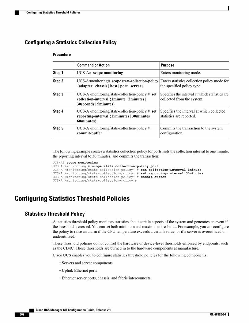
Configuring a Statistics Collection Policy
Procedure
PurposeCommand or Action
Enters monitoring mode.UCS-A# scope monitoringStep 1
Enters statistics collection policy mode forthe specified policy type.
UCS-A/monitoring # scope stats-collection-policy{adapter | chassis | host | port | server}
Step 2
Specifies the interval at which statistics arecollected from the system.
UCS-A /monitoring/stats-collection-policy # setcollection-interval {1minute | 2minutes |30seconds | 5minutes}
Step 3
Specifies the interval at which collectedstatistics are reported.
UCS-A /monitoring/stats-collection-policy # setreporting-interval {15minutes | 30minutes |60minutes}
Step 4
Commits the transaction to the systemconfiguration.
UCS-A /monitoring/stats-collection-policy #commit-buffer
Step 5
The following example creates a statistics collection policy for ports, sets the collection interval to one minute,the reporting interval to 30 minutes, and commits the transaction:UCS-A# scope monitoringUCS-A /monitoring # scope stats-collection-policy portUCS-A /monitoring/stats-collection-policy* # set collection-interval 1minuteUCS-A /monitoring/stats-collection-policy* # set reporting-interval 30minutesUCS-A /monitoring/stats-collection-policy* # commit-bufferUCS-A /monitoring/stats-collection-policy #
Configuring Statistics Threshold Policies
Statistics Threshold PolicyA statistics threshold policy monitors statistics about certain aspects of the system and generates an event ifthe threshold is crossed. You can set both minimum andmaximum thresholds. For example, you can configurethe policy to raise an alarm if the CPU temperature exceeds a certain value, or if a server is overutilized orunderutilized.
These threshold policies do not control the hardware or device-level thresholds enforced by endpoints, suchas the CIMC. Those thresholds are burned in to the hardware components at manufacture.
Cisco UCS enables you to configure statistics threshold policies for the following components:
• Servers and server components
• Uplink Ethernet ports
• Ethernet server ports, chassis, and fabric interconnects
Cisco UCS Manager CLI Configuration Guide, Release 2.1602 OL-28302-04
Configuring Statistics Threshold Policies
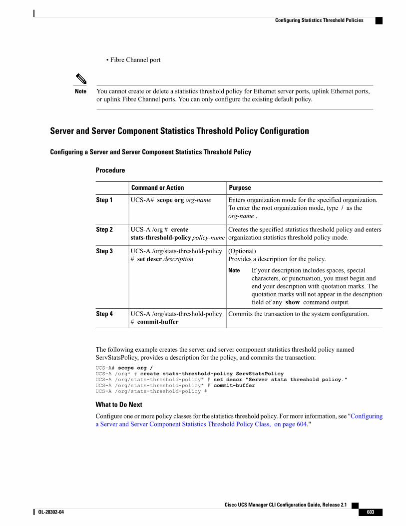
• Fibre Channel port
You cannot create or delete a statistics threshold policy for Ethernet server ports, uplink Ethernet ports,or uplink Fibre Channel ports. You can only configure the existing default policy.
Note
Server and Server Component Statistics Threshold Policy Configuration
Configuring a Server and Server Component Statistics Threshold Policy
Procedure
PurposeCommand or Action
Enters organization mode for the specified organization.To enter the root organization mode, type / as theorg-name .
UCS-A# scope org org-nameStep 1
Creates the specified statistics threshold policy and entersorganization statistics threshold policy mode.
UCS-A /org # createstats-threshold-policy policy-name
Step 2
(Optional)Provides a description for the policy.
UCS-A /org/stats-threshold-policy# set descr description
Step 3
If your description includes spaces, specialcharacters, or punctuation, you must begin andend your description with quotation marks. Thequotation marks will not appear in the descriptionfield of any show command output.
Note
Commits the transaction to the system configuration.UCS-A /org/stats-threshold-policy# commit-buffer
Step 4
The following example creates the server and server component statistics threshold policy namedServStatsPolicy, provides a description for the policy, and commits the transaction:UCS-A# scope org /UCS-A /org* # create stats-threshold-policy ServStatsPolicyUCS-A /org/stats-threshold-policy* # set descr "Server stats threshold policy."UCS-A /org/stats-threshold-policy* # commit-bufferUCS-A /org/stats-threshold-policy #
What to Do Next
Configure one or more policy classes for the statistics threshold policy. For more information, see "Configuringa Server and Server Component Statistics Threshold Policy Class, on page 604."
Cisco UCS Manager CLI Configuration Guide, Release 2.1 OL-28302-04 603
Configuring Statistics Threshold Policies
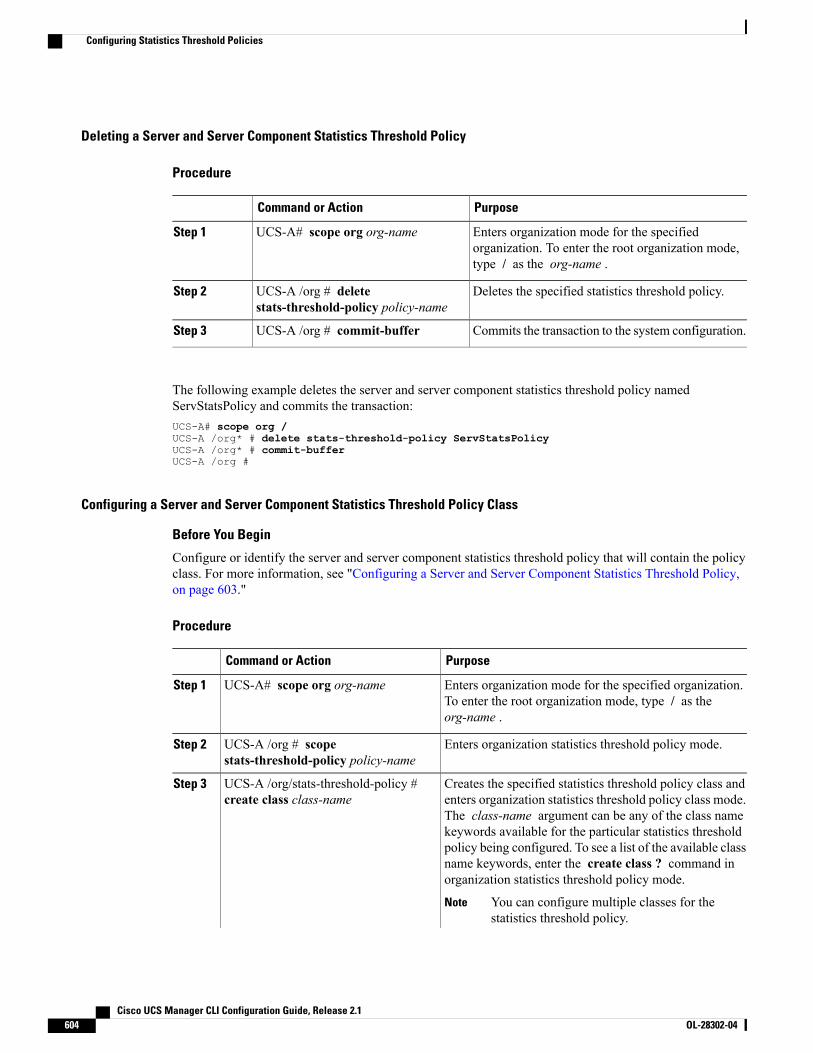
Deleting a Server and Server Component Statistics Threshold Policy
Procedure
PurposeCommand or Action
Enters organization mode for the specifiedorganization. To enter the root organization mode,type / as the org-name .
UCS-A# scope org org-nameStep 1
Deletes the specified statistics threshold policy.UCS-A /org # deletestats-threshold-policy policy-name
Step 2
Commits the transaction to the system configuration.UCS-A /org # commit-bufferStep 3
The following example deletes the server and server component statistics threshold policy namedServStatsPolicy and commits the transaction:UCS-A# scope org /UCS-A /org* # delete stats-threshold-policy ServStatsPolicyUCS-A /org* # commit-bufferUCS-A /org #
Configuring a Server and Server Component Statistics Threshold Policy Class
Before You Begin
Configure or identify the server and server component statistics threshold policy that will contain the policyclass. For more information, see "Configuring a Server and Server Component Statistics Threshold Policy,on page 603."
Procedure
PurposeCommand or Action
Enters organization mode for the specified organization.To enter the root organization mode, type / as theorg-name .
UCS-A# scope org org-nameStep 1
Enters organization statistics threshold policy mode.UCS-A /org # scopestats-threshold-policy policy-name
Step 2
Creates the specified statistics threshold policy class andenters organization statistics threshold policy class mode.
UCS-A /org/stats-threshold-policy #create class class-name
Step 3
The class-name argument can be any of the class namekeywords available for the particular statistics thresholdpolicy being configured. To see a list of the available classname keywords, enter the create class ? command inorganization statistics threshold policy mode.
You can configure multiple classes for thestatistics threshold policy.
Note
Cisco UCS Manager CLI Configuration Guide, Release 2.1604 OL-28302-04
Configuring Statistics Threshold Policies

PurposeCommand or Action
Creates the specified statistics threshold policy classproperty and enters organization statistics threshold policy
UCS-A /org/stats-threshold-policy /class# create property property-name
Step 4
class property mode. The property-name argument canbe any of the property name keywords available for theparticular policy class being configured. To see a list ofthe available property name keywords, enter the createproperty ? command in organization statistics thresholdpolicy class mode.
You can configure multiple properties for thepolicy class.
Note
Specifies the normal value for the class property. Thevalue format can vary depending on the class property
UCS-A/org/stats-threshold-policy/class/property# set normal-value value
Step 5
being configured. To see the required format, enter theset normal-value ? command in organization statisticsthreshold policy class property mode.
Creates the specified threshold value for the class propertyand enters organization statistics threshold policy classproperty threshold value mode.
UCS-A /org/stats-threshold-policy/class/property # create threshold-value{above-normal | below-normal}
Step 6
{cleared | condition | critical | info |major |minor | warning}
You can configure multiple threshold values forthe class property.
Note
Specifies the de-escalating or escalating class propertythreshold value. The value format can vary depending
UCS-A /org/stats-threshold-policy/class/property/threshold-value # set{deescalating | escalating} value
Step 7
on the class property threshold value being configured.To see the required format, enter the set deescalating ?or set escalating ? command in organization statisticsthreshold policy class property threshold value mode.
You can specify both de-escalating and escalatingclass property threshold values.
Note
Commits the transaction to the system configuration.UCS-A /org/stats-threshold-policy/class/property/threshold-value #commit-buffer
Step 8
The following example creates the server and server component statistics threshold policy class for CPUstatistics, creates a CPU temperature property, specifies that the normal CPU temperature is 48.5° C, createsan above normal warning threshold of 50° C, and commits the transaction:UCS-A# scope org /UCS-A /org* # scope stats-threshold-policy ServStatsPolicyUCS-A /org/stats-threshold-policy* # create class cpu-statsUCS-A /org/stats-threshold-policy/class* # create property cpu-tempUCS-A /org/stats-threshold-policy/class/property* # set normal-value 48.5UCS-A /org/stats-threshold-policy/class/property* # create threshold-value above-normalwarningUCS-A /org/stats-threshold-policy/class/property/threshold-value* # set escalating 50.0UCS-A /org/stats-threshold-policy/class/property/threshold-value* # commit-bufferUCS-A /org/stats-threshold-policy/class/property/threshold-value #
Cisco UCS Manager CLI Configuration Guide, Release 2.1 OL-28302-04 605
Configuring Statistics Threshold Policies
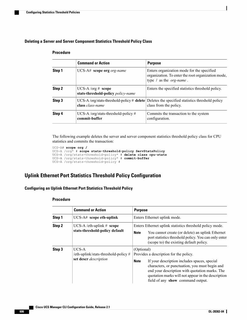
Deleting a Server and Server Component Statistics Threshold Policy Class
Procedure
PurposeCommand or Action
Enters organization mode for the specifiedorganization. To enter the root organization mode,type / as the org-name .
UCS-A# scope org org-nameStep 1
Enters the specified statistics threshold policy.UCS-A /org # scopestats-threshold-policy policy-name
Step 2
Deletes the specified statistics threshold policyclass from the policy.
UCS-A /org/stats-threshold-policy # deleteclass class-name
Step 3
Commits the transaction to the systemconfiguration.
UCS-A /org/stats-threshold-policy #commit-buffer
Step 4
The following example deletes the server and server component statistics threshold policy class for CPUstatistics and commits the transaction:UCS-A# scope org /UCS-A /org* # scope stats-threshold-policy ServStatsPolicyUCS-A /org/stats-threshold-policy* # delete class cpu-statsUCS-A /org/stats-threshold-policy* # commit-bufferUCS-A /org/stats-threshold-policy #
Uplink Ethernet Port Statistics Threshold Policy Configuration
Configuring an Uplink Ethernet Port Statistics Threshold Policy
Procedure
PurposeCommand or Action
Enters Ethernet uplink mode.UCS-A# scope eth-uplinkStep 1
Enters Ethernet uplink statistics threshold policy mode.UCS-A /eth-uplink # scopestats-threshold-policy default
Step 2
You cannot create (or delete) an uplink Ethernetport statistics threshold policy. You can only enter(scope to) the existing default policy.
Note
(Optional)Provides a description for the policy.
UCS-A/eth-uplink/stats-threshold-policy #set descr description
Step 3
If your description includes spaces, specialcharacters, or punctuation, you must begin andend your description with quotation marks. Thequotation marks will not appear in the descriptionfield of any show command output.
Note
Cisco UCS Manager CLI Configuration Guide, Release 2.1606 OL-28302-04
Configuring Statistics Threshold Policies
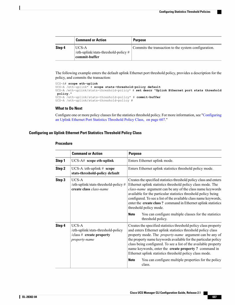
PurposeCommand or Action
Commits the transaction to the system configuration.UCS-A/eth-uplink/stats-threshold-policy #commit-buffer
Step 4
The following example enters the default uplink Ethernet port threshold policy, provides a description for thepolicy, and commits the transaction:UCS-A# scope eth-uplinkUCS-A /eth-uplink* # scope stats-threshold-policy defaultUCS-A /eth-uplink/stats-threshold-policy* # set descr "Uplink Ethernet port stats thresholdpolicy."UCS-A /eth-uplink/stats-threshold-policy* # commit-bufferUCS-A /eth-uplink/stats-threshold-policy #
What to Do Next
Configure one or more policy classes for the statistics threshold policy. For more information, see "Configuringan Uplink Ethernet Port Statistics Threshold Policy Class, on page 607."
Configuring an Uplink Ethernet Port Statistics Threshold Policy Class
Procedure
PurposeCommand or Action
Enters Ethernet uplink mode.UCS-A# scope eth-uplinkStep 1
Enters Ethernet uplink statistics threshold policy mode.UCS-A /eth-uplink # scopestats-threshold-policy default
Step 2
Creates the specified statistics threshold policy class and entersEthernet uplink statistics threshold policy class mode. The
UCS-A/eth-uplink/stats-threshold-policy #create class class-name
Step 3
class-name argument can be any of the class name keywordsavailable for the particular statistics threshold policy beingconfigured. To see a list of the available class name keywords,enter the create class ? command in Ethernet uplink statisticsthreshold policy mode.
You can configure multiple classes for the statisticsthreshold policy.
Note
Creates the specified statistics threshold policy class propertyand enters Ethernet uplink statistics threshold policy class
UCS-A/eth-uplink/stats-threshold-policy
Step 4
property mode. The property-name argument can be any of/class # create propertyproperty-name the property name keywords available for the particular policy
class being configured. To see a list of the available propertyname keywords, enter the create property ? command inEthernet uplink statistics threshold policy class mode.
You can configure multiple properties for the policyclass.
Note
Cisco UCS Manager CLI Configuration Guide, Release 2.1 OL-28302-04 607
Configuring Statistics Threshold Policies
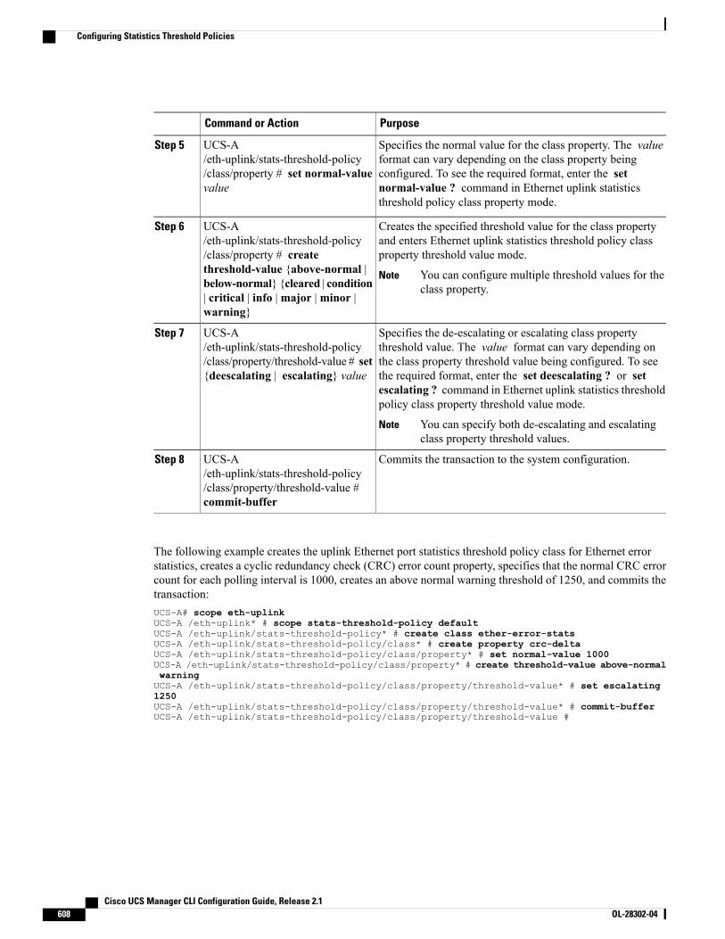
PurposeCommand or Action
Specifies the normal value for the class property. The valueformat can vary depending on the class property being
UCS-A/eth-uplink/stats-threshold-policy/class/property # set normal-valuevalue
Step 5
configured. To see the required format, enter the setnormal-value ? command in Ethernet uplink statisticsthreshold policy class property mode.
Creates the specified threshold value for the class propertyand enters Ethernet uplink statistics threshold policy classproperty threshold value mode.
UCS-A/eth-uplink/stats-threshold-policy/class/property # create
Step 6
threshold-value {above-normal | You can configure multiple threshold values for theclass property.
Notebelow-normal} {cleared | condition| critical | info |major |minor |warning}
Specifies the de-escalating or escalating class propertythreshold value. The value format can vary depending on
UCS-A/eth-uplink/stats-threshold-policy/class/property/threshold-value # set{deescalating | escalating} value
Step 7
the class property threshold value being configured. To seethe required format, enter the set deescalating ? or setescalating ? command in Ethernet uplink statistics thresholdpolicy class property threshold value mode.
You can specify both de-escalating and escalatingclass property threshold values.
Note
Commits the transaction to the system configuration.UCS-A/eth-uplink/stats-threshold-policy
Step 8
/class/property/threshold-value #commit-buffer
The following example creates the uplink Ethernet port statistics threshold policy class for Ethernet errorstatistics, creates a cyclic redundancy check (CRC) error count property, specifies that the normal CRC errorcount for each polling interval is 1000, creates an above normal warning threshold of 1250, and commits thetransaction:UCS-A# scope eth-uplinkUCS-A /eth-uplink* # scope stats-threshold-policy defaultUCS-A /eth-uplink/stats-threshold-policy* # create class ether-error-statsUCS-A /eth-uplink/stats-threshold-policy/class* # create property crc-deltaUCS-A /eth-uplink/stats-threshold-policy/class/property* # set normal-value 1000UCS-A /eth-uplink/stats-threshold-policy/class/property* # create threshold-value above-normalwarningUCS-A /eth-uplink/stats-threshold-policy/class/property/threshold-value* # set escalating1250UCS-A /eth-uplink/stats-threshold-policy/class/property/threshold-value* # commit-bufferUCS-A /eth-uplink/stats-threshold-policy/class/property/threshold-value #
Cisco UCS Manager CLI Configuration Guide, Release 2.1608 OL-28302-04
Configuring Statistics Threshold Policies
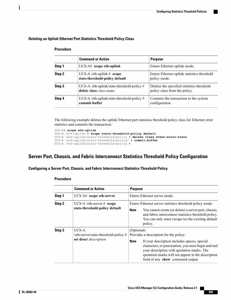
Deleting an Uplink Ethernet Port Statistics Threshold Policy Class
Procedure
PurposeCommand or Action
Enters Ethernet uplink mode.UCS-A# scope eth-uplinkStep 1
Enters Ethernet uplink statistics thresholdpolicy mode.
UCS-A /eth-uplink # scopestats-threshold-policy default
Step 2
Deletes the specified statistics thresholdpolicy class from the policy.
UCS-A /eth-uplink/stats-threshold-policy #delete class class-name
Step 3
Commits the transaction to the systemconfiguration.
UCS-A /eth-uplink/stats-threshold-policy #commit-buffer
Step 4
The following example deletes the uplink Ethernet port statistics threshold policy class for Ethernet errorstatistics and commits the transaction:UCS-A# scope eth-uplinkUCS-A /eth-uplink # scope stats-threshold-policy defaultUCS-A /eth-uplink/stats-threshold-policy # delete class ether-error-statsUCS-A /eth-uplink/stats-threshold-policy* # commit-bufferUCS-A /eth-uplink/stats-threshold-policy #
Server Port, Chassis, and Fabric Interconnect Statistics Threshold Policy Configuration
Configuring a Server Port, Chassis, and Fabric Interconnect Statistics Threshold Policy
Procedure
PurposeCommand or Action
Enters Ethernet server mode.UCS-A# scope eth-serverStep 1
Enters Ethernet server statistics threshold policy mode.UCS-A /eth-server # scopestats-threshold-policy default
Step 2
You cannot create (or delete) a server port, chassis,and fabric interconnect statistics threshold policy.You can only enter (scope to) the existing defaultpolicy.
Note
(Optional)Provides a description for the policy.
UCS-A/eth-server/stats-threshold-policy #set descr description
Step 3
If your description includes spaces, specialcharacters, or punctuation, youmust begin and endyour description with quotation marks. Thequotation marks will not appear in the descriptionfield of any show command output.
Note
Cisco UCS Manager CLI Configuration Guide, Release 2.1 OL-28302-04 609
Configuring Statistics Threshold Policies
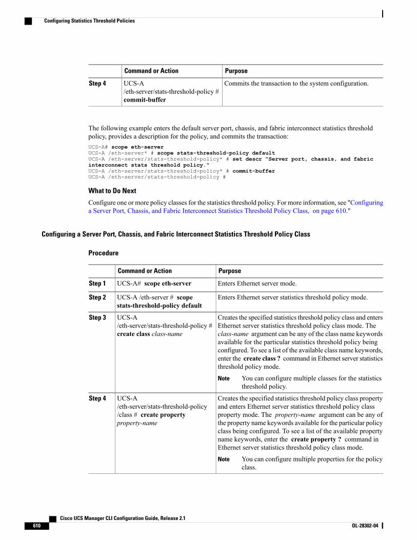
PurposeCommand or Action
Commits the transaction to the system configuration.UCS-A/eth-server/stats-threshold-policy #commit-buffer
Step 4
The following example enters the default server port, chassis, and fabric interconnect statistics thresholdpolicy, provides a description for the policy, and commits the transaction:UCS-A# scope eth-serverUCS-A /eth-server* # scope stats-threshold-policy defaultUCS-A /eth-server/stats-threshold-policy* # set descr "Server port, chassis, and fabricinterconnect stats threshold policy."UCS-A /eth-server/stats-threshold-policy* # commit-bufferUCS-A /eth-server/stats-threshold-policy #
What to Do Next
Configure one or more policy classes for the statistics threshold policy. For more information, see "Configuringa Server Port, Chassis, and Fabric Interconnect Statistics Threshold Policy Class, on page 610."
Configuring a Server Port, Chassis, and Fabric Interconnect Statistics Threshold Policy Class
Procedure
PurposeCommand or Action
Enters Ethernet server mode.UCS-A# scope eth-serverStep 1
Enters Ethernet server statistics threshold policy mode.UCS-A /eth-server # scopestats-threshold-policy default
Step 2
Creates the specified statistics threshold policy class and entersEthernet server statistics threshold policy class mode. The
UCS-A/eth-server/stats-threshold-policy #create class class-name
Step 3
class-name argument can be any of the class name keywordsavailable for the particular statistics threshold policy beingconfigured. To see a list of the available class name keywords,enter the create class ? command in Ethernet server statisticsthreshold policy mode.
You can configure multiple classes for the statisticsthreshold policy.
Note
Creates the specified statistics threshold policy class propertyand enters Ethernet server statistics threshold policy class
UCS-A/eth-server/stats-threshold-policy
Step 4
property mode. The property-name argument can be any of/class # create propertyproperty-name the property name keywords available for the particular policy
class being configured. To see a list of the available propertyname keywords, enter the create property ? command inEthernet server statistics threshold policy class mode.
You can configure multiple properties for the policyclass.
Note
Cisco UCS Manager CLI Configuration Guide, Release 2.1610 OL-28302-04
Configuring Statistics Threshold Policies
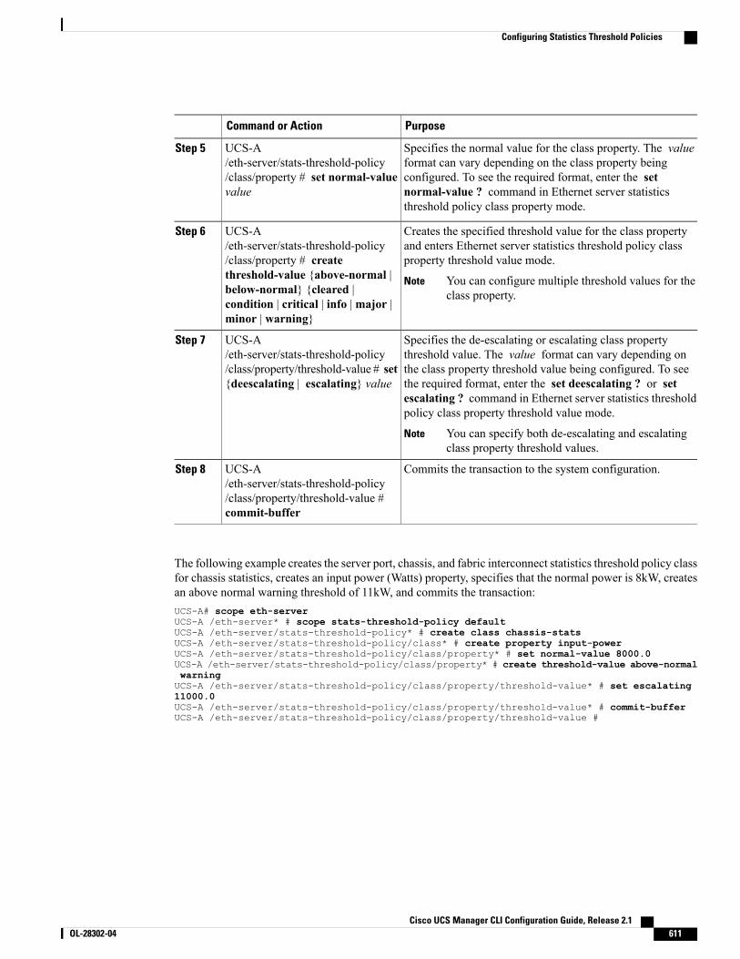
PurposeCommand or Action
Specifies the normal value for the class property. The valueformat can vary depending on the class property being
UCS-A/eth-server/stats-threshold-policy/class/property # set normal-valuevalue
Step 5
configured. To see the required format, enter the setnormal-value ? command in Ethernet server statisticsthreshold policy class property mode.
Creates the specified threshold value for the class propertyand enters Ethernet server statistics threshold policy classproperty threshold value mode.
UCS-A/eth-server/stats-threshold-policy/class/property # create
Step 6
threshold-value {above-normal | You can configure multiple threshold values for theclass property.
Notebelow-normal} {cleared |condition | critical | info |major |minor | warning}
Specifies the de-escalating or escalating class propertythreshold value. The value format can vary depending on
UCS-A/eth-server/stats-threshold-policy/class/property/threshold-value # set{deescalating | escalating} value
Step 7
the class property threshold value being configured. To seethe required format, enter the set deescalating ? or setescalating ? command in Ethernet server statistics thresholdpolicy class property threshold value mode.
You can specify both de-escalating and escalatingclass property threshold values.
Note
Commits the transaction to the system configuration.UCS-A/eth-server/stats-threshold-policy
Step 8
/class/property/threshold-value #commit-buffer
The following example creates the server port, chassis, and fabric interconnect statistics threshold policy classfor chassis statistics, creates an input power (Watts) property, specifies that the normal power is 8kW, createsan above normal warning threshold of 11kW, and commits the transaction:UCS-A# scope eth-serverUCS-A /eth-server* # scope stats-threshold-policy defaultUCS-A /eth-server/stats-threshold-policy* # create class chassis-statsUCS-A /eth-server/stats-threshold-policy/class* # create property input-powerUCS-A /eth-server/stats-threshold-policy/class/property* # set normal-value 8000.0UCS-A /eth-server/stats-threshold-policy/class/property* # create threshold-value above-normalwarningUCS-A /eth-server/stats-threshold-policy/class/property/threshold-value* # set escalating11000.0UCS-A /eth-server/stats-threshold-policy/class/property/threshold-value* # commit-bufferUCS-A /eth-server/stats-threshold-policy/class/property/threshold-value #
Cisco UCS Manager CLI Configuration Guide, Release 2.1 OL-28302-04 611
Configuring Statistics Threshold Policies
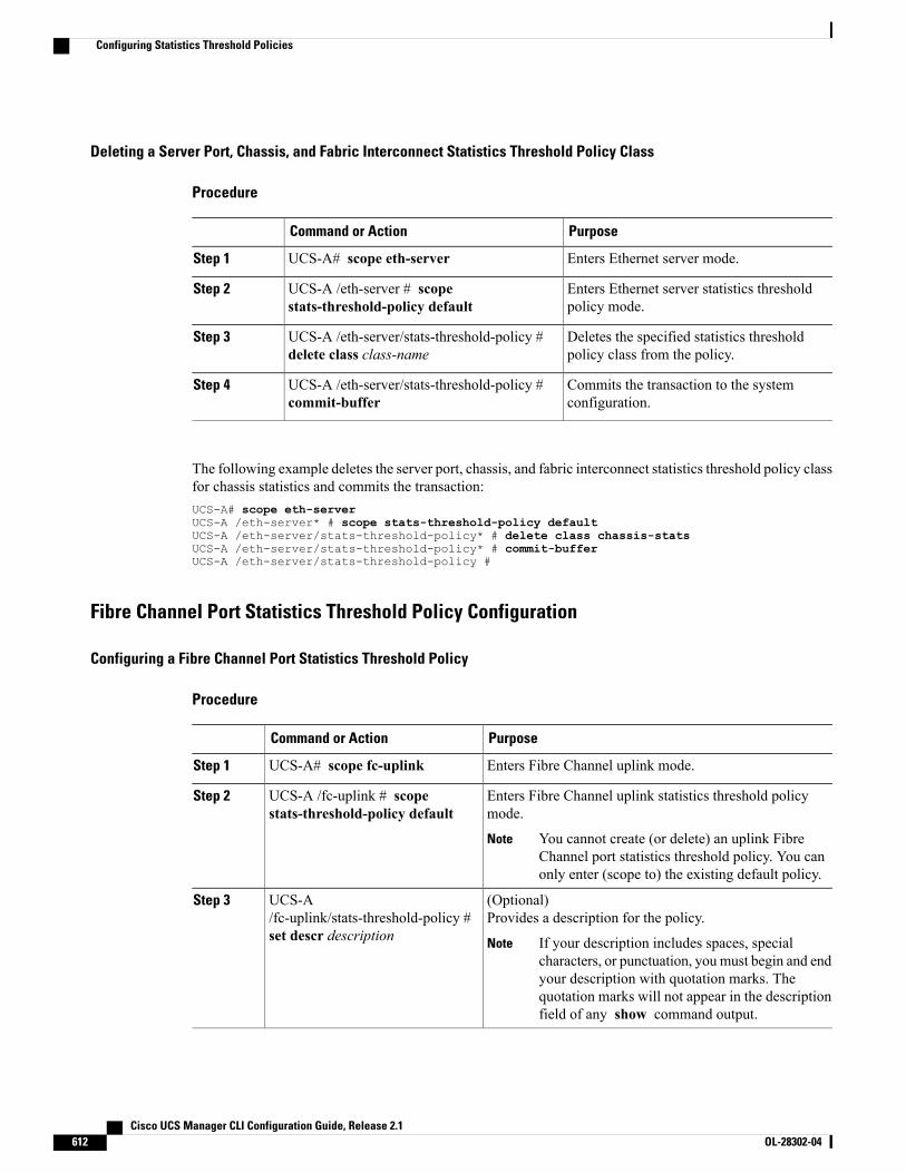
Deleting a Server Port, Chassis, and Fabric Interconnect Statistics Threshold Policy Class
Procedure
PurposeCommand or Action
Enters Ethernet server mode.UCS-A# scope eth-serverStep 1
Enters Ethernet server statistics thresholdpolicy mode.
UCS-A /eth-server # scopestats-threshold-policy default
Step 2
Deletes the specified statistics thresholdpolicy class from the policy.
UCS-A /eth-server/stats-threshold-policy #delete class class-name
Step 3
Commits the transaction to the systemconfiguration.
UCS-A /eth-server/stats-threshold-policy #commit-buffer
Step 4
The following example deletes the server port, chassis, and fabric interconnect statistics threshold policy classfor chassis statistics and commits the transaction:UCS-A# scope eth-serverUCS-A /eth-server* # scope stats-threshold-policy defaultUCS-A /eth-server/stats-threshold-policy* # delete class chassis-statsUCS-A /eth-server/stats-threshold-policy* # commit-bufferUCS-A /eth-server/stats-threshold-policy #
Fibre Channel Port Statistics Threshold Policy Configuration
Configuring a Fibre Channel Port Statistics Threshold Policy
Procedure
PurposeCommand or Action
Enters Fibre Channel uplink mode.UCS-A# scope fc-uplinkStep 1
Enters Fibre Channel uplink statistics threshold policymode.
UCS-A /fc-uplink # scopestats-threshold-policy default
Step 2
You cannot create (or delete) an uplink FibreChannel port statistics threshold policy. You canonly enter (scope to) the existing default policy.
Note
(Optional)Provides a description for the policy.
UCS-A/fc-uplink/stats-threshold-policy #set descr description
Step 3
If your description includes spaces, specialcharacters, or punctuation, youmust begin and endyour description with quotation marks. Thequotation marks will not appear in the descriptionfield of any show command output.
Note
Cisco UCS Manager CLI Configuration Guide, Release 2.1612 OL-28302-04
Configuring Statistics Threshold Policies
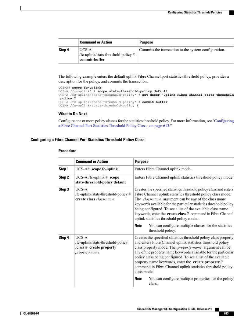
PurposeCommand or Action
Commits the transaction to the system configuration.UCS-A/fc-uplink/stats-threshold-policy #commit-buffer
Step 4
The following example enters the default uplink Fibre Channel port statistics threshold policy, provides adescription for the policy, and commits the transaction:UCS-A# scope fc-uplinkUCS-A /fc-uplink* # scope stats-threshold-policy defaultUCS-A /fc-uplink/stats-threshold-policy* # set descr "Uplink Fibre Channel stats thresholdpolicy."UCS-A /fc-uplink/stats-threshold-policy* # commit-bufferUCS-A /fc-uplink/stats-threshold-policy #
What to Do Next
Configure one or more policy classes for the statistics threshold policy. For more information, see "Configuringa Fibre Channel Port Statistics Threshold Policy Class, on page 613."
Configuring a Fibre Channel Port Statistics Threshold Policy Class
Procedure
PurposeCommand or Action
Enters Fibre Channel uplink mode.UCS-A# scope fc-uplinkStep 1
Enters Fibre Channel uplink statistics threshold policy mode.UCS-A /fc-uplink # scopestats-threshold-policy default
Step 2
Creates the specified statistics threshold policy class and entersFibre Channel uplink statistics threshold policy class mode.
UCS-A/fc-uplink/stats-threshold-policy #create class class-name
Step 3
The class-name argument can be any of the class namekeywords available for the particular statistics threshold policybeing configured. To see a list of the available class namekeywords, enter the create class ? command in Fibre Channeluplink statistics threshold policy mode.
You can configure multiple classes for the statisticsthreshold policy.
Note
Creates the specified statistics threshold policy class propertyand enters Fibre Channel uplink statistics threshold policy
UCS-A/fc-uplink/stats-threshold-policy
Step 4
class property mode. The property-name argument can be/class # create propertyproperty-name any of the property name keywords available for the particular
policy class being configured. To see a list of the availableproperty name keywords, enter the create property ?command in Fibre Channel uplink statistics threshold policyclass mode.
You can configure multiple properties for the policyclass.
Note
Cisco UCS Manager CLI Configuration Guide, Release 2.1 OL-28302-04 613
Configuring Statistics Threshold Policies
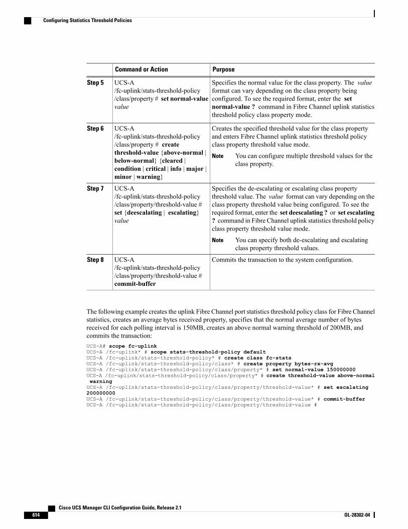
PurposeCommand or Action
Specifies the normal value for the class property. The valueformat can vary depending on the class property being
UCS-A/fc-uplink/stats-threshold-policy/class/property # set normal-valuevalue
Step 5
configured. To see the required format, enter the setnormal-value ? command in Fibre Channel uplink statisticsthreshold policy class property mode.
Creates the specified threshold value for the class propertyand enters Fibre Channel uplink statistics threshold policyclass property threshold value mode.
UCS-A/fc-uplink/stats-threshold-policy/class/property # create
Step 6
threshold-value {above-normal | You can configure multiple threshold values for theclass property.
Notebelow-normal} {cleared |condition | critical | info |major |minor | warning}
Specifies the de-escalating or escalating class propertythreshold value. The value format can vary depending on the
UCS-A/fc-uplink/stats-threshold-policy/class/property/threshold-value #
Step 7
class property threshold value being configured. To see theset {deescalating | escalating}value
required format, enter the set deescalating ? or set escalating? command in Fibre Channel uplink statistics threshold policyclass property threshold value mode.
You can specify both de-escalating and escalatingclass property threshold values.
Note
Commits the transaction to the system configuration.UCS-A/fc-uplink/stats-threshold-policy
Step 8
/class/property/threshold-value #commit-buffer
The following example creates the uplink Fibre Channel port statistics threshold policy class for Fibre Channelstatistics, creates an average bytes received property, specifies that the normal average number of bytesreceived for each polling interval is 150MB, creates an above normal warning threshold of 200MB, andcommits the transaction:UCS-A# scope fc-uplinkUCS-A /fc-uplink* # scope stats-threshold-policy defaultUCS-A /fc-uplink/stats-threshold-policy* # create class fc-statsUCS-A /fc-uplink/stats-threshold-policy/class* # create property bytes-rx-avgUCS-A /fc-uplink/stats-threshold-policy/class/property* # set normal-value 150000000UCS-A /fc-uplink/stats-threshold-policy/class/property* # create threshold-value above-normalwarningUCS-A /fc-uplink/stats-threshold-policy/class/property/threshold-value* # set escalating200000000UCS-A /fc-uplink/stats-threshold-policy/class/property/threshold-value* # commit-bufferUCS-A /fc-uplink/stats-threshold-policy/class/property/threshold-value #
Cisco UCS Manager CLI Configuration Guide, Release 2.1614 OL-28302-04
Configuring Statistics Threshold Policies
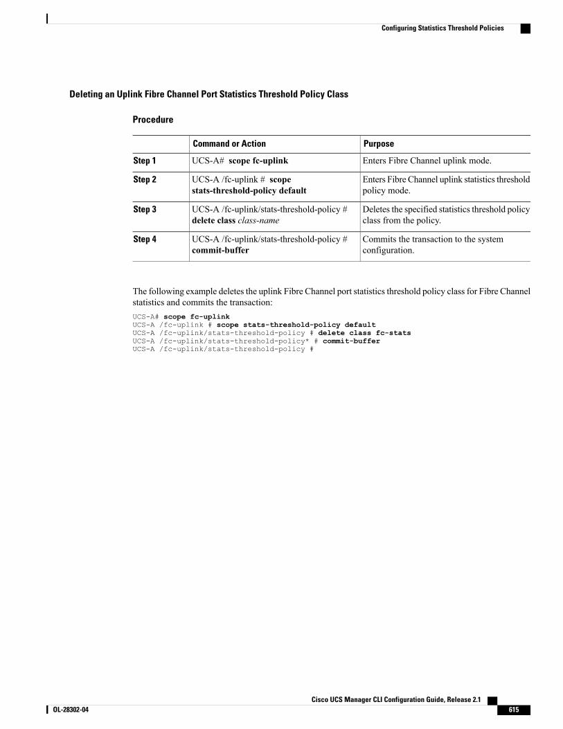
Deleting an Uplink Fibre Channel Port Statistics Threshold Policy Class
Procedure
PurposeCommand or Action
Enters Fibre Channel uplink mode.UCS-A# scope fc-uplinkStep 1
Enters Fibre Channel uplink statistics thresholdpolicy mode.
UCS-A /fc-uplink # scopestats-threshold-policy default
Step 2
Deletes the specified statistics threshold policyclass from the policy.
UCS-A /fc-uplink/stats-threshold-policy #delete class class-name
Step 3
Commits the transaction to the systemconfiguration.
UCS-A /fc-uplink/stats-threshold-policy #commit-buffer
Step 4
The following example deletes the uplink Fibre Channel port statistics threshold policy class for Fibre Channelstatistics and commits the transaction:UCS-A# scope fc-uplinkUCS-A /fc-uplink # scope stats-threshold-policy defaultUCS-A /fc-uplink/stats-threshold-policy # delete class fc-statsUCS-A /fc-uplink/stats-threshold-policy* # commit-bufferUCS-A /fc-uplink/stats-threshold-policy #
Cisco UCS Manager CLI Configuration Guide, Release 2.1 OL-28302-04 615
Configuring Statistics Threshold Policies

Cisco UCS Manager CLI Configuration Guide, Release 2.1616 OL-28302-04
Configuring Statistics Threshold Policies
C H A P T E R 46Configuring Call Home
This chapter includes the following sections:
• Call Home, page 617
• Call Home Considerations and Guidelines, page 619
• Cisco UCS Faults and Call Home Severity Levels, page 620
• Cisco Smart Call Home, page 621
• Configuring Call Home, page 622
• Disabling Call Home, page 624
• Enabling Call Home, page 624
• Configuring System Inventory Messages, page 625
• Configuring Call Home Profiles, page 626
• Sending a Test Call Home Alert, page 630
• Configuring Call Home Policies, page 630
• Example: Configuring Call Home for Smart Call Home, page 633
Call HomeCall Home provides an email-based notification for critical system policies. A range of message formats areavailable for compatibility with pager services or XML-based automated parsing applications. You can usethis feature to page a network support engineer, email a Network Operations Center, or use Cisco Smart CallHome services to generate a case with the Technical Assistance Center.
The Call Home feature can deliver alert messages containing information about diagnostics and environmentalfaults and events.
The Call Home feature can deliver alerts to multiple recipients, referred to as Call Home destination profiles.Each profile includes configurable message formats and content categories. A predefined destination profileis provided for sending alerts to the Cisco TAC, but you also can define your own destination profiles.
When you configure Call Home to send messages, Cisco UCS Manager executes the appropriate CLI showcommand and attaches the command output to the message.
Cisco UCS Manager CLI Configuration Guide, Release 2.1 OL-28302-04 617
Cisco UCS delivers Call Home messages in the following formats:
• Short text format which provides a one or two line description of the fault that is suitable for pagers orprinted reports.
• Full text format which provides fully formatted message with detailed information that is suitable forhuman reading.
• XMLmachine readable format that uses Extensible Markup Language (XML) and Adaptive MessagingLanguage (AML)XML schema definition (XSD). TheAMLXSD is published on the Cisco.comwebsite.The XML format enables communication with the Cisco Systems Technical Assistance Center.
For information about the faults that can trigger Call Home email alerts, see the Cisco UCS Faults and ErrorMessages Reference.
Cisco UCS Manager CLI Configuration Guide, Release 2.1618 OL-28302-04
Call Home
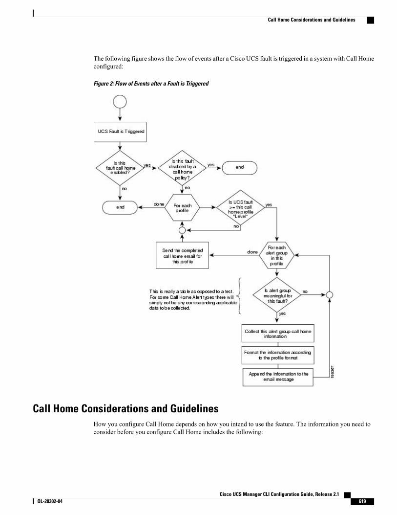
The following figure shows the flow of events after a Cisco UCS fault is triggered in a systemwith Call Homeconfigured:
Figure 2: Flow of Events after a Fault is Triggered
Call Home Considerations and GuidelinesHow you configure Call Home depends on how you intend to use the feature. The information you need toconsider before you configure Call Home includes the following:
Cisco UCS Manager CLI Configuration Guide, Release 2.1 OL-28302-04 619
Call Home Considerations and Guidelines
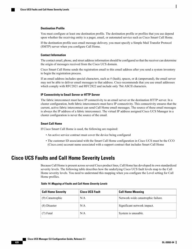
Destination Profile
You must configure at least one destination profile. The destination profile or profiles that you use dependupon whether the receiving entity is a pager, email, or automated service such as Cisco Smart Call Home.
If the destination profile uses email message delivery, you must specify a Simple Mail Transfer Protocol(SMTP) server when you configure Call Home.
Contact Information
The contact email, phone, and street address information should be configured so that the receiver can determinethe origin of messages received from the Cisco UCS domain.
Cisco Smart Call Home sends the registration email to this email address after you send a system inventoryto begin the registration process.
If an email address includes special characters, such as # (hash), spaces, or & (ampersand), the email servermay not be able to deliver email messages to that address. Cisco recommends that you use email addresseswhich comply with RFC2821 and RFC2822 and include only 7bit ASCII characters.
IP Connectivity to Email Server or HTTP Server
The fabric interconnect must have IP connectivity to an email server or the destination HTTP server. In acluster configuration, both fabric interconnects must have IP connectivity. This connectivity ensures that thecurrent, active fabric interconnect can send Call Home email messages. The source of these email messagesis always the IP address of a fabric interconnect. The virtual IP address assigned Cisco UCS Manager in acluster configuration is never the source of the email.
Smart Call Home
If Cisco Smart Call Home is used, the following are required:
• An active service contract must cover the device being configured
• The customer ID associated with the Smart Call Home configuration in Cisco UCS must be the CCO(Cisco.com) account name associated with a support contract that includes Smart Call Home
Cisco UCS Faults and Call Home Severity LevelsBecause Call Home is present across several Cisco product lines, Call Home has developed its own standardizedseverity levels. The following table describes how the underlying Cisco UCS fault levels map to the CallHome severity levels. You need to understand this mapping when you configure the Level setting for CallHome profiles.
Table 14: Mapping of Faults and Call Home Severity Levels
Call Home MeaningCisco UCS FaultCall Home Severity
Network-wide catastrophic failure.N/A(9) Catastrophic
Significant network impact.N/A(8) Disaster
System is unusable.N/A(7) Fatal
Cisco UCS Manager CLI Configuration Guide, Release 2.1620 OL-28302-04
Cisco UCS Faults and Call Home Severity Levels
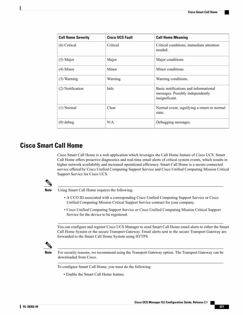
Call Home MeaningCisco UCS FaultCall Home Severity
Critical conditions, immediate attentionneeded.
Critical(6) Critical
Major conditions.Major(5) Major
Minor conditions.Minor(4) Minor
Warning conditions.Warning(3) Warning
Basic notifications and informationalmessages. Possibly independentlyinsignificant.
Info(2) Notification
Normal event, signifying a return to normalstate.
Clear(1) Normal
Debugging messages.N/A(0) debug
Cisco Smart Call HomeCisco Smart Call Home is a web application which leverages the Call Home feature of Cisco UCS. SmartCall Home offers proactive diagnostics and real-time email alerts of critical system events, which results inhigher network availability and increased operational efficiency. Smart Call Home is a secure connectedservice offered by Cisco Unified Computing Support Service and Cisco Unified Computing Mission CriticalSupport Service for Cisco UCS.
Using Smart Call Home requires the following:Note
• A CCO ID associated with a corresponding Cisco Unified Computing Support Service or CiscoUnified Computing Mission Critical Support Service contract for your company.
• Cisco Unified Computing Support Service or Cisco Unified Computing Mission Critical SupportService for the device to be registered.
You can configure and register Cisco UCSManager to send Smart Call Home email alerts to either the SmartCall Home System or the secure Transport Gateway. Email alerts sent to the secure Transport Gateway areforwarded to the Smart Call Home System using HTTPS.
For security reasons, we recommend using the Transport Gateway option. The Transport Gateway can bedownloaded from Cisco.
Note
To configure Smart Call Home, you must do the following:
• Enable the Smart Call Home feature.
Cisco UCS Manager CLI Configuration Guide, Release 2.1 OL-28302-04 621
Cisco Smart Call Home
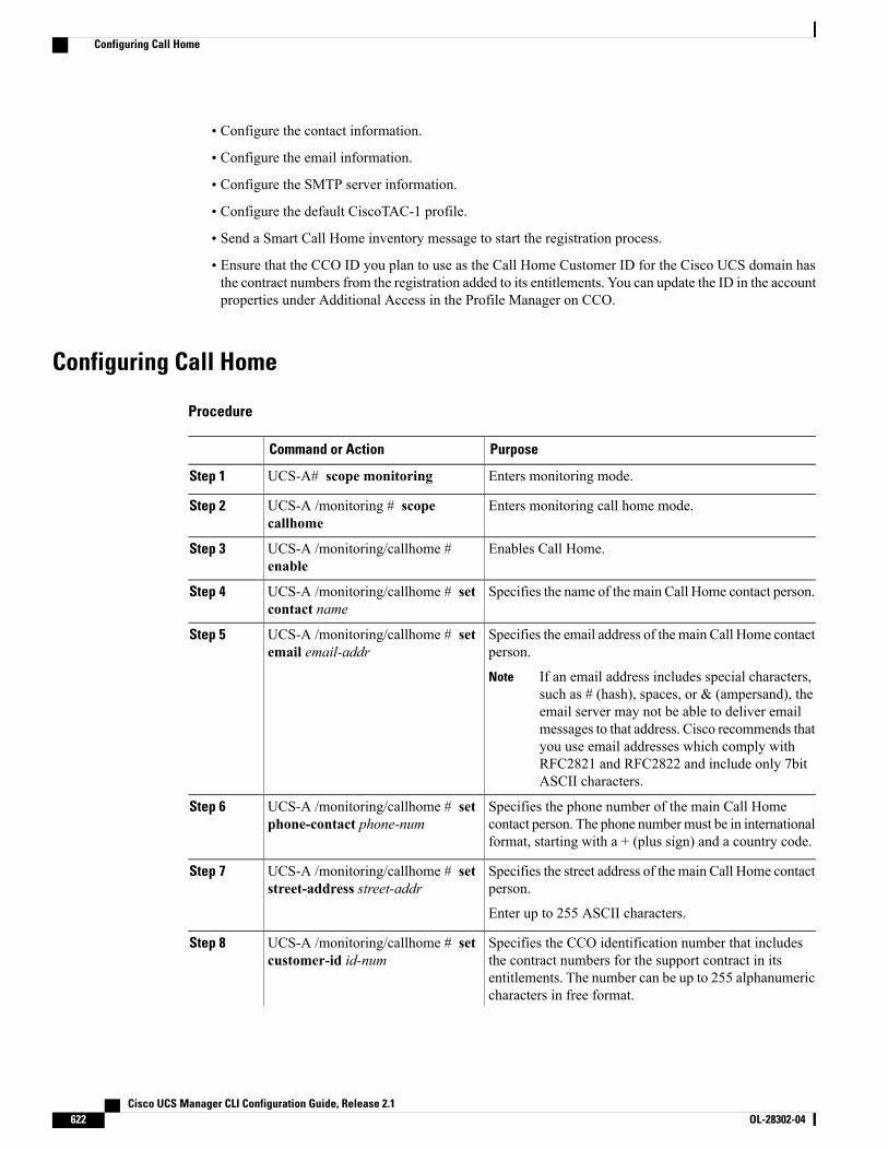
• Configure the contact information.
• Configure the email information.
• Configure the SMTP server information.
• Configure the default CiscoTAC-1 profile.
• Send a Smart Call Home inventory message to start the registration process.
• Ensure that the CCO ID you plan to use as the Call Home Customer ID for the Cisco UCS domain hasthe contract numbers from the registration added to its entitlements. You can update the ID in the accountproperties under Additional Access in the Profile Manager on CCO.
Configuring Call Home
Procedure
PurposeCommand or Action
Enters monitoring mode.UCS-A# scope monitoringStep 1
Enters monitoring call home mode.UCS-A /monitoring # scopecallhome
Step 2
Enables Call Home.UCS-A /monitoring/callhome #enable
Step 3
Specifies the name of the main Call Home contact person.UCS-A /monitoring/callhome # setcontact name
Step 4
Specifies the email address of the main Call Home contactperson.
UCS-A /monitoring/callhome # setemail email-addr
Step 5
If an email address includes special characters,such as # (hash), spaces, or & (ampersand), theemail server may not be able to deliver emailmessages to that address. Cisco recommends thatyou use email addresses which comply withRFC2821 and RFC2822 and include only 7bitASCII characters.
Note
Specifies the phone number of the main Call Homecontact person. The phone numbermust be in internationalformat, starting with a + (plus sign) and a country code.
UCS-A /monitoring/callhome # setphone-contact phone-num
Step 6
Specifies the street address of the main Call Home contactperson.
UCS-A /monitoring/callhome # setstreet-address street-addr
Step 7
Enter up to 255 ASCII characters.
Specifies the CCO identification number that includesthe contract numbers for the support contract in its
UCS-A /monitoring/callhome # setcustomer-id id-num
Step 8
entitlements. The number can be up to 255 alphanumericcharacters in free format.
Cisco UCS Manager CLI Configuration Guide, Release 2.1622 OL-28302-04
Configuring Call Home
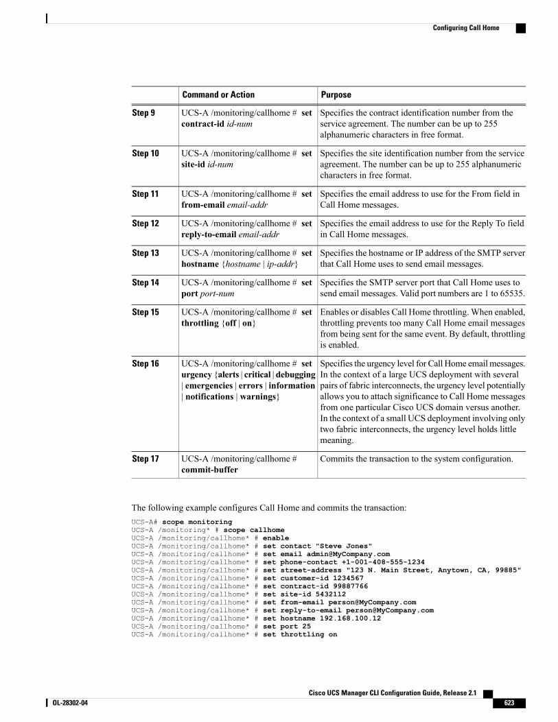
PurposeCommand or Action
Specifies the contract identification number from theservice agreement. The number can be up to 255alphanumeric characters in free format.
UCS-A /monitoring/callhome # setcontract-id id-num
Step 9
Specifies the site identification number from the serviceagreement. The number can be up to 255 alphanumericcharacters in free format.
UCS-A /monitoring/callhome # setsite-id id-num
Step 10
Specifies the email address to use for the From field inCall Home messages.
UCS-A /monitoring/callhome # setfrom-email email-addr
Step 11
Specifies the email address to use for the Reply To fieldin Call Home messages.
UCS-A /monitoring/callhome # setreply-to-email email-addr
Step 12
Specifies the hostname or IP address of the SMTP serverthat Call Home uses to send email messages.
UCS-A /monitoring/callhome # sethostname {hostname | ip-addr}
Step 13
Specifies the SMTP server port that Call Home uses tosend email messages. Valid port numbers are 1 to 65535.
UCS-A /monitoring/callhome # setport port-num
Step 14
Enables or disables Call Home throttling. When enabled,throttling prevents too many Call Home email messages
UCS-A /monitoring/callhome # setthrottling {off | on}
Step 15
from being sent for the same event. By default, throttlingis enabled.
Specifies the urgency level for Call Home email messages.In the context of a large UCS deployment with several
UCS-A /monitoring/callhome # seturgency {alerts | critical | debugging
Step 16
pairs of fabric interconnects, the urgency level potentially| emergencies | errors | information| notifications | warnings} allows you to attach significance to Call Home messages
from one particular Cisco UCS domain versus another.In the context of a small UCS deployment involving onlytwo fabric interconnects, the urgency level holds littlemeaning.
Commits the transaction to the system configuration.UCS-A /monitoring/callhome #commit-buffer
Step 17
The following example configures Call Home and commits the transaction:UCS-A# scope monitoringUCS-A /monitoring* # scope callhomeUCS-A /monitoring/callhome* # enableUCS-A /monitoring/callhome* # set contact "Steve Jones"UCS-A /monitoring/callhome* # set email [email protected] /monitoring/callhome* # set phone-contact +1-001-408-555-1234UCS-A /monitoring/callhome* # set street-address "123 N. Main Street, Anytown, CA, 99885"UCS-A /monitoring/callhome* # set customer-id 1234567UCS-A /monitoring/callhome* # set contract-id 99887766UCS-A /monitoring/callhome* # set site-id 5432112UCS-A /monitoring/callhome* # set from-email [email protected] /monitoring/callhome* # set reply-to-email [email protected] /monitoring/callhome* # set hostname 192.168.100.12UCS-A /monitoring/callhome* # set port 25UCS-A /monitoring/callhome* # set throttling on
Cisco UCS Manager CLI Configuration Guide, Release 2.1 OL-28302-04 623
Configuring Call Home

UCS-A /monitoring/callhome* # set urgency informationUCS-A /monitoring/callhome* # commit-bufferUCS-A /monitoring/callhome #
Disabling Call Home
Procedure
PurposeCommand or Action
Enters monitoring mode.UCS-A# scope monitoringStep 1
Enters monitoring call home mode.UCS-A /monitoring # scope callhomeStep 2
Enables Call Home.UCS-A /monitoring/callhome # disableStep 3
Commits the transaction to the systemconfiguration.
UCS-A /monitoring/callhome #commit-buffer
Step 4
The following example disables Call Home and commits the transaction:UCS-A# scope monitoringUCS-A /monitoring # scope callhomeUCS-A /monitoring/callhome # disableUCS-A /monitoring/callhome* # commit-bufferUCS-A /monitoring/callhome #
Enabling Call Home
Procedure
PurposeCommand or Action
Enters monitoring mode.UCS-A# scope monitoringStep 1
Enters monitoring call home mode.UCS-A /monitoring # scope callhomeStep 2
Enables Call Home.UCS-A /monitoring/callhome # enableStep 3
Commits the transaction to the systemconfiguration.
UCS-A /monitoring/callhome #commit-buffer
Step 4
The following example enables Call Home and commits the transaction:UCS-A# scope monitoringUCS-A /monitoring # scope callhomeUCS-A /monitoring/callhome # enableUCS-A /monitoring/callhome* # commit-bufferUCS-A /monitoring/callhome #
Cisco UCS Manager CLI Configuration Guide, Release 2.1624 OL-28302-04
Disabling Call Home
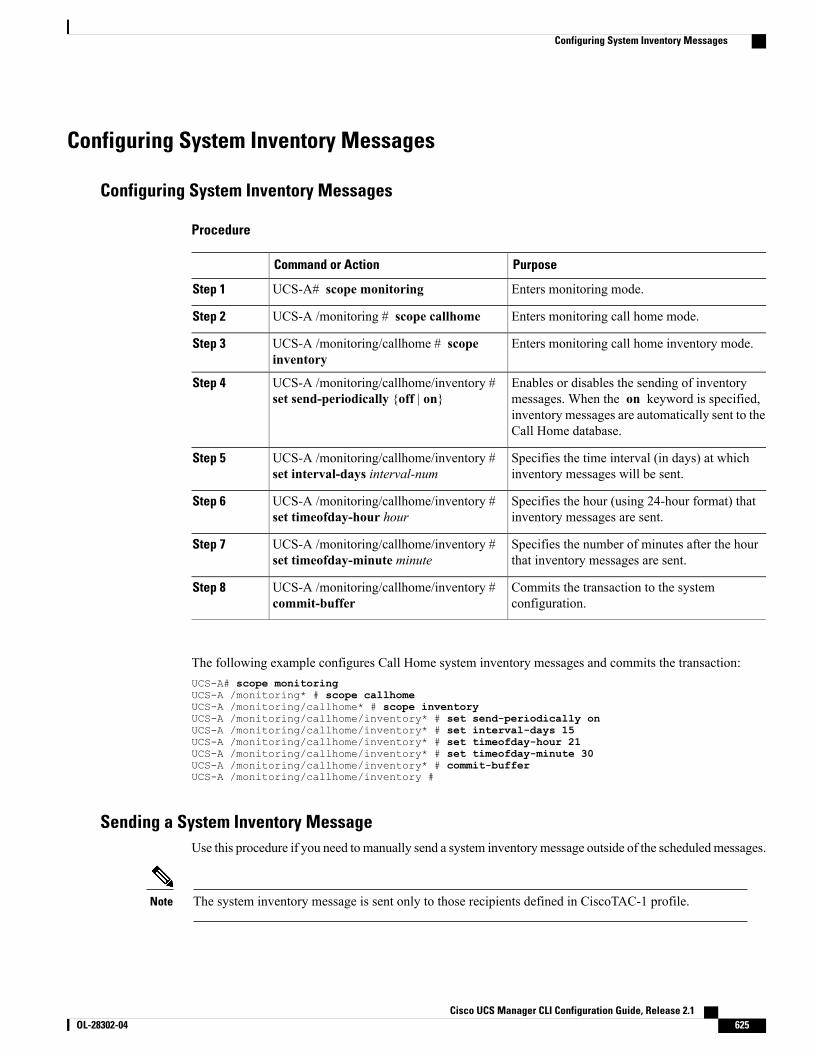
Configuring System Inventory Messages
Configuring System Inventory Messages
Procedure
PurposeCommand or Action
Enters monitoring mode.UCS-A# scope monitoringStep 1
Enters monitoring call home mode.UCS-A /monitoring # scope callhomeStep 2
Enters monitoring call home inventory mode.UCS-A /monitoring/callhome # scopeinventory
Step 3
Enables or disables the sending of inventorymessages. When the on keyword is specified,
UCS-A /monitoring/callhome/inventory #set send-periodically {off | on}
Step 4
inventory messages are automatically sent to theCall Home database.
Specifies the time interval (in days) at whichinventory messages will be sent.
UCS-A /monitoring/callhome/inventory #set interval-days interval-num
Step 5
Specifies the hour (using 24-hour format) thatinventory messages are sent.
UCS-A /monitoring/callhome/inventory #set timeofday-hour hour
Step 6
Specifies the number of minutes after the hourthat inventory messages are sent.
UCS-A /monitoring/callhome/inventory #set timeofday-minute minute
Step 7
Commits the transaction to the systemconfiguration.
UCS-A /monitoring/callhome/inventory #commit-buffer
Step 8
The following example configures Call Home system inventory messages and commits the transaction:UCS-A# scope monitoringUCS-A /monitoring* # scope callhomeUCS-A /monitoring/callhome* # scope inventoryUCS-A /monitoring/callhome/inventory* # set send-periodically onUCS-A /monitoring/callhome/inventory* # set interval-days 15UCS-A /monitoring/callhome/inventory* # set timeofday-hour 21UCS-A /monitoring/callhome/inventory* # set timeofday-minute 30UCS-A /monitoring/callhome/inventory* # commit-bufferUCS-A /monitoring/callhome/inventory #
Sending a System Inventory MessageUse this procedure if you need to manually send a system inventorymessage outside of the scheduledmessages.
The system inventory message is sent only to those recipients defined in CiscoTAC-1 profile.Note
Cisco UCS Manager CLI Configuration Guide, Release 2.1 OL-28302-04 625
Configuring System Inventory Messages
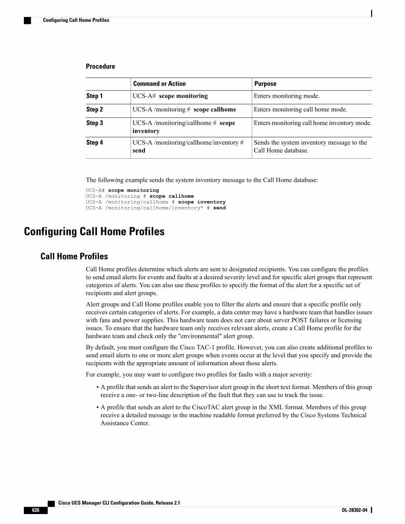
Procedure
PurposeCommand or Action
Enters monitoring mode.UCS-A# scope monitoringStep 1
Enters monitoring call home mode.UCS-A /monitoring # scope callhomeStep 2
Enters monitoring call home inventory mode.UCS-A /monitoring/callhome # scopeinventory
Step 3
Sends the system inventory message to theCall Home database.
UCS-A /monitoring/callhome/inventory #send
Step 4
The following example sends the system inventory message to the Call Home database:UCS-A# scope monitoringUCS-A /monitoring # scope callhomeUCS-A /monitoring/callhome # scope inventoryUCS-A /monitoring/callhome/inventory* # send
Configuring Call Home Profiles
Call Home ProfilesCall Home profiles determine which alerts are sent to designated recipients. You can configure the profilesto send email alerts for events and faults at a desired severity level and for specific alert groups that representcategories of alerts. You can also use these profiles to specify the format of the alert for a specific set ofrecipients and alert groups.
Alert groups and Call Home profiles enable you to filter the alerts and ensure that a specific profile onlyreceives certain categories of alerts. For example, a data center may have a hardware team that handles issueswith fans and power supplies. This hardware team does not care about server POST failures or licensingissues. To ensure that the hardware team only receives relevant alerts, create a Call Home profile for thehardware team and check only the "environmental" alert group.
By default, you must configure the Cisco TAC-1 profile. However, you can also create additional profiles tosend email alerts to one or more alert groups when events occur at the level that you specify and provide therecipients with the appropriate amount of information about those alerts.
For example, you may want to configure two profiles for faults with a major severity:
• A profile that sends an alert to the Supervisor alert group in the short text format. Members of this groupreceive a one- or two-line description of the fault that they can use to track the issue.
• A profile that sends an alert to the CiscoTAC alert group in the XML format. Members of this groupreceive a detailed message in the machine readable format preferred by the Cisco Systems TechnicalAssistance Center.
Cisco UCS Manager CLI Configuration Guide, Release 2.1626 OL-28302-04
Configuring Call Home Profiles
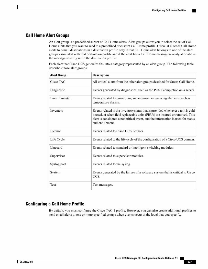
Call Home Alert GroupsAn alert group is a predefined subset of Call Home alerts. Alert groups allow you to select the set of CallHome alerts that you want to send to a predefined or custom Call Home profile. Cisco UCS sends Call Homealerts to e-mail destinations in a destination profile only if that Call Home alert belongs to one of the alertgroups associated with that destination profile and if the alert has a Call Home message severity at or abovethe message severity set in the destination profile
Each alert that Cisco UCS generates fits into a category represented by an alert group. The following tabledescribes those alert groups:
DescriptionAlert Group
All critical alerts from the other alert groups destined for Smart Call Home.Cisco TAC
Events generated by diagnostics, such as the POST completion on a server.Diagnostic
Events related to power, fan, and environment-sensing elements such astemperature alarms.
Environmental
Events related to the inventory status that is provided whenever a unit is coldbooted, or when field replaceable units (FRUs) are inserted or removed. Thisalert is considered a noncritical event, and the information is used for statusand entitlement
Inventory
Events related to Cisco UCS licenses.License
Events related to the life cycle of the configuration of a Cisco UCS domain.Life Cycle
Events related to standard or intelligent switching modules.Linecard
Events related to supervisor modules.Supervisor
Events related to the syslog.Syslog port
Events generated by the failure of a software system that is critical to CiscoUCS.
System
Test messages.Test
Configuring a Call Home ProfileBy default, you must configure the Cisco TAC-1 profile, However, you can also create additional profiles tosend email alerts to one or more specified groups when events occur at the level that you specify.
Cisco UCS Manager CLI Configuration Guide, Release 2.1 OL-28302-04 627
Configuring Call Home Profiles
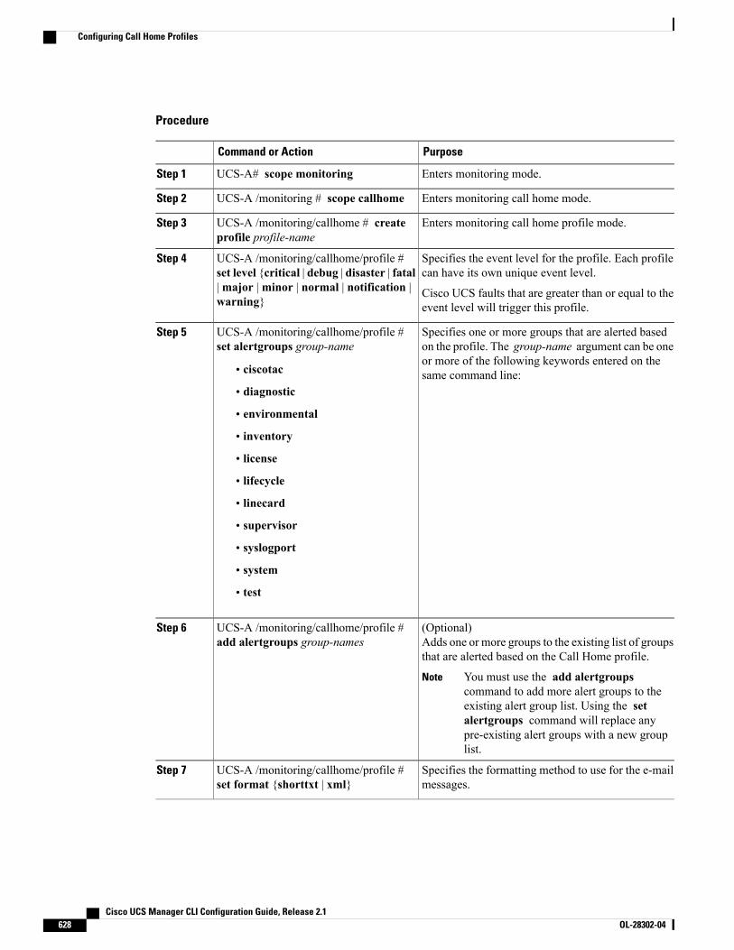
Procedure
PurposeCommand or Action
Enters monitoring mode.UCS-A# scope monitoringStep 1
Enters monitoring call home mode.UCS-A /monitoring # scope callhomeStep 2
Enters monitoring call home profile mode.UCS-A /monitoring/callhome # createprofile profile-name
Step 3
Specifies the event level for the profile. Each profilecan have its own unique event level.
UCS-A /monitoring/callhome/profile #set level {critical | debug | disaster | fatal
Step 4
|major |minor | normal | notification |warning}
Cisco UCS faults that are greater than or equal to theevent level will trigger this profile.
Specifies one or more groups that are alerted basedon the profile. The group-name argument can be one
UCS-A /monitoring/callhome/profile #set alertgroups group-name
Step 5
or more of the following keywords entered on thesame command line:• ciscotac
• diagnostic
• environmental
• inventory
• license
• lifecycle
• linecard
• supervisor
• syslogport
• system
• test
(Optional)Adds one or more groups to the existing list of groupsthat are alerted based on the Call Home profile.
UCS-A /monitoring/callhome/profile #add alertgroups group-names
Step 6
You must use the add alertgroupscommand to add more alert groups to theexisting alert group list. Using the setalertgroups command will replace anypre-existing alert groups with a new grouplist.
Note
Specifies the formatting method to use for the e-mailmessages.
UCS-A /monitoring/callhome/profile #set format {shorttxt | xml}
Step 7
Cisco UCS Manager CLI Configuration Guide, Release 2.1628 OL-28302-04
Configuring Call Home Profiles
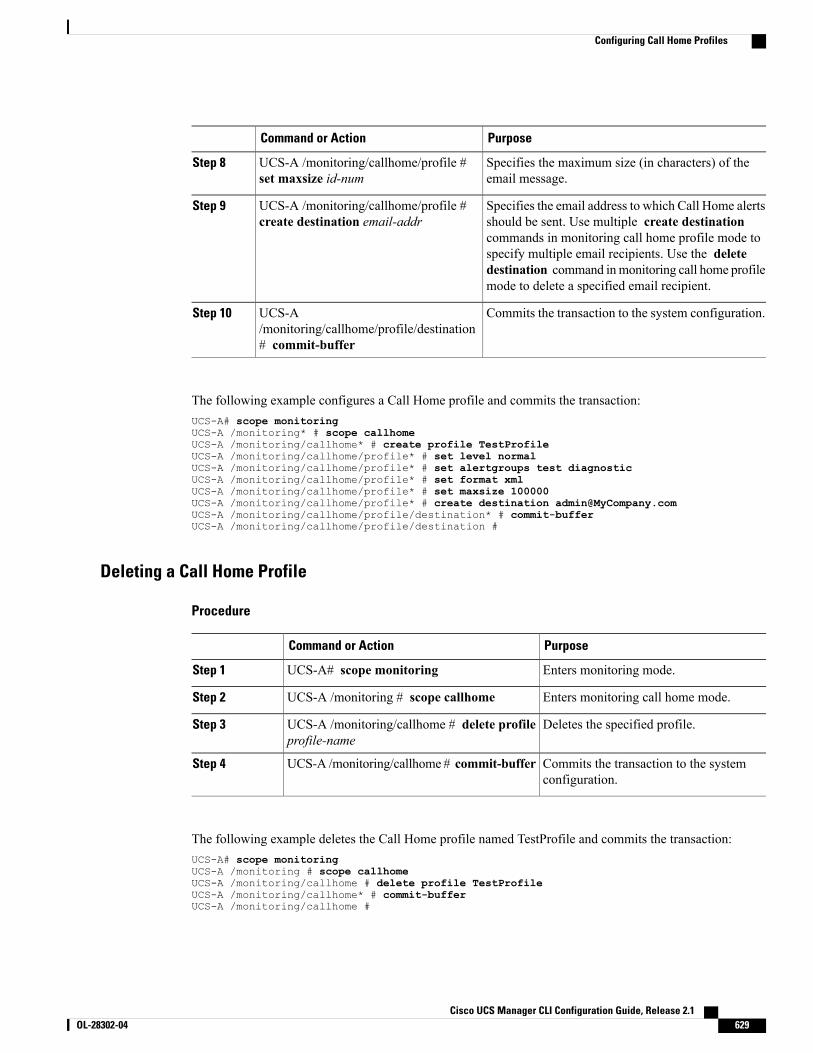
PurposeCommand or Action
Specifies the maximum size (in characters) of theemail message.
UCS-A /monitoring/callhome/profile #set maxsize id-num
Step 8
Specifies the email address to which Call Home alertsshould be sent. Use multiple create destination
UCS-A /monitoring/callhome/profile #create destination email-addr
Step 9
commands in monitoring call home profile mode tospecify multiple email recipients. Use the deletedestination command inmonitoring call home profilemode to delete a specified email recipient.
Commits the transaction to the system configuration.UCS-A/monitoring/callhome/profile/destination# commit-buffer
Step 10
The following example configures a Call Home profile and commits the transaction:UCS-A# scope monitoringUCS-A /monitoring* # scope callhomeUCS-A /monitoring/callhome* # create profile TestProfileUCS-A /monitoring/callhome/profile* # set level normalUCS-A /monitoring/callhome/profile* # set alertgroups test diagnosticUCS-A /monitoring/callhome/profile* # set format xmlUCS-A /monitoring/callhome/profile* # set maxsize 100000UCS-A /monitoring/callhome/profile* # create destination [email protected] /monitoring/callhome/profile/destination* # commit-bufferUCS-A /monitoring/callhome/profile/destination #
Deleting a Call Home Profile
Procedure
PurposeCommand or Action
Enters monitoring mode.UCS-A# scope monitoringStep 1
Enters monitoring call home mode.UCS-A /monitoring # scope callhomeStep 2
Deletes the specified profile.UCS-A /monitoring/callhome # delete profileprofile-name
Step 3
Commits the transaction to the systemconfiguration.
UCS-A /monitoring/callhome # commit-bufferStep 4
The following example deletes the Call Home profile named TestProfile and commits the transaction:UCS-A# scope monitoringUCS-A /monitoring # scope callhomeUCS-A /monitoring/callhome # delete profile TestProfileUCS-A /monitoring/callhome* # commit-bufferUCS-A /monitoring/callhome #
Cisco UCS Manager CLI Configuration Guide, Release 2.1 OL-28302-04 629
Configuring Call Home Profiles
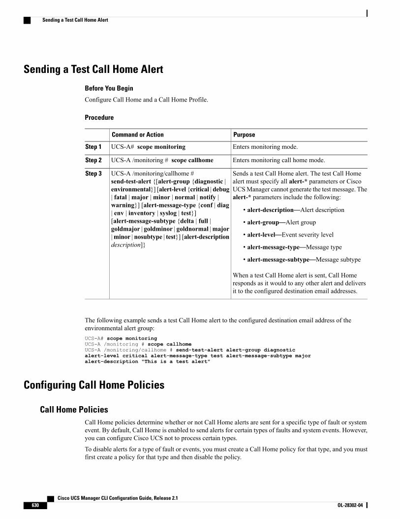
Sending a Test Call Home Alert
Before You Begin
Configure Call Home and a Call Home Profile.
Procedure
PurposeCommand or Action
Enters monitoring mode.UCS-A# scope monitoringStep 1
Enters monitoring call home mode.UCS-A /monitoring # scope callhomeStep 2
Sends a test Call Home alert. The test Call Homealert must specify all alert-* parameters or Cisco
UCS-A /monitoring/callhome #send-test-alert {[alert-group {diagnostic |
Step 3
UCSManager cannot generate the test message. Thealert-* parameters include the following:
environmental}] [alert-level {critical | debug| fatal |major |minor | normal | notify |warning}] [alert-message-type {conf | diag
• alert-description—Alert description| env | inventory | syslog | test}][alert-message-subtype {delta | full | • alert-group—Alert groupgoldmajor | goldminor | goldnormal |major
• alert-level—Event severity level|minor | nosubtype | test}] [alert-descriptiondescription]} • alert-message-type—Message type
• alert-message-subtype—Message subtype
When a test Call Home alert is sent, Call Homeresponds as it would to any other alert and deliversit to the configured destination email addresses.
The following example sends a test Call Home alert to the configured destination email address of theenvironmental alert group:UCS-A# scope monitoringUCS-A /monitoring # scope callhomeUCS-A /monitoring/callhome # send-test-alert alert-group diagnosticalert-level critical alert-message-type test alert-message-subtype majoralert-description "This is a test alert"
Configuring Call Home Policies
Call Home PoliciesCall Home policies determine whether or not Call Home alerts are sent for a specific type of fault or systemevent. By default, Call Home is enabled to send alerts for certain types of faults and system events. However,you can configure Cisco UCS not to process certain types.
To disable alerts for a type of fault or events, you must create a Call Home policy for that type, and you mustfirst create a policy for that type and then disable the policy.
Cisco UCS Manager CLI Configuration Guide, Release 2.1630 OL-28302-04
Sending a Test Call Home Alert
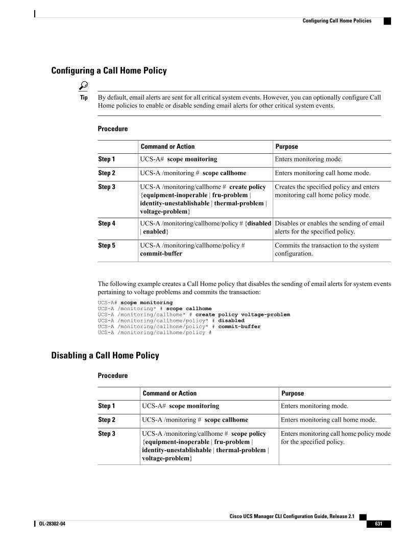
Configuring a Call Home Policy
By default, email alerts are sent for all critical system events. However, you can optionally configure CallHome policies to enable or disable sending email alerts for other critical system events.
Tip
Procedure
PurposeCommand or Action
Enters monitoring mode.UCS-A# scope monitoringStep 1
Enters monitoring call home mode.UCS-A /monitoring # scope callhomeStep 2
Creates the specified policy and entersmonitoring call home policy mode.
UCS-A /monitoring/callhome # create policy{equipment-inoperable | fru-problem |identity-unestablishable | thermal-problem |voltage-problem}
Step 3
Disables or enables the sending of emailalerts for the specified policy.
UCS-A /monitoring/callhome/policy # {disabled| enabled}
Step 4
Commits the transaction to the systemconfiguration.
UCS-A /monitoring/callhome/policy #commit-buffer
Step 5
The following example creates a Call Home policy that disables the sending of email alerts for system eventspertaining to voltage problems and commits the transaction:UCS-A# scope monitoringUCS-A /monitoring* # scope callhomeUCS-A /monitoring/callhome* # create policy voltage-problemUCS-A /monitoring/callhome/policy* # disabledUCS-A /monitoring/callhome/policy* # commit-bufferUCS-A /monitoring/callhome/policy #
Disabling a Call Home Policy
Procedure
PurposeCommand or Action
Enters monitoring mode.UCS-A# scope monitoringStep 1
Enters monitoring call home mode.UCS-A /monitoring # scope callhomeStep 2
Enters monitoring call home policy modefor the specified policy.
UCS-A /monitoring/callhome # scope policy{equipment-inoperable | fru-problem |identity-unestablishable | thermal-problem |voltage-problem}
Step 3
Cisco UCS Manager CLI Configuration Guide, Release 2.1 OL-28302-04 631
Configuring Call Home Policies
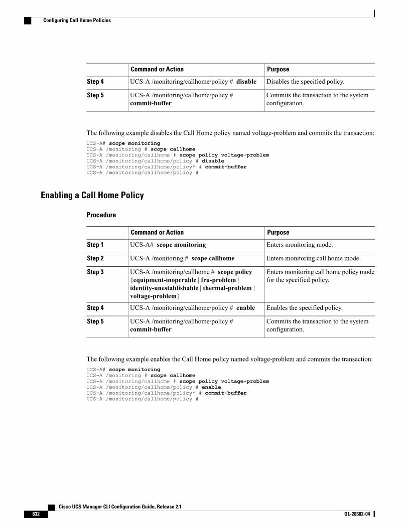
PurposeCommand or Action
Disables the specified policy.UCS-A /monitoring/callhome/policy # disableStep 4
Commits the transaction to the systemconfiguration.
UCS-A /monitoring/callhome/policy #commit-buffer
Step 5
The following example disables the Call Home policy named voltage-problem and commits the transaction:UCS-A# scope monitoringUCS-A /monitoring # scope callhomeUCS-A /monitoring/callhome # scope policy voltage-problemUCS-A /monitoring/callhome/policy # disableUCS-A /monitoring/callhome/policy* # commit-bufferUCS-A /monitoring/callhome/policy #
Enabling a Call Home Policy
Procedure
PurposeCommand or Action
Enters monitoring mode.UCS-A# scope monitoringStep 1
Enters monitoring call home mode.UCS-A /monitoring # scope callhomeStep 2
Enters monitoring call home policy modefor the specified policy.
UCS-A /monitoring/callhome # scope policy{equipment-inoperable | fru-problem |identity-unestablishable | thermal-problem |voltage-problem}
Step 3
Enables the specified policy.UCS-A /monitoring/callhome/policy # enableStep 4
Commits the transaction to the systemconfiguration.
UCS-A /monitoring/callhome/policy #commit-buffer
Step 5
The following example enables the Call Home policy named voltage-problem and commits the transaction:UCS-A# scope monitoringUCS-A /monitoring # scope callhomeUCS-A /monitoring/callhome # scope policy voltage-problemUCS-A /monitoring/callhome/policy # enableUCS-A /monitoring/callhome/policy* # commit-bufferUCS-A /monitoring/callhome/policy #
Cisco UCS Manager CLI Configuration Guide, Release 2.1632 OL-28302-04
Configuring Call Home Policies
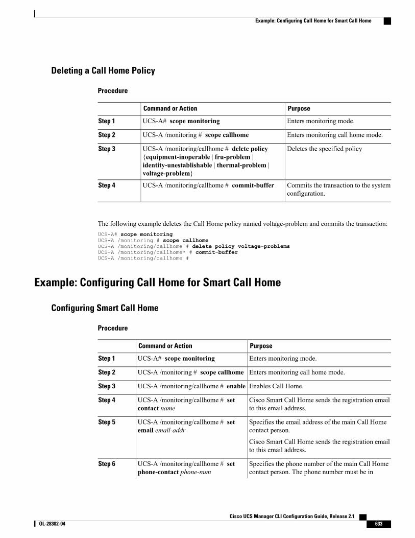
Deleting a Call Home Policy
Procedure
PurposeCommand or Action
Enters monitoring mode.UCS-A# scope monitoringStep 1
Enters monitoring call home mode.UCS-A /monitoring # scope callhomeStep 2
Deletes the specified policyUCS-A /monitoring/callhome # delete policy{equipment-inoperable | fru-problem |
Step 3
identity-unestablishable | thermal-problem |voltage-problem}
Commits the transaction to the systemconfiguration.
UCS-A /monitoring/callhome # commit-bufferStep 4
The following example deletes the Call Home policy named voltage-problem and commits the transaction:UCS-A# scope monitoringUCS-A /monitoring # scope callhomeUCS-A /monitoring/callhome # delete policy voltage-problemsUCS-A /monitoring/callhome* # commit-bufferUCS-A /monitoring/callhome #
Example: Configuring Call Home for Smart Call Home
Configuring Smart Call Home
Procedure
PurposeCommand or Action
Enters monitoring mode.UCS-A# scope monitoringStep 1
Enters monitoring call home mode.UCS-A /monitoring # scope callhomeStep 2
Enables Call Home.UCS-A /monitoring/callhome # enableStep 3
Cisco Smart Call Home sends the registration emailto this email address.
UCS-A /monitoring/callhome # setcontact name
Step 4
Specifies the email address of the main Call Homecontact person.
UCS-A /monitoring/callhome # setemail email-addr
Step 5
Cisco Smart Call Home sends the registration emailto this email address.
Specifies the phone number of the main Call Homecontact person. The phone number must be in
UCS-A /monitoring/callhome # setphone-contact phone-num
Step 6
Cisco UCS Manager CLI Configuration Guide, Release 2.1 OL-28302-04 633
Example: Configuring Call Home for Smart Call Home
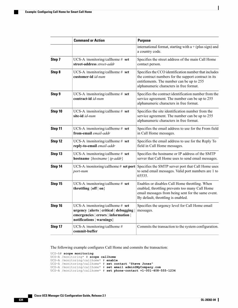
PurposeCommand or Action
international format, starting with a + (plus sign) anda country code.
Specifies the street address of the main Call Homecontact person.
UCS-A /monitoring/callhome # setstreet-address street-addr
Step 7
Specifies the CCO identification number that includesthe contract numbers for the support contract in its
UCS-A /monitoring/callhome # setcustomer-id id-num
Step 8
entitlements. The number can be up to 255alphanumeric characters in free format.
Specifies the contract identification number from theservice agreement. The number can be up to 255alphanumeric characters in free format.
UCS-A /monitoring/callhome # setcontract-id id-num
Step 9
Specifies the site identification number from theservice agreement. The number can be up to 255alphanumeric characters in free format.
UCS-A /monitoring/callhome # setsite-id id-num
Step 10
Specifies the email address to use for the From fieldin Call Home messages.
UCS-A /monitoring/callhome # setfrom-email email-addr
Step 11
Specifies the email address to use for the Reply Tofield in Call Home messages.
UCS-A /monitoring/callhome # setreply-to-email email-addr
Step 12
Specifies the hostname or IP address of the SMTPserver that Call Home uses to send email messages.
UCS-A /monitoring/callhome # sethostname {hostname | ip-addr}
Step 13
Specifies the SMTP server port that Call Home usesto send email messages. Valid port numbers are 1 to65535.
UCS-A /monitoring/callhome # set portport-num
Step 14
Enables or disables Call Home throttling. Whenenabled, throttling prevents too many Call Home
UCS-A /monitoring/callhome # setthrottling {off | on}
Step 15
email messages from being sent for the same event.By default, throttling is enabled.
Specifies the urgency level for Call Home emailmessages.
UCS-A /monitoring/callhome # seturgency {alerts | critical | debugging |emergencies | errors | information |notifications | warnings}
Step 16
Commits the transaction to the system configuration.UCS-A /monitoring/callhome #commit-buffer
Step 17
The following example configures Call Home and commits the transaction:UCS-A# scope monitoringUCS-A /monitoring* # scope callhomeUCS-A /monitoring/callhome* # enableUCS-A /monitoring/callhome* # set contact "Steve Jones"UCS-A /monitoring/callhome* # set email [email protected] /monitoring/callhome* # set phone-contact +1-001-408-555-1234
Cisco UCS Manager CLI Configuration Guide, Release 2.1634 OL-28302-04
Example: Configuring Call Home for Smart Call Home
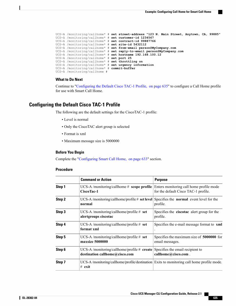
UCS-A /monitoring/callhome* # set street-address "123 N. Main Street, Anytown, CA, 99885"UCS-A /monitoring/callhome* # set customer-id 1234567UCS-A /monitoring/callhome* # set contract-id 99887766UCS-A /monitoring/callhome* # set site-id 5432112UCS-A /monitoring/callhome* # set from-email [email protected] /monitoring/callhome* # set reply-to-email [email protected] /monitoring/callhome* # set hostname 192.168.100.12UCS-A /monitoring/callhome* # set port 25UCS-A /monitoring/callhome* # set throttling onUCS-A /monitoring/callhome* # set urgency informationUCS-A /monitoring/callhome* # commit-bufferUCS-A /monitoring/callhome #
What to Do Next
Continue to "Configuring the Default Cisco TAC-1 Profile, on page 635" to configure a Call Home profilefor use with Smart Call Home.
Configuring the Default Cisco TAC-1 ProfileThe following are the default settings for the CiscoTAC-1 profile:
• Level is normal
• Only the CiscoTAC alert group is selected
• Format is xml
• Maximum message size is 5000000
Before You Begin
Complete the "Configuring Smart Call Home, on page 633" section.
Procedure
PurposeCommand or Action
Enters monitoring call home profile modefor the default Cisco TAC-1 profile.
UCS-A /monitoring/callhome # scope profileCiscoTac-1
Step 1
Specifies the normal event level for theprofile.
UCS-A /monitoring/callhome/profile # set levelnormal
Step 2
Specifies the ciscotac alert group for theprofile.
UCS-A /monitoring/callhome/profile # setalertgroups ciscotac
Step 3
Specifies the e-mail message format to xml.
UCS-A /monitoring/callhome/profile # setformat xml
Step 4
Specifies the maximum size of 5000000 foremail messages.
UCS-A /monitoring/callhome/profile # setmaxsize 5000000
Step 5
Specifies the email recipient [email protected] .
UCS-A /monitoring/callhome/profile # createdestination [email protected]
Step 6
Exits to monitoring call home profile mode.UCS-A /monitoring/callhome/profile/destination# exit
Step 7
Cisco UCS Manager CLI Configuration Guide, Release 2.1 OL-28302-04 635
Example: Configuring Call Home for Smart Call Home
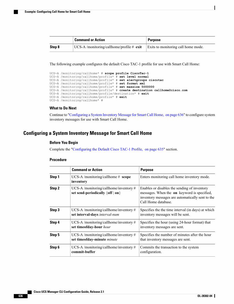
PurposeCommand or Action
Exits to monitoring call home mode.UCS-A /monitoring/callhome/profile # exitStep 8
The following example configures the default Cisco TAC-1 profile for use with Smart Call Home:
UCS-A /monitoring/callhome* # scope profile CiscoTac-1UCS-A /monitoring/callhome/profile* # set level normalUCS-A /monitoring/callhome/profile* # set alertgroups ciscotacUCS-A /monitoring/callhome/profile* # set format xmlUCS-A /monitoring/callhome/profile* # set maxsize 5000000UCS-A /monitoring/callhome/profile* # create destination [email protected] /monitoring/callhome/profile/destination* # exitUCS-A /monitoring/callhome/profile* # exitUCS-A /monitoring/callhome* #
What to Do Next
Continue to "Configuring a System InventoryMessage for Smart Call Home, on page 636" to configure systeminventory messages for use with Smart Call Home.
Configuring a System Inventory Message for Smart Call Home
Before You Begin
Complete the "Configuring the Default Cisco TAC-1 Profile, on page 635" section.
Procedure
PurposeCommand or Action
Enters monitoring call home inventory mode.UCS-A /monitoring/callhome # scopeinventory
Step 1
Enables or disables the sending of inventorymessages. When the on keyword is specified,
UCS-A /monitoring/callhome/inventory #set send-periodically {off | on}
Step 2
inventory messages are automatically sent to theCall Home database.
Specifies the the time interval (in days) at whichinventory messages will be sent.
UCS-A /monitoring/callhome/inventory #set interval-days interval-num
Step 3
Specifies the hour (using 24-hour format) thatinventory messages are sent.
UCS-A /monitoring/callhome/inventory #set timeofday-hour hour
Step 4
Specifies the number of minutes after the hourthat inventory messages are sent.
UCS-A /monitoring/callhome/inventory #set timeofday-minute minute
Step 5
Commits the transaction to the systemconfiguration.
UCS-A /monitoring/callhome/inventory #commit-buffer
Step 6
Cisco UCS Manager CLI Configuration Guide, Release 2.1636 OL-28302-04
Example: Configuring Call Home for Smart Call Home
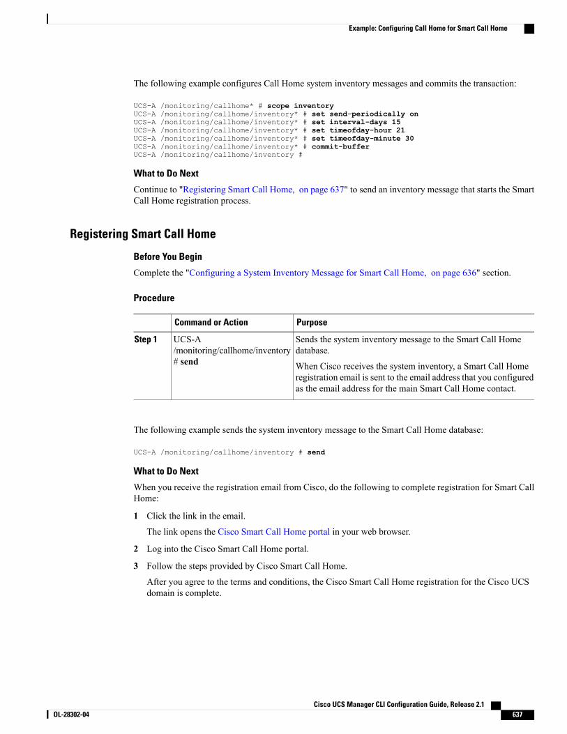
The following example configures Call Home system inventory messages and commits the transaction:
UCS-A /monitoring/callhome* # scope inventoryUCS-A /monitoring/callhome/inventory* # set send-periodically onUCS-A /monitoring/callhome/inventory* # set interval-days 15UCS-A /monitoring/callhome/inventory* # set timeofday-hour 21UCS-A /monitoring/callhome/inventory* # set timeofday-minute 30UCS-A /monitoring/callhome/inventory* # commit-bufferUCS-A /monitoring/callhome/inventory #
What to Do Next
Continue to "Registering Smart Call Home, on page 637" to send an inventory message that starts the SmartCall Home registration process.
Registering Smart Call Home
Before You Begin
Complete the "Configuring a System Inventory Message for Smart Call Home, on page 636" section.
Procedure
PurposeCommand or Action
Sends the system inventory message to the Smart Call Homedatabase.
UCS-A/monitoring/callhome/inventory# send
Step 1
When Cisco receives the system inventory, a Smart Call Homeregistration email is sent to the email address that you configuredas the email address for the main Smart Call Home contact.
The following example sends the system inventory message to the Smart Call Home database:
UCS-A /monitoring/callhome/inventory # send
What to Do Next
When you receive the registration email from Cisco, do the following to complete registration for Smart CallHome:
1 Click the link in the email.
The link opens the Cisco Smart Call Home portal in your web browser.
2 Log into the Cisco Smart Call Home portal.
3 Follow the steps provided by Cisco Smart Call Home.
After you agree to the terms and conditions, the Cisco Smart Call Home registration for the Cisco UCSdomain is complete.
Cisco UCS Manager CLI Configuration Guide, Release 2.1 OL-28302-04 637
Example: Configuring Call Home for Smart Call Home

Cisco UCS Manager CLI Configuration Guide, Release 2.1638 OL-28302-04
Example: Configuring Call Home for Smart Call Home
C H A P T E R 47Managing the System Event Log
This chapter includes the following sections:
• System Event Log, page 639
• Viewing the System Event Log for a Server, page 640
• Configuring the SEL Policy, page 641
• Backing Up the System Event Log for a Server, page 643
• Clearing the System Event Log for a Server, page 644
System Event LogThe system event log (SEL) resides on the CIMC in NVRAM. It records most server-related events, such asover and under voltage, temperature events, fan events, and events from BIOS. The SEL is mainly used fortroubleshooting purposes.
The SEL file is approximately 40KB in size, and no further events can be recorded when it is full. It must becleared before additional events can be recorded.
You can use the SEL policy to backup the SEL to a remote server, and optionally clear the SEL after a backupoperation occurs. Backup operations can be triggered based on specific actions, or they can occur at regularintervals. You can also manually backup or clear the SEL.
The backup file is automatically generated. The filename format issel-SystemName-ChassisID-ServerID-ServerSerialNumber-Timestamp; for example,sel-UCS-A-ch01-serv01-QCI12522939-20091121160736.
Cisco UCS Manager CLI Configuration Guide, Release 2.1 OL-28302-04 639
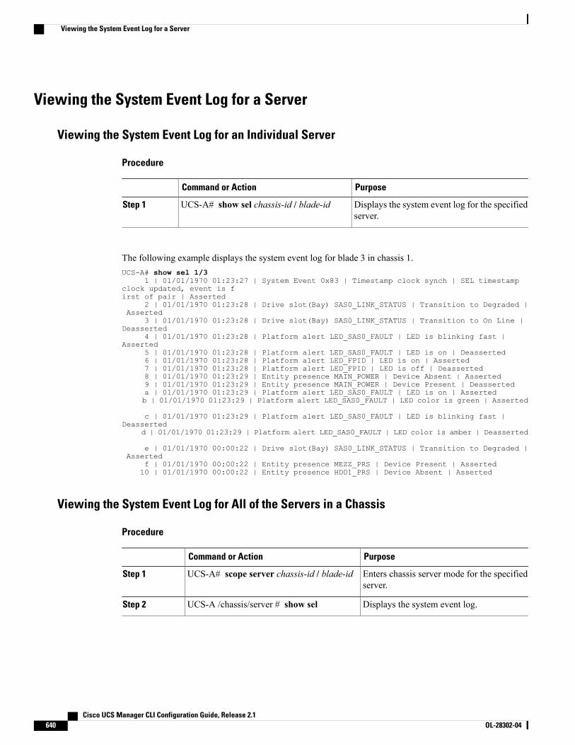
Viewing the System Event Log for a Server
Viewing the System Event Log for an Individual Server
Procedure
PurposeCommand or Action
Displays the system event log for the specifiedserver.
UCS-A# show sel chassis-id / blade-idStep 1
The following example displays the system event log for blade 3 in chassis 1.UCS-A# show sel 1/3
1 | 01/01/1970 01:23:27 | System Event 0x83 | Timestamp clock synch | SEL timestampclock updated, event is first of pair | Asserted
2 | 01/01/1970 01:23:28 | Drive slot(Bay) SAS0_LINK_STATUS | Transition to Degraded |Asserted
3 | 01/01/1970 01:23:28 | Drive slot(Bay) SAS0_LINK_STATUS | Transition to On Line |Deasserted
4 | 01/01/1970 01:23:28 | Platform alert LED_SAS0_FAULT | LED is blinking fast |Asserted
5 | 01/01/1970 01:23:28 | Platform alert LED_SAS0_FAULT | LED is on | Deasserted6 | 01/01/1970 01:23:28 | Platform alert LED_FPID | LED is on | Asserted7 | 01/01/1970 01:23:28 | Platform alert LED_FPID | LED is off | Deasserted8 | 01/01/1970 01:23:29 | Entity presence MAIN_POWER | Device Absent | Asserted9 | 01/01/1970 01:23:29 | Entity presence MAIN_POWER | Device Present | Deasserteda | 01/01/1970 01:23:29 | Platform alert LED_SAS0_FAULT | LED is on | Assertedb | 01/01/1970 01:23:29 | Platform alert LED_SAS0_FAULT | LED color is green | Asserted
c | 01/01/1970 01:23:29 | Platform alert LED_SAS0_FAULT | LED is blinking fast |Deasserted
d | 01/01/1970 01:23:29 | Platform alert LED_SAS0_FAULT | LED color is amber | Deasserted
e | 01/01/1970 00:00:22 | Drive slot(Bay) SAS0_LINK_STATUS | Transition to Degraded |Asserted
f | 01/01/1970 00:00:22 | Entity presence MEZZ_PRS | Device Present | Asserted10 | 01/01/1970 00:00:22 | Entity presence HDD1_PRS | Device Absent | Asserted
Viewing the System Event Log for All of the Servers in a Chassis
Procedure
PurposeCommand or Action
Enters chassis server mode for the specifiedserver.
UCS-A# scope server chassis-id / blade-idStep 1
Displays the system event log.UCS-A /chassis/server # show selStep 2
Cisco UCS Manager CLI Configuration Guide, Release 2.1640 OL-28302-04
Viewing the System Event Log for a Server
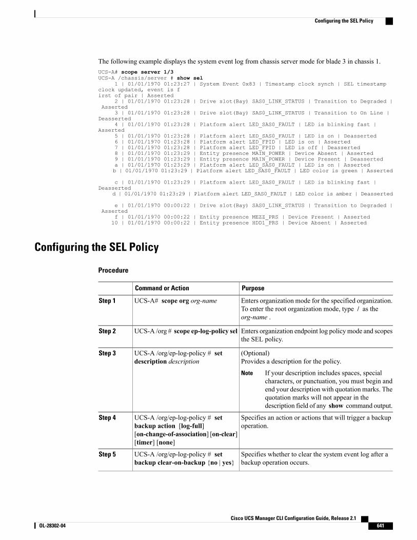
The following example displays the system event log from chassis server mode for blade 3 in chassis 1.UCS-A# scope server 1/3UCS-A /chassis/server # show sel
1 | 01/01/1970 01:23:27 | System Event 0x83 | Timestamp clock synch | SEL timestampclock updated, event is first of pair | Asserted
2 | 01/01/1970 01:23:28 | Drive slot(Bay) SAS0_LINK_STATUS | Transition to Degraded |Asserted
3 | 01/01/1970 01:23:28 | Drive slot(Bay) SAS0_LINK_STATUS | Transition to On Line |Deasserted
4 | 01/01/1970 01:23:28 | Platform alert LED_SAS0_FAULT | LED is blinking fast |Asserted
5 | 01/01/1970 01:23:28 | Platform alert LED_SAS0_FAULT | LED is on | Deasserted6 | 01/01/1970 01:23:28 | Platform alert LED_FPID | LED is on | Asserted7 | 01/01/1970 01:23:28 | Platform alert LED_FPID | LED is off | Deasserted8 | 01/01/1970 01:23:29 | Entity presence MAIN_POWER | Device Absent | Asserted9 | 01/01/1970 01:23:29 | Entity presence MAIN_POWER | Device Present | Deasserteda | 01/01/1970 01:23:29 | Platform alert LED_SAS0_FAULT | LED is on | Assertedb | 01/01/1970 01:23:29 | Platform alert LED_SAS0_FAULT | LED color is green | Asserted
c | 01/01/1970 01:23:29 | Platform alert LED_SAS0_FAULT | LED is blinking fast |Deasserted
d | 01/01/1970 01:23:29 | Platform alert LED_SAS0_FAULT | LED color is amber | Deasserted
e | 01/01/1970 00:00:22 | Drive slot(Bay) SAS0_LINK_STATUS | Transition to Degraded |Asserted
f | 01/01/1970 00:00:22 | Entity presence MEZZ_PRS | Device Present | Asserted10 | 01/01/1970 00:00:22 | Entity presence HDD1_PRS | Device Absent | Asserted
Configuring the SEL Policy
Procedure
PurposeCommand or Action
Enters organization mode for the specified organization.To enter the root organization mode, type / as theorg-name .
UCS-A# scope org org-nameStep 1
Enters organization endpoint log policy mode and scopesthe SEL policy.
UCS-A /org # scope ep-log-policy selStep 2
(Optional)Provides a description for the policy.
UCS-A /org/ep-log-policy # setdescription description
Step 3
If your description includes spaces, specialcharacters, or punctuation, you must begin andend your description with quotation marks. Thequotation marks will not appear in thedescription field of any show command output.
Note
Specifies an action or actions that will trigger a backupoperation.
UCS-A /org/ep-log-policy # setbackup action [log-full][on-change-of-association] [on-clear][timer] [none]
Step 4
Specifies whether to clear the system event log after abackup operation occurs.
UCS-A /org/ep-log-policy # setbackup clear-on-backup {no | yes}
Step 5
Cisco UCS Manager CLI Configuration Guide, Release 2.1 OL-28302-04 641
Configuring the SEL Policy

PurposeCommand or Action
Specifies the protocol, user, password, remote hostname,and remote path for the backup operation. Depending on
UCS-A /org/ep-log-policy # setbackup destination URL
Step 6
the protocol used, specify the URL using one of thefollowing syntax:
• ftp:// username@hostname / path
• scp:// username @ hostname / path
• sftp:// username @ hostname / path
• tftp:// hostname : port-num / path
You can also specify the backup destination byusing the set backup hostname , set backuppassword , set backup protocol , set backupremote-path , set backup user commands, orby using the set backup destination command.Use either method to specify the backupdestination.
Note
Specifies the format for the backup file.UCS-A /org/ep-log-policy # setbackup format {ascii | binary}
Step 7
Specifies the hostname or IP address of the remote server.UCS-A /org/ep-log-policy # setbackup hostname {hostname |ip-addr}
Step 8
Specifies the time interval for the automatic backupoperation. Specifying the never keyword means thatautomatic backups will not be made.
UCS-A /org/ep-log-policy # setbackup interval {1-hour | 2-hours |4-hours | 8-hours | 24-hours | never}
Step 9
Specifies the password for the username. This step doesnot apply if the TFTP protocol is used.
UCS-A /org/ep-log-policy # setbackup password password
Step 10
Specifies the protocol to use when communicating withthe remote server.
UCS-A /org/ep-log-policy # setbackup protocol {ftp | scp | sftp |tftp}
Step 11
Specifies the path on the remote server where the backupfile is to be saved.
UCS-A /org/ep-log-policy # setbackup remote-path path
Step 12
Specifies the username the system should use to log into the remote server. This step does not apply if the TFTPprotocol is used.
UCS-A /org/ep-log-policy # setbackup user username
Step 13
Commits the transaction.UCS-A /org/ep-log-policy #commit-buffer
Step 14
Cisco UCS Manager CLI Configuration Guide, Release 2.1642 OL-28302-04
Configuring the SEL Policy
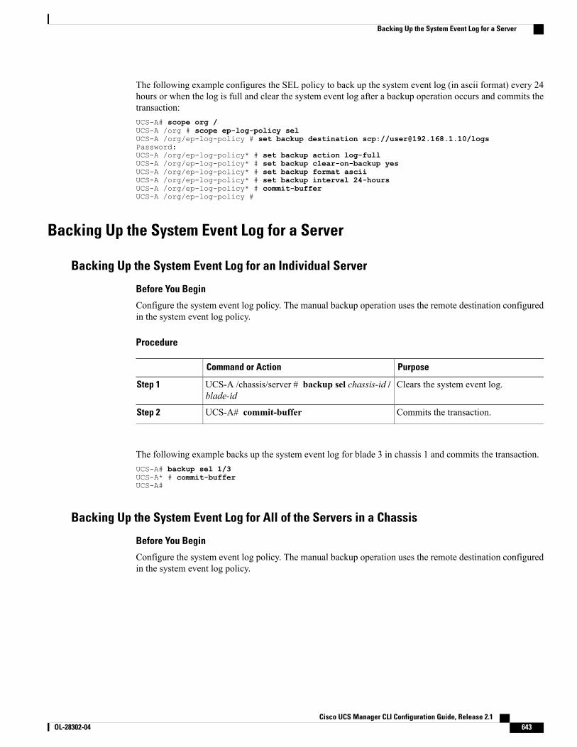
The following example configures the SEL policy to back up the system event log (in ascii format) every 24hours or when the log is full and clear the system event log after a backup operation occurs and commits thetransaction:UCS-A# scope org /UCS-A /org # scope ep-log-policy selUCS-A /org/ep-log-policy # set backup destination scp://[email protected]/logsPassword:UCS-A /org/ep-log-policy* # set backup action log-fullUCS-A /org/ep-log-policy* # set backup clear-on-backup yesUCS-A /org/ep-log-policy* # set backup format asciiUCS-A /org/ep-log-policy* # set backup interval 24-hoursUCS-A /org/ep-log-policy* # commit-bufferUCS-A /org/ep-log-policy #
Backing Up the System Event Log for a Server
Backing Up the System Event Log for an Individual Server
Before You Begin
Configure the system event log policy. The manual backup operation uses the remote destination configuredin the system event log policy.
Procedure
PurposeCommand or Action
Clears the system event log.UCS-A /chassis/server # backup sel chassis-id /blade-id
Step 1
Commits the transaction.UCS-A# commit-bufferStep 2
The following example backs up the system event log for blade 3 in chassis 1 and commits the transaction.UCS-A# backup sel 1/3UCS-A* # commit-bufferUCS-A#
Backing Up the System Event Log for All of the Servers in a Chassis
Before You Begin
Configure the system event log policy. The manual backup operation uses the remote destination configuredin the system event log policy.
Cisco UCS Manager CLI Configuration Guide, Release 2.1 OL-28302-04 643
Backing Up the System Event Log for a Server
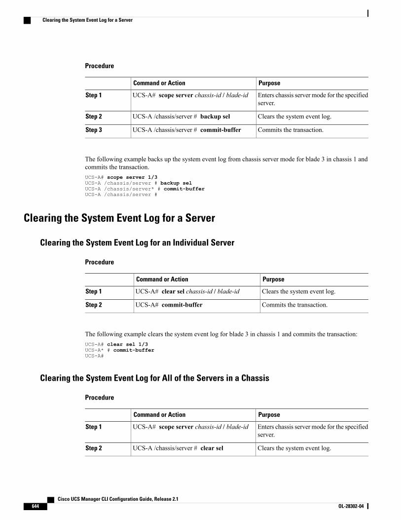
Procedure
PurposeCommand or Action
Enters chassis server mode for the specifiedserver.
UCS-A# scope server chassis-id / blade-idStep 1
Clears the system event log.UCS-A /chassis/server # backup selStep 2
Commits the transaction.UCS-A /chassis/server # commit-bufferStep 3
The following example backs up the system event log from chassis server mode for blade 3 in chassis 1 andcommits the transaction.UCS-A# scope server 1/3UCS-A /chassis/server # backup selUCS-A /chassis/server* # commit-bufferUCS-A /chassis/server #
Clearing the System Event Log for a Server
Clearing the System Event Log for an Individual Server
Procedure
PurposeCommand or Action
Clears the system event log.UCS-A# clear sel chassis-id / blade-idStep 1
Commits the transaction.UCS-A# commit-bufferStep 2
The following example clears the system event log for blade 3 in chassis 1 and commits the transaction:UCS-A# clear sel 1/3UCS-A* # commit-bufferUCS-A#
Clearing the System Event Log for All of the Servers in a Chassis
Procedure
PurposeCommand or Action
Enters chassis server mode for the specifiedserver.
UCS-A# scope server chassis-id / blade-idStep 1
Clears the system event log.UCS-A /chassis/server # clear selStep 2
Cisco UCS Manager CLI Configuration Guide, Release 2.1644 OL-28302-04
Clearing the System Event Log for a Server
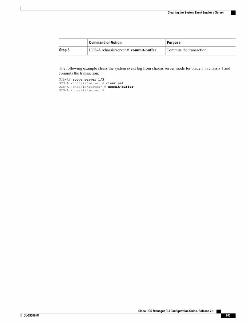
PurposeCommand or Action
Commits the transaction.UCS-A /chassis/server # commit-bufferStep 3
The following example clears the system event log from chassis server mode for blade 3 in chassis 1 andcommits the transaction:UCS-A# scope server 1/3UCS-A /chassis/server # clear selUCS-A /chassis/server* # commit-bufferUCS-A /chassis/server #
Cisco UCS Manager CLI Configuration Guide, Release 2.1 OL-28302-04 645
Clearing the System Event Log for a Server

Cisco UCS Manager CLI Configuration Guide, Release 2.1646 OL-28302-04
Clearing the System Event Log for a Server
C H A P T E R 48Configuring Settings for Faults, Events, and Logs
This chapter includes the following sections:
• Configuring Settings for the Fault Collection Policy, page 647
• Configuring Fault Suppression, page 649
• Configuring Settings for the Core File Exporter, page 681
• Configuring the Syslog, page 682
• Viewing Audit Logs, page 684
• Configuring the Log File Exporter, page 685
Configuring Settings for the Fault Collection Policy
Global Fault PolicyThe global fault policy controls the lifecycle of a fault in a Cisco UCS domain, including when faults arecleared, the flapping interval (the length of time between the fault being raised and the condition being cleared),and the retention interval (the length of time a fault is retained in the system).
A fault in Cisco UCS has the following lifecycle:
1 A condition occurs in the system and Cisco UCS Manager raises a fault. This is the active state.
2 When the fault is alleviated, it enters a flapping or soaking interval that is designed to prevent flapping.Flapping occurs when a fault is raised and cleared several times in rapid succession. During the flappinginterval, the fault retains its severity for the length of time specified in the global fault policy.
3 If the condition reoccurs during the flapping interval, the fault returns to the active state. If the conditiondoes not reoccur during the flapping interval, the fault is cleared.
4 The cleared fault enters the retention interval. This interval ensures that the fault reaches the attention ofan administrator even if the condition that caused the fault has been alleviated and the fault has not beendeleted prematurely. The retention interval retains the cleared fault for the length of time specified in theglobal fault policy.
Cisco UCS Manager CLI Configuration Guide, Release 2.1 OL-28302-04 647

5 If the condition reoccurs during the retention interval, the fault returns to the active state. If the conditiondoes not reoccur, the fault is deleted.
Configuring the Fault Collection Policy
Procedure
PurposeCommand or Action
Enters monitoring mode.UCS-A# scope monitoringStep 1
Enters monitoring fault policy mode.UCS-A /monitoring # scope faultpolicy
Step 2
Specifies whether to retain or delete all cleared messages.If the retain option is specified, then the length of time
UCS-A /monitoring/fault-policy #set clear-action {delete | retain}
Step 3
that the messages are retained is determined by the setretention-interval command.
Specifies the time interval (in seconds) the system waitsbefore changing a fault state. Flapping occurs when a fault
UCS-A /monitoring/fault-policy #set flap-interval seconds
Step 4
is raised and cleared several times in rapid succession. Toprevent this, the system does not allow a fault to changestate until the flapping interval has elapsed after the laststate change. If the fault is raised again during the flappinginterval, it returns to the active state, otherwise, the fault iscleared.
Specifies the time interval the system retains all clearedfault messages before deleting them. The system can retain
UCS-A /monitoring/fault-policy #set retention-interval {days hoursminutes seconds | forever}
Step 5
cleared fault messages forever, or for the specified numberof days, hours, minutes, and seconds.
Commits the transaction.UCS-A /monitoring/fault-policy #commit-buffer
Step 6
This example configures the fault collection policy to retain cleared fault messages for 30 days, sets theflapping interval to 10 seconds, and commits the transaction.UCS-A# scope monitoringUCS-A /monitoring # scope fault policyUCS-A /monitoring/fault-policy # set clear-action retainUCS-A /monitoring/fault-policy* # set flap-interval 10UCS-A /monitoring/fault-policy* # set retention-interval 30 0 0 0UCS-A /monitoring/fault-policy* # commit-bufferUCS-A /monitoring/fault-policy #
Cisco UCS Manager CLI Configuration Guide, Release 2.1648 OL-28302-04
Configuring Settings for the Fault Collection Policy
Configuring Fault Suppression
Fault SuppressionFault suppression allows you to suppress SNMP trap and Call Home notifications during a plannedmaintenancetime. You can create a fault suppression task to prevent notifications from being sent whenever a transientfault is raised or cleared.
Faults remain suppressed until the time duration has expired, or the fault suppression tasks have been manuallystopped by the user. After the fault suppression has ended, Cisco UCS Manager will send notifications forany outstanding suppressed faults that have not been cleared.
Fault suppression uses the following:
Fixed Time Intervals or Schedules
You can use the following to specify the maintenance window during which you want to suppress faults.
• Fixed time intervals allow you to create a start time and a duration when fault suppression is active.Fixed time intervals cannot be reused.
• Schedules are used for one time occurrences or recurring time periods and can be saved and reused.
Suppression Policies
These policies define which causes and types of faults you want to suppress. Only one policy can be assignedto a task. The following policies are defined by Cisco UCS Manager:
• default-chassis-all-maint—Suppresses faults for the chassis and all components installed into thechassis, including all blade servers, power supplies, fan modules, and IOMs.
This policy applies only to chassis.
• default-chassis-phys-maint—Suppresses faults for the chassis and all fan modules and power suppliesinstalled into the chassis.
This policy applies only to chassis.
• default-fex-all-maint—Suppresses faults for the FEX and all power supplies, fan modules, and IOMsin the FEX.
This policy applies only to FEXes.
• default-fex-phys-maint—Suppresses faults for the FEX and all fan modules and power supplies in theFEX.
This policy applies only to FEXes.
• default-server-maint—Suppresses faults for blade servers and/or rack servers.
This policy applies to chassis, organizations, and service profiles.
When applied to a chassis, only blade servers are affected.Note
• default-iom-maint—Suppresses faults for IOMs in a chassis or FEX.
Cisco UCS Manager CLI Configuration Guide, Release 2.1 OL-28302-04 649
Configuring Fault Suppression
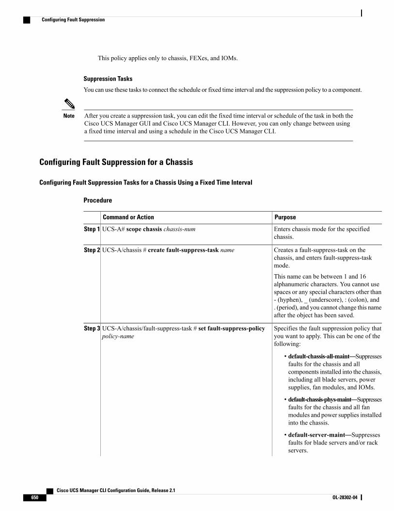
This policy applies only to chassis, FEXes, and IOMs.
Suppression Tasks
You can use these tasks to connect the schedule or fixed time interval and the suppression policy to a component.
After you create a suppression task, you can edit the fixed time interval or schedule of the task in both theCisco UCS Manager GUI and Cisco UCS Manager CLI. However, you can only change between usinga fixed time interval and using a schedule in the Cisco UCS Manager CLI.
Note
Configuring Fault Suppression for a Chassis
Configuring Fault Suppression Tasks for a Chassis Using a Fixed Time Interval
Procedure
PurposeCommand or Action
Enters chassis mode for the specifiedchassis.
UCS-A# scope chassis chassis-numStep 1
Creates a fault-suppress-task on thechassis, and enters fault-suppress-taskmode.
UCS-A/chassis # create fault-suppress-task nameStep 2
This name can be between 1 and 16alphanumeric characters. You cannot usespaces or any special characters other than- (hyphen), _ (underscore), : (colon), and. (period), and you cannot change this nameafter the object has been saved.
Specifies the fault suppression policy thatyou want to apply. This can be one of thefollowing:
UCS-A/chassis/fault-suppress-task # set fault-suppress-policypolicy-name
Step 3
• default-chassis-all-maint—Suppressesfaults for the chassis and allcomponents installed into the chassis,including all blade servers, powersupplies, fan modules, and IOMs.
• default-chassis-phys-maint—Suppressesfaults for the chassis and all fanmodules and power supplies installedinto the chassis.
• default-server-maint—Suppressesfaults for blade servers and/or rackservers.
Cisco UCS Manager CLI Configuration Guide, Release 2.1650 OL-28302-04
Configuring Fault Suppression
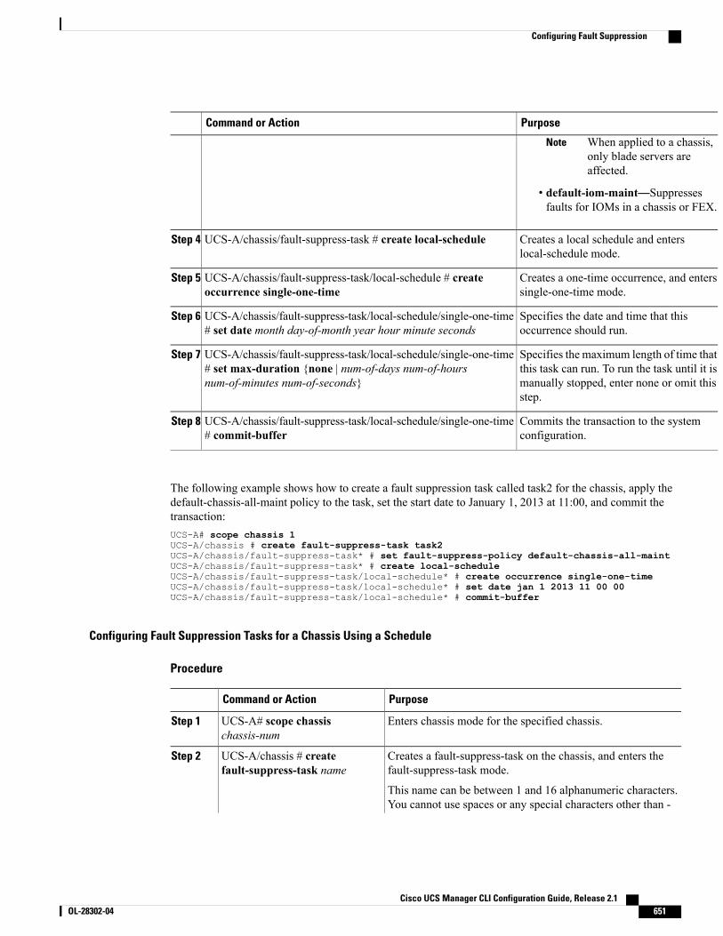
PurposeCommand or Action
When applied to a chassis,only blade servers areaffected.
Note
• default-iom-maint—Suppressesfaults for IOMs in a chassis or FEX.
Creates a local schedule and enterslocal-schedule mode.
UCS-A/chassis/fault-suppress-task # create local-scheduleStep 4
Creates a one-time occurrence, and enterssingle-one-time mode.
UCS-A/chassis/fault-suppress-task/local-schedule # createoccurrence single-one-time
Step 5
Specifies the date and time that thisoccurrence should run.
UCS-A/chassis/fault-suppress-task/local-schedule/single-one-time# set date month day-of-month year hour minute seconds
Step 6
Specifies the maximum length of time thatthis task can run. To run the task until it is
UCS-A/chassis/fault-suppress-task/local-schedule/single-one-time# set max-duration {none | num-of-days num-of-hoursnum-of-minutes num-of-seconds}
Step 7
manually stopped, enter none or omit thisstep.
Commits the transaction to the systemconfiguration.
UCS-A/chassis/fault-suppress-task/local-schedule/single-one-time# commit-buffer
Step 8
The following example shows how to create a fault suppression task called task2 for the chassis, apply thedefault-chassis-all-maint policy to the task, set the start date to January 1, 2013 at 11:00, and commit thetransaction:UCS-A# scope chassis 1UCS-A/chassis # create fault-suppress-task task2UCS-A/chassis/fault-suppress-task* # set fault-suppress-policy default-chassis-all-maintUCS-A/chassis/fault-suppress-task* # create local-scheduleUCS-A/chassis/fault-suppress-task/local-schedule* # create occurrence single-one-timeUCS-A/chassis/fault-suppress-task/local-schedule* # set date jan 1 2013 11 00 00UCS-A/chassis/fault-suppress-task/local-schedule* # commit-buffer
Configuring Fault Suppression Tasks for a Chassis Using a Schedule
Procedure
PurposeCommand or Action
Enters chassis mode for the specified chassis.UCS-A# scope chassischassis-num
Step 1
Creates a fault-suppress-task on the chassis, and enters thefault-suppress-task mode.
UCS-A/chassis # createfault-suppress-task name
Step 2
This name can be between 1 and 16 alphanumeric characters.You cannot use spaces or any special characters other than -
Cisco UCS Manager CLI Configuration Guide, Release 2.1 OL-28302-04 651
Configuring Fault Suppression
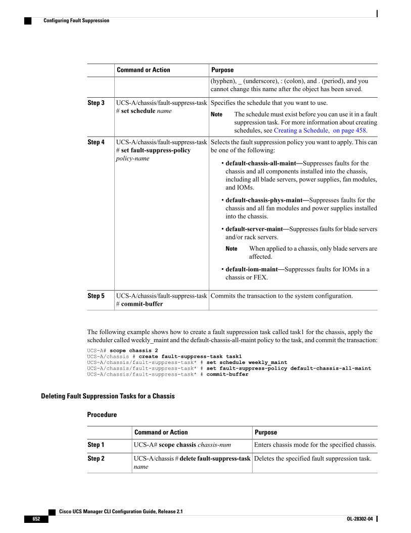
PurposeCommand or Action
(hyphen), _ (underscore), : (colon), and . (period), and youcannot change this name after the object has been saved.
Specifies the schedule that you want to use.UCS-A/chassis/fault-suppress-task# set schedule name
Step 3
The schedule must exist before you can use it in a faultsuppression task. For more information about creatingschedules, see Creating a Schedule, on page 458.
Note
Selects the fault suppression policy you want to apply. This canbe one of the following:
UCS-A/chassis/fault-suppress-task# set fault-suppress-policypolicy-name
Step 4
• default-chassis-all-maint—Suppresses faults for thechassis and all components installed into the chassis,including all blade servers, power supplies, fan modules,and IOMs.
• default-chassis-phys-maint—Suppresses faults for thechassis and all fan modules and power supplies installedinto the chassis.
• default-server-maint—Suppresses faults for blade serversand/or rack servers.
When applied to a chassis, only blade servers areaffected.
Note
• default-iom-maint—Suppresses faults for IOMs in achassis or FEX.
Commits the transaction to the system configuration.UCS-A/chassis/fault-suppress-task# commit-buffer
Step 5
The following example shows how to create a fault suppression task called task1 for the chassis, apply thescheduler called weekly_maint and the default-chassis-all-maint policy to the task, and commit the transaction:UCS-A# scope chassis 2UCS-A/chassis # create fault-suppress-task task1UCS-A/chassis/fault-suppress-task* # set schedule weekly_maintUCS-A/chassis/fault-suppress-task* # set fault-suppress-policy default-chassis-all-maintUCS-A/chassis/fault-suppress-task* # commit-buffer
Deleting Fault Suppression Tasks for a Chassis
Procedure
PurposeCommand or Action
Enters chassis mode for the specified chassis.UCS-A# scope chassis chassis-numStep 1
Deletes the specified fault suppression task.UCS-A/chassis # delete fault-suppress-taskname
Step 2
Cisco UCS Manager CLI Configuration Guide, Release 2.1652 OL-28302-04
Configuring Fault Suppression

PurposeCommand or Action
Commits the transaction to the systemconfiguration.
UCS-A/chassis # commit-bufferStep 3
The following example shows how to delete the fault suppression task called task1:UCS-A# scope chassis 1UCS-A/chassis # delete fault-suppress-task task1UCS-A/chassis* # commit-buffer
Modifying Fault Suppression Tasks for a Chassis
Procedure
PurposeCommand or Action
Enters chassis mode for the specifiedchassis.
UCS-A# scope chassis chassis-numStep 1
Enters fault-suppress-task mode.UCS-A/chassis # scope fault-suppress-task nameStep 2
Modifies the fault suppression policy. Thiscan be one of the following:
UCS-A/chassis/fault-suppress-task # set fault-suppress-policypolicy-name
Step 3
• default-chassis-all-maint—Suppressesfaults for the chassis and allcomponents installed into the chassis,including all blade servers, powersupplies, fan modules, and IOMs.
• default-chassis-phys-maint—Suppressesfaults for the chassis and all fanmodules and power supplies installedinto the chassis.
• default-server-maint—Suppressesfaults for blade servers and/or rackservers.
• default-iom-maint—Suppressesfaults for IOMs in a chassis or FEX.
To apply a different schedule tothe fault suppression task, go toStep 4. To change the fixed timeinterval of the fault suppressiontask, go to Step 5.
Note
Applies the schedule you want to use.UCS-A/chassis/fault-suppress-task # set schedule nameStep 4
Cisco UCS Manager CLI Configuration Guide, Release 2.1 OL-28302-04 653
Configuring Fault Suppression
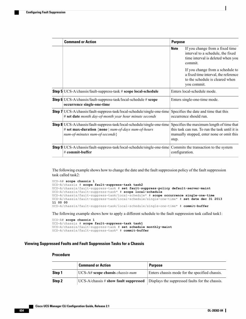
PurposeCommand or Action
If you change from a fixed timeinterval to a schedule, the fixedtime interval is deleted when youcommit.
If you change from a schedule toa fixed time interval, the referenceto the schedule is cleared whenyou commit.
Note
Enters local-schedule mode.UCS-A/chassis/fault-suppress-task # scope local-scheduleStep 5
Enters single-one-time mode.UCS-A/chassis/fault-suppress-task/local-schedule # scopeoccurrence single-one-time
Step 6
Specifies the date and time that thisoccurrence should run.
UCS-A/chassis/fault-suppress-task/local-schedule/single-one-time# set date month day-of-month year hour minute seconds
Step 7
Specifies the maximum length of time thatthis task can run. To run the task until it is
UCS-A/chassis/fault-suppress-task/local-schedule/single-one-time# set max-duration {none | num-of-days num-of-hoursnum-of-minutes num-of-seconds}
Step 8
manually stopped, enter none or omit thisstep.
Commits the transaction to the systemconfiguration.
UCS-A/chassis/fault-suppress-task/local-schedule/single-one-time# commit-buffer
Step 9
The following example shows how to change the date and the fault suppression policy of the fault suppressiontask called task2:UCS-A# scope chassis 1UCS-A/chassis # scope fault-suppress-task task2UCS-A/chassis/fault-suppress-task # set fault-suppress-policy default-server-maintUCS-A/chassis/fault-suppress-task* # scope local-scheduleUCS-A/chassis/fault-suppress-task/local-schedule* # scope occurrence single-one-timeUCS-A/chassis/fault-suppress-task/local-schedule/single-one-time* # set date dec 31 201311 00 00UCS-A/chassis/fault-suppress-task/local-schedule/single-one-time* # commit-buffer
The following example shows how to apply a different schedule to the fault suppression task called task1:UCS-A# scope chassis 1UCS-A/chassis # scope fault-suppress-task task1UCS-A/chassis/fault-suppress-task # set schedule monthly-maintUCS-A/chassis/fault-suppress-task* # commit-buffer
Viewing Suppressed Faults and Fault Suppression Tasks for a Chassis
Procedure
PurposeCommand or Action
Enters chassis mode for the specified chassis.UCS-A# scope chassis chassis-numStep 1
Displays the suppressed faults for the chassis.UCS-A/chassis # show fault suppressedStep 2
Cisco UCS Manager CLI Configuration Guide, Release 2.1654 OL-28302-04
Configuring Fault Suppression
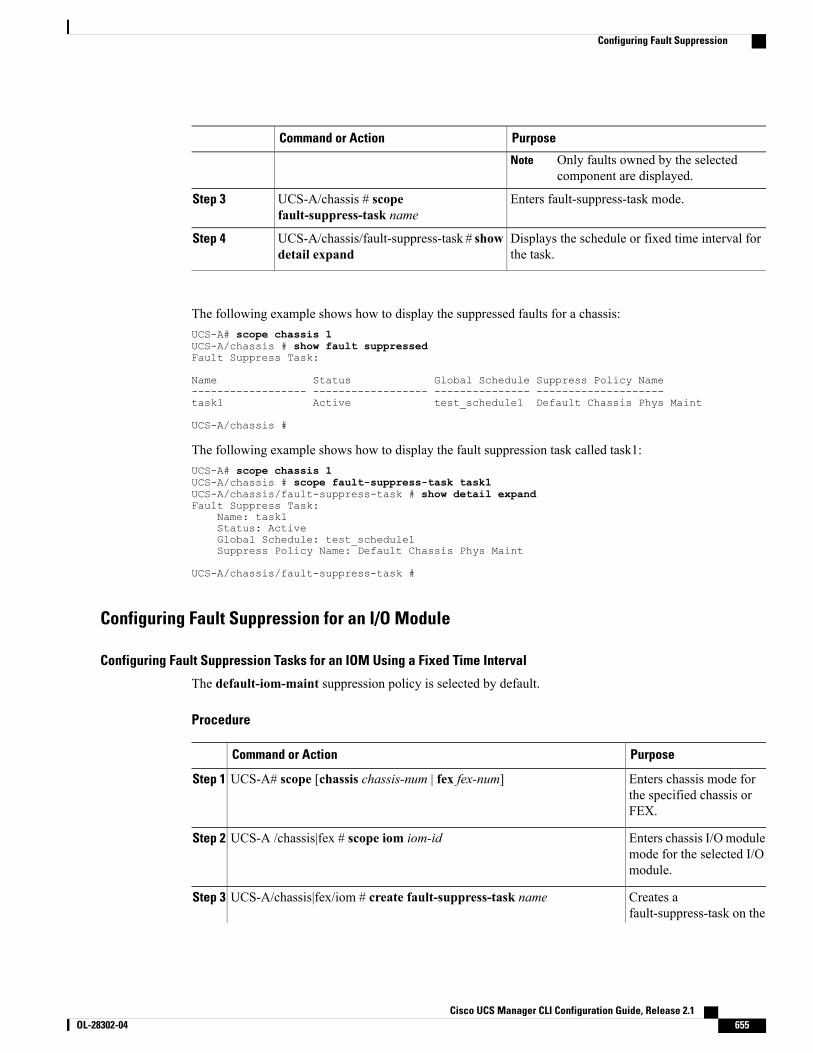
PurposeCommand or Action
Only faults owned by the selectedcomponent are displayed.
Note
Enters fault-suppress-task mode.UCS-A/chassis # scopefault-suppress-task name
Step 3
Displays the schedule or fixed time interval forthe task.
UCS-A/chassis/fault-suppress-task # showdetail expand
Step 4
The following example shows how to display the suppressed faults for a chassis:UCS-A# scope chassis 1UCS-A/chassis # show fault suppressedFault Suppress Task:
Name Status Global Schedule Suppress Policy Name------------------ ------------------ --------------- --------------------task1 Active test_schedule1 Default Chassis Phys Maint
UCS-A/chassis #
The following example shows how to display the fault suppression task called task1:UCS-A# scope chassis 1UCS-A/chassis # scope fault-suppress-task task1UCS-A/chassis/fault-suppress-task # show detail expandFault Suppress Task:
Name: task1Status: ActiveGlobal Schedule: test_schedule1Suppress Policy Name: Default Chassis Phys Maint
UCS-A/chassis/fault-suppress-task #
Configuring Fault Suppression for an I/O Module
Configuring Fault Suppression Tasks for an IOM Using a Fixed Time Interval
The default-iom-maint suppression policy is selected by default.
Procedure
PurposeCommand or Action
Enters chassis mode forthe specified chassis orFEX.
UCS-A# scope [chassis chassis-num | fex fex-num]Step 1
Enters chassis I/Omodulemode for the selected I/Omodule.
UCS-A /chassis|fex # scope iom iom-idStep 2
Creates afault-suppress-task on the
UCS-A/chassis|fex/iom # create fault-suppress-task nameStep 3
Cisco UCS Manager CLI Configuration Guide, Release 2.1 OL-28302-04 655
Configuring Fault Suppression
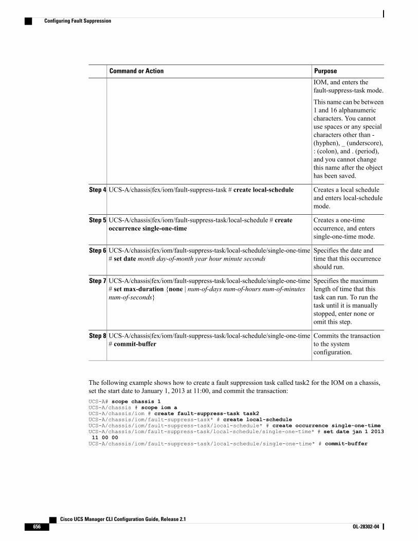
PurposeCommand or Action
IOM, and enters thefault-suppress-task mode.
This name can be between1 and 16 alphanumericcharacters. You cannotuse spaces or any specialcharacters other than -(hyphen), _ (underscore),: (colon), and . (period),and you cannot changethis name after the objecthas been saved.
Creates a local scheduleand enters local-schedulemode.
UCS-A/chassis|fex/iom/fault-suppress-task # create local-scheduleStep 4
Creates a one-timeoccurrence, and enterssingle-one-time mode.
UCS-A/chassis|fex/iom/fault-suppress-task/local-schedule # createoccurrence single-one-time
Step 5
Specifies the date andtime that this occurrenceshould run.
UCS-A/chassis|fex/iom/fault-suppress-task/local-schedule/single-one-time# set date month day-of-month year hour minute seconds
Step 6
Specifies the maximumlength of time that this
UCS-A/chassis|fex/iom/fault-suppress-task/local-schedule/single-one-time# set max-duration {none | num-of-days num-of-hours num-of-minutesnum-of-seconds}
Step 7
task can run. To run thetask until it is manuallystopped, enter none oromit this step.
Commits the transactionto the systemconfiguration.
UCS-A/chassis|fex/iom/fault-suppress-task/local-schedule/single-one-time# commit-buffer
Step 8
The following example shows how to create a fault suppression task called task2 for the IOM on a chassis,set the start date to January 1, 2013 at 11:00, and commit the transaction:UCS-A# scope chassis 1UCS-A/chassis # scope iom aUCS-A/chassis/iom # create fault-suppress-task task2UCS-A/chassis/iom/fault-suppress-task* # create local-scheduleUCS-A/chassis/iom/fault-suppress-task/local-schedule* # create occurrence single-one-timeUCS-A/chassis/iom/fault-suppress-task/local-schedule/single-one-time* # set date jan 1 201311 00 00UCS-A/chassis/iom/fault-suppress-task/local-schedule/single-one-time* # commit-buffer
Cisco UCS Manager CLI Configuration Guide, Release 2.1656 OL-28302-04
Configuring Fault Suppression
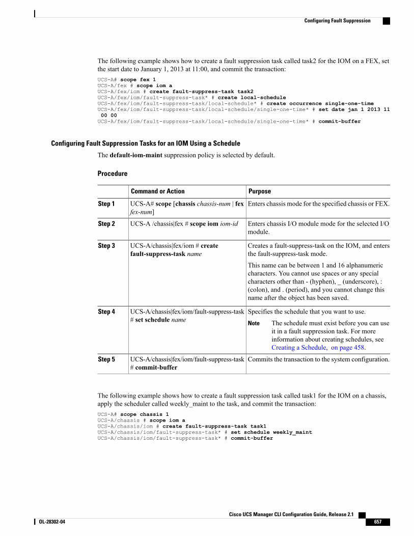
The following example shows how to create a fault suppression task called task2 for the IOM on a FEX, setthe start date to January 1, 2013 at 11:00, and commit the transaction:UCS-A# scope fex 1UCS-A/fex # scope iom aUCS-A/fex/iom # create fault-suppress-task task2UCS-A/fex/iom/fault-suppress-task* # create local-scheduleUCS-A/fex/iom/fault-suppress-task/local-schedule* # create occurrence single-one-timeUCS-A/fex/iom/fault-suppress-task/local-schedule/single-one-time* # set date jan 1 2013 1100 00UCS-A/fex/iom/fault-suppress-task/local-schedule/single-one-time* # commit-buffer
Configuring Fault Suppression Tasks for an IOM Using a Schedule
The default-iom-maint suppression policy is selected by default.
Procedure
PurposeCommand or Action
Enters chassis mode for the specified chassis or FEX.UCS-A# scope [chassis chassis-num | fexfex-num]
Step 1
Enters chassis I/O module mode for the selected I/Omodule.
UCS-A /chassis|fex # scope iom iom-idStep 2
Creates a fault-suppress-task on the IOM, and entersthe fault-suppress-task mode.
UCS-A/chassis|fex/iom # createfault-suppress-task name
Step 3
This name can be between 1 and 16 alphanumericcharacters. You cannot use spaces or any specialcharacters other than - (hyphen), _ (underscore), :(colon), and . (period), and you cannot change thisname after the object has been saved.
Specifies the schedule that you want to use.UCS-A/chassis|fex/iom/fault-suppress-task# set schedule name
Step 4
The schedule must exist before you can useit in a fault suppression task. For moreinformation about creating schedules, seeCreating a Schedule, on page 458.
Note
Commits the transaction to the system configuration.UCS-A/chassis|fex/iom/fault-suppress-task# commit-buffer
Step 5
The following example shows how to create a fault suppression task called task1 for the IOM on a chassis,apply the scheduler called weekly_maint to the task, and commit the transaction:UCS-A# scope chassis 1UCS-A/chassis # scope iom aUCS-A/chassis/iom # create fault-suppress-task task1UCS-A/chassis/iom/fault-suppress-task* # set schedule weekly_maintUCS-A/chassis/iom/fault-suppress-task* # commit-buffer
Cisco UCS Manager CLI Configuration Guide, Release 2.1 OL-28302-04 657
Configuring Fault Suppression
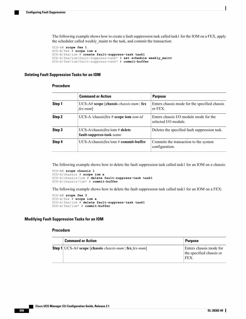
The following example shows how to create a fault suppression task called task1 for the IOM on a FEX, applythe scheduler called weekly_maint to the task, and commit the transaction:UCS-A# scope fex 1UCS-A/fex # scope iom aUCS-A/fex/iom # create fault-suppress-task task1UCS-A/fex/iom/fault-suppress-task* # set schedule weekly_maintUCS-A/fex/iom/fault-suppress-task* # commit-buffer
Deleting Fault Suppression Tasks for an IOM
Procedure
PurposeCommand or Action
Enters chassis mode for the specified chassisor FEX.
UCS-A# scope [chassis chassis-num | fexfex-num]
Step 1
Enters chassis I/O module mode for theselected I/O module.
UCS-A /chassis|fex # scope iom iom-idStep 2
Deletes the specified fault suppression task.UCS-A/chassis|fex/iom # deletefault-suppress-task name
Step 3
Commits the transaction to the systemconfiguration.
UCS-A/chassis|fex/iom # commit-bufferStep 4
The following example shows how to delete the fault suppression task called task1 for an IOM on a chassis:UCS-A# scope chassis 1UCS-A/chassis # scope iom aUCS-A/chassis/iom # delete fault-suppress-task task1UCS-A/chassis/iom* # commit-buffer
The following example shows how to delete the fault suppression task called task1 for an IOM on a FEX:UCS-A# scope fex 3UCS-A/fex # scope iom aUCS-A/fex/iom # delete fault-suppress-task task1UCS-A/fex/iom* # commit-buffer
Modifying Fault Suppression Tasks for an IOM
Procedure
PurposeCommand or Action
Enters chassis mode forthe specified chassis orFEX.
UCS-A# scope [chassis chassis-num | fex fex-num]Step 1
Cisco UCS Manager CLI Configuration Guide, Release 2.1658 OL-28302-04
Configuring Fault Suppression
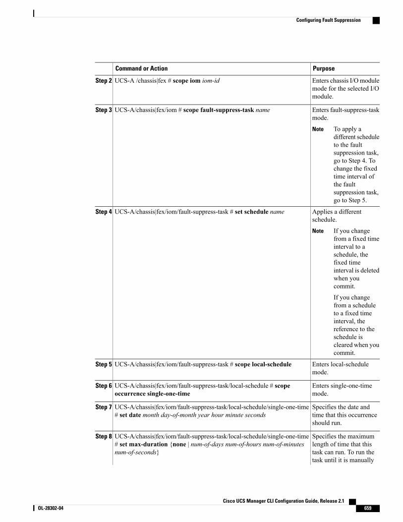
PurposeCommand or Action
Enters chassis I/Omodulemode for the selected I/Omodule.
UCS-A /chassis|fex # scope iom iom-idStep 2
Enters fault-suppress-taskmode.
UCS-A/chassis|fex/iom # scope fault-suppress-task nameStep 3
To apply adifferent scheduleto the faultsuppression task,go to Step 4. Tochange the fixedtime interval ofthe faultsuppression task,go to Step 5.
Note
Applies a differentschedule.
UCS-A/chassis|fex/iom/fault-suppress-task # set schedule nameStep 4
If you changefrom a fixed timeinterval to aschedule, thefixed timeinterval is deletedwhen youcommit.
If you changefrom a scheduleto a fixed timeinterval, thereference to theschedule iscleared when youcommit.
Note
Enters local-schedulemode.
UCS-A/chassis|fex/iom/fault-suppress-task # scope local-scheduleStep 5
Enters single-one-timemode.
UCS-A/chassis|fex/iom/fault-suppress-task/local-schedule # scopeoccurrence single-one-time
Step 6
Specifies the date andtime that this occurrenceshould run.
UCS-A/chassis|fex/iom/fault-suppress-task/local-schedule/single-one-time# set date month day-of-month year hour minute seconds
Step 7
Specifies the maximumlength of time that this
UCS-A/chassis|fex/iom/fault-suppress-task/local-schedule/single-one-time# set max-duration {none | num-of-days num-of-hours num-of-minutesnum-of-seconds}
Step 8
task can run. To run thetask until it is manually
Cisco UCS Manager CLI Configuration Guide, Release 2.1 OL-28302-04 659
Configuring Fault Suppression
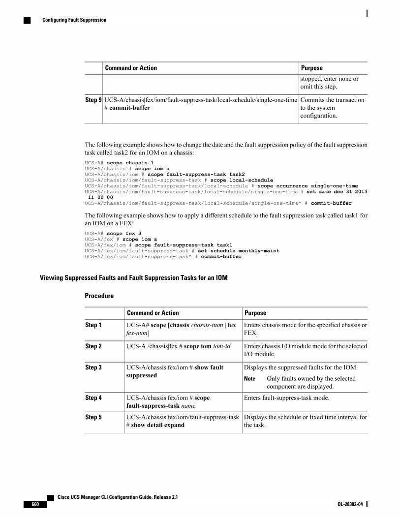
PurposeCommand or Action
stopped, enter none oromit this step.
Commits the transactionto the systemconfiguration.
UCS-A/chassis|fex/iom/fault-suppress-task/local-schedule/single-one-time# commit-buffer
Step 9
The following example shows how to change the date and the fault suppression policy of the fault suppressiontask called task2 for an IOM on a chassis:UCS-A# scope chassis 1UCS-A/chassis # scope iom aUCS-A/chassis/iom # scope fault-suppress-task task2UCS-A/chassis/iom/fault-suppress-task # scope local-scheduleUCS-A/chassis/iom/fault-suppress-task/local-schedule # scope occurrence single-one-timeUCS-A/chassis/iom/fault-suppress-task/local-schedule/single-one-time # set date dec 31 201311 00 00UCS-A/chassis/iom/fault-suppress-task/local-schedule/single-one-time* # commit-buffer
The following example shows how to apply a different schedule to the fault suppression task called task1 foran IOM on a FEX:UCS-A# scope fex 3UCS-A/fex # scope iom aUCS-A/fex/iom # scope fault-suppress-task task1UCS-A/fex/iom/fault-suppress-task # set schedule monthly-maintUCS-A/fex/iom/fault-suppress-task* # commit-buffer
Viewing Suppressed Faults and Fault Suppression Tasks for an IOM
Procedure
PurposeCommand or Action
Enters chassis mode for the specified chassis orFEX.
UCS-A# scope [chassis chassis-num | fexfex-num]
Step 1
Enters chassis I/Omodule mode for the selectedI/O module.
UCS-A /chassis|fex # scope iom iom-idStep 2
Displays the suppressed faults for the IOM.UCS-A/chassis|fex/iom # show faultsuppressed
Step 3
Only faults owned by the selectedcomponent are displayed.
Note
Enters fault-suppress-task mode.UCS-A/chassis|fex/iom # scopefault-suppress-task name
Step 4
Displays the schedule or fixed time interval forthe task.
UCS-A/chassis|fex/iom/fault-suppress-task# show detail expand
Step 5
Cisco UCS Manager CLI Configuration Guide, Release 2.1660 OL-28302-04
Configuring Fault Suppression

The following example shows how to display the suppressed faults for an IOM on a chassis:UCS-A# scope chassis 1UCS-A/chassis # scope iom aUCS-A/chassis/iom # show fault suppressedFault Suppress Task:
Name Status Global Schedule Suppress Policy Name------------------ ------------------ --------------- --------------------task1 Active test_schedule1 Default Iom Maint
UCS-A/chassis/iom #
The following example shows how to display the fault suppression task called task1 for an IOM on a chassis:UCS-A# scope chassis 1UCS-A/chassis # scope iom aUCS-A/chassis/iom # scope fault-suppress-task task1UCS-A/chassis/iom/fault-suppress-task # show detail expandFault Suppress Task:
Name: task1Status: ActiveGlobal Schedule: test_schedule1Suppress Policy Name: Default Iom Maint
UCS-A/chassis/iom/fault-suppress-task #
The following example shows how to display the fault suppression task called task1 for an IOM on a FEX:UCS-A# scope fex 3UCS-A/fex # scope iom aUCS-A/fex/iom # scope fault-suppress-task task1UCS-A/fex/iom/fault-suppress-task # show detail expandFault Suppress Task:
Name: task1Status: ActiveGlobal Schedule: test_schedule1Suppress Policy Name: Default Iom Maint
UCS-A/chassis/iom/fault-suppress-task #
Configuring Fault Suppression for a FEX
Configuring Fault Suppression Tasks for a FEX Using a Fixed Time Interval
Procedure
PurposeCommand or Action
Enters fexmode for the specified FEX.UCS-A# scope fex fex-numStep 1
Creates a fault-suppress-task on thefex, and enters the fault-suppress-taskmode.
UCS-A/fex # create fault-suppress-task nameStep 2
This name can be between 1 and 16alphanumeric characters. You cannotuse spaces or any special charactersother than - (hyphen), _ (underscore),: (colon), and . (period), and youcannot change this name after theobject has been saved.
Cisco UCS Manager CLI Configuration Guide, Release 2.1 OL-28302-04 661
Configuring Fault Suppression

PurposeCommand or Action
Specifies the fault suppression policyyou want to apply. This can be one ofthe following:
UCS-A/fex/fault-suppress-task # set fault-suppress-policypolicy-name
Step 3
• default-fex-all-maint—Suppressesfaults for the FEX and all powersupplies, fan modules, and IOMsin the FEX.
• default-fex-phys-maint—Suppressesfaults for the FEX and all fanmodules and power supplies inthe FEX.
• default-iom-maint—Suppressesfaults for IOMs in a chassis orFEX.
Creates a local schedule and enterslocal-schedule mode.
UCS-A/fex/fault-suppress-task # create local-scheduleStep 4
Creates a one-time occurrence, andenters single-one-time mode.
UCS-A/fex/fault-suppress-task/local-schedule # createoccurrence single-one-time
Step 5
Specifies the date and time that thisoccurrence should run.
UCS-A/fex/fault-suppress-task/local-schedule/single-one-time# set date month day-of-month year hour minute seconds
Step 6
Specifies the maximum length of timethat this task can run. To run the task
UCS-A/fex/fault-suppress-task/local-schedule/single-one-time# set max-duration {none | num-of-days num-of-hoursnum-of-minutes num-of-seconds}
Step 7
until it is manually stopped, enter noneor omit this step.
Commits the transaction to the systemconfiguration.
UCS-A/fex/fault-suppress-task/local-schedule/single-one-time# commit-buffer
Step 8
The following example shows how to create a fault suppression task called task2 for the FEX, apply thedefault-fex-all-maint policy to the task, set the start date to January 1, 2013 at 11:00, and commit the transaction:UCS-A# scope fex 1UCS-A/fex # create fault-suppress-task task2UCS-A/fex/fault-suppress-task* # set fault-suppress-policy default-fex-all-maintUCS-A/fex/fault-suppress-task* # create local-scheduleUCS-A/fex/fault-suppress-task/local-schedule* # create occurrence single-one-timeUCS-A/fex/fault-suppress-task/local-schedule/single-one-time* # set date jan 1 2013 11 0000UCS-A/fex/fault-suppress-task/local-schedule/single-one-time* # commit-buffer
Cisco UCS Manager CLI Configuration Guide, Release 2.1662 OL-28302-04
Configuring Fault Suppression
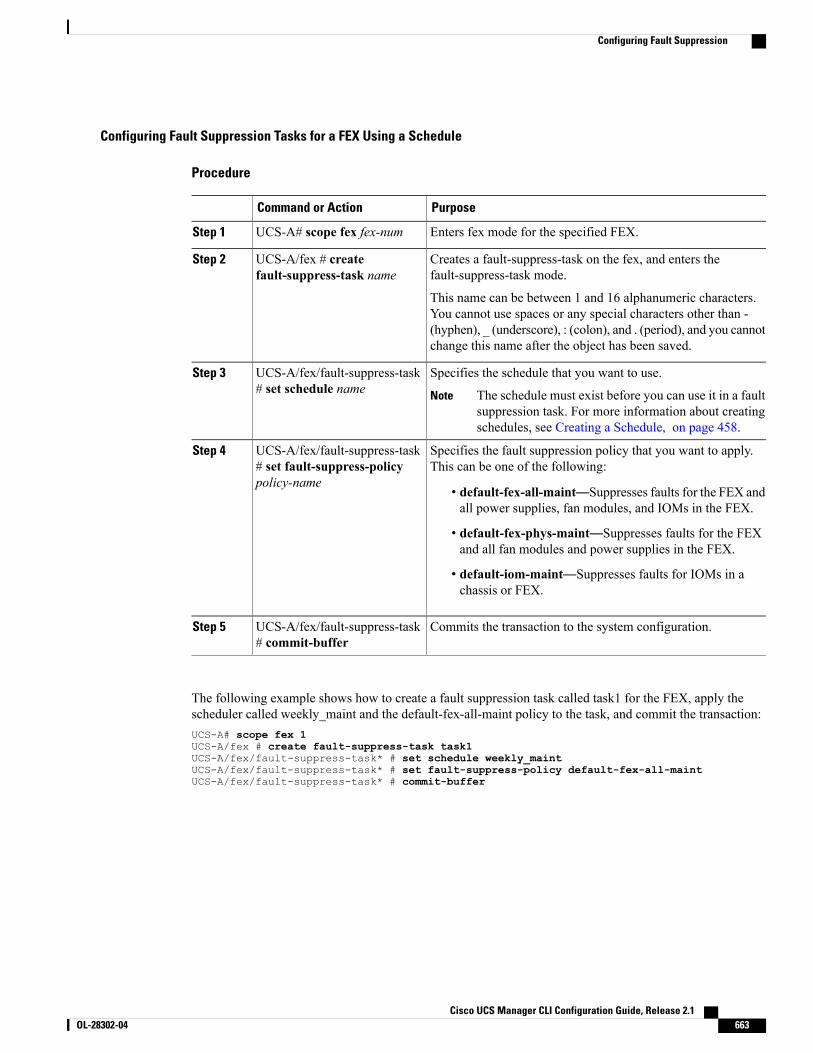
Configuring Fault Suppression Tasks for a FEX Using a Schedule
Procedure
PurposeCommand or Action
Enters fex mode for the specified FEX.UCS-A# scope fex fex-numStep 1
Creates a fault-suppress-task on the fex, and enters thefault-suppress-task mode.
UCS-A/fex # createfault-suppress-task name
Step 2
This name can be between 1 and 16 alphanumeric characters.You cannot use spaces or any special characters other than -(hyphen), _ (underscore), : (colon), and . (period), and you cannotchange this name after the object has been saved.
Specifies the schedule that you want to use.UCS-A/fex/fault-suppress-task# set schedule name
Step 3
The schedule must exist before you can use it in a faultsuppression task. For more information about creatingschedules, see Creating a Schedule, on page 458.
Note
Specifies the fault suppression policy that you want to apply.This can be one of the following:
UCS-A/fex/fault-suppress-task# set fault-suppress-policypolicy-name
Step 4
• default-fex-all-maint—Suppresses faults for the FEX andall power supplies, fan modules, and IOMs in the FEX.
• default-fex-phys-maint—Suppresses faults for the FEXand all fan modules and power supplies in the FEX.
• default-iom-maint—Suppresses faults for IOMs in achassis or FEX.
Commits the transaction to the system configuration.UCS-A/fex/fault-suppress-task# commit-buffer
Step 5
The following example shows how to create a fault suppression task called task1 for the FEX, apply thescheduler called weekly_maint and the default-fex-all-maint policy to the task, and commit the transaction:UCS-A# scope fex 1UCS-A/fex # create fault-suppress-task task1UCS-A/fex/fault-suppress-task* # set schedule weekly_maintUCS-A/fex/fault-suppress-task* # set fault-suppress-policy default-fex-all-maintUCS-A/fex/fault-suppress-task* # commit-buffer
Cisco UCS Manager CLI Configuration Guide, Release 2.1 OL-28302-04 663
Configuring Fault Suppression
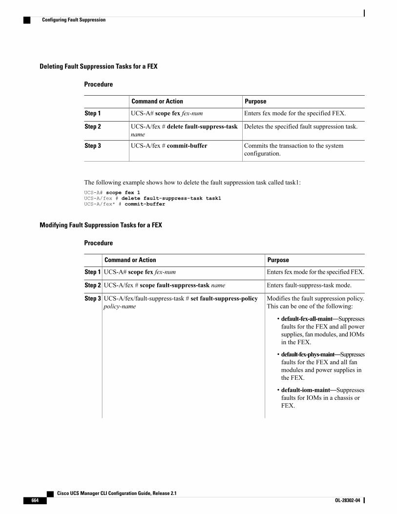
Deleting Fault Suppression Tasks for a FEX
Procedure
PurposeCommand or Action
Enters fex mode for the specified FEX.UCS-A# scope fex fex-numStep 1
Deletes the specified fault suppression task.UCS-A/fex # delete fault-suppress-taskname
Step 2
Commits the transaction to the systemconfiguration.
UCS-A/fex # commit-bufferStep 3
The following example shows how to delete the fault suppression task called task1:UCS-A# scope fex 1UCS-A/fex # delete fault-suppress-task task1UCS-A/fex* # commit-buffer
Modifying Fault Suppression Tasks for a FEX
Procedure
PurposeCommand or Action
Enters fexmode for the specified FEX.UCS-A# scope fex fex-numStep 1
Enters fault-suppress-task mode.UCS-A/fex # scope fault-suppress-task nameStep 2
Modifies the fault suppression policy.This can be one of the following:
UCS-A/fex/fault-suppress-task # set fault-suppress-policypolicy-name
Step 3
• default-fex-all-maint—Suppressesfaults for the FEX and all powersupplies, fan modules, and IOMsin the FEX.
• default-fex-phys-maint—Suppressesfaults for the FEX and all fanmodules and power supplies inthe FEX.
• default-iom-maint—Suppressesfaults for IOMs in a chassis orFEX.
Cisco UCS Manager CLI Configuration Guide, Release 2.1664 OL-28302-04
Configuring Fault Suppression
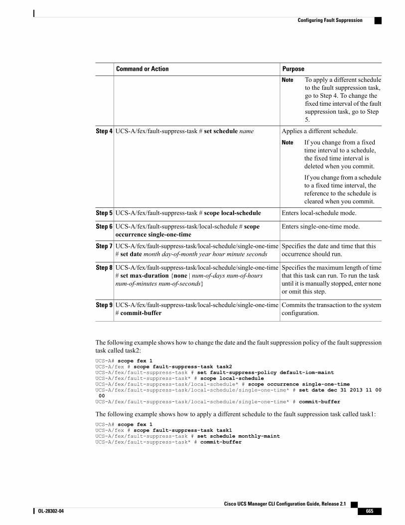
PurposeCommand or Action
To apply a different scheduleto the fault suppression task,go to Step 4. To change thefixed time interval of the faultsuppression task, go to Step5.
Note
Applies a different schedule.UCS-A/fex/fault-suppress-task # set schedule nameStep 4
If you change from a fixedtime interval to a schedule,the fixed time interval isdeleted when you commit.
If you change from a scheduleto a fixed time interval, thereference to the schedule iscleared when you commit.
Note
Enters local-schedule mode.UCS-A/fex/fault-suppress-task # scope local-scheduleStep 5
Enters single-one-time mode.UCS-A/fex/fault-suppress-task/local-schedule # scopeoccurrence single-one-time
Step 6
Specifies the date and time that thisoccurrence should run.
UCS-A/fex/fault-suppress-task/local-schedule/single-one-time# set date month day-of-month year hour minute seconds
Step 7
Specifies the maximum length of timethat this task can run. To run the task
UCS-A/fex/fault-suppress-task/local-schedule/single-one-time# set max-duration {none | num-of-days num-of-hoursnum-of-minutes num-of-seconds}
Step 8
until it is manually stopped, enter noneor omit this step.
Commits the transaction to the systemconfiguration.
UCS-A/fex/fault-suppress-task/local-schedule/single-one-time# commit-buffer
Step 9
The following example shows how to change the date and the fault suppression policy of the fault suppressiontask called task2:UCS-A# scope fex 1UCS-A/fex # scope fault-suppress-task task2UCS-A/fex/fault-suppress-task # set fault-suppress-policy default-iom-maintUCS-A/fex/fault-suppress-task* # scope local-scheduleUCS-A/fex/fault-suppress-task/local-schedule* # scope occurrence single-one-timeUCS-A/fex/fault-suppress-task/local-schedule/single-one-time* # set date dec 31 2013 11 0000UCS-A/fex/fault-suppress-task/local-schedule/single-one-time* # commit-buffer
The following example shows how to apply a different schedule to the fault suppression task called task1:UCS-A# scope fex 1UCS-A/fex # scope fault-suppress-task task1UCS-A/fex/fault-suppress-task # set schedule monthly-maintUCS-A/fex/fault-suppress-task* # commit-buffer
Cisco UCS Manager CLI Configuration Guide, Release 2.1 OL-28302-04 665
Configuring Fault Suppression
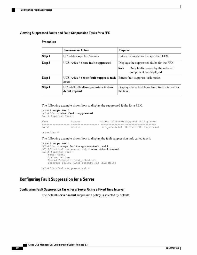
Viewing Suppressed Faults and Fault Suppression Tasks for a FEX
Procedure
PurposeCommand or Action
Enters fex mode for the specified FEX.UCS-A# scope fex fex-numStep 1
Displays the suppressed faults for the FEX.UCS-A/fex # show fault suppressedStep 2
Only faults owned by the selectedcomponent are displayed.
Note
Enters fault-suppress-task mode.UCS-A/fex # scope fault-suppress-taskname
Step 3
Displays the schedule or fixed time interval forthe task.
UCS-A/fex/fault-suppress-task # showdetail expand
Step 4
The following example shows how to display the suppressed faults for a FEX:UCS-A# scope fex 1UCS-A/fex # show fault suppressedFault Suppress Task:
Name Status Global Schedule Suppress Policy Name------------------ ------------------ --------------- --------------------task1 Active test_schedule1 Default FEX Phys Maint
UCS-A/fex #
The following example shows how to display the fault suppression task called task1:UCS-A# scope fex 1UCS-A/fex # scope fault-suppress-task task1UCS-A/fex/fault-suppress-task # show detail expandFault Suppress Task:
Name: task1Status: ActiveGlobal Schedule: test_schedule1Suppress Policy Name: Default FEX Phys Maint
UCS-A/fex/fault-suppress-task #
Configuring Fault Suppression for a Server
Configuring Fault Suppression Tasks for a Server Using a Fixed Time Interval
The default-server-maint suppression policy is selected by default.
Cisco UCS Manager CLI Configuration Guide, Release 2.1666 OL-28302-04
Configuring Fault Suppression
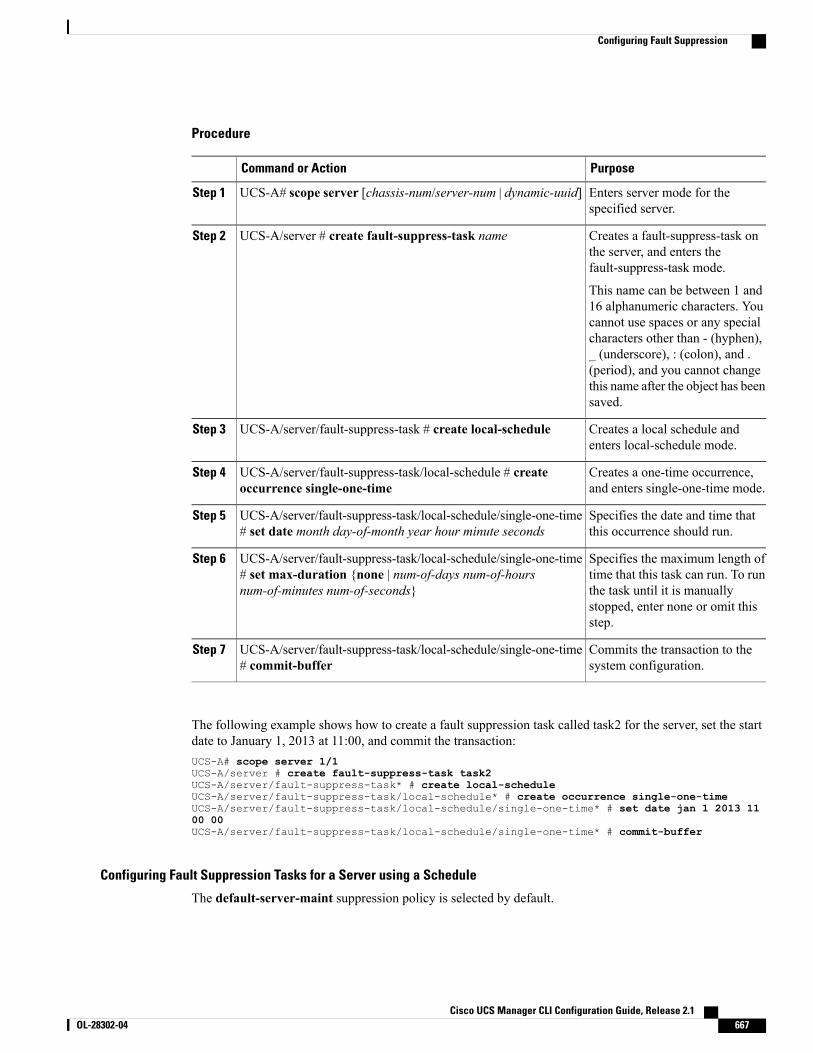
Procedure
PurposeCommand or Action
Enters server mode for thespecified server.
UCS-A# scope server [chassis-num/server-num | dynamic-uuid]Step 1
Creates a fault-suppress-task onthe server, and enters thefault-suppress-task mode.
UCS-A/server # create fault-suppress-task nameStep 2
This name can be between 1 and16 alphanumeric characters. Youcannot use spaces or any specialcharacters other than - (hyphen),_ (underscore), : (colon), and .(period), and you cannot changethis name after the object has beensaved.
Creates a local schedule andenters local-schedule mode.
UCS-A/server/fault-suppress-task # create local-scheduleStep 3
Creates a one-time occurrence,and enters single-one-time mode.
UCS-A/server/fault-suppress-task/local-schedule # createoccurrence single-one-time
Step 4
Specifies the date and time thatthis occurrence should run.
UCS-A/server/fault-suppress-task/local-schedule/single-one-time# set date month day-of-month year hour minute seconds
Step 5
Specifies the maximum length oftime that this task can run. To run
UCS-A/server/fault-suppress-task/local-schedule/single-one-time# set max-duration {none | num-of-days num-of-hoursnum-of-minutes num-of-seconds}
Step 6
the task until it is manuallystopped, enter none or omit thisstep.
Commits the transaction to thesystem configuration.
UCS-A/server/fault-suppress-task/local-schedule/single-one-time# commit-buffer
Step 7
The following example shows how to create a fault suppression task called task2 for the server, set the startdate to January 1, 2013 at 11:00, and commit the transaction:UCS-A# scope server 1/1UCS-A/server # create fault-suppress-task task2UCS-A/server/fault-suppress-task* # create local-scheduleUCS-A/server/fault-suppress-task/local-schedule* # create occurrence single-one-timeUCS-A/server/fault-suppress-task/local-schedule/single-one-time* # set date jan 1 2013 1100 00UCS-A/server/fault-suppress-task/local-schedule/single-one-time* # commit-buffer
Configuring Fault Suppression Tasks for a Server using a Schedule
The default-server-maint suppression policy is selected by default.
Cisco UCS Manager CLI Configuration Guide, Release 2.1 OL-28302-04 667
Configuring Fault Suppression
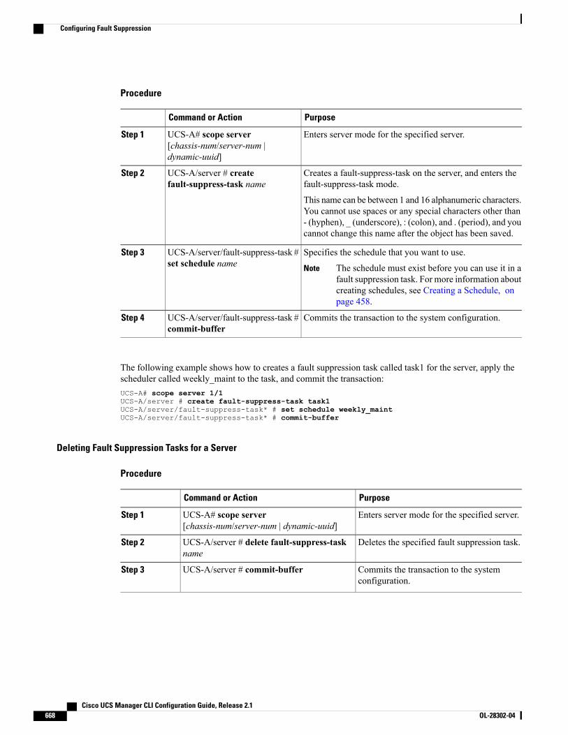
Procedure
PurposeCommand or Action
Enters server mode for the specified server.UCS-A# scope server[chassis-num/server-num |dynamic-uuid]
Step 1
Creates a fault-suppress-task on the server, and enters thefault-suppress-task mode.
UCS-A/server # createfault-suppress-task name
Step 2
This name can be between 1 and 16 alphanumeric characters.You cannot use spaces or any special characters other than- (hyphen), _ (underscore), : (colon), and . (period), and youcannot change this name after the object has been saved.
Specifies the schedule that you want to use.UCS-A/server/fault-suppress-task #set schedule name
Step 3
The schedule must exist before you can use it in afault suppression task. For more information aboutcreating schedules, see Creating a Schedule, onpage 458.
Note
Commits the transaction to the system configuration.UCS-A/server/fault-suppress-task #commit-buffer
Step 4
The following example shows how to creates a fault suppression task called task1 for the server, apply thescheduler called weekly_maint to the task, and commit the transaction:UCS-A# scope server 1/1UCS-A/server # create fault-suppress-task task1UCS-A/server/fault-suppress-task* # set schedule weekly_maintUCS-A/server/fault-suppress-task* # commit-buffer
Deleting Fault Suppression Tasks for a Server
Procedure
PurposeCommand or Action
Enters server mode for the specified server.UCS-A# scope server[chassis-num/server-num | dynamic-uuid]
Step 1
Deletes the specified fault suppression task.UCS-A/server # delete fault-suppress-taskname
Step 2
Commits the transaction to the systemconfiguration.
UCS-A/server # commit-bufferStep 3
Cisco UCS Manager CLI Configuration Guide, Release 2.1668 OL-28302-04
Configuring Fault Suppression
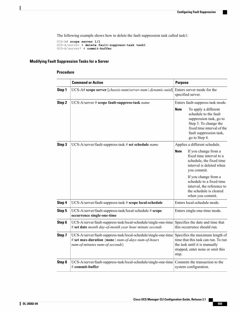
The following example shows how to delete the fault suppression task called task1:UCS-A# scope server 1/1UCS-A/server # delete fault-suppress-task task1UCS-A/server* # commit-buffer
Modifying Fault Suppression Tasks for a Server
Procedure
PurposeCommand or Action
Enters server mode for thespecified server.
UCS-A# scope server [chassis-num/server-num | dynamic-uuid]Step 1
Enters fault-suppress-task mode.UCS-A/server # scope fault-suppress-task nameStep 2
To apply a differentschedule to the faultsuppression task, go toStep 3. To change thefixed time interval of thefault suppression task,go to Step 4.
Note
Applies a different schedule.UCS-A/server/fault-suppress-task # set schedule nameStep 3
If you change from afixed time interval to aschedule, the fixed timeinterval is deleted whenyou commit.
If you change from aschedule to a fixed timeinterval, the reference tothe schedule is clearedwhen you commit.
Note
Enters local-schedule mode.UCS-A/server/fault-suppress-task # scope local-scheduleStep 4
Enters single-one-time mode.UCS-A/server/fault-suppress-task/local-schedule # scopeoccurrence single-one-time
Step 5
Specifies the date and time thatthis occurrence should run.
UCS-A/server/fault-suppress-task/local-schedule/single-one-time# set date month day-of-month year hour minute seconds
Step 6
Specifies the maximum length oftime that this task can run. To run
UCS-A/server/fault-suppress-task/local-schedule/single-one-time# set max-duration {none | num-of-days num-of-hoursnum-of-minutes num-of-seconds}
Step 7
the task until it is manuallystopped, enter none or omit thisstep.
Commits the transaction to thesystem configuration.
UCS-A/server/fault-suppress-task/local-schedule/single-one-time# commit-buffer
Step 8
Cisco UCS Manager CLI Configuration Guide, Release 2.1 OL-28302-04 669
Configuring Fault Suppression

The following example shows how to change the date and the fault suppression policy of the fault suppressiontask called task2:UCS-A# scope server 1/1UCS-A/server # scope fault-suppress-task task2UCS-A/server/fault-suppress-task # scope local-scheduleUCS-A/server/fault-suppress-task/local-schedule # scope occurrence single-one-timeUCS-A/server/fault-suppress-task/local-schedule/single-one-time # set date dec 31 2013 1100 00UCS-A/server/fault-suppress-task/local-schedule/single-one-time* # commit-buffer
The following example shows how to apply a different schedule to the fault suppression task called task1:UCS-A# scope server 1/1UCS-A/server # scope fault-suppress-task task1UCS-A/server/fault-suppress-task # set schedule monthly-maintUCS-A/server/fault-suppress-task* # commit-buffer
Viewing Suppressed Faults and Fault Suppression Tasks for a Server
Procedure
PurposeCommand or Action
Enters server mode for the specified server.UCS-A# scope server[chassis-num/server-num | dynamic-uuid]
Step 1
Displays the suppressed faults for the server.UCS-A/server # show fault suppressedStep 2
Only faults owned by the selectedcomponent are displayed.
Note
Enters fault-suppress-task mode.UCS-A/server # scope fault-suppress-taskname
Step 3
Displays the schedule or fixed time interval forthe task.
UCS-A/server/fault-suppress-task # showdetail expand
Step 4
The following example shows how to display the suppressed faults for a server:UCS-A# scope server 1/1UCS-A/server # show fault suppressedFault Suppress Task:
Name Status Global Schedule Suppress Policy Name------------------ ------------------ --------------- --------------------task1 Active test_schedule1 Default Server Maint
UCS-A/server #
The following example shows how to display the fault suppression task called task1:UCS-A# scope server 1/1UCS-A/server # scope fault-suppress-task task1UCS-A/server/fault-suppress-task # show detail expandFault Suppress Task:
Name: task1Status: ActiveGlobal Schedule: test_schedule1
Cisco UCS Manager CLI Configuration Guide, Release 2.1670 OL-28302-04
Configuring Fault Suppression
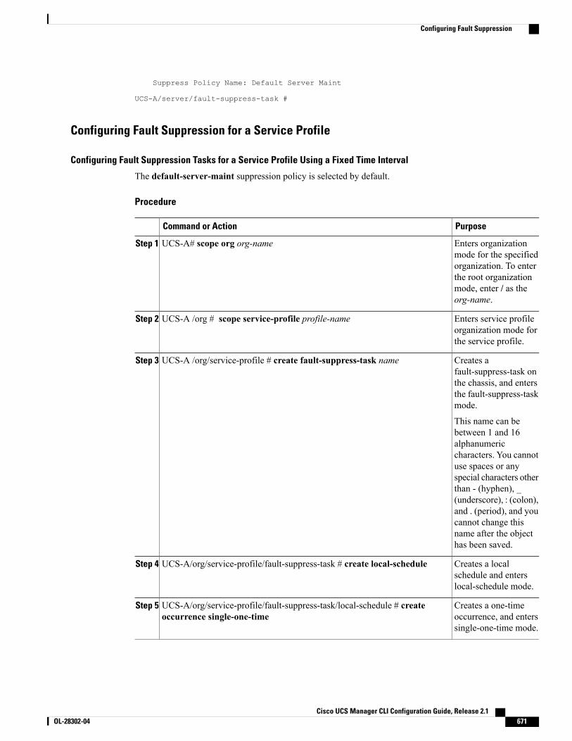
Suppress Policy Name: Default Server Maint
UCS-A/server/fault-suppress-task #
Configuring Fault Suppression for a Service Profile
Configuring Fault Suppression Tasks for a Service Profile Using a Fixed Time Interval
The default-server-maint suppression policy is selected by default.
Procedure
PurposeCommand or Action
Enters organizationmode for the specified
UCS-A# scope org org-nameStep 1
organization. To enterthe root organizationmode, enter / as theorg-name.
Enters service profileorganization mode forthe service profile.
UCS-A /org # scope service-profile profile-nameStep 2
Creates afault-suppress-task on
UCS-A /org/service-profile # create fault-suppress-task nameStep 3
the chassis, and entersthe fault-suppress-taskmode.
This name can bebetween 1 and 16alphanumericcharacters. You cannotuse spaces or anyspecial characters otherthan - (hyphen), _(underscore), : (colon),and . (period), and youcannot change thisname after the objecthas been saved.
Creates a localschedule and enterslocal-schedule mode.
UCS-A/org/service-profile/fault-suppress-task # create local-scheduleStep 4
Creates a one-timeoccurrence, and enterssingle-one-time mode.
UCS-A/org/service-profile/fault-suppress-task/local-schedule # createoccurrence single-one-time
Step 5
Cisco UCS Manager CLI Configuration Guide, Release 2.1 OL-28302-04 671
Configuring Fault Suppression
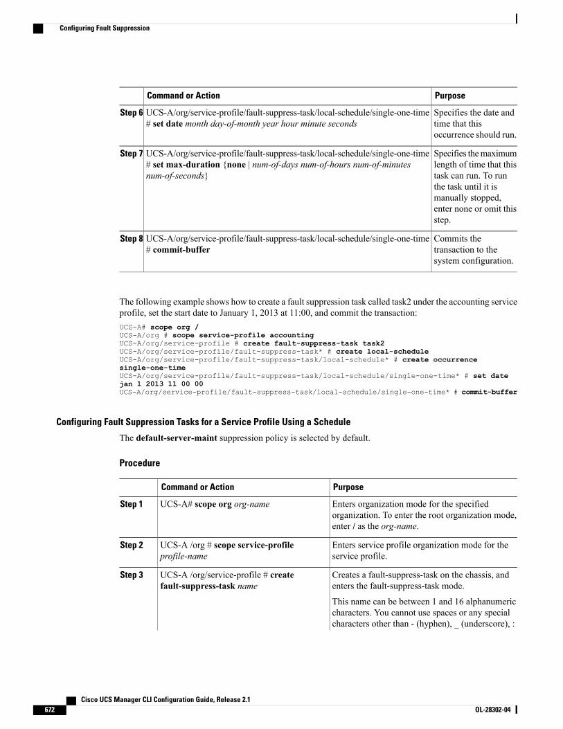
PurposeCommand or Action
Specifies the date andtime that thisoccurrence should run.
UCS-A/org/service-profile/fault-suppress-task/local-schedule/single-one-time# set date month day-of-month year hour minute seconds
Step 6
Specifies themaximumlength of time that this
UCS-A/org/service-profile/fault-suppress-task/local-schedule/single-one-time# set max-duration {none | num-of-days num-of-hours num-of-minutesnum-of-seconds}
Step 7
task can run. To runthe task until it ismanually stopped,enter none or omit thisstep.
Commits thetransaction to thesystem configuration.
UCS-A/org/service-profile/fault-suppress-task/local-schedule/single-one-time# commit-buffer
Step 8
The following example shows how to create a fault suppression task called task2 under the accounting serviceprofile, set the start date to January 1, 2013 at 11:00, and commit the transaction:UCS-A# scope org /UCS-A/org # scope service-profile accountingUCS-A/org/service-profile # create fault-suppress-task task2UCS-A/org/service-profile/fault-suppress-task* # create local-scheduleUCS-A/org/service-profile/fault-suppress-task/local-schedule* # create occurrencesingle-one-timeUCS-A/org/service-profile/fault-suppress-task/local-schedule/single-one-time* # set datejan 1 2013 11 00 00UCS-A/org/service-profile/fault-suppress-task/local-schedule/single-one-time* # commit-buffer
Configuring Fault Suppression Tasks for a Service Profile Using a Schedule
The default-server-maint suppression policy is selected by default.
Procedure
PurposeCommand or Action
Enters organization mode for the specifiedorganization. To enter the root organization mode,enter / as the org-name.
UCS-A# scope org org-nameStep 1
Enters service profile organization mode for theservice profile.
UCS-A /org # scope service-profileprofile-name
Step 2
Creates a fault-suppress-task on the chassis, andenters the fault-suppress-task mode.
UCS-A /org/service-profile # createfault-suppress-task name
Step 3
This name can be between 1 and 16 alphanumericcharacters. You cannot use spaces or any specialcharacters other than - (hyphen), _ (underscore), :
Cisco UCS Manager CLI Configuration Guide, Release 2.1672 OL-28302-04
Configuring Fault Suppression
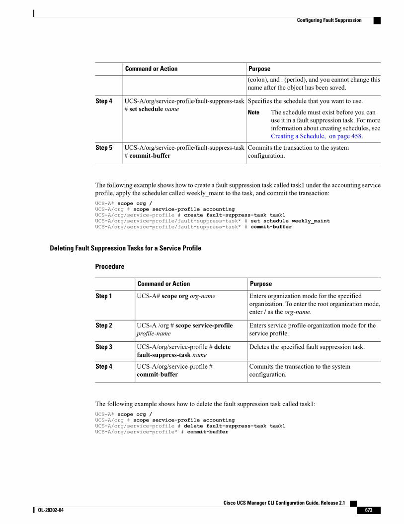
PurposeCommand or Action
(colon), and . (period), and you cannot change thisname after the object has been saved.
Specifies the schedule that you want to use.UCS-A/org/service-profile/fault-suppress-task# set schedule name
Step 4
The schedule must exist before you canuse it in a fault suppression task. For moreinformation about creating schedules, seeCreating a Schedule, on page 458.
Note
Commits the transaction to the systemconfiguration.
UCS-A/org/service-profile/fault-suppress-task# commit-buffer
Step 5
The following example shows how to create a fault suppression task called task1 under the accounting serviceprofile, apply the scheduler called weekly_maint to the task, and commit the transaction:UCS-A# scope org /UCS-A/org # scope service-profile accountingUCS-A/org/service-profile # create fault-suppress-task task1UCS-A/org/service-profile/fault-suppress-task* # set schedule weekly_maintUCS-A/org/service-profile/fault-suppress-task* # commit-buffer
Deleting Fault Suppression Tasks for a Service Profile
Procedure
PurposeCommand or Action
Enters organization mode for the specifiedorganization. To enter the root organization mode,enter / as the org-name.
UCS-A# scope org org-nameStep 1
Enters service profile organization mode for theservice profile.
UCS-A /org # scope service-profileprofile-name
Step 2
Deletes the specified fault suppression task.UCS-A/org/service-profile # deletefault-suppress-task name
Step 3
Commits the transaction to the systemconfiguration.
UCS-A/org/service-profile #commit-buffer
Step 4
The following example shows how to delete the fault suppression task called task1:UCS-A# scope org /UCS-A/org # scope service-profile accountingUCS-A/org/service-profile # delete fault-suppress-task task1UCS-A/org/service-profile* # commit-buffer
Cisco UCS Manager CLI Configuration Guide, Release 2.1 OL-28302-04 673
Configuring Fault Suppression
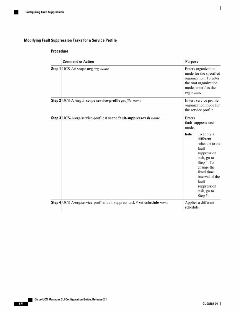
Modifying Fault Suppression Tasks for a Service Profile
Procedure
PurposeCommand or Action
Enters organizationmode for the specified
UCS-A# scope org org-nameStep 1
organization. To enterthe root organizationmode, enter / as theorg-name.
Enters service profileorganization mode forthe service profile.
UCS-A /org # scope service-profile profile-nameStep 2
Entersfault-suppress-taskmode.
UCS-A/org/service-profile # scope fault-suppress-task nameStep 3
To apply adifferentschedule to thefaultsuppressiontask, go toStep 4. Tochange thefixed timeinterval of thefaultsuppressiontask, go toStep 5.
Note
Applies a differentschedule.
UCS-A/org/service-profile/fault-suppress-task # set schedule nameStep 4
Cisco UCS Manager CLI Configuration Guide, Release 2.1674 OL-28302-04
Configuring Fault Suppression
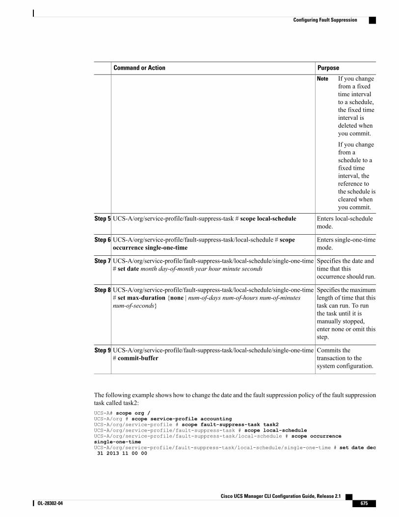
PurposeCommand or Action
If you changefrom a fixedtime intervalto a schedule,the fixed timeinterval isdeleted whenyou commit.
If you changefrom aschedule to afixed timeinterval, thereference tothe schedule iscleared whenyou commit.
Note
Enters local-schedulemode.
UCS-A/org/service-profile/fault-suppress-task # scope local-scheduleStep 5
Enters single-one-timemode.
UCS-A/org/service-profile/fault-suppress-task/local-schedule # scopeoccurrence single-one-time
Step 6
Specifies the date andtime that thisoccurrence should run.
UCS-A/org/service-profile/fault-suppress-task/local-schedule/single-one-time# set date month day-of-month year hour minute seconds
Step 7
Specifies themaximumlength of time that this
UCS-A/org/service-profile/fault-suppress-task/local-schedule/single-one-time# set max-duration {none | num-of-days num-of-hours num-of-minutesnum-of-seconds}
Step 8
task can run. To runthe task until it ismanually stopped,enter none or omit thisstep.
Commits thetransaction to thesystem configuration.
UCS-A/org/service-profile/fault-suppress-task/local-schedule/single-one-time# commit-buffer
Step 9
The following example shows how to change the date and the fault suppression policy of the fault suppressiontask called task2:UCS-A# scope org /UCS-A/org # scope service-profile accountingUCS-A/org/service-profile # scope fault-suppress-task task2UCS-A/org/service-profile/fault-suppress-task # scope local-scheduleUCS-A/org/service-profile/fault-suppress-task/local-schedule # scope occurrencesingle-one-timeUCS-A/org/service-profile/fault-suppress-task/local-schedule/single-one-time # set date dec31 2013 11 00 00
Cisco UCS Manager CLI Configuration Guide, Release 2.1 OL-28302-04 675
Configuring Fault Suppression
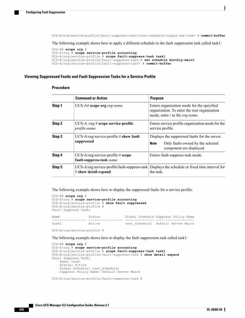
UCS-A/org/service-profile/fault-suppress-task/local-schedule/single-one-time* # commit-buffer
The following example shows how to apply a different schedule to the fault suppression task called task1:UCS-A# scope org /UCS-A/org # scope service-profile accountingUCS-A/org/service-profile # scope fault-suppress-task task1UCS-A/org/service-profile/fault-suppress-task # set schedule monthly-maintUCS-A/org/service-profile/fault-suppress-task* # commit-buffer
Viewing Suppressed Faults and Fault Suppression Tasks for a Service Profile
Procedure
PurposeCommand or Action
Enters organization mode for the specifiedorganization. To enter the root organizationmode, enter / as the org-name.
UCS-A# scope org org-nameStep 1
Enters service profile organization mode for theservice profile.
UCS-A /org # scope service-profileprofile-name
Step 2
Displays the suppressed faults for the server.UCS-A/org/service-profile # show faultsuppressed
Step 3
Only faults owned by the selectedcomponent are displayed.
Note
Enters fault-suppress-task mode.UCS-A/org/service-profile # scopefault-suppress-task name
Step 4
Displays the schedule or fixed time interval forthe task.
UCS-A/org/service-profile/fault-suppress-task# show detail expand
Step 5
The following example shows how to display the suppressed faults for a service profile:UCS-A# scope org /UCS-A/org # scope service-profile accountingUCS-A/org/service-profile # show fault suppressedUCS-A/org/service-profile #Fault Suppress Task:
Name Status Global Schedule Suppress Policy Name------------------ ------------------ --------------- --------------------task1 Active test_schedule1 Default Server Maint
UCS-A/org/service-profile #
The following example shows how to display the fault suppression task called task1:UCS-A# scope org /UCS-A/org # scope service-profile accountingUCS-A/org/service-profile # scope fault-suppress-task task1UCS-A/org/service-profile/fault-suppress-task # show detail expandFault Suppress Task:
Name: task1Status: ActiveGlobal Schedule: test_schedule1Suppress Policy Name: Default Server Maint
UCS-A/org/service-profile/fault-suppress-task #
Cisco UCS Manager CLI Configuration Guide, Release 2.1676 OL-28302-04
Configuring Fault Suppression
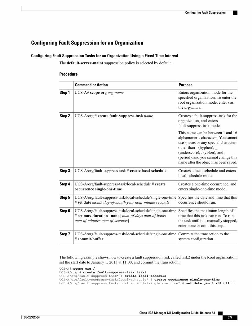
Configuring Fault Suppression for an Organization
Configuring Fault Suppression Tasks for an Organization Using a Fixed Time Interval
The default-server-maint suppression policy is selected by default.
Procedure
PurposeCommand or Action
Enters organization mode for thespecified organization. To enter the
UCS-A# scope org org-nameStep 1
root organization mode, enter / asthe org-name.
Creates a fault-suppress-task for theorganization, and entersfault-suppress-task mode.
UCS-A/org # create fault-suppress-task nameStep 2
This name can be between 1 and 16alphanumeric characters. You cannotuse spaces or any special charactersother than - (hyphen), _(underscore), : (colon), and .(period), and you cannot change thisname after the object has been saved.
Creates a local schedule and enterslocal-schedule mode.
UCS-A/org/fault-suppress-task # create local-scheduleStep 3
Creates a one-time occurrence, andenters single-one-time mode.
UCS-A/org/fault-suppress-task/local-schedule # createoccurrence single-one-time
Step 4
Specifies the date and time that thisoccurrence should run.
UCS-A/org/fault-suppress-task/local-schedule/single-one-time# set date month day-of-month year hour minute seconds
Step 5
Specifies the maximum length oftime that this task can run. To run
UCS-A/org/fault-suppress-task/local-schedule/single-one-time# set max-duration {none | num-of-days num-of-hoursnum-of-minutes num-of-seconds}
Step 6
the task until it is manually stopped,enter none or omit this step.
Commits the transaction to thesystem configuration.
UCS-A/org/fault-suppress-task/local-schedule/single-one-time# commit-buffer
Step 7
The following example shows how to create a fault suppression task called task2 under the Root organization,set the start date to January 1, 2013 at 11:00, and commit the transaction:UCS-A# scope org /UCS-A/org # create fault-suppress-task task2UCS-A/org/fault-suppress-task* # create local-scheduleUCS-A/org/fault-suppress-task/local-schedule* # create occurrence single-one-timeUCS-A/org/fault-suppress-task/local-schedule/single-one-time* # set date jan 1 2013 11 00
Cisco UCS Manager CLI Configuration Guide, Release 2.1 OL-28302-04 677
Configuring Fault Suppression

00UCS-A/org/fault-suppress-task/local-schedule/single-one-time* # commit-buffer
Configuring Fault Suppression Tasks for an Organization Using a Schedule
The default-server-maint suppression policy is selected by default.
Procedure
PurposeCommand or Action
Enters organization mode for the specified organization. Toenter the root organization mode, enter / as the org-name.
UCS-A# scope org org-nameStep 1
Creates a fault-suppress-task for the organization, and entersthe fault-suppress-task mode.
UCS-A/org # createfault-suppress-task name
Step 2
This name can be between 1 and 16 alphanumeric characters.You cannot use spaces or any special characters other than -(hyphen), _ (underscore), : (colon), and . (period), and youcannot change this name after the object has been saved.
Specifies the schedule that you want to use.UCS-A/org/fault-suppress-task# set schedule name
Step 3
The schedule must exist before you can use it in a faultsuppression task. For more information about creatingschedules, see Creating a Schedule, on page 458.
Note
Commits the transaction to the system configuration.UCS-A/org/fault-suppress-task# commit-buffer
Step 4
The following example shows how to create a fault suppression task called task1 under the Root organization,apply the scheduler called weekly_maint to the task, and commit the transaction:UCS-A# scope org /UCS-A/org # create fault-suppress-task task1UCS-A/org/fault-suppress-task* # set schedule weekly_maintUCS-A/org/fault-suppress-task* # commit-buffer
Deleting Fault Suppression Tasks for an Organization
Procedure
PurposeCommand or Action
Enters organization mode for the specifiedorganization. To enter the root organization mode,enter / as the org-name.
UCS-A# scope org org-nameStep 1
Deletes the specified fault suppression task.UCS-A/org # deletefault-suppress-task name
Step 2
Commits the transaction to the system configuration.UCS-A/org # commit-bufferStep 3
Cisco UCS Manager CLI Configuration Guide, Release 2.1678 OL-28302-04
Configuring Fault Suppression
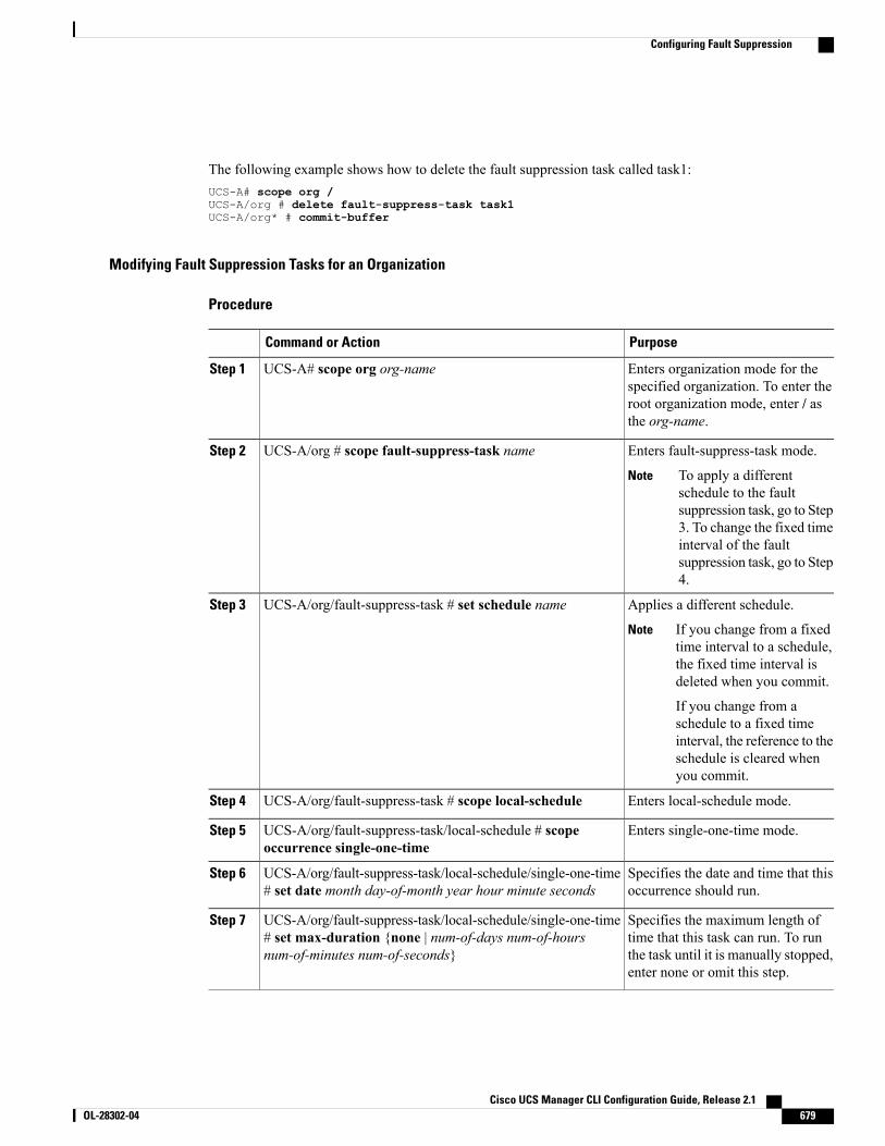
The following example shows how to delete the fault suppression task called task1:UCS-A# scope org /UCS-A/org # delete fault-suppress-task task1UCS-A/org* # commit-buffer
Modifying Fault Suppression Tasks for an Organization
Procedure
PurposeCommand or Action
Enters organization mode for thespecified organization. To enter the
UCS-A# scope org org-nameStep 1
root organization mode, enter / asthe org-name.
Enters fault-suppress-task mode.UCS-A/org # scope fault-suppress-task nameStep 2
To apply a differentschedule to the faultsuppression task, go to Step3. To change the fixed timeinterval of the faultsuppression task, go to Step4.
Note
Applies a different schedule.UCS-A/org/fault-suppress-task # set schedule nameStep 3
If you change from a fixedtime interval to a schedule,the fixed time interval isdeleted when you commit.
If you change from aschedule to a fixed timeinterval, the reference to theschedule is cleared whenyou commit.
Note
Enters local-schedule mode.UCS-A/org/fault-suppress-task # scope local-scheduleStep 4
Enters single-one-time mode.UCS-A/org/fault-suppress-task/local-schedule # scopeoccurrence single-one-time
Step 5
Specifies the date and time that thisoccurrence should run.
UCS-A/org/fault-suppress-task/local-schedule/single-one-time# set date month day-of-month year hour minute seconds
Step 6
Specifies the maximum length oftime that this task can run. To run
UCS-A/org/fault-suppress-task/local-schedule/single-one-time# set max-duration {none | num-of-days num-of-hoursnum-of-minutes num-of-seconds}
Step 7
the task until it is manually stopped,enter none or omit this step.
Cisco UCS Manager CLI Configuration Guide, Release 2.1 OL-28302-04 679
Configuring Fault Suppression
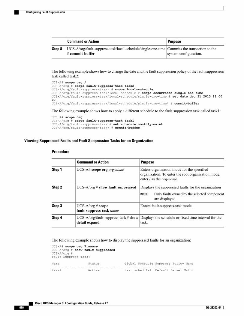
PurposeCommand or Action
Commits the transaction to thesystem configuration.
UCS-A/org/fault-suppress-task/local-schedule/single-one-time# commit-buffer
Step 8
The following example shows how to change the date and the fault suppression policy of the fault suppressiontask called task2:UCS-A# scope org /UCS-A/org # scope fault-suppress-task task2UCS-A/org/fault-suppress-task* # scope local-scheduleUCS-A/org/fault-suppress-task/local-schedule # scope occurrence single-one-timeUCS-A/org/fault-suppress-task/local-schedule/single-one-time # set date dec 31 2013 11 0000UCS-A/org/fault-suppress-task/local-schedule/single-one-time* # commit-buffer
The following example shows how to apply a different schedule to the fault suppression task called task1:UCS-A# scope orgUCS-A/org # scope fault-suppress-task task1UCS-A/org/fault-suppress-task # set schedule monthly-maintUCS-A/org/fault-suppress-task* # commit-buffer
Viewing Suppressed Faults and Fault Suppression Tasks for an Organization
Procedure
PurposeCommand or Action
Enters organization mode for the specifiedorganization. To enter the root organization mode,enter / as the org-name.
UCS-A# scope org org-nameStep 1
Displays the suppressed faults for the organizationUCS-A/org # show fault suppressedStep 2
Only faults owned by the selected componentare displayed.
Note
Enters fault-suppress-task mode.UCS-A/org # scopefault-suppress-task name
Step 3
Displays the schedule or fixed time interval for thetask.
UCS-A/org/fault-suppress-task # showdetail expand
Step 4
The following example shows how to display the suppressed faults for an organization:UCS-A# scope org FinanceUCS-A/org # show fault suppressedUCS-A/org #Fault Suppress Task:
Name Status Global Schedule Suppress Policy Name------------------ ------------------ --------------- --------------------task1 Active test_schedule1 Default Server Maint
Cisco UCS Manager CLI Configuration Guide, Release 2.1680 OL-28302-04
Configuring Fault Suppression
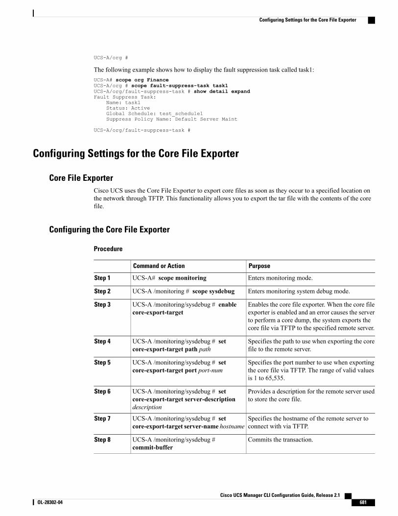
UCS-A/org #
The following example shows how to display the fault suppression task called task1:UCS-A# scope org FinanceUCS-A/org # scope fault-suppress-task task1UCS-A/org/fault-suppress-task # show detail expandFault Suppress Task:
Name: task1Status: ActiveGlobal Schedule: test_schedule1Suppress Policy Name: Default Server Maint
UCS-A/org/fault-suppress-task #
Configuring Settings for the Core File Exporter
Core File ExporterCisco UCS uses the Core File Exporter to export core files as soon as they occur to a specified location onthe network through TFTP. This functionality allows you to export the tar file with the contents of the corefile.
Configuring the Core File Exporter
Procedure
PurposeCommand or Action
Enters monitoring mode.UCS-A# scope monitoringStep 1
Enters monitoring system debug mode.UCS-A /monitoring # scope sysdebugStep 2
Enables the core file exporter. When the core fileexporter is enabled and an error causes the server
UCS-A /monitoring/sysdebug # enablecore-export-target
Step 3
to perform a core dump, the system exports thecore file via TFTP to the specified remote server.
Specifies the path to use when exporting the corefile to the remote server.
UCS-A /monitoring/sysdebug # setcore-export-target path path
Step 4
Specifies the port number to use when exportingthe core file via TFTP. The range of valid valuesis 1 to 65,535.
UCS-A /monitoring/sysdebug # setcore-export-target port port-num
Step 5
Provides a description for the remote server usedto store the core file.
UCS-A /monitoring/sysdebug # setcore-export-target server-descriptiondescription
Step 6
Specifies the hostname of the remote server toconnect with via TFTP.
UCS-A /monitoring/sysdebug # setcore-export-target server-name hostname
Step 7
Commits the transaction.UCS-A /monitoring/sysdebug #commit-buffer
Step 8
Cisco UCS Manager CLI Configuration Guide, Release 2.1 OL-28302-04 681
Configuring Settings for the Core File Exporter
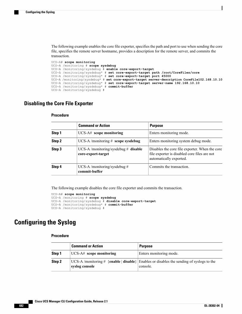
The following example enables the core file exporter, specifies the path and port to use when sending the corefile, specifies the remote server hostname, provides a description for the remote server, and commits thetransaction.UCS-A# scope monitoringUCS-A /monitoring # scope sysdebugUCS-A /monitoring/sysdebug # enable core-export-targetUCS-A /monitoring/sysdebug* # set core-export-target path /root/CoreFiles/coreUCS-A /monitoring/sysdebug* # set core-export-target port 45000UCS-A /monitoring/sysdebug* # set core-export-target server-description CoreFile102.168.10.10UCS-A /monitoring/sysdebug* # set core-export-target server-name 192.168.10.10UCS-A /monitoring/sysdebug* # commit-bufferUCS-A /monitoring/sysdebug #
Disabling the Core File Exporter
Procedure
PurposeCommand or Action
Enters monitoring mode.UCS-A# scope monitoringStep 1
Enters monitoring system debug mode.UCS-A /monitoring # scope sysdebugStep 2
Disables the core file exporter. When the corefile exporter is disabled core files are notautomatically exported.
UCS-A /monitoring/sysdebug # disablecore-export-target
Step 3
Commits the transaction.UCS-A /monitoring/sysdebug #commit-buffer
Step 4
The following example disables the core file exporter and commits the transaction.UCS-A# scope monitoringUCS-A /monitoring # scope sysdebugUCS-A /monitoring/sysdebug # disable core-export-targetUCS-A /monitoring/sysdebug* # commit-bufferUCS-A /monitoring/sysdebug #
Configuring the Syslog
Procedure
PurposeCommand or Action
Enters monitoring mode.UCS-A# scope monitoringStep 1
Enables or disables the sending of syslogs to theconsole.
UCS-A /monitoring # {enable | disable}syslog console
Step 2
Cisco UCS Manager CLI Configuration Guide, Release 2.1682 OL-28302-04
Configuring the Syslog
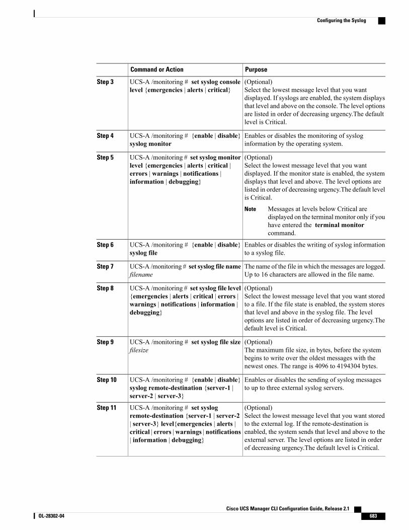
PurposeCommand or Action
(Optional)Select the lowest message level that you wantdisplayed. If syslogs are enabled, the system displays
UCS-A /monitoring # set syslog consolelevel {emergencies | alerts | critical}
Step 3
that level and above on the console. The level optionsare listed in order of decreasing urgency.The defaultlevel is Critical.
Enables or disables the monitoring of sysloginformation by the operating system.
UCS-A /monitoring # {enable | disable}syslog monitor
Step 4
(Optional)Select the lowest message level that you wantdisplayed. If the monitor state is enabled, the system
UCS-A /monitoring # set syslog monitorlevel {emergencies | alerts | critical |errors | warnings | notifications |information | debugging}
Step 5
displays that level and above. The level options arelisted in order of decreasing urgency.The default levelis Critical.
Messages at levels below Critical aredisplayed on the terminal monitor only if youhave entered the terminal monitorcommand.
Note
Enables or disables the writing of syslog informationto a syslog file.
UCS-A /monitoring # {enable | disable}syslog file
Step 6
The name of the file in which themessages are logged.Up to 16 characters are allowed in the file name.
UCS-A /monitoring # set syslog file namefilename
Step 7
(Optional)Select the lowest message level that you want storedto a file. If the file state is enabled, the system stores
UCS-A /monitoring # set syslog file level{emergencies | alerts | critical | errors |warnings | notifications | information |debugging}
Step 8
that level and above in the syslog file. The leveloptions are listed in order of decreasing urgency.Thedefault level is Critical.
(Optional)The maximum file size, in bytes, before the systembegins to write over the oldest messages with thenewest ones. The range is 4096 to 4194304 bytes.
UCS-A /monitoring # set syslog file sizefilesize
Step 9
Enables or disables the sending of syslog messagesto up to three external syslog servers.
UCS-A /monitoring # {enable | disable}syslog remote-destination {server-1 |server-2 | server-3}
Step 10
(Optional)Select the lowest message level that you want storedto the external log. If the remote-destination is
UCS-A /monitoring # set syslogremote-destination {server-1 | server-2| server-3} level{emergencies | alerts |
Step 11
enabled, the system sends that level and above to thecritical | errors |warnings | notifications| information | debugging} external server. The level options are listed in order
of decreasing urgency.The default level is Critical.
Cisco UCS Manager CLI Configuration Guide, Release 2.1 OL-28302-04 683
Configuring the Syslog
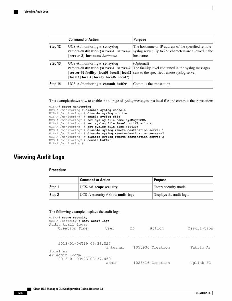
PurposeCommand or Action
The hostname or IP address of the specified remotesyslog server. Up to 256 characters are allowed in thehostname.
UCS-A /monitoring # set syslogremote-destination {server-1 | server-2| server-3} hostname hostname
Step 12
(Optional)The facility level contained in the syslog messagessent to the specified remote syslog server.
UCS-A /monitoring # set syslogremote-destination {server-1 | server-2| server-3} facility {local0 | local1 | local2| local3 | local4 | local5 | local6 | local7}
Step 13
Commits the transaction.UCS-A /monitoring # commit-bufferStep 14
This example shows how to enable the storage of syslog messages in a local file and commits the transaction:UCS-A# scope monitoringUCS-A /monitoring # disable syslog consoleUCS-A /monitoring* # disable syslog monitorUCS-A /monitoring* # enable syslog fileUCS-A /monitoring* # set syslog file name SysMsgsUCSAUCS-A /monitoring* # set syslog file level notificationsUCS-A /monitoring* # set syslog file size 4194304UCS-A /monitoring* # disable syslog remote-destination server-1UCS-A /monitoring* # disable syslog remote-destination server-2UCS-A /monitoring* # disable syslog remote-destination server-3UCS-A /monitoring* # commit-bufferUCS-A /monitoring #
Viewing Audit Logs
Procedure
PurposeCommand or Action
Enters security mode.UCS-A# scope securityStep 1
Displays the audit logs.UCS-A /security # show audit-logsStep 2
The following example displays the audit logs:UCS-A# scope securityUCS-A /security # show audit-logsAudit trail logs:
Creation Time User ID Action Description
-------------------- ---------- -------- ---------------- -----------
2013-01-04T19:05:36.027internal 1055936 Creation Fabric A:
local user admin logge
2013-01-03T23:08:37.459admin 1025416 Creation Uplink FC
Cisco UCS Manager CLI Configuration Guide, Release 2.1684 OL-28302-04
Viewing Audit Logs
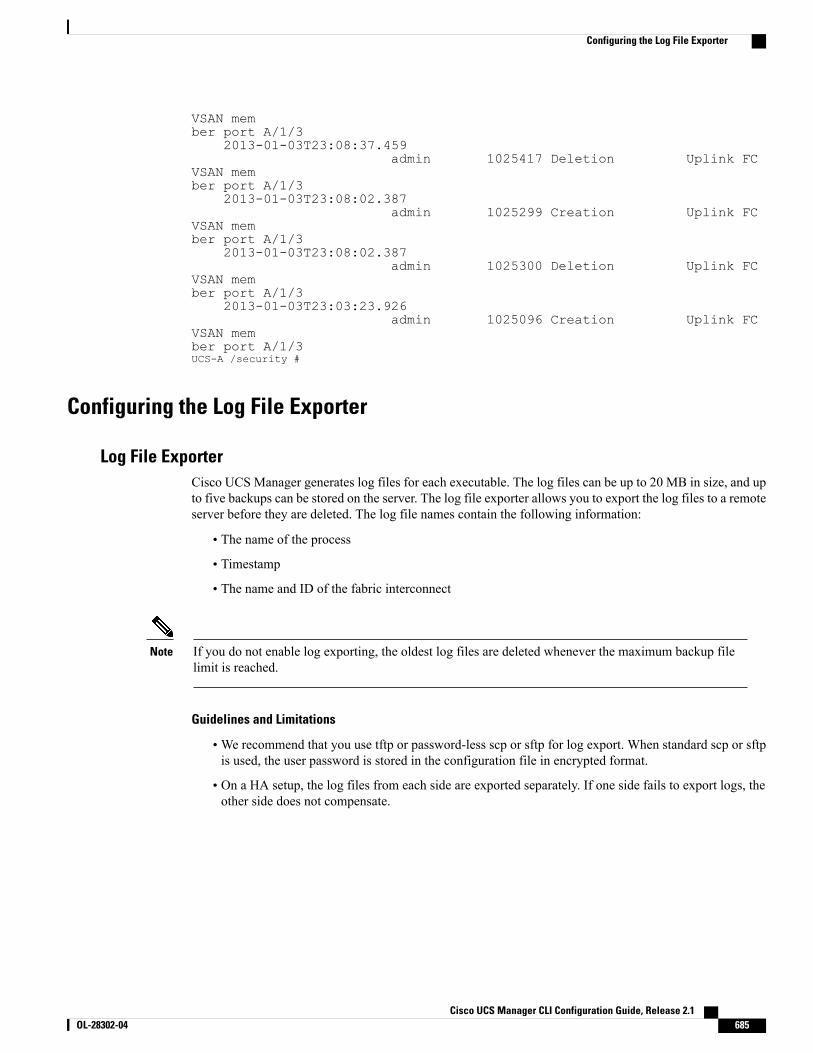
VSAN member port A/1/3
2013-01-03T23:08:37.459admin 1025417 Deletion Uplink FC
VSAN member port A/1/3
2013-01-03T23:08:02.387admin 1025299 Creation Uplink FC
VSAN member port A/1/3
2013-01-03T23:08:02.387admin 1025300 Deletion Uplink FC
VSAN member port A/1/3
2013-01-03T23:03:23.926admin 1025096 Creation Uplink FC
VSAN member port A/1/3UCS-A /security #
Configuring the Log File Exporter
Log File ExporterCisco UCS Manager generates log files for each executable. The log files can be up to 20 MB in size, and upto five backups can be stored on the server. The log file exporter allows you to export the log files to a remoteserver before they are deleted. The log file names contain the following information:
• The name of the process
• Timestamp
• The name and ID of the fabric interconnect
If you do not enable log exporting, the oldest log files are deleted whenever the maximum backup filelimit is reached.
Note
Guidelines and Limitations
•We recommend that you use tftp or password-less scp or sftp for log export. When standard scp or sftpis used, the user password is stored in the configuration file in encrypted format.
• On a HA setup, the log files from each side are exported separately. If one side fails to export logs, theother side does not compensate.
Cisco UCS Manager CLI Configuration Guide, Release 2.1 OL-28302-04 685
Configuring the Log File Exporter
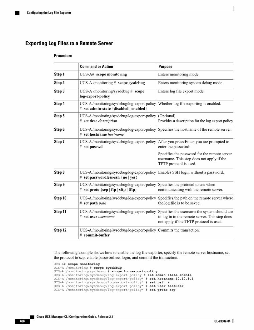
Exporting Log Files to a Remote Server
Procedure
PurposeCommand or Action
Enters monitoring mode.UCS-A# scope monitoringStep 1
Enters monitoring system debug mode.UCS-A /monitoring # scope sysdebugStep 2
Enters log file export mode.UCS-A /monitoring/sysdebug # scopelog-export-policy
Step 3
Whether log file exporting is enabled.UCS-A /monitoring/sysdebug/log-export-policy# set admin-state {disabled | enabled}
Step 4
(Optional)Provides a description for the log export policy
UCS-A /monitoring/sysdebug/log-export-policy# set desc description
Step 5
Specifies the hostname of the remote server.UCS-A /monitoring/sysdebug/log-export-policy# set hostname hostname
Step 6
After you press Enter, you are prompted toenter the password.
UCS-A /monitoring/sysdebug/log-export-policy# set passwd
Step 7
Specifies the password for the remote serverusername. This step does not apply if theTFTP protocol is used.
Enables SSH login without a password.UCS-A /monitoring/sysdebug/log-export-policy# set passwordless-ssh {no | yes}
Step 8
Specifies the protocol to use whencommunicating with the remote server.
UCS-A /monitoring/sysdebug/log-export-policy# set proto {scp | ftp | sftp | tftp}
Step 9
Specifies the path on the remote server wherethe log file is to be saved.
UCS-A /monitoring/sysdebug/log-export-policy# set path path
Step 10
Specifies the username the system should useto log in to the remote server. This step doesnot apply if the TFTP protocol is used.
UCS-A /monitoring/sysdebug/log-export-policy# set user username
Step 11
Commits the transaction.UCS-A /monitoring/sysdebug/log-export-policy# commit-buffer
Step 12
The following example shows how to enable the log file exporter, specify the remote server hostname, setthe protocol to scp, enable passwordless login, and commit the transaction.UCS-A# scope monitoringUCS-A /monitoring # scope sysdebugUCS-A /monitoring/sysdebug # scope log-export-policyUCS-A /monitoring/sysdebug/log-export-policy # set admin-state enableUCS-A /monitoring/sysdebug/log-export-policy* # set hostname 10.10.1.1UCS-A /monitoring/sysdebug/log-export-policy* # set path /UCS-A /monitoring/sysdebug/log-export-policy* # set user testuserUCS-A /monitoring/sysdebug/log-export-policy* # set proto scp
Cisco UCS Manager CLI Configuration Guide, Release 2.1686 OL-28302-04
Configuring the Log File Exporter
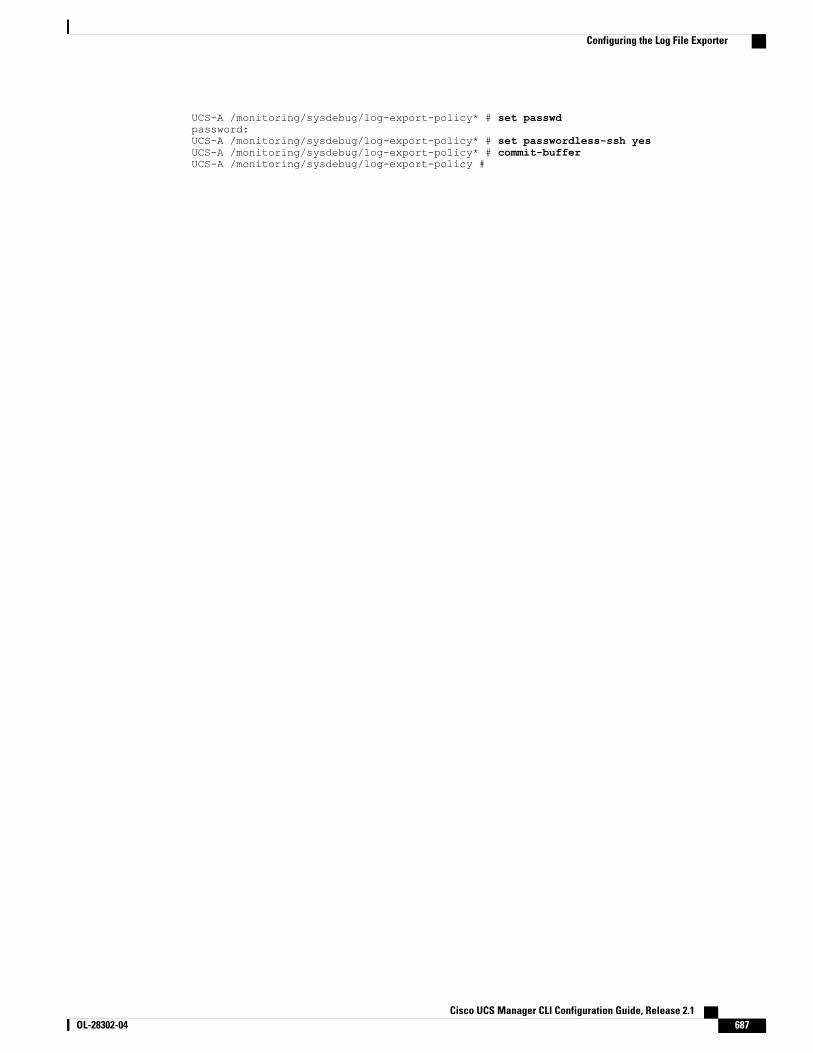
UCS-A /monitoring/sysdebug/log-export-policy* # set passwdpassword:UCS-A /monitoring/sysdebug/log-export-policy* # set passwordless-ssh yesUCS-A /monitoring/sysdebug/log-export-policy* # commit-bufferUCS-A /monitoring/sysdebug/log-export-policy #
Cisco UCS Manager CLI Configuration Guide, Release 2.1 OL-28302-04 687
Configuring the Log File Exporter

Cisco UCS Manager CLI Configuration Guide, Release 2.1688 OL-28302-04
Configuring the Log File Exporter
I N D E X
A
accounts 153, 154, 156, 173, 174, 175, 176admin 154expiration 154locally authenticated 154, 173, 174, 175, 176remotely authenticated 154user 153, 156username guidelines 154
acknowledging 514, 524, 528, 536, 542blade server 524, 528, 542chassis 514rack server 536
activities 457, 464, 465pending 457, 464, 465
adapter 88port channels 88
adapter port channels 89viewing 89
adapter qualification 390, 391creating 390deleting 391
adapters 24, 401, 402NIC 24vCon placement 401vCon placement for all other servers 402vCon placement for N20-B6620-2 and N20-B6625-2 bladeservers 401VIC 24virtualization 24
Address Resolution Protocol 594management interfaces monitoring policy 594
configuring 594admin account 154administration 25aging time 188
MAC address table 188aging time, Mac address table 188
configuring 188alert groups 626, 627
profiles 626, 627alert, call home test 630
all configuration 553appliance port channel, NAS port channel 66
assigning MAC address 66appliance port channels 82
member ports 82deleting 82
appliance port, NAS port 66assigning MAC address 66
appliance ports 80, 81, 82port channels 80, 81, 82
member ports, adding 81member ports, deleting 82unconfiguring 80
appliance, FCoE 72ports 72
configuring 72appliance, NAS 64
ports 64configuring 64
architectural simplification 9assigning port channels to vlans 270assigning ports to vlans 270audit logs 684
viewing 684authentication 117, 118
primary 117remote 118
authentication domains 140about 140
authentication profile 424, 425authentication service 143
selecting default 143authentication services 117
about 117authNoPriv 107authPriv 107autoconfiguration policy 381
about 381
Cisco UCS Manager CLI Configuration Guide, Release 2.1 OL-28302-04 IN-1
B
backing up 553, 554, 555, 556, 557, 558, 561about 553all configuration export policy 555considerations 554creating operations 557database backup policy 555deleting operations 561modifying operations 558running operations 558scheduling 555types 553user role 556
backup operations 557, 558, 561creating 557deleting 561modifying 558running 558
banner 34, 35, 36pre-login 34, 35, 36
beacon leds 56, 61configuring 61
best effort system class 20, 232BIOS 345, 346, 347, 352, 354, 356, 357, 358, 359, 364, 367, 377
actual settings 367default settings 364policy 364scrub policy 377settings 345, 346, 347, 352, 354, 356, 357, 358, 359
about 345boot options 358Intel Directed I/O 352main 346PCI configuration 357processor 347RAS memory 354serial port 356server management 359USB 356
BIOS defaults 365modifying 365
BIOS policy 364creating 364
BIOS, recovering 527, 541blade 505
viewing power cap 505blade server 521, 522, 523, 524, 525, 526, 527, 528, 542
acknowledging 524, 528, 542booting 521CIMC 527
resetting 527decommissioning 525power cycling 523
blade server (continued)removing 524resetting 523resetting CMOS 526shutting down 522turning off locator LED 526turning on locator LED 525
blade servers 519, 520, 527, 532managing 519recovering BIOS 527unexpected power changes 520, 532
blade-level power cap 504setting for server 504
boot 415, 449, 450, 451, 452LAN 449local disk 450, 451SAN 415virtual media 452
boot definitions 483, 484, 485, 486, 487configuring 483deleting 487LAN boot 484storage boot 485virtual media boot 486
boot options, BIOS settings 358boot policies 413, 414, 415, 416, 449, 450, 451, 452, 453
about 413configuring 414deleting 453LAN boot 449local disk boot 450, 451SAN boot 415, 416virtual media boot 452
boot process 418iSCSI 418
bronze system class 20, 232burned in values 14, 468
C
Cabling Considerations for Port Channel Mode} 90About 90
call home 622, 625, 627, 629, 630, 631, 632, 633, 635configuring 622inventory messages, configuring 625inventory messages, sending 625policies, configuring 631policies, deleting 633policies, disabling 631policies, enabling 632profiles, configuring 627profiles, deleting 629
Cisco UCS Manager CLI Configuration Guide, Release 2.1IN-2 OL-28302-04
Index
call home (continued)sending test alert 630smart call home, configuring 633TAC-1 profile, configuring 635
Call Home 617, 619, 620, 621, 626, 627, 630about 617considerations 619policies 630profiles 626, 627severity levels 620Smart Call Home 621
capping server power usage 504certificate 96
about 96changing 125
LDAP group rule 125chassis 181, 184, 514, 515, 516, 518, 650, 651, 653, 654
acknowledging 514decommissioning 514discovery policy 181, 184modifying fault suppression tasks 653recommissioning 515removing 515renumbering 516suppressing faults 650, 651turning off locator LED 518turning on locator LED 518viewing suppressed faults 654
chassis connectivity policy 186system-related policies 186
chassis 186chassis fault suppression tasks 654chassis management 515
removing 515chassis qualification 392
configuring 392deleting 392
chassis/FEX discovery policy 181, 184about 181configuring 184
CIM XML 94configuring 94
CIMC 337, 527, 540IP address 337resetting 527, 540
blade server 527rack server 540
Cisco Discovery Protocol 257Cisco UCS Central 200, 201, 202, 203
policy resolution 200, 202registering 201unregistering 203
Cisco UCS Manager 25about 25
Cisco UCS Manager-based zoning 312, 313, 317, 318about 312active zone set configuration 313Fibre Channel storage connection 313, 317, 318vHBA initiator groups 313
Cisco VM-FEX 24cisco-av-pair 118CiscoAVPair 118CLI session limits 33clock 512
setting manually 512commands for object management 31communication services 33, 34, 93, 97, 98, 99, 101, 102, 110, 112, 113,
114about 93disabling 114HTTPS 97, 98, 99, 101, 102SNMP 110, 112, 113web session limits 33, 34
community, SNMP 110configuration 555, 556, 557, 564, 568, 570
backing up 557erasing 570import methods 556importing 555, 564restoring 556, 568
configuring 64, 72, 73, 74, 88, 97, 98, 99, 101, 102, 338, 339, 340, 499blade server 338, 339
management IP pool 339static IP address 338
Fibre Channel 74storage ports 74
global cap policy 499HTTPS 97, 98, 99, 101, 102port channel 88
unified uplink 88ports 64, 72, 73
appliance, NAS 64unified storage 72unified uplink 73
rack server 339, 340management IP pool 340static IP address 339
configuring ports 57FCoE uplink ports 57
cautions 57considerations 554, 619
backup operations 554Call Home 619
console authentication service 142selecting 142
converged network adapters 24virtualization 24
Cisco UCS Manager CLI Configuration Guide, Release 2.1 OL-28302-04 IN-3
Index
core file exporter 681, 682configuring 681disabling 682
Core File Exporter 681about 681
corrupt BIOS 527, 541cpu qualification 393, 394
creating 393deleting 394
create 31creating 127, 135, 210, 211, 501, 503
LDAP group map 127LDAP provider group 135named VLANS 210, 211
storage Ethernet mode 211uplink Ethernet mode 210
power groups 501power power control policy 503
custom roles 158reserved words 158
D
database 553, 556backing up 553restoring 556
decommissioning 514, 525, 536blade server 525chassis 514rack server 536
decommissioning chassis, guidelines 513decommissioning rack-mount servers 532decommissioning servers 520default service profiles 14, 468default vhba behavior policy 301default vnic behavior policy 248deferring deployment 455, 456, 457, 458, 459, 460, 461, 462, 463, 464,
465guidelines 457maintenance policies 456, 463, 464one time occurrences 459, 461pending activities 457, 464, 465
deploying 465viewing 464
recurring occurrences 460, 462schedules 456, 458, 462service profiles 455
delete 31deleting 128, 136, 138, 139, 502, 503
LDAP group map 128LDAP provider group 136power groups 502
deleting (continued)power power control policy 503RADIUS provider group 138TACACS provider group 139
deleting a RADIUS provider 131deleting a TACACS provider 133deleting an LDAP provider 126deleting fault suppression tasks 652, 658, 664, 668, 673, 678DHCP 437, 438
iSCSI initiator 437, 438deleting DHCP boot parameter 438setting 437
disaster recovery 553, 556discovery policy 181, 184, 187, 383
chassis/FEX 181, 184rack server 187server 383
disjoint L2 networks 265, 266, 267, 269about 265configuring 269guidelines 266pinning considerations 267
disk drive monitoring 595, 596, 597about 595interpreting results 597limitations 596prerequisites 596support 596
disk scrub policy 377DNS servers 179, 180
about 179configuring 179deleting 180
domain pools 15domains, disjoint L2 265
E
enabling 106, 110http to https redirection 106SNMP 110
enforcing password strength 168enter 31Ethernet 11, 21, 53, 62, 63, 64, 75, 76, 77, 78, 237, 583
Fibre Channel over 11flow control policies 21, 237server ports 62
configuring 62unconfiguring 62
uplink port channels 75, 76, 77, 78configuring 76member ports, adding 77
Cisco UCS Manager CLI Configuration Guide, Release 2.1IN-4 OL-28302-04
Index
Ethernet (continued)uplink port channels (continued)
member ports, deleting 78unconfiguring 76
uplink ports 53, 63, 64, 583configuring 63monitoring 583unconfiguring 64
Ethernet adapter policies 244, 297about 244, 297
Ethernet adapter policy 245, 247configuring 245deleting 247
Ethernet switching mode 48, 49about 48
expiration, accounts 154explicit assignment 403, 407exporting 553, 556, 681
backup types 553configuration 553core file 681user role 556
F
fabric 89port channels 89
fabric interconnects 28, 39, 40, 46, 48, 50, 189, 190, 192, 193, 195, 276, 571, 572, 573
admin password recover 572, 573admin password recovery 571determining leadership role 572enabling standalone for cluster 46Ethernet switching mode 48failover 40FC uplink trunking 276Fibre Channel switching mode 50high availability 28host ID 190initial setup 39, 40
about 39management port 40setup mode 40
licenses 189, 192, 193, 195installing 192uninstalling 195viewing 192viewing usage 193
system configuration type 40fabric port channels 91
member ports 91deleting 91
fabric port channels (continued)viewing 91
fabric ports 91port channels 91
member ports, deleting 91fan environment 591fan modules 591fault collection policy 647, 648
about 647configuring 648
fault suppression 649, 652, 658, 664, 668, 673, 678stopping 652, 658, 664, 668, 673, 678
fault suppression tasks 654, 660, 666, 670, 676, 680viewing chassis 654viewing fex 666viewing iom 660viewing organization 680viewing server 670viewing service profile 676
faults 620, 647, 650, 651, 653, 654, 655, 657, 658, 660, 661, 663, 664, 666, 667, 669, 670, 671, 672, 674, 676, 677, 678, 679, 680, 681
Call Home severity levels 620collection policy 647Core File Exporter 681lifecycle 647modifying suppression tasks 653, 658, 664, 669, 674, 679suppressing 650, 651, 655, 657, 661, 663, 666, 667, 671, 672, 677, 678viewing suppressed 654, 660, 666, 670, 676, 680
FC end-host mode 276VSAN ID restrictions 276
FC switch mode 276VSAN ID restrictions 276
FC uplinks 276trunking 276
about 276FCoE 11, 70, 71, 86, 87
port channels 86, 87member ports, adding 87
uplink Port 70, 71configuring 70
ports 70delete,unconfiguring 70
ports 70view 71
ports 71FCoE ports 74, 87
port channels 87member ports, adding 87
unconfiguring 74FCoE VLAN ID 283
changing 283feature 189
licenses 189
Cisco UCS Manager CLI Configuration Guide, Release 2.1 OL-28302-04 IN-5
Index
features 21opt-in 21stateless computing 21
fex 661, 663, 664, 666modifying fault suppression tasks 664suppressing faults 661, 663viewing suppressed faults 666
FEX 181, 184discovery policy 181, 184
fex fault suppression tasks 666Fibre Channel 11, 53, 81, 82, 83, 84, 85, 612, 613
link-level flow control 11over Ethernet 11port channels 82, 83, 84, 85
configuring 83enabling 84member ports, adding 85unconfiguring 84
priority flow control 11statistics threshold policies 612statistics threshold policy classes 613uplink port channels 81
enabling 81uplink ports 53
Fibre Channel adapter policies 244, 297about 244, 297
Fibre Channel adapter policy 298, 300configuring 298deleting 300
Fibre Channel ports 85port channels 85
member ports, adding 85Fibre Channel storage ports 74
configuring 74unconfiguring 74
Fibre channel switching mode 50Fibre Channel switching mode 50
about 50Fibre Channel system class 20, 232Fibre Channel zoning 312, 313, 314, 315, 316, 317, 318
active zone set configuration 313Cisco UCS Manager-based 312, 313configuring 314guidelines 314removing unmanaged zones 315, 316storage connection policy 313, 317, 318support 312switch-based 314
flexibility 10flow control 11
link-level 11priority 11
flow control policies 237, 238configuring 237
flow control policies (continued)deleting 238
flow control policy 21, 237about 21, 237
full state 553
G
global cap policy 499configuring 499
global pools 15gold system class 20, 232group map 127, 128
creating 127LDAP 127
deleting 128LDAP 128
group rule 125changing 125
LDAP 125guidelines 17, 19, 154, 156, 266, 276, 314, 372, 457, 468, 580
deferred deployment 457disjoint L2 networks 266Fibre Channel zoning 314local disk configuration policy 372named VSANs 276oversubscription 17passwords 156pinning 19service profiles 468traffic monitoring 580usernames 154
H
hardware based service profiles 474creating 474
hardware-based service profiles 14, 468hardware, stateless 21heath LED status 529high availability 10, 28, 40
about 28fabric interconnect failover 40
high availability configuration 28about 28
history, passwords 174host ID, obtaining 190host port channels 89
viewing 89HTTP 33, 34, 95, 96
configuring 95
Cisco UCS Manager CLI Configuration Guide, Release 2.1IN-6 OL-28302-04
Index
HTTP (continued)unconfiguring 96web session limits 33, 34
HTTPS 33, 34, 97, 98, 99, 101, 102, 103, 105certificate request 98, 99configuring 103creating key ring 97importing certificate 102regenerating key ring 97trusted point 101unconfiguring 105web session limits 33, 34
I
I/O module 551management 551
IEEE 802.1Qbh 24IEEE 802.3x link-level flow control 11implicit assignment 403import operations 564, 566, 568
creating 564deleting 568modifying 566running 566
importing 555, 556, 564, 566, 568about 555creating operations 564deleting operations 568modifying operations 566restore methods 556running operations 566user role 556
informs 107about 107
inheritance, servers 385inherited values 14, 468initial setup 39, 40
about 39management port IP address 40setup mode 40
initial templates 15, 469initiator groups 306, 309, 313, 488
about 313adding 488SAN connectivity policy 306, 309
Intel Directed I/O, BIOS settings 352inventory messages, call home 625
configuring 625sending 625
inventory messages, smart call home 636configuring 636
iom 655, 657, 658, 660modifying fault suppression tasks 658suppressing faults 655, 657viewing suppressed faults 660
IOM 551resetting 551
iom fault suppression tasks 660IP address pools 426
adding iSCSI initiator address block 426IP addresses 40, 337, 342
CIMC 337management IP pool 342management port 40
IP pools 331, 333, 334, 342about 331adding blocks 333creating 331deleting 334deleting a block 333management 342
IPMI access profile 368, 369, 370, 371configuring 368, 370deleting 369, 371
IPMI access profiles 368about 368
IQN 430creating in service profile 430
IQN pools 439, 440, 441, 442, 443about 439adding a block 441creating 440deleting 442deleting a block 442viewing usage 443
iSCSI adapter policies 422, 424creating 422deleting 424
iSCSI auto target 447, 448creating 447deleting 448
iSCSI boot 418, 419, 421, 424, 425authentication profile 424, 425configuring 421
high-level tasks 421overview 418prerequisites 419
iscsi boot policies 430deleting 430
iSCSI boot policies 427creating 427
iSCSI boot process 418
Cisco UCS Manager CLI Configuration Guide, Release 2.1 OL-28302-04 IN-7
Index
iSCSI initiator 433, 435, 437, 438boot parameters 435, 437
iSCSI initiator 435, 437deleting boot from IP pool parameter 437setting to boot from IP pool 435
deleting boot from DHCP parameter 438deleting boot from IP Pool parameter 437deleting static IP address boot parameters 435IP pools 435, 437
iSCSI initiator 435, 437service profile 433, 435, 437, 438
iSCSI initiator 433, 435, 437, 438deleting boot from IP pool parameter 437deleting static IP address boot parameters 435deleting the boot from DHCP parameter 438setting to boot from DHCP 437setting to boot from IP pool 435setting to boot from static IP address 433
setting to boot from DHCP 437setting to boot from IP Pool 435setting to boot from static IP address 433
iSCSI static target 444, 446creating 444deleting 446
iSCSI vNIC 431, 433creating 431deleting from service profile 433
iSCSI vNICs 254, 256LAN connectivity policy 254, 256
K
key ring 96, 97, 98, 99, 101, 102, 104about 96certificate request 98, 99creating 97deleting 104importing certificate 102regenerating 97trusted point 101
KVM Console 337IP address 337
L
L2 networks, disjoint 265LAN 207, 208, 225, 241, 265
disjoint L2 networks 265pin groups 225PVLANs 208VLANs 207
LAN (continued)vNIC policy 241
LAN boot 449, 484about 449
LAN boot, boot policies 449LAN connectivity policy 249, 250, 251, 253, 254, 256, 301, 302
about 249, 301creating 250deleting 256iSCSI vNICs 254, 256privileges 249, 302service profiles 250, 302vNICs 251, 253
lanes, virtual 20, 231LDAP 121, 125, 127, 128, 135, 136
creating a provider 121group map 127, 128
creating 127deleting 128
group rule 125changing 125
provider group 135, 136creating 135deleting 136
LDAP group mapping 126LDAP group rule 120LDAP provider 118, 120
about 118configuring properties 120user attribute 118
LDAP providers 126deleting 126
licenses 189, 190, 191, 192, 193, 195about 189installing 192obtaining 191obtaining host ID 190uninstalling 195viewing 192viewing usage 193
lifecycle, faults 647link-level flow control 11local disk boot 450, 451
about 450configuring 451
local disk configuration policy 371, 372about 371guidelines 372RAID configuration 372
local disks 374, 375, 376, 480policies 374, 375, 376service profiles 480
locales 160, 164, 165, 166, 170, 171about 160
Cisco UCS Manager CLI Configuration Guide, Release 2.1IN-8 OL-28302-04
Index
locales (continued)assigning an organization 164assigning to user accounts 170creating 164deleting 166deleting an organization from 165removing from user accounts 171
locally authenticated users 154, 155, 173, 174, 175, 176accounts 154change interval 175clearing password history 173no change interval 176password history count 176password profile 174reserved words for accounts 155
log, system 682log, system event 639, 640, 641, 643, 644
about 639backing up 643
all servers in chassis 643individual server 643
clearing 644all servers in chassis 644individual server 644
policy 641viewing 640
chassis server mode 640one server 640
logical configuration 553
M
MAC address table 188aging time, about 188
MAC address table aging time 188configuring 188
MAC addresses 227pools 227
MAC pools 227, 229creating 227deleting 229
MAC sync 40main, BIOS settings 346maintenance policies 456, 458, 462, 463, 464
about 456creating 463deleting 464schedules 458, 462
management 519, 531, 551blade servers 519I/O modules 551rack-mount servers 531
management interfaces monitoring policy 593, 594about 593configuring 594
management IP address 341service profile 341
setting 341management IP addresses 337management IP pool 339, 340
configuring 339, 340blade server 339rack server 340
management IP pools 342, 343about 342configuring 342deleting 343
management port IP address 40, 47changing 47
manual blade-level power capping 504Media Independent Interface 594
management interfaces monitoring policy 594configuring 594
member ports, port channel 77, 78, 85, 87adding 77, 85, 87deleting 78
memory qualification 396, 397creating 396deleting 397
merging configuration 556mobility 21mode 40, 48, 50
end-host 48, 50Ethernet switching 48Fibre Channel switching 50setup 40
modifying fault suppression tasks 653, 658, 664, 669, 674, 679chassis 653fex 664iom 658organization 679server 669service profile 674
monitoring 594, 595, 596, 597disk drive 595, 596disk drives 597interface management 594
multi-tenancy 148name resolution 148
multicast policy 260creating 260
multiple authentication systems 134multitenancy 22, 23, 147
about 22opt-in 23opt-out 23
Cisco UCS Manager CLI Configuration Guide, Release 2.1 OL-28302-04 IN-9
Index
multitenancy (continued)organizations 147
mutual inclusion 265
N
name resolution 148, 179named VLANs 207, 210, 211, 212, 213, 214
about 207creating for dual fabric interconnects 210, 211
storage Ethernet mode 211uplink Ethernet mode 210
creating for single fabric interconnect 212, 213deleting 214
named VSANs 275, 276, 278, 279, 280, 281, 282about 275creating for dual fabric interconnects 278, 279, 281creating for single fabric interconnect 280deleting 282FC uplink trunking 276ID range restrictions 276
named VSANS 283FCoE VLAN ID 283
network 12, 207, 208, 275connectivity 12named VLANs 207named VSANs 275private VLANs 208
network control policies 258, 259configuring 258deleting 259
network control policy 257networks, disjoint L2 265NIC adapters 24
virtualization 24noAuthNoPriv 107NTP servers 509, 511, 512
about 509configuring 511deleting 512
O
occurrences 456, 459, 460, 461, 462one time 456, 459, 461
about 456creating 459deleting 461
recurring 456, 460, 462about 456creating 460
occurrences (continued)recurring (continued)
deleting 462one time occurrences 456, 459, 461
about 456creating 459deleting 461
opt-in 21, 22, 23about 21multitenancy 23stateless computing 22
opt-out 21, 22, 23multitenancy 23stateless computing 22
organization 677, 678, 679, 680modifying fault suppression tasks 679suppressing faults 677, 678viewing suppressed faults 680
organization fault suppression tasks 680organizations 22, 147, 148, 150, 151, 160
about 147configuring under non-root 150configuring under root 150deleting 151locales 160multitenancy 22name resolution 148
overriding server identity 13, 467oversubscription 16, 17
about 16considerations 16guidelines 17
overview 9
P
password profile 173, 174, 175, 176about 174change interval 175clearing password history 173no change interval 176password history count 176
passwords 168, 174change interval 174history count 174strength check 168
passwords, guidelines 156passwords, recovering admin 571, 572, 573PCI configuration, BIOS settings 357pending activities 457, 464, 465
about 457deploying 465
Cisco UCS Manager CLI Configuration Guide, Release 2.1IN-10 OL-28302-04
Index
pending activities (continued)viewing 464
pending commands 32PFC 11physical qualification 397, 398
creating 397deleting 398
pin groups 18, 225, 285about 18LAN 225SAN 285
pin-groups 286FCoE pin-group 286
configure 286ping gateway 594
management interfaces monitoring policy 594configuring 594
pinning 18, 19, 267about 18disjoint L2 networks 267guidelines 19servers to server ports 18
PKI 96placement policies, vNIC/VHBA 405
configuring 405vcons 405
placement profiles, vNIC/VHBA 407deleting 407
platinum system class 20, 232policies 15, 21, 144, 181, 184, 187, 200, 201, 202, 203, 234, 237, 241, 244,
249, 250, 251, 253, 254, 256, 257, 295, 297, 301, 302, 304, 306, 309, 310, 313, 317, 318, 364, 368, 371, 374, 375, 376, 377, 379, 381, 383, 385, 386, 388, 400, 413, 422, 424, 427, 456, 463, 464, 498, 499, 502, 555, 593, 601, 602, 630, 647, 648
about 15all configuration export 555autoconfiguration 381BIOS 364boot 413Call Home 630chassis/FEX discovery 181, 184database backup 555Ethernet 244, 297fault collection 647, 648Fibre Channel adapter 244, 297flow control 21, 237global cap policy 499IPMI access 368iSCSI adapter 422, 424iSCSI boot 427LAN connectivity 249, 250, 251, 253, 254, 256, 301, 302local disk configuration 371local disks 374, 375, 376maintenance 456, 463, 464
policies (continued)management interfaces monitoring 593network control 257power 498power control 502PSU 498QoS 21, 234rack server discovery 187registering with Cisco UCS Central 201resolution 200, 202role for remote users 144SAN connectivity 249, 250, 301, 302, 304, 306, 309, 310scrub 377serial over LAN 379
about 379server discovery 383server inheritance 385
about 385server pool 386server pool qualification 388statistics collection 601storage connection 313, 317, 318threshold 602unregistering from Cisco UCS Central 203vHBA 295vNIC 241vNIC/vHBA placement 400
policies, call home 631, 632, 633configuring 631deleting 633disabling 631enabling 632
policies, multicast policy 260policy 248, 301
default vbha behavior 301default vnic behavior 248
policy classes 604, 606, 607, 609, 610, 612, 613, 615Fibre Channel port statistics, configuring 613server port statistics, configuring 610server port statistics, deleting 612server statistics, configuring 604server statistics, deleting 606uplink Ethernet port statistics, configuring 607uplink Ethernet port statistics, deleting 609, 615
policy-driven chassis group power capping 499pools 15, 227, 229, 289, 290, 292, 327, 329, 330, 331, 334, 342, 426, 439,
440, 442, 443about 15adding iSCSI initiator address block 426domain 15global 15IP 331, 334IQN 439, 440, 442, 443MAC 227, 229
Cisco UCS Manager CLI Configuration Guide, Release 2.1 OL-28302-04 IN-11
Index
pools (continued)management IP 342server 327servers 327UUID suffix 329, 330UUID suffixes 329WWN 289, 290, 292
port channels 75, 76, 77, 78, 80, 81, 82, 83, 84, 85, 86, 87, 88, 89adapter 88appliance 78configuring 76, 78, 83
appliance 78enabling 81, 84fabric 89FCoE 86Fibre Channel 82member ports 77, 78, 81, 85, 87
adding 77, 81, 85, 87deleting 78
unconfiguring 76, 80, 84unified uplink port 87uplink Ethernet 75
port modes 55, 58about 55impact on data traffic 58
port types 55ports 18, 40, 53, 54, 56, 62, 63, 64, 69, 72, 73, 74, 75, 76, 78, 80, 81, 82, 83,
84, 86, 87, 88, 89, 189, 225, 285, 583appliance 64appliance port channels 81
member ports, adding 81appliance port, NAS port 69
unconfiguring 69appliance, NAS 53configuring 64, 72, 73, 88
appliance, NAS 64unified storage 72unified uplink 73, 88
fabric interconnect 53FCoE uplink 69
about 69Fibre Channel storage 74
configuring 74licenses 189management 40pin groups 225, 285pinning server traffic 18port channels 75, 76, 78, 80, 81, 82, 83, 84, 86, 87, 88, 89
configuring 76, 78, 83enabling 81, 84FCoE 86Fibre Channel 82unconfiguring 76, 80, 84
ports (continued)server 53, 62
configuring 62unconfiguring 62
unified 54, 56uplink 53uplink Ethernet 63, 64, 583
configuring 63monitoring 583unconfiguring 64
ports, 77, 78, 82, 85, 87, 91appliance port channels 82
member ports, deleting 82fabric port channels 91
member ports, deleting 91port channels 77, 78, 85, 87
member ports, adding 77, 85, 87member ports, deleting 78
ports{ unified uplink port channel 87port channels 75, 76, 78, 80, 81, 82, 83, 84, 86, 87, 88, 89
power cap 505viewing 505
power capping 499, 504manual blade-level 504policy-driven chassis group 499
power control policy 502, 503creating 503deleting 503
power cycling 523, 535blade server 523rack server 535
power group qualification 395configuring 395deleting 395
power groups 500, 501, 502creating 501deleting 502
power management 497, 500, 501, 502, 503creating 501, 503
power control policy 503power groups 501
deleting 502, 503power control policy 503power groups 502
policies 502power control 502
power groups 500rack server 497
power policy 498about 498
power state, synchronizing 520, 532pre-login banner 34, 35, 36
creating 34deleting 36
Cisco UCS Manager CLI Configuration Guide, Release 2.1IN-12 OL-28302-04
Index
pre-login banner (continued)modifying 35
primary authentication 118remote 118
primary VLAN 215, 216priority flow control 11private VLANs 208, 215, 216, 217
about 208creating primary 215, 216creating secondary 216, 217
privileges 158, 162, 163, 249, 302about 158adding to user roles 162connectivity policies 249, 302removing from user roles 163
processor, BIOS settings 347profiles 12, 174, 626, 627
Call Home alert groups 626, 627password 174
profiles, call home 627, 629configuring 627deleting 629
profiles, TAC-1, smart call home 635configuring 635
provider group 135, 136, 137, 138, 139creating 135, 137, 138
LDAP 135RADIUS 137TACACS 138
deleting 136, 138, 139LDAP 136, 139RADIUS 138
provider groups 135, 140authentication domains 140
PSU policy 498PVLANs 208, 215, 216, 217
about 208creating primary 215, 216creating secondary 216, 217
Q
QoS policies 21, 234, 236about 21, 234configuring 234deleting 236
qualification 390, 393, 396, 397, 399creating adapter 390creating cpu 393creating memory 396creating physical 397creating storage 399
quality of service 20, 21, 231, 232, 233, 234, 237about 20, 231flow control policies 21, 237policies 21, 234system classes 20, 231, 232, 233
configuring 232disabling 233
R
rack server 533, 534, 535, 536, 539, 540acknowledging 536booting 533CIMC 540
resetting 540decommissioning 536power cycling 535resetting 535resetting CMOS 540shutting down 534turning off locator LED 539turning on locator LED 539
rack server discovery policy 187about 187configuring 187
rack server power management 497rack servers 541
recovering BIOS 541rack-mount servers 187, 468, 531
discovery policy 187guidelines for service profiles 468managing 531
RADIUS 129, 137, 138creating provider 129provider group 137, 138
creating 137deleting 138
RADIUS provider 118, 128about 118configuring properties 128user attribute 118
RADIUS provider group 137RADIUS providers 131
deleting 131RAID configurations, local disk configuration policies 372range restrictions, VSAN IDs 276RAS memory, BIOS settings 354recommendations 554
backup operations 554recommissioning 515
chassis 515recovering admin password 571, 572, 573
Cisco UCS Manager CLI Configuration Guide, Release 2.1 OL-28302-04 IN-13
Index
recovering BIOS 527, 541recurring occurrences 456, 460, 462
about 456creating 460deleting 462
registering, Cisco UCS Central 200, 201, 202remote authentication 118
user accounts 118user roles 118
remotely authenticated users 154accounts 154
removing 515, 524blade server 524chassis 515
removing chassis, guidelines 513removing rack-mount servers 532removing servers 520renaming service profiles 492renumbering 516, 537
blade servers 516chassis 516rack-mount servers 537
replacing configuration 556reserved words 155, 158
custom roles 158locally authenticated user accounts 155
resetting 523, 535blade server 523rack server 535
resetting CMOS 526, 540blade server 526rack server 540
resolution, name 179restoring 556, 568
about 556configuration 568user role 556
Restoring 75ports 75
Uplink Fibre Channel port 75role policy for remote users 144
about 144role-based access control 153, 172
user account 172enabling, disabling 172
roles 156, 157, 158, 169, 171, 556about 156assigning to user accounts 169backing up 556default 157privileges 158removing from user accounts 171
RSA 96
S
SAN 275, 285, 295pin groups 285vHBA policy 295VSANs 275
SAN boot 415about 415
SAN boot, boot policies 416SAN connectivity policy 249, 250, 301, 302, 304, 306, 309, 310
about 249, 301creating 302deleting 310initiator groups 306, 309privileges 249, 302service profiles 250, 302vHBAs 304, 306
scalability 10schedules 456, 458, 459, 460, 461, 462
about 456creating 458deleting 462one time occurrences 459, 461
creating 459deleting 461
recurring occurrences 460, 462creating 460deleting 462
scheduling 555all configuration export 555backups 555database backup 555
scope 31scrub policies 377, 378
creating 377deleting 378
scrub policy 377about 377
secondary VLAN 216, 217SEL 639, 640, 641, 643, 644
about 639backing up 643
all servers in chassis 643individual server 643
clearing 644all servers in chassis 644individual server 644
policy 641viewing 640
chassis server mode 640one server 640
selective exclusion 265serial number, obtaining 190
Cisco UCS Manager CLI Configuration Guide, Release 2.1IN-14 OL-28302-04
Index
serial over LAN 379, 482policies 379service profiles 482
serial over LAN policies 380deleting 380
serial over LAN policy 379, 380about 379viewing 380
serial port, BIOS settings 356server 504, 666, 667, 669, 670
modifying fault suppression tasks 669setting power blade-level power cap 504suppressing faults 666, 667viewing suppressed faults 670
server autoconfiguration policies 381, 382configuring 381deleting 382
server autoconfiguration policy 381about 381
server discovery policies 383, 384configuring 383deleting 384discovery policies 383, 384
server, configuring 383server, deleting 384
server discovery policy 383about 383
server fault suppression tasks 670server inheritance policies 385, 386
configuring 385deleting 386
server inheritance policy 385about 385
server management 519, 531server management, BIOS settings 359server pool policies 387
configuring 387deleting 387
server pool policy 386about 386
server pool policy qualification 388, 389about 388creating 389deleting 389
server pools 327, 328creating 327deleting 328
server ports 53, 62about 53configuring 62unconfiguring 62
server virtualization 10
servers 12, 13, 18, 21, 22, 179, 327, 345, 346, 347, 352, 354, 356, 357, 358, 359, 364, 365, 367, 368, 371, 383, 385, 386, 388, 413, 422, 424, 427, 455, 467, 492, 493, 519, 520, 531, 532, 537, 595, 596, 597
actual BIOS settings 367BIOS defaults 364, 365BIOS policies 364BIOS policy 364BIOS settings 345, 346, 347, 352, 354, 356, 357, 358, 359blade 519boot policies 413configuration 12discovery policy 383disk drive monitoring 595, 596disk drive status 597disk drive support 596DNS 179inheritance policy 385IPMI access 368iSCSI adapter policies 422, 424iSCSI boot policies 427local disk configuration 371multitenancy 22pinning 18pool policy 386pool qualifications 388pools 327rack-mount 531renaming service profiles 492renumbering 537resetting UUID 493service profiles 12, 13, 455, 467stateless 21unexpected power changes 520, 532
service profile 431, 433, 671, 672, 674, 676iSCSI vNIC 431, 433
creating 431deleting 433
modifying fault suppression tasks 674suppressing faults 671, 672viewing suppressed faults 676
Service Profile 430creating IQN in 430
service profile fault suppression tasks 676service profiles 12, 13, 14, 15, 249, 250, 301, 302, 455, 467, 468, 469, 470,
473, 474, 477, 479, 480, 482, 483, 484, 485, 486, 487, 488, 490, 491, 492, 493, 494, 495, 520, 532
about 12adding initiator groups 488associating 490, 491
blade server 490rack server 491server pool 490
boot definitions 483, 487configuration 12
Cisco UCS Manager CLI Configuration Guide, Release 2.1 OL-28302-04 IN-15
Index
service profiles (continued)connectivity policies 249, 250, 301, 302deferring deployment 455disassociating 492
blade server 492server pool 492
guidelines 468hardware based 474
creating 474inherited values 14, 468instance, creating from template 473LAN boot 484local disks 480network connectivity 12override identity 13, 467renaming 492resetting MAC address 494resetting UUID 493resetting WWPN 495serial over LAN 482storage boot 485template, creating 470templates 15, 469unexpected power changes 520, 532vHBAs 479virtual media boot 486vNICs 477
setting 341management IP address 341
service profile 341setup mode 40severity levels, Call Home 620shutting down 522, 534
blade server 522rack server 534
silver system class 20, 232smart call home 633, 635, 636, 637
configuring 633inventory messages, configuring 636registering 637TAC-1 profile, configuring 635
Smart Call Home 619, 620, 621about 621considerations 619severity levels 620
SNMP 106, 107, 109, 110, 111, 112, 113about 106community 110enabling 110notifications 107privileges 107security levels 107SNMPv3 users 113support 106, 109
SNMP (continued)trap 112
deleting 112traps 111
creating 111users 112, 113
creating 112deleting 113
Version 3 security features 109SNMPv3 109
security features 109SOL policies 380
deleting 380viewing 380
SPAN, See traffic monitoringstateless computing 21, 22
about 21opt-in 22opt-out 22
statelessness 21static address 433, 435
iSCSI initiator 433, 435deleting 435setting 433
static IP address 338, 339blade server 338
configuring 338rack server 339
configuring 339statistics 602
threshold policies 602statistics collection policies 601
about 601statistics collection policy 602
configuring 602statistics threshold policies 603, 604, 606, 607, 609, 610, 612, 613, 615
Fibre channel port, classes, configuring 613Fibre Channel port, configuring 612server classes, deleting 606server port classes, configuring 610server port classes, deleting 612server port, configuring 609server, classes, configuring 604server, configuring 603server, deleting 604uplink Ethernet port classes, deleting 609, 615uplink Ethernet port, classes, configuring 607uplink Ethernet port, configuring 606
statistics threshold policy classes 604, 606, 607, 609, 610, 612, 613, 615
Fibre Channel port, configuring 613server port, configuring 610server port, deleting 612server, configuring 604
Cisco UCS Manager CLI Configuration Guide, Release 2.1IN-16 OL-28302-04
Index
statistics threshold policy classes (continued)server, deleting 606uplink Ethernet port, configuring 607uplink Ethernet port, deleting 609, 615
stopping fault suppression 652, 658, 664, 668, 673, 678storage boot 485storage connection policy 313, 317, 318
about 313creating 317deleting 318
storage qualification 399, 400creating 399deleting 400
storage VSANS 283FCoE VLAN ID 283
supported tasks 26suppressing faults 650, 651, 655, 657, 661, 663, 666, 667, 671, 672, 677,
678chassis 650, 651fex 661, 663iom 655, 657organization 677, 678server 666, 667service profile 671, 672
switch-based zoning 314about 314
switching mode 49, 50syslog 682system class 232, 233
configuring 232disabling 233
system classes 20, 231, 232best effort 20, 232bronze 20, 232Fibre Channel 20, 232gold 20, 232platinum 20, 232silver 20, 232
system configuration 553system event log 639, 640, 641, 643, 644
about 639backing up 643
all servers in chassis 643individual server 643
clearing 644all servers in chassis 644individual server 644
policy 641viewing 640
chassis server mode 640one server 640
system management 519, 531, 551blade servers 519I/O module 551
system management (continued)rack-mount servers 531
system name 47changing 47
T
TACACS 138, 139provider group 138, 139
creating 138deleting 139
TACACS provider group 138TACACS providers 133
deleting 133TACACS+ 132
creating provider 132TACACS+ provider 118, 131
about 118configuring properties 131user attribute 118
tasks 26, 28supported 26unsupported 28
telnet 114enabling 114
templates 15, 469service profiles 15, 469
test alert, call home 630TFTP Core Exporter 681threshold policies 602
about 602time zones 509, 511, 512
about 509configuring NTP servers 511deleting NTP servers 512setting 509setting clock manually 512viewing 509
traffic management 16, 17, 20, 231oversubscription 16, 17quality of service 20, 231system classes 20, 231virtual lanes 20, 231
traffic monitoring 579, 580, 581, 582, 583, 584, 586, 587, 588, 589about 579activating a session 588adding a storage port source 587adding a VLAN or VSAN source 586adding a vNIC or vHBA source 584adding an uplink source port 583deleting a session 589Ethernet session 581
Cisco UCS Manager CLI Configuration Guide, Release 2.1 OL-28302-04 IN-17
Index
traffic monitoring (continued)Fibre Channel session 582guidelines 580storage ports 587
monitoring 587trap 112
deleting 112traps 107, 111
about 107creating 111
tray 591trunking 276, 284
Fibre Channel 276, 284uplink 276, 284
trunking, named VSANs 276trusted points 96, 101, 105
about 96creating 101deleting 105
turning off locator LED 518, 526, 539blade server 526chassis 518rack server 539
turning on locator LED 518, 525, 539blade server 525chassis 518rack server 539
U
unconfiguring 69ports 69
appliance, NAS port 69unexpected power changes, avoiding 520, 532unified connect 71
about 71unified fabric 10, 11
about 10Fibre Channel 11
unified ports 54, 55, 56, 58guidelines 56port modes 55, 58port types 55ports 56
unified 56guidelines 56
unified uplink 73, 88port channel 88
configuring 88ports 73
configuring 73
unified uplink port 87port channels 87
unregistering, Cisco UCS Central 203unsupported tasks 28updating 455
service profiles 455updating templates 15, 469Uplink Fibre Channel port 75
restoring 75uplink ports 21, 53, 63, 64, 75, 76, 77, 78, 81, 225, 237, 285, 583
about 53Ethernet 63, 64, 583
configuring 63monitoring 583unconfiguring 64
flow control policies 21, 237pin groups 225, 285port channels 75, 76, 77, 78, 81
configuring 76enabling 81member ports, adding 77member ports, deleting 78unconfiguring 76uplink Ethernet 75
uplink trunking 276, 284Fibre Channel 276, 284
about 276enabling, disabling 284
upstream disjoint L2 networks, See disjoint L2 networksusage, licenses 193USB, BIOS settings 356user account 172
enabling, disabling 172user accounts 153, 154, 156, 166, 169, 170, 171, 173, 174, 175, 176, 177
about 153, 156creating 166deleting 173locales 170, 171
assigning 170removing 171
monitoring 177password profile 173, 174, 175, 176roles 169, 171
assigning 169removing 171
username guidelines 154web session limits 156, 169
user attributes 118LDAP 118RADIUS 118TACACS+ 118
user roles 156, 157, 158, 161, 163about 156creating 161
Cisco UCS Manager CLI Configuration Guide, Release 2.1IN-18 OL-28302-04
Index
user roles (continued)default 157deleting 163privileges 158
usernames, guidelines 154users 33, 34, 112, 113, 117, 118, 144, 153, 154, 156, 157, 158, 160, 168, 173,
174, 175, 176, 571, 572, 573access control 153accounts 153, 156authentication 117CLI session limits 33default roles 157guidelines 154locales 160
about 160locally authenticated 154, 173, 174, 175, 176password strength check 168privileges 158recovering admin password 571, 572, 573remote authentication 118remote, role policy 144remotely authenticated 154roles 156SNMPv3 112, 113web session limits 33, 34, 156
UUID 493resetting 493
UUID suffix pools 329, 330about 329creating 329deleting 330
V
VALN 222permissions 222
about 222VALN groups 220
about 220vcons 405
vNIC/vHBA placement policies 405vCons 400, 401, 402, 403, 407
about 400adapter placement 401adapter placement for all other servers 402adapter placement for N20-B6620-2 and N20-B6625-2 bladeservers 401vNIC/vHBA assignment 403, 407
vHBA initiator groups 313about 313
vHBA SAN Connectivity policies 295about 295
vHBA templates 295, 297about 295configuring 295deleting 297
vHBAs 249, 250, 301, 302, 304, 306, 403, 479, 488, 495, 584adding initiator groups 488assignment to vCon 403monitoring 584resetting WWPN 495SAN connectivity policy 249, 250, 301, 302, 304, 306service profiles 479
VIC adapters 24virtualization 24
viewing 380, 505, 654, 660, 666, 670, 676, 680, 684audit logs 684blade-level power cap 505serial over LAN policies 380
viewing health led status 529viewing suppressed faults 654, 660, 666, 670, 676, 680virtual lanes 20, 231virtual machines 23virtual media boot 452, 486
about 452virtual media boot, boot policies 452virtualization 23, 24
about 23converged network adapters 24NIC adapters 24VIC adapter 24VM-FEX 24
about 24VLAN 219, 220, 221
port count optimization 219, 220disable 219enable 219view group 220
VLAN group 221create 221
VLAN groups 221delete 221
VLAN port count optimization 219about 219
VLAN groups 222view 222
VLAN permission 223, 224create 223delete 223display 224
VLAN port count 218VLAN port limitations 209VLANs 207, 208, 215, 216, 217, 220, 265, 266, 267, 269, 586
disjoint L2 networks 265, 266, 267, 269monitoring 586
Cisco UCS Manager CLI Configuration Guide, Release 2.1 OL-28302-04 IN-19
Index
VLANs (continued)named 207
about 207private 208, 215, 216, 217
about 208creating primary 215, 216creating secondary 216, 217
VLAN group 220about 220
VM-FEX 24about 24
vNIC 241policy 241
vNIC LAN Connectivity policies 241about 241
vNIC templates 241, 242, 244about 241configuring 242deleting 244
vNIC/vHBA placement policies 400, 401, 402, 403, 405, 407about 400configuring 405deleting 407vcons 405vCons 400, 401vCons for all other servers 402vCons for N20-B6620-2 and N20-B6625-2 blade servers 401vNIC/vHBA assignment 403
vNICs 249, 250, 251, 253, 301, 302, 403, 407, 431, 433, 477, 494, 584assignment to vCon 403, 407iSCSI 431, 433
creating 431deleting for service profile 433
vNICs (continued)LAN connectivity policy 249, 250, 251, 253, 301, 302monitoring 584resetting MAC address 494service profiles 477
VSANs 275, 276, 312, 313, 314, 315, 316, 317, 318, 586Fibre Channel zoning 312, 313, 314, 317, 318monitoring 586named 275, 276removing unmanaged zones 315, 316
W
web session limits 33, 34, 156, 169user accounts 169
WWN pools 289, 290, 292about 289creating 290deleting 292
WWNN pools 289about 289
WWPN pools 289about 289
WWxN pools 289about 289
Z
zoning 314, 315, 316Fibre Channel 314removing unmanaged zones 315, 316
Cisco UCS Manager CLI Configuration Guide, Release 2.1IN-20 OL-28302-04
Index