cisco solution for emc vspex for deployment of … document is cisco public. page 1 of 63 white...
TRANSCRIPT

© 2013 Cisco and/or its affiliates. All rights reserved. This document is Cisco Public. Page 1 of 63
White Paper
Cisco Solution for EMC VSPEX for Deployment of Microsoft SharePoint 2013 on Microsoft Fast Track 3.0
Enabled by Cisco Unified Computing System B200 M3 Blade Servers, Cisco Nexus
Switching, Microsoft Windows Server 2012 R2 with Hyper-V, and EMC VNX5500

© 2013 Cisco and/or its affiliates. All rights reserved. This document is Cisco Public. Page 2 of 63
Contents
Executive Summary ................................................................................................................................................. 3 Objective ............................................................................................................................................................... 3 Audience ............................................................................................................................................................... 4 Purpose of This Guide .......................................................................................................................................... 4 Use Case .............................................................................................................................................................. 4 Software Requirements ........................................................................................................................................ 7
Microsoft SharePoint Server 2013 .......................................................................................................................... 7 Three-Tier Role-Based Architecture ..................................................................................................................... 7 Search Server ....................................................................................................................................................... 8 Planning and Sizing SharePoint 2013 ................................................................................................................... 9
Microsoft SharePoint 2013 Farm Architecture .................................................................................................... 10
Storage Configuration ........................................................................................................................................... 12 Nexus 1000V Configuration ................................................................................................................................ 14
SCVMM Configuration ........................................................................................................................................... 19
SharePoint 2013 Private Cloud Deployment ....................................................................................................... 25 Prepare Your Environment.................................................................................................................................. 25 Create User Accounts for SharePoint 2013 ........................................................................................................ 25 CodePlex ............................................................................................................................................................ 28 AutoSPInstaller ................................................................................................................................................... 29 Download and Stage AutoSPInstaller ................................................................................................................. 29 Configuring AutoSPInstaller ................................................................................................................................ 31
System Center Virtual Machine Manager ............................................................................................................. 33 Create Application Profile ................................................................................................................................... 34 Create SharePoint Templates ............................................................................................................................. 40 Create SQL Server Templates ............................................................................................................................ 43
Create Service Templates ..................................................................................................................................... 46 Post-Deployment Tasks ...................................................................................................................................... 57 Configure VMs with the Appropriate Multitenant Network ................................................................................... 57
SharePoint 2013 Multitenancy Configuration ...................................................................................................... 59 SharePoint 2013 Service Application Portioning ................................................................................................. 60 Configure Multitenancy ....................................................................................................................................... 60
Conclusion ............................................................................................................................................................. 62 References : ........................................................................................................................................................ 62

© 2013 Cisco and/or its affiliates. All rights reserved. This document is Cisco Public. Page 3 of 63
Executive Summary
This guide describes how to automate the deployment of Microsoft SharePoint 2013 in a private cloud environment
showcasing multitenancy on Microsoft Windows Server 2012 with Hyper-V on a validated Microsoft Private Cloud
Fast Track 3.0 infrastructure. It explains the architecture and the tests conducted at the Cisco® Competency Lab,
providing guidelines to understand the strategy used to deploy SharePoint Server 2013 with multitenancy support
on Cisco Unified Computing System™
(Cisco UCS®).
Multitenancy in SharePoint refers to a single instance of software (SharePoint farm) that serves multiple
organizations or clients through virtually partitioning of its data and configuration, allowing those clients to work
within a customized application instance and independent data spaces (known as site collections).
Microsoft SharePoint Server 2013 provides ideal multitenancy features, such as isolation of data, operational
services, and management. This is achieved by data partitioning, usage administration, customization, and
operations. An environment made up of several Microsoft SharePoint Server 2013 servers that collectively host the
core applications and provide services is called a SharePoint farm. The most used SharePoint 2013 farm topology
is one having a three-tiered architecture, in which each SharePoint tier (web, application, and database) is
deployed using an independent Windows OS instance (VM) responsible for that tier.
A cloud service implementation on a set of dedicated resources is called a private cloud. The dedicated resources
can be either on the consumer premises or co-located with a service provider chosen by the customer. Private
clouds can easily provide several benefits as seen in cloud computing, such as self-service, scalability, and
elasticity, with an added benefit of control, data security, and customization available from those
dedicated resources.
System Center Virtual Machine Manager (SCVMM) is a core tool used to manage private cloud infrastructures,
offering a wide range of scalability across virtual environments including Microsoft Hyper-V, Citrix XenServer, and
VMware ESXi. SCVMM features support for consolidating physical servers into virtual infrastructures, intelligent
placements for virtualized workloads to the best-suited physical host servers, and a library that enables the
provisioning of predefined images to be manually or automatically provisioned.
Multitenancy is driven by key features of SharePoint 2013 and takes advantage of tight integration between
SCVMM and Cisco Nexus® 1000V Switches. Together, these provide a comprehensive and extensible
architectural platform for virtual machine and cloud networking. The switches are designed to accelerate server
virtualization and multitenant cloud deployments in a secure and operationally transparent manner. It is possible to
host multiple department or customer sites within the same infrastructure and farm, helping assure self-sufficiency
and tenant isolation in a SharePoint farm. Each tenant has its own set of site collections that it can centrally
manage and administer.
Objective
This guide serves as a reference architecture to illustrate the benefits of using a Cisco, EMC, and Microsoft Fast
Track 3.0 infrastructure to automate the deployment of a Microsoft SharePoint 2013 farm while enabling
multitenancy to provide a robust, resilient, and efficient infrastructure solution that capable of meeting the needs of
the business.
This guide assumes that the user is familiar with Cisco UCS; Cisco Nexus switches; EMC VNX storage; Microsoft
SCVMM, specifically using service templates; and related Microsoft SharePoint Server 2013 product technologies.

© 2013 Cisco and/or its affiliates. All rights reserved. This document is Cisco Public. Page 4 of 63
Audience
This guide is intended for solution architects, sales engineers, field engineers, and design consultants involved in
planning, designing, and deploying Microsoft SharePoint Server 2013 hosted on the Microsoft Hyper-V
virtualization solution on the Cisco UCS and EMC VSPEX Proven Infrastructure. It assumes that the reader has an
architectural understanding of the base configuration and implementation knowledge of a Microsoft private cloud,
Cisco UCS, Microsoft Hyper-V, Microsoft System Center 2012 Suite, Microsoft Office SharePoint 2013 Server, and
other related software.
Purpose of This Guide
VSPEX Proven Infrastructures are optimized for virtualizing critical business applications and provides\ customers
the ability to design and implement the virtual resources necessary to deploy Microsoft SharePoint Server 2013 in
a virtualized environment.
Use Case
This paper discusses the aspects of building a SharePoint 2013 farm deployment in private cloud with multitenancy
support ,using the core infrastructure of Microsoft Private Cloud Fast Track 3.0.
The scenario considers three fictitious private tenants (Private Tenant 1, Private Tenant 2, and Private Tenant 3),
1000 concurrent users, and 1.5 TB of content database storage.
The infrastructure setup is carried out using the Microsoft suite of products, Cisco UCS, Cisco Nexus switches, and
EMC VNX storage:
● Microsoft Windows Server 2012 with Microsoft Hyper-V,
● SCVMM 2012 SP1
● AutoSPInstaller
● Custom Windows PowerShell scripts
● Cisco Nexus 1000V integration with Microsoft SCVMM
Included are recommended hardware and software requirements for running a Microsoft SharePoint Server 2013
farm in Microsoft Private Cloud Fast Track 3.0.
Customers can now rapidly build and deploy robust, high-perfomance SharePoint 2013 collaborative environments
by using the key benefits of the Cisco, EMC, and Microsoft Private Cloud Fast Track 3.0 infrastructure solution,
enabled with integration and automation support packs.
Note: This paper covers SharePoint 2013 farm configuration for a private cloud with multitenancy. The
infrastructure-related configuration details of the private cloud are outside the scope of this guide. To configure and
install a private cloud infrastructure, see Microsoft Private Cloud Fast Track 3.0 Solution Deployment Guide.

© 2013 Cisco and/or its affiliates. All rights reserved. This document is Cisco Public. Page 5 of 63
Microsoft’s Fast Track 3.0 validated infrastructures use the Microsoft System Center 2012 SP1 suite of products,
with which you can manage and automate the deployment and configuration of servers, switches, and storage in
private cloud environments. This white paper uses the following Microsoft products for SharePoint Server 2013 in a
private cloud, providing support for multitenancy:
System Center Operations Manager (SCOM) with the following supporting management packs:
● Microsoft SharePoint Server 2013
● Cisco UCS
● EMC Storage Integrator (ESI)
Combined, they provide a comprehensive management and monitoring solution that can detect errors or outages
across multiple levels of your infrastructure and application platform solution. This capability helps provide visibility
into the health, performance, and availability of Cisco, EMC, and Microsoft Fast Track 3.0 infrastructure through a
single familiar, easy-to-use interface. The management pack contains rules that monitor the VSPEX infrastructure,
such as chassis, blade servers, rack servers, storage, and service profiles, across various domains to centrally
monitor the private cloud.
System Center Virtual Machine Manager (SCVMM)
Microsoft SCVMM is a tool for managing the private cloud infrastructure. In this solution SCVMM integrates with
the Cisco Nexus 1000V Switches, providing a comprehensive and extensible architectural platform for virtual
machine and cloud networking. The switches are designed to accelerate server virtualization and multitenant cloud
deployments in a highly secure and operationally transparent manner. SCVMM does intelligent placements of
workload on the best-suited physical host servers and provides a library of functionality that allows the
management of predefined images that are ready to be manually or automatically provisioned.
SharePoint Server 2013 Chargeback
System Center 2012 SP1 service manager offers chargeback reports. However, you can also achieve chargeback,
from a SharePoint perspective, based on the number of sites or on total disk space utilization.
With SharePoint multitenancy, it is easier to track the sites that are associated with the different payers, as each
site has a unique subscription ID. Therefore, it is easier to query and calculate chargeable metrics by using this ID.
Architecture
The Cisco and EMC architecture is highly modular. Although each customer’s components might vary in their exact
configuration, after a Cisco and EMC configuration is built, it can easily be scaled as requirements and demands
change. This includes both scaling up (adding additional resources within a Cisco UCS chassis and/or EMC VNX
array) and scaling out (adding additional Cisco UCS chassis and/or EMC VNX arrays).
The Cisco UCS solution validated with Microsoft Private Cloud includes EMC VNX5500 storage, Cisco Nexus 5500
Series network switches, the Cisco UCS platforms, and Microsoft virtualization software in a single package
(Figure 1). The computing and storage can fit in one data center rack, with networking residing in a separate rack
or deployed according to the customer’s data center design. Due to port density, the networking components can
accommodate multiple configurations of this kind.

© 2013 Cisco and/or its affiliates. All rights reserved. This document is Cisco Public. Page 6 of 63
Figure 1. Reference Configuration
The reference configuration shown in Figure 1 contains the following components:
Cisco UCS 5108 Blade Server Chassis, each with eight Cisco UCS B200 M3 Blade Servers, dual Intel® E5-2640
2.50-GHz processors, 256-GB memory, and Cisco UCS Virtual Interface Card (VIC) 1240
Two Cisco UCS 2108 Fabric Extenders per chassis Two Cisco UCS 6248UP 48-Port Fabric Interconnects
Two Cisco Nexus 5548UP Switches
10 Gigabit Ethernet (GbE) and 8-Gbps Fibre Channel connections
EMC VNX5500 Unified Platform
115 x 600-GB 15,000-rpm 3.5-inch SAS disks
6 x 200-GB enterprise flash drives (EFDs)
Hot spares:
4 x 300-GB 15,000-rpm 3.5-inch SAS
1 x 200-GB EFD
EMC SnapView
Storage is provided by an EMC VNX5500 storage array with accompanying disk shelves. All systems and fabric
links feature redundancy, providing for end-to-end high availability (HA configuration within a single chassis). For
server virtualization, the deployment includes Microsoft Hyper-V. Although this is the default base design, each of
the components can be scaled flexibly to support specific business requirements. For example, more (or different)
blades and chassis could be deployed to increase computing capacity, additional disk shelves or flash disks could

© 2013 Cisco and/or its affiliates. All rights reserved. This document is Cisco Public. Page 7 of 63
be deployed to improve I/O capacity and throughput, or special hardware or software features could be added to
introduce new features.
The remainder of this document provides guidance on the low-level steps of deploying the base architecture, as
shown in Figure 1. This includes everything from physical cabling, to computing and storage configuration, to
configuring virtualization with Microsoft Windows Server 2012 Hyper-V.
Software Requirements
Table 1 lists the software requirements for the base architecture.
Table 1. Software Requirements
Specification Supported Version
SharePoint version SharePoint Server 2013 Enterprise edition
System Center System Center 2012 SP1
Operating systems Target virtual machine operating system: Windows Server 2012
Hyper-V® host operating system: Windows Server 2012 with Hyper-V
Network Cisco Nexus 1000V
SQL Server version SQL Server 2012 SP1 Enterprise x64
Note: Refer to the Microsoft Private Cloud Fast Track 3.0 Solution Deployment Guide for a detailed list of
software requirements.
Microsoft SharePoint Server 2013
Microsoft SharePoint Server 2013 is an extensible and scalable web-based platform consisting of tools and
technologies that support the collaboration and sharing of information within teams, throughout the enterprise, and
on the web. The total package is a platform on which one can build business applications to help better store,
share, and manage information within an organization. Microsoft SharePoint turns users into participants, allowing
users to easily create, share, and connect with information, applications, and people. SharePoint Server 2013
provides all the good features present in the earlier versions of the product, along with several new features and
important architectural changes to improve the product.
Three-Tier Role-Based Architecture
The three-tier role-based architecture of a Microsoft SharePoint 2013 farm includes a web server role, application
server role, and database server role (Figure 2).
Web Server Role
The SharePoint web server is responsible for hosting web pages, web services, and web parts that are necessary
to process requests served by the farm. Also, the server is responsible for directing requests to the appropriate
application server.
Application Server Role
The SharePoint application server is associated with services, where each service represents a separate
application service that can potentially reside on a dedicated application server. Services with similar usage and
performance characteristics can be grouped on a server. The grouped services can then be scaled out into
multiple servers.

© 2013 Cisco and/or its affiliates. All rights reserved. This document is Cisco Public. Page 8 of 63
Database Server Role
The SharePoint databases can be categorized broadly by their roles as search database, content database, and
service database. In larger environments, SharePoint databases are grouped by role and deployed onto multiple
database servers.
All the data, including content, configuration, and metadata, is stored in the SQL server. Not all service applications
affect database servers, because only some of them require databases. However, storage access times and
storage capacity are key requirements for this role.
In the default configuration, SharePoint 2013 stores data by uploading it to a SharePoint site in a SQL Server
database. Since the process of uploading a document to the SQL database is not as efficient as simply storing a
file on a file share, optimizing the I/O on the SQL server is very important.
Figure 2. Three-Tier Architecture
Search Server
The Microsoft SharePoint 2013 search service offers significant benefits for users but places a large workload
burden on the farm. When considering the farm performance, you must consider search performance considered
specifically in the context of the farm.
The search comprises the components listed in Table 2.
Table 2. Search Components
Component Description
Crawl Crawls content sources to collect properties and metadata from crawled items and sends this information to the content processing component.
Content processing Transforms the crawled items and sends them to the index component. This component also maps crawled properties to managed properties and interacts with the analytics processing component.
Analytics processing Analyzes the crawled items and lets users interact with the search results. The analysis is used to improve the search relevance and to create search reports and recommendations.
Index Receives processed items from the content processing component and writes them to the search index. This component also handles incoming queries, retrieves information from the search index, and sends back the result set to the query processing component.
Query processing Analyzes incoming queries, which helps optimize precision, recall, and relevance. The queries are sent to the index component, which returns a set of search results.
Search administration Runs the system processes for search, and adds and initializes new instances of search components.
© 2013 Cisco and/or its affiliates. All rights reserved. This document is Cisco Public. Page 9 of 63
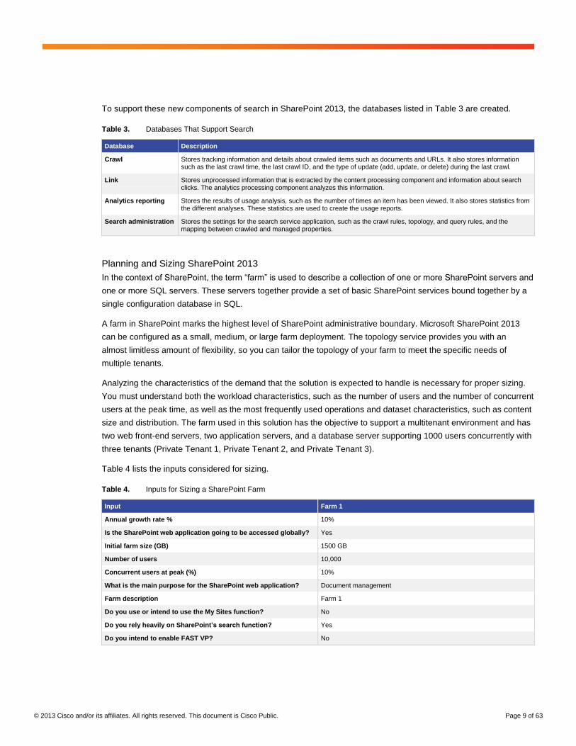
To support these new components of search in SharePoint 2013, the databases listed in Table 3 are created.
Table 3. Databases That Support Search
Database Description
Crawl Stores tracking information and details about crawled items such as documents and URLs. It also stores information such as the last crawl time, the last crawl ID, and the type of update (add, update, or delete) during the last crawl.
Link Stores unprocessed information that is extracted by the content processing component and information about search clicks. The analytics processing component analyzes this information.
Analytics reporting Stores the results of usage analysis, such as the number of times an item has been viewed. It also stores statistics from the different analyses. These statistics are used to create the usage reports.
Search administration Stores the settings for the search service application, such as the crawl rules, topology, and query rules, and the mapping between crawled and managed properties.
Planning and Sizing SharePoint 2013
In the context of SharePoint, the term “farm” is used to describe a collection of one or more SharePoint servers and
one or more SQL servers. These servers together provide a set of basic SharePoint services bound together by a
single configuration database in SQL.
A farm in SharePoint marks the highest level of SharePoint administrative boundary. Microsoft SharePoint 2013
can be configured as a small, medium, or large farm deployment. The topology service provides you with an
almost limitless amount of flexibility, so you can tailor the topology of your farm to meet the specific needs of
multiple tenants.
Analyzing the characteristics of the demand that the solution is expected to handle is necessary for proper sizing.
You must understand both the workload characteristics, such as the number of users and the number of concurrent
users at the peak time, as well as the most frequently used operations and dataset characteristics, such as content
size and distribution. The farm used in this solution has the objective to support a multitenant environment and has
two web front-end servers, two application servers, and a database server supporting 1000 users concurrently with
three tenants (Private Tenant 1, Private Tenant 2, and Private Tenant 3).
Table 4 lists the inputs considered for sizing.
Table 4. Inputs for Sizing a SharePoint Farm
Input Farm 1
Annual growth rate % 10%
Is the SharePoint web application going to be accessed globally? Yes
Initial farm size (GB) 1500 GB
Number of users 10,000
Concurrent users at peak (%) 10%
What is the main purpose for the SharePoint web application? Document management
Farm description Farm 1
Do you use or intend to use the My Sites function? No
Do you rely heavily on SharePoint’s search function? Yes
Do you intend to enable FAST VP? No

© 2013 Cisco and/or its affiliates. All rights reserved. This document is Cisco Public. Page 10 of 63
Table 5 shows the sizing recommended by the EMC VSPEX sizer tool. Table 6 shows the disk requirements.
Table 5. Recommended Sizing
Role Number of VMs
vCPU of RVM Memory of RVM OS Volume Cap of RVM
OS Volume IOPS of RVM
Total RVM
Web servers 2 4 vCPUs (4 RVM) 12 GB (6 RVM) 100 GB (1 RVM) 25 IOPS (1 RVM) 12
SQL Server 1 8 vCPUs (8 RVM) 32 GB (16 RVM) 100 GB (1 RVM) 25 IOPS (1 RVM) 16
Application servers (with crawler)
1 12 vCPUs (12 RVM) 12 GB (6 RVM) 100 GB (1 RVM) 25 IOPS (1 RVM) 12
Application servers (query and other service roles)
1 4 vCPUs (4 RVM) 12 GB (6 RVM) 100 GB (1 RVM) 25 IOPS (1 RVM) 6
Total 5 46
Table 6. Disk Requirements Summary
Pool Name Disk Type Disk Size (GB) Number of Drives RAID
SP content DB pool 15,000 SAS 300 16 RAID 5 (4+1)
Total 16
Note: Reference virtual machines(RMV)The reference architectures create a pool of resources sufficient to
host a target number of reference virtual machines. It is entirely possible that your virtual machines may not exactly
match the specifications above. In that case, you can say that a single specific virtual machine is the equivalent of
some number of reference virtual machines, and assume that number of virtual machines have been used in
the pool.
*RVM—Refernce Virtual Machine
Microsoft SharePoint 2013 Farm Architecture
The enterprise deployment design was determined using results from the evaluation deployment based on
concurrent users, requests per second, and page response times for different features. The final design
incorporates additional Cisco UCS servers, Cisco Nexus switches, and EMC VNX 5500 storage end-to-end
solution components. This solution (Figure 3) comprises four Cisco UCS B200 M3 servers running on Windows
Server 2012 with Hyper-V. All SharePoint servers (web server, application server, and SQL Server) are deployed
on it as virtual machines.

© 2013 Cisco and/or its affiliates. All rights reserved. This document is Cisco Public. Page 11 of 63
Figure 3. Reference Configuration
We used the VSPEX sizing tool for SharePoint Server 2013 to determine the number of server roles, the
computing resources, and the recommended storage layout.
Physical Host
For the purposes of this study, we configured two Cisco UCS B200 M3 servers to host a SharePoint host server
environment (Table 7). However, expansion of the physical servers is possible due to the design of the Fast Track
architecture. Scaling up is just a matter of adding servers.
Table 7. Physical Host Servers
Vendor Name Version Description Quantity
Cisco UCS B200 M3 2.1 (1b) Blade server 2
SharePoint 2013 Farm
Table 8 shows the virtual machines used for this study and their configurations.
Table 8. Virtual Machines
Role Number of VMs vCPUs Memory OS Volume
Web servers 2 4 vCPUs 12 GB 50 GB
SQL Server 1 8 vCPUs 32 GB 50 GB
Application servers (with crawler) 1 12 vCPUs 12 GB 50 GB
Application servers (query and other service roles)
1 4 vCPUs 12 GB 50 GB

© 2013 Cisco and/or its affiliates. All rights reserved. This document is Cisco Public. Page 12 of 63
Storage Configuration
When planning for content storage on SharePoint 2013, you must choose a suitable storage architecture.
SharePoint 2013 content storage has a significant dependency on the underlying database; therefore, database
and SQL Server requirements will drive the storage choices.
Figures 4 and 5 show the cluster shared volumes (CSVs) created for SharePoint 2013 application workload, which
are in addition to the existing volumes in the infrastructure of Private Cloud Fast Track 3.0.
Figure 4. Configuration
SharePoint database storage is provisioned on separate drives for databases and logs. Disks are configured with
RAID 5 and RAID 10. Databases (.mdf) files are hosted on RAID 5 and (.ldf) on RAID 10. SharePoint application
server (search) index files are provisioned on a separate drive on RAID 10.
© 2013 Cisco and/or its affiliates. All rights reserved. This document is Cisco Public. Page 13 of 63
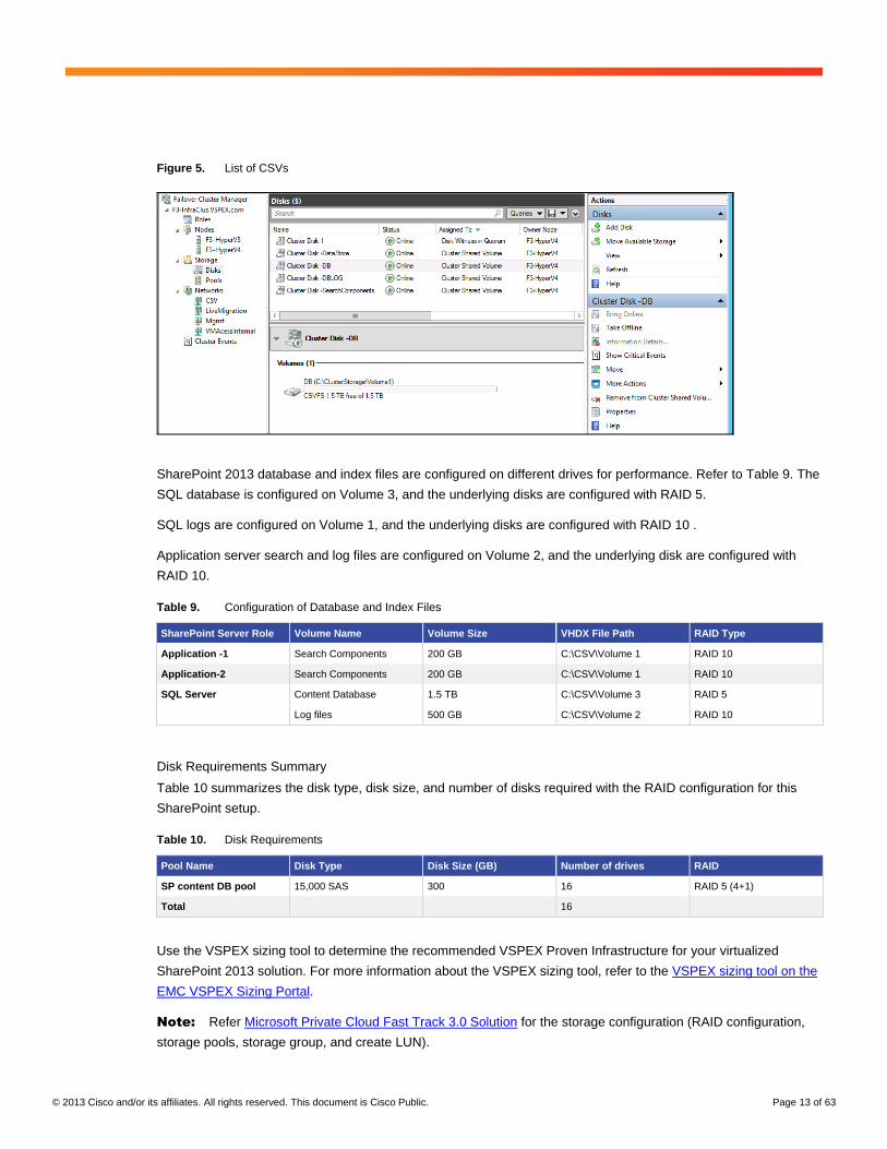
Figure 5. List of CSVs
SharePoint 2013 database and index files are configured on different drives for performance. Refer to Table 9. The
SQL database is configured on Volume 3, and the underlying disks are configured with RAID 5.
SQL logs are configured on Volume 1, and the underlying disks are configured with RAID 10 .
Application server search and log files are configured on Volume 2, and the underlying disk are configured with
RAID 10.
Table 9. Configuration of Database and Index Files
SharePoint Server Role Volume Name Volume Size VHDX File Path RAID Type
Application -1 Search Components 200 GB C:\CSV\Volume 1 RAID 10
Application-2 Search Components 200 GB C:\CSV\Volume 1 RAID 10
SQL Server
Content Database 1.5 TB C:\CSV\Volume 3 RAID 5
Log files 500 GB C:\CSV\Volume 2 RAID 10
Disk Requirements Summary
Table 10 summarizes the disk type, disk size, and number of disks required with the RAID configuration for this
SharePoint setup.
Table 10. Disk Requirements
Pool Name Disk Type Disk Size (GB) Number of drives RAID
SP content DB pool 15,000 SAS 300 16 RAID 5 (4+1)
Total 16
Use the VSPEX sizing tool to determine the recommended VSPEX Proven Infrastructure for your virtualized
SharePoint 2013 solution. For more information about the VSPEX sizing tool, refer to the VSPEX sizing tool on the
EMC VSPEX Sizing Portal.
Note: Refer Microsoft Private Cloud Fast Track 3.0 Solution for the storage configuration (RAID configuration,
storage pools, storage group, and create LUN).

© 2013 Cisco and/or its affiliates. All rights reserved. This document is Cisco Public. Page 14 of 63
Networking Considerations When Providing Multitenancy for SharePoint Server 2013
SharePoint 2013 applications follow a three-tiered functional model, consisting of web, application, and database
tiers. Servers in the web tier provide the public-facing front-end presentation services for the application, while
servers in the application and database tiers function as the middleware and back-end processing components.
Due to this functional split, servers in the web tier are typically considered to be likely targets of malicious attacks,
with the level of vulnerability increasing in proportion to the scope of the user community. Several methods exist for
separation of application tiers:
● Network-centric method. This method involves the use of VLANs within the Layer 2 domain to logically
separate each tier of servers.
● Server-centric method. This method relies on the use of separate VM virtual network interface cards
(vNICs) to daisy-chain the server tiers together.
To support multitenancy while providing the same degree of tenant isolation as a dedicated infrastructure, the
architecture uses path isolation techniques to logically divide a shared infrastructure into multiple (per-tenant)
virtual networks. These rely on both data path and device virtualization, implemented in end-to-end fashion across
the multiple hierarchical layers of the infrastructure and include the following:
Network Layer 2 separation (access, virtual access): VLAN IDs and the 802.1Q tag provide isolation and
identification of tenant traffic across the Layer 2 domain and, more generally, across shared links throughout
the infrastructure.
Traditionally, security policies were implemented at the physical server level. However, server virtualization and
mobility introduce new security challenges and concerns; to meet these challenges, policy must be implemented at
the virtual machine level and be capable of following virtual machines as they move from host to host.
Separation of per-tenant traffic in the computing layer of the infrastructure uses the following technologies:
● vNICs: In the highly virtualized data center, separation of traffic is accomplished via the use of multiple
vNICs, rather than physical NICs. For example, multiple vNICs are used to logically separate production
(data) traffic from back-end management traffic. This is accomplished with the Cisco UCS Virtual Interface
Card (in this case, the 1240 VIC), which allows the creation of virtual adapters mapped to unique
virtual machines.
● VLANs: VLANs provide logical isolation across the Layer 2 domain, including the Nexus 1000V virtual
access switching domain within the computing tier of the infrastructure.
● Port profiles: When combined with Cisco's VN-Link technology, port profiles provide a means of applying
tenant traffic isolation and security policy at the VLAN and virtual machine (vNIC) level of granularity.
Implemented at the virtual access switching domain, these map to System Center Virtual Machine Manager
port groups, and thus provide policy mobility through live migration events.
Nexus 1000V Configuration
This section describes how to configure the Cisco Nexus 1000V Switch for Microsoft Hyper-V in this solution.
● Virtual supervisor module configuration
● SCVMM configuration
© 2013 Cisco and/or its affiliates. All rights reserved. This document is Cisco Public. Page 15 of 63
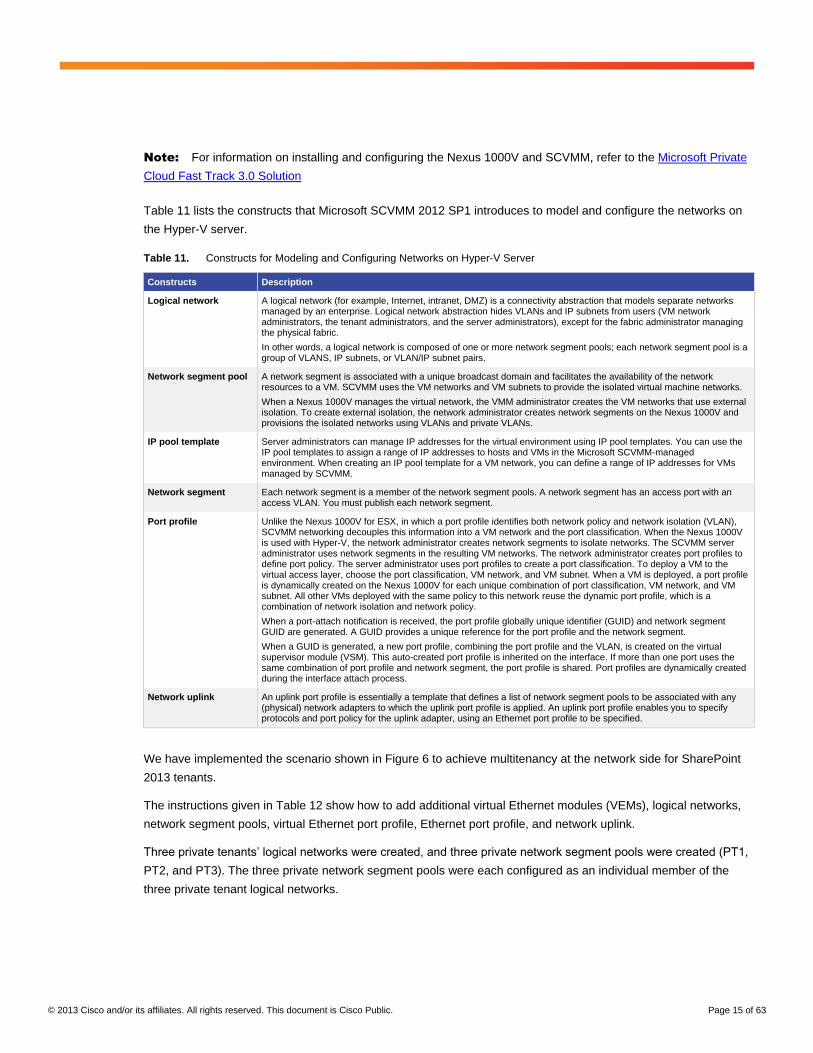
Note: For information on installing and configuring the Nexus 1000V and SCVMM, refer to the Microsoft Private
Cloud Fast Track 3.0 Solution
Table 11 lists the constructs that Microsoft SCVMM 2012 SP1 introduces to model and configure the networks on
the Hyper-V server.
Table 11. Constructs for Modeling and Configuring Networks on Hyper-V Server
Constructs Description
Logical network A logical network (for example, Internet, intranet, DMZ) is a connectivity abstraction that models separate networks managed by an enterprise. Logical network abstraction hides VLANs and IP subnets from users (VM network administrators, the tenant administrators, and the server administrators), except for the fabric administrator managing the physical fabric.
In other words, a logical network is composed of one or more network segment pools; each network segment pool is a group of VLANS, IP subnets, or VLAN/IP subnet pairs.
Network segment pool A network segment is associated with a unique broadcast domain and facilitates the availability of the network resources to a VM. SCVMM uses the VM networks and VM subnets to provide the isolated virtual machine networks.
When a Nexus 1000V manages the virtual network, the VMM administrator creates the VM networks that use external isolation. To create external isolation, the network administrator creates network segments on the Nexus 1000V and provisions the isolated networks using VLANs and private VLANs.
IP pool template Server administrators can manage IP addresses for the virtual environment using IP pool templates. You can use the IP pool templates to assign a range of IP addresses to hosts and VMs in the Microsoft SCVMM-managed environment. When creating an IP pool template for a VM network, you can define a range of IP addresses for VMs managed by SCVMM.
Network segment Each network segment is a member of the network segment pools. A network segment has an access port with an access VLAN. You must publish each network segment.
Port profile Unlike the Nexus 1000V for ESX, in which a port profile identifies both network policy and network isolation (VLAN), SCVMM networking decouples this information into a VM network and the port classification. When the Nexus 1000V is used with Hyper-V, the network administrator creates network segments to isolate networks. The SCVMM server administrator uses network segments in the resulting VM networks. The network administrator creates port profiles to define port policy. The server administrator uses port profiles to create a port classification. To deploy a VM to the virtual access layer, choose the port classification, VM network, and VM subnet. When a VM is deployed, a port profile is dynamically created on the Nexus 1000V for each unique combination of port classification, VM network, and VM subnet. All other VMs deployed with the same policy to this network reuse the dynamic port profile, which is a combination of network isolation and network policy.
When a port-attach notification is received, the port profile globally unique identifier (GUID) and network segment GUID are generated. A GUID provides a unique reference for the port profile and the network segment.
When a GUID is generated, a new port profile, combining the port profile and the VLAN, is created on the virtual supervisor module (VSM). This auto-created port profile is inherited on the interface. If more than one port uses the same combination of port profile and network segment, the port profile is shared. Port profiles are dynamically created during the interface attach process.
Network uplink An uplink port profile is essentially a template that defines a list of network segment pools to be associated with any (physical) network adapters to which the uplink port profile is applied. An uplink port profile enables you to specify protocols and port policy for the uplink adapter, using an Ethernet port profile to be specified.
We have implemented the scenario shown in Figure 6 to achieve multitenancy at the network side for SharePoint
2013 tenants.
The instructions given in Table 12 show how to add additional virtual Ethernet modules (VEMs), logical networks,
network segment pools, virtual Ethernet port profile, Ethernet port profile, and network uplink.
Three private tenants’ logical networks were created, and three private network segment pools were created (PT1,
PT2, and PT3). The three private network segment pools were each configured as an individual member of the
three private tenant logical networks.

© 2013 Cisco and/or its affiliates. All rights reserved. This document is Cisco Public. Page 16 of 63
Figure 6. Multitenancy Scenario for SharePoint 2013 Tenants
Table 12. Steps for Configuring the Cisco Nexus 1000V Switch for Microsoft Hyper-V
Step Configuration Commands
1 Logical network nsm logical network PrivateTenant1
nsm logical network PrivateTenant2
nsm logical network PrivateTenant3
2 Network segment pool nsm network segment pool PT1
nsm network segment pool PT2
nsm network segment pool PT3
nsm network segment pool PT1
member-of logical network PrivateTenant1
nsm network segment pool PT2
member-of logical network PrivateTenant2
nsm network segment pool PT3
member-of logical network PrivateTenant3

© 2013 Cisco and/or its affiliates. All rights reserved. This document is Cisco Public. Page 17 of 63
Step Configuration Commands
3 IP pool template nsm ip pool template PT1-VL2013-IP-Pool
ip address 200.1.3.2 200.1.3.250
network 200.1.3.0 255.255.255.0
default-router 200.1.3.253
nsm ip pool template PT1-VL2014-IP-Pool
ip address 200.1.4.2 200.1.4.250
network 200.1.4.0 255.255.255.0
default-router 200.1.4.253
nsm ip pool template PT2-VL2023-IP-Pool
ip address 200.2.3.2 200.2.3.250
network 200.2.3.0 255.255.255.0
default-router 200.2.3.253
nsm ip pool template PT2-VL2024-IP-Pool
ip address 200.2.4.2 200.2.4.250
network 200.2.4.0 255.255.255.0
default-router 200.2.4.253
nsm ip pool template PT3-VL2033-IP-Pool
ip address 200.3.3.2 200.3.3.250
network 200.3.3.0 255.255.255.0
default-router 200.3.3.253
nsm ip pool template PT3-VL2034-IP-Pool
ip address 200.3.4.2 200.3.4.250
network 200.3.4.0 255.255.255.0
default-router 200.3.4.253

© 2013 Cisco and/or its affiliates. All rights reserved. This document is Cisco Public. Page 18 of 63
Step Configuration Commands
4 Network segment nsm network segment PT1-NetworkSegment2013
member-of vmnetwork PT1-NetworkSegment2013
member-of network segment pool PT1
switchport access vlan 2013
ip pool import template PT1-VL2013-IP-Pool
publish network segment
switchport mode access
nsm network segment PT1-NetworkSegment2014
member-of network segment pool PT1
switchport access vlan 2014
ip pool import template PT1-VL2014-IP-Pool
publish network segment
switchport mode access
nsm network segment PT2-NetworkSegment2023
member-of network segment pool PT2
switchport access vlan 2023
ip pool import template PT2-VL2023-IP-Pool
publish network segment
switchport mode access
nsm network segment PT2-NetworkSegment2024
member-of network segment pool PT2
switchport access vlan 2024
ip pool import template PT2-VL2024-IP-Pool
publish network segment
switchport mode access
nsm network segment PT3-NetworkSegment2033
member-of network segment pool PT3
switchport access vlan 2033
ip pool import template PT3-VL2033-IP-Pool
publish network segment
switchport mode access
nsm network segment PT3-NetworkSegment2034
member-of network segment pool PT3
switchport access vlan 2034
ip pool import template PT3-VL2034-IP-Pool
publish network segment
switchport mode access
5 Virtual Ethernet port profile publish port-profile
port-profile type vethernet PT1-PortProfile
no shutdown
state enabled
publish port-profile
port-profile type vethernet PT2-PortProfile
no shutdown
state enabled
publish port-profile
port-profile type vethernet PT3-PortProfile
no shutdown
state enabled
publish port-profile
© 2013 Cisco and/or its affiliates. All rights reserved. This document is Cisco Public. Page 19 of 63
Step Configuration Commands
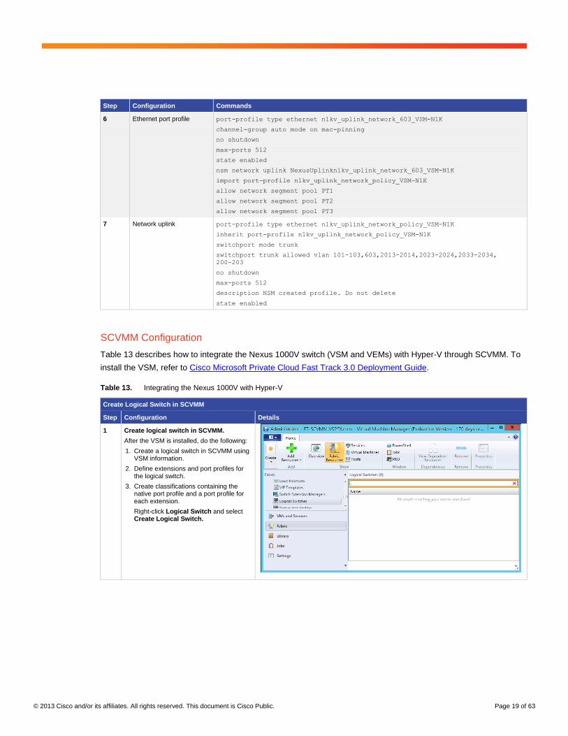
6 Ethernet port profile port-profile type ethernet n1kv_uplink_network_603_VSM-N1K
channel-group auto mode on mac-pinning
no shutdown
max-ports 512
state enabled
nsm network uplink NexusUplinkn1kv_uplink_network_603_VSM-N1K
import port-profile n1kv_uplink_network_policy_VSM-N1K
allow network segment pool PT1
allow network segment pool PT2
allow network segment pool PT3
7 Network uplink port-profile type ethernet n1kv_uplink_network_policy_VSM-N1K
inherit port-profile n1kv_uplink_network_policy_VSM-N1K
switchport mode trunk
switchport trunk allowed vlan 101-103,603,2013-2014,2023-2024,2033-2034,
200-203
no shutdown
max-ports 512
description NSM created profile. Do not delete
state enabled
SCVMM Configuration
Table 13 describes how to integrate the Nexus 1000V switch (VSM and VEMs) with Hyper-V through SCVMM. To
install the VSM, refer to Cisco Microsoft Private Cloud Fast Track 3.0 Deployment Guide.
Table 13. Integrating the Nexus 1000V with Hyper-V
Create Logical Switch in SCVMM
Step Configuration Details
1 Create logical switch in SCVMM.
After the VSM is installed, do the following:
1. Create a logical switch in SCVMM using VSM information.
2. Define extensions and port profiles for the logical switch.
3. Create classifications containing the native port profile and a port profile for each extension.
Right-click Logical Switch and select Create Logical Switch.

© 2013 Cisco and/or its affiliates. All rights reserved. This document is Cisco Public. Page 20 of 63
Create Logical Switch in SCVMM
Step Configuration Details
2 Read the text and click Next.
3 Name the logical switch.
In this case, the hostname of the VSM was used. Use defaults for single-root I/O virtualization (SR-IOV).

© 2013 Cisco and/or its affiliates. All rights reserved. This document is Cisco Public. Page 21 of 63
Create Logical Switch in SCVMM
Step Configuration Details
4 Check the previously configured VSM (n1kv_VSM-N1K) and click Next.
The VSM has the following attributes:
Extension type: Forwarding
Extension Manager: Cisco Nexus 1000V Chassis
Only one virtual switch extension can be selected.
5 Select Team in the uplink mode field and click Add to add the uplink port profile.
6 Select the uplink port profile and click OK.
Confirm the uplink port profile settings and click Next.
The host group SP Host Group is created in Hyper-V. The network sites PT1, PT2, and PT3 were created during Nexus 1000V command-line interface (CLI) configuration.

© 2013 Cisco and/or its affiliates. All rights reserved. This document is Cisco Public. Page 22 of 63
Create Logical Switch in SCVMM
Step Configuration Details
7 Specify the port classifications and click Next.
Port classifications must be created in SCVMM and linked to port profiles created in the VSM.
One port classification per port profile was created. When adding VMs to the logical switch, select the port classification and VM network when configuring network adapters
In the Summary panel, confirm the settings and click Finish to create the logical switch
Add Each Host to Logical Switch
Step Configuration Details
1 Add each host to logical switch.
Add physical adapters to the logical switch team.
Two adapters—for example, VIC Ethernet Interface 3 and VIC Ethernet Interface 4—will be used on each host. Add these to the logical switch.

© 2013 Cisco and/or its affiliates. All rights reserved. This document is Cisco Public. Page 23 of 63
Create VM Network
Step Configuration Details
1 Right-click VM Network and select Create VM Network.
2 Create the VM network name and select the logical network.
Select the network segment.
For example:
Name: PT-VL2013
Logical Network: n1kv_logical_network_VDM-N1K
3 Confirm the VM network settings.
4 Follow the same steps to create the remaining VM networks.

© 2013 Cisco and/or its affiliates. All rights reserved. This document is Cisco Public. Page 24 of 63
Create VM Network
Step Configuration Details
5 All VM networks.
Add VMs to Nexus 1000V Switch for Hyper-V Logical Switch
Step Configuration Details
1 Go to the VM Properties page.
Right-click the VM and select Properties.
2 Select Hardware Configuration and select the adapter to add to the logical switch.
There are two adapters in the test VMs. One connects to the Microsoft external switch for management, and the other connects to the Nexus 1000V.

© 2013 Cisco and/or its affiliates. All rights reserved. This document is Cisco Public. Page 25 of 63
Add VMs to Nexus 1000V Switch for Hyper-V Logical Switch
Step Configuration Details
3 Select the VM network.
On the network adapter properties page, click Browse to see a list of available VM networks.
4 Select the classification.
After selecting the VM network, click the Classification drop-down and select the classification profile. Click OK.
5 Verify that the virtual machine has been deployed by issuing a “show interface virtual” command from the CLI.
SharePoint 2013 Private Cloud Deployment
Prepare Your Environment
The service template model helps IT administrators automate deployment of SharePoint Server 2013 Enterprise on
Windows Server 2012 in a three-tier configuration. You also can easily extend the service template to automate
more advanced deployment scenarios if required in your environment. This section focuses on how to prepare your
environment to use a service template.
Create User Accounts for SharePoint 2013
The service template for SharePoint 2013 Enterprise can potentially take advantage of service accounts for the
installation of SharePoint. These are defined in the provided AutoSPInstaller .xml example file that the
AutoSPInstaller script uses. (AutoSPInstaller is discussed in a later section.) For details on service account
requirements, see Plan for administrative and service accounts in SharePoint 2013.
This service template package uses the user accounts shown in Figure 7. Figure 8 shows the example
AutoSPInstaller script, and Figure 9 shows the system responses to the script.

© 2013 Cisco and/or its affiliates. All rights reserved. This document is Cisco Public. Page 26 of 63
Figure 7. User Accounts
Figure 8. Script Example
Figure 9. System Responses from Windows PowerShell

© 2013 Cisco and/or its affiliates. All rights reserved. This document is Cisco Public. Page 27 of 63
Prepare the VHDX for the Service Template (SQL Tier)
Use the following information to complete this step.
Prepare the Base Virtual Hard Disk
To prepare the base virtual hard disk (VHDX)
● Install the operating system: Create a base VHDX using the Windows 2012 operating system. For more
information on creating a virtual machine on a blank VHDX, see the Microsoft article How to Create and
Deploy a Virtual Machine from a Blank Virtual Hard Disk.
Note: Do not use SysPrep on the operating system at this point. The SysPrep requirement is detailed later in
this section.
Install SQL Server 2012 SP1
To download and stage SQL Server 2012 SP1
1. On the download page for Microsoft SQL Server 2012 Service Pack 1 (SP1), in the list under Files in this
download, select the download link for SQLServer2012SP1-FullSlipstream-ENU-x64.iso.
Use the following information to install SQL Server 2012 SP1 onto the base VHDX image you just created:
● Install SQL Server 2012 on base VHDX: To do so, see the Microsoft article Install SQL Server 2012 Using
SysPrep. Follow the instructions in the Prepare Image section.
Note: Do not use SysPrep on the operating system at this point. The SysPrep requirement is detailed later in
this section.
SQL Server 2012 SP1 media is accessed during the service template customization of SQL. This media must
be located on a local drive on the SQL Server VM that is accessible by the service template execution account
(Figure 10).
Figure 10. Location of SQL Server 2012 SP1 Media

© 2013 Cisco and/or its affiliates. All rights reserved. This document is Cisco Public. Page 28 of 63
Finalize the VHDX and Copy It to the Virtual Machine Library
Use SysPrep to finalize the VHDX, and then copy it to the library so that it can be used by the service template for
SharePoint 2013 Enterprise Three Tier.
To use SysPrep to finalize the VHDX
2. Ensure that you have completed all of the previous substeps in this section.
3. Access SysPrep in the following directory on your virtual machine: %windir%\system32\SysPrep. Then, at an
elevated command prompt, execute the following example command.
C:\windows\system32\SysPrep\SysPrep.exe /oobe /generalize /shutdown
4. After the virtual machine fully shuts down, navigate to the location of the VHDX on your Hyper-V host, and
copy the VHDX to the subdirectory where you store the virtual machine templates in your VMM library.
\\FT-SCVMM\MSSCVMMLibrary\VHDXs\
Prepare the VHDX for the Service Template (Web Front End)
Use the following information to complete this step.
Prepare the Base VHDX
To prepare the base VHDX
● Install the operating system: Create a base VHDX using the Windows 2012 operating system. For more
information on creating a virtual machine on a blank VHDX, see the Microsoft article How to Create and
Deploy a Virtual Machine from a Blank Virtual Hard Disk.
● Download SharePoint Server 2013 Enterprise edition from the following location: Download Microsoft
SharePoint Server 2013.
Install SharePoint Server 2013 Enterprise
Use the following Microsoft resources to install SharePoint Server 2013 (use the base install with no configuration):
● Overview of SharePoint 2013 installation and configuration
● Install SharePoint 2013 across multiple servers for a three-tier farm
To install SharePoint Server 2013 Enterprise
1. Run the prerequisite checker for SharePoint Server 2013 that is included with your source media to install and
enable any server roles or download and apply any updates required for SharePoint.
2. Install SharePoint Server 2013 Enterprise on the virtual machine.
Note: Be sure to only install SharePoint and not configure it. Configuration happens during the service template
deployment process using the AutoSPInstaller script and configuration XML.
CodePlex
CodePlex is an open-source project hosting website from Microsoft. It allows shared development of open-source
software. The site enables engineers and computer scientists to share projects and ideas.

© 2013 Cisco and/or its affiliates. All rights reserved. This document is Cisco Public. Page 29 of 63
While CodePlex encompasses a wide variety of projects, including SQL, Windows Presentation Foundation (WPF),
and Windows Forms-related projects, major activities center around the .NET framework, including ASP.NET, and
Microsoft’s collaboration server, SharePoint. The most prominent and used project that was born inside CodePlex,
the AJAX Control Toolkit, is a joint project between the community and Microsoft. Microsoft solely owns and
operates CodePlex.com.
AutoSPInstaller
AutoSPInstaller is a CodePlex project. The aim of the project is to provide a set of unified scripts for installing
SharePoint 2013. Scripted installations create repeatability and consistency and are very useful when creating
separate environments for test, QA, and production. It offers:
● Centralized, remote install of every SharePoint server in your farm using PowerShell remoting
● Support for parallel binary installations, whether remote install is enabled or not (useful for speeding up
multiserver farm installations)
● Ability to specify a different SQL server for each web application and service application, plus support for
creating an alias for each (except search, currently)
● Screen output and log display the elapsed time to install SharePoint and Office Web App binaries
● Ability to specify an arbitrary XML input file by passing the XML file name as an argument, or just dragging it
onto AutoSPInstallerLaunch.bat
Note: AutoSPInstaller as used in this solution has no support from Cisco.
Download and Stage AutoSPInstaller
The service template for SharePoint 2013 Enterprise takes advantage of a robust scripted solution for the
installation of SharePoint. This community script is located on CodePlex at AutoSPInstaller, and it must be
downloaded and placed on a VM web front end (WFE) and application servers.
To download and stage AutoSPInstaller
Download the AutoSPInstaller configuration script from AutoSPInstaller on the CodePlex website.
Copy the SharePoint binaries and prerequisites to the AutoSPInstaller folder structure. Extract the downloaded
contents to your VM local drive that will be accessible by the account used to deploy the service template
(Figure 11).

© 2013 Cisco and/or its affiliates. All rights reserved. This document is Cisco Public. Page 30 of 63
Figure 11. AutoSPInstaller in VM Local Drive

© 2013 Cisco and/or its affiliates. All rights reserved. This document is Cisco Public. Page 31 of 63
Configuring AutoSPInstaller
Table 14 gives the steps for configuring AutoSPInstaller.
Table 14. Configuring AutoSPInstaller
Step Configuration Details
1 AutoSPInstaller can be run in either offline mode or online mode. In offline mode you need prerequisites files.
First we will prepare the SharePoint 2013 installation. For that, extract the AutoSPInstallerGUI.
Then load the AutoSPInstallerInput.XML using the AutoSPInstallerGUI.Exe
Configurations are saved in the XML input file.

© 2013 Cisco and/or its affiliates. All rights reserved. This document is Cisco Public. Page 32 of 63
Step Configuration Details
2 Main tab:
Provide passwords for the accounts.
These are created using the PowerShell script.
For example:
vspex0\spservice
vspex0\spfarm
vspex0\spcacheuserreader
vspex0\spcacheuserreader
Database section:
Provide the DB Server and Instance name.
Specify web applications as needed. Two web apps are defined by default: Portal and Myhost.
By selecting those from the drop-down menus, you can specify the Name, App Pool Name, URL, and Port.
Specify the App Pool Account.
Specify the SharePoint admin user (spadmin).
3 Services tab:
Applications configuration. Most of the services work with the default configuration.
Specially configure the user profile and search service.
The Sync account is the account used for Active Directory synchronization. Therefore, add an spprofile account.
Specify database names for profile, Sync, and Social.
Select the Search Service account (spsearch).
Specify the spsearch service account.
Search topology.
4 Save the XML file.
For simplicity in automated deployment, we have maintained a separate XML file configuration for each tier, with
different roles. After the configuration settings are complete, copy the entire folder structure to the application and
web front-end servers (the SP folder with all subfolders).

© 2013 Cisco and/or its affiliates. All rights reserved. This document is Cisco Public. Page 33 of 63
The VM is provisioned through an SCVMM service template, and then AutoSPInstaller is run through the VM
startup post-deployment script to achieve automation.
System Center Virtual Machine Manager
Figure 12 shows the process followed in configuring SCVMM for the SharePoint installation.
Figure 12. SCVMM Configuration Process
Log in to SCVMM, and click Library > Select Profiles (Figure 13).

© 2013 Cisco and/or its affiliates. All rights reserved. This document is Cisco Public. Page 34 of 63
Figure 13. Preparing to Create Profiles
Create Application Profile
You can use the procedure in Table 15 to create an application profile in SCVMM. An application profile provides
instructions for installing Microsoft Server Application Virtualization (Server App-V) applications, Microsoft Web
Deploy applications, and Microsoft SQL Server data-tier applications (DACs), and instructions for running scripts
when a virtual machine is deployed as part of a service.
You can use an application profile only when you deploy a virtual machine as part of a service.
Table 15. Creating an Application Profile
Step Configuration Details
1 Open the Library workspace.
On the Home tab, in the Create group, click Create, and then click Application Profile.
The New Application Profile dialog box opens.

© 2013 Cisco and/or its affiliates. All rights reserved. This document is Cisco Public. Page 35 of 63
Step Configuration Details
2 On the General tab, in the Name box, enter a name for the application profile. For example, SP2013Appserver Profile.
3 On the General tab, in the Compatibility list, choose an appropriate option—for example, Windows 2012 STD.
4 Click OK to complete.
Create Guest OS Profile
You can use the procedure in Table 16 to create a guest operating system profile in System center Virtual Machine
Manager (SCVMM). A guest operating system profile specifies the operating system settings that you want the
virtual machine to use when the virtual machine is created and deployed.
Table 16. Creating a Guest OS Profile
Step Configuration Details
1 Open the Library workspace.
On the Home tab, in the Create group, right-click Create, and then click Guest OS Profile.

© 2013 Cisco and/or its affiliates. All rights reserved. This document is Cisco Public. Page 36 of 63
Step Configuration Details
2 The New Guest OS Profile dialog box opens. On the General tab, in the Name box, enter a name for the guest OS profile.
3 Click the Guest OS Profile tab, and then configure the desired settings. For example, you can configure the following settings:
● Computer name
● Local administrator account password
● Product key
● Domain to join
● Windows Server roles or features to install
4 Click OK to complete.
Create Hardware Profile
You can use the procedure in Table 17 to create a hardware profile in System Center Virtual Machine Manager
(SCVMM). A hardware profile specifies the hardware settings that you want the virtual machine to use when it is
created and deployed.

© 2013 Cisco and/or its affiliates. All rights reserved. This document is Cisco Public. Page 37 of 63
Table 17. Creating a Hardware Profile
Step Configuration Details
1 ● Open the Library workspace.
● On the Home tab, in the Create group, right-click Create, and then click Hardware Profile.
● The New Hardware Profile dialog box opens.

© 2013 Cisco and/or its affiliates. All rights reserved. This document is Cisco Public. Page 38 of 63
Step Configuration Details
2 ● On the General tab, in the Name box, enter a name for the hardware profile. For example, enter 8 GB 4 processor server.
● Click the Hardware Profile tab, and then configure the desired settings. For example, you can configure the following settings:
◦ The number of processors. For example, WFE 4vCPU, App 12vCPU, and 4 vPCU and SQL 8vCPU.
◦ The amount of static or dynamic memory. For example, WFE 8 GB, App 12 GB, and SQL 32 GB.
◦ The logical network. For example, Nexus 1000V.
◦ Which capability profiles to use.
◦ Whether to make the virtual machine highly available (we have configured high availability for the SharePoint tiers).
3 Click OK to complete.
Similarly, follow the steps in the previous table to create hardware profiles for the application server and
SQL Server.
Create SQL Server Profile
You can use the procedure in Table 18 to create a SQL Server profile in System Center Virtual Machine Manager
(SCVMM). The SQL Server profile provides instructions for installing an instance of Microsoft SQL Server on a
virtual machine.

© 2013 Cisco and/or its affiliates. All rights reserved. This document is Cisco Public. Page 39 of 63
Table 18. Creating a SQL Server Profile
Step Configuration Details
1 Open the Library workspace.
On the Home tab, in the Create group, click Create, and then click Create SQL Server Profile.
2 On the General tab, in the Name box, enter a name for the hardware profile. For example, enter SQL2012.
3 Enter the SQL Server Deployment.
For example, SQLDeployment.
4 Provide the Media Source for the SQL configuration.
For example, C:\SQL.
Add a SQL Server Administration account. For example, vspex0\administrator.

© 2013 Cisco and/or its affiliates. All rights reserved. This document is Cisco Public. Page 40 of 63
Step Configuration Details
5 In the Service Accounts section, provide the SQL server service Run As account.
For example, NT Authority\System.
Create SharePoint Templates
System Center Virtual Machine Manager (SCVMM) profiles contain configuration settings that you can apply to a
new virtual machine template or virtual machine. You can create, view, and modify profiles in the
Library workspace.
The steps in Table 19 provide information about how to create virtual machine templates for SharePoint 2013. For
example, it contains steps to create a web front-end (WFE) server template and a SQL Server template.
Table 19. Creating Virtual Machine Templates for SharePoint 2013
Step Configuration Details
1 Open the Library workspace.
On the VM Templates tab, right-click Create. A new dialog opens.

© 2013 Cisco and/or its affiliates. All rights reserved. This document is Cisco Public. Page 41 of 63
Step Configuration Details
2 ● On the Select Source tab, click Browse.
● The SCVMM library opens.
● Select the VHDX library.
● Select the SysPrep WFE VHDX file, which has been copied to the SCVMM library.
● For example, create a web front-end server template.
3 Name the VM template. For example, SharePoint 2013-WFE1.
4 On the Configure Hardware tab, select the hardware profile created in Table 17 for the WFE VM.

© 2013 Cisco and/or its affiliates. All rights reserved. This document is Cisco Public. Page 42 of 63
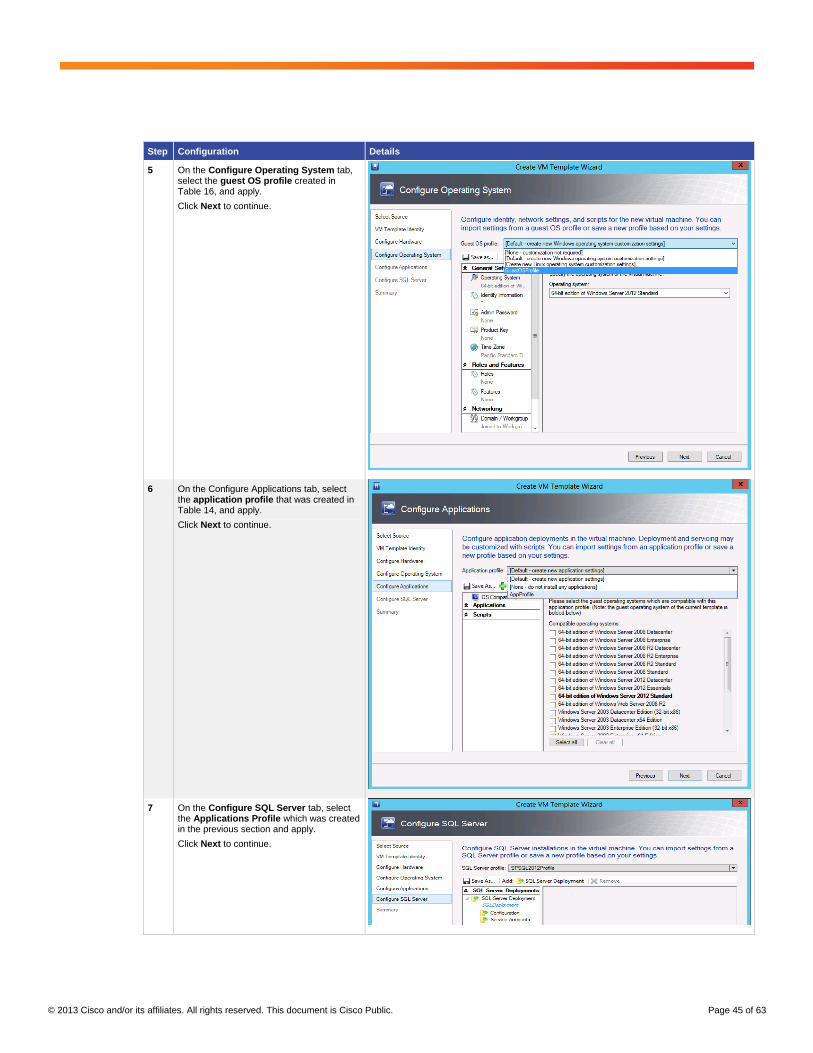
Step Configuration Details
5 In the Configure Operating System section, select the guest OS profile created in Table 16.
Click Next to continue.
6 On the Configure Applications tab, select the application profile that was created in Table 15.
Click Next to continue.

© 2013 Cisco and/or its affiliates. All rights reserved. This document is Cisco Public. Page 43 of 63
Step Configuration Details
7 Click Create to create the template.
Similarly, follow the steps in the previous table to create an application server profile.
Create SQL Server Templates
Table 20 contains information about how to create virtual machine templates for SQL 2012.
Table 20. Creating SQL Server Templates
Step Configuration Details
1 Open the Library workspace.
Right-click Create, and then click Create VM Templates.

© 2013 Cisco and/or its affiliates. All rights reserved. This document is Cisco Public. Page 44 of 63
Step Configuration Details
2 On the Select Source tab, click Browse.
The SCVMM library opens.
Select the VHDX library.
Select the SysPrep SQL2012 VHDX file, which has been copied to the SCVMM library.
Click Next to continue.
3 Name the VM template
For example, SQL2012 or Application Server.
Click Next to continue.
4 On the Configure Hardware tab, select the hardware profile created in Table 17 for the SQL2012 VM.
Click Next to continue.
© 2013 Cisco and/or its affiliates. All rights reserved. This document is Cisco Public. Page 45 of 63
Step Configuration Details
5 On the Configure Operating System tab, select the guest OS profile created in Table 16, and apply.
Click Next to continue.
6 On the Configure Applications tab, select the application profile that was created in Table 14, and apply.
Click Next to continue.
7 On the Configure SQL Server tab, select the Applications Profile which was created in the previous section and apply.
Click Next to continue.
© 2013 Cisco and/or its affiliates. All rights reserved. This document is Cisco Public. Page 46 of 63
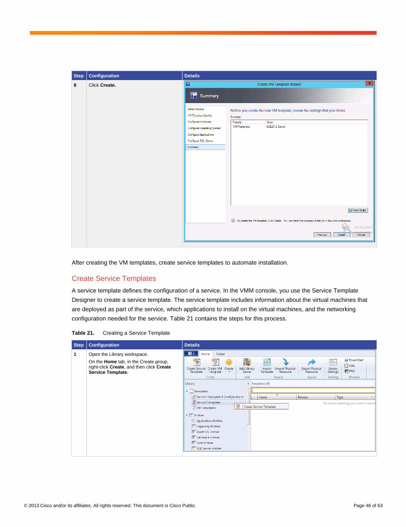
Step Configuration Details
8 Click Create.
After creating the VM templates, create service templates to automate installation.
Create Service Templates
A service template defines the configuration of a service. In the VMM console, you use the Service Template
Designer to create a service template. The service template includes information about the virtual machines that
are deployed as part of the service, which applications to install on the virtual machines, and the networking
configuration needed for the service. Table 21 contains the steps for this process.
Table 21. Creating a Service Template
Step Configuration Details
1 Open the Library workspace.
On the Home tab, in the Create group, right-click Create, and then click Create Service Template.

© 2013 Cisco and/or its affiliates. All rights reserved. This document is Cisco Public. Page 47 of 63
Step Configuration Details
2 The New Service Template dialog box opens. On the Name tab, in the Name box, enter a Name and Release version.
For example, SP2013, Release New.
We are deploying five VMs serving in different roles.
Choose the Blank template.
Click OK.
3 VM templates are displayed. Drag and drop the VM templates onto the tiers.
The most common properties that you can change appear in the details pane in the Service Template Designer. To display all of the settings that you can configure, click View All Properties in the details pane.
4 Click Configure Deployment.
Enter the Name and Destination for the service instance.
For example, Name: SP2013-PrivateCloud Destination: SP host group

© 2013 Cisco and/or its affiliates. All rights reserved. This document is Cisco Public. Page 48 of 63
Step Configuration Details
5 Select the WFE server.
On the canvas, the most common properties that you can change appear in the details pane in the Service Template Designer. To display all settings that you can configure, click View All Properties in the details pane.

© 2013 Cisco and/or its affiliates. All rights reserved. This document is Cisco Public. Page 49 of 63
Step Configuration Details
6 On the canvas, select the VM location, OS Settings, Machine Resources, and networking object that you want to configure.
1. Map the Virtual Machine location
C:\ClusterStorage\Volume4 (provisioned to store VM).
2. In the Identity Information section, rename to SP2013-WFE1.
3. For a network adapter, you can configure the settings shown here:
For example, for a Nexus 1000V switch, assign a static IP address.
7 Click OK.

© 2013 Cisco and/or its affiliates. All rights reserved. This document is Cisco Public. Page 50 of 63
Step Configuration Details
8 Select the destination server based on the VM requirements and on the default placement options.
For example, F3-HyperV4.vspex.com.
9 Similarly follow the above steps to configure the WFE-2 server.
© 2013 Cisco and/or its affiliates. All rights reserved. This document is Cisco Public. Page 51 of 63
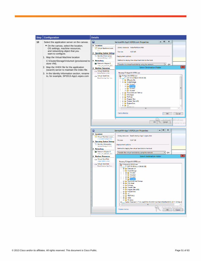
Step Configuration Details
10 Select the application server on the canvas.
● On the canvas, select the location, OS settings, machine resources, and networking object that you want to configure.
1. Map the Virtual Machine location
C:\ClusterStorage\Volume4 (provisioned to store VM).
2. Map the VHDX file for the application (search) server to maintain the index file.
3. In the Identity Information section, rename to, for example, SP2013-App1.vspex.com

© 2013 Cisco and/or its affiliates. All rights reserved. This document is Cisco Public. Page 52 of 63
Step Configuration Details
11 For a network adapter, you can configure the settings shown here.
For the Nexus 1000V switch, we have assigned a static IP address.
12 Click OK.
13 Select the destination server based on the VM requirements and on the default placement options.
For example, F3-HyperV4.vspex.com is selected.

© 2013 Cisco and/or its affiliates. All rights reserved. This document is Cisco Public. Page 53 of 63
Step Configuration Details
14 Similarly, follow the above steps to configure the Application-2 server.
15 SQL server configuration
On the canvas, select the location, identity, machine resources, and networking object that you want to configure.
1. Map the Virtual Machine location:
C:\ClusterStorage\Volume4 (provisioned to store VM).
2. Map the VHDX drive for the SQL database, which has been provisioned on RAID 5.
3. In the Identity Information section, rename to, for example, SP2013.vspex.com.
16 Map the VHDX for SQL log files, which have been provisioned on RAID 10.

© 2013 Cisco and/or its affiliates. All rights reserved. This document is Cisco Public. Page 54 of 63
Step Configuration Details
17 For a network adapter, you can configure the settings shown here:
For example, for a Nexus 1000V switch, assign a static IP address.
18 Click OK.

© 2013 Cisco and/or its affiliates. All rights reserved. This document is Cisco Public. Page 55 of 63
Step Configuration Details
19 Select the destination server based on the VM requirements and on the default placement options.
For example, F3-HyperV3.vspex.com.
20 Once all the VM and destination placement servers are configured, the star indicates that the VMs are ready to be deployed.
21 Click Deploy.

© 2013 Cisco and/or its affiliates. All rights reserved. This document is Cisco Public. Page 56 of 63
Step Configuration Details
22 Deployment starts.
23 Once the deployment kicks off, you can monitor the status of deployment.
24 On the SCVMM, click Jobs to view running jobs in this deployment

© 2013 Cisco and/or its affiliates. All rights reserved. This document is Cisco Public. Page 57 of 63
Step Configuration Details
25 VMs are online and logged in to the network .
26 Windows OS boots and post-deployment scripts will start the SharePoint 2013 installation.
Post-Deployment Tasks
AutoSPInstaller gives you the flexibility to choose the location for the index files at the time of installation. However,
you can also refer link Microsoft Manage the index component in SharePoint Server 2013.
After the deployment of SQL Server, change the Database and Database log location.
WFE servers are configured with multiple NIC adapters with a specific Nexus 1000V port profile with VLAN network
properties to provide network-level multitenancy for multiple tenants in the cloud to access SharePoint services.
Tenants share the same web front-end server and web application.
Configure VMs with the Appropriate Multitenant Network
VMs are deployed through the service template. Configure the tenant networks as shown in Table 22.

© 2013 Cisco and/or its affiliates. All rights reserved. This document is Cisco Public. Page 58 of 63
Table 22. Configuring the Tenant Networks
Step Configuration Details
1 Select the VM right click properties
2 Add Network Adapter to VM
On right plane Selelct radio button Connected to a VM network
On VM network Click Browse
Select PT1-VL2013
Click OK.

© 2013 Cisco and/or its affiliates. All rights reserved. This document is Cisco Public. Page 59 of 63
Step Configuration Details
3 Select Virtual Switch
Select radio button > Logical Switch
For classification, select PT1-PortProfile.
Click OK to complete.
Similarly add tenant networks for multiple tenants in the Private Cloud.
Similarly add tenant networks for multiple tenants in the Private Cloud.
SharePoint 2013 Multitenancy Configuration
SharePoint 2013 provides the ability to host unique deployments for multiple tenants on the same farm by Isolating
the data, operational services, and management of a tenant from other tenants using the same farm.
From a design standpoint, tenants are grouped together in one web application by their respective subscription ID.
Whenever a new site collection is created, it is assigned the same ID as the other site collections in the tenancy. In
addition to site collections for collaboration, a given tenant will also have a site collection used for tenant
administration. The tenant uses its tenant administration site to configure settings such as service application
settings, site collection creation and deletion, etc.
In general, site collection data is maintained in a content database. Whenever site collections are associated with a
subscription ID, they will be stored in a partition of the database that is separate from other tenants in the farm.
This assures that any SQL query performed from within the context of that tenant will never return data from
another tenant.
Service application databases also are partitioned in a similar way. When a web application is associated with two
service applications, since those service applications are created in partitioned mode, the data is stored in tenant
partitions and is isolated from other tenant data. With this approach, you need only one service application for all
your tenants. So rather than having, say, three managed metadata service applications, you could have just one
that is partitioned. This brings a great advantage to your infrastructure, from a scaling angle.
Tenant administration sites maintain most of the settings for the service application. This lets the tenants configure
the settings as they realize suitable, and it assures that the settings for one tenant will not adversely affect the
settings of another tenant.
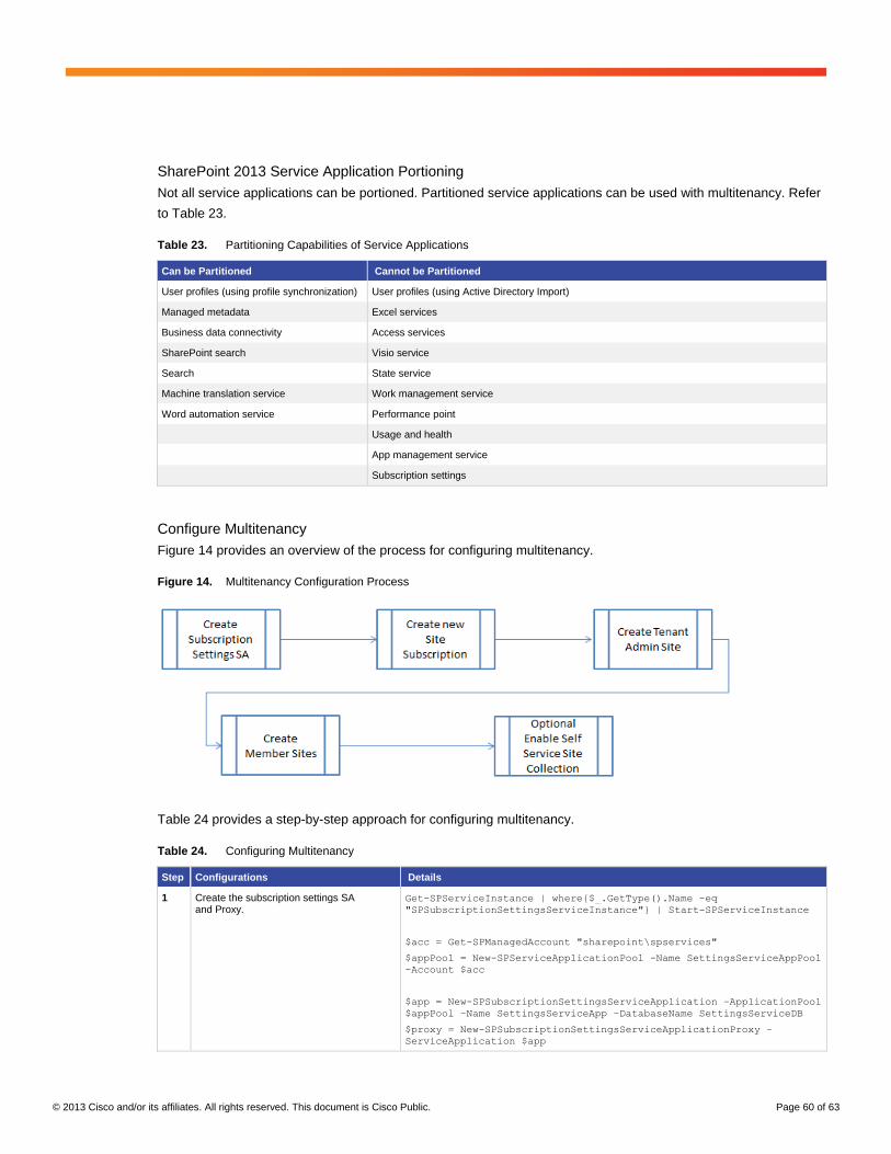
© 2013 Cisco and/or its affiliates. All rights reserved. This document is Cisco Public. Page 60 of 63
SharePoint 2013 Service Application Portioning
Not all service applications can be portioned. Partitioned service applications can be used with multitenancy. Refer
to Table 23.
Table 23. Partitioning Capabilities of Service Applications
Can be Partitioned Cannot be Partitioned
User profiles (using profile synchronization) User profiles (using Active Directory Import)
Managed metadata Excel services
Business data connectivity Access services
SharePoint search Visio service
Search State service
Machine translation service Work management service
Word automation service Performance point
Usage and health
App management service
Subscription settings
Configure Multitenancy
Figure 14 provides an overview of the process for configuring multitenancy.
Figure 14. Multitenancy Configuration Process
Table 24 provides a step-by-step approach for configuring multitenancy.
Table 24. Configuring Multitenancy
Step Configurations Details
1 Create the subscription settings SA and Proxy.
Get-SPServiceInstance | where{$_.GetType().Name -eq
"SPSubscriptionSettingsServiceInstance"} | Start-SPServiceInstance
$acc = Get-SPManagedAccount "sharepoint\spservices"
$appPool = New-SPServiceApplicationPool -Name SettingsServiceAppPool
-Account $acc
$app = New-SPSubscriptionSettingsServiceApplication –ApplicationPool
$appPool –Name SettingsServiceApp –DatabaseName SettingsServiceDB
$proxy = New-SPSubscriptionSettingsServiceApplicationProxy –
ServiceApplication $app

© 2013 Cisco and/or its affiliates. All rights reserved. This document is Cisco Public. Page 61 of 63
Step Configurations Details
2 Create new site subscriptions. $sub = New-SPSiteSubscription
3 CUVC 3545 MCU module for TelePresence, 48 audio ports
New-SPSite -url http://sp2013-App1/Sitest/Privatetenantadmin1 -
owneralias vspex0\administrator -owneremail [email protected] -
template tenantadmin#0 -SiteSubscription $sub -
AdministrationSiteType TenantAdministration
4 CUVC 3545 EMP module for TelePresence Switching, 12 TP ports
New-SPSite -url http://sp2013-App1/Sitest/TenantPT1-owneralias
sharepoint\administrator -owneremail [email protected] -template sts#0
-SiteSubscription $sub
The multitenancy environment is now configured for tenants.
Multitenancy provides a platform for sharing resources and managing services that are scalable, flexible, and
robust. This enables the SharePoint administrator to easily scale from a small farm to a multiserver farm.
There are numerous ways to configure a SharePoint farm. This paper shows a fairly simple way of doing so.

© 2013 Cisco and/or its affiliates. All rights reserved. This document is Cisco Public. Page 62 of 63
Conclusion
The VSPEX solutions integrate computing, networking, and storage resources to provide a unified data center
framework that delivers outstanding performance for virtualized business applications. VSPEX infrastructures
accelerate IT transformation by enabling faster deployments, greater flexibility of choice, efficiency, and lower risk.
Cisco UCS meets server virtualization, private cloud and multitenancy challenges with the next-generation data
center platform that unifies computing, networking, storage access, and virtualization support in a cohesive system
managed centrally and coordinated with virtualization software such as Microsoft Hyper-V server and Nexus 1000V
integration with SCVMM. The system integrates enterprise-class servers in a 10 Gigabit Ethernet unified network
fabric that provides the I/O bandwidth and functions that virtual machines and the virtualization software require.
Finally, Cisco UCS integrates the network access layer into a single easily managed entity in which links to virtual
machines can be configured, managed, and moved as readily as physical links. Cisco UCS continues Cisco's long
history of innovation and delivers innovation in architecture, technology, partnerships, and services.
Microsoft SharePoint 2013 is an extensible and scalable web-based platform consisting of tools and technologies
that support collaboration, multitenancy, and sharing of information within teams and throughout the web.
Microsoft SharePoint 2013 is both performance and storage intensive. Not all storage-intensive workloads are
alike, and the EMC VX5500 storage configuration delivers balanced performance and expandability to best meet
workload requirements ranging from large data to collaboration.
The three-tier architecture provisions an ideal SharePoint topology. Several servers at individual tiers render
various SharePoint components together to make up a SharePoint 2013 farm. Servers at the web tier render web
and search query functions, servers on the application tier are responsible for search indexing and various service
application functions, and the server at the database tier hosts SQL Server databases for the farm.
The paper provides ample guidelines for creating a virtual SharePoint 2013 farm using Microsoft Hyper-V in a
private cloud with multitenancy.
References :
Cisco Microsoft Private Cloud Fast Track 3.0 Solution for EMC VSPEX with System Center 2012 SP1 for 250 VMS
System Center 2012 Virtual Machine Manager
Using Services Templates in System Center Virtual Machine Manager 2012
How to Create and Deploy a Virtual Machine from a Blank Virtual Hard Disk
Install SQL Server 2012 Using SysPrep
Prepare Image SQL 2012
Add Web or Application Servers to Farms in SharePoint 2013
Manage Search Components in SharePoint Server 2013
Manage the Index Component in SharePoint Server 2013
Change the Default Search Topology in SharePoint Server 2013
Attach or Detach Content Databases in SharePoint 2013
Create and Configure a Search Service Application in SharePoint Server 2013
© 2013 Cisco and/or its affiliates. All rights reserved. This document is Cisco Public. Page 63 of 63
Create a Search Center Site in SharePoint Server 2013
Manage Databases in SharePoint 2013
Database Properties (Files Page)
Capacity Management and Sizing for SharePoint Server 2013
Attach or Detach Content Databases in SharePoint 2013
Initial Deployment Administrative and Service Accounts in SharePoint 2013
Install the Hyper-V Role and Configure a Virtual Machine
Install Guest Operating System
Install SharePoint 2013 Across Multiple Servers for a Three-Tier Farm
Manage crawling in SharePoint 2013
View Diagnostic Logs in SharePoint 2013
Configure an Environment for Apps for SharePoint (SharePoint 2013)
Optimizing tempdb Performance
AutoSPInstaller
Provision Tenants
Printed in USA C11-730383-00 11/13