cisco small business slm2008 8-port gigabit smart switch...
TRANSCRIPT
Cisco Small Business
SLM2008 8-Port Gigabit Smart Switch with PD and AC Power
ADMINISTRATION GUIDE

© 2009 Cisco Systems, Inc. All rights reserved. OL-19923-01
CCDE, CCENT, Cisco Eos, Cisco HealthPresence, the Cisco logo, Cisco Lumin, Cisco Nexus, Cisco StadiumVision, Cisco TelePresence, Cisco WebEx, DCE, and
Welcome to the Human Network are trademarks; Changing the Way We Work, Live, Play, and Learn and Cisco Store are service marks; and Access Registrar,
Aironet, AsyncOS, Bringing the Meeting To You, Catalyst, CCDA, CCDP, CCIE, CCIP, CCNA, CCNP, CCSP, CCVP, Cisco, the Cisco Certified Internetwork Expert
logo, Cisco IOS, Cisco Press, Cisco Systems, Cisco Systems Capital, the Cisco Systems logo, Cisco Unity, Collaboration Without Limitation, EtherFast,
EtherSwitch, Event Center, Fast Step, Follow Me Browsing, FormShare, GigaDrive, HomeLink, Internet Quotient, IOS, iPhone, iQuick Study, IronPort, the
IronPort logo, LightStream, Linksys, MediaTone, MeetingPlace, MeetingPlace Chime Sound, MGX, Networkers, Networking Academy, Network Registrar,
PCNow, PIX, PowerPanels, ProConnect, ScriptShare, SenderBase, SMARTnet, Spectrum Expert, StackWise, The Fastest Way to Increase Your Internet Quotient,
TransPath, WebEx, and the WebEx logo are registered trademarks of Cisco Systems, Inc. and/or its affiliates in the United States and certain other countries.
All other trademarks mentioned in this document or website are the property of their respective owners. The use of the word partner does not imply a
partnership relationship between Cisco and any other company. (0812R)
Contents
Chapter 1: Introduction 1
Chapter 2: Getting to Know the Cisco SLM2008 Switch 2
Front Panel 2
Back Panel 3
Side Panels 3
Chapter 3: Connecting the Cisco SLM2008 Switch 5
Placement Options 5
Desktop Option 5
Wall-Mount Option 6
Connecting the Cisco SLM2008 Switch to the Network 7
Chapter 4: Setting Up the Cisco SLM2008 Switch 9
Launching the Web-Based Configuration Utility 9
Navigating the Utility 10
System 11
Port 11
VLAN 11
Security 11
QoS 12
STP 12
Statistics 12
Multicast 13
Admin 13
Chapter 5: Advanced Configuration 14
Setup 14
Using the Help System 14
System 16
Configuring System Settings 16
Cisco SLM2008 8-Port Gigabit Smart Switch with PD and AC Power Administration Guide iii
Contents
Port 18
Configuring Port Settings 18
Configuring Static Link Aggregation 20
Configuring LACP Settings 21
Displaying LACP Status 23
VLAN 24
Configuring VLAN Settings 24
Configuring VLAN Port Settings 25
Security 27
Configuring 802.1X Settings 27
Configuring 802.1X Parameter 30
Configuring Static MAC Address 32
Configuring Management Access List 33
Configuring Storm Control 34
QoS 35
Configuring QoS Settings 35
STP 41
Configuring STP Settings 41
Displaying STP Status 43
Statistics 44
Displaying Statistics Overview 45
Displaying IGMP Status 46
Multicast 47
Configuring IGMP Settings 47
Admin 49
Configuring Ping 50
Configuring Port Mirror 51
Restoring Factory Default 52
Rebooting the Switch 53
Saving Configuration Settings 54
Upgrading the Firmware 55
Cisco SLM2008 8-Port Gigabit Smart Switch with PD and AC Power Administration Guide iv

Contents
Appendix A: Specifications 57
Appendix B: Where to Go From Here 60
Cisco SLM2008 8-Port Gigabit Smart Switch with PD and AC Power Administration Guide v
1
Cisco SLM2008 8-Port Gigabit Smart Switch with PD and AC Power Administration Guide 1
Introduction
The Cisco SLM2008 8-port Gigabit Smart Switch with PD and AC Power allows
you to upgrade your existing network by replacing your current workgroup hub or
switch. At the same time, you can configure advanced features for security, QoS,
and Spanning Tree using its web-based configuration utility.
The Cisco SLM2008 switch not only allows you to upgrade to gigabit speeds but
also allows you to expand your network securely. The Gigabit Smart Switch with
PD have virtual LAN (VLAN) capabilities to restrict the flow of multicast and
broadcast traffic. Stations within a given VLAN can freely communicate using
either unicast or multicast addressing. Communication between different VLANs is
not possible.
Extensive QoS features make the solution ideal for real-time applications like Voice
and Video. The 4 priority queues together with the Weighted Round Robin and
Strict Priority scheduling techniques facilitate efficient coexistence of real-time
traffic with data traffic allowing them each to meet their QoS needs. Individual
users or applications can be prioritized above others using various Class of
Service options - by port, layer 2 priority (802.1p), and layer 3 priority (TOS or
DSCP). Intelligent broadcast and multicast storm controls minimize and contain the
effects of these types of traffic on regular traffic. IGMP Snooping limits
bandwidth-intensive video traffic to only the requestors without flooding all users.
Incoming traffic can be policed and outgoing traffic can be shaped allowing you to
control network access and traffic flow.
There are features that allow you to expand and grow your network of switches.
Link aggregation allows multiple high-bandwidth trunks between switches to be
setup. This also provides a level of reliability in that the system continues to
operate if one of the links breaks. Spanning Tree (STP) allow you to build a mesh of
switches increasing the availability of the system.
2
Getting to Know the Cisco SLM2008 Switch
This chapter describes the external features of the Cisco SLM2008 8-Port Gigabit
Smart Switch with PD and AC Power. The following sections are included:
• Front Panel, page 2
• Back Panel, page 3
• Side Panels, page 3
Front Panel
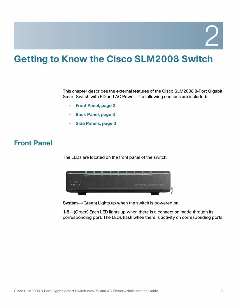
The LEDs are located on the front panel of the switch.
System—(Green) Lights up when the switch is powered on.
1-8—(Green) Each LED lights up when there is a connection made through its
corresponding port. The LEDs flash when there is activity on corresponding ports.
Cisco SLM2008 8-Port Gigabit Smart Switch with PD and AC Power Administration Guide 2

Getting to Know the Cisco SLM2008 Switch
Back Panel 2
Back Panel
The Ethernet ports are located on the back panel of the switch.
Port 1—This port supports the IEEE 802.3af Power-over-Ethernet (PoE) PD
standard, which enables a system to receive data and supply electrical power to
the switch over a standard twisted-pair cable in an Ethernet network. Any 802.3af-
compliant PSE device, such as a PoE switch, can directly supply power to the
switch. Simply connect a standard twisted-pair cable from a PoE switch to Port 1
on the switch. Using PoE to power the switch eliminates the need to use the power
adapter and AC power.
To connect a device to a port, use a Category 5 network cable.
Ports 1-8—These RJ-45 ports support network speeds of either 10 Mbps,
100 Mbps, or 1000 Mbps and can operate in half and full-duplex modes. Auto-
sensing technology enables each port to automatically detect the speed of the
device connected to it and adjust its speed and duplex accordingly.
Side Panels
The reset button and power port are located on the right side panel of the switch.
Cisco SLM2008 8-Port Gigabit Smart Switch with PD and AC Power Administration Guide 3
Getting to Know the Cisco SLM2008 Switch
Side Panels 2
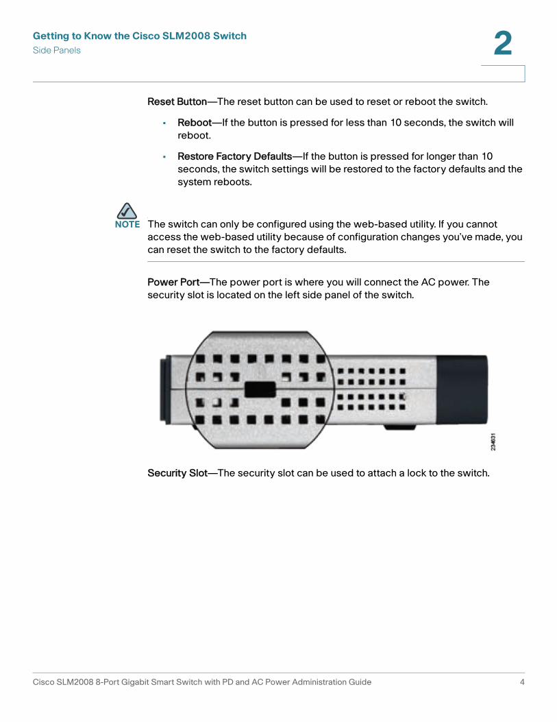
Reset Button—The reset button can be used to reset or reboot the switch.
• Reboot—If the button is pressed for less than 10 seconds, the switch will
reboot.
• Restore Factory Defaults—If the button is pressed for longer than 10
seconds, the switch settings will be restored to the factory defaults and the
system reboots.
NOTE The switch can only be configured using the web-based utility. If you cannot
access the web-based utility because of configuration changes you’ve made, you
can reset the switch to the factory defaults.
Power Port—The power port is where you will connect the AC power. The
security slot is located on the left side panel of the switch.
Security Slot—The security slot can be used to attach a lock to the switch.
Cisco SLM2008 8-Port Gigabit Smart Switch with PD and AC Power Administration Guide 4

3
Connecting the Cisco SLM2008 Switch
This chapter will guide you through the hardware installation for the Cisco
SLM2008 8-Port Gigabit Smart Switch with PD and AC Power. The following
sections are included:
• Placement Options, page 5
• Connecting the Cisco SLM2008 Switch to the Network, page 7
Placement Options
When you choose a location for the switch, observe the following guidelines:
• Make sure that the switch is accessible and that the cables can be easily
connected.
• Keep cabling away from sources of electrical noise, power lines, and
fluorescent lighting fixtures.
• Position the switch away from water and moisture sources.
• To ensure adequate air flow around the switch, be sure to provide a
minimum clearance of two inches (50 mm).
• Do not stack free-standing switches more than four units high.
Desktop Option
For desktop acement, set the Cisco SLM2008 switch horizontally on a surface so
that it sits on its four rubber feet.
Cisco SLM2008 8-Port Gigabit Smart Switch with PD and AC Power Administration Guide 5
Connecting the Cisco SLM2008 Switch
Placement Options 3
Wall-Mount Option
NOTE You will need two suitable screws to mount the switch. Cisco is not responsible for
damages incurred by insecure wall-mounting hardware.
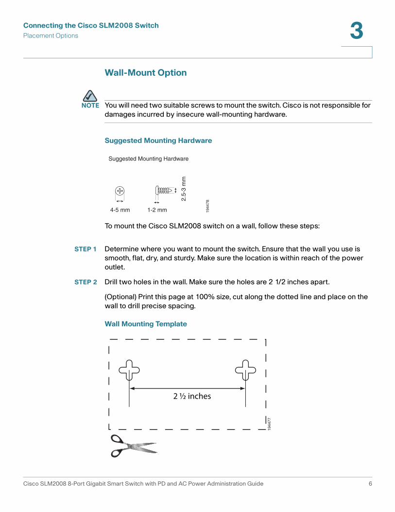
Suggested Mounting Hardware
To mount the Cisco SLM2008 switch on a wall, follow these steps:
STEP 1 Determine where you want to mount the switch. Ensure that the wall you use is
smooth, flat, dry, and sturdy. Make sure the location is within reach of the power
outlet.
STEP 2 Drill two holes in the wall. Make sure the holes are 2 1/2 inches apart.
(Optional) Print this page at 100% size, cut along the dotted line and place on the
wall to drill precise spacing.
Wall Mounting Template
4-5 mm 1-2 mm
2.5-
3 m
m
Suggested Mounting Hardware
1944
78
2 ½ inches
1944
77
Cisco SLM2008 8-Port Gigabit Smart Switch with PD and AC Power Administration Guide 6
Connecting the Cisco SLM2008 Switch
Connecting the Cisco SLM2008 Switch to the Network 3
STEP 3 Insert a screw into each hole and leave 3 mm of its head exposed.
STEP 4 The wall-mount slots are two crisscross slots on the bottom panel of the switch.
The wall-mount slots on the switch line up with the two screws.
STEP 5 Maneuver the switch to insert the screws into the two slots.
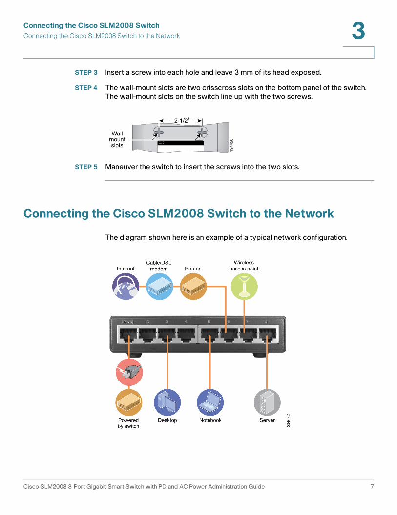
Connecting the Cisco SLM2008 Switch to the Network
The diagram shown here is an example of a typical network configuration.19
4450
Wallmountslots
2-1/2
Cisco SLM2008 8-Port Gigabit Smart Switch with PD and AC Power Administration Guide 7

Connecting the Cisco SLM2008 Switch
Connecting the Cisco SLM2008 Switch to the Network 3
NOTE When you connect your network devices, make sure you do not exceed the
maximum cabling distance of 328 feet (100 meters).
To connect network devices to the switch, follow these steps:
STEP 1 Make sure all the devices you will connect to the switch are powered off.
STEP 2 Connect a Category 5 network cable to one of the numbered ports on the switch.
NOTE Reserve Port 1 if you are using a network device to provide power to the
switch.
STEP 3 Connect the other end to a computer or other network device.
STEP 4 Repeat Step 1, Step 2, and Step 3 to connect additional devices.
NOTE When connecting power, always use a surge protector.
STEP 5 Provide power to the switch in one of two ways:
• Connect a Category 5 network cable from port 1 of the switch to a network
device with the ability to provide Power over Ethernet.
Or
• Connect the supplied power cord to the switch power port, and plug the
other end into an electrical outlet.
STEP 6 Power on the devices connected to the switch. Each active port with a
corresponding LED will light up on the switch.
For information about configuring and managing the switch, see Chapter 5,
“Advanced Configuration.”
Cisco SLM2008 8-Port Gigabit Smart Switch with PD and AC Power Administration Guide 8
4
Setting Up the Cisco SLM2008 Switch
This chapter describes how to configure the Cisco SLM2008 8-Port Gigabit Smart
Switch with PD and AC Power using the web-based configuration utility. The
following sections are included:
• Launching the Web-Based Configuration Utility, page 9
• Navigating the Utility, page 10
Launching the Web-Based Configuration Utility
To configure the Cisco SLM2008 switch, follow these steps to access the web-
based configuration utility from your computer:
STEP 1 Connect your computer to the same network the Cisco SLM2008 switch is
connected to.
STEP 2 Make sure your computer is on the same subnet as the switch (192.168.1.x).
By default, the Cisco SLM2008 switch has an IP address of 192.168.1.254 and a
default subnet mask of 255.255.255.0.
STEP 3 Launch a web browser, such as Internet Explorer or Mozilla Firefox.
STEP 4 In the Address field, enter 192.168.1.254 and press Enter.
NOTE The default IP address is 192.168.1.254. If the IP address has been changed,
enter the assigned IP address instead of the default.
STEP 5 Press Enter. The web-based utility login window appears.
Cisco SLM2008 8-Port Gigabit Smart Switch with PD and AC Power Administration Guide 9
Setting Up the Cisco SLM2008 Switch
Navigating the Utility 4
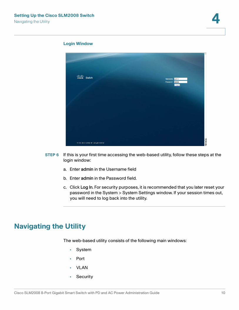
Login Window
STEP 6 If this is your first time accessing the web-based utility, follow these steps at the
login window:
a. Enter admin in the Username field
b. Enter admin in the Password field.
c. Click Log In. For security purposes, it is recommended that you later reset your
password in the System > System Settings window. If your session times out,
you will need to log back into the utility.
Navigating the Utility
The web-based utility consists of the following main windows:
• System
• Port
• VLAN
• Security
Cisco SLM2008 8-Port Gigabit Smart Switch with PD and AC Power Administration Guide 10
Setting Up the Cisco SLM2008 Switch
Navigating the Utility 4
• QoS
• STP
• Statistics
• Multicast
• Admin
System
The System Settings window is the first window displayed when you log in.
• System Settings—Displays a summary of switch information.
Port
This window allows you to manage port settings for the switch.
• Port Settings—Manually configure the speed, duplex, and flow control
settings used on specific ports.
• Static Link Aggregation—Create multiple links between devices that work
as one virtual, aggregate link (LAG).
• LACP Settings—Configure Link Aggregation Control Protocol (LACP)
settings.
• LACP Status—Displays LACP status port information.
VLAN
This window allows you to create VLANs and also manage VLAN settings.
• VLAN Settings—Create or delete a VLAN.
• VLAN Port Settings—Configure VLAN behavior for specific interfaces,
including the mode, accepted frame type, VLAN identifier (PVID), and
ingress filtering.
Security
This window allows you to configure the switch’s security settings.
Cisco SLM2008 8-Port Gigabit Smart Switch with PD and AC Power Administration Guide 11
Setting Up the Cisco SLM2008 Switch
Navigating the Utility 4
• 802.1X Settings—Configure security settings that include 802.1X mode,
RADIUS IP, Radius UDP port, key string or Admin State authentication mode.
• 802.1X Parameter—Enable re-authentication and configure the re-
authentication period or EAP timeout.
• Static MAC Address—Allows you to configure a switch port with the MAC
address of one or more devices that are authorized to access the network
through that port.
• Management Access List—Specifies which Source IP addresses can
manage the device.
• Storm Control—Configure the maximum rate (packets per second) at
which unknown packets are forwarded.
QoS
This window allows you to priortize network traffic and optimize network
performance using Quality of Service (QoS) settings.
• Queue Mode—Set the queue mode priority.
• QoS Mode—Configure the QoS mode settings including QoS disabled,
802.1p, port based, or Differentiated Services Code Point (DSCP).
STP
This window you to configure and view STP settings.
• STP Settings—Configure STP settings including system priority, hello time,
max age, and forward delay.
• STP Status—Displays the current STP status.
Statistics
This window displays statistics and IGMP status.
• Statistics Overview—Displays standard statistics on network traffic for
each port of the device.
• IGMP Status—Displays the IGMP status for each VLAN interface.
Cisco SLM2008 8-Port Gigabit Smart Switch with PD and AC Power Administration Guide 12
Setting Up the Cisco SLM2008 Switch
Navigating the Utility 4
Multicast
This window displays the multicast settings for the switch.
• IGMP Settings—Configure functions that include Enable IGMP Snooping,
Enable Unregistered IP Multicast Flooding, and Enable IGMP Querying.
Admin
This window allows you to manage the switch.
• Ping—Use to see if another site on the network can be reached.
• Port Mirror—Mirror traffic from any source port to a target port for real-
time analysis.
• Factory Default—Resets the switch to its factory default settings.
• Reboot—Reboots the switch.
• Save Configuration—Saves the current switch configuration.
• Firmware Upgrade—Upgrades the switch’s firmware on this window.
Cisco SLM2008 8-Port Gigabit Smart Switch with PD and AC Power Administration Guide 13
5
Advanced Configuration
This chapter describes how to configure the Cisco SLM2008 8-Port Gigabit Smart
Switch with PD and AC Power using the web-based configuration utility.
Setup
The first window displayed upon login is the System Settings window. There are
nine options displayed in the left panel: System, Port, VLAN, Security, QoS, STP,
Statistics, Multicast, and Admin. Each option contains windows that will help you
configure and manage the switch.
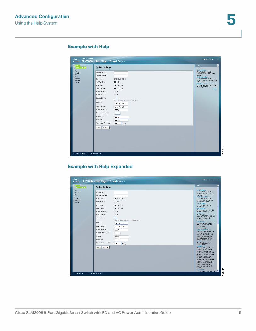
Using the Help System
The switch software includes detailed Help files for all configuration tasks. To view
a Help page, click the Help link in the top right corner of the window. A new
window appears with information about the task that you are currently viewing.
Cisco SLM2008 8-Port Gigabit Smart Switch with PD and AC Power Administration Guide 14
Advanced Configuration
Using the Help System 5
Example with Help
Example with Help Expanded
Cisco SLM2008 8-Port Gigabit Smart Switch with PD and AC Power Administration Guide 15
Advanced Configuration
System 5
System
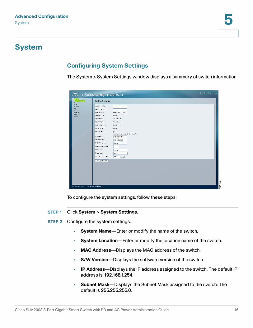
Configuring System Settings
The System > System Settings window displays a summary of switch information.
To configure the system settings, follow these steps:
STEP 1 Click System > System Settings.
STEP 2 Configure the system settings.
• System Name—Enter or modify the name of the switch.
• System Location—Enter or modify the location name of the switch.
• MAC Address—Displays the MAC address of the switch.
• S/W Version—Displays the software version of the switch.
• IP Address—Displays the IP address assigned to the switch. The default IP
address is 192.168.1.254.
• Subnet Mask—Displays the Subnet Mask assigned to the switch. The
default is 255.255.255.0.
Cisco SLM2008 8-Port Gigabit Smart Switch with PD and AC Power Administration Guide 16
Advanced Configuration
System 5
• Default Gateway—Displays the IP address of the gateway between this
device and management stations that exist on other network segments. The
default value is 0.0.0.0.
• DHCP Server—The IP address of the DHCP server.
• Enable DHCP—When enabled, the switch will attempt to obtain an IP
address from a DHCP server on your network. If an IP address is not
obtained, the switch will use the IP address defined in the IP Address field
below.
• IP Address—Enter or modify the IP address assigned to the switch. The
default IP address is 192.168.1.254.
NOTE If the static IP address is changed, the switch will automatically log you out
of the web-based utility. To log back in, you must use the new static IP
address.
• Subnet Mask—Enter or modify the Subnet Mask assigned to the switch.
The default is 255.255.255.0.
• Default Gateway—Modify the IP address of the gateway. The default is
0.0.0.0.
• Management VLAN—Enter the ID of the configured VLAN (1-4094, no
leading zeroes). By default, all ports on the switch are members of VLAN 1.
However, the management station can be attached to a port belonging to
any VLAN, as long as that VLAN has been assigned an IP address.
• Username—Specify the username. The default username is admin. Only
one admin user is allowed.
• Password—Enter a new password. The password is not displayed as it is
entered. Each character is displayed as a bullet in the password field.
• Web Admin Timeout (secs)—As a security measure, the web-based utility
will timeout after being idle for the amount of time defined in this field. If the
switch is idle for the amount of time defined here, login is required to return
to the web-based utility. The time is entered in seconds. The default value is
300 seconds.
STEP 3 Click Save.
Cisco SLM2008 8-Port Gigabit Smart Switch with PD and AC Power Administration Guide 17
Advanced Configuration
Port 5
STEP 4 Reboot the switch by going to the Admin > Reboot window. From there, click
Reboot.
Port
This section describes how to configure the port settings of the switch.
• Configuring Port Settings, page 18
• Configuring Static Link Aggregation, page 20
• Configuring LACP Settings, page 21
• Displaying LACP Status, page 23
Configuring Port Settings
You can manually configure the speed, duplex, and flow control settings used on
specific ports, or use autonegotiation to allow the switch to autodetect the
connection settings used by the attached device. Full-duplex mode should be
used on ports whenever possible to double the throughput of switch connections.
Flow control should also be enabled to control network traffic during periods of
congestion and prevent the loss of packets when port buffer thresholds are
exceeded. The switch supports flow control based on the IEEE 802.3x standard.
Cisco SLM2008 8-Port Gigabit Smart Switch with PD and AC Power Administration Guide 18
Advanced Configuration
Port 5
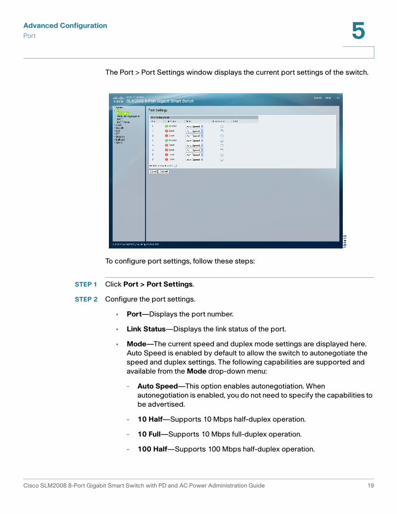
The Port > Port Settings window displays the current port settings of the switch.
To configure port settings, follow these steps:
STEP 1 Click Port > Port Settings.
STEP 2 Configure the port settings.
• Port—Displays the port number.
• Link Status—Displays the link status of the port.
• Mode—The current speed and duplex mode settings are displayed here.
Auto Speed is enabled by default to allow the switch to autonegotiate the
speed and duplex settings. The following capabilities are supported and
available from the Mode drop-down menu:
- Auto Speed—This option enables autonegotiation. When
autonegotiation is enabled, you do not need to specify the capabilities to
be advertised.
- 10 Half—Supports 10 Mbps half-duplex operation.
- 10 Full—Supports 10 Mbps full-duplex operation.
- 100 Half—Supports 100 Mbps half-duplex operation.
Cisco SLM2008 8-Port Gigabit Smart Switch with PD and AC Power Administration Guide 19
Advanced Configuration
Port 5
- 100 Full—Supports 100 Mbps full-duplex operation.
- 1000 Full—Supports 1000 Mbps full-duplex operation.
- Disabled—Disables the port.
• Flow Control—Check this check box to enable flow control.
• LAG—Indicates whether the port is a LAG member.
• Enable Jumbo Frames—Check this check box to enable Jumbo Frame
support (up to 9 KB).
STEP 3 Click Save.
Configuring Static Link Aggregation
You can create multiple links between devices that work as one virtual, aggregate
link (LAG). An aggregated link offers a dramatic increase in bandwidth for network
segments where bottlenecks exist, as well as providing a fault-tolerant link
between two devices. You can create up to two LAGs on the switch. Each LAG
can contain up to eight ports.
Cisco SLM2008 8-Port Gigabit Smart Switch with PD and AC Power Administration Guide 20
Advanced Configuration
Port 5
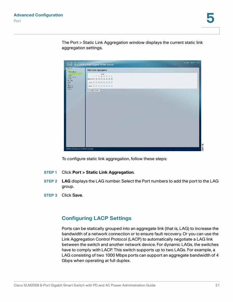
The Port > Static Link Aggregation window displays the current static link
aggregation settings.
To configure static link aggregation, follow these steps:
STEP 1 Click Port > Static Link Aggregation.
STEP 2 LAG displays the LAG number. Select the Port numbers to add the port to the LAG
group.
STEP 3 Click Save.
Configuring LACP Settings
Ports can be statically grouped into an aggregate link (that is, LAG) to increase the
bandwidth of a network connection or to ensure fault recovery. Or you can use the
Link Aggregation Control Protocol (LACP) to automatically negotiate a LAG link
between the switch and another network device. For dynamic LAGs, the switches
have to comply with LACP. This switch supports up to two LAGs. For example, a
LAG consisting of two 1000 Mbps ports can support an aggregate bandwidth of 4
Gbps when operating at full duplex.
Cisco SLM2008 8-Port Gigabit Smart Switch with PD and AC Power Administration Guide 21
Advanced Configuration
Port 5
To avoid creating a loop in the network, be sure you enable LACP before
connecting the ports, and also disconnect the ports before disabling LACP.
NOTE LAG port members will have to be configured with the same speed and
duplex mode. A user must ensure the LAG member’s ports have the same
speed and duplex settings before activating an LACP group.
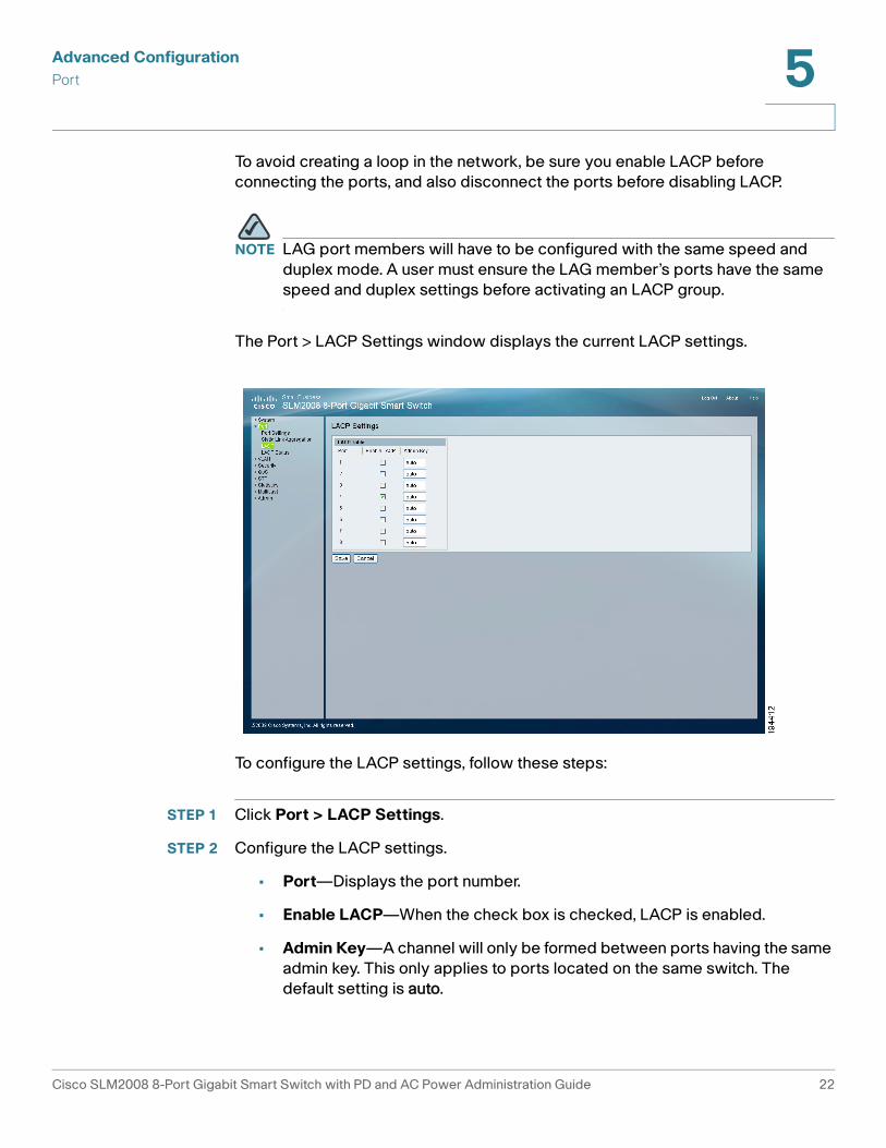
The Port > LACP Settings window displays the current LACP settings.
To configure the LACP settings, follow these steps:
STEP 1 Click Port > LACP Settings.
STEP 2 Configure the LACP settings.
• Port—Displays the port number.
• Enable LACP—When the check box is checked, LACP is enabled.
• Admin Key—A channel will only be formed between ports having the same
admin key. This only applies to ports located on the same switch. The
default setting is auto.
Cisco SLM2008 8-Port Gigabit Smart Switch with PD and AC Power Administration Guide 22

Advanced Configuration
Port 5
STEP 3 Click Save.
Displaying LACP Status
From the Port > LACP Status window, you can see the LACP status for each port,
its partner port number, and operational port key.
To display LACP status, follow these steps:
STEP 1 Click Port > LACP Status.
The following information is displayed:
• LACP Port Status—LACP Status on each interface since the device was
last refreshed.
• Protocol Active—Indicates if the LACP is disabled or enabled on the
interface.
• Partner Port Number—Indicates the port that is in the same LAG group.
• Operational Port Key—A channel will only be formed between ports
having the same operational port key. This only applies to ports located on
the same switch.
Cisco SLM2008 8-Port Gigabit Smart Switch with PD and AC Power Administration Guide 23

Advanced Configuration
VLAN 5
STEP 2 Click Refresh to update the status information.
VLAN
This section describes how to configure the VLAN settings for the switch:
• Configuring VLAN Settings, page 24
• Configuring VLAN Port Settings, page 25
Configuring VLAN Settings
A VLAN is a group of ports that can be located anywhere in the network, but
communicate as though they belong to the same physical segment. VLANs help to
simplify network management by allowing you to move devices to a new VLAN
without having to change any physical connections. VLANs can be easily
organized to reflect departmental groups (such as Marketing or R&D), usage
groups (such as e-mail), or multicast groups (used for multimedia applications such
as videoconferencing). You can create up to 16 VLANs on the switch.
To create a single VLAN, enter the VLAN ID and click Add. Use the VLAN ID
window to configure port members or LAG members for a specific VLAN index.
Cisco SLM2008 8-Port Gigabit Smart Switch with PD and AC Power Administration Guide 24
Advanced Configuration
VLAN 5
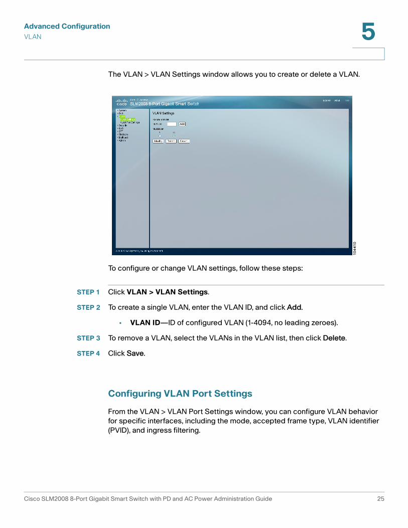
The VLAN > VLAN Settings window allows you to create or delete a VLAN.
To configure or change VLAN settings, follow these steps:
STEP 1 Click VLAN > VLAN Settings.
STEP 2 To create a single VLAN, enter the VLAN ID, and click Add.
• VLAN ID—ID of configured VLAN (1-4094, no leading zeroes).
STEP 3 To remove a VLAN, select the VLANs in the VLAN list, then click Delete.
STEP 4 Click Save.
Configuring VLAN Port Settings
From the VLAN > VLAN Port Settings window, you can configure VLAN behavior
for specific interfaces, including the mode, accepted frame type, VLAN identifier
(PVID), and ingress filtering.
Cisco SLM2008 8-Port Gigabit Smart Switch with PD and AC Power Administration Guide 25
Advanced Configuration
VLAN 5
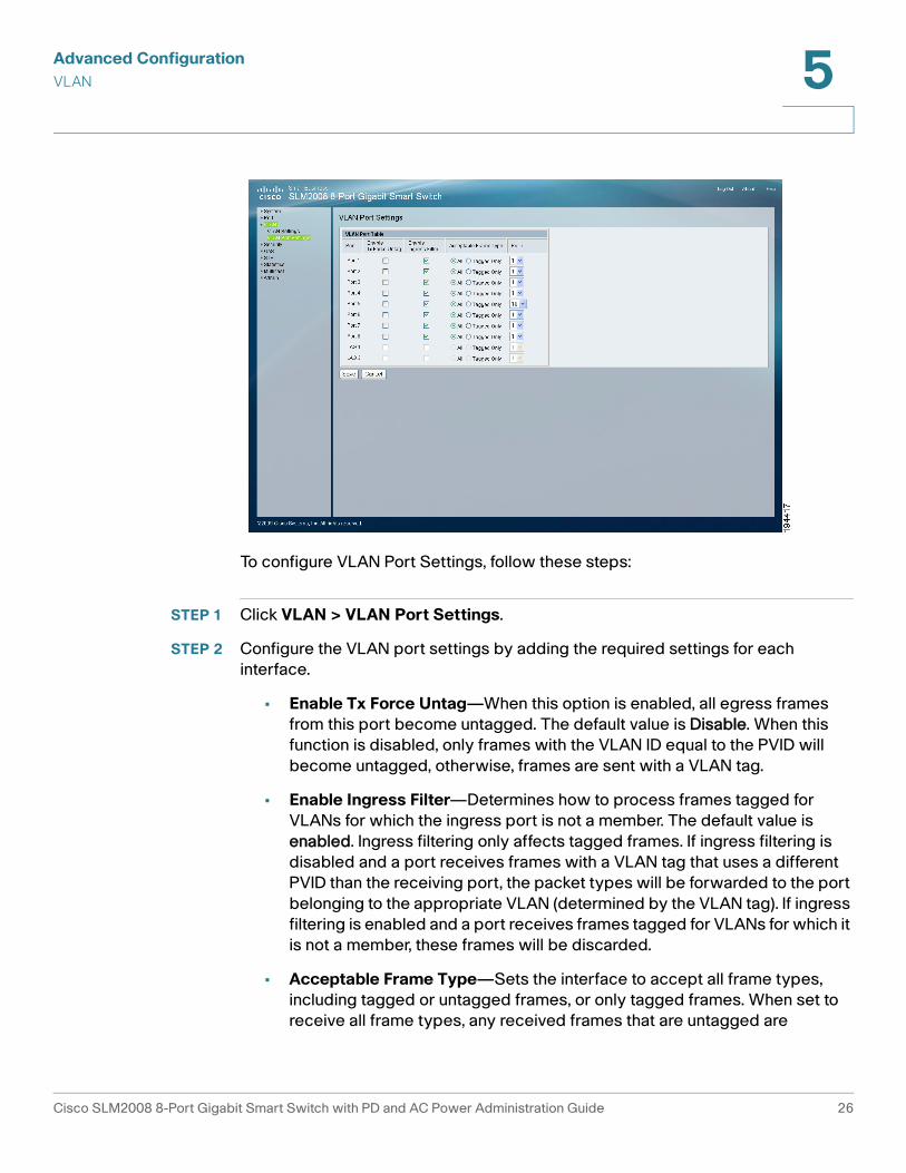
To configure VLAN Port Settings, follow these steps:
STEP 1 Click VLAN > VLAN Port Settings.
STEP 2 Configure the VLAN port settings by adding the required settings for each
interface.
• Enable Tx Force Untag—When this option is enabled, all egress frames
from this port become untagged. The default value is Disable. When this
function is disabled, only frames with the VLAN ID equal to the PVID will
become untagged, otherwise, frames are sent with a VLAN tag.
• Enable Ingress Filter—Determines how to process frames tagged for
VLANs for which the ingress port is not a member. The default value is
enabled. Ingress filtering only affects tagged frames. If ingress filtering is
disabled and a port receives frames with a VLAN tag that uses a different
PVID than the receiving port, the packet types will be forwarded to the port
belonging to the appropriate VLAN (determined by the VLAN tag). If ingress
filtering is enabled and a port receives frames tagged for VLANs for which it
is not a member, these frames will be discarded.
• Acceptable Frame Type—Sets the interface to accept all frame types,
including tagged or untagged frames, or only tagged frames. When set to
receive all frame types, any received frames that are untagged are
Cisco SLM2008 8-Port Gigabit Smart Switch with PD and AC Power Administration Guide 26
Advanced Configuration
Security 5
forwarded to the VLAN based on the PVID of its ingress port. All frame
types are selected by default.
• PVID (Port VLAN identifier)—VLAN ID assigned to untagged frames
received on the interface. The default value is 1. For all other VLANs, an
interface must first be configured as an untagged member before you can
assign its PVID to that group.
STEP 3 Click Save.
Security
This section describes how to configure the security settings for the switch.
• Configuring 802.1X Settings, page 27
• Configuring 802.1X Parameter, page 30
• Configuring Static MAC Address, page 32
• Configuring Management Access List, page 33
• Configuring Storm Control, page 34
Configuring 802.1X Settings
Network switches can provide open and easy access to network resources by
simply attaching a client PC. Although this automatic configuration and access is a
desirable feature, it also allows unauthorized personnel to easily intrude and
possibly gain access to sensitive network data.
The IEEE 802.1X (dot1X) standard defines a port-based access control procedure
that prevents unauthorized access to a network by requiring users to first submit
credentials for authentication. Access to all switch ports in a network can be
centrally controlled from a server, which means that authorized users can use the
same credentials for authentication from any point within the network.
The Cisco SLM2008 switch uses the Extensible Authentication Protocol over
LANs (EAPOL) to exchange authentication protocol messages with the client, and
a remote RADIUS authentication server to verify user identity and access rights.
When a client connects to a switch port, the switch responds with an EAPOL
identity request. The client provides its identity (such as a user name) in an EAPOL
Cisco SLM2008 8-Port Gigabit Smart Switch with PD and AC Power Administration Guide 27

Advanced Configuration
Security 5
response to the switch, which it forwards to the RADIUS server. The RADIUS
server verifies the client identity and sends an access challenge back to the client.
The EAP packet from the RADIUS server contains not only the challenge, but the
authentication method to be used. The client can reject the authentication method
and request another, depending on the configuration of the client software and the
RADIUS server. The authentication method must be MD5. The client responds to
the appropriate method with its credentials, such as a password or certificate. The
RADIUS server verifies the client credentials and responds with an accept or
reject packet. If authentication is successful, the switch allows the client to access
the network. Otherwise, network access is denied and the port remains blocked.
The operation of 802.1X on the Cisco SLM2008 switch requires the following:
• The switch must have an IP address assigned.
• RADIUS authentication must be enabled on the switch and the IP address of
the RADIUS server specified.
• 802.1X must be enabled globally for the switch.
• Each switch port that will be used must be set to dot1X “Auto” mode.
• Each client that needs to be authenticated must have dot1X client software
installed and properly configured.
• The RADIUS server and 802.1X client support EAP. (The switch only
supports EAPOL in order to pass the EAP packets from the server to the
client.)
• The RADIUS server and client also have to support the same EAP
authentication type – MD5. (Some clients have native support in Windows,
otherwise the dot1x client must support it.)
Cisco SLM2008 8-Port Gigabit Smart Switch with PD and AC Power Administration Guide 28
Advanced Configuration
Security 5
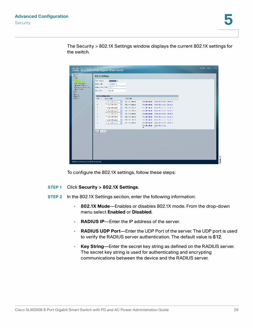
The Security > 802.1X Settings window displays the current 802.1X settings for
the switch.
To configure the 802.1X settings, follow these steps:
STEP 1 Click Security > 802.1X Settings.
STEP 2 In the 802.1X Settings section, enter the following information:
• 802.1X Mode—Enables or disables 802.1X mode. From the drop-down
menu select Enabled or Disabled.
• RADIUS IP—Enter the IP address of the server.
• RADIUS UDP Port—Enter the UDP Port of the server. The UDP port is used
to verify the RADIUS server authentication. The default value is 812.
• Key String—Enter the secret key string as defined on the RADIUS server.
The secret key string is used for authenticating and encrypting
communications between the device and the RADIUS server.
Cisco SLM2008 8-Port Gigabit Smart Switch with PD and AC Power Administration Guide 29
Advanced Configuration
Security 5
STEP 3 In the 802.1X Setting Table section, select the following:
• Admin State—Select one of the following options from the drop-down
menu to set the authentication mode:
- Auto—Requires a dot1x-aware client to be authorized by the
authentication server. Clients that are not dot1x-aware will be denied
access.
- Force-Authorized—Forces the port to grant access to all clients, either
dot1x-aware or otherwise. (This is the default setting.)
- Force-Unauthorized—Forces the port to deny access to all clients,
either dot1x-aware or otherwise.
• Port State—Displays the state of the 802.1X for each port.
• Re-authenticate—It will trigger the switch to ask a connected client to
restart authentication process.
• Force Reinitialize—It will trigger the specific port of the switch to restart
802.1X process.
• Statistics—The switch can display statistics for 802.1X protocol exchanges
for any port.
STEP 4 Click Save.
Configuring 802.1X Parameter
When 802.1X is enabled, you need to configure the parameters for the
authentication process that runs between the client and the Cisco SLM2008
switch. The client identity lookup process that runs between the switch and
authentication server also needs to be configured. These parameters are
described in this section.
Cisco SLM2008 8-Port Gigabit Smart Switch with PD and AC Power Administration Guide 30
Advanced Configuration
Security 5
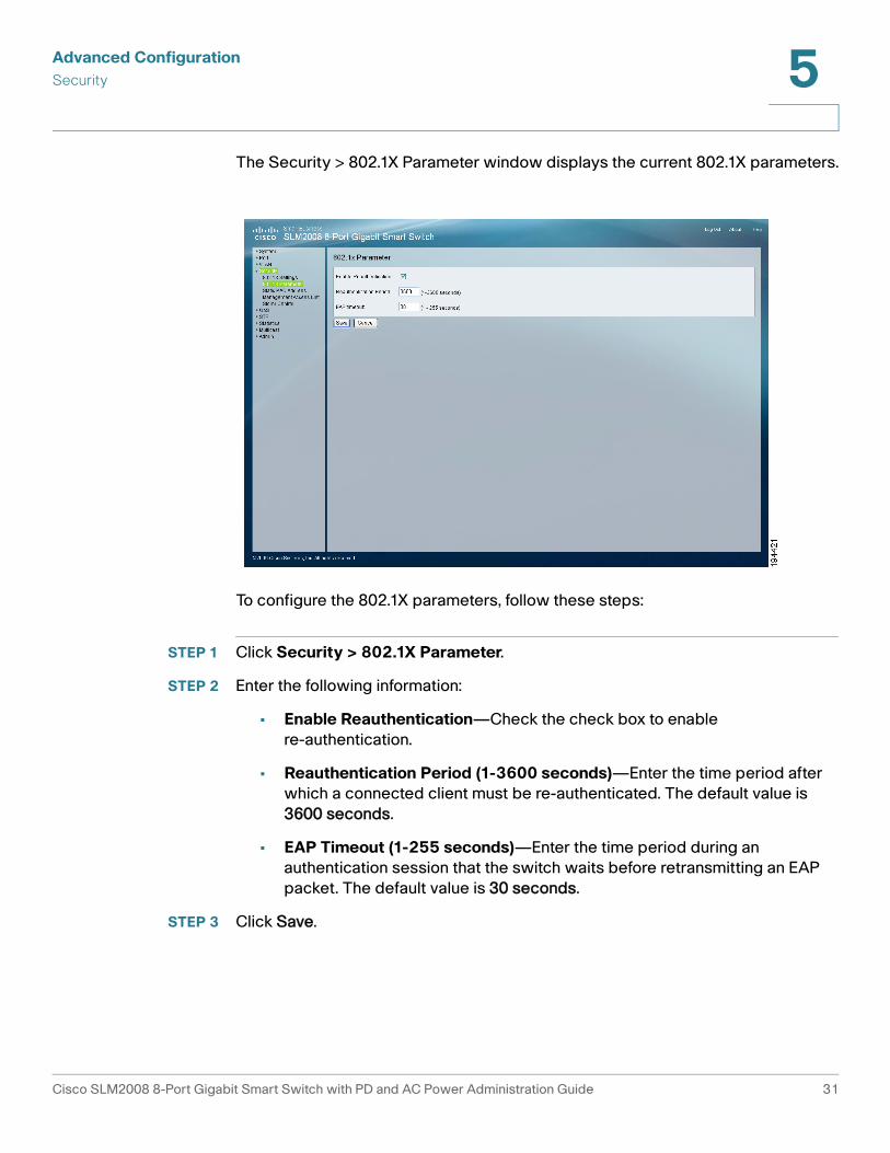
The Security > 802.1X Parameter window displays the current 802.1X parameters.
To configure the 802.1X parameters, follow these steps:
STEP 1 Click Security > 802.1X Parameter.
STEP 2 Enter the following information:
• Enable Reauthentication—Check the check box to enable
re-authentication.
• Reauthentication Period (1-3600 seconds)—Enter the time period after
which a connected client must be re-authenticated. The default value is
3600 seconds.
• EAP Timeout (1-255 seconds)—Enter the time period during an
authentication session that the switch waits before retransmitting an EAP
packet. The default value is 30 seconds.
STEP 3 Click Save.
Cisco SLM2008 8-Port Gigabit Smart Switch with PD and AC Power Administration Guide 31
Advanced Configuration
Security 5
Configuring Static MAC Address
Static MAC Address allows you to configure a switch port with the MAC address
of one or more devices that are authorized to access the network through that
port. The MAC address is bound to the ingress port specified on the list and does
not allow the MAC address to change ports. Only incoming traffic with source
addresses already stored in the static address table will be accepted as
authorized to access the network through that port. MAC addresses on the list do
not age out.
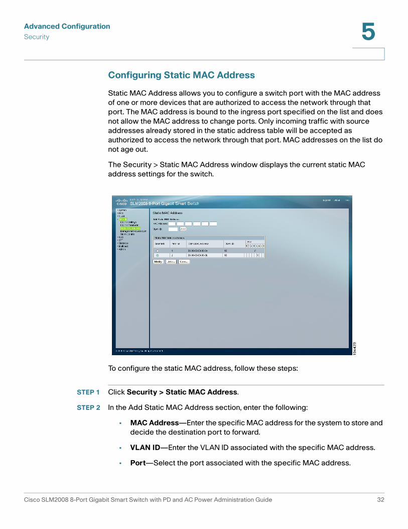
The Security > Static MAC Address window displays the current static MAC
address settings for the switch.
To configure the static MAC address, follow these steps:
STEP 1 Click Security > Static MAC Address.
STEP 2 In the Add Static MAC Address section, enter the following:
• MAC Address—Enter the specific MAC address for the system to store and
decide the destination port to forward.
• VLAN ID—Enter the VLAN ID associated with the specific MAC address.
• Port—Select the port associated with the specific MAC address.
Cisco SLM2008 8-Port Gigabit Smart Switch with PD and AC Power Administration Guide 32
Advanced Configuration
Security 5
STEP 3 Click Save.
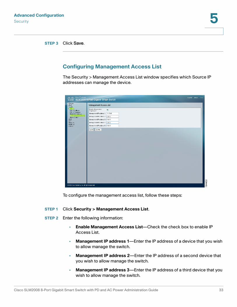
Configuring Management Access List
The Security > Management Access List window specifies which Source IP
addresses can manage the device.
To configure the management access list, follow these steps:
STEP 1 Click Security > Management Access List.
STEP 2 Enter the following information:
• Enable Management Access List—Check the check box to enable IP
Access List.
• Management IP address 1—Enter the IP address of a device that you wish
to allow manage the switch.
• Management IP address 2—Enter the IP address of a second device that
you wish to allow manage the switch.
• Management IP address 3—Enter the IP address of a third device that you
wish to allow manage the switch.
Cisco SLM2008 8-Port Gigabit Smart Switch with PD and AC Power Administration Guide 33
Advanced Configuration
Security 5
• Management IP address 4—Enter the IP address of a fourth device that
you wish to allow manage the switch.
• Management IP address 5—Enter the IP address of a fifth device that you
wish to allow manage the switch.
STEP 3 Click Save.
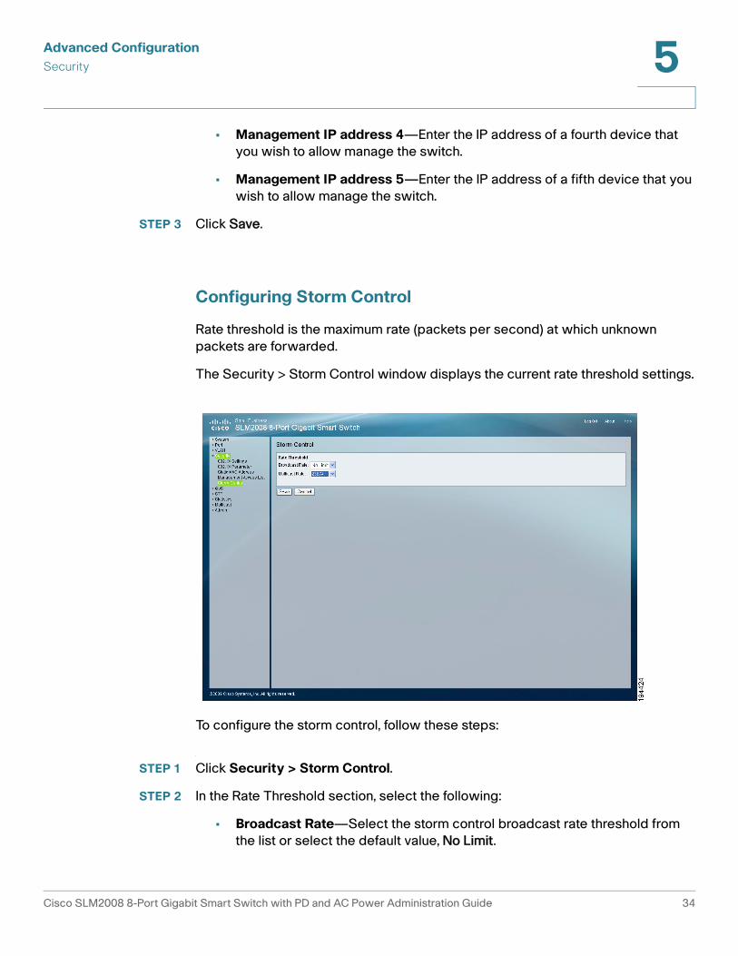
Configuring Storm Control
Rate threshold is the maximum rate (packets per second) at which unknown
packets are forwarded.
The Security > Storm Control window displays the current rate threshold settings.
To configure the storm control, follow these steps:
STEP 1 Click Security > Storm Control.
STEP 2 In the Rate Threshold section, select the following:
• Broadcast Rate—Select the storm control broadcast rate threshold from
the list or select the default value, No Limit.
Cisco SLM2008 8-Port Gigabit Smart Switch with PD and AC Power Administration Guide 34
Advanced Configuration
QoS 5
• Multicast Rate—Select the storm control multicast rate threshold from the
list or select the default value, No Limit.
STEP 3 Click Save.
QoS
Configuring QoS Settings
Network traffic is usually unpredictable and the only basic assurance that can be
offered is best effort traffic delivery. To overcome this challenge, QoS is applied
throughout the network. This ensures that network traffic is prioritized according
to specified criteria, and that specific traffic receives preferential treatment. QoS
in the network optimizes network performance and entails two basic facilities:
Classifying incoming traffic into handling classes, based on an attribute, including:
• The ingress interface
• Packet content
• A combination of these attributes
• Providing various mechanisms for determining the allocation of network
resources to different handling classes, including:
• The assignment of network traffic to a particular hardware queue
• The assignment of internal resources
You can set the switch to service the queues based on a strict rule that requires all
traffic in a higher priority queue to be processed before lower priority queues are
serviced, or use Weighted Round-Robin (WRR) queuing that specifies a relative
weight of each queue. WRR uses a pre-defined relative weight for each queue that
determines the percentage of service time the switch services each queue before
moving on to the next queue. This prevents the head-of-line blocking that can
occur with strict priority queuing.
Cisco SLM2008 8-Port Gigabit Smart Switch with PD and AC Power Administration Guide 35
Advanced Configuration
QoS 5
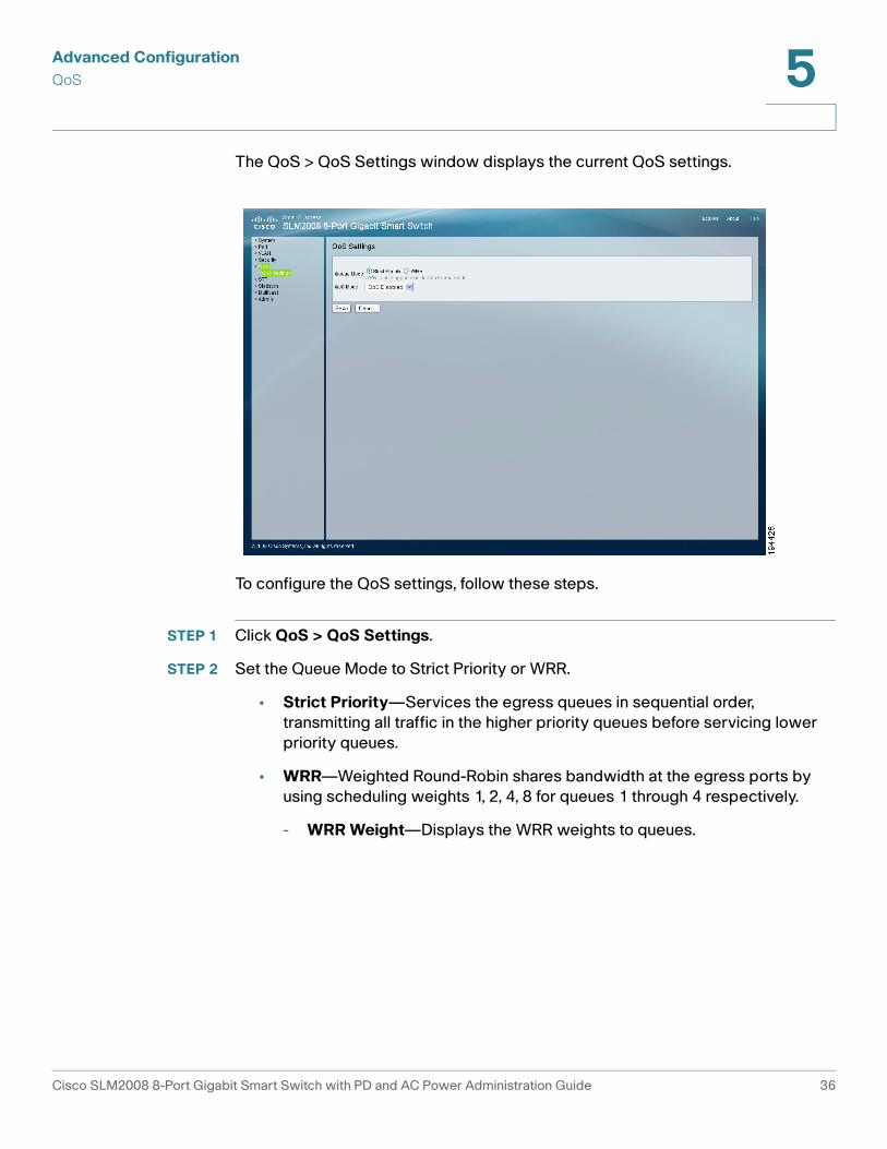
The QoS > QoS Settings window displays the current QoS settings.
To configure the QoS settings, follow these steps.
STEP 1 Click QoS > QoS Settings.
STEP 2 Set the Queue Mode to Strict Priority or WRR.
• Strict Priority—Services the egress queues in sequential order,
transmitting all traffic in the higher priority queues before servicing lower
priority queues.
• WRR—Weighted Round-Robin shares bandwidth at the egress ports by
using scheduling weights 1, 2, 4, 8 for queues 1 through 4 respectively.
- WRR Weight—Displays the WRR weights to queues.
Cisco SLM2008 8-Port Gigabit Smart Switch with PD and AC Power Administration Guide 36
Advanced Configuration
QoS 5
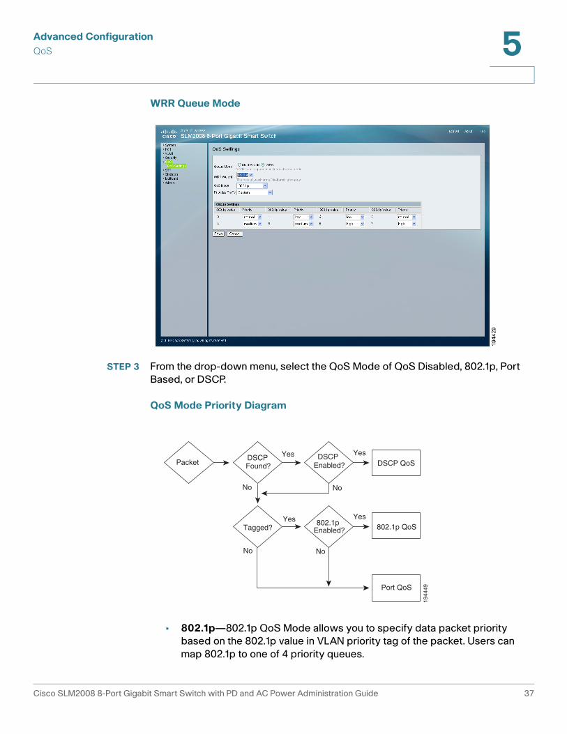
WRR Queue Mode
STEP 3 From the drop-down menu, select the QoS Mode of QoS Disabled, 802.1p, Port
Based, or DSCP.
QoS Mode Priority Diagram
• 802.1p—802.1p QoS Mode allows you to specify data packet priority
based on the 802.1p value in VLAN priority tag of the packet. Users can
map 802.1p to one of 4 priority queues.
802.1p Enabled? 802.1p QoS
YesYes
No
No
Port QoS
No
No
DSCP QoS
Yes Yes
Tagged?
DSCP Found?Packet
DSCP Enabled?
1944
49
Cisco SLM2008 8-Port Gigabit Smart Switch with PD and AC Power Administration Guide 37
Advanced Configuration
QoS 5
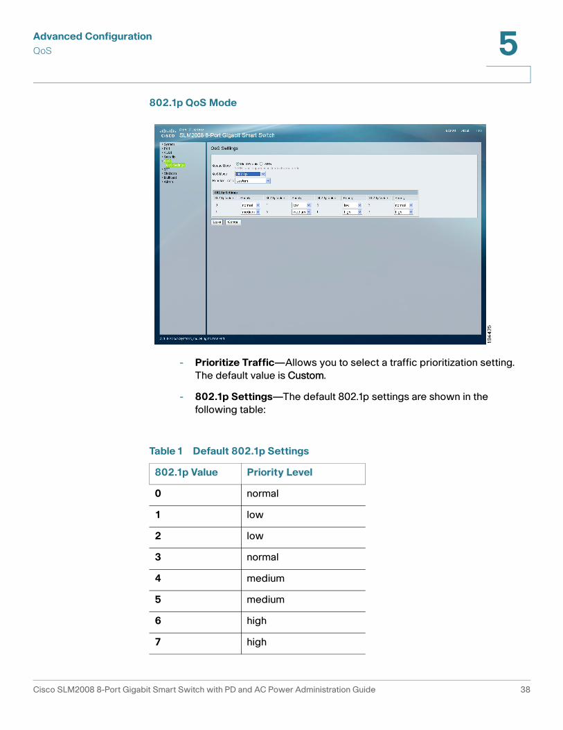
802.1p QoS Mode
- Prioritize Traffic—Allows you to select a traffic prioritization setting.
The default value is Custom.
- 802.1p Settings—The default 802.1p settings are shown in the
following table:
Table 1 Default 802.1p Settings
802.1p Value Priority Level
0 normal
1 low
2 low
3 normal
4 medium
5 medium
6 high
7 high
Cisco SLM2008 8-Port Gigabit Smart Switch with PD and AC Power Administration Guide 38
Advanced Configuration
QoS 5
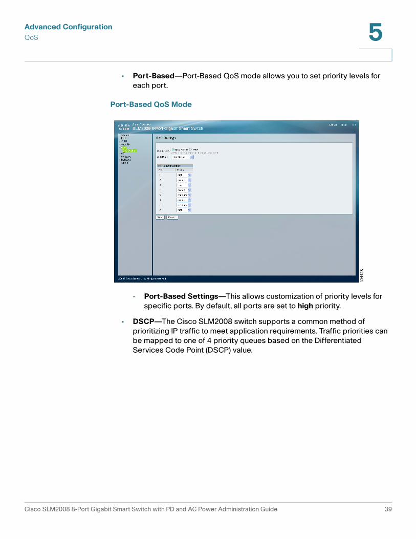
• Port-Based—Port-Based QoS mode allows you to set priority levels for
each port.
Port-Based QoS Mode
- Port-Based Settings—This allows customization of priority levels for
specific ports. By default, all ports are set to high priority.
• DSCP—The Cisco SLM2008 switch supports a common method of
prioritizing IP traffic to meet application requirements. Traffic priorities can
be mapped to one of 4 priority queues based on the Differentiated
Services Code Point (DSCP) value.
Cisco SLM2008 8-Port Gigabit Smart Switch with PD and AC Power Administration Guide 39
Advanced Configuration
QoS 5
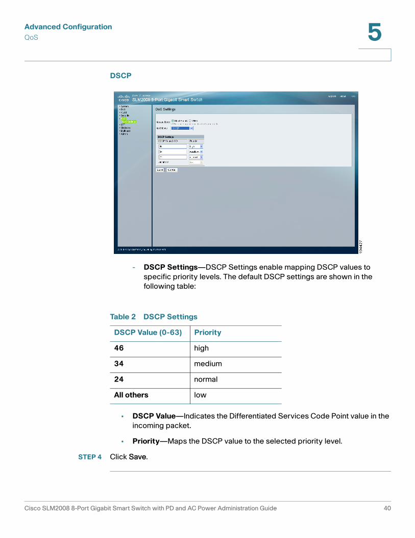
DSCP
- DSCP Settings—DSCP Settings enable mapping DSCP values to
specific priority levels. The default DSCP settings are shown in the
following table:
• DSCP Value—Indicates the Differentiated Services Code Point value in the
incoming packet.
• Priority—Maps the DSCP value to the selected priority level.
STEP 4 Click Save.
Table 2 DSCP Settings
DSCP Value (0-63) Priority
46 high
34 medium
24 normal
All others low
Cisco SLM2008 8-Port Gigabit Smart Switch with PD and AC Power Administration Guide 40
Advanced Configuration
STP 5
STP
This section describes configuring the STP settings.
• Configuring STP Settings, page 41
• Displaying STP Status, page 43
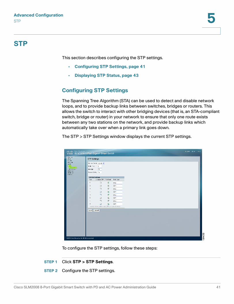
Configuring STP Settings
The Spanning Tree Algorithm (STA) can be used to detect and disable network
loops, and to provide backup links between switches, bridges or routers. This
allows the switch to interact with other bridging devices (that is, an STA-compliant
switch, bridge or router) in your network to ensure that only one route exists
between any two stations on the network, and provide backup links which
automatically take over when a primary link goes down.
The STP > STP Settings window displays the current STP settings.
To configure the STP settings, follow these steps:
STEP 1 Click STP > STP Settings.
STEP 2 Configure the STP settings.
Cisco SLM2008 8-Port Gigabit Smart Switch with PD and AC Power Administration Guide 41

Advanced Configuration
STP 5
• System Priority—Bridge priority is used in selecting the root device, root
port, and designated port. The device with the highest priority becomes
the STA root device. However, if all devices have the same priority, the
device with the lowest MAC address will then become the root device.
From the drop-down menu, select the value. The default value is 32768. The
range is 0 to 61440 in steps of 4096.
• Hello Time—Enter the interval (in seconds) at which the root device
transmits a configuration message. The default is 2 seconds. The range is 0
to 10 seconds.
• Max Age—Enter the maximum time (in seconds) a device can wait without
receiving a configuration message before attempting to reconfigure. The
default max age is 20 seconds. The range is 6 to 40 seconds.
• Forward Delay—Enter the maximum time (in seconds) this device will wait
before changing states (i.e., discarding to learning to forwarding). The
default is 15 seconds. The range is 4 to 30 seconds.
STEP 3 Configure the STP port settings.
• Port—Displays the port number.
• Enable STP—Check the check box to enable STP on the port.
• Port Fast—Check the check box to enable Port Fast on the port. If Port Fast
mode is enabled for a port, the Port State is automatically placed in the
Forwarding state when the port link is up. Port Fast optimizes the STP
protocol convergence.
• Path Cost—The path cost is used to determine the best path between
devices. The default value is auto.
STEP 4 Click Save.
Cisco SLM2008 8-Port Gigabit Smart Switch with PD and AC Power Administration Guide 42
Advanced Configuration
STP 5
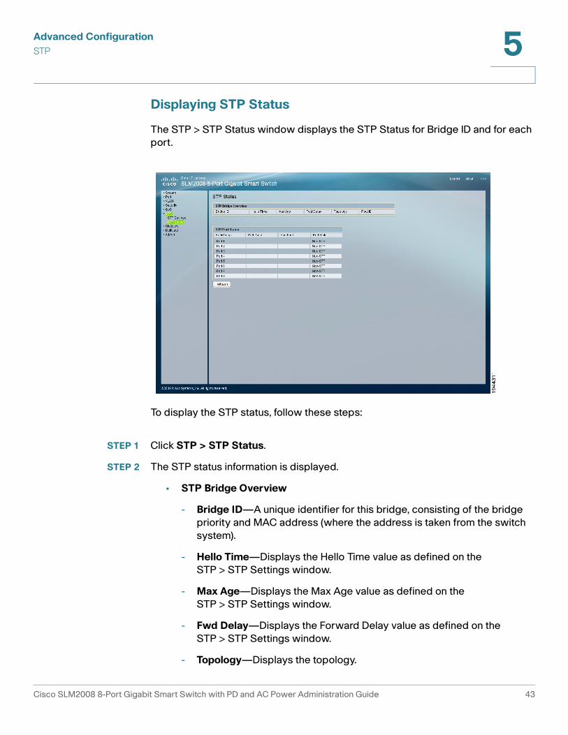
Displaying STP Status
The STP > STP Status window displays the STP Status for Bridge ID and for each
port.
To display the STP status, follow these steps:
STEP 1 Click STP > STP Status.
STEP 2 The STP status information is displayed.
• STP Bridge Overview
- Bridge ID—A unique identifier for this bridge, consisting of the bridge
priority and MAC address (where the address is taken from the switch
system).
- Hello Time—Displays the Hello Time value as defined on the
STP > STP Settings window.
- Max Age—Displays the Max Age value as defined on the
STP > STP Settings window.
- Fwd Delay—Displays the Forward Delay value as defined on the
STP > STP Settings window.
- Topology—Displays the topology.
Cisco SLM2008 8-Port Gigabit Smart Switch with PD and AC Power Administration Guide 43
Advanced Configuration
Statistics 5
- Root ID—The Root ID is displayed here.
• STP Port Status
STP Status on each interface since the device was last refreshed.
- Port—The number of the port.
- Path Cost—The best path between devices.
- Port Fast—Indicates the device is the end for a switch connection.
- Port State—Indicates if the STP is disabled or enabled on the interface.
STEP 3 To update the status information, click Refresh.
Statistics
This section describes the statistics overview and IGMP status displays.
• Displaying Statistics Overview, page 45
• Displaying IGMP Status, page 46
Cisco SLM2008 8-Port Gigabit Smart Switch with PD and AC Power Administration Guide 44
Advanced Configuration
Statistics 5
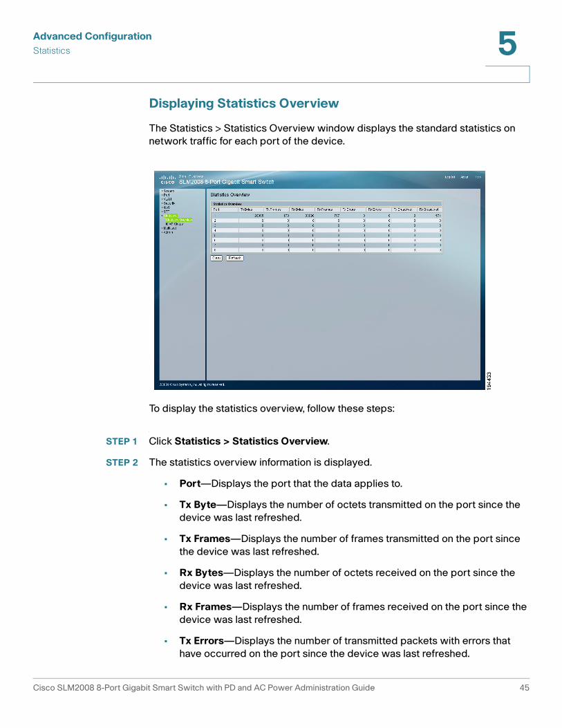
Displaying Statistics Overview
The Statistics > Statistics Overview window displays the standard statistics on
network traffic for each port of the device.
To display the statistics overview, follow these steps:
STEP 1 Click Statistics > Statistics Overview.
STEP 2 The statistics overview information is displayed.
• Port—Displays the port that the data applies to.
• Tx Byte—Displays the number of octets transmitted on the port since the
device was last refreshed.
• Tx Frames—Displays the number of frames transmitted on the port since
the device was last refreshed.
• Rx Bytes—Displays the number of octets received on the port since the
device was last refreshed.
• Rx Frames—Displays the number of frames received on the port since the
device was last refreshed.
• Tx Errors—Displays the number of transmitted packets with errors that
have occurred on the port since the device was last refreshed.
Cisco SLM2008 8-Port Gigabit Smart Switch with PD and AC Power Administration Guide 45
Advanced Configuration
Statistics 5
• Rx Errors—Displays the number of received packets with errors that have
occurred on the port since the device was last refreshed.
• Tx Broadcast—Displays the number of good broadcast packets
transmitted on the port since the device was last refreshed.
• Rx Broadcast—Displays the number of good broadcast packets received
on the port since the device was last refreshed.
STEP 3 To update the statistics information, click Refresh.
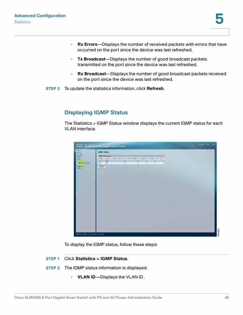
Displaying IGMP Status
The Statistics > IGMP Status window displays the current IGMP status for each
VLAN interface.
To display the IGMP status, follow these steps:
STEP 1 Click Statistics > IGMP Status.
STEP 2 The IGMP status information is displayed.
• VLAN ID—Displays the VLAN ID .
Cisco SLM2008 8-Port Gigabit Smart Switch with PD and AC Power Administration Guide 46
Advanced Configuration
Multicast 5
• Querier—Indicates the IGMP router is active or idle.
• Queries Transmitted—Displays the number of queries that have been
transmitted.
• Queries Received—Displays the number of queries that have been
received.
• v1 Reports—Displays the number of IGMP v1 report packets that have
been received by the switch.
• v2 Reports—Displays the number of IGMP v2 report packets that have
been received by the switch.
• v2 Leaves—Displays the number of IGMP v2 leave packets that have been
received by the switch.
STEP 3 To update the IGMP status information, click Refresh.
Multicast
Configuring IGMP Settings
When IGMP Snooping is enabled globally, all IGMP packets are forwarded to the
CPU. The CPU analyzes the incoming packets and determines:
• The ports that want to join which Multicast groups and issue the IGMP join
packet
• The ports that have Multicast routers generating IGMP queries
Ports requesting to join a specific Multicast group issue an IGMP report,
specifying that Multicast group is accepting members. This results in the creation
of the Multicast filtering database.
Cisco SLM2008 8-Port Gigabit Smart Switch with PD and AC Power Administration Guide 47
Advanced Configuration
Multicast 5
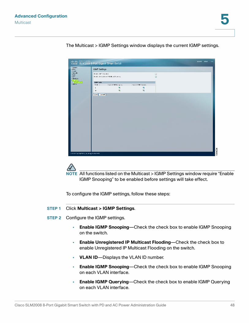
The Multicast > IGMP Settings window displays the current IGMP settings.
NOTE All functions listed on the Multicast > IGMP Settings window require “Enable
IGMP Snooping” to be enabled before settings will take effect.
To configure the IGMP settings, follow these steps:
STEP 1 Click Multicast > IGMP Settings.
STEP 2 Configure the IGMP settings.
• Enable IGMP Snooping—Check the check box to enable IGMP Snooping
on the switch.
• Enable Unregistered IP Multicast Flooding—Check the check box to
enable Unregistered IP Multicast Flooding on the switch.
• VLAN ID—Displays the VLAN ID number.
• Enable IGMP Snooping—Check the check box to enable IGMP Snooping
on each VLAN interface.
• Enable IGMP Querying—Check the check box to enable IGMP Querying
on each VLAN interface.
Cisco SLM2008 8-Port Gigabit Smart Switch with PD and AC Power Administration Guide 48
Advanced Configuration
Admin 5
STEP 3 Click Save.
Admin
This section describes how to configure the administration settings of the switch.
• Configuring Ping, page 50
• Configuring Port Mirror, page 51
• Restoring Factory Default, page 52
• Rebooting the Switch, page 53
• Saving Configuration Settings, page 54
• Upgrading the Firmware, page 55
Cisco SLM2008 8-Port Gigabit Smart Switch with PD and AC Power Administration Guide 49
Advanced Configuration
Admin 5
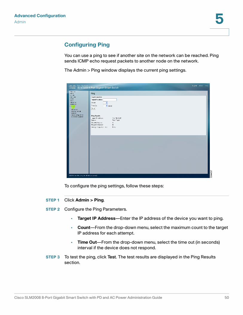
Configuring Ping
You can use a ping to see if another site on the network can be reached. Ping
sends ICMP echo request packets to another node on the network.
The Admin > Ping window displays the current ping settings.
To configure the ping settings, follow these steps:
STEP 1 Click Admin > Ping.
STEP 2 Configure the Ping Parameters.
• Target IP Address—Enter the IP address of the device you want to ping.
• Count—From the drop-down menu, select the maximum count to the target
IP address for each attempt.
• Time Out—From the drop-down menu, select the time out (in seconds)
interval if the device does not respond.
STEP 3 To test the ping, click Test. The test results are displayed in the Ping Results
section.
Cisco SLM2008 8-Port Gigabit Smart Switch with PD and AC Power Administration Guide 50
Advanced Configuration
Admin 5
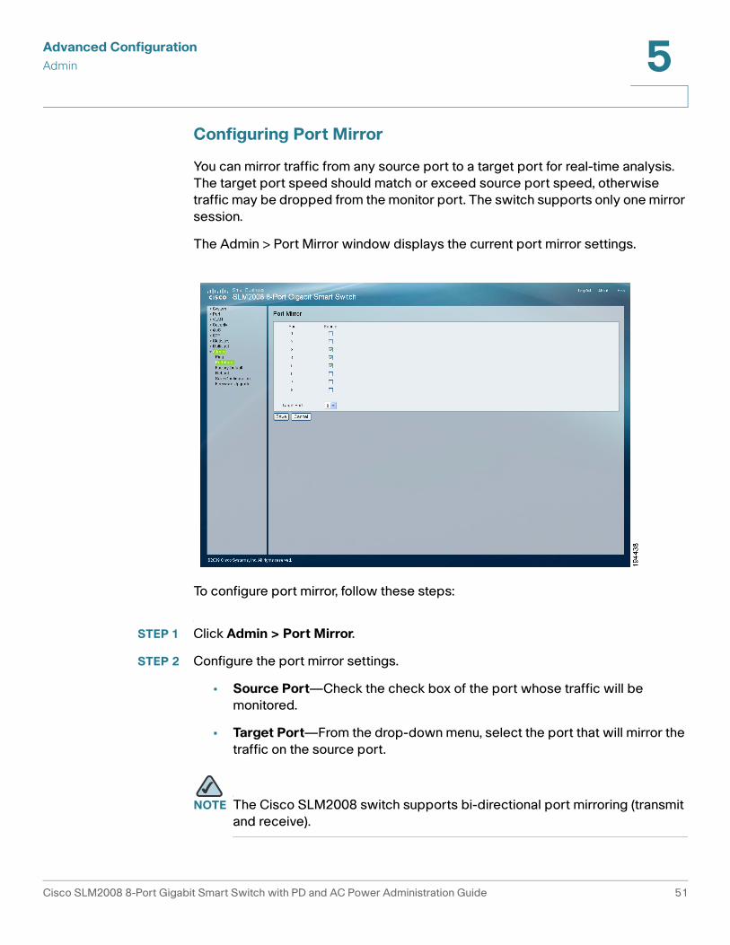
Configuring Port Mirror
You can mirror traffic from any source port to a target port for real-time analysis.
The target port speed should match or exceed source port speed, otherwise
traffic may be dropped from the monitor port. The switch supports only one mirror
session.
The Admin > Port Mirror window displays the current port mirror settings.
To configure port mirror, follow these steps:
STEP 1 Click Admin > Port Mirror.
STEP 2 Configure the port mirror settings.
• Source Port—Check the check box of the port whose traffic will be
monitored.
• Target Port—From the drop-down menu, select the port that will mirror the
traffic on the source port.
NOTE The Cisco SLM2008 switch supports bi-directional port mirroring (transmit
and receive).
Cisco SLM2008 8-Port Gigabit Smart Switch with PD and AC Power Administration Guide 51
Advanced Configuration
Admin 5
STEP 3 Click Save.
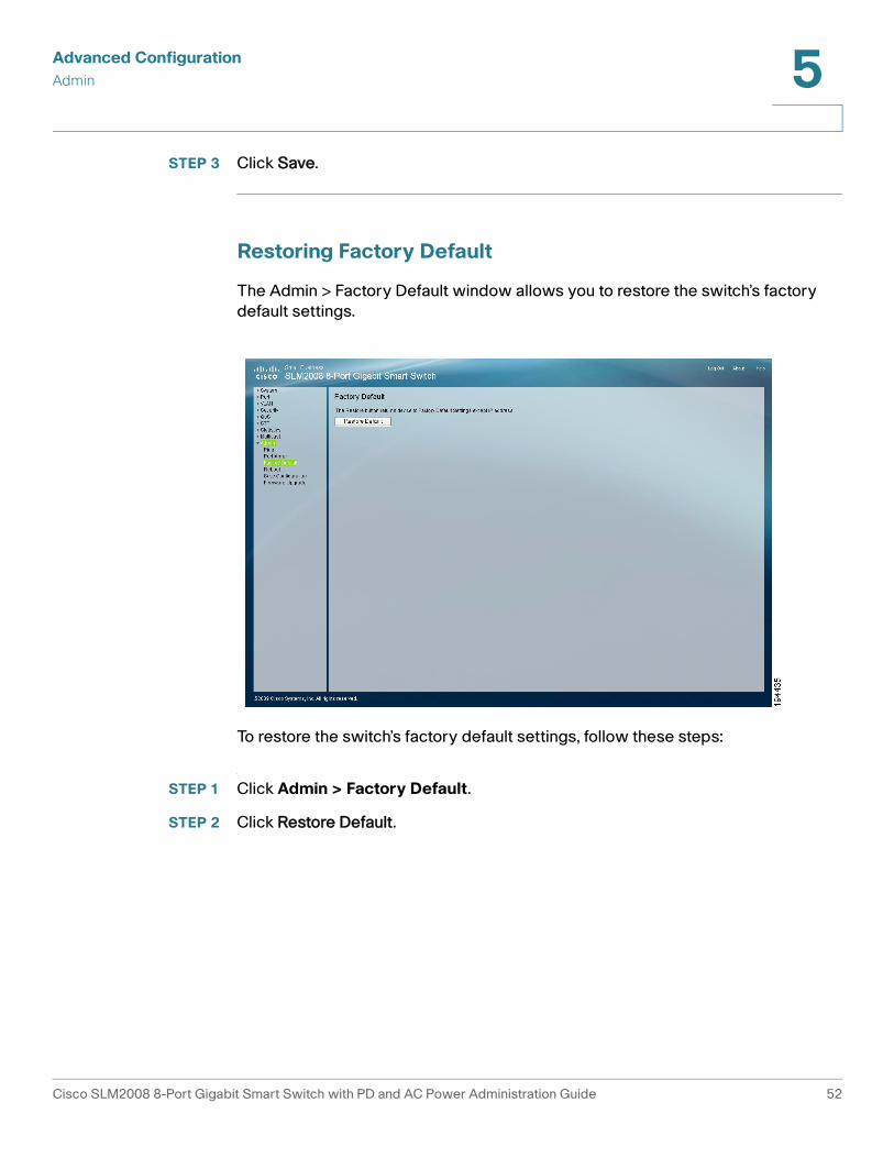
Restoring Factory Default
The Admin > Factory Default window allows you to restore the switch’s factory
default settings.
To restore the switch’s factory default settings, follow these steps:
STEP 1 Click Admin > Factory Default.
STEP 2 Click Restore Default.
Cisco SLM2008 8-Port Gigabit Smart Switch with PD and AC Power Administration Guide 52
Advanced Configuration
Admin 5
Rebooting the Switch
The Admin > Reboot window allows you to reboot the switch. The current
configuration settings are retained.
To reboot the switch, follow these steps:
STEP 1 Click Admin > Reboot.
STEP 2 Click Reboot.
Cisco SLM2008 8-Port Gigabit Smart Switch with PD and AC Power Administration Guide 53
Advanced Configuration
Admin 5
Saving Configuration Settings
The Admin > Save Configuration window allows you to save and retrieve the
switch’s configuration information.
When saving the configuration, there are two options:
• The Configuration Upload section allows you to load a previously saved
configuration file (.cfg).
• The Configuration Backup section allows you to save the switch settings to
a configuration file (.cfg).
To load a previously saved configuration file (.cfg), follow these steps:
STEP 1 Click Admin > Save Configuration.
STEP 2 In the Configuration Upload section, click Browse.
STEP 3 Locate the appropriate file and click Open.
STEP 4 Click Upgrade to load the file.
Cisco SLM2008 8-Port Gigabit Smart Switch with PD and AC Power Administration Guide 54
Advanced Configuration
Admin 5
To save the switch settings to a configuration file (.cfg), follow these steps:
STEP 1 Click Admin > Save Configuration.
STEP 2 In the Configuration Backup section, click Proceed.
STEP 3 Click Save when prompted to open, save, or cancel.
STEP 4 Select the location where the file should be saved and click Save.
Upgrading the Firmware
The Admin > Firmware Upgrade window allows you to upgrade the firmware.
To upgrade the firmware, follow these steps:
STEP 1 Click Admin > Firmware Upgrade.
STEP 2 Click Browse.
Cisco SLM2008 8-Port Gigabit Smart Switch with PD and AC Power Administration Guide 55
Advanced Configuration
Admin 5
STEP 3 Locate the appropriate file and click Open.
STEP 4 Click Proceed to load the file.
Cisco SLM2008 8-Port Gigabit Smart Switch with PD and AC Power Administration Guide 56
A
Specifications
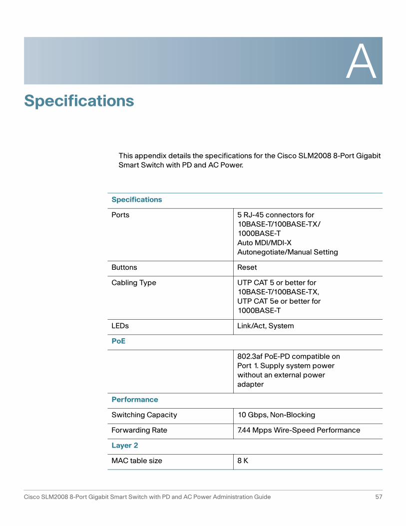
This appendix details the specifications for the Cisco SLM2008 8-Port Gigabit
Smart Switch with PD and AC Power.
Specifications
Ports 5 RJ-45 connectors for
10BASE-T/100BASE-TX/
1000BASE-T
Auto MDI/MDI-X
Autonegotiate/Manual Setting
Buttons Reset
Cabling Type UTP CAT 5 or better for
10BASE-T/100BASE-TX,
UTP CAT 5e or better for
1000BASE-T
LEDs Link/Act, System
PoE
802.3af PoE-PD compatible on
Port 1. Supply system power
without an external power
adapter
Performance
Switching Capacity 10 Gbps, Non-Blocking
Forwarding Rate 7.44 Mpps Wire-Speed Performance
Layer 2
MAC table size 8 K
Cisco SLM2008 8-Port Gigabit Smart Switch with PD and AC Power Administration Guide 57
Specifications A
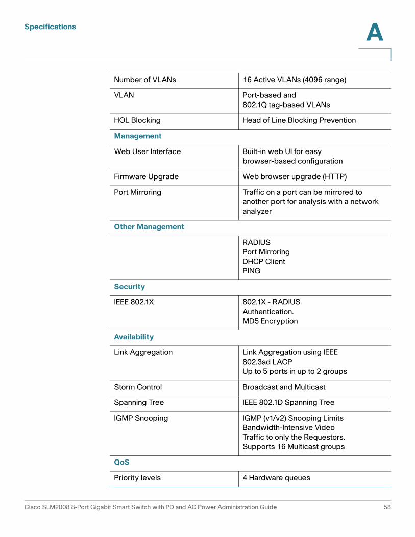
Number of VLANs 16 Active VLANs (4096 range)
VLAN Port-based and
802.1Q tag-based VLANs
HOL Blocking Head of Line Blocking Prevention
Management
Web User Interface Built-in web UI for easy
browser-based configuration
Firmware Upgrade Web browser upgrade (HTTP)
Port Mirroring Traffic on a port can be mirrored to
another port for analysis with a network
analyzer
Other Management
RADIUS
Port Mirroring
DHCP Client
PING
Security
IEEE 802.1X 802.1X - RADIUS
Authentication.
MD5 Encryption
Availability
Link Aggregation Link Aggregation using IEEE
802.3ad LACP
Up to 5 ports in up to 2 groups
Storm Control Broadcast and Multicast
Spanning Tree IEEE 802.1D Spanning Tree
IGMP Snooping IGMP (v1/v2) Snooping Limits
Bandwidth-Intensive Video
Traffic to only the Requestors.
Supports 16 Multicast groups
QoS
Priority levels 4 Hardware queues
Cisco SLM2008 8-Port Gigabit Smart Switch with PD and AC Power Administration Guide 58
Specifications A
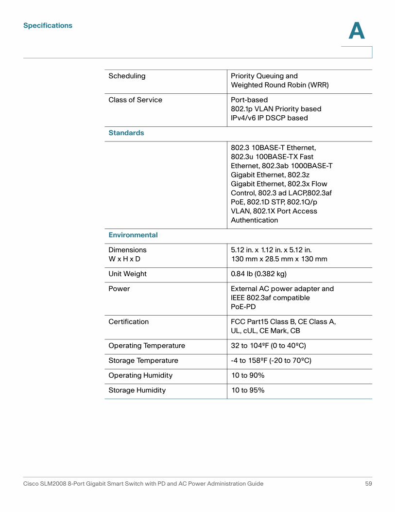
Scheduling Priority Queuing and
Weighted Round Robin (WRR)
Class of Service Port-based
802.1p VLAN Priority based
IPv4/v6 IP DSCP based
Standards
802.3 10BASE-T Ethernet,
802.3u 100BASE-TX Fast
Ethernet, 802.3ab 1000BASE-T
Gigabit Ethernet, 802.3z
Gigabit Ethernet, 802.3x Flow
Control, 802.3 ad LACP,802.3af
PoE, 802.1D STP, 802.1Q/p
VLAN, 802.1X Port Access
Authentication
Environmental
Dimensions
W x H x D
5.12 in. x 1.12 in. x 5.12 in.
130 mm x 28.5 mm x 130 mm
Unit Weight 0.84 lb (0.382 kg)
Power External AC power adapter and
IEEE 802.3af compatible
PoE-PD
Certification FCC Part15 Class B, CE Class A,
UL, cUL, CE Mark, CB
Operating Temperature 32 to 104ºF (0 to 40ºC)
Storage Temperature -4 to 158ºF (-20 to 70ºC)
Operating Humidity 10 to 90%
Storage Humidity 10 to 95%
Cisco SLM2008 8-Port Gigabit Smart Switch with PD and AC Power Administration Guide 59
B
Where to Go From Here
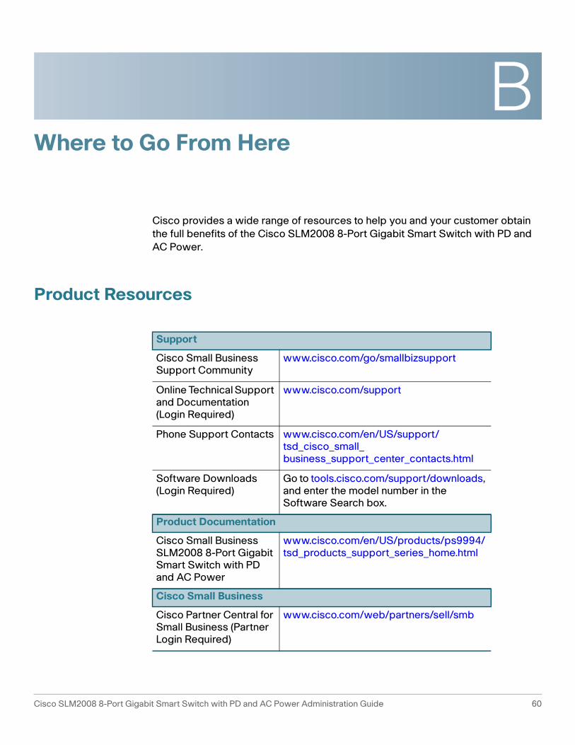
Cisco provides a wide range of resources to help you and your customer obtain
the full benefits of the Cisco SLM2008 8-Port Gigabit Smart Switch with PD and
AC Power.
Product Resources
Support
Cisco Small Business Support Community
www.cisco.com/go/smallbizsupport
Online Technical Support and Documentation (Login Required)
www.cisco.com/support
Phone Support Contacts www.cisco.com/en/US/support/tsd_cisco_small_ business_support_center_contacts.html
Software Downloads(Login Required)
Go to tools.cisco.com/support/downloads, and enter the model number in the Software Search box.
Product Documentation
Cisco Small Business SLM2008 8-Port Gigabit Smart Switch with PD and AC Power
www.cisco.com/en/US/products/ps9994/tsd_products_support_series_home.html
Cisco Small Business
Cisco Partner Central for Small Business (Partner Login Required)
www.cisco.com/web/partners/sell/smb
Cisco SLM2008 8-Port Gigabit Smart Switch with PD and AC Power Administration Guide 60

Where to Go From Here B
Cisco Small Business Home
www.cisco.com/smb
Marketplace www.cisco.com/go/marketplace
Cisco SLM2008 8-Port Gigabit Smart Switch with PD and AC Power Administration Guide 61