cisco security appliance command line …docstore.mik.ua/cisco/pdf/other/pix 70 config guide.pdfi...
TRANSCRIPT

Cisco Security Appliance Command Line Configuration GuideFor the Cisco PIX 500 Series
Software Version 7.0
Corporate HeadquartersCisco Systems, Inc.170 West Tasman DriveSan Jose, CA 95134-1706 USAhttp://www.cisco.comTel: 408 526-4000
800 553-NETS (6387)Fax: 408 526-4100
Customer Order Number: N/A, Online onlyText Part Number: OL-6721-01

THE SPECIFICATIONS AND INFORMATION REGARDING THE PRODUCTS IN THIS MANUAL ARE SUBJECT TO CHANGE WITHOUT NOTICE. ALL STATEMENTS, INFORMATION, AND RECOMMENDATIONS IN THIS MANUAL ARE BELIEVED TO BE ACCURATE BUT ARE PRESENTED WITHOUT WARRANTY OF ANY KIND, EXPRESS OR IMPLIED. USERS MUST TAKE FULL RESPONSIBILITY FOR THEIR APPLICATION OF ANY PRODUCTS.
THE SOFTWARE LICENSE AND LIMITED WARRANTY FOR THE ACCOMPANYING PRODUCT ARE SET FORTH IN THE INFORMATION PACKET THAT SHIPPED WITH THE PRODUCT AND ARE INCORPORATED HEREIN BY THIS REFERENCE. IF YOU ARE UNABLE TO LOCATE THE SOFTWARE LICENSE OR LIMITED WARRANTY, CONTACT YOUR CISCO REPRESENTATIVE FOR A COPY.
The Cisco implementation of TCP header compression is an adaptation of a program developed by the University of California, Berkeley (UCB) as part of UCB’s public domain version of the UNIX operating system. All rights reserved. Copyright © 1981, Regents of the University of California.
NOTWITHSTANDING ANY OTHER WARRANTY HEREIN, ALL DOCUMENT FILES AND SOFTWARE OF THESE SUPPLIERS ARE PROVIDED “AS IS” WITH ALL FAULTS. CISCO AND THE ABOVE-NAMED SUPPLIERS DISCLAIM ALL WARRANTIES, EXPRESSED OR IMPLIED, INCLUDING, WITHOUT LIMITATION, THOSE OF MERCHANTABILITY, FITNESS FOR A PARTICULAR PURPOSE AND NONINFRINGEMENT OR ARISING FROM A COURSE OF DEALING, USAGE, OR TRADE PRACTICE.
IN NO EVENT SHALL CISCO OR ITS SUPPLIERS BE LIABLE FOR ANY INDIRECT, SPECIAL, CONSEQUENTIAL, OR INCIDENTAL DAMAGES, INCLUDING, WITHOUT LIMITATION, LOST PROFITS OR LOSS OR DAMAGE TO DATA ARISING OUT OF THE USE OR INABILITY TO USE THIS MANUAL, EVEN IF CISCO OR ITS SUPPLIERS HAVE BEEN ADVISED OF THE POSSIBILITY OF SUCH DAMAGES.
Cisco Security Appliance Command Line Configuration GuideCopyright © 2005 Cisco Systems, Inc. All rights reserved.
CCIP, CCSP, the Cisco Arrow logo, the Cisco Powered Network mark, the Cisco Systems Verified logo, Cisco Unity, Follow Me Browsing, FormShare, iQ Breakthrough, iQ FastTrack, the iQ Logo, iQ Net Readiness Scorecard, Networking Academy, ScriptShare, SMARTnet, TransPath, and Voice LAN are trademarks of Cisco Systems, Inc.; Changing the Way We Work, Live, Play, and Learn, The Fastest Way to Increase Your Internet Quotient, and iQuick Study are service marks of Cisco Systems, Inc.; and Aironet, ASIST, BPX, Catalyst, CCDA, CCDP, CCIE, CCNA, CCNP, Cisco, the Cisco Certified Internetwork Expert logo, Cisco IOS, the Cisco IOS logo, Cisco Press, Cisco Systems, Cisco Systems Capital, the Cisco Systems logo, Empowering the Internet Generation, Enterprise/Solver, EtherChannel, EtherSwitch, Fast Step, GigaStack, Internet Quotient, IOS, IP/TV, iQ Expertise, LightStream, MGX, MICA, the Networkers logo, Network Registrar, Packet, PIX, Post-Routing, Pre-Routing, RateMUX, Registrar, SlideCast, StrataView Plus, Stratm, SwitchProbe, TeleRouter, and VCO are registered trademarks of Cisco Systems, Inc. and/or its affiliates in the U.S. and certain other countries.
All other trademarks mentioned in this document or Web site are the property of their respective owners. The use of the word partner does not imply a partnership relationship between Cisco and any other company. (0301R)

CiscoOL-6721-01
C O N T E N T S
About This Guide xxi
Document Objectives xxi
Audience xxi
Related Documentation xxii
Document Organization xxii
Document Conventions xxiv
Obtaining Documentation xxv
Cisco.com xxv
Ordering Documentation xxv
Documentation Feedback xxv
Obtaining Technical Assistance xxvi
Cisco Technical Support Website xxvi
Submitting a Service Request xxvi
Definitions of Service Request Severity xxvii
Obtaining Additional Publications and Information xxvii
P A R T 1 Getting Started and General Information
C H A P T E R 1 Introduction to the Security Appliance 1-1
Firewall Functional Overview 1-1
Security Policy Overview 1-2
Permitting or Denying Traffic with Access Lists 1-2
Applying NAT 1-2
Using AAA for Through Traffic 1-2
Applying HTTP, HTTPS, or FTP Filtering 1-3
Applying Application Inspection 1-3
Applying QoS Policies 1-3
Applying Connection Limits and TCP Normalization 1-3
Firewall Mode Overview 1-3
Stateful Inspection Overview 1-4
VPN Functional Overview 1-5
Security Context Overview 1-5
iSecurity Appliance Command Line Configuration Guide

Contents
C H A P T E R 2 Getting Started 2-1
Accessing the Command-Line Interface 2-1
Setting Transparent or Routed Firewall Mode 2-2
Working with the Configuration 2-3
Saving Configuration Changes 2-3
Viewing the Configuration 2-3
Clearing and Removing Configuration Settings 2-4
Creating Text Configuration Files Offline 2-4
C H A P T E R 3 Enabling Multiple Context Mode 3-1
Security Context Overview 3-1
Common Uses for Security Contexts 3-2
Unsupported Features 3-2
Context Configuration Files 3-2
How the Security Appliance Classifies Packets 3-3
Sharing Interfaces Between Contexts 3-6
Shared Interface Guidelines 3-7
Cascading Security Contexts 3-9
Logging into the Security Appliance in Multiple Context Mode 3-10
Enabling or Disabling Multiple Context Mode 3-10
Backing Up the Single Mode Configuration 3-10
Enabling Multiple Context Mode 3-10
Restoring Single Context Mode 3-11
C H A P T E R 4 Configuring Ethernet Settings and Subinterfaces 4-1
Configuring Ethernet Settings 4-1
Configuring Subinterfaces 4-2
C H A P T E R 5 Adding and Managing Security Contexts 5-1
Configuring a Security Context 5-1
Removing a Security Context 5-5
Changing the Admin Context 5-5
Changing Between Contexts and the System Execution Space 5-5
Changing the Security Context URL 5-6
Reloading a Security Context 5-7
Reloading by Clearing the Configuration 5-7
Reloading by Removing and Re-adding the Context 5-7
iiCisco Security Appliance Command Line Configuration Guide
OL-6721-01
Contents
Monitoring Security Contexts 5-8
Viewing Context Information 5-8
Viewing Resource Usage 5-9
C H A P T E R 6 Configuring Interface Parameters 6-1
Security Level Overview 6-1
Configuring the Interface 6-2
Allowing Communication Between Interfaces on the Same Security Level 6-4
C H A P T E R 7 Configuring Basic Settings 7-1
Changing the Enable Password 7-1
Setting the Hostname 7-2
Setting the Domain Name 7-2
Setting the Date and Time 7-2
Setting the Time Zone and Daylight Saving Time Date Range 7-3
Setting the Date and Time Using an NTP Server 7-4
Setting the Date and Time Manually 7-4
Setting the Management IP Address for a Transparent Firewall 7-5
C H A P T E R 8 Configuring IP Routing and DHCP Services 8-1
Configuring Static and Default Routes 8-1
Configuring a Static Route 8-2
Configuring a Default Route 8-3
Configuring OSPF 8-3
OSPF Overview 8-4
Enabling OSPF 8-5
Redistributing Routes Between OSPF Processes 8-5
Adding a Route Map 8-6
Redistributing Static, Connected, or OSPF Routes to an OSPF Process 8-7
Configuring OSPF Interface Parameters 8-8
Configuring OSPF Area Parameters 8-10
Configuring OSPF NSSA 8-11
Configuring Route Summarization Between OSPF Areas 8-12
Configuring Route Summarization When Redistributing Routes into OSPF 8-12
Generating a Default Route 8-13
Configuring Route Calculation Timers 8-13
Logging Neighbors Going Up or Down 8-14
Displaying OSPF Update Packet Pacing 8-14
iiiCisco Security Appliance Command Line Configuration Guide
OL-6721-01

Contents
Monitoring OSPF 8-15
Restarting the OSPF Process 8-15
Configuring RIP 8-16
RIP Overview 8-16
Enabling RIP 8-16
Configuring Multicast Routing 8-17
Multicast Routing Overview 8-17
Enabling Multicast Routing 8-18
Configuring IGMP Features 8-18
Disabling IGMP on an Interface 8-19
Configuring Group Membership 8-19
Configuring a Statically Joined Group 8-19
Controlling Access to Multicast Groups 8-19
Limiting the Number of IGMP States on an Interface 8-20
Modifying the Query Interval and Query Timeout 8-20
Changing the Query Response Time 8-21
Changing the IGMP Version 8-21
Configuring Stub Multicast Routing 8-21
Configuring a Static Multicast Route 8-21
Configuring PIM Features 8-22
Disabling PIM on an Interface 8-22
Configuring a Static Rendezvous Point Address 8-22
Configuring the Designated Router Priority 8-23
Filtering PIM Register Messages 8-23
Configuring PIM Message Intervals 8-23
For More Information about Multicast Routing 8-24
Configuring DHCP 8-24
Configuring a DHCP Server 8-24
Enabling the DHCP Server 8-24
Configuring DHCP Options 8-26
Using Cisco IP Phones with a DHCP Server 8-26
Configuring DHCP Relay Services 8-27
Configuring the DHCP Client 8-28
C H A P T E R 9 Configuring IPv6 9-1
IPv6-enabled Commands 9-1
Configuring IPv6 on an Interface 9-2
Configuring IPv6 Default and Static Routes 9-3
Configuring IPv6 Access Lists 9-4
ivCisco Security Appliance Command Line Configuration Guide
OL-6721-01

Contents
Verifying the IPv6 Configuration 9-5
The show ipv6 interface Command 9-5
The show ipv6 route Command 9-6
Configuring a Dual IP Stack on an Interface 9-6
IPv6 Configuration Example 9-7
C H A P T E R 10 Configuring AAA Servers and the Local Database 10-1
AAA Overview 10-1
About Authentication 10-2
About Authorization 10-2
About Accounting 10-2
AAA Server and Local Database Support 10-3
Summary of Support 10-3
RADIUS Server Support 10-4
Authentication Methods 10-4
Attribute Support 10-4
RADIUS Functions 10-4
TACACS+ Server Support 10-5
SDI Server Support 10-6
SDI Version Support 10-6
Two-step Authentication Process 10-7
SDI Primary and Replica Servers 10-7
NT Server Support 10-7
Kerberos Server Support 10-7
LDAP Server Support 10-8
Local Database Support 10-8
User Profiles 10-8
Local Database Functions 10-8
Fallback Support 10-9
Configuring the Local Database 10-9
Identifying AAA Server Groups and Servers 10-11
C H A P T E R 11 Configuring Failover 11-1
Understanding Failover 11-1
Failover System Requirements 11-2
Hardware Requirements 11-2
Software Requirements 11-2
License Requirements 11-2
vCisco Security Appliance Command Line Configuration Guide
OL-6721-01

Contents
The Failover and State Links 11-3
Failover Link 11-3
State Link 11-4
Active/Active and Active/Standby Failover 11-5
Active/Standby Failover 11-5
Active/Active Failover 11-9
Determining Which Type of Failover to Use 11-12
Regular and Stateful Failover 11-13
Regular Failover 11-13
Stateful Failover 11-13
Failover Health Monitoring 11-14
Unit Health Monitoring 11-14
Interface Monitoring 11-14
Configuring Failover 11-15
Configuring Active/Standby Failover 11-15
Prerequisites 11-16
Configuring Cable-Based Active/Standby Failover (PIX Security Appliance Only) 11-16
Configuring LAN-Based Active/Standby Failover 11-17
Configuring Optional Active/Standby Failover Settings 11-20
Configuring Active/Active Failover 11-23
Prerequisites 11-23
Configuring Cable-Based Active/Active Failover (PIX security appliance Only) 11-23
Configuring LAN-Based Active/Active Failover 11-25
Configuring Optional Active/Active Failover Settings 11-28
Configuring Failover Communication Authentication/Encryption 11-32
Verifying the Failover Configuration 11-32
Using the show failover Command 11-33
Viewing Monitored Interfaces 11-41
Displaying the Failover Commands in the Running Configuration 11-41
Testing the Failover Functionality 11-41
Controlling and Monitoring Failover 11-42
Forcing Failover 11-42
Disabling Failover 11-43
Restoring a Failed Unit or Failover Group 11-43
Monitoring Failover 11-43
Failover System Messages 11-43
Debug Messages 11-44
SNMP 11-44
viCisco Security Appliance Command Line Configuration Guide
OL-6721-01

Contents
Failover Configuration Examples 11-44
Cable-Based Active/Standby Failover Example 11-45
LAN-Based Active/Standby Failover Example 11-46
LAN-Based Active/Active Failover Example 11-48
P A R T 2 Configuring the Firewall
C H A P T E R 12 Firewall Mode Overview 12-1
Routed Mode Overview 12-1
IP Routing Support 12-2
Network Address Translation 12-2
How Data Moves Through the Security Appliance in Routed Firewall Mode 12-3
An Inside User Visits a Web Server 12-4
An Outside User Visits a Web Server on the DMZ 12-5
An Inside User Visits a Web Server on the DMZ 12-6
An Outside User Attempts to Access an Inside Host 12-7
A DMZ User Attempts to Access an Inside Host 12-8
Transparent Mode Overview 12-8
Transparent Firewall Features 12-9
Using the Transparent Firewall in Your Network 12-10
Transparent Firewall Guidelines 12-10
Unsupported Features in Transparent Mode 12-11
How Data Moves Through the Transparent Firewall 12-12
An Inside User Visits a Web Server 12-13
An Outside User Visits a Web Server on the Inside Network 12-14
An Outside User Attempts to Access an Inside Host 12-15
C H A P T E R 13 Identifying Traffic with Access Lists 13-1
Access List Overview 13-1
Access List Types and Uses 13-2
Access List Type Overview 13-2
Controlling Network Access for IP Traffic (Extended) 13-2
Identifying Traffic for AAA Rules (Extended) 13-3
Controlling Network Access for IP Traffic for a Given User (Extended) 13-4
Identifying Addresses for Policy NAT and NAT Exemption (Extended) 13-4
VPN Access (Extended) 13-5
Identify Traffic in a Class Map for Modular Policy Framework 13-5
Controlling Network Access for Non-IP Traffic (EtherType) 13-6
Redistributing OSPF Routes (Standard) 13-6
viiCisco Security Appliance Command Line Configuration Guide
OL-6721-01

Contents
Access List Guidelines 13-6
Access Control Entry Order 13-6
Access Control Implicit Deny 13-7
IP Addresses Used for Access Lists When You Use NAT 13-7
Adding an Extended Access List 13-9
Adding an EtherType Access List 13-11
Adding a Standard Access List 13-13
Simplifying Access Lists with Object Grouping 13-13
How Object Grouping Works 13-13
Adding Object Groups 13-14
Adding a Protocol Object Group 13-14
Adding a Network Object Group 13-15
Adding a Service Object Group 13-15
Adding an ICMP Type Object Group 13-16
Nesting Object Groups 13-17
Using Object Groups with an Access List 13-18
Displaying Object Groups 13-19
Removing Object Groups 13-19
Adding Remarks to Access Lists 13-20
Time Range Options 13-20
Logging Access List Activity 13-20
Access List Logging Overview 13-21
Configuring Logging for an Access Control Entry 13-22
Managing Deny Flows 13-23
C H A P T E R 14 Applying NAT 14-1
NAT Overview 14-1
Introduction to NAT 14-2
NAT Control 14-3
NAT Types 14-5
Dynamic NAT 14-5
PAT 14-6
Static NAT 14-7
Static PAT 14-7
Bypassing NAT when NAT Control is Enabled 14-9
Policy NAT 14-9
NAT and Same Security Level Interfaces 14-12
Order of NAT Commands Used to Match Real Addresses 14-13
viiiCisco Security Appliance Command Line Configuration Guide
OL-6721-01

Contents
Mapped Address Guidelines 14-13
DNS and NAT 14-14
Configuring NAT Control 14-15
Using Dynamic NAT and PAT 14-16
Dynamic NAT and PAT Implementation 14-16
Configuring Dynamic NAT or PAT 14-22
Using Static NAT 14-25
Using Static PAT 14-26
Bypassing NAT 14-29
Configuring Identity NAT 14-29
Configuring Static Identity NAT 14-30
Configuring NAT Exemption 14-31
NAT Examples 14-32
Overlapping Networks 14-33
Redirecting Ports 14-34
C H A P T E R 15 Permitting or Denying Network Access 15-1
Inbound and Outbound Access List Overview 15-1
Applying an Access List to an Interface 15-4
C H A P T E R 16 Applying AAA for Network Access 16-1
AAA Performance 16-1
Configuring Authentication for Network Access 16-1
Authentication Overview 16-2
Enabling Network Access Authentication 16-3
Enabling Secure Authentication of Web Clients 16-4
Configuring Authorization for Network Access 16-6
Configuring TACACS+ Authorization 16-6
Configuring RADIUS Authorization 16-7
Configuring a RADIUS Server to Download Per-User Access Control Lists 16-8
Configuring a RADIUS Server to Download Per-User Access Control List Names 16-10
Configuring Accounting for Network Access 16-10
Using MAC Addresses to Exempt Traffic from Authentication and Authorization 16-11
ixCisco Security Appliance Command Line Configuration Guide
OL-6721-01

Contents
C H A P T E R 17 Applying Filtering Services 17-1
Filtering Overview 17-1
Filtering ActiveX Objects 17-2
Overview 17-2
Enabling ActiveX Filtering 17-2
Filtering Java Applets 17-3
Overview 17-3
Enabling Java Applet Filtering 17-3
Filtering with an External Server 17-4
Filtering Overview 17-4
General Procedure 17-5
Identifying the Filtering Server 17-5
Buffering the Content Server Response 17-6
Caching Server Addresses 17-7
Filtering HTTP URLs 17-7
Configuring HTTP Filtering 17-7
Enabling Filtering of Long HTTP URLs 17-8
Truncating Long HTTP URLs 17-8
Exempting Traffic from Filtering 17-8
Filtering HTTPS URLs 17-8
Filtering FTP Requests 17-9
Viewing Filtering Statistics and Configuration 17-10
Viewing Filtering Server Statistics 17-10
Viewing Buffer Configuration and Statistics 17-10
Viewing Caching Statistics 17-11
Viewing Filtering Performance Statistics 17-11
Viewing Filtering Configuration 17-12
C H A P T E R 18 Using Modular Policy Framework 18-1
Overview 18-1
Identifying Traffic Using a Class Map 18-2
Class Map Example 18-4
Defining Actions Using a Policy Map 18-4
Policy Map Procedure 18-5
Policy Map Examples 18-6
Restrictions 18-7
xCisco Security Appliance Command Line Configuration Guide
OL-6721-01

Contents
Classification Policy within a Policy Map 18-7
Multi-match Classification Policy across Multiple Feature Domains 18-7
First-match Policy within a Feature Domain 18-8
Action Order 18-9
Advanced Options 18-10
Applying a Policy to an Interface Using a Service Policy 18-10
Direction Policies When Applying a Service Policy 18-10
Types of Direction Policies 18-11
Implicit Direction Policies 18-11
Examples 18-11
Match Port/Interface Policy Example 18-11
Match Access List/Interface Policy Example 18-12
Match Port/Global Policy Example 18-13
Service Policy and NAT 18-14
C H A P T E R 19 Intercepting and Responding to Network Attacks 19-1
Configuring IP Audit for Basic IPS Support 19-1
Configuring TCP Normalization 19-2
Protecting Your Network Against Specific Attacks 19-3
Preventing IP Spoofing 19-3
Configuring Connection Limits and Timeouts 19-4
Configuring the Fragment Size 19-5
Blocking Unwanted Connections 19-5
C H A P T E R 20 Applying QoS Policies 20-1
Overview 20-1
QoS Concepts 20-2
Identifying Traffic for QoS 20-3
Classifying Traffic for QoS 20-4
Defining a QoS Policy Map 20-6
Applying Rate Limiting 20-6
Verifying the Traffic-Policing Configuration 20-8
Verifying QoS Statistics 20-8
Viewing QoS Police Statistics 20-8
Viewing QoS Priority-Queue Statistics 20-9
Activating the Service Policy 20-9
xiCisco Security Appliance Command Line Configuration Guide
OL-6721-01

Contents
Applying Low Latency Queueing 20-9
Configuring Priority Queuing 20-10
Sizing the Priority Queue 20-10
Reducing Queue Latency 20-10
Viewing QoS Statistics 20-11
Viewing the Priority-Queue Configuration for an Interface 20-12
C H A P T E R 21 Applying Application Layer Protocol Inspection 21-1
Application Inspection Engines 21-1
Overview 21-2
How Inspection Engines Work 21-2
Supported Protocols 21-3
Applying Application Inspection to Selected Traffic 21-5
Overview 21-5
Identifying Traffic with a Traffic Class Map 21-6
Using an Application Inspection Map 21-8
Defining Actions with a Policy Map 21-9
Applying a Security Policy to an Interface 21-10
Managing CTIQBE Inspection 21-10
CTIQBE Inspection Overview 21-10
Limitations and Restrictions 21-10
Enabling and Configuring CTIQBE Inspection 21-11
Verifying and Monitoring CTIQBE Inspection 21-13
Managing FTP Inspection 21-14
FTP Inspection Overview 21-14
Using the strict Option 21-14
Configuring FTP Inspection 21-15
Verifying and Monitoring FTP Inspection 21-18
Managing GTP Inspection 21-19
GTP Inspection Overview 21-19
Enabling and Configuring GTP Inspection 21-20
Verifying and Monitoring GTP Inspection 21-23
Managing H.323 Inspection 21-24
H.323 Inspection Overview 21-24
How H.323 Works 21-24
Limitations and Restrictions 21-25
Enabling and Configuring H.323 Inspection 21-26
Configuring H.225 Timeout Values 21-28
xiiCisco Security Appliance Command Line Configuration Guide
OL-6721-01

Contents
Verifying and Monitoring H.323 Inspection 21-28
Monitoring H.225 Sessions 21-28
Monitoring H.245 Sessions 21-29
Monitoring H.323 RAS Sessions 21-29
Managing HTTP Inspection 21-30
HTTP Inspection Overview 21-30
Enabling and Configuring Advanced HTTP Inspection 21-31
Managing MGCP Inspection 21-33
MGCP Inspection Overview 21-34
Configuring MGCP Call Agents and Gateways 21-35
Configuring and Enabling MGCP Inspection 21-36
Configuring MGCP Timeout Values 21-38
Verifying and Monitoring MGCP Inspection 21-39
Managing RTSP Inspection 21-39
RTSP Inspection Overview 21-40
Using RealPlayer 21-40
Restrictions and Limitations 21-41
Enabling and Configuring RTSP Inspection 21-41
Managing SIP Inspection 21-43
SIP Inspection Overview 21-43
SIP Instant Messaging 21-43
Enabling and Configuring SIP Inspection 21-44
Configuring SIP Timeout Values 21-46
Verifying and Monitoring SIP Inspection 21-46
Managing Skinny (SCCP) Inspection 21-47
SCCP Inspection Overview 21-47
Supporting Cisco IP Phones 21-48
Restrictions and Limitations 21-48
Verifying and Monitoring SCCP Inspection 21-50
Managing SMTP and Extended SMTP Inspection 21-50
SMTP and Extended SMTP Inspection Overview 21-51
Enabling and Configuring SMTP and Extended SMTP Application Inspection 21-52
Managing SNMP Inspection 21-53
SNMP Inspection Overview 21-54
Enabling and Configuring SNMP Application Inspection 21-54
xiiiCisco Security Appliance Command Line Configuration Guide
OL-6721-01

Contents
C H A P T E R 22 Configuring ARP Inspection and Bridging Parameters 22-1
Configuring ARP Inspection 22-1
ARP Inspection Overview 22-1
Adding a Static ARP Entry 22-2
Enabling ARP Inspection 22-2
Customizing the MAC Address Table 22-3
MAC Address Table Overview 22-3
Adding a Static MAC Address 22-3
Setting the MAC Address Timeout 22-3
Disabling MAC Address Learning 22-4
Viewing the MAC Address Table 22-4
P A R T 3 Configuring VPN
C H A P T E R 23 Configuring IPSec and ISAKMP 23-1
Tunneling Overview 23-1
IPSec Overview 23-2
Configuring ISAKMP 23-2
ISAKMP Overview 23-3
Configuring ISAKMP Policies 23-4
Enabling ISAKMP on the Outside Interface 23-5
Disabling ISAKMP in Aggressive Mode 23-6
Determining an ID Method for ISAKMP Peers 23-6
Enabling IPSec over NAT-T 23-7
Using NAT-T 23-7
Enabling IPSec over TCP 23-7
Waiting for Active Sessions to Terminate Prior to Reboot 23-8
Alerting Peers Before Disconnecting 23-8
Configuring Certificate Group Matching 23-9
Creating a Certificate Group Matching Rule and Policy 23-9
Using the Tunnel-group-map default-group Command 23-11
Configuring IPSec 23-11
Understanding IPSec Tunnels 23-11
Understanding Transform Sets 23-12
Defining Crypto Maps 23-12
Applying Crypto Maps to Interfaces 23-13
Using Interface Access Lists 23-13
Changing IPSec SA Lifetimes 23-15
Creating a Basic IPSec Configuration 23-16
xivCisco Security Appliance Command Line Configuration Guide
OL-6721-01

Contents
Using Dynamic Crypto Maps 23-18
Providing Site-to-Site Redundancy 23-20
Viewing an IPSec Configuration 23-20
Clearing Security Associations 23-20
Clearing Crypto Map Configurations 23-21
C H A P T E R 24 Setting General VPN Parameters 24-1
Configuring VPNs in Single, Routed Mode 24-1
Configuring IPSec to Bypass ACLs 24-1
Permitting Intra-Interface Traffic 24-2
Setting Maximum Active IPSec VPN Sessions 24-2
Configuring Client Update 24-2
C H A P T E R 25 Configuring Tunnel Groups, Group Policies, and Users 25-1
Overview of Tunnel Groups, Group Policies, and Users 25-1
Tunnel Groups 25-2
General Tunnel Group Parameters 25-2
IPSec Connection Parameters 25-3
Configuring Tunnel Groups 25-4
Default Remote Access Tunnel Group Configuration 25-4
Configuring Remote-Access Tunnel Groups 25-4
Specify a Name and Type for the Remote-Access Tunnel Group 25-4
Configure Remote-Access Tunnel Group General Attributes 25-5
Configure Remote-Access Tunnel Group IPSec Attributes 25-6
Default LAN-to-LAN Tunnel Group Configuration 25-8
Configuring LAN-to-LAN Tunnel Groups 25-8
Specify a Name and Type for the LAN-to-LAN Tunnel Group 25-8
Configure LAN-to-LAN Tunnel Group General Attributes 25-8
Configure LAN-to-LAN IPSec Attributes 25-9
Group Policies 25-10
Default Group Policy 25-11
Configuring Group Policies 25-12
Configuring Users 25-26
Viewing the Username Configuration 25-27
Configuring Specific Users 25-27
Setting a User Password and Privilege Level 25-27
Configuring User Attributes 25-28
xvCisco Security Appliance Command Line Configuration Guide
OL-6721-01

Contents
C H A P T E R 26 Configuring IP Addresses for VPNs 26-1
Configuring an IP Address Assignment Method 26-1
Configuring Local IP Address Pools 26-2
Configuring AAA Addressing 26-2
Configuring DHCP Addressing 26-3
C H A P T E R 27 Configuring Remote Access VPNs 27-1
Summary of the Configuration 27-1
Configuring Interfaces 27-2
Configuring ISAKMP Policy and Enabling ISAKMP on the Outside Interface 27-3
Configuring an Address Pool 27-4
Adding a User 27-4
Creating a Transform Set 27-4
Defining a Tunnel Group 27-5
Creating a Dynamic Crypto Map 27-6
Creating a Crypto Map Entry to Use the Dynamic Crypto Map 27-7
27-7
C H A P T E R 28 Configuring LAN-to-LAN VPNs 28-1
Summary of the Configuration 28-1
Configuring Interfaces 28-2
Configuring ISAKMP Policy and Enabling ISAKMP on the Outside Interface 28-2
Creating a Transform Set 28-4
Configuring an ACL 28-4
Defining a Tunnel Group 28-5
Creating a Crypto Map and Applying It To an Interface 28-6
Applying Crypto Maps to Interfaces 28-7
C H A P T E R 29 Configuring Certificates 30-1
Public Key Cryptography 30-1
About Public Key Cryptography 30-1
Certificate Scalability 30-2
About Key Pairs 30-2
About Trustpoints 30-3
About CRLs 30-3
Supported CA Servers 30-4
xviCisco Security Appliance Command Line Configuration Guide
OL-6721-01

Contents
Certificate Configuration 30-4
Preparing for Certificates 30-4
Configuring Key Pairs 30-5
Generating Key Pairs 30-5
Removing Key Pairs 30-6
Configuring Trustpoints 30-6
Obtaining Certificates 30-8
Obtaining Certificates with SCEP 30-8
Obtaining Certificates Manually 30-10
Configuring CRLs for a Trustpoint 30-12
Exporting and Importing Trustpoints 30-14
Exporting a Trustpoint Configuration 30-14
Importing a Trustpoint Configuration 30-14
Configuring CA Certificate Map Rules 30-15
P A R T 4 System Administration
C H A P T E R 30 Managing System Access 31-1
Allowing Telnet Access 31-1
Allowing SSH Access 31-2
Configuring SSH Access 31-2
Using an SSH Client 31-3
Changing the Login Password 31-3
Allowing HTTPS Access for ASDM 31-4
Authenticating and Authorizing System Administrators 31-4
Configuring Authentication for CLI Access 31-5
Configuring Authentication To Access Privileged EXEC Mode 31-5
Configuring Authentication for the Enable Command 31-6
Authenticating Users Using the Login Command 31-6
Configuring Command Authorization 31-7
Command Authorization Overview 31-7
Configuring Local Command Authorization 31-7
Configuring TACACS+ Command Authorization 31-11
Viewing the Current Logged-In User 31-14
Recovering from a Lockout 31-15
Configuring a Login Banner 31-16
xviiCisco Security Appliance Command Line Configuration Guide
OL-6721-01

Contents
C H A P T E R 31 Managing Software, Licenses, and Configurations 32-1
Managing Licenses 32-1
Obtaining an Activation Key 32-1
Entering a New Activation Key 32-2
Installing Application or ASDM Software 32-2
Installation Overview 32-2
Viewing Files in Flash Memory 32-2
Installing Application or ASDM Software to the Flash Memory 32-3
Downloading and Backing Up Configuration Files 32-4
Downloading a Text Configuration 32-4
Backing Up the Configuration 32-6
Copying the Configuration to a Server 32-6
Copying the Configuration from the Terminal Display 32-7
C H A P T E R 32 Monitoring and Troubleshooting 33-1
Monitoring the Security Appliance 33-1
Using System Log Messages 33-1
Using SNMP 33-1
SNMP Overview 33-1
Enabling SNMP 33-3
Troubleshooting the Security Appliance 33-4
Testing Your Configuration 33-4
Enabling ICMP Debug Messages and System Messages 33-5
Pinging Security Appliance Interfaces 33-6
Pinging Through the Security Appliance 33-7
Disabling the Test Configuration 33-9
Reloading the Security Appliance 33-9
Performing Password Recovery 33-9
Password Recovery for the PIX 500 Series Security Appliance 33-10
Disabling Password Recovery 33-11
Other Troubleshooting Tools 33-11
Viewing Debug Messages 33-11
Capturing Packets 33-11
Viewing the Crash Dump 33-12
Common Problems 33-12
xviiiCisco Security Appliance Command Line Configuration Guide
OL-6721-01

Contents
A P P E N D I X A Feature Licenses and Specifications A-1
Supported Platforms A-1
Platform Feature Licenses A-1
VPN Specifications A-4
Cisco VPN Client Support A-4
Site-to-Site VPN Compatibility A-4
Cryptographic Standards A-5
A P P E N D I X B Sample Configurations B-1
Example 1: Multiple Mode Firewall With Outside Access B-1
Example 1: System Configuration B-2
Example 1: Admin Context Configuration B-3
Example 1: Customer A Context Configuration B-4
Example 1: Customer B Context Configuration B-4
Example 1: Customer C Context Configuration B-5
Example 2: Single Mode Firewall Using Same Security Level B-5
Example 3: Shared Resources for Multiple Contexts B-7
Example 3: System Configuration B-8
Example 3: Admin Context Configuration B-9
Example 3: Department 1 Context Configuration B-10
Example 3: Department 2 Context Configuration B-11
Example 4: Multiple Mode, Transparent Firewall with Outside Access B-11
Example 4: System Configuration B-12
Example 4: Admin Context Configuration B-13
Example 4: Customer A Context Configuration B-14
Example 4: Customer B Context Configuration B-14
Example 4: Customer C Context Configuration B-14
A P P E N D I X C Using the Command-Line Interface C-1
Firewall Mode and Security Context Mode C-1
Command Modes and Prompts C-2
Syntax Formatting C-3
Abbreviating Commands C-3
Command-Line Editing C-3
Command Completion C-3
Command Help C-4
Filtering show Command Output C-4
xixCisco Security Appliance Command Line Configuration Guide
OL-6721-01

Contents
Command Output Paging C-5
Adding Comments C-5
Text Configuration Files C-6
How Commands Correspond with Lines in the Text File C-6
Command-Specific Configuration Mode Commands C-6
Automatic Text Entries C-6
Line Order C-7
Commands Not Included in the Text Configuration C-7
Passwords C-7
Multiple Security Context Files C-7
A P P E N D I X D Addresses, Protocols, and Ports D-1
IPv4 Addresses and Subnet Masks D-1
Classes D-2
Private Networks D-2
Subnet Masks D-2
Determining the Subnet Mask D-3
Determining the Address to Use with the Subnet Mask D-3
IPv6 Addresses D-5
IPv6 Address Format D-5
IPv6 Address Types D-6
Unicast Addresses D-6
Multicast Address D-8
Anycast Address D-9
Required Addresses D-10
IPv6 Address Prefixes D-10
Protocols and Applications D-11
TCP and UDP Ports D-12
Local Ports and Protocols D-14
ICMP Types D-15
IN D E X
xxCisco Security Appliance Command Line Configuration Guide
OL-6721-01

About This Guide
This preface introduce the Cisco Security Appliance Command Line Configuration Guide, and includes the following sections:
• Document Objectives, page xxi
• Obtaining Documentation, page xxv
• Documentation Feedback, page xxv
• Obtaining Technical Assistance, page xxvi
• Obtaining Additional Publications and Information, page xxvii
Document ObjectivesThe purpose of this guide is to help you configure the security appliance using the command-line interface. This guide does not cover every feature, but describes only the most common configuration scenarios.
You can also configure and monitor the security appliance by using ASDM, a web-based GUI application. ASDM includes configuration wizards to guide you through some common configuration scenarios, and online Help for less common scenarios. For more information, see: http://www.cisco.com/univercd/cc/td/doc/product/netsec/secmgmt/asdm/index.htm
This guide applies to the Cisco PIX 500 series security appliances (PIX 515E, PIX 525, and PIX 535) . Throughout this guide, the term “security appliance” applies generically to all supported models, unless specified otherwise. The PIX 501, PIX 506E, and PIX 520 security appliances are not supported in software Version 7.0.
Audience This guide is for network managers who perform any of the following tasks:
• Manage network security
• Install and configure firewalls/security appliances
• Configure VPNs
• Configure intrusion detection software
xxiCisco Security Appliance Command Line Configuration Guide
OL-6721-01

About This Guide Document Objectives
Related Documentation For more information, refer to the following documentation:
• Cisco PIX Security Appliance Release Notes
• Cisco ASDM Release Notes
• Cisco PIX 515E Quick Start Guide
• Guide for Cisco PIX 6.2 and 6.3 Users Upgrading to Cisco PIX Software Version 7.0
• Cisco Security Appliance Command Reference
• Cisco Security Appliance Logging Configuration and System Log Messages
Document Organization This guide includes the chapters and appendixes described in Table 1.
Table 1 Document Organization
Chapter/Appendix Definition
Part 1: Getting Started and General Information
Chapter 1, “Introduction to the Security Appliance”
Provides a high-level overview of the security appliance.
Chapter 2, “Getting Started” Describes how to access the command-line interface, configure the firewall mode, and work with the configuration.
Chapter 3, “Enabling Multiple Context Mode”
Describes how to use security contexts and enable multiple context mode.
Chapter 4, “Configuring Ethernet Settings and Subinterfaces”
Describes how to configure Ethernet settings for physical interfaces and add subinterfaces.
Chapter 5, “Adding and Managing Security Contexts”
Describes how to configure multiple security contexts on the security appliance.
Chapter 6, “Configuring Interface Parameters”
Describes how to configure each interface and subinterface for a name, security, level, and IP address.
Chapter 7, “Configuring Basic Settings”
Describes how to configure basic settings that are typically required for a functioning configuration.
Chapter 8, “Configuring IP Routing and DHCP Services”
Describes how to configure IP routing and DHCP.
Chapter 9, “Configuring IPv6” Describes how to enable and configure IPv6.
Chapter 10, “Configuring AAA Servers and the Local Database”
Describes how to configure AAA servers and the local database.
Chapter 11, “Configuring Failover”
Describes the failover feature, which lets you configure two security appliances so that one will take over operation if the other one fails.
xxiiCisco Security Appliance Command Line Configuration Guide
OL-6721-01

About This Guide Document Objectives
Part 2: Configuring the Firewall
Chapter 12, “Firewall Mode Overview”
Describes in detail the two operation modes of the security appliance, routed and transparent mode, and how data is handled differently with each mode.
Chapter 13, “Identifying Traffic with Access Lists”
Describes how to identify traffic with access lists.
Chapter 14, “Applying NAT” Describes how address translation is performed.
Chapter 15, “Permitting or Denying Network Access”
Describes how to control network access through the security appliance using access lists.
Chapter 16, “Applying AAA for Network Access”
Describes how to enable AAA for network access.
Chapter 17, “Applying Filtering Services”
Describes ways to filter web traffic to reduce security risks or prevent inappropriate use.
Chapter 18, “Using Modular Policy Framework”
Describes how to use the Modular Policy Framework to create security policies for TCP, general connection settings, inspection, and QoS.
Chapter 19, “Intercepting and Responding to Network Attacks”
Describes how to configure protection features to intercept and respond to network attacks.
Chapter 20, “Applying QoS Policies”
Describes how to configure the network to provide better service to selected network traffic over various technologies, including Frame Relay, Asynchronous Transfer Mode (ATM), Ethernet and 802.1 networks, SONET, and IP routed networks.
Chapter 21, “Applying Application Layer Protocol Inspection”
Describes how to use and configure application inspection.
Chapter 22, “Configuring ARP Inspection and Bridging Parameters”
Describes how to enable ARP inspection and how to customize bridging operations.
Part 3: Configuring VPN
Chapter 23, “Configuring IPSec and ISAKMP”
Describes how to configure ISAKMP and IPSec tunneling to build and manage VPN “tunnels,” or secure connections between remote users and a private corporate network.
Chapter 24, “Setting General VPN Parameters”
Describes miscellaneous VPN configuration procedures.
Chapter 25, “Configuring Tunnel Groups, Group Policies, and Users”
Describes how to configure VPN tunnel groups, group policies, and users.
Chapter 26, “Configuring IP Addresses for VPNs”
Describes how to configure IP addresses in your private network addressing scheme, which let the client function as a tunnel endpoint.
Chapter 27, “Configuring Remote Access VPNs”
Describes how to configure a remote access VPN connection.
Chapter 28, “Configuring LAN-to-LAN VPNs”
Describes how to build a LAN-to-LAN VPN connection.
Table 1 Document Organization (continued)
Chapter/Appendix Definition
xxiiiCisco Security Appliance Command Line Configuration Guide
OL-6721-01

About This Guide Document Objectives
Document ConventionsCommand descriptions use these conventions:
• Braces ({ }) indicate a required choice.
• Square brackets ([ ]) indicate optional elements.
• Vertical bars ( | ) separate alternative, mutually exclusive elements.
• Boldface indicates commands and keywords that are entered literally as shown.
• Italics indicate arguments for which you supply values.
Examples use these conventions:
• Examples depict screen displays and the command line in screen font.
• Information you need to enter in examples is shown in boldface screen font.
• Variables for which you must supply a value are shown in italic screen font.
Note Means reader take note. Notes contain helpful suggestions or references to material not covered in the manual.
Chapter 29, “Configuring Certificates”
Describes how to configure a digital certificates, which contains information that identifies a user or device. Such information can include a name, serial number, company, department, or IP address. A digital certificate also contains a copy of the public key for the user or device.
Part 4: System Administration
Chapter 30, “Managing System Access”
Describes how to access the security appliance for system management through Telnet, SSH, and HTTPS.
Chapter 31, “Managing Software, Licenses, and Configurations”
Describes how to enter license keys and download software and configurations files.
Chapter 32, “Monitoring and Troubleshooting”
Describes how to monitor and troubleshoot the security appliance.
Appendix A, “Feature Licenses and Specifications”
Describes the feature licenses and specifications.
Appendix B, “Sample Configurations”
Describes a number of common ways to implement the security appliance.
Appendix C, “Using the Command-Line Interface”
Describes how to use the CLI to configure the the security appliance.
Appendix D, “Addresses, Protocols, and Ports”
Provides a quick reference for IP addresses, protocols, and applications.
Table 1 Document Organization (continued)
Chapter/Appendix Definition
xxivCisco Security Appliance Command Line Configuration Guide
OL-6721-01

About This Guide Obtaining Documentation
Obtaining DocumentationCisco documentation and additional literature are available on Cisco.com. Cisco also provides several ways to obtain technical assistance and other technical resources. These sections explain how to obtain technical information from Cisco Systems.
Cisco.comYou can access the most current Cisco documentation at this URL:
http://www.cisco.com/univercd/home/home.htm
You can access the Cisco website at this URL:
http://www.cisco.com
You can access international Cisco websites at this URL:
http://www.cisco.com/public/countries_languages.shtml
Ordering DocumentationYou can find instructions for ordering documentation at this URL:
http://www.cisco.com/univercd/cc/td/doc/es_inpck/pdi.htm
You can order Cisco documentation in these ways:
• Registered Cisco.com users (Cisco direct customers) can order Cisco product documentation from the Ordering tool:
http://www.cisco.com/en/US/partner/ordering/index.shtml
• Nonregistered Cisco.com users can order documentation through a local account representative by calling Cisco Systems Corporate Headquarters (California, USA) at 408 526-7208 or, elsewhere in North America, by calling 1 800 553-NETS (6387).
Documentation FeedbackYou can send comments about technical documentation to [email protected].
You can submit comments by using the response card (if present) behind the front cover of your document or by writing to the following address:
Cisco SystemsAttn: Customer Document Ordering170 West Tasman DriveSan Jose, CA 95134-9883
We appreciate your comments.
xxvCisco Security Appliance Command Line Configuration Guide
OL-6721-01

About This Guide Obtaining Technical Assistance
Obtaining Technical AssistanceFor all customers, partners, resellers, and distributors who hold valid Cisco service contracts, Cisco Technical Support provides 24-hour-a-day, award-winning technical assistance. The Cisco Technical Support Website on Cisco.com features extensive online support resources. In addition, Cisco Technical Assistance Center (TAC) engineers provide telephone support. If you do not hold a valid Cisco service contract, contact your reseller.
Cisco Technical Support WebsiteThe Cisco Technical Support Website provides online documents and tools for troubleshooting and resolving technical issues with Cisco products and technologies. The website is available 24 hours a day, 365 days a year, at this URL:
http://www.cisco.com/techsupport
Access to all tools on the Cisco Technical Support Website requires a Cisco.com user ID and password. If you have a valid service contract but do not have a user ID or password, you can register at this URL:
http://tools.cisco.com/RPF/register/register.do
Note Use the Cisco Product Identification (CPI) tool to locate your product serial number before submitting a web or phone request for service. You can access the CPI tool from the Cisco Technical Support Website by clicking the Tools & Resources link under Documentation & Tools. Choose Cisco Product Identification Tool from the Alphabetical Index drop-down list, or click the Cisco Product Identification Tool link under Alerts & RMAs. The CPI tool offers three search options: by product ID or model name; by tree view; or for certain products, by copying and pasting show command output. Search results show an illustration of your product with the serial number label location highlighted. Locate the serial number label on your product and record the information before placing a service call.
Submitting a Service RequestUsing the online TAC Service Request Tool is the fastest way to open S3 and S4 service requests. (S3 and S4 service requests are those in which your network is minimally impaired or for which you require product information.) After you describe your situation, the TAC Service Request Tool provides recommended solutions. If your issue is not resolved using the recommended resources, your service request is assigned to a Cisco TAC engineer. The TAC Service Request Tool is located at this URL:
http://www.cisco.com/techsupport/servicerequest
For S1 or S2 service requests or if you do not have Internet access, contact the Cisco TAC by telephone. (S1 or S2 service requests are those in which your production network is down or severely degraded.) Cisco TAC engineers are assigned immediately to S1 and S2 service requests to help keep your business operations running smoothly.
To open a service request by telephone, use one of the following numbers:
Asia-Pacific: +61 2 8446 7411 (Australia: 1 800 805 227)EMEA: +32 2 704 55 55USA: 1 800 553-2447
For a complete list of Cisco TAC contacts, go to this URL:
http://www.cisco.com/techsupport/contacts
xxviCisco Security Appliance Command Line Configuration Guide
OL-6721-01

About This Guide Obtaining Additional Publications and Information
Definitions of Service Request SeverityTo ensure that all service requests are reported in a standard format, Cisco has established severity definitions.
Severity 1 (S1)—Your network is “down,” or there is a critical impact to your business operations. You and Cisco will commit all necessary resources around the clock to resolve the situation.
Severity 2 (S2)—Operation of an existing network is severely degraded, or significant aspects of your business operation are negatively affected by inadequate performance of Cisco products. You and Cisco will commit full-time resources during normal business hours to resolve the situation.
Severity 3 (S3)—Operational performance of your network is impaired, but most business operations remain functional. You and Cisco will commit resources during normal business hours to restore service to satisfactory levels.
Severity 4 (S4)—You require information or assistance with Cisco product capabilities, installation, or configuration. There is little or no effect on your business operations.
Obtaining Additional Publications and InformationInformation about Cisco products, technologies, and network solutions is available from various online and printed sources.
• Cisco Marketplace provides a variety of Cisco books, reference guides, and logo merchandise. Visit Cisco Marketplace, the company store, at this URL:
http://www.cisco.com/go/marketplace/
• The Cisco Product Catalog describes the networking products offered by Cisco Systems, as well as ordering and customer support services. Access the Cisco Product Catalog at this URL:
http://cisco.com/univercd/cc/td/doc/pcat/
• Cisco Press publishes a wide range of general networking, training and certification titles. Both new and experienced users will benefit from these publications. For current Cisco Press titles and other information, go to Cisco Press at this URL:
http://www.ciscopress.com
• Packet magazine is the Cisco Systems technical user magazine for maximizing Internet and networking investments. Each quarter, Packet delivers coverage of the latest industry trends, technology breakthroughs, and Cisco products and solutions, as well as network deployment and troubleshooting tips, configuration examples, customer case studies, certification and training information, and links to scores of in-depth online resources. You can access Packet magazine at this URL:
http://www.cisco.com/packet
• iQ Magazine is the quarterly publication from Cisco Systems designed to help growing companies learn how they can use technology to increase revenue, streamline their business, and expand services. The publication identifies the challenges facing these companies and the technologies to help solve them, using real-world case studies and business strategies to help readers make sound technology investment decisions. You can access iQ Magazine at this URL:
http://www.cisco.com/go/iqmagazine
xxviiCisco Security Appliance Command Line Configuration Guide
OL-6721-01

About This Guide Obtaining Additional Publications and Information
• Internet Protocol Journal is a quarterly journal published by Cisco Systems for engineering professionals involved in designing, developing, and operating public and private internets and intranets. You can access the Internet Protocol Journal at this URL:
http://www.cisco.com/ipj
• World-class networking training is available from Cisco. You can view current offerings at this URL:
http://www.cisco.com/en/US/learning/index.html
xxviiiCisco Security Appliance Command Line Configuration Guide
OL-6721-01

P A R T 1
Getting Started and General Information


Cisco Security AppliaOL-6721-01
C H A P T E R 1
Introduction to the Security ApplianceThe security appliance combines advanced stateful firewall and VPN concentrator functionality in one device. The security appliance includes many advanced features, such as multiple security contexts (similar to virtualized firewalls), transparent (Layer 2) firewall or routed (Layer 3) firewall operation, advanced inspection engines, IPSec support, and many more features. See Appendix A, “Feature Licenses and Specifications,” for a list of supported platforms and features. For a list of new features, see the Cisco PIX Security Appliance Release Notes.
Note The Cisco PIX 501 and PIX 506E security appliances are not supported in software Version 7.0.
This chapter includes the following sections:
• Firewall Functional Overview, page 1-1
• VPN Functional Overview, page 1-5
• Security Context Overview, page 1-5
Firewall Functional OverviewFirewalls protect inside networks from unauthorized access by users on an outside network. A firewall can also protect inside networks from each other, for example, by keeping a human resources network separate from a user network. If you have network resources that need to be available to an outside user, such as a web or FTP server, you can place these resources on a separate network behind the firewall, called a demilitarized zone (DMZ). The firewall allows limited access to the DMZ, but because the DMZ only includes the public servers, an attack there only affects the servers and does not affect the other inside networks. You can also control when inside users access outside networks (for example, access to the Internet), by allowing only certain addresses out, by requiring authentication or authorization, or by coordinating with an external URL filtering server.
When discussing networks connected to a firewall, the outside network is in front of the firewall, the inside network is protected and behind the firewall, and a DMZ, while behind the firewall, allows limited access to outside users. Because the security appliance lets you configure many interfaces with varied security policies, including many inside interfaces, many DMZs, and even many outside interfaces if desired, these terms are used in a general sense only.
1-1nce Command Line Configuration Guide

Chapter 1 Introduction to the Security Appliance Firewall Functional Overview
This section includes the following topics:
• Security Policy Overview, page 1-2
• Firewall Mode Overview, page 1-3
• Stateful Inspection Overview, page 1-4
Security Policy OverviewA security policy determines which traffic is allowed to pass through the firewall to access another network. By default, the security appliance allows traffic to flow freely from an inside network (higher security level) to an outside network (lower security level). You can apply actions to traffic to customize the security policy. This section includes the following topics:
• Permitting or Denying Traffic with Access Lists, page 1-2
• Applying NAT, page 1-2
• Using AAA for Through Traffic, page 1-2
• Applying HTTP, HTTPS, or FTP Filtering, page 1-3
• Applying Application Inspection, page 1-3
• Applying QoS Policies, page 1-3
• Applying Connection Limits and TCP Normalization, page 1-3
Permitting or Denying Traffic with Access Lists
You can apply an access list to limit traffic from inside to outside, or allow traffic from outside to inside. For transparent firewall mode, you can also apply an EtherType access list to allow non-IP traffic.
Applying NAT
Some of the benefits of NAT include the following:
• You can use private addresses on your inside networks. Private addresses are not routable on the Internet.
• NAT hides the local addresses from other networks, so attackers cannot learn the real address of a host.
• NAT can resolve IP routing problems by supporting overlapping IP addresses.
Using AAA for Through Traffic
You can require authentication and/or authorization for certain types of traffic, for example, for HTTP. The security appliance also sends accounting information to a RADIUS or TACACS+ server.
1-2Cisco Security Appliance Command Line Configuration Guide
OL-6721-01

Chapter 1 Introduction to the Security Appliance Firewall Functional Overview
Applying HTTP, HTTPS, or FTP Filtering
Although you can use access lists to prevent outbound access to specific websites or FTP servers, configuring and managing web usage this way is not practical because of the size and dynamic nature of the Internet. We recommend that you use the security appliance in conjunction with a separate server running one of the following Internet filtering products:
• Websense Enterprise
• Sentian by N2H2
Applying Application Inspection
Inspection engines are required for services that embed IP addressing information in the user data packet or that open secondary channels on dynamically assigned ports. These protocols require the security appliance to do a deep packet inspection.
Applying QoS Policies
Some network traffic, such as voice and streaming video, cannot tolerate long latency times. QoS is a network feature that lets you give priority to these types of traffic. QoS refers to the capability of a network to provide better service to selected network traffic over various technologies, including Frame Relay, ATM, Ethernet and 802.1 networks, SONET, and IP routed networks, that may use any or all of these underlying technologies.
Applying Connection Limits and TCP Normalization
You can limit TCP and UDP connections and embryonic connections. Limiting the number of connections and embryonic connections protects you from a DoS attack. The security appliance uses the embryonic limit to trigger TCP Intercept, which protects inside systems from a DoS attack perpetrated by flooding an interface with TCP SYN packets. An embryonic connection is a connection request that has not finished the necessary handshake between source and destination.
TCP normalization is a feature consisting of advanced TCP connection settings designed to drop packets that do not appear normal.
Firewall Mode OverviewThe security appliance runs in two different firewall modes:
• Routed
• Transparent
In routed mode, the security appliance is considered to be a router hop in the network.
In transparent mode, the security appliance acts like a “bump in the wire,” or a “stealth firewall,” and is not considered a router hop. The security appliance connects to the same network on its inside and outside interfaces.
You might use a transparent firewall to simplify your network configuration. Transparent mode is also useful if you want the firewall to be invisible to attackers. You can also use a transparent firewall for traffic that would otherwise be blocked in routed mode. For example, a transparent firewall can allow multicast streams using an EtherType access list.
1-3Cisco Security Appliance Command Line Configuration Guide
OL-6721-01

Chapter 1 Introduction to the Security Appliance Firewall Functional Overview
Stateful Inspection OverviewAll traffic that goes through the security appliance is inspected using the Adaptive Security Algorithm and either allowed through or dropped. A simple packet filter can check for the correct source address, destination address, and ports, but it does not check that the packet sequence or flags are correct. A filter also checks every packet against the filter, which can be a slow process.
A stateful firewall like the security appliance, however, takes into consideration the state of a packet:
• Is this a new connection?
If it is a new connection, the security appliance has to check the packet against access lists and perform other tasks to determine if the packet is allowed or denied. To perform this check, the first packet of the session goes through the “session management path,” and depending on the type of traffic, it might also pass through the “control plane path.”
The session management path is responsible for the following tasks:
– Performing the access list checks
– Performing route lookups
– Allocating NAT translations (xlates)
– Establishing sessions in the “fast path”
Note The session management path and the fast path make up the “accelerated security path.”
Some packets that require Layer 7 inspection (the packet payload must be inspected or altered) are passed on to the control plane path. Layer 7 inspection engines are required for protocols that have two or more channels: a data channel, which uses well-known port numbers, and a control channel, which uses different port numbers for each session. These protocols include FTP, H.323, and SNMP.
• Is this an established connection?
If the connection is already established, the security appliance does not need to re-check packets; most matching packets can go through the fast path in both directions. The fast path is responsible for the following tasks:
– IP checksum verification
– Session lookup
– TCP sequence number check
– NAT translations based on existing sessions
– Layer 3 and Layer 4 header adjustments
For UDP or other connectionless protocols, the security appliance creates connection state information so that it can also use the fast path.
Data packets for protocols that require Layer 7 inspection can also go through the fast path.
Some established session packets must continue to go through the session management path or the control plane path. Packets that go through the session management path include HTTP packets that require inspection or content filtering. Packets that go through the control plane path include the control packets for protocols that require Layer 7 inspection.
1-4Cisco Security Appliance Command Line Configuration Guide
OL-6721-01

Chapter 1 Introduction to the Security Appliance VPN Functional Overview
VPN Functional OverviewA VPN is a secure connection across a TCP/IP network (such as the Internet) that appears as a private connection. This secure connection is called a tunnel. The security appliance uses tunneling protocols to negotiate security parameters, create and manage tunnels, encapsulate packets, transmit or receive them through the tunnel, and unencapsulate them. The security appliance functions as a bidirectional tunnel endpoint: it can receive plain packets, encapsulate them, and send them to the other end of the tunnel where they are unencapsulated and sent to their final destination. It can also receive encapsulated packets, unencapsulate them, and send them to their final destination. The security appliance invokes various standard protocols to accomplish these functions.
The security appliance performs the following functions:
• Establishes tunnels
• Negotiates tunnel parameters
• Authenticates users
• Assigns user addresses
• Encrypts and decrypts data
• Manages security keys
• Manages data transfer across the tunnel
• Manages data transfer inbound and outbound as a tunnel endpoint or router
The security appliance invokes various standard protocols to accomplish these functions.
Security Context OverviewYou can partition a single security appliance into multiple virtual devices, known as security contexts. Each context is an independent device, with its own security policy, interfaces, and administrators. Multiple contexts are similar to having multiple standalone devices. Many features are supported in multiple context mode, including routing tables, firewall features, IPS, and management. Some features are not supported, including VPN and dynamic routing protocols.
In multiple context mode, the security appliance includes a configuration for each context that identifies the security policy, interfaces, and almost all the options you can configure on a standalone device. The system administrator adds and manages contexts by configuring them in the system configuration, which, like a single mode configuration, is the startup configuration. The system configuration identifies basic settings for the security appliance. The system configuration does not include any network interfaces or network settings for itself; rather, when the system needs to access network resources (such as downloading the contexts from the server), it uses one of the contexts that is designated as the admin context.
The admin context is just like any other context, except that when a user logs into the admin context, then that user has system administrator rights and can access the system and all other contexts.
Note You can run all your contexts in routed mode or transparent mode; you cannot run some contexts in one mode and others in another.
Multiple context mode supports static routing only.
1-5Cisco Security Appliance Command Line Configuration Guide
OL-6721-01

Chapter 1 Introduction to the Security Appliance Security Context Overview
1-6Cisco Security Appliance Command Line Configuration Guide
OL-6721-01

Cisco Security AppliaOL-6721-01
C H A P T E R 2
Getting StartedThis chapter describes how to access the command-line interface, configure the firewall mode, and work with the configuration. This chapter includes the following sections:
• Accessing the Command-Line Interface, page 2-1
• Setting Transparent or Routed Firewall Mode, page 2-2
• Working with the Configuration, page 2-3
Accessing the Command-Line InterfaceFor initial configuration, access the command-line interface directly from the console port. Later, you can configure remote access using Telnet or SSH according to Chapter 30, “Managing System Access.” If your system is already in multiple context mode, then accessing the console port places you in the system execution space. See Chapter 3, “Enabling Multiple Context Mode,” for more information about multiple context mode.
Note If you want to use ASDM to configure the security appliance instead of the command-line interface, you can connect to the default management address of 192.168.1.1 (if your security appliance includes a factory default configuration). For the PIX 500 series security appliance, the interface to which you connect with ASDM is Ethernet 1. If you do not have a factory default configuration, follow the steps in this section to access the command-line interface. You can then configure the minimum parameters to access ASDM by entering the setup command.
To access the command-line interface, perform the following steps:
Step 1 Connect a PC to the console port using the provided console cable, and connect to the console using a terminal emulator set for 9600 baud, 8 data bits, no parity, 1 stop bit, no flow control.
See the hardware guide that came with your security appliance for more information about the console cable.
Step 2 Press the Enter key to see the following prompt:
hostname>
This prompt indicates that you are in user EXEC mode.
2-1nce Command Line Configuration Guide
Chapter 2 Getting Started Setting Transparent or Routed Firewall Mode
Step 3 To access privileged EXEC mode, enter the following command:
hostname> enable
The following prompt appears:
Password:
Step 4 Enter the enable password at the prompt.
By default, the password is blank, and you can press the Enter key to continue. See the “Changing the Enable Password” section on page 7-1 to change the enable password.
The prompt changes to:
hostname#
To exit privileged mode, enter the disable, exit, or quit command.
Step 5 To access global configuration mode, enter the following command:
hostname# configure terminal
The prompt changes to the following:
hostname(config)#
To exit global configuration mode, enter the exit, quit, or end command.
Setting Transparent or Routed Firewall ModeYou can set the security appliance to run in routed firewall mode (the default) or transparent firewall mode.
For multiple context mode, you can use only one firewall mode for all contexts. You must set the mode in the system execution space.
When you change modes, the security appliance clears the configuration because many commands are not supported for both modes. If you already have a populated configuration, be sure to back up your configuration before changing the mode; you can use this backup for reference when creating your new configuration.
If you download a text configuration to the security appliance that changes the mode with the firewall transparent command, be sure to put the command at the top of the configuration; the security appliance changes the mode as soon as it reads the command and then continues reading the configuration you downloaded. If the command is later in the configuration, the security appliance clears all the preceding lines in the configuration.
• To set the mode to transparent, enter the following command in the system execution space:
hostname(config)# firewall transparent
This command also appears in each context configuration for informational purposes only; you cannot enter this command in a context.
• To set the mode to routed, enter the following command in the system execution space:
hostname(config)# no firewall transparent
2-2Cisco Security Appliance Command Line Configuration Guide
OL-6721-01

Chapter 2 Getting Started Working with the Configuration
Working with the ConfigurationThis section describes how to work with the configuration. The security appliance loads the configuration from a text file, called the startup configuration. This file resides by default as a hidden file in internal Flash memory. You can, however, specify a different path for the startup configuration. (For more information, see Chapter 31, “Managing Software, Licenses, and Configurations.”)
When you enter a command, the change is made only to the running configuration in memory. You must manually save the running configuration to the startup configuration for your changes to remain after a reboot.
The information in this section applies to both single and multiple security contexts, except where noted. Additional information about contexts is in Chapter 3, “Enabling Multiple Context Mode.”
This section includes the following topics:
• Saving Configuration Changes, page 2-3
• Viewing the Configuration, page 2-3
• Clearing and Removing Configuration Settings, page 2-4
• Creating Text Configuration Files Offline, page 2-4
Saving Configuration ChangesTo save your running configuration to the startup configuration, enter the following command:
hostname# copy running-config startup-config
For multiple context mode, context startup configurations can reside on external servers. In this case, the security appliance saves the configuration back to the server you identified in the context URL, except for an HTTP or HTTPS URL, which do not let you save the configuration to the server.
Note The copy running-config startup-config command is equivalent to the write memory command.
Viewing the ConfigurationThe following commands let you view the running and startup configurations.
• To view the running configuration, enter the following command:
hostname# show running-config
• To view the running configuration of a specific command, enter the following command:
hostname# show running-config command
• To view the startup configuration, enter the following command:
hostname# show startup-config
2-3Cisco Security Appliance Command Line Configuration Guide
OL-6721-01

Chapter 2 Getting Started Working with the Configuration
Clearing and Removing Configuration SettingsTo erase settings, enter one of the following commands.
• To clear all the configuration for a specified command, enter the following command:
hostname(config)# clear configure configurationcommand [level2configurationcommand]
This command clears all the current configuration for the specified configuration command. If you only want to clear the configuration for a specific version of the command, you can enter a value for level2configurationcommand.
For example, to clear the configuration for all aaa commands, enter the following command:
hostname(config)# clear configure aaa
To clear the configuration for only aaa authentication commands, enter the following command:
hostname(config)# clear configure aaa authentication
• To disable the specific parameters or options of a command, enter the following command:
hostname(config)# no configurationcommand [level2configurationcommand] qualifier
In this case, you use the no command to remove the specific configuration identified by qualifier.
For example, to remove a specific nat command, enter enough of the command to identify it uniquely as follows:
hostname(config)# no nat (inside) 1
• To erase the startup configuration, enter the following command:
hostname(config)# write erase
• To erase the running configuration, enter the following command:
hostname(config)# clear configure all
Note In multiple context mode, if you enter clear configure all from the system configuration, you also remove all contexts and stop them from running.
Creating Text Configuration Files OfflineThis guide describes how to use the CLI to configure the security appliance; when you save commands, the changes are written to a text file. Instead of using the CLI, however, you can edit a text file directly on your PC and paste a configuration at the configuration mode command-line prompt in its entirety, or line by line. Alternatively, you can download a text file to the security appliance internal Flash memory. See Chapter 31, “Managing Software, Licenses, and Configurations,” for information on downloading the configuration file to the security appliance.
In most cases, commands described in this guide are preceded by a CLI prompt. The prompt in the following example is “hostname(config)#”:
hostname(config)# context a
2-4Cisco Security Appliance Command Line Configuration Guide
OL-6721-01

Chapter 2 Getting Started Working with the Configuration
In the text configuration file you are not prompted to enter commands, so the prompt is omitted as follows:
context a
For additional information about formatting the file, see Appendix C, “Using the Command-Line Interface.”
2-5Cisco Security Appliance Command Line Configuration Guide
OL-6721-01

Chapter 2 Getting Started Working with the Configuration
2-6Cisco Security Appliance Command Line Configuration Guide
OL-6721-01

Cisco Security AppliaOL-6721-01
C H A P T E R 3
Enabling Multiple Context ModeThis chapter describes how to use security contexts and enable multiple context mode. This chapter includes the following sections:
• Security Context Overview, page 3-1
• Enabling or Disabling Multiple Context Mode, page 3-10
Security Context OverviewYou can partition a single security appliance into multiple virtual devices, known as security contexts. Each context is an independent device, with its own security policy, interfaces, and administrators. Multiple contexts are similar to having multiple standalone devices. Many features are supported in multiple context mode, including routing tables, firewall features, IPS, and management. Some features are not supported, including VPN and dynamic routing protocols.
In multiple context mode, the security appliance includes a configuration for each context that identifies the security policy, interfaces, and almost all the options you can configure on a standalone device. The system administrator adds and manages contexts by configuring them in the system configuration, which, like a single mode configuration, is the startup configuration. The system configuration identifies basic settings for the security appliance. The system configuration does not include any network interfaces or network settings for itself; rather, when the system needs to access network resources (such as downloading the contexts from the server), it uses one of the contexts that is designated as the admin context.
The admin context is just like any other context, except that when a user logs in to the admin context, then that user has system administrator rights and can access the system and all other contexts.
This section provides an overview of security contexts, and includes the following topics:
• Common Uses for Security Contexts, page 3-2
• Unsupported Features, page 3-2
• Context Configuration Files, page 3-2
• How the Security Appliance Classifies Packets, page 3-3
• Sharing Interfaces Between Contexts, page 3-6
• Logging into the Security Appliance in Multiple Context Mode, page 3-10
3-1nce Command Line Configuration Guide

Chapter 3 Enabling Multiple Context Mode Security Context Overview
Common Uses for Security ContextsYou might want to use multiple security contexts in the following situations:
• You are a service provider and want to sell security services to many customers. By enabling multiple security contexts on the security appliance, you can implement a cost-effective, space-saving solution that keeps all customer traffic separate and secure, and also eases configuration.
• You are a large enterprise or a college campus and want to keep departments completely separate.
• You are an enterprise that wants to provide distinct security policies to different departments.
• You have any network that requires more than one security appliance.
Unsupported FeaturesMultiple context mode does not support the following features:
• Dynamic routing protocols
Security contexts support only static routes. You cannot enable OSPF or RIP in multiple context mode.
• VPN
• Multicast
Context Configuration FilesEach context has its own configuration file that identifies the security policy, interfaces, and, for supported features, all the options you can configure on a standalone device. You can store context configurations on the internal Flash memory, or you can download them from a TFTP, FTP, or HTTP(S) server.
In addition to individual security contexts, the security appliance also includes a system configuration that identifies basic settings for the security appliance, including a list of contexts. Like the single mode configuration, this configuration resides as the startup configuration.
The system configuration does not include any network interfaces or network settings for itself; rather, when the system needs to access network resources (such as downloading the contexts from a server), it uses one of the contexts that is designated as the admin context. The system configuration does include a specialized failover interface for failover traffic only. If your system is already in multiple context mode, or if you convert from single mode, the admin context is created automatically as a file on the internal Flash memory called admin.cfg. This context is named “admin.” If you do not want to use admin.cfg as the admin context, you can change the admin context.
3-2Cisco Security Appliance Command Line Configuration Guide
OL-6721-01

Chapter 3 Enabling Multiple Context Mode Security Context Overview
How the Security Appliance Classifies PacketsEach packet that enters the security appliance must be classified, so that the security appliance can determine to which context to send a packet. The classifier uses the following rules to assign the packet to a context:
1. If only one context is associated with the ingress interface, the security appliance classifies the packet into that context.
In transparent firewall mode, unique interfaces for contexts are required, so this method is used to classify packets at all times.
2. If multiple contexts are associated with the ingress interface, then the security appliance classifies the packet into a context by matching the destination address to one of the following context configurations:
a. Interface IP address (the ip address command)
The classifier looks at the interface IP address for traffic destined to an interface, such as management traffic.
b. Global address in a static NAT statement (the static command)
The classifier only looks at static commands where the global interface matches the ingress interface of the packet.
c. Global NAT pool address (the global command)
The classifier looks at IP addresses identified by a global pool for the ingress interface.
Note The classifier does not use a NAT exemption configuration for classification purposes because NAT exemption does not identify a global interface.
For example, if each context has unique interfaces, then the classifier associates the packet with the context based on the ingress interface. If you share an interface across contexts, however, then the classifier uses the destination address.
Because the destination address classification requires NAT (for through traffic), be sure to use unique interfaces for each context if you do not use NAT. Alternatively, you can add a global command to the ingress interface that specifies the real addresses in a context; a matching nat command is not required for classification purposes.
3-3Cisco Security Appliance Command Line Configuration Guide
OL-6721-01
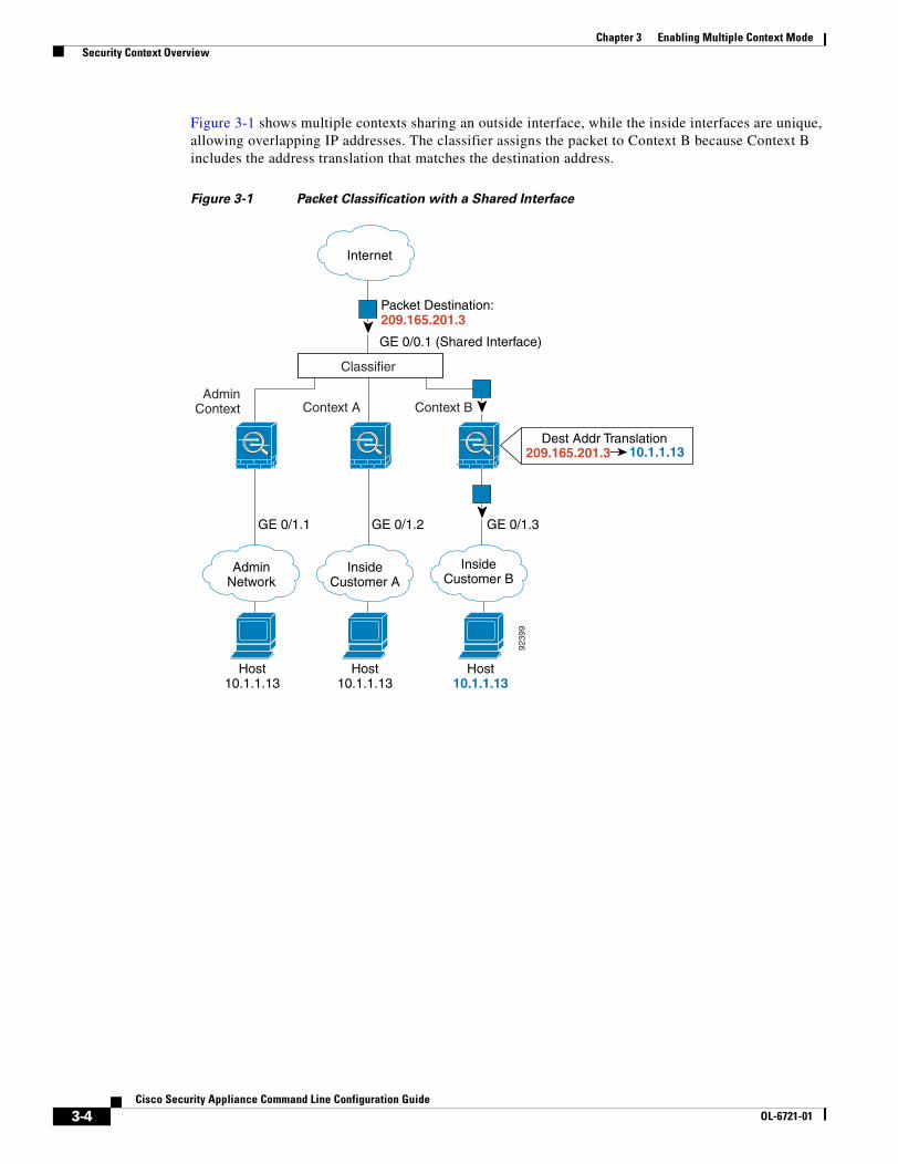
Chapter 3 Enabling Multiple Context Mode Security Context Overview
Figure 3-1 shows multiple contexts sharing an outside interface, while the inside interfaces are unique, allowing overlapping IP addresses. The classifier assigns the packet to Context B because Context B includes the address translation that matches the destination address.
Figure 3-1 Packet Classification with a Shared Interface
Classifier
Context A Context B
GE 0/1.3GE 0/1.2
GE 0/0.1 (Shared Interface)
AdminContext
GE 0/1.1
Host10.1.1.13
Host10.1.1.13
Host10.1.1.13
Dest Addr Translation209.165.201.3
Packet Destination:209.165.201.3
10.1.1.13
Internet
InsideCustomer A
InsideCustomer B
AdminNetwork
9239
9
3-4Cisco Security Appliance Command Line Configuration Guide
OL-6721-01

Chapter 3 Enabling Multiple Context Mode Security Context Overview
Note that all new incoming traffic must be classified, even from inside networks. Figure 3-2 shows a host on the Context B inside network accessing the Internet. The classifier assigns the packet to Context B because the ingress interface is Gigabit Ethernet 0/1.3, which is assigned to Context B.
Figure 3-2 Incoming Traffic from Inside Networks
Host10.1.1.13
Host10.1.1.13
Host10.1.1.13
Classifier
Context A Context B
GE 0/1.3GE 0/1.2
GE 0/0.1Admin
Context
GE 0/1.1
InsideCustomer A
InsideCustomer B
Internet
AdminNetwork
9239
5
3-5Cisco Security Appliance Command Line Configuration Guide
OL-6721-01

Chapter 3 Enabling Multiple Context Mode Security Context Overview
For transparent firewalls, you must use unique interfaces. For the classifier, the lack of NAT support in transparent mode leaves unique interfaces as the only means of classification. Figure 3-3 shows a host on the Context B inside network accessing the Internet. The classifier assigns the packet to Context B because the ingress interface is Gigabit Ethernet 1/0.3, which is assigned to Context B.
Figure 3-3 Transparent Firewall Contexts
Sharing Interfaces Between ContextsRouted Mode Only
The security appliance lets you share an interface between contexts. For example, you might share the outside interface to conserve interfaces. You can also share inside interfaces to share resources between contexts.
This section includes the following topics:
• Shared Interface Guidelines, page 3-7
• Cascading Security Contexts, page 3-9
Host10.1.3.13
Host10.1.2.13
Host10.1.1.13
Context A Context B
GE 1/0.3GE 1/0.2
AdminContext
GE 1/0.1
GE 0/0.3GE 0/0.1
GE 0/0.2
Classifier
InsideCustomer A
InsideCustomer B
Internet
AdminNetwork
9240
1
3-6Cisco Security Appliance Command Line Configuration Guide
OL-6721-01

Chapter 3 Enabling Multiple Context Mode Security Context Overview
Shared Interface Guidelines
If you want to allow traffic from a shared interface through the security appliance, then you must translate the destination addresses of the traffic. In other words, you must have a global command associated with the shared interface or a static command that specifies the shared interface as the global interface. The classifier relies on the address translation configuration to classify the packet within a context. If you do not want to perform NAT, you can still ensure classification into a context by specifying a global command for the shared interface: the global command specifies the real destination addresses, and a matching nat command is not required. (If you share an interface, and you allow only management traffic to and from the interface, then the classifier uses the interface IP address configuration to classify the packets. NAT configuration does not enter into the process.)
The type of NAT configured for the destination address determines whether the traffic can originate on the shared interface or if it can only respond to an existing connection. The properties of dynamic NAT (that uses a global address pool) dictate that you cannot initiate a connection to the host. Therefore, traffic from the shared interface must be in response to an existing connection. Static NAT, however, lets you initiate connections to the host, so with this configuration, you can initiate connections on the shared interface.
For an outside shared interface (connected to the Internet, for example), the inside host addresses are known, so configuring NAT for those addresses is easy, even if you want to configure static NAT. Configuring an inside shared interface poses a problem, however, if you want to allow communication between the shared interface and the Internet. For example, if you want to allow inside hosts on the shared interface to initiate traffic to the Internet, then you need to configure static NAT statements for each Internet address. This requirement necessarily limits the kind of Internet access you can provide for users on an inside shared interface. If you intend to statically translate addresses for Internet servers, then you also need to consider DNS entry addresses and how NAT affects them. For example, if a server sends a packet to www.example.com, then the DNS server needs to return the translated address. Managing DNS entries for translated addresses depends on where the DNS server resides. See the NAT chapter for more information.
Configuration is more straightforward if you want to allow Internet users to initiate connections to a host on the inside shared interface because you can configure a broad dynamic NAT statement for the outside ingress interface that matches any address.
3-7Cisco Security Appliance Command Line Configuration Guide
OL-6721-01

Chapter 3 Enabling Multiple Context Mode Security Context Overview
Figure 3-4 shows two servers on an inside shared interface. One server sends a packet to the translated address of a web server, and the security appliance classifies the packet to go through Context C because it includes a static translation for the address. The other server sends the packet to the real untranslated address, and the packet is dropped because the security appliance cannot classify it.
Figure 3-4 Originating Traffic on a Shared Interface
AdminContext Context A Context B
GE 1/0.1 GE 1/0.1
GE 1/0.1GE 1/0.1
Syslog Server AAA Server
GE 0/0.5
www.example.com209.165.201.4
Context C
Static Translation209.165.201.410.1.2.27
HTTP PacketDest. Address:209.165.201.4
HTTP PacketDest. Address:
10.1.2.27
HTTP PacketDest. Address:209.165.201.4
SharedNetwork
Internet
9239
8
3-8Cisco Security Appliance Command Line Configuration Guide
OL-6721-01

Chapter 3 Enabling Multiple Context Mode Security Context Overview
Cascading Security Contexts
Because of the limitation for originating traffic on a shared interface, a scenario where you place one context behind another requires that you configure static statements in the top context for every single outside address that bottom context users want to access.
Figure 3-5 shows a user in the bottom context (Context A) trying to access www.example.com. Because the Gateway Context does not have a static translation for www.example.com, the user cannot access the web server; the classifier does not know which context on the shared interface to assign the packet.
Figure 3-5 Cascading Contexts
AdminContext Context A
GatewayContext
GE 1/1.43GE 1/1.8
Host
GE 0/0.1(Shared Interface)
www.example.com209.165.201.4
HTTP PacketDest. Address:209.165.201.4
IP Address Classifier
Classifier does not know whetherto send packet to Admin, Gateway,or back to Context A.
Internet
InsideInside
9239
6
3-9Cisco Security Appliance Command Line Configuration Guide
OL-6721-01

Chapter 3 Enabling Multiple Context Mode Enabling or Disabling Multiple Context Mode
Logging into the Security Appliance in Multiple Context ModeWhen you access the security appliance console, you access the system execution space. If you later configure Telnet or SSH access to a context, you can log in to a specific context. If you log in to a specific context, you can only access the configuration for that context. However, if you log in to the admin context or the system execution space, you can access all contexts.
When you change to a context from admin, you continue to use the username and command authorization settings set in the admin context.
The system execution space does not support any AAA commands, but you can configure its own enable password, as well as usernames in the local database to provide individual logins.
Enabling or Disabling Multiple Context ModeYour security appliance might already be configured for multiple security contexts depending on how you ordered it from Cisco. If you are upgrading, however, you might need to convert from single mode to multiple mode by following the procedures in this section. ASDM does not support changing modes, so you need to change modes using the CLI.
This section includes the following topics:
• Backing Up the Single Mode Configuration, page 3-10
• Enabling Multiple Context Mode, page 3-10
• Restoring Single Context Mode, page 3-11
Backing Up the Single Mode ConfigurationWhen you convert from single mode to multiple mode, the security appliance converts the running configuration into two files. The original startup configuration is not saved, so if it differs from the running configuration, you should back it up before proceeding.
Enabling Multiple Context ModeThe context mode (single or multiple) is not stored in the configuration file, even though it does endure reboots. If you need to copy your configuration to another device, set the mode on the new device to match using the mode command.
When you convert from single mode to multiple mode, the security appliance converts the running configuration into two files: a new startup configuration that comprises the system configuration, and admin.cfg that comprises the admin context (in the root directory of the internal Flash memory). The original running configuration is saved as old_running.cfg (in the root directory of the internal Flash memory). The original startup configuration is not saved. The security appliance automatically adds an entry for the admin context to the system configuration with the name “admin.”
To enable multiple mode, enter the following command:
hostname(config)# mode multiple
You are prompted to reboot the security appliance.
3-10Cisco Security Appliance Command Line Configuration Guide
OL-6721-01

Chapter 3 Enabling Multiple Context Mode Enabling or Disabling Multiple Context Mode
Restoring Single Context ModeIf you convert from multiple mode to single mode, you might want to first copy a full startup configuration (if available) to the security appliance; the system configuration inherited from multiple mode is not a complete functioning configuration for a single mode device. Because the system configuration does not have any network interfaces as part of its configuration, you must access the security appliance from the console to perform the copy.
To copy the old running configuration to the startup configuration and to change the mode to single mode, perform the following steps in the system execution space:
Step 1 To copy the backup version of your original running configuration to the current startup configuration, enter the following command in the system execution space:
hostname(config)# copy flash:old_running.cfg startup-config
Step 2 To set the mode to single mode, enter the following command in the system execution space:
hostname(config)# mode single
The security appliance reboots.
3-11Cisco Security Appliance Command Line Configuration Guide
OL-6721-01

Chapter 3 Enabling Multiple Context Mode Enabling or Disabling Multiple Context Mode
3-12Cisco Security Appliance Command Line Configuration Guide
OL-6721-01

Cisco Security AppliaOL-6721-01
C H A P T E R 4
Configuring Ethernet Settings and SubinterfacesThis chapter describes how to configure Ethernet settings for physical interfaces and add subinterfaces. In single context mode, complete the procedures in this chapter and then continue your interface configuration in Chapter 6, “Configuring Interface Parameters.” In multiple context mode, complete the procedures in this chapter in the system execution space, then assign interfaces and subinterfaces to contexts according to Chapter 5, “Adding and Managing Security Contexts,” and finally configure the interface parameters within each context according to Chapter 6, “Configuring Interface Parameters.”
This chapter includes the following sections:
• Configuring Ethernet Settings, page 4-1
• Configuring Subinterfaces, page 4-2
Configuring Ethernet SettingsYou can configure the Ethernet settings for physical interfaces only.
By default, the speed and duplex for copper (RJ-45) interfaces are set to auto-negotiate. The fiber interface has a fixed speed and does not support duplex, but you can set the interface to negotiate link parameters (the default) or not to negotiate.
If you need to set a specific speed and duplex, perform the following steps:
Step 1 To specify the interface you want to configure, enter the following command:
hostname(config)# interface physical_interface
The physical_interface ID includes the type and port number as typeport.
The physical interface types include the following:
• ethernet
• gigabitethernet
For the PIX 500 series security appliance, enter the type followed by the port number, for example, ethernet0.
Step 2 To set the speed, enter the following command:
hostname(config-if)# speed {auto | 10 | 100 | nonegotiate}
4-1nce Command Line Configuration Guide

Chapter 4 Configuring Ethernet Settings and Subinterfaces Configuring Subinterfaces
The auto setting is the default for copper interfaces. For fiber Gigabit Ethernet interfaces, the default is no speed nonegotiate, which sets the speed to 1000 Mbps and enables link negotiation for flow-control parameters and remote fault information. The speed nonegotiate command disables link negotiation. These two commands are the only available options for fiber interfaces.
Step 3 To set the duplex for copper interfaces, enter the following command:
hostname(config-if)# duplex {auto | full | half}
The auto setting is the default. You do not set the duplex for fiber interfaces.
Step 4 To enable the interface, enter the following command:
hostname(config-if)# no shutdown
To disable the interface, enter the shutdown command. If you enter the shutdown command for a physical interface, you also shut down all subinterfaces. If you shut down an interface in the system execution space, then that interface is shut down in all contexts that share it.
Configuring SubinterfacesSubinterfaces let you divide a physical interface into multiple logical interfaces that are tagged with different VLAN IDs. Because VLANs allow you to keep traffic separate on a given physical interface, you can increase the number of interfaces available to your network without adding additional physical interfaces or security appliances. This feature is particularly useful in multiple context mode so you can assign unique interfaces to each context.
To determine how many subinterfaces are allowed for your platform, see Appendix A, “Feature Licenses and Specifications.”
You need to enable the physical interface with the no shutdown command to let subinterfaces be enabled. If you enable subinterfaces, you typically do not also want the physical interface to pass traffic, because the physical interface passes untagged packets. Therefore, you cannot prevent traffic from passing through the physical interface by bringing down the interface. Instead, ensure that the physical interface does not pass traffic by leaving out the nameif command. If you want to let the physical interface pass untagged packets, you can configure the nameif command as usual.
4-2Cisco Security Appliance Command Line Configuration Guide
OL-6721-01

Chapter 4 Configuring Ethernet Settings and Subinterfaces Configuring Subinterfaces
To add a subinterface and assign a VLAN to it, perform the following steps:
Step 1 To specify the new subinterface, enter the following command:
hostname(config)# interface physical_interface.subinterface
See the “Configuring Ethernet Settings” section for a description of the physical interface ID.
The subinterface ID is an integer between 1 and 4294967293.
For example, enter the following command:
hostname(config)# interface gigabitethernet1.100
Step 2 To specify the VLAN for the subinterface, enter the following command:
hostname(config-subif)# vlan vlan_id
The vlan_id is an integer between 1 and 4094. Some VLAN IDs might be reserved on connected switches, so check the switch documentation for more information.
You can only assign a single VLAN to a subinterface, and not to the physical interface. Each subinterface must have a VLAN ID before it can pass traffic. To change a VLAN ID, you do not need to remove the old VLAN ID with the no option; you can enter the vlan command with a different VLAN ID, and the security appliance changes the old ID.
Step 3 To enable the subinterface, enter the following command:
hostname(config-subif)# no shutdown
To disable the interface, enter the shutdown command. If you shut down an interface in the system execution space, then that interface is shut down in all contexts that share it.
4-3Cisco Security Appliance Command Line Configuration Guide
OL-6721-01

Chapter 4 Configuring Ethernet Settings and Subinterfaces Configuring Subinterfaces
4-4Cisco Security Appliance Command Line Configuration Guide
OL-6721-01

Cisco Security AppliaOL-6721-01
C H A P T E R 5
Adding and Managing Security ContextsThis chapter describes how to configure multiple security contexts on the security appliance, and includes the following sections:
• Configuring a Security Context, page 5-1
• Removing a Security Context, page 5-5
• Changing the Admin Context, page 5-5
• Changing Between Contexts and the System Execution Space, page 5-5
• Changing the Security Context URL, page 5-6
• Reloading a Security Context, page 5-7
• Monitoring Security Contexts, page 5-8
For information about how contexts work and how to enable multiple context mode, see Chapter 3, “Enabling Multiple Context Mode.”
Configuring a Security ContextThe security context definition in the system configuration identifies the context name, configuration file URL, and interfaces that a context can use.
Note If you do not have an admin context (for example, if you clear the configuration) then you must first specify the admin context name by entering the following command:
hostname(config)# admin-context name
Although this context name does not exist yet in your configuration, you can subsequently enter the context name command to match the specified name to continue the admin context configuration.
5-1nce Command Line Configuration Guide

Chapter 5 Adding and Managing Security Contexts Configuring a Security Context
To add or change a context in the system configuration, perform the following steps:
Step 1 To add or modify a context, enter the following command in the system execution space:
hostname(config)# context name
The name is a string up to 32 characters long. This name is case sensitive, so you can have two contexts named “customerA” and “CustomerA,” for example. You can use letters, digits, or hyphens, but you cannot start or end the name with a hyphen.
“System” or “Null” (in upper or lower case letters) are reserved names, and cannot be used.
Step 2 (Optional) To add a description for this context, enter the following command:
hostname(config-ctx)# description text
Step 3 To specify the interfaces you can use in the context, enter the command appropriate for a physical interface or for one or more subinterfaces.
• To allocate a physical interface, enter the following command:
hostname(config-ctx)# allocate-interface physical_interface [map_name] [visible | invisible]
• To allocate one or more subinterfaces, enter the following command:
hostname(config-ctx)# allocate-interface physical_interface.subinterface[-physical_interface.subinterface] [map_name[-map_name]] [visible | invisible]
You can enter these commands multiple times to specify different ranges.
Transparent firewall mode allows only two interfaces to pass through traffic.You can assign the same interfaces to multiple contexts in routed mode, if desired. Transparent mode does not allow shared interfaces.
The map_name is an alphanumeric alias for the interface that can be used within the context instead of the interface ID. If you do not specify a mapped name, the interface ID is used within the context. For security purposes, you might not want the context administrator to know which interfaces are being used by the context.
A mapped name must start with a letter, end with a letter or digit, and have as interior characters only letters, digits, or an underscore. For example, you can use the following names:
int0
inta
int_0
For subinterfaces, you can specify a range of mapped names.
5-2Cisco Security Appliance Command Line Configuration Guide
OL-6721-01

Chapter 5 Adding and Managing Security Contexts Configuring a Security Context
If you specify a range of subinterfaces, you can specify a matching range of mapped names. Follow these guidelines for ranges:
• The mapped name must consist of an alphabetic portion followed by a numeric portion. The alphabetic portion of the mapped name must match for both ends of the range. For example, enter the following range:
int0-int10
If you enter gigabitethernet1.1-gigabitethernet1.5 happy1-sad5, for example, the command fails.
• The numeric portion of the mapped name must include the same quantity of numbers as the subinterface range. For example, both ranges include 100 interfaces:
gigabitethernet0.100-gigabitethernet0.199 int1-int100
If you enter gigabitethernet0.100-gigabitethernet0.199 int1-int15, for example, the command fails.
Specify visible to see physical interface properties in the show interface command even if you set a mapped name. The default invisible keyword specifies to only show the mapped name.
The following example shows gigabitethernet1.100, gigabitethernet1.200, and gigabitethernet2.300 through gigabitethernet1.305 assigned to the context. The mapped names are int1 through int8.
hostname(config-ctx)# allocate-interface gigabitethernet1.100 int1hostname(config-ctx)# allocate-interface gigabitethernet1.200 int2hostname(config-ctx)# allocate-interface gigabitethernet2.300-gigabitethernet2.305 int3-int8
Step 4 To identify the URL from which the system downloads the context configuration, enter the following command:
hostname(config-ctx)# config-url url
When you add a context URL, the system immediately loads the context so that it is running.
Note Enter the allocate-interface command(s) before you enter the config-url command. The security appliance must assign interfaces to the context before it loads the context configuration; the context configuration might include commands that refer to interfaces (interface, nat, global...). If you enter the config-url command first, the security appliance loads the context configuration immediately. If the context contains any commands that refer to interfaces, those commands fail.
See the following URL syntax:
• flash:/[path/]filename
This URL indicates the internal Flash memory.
• ftp://[user[:password]@]server[:port]/[path/]filename[;type=xx]
The type can be one of the following keywords:
– ap—ASCII passive mode
– an—ASCII normal mode
– ip—(Default) Binary passive mode
– in—Binary normal mode
• http[s]://[user[:password]@]server[:port]/[path/]filename
• tftp://[user[:password]@]server[:port]/[path/]filename[;int=interface_name]
5-3Cisco Security Appliance Command Line Configuration Guide
OL-6721-01

Chapter 5 Adding and Managing Security Contexts Configuring a Security Context
Specify the interface name if you want to override the route to the server address.
The filename does not require a file extension, although we recommend using “.cfg”.
The admin context file must be stored on the internal Flash memory.
If you download a context configuration from an HTTP or HTTPS server, you cannot save changes back to these servers using the copy running-config startup-config command. You can, however, use the copy tftp command to copy the running configuration to a TFTP server.
If the system cannot retrieve the context configuration file because the server is unavailable, or the file does not yet exist, the system creates a blank context that is ready for you to configure with the command-line interface.
To change the URL, reenter the config-url command with a new URL.
See the “Changing the Security Context URL” section on page 5-6 for more information about changing the URL.
For example, enter the following command:
hostname(config-ctx)# config-url ftp://joe:[email protected]/configlets/test.cfg
Step 5 To view context information, see the show context command in the Cisco Security Appliance Command Reference.
The following example sets the admin context to be “administrator,” creates a context called “administrator” on the internal Flash memory, and then adds two contexts from an FTP server:
hostname(config)# admin-context administratorhostname(config)# context administratorhostname(config-ctx)# allocate-interface gigabitethernet0.1hostname(config-ctx)# allocate-interface gigabitethernet1.1hostname(config-ctx)# config-url flash:/admin.cfg
hostname(config-ctx)# context testhostname(config-ctx)# allocate-interface gigabitethernet0.100 int1hostname(config-ctx)# allocate-interface gigabitethernet0.102 int2hostname(config-ctx)# allocate-interface gigabitethernet0.110-gigabitethernet0.115 int3-int8hostname(config-ctx)# config-url ftp://user1:[email protected]/configlets/test.cfg
hostname(config-ctx)# context samplehostname(config-ctx)# allocate-interface gigabitethernet1.200 int1hostname(config-ctx)# allocate-interface gigabitethernet1.212 int2hostname(config-ctx)# allocate-interface gigabitethernet1.230-gigabitethernet1.235 int3-int8hostname(config-ctx)# config-url ftp://user1:[email protected]/configlets/sample.cfg
5-4Cisco Security Appliance Command Line Configuration Guide
OL-6721-01

Chapter 5 Adding and Managing Security Contexts Removing a Security Context
Removing a Security ContextYou can only remove a context by editing the system configuration. You cannot remove the current admin context, unless you remove all contexts using the clear context command.
Note If you use failover, there is a delay between when you remove the context on the active unit and when the context is removed on the standby unit. You might see an error message indicating that the number of interfaces on the active and standby units are not consistent; this error is temporary and can be ignored.
Use the following commands for removing contexts:
• To remove a single context, enter the following command in the system execution space:
hostname(config)# no context name
All context commands are also removed.
• To remove all contexts (including the admin context), enter the following command in the system execution space:
hostname(config)# clear context
Changing the Admin ContextYou can set any context to be the admin context, as long as the configuration file is stored in the internal Flash memory. To set the admin context, enter the following command in the system execution space:
hostname(config)# admin-context context_name
Any remote management sessions, such as Telnet, SSH, or HTTPS, that are connected to the admin context are terminated. You must reconnect to the new admin context.
Note A few system commands, including ntp server, identify an interface name that belongs to the admin context. If you change the admin context, and that interface name does not exist in the new admin context, be sure to update any system commands that refer to the interface.
Changing Between Contexts and the System Execution SpaceIf you log in to the system execution space (or the admin context using Telnet or SSH), you can change between contexts and perform configuration and monitoring tasks within each context. The running configuration that you edit in a configuration mode, or that is used in the copy or write commands, depends on your location. When you are in the system execution space, the running configuration consists only of the system configuration; when you are in a context, the running configuration consists only of that context. For example, you cannot view all running configurations (system plus all contexts) by entering the show running-config command. Only the current configuration displays.
5-5Cisco Security Appliance Command Line Configuration Guide
OL-6721-01

Chapter 5 Adding and Managing Security Contexts Changing the Security Context URL
To change between the system execution space and a context, or between contexts, see the following commands:
• To change to a context, enter the following command:
hostname# changeto context name
The prompt changes to the following:
hostname/name#
• To change to the system execution space, enter the following command:
hostname/admin# changeto system
The prompt changes to the following:
hostname#
Changing the Security Context URLYou cannot change the security context URL without reloading the configuration from the new URL.
The security appliance merges the new configuration with the current running configuration. Reentering the same URL also merges the saved configuration with the running configuration. A merge adds any new commands from the new configuration to the running configuration. If the configurations are the same, no changes occur. If commands conflict or if commands affect the running of the context, then the effect of the merge depends on the command. You might get errors, or you might have unexpected results. If the running configuration is blank (for example, if the server was unavailable and the configuration was never downloaded), then the new configuration is used. If you do not want to merge the configurations, you can clear the running configuration, which disrupts any communications through the context, and then reload the configuration from the new URL.
To change the URL for a context, perform the following steps:
Step 1 If you do not want to merge the configuration, change to the context and clear its configuration by entering the following commands. If you want to perform a merge, skip to Step 2.
hostname# changeto context namehostname/name# configure terminalhostname/name(config)# clear configure all
Step 2 If required, change to the system execution space by entering the following command:
hostname/name(config)# changeto system
Step 3 To enter the context configuration mode for the context you want to change, enter the following command:
hostname(config)# context name
Step 4 To enter the new URL, enter the following command:
hostname(config)# config-url new_url
The system immediately loads the context so that it is running.
5-6Cisco Security Appliance Command Line Configuration Guide
OL-6721-01

Chapter 5 Adding and Managing Security Contexts Reloading a Security Context
Reloading a Security ContextYou can reload the context in two ways:
• Clear the running configuration and then import the startup configuration.
This action clears most attributes associated with the context, such as connections and NAT tables.
• Remove the context from the system configuration.
This action clears additional attributes, such as memory allocation, which might be useful for troubleshooting. However, to add the context back to the system requires you to respecify the URL and interfaces.
This section includes the following topics:
• Reloading by Clearing the Configuration, page 5-7
• Reloading by Removing and Re-adding the Context, page 5-7
Reloading by Clearing the ConfigurationTo reload the context by clearing the context configuration, and reloading the configuration from the URL, perform the following steps:
Step 1 To change to the context that you want to reload, enter the following command:
hostname# changeto context name
Step 2 To access configuration mode, enter the following command:
hostname/name# configure terminal
Step 3 To clear the running configuration, enter the following command:
hostname/name(config)# clear configure all
This command clears all connections.
Step 4 To reload the configuration, enter the following command:
hostname/name(config)# copy startup-config running-config
The security appliance copies the configuration from the URL specified in the system configuration. You cannot change the URL from within a context.
Reloading by Removing and Re-adding the ContextTo reload the context by removing the context and then re-adding it, perform the steps in the following sections:
1. “Removing a Security Context” section on page 5-5
2. “Configuring a Security Context” section on page 5-1
5-7Cisco Security Appliance Command Line Configuration Guide
OL-6721-01

Chapter 5 Adding and Managing Security Contexts Monitoring Security Contexts
Monitoring Security ContextsThis section describes how to view and monitor context information, and includes the following topics:
• Viewing Context Information, page 5-8
• Viewing Resource Usage, page 5-9
Viewing Context InformationFrom the system execution space, you can view a list of contexts including the name, allocated interfaces, and configuration file URL.
From the system execution space, view all contexts by entering the following command:
hostname# show context [name | detail| count]
The detail option shows additional information. See the following sample displays below for more information.
If you want to show information for a particular context, specify the name.
The count option shows the total number of contexts.
The following is sample output from the show context command. The following sample display shows three contexts:
hostname# show context
Context Name Interfaces URL*admin GigabitEthernet1.100 flash:/admin.cfg
GigabitEthernet1.101contexta GigabitEthernet1.200 flash:/contexta.cfg
GigabitEthernet1.201contextb GigabitEthernet1.300 flash:/contextb.cfg
GigabitEthernet1.301Total active Security Contexts: 3
Table 5-1 shows each field description.
The following is sample output from the show context detail command:
hostname# show context detail
Context "admin", has been created, but initial ACL rules not complete Config URL: flash:/admin.cfg Real Interfaces: Management0/0 Mapped Interfaces: Management0/0 Flags: 0x00000013, ID: 1
Context "ctx", has been created, but initial ACL rules not complete Config URL: ctx.cfg
Table 5-1 show context Fields
Field Description
Context Name Lists all context names. The context name with the asterisk (*) is the admin context.
Interfaces The interfaces assigned to the context.
URL The URL from which the security appliance loads the context configuration.
5-8Cisco Security Appliance Command Line Configuration Guide
OL-6721-01

Chapter 5 Adding and Managing Security Contexts Monitoring Security Contexts
Real Interfaces: GigabitEthernet0.10, GigabitEthernet1.20, GigabitEthernet2.30 Mapped Interfaces: int1, int2, int3 Flags: 0x00000011, ID: 2
Context "system", is a system resource Config URL: startup-config Real Interfaces: Mapped Interfaces: GigabitEthernet0, GigabitEthernet0.10, GigabitEthernet1, GigabitEthernet1.10, GigabitEthernet1.20, GigabitEthernet2, GigabitEthernet2.30, GigabitEthernet3 Flags: 0x00000019, ID: 257
Context "null", is a system resource Config URL: ... null ... Real Interfaces: Mapped Interfaces: Flags: 0x00000009, ID: 258
See the Cisco Security Appliance Command Reference for more information about the detail output.
The following is sample output from the show context count command:
hostname# show context countTotal active contexts: 2
Viewing Resource UsageFrom the system execution space, you can view the resource usage for each context and display the system resource usage. Resources include concurrent connections, Telnet sessions, SSH sessions, hosts, NAT translations, and for single mode, IPSec sessions.
From the system execution space, view the resource usage for each context by entering the following command:
hostname# show resource usage [context context_name | top n | all | summary | system][resource {resource_name | all}] [counter counter_name [count_threshold]]
By default, all context usage is displayed; each context is listed separately.
Enter the top n keyword to show the contexts that are the top n users of the specified resource. You must specify a single resource type, and not resource all, with this option.
The summary option shows all context usage combined.
The system option shows all context usage combined, but shows the system limits for resources instead of the combined context limits.
The resource names include the following values. See also the show resource type command for a complete list. Specify all (the default) for all types.
• conns—TCP or UDP connections between any two hosts, including connections between one host and multiple other hosts.
• hosts—Hosts that can connect through the security appliance.
• ipsec—(Single mode only) IPSec sessions.
• ssh—SSH sessions.
• telnet—Telnet sessions.
• xlates—NAT translations.
5-9Cisco Security Appliance Command Line Configuration Guide
OL-6721-01

Chapter 5 Adding and Managing Security Contexts Monitoring Security Contexts
The counter counter_name is one of the following keywords:
• current—Shows the active concurrent instances or the current rate of the resource.
• peak—Shows the peak concurrent instances, or the peak rate of the resource since the statistics were last cleared, either using the clear resource usage command or because the device rebooted.
• all—(Default) Shows all statistics.
The count_threshold sets the number above which resources are shown. The default is 1. If the usage of the resource is below the number you set, then the resource is not shown. If you specify all for the counter name, then the count_threshold applies to the current usage.
Note To show all resources, set the count_threshold to 0.
The following is sample output from the show resource usage context command, which shows the resource usage for the admin context:
hostname# show resource usage context admin
Resource Current Peak Limit ContextTelnet 1 1 5 adminConns 44 55 N/A adminHosts 45 56 N/A admin
The following is sample output from the show resource usage summary command, which shows the resource usage for all contexts and all resources. This sample shows the limits for 6 contexts.
hostname# show resource usage summary
Resource Current Peak Limit ContextTelnet 3 5 30 SummarySSH 5 7 30 SummaryConns 40 55 N/A SummaryHosts 44 56 N/A Summary
The following is sample output from the show resource usage summary command, which shows the limits for 25 contexts. Because the context limit for Telnet and SSH connections is 5 per context, then the combined limit is 125. The system limit is only 100, so the system limit is shown.
hostname# show resource usage summary
Resource Current Peak Limit ContextTelnet 1 1 100[S] SummarySSH 2 2 100[S] SummaryConns 56 90 N/A SummaryHosts 89 102 N/A SummaryS = System limit: Combined context limits exceed the system limit; the system limit is shown.
The following is sample output from the show resource usage system command, which shows the resource usage for all contexts, but it shows the system limit instead of the combined context limits:
hostname# show resource usage system
Resource Current Peak Limit ContextTelnet 3 5 100 SystemSSH 5 7 100 SystemConns 40 55 N/A SystemHosts 44 56 N/A System
5-10Cisco Security Appliance Command Line Configuration Guide
OL-6721-01

Cisco Security AppliaOL-6721-01
C H A P T E R 6
Configuring Interface ParametersThis chapter describes how to configure each interface and subinterface for a name, security, level, and IP address. For single context mode, the procedures in this chapter continue the interface configuration started in Chapter 4, “Configuring Ethernet Settings and Subinterfaces.” For multiple context mode, the procedures in Chapter 4, “Configuring Ethernet Settings and Subinterfaces,” are performed in the system execution space, while the procedures in this chapter are performed within each security context.
This chapter includes the following sections:
• Security Level Overview, page 6-1
• Configuring the Interface, page 6-2
• Allowing Communication Between Interfaces on the Same Security Level, page 6-4
Security Level OverviewEach interface must have a security level from 0 (lowest) to 100 (highest). For example, you should assign your most secure network, such as the inside host network, to level 100. While the outside network connected to the Internet can be level 0. Other networks, such as DMZs can be in between. You can assign interfaces to the same security level. See the “Allowing Communication Between Interfaces on the Same Security Level” section on page 6-4 for more information.
The level controls the following behavior:
• Network access—By default, there is an implicit permit from a higher security interface to a lower security interface (outbound). Hosts on the higher security interface can access any host on a lower security interface. You can limit access by applying an access list to the interface.
For same security interfaces, there is an implicit permit for interfaces to access other interfaces on the same security level or lower.
• Inspection engines—Some inspection engines are dependent on the security level. For same security interfaces, inspection engines apply to traffic in either direction.
– NetBIOS inspection engine—Applied only for outbound connections.
– OraServ inspection engine—If a control connection for the OraServ port exists between a pair of hosts, then only an inbound data connection is permitted through the security appliance.
• Filtering—HTTP(S) and FTP filtering applies only for outbound connections (from a higher level to a lower level).
For same security interfaces, you can filter traffic in either direction.
6-1nce Command Line Configuration Guide

Chapter 6 Configuring Interface Parameters Configuring the Interface
• NAT control—When you enable NAT control, you must configure NAT for hosts on a higher security interface (inside) when they access hosts on a lower security interface (outside).
Without NAT control, or for same security interfaces, you can choose to use NAT between any interface, or you can choose not to use NAT. Keep in mind that configuring NAT for an outside interface might require a special keyword.
• established command—This command allows return connections from a lower security host to a higher security host if there is already an established connection from the higher level host to the lower level host.
For same security interfaces, you can configure established commands for both directions.
Configuring the InterfaceBy default, all physical interfaces are shut down. You must enable the physical interface before any traffic can pass through an enabled subinterface. For multiple context mode, if you allocate a physical interface or subinterface to a context, the interfaces are enabled by default in the context. However, before traffic can pass through the context interface, you must also enable the interface in the system configuration. If you shut down an interface in the system execution space, then that interface is down in all contexts that share it.
Before you can complete your configuration and allow traffic through the security appliance, you need to configure an interface name, and for routed mode, an IP address. You should also change the security level from the default, which is 0. If you name an interface “inside” and you do not set the security level explicitly, then the security appliance sets the security level to 100.
Note If you are using failover, do not use this procedure to name interfaces that you are reserving for failover and Stateful Failover communications. See Chapter 11, “Configuring Failover.” to configure the failover and state links.
For multiple context mode, follow these guidelines:
• Configure the context interfaces from within each context.
• You can only configure context interfaces that you already assigned to the context in the system configuration.
• The system configuration only lets you configure Ethernet settings and VLANs. The exception is for failover interfaces; do not configure failover interfaces with this procedure. See the Failover chapter for more information.
Note If you change the security level of an interface, and you do not want to wait for existing connections to time out before the new security information is used, you can clear the connections using the clear local-host command.
To configure an interface or subinterface, perform the following steps:
Step 1 To specify the interface you want to configure, enter the following command:
hostname(config)# interface {physical_interface[.subinterface] | mapped_name}
The physical_interface ID includes the type and port number as typeport.
6-2Cisco Security Appliance Command Line Configuration Guide
OL-6721-01

Chapter 6 Configuring Interface Parameters Configuring the Interface
The physical interface types include the following:
• ethernet
• gigabitethernet
For the PIX 500 series security appliance, enter the type followed by the port number, for example, ethernet0.
Append the subinterface ID to the physical interface ID separated by a period (.).
In multiple context mode, enter the mapped name if one was assigned using the allocate-interface command.
For example, enter the following command:
hostname(config)# interface gigabitethernet1.1
Step 2 To name the interface, enter the following command:
hostname(config-if)# nameif name
The name is a text string up to 48 characters, and is not case-sensitive. You can change the name by reentering this command with a new value. Do not enter the no form, because that command causes all commands that refer to that name to be deleted.
Step 3 To set the security level, enter the following command:
hostname(config-if)# security-level number
Where number is an integer between 0 (lowest) and 100 (highest).
Step 4 To set the IP address or routed mode only, enter one of the following commands.
Note To set an IPv6 address, see the “Configuring IPv6 on an Interface” section on page 9-2.
• To set the IP address manually, enter the following command:
hostname(config-if)# ip address ip_address [mask] [standby ip_address]
The standby keyword and address is used for failover. See Chapter 11, “Configuring Failover,” for more information.
• To obtain an IP address from a DHCP server, enter the following command:
hostname(config-if)# ip address dhcp [setroute]
Reenter this command to reset the DHCP lease and request a new lease.
You cannot set this command at the same time as the ip address command.
If you enable the setroute option, do not configure a default route using the static command.
If you do not enable the interface using the no shutdown command before you enter the ip address dhcp command, some DHCP requests might not be sent.
Step 5 To set an interface to management-only mode, enter the following command:
hostname(config-if)# management-only
Step 6 To enable the interface, if it is not already enabled, enter the following command:
hostname(config-if)# no shutdown
6-3Cisco Security Appliance Command Line Configuration Guide
OL-6721-01

Chapter 6 Configuring Interface Parameters Allowing Communication Between Interfaces on the Same Security Level
To disable the interface, enter the shutdown command. If you enter the shutdown command for a physical interface, you also shut down all subinterfaces. If you shut down an interface in the system execution space, then that interface is shut down in all contexts that share it, even though the context configurations show the interface as enabled.
The following example configures parameters for the physical interface in single mode:
hostname(config)# interface ethernet1hostname(config-if)# speed 100hostname(config-if)# duplex fullhostname(config-if)# nameif insidehostname(config-if)# security-level 100hostname(config-if)# ip address 10.1.1.1 255.255.255.0hostname(config-if)# no shutdown
The following example configures parameters for a subinterface in single mode:
hostname(config)# interface gigabitethernet1.1hostname(config-subif)# vlan 101hostname(config-subif)# nameif dmz1hostname(config-subif)# security-level 50hostname(config-subif)# ip address 10.1.2.1 255.255.255.0hostname(config-subif)# no shutdown
The following example configures interface parameters in multiple context mode for the system configuration, and allocates the ethernet 1.1 subinterface to contextA:
hostname(config)# interface ethernet1hostname(config-if)# speed 100hostname(config-if)# duplex fullhostname(config-if)# no shutdownhostname(config-if)# interface ethernet1.1hostname(config-subif)# vlan 101hostname(config-subif)# no shutdownhostname(config-subif)# context contextAhostname(config-ctx)# ...hostname(config-ctx)# allocate-interface ethernet1.1
The following example configures parameters in multiple context mode for the context configuration:
hostname/contextA(config)# interface gigabitethernet1.1hostname/contextA(config-if)# nameif insidehostname/contextA(config-if)# security-level 100hostname/contextA(config-if)# ip address 10.1.2.1 255.255.255.0hostname/contextA(config-if)# no shutdown
Allowing Communication Between Interfaces on the Same Security Level
By default, interfaces on the same security level cannot communicate with each other. Allowing communication between same security interfaces provides the following benefits:
• You can configure more than 101 communicating interfaces.
If you use different levels for each interface and do not assign any interfaces to the same security level, you can configure only one interface per level (0 to 100).
• You want traffic to flow freely between all same security interfaces without access lists.
6-4Cisco Security Appliance Command Line Configuration Guide
OL-6721-01

Chapter 6 Configuring Interface Parameters Allowing Communication Between Interfaces on the Same Security Level
Note If you enable NAT control, you do not need to configure NAT between same security level interfaces.
If you enable same security interface communication, you can still configure interfaces at different security levels as usual.
To enable interfaces on the same security level so that they can communicate with each other, enter the following command:
hostname(config)# same-security-traffic permit inter-interface
To disable this setting, use the no form of this command.
6-5Cisco Security Appliance Command Line Configuration Guide
OL-6721-01

Chapter 6 Configuring Interface Parameters Allowing Communication Between Interfaces on the Same Security Level
6-6Cisco Security Appliance Command Line Configuration Guide
OL-6721-01

Cisco Security AppliaOL-6721-01
C H A P T E R 7
Configuring Basic SettingsThis chapter describes how to configure basic settings on your security appliance that are typically required for a functioning configuration. This chapter includes the following sections:
• Changing the Enable Password, page 7-1
• Setting the Hostname, page 7-2
• Setting the Domain Name, page 7-2
• Setting the Date and Time, page 7-2
• Setting the Management IP Address for a Transparent Firewall, page 7-5
Changing the Enable PasswordThe enable password lets you enter privileged EXEC mode. By default, the enable password is blank. To change the enable password, enter the following command:
hostname(config)# enable password password
The password is a case-sensitive password of up to 16 alphanumeric and special characters. You can use any character in the password except a question mark or a space.
This command changes the password for the highest privilege level. If you configure local command authorization, you can set enable passwords for each privilege level from 0 to 15.
The password is saved in the configuration in encrypted form, so you cannot view the original password after you enter it. Enter the enable password command without a password to set the password to the default, which is blank.
7-1nce Command Line Configuration Guide

Chapter 7 Configuring Basic Settings Setting the Hostname
Setting the HostnameWhen you set a hostname for the security appliance, that name appears in the command line prompt. If you establish sessions to multiple devices, the hostname helps you keep track of where you enter commands. The default hostname depends on your platform.
For multiple context mode, the hostname that you set in the system execution space appears in the command line prompt for all contexts. The hostname that you optionally set within a context does not appear in the command line, but can be used by the banner command $(hostname) token.
To specify the hostname for the security appliance or for a context, enter the following command:
hostname(config)# hostname name
This name can be up to 63 characters, including alphanumeric characters, spaces or any of the following special characters: ` ( ) + - , . / : = ?.
This name appears in the command line prompt. For example:
hostname(config)# hostname farscapefarscape(config)#
Setting the Domain NameThe security appliance appends the domain name as a suffix to unqualified names. For example, if you set the domain name to “example.com,” and specify a syslog server by the unqualified name of “jupiter,” then the security appliance qualifies the name to “jupiter.example.com.”
The default domain name is default.domain.invalid.
For multiple context mode, you can set the domain name for each context, as well as within the system execution space.
To specify the domain name for the security appliance, enter the following command:
hostname(config)# domain-name name
For example, to set the domain as example.com, enter the following command:
hostname(config)# domain-name example.com
Setting the Date and TimeThis section describes how to set the date and time, either manually or dynamically using an NTP server. Time derived from an NTP server overrides any time set manually. This section also describes how to set the time zone and daylight saving time date range.
Note In multiple context mode, set the time in the system configuration only.
This section includes the following topics:
• Setting the Time Zone and Daylight Saving Time Date Range, page 7-3
• Setting the Date and Time Using an NTP Server, page 7-4
• Setting the Date and Time Manually, page 7-4
7-2Cisco Security Appliance Command Line Configuration Guide
OL-6721-01

Chapter 7 Configuring Basic Settings Setting the Date and Time
Setting the Time Zone and Daylight Saving Time Date RangeBy default, the time zone is UTC and the daylight saving time date range is from 2:00 a.m. on the first Sunday in April to 2:00 a.m. on the last Sunday in October. To change the time zone and daylight saving time date range, perform the following steps:
Step 1 To set the time zone, enter the following command in global configuration mode:
hostname(config)# clock timezone zone [-]hours [minutes]
Where zone specifies the time zone as a string, for example, PST for Pacific Standard Time.
The [-]hours value sets the number of hours of offset from UTC. For example, PST is -8 hours.
The minutes value sets the number of minutes of offset from UTC.
Step 2 To change the date range for daylight saving time from the default, enter one of the following commands.
The default recurring date range is from 2:00 a.m. on the first Sunday in April to 2:00 a.m. on the last Sunday in October.
• To set the start and end dates for daylight saving time as a specific date in a specific year, enter the following command:
hostname(config)# clock summer-time zone date {day month | month day} year hh:mm {day month | month day} year hh:mm [offset]
If you use this command, you need to reset the dates every year.
The zone value specifies the time zone as a string, for example, PDT for Pacific Daylight Time.
The day value sets the day of the month, from 1 to 31. You can enter the day and month as April 1 or as 1 April, for example, depending on your standard date format.
The month value sets the month as a string. You can enter the day and month as April 1 or as 1 April, for example, depending on your standard date format.
The year value sets the year using four digits, for example, 2004. The year range is 1993 to 2035.
The hh:mm value sets the hour and minutes in 24-hour time.
The offset value sets the number of minutes to change the time for daylight saving time. By default, the value is 60 minutes.
• To specify the start and end dates for daylight saving time, in the form of a day and time of the month, and not a specific date in a year, enter the following command.
hostname(config)# clock summer-time zone recurring [week weekday month hh:mm week weekday month hh:mm] [offset]
This command lets you set a recurring date range that you do not need to alter yearly.
The zone value specifies the time zone as a string, for example, PDT for Pacific Daylight Time.
The week value specifies the week of the month as an integer between 1 and 4 or as the words first or last. For example, if the day might fall in the partial fifth week, then specify last.
The weekday value specifies the day of the week: Monday, Tuesday, Wednesday, and so on.
The month value sets the month as a string.
The hh:mm value sets the hour and minutes in 24-hour time.
7-3Cisco Security Appliance Command Line Configuration Guide
OL-6721-01

Chapter 7 Configuring Basic Settings Setting the Date and Time
The offset value sets the number of minutes to change the time for daylight saving time. By default, the value is 60 minutes.
Setting the Date and Time Using an NTP ServerTo obtain the date and time from an NTP server, perform the following steps:
Step 1 To configure authentication with an NTP server, perform the following steps:
a. To enable authentication, enter the following command:
hostname(config)# ntp authenticate
b. To specify an authentication key ID to be a trusted key, which is required for authentication with an NTP server, enter the following command:
hostname(config)# ntp trusted-key key_id
Where the key_id is between 1 and 4294967295. You can enter multiple trusted keys for use with multiple servers.
c. To set a key to authenticate with an NTP server, enter the following command:
hostname(config)# ntp authentication-key key_id md5 key
Where key_id is the ID you set in Step 1b using the ntp trusted-key command, and key is a string up to 32 characters in length.
Step 2 To identify an NTP server, enter the following command:
hostname(config)# ntp server ip_address [key key_id] [source interface_name] [prefer]
Where the key_id is the ID you set in Step 1b using the ntp trusted-key command.
The source interface_name identifies the outgoing interface for NTP packets if you do not want to use the default interface in the routing table. Because the system does not include any interfaces in multiple context mode, specify an interface name defined in the admin context.
The prefer keyword sets this NTP server as the preferred server if multiple servers have similar accuracy. NTP uses an algorithm to determine which server is the most accurate and synchronizes to that one. If servers are of similar accuracy, then the prefer keyword specifies which of those servers to use. However, if a server is significantly more accurate than the preferred one, the security appliance uses the more accurate one. For example, the security appliance uses a server of stratum 2 over a server of stratum 3 that is preferred.
You can identify multiple servers; the security appliance uses the most accurate server.
Setting the Date and Time ManuallyTo set the date time manually, enter the following command:
hostname# clock set hh:mm:ss {month day | day month} year
Where hh:mm:ss sets the hour, minutes, and seconds in 24-hour time. For example, set 20:54:00 for 8:54 pm.
7-4Cisco Security Appliance Command Line Configuration Guide
OL-6721-01

Chapter 7 Configuring Basic Settings Setting the Management IP Address for a Transparent Firewall
The day value sets the day of the month, from 1 to 31. You can enter the day and month as april 1 or as 1 april, for example, depending on your standard date format.
The month value sets the month. Depending on your standard date format, you can enter the day and month as april 1 or as 1 april.
The year value sets the year using four digits, for example, 2004. The year range is 1993 to 2035.
The default time zone is UTC. If you change the time zone after you enter the clock set command using the clock timezone command, the time automatically adjusts to the new time zone.
This command sets the time in the hardware chip, and does not save the time in the configuration file. This time endures reboots. Unlike the other clock commands, this command is a privileged EXEC command. To reset the clock, you need to set a new time for the clock set command.
Setting the Management IP Address for a Transparent FirewallTransparent firewall mode only
A transparent firewall does not participate in IP routing. The only IP configuration required for the security appliance is to set the management IP address. This address is required because the security appliance uses this address as the source address for traffic originating on the security appliance, such as system messages or communications with AAA servers. You can also use this address for remote management access.
For multiple context mode, set the management IP address within each context.
To set the management IP address, enter the following command:
hostname(config)# ip address ip_address [mask] [standby ip_address]
This address must be on the same subnet as the upstream and downstream routers. You cannot set the subnet to a host subnet (255.255.255.255). This address must be IPv4; the transparent firewall does not support IPv6.
The standby keyword and address is used for failover. See Chapter 11, “Configuring Failover,” for more information.
7-5Cisco Security Appliance Command Line Configuration Guide
OL-6721-01

Chapter 7 Configuring Basic Settings Setting the Management IP Address for a Transparent Firewall
7-6Cisco Security Appliance Command Line Configuration Guide
OL-6721-01

Cisco Security AppliaOL-6721-01
C H A P T E R 8
Configuring IP Routing and DHCP ServicesThis chapter describes how to configure IP routing and DHCP on the security appliance. This chapter includes the following sections:
• Configuring Static and Default Routes, page 8-1
• Configuring OSPF, page 8-3
• Configuring RIP, page 8-16
• Configuring Multicast Routing, page 8-17
• Configuring DHCP, page 8-24
Configuring Static and Default RoutesThis section describes how to configure static routes on the security appliance.
Multiple context mode does not support dynamic routing, so you must use static routes for any networks to which the security appliance is not directly connected; for example, when there is a router between a network and the security appliance.
You might want to use static routes in single context mode in the following cases:
• Your networks use a different router discovery protocol from RIP or OSPF.
• Your network is small and you can easily manage static routes.
• You do not want the traffic or CPU overhead associated with routing protocols.
The simplest option is to configure a default route to send all traffic to an upstream router, relying on the router to route the traffic for you. However, in some cases the default gateway might not be able to reach the destination network, so you must also configure more specific static routes. For example, if the default gateway is outside, then the default route cannot direct traffic to any inside networks that are not directly connected to the security appliance.
In transparent firewall mode, for traffic that originates on the security appliance and is destined for a non-directly connected network, you need to configure either a default route or static routes so the security appliance knows out of which interface to send traffic. Traffic that originates on the security appliance might include communications to a syslog server, Websense or N2H2 server, or AAA server. If you have servers that cannot all be reached through a single default route, then you must configure static routes.
The security appliance supports up to three equal cost routes on the same interface for load balancing.
8-1nce Command Line Configuration Guide

Chapter 8 Configuring IP Routing and DHCP Services Configuring Static and Default Routes
This section includes the following topics:
• Configuring a Static Route, page 8-2
• Configuring a Default Route, page 8-3
For information about configuring IPv6 static and default routes, see the “Configuring IPv6 Default and Static Routes” section on page 9-3.
Configuring a Static RouteTo add a static route, enter the following command:
hostname(config)# route if_name dest_ip mask gateway_ip [distance]
The dest_ip and mask is the IP address for the destination network and the gateway_ip is the address of the next-hop router.The addresses you specify for the static route are the addresses that are in the packet before entering the security appliance and performing NAT.
The distance is the administrative distance for the route. The default is 1 if you do not specify a value. Administrative distance is a parameter used to compare routes among different routing protocols. The default administrative distance for static routes is 1, giving it precedence over routes discovered by dynamic routing protocols but not directly connect routes. The default administrative distance for routes discovered by OSPF is 110. If a static route has the same administrative distance as a dynamic route, the static routes take precedence. Connected routes always take precedence over static or dynamically discovered routes.
Static routes remain in the routing table even if the specified gateway becomes unavailable. If the specified gateway becomes unavailable, you need to remove the static route from the routing table manually. However, static routes are removed from the routing table if the specified interface goes down. They are reinstated when the interface comes back up.
Note If you create a static route with an administrative distance greater than the administrative distance of the routing protocol running on the security appliance, then a route to the specified destination discovered by the routing protocol takes precedence over the static route. The static route is used only if the dynamically discovered route is removed from the routing table.
The following example creates a static route that sends all traffic destined for 10.1.1.0/24 to the router (10.1.2.45) connected to the inside interface:
hostname(config)# route inside 10.1.1.0 255.255.255.0 10.1.2.45 1
You can define up to three equal cost routes to the same destination per interface. ECMP is not supported across multiple interfaces. With ECMP, the traffic is not necessarily divided evenly between the routes; traffic is distributed among the specified gateways based on an algorithm that hashes the source and destination IP addresses.
The following example shows static routes that are equal cost routes that direct traffic to three different gateways on the outside interface. The security appliance distributes the traffic among the specified gateways.
hostname(config)# route outside 10.10.10.0 255.255.255.0 192.168.1.1hostname(config)# route outside 10.10.10.0 255.255.255.0 192.168.1.2hostname(config)# route outside 10.10.10.0 255.255.255.0 192.168.1.3
8-2Cisco Security Appliance Command Line Configuration Guide
OL-6721-01

Chapter 8 Configuring IP Routing and DHCP Services Configuring OSPF
Configuring a Default RouteA default route identifies the gateway IP address to which the security appliance sends all IP packets for which it does not have a learned or static route. A default route is simply a static route with 0.0.0.0/0 as the destination IP address. Routes that identify a specific destination take precedence over the default route.
You can define up to three equal cost default route entries per device. Defining more than one equal cost default route entry causes the traffic sent to the default route to be distributed among the specified gateways. When defining more than one default route, you must specify the same interface for each entry.
If you attempt to define more than three equal cost default routes, or if you attempt to define a default route with a different interface than a previously defined default route, you receive the message “ERROR: Cannot add route entry, possible conflict with existing routes.”
You can define a separate default route for tunneled traffic along with the standard default route. When you create a default route with the tunneled option, all encrypted traffic that arrives on the security appliance and cannot be routed using learned or static routes is sent to this route. Otherwise, if the traffic is not encrypted, the standard default route entry is used. You cannot define more than one default route with the tunneled option; ECMP for tunneled traffic is not supported.
To define the default route, enter the following command:
hostname(config)# route if_name 0.0.0.0 0.0.0.0 gateway_ip [distance | tunneled]
Tip You can enter 0 0 instead of 0.0.0.0 0.0.0.0 for the destination network address and mask, for example: hostname(config)# route outside 0 0 192.168.1 1
The following example shows a security appliance configured with three equal cost default routes and a default route for tunneled traffic. Unencrypted traffic received by the security appliance for which there is no static or learned route is distributed among the gateways with the IP addresses 192.168.2.1, 192.168.2.2, 192.168.2.3. Encrypted traffic receive by the security appliance for which there is no static or learned route is passed to the gateway with the IP address 192.168.2.4.
hostname(config)# route outside 0 0 192.168.2.1hostname(config)# route outside 0 0 192.168.2.2hostname(config)# route outside 0 0 192.168.2.3hostname(config)# route outside 0 0 192.168.2.4 tunneled
Configuring OSPFThis section describes how to configure OSPF. This section includes the following topics:
• OSPF Overview, page 8-4
• Enabling OSPF, page 8-5
• Redistributing Routes Between OSPF Processes, page 8-5
• Configuring OSPF Interface Parameters, page 8-8
• Configuring OSPF Area Parameters, page 8-10
• Configuring OSPF NSSA, page 8-11
• Configuring Route Summarization Between OSPF Areas, page 8-12
8-3Cisco Security Appliance Command Line Configuration Guide
OL-6721-01

Chapter 8 Configuring IP Routing and DHCP Services Configuring OSPF
• Configuring Route Summarization When Redistributing Routes into OSPF, page 8-12
• Generating a Default Route, page 8-13
• Configuring Route Calculation Timers, page 8-13
• Logging Neighbors Going Up or Down, page 8-14
• Displaying OSPF Update Packet Pacing, page 8-14
• Monitoring OSPF, page 8-15
• Restarting the OSPF Process, page 8-15
OSPF OverviewOSPF uses a link-state algorithm to build and calculate the shortest path to all known destinations. Each router in an OSPF area contains an identical link-state database, which is a list of each of the router usable interfaces and reachable neighbors.
The advantages of OSPF over RIP include the following:
• OSPF link-state database updates are sent less frequently than RIP updates, and the link-state database is updated instantly rather than gradually as stale information is timed out.
• Routing decisions are based on cost, which is an indication of the overhead required to send packets across a certain interface. The security appliance calculates the cost of an interface based on link bandwidth rather than the number of hops to the destination. The cost can be configured to specify preferred paths.
The disadvantage of shortest path first algorithms is that they require a lot of CPU cycles and memory.
The security appliance can run two processes of OSPF protocol simultaneously, on different sets of interfaces. You might want to run two processes if you have interfaces that use the same IP addresses (NAT allows these interfaces to coexist, but OSPF does not allow overlapping addresses). Or you might want to run one process on the inside, and another on the outside, and redistribute a subset of routes between the two processes. Similarly, you might need to segregate private addresses from public addresses.
Redistribution between the two OSPF processes is supported. Static and connected routes configured on OSPF-enabled interfaces on the security appliance can also be redistributed into the OSPF process. You cannot enable RIP on the security appliance if OSPF is enabled. Redistribution between RIP and OSPF is not supported.
The security appliance supports the following OSPF features:
• Support of intra-area, interarea, and external (Type I and Type II) routes.
• Support of a virtual link.
• OSPF LSA flooding.
• Authentication to OSPF packets (both password and MD5 authentication).
• Support for configuring the security appliance as a designated router or a designated backup router. The security appliance also can be set up as an ABR; however, the ability to configure the security appliance as an ASBR is limited to default information only (for example, injecting a default route).
• Support for stub areas and not-so-stubby-areas.
• Area boundary router type-3 LSA filtering.
• Advertisement of static and global address translations.
8-4Cisco Security Appliance Command Line Configuration Guide
OL-6721-01

Chapter 8 Configuring IP Routing and DHCP Services Configuring OSPF
Enabling OSPFTo enable OSPF, you need to create an OSPF routing process, specify the range of IP addresses associated with the routing process, then assign area IDs associated with that range of IP addresses.
Note You cannot enable OSPF if RIP is enabled.
To enable OSPF, perform the following steps:
Step 1 To create an OSPF routing process, enter the following command:
hostname(config)# router ospf process_id
This command enters the router configuration mode for this OSPF process.
The process_id is an internally used identifier for this routing process. It can be any positive integer. This ID does not have to match the ID on any other device; it is for internal use only. You can use a maximum of two processes.
Step 2 To define the IP addresses on which OSPF runs and to define the area ID for that interface, enter the following command:
hostname(config-router)# network ip_address mask area area_id
The following example shows how to enable OSPF:
hostname(config)# router ospf 2hostname(config-router)# network 10.0.0.0 255.0.0.0 area 0
Redistributing Routes Between OSPF ProcessesThe security appliance can control the redistribution of routes between OSPF routing processes. The security appliance matches and changes routes according to settings in the redistribute command or by using a route map. See also the “Generating a Default Route” section on page 8-13 for another use for route maps.
Note The security appliance cannot redistribute routes between routing protocols. However, the security appliance can redistribute static and connected routes.
This section includes the following topics:
• Adding a Route Map, page 8-6
• Redistributing Static, Connected, or OSPF Routes to an OSPF Process, page 8-7
8-5Cisco Security Appliance Command Line Configuration Guide
OL-6721-01

Chapter 8 Configuring IP Routing and DHCP Services Configuring OSPF
Adding a Route Map
To define a route map, perform the following steps:
Step 1 To create a route map entry, enter the following command:
hostname(config)# route-map name {permit | deny} [sequence_number]
Route map entries are read in order. You can identify the order using the sequence_number option, or the security appliance uses the order in which you add the entries.
Step 2 Enter one or more match commands:
• To match any routes that have a destination network that matches a standard ACL, enter the following command:
hostname(config-route-map)# match ip address acl_id [acl_id] [...]
If you specify more than one ACL, then the route can match any of the ACLs.
• To match any routes that have a specified metric, enter the following command:
hostname(config-route-map)# match metric metric_value
The metric_value can be from 0 to 4294967295.
• To match any routes that have a next hop router address that matches a standard ACL, enter the following command:
hostname(config-route-map)# match ip next-hop acl_id [acl_id] [...]
If you specify more than one ACL, then the route can match any of the ACLs.
• To match any routes with the specified next hop interface, enter the following command:
hostname(config-route-map)# match interface if_name
If you specify more than one interface, then the route can match either interface.
• To match any routes that have been advertised by routers that match a standard ACL, enter the following command:
hostname(config-route-map)# match ip route-source acl_id [acl_id] [...]
If you specify more than one ACL, then the route can match any of the ACLs.
• To match the route type, enter the following command:
hostname(config-route-map)# match route-type {internal | external [type-1 | type-2]}
Step 3 Enter one or more set commands.
If a route matches the match commands, then the following set commands determine the action to perform on the route before redistributing it.
• To set the metric, enter the following command:
hostname(config-route-map)# set metric metric_value
The metric_value can be a value between 0 and 294967295
• To set the metric type, enter the following command:
hostname(config-route-map)# set metric-type {type-1 | type-2}
8-6Cisco Security Appliance Command Line Configuration Guide
OL-6721-01

Chapter 8 Configuring IP Routing and DHCP Services Configuring OSPF
The following example shows how to redistribute routes with a hop count equal to 1. The security appliance redistributes these routes as external LSAs with a metric of 5, metric type of Type 1, and a tag equal to 1.
hostname(config)# route-map 1-to-2 permithostname(config-route-map)# match metric 1hostname(config-route-map)# set metric 5hostname(config-route-map)# set metric-type type-1
Redistributing Static, Connected, or OSPF Routes to an OSPF Process
To redistribute static, connected, or OSPF routes from one process into another OSPF process, perform the following steps:
Step 1 If you have not already done so, enter the router configuration mode for the OSPF process you want to redistribute into by entering the following command:
hostname(config)# router ospf process_id
Step 2 To specify the routes you want to redistribute, enter the following command:
hostname(config-router)# redistribute {ospf process_id [match {internal | external 1 | external 2}] | static | connect} [metric metric-value] [metric-type {type-1 | type-2}] [tag tag_value] [subnets] [route-map map_name]
The ospf process_id, static, and connect keywords specify from where you want to redistribute routes.
You can either use the options in this command to match and set route properties, or you can use a route map. The tag and subnets options do not have equivalents in the route-map command. If you use both a route map and options in the redistribute command, then they must match.
The following example shows route redistribution from OSPF process 1 into OSPF process 2 by matching routes with a metric equal to 1. The security appliance redistributes these routes as external LSAs with a metric of 5, metric type of Type 1, and a tag equal to 1.
hostname(config)# route-map 1-to-2 permithostname(config-route-map)# match metric 1hostname(config-route-map)# set metric 5hostname(config-route-map)# set metric-type type-1hostname(config-route-map)# set tag 1hostname(config-route-map)# router ospf 2hostname(config-router)# redistribute ospf 1 route-map 1-to-2
The following example shows the specified OSPF process routes being redistributed into OSPF process 109. The OSPF metric is remapped to 100.
hostname(config)# router ospf 109hostname(config-router)# redistribute ospf 108 metric 100 subnets
The following example shows route redistribution where the link-state cost is specified as 5 and the metric type is set to external, indicating that it has lower priority than internal metrics.
hostname(config)# router ospf 1hostname(config-router)# redistribute ospf 2 metric 5 metric-type external
8-7Cisco Security Appliance Command Line Configuration Guide
OL-6721-01
Chapter 8 Configuring IP Routing and DHCP Services Configuring OSPF
Configuring OSPF Interface ParametersYou can alter some interface-specific OSPF parameters as necessary. You are not required to alter any of these parameters, but the following interface parameters must be consistent across all routers in an attached network: ospf hello-interval, ospf dead-interval, and ospf authentication-key. Be sure that if you configure any of these parameters, the configurations for all routers on your network have compatible values.
To configure OSPF interface parameters, perform the following steps:
Step 1 To enter the interface configuration mode, enter the following command:
hostname(config)# interface interface_name
Step 2 Enter any of the following commands:
• To specify the authentication type for an interface, enter the following command:
hostname(config-interface)# ospf authentication [message-digest | null]
• To assign a password to be used by neighboring OSPF routers on a network segment that is using the OSPF simple password authentication, enter the following command:
hostname(config-interface)# ospf authentication-key key
The key can be any continuous string of characters up to 8 bytes in length.
The password created by this command is used as a key that is inserted directly into the OSPF header when the security appliance software originates routing protocol packets. A separate password can be assigned to each network on a per-interface basis. All neighboring routers on the same network must have the same password to be able to exchange OSPF information.
• To explicitly specify the cost of sending a packet on an OSPF interface, enter the following command:
hostname(config-interface)# ospf cost cost
The cost is an integer from 1 to 65535.
• To set the number of seconds that a device must wait before it declares a neighbor OSPF router down because it has not received a hello packet, enter the following command:
hostname(config-interface)# ospf dead-interval seconds
The value must be the same for all nodes on the network.
• To specify the length of time between the hello packets that the security appliance sends on an OSPF interface, enter the following command:
hostname(config-interface)# ospf hello-interval seconds
The value must be the same for all nodes on the network.
• To enable OSPF MD5 authentication, enter the following command:
hostname(config-interface)# ospf message-digest-key key_id md5 key
Set the following values:
– key_id—An identifier in the range from 1 to 255.
– key—Alphanumeric password of up to 16 bytes.
8-8Cisco Security Appliance Command Line Configuration Guide
OL-6721-01

Chapter 8 Configuring IP Routing and DHCP Services Configuring OSPF
Usually, one key per interface is used to generate authentication information when sending packets and to authenticate incoming packets. The same key identifier on the neighbor router must have the same key value.
We recommend that you not keep more than one key per interface. Every time you add a new key, you should remove the old key to prevent the local system from continuing to communicate with a hostile system that knows the old key. Removing the old key also reduces overhead during rollover.
• To set the priority to help determine the OSPF designated router for a network, enter the following command:
hostname(config-interface)# ospf priority number_value
The number_value is between 0 to 255.
• To specify the number of seconds between LSA retransmissions for adjacencies belonging to an OSPF interface, enter the following command:
hostname(config-interface)# ospf retransmit-interval seconds
The seconds must be greater than the expected round-trip delay between any two routers on the attached network. The range is from 1 to 65535 seconds. The default is 5 seconds.
• To set the estimated number of seconds required to send a link-state update packet on an OSPF interface, enter the following command:
hostname(config-interface)# ospf transmit-delay seconds
The seconds is from 1 to 65535 seconds. The default is 1 second.
The following example shows how to configure the OSPF interfaces:
hostname(config)# router ospf 2hostname(config-router)# network 2.0.0.0 255.0.0.0 area 0hostname(config-router)# interface insidehostname(config-interface)# ospf cost 20hostname(config-interface)# ospf retransmit-interval 15hostname(config-interface)# ospf transmit-delay 10hostname(config-interface)# ospf priority 20hostname(config-interface)# ospf hello-interval 10hostname(config-interface)# ospf dead-interval 40hostname(config-interface)# ospf authentication-key ciscohostname(config-interface)# ospf message-digest-key 1 md5 ciscohostname(config-interface)# ospf authentication message-digest
The following is sample output from the show ospf command:
hostname(config)# show ospf
Routing Process "ospf 2" with ID 20.1.89.2 and Domain ID 0.0.0.2Supports only single TOS(TOS0) routesSupports opaque LSASPF schedule delay 5 secs, Hold time between two SPFs 10 secsMinimum LSA interval 5 secs. Minimum LSA arrival 1 secsNumber of external LSA 5. Checksum Sum 0x 26da6Number of opaque AS LSA 0. Checksum Sum 0x 0Number of DCbitless external and opaque AS LSA 0Number of DoNotAge external and opaque AS LSA 0Number of areas in this router is 1. 1 normal 0 stub 0 nssaExternal flood list length 0 Area BACKBONE(0) Number of interfaces in this area is 1 Area has no authentication
8-9Cisco Security Appliance Command Line Configuration Guide
OL-6721-01
Chapter 8 Configuring IP Routing and DHCP Services Configuring OSPF
SPF algorithm executed 2 times Area ranges are Number of LSA 5. Checksum Sum 0x 209a3 Number of opaque link LSA 0. Checksum Sum 0x 0 Number of DCbitless LSA 0 Number of indication LSA 0 Number of DoNotAge LSA 0 Flood list length 0
Configuring OSPF Area ParametersYou can configure several area parameters. These area parameters (shown in the following task table) include setting authentication, defining stub areas, and assigning specific costs to the default summary route. Authentication provides password-based protection against unauthorized access to an area.
Stub areas are areas into which information on external routes is not sent. Instead, there is a default external route generated by the ABR, into the stub area for destinations outside the autonomous system. To take advantage of the OSPF stub area support, default routing must be used in the stub area. To further reduce the number of LSAs sent into a stub area, you can configure the no-summary keyword of the area stub command on the ABR to prevent it from sending summary link advertisement (LSA type 3) into the stub area.
To specify area parameters for your network, perform the following steps:
Step 1 If you have not already done so, enter the router configuration mode for the OSPF process you want to configure by entering the following command:
hostname(config)# router ospf process_id
Step 2 Enter any of the following commands:
• To enable authentication for an OSPF area, enter the following command:
hostname(config-router)# area area-id authentication
• To enable MD5 authentication for an OSPF area, enter the following command:
hostname(config-router)# area area-id authentication message-digest
• To define an area to be a stub area, enter the following command:
hostname(config-router)# area area-id stub [no-summary]
• To assign a specific cost to the default summary route used for the stub area, enter the following command:
hostname(config-router)# area area-id default-cost cost
The cost is an integer from 1 to 65535. The default is 1.
The following example shows how to configure the OSPF area parameters:
hostname(config)# router ospf 2hostname(config-router)# area 0 authenticationhostname(config-router)# area 0 authentication message-digesthostname(config-router)# area 17 stubhostname(config-router)# area 17 default-cost 20
8-10Cisco Security Appliance Command Line Configuration Guide
OL-6721-01

Chapter 8 Configuring IP Routing and DHCP Services Configuring OSPF
Configuring OSPF NSSAThe OSPF implementation of an NSSA is similar to an OSPF stub area. NSSA does not flood type 5 external LSAs from the core into the area, but it can import autonomous system external routes in a limited way within the area.
NSSA imports type 7 autonomous system external routes within an NSSA area by redistribution. These type 7 LSAs are translated into type 5 LSAs by NSSA ABRs, which are flooded throughout the whole routing domain. Summarization and filtering are supported during the translation.
You can simplify administration if you are an ISP or a network administrator that must connect a central site using OSPF to a remote site that is using a different routing protocol using NSSA.
Before the implementation of NSSA, the connection between the corporate site border router and the remote router could not be run as an OSPF stub area because routes for the remote site could not be redistributed into the stub area, and two routing protocols needed to be maintained. A simple protocol such as RIP was usually run and handled the redistribution. With NSSA, you can extend OSPF to cover the remote connection by defining the area between the corporate router and the remote router as an NSSA.
To specify area parameters for your network as needed to configure OSPF NSSA, perform the following steps:
Step 1 If you have not already done so, enter the router configuration mode for the OSPF process you want to configure by entering the following command:
hostname(config)# router ospf process_id
Step 2 Enter any of the following commands:
• To define an NSSA area, enter the following command:
hostname(config-router)# area area-id nssa [no-redistribution] [default-information-originate]
• To summarize groups of addresses, enter the following command:
hostname(config-router)# summary address ip_address mask [not-advertise] [tag tag]
This command helps reduce the size of the routing table. Using this command for OSPF causes an OSPF ASBR to advertise one external route as an aggregate for all redistributed routes that are covered by the address.
OSPF does not support summary-address 0.0.0.0 0.0.0.0.
In the following example, the summary address 10.1.0.0 includes address 10.1.1.0, 10.1.2.0, 10.1.3.0, and so on. Only the address 10.1.0.0 is advertised in an external link-state advertisement:
hostname(config-router)# summary-address 10.1.1.0 255.255.0.0
Before you use this feature, consider these guidelines:
– You can set a type 7 default route that can be used to reach external destinations. When configured, the router generates a type 7 default into the NSSA or the NSSA area boundary router.
– Every router within the same area must agree that the area is NSSA; otherwise, the routers will not be able to communicate.
8-11Cisco Security Appliance Command Line Configuration Guide
OL-6721-01

Chapter 8 Configuring IP Routing and DHCP Services Configuring OSPF
Configuring Route Summarization Between OSPF AreasRoute summarization is the consolidation of advertised addresses. This feature causes a single summary route to be advertised to other areas by an area boundary router. In OSPF, an area boundary router advertises networks in one area into another area. If the network numbers in an area are assigned in a way such that they are contiguous, you can configure the area boundary router to advertise a summary route that covers all the individual networks within the area that fall into the specified range.
To define an address range for route summarization, perform the following steps:
Step 1 If you have not already done so, enter the router configuration mode for the OSPF process you want to configure by entering the following command:
hostname(config)# router ospf process_id
Step 2 To set the address range, enter the following command:
hostname(config-router)# area area-id range ip-address mask [advertise | not-advertise]
The following example shows how to configure route summarization between OSPF areas:
hostname(config)# router ospf 1hostname(config-router)# area 17 range 12.1.0.0 255.255.0.0
Configuring Route Summarization When Redistributing Routes into OSPFWhen routes from other protocols are redistributed into OSPF, each route is advertised individually in an external LSA. However, you can configure the security appliance to advertise a single route for all the redistributed routes that are covered by a specified network address and mask. This configuration decreases the size of the OSPF link-state database.
To configure the software advertisement on one summary route for all redistributed routes covered by a network address and mask, perform the following steps:
Step 1 If you have not already done so, enter the router configuration mode for the OSPF process you want to configure by entering the following command:
hostname(config)# router ospf process_id
Step 2 To set the summary address, enter the following command:
hostname(config-router)# summary-address ip_address mask [not-advertise] [tag tag]
OSPF does not support summary-address 0.0.0.0 0.0.0.0.
The following example shows how to configure route summarization. The summary address 10.1.0.0 includes address 10.1.1.0, 10.1.2.0, 10.1.3.0, and so on. Only the address 10.1.0.0 is advertised in an external link-state advertisement:
hostname(config)# router ospf 1hostname(config-router)# summary-address 10.1.0.0 255.255.0.0
8-12Cisco Security Appliance Command Line Configuration Guide
OL-6721-01

Chapter 8 Configuring IP Routing and DHCP Services Configuring OSPF
Generating a Default RouteYou can force an autonomous system boundary router to generate a default route into an OSPF routing domain. Whenever you specifically configure redistribution of routes into an OSPF routing domain, the router automatically becomes an autonomous system boundary router. However, an autonomous system boundary router does not by default generate a default route into the OSPF routing domain.
To generate a default route, perform the following steps:
Step 1 If you have not already done so, enter the router configuration mode for the OSPF process you want to configure by entering the following command:
hostname(config)# router ospf process_id
Step 2 To force the autonomous system boundary router to generate a default route, enter the following command:
hostname(config-router)# default-information originate [always] [metric metric-value] [metric-type {1 | 2}] [route-map map-name]
The following example shows how to generate a default route:
hostname(config)# router ospf 2hostname(config-router)# default-information originate always
Configuring Route Calculation TimersYou can configure the delay time between when OSPF receives a topology change and when it starts an SPF calculation. You also can configure the hold time between two consecutive SPF calculations.
To configure route calculation timers, perform the following steps:
Step 1 If you have not already done so, enter the router configuration mode for the OSPF process you want to configure by entering the following command:
hostname(config)# router ospf process_id
Step 2 To configure the route calculation time, enter the following command:
hostname(config-router)# timers spf spf-delay spf-holdtime
The spf-delay is the delay time (in seconds) between when OSPF receives a topology change and when it starts an SPF calculation. It can be an integer from 0 to 65535. The default time is 5 seconds. A value of 0 means that there is no delay; that is, the SPF calculation is started immediately.
The spf-holdtime is the minimum time (in seconds) between two consecutive SPF calculations. It can be an integer from 0 to 65535. The default time is 10 seconds. A value of 0 means that there is no delay; that is, two SPF calculations can be done, one immediately after the other.
The following example shows how to configure route calculation timers:
hostname(config)# router ospf 1hostname(config-router)# timers spf 10 120
8-13Cisco Security Appliance Command Line Configuration Guide
OL-6721-01

Chapter 8 Configuring IP Routing and DHCP Services Configuring OSPF
Logging Neighbors Going Up or DownBy default, the system sends a system message when an OSPF neighbor goes up or down.
Configure this command if you want to know about OSPF neighbors going up or down without turning on the debug ospf adjacency command. The log-adj-changes router configuration command provides a higher level view of the peer relationship with less output. Configure log-adj-changes detail if you want to see messages for each state change.
To log neighbors going up or down, perform the following steps:
Step 1 If you have not already done so, enter the router configuration mode for the OSPF process you want to configure by entering the following command:
hostname(config)# router ospf process_id
Step 2 To configure logging for neighbors going up or down, enter the following command:
hostname(config-router)# log-adj-changes [detail]
Note Logging must be enabled for the the neighbor up/down messages to be sent.
The following example shows how to log neighbors up/down messages:
hostname(config)# router ospf 1hostname(config-router)# log-adj-changes detail
Displaying OSPF Update Packet PacingOSPF update packets are automatically paced so they are not sent less than 33 milliseconds apart. Without pacing, some update packets could get lost in situations where the link is slow, a neighbor could not receive the updates quickly enough, or the router could run out of buffer space. For example, without pacing packets might be dropped if either of the following topologies exist:
• A fast router is connected to a slower router over a point-to-point link.
• During flooding, several neighbors send updates to a single router at the same time.
Pacing is also used between resends to increase efficiency and minimize lost retransmissions. You also can display the LSAs waiting to be sent out an interface. The benefit of the pacing is that OSPF update and retransmission packets are sent more efficiently.
There are no configuration tasks for this feature; it occurs automatically.
To observe OSPF packet pacing by displaying a list of LSAs waiting to be flooded over a specified interface, enter the following command:
hostname# show ospf flood-list if_name
8-14Cisco Security Appliance Command Line Configuration Guide
OL-6721-01

Chapter 8 Configuring IP Routing and DHCP Services Configuring OSPF
Monitoring OSPFYou can display specific statistics such as the contents of IP routing tables, caches, and databases. You can use the information provided to determine resource utilization and solve network problems. You can also display information about node reachability and discover the routing path that your device packets are taking through the network.
To display various routing statistics, perform one of the following tasks, as needed:
• To display general information about OSPF routing processes, enter the following command:
hostname# show ospf [process-id [area-id]]
• To display the internal OSPF routing table entries to the ABR and ASBR, enter the following command:
hostname# show ospf border-routers
• To display lists of information related to the OSPF database for a specific router, enter the following command:
hostname# show ospf [process-id [area-id]] database
• To display a list of LSAs waiting to be flooded over an interface (to observe OSPF packet pacing), enter the following command:
hostname# show ospf flood-list if-name
• To display OSPF-related interface information, enter the following command:
hostname# show ospf interface [if_name]
• To display OSPF neighbor information on a per-interface basis, enter the following command:
hostname# show ospf neighbor [interface-name] [neighbor-id] [detail]
• To display a list of all LSAs requested by a router, enter the following command:
hostname# show ospf request-list neighbor if_name
• To display a list of all LSAs waiting to be resent, enter the following command:
hostname# show ospf retransmission-list neighbor if_name
• To display a list of all summary address redistribution information configured under an OSPF process, enter the following command:
hostname# show ospf [process-id] summary-address
• To display OSPF-related virtual links information, enter the following command:
hostname# show ospf [process-id] virtual-links
Restarting the OSPF ProcessTo restart an OSPF process, clear redistribution, or counters, enter the following command:
hostname(config)# clear ospf pid {process | redistribution | counters [neighbor [neighbor-interface] [neighbor-id]]}
8-15Cisco Security Appliance Command Line Configuration Guide
OL-6721-01

Chapter 8 Configuring IP Routing and DHCP Services Configuring RIP
Configuring RIPThis section describes how to configure RIP. This section includes the following topics:
• RIP Overview, page 8-16
• Enabling RIP, page 8-16
RIP OverviewDevices that support RIP send routing-update messages at regular intervals and when the network topology changes. These RIP packets contain information about the networks that the devices can reach, as well as the number of routers or gateways that a packet must travel through to reach the destination address. RIP generates more traffic than OSPF, but is easier to configure initially.
RIP has advantages over static routes because the initial configuration is simple, and you do not need to update the configuration when the topology changes. The disadvantage to RIP is that there is more network and processing overhead than static routing.
The security appliance uses a limited version of RIP; it does not send out RIP updates that identify the networks that the security appliance can reach. However, you can enable one or both of the following methods:
• Passive RIP—The security appliance listens for RIP updates but does not send any updates about its networks out of the interface.
Passive RIP allows the security appliance to learn about networks to which it is not directly connected.
• Default Route Updates—Instead of sending normal RIP updates that describe all the networks reachable through the security appliance, the security appliance sends a default route to participating devices that identifies the security appliance as the default gateway.
You can use the default route option with passive RIP, or alone. You might use the default route option alone if you use static routes on the security appliance, but do not want to configure static routes on downstream routers. Typically, you would not enable the default route option on the outside interface, because the security appliance is not typically the default gateway for the upstream router.
Enabling RIPTo enable RIP on an interface, enter the following command:
hostname(config)# rip interface_name {default | passive} [version {1 | 2 [authentication {text | md5} key key_id]}]
You can enable both the passive and default modes of RIP on an interface by entering the rip command twice, one time for each method. For example, enter the following commands:
hostname(config)# rip inside default version 2 authentication md5 scorpius 1hostname(config)# rip inside passive version 2 authentication md5 scorpius 1
If you want to enable passive RIP on all interfaces, but only enable default routes on the inside interface, enter the following commands:
hostname(config)# rip inside default version 2 authentication md5 scorpius 1hostname(config)# rip inside passive version 2 authentication md5 scorpius 1hostname(config)# rip outside passive version 2 authentication md5 scorpius 1
8-16Cisco Security Appliance Command Line Configuration Guide
OL-6721-01

Chapter 8 Configuring IP Routing and DHCP Services Configuring Multicast Routing
Note Before testing your configuration, flush the ARP caches on any routers connected to the security appliance. For Cisco routers, use the clear arp command to flush the ARP cache.
You cannot enable RIP if OSPF is enabled.
Configuring Multicast RoutingThis section describes how to configure multicast routing. This section includes the following topics:
• Multicast Routing Overview, page 8-17
• Enabling Multicast Routing, page 8-18
• Configuring IGMP Features, page 8-18
• Configuring Stub Multicast Routing, page 8-21
• Configuring a Static Multicast Route, page 8-21
• Configuring PIM Features, page 8-22
• For More Information about Multicast Routing, page 8-24
Multicast Routing OverviewThe security appliance supports both stub multicast routing and PIM multicast routing. However, you cannot configure both concurrently on a single security appliance.
Stub multicast routing provides dynamic host registration and facilitates multicast routing. When configured for stub multicast routing, the security appliance acts as an IGMP proxy agent. Instead of fully participating in multicast routing, the security appliance forwards IGMP messages to an upstream multicast router, which sets up delivery of the multicast data. When configured for stub multicast routing, the security appliance cannot be configured for PIM.
The security appliance supports both PIM-SM and bi-directional PIM. PIM-SM is a multicast routing protocol that uses the underlying unicast routing information base or a separate multicast-capable routing information base. It builds unidirectional shared trees rooted at a single Rendezvous Point per multicast group and optionally creates shortest-path trees per multicast source.
Bi-directional PIM is a variant of PIM-SM that builds bi-directional shared trees connecting multicast sources and receivers. Bi-directional trees are built using a DF election process operating on each link of the multicast topology. With the assistance of the DF, multicast data is forwarded from sources to the Rendezvous Point, and therefore along the shared tree to receivers, without requiring source-specific state. The DF election takes place during Rendezvous Point discovery and provides a default route to the Rendezvous Point.
Note If the security appliance is the PIM RP, use the untranslated outside address of the security appliance as the RP address.
8-17Cisco Security Appliance Command Line Configuration Guide
OL-6721-01

Chapter 8 Configuring IP Routing and DHCP Services Configuring Multicast Routing
Enabling Multicast RoutingEnabling multicast routing lets the security appliance forward multicast packets. Enabling multicast routing automatically enables PIM and IGMP on all interfaces. To enable multicast routing, enter the following command:
hostname(config)# multicast-routing
The number of entries in the multicast routing tables are limited by the amount of RAM on the system. Table 8-1 lists the maximum number of entries for specific multicast tables based on the amount of RAM on the security appliance. Once these limits are reached, any new entries are discarded.
Configuring IGMP FeaturesIP hosts use IGMP to report their group memberships to directly connected multicast routers. IGMP uses group addresses (Class D IP address) as group identifiers. Host group address can be in the range 224.0.0.0 to 239.255.255.255. The address 224.0.0.0 is never assigned to any group. The address 224.0.0.1 is assigned to all systems on a subnet. The address 224.0.0.2 is assigned to all routers on a subnet.
When you enable multicast routing on the security appliance, IGMP Version 2 is automatically enabled on all interfaces.
Note Only the no igmp command appears in the interface configuration when you use the show run command. If the multicast-routing command appears in the device configuration, then IGMP is automatically enabled on all interfaces.
This section describes how to configure optional IGMP setting on a per-interface basis. This section includes the following topics:
• Disabling IGMP on an Interface, page 8-19
• Configuring Group Membership, page 8-19
• Configuring a Statically Joined Group, page 8-19
• Controlling Access to Multicast Groups, page 8-19
• Limiting the Number of IGMP States on an Interface, page 8-20
• Modifying the Query Interval and Query Timeout, page 8-20
• Changing the Query Response Time, page 8-21
• Changing the IGMP Version, page 8-21
Table 8-1 Entry Limits for Multicast Tables
Table 16 MB 128 MB 128+ MB
MFIB 1000 3000 5000
IGMP Groups 1000 3000 5000
PIM Routes 3000 7000 12000
8-18Cisco Security Appliance Command Line Configuration Guide
OL-6721-01

Chapter 8 Configuring IP Routing and DHCP Services Configuring Multicast Routing
Disabling IGMP on an Interface
You can disable IGMP on specific interfaces. This is useful if you know that you do not have any multicast hosts on a specific interface and you want to prevent the security appliance from sending host query messages on that interface.
To disable IGMP on an interface, enter the following command:
hostname(config-if)# no igmp
To reenable IGMP on an interface, enter the following command:
hostname(config-if)# igmp
Note Only the no igmp command appears in the interface configuration.
Configuring Group Membership
You can configure the security appliance to be a member of a multicast group. Configuring the security appliance to join a multicast group causes upstream routers to maintain multicast routing table information for that group and keep the paths for that group active.
To have the security appliance join a multicast group, enter the following command:
hostname(config-if)# igmp join-group group-address
Configuring a Statically Joined Group
Sometimes a group member cannot report its membership in the group, or there may be no members of a group on the network segment, but you still want multicast traffic for that group to be sent to that network segment. You can have multicast traffic for that group sent to the segment in one of two ways:
• Using the igmp join-group command (see Configuring Group Membership, page 8-19). This causes the security appliance to accept and to forward the multicast packets.
• Using the igmp static-group command. The security appliance does not accept the multicast packets but rather forwards them to the specified interface.
To configure a statically joined multicast group on an interface, enter the following command:
hostname(config-if)# igmp static-group group-address
Controlling Access to Multicast Groups
To control the multicast groups that hosts on the security appliance interface can join, perform the following steps:
Step 1 Create an access list for the multicast traffic. You can create more than one entry for a single access list. You can use extended or standard access lists.
• To create a standard access list, enter the following command:
hostname(config)# access-list name standard [permit | deny] ip_addr mask
The ip_addr argument is the IP address of the multicast group being permitted or denied.
8-19Cisco Security Appliance Command Line Configuration Guide
OL-6721-01

Chapter 8 Configuring IP Routing and DHCP Services Configuring Multicast Routing
• To create an extended access list, enter the following command:
hostname(config)# access-list name extended [permit | deny] protocol src_ip_addr src_mask dst_ip_addr dst_mask
The dst_ip_addr argument is the IP address of the multicast group being permitted or denied.
Step 2 Apply the access list to an interface by entering the following command:
hostname(config-if)# igmp access-group acl
The acl argument is the name of a standard or extended IP access list.
Limiting the Number of IGMP States on an Interface
You can limit the number of IGMP states resulting from IGMP membership reports on a per-interface basis. Membership reports exceeding the configured limits are not entered in the IGMP cache and traffic for the excess membership reports is not forwarded.
To limit the number of IGMP states on an interface, enter the following command:
hostname(config-if)# igmp limit number
Valid values range from 0 to 500, with 500 being the default value. Setting this value to 0 prevents learned groups from being added, but manually defined memberships (using the igmp join-group and igmp static-group commands) are still permitted. The no form of this command restores the default value.
Modifying the Query Interval and Query Timeout
The security appliance sends query messages to discover which multicast groups have members on the networks attached to the interfaces. Members respond with IGMP report messages indicating that they want to receive multicast packets for specific groups. Query messages are addressed to the all-systems multicast group, which has an address of 224.0.0.1, with a time-to-live value of 1.
These messages are sent periodically to refresh the membership information stored on the security appliance. If the security appliance discovers that there are no local members of a multicast group still attached to an interface, it stops forwarding multicast packet for that group to the attached network and it sends a prune message back to the source of the packets.
By default, the PIM designated router on the subnet is responsible for sending the query messages. By default, they are sent once every 125 seconds. To change this interval, enter the following command:
hostname(config-if)# igmp query-interval seconds
If the security appliance does not hear a query message on an interface for the specified timeout value (by default, 255 seconds), then the security appliance becomes the designated router and starts sending the query messages. To change this timeout value, enter the following command:
hostname(config-if)# igmp query-timeout seconds
Note The igmp query-timeout and igmp query-interval commands require IGMP Version 2.
8-20Cisco Security Appliance Command Line Configuration Guide
OL-6721-01

Chapter 8 Configuring IP Routing and DHCP Services Configuring Multicast Routing
Changing the Query Response Time
By default, the maximum query response time advertised in IGMP queries is 10 seconds. If the security appliance does not receive a response to a host query within this amount of time, it deletes the group.
To change the maximum query response time, enter the following command:
hostname(config-if)# igmp query-max-response-time seconds
Changing the IGMP Version
By default, the security appliance runs IGMP Version 2, which enables several additional features such as the igmp query-timeout and igmp query-interval commands.
All multicast routers on a subnet must support the same version of IGMP. The security appliance does not automatically detect version 1 routers and switch to version 1. However, a mix of IGMP Version 1 and 2 hosts on the subnet works; the security appliance running IGMP Version 2 works correctly when IGMP Version 1 hosts are present.
To control which version of IGMP is running on an interface, enter the following command:
hostname(config-if)# igmp version {1 | 2}
Configuring Stub Multicast RoutingA security appliance acting as the gateway to the stub area does not need to participate in PIM. Instead, you can configure it to act as an IGMP proxy agent and forward IGMP messages from hosts connected on one interface to an upstream multicast router on another. To configure the security appliance as an IGMP proxy agent, forward the host join and leave messages from the stub area interface to an upstream interface.
To forward the host join and leave messages, enter the following command from the interface attached to the stub area:
hostname(config-if)# igmp forward interface if_name
Note Stub Multicast Routing and PIM are not supported concurrently.
Configuring a Static Multicast RouteWhen using PIM, the security appliance expects to receive packets on the same interface where it sends unicast packets back to the source. In some cases, such as bypassing a route that does not support multicast routing, you may want unicast packets to take one path and multicast packets to take another.
Static multicast routes are not advertised or redistributed.
To configure a static multicast route for PIM, enter the following command:
hostname(config)# mroute src_ip src_mask input_if_name [distance]
To configure a static multicast route for a stub area, enter the following command:
hostname(config)# mroute src_ip src_mask input_if_name [dense output_if_name] [distance]
8-21Cisco Security Appliance Command Line Configuration Guide
OL-6721-01

Chapter 8 Configuring IP Routing and DHCP Services Configuring Multicast Routing
Note The dense output_if_name keyword and argument pair is only supported for stub multicast routing.
Configuring PIM FeaturesRouters use PIM to maintain forwarding tables for forwarding multicast diagrams. When you enable multicast routing on the security appliance, PIM and IGMP are automatically enabled on all interfaces.
Note PIM is not supported with PAT. The PIM protocol does not use ports and PAT only works with protocols that use ports.
This section describes how to configure optional PIM settings. This section includes the following topics:
• Disabling PIM on an Interface, page 8-22
• Configuring a Static Rendezvous Point Address, page 8-22
• Configuring the Designated Router Priority, page 8-23
• Filtering PIM Register Messages, page 8-23
• Configuring PIM Message Intervals, page 8-23
Disabling PIM on an Interface
You can disable PIM on specific interfaces. To disable PIM on an interface, enter the following command:
hostname(config-if)# no pim
To reenable PIM on an interface, enter the following command:
hostname(config-if)# pim
Note Only the no pim command appears in the interface configuration.
Configuring a Static Rendezvous Point Address
All routers within a common PIM sparse mode or bidir domain require knowledge of the PIM RP address. The address is statically configured using the pim rp-address command.
Note The security appliance does not support Auto-RP or PIM BSR; you must use the pim rp-address command to specify the RP address.
You can configure the security appliance to serve as RP to more than one group. The group range specified in the access list determines the PIM RP group mapping. If an access list is not specified, then the RP for the group is applied to the entire multicast group range (224.0.0.0/4).
8-22Cisco Security Appliance Command Line Configuration Guide
OL-6721-01

Chapter 8 Configuring IP Routing and DHCP Services Configuring Multicast Routing
To configure the address of the PIM PR, enter the following command:
hostname(config)# pim rp-address ip_address [acl] [bidir]
The ip_address argument is the unicast IP address of the router to be a PIM RP. The acl argument is the name or number of an access list that defines which multicast groups the RP should be used with. Excluding the bidir keyword causes the groups to operate in PIM sparse mode.
Note The security appliance always advertises the bidir capability in the PIM hello messages regardless of the actual bidir configuration.
Configuring the Designated Router Priority
The DR is responsible for sending PIM register, join, and prune messaged to the RP. When there is more than one multicast router on a network segment, there is an election process to select the DR based on DR priority. If multiple devices have the same DR priority, then the device with the highest IP address becomes the DR.
By default, the security appliance has a DR priority of 1. You can change this value by entering the following command:
hostname(config-if)# pim dr-priority num
The num argument can be any number from 1 to 4294967294.
Filtering PIM Register Messages
You can configure the security appliance to filter PIM register messages. To filter PIM register messages, enter the following command:
hostname(config)# pim accept-register {list acl | route-map map-name}
Configuring PIM Message Intervals
Router query messages are used to elect the PIM DR. The PIM DR is responsible for sending router query messages. By default, router query messages are sent every 30 seconds. You can change this value by entering the following command:
hostname(config-if)# pim hello-interval seconds
Valid values for the seconds argument range from 1 to 3600 seconds.
Every 60 seconds, the security appliance sends PIM join/prune messages. To change this value, enter the following command:
hostname(config-if)# pim join-prune-interval seconds
Valid values for the seconds argument range from 10 to 600 seconds.
8-23Cisco Security Appliance Command Line Configuration Guide
OL-6721-01

Chapter 8 Configuring IP Routing and DHCP Services Configuring DHCP
For More Information about Multicast RoutingThe following RFCs from the IETF provide technical details about the IGMP and multicast routing standards used for implementing the SMR feature:
• RFC 2236 IGMPv2
• RFC 2362 PIM-SM
• RFC 2588 IP Multicast and Firewalls
• RFC 2113 IP Router Alert Option
• IETF draft-ietf-idmr-igmp-proxy-01.txt
Configuring DHCPDHCP provides network configuration parameters, such as IP addresses, to DHCP clients. The security appliance can provide a DHCP server or DHCP relay services to DHCP clients attached to security appliance interfaces. The DHCP server provides network configuration parameters directly to DHCP clients. DHCP relay passes DHCP requests received on one interface to an external DHCP server located behind a different interface.
This section includes the following topics:
• Configuring a DHCP Server, page 8-24
• Configuring DHCP Relay Services, page 8-27
Configuring a DHCP ServerThis section describes how to configure DHCP server provided by the security appliance. This section includes the following topics:
• Enabling the DHCP Server, page 8-24
• Configuring DHCP Options, page 8-26
• Using Cisco IP Phones with a DHCP Server, page 8-26
Enabling the DHCP Server
The security appliance can act as a DHCP server. DHCP is a protocol that supplies network settings to hosts including the host IP address, the default gateway, and a DNS server.
Note The security appliance DHCP server does not support BOOTP requests.
In multiple context mode, you cannot enable the DHCP server or DHCP relay on an interface that is used by more than one context.
You can configure a DHCP server on each interface of the security appliance. Each interface can have its own pool of addresses to draw from. However the other DHCP settings, such as DNS servers, domain name, options, ping timeout, and WINS servers, are configured globally and used by the DHCP server on all interfaces.
8-24Cisco Security Appliance Command Line Configuration Guide
OL-6721-01

Chapter 8 Configuring IP Routing and DHCP Services Configuring DHCP
You cannot configure a DHCP client or DHCP Relay services on an interface on which the server is enabled. Additionally, DHCP clients must be directly connected to the interface on which the server is enabled.
To enable the DHCP server on a given security appliance interface, perform the following steps:
Step 1 Create a DHCP address pool. Enter the following command to define the address pool:
hostname(config)# dhcpd address ip_address-ip_address interface_name
The security appliance assigns a client one of the addresses from this pool to use for a given length of time. These addresses are the local, untranslated addresses for the directly connected network.
The address pool must be on the same subnet as the security appliance interface.
Step 2 (Optional) To specify the IP address(es) of the DNS server(s) the client will use, enter the following command:
hostname(config)# dhcpd dns dns1 [dns2]
You can specify up to two DNS servers.
Step 3 (Optional) To specify the IP address(es) of the WINS server(s) the client will use, enter the following command:
hostname(config)# dhcpd wins wins1 [wins2]
You can specify up to two WINS servers.
Step 4 (Optional) To change the lease length to be granted to the client, enter the following command:
hostname(config)# dhcpd lease lease_length
This lease equals the amount of time (in seconds) the client can use its allocated IP address before the lease expires. Enter a value between 0 to 1,048,575. The default value is 3600 seconds.
Step 5 (Optional) To configure the domain name the client uses, enter the following command:
hostname(config)# dhcpd domain domain_name
Step 6 (Optional) To configure the DHCP ping timeout value, enter the following command:
hostname(config)# dhcpd ping_timeout milliseconds
To avoid address conflicts, the security appliance sends two ICMP ping packets to an address before assigning that address to a DHCP client. This command specifies the timeout value for those packets.
Step 7 (Transparent Firewall Mode) Define a default gateway. To define the default gateway that is sent to DHCP clients, enter the following command:
hostname(config)# dhcpd option 3 ip gateway_ip
If you do not use the DHCP option 3 to define the default gateway, DHCP clients use the IP address of the management interface. The management interface does not route traffic.
Step 8 To enable the DHCP daemon within the security appliance to listen for DHCP client requests on the enabled interface, enter the following command:
hostname(config)# dhcpd enable interface_name
8-25Cisco Security Appliance Command Line Configuration Guide
OL-6721-01

Chapter 8 Configuring IP Routing and DHCP Services Configuring DHCP
For example, to assign the range 10.0.1.101 to 10.0.1.110 to hosts connected to the inside interface, enter the following commands:
hostname(config)# dhcpd address 10.0.1.101-10.0.1.110 insidehostname(config)# dhcpd dns 209.165.201.2 209.165.202.129hostname(config)# dhcpd wins 209.165.201.5hostname(config)# dhcpd lease 3000hostname(config)# dhcpd domain example.comhostname(config)# dhcpd enable inside
Configuring DHCP Options
You can configure the security appliance to send information for the DHCP options listed in RFC 2132. The DHCP options fall into one of three categories:
• Options that return an IP address.
• Options that return a text string.
• Options that return a hexadecimal value.
The security appliance supports all three categories of DHCP options. To configure a DHCP option, do one of the following:
• To configure a DHCP option that returns one or two IP addresses, enter the following command:
hostname(config)# dhcpd option code ip addr_1 [addr_2]
• To configure a DHCP option that returns a text string, enter the following command:
hostname(config)# dhcpd option code ascii text
• To configure a DHCP option that returns a hexadecimal value, enter the following command:
hostname(config)# dhcpd option code hex value
Note The security appliance does not verify that the option type and value that you provide match the expected type and value for the option code as defined in RFC 2132. For example, you can enter dhcpd option 46 ascii hello, and the security appliance accepts the configuration although option 46 is defined in RFC 2132 as expecting a single-digit, hexadecimal value. For more information about the option codes and their associated types and expected values, refer to RFC 2132.
Specific options, DHCP option 3, 66, and 150, are used to configure Cisco IP Phones. See the “Using Cisco IP Phones with a DHCP Server” section on page 8-26 topic for more information about configuring those options.
Using Cisco IP Phones with a DHCP Server
Enterprises with small branch offices that implement a Cisco IP Telephony Voice over IP solution typically implement Cisco CallManager at a central office to control Cisco IP Phones at small branch offices. This implementation allows centralized call processing, reduces the equipment required, and eliminates the administration of additional Cisco CallManager and other servers at branch offices.
8-26Cisco Security Appliance Command Line Configuration Guide
OL-6721-01

Chapter 8 Configuring IP Routing and DHCP Services Configuring DHCP
Cisco IP Phones download their configuration from a TFTP server. When a Cisco IP Phone starts, if it does not have both the IP address and TFTP server IP address preconfigured, it sends a request with option 150 or 66 to the DHCP server to obtain this information.
• DHCP option 150 provides the IP addresses of a list of TFTP servers.
• DHCP option 66 gives the IP address or the hostname of a single TFTP server.
Cisco IP Phones might also include DHCP option 3 in their requests, which sets the default route.
Cisco IP Phones might include both option 150 and 66 in a single request. In this case, the security appliance DHCP server provides values for both options in the response if they are configured on the security appliance.
You can configure the security appliance to send information for most options listed in RFC 2132. The following table shows the syntax for any option number, as well as the syntax for commonly-used options 66,150, and 3:
• To provide information for DHCP requests that include an option number as specified in RFC-2132, enter the following command:
hostname(config)# dhcpd option number value
• To provide the IP address or name of a TFTP server for option 66, enter the following command:
hostname(config)# dhcpd option 66 ascii server_name
• To provide the IP address or names of one or two TFTP servers for option 150, enter the following command:
hostname(config)# dhcpd option 150 ip server_ip1 [server_ip2]
The server_ip1 is the IP address or name of the primary TFTP server while server_ip2 is the IP address or name of the secondary TFTP server. A maximum of two TFTP servers can be identified using option 150.
• To provide set the default route, enter the following command:
hostname(config)# dhcpd option 3 ip router_ip1
Configuring DHCP Relay ServicesA DHCP relay agent allows the security appliance to forward DHCP requests from clients to a router connected to a different interface.
The following restrictions apply to the use of the DHCP relay agent:
• The relay agent cannot be enabled if the DHCP server feature is also enabled.
• Clients must be directly connected to the security appliance and cannot send requests through another relay agent or a router.
• For multiple context mode, you cannot enable DHCP relay on an interface that is used by more than one context.
Note DHCP Relay services are not available in transparent firewall mode. A security appliance in transparent firewall mode only allows ARP traffic through; all other traffic requires an ACL. To allow DHCP requests and replies through the security appliance in transparent mode, you need to configure two ACLs, one that allows DCHP requests from the inside interface to the outside, and one that allows the replies from the server in the other direction.
8-27Cisco Security Appliance Command Line Configuration Guide
OL-6721-01

Chapter 8 Configuring IP Routing and DHCP Services Configuring DHCP
To enable DHCP relay, perform the following steps:
Step 1 To set the IP address of a DHCP server on a different interface from the DHCP client, enter the following command:
hostname(config)# dhcprelay server ip_address if_name
You can use this command up to 4 times to identify up to 4 servers.
Step 2 To enable DHCP relay on the interface connected to the clients, enter the following command:
hostname(config)# dhcprelay enable interface
Step 3 (Optional) To set the number of seconds allowed for relay address negotiation, enter the following command:
hostname(config)# dhcprelay timeout seconds
Step 4 (Optional) To change the first default router address in the packet sent from the DHCP server to the address of the security appliance interface, enter the following command:
hostname(config)# dhcprelay setroute interface_name
This action allows the client to set its default route to point to the security appliance even if the DHCP server specifies a different router.
If there is no default router option in the packet, the security appliance adds one containing the interface address.
The following example enables the security appliance to forward DHCP requests from clients connected to the inside interface to a DHCP server on the outside interface:
hostname(config)# dhcprelay server 201.168.200.4hostname(config)# dhcprelay enable insidehostname(config)# dhcprelay setroute inside
Configuring the DHCP ClientTo configure the security appliance interface as a DHCP client, perform the following steps:
hostname(config-if)# ip address dhcp [retry num] [setroute]
The optional retry num argument specifies the number of times the interface will attempt to contact a DHCP server. The default value is 4, the maximum value is 48. The setroute keyword causes the security appliance to set the default route using the default gateway the DHCP server returns.
Note You cannot enable a DHCP server or DHCP Relay services on an interface that is configured as a DHCP client.
8-28Cisco Security Appliance Command Line Configuration Guide
OL-6721-01

Cisco Security AppliaOL-6721-01
C H A P T E R 9
Configuring IPv6This chapter describes how to enable and configure IPv6 on the security appliance. IPv6 is available in Routed firewall mode only.
This chapter includes the following sections:
• IPv6-enabled Commands, page 9-1
• Configuring IPv6 on an Interface, page 9-2
• Configuring IPv6 Default and Static Routes, page 9-3
• Configuring IPv6 Access Lists, page 9-4
• Verifying the IPv6 Configuration, page 9-5
• Configuring a Dual IP Stack on an Interface, page 9-6
• IPv6 Configuration Example, page 9-7
IPv6-enabled CommandsThe following security appliance commands can accept and display IPv6 addresses:
• capture
• configure
• copy
• http
• name
• object-group
• ping
• show conn
• show local-host
• show tcpstat
• ssh
9-1nce Command Line Configuration Guide

Chapter 9 Configuring IPv6 Configuring IPv6 on an Interface
• telnet
• tftp-server
• who
• write
When entering IPv6 addresses in commands that support them, simply enter the IPv6 address using standard IPv6 notation, for example ping fe80::2e0:b6ff:fe01:3b7a. The security appliance correctly recognizes and processes the IPv6 address. However, you must enclose the IPv6 address in square brackets ([ ]) in the following situations:
• You need to specify a port number with the address, for example [fe80::2e0:b6ff:fe01:3b7a]:8080.
• The command uses a colon as a separator, such as the write net and config net commands. For example, configure net [fe80::2e0:b6ff:fe01:3b7a]:/tftp/config/pixconfig.
The following commands were modified to work for IPv6:
• debug
• fragment
• ip verify
• mtu
• icmp (entered as ipv6 icmp)
The following inspection engines support IPv6:
• FTP
• HTTP
• ICMP
• SMTP
• TCP
• UDP
Configuring IPv6 on an InterfaceAt a minimum, each interface needs to be configured with an IPv6 link-local address. Additionally, you can add a site-local and global address to the interface.
Note The security appliance does not support IPv6 anycast addresses.
You can configure both IPv6 and IPv4 addresses on an interface.
To configure IPv6 on an interface, perform the following steps:
Step 1 Enter interface configuration mode for the interface for which you are configuring the IPv6 addresses:
hostname(config)# interface if
Step 2 Configure an IPv6 address for the interface. You can assign several IPv6 addresses to an interface, such as an IPv6 link-local, site-local, and global address. However, at a minimum, you must configure a link-local address.
9-2Cisco Security Appliance Command Line Configuration Guide
OL-6721-01

Chapter 9 Configuring IPv6 Configuring IPv6 Default and Static Routes
There are several methods for configuring IPv6 addresses for an interface. Pick the method that suits your needs from the following:
• The simplest method is to enable stateless autoconfiguration on the interface. Enabling stateless autoconfiguration on the interface configures IPv6 addresses based on prefixes received in Router Advertisement messages. A link-local address, based on the Modified EUI-64 interface ID, is automatically generated for the interface when stateless autoconfiguration is enabled. To enable stateless autoconfiguration, enter the following command:
hostname(config-if)# ipv6 address autoconfig
• If you only need to configure a link-local address on the interface and are not going to assign any other IPv6 addresses to the interface, you have the option of manually defining the link-local address or generating one based on the interface MAC address (Modified EUI-64 format).
Enter the following command to manually specify the link-local address:
hostname(config-if)# ipv6 address ipv6-address link-local
Enter the following command to enable IPv6 on the interface and automatically generate the link-local address using the Modified EUI-64 interface ID based on the interface MAC address:
hostname(config-if)# ipv6 enable
Note You do not need to use the ipv6 enable command if you enter any other ipv6 address commands on an interface; IPv6 support is automatically enabled as soon as you assign an IPv6 address to the interface.
• Assign a site-local or global address to the interface. When you assign a site-local or global address, a link-local address is automatically created. Enter the following command to add a global or site-local address to the interface. Use the optional eui-64 keyword to use the Modified EUI-64 interface ID in the low order 64 bits of the address.
hostname(config-if)# ipv6 address ipv6-address [eui-64]
Step 3 (Optional) Suppress Router Advertisement messages on an interface. By default, Router Advertisement messages are automatically sent in response to router solicitation messages. You may want to disable these messages on any interface for which you do not want the security appliance to supply the IPv6 prefix (for example, the outside interface).
Enter the following command to suppress Router Advertisement messages on an interface:
hostname(config-if)# ipv6 nd suppress-ra
See the “IPv6 Configuration Example” section on page 9-7 for an example IPv6 addresses applied to an interface.
Configuring IPv6 Default and Static RoutesIPv6 unicast routing is always enabled. The security appliance routes IPv6 traffic between interfaces as long as the interfaces are enabled for IPv6 and the IPv6 ACLs allow the traffic. You can add a default route and static routes using the ipv6 route command.
To configure an IPv6 default route and static routes, perform the following steps:
9-3Cisco Security Appliance Command Line Configuration Guide
OL-6721-01

Chapter 9 Configuring IPv6 Configuring IPv6 Access Lists
Step 1 To add the default route, use the following command:
hostname(config)# ipv6 route interface_name ::/0 next_hop_ipv6_addr
The address ::/0 is the IPv6 equivalent of “any.”
Step 2 (Optional) Define IPv6 static routes. Use the following command to add an IPv6 static route to the IPv6 routing table:
hostname(config)# ipv6 route if_name destination next_hop_ipv6_addr [admin_distance]
Note The ipv6 route command works like the route command used to define IPv4 static routes.
See the “IPv6 Configuration Example” section on page 9-7 for an example of the ipv6 route command used to configure the default route.
Configuring IPv6 Access ListsConfiguring an IPv6 access list is similar configuring an IPv4 access, but with IPv6 addresses.
To configure an IPv6 access list, perform the following steps:
Step 1 Create an access entry. To create an access list, use the ipv6 access-list command to create entries for the access list. There are two main forms of this command to choose from, one for creating access list entries specifically for ICMP traffic, and one to create access list entries for all other types of IP traffic.
• To create an IPv6 access list entry specifically for ICMP traffic, enter the following command:
hostname(config)# ipv6 access-list id [line num] {permit | deny} icmp source destination [icmp_type]
• To create an IPv6 access list entry, enter the following command:
hostname(config)# ipv6 access-list id [line num] {permit | deny} protocol source [src_port] destination [dst_port]
The following describes the arguments for the ipv6 access-list command:
• id—The name of the access list. Use the same id in each command when you are entering multiple entries for an access list.
• line num—When adding an entry to an access list, you can specify the line number in the list where the entry should appear.
• permit | deny—Determines whether the specified traffic is blocked or allowed to pass.
• icmp—Indicates that the access list entry applies to ICMP traffic.
• protocol—Specifies the traffic being controlled by the access list entry. This can be the name (ip, tcp, or udp) or number (1-254) of an IP protocol. Alternatively, you can specify a protocol object group using object-group grp_id.
• source and destination—Specifies the source or destination of the traffic. The source or destination can be an IPv6 prefix, in the format prefix/length, to indicate a range of addresses, the keyword any, to specify any address, or a specific host designated by host host_ipv6_addr.
9-4Cisco Security Appliance Command Line Configuration Guide
OL-6721-01

Chapter 9 Configuring IPv6 Verifying the IPv6 Configuration
• src_port and dst_port—The source and destination port (or service) argument. Enter an operator (lt for less than, gt for greater than, eq for equal to, neq for not equal to, or range for an inclusive range) followed by a space and a port number (or two port numbers separated by a space for the range keyword).
• icmp_type—Specifies the ICMP message type being filtered by the access rule. The value can be a valid ICMP type number (from 0 to 155) or one of the ICMP type literals as shown in Appendix D, “Addresses, Protocols, and Ports”. Alternatively, you can specify an ICMP object group using object-group id.
Step 2 To apply the access list to an interface, enter the following command:
hostname(config)# access-group access_list_name {in | out} interface if_name
See the “IPv6 Configuration Example” section on page 9-7 for an example IPv6 access list.
Verifying the IPv6 ConfigurationThis section describes how to verify your IPv6 configuration. You can use various show commands to verify your IPv6 settings.
This section includes the following topics:
• The show ipv6 interface Command, page 9-5
• The show ipv6 route Command, page 9-6
The show ipv6 interface CommandTo display the IPv6 interface settings, enter the following command:
hostname# show ipv6 interface [if_name]
Including the interface name, such as “outside”, displays the settings for the specified interface. Excluding the name from the command displays the setting for all interfaces that have IPv6 enabled on them. The output for the command shows the following:
• The name and status of the interface.
• The link-local and global unicast addresses.
• The multicast groups the interface belongs to.
• ICMP redirect and error message settings.
• Neighbor discovery settings.
The following is sample output from the show ipv6 interface command:
hostname# show ipv6 interface
ipv6interface is down, line protocol is down IPv6 is enabled, link-local address is fe80::20d:88ff:feee:6a82 [TENTATIVE] No global unicast address is configured Joined group address(es): ff02::1 ff02::1:ffee:6a82 ICMP error messages limited to one every 100 milliseconds
9-5Cisco Security Appliance Command Line Configuration Guide
OL-6721-01

Chapter 9 Configuring IPv6 Configuring a Dual IP Stack on an Interface
ICMP redirects are enabled ND DAD is enabled, number of DAD attempts: 1 ND reachable time is 30000 milliseconds
Note The show interface command only displays the IPv4 settings for an interface. To see the IPv6 configuration on an interface, you need to use the show ipv6 interface command. The show ipv6 interface command does not display any IPv4 settings for the interface (if both are configured on the interface).
The show ipv6 route CommandTo display the routes in the IPv6 routing table, enter the following command:
hostname# show ipv6 route
The output from the show ipv6 route command is similar to the IPv4 show route command. It displays the following information:
• The protocol that derived the route.
• The IPv6 prefix of the remote network.
• The administrative distance and metric for the route.
• The address of the next-hop router.
• The interface through which the next hop router to the specified network is reached.
The following is sample output from the show ipv6 route command:
hostname# show ipv6 route
IPv6 Routing Table - 7 entriesCodes: C - Connected, L - Local, S - Static, R - RIP, B - BGP U - Per-user Static route I1 - ISIS L1, I2 - ISIS L2, IA - ISIS interarea O - OSPF intra, OI - OSPF inter, OE1 - OSPF ext 1, OE2 - OSPF ext 2L fe80::/10 [0/0] via ::, insideL fec0::a:0:0:a0a:a70/128 [0/0] via ::, insideC fec0:0:0:a::/64 [0/0] via ::, insideL ff00::/8 [0/0] via ::, inside
Configuring a Dual IP Stack on an InterfaceThe security appliance supports the configuration of both IPv6 and IPv4 on an interface. You do not need to enter any special commands to do so; simply enter the IPv4 configuration commands and IPv6 configuration commands as you normally would. Make sure you configure the default route for both IPv4 and IPv6.
9-6Cisco Security Appliance Command Line Configuration Guide
OL-6721-01

Chapter 9 Configuring IPv6 IPv6 Configuration Example
IPv6 Configuration ExampleExample 9-1 shows several features of IPv6 configuration:
• Each interface is configured with both IPv6 and IPv4 addresses.
• The IPv6 default route is set with the ipv6 route command.
• An IPv6 access list is applied to the outside interface.
Example 9-1 IPv6 Configuration Example
interface Ethernet0 speed auto duplex auto nameif outside security-level 0 ip address 16.142.10.100 255.255.255.0 ipv6 address 2001:400:3:1::100/64 ipv6 nd suppress-ra ospf mtu-ignore auto!interface Ethernet1 speed auto duplex auto nameif inside security-level 100 ip address 16.140.10.100 255.255.255.0 ipv6 address 2001:400:1:1::100/64 ospf mtu-ignore auto!enable password 8Ry2YjIyt7RRXU24 encryptedpasswd 2KFQnbNIdI.2KYOU encryptedhostname coyupixboot system flash:/cdisk.7.0.0.16ftp mode passivenamesaccess-list allow extended permit icmp any any pager lines 24logging enablelogging buffered debuggingmtu outside 1500mtu inside 1500ipv6 route outside ::/0 2001:400:3:1::1 ipv6 access-list outacl permit icmp6 2001:400:2:1::/64 2001:400:1:1::/64 ipv6 access-list outacl permit tcp 2001:400:2:1::/64 2001:400:1:1::/64 eq telnet ipv6 access-list outacl permit tcp 2001:400:2:1::/64 2001:400:1:1::/64 eq ftp ipv6 access-list outacl permit tcp 2001:400:2:1::/64 2001:400:1:1::/64 eq www no failover monitor-interface outsidemonitor-interface insideasdm image no asdm history enablearp timeout 14400access-group allow in interface outsideaccess-group outacl in interface outsideroute outside 0.0.0.0 0.0.0.0 16.142.10.1 1timeout xlate 3:00:00timeout conn 1:00:00 half-closed 0:10:00 udp 0:02:00 icmp 0:02:00 rpc 0:10:00 h323 0:05:00 h225 1:00:00 mgcp 0:05:00 mgcp-pat 0:05:00 sip 0:30:00 sip_media 0:02:00timeout uauth 0:05:00 absoluteno snmp-server locationno snmp-server contact
9-7Cisco Security Appliance Command Line Configuration Guide
OL-6721-01

Chapter 9 Configuring IPv6 IPv6 Configuration Example
snmp-server enable traps snmpfragment size 200 outsidefragment chain 24 outsidefragment size 200 insidefragment chain 24 insidesysopt nodnsalias inboundsysopt nodnsalias outboundtelnet timeout 5ssh timeout 5console timeout 0!class-map inspection_default match default-inspection-traffic!!policy-map global_policy class inspection_default inspect dns inspect ftp inspect h323 h225 inspect h323 ras inspect rsh inspect smtp inspect sqlnet inspect sip inspect skinny inspect rpc inspect xdmcp inspect netbios inspect mgcp inspect tftp inspect snmp !terminal width 80service-policy global_policy globalCryptochecksum:00000000000000000000000000000000: end
9-8Cisco Security Appliance Command Line Configuration Guide
OL-6721-01

Cisco Security AppliaOL-6721-01
C H A P T E R 10
Configuring AAA Servers and the Local DatabaseThis chapter describes support for AAA (pronounced “triple A”) and how to configure AAA servers and the local database.
This chapter contains the following sections:
• AAA Overview, page 10-1
• AAA Server and Local Database Support, page 10-3
• Configuring the Local Database, page 10-9
• Identifying AAA Server Groups and Servers, page 10-11
AAA OverviewAAA enables the security appliance to determine who the user is (authentication), what the user can do (authorization), and what the user did (accounting).
AAA provides an extra level of protection and control for user access than using ACLs alone. For example, you can create an ACL allowing all outside users to access Telnet on a server on the DMZ network. If you want only some users to access the server and you might not always know IP addresses of these users, you can enable AAA to allow only authenticated and/or authorized users to make it through the security appliance. (The Telnet server enforces authentication, too; the security appliance prevents unauthorized users from attempting to access the server.)
You can use authentication alone or with authorization and accounting. Authorization always requires a user to be authenticated first. You can use accounting alone, or with authentication and authorization.
This section includes the following topics:
• About Authentication, page 10-2
• About Authorization, page 10-2
• About Accounting, page 10-2
10-1nce Command Line Configuration Guide

Chapter 10 Configuring AAA Servers and the Local Database AAA Overview
About AuthenticationAuthentication controls access by requiring valid user credentials, which are typically a username and password. You can configure the security appliance to authenticate the following items:
• All administrative connections to the security appliance including the following sessions:
– Telnet
– SSH
– Serial console
– ASDM (using HTTPS)
– VPN management access
• The enable command
• Network access
• VPN access
About AuthorizationAuthorization controls access per user after users authenticate. You can configure the security appliance to authorize the following items:
• Management commands
• Network access
• VPN access
Authorization controls the services and commands available to each authenticated user. Were you not to enable authorization, authentication alone would provide the same access to services for all authenticated users.
If you need the control that authorization provides, you can configure a broad authentication rule, and then have a detailed authorization configuration. For example, you authenticate inside users who attempt to access any server on the outside network and then limit the outside servers that a particular user can access using authorization.
The security appliance caches the first 16 authorization requests per user, so if the user accesses the same services during the current authentication session, the security appliance does not resend the request to the authorization server.
About AccountingAccounting tracks traffic that passes through the security appliance, enabling you to have a record of user activity. If you enable authentication for that traffic, you can account for traffic per user. If you do not authenticate the traffic, you can account for traffic per IP address. Accounting information includes when sessions start and stop, username, the number of bytes that pass through the security appliance for the session, the service used, and the duration of each session.
10-2Cisco Security Appliance Command Line Configuration Guide
OL-6721-01

Chapter 10 Configuring AAA Servers and the Local Database AAA Server and Local Database Support
AAA Server and Local Database SupportThe security appliance supports a variety of AAA server types and a local database that is stored on the security appliance. This section describes support for each AAA server type and the local database.
This section contains the following topics:
• Summary of Support, page 10-3
• RADIUS Server Support, page 10-4
• TACACS+ Server Support, page 10-5
• SDI Server Support, page 10-6
• NT Server Support, page 10-7
• Kerberos Server Support, page 10-7
• LDAP Server Support, page 10-8
• Local Database Support, page 10-8
Summary of SupportTable 10-1 summarizes the support for each AAA service by each AAA server type, including the local database. For more information about support for a specific AAA server type, refer to the topics following the table.
Table 10-1 Summary of AAA Support
AAA Service
Database Type
Local RADIUS TACACS+ SDI NT Kerberos LDAP
Authentication of. . .
VPN users Yes Yes Yes Yes Yes Yes No
Firewall sessions Yes Yes Yes No No No No
Administrators Yes Yes Yes No No No No
Authorization of. . .
VPN users Yes Yes No No No No Yes
Firewall sessions No Yes1
1. For firewall sessions, RADIUS authorization is supported with user-specific ACLs only, which are received or specified in a RADIUS authentication response.
Yes No No No No
Administrators Yes2
2. Local command authorization is supported by privilege level only.
No Yes No No No No
Accounting of. . .
VPN connections No Yes Yes No No No No
Firewall sessions No Yes Yes No No No No
Administrators No Yes Yes No No No No
10-3Cisco Security Appliance Command Line Configuration Guide
OL-6721-01

Chapter 10 Configuring AAA Servers and the Local Database AAA Server and Local Database Support
RADIUS Server SupportThe security appliance supports RADIUS servers.
This section contains the following topics:
• Authentication Methods, page 10-4
• Attribute Support, page 10-4
• RADIUS Functions, page 10-4
Authentication Methods
The security appliance supports the following authentication methods with RADIUS:
• PAP
• CHAP
• MS-CHAPv1
• MS-CHAPv2 (including password aging), for IPSec users only
Attribute Support
The security appliance supports the following sets of RADIUS attributes:
• Authentication attributes defined in RFC 2138.
• Accounting attributes defined in RFC 2139.
• RADIUS attributes for tunneled protocol support, defined in RFC 2868.
• Cisco IOS VSAs, identified by RADIUS vendor ID 9.
• Cisco VPN-related VSAs, identified by RADIUS vendor ID 3076.
• Microsoft VSAs, defined in RFC 2548.
RADIUS Functions
The security appliance can use RADIUS servers for the functionality described in Table 10-2.
Table 10-2 RADIUS Functions
Functions Description
User authentication for CLI access When a user attempts to access the security appliance with Telnet, SSH, HTTP, or a serial console connection and the traffic matches an authentication statement, the security appliance challenges the user for a username and password, sends these credentials to the RADIUS server, and grants or denies user CLI access based on the response from the server.
User authentication for the enable command
When a user attempts to access the enable command, the security appliance challenges the user for a password, sends to the RADIUS server the username and enable password, and grants or denies user access to enable mode based on the response from the server.
Accounting for CLI access You can configure the security appliance to send accounting information to a RADIUS server about administrative sessions.
10-4Cisco Security Appliance Command Line Configuration Guide
OL-6721-01

Chapter 10 Configuring AAA Servers and the Local Database AAA Server and Local Database Support
TACACS+ Server SupportThe security appliance can use TACACS+ servers for the functionality described in Table 10-3. The security appliance supports TACACS+ authentication with ASCII, PAP, CHAP, and MS-CHAPv1.
User authentication for network access
When a user attempts to access networks through the security appliance and the traffic matches an authentication statement, the security appliance sends to the RADIUS server the user credentials (typically a username and password) and grants or denies user network access based on the response from the server.
User authorization for network access using dynamic ACLs per user
To implement dynamic ACLs, you must configure the RADIUS server to support it. When the user authenticates, the RADIUS server sends a downloadable ACL to the security appliance. Access to a given service is either permitted or denied by the ACL. The security appliance deletes the ACL when the authentication session expires.
User authorization for network access using a downloaded ACL name per user
To implement downloaded ACL names, you must configure the RADIUS server to support it. When the user authenticates, the RADIUS server sends a name of an ACL. If an ACL with the name specified exists on the security appliance, access to a given service is either permitted or denied by the ACL. You can specify the same ACL for multiple users.
VPN authentication When a user attempts to establish VPN access and the applicable tunnel-group record specifies a RADIUS authentication server group, the security appliance sends to the RADIUS server the username and password, and then grants or denies user access based on the response from the server.
VPN authorization When user authentication for VPN access has succeeded and the applicable tunnel-group record specifies a RADIUS authorization server group, the security appliance sends a request to the RADIUS authorization server and applies to the VPN session the authorizations received.
VPN accounting When user authentication for VPN access has succeeded and the applicable tunnel-group record specifies a RADIUS accounting server group, the security appliance sends the RADIUS server group accounting data about the VPN session.
Accounting for network access per user or IP address
You can configure the security appliance to send accounting information to a RADIUS server about any traffic that passes through the security appliance.
Table 10-2 RADIUS Functions (continued)
Functions Description
Table 10-3 TACACS+ Functions
Functions Description
User authentication for CLI access When a user attempts to access the security appliance with Telnet, SSH, HTTP, or a serial console connection and the traffic matches an authentication statement, the security appliance challenges the user for a username and password, sends these credentials to the TACACS+ server, and grants or denies user CLI access based on the response from the server.
User authentication for the enable command
When a user attempts to access the enable command, the security appliance challenges the user for a password, sends to the TACACS+ server the username and enable password, and grants or denies user access to enable mode based on the response from the server.
10-5Cisco Security Appliance Command Line Configuration Guide
OL-6721-01

Chapter 10 Configuring AAA Servers and the Local Database AAA Server and Local Database Support
SDI Server SupportThe security appliance can use RSA SecureID servers for VPN authentication. These servers are also known as SDI servers. When a user attempts to establish VPN access and the applicable tunnel-group record specifies a SDI authentication server group, the security appliance sends to the SDI server the username and one-time password and grants or denies user access based on the response from the server.
This section contains the following topics:
• SDI Version Support, page 10-6
• Two-step Authentication Process, page 10-7
• SDI Primary and Replica Servers, page 10-7
SDI Version Support
The security appliance offers the following SDI version support:
• Versions prior to version 5.0—SDI versions prior to 5.0 use the concept of an SDI master and an SDI slave server which share a single node secret file (SECURID).
• Versions 5.0—SDI version 5.0 uses the concepts of an SDI primary and SDI replica servers. Each primary and its replicas share a single node secret file. The node secret file has its name based on the hexadecimal value of the ACE/Server IP address with .sdi appended.
Accounting for CLI access You can configure the security appliance to send accounting information to a TACACS+ server about administrative sessions.
User authentication for network access
When a user attempts to access networks through the security appliance and the traffic matches an authentication statement, the security appliance sends to the TACACS+ server the user credentials (typically a username and password) and grants or denies user network access based on the response from the server.
User authorization for network access When a user matches an authorization statement on the security appliance after authenticating, the security appliance consults the TACACS+ server for user access privileges.
VPN authentication When a user attempts to establish VPN access and the applicable tunnel-group record specifies a TACACS+ authentication server group, the security appliance sends to the TACACS+ server the username and password, and then grants or denies user access based on the response from the server.
VPN accounting When user authentication for VPN access has succeeded and the applicable tunnel-group record specifies a TACACS+ accounting server group, the security appliance sends the TACACS+ server group accounting data about the VPN session.
User authorization for management commands.
On the TACACS+ server, configure the commands that a user can use after authenticating for CLI access. Each command that a user enters at the CLI is checked by the TACACS+ server.
Accounting for network access per user or IP address
You can configure the security appliance to send accounting information to the TACACS+ server about any traffic that passes through the security appliance.
Table 10-3 TACACS+ Functions (continued)
Functions Description
10-6Cisco Security Appliance Command Line Configuration Guide
OL-6721-01

Chapter 10 Configuring AAA Servers and the Local Database AAA Server and Local Database Support
A version 5.0 SDI server that you configure on the security appliance can be either the primary or any one of the replicas. See the “SDI Primary and Replica Servers” section on page 10-7 for information about how the SDI agent selects servers to authenticate users.
Two-step Authentication Process
SDI version 5.0 uses a two-step process to prevent an intruder from capturing information from an RSA SecurID authentication request and using it to authenticate to another server. The Agent first sends a lock request to the SecurID server before sending the user authentication request. The server locks the username, preventing another (replica) server from accepting it. This means that the same user cannot authenticate to two security appliances using the same authentication servers simultaneously. After a successful username lock, the security appliance sends the passcode.
SDI Primary and Replica Servers
The security appliance obtains the server list when the first user authenticates to the configured server, which can be either a primary or a replica. The security appliance then assigns priorities to each of the servers on the list, and subsequent server selection derives at random from those assigned priorities. The highest priority servers have a higher likelihood of being selected.
NT Server SupportThe security appliance supports VPN authentication with Microsoft Windows server operating systems that support NTLM version 1, which we collectively refer to as NT servers. When a user attempts to establish VPN access and the applicable tunnel-group record specifies a NT authentication server group, the security appliance uses NTLM version 1 to for user authentication with the Microsoft Windows domain server. The security appliance grants or denies user access based on the response from the domain server.
Note NT servers have a maximum length of 14 characters for user passwords. Longer passwords are truncated. This is a limitation of NTLM version 1.
Kerberos Server SupportThe security appliance can use Kerberos servers for VPN authentication. When a user attempts to establish VPN access through the security appliance, and the traffic matches an authentication statement, the security appliance consults the Kerberos server for user authentication and grants or denies user access based on the response from the server.
The security appliance supports 3DES, DES, and RC4 encryption types.
Note The security appliance does not support changing user passwords during tunnel negotiation. To avoid this situation happening inadvertently, disable password expiration on the Kerberos/Active Directory server for users connecting to the security appliance.
10-7Cisco Security Appliance Command Line Configuration Guide
OL-6721-01

Chapter 10 Configuring AAA Servers and the Local Database AAA Server and Local Database Support
LDAP Server SupportThe security appliance can use LDAP servers for VPN authorization. When user authentication for VPN access has succeeded and the applicable tunnel-group record specifies an LDAP authorization server group, the security appliance queries the LDAP server and applies to the VPN session the authorizations it receives.
Local Database SupportThe security appliance maintains a local database that you can populate with user profiles.
This section contains the following topics:
• User Profiles, page 10-8
• Local Database Functions, page 10-8
• Fallback Support, page 10-9
User Profiles
User profiles contain, at a minimum, a username. Typically, a password is assigned to each username, although passwords are optional.
The username attributes command enables you to enter the username mode. In this mode, you can add other information to a specific user profile. The information you can add includes VPN-related attributes, such as a VPN session timeout value.
Local Database Functions
The security appliance can use local database for the functionality described in Table 10-4.
Table 10-4 Local Database Functions
Functions Description
User authentication for CLI access When a user attempts to access the security appliance with Telnet, SSH, HTTP, or a serial console connection and the traffic matches an authentication statement, the security appliance challenges the user for a username and password, checks these credentials against the local database, and grants or denies user CLI access based on the result.
User authentication for the enable or login command
When a user attempts to access the enable command, the security appliance challenges the user for a password, checks the username and password against the local database, and grants or denies user access to enable mode based on the result.
User authorization for management commands.
When a user authenticates with the enable command (or logs in with the login command), the security appliance places that user in the privilege level defined by the local database. You can configure each command to belong to privilege level between 0 and 15 on the security appliance.
User authentication for network access
When a user attempts to access networks through the security appliance and the traffic matches an authentication statement, the security appliance challenges the user for a username and password, checks these credentials against the local database, and grants or denies user network access based on the result.
10-8Cisco Security Appliance Command Line Configuration Guide
OL-6721-01

Chapter 10 Configuring AAA Servers and the Local Database Configuring the Local Database
Fallback Support
With the exception of fallback for network access authentication, the local database can act as a fallback method for the functions in Table 10-4. This behavior is designed to help you prevent accidental lockout from the security appliance.
For users who need fallback support, we recommend that their usernames and passwords in the local database match their usernames and passwords in the AAA servers. This provides transparent fallback support. Because the user cannot determine whether a AAA server or the local database is providing the service, using usernames and passwords on AAA servers that are different than the usernames and passwords in the local database means that the user cannot be certain which username and password should be given.
The local database supports the following fallback functions:
• Console and enable password authentication—When you use the aaa authentication console command, you can add the LOCAL keyword after the AAA server group tag. If the servers in the group all are unavailable, the security appliance uses the local database to authenticate administrative access. This can include enable password authentication, too.
• Command authorization—When you use the aaa authorization command command, you can add the LOCAL keyword after the AAA server group tag. If the TACACS+ servers in the group all are unavailable, the local database is used to authorize commands based on privilege levels.
• VPN authentication and authorization—VPN authentication and authorization are supported to enable remote access to the security appliance if AAA servers that normally support these VPN services are unavailable. The authentication-server-group command, available in tunnel-group general attributes mode, lets you specify the LOCAL keyword when you are configuring attributes of a tunnel group. When VPN client of an administrator specifies a tunnel group configured to fallback to the local database, the VPN tunnel can be established even if the AAA server group is unavailable, provided that the local database is configured with the necessary attributes.
Configuring the Local DatabaseThis section describes how to manage users in the local database. You can use the local database for CLI access authentication, privileged mode authentication, command authorization, network access authentication, and VPN authentication and authorization. You cannot use the local database for network access authorization. The local database does not support accounting.
For multiple context mode, you can configure usernames in the system execution space to provide individual logins using the login command; however, you cannot configure any aaa commands in the system execution space.
VPN authentication When a user attempts to establish VPN access and the traffic matches an authentication statement, the security appliance checks the username and password received against the local user database, and grants or denies VPN access based on the result.
VPN authorization When user authentication for VPN access has succeeded, the security appliance applies to the VPN session the attributes from the local database that are associated with the username and the applicable group policy.
Table 10-4 Local Database Functions (continued)
Functions Description
10-9Cisco Security Appliance Command Line Configuration Guide
OL-6721-01
Chapter 10 Configuring AAA Servers and the Local Database Configuring the Local Database
Caution If you add to the local database users who can gain access to the CLI but who should not be allowed to enter privileged mode, enable command authorization. (See the “Configuring Local Command Authorization” section on page 30-7.) Without command authorization, users can access privileged mode (and all commands) at the CLI using their own password if their privilege level is 2 or greater (2 is the default). Alternatively, you can use RADIUS or TACACS+ authentication so that the user will not be able to use the login command, or you can set all local users to level 1 so you can control who can use the system enable password to access privileged mode.
To define a user account in the local database, perform the following steps:
Step 1 Create the user account. To do so, enter the following command:
hostname/contexta(config)# username username {nopassword | password password} [encrypted] [privilege level]
where the options are as follows:
• username—A string from 4 to 64 characters long.
• password password—A string from 3 to 16 characters long.
• encrypted—Indicates that the password specified is encrypted.
• privilege level—The privilege level that you want to assign to the new user account (from 0 to 15). The default is 2. This privilege level is used with command authorization.
• nopassword—Creates a user account with no password.
Step 2 To configure a local user account with VPN attributes, follow these steps:
a. Enter the following command:
hostname/contexta(config)# username username attributes
When you enter a username attributes command, you enter username mode. The commands available in this mode are as follows:
• group-lock
• password-storage
• vpn-access-hours
• vpn-filter
• vpn-framed-ip-address
• vpn-group-policy
• vpn-idle-timeout
• vpn-session-timeout
• vpn-simultaneous-logins
• vpn-tunnel-protocol
Use these commands as needed to configure the user profile. For more information about these commands, see the Cisco Security Appliance Command Reference.
b. When you have finished configuring the user profiles, enter exit to return to config mode.
10-10Cisco Security Appliance Command Line Configuration Guide
OL-6721-01

Chapter 10 Configuring AAA Servers and the Local Database Identifying AAA Server Groups and Servers
For example, the following command assigns a privilege level of 15 to the admin user account:
hostname/contexta(config)# username admin password passw0rd privilege 15
The following command creates a user account with no password:
hostname/contexta(config)# username bcham34 nopassword
The following commands creates a user account with a password, enters username mode, and specifies a few VPN attributes:
hostname/contexta(config)# username rwilliams password gOgeOushostname/contexta(config)# username rwilliams attributeshostname/contexta(config-username)# vpn-tunnel-protocol IPSechostname/contexta(config-username)# vpn-simultaneous-logins 6hostname/contexta(config-username)# exit
Identifying AAA Server Groups and ServersIf you want to use an external AAA server for authentication, authorization, or accounting, you must first create at least one AAA server group per AAA protocol and add one or more servers to each group. You identify AAA server groups by name. Each server group is specific to one type of server: Kerberos, LDAP, NT, RADIUS, SDI, or TACACS+.
The security appliance contacts the first server in the group. If that server is unavailable, the security appliance contacts the next server in the group, if configured. If all servers in the group are unavailable, the security appliance tries the local database if you configured it as a fallback method (management authentication and authorization only). If you do not have a fallback method, the security appliance continues to try the AAA servers.
To create a server group and add AAA servers to it, follow these steps:
Step 1 For each AAA server group you need to create, follow these steps:
a. Identify the server group name and the protocol. To do so, enter the following command:
hostname/contexta(config)# aaa-server server_group protocol {kerberos | ldap | nt | radius | sdi | tacacs+}
For example, to use RADIUS to authenticate network access and TACACS+ to authenticate CLI access, you need to create at least two server groups, one for RADIUS servers and one for TACACS+ servers.
You can have up to 15 single-mode server groups or 4 multi-mode server groups. Each server group can have up to 16 servers in single mode or up to 4 servers in multi-mode.
When you enter a aaa-server protocol command, you enter group mode.
b. If you want to specify the maximum number of requests sent to a AAA server in the group before trying the next server, enter the following command:
hostname/contexta(config-aaa-server-group)# max-failed-attempts number
The number can be between 1 and 5. The default is 3.
If you configured a fallback method using the local database (for management access only; see the “Authenticating and Authorizing System Administrators” section on page 30-4 and the “Configuring TACACS+ Command Authorization” section on page 30-11 to configure the fallback mechanism), and all the servers in the group fail to respond, then the group is considered to be
10-11Cisco Security Appliance Command Line Configuration Guide
OL-6721-01

Chapter 10 Configuring AAA Servers and the Local Database Identifying AAA Server Groups and Servers
unresponsive, and the fallback method is tried. The server group remains marked as unresponsive for a period of 10 minutes (by default) so that additional AAA requests within that period do not attempt to contact the server group, and the fallback method is used immediately. To change the unresponsive period from the default, see the reactivation-mode command in the following step.
If you do not have a fallback method, the security appliance continues to retry the servers in the group.
c. If you want to specify the method (reactivation policy) by which failed servers in a group are reactivated, use the reactivation-mode command. For more information about this command, see the Cisco Security Appliance Command Reference.
d. If you want to indicate whether accounting messages are sent to a single server (single mode) or sent to all servers in the group (simultaneous mode), use the accounting-mode command. For more information about this command, see the Cisco Security Appliance Command Reference.
e. When you have finished configuring the AAA server group, enter exit.
Step 2 For each AAA server on your network, follow these steps:
a. Identify the server, including the AAA server group it belongs to. To do so, enter the following command:
hostname/contexta(config)# aaa-server server_group (interface_name) host server_ip
When you enter a aaa-server host command, you enter host mode.
b. As needed, use host mode commands to further configure the AAA server.
The commands in host mode do not apply to all AAA server types. Table 10-5 lists the available commands, the server types they apply to, and whether a new AAA server definition has a default value for that command. Where a command is applicable to the server type you specified and no default value is provided (indicated by “—”), use the command to specify the value. For more information about these commands, see the Cisco Security Appliance Command Reference.
Table 10-5 Host Mode Commands, Server Types, and Defaults
Command Applicable AAA Server Types Default Value
accounting-port RADIUS 1646
authentication-port RADIUS 1645
kerberos-realm Kerberos —
key RADIUS —
TACACS+ —
ldap-base-dn LDAP —
ldap-login-dn LDAP —
ldap-login-password LDAP —
ldap-naming-attribute LDAP —
ldap-scope LDAP —
nt-auth-domain-controller NT —
radius-common-pw RADIUS —
retry-interval Kerberos 10 seconds
RADIUS 10 seconds
sdi-pre-5-slave SDI —
10-12Cisco Security Appliance Command Line Configuration Guide
OL-6721-01

Chapter 10 Configuring AAA Servers and the Local Database Identifying AAA Server Groups and Servers
c. When you have finished configuring the AAA server host, enter exit.
For example, to add one TACACS+ group with one primary and one backup server, one RADIUS group with a single server, and an NT domain server, enter the following commands:
hostname/contexta(config)# aaa-server AuthInbound protocol tacacs+hostname/contexta(config-aaa-server-group)# max-failed-attempts 2hostname/contexta(config-aaa-server-group)# reactivation-mode depletion deadtime 20hostname/contexta(config-aaa-server-group)# exithostname/contexta(config)# aaa-server AuthInbound (inside) host 10.1.1.1hostname/contexta(config-aaa-server-host)# key TACPlusUauthKeyhostname/contexta(config-aaa-server-host)# exithostname/contexta(config)# aaa-server AuthInbound (inside) host 10.1.1.2hostname/contexta(config-aaa-server-host)# key TACPlusUauthKey2hostname/contexta(config-aaa-server-host)# exithostname/contexta(config)# aaa-server AuthOutbound protocol radiushostname/contexta(config-aaa-server-group)# exithostname/contexta(config)# aaa-server AuthOutbound (inside) host 10.1.1.3hostname/contexta(config-aaa-server-host)# key RadUauthKeyhostname/contexta(config-aaa-server-host)# exithostname/contexta(config)# aaa-server NTAuth protocol nthostname/contexta(config-aaa-server-group)# exithostname/contexta(config)# aaa-server NTAuth (inside) host 10.1.1.4hostname/contexta(config-aaa-server-host)# nt-auth-domain-controller primary1hostname/contexta(config-aaa-server-host)# exit
sdi-version SDI sdi-5
server-port Kerberos 88
LDAP 389
NT 139
SDI 5500
TACACS+ 49
timeout All 10 seconds
Table 10-5 Host Mode Commands, Server Types, and Defaults (continued)
Command Applicable AAA Server Types Default Value
10-13Cisco Security Appliance Command Line Configuration Guide
OL-6721-01

Chapter 10 Configuring AAA Servers and the Local Database Identifying AAA Server Groups and Servers
10-14Cisco Security Appliance Command Line Configuration Guide
OL-6721-01

Cisco Security AppliaOL-6721-01
C H A P T E R 11
Configuring FailoverThis chapter describes the security appliance failover feature, which lets you configure two security appliances so that one will take over operation if the other one fails.
This chapter includes the following sections:
• Understanding Failover, page 11-1
• Configuring Failover, page 11-15
• Controlling and Monitoring Failover, page 11-42
• Failover Configuration Examples, page 11-44
Understanding FailoverThe failover configuration requires two identical security appliances connected to each other through a dedicated failover link and, optionally, a state link. The health of the active interfaces and units is monitored to determine if specific failover conditions are met. If those conditions are met, failover occurs.
The security appliance supports two failover configurations, Active/Active failover and Active/Standby failover. Each failover configuration has its own method for determining and performing failover.
With Active/Active failover, both units can pass network traffic. This lets you configure load balancing on your network. Active/Active failover is only available on units running in multiple context mode.
With Active/Standby failover, only one unit passes traffic while the other unit waits in a standby state. Active/Standby failover is available on units running in either single or multiple context mode.
Both failover configurations support stateful or stateless (regular) failover.
Note VPN failover is not supported on units running in multiple context mode. VPN failover available for Active/Standby failover configurations only.
This section includes the following topics:
• Failover System Requirements, page 11-2
• The Failover and State Links, page 11-3
• Active/Active and Active/Standby Failover, page 11-5
• Regular and Stateful Failover, page 11-13
• Failover Health Monitoring, page 11-14
11-1nce Command Line Configuration Guide

Chapter 11 Configuring Failover Understanding Failover
Failover System RequirementsThis section describes the hardware, software, and license requirements for security appliances in a failover configuration. This section contains the following topics:
• Hardware Requirements, page 11-2
• Software Requirements, page 11-2
• License Requirements, page 11-2
Hardware Requirements
The two units in a failover configuration must have the same hardware configuration. They must be the same model, have the same number and types of interfaces, the same amount of Flash memory, and the same amount of RAM.
Software Requirements
The two units in a failover configuration must be in the operating modes (routed or transparent, single or multiple context). They have the same major (first number) and minor (second number) software version. However, you can use different versions of the software during an upgrade process; for example, you can upgrade one unit from Version 7.0(1) to Version 7.0(2) and have failover remain active. We recommend upgrading both units to the same version to ensure long-term compatibility.
License Requirements
On the PIX security appliance platform, at least one of the units must have an unrestricted (UR) license. The other unit can have a Failover Only (FO) license, a Failover Only Active-Active (FO_AA) license, or another UR license. Units with a Restricted license cannot be used for failover, and two units with FO or FO_AA licenses cannot be used together as a failover pair.
Note The FO license does not support Active/Active failover.
The FO and FO_AA licenses are intended to be used solely for units in a failover configuration and not for units in standalone mode. If a failover unit with one of these licenses is used in standalone mode, the unit will reboot at least once every 24 hours until the unit is returned to failover duty. A unit with an FO or FO_AA license operates in standalone mode if it is booted without being connected to a failover peer with a UR license. If the unit with a UR license in a failover pair fails and is removed from the configuration, the unit with the FO or FO_AA license will not automatically reboot every 24 hours; it will operate uninterrupted unless the it is manually rebooted.
When the unit automatically reboots, the following message displays on the console:
=========================NOTICE=========================This machine is running in secondary mode withouta connection to an active primary PIX. Pleasecheck your connection to the primary system.
REBOOTING....========================================================
11-2Cisco Security Appliance Command Line Configuration Guide
OL-6721-01

Chapter 11 Configuring Failover Understanding Failover
The Failover and State LinksThis section describes the failover and the state links, which are dedicated connections between the two units in a failover configuration. This section includes the following topics:
• Failover Link, page 11-3
• State Link, page 11-4
Failover Link
The two units in a failover pair constantly communicate over a failover link to determine the operating status of each unit. The following information is communicated over the failover link:
• The unit state (active or standby).
• Power status (cable-based failover only—available only on the Cisco PIX security appliance platform).
• Hello messages (keep-alives).
• Network link status.
• MAC address exchange.
• Configuration replication and synchronization.
Caution All information sent over the failover and Stateful Failover links is sent in clear text unless you secure the communication with a failover key. If the security appliance is used to terminate VPN tunnels, this information includes any usernames, passwords and preshared keys used for establishing the tunnels. Transmitting this sensitive data in clear text could pose a significant security risk. We recommend securing the failover communication with a failover key if you are using the security appliance to terminate VPN tunnels.
On the PIX security appliance, the failover link can be either a LAN-based connection or a dedicated serial Failover cable.
This section includes the following topics:
• LAN-Based Failover Link, page 11-3
• Serial Cable Failover Link (PIX Security Appliance Only), page 11-4
LAN-Based Failover Link
You can use any unused Ethernet interface on the device as the failover link. You cannot specify an interface that is currently configured with a name. The failover link interface is not configured as a normal networking interface; it exists only for failover communications. This interface should only be used for the failover link (and optionally for the state link). You can connect the LAN-based failover link by using a dedicated switch with no hosts or routers on the link or by using a crossover Ethernet cable to link the units directly.
Note When using VLANs, use a dedicated VLAN for the failover link. Sharing the failover link VLAN with any other VLANs can cause intermittent traffic problems and ping and ARP failures. If you use a switch to connect the failover link, use dedicated interfaces on the switch and security appliance for the failover link; do not share the interface with subinterfaces carrying regular network traffic.
11-3Cisco Security Appliance Command Line Configuration Guide
OL-6721-01

Chapter 11 Configuring Failover Understanding Failover
On systems running in multiple context mode, the failover link resides in the system context. This interface and the state link, if used, are the only interfaces that you can configure in the system context. All other interfaces are allocated to and configured from within security contexts.
Note The IP address and MAC address for the failover link do not change at failover.
Serial Cable Failover Link (PIX Security Appliance Only)
The serial Failover cable, or “cable-based failover,” is only available on the PIX security appliance platform. If the two units are within six feet of each other, then we recommend that you use the serial Failover cable.
The cable that connects the two units is a modified RS-232 serial link cable that transfers data at 117,760 bps (115 Kbps). One end of the cable is labeled “Primary”. The unit attached to this end of the cable automatically becomes the primary unit. The other end of the cable is labeled “Secondary”. The unit attached to this end of the cable automatically becomes the secondary unit. You cannot override these designations in the PIX security appliance software. If you purchased a PIX security appliance failover bundle, this cable is included. To order a spare, use part number PIX-FO=.
The benefits of using cable-based failover include:
• The PIX security appliance can immediately detect a power loss on the peer unit, and to differentiate a power loss from an unplugged cable.
• The standby unit can communicate with the active unit and can receive the entire configuration without having to be bootstrapped for failover. In LAN-based failover you need to configure the failover link on the standby unit before it can communicate with the active unit.
• The switch between the two units in LAN-based failover can be another point of hardware failure; cable-based failover eliminates this potential point of failure.
• You do not have to dedicate an Ethernet interface (and switch) to the failover link.
• The cable determines which unit is primary and which is secondary, eliminating the need to manually enter that information in the unit configurations.
The disadvantages include:
• Distance limitation—the units cannot be separated by more than 6 feet.
• Slower configuration replication.
State Link
To use Stateful Failover, you must configure a state link to pass all state information. You have two options for configuring a state link: you can use any unused Ethernet interface as a dedicated state link or, if you are using LAN-based failover, you can use the failover link. When using a dedicated state link, you cannot specify an interface that is currently configured with a name.
The state link interface is not configured as a normal networking interface; it exists only for Stateful Failover communications and, optionally, for the failover communication if you share the state and failover links. You can connect the state link by using a dedicated switch with no hosts or routers on the link or by using a crossover Ethernet cable to link the units directly.
11-4Cisco Security Appliance Command Line Configuration Guide
OL-6721-01

Chapter 11 Configuring Failover Understanding Failover
Caution Sharing the Stateful Failover link with a regular firewall interface is not supported. This restriction was not enforced in previous versions of the software. If you are upgrading from a previous version of the security appliance software, and have a configuration that shares the state link with a regular firewall interface, then the configuration related to the firewall interface will be lost when you upgrade. To prevent your configuration from being lost, move the state link to a separate physical interface or disable Stateful Failover before upgrading.
Note Enable the PortFast option on Cisco switch ports that connect directly to the security appliance.
The state traffic can be large. If you are using the failover link as the state link, you should use the fastest Ethernet interface available. If you experience performance problems, consider dedicating a separate link for the state traffic.
In multiple context mode, the state link resides in the system context. This interface and the failover interface are the only interfaces in the system context. All other interfaces are allocated to and configured from within security contexts.
Note The IP address and MAC address for the state link do not change at failover.
Caution All information sent over the failover and Stateful Failover links is sent in clear text unless you secure the communication with a failover key. If the security appliance is used to terminate VPN tunnels, this information includes any usernames, passwords and preshared keys used for establishing the tunnels. Transmitting this sensitive data in clear text could pose a significant security risk. We recommend securing the failover communication with a failover key if you are using the security appliance to terminate VPN tunnels.
Active/Active and Active/Standby FailoverThis section describes each failover configuration in detail. This section includes the following topics:
• Active/Standby Failover, page 11-5
• Active/Active Failover, page 11-9
• Determining Which Type of Failover to Use, page 11-12
Active/Standby Failover
This section describes Active/Standby failover and includes the following topics:
• Active/Standby Failover Overview, page 11-6
• Primary/Secondary Status and Active/Standby Status, page 11-6
• Device Initialization and Configuration Synchronization, page 11-6
• Command Replication, page 11-7
• Failover Triggers, page 11-8
• Failover Actions, page 11-8
11-5Cisco Security Appliance Command Line Configuration Guide
OL-6721-01

Chapter 11 Configuring Failover Understanding Failover
Active/Standby Failover Overview
Active/Standby failover lets you use a standby security appliance to take over the functionality of a failed unit. When the active unit fails, it changes to the standby state while the standby unit changes to the active state. The unit that becomes active assumes the IP addresses (or, for transparent firewall, the management IP address) and MAC addresses of the failed unit and begins passing traffic. The unit that is now in standby state takes over the standby IP addresses and MAC addresses. Because network devices see no change in the MAC to IP address pairing, no ARP entries change or time out anywhere on the network.
Note For multiple context mode, the security appliance can fail over the entire unit (including all contexts) but cannot fail over individual contexts separately.
Primary/Secondary Status and Active/Standby Status
The main differences between the two units in a failover pair are related to which unit is active and which unit is standby, namely which IP addresses to use and which unit actively passes traffic.
However, a few differences exist between the units based on which unit is primary (as specified in the configuration) and which unit is secondary:
• The primary unit always becomes the active unit if both units start up at the same time (and are of equal operational health).
• The primary unit MAC address is always coupled with the active IP addresses. The exception to this rule occurs when the secondary unit is active, and cannot obtain the primary MAC address over the failover link. In this case, the secondary MAC address is used.
Device Initialization and Configuration Synchronization
Configuration synchronization occurs when one or both devices in the failover pair boot. Configurations are always synchronized from the active unit to the standby unit. When the standby unit completes its initial startup, it clears its running configuration (except for the failover commands needed to communicate with the active unit), and the active unit sends its entire configuration to the standby unit.
The active unit is determined by the following:
• If a unit boots and detects a peer already running as active, it becomes the standby unit.
• If a unit boots and does not detect a peer, it becomes the active unit.
• If both units boot simultaneously, then the primary unit becomes the active unit and the secondary unit becomes the standby unit.
Note If the secondary unit boots without detecting the primary unit, it becomes the active unit. It uses its own MAC addresses for the active IP addresses. However, when the primary unit becomes available, the secondary unit changes the MAC addresses to those of the primary unit, which can cause an interruption in your network traffic. To avoid this, configure the failover pair with virtual MAC addresses. See the “Configuring Active/Standby Failover” section on page 11-15 for more information.
When the replication starts, the security appliance console on the active unit displays the message “Beginning configuration replication: Sending to mate,” and when it is complete, the security appliance displays the message “End Configuration Replication to mate.” During replication, commands entered on the active unit may not replicate properly to the standby unit, and commands entered on the standby
11-6Cisco Security Appliance Command Line Configuration Guide
OL-6721-01

Chapter 11 Configuring Failover Understanding Failover
unit may be overwritten by the configuration being replicated from the active unit. Avoid entering commands on either unit in the failover pair during the configuration replication process. Depending upon the size of the configuration, replication can take from a few seconds to several minutes.
On the standby unit, the configuration exists only in running memory. To save the configuration to Flash memory after synchronization:
• For single context mode, enter the copy running-config startup-config command on the active unit. The command is replicated to the standby unit, which proceeds to write its configuration to Flash memory.
• For multiple context mode, enter the copy running-config startup-config command on the active unit from the system execution space and from within each context on disk. The command is replicated to the standby unit, which proceeds to write its configuration to Flash memory. Contexts with startup configurations on external servers are accessible from either unit over the network and do not need to be saved separately for each unit. Alternatively, you can copy the contexts on disk from the active unit to an external server, and then copy them to disk on the standby unit, where they become available when the unit reloads.
Command Replication
Command replication always flows from the active unit to the standby unit. As commands are entered on the active unit, they are sent across the failover link to the standby unit. You do not have to save the active configuration to Flash memory to replicate the commands.
Note Changes made on the standby unit are not replicated to the active unit. If you enter a command on the standby unit, the security appliance displays the message **** WARNING **** Configuration Replication is NOT performed from Standby unit to Active unit. Configurations are no
longer synchronized. This message displays even when you enter many commands that do not affect the configuration.
If you enter the write standby command on the active unit, the standby unit clears its running configuration (except for the failover commands used to communicate with the active unit), and the active unit sends its entire configuration to the standby unit.
For multiple context mode, when you enter the write standby command in the system execution space, all contexts are replicated. If you enter the write standby command within a context, the command replicates only the context configuration.
Replicated commands are stored in the running configuration. To save the replicated commands to the Flash memory on the standby unit:
• For single context mode, enter the copy running-config startup-config command on the active unit. The command is replicated to the standby unit, which proceeds to write its configuration to Flash memory.
• For multiple context mode, enter the copy running-config startup-config command on the active unit from the system execution space and within each context on disk. The command is replicated to the standby unit, which proceeds to write its configuration to Flash memory. Contexts with startup configurations on external servers are accessible from either unit over the network and do not need to be saved separately for each unit. Alternatively, you can copy the contexts on disk from the active unit to an external server, and then copy them to disk on the standby unit.
11-7Cisco Security Appliance Command Line Configuration Guide
OL-6721-01

Chapter 11 Configuring Failover Understanding Failover
Failover Triggers
The unit can fail if one of the following events occurs:
• The unit has a hardware failure or a power failure.
• The unit has a software failure.
• Too many monitored interfaces fail.
• The no failover active command is entered on the active unit or the failover active command is entered on the standby unit.
Failover Actions
In Active/Standby failover, failover occurs on a unit basis. Even on systems running in multiple context mode, you cannot fail over individual or groups of contexts.
Table 11-1 shows the failover action for each failure event. For each failure event, the table shows the failover policy (failover or no failover), the action taken by the active unit, the action taken by the standby unit, and any special notes about the failover condition and actions.
Table 11-1 Failover Behavior
Failure Event Policy Active Action Standby Action Notes
Active unit failed (power or hardware)
Failover n/a Become active
Mark active as failed
No hello messages are received on any monitored interface or the failover link.
Formerly active unit recovers No failover Become standby No action None.
Standby unit failed (power or hardware)
No failover Mark standby as failed
n/a When the standby unit is marked as failed, then the active unit will not attempt to fail over, even if the interface failure threshold is surpassed.
Failover link failed during operation
No failover Mark failover interface as failed
Mark failover interface as failed
You should restore the failover link as soon as possible because the unit cannot fail over to the standby unit while the failover link is down.
Failover link failed at startup No failover Mark failover interface as failed
Become active If the failover link is down at startup, both units will become active.
State link failed No failover No action No action State information will become out of date, and sessions will be terminated if a failover occurs.
Interface failure on active unit above threshold
Failover Mark active as failed
Become active None.
Interface failure on standby unit above threshold
No failover No action Mark standby as failed
When the standby unit is marked as failed, then the active unit will not attempt to fail over even if the interface failure threshold is surpassed.
11-8Cisco Security Appliance Command Line Configuration Guide
OL-6721-01

Chapter 11 Configuring Failover Understanding Failover
Active/Active Failover
This section describes Active/Active failover. This section includes the following topics:
• Active/Active Failover Overview, page 11-9
• Primary/Secondary Status and Active/Standby Status, page 11-9
• Device Initialization and Configuration Synchronization, page 11-10
• Command Replication, page 11-10
• Failover Triggers, page 11-11
• Failover Actions, page 11-11
Active/Active Failover Overview
Active/Active failover is only available to security appliances in multiple context mode. In an Active/Active failover configuration, both security appliances can pass network traffic.
In Active/Active failover, you divide the security contexts on the security appliance into failover groups. A failover group is simply a logical group of one or more security contexts. You can create a maximum of two failover groups on the security appliance. The admin context is always a member of failover group 1, and any unassigned security contexts are also members of failover group 1 by default.
The failover group forms the base unit for failover in Active/Active failover. Interface failure monitoring, failover, and active/standby status are all attributes of a failover group, rather than the unit. When an active failover group fails, it changes to the standby state while the standby failover group becomes active. The interfaces in the failover group that becomes active assume the MAC and IP addresses of the interfaces in the failover group that failed. The interfaces in the failover group that is now in the standby state take over the standby MAC and IP addresses.
Note A failover group failing on a unit does not mean that the unit has failed. The unit may still have another failover group passing traffic on it.
When creating the failover groups, you should create them on the unit that will have failover group 1 in the active state.
Note Active/Active failover generates virtual MAC addresses for the interfaces in each failover group. If you have more than one Active/Active failover pair on the same network, it is possible to have the same default virtual MAC addresses assigned to the interfaces on one pair as are assigned to the interfaces of the other pairs because of the way the default virtual MAC addresses are determined. To avoid having duplicate MAC addresses on your network, make sure you assign each physical interface a virtual active and standby MAC address.
Primary/Secondary Status and Active/Standby Status
As in Active/Standby failover, one unit in an Active/Active failover pair is designated the primary unit, and the other unit the secondary unit. Unlike Active/Standby failover, this designation does not indicate which unit becomes active when both units start simultaneously. Instead, the primary/secondary designation determines which unit provides the running configuration to the pair and on which unit each failover group appears in the active state when both start simultaneously.
11-9Cisco Security Appliance Command Line Configuration Guide
OL-6721-01

Chapter 11 Configuring Failover Understanding Failover
Each failover group in the configuration is given a primary or secondary unit preference. This preference determines on which unit in the failover pair the contexts in the failover group appear in the active state when both units start simultaneously. You can have both failover groups be in the active state on a single unit in the pair, with the other unit containing the failover groups in the standby state. However, a more typical configuration is to assign each failover group a different role preference to make each one active on a different unit, balancing the traffic across the devices.
Note The security appliance does not provide load balancing services. Load balancing must be handled by a router passing traffic to the security appliance.
Device Initialization and Configuration Synchronization
Configuration synchronization occurs when one or both units in a failover pair boot.
When a unit boots while the peer unit is not available, then both failover groups become active on the unit regardless of the primary or secondary designation for the failover groups and the unit. Configuration synchronization does not occur. Some reasons a peer unit may not be available are that the peer unit is powered down, the peer unit is in a failed state, or the failover link between the units has not been established.
When a unit boots while the peer unit is active (with both failover groups active on it), the booting unit contacts the active unit to obtain the running configuration. By default, the failover groups will remain active on the active unit regardless of the primary or secondary preference of each failover group and unit designation. The failover groups remain active on that unit until either a failover occurs or until you manually force them to the other unit with the no failover active command. However, using the preempt command, you can configure each failover group to become active on its preferred unit when that unit becomes available. If a failover group is configured with the preempt command, the failover group automatically becomes active on the preferred unit when that unit becomes available.
When both units boot at the same time, the primary unit becomes the active unit. The secondary unit obtains the running configuration from the primary unit. Once the configuration has been synchronized, each failover group becomes active on the preferred unit.
Command Replication
After both units are running, commands are replicated from one unit to the other as follows:
• Commands entered within a security context are replicated from the unit on which the security context appears in the active state to the peer unit.
Note A context is considered in the active state on a unit if the failover group to which it belongs is in the active state on that unit.
• Commands entered in the system execution space are replicated from the unit on which failover group 1 is in the active state to the unit on which failover group 1 is in the standby state.
• Commands entered in the admin context are replicated from the unit on which failover group 1 is in the active state to the unit on which failover group 1 is in the standby state.
Failure to enter the commands on the appropriate unit for command replication to occur will cause the configurations to be out of synchronization. Those changes may be lost the next time the initial configuration synchronization occurs.
11-10Cisco Security Appliance Command Line Configuration Guide
OL-6721-01

Chapter 11 Configuring Failover Understanding Failover
You can use the write standby command to resynchronize configurations that have become out of sync. For Active/Active failover, the write standby command behaves as follows:
• If you enter the write standby command in the system execution space, the system configuration and the configurations for all of the security contexts on the security appliance is written to the peer unit. This includes configuration information for security contexts that are in the standby state. You must enter the command in the system execution space on the unit that has failover group 1 in the active state.
• If you enter the write standby command in a security context, only the configuration for the security context is written to the peer unit. You must enter the command in the security context on the unit where the security context appears in the active state.
Replicated commands are not saved to the Flash memory when replicated to the peer unit. They are added to the running configuration. To save replicated commands to Flash memory on both units, use the write memory or copy running-config startup-config command on the unit that you made the changes on. The command will be replicated to the peer unit and cause the configuration to be saved to Flash memory on the peer unit.
Failover Triggers
In Active/Active failover, failover can be triggered at the unit level if one of the following events occurs:
• The unit has a hardware failure.
• The unit has a power failure.
• The unit has a software failure.
• The no failover active or the failover active command is entered in the system execution space.
Failover is triggered at the failover group level when one of the following events occurs:
• Too many monitored interfaces in the group fail.
• The no failover active group group_id command is entered.
You configure the failover threshold for each failover group by specifying the number or percentage of interfaces within the failover group that must fail before the group fails. Because a failover group can contain multiple contexts, and each context can contain multiple interfaces, it is possible for all interfaces in a single context to fail without causing the associated failover group to fail.
See the “Failover Health Monitoring” section on page 11-14 for more information about interface and unit monitoring.
Failover Actions
In an Active/Active failover configuration, failover occurs on a failover group basis, not a system basis. For example, if you designate both failover groups as active on the primary unit, and failover group 1 fails, then failover group 2 remains active on the primary unit while failover group 1 becomes active on the secondary unit.
Note When configuring Active/Active failover, make sure that the combined traffic for both units is within the capacity of each unit.
11-11Cisco Security Appliance Command Line Configuration Guide
OL-6721-01
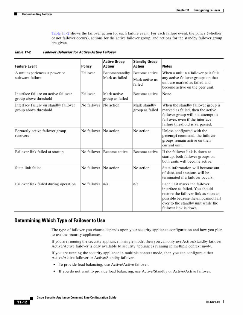
Chapter 11 Configuring Failover Understanding Failover
Table 11-2 shows the failover action for each failure event. For each failure event, the policy (whether or not failover occurs), actions for the active failover group, and actions for the standby failover group are given.
Determining Which Type of Failover to Use
The type of failover you choose depends upon your security appliance configuration and how you plan to use the security appliances.
If you are running the security appliance in single mode, then you can only use Active/Standby failover. Active/Active failover is only available to security appliances running in multiple context mode.
If you are running the security appliance in multiple context mode, then you can configure either Active/Active failover or Active/Standby failover.
• To provide load balancing, use Active/Active failover.
• If you do not want to provide load balancing, use Active/Standby or Active/Active failover.
Table 11-2 Failover Behavior for Active/Active Failover
Failure Event PolicyActive Group Action
Standby Group Action Notes
A unit experiences a power or software failure
Failover Become standby Mark as failed
Become active
Mark active as failed
When a unit in a failover pair fails, any active failover groups on that unit are marked as failed and become active on the peer unit.
Interface failure on active failover group above threshold
Failover Mark active group as failed
Become active None.
Interface failure on standby failover group above threshold
No failover No action Mark standby group as failed
When the standby failover group is marked as failed, then the active failover group will not attempt to fail over, even if the interface failure threshold is surpassed.
Formerly active failover group recovers
No failover No action No action Unless configured with the preempt command, the failover groups remain active on their current unit.
Failover link failed at startup No failover Become active Become active If the failover link is down at startup, both failover groups on both units will become active.
State link failed No failover No action No action State information will become out of date, and sessions will be terminated if a failover occurs.
Failover link failed during operation No failover n/a n/a Each unit marks the failover interface as failed. You should restore the failover link as soon as possible because the unit cannot fail over to the standby unit while the failover link is down.
11-12Cisco Security Appliance Command Line Configuration Guide
OL-6721-01

Chapter 11 Configuring Failover Understanding Failover
Table 11-3 provides a comparison of some of the features supported by each type of failover configuration:
Regular and Stateful FailoverThe security appliance supports two types of failover, regular and stateful. This section includes the following topics:
• Regular Failover, page 11-13
• Stateful Failover, page 11-13
Regular Failover
When a failover occurs, all active connections are dropped. Clients need to reestablish connections when the new active unit takes over.
Stateful Failover
When Stateful Failover is enabled, the active unit continually passes per-connection state information to the standby unit. After a failover occurs, the same connection information is available at the new active unit. Supported end-user applications are not required to reconnect to keep the same communication session.
The state information passed to the standby unit includes the following:
• NAT translation table.
• TCP connection states.
• UDP connection states.
• The ARP table.
• The Layer 2 bridge table (when running in transparent firewall mode).
• The HTTP connection states (if HTTP replication is enabled).
• The ISAKMP and IPSec SA table.
• GTP PDP connection database.
The information that is not passed to the standby unit when Stateful Failover is enabled includes the following:
• The HTTP connection table (unless HTTP replication is enabled).
Table 11-3 Failover Configuration Feature Support
Feature Active/Active Active/Standby
Single Context Mode No Yes
Multiple Context Mode Yes Yes
Load Balancing Network Configurations Yes No
Unit Failover Yes Yes
Failover of Groups of Contexts Yes No
Failover of Individual Contexts No No
11-13Cisco Security Appliance Command Line Configuration Guide
OL-6721-01

Chapter 11 Configuring Failover Understanding Failover
• The user authentication (uauth) table.
• The routing tables.
• State information for Security Service Cards.
Note If failover occurs during an active Cisco IP SoftPhone session, the call will remain active because the call session state information is replicated to the standby unit. When the call is terminated, the IP SoftPhone client will lose connection with the Call Manager. This occurs because there is no session information for the CTIQBE hangup message on the standby unit. When the IP SoftPhone client does not receive a response back from the Call Manager within a certain time period, it considers the Call Manager unreachable and unregisters itself.
Failover Health MonitoringThe security appliance monitors each unit for overall health and for interface health. See the following sections for more information about how the security appliance performs tests to determine the state of each unit:
• Unit Health Monitoring, page 11-14
• Interface Monitoring, page 11-14
Unit Health Monitoring
The security appliance determines the health of the other unit by monitoring the failover link. When a unit does not receive hello messages on the failover link, then the unit sends an ARP request on all interfaces, including the failover interface. The security appliance retries a user-configurable number of times. The action the security appliance takes depends on the response from the other unit. See the following possible actions:
• If the security appliance receives a response on any interface, then it does not fail over.
• If the security appliance does not receive a response on any interface, then the standby unit switches to active mode and classifies the other unit as failed.
• If the security appliance does not receive a response on the failover link only, then the unit does not failover. The failover link is marked as failed. You should restore the failover link as soon as possible because the unit cannot fail over to the standby while the failover link is down.
Note If a failed unit does not recover and you believe it should not be failed, you can reset the state by entering the failover reset command. If the failover condition persists, however, the unit will fail again.
Interface Monitoring
You can monitor up to 250 interfaces divided between all contexts. You should monitor important interfaces, for example, you might configure one context to monitor a shared interface (because the interface is shared, all contexts benefit from the monitoring).
11-14Cisco Security Appliance Command Line Configuration Guide
OL-6721-01

Chapter 11 Configuring Failover Configuring Failover
When a unit does not receive hello messages on a monitored interface, it runs the following tests:
1. Link Up/Down test—A test of the interface status. If the Link Up/Down test indicates that the interface is operational, then the security appliance performs network tests. The purpose of these tests is to generate network traffic to determine which (if either) unit has failed. At the start of each test, each unit clears its received packet count for its interfaces. At the conclusion of each test, each unit looks to see if it has received any traffic. If it has, the interface is considered operational. If one unit receives traffic for a test and the other unit does not, the unit that received no traffic is considered failed. If neither unit has received traffic, then the next test is used.
2. Network Activity test—A received network activity test. The unit counts all received packets for up to 5 seconds. If any packets are received at any time during this interval, the interface is considered operational and testing stops. If no traffic is received, the ARP test begins.
3. ARP test—A reading of the unit ARP cache for the 2 most recently acquired entries. One at a time, the unit sends ARP requests to these machines, attempting to stimulate network traffic. After each request, the unit counts all received traffic for up to 5 seconds. If traffic is received, the interface is considered operational. If no traffic is received, an ARP request is sent to the next machine. If at the end of the list no traffic has been received, the ping test begins.
4. Broadcast Ping test—A ping test that consists of sending out a broadcast ping request. The unit then counts all received packets for up to 5 seconds. If any packets are received at any time during this interval, the interface is considered operational and testing stops.
If all network tests fail for an interface, but this interface on the other unit continues to successfully pass traffic, then the interface is considered to be failed. If the threshold for failed interfaces is met, then a failover occurs. If the other unit interface also fails all the network tests, then both interfaces go into the “Unknown” state and do not count towards the failover limit.
An interface becomes operational again if it receives any traffic. A failed security appliance returns to standby mode if the interface failure threshold is no longer met.
Note If a failed unit does not recover and you believe it should not be failed, you can reset the state by entering the failover reset command. If the failover condition persists, however, the unit will fail again.
Configuring FailoverThis section describes how to configure failover and includes the following topics:
• Configuring Active/Standby Failover, page 11-15
• Configuring Active/Active Failover, page 11-23
• Configuring Failover Communication Authentication/Encryption, page 11-32
• Verifying the Failover Configuration, page 11-32
Configuring Active/Standby FailoverThis section provides step-by-step procedures for configuring Active/Standby failover. This section includes the following topics:
• Prerequisites, page 11-16
• Configuring Cable-Based Active/Standby Failover (PIX Security Appliance Only), page 11-16
11-15Cisco Security Appliance Command Line Configuration Guide
OL-6721-01

Chapter 11 Configuring Failover Configuring Failover
• Configuring LAN-Based Active/Standby Failover, page 11-17
• Configuring Optional Active/Standby Failover Settings, page 11-20
See the “Failover Configuration Examples” section on page 11-44 for examples of typical failover configurations.
Prerequisites
Before you begin, verify the following:
• Both units have the same hardware, software configuration, and proper license.
• Both units are in the same mode (single or multiple, transparent or routed).
Configuring Cable-Based Active/Standby Failover (PIX Security Appliance Only)
Follow these steps to configure Active/Standby failover using a serial cable as the failover link. The commands in this task are entered on the primary unit in the failover pair. The primary unit is the unit that has the end of the cable labeled “Primary” plugged into it. For devices in multiple context mode, the commands are entered in the system execution space unless otherwise noted.
You do not need to bootstrap the secondary unit in the failover pair when you use cable-based failover. Leave the secondary unit powered off until instructed to power it on.
Cable-based failover is only available on the PIX security appliance platform.
To configure cable-based Active/Standby failover, perform the following steps:
Step 1 Connect the Failover cable to the PIX security appliances. Make sure that you attach the end of the cable marked “Primary” to the unit you use as the primary unit, and that you attach the end of the cable marked “Secondary” to the other unit.
Step 2 Power on the primary unit.
Step 3 If you have not done so already, configure the active and standby IP addresses for each interface (routed mode) or for the management interface (transparent mode). The standby IP address is used on the security appliance that is currently the standby unit. It must be in the same subnet as the active IP address.
Note Do not configure an IP address for the state link if you are going to use Stateful Failover.
hostname(config-if)# ip address active_addr netmask standby standby_addr
Note In multiple context mode, you must configure the interface addresses from within each context. Use the changeto context command to switch between contexts. The command prompt changes to hostname/context(config-if)#, where context is the name of the current context.
Step 4 (Optional) To enable Stateful Failover, configure the state link. The state link must be configured on an unused interface.
a. Specify the interface to be used as the state link:
hostname(config)# failover link if_name phy_if
11-16Cisco Security Appliance Command Line Configuration Guide
OL-6721-01

Chapter 11 Configuring Failover Configuring Failover
The if_name argument assigns a logical name to the interface specified by the phy_if argument. The phy_if argument can be the physical port name, such as Ethernet1, or a previously created subinterface, such as Ethernet0/2.3. This interface should not be used for any other purpose.
b. Assign an active and standby IP address to the state link:
hostname(config)# failover interface ip if_name ip_addr mask standby ip_addr
The standby IP address must be in the same subnet as the active IP address. You do not need to identify the standby IP address subnet mask.
The state link IP address and MAC address do not change at failover. The active IP address always stays with the primary unit, while the standby IP address stays with the secondary unit.
c. Enable the interface:
hostname(config)# interface phy_ifhostname(config-if)# no shutdown
Step 5 Enable failover:
hostname(config)# failover
Step 6 Power on the secondary unit and enable failover on the unit if it is not already enabled:
hostname(config)# failover
The active unit sends the configuration in running memory to the standby unit. As the configuration synchronizes, the messages “Beginning configuration replication: sending to mate.” and “End Configuration Replication to mate” appear on the primary console.
Step 7 Save the configuration to Flash memory on the primary unit. Because the commands entered on the primary unit are replicated to the secondary unit, the secondary unit also saves its configuration to Flash memory.
hostname(config)# copy running-config startup-config
Configuring LAN-Based Active/Standby Failover
This section describes how to configure Active/Standby failover using an Ethernet failover link. When configuring LAN-based failover, you must bootstrap the secondary device to recognize the failover link before the secondary device can obtain the running configuration from the primary device.
Note If you are changing from cable-based failover to LAN-based failover, you can skip any steps, such as assigning the active and standby IP addresses for each interface, that you completed for the cable-based failover configuration.
This section includes the following topics:
• Configuring the Primary Unit, page 11-18
• Configuring the Secondary Unit, page 11-19
11-17Cisco Security Appliance Command Line Configuration Guide
OL-6721-01

Chapter 11 Configuring Failover Configuring Failover
Configuring the Primary Unit
Follow these steps to configure the primary unit in a LAN-based, Active/Standby failover configuration. These steps provide the minimum configuration needed to enable failover on the primary unit. For multiple context mode, all steps are performed in the system execution space unless otherwise noted.
To configure the primary unit in an Active/Standby failover pair, perform the following steps:
Step 1 If you have not done so already, configure the active and standby IP addresses for each interface (routed mode) or for the management interface (transparent mode). The standby IP address is used on the security appliance that is currently the standby unit. It must be in the same subnet as the active IP address.
Note Do not configure an IP address for the failover link or for the state link (if you are going to use Stateful Failover).
hostname(config-if)# ip address active_addr netmask standby standby_addr
Note In multiple context mode, you must configure the interface addresses from within each context. Use the changeto context command to switch between contexts. The command prompt changes to hostname/context(config-if)#, where context is the name of the current context.
Step 2 (PIX security appliance platform only) Enable LAN-based failover.
hostname(config)# failover lan enable
Step 3 Designate the unit as the primary unit.
hostname(config)# failover lan unit primary
Step 4 Define the failover interface.
a. Specify the interface to be used as the failover interface.
hostname(config)# failover lan interface if_name phy_if
The if_name argument assigns a name to the interface specified by the phy_if argument. The phy_if argument can be the physical port name, such as Ethernet1, or a previously created subinterface, such as Ethernet0/2.3.
b. Assign the active and standby IP address to the failover link.
hostname(config)# failover interface ip if_name ip_addr mask standby ip_addr
The standby IP address must be in the same subnet as the active IP address. You do not need to identify the standby address subnet mask.
The failover link IP address and MAC address do not change at failover. The active IP address for the failover link always stays with the primary unit, while the standby IP address stays with the secondary unit.
c. Enable the interface.
hostname(config)# interface phy_ifhostname(config-if)# no shutdown
11-18Cisco Security Appliance Command Line Configuration Guide
OL-6721-01
Chapter 11 Configuring Failover Configuring Failover
Step 5 (Optional) To enable Stateful Failover, configure the state link. The state link must be configured on an unused interface.
a. Specify the interface to be used as state link.
hostname(config)# failover link if_name phy_if
Note If the state link uses the failover link, then you only need to supply the if_name argument.
The if_name argument assigns a logical name to the interface specified by the phy_if argument. The phy_if argument can be the physical port name, such as Ethernet1, or a previously created subinterface, such as Ethernet0/2.3. This interface should not be used for any other purpose (except, optionally, the failover link).
b. Assign an active and standby IP address to the state link.
Note If the state link uses the failover link, skip this step. You have already defined the failover link active and standby IP addresses.
hostname(config)# failover interface ip if_name ip_addr mask standby ip_addr
The standby IP address must be in the same subnet as the active IP address. You do not need to identify the standby address subnet mask.
The state link IP address and MAC address do not change at failover. The active IP address always stays with the primary unit, while the standby IP address stays with the secondary unit.
c. Enable the interface.
Note If the state link uses the failover link, skip this step. You have already enabled the failover link.
hostname(config)# interface phy_ifhostname(config-if)# no shutdown
Step 6 Enable failover.
hostname(config)# failover
Step 7 Save the system configuration to Flash memory.
hostname(config)# copy running-config startup-config
Configuring the Secondary Unit
The only configuration required on the secondary unit is for the failover interface. The secondary unit requires these commands to initially communicate with the primary unit. After the primary unit sends its configuration to the secondary unit, the only permanent difference between the two configurations is the failover lan unit command, which identifies each unit as primary or secondary.
For multiple context mode, all steps are performed in the system execution space unless noted otherwise.
11-19Cisco Security Appliance Command Line Configuration Guide
OL-6721-01
Chapter 11 Configuring Failover Configuring Failover
To configure the secondary unit, perform the following steps:
Step 1 (PIX security appliance platform only) Enable LAN-based failover.
hostname(config)# failover lan enable
Step 2 Define the failover interface. Use the same settings as you used for the primary unit.
a. Specify the interface to be used as the failover interface.
hostname(config)# failover lan interface if_name phy_if
The if_name argument assigns a name to the interface specified by the phy_if argument.
b. Assign the active and standby IP address to the failover link.
hostname(config)# failover interface ip if_name ip_addr mask standby ip_addr
Note Enter this command exactly as you entered it on the primary unit when you configured the failover interface on the primary unit.
c. Enable the interface.
hostname(config)# interface phy_ifhostname(config-if)# no shutdown
Step 3 (Optional) Designate this unit as the secondary unit.
hostname(config)# failover lan unit secondary
Note This step is optional because by default units are designated as secondary unless previously configured.
Step 4 Enable failover.
hostname(config)# failover
After you enable failover, the active unit sends the configuration in running memory to the standby unit. As the configuration synchronizes, the messages “Beginning configuration replication: Sending to mate” and “End Configuration Replication to mate” appear on the active unit console.
Step 5 After the running configuration has completed replication, save the configuration to Flash memory.
hostname(config)# copy running-config startup-config
Configuring Optional Active/Standby Failover Settings
You can configure the following optional Active/Standby failover setting when you are initially configuring failover or after failover has already been configured. Unless otherwise noted, the commands should be entered on the active unit.
11-20Cisco Security Appliance Command Line Configuration Guide
OL-6721-01

Chapter 11 Configuring Failover Configuring Failover
This section includes the following topics:
• Enabling HTTP Replication with Stateful Failover, page 11-21
• Disabling and Enabling Interface Monitoring, page 11-21
• Configuring Interface and Unit Poll Times, page 11-22
• Configuring Failover Criteria, page 11-22
• Configuring Virtual MAC Addresses, page 11-22
Enabling HTTP Replication with Stateful Failover
To allow HTTP connections to be included in the state information replication, you need to enable HTTP replication. Because HTTP connections are typically short-lived, and because HTTP clients typically retry failed connection attempts, HTTP connections are not automatically included in the replicated state information.
Enter the following command in global configuration mode to enable HTTP state replication when Stateful Failover is enabled:
hostname(config)# failover replication http
Disabling and Enabling Interface Monitoring
By default, monitoring of physical interfaces is enabled and monitoring of subinterfaces is disabled. You can monitor up to 250 interfaces on a unit. You can control which interfaces affect your failover policy by disabling the monitoring of specific interfaces and enabling the monitoring of others. This lets you exclude interfaces attached to less critical networks from affecting your failover policy.
For units in multiple configuration mode, use the following commands to enable or disable health monitoring for specific interfaces:
• To disable health monitoring for an interface, enter the following command within a context:
hostname/context(config)# no monitor-interface if_name
• To enable health monitoring for an interface, enter the following command within a context:
hostname/context(config)# monitor-interface if_name
For units in single configuration mode, use the following commands to enable or disable health monitoring for specific interfaces:
• To disable health monitoring for an interface, enter the following command in global configuration mode:
hostname(config)# no monitor-interface if_name
• To enable health monitoring for an interface, enter the following command in global configuration mode:
hostname(config)# monitor-interface if_name
11-21Cisco Security Appliance Command Line Configuration Guide
OL-6721-01

Chapter 11 Configuring Failover Configuring Failover
Configuring Interface and Unit Poll Times
The security appliance monitors both unit and interface health for failover. You can configure the amount of time between hello messages when monitoring interface and unit health. Decreasing the poll time allows an interface or unit failure to be detected more quickly, but consumes more system resources.
To change the interface poll time, enter the following command in global configuration mode:
hostname(config)# failover polltime interface seconds
To change the unit poll time, enter the following command in global configuration mode:
hostname(config)# failover polltime seconds
Configuring Failover Criteria
By default, a single interface failure causes failover. You can specify a specific number of interfaces or a percentage of monitored interfaces that must fail before a failover occurs.
To change the default failover criteria, enter the following command in global configuration mode:
hostname(config)# failover interface-policy num[%]
When specifying a specific number of interfaces, the num argument can be from 1 to 250. When specifying a percentage of interfaces, the num argument can be from 1 to 100.
Configuring Virtual MAC Addresses
In Active/Standby failover, the MAC addresses for the primary unit are always associated with the active IP addresses. If the secondary unit boots first and becomes active, it uses the burned-in MAC address for its interfaces. When the primary unit comes online, the secondary unit obtains the MAC addresses from the primary unit. The change can disrupt network traffic.
You can configure virtual MAC addresses for each interface to ensure that the secondary unit uses the correct MAC addresses when it is the active unit, even if it comes online before the primary unit. If you do not specify virtual MAC addresses, then the failover pair uses the burned-in NIC address as the MAC address.
Note You cannot configure a virtual MAC address for the failover or state links. The MAC and IP addresses for those links do not change during failover.
Enter the following command on the active unit to configure the virtual MAC addresses for an interface:
hostname(config)# failover mac address phy_if active_mac standby_mac
The phy_if argument is the physical name of the interface, such as Ethernet1. The active_mac and standby_mac arguments are MAC addresses in H.H.H format, where H is a 16-bit hexadecimal digit. For example, the MAC address 00-0C-F1-42-4C-DE would be entered as 000C.F142.4CDE.
The active_mac address is associated with the active IP address for the interface, and the standby_mac is associated with the standby IP address for the interface.
11-22Cisco Security Appliance Command Line Configuration Guide
OL-6721-01

Chapter 11 Configuring Failover Configuring Failover
Configuring Active/Active FailoverThis section describes how to configure Active/Active failover.
This section includes the following topics:
• Prerequisites, page 11-23
• Configuring Cable-Based Active/Active Failover (PIX security appliance Only), page 11-23
• Configuring LAN-Based Active/Active Failover, page 11-25
• Configuring Optional Active/Active Failover Settings, page 11-28
See the “Failover Configuration Examples” section on page 11-44 for examples of typical failover configurations.
Prerequisites
Before you begin, verify the following:
• Both units have the same hardware, software configuration, and proper license.
• Both units are in multiple context mode.
Configuring Cable-Based Active/Active Failover (PIX security appliance Only)
Follow these steps to configure Active/Active failover using a serial cable as the failover link. The commands in this task are entered on the primary unit in the failover pair. The primary unit is the unit that has the end of the cable labeled “Primary” plugged into it. For devices in multiple context mode, the commands are entered in the system execution space unless otherwise noted.
You do not need to bootstrap the secondary unit in the failover pair when you use cable-based failover. Leave the secondary unit powered off until instructed to power it on.
Cable-based failover is only available on the PIX security appliance platform.
To configure cable-based, Active/Active failover, perform the following steps:
Step 1 Connect the failover cable to the PIX security appliances. Make sure that you attach the end of the cable marked “Primary” to the unit you use as the primary unit, and that you attach the end of the cable marked “Secondary” to the unit you use as the secondary unit.
Step 2 Power on the primary unit.
Step 3 If you have not done so already, configure the active and standby IP addresses for each interface (routed mode) or for the management interface (transparent mode). The standby IP address is used on the security appliance that is currently the standby unit. It must be in the same subnet as the active IP address.
Note Do not configure an IP address for the state link if you are going to use Stateful Failover.
hostname(config-if)# ip address active_addr netmask standby standby_addr
11-23Cisco Security Appliance Command Line Configuration Guide
OL-6721-01

Chapter 11 Configuring Failover Configuring Failover
Note In multiple context mode, you must configure the interface addresses from within each context. Use the changeto context command to switch between contexts. The command prompt changes to hostname/context(config-if)#, where context is the name of the current context.
Step 4 (Optional) To enable Stateful Failover, configure the state link. The state link must be configured on an unused interface.
a. Specify the interface to be used as state link.
hostname(config)# failover link if_name phy_if
The if_name argument assigns a logical name to the interface specified by the phy_if argument. The phy_if argument can be the physical port name, such as Ethernet1, or a previously created subinterface, such as Ethernet0/2.3. This interface should not be used for any other purpose (except, optionally, the failover link).
b. Assign an active and standby IP address to the state link.
hostname(config)# failover interface ip if_name ip_addr mask standby ip_addr
The standby IP address must be in the same subnet as the active IP address. You do not need to identify the standby IP address subnet mask.
The state link IP address and MAC address do not change at failover. The active IP address always stays with the primary unit, while the standby IP address stays with the secondary unit.
c. Enable the interface.
hostname(config)# interface phy_ifhostname(config-if)# no shutdown
Step 5 Configure the failover groups. You can have at most two failover groups. The failover group command creates the specified failover group if it does not exist and enters the failover group configuration mode.
For each failover group, you need to specify whether the failover group has primary or secondary preference using the primary or secondary command. You can assign the same preference to both failover groups. For load balancing configurations, you should assign each failover group a different unit preference.
The following example assigns failover group 1 a primary preference and failover group 2 a secondary preference:
hostname(config)# failover group 1hostname(config-fover-group)# primaryhostname(config-fover-group)# exithostname(config)# failover group 2hostname(config-fover-group)# secondaryhostname(config-fover-group)# exit
Step 6 Assign each user context to a failover group using the join-failover-group command in context configuration mode.
Any unassigned contexts are automatically assigned to failover group 1. The admin context is always a member of failover group 1.
Enter the following commands to assign each context to a failover group:
hostname(config)# context context_namehostname(config-context)# join-failover-group {1 | 2}hostname(config-context)# exit
11-24Cisco Security Appliance Command Line Configuration Guide
OL-6721-01

Chapter 11 Configuring Failover Configuring Failover
Step 7 Enable failover.
hostname(config)# failover
Step 8 Power on the secondary unit and enable failover on the unit if it is not already enabled:
hostname(config)# failover
The active unit sends the configuration in running memory to the standby unit. As the configuration synchronizes, the messages “Beginning configuration replication: Sending to mate” and “End Configuration Replication to mate” appear on the primary console.
Step 9 Save the configuration to Flash memory on the Primary unit. Because the commands entered on the primary unit are replicated to the secondary unit, the secondary unit also saves its configuration to Flash memory.
hostname(config)# copy running-config startup-config
Step 10 If necessary, force any failover group that is active on the primary to the active state on the secondary. To force a failover group to become active on the secondary unit, issue the following command in the system execution space on the primary unit:
hostname# no failover active group group_id
The group_id argument specifies the group you want to become active on the secondary unit.
Configuring LAN-Based Active/Active Failover
This section describes how to configure Active/Active failover using an Ethernet failover link. When configuring LAN-based failover, you must bootstrap the secondary device to recognize the failover link before the secondary device can obtain the running configuration from the primary device.
This section includes the following topics:
• Configure the Primary Unit, page 11-25
• Configure the Secondary Unit, page 11-27
Configure the Primary Unit
To configure the primary unit in an Active/Active failover configuration, perform the following steps:
Step 1 Configure the basic failover parameters in the system execution space.
a. (PIX security appliance platform only) Enable LAN-based failover.
hostname(config)# hostname(config)# failover lan enable
b. Designate the unit as the primary unit.
hostname(config)# failover lan unit primary
c. Specify the failover link.
hostname(config)# failover lan interface if_name phy_if
The if_name argument assigns a logical name to the interface specified by the phy_if argument. The phy_if argument can be the physical port name, such as Ethernet1, or a previously created subinterface, such as Ethernet0/2.3. This interface should not be used for any other purpose (except, optionally, the state link).
11-25Cisco Security Appliance Command Line Configuration Guide
OL-6721-01

Chapter 11 Configuring Failover Configuring Failover
d. Specify the failover link active and standby IP addresses.
hostname(config)# failover interface ip if_name ip_addr mask standby ip_addr
The standby IP address must be in the same subnet as the active IP address. You do not need to identify the standby IP address subnet mask. The failover link IP address and MAC address do not change at failover. The active IP address always stays with the primary unit, while the standby IP address stays with the secondary unit.
Step 2 (Optional) To enable Stateful Failover, configure the state link. The state link must be configured on an unused interface.
a. Specify the interface to be used as state link.
hostname(config)# failover link if_name phy_if
The if_name argument assigns a logical name to the interface specified by the phy_if argument. The phy_if argument can be the physical port name, such as Ethernet1, or a previously created subinterface, such as Ethernet0/2.3. This interface should not be used for any other purpose (except, optionally, the failover link).
Note If the state link uses the failover link, then you only need to supply the if_name argument.
b. Assign an active and standby IP address to the state link.
Note If the state link uses the failover link, skip this step. You have already defined the failover link active and standby IP addresses.
hostname(config)# failover interface ip if_name ip_addr mask standby ip_addr
The standby IP address must be in the same subnet as the active IP address. You do not need to identify the standby address subnet mask.
The state link IP address and MAC address do not change at failover. The active IP address always stays with the primary unit, while the standby IP address stays with the secondary unit.
c. Enable the interface.
Note If the state link uses the failover link, skip this step. You have already enabled the failover link.
hostname(config)# interface phy_ifhostname(config-if)# no shutdown
Step 3 Configure the failover groups. You can have at most two failover groups. The failover group command creates the specified failover group if it does not exist and enters the failover group configuration mode.
For each failover group, you need to specify whether the failover group has primary or secondary preference using the primary or secondary command. You can assign the same preference to both failover groups. For load balancing configurations, you should assign each failover group a different unit preference.
11-26Cisco Security Appliance Command Line Configuration Guide
OL-6721-01

Chapter 11 Configuring Failover Configuring Failover
The following example assigns failover group 1 a primary preference and failover group 2 a secondary preference:
hostname(config)# failover group 1hostname(config-fover-group)# primaryhostname(config-fover-group)# exithostname(config)# failover group 2hostname(config-fover-group)# secondaryhostname(config-fover-group)# exit
Step 4 Assign each user context to a failover group using the join-failover-group command in context configuration mode.
Any unassigned contexts are automatically assigned to failover group 1. The admin context is always a member of failover group 1.
Enter the following commands to assign each context to a failover group:
hostname(config)# context context_namehostname(config-context)# join-failover-group {1 | 2}hostname(config-context)# exit
Step 5 Enable failover.
hostname(config)# failover
Configure the Secondary Unit
When configuring LAN-based Active/Active failover, you need to bootstrap the secondary unit to recognize the failover link. This allows the secondary unit to communicate with and receive the running configuration from the primary unit.
To bootstrap the secondary unit in an Active/Active failover configuration, perform the following steps:
Step 1 (PIX security appliance platform only) Enable LAN-based failover.
hostname(config)# failover lan enable
Step 2 Define the failover interface. Use the same settings as you used for the primary unit.
a. Specify the interface to be used as the failover interface.
hostname(config)# failover lan interface if_name phy_if
The if_name argument assigns a logical name to the interface specified by the phy_if argument. The phy_if argument can be the physical port name, such as Ethernet1, or a previously created subinterface, such as Ethernet0/2.3.
b. Assign the active and standby IP address to the failover link.
hostname(config)# failover interface ip if_name ip_addr mask standby ip_addr
Note Enter this command exactly as you entered it on the primary unit when you configured the failover interface.
The standby IP address must be in the same subnet as the active IP address. You do not need to identify the standby address subnet mask.
11-27Cisco Security Appliance Command Line Configuration Guide
OL-6721-01

Chapter 11 Configuring Failover Configuring Failover
c. Enable the interface.
hostname(config)# interface phy_ifhostname(config-if)# no shutdown
Step 3 (Optional) Designate this unit as the secondary unit.
hostname(config)# failover lan unit secondary
Note This step is optional because by default units are designated as secondary unless previously configured otherwise.
Step 4 Enable failover.
hostname(config)# failover
After you enable failover, the active unit sends the configuration in running memory to the standby unit. As the configuration synchronizes, the messages Beginning configuration replication: Sending to mate and End Configuration Replication to mate appear on the active unit console.
Step 5 After the running configuration has completed replication, enter the following command to save the configuration to Flash memory:
hostname(config)# copy running-config startup-config
Step 6 If necessary, force any failover group that is active on the primary to the active state on the secondary unit. To force a failover group to become active on the secondary unit, enter the following command in the system execution space on the primary unit:
hostname# no failover active group group_id
The group_id argument specifies the group you want to become active on the secondary unit.
Configuring Optional Active/Active Failover Settings
The following optional Active/Active failover settings can be configured when you are initially configuring failover or after you have already established failover. Unless otherwise noted, the commands should be entered on the unit that has failover group 1 in the active state.
This section includes the following topics:
• Configuring Failover Group Preemption, page 11-29
• Enabling HTTP Replication with Stateful Failover, page 11-29
• Disabling and Enabling Interface Monitoring, page 11-29
• Configuring Interface and Unit Poll Times, page 11-29
• Configuring Failover Criteria, page 11-30
• Configuring Virtual MAC Addresses, page 11-30
• Configuring Asymmetric Routing Support, page 11-30
11-28Cisco Security Appliance Command Line Configuration Guide
OL-6721-01

Chapter 11 Configuring Failover Configuring Failover
Configuring Failover Group Preemption
Assigning a primary or secondary priority to a failover group specifies which unit the failover group becomes active on when both units boot simultaneously. However, if one unit boots before the other, then both failover groups become active on that unit. When the other unit comes online, any failover groups that have the unit as a priority do not become active on that unit unless manually forced over, a failover occurs, or the failover group is configured with the preempt command. The preempt command causes a failover group to become active on the designated unit automatically when that unit becomes available.
Enter the following commands to configure preemption for the specified failover group:
hostname(config)# failover group {1 | 2}hostname(config-fover-group)# preempt [delay]
You can enter an optional delay value, which specifies the number of seconds the failover group remains active on the current unit before automatically becoming active on the designated unit.
Enabling HTTP Replication with Stateful Failover
To allow HTTP connections to be included in the state information, you need to enable HTTP replication. Because HTTP connections are typically short-lived, and because HTTP clients typically retry failed connection attempts, HTTP connections are not automatically included in the replicated state information. You can use the replication http command to cause a failover group to replicate HTTP state information when Stateful Failover is enabled.
To enable HTTP state replication for a failover group, enter the following command. This command only affects the failover group in which it was configured. To enable HTTP state replication for both failover groups, you must enter this command in each group. This command should be entered in the system execution space.
hostname(config)# failover group {1 | 2}hostname(config-fover-group)# replication http
Disabling and Enabling Interface Monitoring
You can monitor up to 250 interfaces on a unit. By default, monitoring of physical interfaces is enabled and the monitoring of subinterfaces is disabled. You can control which interfaces affect your failover policy by disabling the monitoring of specific interfaces and enabling the monitoring of others. This lets you exclude interfaces attached to less critical networks from affecting your failover policy.
To disable health monitoring on an interface, enter the following command within a context:
hostname/context(config)# no monitor-interface if_name
To enable health monitoring on an interface, enter the following command within a context:
hostname/context(config)# monitor-interface if_name
Configuring Interface and Unit Poll Times
You can configure the amount of time between hello messages when monitoring the health of the interfaces in a failover group. Decreasing the interface poll time allows failover to occur faster when an interface fails, but consumes more system resources.
To change the default interface poll time, enter the following commands:
hostname(config)# failover group {1 | 2}hostname(config-fover-group)# polltime interface seconds
11-29Cisco Security Appliance Command Line Configuration Guide
OL-6721-01

Chapter 11 Configuring Failover Configuring Failover
The unit poll time specifies the amount of time between hello messages sent across the failover link to determine the health of the peer unit. Decreasing the unit poll time allows a failed unit to be detected faster, but consumes more system resources. To change the unit poll time, enter the following command in global configuration mode of the system execution space:
hostname(config)# failover polltime seconds
Configuring Failover Criteria
By default, if a single interface fails failover occurs. You can specify a specific number of interfaces or a percentage of monitored interfaces that must fail before a failover occurs. The failover criteria is specified on a failover group basis.
To change the default failover criteria for the specified failover group, enter the following commands:
hostname(config)# failover group {1 | 2}hostname(config-fover-group)# interface-policy num[%]
When specifying a specific number of interfaces, the num argument can be from 1 to 250. When specifying a percentage of interfaces, the num argument can be from 1 to 100.
Configuring Virtual MAC Addresses
Active/Active failover uses virtual MAC addresses on all interfaces. If you do not specify the virtual MAC addresses, then they are computed as follows:
• Active unit default MAC address: 00a0.c9physical_port_number.failover_group_id01.
• Standby unit default MAC address: 00a0.c9physical_port_number.failover_group_id02.
Note If you have more than one Active/Active failover pair on the same network, it is possible to have the same default virtual MAC addresses assigned to the interfaces on one pair as are assigned to the interfaces of the other pairs because of the way the default virtual MAC addresses are determined. To avoid having duplicate MAC addresses on your network, make sure you assign each physical interface a virtual active and standby MAC address for all failover groups.
You can configure specific active and standby MAC addresses for an interface by entering the following commands:
hostname(config)# failover group {1 | 2}hostname(config-fover-group)# mac address phy_if active_mac standby_mac
The phy_if argument is the physical name of the interface, such as Ethernet1. The active_mac and standby_mac arguments are MAC addresses in H.H.H format, where H is a 16-bit hexadecimal digit. For example, the MAC address 00-0C-F1-42-4C-DE would be entered as 000C.F142.4CDE.
The active_mac address is associated with the active IP address for the interface, and the standby_mac is associated with the standby IP address for the interface.
Configuring Asymmetric Routing Support
When running in Active/Active failover, a unit may receive a return packet for a connection that originated through its peer unit. Because the security appliance that receives the packet does not have any connection information for the packet, the packet is dropped. This most commonly occurs when the two security appliances in an Active/Active failover pair are connected to different service providers and the outbound connection does not use a NAT address.
11-30Cisco Security Appliance Command Line Configuration Guide
OL-6721-01

Chapter 11 Configuring Failover Configuring Failover
You can prevent the return packets from being dropped using the asr-group command on interfaces where this is likely to occur. With the asr-group command configured on an interface, the interface connection information is sent to the failover peer. If the peer receives a packet for which it does not have an active connection, it looks for a corresponding connection on the other interfaces in the asynchronous routing group. If there is an active connection for it on its peer, it will forward the packet, and any others it receives for that connection, to the peer unit where the connection is active until the connection is terminated.
Note Using the asr-group command to configure asymmetric routing support is more secure than using the static command with the nailed option.
Enter the following commands to configure asymmetric routing support. The asr-group command is only available in the security contexts. Stateful failover must be enabled for asymmetric routing to function properly.
hostname/ctx1(config)# interface phy_ifhostname/ctx1(config-if)# asr-group num
Valid values for num range from 1 to 32. You need to enter the command for each interface that will participate in the asymmetric routing group. You can view the number of ASR packets transmitted, received, or dropped by an interface using the show interface detail command.
Figure 11-1 shows an example of using the asr-group command for asymmetric routing support.
Figure 11-1 ASR Example
Context A is active on one unit and context B is active on the other. Each context has an interface named “outside”, both of which are configured as part of asr-group 1. The outbound traffic is routed through the unit where context A is active. However, the return traffic is being routed through the unit where context B is active. Normally, the return traffic would be dropped because there is no session information for the traffic on the unit. However, because the interface is configured with an asr-group number, the
1321
84
ISP A
Insidenetwork
Failover/State link
Context Ainterface Ethernet4
nameif outsideasr-group 1
Context Binterface Ethernet2
nameif outsideasr-group 1
Outbound Traffic
Return Traffic
ISP B
11-31Cisco Security Appliance Command Line Configuration Guide
OL-6721-01

Chapter 11 Configuring Failover Configuring Failover
unit looks at the session information for any other interfaces with the same asr-group assigned to it. It finds the session information in the outside interface for context A, which is in the standby state on the unit, and forwards the return traffic to the unit where context A is active.
The traffic is forwarded though the outside interface of context A on the unit where context A is in the standby state and returns through the outside interface of context A on the unit where context A is in the active state. This forwarding continues as needed until the session ends.
Configuring Failover Communication Authentication/EncryptionYou can encrypt and authenticate the communication between failover peers by specifying a shared secret.
Caution All information sent over the failover and Stateful Failover links is sent in clear text unless you secure the communication with a failover key. If the security appliance is used to terminate VPN tunnels, this information includes any usernames, passwords and preshared keys used for establishing the tunnels. Transmitting this sensitive data in clear text could pose a significant security risk. We recommend securing the failover communication with a failover key if you are using the security appliance to terminate VPN tunnels.
Enter the following command on the active unit of an Active/Standby failover pair or on the unit that has failover group 1 active of an Active/Active failover pair:
hostname(config)# failover key secret
The secret argument can be from 1 to 63 characters. The characters can be any combination of numbers, letters, or punctuation.
Note To prevent the failover key from being replicated to the peer unit in clear text for an existing failover configuration, disable failover on the active unit (or in the system execution space on the unit that has failover group 1 in the active state), enter the failover key on both units, and then re-enable failover. When failover is re-enabled, the failover communication will be encrypted with the key.
For new LAN-based failover configurations, the failover key command should be part of the failover pair bootstrap configuration.
Verifying the Failover ConfigurationThis section describes how to verify your failover configuration. This section includes the following topics:
• Using the show failover Command, page 11-33
• Viewing Monitored Interfaces, page 11-41
• Displaying the Failover Commands in the Running Configuration, page 11-41
• Testing the Failover Functionality, page 11-41
11-32Cisco Security Appliance Command Line Configuration Guide
OL-6721-01

Chapter 11 Configuring Failover Configuring Failover
Using the show failover Command
This section describes the show failover command output. On each unit you can verify the failover status by entering the show failover command. The information displayed depends upon whether you are using Active/Standby or Active/Active failover.
This section includes the following topics:
• show failover—Active/Standby, page 11-33
• Show Failover—Active/Active, page 11-37
show failover—Active/Standby
The following is sample output from the show failover command for Active/Standby Failover. Table 11-4 provides descriptions for the information shown.
hostname# show failover
Failover OnCable status: N/A - LAN-based failover enabled Failover unit Primary Failover LAN Interface: fover Ethernet2 (up) Unit Poll frequency 1 seconds, holdtime 3 seconds Interface Poll frequency 15 seconds Interface Policy 1 Monitored Interfaces 2 of 250 maximum failover replication http Last Failover at: 22:44:03 UTC Dec 8 2004 This host: Primary - Active Active time: 13434 (sec) Interface inside (10.130.9.3): Normal Interface outside (10.132.9.3): Normal Other host: Secondary - Standby Ready Active time: 0 (sec) Interface inside (10.130.9.4): Normal Interface outside (10.132.9.4): Normal
Stateful Failover Logical Update Statistics Link : fover Ethernet2 (up) Stateful Obj xmit xerr rcv rerr
General 1950 0 1733 0 sys cmd 1733 0 1733 0 up time 0 0 0 0 RPC services 0 0 0 0 TCP conn 6 0 0 0 UDP conn 0 0 0 0 ARP tbl 106 0 0 0 Xlate_Timeout 0 0 0 0 VPN IKE upd 15 0 0 0 VPN IPSEC upd 90 0 0 0 VPN CTCP upd 0 0 0 0 VPN SDI upd 0 0 0 0 VPN DHCP upd 0 0 0 0
Logical Update Queue Information Cur Max Total Recv Q: 0 2 1733 Xmit Q: 0 2 15225
11-33Cisco Security Appliance Command Line Configuration Guide
OL-6721-01

Chapter 11 Configuring Failover Configuring Failover
In multiple context mode, using the show failover command in a security context displays the failover information for that context. The information is similar to the information shown when using the command in single context mode. Instead of showing the active/standby status of the unit, it displays the active/standby status of the context. Table 11-4 provides descriptions for the information shown.
Failover On Last Failover at: 04:03:11 UTC Jan 4 2003 This context: Negotiation Active time: 1222 (sec) Interface outside (192.168.5.121): Normal Interface inside (192.168.0.1): Normal Peer context: Not Detected Active time: 0 (sec) Interface outside (192.168.5.131): Normal Interface inside (192.168.0.11): Normal
Stateful Failover Logical Update Statistics Status: Configured. Stateful Obj xmit xerr rcv rerr RPC services 0 0 0 0 TCP conn 99 0 0 0 UDP conn 0 0 0 0 ARP tbl 22 0 0 0 Xlate_Timeout 0 0 0 0 GTP PDP 0 0 0 0 GTP PDPMCB 0 0 0 0
Table 11-4 Show Failover Display Description
Field Options
Failover • On
• Off
Cable status: • Normal—The cable is connected to both units, and they both have power.
• My side not connected—The serial cable is not connected to this unit. It is unknown if the cable is connected to the other unit.
• Other side is not connected—The serial cable is connected to this unit, but not to the other unit.
• Other side powered off—The other unit is turned off.
• N/A—LAN-based failover is enabled.
Failover Unit Primary or Secondary.
Failover LAN Interface Displays the logical and physical name of the failover link.
Unit Poll frequency Displays the number of seconds between hello messages sent to the peer unit and the number of seconds during which the unit must receive a hello message on the failover link before declaring the peer failed.
Interface Poll frequency n seconds
The number of seconds you set with the failover polltime interface command. The default is 15 seconds.
Interface Policy Displays the number or percentage of interfaces that must fail to trigger failover.
11-34Cisco Security Appliance Command Line Configuration Guide
OL-6721-01

Chapter 11 Configuring Failover Configuring Failover
Monitored Interfaces Displays the number of interfaces monitored out of the maximum possible.
failover replication http Displays if HTTP state replication is enabled for Stateful Failover.
Last Failover at: The date and time of the last failover in the following form:
hh:mm:ss UTC DayName Month Day yyyy
UTC (Coordinated Universal Time) is equivalent to GMT (Greenwich Mean Time).
This host:
Other host:
For each host, the display shows the following information.
Primary or Secondary • Active
• Standby
Active time: n (sec)
The amount of time the unit has been active. This time is cumulative, so the standby unit, if it was active in the past, will also show a value.
Interface name (n.n.n.n): For each interface, the display shows the IP address currently being used on each unit, as well as one of the following conditions:
• Failed—The interface has failed.
• No Link—The interface line protocol is down.
• Normal—The interface is working correctly.
• Link Down—The interface has been administratively shut down.
• Unknown—The security appliance cannot determine the status of the interface.
• Waiting—Monitoring of the network interface on the other unit has not yet started.
Stateful Failover Logical Update Statistics
The following fields relate to the Stateful Failover feature. If the Link field shows an interface name, the Stateful Failover statistics are shown.
Link • interface_name—The interface used for the Stateful Failover link.
• Unconfigured—You are not using Stateful Failover.
• up—The interface is up and functioning.
• down—The interface is either administratively shutdown or is physically down.
• failed—The interface has failed and is not passing stateful data.
Table 11-4 Show Failover Display Description (continued)
Field Options
11-35Cisco Security Appliance Command Line Configuration Guide
OL-6721-01

Chapter 11 Configuring Failover Configuring Failover
Stateful Obj For each field type, the following statistics are shown. They are counters for the number of state information packets sent between the two units; the fields do not necessarily show active connections through the unit.
• xmit—Number of transmitted packets to the other unit.
• xerr—Number of errors that occurred while transmitting packets to the other unit.
• rcv—Number of received packets.
• rerr—Number of errors that occurred while receiving packets from the other unit.
General Sum of all stateful objects.
sys cmd Logical update system commands; for example, LOGIN and Stay Alive.
up time Up time, which the active unit passes to the standby unit.
RPC services Remote Procedure Call connection information.
TCP conn TCP connection information.
UDP conn Dynamic UDP connection information.
ARP tbl Dynamic ARP table information.
L2BRIDGE tbl Layer 2 bridge table information (transparent firewall mode only).
Xlate_Timeout Indicates connection translation timeout information.
VPN IKE upd IKE connection information.
VPN IPSEC upd IPSec connection information.
VPN CTCP upd cTCP tunnel connection information.
VPN SDI upd SDI AAA connection information.
VPN DHCP upd Tunneled DHCP connection information.
GTP PDP GTP PDP update information. This information appears only if inspect GTP is enabled.
GTP PDPMCB GTP PDPMCB update information. This information appears only if inspect GTP is enabled.
Logical Update Queue Information
For each field type, the following statistics are used:
• Cur—Current number of packets
• Max—Maximum number of packets
• Total—Total number of packets
Recv Q The status of the receive queue.
Xmit Q The status of the transmit queue.
Table 11-4 Show Failover Display Description (continued)
Field Options
11-36Cisco Security Appliance Command Line Configuration Guide
OL-6721-01

Chapter 11 Configuring Failover Configuring Failover
Show Failover—Active/Active
The following is sample output from the show failover command for Active/Active Failover. Table 11-5 provides descriptions for the information shown.
hostname# show failover
Failover OnFailover unit PrimaryFailover LAN Interface: third GigabitEthernet0/2 (up) Unit Poll frequency 1 seconds, holdtime 15 seconds Interface Poll frequency 4 seconds Interface Policy 1 Monitored Interfaces 8 of 250 maximum failover replication http Group 1 last failover at: 13:40:18 UTC Dec 9 2004 Group 2 last failover at: 13:40:06 UTC Dec 9 2004
This host: Primary Group 1 State: Active Active time: 2896 (sec) Group 2 State: Standby Ready Active time: 0 (sec)
admin Interface outside (10.132.8.5): Normal admin Interface third (10.132.9.5): Normal admin Interface inside (10.130.8.5): Normal admin Interface fourth (10.130.9.5): Normal ctx1 Interface outside (10.1.1.1): Normal ctx1 Interface inside (10.2.2.1): Normal ctx2 Interface outside (10.3.3.2): Normal ctx2 Interface inside (10.4.4.2): Normal
Other host: Secondary Group 1 State: Standby Ready Active time: 190 (sec) Group 2 State: Active Active time: 3322 (sec)
admin Interface outside (10.132.8.6): Normal admin Interface third (10.132.9.6): Normal admin Interface inside (10.130.8.6): Normal admin Interface fourth (10.130.9.6): Normal ctx1 Interface outside (10.1.1.2): Normal ctx1 Interface inside (10.2.2.2): Normal ctx2 Interface outside (10.3.3.1): Normal ctx2 Interface inside (10.4.4.1): Normal
Stateful Failover Logical Update Statistics Link : third GigabitEthernet0/2 (up) Stateful Obj xmit xerr rcv rerr
General 1973 0 1895 0 sys cmd 380 0 380 0 up time 0 0 0 0 RPC services 0 0 0 0 TCP conn 1435 0 1450 0 UDP conn 0 0 0 0 ARP tbl 124 0 65 0 Xlate_Timeout 0 0 0 0 VPN IKE upd 15 0 0 0 VPN IPSEC upd 90 0 0 0 VPN CTCP upd 0 0 0 0 VPN SDI upd 0 0 0 0 VPN DHCP upd 0 0 0 0
11-37Cisco Security Appliance Command Line Configuration Guide
OL-6721-01

Chapter 11 Configuring Failover Configuring Failover
Logical Update Queue Information Cur Max Total Recv Q: 0 1 1895 Xmit Q: 0 0 1940
The following is sample output from the show failover group command for Active/Active Failover. The information displayed is similar to that of the show failover command, but limited to the specified group. Table 11-5 provides descriptions for the information shown.
hostname# show failover group 1
Last Failover at: 04:09:59 UTC Jan 4 2005
This host: Secondary State: Active Active time: 186 (sec)
admin Interface outside (192.168.5.121): Normal admin Interface inside (192.168.0.1): Normal
Other host: Primary State: Standby Active time: 0 (sec)
admin Interface outside (192.168.5.131): Normal admin Interface inside (192.168.0.11): Normal
Stateful Failover Logical Update Statistics Status: Configured. RPC services 0 0 0 0 TCP conn 33 0 0 0 UDP conn 0 0 0 0 ARP tbl 12 0 0 0 Xlate_Timeout 0 0 0 0 GTP PDP 0 0 0 0 GTP PDPMCB 0 0 0 0
Table 11-5 Show Failover Display Description
Field Options
Failover • On
• Off
Failover Unit Primary or Secondary.
Failover LAN Interface Displays the logical and physical name of the failover link.
Unit Poll frequency Displays the number of seconds between hello messages sent to the peer unit and the number of seconds during which the unit must receive a hello message on the failover link before declaring the peer failed.
Interface Poll frequency n seconds
The number of seconds you set with the failover polltime interface command. The default is 15 seconds.
Interface Policy Displays the number or percentage of interfaces that must fail before triggering failover.
11-38Cisco Security Appliance Command Line Configuration Guide
OL-6721-01

Chapter 11 Configuring Failover Configuring Failover
Monitored Interfaces Displays the number of interfaces monitored out of the maximum possible.
Group 1 Last Failover at:
Group 2 Last Failover at:
The date and time of the last failover for each group in the following form:
hh:mm:ss UTC DayName Month Day yyyy
UTC (Coordinated Universal Time) is equivalent to GMT (Greenwich Mean Time).
This host:
Other host:
For each host, the display shows the following information.
Role Primary or Secondary
System State • Active or Standby Ready
• Active Time in seconds
Group 1 State
Group 2 State
• Active or Standby Ready
• Active Time in seconds
context Interface name (n.n.n.n):
For each interface, the display shows the IP address currently being used on each unit, as well as one of the following conditions:
• Failed—The interface has failed.
• No link—The interface line protocol is down.
• Normal—The interface is working correctly.
• Link Down—The interface has been administratively shut down.
• Unknown—The security appliance cannot determine the status of the interface.
• Waiting—Monitoring of the network interface on the other unit has not yet started.
Stateful Failover Logical Update Statistics
The following fields relate to the Stateful Failover feature. If the Link field shows an interface name, the Stateful Failover statistics are shown.
Link • interface_name—The interface used for the Stateful Failover link.
• Unconfigured—You are not using Stateful Failover.
• up—The interface is up and functioning.
• down—The interface is either administratively shutdown or is physically down.
• failed—The interface has failed and is not passing stateful data.
Table 11-5 Show Failover Display Description (continued)
Field Options
11-39Cisco Security Appliance Command Line Configuration Guide
OL-6721-01

Chapter 11 Configuring Failover Configuring Failover
Stateful Obj For each field type, the following statistics are used. They are counters for the number of state information packets sent between the two units; the fields do not necessarily show active connections through the unit.
• xmit—Number of transmitted packets to the other unit
• xerr—Number of errors that occurred while transmitting packets to the other unit
• rcv—Number of received packets
• rerr—Number of errors that occurred while receiving packets from the other unit
General Sum of all stateful objects.
sys cmd Logical update system commands; for example, LOGIN and Stay Alive.
up time Up time, which the active unit passes to the standby unit.
RPC services Remote Procedure Call connection information.
TCP conn TCP connection information.
UDP conn Dynamic UDP connection information.
ARP tbl Dynamic ARP table information.
L2BRIDGE tbl Layer 2 bridge table information (transparent firewall mode only).
Xlate_Timeout Indicates connection translation timeout information.
VPN IKE upd IKE connection information.
VPN IPSEC upd IPSec connection information.
VPN CTCP upd cTCP tunnel connection information.
VPN SDI upd SDI AAA connection information.
VPN DHCP upd Tunneled DHCP connection information.
GTP PDP GTP PDP update information. This information appears only if inspect GTP is enabled.
GTP PDPMCB GTP PDPMCB update information. This information appears only if inspect GTP is enabled.
Logical Update Queue Information
For each field type, the following statistics are used:
• Cur—Current number of packets
• Max—Maximum number of packets
• Total—Total number of packets
Recv Q The status of the receive queue.
Xmit Q The status of the transmit queue.
Table 11-5 Show Failover Display Description (continued)
Field Options
11-40Cisco Security Appliance Command Line Configuration Guide
OL-6721-01

Chapter 11 Configuring Failover Configuring Failover
Viewing Monitored Interfaces
To view the status of monitored interfaces, enter the following command. In single context mode, enter this command in global configuration mode. In multiple context mode, enter this command within a context.
primary/context(config)# show monitor-interface
For example:
hostname/context(config)# show monitor-interface This host: Primary - Active Interface outside (192.168.1.2): Normal Interface inside (10.1.1.91): Normal Other host: Secondary - Standby Interface outside (192.168.1.3): Normal Interface inside (10.1.1.100): Normal
Displaying the Failover Commands in the Running Configuration
To view the failover commands in the running configuration, enter the following command:
hostname(config)# show running-config failover
All of the failover commands are displayed. On units running multiple context mode, enter this command in the system execution space. Entering show running-config all failover displays the failover commands in the running configuration and includes commands for which you have not changed the default value.
Testing the Failover Functionality
To test failover functionality, perform the following steps:
Step 1 Test that your active unit or failover group is passing traffic as expected by using FTP (for example) to send a file between hosts on different interfaces.
Step 2 Force a failover to the standby unit by entering the following command:
• For Active/Standby failover, enter the following command on the active unit:
hostname(config)# no failover active
• For Active/Active failover, enter the following command on the unit where failover group containing the interface connecting your hosts is active:
hostname(config)# no failover active group group_id
Step 3 Use FTP to send another file between the same two hosts.
11-41Cisco Security Appliance Command Line Configuration Guide
OL-6721-01

Chapter 11 Configuring Failover Controlling and Monitoring Failover
Step 4 If the test was not successful, enter the show failover command to check the failover status.
Step 5 When you are finished, you can restore the unit or failover group to active status by enter the following command:
• For Active/Standby failover, enter the following command on the active unit:
hostname(config)# failover active
• For Active/Active failover, enter the following command on the unit where the failover group containing the interface connecting your hosts is active:
hostname(config)# failover active group group_id
Controlling and Monitoring FailoverThis sections describes how to control and monitor failover. This section includes the following topics:
• Forcing Failover, page 11-42
• Disabling Failover, page 11-43
• Restoring a Failed Unit or Failover Group, page 11-43
• Monitoring Failover, page 11-43
Forcing FailoverTo force the standby unit or failover group to become active, enter one of the following commands:
• For Active/Standby failover:
Enter the following command on the standby unit:
hostname# failover active
Or enter the following command on the active unit:
hostname# no failover active
• For Active/Active failover:
Enter the following command in the system execution space of the unit where failover group is in the standby state:
hostname# failover active group group_id
Or, enter the following command in the system execution space of the unit where the failover group is in the active state:
hostname# no failover active group group_id
Entering the following command in the system execution space causes all failover groups to become active:
hostname# failover active
11-42Cisco Security Appliance Command Line Configuration Guide
OL-6721-01
Chapter 11 Configuring Failover Controlling and Monitoring Failover
Disabling FailoverTo disable failover, enter the following command:
hostname(config)# no failover
Disabling failover on an Active/Standby pair causes the active and standby state of each unit to be maintained until you restart. For example, the standby unit remains in standby mode so that both units do not start passing traffic. To make the standby unit active (even with failover disabled), see the “Forcing Failover” section on page 11-42.
Disabling failover on an Active/Active pair causes the failover groups to remain in the active state on whichever unit they are currently active on, no matter which unit they are configured to prefer. The no failover command should be entered in the system execution space.
Restoring a Failed Unit or Failover GroupTo restore a failed unit to an unfailed state, enter the following command:
hostname(config)# failover reset
To restore a failed Active/Active failover group to an unfailed state, enter the following command:
hostname(config)# failover reset group group_id
Restoring a failed unit or group to an unfailed state does not automatically make it active; restored units or groups remain in the standby state until made active by failover (forced or natural). An exception is a failover group configured with the preempt command. If previously active, a failover group will become active if it is configured with the preempt command and if the unit on which it failed is its preferred unit.
Monitoring FailoverWhen a failover occurs, both security appliances send out system messages. This section includes the following topics:
• Failover System Messages, page 11-43
• Debug Messages, page 11-44
• SNMP, page 11-44
Failover System Messages
The security appliance issues a number of system messages related to failover at priority level 2, which indicates a critical condition. To view these messages, see the Cisco Security Appliance Logging Configuration and System Log Messages to enable logging and to see descriptions of the system messages.
Note During switchover, failover will logically shut down and then bring up interfaces, generating syslog 411001 and 411002 messages. This is normal activity.
11-43Cisco Security Appliance Command Line Configuration Guide
OL-6721-01

Chapter 11 Configuring Failover Failover Configuration Examples
Debug Messages
To see debug messages, enter the debug fover command. See the Cisco Security Appliance Command Reference for more information.
Note Because debugging output is assigned high priority in the CPU process, it can drastically affect system performance. For this reason, use the debug fover commands only to troubleshoot specific problems or during troubleshooting sessions with Cisco technical support staff.
SNMP
To receive SNMP syslog traps for failover, configure the SNMP agent to send SNMP traps to SNMP management stations, define a syslog host, and compile the Cisco syslog MIB into your SNMP management station. See the snmp-server and logging commands in the Cisco Security Appliance Command Reference for more information.
Failover Configuration ExamplesThis section includes sample configurations and network diagrams, and includes the following examples:
• Cable-Based Active/Standby Failover Example, page 11-45
• LAN-Based Active/Standby Failover Example, page 11-46
• LAN-Based Active/Active Failover Example, page 11-48
11-44Cisco Security Appliance Command Line Configuration Guide
OL-6721-01

Chapter 11 Configuring Failover Failover Configuration Examples
Cable-Based Active/Standby Failover ExampleFigure 11-2 shows the network diagram for a failover configuration using a serial Failover cable.
Figure 11-2 Cable-Based Failover Configuration
Example 11-1 lists the typical commands in a cable-based failover configuration.
Example 11-1 Cable-Based Failover Configuration
interface Ethernet0 nameif outsidespeed 100fullip address 209.165.201.1 255.255.255.224 standby 209.165.201.2
interface Ethernet1 nameif insidespeed 100fullip address 192.168.2.1 255.255.255.0 standby 192.168.2.2
interface Ethernet2nameif interface2security-level 4no ip address
interface Ethernet3description STATE Failover Interfaceenable password BVKtebKhYT.3gsIp encrypted
209.165.201.4
192.168.253.1 192.168.253.2
192.168.2.5
192.168.2.1
209.165.201.1209.165.201.2
192.168.2.2
Switch
Switch
state
Serial Failover Cable
outside
inside
PAT: 209.165.201.3
Primary UnitSecondary Unit
Static: 209.165.201.5
Web Server
1269
95
Internet
11-45Cisco Security Appliance Command Line Configuration Guide
OL-6721-01

Chapter 11 Configuring Failover Failover Configuration Examples
passwd iyymOglaKJgF2fx6 encryptedtelnet 192.168.2.45 255.255.255.255hostname pixfirewallaccess-list acl_out permit tcp any host 209.165.201.5 eq 80failoverfailover link state Ethernet3failover ip address state 192.168.253.1 255.255.255.252 standby 192.168.253.2global (outside) 1 209.165.201.3 netmask 255.255.255.224nat (inside) 1 0.0.0.0 0.0.0.0 static (inside,outside) 209.165.201.5 192.168.2.5 netmask 255.255.255.255 0 0access-group acl_out in interface outsideroute outside 0.0.0.0 0.0.0.0 209.165.201.4 1
LAN-Based Active/Standby Failover ExampleFigure 11-3 shows the network diagram for a failover configuration using an Ethernet failover link.
Figure 11-3 LAN-Based Failover Configuration
Internet
209.165.201.4
192.168.254.1
192.168.253.1
192.168.254.2
192.168.253.2
192.168.2.5
192.168.2.1
209.165.201.1209.165.201.2
192.168.2.2
Switch
Switch
Switch
failover
state
outside
inside
PAT: 209.165.201.3
Primary UnitSecondary Unit
Static: 209.165.201.5
Web Server
1266
67
11-46Cisco Security Appliance Command Line Configuration Guide
OL-6721-01

Chapter 11 Configuring Failover Failover Configuration Examples
Example 11-2 (primary unit) and Example 11-3 (secondary unit) list the typical commands in a LAN-based failover configuration.
Example 11-2 LAN-Based Failover Configuration: Primary Unit
interface Ethernet0 nameif outsideip address 209.165.201.1 255.255.255.224 standby 209.165.201.2
interface Ethernet1 nameif insideip address 192.168.2.1 255.255.255.0 standby 192.168.2.2
interface Ethernet2 description LAN Failover Interface
interface ethernet3 description STATE Failover Interface
enable password BVKtebKhYT.3gsIp encryptedpasswd iyymOglaKJgF2fx6 encryptedtelnet 192.168.2.45 255.255.255.255hostname pixfirewallaccess-list acl_out permit tcp any host 209.165.201.5 eq 80failoverfailover lan unit primaryfailover lan interface failover Ethernet2failover lan enablefailover key ******failover link state Ethernet3failover interface ip failover 192.168.254.1 255.255.255.0 standby 192.168.254.2failover interface ip state 192.168.253.1 255.255.255.0 standby 192.168.253.2global (outside) 1 209.165.201.3 netmask 255.255.255.224nat (inside) 1 0.0.0.0 0.0.0.0 static (inside,outside) 209.165.201.5 192.168.2.5 netmask 255.255.255.255 0 0access-group acl_out in interface outsideroute outside 0.0.0.0 0.0.0.0 209.165.201.4 1
Example 11-3 shows the configuration for the secondary unit.
Example 11-3 LAN-Based Failover Configuration: Secondary Unit
failoverfailover lan unit secondaryfailover lan interface failover ethernet2failover lan enablefailover lan key ******failover interface ip failover 192.168.254.1 255.255.255.0 standby 192.168.254.2
11-47Cisco Security Appliance Command Line Configuration Guide
OL-6721-01

Chapter 11 Configuring Failover Failover Configuration Examples
LAN-Based Active/Active Failover ExampleThe following example shows how to configure Active/Active failover. In this example there are 2 user contexts, named admin and ctx1. Figure 11-4 shows the network diagram for the example.
Figure 11-4 Active/Active Failover Configuration
Example 11-4 shows the configuration for the system context. Example 11-5 and Example 11-6 show the configurations for each context.
Example 11-4 System Context Configuration
interface Ethernet0description LAN/STATE Failover Interface
interface Ethernet1interface Ethernet2 interface Ethernet3interface Ethernet4interface Ethernet5interface Ethernet6interface Ethernet7interface Ethernet8interface Ethernet9
1266
69
Internet
Switch
Switch
Outside
192.168.10.71192.168.5.1
Switch
Switch Switch
Inside
192.168.5.101(admin)
192.168.10.31(ctx1)
10.0.4.1 10.0.4.11Failover LinkState Link
192.168.0.1(admin)
192.168.20.1(ctx1)
Primary Secondary
Failover Group 1Active
Active Contexts-admin
Failover Group 2Active
Active Contexts-ctx1
192.168.10.41(ctx1)
192.168.5.111(admin)
192.168.0.11(admin)
192.168.20.11(ctx1)
11-48Cisco Security Appliance Command Line Configuration Guide
OL-6721-01

Chapter 11 Configuring Failover Failover Configuration Examples
enable password 8Ry2YjIyt7RRXU24 encryptedpasswd 2KFQnbNIdI.2KYOU encryptedhostname ciscopixboot system flash:/cdisk.binftp mode passiveno pagerfailoverfailover lan unit primaryfailover lan interface folink Ethernet0failover link folink Ethernet0failover interface ip folink 10.0.4.1 255.255.255.0 standby 10.0.4.11failover group 1 primary preempt failover group 2 secondary preempt no asdm history enablearp timeout 14400timeout xlate 3:00:00timeout conn 1:00:00 half-closed 0:10:00 udp 0:02:00 icmp 0:00:02 rpc 0:10:00 h323 0:05:00 h225 1:00:00 mgcp 0:05:00 mgcp-pat 0:05:00 sip 0:30:00 sip_media 0:02:00timeout uauth 0:05:00 absoluteno snmp-server locationno snmp-server contactsnmp-server enable traps snmpconsole timeout 0terminal width 80
admin-context admincontext admin description admin allocate-interface Ethernet1 allocate-interface Ethernet2 config-url flash:admin.cfg join-failover-group 1
context ctx1 description context 1 allocate-interface Ethernet3 allocate-interface Ethernet4 config-url flash:ctx1.cfg join-failover-group 2
Cryptochecksum:e46a0587966b4c13bf59d7992f994e1e: endciscopix(config)#
ciscopix(config)# changeto context adminciscopix/admin(config)# ciscopix/admin(config)# show running-config: Saved:
Example 11-5 The admin Context Configuration
interface Ethernet1 nameif outside security-level 0 ip address 192.168.5.101 255.255.255.0 standby 192.168.5.111
interface Ethernet2 nameif inside
11-49Cisco Security Appliance Command Line Configuration Guide
OL-6721-01

Chapter 11 Configuring Failover Failover Configuration Examples
security-level 100 ip address 192.168.0.1 255.255.255.0 standby 192.168.0.11
enable password 8Ry2YjIyt7RRXU24 encryptedpasswd 2KFQnbNIdI.2KYOU encryptedhostname adminpager lines 24mtu outside 1500mtu inside 1500no vpn-addr-assign aaano vpn-addr-assign dhcpno vpn-addr-assign localmonitor-interface outsidemonitor-interface insideno asdm history enablearp timeout 14400route outside 0.0.0.0 0.0.0.0 192.168.5.1 1timeout xlate 3:00:00timeout conn 1:00:00 half-closed 0:10:00 udp 0:02:00 icmp 0:00:02 rpc 0:10:00 h323 0:05:00 h225 1:00:00 mgcp 0:05:00 mgcp-pat 0:05:00 sip 0:30:00 sip_media 0:02:00timeout uauth 0:05:00 absoluteno snmp-server locationno snmp-server contactsnmp-server enable traps snmpfragment size 200 outsidefragment chain 24 outsidefragment timeout 5 outsidefragment size 200 insidefragment chain 24 insidefragment timeout 5 insidetelnet timeout 5ssh timeout 5console timeout 0!class-map inspection_default match default-inspection-traffic!!
Example 11-6 The ctx1 Context Configuration
interface Ethernet3 nameif inside security-level 100 ip address 192.168.20.1 255.255.255.0 standby 192.168.20.11 !interface Ethernet4 nameif outside security-level 0 ip address 192.168.10.31 255.255.255.0 standby 192.168.10.41 asr-group 1!enable password 8Ry2YjIyt7RRXU24 encryptedpasswd 2KFQnbNIdI.2KYOU encryptedhostname ctx1access-list 201 extended permit ip any any pager lines 24logging console informationalmtu inside 1500mtu outside 1500no vpn-addr-assign aaano vpn-addr-assign dhcpno vpn-addr-assign local
11-50Cisco Security Appliance Command Line Configuration Guide
OL-6721-01

Chapter 11 Configuring Failover Failover Configuration Examples
monitor-interface insidemonitor-interface outsideno asdm history enablearp timeout 14400access-group 201 in interface outsideroute outside 0.0.0.0 0.0.0.0 192.168.10.71 1timeout xlate 3:00:00timeout conn 1:00:00 half-closed 0:10:00 udp 0:02:00 icmp 0:00:02 rpc 0:10:00 h323 0:05:00 h225 1:00:00 mgcp 0:05:00 mgcp-pat 0:05:00 sip 0:30:00 sip_media 0:02:00timeout uauth 0:05:00 absoluteno snmp-server locationno snmp-server contactsnmp-server enable traps snmp
11-51Cisco Security Appliance Command Line Configuration Guide
OL-6721-01

Chapter 11 Configuring Failover Failover Configuration Examples
11-52Cisco Security Appliance Command Line Configuration Guide
OL-6721-01

P A R T 2
Configuring the Firewall


Cisco Security AppliaOL-6721-01
C H A P T E R 12
Firewall Mode OverviewThis chapter describes how the firewall works in each firewall mode.
The security appliance can run in two firewall modes:
• Routed mode
• Transparent mode
In routed mode, the security appliance is considered to be a router hop in the network. It can perform NAT between connected networks, and can use OSPF or passive RIP (in single context mode). Routed mode supports many interfaces. Each interface is on a different subnet. You can share interfaces between contexts.
In transparent mode, the security appliance acts like a “bump in the wire,” or a “stealth firewall,” and is not a router hop. The security appliance connects the same network on its inside and outside interfaces. No dynamic routing protocols or NAT are used. However, like routed mode, transparent mode also requires access lists to allow any traffic through the security appliance, except for ARP packets, which are allowed automatically. Transparent mode can allow certain types of traffic in an access list that are blocked by routed mode, including unsupported routing protocols. Transparent mode can also optionally use EtherType access lists to allow non-IP traffic. Transparent mode only supports two interfaces, an inside interface and an outside interface, in addition to a dedicated management interface, if available for your platform.
Note The transparent firewall requires a management IP address. The security appliance uses this IP address as the source address for packets originating on the security appliance. The management IP address must be on the same subnet as the connected network.
This chapter includes the following sections:
• Routed Mode Overview, page 12-1
• Transparent Mode Overview, page 12-8
Routed Mode Overview• IP Routing Support, page 12-2
• Network Address Translation, page 12-2
• How Data Moves Through the Security Appliance in Routed Firewall Mode, page 12-3
12-1nce Command Line Configuration Guide

Chapter 12 Firewall Mode Overview Routed Mode Overview
IP Routing SupportThe security appliance acts as a router between connected networks, and each interface requires an IP address on a different subnet. In single context mode, the routed firewall supports OSPF and RIP (in passive mode). Multiple context mode supports static routes only. We recommend using the advanced routing capabilities of the upstream and downstream routers instead of relying on the security appliance for extensive routing needs.
Network Address TranslationNAT substitutes the local address on a packet with a global address that is routable on the destination network. By default, NAT is not required. If you want to enforce a NAT policy that requires hosts on a higher security interface (inside) to use NAT when communicating with a lower security interface (outside), you can enable NAT control (see the nat-control command).
Note NAT control was the default behavior for software versions earlier than Version 7.0. If you upgrade a security appliance from an earlier version, then the nat-control command is automatically added to your configuration to maintain the expected behavior.
Some of the benefits of NAT include the following:
• You can use private addresses on your inside networks. Private addresses are not routable on the Internet.
• NAT hides the local addresses from other networks, so attackers cannot learn the real address of a host.
• NAT can resolve IP routing problems by supporting overlapping IP addresses.
Figure 12-1 shows a typical NAT scenario, with a private network on the inside. When the inside user sends a packet to a web server on the Internet, the local source address of the packet is changed to a routable global address. When the web server responds, it sends the response to the global address, and the security appliance receives the packet. The security appliance then translates the global address to the local address before sending it on to the user.
12-2Cisco Security Appliance Command Line Configuration Guide
OL-6721-01

Chapter 12 Firewall Mode Overview Routed Mode Overview
Figure 12-1 NAT Example
How Data Moves Through the Security Appliance in Routed Firewall ModeThis section describes how data moves through the security appliance in routed firewall mode, and includes the following topics:
• An Inside User Visits a Web Server, page 12-4
• An Outside User Visits a Web Server on the DMZ, page 12-5
• An Inside User Visits a Web Server on the DMZ, page 12-6
• An Outside User Attempts to Access an Inside Host, page 12-7
• A DMZ User Attempts to Access an Inside Host, page 12-8
Web Serverwww.example.com
209.165.201.2
10.1.2.1
10.1.2.27
Source Addr Translation209.165.201.1010.1.2.27
OriginatingPacket
Dest Addr Translation209.165.201.10 10.1.2.27
RespondingPacket
Outside
Inside
9240
5
12-3Cisco Security Appliance Command Line Configuration Guide
OL-6721-01

Chapter 12 Firewall Mode Overview Routed Mode Overview
An Inside User Visits a Web Server
Figure 12-2 shows an inside user accessing an outside web server.
Figure 12-2 Inside to Outside
The following steps describe how data moves through the security appliance (see Figure 12-2):
1. The user on the inside network requests a web page from www.example.com.
2. The security appliance receives the packet and because it is a new session, the security appliance verifies that the packet is allowed according to the terms of the security policy (access lists, filters, AAA).
For multiple context mode, the security appliance first classifies the packet according to either a unique interface or a unique destination address associated with a context; the destination address is associated by matching an address translation in a context. In this case, the interface would be unique; the www.example.com IP address does not have a current address translation in a context.
3. The security appliance translates the local source address (10.1.2.27) to the global address 209.165.201.10, which is on the outside interface subnet.
The global address could be on any subnet, but routing is simplified when it is on the outside interface subnet.
4. The security appliance then records that a session is established and forwards the packet from the outside interface.
Web Server10.1.1.3
www.example.com
User10.1.2.27
209.165.201.2
10.1.1.110.1.2.1
Source Addr Translation209.165.201.1010.1.2.27
Outside
Inside DMZ
9240
4
12-4Cisco Security Appliance Command Line Configuration Guide
OL-6721-01

Chapter 12 Firewall Mode Overview Routed Mode Overview
5. When www.example.com responds to the request, the packet goes through the security appliance, and because the session is already established, the packet bypasses the many lookups associated with a new connection. The security appliance performs NAT by translating the global destination address to the local user address, 10.1.2.27.
6. The security appliance forwards the packet to the inside user.
An Outside User Visits a Web Server on the DMZ
Figure 12-3 shows an outside user accessing the DMZ web server.
Figure 12-3 Outside to DMZ
The following steps describe how data moves through the security appliance (see Figure 12-3):
1. A user on the outside network requests a web page from the DMZ web server using the global destination address of 209.165.201.3, which is on the outside interface subnet.
2. The security appliance receives the packet and because it is a new session, the security appliance verifies that the packet is allowed according to the terms of the security policy (access lists, filters, AAA).
For multiple context mode, the security appliance first classifies the packet according to either a unique interface or a unique destination address associated with a context; the destination address is associated by matching an address translation in a context. In this case, the classifier “knows” that the DMZ web server address belongs to a certain context because of the server address translation.
3. The security appliance translates the destination address to the local address 10.1.1.3.
Web Server10.1.1.3
User
209.165.201.2
10.1.1.110.1.2.1
Dest Addr Translation209.165.201.3 10.1.1.13
Outside
Inside DMZ
9240
6
12-5Cisco Security Appliance Command Line Configuration Guide
OL-6721-01

Chapter 12 Firewall Mode Overview Routed Mode Overview
4. The security appliance then adds a session entry to the fast path and forwards the packet from the DMZ interface.
5. When the DMZ web server responds to the request, the packet goes through the security appliance and because the session is already established, the packet bypasses the many lookups associated with a new connection. The security appliance performs NAT by translating the local source address to 209.165.201.3.
6. The security appliance forwards the packet to the outside user.
An Inside User Visits a Web Server on the DMZ
Figure 12-4 shows an inside user accessing the DMZ web server.
Figure 12-4 Inside to DMZ
The following steps describe how data moves through the security appliance (see Figure 12-4):
1. A user on the inside network requests a web page from the DMZ web server using the destination address of 10.1.1.3.
2. The security appliance receives the packet and because it is a new session, the security appliance verifies that the packet is allowed according to the terms of the security policy (access lists, filters, AAA).
For multiple context mode, the security appliance first classifies the packet according to either a unique interface or a unique destination address associated with a context; the destination address is associated by matching an address translation in a context. In this case, the interface is unique; the web server IP address does not have a current address translation.
Web Server10.1.1.3
User10.1.2.27
209.165.201.2
10.1.1.110.1.2.1
Inside DMZ
Outside92
403
12-6Cisco Security Appliance Command Line Configuration Guide
OL-6721-01

Chapter 12 Firewall Mode Overview Routed Mode Overview
3. The security appliance then records that a session is established and forwards the packet out of the DMZ interface.
4. When the DMZ web server responds to the request, the packet goes through the fast path, which lets the packet bypass the many lookups associated with a new connection.
5. The security appliance forwards the packet to the inside user.
An Outside User Attempts to Access an Inside Host
Figure 12-5 shows an outside user attempting to access the inside network.
Figure 12-5 Outside to Inside
The following steps describe how data moves through the security appliance (see Figure 12-5):
1. A user on the outside network attempts to reach an inside host (assuming the host has a routable IP address).
If the inside network uses private addresses, no outside user can reach the inside network without NAT. The outside user might attempt to reach an inside user by using an existing NAT session.
2. The security appliance receives the packet and because it is a new session, the security appliance verifies if the packet is allowed according to the security policy (access lists, filters, AAA).
3. The packet is denied, and the security appliance drops the packet and logs the connection attempt.
If the outside user is attempting to attack the inside network, the security appliance employs many technologies to determine if a packet is valid for an already established session.
www.example.com
User10.1.2.27
209.165.201.2
10.1.1.110.1.2.1
Outside
Inside DMZ
9240
7
12-7Cisco Security Appliance Command Line Configuration Guide
OL-6721-01

Chapter 12 Firewall Mode Overview Transparent Mode Overview
A DMZ User Attempts to Access an Inside Host
Figure 12-6 shows a user in the DMZ attempting to access the inside network.
Figure 12-6 DMZ to Inside
The following steps describe how data moves through the security appliance (see Figure 12-6):
1. A user on the DMZ network attempts to reach an inside host. Because the DMZ does not have to route the traffic on the internet, the private addressing scheme does not prevent routing.
2. The security appliance receives the packet and because it is a new session, the security appliance verifies if the packet is allowed according to the security policy (access lists, filters, AAA).
3. The packet is denied, and the security appliance drops the packet and logs the connection attempt.
Transparent Mode OverviewThis section describes transparent firewall mode, and includes the following topics:
• Transparent Firewall Features, page 12-9
• Using the Transparent Firewall in Your Network, page 12-10
• Transparent Firewall Guidelines, page 12-10
• Unsupported Features in Transparent Mode, page 12-11
• How Data Moves Through the Transparent Firewall, page 12-12
Web Server10.1.1.3
User10.1.2.27
209.165.201.2
10.1.1.110.1.2.1
Outside
Inside DMZ
9240
2
12-8Cisco Security Appliance Command Line Configuration Guide
OL-6721-01

Chapter 12 Firewall Mode Overview Transparent Mode Overview
Transparent Firewall FeaturesTraditionally, a firewall is a routed hop and acts as a default gateway for hosts that connect to one of its screened subnets. A transparent firewall, on the other hand, is a Layer 2 firewall that acts like a “bump in the wire,” or a “stealth firewall,” and is not seen as a router hop to connected devices. The security appliance connects the same network on its inside and outside ports. Because the firewall is not a routed hop, you can easily introduce a transparent firewall into an existing network; IP readdressing is unnecessary.
Maintenance is facilitated because there are no complicated routing patterns to troubleshoot and no NAT configuration.
Even though transparent mode acts as a bridge, Layer 3 traffic, such as IP traffic, cannot pass through the security appliance unless you explicitly permit it with an extended access list. The only traffic allowed through the transparent firewall without an access list is ARP traffic. ARP traffic can be controlled by ARP inspection.
In routed mode, some types of traffic cannot pass through the security appliance even if you allow it in an access list. The transparent firewall, however, can allow any traffic through using either an extended access list (for IP traffic) or an EtherType access list (for non-IP traffic).
Note The transparent mode security appliance does not pass CDP packets.
For example, you can establish routing protocol adjacencies through a transparent firewall; you can allow OSPF, RIP, EIGRP, or BGP traffic through based on an extended access list. Likewise, protocols like HSRP or VRRP can pass through the security appliance.
Non-IP traffic (for example AppleTalk, IPX, BPDUs, and MPLS) can be configured to go through using an EtherType access list.
For features that are not directly supported on the transparent firewall, you can allow traffic to pass through so that upstream and downstream routers can support the functionality. For example, by using an extended access list, you can allow DHCP traffic (instead of the unsupported DHCP relay feature) or multicast traffic such as that created by IP/TV.
When the security appliance runs in transparent mode, the outgoing interface of a packet is determined by performing a MAC address lookup instead of a route lookup. Route statements can still be configured, but they only apply to security appliance-originated traffic. For example, if your syslog server is located on a remote network, you must use a static route so the security appliance can reach that subnet.
12-9Cisco Security Appliance Command Line Configuration Guide
OL-6721-01

Chapter 12 Firewall Mode Overview Transparent Mode Overview
Using the Transparent Firewall in Your NetworkFigure 12-7 shows a typical transparent firewall network where the outside devices are on the same subnet as the inside devices. The inside router and hosts appear to be directly connected to the outside router.
Figure 12-7 Transparent Firewall Network
Transparent Firewall GuidelinesFollow these guidelines when planning your transparent firewall network:
• A management IP address is required; for multiple context mode, an IP address is required for each context.
Unlike routed mode, which requires an IP address for each interface, a transparent firewall has an IP address assigned to the entire device. The security appliance uses this IP address as the source address for packets originating on the security appliance, such as system messages or AAA communications.
The management IP address must be on the same subnet as the connected network. You cannot set the subnet to a host subnet (255.255.255.255).
• The transparent security appliance uses an inside interface and an outside interface only. If your platform includes a dedicated management interface, you can also configure the management interface or subinterface for management traffic only.
In single mode, you can only use two data interfaces (and the dedicated management interface, if available) even if your security appliance includes more than two interfaces.
10.1.1.1
10.1.1.2Management IP
10.1.1.3
192.168.1.2
Network A
Network B
Internet
9241
1
12-10Cisco Security Appliance Command Line Configuration Guide
OL-6721-01

Chapter 12 Firewall Mode Overview Transparent Mode Overview
• Each directly connected network must be on the same subnet.
• Do not specify the security appliance management IP address as the default gateway for connected devices; devices need to specify the router on the other side of the security appliance as the default gateway.
• For multiple context mode, each context must use different interfaces; you cannot share an interface across contexts.
• For multiple context mode, each context typically uses a different subnet. You can use overlapping subnets, but your network topology requires router and NAT configuration to make it possible from a routing standpoint.
• You must use an extended access list to allow Layer 3 traffic, such as IP traffic, through the security appliance.
You can also optionally use an EtherType access list to allow non-IP traffic through.
Unsupported Features in Transparent ModeThe following features are not supported in transparent mode:
• NAT
NAT is performed on the upstream router.
• Dynamic routing protocols
You can, however, add static routes for traffic originating on the security appliance. You can also allow dynamic routing protocols through the security appliance using an extended access list.
• IPv6
• DHCP relay
The transparent firewall can act as a DHCP server, but it does not support the DHCP relay commands. DHCP relay is not required because you can allow DHCP traffic to pass through using an extended access list.
• Quality of Service
• Multicast
You can, however, allow multicast traffic through the security appliance by allowing it in an extended access list.
• VPN termination for through traffic
The transparent firewall supports site-to-site VPN tunnels for management connections only. It does not terminate VPN connections for traffic through the security appliance. You can pass VPN traffic through the security appliance using an extended access list, but it does not terminate non-management connections.
12-11Cisco Security Appliance Command Line Configuration Guide
OL-6721-01

Chapter 12 Firewall Mode Overview Transparent Mode Overview
How Data Moves Through the Transparent FirewallFigure 12-8 shows a typical transparent firewall implementation with an inside network that contains a public web server. The security appliance has an access list so that the inside users can access Internet resources. Another access list lets the outside users access only the web server on the inside network.
Figure 12-8 Typical Transparent Firewall Data Path
This section describes how data moves through the security appliance, and includes the following topics:
• An Inside User Visits a Web Server, page 12-13
• An Outside User Visits a Web Server on the Inside Network, page 12-14
• An Outside User Attempts to Access an Inside Host, page 12-15
www.example.com
209.165.201.2
Management IP209.165.201.6
209.165.200.230
Web Server209.165.200.225
Host209.165.201.3
Internet
9241
2
12-12Cisco Security Appliance Command Line Configuration Guide
OL-6721-01

Chapter 12 Firewall Mode Overview Transparent Mode Overview
An Inside User Visits a Web Server
Figure 12-9 shows an inside user accessing an outside web server.
Figure 12-9 Inside to Outside
The following steps describe how data moves through the security appliance (see Figure 12-9):
1. The user on the inside network requests a web page from www.example.com.
2. The security appliance receives the packet and adds the source MAC address to the MAC address table, if required. Because it is a new session, it verifies that the packet is allowed according to the terms of the security policy (access lists, filters, AAA).
For multiple context mode, the security appliance first classifies the packet according to a unique interface.
3. The security appliance and records that a session is established.
4. If the destination MAC address is in its table, the security appliance forwards the packet out of the outside interface. The destination MAC address is that of the upstream router, 209.186.201.2.
If the destination MAC address is not in the security appliance table, the security appliance attempts to discover the MAC address by sending an ARP request and a ping. The first packet is dropped.
5. When the web server responds to the request, the security appliance adds the web server MAC address to the MAC address table, if required, and because the session is already established, the packet bypasses the many lookups associated with a new connection.
6. The security appliance forwards the packet to the inside user.
Management IP209.165.201.6
www.example.com
209.165.201.2
Host209.165.201.3
Internet
9240
8
12-13Cisco Security Appliance Command Line Configuration Guide
OL-6721-01

Chapter 12 Firewall Mode Overview Transparent Mode Overview
An Outside User Visits a Web Server on the Inside Network
Figure 12-10 shows an outside user accessing the inside web server.
Figure 12-10 Outside to Inside
The following steps describe how data moves through the security appliance (see Figure 12-10):
1. A user on the outside network requests a web page from the inside web server.
2. The security appliance receives the packet and adds the source MAC address to the MAC address table, if required. Because it is a new session, it verifies that the packet is allowed according to the terms of the security policy (access lists, filters, AAA).
For multiple context mode, the security appliance first classifies the packet according to a unique interface.
3. The security appliance records that a session is established.
4. If the destination MAC address is in its table, the security appliance forwards the packet out of the inside interface. The destination MAC address is that of the downstream router, 209.186.201.1.
If the destination MAC address is not in the security appliance table, the security appliance attempts to discover the MAC address by sending an ARP request and a ping. The first packet is dropped.
5. When the web server responds to the request, the security appliance adds the web server MAC address to the MAC address table, if required, and because the session is already established, the packet bypasses the many lookups associated with a new connection.
6. The security appliance forwards the packet to the outside user.
Host
209.165.201.2
209.165.201.1
209.165.200.230
Web Server209.165.200.225
Management IP209.165.201.6
Internet
9240
9
12-14Cisco Security Appliance Command Line Configuration Guide
OL-6721-01

Chapter 12 Firewall Mode Overview Transparent Mode Overview
An Outside User Attempts to Access an Inside Host
Figure 12-11 shows an outside user attempting to access a host on the inside network.
Figure 12-11 Outside to Inside
The following steps describe how data moves through the security appliance (see Figure 12-11):
1. A user on the outside network attempts to reach an inside host.
2. The security appliance receives the packet and adds the source MAC address to the MAC address table, if required. Because it is a new session, it verifies if the packet is allowed according to the terms of the security policy (access lists, filters, AAA).
For multiple context mode, the security appliance first classifies the packet according to a unique interface.
3. The packet is denied, and the security appliance drops the packet.
4. If the outside user is attempting to attack the inside network, the security appliance employs many technologies to determine if a packet is valid for an already established session.
Management IP209.165.201.6
Host
209.165.201.2
Host209.165.201.3
Internet
9241
0
12-15Cisco Security Appliance Command Line Configuration Guide
OL-6721-01

Chapter 12 Firewall Mode Overview Transparent Mode Overview
12-16Cisco Security Appliance Command Line Configuration Guide
OL-6721-01

Cisco Security AppliaOL-6721-01
C H A P T E R 13
Identifying Traffic with Access ListsThis chapter describes how to identify traffic with access lists.
This chapter includes the following topics:
• Access List Overview, page 13-1
• Adding an Extended Access List, page 13-9
• Adding an EtherType Access List, page 13-11
• Adding a Standard Access List, page 13-13
• Simplifying Access Lists with Object Grouping, page 13-13
• Adding Remarks to Access Lists, page 13-20
• Time Range Options, page 13-20
• Logging Access List Activity, page 13-20
For information about IPv6 access lists, see the “Configuring IPv6 Access Lists” section on page 9-4.
Access List OverviewAccess lists are made up of one or more Access Control Entries. An ACE is a single entry in an access list that specifies a permit or deny rule, and is applied to a protocol, a source and destination IP address or network, and optionally the source and destination ports.
Access lists are used in a variety of features. If your feature uses Modular Policy Framework, you can use an access list to identify traffic within a traffic class map. For more information on Modular Policy Framework, see Chapter 18, “Using Modular Policy Framework.”
This section includes the following topics:
• Access List Types and Uses, page 13-2
• Access List Guidelines, page 13-6
13-1nce Command Line Configuration Guide

Chapter 13 Identifying Traffic with Access Lists Access List Overview
Access List Types and UsesThis section includes the following topics:
• Access List Type Overview, page 13-2
• Controlling Network Access for IP Traffic (Extended), page 13-2
• Identifying Traffic for AAA Rules (Extended), page 13-3
• Controlling Network Access for IP Traffic for a Given User (Extended), page 13-4
• Identifying Addresses for Policy NAT and NAT Exemption (Extended), page 13-4
• VPN Access (Extended), page 13-5
• Controlling Network Access for Non-IP Traffic (EtherType), page 13-6
• Redistributing OSPF Routes (Standard), page 13-6
Access List Type Overview
Table 13-1 lists the types of access lists you can create and how you can use them.
Controlling Network Access for IP Traffic (Extended)
Extended access lists control connections based on source address, destination address, protocol, or port. The security appliance does not allow any traffic from a lower security interface to a higher security interface unless it is explicitly permitted by an extended access list. However, traffic is permitted from a higher security interface to a lower security interface without an extended access list. These rules are true for both routed firewall mode and transparent firewall mode.
Table 13-1 Access List Types and Uses
Access List Use Access List Type For More Information
Control network access for IP traffic Extended See the “Controlling Network Access for IP Traffic for a Given User (Extended)” section on page 13-4.
Identify traffic for AAA rules Extended See the “Identifying Traffic for AAA Rules (Extended)” section on page 13-3.
Control network access for IP traffic for a given user
Extended, downloaded from a AAA server per user
See the “Controlling Network Access for IP Traffic for a Given User (Extended)” section on page 13-4.
Identify addresses for NAT (policy NAT and NAT exemption)
Extended See the “Identifying Addresses for Policy NAT and NAT Exemption (Extended)” section on page 13-4.
Establish VPN access Extended See the “VPN Access (Extended)” section on page 13-5.
Identify traffic in a traffic class map for Modular Policy
Extended See the “Identify Traffic in a Class Map for Modular Policy Framework” section on page 13-5
For transparent firewall mode, control network access for non-IP traffic
EtherType See the “Controlling Network Access for Non-IP Traffic (EtherType)” section on page 13-6.
Identify OSPF route redistribution Standard See the “Redistributing OSPF Routes (Standard)” section on page 13-6.
13-2Cisco Security Appliance Command Line Configuration Guide
OL-6721-01

Chapter 13 Identifying Traffic with Access Lists Access List Overview
For TCP and UDP connections, you do not need an access list to allow returning traffic, because the security appliance allows all returning traffic for established connections. For connectionless protocols such as ICMP, however, you either need access lists to allow ICMP in both directions (by applying access lists to the source and destination interfaces), or you need to enable the ICMP inspection engine (see the “Adding an ICMP Type Object Group” section on page 13-16). The ICMP inspection engine treats ICMP sessions as stateful connections.
You can apply one access list of each type to each direction of an interface. You can also apply the same access lists on multiple interfaces.
To control network access for IP traffic, perform the following task:
1. Create the access list according to the “Adding an Extended Access List” section on page 13-9.
2. Apply the access list according to the “Applying an Access List to an Interface” section on page 15-4.
Allowing Special Traffic through the Transparent Firewall
In routed firewall mode, some types of traffic are blocked even if you allow them in an access list, including unsupported dynamic routing protocols, DHCP (unless you configure DHCP relay), and multicast traffic. Transparent firewall mode can allow any IP traffic through. Because these special types of traffic are connectionless, you need to apply an access list to both interfaces, so returning traffic is allowed through.
Table 13-2 lists common traffic types that you can allow through the transparent firewall. See Appendix D, “Addresses, Protocols, and Ports,” for more information on protocols and ports.
Identifying Traffic for AAA Rules (Extended)
Access lists can be used with AAA in several ways:
• To identify traffic for network access authorization using a TACACS+ server, perform the following tasks:
a. Add the access list using the “Adding an Extended Access List” section on page 13-9.
Permit entries in the access list mark matching traffic for authorization, while deny entries exclude matching traffic from authorization.
Table 13-2 Transparent Firewall Special Traffic
Traffic Type Protocol or Port Notes
BGP1
1. Border Gateway Protocol
TCP port 179 —
DHCP2
2. Dynamic Host Configuration Protocol
UDP ports 67 and 68 If you enable the DHCP server, then the security appliance does not pass DHCP packets.
EIGRP3
3. Enhanced Interior Gateway Routing Protocol
Protocol 88 —
Multicast streams The UDP ports vary depending on the application.
Multicast streams are always destined to a Class D address (224.0.0.0 to 239.x.x.x).
OSPF Protocol 89 —
RIP (v1 or v2) UDP port 520 —
13-3Cisco Security Appliance Command Line Configuration Guide
OL-6721-01

Chapter 13 Identifying Traffic with Access Lists Access List Overview
b. Apply the access list using the aaa authorization match command.
• To identify traffic for network access authentication using a TACACS+ or RADIUS server, perform the following tasks:
a. Add the access list using the “Adding an Extended Access List” section on page 13-9.
Permit entries in the access list mark matching traffic for authentication, while deny entries exclude matching traffic from authentication.
b. Apply the access list using the aaa authentication match command in the “Configuring Authentication for Network Access” section on page 16-1.
• To identify traffic for network access accounting using a TACACS+ or RADIUS server, perform the following tasks:
a. Add the access list using the “Adding an Extended Access List” section on page 13-9.
Permit entries in the access list mark matching traffic for accounting, while deny entries exclude matching traffic from accounting.
b. Apply the access list using the aaa accounting match command in the “Configuring Accounting for Network Access” section on page 16-10.
Controlling Network Access for IP Traffic for a Given User (Extended)
When you configure user authentication for network access, you can also choose to configure user authorization that determines the specific access privileges for each user. If you use a RADIUS server, you can configure the RADIUS server to download a dynamic access list to be applied to the user, or the server can send the name of an access list that you already configured on the security appliance. See the following tasks for each method.
• For dynamic access lists, all access list configuration takes place on the RADIUS server. Perform the following tasks:
a. Refer to the “Adding an Extended Access List” section on page 13-9 for access list syntax and guidelines.
b. To create the access list on the RADIUS server, see the “Configuring a RADIUS Server to Download Per-User Access Control Lists” section on page 16-8.
• For a downloaded access list name, perform the following tasks:
a. Configure an extended access list according to the “Adding an Extended Access List” section on page 13-9.
This extended access list is not assigned to an interface, but is designed to be applied to one or more users.
b. Use the access list name according to the “Configuring a RADIUS Server to Download Per-User Access Control List Names” section on page 16-10.
Identifying Addresses for Policy NAT and NAT Exemption (Extended)
Policy NAT lets you identify local traffic for address translation by specifying the source and destination addresses in an extended access list. You can also optionally specify the source and destination ports. Regular NAT can only consider the local addresses. An access list that is used with policy NAT cannot be configured to deny an ACE.
NAT exemption statements also use access lists, but you cannot specify the ports.
13-4Cisco Security Appliance Command Line Configuration Guide
OL-6721-01
Chapter 13 Identifying Traffic with Access Lists Access List Overview
To use access lists with NAT, perform the following tasks:
1. Add the access list using the “Adding an Extended Access List” section on page 13-9. This access list can contain only permit elements. Specify ports using the eq operator.
2. Use the access list in the nat and static commands described in the following sections:
– “Using Dynamic NAT and PAT” section on page 14-16
– “Using Static NAT” section on page 14-25
– “Using Static PAT” section on page 14-26
– “Configuring Static Identity NAT” section on page 14-30
– “Configuring NAT Exemption” section on page 14-31
VPN Access (Extended)
You can use an extended access list in VPN commands. See the following tasks for each method.
• To identify hosts for an IPSec site-to-site tunnel, perform the following tasks:
a. Add the access list using the “Adding an Extended Access List” section on page 13-9.
Specify the security appliance address as the source address. Specify the remote address(es) for the destination address.
b. Use the access list in the crypto map match address command according to the “Creating a Crypto Map and Applying It To an Interface” section on page 28-6.
• To identify the traffic that should be tunneled from a VPN client, perform the following tasks:
a. Add the access list using the “Adding an Extended Access List” section on page 13-9.
Specify the security appliance address as the source address, and the VPN pool addresses as the destination addresses.
b. Then use the access list in the split-tunnel-network-list command according to the “Configuring Group Policies” section on page 25-12.
Identify Traffic in a Class Map for Modular Policy Framework
Access lists can be used to identify traffic in a class map, which is used for features that support Modular Policy Framework. Features that support Modular Policy Framework include TCP and general connection settings, inspection, IPS, and QoS. You can use one or more access lists to identify specific types of traffic.
To identify traffic in a class map for a feature that supports Modular Policy Framework, perform the following tasks:
1. Add the access list using the “Adding an Extended Access List” section on page 13-9.
The permit statement in an access control entry causes the traffic to be included, while a deny statement causes the traffic to be excluded from the class map.
2. Apply the access list using a class-map configuration mode match command. For more information, see Chapter 18, “Using Modular Policy Framework.”
13-5Cisco Security Appliance Command Line Configuration Guide
OL-6721-01

Chapter 13 Identifying Traffic with Access Lists Access List Overview
Controlling Network Access for Non-IP Traffic (EtherType)
Transparent firewall mode only
You can configure an access list that controls traffic based on its EtherType. The security appliance can control any EtherType identified by a 16-bit hexadecimal number. EtherType access lists support Ethernet V2 frames. 802.3-formatted frames are not handled by the access list because they use a length field as opposed to a type field. Bridge protocol data units, which are handled by the access list, are the only exception: they are SNAP-encapsulated, and the security appliance is designed to specifically handle BPDUs.
To control non-IP traffic, perform the following task:
1. Create the access list according to the “Adding an EtherType Access List” section on page 13-11.
2. Apply the access list according to the “Applying an Access List to an Interface” section on page 15-4.
Redistributing OSPF Routes (Standard)
Single context mode only
Standard access lists include only the destination address. You can use a standard access list with the route-map command to control the redistribution of OSPF routes, perform the following tasks:
1. Create the access list according to the “Adding a Standard Access List” section on page 13-13.
2. Create a route map and apply it according to the “Redistributing Routes Between OSPF Processes” section on page 8-5.
Access List GuidelinesThis section describes the guidelines for creating access lists.
This section includes the following topics:
• Access Control Entry Order, page 13-6
• Access Control Implicit Deny, page 13-7
• IP Addresses Used for Access Lists When You Use NAT, page 13-7
Access Control Entry Order
An access list is made up of one or more Access Control Elements. Depending on the access list type, you can specify the source and destination addresses, the protocol, the ports (for TCP or UDP), the ICMP type (for ICMP), or the EtherType.
Each ACE that you enter for a given access list name is appended to the end of the access list.
The order of ACEs is important. When the security appliance decides whether to forward or drop a packet, the security appliance tests the packet against each ACE in the order in which the entries are listed. After a match is found, no more ACEs are checked. For example, if you create an ACE at the beginning of an access list that explicitly permits all traffic, no further statements are ever checked.
You can disable an Access Control Element by specifying the keyword inactive in the access-list command.
13-6Cisco Security Appliance Command Line Configuration Guide
OL-6721-01

Chapter 13 Identifying Traffic with Access Lists Access List Overview
Access Control Implicit Deny
Access lists have an implicit deny at the end of the list, so unless you explicitly permit it, traffic cannot pass. For example, if you want to allow all users to access a network through the security appliance except for particular addresses, then you need to deny the particular addresses and then permit all others.
IP Addresses Used for Access Lists When You Use NAT
When you use NAT, the IP addresses you specify for an access list depend on the interface to which the access list is attached; you need to use addresses that are valid on the network connected to the interface. This guideline applies for both inbound and outbound access lists: the direction does not determine the address used, only the interface does.
For example, you want to apply an access list to the inbound direction of the inside interface. You configure the security appliance to perform NAT on the inside source addresses when they access outside addresses. Because the access list is applied to the inside interface, the source addresses are the original untranslated addresses. Because the outside addresses are not translated, the destination address used in the access list is the real address (see Figure 13-1).
Figure 13-1 IP Addresses in Access Lists: NAT Used for Source Addresses
See the following commands for this example:
hostname(config)# access-list INSIDE extended permit ip 10.1.1.0 255.255.255.0 host 209.165.200.225hostname(config)# access-group INSIDE in interface inside
If you want to allow an outside host to access an inside host, you can apply an inbound access list on the outside interface. You need to specify the translated address of the inside host in the access list because that address is the address that can be used on the outside network (see Figure 13-2).
209.165.200.225
Inside
Outside
Inbound ACLPermit from 10.1.1.0/24 to 209.165.200.225
10.1.1.0/24
PAT209.165.201.4:port10.1.1.0/24
1046
34
13-7Cisco Security Appliance Command Line Configuration Guide
OL-6721-01

Chapter 13 Identifying Traffic with Access Lists Access List Overview
Figure 13-2 IP Addresses in Access Lists: NAT used for Destination Addresses
See the following commands for this example:
hostname(config)# access-list OUTSIDE extended permit ip host 209.165.200.225 host 209.165.201.5hostname(config)# access-group OUTSIDE in interface outside
If you perform NAT on both interfaces, keep in mind the addresses that are visible to a given interface. In Figure 13-3, an outside server uses static NAT so that a translated address appears on the inside network.
Figure 13-3 IP Addresses in Access Lists: NAT used for Source and Destination Addresses
209.165.200.225
Inside
Outside
Static NAT209.165.201.510.1.1.34
ACLPermit from 209.165.200.225 to 209.165.201.5
1046
36
209.165.200.225
10.1.1.0/24
Inside
Outside
Static NAT10.1.1.56
ACLPermit from 10.1.1.0/24 to 10.1.1.56
PAT209.165.201.4:port10.1.1.0/24
1046
35
13-8Cisco Security Appliance Command Line Configuration Guide
OL-6721-01

Chapter 13 Identifying Traffic with Access Lists Adding an Extended Access List
See the following commands for this example:
hostname(config)# access-list INSIDE extended permit ip 10.1.1.0 255.255.255.0 host 10.1.1.56hostname(config)# access-group INSIDE in interface inside
Adding an Extended Access ListAn extended access list is made up of one or more ACEs, in which you can specify the line number to insert the ACE, source and destination addresses, and, depending on the ACE type, the protocol, the ports (for TCP or UDP), or the ICMP type (for ICMP). You can also specify a log option, disable an ACE, and specify a tme range to allow access, You can identify all of these parameters within the access-list command, or you can use object groups for each parameter. This section describes how to identify the parameters within the command. To use object groups, see the “Simplifying Access Lists with Object Grouping” section on page 13-13.
For TCP and UDP connections, you do not need to also apply an access list on the destination interface to allow returning traffic, because the security appliance allows all returning traffic for established connections. See the “Stateful Inspection Overview” section on page 1-4 for more information. For connectionless protocols such as ICMP, however, you either need access lists to allow ICMP in both directions (by applying access lists to the source and destination interfaces), or you need to enable the ICMP inspection engine. The ICMP inspection engine treats ICMP sessions as stateful connections. For transparent mode, you can allow protocols with an extended access list that are otherwise blocked by a routed mode security appliance, including BGP, DHCP, and multicast streams. Because these protocols do not have sessions on the security appliance to allow returning traffic, these protocols also require access lists on both interfaces.
You can apply only one access list of each type (extended and EtherType) to each direction of an interface. You can apply the same access lists on multiple interfaces.
Note If you change the access list configuration, and you do not want to wait for existing connections to time out before the new access list information is used, you can clear the connections using the clear local-host command.
To add an extended access list, perform the following steps:
Step 1 Add one or more ACEs of the following types using the same access list name.
When you enter the access-list command for a given access list name, the ACE is added to the end of the access list.
Tip Enter the access_list_name in upper case letters so the name is easy to see in the configuration. You might want to name the access list for the interface (for example, INSIDE), or for the purpose for which it is created (for example, NO_NAT or VPN).
Note You specify a network mask in the access-list command (for example, 255.255.255.0 for a Class C mask). This method is different from the Cisco IOS software access-list command, which uses wildcard bits (for example, 0.0.0.255).
13-9Cisco Security Appliance Command Line Configuration Guide
OL-6721-01

Chapter 13 Identifying Traffic with Access Lists Adding an Extended Access List
• Add an ACE for a specific protocol by entering the following command:
hostname(config)# access-list access_list_name [line line_number][extended] {deny | permit} protocol source_address mask dest_address mask
This type of ACE lets you specify any protocol for the source and destination addresses, but not ports. Typically, you identify ip keyword for the protocol, but other protocols are accepted.
Enter host keyword before the IP address to specify a single address. In this case, do not enter a mask. Enter any keyword instead of the address and mask to specify any address.
For a list of protocol names, see the “Protocols and Applications” section on page D-11.
For information about logging options that you can add to the end of the ACE, see the “Logging Access List Activity” section on page 13-20.
For information about time range options, see the “Time Range Options” section on page 13-20.
See the following examples:
The following access list allows all hosts (on the interface to which you apply the access list) to go through the security appliance:
hostname(config)# access-list ACL_IN extended permit ip any any
The following sample access list prevents hosts on 192.168.1.0/24 from accessing the 209.165.201.0/27 network. All other addresses are permitted.
hostname(config)# access-list ACL_IN extended deny tcp 192.168.1.0 255.255.255.0 209.165.201.0 255.255.255.224hostname(config)# access-list ACL_IN extended permit ip any any
If you want to restrict access to only some hosts, then enter a limited permit ACE. By default, all other traffic is denied unless explicitly permitted.
hostname(config)# access-list ACL_IN extended permit ip 192.168.1.0 255.255.255.0 209.165.201.0 255.255.255.224
• Add an ACE for TCP or UDP ports by entering the following command:
hostname(config)# access-list access_list_name [extended] {deny | permit} {tcp | udp} source_address mask [operator port] dest_address mask [operator port]
Enter host keyword before the IP address to specify a single address. In this case, do not enter a mask. Enter any keyword instead of the address and mask to specify any address.
Use an operator to match port numbers used by the source or destination. The permitted operators are as follows:
– lt—less than
– gt—greater than
– eq—equal to
– neq—not equal to
– range—an inclusive range of values. When you use this operator, specify two port numbers, for example:
range 100 200
For a list of permitted keywords and well-known port assignments, see the “TCP and UDP Ports” section on page D-12. DNS, Discard, Echo, Ident, NTP, RPC, SUNRPC, and Talk each require one definition for TCP and one for UDP. TACACS+ requires one definition for port 49 on TCP.
13-10Cisco Security Appliance Command Line Configuration Guide
OL-6721-01

Chapter 13 Identifying Traffic with Access Lists Adding an EtherType Access List
For information about logging options that you can add to the end of the ACE, see the “Logging Access List Activity” section on page 13-20.
See the following example:
The following access list restricts all hosts (on the interface to which you apply the access list) from accessing a website at address 209.165.201.29. All other traffic is allowed.
hostname(config)# access-list ACL_IN extended deny tcp any host 209.165.201.29 eq wwwhostname(config)# access-list ACL_IN extended permit ip any any
• Add an ACE for ICMP by entering the following command:
hostname(config)# access-list access_list_name [extended] {deny | permit} icmp source_address mask dest_address mask [icmp_type]
Enter host keyword before the IP address to specify a single address. In this case, do not enter a mask. Enter any keyword instead of the address and mask to specify any address.
Because ICMP is a connectionless protocol, you either need access lists to allow ICMP in both directions (by applying access lists to the source and destination interfaces), or you need to enable the ICMP inspection engine (see the “Adding an ICMP Type Object Group” section on page 13-16). The ICMP inspection engine treats ICMP sessions as stateful connections.
To control ping, specify echo-reply (0) (security appliance to host) or echo (8) (host to security appliance). See the “Adding an ICMP Type Object Group” section on page 13-16 for a list of ICMP types.
Step 2 For information about logging options that you can add to the end of the ACE, see the “Logging Access List Activity” section on page 13-20. For information about time range options, see “Time Range Options” section on page 13-20.
Adding an EtherType Access ListTransparent firewall mode only
An EtherType ACE controls any EtherType identified by a 16-bit hexadecimal number. You can identify some types by a keyword for convenience. If you add an ACE to an EtherType access list that specifically denies all traffic, then that ACE also denies IP and ARP traffic, even if you have an extended access list that allows IP traffic. The implicit deny at the end of all access lists allows IP and ARP through.
EtherType ACEs do not allow IPv6 traffic, even if you specify the IPv6 EtherType.
Because EtherTypes are connectionless, you need to apply the access list to both interfaces if you want traffic to pass in both directions. For example, you can permit or deny bridge protocol data units. By default, all BPDUs are denied. The security appliance receives trunk port (Cisco proprietary) BPDUs because security appliance ports are trunk ports. Trunk BPDUs have VLAN information inside the payload, so the security appliance modifies the payload with the outgoing VLAN if you allow BPDUs. If you use failover, you must allow BPDUs on both interfaces with an EtherType access list to avoid bridging loops.
If you allow MPLS, ensure that Label Distribution Protocol and Tag Distribution Protocol TCP connections are established through the security appliance by configuring both MPLS routers connected to the security appliance to use the IP address on the security appliance interface as the router-id for LDP or TDP sessions. (LDP and TDP allow MPLS routers to negotiate the labels (addresses) used to forward packets.)
13-11Cisco Security Appliance Command Line Configuration Guide
OL-6721-01

Chapter 13 Identifying Traffic with Access Lists Adding an EtherType Access List
On Cisco IOS routers, enter the appropriate command for your protocol, LDP or TDP. The interface is the interface connected to the security appliance.
hostname(config)# mpls ldp router-id interface force
Or
hostname(config)# tag-switching tdp router-id interface force
You can apply only one access list of each type (extended and EtherType) to each direction of an interface. You can also apply the same access lists on multiple interfaces.
To add an EtherType ACE, enter the following command:
hostname(config)# access-list access_list_name ethertype {permit | deny} {ipx | bpdu | mpls-unicast | mpls-multicast | any | hex_number}
The hex_number is any EtherType that can be identified by a 16-bit hexadecimal number greater than or equal to 0x600. See RFC 1700, “Assigned Numbers,” at http://www.ietf.org/rfc/rfc1700.txt for a list of EtherTypes.
Note If an EtherType access list is configured to deny all, all ethernet frames are discarded. Only physical protocol traffic, such as auto-negotiation, is still allowed.
When you enter the access-list command for a given access list name, the ACE is added to the end of the access list.
Tip Enter the access_list_name in upper case letters so the name is easy to see in the configuration. You might want to name the access list for the interface (for example, INSIDE), or for the purpose (for example, MPLS or IPX).
For example, the following sample access list allows common EtherTypes originating on the inside interface:
hostname(config)# access-list ETHER ethertype permit ipxhostname(config)# access-list ETHER ethertype permit bpduhostname(config)# access-list ETHER ethertype permit mpls-unicasthostname(config)# access-group ETHER in interface inside
The following access list allows some EtherTypes through the security appliance, but denies IPX:
hostname(config)# access-list ETHER ethertype deny ipxhostname(config)# access-list ETHER ethertype permit 0x1234hostname(config)# access-list ETHER ethertype permit bpduhostname(config)# access-list ETHER ethertype permit mpls-unicasthostname(config)# access-group ETHER in interface insidehostname(config)# access-group ETHER in interface outside
The following access list denies traffic with EtherType 0x1256, but allows all others on both interfaces:
hostname(config)# access-list nonIP ethertype deny 1256hostname(config)# access-list nonIP ethertype permit anyhostname(config)# access-group ETHER in interface insidehostname(config)# access-group ETHER in interface outside
13-12Cisco Security Appliance Command Line Configuration Guide
OL-6721-01

Chapter 13 Identifying Traffic with Access Lists Adding a Standard Access List
Adding a Standard Access ListSingle context mode only
Standard access lists identify the destination IP addresses of OSPF routes, and can be used in a route map for OSPF redistribution. Standard access lists cannot be applied to interfaces to control traffic.
The following command adds a standard ACE. To add another ACE at the end of the access list, enter another access-list command specifying the same access list name. Apply the access list using the “Adding a Route Map” section on page 8-6.
To add an ACE, enter the following command:
hostname(config)# access-list access_list_name standard {deny | permit} {any | ip_address mask}
The following sample access list identifies routes to 192.168.1.0/24:
hostname(config)# access-list OSPF standard permit 192.168.1.0 255.255.255.0
Simplifying Access Lists with Object GroupingThis section describes how to use object grouping to simplify access list creation and maintenance.
This section includes the following topics:
• How Object Grouping Works, page 13-13
• Adding Object Groups, page 13-14
• Nesting Object Groups, page 13-17
• Displaying Object Groups, page 13-19
• Removing Object Groups, page 13-19
• Using Object Groups with an Access List, page 13-18
How Object Grouping WorksBy grouping like-objects together, you can use the object group in an ACE instead of having to enter an ACE for each object separately. You can create the following types of object groups:
• Protocol
• Network
• Service
• ICMP type
For example, consider the following three object groups:
• MyServices—Includes the TCP and UDP port numbers of the service requests that are allowed access to the internal network
• TrustedHosts—Includes the host and network addresses allowed access to the greatest range of services and servers
• PublicServers—Includes the host addresses of servers to which the greatest access is provided
After creating these groups, you could use a single ACE to allow trusted hosts to make specific service requests to a group of public servers.
13-13Cisco Security Appliance Command Line Configuration Guide
OL-6721-01

Chapter 13 Identifying Traffic with Access Lists Simplifying Access Lists with Object Grouping
You can also nest object groups in other object groups.
Note The ACE system limit applies to expanded access lists. If you use object groups in ACEs, the number of actual ACEs that you enter is fewer, but the number of expanded ACEs is the same as without object groups. In many cases, object groups create more ACEs than if you added them manually, because creating ACEs manually leads you to summarize addresses more than an object group does. To view the number of expanded ACEs in an access list, enter the show access-list access_list_name command.
Adding Object GroupsThis section describes how to add object groups.
This section includes the following topics:
• Adding a Protocol Object Group, page 13-14
• Adding a Network Object Group, page 13-15
• Adding a Service Object Group, page 13-15
• Adding an ICMP Type Object Group, page 13-16
Adding a Protocol Object Group
To add or change a protocol object group, follow these steps. After you add the group, you can add more objects as required by following this procedure again for the same group name and specifying additional objects. You do not need to reenter existing objects; the commands you already set remain in place unless you remove them with the no form of the command.
To add a protocol group, follow these steps:
Step 1 To add a protocol group, enter the following command:
hostname(config)# object-group protocol grp_id
The grp_id is a text string up to 64 characters in length.
The prompt changes to protocol configuration mode.
Step 2 (Optional) To add a description, enter the following command:
hostname(config-protocol)# description text
The description can be up to 200 characters.
Step 3 To define the protocols in the group, enter the following command for each protocol:
hostname(config-protocol)# protocol-object protocol
The protocol is the numeric identifier of the specific IP protocol (1 to 254) or a keyword identifier (for example, icmp, tcp, or udp). To include all IP protocols, use the keyword ip. For a list of protocols you can specify, see the “Protocols and Applications” section on page D-11.
13-14Cisco Security Appliance Command Line Configuration Guide
OL-6721-01

Chapter 13 Identifying Traffic with Access Lists Simplifying Access Lists with Object Grouping
For example, to create a protocol group for TCP, UDP, and ICMP, enter the following commands:
hostname(config)# object-group protocol tcp_udp_icmphostname(config-protocol)# protocol-object tcphostname(config-protocol)# protocol-object udphostname(config-protocol)# protocol-object icmp
Adding a Network Object Group
To add or change a network object group, follow these steps. After you add the group, you can add more objects as required by following this procedure again for the same group name and specifying additional objects. You do not need to reenter existing objects; the commands you already set remain in place unless you remove them with the no form of the command.
Note A network object group supports IPv4 and IPv6 addresses, depending on the type of access list. For more information about IPv6 access lists, see “Configuring IPv6 Access Lists” section on page 9-4.
To add a network group, follow these steps:
Step 1 To add a network group, enter the following command:
hostname(config)# object-group network grp_id
The grp_id is a text string up to 64 characters in length.
The prompt changes to network configuration mode.
Step 2 (Optional) To add a description, enter the following command:
hostname(config-network)# description text
The description can be up to 200 characters.
Step 3 To define the networks in the group, enter the following command for each network or address:
hostname(config-network)# network-object {host ip_address | ip_address mask}
For example, to create network group that includes the IP addresses of three administrators, enter the following commands:
hostname(config)# object-group network adminshostname(config-network)# description Administrator Addresseshostname(config-network)# network-object host 10.1.1.4hostname(config-network)# network-object host 10.1.1.78hostname(config-network)# network-object host 10.1.1.34
Adding a Service Object Group
To add or change a service object group, follow these steps. After you add the group, you can add more objects as required by following this procedure again for the same group name and specifying additional objects. You do not need to reenter existing objects; the commands you already set remain in place unless you remove them with the no form of the command.
13-15Cisco Security Appliance Command Line Configuration Guide
OL-6721-01

Chapter 13 Identifying Traffic with Access Lists Simplifying Access Lists with Object Grouping
To add a service group, follow these steps:
Step 1 To add a service group, enter the following command:
hostname(config)# object-group service grp_id {tcp | udp | tcp-udp}
The grp_id is a text string up to 64 characters in length.
Specify the protocol for the services (ports) you want to add, either tcp, udp, or tcp-udp keywords. Enter tcp-udp keyword if your service uses both TCP and UDP with the same port number, for example, DNS (port 53).
The prompt changes to service configuration mode.
Step 2 (Optional) To add a description, enter the following command:
hostname(config-service)# description text
The description can be up to 200 characters.
Step 3 To define the ports in the group, enter the following command for each port or range of ports:
hostname(config-service)# port-object {eq port | range begin_port end_port}
For a list of permitted keywords and well-known port assignments, see the “Protocols and Applications” section on page D-11.
For example, to create service groups that include DNS (TCP/UDP), LDAP (TCP), and RADIUS (UDP), enter the following commands:
hostname(config)# object-group service services1 tcp-udphostname(config-service)# description DNS Grouphostname(config-service)# port-object eq domain
hostname(config-service)# object-group service services2 udphostname(config-service)# description RADIUS Grouphostname(config-service)# port-object eq radiushostname(config-service)# port-object eq radius-acct
hostname(config-service)# object-group service services3 tcphostname(config-service)# description LDAP Grouphostname(config-service)# port-object eq ldap
Adding an ICMP Type Object Group
To add or change an ICMP type object group, follow these steps. After you add the group, you can add more objects as required by following this procedure again for the same group name and specifying additional objects. You do not need to reenter existing objects; the commands you already set remain in place unless you remove them with the no form of the command.
To add an ICMP type group, follow these steps:
Step 1 To add an ICMP type group, enter the following command:
hostname(config)# object-group icmp-type grp_id
The grp_id is a text string up to 64 characters in length.
The prompt changes to ICMP type configuration mode.
13-16Cisco Security Appliance Command Line Configuration Guide
OL-6721-01

Chapter 13 Identifying Traffic with Access Lists Simplifying Access Lists with Object Grouping
Step 2 (Optional) To add a description, enter the following command:
hostname(config-icmp-type)# description text
The description can be up to 200 characters.
Step 3 To define the ICMP types in the group, enter the following command for each type:
hostname(config-icmp-type)# icmp-object icmp_type
See the “ICMP Types” section on page D-15 for a list of ICMP types.
For example, to create an ICMP type group that includes echo-reply and echo (for controlling ping), enter the following commands:
hostname(config)# object-group icmp-type pinghostname(config-service)# description Ping Grouphostname(config-icmp-type)# icmp-object echohostname(config-icmp-type)# icmp-object echo-reply
Nesting Object GroupsTo nest an object group within another object group of the same type, first create the group that you want to nest according to the “Adding Object Groups” section on page 13-14. Then follow these steps:
Step 1 To add or edit an object group under which you want to nest another object group, enter the following command:
hostname(config)# object-group {{protocol | network | icmp-type} grp_id | service grp_id {tcp | udp | tcp-udp}}
Step 2 To add the specified group under the object group you specified in Step 1, enter the following command:
hostname(config-group_type)# group-object grp_id
The nested group must be of the same type.
You can mix and match nested group objects and regular objects within an object group.
For example, you create network object groups for privileged users from various departments:
hostname(config)# object-group network enghostname(config-network)# network-object host 10.1.1.5hostname(config-network)# network-object host 10.1.1.9hostname(config-network)# network-object host 10.1.1.89
hostname(config-network)# object-group network hrhostname(config-network)# network-object host 10.1.2.8hostname(config-network)# network-object host 10.1.2.12
hostname(config-network)# object-group network financehostname(config-network)# network-object host 10.1.4.89hostname(config-network)# network-object host 10.1.4.100
13-17Cisco Security Appliance Command Line Configuration Guide
OL-6721-01

Chapter 13 Identifying Traffic with Access Lists Simplifying Access Lists with Object Grouping
You then nest all three groups together as follows:
hostname(config)# object-group network adminhostname(config-network)# group-object enghostname(config-network)# group-object hrhostname(config-network)# group-object finance
You only need to specify the admin object group in your ACE as follows:
hostname(config)# access-list ACL_IN extended permit ip object-group admin host 209.165.201.29
Using Object Groups with an Access ListTo use object groups in an access list, replace the normal protocol (protocol), network (source_address mask, etc.), service (operator port), or ICMP type (icmp_type) parameter with object-group grp_id parameter.
For example, to use object groups for all available parameters in the access-list {tcp | udp} command, enter the following command:
hostname(config)# access-list access_list_name [line line_number] [extended] {deny | permit} {tcp | udp} object-group nw_grp_id [object-group svc_grp_id] object-group nw_grp_id [object-group svc_grp_id] [log [[level] [interval secs] | disable | default]] [inactive | time-range time_range_name]
You do not have to use object groups for all parameters; for example, you can use an object group for the source address, but identify the destination address with an address and mask.
The following normal access list that does not use object groups restricts several hosts on the inside network from accessing several web servers. All other traffic is allowed.
hostname(config)# access-list ACL_IN extended deny tcp host 10.1.1.4 host 209.165.201.29 eq wwwhostname(config)# access-list ACL_IN extended deny tcp host 10.1.1.78 host 209.165.201.29 eq wwwhostname(config)# access-list ACL_IN extended deny tcp host 10.1.1.89 host 209.165.201.29 eq wwwhostname(config)# access-list ACL_IN extended deny tcp host 10.1.1.4 host 209.165.201.16 eq wwwhostname(config)# access-list ACL_IN extended deny tcp host 10.1.1.78 host 209.165.201.16 eq wwwhostname(config)# access-list ACL_IN extended deny tcp host 10.1.1.89 host 209.165.201.16 eq wwwhostname(config)# access-list ACL_IN extended deny tcp host 10.1.1.4 host 209.165.201.78 eq wwwhostname(config)# access-list ACL_IN extended deny tcp host 10.1.1.78 host 209.165.201.78 eq wwwhostname(config)# access-list ACL_IN extended deny tcp host 10.1.1.89 host 209.165.201.78 eq wwwhostname(config)# access-list ACL_IN extended permit ip any anyhostname(config)# access-group ACL_IN in interface inside
13-18Cisco Security Appliance Command Line Configuration Guide
OL-6721-01

Chapter 13 Identifying Traffic with Access Lists Simplifying Access Lists with Object Grouping
If you make two network object groups, one for the inside hosts, and one for the web servers, then the configuration can be simplified and can be easily modified to add more hosts:
hostname(config)# object-group network deniedhostname(config-network)# network-object host 10.1.1.4hostname(config-network)# network-object host 10.1.1.78hostname(config-network)# network-object host 10.1.1.89
hostname(config-network)# object-group network webhostname(config-network)# network-object host 209.165.201.29hostname(config-network)# network-object host 209.165.201.16hostname(config-network)# network-object host 209.165.201.78
hostname(config-network)# access-list ACL_IN extended deny tcp object-group denied object-group web eq wwwhostname(config)# access-list ACL_IN extended permit ip any anyhostname(config)# access-group ACL_IN in interface inside
Displaying Object GroupsTo display a list of the currently configured object groups, enter the following command:
hostname(config)# show object-group [protocol | network | service | icmp-type | id grp_id]
If you enter the command without any parameters, the system displays all configured object groups.
The following is sample output from the show object-group command:
hostname# show object-groupobject-group network ftp_servers description: This is a group of FTP servers network-object host 209.165.201.3 network-object host 209.165.201.4object-group network TrustedHosts network-object host 209.165.201.1 network-object 192.168.1.0 255.255.255.0 group-object ftp_servers
Removing Object GroupsTo remove an object group, enter one of the following commands.
Note You cannot remove an object group or make an object group empty if it is used in an access list.
• To remove a specific object group, enter the following command:
hostname(config)# no object-group grp_id
• To remove all object groups of the specified type, enter the following command:
hostname(config)# clear object-group [protocol | network | services | icmp-type]
If you do not enter a type, all object groups are removed.
13-19Cisco Security Appliance Command Line Configuration Guide
OL-6721-01

Chapter 13 Identifying Traffic with Access Lists Adding Remarks to Access Lists
Adding Remarks to Access ListsYou can include remarks about entries in any access list, including extended, EtherType, and standard access lists. The remarks make the access list easier to understand.
To add a remark after the last access-list command you entered, enter the following command:
hostname(config)# access-list access_list_name remark text
If you enter the remark before any access-list command, then the remark is the first line in the access list.
If you delete an access list using the no access-list access_list_name command, then all the remarks are also removed.
The text can be up to 100 characters in length. You can enter leading spaces at the beginning of the text. Trailing spaces are ignored.
For example, you can add remarks before each ACE, and the remark appears in the access list in this location. Entering a dash (-) at the beginning of the remark helps set it apart from ACEs.
hostname(config)# access-list OUT remark - this is the inside admin addresshostname(config)# access-list OUT extended permit ip host 209.168.200.3 anyhostname(config)# access-list OUT remark - this is the hr admin addresshostname(config)# access-list OUT extended permit ip host 209.168.200.4 any
Time Range OptionsTo implement a time-based access list, use the time-range command to define specific times of the day and week. Then use the with the access-list extended command to bind the time range to an access list. The following example binds an access list named “Sales” to a time range named “New_York_Minute.”
hostname(config)# access-list Sales line 1 extended deny tcp host 209.165.200.225 host 209.165.201.1 time-range New_York_Minutehostname(config)#
Refer to the time-range command in the Cisco Security Appliance Command Reference for more information about how to define a time range.
In place of the time range option, you can also choose to inactivate an ACE. Use the inactive keyword to disable an Access Control Element.
Logging Access List ActivityThis section describes how to configure access list logging for extended access lists and Webtype access lists.
This section includes the following topics:
• Access List Logging Overview, page 13-21
• Configuring Logging for an Access Control Entry, page 13-22
• Managing Deny Flows, page 13-23
13-20Cisco Security Appliance Command Line Configuration Guide
OL-6721-01

Chapter 13 Identifying Traffic with Access Lists Logging Access List Activity
Access List Logging OverviewBy default, when traffic is denied by an extended ACE or a Webtype ACE, the security appliance generates system message 106023 for each denied packet, in the following form:
%PIX-4-106023: Deny protocol src [interface_name:source_address/source_port] dst interface_name:dest_address/dest_port [type {string}, code {code}] by access_group acl_id
If the security appliance is attacked, the number of system messages for denied packets can be very large. We recommend that you instead enable logging using system message 106100, which provides statistics for each ACE and lets you limit the number of system messages produced. Alternatively, you can disable all logging.
Note Only ACEs in the access list generate logging messages; the implicit deny at the end of the access list does not generate a message. If you want all denied traffic to generate messages, add the implicit ACE manually to the end of the access list, as follows.
hostname(config)# access-list TEST deny ip any any log
The log options at the end of the extended access-list command lets you to set the following behavior:
• Enable message 106100 instead of message 106023
• Disable all logging
• Return to the default logging using message 106023
System message 106100 is in the following form:
%PIX-n-106100: access-list acl_id {permitted | denied} protocol interface_name/source_address(source_port) -> interface_name/dest_address(dest_port) hit-cnt number ({first hit | number-second interval})
When you enable logging for message 106100, if a packet matches an ACE, the security appliance creates a flow entry to track the number of packets received within a specific interval. The security appliance generates a system message at the first hit and at the end of each interval, identifying the total number of hits during the interval. At the end of each interval, the security appliance resets the hit count to 0. If no packets match the ACE during an interval, the security appliance deletes the flow entry.
A flow is defined by the source and destination IP addresses, protocols, and ports. Because the source port might differ for a new connection between the same two hosts, you might not see the same flow increment because a new flow was created for the connection. See the “Managing Deny Flows” section on page 13-23 to limit the number of logging flows.
Permitted packets that belong to established connections do not need to be checked against access lists; only the initial packet is logged and included in the hit count. For connectionless protocols, such as ICMP, all packets are logged even if they are permitted, and all denied packets are logged.
See the Cisco Security Appliance Logging Configuration and System Log Messages for detailed information about this system message.
13-21Cisco Security Appliance Command Line Configuration Guide
OL-6721-01

Chapter 13 Identifying Traffic with Access Lists Logging Access List Activity
Configuring Logging for an Access Control EntryTo configure logging for an ACE, see the following information about the log option:
hostname(config)# access-list access_list_name [extended] {deny | permit}...[log [[level] [interval secs] | disable | default]]
See the “Adding an Extended Access List” section on page 13-9 for complete access-list command syntax.
If you enter the log option without any arguments, you enable system log message 106100 at the default level (6) and for the default interval (300 seconds). See the following options:
• level—A severity level between 0 and 7. The default is 6.
• interval secs—The time interval in seconds between system messages, from 1 to 600. The default is 300. This value is also used as the timeout value for deleting an inactive flow.
• disable—Disables all access list logging.
default—Enables logging to message 106023. This setting is the same as having no log option.
For example, you configure the following access list:
hostname(config)# access-list outside-acl permit ip host 1.1.1.1 any log 7 interval 600hostname(config)# access-list outside-acl permit ip host 2.2.2.2 anyhostname(config)# access-list outside-acl deny ip any any log 2hostname(config)# access-group outside-acl in interface outside
When a packet is permitted by the first ACE of outside-acl, the security appliance generates the following system message:
%PIX-7-106100: access-list outside-acl permitted tcp outside/1.1.1.1(12345) -> inside/192.168.1.1(1357) hit-cnt 1 (first hit)
Although 20 additional packets for this connection arrive on the outside interface, the traffic does not have to be checked against the access list, and the hit count does not increase.
If one more connection by the same host is initiated within the specified 10 minute interval (and the source and destination ports remain the same), then the hit count is incremented by 1 and the following message is displayed at the end of the 10 minute interval:
%PIX-7-106100: access-list outside-acl permitted tcp outside/1.1.1.1(12345)-> inside/192.168.1.1(1357) hit-cnt 2 (600-second interval)
When a packet is denied by the third ACE, then the security appliance generates the following system message:
%PIX-2-106100: access-list outside-acl denied ip outside/3.3.3.3(12345) -> inside/192.168.1.1(1357) hit-cnt 1 (first hit)
20 additional attempts within a 5 minute interval (the default) result in the following message at the end of 5 minutes:
%PIX-2-106100: access-list outside-acl denied ip outside/3.3.3.3(12345) -> inside/192.168.1.1(1357) hit-cnt 21 (300-second interval)
13-22Cisco Security Appliance Command Line Configuration Guide
OL-6721-01

Chapter 13 Identifying Traffic with Access Lists Logging Access List Activity
Managing Deny FlowsWhen you enable logging for message 106100, if a packet matches an ACE, the security appliance creates a flow entry to track the number of packets received within a specific interval. The security appliance has a maximum of 32 K logging flows for ACEs. A large number of flows can exist concurrently at any point of time. To prevent unlimited consumption of memory and CPU resources, the security appliance places a limit on the number of concurrent deny flows; the limit is placed only on deny flows (and not permit flows) because they can indicate an attack. When the limit is reached, the security appliance does not create a new deny flow for logging until the existing flows expire.
For example, if someone initiates a DoS attack, the security appliance can create a large number of deny flows in a short period of time. Restricting the number of deny flows prevents unlimited consumption of memory and CPU resources.
When you reach the maximum number of deny flows, the security appliance issues system message 106100:
%PIX-1-106101: The number of ACL log deny-flows has reached limit (number).
To configure the maximum number of deny flows and to set the interval between deny flow alert messages (106101), enter the following commands:
• To set the maximum number of deny flows permitted per context before the security appliance stops logging, enter the following command:
hostname(config)# access-list deny-flow-max number
The number is between 1 and 4096. 4096 is the default.
• To set the amount of time between system messages (number 106101) that identify that the maximum number of deny flows was reached, enter the following command:
hostname(config)# access-list alert-interval secs
The seconds are between 1 and 3600. 300 is the default.
13-23Cisco Security Appliance Command Line Configuration Guide
OL-6721-01

Chapter 13 Identifying Traffic with Access Lists Logging Access List Activity
13-24Cisco Security Appliance Command Line Configuration Guide
OL-6721-01

Cisco Security AppliaOL-6721-01
C H A P T E R 14
Applying NATThis chapter describes Network Address Translation (NAT). In routed firewall mode, the security appliance can perform NAT between each network.
Note In transparent firewall mode, the security appliance does not support NAT.
This chapter contains the following sections:
• NAT Overview, page 14-1
• Configuring NAT Control, page 14-15
• Using Dynamic NAT and PAT, page 14-16
• Using Static NAT, page 14-25
• Using Static PAT, page 14-26
• Bypassing NAT, page 14-29
• NAT Examples, page 14-32
NAT OverviewThis section describes how NAT works on the security appliance, and includes the following topics:
• Introduction to NAT, page 14-2
• NAT Control, page 14-3
• NAT Types, page 14-5
• Policy NAT, page 14-9
• NAT and Same Security Level Interfaces, page 14-12
• Order of NAT Commands Used to Match Real Addresses, page 14-13
• Mapped Address Guidelines, page 14-13
• DNS and NAT, page 14-14
14-1nce Command Line Configuration Guide

Chapter 14 Applying NAT NAT Overview
Introduction to NATAddress translation substitutes the real address in a packet with a mapped address that is routable on the destination network. NAT is comprised of two steps: the process in which a real address is translated into a mapped address, and then the process to undo translation for returning traffic.
The security appliance translates an address when a NAT rule matches the traffic. If no NAT rule matches, processing for the packet continues. The exception is when you enable NAT control. NAT control requires that packets traversing from a higher security interface (inside) to a lower security interface (outside) match a NAT rule, or else processing for the packet stops. (See the “Security Level Overview” section on page 6-1 for more information about security levels, and see “NAT Control” section on page 14-3 for more information about NAT control).
Note In this document, all types of translation are generally referred to as NAT. When discussing NAT, the terms inside and outside are relative, and represent the security relationship between any two interfaces. The higher security level is inside and the lower security level is outside; for example, interface 1 is at 60 and interface 2 is at 50, so interface 1 is “inside” and interface 2 is “outside.”
Some of the benefits of NAT are as follows:
• You can use private addresses on your inside networks. Private addresses are not routable on the Internet. (See the “Private Networks” section on page D-2 for more information.)
• NAT hides the real addresses from other networks, so attackers cannot learn the real address of a host.
• You can resolve IP routing problems such as overlapping addresses.
Note See Table 21-1 on page 21-4 for information about protocols that do not support NAT.
Figure 14-1 shows a typical NAT scenario, with a private network on the inside. When the inside host at 10.1.1.27 sends a packet to a web server, the real source address, 10.1.1.27, of the packet is changed to a mapped address, 209.165.201.10. When the server responds, it sends the response to the mapped address, 209.165.201.10, and the security appliance receives the packet. The security appliance then undoes the translation of the mapped address, 209.165.201.10 back to the real address, 10.1.1.1.27 before sending it on to the host.
14-2Cisco Security Appliance Command Line Configuration Guide
OL-6721-01

Chapter 14 Applying NAT NAT Overview
Figure 14-1 NAT Example
See the following commands for this example:
hostname(config)# nat (inside) 1 10.1.2.0 255.255.255.0hostname(config)# global (outside) 1 209.165.201.1-209.165.201.15
NAT ControlNAT control requires that packets traversing from an inside interface to an outside interface match a NAT rule; for any host on the inside network to access a host on the outside network, you must configure NAT to translate the inside host address (see Figure 14-2).
Figure 14-2 NAT Control and Outbound Traffic
Web Serverwww.cisco.com
Outside
Inside
209.165.201.2
10.1.2.1
10.1.2.27 1300
23
Translation209.165.201.1010.1.2.27
OriginatingPacket
Undo Translation209.165.201.10 10.1.2.27
RespondingPacketSecurity
Appliance
10.1.1.1 NAT
No NAT
209.165.201.1
Inside Outside
10.1.2.1
SecurityAppliance
1322
12
14-3Cisco Security Appliance Command Line Configuration Guide
OL-6721-01

Chapter 14 Applying NAT NAT Overview
Interfaces at the same security level are not required to use NAT to communicate. However, if you configure dynamic NAT or PAT on a same security interface, then all traffic from the interface to a same security interface or an outside interface must match a NAT rule (see Figure 14-3).
Figure 14-3 NAT Control and Same Security Traffic
Similarly, if you enable outside dynamic NAT or PAT, then all outside traffic must match a NAT rule when it accesses an inside interface (see Figure 14-4).
Figure 14-4 NAT Control and Inbound Traffic
Static NAT does not cause these restrictions.
By default, NAT control is disabled, so you do not need to perform NAT on any networks unless you choose to perform NAT. If you upgraded from an earlier version of software, however, NAT control might be enabled on your system.
If you want the added security of NAT control but do not want to translate inside addresses in some cases, you can apply a NAT exemption or identity NAT rule on those addresses. (See the “Bypassing NAT” section on page 14-29 for more information).
To configure NAT control, see the “Configuring NAT Control” section on page 14-15.
Note In multiple context mode, the packet classifier relies on the NAT configuration in some cases to assign packets to contexts. If you do not perform NAT because NAT control is disabled, then the classifier might require changes in your network configuration. See the “How the Security Appliance Classifies Packets” section on page 3-3 for more information about the relationship between the classifier and NAT.
10.1.1.1 Dyn. NAT
No NAT
209.165.201.1
Level 50 Level 50or
Outside
10.1.2.1
SecurityAppliance
10.1.1.1 10.1.1.1No NAT
Level 50 Level 50
SecurityAppliance
1322
15
209.165.202.129 No NAT 209.165.202.129
Outside Inside
SecurityAppliance
209.165.202.129
209.165.200.240
Dyn. NAT 10.1.1.50
Outside Inside
SecurityAppliance
No NAT
1322
13
14-4Cisco Security Appliance Command Line Configuration Guide
OL-6721-01

Chapter 14 Applying NAT NAT Overview
NAT TypesThis section describes the available NAT types. You can implement address translation as dynamic NAT, Port Address Translation, static NAT, or static PAT or as a mix of these types. You can also configure rules to bypass NAT, for example, if you enable NAT control but do not want to perform NAT. This section includes the following topics:
• Dynamic NAT, page 14-5
• PAT, page 14-6
• Static NAT, page 14-7
• Static PAT, page 14-7
• Bypassing NAT when NAT Control is Enabled, page 14-9
Dynamic NAT
Dynamic NAT translates a group of real addresses to a pool of mapped addresses that are routable on the destination network. The mapped pool can include fewer addresses than the real group. When a host you want to translate accesses the destination network, the security appliance assigns it an IP address from the mapped pool. The translation is added only when the real host initiates the connection. The translation is in place only for the duration of the connection, and a given user does not keep the same IP address after the translation times out (see the timeout xlate command in the Cisco Security Appliance Command Reference). Users on the destination network, therefore, cannot reliably initiate a connection to a host that uses dynamic NAT (even if the connection is allowed by an access list), and the security appliance rejects any attempt to connect to a real host address directly. See the following “Static NAT” or “Static PAT” sections for reliable access to hosts.
Figure 14-5 shows a remote host attempting to connect to the real address. The connection is denied because the security appliance only allows returning connections to the mapped address.
Figure 14-5 Remote Host Attempts to Connect to the Real Address
Web Serverwww.example.com
Outside
Inside
209.165.201.2
10.1.2.1
10.1.2.27
Translation209.165.201.1010.1.2.27
10.1.2.27SecurityAppliance
1322
16
14-5Cisco Security Appliance Command Line Configuration Guide
OL-6721-01

Chapter 14 Applying NAT NAT Overview
Figure 14-6 shows a remote host attempting to initiate a connection to a mapped address. This address is not currently in the translation table, so the security appliance drops the packet.
Figure 14-6 Remote Host Attempts to Initiate a Connection to a Mapped Address
Note For the duration of the translation, a remote host can initiate a connection to the translated host if an access list allows it. Because the address is unpredictable, a connection to the host is unlikely. However in this case, you can rely on the security of the access list.
Dynamic NAT has these disadvantages:
• If the mapped pool has fewer addresses than the real group, you could run out of addresses if the amount of traffic is more than expected.
Use PAT if this event occurs often, because PAT provides over 64,000 translations using ports of a single address.
• You have to use a large number of routable addresses in the mapped pool; if the destination network requires registered addresses, such as the Internet, you might encounter a shortage of usable addresses.
The advantage of dynamic NAT is that some protocols cannot use PAT. For example, PAT does not work with IP protocols that do not have a port to overload, such as GRE version 0. PAT also does not work with some applications that have a data stream on one port and the control path on another and are not open standard, such as some multimedia applications. See the “Application Inspection Engines” section on page 21-1 for more information about NAT and PAT support.
PAT
PAT translates multiple real addresses to a single mapped IP address. Specifically, the security appliance translates the real address and source port (real socket) to the mapped address and a unique port above 1024 (mapped socket). Each connection requires a separate translation, because the source port differs for each connection. For example, 10.1.1.1:1025 requires a separate translation from 10.1.1.1:1026.
Web Serverwww.example.com
Outside
Inside
209.165.201.2
10.1.2.1
10.1.2.27
SecurityAppliance
209.165.201.10
1322
17
14-6Cisco Security Appliance Command Line Configuration Guide
OL-6721-01

Chapter 14 Applying NAT NAT Overview
After the connection expires, the port translation also expires after 30 seconds of inactivity. The timeout is not configurable. Users on the destination network cannot reliably initiate a connection to a host that uses PAT (even if the connection is allowed by an access list). Not only can you not predict the real or mapped port number of the host, but the security appliance does not create a translation at all unless the translated host is the initiator. See the following “Static NAT” or “Static PAT” sections for reliable access to hosts.
PAT lets you use a single mapped address, thus conserving routable addresses. You can even use the security appliance interface IP address as the PAT address. PAT does not work with some multimedia applications that have a data stream that is different from the control path. See the “Application Inspection Engines” section on page 21-1 for more information about NAT and PAT support.
Note For the duration of the translation, a remote host can initiate a connection to the translated host if an access list allows it. Because the port address (both real and mapped) is unpredictable, a connection to the host is unlikely. However in this case, you can rely on the security of the access list.
Static NAT
Static NAT creates a fixed translation of real address(es) to mapped address(es).With dynamic NAT and PAT, each host uses a different address or port for each subsequent translation. Because the mapped address is the same for each consecutive connection with static NAT, and a persistent translation rule exists, static NAT allows hosts on the destination network to initiate traffic to a translated host (if there is an access list that allows it).
The main difference between dynamic NAT and a range of addresses for static NAT is that static NAT allows a remote host to initiate a connection to a translated host (if there is an access list that allows it), while dynamic NAT does not. You also need an equal number of mapped addresses as real addresses with static NAT.
Static PAT
Static PAT is the same as static NAT, except it lets you specify the protocol (TCP or UDP) and port for the real and mapped addresses.
This feature lets you identify the same mapped address across many different static statements, so long as the port is different for each statement (you cannot use the same mapped address for multiple static NAT statements).
14-7Cisco Security Appliance Command Line Configuration Guide
OL-6721-01

Chapter 14 Applying NAT NAT Overview
For example, if you want to provide a single address for remote users to access FTP, HTTP, and SMTP, but these are all actually different servers on the real network, you can specify static PAT statements for each server that uses the same mapped IP address, but different ports (see Figure 14-7).
Figure 14-7 Static PAT
See the following commands for this example:
hostname(config)# static (inside,outside) tcp 209.165.201.3 ftp 10.1.2.27 ftp netmask 255.255.255.255hostname(config)# static (inside,outside) tcp 209.165.201.3 http 10.1.2.28 http netmask 255.255.255.255hostname(config)# static (inside,outside) tcp 209.165.201.3 smtp 10.1.2.29 smtp netmask 255.255.255.255
If the application used by the server requires an inspection engine to allow data channels on other ports, such as FTP, then the server needs translation for other ports. Other protocols that require inspection engines for data channels include TFTP, RTSP, and Skinny. See the “Application Inspection Engines” section on page 21-1 for a complete list of protocols that require inspection engines. For example, add the following line to the preceding configuration to translate all other ports from the FTP server at 10.1.2.27:
hostname(config)# nat (inside) 1 10.1.2.27 255.255.255.255hostname(config)# global (outside) 1 209.165.201.3
The preceding configuration also allows the FTP server to initiate connections, if desired.
You can also use static PAT to translate a well-known port to a non-standard port or vice versa. For example, if your inside web servers use port 8080, you can allow outside users to connect to port 80, and then undo translation to the original port 8080. Similarly, if you want to provide extra security, you can tell your web users to connect to non-standard port 6785, and then undo translation to port 80.
Host
Outside
Inside
Undo Translation10.1.2.27209.165.201.3:21
Undo Translation10.1.2.28209.165.201.3:80
Undo Translation10.1.2.29209.165.201.3:25
FTP server10.1.2.27
HTTP server10.1.2.28
SMTP server10.1.2.29
1300
31
14-8Cisco Security Appliance Command Line Configuration Guide
OL-6721-01

Chapter 14 Applying NAT NAT Overview
Bypassing NAT when NAT Control is Enabled
If you enable NAT control, then inside hosts must match a NAT rule when accessing outside hosts. If you do not want to perform NAT for some hosts, then you can bypass NAT for those hosts (alternatively, you can disable NAT control). You might want to bypass NAT, for example, if you are using an application that does not support NAT (see the “Application Inspection Engines” section on page 21-1 for information about inspection engines that do not support NAT).
You can configure traffic to bypass NAT using one of three methods. All methods achieve compatibility with inspection engines. However, each method offers slightly different capabilities, as follows:
• Identity NAT (nat 0 command)—When you configure identity NAT (which is similar to dynamic NAT), you do not limit translation for a host on specific interfaces; you must use identity NAT for connections through all interfaces. Therefore, you cannot choose to perform normal translation on real addresses when you access interface A, but use identity NAT when accessing interface B. Regular dynamic NAT, on the other hand, lets you specify a particular interface on which to translate the addresses. Make sure that the real addresses for which you use identity NAT are routable on all networks that are available according to your access lists.
For identity NAT, even though the mapped address is the same as the real address, you cannot initiate a connection from the outside to the inside (even if the interface access list allows it). Use static identity NAT or NAT exemption for this functionality.
• Static identity NAT (static command)—Static identity NAT lets you specify the interface on which you want to allow the real addresses to appear, so you can use identity NAT when you access interface A, and use regular translation when you access interface B. Static identity NAT also lets you use policy NAT, which identifies the real and destination addresses when determining the real addresses to translate (see the “Policy NAT” section on page 14-9 for more information about policy NAT). For example, you can use static identity NAT for an inside address when it accesses the outside interface and the destination is server A, but use a normal translation when accessing the outside server B.
• NAT exemption (nat 0 access-list command)—NAT exemption allows both translated and remote hosts to initiate connections. Like identity NAT, you do not limit translation for a host on specific interfaces; you must use NAT exemption for connections through all interfaces. However, NAT exemption does let you specify the real and destination addresses when determining the real addresses to translate (similar to policy NAT), so you have greater control using NAT exemption. However unlike policy NAT, NAT exemption does not consider the ports in the access list.
Policy NATPolicy NAT lets you identify real addresses for address translation by specifying the source and destination addresses in an extended access list. You can also optionally specify the source and destination ports. Regular NAT can only consider the real addresses. For example, you can use translate the real address to mapped address A when it accesses server A, but translate the real address to mapped address B when it accesses server B.
Note All types of NAT support policy NAT except for NAT exemption. NAT exemption uses an access list to identify the real addresses, but differs from policy NAT in that the ports are not considered. See the “Bypassing NAT” section on page 14-29 for other differences. You can accomplish the same result as NAT exemption using static identity NAT, which does support policy NAT.
14-9Cisco Security Appliance Command Line Configuration Guide
OL-6721-01

Chapter 14 Applying NAT NAT Overview
Figure 14-8 shows a host on the 10.1.2.0/24 network accessing two different servers. When the host accesses the server at 209.165.201.11, the real address is translated to 209.165.202.129. When the host accesses the server at 209.165.200.225, the real address is translated to 209.165.202.130 so that the host appears to be on the same network as the servers, which can help with routing.
Figure 14-8 Policy NAT with Different Destination Addresses
See the following commands for this example:
hostname(config)# access-list NET1 permit ip 10.1.2.0 255.255.255.0 209.165.201.0 255.255.255.224hostname(config)# access-list NET2 permit ip 10.1.2.0 255.255.255.0 209.165.200.224 255.255.255.224hostname(config)# nat (inside) 1 access-list NET1hostname(config)# global (outside) 1 209.165.202.129hostname(config)# nat (inside) 2 access-list NET2hostname(config)# global (outside) 2 209.165.202.130
Server 1209.165.201.11
Server 2209.165.200.225
DMZ
Inside
10.1.2.27
10.1.2.0/24
1300
39
209.165.201.0/27 209.165.200.224/27
Translation209.165.202.12910.1.2.27
Translation209.165.202.13010.1.2.27
PacketDest. Address:209.165.201.11
PacketDest. Address:
209.165.200.225
14-10Cisco Security Appliance Command Line Configuration Guide
OL-6721-01

Chapter 14 Applying NAT NAT Overview
Figure 14-9 shows the use of source and destination ports. The host on the 10.1.2.0/24 network accesses a single host for both web services and Telnet services. When the host accesses the server for web services, the real address is translated to 209.165.202.129. When the host accesses the same server for Telnet services, the real address is translated to 209.165.202.130.
Figure 14-9 Policy NAT with Different Destination Ports
See the following commands for this example:
hostname(config)# access-list WEB permit tcp 10.1.2.0 255.255.255.0 209.165.201.11 255.255.255.255 eq 80hostname(config)# access-list TELNET permit tcp 10.1.2.0 255.255.255.0 209.165.201.11 255.255.255.255 eq 23hostname(config)# nat (inside) 1 access-list WEBhostname(config)# global (outside) 1 209.165.202.129hostname(config)# nat (inside) 2 access-list TELNEThostname(config)# global (outside) 2 209.165.202.130
For policy static NAT (and for NAT exemption, which also uses an access list to identify traffic), both translated and remote hosts can originate traffic. For traffic originated on the translated network, the NAT access list specifies the real addresses and the destination addresses, but for traffic originated on the remote network, the access list identifies the real addresses and the source addresses of remote hosts who are allowed to connect to the host using this translation.
Web and Telnet server:209.165.201.11
Internet
Inside
Translation209.165.202.12910.1.2.27:80
10.1.2.27
10.1.2.0/24
Translation209.165.202.13010.1.2.27:23
Web PacketDest. Address:
209.165.201.11:80
Telnet PacketDest. Address:
209.165.201.11:23
1300
40
14-11Cisco Security Appliance Command Line Configuration Guide
OL-6721-01

Chapter 14 Applying NAT NAT Overview
Figure 14-10 shows a remote host connecting to a translated host. The translated host has a policy static NAT translation that translates the real address only for traffic to and from the 209.165.201.0/27 network. A translation does not exist for the 209.165.200.224/27 network, so the translated host cannot connect to that network, nor can a host on that network connect to the translated host.
Figure 14-10 Policy Static NAT with Destination Address Translation
See the following commands for this example:
hostname(config)# access-list NET1 permit ip 10.1.2.0 255.255.255.224 209.165.201.0 255.255.255.224hostname(config)# static (inside,outside) 209.165.202.129 access-list NET1
Note Policy NAT does not support SQL*Net, but it is supported by regular NAT. See the “Application Inspection Engines” section on page 21-1 for information about NAT support for other protocols.
NAT and Same Security Level InterfacesNAT is not required between same security level interfaces even if you enable NAT control. You can optionally configure NAT if desired. However, if you configure dynamic NAT when NAT control is enabled, then NAT is required. See the “NAT Control” section on page 14-3 for more information. Also, when you specify a group of IP address(es) for dynamic NAT or PAT on a same security interface, then you must perform NAT on that group of addresses when they access any lower or same security level interface (even when NAT control is not enabled). Traffic identified for static NAT is not affected.
See the “Allowing Communication Between Interfaces on the Same Security Level” section on page 6-4 to enable same security communication.
209.165.201.11 209.165.200.225
DMZ
Inside
No Translation
10.1.2.27
10.1.2.27
10.1.2.0/27
209.165.201.0/27 209.165.200.224/27
Undo Translation209.165.202.129
1300
37
14-12Cisco Security Appliance Command Line Configuration Guide
OL-6721-01

Chapter 14 Applying NAT NAT Overview
Note The security appliance does not support VoIP inspection engines when you configure NAT on same security interfaces. These inspection engines include Skinny, SIP, and H.323. See the “Application Inspection Engines” section on page 21-1 for supported inspection engines.
Order of NAT Commands Used to Match Real AddressesThe security appliance matches real addresses to NAT commands in the following order:
1. NAT exemption (nat 0 access-list)—In order, until the first match. Identity NAT is not included in this category; it is included in the regular static NAT or regular NAT category. We do not recommend overlapping addresses in NAT exemption statements because unexpected results can occur.
2. Static NAT and Static PAT (regular and policy) (static)—In order, until the first match. Static identity NAT is included in this category.
3. Policy dynamic NAT (nat access-list)—In order, until the first match. Overlapping addresses are allowed.
4. Regular dynamic NAT (nat)—Best match. Regular identity NAT is included in this category. The order of the NAT commands does not matter; the NAT statement that best matches the real address is used. For example, you can create a general statement to translate all addresses (0.0.0.0) on an interface. If you want to translate a subset of your network (10.1.1.1) to a different address, then you can create a statement to translate only 10.1.1.1. When 10.1.1.1 makes a connection, the specific statement for 10.1.1.1 is used because it matches the real address best. We do not recommend using overlapping statements; they use more memory and can slow the performance of the security appliance.
Mapped Address GuidelinesWhen you translate the real address to a mapped address, you can use the following mapped addresses:
• Addresses on the same network as the mapped interface.
If you use addresses on the same network as the mapped interface (through which traffic exits the security appliance), the security appliance uses proxy ARP to answer any requests for mapped addresses, and thus intercepts traffic destined for a real address. This solution simplifies routing, because the security appliance does not have to be the gateway for any additional networks. However, this approach does put a limit on the number of available addresses used for translations.
For PAT, you can even use the IP address of the mapped interface.
• Addresses on a unique network.
If you need more addresses than are available on the mapped interface network, you can identify addresses on a different subnet. The security appliance uses proxy ARP to answer any requests for mapped addresses, and thus intercepts traffic destined for a real address. If you use OSPF, and you advertise routes on the mapped interface, then the security appliance advertises the mapped addresses. If the mapped interface is passive (not advertising routes) or you are using static routing, then you need to add a static route on the upstream router that sends traffic destined for the mapped addresses to the security appliance.
14-13Cisco Security Appliance Command Line Configuration Guide
OL-6721-01

Chapter 14 Applying NAT NAT Overview
DNS and NATYou might need to configure the security appliance to modify DNS replies by replacing the address in the reply with an address that matches the NAT configuration. You can configure DNS modification when you configure each translation.
For example, a DNS server is accessible from the outside interface. A server, ftp.cisco.com, is on the inside interface. You configure the security appliance to statically translate the ftp.cisco.com real address (10.1.3.14) to a mapped address (209.165.201.10) that is visible on the outside network (see Figure 14-11). In this case, you want to enable DNS reply modification on this static statement so that inside users who have access to ftp.cisco.com using the real address receive the real address from the DNS server, and not the mapped address.
When an inside host sends a DNS request for the address of ftp.cisco.com, the DNS server replies with the mapped address (209.165.201.10). The security appliance refers to the static statement for the inside server and translates the address inside the DNS reply to 10.1.3.14. If you do not enable DNS reply modification, then the inside host attempts to send traffic to 209.165.201.10 instead of accessing ftp.cisco.com directly.
Figure 14-11 DNS Reply Modification
See the following command for this example:
hostname(config)# static (inside,outside) 209.165.201.10 10.1.3.14 netmask 255.255.255.255 dns
DNS Server
Outside
Inside
User
1300
21
1
2
3
4
5
DNS Reply Modification209.165.201.10 10.1.3.14
DNS Reply209.165.201.10
DNS Reply10.1.3.14
DNS Queryftp.cisco.com?
FTP Request10.1.3.14
SecurityAppliance
ftp.cisco.com10.1.3.14
Static Translationon Outside to:209.165.201.10
14-14Cisco Security Appliance Command Line Configuration Guide
OL-6721-01

Chapter 14 Applying NAT Configuring NAT Control
Figure 14-12 shows a web server and DNS server on the outside. The security appliance has a static translation for the outside server. In this case, when an inside user requests the address for ftp.cisco.com from the DNS server, the DNS server responds with the real address, 209.165.20.10. Because you want inside users to use the mapped address for ftp.cisco.com (10.1.2.56) you need to configure DNS reply modification for the static translation.
Figure 14-12 DNS Reply Modification Using Outside NAT
See the following command for this example:
hostname(config)# static (outside,inside) 10.1.2.56 209.165.201.10 netmask 255.255.255.255 dns
Configuring NAT ControlNAT control requires that packets traversing from an inside interface to an outside interface match a NAT rule. See the “NAT Control” section on page 14-3 for more information.
To enable NAT control, enter the following command:
hostname(config)# nat-control
To disable NAT control, enter the no form of the command.
ftp.cisco.com209.165.201.10
DNS Server
Outside
Inside
User10.1.2.27
Static Translation on Inside to:10.1.2.56
1300
22
1
2
7
6
5
4
3
DNS Queryftp.cisco.com?
DNS Reply209.165.201.10
DNS Reply Modification209.165.201.10 10.1.2.56
DNS Reply10.1.2.56
FTP Request209.165.201.10
Dest Addr. Translation209.165.201.1010.1.2.56
FTP Request10.1.2.56
SecurityAppliance
14-15Cisco Security Appliance Command Line Configuration Guide
OL-6721-01

Chapter 14 Applying NAT Using Dynamic NAT and PAT
Using Dynamic NAT and PATThis section describes how to configure dynamic NAT and PAT, and includes the following topics:
• Dynamic NAT and PAT Implementation, page 14-16
• Configuring Dynamic NAT or PAT, page 14-22
Dynamic NAT and PAT ImplementationFor dynamic NAT and PAT, you first configure a nat command identifying the real addresses on a given interface that you want to translate. Then you configure a separate global command to specify the mapped addresses when exiting another interface (in the case of PAT, this is one address). Each nat command matches a global command by comparing the NAT ID, a number that you assign to each command (see Figure 14-13).
Figure 14-13 nat and global ID Matching
See the following commands for this example:
hostname(config)# nat (inside) 1 10.1.2.0 255.255.255.0hostname(config)# global (outside) 1 209.165.201.3-209.165.201.10
1300
27
Web Server:www.cisco.com
Outside
Inside
Global 1: 209.165.201.3- 209.165.201.10
NAT 1: 10.1.2.0/24
10.1.2.27
Translation209.165.201.310.1.2.27
14-16Cisco Security Appliance Command Line Configuration Guide
OL-6721-01

Chapter 14 Applying NAT Using Dynamic NAT and PAT
You can enter a nat command for each interface using the same NAT ID; they all use the same global command when traffic exits a given interface. For example, you can configure nat commands for Inside and DMZ interfaces, both on NAT ID 1. Then you configure a global command on the Outside interface that is also on ID 1. Traffic from the Inside interface and the DMZ interface share a mapped pool or a PAT address when exiting the Outside interface (see Figure 14-14).
Figure 14-14 nat Commands on Multiple Interfaces
See the following commands for this example:
hostname(config)# nat (inside) 1 10.1.2.0 255.255.255.0hostname(config)# nat (dmz) 1 10.1.1.0 255.255.255.0hostname(config)# global (outside) 1 209.165.201.3-209.165.201.10
Web Server:www.cisco.com
Outside
DMZ
Inside
Global 1: 209.165.201.3- 209.165.201.10
NAT 1: 10.1.2.0/24
NAT 1: 10.1.1.0/24
10.1.1.15
10.1.2.2713
0028
Translation209.165.201.310.1.2.27
Translation209.165.201.410.1.1.15
14-17Cisco Security Appliance Command Line Configuration Guide
OL-6721-01

Chapter 14 Applying NAT Using Dynamic NAT and PAT
You can also enter a global command for each interface using the same NAT ID. If you enter a global command for the Outside and DMZ interfaces on ID 1, then the Inside nat command identifies traffic to be translated when going to both the Outside and the DMZ interfaces. Similarly, if you also enter a nat command for the DMZ interface on ID 1, then the global command on the Outside interface is also used for DMZ traffic. (See Figure 14-15).
Figure 14-15 global and nat Commands on Multiple Interfaces
See the following commands for this example:
hostname(config)# nat (inside) 1 10.1.2.0 255.255.255.0hostname(config)# nat (dmz) 1 10.1.1.0 255.255.255.0hostname(config)# global (outside) 1 209.165.201.3-209.165.201.10hostname(config)# global (dmz) 1 10.1.1.23
If you use different NAT IDs, you can identify different sets of real addresses to have different mapped addresses. For example, on the Inside interface, you can have two nat commands on two different NAT IDs. On the Outside interface, you configure two global commands for these two IDs. Then, when traffic from Inside network A exits the Outside interface, the IP addresses are translated to pool A addresses; while traffic from Inside network B are translated to pool B addresses (see Figure 14-16). If you use policy NAT, you can specify the same real addresses for multiple nat commands, as long as the the destination addresses and ports are unique in each access list.
Web Server:www.cisco.com
Outside
DMZ
Inside
Global 1: 209.165.201.3- 209.165.201.10
NAT 1: 10.1.2.0/24
NAT 1: 10.1.1.0/24Global 1: 10.1.1.23
10.1.1.15
10.1.2.27
1300
24
Translation209.165.201.310.1.2.27
Translation209.165.201.410.1.1.15
Translation10.1.1.23:202410.1.2.27
SecurityAppliance
14-18Cisco Security Appliance Command Line Configuration Guide
OL-6721-01

Chapter 14 Applying NAT Using Dynamic NAT and PAT
Figure 14-16 Different NAT IDs
See the following commands for this example:
hostname(config)# nat (inside) 1 10.1.2.0 255.255.255.0hostname(config)# nat (inside) 2 192.168.1.0 255.255.255.0hostname(config)# global (outside) 1 209.165.201.3-209.165.201.10hostname(config)# global (outside) 2 209.165.201.11
You can enter multiple global commands for one interface using the same NAT ID; the security appliance uses the dynamic NAT global commands first, in the order they are in the configuration, and then uses the PAT global commands in order. You might want to enter both a dynamic NAT global command and a PAT global command if you need to use dynamic NAT for a particular application, but want to have a backup PAT statement in case all the dynamic NAT addresses are depleted. Similarly, you might enter two PAT statements if you need more than the approximately 64,000 PAT sessions that a single PAT mapped statement supports (see Figure 14-17).
Web Server:www.cisco.com
Outside
Inside
Global 1: 209.165.201.3- 209.165.201.10Global 2: 209.165.201.11
NAT 1: 10.1.2.0/24
NAT 2: 192.168.1.0/24
10.1.2.27
192.168.1.14
Translation209.165.201.310.1.2.27
Translation209.165.201.11:4567192.168.1.14
1300
25
SecurityAppliance
14-19Cisco Security Appliance Command Line Configuration Guide
OL-6721-01

Chapter 14 Applying NAT Using Dynamic NAT and PAT
Figure 14-17 NAT and PAT Together
See the following commands for this example:
hostname(config)# nat (inside) 1 10.1.2.0 255.255.255.0hostname(config)# global (outside) 1 209.165.201.3-209.165.201.4hostname(config)# global (outside) 1 209.165.201.5
For outside NAT, you need to identify the nat command for outside NAT (the outside keyword). If you also want to translate the same traffic when it accesses an inside interface (for example, traffic on a DMZ is translated when accessing the Inside and the Outside interfaces), then you must configure a separate nat command without the outside option. In this case, you can identify the same addresses in both statements and use the same NAT ID (see Figure 14-18). Note that for outside NAT (DMZ interface to Inside interface), the inside host uses a static command to allow outside access, so both the source and destination addresses are translated.
Web Server:www.cisco.com
Outside
Inside
Global 1: 209.165.201.3- 209.165.201.4Global 1: 209.165.201.5
NAT 1: 10.1.2.0/24
10.1.2.27
10.1.2.28
10.1.2.29
1300
26
Translation209.165.201.310.1.2.27
Translation209.165.201.410.1.2.28
Translation209.165.201.5:609610.1.2.29
14-20Cisco Security Appliance Command Line Configuration Guide
OL-6721-01

Chapter 14 Applying NAT Using Dynamic NAT and PAT
Figure 14-18 Outside NAT and Inside NAT Combined
See the following commands for this example:
hostname(config)# nat (dmz) 1 10.1.1.0 255.255.255.0 outsidehostname(config)# nat (dmz) 1 10.1.1.0 255.255.255.0hostname(config)# static (inside,dmz) 10.1.2.27 10.1.1.5 netmask 255.255.255.255hostname(config)# global (outside) 1 209.165.201.3-209.165.201.4hostname(config)# global (inside) 1 10.1.2.30-1-10.1.2.40
When you specify a group of IP address(es) in a nat command, then you must perform NAT on that group of addresses when they access any lower or same security level interface; you must apply a global command with the same NAT ID on each interface, or use a static command. NAT is not required for that group when it accesses a higher security interface, because to perform NAT from outside to inside, you must create a separate nat command using the outside keyword. If you do apply outside NAT, then the NAT requirements preceding come into effect for that group of addresses when they access all higher security interfaces. Traffic identified by a static command is not affected.
Outside
DMZ
Inside
Global 1: 209.165.201.3- 209.165.201.10
Global 1: 10.1.2.30- 10.1.2.40 Static to DMZ: 10.1.2.27 10.1.1.5
Outside NAT 1: 10.1.1.0/24NAT 1: 10.1.1.0/24
10.1.1.15
10.1.2.27
Translation209.165.201.410.1.1.15
Translation10.1.2.3010.1.1.15
Undo Translation10.1.2.2710.1.1.5
1300
38
14-21Cisco Security Appliance Command Line Configuration Guide
OL-6721-01

Chapter 14 Applying NAT Using Dynamic NAT and PAT
Configuring Dynamic NAT or PATThis section describes how to configure dynamic NAT or dynamic PAT. The configuration for dynamic NAT and PAT are almost identical; for NAT you specify a range of mapped addresses, and for PAT you specify a single address.
Figure 14-19 shows a typical dynamic NAT scenario. Only translated hosts can create a NAT session, and responding traffic is allowed back. The mapped address is dynamically assigned from a pool defined by the global command.
Figure 14-19 Dynamic NAT
Figure 14-20 shows a typical dynamic PAT scenario. Only translated hosts can create a NAT session, and responding traffic is allowed back. The mapped address defined by the global command is the same for each translation, but the port is dynamically assigned.
Figure 14-20 Dynamic PAT
For more information about dynamic NAT, see the “Dynamic NAT” section on page 14-5. For more information about PAT, see the “PAT” section on page 14-6.
Note If you change the NAT configuration, and you do not want to wait for existing translations to time out before the new NAT information is used, you can clear the translation table using the clear xlate command. However, clearing the translation table disconnects all current connections that use translations.
10.1.1.1 209.165.201.1
Inside Outside
10.1.1.2 209.165.201.2
1300
32
SecurityAppliance
10.1.1.1:1025 209.165.201.1:2020
Inside Outside
10.1.1.1:1026 209.165.201.1:2021
10.1.1.2:1025 209.165.201.1:2022
1300
34
SecurityAppliance
14-22Cisco Security Appliance Command Line Configuration Guide
OL-6721-01
Chapter 14 Applying NAT Using Dynamic NAT and PAT
To configure dynamic NAT or PAT, perform the following steps:
Step 1 To identify the real addresses that you want to translate, enter one of the following commands:
• Policy NAT:
hostname(config)# nat (real_interface) nat_id access-list acl_name [dns] [outside | [norandomseq] [[tcp] tcp_max_conns [emb_limit]] [udp udp_max_conns]]
You can identify overlapping addresses in other nat commands. For example, you can identify 10.1.1.0 in one command, but 10.1.1.1 in another. The traffic is matched to a policy NAT command in order, until the first match, or for regular NAT, using the best match.
See the following description about options for this command:
– access-list acl_name—Identify the real addresses and destination addresses using an extended access list. Create the access list using the access-list command (see the “Adding an Extended Access List” section on page 13-9). This access list should include only permit ACEs. You can optionally specify the real and destination ports in the access list using the eq operator. Policy NAT does not consider the inactive or time-range keywords; all ACEs are considered to be active for policy NAT configuration.
– nat_id—An integer between 1 and 65535. The NAT ID should match a global command NAT ID. See the “Dynamic NAT and PAT Implementation” section on page 14-16 for more information about how NAT IDs are used. 0 is reserved for NAT exemption. (See the “Configuring NAT Exemption” section on page 14-31 for more information about NAT exemption.)
– dns—If your nat command includes the address of a host that has an entry in a DNS server, and the DNS server is on a different interface from a client, then the client and the DNS server need different addresses for the host; one needs the mapped address and one needs the real address. This option rewrites the address in the DNS reply to the client. The translated host needs to be on the same interface as either the client or the DNS server. Typically, hosts that need to allow access from other interfaces use a static translation, so this option is more likely to be used with the static command. (See the “DNS and NAT” section on page 14-14 for more information.)
– outside—If this interface is on a lower security level than the interface you identify by the matching global statement, then you must enter outside to identify the NAT instance as outside NAT.
– norandomseq, tcp tcp_max_conns, udp udp_max_conns, and emb_limit—These keywords set connection limits. However, we recommend using a more versatile method for setting connection limits; see the “Configuring Connection Limits and Timeouts” section on page 19-4.
• Regular NAT:
hostname(config)# nat (real_interface) nat_id real_ip [mask [dns] [outside | [norandomseq] [[tcp] tcp_max_conns [emb_limit]] [udp udp_max_conns]]]
The nat_id is an integer between 1 and 2147483647. The NAT ID must match a global command NAT ID. See the “Dynamic NAT and PAT Implementation” section on page 14-16 for more information about how NAT IDs are used. 0 is reserved for identity NAT. See the “Configuring Identity NAT” section on page 14-29 for more information about identity NAT.
See the preceding policy NAT command for information about other options.
14-23Cisco Security Appliance Command Line Configuration Guide
OL-6721-01

Chapter 14 Applying NAT Using Dynamic NAT and PAT
Step 2 To identify the mapped address(es) to which you want to translate the real addresses when they exit a particular interface, enter the following command:
hostname(config)# global (mapped_interface) nat_id {mapped_ip[-mapped_ip] | interface}
This NAT ID should match a nat command NAT ID. The matching nat command identifies the addresses that you want to translate when they exit this interface.
You can specify a single address (for PAT) or a range of addresses (for NAT). The range can go across subnet boundaries if desired. For example, you can specify the following “supernet”:
192.168.1.1-192.168.2.254
For example, to translate the 10.1.1.0/24 network on the inside interface, enter the following command:
hostname(config)# nat (inside) 1 10.1.1.0 255.255.255.0hostname(config)# global (outside) 1 209.165.201.1-209.165.201.30
To identify a pool of addresses for dynamic NAT as well as a PAT address for when the NAT pool is exhausted, enter the following commands:
hostname(config)# nat (inside) 1 10.1.1.0 255.255.255.0hostname(config)# global (outside) 1 209.165.201.5hostname(config)# global (outside) 1 209.165.201.10-209.165.201.20
To translate the lower security dmz network addresses so they appear to be on the same network as the inside network (10.1.1.0), for example, to simplify routing, enter the following commands:
hostname(config)# nat (dmz) 1 10.1.2.0 255.255.255.0 outside dnshostname(config)# global (inside) 1 10.1.1.45
To identify a single real address with two different destination addresses using policy NAT, enter the following commands (see Figure 14-8 on page 14-10 for a related figure):
hostname(config)# access-list NET1 permit ip 10.1.2.0 255.255.255.0 209.165.201.0 255.255.255.224hostname(config)# access-list NET2 permit ip 10.1.2.0 255.255.255.0 209.165.200.224 255.255.255.224hostname(config)# nat (inside) 1 access-list NET1 tcp 0 2000 udp 10000hostname(config)# global (outside) 1 209.165.202.129hostname(config)# nat (inside) 2 access-list NET2 tcp 1000 500 udp 2000hostname(config)# global (outside) 2 209.165.202.130
To identify a single real address/destination address pair that use different ports using policy NAT, enter the following commands (see Figure 14-9 on page 14-11 for a related figure):
hostname(config)# access-list WEB permit tcp 10.1.2.0 255.255.255.0 209.165.201.11 255.255.255.255 eq 80hostname(config)# access-list TELNET permit tcp 10.1.2.0 255.255.255.0 209.165.201.11 255.255.255.255 eq 23hostname(config)# nat (inside) 1 access-list WEBhostname(config)# global (outside) 1 209.165.202.129hostname(config)# nat (inside) 2 access-list TELNEThostname(config)# global (outside) 2 209.165.202.130
14-24Cisco Security Appliance Command Line Configuration Guide
OL-6721-01

Chapter 14 Applying NAT Using Static NAT
Using Static NATThis section describes how to configure a static translation.
Figure 14-21 shows a typical static NAT scenario. The translation is always active so both translated and remote hosts can originate connections, and the mapped address is statically assigned by the static command.
Figure 14-21 Static NAT
You cannot use the same real or mapped address in multiple static commands between the same two interfaces. Do not use a mapped address in the static command that is also defined in a global command for the same mapped interface.
For more information about static NAT, see the “Static NAT” section on page 14-7.
Note If you remove a static command, existing connections that use the translation are not affected. To remove these connections, enter the clear local-host command.
You cannot clear static translations from the translation table with the clear xlate command; you must remove the static command instead. Only dynamic translations created by the nat and global commands can be removed with the clear xlate command.
To configure static NAT, enter one of the following commands.
• For policy static NAT, enter the following command:
hostname(config)# static (real_interface,mapped_interface) {mapped_ip | interface} access-list acl_name [dns] [norandomseq] [[tcp] tcp_max_conns [emb_limit]] [udp udp_max_conns]
Create the access list using the access-list command (see the “Adding an Extended Access List” section on page 13-9). This access list should include only permit ACEs. The source subnet mask used in the access list is also used for the mapped addresses. You can also specify the real and destination ports in the access list using the eq operator. Policy NAT does not consider the inactive or time-range keywords; all ACEs are considered to be active for policy NAT configuration. See the “Policy NAT” section on page 14-9 for more information.
If you specify a network for translation (for example, 10.1.1.0 255.255.255.0), then the security appliance translates the .0 and .255 addresses. If you want to prevent access to these addresses, be sure to configure an access list to deny access.
See the “Configuring Dynamic NAT or PAT” section on page 14-22 for information about the other options.
10.1.1.1 209.165.201.1
Inside Outside
10.1.1.2 209.165.201.2
1300
35
SecurityAppliance
14-25Cisco Security Appliance Command Line Configuration Guide
OL-6721-01

Chapter 14 Applying NAT Using Static PAT
• To configure regular static NAT, enter the following command:
hostname(config)# static (real_interface,mapped_interface) {mapped_ip | interface} real_ip [netmask mask] [dns] [norandomseq] [[tcp] tcp_max_conns [emb_limit]] [udp udp_max_conns]
See the “Configuring Dynamic NAT or PAT” section on page 14-22 for information about the options.
For example, the following policy static NAT example shows a single real address that is translated to two mapped addresses depending on the destination address (see Figure 14-8 on page 14-10 for a related figure):
hostname(config)# access-list NET1 permit ip host 10.1.2.27 209.165.201.0 255.255.255.224hostname(config)# access-list NET2 permit ip host 10.1.2.27 209.165.200.224 255.255.255.224hostname(config)# static (inside,outside) 209.165.202.129 access-list NET1hostname(config)# static (inside,outside) 209.165.202.130 access-list NET2
The following command maps an inside IP address (10.1.1.3) to an outside IP address (209.165.201.12):
hostname(config)# static (inside,outside) 209.165.201.12 10.1.1.3 netmask 255.255.255.255
The following command maps the outside address (209.165.201.15) to an inside address (10.1.1.6):
hostname(config)# static (outside,inside) 10.1.1.6 209.165.201.15 netmask 255.255.255.255
The following command statically maps an entire subnet:
hostname(config)# static (inside,dmz) 10.1.1.0 10.1.2.0 netmask 255.255.255.0
Using Static PATThis section describes how to configure a static port translation. Static PAT lets you translate the real IP address to a mapped IP address, as well as the real port to a mapped port. You can choose to translate the real port to the same port, which lets you translate only specific types of traffic, or you can take it further by translating to a different port.
Figure 14-22 shows a typical static PAT scenario. The translation is always active so both translated and remote hosts can originate connections, and the mapped address and port is statically assigned by the static command.
Figure 14-22 Static PAT
When you add a static PAT rule, the security appliance automatically enacts an additional internal dynamic PAT rule. This internal rule is necessary to permit applications that are multistreams (FTP, RSH, SQL*Net, SIP, H.323, or CTIQBE) so that they can transparently communicate through the security appliance.
10.1.1.1:23 209.165.201.1:23
Inside Outside
10.1.1.2:8080 209.165.201.2:80
1300
44
SecurityAppliance
14-26Cisco Security Appliance Command Line Configuration Guide
OL-6721-01

Chapter 14 Applying NAT Using Static PAT
For example, configure the following static PAT command:
static (inside,outside) tcp 192.150.49.10 21 10.1.1.10 21
Then, the security appliance automatically enacts the following nat and global commands. These internal rules are not added to your configuration, and you cannot alter them at the CLI.
nat (inside) system-internal-id 10.1.1.10global (outside) system-internal-id 192.150.49.10
You cannot use the same real or mapped address in multiple static statements between the same two interfaces. Do not use a mapped address in the static command that is also defined in a global command for the same mapped interface.
For more information about static PAT, see the “Static PAT” section on page 14-7.
Note If you remove a static command, existing connections that use the translation are not affected. To remove these connections, enter the clear local-host command.
You cannot clear static translations from the translation table with the clear xlate command; you must remove the static command instead. Only dynamic translations created by the nat and global commands can be removed with the clear xlate command.
To configure static PAT, enter one of the following commands.
• For policy static PAT, enter the following command:
hostname(config)# static (real_interface,mapped_interface) {tcp | udp} {mapped_ip | interface} mapped_port access-list acl_name [dns] [norandomseq] [[tcp] tcp_max_conns [emb_limit]] [udp udp_max_conns]
Create the access list using the access-list command (see the “Adding an Extended Access List” section on page 13-9). The protocol in the access list must match the protocol you set in this command. For example, if you specify tcp in the static command, then you must specify tcp in the access list. Specify the port using the eq operator. This access list should include only permit ACEs. The source subnet mask used in the access list is also used for the mapped addresses. Policy NAT does not consider the inactive or time-range keywords; all ACEs are considered to be active for policy NAT configuration.
If you specify a network for translation (for example, 10.1.1.0 255.255.255.0), then the security appliance translates the .0 and .255 addresses. If you want to prevent access to these addresses, be sure to configure an access list to deny access.
See the “Configuring Dynamic NAT or PAT” section on page 14-22 for information about the other options.
• To configure regular static PAT, enter the following command:
hostname(config)# static (real_interface,mapped_interface) {tcp | udp} {mapped_ip | interface} mapped_port real_ip real_port [netmask mask] [dns] [norandomseq] [[tcp] tcp_max_conns [emb_limit]] [udp udp_max_conns]
See the “Configuring Dynamic NAT or PAT” section on page 14-22 for information about the options.
14-27Cisco Security Appliance Command Line Configuration Guide
OL-6721-01
Chapter 14 Applying NAT Using Static PAT
For example, for Telnet traffic initiated from hosts on the 10.1.3.0 network to the security appliance outside interface (10.1.2.14), you can redirect the traffic to the inside host at 10.1.1.15 by entering the following commands:
hostname(config)# access-list TELNET permit tcp host 10.1.1.15 eq telnet 10.1.3.0 255.255.255.0 eq telnethostname(config)# static (inside,outside) tcp 10.1.2.14 telnet access-list TELNET
For HTTP traffic initiated from hosts on the 10.1.3.0 network to the security appliance outside interface (10.1.2.14), you can redirect the traffic to the inside host at 10.1.1.15 by entering:
hostname(config)# access-list HTTP permit tcp host 10.1.1.15 eq http 10.1.3.0 255.255.255.0 eq httphostname(config)# static (inside,outside) tcp 10.1.2.14 http access-list HTTP
To redirect Telnet traffic from the security appliance outside interface (10.1.2.14) to the inside host at 10.1.1.15, enter the following command:
hostname(config)# static (inside,outside) tcp 10.1.2.14 telnet 10.1.1.15 telnet netmask 255.255.255.255
If you want to allow the preceding real Telnet server to initiate connections, though, then you need to provide additional translation. For example, to translate all other types of traffic, enter the following commands. The original static command provides translation for Telnet to the server, while the nat and global commands provide PAT for outbound connections from the server.
hostname(config)# static (inside,outside) tcp 10.1.2.14 telnet 10.1.1.15 telnet netmask 255.255.255.255hostname(config)# nat (inside) 1 10.1.1.15 255.255.255.255hostname(config)# global (outside) 1 10.1.2.14
If you also have a separate translation for all inside traffic, and the inside hosts use a different mapped address from the Telnet server, you can still configure traffic initiated from the Telnet server to use the same mapped address as the static statement that allows Telnet traffic to the server. You need to create a more exclusive nat statement just for the Telnet server. Because nat statements are read for the best match, more exclusive nat statements are matched before general statements. The following example shows the Telnet static statement, the more exclusive nat statement for initiated traffic from the Telnet server, and the statement for other inside hosts, which uses a different mapped address.
hostname(config)# static (inside,outside) tcp 10.1.2.14 telnet 10.1.1.15 telnet netmask 255.255.255.255hostname(config)# nat (inside) 1 10.1.1.15 255.255.255.255hostname(config)# global (outside) 1 10.1.2.14hostname(config)# nat (inside) 2 10.1.1.0 255.255.255.0hostname(config)# global (outside) 2 10.1.2.78
To translate a well-known port (80) to another port (8080), enter the following command:
hostname(config)# static (inside,outside) tcp 10.1.2.45 80 10.1.1.16 8080 netmask 255.255.255.255
14-28Cisco Security Appliance Command Line Configuration Guide
OL-6721-01

Chapter 14 Applying NAT Bypassing NAT
Bypassing NATThis section describes how to bypass NAT. You might want to bypass NAT when you enable NAT control. You can bypass NAT using identity NAT, static identity NAT, or NAT exemption. See the “Bypassing NAT when NAT Control is Enabled” section on page 14-9 for more information about these methods. This section includes the following topics:
• Configuring Identity NAT, page 14-29
• Configuring Static Identity NAT, page 14-30
• Configuring NAT Exemption, page 14-31
Configuring Identity NATIdentity NAT translates the real IP address to the same IP address. Only “translated” hosts can create NAT translations, and responding traffic is allowed back.
Figure 14-23 shows a typical identity NAT scenario.
Figure 14-23 Identity NAT
Note If you change the NAT configuration, and you do not want to wait for existing translations to time out before the new NAT information is used, you can clear the translation table using the clear xlate command. However, clearing the translation table disconnects all current connections that use translations.
To configure identity NAT, enter the following command:
hostname(config)# nat (real_interface) 0 real_ip [mask [dns] [outside | [norandomseq] [[tcp] tcp_max_conns [emb_limit]] [udp udp_max_conns]]]
See the “Configuring Dynamic NAT or PAT” section on page 14-22 for information about the options.
For example, to use identity NAT for the inside 10.1.1.0/24 network, enter the following command:
hostname(config)# nat (inside) 0 10.1.1.0 255.255.255.0
209.165.201.1 209.165.201.1
Inside Outside
209.165.201.2 209.165.201.2
1300
33SecurityAppliance
14-29Cisco Security Appliance Command Line Configuration Guide
OL-6721-01

Chapter 14 Applying NAT Bypassing NAT
Configuring Static Identity NATStatic identity NAT translates the real IP address to the same IP address. The translation is always active, and both “translated” and remote hosts can originate connections. Static identity NAT lets you use regular NAT or policy NAT. Policy NAT lets you identify the real and destination addresses when determining the real addresses to translate (see the “Policy NAT” section on page 14-9 for more information about policy NAT). For example, you can use policy static identity NAT for an inside address when it accesses the outside interface and the destination is server A, but use a normal translation when accessing the outside server B.
Figure 14-24 shows a typical static identity NAT scenario.
Figure 14-24 Static Identity NAT
Note If you remove a static command, existing connections that use the translation are not affected. To remove these connections, enter the clear local-host command.
You cannot clear static translations from the translation table with the clear xlate command; you must remove the static command instead. Only dynamic translations created by the nat and global commands can be removed with the clear xlate command.
To configure static identity NAT, enter one of the following commands:
• To configure policy static identity NAT, enter the following command:
hostname(config)# static (real_interface,mapped_interface) real_ip access-list acl_id [dns] [norandomseq] [[tcp] tcp_max_conns [emb_limit]] [udp udp_max_conns]
Create the access list using the access-list command (see the “Adding an Extended Access List” section on page 13-9). This access list should include only permit ACEs. Make sure the source address in the access list matches the real_ip in this command. Policy NAT does not consider the inactive or time-range keywords; all ACEs are considered to be active for policy NAT configuration. See the “Policy NAT” section on page 14-9 for more information.
See the “Configuring Dynamic NAT or PAT” section on page 14-22 for information about the other options.
• To configure regular static identity NAT, enter the following command:
hostname(config)# static (real_interface,mapped_interface) real_ip real_ip [netmask mask] [dns] [norandomseq] [[tcp] tcp_max_conns [emb_limit]] [udp udp_max_conns]
Specify the same IP address for both real_ip arguments.
See the “Configuring Dynamic NAT or PAT” section on page 14-22 for information about the other options.
209.165.201.1 209.165.201.1
Inside Outside
209.165.201.2 209.165.201.2
1300
36
SecurityAppliance
14-30Cisco Security Appliance Command Line Configuration Guide
OL-6721-01

Chapter 14 Applying NAT Bypassing NAT
For example, the following command uses static identity NAT for an inside IP address (10.1.1.3) when accessed by the outside:
hostname(config)# static (inside,outside) 10.1.1.3 10.1.1.3 netmask 255.255.255.255
The following command uses static identity NAT for an outside address (209.165.201.15) when accessed by the inside:
hostname(config)# static (outside,inside) 209.165.201.15 209.165.201.15 netmask 255.255.255.255
The following command statically maps an entire subnet:
hostname(config)# static (inside,dmz) 10.1.2.0 10.1.2.0 netmask 255.255.255.0
The following static identity policy NAT example shows a single real address that uses identity NAT when accessing one destination address, and a translation when accessing another:
hostname(config)# access-list NET1 permit ip host 10.1.2.27 209.165.201.0 255.255.255.224hostname(config)# access-list NET2 permit ip host 10.1.2.27 209.165.200.224 255.255.255.224hostname(config)# static (inside,outside) 10.1.2.27 access-list NET1hostname(config)# static (inside,outside) 209.165.202.130 access-list NET2
Configuring NAT ExemptionNAT exemption exempts addresses from translation and allows both real and remote hosts to originate connections. NAT exemption lets you specify the real and destination addresses when determining the real traffic to exempt (similar to policy NAT), so you have greater control using NAT exemption than identity NAT. However unlike policy NAT, NAT exemption does not consider the ports in the access list. Use static identity NAT to consider ports in the access list.
Figure 14-25 shows a typical NAT exemption scenario.
Figure 14-25 NAT Exemption
Note If you remove a NAT exemption configuration, existing connections that use NAT exemption are not affected. To remove these connections, enter the clear local-host command.
To configure NAT exemption, enter the following command:
hostname(config)# nat (real_interface) 0 access-list acl_name [outside]
209.165.201.1 209.165.201.1
Inside Outside
209.165.201.2 209.165.201.2
1300
36
SecurityAppliance
14-31Cisco Security Appliance Command Line Configuration Guide
OL-6721-01

Chapter 14 Applying NAT NAT Examples
Create the access list using the access-list command (see the “Adding an Extended Access List” section on page 13-9). This access list should include only permit ACEs. Do not specify the real and destination ports in the access list; NAT exemption does not consider the ports. NAT exemption also does not consider the inactive or time-range keywords; all ACEs are considered to be active for NAT exemption configuration.
By default, this command exempts traffic from inside to outside. If you want traffic from outside to inside to bypass NAT, then add an additional nat command and enter outside to identify the NAT instance as outside NAT. You might want to use outside NAT exemption if you configure dynamic NAT for the outside interface and want to exempt other traffic.
For example, to exempt an inside network when accessing any destination address, enter the following command:
hostname(config)# access-list EXEMPT permit ip 10.1.2.0 255.255.255.0 anyhostname(config)# nat (inside) 0 access-list EXEMPT
To use dynamic outside NAT for a DMZ network, and exempt another DMZ network, enter the following command:
hostname(config)# nat (dmz) 1 10.1.2.0 255.255.255.0 outside dnshostname(config)# global (inside) 1 10.1.1.45hostname(config)# access-list EXEMPT permit ip 10.1.3.0 255.255.255.0 anyhostname(config)# nat (dmz) 0 access-list EXEMPT
To exempt an inside address when accessing two different destination addresses, enter the following commands:
hostname(config)# access-list NET1 permit ip 10.1.2.0 255.255.255.0 209.165.201.0 255.255.255.224hostname(config)# access-list NET1 permit ip 10.1.2.0 255.255.255.0 209.165.200.224 255.255.255.224hostname(config)# nat (inside) 0 access-list NET1
NAT ExamplesThis section describes typical scenarios that use NAT solutions, and includes the following topics:
• Overlapping Networks, page 14-33
• Redirecting Ports, page 14-34
14-32Cisco Security Appliance Command Line Configuration Guide
OL-6721-01

Chapter 14 Applying NAT NAT Examples
Overlapping NetworksIn Figure 14-26, the security appliance connects two private networks with overlapping address ranges.
Figure 14-26 Using Outside NAT with Overlapping Networks
Two networks use an overlapping address space (192.168.100.0/24), but hosts on each network must communicate (as allowed by access lists). Without NAT, when a host on the inside network tries to access a host on the overlapping DMZ network, the packet never makes it past the security appliance, which sees the packet as having a destination address on the inside network. Moreover, if the destination address is being used by another host on the inside network, that host receives the packet.
To solve this problem, use NAT to provide non-overlapping addresses. If you want to allow access in both directions, use static NAT for both networks. If you only want to allow the inside interface to access hosts on the DMZ, then you can use dynamic NAT for the inside addresses, and static NAT for the DMZ addresses you want to access. This example shows static NAT.
To configure static NAT for these two interfaces, perform the following steps. The 10.1.1.0/24 network on the DMZ is not translated.
Step 1 Translate 192.168.100.0/24 on the inside to 10.1.2.0 /24 when it accesses the DMZ by entering the following command:
hostname(config)# static (inside,dmz) 10.1.2.0 192.168.100.0 netmask 255.255.255.0
Step 2 Translate the 192.168.100.0/24 network on the DMZ to 10.1.3.0/24 when it accesses the inside by entering the following command:
hostname(config)# static (dmz,inside) 10.1.3.0 192.168.100.0 netmask 255.255.255.0
Step 3 Configure the following static routes so that traffic to the dmz network can be routed correctly by the security appliance:
hostname(config)# route dmz 192.168.100.128 255.255.255.128 10.1.1.2 1hostname(config)# route dmz 192.168.100.0 255.255.255.128 10.1.1.2 1
192.168.100.2
inside192.168.100.0/24
outside
10.1.1.2
192.168.100.1
192.168.100.2
dmz192.168.100.0/24
192.168.100.310.1.1.1
1300
29
192.168.100.3
14-33Cisco Security Appliance Command Line Configuration Guide
OL-6721-01

Chapter 14 Applying NAT NAT Examples
The security appliance already has a connected route for the inside network. These static routes allow the security appliance to send traffic for the 192.168.100.0/24 network out the DMZ interface to the gateway router at 10.1.1.2. (You need to split the network into two because you cannot create a static route with the exact same network as a connected route.) Alternatively, you could use a more broad route for the DMZ traffic, such as a default route.
If host 192.168.100.2 on the DMZ network wants to initiate a connection to host 192.168.100.2 on the inside network, the following events occur:
1. The DMZ host 192.168.100.2 sends the packet to IP address 10.1.2.2.
2. When the security appliance receives this packet, the security appliance translates the source address from 192.168.100.2 to 10.1.3.2.
3. Then the security appliance translates the destination address from 10.1.2.2 to 192.168.100.2, and the packet is forwarded.
Redirecting PortsFigure 14-27 illustrates a typical network scenario in which the port redirection feature might be useful.
Figure 14-27 Port Redirection Using Static PAT
In the configuration described in this section, port redirection occurs for hosts on external networks as follows:
• Telnet requests to IP address 209.165.201.5 are redirected to 10.1.1.6.
• FTP requests to IP address 209.165.201.5 are redirected to 10.1.1.3.
• HTTP request to security appliance outside IP address 209.165.201.25 are redirected to 10.1.1.5.
• HTTP port 8080 requests to PAT address 209.165.201.15 are redirected to 10.1.1.7 port 80.
Telnet Server10.1.1.6
209.165.201.2510.1.1.1
Inside
FTP Server10.1.1.3
Web Server10.1.1.5
Web Server10.1.1.7
Outside
1300
30
14-34Cisco Security Appliance Command Line Configuration Guide
OL-6721-01

Chapter 14 Applying NAT NAT Examples
To implement this scenario, perform the following steps:
Step 1 Configure PAT for the inside network by entering the following commands:
hostname(config)# nat (inside) 1 0.0.0.0 0.0.0.0 0 0hostname(config)# global (outside) 1 209.165.201.15
Step 2 Redirect Telnet requests for 209.165.201.5 to 10.1.1.6 by entering the following command:
hostname(config)# static (inside,outside) tcp 209.165.201.5 telnet 10.1.1.6 telnet netmask 255.255.255.255
Step 3 Redirect FTP requests for IP address 209.165.201.5 to 10.1.1.3 by entering the following command:
hostname(config)# static (inside,outside) tcp 209.165.201.5 ftp 10.1.1.3 ftp netmask 255.255.255.255
Step 4 Redirect HTTP requests for the security appliance outside interface address to 10.1.1.5 by entering the following command:
hostname(config)# static (inside,outside) tcp interface www 10.1.1.5 www netmask 255.255.255.255
Step 5 Redirect HTTP requests on port 8080 for PAT address 209.165.201.15 to 10.1.1.7 port 80 by entering the following command:
hostname(config)# static (inside,outside) tcp 209.165.201.15 8080 10.1.1.7 www netmask 255.255.255.255
14-35Cisco Security Appliance Command Line Configuration Guide
OL-6721-01

Chapter 14 Applying NAT NAT Examples
14-36Cisco Security Appliance Command Line Configuration Guide
OL-6721-01

Cisco Security AppliaOL-6721-01
C H A P T E R 15
Permitting or Denying Network AccessThis chapter describes how to control network access through the security appliance using access lists. To create an extended access lists or an EtherType access list, see Chapter 13, “Identifying Traffic with Access Lists.”
Note You use ACLs to control network access in both routed and transparent firewall modes. In transparent mode, you can use both extended ACLs (for Layer 3 traffic) and EtherType ACLs (for Layer 2 traffic).
This chapter includes the following sections:
• Inbound and Outbound Access List Overview, page 15-1
• Applying an Access List to an Interface, page 15-4
Inbound and Outbound Access List OverviewTraffic flowing across an interface in the security appliance can be controlled in two ways. Traffic that enters the security appliance can be controlled by attaching an inbound access list to the source interface. Traffic that exits the security appliance can be controlled by attaching an outbound access list to the destination interface. To allow any traffic to enter the security appliance, you must attach an inbound access list to an interface; otherwise, the security appliance automatically drops all traffic that enters that interface. By default, traffic can exit the security appliance on any interface unless you restrict it using an outbound access list, which adds restrictions to those already configured in the inbound access list.
Note “Inbound” and “outbound” refer to the application of an access list on an interface, either to traffic entering the security appliance on an interface or traffic exiting the security appliance on an interface. These terms do not refer to the movement of traffic from a lower security interface to a higher security interface, commonly known as inbound, or from a higher to lower interface, commonly known as outbound.
15-1nce Command Line Configuration Guide

Chapter 15 Permitting or Denying Network Access Inbound and Outbound Access List Overview
You might want to use an outbound access list to simplify your access list configuration. For example, if you want to allow three inside networks on three different interfaces to access each other, you can create a simple inbound access list that allows all traffic on each inside interface (see Figure 15-1).
Figure 15-1 Inbound Access Lists
See the following commands for this example:
hostname(config)# access-list INSIDE extended permit ip any anyhostname(config)# access-group INSIDE in interface inside
hostname(config)# access-list HR extended permit ip any anyhostname(config)# access-group HR in interface hr
hostname(config)# access-list ENG extended permit ip any anyhostname(config)# access-group ENG in interface eng
Web Server:209.165.200.225
10.1.2.0/24 10.1.3.0/2410.1.1.0/24
Inside Eng
Outside
ACL InboundPermit from any to any
ACL InboundPermit from any to any
ACL InboundPermit from any to any
1322
11
Securityappliance
15-2Cisco Security Appliance Command Line Configuration Guide
OL-6721-01

Chapter 15 Permitting or Denying Network Access Inbound and Outbound Access List Overview
Then, if you want to allow only certain hosts on the inside networks to access a web server on the outside network, you can create a more restrictive access list that allows only the specified hosts and apply it to the outbound direction of the outside interface (see Figure 15-1). See the “IP Addresses Used for Access Lists When You Use NAT” section on page 13-7 for information about NAT and IP addresses. The outbound access list prevents any other hosts from reaching the outside network.
Figure 15-2 Outbound Access List
See the following commands for this example:
hostname(config)# access-list INSIDE extended permit ip any anyhostname(config)# access-group INSIDE in interface inside
hostname(config)# access-list HR extended permit ip any anyhostname(config)# access-group HR in interface hr
hostname(config)# access-list ENG extended permit ip any anyhostname(config)# access-group ENG in interface eng
hostname(config)# access-list OUTSIDE extended permit tcp host 209.165.201.4 host 209.165.200.225 eq wwwhostname(config)# access-list OUTSIDE extended permit tcp host 209.165.201.6 host 209.165.200.225 eq wwwhostname(config)# access-list OUTSIDE extended permit tcp host 209.165.201.8 host 209.165.200.225 eq wwwhostname(config)# access-group OUTSIDE out interface outside
Web Server:209.165.200.225
Inside HR Eng
Outside
Static NAT209.165.201.410.1.1.14
Static NAT209.165.201.610.1.2.67 Static NAT
209.165.201.810.1.3.34
ACL OutboundPermit HTTP from 209.165.201.4, 209.165.201.6,and 209.165.201.8 to 209.165.200.225Deny all others
1322
10
ACL InboundPermit from any to any
ACL InboundPermit from any to any
ACL InboundPermit from any to any
Securityappliance
15-3Cisco Security Appliance Command Line Configuration Guide
OL-6721-01

Chapter 15 Permitting or Denying Network Access Applying an Access List to an Interface
Applying an Access List to an InterfaceTo apply an extended access list to the inbound or outbound direction of an interface, enter the following command:
hostname(config)# access-group access_list_name {in | out} interface interface_name [per-user-override]
You can apply one access list of each type (extended and EtherType) to both directions of the interface. See the “Inbound and Outbound Access List Overview” section on page 15-1 for more information about access list directions.
The per-user-override keyword allows dynamic access lists that are downloaded for user authorization to override the access list assigned to the interface. For example, if the interface access list denies all traffic from 10.0.0.0, but the dynamic access list permits all traffic from 10.0.0.0, then the dynamic access list overrides the interface access list for that user. See the “Configuring RADIUS Authorization” section for more information about per-user access lists. The per-user-override keyword is only available for inbound access lists.
For connectionless protocols, you need to apply the access list to the source and destination interfaces if you want traffic to pass in both directions. For example, you can allow BGP in an EtherType access list in transparent mode, and you need to apply the access list to both interfaces.
The following example illustrates the commands required to enable access to an inside web server with the IP address 209.165.201.12 (this IP address is the address visible on the outside interface after NAT):
hostname(config)# access-list ACL_OUT extended permit tcp any host 209.165.201.12 eq wwwhostname(config)# access-group ACL_OUT in interface outside
You also need to configure NAT for the web server.
The following access lists allow all hosts to communicate between the inside and hr networks, but only specific hosts to access the outside network:
hostname(config)# access-list ANY extended permit ip any anyhostname(config)# access-list OUT extended permit ip host 209.168.200.3 anyhostname(config)# access-list OUT extended permit ip host 209.168.200.4 any
hostname(config)# access-group ANY in interface insidehostname(config)# access-group ANY in interface hrhostname(config)# access-group OUT out interface outside
For example, the following sample access list allows common EtherTypes originating on the inside interface:
hostname(config)# access-list ETHER ethertype permit ipxhostname(config)# access-list ETHER ethertype permit bpduhostname(config)# access-list ETHER ethertype permit mpls-unicasthostname(config)# access-group ETHER in interface inside
The following access list allows some EtherTypes through the security appliance, but denies all others:
hostname(config)# access-list ETHER ethertype permit 0x1234hostname(config)# access-list ETHER ethertype permit bpduhostname(config)# access-list ETHER ethertype permit mpls-unicasthostname(config)# access-group ETHER in interface insidehostname(config)# access-group ETHER in interface outside
15-4Cisco Security Appliance Command Line Configuration Guide
OL-6721-01

Chapter 15 Permitting or Denying Network Access Applying an Access List to an Interface
The following access list denies traffic with EtherType 0x1256 but allows all others on both interfaces:
hostname(config)# access-list nonIP ethertype deny 1256hostname(config)# access-list nonIP ethertype permit anyhostname(config)# access-group ETHER in interface insidehostname(config)# access-group ETHER in interface outside
15-5Cisco Security Appliance Command Line Configuration Guide
OL-6721-01

Chapter 15 Permitting or Denying Network Access Applying an Access List to an Interface
15-6Cisco Security Appliance Command Line Configuration Guide
OL-6721-01

Cisco Security AppliaOL-6721-01
C H A P T E R 16
Applying AAA for Network AccessThis chapter describes how to enable AAA (pronounced “triple A”) for network access.
This chapter contains the following sections:
• AAA Performance, page 16-1
• Configuring Authentication for Network Access, page 16-1
• Configuring Authorization for Network Access, page 16-6
• Configuring Accounting for Network Access, page 16-10
• Using MAC Addresses to Exempt Traffic from Authentication and Authorization, page 16-11
AAA PerformanceThe security appliance uses “cut-through proxy” to significantly improve performance compared to a traditional proxy server. The performance of a traditional proxy server suffers because it analyzes every packet at the application layer of the OSI model. The security appliance cut-through proxy challenges a user initially at the application layer and then authenticates against standard RADIUS, TACACS+, or the local database. After the security appliance authenticates the user, it shifts the session flow, and all traffic flows directly and quickly between the source and destination while maintaining session state information.
Configuring Authentication for Network AccessThis section includes the following topics:
• Authentication Overview, page 16-2
• Enabling Network Access Authentication, page 16-3
• Enabling Secure Authentication of Web Clients, page 16-4
16-1nce Command Line Configuration Guide

Chapter 16 Applying AAA for Network Access Configuring Authentication for Network Access
Authentication OverviewThe security appliance lets you configure network access authentication using AAA servers.
A user at a given IP address only needs to authenticate one time for all rules and types, until the authentication session expires. (See the timeout uauth command in the Cisco Security Appliance Command Reference for timeout values.) For example, if you configure the security appliance to authenticate Telnet and FTP and a user first successfully authenticates for Telnet, then as long as the authentication session exists, the user does not also have to authenticate for FTP.
Although you can configure the security appliance to require authentication for network access to any protocol or service, users can authenticate directly with HTTP(S), Telnet, or FTP only. A user must first authenticate with one of these services before the security appliance allows other traffic requiring authentication.
If you do not want to allow HTTP(S), Telnet, or FTP through the security appliance but want to authenticate other types of traffic, you can configure virtual Telnet. With virtual Telnet, the user Telnets to a given IP address configured on the security appliance and the security appliance provides a Telnet prompt. For more information about the virtual telnet command, see the Cisco Security Appliance Command Reference.
For Telnet, HTTP(S), and FTP, the security appliance generates an authentication prompt. If the destination server also has its own authentication, the user enters another username and password.
Note If you use HTTP authentication without using the aaa authentication secure-http-client command, the username and password are sent in clear text to the destination web server, and not just to the AAA server. For example, if you authenticate inside users when they access outside web servers, anyone on the outside can learn valid usernames and passwords. We recommend that you use the aaa authentication secure-http-client command whenever you enable HTTP authentication. For more information about the aaa authentication secure-http-client command, see the “Enabling Secure Authentication of Web Clients” section on page 16-4.
For FTP, a user has the option of entering the security appliance username followed by an at sign (@) and then the FTP username (name1@name2). For the password, the user enters the security appliance password followed by an at sign (@) and then the FTP password (password1@password2). For example, enter the following text.
name> jamiec@jchrichtonpassword> letmein@he110
This feature is useful when you have cascaded firewalls that require multiple logins. You can separate several names and passwords by multiple at signs (@).
16-2Cisco Security Appliance Command Line Configuration Guide
OL-6721-01

Chapter 16 Applying AAA for Network Access Configuring Authentication for Network Access
Enabling Network Access AuthenticationTo enable network access authentication, perform the following steps:
Step 1 Using the aaa-server command, identify your AAA servers. If you have already identified your AAA servers, continue to the next step.
For more information about identifying AAA servers, see the “Identifying AAA Server Groups and Servers” section on page 10-11.
Step 2 Using the access-list command, create an ACL that identifies the source addresses and destination addresses of traffic you want to authenticate. For steps, see the “Adding an Extended Access List” section on page 13-9.
The permit ACEs mark matching traffic for authentication, while deny entries exclude matching traffic from authentication. Be sure to include the destination ports for either HTTP, Telnet, or FTP in the ACL because the user must authenticate with one of these services before other services are allowed through the security appliance.
Step 3 To configure authentication, enter the following command:
hostname/contexta(config)# aaa authentication match acl_name interface_name server_group
where acl_name is the name of the ACL you created in Step 2, interface_name is the name of the interface as specified with the nameif command, and server_group is the AAA server group you created in Step 1.
Note You can alternatively use the aaa authentication include command (which identifies traffic within the command). However, you cannot use both methods in the same configuration. See the Cisco Security Appliance Command Reference for more information.
Step 4 (Optional) If you are using the local database for network access authentication and you want to limit the number of consecutive failed login attempts that the security appliance allows any given user account, use the aaa local authentication attempts max-fail command. For example:
hostname/contexta(config)# aaa local authentication attempts max-fail 7
Tip To clear the lockout status of a specific user or all users, use the clear aaa local user lockout command.
For example, the following commands authenticate all inside HTTP traffic and SMTP traffic:
hostname/contexta(config)# aaa-server AuthOutbound protocol tacacs+hostname/contexta(config-aaa-server-group)# exithostname/contexta(config)# aaa-server AuthOutbound (inside) host 10.1.1.1hostname/contexta(config-aaa-server-host)# key TACPlusUauthKeyhostname/contexta(config-aaa-server-host)# exithostname/contexta(config)# access-list MAIL_AUTH extended permit tcp any any eq smtphostname/contexta(config)# access-list MAIL_AUTH extended permit tcp any any eq wwwhostname/contexta(config)# aaa authentication match MAIL_AUTH inside AuthOutbound
16-3Cisco Security Appliance Command Line Configuration Guide
OL-6721-01

Chapter 16 Applying AAA for Network Access Configuring Authentication for Network Access
The following commands authenticate Telnet traffic from the outside interface to a particular server (209.165.201.5):
hostname/contexta(config)# aaa-server AuthInbound protocol tacacs+hostname/contexta(config-aaa-server-group)# exithostname/contexta(config)# aaa-server AuthInbound (inside) host 10.1.1.1hostname/contexta(config-aaa-server-host)# key TACPlusUauthKeyhostname/contexta(config-aaa-server-host)# exithostname/contexta(config)# access-list TELNET_AUTH extended permit tcp any host 209.165.201.5 eq telnethostname/contexta(config)# aaa authentication match TELNET_AUTH outside AuthInbound
Enabling Secure Authentication of Web ClientsThe security appliance provides a method of securing HTTP authentication. Without securing HTTP authentication, usernames and passwords provided to the security appliance would be passed to the destination web server. By using the aaa authentication secure-http-client command, you enable the exchange of usernames and passwords between a web client and the security appliance with HTTPS. HTTPS encrypts the transmission, preventing the username and password from being passed to the external web server by HTTP.
After enabling this feature, when a user accesses a web page requiring authentication, the security appliance displays the Authentication Proxy Login Page shown in Figure 16-1.
Figure 16-1 Authentication Proxy Login Page
16-4Cisco Security Appliance Command Line Configuration Guide
OL-6721-01
Chapter 16 Applying AAA for Network Access Configuring Authentication for Network Access
Note The Cisco Systems text field shown in this example was customized using the auth-prompt command. For the detailed syntax of this command refer to the Cisco Security Appliance Command Reference. If you do not enter a string using the auth-prompt command, this field will be blank.
After the user enters a valid username and password, an “Authentication Successful” page appears and closes automatically. If the user fails to enter a valid username and password, an “Authentication Failed” page appears.
Secured web-client authentication has the following limitations:
• A maximum of 16 concurrent HTTPS authentication sessions are allowed. If all 16 HTTPS authentication processes are running, a new connection requiring authentication will not succeed.
• When uauth timeout 0 is configured (the uauth timeout is set to 0), HTTPS authentication might not work. If a browser initiates multiple TCP connections to load a web page after HTTPS authentication, the first connection is let through, but the subsequent connections trigger authentication. As a result, users are continuously presented with an authentication page, even if the correct username and password are entered each time. To work around this, set the uauth timeout to 1 second with the timeout uauth 0:0:1 command. However, this workaround opens a 1-second window of opportunity that might allow non-authenticated users to go through the firewall if they are coming from the same source IP address.
• Because HTTPS authentication occurs on the SSL port 443, users must not configure an access-list command statement to block traffic from the HTTP client to HTTP server on port 443. Furthermore, if static PAT is configured for web traffic on port 80, it must also be configured for the SSL port. In the following example, the first line configures static PAT for web traffic and the second line must be added to support the HTTPS authentication configuration.
static (inside,outside) tcp 10.132.16.200 www 10.130.16.10 wwwstatic (inside,outside) tcp 10.132.16.200 443 10.130.16.10 443
• HTTP users see a pop-up window generated by the browser itself if aaa authentication secure-http-client is not configured. If aaa authentication secure-http-client is configured, a form loads in the browser to collect username and password. In either case, if a user enters an incorrect password, the user is prompted again. When the web server and the authentication server are on different hosts, use the virtual command to get the correct authentication behavior.
To enable secure authentication of web clients, perform the following steps:
Step 1 Enable HTTP authentication. For more information about enabling authentication, see the “Enabling Network Access Authentication” section on page 16-3.
Step 2 To enable secure authentication of web clients, enter this command:
aaa authentication secure-http-client
Note Use of the aaa authentication secure-http-client command is not dependent upon enabling HTTP authentication. If you prefer, you can enter this command before you enable HTTP authentication so that if you later enable HTTP authentication, usernames and passwords are already protected by secured web-client authentication.
16-5Cisco Security Appliance Command Line Configuration Guide
OL-6721-01

Chapter 16 Applying AAA for Network Access Configuring Authorization for Network Access
Configuring Authorization for Network AccessAfter a user authenticates for a given connection, the security appliance can use authorization to further control traffic from the user.
This section includes the following topics:
• Configuring TACACS+ Authorization, page 16-6
• Configuring RADIUS Authorization, page 16-7
Configuring TACACS+ AuthorizationYou can configure the security appliance to perform network access authorization with TACACS+. You identify the traffic to be authorized by specifying ACLs that authorization rules must match. Alternatively, you can identify the traffic directly in authorization rules themselves.
Tip Using ACLs to identify traffic to be authorized can greatly reduced the number of authorization commands you must enter. This is because each authorization rule you enter can specify only one source and destination subnet and service, whereas an ACL can include many entries.
Authentication and authorization statements are independent; however, any unauthenticated traffic matched by an authorization statement will be denied. For authorization to succeed, a user must first authenticate with the security appliance. Because a user at a given IP address only needs to authenticate one time for all rules and types, if the authentication session hasn’t expired, authorization can occur even if the traffic is matched by an authentication statement.
After a user authenticates, the security appliance checks the authorization rules for matching traffic. If the traffic matches the authorization statement, the security appliance sends the username to the TACACS+ server. The TACACS+ server responds to the security appliance with a permit or a deny for that traffic, based on the user profile. The security appliance enforces the authorization rule in the response.
See the documentation for your TACACS+ server for information about configuring network access authorizations for a user.
To configure TACACS+ authorization, perform the following steps:
Step 1 Enable authentication. For more information, see the “Enabling Network Access Authentication” section on page 16-3. If you have already enabled authentication, continue to the next step.
Step 2 Using the access-list command, create an ACL that identifies the source addresses and destination addresses of traffic you want to authorize. For steps, see the “Adding an Extended Access List” section on page 13-9.
The permit ACEs mark matching traffic for authorization, while deny entries exclude matching traffic from authorization. The ACL you use for authorization matching should contain rules that are equal to or a subset of the rules in the ACL used for authentication matching.
Note If you have configured authentication and want to authorize all the traffic being authenticated, you can use the same ACL you created for use with the aaa authentication match command.
16-6Cisco Security Appliance Command Line Configuration Guide
OL-6721-01

Chapter 16 Applying AAA for Network Access Configuring Authorization for Network Access
Step 3 To enable authorization, enter the following command:
hostname/contexta(config)# aaa authorization match acl_name interface_name server_group
where acl_name is the name of the ACL you created in Step 2, interface_name is the name of the interface as specified with the nameif command or by default, and server_group is the AAA server group you created when you enabled authentication.
Note Alternatively, you can use the aaa authorization include command (which identifies traffic within the command) but you cannot use both methods in the same configuration. See the Cisco Security Appliance Command Reference for more information.
The following commands authenticate and authorize inside Telnet traffic. Telnet traffic to servers other than 209.165.201.5 can be authenticated alone, but traffic to 209.165.201.5 requires authorization.
hostname/contexta(config)# access-list TELNET_AUTH extended permit tcp any any eq telnethostname/contexta(config)# access-list SERVER_AUTH extended permit tcp any host 209.165.201.5 eq telnethostname/contexta(config)# aaa-server AuthOutbound protocol tacacs+hostname/contexta(config-aaa-server-group)# exithostname/contexta(config)# aaa-server AuthOutbound (inside) host 10.1.1.1hostname/contexta(config-aaa-server-host)# key TACPlusUauthKeyhostname/contexta(config-aaa-server-host)# exithostname/contexta(config)# aaa authentication match TELNET_AUTH inside AuthOutboundhostname/contexta(config)# aaa authorization match SERVER_AUTH inside AuthOutbound
Configuring RADIUS AuthorizationWhen authentication succeeds, the RADIUS protocol returns user authorizations in the access-accept packet sent by a RADIUS server. For more information about configuring authentication, see the “Configuring Authentication for Network Access” section on page 16-1.
When you configure the security appliance to authenticate users for network access, you are also implicitly enabling RADIUS authorizations; therefore, this section contains no information about configuring RADIUS authorization on the security appliance. It does provide information about how the security appliance handles ACL information received from RADIUS servers.
You can configure a RADIUS server to download an ACL to the security appliance or an ACL name at the time of authentication. The user is authorized to do only what is permitted in the user-specific ACL.
Note If you have used the access-group command to apply ACLs to interfaces, be aware of the following effects of the per-user-override keyword on authorization by user-specific ACLs:
• Without the per-user-override keyword, traffic for a user session must be permitted by both the interface ACL and the user-specific ACL.
• With the per-user-override keyword, the user-specific ACL determines what is permitted.
For more information, see the access-group command entry in the Cisco Security Appliance Command Reference.
16-7Cisco Security Appliance Command Line Configuration Guide
OL-6721-01

Chapter 16 Applying AAA for Network Access Configuring Authorization for Network Access
This section includes the following topics:
• Configuring a RADIUS Server to Download Per-User Access Control Lists, page 16-8
• Configuring a RADIUS Server to Download Per-User Access Control List Names, page 16-10
Configuring a RADIUS Server to Download Per-User Access Control Lists
This section describes how to configure Cisco Secure ACS or a third-party RADIUS server, and includes the following topics:
• Configuring Cisco Secure ACS for Downloadable ACLs, page 16-8
• Configuring Any RADIUS Server for Downloadable ACLs, page 16-9
Configuring Cisco Secure ACS for Downloadable ACLs
You can configure downloadable ACLs on Cisco Secure ACS as a shared profile component and then assign the ACL to a group or to an individual user.
The ACL definition consists of one or more security appliance commands that are similar to the extended access-list command (see the “Adding an Extended Access List” section on page 13-9), except without the following prefix:
access-list acl_name extended
The following example is a downloadable ACL definition on Cisco Secure ACS version 3.3:
+--------------------------------------------+| Shared profile Components || || Downloadable IP ACLs Content || || Name: acs_ten_acl || || ACL Definitions || || permit tcp any host 10.0.0.254 || permit udp any host 10.0.0.254 || permit icmp any host 10.0.0.254 || permit tcp any host 10.0.0.253 || permit udp any host 10.0.0.253 || permit icmp any host 10.0.0.253 || permit tcp any host 10.0.0.252 || permit udp any host 10.0.0.252 || permit icmp any host 10.0.0.252 || permit ip any any |+--------------------------------------------+
For more information about creating downloadable ACLs and associating them with users, see the user guide for your version of Cisco Secure ACS.
On the security appliance, the downloaded ACL has the following name:
#ACSACL#-ip-acl_name-number
The acl_name argument is the name that is defined on Cisco Secure ACS (acs_ten_acl in the preceding example), and number is a unique version ID generated by Cisco Secure ACS.
16-8Cisco Security Appliance Command Line Configuration Guide
OL-6721-01

Chapter 16 Applying AAA for Network Access Configuring Authorization for Network Access
The downloaded ACL on the security appliance consists of the following lines:
access-list #ACSACL#-ip-acs_ten_acl-3b5385f7 permit tcp any host 10.0.0.254access-list #ACSACL#-ip-acs_ten_acl-3b5385f7 permit udp any host 10.0.0.254access-list #ACSACL#-ip-acs_ten_acl-3b5385f7 permit icmp any host 10.0.0.254access-list #ACSACL#-ip-acs_ten_acl-3b5385f7 permit tcp any host 10.0.0.253access-list #ACSACL#-ip-acs_ten_acl-3b5385f7 permit udp any host 10.0.0.253access-list #ACSACL#-ip-acs_ten_acl-3b5385f7 permit icmp any host 10.0.0.253access-list #ACSACL#-ip-acs_ten_acl-3b5385f7 permit tcp any host 10.0.0.252access-list #ACSACL#-ip-acs_ten_acl-3b5385f7 permit udp any host 10.0.0.252access-list #ACSACL#-ip-acs_ten_acl-3b5385f7 permit icmp any host 10.0.0.252access-list #ACSACL#-ip-acs_ten_acl-3b5385f7 permit ip any any
Configuring Any RADIUS Server for Downloadable ACLs
You can configure any RADIUS server that supports Cisco IOS RADIUS VSAs to send user-specific ACLs to the security appliance in a Cisco IOS RADIUS cisco-av-pair VSA (VSA number 1). Cisco IOS RADIUS VSAs are identified by RADIUS vendor ID 9.
In the cisco-av-pair VSA, configure one or more ACEs that are similar to the access-list extended command (see the “Adding an Extended Access List” section on page 13-9), except that you replace the following command prefix:
access-list acl_name extended
with the following text:
ip:inacl#nnn=
The nnn argument is a number in the range from 0 to 999999999 that identifies the order of the command statement to be configured on the security appliance. If this parameter is omitted, the sequence value is 0, and the order of the ACEs inside the cisco-av-pair RADIUS VSA is used.
The following example is an ACL definition as it should be configured for a cisco-av-pair VSA on a RADIUS server:
ip:inacl#1=permit tcp 10.1.0.0 255.0.0.0 10.0.0.0 255.0.0.0ip:inacl#99=deny tcp any anyip:inacl#2=permit udp 10.1.0.0 255.0.0.0 10.0.0.0 255.0.0.0ip:inacl#100=deny udp any anyip:inacl#3=permit icmp 10.1.0.0 255.0.0.0 10.0.0.0 255.0.0.0
For information about making unique per user the ACLs that are sent in the cisco-av-pair attribute, see the documentation for your RADIUS server.
On the security appliance, the downloaded ACL name has the following format:
AAA-user-username
The username argument is the name of the user that is being authenticated.
The downloaded ACL on the security appliance consists of the following lines. Notice the order based on the numbers identified on the RADIUS server.
access-list AAA-user-bcham34-79AD4A08 permit tcp 10.1.0.0 255.0.0.0 10.0.0.0 255.0.0.0access-list AAA-user-bcham34-79AD4A08 permit udp 10.1.0.0 255.0.0.0 10.0.0.0 255.0.0.0access-list AAA-user-bcham34-79AD4A08 permit icmp 10.1.0.0 255.0.0.0 10.0.0.0 255.0.0.0access-list AAA-user-bcham34-79AD4A08 deny tcp any anyaccess-list AAA-user-bcham34-79AD4A08 deny udp any any
16-9Cisco Security Appliance Command Line Configuration Guide
OL-6721-01

Chapter 16 Applying AAA for Network Access Configuring Accounting for Network Access
Downloaded ACLs have two spaces between the word “access-list” and the name. These spaces serve to differentiate a downloaded ACL from a local ACL. In this example, “79AD4A08” is a hash value generated by the security appliance to help determine when ACL definitions have changed on the RADIUS server.
Configuring a RADIUS Server to Download Per-User Access Control List Names
To download a name for an ACL that you already created on the security appliance from the RADIUS server when a user authenticates, configure the IETF RADIUS filter-id attribute (attribute number 11) as follows:
filter-id=acl_name
Note In Cisco Secure ACS, the value for filter-id attributes are specified in boxes in the HTML interface, omitting filter-id= and entering only acl_name.
For information about making unique per user the filter-id attribute value, see the documentation for your RADIUS server.
See the “Adding an Extended Access List” section on page 13-9 to create an ACL on the security appliance.
Configuring Accounting for Network AccessThe security appliance can send accounting information to a RADIUS or TACACS+ server about any TCP or UDP traffic that passes through the security appliance. If that traffic is also authenticated, then the AAA server can maintain accounting information by username. If the traffic is not authenticated, the AAA server can maintain accounting information by IP address. Accounting information includes when sessions start and stop, username, the number of bytes that pass through the security appliance for the session, the service used, and the duration of each session.
To configure accounting, perform the following steps:
Step 1 If you want the security appliance to provide accounting data per user, you must enable authentication. For more information, see the “Enabling Network Access Authentication” section on page 16-3. If you want the security appliance to provide accounting data per IP address, enabling authentication is not necessary and you can continue to the next step.
Step 2 Using the access-list command, create an ACL that identifies the source addresses and destination addresses of traffic you want accounted. For steps, see the “Adding an Extended Access List” section on page 13-9.
The permit ACEs mark matching traffic for authorization, while deny entries exclude matching traffic from authorization.
Note If you have configured authentication and want accounting data for all the traffic being authenticated, you can use the same ACL you created for use with the aaa authentication match command.
16-10Cisco Security Appliance Command Line Configuration Guide
OL-6721-01

Chapter 16 Applying AAA for Network Access Using MAC Addresses to Exempt Traffic from Authentication and Authorization
Step 3 To enable accounting, enter the following command:
hostname/contexta(config)# aaa accounting match acl_name interface_name server_group
Note Alternatively, you can use the aaa accounting include command (which identifies traffic within the command) but you cannot use both methods in the same configuration. See the Cisco Security Appliance Command Reference for more information.
The following commands authenticate, authorize, and account for inside Telnet traffic. Telnet traffic to servers other than 209.165.201.5 can be authenticated alone, but traffic to 209.165.201.5 requires authorization and accounting.
hostname/contexta(config)# aaa-server AuthOutbound protocol tacacs+hostname/contexta(config-aaa-server-group)# exithostname/contexta(config)# aaa-server AuthOutbound (inside) host 10.1.1.1hostname/contexta(config-aaa-server-host)# key TACPlusUauthKeyhostname/contexta(config-aaa-server-host)# exithostname/contexta(config)# access-list TELNET_AUTH extended permit tcp any any eq telnethostname/contexta(config)# access-list SERVER_AUTH extended permit tcp any host 209.165.201.5 eq telnethostname/contexta(config)# aaa authentication match TELNET_AUTH inside AuthOutboundhostname/contexta(config)# aaa authorization match SERVER_AUTH inside AuthOutboundhostname/contexta(config)# aaa accounting match SERVER_AUTH inside AuthOutbound
Using MAC Addresses to Exempt Traffic from Authentication and Authorization
The security appliance can exempt from authentication and authorization any traffic from specific MAC addresses.
For example, if the security appliance authenticates TCP traffic originating on a particular network but you want to allow unauthenticated TCP connections from a specific server, you would use the mac-list command to create a rule permitting traffic from the MAC address of the server and then use the aaa mac-exempt command to exempt from authentication and authorization any traffic from the server specified by the MAC list.
Conversely, if traffic from a particular computer should never be permitted regardless of authentication, you can use the MAC address of the computer in a mac-list command that denies traffic from the MAC address. The use of the aaa mac-exempt command in this scenario would disallow traffic from the computer even though authentication rules would otherwise permit the traffic.
16-11Cisco Security Appliance Command Line Configuration Guide
OL-6721-01

Chapter 16 Applying AAA for Network Access Using MAC Addresses to Exempt Traffic from Authentication and Authorization
To use MAC addresses to exempt traffic from authentication and authorization, perform the following steps:
Step 1 To configure a MAC list, enter the following command:
hostname/contexta(config)# mac-list id {deny | permit} mac macmask
where id is the hexadecimal number that you assign to the MAC list, mac is the MAC address of the computer whose traffic you want to permit or deny, and macmask is a MAC address mask. For more information about the mac-list command, see the Cisco Security Appliance Command Reference.
Step 2 To exempt traffic for the MAC addresses specified in a particular MAC list, enter the following command:
hostname/contexta(config)# aaa mac-exempt match id
where id is the string identifying the MAC list containing the MAC addresses whose traffic is to be exempt from authentication and authorization.
The following commands create two MAC lists, each consisting of a single MAC address. One permits traffic from its MAC address while the other denies traffic from its MAC address. The final two commands configure the security appliance to exempt from authentication and authorization any traffic originating from the MAC addresses in the two lists.
hostname/contexta(config)# mac-list adc permit 00a0.cp5d.0282 ffff.ffff.ffffhostname/contexta(config)# mac-list ac deny 0061.54ff.b440 ffff.ffff.ffffhostname/contexta(config)# aaa mac-exempt match adchostname/contexta(config)# aaa mac-exempt match ac
16-12Cisco Security Appliance Command Line Configuration Guide
OL-6721-01

Cisco Security AppliaOL-6721-01
C H A P T E R 17
Applying Filtering ServicesThis chapter describes ways to filter web traffic to reduce security risks or prevent inappropriate use. This chapter contains the following sections:
• Filtering Overview, page 17-1
• Filtering ActiveX Objects, page 17-2
• Filtering Java Applets, page 17-3
• Filtering with an External Server, page 17-4
• Filtering HTTP URLs, page 17-7
• Filtering HTTPS URLs, page 17-8
• Filtering FTP Requests, page 17-9
• Viewing Filtering Statistics and Configuration, page 17-10
Filtering OverviewThis section describes how filtering can provide greater control over traffic passing through the security appliance. Filtering can be used in two distinct ways:
• Filtering ActiveX objects or Java applets
• Filtering with an external filtering server
Instead of blocking access altogether, you can remove specific undesirable objects from HTTP traffic, such as ActiveX objects or Java applets, that may pose a security threat in certain situations.
You can also use URL filtering to direct specific traffic to an external filtering server, such an N2H2 Sentian or Websense filtering server. Filtering servers can block traffic to specific sites or types of sites, as specified by the security policy.
Because URL filtering is CPU-intensive, using an external filtering server ensures that the throughput of other traffic is not affected. However, depending on the speed of your network and the capacity of your URL filtering server, the time required for the initial connection may be noticeably slower when filtering traffic with an external filtering server.
17-1nce Command Line Configuration Guide

Chapter 17 Applying Filtering Services Filtering ActiveX Objects
Filtering ActiveX ObjectsThis section describes how to apply filtering to remove ActiveX objects from HTTP traffic passing through the firewall. This section includes the following topics:
• Overview, page 17-2
• Enabling ActiveX Filtering, page 17-2
OverviewActiveX objects may pose security risks because they can contain code intended to attack hosts and servers on a protected network. You can disable ActiveX objects with ActiveX filtering.
ActiveX controls, formerly known as OLE or OCX controls, are components you can insert in a web page or other application. These controls include custom forms, calendars, or any of the extensive third-party forms for gathering or displaying information. As a technology, ActiveX creates many potential problems for network clients including causing workstations to fail, introducing network security problems, or being used to attack servers.
The filter activex command blocks the HTML <object> commands by commenting them out within the HTML web page. ActiveX filtering of HTML files is performed by selectively replacing the <APPLET> and </APPLET> and <OBJECT CLASSID> and </OBJECT> tags with comments. Filtering of nested tags is supported by converting top-level tags to comments.
Caution This command also blocks any Java applets, image files, or multimedia objects that are embedded in object tags .
If the <object> or </object> HTML tags split across network packets or if the code in the tags is longer than the number of bytes in the MTU, security appliance cannot block the tag.
ActiveX blocking does not occur when users access an IP address referenced by the alias command.
Enabling ActiveX FilteringThis section describes how to remove ActiveX objects in HTTP traffic passing through the security appliance. To remove ActiveX objects, enter the following command in global configuration mode:
hostname(config)# filter activex port[-port] local_ip local_mask foreign_ip foreign_mask
To use this command, replace port with the TCP port to which filtering is applied. Typically, this is port 80, but other values are accepted. The http or url literal can be used for port 80. You can specify a range of ports by using a hyphen between the starting port number and the ending port number.
The local IP address and mask identify one or more internal hosts that are the source of the traffic to be filtered. The foreign address and mask specify the external destination of the traffic to be filtered.
You can set either address to 0.0.0.0 (or in shortened form, 0) to specify all hosts. You can use 0.0.0.0 for either mask (or in shortened form, 0) to specify all hosts.
The following example specifies that ActiveX objects are blocked on all outbound connections:
hostname(config)# filter activex 80 0 0 0 0
17-2Cisco Security Appliance Command Line Configuration Guide
OL-6721-01

Chapter 17 Applying Filtering Services Filtering Java Applets
This command specifies that the ActiveX object blocking applies to web traffic on port 80 from any local host and for connections to any foreign host.
To remove the configuration, use the no form of the command, as in the following example:
hostname(config)# no filter activex 80 0 0 0 0
Filtering Java AppletsThis section describes how to apply filtering to remove Java applets from HTTP traffic passing through the firewall. This section includes the following topics:
• Overview, page 17-3
• Enabling Java Applet Filtering, page 17-3
OverviewJava applets may pose security risks because they can contain code intended to attack hosts and servers on a protected network. You can remove Java applets with the filter java command.
The filter java command filters out Java applets that return to the security appliance from an outbound connection. The user still receives the HTML page, but the web page source for the applet is commented out so that the applet cannot execute.
Note Use the filter activex command to remove Java applets that are embedded in <object> tags.
Enabling Java Applet FilteringTo remove Java applets in HTTP traffic passing through the firewall, enter the following command in global configuration mode:
hostname(config)# filter java port[-port] local_ip local_mask foreign_ip foreign_mask
To use this command, replace port with the TCP port to which filtering is applied. Typically, this is port 80, but other values are accepted. The http or url literal can be used for port 80. You can specify a range of ports by using a hyphen between the starting port number and the ending port number.
The local IP address and mask identify one or more internal hosts that are the source of the traffic to be filtered. The foreign address and mask specify the external destination of the traffic to be filtered.
You can set either address to 0.0.0.0 (or in shortened form, 0) to specify all hosts. You can use 0.0.0.0 for either mask (or in shortened form, 0) to specify all hosts.
You can set either address to 0.0.0.0 (or in shortened form, 0) to specify all hosts. You can use 0.0.0.0 for either mask (or in shortened form, 0) to specify all hosts.
The following example specifies that Java applets are blocked on all outbound connections:
hostname(config)# filter java 80 0 0 0 0
This command specifies that the Java applet blocking applies to web traffic on port 80 from any local host and for connections to any foreign host.
17-3Cisco Security Appliance Command Line Configuration Guide
OL-6721-01

Chapter 17 Applying Filtering Services Filtering with an External Server
The following example blocks downloading of Java applets to a host on a protected network:
hostname(config)# filter java http 192.168.3.3 255.255.255.255 0 0
This command prevents host 192.168.3.3 from downloading Java applets.
To remove the configuration, use the no form of the command, as in the following example:
hostname(config)# no filter java http 192.168.3.3 255.255.255.255 0 0
Filtering with an External ServerThis section provides an overview of filtering with an external server and describes the configuration required regardless of the type of server you are using or the type of content you are filtering. This section includes the following topics:
• Filtering Overview, page 17-4
• General Procedure, page 17-5
• Identifying the Filtering Server, page 17-5
• Buffering the Content Server Response, page 17-6
• Caching Server Addresses, page 17-7
Filtering OverviewYou can apply filtering to connection requests originating from a more secure network to a less secure network. Although you can use ACLs to prevent outbound access to specific content servers, managing usage this way is difficult because of the size and dynamic nature of the Internet. You can simplify configuration and improve security appliance performance by using a separate server running one of the following Internet filtering products:
• Websense Enterprise for filtering HTTP, HTTPS, and FTP.
• Sentian by N2H2 for filtering HTTP only. (Although some versions of Sentian support HTTPS, the security appliance only supports filtering HTTP with Sentian.)
Although security appliance performance is less affected when using an external server, users may notice longer access times to websites or FTP servers when the filtering server is remote from the security appliance.
When filtering is enabled and a request for content is directed through the security appliance, the request is sent to the content server and to the filtering server at the same time. If the filtering server allows the connection, the security appliance forwards the response from the content server to the originating client. If the filtering server denies the connection, the security appliance drops the response and sends a message or return code indicating that the connection was not successful.
If user authentication is enabled on the security appliance, then the security appliance also sends the user name to the filtering server. The filtering server can use user-specific filtering settings or provide enhanced reporting regarding usage.
17-4Cisco Security Appliance Command Line Configuration Guide
OL-6721-01

Chapter 17 Applying Filtering Services Filtering with an External Server
General ProcedureThe following steps summarize the procedure for enabling filtering with an external filtering server. To enable filtering with an external filtering server, perform the following steps:
Step 1 Identify the filtering server. Refer to the following section:
Identifying the Filtering Server, page 17-5
Step 2 (Optional) Buffer responses from the content server. Refer to the following section:
Buffering the Content Server Response, page 17-6
Step 3 (Optional) Cache content server addresses to improve performance. Refer to the following section:
Caching Server Addresses, page 17-7
Step 4 Configure HTTP filtering and the different options available. Refer to the following section:
Configuring HTTP Filtering, page 17-7
Step 5 Configure HTTPS filtering (Websense only). Refer to the following section:
Filtering HTTPS URLs, page 17-8
Step 6 Configure FTP filtering (Websense only). Refer to the following section:
Filtering FTP Requests, page 17-9
Step 7 Configure the external filtering server. Refer to the following websites:
• http://www.websense.com
• http://www.n2h2.com
Identifying the Filtering ServerYou can identify up to four filtering servers per context. The security appliance uses the servers in order until a server responds. You can only configure a single type of server (Websense or N2H2) in your configuration.
Note You must add the filtering server before you can configure filtering for HTTP or HTTPS with the filter command. If you remove the filtering servers from the configuration, then all filter commands are also removed.
Identify the address of the filtering server using the url-server command:
For Websense:
hostname(config)# url-server [if_name] host local_ip [timeout seconds] [protocol TCP | UDP version 1|4]
For N2H2:
hostname(config)# url-server [if_name] vendor n2h2 host local_ip[:port number] [timeout seconds] [protocol TCP | UDP]
17-5Cisco Security Appliance Command Line Configuration Guide
OL-6721-01

Chapter 17 Applying Filtering Services Filtering with an External Server
Replace if_name with the name of the security appliance interface that is connected to the filtering server (the default is inside). Replace local_ip with the IP address of the filtering server. Replace seconds with the number of seconds the security appliance should keep trying to connect to the filtering server.
Note The default port is 4005. This is the default port used by the N2H2 server to communicate to the security appliance via TCP or UDP. For information on changing the default port, please refer to the Filtering by N2H2 Administrator's Guide.
For example, to identify a single Websense filtering server, enter the following command:
hostname(config)# url-server (perimeter) host 10.0.1.1
This identifies a Websense filtering server with the IP address 10.0.1.1 on a perimeter interface of the security appliance.
To identify redundant N2H2 Sentian servers, enter the following commands:
hostname(config)# url-server (perimeter) vendor n2h2 host 10.0.1.1hostname(config)# url-server (perimeter) vendor n2h2 host 10.0.1.2
This identifies two Sentian filtering servers, both on a perimeter interface of the security appliance.
Buffering the Content Server ResponseWhen a user issues a request to connect to a content server, the security appliance sends the request to the content server and to the filtering server at the same time. If the filtering server does not respond before the content server, the server response is dropped. This delays the web server response from the point of view of the web client because the client must reissue the request.
By enabling the HTTP response buffer, replies from web content servers are buffered and the responses are forwarded to the requesting client if the filtering server allows the connection. This prevents the delay that might otherwise occur.
To configure buffering for responses to HTTP or FTP requests, perform the following steps:
Step 1 To enable buffering of responses for HTTP or FTP requests that are pending a response from the filtering server, enter the following command:
hostname(config)# url-block block block-buffer-limit
Replace block-buffer-limit with the maximum number of blocks that will be buffered.
Note Buffering URLs longer than 1159 bytes is only supported for the Websense filtering server.
Step 2 To configure the maximum memory available for buffering pending URLs (and for buffering long URLs with Websense), enter the following command:
hostname(config)# url-block url-mempool memory-pool-size
Replace memory-pool-size with a value from 2 to 10240 for a maximum memory allocation of 2 KB to 10 MB.
17-6Cisco Security Appliance Command Line Configuration Guide
OL-6721-01

Chapter 17 Applying Filtering Services Filtering HTTP URLs
Caching Server AddressesAfter a user accesses a site, the filtering server can allow the security appliance to cache the server address for a certain amount of time, as long as every site hosted at the address is in a category that is permitted at all times. Then, when the user accesses the server again, or if another user accesses the server, the security appliance does not need to consult the filtering server again.
Note Requests for cached IP addresses are not passed to the filtering server and are not logged. As a result, this activity does not appear in any reports. You can accumulate Websense run logs before using the url-cache command.
Use the url-cache command if needed to improve throughput, as follows:
hostname(config)# url-cache dst | src_dst size
Replace size with a value for the cache size within the range 1 to 128 (KB).
Use the dst keyword to cache entries based on the URL destination address. Select this mode if all users share the same URL filtering policy on the Websense server.
Use the src_dst keyword to cache entries based on both the source address initiating the URL request as well as the URL destination address. Select this mode if users do not share the same URL filtering policy on the Websense server.
Filtering HTTP URLsThis section describes how to configure HTTP filtering with an external filtering server. This section includes the following topics:
• Configuring HTTP Filtering, page 17-7
• Enabling Filtering of Long HTTP URLs, page 17-8
• Truncating Long HTTP URLs, page 17-8
• Exempting Traffic from Filtering, page 17-8
Configuring HTTP FilteringYou must identify and enable the URL filtering server before enabling HTTP filtering.
When the filtering server approves an HTTP connection request, the security appliance allows the reply from the web server to reach the originating client. If the filtering server denies the request, the security appliance redirects the user to a block page, indicating that access was denied.
To enable HTTP filtering, enter the following command:
hostname(config)# filter url [http | port[-port] local_ip local_mask foreign_ip foreign_mask] [allow] [proxy-block]
Replace port with one or more port numbers if a different port than the default port for HTTP (80) is used. Replace local_ip and local_mask with the IP address and subnet mask of a user or subnetwork making requests. Replace foreign_ip and foreign_mask with the IP address and subnet mask of a server or subnetwork responding to requests.
17-7Cisco Security Appliance Command Line Configuration Guide
OL-6721-01

Chapter 17 Applying Filtering Services Filtering HTTPS URLs
The allow option causes the security appliance to forward HTTP traffic without filtering when the primary filtering server is unavailable. Use the proxy-block command to drop all requests to proxy servers.
Enabling Filtering of Long HTTP URLsBy default, the security appliance considers an HTTP URL to be a long URL if it is greater than 1159 characters. For Websense servers, you can increase the maximum length allowed.
(Websense only) Configure the maximum size of a single URL with the following command:
hostname(config)# url-block url-size long-url-size
Replace long-url-size with a value from 2 to 4 for a maximum URL size of 2 KB to 4 KB. The default value is 2.
Truncating Long HTTP URLsBy default, if a URL exceeds the maximum permitted size, then it is dropped. To avoid this, you can set the security appliance to truncate a long URL by entering the following command:
hostname(config)# filter url [longurl-truncate | longurl-deny | cgi-truncate]
The longurl-truncate option causes the security appliance to send only the hostname or IP address portion of the URL for evaluation to the filtering server when the URL is longer than the maximum length permitted. Use the longurl-deny option to deny outbound URL traffic if the URL is longer than the maximum permitted.
Use the cgi-truncate option to truncate CGI URLs to include only the CGI script location and the script name without any parameters. Many long HTTP requests are CGI requests. If the parameters list is very long, waiting and sending the complete CGI request including the parameter list can use up memory resources and affect firewall performance.
Exempting Traffic from FilteringTo exempt specific traffic from filtering, enter the following command:
hostname(config)# filter url except source_ip source_mask dest_ip dest_mask
For example, the following commands cause all HTTP requests to be forwarded to the filtering server except for those from 10.0.2.54.
hostname(config)# filter url http 0 0 0 0hostname(config)# filter url except 10.0.2.54 255.255.255.255 0 0
Filtering HTTPS URLsYou must identify and enable the URL filtering server before enabling HTTPS filtering.
Note Filtering HTTPS URLs is only supported for Websense filtering servers.
17-8Cisco Security Appliance Command Line Configuration Guide
OL-6721-01

Chapter 17 Applying Filtering Services Filtering FTP Requests
Because HTTPS content is encrypted, the security appliance sends the URL lookup without directory and filename information. When the filtering server approves an HTTPS connection request, the security appliance allows the completion of SSL connection negotiation and allows the reply from the web server to reach the originating client. If the filtering server denies the request, the security appliance prevents the completion of SSL connection negotiation. The browser displays an error message such as “The Page or the content cannot be displayed.”
Note The security appliance does not provide an authentication prompt for HTTPS, so a user must authenticate with the security appliance using HTTP or FTP before accessing HTTPS servers.
To enable HTTPS filtering, enter the following command:
hostname(config)# filter https port localIP local_mask foreign_IP foreign_mask [allow]
Replace port with the port number if a different port than the default port for HTTPS (443) is used. Replace local_ip and local_mask with the IP address and subnet mask of a user or subnetwork making requests. Replace foreign_ip and foreign_mask with the IP address and subnet mask of a server or subnetwork responding to requests.
The allow option causes the security appliance to forward HTTPS traffic without filtering when the primary filtering server is unavailable.
Filtering FTP RequestsYou must identify and enable the URL filtering server before enabling FTP filtering.
Note Filtering FTP URLs is only supported for Websense filtering servers.
When the filtering server approves an FTP connection request, the security appliance allows the successful FTP return code to reach originating client. For example, a successful return code is “250: CWD command successful.” If the filtering server denies the request, alters the FTP return code to show that the connection was denied. For example, the security appliance changes code 250 to “550 Requested file is prohibited by URL filtering policy.”
To enable FTP filtering, enter the following command:
hostname(config)# filter ftp port localIP local_mask foreign_IP foreign_mask [allow] [interact-block]
Replace port with the port number if a different port than the default port for FTP (21) is used. Replace local_ip and local_mask with the IP address and subnet mask of a user or subnetwork making requests. Replace foreign_ip and foreign_mask with the IP address and subnet mask of a server or subnetwork responding to requests.
The allow option causes the security appliance to forward HTTPS traffic without filtering when the primary filtering server is unavailable.
Use the interact-block option to prevent interactive FTP sessions that do not provide the entire directory path. An interactive FTP client allows the user to change directories without typing the entire path. For example, the user might enter cd ./files instead of cd /public/files.
17-9Cisco Security Appliance Command Line Configuration Guide
OL-6721-01

Chapter 17 Applying Filtering Services Viewing Filtering Statistics and Configuration
Viewing Filtering Statistics and ConfigurationThis section describes how to monitor filtering statistics. This section includes the following topics:
• Viewing Filtering Server Statistics, page 17-10
• Viewing Buffer Configuration and Statistics, page 17-10
• Viewing Caching Statistics, page 17-11
• Viewing Filtering Performance Statistics, page 17-11
• Viewing Filtering Configuration, page 17-12
Viewing Filtering Server StatisticsTo show information about the filtering server, enter the following command:
hostname# show url-server
The following is sample output from the show url-server command:
hostname# show url-serverurl-server (outside) vendor n2h2 host 128.107.254.202 port 4005 timeout 5 protocol TCP
To show information about the filtering server or to show statistics, enter the following command:
The following is sample output from the show url-server stats command, which shows filtering statistics:
hostname# show url-server statsURL Server Statistics:----------------------Vendor websenseURLs total/allowed/denied 50/35/15HTTPSs total/allowed/denied 1/1/0FTPs total/allowed/denied 3/1/2
URL Server Status:------------------10.130.28.18 UP
URL Packets Sent and Received Stats:-----------------------------------Message Sent ReceivedSTATUS_REQUEST 65155 34773LOOKUP_REQUEST 0 0LOG_REQUEST 0 NA-----------------------------------
Viewing Buffer Configuration and StatisticsThe show url-block command displays the number of packets held in the url-block buffer and the number (if any) dropped due to exceeding the buffer limit or retransmission.
17-10Cisco Security Appliance Command Line Configuration Guide
OL-6721-01
Chapter 17 Applying Filtering Services Viewing Filtering Statistics and Configuration
The following is sample output from the show url-block command:
hostname# show url-block url-block url-mempool 128 url-block url-size 4 url-block block 128
This shows the configuration of the URL block buffer.
The following is sample output from the show url-block block statistics command:
hostname# show url-block block statistics
URL Pending Packet Buffer Stats with max block 128 ----------------------------------------------------- Cumulative number of packets held: 896Maximum number of packets held (per URL): 3Current number of packets held (global): 38Packets dropped due to exceeding url-block buffer limit: 7546 HTTP server retransmission: 10Number of packets released back to client: 0
This shows the URL block statistics.
Viewing Caching StatisticsThe following is sample output from the show url-cache stats command:
hostname# show url-cache statsURL Filter Cache Stats---------------------- Size : 128KB Entries : 1724 In Use : 456 Lookups : 45 Hits : 8
This shows how the cache is used.
Viewing Filtering Performance StatisticsThe following is sample output from the show perfmon command:
hostname# show perfmonPERFMON STATS: Current AverageXlates 0/s 0/sConnections 0/s 2/sTCP Conns 0/s 2/sUDP Conns 0/s 0/sURL Access 0/s 2/sURL Server Req 0/s 3/sTCP Fixup 0/s 0/sTCPIntercept 0/s 0/sHTTP Fixup 0/s 3/sFTP Fixup 0/s 0/sAAA Authen 0/s 0/sAAA Author 0/s 0/sAAA Account 0/s 0/s
17-11Cisco Security Appliance Command Line Configuration Guide
OL-6721-01

Chapter 17 Applying Filtering Services Viewing Filtering Statistics and Configuration
This shows URL filtering performance statistics, along with other performance statistics. The filtering statistics are shown in the URL Access and URL Server Req rows.
Viewing Filtering ConfigurationThe following is sample output from the show filter command:
hostname# show filterfilter url http 0.0.0.0 0.0.0.0 0.0.0.0 0.0.0.0
17-12Cisco Security Appliance Command Line Configuration Guide
OL-6721-01

Cisco Security AppliaOL-6721-01
C H A P T E R 18
Using Modular Policy FrameworkThis chapter describes how to use Modular Policy Framework to create security policies for TCP and general connection settings, inspection, and QoS.
The following sections include:
• Overview, page 18-1
• Identifying Traffic Using a Class Map, page 18-2
• Defining Actions Using a Policy Map, page 18-4
• Applying a Policy to an Interface Using a Service Policy, page 18-10
• Direction Policies When Applying a Service Policy, page 18-10
OverviewModular Policy Framework provides a consistent and flexible way to configure security appliance features in a manner similar to Cisco IOS software QoS CLI. For example, you can use Modular Policy Framework to include IP Precedence as one of the criteria to identify traffic for rate-limiting. You can also create a timeout configuration that is specific to a particular TCP application, as opposed to one that applies to all TCP applications.
To configure a security feature using Modular Policy Framework, use the class-map, policy-map, and service-policy global configuration commands.
Modular Policy Framework is supported with these features:
• TCP and general connection settings
• Inspection
• Intrusion Prevention Services
• QoS
Configuring Modular Policy Framework consists of three tasks:
1. Identify a traffic class using the class-map global configuration command.
A traffic class is a set of traffic that is identifiable by its packet content. For example, TCP traffic with a port value of 23 may be classified as a Telnet traffic class.
2. Create a policy map by associating the traffic class with one or more actions using the policy-map global configuration command.
An action protects information or resources, or performs a QoS function.
18-1nce Command Line Configuration Guide

Chapter 18 Using Modular Policy Framework Identifying Traffic Using a Class Map
3. Finally, create a security policy by associating the policy map with one or more interfaces using the service-policy global configuration command.
Associating a policy map with an interface activates the policy.
Identifying Traffic Using a Class MapA traffic class is a set of traffic that is identified by the packet content. To classify a set of traffic with which security actions may be associated, use the class-map command. A class map contains a name and one match command (with the exception of the match tunnel-group and match default-inspection-traffic commands). The class map name can be any string of alphanumeric characters. The match command identifies the traffic included in the traffic class.
Match commands can include different criteria to define the traffic included in the class map. For example, you can use one or more access lists to identify specific types of traffic. The permit statement in an access control entry causes the traffic to be included, while a deny statement causes the traffic to be excluded from the class map. For more information about configuring access lists, see Chapter 13, “Identifying Traffic with Access Lists.”
The following class-map command example uses an access list to classify all TCP traffic:
hostname(config)# access-list tcp_traffic permit tcp any anyhostname(config)# class-map tcp_traffichostname(config-cmap)# match access-list tcp_traffic
After a traffic class is applied to an interface, packets received on that interface are compared to the criteria defined by the match statements in the class map. If the packet matches the specified criteria, it is included in the traffic class and is subjected to any action, such as application inspection, that is associated with that traffic class. Packets that do not match any of the criteria in any traffic class are assigned to the default traffic class.
The following commands are available in class-map configuration mode:
Table 18-1 Class-map Configuration Mode Commands
Command Description
description Specifies a description for the class-map command.
match any Specifies that all traffic is to be matched. It is used in the default class-map class-default command.
match access-list Specifies the name of an access list to be used as match criteria. When a packet does not match an entry in the access list, the match result is a no-match. When a packet matches an entry in an access list, and if it is a permit entry, the match result is a match. Otherwise, if it matches a deny access list entry, the match result is no-match.
match port Specifies to match traffic using a TCP/UDP destination port.
match precedence Specifies to match the precedence value represented by the TOS byte in the IP header.
match dscp Specifies to match the IETF-defined DSCP value in the IP header.
match rtp Specifies to match an RTP port.
18-2Cisco Security Appliance Command Line Configuration Guide
OL-6721-01

Chapter 18 Using Modular Policy Framework Identifying Traffic Using a Class Map
To define a class map, perform the following steps:
Step 1 To use an access list to define the traffic class, define the access list in global configuration mode, as in the following example:
hostname(config)# access-list http_acl permit tcp any any eq 80
The http_acl access list in this example includes TCP traffic on port 80. To enable traffic on more than one non-contiguous port, enter the access-list command to create an access control entry for each port. For the complete syntax of the access-list command refer to the access-list command pages in the Cisco Security Appliance Command Reference.
Step 2 Name the traffic class by entering the following command in global configuration mode:
hostname(config)# class-map class_map_name
Replace class_map_name with the name of the traffic class.
hostname(config)# class-map http_port
When you enter the class-map command, the CLI enters the class map configuration mode, and the prompt changes, as in the following example:
hostname(config-cmap)#
Step 3 In the class map configuration mode, define the traffic to include in the class by entering the following command:
hostname(config-cmap)# match any | access-list acl_ID | {port tcp | udp {eq port_num | range port_num port_num}}
Use the any option to include all traffic in the traffic class. Use the access-list option to match the criteria defined in a specific access list. Use the port option to identify a specific destination port number or a range of destination port numbers.
Note For applications that use multiple ports that are not within a continuous range, use the access-list option and define an access control entry to match each port.
The following example uses the port option to assign the default port to the current traffic class:
hostname(config-cmap)# match port tcp eq 80
match tunnel-group Specifies to match security related tunnel groups. Note that matching on tunnel groups is used with QoS configurations only.
match flow Specifies to match every flow based on unique IP destination address.
match default-inspection-traffic Specifies to match default traffic for the inspect commands.
Table 18-1 Class-map Configuration Mode Commands (continued)
Command Description
18-3Cisco Security Appliance Command Line Configuration Guide
OL-6721-01

Chapter 18 Using Modular Policy Framework Defining Actions Using a Policy Map
The following example uses the access-list option to assign traffic identified by the access control entries in the http_acl access list:
hostname(config-cmap)# match access-list http_acl
You can also use the match command to identify traffic based on IP precedence, DSCP (QoS) value, RTP port, or tunnel group. For the complete syntax of the match command refer to the Cisco Security Appliance Command Reference.
Step 4 To return to global configuration mode, enter the following command:
hostname(config-cmap)# exithostname(config)#
Class Map ExampleThe following is an example for the class-map command:
hostname(config)# access-list udp permit udp any anyhostname(config)# access-list tcp permit tcp any anyhostname(config)# access-list host_foo permit ip any 10.1.1.1 255.255.255.255hostname(config)# class-map all_udphostname(config-cmap)# description “This class-map matches all UDP traffic”hostname(config-cmap)# match access-list udphostname(config)# class-map all_tcphostname(config-cmap)# description “This class-map matches all TCP traffic”hostname(config-cmap)# match access-list tcphostname(config)# class-map all_httphostname(config-cmap)# description “This class-map matches all HTTP traffic”hostname(config-cmap)# match port tcp eq httphostname(config)# class-map to_serverhostname(config-cmap)# description “This class-map matches all traffic to server 10.1.1.1”hostname(config-cmap)# match access-list host_foo
Defining Actions Using a Policy MapThis section describes how to use the policy-map command to associate actions with class maps, An action is taken to protect information or resources, or to perform QoS functionality, and is typically associated with a specific traffic class. Multiple policies may be specified in a policy map.
This section includes the following topics:
• Policy Map Procedure, page 18-5
• Policy Map Examples, page 18-6
• Restrictions, page 18-7
• Classification Policy within a Policy Map, page 18-7
18-4Cisco Security Appliance Command Line Configuration Guide
OL-6721-01

Chapter 18 Using Modular Policy Framework Defining Actions Using a Policy Map
Policy Map ProcedureTo define a policy map, assign a name to the policy with the policy-map command and then list one or more class maps and one or more actions that should be taken on packets that belong to the given traffic class.
To create a policy map by associating an action with a traffic class, complete the following steps:
Step 1 Name the policy map by entering the following command:
hostname(config)# policy-map policy_map_name
The CLI enters the policy map configuration mode and the prompt changes accordingly, as follows:
hostname(config-pmap)#
Step 2 (Optional) Specify a description for the policy map:
hostname(config-pmap)# description text
Step 3 Specify one or more previously configured traffic classes to be included in the traffic policy, as in the following example:
hostname(config-pmap)# class class_map_name
The CLI enters the class map configuration mode and the prompt changes accordingly, as follows:
hostname(config-pmap-c)#
Step 4 Specify one or more of the following class configuration mode commands to define an action for a feature. Table 18-2 lists the class configuration mode commands:
Table 18-2 Class Configuration Mode Commands
Feature Command Description
Connection Settings set connection Specifies the maximum number of simultaneous TCP and/or UDP connections, enables or disables TCP sequence number randomization, or allows unlimited connections.
set connection timeout Specifies the timeout period after which an idle TCP connection is disconnected.
set connection advanced-options
Specifies advanced TCP connection options.
Inspection inspect Specifies a protocol inspection to enable.
IPS ips Specifies the intrusion-prevention action.
QoS police Specifies the rate-limiting requirement.
priority Specifies strict scheduling priority.
18-5Cisco Security Appliance Command Line Configuration Guide
OL-6721-01

Chapter 18 Using Modular Policy Framework Defining Actions Using a Policy Map
For more information about configuring inspection actions for Modular Policy Framework, see Chapter 21, “Applying Application Layer Protocol Inspection.”
For more information about configuring IPS actions for Modular Policy Framework, see Chapter 19, “Intercepting and Responding to Network Attacks.”
For more information about configuring QoS actions for Modular Policy Framework, see Chapter 20, “Applying QoS Policies.”
Step 5 To return to policy map configuration mode, enter the following command:
hostname(config-pmap-c)# exithostname(config-pmap)#
Step 6 To return to global configuration mode, enter the following command:
hostname(config-pmap)# exithostname(config)#
Policy Map ExamplesThe following is an example of the policy-map command; note the change in the prompt:
hostname(config)# policy-map localpolicy1hostname(config-pmap)#
The following is an example of a policy-map command for connection policy. It limits the number of connections allowed to the web server 10.1.1.1:
hostname(config)# access-list http-server permit tcp any host 10.1.1.1hostname(config)# class-map http-server
hostname(config-cmap)# match access-list http-serverhostname(config-cmap)# exit
hostname(config)# policy-map global-policyhostname(config-pmap)# description This policy map defines a policy concerning connection to http server.hostname(config-pmap)# class http-serverhostname(config-pmap-c)# set connection conn-max 256
The following is an example of a policy-map command for the outside_policy:
hostname(config)# class-map outside-voiphostname(config-cmap)# match rtp 2000 100hostname(config-cmap)# exit
hostname(config)# policy-map outside-policyhostname(config-pmap)# description This policy map defines policies for the outside interface.hostname(config-pmap)# class outside-voiphostname(config-pmap-c)# priorityhostname(config-pmap-c)# exithostname(config-pmap)#
18-6Cisco Security Appliance Command Line Configuration Guide
OL-6721-01

Chapter 18 Using Modular Policy Framework Defining Actions Using a Policy Map
RestrictionsIf there is no match default_inspection_traffic or match tunnel-group command in a class map, then at most one inspect command is allowed to be configured under the class. For example, the following class map can be associated with no more than one inspection action.
hostname(config)# class-map ftp-shostname(config-cmap)# match port tcp eq 21hostname(config)# policy-map testhostname(config-pmap)# class ftp-shostname(config-pmap-c)# inspect ftp
Classification Policy within a Policy MapThis section describes how to use a classification policy to classify traffic across all class maps when there are multiple class maps and actions present in a policy map.
This section includes the following topics:
• Multi-match Classification Policy across Multiple Feature Domains, page 18-7
• First-match Policy within a Feature Domain, page 18-8
• Action Order, page 18-9
• Advanced Options, page 18-10
Multi-match Classification Policy across Multiple Feature Domains
When a policy map is configured, Modular Policy Framework features/actions and associated class maps are divided into separate domains based on the type of actions. Because packet classification is performed across all domains that are present in a policy map, the act of classification may produce multiple match results because a packet may match the classification criteria in multiple domains.
Table 18-3 shows Modular Policy Framework feature domains and commands.
The following example shows how multi-match works in a policy map:
hostname(config)# class-map inspection_defaulthostname(config-cmap)# match default-inspection-traffichostname(config)# class-map http_traffichostname(config-cmap)# match port tcp eq 80
Table 18-3 Modular Policy Framework Feature Domains and Commands
Feature Domain Domain Action Command
inspection_type-domain inspect inspection_type
where inspection_type is a specific inspection type such as HTTP, FTP, and so on.
set-connection-domain All set connection commands.
police-domain All police commands.
priority-queuing-domain All priority commands.
IPS-domain All ips commands.
18-7Cisco Security Appliance Command Line Configuration Guide
OL-6721-01

Chapter 18 Using Modular Policy Framework Defining Actions Using a Policy Map
hostname(config)# class-map high_priority_traffichostname(config-cmap)# match dscp AF1 AF2
hostname(config)# policy-map outside_policyhostname(config-pmap)# class inspection_defaulthostname(config-pmap-c)# inspect http http_maphostname(config-pmap-c)# inspect siphostname(config-pmap)# class http_traffichostname(config-pmap-c)# set connection timeout tcp 0:10:0hostname(config-pmap)# class high_priority_traffichostname(config-pmap-c)# priority
In this example, there are four separate feature domains:
When a packet is a TCP packet with destination port 80 and DSCP AF1, Modular Policy Framework will attempt to classify the packet in all four domains that are present in the policy map outside_policy using the class maps that are present in the domain.
The classification will yield three matches:
• Class map inspection_default in the HTTP-inspection domain
• Class map http_traffic in the set-connection domain
• Class map high_priority_traffic in the priority-queuing domain
Based on the classification results, the corresponding commands/actions are performed:
• inspect http http_map
• set connection timeout tcp 0:10:0
• priority
First-match Policy within a Feature Domain
Within a policy map, it is common to have multiple class map action groups that belong to the same feature domain. In such a case, the class maps are logically matched in the same order as they appear in the policy map. Once there is a match, there will be no more matches within the same domain.
The following example shows how first-match works within a domain.
hostname(config)# class-map telnet_traffichostname(config-cmap)# match port tcp eq 23hostname(config)# class-map ftp_traffichostname(config-cmap)# match port tcp eq 21hostname(config)# class-map tcp_traffichostname(config-cmap)# match port tcp range 1 65535hostname(config)# class-map udp_traffichostname(config-cmap)# match port udp range 0 65535
Table 18-4 Example Modular Policy Framework Feature Domains
Domain Domain Class Map Domain Action Command
HTTP-inspection inspection_default inspect http http_map
SIP-inspection inspection_default inspect sip
set-connection http_traffic set connection timeout tcp 0:10:1
priority-queueing high_priority_traffic priority
18-8Cisco Security Appliance Command Line Configuration Guide
OL-6721-01

Chapter 18 Using Modular Policy Framework Defining Actions Using a Policy Map
hostname(config)# policy-map global_policyhostname(config-pmap)# class telnet_traffichostname(config-pmap-c)# set connection timeout tcp 0:0:0hostname(config-pmap-c)# set connection conn-max 100hostname(config-pmap)# class ftp_traffichostname(config-pmap-c)# set connection timeout tcp 0:5:0hostname(config-pmap-c)# set connection conn-max 50hostname(config-pmap)# class tcp_traffichostname(config-pmap-c)# set connection timeout tcp 2:0:0hostname(config-pmap-c)# set connection conn-max 2000hostname(config-pmap)# class udp_traffichostname(config-pmap-c)# set connection conn-max 1000
In this example, there is only one feature domain, but with multiple class maps and associated actions:
When a Telnet connection is initiated, it will match class telnet_traffic within the set-connection domain and the associated actions will be applied. Once there is a match, it will not attempt to match the rest of the class maps, even if the Telnet connection can match the tcp_traffic class map. Similarly, if an FTP connection is initiated, it will not match the telnet_traffic class, but it will match the ftp_traffic class.
Once there is a match, there will be no more attempts to match the rest of the class maps. For any TCP connection other than Telnet and FTP, it will match the tcp_traffic class map and, for any UDP traffic, it will match the udp_traffic class map.
Action Order
The order in which different types of actions in a policy map are performed is independent of the order in which the actions appear in the policy map. Actions are performed in the following order:
• Set connection policy—set connection
• Inspection policy—inspect
• QoS policy—police
• Priority queuing—priority
Table 18-5 Example Modular Policy Framework Feature Domains and Descriptions
DomainDomain Class Map Domain Action Command Description
set-connection telnet_traffic set connection timeout tcp 0:0:0
set connection conn-max 100
For all Telnet traffic, set the TCP idle timeout to never time out and set the total number of Telnet connections to 100.
ftp_traffic set connection timeout tcp 0:5:0
set connection conn-max 2000
For all FTP traffic, set the TCP idle timeout to five minutes and set the total number of FTP connections to 50.
tcp_traffic set connection timeout tcp 2:0:0
set connection conn-max 2000
For all other TCP traffic, set the TCP idle timeout to two hours and set the total number of other TCP connections to 2000.
udp_traffic set connection conn-max 1000 Set the total number of UDP connections to 1000.
18-9Cisco Security Appliance Command Line Configuration Guide
OL-6721-01

Chapter 18 Using Modular Policy Framework Applying a Policy to an Interface Using a Service Policy
Note If there are multiple instances of the same type configured in a policy map, only the first matched instance of that action will be performed.
Advanced Options
Advanced options vary from protocol to protocol, and are configured using the xxx-map commands when applicable, where xxx stands for the name of the protocol. For example, FTP parameters are configured using the ftp-map command and then attached to the inspect ftp, GTP parameters are configured using the gtp-map command and then attached to the inspect gtp, and so on.
Applying a Policy to an Interface Using a Service PolicyAfter defining the policy map, apply the policy map to one or more interfaces on the security appliance using the service-policy command in global configuration mode. You can use the service-policy command to activate a policy map globally on all the security appliance interfaces or on a specific interface.
To create a service policy by associating a policy map with an interface (or all interfaces), enter the following command:
hostname(config)# service-policy policy_map_name [global | interface interface_name]
For example, the following command enables the inbound_policy service policy on the outside interface:
hostname(config)# service-policy inbound_policy interface outside
To enable the inbound_policy service policy on all the security appliance interfaces, enter the following command:
hostname(config)# service-policy inbound_policy global
Note If an action is specified in both a service policy applied to an interface, and in a global service policy, the action specified in the interface service policy takes precedence. A global service policy action applies to an interface service policy as long as there is no conflict in actions between the two.
Direction Policies When Applying a Service PolicyThis section describes the rules for classifying traffic, when a service policy is applied globally or to an interface, and how they are applied to different actions in the service policy. There are certain rules governing the traffic direction based on the classification that is performed.
This section includes the following topics:
• Types of Direction Policies, page 18-11
• Implicit Direction Policies, page 18-11
• Examples, page 18-11
• Service Policy and NAT, page 18-14
18-10Cisco Security Appliance Command Line Configuration Guide
OL-6721-01

Chapter 18 Using Modular Policy Framework Direction Policies When Applying a Service Policy
Types of Direction PoliciesThere are three types of policies when considering which traffic direction to classify traffic:
• Input (or ingress)
• Output (or egress)
• Bidirectional (both ingress and egress)
An input policy on an interface means that classification is applied to traffic that enters the security appliance through an interface. An output policy on an interface means that classification is applied to traffic that exits the security appliance through an interface. A bidirectional policy means that classification is applied to traffic that enters or exits the security appliance through the interface.
Implicit Direction PoliciesTable 18-6 illustrates the implicit direction policies for each supported action on an interface. Note that a global service policy applies policy on all interfaces and an interface policy applies policy only on the interface specified.
ExamplesThe following Modular Policy Framework examples are provided:
• Match Port/Interface Policy Example, page 18-11
• Match Access List/Interface Policy Example, page 18-12
• Match Port/Global Policy Example, page 18-13
Match Port/Interface Policy Example
In the match port/interface policy example:
• Any HTTP connection (TCP traffic on port 80) which enters or exits the security appliance box through the inside interface is classified for HTTP inspection (bidirectional policy).
• Any HTTP connection (TCP traffic on port 80) which exits the security appliance through the inside interface is classified for priority control (output policy).
Table 18-6 Implicit Direction Policies
Action Global Service Policy Interface Service Policy
inspect Input Bidirectional (input and output)
ips Input Bidirectional (input and output)
set connection Input Bidirectional (input and output)
police Output Output
priority Output Output
18-11Cisco Security Appliance Command Line Configuration Guide
OL-6721-01

Chapter 18 Using Modular Policy Framework Direction Policies When Applying a Service Policy
Using Figure 18-1, where Host A is located on outside and Host B is located on inside, all HTTP connections initiated from Host A and destined to Host B will be classified for HTTP inspection and priority queueing. However, all HTTP connections initiated from Host B and destined to Host A will be classified for HTTP inspection only.
Figure 18-1 Match Port/Interface Policy Topology
See the following commands for this example:
hostname(config)# class-map httphostname(config-cmap)# match port tcp eq 80
hostname(config)# policy-map httphostname(config-pmap)# class httphostname(config-pmap-c)# inspect httphostname(config-pmap-c)# priorityhostname(config)# service-policy http interface inside
Match Access List/Interface Policy Example
In the match access list/interface policy example:
• An HTTP connection from Host A to Host SERVER_B is classified for HTTP inspection using http_map_server and connection limit checking.
• An HTTP connection from Host CLIENT_D to Host C is classified for HTTP inspection using http_map_client and police.
1269
91
policy http
outside insideA
Host A Host B
A B/80 inspection (output rule of bi-directional policy) priority (output policy)B A/80 inspection (input rule of bi-directional policy)
Securityappliance
18-12Cisco Security Appliance Command Line Configuration Guide
OL-6721-01

Chapter 18 Using Modular Policy Framework Direction Policies When Applying a Service Policy
Figure 18-2 Match Access List/Interface Policy Topology
See the following commands for this example:
hostname(config)# access-list http_server permit tcp any host SERVER_B eq 80hostname(config)# access-list http_client permit tcp host CLIENT_D any eq 80
hostname(config)# class-map http_serverhostname(config-cmap)# match access-list http_serverhostname(config)# class-map http_clienthostname(config-cmap)# match access-list http_client
hostname(config)# policy-map http_serverhostname(config-pmap)# class http_serverhostname(config-pmap-c)# inspect http http_map_serverhostname(config-pmap-c)# set connection conn-max 100hostname(config)# policy-map http_clienthostname(config-pmap)# class http_clienthostname(config-pmap-c)# inspect http http_map_clienthostname(config-pmap-c)# police output 250000
hostname(config)# service-policy http_server interface insidehostname(config)# service-policy http_client interface outside
Match Port/Global Policy Example
In the match port/global policy example:
• Any HTTP connection (TCP traffic on port 80) which enters the security appliance through any interface is classified for HTTP inspection (input policy when service policy is global).
• Any HTTP connection (TCP traffic on port 80) which exits the security appliance through any interface is classified for policing (output policy).
• Using the topology in Figure 18-3, Host A is located on outside and Host B is located on inside, all HTTP connections initiated from Host A and destined to Host B will be classified for HTTP inspection and policing. And all HTTP connections initiated from Host B and destined to Host A will also be classified for HTTP inspection and policing.
1269
92
A B/80 inspection (output rule of bidirectional policy) set connection limit (output rule of bidirectional policy)B A/80 not classified (does not match the specified access list http_server)D C/80 inspection (output rule of bidirectional policy) police (output policy)C D/80 not classified (does not match the specified access list http_server)
policy http_client
outside inside
policy http_server
SERVER_B
CLIENT_D
Host A
Host C
Securityappliance
18-13Cisco Security Appliance Command Line Configuration Guide
OL-6721-01

Chapter 18 Using Modular Policy Framework Direction Policies When Applying a Service Policy
Figure 18-3 Match Port/Global Policy Topology
See the following commands for this example:
hostname(config)# class-map httphostname(config-cmap)# match port tcp eq 80
hostname(config)# policy-map httphostname(config-pmap)# class httphostname(config-pmap-c)# inspect httphostname(config-pmap-c)# police 1000000
hostname(config)# service-policy http global
Service Policy and NATWhen a policy map is applied as either an interface policy or a global policy, and the policy map refers to class maps that use an access list with IP addresses, then the access list is installed as classification rules on the interface or all interfaces (if global policy). Furthermore, if the IP addresses in the access list involve NAT, then the following simple rule applies: the IP addresses inside the packets (or traffic) on an interface are used for classification by the access list rules installed on the interface.
In the following example, Host CLIENT_D, located on the inside network, has two addresses: one is the real IP address CLIENT_D_REAL, and the other one is the NAT (or also known as global) IP address CLIENT_D_GLOBAL. When configuring an access list to classify traffic from CLIENT_D to any outside hosts, and if the policy is to be applied on the inside interface, then CLIENT_D_REAL must be used in the access list. This is the case because all CLIENT_D related traffic that passes through interface inside will have CLIENT_D_REAL IP address. If, however, the policy is to be applied on the outside interface, then CLIENT_D_GLOBAL should be used in the access list.
1269
93
outside inside
global
A B/80 inspection (input policy on 'outside' when service policy is global) police (output policy on 'inside' interface)B A/80 inspection (input policy on 'inside' when service policy is global) police (output policy on 'outside' interface)
A
Host A Host B
Securityappliance
18-14Cisco Security Appliance Command Line Configuration Guide
OL-6721-01

Chapter 18 Using Modular Policy Framework Direction Policies When Applying a Service Policy
Figure 18-4 Service Policy and NAT Topology
See the following commands for this example:
hostname(config)# static (inside, outside) CLIENT_D_GLOBAL CLIENT_D_REALhostname(config)# access-list http_client permit tcp host CLIENT_D_GLOBAL any eq 80
hostname(config)# class-map http_clienthostname(config-cmap)# match access-list http_client
hostname(config)# policy-map http_clienthostname(config-pmap)# class http_clienthostname(config-pmap-c)# inspect http http_map_clienthostname(config-pmap-c)# police output 250000
hostname(config)# service-policy http_client interface outside
1269
94
policy http_client
outside inside
CLIENT_D_REAL
Host C
Securityappliance
18-15Cisco Security Appliance Command Line Configuration Guide
OL-6721-01

Chapter 18 Using Modular Policy Framework Direction Policies When Applying a Service Policy
18-16Cisco Security Appliance Command Line Configuration Guide
OL-6721-01

Cisco Security AppliaOL-6721-01
C H A P T E R 19
Intercepting and Responding to Network AttacksThis chapter describes how to configure protection features to intercept and respond to network attacks. These features include sending traffic to an AIP SSM, limiting TCP and UDP connections, configuring TCP normalization, and many other protection features.
This chapter includes the following sections:
• Configuring IP Audit for Basic IPS Support, page 19-1
• Configuring TCP Normalization, page 19-2
• Protecting Your Network Against Specific Attacks, page 19-3
Configuring IP Audit for Basic IPS SupportThe IP audit feature provides basic IPS support for a security appliance. It supports a basic list of signatures, and you can configure the security appliance to perform one or more actions on traffic that matches a signature.
To enable IP audit, perform the following steps:
Step 1 To define an IP audit policy for informational signatures, enter the following command:
hostname(config)# ip audit name name info [action [alarm] [drop] [reset]]
Where alarm generates a system message showing that a packet matched a signature, drop drops the packet, and reset drops the packet and closes the connection. If you do not define an action, then the default action is to generate an alarm.
Step 2 To define an IP audit policy for attack signatures, enter the following command:
hostname(config)# ip audit name name attack [action [alarm] [drop] [reset]]
Where alarm generates a system message showing that a packet matched a signature, drop drops the packet, and reset drops the packet and closes the connection. If you do not define an action, then the default action is to generate an alarm.
Step 3 To assign the policy to an interface, enter the following command:
ip audit interface interface_name policy_name
Step 4 To disable signatures, or for more information about signatures, see the ip audit signature command in the Cisco Security Appliance Command Reference.
19-1nce Command Line Configuration Guide

Chapter 19 Intercepting and Responding to Network Attacks Configuring TCP Normalization
Configuring TCP NormalizationTCP normalization is a feature consisting of advanced TCP connection settings designed to drop packets that do not appear normal. It is used with Modular Policy Framework to create a security policy applied to the security appliance. Once a TCP map is created, it is applied using the policy-map command, and activated using the service-policy command. For more information about Modular Policy Framework, see Chapter 18, “Using Modular Policy Framework.”
For example, you can use TCP map to allow the URG pointer for certain applications, such as rsh, rlogin, FTP, and Telnet, but clear for the others. The TCP normalizer commands are used with the existing Modular Policy Framework commands to set advanced TCP connection settings.
To configure advanced TCP connection settings, perform the following steps:
Step 1 To create a TCP map that allows urgent flag and urgent offset packets, enter the following commands:
hostname(config)# tcp-map tmaphostname(config-tmap)# urgent-flag allow
TCP normalization includes the following settings, which are configurable in tcp-map configuration mode.
Step 2 To identify traffic, add a class map using the class-map command according to Chapter 18, “Using Modular Policy Framework.” Enter the following commands:
hostname(config)# class-map urg-classhostname(config-cmap)# match port tcp range ftp-data telnet
Step 3 To add a policy map that identifies the class map and the TCP map, enter the following commands:
hostname(config)# policy-map pmaphostname(config-pmap)# class urg-classhostname(config-pmap-c)# set connection advanced-options tmap
queue-limit Configures the maximum number of out-of-order packets that can be queued for a TCP connection.
urgent-flag Allows or clears the URG pointer through the security appliance.
tcp-options Allows or clears the selective-ack, timestamps, or window-scale TCP options.
window-variation Drops a connection that has changed its window size unexpectedly.
ttl-evasion-protection Enables or disables the TTL evasion protection offered by the security appliance.
reserved-bits Sets the reserved flags policy in the security appliance.
check-retransmission Enables and disables the retransmit data checks.
exceed-mss Allows or drops packets that exceed MSS set by peer.
syn-data Allows or drops SYN packets with data.
checksum-verification Enables and disable checksum verification.
19-2Cisco Security Appliance Command Line Configuration Guide
OL-6721-01

Chapter 19 Intercepting and Responding to Network Attacks Protecting Your Network Against Specific Attacks
Step 4 To activate the policy map globally, enter the following command:
hostname(config)# service-policy pmap global
Step 5 To show the TCP map statistics, enter the following command:
hostname# show service-policy set connection
Protecting Your Network Against Specific AttacksThis section describes how to configure protection from certain attacks. This section includes the following topics:
• Preventing IP Spoofing, page 19-3
• Configuring Connection Limits and Timeouts, page 19-4
• Configuring the Fragment Size, page 19-5
• Blocking Unwanted Connections, page 19-5
Preventing IP SpoofingThis section lets you enable Unicast Reverse Path Forwarding on an interface. Unicast RPF guards against IP spoofing (a packet uses an incorrect source IP address to obscure its true source) by ensuring that all packets have a source IP address that matches the correct source interface according to the routing table.
Normally, the security appliance only looks at the destination address when determining where to forward the packet. Unicast RPF instructs the security appliance to also look at the source address; this is why it is called Reverse Path Forwarding. For any traffic that you want to allow through the security appliance, the security appliance routing table must include a route back to the source address. See RFC 2267 for more information.
For outside traffic, for example, the security appliance can use the default route to satisfy the Unicast RPF protection. If traffic enters from an outside interface, and the source address is not known to the routing table, the security appliance uses the default route to correctly identify the outside interface as the source interface.
If traffic enters the outside interface from an address that is known to the routing table, but is associated with the inside interface, then the security appliance drops the packet. Similarly, if traffic enters the inside interface from an unknown source address, the security appliance drops the packet because the matching route (the default route) indicates the outside interface.
Unicast RPF is implemented as follows:
• ICMP packets have no session, so each packet is checked.
• UDP and TCP have sessions, so the initial packet requires a reverse route lookup. Subsequent packets arriving during the session are checked using an existing state maintained as part of the session. Non-initial packets are checked to ensure they arrived on the same interface used by the initial packet.
To enable Unicast RPF, enter the following command:
hostname(config)# ip verify reverse-path interface interface_name
19-3Cisco Security Appliance Command Line Configuration Guide
OL-6721-01

Chapter 19 Intercepting and Responding to Network Attacks Protecting Your Network Against Specific Attacks
Configuring Connection Limits and TimeoutsThis section describes how to set maximum TCP and UDP connections, maximum embryonic connections, connection timeouts, and how to disable TCP sequence randomization.
Limiting the number of connections and embryonic connections protects you from a DoS attack. The security appliance uses the embryonic limit to trigger TCP Intercept, which protects inside systems from a DoS attack perpetrated by flooding an interface with TCP SYN packets. An embryonic connection is a connection request that has not finished the necessary handshake between source and destination.
TCP sequence randomization should only be disabled if another in-line firewall is also randomizing sequence numbers and the result is scrambling the data. Each TCP connection has two Initial Sequence Numbers (ISNs): one generated by the client and one generated by the server. The security appliance randomizes the ISN that is generated by the host/server. At least one of the ISNs must be randomly generated so that attackers cannot predict the next ISN and potentially hijack the session.
Note You can also configure maximum connections, maximum embryonic connections, and TCP sequence randomization in the NAT configuration. If you configure these settings for the same traffic using both methods, then the security appliance uses the lower limit. For TCP sequence randomization, if it is disabled using either method, then the security appliance disables TCP sequence randomization.
To set connection limits, perform the following steps:
Step 1 To identify the traffic, add a class map using the class-map command according to Chapter 18, “Using Modular Policy Framework.”
Step 2 To add or edit a policy map that sets the actions to take with the class map traffic, enter the following command:
hostname(config)# policy-map name
Step 3 To identify the class map from Step 1 to which you want to assign an action, enter the following command:
hostname(config-pmap)# class class_map_name
Step 4 To set the maximum connections (both TCP and UDP), maximum embryonic connections, or whether to disable TCP sequence randomization, enter the following command:
hostname(config-pmap-c)# set connection {[conn-max number] [embryonic-conn-max number] [random-sequence-number {enable | disable}}
Where number is an integer between 0 and 65535. The default is 0, which means no limit on connections.
You can enter this command all on one line (in any order), or you can enter each attribute as a separate command. The command is combined onto one line in the running configuration.
Step 5 To set the timeout for connections, embryonic connections (half-opened), and half-closed connections, enter the following command:
hostname(config-pmap-c)# set connection {[embryonic hh[:mm[:ss]]] [half-closed hh[:mm[:ss]]] [tcp hh[:mm[:ss]]]}
Where embryonic hh[:mm[:ss] is a time between 0:0:5 and 1192:59:59. The default is 0:0:30. You can also set this value to 0, which means the connection never times out.
19-4Cisco Security Appliance Command Line Configuration Guide
OL-6721-01

Chapter 19 Intercepting and Responding to Network Attacks Protecting Your Network Against Specific Attacks
The half-closed hh[:mm[:ss] and tcp hh[:mm[:ss] values are a time between 0:5:0 and 1192:59:59. The default for half-closed is 0:10:0 and the default for tcp is 1:0:0. You can also set these values to 0, which means the connection never times out.
You can enter this command all on one line (in any order), or you can enter each attribute as a separate command. The command is combined onto one line in the running configuration.
Step 6 To activate the policy map on one or more interfaces, enter the following command:
hostname(config)# service-policy policymap_name {global | interface interface_name}
Where global applies the policy map to all interfaces, and interface applies the policy to one interface. Only one global policy is allowed. You can override the global policy on an interface by applying a service policy to that interface. You can only apply one policy map to each interface.
Configuring the Fragment SizeBy default, the security appliance allows up to 24 fragments per IP packet, and up to 200 fragments awaiting reassembly. You might need to let fragments on your network if you have an application that routinely fragments packets, such as NFS over UDP. However, if you do not have an application that fragments traffic, we recommend that you do not allow fragments through the security appliance. Fragmented packets are often used as DoS attacks. To set disallow fragments, enter the following command:
hostname(config)# fragment chain 1 [interface_name]
Enter an interface name if you want to prevent fragmentation on a specific interface. By default, this command applies to all interfaces.
Blocking Unwanted ConnectionsIf you know that a host is attempting to attack your network (for example, system log messages show an attack), then you can block (or shun) connections based on the source IP address and other identifying parameters. No new connections can be made until you remove the shun.
Note If you have an IPS that monitors traffic, such as the AIP SSM, then the IPS can shun connections automatically.
To shun a connection manually, perform the following steps:
Step 1 If necessary, view information about the connection by entering the following command:
hostname# show conn
The security appliance shows information about each connection, such as the following:
TCP out 64.101.68.161:4300 in 10.86.194.60:23 idle 0:00:00 bytes 1297 flags UIO
Step 2 To shun connections from the source IP address, enter the following command:
hostname(config)# shun src_ip [dst_ip src_port dest_port [protocol]] [vlan vlan_id]
19-5Cisco Security Appliance Command Line Configuration Guide
OL-6721-01

Chapter 19 Intercepting and Responding to Network Attacks Protecting Your Network Against Specific Attacks
If you enter only the source IP address, then all future connections are shunned; existing connections remain active.
To drop an existing connection, as well as blocking future connections from the source IP address, enter the destination IP address, source and destination ports, and the protocol. By default, the protocol is 0 for IP.
For multiple context mode, you can enter this command in the admin context, and by specifying a VLAN ID that is assigned to a subinterface in other contexts, you can shun the connection in other contexts.
Step 3 To remove the shun, enter the following command:
hostname(config)# no shun src_ip [vlan vlan_id]
19-6Cisco Security Appliance Command Line Configuration Guide
OL-6721-01

Cisco Security AppliaOL-6721-01
C H A P T E R 20
Applying QoS PoliciesThis chapter describes how to apply QoS policies, and contains the following sections:
• Overview, page 20-1
• QoS Concepts, page 20-2
• Identifying Traffic for QoS, page 20-3
• Classifying Traffic for QoS, page 20-4
• Defining a QoS Policy Map, page 20-6
• Applying Rate Limiting, page 20-6
• Activating the Service Policy, page 20-9
• Applying Low Latency Queueing, page 20-9
• Viewing QoS Statistics, page 20-11
• Viewing the Priority-Queue Configuration for an Interface, page 20-12
OverviewHave you ever participated in a long-distance phone call that involved a satellite connection? The conversation may be punctuated with brief, but perceptible, gaps at odd intervals. Those gaps are the time, called the latency, between the arrival of packets being transmitted over the network. Some network traffic, such as voice and streaming video, cannot tolerate long latency times. Quality of Service (QoS) is a network feature that lets you give priority to these types of traffic.
As the Internet community of users upgrades their access points from modems to high-speed broadband connections like DSL and cable, the likelihood increases that at any given time, a single user might be able to absorb most, if not all, of the available bandwidth, thus starving the other users. To prevent any one user or site-to-site connection from consuming more than its fair share of bandwidth, QoS provides a policing feature that regulates the maximum bandwidth that any user can use.
QoS refers to the capability of a network to provide better service to selected network traffic over various technologies for the best overall services with limited bandwidth of the underlying technologies.
The primary goal of QoS in the security appliance is to provide rate limiting on selected network traffic for both individual flow or VPN tunnel flow to ensue that all traffic gets its fair share of limited bandwidth.
20-1nce Command Line Configuration Guide

Chapter 20 Applying QoS Policies QoS Concepts
Note A flow can be defined in a number of ways. In the security appliance, QoS can apply to a combination of source and destination IP addresses, source and destination port number, and the TOS byte of the IP header.
QoS ConceptsQoS is a traffic-management strategy that lets you allocate network resources for both mission-critical and normal data, based on the type of network traffic and the priority you assign to that traffic. In short, QoS ensures unimpeded priority traffic and provides the capability of rate-limiting (policing) default traffic.
For example, video and voice over IP (VoIP) are increasingly important for interoffice communication between geographically dispersed sites, using the infrastructure of the Internet as the transport mechanism. Firewalls are key to securing networks by controlling access, which includes inspecting VoIP protocols. QoS is the focal point to provide clear, uninterrupted voice and video communications, while still providing a basic level of service for all other traffic passing through the device.
For voice and video to traverse IP networks in a secure, reliable, and toll-quality manner, QoS must be enabled at all points of the network. Implementing QoS lets you:
• Simplify network operations by collapsing all data, voice, and video network traffic onto a single backbone using similar technologies.
• Enable new network applications, such as integrated call center applications and video-based training, that can help differentiate enterprises in their respective market spaces and increase productivity.
• Control resource use by controlling which traffic receives which resources. For example, you can ensure that the most important, time-critical traffic receives the network resources (available bandwidth and minimum delay) it needs, and that other applications using the link get their fair share of service without interfering with mission-critical traffic.
QoS provides maximum rate control, or policing, for tunneled traffic for each individual user tunnel and every site-to-site tunnel. In this release, there is no minimum bandwidth guarantee.
The security appliance can police individual user traffic within a LAN-to-LAN tunnel by configuring class-maps that are not associated with the tunnel, but whose traffic eventually passes through the LAN-to-LAN tunnel. The traffic before the LAN-to-LAN tunnel can then be specifically policed as it passes through the tunnel and is policed again to the aggregate rate applied to the tunnel.
The security appliance achieves QoS by allowing two types of traffic queues for each interface: a low-latency queue (LLQ) and a default queue. Only the default traffic is subject to rate limiting.
Because QoS can consume large amounts of resources, which could degrade security appliance performance, QoS is disabled by default.
Note You must consider that in an ever-changing network environment, QoS is not a one-time deployment, but an ongoing, essential part of network design.
20-2Cisco Security Appliance Command Line Configuration Guide
OL-6721-01

Chapter 20 Applying QoS Policies Identifying Traffic for QoS
Identifying Traffic for QoSOn the security appliance, the specification of a classification policy—that is, the definition of traffic classes, is separate from the specification of the policies that act on the results of the classification.
In general, provisioning QoS policies requires the following steps:
1. Specifying traffic classes.
2. Associating actions with each traffic class to formulate policies.
3. Activating the policies.
A traffic class is a set of traffic that is identifiable by its packet content. For example, TCP traffic with a port value of 23 might be classified as a Telnet traffic class.
An action is a specific activity taken to protect information or resources, in this case to perform QoS functions. An action is typically associated with a specific traffic class.
Configuring a traditional QoS policy for the security appliance consists of the following steps:
• Defining traffic classes (class-map command).
• Associating policies and actions with each class of traffic (policy-map command).
• Attaching policies to logical or physical interfaces (service-policy command).
The class-map command defines a named object representing a class of traffic, specifying the packet matching criteria that identifies packets that belong to this class. The basic form of the command is:
class-map class-map-name-1match match-criteria-1
class-map class-map-name-nmatch match-criteria-n
The policy-map command defines a named object that represents a set of policies to be applied to a set of traffic classes. An example of such a policy is policing the traffic class to some maximum rate. The basic form of the command is:
policy-map policy-map-nameclass class-map-name-1
policy-1policy-n
class class-map-name-npolicy-mpolicy-m+1
The service-policy command attaches a policy-map and its associated policies to a target, named interface.
Note QoS-related policies under policy-map-name apply only to the outbound traffic, not to the inbound traffic of the named interface.
The command also indicates whether the policies apply to packets coming from or sent to the target. For example, an output policy (applied to packets exiting an interface) is applied as follows:
interface GigabitEthernet0/3service-policy output policy-map-name
In addition, if you are differentiating between priority traffic and best-effort traffic, you must define a low-latency queue (priority-queue command).
20-3Cisco Security Appliance Command Line Configuration Guide
OL-6721-01

Chapter 20 Applying QoS Policies Classifying Traffic for QoS
The following example enables a default priority-queue with the default queue-limit and tx-ring-limit:
priority-queue name-interface
The following sections explain each of these uses in more detail.
Classifying Traffic for QoSThe class-map command classifies a set of traffic with which QoS actions are associated. You can use various types of match criteria to classify traffic. The match commands identify the traffic included in the traffic class for a class map. They include different criteria to define the traffic included in a class-map. Define a traffic class using the class-map global configuration command as part of configuring a security feature using Modular Policy Framework. From class-map configuration mode, you can define the traffic to include in the class using the match command.
After a traffic class is applied to an interface, packets received on that interface are compared to the criteria defined by the match statements in the class map. If the packet matches the specified criteria, it is included in the traffic class and is subjected to any actions associated with that traffic class. Packets that do not match any of the criteria in any traffic class are assigned to the default traffic class.
One such criterion is access-list. For example, in the following sequence, the class-map command classifies all non-tunneled TCP traffic, using an access-list named tcp_traffic:
hostname# access-list tcp_traffic permit tcp any anyhostname# class-map tcp_traffichostname(config-cmap)# match access-list tcp_traffic
When a packet is matched against a class-map, the result is either a match or a no-match.
In the following example, other, more specific match criteria are used for classifying traffic for specific, security-related tunnel groups. These specific match criteria stipulate that a match on tunnel-group (in this case, the previously-defined Tunnel-Group-1) is required as the first match characteristic to classify traffic for a specific tunnel, and it allows for an additional match line to classify the traffic (IP differential services code point, expedited forwarding).
hostname# class-map TG1-voicehostname(config-cmap)# match tunnel-group Tunnel-Group-1hostname(config-cmap)# match dscp ef
In the following example, the class-map command classifies both tunneled and non-tunneled traffic according to the traffic type:
hostname# access-list tunneled extended permit ip 10.10.34.0 255.255.255.0 20.20.10.0 255.255.255.0hostname# access-list non-tunneled extended permit tcp any anyhostname# tunnel-group tunnel-grp1 type IPSec_L2L
hostname# class-map browsehostname(config-cmap)# description “This class-map matches all non-tunneled tcp traffic.”hostname(config-cmap)# match access-list non-tunneled
hostname(config-cmap)# class-map TG1-voicehostname(config-cmap)# description “This class-map matches all dscp ef traffic for tunnel-grp 1.”hostname(config-cmap)# match dscp efhostname(config-cmap)# match tunnel-group tunnel-grp1
hostname(config-cmap)# class-map TG1-BestEfforthostname(config-cmap)# description “This class-map matches all best-effort traffic for tunnel-grp1.”
20-4Cisco Security Appliance Command Line Configuration Guide
OL-6721-01

Chapter 20 Applying QoS Policies Classifying Traffic for QoS
hostname(config-cmap)# match tunnel-group tunnel-grp1hostname(config-cmap)# match flow ip destination-addresshostname(config-cmap)# exithostname(config)#
The following example shows a way of policing a flow within a tunnel, provided the classed traffic is not specified as a tunnel, but does go through the tunnel. In this example, 192.168.10.10 is the address of the host machine on the private side of the remote tunnel, and the access list is named “host-over-l2l”. By creating a class-map (named “host-specific”), you can then police the “host-specific” class before the LAN-to-LAN connection polices the tunnel. In this example, the “host-specific” traffic is rate-limited before the tunnel, then the tunnel is rate-limited:
hostname# access-list host-over-l2l extended permit ip any host 192.168.10.10hostname# class-map host-specific
hostname# match access-list host-over-l2l
The following table summarizes the match command criteria available and relevant to QoS. For the full list of all match commands and their syntax, see Cisco Security Appliance Command Reference:
In addition to the user-defined classes, a system-defined class named class-default also exists. This class-default represents all packets that do not match any of the user-defined classes, so that policies can be defined for these packets.
Command Description
match access-list Matches, by name or number, access list traffic within a class map.
match any Identifies traffic that matches any of the criteria in the class map.
match dscp Matches the IETF-defined DSCP value (in an IP header) in a class map. You can specify up to 64 different dscp values, defining the class as composed of packets that match any of the specified values.
match flow ip destination-address
Enables flow-based policy actions. The criteria to define flow is the destination IP address. All traffic going to a unique IP destination address is considered a flow. Policy action is applied to each flow instead of the entire class of traffic. This command always accompanies match tunnel group. For remote-access VPNs, this command applies to each remote-access host flow. For LAN-to-LAN VPNs, this command applies to the single aggregated VPN flow identified by the local and remote tunnel address pair.
match port Specifies the TCP/UDP ports as the comparison criteria for packets received on that interface.
match precedence Matches the precedence value represented by the TOS byte in the IP header. You can specify up to 8 different precedence values, defining the class as composed of packets that match any of the specified values.
match rtp Matches traffic that uses a specific RTP port within a specified range. The allowed range is targeted at capturing applications likely to be using RTP. The packet matches the defined class only if the UDP port falls within the specified range, inclusive, and the port number is an even number.
match tunnel group Matches every tunnel within the specified tunnel group.
20-5Cisco Security Appliance Command Line Configuration Guide
OL-6721-01

Chapter 20 Applying QoS Policies Defining a QoS Policy Map
Defining a QoS Policy MapThe policy-map command configures various policies, such as security policies or QoS policies. A policy is an association of a traffic class, specified by a class command, and one or more actions. This section specifically deals with using the policy-map command to define the QoS policies for one or more classes of packets.
When you enter a policy-map command you enter the policy-map configuration mode, and the prompt changes to indicate this. In this mode, you can enter class and description commands. A policy-map command can specify multiple policies. The maximum number of policy maps is 64.
After entering the policy-map command, you then enter a class command to specify the classification of the packet traffic. The class command configures QoS policies for the class of traffic specified in the given class-map. A traffic class is a set of traffic that is identifiable by its packet content. For example, TCP traffic with a port value of 23 can be classified as a Telnet traffic class. The class commands are differentiated by their previously named and constructed class-map designations, and the associated actions follow immediately after.
The security appliance evaluates class-maps in the order in which they were entered in the policy-map configuration. It classifies a packet to the first class-map that matches the packet.
Note The order in which different types of actions in a policy-map are performed is independent of the order in which the actions appear in the command descriptions in this document.
The priority command provides low-latency queuing for delay-sensitive traffic, such as voice. This command selects all packets that match the associated class (TG1-voice in the previous example) and sends them to the low latency queue for priority processing.
Applying Rate LimitingEvery user’s Bandwidth Limiting Traffic stream (BLT) can participate in maximum bandwidth limiting; that is, strict policing, which rate-limits the individual user’s default traffic to some maximum rate. This prevents any one individual user’s BLTs from overwhelming any other. LLQ traffic, however, is marked and processed downstream in a priority queue. This traffic is not rate-limited.
Policing is a way of ensuring that no traffic exceeds the maximum rate (bits/second) that you configure, thus ensuring that no one traffic flow can take over the entire resource. You use the police command to specify the maximum rate (that is, the rate limit for this traffic flow); this is a value in the range 8000-2000000000, specifying the maximum speed (bits per second) allowed.
You also specify what action, drop or transmit, to take for traffic that conforms to the limit and for traffic that exceeds the limit.
Note You can specify the drop action, but it is not functional. The action is always to transmit, except when the rate is exceeded, and even then, the action is to throttle the traffic to the maximum allowable speed.
The police command also configures the largest single burst of traffic allowed. A burst value in the range 1000-512000000 specifies the maximum number of instantaneous bytes allowed in a sustained burst before throttling to the conforming rate value.
20-6Cisco Security Appliance Command Line Configuration Guide
OL-6721-01

Chapter 20 Applying QoS Policies Applying Rate Limiting
Note Policing is applied only in the output direction.
You cannot enable both priority and policing together.
If a service policy is applied or removed from an interface that has existing VPN client/LAN-to-LAN or non-tunneled traffic already established, the QoS policy is not applied or removed from the traffic stream. To apply or remove the QoS policy for such connections, you must clear (that is, drop) the connections and re-establish them.
Note When policing is specified in the default class map, class-default, the police values of class-default are applied to the aggregated LAN-to-LAN VPN flow if there is no police command defined for tunnel-group of LAN-to-LAN VPN. In other words, the policing values of class-default are never applied to the individual flow of a LAN-to-LAN VPN that exists before encryption.
The following example builds on the configuration developed in the previous section. As in the previous example, there are two named class-maps: tcp_traffic and TG1-voice. Adding a third class-map:
hostname# class-map TG1-best-efforthostname(config-cmap)# match tunnel-group Tunnel-Group-1hostname(config-cmap)# match flow ip destination-address
provides a basis for defining a tunneled and non-tunneled QoS policy, as follows, which creates a simple QoS policy for tunneled and non-tunneled traffic, assigning packets of the class TG1-voice to the low latency queue and setting rate limits on the tcp_traffic and TG1-best-effort traffic flows.
Note “Best effort” does not guarantee reliable packet delivery, in that it does not use a sophisticated acknowledgement system. It does, however, make a “best effort” to deliver packets to the destination.
In this example, the maximum rate for traffic of the tcp_traffic class is 56000 bits/second and a maximum burst size of 10500 bytes per second. For the TC1-BestEffort class, the maximum rate is 200000 bits/second, with a maximum burst of 37500 bytes/second. Traffic in the TC1-voice class has no policed maximum speed or burst rate because it belongs to a priority class:
hostname# policy-map qoshostname (config-pmap)# class tcp_traffichostname (config-pmap-c)# police outside 56000 10500
hostname (config-pmap-c)# class TG1-voicehostname (config-pmap-c)# priorityhostname (config-pmap-c)# class TG1-best-efforthostname (config-pmap-c)# police outside 200000 37500hostname (config-pmap-c)# class class-defaulthostname (config-pmap-c)# police outside 1000000 37500
Note You can have up to 256 policy-maps, and up to 256 classes in a policy map. The maximum number of classes in all policy maps together is 256. For any class-map, you can have only one match statement associated with it, with the exception of a tunnel class. For a tunnel class, an additional match tunnel-group statement is allowed.
Note The class class-default always exists. It does not need to be declared.
20-7Cisco Security Appliance Command Line Configuration Guide
OL-6721-01

Chapter 20 Applying QoS Policies Applying Rate Limiting
Verifying the Traffic-Policing ConfigurationTo verify that the traffic-policing feature is configured on an interface, use the following command in privileged EXEC mode:
hostname# show running-config policy-map
This command displays all configured traffic policies. For the foregoing examples, the result would look something like the following:
hostname# show running-config policy-map!policy-map test class class-defaultpolicy-map inbound_policy class ftp-port inspect ftp strict inbound_ftppolicy-map qos class browse police 56000 10500 class TG1-voice priority class TG1-BestEffort police 200000 37500
Verifying QoS StatisticsTo view QoS statistics, use the show service-policy command with appropriate keywords: police to show traffic policing statistics or priority to show QoS priority-queue statistics.
Viewing QoS Police Statistics
To view the QoS statistics for traffic policing, use the following command in privileged EXEC mode:
hostname# show service-policy police
This command displays the QoS policing statistics; for example:
hostname# show service-policy police
Global policy:Service -policy: global_fw_policy
Interface outside:Service-policy: qos
Class-map: browsepolice Interface outside:
cir 56000 bps, bc 10500 bytesconformed 10065 packets, 12621510 bytes; actions: transmitexceeded 499 packets, 625146 bytes; actions: dropconformed 5600 bps, exceed 5016 bps
Class-map: cmap2police Interface outside:
cir 200000 bps, bc 37500 bytesconformed 17179 packets, 20614800 bytes; actions: transmitexceeded 617 packets, 770718 bytes; actions: dropconformed 198785 bps, exceed 2303 bps
20-8Cisco Security Appliance Command Line Configuration Guide
OL-6721-01

Chapter 20 Applying QoS Policies Activating the Service Policy
Viewing QoS Priority-Queue Statistics
To view the QoS priority-queue statistics, use the following command in privileged EXEC mode:
hostname# show service-policy priority
This command displays the QoS priority-queue statistics; for example:
hostname# show service-policy priorityGlobal policy:
Service-policy: global_fw_policyInterface outside:
Service-policy: qosClass-map: TG1-voice
Priority:Interface outside: aggregate drop 0, aggregate transmit 9383
Note “Aggregate drop” denotes the aggregated drop in this interface; “aggregate transmit” denotes the aggregated number of transmitted packets in this interface.
Activating the Service PolicyThe service-policy command activates a policy-map command globally on all interfaces or on a targeted interface. An interface can be a virtual (vlan) interface or a physical interface. Only one global policy-map is allowed. If you specify the keyword interface and an interface name, the policy-map applies only to that interface. An interface policy-map overrides a global policy-map, and only one policy-map is allowed per interface. In general, a service-policy command can be applied to any interface that can be defined by the nameif command.
Using the policy-map example in the previous section, the following service-policy command activates the policy-map “qos,” defined in the previous section, for traffic on the outside interface:
hostname# service-policy qos interface outside
Applying Low Latency QueueingThe security appliance allows two classes of traffic: low latency queuing (LLQ) for higher priority, latency-sensitive traffic (such as voice and video) and best effort, the default, for all other traffic. These two queues are built into the system. The security appliance recognizes QoS priority traffic and enforces appropriate QoS policies.
Because queues are not of infinite size, they can fill and overflow. When a queue is full, any additional packets cannot get into the queue and are dropped. This is tail drop. To avoid having the queue fill up, you can use the queue-limit command to increase the queue buffer size.
You can configure the low latency (priority) queue to fine-tune the maximum number of packets allowed into the transmit queue (using the tx-ring-limit command) and to size the depth of the priority queue (using the queue-limit command). This lets you control the latency and robustness of the priority queuing.
20-9Cisco Security Appliance Command Line Configuration Guide
OL-6721-01

Chapter 20 Applying QoS Policies Applying Low Latency Queueing
Note The upper limit of the range of values for the queue-limit and tx-ring-limit commands is determined dynamically at run time. To view this limit, enter help or ? on the command line. The key determinants are the memory needed to support the queues and the memory available on the device. The range of queue-limit values is 0 through 2048 packets. The range of tx-ring-limit values is 3 through 128 packets.
Configuring Priority QueuingYou must use the priority-queue command, in global configuration mode, to create the priority queue for an interface before priority queuing takes effect. You can apply one priority-queue command to any interface that can be defined by the nameif command. All other traffic is delivered on a best-effort basis.
In general, you can apply a priority-queue command to any interface that can be defined by the nameif command. The priority-queue command enters priority-queue mode, as shown by the prompt, which lets you configure the maximum number of packets allowed in the transmit queue and the size of the priority queue.
Note You cannot enable both priority queuing and policing together. In other words, only packets with normal priority can be policed; packets with high priority are not policed.
Sizing the Priority QueueThe size that you specify for the priority queue affects both the low latency queue and the best-effort queue. The queue-limit command specifies a maximum number of packets that can be queued to a priority queue before it drops data. This limit must be in the range of 0 through 2048 packets.
Reducing Queue LatencyThe tx-ring-limit command lets you configure the maximum number of packets (that is, the depth) allowed to be queued in the Ethernet transmit driver ring at any given time. This allows for fine-tuning the transmit queue to reduce latency and offer better performance through the transmit driver. This limit must be in the range 3 through 128 packets on the PIX platform.
The default queue-limit is the number of average, 256-byte packets that the specified interface can transmit in a 500-ms interval, with an upper limit of 2048 packets. A packet that stays more than 500 ms in a network node might trigger a timeout in the end-to-end application. Such a packet can be discarded in each network node.
The default tx-ring-limit is the number of maximum 1550-byte packets that the specified interface can transmit in a 10-ms interval. This guarantees that the hardware-based transmit ring imposes no more than 10-ms of extra latency for a high-priority packet.
20-10Cisco Security Appliance Command Line Configuration Guide
OL-6721-01

Chapter 20 Applying QoS Policies Viewing QoS Statistics
The following example establishes a priority queue on interface “outside” (the GigabitEthernet0/1 interface), with the default queue-limit and tx-ring-limit.
hostname(config)# priority-queue outside
The following example establishes a priority queue on the interface “outside” (the GigabitEthernet0/1 interface), sets the queue-limit to 2048 packets, and sets the tx-ring-limit to 256:
hostname(config)# priority-queue outsidehostname(priority-queue)# queue-limit 2048hostname(priority-queue)# tx-ring-limit 256
Note When priority-queue is enabled, all packets in higher priority queues are totally drained before packets in lower priority queues can be serviced.
Viewing QoS StatisticsTo display the priority-queue statistics for an interface, use the show priority-queue statistics command in privileged EXEC mode. The results show the statistics for both the best-effort (BE) queue and the low-latency queue (LLQ). The following example shows the use of the show priority-queue statistics command for the interface named test, and the command output:
hostname# show priority-queue statistics test
Priority-Queue Statistics interface test
Queue Type = BEPackets Dropped = 0Packets Transmit = 0Packets Enqueued = 0Current Q Length = 0Max Q Length = 0
Queue Type = LLQPackets Dropped = 0Packets Transmit = 0Packets Enqueued = 0Current Q Length = 0Max Q Length = 0hostname#
In this statistical report, the meaning of the line items is as follows:
• “Packets Dropped” denotes the overall number of packets that have been dropped in this queue.
• “Packets Transmit” denotes the overall number of packets that have been transmitted in this queue.
• “Packets Enqueued” denotes the overall number of packets that have been queued in this queue.
• “Current Q Length” denotes the current depth of this queue.
• “Max Q Length” denotes the maximum depth that ever occurred in this queue.
20-11Cisco Security Appliance Command Line Configuration Guide
OL-6721-01

Chapter 20 Applying QoS Policies Viewing the Priority-Queue Configuration for an Interface
Viewing the Priority-Queue Configuration for an InterfaceTo display the priority-queue configuration for an interface, enter the show running-config priority-queue command in global configuration mode. The following example shows the priority-queue configuration for the interface named “test”:
hostname(config)# show running-config priority-queue testpriority-queue test queue-limit 2048 tx-ring-limit 256hostname(config)#
20-12Cisco Security Appliance Command Line Configuration Guide
OL-6721-01

Cisco Security AppliaOL-6721-01
C H A P T E R 21
Applying Application Layer Protocol InspectionThis chapter describes how to use and configure application inspection. This chapter includes the following sections:
• Application Inspection Engines, page 21-1
• Applying Application Inspection to Selected Traffic, page 21-5
• Managing CTIQBE Inspection, page 21-10
• Managing FTP Inspection, page 21-14
• Managing GTP Inspection, page 21-19
• Managing H.323 Inspection, page 21-24
• Managing HTTP Inspection, page 21-30
• Managing MGCP Inspection, page 21-33
• Managing RTSP Inspection, page 21-39
• Managing SIP Inspection, page 21-43
• Managing Skinny (SCCP) Inspection, page 21-47
• Managing SMTP and Extended SMTP Inspection, page 21-50
• Managing SNMP Inspection, page 21-53
Application Inspection EnginesThis section describes how application inspection engines work. This section includes the following topics:
• Overview, page 21-2
• How Inspection Engines Work, page 21-2
• Supported Protocols, page 21-3
21-1nce Command Line Configuration Guide

Chapter 21 Applying Application Layer Protocol Inspection Application Inspection Engines
OverviewThe Adaptive Security Algorithm, used by the security appliance for stateful application inspection, ensures the secure use of applications and services. Some applications require special handling by the security appliance and specific application inspection engines are provided for this purpose. Applications that require special application inspection engines are those that embed IP addressing information in the user data packet or open secondary channels on dynamically assigned ports.
Application inspection engines work with NAT to help identify the location of embedded addressing information. This allows NAT to translate these embedded addresses and to update any checksum or other fields that are affected by the translation.
Each application inspection engine also monitors sessions to determine the port numbers for secondary channels. Many protocols open secondary TCP or UDP ports to improve performance. The initial session on a well-known port is used to negotiate dynamically assigned port numbers. The application inspection engine monitors these sessions, identifies the dynamic port assignments, and permits data exchange on these ports for the duration of the specific session.
How Inspection Engines WorkAs illustrated in Figure 21-1, the security appliance uses three databases for its basic operation:
• Access lists —Used for authentication and authorization of connections based on specific networks, hosts, and services (TCP/UDP port numbers).
• Inspections—Contains a static, predefined set of application-level inspection functions.
• Connections (XLATE and CONN tables)—Maintains state and other information about each established connection. This information is used by the Adaptive Security Algorithm and cut-through proxy to efficiently forward traffic within established sessions.
Figure 21-1 Basic Adaptive Security Algorithm Operations
6756
4
1
7
6
5
2
3 4
Client
ACL
XLATECONN
Inspection
Server
Securityappliance
21-2Cisco Security Appliance Command Line Configuration Guide
OL-6721-01

Chapter 21 Applying Application Layer Protocol Inspection Application Inspection Engines
In Figure 21-1, operations are numbered in the order they occur, and are described as follows:
1. A TCP SYN packet arrives at the security appliance to establish a new connection.
2. The security appliance checks the access list database to determine if the connection is permitted.
3. The security appliance creates a new entry in the connection database (XLATE and CONN tables).
4. The security appliance checks the Inspections database to determine if the connection requires application-level inspection.
5. After the application inspection engine completes any required operations for the packet, the security appliance forwards the packet to the destination system.
6. The destination system responds to the initial request.
7. The security appliance receives the reply packet, looks up the connection in the connection database, and forwards the packet because it belongs to an established session.
The default configuration of the security appliance includes a set of application inspection entries that associate supported protocols with specific TCP or UDP port numbers and that identify any special handling required. For certain applications some inspection engines do not support NAT or PAT because of the constraints imposed by the applications. You can change the port assignments for some applications, while other applications have fixed port assignments that you cannot change. Table 21-1 summarizes this information about the application inspection engines provided with the security appliance.
Supported ProtocolsTable 21-1 summarizes the type of application inspections that is provided for each protocol supported by the security appliance. The following inspection engines are described in this chapter:
• CTIQBE—See the “Managing CTIQBE Inspection” section on page 21-10
• FTP—See the “Managing FTP Inspection” section on page 21-14
• GTP—See the “Managing GTP Inspection” section on page 21-19
• H.323—See the “Managing H.323 Inspection” section on page 21-24
• HTTP—See the “Managing HTTP Inspection” section on page 21-30
• MGCP—See the “Managing MGCP Inspection” section on page 21-33
• RTSP—See the “Managing RTSP Inspection” section on page 21-39
• SIP—See the “Managing SIP Inspection” section on page 21-43
• Skinny—See the “Managing Skinny (SCCP) Inspection” section on page 21-47
• SMTP/ESMTP—See the “Managing SMTP and Extended SMTP Inspection” section on page 21-50
• SNMP—See the “Managing SNMP Inspection” section on page 21-53
For more information about the other inspection engines, which are not discussed in this chapter, see the following inspect command pages in the Cisco Security Appliance Command Line Configuration Guide.
21-3Cisco Security Appliance Command Line Configuration Guide
OL-6721-01

Chapter 21 Applying Application Layer Protocol Inspection Application Inspection Engines
Table 21-1 Application Inspection Engines
Application PAT? NAT (1-1)?Configure Port? Default Port Standards Comments
CTIQBE Yes Yes Yes TCP/2748 — —
DNS1
1. No NAT support is available for name resolution through WINS.
Yes Yes No UDP/53 RFC 1123 Only forward NAT. No PTR records are changed.
FTP Yes Yes Yes TCP/21 RFC 959 —
GTP Yes Yes Yes UDP/3386UDP/2123
— Requires a special license.
H.323 Yes Yes Yes TCP/1720 UDP/1718UDP (RAS) 1718-1719
ITU-T H.323, H.245, H225.0, Q.931, Q.932
HTTP Yes Yes Yes TCP/80 RFC 2616 Beware of MTU limitations when stripping ActiveX and Java.2
2. If the MTU is too small to allow the Java or ActiveX tag to be included in one packet, stripping may not occur.
ICMP Yes Yes No — — —
ICMP ERROR Yes Yes No — — —
ILS (LDAP) Yes Yes Yes — — —
MGCP Yes Yes Yes 2427, 2727 RFC2705bis-05 —
NBDS / UDP Yes Yes No UDP/138 — —
NBNS / UDP No No No UDP/137 — No WINS support.
NetBIOS over IP3
3. NetBIOS is supported by performing NAT of the packets for NBNS UDP port 137 and NBDS UDP port 138.
No No No — — —
PPTP Yes Yes Yes 1723 RFC2637 —
RSH Yes Yes Yes TCP/514 Berkeley UNIX —
RTSP No No Yes TCP/554 RFC 2326, RFC 2327, RFC 1889
No handling for HTTP cloaking.
SIP Yes Yes Yes TCP/5060UDP/5060
RFC 2543 —
SKINNY (SCCP)
Yes Yes Yes TCP/2000 — Does not handle TFTP uploaded Cisco IP Phone configurations under certain circumstances.
SMTP/ESMTP Yes Yes Yes TCP/25 RFC 821, 1123 —
SQL*Net Yes Yes Yes TCP/1521 (v.1)
— V.1 and v.2.
Sun RPC No No No UDP/111 TCP/111
— Payload not NATed.
XDCMP No No No UDP/177 — —
21-4Cisco Security Appliance Command Line Configuration Guide
OL-6721-01

Chapter 21 Applying Application Layer Protocol Inspection Applying Application Inspection to Selected Traffic
Applying Application Inspection to Selected TrafficThis section describes how to identify traffic to which you want to apply an inspection engine, how to associate the inspection engine with a particular security policy, and how to apply the policy to one or more interfaces on the security appliance. This section includes the following topics:
• Overview, page 21-5
• Identifying Traffic with a Traffic Class Map, page 21-6
• Using an Application Inspection Map, page 21-8
• Defining Actions with a Policy Map, page 21-9
• Applying a Security Policy to an Interface, page 21-10
OverviewApplication inspection is enabled by default for many protocols, while it is disabled for other protocols. In most cases, you can change the port on which the application inspection listens for traffic. To change the default configuration for application inspection for any application inspection engine, use the Modular Policy Framework CLI.
Modular Policy Framework provides a consistent and flexible way to configure security appliance features in a manner to similar to Cisco IOS software Modular Quality of Server (QoS) CLI.
To use Modular Policy Framework to enable application inspection, perform the following steps:
Step 1 (Optional) Define a traffic class by entering the class-map command.
A traffic class is a set of traffic that is identifiable by its packet content. You only need to perform this step if you want to change the default port assignments for application inspection or identify traffic to be subjected to application inspection using other criteria, such as the IP address. For a list of default port assignments used for application inspection, see Table 21-1.
Step 2 Create a policy map by associating the traffic class with one or more actions by entering the policy-map command.
An action is a security feature, such as application inspection, that helps protect information or resources on one or more protected network interfaces. Application inspection for a specific protocol is one type of action that can be applied using Modular Policy Framework.
Step 3 (Optional) Use an application inspection map to change the parameters used for certain application inspection engines.
The application inspection map command enables the configuration mode for a specific application inspection engine, from where you can enter the commands required to change the configuration. The supported application inspection map commands include the following:
• ftp-map—See Managing FTP Inspection, page 21-14.
• gtp-map—See Managing GTP Inspection, page 21-19.
• http-map—See Managing HTTP Inspection, page 21-30.
• mgcp-map—See Managing MGCP Inspection, page 21-33.
• snmp-map—See Managing SNMP Inspection, page 21-53.
For detailed information about the syntax for each of these commands, see the Cisco Security Appliance Command Reference.
21-5Cisco Security Appliance Command Line Configuration Guide
OL-6721-01

Chapter 21 Applying Application Layer Protocol Inspection Applying Application Inspection to Selected Traffic
Step 4 Create a security policy by associating the policy map with one or more interfaces by entering the service-policy command.
A security policy associates a previously defined traffic class with a security-related action and applies it to a specific interface.
You can associate more than one traffic class with a single action and more than one action with a specific traffic class. You can associate all interfaces with a traffic class by entering the global option, or multiple interfaces by entering the service-policy command on separate interfaces.
Identifying Traffic with a Traffic Class MapA traffic class map contains a name and one match command. The match command identifies the traffic included in the traffic class. The name can be any string of alphanumeric characters.
Match commands can include different criteria to define the traffic included in the class map. For example, you can use one or more access lists to identify specific types of traffic. The permit command in an access control entry causes the traffic to be included, while a deny command causes the traffic to be excluded from the traffic class map. For more information about configuring access lists, see Chapter 9, “Identifying Traffic with Access Control Lists,” in the Cisco Security Appliance Command Line Configuration Guide.
After a traffic class is applied to an interface, packets received on that interface are compared to the criteria defined by the match commands in the class map.
If the packet matches the specified criteria, it is included in the traffic class and is subjected to any action, such as application inspection, that is associated with that traffic class. Packets that do not match any of the criteria in any traffic class are assigned to the default traffic class.
To define a traffic class map, perform the following steps:
Step 1 To use an access list to define the traffic class, define the access list in global configuration mode, as in the following example:
hostname(config)# access-list http_acl permit tcp any any eq 80
The http_acl access list in this example includes traffic on port 80. To enable traffic on more than one non-contiguous port, enter the access-list command to create an access control entry for each port. For the complete syntax of the access-list command see the access-list command page in the Cisco Security Appliance Command Reference.
Step 2 Name the traffic class by entering the following command in global configuration mode:
hostname(config)# class-map class_map_name
Replace class_map_name with the name of the traffic class, as in the following example:
hostname(config)# class-map http_port
When you enter the class-map command, the CLI enters the class map configuration mode, and the prompt changes, as in the following example:
hostname(config-cmap)#
21-6Cisco Security Appliance Command Line Configuration Guide
OL-6721-01

Chapter 21 Applying Application Layer Protocol Inspection Applying Application Inspection to Selected Traffic
Step 3 In the class map configuration mode, define the traffic to include in the class by entering the following command:
hostname(config-cmap)# match any | access-list acl_ID | {port tcp | udp {eq port_num | range port_num port_num}}
Use the any option to include all traffic in the traffic class. Use the access-list option to match the criteria defined in a specific access list. Use the port option to identify a specific port number or a range of port numbers.
Note For applications that use multiple ports that are not within a continuous range, enter the access-list option and define an access control entry to match each port.
The following example uses the port option to assign the default port to the current traffic class:
hostname(config-cmap)# match port tcp eq 80
The following example uses the access-list option to assign traffic identified by the access control entries in the http_acl access list:
hostname(config-cmap)# match access-list http_acl
You can also enter the match command to identify traffic based on IP precedence, DSCP (QoS) value, RTP port, or tunnel group. For the complete syntax of the match command, see the Cisco Security Appliance Command Reference.
Step 4 To apply application inspection to the default port assignments for every application and protocol, enter the following command:
hostname(config-cmap)# match default-inspection-traffic
This command overrides any other port assignments made by entering another match command. However, it can be used with another match command that specifies other criteria, such as destination or source IP address. Table 21-2 lists the default port assignments for different protocols.
Table 21-2 Default Port Assignments
Protocol Name Protocol Port
ctiqbe tcp 2748
dns udp 53
ftp tcp 21
gtp udp 2123,3386
h323 h225 tcp 1720
h323 ras udp 1718-1719
http tcp 80
icmp icmp N/A
ils tcp 389
mgcp udp 2427,2727
netbios udp N/A
rpc/sunrpc udp 111
rsh tcp 514
21-7Cisco Security Appliance Command Line Configuration Guide
OL-6721-01

Chapter 21 Applying Application Layer Protocol Inspection Applying Application Inspection to Selected Traffic
Step 5 To return to global configuration mode, enter the following command:
hostname(config-cmap)# exithostname(config)#
Using an Application Inspection MapSome application inspection engines have configurable parameters that are used to control application inspection. The default value of these parameters may work without modification, but if you need to fine tune control of the application inspection engine, use an application inspection map. The following procedure provides the general steps required to create an application inspection map.
To use an application inspection map, perform the following steps:
Step 1 Create an application inspection map by entering the following command:
hostname(config)# application-map application_map_name
Replace application with the type of application inspection. Replace application_map_name with the name of the application inspection map, for example:
hostname(config)# http-map inbound_http
This example causes the system to enter HTTP map configuration mode and the CLI prompt changes as follows:
hostname(config-http-map)#
Step 2 Define the configuration of the application inspection map by entering any of the supported commands. To display a list of the supported commands, type a question mark (?) from within the application.
hostname(config-http-map)# ?Http-map configuration commands: content-length Content length range inspection content-type-verification Content type inspection max-header-length Maximum header size inspection max-uri-length Maximum URI size inspection no Negate a command or set its defaults port-misuse Application inspection request-method Request method inspection strict-http Strict HTTP inspection transfer-encoding Transfer encoding inspection
rtsp tcp 554
sip tcp, udp 5060
skinny tcp 2000
smtp tcp 25
sqlnet tcp 1521
tftp udp 69
xdmcp udp 177
Table 21-2 Default Port Assignments (continued)
Protocol Name Protocol Port
21-8Cisco Security Appliance Command Line Configuration Guide
OL-6721-01

Chapter 21 Applying Application Layer Protocol Inspection Applying Application Inspection to Selected Traffic
hostname(config-http-map)# strict-httphostname(config-http-map)#
Step 3 Return to global configuration mode:
hostname(config-http-map)# exithostname(config)#
Defining Actions with a Policy MapYou use a policy map to associate a traffic class map with a specific action, such as application inspection for a particular protocol. To define a policy map, assign a name to the policy with the policy-map command and then list one or more traffic class maps and one or more actions that should be taken on packets that belong to the given traffic class.
Note A packet is assigned to the first matching traffic class in the policy map.
To create a policy map by associating an action with a traffic class, perform the following steps:
Step 1 Name the policy map by entering the following command:
hostname(config)# policy-map policy_map_name
For example, the following command creates or modifies the http_policy policy map:
(config)# policy-map http_policy
The CLI enters the policy map configuration mode and the prompt changes accordingly, as follows:
hostname(config-pmap)#
Step 2 Specify one or more traffic classes to be included in the traffic policy, as in the following example:
hostname(config-pmap)# class class_map_name
For example, the following command creates the http_port policy map:
hostname(config-pmap)# class http_port
The CLI enters the class map configuration mode and the prompt changes accordingly, as follows:
hostname(config-pmap-c)#
Step 3 Enable application inspection by entering the following command:
hostname(config-pmap-c)# inspect protocol application_inspection_map
Use application_inspection_map if you are enabling a protocol that uses an application map for setting configurable parameters. For example, the following command enables HTTP application inspection using the parameters defined using the http_traffic application inspection map.
hostname(config-pmap-c)# inspect http http_traffic
Step 4 To return to policy map configuration mode, enter the following command:
hostname(config-pmap-c)# exithostname(config-pmap)#
21-9Cisco Security Appliance Command Line Configuration Guide
OL-6721-01

Chapter 21 Applying Application Layer Protocol Inspection Managing CTIQBE Inspection
Step 5 To return to global configuration mode, enter the following command:
hostname(config-pmap-c)# exit
Applying a Security Policy to an InterfaceAfter defining the policy map, apply the policy map to one or more interfaces on the security appliance by entering the service-policy command in global configuration mode. You can enter the service-policy command to activate a policy map globally on all the security appliance interfaces or on a specific interface.
For example, the following command enables the http_policy service policy on the outside interface:
hostname(config)# service-policy http_policy interface outside
To enable the http_policy service policy on all the security appliance interfaces, enter the following command:
hostname(config)# service-policy http_policy global
Managing CTIQBE InspectionThis section describes how to enable CTIQBE application inspection and change the default port configuration. This section includes the following topics:
• CTIQBE Inspection Overview, page 21-10
• Limitations and Restrictions, page 21-10
• Enabling and Configuring CTIQBE Inspection, page 21-11
• Verifying and Monitoring CTIQBE Inspection, page 21-13
CTIQBE Inspection OverviewThe inspect ctiqbe 2748 command enables CTIQBE protocol inspection, which supports NAT, PAT, and bidirectional NAT. This enables Cisco IP SoftPhone and other Cisco TAPI/JTAPI applications to work successfully with Cisco CallManager for call setup across the security appliance.
TAPI and JTAPI are used by many Cisco VoIP applications. CTIQBE is used by Cisco TSP to communicate with Cisco CallManager.
Limitations and RestrictionsThe following summarizes limitations that apply when using CTIQBE application inspection:
• CTIQBE application inspection does not support configurations with the alias command.
• Stateful Failover of CTIQBE calls is not supported.
21-10Cisco Security Appliance Command Line Configuration Guide
OL-6721-01

Chapter 21 Applying Application Layer Protocol Inspection Managing CTIQBE Inspection
• Entering the debug ctiqbe command may delay message transmission, which may have a performance impact in a real-time environment. When you enable this debugging or logging and Cisco IP SoftPhone seems unable to complete call setup through the security appliance, increase the timeout values in the Cisco TSP settings on the system running Cisco IP SoftPhone.
The following summarizes special considerations when using CTIQBE application inspection in specific scenarios:
• If two Cisco IP SoftPhones are registered with different Cisco CallManagers, which are connected to different interfaces of the security appliance, calls between these two phones fails.
• When Cisco CallManager is located on the higher security interface compared to Cisco IP SoftPhones, if NAT or outside NAT is required for the Cisco CallManager IP address, the mapping must be static as Cisco IP SoftPhone requires the Cisco CallManager IP address to be specified explicitly in its Cisco TSP configuration on the PC.
• When using PAT or Outside PAT, if the Cisco CallManager IP address is to be translated, its TCP port 2748 must be statically mapped to the same port of the PAT (interface) address for Cisco IP SoftPhone registrations to succeed. The CTIQBE listening port (TCP 2748) is fixed and is not user-configurable on Cisco CallManager, Cisco IP SoftPhone, or Cisco TSP.
Enabling and Configuring CTIQBE InspectionTo enable CTIQBE inspection or change the default port used for receiving CTIQBE traffic, perform the following steps:
Step 1 Name the traffic class by entering the following command in global configuration mode:
hostname(config)# class-map class_map_name
Replace class_map_name with the name of the traffic class, For example:
hostname(config)# class-map ctiqbe_port
When you enter the class-map command, the CLI enters the class map configuration mode, and the prompt changes, as in the following example:
hostname(config-cmap)#
Step 2 In the class map configuration mode, define the match command, as in the following example:
hostname(config-cmap)# match port tcp eq 2748hostname(config-cmap)# exithostname(config)#
To assign a range of continuous ports, enter the range keyword, as in the following example:
hostname(config-cmap)# match port tcp range 2748-2750
To assign more than one non-contiguous port for CTIQBE inspection, enter the access-list command and define an access control entry to match each port. Then enter the match command to associate the access lists with the CTIQBE traffic class.
Step 3 Name the policy map by entering the following command:
hostname(config)# policy-map policy_map_name
Replace policy_map_name with the name of the policy map, as in the following example:
hostname(config)# policy-map inbound_policy
21-11Cisco Security Appliance Command Line Configuration Guide
OL-6721-01

Chapter 21 Applying Application Layer Protocol Inspection Managing CTIQBE Inspection
The CLI enters the policy map configuration mode and the prompt changes accordingly, as follows:
hostname(config-pmap)#
Step 4 Specify the traffic class defined in Step 2 to be included in the policy map by entering the following command:
hostname(config-pmap)# class class_map_name
For example, the following command assigns the ctiqbe_port traffic class to the current policy map:
hostname(config-pmap)# class ctiqbe_port
The CLI enters the policy map class configuration mode and the prompt changes accordingly, as follows:
hostname(config-pmap-c)#
Step 5 To enable CTIQBE application inspection, enter the following command:
hostname(config-pmap-c)# inspect ctiqbe
Step 6 Return to policy map configuration mode by entering the following command:
hostname(config-pmap-c)# exithostname(config-pmap)#
Step 7 Return to global configuration mode by entering the following command:
hostname(config-pmap)# exithostname(config)#
Step 8 Apply the policy map globally or to a specific interface by entering the following command:
hostname(config)# service-policy policy_map_name [global | interface interface_ID
Replace policy_map_name with the policy map you configured in Step 5, and identify all the interfaces with the global option or a specific interface using the name assigned with the name-if command.
For example, the following command applies the inbound_policy to the outside interface:
hostname(config)# service-policy inbound_policy interface outside
The following command applies the inbound_policy to the all the security appliance interfaces:
hostname(config)# service-policy inbound_policy global
Example 21-1 Enabling and Configuring CTIQBE Inspection
You enable the CTIQBE inspection engine as shown in the following example, which creates a class map to match CTIQBE traffic on the default port (2748). The service policy is then applied to the outside interface.
hostname(config)# class-map ctiqbe_porthostname(config-cmap)# match port tcp eq 2748hostname(config-cmap)# exithostname(config)# policy-map inbound_policy hostname(config-pmap)# class ctiqbe_porthostname(config-pmap-c)# inspect ctiqbehostname(config-pmap-c)# exithostname(config)# service-policy inbound_policy interface outside
To enable CTIQBE inspection for all interfaces, enter the global parameter in place of interface outside.
21-12Cisco Security Appliance Command Line Configuration Guide
OL-6721-01

Chapter 21 Applying Application Layer Protocol Inspection Managing CTIQBE Inspection
Verifying and Monitoring CTIQBE InspectionThe show ctiqbe command displays information regarding the CTIQBE sessions established across the security appliance. It shows information about the media connections allocated by the CTIQBE inspection engine.
The following is sample output from the show ctiqbe command under the following conditions. There is only one active CTIQBE session setup across the security appliance. It is established between an internal CTI device (for example, a Cisco IP SoftPhone) at local address 10.0.0.99 and an external Cisco CallManager at 172.29.1.77, where TCP port 2748 is the Cisco CallManager. The heartbeat interval for the session is 120 seconds.
hostname# # show ctiqbe
Total: 1 LOCAL FOREIGN STATE HEARTBEAT---------------------------------------------------------------1 10.0.0.99/1117 172.29.1.77/2748 1 120 ---------------------------------------------- RTP/RTCP: PAT xlates: mapped to 172.29.1.99(1028 - 1029) ---------------------------------------------- MEDIA: Device ID 27 Call ID 0 Foreign 172.29.1.99 (1028 - 1029) Local 172.29.1.88 (26822 - 26823) ----------------------------------------------
The CTI device has already registered with the CallManager. The device internal address and RTP listening port is PATed to 172.29.1.99 UDP port 1028. Its RTCP listening port is PATed to UDP 1029.
The line beginning with RTP/RTCP: PAT xlates: appears only if an internal CTI device has registered with an external CallManager and the CTI device address and ports are PATed to that external interface. This line does not appear if the CallManager is located on an internal interface, or if the internal CTI device address and ports are NATed to the same external interface that is used by the CallManager.
The output indicates a call has been established between this CTI device and another phone at 172.29.1.88. The RTP and RTCP listening ports of the other phone are UDP 26822 and 26823. The other phone locates on the same interface as the CallManager because the security appliance does not maintain a CTIQBE session record associated with the second phone and CallManager. The active call leg on the CTI device side can be identified with Device ID 27 and Call ID 0.
The following is sample output from the show xlate debug command for these CTIBQE connections:
hostname# show xlate debug3 in use, 3 most usedFlags: D - DNS, d - dump, I - identity, i - inside, n - no random, r - portmap, s - staticTCP PAT from inside:10.0.0.99/1117 to outside:172.29.1.99/1025 flags ri idle 0:00:22 timeout 0:00:30UDP PAT from inside:10.0.0.99/16908 to outside:172.29.1.99/1028 flags ri idle 0:00:00 timeout 0:04:10UDP PAT from inside:10.0.0.99/16909 to outside:172.29.1.99/1029 flags ri idle 0:00:23 timeout 0:04:10
The show conn state ctiqbe command displays the status of CTIQBE connections. In the output, the media connections allocated by the CTIQBE inspection engine are denoted by a ‘C’ flag. The following is sample output from the show conn state ctiqbe command:
hostname# show conn state ctiqbe1 in use, 10 most usedhostname# show conn state ctiqbe detail1 in use, 10 most usedFlags: A - awaiting inside ACK to SYN, a - awaiting outside ACK to SYN,
21-13Cisco Security Appliance Command Line Configuration Guide
OL-6721-01

Chapter 21 Applying Application Layer Protocol Inspection Managing FTP Inspection
B - initial SYN from outside, C - CTIQBE media, D - DNS, d - dump, E - outside back connection, F - outside FIN, f - inside FIN, G - group, g - MGCP, H - H.323, h - H.225.0, I - inbound data, i - incomplete, J - GTP, j - GTP data, k - Skinny media, M - SMTP data, m - SIP media, O - outbound data, P - inside back connection, q - SQL*Net data, R - outside acknowledged FIN, R - UDP RPC, r - inside acknowledged FIN, S - awaiting inside SYN, s - awaiting outside SYN, T - SIP, t - SIP transient, U - up
Managing FTP InspectionThis section describes how the FTP inspection engine works and how you can change its configuration. This section includes the following topics:
• FTP Inspection Overview, page 21-14
• Using the strict Option, page 21-14
• Configuring FTP Inspection, page 21-15
• Verifying and Monitoring FTP Inspection, page 21-18
FTP Inspection OverviewThe FTP application inspection inspects the FTP sessions and performs four tasks:
• Prepares dynamic secondary data connection
• Tracks ftp command-response sequence
• Generates an audit trail
• NATs embedded IP address
FTP application inspection prepares secondary channels for FTP data transfer. The channels are allocated in response to a file upload, a file download, or a directory listing event and must be pre-negotiated. The port is negotiated through the PORT or PASV commands.
Note If you disable FTP inspection engines with the no inspect ftp command, outbound users can start connections only in passive mode, and all inbound FTP is disabled.
Using the strict OptionThe strict option increases the security of protected networks by preventing web browsers from sending embedded commands in FTP requests.
Note To specify FTP commands that are not permitted to pass through the security appliance, create an FTP map and enter the request-command deny command in FTP map configuration mode.
21-14Cisco Security Appliance Command Line Configuration Guide
OL-6721-01

Chapter 21 Applying Application Layer Protocol Inspection Managing FTP Inspection
After enabling the strict option on an interface, an ftp command must be acknowledged before a new command is allowed. Connections sending embedded commands are dropped. The strict option restricts an FTP server to generating the 227 command and restricts the FTP client to generating the PORT command. The 227 and PORT commands are further checked to ensure they do not appear in an error string.
Caution Entering the strict option may break FTP clients that do not comply strictly to the RFC standards.
If the strict option is enabled, each ftp command and response sequence is tracked for the following anomalous activity:
• Truncated command—Number of commas in the PORT and PASV reply command is checked to see if it is five. If it is not five, then the PORT command is assumed to be truncated and the TCP connection is closed.
• Incorrect command—Checks the ftp command to see if it ends with <CR><LF> characters, as required by the RFC. If it does not, the connection is closed.
• Size of RETR and STOR commands—These are checked against a fixed constant. If the size is greater, then an error message is logged and the connection is closed.
• Command spoofing—The PORT command should always be sent from the client. The TCP connection is denied if a PORT command is sent from the server.
• Reply spoofing—PASV reply command (227) should always be sent from the server. The TCP connection is denied if a PASV reply command is sent from the client. This prevents the security hole when the user executes “227 xxxxx a1, a2, a3, a4, p1, p2.”
• TCP stream editing.
• Invalid port negotiation—The negotiated dynamic port value is checked to see if it is less than 1024. As port numbers in the range from 1 to 1024 are reserved for well-known connections, if the negotiated port falls in this range, then the TCP connection is freed.
• Command pipelining—The number of characters present after the port numbers in the PORT and PASV reply command is cross checked with a constant value of 8. If it is more than 8, then the TCP connection is closed.
• The security appliance replaces the FTP server response to the SYST command with a series of Xs. to prevent the server from revealing its system type to FTP clients. To override this default behavior, use the no mask-syst-reply command in FTP map configuration mode.
Configuring FTP InspectionFTP application inspection is enabled default, so you only need to perform the procedures in this section if you want to change the default FTP configuration, in any of the following ways:
• Enable the strict option.
• Identify specific FTP commands that are not permitted to pass through the security appliance.
• Change the default port number.
21-15Cisco Security Appliance Command Line Configuration Guide
OL-6721-01

Chapter 21 Applying Application Layer Protocol Inspection Managing FTP Inspection
To change the default configuration for FTP inspection, perform the following steps:
Step 1 Name the traffic class by entering the following command in global configuration mode:
hostname(config)# class-map class_map_name
Replace class_map_name with the name of the traffic class, as in the following example:
hostname(config)# class-map ftp_port
When you enter the class-map command, the CLI enters the class map configuration mode, and the prompt changes, as in the following example:
hostname(config-cmap)#
Step 2 In the class map configuration mode, define the match command, as in the following example:
hostname(config-cmap)# match port tcp eq 23hostname(config-cmap)# exithostname(config)#
To assign a range of continuous ports, enter the range keyword, as in the following example:
hostname(config-cmap)# match port tcp range 1023-1025
To assign more than one non-contiguous port for FTP inspection, enter the access-list command and define an access control entry to match each port. Then enter the match command to associate the access lists with the FTP traffic class.
Step 3 Create an FTP map by entering the following command:
hostname(config)# ftp-map ftp_map_name
Replace ftp_map_name with the name of the FTP map, for example:
hostname(config)# ftp-map inbound_ftp
The system enters FTP map configuration mode and the CLI prompt changes as in the following example:
hostname(config-ftp-map)#
Step 4 Define the configuration of the FTP map by entering the following command:
hostname(config-ftp-map)# request-command deny ftp_commandhostname(config-ftp-map)# exithostname(config)#
Replace ftp_command with one or more FTP commands that you want to restrict. See Table 21-3 for a list of the FTP commands that you can restrict. For example, the following command prevents storing or appending files:
hostname(config-inbound_ftp)# request-command deny put stou appe
Note When FTP inspection is enabled, the security appliance replaces the FTP server response to the SYST command with a series of Xs. This prevents the server from revealing its system type to FTP clients. To change this default behavior, use the no mask-syst-reply command in FTP map configuration mode.
21-16Cisco Security Appliance Command Line Configuration Guide
OL-6721-01

Chapter 21 Applying Application Layer Protocol Inspection Managing FTP Inspection
Step 5 Name the policy map by entering the following command:
hostname(config)# policy-map policy_map_name
Replace policy_map_name with the name of the policy map, as in the following example:
hostname(config)# policy-map inbound_policy
The CLI enters the policy map configuration mode and the prompt changes accordingly, as follows:
hostname(config-pmap)#
Step 6 Specify the traffic class defined in Step 1 to be included in the policy map by entering the following command:
hostname(config-pmap)# class class_map_name
For example, the following command assigns the ftp_port traffic class to the current policy map.
hostname(config-pmap)# class ftp_port
The CLI enters the policy map class configuration mode and the prompt changes accordingly, as follows:
hostname(config-pmap-c)#
Step 7 To apply strict inspection to the traffic that matches the criteria defined in the traffic class, enter the following command:
hostname(config-pmap-c)# inspect strict ftp ftp_map_name
Replace ftp_map_name with the FTP map that you want to use. For example, the following command causes the security appliance to use the FTP map created in the previous steps.
hostname(config-pmap-c)# inspect ftp strict inbound_ftp
Step 8 Return to policy map configuration mode by entering the following command:
hostname(config-pmap-c)# exithostname(config-pmap)#
Step 9 Return to global configuration mode by entering the following command:
hostname(config-pmap)# exithostname(config)#
Step 10 Apply the policy map globally or to a specific interface by entering the following command:
hostname(config)# service-policy policy_map_name [global | interface interface_ID
Replace policy_map_name with the policy map you configured in Step 5, and identify all the interfaces with the global option or a specific interface using the name assigned with the name-if command.
For example, the following command applies the inbound_policy to the outside interface:
hostname(config)# service-policy inbound_policy interface outside
The following command applies the inbound_policy to the all the security appliance interfaces:
hostname(config)# service-policy inbound_policy global
21-17Cisco Security Appliance Command Line Configuration Guide
OL-6721-01

Chapter 21 Applying Application Layer Protocol Inspection Managing FTP Inspection
.
The following complete example shows how to identify FTP traffic, define a FTP map, define a policy, and apply the policy to the outside interface.
Example 21-2 Enabling and Configuring Strict FTP Inspection
hostname(config)# class-map ftp_port hostname(config-cmap)# match port tcp eq 21hostname(config-cmap)# exithostname(config)# ftp-map inbound_ftphostname(config-ftp-map)# request-command deny put stou appehostname(config-ftp-map)# exithostname(config)# policy-map inbound_policy hostname(config-pmap)# class ftp_porthostname(config-pmap-c)# inspect ftp strict inbound_ftp hostname(config-pmap-c)# exithostname(config-pmap)# exithostname(config)# service-policy inbound_policy interface outside
To enable FTP inspection for all interfaces, enter the global parameter in place of interface outside.
Verifying and Monitoring FTP InspectionFTP application inspection generates the following log messages:
• An Audit record 302002 is generated for each file that is retrieved or uploaded.
• The ftp command is checked to see if it is RETR or STOR and the retrieve and store commands are logged.
• The username is obtained by looking up a table providing the IP address.
Table 21-3 FTP Map request-command deny Options
request-command deny Option Purpose
appe Disallows the command that appends to a file.
cdup Disallows the command that changes to the parent directory of the current working directory.
dele Disallows the command that deletes a file on the server.
get Disallows the client command for retrieving a file from the server.
help Disallows the command that provides help information.
mkd Disallows the command that makes a directory on the server.
put Disallows the client command for sending a file to the server.
rmd Disallows the command that deletes a directory on the server.
rnfr Disallows the command that specifies rename-from filename.
rnto Disallows the command that specifies rename-to filename.
site Disallows the command that are specific to the server system. Usually used for remote administration.
stou Disallows the command that stores a file using a unique file name.
21-18Cisco Security Appliance Command Line Configuration Guide
OL-6721-01

Chapter 21 Applying Application Layer Protocol Inspection Managing GTP Inspection
• The username, source IP address, destination IP address, NAT address, and the file operation are logged.
• Audit record 201005 is generated if the secondary dynamic channel preparation failed due to memory shortage.
In conjunction with NAT, the FTP application inspection translates the IP address within the application payload. This is described in detail in RFC 959.
Managing GTP InspectionThis section describes how the GTP inspection engine works and how you can change its configuration. This section includes the following topics:
• GTP Inspection Overview, page 21-19
• Enabling and Configuring GTP Inspection, page 21-20
• Verifying and Monitoring GTP Inspection, page 21-23
Note GTP inspection requires a special license. If you enter GTP-related commands on a security appliance without the required license, the security appliance displays an error message.
GTP Inspection OverviewGPRS provides uninterrupted connectivity for mobile subscribers between GSM networks and corporate networks or the Internet. The GGSN is the interface between the GPRS wireless data network and other networks. The SGSN performs mobility, data session management, and data compression (See Figure 21-2).
Figure 21-2 GPRS Tunneling Protocol
1199
35
Internet
Corporatenetwork 2
Corporatenetwork 1
Home PLMN
Gn
Gp
GRX
Roaming partner(visited PLMN)
MS
SGSN GGSN Gi
21-19Cisco Security Appliance Command Line Configuration Guide
OL-6721-01

Chapter 21 Applying Application Layer Protocol Inspection Managing GTP Inspection
The UMTS is the commercial convergence of fixed-line telephony, mobile, Internet and computer technology. UTRAN is the networking protocol used for implementing wireless networks in this system. GTP allows multi-protocol packets to be tunneled through a UMTS/GPRS backbone between a GGSN, an SGSN and the UTRAN.
GTP does not include any inherent security or encryption of user data, but using GTP with the security appliance helps protect your network against these risks.
The SGSN is logically connected to a GGSN using GTP. GTP allows multiprotocol packets to be tunneled through the GPRS backbone between GSNs. GTP provides a tunnel control and management protocol that allows the SGSN to provide GPRS network access for a mobile station by creating, modifying and deleting tunnels. GTP uses a tunneling mechanism to provide a service for carrying user data packets.
Enabling and Configuring GTP InspectionGTP application inspection is disabled by default, so you need to complete the procedures described in this section to enable GTP inspection.
Note GTP inspection requires a special license. If you enter GTP-related commands on a security appliance without the required license, the security appliance displays an error message.
To enable or change GTP configuration, perform the following steps:
Step 1 Define access control lists to identify the two ports required for receiving GTP traffic. For example, the following commands identify the default ports for GTP inspection.
hostname(config)# access-list gtp_acl permit udp any any eq 3386 hostname(config)# access-list gtp_acl permit udp any any eq 2123
Step 2 Name the traffic class by entering the following command in global configuration mode:
hostname(config)# class-map class_map_name
Replace class_map_name with the name of the traffic class, for example:
hostname(config)# class-map gtp_port
When you enter the class-map command, the CLI enters the class map configuration mode, and the prompt changes, as in the following example:
hostname(config-cmap)#
Step 3 In the class map configuration mode, define the match command, as in the following example:
hostname(config-cmap)# match access-list gtp_aclhostname(config-cmap)# exithostname(config)#
Step 4 (Optional) Create a GTP map by entering the following command:
hostname(config)# gtp-map gtp_map_name
Replace gtp_map_name with the name of the GTP map, for example:
hostname(config)# gtp-map inbound_gtp
This map is automatically enabled when you enable GTP without specifying a GTP map.
21-20Cisco Security Appliance Command Line Configuration Guide
OL-6721-01

Chapter 21 Applying Application Layer Protocol Inspection Managing GTP Inspection
The system enters GTP map configuration mode and the CLI prompt changes as in the following example:
hostname(config-gtp-map)#hostname(config-gtp-)# exithostname(config)#
Step 5 (Optional) Change the default configuration as required by entering any of the supported GTP map configuration commands, summarized in Table 21-3.
The default GTP map is used when you enable GTP without specifying a GTP map. This default GTP map is preconfigured with the following default values:
• timeout tunnel 0:01:00
• request-queue 200
• timeout gsn 0:30:00
• timeout pdp-context 0:30:00
• timeout request 0:01:00
• timeout signaling 0:30:00
• tunnel-limit 500
Step 6 Name the policy map by entering the following command:
hostname(config-gtp-)# exithostname(config)# policy-map policy_map_name
Replace policy_map_name with the name of the policy map, as in the following example:
hostname(config)# policy-map inbound_policy
The CLI enters the policy map configuration mode and the prompt changes accordingly, as follows:
hostname(config-pmap)#
Step 7 Specify the traffic class defined in Step 2 to be included in the policy may by entering the following command:
hostname(config-pmap)# class class_map_name
For example, the following command assigns the gtp_port traffic class to the current policy map:
hostname(config-pmap)# class gtp_port
The CLI enters the policy map class configuration mode and the prompt changes accordingly, as follows:
hostname(config-pmap-c)#
Step 8 To enable GTP application inspection using a GTP map, enter the following command:
hostname(config-pmap-c)# inspect gtp [gtp_map_name]
The default GTP map is used when you enable GTP without specifying a GTP map. To use a different GTP map, replace gtp_map_name with the GTP map that you want to use. For example, the following command causes the security appliance to use the GTP map created in the previous steps.
hostname(config-pmap-c)# inspect gtp inbound_gtp
Step 9 Return to policy map configuration mode by entering the following command:
hostname(config-pmap-c)# exithostname(config-pmap)#
21-21Cisco Security Appliance Command Line Configuration Guide
OL-6721-01

Chapter 21 Applying Application Layer Protocol Inspection Managing GTP Inspection
Step 10 Return to global configuration mode by entering the following command:
hostname(config-pmap)# exithostname(config)#
Step 11 Apply the policy map globally or to a specific interface by entering the following command:
hostname(config)# service-policy policy_map_name [global | interface interface_ID
Replace policy_map_name with the policy map you configured in Step 5, and identify all the interfaces with the global option or a specific interface using the name assigned with the name-if command.
For example, the following command applies the inbound_policy to the outside interface:
hostname(config)# service-policy inbound_policy interface outside
The following command applies the inbound_policy to the all the security appliance interfaces:
hostname(config)# service-policy inbound_policy global
The following example shows how to use access lists to identify GTP traffic, define a GTP map, define a policy, and apply the policy to the outside interface.
Example 21-3 Enabling and Configuring GTP Inspection
hostname(config)# access-list gtp_acl permit udp any any eq 3386 hostname(config)# access-list gtp_acl permit udp any any eq 2123hostname(config)# class-map gtp-traffic hostname(config-cmap)# match access-list gtp_acl hostname(config-cmap)# exithostname(config)# gtp-map gtp-policyhostname(config-gtp-map)# request-queue 300hostname(config-gtp-map)# permit mcc 111 mnc 222hostname(config-gtp-map)# message-length min 20 max 300hostname(config-gtp-map)# drop message 20hostname(config-gtp-map)# tunnel-limit 10000 hostname(config)# policy-map inspection_policy hostname(config-pmap)# class gtp-traffic hostname(config-pmap-c)# inspect gtp inbound_gtp hostname(config)# service-policy inspection_policy outside
Table 21-4 summarizes the configuration commands available in GTP map configuration mode. Refer to the command page in the Cisco Security Appliance Command Reference for the detailed syntax of each command.
Table 21-4 GTP Map Configuration Commands
Command Description
description Specifies the GTP configuration map description.
drop Specifies the message ID, APN, or GTP version to drop.
help Displays help for GTP map configuration commands.
mcc Specifies the three-digit mobile country code (000 - 999) and the two or three-digit mobile network code. One or two- digit entries are prepended with 0s.
message-length Specifies the message length min and max values.
permit errors Permits packets with errors or different GTP versions.
21-22Cisco Security Appliance Command Line Configuration Guide
OL-6721-01

Chapter 21 Applying Application Layer Protocol Inspection Managing GTP Inspection
Note The actions that you can specify for messages that fail the criteria set using the different configuration commands include allow, reset, or drop. In addition to these actions, you can specify to log the event or not.
Verifying and Monitoring GTP InspectionTo display GTP configuration, enter the show service-policy inspect gtp command in privileged EXEC mode. For the detailed syntax for this command, see the command page in the Cisco Security Appliance Command Line Configuration Guide.
Use the show service-policy inspect gtp statistics command to show the statistics for GTP inspection. The following is sample output from the show service-policy inspect gtp statistics command:
hostname# show service-policy inspect gtp statisticsGPRS GTP Statistics: version_not_support 0 msg_too_short 0 unknown_msg 0 unexpected_sig_msg 0 unexpected_data_msg 0 ie_duplicated 0 mandatory_ie_missing 0 mandatory_ie_incorrect 0 optional_ie_incorrect 0 ie_unknown 0 ie_out_of_order 0 ie_unexpected 0 total_forwarded 0 total_dropped 0 signalling_msg_dropped 0 data_msg_dropped 0 signalling_msg_forwarded 0 data_msg_forwarded 0 total created_pdp 0 total deleted_pdp 0 total created_pdpmcb 0 total deleted_pdpmcb 0 pdp_non_existent 0
You can use the vertical bar (|) to filter the display. Type ?| for more display filtering options.
Use the show service-policy inspect gtp pdp-context command to display PDP context-related information. The following is sample output from the show service-policy inspect gtp pdp-context command:
hostname# show service-policy inspect gtp pdp-context detail1 in use, 1 most used, timeout 0:00:00
Version TID MS Addr SGSN Addr Idle APNv1 1234567890123425 10.0.1.1 10.0.0.2 0:00:13 gprs.cisco.com
user_name (IMSI): 214365870921435 MS address: 1.1.1.1 primary pdp: Y nsapi: 2 sgsn_addr_signal: 10.0.0.2 sgsn_addr_data: 10.0.0.2 ggsn_addr_signal: 10.1.1.1 ggsn_addr_data: 10.1.1.1 sgsn control teid: 0x000001d1 sgsn data teid: 0x000001d3 ggsn control teid: 0x6306ffa0 ggsn data teid: 0x6305f9fc
no Removes the specified configuration.
request-queue Specifies the maximum requests allowed in the queue.
timeout Specifies the idle timeout for the GSN, PDP context, requests, signaling connections, and tunnels.
tunnel-limit Specifies the maximum number of tunnels allowed.
Table 21-4 GTP Map Configuration Commands (continued)
Command Description
21-23Cisco Security Appliance Command Line Configuration Guide
OL-6721-01

Chapter 21 Applying Application Layer Protocol Inspection Managing H.323 Inspection
seq_tpdu_up: 0 seq_tpdu_down: 0 signal_sequence: 0 upstream_signal_flow: 0 upstream_data_flow: 0 downstream_signal_flow: 0 downstream_data_flow: 0 RAupdate_flow: 0
The PDP context is identified by the tunnel ID, which is a combination of the values for IMSI and NSAPI. A GTP tunnel is defined by two associated PDP contexts in different GSN nodes and is identified with a Tunnel ID. A GTP tunnel is necessary to forward packets between an external packet data network and a MS user.
You can use the vertical bar (|) to filter the display, as in the following example:
hostname# show service-policy gtp statistics | grep gsn
Managing H.323 InspectionThis section describes how to enable H.323 application inspection and change the default port configuration. This section includes the following topics:
• H.323 Inspection Overview, page 21-24
• How H.323 Works, page 21-24
• Limitations and Restrictions, page 21-25
• Enabling and Configuring H.323 Inspection, page 21-26
• Configuring H.225 Timeout Values, page 21-28
• Verifying and Monitoring H.323 Inspection, page 21-28
H.323 Inspection OverviewThe inspect h323 command provides support for H.323 compliant applications such as Cisco CallManager and VocalTec Gatekeeper. H.323 is a suite of protocols defined by the International Telecommunication Union for multimedia conferences over LANs. The security appliance supports H.323 through Version 4, including H.323 v3 feature Multiple Calls on One Call Signaling Channel.
With H323 inspection enabled, the security appliance supports multiple calls on the same call signaling channel, a feature introduced with H.323 Version 3. This feature reduces call setup time and reduces the use of ports on the security appliance.
The two major functions of H.323 inspection are as follows:
• NAT the necessary embedded IPv4 addresses in the H.225 and H.245 messages. Because H.323 messages are encoded in PER encoding format, the security appliance uses an ASN.1 decoder to decode the H.323 messages.
• Dynamically allocate the negotiated H.245 and RTP/RTCP connections.
How H.323 WorksThe H.323 collection of protocols collectively may use up to two TCP connection and four to six UDP connections. FastConnect uses only one TCP connection, and RAS uses a single UDP connection for registration, admissions, and status.
21-24Cisco Security Appliance Command Line Configuration Guide
OL-6721-01

Chapter 21 Applying Application Layer Protocol Inspection Managing H.323 Inspection
An H.323 client may initially establish a TCP connection to an H.323 server using TCP port 1720 to request Q.931 call setup. As part of the call setup process, the H.323 terminal supplies a port number to the client to use for an H.245 TCP connection. In environments where H.323 gatekeeper is in use, the initial packet is transmitted using UDP.
H.323 inspection monitors the Q.931 TCP connection to determine the H.245 port number. If the H.323 terminals are not using FastConnect, the security appliance dynamically allocates the H.245 connection based on the inspection of the H.225 messages.
Within each H.245 message, the H.323 endpoints exchange port numbers that are used for subsequent UDP data streams. H.323 inspection inspects the H.245 messages to identify these ports and dynamically creates connections for the media exchange. RTP uses the negotiated port number, while RTCP uses the next higher port number.
The H.323 control channel handles H.225 and H.245 and H.323 RAS. H.323 inspection uses the following ports.
• 1718—Gate Keeper Discovery UDP port
• 1719—RAS UDP port
• 1720—TCP Control Port
You must open an access list for the well-known H.323 port 1720 for the H.225 call signaling. However, the H.245 signaling ports are negotiated between the endpoints in the H.225 signaling. When an H.323 gatekeeper is used, the security appliance opens an H.225 connection based on inspection of the ACF message.
The security appliance dynamically allocates the H.245 channel after inspecting the H.225 messages and then links to the H.245 channel to be fixed up as well. That means whatever H.245 messages pass through the security appliance pass through the H.245 application inspection, NATing embedded IP addresses and opening the negotiated media channels.
The H.323 ITU standard requires that a TPKT header, defining the length of the message, precede the H.225 and H.245, before being passed on to the reliable connection. Because the TPKT header does not necessarily need to be sent in the same TCP packet as the H.225/H.245 message, the security appliance must remember the TPKT length to process/decode the messages properly. The security appliance keeps a data structure for each connection and that data structure contains the TPKT length for the next expected message.
If the security appliance needs to NAT any IP addresses, then it changes the checksum, the UUIE length, and the TPKT, if included in the TCP packet with the H.225 message. If the TPKT is sent in a separate TCP packet, then the security appliance proxy ACKs that TPKT and append a new TPKT to the H.245 message with the new length.
Note The security appliance does not support TCP options in the Proxy ACK for the TPKT.
Each UDP connection with a packet going through H.323 inspection is marked as an H.323 connection and times out with the H.323 timeout as configured with the timeout command.
Limitations and RestrictionsThe following are some of the known issues and limitations when using H.323 application inspection:
• Static PAT may not properly translate IP addresses embedded in optional fields within H.323 messages. If you experience this kind of problem, do not use static PAT with H.323.
21-25Cisco Security Appliance Command Line Configuration Guide
OL-6721-01

Chapter 21 Applying Application Layer Protocol Inspection Managing H.323 Inspection
• It has been observed that when a NetMeeting client registers with an H.323 gatekeeper and tries to call an H.323 gateway that is also registered with the H.323 gatekeeper, the connection is established but no voice is heard in either direction. This problem is unrelated to the security appliance.
• If you configure a network static address where the network static address is the same as a third-party netmask and address, then any outbound H.323 connection fails.
Enabling and Configuring H.323 InspectionTo enable H.323 inspection or change the default port used for receiving H.323 traffic, perform the following steps:
Step 1 Define access control lists to identify the two ports required for receiving H.323 traffic. For example, the following commands identify the default ports for H.323 inspection.
hostname(config)# access-list h323_acl permit udp any any eq 1720 hostname(config)# access-list h323_acl permit udp any any eq 1721
Step 2 Name the traffic class by entering the following command in global configuration mode:
hostname(config)# class-map class_map_name
Replace class_map_name with the name of the traffic class, for example:
hostname(config)# class-map h323_port
When you enter the class-map command, the CLI enters the class map configuration mode, and the prompt changes, as in the following example:
hostname(config-cmap)#
In the class map configuration mode, define the match command, as in the following example:
hostname(config-cmap)# match access-list h323_aclhostname(config-cmap)# exithostname(config)#
To assign a range of continuous ports, enter the range keyword, as in the following example:
hostname(config-cmap)# match port tcp range 1718-1720
To assign more than one non-contiguous port for H323 inspection, enter the access-list command and define an access control entry to match each port. Then enter the match command to associate the access lists with the H323 traffic class.
Step 3 Name the policy map by entering the following command:
hostname(config)# policy-map policy_map_name
Replace policy_map_name with the name of the policy map, as in the following example:
hostname(config)# policy-map inbound_policy
The CLI enters the policy map configuration mode and the prompt changes accordingly, as follows:
hostname(config-pmap)#
Step 4 Specify the traffic class defined in Step 2 to be included in the policy map by entering the following command:
hostname(config-pmap)# class class_map_name
21-26Cisco Security Appliance Command Line Configuration Guide
OL-6721-01

Chapter 21 Applying Application Layer Protocol Inspection Managing H.323 Inspection
For example, the following command assigns the h323_port traffic class to the current policy map.
hostname(config-pmap)# class h323_port
The CLI enters the policy map class configuration mode and the prompt changes accordingly, as follows:
hostname(config-pmap-c)#
Step 5 To enable H.323 traffic inspection, enter the following commands:
hostname(config-pmap-c)# inspect h323 rashostname(config-pmap-c)# inspect h323 h225
Return to policy map configuration mode by entering the following command:
hostname(config-pmap-c)# exithostname(config-pmap)#
Step 6 Return to global configuration mode by entering the following command:
hostname(config-pmap)# exithostname(config)#
Step 7 Apply the policy map globally or to a specific interface by entering the following command:
hostname(config)# service-policy policy_map_name [global | interface interface_ID
Replace policy_map_name with the policy map you configured in Step 5, and identify all the interfaces with the global option or a specific interface using the name assigned with the name-if command.
For example, the following command applies the inbound_policy to the outside interface:
hostname(config)# service-policy inbound_policy interface outside
The following command applies the inbound_policy to all the security appliance interfaces:
hostname(config)# service-policy inbound_policy global
Example 21-4 Enabling and Configuring H.323 Inspection
You enable the H.323 inspection engine as shown in the following example, which creates a class map to match H.323 traffic on the default port (1720). The service policy is then applied to the outside interface.
hostname(config)# access-list h323_acl permit udp any any eq 1720 hostname(config)# access-list h323_acl permit udp any any eq 1721hostname(config)# class-map h323-traffic hostname(config-cmap)# match access-list h323_acl hostname(config-cmap)# exithostname(config)# policy-map inbound_policy hostname(config-pmap)# class h323_porthostname(config-pmap-c)# inspect h323 rashostname(config-pmap-c)# inspect h323 h225hostname(config-pmap-c)# exithostname(config)# service-policy inbound_policy interface outside
To enable H.323 inspection for all interfaces, enter the global parameter in place of interface outside.
21-27Cisco Security Appliance Command Line Configuration Guide
OL-6721-01

Chapter 21 Applying Application Layer Protocol Inspection Managing H.323 Inspection
Configuring H.225 Timeout ValuesTo configure the idle time after which an H.225 signalling connection is closed, enter the following command:
hostname(config)# timeout h225
The default is 1:00:00.
To configure the idle time after which an H.323 control connection is closed, enter the following command:
hostname(config)# timeout h323
The default is 0:05:00.
Verifying and Monitoring H.323 InspectionThis section describes how to display information about H.323 sessions. This section includes the following topics:
• Monitoring H.225 Sessions, page 21-28
• Monitoring H.245 Sessions, page 21-29
• Monitoring H.323 RAS Sessions, page 21-29
Monitoring H.225 Sessions
The show h225 command displays information for H.225 sessions established across the security appliance. Along with the debug h323 h225 event, debug h323 h245 event, and show local-host commands, this command is used for troubleshooting H.323 inspection engine issues.
Before entering the show h225, show h245, or show h323-ras commands, we recommend that you configure the pager command. If there are a lot of session records and the pager command is not configured, it may take a while for the show command output to reach its end. If there is an abnormally large number of connections, check that the sessions are timing out based on the default timeout values or the values set by you. If they are not, then there is a problem that needs to be investigated.
The following is sample output from the show h225 command:
hostname# show h225Total H.323 Calls: 11 Concurrent Call(s) for Local: 10.130.56.3/1040 Foreign: 172.30.254.203/1720 1. CRV 9861 Local: 10.130.56.3/1040 Foreign: 172.30.254.203/17200 Concurrent Call(s) for Local: 10.130.56.4/1050 Foreign: 172.30.254.205/1720
This output indicates that there is currently 1 active H.323 call going through the security appliance between the local endpoint 10.130.56.3 and foreign host 172.30.254.203, and for these particular endpoints, there is 1 concurrent call between them, with a CRV for that call of 9861.
For the local endpoint 10.130.56.4 and foreign host 172.30.254.205, there are 0 concurrent calls. This means that there is no active call between the endpoints even though the H.225 session still exists. This could happen if, at the time of the show h225 command, the call has already ended but the H.225 session has not yet been deleted. Alternately, it could mean that the two endpoints still have a TCP connection
21-28Cisco Security Appliance Command Line Configuration Guide
OL-6721-01

Chapter 21 Applying Application Layer Protocol Inspection Managing H.323 Inspection
opened between them because they set “maintainConnection” to TRUE, so the session is kept open until they set it to FALSE again, or until the session times out based on the H.225 timeout value in your configuration.
Monitoring H.245 Sessions
The show h245 command displays information for H.245 sessions established across the security appliance by endpoints using slow start. Slow start is when the two endpoints of a call open another TCP control channel for H.245. Fast start is where the H.245 messages are exchanged as part of the H.225 messages on the H.225 control channel.) Along with the debug h323 h245 event, debug h323 h225 event, and show local-host commands, this command is used for troubleshooting H.323 inspection engine issues.
The following is sample output from the show h245 command:
hostname# show h245Total: 1 LOCAL TPKT FOREIGN TPKT1 10.130.56.3/1041 0 172.30.254.203/1245 0 MEDIA: LCN 258 Foreign 172.30.254.203 RTP 49608 RTCP 49609 Local 10.130.56.3 RTP 49608 RTCP 49609 MEDIA: LCN 259 Foreign 172.30.254.203 RTP 49606 RTCP 49607 Local 10.130.56.3 RTP 49606 RTCP 49607
There is currently one H.245 control session active across the security appliance. The local endpoint is 10.130.56.3, and we are expecting the next packet from this endpoint to have a TPKT header because the TPKT value is 0. The TKTP header is a 4-byte header preceding each H.225/H.245 message. It gives the length of the message, including the 4-byte header. The foreign host endpoint is 172.30.254.203, and we are expecting the next packet from this endpoint to have a TPKT header because the TPKT value is 0.
The media negotiated between these endpoints have an LCN of 258 with the foreign RTP IP address/port pair of 172.30.254.203/49608 and an RTCP IP address/port of 172.30.254.203/49609 with a local RTP IP address/port pair of 10.130.56.3/49608 and an RTCP port of 49609.
The second LCN of 259 has a foreign RTP IP address/port pair of 172.30.254.203/49606 and an RTCP IP address/port pair of 172.30.254.203/49607 with a local RTP IP address/port pair of 10.130.56.3/49606 and RTCP port of 49607.
Monitoring H.323 RAS Sessions
The show h323-ras command displays information for H.323 RAS sessions established across the security appliance between a gatekeeper and its H.323 endpoint. Along with the debug h323 ras event and show local-host commands, this command is used for troubleshooting H.323 RAS inspection engine issues.
The show h323-ras command displays connection information for troubleshooting H.323 inspection engine issues. The following is sample output from the show h323-ras command:
hostname# show h323-rasTotal: 1 GK Caller 172.30.254.214 10.130.56.14
This output shows that there is one active registration between the gatekeeper 172.30.254.214 and its client 10.130.56.14.
21-29Cisco Security Appliance Command Line Configuration Guide
OL-6721-01

Chapter 21 Applying Application Layer Protocol Inspection Managing HTTP Inspection
Managing HTTP InspectionThis section describes how the HTTP inspection engine works and how you can change its configuration. This section includes the following topics:
• HTTP Inspection Overview, page 21-30
• Enabling and Configuring Advanced HTTP Inspection, page 21-31
HTTP Inspection OverviewUse the inspect http command to protect against specific attacks and other threats that may be associated with HTTP traffic. HTTP inspection performs several functions:
• Enhanced HTTP inspection
• URL screening through N2H2 or Websense
• Java and ActiveX filtering
The latter two features are configured in conjunction with the filter command. See the “Applying Filtering” chapter.
Note The no inspect http command also disables the filter url command.
The enhanced HTTP inspection feature, which is also known as an application firewall, verifies that HTTP messages conform to RFC 2616, use RFC-defined methods, and comply with various other criteria. This can help prevent attackers from using HTTP messages for circumventing network security policy. In many cases, you can configure these criteria and the way the system responds when these criteria are not met. The actions that you can specify for messages that fail the criteria set using the different configuration commands include allow, reset, or drop. In addition to these actions, you can specify to log the event or not.
The criteria that you can apply to HTTP messages include the following:
• Does not include any method on a configurable list.
• Specific transfer encoding method or application type.
• HTTP transaction adheres to RFC specification.
• Message body size is within configurable limits.
• Request and response message header size is within a configurable limit.
• URI length is within a configurable limit.
• The content-type in the message body matches the header.
• The content-type in the response message matches the accept-type field in the request message.
• MIME type is included on a predefined list.
• Specified keywords are present or absent at specified positions in the message.
To enable enhanced HTTP inspection, enter the inspect http http-map command. The rules that this applies to HTTP traffic are defined by the specific HTTP map, which you configure by entering the http-map command and HTTP map configuration mode commands.
21-30Cisco Security Appliance Command Line Configuration Guide
OL-6721-01

Chapter 21 Applying Application Layer Protocol Inspection Managing HTTP Inspection
Note When you enable HTTP inspection with an HTTP map, strict HTTP inspection with the action reset and log is enabled by default. You can change the actions performed in response to inspection failure, but you cannot disable strict inspection as long as the HTTP map remains enabled.
Enabling and Configuring Advanced HTTP InspectionUse the procedures in this section to change the default HTTP configuration, in any of the following ways:
• Enable enhanced HTTP inspection (application firewall)
• Change the default configuration for enhanced HTTP inspection
• Change the default port number
To enable or configure enhanced HTTP inspection, perform the following steps:
Step 1 Name the traffic class by entering the following command in global configuration mode:
hostname(config)# class-map class_map_name
Replace class_map_name with the name of the traffic class, for example:
hostname(config)# class-map http_port
When you enter the class-map command, the CLI enters the class map configuration mode, and the prompt changes, as in the following example:
hostname(config-cmap)#
Step 2 In the class map configuration mode, define the match command, as in the following example:
hostname(config-cmap)# match port tcp eq 80hostname(config-cmap)# exithostname(config)#
To assign a range of continuous ports, enter the range keyword, as in the following example:
hostname(config-cmap)# match port tcp range 1080-1090
To assign more than one non-contiguous port for HTTP inspection, enter the access-list command and define an access control entry to match each port. Then enter the match command to associate the access lists with the HTTP traffic class.
Step 3 Create an HTTP map by entering the following command:
hostname(config)# http-map http_map_name
Replace http_map_name with the name of the HTTP map, for example:
hostname(config)# http-map inbound_http
The system enters HTTP map configuration mode and the CLI prompt changes as in the following example:
hostname(config-http-map)#
Step 4 Change the default configuration as required by entering any of the supported HTTP map configuration commands, summarized in Table 21-5.
21-31Cisco Security Appliance Command Line Configuration Guide
OL-6721-01

Chapter 21 Applying Application Layer Protocol Inspection Managing HTTP Inspection
Step 5 Return to global configuration mode by entering the following command:
hostname(config-http-map)# exithostname(config)#
Step 6 Name the policy map by entering the following command:
hostname(config)# policy-map policy_map_name
Replace policy_map_name with the name of the policy map, as in the following example:
hostname(config)# policy-map inbound_policy
The CLI enters the policy map configuration mode and the prompt changes accordingly, as follows:
hostname(config-pmap)#
Step 7 Specify the traffic class defined in Step 1 to be included in the policy map by entering the following command:
hostname(config-pmap)# class class_map_name
For example, the following command assigns the http_port traffic class to the current policy map.
hostname(config-pmap)# class http_port
The CLI enters the policy map class configuration mode and the prompt changes accordingly, as follows:
hostname(config-pmap-c)#
Step 8 To apply strict inspection to the traffic that matches the criteria defined in the traffic class, enter the following command:
hostname(config-pmap-c)# inspect http inbound_http
Step 9 Return to policy map configuration mode by entering the following command:
hostname(config-pmap-c)# exithostname(config-pmap)#
Step 10 Return to global configuration mode by entering the following command:
hostname(config-pmap)# exithostname(config)#
Step 11 Apply the policy map globally or to a specific interface by entering the following command:
hostname(config)# service-policy policy_map_name [global | interface interface_ID
Replace policy_map_name with the policy map you configured in Step 5, and identify all the interfaces with the global option or a specific interface using the name assigned with the name-if command.
For example, the following command applies the inbound_policy to the outside interface:
hostname(config)# service-policy inbound_policy interface outside
The following command applies the inbound_policy to the all the security appliance interfaces:
hostname(config)# service-policy inbound_policy global
21-32Cisco Security Appliance Command Line Configuration Guide
OL-6721-01

Chapter 21 Applying Application Layer Protocol Inspection Managing MGCP Inspection
Example 21-5 Enabling and Configuring Enhanced HTTP Inspection
The following example shows how to use access lists to identify HTTP traffic, define an HTTP map, define a policy, and apply the policy to the outside interface:
hostname(config)# class-map http_port hostname(config-cmap)# match port tcp eq 80hostname(config-cmap)# exithostname(config)# http-map inbound_httphostname(config-http-map)# content-length min 100 max 2000 action reset loghostname(config-http-map)# content-type-verification match-req-rsp reset loghostname(config-http-map)# max-header-length request bytes 100 action log resethostname(config-http-map)# max-uri-length 100 action reset loghostname(config-http-map)# exithostname(config)# policy-map inbound_policy hostname(config-pmap)# class http_porthostname(config-pmap-c)# inspect http inbound_http hostname(config-pmap-c)# exithostname(config-pmap)# exithostname(config)# service-policy inbound_policy interface outside
Table 21-5 summarizes the configuration commands available in HTTP map configuration mode. Refer to the command page in the Cisco Security Appliance Command Reference for the detailed syntax of each command.
Note The actions that you can specify for messages that fail the criteria set using the different configuration commands include allow, reset, or drop. In addition to these actions, you can specify to log the event or not.
Managing MGCP InspectionThis section describes how to enable and configure MGCP application inspection and change the default port configuration. This section includes the following topics:
• MGCP Inspection Overview, page 21-34
• Configuring MGCP Call Agents and Gateways, page 21-35
Table 21-5 HTTP Map Configuration Commands
Command Description
content-length Enables inspection based on the length of the HTTP content.
content-type-verification Enables inspection based on the type of HTTP content.
max-header-length Enables inspection based on the length of the HTTP header.
max-uri-length Enables inspection based on the length of the URI.
no Negates a command or sets a parameter to its default value.
port-misuse Enables application firewall inspection.
request-method Enables inspection based on the HTTP request method.
strict-http Enables strict HTTP inspection.
transfer-encoding Enables inspection based on the transfer encoding type.
21-33Cisco Security Appliance Command Line Configuration Guide
OL-6721-01

Chapter 21 Applying Application Layer Protocol Inspection Managing MGCP Inspection
• Configuring and Enabling MGCP Inspection, page 21-36
• Configuring MGCP Timeout Values, page 21-38
• Verifying and Monitoring MGCP Inspection, page 21-39
MGCP Inspection OverviewMGCP is a master/slave protocol used to control media gateways from external call control elements called media gateway controllers or call agents. A media gateway is typically a network element that provides conversion between the audio signals carried on telephone circuits and data packets carried over the Internet or over other packet networks. Using NAT and PAT with MGCP lets you support a large number of devices on an internal network with a limited set of external (global) addresses. Examples of media gateways are:
• Trunking gateways, that interface between the telephone network and a Voice over IP network. Such gateways typically manage a large number of digital circuits.
• Residential gateways, that provide a traditional analog (RJ11) interface to a Voice over IP network. Examples of residential gateways include cable modem/cable set-top boxes, xDSL devices, broad-band wireless devices.
• Business gateways, that provide a traditional digital PBX interface or an integrated soft PBX interface to a Voice over IP network.
MGCP messages are transmitted over UDP. A response is sent back to the source address (IP address and UDP port number) of the command, but the response may not arrive from the same address as the command was sent to. This can happen when multiple call agents are being used in a failover configuration and the call agent that received the command has passed control to a backup call agent, which then sends the response. Figure 21-3 illustrates how NAT can be used with MGCP.
Figure 21-3 Using NAT with MGCP
1199
36
CiscoCallManager
Gateway is toldto send its mediato 209.165.200.1(public addressof the IP Phone)
M
IP
MM
CiscoPGW 2200 H.323
To PSTN
209.165.201.10209.165.201.11
209.165.201.1
IP IP
Branch offices
RTP to 209.165.201.1from 209.165.200.1
RTP to 10.0.0.76from 209.165.200.1
10.0.0.76
209.165.200.1
MGCP SCCP
GWGW
209.165.200.1
21-34Cisco Security Appliance Command Line Configuration Guide
OL-6721-01

Chapter 21 Applying Application Layer Protocol Inspection Managing MGCP Inspection
MGCP endpoints are physical or virtual sources and destinations for data. Media gateways contain endpoints on which the call agent can create, modify and delete connections to establish and control media sessions with other multimedia endpoints. Also, the call agent can instruct the endpoints to detect certain events and generate signals. The endpoints automatically communicate changes in service state to the call agent.
MGCP transactions are composed of a command and a mandatory response. There are eight types of commands:
• CreateConnection
• ModifyConnection
• DeleteConnection
• NotificationRequest
• Notify
• AuditEndpoint
• AuditConnection
• RestartInProgress
The first four commands are sent by the call agent to the gateway. The Notify command is sent by the gateway to the call agent. The gateway may also send a DeleteConnection. The registration of the MGCP gateway with the call agent is achieved by the RestartInProgress command. The AuditEndpoint and the AuditConnection commands are sent by the call agent to the gateway.
All commands are composed of a Command header, optionally followed by a session description. All responses are composed of a Response header, optionally followed by a session description.
To use MGCP, you usually need to configure at least two inspect commands: one for the port on which the gateway receives commands, and one for the port on which the call agent receives commands. Normally, a call agent sends commands to the default MGCP port for gateways (2427) while a gateway sends commands to the default MGCP port for call agents (2727).
Configuring MGCP Call Agents and GatewaysUse the call-agent command to specify a group of call agents that can manage one or more gateways. The call agent group information is used to open connections for the call agents in the group (other than the one a gateway sends a command to) so that any of the call agents can send the response. call agents with the same group_id belong to the same group. A call agent may belong to more than one group. The group_id option is a number from 0 to 4294967295. The ip_address option specifies the IP address of the call agent.
To specify a group of call agents, enter the call-agent command in MGCP map configuration mode, which is accessible by entering the mgcp-map command. To remove the configuration, enter the no form of the command.
Use the gateway command to specify which group of call agents are managing a particular gateway. The IP address of the gateway is specified with the ip_address option. The group_id option is a number from 0 to 4294967295 that must correspond with the group_id of the call agents that are managing the gateway. A gateway may only belong to one group.
Note MGCP call agents send AUEP messages to determine if MGCP end points are present. This establishes a flow through the security appliance and allows MGCP end points to register with the call agent.
21-35Cisco Security Appliance Command Line Configuration Guide
OL-6721-01

Chapter 21 Applying Application Layer Protocol Inspection Managing MGCP Inspection
Configuring and Enabling MGCP InspectionUse the mgcp-map command to identify a specific map for defining the parameters for MGCP inspection. When you enter this command, the system enters a configuration mode that lets you enter the different commands used for defining the specific map. After defining the MGCP map, you enter the inspect mgcp command to enable the map. You use Modular Policy Framework to apply the inspect command to a defined class of traffic and to apply the policy to a specific interface.
To enable and configure MGCP application inspection, perform the following steps:
Step 1 Define access control lists to identify the two ports required for receiving MGCP traffic. For example, the following commands identify the default ports for MGCP inspection.
hostname(config)# access-list mgcp_acl permit udp any any eq 2427 hostname(config)# access-list mgcp_acl permit udp any any eq 2727hostname(config)# class-map mgcp-traffic hostname(config-cmap)# match access-list mgcp_acl
Name the traffic class by entering the following command in global configuration mode:
hostname(config)# class-map class_map_name
Replace class_map_name with the name of the traffic class, for example:
hostname(config)# class-map mgcp_port
When you enter the class-map command, the CLI enters the class map configuration mode, and the prompt changes, as in the following example:
hostname(config-cmap)#
Step 2 In the class map configuration mode, define the match command, as in the following example:
hostname(config-cmap)# match port udp eq 2427hostname(config-cmap)# exithostname(config)#
Step 3 (Optional) Create a MGCP map by entering the following command:
hostname(config)# mgcp-map policy_map_name
Note An MGCP map is only required if the network has multiple call agents and gateways for which the firewall has to open pinholes.
Replace mgcp_map_name with the name of the MGCP map, for example:
hostname(config)# mgcp-map inbound_mgcp
The system enters MGCP map configuration mode and the CLI prompt changes as in the following example:
hostname(config-mgcp-map)#
Step 4 Configure the call agents, as in the following example:
hostname(config-mgcp-map)# call-agent 10.10.11.5 101hostname(config-mgcp-map)# call-agent 10.10.11.6 101hostname(config-mgcp-map)# call-agent 10.10.11.7 102hostname(config-mgcp-map)# call-agent 10.10.11.8 102
21-36Cisco Security Appliance Command Line Configuration Guide
OL-6721-01

Chapter 21 Applying Application Layer Protocol Inspection Managing MGCP Inspection
Step 5 Configure the gateways, as in the following example:
hostname(config-mgcp-map)# gateway 10.10.10.115 101hostname(config-mgcp-map)# gateway 10.10.10.116 102hostname(config-mgcp-map)# gateway 10.10.10.117 102
Step 6 (Optional) To change the maximum number of commands allowed in the MGCP command queue, enter the following command:
hostname(config-mgcp-map)# command-queue command_limithostname(config-mgcp-map)# exithostname(config)#
Step 7 Name the policy map by entering the following command:
hostname(config)# policy-map policy_map_name
Replace policy_map_name with the name of the policy map, as in the following example:
hostname(config)# policy-map inbound_policy
The CLI enters the policy map configuration mode and the prompt changes accordingly, as follows:
hostname(config-pmap)#
Step 8 Specify the traffic class defined in Step 2 to be included in the policy map by entering the following command:
hostname(config-pmap)# class class_map_name
For example, the following command assigns the mgcp_port traffic class to the current policy map.
hostname(config-pmap)# class mgcp_port
The CLI enters the policy map class configuration mode and the prompt changes accordingly, as follows:
hostname(config-pmap-c)#
Step 9 (Optional) To change the default port used by the security appliance for receiving MGCP traffic, enter the following command:
hostname(config-pmap-c)# inspect mgcp inbound_mgcp
If you are not using an MGCP map, enter the following command:
hostname(config-pmap-c)# inspect mgcp
Step 10 Return to policy map configuration mode by entering the following command:
hostname(config-pmap-c)# exithostname(config-pmap)#
Step 11 Return to global configuration mode by entering the following command:
hostname(config-pmap)# exithostname(config)#
Step 12 Apply the policy map globally or to a specific interface by entering the following command:
hostname(config)# service-policy policy_map_name [global | interface interface_ID
Replace policy_map_name with the policy map you configured in Step 5, and identify all the interfaces with the global option or a specific interface using the name assigned with the name-if command.
For example, the following command applies the inbound_policy to the outside interface:
hostname(config)# service-policy inbound_policy interface outside
21-37Cisco Security Appliance Command Line Configuration Guide
OL-6721-01

Chapter 21 Applying Application Layer Protocol Inspection Managing MGCP Inspection
The following command applies the inbound_policy to the all the security appliance interfaces:
hostname(config)# service-policy inbound_policy global
Example 21-6 shows how to identify MGCP traffic, define a MGCP map, define a policy, and apply the policy to the outside interface. This creates a class map to match MGCP traffic on the default ports (2427 and 2727). The service policy is then applied to the outside interface.
Example 21-6 Enabling and Configuring MGCP Inspection
hostname(config)# access-list mgcp_acl permit udp any any eq 2427 hostname(config)# access-list mgcp_acl permit udp any any eq 2727hostname(config)# class-map mgcp-traffic hostname(config-cmap)# match access-list mgcp_acl hostname(config-cmap)# exithostname(config)# mgcp-map inbound_mgcphostname(config-mgcp-map)# call-agent 10.10.11.5 101hostname(config-mgcp-map)# call-agent 10.10.11.6 101hostname(config-mgcp-map)# call-agent 10.10.11.7 102hostname(config-mgcp-map)# call-agent 10.10.11.8 102hostname(config-mgcp-map)# gateway 10.10.10.115 101hostname(config-mgcp-map)# gateway 10.10.10.116 102hostname(config-mgcp-map)# gateway 10.10.10.117 102hostname(config-mgcp-map)# command-queue 150hostname(config-mgcp-map)# exithostname(config)# policy-map inbound_policyhostname(config-pmap)# class mgcp_porthostname(config-pmap-c)# inspect mgcp inbound_mgcphostname(config-pmap-c)# exithostname(config)# service-policy inbound_policy interface outside
This configuration allows call agents 10.10.11.5 and 10.10.11.6 to control gateway 10.10.10.115, and allows call agents 10.10.11.7 and 10.10.11.8 to control both gateways 10.10.10.116 and 10.10.10.117. The maximum number of MGCP commands that can be queued is 150.
To enable MGCP inspection for all interfaces, enter the global parameter in place of interface outside.
Configuring MGCP Timeout ValuesThe timeout mgcp command lets you set the interval for inactivity after which an MGCP media connection is closed. The default is 5 minutes.
The timeout mgcp-pat command lets you set the timeout for PAT xlates. Because MGCP does not have a keepalive mechanism, if you use non-Cisco MGCP gateways (call agents), the PAT xlates are torn down after the default timeout interval, which is 30 seconds.
21-38Cisco Security Appliance Command Line Configuration Guide
OL-6721-01

Chapter 21 Applying Application Layer Protocol Inspection Managing RTSP Inspection
Verifying and Monitoring MGCP InspectionThe show mgcp commands command lists the number of MGCP commands in the command queue. The show mgcp sessions command lists the number of existing MGCP sessions. The detail option includes additional information about each command (or session) in the output. The following is sample output from the show mgcp commands command:
hostname# show mgcp commands1 in use, 1 most used, 200 maximum allowedCRCX, gateway IP: host-pc-2, transaction ID: 2052, idle: 0:00:07
The following is sample output from the show mgcp detail command.
hostname# show mgcp commands detail1 in use, 1 most used, 200 maximum allowedCRCX, idle: 0:00:10
Gateway IP host-pc-2Transaction ID 2052Endpoint name aaln/1Call ID 9876543210abcdefConnection ID Media IP 192.168.5.7Media port 6058
The following is sample output from the show mgcp sessions command.
hostname# show mgcp sessions1 in use, 1 most usedGateway IP host-pc-2, connection ID 6789af54c9, active 0:00:11
The following is sample output from the show mgcp sessions detail command.
hostname# show mgcp sessions detail1 in use, 1 most usedSession active 0:00:14
Gateway IP host-pc-2Call ID 9876543210abcdefConnection ID 6789af54c9Endpoint name aaln/1Media lcl port 6166Media rmt IP 192.168.5.7Media rmt port 6058
Managing RTSP InspectionThis section describes how to enable RTSP application inspection and change the default port configuration. This section includes the following topics:
• RTSP Inspection Overview, page 21-40
• Using RealPlayer, page 21-40
• Restrictions and Limitations, page 21-41
• Enabling and Configuring RTSP Inspection, page 21-41
21-39Cisco Security Appliance Command Line Configuration Guide
OL-6721-01

Chapter 21 Applying Application Layer Protocol Inspection Managing RTSP Inspection
RTSP Inspection OverviewTo enable RTSP application inspection or to change the ports to which the security appliance listens, enter the inspect rtsp command in policy map class configuration mode, which is accessible by entering the class command within policy map configuration mode. To remove the configuration, enter the no form of the command. This command is disabled by default.
The inspect rtsp command lets the security appliance pass RTSP packets. RTSP is used by RealAudio, RealNetworks, Apple QuickTime 4, RealPlayer, and Cisco IP/TV connections.
Note For Cisco IP/TV, use RTSP TCP port 554 and TCP 8554.
RTSP applications use the well-known port 554 with TCP (rarely UDP) as a control channel. The security appliance only supports TCP, in conformity with RFC 2326. This TCP control channel is used to negotiate the data channels that is used to transmit audio/video traffic, depending on the transport mode that is configured on the client.
The supported RDT transports are: rtp/avp, rtp/avp/udp, x-real-rdt, x-real-rdt/udp, and x-pn-tng/udp.
The security appliance parses Setup response messages with a status code of 200. If the response message is travelling inbound, the server is outside relative to the security appliance and dynamic channels need to be opened for connections coming inbound from the server. If the response message is outbound, then the security appliance does not need to open dynamic channels.
Because RFC 2326 does not require that the client and server ports must be in the SETUP response message, the security appliance keeps state and remembers the client ports in the SETUP message. QuickTime places the client ports in the SETUP message and then the server responds with only the server ports.
RTSP inspection does not support PAT or dual-NAT. Also, the security appliance cannot recognize HTTP cloaking where RTSP messages are hidden in the HTTP messages.
Using RealPlayerWhen using RealPlayer, it is important to properly configure transport mode. For the security appliance, add an access-list command from the server to the client or vice versa. For RealPlayer, change transport mode by clicking Options>Preferences>Transport>RTSP Settings.
If using TCP mode on the RealPlayer, select the Use TCP to Connect to Server and Attempt to use TCP for all content check boxes. On the security appliance, there is no need to configure the inspection engine.
If using UDP mode on the RealPlayer, select the Use TCP to Connect to Server and Attempt to use UDP for static content check boxes, and for live content not available via Multicast. On the security appliance, add an inspect rtsp port command.
21-40Cisco Security Appliance Command Line Configuration Guide
OL-6721-01

Chapter 21 Applying Application Layer Protocol Inspection Managing RTSP Inspection
Restrictions and LimitationsThe following restrictions apply to the inspect rtsp command. The security appliance does not support multicast RTSP or RTSP messages over UDP.
• PAT is not supported with the inspect rtsp command.
• The security appliance does not have the ability to recognize HTTP cloaking where RTSP messages are hidden in the HTTP messages.
• The security appliance cannot perform NAT on RTSP messages because the embedded IP addresses are contained in the SDP files as part of HTTP or RTSP messages. Packets could be fragmented and security appliance cannot perform NAT on fragmented packets.
• With Cisco IP/TV, the number of NATs the security appliance performs on the SDP part of the message is proportional to the number of program listings in the Content Manager (each program listing can have at least six embedded IP addresses).
• You can configure NAT for Apple QuickTime 4 or RealPlayer. Cisco IP/TV only works with NAT if the Viewer and Content Manager are on the outside network and the server is on the inside network.
Enabling and Configuring RTSP Inspection To enable or configure RTSP application inspection, perform the following steps:
Step 1 Define access control lists to identify the two ports required for receiving RTSP traffic. For example, the following commands identify the default ports for RTSP inspection:
hostname(config)# access-list rtsp_acl permit tcp any any eq 554 hostname(config)# access-list rtsp_acl permit tcp any any eq 8554
Step 2 Name the traffic class by entering the following command in global configuration mode:
hostname(config)# class-map class_map_name
Replace class_map_name with the name of the traffic class, for example:
hostname(config)# class-map rtsp_port
When you enter the class-map command, the CLI enters the class map configuration mode, and the prompt changes, as in the following example:
hostname(config-cmap)#
Step 3 In the class map configuration mode, define the match command, as in the following example:
hostname(config-cmap)# match access-list rtsp_aclhostname(config-cmap)# exithostname(config)#
Step 4 Name the policy map by entering the following command:
hostname(config)# policy-map policy_map_name
Replace policy_map_name with the name of the policy map, as in the following example:
hostname(config)# policy-map inbound_policy
21-41Cisco Security Appliance Command Line Configuration Guide
OL-6721-01

Chapter 21 Applying Application Layer Protocol Inspection Managing RTSP Inspection
The CLI enters the policy map configuration mode and the prompt changes accordingly, as follows:
hostname(config-pmap)#
Step 5 Specify the traffic class defined in Step 2 to be included in the policy map by entering the following command:
hostname(config-pmap)# class class_map_name
For example, the following command assigns the rtsp_port traffic class to the current policy map.
hostname(config-pmap)# class rtsp_port
The CLI enters the policy map class configuration mode and the prompt changes accordingly, as follows:
hostname(config-pmap-c)#
Step 6 (Optional) To change the default port used by the security appliance for receiving RTSP traffic, enter the following command:
hostname(config-pmap-c)# inspect rtsp
Step 7 Return to policy map configuration mode by entering the following command:
hostname(config-pmap-c)# exithostname(config-pmap)#
Step 8 Return to global configuration mode by entering the following command:
hostname(config-pmap)# exithostname(config)#
Step 9 Apply the policy map globally or to a specific interface by entering the following command:
hostname(config)# service-policy policy_map_name [global | interface interface_ID
Replace policy_map_name with the policy map you configured in Step 5, and identify all the interfaces with the global option or a specific interface using the name assigned with the name-if command.
For example, the following command applies the inbound_policy to the outside interface:
hostname(config)# service-policy inbound_policy interface outside
The following command applies the inbound_policy to all the security appliance interfaces:
hostname(config)# service-policy inbound_policy global
Example 21-7 Enabling and Configuring RTSP Inspection
You enable the RTSP inspection engine as shown in the following example, which creates a class map to match RTSP traffic on the default ports (554 and 8554). The service policy is then applied to the outside interface.
hostname(config)# access-list rtsp_acl permit tcp any any eq 554 hostname(config)# access-list rtsp_acl permit tcp any any eq 8554hostname(config)# class-map rtsp-traffic hostname(config-cmap)# match access-list rtsp_acl hostname(config-cmap)# exithostname(config)# policy-map inbound_policy hostname(config-pmap)# class rtsp_porthostname(config-pmap-c)# inspect rtsp 554
21-42Cisco Security Appliance Command Line Configuration Guide
OL-6721-01

Chapter 21 Applying Application Layer Protocol Inspection Managing SIP Inspection
hostname(config-pmap-c)# inspect rtsp 8554hostname(config-pmap-c)# exithostname(config)# service-policy inbound_policy interface outside
To enable RTSP inspection for all interfaces, enter the global parameter in place of interface outside.
Managing SIP InspectionThis section describes how to enable SIP application inspection and change the default port configuration. This section includes the following topics:
• SIP Inspection Overview, page 21-43
• SIP Instant Messaging, page 21-43
• Enabling and Configuring SIP Inspection, page 21-44
• Configuring SIP Timeout Values, page 21-46
• Verifying and Monitoring SIP Inspection, page 21-46
SIP Inspection OverviewSIP, as defined by the IETF, enables call handling sessions, particularly two-party audio conferences, or “calls.” SIP works with SDP for call signalling. SDP specifies the ports for the media stream. Using SIP, the security appliance can support any SIP VoIP gateways and VoIP proxy servers. SIP and SDP are defined in the following RFCs:
• SIP: Session Initiation Protocol, RFC 2543
• SDP: Session Description Protocol, RFC 2327
To support SIP calls through the security appliance, signaling messages for the media connection addresses, media ports, and embryonic connections for the media must be inspected, because while the signaling is sent over a well-known destination port (UDP/TCP 5060), the media streams are dynamically allocated. Also, SIP embeds IP addresses in the user-data portion of the IP packet. SIP inspection applies NAT for these embedded IP addresses.
Note If a remote endpoint tries to register with a SIP proxy on a network protected by the security appliance, the registration will fail under very specific conditions. These conditions are when PAT is configured for the remote endpoint, the SIP registrar server is on the outside network, and when the port is missing in the contact field in the REGISTER message sent by the endpoint to the proxy server.
SIP Instant MessagingInstant Messaging refers to the transfer of messages between users in near real-time. SIP supports the Chat feature on Windows XP using Windows Messenger RTC Client version 4.7.0105 only. The MESSAGE/INFO methods and 202 Accept response are used to support IM as defined in the following RFCs:
• Session Initiation Protocol (SIP)-Specific Event Notification, RFC 3265
• Session Initiation Protocol (SIP) Extension for Instant Messaging, RFC 3428
21-43Cisco Security Appliance Command Line Configuration Guide
OL-6721-01

Chapter 21 Applying Application Layer Protocol Inspection Managing SIP Inspection
MESSAGE/INFO requests can come in at any time after registration/subscription. For example, two users can be online at any time, but not chat for hours. Therefore, the SIP inspection engine opens pinholes that time out according to the configured SIP timeout value. This value must be configured at least five minutes longer than the subscription duration. The subscription duration is defined in the Contact Expires value and is typically 30 minutes.
Because MESSAGE/INFO requests are typically sent using a dynamically allocated port other than port 5060, they are required to go through the SIP inspection engine.
Note Only the Chat feature is currently supported. Whiteboard, File Transfer, and Application Sharing are not supported. RTC Client 5.0 is not supported.
SIP inspection NATs the SIP text-based messages, recalculates the content length for the SDP portion of the message, and recalculates the packet length and checksum. It dynamically opens media connections for ports specified in the SDP portion of the SIP message as address/ports on which the endpoint should listen.
SIP inspection has a database with indices CALL_ID/FROM/TO from the SIP payload that identifies the call, as well as the source and destination. Contained within this database are the media addresses and media ports that were contained in the SDP media information fields and the media type. There can be multiple media addresses and ports for a session. RTP/RTCP connections are opened between the two endpoints using these media addresses/ports.
The well-known port 5060 must be used on the initial call setup (INVITE) message. However, subsequent messages may not have this port number. The SIP inspection engine opens signaling connection pinholes, and marks these connections as SIP connections. This is done for the messages to reach the SIP application and be NATed.
As a call is set up, the SIP session is considered in the “transient” state until the media address and media port is received in a Response message from the called endpoint indicating the RTP port the called endpoint listen on. If there is a failure to receive the response messages within one minute, the signaling connection is torn down.
Once the final handshake is made, the call state is moved to active and the signaling connection remains until a BYE message is received.
If an inside endpoint initiates a call to an outside endpoint, a media hole is opened to the outside interface to allow RTP/RTCP UDP packets to flow to the inside endpoint media address and media port specified in the INVITE message from the inside endpoint. Unsolicited RTP/RTCP UDP packets to an inside interface does not traverse the security appliance, unless the security appliance configuration specifically allows it.
Enabling and Configuring SIP InspectionTo enable SIP inspection or change the default port used for receiving SIP traffic, perform the following steps:
Step 1 Name the traffic class by entering the following command in global configuration mode:
hostname(config)# class-map class_map_name
Replace class_map_name with the name of the traffic class, for example:
hostname(config)# class-map sip_port
21-44Cisco Security Appliance Command Line Configuration Guide
OL-6721-01

Chapter 21 Applying Application Layer Protocol Inspection Managing SIP Inspection
When you enter the class-map command, the CLI enters the class map configuration mode, and the prompt changes, as in the following example:
hostname(config-cmap)#
Step 2 In the class map configuration mode, define the match command, as in the following example:
hostname(config-cmap)# match port tcp eq 5060hostname(config-cmap)# exithostname(config)#
To assign a range of continuous ports, enter the range keyword, as in the following example:
hostname(config-cmap)# match port tcp range 5060-5070
To assign more than one non-contiguous port for SIP inspection, enter the access-list command and define an access control entry to match each port. Then enter the match command to associate the access lists with the SIP traffic class.
Step 3 Name the policy map by entering the following command:
hostname(config)# policy-map policy_map_name
Replace policy_map_name with the name of the policy map, as in the following example:
hostname(config)# policy-map inbound_policy
The CLI enters the policy map configuration mode and the prompt changes accordingly, as follows:
hostname(config-pmap)#
Step 4 Specify the traffic class defined in Step 2 to be included in the policy map by entering the following command:
hostname(config-pmap)# class class_map_name
For example, the following command assigns the sip_port traffic class to the current policy map.
hostname(config-pmap)# class sip_port
The CLI enters the policy map class configuration mode and the prompt changes accordingly, as follows:
hostname(config-pmap-c)#
Step 5 (Optional) To change the default port used by the security appliance for receiving SIP traffic, enter the following command:
hostname(config-pmap-c)# inspect sip
Step 6 Return to policy map configuration mode by entering the following command:
hostname(config-pmap-c)# exithostname(config-pmap)#
Step 7 Return to global configuration mode by entering the following command:
hostname(config-pmap)# exithostname(config)#
Step 8 Apply the policy map globally or to a specific interface by entering the following command:
hostname(config)# service-policy policy_map_name [global | interface interface_ID
Replace policy_map_name with the policy map you configured in Step 5, and identify all the interfaces with the global option or a specific interface using the name assigned with the name-if command.
21-45Cisco Security Appliance Command Line Configuration Guide
OL-6721-01

Chapter 21 Applying Application Layer Protocol Inspection Managing SIP Inspection
For example, the following command applies the inbound_policy to the outside interface:
hostname(config)# service-policy inbound_policy interface outside
The following command applies the inbound_policy to the all the security appliance interfaces:
hostname(config)# service-policy inbound_policy global
You enable the SIP inspection engine as shown in Example 21-8, which creates a class map to match SIP traffic on the default port (5060). The service policy is then applied to the outside interface.
Example 21-8 Enabling SIP Application Inspection
hostname(config)# class-map sip_porthostname(config-cmap)# match port tcp eq 5060hostname(config-cmap)# exithostname(config)# policy-map inbound_policy hostname(config-pmap)# class sip_porthostname(config-pmap-c)# inspect sip 5060hostname(config-pmap-c)# exithostname(config)# service-policy inbound_policy interface outside
To enable SIP inspection for all interfaces, enter the global parameter in place of interface outside.
Configuring SIP Timeout ValuesThe media connections are torn down within two minutes after the connection becomes idle. This is, however, a configurable timeout and can be set for a shorter or longer period of time. To configure the timeout for the SIP control connection, enter the following command:
timeout sip
This command configures the idle timeout after which a SIP control connection is closed.
To configure the timeout for the SIP media connection, enter the following command:
timeout sip_media
This command configures the idle timeout after which a SIP media connection is closed.
Verifying and Monitoring SIP InspectionThe show sip command assists in troubleshooting SIP inspection engine issues and is described with the inspect protocol sip udp 5060 command. The show timeout sip command displays the timeout value of the designated protocol.
The show sip command displays information for SIP sessions established across the security appliance. Along with the debug sip and show local-host commands, this command is used for troubleshooting SIP inspection engine issues.
Note We recommend that you configure the pager command before entering the show sip command. If there are a lot of SIP session records and the pager command is not configured, it takes a while for the show sip command output to reach its end.
21-46Cisco Security Appliance Command Line Configuration Guide
OL-6721-01

Chapter 21 Applying Application Layer Protocol Inspection Managing Skinny (SCCP) Inspection
The following is sample output from the show sip command:
hostname# show sipTotal: 2call-id [email protected] state Call init, idle 0:00:01call-id [email protected] state Active, idle 0:00:06
This sample shows two active SIP sessions on the security appliance (as shown in the Total field). Each call-id represents a call.
The first session, with the call-id [email protected], is in the state Call Init, which means the session is still in call setup. Call setup is not complete until a final response to the call has been received. For instance, the caller has already sent the INVITE, and maybe received a 100 Response, but has not yet seen the 200 OK, so the call setup is not complete yet. Any non-1xx response message is considered a final response. This session has been idle for 1 second.
The second session is in the state Active, in which call setup is complete and the endpoints are exchanging media. This session has been idle for 6 seconds.
Managing Skinny (SCCP) InspectionThis section describes how to enable SCCP application inspection and change the default port configuration. This section includes the following topics:
• SCCP Inspection Overview, page 21-47
• Supporting Cisco IP Phones, page 21-48
• Restrictions and Limitations, page 21-48
• Verifying and Monitoring SCCP Inspection, page 21-50
SCCP Inspection OverviewSkinny (SCCP) is a simplified protocol used in VoIP networks. Cisco IP Phones using SCCP can coexist in an H.323 environment. When used with Cisco CallManager, the SCCP client can interoperate with H.323 compliant terminals. Application layer functions in the security appliance recognize SCCP Version 3.3. The functionality of the application layer software ensures that all SCCP signalling and media packets can traverse the security appliance by providing NAT of the SCCP Signaling packets.
There are 5 versions of the SCCP protocol: 2.4, 3.0.4, 3.1.1, 3.2, and 3.3.2. The security appliance supports all versions through Version 3.3.2. The security appliance provides both PAT and NAT support for SCCP. PAT is necessary if you have limited numbers of global IP addresses for use by IP phones.
Normal traffic between the Cisco CallManager and Cisco IP Phones uses SCCP and is handled by SCCP inspection without any special configuration.The security appliance also supports DHCP options 150 and 66, which allow the security appliance to send the location of a TFTP server to Cisco IP Phones and other DHCP clients. Cisco IP Phones might also include DHCP option 3 in their requests, which sets the default route. For more information, see the “Using Cisco IP Phones with a DHCP Server” section in Chapter 8, “Configuring IP Networking.”
21-47Cisco Security Appliance Command Line Configuration Guide
OL-6721-01

Chapter 21 Applying Application Layer Protocol Inspection Managing Skinny (SCCP) Inspection
Supporting Cisco IP PhonesIn topologies where Cisco CallManager is located on the higher security interface with respect to the Cisco IP Phones, if NAT is required for the Cisco CallManager IP address, the mapping must be static as a Cisco IP Phone requires the Cisco CallManager IP address to be specified explicitly in its configuration. An identity static entry allows the Cisco CallManager on the higher security interface to accept registrations from the Cisco IP Phones.
Cisco IP Phones require access to a TFTP server to download the configuration information they need to connect to the Cisco CallManager server.
When the Cisco IP Phones are on a lower security interface compared to the TFTP server, you must use an access list to connect to the protected TFTP server on UDP port 69. While you do need a static entry for the TFTP server, this does not have to be an identity static entry. When using NAT, an identity static entry maps to the same IP address. When using PAT, it maps to the same IP address and port.
When the Cisco IP Phones are on a higher security interface compared to the TFTP server and Cisco CallManager, no access list or static entry is required to allow the Cisco IP Phones to initiate the connection.
Restrictions and LimitationsThe following are limitations that apply to the current version of PAT and NAT support for SCCP:
• PAT does not work with configurations containing the alias command.
• Outside NAT or PAT is not supported.
Note Stateful Failover of SCCP calls is now supported except for calls that are in the middle of call setup.
If the address of an internal Cisco CallManager is configured for NAT or PAT to a different IP address or port, registrations for external Cisco IP Phones fail because the security appliance currently does not support NAT or PAT for the file content transferred over TFTP. Although the security appliance does support NAT of TFTP messages, and opens a pinhole for the TFTP file to traverse the security appliance, the security appliance cannot translate the Cisco CallManager IP address and port embedded in the Cisco IP Phone configuration files that are being transferred using TFTP during phone registration.
To enable SCCP inspection or change the default port used for receiving SCCP traffic, perform the following steps:
Step 1 Name the traffic class by entering the following command in global configuration mode:
hostname(config)# class-map class_map_name
Replace class_map_name with the name of the traffic class, for example:
hostname(config)# class-map sccp_port
When you enter the class-map command, the CLI enters the class map configuration mode, and the prompt changes, as in the following example:
hostname(config-cmap)#
Step 2 In the class map configuration mode, define the match command, as in the following example:
hostname(config-cmap)# match port tcp eq 2000hostname(config-cmap)# exit
21-48Cisco Security Appliance Command Line Configuration Guide
OL-6721-01

Chapter 21 Applying Application Layer Protocol Inspection Managing Skinny (SCCP) Inspection
hostname(config)#
To assign a range of continuous ports, enter the range keyword, as in the following example:
hostname(config-cmap)# match port tcp range 2000-2010
To assign more than one non-contiguous port for SCCP inspection, enter the access-list command and define an access control entry to match each port. Then enter the match command to associate the access lists with the SCCP traffic class.
Step 3 Name the policy map by entering the following command:
hostname(config)# policy-map policy_map_name
Replace policy_map_name with the name of the policy map, as in the following example:
hostname(config)# policy-map inbound_policy
The CLI enters the policy map configuration mode and the prompt changes accordingly, as follows:
hostname(config-pmap)#
Step 4 Specify the traffic class defined in Step 2 to be included in the policy map by entering the following command:
hostname(config-pmap)# class class_map_name
For example, the following command assigns the sccp_port traffic class to the current policy map:
hostname(config-pmap)# class sccp_port
The CLI enters the policy map class configuration mode and the prompt changes accordingly, as follows:
hostname(config-pmap-c)#
Step 5 (Optional) To change the default port used by the security appliance for receiving SCCP traffic, enter the following command:
hostname(config-pmap-c)# inspect skinny
Step 6 Return to policy map configuration mode by entering the following command:
hostname(config-pmap-c)# exithostname(config-pmap)#
Step 7 Return to global configuration mode by entering the following command:
hostname(config-pmap)# exithostname(config)#
Step 8 Apply the policy map globally or to a specific interface by entering the following command:
hostname(config)# service-policy policy_map_name [global | interface interface_ID
Replace policy_map_name with the policy map you configured in Step 5, and identify all the interfaces with the global option or a specific interface using the name assigned with the name-if command.
For example, the following command applies the inbound_policy to the outside interface:
hostname(config)# service-policy inbound_policy interface outside
The following command applies the inbound_policy to the all the security appliance interfaces:
hostname(config)# service-policy inbound_policy global
21-49Cisco Security Appliance Command Line Configuration Guide
OL-6721-01

Chapter 21 Applying Application Layer Protocol Inspection Managing SMTP and Extended SMTP Inspection
You enable the SCCP inspection engine as shown in Example 21-9, which creates a class map to match SCCP traffic on the default port (2000). The service policy is then applied to the outside interface.
Example 21-9 Enabling SCCP Application Inspection
hostname(config)# class-map sccp_porthostname(config-cmap)# match port tcp eq 2000hostname(config-cmap)# exithostname(config)# policy-map inbound_policy hostname(config-pmap)# class sccp_porthostname(config-pmap-c)# inspect skinnyhostname(config-pmap-c)# exithostname(config)# service-policy inbound_policy interface outside
Verifying and Monitoring SCCP InspectionThe show skinny command assists in troubleshooting SCCP (Skinny) inspection engine issues. The following is sample output from the show skinny command under the following conditions. There are two active Skinny sessions set up across the security appliance. The first one is established between an internal Cisco IP Phone at local address 10.0.0.11 and an external Cisco CallManager at 172.18.1.33. TCP port 2000 is the CallManager. The second one is established between another internal Cisco IP Phone at local address 10.0.0.22 and the same Cisco CallManager.
hostname# show skinny LOCAL FOREIGN STATE---------------------------------------------------------------1 10.0.0.11/52238 172.18.1.33/2000 1 MEDIA 10.0.0.11/22948 172.18.1.22/207982 10.0.0.22/52232 172.18.1.33/2000 1 MEDIA 10.0.0.22/20798 172.18.1.11/22948
The output indicates that a call has been established between two internal Cisco IP Phones. The RTP listening ports of the first and second phones are UDP 22948 and 20798 respectively.
The following is sample output from the show xlate debug command for these Skinny connections:
hostname# show xlate debug2 in use, 2 most usedFlags: D - DNS, d - dump, I - identity, i - inside, n - no random, r - portmap, s - staticNAT from inside:10.0.0.11 to outside:172.18.1.11 flags si idle 0:00:16 timeout 0:05:00NAT from inside:10.0.0.22 to outside:172.18.1.22 flags si idle 0:00:14 timeout 0:05:00
Managing SMTP and Extended SMTP InspectionThis section describes how to enable SMTP and ESMTP application inspection and change the default port configuration. This section includes the following topics:
• SMTP and Extended SMTP Inspection Overview, page 21-51
• Enabling and Configuring SMTP and Extended SMTP Application Inspection, page 21-52
21-50Cisco Security Appliance Command Line Configuration Guide
OL-6721-01

Chapter 21 Applying Application Layer Protocol Inspection Managing SMTP and Extended SMTP Inspection
SMTP and Extended SMTP Inspection OverviewESMTP application inspection provides improved protection against SMTP-based attacks by restricting the types of SMTP commands that can pass through the security appliance and by adding monitoring capabilities.
ESMTP is an enhancement to the SMTP protocol and is similar is most respects to SMTP. For convenience, the term SMTP is used in this document to refer to both SMTP and ESMTP. The application inspection process for extended SMTP is similar to SMTP application inspection and includes support for SMTP sessions. Most commands used in an extended SMTP session are the same as those used in an SMTP session but an ESMTP session is considerably faster and offers more options related to reliability and security, such as delivery status notification.
The inspect esmtp command includes the functionality previously provided by the inspect smtp command, and provides additional support for some extended SMTP commands. Extended SMTP application inspection adds support for eight extended SMTP commands, including AUTH, DATA, EHLO, ETRN, SAML, SEND, SOML and VRFY. Along with the support for seven RFC 821 commands (HELO, HELP, MAIL, NOOP, QUIT, RCPT, RSET), the security appliance supports a total of fifteen SMTP commands.
Other extended SMTP commands, such as ATRN, STARTLS, ONEX, VERB, CHUNKING, and private extensions and are not supported. Unsupported commands are translated into Xs, which are rejected by the internal server. This results in a message such as “500 Command unknown: 'XXX'.” Incomplete commands are discarded.
If you enter the inspect smtp command, the security appliance automatically converts the command into the inspect esmtp command, which is the configuration that is shown if you enter the show running-config command.
The inspect esmtp command changes the characters in the server SMTP banner to asterisks except for the “2”, “0”, “0” characters. Carriage return (CR) and linefeed (LF) characters are ignored.
With SMTP inspection enabled, a Telnet session used for interactive SMTP may hang if the following rules are not observed: SMTP commands must be at least four characters in length; must be terminated with carriage return and line feed; and must wait for a response before issuing the next reply.
An SMTP server responds to client requests with numeric reply codes and optional human-readable strings. SMTP application inspection controls and reduces the commands that the user can use as well as the messages that the server returns. SMTP inspection performs three primary tasks:
• Restricts SMTP requests to seven basic SMTP commands and eight extended commands.
• Monitors the SMTP command-response sequence.
• Generates an audit trail—Audit record 108002 is generated when invalid character embedded in the mail address is replaced. For more information, see RFC 821.
SMTP inspection monitors the command and response sequence for the following anomalous signatures:
• Truncated commands.
• Incorrect command termination (not terminated with <CR><LR>).
• The MAIL and RCPT commands specify who are the sender and the receiver of the mail. Mail addresses are scanned for strange characters. The pipeline character (|) is deleted (changed to a blank space) and “<” ‚”>” are only allowed if they are used to define a mail address (“>” must be preceded by “<”).
• Unexpected transition by the SMTP server.
21-51Cisco Security Appliance Command Line Configuration Guide
OL-6721-01

Chapter 21 Applying Application Layer Protocol Inspection Managing SMTP and Extended SMTP Inspection
• For unknown commands, the security appliance changes all the characters in the packet to X. In this case, the server generates an error code to the client. Because of the change in the packed, the TCP checksum has to be recalculated or adjusted.
• TCP stream editing.
• Command pipelining.
Enabling and Configuring SMTP and Extended SMTP Application InspectionTo enable SMTP and extended SMTP inspection or change the default port used for receiving SMTP traffic, perform the following steps:
Step 1 Name the traffic class by entering the following command in global configuration mode:
hostname(config)# class-map class_map_name
Replace class_map_name with the name of the traffic class, for example:
hostname(config)# class-map smtp_port
When you enter the class-map command, the CLI enters the class map configuration mode, and the prompt changes, as in the following example:
hostname(config-cmap)#
Step 2 In the class map configuration mode, define the match command, as in the following example:
hostname(config-cmap)# match port tcp eq 25hostname(config-cmap)# exithostname(config)#
To assign a range of continuous ports, enter the range keyword, as in the following example:
hostname(config-cmap)# match port tcp range 2025-2030
To assign more than one non-contiguous port for SMTP inspection, enter the access-list command and define an access control entry to match each port. Then enter the match command to associate the access lists with the SMTP traffic class.
Step 3 Name the policy map by entering the following command:
hostname(config)# policy-map policy_map_name
Replace policy_map_name with the name of the policy map, as in the following example:
hostname(config)# policy-map inbound_policy
The CLI enters the policy map configuration mode and the prompt changes accordingly, as follows:
hostname(config-pmap)#
Step 4 Specify the traffic class defined in Step 2 to be included in the policy map by entering the following command:
hostname(config-pmap)# class class_map_name
For example, the following command assigns the smtp_port traffic class to the current policy map.
hostname(config-pmap)# class smtp_port
21-52Cisco Security Appliance Command Line Configuration Guide
OL-6721-01

Chapter 21 Applying Application Layer Protocol Inspection Managing SNMP Inspection
The CLI enters the policy map class configuration mode and the prompt changes accordingly, as follows:
hostname(config-pmap-c)#
Step 5 (Optional) To change the default port used by the security appliance for receiving SMTP traffic, enter the following command:
hostname(config-pmap-c)# inspect esmtp
Step 6 Return to policy map configuration mode by entering the following command:
hostname(config-pmap-c)# exithostname(config-pmap)#
Step 7 Return to global configuration mode by entering the following command:
hostname(config-pmap)# exithostname(config)#
Step 8 Apply the policy map globally or to a specific interface by entering the following command:
hostname(config)# service-policy policy_map_name [global | interface interface_ID
Replace policy_map_name with the policy map you configured in Step 3. Identify all the security appliance interfaces with the global option or identify a specific interface using the name assigned with the name-if command.
For example, the following command applies the inbound_policy policy map to the outside interface:
hostname(config)# service-policy inbound_policy interface outside
The following command applies the inbound_policy policy map to the all the security appliance interfaces:
hostname(config)# service-policy inbound_policy global
You enable the SMTP inspection engine as shown in Example 21-10, which enables SMTP traffic on the default port (25). The service policy is then applied to the outside interface.
Example 21-10 Enabling and Configuring SMTP and ESMTP Inspection
hostname(config)# class-map smtp_porthostname(config-cmap)# match port tcp eq 25hostname(config-cmap)# exithostname(config)# policy-map inbound_policy hostname(config-pmap)# class smtp_porthostname(config-pmap-c)# inspect esmtp 25hostname(config-pmap-c)# exithostname(config)# service-policy inbound_policy interface outside
To enable SMTP inspection for all interfaces, enter the global parameter in place of interface outside.
Managing SNMP InspectionThis section describes how to enable SNMP application inspection and change the default port configuration. This section includes the following topics:
• SNMP Inspection Overview, page 21-54
• Enabling and Configuring SNMP Application Inspection, page 21-54
21-53Cisco Security Appliance Command Line Configuration Guide
OL-6721-01

Chapter 21 Applying Application Layer Protocol Inspection Managing SNMP Inspection
SNMP Inspection OverviewUse the inspect snmp command to enable SNMP inspection, using the settings configured with an SNMP map, which you create by entering the snmp-map command. Enter the deny version command in SNMP map configuration mode to restrict SNMP traffic to a specific version of SNMP.
Earlier versions of SNMP are less secure so denying SNMP Version 1 traffic may be required by your security policy. To deny a specific version of SNMP, enter the deny version command within an SNMP map, which you create by entering the snmp-map command. After configuring the SNMP map, you enable the map by entering the inspect snmp command and then apply it to one or more interfaces by entering the service-policy command.
Enabling and Configuring SNMP Application InspectionTo change the default configuration for SNMP inspection, perform the following steps:
Step 1 Define access control lists to identify the two ports required for receiving SNMP traffic. For example, the following commands identify the default ports for SNMP inspection:
hostname(config)# access-list snmp_acl permit tcp any any eq 161 hostname(config)# access-list snmp_acl permit tcp any any eq 162
Step 2 Name the traffic class by entering the following command in global configuration mode:
hostname(config)# class-map class_map_name
Replace class_map_name with the name of the traffic class, for example:
hostname(config)# class-map snmp_port
When you enter the class-map command, the CLI enters the class map configuration mode, and the prompt changes, as in the following example:
hostname(config-cmap)#
Step 3 In the class map configuration mode, define the match command, as in the following example:
hostname(config-cmap)# match access-list snmp_aclhostname(config-cmap)# exithostname(config)#
To assign a range of continuous ports, you can also enter the range keyword, as in the following example:
hostname(config-cmap)# match port tcp range 161-162
In this case, you do not need to create access lists for defining the ports on which to enable SNMP application inspection.
Step 4 Create an SNMP map by entering the following command:
hostname(config)# snmp-map policy_map_name
Replace snmp_map_name with the name of the SNMP map, for example:
hostname(config)# snmp-map inbound_snmp
The system enters SNMP map configuration mode and the CLI prompt changes as in the following example:
hostname(config-snmp-map)#
21-54Cisco Security Appliance Command Line Configuration Guide
OL-6721-01

Chapter 21 Applying Application Layer Protocol Inspection Managing SNMP Inspection
Step 5 Define the configuration of the SNMP map by entering the following command:
hostname(config-snmp-map)# deny version version
Replace version with one or more SNMP versions that you want to restrict, for example:
hostname(config-inbound_ftp)# deny version 1
Step 6 Name the policy map by entering the following command:
hostname(config)# policy-map policy_map_name
Replace policy_map_name with the name of the policy map, as in the following example:
hostname(config)# policy-map inbound_policy
The CLI enters the policy map configuration mode and the prompt changes accordingly, as follows:
hostname(config-pmap)#
Step 7 Specify the traffic class defined in Step 1 to be included in the policy map by entering the following command:
hostname(config-pmap)# class class_map_name
For example, the following command assigns the snmp_port traffic class to the current policy map.
hostname(config-pmap)# class snmp_port
The CLI enters the policy map class configuration mode and the prompt changes accordingly, as follows:
hostname(config-pmap-c)#
Step 8 To apply strict inspection to the traffic that matches the criteria defined in the traffic class enter the following command:
hostname(config-pmap-c)# inspect snmp snmp_map_name
Replace snmp_map_name with the SNMP map that you want to use. For example, the following command causes the security appliance to use the SNMP map created in the previous steps:
For example,
hostname(config-pmap-c)# inspect snmp inbound_snmp
Step 9 Return to policy map configuration mode by entering the following command:
hostname(config-pmap-c)# exithostname(config-pmap)#
Step 10 Return to global configuration mode by entering the following command:
hostname(config-pmap)# exithostname(config)#
Step 11 Apply the policy map globally or to a specific interface by entering the following command:
hostname(config)# service-policy policy_map_name [global | interface interface_ID
Replace policy_map_name with the policy map you configured in Step 5, and identify all the interfaces with the global option or a specific interface using the name assigned with the name-if command.
For example, the following command applies the inbound_policy to the outside interface:
hostname(config)# service-policy inbound_policy interface outside
21-55Cisco Security Appliance Command Line Configuration Guide
OL-6721-01

Chapter 21 Applying Application Layer Protocol Inspection Managing SNMP Inspection
The following command applies the inbound_policy to the all the security appliance interfaces:
hostname(config)# service-policy inbound_policy global
The following example identifies SNMP traffic, defines an SNMP map, defines a policy, enables SNMP inspection, and applies the policy to the outside interface:
Example 21-11 Configuring SNMP Application Inspection
hostname(config)# access-list snmp_acl permit tcp any any eq 161 hostname(config)# access-list snmp_acl permit tcp any any eq 162hostname(config)# class-map snmp-port hostname(config-cmap)# match access-list snmp_aclhostname(config-cmap)# exithostname(config)# snmp-map inbound_snmphostname(config-snmp-map)# deny version 1hostname(config-snmp-map)# exithostname(config)# policy-map inbound_policy hostname(config-pmap)# class snmp-porthostname(config-pmap-c)# inspect snmp inbound_snmp hostname(config-pmap-c)# exit
To enable strict SNMP application inspection for all interfaces, enter the global parameter in place of interface outside.
21-56Cisco Security Appliance Command Line Configuration Guide
OL-6721-01

Cisco Security AppliaOL-6721-01
C H A P T E R 22
Configuring ARP Inspection and Bridging ParametersTransparent Firewall Mode Only
This chapter describes how to enable ARP inspection and how to customize bridging operations for the security appliance. In multiple context mode, the commands in this chapter can be entered in a security context, but not the system.
This chapter includes the following sections:
• Configuring ARP Inspection, page 22-1
• Customizing the MAC Address Table, page 22-3
Configuring ARP InspectionThis section describes ARP inspection and how to enable it, and includes the following topics:
• ARP Inspection Overview, page 22-1
• Adding a Static ARP Entry, page 22-2
• Enabling ARP Inspection, page 22-2
ARP Inspection OverviewBy default, all ARP packets are allowed through the security appliance. You can control the flow of ARP packets by enabling ARP inspection.
When you enable ARP inspection, the security appliance compares the MAC address, IP address, and source interface in all ARP packets to static entries in the ARP table, and takes the following actions:
• If the IP address, MAC address, and source interface match an ARP entry, the packet is passed through.
• If there is a mismatch between the MAC address, the IP address, or the interface, then the security appliance drops the packet.
• If the ARP packet does not match any entries in the static ARP table, then you can set the security appliance to either forward the packet out all interfaces (flood), or to drop the packet.
Note The dedicated management interface, if present, never floods packets even if this parameter is set to flood.
22-1nce Command Line Configuration Guide

Chapter 22 Configuring ARP Inspection and Bridging Parameters Configuring ARP Inspection
ARP inspection prevents malicious users from impersonating other hosts or routers (known as ARP spoofing). ARP spoofing can enable a “man-in-the-middle” attack. For example, a host sends an ARP request to the gateway router; the gateway router responds with the gateway router MAC address. The attacker, however, sends another ARP response to the host with the attacker MAC address instead of the router MAC address. The attacker can now intercept all the host traffic before forwarding it on to the router.
ARP inspection ensures that an attacker cannot send an ARP response with the attacker MAC address, so long as the correct MAC address and the associated IP address are in the static ARP table.
Adding a Static ARP EntryARP inspection compares ARP packets with static ARP entries in the ARP table. To add a static ARP entry, enter the following command:
hostname(config)# arp interface_name ip_address mac_address
For example, to allow ARP responses from the router at 10.1.1.1 with the MAC address 0009.7cbe.2100 on the outside interface, enter the following command:
hostname(config)# arp outside 10.1.1.1 0009.7cbe.2100
Note The transparent firewall uses dynamic ARP entries in the ARP table for traffic to and from the security appliance, such as management traffic.
Enabling ARP InspectionTo enable ARP inspection, enter the following command:
hostname(config)# arp-inspection interface_name enable [flood | no-flood]
Where flood forwards non-matching ARP packets out all interfaces, and no-flood drops non-matching packets.
Note The default setting is to flood non-matching packets. To restrict ARP through the security appliance to only static entries, then set this command to no-flood.
For example, to enable ARP inspection on the outside interface, and to drop all non-matching ARP packets, enter the following command:
hostname(config)# arp-inspection outside enable no-flood
To view the current settings for ARP inspection on all interfaces, enter the show arp-inspection command.
22-2Cisco Security Appliance Command Line Configuration Guide
OL-6721-01

Chapter 22 Configuring ARP Inspection and Bridging Parameters Customizing the MAC Address Table
Customizing the MAC Address TableThis section describes the MAC address table, and includes the following topics:
• MAC Address Table Overview, page 22-3
• Adding a Static MAC Address, page 22-3
• Setting the MAC Address Timeout, page 22-3
• Disabling MAC Address Learning, page 22-4
• Viewing the MAC Address Table, page 22-4
MAC Address Table OverviewThe security appliance learns and builds a MAC address table in a similar way as a normal bridge or switch: when a device sends a packet through the security appliance, the security appliance adds the MAC address to its table. The table associates the MAC address with the source interface so that the security appliance knows to send any packets addressed to the device out the correct interface.
Because the security appliance is a firewall, if the destination MAC address of a packet is not in the table, the security appliance does not flood the original packet on all interfaces as a normal bridge does. Instead, it generates the following packets for directly connected devices or for remote devices:
• Packets for directly connected devices—The security appliance generates an ARP request for the destination IP address, so that the security appliance can learn which interface receives the ARP response.
• Packets for remote devices—The security appliance generates a ping to the destination IP address so that the security appliance can learn which interface receives the ping reply.
The original packet is dropped.
Adding a Static MAC AddressNormally, MAC addresses are added to the MAC address table dynamically as traffic from a particular MAC address enters an interface. You can add static MAC addresses to the MAC address table if desired. One benefit to adding static entries is to guard against MAC spoofing. If a client with the same MAC address as a static entry attempts to send traffic to an interface that does not match the static entry, then the security appliance drops the traffic and generates a system message.
To add a static MAC address to the MAC address table, enter the following command:
hostname(config)# mac-address-table static interface_name mac_address
The interface_name is the source interface.
Setting the MAC Address TimeoutThe default timeout value for dynamic MAC address table entries is 5 minutes, but you can change the timeout. To change the timeout, enter the following command:
hostname(config)# mac-address-table aging-time timeout_value
The timeout_value (in minutes) is between 5 and 720 (12 hours). 5 minutes is the default.
22-3Cisco Security Appliance Command Line Configuration Guide
OL-6721-01

Chapter 22 Configuring ARP Inspection and Bridging Parameters Customizing the MAC Address Table
Disabling MAC Address LearningBy default, each interface automatically learns the MAC addresses of entering traffic, and the security appliance adds corresponding entries to the MAC address table. You can disable MAC address learning if desired, however, unless you statically add MAC addresses to the table, no traffic can pass through the security appliance.
To disable MAC address learning, enter the following command:
hostname(config)# mac-learn interface_name disable
The no form of this command reenables MAC address learning. The clear configure mac-learn command reenables MAC address learning on all interfaces.
Viewing the MAC Address TableYou can view the entire MAC address table (including static and dynamic entries for both interfaces), or you can view the MAC address table for an interface. To view the MAC address table, enter the following command:
hostname# show mac-address-table [interface_name]
The following is sample output from the show mac-address-table command that shows the entire table:
hostname# show mac-address-tableinterface mac address type Time Left-----------------------------------------------------------------------outside 0009.7cbe.2100 static -inside 0010.7cbe.6101 static -inside 0009.7cbe.5101 dynamic 10
The following is sample output from the show mac-address-table command that shows the table for the inside interface:
hostname# show mac-address-table insideinterface mac address type Time Left-----------------------------------------------------------------------inside 0010.7cbe.6101 static -inside 0009.7cbe.5101 dynamic 10
22-4Cisco Security Appliance Command Line Configuration Guide
OL-6721-01

P A R T 3
Configuring VPN


Cisco Security AppliaOL-6721-01
C H A P T E R 23
Configuring IPSec and ISAKMPThis chapter describes how to configure the IPSec and ISAKMP standards to build virtual private networks. It includes the following sections:
• Tunneling Overview, page 23-1
• IPSec Overview, page 23-2
• Configuring ISAKMP, page 23-2
• Configuring Certificate Group Matching, page 23-9
• Configuring IPSec, page 23-11
• Clearing Security Associations, page 23-20
• Clearing Crypto Map Configurations, page 23-21
Tunneling OverviewTunneling is the heart of virtual private networks. Tunnels make it possible to use a public TCP/IP network, such as the Internet, to create secure connections between remote users and a private corporate network.
The secure connection is called a tunnel. The security appliance uses the ISAKMP and IPSec tunneling standards to build and manage tunnels. ISAKMP and IPSec accomplish the following:
• Negotiate tunnel parameters
• Establish tunnels
• Authenticate users and data
• Manage security keys
• Encrypt and decrypt data
• Manage data transfer across the tunnel
• Manage data transfer inbound and outbound as a tunnel endpoint or router
The security appliance functions as a bidirectional tunnel endpoint. It can receive plain packets from the private network, encapsulate them, create a tunnel, and send them to the other end of the tunnel where they are unencapsulated and sent to their final destination. It can also receive encapsulated packets from the public network, unencapsulate them, and send them to their final destination on the private network.
23-1nce Command Line Configuration Guide

Chapter 23 Configuring IPSec and ISAKMP IPSec Overview
IPSec OverviewIPSec provides the most complete architecture for VPN tunnels, and it is perceived as the most secure protocol. IPSec provides authentication and encryption services to prevent unauthorized viewing or modification of data within your network or as it travels over an unprotected network, such as the public Internet. Our implementation of the IPSec standard uses the ESP security protocol to provide authentication, encryption, and anti-replay services.
The security appliance implements IPSec in two types of configurations:
• LAN-to-LAN configurations are between two IPSec security gateways, such as security appliance units or other protocol-compliant VPN devices. A LAN-to-LAN VPN connects networks in different geographic locations.
• Remote access configurations provide secure remote access for VPN clients, such as mobile users. A remote access VPN lets remote users securely access centralized network resources. The VPN client complies with the IPSec protocol and is specifically designed to work with the security appliance. However, the security appliance can establish IPSec connections with many protocol-compliant clients.
In IPSec LAN-to-LAN connections, the VPN concentrator can function as initiator or responder. In IPSec remote access connections, the VPN concentrator functions only as responder. Initiators propose SAs; responders accept, reject, or make counter-proposals—all in accordance with configured SA parameters. To establish a connection, both entities must agree on the SAs.
In IPSec terminology, a peer is a remote-access client or another secure gateway.
Configuring ISAKMPThis section describes the Internet Key Exchange protocol which is also called the Internet Security Association and Key Management Protocol. The security appliance IKE commands use ISAKMP as a keyword, which this guide echoes. ISAKMP works with IPSec to make VPNs more scalable. This section includes the following topics:
• ISAKMP Overview, page 23-3
• Configuring ISAKMP Policies, page 23-4
• Enabling ISAKMP on the Outside Interface, page 23-5
• Disabling ISAKMP in Aggressive Mode, page 23-6
• Determining an ID Method for ISAKMP Peers, page 23-6
• Enabling IPSec over NAT-T, page 23-7
• Enabling IPSec over TCP, page 23-7
• Waiting for Active Sessions to Terminate Prior to Reboot, page 23-8
• Alerting Peers Before Disconnecting, page 23-8
23-2Cisco Security Appliance Command Line Configuration Guide
OL-6721-01

Chapter 23 Configuring IPSec and ISAKMP Configuring ISAKMP
ISAKMP OverviewIKE, also called ISAKMP, is the negotiation protocol that lets two hosts agree on how to build an IPSec security association. Each ISAKMP negotiation is divided into two sections, Phase 1 and Phase 2.
Phase 1 creates the first tunnel, which protects later ISAKMP negotiation messages. Phase 2 creates the tunnel that protects data.
To set the terms of the ISAKMP negotiations, you create an ISAKMP policy, which includes the following:
• An authentication method, to ensure the identity of the peers.
• An encryption method, to protect the data and ensure privacy.
• A Hashed Message Authentication Codes (HMAC) method to ensure the identity of the sender, and to ensure that the message has not been modified in transit.
• A Diffie-Hellman group to establish the strength of the encryption-key-determination algorithm. The security appliance uses this algorithm to derive the encryption and hash keys.
• A limit for how long the security appliance uses an encryption key before replacing it.
Table 23-1 provides information about the ISAKMP policy keywords and their values.
Table 23-1 ISAKMP Policy Keywords for CLI Commands
Command Keyword Meaning Description
isakmp policy authentication rsa-sig A digital certificate with keys generated by the RSA signatures algorithm
Specifies the authentication method the security appliance uses to establish the identity of each IPSec peer.
dsa-sig A digital certificate with keys generated by the DSA signatures algorithm
pre-share
(default)
Preshared keys Preshared keys do not scale well with a growing network but are easier to set up in a small network.
isakmp policy encryption des
3des (default)
56-bit DES-CBC
168-bit Triple DES
Specifies the symmetric encryption algorithm that protects data transmitted between two IPSec peers. The default is 168-bit Triple DES.
aesaes-192aes-256
The Advanced Encryption Standard supports key lengths of 128, 192, 256 bits.
isakmp policy hash sha (default) SHA-1 (HMAC variant)
Specifies the hash algorithm used to ensure data integrity. It ensures that a packet comes from whom you think it comes from, and that it has not been modified in transit.
md5 MD5 (HMAC variant) The default is SHA-1. MD5 has a smaller digest and is considered to be slightly faster than SHA-1. A successful (but extremely difficult) attack against MD5 has occurred; however, the HMAC variant IKE uses prevents this attack.
23-3Cisco Security Appliance Command Line Configuration Guide
OL-6721-01

Chapter 23 Configuring IPSec and ISAKMP Configuring ISAKMP
You can have a maximum of 20ISAKMP policies, each with a different combination of values. For each policy that you create, you assign a unique priority, with 1 representing a higher priority than 2.
When ISAKMP negotiations begin, the peer that initiates the negotiation sends all of its policies to the remote peer, and the remote peer tries to find a match. The remote peer checks all of the peer's policies against each of its configured policies in priority order (highest priority first) until it discovers a match.
A match exists when both policies from the two peers contain the same encryption, hash, authentication, and Diffie-Hellman parameter values, and when the remote peer policy specifies a lifetime less than or equal to the lifetime in the policy the initiator sent. If the lifetimes are not identical, the security appliance uses the shorter lifetime. If no acceptable match exists, ISAKMP refuses negotiation and the SA is not established.
There is an implicit trade-off between security and performance when you choose a specific value for each parameter. The level of security the default values provide is adequate for the security requirements of most organizations. If you are interoperating with a peer that supports only one of the values for a parameter, your choice is limited to that value.
If you are upgrading from a PIX version 6.3 or older configuration, the security appliance includes a default ISAKMP policy, which consists of the default configuration for each parameter. If you are configuring a new security appliance, there is no default ISAKMP policy, although individual parameters do have default values.
Configuring ISAKMP PoliciesTo configure ISAKMP policies, in global configuration mode, use the isakmp policy command with its various arguments. The syntax for ISAKMP policy commands is as follows:
isakmp policy priority attribute_name [attribute_value | integer].
You must include the priority in each of the ISAKMP commands. The priority number uniquely identifies the policy as well as setting its priority in ISAKMP negotiations.
isakmp policy group 1 Group 1 (768-bit) Specifies the Diffie-Hellman group identifier, which the two IPSec peers use to derive a shared secret without transmitting it to each other. The default, Group 2 (1024-bit Diffie-Hellman) requires less CPU time to execute but is less secure than Group 5 or 7.
2 (default) Group 2 (1024-bit)
5 Group 5 (1536-bit)
7 Group 7 (Elliptical curve field size is 163 bits.)
isakmp policy lifetime integer value
(86400 = default)
120 to 2147483647 seconds
Specifies the SA lifetime. The default is 86,400 seconds or 24 hours. As a general rule, a shorter lifetime (up to a point) provides more secure ISAKMP negotiations. However, with shorter lifetimes, the security appliance sets up future IPSec security associations more quickly.
Table 23-1 ISAKMP Policy Keywords for CLI Commands (continued)
Command Keyword Meaning Description
23-4Cisco Security Appliance Command Line Configuration Guide
OL-6721-01

Chapter 23 Configuring IPSec and ISAKMP Configuring ISAKMP
To enable and configure ISAKMP, complete the following steps, using the examples as a guide:
Note If you do not specify a value for a given policy parameter, the default value applies.
Step 1 Specify the encryption algorithm. The default is Triple DES. This example sets encryption to DES.
isakmp policy priority encryption [aes | aes-192 | aes-256 | des | 3des]
For example:
hostname(config)# isakmp policy 2 encryption des
Step 2 Specify the hash algorithm. The default is SHA-1. This example configures MD5.
isakmp policy priority hash [md5 | sha]
For example:
hostname(config)# isakmp policy 2 hash md5
Step 3 Specify the authentication method. The default is preshared keys.This example configures RSA signatures.
isakmp policy priority authentication [pre-share | dsa-sig | rsa-sig]
For example:
hostname(config)# isakmp policy 2 authentication rsa-sig
Step 4 Specify the Diffie-Hellman group identifier. The default is Group 2. This example configures Group 5.
isakmp policy priority group [1 | 2 | 5 | 7]
For example:
hostname(config)# isakmp policy 2 group 5
Step 5 Specify the security association lifetime. This examples sets a lifetime of 4 hours (14400 seconds). The default is 86400 seconds (24 hours).
isakmp policy priority lifetime seconds
For example:
hostname(config)# isakmp policy 2 lifetime 14400
Enabling ISAKMP on the Outside InterfaceYou must enable ISAKMP on the interface that terminates the VPN tunnel. Typically this is the outside, or public interface.
To enable ISAKMP, enter the following command:
isakmp enable interface-name
For example:
hostname(config)# isakmp enable outside
23-5Cisco Security Appliance Command Line Configuration Guide
OL-6721-01

Chapter 23 Configuring IPSec and ISAKMP Configuring ISAKMP
Disabling ISAKMP in Aggressive ModePhase 1 ISAKMP negotiations can use either main mode or aggressive mode. Both provide the same services, but aggressive mode requires only two exchanges between the peers, rather than three. Aggressive mode is faster, but does not provide identity protection for the communicating parties. It is therefore necessary that they exchange identification information prior to establishing a secure SA in which to encrypt in formation. Aggressive mode is enabled by default.
• Main mode is slower, using more exchanges, but it protects the identities of the communicating peers.
• Aggressive mode is faster, but does not protect the identities of the peers.
To disable ISAKMP in aggressive mode, enter the following command:
isakmp am-disable
For example:
hostname(config)# isakmp am-disable
If you have disabled aggressive mode, and want to revert to back to it, use the no form of the command. For example:
hostname(config)# no isakmp am-disable
Determining an ID Method for ISAKMP PeersDuring Phase I ISAKMP negotiations the peers must identify themselves to each other. You can choose the identification method from the following options:
The security appliance uses the Phase I ID to look up the tunnel group for the connection. This is trues for all VPN scenarios except LAN-to-LAN connections in MM that authenticate with preshared keys.
To change the peer identification method from the default, hostname, enter the following command:
isakmp identity {address | hostname | key-id id-string | auto}
For example, the following command sets the identification method to automatic:
hostname(config)# isakmp identity auto
Address Uses the IP addresses of the hosts exchanging ISAKMP identity information
Automatic Determines ISAKMP negotiation by connection type:
• IP address for preshared key
• Cert DN for certificate authentication.
Hostname Uses the fully qualified domain name of the hosts exchanging ISAKMP identity information (default). This name comprises the hostname and the domain name
Key ID Uses the string the remote peer uses to look up the preshared key
23-6Cisco Security Appliance Command Line Configuration Guide
OL-6721-01
Chapter 23 Configuring IPSec and ISAKMP Configuring ISAKMP
Enabling IPSec over NAT-TNAT-T lets IPSec peers establish a connection through a NAT device. It does this by encapsulating IPSec traffic in UDP datagrams, using port 4500, thereby providing NAT devices with port information. NAT-T auto-detects any NAT devices, and only encapsulates IPSec traffic when necessary. This feature is disabled by default.
• The security appliance can simultaneously support standard IPSec, IPSec over TCP, NAT-T, and IPSec over UDP, depending on the client with which it is exchanging data.
• When both NAT-T and IPSec over UDP are enabled, NAT-T takes precedence.
• When enabled, IPSec over TCP takes precedence over all other connection methods.
• When you enable NAT-T, the security appliance automatically opens port 4500 on all IPSec enabled interfaces.
The security appliance implementation of NAT-T supports IPSec peers behind a single NAT/PAT device as follows:
• One LAN-to-LAN connection.
• Either a LAN-to-LAN connection or multiple remote access clients, but not a mixture of both.
This restriction applies when you the IP address of the NAT device is the name of the tunnel group. This is because all peers behind that NAT device are likely to be associated with that same tunnel group. This may result in failed negotiations when connecting to multiple LAN-to-LAN peers behind the NAT device, or VPN clients being associated to a NAT device when there a mixture of remote access and LAN-to-LAN peers.
Using NAT-T
To use NAT-T you must perform three tasks:
1. Enable IPSec over NAT-T globally on the security appliance.
2. Select the “before-fragmentation” option for the IPSec fragmentation policy. This option lets traffic travel across NAT devices that do not support IP fragmentation. It does not impede the operation of NAT devices that do support IP fragmentation.
3. Set a keepalive value, which can be from 10 to 3600 seconds. The default is 20 seconds.
To enable NAT-T globally on the security appliance, enter the following command:
isakmp nat-traversal natkeepalive
This example sets enables NAT-T and sets the keepalive to one hour.
hostname(config)# isakmp nat-traversal 3600
Enabling IPSec over TCPIPSec over TCP enables a VPN client to operate in an environment in which standard ESP or ISAKMP cannot function, or can function only with modification to existing firewall rules. IPSec over TCP encapsulates both the ISAKMP and IPSec protocols within a TCP packet, and enables secure tunneling through both NAT and PAT devices and firewalls. This feature is disabled by default.
Note This feature does not work with proxy-based firewalls.
23-7Cisco Security Appliance Command Line Configuration Guide
OL-6721-01

Chapter 23 Configuring IPSec and ISAKMP Configuring ISAKMP
IPSec over TCP works with remote access clients. You enable it globally, and it works on all ISAKMP enabled interfaces. It is a client to security appliance feature only. It does not work for LAN-to-LAN connections.
• The security appliance can simultaneously support standard IPSec, IPSec over TCP, NAT-Traversal, and IPSec over UDP, depending on the client with which it is exchanging data.
• The VPN 3002 hardware client, which supports one tunnel at a time, can connect using standard IPSec, IPSec over TCP, NAT-Traversal, or IPSec over UDP.
• When enabled, IPSec over TCP takes precedence over all other connection methods.
You enable IPSec over TCP on both the security appliance and the client to which it connects.
You can enable IPSec over TCP for up to 10 ports that you specify. If you enter a well-known port, for example port 80 (HTTP) or port 443 (HTTPS), the system displays a warning that the protocol associated with that port no longer works on the public interface. The consequence is that you can no longer use a browser to manage the security appliance through the public interface. To solve this problem, reconfigure the HTTP/HTTPS management to different ports.
The default port is 10000.
You must configure TCP port(s) on the client as well as on the security appliance. The client configuration must include at least one of the ports you set for the security appliance.
To enable IPSec over TCP globally on the security appliance, enter the following command:
isakmp ipsec-over-tcp [port port 1...port0]
This example enables IPSec over TCP on port 45:
hostname(config)# isakmp ctcp port 45
Waiting for Active Sessions to Terminate Prior to RebootYou can schedule a security appliance reboot to occur only when all active sessions have terminated voluntarily. This feature is disabled by default.
To enable waiting for all active sessions to voluntarily terminate before the security appliance reboots, enter the following command:
isakmp reload-wait
For example:
hostname(config)# isakmp reload-wait
Use the reload command to reboot the security appliance. If you set the reload-wait command, you can use the reload quick command to override the reload-wait setting. The reload and reload-wait commands are available in Privileged EXEC mode; neither includes the isakmp prefix.
Alerting Peers Before DisconnectingRemote access or LAN-to-LAN sessions may be dropped for several reasons, such as: a security appliance shutdown or reboot, session idle timeout, maximum connection time exceeded, or administrator cut-off.
23-8Cisco Security Appliance Command Line Configuration Guide
OL-6721-01

Chapter 23 Configuring IPSec and ISAKMP Configuring Certificate Group Matching
The security appliance can notify qualified peers (in LAN-to-LAN configurations), VPN clients and VPN 3002 hardware clients of sessions that are about to be disconnected. The peer or client receiving the alert decodes the reason and displays it in the event log or in a pop-up panel. This feature is disabled by default.
Qualified clients and peers include the following:
• security appliances with Alerts enabled.
• VPN clients running version 4.0 or later software (no configuration required).
• VPN 3002 hardware clients running version 4.0 or later software, and with Alerts enabled.
• VPN 3000 Series concentrators running version 4.0 or later software, with Alerts enabled.
To enable disconnect notification to IPSec peers, enter the isakmp disconnect-notify command.
For example:
hostname(config)# isakmp disconnect-notify
Configuring Certificate Group MatchingTunnel groups define user connection terms and permissions. Certificate group matching lets you match a user to a tunnel group using either the Subject DN or Issuer DN of the user certificate.
To match users to tunnel groups based on these fields of the certificate, you must first create rules that define a matching criteria, and then associate each rule with the desired tunnel group.
To create a certificate map, use the crypto ca certificate map command. To define a tunnel group, use the tunnel-group command.
You must also configure a certificate group matching policy that sets one of the following methods for identifying the permission groups of certificate users:
• Match the group from the rules
• Match the group from the OU field
• Use a default group for all certificate users
You can use any or all of these methods.
Creating a Certificate Group Matching Rule and PolicyTo configure the policy and rules by which certificate-based ISAKMP sessions map to tunnel groups, and to associate the certificate map entries with tunnel groups, enter the tunnel-group-map command in global configuration mode.
The syntax follows:
tunnel-group-map enable {rules | ou | ike-id | peer ip}
tunnel-group-map [rule-index] enable policy
23-9Cisco Security Appliance Command Line Configuration Guide
OL-6721-01

Chapter 23 Configuring IPSec and ISAKMP Configuring Certificate Group Matching
Be aware of the following:
• You can invoke this command multiple times as long as each invocation is unique and you do not reference a map index more than once.
• Rules cannot be longer than 255 characters.
• You can assign multiple rules to the same group. To do that, you add the rule priority and group first. Then you define as many criteria statements as you need for each group. When multiple rules are assigned to the same group, a match results for the first rule that tests true.
• To match users to tunnel groups based on multiple fields in the certificate so that all the criteria must match for the user to be assigned to a permission group, create a single rule with multiple matching criteria. To match users to tunnel groups based on one criterion or another so that successfully matching any of the criteria identifies the member of the group, create multiple rules.
The following example enables mapping of certificate-based ISAKMP sessions to a tunnel group based on the content of the phase1 ISAKMP ID:
hostname(config)# tunnel-group-map enable ike-idhostname(config)#
The following example enables mapping of certificate-based ISAKMP sessions to a tunnel group based on the IP address of the peer:
hostname(config)# tunnel-group-map enable peer-iphostname(config)#
The following example enables mapping of certificate-based ISAKMP sessions based on the organizational unit (OU) in the subject distinguished name (DN):
hostname(config)# tunnel-group-map enable ouhostname(config)#
The following example enables mapping of certificate-based ISAKMP sessions based on established rules:
hostname(config)# tunnel-group-map enable ruleshostname(config)#
policy Specifies the policy for deriving the tunnel group name from the certificate. Policy can be one of the following:
ike-id—Indicates that if a tunnel-group is not determined based on a rule lookup or taken from the ou, then the certificate-based ISAKMP sessions are mapped to a tunnel group based on the content of the phase1 ISAKMP ID.
ou—Indicates that if a tunnel-group is not determined based on a rule lookup, then use the value of the organizational unit (OU) in the subject distinguished name (DN).
peer-ip—Indicates that if a tunnel-group is not determined based on a rule lookup or taken from the ou or ike-id methods, then use the peer IP address.
rules—Indicates that the certificate-based ISAKMP sessions are mapped to a tunnel group based on the certificate map associations configured by this command.
rule index Optional. Refers to parameters specified by the crypto ca certificate map command. The values are 1 to 65535.
23-10Cisco Security Appliance Command Line Configuration Guide
OL-6721-01

Chapter 23 Configuring IPSec and ISAKMP Configuring IPSec
Using the Tunnel-group-map default-group CommandThis command specifies a default tunnel group to use when the name cannot be derived by other configured methods.
The syntax is tunnel-group-map [rule-index] default-group tunnel-group-name where the rule-index is the priority for the rule, and tunnel-group name must be for a tunnel group that already exists.
Configuring IPSecThis section provides background information about IPSec and describes the procedures required to configure the security appliance when using IPSec to implement a VPN. It contains the following topics:
• Understanding IPSec Tunnels, page 23-11
• Understanding Transform Sets, page 23-12
• Defining Crypto Maps, page 23-12
• Applying Crypto Maps to Interfaces, page 23-13
• Using Interface Access Lists, page 23-13
• Changing IPSec SA Lifetimes, page 23-15
• Creating a Basic IPSec Configuration, page 23-16
• Using Dynamic Crypto Maps, page 23-18
• Providing Site-to-Site Redundancy, page 23-20
• Viewing an IPSec Configuration, page 23-20
Understanding IPSec TunnelsIPSec tunnels are sets of security associations (SAs) that the security appliance establishes between peers. The SAs define the protocols and algorithms to apply to sensitive data, and also specify the keying material the peers use. IPSec SAs control the actual transmission of user traffic. SAs are unidirectional, but are generally established in pairs (inbound and outbound).
The peers negotiate the settings to use for each security SA. Each SA consists of the following:
• Transform sets
• Crypto maps
• Access lists
• Tunnel groups
• Pre fragmentation policies
23-11Cisco Security Appliance Command Line Configuration Guide
OL-6721-01

Chapter 23 Configuring IPSec and ISAKMP Configuring IPSec
Understanding Transform SetsA transform set is a combination of security protocols and algorithms that define how the security appliance protects data. You create multiple transform sets, and then specify one or more of them in a crypto map entry.
During IPSec SA negotiations, the peers must identify a transform set that is the same at both peers. The security appliance then applies the matching transform set to create an SA that protects data flows in the access list for that crypto map entry.
If you change a transform set definition, the security appliance tears down the tunnel. See “Clearing Security Associations” for further information.
Note If you clear or delete the last element from a transform set, the crypto map references to the destroyed transform set are also removed.
Defining Crypto MapsCrypto maps define IPSec policy. Crypto map entries pull together the various parts of an IPSec SA, including the following:
• An access list that identifies the traffic that the IPSec connection permits and protects.
• Peer identification
• The local address for the IPSec traffic (See “Applying Crypto Maps to Interfaces” for more details.)
• One or more transform sets that specify the security to apply to the traffic.
Crypto map entries with the same crypto map name (but different map sequence numbers) are grouped into a crypto map set. You apply crypto map sets to interfaces, and the security appliance evaluates all IP traffic passing through the interface against that crypto map set.
The policy a crypto map entry defines applies during SA negotiations. If the local security appliance initiates the negotiation, it uses the policy specified in the static crypto map entries to create the offer to send to the specified peer. If the peer initiates the negotiation, the security appliance checks the policy from the static crypto map entries, as well as any referenced dynamic crypto map entries to decide whether to accept or reject the peer offer.
For two peers to succeed in establishing an SA, they must have at least one crypto map entry that is compatible. To be compatible, crypto map entries must meet the following criteria:
• The crypto map entries must contain compatible crypto access lists (for example, mirror image access lists). In the case where the responding peer is using dynamic crypto maps, the entries in the security appliance crypto access list must be “permitted” by the peer crypto access list.
• The crypto map entries each identify the other peer (unless the responding peer is using dynamic crypto maps).
• The crypto map entries have at least one transform set in common.
You can apply only one crypto map set to a single interface.
If you create more than one crypto map entry for a given interface, use the seq-num of each map entry to rank the map entries: the lower the seq-num, the higher the priority. At the interface that has the crypto map set, traffic is evaluated against higher priority map entries first.
23-12Cisco Security Appliance Command Line Configuration Guide
OL-6721-01

Chapter 23 Configuring IPSec and ISAKMP Configuring IPSec
Create multiple crypto map entries for a given security appliance interface, if any of the following conditions exist:
• If different data flows are to be handled by separate peers.
• If you want to apply different IPSec security to different types of traffic (to the same or separate peers); for example, if you want traffic between one set of subnets to be authenticated, and traffic between another set of subnets to be both authenticated and encrypted. In this case, the different types of traffic should have been defined in two separate access lists, and you create a separate crypto map entry for each crypto access list.
Applying Crypto Maps to InterfacesYou must apply a crypto map set to each interface through which IPSec traffic flows. The security appliance supports IPSec on all interfaces. Applying the crypto map set to an interface instructs the security appliance to evaluate all the traffic against the crypto map set and to use the specified policy during connection or SA negotiation.
Binding a crypto map to an interface also initializes run-time data structures, such as the security association database and the security policy database. If the crypto map is modified in any way, reapplying the crypto map to the interface resynchronizes the various run-time data structures with the crypto map configuration. In addition, any existing connections are torn down and reestablished after the new crypto map is triggered.
Using Interface Access ListsBy default, the security appliance lets IPSec packets bypass interface ACLs. If you want to apply interface access lists to IPSec traffic, use the no form of the sysopt connection permit-ipsec command.
The crypto map access list bound to the outgoing interface either permits or denies IPSec packets through the VPN tunnel. IPSec authenticates and deciphers packets that arrive from an IPSec tunnel, and subjects them to the crypto ACL match of the tunnel.
Permit and deny have different meanings depending on the type of ACL. When used in an outbound crypto ACL, permit means “apply IPSec” and deny means “don't apply IPSec.” In an inbound crypto ACL, permit and deny statements ensure sure that traffic received through the tunnel matches the correct permit rule.
Access lists define which IP traffic to protect. For example, you can create access lists to protect all IP traffic between Subnet A and Subnet Y or between Host A and Host B. (These access lists are similar to access lists used with the access-group command. With the access-group command, the access list determines which traffic to forward or block at an interface.)
The access lists themselves are not specific to IPSec. It is the crypto map entry referencing the specific access list that defines whether IPSec processing applies to the traffic matching a permit in the access list.
Access lists associated with IPSec crypto map entries have four primary functions:
• Select outbound traffic to be protected by IPSec (permit = protect).
• Trigger and ISAKMP negotiation for data travelling without and established SA.
• Process inbound traffic to filter out and discard traffic that should have been protected by IPSec.
23-13Cisco Security Appliance Command Line Configuration Guide
OL-6721-01

Chapter 23 Configuring IPSec and ISAKMP Configuring IPSec
• Determine whether or not to accept requests for IPSec security associations on behalf of the requested data flows when processing IKE negotiation from the peer. (Negotiation is done only for ipsec-isakmp crypto map entries.) For the peer’s request to be accepted during negotiation, the peer should specify a data flow that is “permitted” by a crypto access list associated with an ipsec-isakmp crypto map command entry.
If you want certain traffic to receive one combination of IPSec protection (for example, authentication only) and other traffic to receive a different combination of IPSec protection (for example, both authentication and encryption), you must create two different crypto access lists to define the two different types of traffic. These different access lists are then used in different crypto map entries which specify different IPSec policies.
Using the permit keyword causes all IP traffic that matches the specified conditions to be protected by crypto, using the policy described by the corresponding crypto map entry. Using the deny keyword prevents traffic from being protected by crypto IPSec in the context of that particular crypto map entry. (In other words, it does not allow the policy as specified in this crypto map entry to apply to this traffic.) If all the crypto map entries for that interface deny this traffic, it is not protected by crypto IPSec.
A crypto access list you define applies to an interface after you define the corresponding crypto map entry and apply the crypto map set to the interface. You should use different access lists in different entries of the same crypto map set. However, the security appliance evaluates both inbound and outbound traffic against the same “outbound” IPSec access list.
Therefore, the access list criteria apply in the forward direction to traffic exiting your security appliance, and the reverse direction to traffic entering your security appliance. In Figure 23-1, IPSec protection applies to traffic between Host 10.0.0.1 and Host 10.2.2.2 as the data exits the outside interface on security appliance A toward Host 10.2.2.2. For traffic from Host 10.0.0.1 to Host 10.2.2.2, the security appliance evaluates A as follows:
source = host 10.0.0.1
dest = host 10.2.2.2
For traffic from Host 10.2.2.2 to Host 10.0.0.1, that same access list entry on security appliance A is evaluated as follows:
source = host 10.2.2.2
dest = host 10.0.0.1
Figure 23-1 How Crypto Access Lists Apply to IPSec
IPSec peers
9261
6
Internet
outside outside
SecurityApplianceFirewall A
SecurityApplianceFirewall B
Host10.0.0.1
Host10.2.2.2
IPSec Access List at "outside" interface:access-list 101 permit ip host 10.0.0.1 host 10.2.2.2
IPSec Access List at "outside" interface:access-list 111 permit ip host 10.2.2.2 host 10.0.0.1
Traffic exchanged between hosts 10.0.0.1 and 10.2.2.2 is protected betweenSecurity Appliance Firewall A "outside" and Security Appliance Firewall B "outside"
23-14Cisco Security Appliance Command Line Configuration Guide
OL-6721-01

Chapter 23 Configuring IPSec and ISAKMP Configuring IPSec
If you configure multiple statements for a given crypto access list that is used for IPSec, in general the first permit statement that matches is the statement that determines the scope of the IPSec security association. That is, the IPSec security association is set up to protect traffic that meets the criteria of the matched statement only. Later, if traffic matches a different permit statement of the crypto access list, a new, separate IPSec security association is negotiated to protect traffic matching the newly matched access list statement.
The security appliance drops any unprotected inbound traffic that matches a permit entry in the crypto access list for a crypto map entry flagged as IPSec because the security appliance expects this traffic to be protected by IPSec.
Note If you clear or delete the last element from an access list, the crypto map references to the destroyed access list are also removed.
If you modify an access list that is currently referenced by one or more crypto map entries, the run-time security association database must be re initialized using the crypto map interface command. See the crypto map command for more information.
We recommend that for every crypto access list specified for a static crypto map entry that you define at the local peer, you define a “mirror image” crypto access list at the remote peer. This ensures that traffic that has IPSec protection applied locally can be processed correctly at the remote peer. (The crypto map entries themselves should also support common transforms and refer to the other system as a peer.)
Note Every static crypto map must define an access list and an IPSec peer. If either is missing, the crypto map is incomplete and the security appliance drops any traffic that it has not already matched to an earlier, complete crypto map. Use the show conf command to ensure that every crypto map is complete. To fix an incomplete crypto map, remove the crypto map, add the missing entries, and reapply it.
When you create crypto access lists, using the any keyword could cause problems. We discourage the use of the any keyword to specify source or destination addresses.
We strongly discourage the permit any any command statement, as this causes all outbound traffic to be protected (and all protected traffic sent to the peer specified in the corresponding crypto map entry) and requires protection for all inbound traffic. Then the security appliance silently drops all inbound packets that lack IPSec protection.
Be sure that you define which packets to protect. If you use the any keyword in a permit command statement, preface that statement with a series of deny command statements to filter out any traffic (that would otherwise fall within that permit command statement) that you do not want to be protected.
Changing IPSec SA LifetimesYou can change the global lifetime values that the security appliance uses when negotiating new IPSec security associations. You can override these global lifetime values for a particular crypto map entry.
There are two lifetimes: a “timed” lifetime and a “traffic-volume” lifetime. A security association expires after the respective lifetime is reached and negotiations begin for a new one. The default lifetimes are 28,800 seconds (eight hours) and 4,608,000 kilobytes (10 megabytes per second for one hour).
If you change a global lifetime, the security appliance drops the tunnel. It uses the new value in the negotiation of subsequently established security associations.
IPSec security associations use a shared secret key. The key is an integral part of the security association, and they time out together.
23-15Cisco Security Appliance Command Line Configuration Guide
OL-6721-01

Chapter 23 Configuring IPSec and ISAKMP Configuring IPSec
Assuming that the particular crypto map entry does not have lifetime values configured, when the security appliance requests new security associations it specifies its global lifetime values in the request to the peer; it uses this value as the lifetime of the new security associations. When the security appliance receives a negotiation request from the peer, it uses the smaller of either the lifetime value the peer proposes or the locally configured lifetime value as the lifetime of the new security associations.
A new security association is negotiated before the lifetime threshold of the existing security association is reached to ensure that a new security association is ready for use when the old one expires. The new security association is negotiated when approximate 5 to 15 per cent of the original SA lifetime remains.
Creating a Basic IPSec ConfigurationThe following steps cover basic IPSec configuration with static crypto maps.
Step 1 Create an access list to define the traffic to protect:
access-list access-list-name {deny | permit} ip source source-netmask destination destination-netmask
For example:
access-list 101 permit ip 10.0.0.0 255.255.255.0 10.1.1.0 255.255.255.0
In this example, the permit keyword causes all traffic that matches the specified conditions to be protected by crypto.
Step 2 Configure a transform set that defines how to protect the traffic. You can configure multiple transform sets, and then specify one or more of these transform sets in a crypto map entry (Step 3c).
crypto ipsec transform-set transform-set-name transform1 [tcansform2, transform3]
For example:
crypto ipsec transform-set myset1 esp-des esp-sha-hmaccrypto ipsec transform-set myset2 esp-3des esp-sha-hmaccrypto ipsec transform-set aes_set esp-md5-hmac esp-aes-256
In this example, “myset1” and “myset2” and “aes_set” are the names of the transform sets.
Step 3 Create a crypto map entry by performing the following steps:
In this example, “mymap” is the name of the crypto map set. The map set sequence number is 10, which is used to rank multiple entries within one crypto map set. The lower the sequence number, the higher the priority.
a. Assign an access list to a crypto map entry:
crypto map map-name seq-num match address access-list-name
For example:
crypto map mymap 10 match address 101
In this example, the access list named 101 is assigned to crypto map “mymap.”
b. Specify the peer to which the IPSec protected traffic can be forwarded:
crypto map map-name seq-num set peer ip-address
23-16Cisco Security Appliance Command Line Configuration Guide
OL-6721-01

Chapter 23 Configuring IPSec and ISAKMP Configuring IPSec
For example:
crypto map mymap 10 set peer 192.168.1.100
The security association is set up with the peer having an IP address of 192.168.1.100. Specify multiple peers by repeating this command.
c. Specify which transform sets are allowed for this crypto map entry. List multiple transform sets in order of priority (highest priority first). You can specify up to six transform sets.
crypto map map-name seq-num set transform-set transform-set-name1 [transform-set-name2, …transform-set-name6]
For example:
crypto map mymap 10 set transform-set myset1 myset2
In this example, when traffic matches access list 101, the security association can use either “myset1” (first priority) or “myset2” (second priority) depending on which transform set matches the peer’s transform set.
d. (Optional) Specify security association lifetime for the crypto map entry, if you want the security associations for this entry to be negotiated using different IPSec security association lifetimes other than the global lifetimes.
crypto map map-name seq-num set security-association lifetime {seconds seconds | kilobytes kilobytes}
For example:
crypto map mymap 10 set security-association lifetime seconds 2700
This example shortens the timed lifetime for the crypto map “mymap 10” to 2700 seconds (45 minutes). The traffic volume lifetime is not changed.
e. (Optional) Specify that IPSec should ask for perfect forward secrecy when requesting new security associations for this crypto map entry, or should require PFS in requests received from the peer:
crypto map map-name seq-num set pfs [group1 | group2 | group5 | group7]
For example:
crypto map mymap 10 set pfs group2
This example specifies using PFS whenever a new security association is negotiated for the crypto map “mymap 10.” The 1024-bit Diffie-Hellman prime modulus group is used when a new security association is negotiated using the Diffie-Hellman exchange.
Step 4 Apply a crypto map set to an interface for evaluating IPSec traffic:
crypto map map-name interface interface-name
For example:
crypto map mymap interface outside
In this example, the security appliance evaluates the traffic going through the outside interface against the crypto map “mymap” to determine whether it needs to be protected.
23-17Cisco Security Appliance Command Line Configuration Guide
OL-6721-01

Chapter 23 Configuring IPSec and ISAKMP Configuring IPSec
Using Dynamic Crypto MapsDynamic crypto maps can ease IPSec configuration and we recommend them for use in networks where the peers are not always predetermined. You use dynamic crypto maps for VPN clients (such as mobile users) and routers that obtain dynamically assigned IP addresses.
Note Use care when using the any keyword in permit command entries in dynamic crypto maps. If it is possible for the traffic covered by such a permit command entry to include multicast or broadcast traffic, the access list should include deny command entries for the appropriate address range. Access lists should also include deny command entries for network and subnet broadcast traffic, and for any other traffic that IPSec should not protect.
Dynamic crypto maps work only to negotiate SAs with remote peers that initiate the connection. The security appliance cannot use dynamic crypto maps to initiate connections to a remote peer. With a dynamic crypto map entry, if outbound traffic matches a permit statement in an access list and the corresponding security association does not yet exist, the security appliance drops the traffic.
A dynamic crypto map entry is essentially a crypto map entry without all the parameters configured. It acts as a policy template where the missing parameters are later dynamically configured (as the result of an IPSec negotiation) to match the peer requirements. Dynamic crypto maps let peers exchange IPSec traffic with the security appliance even if the security appliance does not have a crypto map entry specifically configured that meets all the peer requirements.
Note A dynamic crypto map entry requires only the transform-set parameter.
A dynamic crypto map set is included by reference as part of a crypto map set. Any crypto map entries that reference dynamic crypto map sets should be the lowest priority crypto map entries in the crypto map set (that is, have the highest sequence numbers) so that the security appliance evaluates other crypto map entries first. It examines the dynamic crypto map set only when the other (static) map entries do not match.
Dynamic crypto map entries, like regular static crypto map entries, are grouped into sets. A set is a group of dynamic crypto map entries all with the same dynamic-map-name but each with a different dynamic-seq-num. If you configure a dynamic crypto map entry, the data flow identity the IPSec peer proposes should fall within a permit statement for this crypto access list bound to this static crypto map. Otherwise the security appliance accepts any data flow identity the peer proposes.
You can add one or more dynamic crypto map sets into a crypto map set via crypto map entries that reference the dynamic crypto map sets. You should set the crypto map entries referencing dynamic maps to be the lowest priority entries in a crypto map set (that is, use the highest sequence numbers).
Note Use care when using the any keyword in permit entries in dynamic crypto maps. If it is possible for the traffic covered by such a permit entry to include multicast or broadcast traffic, the access list should include deny entries for the appropriate address range. Access lists should also include deny entries for network and subnet broadcast traffic, and for any other traffic that IPSec should not protect.
The procedure for using a crypto dynamic map entry is the same as the basic configuration described in “Creating a Basic IPSec Configuration,” except that instead of creating a static crypto map entry, you create a crypto dynamic map entry. You can also combine static and dynamic map entries within a single crypto map set.
23-18Cisco Security Appliance Command Line Configuration Guide
OL-6721-01

Chapter 23 Configuring IPSec and ISAKMP Configuring IPSec
Create a crypto dynamic map entry by performing the following steps:
Step 1 (Optional) Assign an access list to a dynamic crypto map entry:
crypto dynamic-map dynamic-map-name dynamic-seq-num match address access-list-name
This determines which traffic should be protected and not protected.
For example:
crypto dynamic-map dyn1 10 match address 101
In this example, access list 101 is assigned to dynamic crypto map “dyn1.” The map’s sequence number is 10.
Step 2 Specify which transform sets are allowed for this dynamic crypto map entry. List multiple transform sets in order of priority (highest priority first).
crypto dynamic-map dynamic-map-name dynamic-seq-num set transform-set transform-set-name1, [transform-set-name2, …transform-set-name9]
For example:
crypto dynamic-map dyn 10 set transform-set myset1 myset2
In this example, when traffic matches access list 101, the security association can use either “myset1” (first priority) or “myset2” (second priority) depending on which transform set matches the peer’s transform sets.
Step 3 (Optional) Specify security association lifetime for the crypto dynamic map entry, if you want the security associations for this entry to be negotiated using different IPSec security association lifetimes other than the global lifetimes:
crypto dynamic-map dynamic-map-name dynamic-seq-num set security-association lifetime {seconds seconds | kilobytes kilobytes}
For example:
crypto dynamic-map dyn1 10 set security-association lifetime seconds 2700
This example shortens the timed lifetime for dynamic crypto map “dyn1 10” to 2700 seconds (45 minutes). The time volume lifetime is not changed.
Step 4 (Optional) Specify that IPSec should ask for PFS when requesting new security associations for this dynamic crypto map entry, or should demand PFS in requests received from the peer:
crypto dynamic-map dynamic-map-name dynamic-seq-num set pfs [group1 | group2 | group5 | group7]
For example:
crypto dynamic-map dyn1 10 set pfs group5
Step 5 Add the dynamic crypto map set into a static crypto map set.
Be sure to set the crypto map entries referencing dynamic maps to be the lowest priority entries (highest sequence numbers) in a crypto map set.
crypto map map-name seq-num ipsec-isakmp dynamic dynamic-map-name
For example:
crypto map mymap 200 ipsec-isakmp dynamic dyn1
23-19Cisco Security Appliance Command Line Configuration Guide
OL-6721-01
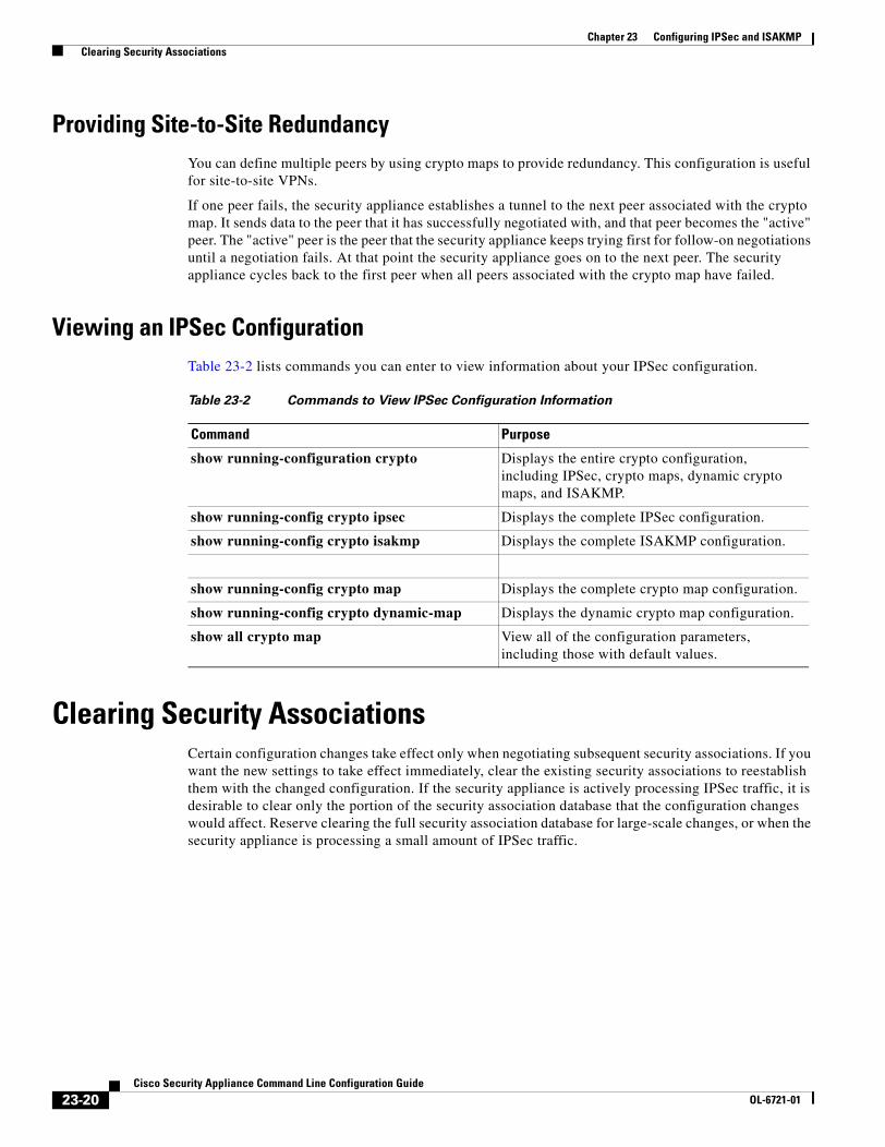
Chapter 23 Configuring IPSec and ISAKMP Clearing Security Associations
Providing Site-to-Site RedundancyYou can define multiple peers by using crypto maps to provide redundancy. This configuration is useful for site-to-site VPNs.
If one peer fails, the security appliance establishes a tunnel to the next peer associated with the crypto map. It sends data to the peer that it has successfully negotiated with, and that peer becomes the "active" peer. The "active" peer is the peer that the security appliance keeps trying first for follow-on negotiations until a negotiation fails. At that point the security appliance goes on to the next peer. The security appliance cycles back to the first peer when all peers associated with the crypto map have failed.
Viewing an IPSec ConfigurationTable 23-2 lists commands you can enter to view information about your IPSec configuration.
Clearing Security AssociationsCertain configuration changes take effect only when negotiating subsequent security associations. If you want the new settings to take effect immediately, clear the existing security associations to reestablish them with the changed configuration. If the security appliance is actively processing IPSec traffic, it is desirable to clear only the portion of the security association database that the configuration changes would affect. Reserve clearing the full security association database for large-scale changes, or when the security appliance is processing a small amount of IPSec traffic.
Table 23-2 Commands to View IPSec Configuration Information
Command Purpose
show running-configuration crypto Displays the entire crypto configuration, including IPSec, crypto maps, dynamic crypto maps, and ISAKMP.
show running-config crypto ipsec Displays the complete IPSec configuration.
show running-config crypto isakmp Displays the complete ISAKMP configuration.
show running-config crypto map Displays the complete crypto map configuration.
show running-config crypto dynamic-map Displays the dynamic crypto map configuration.
show all crypto map View all of the configuration parameters, including those with default values.
23-20Cisco Security Appliance Command Line Configuration Guide
OL-6721-01

Chapter 23 Configuring IPSec and ISAKMP Clearing Crypto Map Configurations
Table 23-3 lists commands you can enter to clear and reinitialize IPSec security associations.
Clearing Crypto Map ConfigurationsThe clear configure crypto command includes arguments that let you remove elements of the crypto configuration, including IPSec, crypto maps, dynamic crypto maps, CA trustpoints, all certificates, certificate map configurations, and ISAKMP.
Be aware that if you enter the clear configure crypto command without arguments, you remove the entire crypto configuration, including all certificates.
For more information, see the clear configure crypto command in the Cisco Security Appliance Command Reference.
Table 23-3 Commands to Clear and Reinitialize IPSec SAs
Command Purpose
clear configure crypto Removes an entire crypto configuration, including IPSec, crypto maps, dynamic crypto maps, and ISAKMP.
clear configure crypto ca trustpoint Removes all trustpoints.
clear configure crypto dynamic-map Removes all dynamic crypto maps. Includes keywords that let you remove specific dynamic crypto maps.
clear configure crypto map Removes all crypto maps. Includes keywords that let you remove specific crypto maps.
clear configure isakmp Removes the entire ISAKMP configuration.
clear configure isakmp policy Removes all ISAKMP policies or a specific policy.
clear isakmp sa Removes the entire ISAKMP SA database.
23-21Cisco Security Appliance Command Line Configuration Guide
OL-6721-01

Chapter 23 Configuring IPSec and ISAKMP Clearing Crypto Map Configurations
23-22Cisco Security Appliance Command Line Configuration Guide
OL-6721-01

Cisco Security AppliaOL-6721-01
C H A P T E R 24
Setting General VPN ParametersThe security appliance implementation of virtual private networking includes useful features that do not fit neatly into categories. This chapter describes some of these features. It includes the following sections:
• Configuring VPNs in Single, Routed Mode, page 24-1
• Configuring IPSec to Bypass ACLs, page 24-1
• Permitting Intra-Interface Traffic, page 24-2
• Setting Maximum Active IPSec VPN Sessions, page 24-2
• Configuring Client Update, page 24-2
Configuring VPNs in Single, Routed ModeVPNs work only in single, routed mode. VPN functionality is unavailable in configurations that include either security contexts, also referred to as multi-mode firewall, or Active/Active stateful failover.
The exception to this caveat is that you can configure and use one connection for administrative purposes to (not through) the security appliance in transparent mode.
Configuring IPSec to Bypass ACLsTo permit any packets that come from an IPSec tunnel without checking ACLs for the source and destination interfaces, enter the sysopt connection permit-ipsec command in global configuration mode.
You might want to bypass interface ACLs for IPSec traffic if you use a separate VPN concentrator behind the security appliance and want to maximize the security appliance performance. Typically, you create an ACL that permits IPSec packets using the access-list command and apply it to the source interface. Using an ACL is more secure because you can specify the exact traffic you want to allow through the security appliance.
The syntax is sysopt connection permit-ipsec. The command has no keywords or arguments.
The following example enables IPSec traffic through the security appliance without checking ACLs:
hostname(config)# sysopt connection permit-ipsec
24-1nce Command Line Configuration Guide

Chapter 24 Setting General VPN Parameters Permitting Intra-Interface Traffic
Permitting Intra-Interface TrafficThe security appliance includes a feature that lets users on the same subnet send IPSec-protected traffic to each other. It does so by allowing such traffic in and out of the same interface. This is called hairpinning.
To configure this feature, use the same-security-traffic command in global configuration mode with its intra-interface argument.
The command syntax is same-security-traffic permit {inter-interface | intra-interface}.
The following example shows how to enable intra-interface traffic:
hostname(config)# same-security-traffic permit intra-interfacehostname(config)#
Note You use the same-security-traffic command, but with the inter-interface argument, to permit communication between interfaces that have the same security level. This feature is not specific to IPSec connections. For more information, see the “Configuring Interface Parameters” chapter of this guide.
Setting Maximum Active IPSec VPN Sessions To limit VPN sessions to a lower value than the security appliance allows, enter the vpn-sessiondb max-session-limit command in global configuration mode.
• This command applies to all types of VPN sessions.
The syntax is vpn-sessiondb max-session-limit {session-limit}.
The following example shows how to set a maximum VPN session limit of 450:
hostname (config)# vpn-sessiondb max-session-limit 450hostname (config)#
Configuring Client UpdateThe client update feature lets administrators at a central location automatically notify VPN client users when it is time to update the VPN client software and the VPN 3002 hardware client image.
To configure client update, enter the client-update command in tunnel-group ipsec-attributes configuration mode. If the client is already running a software version on the list of revision numbers, it does not need to update its software. If the client is not running a software version on the list, it should update. You can specify up to 4 client update entries.
24-2Cisco Security Appliance Command Line Configuration Guide
OL-6721-01

Chapter 24 Setting General VPN Parameters Configuring Client Update
The command syntax follows:
client-update type type {url url-string} {rev-nums rev-nums}
no client-update [type]
Syntax Description
The following example configures client update parameters for the remote-access tunnel-group called remotegrp. It designates the revision number 4.6.1 and the URL for retrieving the update, which is https://support/updates.
hostname(config)# tunnel-group remotegrp type ipsec_rahostname(config)# tunnel-group remotegrp ipsec-attributeshostname(config-ipsec)# client-update type windows url https://support/updates/ rev-nums 4.6.1hostname(config-ipsec)#
rev-nums rev-nums Specifies the software or firmware images for this client. Enter up to 4, separated by commas.
type Specifies the operating systems to notify of a client update. The list of operating systems comprises the following:
• Windows: all windows-based platforms
• WIN9X: Windows 95, Windows 98, and Windows ME platforms
• WinNT: Windows NT 4.0, Windows 2000, and Windows XP platforms
• vpn3002: VPN 3002 hardware client
url url-string Specifies the URL for the software/firmware image. This URL must point to a file appropriate for the client.
24-3Cisco Security Appliance Command Line Configuration Guide
OL-6721-01

Chapter 24 Setting General VPN Parameters Configuring Client Update
24-4Cisco Security Appliance Command Line Configuration Guide
OL-6721-01

Cisco Security AppliaOL-6721-01
C H A P T E R 25
Configuring Tunnel Groups, Group Policies, and UsersThis chapter describes how to configure VPN tunnel groups, group policies, and users. This chapter includes the following sections.
• Overview of Tunnel Groups, Group Policies, and Users, page 25-1
• Configuring Tunnel Groups, page 25-4
• Group Policies, page 25-10
• Configuring Users, page 25-26
In summary, you first configure tunnel groups to set the values for the connection. Then you configure group policies. These set values for users in the aggregate. Then you configure users, which can inherit values from groups and configure certain values on an individual user basis. This chapter describes how and why to configure these entities.
Overview of Tunnel Groups, Group Policies, and Users Groups and users are core concepts in managing the security of virtual private networks (VPNs) and in configuring the security appliance. They specify attributes that determine user access to and use of the VPN. A group is a collection of users treated as a single entity. Users get their attributes from group policies. Tunnel groups identify the group policy for a specific connection. If you do not assign a particular group policy to a user, the default group policy for the connection applies.
Tunnel groups and group policies simplify system management. To streamline the configuration task, the security appliance provides a default LAN-to-LAN tunnel group (DefaultL2Lgroup), a default remote access tunnel group (DefaultRAgroup), and a default group policy (DfltGrpPolicy). The default tunnel groups and group policy provide settings that are likely to be common for many users. As you add users, you can specify that they “inherit” parameters from a group policy. Thus you can quickly configure VPN access for large numbers of users.
If you decide to grant identical rights to all VPN users, then you do not need to configure specific tunnel groups or group policies, but VPNs seldom work that way. For example, you might allow a finance group to access one part of a private network, a customer support group to access another part, and an MIS group to access other parts. In addition, you might allow specific users within MIS to access systems that other MIS users cannot access. Tunnel groups and group policies provide the flexibility to do so securely.
25-1nce Command Line Configuration Guide

Chapter 25 Configuring Tunnel Groups, Group Policies, and Users Overview of Tunnel Groups, Group Policies, and Users
Note The security appliance also includes the concept of object groups, which are a superset of network lists. Object groups let you define VPN access to ports as well as networks. Object groups relate to ACLs rather than to group policies and tunnel groups. For more information about using object groups, see Chapter 13, “Identifying Traffic with Access Lists.”
Tunnel GroupsA tunnel group consists of a set of records that contain tunnel connection policies. Tunnel groups contain a small number of attributes that pertain to creating the tunnel itself. Tunnel groups include a pointer to a group policy that defines user-oriented attributes.
The security appliance provides two default tunnel groups, one for LAN-to-LAN connections, and one for remote access connections. You can modify these default tunnel groups, but you cannot delete them. You can also create one or more tunnel groups specific to your environment. Tunnel groups are local to the security appliance and are not configurable on external servers.
Tunnel groups specify the following attributes:
• General parameters
• IPSec connection parameters
General Tunnel Group Parameters
The general parameters include the following:
• Tunnel group name—Both remote access and LAN-to-LAN clients select a tunnel group by its name, as follows:
– For IPSec clients that use preshared keys to authenticate, the tunnel group name is the same as the group name that the IPSec client passes to the security appliance.
– IPSec clients that use certificates to authenticate pass this name as part of the certificate, and the security appliance extracts the name from the certificate.
Tunnel group records contain tunnel connection policy information. These records identify the servers to which the tunnel user is authenticated, as well as the accounting servers to which connection information is sent. They also identify a default group policy for the connection, and they contain protocol-specific connection parameters.
• Connection type—Connection types include remote access IPSec, and LAN-to-LAN IPSec. A tunnel group can have only one connection type.
• Authentication, Authorization, and Accounting servers—These parameters identify the server groups or lists that the security appliance uses for the following purposes:
– Authenticating users
– Obtaining information about services users are authorized to access
– Storing accounting records
A server group can consist of one or more servers.
25-2Cisco Security Appliance Command Line Configuration Guide
OL-6721-01

Chapter 25 Configuring Tunnel Groups, Group Policies, and Users Overview of Tunnel Groups, Group Policies, and Users
• Default group policy for the connection—A group policy is a set of user-oriented attributes. The default group policy is the group policy whose attributes the security appliance uses as defaults when authenticating or authorizing a tunnel user.
• Client address assignment method—This method includes values for one or more DHCP servers or address pools that the security appliance assigns to clients.
IPSec Connection Parameters
IPSec parameters include the following:
• A client authentication method: preshared keys or certificates.
• ISAKMP keepalive settings. This feature lets the security appliance monitor the continued presence of a remote peer and report its own presence to that peer. If the peer becomes unresponsive, the security appliance removes the connection. Enabling IKE keepalives prevents hung connections when the IKE peer loses connectivity.
There are various forms of IKE keepalives. For this feature to work, both the security appliance and its remote peer must support a common form. This feature works with the following peers:
– Cisco VPN client (Release 3.0 and above)
– Cisco VPN 3000 Client (Release 2.x)
– Cisco VPN 3002 Hardware Client
– Cisco VPN 3000 Series Concentrators
– Cisco IOS software
– Cisco Secure PIX Firewall
Non-Cisco VPN clients do not support IKE keepalives.
If you are configuring a group of mixed peers, and some of those peers support IKE keepalives and others do not, enable IKE keepalives for the entire group. The feature does not affect the peers that do not support it.
If you disable IKE keepalives, connections with unresponsive peers remain active until they time out, so we recommend that you keep your idle timeout short. To change your idle timeout, see “Configuring Group Policies” section on page 25-12.
Note To reduce connectivity costs, disable IKE keepalives if this group includes any clients connecting via ISDN lines. ISDN connections normally disconnect if idle, but the IKE keepalives mechanism prevents connections from idling and therefore from disconnecting.
If you do disable IKE keepalives, the client disconnects only when either its IKE or IPSec keys expire. Failed traffic does not disconnect the tunnel with the Peer Timeout Profile values as it does when IKE keepalives are enabled.
Note If you have a LAN-to-LAN configuration using IKE main mode, make sure that the two peers have the same IKE keepalives configuration. Both peers must have IKE keepalives enabled or both peers must have it disabled.
• Values for defining authorization usernames.
25-3Cisco Security Appliance Command Line Configuration Guide
OL-6721-01

Chapter 25 Configuring Tunnel Groups, Group Policies, and Users Configuring Tunnel Groups
Configuring Tunnel GroupsThe security appliance provides two default tunnel groups, one for remote access (DefaultRAGroup) and one for LAN-to-LAN (DefaultL2LGroup). You can modify these groups, but you cannot delete them. To see the current configured and default configuration of all your tunnel groups, including the default tunnel group, enter the show running-config all tunnel-group command.
You can configure a new tunnel group as either an IPSec Remote Access (ipsec-ra) tunnel or an IPSec LAN-to-LAN (ipsec-l2l) tunnel. The default is ipsec-ra. The subsequent parameters depend upon your choice of tunnel type.
Default Remote Access Tunnel Group ConfigurationThe contents of the default remote-access tunnel group are as follows:
tunnel-group DefaultRAGroup type ipsec-ratunnel-group DefaultRAGroup general-attributes no address-pool authentication-server-group LOCAL no authorization-server-group no accounting-server-group default-group-policy DfltGrpPolicy no dhcp-server no strip-realm no strip-grouptunnel-group DefaultRAGroup ipsec-attributes no pre-shared-key no authorization-required authorization-dn-attributes CN OU peer-id-validate req no radius-with-expiry no chain no trust-point isakmp keepalive threshold 300 retry 2
Configuring Remote-Access Tunnel GroupsTo configure a remote-access tunnel group, follow the steps in this section. An IPSec Remote Access VPN tunnel group applies only to remote-access IPSec client connections.
Specify a Name and Type for the Remote-Access Tunnel Group
To assign a name and type for the tunnel group, enter the tunnel-group command to assign a name and type for the tunnel group.
hostname(config)# tunnel-group tunnel_group_name type tunnel_type
For a remote-access tunnel, the type is ipsec-ra; for example:
hostname(config)# tunnel-group TunnelGroup1 type ipsec-ra
25-4Cisco Security Appliance Command Line Configuration Guide
OL-6721-01

Chapter 25 Configuring Tunnel Groups, Group Policies, and Users Configuring Tunnel Groups
Configure Remote-Access Tunnel Group General Attributes
To configure the tunnel group general attributes, specify the parameters in the following steps.
Step 1 Enter the config-general mode by specifying the tunnel-group command with the general-attributes designator:
hostname(config)# tunnel-group tunnel_group_name general-attributes
This command enters config-general mode, in which you configure the tunnel-group general attributes.
Step 2 Specify the name of the authentication-server group, if any, to use. If you want to use the LOCAL database for authentication if the specified server group fails, append the word LOCAL:
hostname(config-general)# authentication-server-group groupname [LOCAL]
You can also configure interface-specific authentication by including the name of an interface after the group name. The following command configures interface-specific authentication for the interface named “test” using the server “servergroup1” for authentication:
hostname(config-general)# authentication-server-group test servergroup1
Step 3 Specify the name of the authorization-server group, if any, to use:
hostname(config-general)# authorization-server-group groupname
Step 4 Specify the name of the accounting-server group, if any, to use:
hostname(config-general)# accounting-server-group groupname
Step 5 Specify the name of the default group policy:
hostname(config-general)# default-group-policy policyname
The following example sets “DfltGrpPolicy” as the name of the group policy:
hostname(config)# default-group-policy DfltGrpPolicy
Step 6 Specify the name or IP address of the DHCP server (up to 10 servers), and the names of the DHCP address pools (up to 6 pools). The defaults are no DHCP server and no address pool.
hostname(config-general)# dhcp-server server1 [...server10]hostname(config-general)# address-pool [(interface name)] address_pool1 [...address_pool6]
Note The interface name must be enclosed in parentheses.
You configure address pools with the ip local pool command in global configuration mode.
Step 7 Specify whether to strip the group or the realm from the username before passing it on to the AAA server. The default is not to strip either the group name or the realm.
hostname(config-general)# strip-grouphostname(config-general)# strip-realm
Enter the strip-realm command to remove the realm qualifier of the username during authentication. If you do so, authentication is based on the username alone. Otherwise, authentication is based on the full username@realm string. You must enable strip realm if your server is unable to parse delimiters. If you are using the Group Lookup feature and strip realm, do not use the @ character for the group delimiter.
25-5Cisco Security Appliance Command Line Configuration Guide
OL-6721-01

Chapter 25 Configuring Tunnel Groups, Group Policies, and Users Configuring Tunnel Groups
Step 8 Whether users must exist in the authorization database to connect.
hostname(config)# authorization-server-group groupname
Configure Remote-Access Tunnel Group IPSec Attributes
To configure the IPSec attributes, specify the following parameters:
Step 1 Specify the IPSec-attributes designator:
hostname(config)# tunnel-group tunnel-group-name ipsec-attributes
For example, the following command designates that the config-ipsec mode commands that follow pertain to the tunnel group named “TG1”:
hostname(config)# tunnel-group TG1 ipsec-attributes
This command enters config-ipsec mode, in which you configure the tunnel-group IPSec attributes.
Step 2 Specify the attribute or attributes to use in deriving a name for an authorization query from a certificate. This attribute specifies what part of the subject DN field to use as the username for authorization:
hostname(config-ipsec)# authorization-dn-attributes {primary-attribute [secondary-attribute] | use-entire-name}
For example, the following command specifies the use of the “CN” attribute as the username for authorization:
hostname(config-ipsec)# authorization-dn-attributes CN
The authorization-dn-attributes are C (Country), CN (Common Name), DNQ (DN qualifier), EA (E-mail Address), GENQ (Generational qualifier), GN (Given Name), I (Initials), L (Locality), N (Name), O (Organization), OU (Organizational Unit), SER (Serial Number), SN (Surname), SP (State/Province), T (Title), and UID (User ID)
Step 3 Specify whether to require a successful authorization before allowing a user to connect. The default is not to require authorization.
hostname(config-ipsec)# authorization-required
Step 4 Specify the client-update parameters; that is, the client type and the acceptable revision levels for that client:
hostname(config-ipsec)# client-update type type url url-string rev-nums rev-numbers
The available client types are Win9X (includes Windows 95, Windows 98 and Windows ME platforms), WinNT (includes Windows NT 4.0, Windows 2000 and Windows XP platforms), Windows (Includes all Windows based platforms), and vpn3002 (VPN3002 hardware client).
If the client is already running a software version on the list of revision numbers, it does not need to update its software. If the client is not running a software version on the list, it should update. You can specify up to four of these client update entries.
The following example configures client update parameters for the remote-access tunnel-group. It designates the revision number, 4.6.1 and the URL for retrieving the update, which is “https://support/updates”:
hostname(config-ipsec)# client-update type windows url https://support/updates/ rev-nums 4.6.1
25-6Cisco Security Appliance Command Line Configuration Guide
OL-6721-01

Chapter 25 Configuring Tunnel Groups, Group Policies, and Users Configuring Tunnel Groups
Step 5 Specify the preshared key to support IKE connections based on preshared keys.
hostname(config-ipsec)# pre-shared-key xyzx
The preceding command specifies the preshared key xyzx to support IKE connections for an IPSec remote access tunnel group:
Step 6 Specify whether to validate the identity of the peer using the peer’s certificate:
hostname(config-ipsec)# peer-id-validate option
The available options are req (required), cert (if supported by certificate), and nocheck (do not check). The default is req.
Step 7 Specify whether to enable sending of a certificate chain. The following command includes the root certificate and any subordinate CA certificates in the transmission:
hostname(config-ipsec)# chain
You can apply this attribute to all tunnel-group types.
Step 8 Specify the name of a trustpoint that identifies the certificate to be sent to the IKE peer:
hostname(config-ipsec)# trust-point trust-point-name
The following command specifies “mytrustpoint” as the name of the certificate to be sent to the IKE peer:
hostname(config-ipsec)# trust-point mytrustpoint
You can apply this attribute to all tunnel-group types.
Step 9 Specify whether to have the security appliance use MS-CHAPv2 to negotiate a password update with the user during authentication:
hostname(config-ipsec)# radius-with-expiry
The security appliance ignores this command if RADIUS authentication has not been configured.
Step 10 ISAKMP keepalive threshold and the number of retries allowed.
hostname(config)# isakmp keepalive threshold <number> retry <number>
The threshold parameter specifies the number of seconds (10 through 3600) that the peer is allowed to idle before beginning keepalive monitoring. The retry parameter is the interval (2 through 10 seconds) between retries after a keepalive response has not been received. IKE keepalives are enabled by default. To disable IKE keepalives, enter the no form of the isakmp command:
For example, the following command sets the IKE keepalive threshold value to 15 seconds and sets the retry interval to 10 seconds:
hostname(config-ipsec)# isakmp keepalive threshold 15 retry 10
The default value for the threshold parameter is 300 for remote-access and 10 for LAN-to-LAN, and the default value for the retry parameter is 2.
25-7Cisco Security Appliance Command Line Configuration Guide
OL-6721-01

Chapter 25 Configuring Tunnel Groups, Group Policies, and Users Configuring Tunnel Groups
Default LAN-to-LAN Tunnel Group ConfigurationThe contents of the default LAN-to-LAN tunnel group are as follows:
tunnel-group DefaultL2LGroup type ipsec-l2ltunnel-group DefaultL2LGroup general-attributes no accounting-server-group default-group-policy DfltGrpPolicytunnel-group DefaultL2LGroup ipsec-attributes no pre-shared-key peer-id-validate req no chain no trust-point isakmp keepalive threshold 10 retry 2
LAN-to-LAN tunnel groups have fewer parameters than remote-access tunnel groups, and most of these are the same for both groups. For your convenience in configuring the connection, they are listed separately here.
Configuring LAN-to-LAN Tunnel GroupsAn IPSec LAN-to-LAN VPN tunnel group applies only to LAN-to-LAN IPSec client connections. To configure a LAN-to-LAN tunnel group, follow the steps in this section.
Specify a Name and Type for the LAN-to-LAN Tunnel Group
To specify a name and a type for a tunnel group, enter the tunnel-group command, as follows:
hostname(config)# tunnel-group tunnel_group_name type tunnel_type
For a LAN-to-LAN tunnel, the type is ipsec-l2l.; for example:
hostname(config)# tunnel-group TunnelGroup1 type ipsec-l2l
Configure LAN-to-LAN Tunnel Group General Attributes
To configure the tunnel group general attributes, specify the parameters in the following steps:
Step 1 Enter configuration-general mode by specifying the general-attributes designator:
hostname(config)# tunnel-group tunnel_group_tunnel-group-name general-attributeshostname(config-general)#
The prompt changes to indicate that you are now in config-general mode, in which you configure the tunnel-group general attributes.
Step 2 Specify the name of the accounting-server group, if any, to use:
hostname(config-general)# accounting-server-group groupname
For example, the following command specifies the use of the accounting-server group “acctgserv1”:
hostname(config-general)# accounting-server-group acctgserv1
25-8Cisco Security Appliance Command Line Configuration Guide
OL-6721-01

Chapter 25 Configuring Tunnel Groups, Group Policies, and Users Configuring Tunnel Groups
Step 3 Specify the name of the default group policy:
hostname(config-general)# default-group-policy policyname
For example, the following command specifies that the name of the default group policy is “MyPolicy”:
hostname(config-general)# default-group-policy MyPolicy
Configure LAN-to-LAN IPSec Attributes
To configure the IPSec attributes, do the following steps:
Step 1 To enter config-ipsec mode, in which you configure the tunnel-group IPSec attributes, enter the tunnel-group command with the IPSec-attributes designator.
hostname(config)# tunnel-group tunnel-group-name ipsec-attributes
For example, the following command enters config-ipsec mode so you can configure the parameters for the tunnel group named “TG1”:
hostname(config)# tunnel-group TG1 ipsec-attributeshostname(config-ipsec)#
The prompt changes to indicate that you are now in config-ipsec mode.
Step 2 Specify the preshared key to support IKE connections based on preshared keys.
hostname(config-ipsec)# pre-shared-key key
For example, the following command specifies the preshared key XYZX to support IKE connections for an IPSec remote access tunnel group:
hostname(config-ipsec)# pre-shared-key xyzx
Step 3 Specify whether to validate the identity of the peer using the peer’s certificate:
hostname(config-ipsec)# peer-id-validate option
The available options are req (required), cert (if supported by certificate), and nocheck (do not check). The default is req. For example, the following command sets the peer-id-validate option to nocheck:
hostname(config-ipsec)# peer-id-validate nocheck
Step 4 Specify whether to enable sending of a certificate chain. This action includes the root certificate and any subordinate CA certificates in the transmission:
hostname(config-ipsec)# chain
You can apply this attribute to all tunnel-group types.
Step 5 Specify the name of a trustpoint that identifies the certificate to be sent to the IKE peer:
hostname(config-ipsec)# trust-point trust-point-name
For example, the following command sets the trustpoint name to “mytrustpoint”:
hostname(config-ipsec)# trust-point mytrustpoint
You can apply this attribute to all tunnel-group types.
25-9Cisco Security Appliance Command Line Configuration Guide
OL-6721-01

Chapter 25 Configuring Tunnel Groups, Group Policies, and Users Group Policies
Step 6 Specify the ISAKMP keepalive threshold and the number of retries allowed. The threshold parameter specifies the number of seconds (10 through 3600) that the peer is allowed to idle before beginning keepalive monitoring. The retry parameter is the interval (2 through 10 seconds) between retries after a keepalive response has not been received. IKE keepalives are enabled by default. To disable IKE keepalives, enter the no form of the isakmp command:
hostname(config)# isakmp keepalive threshold <number> retry <number>
For example, the following command sets the ISAKMP keepalive threshold to 15 seconds and sets the retry interval to 10 seconds.:
hostname(config-ipsec)# isakmp keepalive threshold 15 retry 10
The default value for the threshold parameter for LAN-to-LAN is 10, and the default value for the retry parameter is 2.
Group PoliciesA group policy is a set of user-oriented attribute/value pairs for IPSec connections that are stored either internally (locally) on the device or externally on a RADIUS server. The tunnel group refers to a group policy that sets terms for user connections after the tunnel is established. Group policies let you apply whole sets of attributes to a user or a group of users, rather than having to specify each attribute individually for each user.
Enter the group-policy commands in global configuration mode to assign a group policy to users or to modify a group policy for specific users.
The security appliance includes a default group policy. You can modify this default group policy, but you cannot delete it. You can also create one or more group policies specific to your environment.
Group policies include the following attributes:
• Identity
• Defining servers
• Client firewall settings
• Tunneling protocols
• IPSec settings
• Hardware client settings
• Filters
• Client configuration settings
• Connection settings
25-10Cisco Security Appliance Command Line Configuration Guide
OL-6721-01

Chapter 25 Configuring Tunnel Groups, Group Policies, and Users Group Policies
Default Group PolicyThe security appliance supplies a default group policy. You can modify this default group policy, but you cannot delete it. A default group policy, named “DfltGrpPolicy”, always exists on the security appliance, but this default group policy does not take effect unless you configure the security appliance to use it.To view the default group policy, enter the following command:
hostname(config)# show running-config all group-policy DfltGrpPolicy
To configure the default group policy, enter the following command:
hostname(config)# group-policy DfltGrpPolicy internal
Note The default group policy is internal. Despite the fact that the command syntax ishostname(config)# group-policy DfltGrpPolicy {internal | external}, you cannot change the type to external.
If you want to change any of the attributes of the group policy, use the group-policy attributes command to enter attributes mode, then specify the commands to change whatever attributes that you want to modify:
hostname(config)# group-policy DfltGrpPolicy attributes
Note The attributes mode applies only for internal group policies.
The default group policy that the security appliance provides, “DfltGrpPolicy”, is as follows:
group-policy DfltGrpPolicy internalgroup-policy DfltGrpPolicy attributes wins-server none dns-server none vpn-access-hours none vpn-simultaneous-logins 3 vpn-idle-timeout 30 vpn-session-timeout none vpn-filter none vpn-tunnel-protocol IPSec password-storage disable ip-comp disable re-xauth disable group-lock none pfs disable banner none ipsec-udp disable ipsec-udp-port 10000 split-tunnel-policy tunnelall split-tunnel-network-list none default-domain none split-dns none secure-unit-authentication disable user-authentication disable user-authentication-idle-timeout 30 ip-phone-bypass disable leap-bypass disable nem disable backup-servers keep-client-config client-firewall none client-access-rule none
25-11Cisco Security Appliance Command Line Configuration Guide
OL-6721-01

Chapter 25 Configuring Tunnel Groups, Group Policies, and Users Group Policies
You can modify the default group policy, and you can also create one or more group policies specific to your environment.
Configuring Group PoliciesA group policy can apply to either remote-access or LAN-to-LAN IPSec tunnels. In each case, if you do not explicitly define a parameter, the group takes the value from the default group policy. To configure a group policy, follow these steps:
Step 1 Specify a name and type (internal or external) for the group policy:
hostname(config)# group-policy group_policy_name type
For example, the following command specifies that the group policy is named “GroupPolicy1” and that its type is internal:
hostname(config)# group-policy GroupPolicy1 internal
The default type is internal.
You can initialize the attributes of an internal group policy to the values of a preexisting group policy by appending the keyword from and specifying the name of the existing policy:
hostname(config)# group-policy group_policy_name internal from group_policy_name
For an external group policy, you must identify the AAA server group that the security appliance can query for attributes and specify the password to use when retrieving attributes from the external AAA server group, as follows:
hostname(config)# group-policy name external server-group server_group password server_password}
Note For an external group policy, RADIUS is the only supported AAA server type.
Step 2 Enter the group-policy attributes mode, using the group-policy attributes command in global configuration mode.
hostname(config)# group-policy name attributeshostname(config-group-policy)#
The prompt changes to indicate the mode change. The group-policy-attributes mode lets you configure attribute-value pairs for a specified group policy. In group-policy-attributes mode, explicitly configure the attribute-value pairs that you do not want to inherit from the default group. The commands to do this are described in the following steps.
Step 3 Specify the primary and secondary WINS servers:
hostname(config-group-policy)# wins-server value {ip_address [ip_address] | none}
The first IP address specified is that of the primary WINS server. The second (optional) IP address is that of the secondary WINS server. Specifying the none keyword instead of an IP address sets WINS servers to a null value, which allows no WINS servers and prevents inheriting a value from a default or specified group policy.
25-12Cisco Security Appliance Command Line Configuration Guide
OL-6721-01

Chapter 25 Configuring Tunnel Groups, Group Policies, and Users Group Policies
Every time that you enter the wins-server command, you overwrite the existing setting. For example, if you configure WINS server x.x.x.x and then configure WINS server y.y.y.y, the second command overwrites the first, and y.y.y.y becomes the sole WINS server. The same is true for multiple servers. To add a WINS server rather than overwrite previously configured servers, include the IP addresses of all WINS servers when you enter this command.
The following example shows how to configure WINS servers with the IP addresses 10.10.10.15 and 10.10.10.30 for the group policy named “FirstGroup”:
hostname(config)# group-policy FirstGroup attributeshostname(config-group-policy)# wins-server value 10.10.10.15 10.10.10.30
Step 4 Specify the primary and secondary DNS servers:
hostname(config-group-policy)# dns-server value {ip_address [ip_address] | none}
The first IP address specified is that of the primary DNS server. The second (optional) IP address is that of the secondary DNS server. Specifying the none keyword instead of an IP address sets DNS servers to a null value, which allows no DNS servers and prevents inheriting a value from a default or specified group policy.
Every time that you enter the dns-server command you overwrite the existing setting. For example, if you configure DNS server x.x.x.x and then configure DNS server y.y.y.y, the second command overwrites the first, and y.y.y.y becomes the sole DNS server. The same is true for multiple servers. To add a DNS server rather than overwrite previously configured servers, include the IP addresses of all DNS servers when you enter this command.
The following example shows how to configure DNS servers with the IP addresses 10.10.10.15, and 10.10.10.30 for the group policy named “FirstGroup”:
hostname(config)# group-policy FirstGroup attributeshostname(config-group-policy)# dns-server value 10.10.10.15 10.10.10.30
Step 5 Set the VPN access hours. To do this, you associate a group policy with a configured time-range policy, using the vpn-access-hours command in group-policy configuration mode.
hostname(config-group-policy)# vpn-access-hours value {time-range | none}
A group policy can inherit a time-range value from a default or specified group policy. To prevent this inheritance, enter the none keyword instead of the name of a time-range in this command. This keyword sets VPN access hours to a null value, which allows no time-range policy.
The time-range variable is the name of a set of access hours defined in global configuration mode using the time-range command. The following example shows how to associate the group policy named “FirstGroup” with a time-range policy called “824”:
hostname(config)# group-policy FirstGroup attributeshostname(config-group-policy)# vpn-access-hours value 824
Step 6 Specify the number of simultaneous logins allowed for any user, using the vpn-simultaneous-logins command in group-policy configuration mode.
hostname(config-group-policy)# vpn-simultaneous-logins integer
The default value is 3. The range is an integer in the range 0 through 2147483647. A group policy can inherit this value from another group policy. Enter 0 to disable login and prevent user access. The following example shows how to allow a maximum of 4 simultaneous logins for the group policy named “FirstGroup”:
hostname(config)# group-policy FirstGroup attributeshostname(config-group-policy)# vpn-simultaneous-logins 4
25-13Cisco Security Appliance Command Line Configuration Guide
OL-6721-01

Chapter 25 Configuring Tunnel Groups, Group Policies, and Users Group Policies
Note While there is no maximum limit to the number of simultaneous logins, allowing several could compromise security and affect performance.
Step 7 Configure the user timeout period by entering the vpn-idle-timeout command in group-policy configuration mode or in username configuration mode:
hostname(config-group-policy)# vpn-idle-timeout {minutes | none}
The minimum time is 1 minute, and the maximum time is 35791394 minutes. The default is 30 minutes. If there is no communication activity on the connection in this period, the security appliance terminates the connection.
A group policy can inherit this value from another group policy. To prevent inheriting a value, enter the none keyword instead of specifying a number of minutes with this command. The none keyword also permits an unlimited idle timeout period. It sets the idle timeout to a null value, thereby disallowing an idle timeout.
The following example shows how to set a VPN idle timeout of 15 minutes for the group policy named “FirstGroup”:
hostname(config)# group-policy FirstGroup attributeshostname(config-group-policy)# vpn-idle-timeout 15
Step 8 Configure a maximum amount of time for VPN connections, using the vpn-session-timeout command in group-policy configuration mode or in username configuration mode.
hostname(config-group-policy)# vpn-session-timeout {minutes | none}
The minimum time is 1 minute, and the maximum time is 35791394 minutes. There is no default value. At the end of this period of time, the security appliance terminates the connection.
A group policy can inherit this value from another group policy. To prevent inheriting a value, enter the none keyword instead of specifying a number of minutes with this command. Specifying the none keyword permits an unlimited session timeout period and sets session timeout with a null value, which disallows a session timeout.
The following example shows how to set a VPN session timeout of 180 minutes for the group policy named “FirstGroup”:
hostname(config)# group-policy FirstGroup attributeshostname(config-group-policy)# vpn-session-timeout 180
Step 9 Specify the name of the ACL to use for VPN connections, using the vpn-filter command in group policy or username mode.
hostname(config-group-policy)# vpn-filter {value ACL name | none}
To remove the ACL, including a null value created by entering the vpn-filter none command, enter the no form of this command. The no option allows inheritance of a value from another group policy.
A group policy can inherit this value from another group policy. To prevent inheriting a value, enter the none keyword instead of specifying an ACL name. The none keyword indicates that there is no access list and sets a null value, thereby disallowing an access list.
You configure ACLs to permit or deny various types of traffic for this group policy. You then enter the vpn-filter command to apply those ACLs.
25-14Cisco Security Appliance Command Line Configuration Guide
OL-6721-01

Chapter 25 Configuring Tunnel Groups, Group Policies, and Users Group Policies
The following example shows how to set a filter that invokes an access list named “acl_vpn” for the group policy named “FirstGroup”:
hostname(config)# group-policy FirstGroup attributeshostname(config-group-policy)# vpn-filter acl_vpn
Step 10 Specify the VPN tunnel type (IPSec) for this group policy.
hostname(config-group-policy)# vpn-tunnel-protocol IPSec
The default is IPSec. To remove the attribute from the running configuration, enter the no form of this command.
hostname(config-group-policy)# no vpn-tunnel-protocol [IPSec]
The parameter values for this command follow:
IPSec—Negotiates an IPSec tunnel between two peers (a remote access client or another secure gateway). Creates security associations that govern authentication, encryption, encapsulation, and key management.
Enter this command to configure one or more tunneling modes. You must configure at least one tunneling mode for users to connect over a VPN tunnel.
The following example shows how to configure the IPSec tunneling mode for the group policy named “FirstGroup”:
hostname(config)# group-policy FirstGroup attributeshostname(config-group-policy)# vpn-tunnel-protocol IPSec
Step 11 Specify whether to let users store their login passwords on the client system, using the password-storage command with the enable keyword in group-policy configuration mode. To disable password storage, use the password-storage command with the disable keyword.
hostname(config-group-policy)# password-storage {enable | disable}
For security reasons, password storage is disabled by default. Enable password storage only on systems that you know to be in secure sites.
To remove the password-storage attribute from the running configuration, enter the no form of this command:
hostname(config-group-policy)# no password-storage
Specifying the no form enables inheritance of a value for password-storage from another group policy.
This command does not apply to interactive hardware client authentication or individual user authentication for hardware clients.
The following example shows how to enable password storage for the group policy named “FirstGroup”:
hostname(config)# group-policy FirstGroup attributeshostname(config-group-policy)# password-storage enable
Step 12 Specify whether to enable IP compression, which is disabled by default.
hostname(config-group-policy)# ip-comp {enable | disable}
To enable LZS IP compression, enter the ip-comp command with the enable keyword in group-policy configuration mode. To disable IP compression, enter the ip-comp command with the disable keyword.
To remove the ip-comp attribute from the running configuration, enter the no form of this command. This enables inheritance of a value from another group policy.
hostname(config-group-policy)# no ip-comp
25-15Cisco Security Appliance Command Line Configuration Guide
OL-6721-01

Chapter 25 Configuring Tunnel Groups, Group Policies, and Users Group Policies
Enabling data compression might speed up data transmission rates for remote dial-in users connecting with modems.
Caution Data compression increases the memory requirement and CPU usage for each user session and consequently decreases the overall throughput of the security appliance. For this reason, we recommend that you enable data compression only for remote users connecting with a modem. Design a group policy specific to modem users, and enable compression only for them.
Step 13 Specify whether to require that users reauthenticate on IKE rekey by using the re-xauth command with the enable keyword in group-policy configuration mode. To disable user reauthentication on IKE rekey, enter the disable keyword.
hostname(config-group-policy)# re-xauth {enable | disable}
To remove the re-xauth attribute from the running configuration, enter the no form of this command. This enables inheritance of a value for reauthentication on IKE rekey from another group policy.
hostname(config-group-policy)# no re-xauth
Reauthentication on IKE rekey is disabled by default.If you enable reauthentication on IKE rekey, the security appliance prompts the user to enter a username and password during initial Phase 1 IKE negotiation and also prompts for user authentication whenever an IKE rekey occurs. Reauthentication provides additional security.
If the configured rekey interval is very short, users might find the repeated authorization requests inconvenient. To avoid repeated authorization requests, disable reauthentication. To check the configured rekey interval, in monitoring mode, enter the show crypto ipsec sa command to view the security association lifetime in seconds and lifetime in kilobytes of data.
Note Reauthentication fails if there is no user at the other end of the connection.
Step 14 Specify whether to restrict remote users to access through the tunnel group only, using the group-lock command in group-policy configuration mode.
hostname(config-group-policy)# group-lock {value tunnel-grp-name | none}hostname(config-group-policy)# no group-lock
The tunnel-grp-name variable specifies the name of an existing tunnel group that the security appliance requires for the user to connect. Group-lock restricts users by checking if the group configured in the VPN client is the same as the tunnel group to which the user is assigned. If it is not, the security appliance prevents the user from connecting. If you do not configure group-lock, the security appliance authenticates users without regard to the assigned group. Group locking is disabled by default.
To remove the group-lock attribute from the running configuration, enter the no form of this command. This option allows inheritance of a value from another group policy.
To disable group-lock, enter the group-lock command with the none keyword. The none keyword sets group-lock to a null value, thereby allowing no group-lock restriction. It also prevents inheriting a group-lock value from a default or specified group policy
Step 15 Specify whether to enable perfect forward secrecy by using the pfs command with the enable keyword in group-policy configuration mode.
hostname(config-group-policy)# pfs {enable | disable}
In IPSec negotiations, PFS ensures that each new cryptographic key is unrelated to any previous key. PFS is disabled by default.
25-16Cisco Security Appliance Command Line Configuration Guide
OL-6721-01

Chapter 25 Configuring Tunnel Groups, Group Policies, and Users Group Policies
To disable PFS, enter the disable keyword.
To remove the PFS attribute from the running configuration, enter the no form of this command. A group policy can inherit a value for PFS from another group policy. To prevent inheriting a value, enter the no form of this command.
hostname(config-group-policy)# no pfs
Step 16 Specify the banner, or welcome message, if any, that you want to display. The default is no banner. The message that you specify is displayed on remote clients when they connect. To specify a banner, enter the banner command in group-policy configuration mode. The banner text can be up to 510 characters long. Enter the “\n” sequence to insert a carriage return.
Note A carriage-return/line-feed included in the banner counts as two characters.
To delete a banner, enter the no form of this command. Be aware that using the no version of the command deletes all banners for the group policy.
A group policy can inherit this value from another group policy. To prevent inheriting a value, enter the none keyword instead of specifying a value for the banner string, as follows:
hostname(config-group-policy)# banner {value banner_string | none}
The following example shows how to create a banner for the group policy named “FirstGroup”:
hostname(config)# group-policy FirstGroup attributeshostname(config-group-policy)# banner value Welcome to Cisco Systems 7.0.
Step 17 Specify whether to enable IPSec over UDP. To use IPSec over UDP, you must also configure the ipsec-udp-port command, as follows:
hostname(config-group-policy)# ipsec-udp {enable | disable}hostname(config-group-policy)# no ipsec-udp
IPSec over UDP, sometimes called IPSec through NAT, lets a Cisco VPN client or hardware client connect via UDP to a security appliance that is running NAT. It is disabled by default. To enable IPSec over UDP, configure the ipsec-udp command with the enable keyword in group-policy configuration mode. To disable IPSec over UDP, enter the disable keyword. To remove the IPSec over UDP attribute from the running configuration, enter the no form of this command. This enables inheritance of a value for IPSec over UDP from another group policy.
The Cisco VPN client must also be configured to use IPSec over UDP (it is configured to use it by default). The VPN 3002 requires no configuration to use IPSec over UDP.
IPSec over UDP is proprietary; it applies only to remote-access connections, and it requires mode configuration. The security appliance exchanges configuration parameters with the client while negotiating SAs. Using IPSec over UDP may slightly degrade system performance.
The following example shows how to set IPSec over UDP for the group policy named “FirstGroup”:
hostname(config)# group-policy FirstGroup attributeshostname(config-group-policy)# ipsec-udp enable
If you enabled IPSec over UDP, you must also configure the ipsec-udp-port command in group-policy configuration mode. This command sets a UDP port number for IPSec over UDP. In IPSec negotiations, the security appliance listens on the configured port and forwards UDP traffic for that port even if other filter rules drop UDP traffic. The port numbers can range from 4001 through 49151. The default port value is 10000.
25-17Cisco Security Appliance Command Line Configuration Guide
OL-6721-01

Chapter 25 Configuring Tunnel Groups, Group Policies, and Users Group Policies
To disable the UDP port, enter the no form of this command. This enables inheritance of a value for the IPSec over UDP port from another group policy.
hostname(config-group-policy)# ipsec-udp-port port
The following example shows how to set an IPSec UDP port to port 4025 for the group policy named “FirstGroup”:
hostname(config)# group-policy FirstGroup attributeshostname(config-group-policy)# ipsec-udp-port 4025
Step 18 Set the rules for tunneling traffic by specifying the split-tunneling policy.
hostname(config-group-policy)# split-tunnel-policy {tunnelall | tunnelspecified | excludespecified}hostname(config-group-policy)# no split-tunnel-policy
The default is to tunnel all traffic. To set a split tunneling policy, enter the split-tunnel-policy command in group-policy configuration mode. To remove the split-tunnel-policy attribute from the running configuration, enter the no form of this command. This enables inheritance of a value for split tunneling from another group policy.
Split tunneling lets a remote-access IPSec client conditionally direct packets over an IPSec tunnel in encrypted form or to a network interface in clear text form. With split tunneling enabled, packets not bound for destinations on the other side of the IPSec tunnel do not have to be encrypted, sent across the tunnel, decrypted, and then routed to a final destination. This command applies this split tunneling policy to a specific network.
The excludespecified keyword defines a list of networks to which traffic goes in the clear. This feature is useful for remote users who want to access devices on their local network, such as printers, while they are connected to the corporate network through a tunnel. This option applies only to the Cisco VPN client.
The tunnelall keyword specifies that no traffic goes in the clear or to any other destination than the security appliance. This, in effect, disables split tunneling. Remote users reach internet networks through the corporate network and do not have access to local networks. This is the default option.
The tunnelspecified keyword tunnels all traffic from or to the specified networks. This option enables split tunneling. It lets you create a network list of addresses to tunnel. Data to all other addresses travels in the clear and is routed by the remote user’s Internet service provider.
Note Split tunneling is primarily a traffic management feature, not a security feature. For optimum security, we recommend that you do not enable split tunneling.
The following example shows how to set a split tunneling policy of tunneling only specified networks for the group policy named “FirstGroup”:
hostname(config)# group-policy FirstGroup attributeshostname(config-group-policy)# split-tunnel-policy tunnelspecified
Step 19 Create a network list for split tunneling using the split-tunnel-network-list command in group-policy configuration mode.
hostname(config-group-policy)# split-tunnel-network-list {value access-list_name | none}hostname(config-group-policy)# no split-tunnel-network-list value [access-list_name]
Split tunneling network lists distinguish networks that require traffic to travel across the tunnel from those that do not require tunneling. The security appliance makes split tunneling decisions on the basis of a network list, which is an ACL that consists of a list of addresses on the private network. Only standard-type ACLs are allowed.
25-18Cisco Security Appliance Command Line Configuration Guide
OL-6721-01

Chapter 25 Configuring Tunnel Groups, Group Policies, and Users Group Policies
The value access-list name parameter identifies an access list that enumerates the networks to tunnel or not tunnel.
The none keyword indicates that there is no network list for split tunneling; the security appliance tunnels all traffic. Specifying the none keyword sets a split tunneling network list with a null value, thereby disallowing split tunneling. It also prevents inheriting a default split tunneling network list from a default or specified group policy.
To delete a network list, enter the no form of this command. To delete all split tunneling network lists, enter the no split-tunnel-network-list command without arguments. This command deletes all configured network lists, including a null list if you created one by entering the none keyword.
When there are no split tunneling network lists, users inherit any network lists that exist in the default or specified group policy. To prevent users from inheriting such network lists, enter the split-tunnel-network-list none command.
The following example shows how to set a network list called “FirstList” for the group policy named “FirstGroup”:
hostname(config)# group-policy FirstGroup attributeshostname(config-group-policy)# split-tunnel-network-list FirstList
Step 20 Specify the default domain name. To set a default domain name for users of the group policy, enter the default-domain command in group-policy configuration mode. To delete a domain name, enter the no form of this command.
hostname(config-group-policy)# default-domain {value domain-name | none}hostname(config-group-policy)# no default-domain [domain-name]
The security appliance passes the default domain name to the IPSec client to append to DNS queries that omit the domain field. This domain name applies only to tunneled packets. When there are no default domain names, users inherit the default domain name in the default group policy.
The value domain-name parameter identifies the default domain name for the group. To specify that there is no default domain name, enter the none keyword. This command sets a default domain name with a null value, which disallows a default domain name and prevents inheriting a default domain name from a default or specified group policy.
To delete all default domain names, enter the no default-domain command without arguments. This command deletes all configured default domain names, including a null list if you created one by entering the default-domain command with the none keyword. The no form allows inheriting a domain name.
The following example shows how to set a default domain name of “FirstDomain” for the group policy named “FirstGroup”:
hostname(config)# group-policy FirstGroup attributeshostname(config-group-policy)# default-domain value FirstDomain
Step 21 Enter a list of domains to be resolved through the split tunnel. Enter the split-dns command in group-policy configuration mode. To delete a list, enter the no form of this command.
When there are no split tunneling domain lists, users inherit any that exist in the default group policy. To prevent users from inheriting such split tunneling domain lists, enter the split-dns command with the none keyword.
To delete all split tunneling domain lists, enter the no split-dns command without arguments. This deletes all configured split tunneling domain lists, including a null list created by issuing the split-dns command with the none keyword.
25-19Cisco Security Appliance Command Line Configuration Guide
OL-6721-01

Chapter 25 Configuring Tunnel Groups, Group Policies, and Users Group Policies
The parameter value domain-name provides a domain name that the security appliance resolves through the split tunnel. The none keyword indicates that there is no split DNS list. It also sets a split DNS list with a null value, thereby disallowing a split DNS list, and prevents inheriting a split DNS list from a default or specified group policy.
hostname(config-group-policy)# split-dns {value domain-name1 [domain-name2... domain-nameN] | none}hostname(config-group-policy)# no split-dns [domain-name domain-name2 domain-nameN]
Enter a single space to separate each entry in the list of domains. There is no limit on the number of entries, but the entire string can be no longer than 255 characters. You can use only alphanumeric characters, hyphens (-), and periods (.).
The following example shows how to configure the domains Domain1, Domain2, Domain3, and Domain4 to be resolved through split tunneling for the group policy named “FirstGroup”:
hostname(config)# group-policy FirstGroup attributeshostname(config-group-policy)# split-dns value Domain1 Domain2 Domain3 Domain4
Step 22 Specify whether to enable secure unit authentication by entering the secure-unit-authentication command with the enable keyword in group-policy configuration mode.
hostname(config-group-policy)# secure-unit-authentication {enable | disable}hostname(config-group-policy)# no secure-unit-authentication
Secure unit authentication provides additional security by requiring VPN hardware clients to authenticate with a username and password each time that the client initiates a tunnel. With this feature enabled, the hardware client does not have a saved username and password. Secure unit authentication is disabled by default.
To disable secure unit authentication, enter the disable keyword. To remove the secure unit authentication attribute from the running configuration, enter the no form of this command. This option allows inheritance of a value for secure unit authentication from another group policy.
Note With this feature enabled, to bring up a VPN tunnel, a user must be present to enter the username and password.
Secure unit authentication requires that you have an authentication server group configured for the tunnel group the hardware client(s) use.
If you require secure unit authentication on the primary security appliance, be sure to configure it on any backup servers as well.
The following example shows how to enable secure unit authentication for the group policy named “FirstGroup”:
hostname(config)# group-policy FirstGroup attributeshostname(config-group-policy)# secure-unit-authentication enable
Step 23 Specify whether to enable user authentication by entering the user-authentication command with the enable keyword in group-policy configuration mode.
hostname(config-group-policy)# user-authentication {enable | disable}hostname(config-group-policy)# no user-authentication
To disable user authentication, enter the disable keyword. To remove the user authentication attribute from the running configuration, enter the no form of this command. This option allows inheritance of a value for user authentication from another group policy.
25-20Cisco Security Appliance Command Line Configuration Guide
OL-6721-01

Chapter 25 Configuring Tunnel Groups, Group Policies, and Users Group Policies
User authentication is disabled by default. When enabled, user authentication requires that individual users behind a hardware client authenticate to gain access to the network across the tunnel. Individual users authenticate according to the order of authentication servers that you configure.
If you require user authentication on the primary security appliance, be sure to configure it on any backup servers as well.
The following example shows how to enable user authentication for the group policy named “FirstGroup”:
hostname(config)# group-policy FirstGroup attributeshostname(config-group-policy)# user-authentication enable
Step 24 Set an idle timeout for individual users behind hardware clients, using the user-authentication-idle-timeout command in group-policy configuration mode.
hostname(config-group-policy)# user-authentication-idle-timeout {minutes | none}hostname(config-group-policy)# no user-authentication-idle-timeout
The minutes parameter specifies the number of minutes in the idle timeout period.The minimum is 1 minute, the default is 30 minutes, and the maximum is 35791394 minutes.
To delete the idle timeout value, enter the no form of this command. This option allows inheritance of an idle timeout value from another group policy.
To prevent inheriting an idle timeout value, enter the user-authentication-idle-timeout command with the none keyword. This command sets the idle timeout with a null value, which disallows an idle timeout and prevents inheriting an user authentication idle timeout value from a default or specified group policy.
If there is no communication activity by a user behind a hardware client in the idle timeout period, the security appliance terminates the client’s access.
Note The user-authentication-idle-timeout command terminates only the client’s access through the VPN tunnel, not the VPN tunnel itself.
The following example shows how to set an idle timeout value of 45 minutes for the group policy named “FirstGroup”:
hostname(config)# group-policy FirstGroup attributeshostname(config-group-policy)# user-authentication-idle-timeout 45
Step 25 To enable IP Phone Bypass, enter the ip-phone-bypass command with the enable keyword in group-policy configuration mode. IP Phone Bypass lets IP phones behind hardware clients connect without undergoing user authentication processes. IP Phone Bypass is disabled by default. If enabled, secure unit authentication remains in effect.
To disable IP Phone Bypass, enter the disable keyword. To remove the IP phone Bypass attribute from the running configuration, enter the no form of this command. This option allows inheritance of a value for IP Phone Bypass from another group policy.
hostname(config-group-policy)# ip-phone-bypass {enable | disable}hostname(config-group-policy)# no ip-phone-bypass
Step 26 Specify whether to enable LEAP Bypass. To enable LEAP Bypass, enter the leap-bypass command with the enable keyword in group-policy configuration mode. To disable LEAP Bypass, enter the disable keyword. To remove the LEAP Bypass attribute from the running configuration, enter the no form of this command. This option allows inheritance of a value for LEAP Bypass from another group policy.
hostname(config-group-policy)# leap-bypass {enable | disable}hostname(config-group-policy)# no leap-bypass
25-21Cisco Security Appliance Command Line Configuration Guide
OL-6721-01

Chapter 25 Configuring Tunnel Groups, Group Policies, and Users Group Policies
When LEAP Bypass is enabled, LEAP packets from wireless devices behind a VPN hardware client travel across a VPN tunnel prior to user authentication. This action lets workstations using Cisco wireless access point devices establish LEAP authentication and then authenticate again per user authentication. LEAP Bypass is disabled by default.
Note IEEE 802.1X is a standard for authentication on wired and wireless networks. It provides wireless LANs with strong mutual authentication between clients and authentication servers, which can provide dynamic per-user, per session wireless encryption privacy (WEP) keys, removing administrative burdens and security issues that are present with static WEP keys.
Cisco Systems has developed an 802.1X wireless authentication type called Cisco LEAP. LEAP (Lightweight Extensible Authentication Protocol) implements mutual authentication between a wireless client on one side of a connection and a RADIUS server on the other side. The credentials used for authentication, including a password, are always encrypted before they are transmitted over the wireless medium.
Cisco LEAP authenticates wireless clients to RADIUS servers. It does not include RADIUS accounting services.
This feature does not work as intended if you enable interactive hardware client authentication.
Caution There might be security risks to your network in allowing any unauthenticated traffic to traverse the tunnel.
The following example shows how to set LEAP Bypass for the group policy named “FirstGroup”:
hostname(config)# group-policy FirstGroup attributeshostname(config-group-policy)# leap-bypass enable
Step 27 Enable network extension mode for hardware clients by entering the nem command with the enable keyword in group-policy configuration mode.
hostname(config-group-policy)# nem {enable | disable}hostname(config-group-policy)# no nem
Network Extension mode lets hardware clients present a single, routable network to the remote private network over the VPN tunnel. IPSec encapsulates all traffic from the private network behind the hardware client to networks behind the security appliance. PAT does not apply. Therefore, devices behind the security appliance have direct access to devices on the private network behind the hardware client over the tunnel, and only over the tunnel, and vice versa. The hardware client must initiate the tunnel, but after the tunnel is up, either side can initiate data exchange.
To disable NEM, enter the disable keyword. To remove the NEM attribute from the running configuration, enter the no form of this command. This option allows inheritance of a value from another group policy.
The following example shows how to set NEM for the group policy named “FirstGroup”:
hostname(config)# group-policy FirstGroup attributeshostname(config-group-policy)# nem enable
25-22Cisco Security Appliance Command Line Configuration Guide
OL-6721-01

Chapter 25 Configuring Tunnel Groups, Group Policies, and Users Group Policies
Step 28 Configure backup servers if you plan on using them. IPSec backup servers let a VPN client connect to the central site when the primary security appliance is unavailable. To configure backup servers, enter the backup-servers command in group-policy configuration mode.
hostname(config-group-policy)# backup-servers {server1 server2... server10 | clear-client-config | keep-client-config}
When you configure backup servers, the security appliance pushes the server list to the client as the IPSec tunnel is established. Backup servers do not exist until you configure them, either on the client or on the primary security appliance.
To remove a backup server, enter the no form of this command. To remove the backup-servers attribute from the running configuration and enable inheritance of a value for backup-servers from another group policy, enter the no form of this command without arguments.
hostname(config-group-policy)# no backup-servers [server1 server2... server10 | clear-client-config | keep-client-config]
The clear-client-config keyword specifies that the client uses no backup servers. The security appliance pushes a null server list.
The keep-client-config keyword specifies that the security appliance sends no backup server information to the client. The client uses its own backup server list, if configured. This is the default.
The server1 server 2.... server10 parameter list is a space-delimited, priority-ordered list of servers for the VPN client to use when the primary security appliance is unavailable. This list identifies servers by IP address or hostname. The list can be 500 characters long, but it can contain only 10 entries.
Configure backup servers either on the client or on the primary security appliance. If you configure backup servers on the security appliance, it pushes the backup server policy to the clients in the group, replacing the backup server list on the client if one is configured.
Note If you are using hostnames, it is wise to have backup DNS and WINS servers on a separate network from that of the primary DNS and WINS servers. Otherwise, if clients behind a hardware client obtain DNS and WINS information from the hardware client via DHCP, and the connection to the primary server is lost, and the backup servers have different DNS and WINS information, clients cannot be updated until the DHCP lease expires. In addition, if you use hostnames and the DNS server is unavailable, significant delays can occur.
The following example shows how to configure backup servers with IP addresses 10.10.10.1 and 192.168.10.14, for the group policy named “FirstGroup”:
hostname(config)# group-policy FirstGroup attributeshostname(config-group-policy)# backup-servers 10.10.10.1 192.168.10.14
Step 29 Set personal firewall policies that the security appliance pushes to the VPN client during IKE tunnel negotiation by using the client-firewall command in group-policy configuration mode. To delete a firewall policy, enter the no form of this command.
To delete all firewall policies, enter the no client-firewall command without arguments. This command deletes all configured firewall policies, including a null policy if you created one by entering the client-firewall command with the none keyword.
When there are no firewall policies, users inherit any that exist in the default or other group policy. To prevent users from inheriting such firewall policies, enter the client-firewall command with the none keyword.
25-23Cisco Security Appliance Command Line Configuration Guide
OL-6721-01

Chapter 25 Configuring Tunnel Groups, Group Policies, and Users Group Policies
Enter the following commands to set the appropriate client firewall parameters. Table 25-1, following this set of commands, explains the syntax elements of these commands:
hostname(config-group-policy)# client-firewall none
hostname(config-group-policy)# client-firewall opt | req custom vendor-id num product-id num policy AYT | {CPP acl-in ACL acl-out ACL} [description string]
hostname(config-group-policy)# client-firewall opt | req zonelabs-zonealarm policy AYT | {CPP acl-in ACL acl-out ACL}
hostname(config-group-policy)# client-firewall opt | req zonelabs-zonealarmorpro policy AYT | {CPP acl-in ACL acl-out ACL}
client-firewall opt | req zonelabs-zonealarmpro policy AYT | {CPP acl-in ACL acl-out ACL}
hostname(config-group-policy)# client-firewall opt | req cisco-integrated acl-in ACL acl-out ACL
hostname(config-group-policy)# client-firewall opt | req sygate-personal
hostname(config-group-policy)# client-firewall opt | req sygate-personal-pro
hostname(config-group-policy)# client-firewall opt | req sygate-security-agent
hostname(config-group-policy)# client-firewall opt | req networkice-blackice
hostname(config-group-policy)# client-firewall opt | req cisco-security-agent
Table 25-1 client-firewall Command Parameters
Parameter Description
acl-in <ACL> Provides the policy the client uses for inbound traffic.
acl-out <ACL> Provides the policy the client uses for outbound traffic.
AYT Specifies that the client PC firewall application controls the firewall policy. The security appliance checks to make sure that the firewall is running. It asks, “Are You There?” If there is no response, the security appliance tears down the tunnel.
cisco-integrated Specifies Cisco Integrated firewall type.
cisco-security-agent Specifies Cisco Intrusion Prevention Security Agent firewall type.
CPP Specifies Policy Pushed as source of the VPN client firewall policy.
custom Specifies Custom firewall type.
description <string> Describes the firewall.
networkice-blackice Specifies Network ICE Black ICE firewall type.
none Indicates that there is no client firewall policy. Sets a firewall policy with a null value, thereby disallowing a firewall policy. Prevents inheriting a firewall policy from a default or specified group policy.
opt Indicates an optional firewall type.
product-id Identifies the firewall product.
req Indicates a required firewall type.
sygate-personal Specifies Sygate Personal firewall type.
sygate-personal-pro Specifies Sygate Personal Pro firewall type.
25-24Cisco Security Appliance Command Line Configuration Guide
OL-6721-01

Chapter 25 Configuring Tunnel Groups, Group Policies, and Users Group Policies
The following example shows how to set a client firewall policy that requires Cisco Intrusion Prevention Security Agent for the group policy named “FirstGroup”:
hostname(config)# group-policy FirstGroup attributeshostname(config-group-policy)# client-firewall req cisco-security-agent
Step 30 Configure rules that limit the remote access client types and versions that can connect via IPSec through the security appliance by using the client-access-rule command in group-policy configuration mode. To delete a rule, enter the no form of this command. This command is equivalent to the following command:
hostname(config-group-policy)# client-access-rule 1 deny type "Cisco VPN Client" version 4.0
To delete all rules, enter the no client-access-rule command without arguments. This deletes all configured rules, including a null rule if you created one by issuing the client-access-rule command with the none keyword.
By default, there are no access rules. When there are no client access rules, users inherit any rules that exist in the default group policy.
To prevent users from inheriting client access rules, enter the client-access-rule command with the none keyword. The result of this command is that all client types and versions can connect.
hostname(config-group-policy)# client-access rule priority {permit | deny} type type version {version | none}
hostname(config-group-policy)# no client-access rule [priority {permit | deny} type type version version]
Table 25-2 explains the meaning of the keywords and parameters in these commands.
sygate-security-agent Specifies Sygate Security Agent firewall type.
vendor-id Identifies the firewall vendor.
zonelabs-zonealarm Specifies Zone Labs Zone Alarm firewall type.
zonelabs-zonealarmorpro policy
Specifies Zone Labs Zone Alarm or Pro firewall type.
zonelabs-zonealarmpro policy Specifies Zone Labs Zone Alarm Pro firewall type.
Table 25-1 client-firewall Command Parameters (continued)
Table 25-2 client-access rule Command Parameters
Parameter Description
deny Denies connections for devices of a particular type and/or version.
none Allows no client access rules. Sets client-access-rule to a null value, thereby allowing no restriction. Prevents inheriting a value from a default or specified group policy.
permit Permits connections for devices of a particular type and/or version.
priority Determines the priority of the rule. The rule with the lowest integer has the highest priority. Therefore, the rule with the lowest integer that matches a client type and/or version is the rule that applies. If a lower priority rule contradicts, the security appliance ignores it.
25-25Cisco Security Appliance Command Line Configuration Guide
OL-6721-01

Chapter 25 Configuring Tunnel Groups, Group Policies, and Users Configuring Users
Construct rules according to these guidelines:
• If you do not define any rules, the security appliance permits all connection types.
• When a client matches none of the rules, the security appliance denies the connection. If you define a deny rule, you must also define at least one permit rule, or the security appliance denies all connections.
• For both software and hardware clients, type and version must match exactly their appearance in the show vpn-sessiondb remote display.
• The * character is a wildcard, which you can enter multiple times in each rule. For example, client-access rule 3 deny type * version 3.* creates a priority 3 client access rule that denies all client types running release versions 3.x software.
• You can construct a maximum of 25 rules per group policy.
• There is a limit of 255 characters for an entire set of rules.
• You can enter n/a for clients that do not send client type and/or version.
The following example shows how to create client access rules for the group policy named “FirstGroup”. These rules permit Cisco VPN clients running software version 4.x, while denying all Windows NT clients:
hostname(config)# group-policy FirstGroup attributeshostname(config-group-policy)# client-access-rule 1 deny type WinNT version *hostname(config-group-policy)# client-access-rule 2 permit “Cisco VPN Client” version 4.*
Note The “type” field is a free-form string that allows any value, but that value must match the fixed value that the client sends to the security appliance at connect time.
Configuring UsersBy default, users inherit all user attributes from the assigned group policy. The security appliance also lets you assign individual attributes at the user level, overriding values in the group policy that applies to that user. For example, you can specify a group policy giving all users access during business hours, but give a specific user 24-hour access.
type type Identifies device types via free-form strings, for example VPN 3002. A string must match exactly its appearance in the show vpn-sessiondb remote display, except that you can enter the * character as a wildcard.
version version Identifies the device version via free-form strings, for example 7.0. A string must match exactly its appearance in the show vpn-sessiondb remote display, except that you can enter the * character as a wildcard.
Table 25-2 client-access rule Command Parameters (continued)
25-26Cisco Security Appliance Command Line Configuration Guide
OL-6721-01

Chapter 25 Configuring Tunnel Groups, Group Policies, and Users Configuring Users
Viewing the Username ConfigurationTo display the configuration for all usernames, including default values inherited from the group policy, enter the all keyword with the show running-config username command, as follows:
hostname# show running-config all username
If you omit the all keyword, only explicitly configured values appear in this list. In this example, the usernames are “testuser” and “oliverw”. The configuration for all configured users, including the inherited values is as follows:
username testuser password 12RsxXQnphyr/I9Z encrypted privilege 15username testuser attributes vpn-group-policy testing vpn-access-hours value averylongtime vpn-simultaneous-logins 4 vpn-idle-timeout 30 vpn-session-timeout none vpn-filter value tunneled no vpn-framed-ip-address group-lock value test username cisco password 3USUcOPFUiMCO4Jk encrypted privilege 15username newuser nopassword privilege 15
Configuring Specific UsersTo configure specific users, you assign a password (or no password) and attributes to a user using the username command, which enters username mode. Any attributes that you do not specify are inherited from the group policy.
The internal user authentication database consists of the users entered with the username command. The login command uses this database for authentication. To add a user to the security appliance database, enter the username command in global configuration mode. To remove a user, use the no version of this command with the username you want to remove. To remove all usernames, use the clear configure username command without appending a username.
Setting a User Password and Privilege Level
Use the username command to assign a password and a privilege level for a user. You can, instead, enter the nopassword keyword to specify that this user does not require a password. If you do specify a password, you can specify whether that password is stored in an encrypted form.
The optional privilege keyword lets you set a privilege level for this user. Privilege levels range from 0 (the lowest) through 15. System administrators generally have the highest privilege level. The default level is 2.
hostname(config)# username name {nopassword | password password [encrypted]} [privilege priv_level]}
hostname(config)# no username [name]
25-27Cisco Security Appliance Command Line Configuration Guide
OL-6721-01

Chapter 25 Configuring Tunnel Groups, Group Policies, and Users Configuring Users
The following table describes the meaning of the keywords and variables used in this command.
By default, VPN users that you add with this command have no attributes or group policy association. You must configure all values explicitly.
The following example shows how to configure a user named “anyuser” with a n encrypted password of pw_12345678 and a privilege level of 12:
hostname(config)# username anyuser password pw_12345678 encrypted privilege 12
Configuring User Attributes
After configuring the user’s password (if any) and privilege level, you set the other attributes. These can be in any order. To remove any attribute-value pair, enter the no form of the command.
Step 1 Enter username mode by entering the username command with the attributes keyword:
hostname(config)# username name attributeshostname(config-username)#
The prompt changes to indicate the new mode. You can now configure the attributes.
Step 2 Specify the name of the group policy from which this user inherits attributes. By default, VPN users have no group policy association.
hostname(config-username)# vpn-group-policy group-policy-namehostname(config-username)# no vpn-group-policy group-policy-name
Using this command lets users inherit attributes that you have not configured at the username level.
You can override the value of an attribute in a group policy for a particular user by configuring it in username mode, if that attribute is available in username mode.
The following example shows how to configure a user named “anyuser” to use attributes from the group policy named “FirstGroup”:
hostname(config)# username anyuser attributeshostname(config-username)# vpn-group-policy FirstGroup
Step 3 Associate the hours that this user is allowed to access the system by specifying the name of a configured time-range policy:
To remove the attribute from the running configuration, enter the no form of this command. This option allows inheritance of a time-range value from another group policy. To prevent inheriting a value, enter the vpn-access-hours none command. The default is unrestricted access.
hostname(config-username)# vpn-access-hours value {time-range | none}hostname(config-username)# vpn-access-hours value none
encrypted Indicates that the password is encrypted.
name Provides the name of the user.
nopassword Indicates that this user needs no password.
password password Indicates that this user has a password, and provides the password.
privilege priv_level Sets a privilege level for this user. The range is from 0 to 15, with lower numbers having less ability to use commands and administer the security appliance. The default privilege level is 2. The typical privilege level for a system administrator is 15.
25-28Cisco Security Appliance Command Line Configuration Guide
OL-6721-01
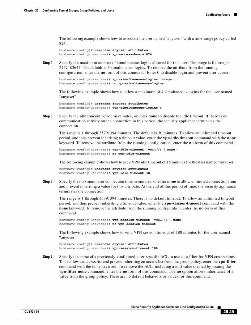
Chapter 25 Configuring Tunnel Groups, Group Policies, and Users Configuring Users
The following example shows how to associate the user named “anyuser” with a time-range policy called 824:
hostname(config)# username anyuser attributeshostname(config-username)# vpn-access-hours 824
Step 4 Specify the maximum number of simultaneous logins allowed for this user. The range is 0 through 2147483647. The default is 3 simultaneous logins. To remove the attribute from the running configuration, enter the no form of this command. Enter 0 to disable login and prevent user access.
hostname(config-username)# vpn-simultaneous-logins integerhostname(config-username)# no vpn-simultaneous-logins
The following example shows how to allow a maximum of 4 simultaneous logins for the user named “anyuser”:
hostname(config)# username anyuser attributeshostname(config-username)# vpn-simultaneous-logins 4
Step 5 Specify the idle timeout period in minutes, or enter none to disable the idle timeout. If there is no communication activity on the connection in this period, the security appliance terminates the connection.
The range is 1 through 35791394 minutes. The default is 30 minutes. To allow an unlimited timeout period, and thus prevent inheriting a timeout value, enter the vpn-idle-timeout command with the none keyword. To remove the attribute from the running configuration, enter the no form of this command.
hostname(config-username)# vpn-idle-timeout {minutes | none}hostname(config-username)# no vpn-idle-timeout
The following example shows how to set a VPN idle timeout of 15 minutes for the user named “anyuser”:
hostname(config)# username anyuser attributeshostname(config-username)# vpn-idle-timeout 30
Step 6 Specify the maximum user connection time in minutes, or enter none to allow unlimited connection time and prevent inheriting a value for this attribute. At the end of this period of time, the security appliance terminates the connection.
The range is 1 through 35791394 minutes. There is no default timeout. To allow an unlimited timeout period, and thus prevent inheriting a timeout value, enter the vpn-session-timeout command with the none keyword. To remove the attribute from the running configuration, enter the no form of this command.
hostname(config-username)# vpn-session-timeout {minutes | none}hostname(config-username)# no vpn-session-timeout
The following example shows how to set a VPN session timeout of 180 minutes for the user named “anyuser”:
hostname(config)# username anyuser attributeshostname(config-username)# vpn-session-timeout 180
Step 7 Specify the name of a previously-configured, user-specific ACL to use a s a filter for VPN connections. To disallow an access list and prevent inheriting an access list from the group policy, enter the vpn-filter command with the none keyword. To remove the ACL, including a null value created by issuing the vpn-filter none command, enter the no form of this command. The no option allows inheritance of a value from the group policy. There are no default behaviors or values for this command.
25-29Cisco Security Appliance Command Line Configuration Guide
OL-6721-01

Chapter 25 Configuring Tunnel Groups, Group Policies, and Users Configuring Users
You configure ACLs to permit or deny various types of traffic for this user. You then use the vpn-filter command to apply those ACLs.
hostname(config-username)# vpn-filter {value ACL name | none}
hostname(config-username)# no vpn-filter
The following example shows how to set a filter that invokes an access list named “acl_vpn” for the user named “anyuser”:
hostname(config)# username anyuser attributeshostname(config-username)# vpn-filter value acl_vpn
Step 8 Specify the IP address and netmask to assign to a particular user. To remove the IP address, enter the no form of this command.
hostname(config-username)# vpn-framed-ip-address {ip_address}hostname(config-username)# no vpn-framed-ip-address
The following example shows how to set an IP address of 10.92.166.7 for a user named “anyuser”:
hostname(config)# username anyuser attributeshostname(config-username)# vpn-framed-ip-address 10.92.166.7
Step 9 Specify the network mask to use with the IP address specified in the previous step. If you used the no vpn-framed-ip-address command, do not specify a network mask. To remove the subnet mask, enter the no form of this command. There is no default behavior or value.
hostname(config-username)# vpn-framed-ip-netmask {netmask}hostname(config-username)# no vpn-framed-ip-netmask
The following example shows how to set a subnet mask of 255.255.255. 254 for a user named “anyuser”:
hostname(config)# username anyuser attributeshostname(config-username)# vpn-framed-ip-netmask 255.255.255.254
Step 10 Specify the VPN tunnel types (IPSec) that this user can use. The default is taken from the default group policy, the default for which is IPSec. To remove the attribute from the running configuration, enter the no form of this command.
hostname(config-username)# vpn-tunnel-protocol IPSechostname(config-username)# no vpn-tunnel-protocol [IPSec]
The parameter values for this command are as follows:
• IPSec—Negotiates an IPSec tunnel between two peers (a remote access client or another secure gateway). Creates security associations that govern authentication, encryption, encapsulation, and key management.
Enter this command to configure one or more tunneling modes. You must configure at least one tunneling mode for users to connect over a VPN tunnel.
The following example shows how to configure IPSec tunneling mode for the user named “anyuser”:
hostname(config)# username anyuser attributeshostname(config-username)# vpn-tunnel-protocol IPSec
Step 11 Configure the group-lock attribute with the value keyword to restrict remote users to access only through the specified, preexisting tunnel group. To remove the group-lock attribute from the running configuration, enter the no form of this command. This option allows inheritance of a value from the group policy. To disable group-lock, and to prevent inheriting a group-lock value from a default or specified group policy, enter the group-lock command with the none keyword.
25-30Cisco Security Appliance Command Line Configuration Guide
OL-6721-01

Chapter 25 Configuring Tunnel Groups, Group Policies, and Users Configuring Users
Group-lock restricts users by checking whether the group configured in the VPN client is the same as the tunnel group to which the user is assigned. If it is not, the security appliance prevents the user from connecting. If you do not configure group-lock, the security appliance authenticates users without regard to the assigned group.
hostname(config-username)# group-lock {value tunnel-grp-name | none}hostname(config-username)# no group-lock
The following example shows how to set group lock for the user named “anyuser”:
hostname(config)# username anyuser attributeshostname(config-username)# group-lock value tunnel group name
Step 12 Specify whether to let users store their login passwords on the client system. Password storage is disabled by default. Enable password storage only on systems that you know to be in secure sites. To disable password storage, enter the password-storage command with the disable keyword. To remove the password-storage attribute from the running configuration, enter the no form of this command. This enables inheritance of a value for password-storage from the group policy.
hostname(config-username)# password-storage {enable | disable}hostname(config-username)# no password-storage
This command has no bearing on interactive hardware client authentication or individual user authentication for hardware clients.
The following example shows how to enable password storage for the user named “anyuser”:
hostname(config)# username anyuser attributeshostname(config-username)# password-storage enable
25-31Cisco Security Appliance Command Line Configuration Guide
OL-6721-01

Chapter 25 Configuring Tunnel Groups, Group Policies, and Users Configuring Users
25-32Cisco Security Appliance Command Line Configuration Guide
OL-6721-01

Cisco Security AppliaOL-6721-01
C H A P T E R 26
Configuring IP Addresses for VPNsThis chapter describes IP address assignment methods.
IP addresses make internetwork connections possible. They are like telephone numbers: both the sender and receiver must have an assigned number to connect. But with VPNs, there are actually two sets of addresses: the first set connects client and server on the public network. Once that connection is made, the second set connects client and server through the VPN tunnel.
In security appliance address management, we are dealing with the second set of IP addresses: those private IP addresses that connect a client with a resource on the private network, through the tunnel, and let the client function as if it were directly connected to the private network. Furthermore, we are dealing only with the private IP addresses that get assigned to clients. The IP addresses assigned to other resources on your private network are part of your network administration responsibilities, not part of VPN management. Therefore, when we discuss IP addresses here, we mean those IP addresses available in your private network addressing scheme that let the client function as a tunnel endpoint.
This chapter includes the following sections:
Configuring an IP Address Assignment Method, page 1
Configuring Local IP Address Pools, page 2
Configuring AAA Addressing, page 2
Configuring DHCP Addressing, page 3
Configuring an IP Address Assignment MethodThe security appliance can use one or more of the following methods for assigning IP addresses to remote access clients. If you configure more than one address assignment method, the security appliance searches each of the options until it finds an IP address. By default, all methods are enabled. To view the current configuration, enter the show running-config all vpn-addr-assign command.
• aaa—Retrieves addresses from an external authentication server on a per-user basis. If you are using an authentication server that has IP addresses configured, we recommend using this method.
• dhcp—Obtains IP addresses from a DHCP server. If you want to use DHCP, you must configure a DHCP server. You must also define the range of IP addresses that the DHCP server can use.
• local—Use an internal address pool. Internally configured address pools are the easiest method of address pool assignment to configure. If you choose local, you must also use the ip-local-pool command to define the range of IP addresses to use.
To specify a method for assigning IP addresses to remote access clients, enter the vpn-addr-assign command in global configuration mode. The syntax is vpn-addr-assign {aaa | dhcp | local}.
26-1nce Command Line Configuration Guide

Chapter 26 Configuring IP Addresses for VPNs Configuring an IP Address Assignment Method
Configuring Local IP Address PoolsTo configure IP address pools to use for VPN remote access tunnels, enter the ip local pool command in global configuration mode. To delete address pools, enter the no form of this command.
The security appliance uses address pools based on the tunnel group for the connection. If you configure more than one address pool for a tunnel group, the security appliance uses them in the order in which they are configured.
If you assign addresses from a non-local subnet, we suggest that you add pools that fall on subnet boundaries to make adding routes for these networks easier.
A summary of the configuration of local address pools follows:
hostname(config)# vpn-addr-assign localhostname(config)# ip local pool firstpool 10.20.30.40-10.20.30.50 mask 255.255.255.0hostname(config)
Step 1 To configure IP address pools as the address assignment method, enter the vpn-addr-assign command with the local argument:
hostname(config)# vpn-addr-assign localhostname(config)#
Step 2 To configure an address pool, enter the ip local pool command. The syntax is ip local pool poolname first-address—last-address mask mask.
The following example configures an IP address pool named firstpool. The starting address is 10.20.30.40 and the ending address is 10.20.30.50. The network mask is 255.255.255.0.
hostname(config)# ip local pool firstpool 10.20.30.40-10.20.30.50 mask 255.255.255.0hostname(config)
Configuring AAA AddressingTo use a AAA server to assign addresses for VPN remote access clients, you must first configure a AAA server or server group. See the aaa-server protocol command in the Cisco Security Appliance Command Reference and “Identifying AAA Server Groups and Servers,” in Chapter 10, “Configuring AAA Servers and the Local Database” of this guide.
In addition, the user must match a tunnel group configured for RADIUS authentication.
The following examples illustrate how to define a AAA server group called RAD2 for the tunnel group named firstgroup. It includes one more step than is necessary, in that previously you might have named the tunnel group and define the tunnel group type. This step appears in the following example as a reminder that you have no access to subsequent tunnel-group commands until you set these values.
A summary of the configuration that these examples create follows:
hostname(config)# vpn-addr-assign aaahostname(config)# tunnel-group firstgroup type ipsec-ra hostname(config)# tunnel-group firstgroup general-attributeshostname(config-general)# authentication-server-group RAD2
26-2Cisco Security Appliance Command Line Configuration Guide
OL-6721-01

Chapter 26 Configuring IP Addresses for VPNs Configuring an IP Address Assignment Method
To configure AAA for IP addressing, perform the following steps:
Step 1 To configure AAA as the address assignment method, enter the vpn-addr-assign command with the aaa argument:
hostname(config)# vpn-addr-assign aaahostname(config)#
Step 2 To establish the tunnel group called firstgroup as a remote access or LAN-to-LAN tunnel group, enter the tunnel-group command with the type keyword. The following example configures a remote access tunnel group.
hostname(config)# tunnel-group firstgroup type ipsec-ra hostname(config)#
Step 3 To enter general-attributes configuration mode, which lets you define a AAA server group for the tunnel group called firstgroup, enter the tunnel-group command with the general-attributes argument.
hostname(config)# tunnel-group firstgroup general-attributeshostname(config-general)#
Step 4 To specify the AAA server group to use for authentication, enter the authentication-server-group command.
hostname(config-general)# authentication-server-group RAD2hostname(config-general)#
This command has more arguments that this example includes. For more information, see the Cisco Security Appliance Command Reference.
Configuring DHCP AddressingTo use DHCP to assign addresses for VPN clients, you must first configure a DHCP server and the range of IP addresses that the DHCP server can use. Then you define the DHCP server on a tunnel group basis. Optionally, you can also define a DHCP network scope in the group policy associated with the tunnel group or username. This is either an IP network number or IP Address that identifies to the DHCP server which pool of IP addresses to use.
The following examples define the DHCP server at IP address 172.33.44.19 for the tunnel group named firstgroup. They also define a DHCP network scope of 192.86.0.0 for the group policy called remotegroup. (The group policy called remotegroup is associated with the tunnel group called firstgroup). If you do not define a network scope, the DHCP server assigns IP addresses in the order of the address pools configured. It goes through the pools until it identifies an unassigned address.
The following configuration includes more steps than are necessary, in that previously you might have named and defined the tunnel group type as remote access, and named and identified the group policy as internal or external. These steps appear in the following examples as a reminder that you have no access to subsequent tunnel-group and group-policy commands until you set these values.
A summary of the configuration that these examples create follows:
hostname(config)# vpn-addr-assign dhcphostname(config)# tunnel-group firstgroup type ipsec-ra hostname(config)# tunnel-group firstgroup general-attributeshostname(config-general)# dhcp-server 172.33.44.19hostname(config-general)# exithostname(config)# group-policy remotegroup internal
26-3Cisco Security Appliance Command Line Configuration Guide
OL-6721-01

Chapter 26 Configuring IP Addresses for VPNs Configuring an IP Address Assignment Method
hostname(config)# group-policy remotegroup attributeshostname(config-group-policy)# dhcp-network-scope 192.86.0.0
To define a DHCP server for IP addressing, perform the following steps.
Step 1 To configure DHCP as the address assignment method, enter the vpn-addr-assign command with the dhcp argument:
hostname(config)# vpn-addr-assign dhcphostname(config)#
Step 2 To establish the tunnel group called firstgroup as a remote access or LAN-to-LAN tunnel group, enter the tunnel-group command with the type keyword. The following example configures a remote access tunnel group.
hostname(config)# tunnel-group firstgroup type ipsec-ra hostname(config)#
Step 3 To enter general-attributes configuration mode, which lets you configure a DHCP server, enter the tunnel-group command with the general-attributes argument.
hostname(config)# tunnel-group firstgroup general-attributeshostname(config)#
Step 4 To define the DHCP server, enter the dhcp-server command. The following example configures a DHCP server at IP address 172.33.44.19.
hostname(config-general)# dhcp-server 172.33.44.19hostname(config-general)#
Step 5 Exit tunnel-group mode.
hostname(config-general)# exithostname(config)#
Step 6 To define the group policy called remotegroup as an internally or externally configured group, enter the group-policy command with the internal or external argument. The following example configures an internal group.
hostname(config)# group-policy remotegroup internalhostname(config)#
Step 7 (Optional) To enter group-policy attributes configuration mode, which lets you configure a subnetwork of IP addresses for the DHCP server to use, enter the group-policy command with the attributes keyword.
hostname(config)# group-policy remotegroup attributeshostname(config-group-policy)#
Step 8 (Optional) To specify the range of IP addresses the DHCP server should use to assign addresses to users of the group policy called remotegroup, enter the dhcp-network-scope command. The following example configures at network scope of 192.86.0.0.
hostname(config-group-policy)# dhcp-network-scope 192.86.0.0hostname(config-group-policy)#
26-4Cisco Security Appliance Command Line Configuration Guide
OL-6721-01

Cisco Security AppliaOL-6721-01
C H A P T E R 27
Configuring Remote Access VPNsRemote access VPNs let single users connect to a central site through a secure connection over a TCP/IP network such as the Internet.
This chapter describes how to build a remote access VPN connection. It includes the following sections:
• Summary of the Configuration, page 27-1
• Configuring Interfaces, page 27-2
• Configuring ISAKMP Policy and Enabling ISAKMP on the Outside Interface, page 27-3
• Configuring an Address Pool, page 27-4
• Adding a User, page 27-4
• Creating a Transform Set, page 27-4
• Defining a Tunnel Group, page 27-5
• Creating a Dynamic Crypto Map, page 27-6
• Creating a Crypto Map Entry to Use the Dynamic Crypto Map, page 27-7
Summary of the ConfigurationThis chapter uses the following configuration to explain how to configure a remote access connection. Later sections provide step-by-step instructions.
hostname(config)# interface ethernet0hostname(config-if)# ip address 10.10.4.200 255.255.0.0hostname(config-if)# nameif outsidehostname(config)# no shutdownhostname(config)# isakmp policy 1 authentication pre-sharehostname(config)# isakmp policy 1 encryption 3deshostname(config)# isakmp policy 1 hash shahostname(config)# isakmp policy 1 group 2hostname(config)# isakmp policy 1 lifetime 43200hostname(config)# isakmp enable outsidehostname(config)# ip local pool testpool 192.168.0.10-192.168.0.15hostname(config)# username testuser password 12345678hostname(config)# crypto ipsec transform set FirstSet esp-3des esp-md5-hmachostname(config)# tunnel-group testgroup type ipsec-rahostname(config)# tunnel-group testgroup general-attributeshostname(config-general)# address-pool testpoolhostname(config)# tunnel-group testgroup ipsec-attributeshostname(config-ipsec)# pre-shared-key 44kkaol59636jnfxhostname(config)# crypto dynamic-map dyn1 1 set transform-set FirstSet
27-1nce Command Line Configuration Guide

Chapter 27 Configuring Remote Access VPNs Configuring Interfaces
hostname(config)# crypto dynamic-map dyn1 1 set reverse-routehostname(config)# crypto map mymap 1 ipsec-isakmp dynamic dyn1hostname(config)# crypto map mymap interface outsidehostname(config)# write memory
Configuring InterfacesA security appliance has at least two interfaces, referred to here as outside and inside. Typically, the outside interface is connected to the public Internet, while the inside interface is connected to a private network and is protected from public access.
To begin, configure and enable two interfaces on the security appliance. Then assign a name, IP address and subnet mask. Optionally, configure its security level, speed and duplex operation on the security appliance.
To configure interfaces, perform the following steps, using the command syntax in the examples:
Step 1 To enter Interface configuration mode, in global configuration mode enter the interface command with the default name of the interface to configure. In the following example the interface is ethernet0.
hostname(config)# interface ethernet0hostname(config-if)#
Step 2 To set the IP address and subnet mask for the interface, enter the ip address command. In the following example the IP address is 10.10.4.100 and the subnet mask is 255.255.0.0.
hostname(config-if)# ip address 10.10.4.200 255.255.0.0hostname(config-if)#
Step 3 To name the interface, enter the nameif command, maximum of 48 characters. You cannot change this name after you set it. In the following example the name of the ethernet0 interface is outside.
hostname(config-if)# nameif outsidehostname(config-if)##
Step 4 To enable the interface, enter the no version of the shutdown command. By default, interfaces are disabled.
hostname(config-if)# no shutdownhostname(config-if)#
Step 5 To save your changes, enter the write memory command.
hostname(config-if)# write memoryhostname(config-if)#
Step 6 To configure a second interface, use the same procedure.
27-2Cisco Security Appliance Command Line Configuration Guide
OL-6721-01

Chapter 27 Configuring Remote Access VPNs Configuring ISAKMP Policy and Enabling ISAKMP on the Outside Interface
Configuring ISAKMP Policy and Enabling ISAKMP on the Outside Interface
The Internet Security Association and Key Management Protocol, also called IKE, is the negotiation protocol that lets two hosts agree on how to build an IPSec Security Association. Each ISAKMP negotiation is divided into two sections called Phase1 and Phase2.
Phase 1 creates the first tunnel to protect later ISAKMP negotiation messages. Phase 2 creates the tunnel that protects data travelling across the secure connection.
To set the terms of the ISAKMP negotiations, you create an ISAKMP policy. It includes the following:
• An authentication method, to ensure the identity of the peers.
• An encryption method, to protect the data and ensure privacy.
• A Hashed Message Authentication Codes method to ensure the identity of the sender and to ensure that the message has not been modified in transit.
• A Diffie-Hellman group to set the size of the encryption key.
• A time limit for how long the security appliance uses an encryption key before replacing it.
See on page 23-3 in the “Configuring IPSec and ISAKMP” chapter of this guide for detailed information about the IKE policy keywords and their values.
To configure ISAKMP policies, in global configuration mode, enter the isakmp policy command with its various arguments. The syntax for ISAKMP policy commands isisakmp policy priority attribute_name [attribute_value | integer].
Perform the following steps and use the command syntax in the following examples as a guide.
Step 1 Set the authentication method. The following example configures preshared key. The priority is 1 in this and all following steps.
hostname(config)# isakmp policy 1 authentication pre-sharehostname(config)#
Step 2 Set the encryption method. The following example configures 3DES.
hostname(config)# isakmp policy 1 encryption 3deshostname(config)#
Step 3 Set the HMAC method. The following example configures SHA-1.
hostname(config)# isakmp policy 1 hash shahostname(config)#
Step 4 Set the Diffie-Hellman group. The following example configures Group 2.
hostname(config)# isakmp policy 1 group 2hostname(config)#
Step 5 Set the encryption key lifetime. The following example configures 43,200 seconds (12 hours).
hostname(config)# isakmp policy 1 lifetime 43200hostname(config)#
Step 6 Enable ISAKMP on the interface named outside.
hostname(config)# isakmp enable outsidehostname(config)#
27-3Cisco Security Appliance Command Line Configuration Guide
OL-6721-01

Chapter 27 Configuring Remote Access VPNs Configuring an Address Pool
Step 7 To save your changes, enter the write memory command.
hostname(config)# write memoryhostname(config)#
Configuring an Address PoolThe security appliance requires a method for assigning IP addresses to users. A common method is using address pools. The alternatives are having a DHCP server assign address or having an AAA server assign them. The following example uses an address pool.
Step 1 To configure an address pool, enter the ip local pool command. The syntax is ip local pool poolname first_address-last_address. In the following example the pool name is testpool.
hostname(config)# ip local pool testpool 192.168.0.10-192.168.0.15
hostname(config)#
Step 2 Save your changes.
hostname(config)# write memoryhostname(config)#
Adding a UserTo identify remote access users to the security appliance, configure usernames and passwords.
Step 1 To add users, enter the username command. The syntax is username username password password. In the following example the username is testuser and the password is 12345678.
hostname(config)# username testuser password 12345678
hostname(config)#
Step 2 Repeat Step 1 for each additional user.
Creating a Transform SetA transform set combines an encryption method and an authentication method. During the IPSec security association negotiation with ISAKMP, the peers agree to use a particular transform set to protect a particular data flow. The transform set must be the same for both peers.
You can create multiple transform sets, and then specify one or more of these transform sets in a crypto map entry. The security appliance uses the transform set to protect the data flows for that crypto map entry access list. For more overview information, including a table that lists valid encryption and authentication methods, see Creating a Transform Set in Chapter 28, “Configuring LAN-to-LAN VPNs” of this guide.
27-4Cisco Security Appliance Command Line Configuration Guide
OL-6721-01

Chapter 27 Configuring Remote Access VPNs Defining a Tunnel Group
Step 1 To configure a transform set, in global configuration mode enter the crypto ipsec transform-set command. The syntax is:
crypto ipsec transform-set transform-set-name encryption-method authentication-method
The following example configures a transform set with the name FirstSet, esp-3des encryption, and esp-md5-hmac authentication:
hostname(config)# crypto ipsec transform set FirstSet esp-3des esp-md5-hmachostname(config)#
Step 2 Save the changes.
hostname(config)# write memoryhostname(config)#
Defining a Tunnel GroupA tunnel group is a set of records that contain tunnel connection policies. You configure a tunnel group to identify AAA servers, specify connection parameters, and define a default group policy. The security appliance stores tunnel groups internally.
There are two default tunnel groups in the security appliance system: DefaultRAGroup, which is the default IPSec remote-access tunnel group, and DefaultL2Lgroup, which is the default IPSec LAN-to-LAN tunnel group. You can change them but not delete them. The security appliance uses these groups to configure default tunnel parameters for remote access and LAN-to-LAN tunnel groups when there is no specific tunnel group identified during tunnel negotiation.
To establish a basic remote access connection, you must set three attributes for a tunnel group:
• Set the connection type to IPSec remote access.
• Configure the address assignment method, in the following example, address pool.
• Configure an authentication method, in the following example, preshared key.
Step 1 To set the connection type to IPSec remote access, enter the tunnel-group command. The command syntax is tunnel-group name type type, where name is the name you assign to the tunnel group, and type is the type of tunnel. The tunnel types as you enter them in the CLI include the following:
• ipsec-ra (IPSec remote access)
• ipsec-l2l (IPSec LAN to LAN)
In the following example the name of the tunnel group is testgroup.
hostname(config)# tunnel-group testgroup type ipsec-rahostname(config)#
Step 2 To configure an authentication method for the tunnel group, enter the general-attributes mode and then enter the address-pool command to create the address pool. In the following example the name of the group is testgroup and the name of the address pool is testpool.
hostname(config)# tunnel-group testgroup general-attributeshostname(config-general)# address-pool testpool
27-5Cisco Security Appliance Command Line Configuration Guide
OL-6721-01

Chapter 27 Configuring Remote Access VPNs Creating a Dynamic Crypto Map
Step 3 To configure the authentication method, enter the ipsec-attributes mode and then enter the pre-shared-key command to create the preshared key. You need to use the same preshared key on both the security appliance and the client.
The key is an alphanumeric string of 1-128 characters. In the following example the preshared key is 44kkaol59636jnfx.
hostname(config)# tunnel-group testgroup ipsec-attributeshostname(config-ipsec)# pre-shared-key 44kkaol59636jnfx
Step 4 Save your changes.
hostname(config)# write memoryhostname(config)#
Creating a Dynamic Crypto Map The security appliance uses dynamic crypto maps to define a policy template where all the parameters do not have to be configured. These dynamic crypto maps let the security appliance receive connections from peers without known IP addresses. Remote access clients fall in this category.
Dynamic crypto map entries identify the transform set for the connection. You also enable reverse routing, which lets the security appliance learn routing information for connected clients, and advertise it via RIP or OSPF.
Step 1 To specify a transform set for a dynamic crypto map entry, enter the crypto dynamic-map set transform-set command.
The syntax is crypto dynamic -map dynamic-map-name seq-num set transform-set transform-set-name. In the following example the name of the dynamic map is dyn1, the sequence number is 1, and the transform set name is FirstSet.
hostname(config)# crypto dynamic-map dyn1 1 set transform-set FirstSethostname(config)#
Step 2 To enable RRI for any connection based on this crypto map entry, enter the crypto dynamic-map set reverse route command.
hostname(config)# crypto dynamic-map dyn1 1 set reverse-routehostname(config)#
Step 3 Save your changes.
hostname(config)# write memoryhostname(config)#
27-6Cisco Security Appliance Command Line Configuration Guide
OL-6721-01

Chapter 27 Configuring Remote Access VPNs Creating a Crypto Map Entry to Use the Dynamic Crypto Map
Creating a Crypto Map Entry to Use the Dynamic Crypto MapNext create a crypto map entry that lets the security appliance use the dynamic crypto map to set the parameters of IPSec security associations.
In the following examples for this command, the name of the crypto map is mymap, the sequence number is 1, and the name of the dynamic crypto map is dyn1, which you created in the previous section, Creating a Dynamic Crypto Map. Enter these commands in global configuration mode.
Step 1 To create a crypto map entry that uses a dynamic crypto map, enter the crypto map command. The syntax is crypto map map-name seq-num ipsec-isakmp dynamic dynamic-map-name.
hostname(config)# crypto map mymap 1 ipsec-isakmp dynamic dyn1
hostname(config)#
Step 2 To apply the crypto map to the outside interface, enter the crypto map interface command.
The syntax is crypto map map-name interface interface-name
hostname(config)# crypto map mymap interface outsidehostname(config)#
27-7Cisco Security Appliance Command Line Configuration Guide
OL-6721-01

Chapter 27 Configuring Remote Access VPNs
27-8Cisco Security Appliance Command Line Configuration Guide
OL-6721-01

Cisco Security AppliaOL-6721-01
C H A P T E R 28
Configuring LAN-to-LAN VPNsLAN-to-LAN VPN configurations are between two IPSec security gateways, such as security appliances or other protocol-compliant VPN devices. A LAN-to-LAN VPN connects networks in different geographic locations.
This chapter describes how to build a LAN-to-LAN VPN connection. It includes the following sections:
• Summary of the Configuration, page 28-1
• Configuring Interfaces, page 28-2
• Configuring ISAKMP Policy and Enabling ISAKMP on the Outside Interface, page 28-2
• Creating a Transform Set, page 28-4
• Configuring an ACL, page 28-4
• Defining a Tunnel Group, page 28-5
• Creating a Crypto Map and Applying It To an Interface, page 28-6
Summary of the ConfigurationThis section provides a summary of the example LAN-to-LAN configuration this chapter creates. Later sections provide step-by-step instructions.
hostname(config)# interface ethernet0hostname(config-if)# ip address 10.10.4.100 255.255.0.0hostname(config-if)# no shutdownhostname(config)# isakmp policy 1 authentication pre-sharehostname(config)# isakmp policy 1 encryption 3deshostname(config)# isakmp policy 1 hash shahostname(config)# isakmp policy 1 group 2hostname(config)# isakmp policy 1 lifetime 43200hostname(config)# isakmp enable outsidehostname(config)# crypto ipsec transform set FirstSet esp-3des esp-md5-hmachostname(config)# access-list l2l_list extended permit ip 192.168.0.0 255.255.0.0 150.150.0.0 255.255.0.0hostname(config)# tunnel-group 10.10.4.108 type ipsec-l2lhostname(config)# tunnel-group 10.10.4.108 ipsec-attributeshostname(config-ipsec)# pre-shared-key 44kkaol59636jnfxhostname(config)# crypto map abcmap 1 match address xyzhostname(config)# crypto map abcmap 1 set peer 10.10.4.108hostname(config)# crypto map abcmap 1 set transform-set FirstSethostname(config)# crypto map abcmap interface outsidehostname(config)# write memory
28-1nce Command Line Configuration Guide

Chapter 28 Configuring LAN-to-LAN VPNs Configuring Interfaces
Configuring InterfacesA security appliance has at least two interfaces, referred to here as outside and inside. Typically, the outside interface is connected to the public Internet, while the inside interface is connected to a private network and is protected from public access.
To begin, configure and enable two interfaces on the security appliance. Then, assign a name, IP address and subnet mask. Optionally, configure its security level, speed, and duplex operation on the security appliance.
To configure interfaces, perform the following steps, using the command syntax in the examples:
Step 1 To enter Interface configuration mode, in global configuration mode enter the interface command with the default name of the interface to configure. In the following example the interface is ethernet0.
hostname(config)# interface ethernet0hostname(config-if)#
Step 2 To set the IP address and subnet mask for the interface, enter the ip address command. In the following example the IP address is 10.10.4.100 and the subnet mask is 255.255.0.0.
hostname(config-if)# ip address 10.10.4.100 255.255.0.0hostname(config-if)#
Step 3 To name the interface, enter the nameif command, maximum of 48 characters. You cannot change this name after you set it. In the following example the name of the ethernet0 interface is outside.
hostname(config-if)# nameif outsidehostname(config-if)##
Step 4 To enable the interface, enter the no version of the shutdown command. By default, interfaces are disabled.
hostname(config-if)# no shutdownhostname(config-if)#
Step 5 To save your changes, enter the write memory command.
hostname(config-if)# write memoryhostname(config-if)#
Step 6 To configure a second interface, use the same procedure.
Configuring ISAKMP Policy and Enabling ISAKMP on the Outside Interface
The Internet Security Association and Key Management Protocol, also called IKE, is the negotiation protocol that lets two hosts agree on how to build an IPSec security association. Each ISAKMP negotiation is divided into two sections called Phase1 and Phase 2.
Phase 1 creates the first tunnel, which protects later ISAKMP negotiation messages. Phase 2 creates the tunnel that protects data travelling across the secure connection.
28-2Cisco Security Appliance Command Line Configuration Guide
OL-6721-01

Chapter 28 Configuring LAN-to-LAN VPNs Configuring ISAKMP Policy and Enabling ISAKMP on the Outside Interface
To set the terms of the ISAKMP negotiations, you create an ISAKMP policy, which includes the following:
• An authentication method, to ensure the identity of the peers.
• An encryption method, to protect the data and ensure privacy.
• A Hashed Message Authentication Codes method to ensure the identity of the sender and to ensure that the message has not been modified in transit.
• A Diffie-Hellman group to establish the strength of the encryption-key-determination algorithm. The security appliance uses this algorithm to derive the encryption and hash keys.
• A time limit for how long the security appliance uses an encryption key before replacing it.
See on page 23-3 in the “Configuring IPSec and ISAKMP” chapter of this guide for detailed information about the IKE policy keywords and their values.
To configure ISAKMP policies, in global configuration mode use the isakmp policy command with its various arguments. The syntax for ISAKMP policy commands is as follows:
isakmp policy priority attribute_name [attribute_value | integer].
Perform the following steps and use the command syntax in the following examples as a guide.
Step 1 Set the authentication method. The following example configures a preshared key. The priority is 1 in this and all following steps.
hostname(config)# isakmp policy 1 authentication pre-sharehostname(config)#
Step 2 Set the encryption method. The following example configures 3DES.
hostname(config)# isakmp policy 1 encryption 3deshostname(config)#
Step 3 Set the HMAC method. The following example configures SHA-1.
hostname(config)# isakmp policy 1 hash shahostname(config)#
Step 4 Set the Diffie-Hellman group. The following example configures Group 2.
hostname(config)# isakmp policy 1 group 2hostname(config)#
Step 5 Set the encryption key lifetime. The following example configures 43,200 seconds (12 hours).
hostname(config)# isakmp policy 1 lifetime 43200hostname(config)#
Step 6 Enable ISAKMP on the interface named outside.
hostname(config)# isakmp enable outsidehostname(config)#
Step 7 To save your changes, enter the write memory command.
hostname(config)# write memoryhostname(config)#
28-3Cisco Security Appliance Command Line Configuration Guide
OL-6721-01

Chapter 28 Configuring LAN-to-LAN VPNs Creating a Transform Set
Creating a Transform SetA transform set combines an encryption method and an authentication method. During the IPSec security association negotiation with ISAKMP, the peers agree to use a particular transform set to protect a particular data flow. The transform set must be the same for both peers.
You can create multiple transform sets, and then specify one or more of these transform sets in a crypto map entry. The security appliance uses the transform set to protect the data flows for that crypto map entry access list.
Table 28-1 lists valid encryption and authentication methods.
Tunnel Mode is the usual way to implement IPSec between two security appliances that are connected over an untrusted network, such as the public Internet. Tunnel mode is the default and requires no configuration.
To configure a transform set, perform the following steps:
Step 1 In global configuration mode enter the crypto ipsec transform-set command. The following example configures a transform set with the name FirstSet, esp-3des encryption, and esp-md5-hmac authentication. The syntax is as follows:
crypto ipsec transform-set transform-set-name encryption-method authentication-method
hostname(config)# crypto ipsec transform-set FirstSet esp-3des esp-md5-hmachostname(config)#
Step 2 Save your changes.
hostname(config)# write memoryhostname(config)#
Configuring an ACL The security appliance uses access control lists to control network access. By default, the security appliance denies all traffic. You need to configure an ACL that permits traffic.
The ACLs that you configure for this LAN-to-LAN VPN control connections are based on the source and destination IP addresses. Configure ACLs that mirror each other on both sides of the connection.
Table 28-1 Encryption and Authentication Methods
Valid Encryption Methods Valid Authentication Methods
esp-des esp-md5-hmac
esp-3des (default) esp-sha-hmac (default)
esp-aes (128-bit encryption)
esp-aes-192
esp-aes-256
esp-null
28-4Cisco Security Appliance Command Line Configuration Guide
OL-6721-01
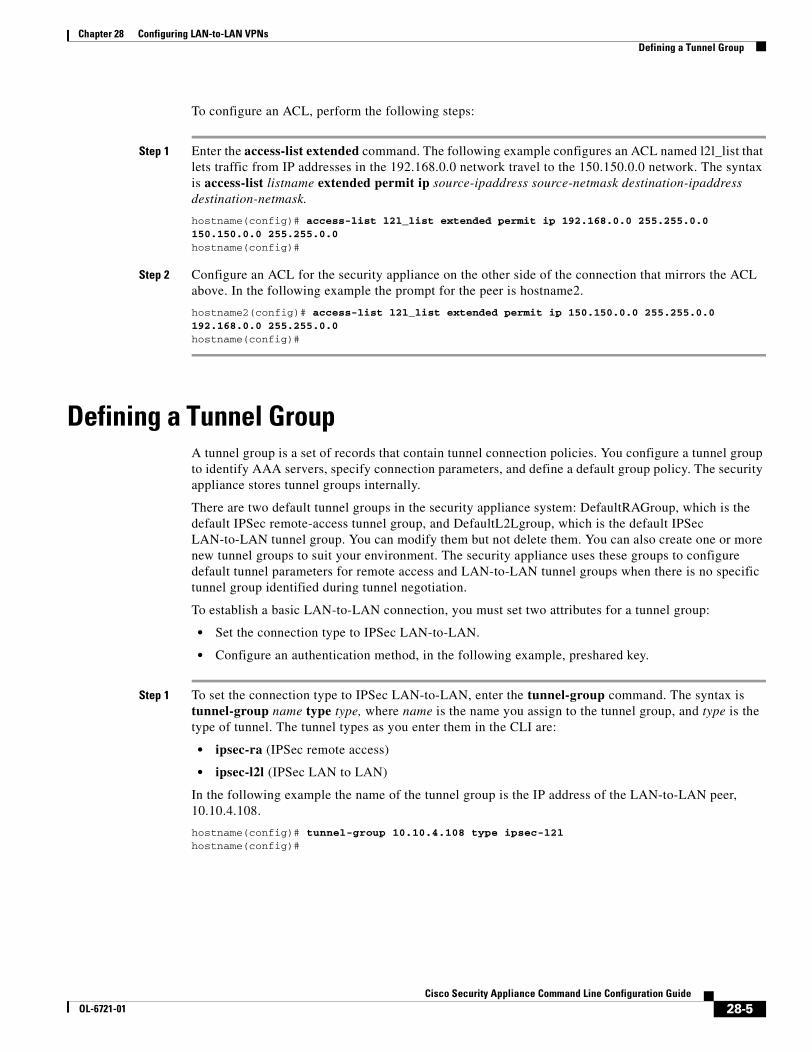
Chapter 28 Configuring LAN-to-LAN VPNs Defining a Tunnel Group
To configure an ACL, perform the following steps:
Step 1 Enter the access-list extended command. The following example configures an ACL named l2l_list that lets traffic from IP addresses in the 192.168.0.0 network travel to the 150.150.0.0 network. The syntax is access-list listname extended permit ip source-ipaddress source-netmask destination-ipaddress destination-netmask.
hostname(config)# access-list l2l_list extended permit ip 192.168.0.0 255.255.0.0 150.150.0.0 255.255.0.0hostname(config)#
Step 2 Configure an ACL for the security appliance on the other side of the connection that mirrors the ACL above. In the following example the prompt for the peer is hostname2.
hostname2(config)# access-list l2l_list extended permit ip 150.150.0.0 255.255.0.0 192.168.0.0 255.255.0.0hostname(config)#
Defining a Tunnel GroupA tunnel group is a set of records that contain tunnel connection policies. You configure a tunnel group to identify AAA servers, specify connection parameters, and define a default group policy. The security appliance stores tunnel groups internally.
There are two default tunnel groups in the security appliance system: DefaultRAGroup, which is the default IPSec remote-access tunnel group, and DefaultL2Lgroup, which is the default IPSec LAN-to-LAN tunnel group. You can modify them but not delete them. You can also create one or more new tunnel groups to suit your environment. The security appliance uses these groups to configure default tunnel parameters for remote access and LAN-to-LAN tunnel groups when there is no specific tunnel group identified during tunnel negotiation.
To establish a basic LAN-to-LAN connection, you must set two attributes for a tunnel group:
• Set the connection type to IPSec LAN-to-LAN.
• Configure an authentication method, in the following example, preshared key.
Step 1 To set the connection type to IPSec LAN-to-LAN, enter the tunnel-group command. The syntax is tunnel-group name type type, where name is the name you assign to the tunnel group, and type is the type of tunnel. The tunnel types as you enter them in the CLI are:
• ipsec-ra (IPSec remote access)
• ipsec-l2l (IPSec LAN to LAN)
In the following example the name of the tunnel group is the IP address of the LAN-to-LAN peer, 10.10.4.108.
hostname(config)# tunnel-group 10.10.4.108 type ipsec-l2lhostname(config)#
28-5Cisco Security Appliance Command Line Configuration Guide
OL-6721-01

Chapter 28 Configuring LAN-to-LAN VPNs Creating a Crypto Map and Applying It To an Interface
Step 2 To set the authentication method to preshared key, enter the ipsec-attributes mode and then enter the pre-shared-key command to create the preshared key. You need to use the same preshared key on both security appliances for this LAN-to-LAN connection.
The key is an alphanumeric string of 1-128 characters. In the following example the preshared key is 44kkaol59636jnfx.
hostname(config)# tunnel-group 10.10.4.108 ipsec-attributeshostname(config-ipsec)# pre-shared-key 44kkaol59636jnfx
Step 3 Save your changes.
hostname(config)# write memoryhostname(config)#
Creating a Crypto Map and Applying It To an InterfaceCrypto map entries pull together the various elements of IPSec security associations, including the following:
• Which traffic IPSec should protect, which you define in an access list.
• Where to send IPSec-protected traffic, by identifying the peer.
• What IPSec security applies to this traffic, which a transform set specifies.
• The local address for IPSec traffic, which you identify by applying the crypto map to an interface.
For IPSec to succeed, both peers must have crypto map entries with compatible configurations. For two crypto map entries to be compatible, they must, at a minimum, meet the following criteria:
• The crypto map entries must contain compatible crypto access lists (for example, mirror image access lists). If the responding peer uses dynamic crypto maps, the entries in the security appliance crypto access list must be “permitted” by the peer’s crypto access list.
• The crypto map entries each must identify the other peer (unless the responding peer is using a dynamic crypto map).
• The crypto map entries must have at least one transform set in common.
If you create more than one crypto map entry for a given interface, use the sequence number (seq-num) of each entry to rank it: the lower the seq-num, the higher the priority. At the interface that has the crypto map set, the security appliance evaluates traffic against the entries of higher priority maps first.
Create multiple crypto map entries for a given interface if either of the following conditions exist:
• Different peers handle different data flows.
• You want to apply different IPSec security to different types of traffic (to the same or separate peers), for example, if you want traffic between one set of subnets to be authenticated, and traffic between another set of subnets to be both authenticated and encrypted. In this case, define the different types of traffic in two separate access lists, and create a separate crypto map entry for each crypto access list.
To create a crypto map and apply it to the outside interface in global configuration mode, enter several of the crypto map commands. These commands use a variety of arguments, but the syntax for all of them begin with crypto map map-name-seq-num. In the following example the map-name is abcmap, the sequence number is 1.
28-6Cisco Security Appliance Command Line Configuration Guide
OL-6721-01

Chapter 28 Configuring LAN-to-LAN VPNs Creating a Crypto Map and Applying It To an Interface
Enter these commands in global configuration mode:
Step 1 To assign an access list to a crypto map entry, enter the crypto map match address command.
The syntax is crypto map map-name seq-num match address aclname. In the following example the map name is abcmap, the sequence number is 1, and the access list name is xyz.
hostname(config)# crypto map abcmap 1 match address xyzhostname(config)#
Step 2 To identify the peer (s) for the IPSec connection, enter the crypto map set peer command.
The syntax is crypto map map-name seq-num set peer {ip_address1 | hostname1}[... ip_address10 | hostname10]. In the following example the peer name is 10.10.4.108.
hostname(config)# crypto map abcmap 1 set peer 10.10.4.108hostname(config)#
Step 3 To specify a transform set for a crypto map entry, enter the crypto map set transform-set command.
The syntax is crypto map map-name seq-num set transform-set transform-set-name. In the following example the transform set name is FirstSet.
hostname(config)# crypto map abcmap 1 set transform-set FirstSethostname(config)#
Applying Crypto Maps to InterfacesYou must apply a crypto map set to each interface through which IPSec traffic travels. The security appliance supports IPSec on all interfaces. Applying the crypto map set to an interface instructs the security appliance to evaluate all interface traffic against the crypto map set and to use the specified policy during connection or security association negotiations.
Binding a crypto map to an interface also initializes the runtime data structures, such as the security association database and the security policy database. When you later modify a crypto map in any way, the security appliance automatically applies the changes to the running configuration. It drops any existing connections and reestablishes them after applying the new crypto map.
Step 1 To apply the configured crypto map to the outside interface, enter the crypto map interface command. The syntax is crypto map map-name interface interface-name.
hostname(config)# crypto map abcmap interface outside
hostname(config)#
Step 2 Save your changes.
hostname(config)# write memory
hostname(config)#
28-7Cisco Security Appliance Command Line Configuration Guide
OL-6721-01

Chapter 28 Configuring LAN-to-LAN VPNs Creating a Crypto Map and Applying It To an Interface
28-8Cisco Security Appliance Command Line Configuration Guide
OL-6721-01

Cisco Security AppliaOL-6721-01
C H A P T E R 29
Configuring CertificatesThis chapter describes how to configure certificates. CAs are responsible for managing certificate requests and issuing digital certificates. A digital certificate contains information that identifies a user or device. Some of this information can include a name, serial number, company, department, or IP address. A digital certificate also contains a copy of the public key for the user or device. A CA can be a trusted third party, such as VeriSign, or a private (in-house) CA that you establish within your organization.
This chapter includes the following sections:
• Public Key Cryptography, page 29-1
• Certificate Configuration, page 29-4
Public Key CryptographyThis section includes the following topics:
• About Public Key Cryptography, page 29-1
• Certificate Scalability, page 29-2
• About Key Pairs, page 29-2
• About Trustpoints, page 29-3
• About CRLs, page 29-3
• Supported CA Servers, page 29-4
About Public Key CryptographyDigital signatures, enabled by public key cryptography, provide a means to authenticate devices and users. In public key cryptography, such as the RSA encryption system, each user has a key pair containing both a public and a private key. The keys act as complements, and anything encrypted with one of the keys can be decrypted with the other.
In simple terms, a signature is formed when data is encrypted with a private key. The signature is attached to the data and sent to the receiver. The receiver applies the public key of the sender to the data. If the signature sent with the data matches the result of applying the public key to the data, the validity of the message is established.
This process relies on the receiver having a copy of the public key of the sender and having a high degree of certainty that this key belongs to the sender, not to someone pretending to be the sender.
29-1nce Command Line Configuration Guide

Chapter 29 Configuring Certificates Public Key Cryptography
Obtaining the public key of a sender is normally handled out-of-band or through an operation done at installation. For instance, most web browsers are configured with the root certificates of several CAs by default. For VPN, the IKE protocol, a component of IPSec, can use digital signatures to authenticate peer devices before setting up security associations.
Certificate ScalabilityWithout digital certificates, you must manually configure each IPSec peer for every peer with which it communicates, and every new peer you add to a network would thus require a configuration change on every peer with which you need it to communicate securely.
When you use digital certificates, each peer is enrolled with a CA. When two peers attempt to communicate, they exchange certificates and digitally sign data to authenticate each other. When a new peer is added to the network, you enroll that peer with a CA and none of the other peers need modification. When the new peer attempts an IPSec connection, certificates are automatically exchanged and the peer can be authenticated.
With a CA, a peer authenticates itself to the remote peer by sending a certificate to the remote peer and performing some public key cryptography. Each peer sends its unique certificate which was issued by the CA. This process works because each certificate encapsulates the public key for the associated peer and each certificate is authenticated by the CA, and all participating peers recognize the CA as an authenticating authority. This is called IKE with an RSA signature.
The peer can continue sending its certificate for multiple IPSec sessions, and to multiple IPSec peers, until the certificate expires. When its certificate expires, the peer administrator must obtain a new one from the CA.
CAs can also revoke certificates for peers that no longer participate in IPSec. Revoked certificates are not recognized as valid by other peers. Revoked certificates are listed in a CRL, which each peer may check before accepting a certificate from another peer.
Some CAs have an RA as part of their implementation. An RA is a server that acts as a proxy for the CA so that CA functions can continue when the CA is unavailable.
About Key PairsKey pairs can be either RSA keys or DSA keys. Support for these two types of keys differs as follows.
• DSA keys cannot be used for SSH or SSL. To enable SSH or SSL access to a security appliance, you must use RSA keys.
• SCEP enrollment is only supported for the certification of RSA keys. If you use DSA keys, enrollment must be performed manually.
• For the purposes of generating keys, the maximum key modulus for RSA keys is 2048 while the maximum key modulus for DSA keys is 1024. When you generate keys, the default size for either key type is 1024.
• For signature operations, the supported maximum key sizes are 4096 bits for RSA keys and 1024 bits for DSA keys.
• You can generate a general purpose RSA key pair, used for both signing and encryption, or you can generate separate RSA key pairs for each purpose. You can only generate a DSA key pair for signing purposes.
29-2Cisco Security Appliance Command Line Configuration Guide
OL-6721-01

Chapter 29 Configuring Certificates Public Key Cryptography
Separate signing and encryption keys helps reduce exposure of the keys. This is because SSL uses a key for encryption but not signing but IKE uses a key for signing but not encryption. By using separate keys for each, exposure of the keys is minimized.
About TrustpointsTrustpoints let you manage and track CAs and certificates. A trustpoint is a representation of a CA or identity pair. A trustpoint contains the identity of the CA, CA-specific configuration parameters, and an association with one enrolled identity certificate.
After you have defined a trustpoint, you can reference it by name in commands requiring that you specify a CA. You can configure many trustpoints.
Note If a security appliance has trustpoints that share the same CA, only one trustpoint sharing the CA can be used to validate user certificates. Use the support-user-cert-validation command to control which trustpoint sharing a CA is used for validation of user certificates issued by that CA.
For automatic enrollment, a trustpoint must be configured with an enrollment URL and the CA that the trustpoint represents must be available on the network and must support SCEP.
You can export and import the keypair and issued certificates associated with a trustpoint in PKCS12 format. This is useful if you wish to manually duplicate a trustpoint configuration on a different security appliance.
About CRLsCRLs provide the security appliance with a means of determining whether a certificate that is within its valid time range has been revoked by its issuing CA. You can configure the security appliance to make CRL checks mandatory when authenticating a certificate. You can also make the CRL check optional, which allows the certificate authentication to succeed when the CA is unavailable to provide updated CRL data.
CRL configuration is a part of the configuration of each trustpoint you define. The security appliance can retrieve CRLs from CAs using HTTP, SCEP, or LDAP. CRLs retrieved for each trustpoint are cached for a length of time configurable for each trustpoint.
When the security appliance has cached a CRL for more than the length of time it is configured to cache CRLs, the security appliance considers the CRL too old to be reliable, or “stale”. The security appliance attempts to retrieve a newer version of the CRL the next time a certificate authentication requires that the stale CRL is checked.
The security appliance caches CRLs for a length of time determined by the following two factors:
• The number of minutes specified with the cache-time command. The default value is 60 minutes.
• The NextUpdate field in the CRLs retrieved, which may be absent from CRLs. You control whether the security appliance requires and uses the NextUpdate field with the enforcenextupdate command.
29-3Cisco Security Appliance Command Line Configuration Guide
OL-6721-01

Chapter 29 Configuring Certificates Certificate Configuration
The security appliance uses these two factors as follows:
• If the NextUpdate field is not required, the security appliance marks CRLs as stale after the length of time defined by the cache-time command.
• If the NextUpdate field is required, the security appliance marks CRLs as stale at the sooner of the two times specified by the cache-time command and the NextUpdate field. For example, if the cache-time command is set to 100 minutes and the NextUpdate field specifies that the next update is 70 minutes away, the security appliance marks CRLs as stale in 70 minutes.
If the security appliance has insufficient memory to store all CRLs cached for a given trustpoint, it deletes the least recently used CRL to make room for a newly retrieved CRL.
For information about configuring CRL behavior for a trustpoint, see the “Configuring CRLs for a Trustpoint” section on page 29-12.
Supported CA ServersThe security appliance supports the following CA servers:
• Cisco IOS CS
• Baltimore Technologies
• Entrust
• Microsoft Certificate Services
• Netscape CMS
• RSA Keon
• VeriSign
Certificate ConfigurationThis section describes how to configure the security appliance with certificates and other procedures related to certificate use and management.
This section includes the following topics:
• Preparing for Certificates, page 29-4
• Configuring Key Pairs, page 29-5
• Configuring Trustpoints, page 29-6
• Obtaining Certificates, page 29-8
• Configuring CRLs for a Trustpoint, page 29-12
• Exporting and Importing Trustpoints, page 29-14
• Configuring CA Certificate Map Rules, page 29-15
Preparing for CertificatesBefore you configure a security appliance with certificates, ensure that the security appliance is configured properly to support certificates. An improperly configured security appliance can cause enrollment to fail or for enrollment to request a certificate containing inaccurate information.
29-4Cisco Security Appliance Command Line Configuration Guide
OL-6721-01

Chapter 29 Configuring Certificates Certificate Configuration
To prepare a security appliance for certificates, perform the following steps:
Step 1 Ensure that the hostname and domain name of the security appliance are configured correctly. You can use the show running-config command to view the hostname and domain name as currently configured.
For information about configuring the hostname, see the “Setting the Hostname” section on page 7-2.
For information about configuring the domain name, see the “Setting the Domain Name” section on page 7-2.
Step 2 Be sure that the security appliance clock is set accurately before configuring the CA. Certificates have a date and time that they become valid and that they expire. When the security appliance enrolls with a CA and gets a certificate, the security appliance checks that the current time is within the valid range for the certificate. If it is outside that range, enrollment fails.
For information about setting the clock, see the “Setting the Date and Time” section on page 7-2.
Configuring Key PairsThis section includes the following topics:
• Generating Key Pairs, page 29-5
• Removing Key Pairs, page 29-6
Generating Key Pairs
Key pairs can be either RSA keys or DSA keys, as discussed in the “About Key Pairs” section on page 29-2. You must generate key pairs for the types of certification you want to use.
To generate key pairs, perform the following steps:
Step 1 Generate the types of key pairs needed for your PKI implementation. To do so, perform the following steps, as applicable:
a. If you want to generate RSA key pairs, use the crypto key generate rsa command.
hostname/contexta(config)# crypto key generate rsa
If you do not use additional keywords this command generates one general purpose RSA key pair. Because the key modulus is not specified, the default key modulus of 1024 is used. You can specify other modulus sizes with the modulus keyword. You can also assign a label to each key pair using the label keyword. The label is referenced by the trustpoint that uses the key pair. If you do not assign a label, the key pair is automatically labeled <Default-RSA-Key>.
b. If you want to generate DSA key pairs, use the crypto key generate dsa command.
hostname/contexta(config)# crypto key generate dsa label key-pair-label
This command generates one DSA key pair. Because the key modulus is not specified, the default key modulus of 1024 is used. You can specify other modulus sizes with the modulus keyword. You must assign a label to the key pair using the label keyword. When you configure a trustpoint, you can specify a key pair using its label.
29-5Cisco Security Appliance Command Line Configuration Guide
OL-6721-01

Chapter 29 Configuring Certificates Certificate Configuration
Note When generating DSA keys, you may encounter a delay. On a Cisco PIX 515E Firewall, this delay may extend up to few minutes.
Step 2 (Optional) Use the show crypto key mypubkey command to view key pair(s). Use the rsa and dsa keywords to specify which type of keys you want to view. The following example shows an RSA general-purpose key:
hostname/contexta(config)# show crypto key mypubkey rsaKey pair was generated at: 16:39:47 central Feb 10 2005Key name: <Default-RSA-Key> Usage: General Purpose Key Modulus Size (bits): 1024 Key Data:
30819f30 0d06092a 864886f7 0d010101 05000381 8d003081 89028181 00ea51b7 0781848f 78bccac2 4a1b5b8d 2f3e30b4 4cae9f86 f4485207 159108c9 f5e49103 9eeb0f5d 45fd1811 3b4aafce 292b3b64 b4124a6f 7a777b08 75b88df1 8092a9f8 5508e9e5 2c271245 7fd1c0c3 3aaf1e04 c7c4efa4 600f4c4a 6afe56ad c1d2c01c e08407dd 45d9e36e 8cc0bfef 14f9e6ac eca141e4 276d7358 f7f50d13 79020301 0001Key pair was generated at: 16:34:54 central Feb 10 2005
Step 3 Save the key pair you have generated. To do so, save the running configuration by entering the write memory command.
Removing Key Pairs
To remove key pairs, use the crypto key zeroize command in global configuration mode.
The following example removes RSA key pairs:
hostname(config)# crypto key zeroize rsaWARNING: All RSA keys will be removed.WARNING: All device certs issued using these keys will also be removed.
Do you really want to remove these keys? [yes/no] yhostname(config)#
Configuring TrustpointsFor information about trustpoints, see the “About Trustpoints” section on page 29-3.
To configure a trustpoint, perform the following steps:
Step 1 Create a trustpoint corresponding to the CA from which the security appliance needs to receive its certificate.
hostname/contexta(config)# crypto ca trustpoint trustpoint
For example, to declare a trustpoint called Main:
hostname/contexta(config)# crypto ca trustpoint Mainhostname/contexta(config-ca-trustpoint)#
Upon entering this command, you enter the Crypto ca trustpoint configuration mode.
29-6Cisco Security Appliance Command Line Configuration Guide
OL-6721-01

Chapter 29 Configuring Certificates Certificate Configuration
Step 2 Specify the enrollment method to be used with this trustpoint.
Note If the trustpoint uses DSA keys, enrollment must be manual. The security appliance does not support automatic enrollment for certification with DSA keys.
To specify the enrollment method, do one of the following items:
• To specify SCEP enrollment, use the enrollment url command to configure the URL to be used for SCEP enrollment with the trustpoint you declared. For example, if the security appliance requests certificates from trustpoint Main using the URL http://10.29.67.142:80/certsrv/mscep/mscep.dll, then the command would be as follows:
hostname/contexta(config-ca-trustpoint)# enrollment url http://10.29.67.142:80/certsrv/mscep/mscep.dll
• To specify manual enrollment, use the enrollment terminal command to indicate that you will paste the certificate received from the CA into the terminal.
Step 3 As needed, specify other characteristics for the trustpoint. The characteristics you need to define depend upon your CA and its configuration. You can specify characteristics for the trustpoint using the following commands. Refer to the Cisco Security Appliance Command Reference for complete descriptions and usage guidelines of these commands.
• crl required | optional | nocheck—Specifies CRL configuration options. When you enter the crl command with the optional keyword included within the command statement, certificates from peers can still be accepted by your security appliance even if the CRL is not accessible to your security appliance.
Note If you chose to enable required or optional CRL checking, be sure you configure the trustpoint for CRL managemen2t, which should be completed after you have obtained certificates. For details about configuring CRL management for a trustpoint, see the “Configuring CRLs for a Trustpoint” section on page 29-12.
• crl configure—Enters CRL configuration mode.
• default enrollment—Returns all enrollment parameters to their system default values. Invocations of this command do not become part of the active configuration.
• enrollment retry period —(Optional) Specifies a retry period in minutes. This characteristic only applies if you are using SCEP enrollment.
• enrollment retry count—(Optional) Specifies a maximum number of permitted retries. This characteristic only applies if you are using SCEP enrollment.
• enrollment terminal—Specifies cut and paste enrollment with this trustpoint.
• enrollment url URL—Specifies automatic enrollment (SCEP) to enroll with this trustpoint and configures the enrollment URL.
• fqdn fqdn—During enrollment, asks the CA to include the specified fully qualified domain name in the Subject Alternative Name extension of the certificate.
• email address—During enrollment, asks the CA to include the specified email address in the Subject Alternative Name extension of the certificate.
• subject-name X.500 name—During enrollment, asks the CA to include the specified subject DN in the certificate.
29-7Cisco Security Appliance Command Line Configuration Guide
OL-6721-01

Chapter 29 Configuring Certificates Certificate Configuration
• serial-number—During enrollment, asks the CA to include the security appliance serial number in the certificate.
• ip-address ip-address—During enrollment, asks the CA to include the IP address of the security appliance in the certificate.
• password string—Specifies a challenge phrase that is registered with the CA during enrollment. The CA typically uses this phrase to authenticate a subsequent revocation request.
• keypair name—Specifies the key pair whose public key is to be certified.
• id-cert-issuer—Indicates whether the system accepts peer certificates issued by the CA associated with this trustpoint.
• accept-subordinates—Indicates whether CA certificates subordinate to the CA associated with the trustpoint are accepted if delivered during phase one IKE exchange when not previously installed on the device.
• support-user-cert-validation—If enabled, the configuration settings to validate a remote user certificate can be taken from this trustpoint, provided that this trustpoint is authenticated to the CA that issued the remote certificate.
• exit—Leaves the mode.
Step 4 Save the trustpoint configuration. To do so, save the running configuration by entering the write memory command.
Obtaining CertificatesThe security appliance needs a CA certificate for each trustpoint and one or two certificates for itself, depending upon the configuration of the keys used by the trustpoint. If the trustpoint uses separate RSA keys for signing and encryption, the security appliance needs two certificates, one for each purpose. In other key configurations, only one certificate is needed.
The security appliance supports enrollment with SCEP and with manual enrollment, which lets you paste a base-64-encoded certificate directly into the terminal. For site-to-site VPNs, you must enroll each security appliance. For remote access VPNs, you must enroll each security appliance and each remote access VPN client.
This section includes the following topics:
• Obtaining Certificates with SCEP, page 29-8
• Obtaining Certificates Manually, page 29-10
Obtaining Certificates with SCEP
This procedure provides steps for configuring certificates using SCEP. These steps should be repeated for each trustpoint you configure for automatic enrollment. When you have completed this procedure, the security appliance will have received a CA certificate for the trustpoint and one or two certificates for signing and encryption purposes. If you use DSA keys, the certificate received is for signing only. If you use general-purpose RSA keys, the certificate received is for signing and encryption. If you use separate RSA keys for signing and encryption, the security appliance receives separate certificates for each purpose.
29-8Cisco Security Appliance Command Line Configuration Guide
OL-6721-01

Chapter 29 Configuring Certificates Certificate Configuration
Note Whether a trustpoint uses SCEP for obtaining certificates is determined by the use of the enrollment url command when you configure the trustpoint (see the “Configuring Trustpoints” section on page 29-6).
To obtain certificates with SCEP, perform the following steps:
Step 1 Obtain the CA certificate for the trustpoint you configured.
hostname/contexta(config)# crypto ca authenticate trustpoint
For example, using trustpoint named Main, which represents a subordinate CA:
hostname/contexta(config)# crypto ca authenticate Main
INFO: Certificate has the following attributes:Fingerprint: 3736ffc2 243ecf05 0c40f2fa 26820675 Do you accept this certificate? [yes/no]: y
Trustpoint 'Main' is a subordinate CA and holds a non self signed cert.Trustpoint CA certificate accepted.
Step 2 Enroll the security appliance with the trustpoint. This process retrieves a certificate for signing data and, depending upon the type of keys you configured, for encrypting data.
Step 3 To perform enrollment, use the crypto ca enroll command. Before entering this command, contact your CA administrator because the administrator may need to authenticate your enrollment request manually before the CA grants its certificates.
hostname(config)# crypto ca enroll trustpoint
If the security appliance does not receive a certificate from the CA within 1 minute (the default) of sending a certificate request, it resends the certificate request. The security appliance continues sending a certificate request every 1 minute until a certificate is received.
Note If the fully qualified domain name configured for the trustpoint is not identical to the fully qualified domain name of the security appliance, including the case of the characters, a warning appears. If needed, you can exit the enrollment process, make any necessary corrections, and enter the crypto ca enroll command again.
The following enrollment example performs enrollment with the trustpoint named Main:
hostname(config)# crypto ca enroll Main%% Start certificate enrollment ..% Create a challenge password. You will need to verbally provide this% password to the CA Administrator in order to revoke your certificate.% For security reasons your password will not be saved in the configuration.% Please make a note of it.Password: 2b0rn0t2bRe-enter password: 2b0rn0t2b% The subject name in the certificate will be: securityappliance.example.com% The fully-qualified domain name in the certificate will be: securityappliance.example.com% Include the device serial number in the subject name? [yes/no]: noRequest certificate from CA [yes/no]: yes% Certificate request sent to Certificate authority.
29-9Cisco Security Appliance Command Line Configuration Guide
OL-6721-01

Chapter 29 Configuring Certificates Certificate Configuration
Note The password is required if the certificate for the security appliance needs to be revoked, so it is crucial that you remember this password. Note it and store it in a safe place.
You must enter the crypto ca enroll command for each trustpoint with which the security appliance needs to enroll.
Note If your security appliance reboots after you issued the crypto ca enroll command but before you received the certificate, reissue the crypto ca enroll command and notify the CA administrator.
Step 4 Verify that the enrollment process was successful using the show crypto ca certificate command. For example, to show the certificate received from trustpoint Main:
hostname/contexta(config)# show crypto ca certificate Main
The output of this command shows the details of the certificate issued for the security appliance and the CA certificate for the trustpoint.
Step 5 Save the configuration using the write memory command:
hostname/contexta(config)# write memory
Obtaining Certificates Manually
This procedure provides steps for configuring certificates using manual certificate requests. These steps should be repeated for each trustpoint you configure for manual enrollment. When you have completed this procedure, the security appliance will have received a CA certificate for the trustpoint and one or two certificates for signing and encryption purposes. If you use DSA keys, the certificate received is for signing only. If you use general-purpose RSA keys, the certificate received is for signing and encryption. If you use separate RSA keys for signing and encryption, the certificates received are used for each purpose exclusively.
Note Whether a trustpoint requires that you manually obtain certificates is determined by the use of the enrollment terminal command when you configure the trustpoint (see the “Configuring Trustpoints” section on page 29-6).
To obtain certificates manually, perform the following steps:
Step 1 Obtain a base-64 encoded CA certificate from the CA represented by the trustpoint.
Step 2 Import the CA certificate. To do so, use the crypto ca authenticate command. The following example shows a CA certificate request for the trustpoint Main.
hostname (config)# crypto ca authenticate MainEnter the base 64 encoded CA certificate.End with a blank line or the word "quit" on a line by itselfMIIDRTCCAu+gAwIBAgIQKVcqP/KW74VP0NZzL+JbRTANBgkqhkiG9w0BAQUFADCB[ certificate data omitted ]/7QEM8izy0EOTSErKu7Nd76jwf5e4qttkQ==quit
29-10Cisco Security Appliance Command Line Configuration Guide
OL-6721-01

Chapter 29 Configuring Certificates Certificate Configuration
INFO: Certificate has the following attributes:Fingerprint: 24b81433 409b3fd5 e5431699 8d490d34 Do you accept this certificate? [yes/no]: yTrustpoint CA certificate accepted.
% Certificate successfully importedhostname (config)#
Step 3 Generate a certificate request. To do so, use the crypto ca enroll command. The following example shows a certificate and encryption key request for the trustpoint Main, which is configured to use manual enrollment and general-purpose RSA keys for signing and encryption.
hostname (config)# crypto ca enroll Main% Start certificate enrollment ..
% The fully-qualified domain name in the certificate will be: securityappliance.example.com
% Include the device serial number in the subject name? [yes/no]: n
Display Certificate Request to terminal? [yes/no]: yCertificate Request follows:
MIIBoDCCAQkCAQAwIzEhMB8GCSqGSIb3DQEJAhYSRmVyYWxQaXguY2lzY28uY29t[ certificate request data omitted ]jF4waw68eOxQxVmdgMWeQ+RbIOYmvt8g6hnBTrd0GdqjjVLt
---End - This line not part of the certificate request---
Redisplay enrollment request? [yes/no]: nhostname (config)#
Note If you use separate RSA keys for signing and encryption, the crypto ca enroll command displays two certificate requests, one for each key. To complete enrollment, acquire a certificate for all certificate requests generated by the crypto ca enroll command.
Step 4 For each request generated by the crypto ca enroll command, obtain a certificate from the CA represented by the applicable trustpoint. Be sure the certificate is in base-64 format.
Step 5 For each certificate you receive from the CA, use the crypto ca import certificate command. The security appliance prompts you to paste the certificate to the terminal in base-64 format.
Note If you use separate RSA key pairs for signing and encryption, perform this step for each certificate separately. The security appliance determines automatically whether the certificate is for the signing or encryption key pair. The order in which you import the two certificates is irrelevant.
29-11Cisco Security Appliance Command Line Configuration Guide
OL-6721-01

Chapter 29 Configuring Certificates Certificate Configuration
The following example manually imports a certificate for the trustpoint Main:
hostname (config)# crypto ca import Main certificate% The fully-qualified domain name in the certificate will be: securityappliance.example.com
Enter the base 64 encoded certificate.End with a blank line or the word “quit” on a line by itself[ certificate data omitted ]quitINFO: Certificate successfully importedhostname (config)#
Step 6 Verify that the enrollment process was successful using the show crypto ca certificate command. For example, to show the certificate received from trustpoint Main:
hostname/contexta(config)# show crypto ca certificate Main
The output of this command shows the details of the certificate issued for the security appliance and the CA certificate for the trustpoint.
Step 7 Save the configuration using the write memory command:
hostname/contexta(config)# write memory
Configuring CRLs for a TrustpointIf you want to use mandatory or optional CRL checking during certificate authentication, you must perform CRL configuration for each trustpoint. For more information about CRLs, see the “About CRLs” section on page 29-3.
To configure CRLs for a trustpoint, perform the following steps:
Step 1 Enter Crypto ca trustpoint configuration mode for the trustpoint whose CRL configuration you want to modify. To do so, enter the crypto ca trustpoint command.
Step 2 If you have not already enabled CRLs, you can do so now by using the crl command with either the required or optional keyword. If you specify the required keyword, certificate authentication with this trustpoint cannot succeed if the CRL is unavailable.
Step 3 Enter the crl configure command.
hostname/contexta(config-ca-trustpoint)# crl configurehostname/contexta(config-ca-crl)#
Upon entering this command, you enter the crl configuration mode for the current trustpoint.
Tip To set all CRL configuration options to their default values, use the default command. At any time while performing CRL configuration, if you want to start over, enter this command and restart this procedure.
29-12Cisco Security Appliance Command Line Configuration Guide
OL-6721-01

Chapter 29 Configuring Certificates Certificate Configuration
Step 4 Configure the retrieval policy with the policy command. The following keywords for this command determine the policy.
• cdp—CRLs are retrieved only from the CRL distribution points specified in authenticated certificates.
Note SCEP retrieval is not supported by distribution points specified in certificates.
• static—CRLs are retrieved only from URLs you configure.
• both—CRLs are retrieved from CRL distribution points specified in authenticated certificates and from URLs you configure.
Step 5 If you used the keywords static or both when you configured the CRL policy, you need to configure URLs for CRL retrieval, using the url command. You can enter up to 5 URLs, ranked 1 through 5.
hostname/contexta(config-ca-crl)# url n URL
where n is the rank assigned to the URL. To remove a URL, use the no url n command.
Step 6 Configure the retrieval method with the protocol command. The following keywords for this command determine the retrieval method.
• http—Specifies HTTP as the CRL retrieval method.
• ldap—Specifies LDAP as the CRL retrieval method.
• scep—Specifies SCEP as the CRL retrieval method.
Step 7 Configure how long the security appliance caches CRLs for the current trustpoint. To specify the number of minutes the security appliance waits before considering a CRL stale, enter the following command.
hostname/contexta(config-ca-crl)# cache-time n
where n is the number of minutes. For example, to specify that CRLs should be cached for seven hours, enter the following command.
hostname/contexta(config-ca-crl)# cache-time 420
Step 8 Configure whether the security appliance requires the NextUpdate field in CRLs. For more information about how the security appliance uses the NextUpdate field, see the “About CRLs” section on page 29-3.
Do one of the following:
• To require the NextUpdate field, enter the enforcenextupdate command. This is the default setting.
• To allow the NextUpdate field to be absent in CRLs, enter the no enforcenextupdate command.
Step 9 If you specified LDAP as the retrieval protocol, perform the following steps:
a. Enter the following command to identify the LDAP server to the security appliance:
hostname/contexta(config-ca-crl)# ldap-defaults server
You can specify the server by DNS hostname or by IP address. You can also provide a port number if the server listens for LDAP queries on a port other than the default of 389. For example, the following command configures the security appliance to retrieve CRLs from an LDAP server whose hostname is ldap1.
hostname/contexta(config-ca-crl)# ldap-defaults ldap1
29-13Cisco Security Appliance Command Line Configuration Guide
OL-6721-01

Chapter 29 Configuring Certificates Certificate Configuration
Note If you use a hostname rather than an IP address to specify the LDAP server, be sure you have configured the security appliance to use DNS. For information about configuring DNS, see the dns commands in the Cisco Security Appliance Command Reference.
b. If LDAP server requires credentials to permit CRL retrieval, enter the following command:
hostname/contexta(config-ca-crl)# ldap-dn admin-DN password
For example:
hostname/contexta(config-ca-crl)# ldap-dn cn=admin,ou=devtest,o=engineering c00lRunZ
Step 10 To test CRL configuration for the current trustpoint, use the crypto ca crl request command. This command retrieves the current CRL from the CA represented by the trustpoint you specify.
Step 11 Save the running configuration. Enter the write memory command.
Exporting and Importing TrustpointsYou can export and import keypairs and issued certificates associated with a trustpoint configuration. The security appliance supports PKCS12 format for the export and import of trustpoints.
This section includes the following topics:
• Exporting a Trustpoint Configuration, page 29-14
• Importing a Trustpoint Configuration, page 29-14
Exporting a Trustpoint Configuration
To export a trustpoint configuration with all associated keys and certificates in PKCS12 format, use the crypto ca export command. The security appliance displays the PKCS12 data in the terminal. You can copy the data. The trustpoint data is password protected; however, if you save the trustpoint data in a file, be sure the file is in a secure location.
The following example exports PKCS12 data for trustpoint Main using Wh0zits as the passphrase:
hostname (config)# crypto ca export Main pkcs12 Wh0zits
Exported pkcs12 follows:
[ PKCS12 data omitted ]
---End - This line not part of the pkcs12---
hostname (config)#
Importing a Trustpoint Configuration
To import the keypairs and issued certificates associated with a trustpoint configuration, use the crypto ca import pkcs12 command in global configuration mode. The security appliance prompts you to paste the text to the terminal in base-64 format.
29-14Cisco Security Appliance Command Line Configuration Guide
OL-6721-01

Chapter 29 Configuring Certificates Certificate Configuration
The key pair imported with the trustpoint is assigned a label matching the name of the trustpoint you create. For example, if an exported trustpoint used an RSA key labeled <Default-RSA-Key>, creating trustpoint named Main by importing the PKCS12 creates a key pair named Main, not <Default-RSA-Key>.
Note If a security appliance has trustpoints that share the same CA, only one of the trustpoints sharing the CA can be used to validate user certificates. The crypto ca import pkcs12 command can create this situation. Use the support-user-cert-validation command to control which trustpoint sharing a CA is used for validation of user certificates issued by that CA.
The following example manually imports PKCS12 data to the trustpoint Main with the passphrase Wh0zits:
hostname (config)# crypto ca import Main pkcs12 Wh0zits
Enter the base 64 encoded pkcs12.End with a blank line or the word "quit" on a line by itself:[ PKCS12 data omitted ]quitINFO: Import PKCS12 operation completed successfullyhostname (config)#
Configuring CA Certificate Map RulesYou can configure rules based on the Issuer and Subject fields of a certificate. Using the rules you create, you can map IPSec peer certificates to tunnel groups with the tunnel-group-map command. The security appliance supports one CA certificate map, which can contain many rules. For more information about using CA certificate map rules with tunnel groups, see the “Creating a Certificate Group Matching Rule and Policy” section on page 23-9.
To configure a CA certificate map rule, perform the following steps:
Step 1 Enter CA certificate map configuration mode for the rule you want to configure. To do so, enter the crypto ca certificate map command and specify the rule index number. The following example enters CA certificate map mode for the rule with index number 1.
hostname(config)# crypto ca certificate map 1hostname(config-ca-cert-map)#
Step 2 Use the issuer-name and subject-name commands to configure the rule. These commands specify tests that the security appliance can apply to values found in the Issuer or Subject fields of certificates. The tests can apply to specific attributes or to the whole of the Issuer or Subject fields. You can configure many tests per rule, and all the tests you specify with these commands must be true for a rule to match a certificate. Valid operators in the issuer-name and subject-name commands are as follows.
Operator Meaning
eq The field or attribute must be identical to the value given.
ne The field or attribute cannot be identical to the value given.
co Part or all of the field or attribute must match the value given.
nc No part of the field or attribute can match the value given.
29-15Cisco Security Appliance Command Line Configuration Guide
OL-6721-01

Chapter 29 Configuring Certificates Certificate Configuration
For more information about the issuer-name and subject-name commands, see the Cisco Security Appliance Command Reference.
The following example specifies that any attribute within the Issuer field must contain the string cisco.
hostname(config-ca-cert-map)# issuer-name co ciscohostname(config-ca-cert-map)#
The following example specifies that within the Subject field an Organizational Unit attribute must exactly match the string Engineering.
hostname(config-ca-cert-map)# subject-name attr ou eq Engineeringhostname(config-ca-cert-map)#
Map rules appear in the output of the show running-config command.
crypto ca certificate map 1 issuer-name co cisco subject-name attr ou eq Engineering
Step 3 When you have finished configuring the map rule, save your work. Enter the write memory command.
29-16Cisco Security Appliance Command Line Configuration Guide
OL-6721-01

P A R T 4
System Administration


Cisco Security AppliaOL-6721-01
C H A P T E R 30
Managing System AccessThis chapter describes how to access the security appliance for system management through Telnet, SSH, and HTTPS. It also describes how to authenticate and authorize users and how to create login banners.
This chapter includes the following sections:
• Allowing Telnet Access, page 30-1
• Allowing SSH Access, page 30-2
• Configuring SSH Access, page 30-2
• Using an SSH Client, page 30-3
• Changing the Login Password, page 30-3
• Allowing HTTPS Access for ASDM, page 30-4
• Authenticating and Authorizing System Administrators, page 30-4
• Configuring a Login Banner, page 30-16
Allowing Telnet AccessThe security appliance allows Telnet connections to the security appliance for management purposes. You cannot use Telnet to the lowest security interface unless you use Telnet inside an IPSec tunnel.
The security appliance allows a maximum of 5 concurrent Telnet connections per context, if available, with a maximum of 100 connections divided between all contexts.
To configure Telnet access to the security appliance, follow these steps:
Step 1 To identify the IP addresses from which the security appliance accepts connections, enter the following command for each address or subnet:
hostname(config)# telnet source_IP_address mask source_interface
If there is only one interface, you can configure Telnet to access that interface as long as the interface has a security level of 100.
Step 2 (Optional) To set the duration for how long a Telnet session can be idle before the security appliance disconnects the session, enter the following command:
hostname(config)# telnet timeout minutes
30-1nce Command Line Configuration Guide

Chapter 30 Managing System Access Allowing SSH Access
Set the timeout from 1 to 1440 minutes. The default is 5 minutes. The default duration is too short in most cases and should be increased until all pre-production testing and troubleshooting has been completed.
For example, to let a host on the inside interface with an address of 192.168.1.2 access the security appliance, enter the following command:
hostname(config)# telnet 192.168.1.2 255.255.255.255 insidehostname(config)# telnet timeout 30
To allow all users on the 192.168.3.0 network to access the security appliance on the inside interface, enter the following command:
hostname(config)# telnet 192.168.3.0 255.255.255.0 inside
Allowing SSH AccessThe security appliance allows SSH connections to the security appliance for management purposes. The security appliance allows a maximum of 5 concurrent SSH connections per context, if available, with a maximum of 100 connections divided between all contexts.
SSH is an application running on top of a reliable transport layer, such as TCP/IP, that provides strong authentication and encryption capabilities. The security appliance supports the SSH remote shell functionality provided in SSH Versions 1 and 2 and supports DES and 3DES ciphers.
Note XML management over SSL and SSH are not supported in PIX Version 7.0.
This section includes the following topics:
• Configuring SSH Access, page 30-2
• Using an SSH Client, page 30-3
Configuring SSH AccessTo configure SSH access to the security appliance, follow these steps:
Step 1 To generate an RSA key pair, which is required for SSH, enter the following command:
hostname(config)# crypto key generate rsa modulus modulus_size
The modulus (in bits) is 512, 768, 1024, or 2048. The larger the key modulus size you specify, the longer it takes to generate an RSA. We recommend a value of 1024.
Step 2 To save the RSA keys to persistent Flash memory, enter the following command:
hostname(config)# write mem
Step 3 To identify the IP addresses from which the security appliance accepts connections, enter the following command for each address or subnet:
hostname(config)# ssh source_IP_address mask source_interface
30-2Cisco Security Appliance Command Line Configuration Guide
OL-6721-01

Chapter 30 Managing System Access Allowing SSH Access
The security appliance accepts SSH connections from all interfaces, including the one with the lowest security level.
Step 4 (Optional) To set the duration for how long an SSH session can be idle before the security appliance disconnects the session, enter the following command:
hostname(config)# ssh timeout minutes
Set the timeout from 1 to 60 minutes. The default is 5 minutes. The default duration is too short in most cases and should be increased until all pre-production testing and troubleshooting has been completed.
For example, to generate RSA keys and let a host on the inside interface with an address of 192.168.1.2 access the security appliance, enter the following command:
hostname(config)# crypto key generate rsa modulus 1024hostname(config)# write memhostname(config)# ssh 192.168.1.2 255.255.255.255 insidehostname(config)# ssh 192.168.1.2 255.255.255.255 insidehostname(config)# ssh timeout 30
To allow all users on the 192.168.3.0 network to access the security appliance on the inside interface, the following command:
hostname(config)# ssh 192.168.3.0 255.255.255.0 inside
By default SSH allows both version one and version two. To specify the version number enter the following command:
hostname(config)# ssh version version_number
The version_number can be 1 or 2.
Using an SSH ClientTo gain access to the security appliance console using SSH, at the SSH client enter the username pix and enter the login password set by the password command (see the “Changing the Login Password” section on page 30-3).
When starting an SSH session, a dot (.) displays on the security appliance console before the SSH user authentication prompt appears, as follows:
hostname(config)# .
The display of the dot does not affect the functionality of SSH. The dot appears at the console when generating a server key or decrypting a message using private keys during SSH key exchange before user authentication occurs. These tasks can take up to two minutes or longer. The dot is a progress indicator that verifies that the security appliance is busy and has not hung.
Changing the Login PasswordThe login password is used for Telnet and SSH connections. By default, the login password is “cisco.” To change the password, enter the following command:
hostname(config)# {passwd | password} password
You can enter passwd or password. The password is a case-sensitive password of up to 16 alphanumeric and special characters. You can use any character in the password except a question mark or a space.
30-3Cisco Security Appliance Command Line Configuration Guide
OL-6721-01

Chapter 30 Managing System Access Allowing HTTPS Access for ASDM
The password is saved in the configuration in encrypted form, so you cannot view the original password after you enter it. Use the no password command to restore the password to the default setting.
Allowing HTTPS Access for ASDMTo use ASDM, you need to enable the HTTPS server, and allow HTTPS connections to the security appliance. All of these tasks are completed if you use the setup command. This section describes how to manually configure ASDM access.
The security appliance allows a maximum of 5 concurrent ASDM instances per context, if available, with a maximum of 32 ASDM instances between all contexts.
To configure ASDM access, follow these steps:
Step 1 To identify the IP addresses from which the security appliance accepts HTTPS connections, enter the following command for each address or subnet:
hostname(config)# http source_IP_address mask source_interface
Step 2 To enable the HTTPS server, enter the following command:
hostname(config)# http server enable
Step 3 To specify the location of the ASDM image, enter the following command:
hostname(config)# asdm image disk0:/asdmfile
For example, to enable the HTTPS server and let a host on the inside interface with an address of 192.168.1.2 access ASDM, enter the following commands:
hostname(config)# crypto key generate rsa modulus 1024hostname(config)# write memhostname(config)# http server enablehostname(config)# http 192.168.1.2 255.255.255.255 inside
To allow all users on the 192.168.3.0 network to access ASDM on the inside interface, enter the following command:
hostname(config)# http 192.168.3.0 255.255.255.0 inside
Authenticating and Authorizing System AdministratorsThis section describes how to enable authentication and command authorization for system administrators. Before you configure AAA for system administrators, first configure the local database or AAA server according to Chapter 10, “AAA Server and Local Database Support.”
This section includes the following topics:
• Configuring Authentication for CLI Access, page 30-5
• Configuring Authentication To Access Privileged EXEC Mode, page 30-5
• Configuring Command Authorization, page 30-7
30-4Cisco Security Appliance Command Line Configuration Guide
OL-6721-01

Chapter 30 Managing System Access Authenticating and Authorizing System Administrators
Configuring Authentication for CLI AccessIf you enable CLI authentication, the security appliance prompts you for your username and password to log in. After you enter your information, you have access to user EXEC mode.
To enter privileged EXEC mode, enter the enable command or the login command (if you are using the local database only).
If you configure enable authentication (see the “Configuring Authentication for the Enable Command” section on page 30-6), the security appliance prompts you for your username and password. If you do not configure enable authentication, enter the system enable password when you enter the enable command (set by the enable password command). However, if you do not use enable authentication, after you enter the enable command, you are no longer logged in as a particular user. To maintain your username, use enable authentication.
For authentication using the local database, you can use the login command, which maintains the username but requires no configuration to turn on authentication.
Note Before the security appliance can authenticate a Telnet, SSH, or HTTP user, you must first configure access to the security appliance using the telnet, ssh, and http commands. These commands identify the IP addresses that are allowed to communicate with the security appliance.
To authenticate users who access the CLI, enter the following command:
hostname(config)# aaa authentication {telnet | ssh | http | serial} console {LOCAL | server_group [LOCAL]}
The http keyword authenticates the ASDM client that accesses the security appliance using HTTPS. You only need to configure HTTP authentication if you want to use a RADIUS or TACACS+ server. By default, ASDM uses the local database for authentication even if you do not configure this command.
If you use a TACACS+ or RADIUS server group for authentication, you can configure the security appliance to use the local database as a fallback method if the AAA server is unavailable. Specify the server group name followed by LOCAL (LOCAL is case sensitive). We recommend that you use the same username and password in the local database as the AAA server because the security appliance prompt does not give any indication which method is being used.
You can alternatively use the local database as your main method of authentication (with no fallback) by entering LOCAL alone.
Configuring Authentication To Access Privileged EXEC ModeYou can configure the security appliance to authenticate users with a AAA server or the local database when they enter the enable command. Alternatively, users are automatically authenticated with the local database when they enter the login command, which also accesses privileged EXEC mode depending on the user level in the local database.
This section includes the following topics:
• Configuring Authentication for the Enable Command, page 30-6
• Authenticating Users Using the Login Command, page 30-6
30-5Cisco Security Appliance Command Line Configuration Guide
OL-6721-01

Chapter 30 Managing System Access Authenticating and Authorizing System Administrators
Configuring Authentication for the Enable Command
You can configure the security appliance to authenticate users when they enter the enable command. If you do not authenticate the enable command, when you enter enable, the security appliance prompts for the system enable password (set by the enable password command), and you are no longer logged in as a particular user. Applying authentication to the enable command maintains the username. This feature is particularly useful when you perform command authorization, where usernames are important to determine the commands a user can enter.
To authenticate users who enter the enable command, enter the following command:
hostname(config)# aaa authentication enable console {LOCAL | server_group [LOCAL]}
The user is prompted for the username and password.
If you use a TACACS+ or RADIUS server group for authentication, you can configure the security appliance to use the local database as a fallback method if the AAA server is unavailable. Specify the server group name followed by LOCAL (LOCAL is case sensitive). We recommend that you use the same username and password in the local database as the AAA server because the security appliance prompt does not give any indication which method is being used.
You can alternatively use the local database as your main method of authentication (with no fallback) by entering LOCAL alone.
Authenticating Users Using the Login Command
From user EXEC mode, you can log in as any username in the local database using the login command. Unlike enable authentication, this method is available in the system execution space in multiple context mode.
This feature allows users to log in with their own username and password to access privileged EXEC mode, so you do not have to give out the system enable password to everyone. To allow users to access privileged EXEC mode (and all commands) when they log in, set the user privilege level to 2 (the default) through 15. If you configure local command authorization, then the user can only enter commands assigned to that privilege level or lower. See the “Configuring Local Command Authorization” section on page 30-7 for more information.
Caution If you add users to the local database who can gain access to the CLI and whom you do not want to enter privileged EXEC mode, you should configure command authorization. Without command authorization, users can access privileged EXEC mode (and all commands) at the CLI using their own password if their privilege level is 2 or greater (2 is the default). Alternatively, you can use RADIUS or TACACS+ authentication, or you can set all local users to level 1 so you can control who can use the system enable password to access privileged EXEC mode.
To log in as a user from the local database, enter the following command:
hostname> login
The security appliance prompts for your username and password. After you enter your password, the security appliance places you in the privilege level that the local database specifies.
30-6Cisco Security Appliance Command Line Configuration Guide
OL-6721-01

Chapter 30 Managing System Access Authenticating and Authorizing System Administrators
Configuring Command AuthorizationBy default when you log in, you can access user EXEC mode, which offers only minimal commands. When you enter the enable command (or the login command when you use the local database), you can access privileged EXEC mode and advanced commands, including configuration commands. If you want to control the access to commands, the security appliance lets you configure command authorization, where you can determine which commands that are available to a user.
This section includes the following topics:
• Command Authorization Overview, page 30-7
• Configuring Local Command Authorization, page 30-7
• Configuring TACACS+ Command Authorization, page 30-11
Command Authorization Overview
You can use one of two command authorization methods:
• Local database—Configure the command privilege levels on the security appliance. When a local user authenticates with the enable command (or logs in with the login command), the security appliance places that user in the privilege level that is defined by the local database. The user can then access commands at the user’s privilege level and below.
Note You can use local command authorization without any users in the local database and without CLI or enable authentication. Instead, when you enter the enable command, you enter the system enable password, and the security appliance places you in level 15. You can then create enable passwords for every level, so that when you enter enable n (2 to 15), the security appliance places you in level n. These levels are not used unless you turn on local command authorization (see “Configuring Local Command Authorization” below). (See the Cisco Security Appliance Command Reference for more information about enable.)
• TACACS+ server—On the TACACS+ server, configure the commands that a user or group can use after they authenticate for CLI access. Every command that a user enters at the CLI is checked with the TACACS+ server.
Configuring Local Command Authorization
Local command authorization places each user at a privilege level, and each user can enter any command at their privilege level or below. The security appliance lets you assign commands to one of 16 privilege levels (0 to 15). By default, each command is assigned either to privilege level 0 or 15.
This section includes the following topics:
• Local Command Authorization Prerequisites, page 30-8
• Default Command Privilege Levels, page 30-8
• Assigning Privilege Levels to Commands and Enabling Authorization, page 30-8
• Viewing Command Privilege Levels, page 30-10
30-7Cisco Security Appliance Command Line Configuration Guide
OL-6721-01

Chapter 30 Managing System Access Authenticating and Authorizing System Administrators
Local Command Authorization Prerequisites
Complete the following tasks as part of your command authorization configuration:
• Configure enable authentication. (See the “Configuring Authentication To Access Privileged EXEC Mode” section on page 30-5.)
Alternatively, you can use the login command (which is the same as the enable command with authentication), which requires no configuration. We do not recommend this option because it is not as secure as enable authentication.
You can also use CLI authentication, but it is not required.
• Configure each user in the local database at a privilege level from 0 to 15.
Default Command Privilege Levels
By default, the following commands are assigned to privilege level 0. All other commands are at level 15.
• show checksum
• show curpriv
• enable (enable mode)
• help
• show history
• login
• logout
• pager
• show pager
• clear pager
• quit
• show version
If you move any configure mode commands to a lower level than 15, be sure to move the configure command to that level as well, otherwise, the user will not be able to enter configuration mode.
To view all privilege levels, see the “Viewing Command Privilege Levels” section on page 30-10.
Assigning Privilege Levels to Commands and Enabling Authorization
To assign a command to a new privilege level, and enable authorization, follow these steps:
Step 1 To assign a command to a privilege level, enter the following command:
hostname(config)# privilege [show | clear | cmd] level level [mode {enable | cmd}] command command
Repeat this command for each command you want to reassign.
30-8Cisco Security Appliance Command Line Configuration Guide
OL-6721-01

Chapter 30 Managing System Access Authenticating and Authorizing System Administrators
See the following information about the options in this command:
• show | clear | cmd—These optional keywords let you set the privilege only for the show, clear, or configure form of the command. The configure form of the command is typically the form that causes a configuration change, either as the unmodified command (without the show or clear prefix) or as the no form. If you do not use one of these keywords, all forms of the command are affected.
• level level—A level between 0 and 15.
• mode {enable | configure}—If a command can be entered in user EXEC/privileged EXEC mode as well as configuration mode, and the command performs different actions in each mode, you can set the privilege level for these modes separately:
– enable—Specifies both user EXEC mode and privileged EXEC mode.
– configure—Specifies configuration mode, accessed using the configure terminal command.
• command command—The command you are configuring. You can only configure the privilege level of the main command. For example, you can configure the level of all aaa commands, but not the level of the aaa authentication command and the aaa authorization command separately.
Also, you cannot configure the privilege level of subcommands separately from the main command. For example, you can configure the context command, but not the allocate-interface command, which inherits the settings from the context command.
Step 2 To enable local command authorization, enter the following command:
hostname(config)# aaa authorization command LOCAL
Even if you set command privilege levels, command authorization does not take place unless you enable command authorization with this command.
For example, the filter command has the following forms:
• filter (represented by the configure option)
• show running-config filter
• clear configure filter
You can set the privilege level separately for each form, or set the same privilege level for all forms by omitting this option. For example, set each form separately as follows.
hostname(config)# privilege show level 5 command filterhostname(config)# privilege clear level 10 command filterhostname(config)# privilege cmd level 10 command filter
Alternatively, you can set all filter commands to the same level:
hostname(config)# privilege level 5 command filter
The show privilege command separates the forms in the display.
The following example shows the use of the mode keyword. The enable command must be entered from user EXEC mode, while the enable password command, which is accessible in configuration mode, requires the highest privilege level.
hostname(config)# privilege cmd level 0 mode enable command enablehostname(config)# privilege cmd level 15 mode cmd command enablehostname(config)# privilege show level 15 mode cmd command enable
30-9Cisco Security Appliance Command Line Configuration Guide
OL-6721-01

Chapter 30 Managing System Access Authenticating and Authorizing System Administrators
This example shows an additional command, the configure command, that uses the mode keyword:
hostname(config)# privilege show level 5 mode cmd command configurehostname(config)# privilege clear level 15 mode cmd command configurehostname(config)# privilege cmd level 15 mode cmd command configurehostname(config)# privilege cmd level 15 mode enable command configure
Note This last line is for the configure terminal command.
Viewing Command Privilege Levels
The following commands let you view privilege levels for commands.
• To show all commands, enter the following command:
hostname(config)# show running-config all privilege all
• To show commands for a specific level, enter the following command:
hostname(config)# show running-config privilege level level
The level is an integer between 0 and 15.
• To show the level of a specific command, enter the following command:
hostname(config)# show running-config privilege command command
For example, for the show running-config all privilege all command, the system displays the current assignment of each CLI command to a privilege level. The following is sample output from the command.
hostname(config)# show running-config all privilege allprivilege show level 15 command aaaprivilege clear level 15 command aaaprivilege configure level 15 command aaaprivilege show level 15 command aaa-serverprivilege clear level 15 command aaa-serverprivilege configure level 15 command aaa-serverprivilege show level 15 command access-groupprivilege clear level 15 command access-groupprivilege configure level 15 command access-groupprivilege show level 15 command access-listprivilege clear level 15 command access-listprivilege configure level 15 command access-listprivilege show level 15 command activation-keyprivilege configure level 15 command activation-key....
The following command displays the command assignments for privilege level 10:
hostname(config)# show running-config privilege level 10privilege show level 10 command aaa
The following command displays the command assignment for the access-list command:
hostname(config)# show running-config privilege command access-listprivilege show level 15 command access-listprivilege clear level 15 command access-listprivilege configure level 15 command access-list
30-10Cisco Security Appliance Command Line Configuration Guide
OL-6721-01

Chapter 30 Managing System Access Authenticating and Authorizing System Administrators
Configuring TACACS+ Command Authorization
If you enable TACACS+ command authorization, and a user enters a command at the CLI, the security appliance sends the command and username to the TACACS+ server to determine if the command is authorized.
When configuring command authorization with a TACACS+ server, do not save your configuration until you are sure it works the way you want. If you get locked out because of a mistake, you can usually recover access by restarting the security appliance. If you still get locked out, see the “Recovering from a Lockout” section on page 30-15.
Be sure that your TACACS+ system is completely stable and reliable. The necessary level of reliability typically requires that you have a fully redundant TACACS+ server system and fully redundant connectivity to the security appliance. For example, in your TACACS+ server pool, include one server connected to interface 1, and another to interface 2. You can also configure local command authorization as a fallback method if the TACACS+ server is unavailable. In this case, you need to configure local users and command privilege levels according to the “Configuring Command Authorization” section on page 30-7.
This section includes the following topics:
• TACACS+ Command Authorization Prerequisites, page 30-11
• Configuring Commands on the TACACS+ Server, page 30-11
• Enabling TACACS+ Command Authorization, page 30-14
TACACS+ Command Authorization Prerequisites
Complete the following tasks as part of your command authorization configuration:
• Configure CLI authentication (see the “Configuring Local Command Authorization” section on page 30-7).
• Configure enable authentication (see the “Configuring Authentication To Access Privileged EXEC Mode” section on page 30-5).
Configuring Commands on the TACACS+ Server
You can configure commands on a CiscoSecure Access Control Server (ACS) TACACS+ server as a shared profile component, for a group, or for individual users. For third-party TACACS+ servers, see your server documentation for more information about command authorization support.
See the following guidelines for configuring commands on a CiscoSecure ACS TACACS+ server Version 3.1; many of these guidelines also apply to third-party servers:
• The security appliance sends the commands to be authorized as “shell” commands, so configure the commands on the TACACS+ server as shell commands.
Note The Cisco Secure ACS server might include a command type called “pix-shell.” Do not use this type for security appliance command authorization.
• The first word of the command is considered to be the main command. All additional words are considered to be arguments, which need to be preceded by permit or deny.
For example, to allow the show running-configuration aaa-server command, add show running-configuration to the command box, and type permit aaa-server in the arguments box.
30-11Cisco Security Appliance Command Line Configuration Guide
OL-6721-01

Chapter 30 Managing System Access Authenticating and Authorizing System Administrators
• You can permit all arguments of a command that you do not explicitly deny by selecting the Permit Unmatched Args check box.
For example, you can configure just the show command, and then all the show commands are allowed. We recommend using this method so that you do not have to anticipate every variant of a command, including abbreviations and ?, which shows CLI usage (see Figure 30-1).
Figure 30-1 Permitting All Related Commands
• For commands that are a single word, you must permit unmatched arguments, even if there are no arguments for the command, for example enable or help (see Figure 30-2).
Figure 30-2 Permitting Single Word Commands
• To disallow some arguments, enter the arguments preceded by deny.
For example, to allow enable, but not enable password, enter enable in the commands box, and deny password in the arguments box. Be sure to select the Permit Unmatched Args check box so that enable alone is still allowed (see Figure 30-3).
30-12Cisco Security Appliance Command Line Configuration Guide
OL-6721-01

Chapter 30 Managing System Access Authenticating and Authorizing System Administrators
Figure 30-3 Disallowing Arguments
• When you abbreviate a command at the command line, the security appliance expands the prefix and main command to the full text, but it sends additional arguments to the TACACS+ server as you enter them.
For example, if you enter sh log, then the security appliance sends the entire command to the TACACS+ server, show logging. However, if you enter sh log mess, then the security appliance sends show logging mess to the TACACS+ server, and not the expanded command show logging message. You can configure multiple spellings of the same argument to anticipate abbreviations (see Figure 30-4).
Figure 30-4 Specifying Abbreviations
• We recommend that you allow the following basic commands for all users:
– show checksum
– show curpriv
– enable
– help
– show history
– login
– logout
– pager
30-13Cisco Security Appliance Command Line Configuration Guide
OL-6721-01

Chapter 30 Managing System Access Authenticating and Authorizing System Administrators
– show pager
– clear pager
– quit
– show version
Enabling TACACS+ Command Authorization
Before you enable TACACS+ command authorization, be sure that you are logged into the security appliance as a user that is defined on the TACACS+ server, and that you have the necessary command authorization to continue configuring the security appliance. For example, you should log in as an admin user with all commands authorized. Otherwise, you could become unintentionally locked out.
To perform command authorization using a TACACS+ server, enter the following command:
hostname(config)# aaa authorization command tacacs+_server_group [LOCAL]
You can configure the security appliance to use the local database as a fallback method if the TACACS+ server is unavailable. To enable fallback, specify the server group name followed by LOCAL (LOCAL is case sensitive). We recommend that you use the same username and password in the local database as the TACACS+ server because the security appliance prompt does not give any indication which method is being used. Be sure to configure users in the local database (see the “Configuring Command Authorization” section on page 30-7) and command privilege levels (see the “Configuring Local Command Authorization” section on page 30-7).
Viewing the Current Logged-In User
To view the current logged-in user, enter the following command:
hostname# show curpriv
See the following sample show curpriv command output. A description of each field follows.
hostname# show curprivUsername : adminCurrent privilege level : 15Current Mode/s : P_PRIV
Table 30-1 describes the show curpriv command output.
Table 30-1 show curpriv Display Description
Field Description
Username Username. If you are logged in as the default user, the name is enable_1 (user EXEC) or enable_15 (privileged EXEC).
Current privilege level Level from 0 to 15. Unless you configure local command authorization and assign commands to intermediate privilege levels, levels 0 and 15 are the only levels that are used.
Current Mode/s Shows the access modes:
• P_UNPR—User EXEC mode (levels 0 and 1)
• P_PRIV—Privileged EXEC mode (levels 2 to 15)
• P_CONF—Configuration mode
30-14Cisco Security Appliance Command Line Configuration Guide
OL-6721-01

Chapter 30 Managing System Access Authenticating and Authorizing System Administrators
Recovering from a Lockout
In some circumstances, when you turn on command authorization or CLI authentication, you can be locked out of the security appliance CLI. You can usually recover access by restarting the security appliance. However, if you already saved your configuration, you might be locked out. Table 30-2 lists the common lockout conditions and how you might recover from them.
Table 30-2 CLI Authentication and Command Authorization Lockout Scenarios
Feature Lockout Condition Description Workaround: Single Mode Workaround: Multiple Mode
Local CLI authentication
No users in the local database
If you have no users in the local database, you cannot log in, and you cannot add any users.
Log in and reset the passwords and aaa commands.
Session into the security appliance from the switch. From the system execution space, you can change to the context and add a user.
TACACS+ command authorization
TACACS+ CLI authentication
RADIUS CLI authentication
Server down or unreachable and you do not have the fallback method configured
If the server is unreachable, then you cannot log in or enter any commands.
1. Log in and reset the passwords and AAA commands.
2. Configure the local database as a fallback method so you do not get locked out when the server is down.
1. If the server is unreachable because the network configuration is incorrect on the security appliance, session into the security appliance from the switch. From the system execution space, you can change to the context and reconfigure your network settings.
2. Configure the local database as a fallback method so you do not get locked out when the server is down.
TACACS+ command authorization
You are logged in as a user without enough privileges or as a user that does not exist
You enable command authorization, but then find that the user cannot enter any more commands.
Fix the TACACS+ server user account.
If you do not have access to the TACACS+ server and you need to configure the security appliance immediately, then log into the maintenance partition and reset the passwords and aaa commands.
Session into the security appliance from the switch. From the system execution space, you can change to the context and complete the configuration changes. You can also disable command authorization until you fix the TACACS+ configuration.
Local command authorization
You are logged in as a user without enough privileges
You enable command authorization, but then find that the user cannot enter any more commands.
Log in and reset the passwords and aaa commands.
Session into the security appliance from the switch. From the system execution space, you can change to the context and change the user level.
30-15Cisco Security Appliance Command Line Configuration Guide
OL-6721-01

Chapter 30 Managing System Access Configuring a Login Banner
Configuring a Login BannerYou can configure a message to display when a user connects to the security appliance, before a user logs in, or before a user enters privileged EXEC mode.
To configure a login banner, enter the following command in the system execution space or within a context:
hostname(config)# banner {exec | login | motd} text
Adds a banner to display at one of three times: when a user first connects (message-of-the-day (motd)), when a user logs in (login), and when a user accesses privileged EXEC mode (exec). When a user connects to the security appliance, the message-of-the-day banner appears first, followed by the login banner and prompts. After the user successfully logs in to the security appliance, the exec banner displays.
For the banner text, spaces are allowed but tabs cannot be entered using the CLI. You can dynamically add the hostname or domain name of the security appliance by including the strings $(hostname) and $(domain). If you configure a banner in the system configuration, you can use that banner text within a context by using the $(system) string in the context configuration.
To add more than one line, precede each line by the banner command.
For example, to add a message-of-the-day banner, enter:
hostname(config)# banner motd Welcome to $(hostname).hostname(config)# banner motd Contact me at [email protected] for anyhostname(config)# banner motd issues.
30-16Cisco Security Appliance Command Line Configuration Guide
OL-6721-01

Cisco Security AppliaOL-6721-01
C H A P T E R 31
Managing Software, Licenses, and ConfigurationsManaging LicensesWhen you install the software, the existing activation key is extracted from the original image and stored in a file in the security appliance file system.
Obtaining an Activation KeyTo obtain an activation key, you will need a Product Authorization Key, which you can purchase from your Cisco account representative. After obtaining the Product Authorization Key, register it on the Web to obtain an activation key by performing the following steps:
Step 1 Connect a web browser to one of the following websites (the URLs are case-sensitive):
Use the following website if you are a registered user of Cisco Connection Online:
http://www.cisco.com/go/license
Use the following website if you are not a registered user of Cisco Connection Online:
http://www.cisco.com/go/license/public
Step 2 Obtain the serial number for your PIX Firewall by entering the following command:
show version
Step 3 Enter the following information, when prompted:
• Your Product Authorization Key
• The serial number of your security appliance.
• Your email address.
The activation key will be automatically generated and sent to the email address that you provide.
31-1nce Command Line Configuration Guide

Chapter 31 Managing Software, Licenses, and Configurations Installing Application or ASDM Software
Entering a New Activation KeyTo change the activation key on the security appliance and check the activation key running on the security appliance against the activation key that is stored as a hidden file in the Flash partition of the security appliance, use the activation-key command in global configuration mode.
Before entering the activation key, ensure that the image in Flash memory and the running image are the same. You can do this by rebooting the security appliance before entering the new activation key.
Note You must reboot the security appliance after entering the new activation key for the change to take effect in the running image.
This example shows how to change the activation key on the security appliance:
hostname(config)# activation-key 0xe02888da 0x4ba7bed6 0xf1c123ae 0xffd8624e
Installing Application or ASDM SoftwareThis section contains the following topics:
• Installation Overview, page 31-2
• Viewing Files in Flash Memory, page 31-2
• Installing Application or ASDM Software to the Flash Memory, page 31-3
Installation OverviewOn systems that support removable flash media, you can copy image and configuration files from one flash device to another.
Image, configuration, and ASDM files can be installed in either internal or removable media, or both. Images stored on removable media are not booted by default, unless the boot system command exists in the startup configuration and points to that image.
Viewing Files in Flash MemoryTo view the files available in flash memory, enter the following command:
hostname# dir flash
The flash argument can be disk0: or disk1:. For example:
hostname# dir
Directory of disk0:/
500 -rw- 4958208 22:56:20 Nov 29 2004 cdisk.bin
2513 -rw- 4634 19:32:48 Sep 17 2004 first-backup
2788 -rw- 21601 20:51:46 Nov 23 2004 backup.cfg
2927 -rw- 8670632 20:42:48 Dec 08 2004 asdmfile.bin
31-2Cisco Security Appliance Command Line Configuration Guide
OL-6721-01

Chapter 31 Managing Software, Licenses, and Configurations Installing Application or ASDM Software
To view extended information about specific files listed, enter the following command:
hostname# show file information cdisk.bin
disk0:/cdisk.bin:
type is image (XXX) []
file size is 4976640 bytes version 7.0(1)
hostname#
The file size listed is for example only.
Installing Application or ASDM Software to the Flash MemoryWhen you log into the security appliance during normal operation, you can copy the application software or ASDM software to the flash file system from a TFTP, FTP, HTTP, or HTTPS server.
For multiple context mode, you must be in the system execution space.
Make sure you have network access to the server:
• For single context mode, configure any interface, its IP address, and any static routes required to reach the server. See the “Configuring Interfaces” section on page 28-2 and then Chapter 8, “Configuring IP Routing and DHCP Services.”
• For multiple context mode, you must first add the admin context and configure interfaces, IP addresses, and routing to provide network access. See the “Configuring a Security Context” section on page 5-1, and then the “Configuring Interfaces” section on page 28-2 and Chapter 8, “Configuring IP Routing and DHCP Services.”
To copy the application or ASDM software, enter one of the following commands for the appropriate download server:
• To copy from a TFTP server, enter the following command:
hostname# copy tftp://server[/path]/filename flash:/filename
• To copy from an FTP server, enter the following command:
hostname# copy ftp://[user[:password]@]server[/path]/filename[;type=xx] flash:/filename
The type can be one of the following keywords:
– ap—ASCII passive mode
– an—ASCII normal mode
– ip—(Default) Binary passive mode
– in—Binary normal mode
Use binary for image files.
• To copy from an HTTP or HTTPS server, enter the following command:
hostname# copy http[s]://[user[:password]@]server[:port][/path]/filename flash:/filename
For example, to copy the application software from a TFTP server, enter:
hostname# copy tftp://209.165.200.226/cisco/xxxfile.bin flash:/xxxfile.bin
31-3Cisco Security Appliance Command Line Configuration Guide
OL-6721-01

Chapter 31 Managing Software, Licenses, and Configurations Downloading and Backing Up Configuration Files
To copy the application software from an FTP server, enter:
hostname# copy ftp://admin:[email protected]/cisco/xxxfile.bin;type=ip flash:/xxxfile.bin
To copy to the ASDM from an HTTPS server, enter:
hostname# copy http://admin:[email protected]/adsm/asdm.bin flash:/asdm.bin
To use secure copy, first enable SSH, then enter the following command:
ssh scopy enable
Then from a Linux client enter the following command:
scp -v -pw password filename username@address:directory/filename
The -v is for verbose, and if -pw is not specified you will be prompted for a password.
Downloading and Backing Up Configuration FilesThis section describes how to download and back up configuration files, and includes the following sections:
• Downloading a Text Configuration, page 31-4
• Backing Up the Configuration, page 31-6
Downloading a Text ConfigurationYou can download a text file from the following server types:
• TFTP
• FTP
• HTTP
• HTTPS
Make sure you have network access to the server:
• For single context mode, configure any interface, its IP address, and any static routes required to reach the server. See the “Configuring Interfaces” section on page 28-2 and then Chapter 8, “Configuring IP Routing and DHCP Services.”
• For multiple context mode, add the admin context and configure interfaces, IP addresses, and routing to provide network access. See the “Configuring a Security Context” section on page 5-1, and then the “Configuring Interfaces” section on page 28-2 and Chapter 8, “Configuring IP Routing and DHCP Services.”
31-4Cisco Security Appliance Command Line Configuration Guide
OL-6721-01

Chapter 31 Managing Software, Licenses, and Configurations Downloading and Backing Up Configuration Files
To download a text configuration from a server, follow these steps:
Step 1 To copy the single mode startup configuration or the multiple mode system startup configuration from the server to flash memory, enter one of the following commands for the appropriate download server:
• To copy from a TFTP server, enter the following command:
hostname# copy tftp://server[/path]/filename startup-config
• To copy from an FTP server, enter the following command:
hostname# copy ftp://[user[:password]@]server[/path]/filename[;type=xx] startup-config
The type can be one of the following keywords:
– ap—ASCII passive mode
– an—ASCII normal mode
– ip—(Default) Binary passive mode
– in—Binary normal mode
You can use ASCII or binary for configuration files.
• To copy from an HTTP or HTTPS server, enter the following command:
hostname# copy http[s]://[user[:password]@]server[:port][/path]/filename startup-config
For example, to copy the configuration from a TFTP server, enter the following command:
hostname# copy tftp://209.165.200.226/configs/startup.cfg startup-config
To copy the configuration from an FTP server, enter the following command:
hostname# copy ftp://admin:[email protected]/configs/startup.cfg;type=an startup-config
To copy the configuration from an HTTP server, enter the following command:
hostname# copy http://209.165.200.228/configs/startup.cfg startup-config
Step 2 (Multiple context mode only) To copy context configurations to disk, including the admin configuration, enter one of the following commands for the appropriate download server:
• To copy from a TFTP server, enter the following command:
hostname# copy tftp://server[/path]/filename disk0:[path/]filename
• To copy from a FTP server, enter the following command:
hostname# copy ftp://[user[:password]@]server[/path]/filename[;type=xx] disk:[path/]filename
The type can be one of the following keywords:
– ap—ASCII passive mode
– an—ASCII normal mode
– ip—(Default) Binary passive mode
– in—Binary normal mode
You can use ASCII or binary for configuration files.
31-5Cisco Security Appliance Command Line Configuration Guide
OL-6721-01

Chapter 31 Managing Software, Licenses, and Configurations Downloading and Backing Up Configuration Files
• To copy from a HTTP or HTTPS server, enter the following command:
hostname# copy http[s]://[user[:password]@]server[:port][/path]/filename disk0:[path/]filename
Step 3 Copy the new startup configuration to the running configuration using one of these options:
• To merge the startup configuration with the current running configuration, enter the following command:
hostname(config)# copy startup-config running-config
• To load the startup configuration and discard the running configuration, restart the security appliance by entering the following command:
hostname# reboot
Alternatively, you can use the following commands to load the startup configuration and discard the running configuration without requiring a reboot:
hostname/contexta(config)# clear config all
hostname/contexta(config)# copy start run
Backing Up the ConfigurationTo back up your configuration, copy it to an external server. Use one of the following methods:
• Copying the Configuration to a Server, page 31-6
• Copying the Configuration from the Terminal Display, page 31-7
Copying the Configuration to a Server
You can back up configuration files in the following circumstances:
• Backing up the Single Mode Configuration or Multiple Mode System Configuration, page 31-6
• Backing Up a Context Configuration within the Context, page 31-7
Backing up the Single Mode Configuration or Multiple Mode System Configuration
In single context mode, or from the system configuration in multiple mode, you can copy the startup configuration, running configuration, or a configuration file by name on disk (such as the admin.cfg).
Enter one of the following commands for the appropriate backup server:
• To copy to a TFTP server, enter the following command:
hostname# copy {startup-config | running-config | disk0:[path/]filename} tftp://server[/path]/filename
• To copy to a FTP server, enter the following command:
hostname# copy {startup-config | running-config | disk0:[path/]filename} ftp://[user[:password]@]server[/path]/filename[;type=xx]
The type can be one of the following keywords:
– ap—ASCII passive mode
– an—ASCII normal mode
31-6Cisco Security Appliance Command Line Configuration Guide
OL-6721-01

Chapter 31 Managing Software, Licenses, and Configurations Downloading and Backing Up Configuration Files
– ip—(Default) Binary passive mode
– in—Binary normal mode
Use ASCII or binary for configuration files (as in this case), and binary only for image files.
Backing Up a Context Configuration within the Context
In multiple context mode, from within a context, you can perform the following backups:
• To copy the running configuration to the startup configuration server (connected to the admin context), enter the following command:
hostname/contexta# copy running-config startup-config
• To copy the running configuration to a TFTP server connected to the context network, follow these steps:
a. To specify the TFTP server that is connected to the context network, enter the following command:
hostname/contexta# tftp-server interface_name ip_address path[/filename]
b. To copy the running configuration to the TFTP server, enter the following command:
hostname/contexta(config)# write net [:filename]
If you specify the filename in the tftp-server command (above), you do not need to identify it in the write net command.
For example:
hostname/contexta(config)# tftp-server 10.1.1.1 /configs/contextbackup.cfghostname/contexta(config)# write net
Alternatively, you can use the following command:
hostname/contexta# copy run tftp:
Copying the Configuration from the Terminal Display
To print the configuration to the terminal, enter the following command:
hostname# show run
Copy the output from this command, then paste the configuration into a text file.
31-7Cisco Security Appliance Command Line Configuration Guide
OL-6721-01

Chapter 31 Managing Software, Licenses, and Configurations Downloading and Backing Up Configuration Files
31-8Cisco Security Appliance Command Line Configuration Guide
OL-6721-01

Cisco Security AppliaOL-6721-01
C H A P T E R 32
Monitoring and TroubleshootingThis chapter describes how to monitor and troubleshoot the security appliance, and includes the following sections:
• Monitoring the Security Appliance, page 32-1
• Troubleshooting the Security Appliance, page 32-4
Monitoring the Security ApplianceThis section describes how to monitor the security appliance, and includes the following topics:
• Using System Log Messages, page 32-1
• Using SNMP, page 32-1
Using System Log MessagesThe security appliance provides extensive system log messages. See the Cisco Security Appliance Logging Configuration and System Log Messages to configure logging and to view system log message descriptions.
Using SNMPThis section describes how to use SNMP and includes the following topics:
• SNMP Overview, page 32-1
• Enabling SNMP, page 32-3
SNMP Overview
The security appliance provides support for network monitoring using SNMP V1 and V2c. The security appliance supports traps and SNMP read access, but does not support SNMP write access.
You can configure the security appliance to send traps (event notifications) to a network management station (NMS), or you can use the NMS to browse the MIBs on the security appliance. MIBs are a collection of definitions, and the security appliance maintains a database of values for each definition. Browsing a MIB entails issuing an SNMP get request from the NMS. Use CiscoWorks for Windows or any other SNMP V1, MIB-II compliant browser to receive SNMP traps and browse a MIB.
32-1nce Command Line Configuration Guide

Chapter 32 Monitoring and Troubleshooting Monitoring the Security Appliance
Table 32-1 lists supported MIBs and traps for the security appliance and, in multiple mode, for each context. You can download Cisco MIBs from the following website.
http://www.cisco.com/public/sw-center/netmgmt/cmtk/mibs.shtml
After you download the MIBs, compile them for your NMS.
Table 32-1 SNMP MIB and Trap Support
MIB or Trap Support Description
SNMP core traps The security appliance sends the following core SNMP traps:
• authentication—An SNMP request fails because the NMS did not authenticate with the correct community string.
• linkup—An interface has transitioned to the “up” state.
• linkdown—An interface is down, for example, if you removed the nameif command.
• coldstart—The security appliance is running after a reload.
MIB-II The security appliance supports browsing of the following groups and tables:
• system
IF-MIB The security appliance supports browsing of the following tables:
• ifTable
• ifXTable
RFC1213-MIB The security appliance supports browsing of the following table:
• ip.ipAddrTable
SNMPv2-MIB The security appliance supports browsing the following:
• snmp
ENTITY-MIB The security appliance supports browsing of the following groups and tables:
• entPhysicalTable
• entLogicalTable
The security appliance supports browsing of the following traps:
• snmp-server enable traps entity {config-change|fru-insert|fru-remove}
CISCO-IPSEC-FLOW-MONITOR-MIB The security appliance supports browsing of the MIB.
The security appliance supports browsing of the following traps:
• snmp-server enable traps ipsec {start|stop}
CISCO-REMOTE-ACCESS-MONITOR-MIB The security appliance supports browsing of the MIB.
The security appliance supports browsing of the following traps:
• snmp-server enable traps remote-access {session-threshold-exceeded}
CISCO-CRYPTO-ACCELERATOR-MIB The security appliance supports browsing of the MIB.
ALTIGA-GLOBAL-REG The security appliance supports browsing of the MIB.
32-2Cisco Security Appliance Command Line Configuration Guide
OL-6721-01

Chapter 32 Monitoring and Troubleshooting Monitoring the Security Appliance
Enabling SNMP
The SNMP agent that runs on the security appliance performs two functions:
• Replies to SNMP requests from NMSs.
• Sends traps (event notifications) to NMSs.
To enable the SNMP agent and identify an NMS that can connect to the security appliance, follow these steps:
Step 1 To identify the IP address of the NMS that can connect to the security appliance, enter the following command:
hostname(config)# snmp-server host interface_name ip_address [trap | poll] [community text] [version 1 | 2c] [udp-port port]
Specify trap or poll if you want to limit the NMS to receiving traps only or browsing (polling) only. By default, the NMS can use both functions.
SNMP traps are sent on UDP port 162 by default. You can change the port number using the udp-port keyword.
Step 2 To specify the community string, enter the following command:
hostname(config)# snmp-server community key
The SNMP community string is a shared secret between the security appliance and the NMS. The key is a case-sensitive value up to 32 characters in length. Spaces are not permitted.
Step 3 (Optional) To set the SNMP server location or contact information, enter the following command:
hostname(config)# snmp-server {contact | location} text
Step 4 To enable the security appliance to send traps to the NMS, enter the following command:
hostname(config)# snmp-server enable [traps [all | feature [trap1] [trap2]] [...]]
Cisco Firewall MIB The security appliance supports browsing of the following groups:
• cfwSystem
The information is cfwSystem.cfwStatus, which relates to failover status, pertains to the entire device and not just a single context.
Cisco Memory Pool MIB The security appliance supports browsing of the following table:
• ciscoMemoryPoolTable—The memory usage described in this table applies only to the security appliance general-purpose processor, and not to the network processors.
Cisco Process MIB The security appliance supports browsing of the following table:
• cpmCPUTotalTable
Cisco Syslog MIB The security appliance supports the following trap:
• clogMessageGenerated
You cannot browse this MIB.
Table 32-1 SNMP MIB and Trap Support (continued)
MIB or Trap Support Description
32-3Cisco Security Appliance Command Line Configuration Guide
OL-6721-01

Chapter 32 Monitoring and Troubleshooting Troubleshooting the Security Appliance
By default, SNMP core traps are enabled (snmp). If you do not enter a trap type in the command, syslog is the default. To enable or disable all traps, enter the all option. For snmp, you can identify each trap type separately. See Table 32-1 on page 32-2 for a list of traps.
Step 5 To enable system messages to be sent as traps to the NMS, enter the following command:
hostname(config)# logging history level
You must also enable syslog traps using the preceding snmp-server enable traps command.
Step 6 To enable logging, so system messages are generated and can then be sent to an NMS, enter the following command:
hostname(config)# logging on
The following example sets the security appliance to receive requests from host 192.168.3.2 on the inside interface.
hostname(config)# snmp-server host 192.168.3.2hostname(config)# snmp-server location building 42hostname(config)# snmp-server contact Pat leehostname(config)# snmp-server community ohwhatakeyisthee
Troubleshooting the Security ApplianceThis section describes how to troubleshoot the security appliance, and includes the following topics:
• Testing Your Configuration, page 32-4
• Reloading the Security Appliance, page 32-9
• Performing Password Recovery, page 32-9
• Other Troubleshooting Tools, page 32-11
• Common Problems, page 32-12
Testing Your ConfigurationThis section describes how to test connectivity for the single mode security appliance or for each security context. The following steps describe how to ping the security appliance interfaces, and how to allow hosts on one interface to ping through to hosts on another interface.
We recommend that you only enable pinging and debug messages during troubleshooting. When you are done testing the security appliance, follow the steps in the “Disabling the Test Configuration” section on page 32-9.
This section includes:
• Enabling ICMP Debug Messages and System Messages, page 32-5
• Pinging Security Appliance Interfaces, page 32-6
• Pinging Through the Security Appliance, page 32-7
• Disabling the Test Configuration, page 32-9
32-4Cisco Security Appliance Command Line Configuration Guide
OL-6721-01

Chapter 32 Monitoring and Troubleshooting Troubleshooting the Security Appliance
Enabling ICMP Debug Messages and System Messages
Debug messages and system messages can help you troubleshoot why your pings are not successful. The security appliance only shows ICMP debug messages for pings to the security appliance interfaces, and not for pings through the security appliance to other hosts. To enable debugging and system messages, perform the following steps:
Step 1 To show ICMP packet information for pings to the security appliance interfaces, enter the following command:
hostname(config)# debug icmp trace
Step 2 To set system messages to be sent to Telnet or SSH sessions, enter the following command:
hostname(config)# logging monitor debug
You can alternately use logging buffer debug to send messages to a buffer, and then view them later using the show logging command.
Step 3 To send the system messages to your Telnet or SSH session, enter the following command:
hostname(config)# terminal monitor
Step 4 To enable system messages, enter the following command:
hostname(config)# logging on
The following example shows a successful ping from an external host (209.165.201.2) to the security appliance outside interface (209.165.201.1):
hostname(config)# debug icmp traceInbound ICMP echo reply (len 32 id 1 seq 256) 209.165.201.1 > 209.165.201.2Outbound ICMP echo request (len 32 id 1 seq 512) 209.165.201.2 > 209.165.201.1Inbound ICMP echo reply (len 32 id 1 seq 512) 209.165.201.1 > 209.165.201.2Outbound ICMP echo request (len 32 id 1 seq 768) 209.165.201.2 > 209.165.201.1Inbound ICMP echo reply (len 32 id 1 seq 768) 209.165.201.1 > 209.165.201.2Outbound ICMP echo request (len 32 id 1 seq 1024) 209.165.201.2 > 209.165.201.1Inbound ICMP echo reply (len 32 id 1 seq 1024) 209.165.201.1 > 209.165.201.2
The preceding example shows the ICMP packet length (32 bytes), the ICMP packet identifier (1), and the ICMP sequence number (the ICMP sequence number starts at 0 and is incremented each time a request is sent).
32-5Cisco Security Appliance Command Line Configuration Guide
OL-6721-01

Chapter 32 Monitoring and Troubleshooting Troubleshooting the Security Appliance
Pinging Security Appliance Interfaces
To test that the security appliance interfaces are up and running and that the security appliance and connected routers are routing correctly, you can ping the security appliance interfaces. To ping the security appliance interfaces, perform the following steps:
Step 1 Create a sketch of your single mode security appliance or security context showing the interface names, security levels, and IP addresses. The sketch should also include any directly connected routers, and a host on the other side of the router from which you will ping the security appliance. You will use this information for this procedure as well as the procedure in the “Pinging Through the Security Appliance” section on page 32-7. For example:
Figure 32-1 Network Sketch with Interfaces, Routers, and Hosts
Step 2 Ping each security appliance interface from the directly connected routers. For transparent mode, ping the management IP address.
This test ensures that the security appliance interfaces are active and that the interface configuration is correct.
A ping might fail if the security appliance interface is not active, the interface configuration is incorrect, or if a switch between the security appliance and router is down (see Figure 32-2). In this case, no debug messages or system messages appear on the security appliance, because the packet never reaches it.
Routed SecurityAppliance
10.1.1.56 10.1.3.6209.265.200.230
10.1.2.90 10.1.4.6710.1.0.34
209.165.201.24
10.1.1.5
Transp. SecurityAppliance 10.1.0.3
Host
Host
10.1.1.2
192.168.1.2
209.265.200.226
209.165.201.2
10.1.3.2
192.168.3.2
192.168.2.2
10.1.2.2
192.168.0.2
10.1.0.2
192.168.4.2
10.1.4.2
dmz1192.168.1.
outside209.165.201.1
security0
inside192.168.0.1security100
209.165.201.1
10.1.0.1
10.1.0.2
10.1.1.1
outsidesecurity0
insidesecurity100
dmz2192.168.2.1
security40
dmz3192.168.3.
dmz4192.168.4.1security80
1266
92
Host Host
Host HostHost
Host
RouterRouter Router
RouterRouter Router Router
Router
32-6Cisco Security Appliance Command Line Configuration Guide
OL-6721-01

Chapter 32 Monitoring and Troubleshooting Troubleshooting the Security Appliance
Figure 32-2 Ping Failure at Security Appliance Interface
If the ping reaches the security appliance, and the security appliance responds, you see debug messages like the following:
ICMP echo reply (len 32 id 1 seq 256) 209.165.201.1 > 209.165.201.2ICMP echo request (len 32 id 1 seq 512) 209.165.201.2 > 209.165.201.1
If the ping reply does not return to the router, then you might have a switch loop or redundant IP addresses (see Figure 32-3).
Figure 32-3 Ping Failure Because of IP Addressing Problems
Step 3 Ping each security appliance interface from a remote host. For transparent mode, ping the management IP address.
This test checks that the directly connected router can route the packet between the host and the security appliance, and that the security appliance can correctly route the packet back to the host.
A ping might fail if the security appliance does not have a route back to the host through the intermediate router (see Figure 32-4). In this case, the debug messages show that the ping was successful, but you see system message 110001 indicating a routing failure.
Figure 32-4 Ping Failure Because the Security Appliance has no Route
Pinging Through the Security Appliance
After you successfully ping the security appliance interfaces, you should make sure traffic can pass successfully through the security appliance. For routed mode, this test shows that NAT is working correctly, if configured. For transparent mode, which does not use NAT, this test confirms that the security appliance is operating correctly; if the ping fails in transparent mode, contact Cisco TAC.
To ping between hosts on different interfaces, perform the following steps:
Ping
SecurityAppliance
Router
1266
95
192.168.1.1192.168.1.2
192.168.1.2
Ping
Router SecurityAppliance
Host 1266
96
Ping
RouterHost
?
SecurityAppliance 12
6693
32-7Cisco Security Appliance Command Line Configuration Guide
OL-6721-01

Chapter 32 Monitoring and Troubleshooting Troubleshooting the Security Appliance
Step 1 To add an access list allowing ICMP from any source host, enter the following command:
hostname(config)# access-list ICMPACL extended permit icmp any any
By default, when hosts access a lower security interface, all traffic is allowed through. However, to access a higher security interface, you need the preceding access list.
Step 2 To assign the access list to each source interface, enter the following command:
hostname(config)# access-group ICMPACL in interface interface_name
Repeat this command for each source interface.
Step 3 To enable the ICMP inspection engine, so ICMP responses are allowed back to the source host, enter the following commands:
hostname(config)# class-map ICMP-CLASShostname(config-cmap)# match access-list ICMPACLhostname(config-cmap)# policy-map ICMP-POLICYhostname(config-pmap)# class ICMP-CLASShostname(config-pmap-c)# inspect icmphostname(config-pmap-c)# service-map ICMP-POLICY global
Alternatively, you can also apply the ICMPACL access list to the destination interface to allow ICMP traffic back through the security appliance.
Step 4 Ping from the host or router through the source interface to another host or router on another interface.
Repeat this step for as many interface pairs as you want to check.
If the ping succeeds, you see a system message confirming the address translation for routed mode (305009 or 305011) and that an ICMP connection was established (302020). You can also enter the show xlate and show conns commands to view this information.
If the ping fails for transparent mode, contact Cisco TAC.
For routed mode, the ping might fail because NAT is not configured correctly (see Figure 32-5). This is more likely if you enable NAT control. In this case, you see a system message showing that the NAT translation failed (305005 or 305006). If the ping is from an outside host to an inside host, and you do not have a static translation (which is required with NAT control), you see message 106010: deny inbound icmp.
Note The security appliance only shows ICMP debug messages for pings to the security appliance interfaces, and not for pings through the security appliance to other hosts.
Figure 32-5 Ping Failure Because the Security Appliance is not Translating Addresses
Ping
Router RouterHost HostSecurityAppliance
1266
94
32-8Cisco Security Appliance Command Line Configuration Guide
OL-6721-01

Chapter 32 Monitoring and Troubleshooting Troubleshooting the Security Appliance
Disabling the Test Configuration
After you complete your testing, disable the test configuration that allows ICMP to and through the security appliance and that prints debug messages. If you leave this configuration in place, it can pose a serious security risk. Debug messages also slow the security appliance performance.
To disable the test configuration, perform the following steps:
Step 1 To disable ICMP debug messages, enter the following command:
hostname(config)# no debug icmp trace
Step 2 To disable logging, if desired, enter the following command:
hostname(config)# no logging on
Step 3 To remove the ICMPACL access list, and also delete the related access-group commands, enter the following command:
hostname(config)# no access-list ICMPACL
Step 4 (Optional) To disable the ICMP inspection engine, enter the following command:
hostname(config)# no service-map ICMP-POLICY
Reloading the Security ApplianceIn multiple mode, you can only reload from the system execution space. To reload the security appliance, enter the following command:
hostname# reload
Performing Password RecoveryThis section describes how to recover if you forget passwords, or you create a lockout situation because of AAA settings. You can also disable password recovery for extra security. This section includes the following topics:
• Password Recovery for the PIX 500 Series Security Appliance, page 32-10
• Disabling Password Recovery, page 32-11
32-9Cisco Security Appliance Command Line Configuration Guide
OL-6721-01

Chapter 32 Monitoring and Troubleshooting Troubleshooting the Security Appliance
Password Recovery for the PIX 500 Series Security Appliance
Performing password recovery on the security appliance erases the login password, enable password, and aaa authentication console commands. To erase these commands so you can log in with the default passwords, perform the following steps:
Step 1 Download the PIX password tool from Cisco.com to a TFTP server accessible from the security appliance. See the link in the “Password Recovery Procedure for the PIX” document at the following URL:
http://www.cisco.com/en/US/products/hw/vpndevc/ps2030/products_password_recovery09186a008009478b.shtml
Step 2 Connect to the security appliance console port according to the “Accessing the Command-Line Interface” section on page 2-1.
Step 3 Power off the security appliance, and then power it on.
Step 4 Immediately after the startup messages appear, press the Escape key to enter monitor mode.
Step 5 Configure the network settings for the interface that accesses the TFTP server by entering the following commands:
monitor> interface interface_idmonitor> address interface_ipmonitor> server tftp_ipmonitor> file pw_tool_namemonitor> gateway gateway_ip
Step 6 Download the PIX password tool from the TFTP server by entering the following command:
monitor> tftp
If you have trouble reaching the server, you can enter the ping address command to test the connection.
Step 7 At the “Do you wish to erase the passwords?” prompt, enter Y.
You can now log in with the default login password of “cisco” and the blank enable password.
The following example shows the PIX password recovery with the TFTP server on the outside interface:
monitor> interface 00: i8255X @ PCI(bus:0 dev:13 irq:10)1: i8255X @ PCI(bus:0 dev:14 irq:7 ) Using 0: i82559 @ PCI(bus:0 dev:13 irq:10), MAC: 0050.54ff.82b9monitor> address 10.21.1.99address 10.21.1.99monitor> server 172.18.125.3server 172.18.125.3monitor> file np70.binfile np52.binmonitor> gateway 10.21.1.1gateway 10.21.1.1monitor> ping 172.18.125.3Sending 5, 100-byte 0xf8d3 ICMP Echoes to 172.18.125.3, timeout is 4 seconds:!!!!!Success rate is 100 percent (5/5)monitor> tftptftp [email protected] via 10.21.1.1...................................Received 73728 bytes
32-10Cisco Security Appliance Command Line Configuration Guide
OL-6721-01

Chapter 32 Monitoring and Troubleshooting Troubleshooting the Security Appliance
Cisco PIX password tool (4.0) #0: Tue Aug 22 23:22:19 PDT 2005Flash=i28F640J5 @ 0x300BIOS Flash=AT29C257 @ 0xd8000 Do you wish to erase the passwords? [yn] yPasswords have been erased. Rebooting....
Disabling Password Recovery
You might want to disable password recovery to ensure that unauthorized users cannot use the password recovery mechanism to compromise the security appliance. To disable password recovery, enter the following command:
hostname(config)# no service password-recovery
On the PIX 500 series security appliance, the no service password-recovery command forces the PIX password tool to prompt the user to erase all Flash file systems. The user cannot use the PIX password tool without first performing this erasure. If a user chooses not to erase the Flash file system, the security appliance reloads. Because password recovery depends on maintaining the existing configuration, this erasure prevents you from recovering a password. However, disabling password recovery prevents unauthorized users from viewing the configuration or inserting different passwords. In this case, to recover the system to an operating state, load a new image and a backup configuration file, if available.
Other Troubleshooting ToolsThe security appliance provides other troubleshooting tools to be used in conjunction with Cisco TAC:
• Viewing Debug Messages, page 32-11
• Capturing Packets, page 32-11
• Viewing the Crash Dump, page 32-12
Viewing Debug Messages
Because debugging output is assigned high priority in the CPU process, it can render the system unusable. For this reason, use debug commands only to troubleshoot specific problems or during troubleshooting sessions with Cisco TAC. Moreover, it is best to use debug commands during periods of lower network traffic and fewer users. Debugging during these periods decreases the likelihood that increased debug command processing overhead will affect system use. To enable debug messages, see the debug commands in the Cisco Security Appliance Command Reference.
Capturing Packets
Capturing packets is sometimes useful when troubleshooting connectivity problems or monitoring suspicious activity. We recommend contacting Cisco TAC if you want to use the packet capture feature. See the capture command in the Cisco Security Appliance Command Reference.
32-11Cisco Security Appliance Command Line Configuration Guide
OL-6721-01

Chapter 32 Monitoring and Troubleshooting Troubleshooting the Security Appliance
Viewing the Crash Dump
If the security appliance crashes, you can view the crash dump information. We recommend contacting Cisco TAC if you want to interpret the crash dump. See the show crashdump command in the Cisco Security Appliance Command Reference.
Common ProblemsThis section describes common problems with the security appliance, and how you might resolve them.
Symptom The context configuration was not saved, and was lost when you reloaded.
Possible Cause You did not save each context within the context execution space. If you are configuring contexts at the command line, you did not save the context before you changed to the next context.
Recommended Action Save each context within the context execution space using the copy run start command. You cannot save contexts from the system execution space.
Symptom You cannot make a Telnet connection or SSH to the security appliance interface.
Possible Cause You did not enable Telnet or SSH to the security appliance.
Recommended Action Enable Telnet or SSH to the security appliance according to the “Allowing Telnet Access” section on page 30-1 or the “Allowing SSH Access” section on page 30-2.
Symptom You cannot ping the security appliance interface.
Possible Cause You disabled ICMP to the security appliance.
Recommended Action Enable ICMP to the security appliance for your IP address using the icmp command.
Symptom You cannot ping through the security appliance, even though the access list allows it.
Possible Cause You did not enable the ICMP inspection engine or apply access lists on both the ingress and egress interfaces.
Recommended Action Because ICMP is a connectionless protocol, the security appliance does not automatically allow returning traffic through. In addition to an access list on the ingress interface, you either need to apply an access list to egress interface to allow replying traffic, or enable the ICMP inspection engine, which treats ICMP connections as stateful connections.
32-12Cisco Security Appliance Command Line Configuration Guide
OL-6721-01

Chapter 32 Monitoring and Troubleshooting Troubleshooting the Security Appliance
Symptom Traffic does not pass between two interfaces on the same security level.
Possible Cause You did not enable the feature that allows traffic to pass between interfaces on the same security level.
Recommended Action Enable this feature according to the “Allowing Communication Between Interfaces on the Same Security Level” section on page 6-4.
32-13Cisco Security Appliance Command Line Configuration Guide
OL-6721-01

Chapter 32 Monitoring and Troubleshooting Troubleshooting the Security Appliance
32-14Cisco Security Appliance Command Line Configuration Guide
OL-6721-01

Cisco Security AppliaOL-6721-01
A P P E N D I X A
Feature Licenses and SpecificationsThis appendix describes the feature licenses and specifications. This appendix includes the following sections:
• Supported Platforms, page A-1
• Platform Feature Licenses, page A-1
• VPN Specifications, page A-4
Supported PlatformsThis software version supports the following platforms:
• PIX 515/515E
• PIX 525
• PIX 535
Platform Feature LicensesThe following tables list the feature support for each platform license.
Note Items that are in italics are separate, optional licenses that you can add on to a base license. You can mix and match licenses, for example, the 10 security context license plus the Strong Encryption license; or the VPN Plus license plus the GTP/GPRS license; or all four licenses together.
A-1nce Command Line Configuration Guide

Appendix A Feature Licenses and Specifications Platform Feature Licenses
Table A-1 PIX 500 Series Security Appliance License Features
Platforms and Features Licenses
PIX 515/515E1 R (Restricted) UR (Unrestricted) FO (Failover)2 FO-AA (Failover Active/Active)2
Security Contexts
No support 2 Add-on license: 2 Add-on license: 2 Add-on license:
5 5 5
VPN Peers 2000 IPSec 2000 IPSec 2000 IPSec 2000 IPSec
Failover No support Active/StandbyActive/Active
Active/Standby Active/StandbyActive/Active
GTP/GPRS None Add-on license:Enabled
None Add-on license:Enabled
None Add-on license:Enabled
None Add-on license:Enabled
Maximum VLANs
10 25 25 25
Concurrent Connections3
48 K 130 K 130 K 130 K
Max. Physical Interfaces
3 6 6 6
Encryption None Add-on license:Base (DES)
Add-on license:Strong (3DES/AES)
None Add-on license:Base (DES)
Add-on license:Strong (3DES/AES)
None Add-on license:Base (DES)
Add-on license:Strong (3DES/AES)
None Add-on license:Base (DES)
Add-on license:Strong (3DES/AES)
Minimum RAM
64 MB 128 MB 128 MB 128 MB
PIX 5251 R (Restricted) UR (Unrestricted) FO (Failover)2 FO-AA (Failover Active/Active)2
Security Contexts
No support 2 Add-on licenses: 2 Add-on licenses: 2 Add-on licenses:
5 10 20 50 5 10 20 50 5 10 20 50
VPN Peers 2000 IPSec 2000 IPSec 2000 IPSec 2000 IPSec
Failover No support Active/StandbyActive/Active
Active/Standby Active/StandbyActive/Active
GTP/GPRS None Add-on license:Enabled
None Add-on license:Enabled
None Add-on license:Enabled
None Add-on license:Enabled
A-2Cisco Security Appliance Command Line Configuration Guide
OL-6721-01

Appendix A Feature Licenses and Specifications Platform Feature Licenses
Maximum VLANs
25 100 100 100
Concurrent Connections3
140 K 280 K 280 K 280 K
Max. Physical Interfaces
6 10 10 10
Encryption None Add-on license:Base (DES)
Add-on license:Strong (3DES/AES)
None Add-on license:Base (DES)
Add-on license:Strong (3DES/AES)
None Add-on license:Base (DES)
Add-on license:Strong (3DES/AES)
None Add-on license:Base (DES)
Add-on license:Strong (3DES/AES)
Minimum RAM
128 MB 512 MB 512 MB 512 MB
PIX 5351 R (Restricted) UR (Unrestricted) FO (Failover)2 FO-AA (Failover Active/Active)2
Security Contexts
No support 2 Add-on licenses: 2 Add-on licenses: 2 Add-on licenses:
5 10 20 50 5 10 20 50 5 10 20 50
VPN Peers 2000 IPSec 2000 IPSec 2000 IPSec 2000 IPSec
Failover No support Active/StandbyActive/Active
Active/Standby Active/StandbyActive/Active
GTP/GPRS None Add-on license:Enabled
None Add-on license:Enabled
None Add-on license:Enabled
None Add-on license:Enabled
Max. VLANs 50 150 150 150
Concurrent Connections3
250 K 500 K 500 K 500 K
Max. Physical Interfaces
8 14 14 14
Encryption None Add-on license:Base (DES)
Add-on license:Strong (3DES/AES)
None Add-on license:Base (DES)
Add-on license:Strong (3DES/AES)
None Add-on license:Base (DES)
Add-on license:Strong (3DES/AES)
None Add-on license:Base (DES)
Add-on license:Strong (3DES/AES)
Minimum RAM
512 MB 1024 MB 1024 MB 1024 MB
1. The PIX 500 series security appliance does not support WebVPN.
2. This license can only be used in a failover pair with another unit with a UR license. Both units must be the same model.
3. The concurrent connections are based on a traffic mix of 80% TCP and 20% UDP, with one host and one dynamic translation for every four connections.
Table A-1 PIX 500 Series Security Appliance License Features (continued)
Platforms and Features Licenses
A-3Cisco Security Appliance Command Line Configuration Guide
OL-6721-01

Appendix A Feature Licenses and Specifications VPN Specifications
VPN SpecificationsThis section describes the VPN specifications for the security appliance. This section includes the following topics:
• Cisco VPN Client Support, page A-4
• Site-to-Site VPN Compatibility, page A-4
• Cryptographic Standards, page A-5
Cisco VPN Client SupportThe security appliance supports a wide variety of software and hardware-based Cisco VPN clients, as shown in Table A-2.
Site-to-Site VPN CompatibilityIn addition to providing interoperability for many third-party VPN products, the security appliance interoperates with the Cisco VPN products for site-to-site VPN connectivity shown in Table A-3.
Table A-2 Cisco VPN Client Support
Client Type Client Versions
Software IPSec VPN clients Cisco VPN client for Windows, Version 3.6 or higher
Cisco VPN client for Linux, Version 3.6 or higher
Cisco VPN client for Solaris, Version 3.6 or higher
Cisco VPN client for Mac OS X, Version 3.6 or higher
Hardware IPSec VPN clients (Cisco Easy VPN remote)
Cisco VPN 3002 hardware client, Version 3.0 or higher
Cisco IOS Software Easy VPN remote, Release 12.2(8)YJ
Cisco PIX 500 series security appliance, Version 6.2 or higher
Table A-3 Site-to-Site VPN Compatibility
Platforms Software Versions
Cisco IOS routers Release 12.1(6)T or higher
Cisco PIX 500 series security appliances Version 5.1(1) or higher
Cisco VPN 3000 series concentrators Version 2.5.2 or higher
A-4Cisco Security Appliance Command Line Configuration Guide
OL-6721-01

Appendix A Feature Licenses and Specifications VPN Specifications
Cryptographic StandardsThe security appliance supports numerous cryptographic standards and related third-party products and services, including those shown in Table A-4.
Table A-4 Cryptographic Standards
Type Description
Asymmetric (public key) encryption algorithms RSA public/private key pairs, 512 bits to 4096 bits
DSA public/private key pairs, 512 bits to 1024 bits
Symmetric encryption algorithms AES—128, 192, and 256 bits
DES—56 bits
3DES—168 bits
RC4—40, 56, 64, and 128 bits
Perfect forward secrecy (Diffie-Hellman key negotiation)
Group 1— 768 bits
Group 2—1024 bits
Group 5— 1536 bits
Group 7—163 bits (Elliptic Curve Diffie-Hellman)
Hash algorithms MD5—128 bits
SHA-1—160 bits
X.509 certificate authorities Cisco IOS software
Baltimore UniCERT
Entrust Authority
iPlanet/Netscape CMS
Microsoft Certificate Services
RSA Keon
VeriSign OnSite
X.509 certificate enrollment methods SCEP
PKCS #7 and #10
A-5Cisco Security Appliance Command Line Configuration Guide
OL-6721-01

Appendix A Feature Licenses and Specifications VPN Specifications
A-6Cisco Security Appliance Command Line Configuration Guide
OL-6721-01

Cisco Security AppliaOL-6721-01
A P P E N D I X B
Sample ConfigurationsThis appendix illustrates and describes a number of common ways to implement the security appliance, and includes the following topics:
• Example 1: Multiple Mode Firewall With Outside Access, page 1
• Example 2: Single Mode Firewall Using Same Security Level, page 5
• Example 3: Shared Resources for Multiple Contexts, page 7
• Example 4: Multiple Mode, Transparent Firewall with Outside Access, page 11
For failover examples, see Chapter 11, “Failover Configuration Examples,”
Example 1: Multiple Mode Firewall With Outside AccessThis configuration creates three security contexts plus the admin context, each with an inside and an outside interface. The Customer C context includes a DMZ interface where a Websense server for HTTP filtering resides on the service provider premises (see Figure B-1).
Inside hosts can access the Internet through the outside using dynamic NAT or PAT, but no outside hosts can access the inside.
The Customer A context has a second network behind an inside router.
The admin context allows SSH sessions to the security appliance from one host.
Although inside IP addresses can be the same across contexts when the interfaces are unique, keeping them unique is easier to manage.
B-1nce Command Line Configuration Guide

Appendix B Sample Configurations Example 1: Multiple Mode Firewall With Outside Access
Figure B-1 Example 1
See the following sections for the configurations for this scenario:
• Example 1: System Configuration, page 2
• Example 1: Admin Context Configuration, page 3
• Example 1: Customer A Context Configuration, page 4
• Example 1: Customer B Context Configuration, page 4
• Example 1: Customer C Context Configuration, page 5
Example 1: System ConfigurationYou must first enable multiple context mode using the mode multiple command. The mode is not stored in the configuration file, even though it endures reboots. If you view the configuration on the security appliance using the write terminal, show startup-config, or show running-config commands, the mode displays after the security appliance Version (blank means single mode, “<system>” means you are in multiple mode in the system configuration, and <context> means you are in multiple mode in a context).
customerAoutside
209.165.201.3
customerBoutside
209.165.201.4
customerCoutside
209.165.201.5
209.165.201.1
Internet
AdminNetwork
customerANetwork 1
customerANetwork 2
customerBNetwork
customerCNetwork
Admin Contextoutside
209.165.201.2
inside10.1.2.1
10.1.2.2
192.168.1.1Management host10.1.1.75
inside10.1.3.1
inside10.1.4.1
DMZ192.168.2.1
inside10.1.1.1
Websense192.168.2.2
1269
78
B-2Cisco Security Appliance Command Line Configuration Guide
OL-6721-01

Appendix B Sample Configurations Example 1: Multiple Mode Firewall With Outside Access
hostname Farscapepassword passw0rdenable password chr1cht0nadmin-context admininterface gigabitethernet 0
shutdowninterface gigabitethernet 0.3
no shutdowninterface gigabitethernet 1
no shutdowninterface gigabitethernet 1.4
no shutdowninterface gigabitethernet 1.5
no shutdowninterface gigabitethernet 1.6
no shutdowninterface gigabitethernet 1.7
no shutdowninterface gigabitethernet 1.8
no shutdowncontext admin
allocate-interface gigabitethernet 0.3allocate-interface gigabitethernet 1.4config-url disk0://admin.cfg
context customerAdescription This is the context for customer Aallocate-interface gigabitethernet 0.3allocate-interface gigabitethernet 1.5config-url disk0://contexta.cfg
context customerBdescription This is the context for customer Ballocate-interface gigabitethernet 0.3allocate-interface gigabitethernet 1.6config-url disk0://contextb.cfg
context customerCdescription This is the context for customer Callocate-interface gigabitethernet 0.3allocate-interface gigabitethernet 1.7-gigabitethernet 1.8config-url disk0://contextc.cfg
Example 1: Admin Context ConfigurationThe host at 10.1.1.75 can access the context using SSH, which requires a key to be generated using the crypto key generate command.
hostname Admindomain ispinterface gigabitethernet 0.3
nameif outsidesecurity-level 0ip address 209.165.201.2 255.255.255.224no shutdown
interface gigabitethernet 1.4 nameif insidesecurity-level 100ip address 10.1.1.1 255.255.255.0no shutdown
passwd secret1969enable password h1andl0route outside 0 0 209.165.201.1 1ssh 10.1.1.75 255.255.255.255 inside
B-3Cisco Security Appliance Command Line Configuration Guide
OL-6721-01

Appendix B Sample Configurations Example 1: Multiple Mode Firewall With Outside Access
nat (inside) 1 10.1.1.0 255.255.255.0! This context uses dynamic NAT for inside users that access the outsideglobal (outside) 1 209.165.201.10-209.165.201.29! The host at 10.1.1.75 has access to the Websense server in Customer C, so! it needs a static translation for use in Customer C’s access liststatic (inside,outside) 209.165.201.30 10.1.1.75 netmask 255.255.255.255
Example 1: Customer A Context Configurationinterface gigabitethernet 0.3
nameif outsidesecurity-level 0ip address 209.165.201.3 255.255.255.224no shutdown
interface gigabitethernet 1.5 nameif insidesecurity-level 100ip address 10.1.2.1 255.255.255.0no shutdown
passwd hell0!enable password enter55route outside 0 0 209.165.201.1 1! The Customer A context has a second network behind an inside router that requires a! static route. All other traffic is handled by the default route pointing to the router.route inside 192.168.1.0 255.255.255.0 10.1.2.2 1nat (inside) 1 10.1.2.0 255.255.255.0! This context uses dynamic PAT for inside users that access that outside. The outside! interface address is used for the PAT addressglobal (outside) 1 interface
Example 1: Customer B Context Configurationinterface gigabitethernet 0.3
nameif outsidesecurity-level 0ip address 209.165.201.4 255.255.255.224no shutdown
interface gigabitethernet 1.6 nameif insidesecurity-level 100ip address 10.1.3.1 255.255.255.0no shutdown
passwd tenac10usenable password defen$eroute outside 0 0 209.165.201.1 1nat (inside) 1 10.1.3.0 255.255.255.0! This context uses dynamic PAT for inside users that access the outsideglobal (outside) 1 209.165.201.9 netmask 255.255.255.255access-list INTERNET remark Inside users only access HTTP and HTTPS servers on the outsideaccess-list INTERNET extended permit tcp any any eq httpaccess-list INTERNET extended permit tcp any any eq httpsaccess-group INTERNET in interface inside
B-4Cisco Security Appliance Command Line Configuration Guide
OL-6721-01

Appendix B Sample Configurations Example 2: Single Mode Firewall Using Same Security Level
Example 1: Customer C Context Configurationinterface gigabitethernet 0.3
nameif outsidesecurity-level 0ip address 209.165.201.5 255.255.255.224no shutdown
interface gigabitethernet 1.7 nameif insidesecurity-level 100ip address 10.1.4.1 255.255.255.0no shutdown
interface gigabitethernet 1.8 nameif dmzsecurity-level 50ip address 192.168.2.1 255.255.255.0no shutdown
passwd fl0werenable password treeh0u$eroute outside 0 0 209.165.201.1 1url-server (dmz) vendor websense host 192.168.2.2 url-block block 50url-cache dst 128filter url http 10.1.4.0 255.255.255.0 0 0! When inside users access an HTTP server, the security appliance consults with a! Websense server to determine if the traffic is allowednat (inside) 1 10.1.4.0 255.255.255.0! This context uses dynamic NAT for inside users that access the outsideglobal (outside) 1 209.165.201.9 netmask 255.255.255.255! A host on the admin context requires access to the Websense server for management using! pcAnywhere, so the Websense server uses a static translation for its private addressstatic (dmz,outside) 209.165.201.6 192.168.2.2 netmask 255.255.255.255access-list MANAGE remark Allows the management host to use pcAnywhere on the Websense serveraccess-list MANAGE extended permit tcp host 209.165.201.30 host 209.165.201.6 eq pcanywhere-dataaccess-list MANAGE extended permit udp host 209.165.201.30 host 209.165.201.6 eq pcanywhere-statusaccess-group MANAGE in interface outside
Example 2: Single Mode Firewall Using Same Security LevelThis configuration creates three internal interfaces. Two of the interfaces connect to departments that are on the same security level, which allows all hosts to communicate without using access lists. The DMZ interface hosts a Syslog server. The management host on the outside needs access to the Syslog server and the security appliance. To connect to the security appliance, the host uses a VPN connection. The security appliance uses RIP on the inside interfaces to learn routes. Because the security appliance does not advertise routes with RIP, the upstream router needs to use static routes for security appliance traffic (see Figure B-2).
The Department networks are allowed to access the Internet, and use PAT.
B-5Cisco Security Appliance Command Line Configuration Guide
OL-6721-01

Appendix B Sample Configurations Example 2: Single Mode Firewall Using Same Security Level
Figure B-2 Example 2
interface gigabitethernet 0nameif outsidesecurity-level 0ip address 209.165.201.3 255.255.255.224no shutdown
interface gigabitethernet 1nameif dept2 security-level 100ip address 10.1.2.1 255.255.255.0no shutdown
interface gigabitethernet 2nameif dept1security-level 100ip address 10.1.1.1 255.255.255.0no shutdown
interface gigabitethernet 3nameif dmzsecurity-level 50ip address 192.168.2.1 255.255.255.0no shutdown
passwd g00fba11enable password gen1u$hostname Bustersame-security-traffic permit inter-interface
DMZ192.168.2.1
Syslog Server192.168.2.2
Management Host209.165.200.225
outside209.165.201.3
209.165.201.1
Internet
Department 2
Department 2Network 2
Department 1
dept210.1.2.1
dept110.1.1.1
10.1.2.2
192.168.1.1
1269
79
B-6Cisco Security Appliance Command Line Configuration Guide
OL-6721-01

Appendix B Sample Configurations Example 3: Shared Resources for Multiple Contexts
route outside 0 0 209.165.201.1 1nat (dept1) 1 10.1.1.0 255.255.255.0nat (dept2) 1 10.1.2.0 255.255.255.0! The dept1 and dept2 networks use PAT when accessing the outsideglobal (outside) 1 209.165.201.9 netmask 255.255.255.255! Because we perform dynamic NAT on these addresses for outside access, we need to perform! NAT on them for all other interface access. This identity static statement just! translates the local address to the same address.static (dept1,dept2) 10.1.1.0 10.1.1.0 netmask 255.255.255.0static (dept2,dept1) 10.1.2.0 10.1.2.0 netmask 255.255.255.0! The syslog server uses a static translation so the outside management host can access! the serverstatic (dmz,outside) 209.165.201.5 192.168.2.2 netmask 255.255.255.255access-list MANAGE remark Allows the management host to access the syslog serveraccess-list MANAGE extended permit tcp host 209.165.200.225 host 209.165.201.5 eq telnetaccess-group MANAGE in interface outside! Advertises the security appliance IP address as the default gateway for the downstream! router. The security appliance does not advertise a default route to the router.rip dept2 default version 2 authentication md5 scorpius 1! Listens for RIP updates from the downstream router. The security appliance does not! listen for RIP updates from the router because a default route to the router is all that! is required.rip dept2 passive version 2 authentication md5 scorpius 1! The client uses a pre-shared key to connect to the security appliance over IPSec. The! key is the password in the username command following.isakmp policy 1 authentication pre-shareisakmp policy 1 encryption 3desisakmp policy 1 group 2isakmp policy 1 hash shaisakmp enable outsidecrypto ipsec transform-set vpn_client esp-3des esp-sha-hmacusername admin password passw0rdcrypto ipsec transform-set vpn esp-3des esp-sha-hmaccrypto dynamic-map vpn_client 1 set transform-set vpncrypto map telnet_tunnel 1 ipsec-isakmp dynamic vpn_clientcrypto map telnet_tunnel interface outsideip local pool client_pool 10.1.1.2access-list VPN_SPLIT extended permit ip host 209.165.201.3 host 10.1.1.2telnet 10.1.1.2 255.255.255.255 outsidetelnet timeout 30logging trap 5! System messages are sent to the syslog server on the DMZ networklogging host dmz 192.168.2.2logging on
Example 3: Shared Resources for Multiple ContextsThis configuration includes multiple contexts for multiple departments within a company. Each department has its own security context so that each department can have its own security policy. However, the syslog, mail, and AAA servers are shared across all departments. These servers are placed on a shared interface (see Figure B-3).
Department 1 has a web server that outside users who are authenticated by the AAA server can access.
B-7Cisco Security Appliance Command Line Configuration Guide
OL-6721-01

Appendix B Sample Configurations Example 3: Shared Resources for Multiple Contexts
Figure B-3 Example 3
See the following sections for the configurations for this scenario:
• Example 3: System Configuration, page 8
• Example 3: Admin Context Configuration, page 9
• Example 3: Department 1 Context Configuration, page 10
• Example 3: Department 2 Context Configuration, page 11
Example 3: System ConfigurationYou must first enable multiple context mode using the mode multiple command. The mode is not stored in the configuration file, even though it endures reboots. If you view the configuration on the security appliance using the write terminal, show startup-config, or show running-config commands, the mode displays after the security appliance Version (blank means single mode, “<system>” means you are in multiple mode in the system configuration, and <context> means you are in multiple mode in a context).
SharedNetwork
AdminContext Department 1 Department 2
Mail Server10.1.1.7
Syslog Server10.1.1.8
Inside10.1.0.1
Inside10.1.2.1
Shared10.1.1.1
Shared10.1.1.2
Shared10.1.1.3
Outside209.165.201.3
Outside209.165.201.4
Outside209.165.201.5
209.165.201.2
Inside10.1.3.1
Admin Host10.1.0.15
Internet
Inside
AAA Server10.1.1.6
Web Server10.1.2.3Config Server
10.1.0.16
1269
80
B-8Cisco Security Appliance Command Line Configuration Guide
OL-6721-01

Appendix B Sample Configurations Example 3: Shared Resources for Multiple Contexts
hostname Ubikpassword pkd55enable password deckard69admin-context admininterface gigabitethernet 0
no shutdowninterface gigabitethernet 0.200
no shutdowninterface gigabitethernet 1
shutdowninterface gigabitethernet 1.201
no shutdowninterface gigabitethernet 1.202
no shutdowninterface gigabitethernet 1.300
no shutdowncontext admin
allocate-interface gigabitethernet 0.200allocate-interface gigabitethernet 1.201allocate-interface gigabitethernet 1.300config-url disk0://admin.cfg
context department1allocate-interface gigabitethernet 0.200allocate-interface gigabitethernet 1.202allocate-interface gigabitethernet 1.300config-url ftp://admin:[email protected]/dept1.cfg
context department2allocate-interface gigabitethernet 0.200allocate-interface gigabitethernet 1.203allocate-interface gigabitethernet 1.300config-url ftp://admin:[email protected]/dept2.cfg
Example 3: Admin Context Configuration
hostname Admininterface gigabitethernet 0.200
nameif outsidesecurity-level 0ip address 209.165.201.3 255.255.255.224no shutdown
interface gigabitethernet 0.201nameif insidesecurity-level 100ip address 10.1.0.1 255.255.255.0no shutdown
interface gigabitethernet 0.300nameif sharedsecurity-level 50ip address 10.1.1.1 255.255.255.0no shutdown
passwd v00d00enable password d011route outside 0 0 209.165.201.2 1nat (inside) 1 10.1.0.0 255.255.255.0! This context uses PAT for inside users that access the outsideglobal (outside) 1 209.165.201.6 netmask 255.255.255.255! This context uses PAT for inside users that access the shared networkglobal (shared) 1 10.1.1.30! Because this host can access the web server in the Department 1 context, it requires a! static translationstatic (inside,outside) 209.165.201.7 10.1.0.15 netmask 255.255.255.255
B-9Cisco Security Appliance Command Line Configuration Guide
OL-6721-01
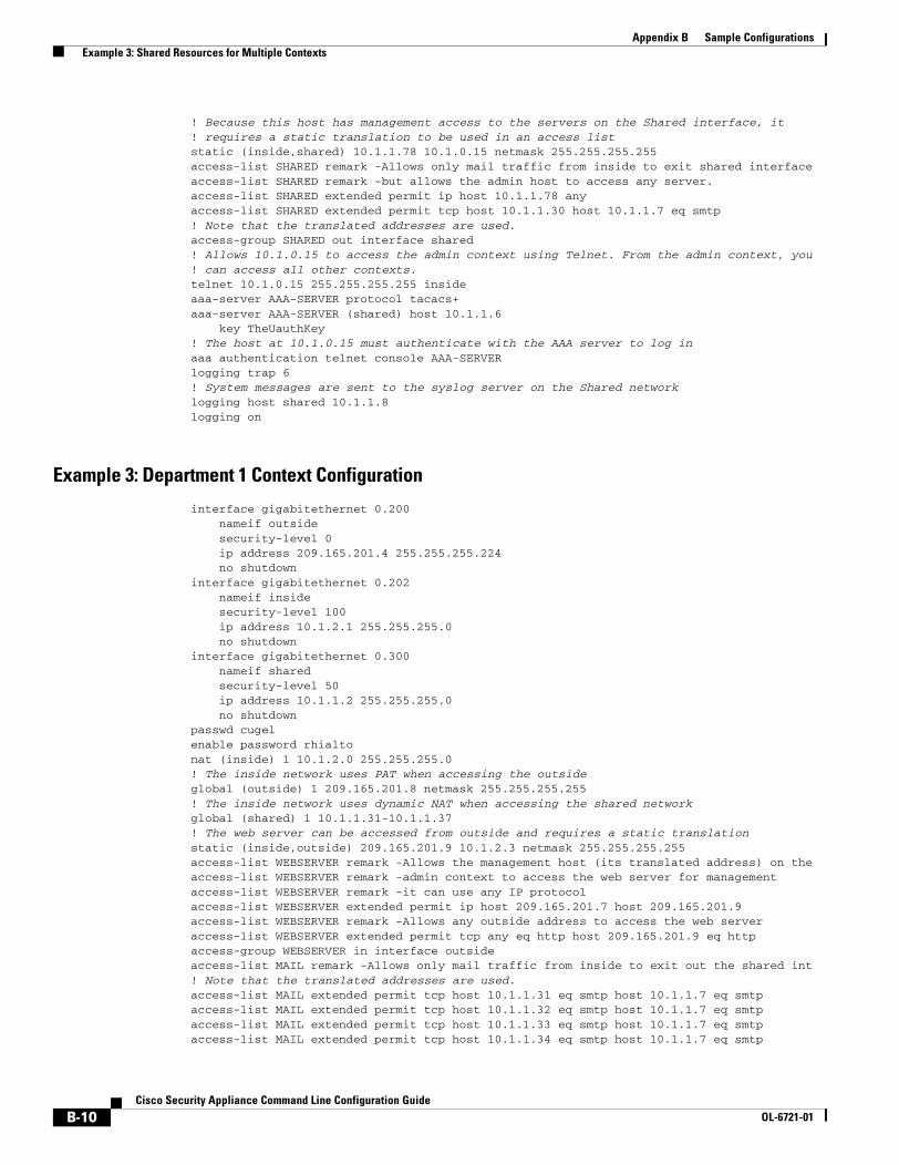
Appendix B Sample Configurations Example 3: Shared Resources for Multiple Contexts
! Because this host has management access to the servers on the Shared interface, it! requires a static translation to be used in an access liststatic (inside,shared) 10.1.1.78 10.1.0.15 netmask 255.255.255.255access-list SHARED remark -Allows only mail traffic from inside to exit shared interfaceaccess-list SHARED remark -but allows the admin host to access any server.access-list SHARED extended permit ip host 10.1.1.78 anyaccess-list SHARED extended permit tcp host 10.1.1.30 host 10.1.1.7 eq smtp! Note that the translated addresses are used.access-group SHARED out interface shared! Allows 10.1.0.15 to access the admin context using Telnet. From the admin context, you! can access all other contexts.telnet 10.1.0.15 255.255.255.255 insideaaa-server AAA-SERVER protocol tacacs+aaa-server AAA-SERVER (shared) host 10.1.1.6
key TheUauthKey! The host at 10.1.0.15 must authenticate with the AAA server to log inaaa authentication telnet console AAA-SERVERlogging trap 6! System messages are sent to the syslog server on the Shared networklogging host shared 10.1.1.8logging on
Example 3: Department 1 Context Configuration
interface gigabitethernet 0.200nameif outsidesecurity-level 0ip address 209.165.201.4 255.255.255.224no shutdown
interface gigabitethernet 0.202nameif insidesecurity-level 100ip address 10.1.2.1 255.255.255.0no shutdown
interface gigabitethernet 0.300nameif sharedsecurity-level 50ip address 10.1.1.2 255.255.255.0no shutdown
passwd cugelenable password rhialtonat (inside) 1 10.1.2.0 255.255.255.0! The inside network uses PAT when accessing the outsideglobal (outside) 1 209.165.201.8 netmask 255.255.255.255! The inside network uses dynamic NAT when accessing the shared networkglobal (shared) 1 10.1.1.31-10.1.1.37! The web server can be accessed from outside and requires a static translationstatic (inside,outside) 209.165.201.9 10.1.2.3 netmask 255.255.255.255access-list WEBSERVER remark -Allows the management host (its translated address) on the access-list WEBSERVER remark -admin context to access the web server for managementaccess-list WEBSERVER remark -it can use any IP protocolaccess-list WEBSERVER extended permit ip host 209.165.201.7 host 209.165.201.9access-list WEBSERVER remark -Allows any outside address to access the web serveraccess-list WEBSERVER extended permit tcp any eq http host 209.165.201.9 eq httpaccess-group WEBSERVER in interface outsideaccess-list MAIL remark -Allows only mail traffic from inside to exit out the shared int! Note that the translated addresses are used.access-list MAIL extended permit tcp host 10.1.1.31 eq smtp host 10.1.1.7 eq smtpaccess-list MAIL extended permit tcp host 10.1.1.32 eq smtp host 10.1.1.7 eq smtpaccess-list MAIL extended permit tcp host 10.1.1.33 eq smtp host 10.1.1.7 eq smtpaccess-list MAIL extended permit tcp host 10.1.1.34 eq smtp host 10.1.1.7 eq smtp
B-10Cisco Security Appliance Command Line Configuration Guide
OL-6721-01

Appendix B Sample Configurations Example 4: Multiple Mode, Transparent Firewall with Outside Access
access-list MAIL extended permit tcp host 10.1.1.35 eq smtp host 10.1.1.7 eq smtpaccess-list MAIL extended permit tcp host 10.1.1.36 eq smtp host 10.1.1.7 eq smtpaccess-list MAIL extended permit tcp host 10.1.1.37 eq smtp host 10.1.1.7 eq smtpaccess-group MAIL out interface sharedaaa-server AAA-SERVER protocol tacacs+aaa-server AAA-SERVER (shared) host 10.1.1.6
key TheUauthKey! All traffic matching the WEBSERVER access list must authenticate with the AAA serveraaa authentication match WEBSERVER outside AAA-SERVERlogging trap 4! System messages are sent to the syslog server on the Shared networklogging host shared 10.1.1.8logging on
Example 3: Department 2 Context Configuration
interface gigabitethernet 0.200nameif outsidesecurity-level 0ip address 209.165.201.5 255.255.255.224no shutdown
interface gigabitethernet 0.203nameif insidesecurity-level 100ip address 10.1.3.1 255.255.255.0no shutdown
interface gigabitethernet 0.300nameif sharedsecurity-level 50ip address 10.1.1.3 255.255.255.0no shutdown
passwd maz1r1anenable password ly0ne$$eroute outside 0 0 209.165.201.2 1nat (inside) 1 10.1.3.0 255.255.255.0! The inside network uses PAT when accessing the outsideglobal (outside) 1 209.165.201.10 netmask 255.255.255.255! The inside network uses PAT when accessing the shared networkglobal (shared) 1 10.1.1.38access-list MAIL remark -Allows only mail traffic from inside to exit out the shared int access-list MAIL extended permit tcp host 10.1.1.38 host 10.1.1.7 eq smtp! Note that the translated PAT address is used.access-group MAIL out interface sharedlogging trap 3! System messages are sent to the syslog server on the Shared networklogging host shared 10.1.1.8logging on
Example 4: Multiple Mode, Transparent Firewall with Outside Access
This configuration creates three security contexts plus the admin context. Each context allows OSPF traffic to pass between the inside and outside routers (see Figure B-4).
Inside hosts can access the Internet through the outside, but no outside hosts can access the inside.
The admin context allows SSH sessions to the security appliance from one host.
B-11Cisco Security Appliance Command Line Configuration Guide
OL-6721-01

Appendix B Sample Configurations Example 4: Multiple Mode, Transparent Firewall with Outside Access
Although inside IP addresses can be the same across contexts, keeping them unique is easier to manage.
Figure B-4 Example 4
See the following sections for the configurations for this scenario:
• Example 4: System Configuration, page 12
• Example 4: Admin Context Configuration, page 13
• Example 4: Customer A Context Configuration, page 14
• Example 4: Customer B Context Configuration, page 14
• Example 4: Customer C Context Configuration, page 14
Example 4: System ConfigurationYou must first enable multiple context mode using the mode multiple command. The mode is not stored in the configuration file, even though it endures reboots. If you view the configuration on the security appliance using the write terminal, show startup-config, or show running-config commands, the mode displays after the security appliance version (blank means single mode, “<system>” means you are in multiple mode in the system configuration, and <context> means you are in multiple mode in a context).
firewall transparent
10.1.n.2
Internet
customerANetwork 2
inside
10.1.2.3
192.168.2.1
Management host10.1.1.75
inside insideinside
AdminNetwork 2
10.1.1.3
192.168.1.1
customerBNetwork 2
10.1.3.3
192.168.3.1
customerCNetwork 2
10.1.4.3
192.168.4.1
Admin Contextoutside
customerAoutside
customerBoutside
customerCoutside
10.1.1.1 10.1.2.1 10.1.3.1 10.1.4.1
1269
81
B-12Cisco Security Appliance Command Line Configuration Guide
OL-6721-01

Appendix B Sample Configurations Example 4: Multiple Mode, Transparent Firewall with Outside Access
hostname Farscapepassword passw0rdenable password chr1cht0nadmin-context admininterface gigabitethernet 0
no shutdowninterface gigabitethernet 0.150
no shutdowninterface gigabitethernet 0.151
no shutdowninterface gigabitethernet 0.152
no shutdowninterface gigabitethernet 0.153
no shutdowninterface gigabitethernet 1
shutdowninterface gigabitethernet 1.4
no shutdowninterface gigabitethernet 1.5
no shutdowninterface gigabitethernet 1.6
no shutdowninterface gigabitethernet 1.7
no shutdowncontext admin
allocate-interface gigabitethernet 0.150allocate-interface gigabitethernet 1.4config-url disk0://admin.cfg
context customerAdescription This is the context for customer Aallocate-interface gigabitethernet 0.151allocate-interface gigabitethernet 1.5config-url disk0://contexta.cfg
context customerBdescription This is the context for customer Ballocate-interface gigabitethernet 0.152allocate-interface gigabitethernet 1.6config-url disk0://contextb.cfg
context customerCdescription This is the context for customer Callocate-interface gigabitethernet 0.153allocate-interface gigabitethernet 1.7config-url disk0://contextc.cfg
Example 4: Admin Context ConfigurationThe host at 10.1.1.75 can access the context using SSH, which requires a key pair to be generated using the crypto key generate command.
hostname Admindomain ispinterface gigabitethernet 0.150
nameif outsidesecurity-level 0no shutdown
interface gigabitethernet 1.4nameif insidesecurity-level 100no shutdown
passwd secret1969enable password h1andl0
B-13Cisco Security Appliance Command Line Configuration Guide
OL-6721-01

Appendix B Sample Configurations Example 4: Multiple Mode, Transparent Firewall with Outside Access
ip address 10.1.1.1 255.255.255.0route outside 0 0 10.1.1.2 1ssh 10.1.1.75 255.255.255.255 insideaccess-list OSPF remark -Allows OSPFaccess-list OSPF extended permit 89 any anyaccess-group OSPF in interface outside
Example 4: Customer A Context Configurationinterface gigabitethernet 0.151
nameif outsidesecurity-level 0no shutdown
interface gigabitethernet 1.5nameif insidesecurity-level 100no shutdown
passwd hell0!enable password enter55ip address 10.1.2.1 255.255.255.0route outside 0 0 10.1.2.2 1access-list OSPF remark -Allows OSPFaccess-list OSPF extended permit 89 any anyaccess-group OSPF in interface outside
Example 4: Customer B Context Configurationinterface gigabitethernet 0.152
nameif outsidesecurity-level 0no shutdown
interface gigabitethernet 1.6nameif insidesecurity-level 100no shutdown
passwd tenac10usenable password defen$eip address 10.1.3.1 255.255.255.0route outside 0 0 10.1.3.2 1access-list OSPF remark -Allows OSPFaccess-list OSPF extended permit 89 any anyaccess-group OSPF in interface outside
Example 4: Customer C Context Configurationinterface gigabitethernet 0.153
nameif outsidesecurity-level 0no shutdown
interface gigabitethernet 1.7nameif insidesecurity-level 100no shutdown
passwd fl0wer
B-14Cisco Security Appliance Command Line Configuration Guide
OL-6721-01

Appendix B Sample Configurations Example 4: Multiple Mode, Transparent Firewall with Outside Access
enable password treeh0u$eip address 10.1.4.1 255.255.255.0route outside 0 0 10.1.4.2 1access-list OSPF remark -Allows OSPFaccess-list OSPF extended permit 89 any anyaccess-group OSPF in interface outside
B-15Cisco Security Appliance Command Line Configuration Guide
OL-6721-01

Appendix B Sample Configurations Example 4: Multiple Mode, Transparent Firewall with Outside Access
B-16Cisco Security Appliance Command Line Configuration Guide
OL-6721-01

Cisco Security AppliaOL-6721-01
A P P E N D I X C
Using the Command-Line InterfaceThis appendix describes how to use the CLI on the security appliance, and includes the following sections:
• Firewall Mode and Security Context Mode, page C-1
• Command Modes and Prompts, page C-2
• Syntax Formatting, page C-3
• Abbreviating Commands, page C-3
• Command-Line Editing, page C-3
• Command Completion, page C-3
• Command Help, page C-4
• Filtering show Command Output, page C-4
• Command Output Paging, page C-5
• Adding Comments, page C-5
• Text Configuration Files, page C-6
Note The CLI uses similar syntax and other conventions to the Cisco IOS CLI, but the security appliance operating system is not a version of Cisco IOS software. Do not assume that a Cisco IOS CLI command works with or has the same function on the security appliance.
Firewall Mode and Security Context ModeThe security appliance runs in a combination of the following modes:
• Transparent firewall or routed firewall mode
The firewall mode determines if the security appliance runs as a Layer 2 or Layer 3 firewall.
• Multiple context or single context mode
The security context mode determines if the security appliance runs as a single device or as multiple security contexts, which act like virtual devices.
Some commands are only available in certain modes.
C-1nce Command Line Configuration Guide

Appendix C Using the Command-Line Interface Command Modes and Prompts
Command Modes and PromptsThe security appliance CLI includes command modes. Some commands can only be entered in certain modes. For example, to enter commands that show sensitive information, you need to enter a password and enter a more privileged mode. Then, to ensure that configuration changes are not entered accidentally, you have to enter a configuration mode. All lower commands can be entered in higher modes, for example, you can enter a privileged EXEC command in global configuration mode.
When you are in the system configuration or in single context mode, the prompt begins with the hostname:
hostname
When you are within a context, the prompt begins with the hostname followed by the context name:
hostname/context
The prompt changes depending on the access mode:
• User EXEC mode
User EXEC mode lets you see minimum security appliance settings. The user EXEC mode prompt appears as follows when you first access the security appliance:
hostname>
hostname/context>
• Privileged EXEC mode
Privileged EXEC mode lets you see all current settings up to your privilege level. Any user EXEC mode command will work in privileged EXEC mode. Enter the enable command in user EXEC mode, which requires a password, to start privileged EXEC mode. The prompt includes the number sign (#):
hostname#
hostname/context#
• Global configuration mode
Global configuration mode lets you change the security appliance configuration. All user EXEC, privileged EXEC, and global configuration commands are available in this mode. Enter the configure terminal command in privileged EXEC mode to start global configuration mode. The prompt changes to the following:
hostname(config)#
hostname/context(config)#
• Command-specific configuration modes
From global configuration mode, some commands enter a command-specific configuration mode. All user EXEC, privileged EXEC, global configuration, and command-specific configuration commands are available in this mode. For example, the interface command enters interface configuration mode. The prompt changes to the following:
hostname(config-if)#
hostname/context(config-if)#
C-2Cisco Security Appliance Command Line Configuration Guide
OL-6721-01

Appendix C Using the Command-Line Interface Syntax Formatting
Syntax FormattingCommand syntax descriptions use the following conventions:
Abbreviating CommandsYou can abbreviate most commands down to the fewest unique characters for a command; for example, you can enter wr t to view the configuration instead of entering the full command write terminal, or you can enter en to start privileged mode and conf t to start configuration mode. In addition, you can enter 0 to represent 0.0.0.0.
Command-Line EditingThe security appliance uses the same command-line editing conventions as Cisco IOS software. You can view all previously entered commands with the show history command or individually with the up arrow or ^p command. Once you have examined a previously entered command, you can move forward in the list with the down arrow or ^n command. When you reach a command you wish to reuse, you can edit it or press the Enter key to start it. You can also delete the word to the left of the cursor with ^w, or erase the line with ^u.
The security appliance permits up to 512 characters in a command; additional characters are ignored.
Command CompletionTo complete a command or keyword after entering a partial string, press the Tab key. The security appliance only completes the command or keyword if the partial string matches only one command or keyword. For example, if you enter s and press the Tab key, the security appliance does not complete the command because it matches more than one command. However, if you enter dis, the Tab key completes the command disable.
Table C-1 Syntax Conventions
Convention Description
bold Bold text indicates commands and keywords that you enter literally as shown.
italics Italic text indicates arguments for which you supply values.
[x] Square brackets enclose an optional element (keyword or argument).
| A vertical bar indicates a choice within an optional or required set of keywords or arguments.
[x | y] Square brackets enclosing keywords or arguments separated by a vertical bar indicate an optional choice.
{x | y} Braces enclosing keywords or arguments separated by a vertical bar indicate a required choice.
[x {y | z}] Nested sets of square brackets or braces indicate optional or required choices within optional or required elements. Braces and a vertical bar within square brackets indicate a required choice within an optional element.
C-3Cisco Security Appliance Command Line Configuration Guide
OL-6721-01

Appendix C Using the Command-Line Interface Command Help
Command HelpHelp information is available from the command line by entering the following commands:
• help command_name
Shows help for the specific command.
• command_name ?
Shows a list of arguments available.
• string? (no space)
Lists the possible commands that start with the string.
• ? and +?
Lists all commands available. If you enter ?, the security appliance shows only commands available for the current mode. To show all commands available, including those for lower modes, enter +?.
Note If you want to include a question mark (?) in a command string, you must press Ctrl-V before typing the question mark so you do not inadvertently invoke CLI help.
Filtering show Command OutputYou can use the vertical bar (|) with any show command and include a filter option and filtering expression. The filtering is performed by matching each output line with a regular expression, similar to Cisco IOS software. By selecting different filter options you can include or exclude all output that matches the expression. You can also display all output beginning with the line that matches the expression.
The syntax for using filtering options with the show command is as follows:
hostname# show command | {include | exclude | begin | grep [-v]} regexp
In this command string, the first vertical bar (|) is the operator and must be included in the command. This operator directs the output of the show command to the filter. In the syntax diagram, the other vertical bars (|) indicate alternative options and are not part of the command.
The include option includes all output lines that match the regular expression. The grep option without -v has the same effect. The exclude option excludes all output lines that match the regular expression. The grep option with -v has the same effect. The begin option shows all the output lines starting with the line that matches the regular expression.
Replace regexp with any Cisco IOS regular expression. See The regular expression is not enclosed in quotes or double-quotes, so be careful with trailing white spaces, which will be taken as part of the regular expression.
When creating regular expressions, you can use any letter or number that you want to match. In addition, certain keyboard characters have special meaning when used in regular expressions. Table C-2 lists the keyboard characters that have special meaning.
C-4Cisco Security Appliance Command Line Configuration Guide
OL-6721-01

Appendix C Using the Command-Line Interface Command Output Paging
To use these special characters as single-character patterns, remove the special meaning by preceding each character with a backslash (\).
Command Output PagingOn commands such as help or?, show, show xlate, or other commands that provide long listings, you can determine if the information displays a screen and pauses, or lets the command run to completion. The pager command lets you choose the number of lines to display before the More prompt appears.
When paging is enabled, the following prompt appears:
<--- More --->
The More prompt uses syntax similar to the UNIX more command:
• To view another screen, press the Space bar.
• To view the next line, press the Enter key.
• To return to the command line, press the q key.
Adding CommentsYou can precede a line with a colon ( : ) to create a comment. However, the comment only appears in the command history buffer and not in the configuration. Therefore, you can view the comment with the show history command or by pressing an arrow key to retrieve a previous command, but because the comment is not in the configuration, the write terminal command does not display it.
Table C-2 Using Special Characters in Regular Expressions
Character Type Character Special Meaning
period . Matches any single character, including white space.
asterisk * Matches 0 or more sequences of the pattern.
plus sign + Matches 1 or more sequences of the pattern.
question mark ?1
1. Precede the question mark with Ctrl-V to prevent the question mark from being interpreted as a help command.
Matches 0 or 1 occurrences of the pattern.
caret ^ Matches the beginning of the input string.
dollar sign $ Matches the end of the input string.
underscore _ Matches a comma (,), left brace ({), right brace (}), left parenthesis, right parenthesis, the beginning of the input string, the end of the input string, or a space.
brackets [] Designates a range of single-character patterns.
hyphen - Separates the end points of a range.
C-5Cisco Security Appliance Command Line Configuration Guide
OL-6721-01

Appendix C Using the Command-Line Interface Text Configuration Files
Text Configuration FilesThis section describes how to format a text configuration file that you can download to the security appliance, and includes the following topics:
• How Commands Correspond with Lines in the Text File, page C-6
• Command-Specific Configuration Mode Commands, page C-6
• Automatic Text Entries, page C-6
• Line Order, page C-7
• Commands Not Included in the Text Configuration, page C-7
• Passwords, page C-7
• Multiple Security Context Files, page C-7
How Commands Correspond with Lines in the Text FileThe text configuration file includes lines that correspond with the commands described in this guide.
In examples, commands are preceded by a CLI prompt. The prompt in the following example is “hostname(config)#”:
hostname(config)# context a
In the text configuration file you are not prompted to enter commands, so the prompt is omitted:
context a
Command-Specific Configuration Mode CommandsCommand-specific configuration mode commands appear indented under the main command when entered at the command line. Your text file lines do not need to be indented, as long as the commands appear directly following the main command. For example, the following unindented text is read the same as indented text:
interface gigabitethernet0nameif insideinterface gigabitethernet1
nameif outside
Automatic Text EntriesWhen you download a configuration to the security appliance, the security appliance inserts some lines automatically. For example, the security appliance inserts lines for default settings or for the time the configuration was modified. You do not need to enter these automatic entries when you create your text file.
C-6Cisco Security Appliance Command Line Configuration Guide
OL-6721-01

Appendix C Using the Command-Line Interface Text Configuration Files
Line OrderFor the most part, commands can be in any order in the file. However, some lines, such as ACEs, are processed in the order they appear, and the order can affect the function of the access list. Other commands might also have order requirements. For example, you must enter the nameif command for an interface first because many subsequent commands use the name of the interface. Also, commands in a command-specific configuration mode must directly follow the main command.
Commands Not Included in the Text ConfigurationSome commands do not insert lines in the configuration. For example, a runtime command such as show running-config does not have a corresponding line in the text file.
PasswordsThe login, enable, and user passwords are automatically encrypted before they are stored in the configuration. For example, the encrypted form of the password “cisco” might look like jMorNbK0514fadBh. You can copy the configuration passwords to another security appliance in their encrypted form, but you cannot unencrypt the passwords yourself.
If you enter an unencrypted password in a text file, the security appliance does not automatically encrypt them when you copy the configuration to the security appliance. The security appliance only encrypts them when you save the running configuration from the command line using the copy running-config startup-config or write memory command.
Multiple Security Context FilesFor multiple security contexts, the entire configuration consists of multiple parts:
• The security context configurations
• The system configuration, which identifies basic settings for the security appliance, including a list of contexts
• The admin context, which provides network interfaces for the system configuration
The system configuration does not include any interfaces or network settings for itself. Rather, when the system needs to access network resources (such as downloading the contexts from the server), it uses a context that is designated as the admin context.
Each context is similar to a single context mode configuration. The system configuration differs from a context configuration in that the system configuration includes system-only commands (such as a list of all contexts) while other typical commands are not present (such as many interface parameters).
C-7Cisco Security Appliance Command Line Configuration Guide
OL-6721-01

Appendix C Using the Command-Line Interface Text Configuration Files
C-8Cisco Security Appliance Command Line Configuration Guide
OL-6721-01

Cisco Security AppliaOL-6721-01
A P P E N D I X D
Addresses, Protocols, and PortsThis appendix provides a quick reference for IP addresses, protocols, and applications. This appendix includes the following sections:
• IPv4 Addresses and Subnet Masks, page D-1
• IPv6 Addresses, page D-5
• Protocols and Applications, page D-11
• TCP and UDP Ports, page D-12
• Local Ports and Protocols, page D-14
• ICMP Types, page D-15
IPv4 Addresses and Subnet MasksThis section describes how to use IPv4 addresses in the security appliance. An IPv4 address is a 32-bit number written in dotted-decimal notation: four 8-bit fields (octets) converted from binary to decimal numbers, separated by dots. The first part of an IP address identifies the network on which the host resides, while the second part identifies the particular host on the given network. The network number field is called the network prefix. All hosts on a given network share the same network prefix but must have a unique host number. In classful IP, the class of the address determines the boundary between the network prefix and the host number.
This section includes the following topics:
• Classes, page D-2
• Private Networks, page D-2
• Subnet Masks, page D-2
D-1nce Command Line Configuration Guide

Appendix D Addresses, Protocols, and Ports IPv4 Addresses and Subnet Masks
ClassesIP host addresses are divided into three different address classes: Class A, Class B, and Class C. Each class fixes the boundary between the network prefix and the host number at a different point within the 32-bit address. Class D addresses are reserved for multicast IP.
• Class A addresses (1.xxx.xxx.xxx through 126.xxx.xxx.xxx) use only the first octet as the network prefix.
• Class B addresses (128.0.xxx.xxx through 191.255.xxx.xxx) use the first two octets as the network prefix.
• Class C addresses (192.0.0.xxx through 223.255.255.xxx) use the first three octets as the network prefix.
Because Class A addresses have 16,777,214 host addresses, and Class B addresses 65,534 hosts, you can use subnet masking to break these huge networks into smaller subnets.
Private NetworksIf you need large numbers of addresses on your network, and they do not need to be routed on the Internet, you can use private IP addresses that the Internet Assigned Numbers Authority (IANA) recommends (see RFC 1918). The following address ranges are designated as private networks that should not be advertised:
• 10.0.0.0 through 10.255.255.255
• 172.16.0.0 through 172.31.255.255
• 192.168.0.0 through 192.168.255.255
Subnet MasksA subnet mask lets you convert a single Class A, B, or C network into multiple networks. With a subnet mask, you can create an extended network prefix that adds bits from the host number to the network prefix. For example, a Class C network prefix always consists of the first three octets of the IP address. But a Class C extended network prefix uses part of the fourth octet as well.
Subnet masking is easy to understand if you use binary notation instead of dotted decimal. The bits in the subnet mask have a one-to-one correspondence with the Internet address:
• The bits are set to 1 if the corresponding bit in the IP address is part of the extended network prefix.
• The bits are set to 0 if the bit is part of the host number.
Example 1: If you have the Class B address 129.10.0.0 and you want to use the entire third octet as part of the extended network prefix instead of the host number, you must specify a subnet mask of 11111111.11111111.11111111.00000000. This subnet mask converts the Class B address into the equivalent of a Class C address, where the host number consists of the last octet only.
Example 2: If you want to use only part of the third octet for the extended network prefix, then you must specify a subnet mask like 11111111.11111111.11111000.00000000, which uses only 5 bits of the third octet for the extended network prefix.
You can write a subnet mask as a dotted-decimal mask or as a /bits (“slash bits”) mask. In Example 1, for a dotted-decimal mask, you convert each binary octet into a decimal number: 255.255.255.0. For a /bits mask, you add the number of 1s: /24. In Example 2, the decimal number is 255.255.248.0 and the /bits is /21.
D-2Cisco Security Appliance Command Line Configuration Guide
OL-6721-01

Appendix D Addresses, Protocols, and Ports IPv4 Addresses and Subnet Masks
You can also supernet multiple Class C networks into a larger network by using part of the third octet for the extended network prefix. For example, 192.168.0.0/20.
This section includes the following topics:
• Determining the Subnet Mask, page D-3
• Determining the Address to Use with the Subnet Mask, page D-3
Determining the Subnet Mask
To determine the subnet mask based on how many hosts you want, see Table D-1.
Determining the Address to Use with the Subnet Mask
The following sections describe how to determine the network address to use with a subnet mask for a Class C-size and a Class B-size network. This section includes the following topics:
• Class C-Size Network Address, page D-4
• Class B-Size Network Address, page D-4
Table D-1 Hosts, Bits, and Dotted-Decimal Masks
Hosts1
1. The first and last number of a subnet are reserved, except for /32, which identifies a single host.
/Bits Mask Dotted-Decimal Mask
16,777,216 /8 255.0.0.0 Class A Network
65,536 /16 255.255.0.0 Class B Network
32,768 /17 255.255.128.0
16,384 /18 255.255.192.0
8192 /19 255.255.224.0
4096 /20 255.255.240.0
2048 /21 255.255.248.0
1024 /22 255.255.252.0
512 /23 255.255.254.0
256 /24 255.255.255.0 Class C Network
128 /25 255.255.255.128
64 /26 255.255.255.192
32 /27 255.255.255.224
16 /28 255.255.255.240
8 /29 255.255.255.248
4 /30 255.255.255.252
Do not use /31 255.255.255.254
1 /32 255.255.255.255 Single Host Address
D-3Cisco Security Appliance Command Line Configuration Guide
OL-6721-01

Appendix D Addresses, Protocols, and Ports IPv4 Addresses and Subnet Masks
Class C-Size Network Address
For a network between 2 and 254 hosts, the fourth octet falls on a multiple of the number of host addresses, starting with 0. For example, the 8-host subnets (/29) of 192.168.0.x are as follows:
Class B-Size Network Address
To determine the network address to use with the subnet mask for a network with between 254 and 65,534 hosts, you need to determine the value of the third octet for each possible extended network prefix. For example, you might want to subnet an address like 10.1.x.0, where the first two octets are fixed because they are used in the extended network prefix, and the fourth octet is 0 because all bits are used for the host number.
To determine the value of the third octet, follow these steps:
Step 1 Calculate how many subnets you can make from the network by dividing 65,536 (the total number of addresses using the third and fourth octet) by the number of host addresses you want.
For example, 65,536 divided by 4096 hosts equals 16.
Therefore, there are 16 subnets of 4096 addresses each in a Class B-size network.
Step 2 Determine the multiple of the third octet value by dividing 256 (the number of values for the third octet) by the number of subnets:
In this example, 256/16 = 16.
The third octet falls on a multiple of 16, starting with 0.
Therefore, the 16 subnets of the network 10.1 are as follows:
Subnet with Mask /29 (255.255.255.248) Address Range1
1. The first and last address of a subnet are reserved. In the first subnet example, you cannot use 192.168.0.0 or 192.168.0.7.
192.168.0.0 192.168.0.0 to 192.168.0.7
192.168.0.8 192.168.0.8 to 192.168.0.15
192.168.0.16 192.168.0.16 to 192.168.0.31
… …
192.168.0.248 192.168.0.248 to 192.168.0.255
Subnet with Mask /20 (255.255.240.0) Address Range1
1. The first and last address of a subnet are reserved. In the first subnet example, you cannot use 10.1.0.0 or 10.1.15.255.
10.1.0.0 10.1.0.0 to 10.1.15.255
10.1.16.0 10.1.16.0 to 10.1.31.255
10.1.32.0 10.1.32.0 to 10.1.47.255
… …
10.1.240.0 10.1.240.0 to 10.1.255.255
D-4Cisco Security Appliance Command Line Configuration Guide
OL-6721-01

Appendix D Addresses, Protocols, and Ports IPv6 Addresses
IPv6 AddressesIPv6 is the next generation of the Internet Protocol after IPv4. It provides an expanded address space, a simplified header format, improved support for extensions and options, flow labeling capability, and authentication and privacy capabilities. IPv6 is described in RFC 2460. The IPv6 addressing architecture is described in RFC 3513.
This section describes the IPv6 address format and architecture and includes the following topics:
• IPv6 Address Format, page D-5
• IPv6 Address Types, page D-6
• IPv6 Address Prefixes, page D-10
Note This section describes the IPv6 address format, the types, and prefixes. For information about configuring the security appliance to use IPv6, see Chapter 6, “Configuring Interface Parameters.”
IPv6 Address FormatIPv6 addresses are represented as a series of eight 16-bit hexadecimal fields separated by colons (:) in the format: x:x:x:x:x:x:x:x. The following are two examples of IPv6 addresses:
• 2001:0DB8:7654:3210:FEDC:BA98:7654:3210
• 2001:0DB8:0000:0000:0008:0800:200C:417A
Note The hexadecimal letters in IPv6 addresses are not case-sensitive.
It is not necessary to include the leading zeros in an individual field of the address. But each field must contain at least one digit. So the example address 2001:0DB8:0000:0000:0008:0800:200C:417A can be shortened to 2001:0DB8:0:0:8:800:200C:417A by removing the leading zeros from the third through sixth fields from the left. The fields that contained all zeros (the third and fourth fields from the left) were shortened to a single zero. The fifth field from the left had the three leading zeros removed, leaving a single 8 in that field, and the sixth field from the left had the one leading zero removed, leaving 800 in that field.
It is common for IPv6 addresses to contain several consecutive hexadecimal fields of zeros. You can use two colons (::) to compress consecutive fields of zeros at the beginning, middle, or end of an IPv6 address (the colons represent the successive hexadecimal fields of zeros). Table D-2 shows several examples of address compression for different types of IPv6 address.
Table D-2 IPv6 Address Compression Examples
Address Type Standard Form Compressed Form
Unicast 2001:0DB8:0:0:0:BA98:0:3210 2001:0DB8::BA98:0:3210
Multicast FF01:0:0:0:0:0:0:101 FF01::101
Loopback 0:0:0:0:0:0:0:1 ::1
Unspecified 0:0:0:0:0:0:0:0 ::
D-5Cisco Security Appliance Command Line Configuration Guide
OL-6721-01

Appendix D Addresses, Protocols, and Ports IPv6 Addresses
Note Two colons (::) can be used only once in an IPv6 address to represent successive fields of zeros.
An alternative form of the IPv6 format is often used when dealing with an environment that contains both IPv4 and IPv6 addresses. This alternative has the format x:x:x:x:x:x:y.y.y.y, where x represent the hexadecimal values for the six high-order parts of the IPv6 address and y represent decimal values for the 32-bit IPv4 part of the address (which takes the place of the remaining two 16-bit parts of the IPv6 address). For example, the IPv4 address 192.168.1.1 could be represented as the IPv6 address 0:0:0:0:0:0:FFFF:192.168.1.1, or ::FFFF:192.168.1.1.
IPv6 Address TypesThe following are the three main types of IPv6 addresses:
• Unicast—A unicast address is an identifier for a single interface. A packet sent to a unicast address is delivered to the interface identified by that address. An interface may have more than one unicast address assigned to it.
• Multicast—A multicast address is an identifier for a set of interfaces. A packet sent to a multicast address is delivered to all addresses identified by that address.
• Anycast—An anycast address is an identifier for a set of interfaces. Unlike a multicast address, a packet sent to an anycast address is only delivered to the “nearest” interface, as determined by the measure of distances for the routing protocol.
Note There are no broadcast addresses in IPv6. Multicast addresses provide the broadcast functionality.
This section includes the following topics:
• Unicast Addresses, page D-6
• Multicast Address, page D-8
• Anycast Address, page D-9
• Required Addresses, page D-10
Unicast Addresses
This section describes IPv6 unicast addresses. Unicast addresses identify an interface on a network node.
This section includes the following topics:
• Global Address, page D-7
• Site-Local Address, page D-7
• Link-Local Address, page D-7
• IPv4-Compatible IPv6 Addresses, page D-7
• Unspecified Address, page D-8
• Loopback Address, page D-8
• Interface Identifiers, page D-8
D-6Cisco Security Appliance Command Line Configuration Guide
OL-6721-01

Appendix D Addresses, Protocols, and Ports IPv6 Addresses
Global Address
The general format of an IPv6 global unicast address is a global routing prefix followed by a subnet ID followed by an interface ID. The global routing prefix can be any prefix not reserved by another IPv6 address type (see IPv6 Address Prefixes, page D-10, for information about the IPv6 address type prefixes).
All global unicast addresses, other than those that start with binary 000, have a 64-bit interface ID in the Modified EUI-64 format. See Interface Identifiers, page D-8, for more information about the Modified EUI-64 format for interface identifiers.
Global unicast address that start with the binary 000 do not have any constraints on the size or structure of the interface ID portion of the address. One example of this type of address is an IPv6 address with an embedded IPv4 address (see IPv4-Compatible IPv6 Addresses, page D-7).
Site-Local Address
Site-local addresses are used for addressing within a site. They can be use to address an entire site without using a globally unique prefix. Site-local addresses have the prefix FEC0::/10, followed by a 54-bit subnet ID, and end with a 64-bit interface ID in the modified EUI-64 format.
Site-local Routers do not forward any packets that have a site-local address for a source or destination outside of the site. Therefore, site-local addresses can be considered private addresses.
Link-Local Address
All interfaces are required to have at least one link-local address. You can configure multiple IPv6 addresses per interfaces, but only one link-local address.
A link-local address is an IPv6 unicast address that can be automatically configured on any interface using the link-local prefix FE80::10 and the interface identifier in modified EUI-64 format. Link-local addresses are used in the neighbor discovery protocol and the stateless autoconfiguration process. Nodes with a link-local address can communicate; they do not need a site-local or globally unique address to communicate.
Routers do not forward any packets that have a link-local address for a source or destination. Therefore, link-local addresses can be considered private addresses.
IPv4-Compatible IPv6 Addresses
There are two types of IPv6 addresses that can contain IPv4 addresses.
The first type is the “IPv4-compatibly IPv6 address.” The IPv6 transition mechanisms include a technique for hosts and routers to dynamically tunnel IPv6 packets over IPv4 routing infrastructure. IPv6 nodes that use this technique are assigned special IPv6 unicast addresses that carry a global IPv4 address in the low-order 32 bits. This type of address is termed an “IPv4-compatible IPv6 address” and has the format ::y.y.y.y, where y.y.y.y is an IPv4 unicast address.
Note The IPv4 address used in the “IPv4-compatible IPv6 address” must be a globally-unique IPv4 unicast address.
The second type of IPv6 address which holds an embedded IPv4 address is called the “IPv4-mapped IPv6 address.” This address type is used to represent the addresses of IPv4 nodes as IPv6 addresses. This type of address has the format ::FFFF:y.y.y.y, where y.y.y.y is an IPv4 unicast address.
D-7Cisco Security Appliance Command Line Configuration Guide
OL-6721-01

Appendix D Addresses, Protocols, and Ports IPv6 Addresses
Unspecified Address
The unspecified address, 0:0:0:0:0:0:0:0, indicates the absence of an IPv6 address. For example, a newly initialized node on an IPv6 network may use the unspecified address as the source address in its packets until it receives its IPv6 address.
Note The IPv6 unspecified address cannot be assigned to an interface. The unspecified IPv6 addresses must not be used as destination addresses in IPv6 packets or the IPv6 routing header.
Loopback Address
The loopback address, 0:0:0:0:0:0:0:1, may be used by a node to send an IPv6 packet to itself. The loopback address in IPv6 functions the same as the loopback address in IPv4 (127.0.0.1).
Note The IPv6 loopback address cannot be assigned to a physical interface. A packet that has the IPv6 loopback address as its source or destination address must remain within the node that created the packet. IPv6 routers do not forward packets that have the IPv6 loopback address as their source or destination address.
Interface Identifiers
Interface identifiers in IPv6 unicast addresses are used to identify the interfaces on a link. They need to be unique within a subnet prefix. In many cases, the interface identifier is derived from the interface link-layer address. The same interface identifier may be used on multiple interfaces of a single node, as long as those interfaces are attached to different subnets.
For all unicast addresses, except those that start with the binary 000, the interface identifier is required to be 64 bits long and to be constructed in the Modified EUI-64 format. The Modified EUI-64 format is created from the 48-bit MAC address by inverting the universal/local bit in the address and by inserting the hexadecimal number FFFE between the upper three bytes and lower three bytes of the of the MAC address.
For example, and interface with the MAC address of 00E0.b601.3B7A would have a 64-bit interface ID of 02E0:B6FF:FE01:3B7A.
Multicast Address
An IPv6 multicast address is an identifier for a group of interfaces, typically on different nodes. A packet sent to a multicast address is delivered to all interfaces identified by the multicast address. An interface may belong to any number of multicast groups.
An IPv6 multicast address has a prefix of FF00::/8 (1111 1111). The octet following the prefix defines the type and scope of the multicast address. A permanently assigned (“well known”) multicast address has a flag parameter equal to 0; a temporary (“transient”) multicast address has a flag parameter equal to 1. A multicast address that has the scope of a node, link, site, or organization, or a global scope has a scope parameter of 1, 2, 5, 8, or E, respectively. For example, a multicast address with the prefix FF02::/16 is a permanent multicast address with a link scope. Figure D-1 shows the format of the IPv6 multicast address.
D-8Cisco Security Appliance Command Line Configuration Guide
OL-6721-01

Appendix D Addresses, Protocols, and Ports IPv6 Addresses
Figure D-1 IPv6 Multicast Address Format
IPv6 nodes (hosts and routers) are required to join the following multicast groups:
• The All Nodes multicast addresses:
– FF01:: (interface-local)
– FF02:: (link-local)
• The Solicited-Node Address for each IPv6 unicast and anycast address on the node: FF02:0:0:0:0:1:FFXX:XXXX/104, where XX:XXXX is the low-order 24-bits of the unicast or anycast address.
Note Solicited-Node addresses are used in Neighbor Solicitation messages.
IPv6 routers are required to join the following multicast groups:
• FF01::2 (interface-local)
• FF02::2 (link-local)
• FF05::2 (site-local)
Multicast address should not be used as source addresses in IPv6 packets.
Note There are no broadcast addresses in IPv6. IPv6 multicast addresses are used instead of broadcast addresses.
Anycast Address
The IPv6 anycast address is a unicast address that is assigned to more than one interface (typically belonging to different nodes). A packet that is routed to an anycast address is routed to the nearest interface having that address, the nearness being determined by the routing protocol in effect.
Anycast addresses are allocated from the unicast address space. An anycast address is simply a unicast address that has been assigned to more than one interface, and the interfaces must be configured to recognize the address as an anycast address.
9261
7
128 bits
4 bits4 bits
0 if permanent1 if temporary
Interface ID0
1111 1111
8 bits 8 bits
F F Flag Scope Flag =
Scope =
1 = node2 = link4 = admin5 = site8 = organizationE = global
D-9Cisco Security Appliance Command Line Configuration Guide
OL-6721-01

Appendix D Addresses, Protocols, and Ports IPv6 Addresses
The following restrictions apply to anycast addresses:
• An anycast address cannot be used as the source address for an IPv6 packet.
• An anycast address cannot be assigned to an IPv6 host; it can only be assigned to an IPv6 router.
Note Anycast addresses are not supported on the security appliance.
Required Addresses
IPv6 hosts must, at a minimum, be configured with the following addresses (either automatically or manually):
• A link-local address for each interface.
• The loopback address.
• The All-Nodes multicast addresses
• A Solicited-Node multicast address for each unicast or anycast address.
IPv6 routers must, at a minimum, be configured with the following addresses (either automatically or manually):
• The required host addresses.
• The Subnet-Router anycast addresses for all interfaces for which it is configured to act as a router.
• The All-Routers multicast addresses.
IPv6 Address PrefixesAn IPv6 address prefix, in the format ipv6-prefix/prefix-length, can be used to represent bit-wise contiguous blocks of the entire address space. The IPv6-prefix must be in the form documented in RFC 2373 where the address is specified in hexadecimal using 16-bit values between colons. The prefix length is a decimal value that indicates how many of the high-order contiguous bits of the address comprise the prefix (the network portion of the address). For example, 2001:0DB8:8086:6502::/32 is a valid IPv6 prefix.
The IPv6 prefix identifies the type of IPv6 address. Table D-3 shows the prefixes for each IPv6 address type.
Table D-3 IPv6 Address Type Prefixes
Address Type Binary Prefix IPv6 Notation
Unspecified 000...0 (128 bits) ::/128
Loopback 000...1 (128 bits) ::1/128
Multicast 11111111 FF00::/8
Link-Local (unicast) 1111111010 FE80::/10
Site-Local (unicast) 1111111111 FEC0::/10
Global (unicast) All other addresses.
Anycast Taken from the unicast address space.
D-10Cisco Security Appliance Command Line Configuration Guide
OL-6721-01

Appendix D Addresses, Protocols, and Ports Protocols and Applications
Protocols and ApplicationsTable D-4 lists the protocol literal values and port numbers; either can be entered in security appliance commands.
Protocol numbers can be viewed online at the IANA website:
http://www.iana.org/assignments/protocol-numbers
Table D-4 Protocol Literal Values
Literal Value Description
ah 51 Authentication Header for IPv6, RFC 1826.
eigrp 88 Enhanced Interior Gateway Routing Protocol.
esp 50 Encapsulated Security Payload for IPv6, RFC 1827.
gre 47 Generic Routing Encapsulation.
icmp 1 Internet Control Message Protocol, RFC 792.
icmp6 58 Internet Control Message Protocol for IPv6, RFC 2463.
igmp 2 Internet Group Management Protocol, RFC 1112.
igrp 9 Interior Gateway Routing Protocol.
ip 0 Internet Protocol.
ipinip 4 IP-in-IP encapsulation.
ipsec 50 IP Security. Entering the ipsec protocol literal is equivalent to entering the esp protocol literal.
nos 94 Network Operating System (Novell’s NetWare).
ospf 89 Open Shortest Path First routing protocol, RFC 1247.
pcp 108 Payload Compression Protocol.
pim 103 Protocol Independent Multicast.
pptp 47 Point-to-Point Tunneling Protocol. Entering the pptp protocol literal is equivalent to entering the gre protocol literal.
snp 109 Sitara Networks Protocol.
tcp 6 Transmission Control Protocol, RFC 793.
udp 17 User Datagram Protocol, RFC 768.
D-11Cisco Security Appliance Command Line Configuration Guide
OL-6721-01

Appendix D Addresses, Protocols, and Ports TCP and UDP Ports
TCP and UDP PortsTable D-5 lists the literal values and port numbers; either can be entered in security appliance commands. See the following caveats:
• The security appliance uses port 1521 for SQL*Net. This is the default port used by Oracle for SQL*Net. This value, however, does not agree with IANA port assignments.
• The security appliance listens for RADIUS on ports 1645 and 1646. If your RADIUS server uses the standard ports 1812 and 1813, you can configure the security appliance to listen to those ports using the authentication-port and accounting-port commands.
• To assign a port for DNS access, use the domain literal value, not dns. If you use dns, the security appliance assumes you meant to use the dnsix literal value.
Port numbers can be viewed online at the IANA website:
http://www.iana.org/assignments/port-numbers
Table D-5 Port Literal Values
Literal TCP or UDP? Value Description
aol TCP 5190 America Online
bgp TCP 179 Border Gateway Protocol, RFC 1163
biff UDP 512 Used by mail system to notify users that new mail is received
bootpc UDP 68 Bootstrap Protocol Client
bootps UDP 67 Bootstrap Protocol Server
chargen TCP 19 Character Generator
citrix-ica TCP 1494 Citrix Independent Computing Architecture (ICA) protocol
cmd TCP 514 Similar to exec except that cmd has automatic authentication
ctiqbe TCP 2748 Computer Telephony Interface Quick Buffer Encoding
daytime TCP 13 Day time, RFC 867
discard TCP, UDP 9 Discard
domain TCP, UDP 53 DNS
dnsix UDP 195 DNSIX Session Management Module Audit Redirector
echo TCP, UDP 7 Echo
exec TCP 512 Remote process execution
finger TCP 79 Finger
ftp TCP 21 File Transfer Protocol (control port)
ftp-data TCP 20 File Transfer Protocol (data port)
gopher TCP 70 Gopher
https TCP 443 HTTP over SSL
D-12Cisco Security Appliance Command Line Configuration Guide
OL-6721-01

Appendix D Addresses, Protocols, and Ports TCP and UDP Ports
h323 TCP 1720 H.323 call signalling
hostname TCP 101 NIC Host Name Server
ident TCP 113 Ident authentication service
imap4 TCP 143 Internet Message Access Protocol, version 4
irc TCP 194 Internet Relay Chat protocol
isakmp UDP 500 Internet Security Association and Key Management Protocol
kerberos TCP, UDP 750 Kerberos
klogin TCP 543 KLOGIN
kshell TCP 544 Korn Shell
ldap TCP 389 Lightweight Directory Access Protocol
ldaps TCP 636 Lightweight Directory Access Protocol (SSL)
lpd TCP 515 Line Printer Daemon - printer spooler
login TCP 513 Remote login
lotusnotes TCP 1352 IBM Lotus Notes
mobile-ip UDP 434 MobileIP-Agent
nameserver UDP 42 Host Name Server
netbios-ns UDP 137 NetBIOS Name Service
netbios-dgm UDP 138 NetBIOS Datagram Service
netbios-ssn TCP 139 NetBIOS Session Service
nntp TCP 119 Network News Transfer Protocol
ntp UDP 123 Network Time Protocol
pcanywhere-status UDP 5632 pcAnywhere status
pcanywhere-data TCP 5631 pcAnywhere data
pim-auto-rp TCP, UDP 496 Protocol Independent Multicast, reverse path flooding, dense mode
pop2 TCP 109 Post Office Protocol - Version 2
pop3 TCP 110 Post Office Protocol - Version 3
pptp TCP 1723 Point-to-Point Tunneling Protocol
radius UDP 1645 Remote Authentication Dial-In User Service
radius-acct UDP 1646 Remote Authentication Dial-In User Service (accounting)
rip UDP 520 Routing Information Protocol
secureid-udp UDP 5510 SecureID over UDP
smtp TCP 25 Simple Mail Transport Protocol
snmp UDP 161 Simple Network Management Protocol
snmptrap UDP 162 Simple Network Management Protocol - Trap
Table D-5 Port Literal Values (continued)
Literal TCP or UDP? Value Description
D-13Cisco Security Appliance Command Line Configuration Guide
OL-6721-01

Appendix D Addresses, Protocols, and Ports Local Ports and Protocols
Local Ports and ProtocolsTable D-6 lists the protocols, TCP ports, and UDP ports that the security appliance may open to process traffic destined to the security appliance. Unless you enable the features and services listed in Table D-6, the security appliance does not open any local protocols or any TCP or UDP ports. You must configure a feature or service for the security appliance to open the default listening protocol or port. In many cases you can configure ports other than the default port when you enable a feature or service.
sqlnet TCP 1521 Structured Query Language Network
ssh TCP 22 Secure Shell
sunrpc (rpc) TCP, UDP 111 Sun Remote Procedure Call
syslog UDP 514 System Log
tacacs TCP, UDP 49 Terminal Access Controller Access Control System Plus
talk TCP, UDP 517 Talk
telnet TCP 23 RFC 854 Telnet
tftp UDP 69 Trivial File Transfer Protocol
time UDP 37 Time
uucp TCP 540 UNIX-to-UNIX Copy Program
who UDP 513 Who
whois TCP 43 Who Is
www TCP 80 World Wide Web
xdmcp UDP 177 X Display Manager Control Protocol
Table D-5 Port Literal Values (continued)
Literal TCP or UDP? Value Description
Table D-6 Protocols and Ports Opened by Features and Services
Feature or Service Protocol Port Number Comments
DHCP UDP 67,68 —
Failover Control 108 N/A —
HTTP TCP 80 —
HTTPS TCP 443 —
ICMP 1 N/A —
IGMP 2 N/A Protocol only open on destination IP address 224.0.0.1
ISAKMP/IKE UDP 500 Configurable.
IPSec (ESP) 50 N/A —
IPSec over UDP (NAT-T)
UDP 4500 —
D-14Cisco Security Appliance Command Line Configuration Guide
OL-6721-01

Appendix D Addresses, Protocols, and Ports ICMP Types
ICMP TypesTable D-7 lists the ICMP type numbers and names that you can enter in security appliance commands:
IPSec over UDP (Cisco VPN 3000 Series compatible)
UDP 10000 Configurable.
IPSec over TCP (CTCP)
TCP — No default port is used. You must specify the port number when configuring IPSec over TCP.
NTP UDP 123 —
OSPF 89 N/A Protocol only open on destination IP address 224.0.0.5 and 224.0.0.6
PIM 103 N/A Protocol only open on destination IP address 224.0.0.13
RIP UDP 520 —
RIPv2 UDP 520 Port only open on destination IP address 224.0.0.9
SNMP UDP 161 Configurable.
SSH TCP 22 —
Stateful Update 105 N/A —
Telnet TCP 23 —
VPN Load Balancing UDP 9023 Configurable.
VPN Individual User Authentication Proxy
UDP 1645, 1646 Port accessible only over VPN tunnel.
Table D-6 Protocols and Ports Opened by Features and Services (continued)
Feature or Service Protocol Port Number Comments
Table D-7 ICMP Types
ICMP Number ICMP Name
0 echo-reply
3 unreachable
4 source-quench
5 redirect
6 alternate-address
8 echo
9 router-advertisement
10 router-solicitation
11 time-exceeded
12 parameter-problem
D-15Cisco Security Appliance Command Line Configuration Guide
OL-6721-01

Appendix D Addresses, Protocols, and Ports ICMP Types
13 timestamp-request
14 timestamp-reply
15 information-request
16 information-reply
17 mask-request
18 mask-reply
31 conversion-error
32 mobile-redirect
Table D-7 ICMP Types (continued)
ICMP Number ICMP Name
D-16Cisco Security Appliance Command Line Configuration Guide
OL-6721-01

Cisco Security AppliancOL-6721-01
G L O S S A R Y
Numerics
3DES See DES.
A
AAA Authentication, authorization, and accounting. See also TACACS+ and RADIUS.
ABR Area Border Router. In OSPF, a router with interfaces in multiple areas.
ACE Access Control Entry. Information entered into the configuration that lets you specify what type of traffic to permit or deny on an interface. By default, traffic that is not explicitly permitted is denied.
Access Modes The security appliance CLI uses several command modes. The commands available in each mode vary. See also user EXEC mode, privileged EXEC mode, global configuration mode, command-specific configuration mode.
ACL Access Control List. A collection of ACEs. An ACL lets you specify what type of traffic to allow on an interface. By default, traffic that is not explicitly permitted is denied. ACLs are usually applied to the interface which is the source of inbound traffic. See also rule, outbound ACL.
ActiveX A set of object-oriented programming technologies and tools used to create mobile or portable programs. An ActiveX program is roughly equivalent to a Java applet.
Address Resolution
Protocol
See ARP.
address translation The translation of a network address and/or port to another network address/or port. See also IP address, interface PAT, NAT, PAT, Static PAT, xlate.
AES Advanced Encryption Standard. A symmetric block cipher that can encrypt and decrypt information. The AES algorithm is capable of using cryptographic keys of 128, 192 and 256 bits to encrypt and decrypt data in blocks of 128 bits. See also DES.
AH Authentication Header. An IP protocol (type 51) that can ensure data integrity, authentication, and replay detection. AH is embedded in the data to be protected (a full IP datagram, for example). AH can be used either by itself or with ESP. This is an older IPSec protocol that is less important in most networks than ESP. AH provides authentication services but does not provide encryption services. It is provided to ensure compatibility with IPSec peers that do not support ESP, which provides both authentication and encryption. See also encryption and VPN. Refer to the RFC 2402.
A record address “A” stands for address, and refers to name-to-address mapped records in DNS.
GL-1e Command Line Configuration Guide

Glossary
ARP Address Resolution Protocol. A low-level TCP/IP protocol that maps a hardware address, or MAC address, to an IP address. An example hardware address is 00:00:a6:00:01:ba. The first three groups of characters (00:00:a6) identify the manufacturer; the rest of the characters (00:01:ba) identify the system card. ARP is defined in RFC 826.
ASA Adaptive Security Algorithm. Used by the security appliance to perform inspections. ASA allows one-way (inside to outside) connections without an explicit configuration for each internal system and application. See also inspection engine.
ASDM Adaptive Security Device Manager. An application for managing and configuring a single security appliance.
asymmetric
encryption
Also called public key systems, asymmetric encryption allows anyone to obtain access to the public key of anyone else. Once the public key is accessed, one can send an encrypted message to that person using the public key. See also encryption, public key.
authentication Cryptographic protocols and services that verify the identity of users and the integrity of data. One of the functions of the IPSec framework. Authentication establishes the integrity of datastream and ensures that it is not tampered with in transit. It also provides confirmation about the origin of the datastream. See also AAA, encryption, and VPN.
B
BGP Border Gateway Protocol. BGP performs interdomain routing in TCP/IP networks. BGP is an Exterior Gateway Protocol, which means that it performs routing between multiple autonomous systems or domains and exchanges routing and access information with other BGP systems. The security appliance does not support BGP. See also EGP.
BLT stream Bandwidth Limited Traffic stream. Stream or flow of packets whose bandwidth is constrained.
BOOTP Bootstrap Protocol. Lets diskless workstations boot over the network as is described in RFC 951 and RFC 1542.
BPDU Bridge Protocol Data Unit. Spanning-Tree Protocol hello packet that is sent out at configurable intervals to exchange information among bridges in the network. Protocol data unit is the OSI term for packet.
C
CA Certificate Authority, Certification Authority. A third-party entity that is responsible for issuing and revoking certificates. Each device with the public key of the CA can authenticate a device that has a certificate issued by the CA. The term CA also refers to software that provides CA services. See also certificate, CRL, public key, RA.
cache A temporary repository of information accumulated from previous task executions that can be reused, decreasing the time required to perform the tasks.
CBC Cipher Block Chaining. A cryptographic technique that increases the encryption strength of an algorithm. CBC requires an initialization vector (IV) to start encryption. The IV is explicitly given in the IPSec packet.
GL-2Cisco Security Appliance Command Line Configuration Guide
OL-6721-01

Glossary
certificate A signed cryptographic object that contains the identity of a user or device and the public key of the CA that issued the certificate. Certificates have an expiration date and may also be placed on a CRL if known to be compromised. Certificates also establish non-repudiation for IKE negotiation, which means that you can prove to a third party that IKE negotiation was completed with a specific peer.
CHAP Challenge Handshake Authentication Protocol.
CLI command line interface. The primary interface for entering configuration and monitoring commands to the security appliance.
client/server
computing
Distributed computing (processing) network systems in which transaction responsibilities are divided into two parts: client (front end) and server (back end). Also called distributed computing. See also RPC.
command-specific
configuration mode
From global configuration mode, some commands enter a command-specific configuration mode. All user EXEC, privileged EXEC, global configuration, and command-specific configuration commands are available in this mode. See also global configuration mode, privileged EXEC mode, user EXEC mode.
configuration,
config, config file
A file on the security appliance that represents the equivalent of settings, preferences, and properties administered by ASDM or the CLI.
cookie A cookie is a object stored by a browser. Cookies contain information, such as user preferences, to persistent storage.
CPU Central Processing Unit. Main processor.
CRC Cyclical Redundancy Check. Error-checking technique in which the frame recipient calculates a remainder by dividing frame contents by a prime binary divisor and compares the calculated remainder to a value stored in the frame by the sending node.
CRL Certificate Revocation List. A digitally signed message that lists all of the current but revoked certificates listed by a given CA. This is analogous to a book of stolen charge card numbers that allow stores to reject bad credit cards. When certificates are revoked, they are added to a CRL. When you implement authentication using certificates, you can choose to use CRLs or not. Using CRLs lets you easily revoke certificates before they expire, but the CRL is generally only maintained by the CA or an RA. If you are using CRLs and the connection to the CA or RA is not available when authentication is requested, the authentication request will fail. See also CA, certificate, public key, RA.
CRV Call Reference Value. Used by H.225.0 to distinguish call legs signalled between two entities.
cryptography Encryption, authentication, integrity, keys and other services used for secure communication over networks. See also VPN and IPSec.
crypto map A data structure with a unique name and sequence number that is used for configuring VPNs on the security appliance. A crypto map selects data flows that need security processing and defines the policy for these flows and the crypto peer that traffic needs to go to. A crypto map is applied to an interface. Crypto maps contain the ACLs, encryption standards, peers, and other parameters necessary to specify security policies for VPNs using IKE and IPSec. See also VPN.
GL-3Cisco Security Appliance Command Line Configuration Guide
OL-6721-01

Glossary
CTIQBE Computer Telephony Interface Quick Buffer Encoding. A protocol used in IP telephony between the Cisco CallManager and CTI TAPI and JTAPI applications. CTIQBE is used by the TAPI/JTAPI protocol inspection module and supports NAT, PAT, and bi-directional NAT. This enables Cisco IP SoftPhone and other Cisco TAPI/JTAPI applications to communicate with Cisco CallManager for call setup and voice traffic across the security appliance.
cut-through proxy Enables the security appliance to provide faster traffic flow after user authentication. The cut-through proxy challenges a user initially at the application layer. After the security appliance authenticates the user, it shifts the session flow and all traffic flows directly and quickly between the source and destination while maintaining session state information.
D
data confidentiality Describes any method that manipulates data so that no attacker can read it. This is commonly achieved by data encryption and keys that are only available to the parties involved in the communication.
data integrity Describes mechanisms that, through the use of encryption based on secret key or public key algorithms, allow the recipient of a piece of protected data to verify that the data has not been modified in transit.
data origin
authentication
A security service where the receiver can verify that protected data could have originated only from the sender. This service requires a data integrity service plus a key distribution mechanism, where a secret key is shared only between the sender and receiver.
decryption Application of a specific algorithm or cipher to encrypted data so as to render the data comprehensible to those who are authorized to see the information. See also encryption.
DES Data encryption standard. DES was published in 1977 by the National Bureau of Standards and is a secret key encryption scheme based on the Lucifer algorithm from IBM. Cisco uses DES in classic crypto (40-bit and 56-bit key lengths), IPSec crypto (56-bit key), and 3DES (triple DES), which performs encryption three times using a 56-bit key. 3DES is more secure than DES but requires more processing for encryption and decryption. See also AES, ESP.
DHCP Dynamic Host Configuration Protocol. Provides a mechanism for allocating IP addresses to hosts dynamically, so that addresses can be reused when hosts no longer need them and so that mobile computers, such as laptops, receive an IP address applicable to the LAN to which it is connected.
Diffie-Hellman A public key cryptography protocol that allows two parties to establish a shared secret over insecure communications channels. Diffie-Hellman is used within IKE to establish session keys. Diffie-Hellman is a component of Oakley key exchange.
Diffie-Hellman
Group 1, Group 2,
Group 5, Group 7
Diffie-Hellman refers to a type of public key cryptography using asymmetric encryption based on large prime numbers to establish both Phase 1 and Phase 2 SAs. Group 1 provides a smaller prime number than Group 2 but may be the only version supported by some IPSec peers. Diffe-Hellman Group 5 uses a 1536-bit prime number, is the most secure, and is recommended for use with AES. Group 7 has an elliptical curve field size of 163 bits and is for use with the Movian VPN client, but works with any peer that supports Group 7 (ECC). See also VPN and encryption.
digital certificate See certificate.
DMZ See interface.
GL-4Cisco Security Appliance Command Line Configuration Guide
OL-6721-01

Glossary
DN Distinguished Name. Global, authoritative name of an entry in the OSI Directory (X.500).
DNS Domain Name System (or Service). An Internet service that translates domain names into IP addresses.
DoS Denial of Service. A type of network attack in which the goal is to render a network service unavailable.
DSL digital subscriber line. Public network technology that delivers high bandwidth over conventional copper wiring at limited distances. DSL is provisioned via modem pairs, with one modem located at a central office and the other at the customer site. Because most DSL technologies do not use the whole bandwidth of the twisted pair, there is room remaining for a voice channel.
DSP digital signal processor. A DSP segments a voice signal into frames and stores them in voice packets.
DSS Digital Signature Standard. A digital signature algorithm designed by The US National Institute of Standards and Technology and based on public-key cryptography. DSS does not do user datagram encryption. DSS is a component in classic crypto, as well as the Redcreek IPSec card, but not in IPSec implemented in Cisco IOS software.
Dynamic NAT See NAT and address translation.
Dynamic PAT Dynamic Port Address Translation. Dynamic PAT lets multiple outbound sessions appear to originate from a single IP address. With PAT enabled, the security appliance chooses a unique port number from the PAT IP address for each outbound translation slot (xlate). This feature is valuable when an ISP cannot allocate enough unique IP addresses for your outbound connections. The global pool addresses always come first, before a PAT address is used. See also NAT, Static PAT, and xlate.
E
ECHO See Ping, ICMP. See also inspection engine.
EGP Exterior Gateway Protocol. Replaced by BGP. The security appliance does not support EGP. See also BGP.
EIGRP Enhanced Interior Gateway Routing Protocol. The security appliance does not support EIGRP.
EMBLEM Enterprise Management BaseLine Embedded Manageability. A syslog format designed to be consistent with the Cisco IOS system log format and is more compatible with CiscoWorks management applications.
encryption Application of a specific algorithm or cipher to data so as to render the data incomprehensible to those unauthorized to see the information. See also decryption.
ESMTP Extended SMTP. Extended version of SMTP that includes additional functionality, such as delivery notification and session delivery. ESMTP is described in RFC 1869, SMTP Service Extensions.
ESP Encapsulating Security Payload. An IPSec protocol, ESP provides authentication and encryption services for establishing a secure tunnel over an insecure network. For more information, refer to RFCs 2406 and 1827.
GL-5Cisco Security Appliance Command Line Configuration Guide
OL-6721-01

Glossary
F
failover, failover
mode
Failover lets you configure two security appliances so that one will take over operation if the other one fails. The security appliance supports two failover configurations, Active/Active failover and Active/Standby failover. Each failover configuration has its own method for determining and performing failover. With Active/Active failover, both units can pass network traffic. This lets you configure load balancing on your network. Active/Active failover is only available on units running in multiple context mode. With Active/Standby failover, only one unit passes traffic while the other unit waits in a standby state. Active/Standby failover is available on units running in either single or multiple context mode.
Fixup See inspection engine.
Flash, Flash
memory
A nonvolatile storage device used to store the configuration file when the security appliance is powered down.
FQDN/IP Fully qualified domain name/IP address. IPSec parameter that identifies peers that are security gateways.
FragGuard Provides IP fragment protection and performs full reassembly of all ICMP error messages and virtual reassembly of the remaining IP fragments that are routed through the security appliance.
FTP File Transfer Protocol. Part of the TCP/IP protocol stack, used for transferring files between hosts.
G
GGSN gateway GPRS support node. A wireless gateway that allows mobile cell phone users to access the public data network or specified private IP networks.
global
configuration mode
Global configuration mode lets you to change the security appliance configuration. All user EXEC, privileged EXEC, and global configuration commands are available in this mode. See also user EXEC mode, privileged EXEC mode, command-specific configuration mode.
GMT Greenwich Mean Time. Replaced by UTC (Coordinated Universal Time) in 1967 as the world time standard.
GPRS general packet radio service. A service defined and standardized by the European Telecommunication Standards Institute. GPRS is an IP-packet-based extension of GSM networks and provides mobile, wireless, data communications
GRE Generic Routing Encapsulation described in RFCs 1701 and 1702. GRE is a tunneling protocol that can encapsulate a wide variety of protocol packet types inside IP tunnels, creating a virtual point-to-point link to routers at remote points over an IP network. By connecting multiprotocol subnetworks in a single-protocol backbone environment, IP tunneling using GRE allows network expansion across a single protocol backbone environment.
GL-6Cisco Security Appliance Command Line Configuration Guide
OL-6721-01

Glossary
GSM Global System for Mobile Communication. A digital, mobile, radio standard developed for mobile, wireless, voice communications.
GTP GPRS tunneling protocol. GTP handles the flow of user packet data and signaling information between the SGSN and GGSN in a GPRS network. GTP is defined on both the Gn and Gp interfaces of a GPRS network.
H
H.225 A protocol used for TCP signalling in applications such as video conferencing. See also H.323 and inspection engine.
H.225.0 An ITU standard that governs H.225.0 session establishment and packetization. H.225.0 actually describes several different protocols: RAS, use of Q.931, and use of RTP.
H.245 An ITU standard that governs H.245 endpoint control.
H.320 Suite of ITU-T standard specifications for video conferencing over circuit-switched media, such as ISDN, fractional T-1, and switched-56 lines. Extensions of ITU-T standard H.320 enable video conferencing over LANs and other packet-switched networks, as well as video over the Internet.
H.323 Allows dissimilar communication devices to communicate with each other by using a standardized communication protocol. H.323 defines a common set of CODECs, call setup and negotiating procedures, and basic data transport methods.
H.323 RAS Registration, admission, and status signaling protocol. Enables devices to perform registration, admissions, bandwidth changes, and status and disengage procedures between VoIP gateway and the gatekeeper.
H.450.2 Call transfer supplementary service for H.323.
H.450.3 Call diversion supplementary service for H.323.
Hash, Hash
Algorithm
A hash algorithm is a one way function that operates on a message of arbitrary length to create a fixed-length message digest used by cryptographic services to ensure its data integrity. MD5 has a smaller digest and is considered to be slightly faster than SHA-1. Cisco uses both SHA-1 and MD5 hashes within our implementation of the IPSec framework. See also encryption, HMAC, and VPN.
headend A firewall, concentrator, or other host that serves as the entry point into a private network for VPN client connections over the public network. See also ISP and VPN.
HMAC A mechanism for message authentication using cryptographic hashes such as SHA-1 and MD5.
host The name for any device on a TCP/IP network that has an IP address. See also network and node.
host/network An IP address and netmask used with other information to identify a single host or network subnet for security appliance configuration, such as an address translation (xlate) or ACE.
HTTP Hypertext Transfer Protocol. A protocol used by browsers and web servers to transfer files. When a user views a web page, the browser can use HTTP to request and receive the files used by the web page. HTTP transmissions are not encrypted.
HTTPS Hypertext Transfer Protocol Secure. An SSL-encrypted version of HTTP.
GL-7Cisco Security Appliance Command Line Configuration Guide
OL-6721-01
Glossary
I
IANA Internet Assigned Number Authority. Assigns all port and protocol numbers for use on the Internet.
ICMP Internet Control Message Protocol. Network-layer Internet protocol that reports errors and provides other information relevant to IP packet processing.
IDS Intrusion Detection System. A method of detecting malicious network activity by signatures and then implementing a policy for that signature.
IETF The Internet Engineering Task Force. A technical standards organization that develops RFC documents defining protocols for the Internet.
IGMP Internet Group Management Protocol. IGMP is a protocol used by IPv4 systems to report IP multicast memberships to neighboring multicast routers.
IKE Internet Key Exchange. IKE establishes a shared security policy and authenticates keys for services (such as IPSec) that require keys. Before any IPSec traffic can be passed, each security appliance must verify the identity of its peer. This can be done by manually entering preshared keys into both hosts or by a CA service. IKE is a hybrid protocol that uses part Oakley and part of another protocol suite called SKEME inside ISAKMP framework. This is the protocol formerly known as ISAKMP/Oakley, and is defined in RFC 2409.
IKE Extended
Authentication
IKE Extended Authenticate (Xauth) is implemented per the IETF draft-ietf-ipsec-isakmp-xauth-04.txt (“extended authentication” draft). This protocol provides the capability of authenticating a user within IKE using TACACS+ or RADIUS.
IKE Mode
Configuration
IKE Mode Configuration is implemented per the IETF draft-ietf-ipsec-isakmp-mode-cfg-04.txt. IKE Mode Configuration provides a method for a security gateway to download an IP address (and other network level configuration) to the VPN client as part of an IKE negotiation.
ILS Internet Locator Service. ILS is based on LDAP and is ILSv2 compliant. ILS was developed by Microsoft for use with its NetMeeting, SiteServer, and Active Directory products.
IMAP Internet Message Access Protocol. Method of accessing e-mail or bulletin board messages kept on a mail server that can be shared. IMAP permits client e-mail applications to access remote message stores as if they were local without actually transferring the message.
implicit rule An access rule automatically created by the security appliance based on default rules or as a result of user-defined rules.
IMSI International Mobile Subscriber Identity. One of two components of a GTP tunnel ID, the other being the NSAPI. See also NSAPI.
inside The first interface, usually port 1, that connects your internal, “trusted” network protected by the security appliance. See also interface, interface names.
GL-8Cisco Security Appliance Command Line Configuration Guide
OL-6721-01

Glossary
inspection engine The security appliance inspects certain application-level protocols to identify the location of embedded addressing information in traffic. This allows NAT to translate these embedded addresses and to update any checksum or other fields that are affected by the translation. Because many protocols open secondary TCP or UDP ports, each application inspection engine also monitors sessions to determine the port numbers for secondary channels. The initial session on a well-known port is used to negotiate dynamically assigned port numbers. The application inspection engine monitors these sessions, identifies the dynamic port assignments, and permits data exchange on these ports for the duration of the specific session. Some of the protocols that the security appliance can inspect are CTIQBE, FTP, H.323, HTTP, MGCP, SMTP, and SNMP.
interface The physical connection between a particular network and a security appliance.
interface ip_address The IP address of a security appliance network interface. Each interface IP address must be unique. Two or more interfaces must not be given the same IP address or IP addresses that are on the same IP network.
interface names Human readable name assigned to a security appliance network interface. The inside interface default name is “inside” and the outside interface default name is “outside.” Any perimeter interface default names are “intfn”, such as intf2 for the first perimeter interface, intf3 for the second perimeter interface, and so on to the last interface. The numbers in the intf string corresponds to the position of the interface card in the security appliance. You can use the default names or, if you are an experienced user, give each interface a more meaningful name. See also inside, intfn, outside.
intfn Any interface, usually beginning with port 2, that connects to a subset network of your design that you can custom name and configure.
interface PAT The use of PAT where the PAT IP address is also the IP address of the outside interface. See Dynamic PAT, Static PAT.
Internet The global network that uses IP. Not a LAN. See also intranet.
intranet Intranetwork. A LAN that uses IP. See also network and Internet.
IP Internet Protocol. IP protocols are the most popular nonproprietary protocols because they can be used to communicate across any set of interconnected networks and are equally well suited for LAN and WAN communications.
IPS Intrusion Prevention Service. An in-line, deep-packet inspection-based solution that helps mitigate a wide range of network attacks.
IP address An IP protocol address. A security appliance interface ip_address. IP version 4 addresses are 32 bits in length. This address space is used to designate the network number, optional subnetwork number, and a host number. The 32 bits are grouped into four octets (8 binary bits), represented by 4 decimal numbers separated by periods, or dots. The meaning of each of the four octets is determined by their use in a particular network.
IP pool A range of local IP addresses specified by a name, and a range with a starting IP address and an ending address. IP Pools are used by DHCP and VPNs to assign local IP addresses to clients on the inside interface.
GL-9Cisco Security Appliance Command Line Configuration Guide
OL-6721-01

Glossary
IPSec IP Security. A framework of open standards that provides data confidentiality, data integrity, and data authentication between participating peers. IPSec provides these security services at the IP layer. IPSec uses IKE to handle the negotiation of protocols and algorithms based on local policy and to generate the encryption and authentication keys to be used by IPSec. IPSec can protect one or more data flows between a pair of hosts, between a pair of security gateways, or between a security gateway and a host.
IPSec Phase 1 The first phase of negotiating IPSec, includes the key exchange and the ISAKMP portions of IPSec.
IPSec Phase 2 The second phase of negotiating IPSec. Phase two determines the type of encryption rules used for payload, the source and destination that will be used for encryption, the definition of interesting traffic according to access lists, and the IPSec peer. IPSec is applied to the interface in Phase 2.
IPSec transform set A transform set specifies the IPSec protocol, encryption algorithm, and hash algorithm to use on traffic matching the IPSec policy. A transform describes a security protocol (AH or ESP) with its corresponding algorithms. The IPSec protocol used in almost all transform sets is ESP with the DES algorithm and HMAC-SHA for authentication.
ISAKMP Internet Security Association and Key Management Protocol. A protocol framework that defines payload formats, the mechanics of implementing a key exchange protocol, and the negotiation of a security association. See IKE.
ISP Internet Service Provider. An organization that provides connection to the Internet via their services, such as modem dial in over telephone voice lines or DSL.
J
JTAPI Java Telephony Application Programming Interface. A Java-based API supporting telephony functions. See also TAPI.
K
key A data object used for encryption, decryption, or authentication.
L
LAN Local area network. A network residing in one location, such as a single building or campus. See also Internet, intranet, and network.
layer, layers Networking models implement layers with which different protocols are associated. The most common networking model is the OSI model, which consists of the following 7 layers, in order: physical, data link, network, transport, session, presentation, and application.
LCN Logical channel number.
LDAP Lightweight Directory Access Protocol. LDAP provides management and browser applications with access to X.500 directories.
GL-10Cisco Security Appliance Command Line Configuration Guide
OL-6721-01

Glossary
M
mask A 32-bit mask that shows how an Internet address is divided into network, subnet, and host parts. The mask has ones in the bit positions to be used for the network and subnet parts, and zeros for the host part. The mask should contain at least the standard network portion, and the subnet field should be contiguous with the network portion.
MCR See multicast.
MC router Multicast (MC) routers route multicast data transmissions to the hosts on each LAN in an internetwork that are registered to receive specific multimedia or other broadcasts. See also multicast.
MD5 Message Digest 5. A one-way hashing algorithm that produces a 128-bit hash. Both MD5 and SHA-1 are variations on MD4 and are designed to strengthen the security of the MD4 hashing algorithm. SHA-1 is more secure than MD4 and MD5. Cisco uses hashes for authentication within the IPSec framework. Also used for message authentication in SNMP v.2. MD5 verifies the integrity of the communication, authenticates the origin, and checks for timeliness. MD5 has a smaller digest and is considered to be slightly faster than SHA-1.
MDI Media dependent interface.
MDIX Media dependent interface crossover.
Message Digest A message digest is created by a hash algorithm, such as MD5 or SHA-1, that is used for ensuring message integrity.
MGCP Media Gateway Control Protocol. Media Gateway Control Protocol is a protocol for the control of VoIP calls by external call-control elements known as media gateway controllers or call agents. MGCP merges the IPDC and SGCP protocols.
Mode See Access Modes.
Mode Config See IKE Mode Configuration.
Modular Policy
Framework
Modular Policy Framework. A means of configuring security appliance features in a manner to similar to Cisco IOS software Modular QoS CLI.
MS mobile station. Refers generically to any mobile device, such as a mobile handset or computer, that is used to access network services. GPRS networks support three classes of MS, which describe the type of operation supported within the GPRS and the GSM mobile wireless networks. For example, a Class A MS supports simultaneous operation of GPRS and GSM services.
MS-CHAP Microsoft CHAP.
MTU Maximum transmission unit, the maximum number of bytes in a packet that can flow efficiently across the network with best response time. For Ethernet, the default MTU is 1500 bytes, but each network can have different values, with serial connections having the smallest values. The MTU is described in RFC 1191.
multicast Multicast refers to a network addressing method in which the source transmits a packet to multiple destinations, a multicast group, simultaneously. See also PIM, SMR.
GL-11Cisco Security Appliance Command Line Configuration Guide
OL-6721-01

Glossary
N
N2H2 A third-party, policy-oriented filtering application that works with the security appliance to control user web access. N2H2 can filter HTTP requests based on destination host name, destination IP address, and username and password. The N2H2 corporation was acquired by Secure Computing in October, 2003.
NAT Network Address Translation. Mechanism for reducing the need for globally unique IP addresses. NAT allows an organization with addresses that are not globally unique to connect to the Internet by translating those addresses into a globally routable address space.
NEM Network Extension Mode. Lets VPN hardware clients present a single, routable network to the remote private network over the VPN tunnel.
NetBIOS Network Basic Input/Output System. A Microsoft protocol that supports Windows host name registration, session management, and data transfer. The security appliance supports NetBIOS by performing NAT of the packets for NBNS UDP port 137 and NBDS UDP port 138.
netmask See mask.
network In the context of security appliance configuration, a network is a group of computing devices that share part of an IP address space and not a single host. A network consists of multiple nodes or hosts. See also host, Internet, intranet, IP, LAN, and node.
NMS network management system. System responsible for managing at least part of a network. An NMS is generally a reasonably powerful and well-equipped computer, such as an engineering workstation. NMSs communicate with agents to help keep track of network statistics and resources.
node Devices such as routers and printers that would not normally be called hosts. See also host, network.
nonvolatile storage,
memory
Storage or memory that, unlike RAM, retains its contents without power. Data in a nonvolatile storage device survives a power-off, power-on cycle or reboot.
NSAPI Network service access point identifier. One of two components of a GTP tunnel ID, the other component being the IMSI. See also IMSI.
NSSA Not-so-stubby-area. An OSPF feature described by RFC 1587. NSSA was first introduced in Cisco IOS software release 11.2. It is a non-proprietary extension of the existing stub area feature that allows the injection of external routes in a limited fashion into the stub area.
NTLM NT Lan Manager. A Microsoft Windows challenge-response authentication method.
NTP Network time protocol.
O
Oakley A key exchange protocol that defines how to acquire authenticated keying material. The basic mechanism for Oakley is the Diffie-Hellman key exchange algorithm. Oakley is defined in RFC 2412.
object grouping Simplifies access control by letting you apply access control statements to groups of network objects, such as protocol, services, hosts, and networks.
GL-12Cisco Security Appliance Command Line Configuration Guide
OL-6721-01

Glossary
OSPF Open Shortest Path First. OSPF is a routing protocol for IP networks. OSPF is a routing protocol widely deployed in large networks because of its efficient use of network bandwidth and its rapid convergence after changes in topology. The security appliance supports OSPF.
OU Organizational Unit. An X.500 directory attribute.
outbound Refers to traffic whose destination is on an interface with lower security than the source interface.
outbound ACL An ACL applied to outbound traffic.
outside The first interface, usually port 0, that connects to other “untrusted” networks outside the security appliance; the Internet. See also interface, interface names, outbound.
P
PAC PPTP Access Concentrator. A device attached to one or more PSTN or ISDN lines capable of PPP operation and of handling the PPTP protocol. The PAC need only implement TCP/IP to pass traffic to one or more PNSs. It may also tunnel non-IP protocols.
PAT See Dynamic PAT, interface PAT, and Static PAT.
Perfmon The security appliance feature that gathers and reports a wide variety of feature statistics, such as connections/second, xlates/second, etc.
PFS Perfect Forwarding Secrecy. PFS enhances security by using different security key for the IPSec Phase 1 and Phase 2 SAs. Without PFS, the same security key is used to establish SAs in both phases. PFS ensures that a given IPSec SA key was not derived from any other secret (like some other keys). In other words, if someone were to break a key, PFS ensures that the attacker would not be able to derive any other key. If PFS were not enabled, someone could hypothetically break the IKE SA secret key, copy all the IPSec protected data, and then use knowledge of the IKE SA secret to compromise the IPSec SA setup by this IKE SA. With PFS, breaking IKE would not give an attacker immediate access to IPSec. The attacker would have to break each IPSec SA individually.
Phase 1 See IPSec Phase 1.
Phase 2 See IPSec Phase 2.
PIM Protocol Independent Multicast. PIM provides a scalable method for determining the best paths for distributing a specific multicast transmission to a group of hosts. Each host has registered using IGMP to receive the transmission. See also PIM-SM.
PIM-SM Protocol Independent Multicast-Sparse Mode. With PIM-SM, which is the default for Cisco routers, when the source of a multicast transmission begins broadcasting, the traffic is forwarded from one MC router to the next, until the packets reach every registered host. See also PIM.
Ping An ICMP request sent by a host to determine if a second host is accessible.
PIX Private Internet eXchange. The Cisco PIX 500-series security appliances range from compact, plug-and-play desktop models for small/home offices to carrier-class gigabit models for the most demanding enterprise and service provider environments. Cisco PIX security appliances provide robust, enterprise-class integrated network security services to create a strong multilayered defense for fast changing network environments.
GL-13Cisco Security Appliance Command Line Configuration Guide
OL-6721-01

Glossary
PKCS12 A standard for the transfer of PKI-related data, such as private keys, certificates, and other data. Devices supporting this standard let administrators maintain a single set of personal identity information.
PNS PPTP Network Server. A PNS is envisioned to operate on general-purpose computing/server platforms. The PNS handles the server side of PPTP. Because PPTP relies completely on TCP/IP and is independent of the interface hardware, the PNS may use any combination of IP interface hardware including LAN and WAN devices.
Policy NAT Lets you identify local traffic for address translation by specifying the source and destination addresses (or ports) in an access list.
POP Post Office Protocol. Protocol that client e-mail applications use to retrieve mail from a mail server.
Pool See IP pool.
Port A field in the packet headers of TCP and UDP protocols that identifies the higher level service which is the source or destination of the packet.
PPP Point-to-Point Protocol. Developed for dial-up ISP access using analog phone lines and modems.
PPTP Point-to-Point Tunneling Protocol. PPTP was introduced by Microsoft to provide secure remote access to Windows networks; however, because it is vulnerable to attack, PPTP is commonly used only when stronger security methods are not available or are not required. PPTP Ports are pptp, 1723/tcp, 1723/udp, and pptp. For more information about PPTP, see RFC 2637. See also PAC, PPTP GRE, PPTP GRE tunnel, PNS, PPTP session, and PPTP TCP.
PPTP GRE Version 1 of GRE for encapsulating PPP traffic.
PPTP GRE tunnel A tunnel defined by a PNS-PAC pair. The tunnel protocol is defined by a modified version of GRE. The tunnel carries PPP datagrams between the PAC and the PNS. Many sessions are multiplexed on a single tunnel. A control connection operating over TCP controls the establishment, release, and maintenance of sessions and of the tunnel itself.
PPTP session PPTP is connection-oriented. The PNS and PAC maintain state for each user that is attached to a PAC. A session is created when end-to-end PPP connection is attempted between a dial user and the PNS. The datagrams related to a session are sent over the tunnel between the PAC and PNS.
PPTP TCP Standard TCP session over which PPTP call control and management information is passed. The control session is logically associated with, but separate from, the sessions being tunneled through a PPTP tunnel.
preshared key A preshared key provides a method of IKE authentication that is suitable for networks with a limited, static number of IPSec peers. This method is limited in scalability because the key must be configured for each pair of IPSec peers. When a new IPSec peer is added to the network, the preshared key must be configured for every IPSec peer with which it communicates. Using certificates and CAs provides a more scalable method of IKE authentication.
primary, primary
unit
The security appliance normally operating when two units, a primary and secondary, are operating in failover mode.
privileged EXEC
mode
Privileged EXEC mode lets you to change current settings. Any user EXEC mode command will work in privileged EXEC mode. See also command-specific configuration mode, global configuration mode, user EXEC mode.
GL-14Cisco Security Appliance Command Line Configuration Guide
OL-6721-01

Glossary
protocol, protocol
literals
A standard that defines the exchange of packets between network nodes for communication. Protocols work together in layers. Protocols are specified in a security appliance configuration as part of defining a security policy by their literal values or port numbers. Possible security appliance protocol literal values are ahp, eigrp, esp, gre, icmp, igmp, igrp, ip, ipinip, ipsec, nos, ospf, pcp, snp, tcp, and udp.
Proxy-ARP Enables the security appliance to reply to an ARP request for IP addresses in the global pool. See also ARP.
public key A public key is one of a pair of keys that are generated by devices involved in public key infrastructure. Data encrypted with a public key can only be decrypted using the associated private key. When a private key is used to produce a digital signature, the receiver can use the public key of the sender to verify that the message was signed by the sender. These characteristics of key pairs provide a scalable and secure method of authentication over an insecure media, such as the Internet.
Q
QoS quality of service. Measure of performance for a transmission system that reflects its transmission quality and service availability.
R
RA Registration Authority. An authorized proxy for a CA. RAs can perform certificate enrollment and can issue CRLs. See also CA, certificate, public key.
RADIUS Remote Authentication Dial-In User Service. RADIUS is a distributed client/server system that secures networks against unauthorized access. RFC 2058 and RFC 2059 define the RADIUS protocol standard. See also AAA and TACACS+.
Refresh Retrieve the running configuration from the security appliance and update the screen. The icon and the button perform the same function.
registration
authority
See RA.
replay-detection A security service where the receiver can reject old or duplicate packets to defeat replay attacks. Replay attacks rely on the attacker sending out older or duplicate packets to the receiver and the receiver thinking that the bogus traffic is legitimate. Replay-detection is done by using sequence numbers combined with authentication, and is a standard feature of IPSec.
RFC Request for Comments. RFC documents define protocols and standards for communications over the Internet. RFCs are developed and published by IETF.
RIP Routing Information Protocol. Interior gateway protocol (IGP) supplied with UNIX BSD systems. The most common IGP in the Internet. RIP uses hop count as a routing metric.
GL-15Cisco Security Appliance Command Line Configuration Guide
OL-6721-01

Glossary
RLLA Reserved Link Local Address. Multicast addresses range from 224.0.0.0 to 239.255.255.255, however only the range 224.0.1.0 to 239.255.255.255 is available to us. The first part of the multicast address range, 224.0.0.0 to 224.0.0.255, is reserved and referred to as the RLLA. These addresses are unavailable. We can exclude the RLLA range by specifying: 224.0.1.0 to 239.255.255.255. 224.0.0.0 to 239.255.255.255 excluding 224.0.0.0 to 224.0.0.255. This is the same as specifying: 224.0.1.0 to 239.255.255.255.
route, routing The path through a network.
routed firewall
mode
In routed firewall mode, the security appliance is counted as a router hop in the network. It performs NAT between connected networks and can use OSPF or RIP. See also transparent firewall mode.
RPC Remote Procedure Call. RPCs are procedure calls that are built or specified by clients and executed on servers, with the results returned over the network to the clients.
RSA A public key cryptographic algorithm (named after its inventors, Rivest, Shamir, and Adelman) with a variable key length. The main weakness of RSA is that it is significantly slow to compute compared to popular secret-key algorithms, such as DES. The Cisco implementation of IKE uses a Diffie-Hellman exchange to get the secret keys. This exchange can be authenticated with RSA (or preshared keys). With the Diffie-Hellman exchange, the DES key never crosses the network (not even in encrypted form), which is not the case with the RSA encrypt and sign technique. RSA is not public domain, and must be licensed from RSA Data Security.
RSH Remote Shell. A protocol that allows a user to execute commands on a remote system without having to log in to the system. For example, RSH can be used to remotely examine the status of a number of access servers without connecting to each communication server, executing the command, and then disconnecting from the communication server.
RTCP RTP Control Protocol. Protocol that monitors the QoS of an IPv6 RTP connection and conveys information about the on-going session. See also RTP.
RTP Real-Time Transport Protocol. Commonly used with IP networks. RTP is designed to provide end-to-end network transport functions for applications transmitting real-time data, such as audio, video, or simulation data, over multicast or unicast network services. RTP provides such services as payload type identification, sequence numbering, timestamping, and delivery monitoring to real-time applications.
RTSP Real Time Streaming Protocol. Enables the controlled delivery of real-time data, such as audio and video. RTSP is designed to work with established protocols, such as RTP and HTTP.
rule Conditional statements added to the security appliance configuration to define security policy for a particular situation. See also ACE, ACL, NAT.
running
configuration
The configuration currently running in RAM on the security appliance. The configuration that determines the operational characteristics of the security appliance.
GL-16Cisco Security Appliance Command Line Configuration Guide
OL-6721-01

Glossary
S
SA security association. An instance of security policy and keying material applied to a data flow. SAs are established in pairs by IPSec peers during both phases of IPSec. SAs specify the encryption algorithms and other security parameters used to create a secure tunnel. Phase 1 SAs (IKE SAs) establish a secure tunnel for negotiating Phase 2 SAs. Phase 2 SAs (IPSec SAs) establish the secure tunnel used for sending user data. Both IKE and IPSec use SAs, although SAs are independent of one another. IPSec SAs are unidirectional and they are unique in each security protocol. A set of SAs are needed for a protected data pipe, one per direction per protocol. For example, if you have a pipe that supports ESP between peers, one ESP SA is required for each direction. SAs are uniquely identified by destination (IPSec endpoint) address, security protocol (AH or ESP), and Security Parameter Index. IKE negotiates and establishes SAs on behalf of IPSec. A user can also establish IPSec SAs manually. An IKE SA is used by IKE only, and unlike the IPSec SA, it is bidirectional.
SCCP Skinny Client Control Protocol. A Cisco-proprietary protocol used between Cisco Call Manager and Cisco VoIP phones.
SCEP Simple Certificate Enrollment Protocol. A method of requesting and receiving (also known as enrolling) certificates from CAs.
SDP Session Definition Protocol. An IETF protocol for the definition of Multimedia Services. SDP messages can be part of SGCP and MGCP messages.
secondary unit The backup security appliance when two are operating in failover mode.
secret key A secret key is a key shared only between the sender and receiver. See key, public key.
security context You can partition a single security appliance into multiple virtual firewalls, known as security contexts. Each context is an independent firewall, with its own security policy, interfaces, and administrators. Multiple contexts are similar to having multiple stand-alone firewalls.
security services See cryptography.
serial transmission A method of data transmission in which the bits of a data character are transmitted sequentially over a single channel.
SGCP Simple Gateway Control Protocol. Controls VoIP gateways by an external call control element (called a call-agent).
SGSN Serving GPRS Support Node. The SGSN ensures mobility management, session management and packet relaying functions.
SHA-1 Secure Hash Algorithm 1. SHA-1 [NIS94c] is a revision to SHA that was published in 1994. SHA is closely modeled after MD4 and produces a 160-bit digest. Because SHA produces a 160-bit digest, it is more resistant to brute-force attacks than 128-bit hashes (such as MD5), but it is slower. Secure Hash Algorithm 1 is a joint creation of the National Institute of Standards and Technology and the National Security Agency. This algorithm, like other hash algorithms, is used to generate a hash value, also known as a message digest, that acts like a CRC used in lower-layer protocols to ensure that message contents are not changed during transmission. SHA-1 is generally considered more secure than MD5.
GL-17Cisco Security Appliance Command Line Configuration Guide
OL-6721-01

Glossary
SIP Session Initiation Protocol. Enables call handling sessions, particularly two-party audio conferences, or “calls.” SIP works with SDP for call signaling. SDP specifies the ports for the media stream. Using SIP, the security appliance can support any SIP VoIP gateways and VoIP proxy servers.
site-to-site VPN A site-to-site VPN is established between two IPSec peers that connect remote networks into a single VPN. In this type of VPN, neither IPSec peer is the destination or source of user traffic. Instead, each IPSec peer provides encryption and authentication services for hosts on the LANs connected to each IPSec peer. The hosts on each LAN send and receive data through the secure tunnel established by the pair of IPSec peers.
SKEME A key exchange protocol that defines how to derive authenticated keying material, with rapid key refreshment.
SMR Stub Multicast Routing. SMR allows the security appliance to function as a “stub router.” A stub router is a device that acts as an IGMP proxy agent. IGMP is used to dynamically register specific hosts in a multicast group on a particular LAN with a multicast router. Multicast routers route multicast data transmissions to hosts that are registered to receive specific multimedia or other broadcasts. A stub router forwards IGMP messages between hosts and MC routers.
SMTP Simple Mail Transfer Protocol. SMTP is an Internet protocol that supports email services.
SNMP Simple Network Management Protocol. A standard method for managing network devices using data structures called Management Information Bases.
split tunneling Allows a remote VPN client simultaneous encrypted access to a private network and clear unencrypted access to the Internet. If you do not enable split tunneling, all traffic between the VPN client and the security appliance is sent through an IPSec tunnel. All traffic originating from the VPN client is sent to the outside interface through a tunnel, and client access to the Internet from its remote site is denied.
spoofing A type of attack designed to foil network security mechanisms such as filters and access lists. A spoofing attack sends a packet that claims to be from an address from which it was not actually sent.
SQL*Net Structured Query Language Protocol. An Oracle protocol used to communicate between client and server processes.
SSH Secure Shell. An application running on top of a reliable transport layer, such as TCP/IP, that provides strong authentication and encryption capabilities.
SSL Secure Sockets Layer. A protocol that resides between the application layer and TCP/IP to provide transparent encryption of data traffic.
standby unit See secondary unit.
stateful inspection Network protocols maintain certain data, called state information, at each end of a network connection between two hosts. State information is necessary to implement the features of a protocol, such as guaranteed packet delivery, data sequencing, flow control, and transaction or session IDs. Some of the protocol state information is sent in each packet while each protocol is being used. For example, a browser connected to a web server uses HTTP and supporting TCP/IP protocols. Each protocol layer maintains state information in the packets it sends and receives. The security appliance and some other firewalls inspect the state information in each packet to verify that it is current and valid for every protocol it contains. This is called stateful inspection and is designed to create a powerful barrier to certain types of computer security threats.
GL-18Cisco Security Appliance Command Line Configuration Guide
OL-6721-01

Glossary
Static PAT Static Port Address Translation. Static PAT is a static address that also maps a local port to a global port. See also Dynamic PAT, NAT.
subnetmask See mask.
T
TACACS+ Terminal Access Controller Access Control System Plus. A client-server protocol that supports AAA services, including command authorization. See also AAA, RADIUS.
TAPI Telephony Application Programming Interface. A programming interface in Microsoft Windows that supports telephony functions.
TCP Transmission Control Protocol. Connection-oriented transport layer protocol that provides reliable full-duplex data transmission.
TCP Intercept With the TCP intercept feature, once the optional embryonic connection limit is reached, and until the embryonic connection count falls below this threshold, every SYN bound for the effected server is intercepted. For each SYN, the security appliance responds on behalf of the server with an empty SYN/ACK segment. The security appliance retains pertinent state information, drops the packet, and waits for the client acknowledgment. If the ACK is received, then a copy of the client SYN segment is sent to the server and the TCP three-way handshake is performed between the security appliance and the server. If this three-way handshake completes, may the connection resume as normal. If the client does not respond during any part of the connection phase, then the security appliance retransmits the necessary segment using exponential back-offs.
TDP Tag Distribution Protocol. TDP is used by tag switching devices to distribute, request, and release tag binding information for multiple network layer protocols in a tag switching network. TDP does not replace routing protocols. Instead, it uses information learned from routing protocols to create tag bindings. TDP is also used to open, monitor, and close TDP sessions and to indicate errors that occur during those sessions. TDP operates over a connection-oriented transport layer protocol with guaranteed sequential delivery (such as TCP). The use of TDP does not preclude the use of other mechanisms to distribute tag binding information, such as piggybacking information on other protocols.
Telnet A terminal emulation protocol for TCP/IP networks such as the Internet. Telnet is a common way to control web servers remotely; however, its security vulnerabilities have led to its replacement by SSH.
TFTP Trivial File Transfer Protocol. TFTP is a simple protocol used to transfer files. It runs on UDP and is explained in depth in RFC 1350.
TLS Transport Layer Security. A future IETF protocol to replace SSL.
traffic policing The traffic policing feature ensures that no traffic exceeds the maximum rate (bits per second) that you configure, thus ensuring that no one traffic flow can take over the entire resource.
transform set See IPSec transform set.
translate,
translation
See xlate.
GL-19Cisco Security Appliance Command Line Configuration Guide
OL-6721-01
Glossary
transparent firewall
mode
A mode in which the security appliance is not a router hop. You can use transparent firewall mode to simplify your network configuration or to make the security appliance invisible to attackers. You can also use transparent firewall mode to allow traffic through that would otherwise be blocked in routed firewall mode. See also routed firewall mode.
transport mode An IPSec encryption mode that encrypts only the data portion (payload) of each packet, but leaves the header untouched. Transport mode is less secure than tunnel mode.
TSP TAPI Service Provider. See also TAPI.
tunnel mode An IPSec encryption mode that encrypts both the header and data portion (payload) of each packet. Tunnel mode is more secure than transport mode.
tunnel A method of transporting data in one protocol by encapsulating it in another protocol. Tunneling is used for reasons of incompatibility, implementation simplification, or security. For example, a tunnel lets a remote VPN client have encrypted access to a private network.
Turbo ACL Increases ACL lookup speeds by compiling them into a set of lookup tables. Packet headers are used to access the tables in a small, fixed number of lookups, independent of the existing number of ACL entries.
U
UDP User Datagram Protocol. A connectionless transport layer protocol in the IP protocol stack. UDP is a simple protocol that exchanges datagrams without acknowledgments or guaranteed delivery, which requires other protocols to handle error processing and retransmission. UDP is defined in RFC 768.
UMTS Universal Mobile Telecommunication System. An extension of GPRS networks that moves toward an all-IP network by delivering broadband information, including commerce and entertainment services, to mobile users via fixed, wireless, and satellite networks
Unicast RPF Unicast Reverse Path Forwarding. Unicast RPF guards against spoofing by ensuring that packets have a source IP address that matches the correct source interface according to the routing table.
URL Uniform Resource Locator. A standardized addressing scheme for accessing hypertext documents and other services using a browser. For example, http://www.cisco.com.
user EXEC mode User EXEC mode lets you to see the security appliance settings. The user EXEC mode prompt appears as follows when you first access the security appliance. See also command-specific configuration mode, global configuration mode, and privileged EXEC mode.
UTC Coordinated Universal Time. The time zone at zero degrees longitude, previously called Greenwich Mean Time (GMT) and Zulu time. UTC replaced GMT in 1967 as the world time standard. UTC is based on an atomic time scale rather than an astronomical time scale.
UTRAN Universal Terrestrial Radio Access Network. Networking protocol used for implementing wireless networks in UMTS. GTP allows multi-protocol packets to be tunneled through a UMTS/GPRS backbone between a GGSN, an SGSN and the UTRAN.
UUIE User-User Information Element. An element of an H.225 packet that identifies the users implicated in the message.
GL-20Cisco Security Appliance Command Line Configuration Guide
OL-6721-01

Glossary
V
VLAN Virtual LAN. A group of devices on one or more LANs that are configured (using management software) so that they can communicate as if they were attached to the same physical network cable, when in fact they are located on a number of different LAN segments. Because VLANs are based on logical instead of physical connections, they are extremely flexible.
VoIP Voice over IP. VoIP carries normal voice traffic, such as telephone calls and faxes, over an IP-based network. DSP segments the voice signal into frames, which then are coupled in groups of two and stored in voice packets. These voice packets are transported using IP in compliance with ITU-T specification H.323.
VPN Virtual Private Network. A network connection between two peers over the public network that is made private by strict authentication of users and the encryption of all data traffic. You can establish VPNs between clients, such as PCs, or a headend, such as the security appliance.
virtual firewall See security context.
VSA Vendor-specific attribute. An attribute in a RADIUS packet that is defined by a vendor rather than by RADIUS RFCs. The RADIUS protocol uses IANA-assigned vendor numbers to help identify VSAs. This lets different vendors have VSAs of the same number. The combination of a vendor number and a VSA number makes a VSA unique. For example, the cisco-av-pair VSA is attribute 1 in the set of VSAs related to vendor number 9. Each vendor can define up to 256 VSAs. A RADIUS packet contains any VSAs attribute 26, named Vendor-specific. VSAs are sometimes referred to as subattributes.
W
WAN wide-area network. Data communications network that serves users across a broad geographic area and often uses transmission devices provided by common carriers.
Websense A content filtering solution that manages employee access to the Internet. Websense uses a policy engine and a URL database to control user access to websites.
WEP Wired Equivalent Privacy. A security protocol for wireless LANs, defined in the IEEE 802.11b standard.
WINS Windows Internet Naming Service. A Windows system that determines the IP address associated with a particular network device, also known as “name resolution.” WINS uses a distributed database that is automatically updated with the NetBIOS names of network devices currently available and the IP address assigned to each one.WINS provides a distributed database for registering and querying dynamic NetBIOS names to IP address mapping in a routed network environment. It is the best choice for NetBIOS name resolution in such a routed network because it is designed to solve the problems that occur with name resolution in complex networks.
GL-21Cisco Security Appliance Command Line Configuration Guide
OL-6721-01

Glossary
X
X.509 A widely used standard for defining digital certificates. X.509 is actually an ITU recommendation, which means that it has not yet been officially defined or approved for standardized usage.
xauth See IKE Extended Authentication.
xlate An xlate, also referred to as a translation entry, represents the mapping of one IP address to another, or the mapping of one IP address/port pair to another.
GL-22Cisco Security Appliance Command Line Configuration Guide
OL-6721-01

Cisco Security ApplianceOL-6721-01
I N D E X
Symbols
/bits subnet masks D-3
?
command string C-4
help C-4
A
AAA
accounting 16-10
addressing, configuring 26-2
authentication
network access 16-1
authorization
downloadable ACLs 16-7
network access 16-6
local database support 10-8
overview 10-1
performance 16-1
server
adding 10-11
types 10-3
support summary 10-3
with web clients 16-4
abbreviating commands C-3
access list
use in classifying QoS traffic 20-4
ACEs
logging 13-20
ACLs
comments 13-20
downloadable 16-8
inbound 15-1
IP address guidelines 13-7
IPSec 23-13
logging 13-20
NAT addresses 13-7
object groups 13-19
outbound 15-1
remarks 13-20
active state, failover 11-6
Adaptive Security Algorithm (ASA) 21-2
address
pool, configuring 27-4
range, subnets D-4
admin context
changing 5-5
overview 1-5, 3-1
Advanced Encryption Standard (AES) 23-3
alternate address, ICMP message D-15
application inspection
configuring 21-1
ARP
inspection
enabling 22-2
overview 22-1
static entry 22-2
test, failover 11-15
ARP spoofing 22-2
ASA 1-4
ASDM
installation 32-3
attributes
user, configuring 25-28
IN-1 Command Line Configuration Guide

Index
authentication
FTP 16-2
HTTP 16-2
network access 16-1
overview 10-2
Telnet 16-2
web clients 16-4
authorization
network access 16-6
overview 10-2
B
Baltimore Technologies
CA server support 30-4
Bandwidth Limiting Traffic stream (BLT) 20-6
BGP 13-3
bits subnet masks D-3
BPDUs
ACL, EtherType 13-12
bridge
entry timeout 22-3
table
See MAC address table
broadcast Ping test 11-15
C
CA
CRs. and 30-2
public key cryptography 30-1
revoked certificates 30-2
server support 30-4
supported servers 30-4
capturing packets 33-11
certificate enrollment protocol 30-7
IN-2Cisco Security Appliance Command Line Configuration Guide
certificate group matching
configuring 23-9
rule and policy, creating 23-9
Certificate Revocation Lists
See CRLs
certification authority
See CA
changing between contexts 5-5
Cisco IP Phones
application inspection 21-47
with DHCP 8-26
Class A, B, and C addresses D-2
classification policy, traffic 20-3
classifying traffic for QoS 20-4
CLI
abbreviating commands C-3
adding comments C-5
command line editing C-3
command output paging C-5
displaying C-5
help C-4
paging C-5
syntax formatting C-3
client update, configuring 24-2
command prompts C-2
comments
ACLs 13-20
configuration C-5
configuration
clearing 2-4
comments C-5
context files 3-2
failover 11-7
saving 2-3
text file 2-4
URL for a context 5-3
viewing 2-3
OL-6721-01

Index
configuration mode
accessing 2-2
prompt C-2
contexts
resource usage 5-9
See security contexts
conversion error, ICMP message D-16
crash dump 33-12
crypto map
ACLs 23-13
applying to interfaces 23-13, 28-7
clearing configurations 23-21
creating an entry to use the dynamic crypto map 27-7
definition 23-12
dynamic 23-18
dynamic, creating 27-6
entries 23-12
examples 23-14
policy 23-12
crypto show commands 23-20
CTIQBE 21-10
cut-through proxy 16-1
D
data flow
routed firewall 12-3
transparent firewall 12-12
debug messages 33-11
default
DefaultL2Lgroup 25-1
DefaultRAgroup 25-1
DfltGrpPolicy 25-11
group policy 25-11
LAN-to-LAN tunnel group 25-8
queue 20-2
remote access tunnel group, configuring 25-4
tunnel group 23-11
COL-6721-01
delay-sensitive traffic, priority 20-6
deny flows, logging 13-23
DES
IKE policy keywords (table) 23-3
DHCP
addressing, configuring 26-3
relay 8-27
server
Cisco IP Phones 8-26
configuring 8-24
overview 8-24
transparent firewall 13-3
Diffie-Hellman
Group 5 23-4
groups supported 23-4
DMZ, definition 1-1
DNS
NAT effect on 14-14
domain name 7-2
dotted decimal subnet masks D-3
downloadable ACLs 16-8
DSA keys
generating 30-5
dynamic crypto map 23-18
adding to crypto maps 23-18
creating 27-6
entries 23-18
referencing 23-18
See also crypto map
sets 23-18
dynamic NAT
See NAT
E
echo reply, ICMP message D-15
editing command lines C-3
EIGRP 13-3
IN-3isco Security Appliance Command Line Configuration Guide

Index
enable
accessing 2-2
Entrust
CA server support 30-4
ESP security protocol 23-2
established command
security level requirements 6-2
EtherType
assigned numbers 13-12
F
failover
actions 11-8
active state 11-6
configuration file
replication 11-7
terminal messages 11-6
configuring 11-15
contexts 11-6
debugging 11-44
disabling 11-43
Ethernet failover cable 11-3
examples 11-44
forcing 11-42
interface monitoring 11-14
interface tests 11-15
link communications 11-3
MAC addresses 11-6
monitoring 11-14
network tests 11-15
primary unit 11-6
secondary unit 11-6
serial cable 11-4
software versions 11-2
standby state 11-6
Stateful Failover
statistics 11-35, 11-39
IN-4Cisco Security Appliance Command Line Configuration Guide
stateful failover
overview 11-13
state information 11-13
state link 11-4
system messages 11-43
testing 11-41
triggers 11-8
unit health 11-14
verifying 11-32
fast path 1-4
filtering
security level requirements 6-1
servers supported 17-4
show command output C-4
URLs 17-4
fixup protocol
CTIQBE 21-10
FO (failover) license 11-2
fragmentation policy, IPSec 23-7
G
generating
DSA keys 30-5
RSA keys 30-5
global addresses
recommendations 14-13
specifying 14-24
global IPSec SA lifetimes, changing 23-15
group policy
configuring 25-12
default 25-11
definition 25-1, 25-10
H
H.245
troubleshooting 21-29
OL-6721-01

Index
H.323
troubleshooting 21-28, 21-29
help, command line C-4
HMAC hashing method 23-3
hosts, subnet masks for D-3
HSRP 12-9
HTTP
authentication 31-5
filtering 17-4
I
ICMP
ACL 13-11
testing connectivity 33-4
type numbers D-15
ID method for ISAKMP peers, determining 23-6
IKE
benefits 23-3
creating policies 23-4
See also ISAKMP
IM 21-43
inactive keyword
ACLs 13-20
inbound ACLs 15-1
information
reply, ICMP message D-16
request, ICMP message D-16
inside, definition 1-1
inspection engines
security level requirements 6-1
static PAT 14-8
installation
software to current partition 32-3
Instant Messaging
See IM
interfaces
configuring for remote access 27-2
enabled status 6-2
COL-6721-01
failover monitoring 11-14
global addresses 14-24
naming 6-3
shared 3-6
Internet Security Association and Key Management Protocol
See ISAKMP
IP addresses
classes D-2
configuring an assignment method 26-1
configuring for VPNs 26-1
configuring local IP address pools 26-2
management, transparent firewall 7-5
overlapping between contexts 3-4
private D-2
subnet mask D-4
IPSec
ACLs 23-13
basic configuration with static crypto maps 23-16
Cisco VPN Client 23-2
clearing SAs 23-21
configuring 23-1, 23-11
crypto map entries 23-12
fragmentation policy 23-7
LAN-to-LAN configurations 23-2
over NAT-T, enabling 23-7
over TCP, enabling 23-7
overview 23-2
remote access configurations 23-2
SA lifetimes, changing 23-15
setting maximum active VPN sessions 24-2
tunnel 23-11
viewing configuration 23-20
ISAKMP
configuring 23-1, 23-2
determining an ID method for peers 23-6
disabling in aggressive mode 23-6
enabling on the outside interface 23-5, 27-3
IN-5isco Security Appliance Command Line Configuration Guide

Index
overview 23-3
policies, configuring 23-4
See also IKE
J
Java applets
filtering 17-2
K
Kerberos
configuring 10-11
support 10-7
L
LAN-to-LAN tunnel group, configuring 25-8
latency 20-1, 20-9
reducing 20-10
Layer 2
forwarding table
See MAC address table
Layer 2 firewall
See transparent firewall
LDAP
configuring 10-11
support 10-8
link up/down test 11-15
LLQ
See low-latency queue
local user database
adding a user 10-10
configuring 10-9
logging in 31-6
support 10-8
logging
ACLs 13-20
IN-6Cisco Security Appliance Command Line Configuration Guide
login
FTP 16-2
local user 31-6
low-latency queue 20-2
applying 20-9
M
MAC addresses, failover 11-6
MAC address table
entry timeout 22-3
MAC learning, disabling 22-4
overview 12-12
static entry 22-3
MAC learning, disabling 22-4
management IP address, transparent firewall 7-5
man-in-the-middle attack 22-2
mapped interface name 5-2
mask
reply, ICMP message D-16
request, ICMP message D-16
matching
command criteria for QoS 20-5
matching, certificate group 23-9
maximum active IPSec VPN sessions, setting 24-2
MD5
IKE policy keywords (table) 23-3
message-of-the-day banner 31-16
MIBs 33-2
Microsoft Windows 2000 CA
supported 30-4
mobile redirection, ICMP message D-16
mode
context 3-10
monitoring
failover 11-14
OSPF 8-15
SNMP 33-1
More prompt C-5
OL-6721-01

Index
MPLS
LDP 13-12
router-id 13-12
TDP 13-12
multicast traffic 12-9
multiple mode, enabling 3-10
N
N2H2 filtering server
supported 17-4
URL for website 17-4
naming an interface 6-3
NAT
bypassing NAT
configuration 14-29
overview 14-9
DNS 14-14
dynamic NAT
configuring 14-22
implementation 14-16
overview 14-5
examples 14-32
exemption from NAT
configuration 14-31
overview 14-9
identity NAT
configuration 14-29
overview 14-9
NAT ID 14-16
order of statements 14-13
overlapping addresses 14-33
overview 14-1, 14-2
PAT
configuring 14-22
implementation 14-16
overview 14-6
COL-6721-01
policy NAT
overview 14-9
port redirection 14-34
same security level 14-12
security level requirements 6-2
static NAT
configuring 14-25
overview 14-7
static PAT
configuring 14-26
overview 14-7
transparent firewall 12-11
types 14-5
NAT-T
enabling IPSec over NAT-T 23-7
using 23-7
Netscape CMS
CA server support 30-4
Network Activity test 11-15
Network Address Translation
See NAT
NTLM support 10-7
NT server
configuring 10-11
support 10-7
O
object groups
nesting 13-17
removing 13-19
open ports D-14
OSPF
area authentication 8-10
area MD5 authentication 8-10
area parameters 8-10
authentication key 8-8
cost 8-8
IN-7isco Security Appliance Command Line Configuration Guide

Index
dead interval 8-8
default route 8-13
displaying update packet pacing 8-14
enabling 8-5
hello interval 8-8
interface parameters 8-8
link-state advertisement 8-4
logging neighbor states 8-14
MD5 authentication 8-8
monitoring 8-15
NSSA 8-11
overview 8-4
packet pacing 8-14
processes 8-4
redistributing routes 8-5
route calculation timers 8-13
route map 8-6
route summarization 8-12
stub area 8-10
summary route cost 8-10
outbound ACLs 15-1
outside, definition 1-1
P
packet
capture 33-11
classifier 3-3
flow, transparent firewall 12-12
packet flow
routed firewall 12-3
paging screen displays C-5
parameter problem, ICMP message D-15
password
user, setting 25-27
PAT (Port Address Translation)
limitations 21-41
See also NAT
IN-8Cisco Security Appliance Command Line Configuration Guide
peers
alerting before disconnecting 23-8
ISAKMP, determining ID method 23-6
ping
See ICMP
PKI protocol 30-7
policing
flow within a tunnel 20-5
QoS 20-2
strict 20-6
verifying the configuration 20-8
policy, QoS 20-1
policy-map
defining for QoS 20-6
use in QoS 20-7
policy NAT
dynamic, configuring 14-23
inspection engines 14-8
overview 14-9
static, configuring 14-25
static PAT, configuring 14-27
pools
address
DHCP 8-25
global NAT 14-24
PORT command, FTP 21-15
ports
open on device D-14
redirection, NAT 14-34
primary unit, failover
overview 11-6
priority queue
configuration for an interface, viewing 20-12
configuring 20-10
for delay-sensitive traffic 20-6
sizing 20-10
private networks D-2
OL-6721-01

Index
privileged mode
accessing 2-2
prompt C-2
privilege level
user, setting 25-27
prompts
command C-2
more C-5
protocol numbers and literal values D-11
proxy servers
SIP and 21-43
public key cryptography 30-1
Q
QoS
(definition) 20-1
action 20-3
classifying traffic 20-4
concepts 20-2
defining a policy map 20-6
match command criteria 20-5
overview 20-1
policies 20-1
policing 20-2
policy, configuring 20-3
statistics 20-8
traffic class 20-3
viewing statistics 20-8, 20-11
Quality of Service, See QoS
question mark
command string C-4
help C-4
queue
latency, reducing 20-10
limit 20-9
priority, configuring 20-6, 20-10
COL-6721-01
R
RADIUS
configuring a server 10-11
downloadable ACLs 16-8
network access authentication 16-3
network access authorization 16-7
support 10-4
RAS
H.323 troubleshooting 21-29
rate limiting 20-6
reboot, waiting until active sessions end 23-8
redirect, ICMP message D-15
redundancy, in site-to-site VPNs, using crypto maps 23-20
Registration Authority
description 30-2
reloading
context 5-7
remarks 13-20
remote access
configuration summary 27-1
tunnel group, configuring 25-4
tunnel group, configuring default 25-4
user
adding 27-4
VPN, configuring 27-1
resource usage 5-9
resource types 5-9
revoked certificates 30-2
RIP
default route updates 8-16
enabling 8-16
overview 8-16
passive 8-16
router
advertisement, ICMP message D-15
solicitation, ICMP message D-15
IN-9isco Security Appliance Command Line Configuration Guide

Index
routing
OSPF 8-16
other protocols 13-3
RIP 8-17
RS-232 cable
See failover 11-4
RSA
KEON
CA server support 30-4
keys
generating 30-5, 31-2
signatures
IKE authentication method 30-2
S
same security level communication
NAT 14-12
SAs
clearing IPSec 23-21
lifetimes 23-15
See also security associations
SDI
configuring 10-11
support 10-6
secondary unit, failover 11-6
security association
and tunnels 23-11
clearing 23-20
See also SAs
security contexts
adding 5-2
admin context
changing 5-5
overview 1-5, 3-1
changing between 5-5
classifier 3-3
IN-10Cisco Security Appliance Command Line Configuration Guide
configuration
files 3-2
URL, changing 5-6
URL, setting 5-3
logging in 3-10
mapped interface name 5-2
multiple mode, enabling 3-10
nesting or cascading 3-9
overview 3-1
prompt C-2
reloading 5-7
removing 5-5
unsupported features 3-2
VLAN allocation 5-2
See ASA
serial cable
See failover
session management path 1-4
SHA
IKE policy keywords (table) 23-3
shared VLANs 3-6
show command, filtering output C-4
single mode
backing up configuration 3-10
configuration 3-10
enabling 3-10
restoring 3-11
SIP
troubleshooting 21-46
site-to-site VPNs, redundancy 23-20
sizing the priority queue 20-10
SNMP
MIBs 33-2
overview 33-1
traps 33-2
software installation
current partition 32-3
source quench, ICMP message D-15
OL-6721-01

Index
SSH
authentication 31-5
concurrent connections 31-2
login 31-3
RSA key 31-2
username 31-3
standby state, failover 11-6
startup configuration 3-2
stateful failover
See failover
stateful inspection 1-4
state information 11-13
state link 11-4
static ARP entry 22-2
static bridge entry 22-3
static NAT
See NAT
static PAT
See NAT
statistics
QoS 20-8
viewing QoS 20-11
stealth firewall
See transparent firewall
stub multicast routing
See SMR
subcommand mode prompt C-2
subnet masks
/bits D-3
address range D-4
dotted decimal D-3
number of hosts D-3
overview D-2
syntax formatting C-3
system configuration
network settings 3-2
overview 1-5, 3-1
COL-6721-01
T
TACACS+
configuring a server 10-11
network access authorization 16-6
support 10-5
tail drop 20-9
TCP
ports and literal values D-11
sequence number randomization
disabling
routed mode 14-23Telnet
authentication 31-5
concurrent connections 31-1
test 11-15
testing configuration 33-4
time exceeded, ICMP message D-15
time ranges
ACLs 13-20
timestamp
reply, ICMP message D-16
request, ICMP message D-16
traffic
classifying for QoS 20-4
traffic class, QoS 20-3
traffic flow
routed firewall 12-3
transparent firewall 12-12
traffic policing
verifying the configuration 20-8
Transform 23-12
transform set
creating 27-4
definition 23-12
transmit queue ring limit 20-9
transparent firewall
ARP inspection
enabling 22-2
IN-11isco Security Appliance Command Line Configuration Guide

Index
overview 22-1
static entry 22-2
data flow 12-12
DHCP packets, allowing 13-3
guidelines 12-10
HSRP 12-9
MAC address timeout 22-3
MAC learning, disabling 22-4
management IP address 7-5
multicast traffic 12-9
NAT 12-11
overview 12-9
packet handling 13-3
static bridge entry 22-3
VRRP 12-9
traps, SNMP 33-2
troubleshooting
H.323 21-28
H.323 RAS 21-29
SIP 21-46
trustpoint 30-3
tunnel
IPSec 23-11
security appliance as a tunnel endpoint 23-1
tunnel group
configuring 25-4
default 23-11, 25-1
LAN-to-LAN, configuring 25-8
remote access, configuring 25-4
definition 25-1, 25-2
IPSec parameters 25-3
LAN-to-LAN, configuring 25-8
remote access
configuring 27-5
remote access, configuring 25-4
tunneling
overview 23-1
tx-ring-limit 20-9
IN-12Cisco Security Appliance Command Line Configuration Guide
U
UDP
connection state information 1-4
ports and literal values D-11
unprivileged mode
prompt C-2
unreachable, ICMP message D-15
UR (unrestricted) license 11-2
URL
context configuration, changing 5-6
context configuration, setting 5-3
URLs
filtering 17-4
filtering, configuration 17-7
user
attributes, configuring 25-28
configuring 25-26
configuring specific 25-27
definition 25-1
password, setting 25-27
privilege level, setting 25-27
remote access
adding 27-4
V
verifying the traffic-policing configuration 20-8
VeriSign
configuring CAs, example 30-4
viewing QoS statistics 20-8, 20-11
virtual firewalls
See security contexts
VLANs
allocating to a context 5-2
mapped interface name 5-2
shared 3-6
OL-6721-01

Index
VoIP
proxy servers 21-43
troubleshooting 21-28
VPN
Client, IPSec attributes 23-2
parameters, general, setting 24-1
setting maximum number of IPSec sessions 24-2
VRRP 12-9
W
web clients
secure authentication 16-4
COL-6721-01
IN-13isco Security Appliance Command Line Configuration Guide

Index
IN-14Cisco Security Appliance Command Line Configuration Guide
OL-6721-01