cisco sba solutions—vdi—basic implementation … ucs and citrix deployment guide. ... the...
TRANSCRIPT

August 2012 Series
VDI—Basic Implementation with Cisco UCS and Citrix Deployment Guide
PrefaceAugust 2012 Series
Preface
Who Should Read This GuideThis Cisco® Smart Business Architecture (SBA) guide is for people who fill a variety of roles:
• Systems engineers who need standard procedures for implementing solutions
• Project managers who create statements of work for Cisco SBA implementations
• Sales partners who sell new technology or who create implementation documentation
• Trainers who need material for classroom instruction or on-the-job training
In general, you can also use Cisco SBA guides to improve consistency among engineers and deployments, as well as to improve scoping and costing of deployment jobs.
Release SeriesCisco strives to update and enhance SBA guides on a regular basis. As we develop a series of SBA guides, we test them together, as a complete system. To ensure the mutual compatibility of designs in Cisco SBA guides, you should use guides that belong to the same series.
The Release Notes for a series provides a summary of additions and changes made in the series.
All Cisco SBA guides include the series name on the cover and at the bottom left of each page. We name the series for the month and year that we release them, as follows:
month year Series
For example, the series of guides that we released in August 2012 are the “August 2012 Series”.
You can find the most recent series of SBA guides at the following sites:
Customer access: http://www.cisco.com/go/sba
Partner access: http://www.cisco.com/go/sbachannel
How to Read CommandsMany Cisco SBA guides provide specific details about how to configure Cisco network devices that run Cisco IOS, Cisco NX-OS, or other operating systems that you configure at a command-line interface (CLI). This section describes the conventions used to specify commands that you must enter.
Commands to enter at a CLI appear as follows:
configure terminal
Commands that specify a value for a variable appear as follows:
ntp server 10.10.48.17
Commands with variables that you must define appear as follows:
class-map [highest class name]
Commands shown in an interactive example, such as a script or when the command prompt is included, appear as follows:
Router# enable
Long commands that line wrap are underlined. Enter them as one command:
wrr-queue random-detect max-threshold 1 100 100 100 100 100 100 100 100
Noteworthy parts of system output or device configuration files appear highlighted, as follows:
interface Vlan64 ip address 10.5.204.5 255.255.255.0
Comments and QuestionsIf you would like to comment on a guide or ask questions, please use the SBA feedback form.
If you would like to be notified when new comments are posted, an RSS feed is available from the SBA customer and partner pages.
Table of ContentsAugust 2012 Series
What’s In This SBA Guide . . . . . . . . . . . . . . . . . . . . . . . . . . . . . . . . . . . . . . . . . . . . . . . . . .1
Cisco SBA Solutions . . . . . . . . . . . . . . . . . . . . . . . . . . . . . . . . . . . . . . . . . . . . . . . . . . . . 1
Route to Success . . . . . . . . . . . . . . . . . . . . . . . . . . . . . . . . . . . . . . . . . . . . . . . . . . . . . . . 1
About This Guide . . . . . . . . . . . . . . . . . . . . . . . . . . . . . . . . . . . . . . . . . . . . . . . . . . . . . . . 1
Introduction . . . . . . . . . . . . . . . . . . . . . . . . . . . . . . . . . . . . . . . . . . . . . . . . . . . . . . . . . . . . . . . .2
Related Reading . . . . . . . . . . . . . . . . . . . . . . . . . . . . . . . . . . . . . . . . . . . . . . . . . . . . . . . . 2
Business Overview . . . . . . . . . . . . . . . . . . . . . . . . . . . . . . . . . . . . . . . . . . . . . . . . . . . . . . 3
Technology Overview . . . . . . . . . . . . . . . . . . . . . . . . . . . . . . . . . . . . . . . . . . . . . . . . . . . 3
Deployment Details . . . . . . . . . . . . . . . . . . . . . . . . . . . . . . . . . . . . . . . . . . . . . . . . . . . . . . . .7
Configuring Cisco UCS C-Series Server Hardware . . . . . . . . . . . . . . . . . . . . . 7
Loading XenServer Hypervisor Software . . . . . . . . . . . . . . . . . . . . . . . . . . . . . . . 8
Installing Citrix XenCenter . . . . . . . . . . . . . . . . . . . . . . . . . . . . . . . . . . . . . . . . . . . . . 15
Installing Citrix VDI-in-a-Box Manager . . . . . . . . . . . . . . . . . . . . . . . . . . . . . . . . . 18
Creating First OS Image and Template for Virtualized Desktops . . . . . . . 22
Assigning Users to Work Templates and Testing Citrix Receiver . . . . . . . 34
Appendix A: Product List . . . . . . . . . . . . . . . . . . . . . . . . . . . . . . . . . . . . . . . . . . . . . . . . 42
Table of Contents
About This GuideThis deployment guide contains one or more deployment chapters, which each include the following sections:
• BusinessOverview—Describes the business use case for the design. Business decision makers may find this section especially useful.
• TechnologyOverview—Describes the technical design for the business use case, including an introduction to the Cisco products that make up the design. Technical decision makers can use this section to understand how the design works.
• DeploymentDetails—Provides step-by-step instructions for deploying and configuring the design. Systems engineers can use this section to get the design up and running quickly and reliably.
You can find the most recent series of Cisco SBA guides at the following sites:
Customer access: http://www.cisco.com/go/sba
Partner access: http://www.cisco.com/go/sbachannel
What’s In This SBA Guide
Cisco SBA SolutionsCisco SBA helps you design and quickly deploy a full-service business network. A Cisco SBA deployment is prescriptive, out-of-the-box, scalable, and flexible.
Cisco SBA incorporates LAN, WAN, wireless, security, data center, application optimization, and unified communication technologies—tested together as a complete system. This component-level approach simplifies system integration of multiple technologies, allowing you to select solutions that solve your organization’s problems—without worrying about the technical complexity.
Cisco SBA Solutions are designs for specific problems found within the most common technology trends. Often, Cisco SBA addresses more than one use case per solution because customers adopt new trends differently and deploy new technology based upon their needs.
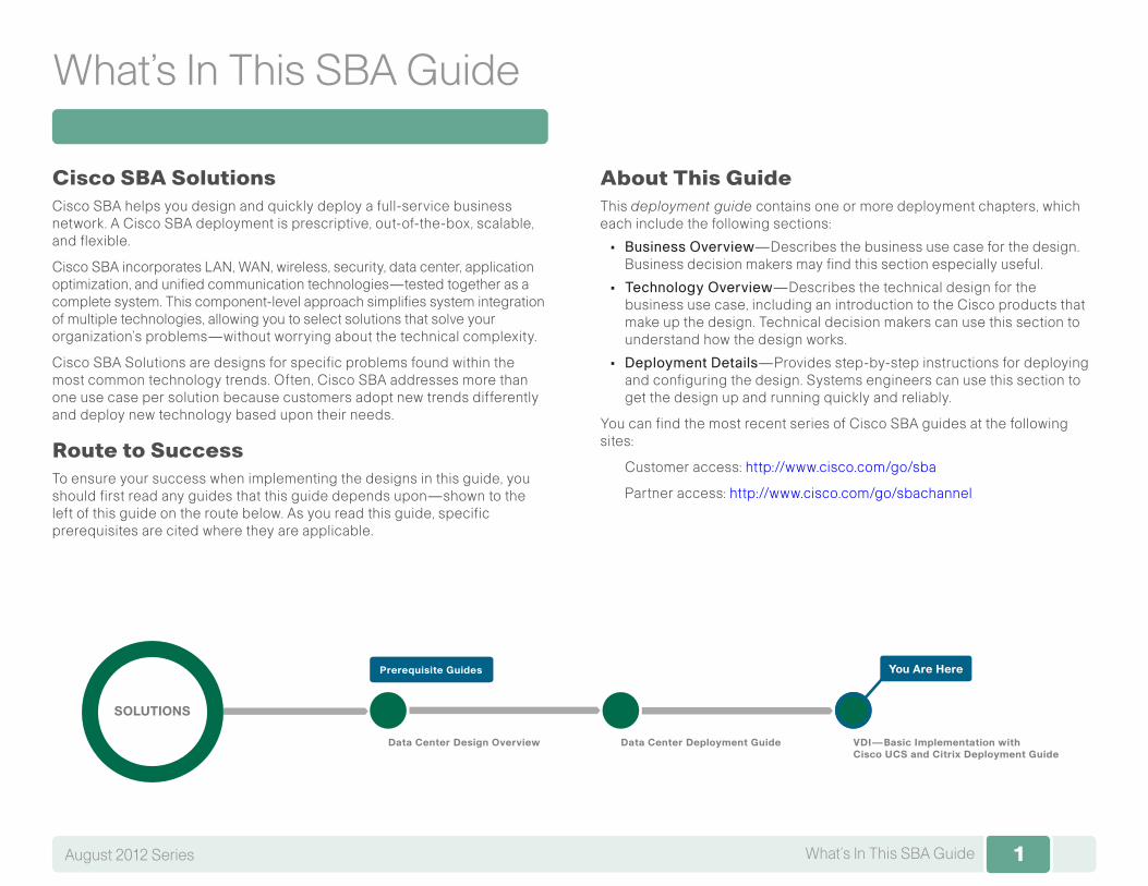
Route to SuccessTo ensure your success when implementing the designs in this guide, you should first read any guides that this guide depends upon—shown to the left of this guide on the route below. As you read this guide, specific prerequisites are cited where they are applicable.
1What’s In This SBA GuideAugust 2012 Series
Data Center Design Overview VDI—Basic Implementation with Cisco UCS and Citrix Deployment Guide
Data Center Deployment Guide
SOLUTIONS
You Are HerePrerequisite Guides
22IntroductionAugust 2012 Series
Introduction
Desktop virtualization separates a personal desktop environment, including operating system, desktop applications, and personal files and settings, from the physical device on which the desktop environment runs. In a virtual desktop infrastructure (VDI) deployment, the operating system runs in a virtual machine on a server hosted in a data center.
The VDI—Basic Implementation with Cisco UCS and Citrix Deployment Guide is designed to be a comprehensive guide for an organization’s initial needs for virtual desktops, deployed rapidly by using basic configuration options for VDI. With the end goal of rapid provisioning in mind, the basic setup uses a single Cisco Unified Computing System (UCS) C-Series server with integrated hard drives, teamed with Citrix virtualization components. It also uses the Citrix XenServer host hypervisor and the Citrix VDI-in-a-Box software appliance for desktop virtualization management.
Related ReadingEven though the VDI—Basic Implementation with Cisco UCS and Citrix Deployment Guide offers a comprehensive solution, other guides in the Cisco SBA August 2012 Series may be beneficial for organizations wishing to customize or scale their deployments by using additional servers or blade servers, UCS Manager, RAID storage, a different hypervisor, or networking components.
• The Cisco SBA—Data Center Unified Computing System Deployment Guide provides the processes and procedures necessary to deploy a Cisco Unified Computing System using both the Cisco B-Series Blade Server system and Cisco C-Series Rack-Mount Servers to a point where they are ready to deploy an operating system or hypervisor software.
• The Cisco SBA—Data Center Virtualization with Cisco UCS, Nexus 1000V, and VMware Deployment Guide describes how to deploy a VMware hypervisor on the Cisco Unified Computing System, including both the Cisco B-Series Blade Servers and Cisco C-Series Rack-Mount Servers. It also describes how to install and deploy Cisco Nexus 1000V Series Switches as a full-featured virtual switch for the VMware servers.
• The Cisco SBA—Data Center Design Overview provides an overview of the data center architecture. This guide discusses how the Cisco SBA data center architecture is built in layers—the foundation of Ethernet and storage networks and computing resources; the data center ser-vices of security, application resilience, and virtual switching; and the user services layer that contains applications and user services.
• The Cisco SBA—Data Center Deployment Guide focuses on the processes and procedures necessary to deploy your data center foundation Ethernet and storage transport. The data center foundation is designed to support the flexibility and scalability of the Cisco Unified Computing System and provides details for the integration of functional-ity between the server and the network for Cisco and non-Cisco serv-ers. The foundation design includes data center services like security with firewall and intrusion prevention, and application resiliency with advanced server load-balancing techniques. This guide also discusses the considerations and options for data center power and cooling. The supplemental Data Center Configuration Files Guide provides snap-shots of the actual platform configurations used in the design.
There are also a number of related Cisco SBA Bring Your Own Device (BYOD) guides, which are helpful for deploying the client connectivity to the network for VDI access. They include:
• Cisco SBA Solutions—BYOD—Virtual Desktop Access Deployment Guide
• Cisco SBA Solutions—BYOD—Advanced Guest Wireless Access Deployment Guide
• Cisco SBA Solutions—BYOD—Identification and Authentication Deployment Guide
• Cisco SBA Solutions—BYOD—Internal Corporate Access Deployment Guide
• Cisco SBA Solutions—BYOD—Remote Mobile Device Access Deployment Guide

3IntroductionAugust 2012 Series 3
Business OverviewSmaller organizations face many of the same IT challenges as larger organi-zations when trying to accommodate increasing demand for new IT capabili-ties and services. They often place even greater emphasis on cost savings and on protecting business-critical systems and data because they have smaller IT staffs and budgets, and they need to leverage IT assets to their fullest extent. Organizations require cost-effective solutions that can better leverage their existing server, storage, and network resources.
To improve availability and ensure business continuity, organizations need efficient ways to maintain production systems while minimizing downtime. Virtualization technology simplifies IT so that organizations can more effectively use their storage, network, and computing resources to control costs and respond faster. The virtual approach to IT management creates virtual services out of the physical IT infrastructure, enabling administrators to allocate these resources efficiently.
With virtualization, hardware management is completely separated from software management, and hardware equipment can be treated as a single pool of processing, storage, and networking resources to be reallocated as needed to various software applications. In a virtual infrastructure, users see resources as if they were dedicated to them—while administrators gain the ability to efficiently manage and optimize resources to serve the needs of the organization.
Technology Overview
Virtual Desktop Infrastructure
VDI delivers a desktop and workspace virtualization solution that can dramatically improve business operations and data security while increas-ing end-user productivity, mobility, and flexibility. The premise of VDI is to decouple the location of the execution of the application from where the client resides allowing new client compute paradigms. These tools to help enterprises rapidly respond to events such as mergers and acquisi-tions, open new branch offices, and maintain business continuity across workplace interruptions. By keeping the work data centrally located and not available on storage of devices such as laptops leaving the organization’s facilities, data is retained by the organization in the data center, where it can be protected.
Managing the virtual machines on the physical servers and the connected networks requires a design that integrates all of these systems so that they work together without creating an operational burden on the IT staff who must maintain them. Using proven and tested designs lowers the time needed to deploy these new solutions and reduces the time required to deploy new applications.
In a VDI deployment, a worker’s desktop operating system and applications run in a virtual machine on a server hosted in a data center or server room. A VDI client, which can be in the same building, the same network, or remotely accessing the network across the Internet, views and operates the worker’s desktop. The organization can deploy VDI client software on desktops, laptops, or deploy dedicated appliances. When organizations also permit a Bring Your Own Device (BYOD) environment, workers can use personal laptops, tablets, and even smartphones, for similar remote desktop access.
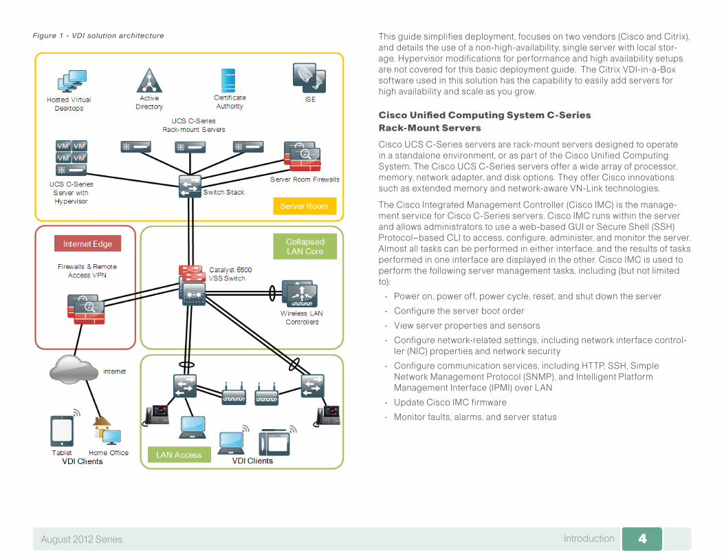
In the data center or server room, this deployment uses Cisco UCS serv-ers to host the virtual desktops and other data center services required to complete the solution, such as the Microsoft Active Directory servers, certifi-cate authorities, and the Cisco Identity Solution Engine (ISE). Deploying the initial VDI solution with a Cisco UCS C-Series rack-mount server ensures that as an organization grows, the deployment can grow using advantages of unified computing, while integrating into the tested Cisco SBA data center architecture.
Cisco ASA Firewalls are used in the server room to implement security policies between the virtual desktop VLANs and organizational or customer confidential information running on application servers in the server VLANs. A separate set of Cisco ASA Firewalls are used in the Internet edge to isolate and protect the organization from Internet originated attacks. The firewalls also provide the remote access VPN termination point, allowing users to access the solution from remote locations.
4IntroductionAugust 2012 Series 4
Figure 1 - VDI solution architecture This guide simplifies deployment, focuses on two vendors (Cisco and Citrix), and details the use of a non-high-availability, single server with local stor-age. Hypervisor modifications for performance and high availability setups are not covered for this basic deployment guide. The Citrix VDI-in-a-Box software used in this solution has the capability to easily add servers for high availability and scale as you grow.
Cisco Unified Computing System C-Series Rack-Mount Servers
Cisco UCS C-Series servers are rack-mount servers designed to operate in a standalone environment, or as part of the Cisco Unified Computing System. The Cisco UCS C-Series servers offer a wide array of processor, memory, network adapter, and disk options. They offer Cisco innovations such as extended memory and network-aware VN-Link technologies.
The Cisco Integrated Management Controller (Cisco IMC) is the manage-ment service for Cisco C-Series servers. Cisco IMC runs within the server and allows administrators to use a web-based GUI or Secure Shell (SSH) Protocol–based CLI to access, configure, administer, and monitor the server. Almost all tasks can be performed in either interface, and the results of tasks performed in one interface are displayed in the other. Cisco IMC is used to perform the following server management tasks, including (but not limited to):
• Power on, power off, power cycle, reset, and shut down the server
• Configure the server boot order
• View server properties and sensors
• Configure network-related settings, including network interface control-ler (NIC) properties and network security
• Configure communication services, including HTTP, SSH, Simple Network Management Protocol (SNMP), and Intelligent Platform Management Interface (IPMI) over LAN
• Update Cisco IMC firmware
• Monitor faults, alarms, and server status
5IntroductionAugust 2012 Series 5
You use the anticipated quantities and types of workloads to choose an appropriately sized server. A guide and calculator for server sizing with VDI-in-a-Box workloads can be consulted at the Citrix web site, here:
http://www.citrix.com/products/vdi-in-a-box/resources-and-support.html
Tech Tip
Citrix VDI-in-a-Box
Citrix is a computing virtualization provider, with technology solutions to equip organizations for optimizing the use of their existing IT assets and resources, as well as protecting the systems, data, and applications that run the business. As virtualization adoption increases, the benefits are making this compelling virtualization technology a mainstream mandate. Citrix XenServer technology allows virtual machines (VMs) to be easily created as needed, and migrated from one hardware platform to another.
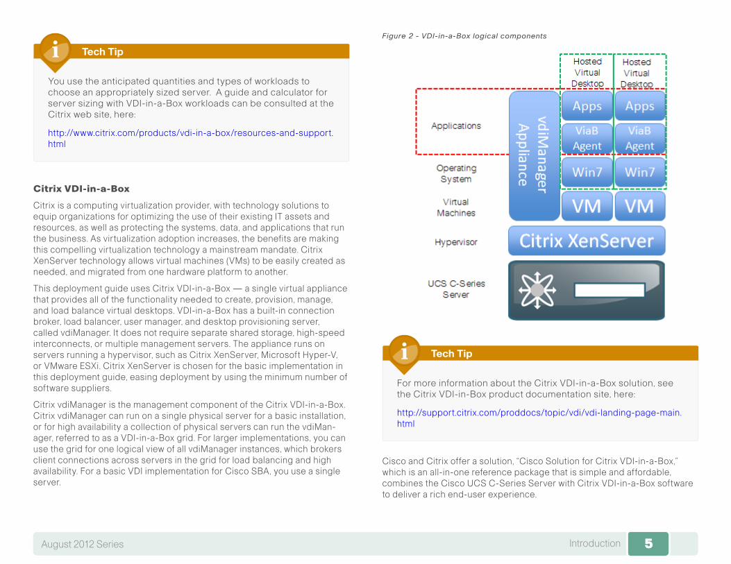
This deployment guide uses Citrix VDI-in-a-Box — a single virtual appliance that provides all of the functionality needed to create, provision, manage, and load balance virtual desktops. VDI-in-a-Box has a built-in connection broker, load balancer, user manager, and desktop provisioning server, called vdiManager. It does not require separate shared storage, high-speed interconnects, or multiple management servers. The appliance runs on servers running a hypervisor, such as Citrix XenServer, Microsoft Hyper-V, or VMware ESXi. Citrix XenServer is chosen for the basic implementation in this deployment guide, easing deployment by using the minimum number of software suppliers.
Citrix vdiManager is the management component of the Citrix VDI-in-a-Box. Citrix vdiManager can run on a single physical server for a basic installation, or for high availability a collection of physical servers can run the vdiMan-ager, referred to as a VDI-in-a-Box grid. For larger implementations, you can use the grid for one logical view of all vdiManager instances, which brokers client connections across servers in the grid for load balancing and high availability. For a basic VDI implementation for Cisco SBA, you use a single server.
Figure 2 - VDI-in-a-Box logical components
For more information about the Citrix VDI-in-a-Box solution, see the Citrix VDI-in-Box product documentation site, here:
http://support.citrix.com/proddocs/topic/vdi/vdi-landing-page-main.html
Tech Tip
Cisco and Citrix offer a solution, “Cisco Solution for Citrix VDI-in-a-Box,” which is an all-in-one reference package that is simple and affordable, combines the Cisco UCS C-Series Server with Citrix VDI-in-a-Box software to deliver a rich end-user experience.

6IntroductionAugust 2012 Series 6
For more information about Cisco solutions with Citrix, see the site here:
http://cisco.com/go/citrix
Tech Tip
Citrix Receiver
Citrix Receiver helps provide VDI-in-a-Box desktop users with secure con-nections to a high-definition user experience. Although the desktops run on remote servers, the user experience is equivalent to that of a local Windows desktop. From the user’s perspective, logging on to a virtual desktop is the same as logging on to a local desktop. The Citrix Receiver client runs on PCs, tablets, and smartphones. Microsoft Windows 7, Apple iOS, and Android Citrix Receiver access is tested in this guide to validate solution functionality.
7Deployment DetailsAugust 2012 Series 7
Deployment Details
Configuring Cisco UCS C-Series Server Hardware
1. Configure Cisco IMC management access
Process
You can use the Cisco Integrated Management Controller (Cisco IMC) to set up the Cisco UCS C-Series Rack-Mount Server and complete the basic configuration to prepare for Ethernet communications. Cisco IMC is the management service built into and running within the server. Cisco IMC allows you to use a web-based GUI or SSH-based CLI to access, configure, administer, and monitor the server. Almost all tasks can be performed in either interface, and the results of tasks performed in one interface are displayed in the other.
Cisco UCS C-Series Rack-Mount Servers are connected to available Ethernet interfaces in the Cisco SBA data center infrastructure. Dual 10-Gigabit Ethernet ports are used for virtual desktop communication. An additional 100-Mbps Ethernet connection is used for the integrated man-agement, and another Gigabit Ethernet connection is used for hypervisor management. Details for data center core port configurations are covered in the Cisco SBA—Data Center Deployment Guide.
Procedure 1 Configure Cisco IMC management access
Step 1: Connect a keyboard, video display, and mouse to the server for the initial setup, and then power up the server.
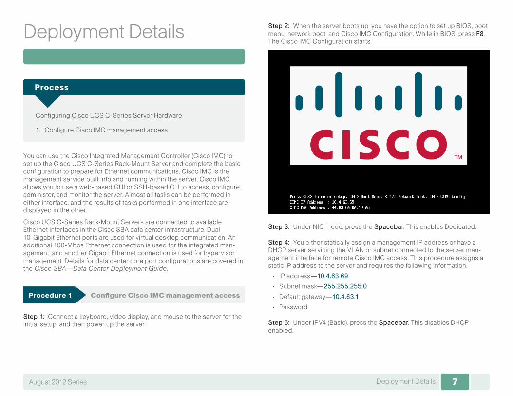
Step 2: When the server boots up, you have the option to set up BIOS, boot menu, network boot, and Cisco IMC Configuration. While in BIOS, press F8. The Cisco IMC Configuration starts.
Step 3: Under NIC mode, press theSpacebar. This enables Dedicated.
Step 4: You either statically assign a management IP address or have a DHCP server servicing the VLAN or subnet connected to the server man-agement interface for remote Cisco IMC access. This procedure assigns a static IP address to the server and requires the following information:
• IP address—10.4.63.69
• Subnet mask—255.255.255.0
• Default gateway—10.4.63.1
• Password
Step 5: Under IPV4 (Basic), press the Spacebar. This disables DHCP enabled.
8Deployment DetailsAugust 2012 Series 8
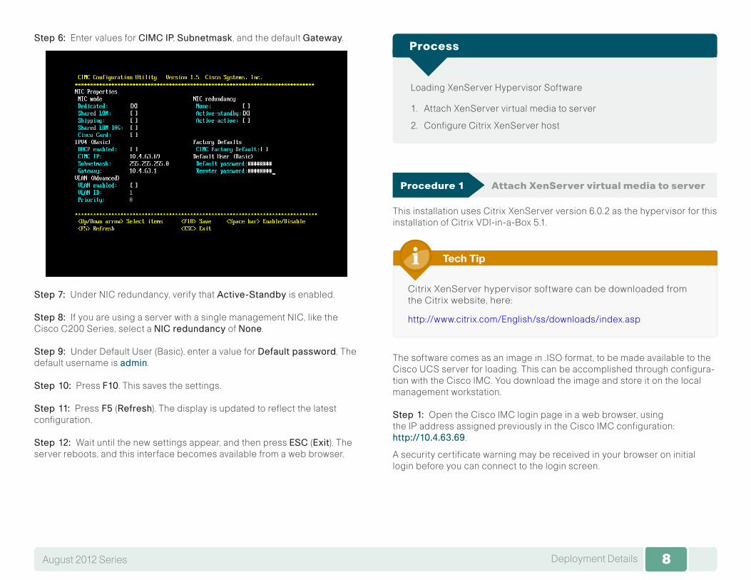
Step 6: Enter values for CIMCIP, Subnetmask , and the default Gateway.
Step 7: Under NIC redundancy, verify that Active-Standby is enabled.
Step 8: If you are using a server with a single management NIC, like the Cisco C200 Series, select a NICredundancy of None.
Step 9: Under Default User (Basic), enter a value for Defaultpassword. The default username is admin.
Step 10: Press F10. This saves the settings.
Step 11: PressF5 (Refresh). The display is updated to reflect the latest configuration.
Step 12: Wait until the new settings appear, and then press ESC (Exit). The server reboots, and this interface becomes available from a web browser.
Loading XenServer Hypervisor Software
1. Attach XenServer virtual media to server
2. Configure Citrix XenServer host
Process
Procedure 1 Attach XenServer virtual media to server
This installation uses Citrix XenServer version 6.0.2 as the hypervisor for this installation of Citrix VDI-in-a-Box 5.1.
Citrix XenServer hypervisor software can be downloaded from the Citrix website, here:
http://www.citrix.com/English/ss/downloads/index.asp
Tech Tip
The software comes as an image in .ISO format, to be made available to the Cisco UCS server for loading. This can be accomplished through configura-tion with the Cisco IMC. You download the image and store it on the local management workstation.
Step 1: Open the Cisco IMC login page in a web browser, using the IP address assigned previously in the Cisco IMC configuration: http://10.4.63.69.
A security certificate warning may be received in your browser on initial login before you can connect to the login screen.
9Deployment DetailsAugust 2012 Series 9
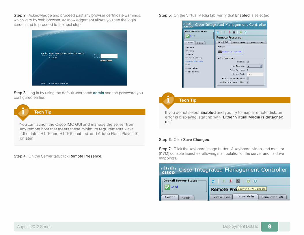
Step 2: Acknowledge and proceed past any browser certificate warnings, which vary by web browser. Acknowledgement allows you see the login screen and to proceed to the next step.
Step 3: Log in by using the default username admin and the password you configured earlier.
You can launch the Cisco IMC GUI and manage the server from any remote host that meets these minimum requirements: Java 1.6 or later, HTTP and HTTPS enabled, and Adobe Flash Player 10 or later.
Tech Tip
Step 4: On the Server tab, click RemotePresence.
Step 5: On the Virtual Media tab, verify that Enabled is selected.
If you do not selectEnabled and you try to map a remote disk, an error is displayed, starting with “EitherVirtualMediaisdetachedor...”
Tech Tip
Step 6: Click SaveChanges.
Step 7: Click the keyboard image button. A keyboard, video, and monitor (KVM) console launches, allowing manipulation of the server and its drive mappings.
10Deployment DetailsAugust 2012 Series 10
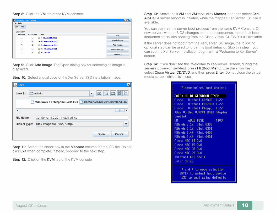
Step 8: Click the VM tab of the KVM console.
Step 9: Click AddImage. The Open dialog box for selecting an image is displayed.
Step 10: Select a local copy of the XenServer .ISO installation image.
Step 11: Select the check box in the Mapped column for the ISO file. Do not click Exit when complete. Instead, proceed to the next step.
Step 12: Click on the KVM tab of the KVM console.
Step 13: Above the KVM and VM tabs, click Macros, and then select Ctrl-Alt-Del. A server reboot is initiated, while the mapped XenServer .ISO file is available.
You can observe the server boot process from the same KVM Console. On new servers without BIOS changes to the boot sequence, the default boot sequence starts with booting from the Cisco Virtual CD/DVD, if it’s available.
If the server does not boot from the XenServer ISO image, the following optional step can be used to force this boot behavior. Skip this step if you can see the XenServer installation begin, with a “Welcome to XenServer” screen.
Step 14: If you don’t see the “Welcome to XenServer” screen, during the server’s power-on self-test, press F6 (BootMenu). Use the arrow key to select CiscoVirtualCD/DVD, and then press Enter. Do not close the virtual media screen while it is in use.
11Deployment DetailsAugust 2012 Series 11
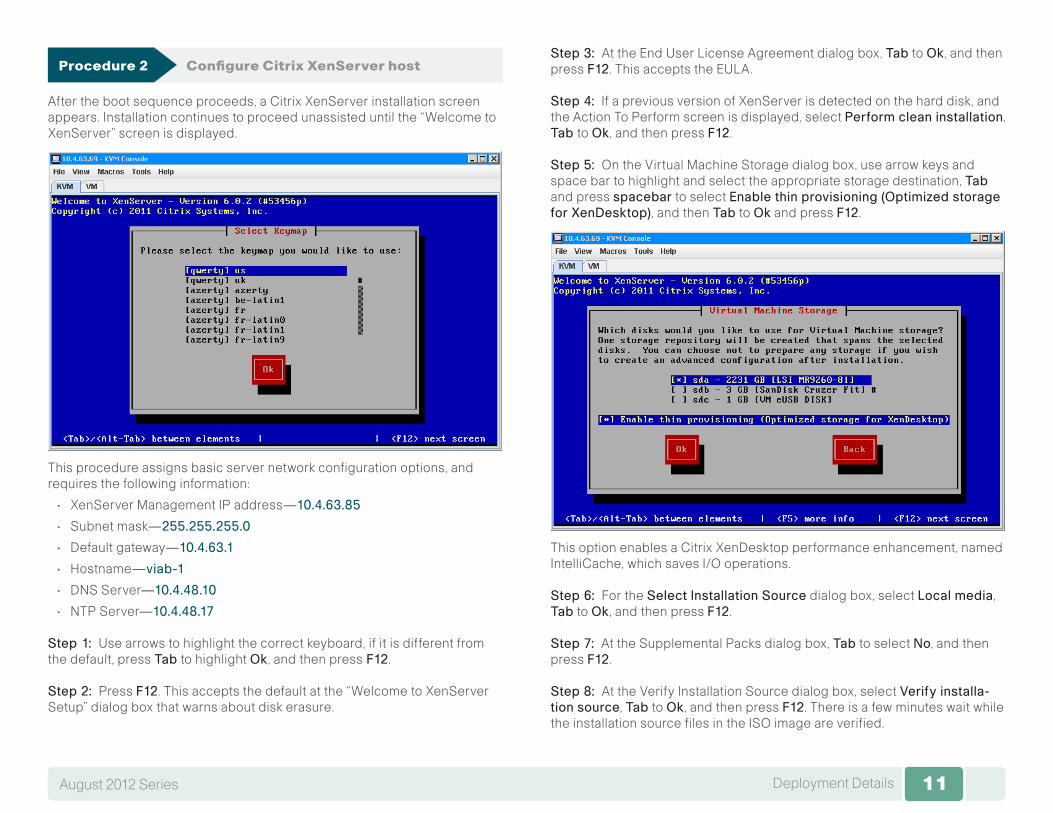
Procedure 2 Configure Citrix XenServer host
After the boot sequence proceeds, a Citrix XenServer installation screen appears. Installation continues to proceed unassisted until the “Welcome to XenServer” screen is displayed.
This procedure assigns basic server network configuration options, and requires the following information:
• XenServer Management IP address—10.4.63.85
• Subnet mask—255.255.255.0
• Default gateway—10.4.63.1
• Hostname—viab-1
• DNS Server—10.4.48.10
• NTP Server—10.4.48.17
Step 1: Use arrows to highlight the correct keyboard, if it is different from the default, press Tab to highlight Ok , and then pressF12.
Step 2: Press F12. This accepts the default at the “Welcome to XenServer Setup” dialog box that warns about disk erasure.
Step 3: At the End User License Agreement dialog box, Tab to Ok , and then press F12. This accepts the EULA.
Step 4: If a previous version of XenServer is detected on the hard disk, and the Action To Perform screen is displayed, select Performcleaninstallation, Tabto Ok , and then press F12.
Step 5: On the Virtual Machine Storage dialog box, use arrow keys and space bar to highlight and select the appropriate storage destination, Tab and press spacebar to select Enablethinprovisioning(OptimizedstorageforXenDesktop), and then Tab to Ok and press F12.
This option enables a Citrix XenDesktop performance enhancement, named IntelliCache, which saves I/O operations.
Step 6: For the SelectInstallationSource dialog box, select Localmedia, Tab to Ok , and then press F12.
Step 7: At the Supplemental Packs dialog box, Tab to select No, and then press F12.
Step 8: At the Verify Installation Source dialog box, select Verifyinstalla-tionsource, Tab to Ok , and then press F12. There is a few minutes wait while the installation source files in the ISO image are verified.
12Deployment DetailsAugust 2012 Series 12
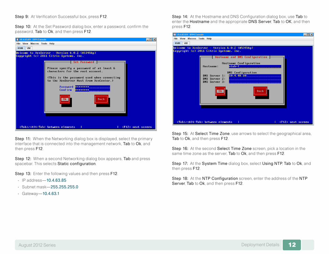
Step 9: At Verification Successful box, press F12.
Step 10: At theSet Password dialog box, enter a password, confirm the password, Tab toOk , and then press F12.
Step 11: When the Networking dialog box is displayed, select the primary interface that is connected into the management network, Tab to Ok , and then press F12.
Step 12: When a second Networking dialog box appears, Tab and press spacebar. This selects Staticconfiguration.
Step 13: Enter the following values and then press F12.
• IP address—10.4.63.85
• Subnet mask—255.255.255.0
• Gateway—10.4.63.1
Step 14: At theHostname and DNS Configuration dialog box, use Tab to enter the Hostname andthe appropriate DNSServer, Tab to OK , and then pressF12.
Step 15: At SelectTimeZone, use arrows to select the geographical area, Tab to Ok , and then press F12.
Step 16: At the second SelectTimeZone screen, pick a location in the same time zone as the server, Tab to Ok , and then press F12.
Step 17: At the SystemTime dialog box, select Using NTP, Tab to Ok , and then press F12.
Step 18: At the NTPConfiguration screen, enter the address of the NTPServer, Tab to Ok , and then press F12.
13Deployment DetailsAugust 2012 Series 13
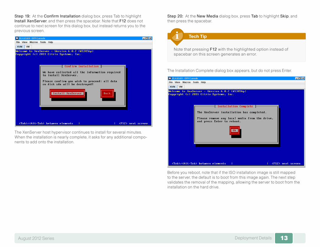
Step 19: At the ConfirmInstallation dialog box, press Tab to highlight InstallXenServer, and then press the spacebar. Note that F12 does not continue to next screen for this dialog box, but instead returns you to the previous screen.
The XenServer host hypervisor continues to install for several minutes. When the installation is nearly complete, it asks for any additional compo-nents to add onto the installation.
Step 20: At the NewMedia dialog box, press Tab to highlight Skip, and then press the spacebar.
Note that pressing F12 with the highlighted option instead of spacebar on this screen generates an error.
Tech Tip
The Installation Complete dialog box appears, but do not press Enter.
:Before you reboot, note that if the ISO installation image is still mapped to the server, the default is to boot from this image again. The next step validates the removal of the mapping, allowing the server to boot from the installation on the hard drive.

14Deployment DetailsAugust 2012 Series 14
Step 21: Click the VM tab in the KVM Console and verify that the XenServer ISO Image File does not have a check mark in the Mapped column.
Step 22: Click the KVM tab on the KVM Console. This returns you to the Installation Complete screen.
Step 23: Select OKby pressing Enter. The server reboots and loads from the new XenServer installation.
It takes several minutes to load the Linux OS with Citrix components after the reboot. Upon completion, a graphical XenServer screen with progress bar is displayed.
The graphical screen is replaced by a text progress screen, as the server continues to boot into the XenServer host environment. Once the XenServer host is running, the status displays on the configuration screen of the KVM console.

15Deployment DetailsAugust 2012 Series 15
Installing Citrix XenCenter
1. Install XenCenter management tool
2. Enable XenCenter to manage XenServer
3. Create XenServer network connections
Process
Procedure 1 Install XenCenter management tool
You use the Citrix XenCenter management tool to manage any virtual machines that will be generated and running on Citrix XenServer. Citrix XenCenter comes with Citrix XenServer, and the installation image can be obtained via web browser access to an automatically started web server, enabled as a result of the Citrix XenServer host installation.
Step 1: Open a web browser from the management workstation, and then connect to the IP address of the XenServer by typing the IP address, 10.4.63.85, as the browser URL destination.
The browser now displays the following:
Citrix Systems, Inc. XenServer 6.0.2, with hyperlinks to:
XenCenter CD image and XenCenter installer.
Step 2: Click XenCenterinstaller. The link to the XenCenter.msi file opens.
Step 3: Click SaveFile. This saves the XenCenter.msi file to the manage-ment workstation.
Step 4: Double-click the XenCenter icon for the downloaded file to launch the installation, and accept any security warning that may be displayed as part of the installation.
Step 5: On the CitrixXenCenterSetup dialog box, Click Next.
Step 6: Accept the default destination folder and installation user by click-ing Next.
Step 7: On the ReadytoinstallCitrixXenCenter dialog box, click Install.
Step 8: Accept any security warnings as the Setup Wizard begins the installation.
Step 9: On the CompletedtheCitrixXenCenterSetupWizard dialog box, click Finish.
Step 10: Citrix XenCenter is now installed on the management workstation.
Procedure 2 Enable XenCenter to manage XenServer
Step 1: From the Windows Start menu on the management station, launch Citrix XenCenter. The main XenCenter window appears.
Step 2: Click AddNewServer.

16Deployment DetailsAugust 2012 Series 16
Step 3: In the Add New Server dialog box, enter the Citrix XenServer name and the root password configured during the XenServer installation.
Citrix XenCenter connects and synchronizes with the XenServer installation, and displays information for the server.
Procedure 3 Create XenServer network connections
The Cisco UCS C-Series server includes multiple Ethernet NIC connections. Two are associated for use together as dual active connections to the Cisco SBA data center, allowing resiliency and load sharing of desktops between links. Because the server is hosting client virtual desktop machines, its behavior can be characterized as being similar to the activity of many clients, and thus it is placed in the client VLAN in the data center. Traffic to and from the server network interfaces is tagged with the client data center VLAN 157.
Use Citrix XenCenter to configure the network, creating desktop VMs in later steps. To manage the server hardware and hypervisor, use NIC 0 and NIC 1 network interfaces. For traffic to the Citrix XenServer VMs, use 10Gbps NIC 4 and NIC 5 network interfaces.
Table 1 - Cisco UCS Server network interface assignments
Cisco UCS interface Type Use VLAN
NIC 0 100 Mbps Ethernet CIMC 163 - Management
NIC 1 Gigabit Ethernet Hypervisor 163 - Management
NIC 4 10-Gigabit Ethernet VDI communication 157 - DC user
NIC 5 10-Gigabit Ethernet VDI communication 157 - DC user
Step 1: In the XenCenter management console, highlight the installed XenServer instance, and then click the NICs tab. When the NICs are con-nected to data center switch ports that are enabled, the active network interfaces, NIC 4 and NIC 5, appear with a Link Status of connected.
Step 2: Click the Networking tab, and then click AddNetwork . A New Network dialog box appears.
Step 3: Select BondedNetwork , and then click Next.

17Deployment DetailsAugust 2012 Series 17
Step 4: Select NIC4 and NIC5, the two available Connected NICs, to bond. Leave Bond mode as Active-active, keep the default MTU, and enable Automaticallyaddthisnetworktonewvirtualmachines by selecting the box next to the option.
Step 5: Click Finish. The new bonded network is displayed.
Step 6: On the Networking tab, click AddNetworkagain. This time, select ExternalNetwork , and then click the Next.
Step 7: Click Details, in the Namebox , enter VDI-Client, in the Descriptionbox, enter NetworkforVDIclienttraffic, and then click Next.
Step 8: Click Interface.
18Deployment DetailsAugust 2012 Series 18
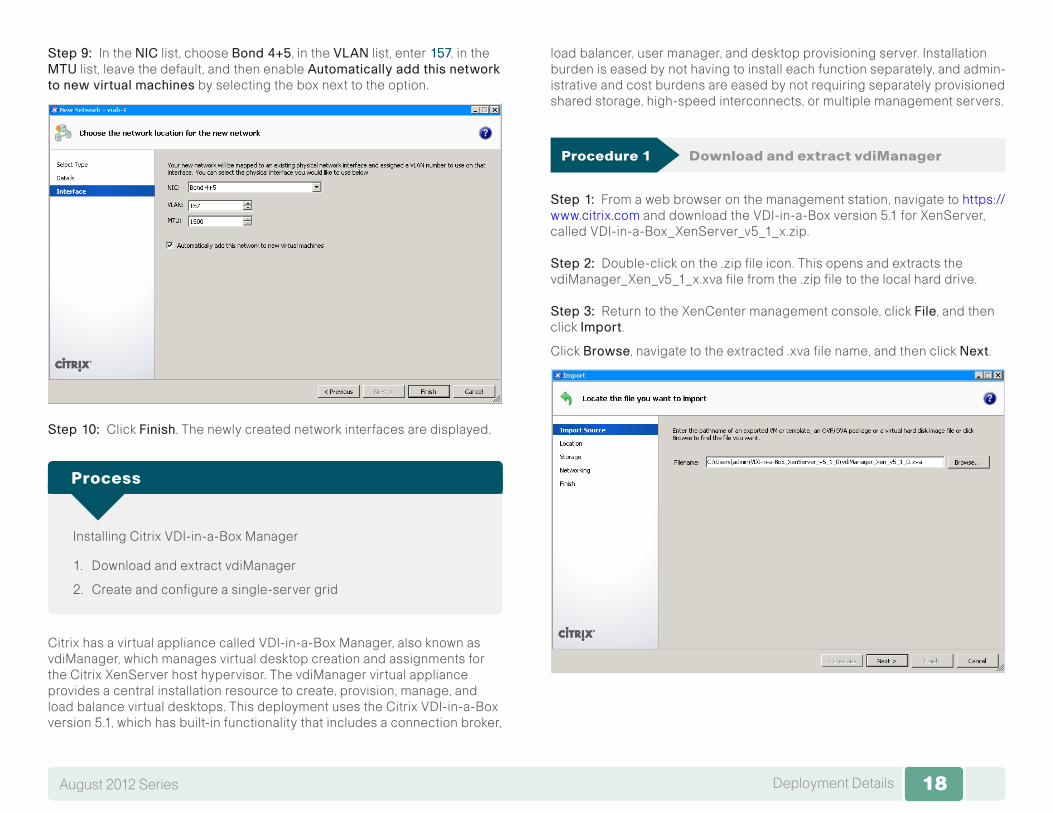
Step 9: In the NIC list, choose Bond4+5, in the VLAN list, enter 157, in the MTU list, leave the default, and then enable Automaticallyaddthisnetworktonewvirtualmachines by selecting the box next to the option.
Step 10: Click Finish. The newly created network interfaces are displayed.
Installing Citrix VDI-in-a-Box Manager
1. Download and extract vdiManager
2. Create and configure a single-server grid
Process
Citrix has a virtual appliance called VDI-in-a-Box Manager, also known as vdiManager, which manages virtual desktop creation and assignments for the Citrix XenServer host hypervisor. The vdiManager virtual appliance provides a central installation resource to create, provision, manage, and load balance virtual desktops. This deployment uses the Citrix VDI-in-a-Box version 5.1, which has built-in functionality that includes a connection broker,
load balancer, user manager, and desktop provisioning server. Installation burden is eased by not having to install each function separately, and admin-istrative and cost burdens are eased by not requiring separately provisioned shared storage, high-speed interconnects, or multiple management servers.
Procedure 1 Download and extract vdiManager
Step 1: From a web browser on the management station, navigate to https://www.citrix.com and download the VDI-in-a-Box version 5.1 for XenServer, called VDI-in-a-Box_XenServer_v5_1_x.zip.
Step 2: Double-click on the .zip file icon. This opens and extracts the vdiManager_Xen_v5_1_x.xva file from the .zip file to the local hard drive.
Step 3: Return to the XenCenter management console, click File, and then click Import.
Click Browse, navigate to the extracted .xva file name, and then click Next.
19Deployment DetailsAugust 2012 Series 19
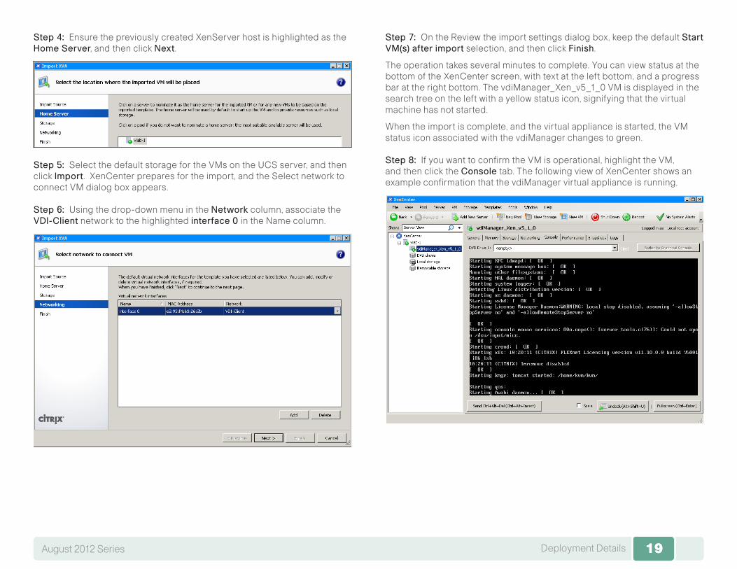
Step 4: Ensure the previously created XenServer host is highlighted as the HomeServer, and then click Next.
Step 5: Select the default storage for the VMs on the UCS server, and then click Import. XenCenter prepares for the import, and the Select network to connect VM dialog box appears.
Step 6: Using the drop-down menu in the Network column, associate the VDI-Client network to the highlighted interface0in the Name column.
Step 7: On the Review the import settings dialog box, keep the default StartVM(s)afterimport selection, and then click Finish.
The operation takes several minutes to complete. You can view status at the bottom of the XenCenter screen, with text at the left bottom, and a progress bar at the right bottom. The vdiManager_Xen_v5_1_0 VM is displayed in the search tree on the left with a yellow status icon, signifying that the virtual machine has not started.
When the import is complete, and the virtual appliance is started, the VM status icon associated with the vdiManager changes to green.
Step 8: If you want to confirm the VM is operational, highlight the VM, and then click the Console tab. The following view of XenCenter shows an example confirmation that the vdiManager virtual appliance is running.
20Deployment DetailsAugust 2012 Series 20
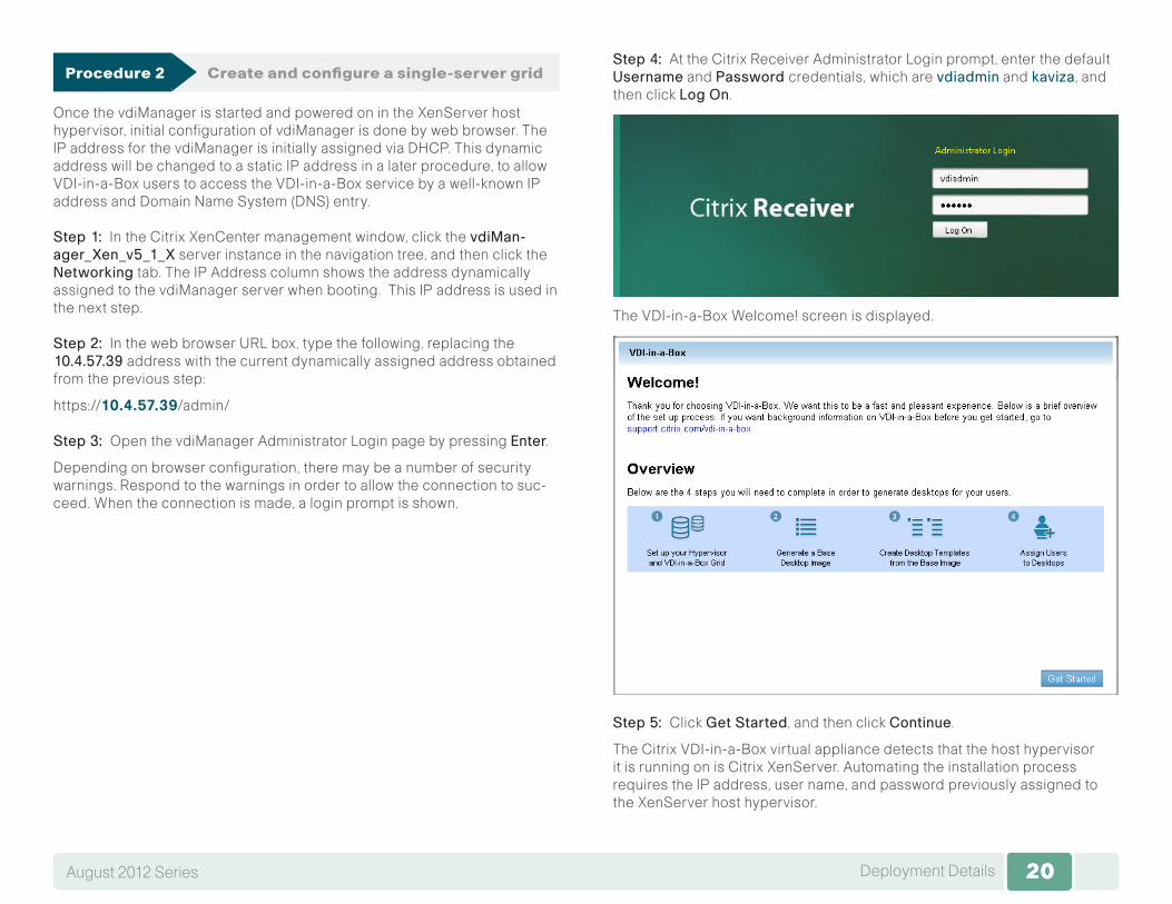
Procedure 2 Create and configure a single-server grid
Once the vdiManager is started and powered on in the XenServer host hypervisor, initial configuration of vdiManager is done by web browser. The IP address for the vdiManager is initially assigned via DHCP. This dynamic address will be changed to a static IP address in a later procedure, to allow VDI-in-a-Box users to access the VDI-in-a-Box service by a well-known IP address and Domain Name System (DNS) entry.
Step 1: In the Citrix XenCenter management window, click the vdiMan-ager_Xen_v5_1_X server instance in the navigation tree, and then click the Networking tab. The IP Address column shows the address dynamically assigned to the vdiManager server when booting. This IP address is used in the next step.
Step 2: In the web browser URL box, type the following, replacing the 10.4.57.39 address with the current dynamically assigned address obtained from the previous step:
https://10.4.57.39/admin/
Step 3: Open the vdiManager Administrator Login page by pressing Enter.
Depending on browser configuration, there may be a number of security warnings. Respond to the warnings in order to allow the connection to suc-ceed. When the connection is made, a login prompt is shown.
Step 4: At the Citrix Receiver Administrator Login prompt, enter the default Username and Passwordcredentials, which are vdiadmin and kaviza, and then click LogOn.
The VDI-in-a-Box Welcome! screen is displayed.
Step 5: Click GetStarted, and then click Continue.
The Citrix VDI-in-a-Box virtual appliance detects that the host hypervisor it is running on is Citrix XenServer. Automating the installation process requires the IP address, user name, and password previously assigned to the XenServer host hypervisor.

21Deployment DetailsAugust 2012 Series 21
Step 6: In the IP Address box, enter10.4.63.85, in the User Name box, enter root, in the Password box, enter the previously assigned password, and then click Next.
Step 7: In the Datastore list, choose the Cisco UCS local storage, in the NetworkLabel list, choose VDI-Client, and then click Next.
Step 8: For the Grid option on the displayed window, select CreateanewVDI-in-a-Boxgrid, and then click Next.
Step 9: This vdiManager becomes the only member of the single-server grid, and the next screen is displayed.
Step 10: For User Database, select MicrosoftActiveDirectory. More fields become available to fill out.
Step 11: In the IP Address box, enter 10.4.48.10, in the Domain box, entercisco.local, in the User Name box, enter Administrator, in the Password box, enter the password, and then click Next.
Step 12: Click Yes, which acknowledges that a reserved IP address is used, and then click Done.
The Generate a Base Desktop Image screen is displayed.
22Deployment DetailsAugust 2012 Series 22
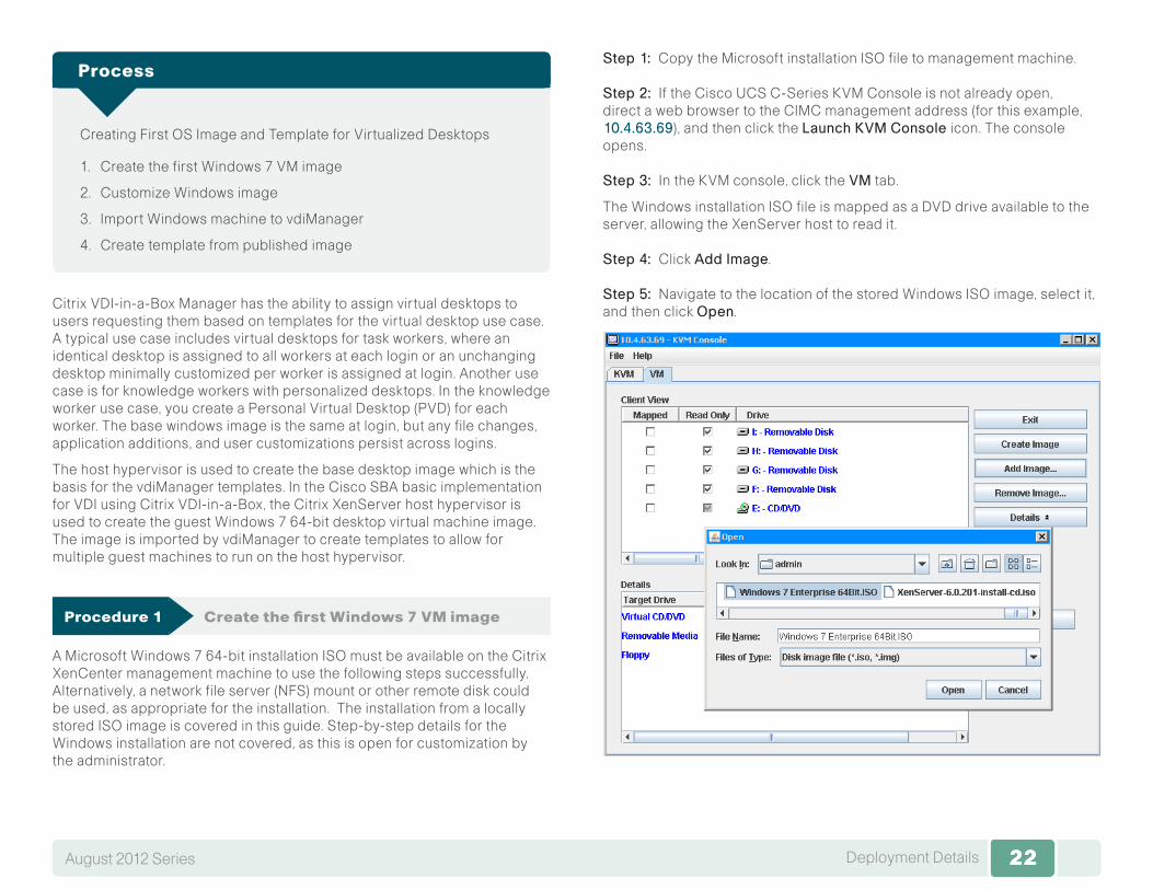
Creating First OS Image and Template for Virtualized Desktops
1. Create the first Windows 7 VM image
2. Customize Windows image
3. Import Windows machine to vdiManager
4. Create template from published image
Process
Citrix VDI-in-a-Box Manager has the ability to assign virtual desktops to users requesting them based on templates for the virtual desktop use case. A typical use case includes virtual desktops for task workers, where an identical desktop is assigned to all workers at each login or an unchanging desktop minimally customized per worker is assigned at login. Another use case is for knowledge workers with personalized desktops. In the knowledge worker use case, you create a Personal Virtual Desktop (PVD) for each worker. The base windows image is the same at login, but any file changes, application additions, and user customizations persist across logins.
The host hypervisor is used to create the base desktop image which is the basis for the vdiManager templates. In the Cisco SBA basic implementation for VDI using Citrix VDI-in-a-Box, the Citrix XenServer host hypervisor is used to create the guest Windows 7 64-bit desktop virtual machine image. The image is imported by vdiManager to create templates to allow for multiple guest machines to run on the host hypervisor.
Procedure 1 Create the first Windows 7 VM image
A Microsoft Windows 7 64-bit installation ISO must be available on the Citrix XenCenter management machine to use the following steps successfully. Alternatively, a network file server (NFS) mount or other remote disk could be used, as appropriate for the installation. The installation from a locally stored ISO image is covered in this guide. Step-by-step details for the Windows installation are not covered, as this is open for customization by the administrator.
Step 1: Copy the Microsoft installation ISO file to management machine.
Step 2: If the Cisco UCS C-Series KVM Console is not already open, direct a web browser to the CIMC management address (for this example, 10.4.63.69), and then click the LaunchKVMConsole icon. The console opens.
Step 3: In the KVM console, click the VM tab.
The Windows installation ISO file is mapped as a DVD drive available to the server, allowing the XenServer host to read it.
Step 4: Click AddImage.
Step 5: Navigate to the location of the stored Windows ISO image, select it, and then click Open.

23Deployment DetailsAugust 2012 Series 23
Step 6: Under Mapped, select the check box for the ISO image.
After using this mapping, you will remove the mapping for the ISO at the end of the procedure to avoid the ISO being used as a boot device in case the Cisco UCS server is reset.
Step 7: Open the Citrix XenCenter management application, and then click NewVM. The New VM wizard opens.
Step 8: Select the Windows7(64-bit) provisioning template, and then click Next.
Step 9: For the virtual machine image, enter values for Name and Description. Cisco SBA uses Win7-64bit-VM and Windows764-bitbaseVMimage. Click Next.
Step 10: Select InstallfromISOlibraryorDVDdrive, from the drop-down menu, choose DVDdrive1onviab-1, and then click Next.
Using the DVD drive allows booting from the Cisco UCS attached media, which you previously configured.
Step 11: Verify the default action is to PlacetheVMonthisserver with the default Citrix XenServer host instance highlighted, and then click Next.
Step 12: In vCPUs, enter1, inMemory,enter 2048 MB (these are the minimum values), and then click Next.
Step 13: Select the default Usethesevirtualdisks, select the default highlighted local storage, and then click Next.
Step 14: Highlight all network interfaces, and then click Delete.
24Deployment DetailsAugust 2012 Series 24
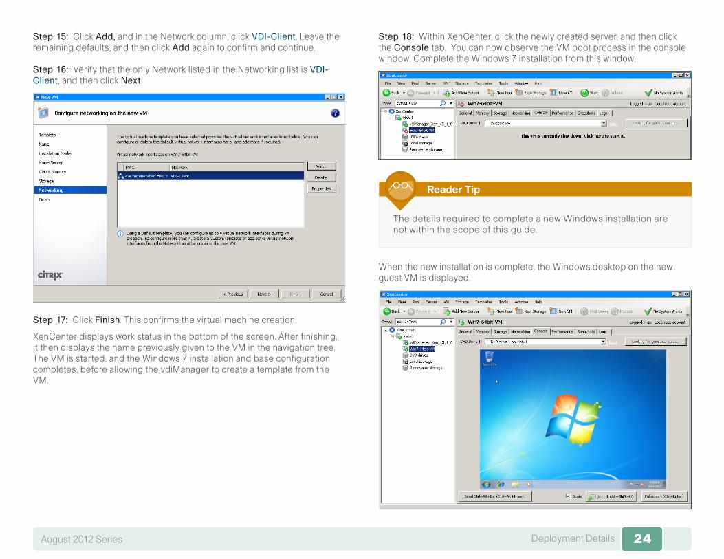
Step 15: Click Add,and in the Network column, click VDI-Client. Leave the remaining defaults, and then click Add again to confirm and continue.
Step 16: Verify that the only Network listed in the Networking list is VDI-Client, and then click Next.
Step 17: Click Finish. This confirms the virtual machine creation.
XenCenter displays work status in the bottom of the screen. After finishing, it then displays the name previously given to the VM in the navigation tree. The VM is started, and the Windows 7 installation and base configuration completes, before allowing the vdiManager to create a template from the VM.
Step 18: Within XenCenter, click the newly created server, and then click the Console tab. You can now observe the VM boot process in the console window. Complete the Windows 7 installation from this window.
The details required to complete a new Windows installation are not within the scope of this guide.
Reader Tip
When the new installation is complete, the Windows desktop on the new guest VM is displayed.

25Deployment DetailsAugust 2012 Series 25
Step 19: After the new Windows installation is complete, next to the DVDDrive1 menu, click the underlined Eject text.
Step 20: Return to the KVM tab of the VM Console window, and then clear the Mapped check box next to the Windows ISO image.
Step 21: When the Unmap Drive Requested warning message appears, click Yes.
Undesired behavior results if the ISO image is not unmapped from the server and the server reboots. In those circumstances, the server boots from the mapped ISO image, and attempts to install Windows on the Cisco UCS hardware to replace the Citrix XenServer installation.
Step 22: For the highlighted Windows ISO file, click RemoveImage. The ISO image, which is no longer needed, is disassociated from the Cisco UCS server.
Procedure 2 Customize Windows image
Once the Windows VM is running, there are some required customizations to be completed. XenServer Tools must be installed on each VM to have a fully supported configuration with enhanced disk and network performance.
A valid Administrator account with password is required for later steps in this procedure.
Step 1: Return to the Citrix XenCenter Window, in the navigation pane, select the XenServer host, and then click the Search tab. Observe that the “XenServer Tools not installed” blue status text appears next to the new Windows guest VM.
Step 2: Click the XenServerToolsnotinstalled link. The Install XenServer Tools setup wizard on the VM console opens.
26Deployment DetailsAugust 2012 Series 26
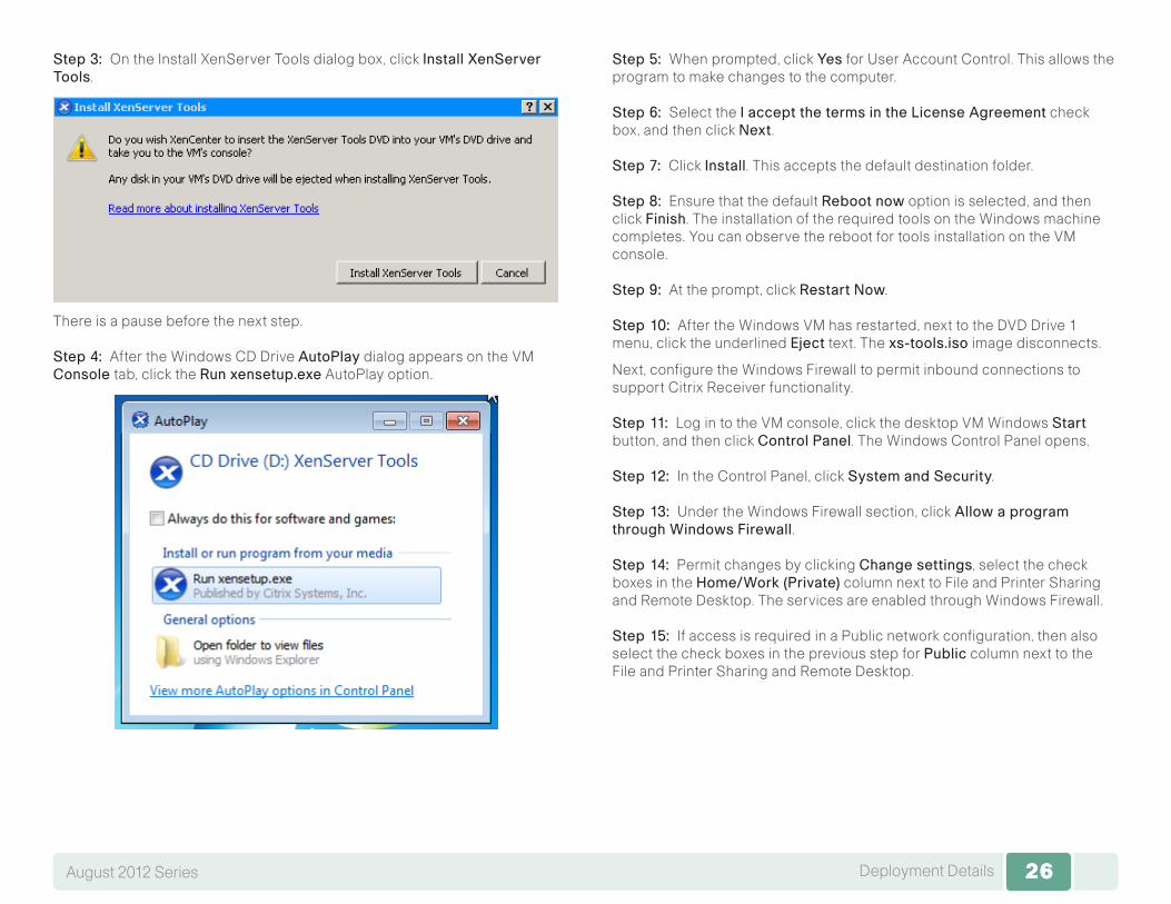
Step 3: On the Install XenServer Tools dialog box, click InstallXenServerTools.
There is a pause before the next step.
Step 4: After the Windows CD Drive AutoPlay dialog appears on the VM Console tab, click the Runxensetup.exe AutoPlay option.
Step 5: When prompted, click Yes for User Account Control. This allows the program to make changes to the computer.
Step 6: Select the IacceptthetermsintheLicenseAgreement check box, and then click Next.
Step 7: Click Install. This accepts the default destination folder.
Step 8: Ensure that the default Rebootnow option is selected, and then click Finish. The installation of the required tools on the Windows machine completes. You can observe the reboot for tools installation on the VM console.
Step 9: At the prompt, click RestartNow.
Step 10: After the Windows VM has restarted, next to the DVD Drive 1 menu, click the underlined Eject text. The xs-tools.iso image disconnects.
Next, configure the Windows Firewall to permit inbound connections to support Citrix Receiver functionality.
Step 11: Log in to the VM console, click the desktop VM Windows Start button, and then click ControlPanel. The Windows Control Panel opens.
Step 12: In the Control Panel, click SystemandSecurity.
Step 13: Under the Windows Firewall section, click AllowaprogramthroughWindowsFirewall.
Step 14: Permit changes by clicking Changesettings, select the check boxes in the Home/Work(Private) column next to File and Printer Sharing and Remote Desktop. The services are enabled through Windows Firewall.
Step 15: If access is required in a Public network configuration, then also select the check boxes in the previous step for Public column next to the File and Printer Sharing and Remote Desktop.

27Deployment DetailsAugust 2012 Series 27
Step 16: Click OK .
The services are enabled through Windows Firewall.
Step 17: Under the System section of the Control Panel, click AllowRemoteAccess.
Step 18: In System Properties, click the Remote tab, and then, under Remote Desktop, select AllowconnectionsfromcomputersrunninganyversionofRemoteDesktop(lesssecure).
Step 19: Click OK .
28Deployment DetailsAugust 2012 Series 28
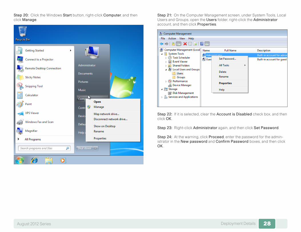
Step 20: Click the Windows Start button, right-click Computer, and then click Manage.
Step 21: On the Computer Management screen, under System Tools, Local Users and Groups, open the Users folder, right-click the Administrator account, and then click Properties.
Step 22: If it is selected, clear theAccountisDisabled check box, and then click OK .
Step 23: Right-click Administrator again, and then click SetPassword.
Step 24: At the warning, click Proceed, enter the password for the admin-istrator in the Newpassword and ConfirmPasswordboxes, and then click OK .

29Deployment DetailsAugust 2012 Series 29
Step 25: At the acknowledgement, click OK , and then close the Computer Management window. Initiate a Windows update , and apply any available Windows patches.
Not applying the latest Windows patches may keep the VM from fully booting, and may not allow required agent software to install.
Caution
After Windows updates are completed, the next step is to disable Automatic updates started by the Windows Update service, so that the Citrix VDI-in-a-Box installation can run to completion. Click the Windows Start button, in the search box, type automaticup, and then click Turnautomaticupdatingonoroff. The Change settings Control Panel opens.
Step 26: Under Important updates, choose Nevercheckforupdates(notrecommended) from the drop-down menu, and then select OK .
At this time, complete any additional customizations that you want to be replicated by all virtual desktops. Notably, a Windows machine needs to have a Microsoft Volume Activation key, since duplicate keys exist on all replicated virtual machines. All machines should be joined to a domain, and the domain configuration should be completed before proceeding.

30Deployment DetailsAugust 2012 Series 30
Procedure 3 Import Windows machine to vdiManager
Step 1: Return to the web browser window showing the Citrix VDI-in-a-Box first setup procedure, click Continue, and then, in the new window, click RefreshView.
Step 2: If the following dialog box is displayed after clicking RefreshView, click the VM to get hints as to what still needs to be configured before the VM can be imported.
Step 3: On the new window, clickRefreshView, and then select the Windows VM just created and configured, named Win7-64bit-VM in this example.
31Deployment DetailsAugust 2012 Series 31
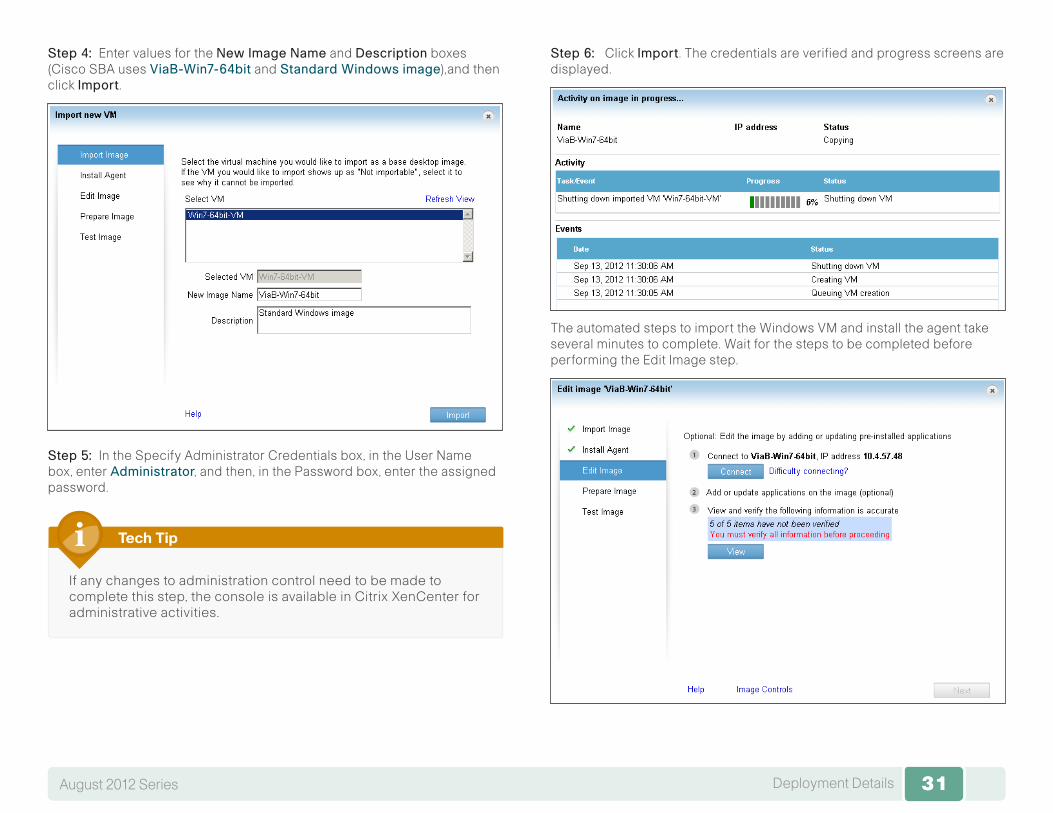
Step 4: Enter values for the NewImageName and Description boxes (Cisco SBA uses ViaB-Win7-64bit and StandardWindowsimage),and then click Import.
Step 5: In the Specify Administrator Credentials box, in the User Namebox, enter Administrator, and then, in the Password box, enter the assigned password.
If any changes to administration control need to be made to complete this step, the console is available in Citrix XenCenter for administrative activities.
Tech Tip
Step 6: Click Import. The credentials are verified and progress screens are displayed.
The automated steps to import the Windows VM and install the agent take several minutes to complete. Wait for the steps to be completed before performing the Edit Image step.
32Deployment DetailsAugust 2012 Series 32
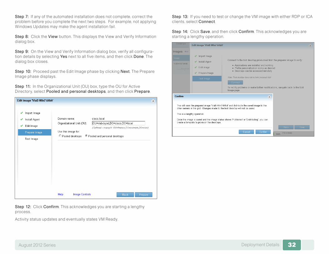
Step 7: If any of the automated installation does not complete, correct the problem before you complete the next two steps. For example, not applying Windows Updates may make the agent installation fail.
Step 8: Click the View button. This displays the View and Verify Information dialog box.
Step 9: On the View and Verify Information dialog box, verify all configura-tion details by selecting Yes next to all five items, and then click Done. The dialog box closes.
Step 10: Proceed past the Edit Image phase by clicking Next. The Prepare Image phase displays.
Step 11: In the Organizational Unit (OU) box, type the OU for Active Directory, select Pooledandpersonaldesktops, and then click Prepare.
Step 12: Click Confirm. This acknowledges you are starting a lengthy process.
Activity status updates and eventually states VM Ready.
Step 13: If you need to test or change the VM image with either RDP or ICA clients, select Connect.
Step 14: Click Save, and then click Confirm. This acknowledges you are starting a lengthy operation.
33Deployment DetailsAugust 2012 Series 33
Procedure 4 Create template from published image
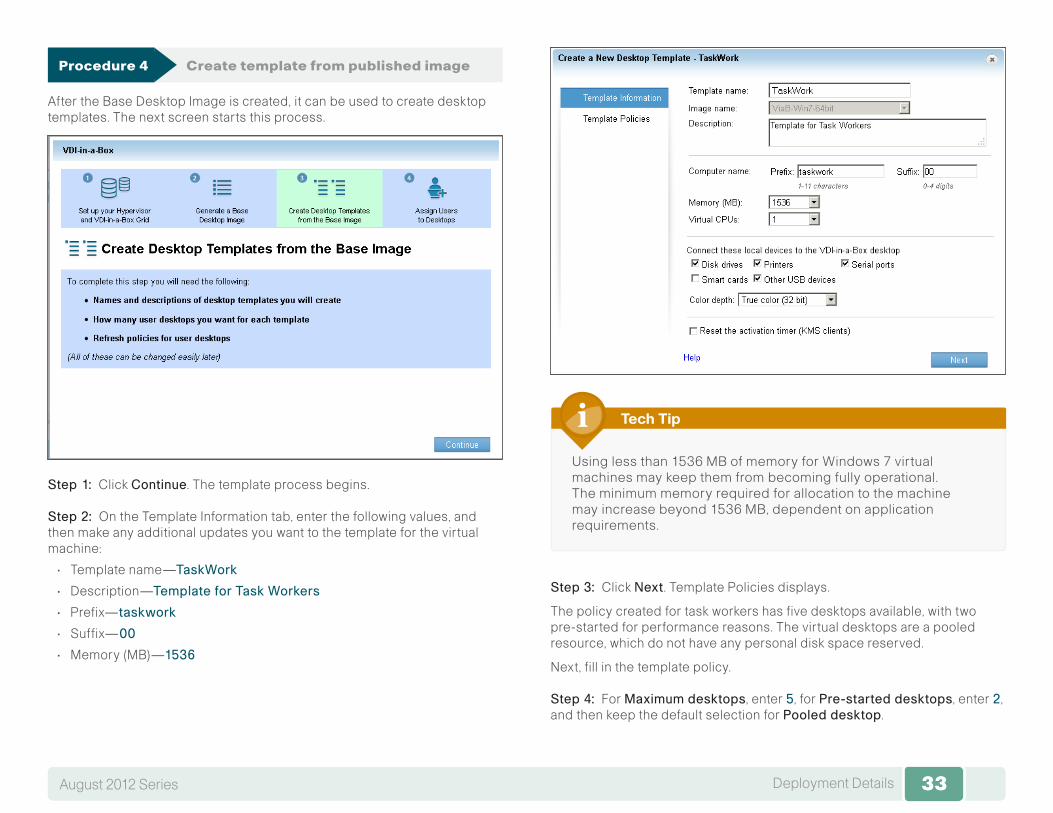
After the Base Desktop Image is created, it can be used to create desktop templates. The next screen starts this process.
Step 1: Click Continue. The template process begins.
Step 2: On the Template Information tab, enter the following values, and then make any additional updates you want to the template for the virtual machine:
• Template name—TaskWork
• Description—TemplateforTaskWorkers
• Prefix—taskwork
• Suffix—00
• Memory (MB)—1536
Using less than 1536 MB of memory for Windows 7 virtual machines may keep them from becoming fully operational. The minimum memory required for allocation to the machine may increase beyond 1536 MB, dependent on application requirements.
Tech Tip
Step 3: Click Next. Template Policies displays.
The policy created for task workers has five desktops available, with two pre-started for performance reasons. The virtual desktops are a pooled resource, which do not have any personal disk space reserved.
Next, fill in the template policy.
Step 4: For Maximumdesktops, enter 5, for Pre-starteddesktops, enter 2, and then keep the default selection for Pooleddesktop.
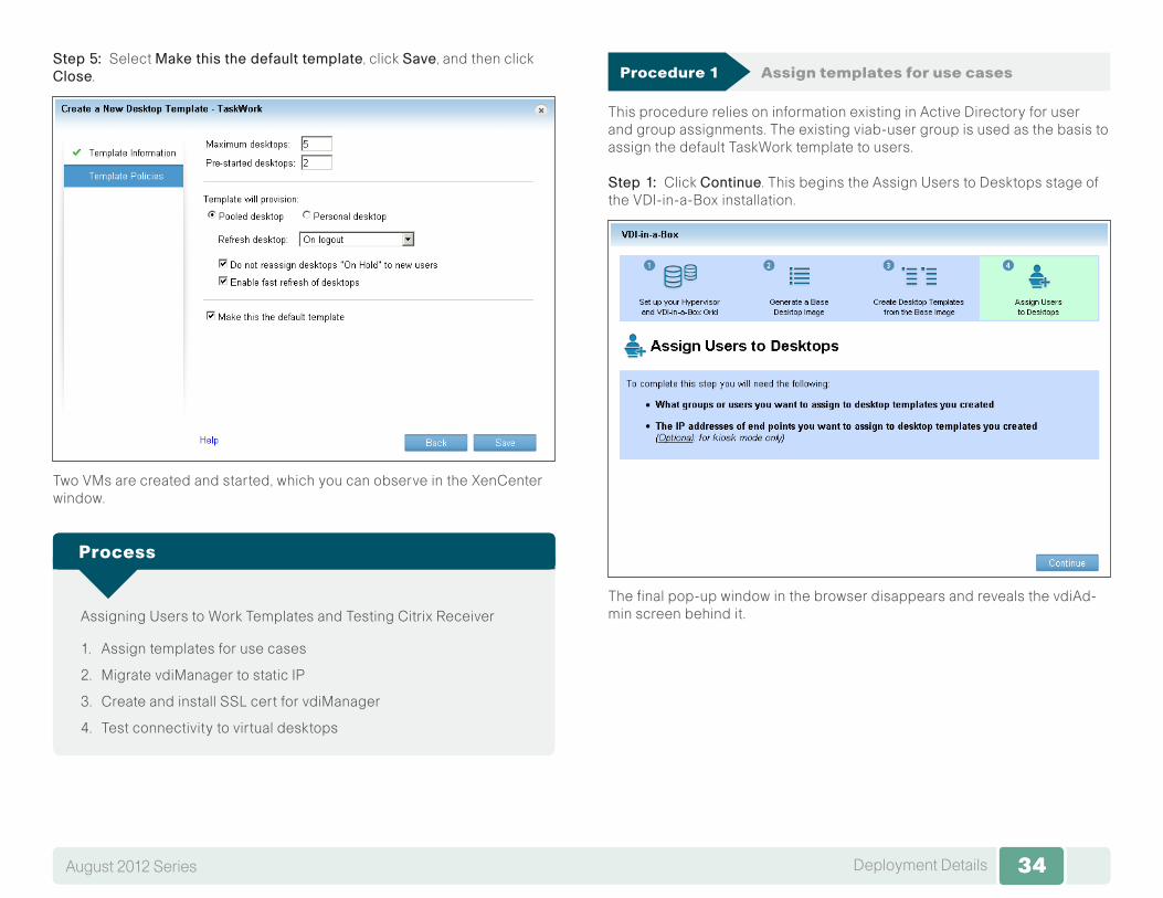
34Deployment DetailsAugust 2012 Series 34
Step 5: Select Makethisthedefaulttemplate, click Save, and then click Close.
Two VMs are created and started, which you can observe in the XenCenter window.
Assigning Users to Work Templates and Testing Citrix Receiver
1. Assign templates for use cases
2. Migrate vdiManager to static IP
3. Create and install SSL cert for vdiManager
4. Test connectivity to virtual desktops
Process
Procedure 1 Assign templates for use cases
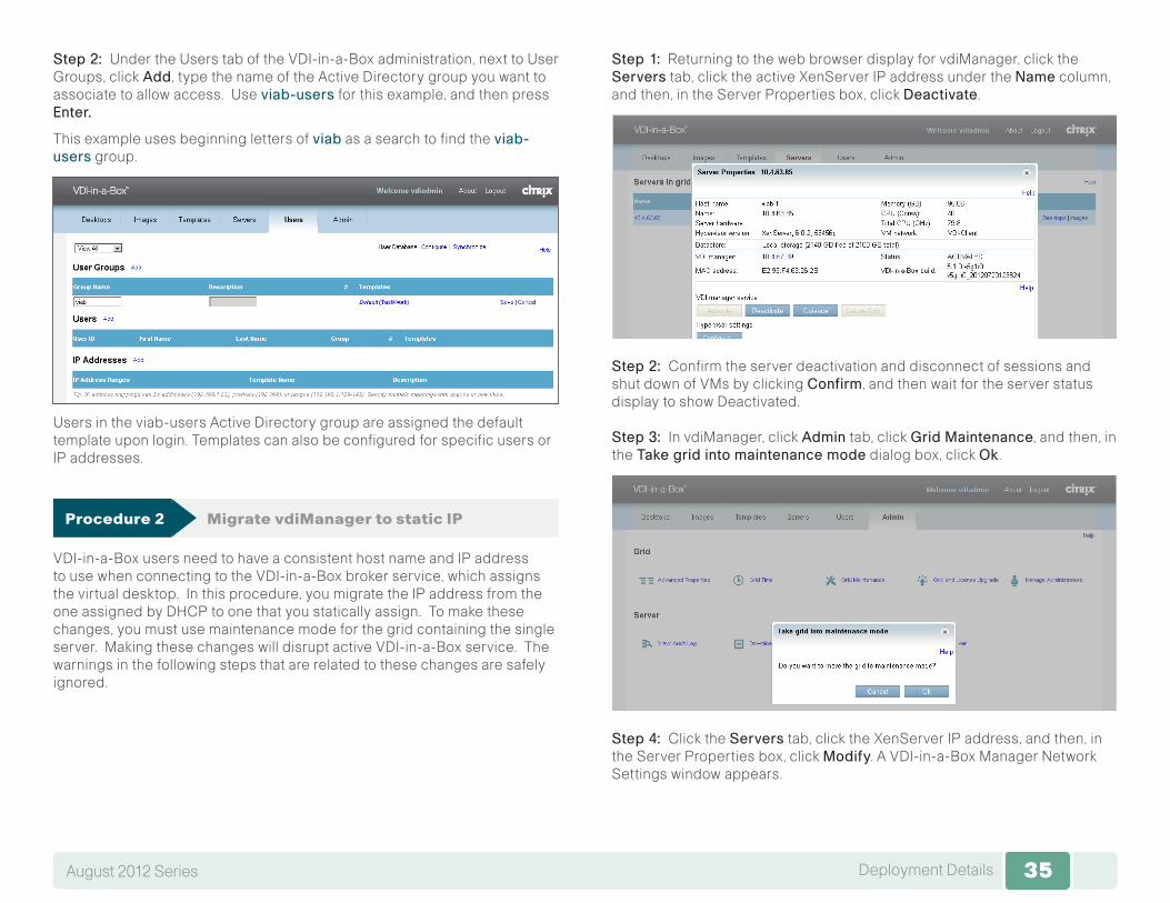
This procedure relies on information existing in Active Directory for user and group assignments. The existing viab-user group is used as the basis to assign the default TaskWork template to users.
Step 1: Click Continue. This begins the Assign Users to Desktops stage of the VDI-in-a-Box installation.
The final pop-up window in the browser disappears and reveals the vdiAd-min screen behind it.
35Deployment DetailsAugust 2012 Series 35
Step 2: Under the Users tab of the VDI-in-a-Box administration, next to User Groups, click Add, type the name of the Active Directory group you want to associate to allow access. Use viab-users for this example, and then press Enter.
This example uses beginning letters of viab as a search to find the viab-users group.
Users in the viab-users Active Directory group are assigned the default template upon login. Templates can also be configured for specific users or IP addresses.
Procedure 2 Migrate vdiManager to static IP
VDI-in-a-Box users need to have a consistent host name and IP address to use when connecting to the VDI-in-a-Box broker service, which assigns the virtual desktop. In this procedure, you migrate the IP address from the one assigned by DHCP to one that you statically assign. To make these changes, you must use maintenance mode for the grid containing the single server. Making these changes will disrupt active VDI-in-a-Box service. The warnings in the following steps that are related to these changes are safely ignored.
Step 1: Returning to the web browser display for vdiManager, click the Servers tab, click the active XenServer IP address under the Name column, and then, in the Server Properties box, click Deactivate.
Step 2: Confirm the server deactivation and disconnect of sessions and shut down of VMs by clicking Confirm, and then wait for the server status display to show Deactivated.
Step 3: In vdiManager, click Admin tab, click GridMaintenance, and then, in the Takegridintomaintenancemode dialog box, click Ok .
Step 4: Click the Servers tab, click the XenServer IP address, and then, in the Server Properties box, click Modify. A VDI-in-a-Box Manager Network Settings window appears.
36Deployment DetailsAugust 2012 Series 36
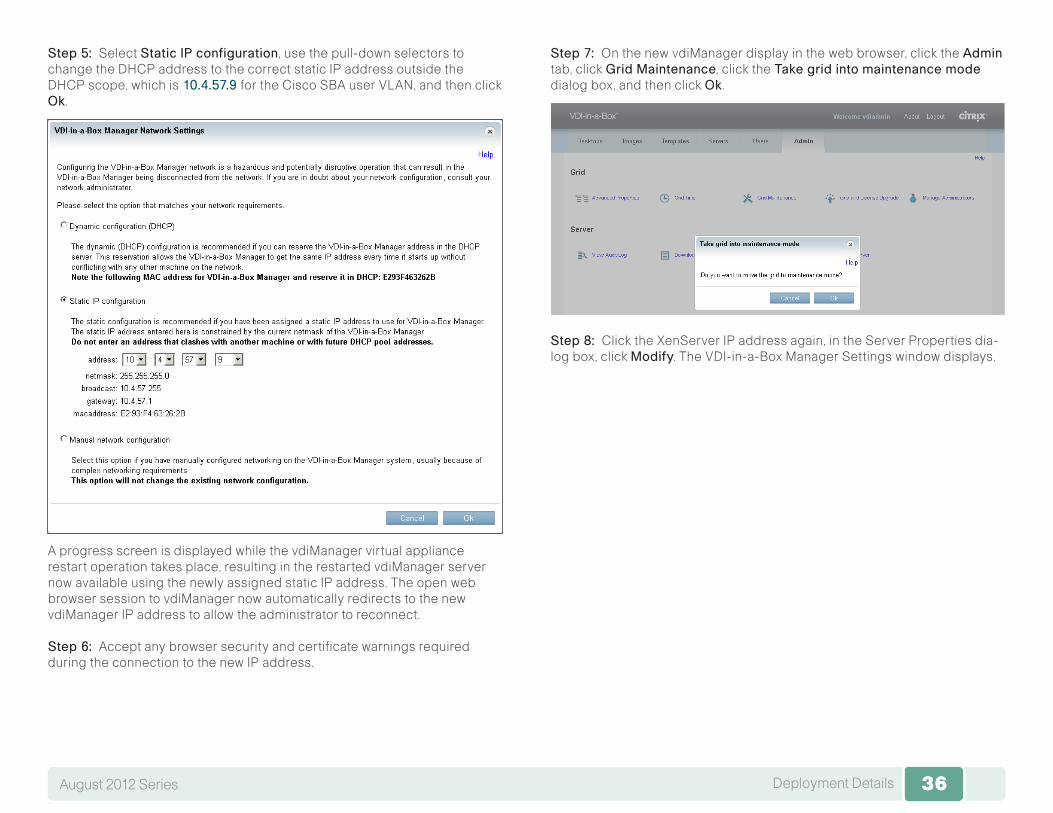
Step 5: Select StaticIPconfiguration, use the pull-down selectors to change the DHCP address to the correct static IP address outside the DHCP scope, which is 10.4.57.9 for the Cisco SBA user VLAN, and then click Ok .
A progress screen is displayed while the vdiManager virtual appliance restart operation takes place, resulting in the restarted vdiManager server now available using the newly assigned static IP address. The open web browser session to vdiManager now automatically redirects to the new vdiManager IP address to allow the administrator to reconnect.
Step 6: Accept any browser security and certificate warnings required during the connection to the new IP address.
Step 7: On the new vdiManager display in the web browser, click the Admin tab, click GridMaintenance, click the Takegridintomaintenancemode dialog box, and then click Ok .
Step 8: Click the XenServer IP address again, in the Server Properties dia-log box, click Modify. The VDI-in-a-Box Manager Settings window displays.

37Deployment DetailsAugust 2012 Series 37
Step 9: For the VDI-in-a-Box manager service settings, click Activate, and then click Confirm.
The dialog box closes, and the server status transitions to Activated. The number of desktop VM templates that are configured to pre-start is also made available for use.
Procedure 3 Create and install SSL cert for vdiManager
To access their virtual desktop, remote devices run the Citrix Receiver client over Secure Sockets Layer (SSL) transport for secure connectivity to the vdiManager virtual appliance. To do so requires a certificate to be installed on the vdiManager, which the client validates with the appropriate Trusted Certificate Authority to make the connection. Without a valid and trusted certificate, the client may display an error message, such as, “Certificate provided by the server is not trusted. Account information cannot be added.”
To address this situation, administrators should plan to request a certificate from their preferred certificate authority (CA).
For more information about the certificate process in relationship to vdiManager, see:
http://support.citrix.com/article/CTX132235
Tech Tip
In the Cisco SBA topology, the certificate request and installation for this procedure uses the local Microsoft Active Directory server as the root CA, for a non-vendor-specific certificate signing example. A Java utility named “keytool” is accessed at the Citrix VDI-in-a-Box Linux command line to man-age the certificate request and installation process.
Step 1: Using an SSH terminal client, open a connection to the VDI-in-a-Box appliance by its DNS name or IP address, and then log in by using the default credentials of kvm with a password of kaviza123.
Step 2: Create a directory for key storage, and then change the local direc-tory to the created directory location.
mkdir /home/kvm/keystorecd /home/kvm/keystore
Step 3: Generate a server key.
keytool –genkey –alias vdimgr.cisco.local –keyalg RSA –keysize 2048 –keystore kmgr.keystore
where the -alias vdimgr.cisco.local parameter is the vdiManager DNS name.
The command triggers a prompt for a 6-character minimum length pass-word to be entered, and then prompt for confirmation. After confirmation, there are a number of prompts for information related to the certificate, with the first question being the most critical. The prompt, “What is your first and last name?” is a request for the certificate Common Name (CN) field infor-mation, and needs to be interpreted as asking for the fully qualified domain name (FQDN) of the server.
38Deployment DetailsAugust 2012 Series 38
Step 4: Answer the series of prompts.
What is your first and last name? [Unknown]: vdimgr.cisco.localWhat is the name of your organizational unit? [Unknown]: SBA What is the name of your organization? [Unknown]: CiscoWhat is the name of your City or Locality? [Unknown]: San JoseWhat is the name of your State or Province? [Unknown]: CAWhat is the two-letter country code for this unit? [Unknown]: USIs CN=vdimgr.cisco.local, OU=SBA, O=Cisco, L=San Jose, ST=CA, C=US correct? [no]: yesEnter key password for <vdimgr.cisco.local> (RETURN if same as keystore password):
Step 5: Press Enter. The command completes and Linux prompt displays.
Step 6: Generate a Certificate Signing Request (CSR).
keytool -certreq -alias vdimgr.cisco.local -file kmgr.csr -keystore kmgr.keystore
The command asks to enter the keystore password. Enter the password previously used.
Step 7: List the directory contents by typing the Linux ls command and pressing Enter, and then verify that both the kmgr.csr and kmgr.keystore files exist.
Step 8: Connect to the vdimgr.cisco.local machine by using a Stream Control Transmission Protocol (SCTP) utility, enter credentials by using the kvm username and kaviza123 password, retrieve the /home/kvm/keystore/kmgr.csr file, and then store the file on the local management machine.
The information contained in the kmgr.csr file is used with the CA to request a certificate signing.
Step 9: Using the contents of the kmgr.csr file, connect to the CA and request a certificate signing. For the Microsoft Active Directory CA, use the following URL:
http://cacisco.local/certsrv/
Step 10: Click the Requestacertificate, click Submitanadvancedcer-tificaterequest link, and then fill out the displayed web form by opening the kmgr.csr file with Notepad and pasting the contents into the Saved Request box.
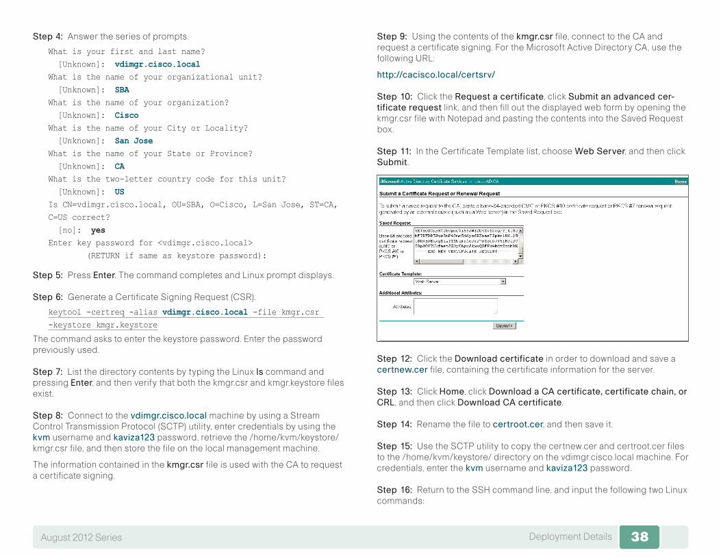
Step 11: In the Certificate Template list, choose WebServer, and then click Submit.
Step 12: Click the Downloadcertificate in order to download and save a certnew.cer file, containing the certificate information for the server.
Step 13: Click Home, click DownloadaCAcertificate,certificatechain,orCRL, and then click DownloadCAcertificate.
Step 14: Rename the file to certroot.cer, and then save it.
Step 15: Use the SCTP utility to copy the certnew.cer and certroot.cer files to the /home/kvm/keystore/ directory on the vdimgr.cisco.local machine. For credentials, enter the kvm username and kaviza123 password.
Step 16: Return to the SSH command line, and input the following two Linux commands:

39Deployment DetailsAugust 2012 Series 39
keytool –import –trustcacerts –alias root –file certroot.cer –keystore kmgr.keystore
keytool –import –trustcacerts –alias vdimgr.cisco.local –file certnew.cer –keystore kmgr.keystore
Step 17: After each command, enter the password again, and then, in response to the query, “Trust this certificate?”,enter yes. You receive the following replies:
◦ Certificate was added to keystore ◦ Certificate reply was installed in keystore
Step 18: Replace the existing self-signed certificate with the new certificate.
cd /home/kvm/kvm/install/servlet_container/confmv .keystore old.keystorecp /home/kvm/keystore/kmgr.keystore .keystore
Step 19: The web server configuration must now be updated to use the password for the keystore.
Step 20: Edit the server.xml file with the vi editor.
sudo vi server.xml
Step 21: In the vi editing session, find the clientAuth line by using the following vi search.
/clientAuth=
Then, go to the end of the line found, by typing the following keys for a vi search.
/>
Cursor back a character over the slash character, and then enter insert mode by typing the keys.
hi
In vi insert mode, type space and the text keystorePass=”password”, where the password between the quotes is the one previously used for keystore.
The full line in the file should look like the following.
clientAuth=”false” sslProtocol=”TLS” URIEncoding=”UTF-8” keystorePass=”password”/>
Step 22: Save and exit vi by typing two uppercase Z letters.
ZZ
Step 23: Restart the web server Tomcat services need by typing the follow-ing. This enables the new settings to take effect.
tc_start
The web server with correct certificates is now ready to be used.
Procedure 4 Test connectivity to virtual desktops
Download the appropriate Citrix Receiver for the remote client, and then install the Citrix Receiver application.
Android clients are available from Google Play, and iOS clients for the iPad are available at the Apple App Store. Windows clients are available from the Citrix website, here:
http://www.citrix.com
This guide uses the Windows version for testing in this procedure.
Step 1: Launch the Windows Citrix Receiver, click the Settings gear icon at the top, click Accounts, click Addaccount, and then click Add. The Add Account dialog box is displayed.
Step 2: In the Enteryourworkemailorserveraddress box, enter the following vdiManager virtual appliance URL:
https://vdimgr.cisco.local/dt/PNAgent/config.xml
40Deployment DetailsAugust 2012 Series 40
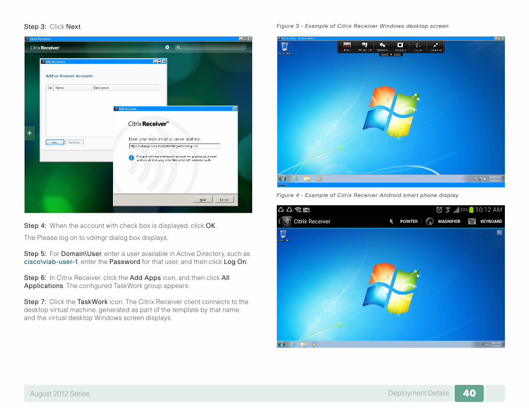
Step 3: Click Next.
Step 4: When the account with check box is displayed, click OK .
The Please log on to vdimgr dialog box displays.
Step 5: For Domain\User, enter a user available in Active Directory, such as cisco\viab-user-1, enter the Password for that user, and then click LogOn.
Step 6: In Citrix Receiver, click the AddApps icon, and then click AllApplications. The configured TaskWork group appears.
Step 7: Click the TaskWork icon. The Citrix Receiver client connects to the desktop virtual machine, generated as part of the template by that name, and the virtual desktop Windows screen displays.
Figure 3 - Example of Citrix Receiver Windows desktop screen
Figure 4 - Example of Citrix Receiver Android smart phone display

41Deployment DetailsAugust 2012 Series 41
Figure 5 - Example of Citrix Receiver for iPad IOS display Step 8: If you want to confirm that the VDI-in-a-Box service is operational and that the desktops are active, use the vdiManager application Servers and Desktops tabs.
.
42Appendix A: Product ListAugust 2012 Series 42
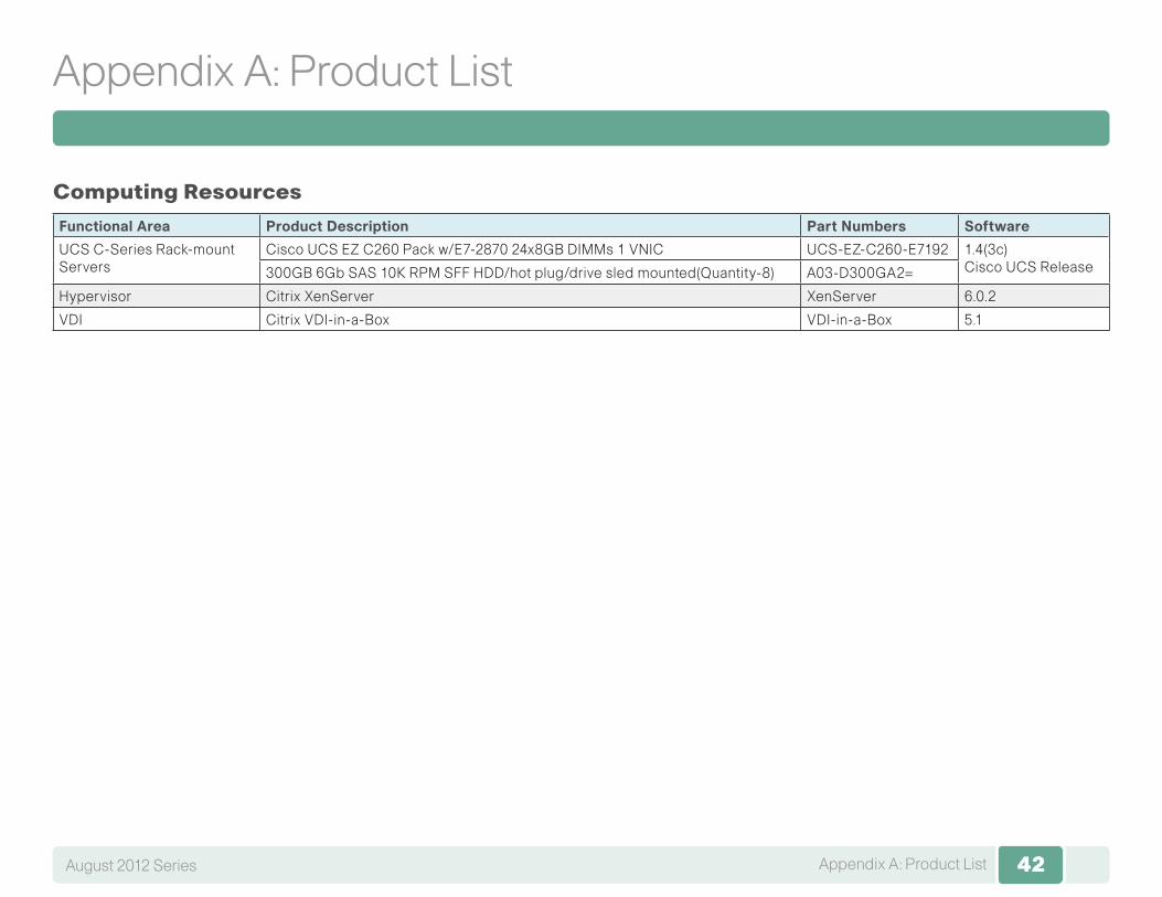
Appendix A: Product List
Computing Resources
Functional Area Product Description Part Numbers Software
UCS C-Series Rack-mount Servers
Cisco UCS EZ C260 Pack w/E7-2870 24x8GB DIMMs 1 VNIC UCS-EZ-C260-E7192 1.4(3c) Cisco UCS Release300GB 6Gb SAS 10K RPM SFF HDD/hot plug/drive sled mounted(Quantity-8) A03-D300GA2=
Hypervisor Citrix XenServer XenServer 6.0.2
VDI Citrix VDI-in-a-Box VDI-in-a-Box 5.1

SMART BUSINESS ARCHITECTURE
ALL DESIGNS, SPECIFICATIONS, STATEMENTS, INFORMATION, AND RECOMMENDATIONS (COLLECTIVELY, “DESIGNS”) IN THIS MANUAL ARE PRESENTED “AS IS,” WITH ALL FAULTS. CISCO AND ITS SUPPLiERS DISCLAIM ALL WARRANTIES, INCLUDING, WITH-OUT LIMITATION, THE WARRANTY OF MERCHANTABILITY, FITNESS FOR A PARTICULAR PURPOSE AND NONINFRINGEMENT OR ARISING FROM A COURSE OF DEALING, USAGE, OR TRADE PRACTICE. IN NO EVENT SHALL CISCO OR ITS SUPPLIERS BE LIABLE FOR ANY INDIRECT, SPECIAL, CONSEQUENTIAL, OR INCIDENTAL DAMAGES, INCLUDING, WITHOUT LIMITATION, LOST PROFITS OR LOSS OR DAMAGE TO DATA ARISING OUT OF THE USE OR INABILITY TO USE THE DESIGNS, EVEN IF CISCO OR ITS SUPPLIERS HAVE BEEN ADVISED OF THE POSSIBILITY OF SUCH DAMAGES. THE DESIGNS ARE SUBJECT TO CHANGE WITHOUT NOTICE. USERS ARE SOLELY RESPONSIBLE FOR THEIR APPLICATION OF THE DESIGNS. THE DESIGNS DO NOT CONSTITUTE THE TECHNICAL OR OTHER PROFESSIONAL ADVICE OF CISCO, ITS SUPPLIERS OR PARTNERS. USERS SHOULD CONSULT THEIR OWN TECHNICAL ADVISORS BEFORE IMPLEMENTING THE DESIGNS. RESULTS MAY VARY DEPENDING ON FACTORS NOT TESTED BY CISCO.
Any Internet Protocol (IP) addresses used in this document are not intended to be actual addresses. Any examples, command display output, and figures included in the document are shown for illustrative purposes only. Any use of actual IP addresses in illustrative content is unintentional and coincidental.
© 2012 Cisco Systems, Inc. All rights reserved.
Click here to provide feedback to Cisco SBA.
Feedback
Americas HeadquartersCisco Systems, Inc.San Jose, CA
Asia Pacific HeadquartersCisco Systems (USA) Pte. Ltd.Singapore
Europe HeadquartersCisco Systems International BV Amsterdam,The Netherlands
Cisco has more than 200 offices worldwide. Addresses, phone numbers, and fax numbers are listed on the Cisco Website at www.cisco.com/go/offices.
Cisco and the Cisco logo are trademarks or registered trademarks of Cisco and/or its affiliates in the U.S. and other countries. To view a list of Cisco trademarks, go to this URL: www.cisco.com/go/trademarks. Third-party trademarks mentioned are the property of their respective owners. The use of the word partner does not imply a partnership relationship between Cisco and any other company. (1110R)
B-0000321-1 10/12