cisco pix 515e firewall - used cisco liquidators - network ... · cisco pix 515e firewall ... about...
TRANSCRIPT
Quick Start Guide
Cisco PIX 515E Firewall
1 Check Items Included
2 Install the PIX 515E
3 Configure the PIX 515E
4 Example Configurations
5 Optional Maintenance and Upgrade Procedures
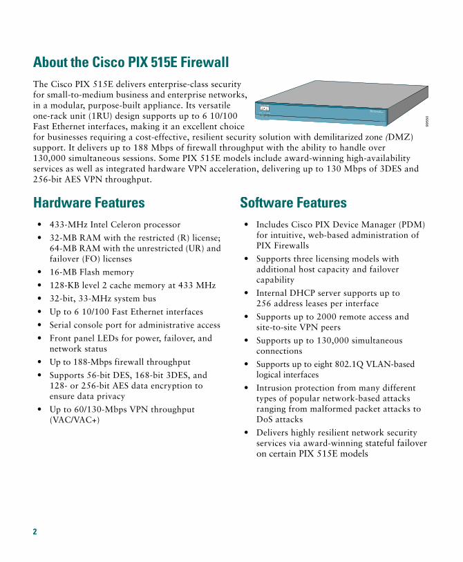
About the Cisco PIX 515E FirewallThe Cisco PIX 515E delivers enterprise-class security for small-to-medium business and enterprise networks, in a modular, purpose-built appliance. Its versatile one-rack unit (1RU) design supports up to 6 10/100 Fast Ethernet interfaces, making it an excellent choice for businesses requiring a cost-effective, resilient security solution with demilitarized zone (DMZ) support. It delivers up to 188 Mbps of firewall throughput with the ability to handle over 130,000 simultaneous sessions. Some PIX 515E models include award-winning high-availability services as well as integrated hardware VPN acceleration, delivering up to 130 Mbps of 3DES and 256-bit AES VPN throughput.
99
55
0
POWER ACT NETWORK
PIX Firewall SERIES
Hardware Features• 433-MHz Intel Celeron processor
• 32-MB RAM with the restricted (R) license; 64-MB RAM with the unrestricted (UR) and failover (FO) licenses
• 16-MB Flash memory
• 128-KB level 2 cache memory at 433 MHz
• 32-bit, 33-MHz system bus
• Up to 6 10/100 Fast Ethernet interfaces
• Serial console port for administrative access
• Front panel LEDs for power, failover, and network status
• Up to 188-Mbps firewall throughput
• Supports 56-bit DES, 168-bit 3DES, and 128- or 256-bit AES data encryption to ensure data privacy
• Up to 60/130-Mbps VPN throughput (VAC/VAC+)
Software Features• Includes Cisco PIX Device Manager (PDM)
for intuitive, web-based administration of PIX Firewalls
• Supports three licensing models with additional host capacity and failover capability
• Internal DHCP server supports up to 256 address leases per interface
• Supports up to 2000 remote access and site-to-site VPN peers
• Supports up to 130,000 simultaneous connections
• Supports up to eight 802.1Q VLAN-based logical interfaces
• Intrusion protection from many different types of popular network-based attacks ranging from malformed packet attacks to DoS attacks
• Delivers highly resilient network security services via award-winning stateful failover on certain PIX 515E models
2
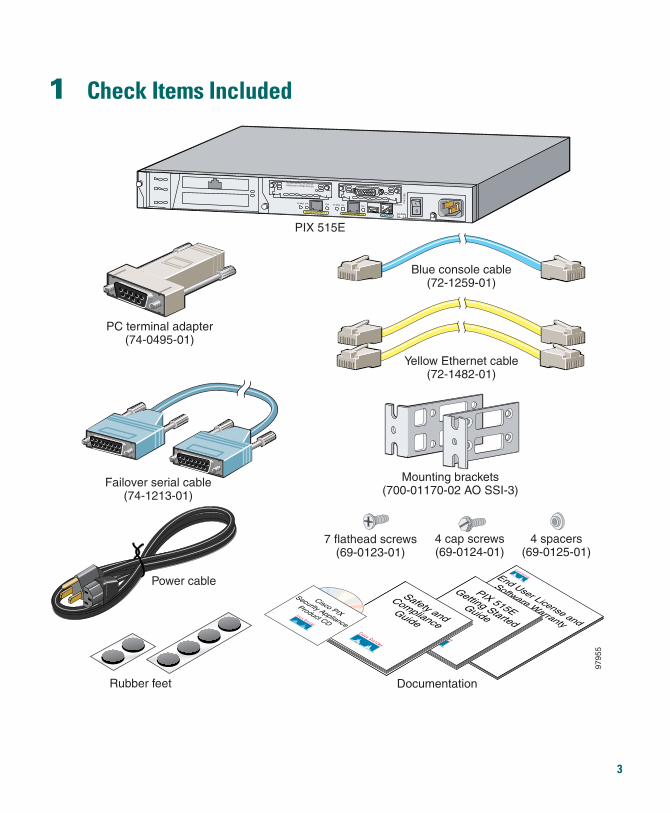
1 Check Items Included
End User License and
Software Warranty
PIX 515E
Getting Started
Guide
Safety and
ComplianceGuide
PIX 515E
PC terminal adapter(74-0495-01)
Documentation
Blue console cable(72-1259-01)
Yellow Ethernet cable(72-1482-01)
Cisco PIX
Security Appliance
Product CD
DO NOT INSTALL INTERFACECARDS WITH POWER APPLIED
Link FDXFDX
100 MbpsLink100 Mbps FAILOVER
PIX
-515
E
CONSOLE
10/100 ETHERNET 1 10/100 ETHERNET 0
Failover serial cable(74-1213-01)
Mounting brackets(700-01170-02 AO SSI-3)
7 flathead screws(69-0123-01)
4 cap screws(69-0124-01)
4 spacers(69-0125-01)
Rubber feet
9795
5
Power cable
3
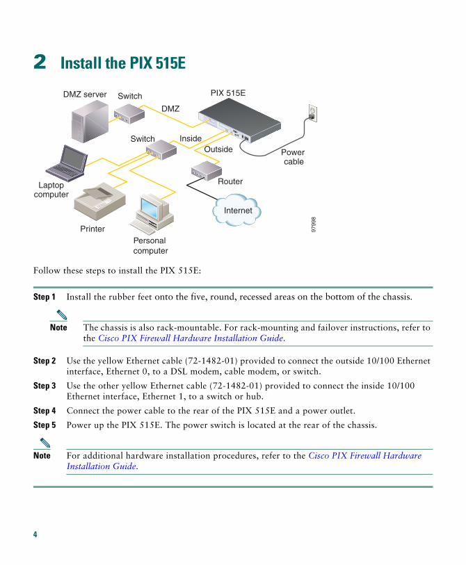
2 Install the PIX 515E
Follow these steps to install the PIX 515E:
Step 1 Install the rubber feet onto the five, round, recessed areas on the bottom of the chassis.
Note The chassis is also rack-mountable. For rack-mounting and failover instructions, refer to the Cisco PIX Firewall Hardware Installation Guide.
Step 2 Use the yellow Ethernet cable (72-1482-01) provided to connect the outside 10/100 Ethernet interface, Ethernet 0, to a DSL modem, cable modem, or switch.
Step 3 Use the other yellow Ethernet cable (72-1482-01) provided to connect the inside 10/100 Ethernet interface, Ethernet 1, to a switch or hub.
Step 4 Connect the power cable to the rear of the PIX 515E and a power outlet.
Step 5 Power up the PIX 515E. The power switch is located at the rear of the chassis.
Note For additional hardware installation procedures, refer to the Cisco PIX Firewall Hardware Installation Guide.
Internet
9799
8
DMZ server
Laptopcomputer
PrinterPersonalcomputer
Switch
Switch InsideOutside
Router
PIX 515E
Power cable
DMZ
4
3 Configure the PIX 515EThe PIX 515E comes with a factory-default configuration that meets the needs of most small and medium business networking environments. A default DHCP server address pool is included for hosts on the inside interface. The factory-default configuration on the PIX 515E protects your inside network from unsolicited traffic.
By default, the PIX 515E denies all inbound traffic through the outside interface. Based on your network security policy, you should also consider configuring the PIX 515E to deny all ICMP traffic to the outside interface, or any other interface you deem necessary, by entering the icmp command. For more information about the icmp command, refer to the Cisco PIX Firewall Command Reference.
The PIX 515E contains an integrated web-based configuration tool called the Cisco PIX Device Manager (PDM), that is designed to help you set up the PIX Firewall. PDM is preinstalled on the PIX 515E. To access PDM, make sure that JavaScript and Java are enabled in your web browser. Refer to the Cisco PIX Device Manager Installation Guide for more information on the operating system and web browser environments supported by PDM.
PDM includes a Startup Wizard for simplified initial configuration of your PIX Firewall. With just a few steps, the PDM Startup Wizard enables you to efficiently create a basic configuration that allows packets to flow through the PIX Firewall from the inside network to the outside network securely. Follow these steps to use the Startup Wizard:
Step 1 If you have not already done so, connect the inside Ethernet 1 interface of the PIX 515E to a switch or hub using the Ethernet cable. To this same switch, connect a PC for configuring the PIX 515E.
Step 2 Configure your PC to use DHCP (to receive an IP address automatically from the PIX 515E) or assign a static IP address to your PC by selecting an address out of the 192.168.1.0 network. (Valid addresses are 192.168.1.2 through 192.168.1.254 with a mask of 255.255.255.0 and default route of 192.168.1.1.)
Note The inside interface of the PIX 515E is assigned 192.168.1.1 by default, so this address is unavailable.
Step 3 Check the LINK LED on the PIX 515E Ethernet 1 interface. When connectivity occurs, the LINK LED on the Ethernet 1 interface of the PIX Firewall and the corresponding LINK LED on the switch or hub lights up solid green.
5
Step 4 To access the Startup Wizard, use the PC connected to the switch or hub and enter the URL https://192.168.1.1/startup.html into your Internet browser.
Note Remember to add the “s” in “https” or the connection fails. HTTPS (HTTP over SSL) provides a secure connection between your browser and the PIX 515E.
Step 5 Leave both the username and password boxes empty. Press Enter.
Step 6 Select Yes to accept the certificates and follow the instructions in the Startup Wizard to set up your PIX 515E. For online Help, click the Help button at the bottom of the Startup Wizard window.
4 Example ConfigurationsThe following section provides configuration examples for two common PIX 515E configuration scenarios: hosting a web server on a DMZ network and establishing a site-to-site VPN connection with other business partners or remote offices. Use these examples to set up your network. Substitute network addresses and apply additional policies as needed.
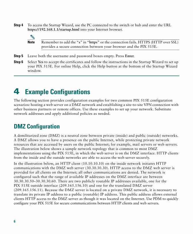
DMZ Configuration A demilitarized zone (DMZ) is a neutral zone between private (inside) and public (outside) networks. A DMZ allows you to have a presence on the public Internet, while protecting private network resources that are accessed by users on the public Internet; for example, mail servers or web servers. The illustration below shows a sample network topology that is common to most DMZ implementations using the PIX 515E, in which the web server is on the DMZ interface. HTTP clients from the inside and the outside networks are able to access the web server securely.
In the illustration below, an HTTP client (10.10.10.10) on the inside network initiates HTTP communications with the DMZ web server (30.30.30.30). HTTP access to the DMZ web server is provided for all clients on the Internet; all other communications are denied. The network is configured such that the range of available IP addresses on the DMZ interface are between 30.30.30.50–30.30.30.60. There are two publicly routable IP addresses available, one for the PIX 515E outside interface (209.165.156.10) and one for the translated DMZ server (209.165.156.11). Because the DMZ server is located on a private DMZ network, it is necessary to translate its private IP address to a public (routable) IP address. This public address allows external clients HTTP access to the DMZ server as though it was located on the Internet. Use PDM to quickly configure your PIX 515E for secure communications between HTTP clients and web servers.
6
Step 1 Manage IP Pools for Network Translations
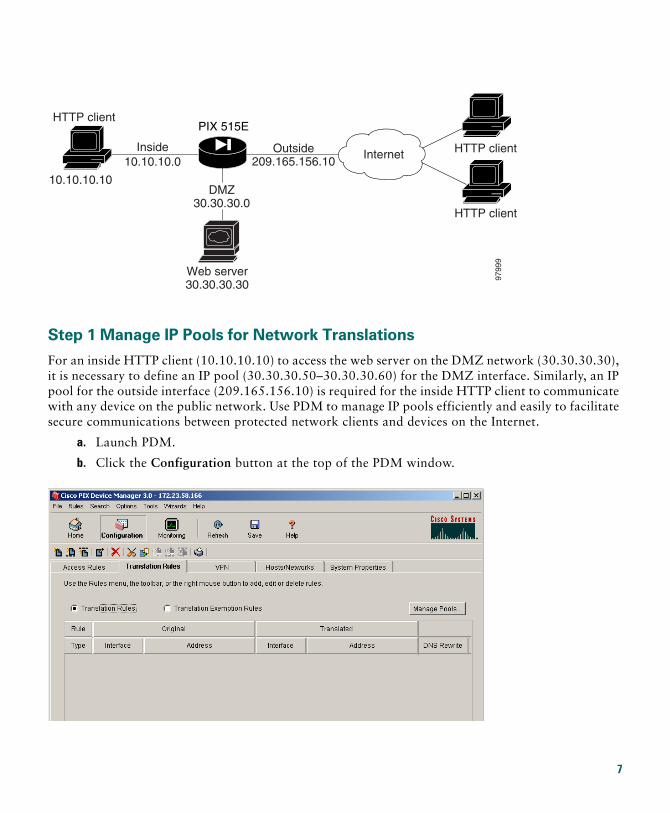
For an inside HTTP client (10.10.10.10) to access the web server on the DMZ network (30.30.30.30), it is necessary to define an IP pool (30.30.30.50–30.30.30.60) for the DMZ interface. Similarly, an IP pool for the outside interface (209.165.156.10) is required for the inside HTTP client to communicate with any device on the public network. Use PDM to manage IP pools efficiently and easily to facilitate secure communications between protected network clients and devices on the Internet.
a. Launch PDM.
b. Click the Configuration button at the top of the PDM window.
9799
9
PIX 515E
Internet
HTTP client
10.10.10.10
Web server30.30.30.30
DMZ30.30.30.0
Inside10.10.10.0
HTTP client
HTTP client
Outside209.165.156.10
7
c. Select the Translation Rules tab.
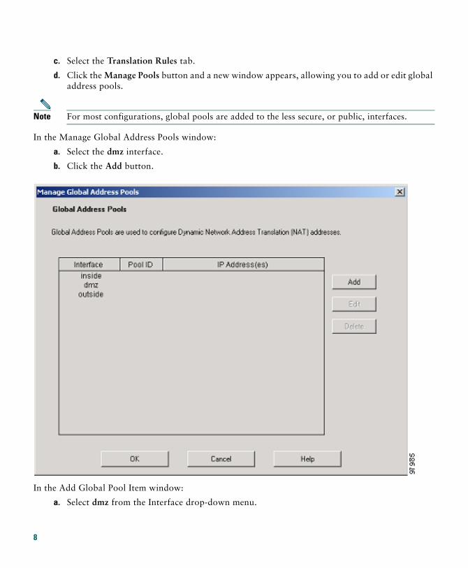
d. Click the Manage Pools button and a new window appears, allowing you to add or edit global address pools.
Note For most configurations, global pools are added to the less secure, or public, interfaces.
In the Manage Global Address Pools window:
a. Select the dmz interface.
b. Click the Add button.
In the Add Global Pool Item window:
a. Select dmz from the Interface drop-down menu.
8
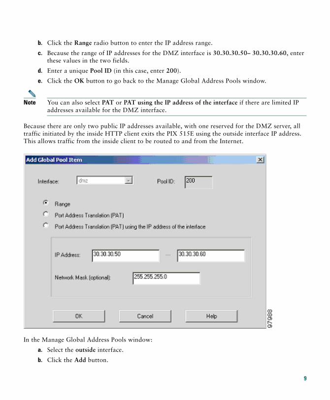
b. Click the Range radio button to enter the IP address range.
c. Because the range of IP addresses for the DMZ interface is 30.30.30.50– 30.30.30.60, enter these values in the two fields.
d. Enter a unique Pool ID (in this case, enter 200).
e. Click the OK button to go back to the Manage Global Address Pools window.
Note You can also select PAT or PAT using the IP address of the interface if there are limited IP addresses available for the DMZ interface.
Because there are only two public IP addresses available, with one reserved for the DMZ server, all traffic initiated by the inside HTTP client exits the PIX 515E using the outside interface IP address. This allows traffic from the inside client to be routed to and from the Internet.
In the Manage Global Address Pools window:
a. Select the outside interface.
b. Click the Add button.
9
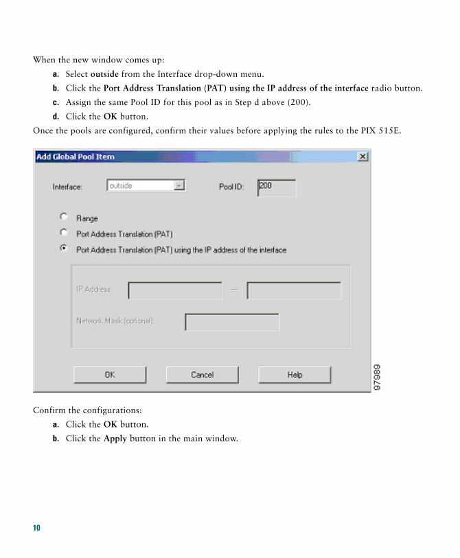
When the new window comes up:
a. Select outside from the Interface drop-down menu.
b. Click the Port Address Translation (PAT) using the IP address of the interface radio button.
c. Assign the same Pool ID for this pool as in Step d above (200).
d. Click the OK button.
Once the pools are configured, confirm their values before applying the rules to the PIX 515E.
Confirm the configurations:
a. Click the OK button.
b. Click the Apply button in the main window.
10
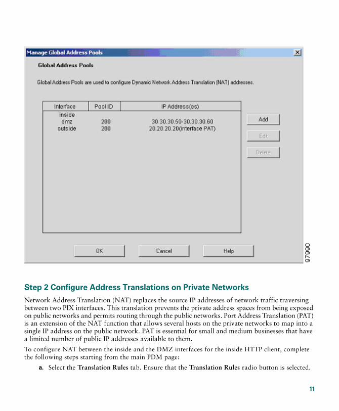
Step 2 Configure Address Translations on Private Networks
Network Address Translation (NAT) replaces the source IP addresses of network traffic traversing between two PIX interfaces. This translation prevents the private address spaces from being exposed on public networks and permits routing through the public networks. Port Address Translation (PAT) is an extension of the NAT function that allows several hosts on the private networks to map into a single IP address on the public network. PAT is essential for small and medium businesses that have a limited number of public IP addresses available to them.
To configure NAT between the inside and the DMZ interfaces for the inside HTTP client, complete the following steps starting from the main PDM page:
a. Select the Translation Rules tab. Ensure that the Translation Rules radio button is selected.
11
b. Right click in the gray area below the Manage Pools button and select Add.
c. In the new window, select the inside interface.
d. Enter the IP address of the client (10.10.10.10).
e. Select 255.255.255.255 from the Mask drop-down menu.
Note You can select the inside host by clicking on the Browse button.
f. Select the DMZ interface on which the translation is required.
g. Click the Dynamic radio button in the Translate Address to section.
h. Select 200 from the Address Pools drop-down menu for the appropriate Pool ID.
i. Click the OK button.
12
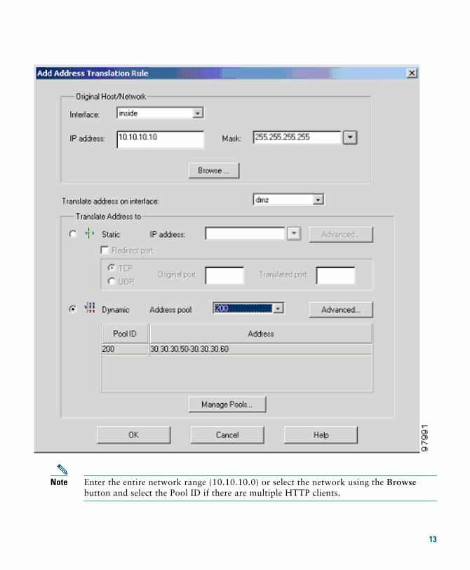
Note Enter the entire network range (10.10.10.0) or select the network using the Browse button and select the Pool ID if there are multiple HTTP clients.
13
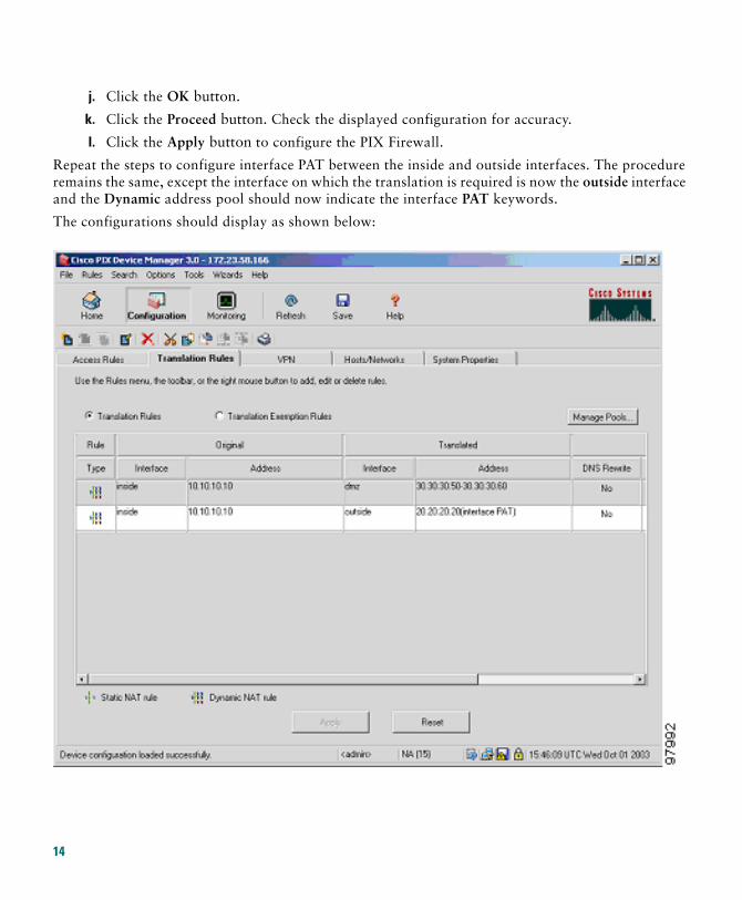
j. Click the OK button.
k. Click the Proceed button. Check the displayed configuration for accuracy.
l. Click the Apply button to configure the PIX Firewall.
Repeat the steps to configure interface PAT between the inside and outside interfaces. The procedure remains the same, except the interface on which the translation is required is now the outside interface and the Dynamic address pool should now indicate the interface PAT keywords.
The configurations should display as shown below:
14
Step 3 Configure External Identity for the DMZ Web Server
The DMZ server is easily accessible by all hosts on the Internet. This configuration requires translating the DMZ server IP address so that it appears to be located on the Internet, enabling outside HTTP clients to access it unaware of the firewall. Complete the following steps to map the DMZ IP address (30.30.30.30) statically to a public IP address (209.165.156.11):
a. Right click in the gray area under the Translation Rules tab.
b. Select Add.
c. Select dmz from the drop-down menu of interfaces.
d. Enter the server IP address (30.30.30.30) or select the server by clicking on the Browse button.
e. Select 255.255.255.255 from the Mask drop-down menu.
f. Click the Static radio button.
g. Enter the external IP address (209.165.156.11). The Advanced button allows you to configure features such as limiting the number of connections per static entry and DNS rewrites.
h. Click the OK button.
i. Confirm the values that you entered. Click the Apply button.
15
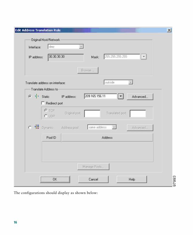
The configurations should display as shown below:
16
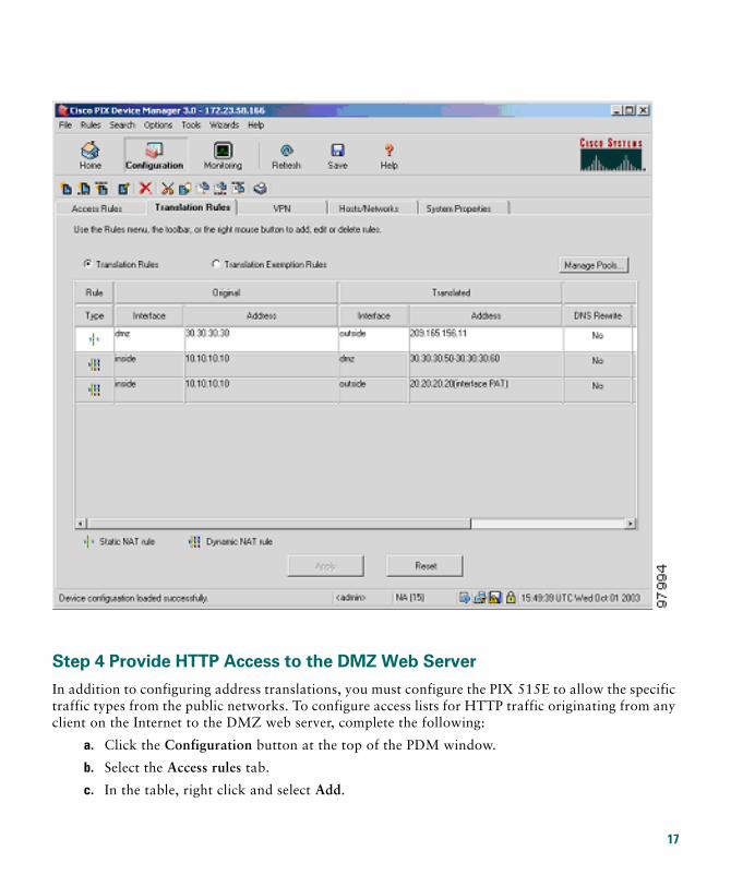
Step 4 Provide HTTP Access to the DMZ Web Server
In addition to configuring address translations, you must configure the PIX 515E to allow the specific traffic types from the public networks. To configure access lists for HTTP traffic originating from any client on the Internet to the DMZ web server, complete the following:
a. Click the Configuration button at the top of the PDM window.
b. Select the Access rules tab.
c. In the table, right click and select Add.
17
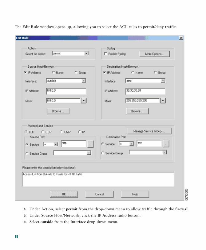
The Edit Rule window opens up, allowing you to select the ACL rules to permit/deny traffic.
a. Under Action, select permit from the drop-down menu to allow traffic through the firewall.
b. Under Source Host/Network, click the IP Address radio button.
c. Select outside from the Interface drop-down menu.
18
d. Enter the Source Host/Network information (0.0.0.0 for any host or network).
e. Under Destination Host/Network, click the IP Address radio button.
f. Select dmz from the Interface drop-down menu.
g. Enter 30.30.30.30 in the IP address box.
h. Select 255.255.255.255 from the Mask drop-down menu.
Note Alternatively, you can select the Hosts/Networks in both cases by clicking on the respective Browse buttons.
Select the type of traffic that you would permit:
Note HTTP traffic is always directed from any TCP source port number toward a fixed destination TCP port number 80.
i. Select the TCP radio button, under Protocol and Service.
j. Select “=” (equal to) from the Service drop-down menu under Source Port.
k. Scroll through the options, and select Any.
l. Select “=” (equal to) from the Service drop-down menu under Destination Port.
m. Scroll through the options, and select HTTP.
n. Click the OK button.
Note For additional features, such as system log messages by ACL, check the radio button at the top and click the More options button. You can provide a name for the access rule in the window at the bottom.
o. Check the various fields for accuracy and click the OK button.
Note Although the destination address specified above is the private address of the DMZ web server (30.30.30.30), HTTP traffic from any host on the Internet destined for 209.165.156.11 is permitted through the PIX 515E. This is made possible by the translation (30.30.30.30 = 209.165.156.11).
p. Click the Apply button in the main window.
19
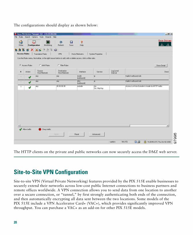
The configurations should display as shown below:
The HTTP clients on the private and public networks can now securely access the DMZ web server.
Site-to-Site VPN ConfigurationSite-to-site VPN (Virtual Private Networking) features provided by the PIX 515E enable businesses to securely extend their networks across low-cost public Internet connections to business partners and remote offices worldwide. A VPN connection allows you to send data from one location to another over a secure connection, or “tunnel,” by first strongly authenticating both ends of the connection, and then automatically encrypting all data sent between the two locations. Some models of the PIX 515E include a VPN Accelerator Card+ (VAC+), which provides significantly improved VPN throughput. You can purchase a VAC+ as an add-on for other PIX 515E models.
20
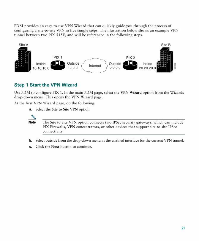
PDM provides an easy-to-use VPN Wizard that can quickly guide you through the process of configuring a site-to-site VPN in five simple steps. The illustration below shows an example VPN tunnel between two PIX 515E, and will be referenced in the following steps.
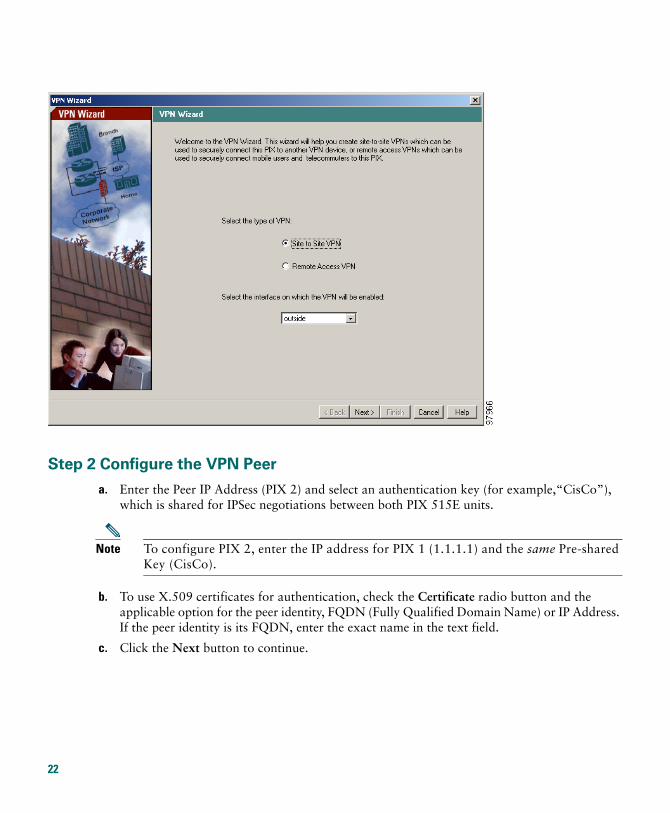
Step 1 Start the VPN Wizard
Use PDM to configure PIX 1. In the main PDM page, select the VPN Wizard option from the Wizards drop-down menu. This opens the VPN Wizard page.
At the first VPN Wizard page, do the following:
a. Select the Site to Site VPN option.
Note The Site to Site VPN option connects two IPSec security gateways, which can include PIX Firewalls, VPN concentrators, or other devices that support site-to-site IPSec connectivity.
b. Select outside from the drop-down menu as the enabled interface for the current VPN tunnel.
c. Click the Next button to continue.
9800
0
PIX 2
InternetInside10.10.10.0
Outside1.1.1.1
Outside2.2.2.2
PIX 1
Site A
Inside20.20.20.0
Site B
21
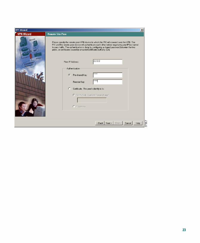
Step 2 Configure the VPN Peer
a. Enter the Peer IP Address (PIX 2) and select an authentication key (for example,“CisCo”), which is shared for IPSec negotiations between both PIX 515E units.
Note To configure PIX 2, enter the IP address for PIX 1 (1.1.1.1) and the same Pre-shared Key (CisCo).
b. To use X.509 certificates for authentication, check the Certificate radio button and the applicable option for the peer identity, FQDN (Fully Qualified Domain Name) or IP Address. If the peer identity is its FQDN, enter the exact name in the text field.
c. Click the Next button to continue.
22
23
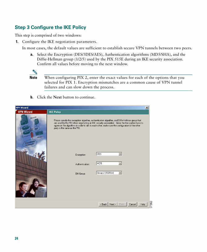
Step 3 Configure the IKE Policy
This step is comprised of two windows:
1. Configure the IKE negotiation parameters.
In most cases, the default values are sufficient to establish secure VPN tunnels between two peers.
a. Select the Encryption (DES/3DES/AES), Authentication algorithms (MD5/SHA), and the Diffie-Hellman group (1/2/5) used by the PIX 515E during an IKE security association. Confirm all values before moving to the next window.
Note When configuring PIX 2, enter the exact values for each of the options that you selected for PIX 1. Encryption mismatches are a common cause of VPN tunnel failures and can slow down the process.
b. Click the Next button to continue.
24
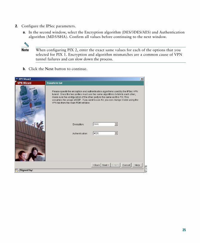
2. Configure the IPSec parameters.
a. In the second window, select the Encryption algorithm (DES/3DES/AES) and Authentication algorithm (MD5/SHA). Confirm all values before continuing to the next window.
Note When configuring PIX 2, enter the exact same values for each of the options that you selected for PIX 1. Encryption and algorithm mismatches are a common cause of VPN tunnel failures and can slow down the process.
b. Click the Next button to continue.
25
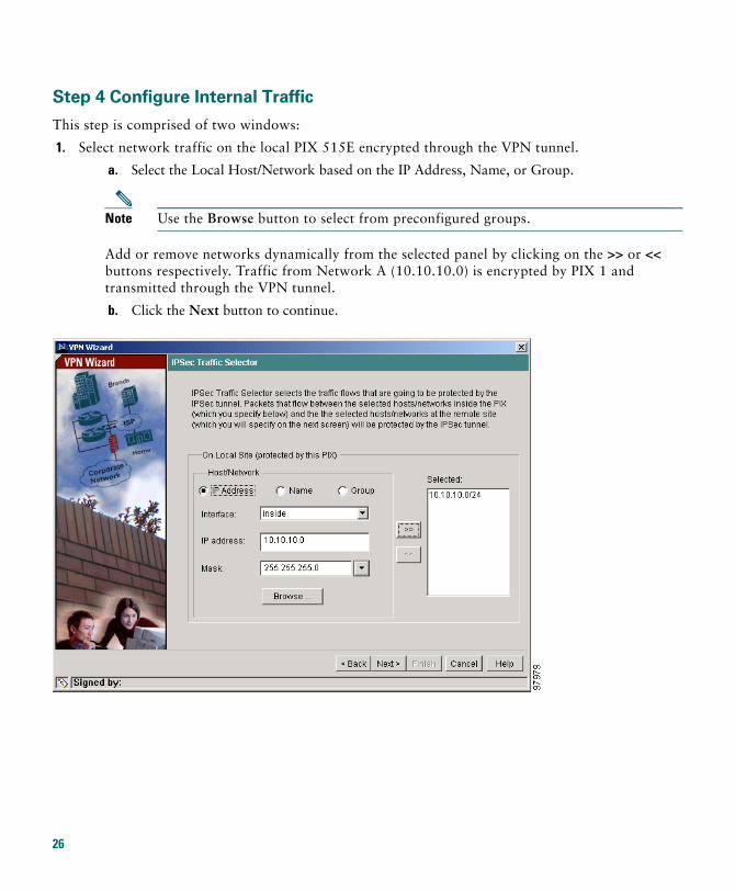
Step 4 Configure Internal Traffic
This step is comprised of two windows:
1. Select network traffic on the local PIX 515E encrypted through the VPN tunnel.
a. Select the Local Host/Network based on the IP Address, Name, or Group.
Note Use the Browse button to select from preconfigured groups.
Add or remove networks dynamically from the selected panel by clicking on the >> or << buttons respectively. Traffic from Network A (10.10.10.0) is encrypted by PIX 1 and transmitted through the VPN tunnel.
b. Click the Next button to continue.
26
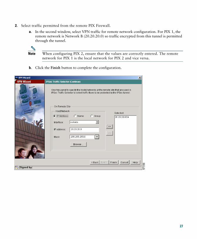
2. Select traffic permitted from the remote PIX Firewall.
a. In the second window, select VPN traffic for remote network configuration. For PIX 1, the remote network is Network B (20.20.20.0) so traffic encrypted from this tunnel is permitted through the tunnel.
Note When configuring PIX 2, ensure that the values are correctly entered. The remote network for PIX 1 is the local network for PIX 2 and vice versa.
b. Click the Finish button to complete the configuration.
27
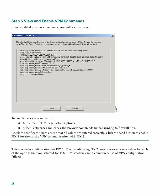
Step 5 View and Enable VPN Commands
If you enabled preview commands, you will see this page:
To enable preview commands:
a. In the main PDM page, select Options.
b. Select Preferences and check the Preview commands before sending to firewall box.
Check the configuration to ensure that all values are entered correctly. Click the Send button to enable PIX 1 for site-to-site VPN communication with PIX 2.
This concludes configuration for PIX 1. When configuring PIX 2, enter the exact same values for each of the options that you selected for PIX 1. Mismatches are a common cause of VPN configuration failures.
28
Establishing Site-to-Site VPNs with other Cisco ProductsFor information on configuring VPN between a PIX 515E and other products such as a Cisco router that runs Cisco IOS software, and Cisco VPN 3000 Concentrators, go to the following links:
http://www.cisco.com/warp/customer/471/pix_router_dyn.html
http://www.cisco.com/warp/public/471/ALTIGA_pix.html
http://www.cisco.com/warp/public/110/39.html
5 Optional Maintenance and Upgrade Procedures
Obtaining DES and 3DES/AES Encryption LicensesThe PIX 515E requires a DES or 3DES/AES encryption license key to enable specific features that provide encryption technology, such as secure remote management (SSH, PDM, etc.), site-to-site VPN, and remote access VPN. These encryption licenses are available for free at Cisco.com.
If you are a registered user of Cisco.com and would like to obtain a DES or 3DES/AES encryption license, go to the following website:
http://www.cisco.com/cgi-bin/Software/FormManager/formgenerator.pl
If you are not a registered user of Cisco.com, go to the following website:
http://www.cisco.com/pcgi-bin/Software/FormManager/formgenerator.pl
Provide your name, e-mail address, and the serial number for the PIX 515E, as it appears in the show version command output.
Note You will receive the new activation key for your PIX 515E within two hours (or less) on requesting the license upgrade.
For more information on activation key examples or upgrading software, refer to the Cisco PIX Firewall and VPN Configuration Guide.
29
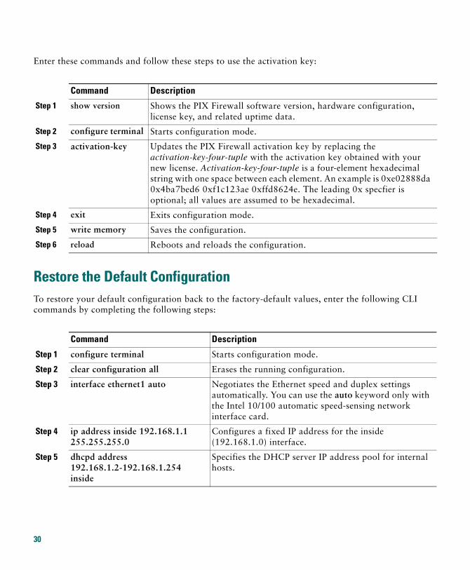
Enter these commands and follow these steps to use the activation key:
Restore the Default ConfigurationTo restore your default configuration back to the factory-default values, enter the following CLI commands by completing the following steps:
Command Description
Step 1 show version Shows the PIX Firewall software version, hardware configuration, license key, and related uptime data.
Step 2 configure terminal Starts configuration mode.
Step 3 activation-key Updates the PIX Firewall activation key by replacing the activation-key-four-tuple with the activation key obtained with your new license. Activation-key-four-tuple is a four-element hexadecimal string with one space between each element. An example is 0xe02888da 0x4ba7bed6 0xf1c123ae 0xffd8624e. The leading 0x specfier is optional; all values are assumed to be hexadecimal.
Step 4 exit Exits configuration mode.
Step 5 write memory Saves the configuration.
Step 6 reload Reboots and reloads the configuration.
Command Description
Step 1 configure terminal Starts configuration mode.
Step 2 clear configuration all Erases the running configuration.
Step 3 interface ethernet1 auto Negotiates the Ethernet speed and duplex settings automatically. You can use the auto keyword only with the Intel 10/100 automatic speed-sensing network interface card.
Step 4 ip address inside 192.168.1.1 255.255.255.0
Configures a fixed IP address for the inside (192.168.1.0) interface.
Step 5 dhcpd address 192.168.1.2-192.168.1.254 inside
Specifies the DHCP server IP address pool for internal hosts.
30
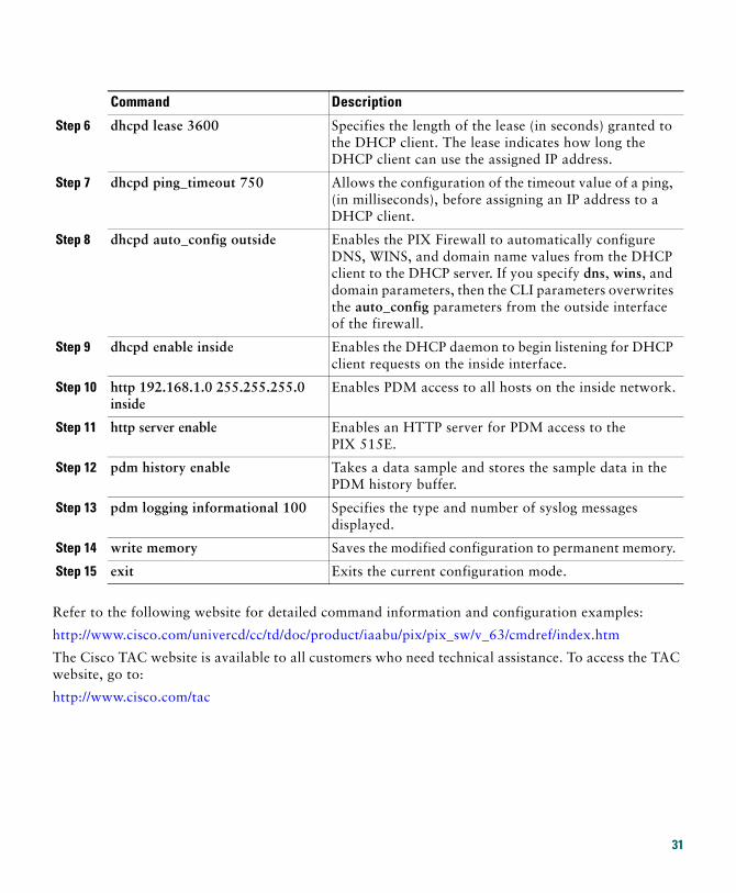
Refer to the following website for detailed command information and configuration examples:
http://www.cisco.com/univercd/cc/td/doc/product/iaabu/pix/pix_sw/v_63/cmdref/index.htm
The Cisco TAC website is available to all customers who need technical assistance. To access the TAC website, go to:
http://www.cisco.com/tac
Step 6 dhcpd lease 3600 Specifies the length of the lease (in seconds) granted to the DHCP client. The lease indicates how long the DHCP client can use the assigned IP address.
Step 7 dhcpd ping_timeout 750 Allows the configuration of the timeout value of a ping, (in milliseconds), before assigning an IP address to a DHCP client.
Step 8 dhcpd auto_config outside Enables the PIX Firewall to automatically configure DNS, WINS, and domain name values from the DHCP client to the DHCP server. If you specify dns, wins, and domain parameters, then the CLI parameters overwrites the auto_config parameters from the outside interface of the firewall.
Step 9 dhcpd enable inside Enables the DHCP daemon to begin listening for DHCP client requests on the inside interface.
Step 10 http 192.168.1.0 255.255.255.0 inside
Enables PDM access to all hosts on the inside network.
Step 11 http server enable Enables an HTTP server for PDM access to the PIX 515E.
Step 12 pdm history enable Takes a data sample and stores the sample data in the PDM history buffer.
Step 13 pdm logging informational 100 Specifies the type and number of syslog messages displayed.
Step 14 write memory Saves the modified configuration to permanent memory.
Step 15 exit Exits the current configuration mode.
Command Description
31
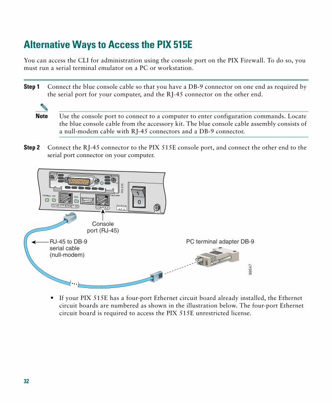
Alternative Ways to Access the PIX 515EYou can access the CLI for administration using the console port on the PIX Firewall. To do so, you must run a serial terminal emulator on a PC or workstation.
Step 1 Connect the blue console cable so that you have a DB-9 connector on one end as required by the serial port for your computer, and the RJ-45 connector on the other end.
Note Use the console port to connect to a computer to enter configuration commands. Locate the blue console cable from the accessory kit. The blue console cable assembly consists of a null-modem cable with RJ-45 connectors and a DB-9 connector.
Step 2 Connect the RJ-45 connector to the PIX 515E console port, and connect the other end to the serial port connector on your computer.
• If your PIX 515E has a four-port Ethernet circuit board already installed, the Ethernet circuit boards are numbered as shown in the illustration below. The four-port Ethernet circuit board is required to access the PIX 515E unrestricted license.
9954
7
RJ-45 to DB-9serial cable (null-modem)
PC terminal adapter DB-9
CONSOLE10/100 ETHERNET 0/0
FDXLink100 Mbps FAILOVER
PIX
-515
Consoleport (RJ-45)
32
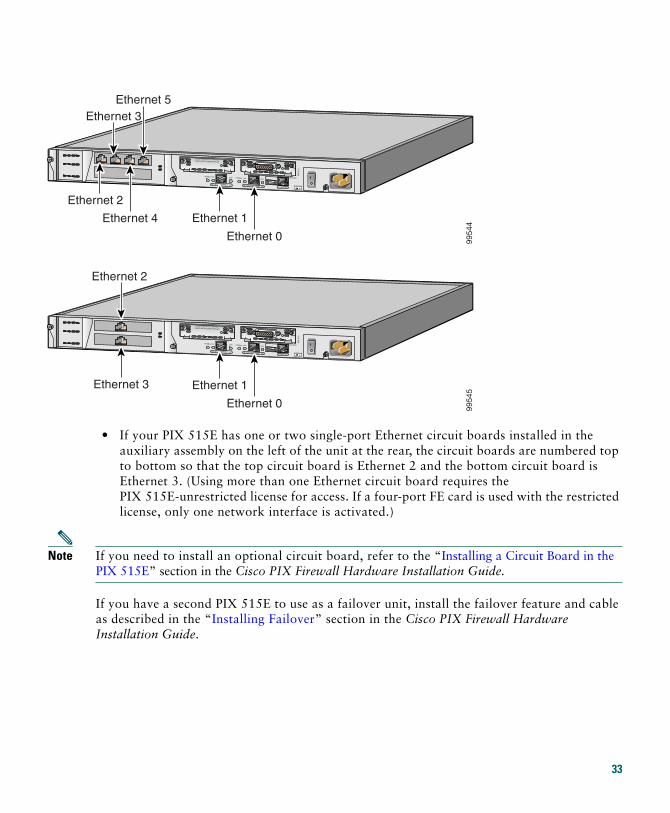
• If your PIX 515E has one or two single-port Ethernet circuit boards installed in the auxiliary assembly on the left of the unit at the rear, the circuit boards are numbered top to bottom so that the top circuit board is Ethernet 2 and the bottom circuit board is Ethernet 3. (Using more than one Ethernet circuit board requires the PIX 515E-unrestricted license for access. If a four-port FE card is used with the restricted license, only one network interface is activated.)
Note If you need to install an optional circuit board, refer to the “Installing a Circuit Board in the PIX 515E” section in the Cisco PIX Firewall Hardware Installation Guide.
If you have a second PIX 515E to use as a failover unit, install the failover feature and cable as described in the “Installing Failover” section in the Cisco PIX Firewall Hardware Installation Guide.
DO NOT INSTALL INTERFACECARDS WITH POWER APPLIED
CONSOLE10/100 ETHERNET 0/0
Link FDXFDX
100 MbpsLink100 Mbps FAILOVER
10/100 ETHERNET 0/0
PIX
-515
9954
4
Ethernet 2
Ethernet 4 Ethernet 1
Ethernet 0
Ethernet 3Ethernet 5
DO NOT INSTALL INTERFACECARDS WITH POWER APPLIED
CONSOLE10/100 ETHERNET 0/0
Link FDXFDX
100 MbpsLink100 Mbps FAILOVER
10/100 ETHERNET 0/0
PIX
-515
9954
5Ethernet 1
Ethernet 0
Ethernet 3
Ethernet 2
33
Step 3 Connect the inside, outside, or perimeter network cables to the interface ports. Starting from the top left, the connectors are Ethernet 2, Ethernet 3, Ethernet 4, and Ethernet 5. The maximum number of allowed interfaces is six with an unrestricted license.
Note Do not add a single-port circuit board in the extra slot below the four-port circuit board because the maximum number of allowed interfaces is six.
Step 4 Power on the unit from the switch at the rear to start the PIX 515E. Do not power on the failover units until the active unit is configured.
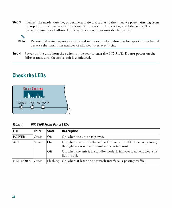
Check the LEDs
Table 1 PIX 515E Front Panel LEDs
LED Color State Description
POWER Green On On when the unit has power.
ACT Green On On when the unit is the active failover unit. If failover is present, the light is on when the unit is the active unit.
Off Off when the unit is in standby mode. If failover is not enabled, this light is off.
NETWORK Green Flashing On when at least one network interface is passing traffic.
POWER ACT NETWORK
9777
9
34
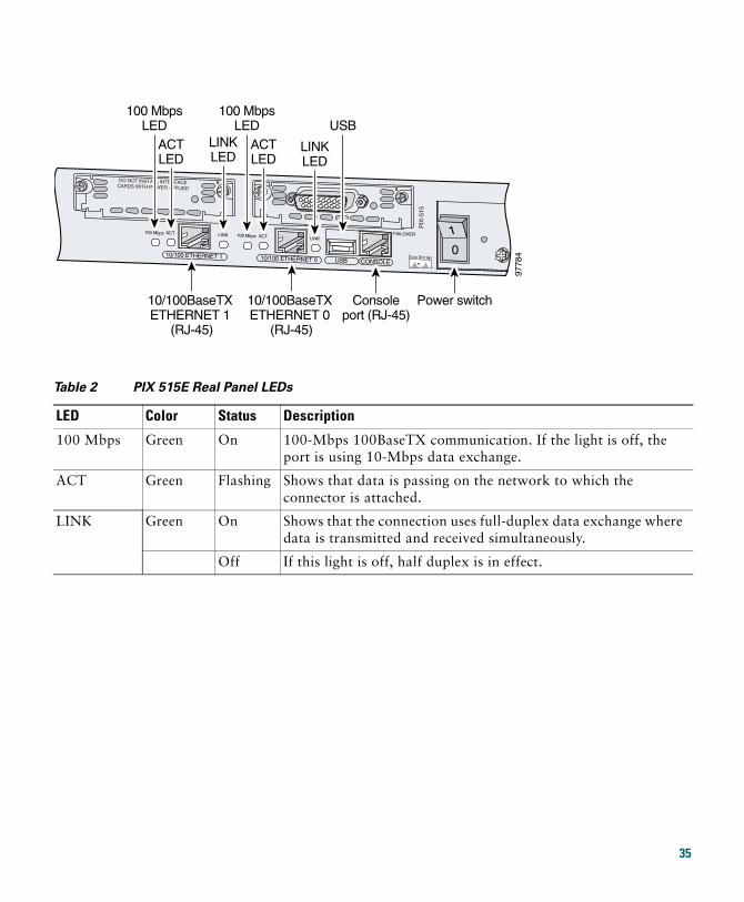
Table 2 PIX 515E Real Panel LEDs
LED Color Status Description
100 Mbps Green On 100-Mbps 100BaseTX communication. If the light is off, the port is using 10-Mbps data exchange.
ACT Green Flashing Shows that data is passing on the network to which the connector is attached.
LINK Green On Shows that the connection uses full-duplex data exchange where data is transmitted and received simultaneously.
Off If this light is off, half duplex is in effect.
9778
4
DO NOT INSTALL INTERFACECARDS WITH POWER APPLIED
CONSOLE10/100 ETHERNET 0
ACT LINKLINK
100 MbpsACT100 Mbps FAILOVER
USB10/100 ETHERNET 1
PIX
-515
10/100BaseTX ETHERNET 0
(RJ-45)
10/100BaseTX ETHERNET 1
(RJ-45)
Consoleport (RJ-45)
Power switch
ACTLED
100 MbpsLED
LINKLED
ACTLED
100 MbpsLED
LINKLED
USB
35
6 Obtaining DocumentationCisco provides several ways to obtain documentation, technical assistance, and other technical resources. These sections explain how to obtain technical information from Cisco Systems.
Cisco.comYou can access the most current Cisco documentation on the World Wide Web at this URL:
http://www.cisco.com/univercd/home/home.htm
You can access the Cisco website at this URL:
http://www.cisco.com
International Cisco websites can be accessed from this URL:
http://www.cisco.com/public/countries_languages.shtml
Documentation CD-ROMCisco documentation and additional literature are available in a Cisco Documentation CD-ROM package, which may have shipped with your product. The Documentation CD-ROM is updated regularly and may be more current than printed documentation. The CD-ROM package is available as a single unit or through an annual or quarterly subscription.
Registered Cisco.com users can order a single Documentation CD-ROM (product number DOC-CONDOCCD=) through the Cisco Ordering tool:
http://www.cisco.com/en/US/partner/ordering/ordering_place_order_ordering_tool_launch.html
All users can order annual or quarterly subscriptions through the online Subscription Store:
http://www.cisco.com/go/subscription
Click Subscriptions & Promotional Materials in the left navigation bar.
Ordering DocumentationYou can find instructions for ordering documentation at this URL:
http://www.cisco.com/univercd/cc/td/doc/es_inpck/pdi.htm
36
You can order Cisco documentation in these ways:
• Registered Cisco.com users (Cisco direct customers) can order Cisco product documentation from the Networking Products MarketPlace:
http://www.cisco.com/en/US/partner/ordering/index.shtml
• Nonregistered Cisco.com users can order documentation through a local account representative by calling Cisco Systems Corporate Headquarters (California, USA) at 408 526-7208 or, elsewhere in North America, by calling 800 553-NETS (6387).
7 Documentation FeedbackYou can submit e-mail comments about technical documentation to [email protected].
You can submit comments by using the response card (if present) behind the front cover of your document or by writing to the following address:
Cisco SystemsAttn: Customer Document Ordering170 West Tasman DriveSan Jose, CA 95134-9883
We appreciate your comments.
8 Obtaining Technical AssistanceFor all customers, partners, resellers, and distributors who hold valid Cisco service contracts, the Cisco Technical Assistance Center (TAC) provides 24-hour-a-day, award-winning technical support services, online and over the phone. Cisco.com features the Cisco TAC website as an online starting point for technical assistance. If you do not hold a valid Cisco service contract, please contact your reseller.
Cisco TAC WebsiteThe Cisco TAC website provides online documents and tools for troubleshooting and resolving technical issues with Cisco products and technologies. The Cisco TAC website is available 24 hours a day, 365 days a year. The Cisco TAC website is located at this URL:
http://www.cisco.com/tac
Accessing all the tools on the Cisco TAC website requires a Cisco.com user ID and password. If you have a valid service contract but do not have a login ID or password, register at this URL:
http://tools.cisco.com/RPF/register/register.do
37
Opening a TAC CaseUsing the online TAC Case Open Tool is the fastest way to open P3 and P4 cases. (P3 and P4 cases are those in which your network is minimally impaired or for which you require product information.) After you describe your situation, the TAC Case Open Tool automatically recommends resources for an immediate solution. If your issue is not resolved using the recommended resources, your case will be assigned to a Cisco TAC engineer. The online TAC Case Open Tool is located at this URL:
http://www.cisco.com/tac/caseopen
For P1 or P2 cases (P1 and P2 cases are those in which your production network is down or severely degraded) or if you do not have Internet access, contact Cisco TAC by telephone. Cisco TAC engineers are assigned immediately to P1 and P2 cases to help keep your business operations running smoothly.
To open a case by telephone, use one of the following numbers:
Asia-Pacific: +61 2 8446 7411 (Australia: 1 800 805 227) EMEA: +32 2 704 55 55 USA: 1 800 553-2447
For a complete listing of Cisco TAC contacts, go to this URL:
http://www.cisco.com/warp/public/687/Directory/DirTAC.shtml
TAC Case Priority DefinitionsTo ensure that all cases are reported in a standard format, Cisco has established case priority definitions.
Priority 1 (P1)—Your network is “down” or there is a critical impact to your business operations. You and Cisco will commit all necessary resources around the clock to resolve the situation.
Priority 2 (P2)—Operation of an existing network is severely degraded, or significant aspects of your business operation are negatively affected by inadequate performance of Cisco products. You and Cisco will commit full-time resources during normal business hours to resolve the situation.
Priority 3 (P3)—Operational performance of your network is impaired, but most business operations remain functional. You and Cisco will commit resources during normal business hours to restore service to satisfactory levels.
Priority 4 (P4)—You require information or assistance with Cisco product capabilities, installation, or configuration. There is little or no effect on your business operations.
38
9 Obtaining Additional Publications and InformationInformation about Cisco products, technologies, and network solutions is available from various online and printed sources.
• The Cisco Product Catalog describes the networking products offered by Cisco Systems, as well as ordering and customer support services. Access the Cisco Product Catalog at this URL:
http://www.cisco.com/en/US/doctypes/prod_series_index_listing_sitecopy.html
• Cisco Press publishes a wide range of general networking, training and certification titles. Both new and experienced users will benefit from these publications. For current Cisco Press titles and other information, go to Cisco Press online at this URL:
http://www.ciscopress.com
• Packet magazine is the Cisco quarterly publication that provides the latest networking trends, technology breakthroughs, and Cisco products and solutions to help industry professionals get the most from their networking investment. Included are networking deployment and troubleshooting tips, configuration examples, customer case studies, tutorials and training, certification information, and links to numerous in-depth online resources. You can access Packet magazine at this URL:
http://www.cisco.com/packet
• Internet Protocol Journal is a quarterly journal published by Cisco Systems for engineering professionals involved in designing, developing, and operating public and private internets and intranets. You can access the Internet Protocol Journal at this URL:
http://www.cisco.com/en/US/about/ac123/ac147/about_cisco_the_internet_protocol_journal.html
• Training—Cisco offers world-class networking training. Current offerings in network training are listed at this URL:
http://www.cisco.com/en/US/learning/index.html
39

40
Corporate HeadquartersCisco Systems, Inc.170 West Tasman DriveSan Jose, CA 95134-1706USAwww.cisco.comTel: 408 526-4000
800 553-NETS (6387)Fax: 408 526-4100
European HeadquartersCisco Systems International BVHaarlerbergparkHaarlerbergweg 13-191101 CH AmsterdamThe Netherlandswww-europe.cisco.comTel: 31 0 20 357 1000Fax: 31 0 20 357 1100
Americas HeadquartersCisco Systems, Inc.170 West Tasman DriveSan Jose, CA 95134-1706USAwww.cisco.comTel: 408 526-7660Fax: 408 527-0883
Asia Pacific HeadquartersCisco Systems, Inc.Capital Tower168 Robinson Road#22-01 to #29-01Singapore 068912www.cisco.comTel: +65 6317 7777Fax: +65 6317 7799
Cisco Systems has more than 200 offices in the following countries. Addresses, phone numbers, and fax numbers are listed on theC i s c o W e b s i t e a t w w w . c i s c o . c o m / g o / o f f i c e s
Argentina • Australia • Austria • Belgium • Brazil • Bulgaria • Canada • Chile • China PRC • Colombia • Costa Rica • Croatia • Czech Republic • Denmark • Dubai, UAEFinland • France • Germany • Greece • Hong Kong SAR • Hungary • India • Indonesia • Ireland • Israel • Italy • Japan • Korea • Luxembourg • Malaysia • MexicoThe Netherlands • New Zealand • Norway • Peru • Philippines • Poland • Portugal • Puerto Rico • Romania • Russia • Saudi Arabia • Scotland • Singapore • SlovakiaSlovenia • South Africa • Spain • Sweden • Switzerland • Taiwan • Thailand • Turkey • Ukraine • United Kingdom • United States • Venezuela • Vietnam • Zimbabwe
CCIP, CCSP, the Cisco Arrow logo, the Cisco Powered Network mark, Cisco Unity, Follow Me Browsing, FormShare, and StackWise are trademarks of Cisco Systems, Inc.;Changing the Way We Work, Live, Play, and Learn, and iQuick Study are service marks of Cisco Systems, Inc.; and Aironet, ASIST, BPX, Catalyst, CCDA, CCDP, CCIE, CCNA,CCNP, Cisco, the Cisco Certified Internetwork Expert logo, Cisco IOS, the Cisco IOS logo, Cisco Press, Cisco Systems, Cisco Systems Capital, the Cisco Systems logo,Empowering the Internet Generation, Enterprise/Solver, EtherChannel, EtherSwitch, Fast Step, GigaStack, Internet Quotient, IOS, IP/TV, iQ Expertise, the iQ logo, iQ NetReadiness Scorecard, LightStream, MGX, MICA, the Networkers logo, Networking Academy, Network Registrar, Packet, PIX, Post-Routing, Pre-Routing, RateMUX, Registrar,ScriptShare, SlideCast, SMARTnet, StrataView Plus, Stratm, SwitchProbe, TeleRouter, The Fastest Way to Increase Your Internet Quotient, TransPath, and VCO are registeredtrademarks of Cisco Systems, Inc. and/or its affiliates in the U.S. and certain other countries.
All other trademarks mentioned in this document or Web site are the property of their respective owners. The use of the word partner does not imply a partnership relationshipbetween Cisco and any other company. (0304R)
Printed in the USA on recycled paper containing 10% postconsumer waste.
78-16055-01

42