cisco ios asynchronous transfer mode command … · cisco ios asynchronous transfer mode ... (acr),...
TRANSCRIPT

Corporate HeadquartersCisco Systems, Inc.170 West Tasman DriveSan Jose, CA 95134-1706 USAhttp://www.cisco.comTel: 408 526-4000
800 553-NETS (6387)Fax: 408 526-4100
Cisco IOS Asynchronous Transfer ModeCommand ReferenceRelease 12.4T
Text Part Number: OL-7920-01

THE SPECIFICATIONS AND INFORMATION REGARDING THE PRODUCTS IN THIS MANUAL ARE SUBJECT TO CHANGE WITHOUT NOTICE. ALL STATEMENTS, INFORMATION, AND RECOMMENDATIONS IN THIS MANUAL ARE BELIEVED TO BE ACCURATE BUT ARE PRESENTED WITHOUT WARRANTY OF ANY KIND, EXPRESS OR IMPLIED. USERS MUST TAKE FULL RESPONSIBILITY FOR THEIR APPLICATION OF ANY PRODUCTS.
THE SOFTWARE LICENSE AND LIMITED WARRANTY FOR THE ACCOMPANYING PRODUCT ARE SET FORTH IN THE INFORMATION PACKET THAT SHIPPED WITH THE PRODUCT AND ARE INCORPORATED HEREIN BY THIS REFERENCE. IF YOU ARE UNABLE TO LOCATE THE SOFTWARE LICENSE OR LIMITED WARRANTY, CONTACT YOUR CISCO REPRESENTATIVE FOR A COPY.
The Cisco implementation of TCP header compression is an adaptation of a program developed by the University of California, Berkeley (UCB) as part of UCB’s public domain version of the UNIX operating system. All rights reserved. Copyright © 1981, Regents of the University of California.
NOTWITHSTANDING ANY OTHER WARRANTY HEREIN, ALL DOCUMENT FILES AND SOFTWARE OF THESE SUPPLIERS ARE PROVIDED “AS IS” WITH ALL FAULTS. CISCO AND THE ABOVE-NAMED SUPPLIERS DISCLAIM ALL WARRANTIES, EXPRESSED OR IMPLIED, INCLUDING, WITHOUT LIMITATION, THOSE OF MERCHANTABILITY, FITNESS FOR A PARTICULAR PURPOSE AND NONINFRINGEMENT OR ARISING FROM A COURSE OF DEALING, USAGE, OR TRADE PRACTICE.
IN NO EVENT SHALL CISCO OR ITS SUPPLIERS BE LIABLE FOR ANY INDIRECT, SPECIAL, CONSEQUENTIAL, OR INCIDENTAL DAMAGES, INCLUDING, WITHOUT LIMITATION, LOST PROFITS OR LOSS OR DAMAGE TO DATA ARISING OUT OF THE USE OR INABILITY TO USE THIS MANUAL, EVEN IF CISCO OR ITS SUPPLIERS HAVE BEEN ADVISED OF THE POSSIBILITY OF SUCH DAMAGES.
Any Internet Protocol (IP) addresses used in this document are not intended to be actual addresses. Any examples, command display output, and figures included in the document are shown for illustrative purposes only. Any use of actual IP addresses in illustrative content is unintentional and coincidental.
Cisco IOS Asynchronous Transfer Mode Command Reference© 1992–2006 Cisco Systems, Inc. All rights reserved.
CCSP, CCVP, the Cisco Square Bridge logo, Follow Me Browsing, and StackWise are trademarks of Cisco Systems, Inc.; Changing the Way We Work, Live, Play, and Learn, and iQuick Study are service marks of Cisco Systems, Inc.; and Access Registrar, Aironet, BPX, Catalyst, CCDA, CCDP, CCIE, CCIP, CCNA, CCNP, Cisco, the Cisco Certified Internetwork Expert logo, Cisco IOS, Cisco Press, Cisco Systems, Cisco Systems Capital, the Cisco Systems logo, Cisco Unity, Enterprise/Solver, EtherChannel, EtherFast, EtherSwitch, Fast Step, FormShare, GigaDrive, GigaStack, HomeLink, Internet Quotient, IOS, IP/TV, iQ Expertise, the iQ logo, iQ Net Readiness Scorecard, LightStream, Linksys, MeetingPlace, MGX, the Networkers logo, Networking Academy, Network Registrar, Packet, PIX, Post-Routing, Pre-Routing, ProConnect, RateMUX, ScriptShare, SlideCast, SMARTnet, The Fastest Way to Increase Your Internet Quotient, and TransPath are registered trademarks of Cisco Systems, Inc. and/or its affiliates in the United States and certain other countries.
All other trademarks mentioned in this document or Website are the property of their respective owners. The use of the word partner does not imply a partnership relationship between Cisco and any other company. (0601R)

iiiCisco IOS Asynchronous Transfer Mode Command Reference
C O N T E N T S
Introduction ATM-1
Cisco IOS ATM Commands ATM-3

Contents
ivCisco IOS Asynchronous Transfer Mode Command Reference
ATM-1Cisco IOS Asynchronous Transfer Mode Command Reference
Introduction
This document describes the commands used to configure ATM features with Cisco IOS software. ATM commands are used to configure ATM interfaces and to configure serial interfaces for ATM access. For ATM configuration information and examples, refer to the “Configuring ATM” section of the Cisco IOS Wide-Area Networking Configuration Guide.
Prior to Cisco IOS Release 12.3(14)T, the commands for configuring ATM features were presented in separate command reference books:
• The commands for configuring LAN ATM features were presented in the Cisco IOS Switching Services Command Reference.
• The commands for configuring WAN ATM features were presented in the Cisco IOS Wide-Area Networking Command Reference.
For information about configuration, refer to the Cisco IOS Asynchronous Transfer Mode Configuration Guide, Release 12.4.

Introduction
ATM-2Cisco IOS Asynchronous Transfer Mode Command Reference
ATM-3Cisco IOS Asynchronous Transfer Mode Command Reference
Cisco IOS ATM Commands
This chapter presents the Cisco IOS ATM commands.

Cisco IOS ATM Commandsabr
ATM-4Cisco IOS Asynchronous Transfer Mode Command Reference
abrTo select available bit rate (ABR) quality of service (QoS) and configure the output peak cell rate and output minimum guaranteed cell rate for an ATM permanent virtual circuit (PVC) or virtual circuit (VC) class, use the abr command in the appropriate command mode. To remove the ABR parameters, use the no form of this command.
abr output-pcr output-mcr
no abr output-pcr output-mcr
Syntax Description
Defaults ABR QoS at the maximum line rate of the physical interface.
Command Modes Interface-ATM-VC configuration (for an ATM PVC) VC-class configuration (for a VC class)PVC range configuration (for an ATM PVC range) PVC-in-range configuration (for an individual PVC within a PVC range)
Command History
Usage Guidelines If the abr command is not explicitly configured on an ATM PVC, the VC inherits the following default configuration (listed in order of precedence):
• Configuration of any QoS command (abr, ubr, ubr+, or vbr-nrt) in a VC class assigned to the PVC itself.
• Configuration of any QoS command (abr, ubr, ubr+, or vbr-nrt) in a VC class assigned to the PVC’s ATM subinterface.
• Configuration of any QoS command (abr, ubr, ubr+, or vbr-nrt) in a VC class assigned to the PVC’s ATM main interface.
• Global default value: ABR QoS at the maximum line rate of the PVC.
ABR is a quality of service class defined by the ATM Forum for ATM networks. ABR is used for connections that do not require timing relationships between source and destination. ABR provides no guarantees in terms of cell loss or delay, providing only best-effort service. Traffic sources adjust their transmission rate in response to information they receive describing the status of the network and its capability to successfully deliver data.
output-pcr The output peak cell rate, in kilobits per second.
output-mcr The output minimum guaranteed cell rate, in kilobits per second.
Release Modification
11.1 This command was introduced.
12.1(5)T This command was modified to be available in PVC range and PVC-in-range configuration modes.

Cisco IOS ATM Commandsabr
ATM-5Cisco IOS Asynchronous Transfer Mode Command Reference
In ABR transmission, the peak cell rate (PCR) specifies the maximum value of the allowed cell rate (ACR), and minimum cell rate (MCR) specifies the minimum value for the ACR. ACR varies between the MCR and the PCR and is dynamically controlled using congestion control mechanisms.
Examples The following example specifies the output-pcr argument to be 100,000 kbps and the output-mcr argument to be 3000 kbps for an ATM PVC:
pvc 1/32abr 100000 3000
Related Commands Command Description
ubr Configures UBR QoS and specifies the output peak cell rate for an ATM PVC, SVC, VC class, or VC bundle member.
ubr+ Configures UBR QoS and specifies the output peak cell rate and output minimum guaranteed cell rate for an ATM PVC, SVC, VC class or VC bundle member.
vbr-nrt Configures the VBR-NRT QoS and specifies output peak cell rate, output sustainable cell rate, and output maximum burst cell size for an ATM PVC, SVC, or VC class.
Cisco IOS ATM Commandsatm aal aal3/4
ATM-6Cisco IOS Asynchronous Transfer Mode Command Reference
atm aal aal3/4To enable support for ATM adaptation layer 3/4 (AAL3/4) on an ATM interface, use the atm aal aal3/4 command in interface configuration mode. To disable support for AAL3/4 on an ATM interface, use the no form of this command.
atm aal aal3/4
no atm aal aal3/4
Syntax Description This command has no arguments or keywords.
Defaults Support for AAL3/4 is disabled.
Command Modes Interface configuration
Command History
Usage Guidelines This command is supported on Cisco 7500 series routers with ATM Interface Processor (AIP). This command is not supported on the ATM port adapter. Because Cisco 4500 and Cisco 4700 routers always support both AAL3/4 and AAL5, this command is not required on Cisco 4500 and Cisco 4700 routers.
Only one virtual circuit can exist on a subinterface that is being used for AAL3/4 processing, and that virtual circuit must be an AAL3/4 virtual circuit.
The AAL3/4 support feature requires static mapping of all protocols except IP.
Examples The following example enables AAL3/4 on ATM interface 2/0:
interface atm2/0ip address 172.21.177.178 255.255.255.0atm aal aal3/4
Related Commands
Release Modification
10.3 This command was introduced.
Command Description
atm mid-per-vc Limits the number of MID numbers allowed on each VC.
atm multicast Assigns an SMDS E.164 multicast address to the ATM subinterface that supports AAL3/4 and SMDS encapsulation.
atm smds-address Assigns a unicast E.164 address to the ATM subinterface that supports AAL3/4 and SMDS encapsulation.
pvc Creates or assigns a name to an ATM PVC, specifies the encapsulation type on an ATM PVC, or enters interface-ATM-VC configuration mode.

Cisco IOS ATM Commandsatm abr rate-factor
ATM-7Cisco IOS Asynchronous Transfer Mode Command Reference
atm abr rate-factorTo configure the amount by which the cell transmission rate increases or decreases in response to flow control information from the network or destination for available bit rate (ABR) virtual circuits (VCs), use the atm abr rate-factor command in interface configuration mode. To return to the default, use the no form of this command.
atm abr rate-factor [rate-increase-factor] [rate-decrease-factor]
no atm abr rate-factor [rate-increase-factor] [rate-decrease-factor]
Syntax Description
Defaults ABR rate increase and decrease factor is 16.
Command Modes Interface configuration
Command History
Usage Guidelines To configure an ABR VC, use the pvc command with the abr keyword.
To verify the ABR rate factor, use the show atm interface atm EXEC command.
Examples The following example sets the ABR rate factor to 32 for the next cell transferred on ATM interface 4/0:
interface atm 4/0atm abr rate-factor 32 32
Related Commands
rate-increase-factor (Optional) Factor by which to increase the data rate. The rate increase factor is specified in powers of 2 from 1 to 32768.
rate-decrease-factor (Optional) Factor by which to decrease the data rate. The rate decrease factor is specified in powers of 2 from 1 to 32768.
Release Modification
11.1 This command was introduced.
Command Description
pvc Configures the PVC interface.
show atm interface atm Displays ATM-specific information about an ATM interface.

Cisco IOS ATM Commandsatm address-registration
ATM-8Cisco IOS Asynchronous Transfer Mode Command Reference
atm address-registrationTo enable the router to engage in address registration and callback functions with the Interim Local Management Interface (ILMI), use the atm address-registration command in interface configuration mode. To disable ILMI address registration functions, use the no form of this command.
atm address-registration
no atm address-registration
Syntax Description This command has no arguments or keywords.
Defaults Enabled
Command Modes Interface configuration
Command History
Usage Guidelines This command enables a router to register its address with the ILMI for callback when specific events occur, such as incoming Simple Network Management Protocol (SNMP) traps or incoming new network prefixes.
Examples The following example enables ATM interface 1/0 to register its address:
interface atm 1/0atm address-registration
Related Commands
Release Modification
11.0 This command was introduced.
Command Description
atm ilmi-keepalive Enables ILMI keepalives.

Cisco IOS ATM Commandsatm arp-server
ATM-9Cisco IOS Asynchronous Transfer Mode Command Reference
atm arp-serverTo identify an ATM Address Resolution Protocol (ARP) server for the IP network or set time-to-live (TTL) values for entries in the ATM ARP table, use the atm arp-server command in interface configuration mode. To remove the definition of an ATM ARP server, use the no form of this command.
atm arp-server [self | nsap nsap-address] [time-out minutes]
no atm arp-server [self [time-out minutes] | [nsap nsap-address]]
Syntax Description
Defaults The default timeout value is 20 minutes.
The ARP server process is disabled.
Command Modes Interface configuration
Command History
Usage Guidelines If an NSAP address is specified, the ARP client on this interface uses the specified host as an ARP server. You can specify multiple ATM ARP servers by repeating the command. If self is specified, this interface acts as the ARP server for the logical IP network.
The ATM ARP server takes one of the following actions if a destination listed in the server’s ARP table expires:
• If a virtual circuit still exists to that destination, the server sends an Inverse ARP request. If no response arrives, the entry times out.
• If a virtual circuit does not exist to the destination, the entry times out immediately.
This implementation follows RFC 1577, Classical IP over ATM.
To configure redundant ARP servers, you must first enable redundant ARP server support by entering the atm classic-ip-extensions command with the BFI keyword.
self (Optional) Specifies the current router as the ATM ARP server.
time-out minutes (Optional) Number of minutes for which a destination entry listed in the ATM ARP server’s ARP table will be kept before the server takes any action to verify or time out the entry.
nsap nsap-address (Optional) Network service access point (NSAP) address of an ATM ARP server.
Release Modification
11.1 This command was introduced.

Cisco IOS ATM Commandsatm arp-server
ATM-10Cisco IOS Asynchronous Transfer Mode Command Reference
Examples The following example configures ATM on an interface and configures the interface to function as the ATM ARP server for the IP subnetwork:
interface atm 0/0ip address 10.0.0.1.255.0.0.0
atm nsap-address ac.1533.66.020000.0000.0000.0000.0000.0000.0000.00atm rate-queue 1 100atm maxvc 1024atm pvc 1 0 5 qsaalatm arp-server self
Related Commands Command Description
atm classic-ip-extensions Enables support for redundant ATM ARP servers on a single LIS.

Cisco IOS ATM Commandsatm classic-ip-extensions
ATM-11Cisco IOS Asynchronous Transfer Mode Command Reference
atm classic-ip-extensionsTo enable support for redundant ATM Address Resolution Protocol (ARP) servers on a single logical IP subnetwork (LIS), use the atm classic-ip-extensions command in interface configuration mode. To remove support for redundant ATM ARP servers, use the no form of this command.
atm classic-ip-extensions {BFI | none}
no atm classic-ip-extensions
Syntax Description
Defaults Redundant ATM ARP server support is not enabled.
Command Modes Interface configuration
Command History
Usage Guidelines Cisco’s implementation of the ATM ARP server supports redundant ATM ARP servers on a single logical IP subnetwork (LIS). In order for redundant ATM ARP server support to work, all of the devices on the LIS must be Cisco devices and must have the atm classic-ip-extensions BFI command configured.
The none keyword enables behavior that complies with RFC 1577, Classical IP over ATM. RFC 1577 does not support redundant ARP servers.
Examples The following example shows how to configure redundant ARP servers on an ATM interface:
Router(config)# interface atm 1/0Router(config-if)# atm classic-ip-extensions BFIRouter(config-if)# atm arp-server nsap 47.000580FFE1000000F21A3167.666666666666.00Router(config-if)# atm arp-server nsap 47.000580FFE1000000F21A3167.555555555555.00
Related Commands
BFI Enables simple redundant ARP server support. BFI as an acronym is undefined.
none Enables standard RFC 1577 behavior (no redundant ARP server support).
Release Modification
11.2 This command was introduced.
Command Description
atm arp-server Identifies an ATM Address Resolution Protocol (ARP) server for the IP network or sets TTL values for entries in the ATM ARP table.

Cisco IOS ATM Commandsatm clock internal
ATM-12Cisco IOS Asynchronous Transfer Mode Command Reference
atm clock internalTo cause the ATM interface to generate the transmit clock internally, use the atm clock internal command in interface configuration mode. To restore the default value, use the no form of this command.
atm clock internal
no atm clock internal
Syntax Description This command has no arguments or keywords.
Defaults The ATM interface uses the transmit clock signal from the remote connection (the line). The switch provides the clocking.
Command Modes Interface configuration
Command History
Usage Guidelines This command is meaningless on a 4B/5B physical layer interface module (PLIM).
For SONET interfaces, use the atm clock internal command to configure an ATM port adapter to supply its internal clock to the line.
Examples The following example causes the ATM interface to generate the transmit clock internally:
interface atm 4/0atm clock internal
Release Modification
10.0 This command was introduced.

Cisco IOS ATM Commandsatm compression
ATM-13Cisco IOS Asynchronous Transfer Mode Command Reference
atm compressionTo specify the software compression mode on an interface, use the atm compression command in interface configuration mode. To remove the compression mode setting, use the no form of this command.
atm compression {per-packet | per-interface | per-vc}
no atm compression {per-packet | per-interface | per-vc}
Syntax Description
Defaults per-packet
Command Modes Interface configuration
Command History
Usage Guidelines This command applies to ATM configuration on the Cisco MC3810 multiservice concentrator.
Examples The following example configures per-packet ATM compression:
interface atm0atm compression per-packet
per-packet Specifies packet-by-packet compression mode (no history). This is the default.
per-interface Specifies one context per interface (with history).
per-vc Specifies one context for every virtual circuit (with history).
Release Modification
11.3(1)MA This command was introduced on the Cisco MC3810 multiservice concentrator.

Cisco IOS ATM Commandsatm ds3-scramble
ATM-14Cisco IOS Asynchronous Transfer Mode Command Reference
atm ds3-scrambleTo enable scrambling of the ATM cell payload for the DS3 physical layer interface module (PLIM) on an ATM interface, use the atm ds3-scramble command in interface configuration mode. To disable scrambling of the ATM cell payload for the DS3 PLIM, use the no form of this command.
atm ds3-scramble
no atm ds3-scramble
Syntax Description This command has no arguments or keywords.
Defaults DS3 scrambling is not enabled.
Command Modes Interface configuration
Command History
Usage Guidelines DS3 scrambling is used to assist clock recovery on the receiving end.
Examples The following example disables DS3 scrambling on the interface:
interface atm 4/0no atm ds3-scramble
Release Modification
11.0 This command was introduced.
11.1 Command syntax was changed from ds3 scramble to atm ds3-scramble.

Cisco IOS ATM Commandsatm e164 auto-conversion
ATM-15Cisco IOS Asynchronous Transfer Mode Command Reference
atm e164 auto-conversionTo enable ATM E164 autoconversion, use the atm e164 auto-conversion command in interface configuration mode. To disable autoconversion, use the no form of this command.
atm e164 auto-conversion
no atm e164 auto-conversion
Syntax Description This command has no arguments or keywords.
Defaults E.164 auto conversion is not enabled.
Command Modes Interface configuration
Command History
Usage Guidelines You must enable the ATM interface before using the atm e164 auto-conversion command.
When an interface is configured for E.164 auto conversion, ATM E.164 format addresses are converted to the corresponding native E.164 address for outgoing calls. For incoming calls, native E.164 addresses are converted to the corresponding ATM E.164 format.
Examples The following example enables E.164 auto conversion on ATM interface 0/0/1:
interface atm 0/0/1atm e164 auto-conversion
Release Modification
11.3 This command was introduced.

Cisco IOS ATM Commandsatm e3-scramble
ATM-16Cisco IOS Asynchronous Transfer Mode Command Reference
atm e3-scrambleTo enable scrambling of the ATM cell payload for the E3 physical layer interface module (PLIM) on an ATM interface, use the atm e3-scramble command in interface configuration mode. To disable scrambling of the ATM cell payload for the E3 PLIM, use the no form of this command.
atm e3-scramble
no atm e3-scramble
Syntax Description This command has no arguments or keywords.
Defaults E3 scrambling is enabled.
Command Modes Interface configuration
Command History
Usage Guidelines E3 scrambling is used to assist clock recovery on the receiving end.
Examples The following example disables E3 scrambling on the interface:
interface atm 2/0no atm e3-scramble
Release Modification
11.1 This command was introduced.
Cisco IOS ATM Commandsatm esi-address
ATM-17Cisco IOS Asynchronous Transfer Mode Command Reference
atm esi-addressTo enter the end station ID (ESI) and selector byte fields of the ATM network service access point (NSAP) address, use the atm esi-address command in interface configuration mode. The NSAP address prefix is filled in via Integrated Local Management Interface (ILMI) from the ATM switch. To delete the end station address, use the no form of this command.
atm esi-address esi.selector
no atm esi-address esi.selector
Syntax Description
Defaults No ESI is defined.
Command Modes Interface configuration
Command History
Usage Guidelines The atm esi-address command allows you to configure the ATM address by entering the ESI (12 hexadecimal characters) and the selector byte (2 hexadecimal characters). The ATM prefix (26 hexadecimal characters) will be provided by the ATM switch. To get the prefix from the ATM switch, the ILMI permanent virtual circuit (PVC) must be configured on the router and the ATM switch must be able to supply a prefix via ILMI. A period must be used to separate the esi from the selector arguments.
Note When ILMI is configured, use the atm esi-address command instead of the atm nsap-address command. The atm esi-address and atm nsap-address commands are mutually exclusive. Configuring the router with the atm esi-address command negates the atm nsap-address setting, and vice versa.
The ILMI PVC must be configured in order to get an NSAP address prefix from the switch.
Examples The following example sets up the ILMI PVC and assigns the ESI and selector field values on the ATM interface 4/0:
interface atm 4/0atm pvc 2 0 16 ilmiatm esi-address 345678901234.12
esi End station ID field value in hexadecimal; 6 bytes long.
.selector Selector field value in hexadecimal; 1 byte long. Dot is required as a separator.
Release Modification
11.1 This command was introduced.

Cisco IOS ATM Commandsatm esi-address
ATM-18Cisco IOS Asynchronous Transfer Mode Command Reference
Related Commands Command Description
atm nsap-address Sets the NSAP address for an ATM interface using SVC mode.
ilmi manage Enables ILMI management on an ATM PVC.
pvc Configures the PVC interface.

Cisco IOS ATM Commandsatm exception-queue
ATM-19Cisco IOS Asynchronous Transfer Mode Command Reference
atm exception-queueTo set the exception queue length, use the atm exception-queue command in interface configuration mode. To restore the default value, use the no form of this command.
atm exception-queue number
no atm exception-queue
Syntax Description
Defaults 32 entries
Command Modes Interface configuration
Command History
Usage Guidelines This command is supported on ATM interface processor (AIP) for Cisco 7500 series routers. This command is not supported on the ATM port adapter for Cisco 7200 and 7500 series routers, nor is it supported on Cisco 4500 and Cisco 4700 routers.
The exception queue is used for reporting ATM events, such as cycle redundancy check (CRC) errors.
Examples The following example sets the exception queue to 50 entries:
atm exception-queue 50
number Number of entries. Range is from 8 to 256. Default is 32.
Release Modification
10.0 This command was introduced.

Cisco IOS ATM Commandsatm framing (DS3)
ATM-20Cisco IOS Asynchronous Transfer Mode Command Reference
atm framing (DS3)To specify digital signal level 3 (DS3) line framing on an ATM interface, use the atm framing command in interface configuration mode. To return to the default C-bit with Physical Layer Convergence Protocol (PLCP) framing, use the no form of this command.
atm framing [cbitadm | cbitplcp | m23adm | m23plcp]
no atm framing [cbitadm | cbitplcp | m23adm | m23plcp]
Syntax Description
Defaults cbitplcp
Command Modes Interface configuration
Command History
Usage Guidelines This command is available on Cisco 4500 and 4700 routers with DS3 access speeds, Cisco 7200 series routers, and Cisco 7500 series routers.
Framing on the interface must match that on the switch for this ATM link.
Examples The following example specifies M23 ADM framing on a router that has been set up with DS3 access to an ATM network:
interface atm 4/0atm framing m23adm
cbitadm (Optional) Specifies C-bit with ATM direct mapping (ADM).
cbitplcp (Optional) Specifies C-bit with PLCP framing.
m23adm (Optional) Specifies M23 ATM direct mapping.
m23plcp (Optional) Specifies M23 with PLCP framing.
Release Modification
11.0 This command was introduced.
11.1 This command was modified to include the Cisco 7200 series routers with the ATM-CES port adapter.

Cisco IOS ATM Commandsatm framing (E3)
ATM-21Cisco IOS Asynchronous Transfer Mode Command Reference
atm framing (E3)To specify E3 line framing, use the atm framing command in interface configuration mode. To return to the default G.751 Physical Layer Convergence Protocol (PLCP) framing, use the no form of this command.
atm framing [g751adm | g832adm | g751plcp]
no atm framing [g751adm | g832adm | g751plcp]
Syntax Description
Defaults g751plcp
Command Modes Interface configuration
Command History
Usage Guidelines The default framing is described in the ITU-T Recommendation G.751.
Framing on the interface must match that on the switch for this ATM link.
Examples The following example specifies G.832 ADM framing on a router that has been set up with E3 access to an ATM network:
interface atm 4/0atm framing g832adm
g751adm (Optional) Specifies G.751 ATM direct mapping (ADM).
g832adm (Optional) Specifies G.832 ATM direct mapping.
g751plcp (Optional) Specifies G.751 PLCP encapsulation.
Release Modification
11.0 This command was introduced.
11.1 The g751plcp keyword was added, together with information on the Cisco 7200 series router with the ATM-CES port adapter.
Cisco IOS ATM Commandsatm ilmi-keepalive
ATM-22Cisco IOS Asynchronous Transfer Mode Command Reference
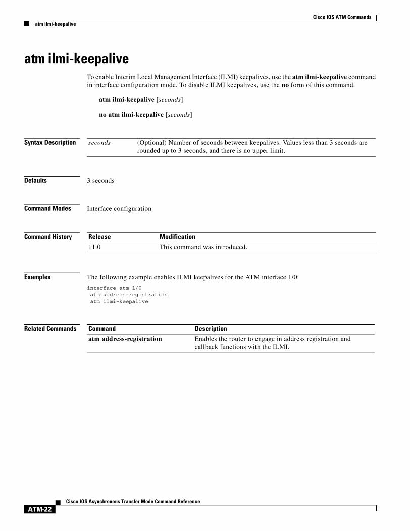
atm ilmi-keepaliveTo enable Interim Local Management Interface (ILMI) keepalives, use the atm ilmi-keepalive command in interface configuration mode. To disable ILMI keepalives, use the no form of this command.
atm ilmi-keepalive [seconds]
no atm ilmi-keepalive [seconds]
Syntax Description
Defaults 3 seconds
Command Modes Interface configuration
Command History
Examples The following example enables ILMI keepalives for the ATM interface 1/0:
interface atm 1/0atm address-registrationatm ilmi-keepalive
Related Commands
seconds (Optional) Number of seconds between keepalives. Values less than 3 seconds are rounded up to 3 seconds, and there is no upper limit.
Release Modification
11.0 This command was introduced.
Command Description
atm address-registration Enables the router to engage in address registration and callback functions with the ILMI.

Cisco IOS ATM Commandsatm ilmi-pvc-discovery
ATM-23Cisco IOS Asynchronous Transfer Mode Command Reference
atm ilmi-pvc-discoveryTo enable ATM permanent virtual circuit (PVC) discovery, use the atm ilmi-pvc-discovery command in interface configuration mode. To disable PVC discovery, use the no form of this command.
atm ilmi-pvc-discovery [subinterface]
no atm ilmi-pvc-discovery [subinterface]
Syntax Description
Defaults PVC discovery is not enabled.
Command Modes Interface configuration
Command History
Examples The following example enables PVC discovery on the ATM main interface 2/0. The subinterface keyword is used so that all discovered PVCs with a VPI value of 1 will be assigned to the subinterface 2/0.1:
interface atm 2/0pvc RouterA 0/16 ilmiexitatm ilmi-pvc-discovery subinterfaceexit
interface atm 2/0.1 multipointip address 172.21.51.5 255.255.255.0
subinterface (Optional) Causes discovered PVCs to be assigned to the ATM subinterface whose number matches the discovered PVC’s VPI number.
Release Modification
11.3 This command was introduced.
Cisco IOS ATM Commandsatm lbo
ATM-24Cisco IOS Asynchronous Transfer Mode Command Reference
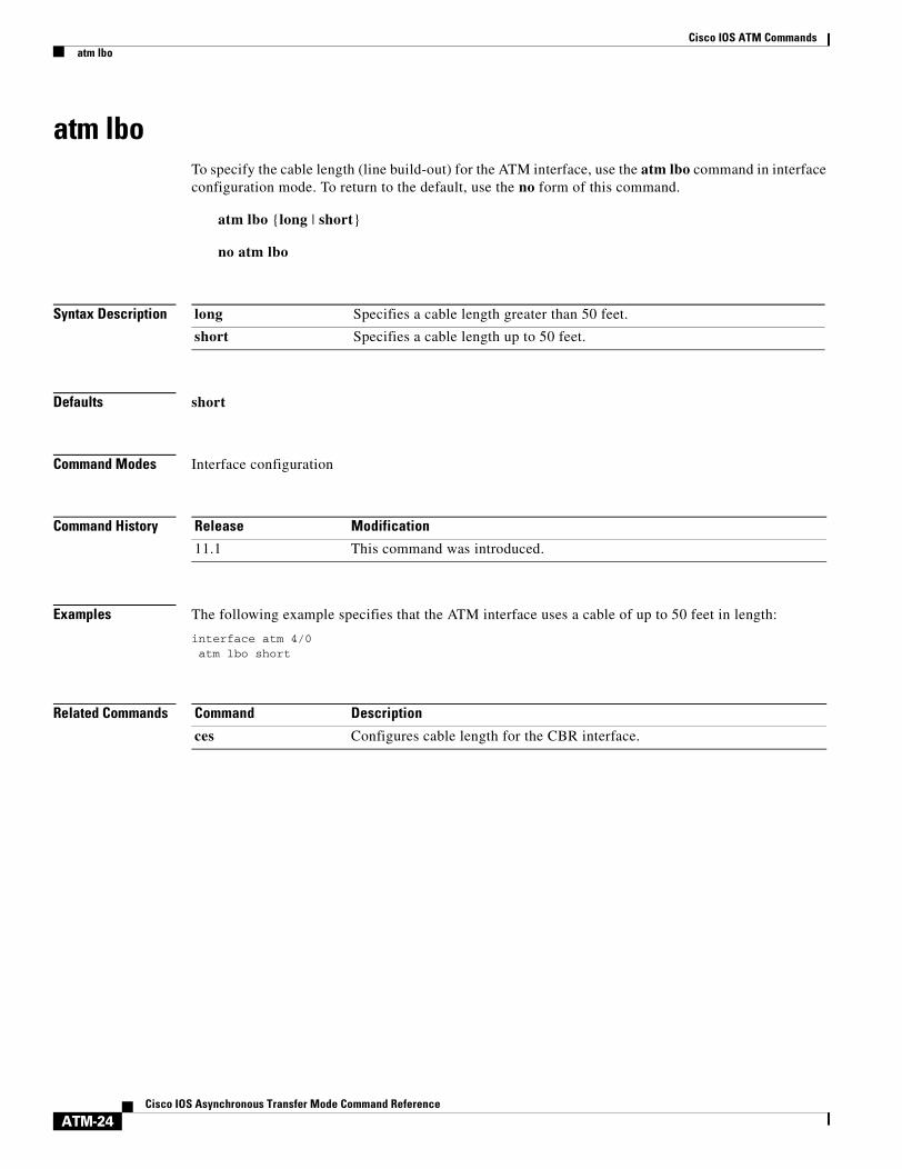
atm lboTo specify the cable length (line build-out) for the ATM interface, use the atm lbo command in interface configuration mode. To return to the default, use the no form of this command.
atm lbo {long | short}
no atm lbo
Syntax Description
Defaults short
Command Modes Interface configuration
Command History
Examples The following example specifies that the ATM interface uses a cable of up to 50 feet in length:
interface atm 4/0atm lbo short
Related Commands
long Specifies a cable length greater than 50 feet.
short Specifies a cable length up to 50 feet.
Release Modification
11.1 This command was introduced.
Command Description
ces Configures cable length for the CBR interface.

Cisco IOS ATM Commandsatm max-channels
ATM-25Cisco IOS Asynchronous Transfer Mode Command Reference
atm max-channelsTo configure the number of transmit channels for the interface, use the atm max-channels command in interface configuration mode. To return to the default, use the no form of this command.
atm max-channels number
no atm max-channels
Syntax Description
Defaults 64 channels
Command Modes Interface configuration
Command History
Usage Guidelines The atm max-channels command replaces the atm tx-channels command.
Transmit Descriptors
The atm max-channels command can be used to divide the available number (fixed) of transmit descriptors across the configured number of transmit channels. Typically, you think of a one-to-one association between a transmit channel and a VC; however, the ATM-CES port adapter supports other types of VCs than data VCs (for example CES VCs). Also, the ATM-CES port adapter can multiplex one or more VCs over a single virtual path (VP) that is shaped, and the VP only requires a single transmit channel. Therefore, the term transmit channel is used rather than virtual circuit.
Maximum Burst
The maximum burst of packets that are allowed per VC is limited by the number of transmit descriptors allocated per VC. Because the total number of transmit descriptors available is limited by the available SRAM space, configuration of the number of transmit channels for the interface determines the number of transmit descriptors for each transmit channel. Hence the burst size for each transmit channel is determined by the atm max-channels command. For example, for 64 (the default) transmit channels for the interface, 255 transmit descriptors are associated per channel, and for 512 transmit channels for the interface, 31 transmit descriptors are associated per channel.
To display information about the transmit descriptors, use the show atm interface atm command.
Examples The following example sets the number of transmit descriptors for the interface to 120.
interface atm 2/0atm max-channels 120
number Maximum number of transmit channels for the interface. The range is from 64 to 2048 channels. The default is 64 channels.
Release Modification
11.1 This command was introduced.

Cisco IOS ATM Commandsatm max-channels
ATM-26Cisco IOS Asynchronous Transfer Mode Command Reference
Related Commands Command Description
show atm interface atm Displays ATM-specific information about an ATM interface.

Cisco IOS ATM Commandsatm maxvc
ATM-27Cisco IOS Asynchronous Transfer Mode Command Reference
atm maxvcTo set the ceiling value of the virtual circuit descriptor (VCD) on the ATM interface, use the atm maxvc command in interface configuration mode. To restore the default value, use the no form of this command.
atm maxvc number
no atm maxvc
Syntax Description
Defaults 2048 virtual circuits
Command Modes Interface configuration
Command History
Usage Guidelines This command is supported on Cisco 7500 series routers; it is not supported on the Cisco 4500 and Cisco 4700 routers, which have a fixed maximum of 1024 VCs.
This command sets the maximum value supported for the vcd argument in the atm pvc command. It also determines the maximum number of virtual circuits on which the AIP allows segmentation and reassembly (SAR) to occur. However, if you set a maxvc limit and then enter the atm pvc command with a larger value for the vcd argument, the software does not generate an error message.
This command does not affect the virtual path identifier (VPI)-virtual channel identifier (VCI) pair of each virtual circuit.
Examples The following example sets a ceiling VCD value of 1024 and restricts the AIP to supporting no more than 1024 virtual circuits:
atm maxvc 1024
Related Commands
number Maximum number of supported virtual circuits. Valid values are 256, 512, 1024, and 2048.
Release Modification
10.0 This command was introduced.
Command Description
pvc Configures an ATM PVC.

Cisco IOS ATM Commandsatm mid-per-vc
ATM-28Cisco IOS Asynchronous Transfer Mode Command Reference
atm mid-per-vcTo limit the number of message identifier (MID) numbers allowed on each virtual circuit, use the atm mid-per-vc command in interface configuration mode.
atm mid-per-vc maximum
Syntax Description
Defaults 16 MIDs per virtual circuit.
Command Modes Interface configuration
Command History
Usage Guidelines This command is supported on Cisco 7200 and 7500 series routers.
MID numbers are used by receiving devices to reassemble cells from multiple sources into packets.
This command limits the number of discrete messages allowed on the PVC at the same time. It does not limit the number of cells associated with each message.
The maximum set by the atm mid-per-vc command overrides the range between the midhigh and midlow values set by the atm pvc command. If you set a maximum of 16 but a midlow of 0 and a midhigh of 255, only 16 MIDs (not 256) are allowed on the virtual circuit.
Examples The following example allows 64 MIDs per ATM virtual circuit:
atm mid-per-vc 64
Related Commands
maximum Number of MIDs allowed per virtual circuit on this interface. The values allowed are 16, 32, 64, 128, 256, 512, and 1024.
Release Modification
10.3 This command was introduced.
Command Description
pvc Configures the PVC interface.

Cisco IOS ATM Commandsatm multicast
ATM-29Cisco IOS Asynchronous Transfer Mode Command Reference
atm multicastTo assign a Switched Multimegabit Data Service (SMDS) E.164 multicast address to the ATM subinterface that supports ATM adaptation layer 3/4 (AAL3/4) and SMDS encapsulation, use the atm multicast command in interface configuration mode.
atm multicast address
Syntax Description
Defaults No multicast E.164 address is defined.
Command Modes Interface configuration
Command History
Usage Guidelines This command is supported on Cisco 7500 series, Cisco 4500, and Cisco 4700 routers. This command is not supported on the ATM port adapter.
Each AAL3/4 subinterface is allowed only one multicast E.164 address. This multicast address is used for all protocol broadcast operations.
Examples The following example assigns a multicast E.164 address to the ATM subinterface that is being configured:
atm multicast e180.0999.000
Related Commands
address Multicast E.164 address assigned to the subinterface.
Release Modification
10.3 This command was introduced.
Command Description
abr Selects ABR QoS and configures output peak cell rate and output minimum guaranteed cell rate for an ATM PVC or VC class.
atm smds-address Assigns a unicast E.164 address to the ATM subinterface that supports AAL3/4 and SMDS encapsulation.
pvc Configures the PVC interface.

Cisco IOS ATM Commandsatm multipoint-interval
ATM-30Cisco IOS Asynchronous Transfer Mode Command Reference
atm multipoint-intervalTo specify how often new destinations can be added to multipoint calls to an ATM switch in the network, use the atm multipoint-interval command in interface configuration mode. To return to the default interval, use the no form of this command.
atm multipoint-interval interval
no atm multipoint-interval interval
Syntax Description
Defaults 30 seconds
Command Modes Interface configuration
Command History
Usage Guidelines This command applies to switched virtual circuits (SVCs) only, not to permanent virtual circuits (PVCs).
This command has no effect unless ATM multipoint signaling is enabled on the interface.
Examples The following example enables point-to-multipoint signaling on the ATM interface 2/0. It also specifies that new destinations can be added to multipoint calls every 60 seconds:
interface atm 2/0atm multipoint-signallingatm multipoint-interval 60
Related Commands
interval Interval length, in seconds. Range is from 0 to 4294967. Default is 30.
Release Modification
11.0 This command was introduced.
Command Description
atm multipoint-signalling Enables point-to-multipoint signaling to the ATM switch.

Cisco IOS ATM Commandsatm multipoint-signalling
ATM-31Cisco IOS Asynchronous Transfer Mode Command Reference
atm multipoint-signallingTo enable point-to-multipoint signaling to the ATM switch, use the atm multipoint-signalling command in interface configuration mode. To disable point-to-multipoint signalling to the ATM switch, use the no form of this command.
atm multipoint-signalling
no atm multipoint-signalling
Syntax Description This command has no arguments or keywords.
Defaults Point-to-multipoint signaling is not enabled.
Command Modes Interface configuration
Command History
Usage Guidelines If multipoint signaling is enabled, the router uses existing static map entries that have the broadcast keyword set to establish multipoint calls. One call is established for each logical subnet of each protocol.
All destinations are added to the call. One multicast packet is sent to the ATM switch for each multipoint call. The ATM switch replicates the packet to all destinations.
The atm multipoint-interval command determines how often new destinations can be added to a multipoint call.
Note Prior to Cisco IOS Release 11.1, when this command was used on the main interface, it also affected all subinterfaces. For Release 11.1 and later, explicit configuration on each subinterface is required to obtain the same functionality.
Examples The following example enables point-to-multipoint signalling on the ATM interface 2/0:
interface atm 2/0atm multipoint-signalling
Related Commands
Release Modification
11.0 This command was introduced.
11.1 Functionality was changed to allow this command on all subinterfaces, not just the main interface.
Command Description
atm multipoint-interval Specifies how often new destinations can be added to multipoint calls to an ATM switch in the network.

Cisco IOS ATM Commandsatm nsap-address
ATM-32Cisco IOS Asynchronous Transfer Mode Command Reference
atm nsap-addressTo set the network service access point (NSAP) address for an ATM interface using switched virtual circuit (SVC) mode, use the atm nsap-address command in interface configuration mode. To remove any configured address for the interface, use the no form of this command.
atm nsap-address nsap-address
no atm nsap-address
Syntax Description
Defaults No NSAP address is defined for this interface.
Command Modes Interface configuration
Command History
Usage Guidelines When configuring an SVC, you must use the atm nsap-address command to define the source NSAP address. It identifies a particular port on the ATM network and must be unique across the network.
Note When the Integrated Local Management Interface (ILMI) is configured, use the atm esi-address command instead of the atm nsap-address command. The atm esi-address and atm nsap-address commands are mutually exclusive. Configuring the router with the atm esi-address command negates the atm nsap-address setting, and vice versa.
Configuring a new address on the interface overwrites the previous address. The router considers the address as a string of bytes and will not prefix or suffix the address with any other strings or digits. The complete NSAP address must be specified, because this value is used in the Calling Party Address Information Element in the SETUP message to establish a virtual circuit.
ATM NSAP addresses have a fixed length of 40 hexadecimal digits. You must configure the complete address in the following dotted format:
xx.xxxx.xx.xxxxxx.xxxx.xxxx.xxxx.xxxx.xxxx.xxxx.xx
Note All ATM NSAP addresses should be entered in the dotted hexadecimal format shown above, which conforms to the User-Network Interface (UNI) specification.The dotted method provides some validation that the address is a legal value. If you know your address format is correct, the dots may be omitted.
nsap-address The 40-digit hexadecimal NSAP address of this interface (the source address).
Release Modification
10.0 This command was introduced.

Cisco IOS ATM Commandsatm nsap-address
ATM-33Cisco IOS Asynchronous Transfer Mode Command Reference
Examples In the following example, the source NSAP address for the interface is AB.CDEF.01.234567.890A.BCDE.F012.3456.7890.1234.12:
atm nsap-address AB.CDEF.01.234567.890A.BCDE.F012.3456.7890.1234.12

Cisco IOS ATM Commandsatm oam flush
ATM-34Cisco IOS Asynchronous Transfer Mode Command Reference
atm oam flushTo drop all current and future Operation, Administration, and Maintenance (OAM) cells received on an ATM interface, use the atm oam flush command in interface configuration mode. To receive OAM cells on an ATM interface, use the no form of this command.
atm oam flush
no atm oam flush
Syntax Description This command has no arguments or keywords.
Defaults Dropping of OAM cells is disabled.
Command Modes Interface configuration
Command History
Examples The following example drops all current and future OAM cells received on the ATM main interface with slot 0 and port 0:
interface atm 0/0atm oam flush
Release Modification
11.3 This command was introduced.

Cisco IOS ATM Commandsatm oversubscribe
ATM-35Cisco IOS Asynchronous Transfer Mode Command Reference
atm oversubscribeTo disable bandwidth management for service categories other than constant bit rate (CBR), use the atm oversubscribe command in interface configuration mode. To enable bandwidth management, use the no form of the command.
atm oversubscribe
no atm oversubscribe
Syntax Description This command has no arguments or keywords.
Command Default The default is to allow as much bandwidth as possible with no upper limits (except on DSL ATM interfaces, in which oversubscription is a factor of 2). The no form of the atm oversubscribe command enables bandwidth management on any ATM interface you specify.
Command Modes Interface configuration
Command History
Usage Guidelines When you type the enabling command (the no version), a check determines if the ATM link is already oversubscribed. If so, the command is rejected. Otherwise, the total bandwidth available on the link is recorded and all future connection setup requests are monitored to ensure that the link is not oversubscribed.
The bandwidth allocated for each service category is displayed in the output of the show atm interface atm command.
The ATM bandwidth manager keeps track of bandwidth used by VCs on a per-interface basis. Because many services require guaranteed bandwidth (for variable bit rate-real time (VBR-RT), available bit rate (ABR), CBR, for instance), bandwidth management is required. The purpose of the bandwidth manager is to reserve resources for connections that require guaranteed services. Bandwidth management for CBR is turned on automatically for all interfaces supporting CBR. Bandwidth management for other service categories must be turned on by the user. All service categories outside CBR are monitored only if specifically requested.
Note Because unspecified bit rate (UBR) does not provide any guarantees, bandwidth specified for a UBR connection is not used in any calculations.
In all cases, bandwidth check for a PVC is done when the PVC is configured. Bandwidth check for a SVC is done when a signaling call is placed or received.
Release Modification
12.0(3)T This command was introduced.
12.4(6)T Support for this command was added to DSL ATM interfaces.

Cisco IOS ATM Commandsatm oversubscribe
ATM-36Cisco IOS Asynchronous Transfer Mode Command Reference
When you specify the atm pvp command, the system checks if the specified bandwidth is available on the interface. If the bandwidth available is greater than or equal to the peak rate specified for the Permanent Virtual Path (PVP), the command is accepted; otherwise the command is rejected.
Within the VC mode, the steps taken to check for bandwidth available are to ascertain if the bandwidth is already used by the VC to fulfill the request. If the VC being configured is a PVC and belongs to a PVP, the bandwidth available on the PVP is used for the check; otherwise the bandwidth available on the interface is used for the check.
When services within a VC class are being configured, the steps taken are to check if the new bandwidth requirement can be fulfilled for all VCs using the class (on a per-interface basis) by comparing with the bandwidth available on the corresponding interface.
Bandwidth checking for an SVC occurs before a SETUP message is sent for an outbound call. If the bandwidth check fails, the SETUP message is not sent. If the bandwidth check passes, the traffic class from which the service category is inherited is updated with the requirements for the new SVC.
When an SVC setup is requested for remotely initiated calls, a bandwidth check occurs as soon as the SETUP message is received. This bandwidth check has two components:
• Match the bandwidth requested by the remote end with the bandwidth configured locally.
• Check if bandwidth configured locally can be satisfied currently.
If the bandwidth check fails, a RELEASE message is sent out and the call is rejected. If the bandwidth check passes, resources are reserved for the VC and the call is accepted.
Examples The following example displays the available bandwidth after you enter VC mode. Notice that the bandwidth is specified in kbps.
Router# show atm interface atm 2/0
Interface ATM2/0:AAL enabled: AAL5, Maximum VCs:1024, Current VCCs:5
Maximum Transmit Channels:64Max. Datagram Size:4496PLIM Type:SONET - 155Mbps, TX clocking:LINECell-payload scrambling:OFFsts-stream scrambling:ON877 input, 120843834 output, 0 IN fast, 20 OUT fastABR parameters, rif:16 rdf:16, 0 out dropBandwidth distribution :CBR :16000 Avail bw = 139000 Config. is ACTIVE
Notice that the bandwidth is specified as 139000 kbps.
Related Commands Command Description
atm oversubscribe factor Enables finite line bandwidth oversubscription for DSL.
show atm interface atm Displays ATM-specific information about an ATM interface.
ubr+ Configures unspecified bit rate plus for an ATM PVC.
vbr-nrt Configures variable bit rate-nonreal time for an ATM PVC.
vbr-rt Configures variable bit rate real-time for VoATM voice connections.

Cisco IOS ATM Commandsatm oversubscribe factor
ATM-37Cisco IOS Asynchronous Transfer Mode Command Reference
atm oversubscribe factorTo set up finite line bandwidth oversubscription for digital subscriber line (DSL), use the atm oversubscribe factor command in interface configuration mode. To disable finite line bandwidth oversubscription for DSL, use the no form of this command.
atm oversubscribe factor factor
no atm oversubscribe factor factor
Syntax Description
Command Default Finite line bandwidth oversubscription for DSL is disabled.
Command Modes Interface configuration
Command History
Usage Guidelines Resource limitations on Cisco xDSL interfaces require a way to configure bandwidth oversubscription up to a defined bandwidth (a finite oversubscription of bandwidth). For this requirement, the atm oversubscribe factor command is used. A DSL ATM interface supports only an oversubscribe factor of 2.
Oversubscription is allowed on variable bit rate real time class (VBR-rt), variable bit rate non-real time class (VBR-nrt), and unspecified bit rate plus (UBR+) permanent virtual circuits (PVCs). With oversubscription enabled, multiple VBR-rt, VBR-nrt, and UBR+ PVCs can be configured even when the sum of their sustainable cell rates (SCRs) exceeds the actual bandwidth available over the physical line. For example, if oversubscription is enabled and an oversubscription factor of 2 is set for a line rate of 2304 kbps, the sum of SCRs and minimum desired cell rates of VBR-rt, VBR-nrt, and UBR+ PVCs must be less than or equal to 4608 kbps, excluding the constant bit rate (CBR) PVC bandwidth.
An oversubscription factor of 2 is used internally; that is, VBR and UBR+ PVCs with a sum of SCRs up to twice the current line rate are valid. If you configure VBR-rt, VBR-nrt, or UBR+ for more than the configured oversubscription factor, the PVCs will be configured when bandwidth is available. But when no oversubscription bandwidth is available, a PVC is downgraded to an unspecified bit rate (UBR) (CBR PVCs are not affected, however); in this state, if you try to configure VBR or UBR+ PVCs beyond the line rate, the new PVCs will be downgraded to UBR state. If you have no oversubscription configured, each virtual circuit (VC) receives up to its configured SCR value of traffic, and VCs with higher SCR values receive more bandwidth. For example, if VC1 is a VBR-rt PVC configured with peak cell rate (PCR) and SCR line rates of 2304 kbps (command vbr-rt 2304 2304), VC2 is a VBR-nrt PVC configured with PCR and SCR line rates of 2000 kbps (command vbr-nrt 2000 2000), and VC3 has PCR
factor Oversubscription factor in the range from 2 to 14000000000.
Release Modification
12.4(2)XA This command was introduced.
12.4(6)T This command was integrated into Cisco IOS Release 12.4(6)T.

Cisco IOS ATM Commandsatm oversubscribe factor
ATM-38Cisco IOS Asynchronous Transfer Mode Command Reference
and SCR line rates of 496 kbps (command vbr-rt 496 496), then when no oversubscription bandwidth is available, VC1 and VC 2 are configured with the specified PCR and SCR line rates, but VC3 is downgraded to UBR class.
If the DSL line rate goes down and comes back up with less than the trained rate (based on the trained bandwidth PVCs) and no bandwidth is left, some PVCs might be downgraded to UBR class.
The value of the oversubscription factor determines the maximum bandwidth that is configured, which is the sum of SCRs for all VBR-rt, VBR-nrt, and UBR+. PVCs. To disable oversubscription, the total configured bandwidth of CBR, VBR-rt, VBR-nrt, and UBR+ must not exceed actual trained bandwidth. The CBR bandwidth is counted when disabling oversubscription.
With oversubscription disabled, a PVC can be configured only up to the line rate. For example, if the line rate is 2304 kbps, the SCR or PCR of a VBR PVC cannot be more than 2304 kbps (assuming there are no other PVCs). If there is another PVC, such as a CBR PVC with a PCR of 500 kbps, that line rate is subtracted, and the maximum SCR or PCR allowed on the VBR PVC is 1804 kbps.
The first time VBR-rt, VBR-nrt, or UBR+ PVCs are configured with the oversubscription factor enabled, the available bandwidth is checked. If the required bandwidth is available, the service class commands (vbr-rt, vbr-nrt, and ubr+) are accepted. If there is not enough requested bandwidth, the service class commands are rejected, and the PVC state will be UP with service class set to UBR.
After VBR-rt, VBR-nrt, or UBR+ PVCs are configured, a dynamic line rate modification occurs when the atm oversubscribe factor command is enabled. The available bandwidth is checked, and if the required amount is available, the PVC state will be UP with the configured service class. If there is not enough bandwidth, the PVC state will be UP with service class UBR.
DSL ATM interfaces do not support switched virtual circuits (SVCs).
Examples The following example shows how to set oversubscription on the link by a factor of 2.
interface ATM0/0 no ip address atm oversubscribe factor 2 no atm ilmi-keepalive pvc 2/100 vbr-nrt 2304 2304 1 ! pvc 3/100 cbr 2304 ! pvc 4/100 ubr+ 2304 2304 ! pvc 5/100 !
The oversubscription configuration can be verified by using the show atm interface EXEC command. The report from the command indicates that the link is oversubscribed by 4608 kbps.
Router# show atm interface atm 0/0
Interface ATM0/0:AAL enabled: AAL5 , Maximum VCs: 23, Current VCCs: 4
VCIs per VPI: 256, Max. Datagram Size: 4528PLIM Type: GSHDSL - 2304Kbps, Framing is Unknown,, TX clocking: LINE0 input, 0 output, 0 IN fast, 0 OUT fastCBR : 2304 UBR+ : 2304 VBR-NRT : 2304 Link oversubscribed by 4608 kbpsConfig. is ACTIVE

Cisco IOS ATM Commandsatm oversubscribe factor
ATM-39Cisco IOS Asynchronous Transfer Mode Command Reference
Related Commands Command Description
atm oversubscribe Disables bandwidth management for service categories other than CBR.
show atm interface atm Displays ATM-specific information about an ATM interface.
ubr+ Configures unspecified bit rate plus for an ATM PVC.
vbr-nrt Configures variable bit rate-nonreal time for an ATM PVC.
vbr-rt Configures variable bit rate real-time for VoATM voice connections.

Cisco IOS ATM Commandsatm pppatm passive
ATM-40Cisco IOS Asynchronous Transfer Mode Command Reference
atm pppatm passiveTo place an ATM subinterface in passive mode, use the atm pppatm passive command in ATM subinterface configuration mode. To change the configuration back to the default (active) mode, use the no form of this command.
atm pppatm passive
no atm pppatm passive
Syntax Description This command has no arguments or keywords.
Defaults Active mode
Command Modes ATM subinterface configuration
Command History
Usage Guidelines The atm pppatm passive command places PPP over ATM (PPPoA) sessions on an ATM subinterface in “listening” mode. Rather than trying to establish the sessions actively by sending out Link Control Protocol (LCP) packets, these sessions listen to the incoming LCP packets and become active only after they have received their first LCP packet. This feature is useful for L2TP access concentrators (LACs) in the broadband access deployments where thousands of PPPoA sessions are configured on LACs. When PPPoA is in the passive mode, the LAC will bring up the sessions only when the subscribers become active and not waste its processing power on polling all the sessions.
For better scalability and faster convergence of PPP sessions, Cisco recommends setting the PPPoA sessions to passive mode at the LAC.
Examples The following example configures the passive mode for the PPPoA sessions on an ATM subinterface:
interface atm 1/0.1 multipointatm pppatm passiverange range-pppoa-1 pvc 100 199protocol ppp virtual-template 1
Release Modification
12.2(13)T This feature was introduced.

Cisco IOS ATM Commandsatm pvp
ATM-41Cisco IOS Asynchronous Transfer Mode Command Reference
atm pvpTo create a permanent virtual path (PVP) used to multiplex (or bundle) one or more virtual circuits (VCs), use the atm pvp command in interface configuration mode. To remove a PVP, use the no form of this command.
atm pvp vpi [peak-rate]
no atm pvp vpi
Syntax Description
Defaults PVP is not configured.The default peak-rate is the line rate.
Command Modes Interface configuration
Command History
Usage Guidelines This command is commonly used to create a PVP that is used multiplex circuit emulation service (CES) and data VCs.
The ATM-CES port adapter supports multiplexing of one or more VCs over a virtual path that is shaped at a constant bandwidth. For example, you can buy a virtual path service from an ATM service provider and multiplex both the CES and data traffic over the virtual path.
All subsequently created VCs with a vpi argument matching the vpi specified with the atm pvp command are multiplexed onto this PVP. This PVP connection is an ATM connection where switching is performed on the VPI field of the cell only. A PVP is created and left up indefinitely. All VCs that are multiplexed over a PVP share and are controlled by the traffic parameters associated with the PVP.
Changing the peak-rate argument causes the ATM-CES port adapter to go down and then back up.
When you create a PVP, two VC are created (VCI 3 and 4) by default. These VCs are created for VP end-to-end loopback and segment loopback OAM support.
To verify the configuration of a PVP, use the show atm vp command in EXEC mode.
vpi ATM network virtual path identifier (VPI) of the VC to multiplex on the permanent virtual path. The range is 0 to 255. The VPI is an 8-bit field in the header of the ATM cell. The VPI value is unique only on a single link, not throughout the ATM network because it has local significance only. The VPI value must match that of the switch.
The number specified for the vpi must not already exist. If the number specified for the vpi is already being used by an existing VC, this command is rejected.
peak-rate (Optional) Maximum rate in kbps at which the PVP can transmit data. The range is 84 kbps to line rate. The default is the line rate.
Release Modification
11.1 This command was introduced.

Cisco IOS ATM Commandsatm pvp
ATM-42Cisco IOS Asynchronous Transfer Mode Command Reference
Examples The following example creates a permanent virtual path with a peak rate of 2000 kbps. The subsequent VC created are multiplexed onto this virtual path.
interface atm 6/0atm pvp 1 2000atm pvc 13 1 13 aal5snapexit
interface cbr 6/1ces circuit 0ces pvc 9 interface atm6/0 vpi 1 vci 100exit
Related Commands Command Description
show atm vp Displays the statistics for all VPs on an interface or for a specific VP.

Cisco IOS ATM Commandsatm rate-queue
ATM-43Cisco IOS Asynchronous Transfer Mode Command Reference
atm rate-queueTo create a permanent rate queue or specify a rate queue tolerance, use the atm rate-queue command in interface configuration mode. To remove a rate queue or rate queue tolerance, use the no form of this command.
atm rate-queue {queue-number speed | tolerance svc [pvc] tolerance-value [strict]}
no atm rate-queue {queue-number speed | tolerance svc [pvc] tolerance-value [strict]}
Syntax Description
Defaults No rate queue is defined. The default rate-queue tolerance for SVCs and discovered VCs is 10. For PVCs, it is 0.
Command Modes Interface configuration
queue-number Queue number in the range 0 through 7 on the ATM Interface Processor (AIP) for Cisco 7500 series routers, and in the range 0 through 3 on the network processing module (NPM) for Cisco 4500 and Cisco 4700 routers.
On the AIP, queues 0 through 3 are in the high-priority bank, and queues 4 through 7 are in the low-priority bank. Queues in the same priority bank have the same priority; for example, queues 0 and 3 have the same priority. On the NPM, all 4 queues have the same priority.
speed Speed in megabits per second (Mbps) in the range from 1 through 155. The maximum speed is determined by the detected physical layer inteface module (PLIM) type on the AIP or NPM:
• 34 Mbps for E3
• 45 Mbps for DS-3
• 100 Mbps for Transparent Asynchronous Transmitter/Receiver Interface (TAXI)
• 155 Mbps for Synchronous Optical Network (SONET)
tolerance Specifies that you want to use a rate queue tolerance value.
svc Specifies that the tolerance-value will be applied to SVCs.
pvc (Optional) If specified, the tolerance-value will be applied to PVCs.
tolerance-value A tolerance level expressed as a percentage used for assigning rate queues for each virtual circuit (VC) with a requested peak rate. This value is applied to switched virtual circuits (SVCs), discovered VCs, and permanent virtual circuits (PVCs) (when the pvc keyword is used). This value can be 0 or 5 through 99. For SVCs and discovered VCs, the default value is 10. For PVCs, the default value is 0.
strict (Optional) Indicates whether SVC traffic-shaping parameters are altered beyond the SVC tolerance or rejects the incoming call.

Cisco IOS ATM Commandsatm rate-queue
ATM-44Cisco IOS Asynchronous Transfer Mode Command Reference
Command History
Usage Guidelines If a PVC or SVC is created, and its rate queue does not match a permanent rate queue that was created using the atm-rate queue queue-number speed command, one of the following will occur:
• The PVC or SVC will use an existing rate queue if the PVC’s or SVC’s rate queue falls within the tolerance-value specified.
• The software will dynamically create a new and unique rate queue if the PVC or SVC does not fall within a previously configured rate-queue tolerance.
If you do not create permanent rate queues or if you create PVCs with peak or average rates that are not matched by the rate queues you configure, the software dynamically creates rate queues as necessary to satisfy the requests of the atm pvc commands.
You can create multiple rate queues. A warning message appears if all rate queues are deconfigured or if the combined rate queues exceed the PLIM rate.
Examples The following example configures a permanent rate queue with a queue-number of 1 and a speed of 100 Mbps:
atm rate-queue 1 100
The following example configures a rate queue with a tolerance-value of 20, which will apply to SVCs, discovered VCs, and PVCs.
interface atm 2/0atm rate-queue tolerance svc pvc 20
Related Commands
Release Modification
10.0 This command was introduced.
11.3 The following keywords were added:
• tolerance
• svc
Command Description
pvc Configures the PVC interface.
svc Creates an ATM SVC and specifies the destination NSAP address on a main interface or subinterface.

Cisco IOS ATM Commandsatm rawq-size
ATM-45Cisco IOS Asynchronous Transfer Mode Command Reference
atm rawq-sizeTo define the ATM Interface Processor (AIP) raw-queue size, use the atm rawq-size command in interface configuration mode. To restore the default value, use the no form of this command.
atm rawq-size number
no atm rawq-size
Syntax Description
Defaults 32 cells
Command Modes Interface configuration
Command History
Usage Guidelines This command is supported on the Cisco 7200 and 7500 series routers, but not on the Cisco 4500 and Cisco 4700 routers.
The raw queue is used for raw ATM cells, which include Operation, Administration, and Maintenance (OAM) (F4 and F5) and Interim Local Management Interface (ILMI) cells.
Examples The following example allows a maximum of 48 cells in the raw queue:
atm rawq-size 48
number Maximum number of cells in the raw queue simultaneously. Range is from 8 to 256. Default is 32.
Release Modification
10.0 This command was introduced.

Cisco IOS ATM Commandsatm rxbuff
ATM-46Cisco IOS Asynchronous Transfer Mode Command Reference
atm rxbuffTo set the maximum number of receive buffers for simultaneous packet reassembly, use the atm rxbuff command in interface configuration mode. To restore the default value, use the no form of this command.
atm rxbuff number
no atm rxbuff
Syntax Description
Defaults 256 packet reassemblies
Command Modes Interface configuration
Command History
Usage Guidelines This command is supported on AIP for Cisco 7500 series routers. This command is not supported on the ATM port adapter for Cisco 7200 and 7500 series routers, nor is it supported on Cisco 4500 and Cisco 4700 routers.
Examples The following example allows the AIP to perform a maximum of 300 packet reassemblies simultaneously:
atm rxbuff 300
number Maximum number of packet reassemblies that the ATM Interface Processor (AIP) can perform simultaneously. Range is from 0 to 512. Default is 256.
Release Modification
10.0 This command was introduced.

Cisco IOS ATM Commandsatm sig-traffic-shaping strict
ATM-47Cisco IOS Asynchronous Transfer Mode Command Reference
atm sig-traffic-shaping strictTo specify that a switched virtual circuit (SVC) should be established on an ATM interface only if shaping can be done in accordance with the signaled traffic parameters, use the atm sig-traffic-shaping strict command in interface configuration mode. To disable strict traffic shaping, use the no form of this command.
atm sig-traffic-shaping strict
no atm sig-traffic-shaping strict
Syntax Description This command has no arguments or keywords.
Defaults The default value is lenient (not strict) traffic shaping for SVCs.
Command Modes Interface configuration
Command History
Usage Guidelines This command is supported on the Cisco 7500 series routers, Cisco 4500 routers, and Cisco 4700 routers. This command is not supported on the ATM port adapter.
If strict traffic shaping is configured on the router ATM interface, then an SVC is established only if traffic shaping can be provided for the transmit cell flow according to the signaled traffic parameters. If such shaping cannot be provided, the SVC is released.
If strict traffic shaping is not configured on the router ATM interface, an attempt is made to establish an SVC with traffic shaping for the transmit cell flow according to the signaled traffic parameters. If such shaping cannot be provided, the SVC is installed with default shaping parameters (it behaves as though a permanent virtual circuit (PVC) were created without specifying traffic parameters).
The signalling SETUP message carries the forward and backward traffic parameters. For connections initiated by the source router, traffic is shaped to the SETUP message forward parameters. For connections initiated by another router or host, traffic is shaped to the backward parameters.
Examples The following example allows an SVC to be established on an ATM interface using only signaled traffic parameters:
atm sig-traffic-shaping strict
Release Modification
10.3 This command was introduced.

Cisco IOS ATM Commandsatm smds-address
ATM-48Cisco IOS Asynchronous Transfer Mode Command Reference
atm smds-addressTo assign a unicast E.164 address to the ATM subinterface that supports ATM adaptation layer 3/4 (AAL3/4) and Switched Multimegabit Data Service (SMDS) encapsulation, use the atm smds-address command in interface configuration mode.
atm smds-address address
Syntax Description
Defaults No E.164 address is assigned.
Command Modes Interface configuration
Command History
Usage Guidelines This command is supported on Cisco 7500 series routers, Cisco 4500 routers, and Cisco 4700 routers. This command is not supported on the ATM port adapter.
Each AAL3/4 subinterface is allowed only one unicast E.164 address.
Examples The following example assigns a unicast E.164 address to the ATM subinterface that is being configured:
atm smds-address c141.555.1212
Related Commands
address Unicast E.164 address assigned to the subinterface.
Release Modification
10.3 This command was introduced.
Command Description
abr Selects ABR QoS and configures output peak cell rate and output minimum guaranteed cell rate for an ATM PVC or VC class.
atm aal aal3/4 Enables support for AAL3/4 on an ATM interface.
atm multicast Assigns an SMDS E.164 multicast address to the ATM subinterface that supports AAL3/4 and SMDS encapsulation.
pvc Configures the PVC interface.

Cisco IOS ATM Commandsatm sonet stm-1
ATM-49Cisco IOS Asynchronous Transfer Mode Command Reference
atm sonet stm-1To set the mode of operation and thus control type of ATM cell used for cell-rate decoupling on the SONET physical layer interface module (PLIM), use the atm sonet stm-1 command in interface configuration mode. To restore the default Synchronous Transport Signal level 3, concatenated (STS-3c) operation, use the no form of this command.
atm sonet stm-1
no atm sonet stm-1
Syntax Description This command has no arguments or keywords.
Defaults STS-3c
Command Modes Interface configuration
Command History
Usage Guidelines Use STM-1 in applications where the ATM switch requires “idle cells” for rate adaptation. An idle cell contains 31 zeros followed by a one. STM-1 is defined as a Synchronous Digital Hierarchy/Synchronous Transport Signal level 1 (SDH/STM-1) operation (ITU-T specification).
Use the default (STS-3c) in applications where the ATM switch requires “unassigned cells” for rate adaptation. An unassigned cell contains 32 zeros.
Examples The following example specifies ATM SONET STM-1:
atm sonet stm-1
Release Modification
10.0 This command was introduced.
Cisco IOS ATM Commandsatm svc-upc-intent
ATM-50Cisco IOS Asynchronous Transfer Mode Command Reference
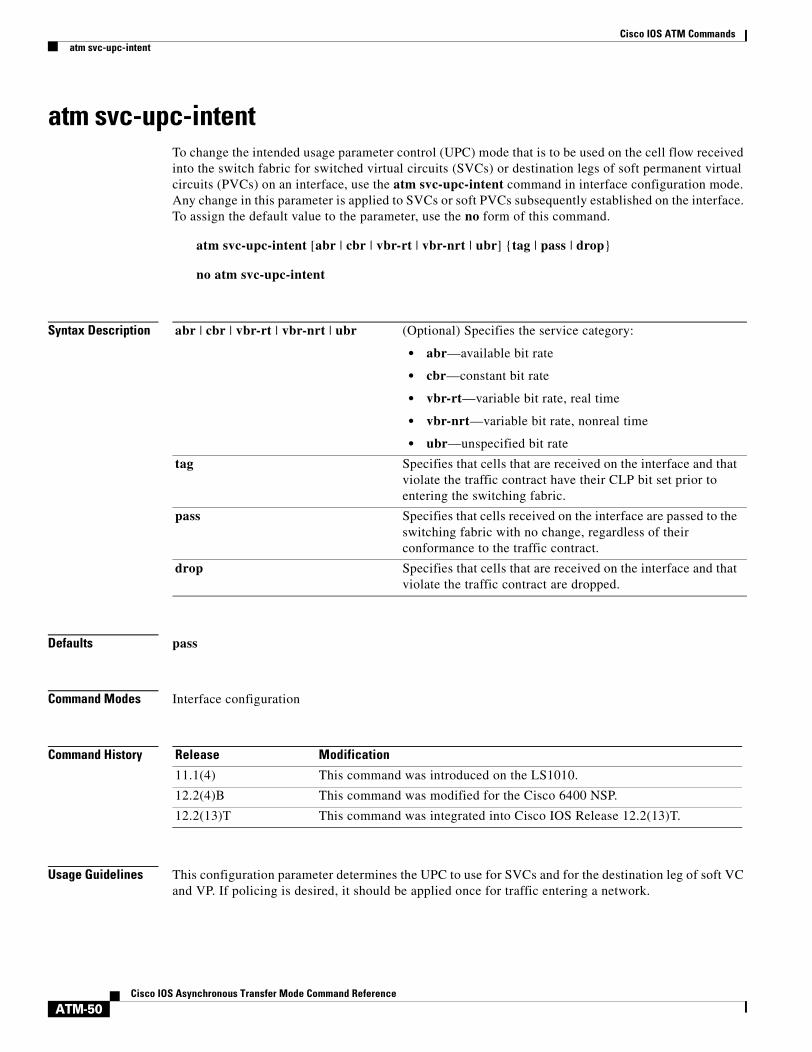
atm svc-upc-intentTo change the intended usage parameter control (UPC) mode that is to be used on the cell flow received into the switch fabric for switched virtual circuits (SVCs) or destination legs of soft permanent virtual circuits (PVCs) on an interface, use the atm svc-upc-intent command in interface configuration mode. Any change in this parameter is applied to SVCs or soft PVCs subsequently established on the interface. To assign the default value to the parameter, use the no form of this command.
atm svc-upc-intent [abr | cbr | vbr-rt | vbr-nrt | ubr] {tag | pass | drop}
no atm svc-upc-intent
Syntax Description
Defaults pass
Command Modes Interface configuration
Command History
Usage Guidelines This configuration parameter determines the UPC to use for SVCs and for the destination leg of soft VC and VP. If policing is desired, it should be applied once for traffic entering a network.
abr | cbr | vbr-rt | vbr-nrt | ubr (Optional) Specifies the service category:
• abr—available bit rate
• cbr—constant bit rate
• vbr-rt—variable bit rate, real time
• vbr-nrt—variable bit rate, nonreal time
• ubr—unspecified bit rate
tag Specifies that cells that are received on the interface and that violate the traffic contract have their CLP bit set prior to entering the switching fabric.
pass Specifies that cells received on the interface are passed to the switching fabric with no change, regardless of their conformance to the traffic contract.
drop Specifies that cells that are received on the interface and that violate the traffic contract are dropped.
Release Modification
11.1(4) This command was introduced on the LS1010.
12.2(4)B This command was modified for the Cisco 6400 NSP.
12.2(13)T This command was integrated into Cisco IOS Release 12.2(13)T.

Cisco IOS ATM Commandsatm svc-upc-intent
ATM-51Cisco IOS Asynchronous Transfer Mode Command Reference
Examples In the following example, the intended UPC for SVCs on an interface is set to tagging:
Router(config-if)# atm svc-upc-intent tag
In the following example, the UBR traffic on an interface is passed while all other traffic is policed:
Router(config-if)# atm svc-upc-intent ubr passRouter(config-if)# atm svc-upc-intent cbr tagRouter(config-if)# atm svc-upc-intent vbr-rt tagRouter(config-if)# atm svc-upc-intent vbr-nrt tagRouter(config-if)# atm svc-upc-intent abr drop
Related Commands Command Description
show atm interface Displays ATM-specific information about an ATM interface.

Cisco IOS ATM Commandsatm txbuff
ATM-52Cisco IOS Asynchronous Transfer Mode Command Reference
atm txbuffTo set the maximum number of transmit buffers for simultaneous packet fragmentation, use the atm txbuff command in interface configuration mode. To restore the default value, use the no form of this command.
atm txbuff number
no atm txbuff
Syntax Description
Defaults 256
Command Modes Interface configuration
Command History
Usage Guidelines This command is supported on the AIP for Cisco 7500 series routers. This command is not supported on the ATM port adapter for Cisco 7200 and 7500 series routers, nor is it supported on Cisco 4500 and Cisco 4700 routers.
Examples The following example configures the AIP to perform up to 300 packet fragmentations simultaneously:
atm txbuff 300
number Maximum number of packet fragmentations that the ATM Interface Processor (AIP) can perform simultaneously. Range is from 0 to 512. Default is 256.
Release Modification
10.0 This command was introduced.

Cisco IOS ATM Commandsatm uni-version
ATM-53Cisco IOS Asynchronous Transfer Mode Command Reference
atm uni-versionTo specify the User-Network Interface (UNI) version (3.0 or 3.1) the router should use when Interim Local Management Interface (ILMI) link autodetermination is unsuccessful or ILMI is disabled, use the atm uni-version command in interface configuration mode. To restore the default value to 3.0, use the no form of this command.
atm uni-version version-number
no atm uni-version version-number
Syntax Description
Defaults Version 3.0
Command Modes Interface configuration
Command History
Usage Guidelines Normally, when the ILMI link autodetermination is enabled on the interface and is successful, the router accepts the UNI version returned by ILMI. If the ILMI link autodetermination is unsuccessful or ILMI is disabled, the UNI version defaults to 3.0. You can override the default UNI version by using this command to enable UNI 3.1 signalling support. The no form of the command sets the UNI version to one returned by ILMI if ILMI is enabled and the link autodetermination process is successful. Otherwise, the UNI version reverts to 3.0.
Examples The following example specifies UNI version 3.1 signaling port on the ATM interface 2/0:
interface atm 2/0atm uni-version 3.1
version-number UNI version selected on an interface. Valid values are 3.0 and 3.1.
Release Modification
11.2 This command was introduced.

Cisco IOS ATM Commandsatm vc-per-vp
ATM-54Cisco IOS Asynchronous Transfer Mode Command Reference
atm vc-per-vpTo set the maximum number of virtual channel identifier (VCIs) to support per virtual path identifier (VPI), use the atm vc-per-vp interface configuration command. To restore the default value, use the no form of this command.
atm vc-per-vp number
no atm vc-per-vp
Syntax Description
Defaults 1024
Command Modes Interface configuration
Command History
Usage Guidelines This command controls the memory allocation in the ATM Interface Processor (AIP), ATM port adapter, ATM network module, or network processor module (NPM) to deal with the VCI table. It defines the maximum number of VCIs to support per VPI; it does not bound the VCI numbers.
An invalid VCI causes a warning message to be displayed.
Cisco 2600 and 3600 Series with IMA
Note For Cisco 2600 and 3600 series with IMA, changing the value of the atm vc-per-vp command on one interface affects all of the interfaces on that network module.
number Maximum number of VCIs to support per VPI. See the following list for valid values:
• AIP for Cisco 7500 series—Valid values are 16, 32, 64, 128, 256, 512, and 1024.
• ATM port adapter for Cisco 7200 series and 7500 series—Valid values are 16, 32, 64, 128, 256, 512, 1024, and 2048.
• NPM for Cisco 4500 and Cisco 4700 routers—Valid values are 32, 64, 128, 256, 512, 1024, 2048, 4096, and 8192.
• Network module with IMA for the Cisco 2600 series and 3600 series—Valid values are 256, 512, and 1024.
Release Modification
10.0 This command was introduced.

Cisco IOS ATM Commandsatm vc-per-vp
ATM-55Cisco IOS Asynchronous Transfer Mode Command Reference
Table 1 lists the possible VCI ranges and corresponding VPI ranges for the Cisco 2600 and 3600 series with IMA.
Examples The following example sets the maximum number of VCIs per VPI to 512:
atm vc-per-vp 512
Related Commands
Table 1 VCI and VPI Ranges for Cisco 2600 and 3600 Series with IMA
VCI Range VPI Range
0–255 0–15, 64–79, 128–143, and 192–207
0–511 0–15, 64–79
0–1023 0–15
Command Description
pvc Configures the PVC interface.

Cisco IOS ATM Commandsatm vp-filter
ATM-56Cisco IOS Asynchronous Transfer Mode Command Reference
atm vp-filterTo set the ATM Interface Processor (AIP) filter register, use the atm vp-filter command in interface configurationmode. To restore the default value, use the no form of this command.
atm vp-filter hexvalue
no atm vp-filter
Syntax Description
Defaults 0x7B
Command Modes Interface configuration
Command History
Usage Guidelines This command is supported on Cisco 7500 series routers, but not on Cisco 4500 and Cisco 4700 routers. This command is not supported on ATM port adapters.
This command allows you to specify a virtual path identifier (VPI) or range of VPIs to be used for ATM adaptation layer 3/4 (AAL3/4) processing. All other VPIs map to AAL5 processing. If only AAL5 processing is required, you can either let the virtual path filter default or set it to an arbitrary VPI so that AAL5 processing is performed on all VPIs.
This command configures the hexadecimal value used in the virtual path filter register in the reassembly operation. The virtual path filter comprises 16 bits. The virtual path filter register uses the most significant bits (bits 15 through 8, the left half of the filter) as mask bits, and uses bits 7 through 0 (the right half of the filter) as compare bits.
When a cell is received, the right half of the filter is exclusively NORed with the binary value of the incoming VPI. The result is then ORed with the left half of the filter (the mask). If the result is all ones, reassembly is done using the VCI/message identifier (MID) table (AAL3/4 processing). Otherwise, reassembly is done using the VPI-VCI pair table (AAL5 processing).
hexvalue Value in hexadecimal format.
Release Modification
10.0 This command was introduced.

Cisco IOS ATM Commandsatm vp-filter
ATM-57Cisco IOS Asynchronous Transfer Mode Command Reference
Examples In the following example, all incoming cells are reassembled using AAL3/4 processing:
atm vp-filter ff00
In the following example, all incoming cells with the virtual path equal to 0 are reassembled using AAL3/4 processing; all other cells are reassembled using AAL5 processing:
atm vp-filter 0
In the following example, all incoming cells with the most significant bit of the virtual path set are reassembled using AAL3/4 processing; all other cells are reassembled using AAL5 processing:
atm vp-filter 7f80

Cisco IOS ATM Commandsatm-address
ATM-58Cisco IOS Asynchronous Transfer Mode Command Reference
atm-addressTo override the control ATM address of a Multiprotocol over ATM client (MPC) or a Multiprotocol over ATM server (MPS), use the atm-address command in interface configuration mode. To revert to the default address, use the no form of this command.
atm-address atm-address
no atm-address
Syntax Description
Defaults The default is an automatically generated ATM address.
Command Modes Interface configuration
Command History
Usage Guidelines This command specifies the control ATM address that an MPC or MPS should use when it comes up. if it is associated with a hardware interface.
The atm-address command overrides the default operational control address of the MPC or MPS. When this address is deleted (using the no form of the command), the MPC or MPS uses an automatically generated address as its control address.
Examples The following example shows how to specify the ATM address for an MPC:
Router(config-if)# atm-address 47.0091810000000061705b7701.00400BFF0011.00
The following example shows how to specify the ATM address for an MPS:
Router(config-if)# atm-address 47.0091810000000061705C2B01.00E034553024.00
atm-address Control ATM address.
Release Modification
11.3(3a)WA4(5) This command was introduced.

Cisco IOS ATM Commandsatm-address
ATM-59Cisco IOS Asynchronous Transfer Mode Command Reference
atm-addressTo override the control ATM address of a Multiprotocol over ATM client (MPC) or a Multiprotocol over ATM server (MPS), use the atm-address command in interface configuration mode. To revert to the default address, use the no form of this command.
atm-address atm-address
no atm-address
Syntax Description
Defaults The default is an automatically generated ATM address.
Command Modes Interface configuration
Command History
Usage Guidelines This command specifies the control ATM address that an MPC or MPS should use when it comes up. if it is associated with a hardware interface.
The atm-address command overrides the default operational control address of the MPC or MPS. When this address is deleted (using the no form of the command), the MPC or MPS uses an automatically generated address as its control address.
Examples The following example shows how to specify the ATM address for an MPC:
Router(config-if)# atm-address 47.0091810000000061705b7701.00400BFF0011.00
The following example shows how to specify the ATM address for an MPS:
Router(config-if)# atm-address 47.0091810000000061705C2B01.00E034553024.00
atm-address Control ATM address.
Release Modification
11.3(3a)WA4(5) This command was introduced.

Cisco IOS ATM Commandsatmsig close atm
ATM-60Cisco IOS Asynchronous Transfer Mode Command Reference
atmsig close atmTo disconnect a switched virtual circuit (SVC), use the atmsig close atm command in EXEC mode.
AIP on Cisco 7500 series; ATM, ATM-CES, Enhanced ATM Port Adapter on Cisco 7200 Series; 1-port ATM-25 Network Module on Cisco 2600 and 3600 Series
atmsig close atm slot/0 vcd
ATM and Enhanced ATM Port Adapter on Cisco 7500 series
atmsig close atm slot/port-adapter/0 vcd
NPM on Cisco 4500 and Cisco 4700
atmsig close atm number vcd
Syntax Description
Command Modes EXEC
Command History
Usage Guidelines Execute this command if you want to close a particular SVC. Because virtual circuits are numbered per interface, you must specify the ATM interface by its slot number.
Examples The following example closes SVC 2 on ATM interface 4/0:
atmsig close atm4/0 2
slot ATM slot number. Use this format for the following platform configurations:
• AIP on Cisco 7500 series routers.
• ATM port adapter, ATM-CES port adapter, or enhanced ATM port adapter on Cisco 7200 series routers.
• 1-port ATM-25 network module on Cisco 2600 and 3600 series routers.
/0 ATM port number. Because the AIP and all ATM port adapters have a single ATM interface, the port number is always 0. The slash (/) is required.
vcd Virtual circuit descriptor of the signalling SVC to close.
slot/port-adapter ATM slot number and port adapter number. Use this format for the ATM port adapter or ATM-CES port adapter on Cisco 7500 series routers.
number ATM network processor module number for the NPM on Cisco 4500 and Cisco 4700 routers.
Release Modification
10.3 This command was introduced.
11.1 The number argument was added.

Cisco IOS ATM Commandsbroadcast
ATM-61Cisco IOS Asynchronous Transfer Mode Command Reference
broadcastTo configure broadcast packet duplication and transmission for an ATM virtual circuit (VC) class, permanent virtual circuit (PVC), switched virtual circuit (SVC), or VC bundle, use the broadcast command in the appropriate command mode. To disable transmission of broadcast packets for your ATM VC class, PVC, SVC, or VC bundle, use the no form of this command. To restore the default behavior according to the description in the “Usage Guidelines” section, use the default form of this command.
broadcast
no broadcast
default broadcast
Syntax Description This command has no arguments or keywords.
Defaults Broadcast transmission is not enabled. For classical IP SVCs, broadcast is enabled.
Command Modes Interface-ATM-VC configuration (for ATM PVCs and SVCs)VC-class configuration (for a VC-class)Bundle configuration (for a VC bundle)PVC range configuration (for an ATM PVC range) PVC-in-range configuration (for an individual PVC within a PVC range)
Command History
Usage Guidelines If broadcasting and multipoint signaling are enabled on an SVC, a multipoint SVC will be created to handle the SVC.
Note If you use the broadcast command to configure broadcasting for an ATM PVC or SVC, VC-class, or VC bundle, this configuration takes precedence over any previous configuration using the broadcast command.
Release Modification
11.3T This command was introduced.
12.0(3)T Enhancements were added for configuration of broadcast packet duplication and transmission for an ATM VC bundle.
12.1(5)T This command was made available in PVC range and PVC-in-range configuration modes.

Cisco IOS ATM Commandsbroadcast
ATM-62Cisco IOS Asynchronous Transfer Mode Command Reference
If the broadcast command is not explicitly configured on an ATM PVC, SVC, or VC bundle, the VC inherits the following default configuration (listed in order of precedence):
• Configuration of the broadcast command in a VC class assigned to the PVC, SVC, or VC bundle itself.
• Configuration of the broadcast command in a VC class assigned to the PVC’s, SVC’s, or VC bundle’s ATM subinterface.
• Configuration of the broadcast command in a VC class assigned to the PVC’s, SVC’s, or VC bundle’s ATM main interface.
Note When a VC is a member of a VC bundle, configuration using the broadcast command in VC-class configuration mode no longer applies to the VC. Bundle configuration takes precedence.
To use the broadcast command in bundle configuration mode, enter the bundle command to enact bundle configuration mode for the bundle for which you want to enable broadcast forwarding.
Examples The following example enables the transmission of broadcast packets on an ATM PVC named “router5”:
pvc router5 1/32broadcast
The following example enables the transmission of broadcast packets on an ATM PVC bundle named “bundle1”:
bundle bundle1 broadcast
Related Commands Command Description
class-int Assigns a VC class to an ATM main interface or subinterface.
class-vc Assigns a VC class to an ATM PVC, SVC, or VC bundle member.
encapsulation Sets the encapsulation method used by the interface.
enwrap Configures the Inverse ARP time period for an ATM PVC, VC class, or VC bundle.
oam-bundle Enables end-to-end F5 OAM loopback cell generation and OAM management for a virtual circuit class that can be applied to a virtual circuit bundle.
am retry Configures parameters related to OAM management for an ATM PVC, SVC, VC class, or VC bundle.
protocol (ATM) Configures a static map for an ATM PVC, SVC, VC class, or VC bundle. Enables Inverse ARP or Inverse ARP broadcasts on an ATM PVC by either configuring Inverse ARP directly on the PVC, on the VC bundle, or in a VC class (applies to IP and IPX protocols only).
ubr Configures UBR QoS and specifies the output peak cell rate for an ATM PVC, SVC, VC class, or VC bundle member.
ubr+ Configures UBR QoS and specifies the output peak cell rate and output minimum guaranteed cell rate for an ATM PVC, SVC, VC class, or VC bundle member.
vbr-nrt Configures the VBR-NRT QoS and specifies output peak cell rate, output sustainable cell rate, and output maximum burst cell size for an ATM PVC, SVC, VC class, or VC bundle member.

Cisco IOS ATM Commandscbr
ATM-63Cisco IOS Asynchronous Transfer Mode Command Reference
cbrTo configure the constant bit rate (CBR) for the ATM circuit emulation service (CES) for an ATM permanent virtual circuit (PVC) on the Cisco MC3810, use the cbr command in the appropriate configuration mode. To restore the default, use the no form of this command.
cbr rate
no cbr rate
Syntax Description
Defaults The CBR is not configured.
Command Modes Interface-ATM-VC configuration (for ATM PVCs and SVCs)PVC range configuration (for an ATM PVC range) PVC-in-range configuration (for an individual PVC within a PVC range)
Command History
Usage Guidelines This command applies to ATM configuration on the Cisco MC3810.
Examples The following example configures the constant bit rate on ATM PVC 20 on the Cisco MC3810:
pvc 20cbr 56
Related Commands
rate Constant bit bate (also known as the average cell rate) for ATM CES. The valid range for this command is from 56 to 10000 kbps.
Release Modification
12.0 This command was introduced.
12.1(5)T This command was made available in PVC range and PVC-in-range configuration modes.
Command Description
ces cell-loss-integration-period Sets the CES cell-loss integration period on the Cisco MC3810 multiservice concentrator.
ces clockmode synchronous Configures the ATM CES synchronous clock mode on the Cisco MC3810 multiservice concentrator.
ces connect Maps the CES service to an ATM PVC on the Cisco MC3810multiservice concentrator.
ces initial-delay Configures the size of the receive buffer of a CES circuit on the Cisco MC3810 multiservice concentrator.
Cisco IOS ATM Commandscbr
ATM-64Cisco IOS Asynchronous Transfer Mode Command Reference
ces max-buf-size Configures the send buffer of a CES circuit on the Cisco MC3810 multiservice concentrator.
ces partial-fill Configures the number of user octets per cell for the ATM CES on the Cisco MC3810 multiservice concentrator.
ces service Configures the ATM CES type on the Cisco MC3810 multiservice concentrator.
encapsulation atm-ces Enables CES ATM encapsulation on the Cisco MC3810 multiservice concentrator.
Command Description

Cisco IOS ATM Commandsces aal1 clock
ATM-65Cisco IOS Asynchronous Transfer Mode Command Reference
ces aal1 clockTo configure the ATM adaptation layer 1 (AAL1) timing recovery clock for the constant bit rate (CBR) interface, use the ces aal1 clock command in interface configuration mode. To return the clock to the default, use the no form of this command.
ces aal1 clock {adaptive | srts | synchronous}
no ces aal1 clock
Syntax Description
Defaults synchronous
Command Modes Interface configuration
Command History
Usage Guidelines The clock mode must be synchronous for structured mode. In unstructured mode, use the adaptive keyword when a network-derived clock is not available.
Use the srts keyword when a network-derived clock is available but devices attached to the CES port use a different clock reference. The srts keyword samples the incoming clock, subtracts from the network clock, and sends the remainder in an AAL1 header. The clock is reconstructed during output by adding the residual to the network reference.
Use the synchronous keyword for all other modes.
Examples The following command sets the AAL1 timing recovery clock to adaptive mode:
interface cbr 4/0ces aal1 clock adaptive
Related Commands
adaptive Adjusts output clock on a received AAL1 on FIFO basis. Use in unstructured mode.
srts Sets the clocking mode to synchronous residual time stamp.
synchronous Configures the timing recovery to synchronous for structured mode.
Release Modification
11.1 This command was introduced.
Command Description
ces aal1 service Configures the type of CES used on the CBR interface.
ces dsx1 clock source Configures a transmit clock source for the CBR interface.
network-clock-select (ATM) Establishes the sources and priorities of the requisite clocking signals for an ATM-CES port adapter.
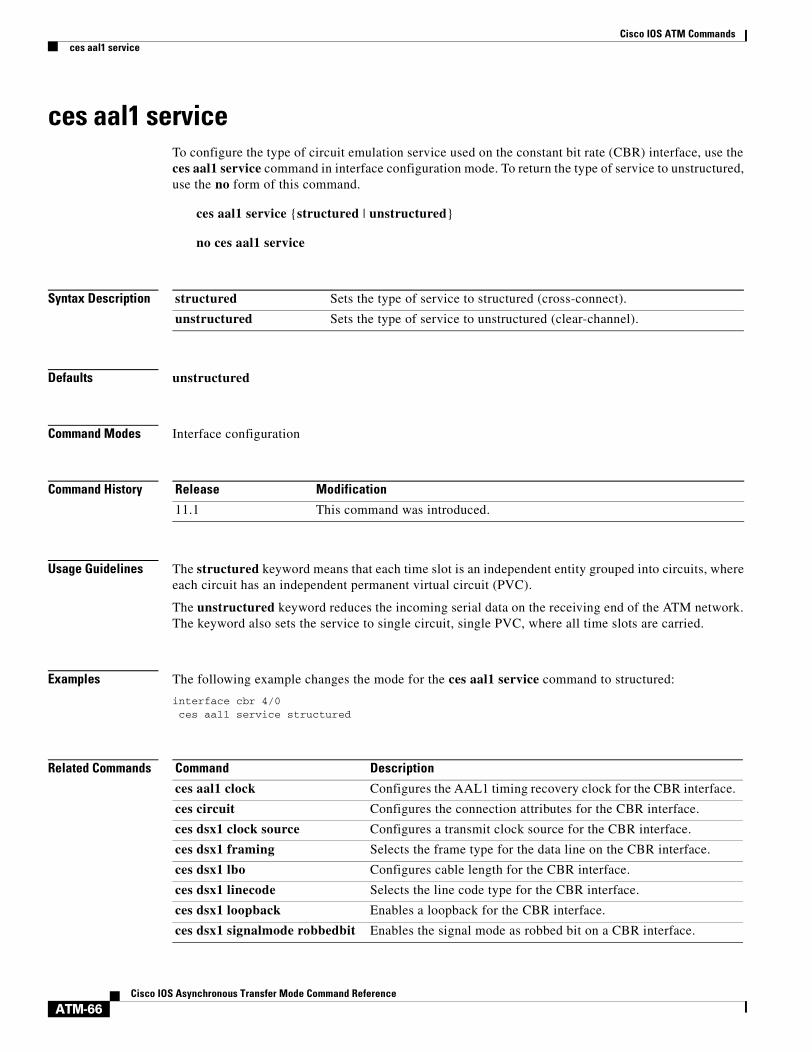
Cisco IOS ATM Commandsces aal1 service
ATM-66Cisco IOS Asynchronous Transfer Mode Command Reference
ces aal1 serviceTo configure the type of circuit emulation service used on the constant bit rate (CBR) interface, use the ces aal1 service command in interface configuration mode. To return the type of service to unstructured, use the no form of this command.
ces aal1 service {structured | unstructured}
no ces aal1 service
Syntax Description
Defaults unstructured
Command Modes Interface configuration
Command History
Usage Guidelines The structured keyword means that each time slot is an independent entity grouped into circuits, where each circuit has an independent permanent virtual circuit (PVC).
The unstructured keyword reduces the incoming serial data on the receiving end of the ATM network. The keyword also sets the service to single circuit, single PVC, where all time slots are carried.
Examples The following example changes the mode for the ces aal1 service command to structured:
interface cbr 4/0ces aal1 service structured
Related Commands
structured Sets the type of service to structured (cross-connect).
unstructured Sets the type of service to unstructured (clear-channel).
Release Modification
11.1 This command was introduced.
Command Description
ces aal1 clock Configures the AAL1 timing recovery clock for the CBR interface.
ces circuit Configures the connection attributes for the CBR interface.
ces dsx1 clock source Configures a transmit clock source for the CBR interface.
ces dsx1 framing Selects the frame type for the data line on the CBR interface.
ces dsx1 lbo Configures cable length for the CBR interface.
ces dsx1 linecode Selects the line code type for the CBR interface.
ces dsx1 loopback Enables a loopback for the CBR interface.
ces dsx1 signalmode robbedbit Enables the signal mode as robbed bit on a CBR interface.

Cisco IOS ATM Commandsces aal1 service
ATM-67Cisco IOS Asynchronous Transfer Mode Command Reference
ces pvc Configures the destination port for the circuit on the CBR interface.
show ces circuit Displays detailed circuit information for the CBR interface.
show ces interface cbr Displays detailed CBR port information.
show ces status Displays the status of the ports on the ATM-CES port adapter.
show interface cbr Displays the information about the CBR interface on the ATM-CES port adapter.
Command Description

Cisco IOS ATM Commandsces circuit
ATM-68Cisco IOS Asynchronous Transfer Mode Command Reference
ces circuitTo configure the connection attributes for the constant bit rate (CBR) interface, use the ces circuit command in interface configuration mode. To return the connection attributes to the default or to enable the circuit, use the no form of this command.
ces circuit circuit-number [cas | no cas] [cdv range] [circuit-name name] [on-hook-detection hex-number] [partial-fill range] [shutdown | no shutdown] [timeslots range]
no ces circuit circuit-number [[no] cas] [cdv range] [circuit-name name] [on-hook-detection hex-number] [partial-fill range] [[no] shutdown] [timeslots range]
Syntax Description
Defaults No circuit is configured.
Command Modes Interface configuration
circuit-number Selects the circuit identification. For unstructured service, use 0. For T1 structured service, the range is from 1 to 24. For E1 structure service, the range is from 1 to 31.
cas (Optional) Enables channel-associated signaling for structured service only. no cas disables channel-associated signaling. The default is no cas.
no cas (Optional) Disables channel-associated signaling for structured service only. This is the default.
cdv range (Optional) Enables the peak-to-peak cell delay variation requirement. The range for CDV is 1 through 65535 milliseconds. The default is 2000 milliseconds.
circuit-name name (Optional) Sets the ASCII name for the circuit emulation service internetworking function CES-IWF circuit. The string for the circuit name ranges from 0 to 255. The default is CBRx/x:0.
on-hook-detection hex-number (Optional) Enables detection of whether the circuit is on-hook. Hex values are 0 through F to indicate a 2- or 4-bit AB[CD] pattern to detect on-hook. The AB[CD] bits are determined by the manufacturer of the voice/video telephony device that is generating the CBR traffic.
partial-fill range (Optional) Enables the partial AAL1 cell fill service for structured service only. The range is from 0 to 47. The default is 47.
shutdown (Optional) Marks the CES-IWF circuit administratively down. The default is no shutdown.
no shutdown (Optional) Returns the CES-IWF circuit to an administrative up state.
timeslots range (Optional) Configures the time slots for the CES-IWF circuit for structured service only. The range is from 1 to 24 for T1. The range is from 1 to 31 for E1.
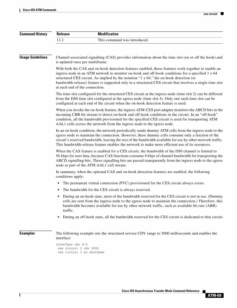
Cisco IOS ATM Commandsces circuit
ATM-69Cisco IOS Asynchronous Transfer Mode Command Reference
Command History
Usage Guidelines Channel-associated signalling (CAS) provides information about the time slot (on or off the hook) and is updated once per multiframe.
With both the CAS and on-hook detection features enabled, these features work together to enable an ingress node in an ATM network to monitor on-hook and off-hook conditions for a specified 1 x 64 structured CES circuit. As implied by the notation “1 x 64,” the on-hook detection (or bandwidth-release) feature is supported only in a structured CES circuit that involves a single time slot at each end of the connection.
The time slot configured for the structured CES circuit at the ingress node (time slot 2) can be different from the DS0 time slot configured at the egress node (time slot 4). Only one such time slot can be configured at each end of the circuit when the on-hook detection feature is used.
When you invoke the on-hook feature, the ingress ATM-CES port adapter monitors the ABCD bits in the incoming CBR bit stream to detect on-hook and off-hook conditions in the circuit. In an “off-hook” condition, all the bandwidth provisioned for the specified CES circuit is used for transporting ATM AAL1 cells across the network from the ingress node to the egress node.
In an on-hook condition, the network periodically sends dummy ATM cells from the ingress node to the egress node to maintain the connection. However, these dummy cells consume only a fraction of the circuit’s reserved bandwidth, leaving the rest of the bandwidth available for use by other network traffic. This bandwidth-release feature enables the network to make more efficient use of its resources.
When the CAS feature is enabled for a CES circuit, the bandwidth of the DS0 channel is limited to 56 kbps for user data, because CAS functions consume 8 kbps of channel bandwidth for transporting the ABCD signalling bits. These signalling bits are passed transparently from the ingress node to the egress node as part of the ATM AAL1 cell stream.
In summary, when the optional CAS and on-hook detection features are enabled, the following conditions apply:
• The permanent virtual connection (PVC) provisioned for the CES circuit always exists.
• The bandwidth for the CES circuit is always reserved.
• During an on-hook state, most of the bandwidth reserved for the CES circuit is not in use. (Dummy cells are sent from the ingress node to the egress node to maintain the connection.) Therefore, this bandwidth becomes available for use by other network traffic, such as available bit rate (ABR) traffic.
• During an off-hook state, all the bandwidth reserved for the CES circuit is dedicated to that circuit.
Examples The following example sets the structured service CDV range to 5000 milliseconds and enables the interface:
interface cbr 4/0ces circuit 3 cdv 5000ces circuit 3 no shutdown
Release Modification
11.1 This command was introduced.

Cisco IOS ATM Commandsces circuit
ATM-70Cisco IOS Asynchronous Transfer Mode Command Reference
Related Commands Command Description
ces aal1 service Configures the type of CES used on the CBR interface.
show ces circuit Displays detailed circuit information for the CBR interface.
show ces interface cbr Displays detailed CBR port information.
show ces status Displays the status of the ports on the ATM-CES port adapter.
show interface cbr Displays the information about the CBR interface on the ATM-CES port adapter.
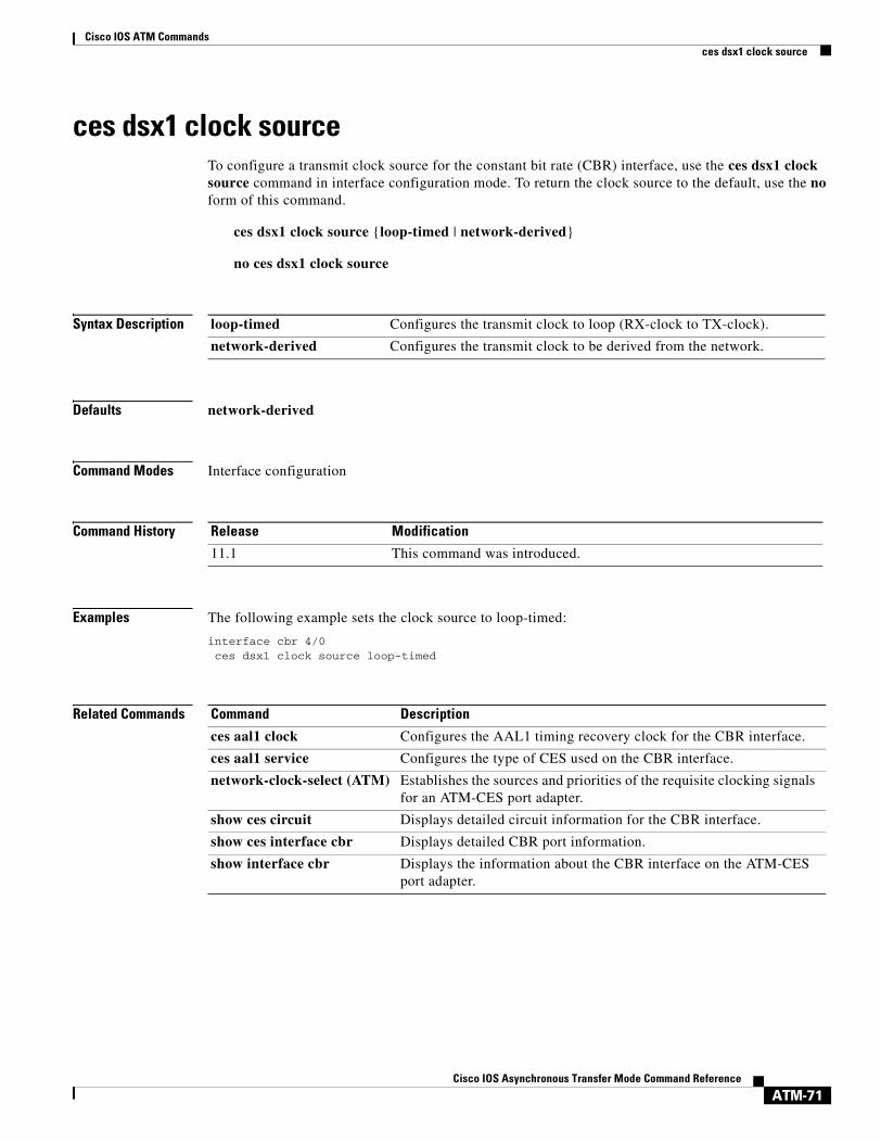
Cisco IOS ATM Commandsces dsx1 clock source
ATM-71Cisco IOS Asynchronous Transfer Mode Command Reference
ces dsx1 clock sourceTo configure a transmit clock source for the constant bit rate (CBR) interface, use the ces dsx1 clock source command in interface configuration mode. To return the clock source to the default, use the no form of this command.
ces dsx1 clock source {loop-timed | network-derived}
no ces dsx1 clock source
Syntax Description
Defaults network-derived
Command Modes Interface configuration
Command History
Examples The following example sets the clock source to loop-timed:
interface cbr 4/0ces dsx1 clock source loop-timed
Related Commands
loop-timed Configures the transmit clock to loop (RX-clock to TX-clock).
network-derived Configures the transmit clock to be derived from the network.
Release Modification
11.1 This command was introduced.
Command Description
ces aal1 clock Configures the AAL1 timing recovery clock for the CBR interface.
ces aal1 service Configures the type of CES used on the CBR interface.
network-clock-select (ATM) Establishes the sources and priorities of the requisite clocking signals for an ATM-CES port adapter.
show ces circuit Displays detailed circuit information for the CBR interface.
show ces interface cbr Displays detailed CBR port information.
show interface cbr Displays the information about the CBR interface on the ATM-CES port adapter.

Cisco IOS ATM Commandsces dsx1 framing
ATM-72Cisco IOS Asynchronous Transfer Mode Command Reference
ces dsx1 framingTo select the frame type for the data line on the constant bit rate (CBR) interface, use the ces dsx1 framing command in interface configuration mode. To return the frame type to the default, use the no form of this command.
T1
ces dsx1 framing {esf | sf}
no ces dsx1 framing
E1
ces dsx1 framing {e1_crc_mfCASlt | e1_crc_mf_lt | e1_lt | e1_mfCAS_lt}
no ces dsx1 framing
Syntax Description
Defaults esf (for T1) e1_lt (for E1)
Command Modes Interface configuration
Command History
Usage Guidelines Use this command in configurations where the router communicates with the data line. The service provider determines which framing type is required for your circuit.
Examples The following example sets the data line type to super frame:
interface cbr 4/0ces dsx1 framing sf
esf Configures the line type to extended super frame for T1.
sf Configures the line type to super frame for T1.
e1_crc_mfCASlt Configures the line type to E1 CRC with channel-associated signalling (CAS) enabled.
e1_crc_mf_lt Configures the line type to E1 CRC with CAS disabled.
e1_lt Configures the line type to E1 with CAS disabled.
e1_mfCAS_lt Configures the line type to E1 with CAS enabled.
Release Modification
11.1 This command was introduced.

Cisco IOS ATM Commandsces dsx1 framing
ATM-73Cisco IOS Asynchronous Transfer Mode Command Reference
Related Commands Command Description
ces aal1 service Configures the type of CES used on the CBR interface.
show ces circuit Displays detailed circuit information for the CBR interface.
show ces interface cbr Displays detailed CBR port information.
show ces status Displays the status of the ports on the ATM-CES port adapter.
show interface cbr Displays the information about the CBR interface on the ATM-CES port adapter.

Cisco IOS ATM Commandsces dsx1 lbo
ATM-74Cisco IOS Asynchronous Transfer Mode Command Reference
ces dsx1 lboTo configure cable length for the constant bit rate (CBR) interface, use the ces dsx1 lbo command in interface configuration mode. To return the cable length to the default, use the no form of this command.
ces dsx1 lbo length
no ces dsx1 lbo
Syntax Description
Defaults 0_110 feet
Command Modes Interface configuration
Command History
Usage Guidelines Set the cable length to the desired number of feet on your system.
Examples The following example sets the cable length to 440 feet:
interface cbr 4/0ces dsx1 lbo 440_550
Related Commands
length Sets the cable length. Values (in feet) are 0_110, 110_200, 220_330, 330_440, 440_550, 550_660, 660_above, and square_pulse. Values represent a range in feet.
Release Modification
11.1 This command was introduced.
Command Description
atm lbo Specifies the cable length (line build-out) for the ATM interface.
ces aal1 service Configures the type of CES used on the CBR interface.
show ces circuit Displays detailed circuit information for the CBR interface.
show ces interface cbr Displays detailed CBR port information.
show ces status Displays the status of the ports on the ATM-CES port adapter.
show interface cbr Displays the information about the CBR interface on the ATM-CES port adapter.
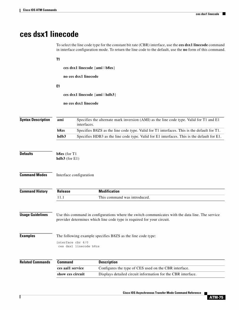
Cisco IOS ATM Commandsces dsx1 linecode
ATM-75Cisco IOS Asynchronous Transfer Mode Command Reference
ces dsx1 linecodeTo select the line code type for the constant bit rate (CBR) interface, use the ces dsx1 linecode command in interface configuration mode. To return the line code to the default, use the no form of this command.
T1
ces dsx1 linecode {ami | b8zs}
no ces dsx1 linecode
E1
ces dsx1 linecode {ami | hdb3}
no ces dsx1 linecode
Syntax Description
Defaults b8zs (for T1hdb3 (for E1)
Command Modes Interface configuration
Command History
Usage Guidelines Use this command in configurations where the switch communicates with the data line. The service provider determines which line code type is required for your circuit.
Examples The following example specifies B8ZS as the line code type:
interface cbr 4/0ces dsx1 linecode b8zs
Related Commands
ami Specifies the alternate mark inversion (AMI) as the line code type. Valid for T1 and E1 interfaces.
b8zs Specifies B8ZS as the line code type. Valid for T1 interfaces. This is the default for T1.
hdb3 Specifies HDB3 as the line code type. Valid for E1 interfaces. This is the default for E1.
Release Modification
11.1 This command was introduced.
Command Description
ces aal1 service Configures the type of CES used on the CBR interface.
show ces circuit Displays detailed circuit information for the CBR interface.

Cisco IOS ATM Commandsces dsx1 linecode
ATM-76Cisco IOS Asynchronous Transfer Mode Command Reference
show ces interface cbr Displays detailed CBR port information.
show ces status Displays the status of the ports on the ATM-CES port adapter.
show interface cbr Displays the information about the CBR interface on the ATM-CES port adapter.
Command Description

Cisco IOS ATM Commandsces dsx1 loopback
ATM-77Cisco IOS Asynchronous Transfer Mode Command Reference
ces dsx1 loopbackTo enable a loopback for the constant bit rate (CBR) interface, use the ces dsx1 loopback command in interface configuration mode. To disable the loopback, use the no form of this command.
ces dsx1 loopback {line | noloop | payload}
no ces dsx1 loopback {line | noloop | payload}
Syntax Description
Defaults No loopback
Command Modes Interface configuration
Command History
Usage Guidelines This command is useful for testing the circuit emulation port adapter module.
Examples The following example sets a payload loopback:
interface cbr 4/0ces dsx1 loopback payload
Related Commands
line Sets the received signal to be looped at the line (does not penetrate the line).
noloop Sets the interface to no loop.
payload Sets the received signal to be looped through the device and returned.
Release Modification
11.1 This command was introduced.
Command Description
ces aal1 service Configures the type of CES used on the CBR interface.
loopback Configures the ATM interface into loopback mode.
show ces circuit Displays detailed circuit information for the CBR interface.
show ces interface cbr Displays detailed CBR port information.
show ces status Displays the status of the ports on the ATM-CES port adapter.
show interface cbr Displays the information about the CBR interface on the ATM-CES port adapter.

Cisco IOS ATM Commandsces dsx1 signalmode robbedbit
ATM-78Cisco IOS Asynchronous Transfer Mode Command Reference
ces dsx1 signalmode robbedbitTo enable the signal mode as robbed bit on a constant bit rate (CBR) interface, use the ces dsx1 signalmode robbedbit command in interface configuration mode. To return the signal mode to the default, use the no form of this command.
ces dsx1 signalmode robbedbit
no ces dsx1 signalmode robbedbit
Syntax Description This command has no arguments or keywords.
Defaults No signal mode is enabled.
Command Modes Interface configuration
Command History
Usage Guidelines A T1 frame consists of 24 time slots (DS0) that send at a rate of 64 kbps. T1 defines the ability to send signaling in-band on individual time slots by removing the low bit of each byte for signaling in robbedbit mode. This procedure allows 8 kbps for signalling and leaves 56 kbps for data.
In structured mode, you can send the T1 signalling information across the network. Structured mode means that after you enable robbedbit signalling mode on the port, and enable CAS on individual circuits that need this type of service, you are robbing bits from the DS0. The system then puts the bits in the specified format to be sent across the network and reinserts them at the passive side on the CES-IWF connection.
Examples The following example enables channel-associated signaling and robbed-bit signaling:
interface cbr 4/0ces circuit 1 casces dsx1 signalmode robbedbit
Related Commands
Release Modification
11.1 This command was introduced.
Command Description
ces aal1 service Configures the type of CES used on the CBR interface.
ces circuit Configures the connection attributes for the CBR interface.
show ces circuit Displays detailed circuit information for the CBR interface.
show ces interface cbr Displays detailed CBR port information.

Cisco IOS ATM Commandsces dsx1 signalmode robbedbit
ATM-79Cisco IOS Asynchronous Transfer Mode Command Reference
show ces status Displays the status of the ports on the ATM-CES port adapter.
show interface cbr Displays the information about the CBR interface on the ATM-CES port adapter.
Command Description

Cisco IOS ATM Commandsces partial-fill
ATM-80Cisco IOS Asynchronous Transfer Mode Command Reference
ces partial-fillTo configure the number of user octets per cell for the ATM circuit emulation service (CES), use the ces partial-fill command in interface configuration mode. To delete the CES partial-fill value, use the no form of this command.
ces partial-fill octets
no ces partial-fill octets
Syntax Description
Defaults 47 octets
Command Modes Interface configuration
Command History
Usage Guidelines This command applies to ATM configuration on the Cisco MC3810.
Setting the value of the ces partial-fill command to zero disables partial cell fill and causes all cells to be completely filled before they are sent. This command is supported on serial ports 0 and 1 when the encapsulation atm-ces command is enabled.
Examples The following example sets the CES partial cell fill to 20 octets per cell for serial port 0:
interface serial 0ces partial-fill 20
Related Commands
octets Number of user octets per cell for the CES. Possible values of octet range from 0 to 47. The default is 47.
Release Modification
11.3 MA This command was introduced.
Command Description
ces cell-loss-integration-period Sets the CES cell-loss integration period on the Cisco MC3810 multiservice concentrator.
ces clockmode synchronous Configures the ATM CES synchronous clock mode on the Cisco MC3810 multiservice concentrator.
ces connect Maps the CES service to an ATM PVC on the Cisco MC3810 multiservice concentrator.
ces initial-delay Configures the size of the receive buffer of a CES circuit on the Cisco MC3810 multiservice concentrator.

Cisco IOS ATM Commandsces partial-fill
ATM-81Cisco IOS Asynchronous Transfer Mode Command Reference
ces max-buf-size Configures the send buffer of a CES circuit on the Cisco MC3810 multiservice concentrator.
ces service Configures the ATM CES type on the Cisco MC3810 multiservice concentrator.
Command Description
Cisco IOS ATM Commandsces pvc
ATM-82Cisco IOS Asynchronous Transfer Mode Command Reference
ces pvcTo configure the destination port for the circuit on the constant bit rate (CBR) interface, use the ces pvc command in interface configuration mode. To remove the destination port on the circuit, use the no form of this command.
ces pvc circuit-number interface atm slot/port vpi number vci number
no ces pvc circuit-number interface atm slot/port vpi number vci number
Syntax Description
Defaults No destination port is configured.
Command Modes Interface configuration
Command History
Usage Guidelines Use the interface option to create a hard PVC. Use the dest-atm-addr option to create a soft PVC. Soft PVCs are not supported on Cisco 7200 series routers.
You must configure both sides of the CES circuits because at the source (the active side in CES-IWF), the time slots are not recognized at the destination (the passive side).
Each CES circuit has an ATM address. When configuring the source PVC, you need the destination ATM address.
Examples The following example shows setting a hard PVC. In this example, the destination of ATM port 0 in slot 1 is assigned to circuit 31 on CBR port 0 in slot 1.
interface cbr 1/0ces pvc 31 interface atm 1/0 vpi 0 vci 512
circuit-number Selects the circuit identification. The range is from 0 to 24. For unstructured service, use 0. For T1 structure service, the range is from 1 to 24. For E1 structure service, the range is from 1 to 31.
interface atm slot/port Slot and port number of the ATM interface. The slash (/) is required. Used to create a hard permanent virtual circuit (PVC). Only a hard PVC can be configured for the CBR interfaces on the ATM-CES port adapter.
vpi number Virtual path identifier of the destination PVC. Range is from 0 to 255.
vci number Virtual channel identifier of the destination PVC. Range is from 1 to 16383.
Release Modification
11.1 This command was introduced.

Cisco IOS ATM Commandsces pvc
ATM-83Cisco IOS Asynchronous Transfer Mode Command Reference
Related Commands Command Description
ces aal1 service Configures the type of CES used on the CBR interface.
show ces circuit Displays detailed circuit information for the CBR interface.
show ces interface cbr Displays detailed CBR port information.
show ces status Displays the status of the ports on the ATM-CES port adapter.
show interface cbr Displays the information about the CBR interface on the ATM-CES port adapter.

Cisco IOS ATM Commandsces
ATM-84Cisco IOS Asynchronous Transfer Mode Command Reference
cesTo configure circuit emulation service (CES) on a router port and enter CES configuration mode, use the ces command in global configuration mode.
ces slot/port
Syntax Description
Defaults No CES interface is configured.
Command Modes Global configuration
Command History
Usage Guidelines This command is used on Cisco 2600 series and 3600 series routers that have OC-3/STM-1 ATM CES network modules.
The ces command enters CES configuration mode. Use CES configuration mode to configure CES parameters such as the CES clock.
Examples The following example configures the CES interface in slot 2:
ces 2/0
Related Commands
slot/port Backplane slot number and port number on the interface. The port value is always 0 because the interface configuration applies to all ports in the slot. The slash (/) is required.
Release Modification
12.1(2)T This command was introduced.
Command Description
clock-select Allows the selection of clock sources and priority.

Cisco IOS ATM Commandsces-cdv
ATM-85Cisco IOS Asynchronous Transfer Mode Command Reference
ces-cdvTo set the cell delay variation, use the ces-cdv command in interface-ATM-VC configuration mode.
ces-cdv time
Syntax Description
Defaults 5000 microseconds
Command Modes Interface-ATM-VC configuration
Command History
Usage Guidelines This command is used on Cisco 2600 series and 3600 series routers that have OC-3/STM-1 ATM CES network modules.
Examples The following example configures the maximum tolerable cell arrival jitter at 7500 microseconds:
interface atm1/0pvc 0 0/41 cesces-cdv 7500
Related Commands
time Maximum tolerable cell arrival jitter with a range from 1 to 65535 microseconds. Default is 5000.
Release Modification
12.1(2)T This command was introduced.
Command Description
interface atm Configures the ATM interface.
svc Configures the SVC.

Cisco IOS ATM Commandsclass-int
ATM-86Cisco IOS Asynchronous Transfer Mode Command Reference
class-intTo assign a virtual circuit (VC) class to an ATM main interface or subinterface, use the class-int command in interface configuration mode. To remove a VC class, use the no form of this command.
class-int vc-class-name
no class-int vc-class-name
Syntax Description
Defaults No VC class is assigned to an ATM main interface or subinterface.
Command Modes Interface configuration
Command History
Usage Guidelines Use this command to assign a previously defined set of parameters (defined in a VC class) to an ATM main interface or subinterface. To create a VC class that defines these parameters, use the vc-class atm command. Refer to the section “Configuring VC Classes” in the “Configuring ATM” chapter of the Cisco IOS Wide-Area Networking Configuration Guide for more information.
To use this command for assigning a VC class to an ATM main interface or subinterface, you must first enter the interface atm command to enter interface configuration mode.
When you create a VC class for an ATM main interface or subinterface, you can use the following commands to define your parameters: abr, broadcast, bump, encapsulation, idle-timeout, ilmi manage, inarp, oam-bundle, oam-pvc, oam retry, oam-svc, protocol, ubr, ubr+, and vbr-nrt.
Parameters applied to an individual VC supersede interface- and subinterface-level parameters. Parameters that are configured for a VC through discrete commands entered in interface-ATM-VC configuration mode supersede VC class parameters assigned to an ATM main interface or subinterface by the class-int command.
vc-class-name Name of the VC class you are assigning to your ATM main interface or subinterface.
Release Modification
11.3(4)T This command was introduced, replacing the class command for assigning VC classes to ATM main interfaces or subinterfaces.

Cisco IOS ATM Commandsclass-int
ATM-87Cisco IOS Asynchronous Transfer Mode Command Reference
Examples In the following example, a class called “classA” is first created and then applied to ATM main interface 2/0:
! The following commands create the class classA:vc-class atm classAubr 10000encapsulation aal5mux ip
! The following commands apply classA to ATM main interface 2/0:interface atm 2/0class-int classA
Related Commands Command Description
protocol (ATM) Configures a static map for an ATM PVC, SVC, VC class, or VC bundle and enables Inverse ARP or Inverse ARP broadcasts on an ATM PVC.
show atm map Displays the list of all configured ATM static maps to remote hosts on an ATM network.
vc-class atm Configures a VC class for an ATM VC or interface.

Cisco IOS ATM Commandsclass-vc
ATM-88Cisco IOS Asynchronous Transfer Mode Command Reference
class-vc To assign a virtual circuit (VC) class to an ATM permanent virtual circuit (PVC), switched virtual circuit (SVC), or VC bundle member, use the class-vc command in the appropriate configuration mode. To remove a VC class, use the no form of this command.
class-vc vc-class-name
no class-vc vc-class-name
Syntax Description
Defaults No VC class is assigned to an ATM PVC, SVC, or VC bundle member.
Command Modes Interface-ATM-VC configuration (for ATM PVCs and SVCs)Bundle-vc configuration (for VC bundle members)PVC-in-range configuration (for an individual PVC within a PVC range)
Command History
Usage Guidelines Use this command to assign a previously defined set of parameters (defined in a VC class) to an ATM PVC, SVC, or VC bundle member. To create a VC class that defines these parameters, use the vc-class atm command. Refer to the section “Configuring VC Classes” in the “Configuring ATM” chapter of the Cisco IOS Wide-Area Networking Configuration Guide for more information.
ATM PVCs and SVCs
To use this command for assigning a VC class to an ATM PVC or SVC, you must first enter the interface atm command in global configuration mode and then the pvc or svc command in interface configuration mode.
When you create a VC class for an ATM PVC or SVC, you can use the following commands to define your parameters: abr, broadcast, bump, encapsulation, idle-timeout, ilmi manage, inarp, oam-bundle, oam-pvc, oam retry, oam-svc, protocol, ubr, ubr+, and vbr-nrt.
Parameters that are configured for a PVC or SVC through discrete commands entered in interface-ATM-VC configuration mode supersede VC class parameters assigned to an ATM PVC or SVC by the class-vc command.
vc-class-name Name of the VC class you are assigning to your ATM PVC, SVC, or VC bundle member.
Release Modification
11.3(4)T This command was introduced, replacing the class command for assigning VC classes to ATM PVCs and SVCs.
12.0(3)T This command was modified to support application of a VC class to an ATM VC bundle and an ATM VC bundle member.
12.1(5)T This command was made available in PVC-in-range configuration mode.

Cisco IOS ATM Commandsclass-vc
ATM-89Cisco IOS Asynchronous Transfer Mode Command Reference
ATM VC Bundle Members
To use this command for assigning a VC class to a VC bundle member, you must first use the pvc-bundle command to enter bundle-vc configuration mode.
When you create a VC class for a VC bundle member, you can use the following commands to define your parameters: bump, precedence, protect, ubr, ubr+, and vbr-nrt. You cannot use the following commands in vc-class configuration mode to configure a VC bundle member: encapsulation, protocol, inarp, and broadcast. These commands are useful only at the bundle level, not the bundle member level.
Parameters applied to an individual VC supersede bundle-level parameters. Parameters that are directly configured for a VC through discrete commands entered in bundle-vc configuration mode supersede VC class parameters assigned to a VC bundle member by the class-vc command.
Examples The following sections show examples for applying the class-vc command to ATM PVC, SVC, and VC bundle members.
In the following example, a class called “classA” is first created and then applied to an ATM PVC:
! The following commands create the class classA:vc-class atm classAubr 10000encapsulation aal5mux ip
! The following commands apply classA to an ATM PVC:interface atm 2/0pvc router5 1/32class-vc classA
In the following example, a class called “classA” is first created and then applied to the bundle member called “vcmember”, a member of “bundle1”:
! The following commands create the class classA:vc-class atm classAprecedence 6-5no bump trafficprotect groupbump explicitly 7vbr-nrt 20000 10000 32
! The following commands create bundle1, add vcmember to bundle1, and then applies classA! to vcmember:bundle bundle1pvc-bundle vcmemberclass-vc classA
Taking into account hierarchy precedence rules, the VC bundle member “vcmember” will be characterized by these parameters:
• It carries traffic whose IP Precedence level is 6 and 5.
• It does not allow other traffic to be bumped onto it. When the VC goes down, its bumped traffic will be redirected to a VC whose IP Precedence level is 7.
• It is a member of the protected group of the bundle. When all members of a protected group go down, the bundle goes down.
• It has Variable Bit Rate-Non Real Time (VBR-NRT) quality of service traffic parameters.

Cisco IOS ATM Commandsclass-vc
ATM-90Cisco IOS Asynchronous Transfer Mode Command Reference
Related Commands Command Description
class-bundle Configures a VC bundle with the bundle-level commands contained in the specified VC class.
pvc-bundle Adds a PVC to a bundle as a member of the bundle and enters bundle-vc configuration mode in order to configure that PVC bundle member.
show atm bundle Displays the bundle attributes assigned to each bundle VC member and the current working status of the VC members.
show atm bundle statistics
Displays statistics on the specified bundle.
show atm map Displays the list of all configured ATM static maps to remote hosts on an ATM network.
vc-class atm Configures a VC class for an ATM VC or interface.

Cisco IOS ATM Commandsclear atm arp
ATM-91Cisco IOS Asynchronous Transfer Mode Command Reference
clear atm arpTo clear Address Resolution Protocol (ARP) entries for an ATM interface that is configured as an ARP server, use the clear atm arp command in privileged EXEC mode.
clear atm arp atm-interface {ip-address | *}
Syntax Description
Defaults No default behavior or values.
Command Modes Privileged EXEC
Command History
Usage Guidelines Use this command to clear ARP entries for an ATM interface. Specify the IP address of a particular entry to be deleted, or use the asterisk (*) to delete all the ARP entries for the interface.
If an ARP entry for an existing virtual circuit (VC) is deleted, the ARP server will immediately try to get another entry for that VC.
Examples The following example shows how to delete the ARP entry for 172.20.173.28:
Router# clear atm arp 3/0 172.20.173.28
atm-interface ATM interface number (for example, 3/0).
ip-address Clears the ARP entry for the specified IP address.
* Clears all ARP entries on the interface.
Release Modification
11.2 This command was introduced.
Cisco IOS ATM Commandsclear atm vc
ATM-92Cisco IOS Asynchronous Transfer Mode Command Reference
clear atm vcTo release a specified switched virtual circuit (SVC), use the clear atm vc command in privileged EXEC mode.
clear atm vc vcd
Syntax Description
Command Modes Privileged EXEC
Command History
Usage Guidelines For multicast or control virtual channel connections (VCCs), this command causes the LAN emulation (LANE) client to exit and rejoin an emulated LAN.
For data VCCs, this command also removes the associated LAN Emulation Address Resolution Protocol (LE ARP) table entries.
Examples The following example shows how to release SVC 1024:
Router# clear atm vc 1024
vcd Virtual channel descriptor of the channel to be released.
Release Modification
11.0 This command was introduced.

Cisco IOS ATM Commandsclear lane le-arp
ATM-93Cisco IOS Asynchronous Transfer Mode Command Reference
clear lane le-arpTo clear the dynamic LAN Emulation Address Resolution Protocol (LE ARP) table or a single LE ARP entry of the LANE client configured on the specified subinterface or emulated LAN, use the clear lane le-arp command in user EXEC or privileged EXEC mode.
Cisco 7500 Series
clear lane le-arp [interface slot/port [.subinterface-number] | name elan-name] [mac-address mac-address | route-desc segment segment-number bridge bridge-number]
Cisco 4500 and 4700 Routers
clear lane le-arp [interface number [.subinterface-number] | name elan-name] [mac-address mac-address | route-desc segment segment-number bridge bridge-number]
Syntax Description
Command Modes User EXECPrivileged EXEC
Command History
Usage Guidelines This command removes dynamic LE ARP table entries only. It does not remove static LE ARP table entries.
interface slot/port[.subinterface-number] (Optional) Interface or subinterface for the LAN emulation (LANE) client whose LE ARP table or entry is to be cleared for the Cisco 7500 series routers. The space between the interface keyword and the slot argument is optional.
interface number[.subinterface-number] (Optional) Interface or subinterface for the LANE client whose LE ARP table or entry is to be cleared for the Cisco 4500 or 4700 routers. The space between the interface keyword and the number argument is optional.
name elan-name (Optional) Name of the emulated LAN for the LANE client whose LE ARP table or entry is to be cleared. Maximum length is 32 characters.
mac-address mac-address (Optional) Keyword and MAC address of the LANE client.
route-desc segment segment-number (Optional) Keywords and LANE segment number. The segment number ranges from 1 to 4095.
bridge bridge-number (Optional) Keyword and bridge number that is contained in the route descriptor. The bridge number ranges from 1 to 15.
Release Modification
11.0 This command was introduced.

Cisco IOS ATM Commandsclear lane le-arp
ATM-94Cisco IOS Asynchronous Transfer Mode Command Reference
If you do not specify an interface or an emulated LAN, this command clears all the LE ARP tables of any LANE client in the router.
If you specify a major interface (not a subinterface), this command clears all the LE ARP tables of every LANE client on all the subinterfaces of that interface.
This command also removes the fast-cache entries built from the LE ARP entries.
Examples The following example shows how to clear all the LE ARP tables for all clients on the router:
Router# clear lane le-arp
The following example shows how to clear all the LE ARP tables for all LANE clients on all the subinterfaces of interface 1/0:
Router# clear lane le-arp interface 1/0
The following example shows how to clear the entry corresponding to MAC address 0800.aa00.0101 from the LE ARP table for the LANE client on the emulated LAN named red:
Router# clear lane le-arp name red 0800.aa00.0101
The following example shows how to clear all dynamic entries from the LE ARP table for the LANE client on the emulated LAN named red:
Router# clear lane le-arp name red
The following example shows how to clear the dynamic entry from the LE ARP table for the LANE client on segment number 1, bridge number 1 in the emulated LAN named red:
Router# clear lane le-arp name red route-desc segment 1 bridge 1
Note MAC addresses are written in the same dotted notation for the clear lane le-arp command as they are for the global IP arp command.

Cisco IOS ATM Commandsclear lane server
ATM-95Cisco IOS Asynchronous Transfer Mode Command Reference
clear lane serverTo force a LAN emulation (LANE) server to drop a client and allow the LANE configuration server to assign the client to another emulated LAN (ELAN), use the clear lane server command in user EXEC or privileged EXEC mode.
Cisco 7500 Series
clear lane server {interface slot/port [.subinterface-number] | name elan-name} [mac-address mac-address | client-atm-address atm-address | lecid lane-client-id | route-desc segment segment-number bridge bridge-number]
Cisco 4500 and 4700 Routers
clear lane server {interface number [.subinterface-number] | name elan-name} [mac-address mac-address | client-atm-address atm-address | lecid lecid | route-desc segment segment-number bridge bridge-number]
Syntax Description
Command Modes User EXECPrivileged EXEC
Command History
interface slot/port [.subinterface-number] Interface or subinterface where the LANE server is configured for the Cisco 7500 series. The space between the interface keyword and the slot argument is optional.
interface number [.subinterface-number] Interface or subinterface where the LANE server is configured for the Cisco 4500 or 4700 routers. The space between the interface keyword and the number argument is optional.
name elan-name Name of the emulated LAN on which the LANE server is configured. Maximum length is 32 characters.
mac-address mac-address (Optional) Keyword and MAC address of the LANE client.
client-atm-address atm-address (Optional) Keyword and ATM address of the LANE client.
lecid lane-client-id (Optional) Keyword and ID of the LANE client. The LANE client ID is a value from 1 to 4096.
route-desc segment segment-number (Optional) Keywords and LANE segment number. The segment number ranges from 1 to 4095.
bridge bridge-number (Optional) Keyword and bridge number that is contained in the route descriptor. The bridge number ranges from 1 to 15.
Release Modification
11.0 This command was introduced.

Cisco IOS ATM Commandsclear lane server
ATM-96Cisco IOS Asynchronous Transfer Mode Command Reference
Usage Guidelines After changing the bindings on the configuration server, use this command on the LANE server to force the client to leave one emulated LAN. The LANE server will drop the Control Direct and Control Distribute virtual channel connections (VCCs) to the LANE client. The client will then ask the LANE configuration server for the location of the LANE server of the emulated LAN it should join.
If no LANE client is specified, all LANE clients attached to the LANE server are dropped.
Examples The following example shows how to force all the LANE clients on the emulated LAN named red to be dropped. The next time they try to join, they will be forced to join a different emulated LAN.
Router# clear lane server name red
Related Commands Command Description
client-atm-address name Adds a LANE client address entry to the configuration database of the configuration server.
lane database Creates a named configuration database that can be associated with a configuration server.
mac-address Sets the MAC layer address of the Cisco Token Ring.
show lane server Displays global information for the LANE server configured on an interface, on any of its subinterfaces, on a specified subinterface, or on an ELAN.

Cisco IOS ATM Commandsclear mpoa client cache
ATM-97Cisco IOS Asynchronous Transfer Mode Command Reference
clear mpoa client cacheTo clear the ingress and egress cache entries of one or all Multiprotocol over ATM (MPOA) Clients MPCs, use the clear mpoa client cache command in user EXEC or privileged EXEC mode.
clear mpoa client [name mpc-name] cache [ingress | egress] [ip-address ip-address]
Syntax Description
Defaults The system defaults are:
• All MPC cache entries are cleared.
• Both caches are cleared.
• Entries matching only the specified destination IP address are cleared.
Command Modes User EXECPrivileged EXEC
Command History
Examples The following example shows how to clear the ingress and egress cache entries for the MPC named ip_mpc:
Router# clear mpoa client name ip_mpc cache
Related Commands
name mpc-name (Optional) Specifies the name of the MPC with the specified name.
ingress (Optional) Clears ingress cache entries associated with the MPC.
egress (Optional) Clears egress cache entries associated with the MPC.
ip-address ip-address (Optional) Clears matching cache entries with the specified IP address.
Release Modification
11.3(3a)WA4(5) This command was introduced.
Command Description
show mpoa client cache Displays the ingress or egress cache entries matching the IP addresses for the MPCs.

Cisco IOS ATM Commandsclear mpoa server cache
ATM-98Cisco IOS Asynchronous Transfer Mode Command Reference
clear mpoa server cacheTo clear the ingress and egress cache entries, use the clear mpoa server cache command in user EXEC or privileged EXEC mode.
clear mpoa server [name mps-name] cache [ingress | egress] [ip-address ip-address]
Syntax Description
Command Modes User EXECPrivileged EXEC
Command History
Examples The following example shows how to clear all cache entries:
Router# clear mpoa server cache
Related Commands
name mps-name (Optional) Specifies the name of the Multiprotocol over ATM (MPOA) Server (MPS). If this keyword is omitted, this command will apply to all servers.
ingress (Optional) Clears ingress cache entries associated with the MPS.
egress (Optional) Clears egress cache entries associated with the MPS.
ip-address ip-address (Optional) Clears matching cache entries with the specified IP address. If this keyword is omitted, this command will clear all entries.
Release Modification
11.3(3a)WA4(5) This command was introduced.
Command Description
show mpoa server cache Displays ingress and egress cache entries associated with the MPS.
Cisco IOS ATM Commandsclear pppatm interface atm
ATM-99Cisco IOS Asynchronous Transfer Mode Command Reference
clear pppatm interface atmTo clear PPP ATM sessions on an ATM interface, use the clear pppatm interface atm command in privileged EXEC mode.
clear pppatm interface atm interface-number[.subinterface-number] [vc {[vpi/]vci | virtual-circuit-name}]
Syntax Description
Command Modes Privileged EXEC
Command History
Usage Guidelines This command clears the PPP over ATM (PPPoA) sessions in an interface, or in a VC when the VC is specified.
When the clear pppatm interface atm command is used to clear sessions on an interface, PPP keepalives continue to work and can be used to detect a broken link.
Examples The following example clears a PPP ATM session on ATM interface 1/0.10:
Router# clear pppatm interface atm 1/0.10
Related Commands
interface-number ATM interface number.
.subinterface-number (Optional) ATM subinterface number. A period must precede the number.
vc [vpi/]vci (Optional) Specifies virtual circuit (VC) by virtual path identifier (VPI) and virtual channel identifier (VCI). A slash must follow the VPI.
virtual-circuit-name (Optional) Specifies VC by name.
Release Modification
12.2(13)T This command was introduced.
Command Description
debug pppatm Enables reports for PPPoA events, errors, and states either globally or conditionally on an interface or VC.
show pppatm summary Displays PPPoA session counts.

Cisco IOS ATM Commandsclient-atm-address name
ATM-100Cisco IOS Asynchronous Transfer Mode Command Reference
client-atm-address nameTo add a LAN emulation (LANE) client address entry to the configuration server’s configuration database, use the client-atm-address name command in database configuration mode. To remove a client address entry from the table, use the no form of this command.
client-atm-address atm-address-template name elan-name
no client-atm-address atm-address-template
Syntax Description
Defaults No address and no emulated LAN name are provided.
Command Modes Database configuration
Command History
Usage Guidelines The effect of this command is to bind any client whose address matches the specified template into the specified emulated LAN. When a client comes up, it consults the LANE configuration server, which responds with the ATM address of the LANE server for the emulated LAN. The client then initiates join procedures with the LANE server.
Before this command is used, the emulated LAN specified by the elan-name argument must have been created in the configuration server’s database by use of the name server-atm-address command.
If an existing entry in the configuration server’s database binds the LANE client ATM address to a different emulated LAN, the new command is rejected.
This command affects only the bindings in the named configuration server database. It has no effect on the LANE components themselves.
See the lane database command for information about creating the database, and the name server-atm-address command for information about binding the emulated LAN’s name to the server’s ATM address.
The client-atm-address name command is a subcommand of the global lane database command.
atm-address-template Template that explicitly specifies an ATM address or a specific part of an ATM address and uses wildcard characters for other parts of the ATM address, making it easy and convenient to specify multiple addresses matching the explicitly specified part.
Wildcard characters can replace any nibble or group of nibbles in the prefix, the end-system identifier (ESI), or the selector fields of the ATM address.
name elan-name Name of the emulated LAN. Maximum length is 32 characters.
Release Modification
11.0 This command was introduced.

Cisco IOS ATM Commandsclient-atm-address name
ATM-101Cisco IOS Asynchronous Transfer Mode Command Reference
ATM Addresses
A LANE ATM address has the same syntax as a network service access point (NSAP), but it is not a network-level address. It consists of the following:
• A 13-byte prefix that includes the following fields defined by the ATM Forum:
– AFI (Authority and Format Identifier) field (1 byte), DCC (Data Country Code) or ICD (International Code Designator) field (2 bytes), DFI (Domain Specific Part Format Identifier) field (1 byte), Administrative Authority field (3 bytes), Reserved field (2 bytes), Routing Domain field (2 bytes), and the Area field (2 bytes)
• A 6-byte ESI
• A 1-byte selector field
Address Templates
LANE ATM address templates can use two types of wildcards: an asterisk (*) to match any single character (nibble), and an ellipsis (...) to match any number of leading, middle, or trailing characters. The values of the characters replaced by wildcards come from the automatically assigned ATM address.
In LANE, a prefix template explicitly matches the prefix but uses wildcards for the ESI and selector fields. An ESI template explicitly matches the ESI field but uses wildcards for the prefix and selector.
In our implementation of LANE, the prefix corresponds to the switch, the ESI corresponds to the ATM interface, and the selector field corresponds to the specific subinterface of the interface.
Examples The following example shows how to use an ESI template to specify the part of the ATM address corresponding to the interface. This example allows any client on any subinterface of the interface that corresponds to the displayed ESI value, no matter to which switch the router is connected, to join the emulated LAN named engineering:
ATM(lane-config-database)# client-atm-address ...0800.200C.1001.** name engineering
The following example shows how to use a prefix template to specify the part of the ATM address corresponding to the switch. This example allows any client on a subinterface of any interface connected to the switch that corresponds to the displayed prefix to join the emulated LAN named marketing:
ATM(lane-config-database)# client-atm-address 47.000014155551212f.00.00... name marketing
Related Commands Command Description
default-name Provides an ELAN name in the database of the configuration server for those client MAC addresses and client ATM addresses that do not have explicit ELAN name bindings.
lane database Creates a named configuration database that can be associated with a configuration server.
mac-address Sets the MAC layer address of the Cisco Token Ring.
name server-atm-address
Specifies or replaces the ATM address of the LANE server for the ELAN in the configuration database of the configuration server.

Cisco IOS ATM Commandsdbs enable
ATM-102Cisco IOS Asynchronous Transfer Mode Command Reference
dbs enableTo apply Dynamic Subscriber Bandwidth Selection (DBS) QoS parameters, use the dbs enable command in the appropriate configuration mode. To remove DBS QoS parameters, use the no form of this command.
dbs enable
no dbs enable
Syntax Description This command has no arguments or keywords.
Defaults DBS QoS parameters are not applied.
Command Modes ATM VC class configurationATM VC configuration ATM PVC range configurationATM PVC-in-range configuration
Command History
Usage Guidelines The no dbs enable command configured in any configuration mode overrides the dbs enable command configured in any configuration mode. Both the dbs enable and no dbs enable commands are saved in the running configuration and appear, when configured, in the output of the show running-config command. The default dbs enable command does not appear in the output of the show running-config command when configured.
When you enter the dbs enable or no dbs enable command, existing sessions are not disconnected. If you have a session that has been configured for DBS and you configure the no dbs enable command on a VC, additional sessions that are configured will display DBS-configured QoS values until the first new session is up. After the first session is brought up, the VC has default and locally configured values. If you configure the dbs enable command after multiple sessions are already up on the VC, all sessions on that VC have DBS QoS parameters.
RADIUS QoS attributes are applied to PVCs when a new PPP over Ethernet (PPPoE) session has peak cell rate (PCR) and sustainable cell rate (SCR) values that are higher than existing PPPoE sessions. If a new PPPoE session with lower PCR and SCR values is added to a PVC, the RADIUS QoS attributes are not applied to the new session. If the user of the PPPoE session that has the higher PCR and SCR values logs out, the QoS attributes are set to those of the lower bandwidth user.
RADIUS QoS attributes override attributes on a PVC configured in ATM PVC-in-range or ATM PVC range configuration mode. If the RADIUS QoS attributes cannot be applied to a PVC, PPPoE and PPPoA sessions cannot be established.
Release Modification
12.2(4)B This command was introduced.
12.2(13)T This command was integrated into Cisco IOS Release 12.2(13)T.

Cisco IOS ATM Commandsdbs enable
ATM-103Cisco IOS Asynchronous Transfer Mode Command Reference
When DBS is configured, normal ATM precedences apply. PVC configurations take precedence over VC class configurations. Thus, if DBS QoS parameters are applied on a VC class and disabled on one PVC in that VC class, DBS QoS parameters are not applied on the PVC. ATM PVC-in-range configurations take precedence over PVC range configurations.
When you configure DBS on a PVC, existing sessions on that PVC remain connected.
Examples The following example configures DBS in ATM VC class configuration mode:
vc-class atm pppoedbs enable
The following example configures DBS in ATM VC configuration mode:
interface atm0/0/0.5 point-to-pointip address 10.0.0.0 255.255.255.0pvc 0/100dbs enableprotocol pppoe
The following example configures DBS in ATM PVC range configuration mode:
interface atm0/0/0.1 multipointip address 10.0.0.0 255.255.255.0range pvc 0/50 0/70dbs enable
The following example configures DBS in ATM PVC-in-range configuration mode:
interface atm0/0/0.1 multipointrange pvc 0/50 0/70pvc-in-range 60dbs enable
Related Commands Command Description
pvc Creates or assigns a name to an ATM PVC, specifies the encapsulation type on an ATM PVC, or enters interface-ATM-VC configuration mode.
pvc-in-range Configures an individual PVC within a PVC range.
range pvc Defines a range of ATM PVCs.
show atm pvc dbs Displays all ATM PVCs on which DBS QoS parameters are applied.
vc-class atm Configures a VC class for an ATM VC or interface.

Cisco IOS ATM Commandsdefault-name
ATM-104Cisco IOS Asynchronous Transfer Mode Command Reference
default-nameTo provide an emulated LAN name in the configuration server’s database for those client MAC addresses and client ATM addresses that do not have explicit emulated LAN name bindings, use the default-name command in database configuration mode. To remove the default name, use the no form of this command.
default-name elan-name
no default-name
Syntax Description
Defaults No name is provided.
Command Modes Database configuration
Command History
Usage Guidelines This command affects only the bindings in the configuration server’s database. It has no effect on the LANE components themselves.
The named emulated LAN must already exist in the configuration server’s database before this command is used. If the default name-to-emulated LAN name binding already exists, the new binding replaces it.
The default-name command is a subcommand of the global lane database global configuration command.
Examples The following example shows how to specify the emulated Token Ring LAN named man as the default emulated LAN. Because none of the emulated LANs are restricted, clients are assigned to whichever emulated LAN they request. Clients that do not request a particular emulated LAN will be assigned to the named man emulated LAN.
lane database example2 name eng server-atm-address 39.000001415555121101020304.0800.200c.1001.02 name eng local-seg-id 1000 name man server-atm-address 39.000001415555121101020304.0800.200c.1001.01 name man local-seg-id 2000 name mkt server-atm-address 39.000001415555121101020304.0800.200c.4001.01 name mkt local-seg-id 3000 default-name man
elan-name Default emulated LAN name for any LAN emulation (LANE) client MAC address or LANE client ATM address not explicitly bound to any emulated LAN name. Maximum length is 32 characters.
Release Modification
11.0 This command was introduced.

Cisco IOS ATM Commandsdefault-name
ATM-105Cisco IOS Asynchronous Transfer Mode Command Reference
Related Commands Command Description
client-atm-address name
Adds a LANE client address entry to the configuration database of the configuration server.
lane database Creates a named configuration database that can be associated with a configuration server.
mac-address Sets the MAC layer address of the Cisco Token Ring.
name server-atm-address
Specifies or replaces the ATM address of the LANE server for the ELAN in the configuration database of the configuration server.

Cisco IOS ATM Commandsdxi map
ATM-106Cisco IOS Asynchronous Transfer Mode Command Reference
dxi mapTo map a protocol address to a given virtual path identifier (VPI) and virtual channel identifier (VCI), use the dxi map command in interface configuration mode. To remove the mapping for that protocol and protocol address, use the no form of this command.
dxi map protocol protocol-address vpi vci [broadcast]
no dxi map protocol protocol-address
Syntax Description
Defaults No map definition is established.
Command Modes Interface configuration
Command History
Usage Guidelines This command is used in configurations where the router is intended to communicate with an ATM network through an ATM data service unit (ADSU). Given the circuit identifier parameters (VPI and VCI) for the ATM permanent virtual circuit (PVC), the router computes and uses the DXI frame address (DFA) that is used for communication between the router and the ADSU.
The dxi map command can be used only on a serial interface or HSSI configured for ATM-DXI encapsulation.
Examples The following example converts all IP packets intended for the host with IP address 172.21.170.49 into ATM cells identified with a VPI of 2 (binary 0000 0010) and a VCI of 46 (binary 0000 0000 0010 1110) by the ADSU:
interface serial 0dxi map ip 172.21.170.49 2 46 broadcast
protocol One of the following bridging or protocol keywords: appletalk, bridge, clns, decnet, ip, or novell.
protocol-address Protocol-specific address.
vpi Virtual path identifier in the range from 0 to 15.
vci Virtual circuit identifier in the range from 0 to 63.
broadcast (Optional) Address to which broadcasts should be forwarded.
Release Modification
10.3 This command was introduced.
12.2(13)T The apollo, vines, and xns arguments were removed because Apollo Domain, Banyan VINES, and Xerox Network Systems are no longer supported in the Cisco IOS software.
Cisco IOS ATM Commandsdxi map
ATM-107Cisco IOS Asynchronous Transfer Mode Command Reference
Using the mapping defined in Annex A of the ATM DXI Specification, the router uses the VPI and VCI information in this example to compute a DFA of 558 (binary 1000101110). The ADSU will use the DFA of the incoming frame to extract the VPI and VCI information when formulating ATM cells.
Related Commands Command Description
dxi pvc Configures multiprotocol or single-protocol ATM-DXI encapsulation.
encapsulation atm-dxi Enables ATM-DXI encapsulation.

Cisco IOS ATM Commandsdxi pvc
ATM-108Cisco IOS Asynchronous Transfer Mode Command Reference
dxi pvcTo configure multiprotocol or single protocol ATM-Data Exchange Interface (DXI) encapsulation, use the dxi pvc command in interface configuration mode. To disable multiprotocol ATM-DXI encapsulation, use the no form of this command.
dxi pvc vpi vci [snap | nlpid | mux]
no dxi pvc vpi vci [snap | nlpid | mux]
Syntax Description
Defaults LLC/SNAP encapsulation
Command Modes Interface configuration
Command History
Usage Guidelines This command can be used only on a serial interface or HSSI that is configured with ATM-DXI encapsulation.
Select the nlpid option if you are using the default encapsulation for software releases earlier than Cisco IOS Release 10.3.
vpi ATM network virtual path identifier (VPI) of this permanent virtual circuit (PVC), in the range from 0 to 15. The VPI is a 4-bit field in the header of the ATM DXI frame. The VPI value is unique only on a single interface, not throughout the ATM network, because it has local significance only.
Both vpi and vci cannot be specified as 0; if one is 0, the other cannot be 0.
vci ATM network virtual channel identifier (VCI) of this PVC, in the range from 0 to 63. The VCI is a 6-bit field in the header of the ATM DXI frame. The VCI value is unique only on a single interface, not throughout the ATM network, because it has local significance only.
Both vpi and vci cannot be specified as 0; if one is 0, the other cannot be 0.
snap (Optional) LLC/SNAP encapsulation based on the protocol used in the packet. This keyword defines a PVC that can carry multiple network protocols. This is the default.
nlpid (Optional) RFC 1294/1490 encapsulation. This option is provided for backward compatibility with the default encapsulation in earlier versions of the Cisco IOS software.
mux (Optional) MUX encapsulation; the carried protocol is defined by the dxi map command when the PVC is set up. This keyword defines a PVC that carries only one network protocol.
Release Modification
10.3 This command was introduced.

Cisco IOS ATM Commandsdxi pvc
ATM-109Cisco IOS Asynchronous Transfer Mode Command Reference
Examples The following example configures ATM-DXI MUX encapsulation on serial interface 1. The PVC identified by a VPI of 10 and a VCI of 10 can carry a single protocol. Then the protocol to be carried on this PVC is defined by the dxi map command.
interface serial 1dxi pvc 10 10 muxdxi map ip 172.21.176.45 10 10 broadcast
The following example configures ATM-DXI NLPID encapsulation on serial interface 1. The PVC identified by a VPI of 11 and a VCI of 12 can carry multiprotocol traffic that is encapsulated with a header described in RFC 1294/1490.
interface serial 1dxi pvc 11 12 nlpid
Related Commands Command Description
class-int Maps a protocol address to a given VPI and VCI.
encapsulation atm-dxi Enables ATM-DXI encapsulation.
show dxi pvc Displays the PVC statistics for a serial interface.

Cisco IOS ATM Commandsencapsulation (ATM)
ATM-110Cisco IOS Asynchronous Transfer Mode Command Reference
encapsulation (ATM)To configure the ATM adaptation layer (AAL) and encapsulation type for an ATM virtual circuit (VC), VC class, VC, bundle, or permanent virtual circuit (PVC) range, use the encapsulation command in the appropriate mode. To remove an encapsulation type, use the no form of this command.
encapsulation {aal2 | aal5auto | aal5autoppp virtual-template number [group group-name] | aal5ciscoppp virtual-template number | aal5mux protocol | aal5nlpid | aal5snap}
no encapsulation {aal2 | aal5auto | aal5autoppp virtual-template number [group group-name] | aal5ciscoppp virtual-template number | aal5mux protocol | aal5nlpid | aal5snap}
Syntax Description aal2 AAL and encapsulation type for PVCs dedicated to AAL2 Voice over ATM.
aal5auto AAL and encapsulation type for PPP over ATM (PPPoA) switched virtual circuits (SVCs). Enables an ATM SVC to use either aal5snap or aal5mux encapsulation options.
aal5autoppp Enables PPPoA/PPPoE autosense. PPPoA/PPPoE autosense enables a router to distinguish between incoming PPPoA and PPP over Ethernet (PPPoE) sessions and create virtual access for both PPP types based on demand.
virtual-template number
Number used to identify the virtual template.
group (Optional) Specifies that a PPPoE profile will be used by PPPoE sessions on the interface.
group-name (Optional) Name of the PPPoE profile to be used by PPPoE sessions on the interface.
aal5ciscoppp AAL and encapsulation type for Cisco PPP over ATM. Supported on ATM PVCs only.
aal5mux AAL and encapsulation type for multiplex (MUX)-type VCs. A protocol must be specified when using this encapsulation type.
protocol Protocol type being used by the MUX-encapsulated VC. Possible values for the protocol argument are as follows:
• appletalk—AppleTalk protocol.
• decnet—DECnet protocol.
• frame-relay—Frame Relay-ATM Network Interworking (FRF.5) on the Cisco MC3810.
• fr-atm-srv—Frame Relay-ATM Service Interworking (FRF.8) on the Cisco MC3810.
• ip—IP protocol.
• ipx—IPX protocol.
• ppp virtual-template number—Internet Engineering Task Force (IETF)-compliant PPP over ATM. Use the virtual-template number options to identify the virtual template. Supported on ATM PVCs only.
• voice—Voice over ATM.

Cisco IOS ATM Commandsencapsulation (ATM)
ATM-111Cisco IOS Asynchronous Transfer Mode Command Reference
Defaults The global default encapsulation option is aal5snap. See the “Usage Guidelines” section for other default characteristics.
Command Modes ATM VC configuration (for an ATM PVC or SVC)VC-class configuration (for a VC class)Bundle configuration (for a VC bundle)PVC range configuration (for an ATM PVC range)PVC-in-range configuration (for an individual PVC within a PVC range)
Command History
aal5nlpid AAL and encapsulation type that allows ATM interfaces to interoperate with High-Speed Serial Interfaces (HSSIs) that are using an ATM data service unit (ADSU) and running ATM-Data Exchange Interface (DXI). Supported on ATM PVCs only.
aal5snap AAL and encapsulation type that supports Inverse ARP. Logical Link Control/Subnetwork Access Protocol (LLC/SNAP) precedes the protocol datagram.
Release Modification
11.3 T This command was introduced.
12.0(3)T This command was enhanced to provide encapsulation configuration for ATM VC bundles. The aal5mux frame and aal5mux voice keywords were added for the Cisco MC3810 series router.
12.0(7)XK Support for the aal5mux voice option was added to Cisco 3600 series routers.
12.0(7)T The aal5mux fr-atm-srv option was added for the Cisco MC3810 router. The aal5mux frame option was changed to aal5mux frame-relay.
12.1(1)XA Support for the aal2 option was added to the Cisco MC3810 router.
12.1(3)T The aal5auto option was added to provide encapsulation configuration for PPP over ATM SVCs.
12.1(5)XM Support for the aal2 option was added to the Cisco AS5300 access server and Cisco 3600 multiservice platforms.
12.1(5)T The aal5ciscoppp, aal5mux, and aal5snap options were made available in PVC range and PVC-in-range configuration modes.
12.2(2)T This command was integrated into Cisco IOS Release 12.2(2)T.
12.1(1)DC1 The aal5autoppp option was introduced on the Cisco 6400 universal access concentrator.
12.2(4)T The aal5autoppp option was implemented in Cisco IOS Release 12.2(4)T.
12.2(13)T The apollo, vines, and xns values were removed as options for the protocol argument because Apollo Domain, Banyan VINES, and Xerox Network Systems are no longer supported in the Cisco IOS software.
12.2(15)T The group option was added.
12.3(7)XI3 This command was integrated into Cisco IOS Release 12.3(7)XI3.

Cisco IOS ATM Commandsencapsulation (ATM)
ATM-112Cisco IOS Asynchronous Transfer Mode Command Reference
Usage Guidelines Use the aal5mux encapsulation option to dedicate the specified PVC to a single protocol; use the aal5snap encapsulation option to multiplex two or more protocols over the same PVC. Whether you select aal5mux or aal5snap encapsulation might depend on practical considerations, such as the type of network and the pricing offered by the network. If the pricing of the network depends on the number of PVCs set up, aal5snap might be the appropriate choice. If pricing depends on the number of bytes transmitted, aal5mux might be the appropriate choice because it has slightly less overhead.
Note To configure Integrated Local Management Interface (ILMI), QSAAL, or Switched Multimegabit Data Service (SMDS) encapsulations for an ATM PVC, use the pvc command.
Encapsulation for PPPoA
When configuring Cisco PPP over ATM, use the aal5ciscoppp keyword and specify the virtual template number.
It is possible to implicitly create a virtual template when configuring Cisco PPP over ATM. In other words, if the parameters of the virtual template are not explicitly defined before you configure the ATM PVC, the PPP interface will be brought up using default values from the virtual template identified. However, some parameters (such as an IP address) take effect only if they are specified before the PPP interface comes up. Therefore, we recommend that you explicitly create and configure the virtual template before configuring the ATM PVC to ensure that such parameters take effect.
If you specify virtual template parameters after the ATM PVC is configured, you should enter a shutdown command followed by a no shutdown command on the ATM subinterface to restart the interface, causing the newly configured parameters (such as an IP address) to take effect.
Configuring PPPoA/PPPoE Autosense
Use the encapsulation aal5autoppp virtual-template template-number command to configure PPPoA/PPPoE autosense. PPPoA/PPPoE autosense enables a router to distinguish between incoming PPPoA and PPPoE sessions and create virtual access for both PPP types based on demand.
If a PPPoE profile is not specified by using the group group-name option, PPPoE sessions will be established using parameters from the global PPPoE profile. PPPoE profiles must be configured using the bba-group pppoe command.
Note Do not use this command on a router that initiates PPPoA sessions.
Entering the no encapsulation aal5autoppp virtual-template command will terminate the PPPoA or PPPoE session and detach the virtual-access interface from the PVC.
Configuring Encapsulation for VC Bundles
Before using this command to configure a VC bundle, enter the bundle subinterface configuration command to create a new bundle or modify an existing one and to enter bundle configuration mode.
A VC bundle can have only one encapsulation configured for it: either aal5snap or aal5mux.

Cisco IOS ATM Commandsencapsulation (ATM)
ATM-113Cisco IOS Asynchronous Transfer Mode Command Reference
Encapsulation Rules of Precedence
If the encapsulation command is not explicitly configured on an ATM PVC, SVC, or VC bundle, the VC inherits the following default configuration (listed in order of precedence from lowest to highest):
• Configuration of the encapsulation command in a VC class assigned to the PVC, PVC bundle, or SVC itself.
• Configuration of the encapsulation command in a VC class assigned to the ATM subinterface of the PVC, SVC, or VC bundle.
• Configuration of the encapsulation command in a VC class assigned to the ATM main interface of the PVC, SVC, or VC bundle.
• Global encapsulation option default: aal5snap
Note When a VC is a member of a VC bundle, configuration using the encapsulation command in VC-class mode no longer applies to the VC. Bundle configuration takes precedence.
Configuring Encapsulation for a PVC Range
When a PVC range or an individual PVC within a PVC range is being configured, the following options are available:
• encapsulation aal5ciscoppp
• encapsulation aal5mux
• encapsulation aal5snap
Examples MUX-Type Encapsulation on a VC Example
The following example configures an ATM PVC with VPI 0 and VCI 33 for a MUX-type encapsulation using IP:
interface atm 1/0pvc 0/33encapsulation aal5mux ip
SNAP Encapsulation Example
The following example configures a bundle called “chicago” for aal5snap encapsulation:
bundle chicagoencapsulation aal5snap
PPP over ATM SVCs Example
The following example configures an ATM SVC called “chicago” with the encapsulation type aal5auto. Encapsulation type aal5auto enables the SVC to use PPP and either aal5snap or aal5mux encapsulation.
interface ATM 2/0/0svc chicagoencapsulation aal5auto

Cisco IOS ATM Commandsencapsulation (ATM)
ATM-114Cisco IOS Asynchronous Transfer Mode Command Reference
PPPoA/PPPoE Autosense Example
The following example enables PPPoA/PPPoE autosense on PVC 30/33. PPPoA sessions will use virtual template 1, and PPPoE sessions will use the global PPPoE profile.
interface ATM 0/0/0.33 multipointpvc 30/33 encapsulation aal5autoppp virtual-template 1
!bba-group pppoe global virtual-template 1 sessions max limit 8000 sessions per-vc limit 8 sessions per-mac limit 2
AAL2 Voice over ATM Example
The following example configures a PVC to support AAL2 encapsulation for Voice over ATM:
interface ATM0.2 point-to-pointpvc 2/200 vbr-rt 760 760 100encapsulation aal2
Related Commands Command Description
bba-group pppoe Creates a PPPoE profile.
broadcast Configures broadcast packet duplication and transmission for an ATM VC class, PVC, SVC, or VC bundle.
class-vc Assigns a VC class to an ATM PVC, SVC, or VC bundle member.
debug pppoe Displays debugging information for PPPoE sessions.
inarp Configures the Inverse ARP time period for an ATM PVC, VC class, or VC bundle.
oam retry Configures parameters related to OAM management for an ATM PVC, SVC, VC class, or VC bundle.
protocol (ATM) Configures a static map for an ATM PVC, SVC, VC class, or VC bundle and enables Inverse ARP or Inverse ARP broadcasts on an ATM PVC.

Cisco IOS ATM Commandsencapsulation atm-dxi
ATM-115Cisco IOS Asynchronous Transfer Mode Command Reference
encapsulation atm-dxiTo enable ATM-Data Exchange Interface (DXI) encapsulation, use the encapsulation atm-dxi command in interface configuration mode. To disable ATM-DXI, use the no form of this command.
encapsulation atm-dxi
no encapsulation atm-dxi
Syntax Description This command has no arguments or keywords.
Defaults When ATM-DXI encapsulation is not configured, HDLC is the default encapsulation.
Command Modes Interface configuration
Command History
Examples The following example configures ATM-DXI encapsulation on serial interface 1:
interface serial 1encapsulation atm-dxi
Related Commands
Release Modification
10.0 This command was introduced.
Command Description
class-int Maps a protocol address to a given VPI and VCI.

Cisco IOS ATM Commandsframer-type
ATM-116Cisco IOS Asynchronous Transfer Mode Command Reference
framer-typeTo set the framer type of supported circuit emulation service (CES) multiservice interchange (MIX) connections to T1 or E1, use the framer-type command in CES configuration mode.
framer-type {t1 | e1}
Syntax Description
Defaults T1
Command Modes CES configuration
Command History
Usage Guidelines This command is needed only with CES-enabled network modules (ATM OC-3 CES network modules) that do not contain Cisco T1/E1 multiflex voice/WAN interface cards (VWICs) on the Cisco 3660. Other network modules set their framer type automatically and therefore do not require use of this command. It is also not necessary to use this command for T1 connections, because t1 is the default argument.
To reach CES configuration mode for a particular slot, enter ces and the slot number and port number while in global configuration mode. Note that the port value is always 0, as the interface configuration applies to all ports in the slot.
Examples The following example sets the framer type of the CES card in slot 1 to E1:
Router(config)# ces 1/0Router(config-ces)# framer-type e1
Related Commands
t1 Sets the framer type of supported CES connections to T1.
e1 Sets the framer type of supported CES connections to E1.
Release Modification
12.1(5)XM This command was introduced for the Cisco 3660.
12.2(4)T This command was integrated into Cisco IOS Release 12.2(4)T.
Command Description
ces Configures CES on a router port and enters controller configuration mode.
Cisco IOS ATM Commandsholding-time
ATM-117Cisco IOS Asynchronous Transfer Mode Command Reference
holding-timeTo specify the holding time value for the MPS-p7 variable of a Multiprotocol over ATM server (MPS), use the holding-time command in MPS configuration mode. To revert to the default value, use the no form of this command.
holding-time seconds
no holding-time seconds
Syntax Description
Defaults The default holding time is 1200 seconds (20 minutes).
Command Modes MPS configuration
Command History
Examples The following example shows how to set the holding time to 600 seconds (10 minutes):
holding-time 600
seconds Specifies the holding time value in seconds. The default is 1200 seconds.
Release Modification
11.3(3a)WA4(5) This command was introduced.

Cisco IOS ATM Commandsidle-timeout
ATM-118Cisco IOS Asynchronous Transfer Mode Command Reference
idle-timeoutTo configure the idle timeout parameter for tearing down an ATM switched virtual circuit (SVC) connection, use the idle-timeout command in the appropriate command mode. To disable the timeout parameter, use the no form of this command.
idle-timeout seconds [minimum-rate]
no idle-timeout seconds [minimum-rate]
Syntax Description
Defaults The default idle timeout is 300 seconds.The default minimum rate is 0 kbps.
Command Modes Interface-ATM-VC configuration (for ATM permanent virtual circuits [PVCs] or SVCs)VC-class configuration (for virtual circuit [VC] classes)
Command History
Usage Guidelines If within the idle timeout period, both the input and output traffic rates are below the minimum-rate, the SVC connection is torn down. The input and output traffic rates are set using the ubr, ubr+, or vbr-nrt command.
If the idle-timeout command is not explicitly configured on an ATM SVC, the SVC inherits the following default configuration (listed in order of next highest precedence):
• Configuration of the idle-timeout command in a VC class assigned to the SVC itself.
• Configuration of the idle-timeout command in a VC class assigned to the SVC’s ATM subinterface.
• Configuration of the idle-timeout command in a VC class assigned to the SVC’s ATM main interface.
• Global default—The global idle timeout default is the value set using the idle-timeout interface configuration command. If the idle-timeout command is not configured, the default idle timeout is 300 seconds, and the minimum-rate is 0 kbps.
Examples The following example configures an ATM SVC connection inactive after an idle period of 300 seconds. The SVC connection is also configured so that it is considered inactive if the traffic rate is less than 5 kbps.
idle-timeout 300 5
seconds Number of seconds that the SVC is idle, after which the ATM SVC is disconnected.
minimum-rate (Optional) Minimum traffic rate, in kilobits per second (kbps), required on an ATM SVC to maintain the SVC connection.
Release Modification
11.3 This command was introduced.

Cisco IOS ATM Commandsidle-timeout
ATM-119Cisco IOS Asynchronous Transfer Mode Command Reference
Related Commands Command Description
ubr Selects UBR QoS and configures the output peak cell rate for an ATM PVC, SVC, or VC class.
ubr+ Selects UBR QoS and configures the output peak cell rate and output minimum guaranteed cell rate for an ATM PVC, SVC, or VC class.
vbr-nrt Configures the VBR-NRT QoS and specifies output peak cell rate, output sustainable cell rate, and output maximum burst cell size for an ATM PVC, SVC, or VC class.

Cisco IOS ATM Commandsilmi manage
ATM-120Cisco IOS Asynchronous Transfer Mode Command Reference
ilmi manageTo enable Integrated Local Management Interface (ILMI) management on an ATM permanent virtual circuit (PVC), use the ilmi manage command in the appropriate command mode. To disable ILMI management, use the no form of this command.
ilmi manage
no ilmi manage
Syntax Description This command has no arguments or keywords.
Defaults ILMI management is disabled.
Command Modes Interface-ATM-VC configuration (for an ATM PVC)VC-class configuration (for a virtual circuit [VC] class)PVC range configuration (for an ATM PVC range) PVC-in-range configuration (for an individual PVC within a PVC range)
Command History
Usage Guidelines If the ilmi manage command is not explicitly configured on an ATM PVC, the PVC inherits the following default configuration (listed in order of precedence):
• Configuration of the ilmi manage command in a VC class assigned to the PVC itself.
• Configuration of the ilmi manage command in a VC class assigned to the PVC’s ATM subinterface.
• Configuration of the ilmi manage command in a VC class assigned to the PVC’s ATM main interface.
• Global default: ILMI management is disabled.
Examples The following example enables ILMI management on the ATM PVC with VPI 0 and VCI 60. The ILMI PVC is assigned the name routerA and the VPI and VCI are 0 and 16, respectively.
interface atm 0/0pvc routerA 0/16 ilmiexit
interface atm 0/0.1 multipointpvc 0/60ilmi manage
Release Modification
11.3 T This command was introduced.
12.1(5)T This command was made available in PVC range and PVC-in-range configuration modes.

Cisco IOS ATM Commandsima active-links-minimum
ATM-121Cisco IOS Asynchronous Transfer Mode Command Reference
ima active-links-minimumTo set the minimum number of links that must be operating in order for an ATM inverse multiplexing over ATM (IMA) group to remain in service, use the ima active-links-minimum interface configuration command. To remove the current configuration and set the value to the default, use the no form of this command.
ima active-links-minimum number
no ima active-links-minimum number
Syntax Description
Defaults Links: 1
Command Modes Interface configuration
Command History
Usage Guidelines The minimum number of links that should be active for continued group operation depends upon the applications you are using and the speeds they require. ATM frame size and the number of links in a group affect the overhead required by ATM.
Examples The following example specifies that two links in IMA group 2 must be operational in order for the group to remain in service:
interface atm 0/ima2 ima active-links-minimum 2
Related Commands
number Number of links; a value from 1 to 8.
Release Modification
12.0(5)XK This command was introduced on Cisco 2600 and 3600 series routers.
12.0(5)T This command was integrated into Cisco IOS Release 12.0(5)T.
12.0(5)XE Support for Cisco 7200 and 7500 series routers was added.
12.0(7)XE1 Support for Cisco 7100 series routers was added.
12.1(5)T Support for Cisco 7100, 7200, and 7500 series routers was integrated into Cisco IOS Release 12.1(5)T.
Command Description
interface atm ima Configures an ATM IMA group.

Cisco IOS ATM Commandsima clock-mode
ATM-122Cisco IOS Asynchronous Transfer Mode Command Reference
ima clock-modeTo set the transmit clock mode for an ATM inverse multiplexing over ATM (IMA) group, use the ima clock-mode command in interface configuration mode. To remove the current configuration, use the no form of this command.
ima clock-mode {common port | independent}
no ima clock-mode
Syntax Description
Defaults The default value is common. If no port is specified, the system automatically chooses an active link to provide clocking.
Command Modes Interface configuration
Command History
Usage Guidelines This command controls the clock for the IMA group as a whole. If all the links in the group share a clock source, use the common keyword. If all the links use different clock sources, use the independent clock source keyword.
When the common keyword is set, the clock source ATM interface configuration command for the common link determines clocking for all the links in the group.When the independent keyword is set, the clock source ATM interface configuration command is used under each interface to determine clocking individually.
common Sets the transmit clocks for all the links in the group to be derived from the same source.
port Link that will provide clocking for the IMA group (called the command link). If the common link fails, the system automatically chooses one of the remaining active links to provide clocking.
independent Sets the transmit clock source for at least one link in the IMA group to be different from the clock source used by the other links.
Release Modification
12.0(5)XK This command was introduced on Cisco 2600 and 3600 series routers.
12.0(5)T This command was integrated into Cisco IOS Release 12.0(5)T
12.0(5)XE This command was implemented on Cisco 7200 and 7500 series routers.
12.0(7)XE1 This command was implemented on Cisco 7100 series routers.
12.1(5)T Support for Cisco 7100, 7200, and 7500 series routers was implemented in Cisco IOS Release 12.1(5)T.

Cisco IOS ATM Commandsima clock-mode
ATM-123Cisco IOS Asynchronous Transfer Mode Command Reference
Because the system automatically chooses a replacement for the common link when it fails, any link in an IMA group potentially can provide the recovered transmit clock. For this reason, even when the common keyword is set with a specific link stipulated by the port value, you should use the ATM interface configuration clock source command to make sure that the clock source is configured correctly on each interface in the IMA group.
Examples The following example specifies that the links in IMA group 2 use a common clock source on link 0:
interface atm0/ima2 ima clock-mode common 0
Related Commands Command Description
clock source Configures the clock source of a DS1 link.
interface atm ima Configures an ATM IMA group.
show ima interface atm Provides information about all configured IMA groups or a specific IMA group.

Cisco IOS ATM Commandsima differential-delay-maximum
ATM-124Cisco IOS Asynchronous Transfer Mode Command Reference
ima differential-delay-maximumTo specify the maximum differential delay among the active links in an inverse multiplexing over ATM (IMA) group, use the ima differential-delay-maximum command in interface configuration mode. To restore the default setting, use the no form of this command.
ima differential-delay-maximum milliseconds
no ima differential-delay-maximum milliseconds
Syntax Description
Defaults 25 milliseconds
Command Modes Interface configuration
Command History
Usage Guidelines This command helps control latency in ATM-layer traffic by setting a limit on how much latency the slowest link in the group is allowed to introduce (a slower link has a longer propagation delay—for example, due to a longer path through the network or less accurate physical layer clocking—than other links). Setting a high value allows a slow link to continue operating as part of the group, although such a setting means there is added delay to links across the group. A low setting may result in less latency for traffic across the group than a high setting, but it can mean that the system takes a slow link out of operation, reducing total bandwidth.
When a link has been removed from service, it is automatically placed back in service when it meets the delay differential standard. If a link delay exceeds the specified maximum, the link is dropped; otherwise, the IMA feature adjusts for differences in delays so that all links in a group are aligned and carry ATM-layer traffic.
msec Specifies the differential delay in milliseconds (ms). The range of values depends on the type of card used.
PA-A3-8T1IMA—25 to 250 milliseconds
PA-A3-8E1IMA—25 to 190 milliseconds
NM-8T1-IMA—25 to 200 milliseconds
Release Modification
12.0(5)XK This command was introduced on Cisco 2600 and 3600 series routers.
12.0(5)T This command was integrated into Cisco IOS Release 12.0(5)T.
12.0(5)XE This command was implemented on Cisco 7200 and 7500 series routers.
12.0(7)XE1 This command was implemented on Cisco 7100 series routers.
12.1(5)T Support for Cisco 7100, 7200, and 7500 series routers was implemented in Cisco IOS Release 12.1(5)T.
Cisco IOS ATM Commandsima differential-delay-maximum
ATM-125Cisco IOS Asynchronous Transfer Mode Command Reference
Examples The following example specifies that the links in IMA group 2 have a maximum differential delay of 50 ms:
interface atm0/ima2 ima differential-delay-maximum 50
Related Commands Command Description
show ima interface atm Provides information about all configured IMA groups or a specific IMA group.

Cisco IOS ATM Commandsima frame-length
ATM-126Cisco IOS Asynchronous Transfer Mode Command Reference
ima frame-lengthTo specify the number of cells in inverse multiplexing over ATM (IMA) frames, use the ima frame-length interface configuration command. To remove the current setting and restore the default value, use the no form of this command.
ima frame-length {32 | 64 | 128 | 256}
no ima frame-length {32 | 64 | 128 | 256}
Syntax Description
Defaults The default value is 128 cells in a frame.
Command Modes Interface configuration
Command History
Usage Guidelines IMA frames are numbered sequentially, and each contains an IMA Control Protocol (ICP) cell at a specific position.
Frame length can affect performance because the greater the total number of frames required to communicate a given number of cells, the greater the overhead for header and other control cells. In addition, shorter frame lengths might diminish performance when translated ATM-Frame Relay interworking occurs.
Examples On Cisco 7100 and 7200 series routers, the following example specifies that the links in IMA group 2 have a frame length of 64 cells:
interface atm 1/ima2ima frame-length 64
32 Specifies a value of 32 cells.
64 Specifies a value of 64 cells.
128 Specifies a value of 128 cells.
256 Specifies a value of 256 cells.
Release Modification
12.0(5)XE This command was introduced.
12.0(7)XE1 Support for Cisco 7100 series routers added.
12.1(5)T This command was integrated into Cisco IOS Release 12.1(5)T.

Cisco IOS ATM Commandsima test
ATM-127Cisco IOS Asynchronous Transfer Mode Command Reference
ima testTo specify an interface and test pattern for verifying connectivity of all links in an inverse multiplexing over ATM (IMA) group, use the ima test command in interface configuration mode. To stop the test, use the no form of this command.
ima test [link port] [pattern pattern-id]
no ima test [link port] [pattern pattern-id]
Syntax Description
Defaults There is no default for the port value. The default value for pattern-id is 106 (0x6A).
Command Modes Interface configuration
Command History
Usage Guidelines To verify link and group connectivity, the pattern is sent from the specified link and looped back from the receiving end across all links belonging to the group as defined at the remote end. Verifying link and group connectivity can help troubleshoot physical link connectivity or configuration problems at the remote end. The local end verifies that the pattern is returned on all links belonging to the group at the local end, and testing is continuous. An IMA control protocol (ICP) cell in each frame identifies the pattern.
When a link is not transmitting or receiving a pattern correctly, the command reports the link number where the problem exists.
Examples The following example configures link 4 to send test pattern 56:
interface atm 0/ima 2 ima test link 2 pattern 56
link port (Optional) The identifier for the interface where the physical link is located.
pattern pattern-id (Optional) A value from 0 to 254, set in hexadecimal or decimal numbers, identifying a pattern to be sent to the far end of the link.
Release Modification
12.0(5)XK This command was introduced on Cisco 2600 and 3600 series routers.
12.0(5)T This command was integrated into Cisco IOS 12.0(5)T.
12.0(5)XE Support for Cisco 7200 and 7500 series routers was added.
12.0(7)XE1 Support for Cisco 7100 series routers was added.
12.1(5)T This command was integrated into Cisco IOS Release 12.1(5)T.

Cisco IOS ATM Commandsima test
ATM-128Cisco IOS Asynchronous Transfer Mode Command Reference
Related Commands Command Description
show ima interface atm Provides information about all configured IMA groups or a specific IMA group.

Cisco IOS ATM Commandsima-group
ATM-129Cisco IOS Asynchronous Transfer Mode Command Reference
ima-groupTo define physical links as inverse multiplexing over ATM (IMA) group members, use the ima-group command in interface configuration mode for each group member. To remove the port from the group, use the no form of this command.
ima-group group-number
no ima-group group-number
Syntax Description
Defaults Physical links are not included in IMA groups.
Command Modes Interface configuration
Command History
Usage Guidelines When the configuration is first performed or when the group number is changed, the interface is automatically disabled, moved to the new group, and then enabled.
Examples The following example makes interface 1 on the ATM module in slot 0 a member of IMA group 2:
interface atm0/1 ima-group 2
Related Commands
group-number Specifies an IMA group number from 0 to 3. IMA groups can span multiple ports on a port adapter but cannot span port adapters.
Release Modification
12.0(5)XK This command was introduced on Cisco 2600 and 3600 series routers.
12.0(5)T This command was integrated into Cisco IOS 12.0(5)T.
12.0(5)XE Support for Cisco 7200 and 7500 series routers was added.
12.0(7)XE1 Support for Cisco 7100 series routers was added.
12.1(5)T Support for Cisco 7100, 7200, and 7500 series routers was integrated into Cisco IOS Release 12.1(5)T.
Command Description
interface atm Configures an ATM interface.
interface atm ima Configures an ATM IMA group.
show ima interface atm Provides information about all configured IMA groups or a specific IMA group.
shutdown (interface) Disables an interface.

Cisco IOS ATM Commandsinarp
ATM-130Cisco IOS Asynchronous Transfer Mode Command Reference
inarpTo configure the Inverse Address Resolution Protocol (ARP) time period for an ATM permanent virtual circuit (PVC), virtual circuit (VC) class, or VC bundle, use the inarp command in the appropriate command mode. To restore the default Inverse ARP time period behavior, use the no form of this command.
inarp minutes
no inarp minutes
Syntax Description
Defaults minutes: 15 minutes.
Command Modes Interface-ATM-VC configuration (for an ATM PVC)VC-class configuration (for a VC class)Bundle configuration (for a VC bundle)PVC range configuration (for an ATM PVC range) PVC-in-range configuration (for an individual PVC within a PVC range)
Command History
Usage Guidelines This command is supported for aal5snap encapsulation only when Inverse ARP is enabled. Refer to the encapsulation command for configuring aal5snap encapsulation and the protocol command for enabling Inverse ARP.
If the inarp command is not explicitly configured on an ATM PVC, the PVC inherits the following default configuration (listed in order of precedence):
• Configuration of the inarp command in a VC class assigned to the PVC itself.
• Configuration of the inarp command in a VC class assigned to the PVC’s ATM subinterface.
• Configuration of the inarp command in a VC class assigned to the PVC’s ATM main interface.
• Global default for the minutes argument is 15 minutes; this default assumes that Inverse ARP is enabled.
minutes Number of minutes for the Inverse ARP time period.
Release Modification
11.3 T This command was introduced.
12.0(3)T This command was enhanced to provide support to configure the Inverse ARP time period for an ATM VC bundle.
12.1(5)T This command was made available in PVC range and PVC-in-range configuration modes.
Cisco IOS ATM Commandsinarp
ATM-131Cisco IOS Asynchronous Transfer Mode Command Reference
Note As the inheritance rules imply, when a VC is a member of a VC bundle, configuration using the inarp command in VC-class configuration mode no longer applies to that VC. Bundle configuration takes precedence.
For ATM VC bundle management, the Inverse ARP parameter can only be enabled at the bundle level and applied to all VC members of the bundle—that is, it cannot be enabled in bundle-vc configuration mode for individual VC bundle members. To use this command in bundle configuration mode, first enter the bundle command to create the bundle and enter bundle configuration mode.
Examples The following example sets the Inverse ARP time period to 10 minutes:
inarp 10
Related Commands Command Description
bundle Creates a bundle or modifies an existing bundle to enter bundle configuration mode.
broadcast Configures broadcast packet duplication and transmission for an ATM VC class, PVC, SVC, or VC bundle.
class-int Assigns a VC class to an ATM main interface or subinterface.
class-vc Assigns a VC class to an ATM PVC, SVC, or VC bundle member.
encapsulation atm-dxi Configures the AAL and encapsulation type for an ATM PVC, SVC, or VC class.
oam-bundle Enables end-to-end F5 OAM loopback cell generation and OAM management for a virtual circuit class that can be applied to a virtual circuit bundle.
oam retry Configures parameters related to OAM management for an ATM PVC, SVC, VC class, or VC bundle.
protocol (ATM) Configures a static map for an ATM PVC, SVC, VC class, or VC bundle. Enables Inverse ARP or Inverse ARP broadcasts on an ATM PVC by either configuring Inverse ARP directly on the PVC, on the VC bundle, or in a VC class (applies to IP and IPX protocols only).

Cisco IOS ATM Commandsinarp-vc
ATM-132Cisco IOS Asynchronous Transfer Mode Command Reference
inarp-vcTo enable Inverse Address Resolution Protocol (InARP) for a permanent virtual circuit (PVC) bundle member, use the inarp-vc command in ATM VC bundle-member configuration mode. To disable InARP for a PVC bundle member, use the no form of this command.
inarp-vc
no inarp-vc
Syntax Description This command has no arguments or keywords.
Command Default InARP is disabled for the PVC bundle member.
Command Modes ATM VC bundle-member configuration
Command History
Usage Guidelines You can use this command only when using the quality of service (QoS) group method for selecting the PVC bundle members. When InARP is enabled for a PVC bundle member, InARP requests are sent and are expected to be received on the PVC bundle member, and InARP replies are expected to be received on the PVC bundle member.
Examples The following example associates QoS group 1 with a PVC bundle member and enables InARP on the PVC bundle member:
Router> enablePassword:Router# configure terminalEnter configuration commands, one per line. End with CNTL/Z.Router(config)# interface atm 2/0Router(config-subif)# bundle ciscoRouter(config-if-atm-bundle)# selection-method qos-groupRouter(config-if-atm-bundle)# pvc 1/32Router(config-if-atm-member)# qos-group 1Router(config-if-atm-member)# inarp-vcRouter(config-if-atm-member)# end
Related Commands
Release Modification
12.4(4)T This command was introduced.
Command Description
qos-group (ATM VC bundle member)
Associates a QoS group or groups with a PVC bundle member.
selection-method Specifies the method for selection of the PVC bundle member.
Cisco IOS ATM Commandsinterface atm ima
ATM-133Cisco IOS Asynchronous Transfer Mode Command Reference
interface atm imaTo configure an inverse multiplexing over ATM (IMA) group, use the interface atm ima global configuration command.
interface atm slot/imagroup-number
Syntax Description
Defaults There are no IMA groups, only individual ATM links.
Command Modes Global configuration
Command History
Usage Guidelines If the group does not exist when the command is issued, the command automatically creates the group.
When a port is configured for IMA functionality, it no longer operates as an individual ATM link.
Specifying ATM links as members of a group by using the ima group interface command does not enable the group. You must use the interface atm ima command to create the group.
Examples The following example configures IMA group 0 on the module in slot 1:
interface atm 1/ima0ip address 10.18.16.121 255.255.255.192
Related Commands
slot/ Specifies the slot location of the ATM IMA network module. The values range from 0 to 5 depending on the router.
group-number Enter an IMA group number from 0 to 3. You can create up to four groups. Do not include a space before the group number.
Release Modification
12.0(5)XK This command was introduced on Cisco 2600 and 3600 series routers.
12.0(5)T This command was integrated into Cisco IOS 12.0(5)T.
12.0(5)XE Support for Cisco 7200 and 7500 series routers was added.
12.0(7)XE1 Support for Cisco 7100 series routers was added.
12.1(5)T Support for Cisco 7100, 7200, and 7500 series routers was integrated into Cisco IOS Release 12.1(5)T.
Command Description
ima-group Defines IMA group members.
interface atm Configures an ATM interface.

Cisco IOS ATM Commandsinterface atm ima
ATM-134Cisco IOS Asynchronous Transfer Mode Command Reference
show ima interface atm Provides information about all configured IMA groups or a specific IMA group.
shutdown (interface) Disables an interface.
Command Description

Cisco IOS ATM Commandsinterface atm
ATM-135Cisco IOS Asynchronous Transfer Mode Command Reference
interface atmTo configure an ATM interface and enter interface configuration mode, use the interface atm command in global configuration mode.
interface atm interface-number[.subinterface-number {mpls | multipoint | point-to-point}]
Syntax Description
Defaults No default behavior or values.
Command Modes Global configuration
Command History
Usage Guidelines The interface atm command enables you to define a subinterface for a specified type of ATM interface. The subinterface for the ATM interface is created the first time this command is issued with a specified subinterface number.
Examples For physical ATM interface 3/0, the following command creates an ATM MPLS subinterface having subinterface number 1:
Router# interface atm 3/0.1 mpls
Related Commands
interface-number Specifies a (physical) ATM interface (for example, 3/0).
.subinterface-number (Optional) Specifies a subinterface number. A dot (.) must be used to separate the interface-number from the subinterface-number (for example 2/0.1).
mpls (Optional) Specifies MPLS as the interface type for which a subinterface is to be created.
multipoint (Optional) Specifies multipoint as the interface type for which a subinterface is to be created.
point-to-point (Optional) Specifies point-to-point as the interface type for which a subinterface is to be created.
Release Modification
10.0 This command was introduced.
12.1(3)T New optional subinterface types were introduced.
Command Description
show interfaces atm Displays information about the ATM interface.
show mpls interfaces Displays information about one or more MPLS interfaces that have been configured for label switching.

Cisco IOS ATM Commandsinterface cbr
ATM-136Cisco IOS Asynchronous Transfer Mode Command Reference
interface cbrTo specify the T1 or E1 constant bit rate interface on an ATM-CES port adapter, and to enter interface configuration mode, use the interface cbr command in global configuration mode.
interface cbr slot/port
Syntax Description
Defaults No default behavior or values
Command Modes Global configuration
Command History
Usage Guidelines The ATM-CES port adapter has four T1 (1.544 Mbps) or four E1 (2.048 Mbps) ports (75- or 120-ohm) that can support both structured (N x 64 kbps) and unstructured ATM Forum-compliant circuit emulation services (CES), and one port that supports an OC-3 (155 Mbps) single-mode intermediate reach interface or a T3 (45 Mbps) or E3 (34 Mbps) standards-based ATM interface.
Examples The following example specifies the first T1 or E1 port on the ATM-CES port adapter in slot 1:
interface cbr 1/0
Related Commands
slot/ Backplane slot number. The slash (/) must be typed.
port Interface port number.
Release Modification
11.1 This command was introduced.
Command Description
show ces interface cbr Displays detailed CBR port information.
show interface cbr Displays the information about the CBR interface on the ATM-CES port adapter.

Cisco IOS ATM Commandskeepalive-lifetime
ATM-137Cisco IOS Asynchronous Transfer Mode Command Reference
keepalive-lifetimeTo specify the duration that a keepalive message from a Multiprotocol over ATM server (MPS) is considered valid by the Multiprotocol over ATM client (MPC), use the keepalive-lifetime command in global configuration mode.
keepalive-lifetime seconds
Syntax Description
Defaults The default is 35 seconds.
Command Modes Global configuration
Command History
Usage Guidelines The keepalive lifetime (MPS-p2) must be greater than or equal to three times the value of the keepalive time (MPS-p1). MPS-p1 specifies the frequency with which a keepalive message is sent from the MPS to the MPC.
Examples The following example shows how to specify a keepalive lifetime of 60 seconds:
Router(config)# keepalive-lifetime 60
Related Commands
seconds Time (in seconds) for the MPS-p2 variable of the MPS. The default value is 35 seconds.
Release Modification
12.0(3)T This command was introduced.
Command Description
keepalive-time Specifies the keepalive time value for the MPS-p1 variable of an MPS.

Cisco IOS ATM Commandskeepalive-time
ATM-138Cisco IOS Asynchronous Transfer Mode Command Reference
keepalive-timeTo specify the keepalive time value for the Multiprotocol over ATM (MPOA) server (MPS)-p1variable of an MPS, use the keepalive-time command in MPS configuration mode. To revert to the default value, use the no form of this command.
keepalive-time seconds
no keepalive-time seconds
Syntax Description
Defaults The default keepalive time is 10 seconds.
Command Modes MPS configuration
Command History
Examples The following example shows how to set the keepalive time to 25 seconds:
Router(mpoa-server-config)# keepalive-time 25
seconds Specifies the keepalive time value (in seconds). The default value is 10 seconds.
Release Modification
11.3(3a)WA4(5) This command was introduced.

Cisco IOS ATM Commandslane auto-config-atm-address
ATM-139Cisco IOS ATM Command Reference
lane auto-config-atm-addressTo specify that the configuration server ATM address is computed by the Cisco automatic method, use the lane auto-config-atm-address command in interface configuration mode. To remove the previously assigned ATM address, use the no form of this command.
lane [config] auto-config-atm-address
no lane [config] auto-config-atm-address
Syntax Description
Defaults No specific ATM address is set.
Command Modes Interface configuration
Command History
Usage Guidelines When the config keyword is not present, this command causes the LANE server and LANE client on the subinterface to use the automatically assigned ATM address for the configuration server.
When the config keyword is present, this command assigns the automatically generated ATM address to the configuration server (LECS) configured on the interface. Multiple commands that assign ATM addresses to the LANE configuration server can be issued on the same interface to assign different ATM addresses to the configuration server. Commands that assign ATM addresses to the LANE configuration server include lane auto-config-atm-address, lane config-atm-address, and lane fixed-config-atm-address.
For a discussion of Cisco’s method of automatically assigning ATM addresses, refer to the “Configuring LAN Emulation” chapter in the Cisco IOS Switching Services Configuration Guide.
Examples The following example shows how to associate the LANE configuration server with the database named network1 and specifies that the configuration server’s ATM address will be assigned by the Cisco automatic method:
Router(config)# lane database network1Router(lane-config-dat)# name eng server-atm-address 39.020304050607080910111213.0800.AA00.1001.02Router(lane-config-dat)# name mkt server-atm-address 39.020304050607080910111213.0800.AA00.4001.01
Router(config)# interface atm 1/0
config (Optional) When the config keyword is used, this command applies only to the LAN Emulation Configuration Server (LECS). This keyword indicates that the LECS should use the auto computed LECS address.
Release Modification
11.0 This command was introduced.

Cisco IOS ATM Commandslane auto-config-atm-address
ATM-140Cisco IOS ATM Command Reference
Router(config-if)# lane config database network1Router(config-if)# lane config auto-config-atm-address
The following example shows how to cause the LANE server and LANE client on the subinterface to use the automatically assigned ATM address to communicate with the configuration server:
Router(config)# interface atm 2/0.1Router(config-if)# ip address 172.16.0.4 255.255.255.0Router(config-if)# lane client ethernetRouter(config-if)# lane server-bus ethernet engRouter(config-if)# lane auto-config-atm-address
Related Commands Command Description
lane config-atm-address Specifies the ATM address of the configuration server explicitly.
lane database Creates a named configuration database that can be associated with a configuration server.
lane fixed-config-atm-address Specifies that the fixed configuration server ATM address assigned by the ATM Forum will be used.

Cisco IOS ATM Commandslane bus-atm-address
ATM-141Cisco IOS ATM Command Reference
lane bus-atm-addressTo specify an ATM address—and thus override the automatic ATM address assignment—for the broadcast and unknown server on the specified subinterface, use the lane bus-atm-address command in interface configuration mode. To remove the ATM address previously specified for the broadcast and unknown server on the specified subinterface and thus revert to the automatic address assignment, use the no form of this command.
lane bus-atm-address atm-address-template
no lane bus-atm-address [atm-address-template]
Syntax Description
Defaults For the broadcast and unknown server, the default is automatic ATM address assignment.
Command Modes Interface configuration
Command History
Usage Guidelines When applied to a broadcast and unknown server, this command overrides automatic ATM address assignment for the broadcast and unknown server. When applied to a LANE client, this command gives the client the ATM address of the broadcast and unknown server. The client will use this address rather than sending LAN Emulation Address Resolution Protocol (LE ARP) requests for the broadcast address.
When applied to a selected interface, but with a different ATM address from what was used previously, this command replaces the broadcast and unknown server’s ATM address.
ATM Addresses
A LANE ATM address has the same syntax as a network service access point (NSAP) (but it is not a network-level address). It consists of the following:
• A 13-byte prefix that includes the following fields defined by the ATM Forum:
– AFI (Authority and Format Identifier) field (1 byte)
– DCC (Data Country Code) or ICD (International Code Designator) field (2 bytes)
– DFI field (Domain Specific Part Format Identifier) (1 byte)
– Administrative Authority field (3 bytes)
– Reserved field (2 bytes)
– Routing Domain field (2 bytes)
atm-address-template ATM address or a template in which wildcard characters are replaced by any nibble or group of nibbles of the prefix bytes, the end-system identifier (ESI) bytes, or the selector byte of the automatically assigned ATM address.
Release Modification
11.0 This command was introduced.

Cisco IOS ATM Commandslane bus-atm-address
ATM-142Cisco IOS ATM Command Reference
– Area field (2 bytes)
• A 6-byte ESI
• A 1-byte selector field
Address Templates
LANE ATM address templates can use two types of wildcards: an asterisk (*) to match any single character (nibble), and an ellipsis (...) to match any number of leading, middle, or trailing characters. The values of the characters replaced by wildcards come from the automatically assigned ATM address.
The values of the digits that are replaced by wildcards come from the automatic ATM assignment method.
In LANE, a prefix template explicitly matches the prefix but uses wildcards for the ESI and selector fields. An ESI template explicitly matches the ESI field but uses wildcards for the prefix and selector.
In the Cisco implementation of LANE, the prefix corresponds to the switch, the ESI corresponds to the ATM interface, and the selector field corresponds to the specific subinterface of the interface.
Examples The following example shows how to use an ESI template to specify the part of the ATM address corresponding to the interface; the remaining values in the ATM address come from automatic assignment:
Router(config-if)# lane bus-atm-address ...0800.200C.1001.**
The following example shows how to use a prefix template to specify the part of the ATM address corresponding to the switch; the remaining values in the ATM address come from automatic assignment:
Router(config-if)# lane bus-atm-address 45.000014155551212f.00.00...
Related Commands Command Description
lane server-bus Enables a LANE server and a broadcast and unknown server on the specified subinterface with the ELAN ID.

Cisco IOS ATM Commandslane client flush
ATM-143Cisco IOS ATM Command Reference
lane client flushTo enable the flush mechanism of a LAN Emulation Client (LEC), use the lane client flush command in global configuration mode. To disable the flush mechanism of a LEC, use the no form of this command.
lane client flush
no lane client flush
Syntax Description This command contains no arguments or keywords.
Defaults All the LECs perform the LANE LE_FLUSH process by default.
Command Modes Global configuration
Command History
Usage Guidelines In Cisco IOS Release 12.1(3)T and later releases, the lane client flush command will be hidden and will not be visible in the configuration.
Configuring the no lane client flush command on a Cisco networking device is recommended to prevent the initial packet drops during the establishment of LANE data direct virtual connection (VCC).
Use the no lane client flush command to keep LANE clients from sending LE_FLUSH messages to the remote LANE client. This configuration also allows the LANE clients to process the LE_FLUSH messages from the remote LANE clients.
Note Configuring the no lane client flush command on a Cisco networking device does not guarantee the orderly delivery of incoming packets. There is a chance of receiving out-of-order packets at the destination during the establishment of a LANE data direct VCC.
Examples The following example shows how to disable the flush mechanism of a LEC:
Router(config)# no lane client flush
Related Commands
Release Modification
12.1(2)T This command was introduced.
Command Description
lane client Activates a LANE client on the specified subinterface.
lane client-atm-address Specifies an ATM address—and thus overrides the automatic ATM address assignment—for the LANE client on the specified subinterface.

Cisco IOS ATM Commandslane client mpoa client name
ATM-144Cisco IOS ATM Command Reference
lane client mpoa client nameTo bind a LAN Emulation Client (LEC) to the named Multiprotocol over ATM client (MPC), use the lane client mpoa client name command in interface configuration mode. To unbind the named MPC from a LEC, use the no form of this command.
lane client mpoa client name mpc-name
no lane client mpoa client name mpc-name
Syntax Description
Defaults No LEC is bound to a named MPC.
Command Modes Interface configuration
Command History
Usage Guidelines When you enter this command, the named MPC is bound to a LEC. The named MPC must exist before this command is accepted. If you enter this command before a LEC is configured (not necessarily running), a warning message is issued.
Examples The following example shows how to bind a LEC on a subinterface to the MPC:
Router(config-if)# lane client mpoa client name ip_mpc
mpc-name Name of the specific MPC.
Release Modification
11.3(3a)WA4(5) This command was introduced.

Cisco IOS ATM Commandslane client mpoa server name
ATM-145Cisco IOS ATM Command Reference
lane client mpoa server nameTo bind a LAN Emulation Client (LEC) with the named Multiprotocol over ATM server (MPS), use the lane client mpoa server name command in interface configuration mode. To unbind the server, use the no form of this command.
lane client mpoa server name mps-name
no lane client mpoa server name mps-name
Syntax Description
Defaults No LEC is bound to a named MPS.
Command Modes Interface configuration
Command History
Usage Guidelines This command binds a LEC to the named MPS. The specified MPS must exist before this command is accepted. If this command is entered when a LEC is not already configured (not necessarily running), a warning message will be issued.
Examples The following example shows how to bind a LANE client with the MPS named MYMPS:
Router(config-if)# lane client mpoa server name MYMPS
mps-name Name of the specific MPS.
Release Modification
11.3(3a)WA4(5) This command was introduced.

Cisco IOS ATM Commandslane client
ATM-146Cisco IOS ATM Command Reference
lane clientTo activate a LAN Emulation (LANE) client on the specified subinterface, use the lane client command in interface configuration mode. To remove a previously activated LANE client on the subinterface, use the no form of this command.
lane client {ethernet} [elan-name]
no lane client {ethernet} [elan-name]
Syntax Description
Defaults No LANE clients are enabled on the interface.
Command Modes Interface configuration
Command History
Usage Guidelines If a lane client command has already been used on the subinterface for a different ELAN, then the client initiates termination procedures for that ELAN and joins the new ELAN.
If you do not provide an elan-name value, the client contacts the server to find which ELAN to join. If you do provide an ELAN name, the client consults the configuration server to ensure that no conflicting bindings exist.
Examples The following example shows how to enable an Ethernet LANE client on an interface:
Router(config-if)# lane client ethernet
Related Commands
ethernet Identifies the emulated LAN (ELAN) attached to this subinterface as an Ethernet ELAN.
elan-name (Optional) Name of the ELAN. This argument is optional because the client obtains its ELAN name from the configuration server. The maximum length of the name is 32 characters.
Release Modification
11.0 This command was introduced.
12.3(2)T The tokenring keyword was removed.
Command Description
lane client-atm-address Specifies an ATM address—and thus overrides the automatic ATM address assignment—for the LANE client on the specified subinterface.

Cisco IOS ATM Commandslane client-atm-address
ATM-147Cisco IOS ATM Command Reference
lane client-atm-addressTo specify an ATM address—and thus override the automatic ATM address assignment—for the LAN Emulation (LANE) client on the specified subinterface, use the lane client-atm-address command in interface configuration mode. To remove the ATM address previously specified for the LANE client on the specified subinterface and thus revert to the automatic address assignment, use the no form of this command.
lane client-atm-address atm-address-template
no lane client-atm-address [atm-address-template]
Syntax Description
Defaults Automatic ATM address assignment
Command Modes Interface configuration
Command History
Usage Guidelines Use of this command on a selected subinterface, but with a different ATM address from what was used previously, replaces the ATM address of the LANE client.
ATM Addresses
A LANE ATM address has the same syntax as a network service access point (NSAP) (but it is not a network-level address). It consists of the following:
• A 13-byte prefix that includes the following fields defined by the ATM Forum:
– AFI (Authority and Format Identifier) field (1 byte)
– DCC (Data Country Code) or ICD (International Code Designator) field (2 bytes)
– DFI field (Domain Specific Part Format Identifier) (1 byte)
– Administrative Authority field (3 bytes)
– Reserved field (2 bytes)
– Routing Domain field (2 bytes)
– Area field (2 bytes)
• A 6-byte ESI
• A 1-byte selector field
atm-address-template ATM address or a template in which wildcard characters are replaced by any nibble or group of nibbles of the prefix bytes, the end-system identifier (ESI) bytes, or the selector byte of the automatically assigned ATM address.
Release Modification
11.0 This command was introduced.

Cisco IOS ATM Commandslane client-atm-address
ATM-148Cisco IOS ATM Command Reference
Address Templates
LANE ATM address templates can use two types of wildcards: an asterisk (*) to match any single character (nibble), and an ellipsis (...) to match any number of leading, middle, or trailing characters. The values of the characters replaced by wildcards come from the automatically assigned ATM address.
In LANE, a prefix template explicitly matches the ATM address prefix but uses wildcards for the ESI and selector fields. An ESI template explicitly matches the ESI field but uses wildcards for the prefix and selector.
The Cisco implementation of LANE, the prefix corresponds to the switch, the ESI corresponds to the ATM interface, and the selector field corresponds to the specific subinterface of the interface.
For a discussion of Cisco’s method of automatically assigning ATM addresses, refer to the “Configuring LAN Emulation” chapter in the Cisco IOS Switching Services Configuration Guide.
Examples The following example shows how to use an ESI template to specify the part of the ATM address corresponding to the interface; the remaining parts of the ATM address come from automatic assignment:
Router(config-if)# lane client-atm-address...0800.200C.1001.**
The following example shows how to use a prefix template to specify the part of the ATM address corresponding to the switch; the remaining parts of the ATM address come from automatic assignment:
Router(config-if)# lane client-atm-address 47.000014155551212f.00.00...
Related Commands Command Description
lane client Activates a LANE client on the specified subinterface.

Cisco IOS ATM Commandslane config database
ATM-149Cisco IOS ATM Command Reference
lane config databaseTo associate a named configuration table (database) with the configuration server on the selected ATM interface, use the lane config database command in interface configuration mode. To remove the association between a named database and the configuration server on the specified interface, use the no form of this command.
lane config database database-name
no lane config database
Syntax Description
Defaults No configuration server is defined, and no database name is provided.
Command Modes Interface configuration
Command History
Usage Guidelines This command is valid only on a major interface, not a subinterface, because only one LANE Configuration Server (LECS) can exist per interface.
The named database must exist before the lane config database command is used. Refer to the lane database command for more information.
Multiple lane config database commands cannot be used multiple times on the same interface. You must delete an existing association by using the no form of this command before you can create a new association on the specified interface.
Activating a LANE configuration server requires the lane config database command and one of the following commands: lane fixed-config-atm-address, lane auto-config-atm-address, or lane config-atm-address.
Examples The following example shows how to associate the LECS with the database named network1 and to specify that the configuration server’s ATM address will be assigned by the Cisco automatic method:
Router(config)# lane database network1Router(lane-config-dat)# name eng server-atm-address 39.020304050607080910111213.0800.AA00.1001.02Router(lane-config-dat)# name mkt server-atm-address 39.020304050607080910111213.0800.AA00.4001.01Router(config)# interface atm 1/0Router(config-if)# lane config database network1Router(config-if)# lane config auto-config-atm-address
database-name Name of the LAN emulation (LANE) database.
Release Modification
11.0 This command was introduced.

Cisco IOS ATM Commandslane config database
ATM-150Cisco IOS ATM Command Reference
Related Commands Command Description
lane auto-config-atm-address Specifies that the configuration server ATM address is computed by the Cisco automatic method.
lane config-atm-address Specifies the ATM address of the configuration server explicitly.
lane database Creates a named configuration database that can be associated with a configuration server.
lane fixed-config-atm-address Specifies that the fixed configuration server ATM address assigned by the ATM Forum will be used.

Cisco IOS ATM Commandslane config-atm-address
ATM-151Cisco IOS ATM Command Reference
lane config-atm-addressTo specify a configuration server’s ATM address explicitly, use the lane config-atm-address command in interface configuration mode. To remove an assigned ATM address, use the no form of this command.
lane [config] config-atm-address atm-address-template
no lane [config] config-atm-address atm-address-template
Syntax Description
Defaults No specific ATM address or method is set.
Command Modes Interface configuration
Command History
Usage Guidelines If the config keyword is not present, this command causes the LAN Emulation (LANE) server and LANE client on the subinterface to use the specified ATM address for the configuration server.
When the config keyword is present, this command adds an ATM address to the configuration server configured on the interface. A LECS can listen on multiple ATM addresses. Multiple commands that assign ATM addresses to the LECS can be issued on the same interface to assign different ATM addresses to the LECS.
ATM Addresses
A LANE ATM address has the same syntax as an NSAP (but it is not a network-level address). It consists of the following:
• A 13-byte prefix that includes the following fields defined by the ATM Forum:
– AFI (Authority and Format Identifier) field (1 byte)
– DCC (Data Country Code) or ICD (International Code Designator) field (2 bytes)
– DFI field (Domain Specific Part Format Identifier) (1 byte)
– Administrative Authority field (3 bytes)
– Reserved field (2 bytes)
config (Optional) When the config keyword is used, this command applies only to the LANE Configuration Server (LECS). This keyword indicates that the LECS should use the 20-byte address that you explicitly entered.
atm-address-template ATM address or a template in which wildcard characters are replaced by any nibble or group of nibbles of the prefix bytes, the end-system identifier (ESI) bytes, or the selector byte of the automatically assigned ATM address.
Release Modification
11.0 This command was introduced.
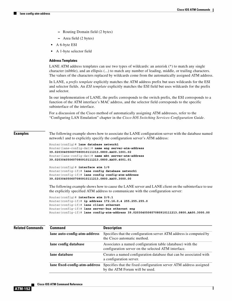
Cisco IOS ATM Commandslane config-atm-address
ATM-152Cisco IOS ATM Command Reference
– Routing Domain field (2 bytes)
– Area field (2 bytes)
• A 6-byte ESI
• A 1-byte selector field
Address Templates
LANE ATM address templates can use two types of wildcards: an asterisk (*) to match any single character (nibble), and an ellipsis (...) to match any number of leading, middle, or trailing characters. The values of the characters replaced by wildcards come from the automatically assigned ATM address.
In LANE, a prefix template explicitly matches the ATM address prefix but uses wildcards for the ESI and selector fields. An ESI template explicitly matches the ESI field but uses wildcards for the prefix and selector.
In our implementation of LANE, the prefix corresponds to the switch prefix, the ESI corresponds to a function of the ATM interface’s MAC address, and the selector field corresponds to the specific subinterface of the interface.
For a discussion of the Cisco method of automatically assigning ATM addresses, refer to the “Configuring LAN Emulation” chapter in the Cisco IOS Switching Services Configuration Guide.
Examples The following example shows how to associate the LANE configuration server with the database named network1 and to explicitly specify the configuration server’s ATM address:
Router(config)# lane database network1Router(lane-config-dat)# name eng server-atm-address 39.020304050607080910111213.0800.AA00.1001.02Router(lane-config-dat)# name mkt server-atm-address 39.020304050607080910111213.0800.AA00.4001.01
Router(config)# interface atm 1/0Router(config-if)# lane config database network1Router(config-if)# lane config config-atm-address 39.020304050607080910111213.0800.AA00.3000.00
The following example shows how to cause the LANE server and LANE client on the subinterface to use the explicitly specified ATM address to communicate with the configuration server:
Router(config)# interface atm 2/0.1Router(config-if)# ip address 172.16.0.4 255.255.255.0Router(config-if)# lane client ethernetRouter(config-if)# lane server-bus ethernet engRouter(config-if)# lane config-atm-address 39.020304050607080910111213.0800.AA00.3000.00
Related Commands Command Description
lane auto-config-atm-address Specifies that the configuration server ATM address is computed by the Cisco automatic method.
lane config database Associates a named configuration table (database) with the configuration server on the selected ATM interface.
lane database Creates a named configuration database that can be associated with a configuration server.
lane fixed-config-atm-address Specifies that the fixed configuration server ATM address assigned by the ATM Forum will be used.

Cisco IOS ATM Commandslane database
ATM-153Cisco IOS ATM Command Reference
lane databaseTo create a named configuration database that can be associated with a configuration server, use the lane database command in global configuration mode. To delete the database, use the no form of this command.
lane database database-name
no lane database database-name
Syntax Description
Defaults No name is provided.
Command Modes Global configuration
Command History
Usage Guidelines Use of the lane database command places you in database configuration mode, in which you can use the client-atm-address name, default name, mac-address name, name restricted, name unrestricted, name new-name, and name server-atm-address commands to create entries in the specified database. When you are finished creating entries, type ^Z or exit to return to global configuration mode.
Examples The following example shows how to create the database named network1 and associates it with the configuration server on interface ATM 1/0:
Router(config)# lane database network1Router(lane-config-dat)# name eng server-atm-address 39.020304050607080910111213.0800.AA00.1001.02Router(lane-config-dat)# name mkt server-atm-address 39.020304050607080910111213.0800.AA00.4001.01Router(lane-config-dat)# default-name eng
Router(config)# interface atm 1/0Router(config-if)# lane config database network1Router(config-if)# lane config auto-config-atm-address
database-name Database name (32 characters maximum).
Release Modification
11.0 This command was introduced.

Cisco IOS ATM Commandslane database
ATM-154Cisco IOS ATM Command Reference
Related Commands Command Description
client-atm-address name Adds a LANE client address entry to the configuration database of the configuration server.
default-name Provides an ELAN name in the database of the configuration server for those client MAC addresses and client ATM addresses that do not have explicit ELAN name bindings.
lane config database Associates a named configuration table (database) with the configuration server on the selected ATM interface.
mac-address Sets the MAC-layer address of the Cisco Token Ring.
name Assigns a name to the internal adapter.
name server-atm-address Specifies or replaces the ATM address of the LANE server for the ELAN in the configuration database of the configuration server.
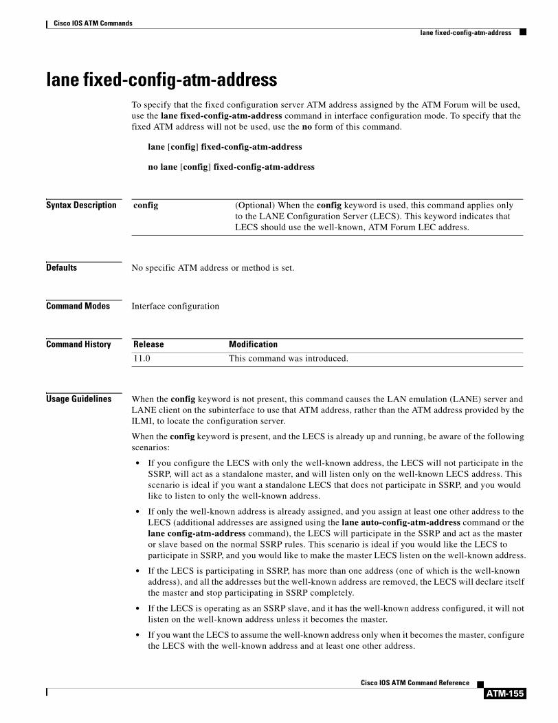
Cisco IOS ATM Commandslane fixed-config-atm-address
ATM-155Cisco IOS ATM Command Reference
lane fixed-config-atm-addressTo specify that the fixed configuration server ATM address assigned by the ATM Forum will be used, use the lane fixed-config-atm-address command in interface configuration mode. To specify that the fixed ATM address will not be used, use the no form of this command.
lane [config] fixed-config-atm-address
no lane [config] fixed-config-atm-address
Syntax Description
Defaults No specific ATM address or method is set.
Command Modes Interface configuration
Command History
Usage Guidelines When the config keyword is not present, this command causes the LAN emulation (LANE) server and LANE client on the subinterface to use that ATM address, rather than the ATM address provided by the ILMI, to locate the configuration server.
When the config keyword is present, and the LECS is already up and running, be aware of the following scenarios:
• If you configure the LECS with only the well-known address, the LECS will not participate in the SSRP, will act as a standalone master, and will listen only on the well-known LECS address. This scenario is ideal if you want a standalone LECS that does not participate in SSRP, and you would like to listen to only the well-known address.
• If only the well-known address is already assigned, and you assign at least one other address to the LECS (additional addresses are assigned using the lane auto-config-atm-address command or the lane config-atm-address command), the LECS will participate in the SSRP and act as the master or slave based on the normal SSRP rules. This scenario is ideal if you would like the LECS to participate in SSRP, and you would like to make the master LECS listen on the well-known address.
• If the LECS is participating in SSRP, has more than one address (one of which is the well-known address), and all the addresses but the well-known address are removed, the LECS will declare itself the master and stop participating in SSRP completely.
• If the LECS is operating as an SSRP slave, and it has the well-known address configured, it will not listen on the well-known address unless it becomes the master.
• If you want the LECS to assume the well-known address only when it becomes the master, configure the LECS with the well-known address and at least one other address.
config (Optional) When the config keyword is used, this command applies only to the LANE Configuration Server (LECS). This keyword indicates that LECS should use the well-known, ATM Forum LEC address.
Release Modification
11.0 This command was introduced.

Cisco IOS ATM Commandslane fixed-config-atm-address
ATM-156Cisco IOS ATM Command Reference
When you use this command with the config keyword, and the LECS is a master, the master will listen on the fixed address. If you use this command when an LECS is not a master, the LECS will listen on this address when it becomes a master. If you do not use this command, the LECS will not listen on the fixed address.
Multiple commands that assign ATM addresses to the LECS can be issued on the same interface in order to assign different ATM addresses to the LECS. Commands that assign ATM addresses to the LECS include lane auto-config-atm-address, lane config-atm-address, and lane fixed-config-atm-address. The lane config database command and at least one command that assigns an ATM address to the LECS are required to activate a LECS.
Examples The following example shows how to associate the LECS with the database named network1 and how to specify that the configuration server’s ATM address is the fixed address:
Router(config)# lane database network1Router(lane-config-dat)# name eng server-atm-address 39.020304050607080910111213.0800.AA00.1001.02Router(lane-config-dat)# name mkt server-atm-address 39.020304050607080910111213.0800.AA00.4001.01
Router(config)# interface atm 1/0Router(config-if)# lane config database network1Router(config-if)# lane config fixed-config-atm-address
The following example shows how to cause the LANE server and LANE client on the subinterface to use the fixed ATM address to communicate with the configuration server:
Router(config)# interface atm 2/0.1Router(config-if)# ip address 172.16.0.4 255.255.255.0Router(config-if)# lane client ethernetRouter(config-if)# lane server-bus ethernet engRouter(config-if)# lane fixed-config-atm-address
Related Commands Command Description
lane auto-config-atm-address Specifies that the configuration server ATM address is computed by the Cisco automatic method.
lane config-atm-address Specifies the ATM address of the configuration server explicitly.
lane config database Associates a named configuration table (database) with the configuration server on the selected ATM interface.

Cisco IOS ATM Commandslane fssrp
ATM-157Cisco IOS ATM Command Reference
lane fssrpTo enable the special LANE features such that LANE components (such as the LANE Configuration Server, the LANE client, the LANE server, and the BUS) become aware of the Fast Simple Server Redundancy Protocol (FSSRP), use the lane fssrp command in interface configuration mode. To disable the LANE FSSRP configuration, use the no form of this command.
lane fssrp
no lane fssrp
Syntax Description This command contains no arguments or keywords.
Defaults FSSRP is not enabled by default.
Command Modes Interface configuration
Command History
Usage Guidelines You must execute this command on all ATM interfaces to enable FSSRP capability for all LANE components on that interface and hence all its subinterfaces.
Examples The following example shows how to enable FSSRP on an ATM interface:
Router(config-if)# lane fssrp
Related Commands
Release Modification
12.0(4c)W5(10a) This command was introduced.
Command Description
lane client Activates a LANE client on the specified subinterface.
lane server Activates a LANE server on the specified subinterface.
show lane client Generates additional FSSRP information about a LANE client.
show lane config Displays global LANE information for the configuration server configured on an interface.
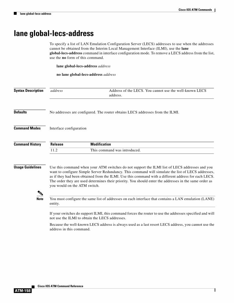
Cisco IOS ATM Commandslane global-lecs-address
ATM-158Cisco IOS ATM Command Reference
lane global-lecs-addressTo specify a list of LAN Emulation Configuration Server (LECS) addresses to use when the addresses cannot be obtained from the Interim Local Management Interface (ILMI), use the lane global-lecs-address command in interface configuration mode. To remove a LECS address from the list, use the no form of this command.
lane global-lecs-address address
no lane global-lecs-address address
Syntax Description
Defaults No addresses are configured. The router obtains LECS addresses from the ILMI.
Command Modes Interface configuration
Command History
Usage Guidelines Use this command when your ATM switches do not support the ILMI list of LECS addresses and you want to configure Simple Server Redundancy. This command will simulate the list of LECS addresses, as if they had been obtained from the ILMI. Use this command with a different address for each LECS. The order they are used determines their priority. You should enter the addresses in the same order as you would on the ATM switch.
Note You must configure the same list of addresses on each interface that contains a LAN emulation (LANE) entity.
If your switches do support ILMI, this command forces the router to use the addresses specified and will not use the ILMI to obtain the LECS addresses.
Because the well-known LECS address is always used as a last resort LECS address, you cannot use the address in this command.
address Address of the LECS. You cannot use the well-known LECS address.
Release Modification
11.2 This command was introduced.

Cisco IOS ATM Commandslane le-arp
ATM-159Cisco IOS ATM Command Reference
lane le-arpTo add a static entry to the LAN Emulation Address Resolution Protocol (LE ARP) table of the LANE client configured on the specified subinterface, use the lane le-arp command in interface configuration mode. To remove a static entry from the LE ARP table of the LANE client on the specified subinterface, use the no form of this command.
lane le-arp {mac-address | route-desc segment segment-number bridge bridge-number} atm-address
no lane le-arp {mac-address | route-desc segment segment-number bridge bridge-number} atm-address
Syntax Description
Defaults No static address bindings are provided.
Command Modes Interface configuration
Command History
Usage Guidelines This command adds or removes a static entry binding a MAC address or segment number and bridge number to an ATM address. It does not add or remove dynamic entries. Removing the static entry for a specified ATM address from a LE ARP table does not release data direct VCCs established to that ATM address. However, clearing a static entry clears any fast-cache entries that were created from the MAC address-to-ATM address binding.
Static LE ARP entries are neither aged nor removed automatically.
To remove dynamic entries from the LE ARP table of the LANE client on the specified subinterface, use the clear lane le-arp command.
Examples The following example shows how to add a static entry to the LE ARP table:
Router(config-if)# lane le-arp 0800.aa00.0101 47.000014155551212f.00.00.0800.200C.1001.01
mac-address MAC address to bind to the specified ATM address.
route-desc segment segment-number
LANE segment number. The segment number ranges from 1 to 4095.
bridge bridge-number Bridge number that is contained in the route descriptor. The bridge number ranges from 1 to 15.
atm-address ATM address.
Release Modification
11.0 This command was introduced.

Cisco IOS ATM Commandslane le-arp
ATM-160Cisco IOS ATM Command Reference
The following example shows how to add a static entry to the LE ARP table binding segment number 1, bridge number 1 to the ATM address:
Router(config-if)# lane le-arp route-desc segment 1 bridge 1 39.020304050607080910111213.00000CA05B41.01
Related Commands Command Description
clear lane le-arp Forces a LANE server to drop a client and allow the LANE configuration server to assign the client to another ELAN.

Cisco IOS ATM Commandslane server-atm-address
ATM-161Cisco IOS ATM Command Reference
lane server-atm-addressTo specify an ATM address—and thus override the automatic ATM address assignment—for the LAN emulation (LANE) server on the specified subinterface, use the lane server-atm-address command in interface configuration mode. To remove the ATM address previously specified for the LANE server on the specified subinterface and thus revert to the automatic address assignment, use the no form of this command.
lane server-atm-address atm-address-template
no lane server-atm-address [atm-address-template]
Syntax Description
Defaults For the LANE server, the default is automatic address assignment; the LANE client finds the LANE server by consulting the configuration server.
Command Modes Interface configuration
Command History
Usage Guidelines This command also instructs the LANE client configured on this subinterface to reach the LANE server by using the specified ATM address instead of the ATM address provided by the configuration server.
When used on a selected subinterface, but with a different ATM address than was used previously, this command replaces the ATM address of the LANE server.
ATM Addresses
A LANE ATM address has the same syntax as an network service access point (NSAP) (but it is not a network-level address). It consists of the following:
• A 13-byte prefix that includes the following fields defined by the ATM Forum:
– AFI (Authority and Format Identifier) field (1 byte)
– DCC (Data Country Code) or ICD (International Code Designator) field (2 bytes)
– DFI field (Domain Specific Part Format Identifier) (1 byte)
– Administrative Authority field (3 bytes)
– Reserved field (2 bytes)
– Routing Domain field (2 bytes)
atm-address-template ATM address or a template in which wildcard characters are replaced by any nibble or group of nibbles of the prefix bytes, the end-system identifier (ESI) bytes, or the selector byte of the automatically assigned ATM address.
Release Modification
11.0 This command was introduced.

Cisco IOS ATM Commandslane server-atm-address
ATM-162Cisco IOS ATM Command Reference
– Area field (2 bytes)
• A 6-byte ESI
• A 1-byte selector field
Address Templates
LANE ATM address templates can use two types of wildcards: an asterisk (*) to match any single character (nibble), and an ellipsis (...) to match any number of leading, middle, or trailing characters. The values of the characters replaced by wildcards come from the automatically assigned ATM address.
In LANE, a prefix template explicitly matches the prefix, but uses wildcards for the ESI and selector fields. An ESI template explicitly matches the ESI field, but uses wildcards for the prefix and selector.
In the Cisco implementation of LANE, the prefix corresponds to the switch, the ESI corresponds to the ATM interface, and the selector field corresponds to the specific subinterface of the interface.
For a discussion of the Cisco method of automatically assigning ATM addresses, refer to the “Configuring LAN Emulation” chapter of the Cisco IOS Switching Services Configuration Guide.
Examples The following example shows how to used an ESI template to specify the part of the ATM address corresponding to the interface; the remaining parts of the ATM address come from automatic assignment:
Router(config-if)# lane server-atm-address ...0800.200C.1001.**
The following example shows how to use a prefix template to specify the part of the ATM address corresponding to the switch; the remaining part of the ATM address come from automatic assignment:
Router(config-if)# lane server-atm-address 45.000014155551212f.00.00...
Related Commands Command Description
lane server-bus Enables a LANE server and a BUS on the specified subinterface with the ELAN ID.
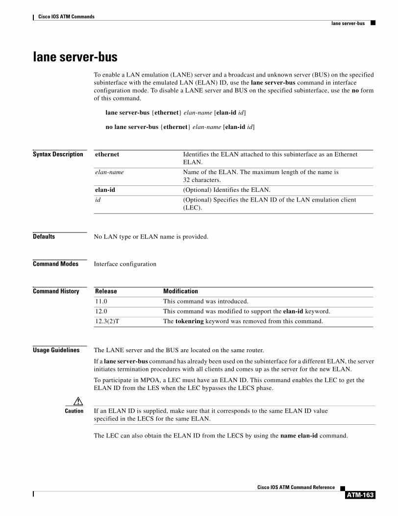
Cisco IOS ATM Commandslane server-bus
ATM-163Cisco IOS ATM Command Reference
lane server-busTo enable a LAN emulation (LANE) server and a broadcast and unknown server (BUS) on the specified subinterface with the emulated LAN (ELAN) ID, use the lane server-bus command in interface configuration mode. To disable a LANE server and BUS on the specified subinterface, use the no form of this command.
lane server-bus {ethernet} elan-name [elan-id id]
no lane server-bus {ethernet} elan-name [elan-id id]
Syntax Description
Defaults No LAN type or ELAN name is provided.
Command Modes Interface configuration
Command History
Usage Guidelines The LANE server and the BUS are located on the same router.
If a lane server-bus command has already been used on the subinterface for a different ELAN, the server initiates termination procedures with all clients and comes up as the server for the new ELAN.
To participate in MPOA, a LEC must have an ELAN ID. This command enables the LEC to get the ELAN ID from the LES when the LEC bypasses the LECS phase.
Caution If an ELAN ID is supplied, make sure that it corresponds to the same ELAN ID value specified in the LECS for the same ELAN.
The LEC can also obtain the ELAN ID from the LECS by using the name elan-id command.
ethernet Identifies the ELAN attached to this subinterface as an Ethernet ELAN.
elan-name Name of the ELAN. The maximum length of the name is 32 characters.
elan-id (Optional) Identifies the ELAN.
id (Optional) Specifies the ELAN ID of the LAN emulation client (LEC).
Release Modification
11.0 This command was introduced.
12.0 This command was modified to support the elan-id keyword.
12.3(2)T The tokenring keyword was removed from this command.

Cisco IOS ATM Commandslane server-bus
ATM-164Cisco IOS ATM Command Reference
Examples The following example shows how to enable a LANE server and BUS for an Ethernet ELAN named MYELAN:
Router(config-if)# lane server-bus ethernet myelan
Related Commands Command Description
lane server-atm-address Specifies an ATM address and thus overrides the automatic ATM address assignment for the LANE server on a specified subinterface.
name elan-id Configures the ELAN ID of an ELAN in the LECS database to participate in MPOA.

Cisco IOS ATM Commandsloopback (ATM)
ATM-165Cisco IOS ATM Command Reference
loopback (ATM)To configure the ATM interface into loopback mode, use the loopback interface configuration command. To remove the loopback, use the no form of this command.
loopback [cell | line | payload]
no loopback [cell | line | payload]
Syntax Description
Defaults line
Command Modes Interface configuration
Command History
Usage Guidelines This command is useful for testing because it loops all packets from the ATM interface back to the interface as well as directing the packets to the network.
Use the loopback line command to check that the PA-A3 port adapter is working by looping the receive data back to the transmit data.
Examples The following example loops all packets back to the ATM interface:
interface atm 4/0loopback
Related Commands
cell (Optional) Places the interface into external loopback at cell level.
line (Optional) Places the interface into external loopback at the line.
payload (Optional) Places the interface into external loopback at the payload level.
Release Modification
11.0 This command was introduced.
11.1 The following keywords were removed:
• diagnostic
• test
Command Description
ces dsx1 loopback Enables a loopback for the CBR interface.

Cisco IOS ATM Commandsloopback
ATM-166Cisco IOS ATM Command Reference
loopbackTo loop packets back to the interface for testing, use the loopback interface configuration command with or without an optional keyword. To remove the loopback, use the no form of this command.
Cisco 2600 and 3600 Series
loopback [line | local | payload | remote]
no loopback [line | local | payload | remote]
Cisco 7100, 7200, and 7500 Series
For T1 lines:
loopback {diagnostic | local {payload | line} | remote {iboc | esf {payload | line}}}
For E1 lines:
loopback {diagnostic | local {payload | line}}
no loopback
Syntax Description
Defaults The line keyword is the default.Loopback is disabled by default.
Command Modes Interface configuration
Command History
line Places the interface into external loopback mode at the line.
local Places the interface into local loopback mode.
payload Places the interface into external loopback mode at the payload level.
remote Keeps the local end of the connection in remote loopback mode.
diagnostic Loops the outgoing transmit signal back to the receive signal.
iboc Sends an in-band code to the far-end receiver to cause it to go into line loopback.
esf Specifies the FDL loopbacks. FDL should be configured on the link.
Release Modification
10.0 This command was introduced.
11.3 MA This command was modified for the Cisco MC3810.
12.0(5)XK Support for the Cisco 2600 and 3600 series routers was added.
12.0(5)T Support for the Cisco 2600 and 3600 series routers was integrated into Cisco IOS Release 12.0(5)T.
12.0(5)XE Support for the Cisco 720 0 and 7500 series routers was added.

Cisco IOS ATM Commandsloopback
ATM-167Cisco IOS ATM Command Reference
Usage Guidelines You can use a loopback test on lines to detect and distinguish equipment malfunctions caused either by line and channel service unit/digital service unit (CSU/DSU) or by the interface. If correct data transmission is not possible when an interface is in loopback mode, the interface is the source of the problem.
The local loopback does not generate any packets automatically. Instead, the ping command is used.
Examples The following example sets up local loopback diagnostics:
interface atm 1/0loopback local
12.0(7)XE1 Support for the Cisco 7100 series routers was added.
12.1(5)T Support for Cisco 7100, 7200, and 7500 series routers was integrated into Cisco IOS Release 12.1(5)T.
Release Modification

Cisco IOS ATM Commandsmac-address (ATM)
ATM-168Cisco IOS ATM Command Reference
mac-address (ATM)To configure the MAC address on ATM permanent virtual circuits (PVCs) in a broadband access (BBA) group for using a different MAC address for PPP over Ethernet over ATM (PPPoEoA), use the mac-address command in BBA group configuration mode. To remove a MAC address, use the no form of this command.
mac-address {autoselect | mac-address}
no mac-address {autoselect | mac-address}
Syntax Description
Defaults No MAC address change. Any change in the usage of MAC addresses will not happen unless this command is explicitly configured.
Command Modes BBA group configuration mode
Command History
Usage Guidelines Except for using a different MAC address, this command does not change the way PPPoE works.
Use the mac-address command to configure the MAC address on ATM PVCs in a BBA group so there will be a different MAC address for PPPoEoA.
If a PPP over Ethernet (PPPoE) profile is not specified by using the group option, PPPoE sessions will be established using values from the global PPPoE profile. PPPoE profiles must be configured using the bba-group pppoe command.
Examples The following example configures the MAC address on an ATM PVC in a BBA group using values from the global PPPoE profile by specifying the MAC address:
Router(config)# bba-group pppoe globalRouter(config-bba-group)# virtual-template 1Router(config-bba-group)# mac-address 1.1.3
The following example configures the MAC address automatically on an ATM PVC in a BBA group using group profile by using the autoselect option:
Router(config)# bba-group pppoe vpn1Router(config-bba-group)# virtual-template 1Router(config-bba-group)# mac-address autoselect
autoselect Automatically selects the MAC address based on the ATM interface.
mac-address MAC address (MAC value) to be used on ATM interfaces, entered as a series of three hexadecimal numbers presented in dotted notation. Example: 0100.CCCC.CCCD.
Release Modification
12.3(11)T This command was introduced.

Cisco IOS ATM Commandsmac-address (ATM)
ATM-169Cisco IOS ATM Command Reference
Related Commands Command Description
bba-group pppoe Creates a PPPoE profile on the BBA group.
protocol pppoe Establishes PPPoE sessions on PVCs.

Cisco IOS ATM Commandsmap-class atm
ATM-170Cisco IOS ATM Command Reference
map-class atmThis command is no longer supported.

Cisco IOS ATM Commandsmid
ATM-171Cisco IOS ATM Command Reference
midTo set the range of message identifier (MID) values on a permanent virtual circuit (PVC), use the mid interface-ATM-VC configuration command. To remove MID value range settings, use the no form of this command.
mid midlow midhigh
no mid midlow midhigh
Syntax Description
Defaults 0
Command Modes Interface-ATM-VC configuration
Command History
Usage Guidelines This command is only available when SMDS encapsulation is configured on a PVC.
Use this command to assign different ranges of message identifiers to different PVCs.
Examples In the following example, the atm mid-per-vc command limits the maximum number of message identifiers to 32 for each VC on the ATM interface. Using the mid command, the selected range of numbers that are available for the message identifiers on PVC 1/40 is 0 to 31. For PVC 2/50, the range is 32 to 63.
interface atm 2/0atm mid-per-vc 32pvc 1/40 smdsmid 0 31pvc 2/50 smdsmid 32 63
midlow Starting MID number for this PVC. This can be set between 0 and 1023.
midhigh Ending MID number for this PVC. This can be set between 0 and 1023.
Release Modification
11.3(2)T This command was introduced.

Cisco IOS ATM Commandsmpoa client config name
ATM-172Cisco IOS ATM Command Reference
mpoa client config nameTo define a Multiprotocol over ATM (MPOA) client (MPC) with a specified name, use the mpoa client config name command in global configuration mode. To delete the MPC, use the no form of this command.
mpoa client config name mpc-name
no mpoa client config name mpc-name
Syntax Description
Defaults No MPC is defined.
Command Modes Global configuration
Command History
Usage Guidelines When you configure or create an MPC, you automatically enter the MPC configuration mode. From here, you can enter subcommands to define or change MPC variables specific only to this MPC. Note that the MPC is not functional until it is attached to a hardware interface.
Examples The following example shows how to create or modify the MPC named ip_mpc:
Router(config)# mpoa client config name ip_mpc
Related Commands
mpc-name Specifies the name of an MPC.
Release Modification
11.3(3a)WA4(5) This command was introduced.
Command Description
atm-address Overrides the control ATM address of an MPC or MPS.
shortcut-frame-count Specifies the maximum number of times a packet can be routed to the default router within shortcut-frame time before an MPOA resolution request is sent.
shortcut-frame-time Sets the shortcut-setup frame time (in seconds) for the MPC.

Cisco IOS ATM Commandsmpoa client name
ATM-173Cisco IOS ATM Command Reference
mpoa client nameTo attach a Multiprotocol over ATM (MPOA) client (MPC) to a major ATM interface, use the mpoa client name command in interface configuration mode. To break the attachment, use the no form of this command.
mpoa client name mpc-name
no mpoa client name mpc-name
Syntax Description
Defaults No MPC is attached to an ATM interface.
Command Modes Interface configuration
Command History
Usage Guidelines The mpoa client name command provides an interface to the MPC through which the MPC can set up and receive calls.
When you enter this command on a major interface that is up and operational, the named MPC becomes operational. Once the MPC is fully operational, it can register its ATM address.
Examples The following example shows how to attache the MPC named ip_mpc to an interface:
Router(config)# interface atm 1/0Router(config-if)# mpoa client name ip_mpc
mpc-name Specifies the name of an MPC.
Release Modification
11.3(3a)WA4(5) This command was introduced.

Cisco IOS ATM Commandsmpoa server config name
ATM-174Cisco IOS ATM Command Reference
mpoa server config nameTo define a Multiprotocol over ATM (MPOA) server (MPS) with the specified name, use the mpoa server config name command in global configuration mode. To delete an MPS, use the no form of this command.
mpoa server config name mps-name
no mpoa server config name mps-name
Syntax Description
Defaults No MPS is defined.
Command Modes Global configuration
Command History
Usage Guidelines This command defines an MPS with the specified name. The MPS does not actually start functioning until it is attached to a specific hardware interface. Once that attachment is complete, the MPS starts functioning. When you configure or create an MPS, you automatically enter the MPS configuration mode.
You can define the MPS variables specific to an MPS only after that MPS has been defined with a specified name. After this command is entered, further commands can be used to change MPS variables that are specific only to this MPS.
Examples The following example shows how to define the MPS named MYMPS:
Router(config)# mpoa server config name MYMPS
mps-name Name of the MPOA server.
Release Modification
11.3(3a)WA4(5) This command was introduced.

Cisco IOS ATM Commandsmpoa server name trigger ip-address
ATM-175Cisco IOS ATM Command Reference
mpoa server name trigger ip-addressTo originate a Multiprotocol over ATM (MPOA) trigger for the specified IP address to the specified MPOA client from the specified Multiprotocol over ATM server (MPS), use the mpoa server name trigger ip-address command in interface configuration mode.
mpoa server name mps-name trigger ip-address ip-address [mpc-address mpc-address]
Syntax Description
Command Modes Interface configuration
Command History
Usage Guidelines This command sends an MPOA trigger for the specified IP address to the specified MPOA client from the specified MPOA server. If an MPOA client is not specified, it is triggered to all MPOA clients.
Examples The following example shows how to send an MPOA trigger for the specified IP address 128.9.0.7 to all known MPOA clients from the MPOA server named MYMPS:
Router(config)# interface atm 1/0Router(config-if)# mpoa server name MYMPS trigger ip-address 128.9.0.7
mps-name Specifies the name of the MPOA server.
ip-address Specifies the IP address.
mpc-address mpc-address (Optional) Specifies the MPOA client (MPC) address to which the trigger should be sent. If the address is not specified, a trigger will be sent to all clients.
Release Modification
11.3(3a)WA4(5) This command was introduced.

Cisco IOS ATM Commandsmpoa server name
ATM-176Cisco IOS ATM Command Reference
mpoa server nameTo attach a Multiprotocol over ATM (MPOA) server (MPS) to a major ATM interface, use the mpoa server name command in interface configuration mode. To break the attachment, use the no form of this command.
mpoa server name mps-name
no mpoa server name mps-name
Syntax Description
Defaults No MPS is attached to an ATM interface.
Command Modes Interface configuration
Command History
Usage Guidelines This command attaches an MPS to a specific (major) interface. At this point, the MPS can obtain its autogenerated ATM address and an interface through which it can communicate to the neighboring MPOA devices. Only when an MPS is both defined globally and attached to an interface is it considered to be operational. Although multiple different servers may share the same hardware interface, an MPS can be attached to only a single interface at any one time. The specified MPS must already be defined when this command is entered.
Examples The following example attaches the MPS named MYMPS to an ATM interface:
Router(config)# interface atm 1/0Router(config-if)# mpoa server name MYMPS
mps-name Name of the MPOA server.
Release Modification
11.3(3a)WA4(5) This command was introduced.

Cisco IOS ATM Commandsmultiqueue
ATM-177Cisco IOS ATM Command Reference
multiqueueTo enable two queues to prioritize multiple classes of packet streams over the same PVC, use the multiqueue command in PVC- or VC-class configuration mode To return to a single-queue approach, use the no form of this command.
multiqueue
no multiqueue
Syntax Description This command has no arguments or keywords.
Command Default Only a single queue per PVC is enabled.
Command Modes PVC-class configurationVC-class configuration
Command History
Usage Guidelines This command enables a priority queue and a regular (nonpriority) queue for traffic streams. When the multiqueue command is enabled and multiple classes of packet streams exist over the same PVC, packets coming from the streams that have priority values configured in a policy map are sent to the high-priority queue. Packets from all other streams are sent to the low-priority queue.
This command applies only to DSL ATM interfaces. Multiqueueing is intended for configuring DSL lines and allows configuring one data flow in a priority queue. If you have configured more than one flow in a priority queue, the latency for delay-sensitive traffic flow might not be guaranteed.
Multiqueueing does not work well with applications such as Multilink PPP (MLP) with interleave and Crypto. This is because MLP uses the same sequence numbering scheme for interleaved packets as multiqueueing. For example, if there are a voice packet and two data packets interleaved, the MLP sequence numbers for these packets could be 1 for the first data packet, 2 for the voice packet, and 3 for a second data packet. With multiqueueing, the voice packet with MLP sequence number 2 goes out before the data packet with MLP sequence number 1. This causes out-of-order sequencing of packets as far as MLP is concerned and causes unexpected behavior. The same problems apply to the Crypto application.
Multiqueueing is disabled by default, so that when MLP and the Crypto applications are used with DSL, the network is disrupted by upgrading to an image with multiqueueing support.
Examples The following example shows how to enter the command from PVC configuration mode:
Router(config-if-atm-vc)# multiqueue
Release Modification
12.4(2)XA This command was introduced.
12.4(6)T This command was integrated into Cisco IOS Release 12.4(6)T.

Cisco IOS ATM Commandsmultiqueue
ATM-178Cisco IOS ATM Command Reference
The following example shows how to enter the command from VC-class configuration mode:
Router(config)# vc-class atm xRouter(config-vc-class)# multiqueue
The following example shows how to return the queues to the default state:
Router(config-if-atm-vc)# no multiqueue
Related Commands Command Description
tx-ring-limit Limits the number of packets that can be used on a transmission ring on the DSL WIC or interface.

Cisco IOS ATM Commandsname elan-id
ATM-179Cisco IOS ATM Command Reference
name elan-idTo configure the emulated LAN (ELAN) ID of an ELAN in the LAN Emulation Configuration Server (LECS) database to participate in Multiprotocol over ATM (MPOA), use the name elan-id command in LANE database configuration mode. To disable the ELAN ID of an ELAN in the LECS database to participate in MPOA, use the no form of this command.
name name elan-id id
no name name elan-id id
Syntax Description
Defaults No ELAN ID is configured.
Command Modes LANE database configuration
Command History
Usage Guidelines To participate in MPOA, a LAN Emulation Client (LEC) must have an ELAN ID. The LEC obtains the ELAN ID from the LECS. In case the LEC bypasses the LECS phase, the LEC can get the ELAN ID from the LES when the name elan-id command is used.
Examples The following example shows how to set the ELAN ID to 10 for an ELAN named MYELAN:
Router(lane-config-dat)# name MYELAN elan-id 10
Related Commands
name Specifies the name of the ELAN.
id Specifies the identification number of the ELAN.
Release Modification
12.0 This command was introduced.
Command Description
lane server-bus Enables a LANE server and a broadcast and unknown server on the specified subinterface with the ELAN ID.

Cisco IOS ATM Commandsname local-seg-id
ATM-180Cisco IOS ATM Command Reference
name local-seg-idTo specify or replace the ring number of the emulated LAN (ELAN) in the configuration server’s configuration database, use the name local-seg-id command in database configuration mode. To remove the ring number from the database, use the no form of this command.
name elan-name local-seg-id segment-number
no name elan-name local-seg-id segment-number
Syntax Description
Defaults No ELAN name or segment number is provided.
Command Modes LANE database configuration
Command History
Usage Guidelines This command is ordinarily used for Token Ring LANE.
The same LANE ring number cannot be assigned to more than one ELAN.
The no form of this command deletes the relationships.
Examples The following example shows how to specify a ring number of 1024 for the ELAN named red:
Router(lane-config-dat)# name red local-seg-id 1024
Related Commands
elan-name Name of the ELAN. The maximum length of the name is 32 characters.
segment-number Segment number to be assigned to the ELAN. The number ranges from 1 to 4095.
Release Modification
11.3 This command was introduced.
Command Description
default-name Provides an ELAN name in the database of the configuration server for those client MAC addresses and client ATM addresses that do not have explicit ELAN name bindings.
lane database Creates a named configuration database that can be associated with a configuration server.
mac-address Sets the MAC-layer address of the Cisco Token Ring.
Cisco IOS ATM Commandsname preempt
ATM-181Cisco IOS ATM Command Reference
name preemptTo set the emulated LAN (ELAN) preempt, use the name preempt command in LANE database configuration mode. To disable preemption, use the no form of this command.
name elan-name preempt
no name elan-name preempt
Syntax Description
Defaults Preemption is disabled by default.
Command Modes LANE database configuration
Command History
Usage Guidelines Prior to Cisco IOS Release 11.3, when the primary LAN Emulation Server (LES) failed, the Cisco Simple Server Redundancy Protocol (SSRP) switched over to a secondary LES. But when a LES that is ranked higher in the list came back up, the SSRP protocol switched the active LES to the new LES, which had a higher priority. This forced the network to flap multiple times. We have prevented the network flapping by staying with the currently active master LES regardless of the priority. If a higher priority LES comes back online, SSRP will not switch to that LES.
LES preemption is off by default. The first LES that comes on becomes the master. Users can revert to the old behavior (of switching to the higher-priority LES all the time) by specifying the name elan-name preempt command in the LECS database.
Examples The following example shows how to set the ELAN preempt for the ELAN named MYELAN:
Router(lane-config-dat)# name MYELAN preempt
elan-name Specifies the name of the ELAN.
Release Modification
11.3 This command was introduced.

Cisco IOS ATM Commandsname server-atm-address
ATM-182Cisco IOS ATM Command Reference
name server-atm-addressTo specify or replace the ATM address of the LAN Emulation (LANE) server for the emulated LAN (ELAN) in the configuration server’s configuration database, use the name server-atm-address command in database configuration mode. To remove it from the database, use the no form of this command.
name elan-name server-atm-address atm-address [restricted | un-restricted] [index number]
no name elan-name server-atm-address atm-address [restricted | un-restricted] [index number]
Syntax Description
Defaults No emulated LAN name or server ATM address is provided.
Command Modes Database configuration
Command History
Usage Guidelines ELAN names must be unique within one named LANE configuration database.
Specifying an existing ELAN name with a new LANE server ATM address adds the LANE server ATM address for that ELAN for redundant server operation or simple LANE service replication. This command can be used multiple times.
The no form of this command deletes the relationships.
Examples The following example shows how to configure the example3 database with two restricted and one unrestricted ELANs. The clients that can be assigned to the eng and mkt ELANs are specified using the client-atm-address commands. All other clients are assigned to the man ELAN.
Router(config)# lane database example3
elan-name Name of the ELAN. Maximum length is 32 characters.
atm-address LANE server’s ATM address.
restricted | un-restricted (Optional) Membership in the named ELAN is restricted to the LANE clients explicitly defined to the ELAN in the configuration server’s database.
index number (Optional) Priority number. When specifying multiple LANE servers for fault tolerance, you can specify a priority for each server. 0 is the highest priority.
Release Modification
11.0 This command was introduced.
11.2 The following keywords were added:
• un-restricted
• index

Cisco IOS ATM Commandsname server-atm-address
ATM-183Cisco IOS ATM Command Reference
Router(lane-config-dat)# name eng server-atm-address 39.000001415555121101020304.0800.200c.1001.02 restrictedRouter(lane-config-dat)# name man server-atm-address 39.000001415555121101020304.0800.200c.1001.01Router(lane-config-dat)# name mkt server-atm-address 39.000001415555121101020304.0800.200c.4001.01 restrictedRouter(lane-config-dat)# client-atm-address 39.000001415555121101020304.0800.200c.1000.02 name engRouter(lane-config-dat)# client-atm-address 39.0000001415555121101020304.0800.200c.2000.02 name engRouter(lane-config-dat)# client-atm-address 39.000001415555121101020304.0800.200c.3000.02 name mktRouter(lane-config-dat)# client-atm-address 39.000001415555121101020304.0800.200c.4000.01 name mktRouter(lane-config-dat)# default-name manRouter(lane-config-dat)# exit
Related Commands Command Description
client-atm-address name Adds a LANE client address entry to the configuration database of the configuration server.
default-name Provides an ELAN name in the database of the configuration server for those client MAC addresses and client ATM addresses that do not have explicit ELAN name bindings.
lane database Creates a named configuration database that can be associated with a configuration server.
mac-address Sets the MAC-layer address of the Cisco Token Ring.

Cisco IOS ATM Commandsnetwork-clock-select (ATM)
ATM-184Cisco IOS ATM Command Reference
network-clock-select (ATM)To establish the sources and priorities of the requisite clocking signals for an ATM-CES port adapter, use the network-clock-select command in global configuration mode. To remove the clock source, use the no form of this command.
network-clock-select priority {cbr | atm} slot/port
no network-clock-select priority {cbr | atm} slot/port
Syntax Description
Defaults No default behavior or values
Command Modes Global configuration
Command History
Usage Guidelines To support synchronous or synchronous residual time stamp (SRTS) clocking modes on the CBR interface, you must specify a primary reference source to synchronize the flow of CBR data from its source to its destination.
You can specify up to four clock priorities. The highest priority active interface in the router supplies primary reference source to all other interfaces that require network clock synchronization services. The fifth priority is the local oscillator on the ATM-CES port adapter.
Use the show network-clocks command to display currently configured clock priorities on the router.
Examples The following example defines two clock priorities on the router:
network-clock-select 1 cbr 2/0network-clock-select 2 atm 2/0
priority Priority of the clock source. Values are 1 (high priority) to 4 (low priority).
cbr Specifies a CBR interface to supply the clock source.
atm Specifies an ATM interface to supply the clock source.
slot/ Backplane slot number.
port Interface port number.
Release Modification
11.1 This command was introduced.

Cisco IOS ATM Commandsnetwork-clock-select (ATM)
ATM-185Cisco IOS ATM Command Reference
Related Commands Command Description
ces aal1 clock Configures the AAL1 timing recovery clock for the CBR interface.
ces dsx1 clock source Configures a transmit clock source for the CBR interface.
show network-clocks Displays which ports are designated as network clock sources.

Cisco IOS ATM Commandsnetwork-id
ATM-186Cisco IOS ATM Command Reference
network-idTo specify the network ID of a Multiprotocol over ATM (MPOA) server (MPS), use the network-id command in MPS configuration mode. To revert to the default value (default value is 1), use the no form of this command.
network-id id
no network-id
Syntax Description
Defaults The default value for the network ID is 1.
Command Modes MPS configuration
Command History
Usage Guidelines Specifies the network ID of this MPS. This value is used in a very similar way the NHRP network ID is used. It is for partitioning nonbroadcast multiaccess (NBMA) clouds artificially by administration.
Examples The following example shows how to set the network ID to 5:
Router(mpoa-server-config)# network-id 5
id Specifies the network ID of the MPOA server.
Release Modification
11.3(3a)WA4(5) This command was introduced.
Cisco IOS ATM Commandsoam ais-rdi
ATM-187Cisco IOS ATM Command Reference
oam ais-rdiTo configure an ATM permanent virtual circuit (PVC) to be brought down after a specified number of Operation, Administration, and Maintenance (OAM) alarm indication signal/remote defect indication (AIS/RDI) cells have been received on the PVC or brought up if no OAM AIS/RDI cells have been received in a specified interval, use the oam ais-rdi command in ATM VC configuration or VC class configuration mode. To return OAM AIS/RDI behavior to the default, use the no form of this command.
oam ais-rdi [down-count [up-count]]
no oam ais-rdi [down-count [up-count]]
Syntax Description
Defaults Down count: 1Up count: 3
Command Modes ATM VC configurationVC class configuration
Command History
Usage Guidelines The default values for the OAM AIS/RDI down count and up count are used in the following situations:
• If the oam ais-rdi command has not been entered
• If the oam ais-rdi command is entered without the up-count or down-count argument
• If the no oam ais-rdi command is entered
If the oam ais-rdi command is entered without the up-count or down-count argument, the command will not appear in the show running-config command output.
down-count (Optional) Number of consecutive OAM AIS/RDI cells received before the PVC is brought down. The range is from 1 to 60. The default is 1.
up-count (Optional) Number of seconds after which a PVC will be brought up if no OAM AIS/RDI cells are received. The range is from 3 to 60. The default is 3.
Release Modification
12.1(2)T This command was introduced.

Cisco IOS ATM Commandsoam ais-rdi
ATM-188Cisco IOS ATM Command Reference
Examples In the following example, PVC 0/400 will be brought down after 25 consecutive OAM AIS/RDI cells have been received on the PVC. The PVC will be brought up when no OAM AIS/RDI cells have been received for 5 seconds.
interface ATM2/0/0ip address 172.2.222.20 255.255.255.0no ip route-cache cefno ip route-cache distributedno atm ilmi-keepalivepvc 0/400 protocol ip 172.2.223.21oam-pvc manage 30oam ais-rdi 25 5

Cisco IOS ATM Commandsoam retry cc
ATM-189Cisco IOS ATM Command Reference
oam retry ccTo set the frequency at which ATM Operation, Administration, and Maintenance (OAM) F5 continuity check (CC) activation and deactivation requests are sent to a device at the other end of a segment or permanent virtual circuit (PVC), use the oam retry cc command in ATM virtual circuit configuration mode. To remove the retry settings, use the no form of this command.
oam retry cc {end | segment} [activation-count [deactivation-count [retry-frequency]]]
no oam retry cc {end | segment} [activation-count [deactivation-count [retry-frequency]]]
Syntax Description
Defaults Activation count: 3Deactivation count: 3Retry frequency: 30 seconds
Command Modes ATM virtual circuit configuration
Command History
Examples The following example shows how to configure ATM OAM F5 CC support over the segment and configure the router to function as the source. The frequency at which CC activation and deactivation requests will be sent over the segment is also configured.
interface atm 0ip address 10.0.0.3 255.255.255.0pvc 0/40oam-pvc manage cc segment direction sourceoam retry cc segment 10 10 30
end End-to-end continuity check.
segment Segment continuity check.
activation-count (Optional) Maximum number of times the activation request will be sent before the receipt of an acknowledgment. The range is from 3 to 600. The default is 3.
deactivation-count (Optional) Maximum number of times the deactivation request will be sent before the receipt of an acknowledgment. The range is from 3 to 600. The default is 3.
retry-frequency (Optional) Interval between retries, in seconds. The default is 30 seconds.
Release Modification
12.2(13)T This command was introduced.

Cisco IOS ATM Commandsoam retry cc
ATM-190Cisco IOS ATM Command Reference
Related Commands Command Description
oam-pvc manage cc deny
Configures ATM OAM F5 CC management.
oam-pvc manage cc deny
Disables ATM OAM F5 CC support and configures the PVC to deny CC activation requests.

Cisco IOS ATM Commandsoam retry
ATM-191Cisco IOS ATM Command Reference
oam retryTo configure parameters related to Operation, Administration, and Maintenance (OAM) management for an ATM permanent virtual circuit (PVC), switched virtual circuit (SVC), VC class, or VC bundle, or label-controlled ATM (LC-ATM) VC, use the oam retry command in the appropriate command mode. To remove OAM management parameters, use the no form of this command.
oam retry up-count down-count retry-frequency
no oam retry
Syntax Description
Defaults ATM PVCs and SVCs
up-count: 3down-count: 5retry-frequency: 1 second
LC-ATM VCs
up-count: 2down-count: 2retry-frequency: 2 seconds
Command Modes Interface-ATM-VC configuration (for an ATM PVC or SVC)VC-class configuration (for a VC class)Bundle configuration mode (for a VC bundle)PVC range configuration (for an ATM PVC range) PVC-in-range configuration (for an individual PVC within a PVC range)Control-VC configuration (for an LC-ATM VC)
Command History
up-count Number of consecutive end-to-end F5 OAM loopback cell responses that must be received in order to change a connection state to up. This argument does not apply to SVCs.
down-count Number of consecutive end-to-end F5 OAM loopback cell responses that are not received in order to change the state to down or tear down an SVC connection.
retry-frequency The frequency (in seconds) at which end-to-end F5 OAM loopback cells are transmitted when a change in the up/down state is being verified. For example, if a PVC is up and a loopback cell response is not received after the frequency (in seconds) argument is specified using the oam-pvc command, loopback cells are sent at the retry-frequency to verify whether the PVC is down.
Release Modification
11.3 T This command was introduced.
12.0(3)T This command was modified to allow configuration parameters related to OAM management for ATM VC bundles.

Cisco IOS ATM Commandsoam retry
ATM-192Cisco IOS ATM Command Reference
Usage Guidelines The following guidelines apply to PVCs, SVCs, and VC classes. They do not apply to LC-ATM VCs.
• For ATM PVCs, SVCs, or VC bundles, if the oam retry command is not explicitly configured, the VC inherits the following default configuration (listed in order of precedence):
– Configuration of the oam retry command in a VC class assigned to the PVC or SVC itself.
– Configuration of the oam retry command in a VC class assigned to the PVC’s or SVC’s ATM subinterface.
– Configuration of the oam retry command in a VC class assigned to the PVC’s or SVC’s ATM main interface.
– Global default: up-count = 3, down-count = 5, retry-frequency = 1 second. This set of defaults assumes that OAM management is enabled using the oam-pvc or oam-svc command. The up-count and retry-frequency arguments do not apply to SVCs.
• To use this command in bundle configuration mode, enter the bundle command to create the bundle or to specify an existing bundle before you enter this command.
• If you use the oam retry command to configure a VC bundle, you configure all VC members of that bundle. VCs in a VC bundle are further subject to the following inheritance rules (listed in order of precedence):
– VC configuration in bundle-vc mode
– Bundle configuration in bundle mode (with the effect of assigned VC-class configuration)
– Subinterface configuration in subinterface mode
Examples The following example shows how to configure the OAM management parameters with an up count of 3, a down-count of 3, and the retry frequency set at 10 seconds:
Router(cfg-mpls-atm-cvc)# oam retry 3 3 10
Related Commands
12.1(5)T This command was implemented in PVC range and PVC-in-range configuration modes.
12.3(2)T This command was implemented in control-VC configuration mode.
Release Modification
Command Description
broadcast Configures broadcast packet duplication and transmission for an ATM VC class, PVC, SVC, or VC bundle.
class-int Assigns a VC class to an ATM main interface or subinterface.
class-vc Assigns a VC class to an ATM PVC, SVC, or VC bundle member.
encapsulation Sets the encapsulation method used by the interface.
inarp Configures the Inverse ARP time period for an ATM PVC, VC class, or VC bundle.
oam-bundle Enables end-to-end F5 OAM loopback cell generation and OAM management for a virtual circuit class that can be applied to a virtual circuit bundle.

Cisco IOS ATM Commandsoam retry
ATM-193Cisco IOS ATM Command Reference
oam-pvc Enables end-to-end F5 OAM loopback cell generation and OAM management for an ATM PVC or virtual circuit class.
oam-svc Enables end-to-end F5 OAM loopback cell generation and OAM management for an ATM SVC or virtual circuit class.
protocol (ATM) Configures a static map for an ATM PVC, SVC, VC class, or VC bundle. Enables Inverse ARP or Inverse ARP broadcasts on an ATM PVC by either configuring Inverse ARP directly on the PVC, on the VC bundle, or in a VC class (applies to IP and IPX protocols only).
ubr Configures UBR QoS and specifies the output peak cell rate for an ATM PVC, SVC, VC class, or VC bundle member.
ubr+ Configures UBR QoS and specifies the output peak cell rate and output minimum guaranteed cell rate for an ATM PVC, SVC, VC class, or VC bundle member.
vbr-nrt Configures the VBR-NRT QoS and specifies output peak cell rate, output sustainable cell rate, and output maximum burst cell size for an ATM PVC, SVC, VC class, or VC bundle member.
Command Description

Cisco IOS ATM Commandsoam-pvc manage cc deny
ATM-194Cisco IOS ATM Command Reference
oam-pvc manage cc denyTo disable ATM Operation, Administration, and Maintenance (OAM) F5 continuity check (CC) support and configure a permanent virtual circuit (PVC) to deny CC activation requests, use the oam-pvc manage cc deny command in ATM virtual circuit configuration mode. To reenable OAM F5 CC support and allow CC activation requests, use the no form of this command.
oam-pvc manage cc {end | segment} deny
no oam-pvc manage cc {end | segment} deny
Syntax Description
Defaults If the peer device sends the activation message, F5 CC management will be enabled on the PVC.
Command Modes ATM virtual circuit configuration
Command History
Usage Guidelines Use the oam-pvc manage cc deny command to configure a permanent virtual circuit (PVC) to respond to activation requests from a peer device with “activation denied” messages. The oam-pvc manage cc deny command prevents ATM OAM F5 CC management from being activated on the PVC.
Use the no oam-pvc manage cc command to send a deactivation request to the peer device. The no oam-pvc manage cc command will disable ATM OAM F5 CC management on the PVC until the PVC receives an activation request. When the PVC receives an activation request, ATM OAM F5 CC management will be reenabled.
Examples The following example shows how to disable ATM OAM F5 CC support and configure the VC to deny CC activation requests:
interface atm 0ip address 10.0.0.3 255.255.255.0pvc 0/40oam-pvc manage cc segment deny
end End-to-end continuity checking.
segment Segment continuity checking.
Release Modification
12.2(13)T This command was introduced.

Cisco IOS ATM Commandsoam-pvc manage cc deny
ATM-195Cisco IOS ATM Command Reference
Related Commands Command Description
oam-pvc manage cc deny
Configures ATM OAM F5 CC management.
oam retry cc Sets the frequency at which ATM OAM F5 CC activation and deactivation requests are sent to the device at the other end of a segment or PVC.

Cisco IOS ATM Commandsoam-pvc manage cc
ATM-196Cisco IOS ATM Command Reference
oam-pvc manage ccTo configure ATM Operation, Administration, and Maintenance (OAM) F5 continuity check (CC) management, use the oam-pvc manage cc command in ATM virtual circuit configuration mode. To disable OAM F5 continuity checking, use the no form of this command.
oam-pvc manage cc {end | segment} [direction {both | sink | source}] [keep-vc-up [end aisrdi failure | seg aisrdi failure]]
no oam-pvc manage cc {end | segment} [deactivate-down-vc] [direction {both | sink | source}] [keep-vc-up [end aisrdi failure | seg aisrdi failure]]
Syntax Description
Defaults The default direction is sink.
Command Modes ATM virtual circuit configuration
Command History
end End-to-end continuity checking. Monitoring occurs on the entire VC between two ATM end stations.
segment Segment continuity checking. Monitoring occurs on a VC segment between a router and a first-hop ATM switch.
direction (Optional) Direction of CC cell transmission.
both (Optional) Specifies that CC cells transmit toward and away from the activator.
sink (Optional) Specifies that CC cells transmit toward the activator. This is the default direction.
source (Optional) Specifies that CC cells transmit away from the activator.
keep-vc-up (Optional) Specifies that VC will be kept in the UP state when CC cells detect connectivity failure.
end aisrdi failure (Optional) Specifies that if end alarm indication signals/remote defect indications (AIS/RDI) cells are received, the VC will not be brought down because of segment CC failure.
seg aisrdi failure (Optional) Specifies that if segment AIS/RDI cells are received, the VC will not be brought down because of end CC failure or loopback failure.
deactivate-down-vc (Optional) Specifies that an OAM F5 CC deactivation message will be sent when the VC is operationally down and in the CC active state. This keyword is available only when the no form of this command is used.
Release Modification
12.2(13)T This command was introduced.

Cisco IOS ATM Commandsoam-pvc manage cc
ATM-197Cisco IOS ATM Command Reference
Usage Guidelines ATM OAM F5 continuity checking enables OAM to support the use of F5 segment and end-to-end CC cells to detect connectivity failures.
It is not necessary to enter a CC configuration on the router at the other end of a segment. The router on which CC management has been configured sends a CC activation request to the router at the other end of the segment, directing it to act as either a source or a sink.
Use the oam-pvc manage cc deny command to configure a permanent virtual circuit (PVC) to respond to activation requests from a peer device with “activation denied” messages. The oam-pvc manage cc deny command prevents ATM OAM F5 CC management from being activated on the PVC.
Use the no oam-pvc manage cc command to send a deactivation request to the peer device. The no oam-pvc manage cc command will disable ATM OAM F5 CC management on the PVC until the PVC receives an activation request. When the PVC receives an activation request, ATM OAM F5 CC management will be reenabled.
The no oam-pvc manage cc {end | segment} deactivate-down-vc command does not disable ATM OAM F5 CC support. This command causes OAM F5 CC deactivation messages to be sent over the VC when the VC goes down.
To enable the SNMP notifications that support ATM OAM F5 continuity checking, use the snmp-server enable traps atm pvc extension command.
Examples ATM OAM F5 CC Support on a PVC Configuration Example
The following example shows how to configure ATM OAM F5 CC support over the segment and configure the router to function as the source. The frequency at which CC activation and deactivation requests will be sent over the segment is also configured.
interface atm 0ip address 10.0.0.3 255.255.255.0pvc 0/40oam-pvc manage cc segment direction sourceoam retry cc segment 10 10 30
Deactivation of ATM OAM F5 CC upon VC Failure Example
The following example shows how to configure OAM to send a CC deactivation request across the segment when PVC 0/1 goes down:
interface atm 0ip address 10.0.0.3 255.255.255.0pvc 0/40no oam-pvc manage cc segment deactivate-down-vc
Related Commands Command Description
debug atm oam cc Displays ATM OAM F5 CC management activity.
oam-pvc manage cc deny Disables ATM OAM F5 CC support and configures the PVC to deny CC activation requests.
oam retry cc Sets the frequency at which ATM OAM F5 CC activation and deactivation requests are sent to the device at the other end of a segment or PVC.
show atm pvc Displays all ATM PVCs and traffic information.

Cisco IOS ATM Commandsoam-pvc manage cc
ATM-198Cisco IOS ATM Command Reference
snmp-server enable traps atm pvc extension mibversion
Specifies the MIB that supports extended ATM PVC SNMP notifications or the MIB that supports SNMP notifications for ATM OAM F5 CC management, ATM OAM F5 AIS/RDI management, and F5 loopback failure management.
vpn service Enables the sending of extended ATM PVC SNMP notifications and SNMP notifications for ATM OAM F5 CC, ATM OAM F5 AIS/RDI, and loopback failures.
Command Description

Cisco IOS ATM Commandsoam-pvc
ATM-199Cisco IOS ATM Command Reference
oam-pvcTo enable end-to-end F5 Operation, Administration, and Maintenance (OAM) loopback cell generation and OAM management for an ATM permanent virtual circuit (PVC), virtual circuit (VC) class, or label-controlled ATM (LC-ATM) VC, use the oam-pvc command in the appropriate command mode. To disable generation of OAM loopback cells and OAM management, use the no form of this command.
ATM VC or VC Class
oam-pvc [manage] [frequency]
no oam-pvc [manage]
LC-ATM VC
oam-pvc manage [frequency]
no oam-pvc manage
Loopback Mode Detection
oam-pvc manage [frequency] loop-detection
no oam-pvc manage loop-detection
Syntax Description
Command Default Disabled.
Command Modes Interface-ATM-VC configuration (for an ATM PVC or Loopback Mode Detection) VC-class configuration (for a VC class)PVC-in-range configuration (for an individual PVC within a PVC range)Control-VC configuration (for enabling OAM management on an LC-ATM VC)
Command History
manage (Optional for ATM VCs or VC classes; required for LC-ATM VCs) Enables OAM management. The default is disabled.
frequency (Optional) Time delay between transmitting OAM loopback cells. For ATM VCs or VC classes and loopback mode detection, the range of values is from 0 to 600 seconds. The default is 10 seconds. For LC-ATM VCs, the range of values is from 0 to 255 seconds. The default is 5 seconds.
loop-detection Enables automatic detection of whether the physically connected ATM switch is in loopback mode. The default is disabled.
Release Modification
11.3 This command was introduced.
12.1(5)T This command was implemented in PVC-in-range configuration mode.

Cisco IOS ATM Commandsoam-pvc
ATM-200Cisco IOS ATM Command Reference
Usage Guidelines If OAM management is enabled, further control of OAM management is configured using the oam retry command.
ATM VCS or VC Classes
If the oam-pvc command is not explicitly configured on an ATM PVC, the PVC inherits the following default configuration (listed in order of precedence):
• Configuration of the oam-pvc command in a VC class assigned to the PVC itself.
• Configuration of the oam-pvc command in a VC class assigned to the PVC’s ATM subinterface.
• Configuration of the oam-pvc command in a VC class assigned to the PVC’s ATM main interface.
• Global default: End-to-end F5 OAM loopback cell generation and OAM management are disabled, but if OAM cells are received, they are looped back. The default value for the frequency argument is 10 seconds.
Loopback Mode Detection
When a PVC traverses an ATM cloud and OAM is enabled, the router sends a loopback cell to the other end and waits for a response to determine whether the circuit is up. If an intervening router within the ATM cloud is in loopback mode, however, the router considers the circuit to be up, when in fact the other end is not reachable.
When enabled, the Loopback Mode Detection Through OAM feature detects when an intervening router is in loopback mode, in which case it sets the OAM state to NOT_VERIFIED. This prevents traffic from being routed on the PVC for as long as any intervening router is detected as being in loopback mode.
Examples The following example shows how to enable end-to-end F5 OAM loopback cell transmission and OAM management on an ATM PVC with a transmission frequency of 3 seconds:
Router(cfg-mpls-atm-cvc)# oam-pvc manage 3
The following example shows how to enable end-to-end F5 OAM loopback cell transmission and OAM management on an LC-ATM interface with a transmission frequency of 2 seconds:
Router(config)# interface Switch1.10 mplsRouter(config-subif)# ip unnumbered Loopback0Router(config-subif)# mpls atm control-vc 0 32Router(cfg-mpls-atm-cvc)# oam-pvc manage 2
The following example shows how to create a PVC and enable loopback detection:
Router(config)# interface ATM1/0Router(config-if)# pvc 4/100 Router(config-if-atm-vc)# oam-pvc manage loop-detection
12.3(2)T This command was implemented for LC-ATM VCs.
12.0(30)S The loop-detection keyword was added.
Release Modification

Cisco IOS ATM Commandsoam-pvc
ATM-201Cisco IOS ATM Command Reference
Related Commands Command Description
ilmi manage Enables ILMI management on an ATM PVC.
oam retry Configures parameters related to OAM management for an ATM PVC, SVC, VC class, or LC-ATM VC.
show atm pvc Displays all ATM PVCs and traffic information.

Cisco IOS ATM Commandsoam-range
ATM-202Cisco IOS ATM Command Reference
oam-rangeTo enable end-to-end F5 Operation, Administration, and Maintenance (OAM) loopback cell generation and OAM management for an ATM permanent virtual circuit (PVC) range, use the oam-range command in PVC range configuration mode. To disable generation of OAM loopback cells and OAM management, use the no form of this command.
oam-range [manage] [frequency]
no oam-range [manage] [frequency]
Syntax Description
Defaults 10 seconds
Command Modes PVC range configuration
Command History
Usage Guidelines If OAM management is enabled, further control of OAM management is configured using the oam retry command.
If the oam-range command is not explicitly configured for an ATM PVC range, the range inherits the following default configuration (listed in order of precedence):
• Configuration of the oam-range command in a VC class assigned to the range.
• Configuration of the oam-range command in a VC class assigned to the ATM subinterface for the range.
• Configuration of the oam-range command in a VC class assigned to the ATM main interface for the range.
• Global default: End-to-end F5 OAM loopback cell generation and OAM management are disabled, but if OAM cells are received, they are looped back. The default value for the frequency argument is 10 seconds.
Examples The following example enables end-to-end F5 OAM loopback cell transmission and OAM management on an ATM PVC range called “range1” with a transmission frequency of 11 seconds:
interface atm 6/0.1range range1 pvc 7/101 7/103oam-range manage 11oam retry 8 9 10
manage (Optional) Enables OAM management.
frequency (Optional) Time delay (0 to 600 seconds) between transmissions of OAM loopback cells.
Release Modification
12.1(5)T This command was introduced.

Cisco IOS ATM Commandsoam-range
ATM-203Cisco IOS ATM Command Reference
Related Commands Command Description
ilmi manage Enables ILMI management on an ATM PVC.
oam-pvc Enables end-to-end F5 OAM loopback cell generation and OAM management for an ATM PVC or VC class.
oam retry Configures parameters related to OAM management for ATM PVC, SVC, or VC class.

Cisco IOS ATM Commandsoam-svc
ATM-204Cisco IOS ATM Command Reference
oam-svcTo enable end-to-end F5 Operation, Administration, and Maintenance (OAM) loopback cell generation and OAM management for an ATM switched virtual circuit (SVC) or virtual circuit (VC) class, use the oam-svc command in the appropriate command mode. To disable generation of OAM loopback cells and OAM management, use the no form of this command.
oam-svc [manage] [frequency]
no oam-svc [manage] [frequency]
Syntax Description
Defaults 10 seconds
Command Modes Interface-ATM-VC configuration (for an ATM SVC)VC-class configuration (for a VC class)
Command History
Usage Guidelines If OAM management is enabled, further control of OAM management is configured using the oam retry command.
Note Generally, ATM signalling manages ATM SVCs. Configuring the oam-svc command on an SVC verifies the inband integrity of the SVC.
If the oam-svc command is not explicitly configured on an ATM SVC, the SVC inherits the following default configuration (listed in order of precedence):
• Configuration of the oam-svc command in a VC class assigned to the SVC itself.
• Configuration of the oam-svc command in a VC class assigned to the SVC’s ATM subinterface.
• Configuration of the oam-svc command in a VC class assigned to the SVC’s ATM main interface.
• Global default: End-to-end F5 OAM loopback cell generation and OAM management are disabled, but if OAM cells are received, they are looped back. The default value for frequency is 10 seconds.
Examples The following example enables end-to-end F5 OAM loopback cell transmission and OAM management on an ATM SVC with a transmission frequency of 3 seconds:
oam-svc manage 3
manage (Optional) Enable OAM management.
frequency (Optional) Time delay (0 to 600 seconds) between transmitting OAM loopback cells.
Release Modification
11.3 This command was introduced.

Cisco IOS ATM Commandsoam-svc
ATM-205Cisco IOS ATM Command Reference
Related Commands Command Description
oam retry Configures parameters related to OAM management for an ATM PVC, SVC, or VC class.
Cisco IOS ATM Commandspartial-fill
ATM-206Cisco IOS ATM Command Reference
partial-fillTo configure the number of AAL1 user octets per cell for the ATM circuit emulation service (CES) on the OC-3/STM-1 Circuit Emulation Service network module, use the partial-fill command in interface-CES-VC mode. To delete the CES partial-fill value, use the no form of this command.
partial-fill octet
no partial-fill octet
Syntax Description
Defaults No partial-fill
Command Modes Interface-CES-VC configuration
Command History
Usage Guidelines The partial-fill command applies to CES switched virtual circuits (SVCs) and permanent virtual circuits (PVCs) configured on Cisco 2600 series and Cisco 3600 series routers that have OC-3/STM-1 ATM CES network modules.
Examples The following example sets the CES partial cell fill to 50 octets per cell for SVC “ces1”:
interface atm 1/0svc ces1 nsap 47.00.00......01.01.00 cespartial fill 40
Related Commands
octet Number of user octets per cell for the CES. Possible values of octet range from 1 to 47.
Release Modification
12.1(2)T This command was introduced.
Command Description
svc Creates an ATM SVC and specifies the destination NSAP address on a main interface or subinterface.

Cisco IOS ATM Commandsping atm interface atm
ATM-207Cisco IOS ATM Command Reference
ping atm interface atmTo perform an ATM Operation Administration Maintenance (OAM) ping on a specific permanent virtual circuit (PVC), use the ping atm interface atm command in privileged EXEC mode.
ping atm interface atm interface-number vpi-value vci-value [end-loopback [repeat [timeout]] | seg-loopback [repeat [timeout]]]
Syntax Description
Defaults End loopbackRepeats: 5Timeout interval: 2 seconds
Command Modes Privileged EXEC
Command History
Usage Guidelines The ping atm interface atm command sends an OAM packet and indicates when a response is received. It can be used either in normal mode or in interactive mode. The ping atm interface atm command provides two ATM OAM ping options:
• End loopback—Verifies end-to-end PVC integrity.
• Segment loopback—Verifies PVC integrity to the neighboring ATM device.
atm interface_number ATM interface name.
vpi-value Virtual path identifier. Range: 0 to 255.
vci-value Virtual channel identifier. Range: 0 to 65535.
end-loopback (Optional) Send ATM end loopback cells. This is the default.
seg-loopback (Optional) Send ATM segment loopback cells.
repeat (Optional) Number of ping packets that are sent to the destination address. Range: 1 to 1000. Default: 5.
timeout (Optional) Timeout interval, in seconds. Range: 1 to 30. Default: 2.
Release Modification
11.4 This command was introduced on the LightStream 1010.
12.0(21)S Support for this command was integrated into Cisco IOS Release 12.0(21)S.
12.2(13)T Support for this command was integrated into Cisco IOS Release 12.2(13)T.
12.2(25)S Support for this command was integrated into Cisco IOS Release 12.2(25)S.

Cisco IOS ATM Commandsping atm interface atm
ATM-208Cisco IOS ATM Command Reference
Examples In the following example, an ATM OAM ping with a 15-second timeout verifies end-to-end connectivity for PVC 0/500 in the normal mode:
Router# ping atm interface atm1/1.1 0 500 end-loopback 30 15
Type escape sequence to abort.Sending 30, 53-byte end-to-end OAM echoes, timeout is 15 seconds:!!!!!!!!!!!!!!!!!!!!!!!!!!!!!!Success rate is 100 percent (30/30), round-trip min/avg/max = 1/1/4 ms
In the following example, an ATM OAM ping verifies connectivity to the first-hop ATM switch on PVC 1/100 in the normal mode:
Router# ping atm interface atm1/1.1 0 500 seg-loopback 30 10
Type escape sequence to abort. Sending 30, 53-byte segment OAM echoes, timeout is 10 seconds:!!!!!!!!!!!!!!!!!!!!!!!!!!!!!!Success rate is 100 percent (30/30), round-trip min/avg/max = 1/1/4 ms
Table 2 describes the output of the ping atm interface atm command.
The following example verifies connectivity to the neighboring ATM device for the ATM PVC with the virtual path identifier (VPI) / virtual channel identifier (VCI) value 0/500 in the interactive mode:
Router# ping
Protocol [ip]:atm
ATM Interface:atm1/1.1
VPI value [0]:0
VCI value [1]:500
Loopback - End(0), Segment(1) [0]:1
Repeat Count [5]:Timeout [2]:
Type escape sequence to abort. Sending 5, 53-byte segment OAM echoes, timeout is 2 seconds:!!!!!Success rate is 100 percent (5/5), round-trip min/avg/max = 1/1/1 ms
Table 2 ping atm Field Descriptions
Field Description
Success rate is 100 percent Percentage of packets successfully echoed back to the router. Anything less than 80 percent is usually considered problematic.
round-trip min/avg/max = 1/1/4 ms Round-trip travel time intervals for the OAM loopback cells, including minimum/average/maximum (in milliseconds).
!!!!!! Each exclamation point (!) indicates receipt of a reply. A period (.) indicates that an OAM response cell was not received within the timeout interval.

Cisco IOS ATM Commandsping atm interface atm
ATM-209Cisco IOS ATM Command Reference
Table 3 describes the ping fields shown in the display.
Related Commands
Table 3 ping Field Descriptions for ATM
Field Description
Protocol [ip]: Prompt for a supported protocol.
ATM Interface: Prompt for the ATM interface.
VPI value [0]: Prompt for the virtual path identifier. Default: 0.
VCI value [1]: Prompt for the virtual channel identifier. Default: 1.
Loopback - End(0), Segment(1) [0]: Prompt to specify end loopback, which verifies end-to-end PVC integrity, or segment loopback, which verifies PVC integrity to the neighboring ATM device. Default: end loopback.
Repeat Count [5]: Number of ping packets that will be sent to the destination. Default: 5.
Timeout [2]: Timeout interval, in seconds. Default: 2.
Command Description
debug atm oam Displays information about ATM OAM events.
show atm pvc Displays the OAM status information.
show atm oam auto-detect
Displays ATM Operations and Maintenance (OAM) autodetect statistics.

Cisco IOS ATM Commandsprotocol (ATM)
ATM-210Cisco IOS ATM Command Reference
protocol (ATM)To configure a static map for an ATM permanent virtual circuit (PVC), switched virtual circuit (SVC), or virtual circuit (VC) class or to enable Inverse Address Resolution Protocol (ARP) or Inverse ARP broadcasts on an ATM PVC, use the protocol command in the appropriate mode. To remove a static map or disable Inverse ARP, use the no form of this command.
protocol protocol {protocol-address [virtual-template] | inarp} [[no] broadcast]
no protocol protocol {protocol-address [virtual-template] | inarp} [[no] broadcast]
Syntax Description protocol Choose one of the following values:
aarp—AppleTalk ARPappletalk—AppleTalkarp—IP ARPbridge—bridgingbstun—block serial tunnelcdp—Cisco Discovery Protocolclns—ISO Connectionless Network Service (CLNS)clns_es—ISO CLNS end systemclns_is—ISO CLNS intermediate systemcmns—ISO CMNScompressedtcp—Compressed TCPdecnet—DECnetdecnet_node—DECnet nodedecnet_prime_router—DECnet prime routerdecnet_router-l1—DECnet router L1decnet_router-l2—DECnet router L2dlsw—data link switchingip—IPipx—Novell IPXllc2—llc2pad—packet assembler/disassembler (PAD) linksppp—Point-to-Point Protocol carried on the VC pppoe—PPP over Ethernetqllc—Qualified Logical Link Control protocolrsrb—remote source-route bridgingsnapshot—snapshot routing supportstun—serial tunnel
protocol-address Destination address that is being mapped to a PVC.
virtual-template (Optional) Specifies parameters that the point-to-point protocol over ATM (PPoA) sessions will use.
Note This keyword is valid only for the ppp protocol.

Cisco IOS ATM Commandsprotocol (ATM)
ATM-211Cisco IOS ATM Command Reference
Defaults Inverse ARP is enabled for IP and IPX if the protocol is running on the interface and no static map is configured.
Command Modes Interface-ATM-VC configuration (for an ATM PVC or SVC)VC-class configuration (for a VC class)PVC range configuration (for an ATM PVC range) PVC-in-range configuration (for an individual PVC within a PVC range)
Command History
Usage Guidelines Command Application
Use this command to perform either of the following tasks:
• Configure a static map for an ATM PVC, SVC, or VC class.
• Enable Inverse ARP or Inverse ARP broadcasts on an ATM PVC or PVC range by configuring Inverse ARP directly on the PVC, in the PVC range, or in a VC class (applies to IP and IPX protocols only).
PVC range and PVC-in-range configuration modes support only the protocols that do not require static map configuration. Those protocol options are ip and ipx.
Default Configurations
If the protocol command is not explicitly configured on an ATM PVC or SVC, the VC inherits the following default configuration (listed in order of precedence):
• Configuration of the protocol ip inarp or protocol ipx inarp command in a VC class assigned to the PVC or SVC itself.
• Configuration of the protocol ip inarp or protocol ipx inarp command in a VC class assigned to the ATM subinterface of the PVC or SVC.
inarp (Valid only for IP and IPX protocols on PVCs) Enables Inverse ARP on an ATM PVC. If you specify a protocol-address instead of inarp, Inverse ARP is automatically disabled for that protocol.
[no] broadcast (Optional) broadcast indicates that this map entry is used when the corresponding protocol sends broadcast packets to the interface. Pseudobroadcasting is supported. The broadcast keyword of the protocol command takes precedence if you previously configured the broadcast command on the ATM PVC or SVC.
Release Modification
11.3 This command was introduced.
12.1 The ppp and virtual-template keywords were added.
12.1(5)T The ip and ipx options were made available in PVC range and PVC-in-range configuration modes.
12.2(13)T The apollo, vines, and xns arguments were removed because Apollo Domain, Banyan VINES, and Xerox Network Systems are no longer supported in the Cisco IOS software.

Cisco IOS ATM Commandsprotocol (ATM)
ATM-212Cisco IOS ATM Command Reference
• Configuration of the protocol ip inarp or protocol ipx inarp command in a VC class assigned to the ATM main interface of the PVC or SVC.
• Global default: Inverse ARP is enabled for IP and IPX if the protocol is running on the interface and no static map is configured.
Examples The following example creates a static map on a VC, indicates that 10.68.34.237 is connected to this VC, and sends ATM pseudobroadcasts:
protocol ip 10.68.34.237 broadcast
The following example enables Inverse ARP for IPX and does not send ATM pseudobroadcasts:
protocol ipx inarp no broadcast
The following example removes a static map from a VC and restores the default behavior for Inverse ARP (Refer to the “Default” section described above):
no protocol ip 10.68.34.237
In the following example, the VC carries PPP traffic and its associated parameters.
protocol ppp 10.68.34.237 virtual-template

Cisco IOS ATM Commandspvc
ATM-213Cisco IOS ATM Command Reference
pvcTo create or assign a name to an ATM permanent virtual circuit (PVC), to specify the encapsulation type on an ATM PVC, and to enter ATM virtual circuit configuration mode, use the pvc command in interface configuration mode or subinterface configuration mode. To remove an ATM PVC from an interface, use the no form of this command.
pvc [name] vpi/vci [ces | ilmi | qsaal | smds | l2transport]
no pvc [name] vpi/vci [ces | ilmi | qsaal | smds | l2transport]
Syntax Description name (Optional) The name of the PVC or map. The name can be up to 15 characters long.
vpi/ ATM network virtual path identifier (VPI) for this PVC. The absence of the “/” and a vpi value causes the vpi value to default to 0.
Valid value ranges are as follows:
• Cisco 7200 and 7500 series routers: 0 to 255 .
• Cisco 4500 and 4700 routers: 0 to 1 less than the quotient of 8192 divided by the value set by the atm vc-per-vp command.
• Cisco 2600 and 3600 series routers using Inverse Multiplexing for ATM (IMA): 0 to 15, 64 to 79, 128 to 143, and 192 to 207.
• A value that is out of range is interpreted as a string and is treated as the connection ID.
• The arguments vpi and vci cannot both be set to 0; if one is 0, the other cannot be 0.
vci ATM network virtual channel identifier (VCI) for this PVC. This value ranges from 0 to 1 less than the maximum value set for this interface by the atm vc-per-vp command. Typically, lower values from 0 to 31 are reserved for specific traffic (for example, F4 OAM, SVC signaling, ILMI, and so on) and should not be used.
The VCI is a 16-bit field in the header of the ATM cell. The VCI value is unique only on a single link, not throughout the ATM network, because it has local significance only.
A value that is out of range causes an “unrecognized command” error message.
The arguments vpi and vci cannot both be set to 0; if one is 0, the other cannot be 0.
ces (Optional) Circuit Emulation Service encapsulation. This keyword is available on the OC-3/STM-1 ATM Circuit Emulation Service network module and on AIM-ATM and AIM-ATM-VOICE-30 network modules only.
ilmi (Optional) Sets up communication with the Interim Local Management Interface (ILMI); the associated vpi and vci values ordinarily are 0 and 16, respectively.

Cisco IOS ATM Commandspvc
ATM-214Cisco IOS ATM Command Reference
Defaults No PVC is defined. When a PVC is defined, the global default of the encapsulation command applies (aal5snap).
Command Modes Interface configuration Subinterface configuration
Command History
Usage Guidelines Creating and Configuring PVCs
The pvc command replaces the atm pvc command. Use the pvc command to configure a single ATM VC only, not a VC that is a bundle member. We recommend that you use the pvc command in conjunction with the encapsulation and random-detect attach commands instead of the atm pvc command.
The pvc command creates a PVC and attaches it to the VPI and VCI specified. Both the vpi and vci arguments cannot be simultaneously specified as 0; if one is 0, the other cannot be 0.
When configuring an SVC, use the pvc command to configure the PVC that handles SVC call setup and termination. In this case, specify the qsaal keyword. See the second example that follows.
qsaal (Optional) A signaling-type PVC used for setting up or tearing down SVCs; the associated vpi and vci values ordinarily are 0 and 5, respectively.
smds (Optional) Encapsulation for SMDS networks. If you are configuring an ATM PVC on the ATM Interface Processor (AIP), you must configure AAL3/4SMDS using the atm aal aal3/4 command before specifying smds encapsulation. If you are configuring an ATM network processor module (NPM), the atm aal aal3/4 command is not required. SMDS encapsulation is not supported on the ATM port adapter.
l2transport (Optional) Specifies that the PVC is switched and not terminated.
Release Modification
11.3 T This command was introduced.
12.1(2)T The ranges for the VPI were increased for Cisco 2600 and Cisco 3600 series routers using Inverse Multiplexing for ATM (IMA).
The ces keyword was added for configuring CES encapsulation when using the OC-3/STM-1 ATM Circuit Emulation Service network module on Cisco 2600 and Cisco 3600 series routers.
12.1(5)XM This command was extended to the merged Simple Gateway Control Protocol (SGCP)/Media Gateway Control Protocol (MGCP) software.
12.2(2)T This command was integrated into Cisco IOS Release 12.2(2)T.
12.0(23)S The l2transport keyword was added.
12.2(14)S This command was integrated into Cisco IOS Release 12.2(14)S.
12.2(15)T This command was integrated into Cisco IOS Release 12.2(15)T.
12.3(8)T The ces keyword was added to AIM-ATM and AIM-ATM-VOICE-30 network modules.

Cisco IOS ATM Commandspvc
ATM-215Cisco IOS ATM Command Reference
ATM PVC Names
Once you specify a name for a PVC, you can reenter ATM virtual circuit configuration mode by simply entering the pvc name command. You can remove a PVC and any associated parameters by entering no pvc name or no pvc vpi/vci.
Note After configuring the parameters for an ATM PVC, you must exit the ATM virtual circuit configuration mode in order to create the PVC and enable the settings.
Encapsulation Types on ATM PVCs
Specify CES, ILMI, QSAAL, or SMDS as the encapsulation type on an ATM PVC. (To configure other encapsulations types, see the encapsulation command.)
Configuring CES encapsulation on a PVC is equivalent to creating a constant bit rate (CBR) class of service.
Rate Queues
The Cisco IOS software dynamically creates rate queues as necessary to satisfy the requests of the pvc commands.
Default Configurations
If ilmi, qsaal, or smds encapsulation is not explicitly configured on the ATM PVC, the PVC inherits the following default configuration (listed in order of precedence):
• Configuration of the encapsulation command in a VC class assigned to the PVC itself.
• Configuration of the encapsulation command in a VC class assigned to the ATM subinterface of the PVC.
• Configuration of the encapsulation command in a VC class assigned to the ATM main interface of the PVC.
• Global default: The global default value of the encapsulation command applies (aal5snap).
Examples The following example creates a PVC with VPI 0 and VCI 16, and communication is set up with the ILMI:
pvc cisco 0/16 ilmiexit
The following example creates a PVC used for ATM signaling for an SVC. It specifies VPI 0 and VCI 5:
pvc cisco 0/5 qsaalexit
The following example configures the PVC called “cisco” to use class-based weighted fair queueing (CBWFQ). It attaches a policy map called “policy1” to the PVC. The classes that make up “policy1” determine the service policy for the PVC:
pvc cisco 0/5service-policy output policy1vbr-nrt 2000 2000encap aal5snap

Cisco IOS ATM Commandspvc
ATM-216Cisco IOS ATM Command Reference
Related Commands Command Description
atm vc-per-vp Sets the maximum number of VCIs to support per VPI.
pvc-bundle Adds a PVC to a bundle as a member of the bundle.

Cisco IOS ATM Commandsqos-group (ATM VC bundle member)
ATM-217Cisco IOS ATM Command Reference
qos-group (ATM VC bundle member)To associate a quality of service (QoS) group or groups with a permanent virtual circuit (PVC) bundle member, use the qos-group command in ATM VC bundle-member configuration mode. To disassociate a QoS group or groups from a PVC bundle member, use the no form of this command.
qos-group qos-groups
no qos-group qos-groups
Syntax Description
Command Default No QoS groups are associated with the PVC bundle member.
Command Modes ATM VC bundle-member configuration
Command History
Examples The following example associates a single QoS group with a PVC bundle member:
Router> enablePassword:Router# configure terminalEnter configuration commands, one per line. End with CNTL/Z.Router(config)# interface atm 2/0Router(config-subif)# bundle ciscoRouter(config-if-atm-bundle)# selection-method qos-groupRouter(config-if-atm-bundle)# pvc 1/32Router(config-if-atm-member)# qos-group 1Router(config-if-atm-member)# end
The following example associates a range of QoS groups from 1 to 5 with a PVC bundle member:
Router> enablePassword:Router# configure terminalEnter configuration commands, one per line. End with CNTL/Z.Router(config)# interface atm 2/0Router(config-subif)# bundle ciscoRouter(config-if-atm-bundle)# selection-method qos-groupRouter(config-if-atm-bundle)# pvc 1/32Router(config-if-atm-member)# qos-group 1-5Router(config-if-atm-member)# end
qos-groups QoS group or groups. You can specify a QoS group, a range of QoS groups, or any combination of QoS groups and ranges of QoS groups separated by commas. You specify a range by entering the starting and ending QoS group numbers separated by a hyphen (-).
Release Modification
12.4(4)T This command was introduced.

Cisco IOS ATM Commandsqos-group (ATM VC bundle member)
ATM-218Cisco IOS ATM Command Reference
The following example associates QoS groups 1 and 7 with a PVC bundle member:
Router> enablePassword:Router# configure terminalEnter configuration commands, one per line. End with CNTL/Z.Router(config)# interface atm 2/0Router(config-subif)# bundle ciscoRouter(config-if-atm-bundle)# selection-method qos-groupRouter(config-if-atm-bundle)# pvc 1/32Router(config-if-atm-member)# qos-group 1,7Router(config-if-atm-member)# end
The following example associates a range of QoS groups 1 to 5 and a range of QoS groups 7-10 with a PVC bundle member:
Router> enablePassword:Router# configure terminalEnter configuration commands, one per line. End with CNTL/Z.Router(config)# interface atm 2/0Router(config-subif)# bundle ciscoRouter(config-if-atm-bundle)# selection-method qos-groupRouter(config-if-atm-bundle)# pvc 1/32Router(config-if-atm-member)# qos-group 1-5,7-10Router(config-if-atm-member)# end
Related Commands Command Description
inarp-vc Enables InARP for a PVC bundle member.
selection-method Specifies the method for selection of the PVC bundle member.

Cisco IOS ATM Commandsretry (SVC)
ATM-219Cisco IOS ATM Command Reference
retry (SVC)To configure a router to periodically attempt to bring up an active switched virtual circuit (SVC) connection after the initial call setup failed, use the retry command in interface-CES-VC configuration mode. To disable the retry mechanism, use the no form of this command.
retry timeout-value [retry-limit] [first-retry-interval]
no retry
Syntax Description
Defaults There is no default timeout-value.retry-limit: 0first-retry-interval: 10 seconds
Command Modes Interface-CES-VC configuration
Command History
Usage Guidelines This command is used on Cisco 2600 series and 3600 series routers that have OC-3/STM-1 ATM CES network modules.
The retry command applies only to active SVCs.
Examples In the following example, the router is configured to make up to 20 attempts to bring up a connection on SVC “ces1”. The interval between attempts is set at 10 seconds.
interface atm 1/0svc ces1 nsap 47.0091.81.000000.0040.0B0A.2501.ABC1.3333.3333.05 cesretry 10 20
timeout-value Number of seconds between attempts to bring up the connection. The range is from 1 to 86400 seconds.
retry-limit (Optional) Number of attempts the router will make to bring up the connection. The range is from 0 to 65535. The default value of 0 indicates no limit.
first-retry-interval (Optional) Number of seconds the router will wait after the first call attempt failed before trying the call again. The default is 10 seconds.
Release Modification
12.1(2)T This command was introduced.

Cisco IOS ATM Commandsretry (SVC)
ATM-220Cisco IOS ATM Command Reference
Related Commands Command Description
ces Configures CES on a router port and enters CES configuration mode.
svc Creates an ATM SVC and specifies the destination NSAP address on a main interface or subinterface.

Cisco IOS ATM Commandsscrambling cell-payload
ATM-221Cisco IOS ATM Command Reference
scrambling cell-payloadTo improve data reliability by randomizing the ATM cell payload frames on Cisco 7100, 7200, or 7500 series routers, use the scrambling cell-payload command in interface configuration mode. To disable scrambling, use the no form of this command.
scrambling cell-payload
no scrambling cell-payload
Syntax Description This command has no arguments or keywords.
Defaults No scrambling
Command Modes Interface configuration
Command History
Usage Guidelines Normally, you do not issue the scrambling cell-payload command explicitly, because the default value is sufficient. On T1 links, the default b8zs line encoding normally assures sufficient reliability. The default for E1 is hdb3.
The scrambling setting must match that of the far-end receiver.
Examples On Cisco 7100 or 7200 series routers, the following example sets the link on interface 1 on the port adapter in slot 0 to no scrambling:
interface atm0/1 no scrambling cell-payload
Related Commands
Release Modification
12.0(5)XE This command was introduced.
12.0(7)XE1 Support for Cisco 7100 series routers added.
12.1(5)T This command was integrated into Cisco IOS Release 12.1(5)T.
Command Description
scrambling-payload Improves data reliability by randomizing the ATM cell payload frames on Cisco 2600 and 3600 series routers.

Cisco IOS ATM Commandsscrambling-payload
ATM-222Cisco IOS ATM Command Reference
scrambling-payloadTo improve data reliability by randomizing the ATM cell payload frames on Cisco 2600 or 3600 series routers, use the scrambling-payload command in interface configuration mode. To disable scrambling, use the no form of this command.
scrambling-payload
no scrambling-payload
Syntax Description This command has no arguments or keywords.
Defaults By default, payload scrambling is on for E1 links and off for T1 links.
Command Modes Interface configuration
Command History
Usage Guidelines Normally, you do not issue the scrambling-payload command explicitly, because the default value is sufficient. On T1 links, the default b8zs line encoding normally assures sufficient reliability.
The scrambling setting must match that of the far end.
Examples On a Cisco 2600 or 3600 series router, the following example sets the link on interface 1 on the module in slot 0 to no scrambling:
interface atm0/1 no scrambling-payload
Related Commands
Release Modification
12.0(5)XK This command was introduced.
12.0(5)T This command was integrated into Cisco IOS Release 12.0(5)T.
Command Description
scrambling cell-payload Improves data reliability by randomizing the ATM cell payload frames on Cisco 7100, 7200, or 7500 series routers.
Cisco IOS ATM Commandsselection-method
ATM-223Cisco IOS ATM Command Reference
selection-methodTo specify the method for selection of permanent virtual circuit (PVC) bundle members, use the selection-method command in ATM VC bundle configuration mode. To disable a selection method, use the no form of this command.
selection-method {qos-group | tos-exp}
no selection-method {qos-group | tos-exp}
Syntax Description
Command Default No selection method is set.
Command Modes ATM VC bundle configuration
Command History
Usage Guidelines You can change the selection method from QoS groups to ToS or EXP only if none of the PVC bundle members have QoS groups or Inverse Address Resolution Protocol (InARP) configured.
You can change the selection method from ToS or EXP to QoS groups only if none of the PVC bundle members have precedence, protection, or bumping configured.
Examples The following example specifies the QoS group selection method for a PVC bundle and associates a QoS group with a member of the PVC bundle:
Router> enablePassword:Router# configure terminalEnter configuration commands, one per line. End with CNTL/Z.Router(config)# interface atm 2/0Router(config-subif)# bundle ciscoRouter(config-if-atm-bundle)# selection-method qos-groupRouter(config-if-atm-bundle)# pvc 1/32Router(config-if-atm-member)# qos-group 1Router(config-if-atm-member)# end
qos-group Use the quality of service (QoS) group value associated with each packet for selection of PVC bundle members.
tos-exp Use ToS bit settings of each packet (for IP packets) or EXP bit settings of each packet (for Multiprotocol Label Switching (MPLS) packets) for selection of PVC bundle members.
Release Modification
12.4(4)T This command was introduced.

Cisco IOS ATM Commandsselection-method
ATM-224Cisco IOS ATM Command Reference
The following example specifies the ToS or EXP selection method for a PVC bundle:
Router> enablePassword:Router# configure terminalEnter configuration commands, one per line. End with CNTL/Z.Router(config)# interface atm 2/0Router(config-subif)# bundle ciscoRouter(config-if-atm-bundle)# selection-method tos-expRouter(config-if-atm-member)# end
Related Commands Command Description
inarp-vc Enables InARP for a PVC bundle member.
qos-group (ATM VC bundle member)
Associates a QoS group or groups with a PVC bundle member.

Cisco IOS ATM Commandsshortcut-frame-count
ATM-225Cisco IOS ATM Command Reference
shortcut-frame-countTo specify the maximum number of times a packet can be routed to the default router within shortcut-frame time before a Multiprotocol over ATM (MPOA) resolution request is sent, use the shortcut-frame-count command in MPC configuration mode. To restore the default shortcut-setup frame count value, use the no form of this command.
shortcut-frame-count count
no shortcut-frame-count
Syntax Description
Defaults The default is 10 frames.
Command Modes MPC configuration
Command History
Examples The following example shows how to set the shortcut-setup frame count to 5 for the MPC:
Router(mpoa-client-config)# shortcut-frame-count 5
Related Commands
count Shortcut-setup frame count. The default is 10 frames.
Release Modification
11.3(3a)WA4(5) This command was introduced.
Command Description
atm-address Overrides the control ATM address of an MPC or MPS.
mpoa client config name Defines an MPC with a specified name.
shortcut-frame-time Sets the shortcut-setup frame time (in seconds) for the MPC.

Cisco IOS ATM Commandsshortcut-frame-time
ATM-226Cisco IOS ATM Command Reference
shortcut-frame-timeTo set the shortcut-setup frame time (in seconds) for the Multiprotocol over ATM (MPOA) client (MPC), use the shortcut-frame-time command in MPC configuration mode. To restore the default shortcut-setup frame-time value, use the no form of this command.
shortcut-frame-time time
no shortcut-frame-time
Syntax Description
Defaults The default is 1 second.
Command Modes MPC configuration
Command History
Examples The following example shows how to set the shortcut-setup frame time to 7 for the MPC:
Router(mpoa-client-config)# shortcut-frame-time 7
Related Commands
time Shortcut-setup frame time (in seconds).
Release Modification
11.3(3a)WA4(5) This command was introduced.
Command Description
atm-address Overrides the control ATM address of an MPC or MPS.
mpoa client config name Defines an MPC with a specified name.
shortcut-frame-count Specifies the maximum number of times a packet can be routed to the default router within shortcut-frame time before an MPOA resolution request is sent.

Cisco IOS ATM Commandsshow atm arp-server
ATM-227Cisco IOS ATM Command Reference
show atm arp-serverTo display the ATM Address Resolution Protocol (ARP) server’s information about one specific interface or all interfaces, use the show atm arp-server user EXEC command.
AIP on Cisco 7500 series with AIP; Cisco 7200 series with ATM, ATM-CES, and enhanced ATM port adapters; Cisco 2600 and 3600 series with 1-port ATM-25 network module
show atm arp-server [atm slot/port[.subinterface-number]]
Cisco 7500 series with ATM and enhanced ATM port adapters
show atm arp-server [atm slot/port-adapter/port[.subinterface-number]]
Cisco 4500 and 4700 series with NPM
show atm arp-server [atm number[.subinterface-number]]
Syntax Description
Command Modes User EXEC
Command History
atm slot/port (Optional) ATM slot and port numbers. Use this format for the following platform configurations:
• AIP on Cisco 7500 series routers.
• ATM port adapter, ATM-CES port adapter, and enhanced ATM port adapter on Cisco 7200 series routers.
• 1-port ATM-25 network module on Cisco 2600 and 3600 series routers.
atm slot/port-adapter/port (Optional) ATM slot, port adapter, and port numbers. Use this format for the ATM port adapter or enhanced ATM port adapter on Cisco 7500 series routers.
atm number (Optional) ATM network processor module (NPM) number on Cisco 4500 and 4700 routers.
.subinterface-number (Optional) Subinterface number.
Release Modification
11.1 This command was introduced.

Cisco IOS ATM Commandsshow atm arp-server
ATM-228Cisco IOS ATM Command Reference
Examples The following is sample output from the show atm arp-server command when no interface is specified:
Router# show atm arp-server
Note that a '*' next to an IP address indicates an active call
IP Address TTL ATM AddressATM1/0: * 4.4.4.2 19:50 ac15336602000000000000000000000000000000 * 4.4.4.6 19:50 ac15336606000000000000000000000000000000 * 4.4.4.15 19:14 ac15336615000000000000000000000000000000
ATM1/0.23: * 10.0.0.2 19:50 ac15336602000000000000000000000000000023 * 10.0.0.6 19:50 ac15336606000000000000000000000000000023
The following is sample output from the show atm arp-server command when a slot and port are specified on the Cisco 7500:
Router# show atm arp-server atm 1/0
Note that a '*' next to an IP address indicates an active call
IP Address TTL ATM Address * 4.4.4.2 19:00 ac15336602000000000000000000000000000000 * 4.4.4.6 19:00 ac15336606000000000000000000000000000000 * 4.4.4.15 19:14 ac15336615000000000000000000000000000000
Related Commands Command Description
atm arp-server Identifies an ATM ARP server for the IP network or sets TTL values for entries in the ATM ARP table.
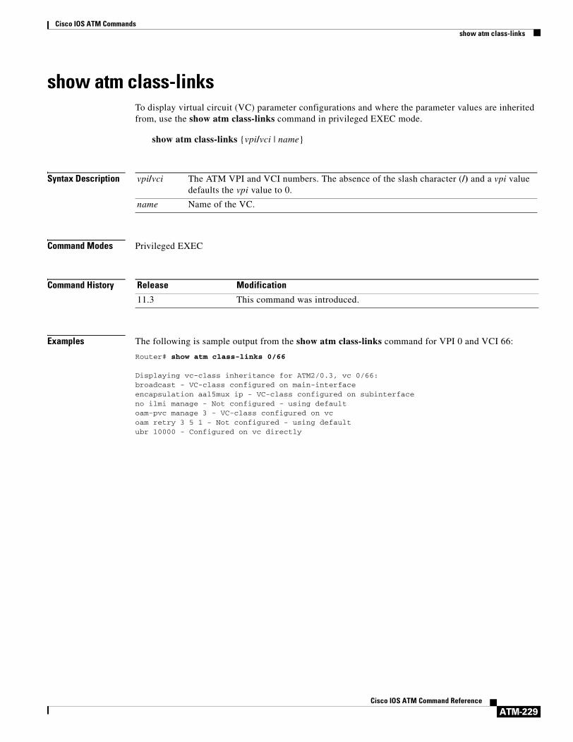
Cisco IOS ATM Commandsshow atm class-links
ATM-229Cisco IOS ATM Command Reference
show atm class-linksTo display virtual circuit (VC) parameter configurations and where the parameter values are inherited from, use the show atm class-links command in privileged EXEC mode.
show atm class-links {vpi/vci | name}
Syntax Description
Command Modes Privileged EXEC
Command History
Examples The following is sample output from the show atm class-links command for VPI 0 and VCI 66:
Router# show atm class-links 0/66
Displaying vc-class inheritance for ATM2/0.3, vc 0/66:broadcast - VC-class configured on main-interfaceencapsulation aal5mux ip - VC-class configured on subinterfaceno ilmi manage - Not configured - using defaultoam-pvc manage 3 - VC-class configured on vcoam retry 3 5 1 - Not configured - using defaultubr 10000 - Configured on vc directly
vpi/vci The ATM VPI and VCI numbers. The absence of the slash character (/) and a vpi value defaults the vpi value to 0.
name Name of the VC.
Release Modification
11.3 This command was introduced.

Cisco IOS ATM Commandsshow atm ilmi-configuration
ATM-230Cisco IOS ATM Command Reference
show atm ilmi-configurationTo display ILMI configuration information, use the show atm ilmi-configuration command in privileged EXEC mode.
show atm ilmi-configuration
Syntax Description This command has no arguments or keywords.
Command Modes Privileged EXEC
Command History
Examples The following example shows sample output for the show atm ilmi-configuration command:
Router# show atm ilmi-configuration
LECS Address(s):1122334455667788990011223344556677889900
Table 4 describes the fields shown in the display.
Related Commands
Release Modification
12.0 This command was introduced prior to Cisco IOS Release 12.0.
Table 4 show atm ilmi-configuration Field Descriptions
Field Description
LECS Address(s) Current ATM LAN Emulation Clients (LECs) addresses.
Command Description
show atm ilmi-status Displays ILMI-related status information.

Cisco IOS ATM Commandsshow atm ilmi-status
ATM-231Cisco IOS ATM Command Reference
show atm ilmi-statusTo display ILMI-related status information, use the show atm ilmi-status command in privileged EXEC mode.
show atm ilmi-status [atm interface-number]
Syntax Description
Command Modes Privileged EXEC
Command History
Usage Guidelines Entering the show atm ilmi-status command without specifying an interface will display ILMI-related status information for all of the ATM interfaces.
Examples The following example is sample output for the show atm ilmi-status command:
Router# show atm ilmi-status
Interface :ATM2/0 Interface Type :Unknown ILMI VCC :(0, 16) ILMI Keepalive :DisabledILMI State: Restarting
Interface :ATM5/0 Interface Type :Private UNI (User-side) ILMI VCC :(0, 16) ILMI Keepalive :DisabledILMI State: UpAndNormalPeer IP Addr: 10.0.52.17 Peer IF Name: ATM1/1/0Peer MaxVPIbits: 8 Peer MaxVCIbits: 14Active Prefix(s) :47.0091.8100.0000.0040.0b0a.2501End-System Registered Address(s) :47.0091.8100.0000.0040.0b0a.2501.bbbb.ccdd.eeff.12(Confirmed)
Table 5 describes the fields shown in the display.
atm (Optional) ATM interface.
interface-number (Optional) Number of the ATM interface.
Release Modification
12.0 This command was introduced in a release prior to Cisco IOS Release 12.0.
Table 5 show atm ilmi-status Field Descriptions
Field Description
interface ATM interface.
Interface Type Type of ATM interface.
ILMI VCC Number of the current ILMI VCC for the interface.
ILMI Keepalive Status of ILMI keepalive packets.
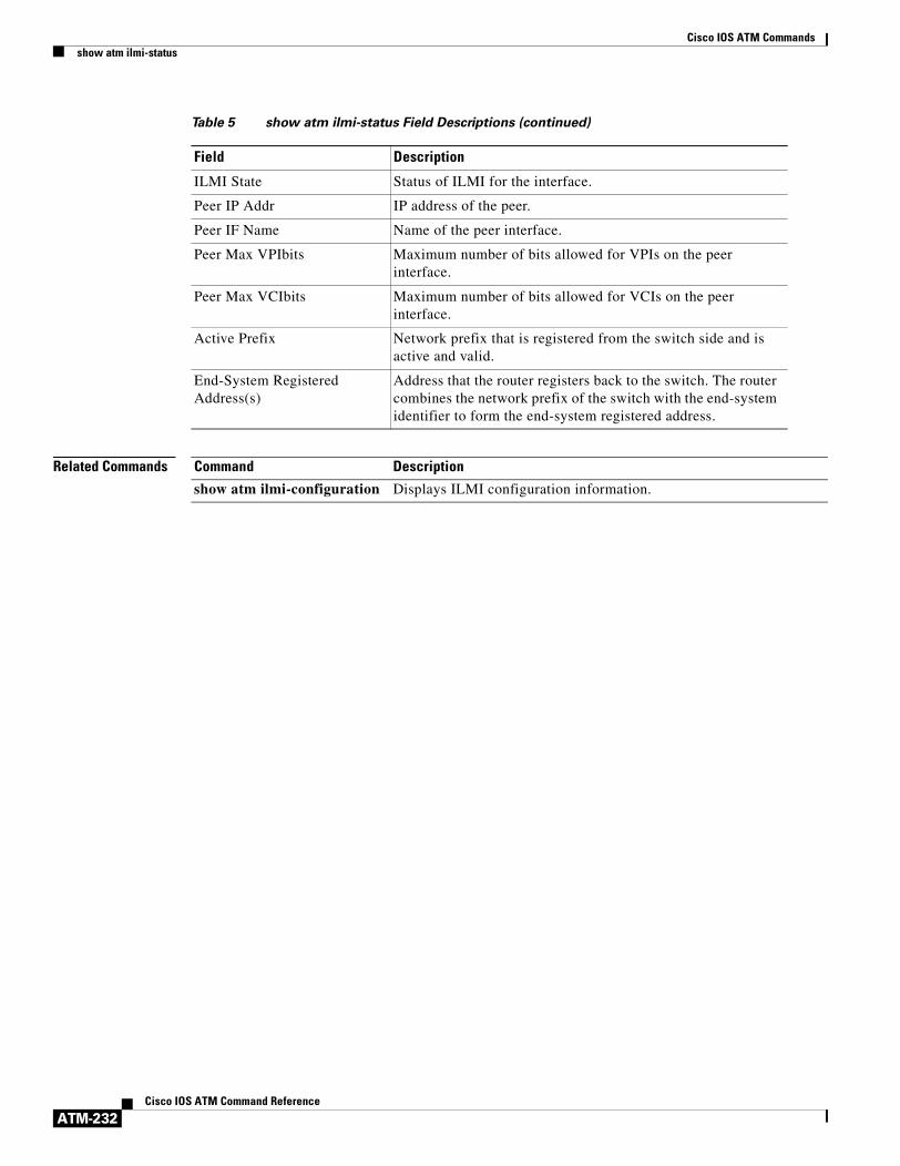
Cisco IOS ATM Commandsshow atm ilmi-status
ATM-232Cisco IOS ATM Command Reference
Related Commands
ILMI State Status of ILMI for the interface.
Peer IP Addr IP address of the peer.
Peer IF Name Name of the peer interface.
Peer Max VPIbits Maximum number of bits allowed for VPIs on the peer interface.
Peer Max VCIbits Maximum number of bits allowed for VCIs on the peer interface.
Active Prefix Network prefix that is registered from the switch side and is active and valid.
End-System Registered Address(s)
Address that the router registers back to the switch. The router combines the network prefix of the switch with the end-system identifier to form the end-system registered address.
Table 5 show atm ilmi-status Field Descriptions (continued)
Field Description
Command Description
show atm ilmi-configuration Displays ILMI configuration information.

Cisco IOS ATM Commandsshow atm interface atm
ATM-233Cisco IOS ATM Command Reference
show atm interface atmTo display ATM-specific information about an ATM interface, use the show atm interface atm command in privileged EXEC mode.
Cisco 7500 series with AIP; Cisco 7200 series with ATM, ATM-CES, and enhanced ATM port adapters; Cisco 2600 and 3600 series with 1-port ATM-25 network module
show atm interface atm slot/port
Cisco 7500 series with ATM and enhanced ATM port adapters
show atm interface atm slot/port-adapter/port
Cisco 4500 and 4700 series with NPM
show atm interface atm number
Syntax Description
Command Modes Privileged EXEC
Command History
Examples The following is sample output for the ATM-CES port adapter to display statistics on slot 4, port 0:
Router# show atm interface atm 4/0
ATM interface ATM4/0:AAL enabled: AAL5, Maximum VCs: 1024, Current VCs: 6Tx buffers 256, Rx buffers 256, Exception Queue: 32, Raw Queue: 32VP Filter: 0x7B, VCIs per VPI: 1024, Max Datagram Size:4496, MIDs/VC:16PLIM Type:4B5B - 100Mbps, No Framing, TX clocking: LINE4897 input, 2900 output, 0 IN fast, 0 OUT fast
slot/port ATM slot number and port number. Use this format on the following platform configurations:
• The AIP on Cisco 7500 series routers.
• The ATM port adapter, ATM-CES port adapter, or enhanced ATM port adapter on Cisco 7200 series routers.
• The 1-port ATM-25 network module on Cisco 2600 and 3600 series routers.
slot/port-adapter/port ATM slot, port adapter, and port number. Use this format on the ATM port adapter or ATM-CES port adapter on Cisco 7500 series routers.
number NPM number for Cisco 4500 and 4700 routers.
Release Modification
10.0 This command was introduced.
11.0 The number argument was added.
11.2 The slot/port-adapter/port arguments were added.

Cisco IOS ATM Commandsshow atm interface atm
ATM-234Cisco IOS ATM Command Reference
Rate-Queue 1 set to 100Mbps, reg=0x4EA DYNAMIC, 1 VCCsATM4/0.1:AAL3/4-SMDS address c111.1111.1111 Multicast e222.2222.222Config. is ACTIVE
The following is sample output for the enhanced ATM port adapter to display statistics on slot 6, port 0:
Router# show atm interface atm 6/0
ATM interface ATM6/0AAL enabled: AAL5, Maximum VCs: 2048, Current VCs: 3Maximum Transmit Channels: 64Tx buffers: 256, Rx buffers 256, Exception Queue: 32, Raw Queue: 32VP Filter: 0x7B, VCIs per VPI: 1024, Max Datagram Size: 4496PLIM Type: SONET - 155Mbps, TX clocking: INTERNAL0 input, 59 output, 0 IN fast, 0 OUT fastABR parameters, rif: 16 rdf: 16Config. is ACTIVE
Table 6 describes the fields shown in the display.
Table 6 show atm interface atm Field Descriptions
Field Description
ATM interface Slot and port number of the interface.
AAL enabled Type of AAL. If both AAL5 and AAL3/4 are enabled on the interface, the output will include both AAL5 and AAL3/4.
Maximum VCs Maximum number of virtual circuits this interface can support.
Current VCs Number of active virtual circuits.
Tx buffers, Rx buffers Number of transmit and receive buffers.
Exception Queue Number of exception buffers.
Raw Queue Queue size.
VP Filter Hexadecimal value of the VP filter.
VCIs per VPI Maximum number of VCIs to support per VPI.
Max Datagram Size The configured maximum number of bytes in the largest datagram.
MIDs/VC The configured maximum number of message identifiers allowed per virtual circuit on this interface.
PLIM Type Physical Layer Interface Module (PLIM) type (E3, 4B/5B, or SONET).
Framing For E3, this might be G.804; otherwise, no framing.
TX clocking Clocking on the router. For E3 or SONET, this might be INTERNAL, meaning that the AIP or NPM generates the clock. Otherwise, LINE indicates that the ATM switch provides the clocking.
input Number of packets received and process-switched.
output Number of packets sent from process switch.
IN fast Number of input packets fast-switched.
OUT fast Number of output packets fast-switched.

Cisco IOS ATM Commandsshow atm interface atm
ATM-235Cisco IOS ATM Command Reference
Related Commands
ABR parameters, rif rdf The amount that the cell transmission rate increases or decreases in response to flow control information from the network or destination for available bit rate (ABR) PVCs. The rate increase factor (RIF) and rate decrease factor (RDF) in this example are 16, the default.
Rate-Queue List of configured rate queues.
reg= Actual register value passed to the AIP to define a specific rate queue (AIP only).
DYNAMIC Indicates that the rate queue is dynamic and was created automatically by the software. Dynamic rate queues are created when an atm pvc command specifies a peak or average rate that does not match any user configured rate queue. The value PERMANENT indicates that the rate queue was user-configured.
VCCs Number of virtual channel connections (VCCs) dynamically attached to this rate queue.
ATM4/0.1 Indicates that the subinterface supports ATM adaptation layer AAL3/4 and displays the SMDS E.164 unicast address and the SMDS E.164 multicast address assigned to the subinterface.
Config. is ACTIVE or VALID in n SECONDS. ACTIVE indicates that the current AIP or NPM configuration has been loaded into the AIP and is being used. There is a 5-second window when a user changes a configuration and the configuration is sent to the AIP.
Table 6 show atm interface atm Field Descriptions (continued)
Field Description
Command Description
pvc Configures the PVC interface.

Cisco IOS ATM Commandsshow atm map
ATM-236Cisco IOS ATM Command Reference
show atm mapTo display the list of all configured ATM static maps to remote hosts on an ATM network and on ATM bundle maps, use the show atm map command in user EXEC or privileged mode.
show atm map
Syntax Description This command has no arguments or keywords.
Command Modes User EXECPrivileged EXEC
Command History
Examples The following is sample output from the show atm map command for a bundle called san-jose (0/122, 0/123, 0/124, and 0/126 are the virtual path and virtual channel identifiers of the bundle members):
Router# show atm map
Map list san-jose_B_ATM1/0.52 : PERMANENTip 10.1.1.1. maps to bundle san-jose, 0/122, 0/123, 0/124, 0/126, ATM1/0.52, broadcast
The following is sample output from the show atm map command for an ATM-CES PA on the Cisco 7200 series router:
Router# show atm map
Map list alien: PERMANENTip 10.1.1.1 maps to VC 6ip 10.1.1.2 maps to VC 6
The following is sample output from the show atm map command that displays information for a bundle called new-york:
Router# show atm map
Map list atm:vines 3004B310:0001 maps to VC 4, broadcastip 172.21.168.110 maps to VC 1, broadcastclns 47.0004.0001.0000.0c00.6e26.00 maps to VC 6, broadcastappletalk 10.1 maps to VC 7, broadcast
Release Modification
10.0 This command was introduced.
11.1 CA This command was modified to include an example for the ATM-CES port adapter (PA).
12.0(3)T This command was modified to include display for ATM bundle maps. An ATM bundle map identifies a bundle and all of its related virtual circuits (VCs).
12.2(2)T, 12.0(21)ST, 12.0(22)S, 12.2(14)S
The display output for this command was modified to include the IPv6 address mappings of remote nodes to ATM permanent virtual circuits (PVCs).

Cisco IOS ATM Commandsshow atm map
ATM-237Cisco IOS ATM Command Reference
decnet 10.1 maps to VC 2, broadcastMap list new-york: PERMANENTip 10.0.0.2 maps to bundle new-york, 0/200, 0/205, 0/210, ATM1/0.1
The following is sample output from the show atm map command for a multipoint connection:
Router# show atm map
Map list atm_pri: PERMANENTip 10.4.4.4 maps to NSAP CD.CDEF.01.234567.890A.BCDE.F012.3456.7890.1234.12, broadcast, aal5mux, multipoint connection up, VC 6ip 10.4.4.6 maps to NSAP DE.CDEF.01.234567.890A.BCDE.F012.3456.7890.1234.12, broadcast, aal5mux, connection up, VC 15, multipoint connection up, VC 6
Map list atm_ipx: PERMANENTipx 1004.dddd.dddd.dddd maps to NSAP DE.CDEF.01.234567.890A.BCDE.F012.3456.7890.1234.12, broadcast, aal5mux, multipoint connection up, VC 8ipx 1004.cccc.cccc.cccc maps to NSAP CD.CDEF.01.234567.890A.BCDE.F012.3456.7890.1234.12, broadcast, aal5mux, multipoint connection up, VC 8
Map list atm_apple: PERMANENTappletalk 62000.5 maps to NSAP CD.CDEF.01.234567.890A.BCDE.F012.3456.7890.1234.12, broadcast, aal5mux, multipoint connection up, VC 4appletalk 62000.6 maps to NSAP DE.CDEF.01.234567.890A.BCDE.F012.3456.7890.1234.12, broadcast, aal5mux, multipoint connection up, VC 4
The following is sample output from the show atm map command if you configure an ATM PVC using the pvc command:
Router# show atm map
Map list endA: PERMANENTip 10.11.11.1 maps to VC 4, VPI 0, VCI 60, ATM0.2
The following sample output from the show atm map command shows the link-local and global IPv6 addresses (FE80::60:3E47:AC8:C and 2001:0DB8:2222::72, respectively) of a remote node that are explicitly mapped to PVC 1/32 of ATM interface 0;
Router# show atm map
Map list ATM0pvc1 : PERMANENTipv6 FE80::60:3E47:AC8:C maps to VC 1, VPI 1, VCI 32, ATM0 , broadcastipv6 2001:0DB8:2222::72 maps to VC 1, VPI 1, VCI 32, ATM0
Table 7 describes the significant fields shown in the displays.
Table 7 show atm map Field Descriptions
Field Description
Map list Name of map list.
PERMANENT This map entry was entered from configuration; it was not entered automatically by a process.
ip 172.21.168.110 maps to VC 1orip 10.4.4.6 maps to NSAP DE.CDEF.01.234567.890A.BCDE.F012.3456.7890.1234.12
Name of protocol, the protocol address, and the virtual circuit descriptor (VCD) or network service access point (NSAP) to which the address is mapped (for ATM VCs configured with the atm pvc command).
broadcast Indicates pseudobroadcasting.

Cisco IOS ATM Commandsshow atm map
ATM-238Cisco IOS ATM Command Reference
Related Commands
ip 10.11.11.1 maps to VC 4, VPI 0, VCI 60, ATM0.2
or
ip 10.4.4.6 maps to NSAP DE.CDEF.01.234567.890A.BCDE.F012.3456.7890.1234.12
Name of protocol, the protocol address, the virtual path identifier (VPI) number, the virtual channel identifier (VCI) number, and the ATM interface or subinterface (for ATM PVCs configured using the pvc command).
or
Name of the protocol, the protocol address, and the NSAP to which the address is mapped (for ATM switched virtual circuits (SVCs) configured using the svc command).
aal5mux Indicates the encapsulation used, a multipoint or point-to-point VC, and the number of the virtual circuit.
multipoint connection up Indicates that this is a multipoint VC.
VC 6 Number of the VC.
connection up Indicates a point-to-point VC.
VPI VPI for the VC.
VCI VCI for the VC.
ATM1/0.52 ATM interface or subinterface number.
Map list Name of the bundle whose mapping information follows.
ip 10.1.1.1 maps to bundle san-jose, 0/122, 0/123, 0/124, 0/126
IP address of the bundle and VC members that belong to the bundle.
Table 7 show atm map Field Descriptions (continued)
Field Description
Command Description
protocol (ATM) Configures a static map for an ATM PVC, SVC, VC class, or VC bundle. Enables Inverse ARP or Inverse ARP broadcasts on an ATM PVC by either configuring Inverse ARP directly on the PVC, on the VC bundle, or in a VC class (applies to IP and IPX protocols only).
protocol ipv6 (ATM) Maps the IPv6 address of a remote node to the ATM PVC used to reach the address.
pvc Creates or assigns a name to an ATM PVC, specifies the encapsulation type on an ATM PVC, or enters interface-ATM-VC configuration mode.
show atm bundle Displays the bundle attributes assigned to each bundle VC member and the current working status of the VC members.
show atm bundle statistics
Displays statistics on the specified bundle.
svc Creates an ATM SVC and specifies destination NSAP address on an interface or subinterface.
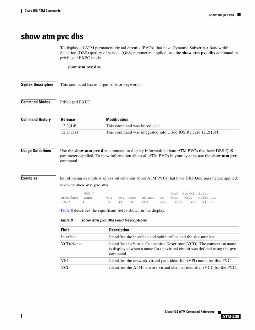
Cisco IOS ATM Commandsshow atm pvc dbs
ATM-239Cisco IOS ATM Command Reference
show atm pvc dbsTo display all ATM permanent virtual circuits (PVCs) that have Dynamic Subscriber Bandwidth Selection (DBS) quality of service (QoS) parameters applied, use the show atm pvc dbs command in privileged EXEC mode.
show atm pvc dbs
Syntax Description This command has no arguments or keywords.
Command Modes Privileged EXEC
Command History
Usage Guidelines Use the show atm pvc dbs command to display information about ATM PVCs that have DBS QoS parameters applied. To view information about all ATM PVCs in your system, use the show atm pvc command.
Examples he following example displays information about ATM PVCs that have DBS QoS parameters applied:
Router# show atm pvc dbs
VCD / Peak Avg/Min BurstInterface Name VPI VCI Type Encaps SC Kbps Kbps Cells Sts1/0.7 3 0 95 PVC MUX VBR 2000 700 94 UP
Table 8 describes the significant fields shown in the display.
Release Modification
12.2(4)B This command was introduced.
12.2(13)T This command was integrated into Cisco IOS Release 12.2(13)T.
Table 8 show atm pvc dbs Field Descriptions
Field Description
Interface Identifies the interface and subinterface and the slot number.
VCD/Name Identifies the Virtual Connection Descriptor (VCD). The connection name is displayed when a name for the virtual circuit was defined using the pvc command.
VPI Identifies the network virtual path identifier (VPI) name for this PVC.
VCI Identifies the ATM network virtual channel identifier (VCI) for the PVC.

Cisco IOS ATM Commandsshow atm pvc dbs
ATM-240Cisco IOS ATM Command Reference
Related Commands
Type Identifies the type of PVC detected from PVC Discovery.
• PVC-D—Indicates a PVC created due to PVC Discovery.
• PVC-L—Indicates that the corresponding peer of this PVC could not be found on the switch.
• PVC-M—Indicates that some or all of the QoS parameters of this PVC do not match the QoS parameters of the corresponding peer.
Encaps Identifies the ATM encapsulation type of the VC.
SC Identifies the service category for the VC.
Peak Kbps Identifies the number of kilobits per second sent at the peak rate.
Avg/Min Kbps Identifies the number of kilobits per second sent at the average rate.
Burst Cells Identifies the burst cell size in terms of number of cells. This number is the maximum number of ATM cells the VC can send at the peak rate.
Sts Identifies the status of the virtual circuit.
Table 8 show atm pvc dbs Field Descriptions (continued)
Field Description
Command Description
dbs enable Enables DBS.
pvc Creates or assigns a name to an ATM PVC, specifies the encapsulation type on an ATM PVC, or enters interface-ATM-VC configuration mode.
pvc-in-range Configures an individual PVC within a PVC range.
range pvc Defines a range of ATM PVCs.
show atm pvc Displays all ATM PVCs and traffic information.
vc-class atm Configures a VC class for an ATM VC or interface.

Cisco IOS ATM Commandsshow atm pvc
ATM-241Cisco IOS ATM Command Reference
show atm pvcTo display all ATM permanent virtual connections (PVCs) and traffic information, use the show atm pvc command in privileged EXEC mode.
show atm pvc [vpi/vci | name | interface atm interface-number[.subinterface-number multipoint]] [ppp]
Syntax Description
Command Modes Privileged EXEC
Command History
vpi/vci (Optional) ATM virtual path identifier (VPI) and virtual channel identifier (VCI) numbers. The absence of the slash character (/) and a vpi value causes the vpi value to default to 0.
name (Optional) Name of the PVC.
interface atm interface-number (Optional) Displays all PVCs on the specified ATM interface.
To determine the appropriate form of the interface-number argument, consult your ATM network module, port adapter, or router documentation.
.subinterface-number (Optional) Subinterface number in the range from 1 to 4294967293. The dot (.) is required as a separator between interface-number and subinterface-number.
multipoint (Optional) Multipoint subinterface.
ppp (Optional) Displays each PVC configured for PPP over ATM.
Release Modification
11.3T This command was introduced.
12.1(1)T This command was modified to display PPPoE status.
12.2(4)T This command was modified to display only PVCs that are attached to a virtual access interface. Before this modification, all PVCs that were configured with PPPoA or PPPoE were displayed.
12.0(23)S This command was modified to display OAM cell emulation status for Any Transport over MPLS (AToM).
12.2(14)S This command was integrated into Cisco IOS Release 12.2(14)S.
12.2(15)T This command was integrated into Cisco IOS Release 12.2(15)T.
12.3(7)T This command was modified to display information about multilink PPP over ATM link fragmentation and interleaving for ATM PVCs.
12.0(30)S This command was modified to display information about OAM loopback detection.

Cisco IOS ATM Commandsshow atm pvc
ATM-242Cisco IOS ATM Command Reference
Usage Guidelines If the vpi/vci or name argument is not specified, the output of this command is the same as that of the show atm vc command, but only the configured PVCs are displayed.
If the vpi/vci or name argument is specified, the output of this command is the same as that of the show atm vc vcd command, with extra information related to PVC management, including connection name, detailed states, and Operation, Administration, and Maintenance (OAM) counters.
If the interface atm interface-number option is included in the command, all PVCs under that interface or subinterface are displayed.
Examples The following is sample output from the show atm pvc command. The output is the same as that of the show atm vc command, but only the configured PVCs are displayed.
Router# show atm pvc
VCD/ Peak Avg/Min BurstInterface Name VPI VCI Type Encaps Kbps Kbps Cells Sts2/0 1 0 5 PVC SAAL 155000 155000 UP2/0 2 0 16 PVC ILMI 155000 155000 UP2/0.2 101 0 50 PVC SNAP 155000 155000 UP2/0.2 102 0 60 PVC SNAP 155000 155000 DOWN2/0.2 104 0 80 PVC SNAP 155000 155000 UP2/0 hello 0 99 PVC SNAP 1000 UP
The following is sample output from the show atm pvc command with the vpi/vci argument specified:
Router# show atm pvc 0/41
ATM2/0: VCD: 3, VPI: 0, VCI: 41UBR, PeakRate: 155000AAL5-LLC/SNAP, etype:0x0, Flags: 0xC20, VCmode: 0x0OAM frequency: 0 second(s), OAM retry frequency: 1 second(s), OAM retry frequency: 1 second(s)OAM up retry count: 3, OAM down retry count: 5OAM Loopback status: OAM DisabledOAM VC state: Not ManagedOAM Loop detection: DisabledILMI VC state: Not ManagedInARP frequency: 15 minutes(s)InPkts: 31759, OutPkts: 26497, InBytes: 2356434, OutBytes: 1589743InPRoc: 15785, OutPRoc: 26472, Broadcasts: 0InFast: 20, OutFast: 20, InAS: 15954, OutAS: 6OAM cells received: 0F5 InEndloop: 0, F5 InSegloop: 0, F5 InAIS: 0, F5 InRDI: 0F4 InEndloop: 0, F4 InSegloop: 0, F4 InAIS: 0, F4 InRDI: 0OAM cells sent: 0F5 OutEndloop: 0, F5 OutSegloop: 0, F5 OutRDI: 0F4 OutEndloop: 0, F4 OutSegloop: 0, F4 OutRDI: 0OAM cell drops: 0Status: UPPPPOE enabled.
The following sample output from the show atm pvc command displays OAM cell emulation statistics, which are marked in this example by exclamation points:
Router# show atm pvc 5/500
ATM4/1/0.200: VCD: 6, VPI: 5, VCI: 500 UBR, PeakRate: 1 AAL5-LLC/SNAP, etype:0x0, Flags: 0x34000C20, VCmode: 0x0 OAM Cell Emulation: enabled, F5 End2end AIS Xmit frequency: 1 second(s) !!!

Cisco IOS ATM Commandsshow atm pvc
ATM-243Cisco IOS ATM Command Reference
OAM frequency: 0 second(s), OAM retry frequency: 1 second(s)OAM up retry count: 3, OAM down retry count: 5OAM Loopback status: OAM DisabledOAM VC state: Not ManagedVerifiedOAM Loop detection: DisabledILMI VC state: Not ManagedInPkts: 564, OutPkts: 560, InBytes: 19792, OutBytes: 19680InPRoc: 0, OutPRoc: 0InFast: 4, OutFast: 0, InAS: 560, OutAS: 560InPktDrops: 0, OutPktDrops: 0CrcErrors: 0, SarTimeOuts: 0, OverSizedSDUs: 0Out CLP=1 Pkts: 0OAM cells received: 26F5 InEndloop: 0, F5 InSegloop: 0, F5 InAIS: 0, F5 InRDI: 26OAM cells sent: 77F5 OutEndloop: 0, F5 OutSegloop: 0, F5 OutAIS: 77, F5 OutRDI: 0 !!!OAM cell drops: 0Status: UP
The following is sample output from the show atm pvc command with the ATM subinterface specified:
Router# show atm pvc interface atm 2/0.2
VCD/ Peak Avg/Min BurstInterface Name VPI VCI Type Encaps Kbps Kbps Cells Sts2/0.2 101 0 50 PVC SNAP 155000 155000 UP2/0.2 102 0 60 PVC SNAP 155000 155000 DOWN2/0.2 104 0 80 PVC SNAP 155000 155000 UP
The following is sample output for the show atm pvc command for a PVC that is a member of a multilink PPP bundle:
Router# show atm pvc 15/200
ATM4/0.10000:VCD:16, VPI:15, VCI:200UBR, PeakRate:149760 (353208 cps)AAL5-LLC/SNAP, etype:0x0, Flags:0xC20, VCmode:0x0, Encapsize:12OAM frequency:0 second(s), OAM retry frequency:1 second(s)OAM up retry count:3, OAM down retry count:5OAM Loopback status:OAM DisabledOAM VC State:Not ManagedOAM Loop detection: DisabledILMI VC status:Not ManagedVC TxRingLimit:40 particlesVC Rx Limit:800 particlesInARP frequency:15 minutes(s)Transmit priority 6InPkts:347, OutPkts:399, InBytes:6268, OutBytes:7728InCells:347, OutCells:399InPRoc:7, OutPRoc:228InFast:338, OutFast:169, InAS:0, OutAS:0InPktDrops:0, OutPktDrops:0/0/0 (holdq/outputq/total)InCellDrops:0, OutCellDrops:0InByteDrops:0, OutByteDrops:0CrcErrors:0, SarTimeOuts:0, OverSizedSDUs:0, LengthViolation:0, CPIErrors:0Out CLP=1 Pkts:0, Cells:0OAM cells received:0F5 InEndloop:0, F5 InSegloop:0, F5 InAIS:0, F5 InRDI:0F4 InEndloop:0, F4 InSegloop:0, F4 InAIS:0, F4 InRDI:0OAM cells sent:0F5 OutEndloop:0, F5 OutSegloop:0, F5 OutRDI:0F4 OutEndloop:0, F4 OutSegloop:0, F4 OutRDI:0OAM cell drops:0

Cisco IOS ATM Commandsshow atm pvc
ATM-244Cisco IOS ATM Command Reference
Status:UPPPP:Virtual-Access3 from Virtual-Template1PPPoA Current State = LOCALLY_TERMINATEDPPPoA Latest Event = Vaccess UpPPPoA Latest Error = NonePPPoA Session ID = 7PPPoA Handle = 0x4D000006, SSS Handle = 0x00000000Switch Handle = 0xB5000006, PPP Handle = 0xD700000AAAA Unique ID = 0x00000007, AIE Handle = 0xE7000006PVC belongs to Multilink PPP Bundle Virtual-Access4 as a PPPoA member linkPackets in VC Holdq:0 , Particles in VC Tx Ring:0
The following is sample output from the show atm pvc command with loopback detection mode through OAM enabled:
Router# show atm pvc 4/100
ATM1/0: VCD: 4, VPI: 4, VCI: 100UBR, PeakRate: 149760AAL5-LLC/SNAP, etype:0x0, Flags: 0xC20, VCmode: 0x0!OAM frequency: 10 second(s), OAM retry frequency: 1 second(s)OAM up retry count: 3, OAM down retry count: 5OAM Loopback status: OAM ReceivedOAM VC state: VerifiedOAM Loop detection: Enabled ! Indicates that loopback mode detection is enabled.!ILMI VC state: Not ManagedVC is managed by OAM.InARP frequency: 15 minutes(s)Transmit priority 4InPkts: 0, OutPkts: 0, InBytes: 0, OutBytes: 0InPRoc: 0, OutPRoc: 0, Broadcasts: 0InFast: 0, OutFast: 0, InAS: 0, OutAS: 0InPktDrops: 0, OutPktDrops: 0CrcErrors: 0, SarTimeOuts: 0, OverSizedSDUs: 0Out CLP=1 Pkts: 0OAM cells received: 27F5 InEndloop: 27, F5 InSegloop: 0, F5 InAIS: 0, F5 InRDI: 0OAM cells sent: 27F5 OutEndloop: 27, F5 OutSegloop: 0, F5 OutAIS: 0, F5 OutRDI: 0OAM cell drops: 3Status: UP
The following is sample output from the show atm pvc command when loopback mode has been detected:
Router# show atm pvc 4/100
ATM1/0: VCD: 4, VPI: 4, VCI: 100UBR, PeakRate: 149760AAL5-LLC/SNAP, etype:0x0, Flags: 0xC20, VCmode: 0x0!OAM frequency: 10 second(s), OAM retry frequency: 1 second(s)OAM up retry count: 3, OAM down retry count: 5OAM Loopback status: OAM SentOAM VC state: Not VerifiedOAM Loop detection: Enabled, Detected ! Indicates that loopback mode has been detected on this interface.!ILMI VC state: Not ManagedVC is managed by OAM.InARP frequency: 15 minutes(s)Transmit priority 4
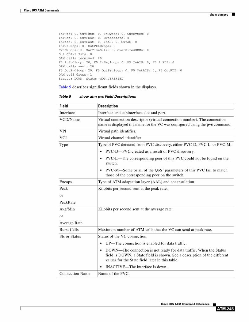
Cisco IOS ATM Commandsshow atm pvc
ATM-245Cisco IOS ATM Command Reference
InPkts: 0, OutPkts: 0, InBytes: 0, OutBytes: 0InPRoc: 0, OutPRoc: 0, Broadcasts: 0InFast: 0, OutFast: 0, InAS: 0, OutAS: 0InPktDrops: 0, OutPktDrops: 0CrcErrors: 0, SarTimeOuts: 0, OverSizedSDUs: 0Out CLP=1 Pkts: 0OAM cells received: 20F5 InEndloop: 20, F5 InSegloop: 0, F5 InAIS: 0, F5 InRDI: 0OAM cells sent: 20F5 OutEndloop: 20, F5 OutSegloop: 0, F5 OutAIS: 0, F5 OutRDI: 0OAM cell drops: 1Status: DOWN, State: NOT_VERIFIED
Table 9 describes significant fields shown in the displays.
Table 9 show atm pvc Field Descriptions
Field Description
Interface Interface and subinterface slot and port.
VCD/Name Virtual connection descriptor (virtual connection number). The connection name is displayed if a name for the VC was configured using the pvc command.
VPI Virtual path identifier.
VCI Virtual channel identifier.
Type Type of PVC detected from PVC discovery, either PVC-D, PVC-L, or PVC-M:
• PVC-D—PVC created as a result of PVC discovery.
• PVC-L—The corresponding peer of this PVC could not be found on the switch.
• PVC-M—Some or all of the QoS1 parameters of this PVC fail to match those of the corresponding peer on the switch.
Encaps Type of ATM adaptation layer (AAL) and encapsulation.
Peak
or
PeakRate
Kilobits per second sent at the peak rate.
Avg/Min
or
Average Rate
Kilobits per second sent at the average rate.
Burst Cells Maximum number of ATM cells that the VC can send at peak rate.
Sts or Status Status of the VC connection:
• UP—The connection is enabled for data traffic.
• DOWN—The connection is not ready for data traffic. When the Status field is DOWN, a State field is shown. See a description of the different values for the State field later in this table.
• INACTIVE—The interface is down.
Connection Name Name of the PVC.

Cisco IOS ATM Commandsshow atm pvc
ATM-246Cisco IOS ATM Command Reference
UBR, UBR+, or VBR–NRT
• UBR—Unspecified bit rate QoS is specified for this PVC. See the ubr command for further information.
• UBR+—Unspecified bit rate QoS is specified for this PVC. See the ubr+ command for further information.
• VBR–NRT—Variable bit rate–non-real-time QoS rates are specified for this PVC. See the vbr-nrt command for further information.
etype Encapsulation type.
Flags Bit mask describing VC information. The flag values are summed to result in the displayed value:
• 0x40—SVC
• 0x20—PVC
• 0x10—ACTIVE
• 0x0—AAL5-SNAP
• 0x1—AAL5-NLPID
• 0x2—AAL5-FRNLPID
• 0x3—AAL5-MUX
• 0x4—AAL3/4-SMDS
• 0x5—QSAAL
• 0x6—ILMI
• 0x7—AAL5-LANE
• 0x9—AAL5-CISCOPPP
virtual-access Virtual-access interface identifier.
virtual-template Virtual template identifier.
VCmode AIP-specific or NPM-specific register describing the usage of the VC. This register contains values such as rate queue, peak rate, and AAL mode, which are also displayed in other fields.
OAM Cell emulation The status of the OAM cell emulation functionality. It is either enabled or disabled.
F5 end2end AIS xmit frequency
Number of seconds between transmission of AIS cells.
OAM frequency Number of seconds between transmission of OAM loopback cells.
OAM retry frequency
Frequency (in seconds) at which end-to-end F5 loopback cells should be sent when a change in state (up or down) is being verified. For example, if a PVC is up and a loopback cell response is not received after the value of the frequency argument (in seconds) specified using the oam-pvc command, loopback cells are sent at the value of the retry-frequency argument to determine whether the PVC is down.
OAM up retry count Number of consecutive end-to-end F5 OAM loopback cell responses that must be received in order to change a PVC state to up. Does not apply to SVCs.
Table 9 show atm pvc Field Descriptions (continued)
Field Description

Cisco IOS ATM Commandsshow atm pvc
ATM-247Cisco IOS ATM Command Reference
OAM down retry count
Number of consecutive end-to-end F5 OAM loopback cell responses that are not received in order to change a PVC state to down or tear down an SVC.
OAM Loopback status
Status of end-to-end F5 OAM loopback cell generation for this VC. This field will have one of the following values:
• OAM Disabled—End-to-end F5 OAM loopback cell generation is disabled.
• OAM Sent—OAM cell was sent.
• OAM Received—OAM cell was received.
• OAM Failed—OAM reply was not received within the frequency period or contained a bad correlation tag.
OAM VC state This field will have one of the following states for this VC:
• AIS2/RDI3—The VC received AIS/RDI cells. End-to-end F5 OAM loopback cells are not sent in this state.
• Down Retry—An OAM loopback failed. End-to-end F5 OAM loopback cells are sent at retry frequency to verify that the VC is really down. After down-count unsuccessful retries, the VC goes to the Not Verified state.
• Not Managed—VC is not being managed by OAM.
• Not Verified—VC has not been verified by end-to-end F5 OAM loopback cells. AIS and RDI conditions are cleared.
• Up Retry—An OAM loopback was successful. End-to-end F5 OAM loopback cells are sent at retry frequency to verify that the VC is really up. After up-count successive and successful loopback retries, the VC goes to the Verified state.
• Verified—Loopbacks are successful. AIS/RDI cell was not received.
OAM Loop detection
Status of loopback detection mode through OAM:
• Disabled—Automatic loopback detection is disabled.
• Enabled—Automatic loopback detection is enabled.
• Detected—Loopback mode is detected on an ATM interface.
ILMI VC state This field will have one of the following states for this VC:
• Not Managed—VC is not being managed by ILMI4.
• Not Verified—VC has not been verified by ILMI.
• Verified—VC has been verified by ILMI.
VC is managed by OAM/ILMI
VC is managed by OAM or ILMI.
InARP frequency Number of minutes for the Inverse Address Resolution Protocol (ARP) time period.
InPkts Total number of packets received on this VC. This number includes all fast-switched and process-switched packets.
OutPkts Total number of packets sent on this VC. This number includes all fast-switched and process-switched packets.
Table 9 show atm pvc Field Descriptions (continued)
Field Description

Cisco IOS ATM Commandsshow atm pvc
ATM-248Cisco IOS ATM Command Reference
InBytes Total number of bytes received on this VC. This number includes all fast-switched and process-switched bytes.
OutBytes Total number of bytes sent on this VC. This number includes all fast-switched and process-switched bytes.
InPRoc Number of process-switched input packets.
OutPRoc Number of process-switched output packets.
Broadcasts Number of process-switched broadcast packets.
InFast Number of fast-switched input packets.
OutFast Number of fast-switched output packets.
InAS Number of autonomous-switched or silicon-switched input packets.
OutAS Number of autonomous-switched or silicon-switched output packets.
OAM cells received Total number of OAM cells received on this VC.
F5 InEndloop Number of end-to-end F5 OAM loopback cells received.
F5 InSegloop Number of segment F5 OAM loopback cells received.
F5 InAIS Number of F5 OAM AIS cells received.
F5 InRDI Number of F5 OAM RDI cells received.
F4 InEndloop Number of end-to-end F4 OAM loopback cells received.
F4 InSegloop Number of segment F4 OAM loopback cells received.
F4 InAIS Number of F4 OAM AIS cells received.
F4 InRDI Number of F4 OAM RDI cells received.
OAM cells sent Total number of OAM cells sent on this VC.
F5 OutEndloop Number of end-to-end F5 OAM loopback cells sent.
F5 OutSegloop Number of segment F5 OAM loopback cells sent.
F5 OutRDI Number of F5 OAM RDI cells sent.
OAM cell drops Number of OAM cells dropped (or flushed).
Table 9 show atm pvc Field Descriptions (continued)
Field Description

Cisco IOS ATM Commandsshow atm pvc
ATM-249Cisco IOS ATM Command Reference
PVC Discovery • NOT_VERIFIED—This PVC is manually configured on the router and not yet verified with the attached adjacent switch.
• WELL_KNOWN—This PVC has a VCI value of 0 through 31.
• DISCOVERED—This PVC is learned from the attached adjacent switch via ILMI.
• MIXED—Some of the traffic parameters for this PVC were learned from the switch via ILMI.
• MATCHED—This PVC is manually configured on the router, and the local traffic-shaping parameters match the parameters learned from the switch.
• MISMATCHED—This PVC is manually configured on the router, and the local traffic-shaping parameters do not match the parameters learned from the switch.
• LOCAL_ONLY—This PVC is configured locally on the router and not on the remote switch.
Status When the Status field indicates UP, the VC is established. When the Status field indicates DOWN, refer to the State field for further information about the VC state.
State When the Status field is UP, this field does not appear. When the Status field is DOWN or INACTIVE, the State field will appear with one of the following values:
• NOT_VERIFIED—The VC has been established successfully; waiting for OAM (if enabled) and ILMI (if enabled) to verify that the VC is up.
• NOT_EXIST—VC has not been created.
• HASHING_IN—VC has been hashed into a hash table.
• ESTABLISHING—Ready to establish VC connection.
• MODIFYING—VC parameters have been modified.
• DELETING—VC is being deleted.
• DELETED—VC has been deleted.
• NOT_IN_SERVICE—ATM interface is shut down.
PPP For PPP over ATM, indicates the virtual access interface number and virtual template number being used.
PPPoA Current State State of the PPPoA session associated with the VC.
PPPoA Latest Event The latest event that occurred on the PPPoA session associated with the VC.
PPPoA Latest Error The latest error that occurred on the PPPoA session associated with the VC.
PPPoA Session ID PPPoA session identifier of the PPPoA session associated with the VC.
PPPoA Handle PPPoA context handle.
SSS Handle SSS handle for PPPoA session associated with the VC.
Switch Handle SSS handle for switch management.
PPP Handle Handle associated with the PPP context.
Table 9 show atm pvc Field Descriptions (continued)
Field Description

Cisco IOS ATM Commandsshow atm pvc
ATM-250Cisco IOS ATM Command Reference
AAA Unique ID Unique identifier associated with the AAA session.
AIE Handle Access IE handle for the PPPoA session.
Packets in VC Holdq Number of packets in the hold queue of the VC.
Particles in VC Tx Ring
Number of particles in the Tx ring of the VC.
1. QoS = quality of service
2. AIS = alarm indication signal
3. RDI = remote defect identification
4. ILMI = Interim Local Management Interface
Table 9 show atm pvc Field Descriptions (continued)
Field Description
Cisco IOS ATM Commandsshow atm svc
ATM-251Cisco IOS ATM Command Reference
show atm svcTo display all ATM switched virtual circuits (SVCs) and traffic information, use the show atm svc command in privileged EXEC mode.
show atm svc [vpi/vci | name | interface atm interface-number]
Syntax Description
Command Modes Privileged EXEC
Command History
Usage Guidelines If the vpi/vci or name argument is not specified, the output of this command is the same as that of the show atm vc command but only the configured SVCs are displayed. See the first sample output below, which uses the show atm svc command without any of the optional arguments.
If the vpi/vci or name argument is specified, the output of this command is the same as the show atm vc vcd command, plus extra information related to SVC management including connection name, detailed states, and OAM counters. See the second sample output below, which uses the show atm svc command with the vpi/vci specified as 0/34.
vpi/vci (Optional) The ATM VPI and VCI numbers. The absence of the slash character (/) and a vpi value causes the vpi value to default to 0.
name (Optional) Name of the SVC.
interface atm interface-number (Optional) Interface number or subinterface number of the SVC. Displays all SVCs on the specified interface or subinterface.
The interface-number argument uses one of the following formats, depending on what router platform you are using:
• For the AIP on Cisco 7500 series routers; For the ATM port adapter, ATM-CES port adapter, and enhanced ATM port adapter on Cisco 7200 series routers; For the 1-port ATM-25 network module on Cisco 2600 and 3600 series routers: slot/0[.subinterface-number multipoint]
• For the ATM port adapter and enhanced ATM port adapter on Cisco 7500 series routers: slot/port-adapter/0[.subinterface-number multipoint]
• For the NPM on Cisco 4500 and 4700 routers: number[.subinterface-number multipoint]
For a description of these arguments, refer to the interface atm command.
Release Modification
11.3 This command was introduced.

Cisco IOS ATM Commandsshow atm svc
ATM-252Cisco IOS ATM Command Reference
If the interface atm interface-number option is included in the command, all SVCs under that interface or subinterface are displayed. See the third sample output below, which uses the show atm svc command with the ATM subinterface specified as 2/0.2.
Examples The following is sample output from the show atm svc command:
Router# show atm svc
VCD/ Peak Avg/Min BurstInterface Name VPI VCI Type Encaps Kbps Kbps Cells Sts2/0.2 4 0 32 SVC SNAP 155000 155000 UP2/0.2 3 0 33 SVC SNAP 155000 155000 UP2/0.1 5 0 34 SVC SNAP 155000 UP2/0.2 6 0 35 SVC SNAP 155000 155000 UP
The following is sample output from the show atm svc command with VPI 0 and VCI 34 specified:
Router# show atm svc 0/34
ATM2/0.1: VCD: 5, VPI: 0, VCI: 34UBR, PeakRate: 155000AAL5-LLC/SNAP, etype: 0x0, Flags 0x440, VCmode: 0xE000OAM frequency: 0 second(s), OAM retry frequency: 1 second(s)OAM up retry count: 3, OAM down retry count: 5OAM Loopback status: OAM DisabledOAM VC state: Not ManagedILMI VC state: Not ManagedInARP DISABLEDInPkts: 4, OutPkts: 4, InBytes: 432, OutBytes: 432InPRoc: 4, OutPRoc: 4, Broadcasts: 0InFast: 0, OutFast: 0, InAS: 0, OutAS: 0OAM cells received: 0F5 InEndloop: 0, F5 InSegloop: 0, F5 InAIS: 0, F5 InRDI:0F4 InEndloop: 0, F4 InSegloop: 0, F4 InAIS: 0, F4 InRDI:0OAM cells sent: 0F5 OutEndloop: 0, F5 OutSegloop: 0, F5 OutRDI: 0OAM cell drops: 0Status: UPTTL: 3interface = ATM2/0.2, call locally initiated, call reference = 8388610vcnum = 5, vpi = 0, vci = 34, state = Active(U10), point-to-point callRetry count: Current = 0timer currently inactive, timer value = 00:00:00Remote Atm Nsap address:47.00918100000000400B0A2501.0060837B4743.00, VCowner:Static Map
The following is sample output from the show atm svc interface atm interface-number command:
Router# show atm svc interface atm 2/0.2
VCD/ Peak Avg/Min BurstInterface Name VPI VCI Type Encaps Kbps Kbps Cells Sts2/0.2 4 0 32 SVC SNAP 155000 155000 UP2/0.2 3 0 33 SVC SNAP 155000 155000 UP2/0.2 6 0 35 SVC SNAP 155000 155000 UP

Cisco IOS ATM Commandsshow atm svc
ATM-253Cisco IOS ATM Command Reference
Table 10 describes significant fields shown in the displays.
Table 10 show atm svc Field Descriptions
Field Description
Interface Interface and subinterface slot and port.
VCD/Name Virtual circuit descriptor (virtual circuit number). The connection name is displayed if a name for the VC was configured using the svc command.
VPI Virtual path identifier.
VCI Virtual channel identifier.
Type Type of virtual circuit, either SVC or MSVC (multipoint SVC).
• MSVC (with no -x ) indicates that VCD is a leaf of some other router’s multipoint VC.
• MSVC-x indicates there are x leaf routers for that multipoint VC opened by the root.
Encaps Type of ATM adaptation layer (AAL) and encapsulation.
Peak
or
PeakRate
Kilobits per second transmitted at the peak rate.
Avg/Min
or
Average Rate
Kilobits per second transmitted at the average rate.
Burst Cells Value that equals the maximum number of ATM cells the virtual circuit can transmit at peak rate.
Sts or Status Status of the VC connection.
• UP indicates that the connection is enabled for data traffic.
• DOWN indicates that the connection is not ready for data traffic. When the Status field is DOWN, a State field is shown. See a description of the different values for this field listed later in this table.
• INACTIVE indicates that the interface is down.
Connection Name The name of the SVC.
UBR, UBR+, or VBR–NRT
UBR—Unspecified Bit Rate QoS is specified for this SVC. See the ubr command for further information.
UBR+—Unspecified Bit Rate QoS is specified for this SVC. See the ubr+ command for further information.
VBR–NRT—Variable Bit Rate–Non Real Time QoS rates are specified for this SVC. See the vbr-nrt command for further information.
etype Encapsulation type.

Cisco IOS ATM Commandsshow atm svc
ATM-254Cisco IOS ATM Command Reference
Flags Bit mask describing virtual circuit information. The flag values are summed to result in the displayed value.
0x40—SVC
0x20—PVC
0x10—ACTIVE
0x0—AAL5-SNAP
0x1—AAL5-NLPID
0x2—AAL5-FRNLPID
0x3—AAL5-MUX
0x4—AAL3/4-SMDS
0x5—QSAAL
0x6—ILMI
0x7—AAL5-LANE
0x9—AAL5-CISCOPPP
VCmode AIP-specific or NPM-specific register describing the usage of the virtual circuit. This register contains values such as rate queue, peak rate, and AAL mode, which are also displayed in other fields.
OAM frequency Number of seconds between sending OAM loopback cells.
OAM retry frequency
The frequency (in seconds) that end-to-end F5 loopback cells should be transmitted when a change in UP/DOWN state is being verified. For example, if an SVC is up and a loopback cell response is not received after the frequency (in seconds) specified using the oam-svc command, then loopback cells are sent at the retry-frequency to verify whether the SVC is down.
OAM up retry count Number of consecutive end-to-end F5 OAM loopback cell responses that must be received in order to change a PVC state to up. Does not apply to SVCs.
OAM down retry count
Number of consecutive end-to-end F5 OAM loopback cell responses that are not received in order to change a PVC state to down or tear down an SVC.
OAM Loopback status
Status of end-to-end F5 OAM loopback cell generation for this VC. This field will have one of the following values:
• OAM Disabled—End-to-End F5 OAM loopback cell generation is disabled.
• OAM Sent—OAM cell was sent.
• OAM Received—OAM cell was received.
• OAM Failed—OAM reply was not received within the frequency period or contained bad correlation tag.ssss.
Table 10 show atm svc Field Descriptions (continued)
Field Description

Cisco IOS ATM Commandsshow atm svc
ATM-255Cisco IOS ATM Command Reference
OAM VC state This field will have one of the following states for this VC:
• AIS/RDI—The VC received AIS/RDI cells. End-to-end F5 OAM loopback cells are not sent in this state.
• Down Retry—An OAM loopback failed. End-to-end F5 OAM loopback cells are sent at retry frequency to verify the VC is really down. After down-count unsuccessful retries, the VC goes to the Not Verified state.
• Not Managed—VC is not being managed by OAM.
• Not Verified—VC has not been verified by end-to-end F5 OAM loopback cells. AIS and RDI conditions are cleared.
• Up Retry—An OAM loopback was successful. End-to-end F5 OAM loopback cells are sent at retry frequency to verify the VC is really up. After up-count successive and successful loopback retries, the VC goes to the Verified state.
• Verified—Loopbacks are successful. AIS/RDI cell was not received.
ILMI VC state This field will have one of the following states for this VC:
• Not Managed—VC is not being managed by ILMI.
• Not Verified—VC has not been verified by ILMI.
• Verified—VC has been verified by ILMI.
VC is managed by OAM/ILMI
VC is managed by OAM and/or ILMI.
InARP frequency Number of minutes for the Inverse ARP time period.
InPkts Total number of packets received on this virtual circuit. This number includes all fast-switched and process-switched packets.
OutPkts Total number of packets sent on this virtual circuit. This number includes all fast-switched and process-switched packets.
InBytes Total number of bytes received on this virtual circuit. This number includes all fast-switched and process-switched bytes.
OutBytes Total number of bytes sent on this virtual circuit. This number includes all fast-switched and process-switched bytes.
InPRoc Number of process-switched input packets.
OutPRoc Number of process-switched output packets.
Broadcasts Number of process-switched broadcast packets.
InFast Number of fast-switched input packets.
OutFast Number of fast-switched output packets.
InAS Number of autonomous-switched or silicon-switched input packets.
OutAS Number of autonomous-switched or silicon-switched output packets.
OAM cells received Total number of OAM cells received on this virtual circuit.
F5 InEndloop Number of end-to-end F5 OAM loopback cells received.
F5 InSegloop Number of segment F5 OAM loopback cells received.
Table 10 show atm svc Field Descriptions (continued)
Field Description

Cisco IOS ATM Commandsshow atm svc
ATM-256Cisco IOS ATM Command Reference
F5 InAIS Number of F5 OAM AIS cells received.
F5 InRDI Number of F5 OAM RDI cells received.
F4 InEndloop Number of end-to-end F4 OAM loopback cells received.
F4 InSegloop Number of segment F4 OAM loopback cells received.
F4 InAIS Number of F4 OAM AIS cells received.
F4 InRDI Number of F4 OAM RDI cells received.
OAM cells sent Total number of OAM cells sent on this virtual circuit.
F5 OutEndloop Number of end-to-end F5 OAM loopback cells sent.
F5 OutSegloop Number of segment F5 OAM loopback cells sent.
F5 OutRDI Number of F5 OAM RDI cells sent.
OAM cell drops Number of OAM cells dropped (or flushed).
State When the Status field is DOWN or INACTIVE, the State field will appear with one of the following values:
NOT_VERIFIED—The VC has been established successfully; Waiting for OAM (if enabled) and ILMI (if enabled) to verify that the VC is up.
NOT_EXIST—VC has not been created.
HASHING_IN—VC has been hashed into a hash table.
ESTABLISHING—Ready to establish VC connection.
MODIFYING—VC parameters have been modified.
DELETING—VC is being deleted.
DELETED—VC has been deleted.
NOT_IN_SERVICE—ATM interface is shut down.
TTL Time-to-live in ATM hops across the VC.
VC owner IP Multicast address of group.
Table 10 show atm svc Field Descriptions (continued)
Field Description

Cisco IOS ATM Commandsshow atm traffic
ATM-257Cisco IOS ATM Command Reference
show atm trafficTo display current, global ATM traffic information to and from all ATM networks connected to the router, use the show atm traffic command in privileged EXEC mode.
show atm traffic
Syntax Description This command has no arguments or keywords.
Command Modes Privileged EXEC
Command History
Examples The following is sample output from the show atm traffic command for the ATM-CES port adapter on a Cisco 7200 series router:
Router# show atm traffic
0 Input packets1044 Output packets1021 Broadcast packets0 Packets received on non-existent VC0 Packets attempted to send on non-existent VC0 OAM cells received0 OAM cells sent
The following is sample output from the show atm traffic command for the AIP on a Cisco 7500 series router:
Router# show atm traffic
276875 Input packets272965 Output packets2 Broadcast packets0 Packets received on non-existent VC6 Packets attempted to send on non-existent VC272523 OAM cells receivedF5 InEndloop: 272523, F5 InSegloop: 0, F5 InAIS: 0, F5 InRDI: 0F4 InEndloop: 0, F4 InSegloop: 0, F4 InAIS: 0, F4 InRDI: 0272963 OAM cells sentF5 OutEndloop: 272963, F5 OutSegloop: 0, F5 OutRDI: 00 OAM cell drops
Release Modification
10.0 This command was introduced.

Cisco IOS ATM Commandsshow atm traffic
ATM-258Cisco IOS ATM Command Reference
Table 11 describes the fields shown in the display.
Related Commands
Table 11 show atm traffic Field Descriptions
Field Description
Input packets Total packets input.
Output packets Total packets output.
Broadcast packets Total broadcast packets output.
Packets received on nonexistent VC Number of packets sent to virtual circuits not configured.
Packets attempted to send on non-existent VC
Number of packets attempted to be sent on a virtual circuit that were not configured.
OAM cells received Total Operation, Administration, and Maintenance (OAM) cells received.
F5 InEndloop Number of end-to-end F5 OAM loopback cells received.
F5 InSegloop Number of segment F5 OAM loopback cells received.
F5 InAIS Number of F5 OAM AIS cells received.
F5 InRDI Number of F5 OAM RDI cells received.
F4 InEndloop Number of end-to-end F4 OAM loopback cells received.
F4 InSegloop Number of segment F4 OAM loopback cells received.
F4 InAIS Number of F4 OAM AIS cells received.
F4 InRDI Number of F4 OAM RDI cells received.
OAM cells sent Total number of OAM cells sent on this VC.
F5 OutEndloop Number of end-to-end F5 OAM loopback cells sent.
F5OutSegloop Number of segment F5 OAM loopback cells sent.
F5 OutRDI Number of F5 OAM RDI cells sent.
OAM cell drops Number of OAM cells dropped (or flushed).
Command Description
pvc Configures the PVC interface.
svc Creates an ATM SVC and specifies the destination NSAP address on a main interface or subinterface.

Cisco IOS ATM Commandsshow atm vc
ATM-259Cisco IOS ATM Command Reference
show atm vcTo display all ATM permanent virtual circuits (PVCs) and switched virtual circuits (SVCs) and traffic information, use the show atm vc command in privileged EXEC mode.
show atm vc [vcd | interface interface-number]
Syntax Description
Command Modes Privileged EXEC
Command History
Usage Guidelines If no vcd value is specified, the command displays information for all PVCs and SVCs. The output is in summary form (one line per virtual circuit).
VCs on the extended MPLS ATM interfaces do not appear in the show atm vc command output. Instead, the show xtagatm vc command provides a similar output which shows information only on extended MPLS ATM VCs.
Examples The following is sample output from the show atm vc command when no vcd value is specified. The status field is either ACTIVE or INACTIVE.
Router# show atm vc
Interface VCD VPI VCI Type AAL/Encaps Peak Avg. Burst StatusATM2/0 1 0 5 PVC AAL5-SAAL 155000 155000 93 ACTIVEATM2/0.4 3 0 32 SVC AAL5-SNAP 155000 155000 93 ACTIVEATM2/0.65432 10 10 10 PVC AAL5-SNAP 100000 40000 10 ACTIVEATM2/0 99 0 16 PVC AAL5-ILMI 155000 155000 93 ACTIVEATM2/0.105 250 33 44 PVC AAL5-SNAP 155000 155000 93 ACTIVEATM2/0.100 300 22 33 PVC AAL5-SNAP 155000 155000 93 ACTIVEATM2/0.12345 2047 255 65535 PVC AAL5-SNAP 56 28 2047 ACTIVE
vcd (Optional) Specifies which virtual circuit about which to display information.
interface interface-number
(Optional) Interface number or subinterface number of the PVC or SVC. Displays all PVCs and SVCs on the specified interface or subinterface.
Release Modification
10.0 This command was introduced.
11.1 CA Information about VCs on an ATM-CES port adapter was added to the command output.
12.0(5)T Information about VCs on an extended Multiprotocol Label Switching (MPLS) ATM interface was added to the command output.

Cisco IOS ATM Commandsshow atm vc
ATM-260Cisco IOS ATM Command Reference
The following is sample output from the show atm vc command when a vcd value is specified for a circuit emulation service (CES) circuit:
Router# show atm vc 2
ATM6/0: VCD: 2, VPI: 10, VCI: 10PeakRate: 2310, Average Rate: 2310, Burst Cells: 94CES-AAL1, etype:0x0, Flags: 0x20138, VCmode: 0x0OAM DISABLEDInARP DISABLEDOAM cells received: 0OAM cells sent: 334272Status: ACTIVE
The following is sample output from the show atm vc command when a vcd value is specified, displaying statistics for that virtual circuit only:
Router# show atm vc 8
ATM4/0: VCD: 8, VPI: 8, VCI: 8PeakRate: 155000, Average Rate: 155000, Burst Cells: 0AAL5-LLC/SNAP, etype:0x0, Flags: 0x30, VCmode: 0xE000OAM frequency: 0 second(s)InARP frequency: 1 minute(s)InPkts: 181061, OutPkts: 570499, InBytes: 757314267, OutBytes: 2137187609InPRoc: 181011, OutPRoc: 10, Broadcasts: 570459InFast: 39, OutFast: 36, InAS: 11, OutAS: 6OAM cells received: 0OAM cells sent: 0Status: UP
The following is sample output from the show atm vc command when a vcd value is specified, AAL3/4 is enabled, an ATM SMDS subinterface has been defined, and a range of message identifier numbers (MIDs) has been assigned to the PVC:
Router# show atm vc 1
ATM4/0.1: VCD: 1, VPI: 0, VCI: 1PeakRate: 0, Average Rate: 0, Burst Cells: 0AAL3/4-SMDS, etype:0x1, Flags: 0x35, VCmode: 0xE200MID start: 1, MID end: 16InPkts: 0, OutPkts: 0, InBytes: 0, OutBytes: 0InPRoc: 0, OutPRoc: 0, Broadcasts: 0InFast: 0, OutFast: 0, InAS: 0, OutAS: 0
The following is sample output from the show atm vc command when a vcd value is specified and generation of Operation, Administration, and Maintenance (OAM) F5 loopback cells has been enabled.
Router# show atm vc 7
ATM4/0: VCD: 7, VPI: 7, VCI: 7 PeakRate: 0, Average Rate: 0, Burst Cells: 0AAL5-LLC/SNAP, etype:0x0, Flags: 0x30, VCmode: 0xE000OAM frequency: 10 second(s)InARP DISABLEDInPkts: 0, OutPkts: 0, InBytes: 0, OutBytes: 0InPRoc: 0, OutPRoc: 0, Broadcasts: 0InFast:0, OutFast:0, InAS:0, OutAS:0OAM cells received: 0OAM cells sent: 1Status: UP
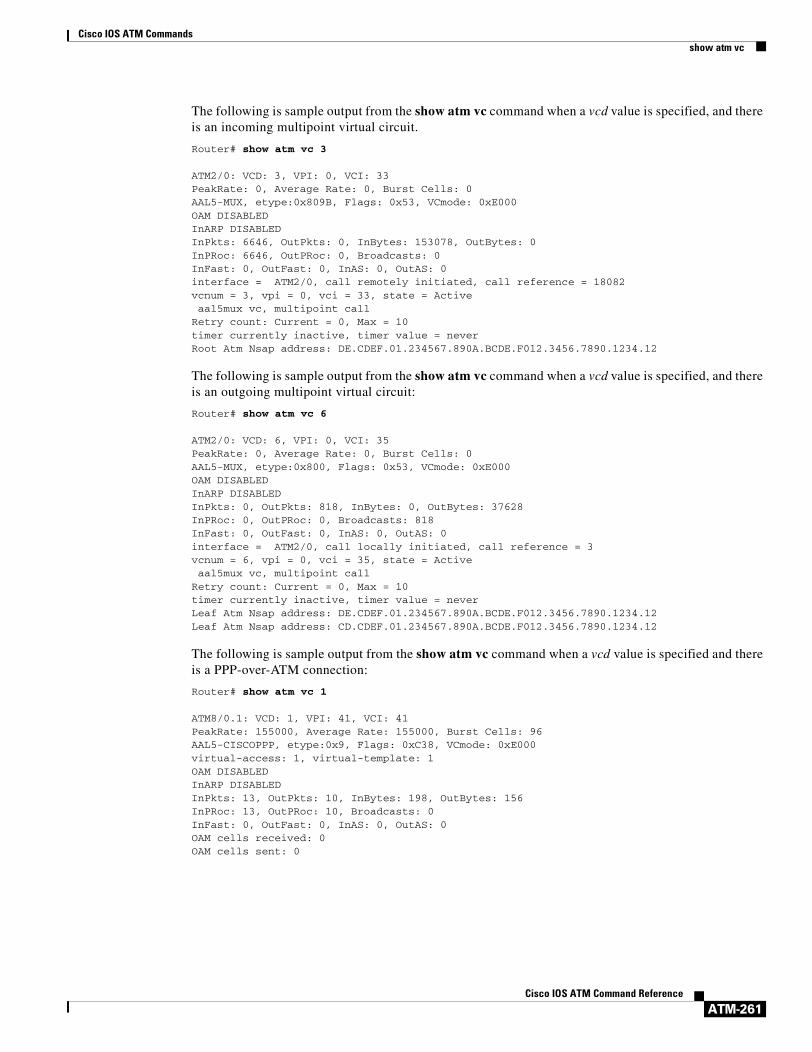
Cisco IOS ATM Commandsshow atm vc
ATM-261Cisco IOS ATM Command Reference
The following is sample output from the show atm vc command when a vcd value is specified, and there is an incoming multipoint virtual circuit.
Router# show atm vc 3
ATM2/0: VCD: 3, VPI: 0, VCI: 33PeakRate: 0, Average Rate: 0, Burst Cells: 0AAL5-MUX, etype:0x809B, Flags: 0x53, VCmode: 0xE000OAM DISABLEDInARP DISABLEDInPkts: 6646, OutPkts: 0, InBytes: 153078, OutBytes: 0InPRoc: 6646, OutPRoc: 0, Broadcasts: 0InFast: 0, OutFast: 0, InAS: 0, OutAS: 0interface = ATM2/0, call remotely initiated, call reference = 18082vcnum = 3, vpi = 0, vci = 33, state = Active aal5mux vc, multipoint callRetry count: Current = 0, Max = 10timer currently inactive, timer value = neverRoot Atm Nsap address: DE.CDEF.01.234567.890A.BCDE.F012.3456.7890.1234.12
The following is sample output from the show atm vc command when a vcd value is specified, and there is an outgoing multipoint virtual circuit:
Router# show atm vc 6
ATM2/0: VCD: 6, VPI: 0, VCI: 35PeakRate: 0, Average Rate: 0, Burst Cells: 0AAL5-MUX, etype:0x800, Flags: 0x53, VCmode: 0xE000OAM DISABLEDInARP DISABLEDInPkts: 0, OutPkts: 818, InBytes: 0, OutBytes: 37628InPRoc: 0, OutPRoc: 0, Broadcasts: 818InFast: 0, OutFast: 0, InAS: 0, OutAS: 0interface = ATM2/0, call locally initiated, call reference = 3vcnum = 6, vpi = 0, vci = 35, state = Active aal5mux vc, multipoint callRetry count: Current = 0, Max = 10timer currently inactive, timer value = neverLeaf Atm Nsap address: DE.CDEF.01.234567.890A.BCDE.F012.3456.7890.1234.12Leaf Atm Nsap address: CD.CDEF.01.234567.890A.BCDE.F012.3456.7890.1234.12
The following is sample output from the show atm vc command when a vcd value is specified and there is a PPP-over-ATM connection:
Router# show atm vc 1
ATM8/0.1: VCD: 1, VPI: 41, VCI: 41PeakRate: 155000, Average Rate: 155000, Burst Cells: 96AAL5-CISCOPPP, etype:0x9, Flags: 0xC38, VCmode: 0xE000virtual-access: 1, virtual-template: 1OAM DISABLEDInARP DISABLEDInPkts: 13, OutPkts: 10, InBytes: 198, OutBytes: 156InPRoc: 13, OutPRoc: 10, Broadcasts: 0InFast: 0, OutFast: 0, InAS: 0, OutAS: 0OAM cells received: 0OAM cells sent: 0

Cisco IOS ATM Commandsshow atm vc
ATM-262Cisco IOS ATM Command Reference
The following is sample output from the show atm vc command for IP multicast virtual circuits. The display shows the leaf count for multipoint VCs opened by the root. VCD 3 is a root of a multipoint VC with three leaf routers. VCD 4 is a leaf of some other router’s multipoint VC. VCD 12 is a root of a multipoint VC with only one leaf router.
Router# show atm vc
VCD/ Peak Avg/Min BurstInterface Name VPI VCI Type Encaps Kbps Kbps Cells Sts0/0 1 0 5 PVC SAAL 155000 155000 96 UP0/0 2 0 16 PVC ILMI 155000 155000 96 UP0/0 3 0 124 MSVC-3 SNAP 155000 155000 96 UP0/0 4 0 125 MSVC SNAP 155000 155000 96 UP0/0 5 0 126 MSVC SNAP 155000 155000 96 UP0/0 6 0 127 MSVC SNAP 155000 155000 96 UP0/0 9 0 130 MSVC SNAP 155000 155000 96 UP0/0 10 0 131 SVC SNAP 155000 155000 96 UP0/0 11 0 132 MSVC-3 SNAP 155000 155000 96 UP0/0 12 0 133 MSVC-1 SNAP 155000 155000 96 UP0/0 13 0 134 SVC SNAP 155000 155000 96 UP0/0 14 0 135 MSVC-2 SNAP 155000 155000 96 UP0/0 15 0 136 MSVC-2 SNAP 155000 155000 96 UP
The following is sample output from the show atm vc command for an IP multicast virtual circuit. The display shows the owner of the VC and leafs of the multipoint VC. This VC was opened by IP multicast and the three leaf routers’ ATM addresses are included in the display. The VC is associated with IP group address 10.1.1.1.
Router# show atm vc 11
ATM0/0: VCD: 11, VPI: 0, VCI: 132PeakRate: 155000, Average Rate: 155000, Burst Cells: 96AAL5-LLC/SNAP, etype:0x0, Flags: 0x650, VCmode: 0xE000OAM DISABLEDInARP DISABLEDInPkts: 0, OutPkts: 12, InBytes: 0, OutBytes: 496InPRoc: 0, OutPRoc: 0, Broadcasts: 12InFast: 0, OutFast: 0, InAS: 0, OutAS: 0OAM cells received: 0OAM cells sent: 0Status: ACTIVE, TTL: 2, VC owner: IP Multicast (10.1.1.1) <<<interface = ATM0/0, call locally initiated, call reference = 2vcnum = 11, vpi = 0, vci = 132, state = Active aal5snap vc, multipoint callRetry count: Current = 0, Max = 10timer currently inactive, timer value = 00:00:00Leaf Atm Nsap address: 47.0091810000000002BA08E101.444444444444.02 <<<Leaf Atm Nsap address: 47.0091810000000002BA08E101.333333333333.02 <<<Leaf Atm Nsap address: 47.0091810000000002BA08E101.222222222222.02 <<<
The following is sample output from the show atm vc command where no VCD is specified and private VCs are present.
Router# show atm vc
AAL / Peak Avg. Burst Interface VCD VPI VCI Type Encapsulation Kbps Kbps Cells StatusATM1/0 1 0 40 PVC AAL5-SNAP 0 0 0 ACTIVE ATM1/0 2 0 41 PVC AAL5-SNAP 0 0 0 ACTIVE ATM1/0 3 0 42 PVC AAL5-SNAP 0 0 0 ACTIVE ATM1/0 4 0 43 PVC AAL5-SNAP 0 0 0 ACTIVE ATM1/0 5 0 44 PVC AAL5-SNAP 0 0 0 ACTIVE ATM1/0 15 1 32 PVC AAL5-XTAGATM 0 0 0 ACTIVE

Cisco IOS ATM Commandsshow atm vc
ATM-263Cisco IOS ATM Command Reference
ATM1/0 17 1 34 TVC AAL5-XTAGATM 0 0 0 ACTIVE ATM1/0 26 1 43 TVC AAL5-XTAGATM 0 0 0 ACTIVE ATM1/0 28 1 45 TVC AAL5-XTAGATM 0 0 0 ACTIVE ATM1/0 29 1 46 TVC AAL5-XTAGATM 0 0 0 ACTIVE ATM1/0 33 1 50 TVC AAL5-XTAGATM 0 0 0 ACTIVE
When you specify a VCD value and the VCD corresponds to that of a private VC on a control interface, the display output appears as follows:
Router# show atm vc 15
ATM1/0 33 1 50 TVC AAL5-XTAGATM 0 0 0 ACTIVEATM1/0: VCD: 15, VPI: 1, VCI: 32, etype:0x8, AAL5 - XTAGATM, Flags: 0xD38PeakRate: 0, Average Rate: 0, Burst Cells: 0, VCmode: 0x0XTagATM1, VCD: 1, VPI: 0, VCI: 32OAM DISABLED, InARP DISABLEDInPkts: 38811, OutPkts: 38813, InBytes: 2911240, OutBytes: 2968834InPRoc: 0, OutPRoc: 0, Broadcasts: 0InFast: 0, OutFast: 0, InAS: 0, OutAS: 0OAM F5 cells sent: 0, OAM cells received: 0Status: ACTIVE
Table 12 describes the fields shown in the displays.
Table 12 show atm vc Field Descriptions
Field Description
Interface Interface slot and port.
VCD/Name Virtual circuit descriptor (virtual circuit number). The connection name is displayed if the VC was configured using the pvc command and the name was specified.
VPI Virtual path identifier.
VCI Virtual channel identifier.
Type Type of virtual circuit, either PVC, SVC, or multipoint SVC (MSVC).
• MSVC (with no -x ) indicates that VCD is a leaf of some other router’s multipoint VC.
• MSVC-x indicates there are x leaf routers for that multipoint VC opened by the root.
Type of PVC detected from PVC discovery, either PVC-D, PVC-L, or PVC-M.
• PVC-D indicates a PVC created due to PVC discovery.
• PVC-L indicates that the corresponding peer of this PVC could not be found on the switch.
• PVC-M indicates that some or all of the QOS parameters of this PVC mismatch that of the corresponding peer on the switch.
Encaps Type of ATM adaptation layer (AAL) and encapsulation.
PeakRate Kilobits per second transmitted at the peak rate.
Average Rate Kilobits per second transmitted at the average rate.
Burst Cells Value that equals the maximum number of ATM cells the virtual circuit can send at peak rate.
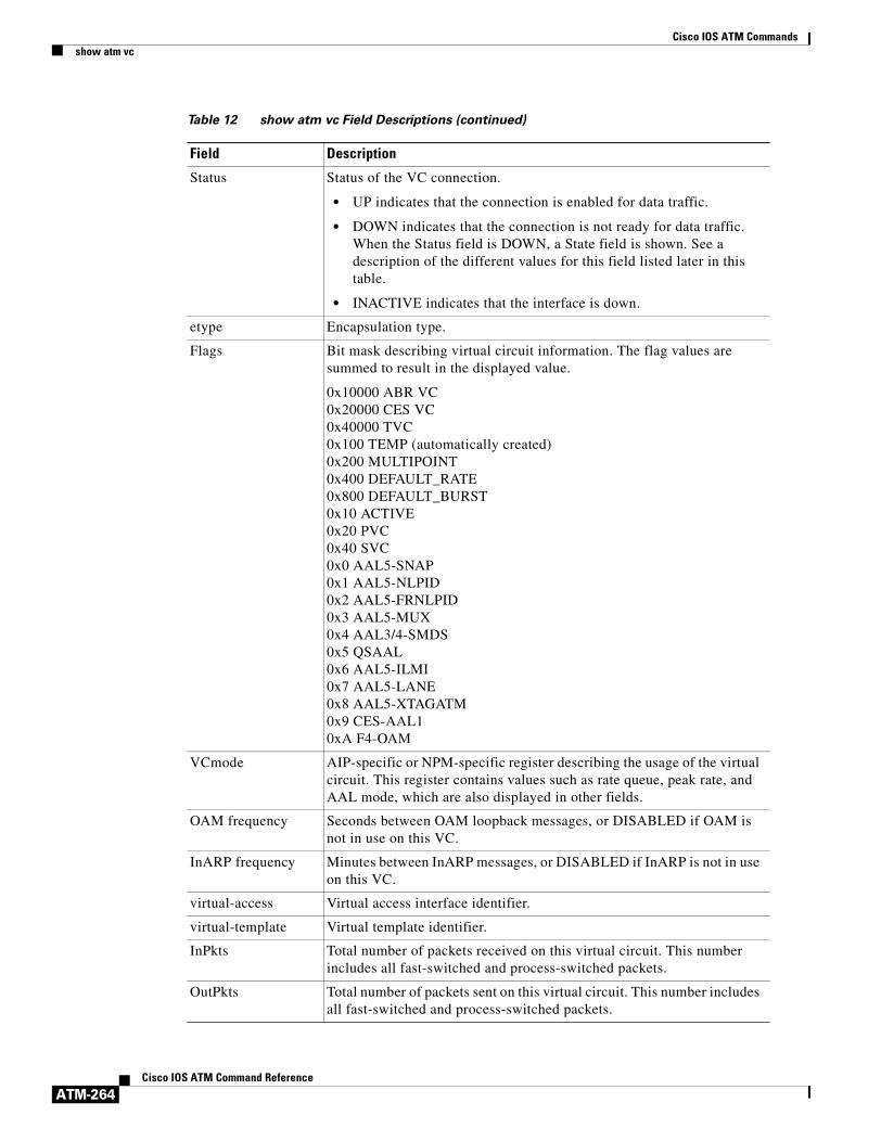
Cisco IOS ATM Commandsshow atm vc
ATM-264Cisco IOS ATM Command Reference
Status Status of the VC connection.
• UP indicates that the connection is enabled for data traffic.
• DOWN indicates that the connection is not ready for data traffic. When the Status field is DOWN, a State field is shown. See a description of the different values for this field listed later in this table.
• INACTIVE indicates that the interface is down.
etype Encapsulation type.
Flags Bit mask describing virtual circuit information. The flag values are summed to result in the displayed value.
0x10000 ABR VC0x20000 CES VC0x40000 TVC 0x100 TEMP (automatically created)0x200 MULTIPOINT0x400 DEFAULT_RATE0x800 DEFAULT_BURST 0x10 ACTIVE0x20 PVC 0x40 SVC 0x0 AAL5-SNAP0x1 AAL5-NLPID0x2 AAL5-FRNLPID 0x3 AAL5-MUX 0x4 AAL3/4-SMDS 0x5 QSAAL 0x6 AAL5-ILMI 0x7 AAL5-LANE 0x8 AAL5-XTAGATM 0x9 CES-AAL1 0xA F4-OAM
VCmode AIP-specific or NPM-specific register describing the usage of the virtual circuit. This register contains values such as rate queue, peak rate, and AAL mode, which are also displayed in other fields.
OAM frequency Seconds between OAM loopback messages, or DISABLED if OAM is not in use on this VC.
InARP frequency Minutes between InARP messages, or DISABLED if InARP is not in use on this VC.
virtual-access Virtual access interface identifier.
virtual-template Virtual template identifier.
InPkts Total number of packets received on this virtual circuit. This number includes all fast-switched and process-switched packets.
OutPkts Total number of packets sent on this virtual circuit. This number includes all fast-switched and process-switched packets.
Table 12 show atm vc Field Descriptions (continued)
Field Description

Cisco IOS ATM Commandsshow atm vc
ATM-265Cisco IOS ATM Command Reference
Related Commands
InBytes Total number of bytes received on this virtual circuit. This number includes all fast-switched and process-switched packets.
OutBytes Total number of bytes sent on this virtual circuit. This number includes all fast-switched and process-switched packets.
InPRoc Number of process-switched input packets.
OutPRoc Number of process-switched output packets.
Broadcast Number of process-switched broadcast packets.
InFast Number of fast-switched input packets.
OutFast Number of fast-switched output packets.
InAS Number of autonomous-switched or silicon-switched input packets.
OutAS Number of autonomous-switched or silicon-switched output packets.
OAM cells received Number of OAM cells received on this virtual circuit.
OAM cells sent Number of OAM cells sent on this virtual circuit.
TTL Time-to-live in ATM hops across the VC.
VC owner IP Multicast address of group.
Table 12 show atm vc Field Descriptions (continued)
Field Description
Command Description
atm nsap-address Sets the NSAP address for an ATM interface using SVC mode.

Cisco IOS ATM Commandsshow atm vp
ATM-266Cisco IOS ATM Command Reference
show atm vpTo display the statistics for all virtual paths (VPs) on an interface or for a specific VP, use the show atm vp command in privileged EXEC mode.
show atm vp [vpi]
Syntax Description
Command Modes Privileged EXEC
Command History
Examples The following is sample output from the show atm vp command. This output shows the interface name, the status of the interface, the administrative status of the interface, the port type, and the number of channels in use on the interface. The status of the interface can be UP (in operation) or DOWN (not in operation).
Router# show atm vp 1
ATM6/0 VPI: 1, PeakRate: 155000, CesRate: 1742, DataVCs: 1, CesVCs:1, Status: ACTIVE VCD VCI Type InPkts OutPkts AAL/Encap Status 1 100 PVC n/a n/a CES-AAL1 ACTIVE 13 13 PVC 0 0 AAL5-SNAP ACTIVE 409 3 PVC 0 0 F4 OAM ACTIVE 410 4 PVC 0 0 F4 OAM ACTIVE TotalInPkts: 0, TotalOutPkts: 0, TotalInFast: 0, TotalOutFast: 0, TotalBroadcasts: 0
Table 13 describes the fields shown in the display.
vpi (Optional) ATM network virtual path identifier (VPI) of the permanent virtual path. The range is from 0 to 255. The VPI is an 8-bit field in the header of the ATM cell.
Release Modification
11.1 This command was introduced.
Table 13 show atm vp Field Descriptions
Field Description
ATM6/0 Interface type, slot, and port number of the VP.
VPI Virtual path identifier of the VP.
PeakRate Maximum rate, in kbps, at which the VP can send data. Range is 84 kbps to line rate. The default is the line rate.
CesRate Total circuit emulation service (CES) bandwidth allocated for the VP.
DataVCs Number of data virtual circuits (VCs) on the VP.
CesVCs Number of CES VC on the VP.
Status Current status of the VP. Values are ACTIVE and INACTIVE.

Cisco IOS ATM Commandsshow atm vp
ATM-267Cisco IOS ATM Command Reference
Related Commands
VCD Virtual circuit descriptor of the VC associated with this VP.
VCI Virtual channel identifier of the VC associated with this VP.
Type Type of VC associated with this VP. Values are PVC and SVC.
InPkts Number of packets received on the VP.
OutPkts Number of packets transmitted on the VP.
AAL/Encap Type of encapsulation used on the VC associated with this VP.
Status Status of the VP (ACTIVE or INACTIVE).
TotalInPkts: Total number of input packets process-switched and fast-switched on the VP.
TotalOutPkts: Total number of output packets process-switched and fast-switched on the VP.
TotalInFast Total number of input packets fast-switched.
TotalOutFast: Total number of output packets fast-switched.
TotalBroadcasts: Total number of broadcast packets fast-switched.
Table 13 show atm vp Field Descriptions (continued)
Field Description
Command Description
atm pvp Creates a PVP used to multiplex (or bundle) one or more VCs (especially CES and data VCs).

Cisco IOS ATM Commandsshow ces circuit
ATM-268Cisco IOS ATM Command Reference
show ces circuitTo display detailed circuit information for the constant bit rate (CBR) interface, use the show ces circuit command in privileged EXEC mode.
show ces circuit [interface cbr slot/port [circuit-number]]
Syntax Description
Command Modes Privileged EXEC
Command History
Examples The following is sample output from the show ces circuit command.
Router # show ces circuit
Interface Circuit Circuit-Type X-interface X-vpi X-vci StatusCBR6/0 1 HardPVC ATM6/0 0 34 UPCBR6/1 1 HardPVC ATM6/1 0 34 UP
Table 14 describes the fields shown in the display.
interface cbr slot/port (Optional) Slot and port number of the CBR interface.
circuit-number (Optional) Circuit identification. For unstructured service, use 0. For T1 structure service, the range is from 1 to 24. For E1 structure service, the range is from 1 to 31.
Release Modification
11.1 This command was introduced.
Table 14 show ces circuit Field Descriptions
Field Description
Interface Type, slot, and port number of the interface.
Circuit Circuit number assigned to the PVC.
Circuit-Type Type of circuit.Values are HardPVC or SoftPVC. Only HardPVC is supported on the ATM-CES port adapter.
X-interface Type, slot, and port number of the destination interface.
X-vpi Virtual path identifier of the destination interface.
X-vci Virtual channel identifier of the destination interface.
Status State of the circuit. Values are Up and Down.

Cisco IOS ATM Commandsshow ces circuit
ATM-269Cisco IOS ATM Command Reference
The following is sample output from the show ces circuit command for a circuit 1 on CBR interface 6/0:
Router# show ces circuit interface cbr 6/0 1
circuit: Name CBR6/0:1, Circuit-state ADMIN_UP / Interface CBR6/0, Circuit_id 1,Port-Type T1, Port-State UPPort Clocking network-derived, aal1 Clocking Method CESIWF_AAL1_CLOCK_SyncChannel in use on this port: 1Channels used by this circuit: 1Cell-Rate: 171, Bit-Rate 64000cas OFF, cell-header 0X3E80 (vci = 1000)Configured CDV 2000 usecs, Measured CDV unavailableErrTolerance 8, idleCircuitdetect OFF, onHookIdleCode 0x0state: VcActive, maxQueueDepth 128, startDequeueDepth 111Partial Fill: 47, Structured Data Transfer 24HardPVCsrc: CBR6/0 vpi 0, vci 16Dst: ATM6/0 vpi0, vci 1000
Table 15 describes the fields shown in the display.
Table 15 show ces circuit interface Field Descriptions
Field Description
circuit Name Name of the circuit specified with the ces circuit interface command.
Circuit-state Current configuration state of the circuit. Values are ADMIN_UP or ADMIN_DOWN.
Interface Type, slot, and port number of the interface.
Circuit_ID Circuit identification specified with the ces pvc interface command.
Port-Type Type of interface on the ATM-CES port adapter. Values are T1 and E1.
Port-State Current status of the port. Values are Up and Down.
Port Clocking Clocking mode used by the interface specified with the ces dsx1 clock interface command. Values are Loop-Timed and Network-Derived Adaptive.
aal1 Clocking Method AAL1 clocking mode used by the interface specified with the ces aal1 clock interface command. Values are Adaptive, Synchronous Residual Time Stamp (SRTS), and Synchronous.
Channel in use on this port
Number of active channels used by this interface.
Channels used by this circuit
Number of channels used by the circuit.
Cell-Rate Number of cells transmitted or received on the interface per second.
Bit-Rate Speed at which the cells are transmitted or received.
cas Indicates whether channel-associated signaling (CAS) is enabled on the interface with the ces circuit interface command.
cell-header ATM cell header VCI bytes used for debugging only.
Configured CDV Indicates the peak-to-peak cell delay variation (CDV) requirement (CDV) in milliseconds specified with the ces circuit interface command. The range for CDV is 1 through 65535 milliseconds. The default is 2000 milliseconds.
Measured CDV Indicates the actual cell delay variation in milliseconds.
ErrTolerance For internal use only.

Cisco IOS ATM Commandsshow ces circuit
ATM-270Cisco IOS ATM Command Reference
Related Commands
idleCircuitdetect Indicates whether idle circuit detection is enabled (ON) or disabled (OFF).
onHookIdleCode Indicates that the on-hook detection feature is enabled with the ces circuit interface command and the hex value (0 through F) that indicates a 2 or 4 bit AB[CD] pattern to detect on-hook. The AB[CD] bits are determined by the manufacturer of the voice/video telephony device that is generating the CBR traffic.
state Current state of the circuit. Values are VcActive, VcInactive, VcLOC (loss of cell), or VcAlarm (alarm condition).
maxQueueDepth Maximum queue depth in bits.
startDequeueDepth Start dequeue depth in bits.
Partial Fill Indicates the partial AAL1 cell fill service for structured service only specified by the ces circuit interface command. The range is 0 through 47. The default is 47.
Structured Data Transfer
Size (in bytes) of the structured data transfer frame.
HardPVC Only hard PVC are supported by the ATM-CES port adapter.
src Source interface type, slot, and port number and VPI and VCI for the circuit.
Dst Destination interface interface type, slot, and port number and the VPI and VCI for the circuit.
Table 15 show ces circuit interface Field Descriptions (continued)
Field Description
Command Description
show ces circuit Displays detailed circuit information for the CBR interface.
show ces status Displays the status of the ports on the ATM-CES port adapter.

Cisco IOS ATM Commandsshow ces interface cbr
ATM-271Cisco IOS ATM Command Reference
show ces interface cbrTo display detailed constant bit rate (CBR) port information, use the show ces interface cbr command in privileged EXEC mode.
show ces interface cbr slot/port
Syntax Description
Command Modes Privileged EXEC
Command History
Examples The following is sample output from the show ces interface cbr command for CBR interface 6/0:
Router# show ces interface cbr 6/0
Interface: CBR6/0 Port-type:T1-DCUIF Status: UP Admin Status: UPChannels in use on this port: 1LineType: ESF LineCoding: B8ZS LoopConfig: NoLoopSignalMode: NoSignalling XmtClockSrc: network-derivedDataFormat: Structured AAL1 Clocking Mode: Synchronous LineLength: 0_110LineState: LossOfSignalErrors in the Current Interval: PCVs 0 LCVs 0 ESs 0 SESs 0 SEFSs 0 UASs 0 CSSs 0 LESs 0 BESs 0 DMs 0Errors in the last 24Hrs: PCVs 514 LCVs 0 ESs 0 SESs 1 SEFSs 0 UASs 0 CSSs 0 LESs 0 BESs 0 DMs 0Input Counters: 0 cells, 0 bytesOutput Counters: 0 cells, 0 bytes
Table 16 describes the fields shown in the display.
slot/port Slot and port number of the CES interface.
Release Modification
11.1 This command was introduced.
Table 16 show ces interface cbr Field Descriptions
Field Description
Interface Type, slot, and port number of the interface.
Port-type Type of port on the ATM-CES port adapter. Values are T1-DCU and E1-DCU.
IF Status Status of the interface. Values are Up and Down.
Admin Status Configured status of the interface. Values are Up and Down (administratively configured down).
Channels in use on this port
Number of active channels used by this interface.

Cisco IOS ATM Commandsshow ces interface cbr
ATM-272Cisco IOS ATM Command Reference
LineType Framing used on the interface specified with the ces dsx1 framing interface command. Values (for T1) are ESF and SF; (for E1) E1-CRC-MFCASLT, E1-CRC-MFLT, E1-LT, and E1-MFCASLT.
LineCoding Line coding used on the interface specified with the ces dsx1 linecode interface command. Values (for T1) are AMI and B8ZS; (for E1) HDB3.
LoopConfig Indicates whether the interface in in a loop state specified by the ces dsx1 loopback interface command. Values are line loopback, payload loopback, and noloop.
SignalMode For T1 to use robbed-bit signaling or not.
XmitClockSrc Transmit clock source specified by the ces dsx1 clock interface command. Values are loop-timed or network-derived.
DataFormat Type of CES services specified by the ces aal1 service interface command. Values are structured or unstructured.
AAL1 Clocking Mode AAL1 clocking mode used by the interface specified with the ces aal1 clock interface command. Values are adaptive, synchronous residual time stamp (SRTS), or synchronous.
LineLength Cable length specified by the ces dsx1 lbo interface command. Values are 0-110, 10-200, 220-330, 330-440, 440-550, 550-660, 660-above, and square-pulse.
LineState Current status of the line. Values are:
• Unknown
• NoAlarm
• RcvFarEndLOF
• XmtFarEndLOF
• RcvAIS
• XmtAIS
• LossOfFrame
• LossOfSignal
• LoopbackState
• T16AIS
Errors in the Current Interval
Error statistics received during the current 15-minute interval.
PCVs Number of Path Code Violations (PCVs). PCVs indicate a frame synchronization bit error in the D4 and E1 no-CRC formats, or a CRC error in the ESF and E1 CRC formats.
LCVs Number of Line Code Violations (LCVs). LCVs indicate the occurrence of either a Bipolar Violation (BPV) or Excessive Zeros (EXZ) error event.
Table 16 show ces interface cbr Field Descriptions (continued)
Field Description

Cisco IOS ATM Commandsshow ces interface cbr
ATM-273Cisco IOS ATM Command Reference
Related Commands
ESs Number of errored seconds. In ESF and E1 CRC links, an Errored Second is a second in which one of the following are detected: one or more Path Code Violations, one or more Out of Frame defects, one or more Controlled Slip events, or a detected AIS defect.
For SF and E1 no-CRC links, the presence of Bipolar Violations also triggers an Errored Second.
SESs Number of Severely Errored Seconds (SESs). A SESs is a second with 320 or more path code violation errors events, one or more Out of Frame defects, or a detected AIS defect.
SEFSs Number of Severely Errored Framing Seconds (SEFS). SEFS is a second with one or more Out of Frame defects or a detected incoming AIS.
UASs Number of Unavailable Seconds (UASs). UAS is a count of the total number of seconds on the interface.
CSSs Number of Controlled Slip Second (CSS). CSS is a 1-second interval containing one or more controlled slips.
LESs Number of Line Errored Seconds (LES). LES is a second in which one or more Line Code Violation errors are detected.
BESs Number of Bursty Errored Seconds (BES). BES is a second with fewer than 320 and more than one Path Coding Violation error, no Severely Errored Frame defects, and no detected incoming AIS defects. Controlled slips are not included in this parameter.
DMs Number of Degraded Minutes (DMs). A degraded minute is one in which the estimated error rate exceeds 1E-6 but does not exceed 1E-3. For more information, refer to RFC 1406.
Errors in the last 24Hrs Error statistics received during the during the last 24 hours.
Input Counters Number of cells and bytes received on the interface.
Output Counters Number of cells and bytes.
Table 16 show ces interface cbr Field Descriptions (continued)
Field Description
Command Description
show interface cbr Displays the information about the CBR interface on the ATM-CES port adapter.

Cisco IOS ATM Commandsshow ces status
ATM-274Cisco IOS ATM Command Reference
show ces statusTo display the status of the ports on the ATM-CES port adapter, use the show ces status command in privileged EXEC mode.
show ces status
Syntax Description This command has no arguments or keywords.
Command Modes Privileged EXEC
Command History
Examples The following is sample output from the show ces status command. This output shows the interface name, the status of the interface, the administrative status of the interface, the port type, and the number of channels in use on the interface. The status of the interface can be UP (in operation) or DOWN (not in operation).
Router# show ces status
Interface IF Admin Port Channels inName Status Status Type use
------------- -------- --------- ----------- -----------CBR0/0/0 UP UP T1 1-24CBR0/0/1 UP UP T1 1-24CBR0/0/2 UP UP T1 1-24CBR0/0/3 UP UP T1
Related Commands
Release Modification
11.1 This command was introduced.
Command Description
show ces circuit Displays detailed circuit information for the CBR interface.

Cisco IOS ATM Commandsshow ces
ATM-275Cisco IOS ATM Command Reference
show cesTo display details about a Circuit Emulation Service (CES) connection, use the show ces privileged EXEC command.
show ces [slot/port]
Syntax Description
Command Modes Privileged EXEC
Command History
Usage Guidelines This command is used on Cisco 2600 series and Cisco 3600 series routers that have OC-3/STM-1 ATM CES network modules.
Examples The following is sample output from the show ces command.
Router# show ces 3/0
CURRENT VPD CES CLOCK:Set to ATMATM CLOCKING:Clock Source is LineVPD BASE ADDRESS->(0x3DE00000)Multi Mode VPD InstalledVIC/WIC PRESENT-> 2 port drop&insert T1 humvee installedCONTROLLER CLOCKING-> PORT[0]:Clock is InternalCONTROLLER CLOCKING-> PORT[1]:Clock is InternalDCU [0]: port State: active alarm State:normal Loop Type: noloop Clocking Mode:loopTimed Data Mode: crossConnect Framing Type: d4 Line Coding: ami t1Cas: off tsInUse: 0000001C VPI/VCI 6/78 CES AAL1 Input cells 210252 CES AAL1 Output cells 210252 imRestart 0 xcUndfrmslp 2 overflow 0DCU [1]: port State: inactive alarm State:normal Loop Type: noloop Clocking Mode:synchronous Data Mode: clearChannel Framing Type:none Line Coding: ami t1Cas: off tsInUse: 00000000DCU [2]: port State: inactive alarm State:normal Loop Type: noloop Clocking Mode:synchronous Data Mode: clearChannel Framing Type:none Line Coding: ami t1Cas: off tsInUse: 00000000DCU [3]: port State: inactive alarm State:normal Loop Type: noloop Clocking Mode:synchronous Data Mode: clearChannel Framing Type:none Line Coding: ami t1Cas: off tsInUse: 00000000
Table 17 describes significant fields shown in the display.
slot/port (Optional) Slot and port number of the CES interface.
Release Modification
12.1(2)T This command was introduced.

Cisco IOS ATM Commandsshow ces
ATM-276Cisco IOS ATM Command Reference
Related Commands
Table 17 show ces Field Descriptions
Field Description
CURRENT VPD CES CLOCK
Clock being used by the CES function.
ATM CLOCKING
Clock being used by the ATM interface.
VIC/WIC PRESENT
Type of WIC plugged into the Network Module.
CONTROLLER CLOCKING
Clock being used by the T1 controller.
port State Current state of port. Values are active or inactive.
alarm State Current state of the CES port.
Clocking Mode CES circuit clocking mode.
Data Mode CES circuit data mode.
Framing Type CES port framing type. Values are d4 and esf.
Line Coding CES port line code type. Values are ami and b8zs.
t1Cas Current state of T1 Channel Associated Signalling on CES port. Values are on and off.
tsInUse Bit mask of timeslots in use.
VPI/VCI VPI/VCI used by CES circuit.
CES AAL1 Input cells
Number of CES cells received.
CES AAL1 Output cells
Number of CES cells transmitted.
xcUndfrmslp Structured CES circuit Under Frame Slips.
overflow CES circuit overflows.
Command Description
ces Configures CES on a router port.
Cisco IOS ATM Commandsshow controllers atm
ATM-277Cisco IOS ATM Command Reference
show controllers atmTo display information about an inverse multiplexing over ATM (IMA) group, use the show controllers atm privileged EXEC command.
Cisco 2600 and 3600 Series
show controllers atm [slot/ima group-number]
Cisco 7200 Series
show controller atm [slot/port]
or
show controllers atm [slot/imagroup-number]
Cisco 7500 Series (physical port hardware information)
show controllers atm [slot/port-adapter/port]
Cisco 7500 Series (IMA group hardware information)
show controllers atm [slot/port-adapter/imagroup-number]
Syntax Description
Command Modes Privileged EXEC
Command History
slot/ (Optional) ATM slot number.
ima (Optional) This keyword indicates an IMA group specification rather than a port value for a UNI interface.
group-number (Optional) Enter an IMA group number from 0 to 3. If you specify the group number, do not insert a space between ima and the number.
port (Optional) ATM port number.
port-adapter/ (Optional) ATM port adapter.
Release Modification
11.2 GS This command was introduced.
12.0(5)T and 12.0(5)XK This command was modified to support IMA groups on Cisco 2600 and 3600 series routers.
12.0(5)XE Support for Cisco 7200 and 7500 series routers was added.
12.0(7)XE1 Support for Cisco 7100 series routers was added.
12.1(5)T Support for Cisco 7100,7200, and 7500 series routers was integrated into Cisco IOS Release 12.1(5)T.

Cisco IOS ATM Commandsshow controllers atm
ATM-278Cisco IOS ATM Command Reference
Usage Guidelines Use this command to monitor and diagnose ATM IMA links and groups.
Examples Cisco 7100 or 7200 Series Example
On Cisco 7100 series or 7200 series routers, the following example displays detailed information about IMA group hardware related information. It includes the configuration of IMA hardware and IMA alarms.
Router# show controllers atm 1/ima0
Interface ATM1/ima0 is upHardware is IMA PA - DS1 (1Mbps)Framer is PMC PM7344, SAR is LSI ATMIZER IIFirmware rev:G102, ATMIZER II rev:3 idb=0x61DE9F10, ds=0x6185C0A0, vc=0x6187D3C0, pa=0x6184AF40 slot 1, unit 9, subunit 0, fci_type 0x00BA, ticks 701720 400 rx buffers:size=512, encap=64, trailer=28, magic=4Curr Stats: rx_cell_lost=0, rx_no_buffer=0, rx_crc_10=0 rx_cell_len=0, rx_no_vcd=0, rx_cell_throttle=0, tx_aci_err=0Rx Free Ring status: base=0x3CFF0040, size=1024, write=320Rx Compl Ring status: base=0x338DCE40, size=2048, read=1275Tx Ring status: base=0x3CFE8040, size=8192, write=700Tx Compl Ring status: base=0x338E0E80, size=2048, read=344BFD Cache status: base=0x61878340, size=5120, read=5107Rx Cache status: base=0x61863D80, size=16, write=11Tx Shadow status: base=0x618641C0, size=8192, read=687, write=700Control data: rx_max_spins=12, max_tx_count=25, tx_count=13 rx_threshold=267, rx_count=11, tx_threshold=3840 tx bfd write indx=0x27, rx_pool_info=0x61863E20Control data base address: rx_buf_base = 0x038A15A0 rx_p_base = 0x6185CB40 rx_pak = 0x61863AF0 cmd = 0x6185C320 device_base = 0x3C800000 ima_pa_stats = 0x038E2FA0 sdram_base = 0x3CE00000 pa_cmd_buf = 0x3CFFFC00 vcd_base[0] = 0x3CE3C100 vcd_base[1] = 0x3CE1C000 chip_dump = 0x038E3D7C dpram_base = 0x3CD80000 sar_buf_base[0] = 0x3CE4C000 sar_buf_base[1] = 0x3CF22000 bfd_base[0] = 0x3CFD4000 bfd_base[1] = 0x3CFC0000 acd_base[0] = 0x3CE88360 acd_base[1] = 0x3CE5C200 pci_atm_stats = 0x038E2EC0ATM1/ima0 is up hwgrp number = 1grp tx up reg= 0x5, grp rx up reg= 0x3, rx dcb reg= 0xD4 0x4, tx links grp reg= 0x3, scci reg= 0x3C, ima id reg= 0x0, group status reg= 0xA2, tx timing reg= 0x20, tx test reg= 0x21, tx test pattern reg= 0x41, rx test pattern reg= 0x42, icp cell link info reg= 0xFC, icp cell link info reg= 0xFC, icp cell link info reg= 0x0, icp cell link info reg= 0x0, icp cell link info reg= 0x0, icp cell link info reg= 0x0, icp cell link info reg= 0x0, icp cell link info reg= 0x0
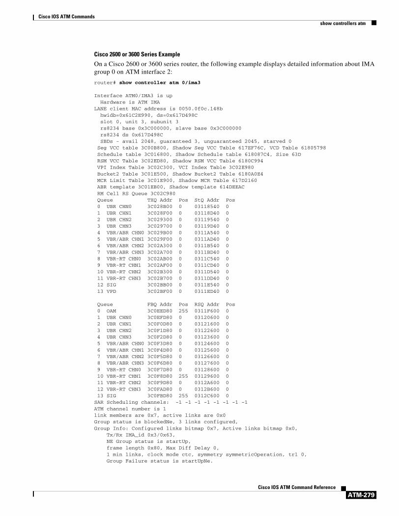
Cisco IOS ATM Commandsshow controllers atm
ATM-279Cisco IOS ATM Command Reference
Cisco 2600 or 3600 Series Example
On a Cisco 2600 or 3600 series router, the following example displays detailed information about IMA group 0 on ATM interface 2:
router# show controller atm 0/ima3
Interface ATM0/IMA3 is up Hardware is ATM IMALANE client MAC address is 0050.0f0c.148b hwidb=0x61C2E990, ds=0x617D498C slot 0, unit 3, subunit 3 rs8234 base 0x3C000000, slave base 0x3C000000 rs8234 ds 0x617D498C SBDs - avail 2048, guaranteed 3, unguaranteed 2045, starved 0 Seg VCC table 3C00B800, Shadow Seg VCC Table 617EF76C, VCD Table 61805798 Schedule table 3C016800, Shadow Schedule table 618087C4, Size 63D RSM VCC Table 3C02ED80, Shadow RSM VCC Table 6180C994 VPI Index Table 3C02C300, VCI Index Table 3C02E980 Bucket2 Table 3C01E500, Shadow Bucket2 Table 6180A0E4 MCR Limit Table 3C01E900, Shadow MCR Table 617D2160 ABR template 3C01EB00, Shadow template 614DEEAC RM Cell RS Queue 3C02C980 Queue TXQ Addr Pos StQ Addr Pos 0 UBR CHN0 3C028B00 0 03118540 0 1 UBR CHN1 3C028F00 0 03118D40 0 2 UBR CHN2 3C029300 0 03119540 0 3 UBR CHN3 3C029700 0 03119D40 0 4 VBR/ABR CHN0 3C029B00 0 0311A540 0 5 VBR/ABR CHN1 3C029F00 0 0311AD40 0 6 VBR/ABR CHN2 3C02A300 0 0311B540 0 7 VBR/ABR CHN3 3C02A700 0 0311BD40 0 8 VBR-RT CHN0 3C02AB00 0 0311C540 0 9 VBR-RT CHN1 3C02AF00 0 0311CD40 0 10 VBR-RT CHN2 3C02B300 0 0311D540 0 11 VBR-RT CHN3 3C02B700 0 0311DD40 0 12 SIG 3C02BB00 0 0311E540 0 13 VPD 3C02BF00 0 0311ED40 0 Queue FBQ Addr Pos RSQ Addr Pos 0 OAM 3C0EED80 255 0311F600 0 1 UBR CHN0 3C0EFD80 0 03120600 0 2 UBR CHN1 3C0F0D80 0 03121600 0 3 UBR CHN2 3C0F1D80 0 03122600 0 4 UBR CHN3 3C0F2D80 0 03123600 0 5 VBR/ABR CHN0 3C0F3D80 0 03124600 0 6 VBR/ABR CHN1 3C0F4D80 0 03125600 0 7 VBR/ABR CHN2 3C0F5D80 0 03126600 0 8 VBR/ABR CHN3 3C0F6D80 0 03127600 0 9 VBR-RT CHN0 3C0F7D80 0 03128600 0 10 VBR-RT CHN1 3C0F8D80 255 03129600 0 11 VBR-RT CHN2 3C0F9D80 0 0312A600 0 12 VBR-RT CHN3 3C0FAD80 0 0312B600 0 13 SIG 3C0FBD80 255 0312C600 0SAR Scheduling channels: -1 -1 -1 -1 -1 -1 -1 -1ATM channel number is 1link members are 0x7, active links are 0x0Group status is blockedNe, 3 links configured,Group Info: Configured links bitmap 0x7, Active links bitmap 0x0, Tx/Rx IMA_id 0x3/0x63, NE Group status is startUp, frame length 0x80, Max Diff Delay 0, 1 min links, clock mode ctc, symmetry symmetricOperation, trl 0, Group Failure status is startUpNe.

Cisco IOS ATM Commandsshow controllers atm
ATM-280Cisco IOS ATM Command Reference
Test pattern procedure is disabledSAR counter totals across all links and groups: 0 cells output, 0 cells stripped 0 cells input, 0 cells discarded, 0 AAL5 frames discarded 0 pci bus err, 0 dma fifo full err, 0 rsm parity err 0 rsm syn err, 0 rsm/seg q full err, 0 rsm overflow err 0 hs q full err, 0 no free buff q err, 0 seg underflow err 0 host seg stat q full err
Related Commands Command Description
show controllers atm Displays information about an IMA group.
show ima interface atm Provides information about all configured IMA groups or a specific IMA group.

Cisco IOS ATM Commandsshow dxi map
ATM-281Cisco IOS ATM Command Reference
show dxi mapTo display all the protocol addresses mapped to a serial interface, use the show dxi map EXEC command.
show dxi map
Syntax Description This command has no arguments or keywords.
Command Modes EXEC
Command History
Examples The following is sample output from the show dxi map command. It displays output for several previously defined ATM-DXI maps that defined Apollo, IP, DECnet, CLNS, and AppleTalk protocol addresses, various encapsulations, and broadcast traffic.
Router# show dxi map
Serial0 (administratively down): ipx 123.0000.1234.1234 DFA 69(0x45,0x1050), static, vpi = 4, vci = 5, encapsulation: SNAPSerial0 (administratively down): appletalk 2000.5 DFA 52(0x34,0xC40), static, vpi = 3, vci = 4, encapsulation: NLPIDSerial0 (administratively down): ip 172.21.177.1 DFA 35(0x23,0x830), static, broadcast, vpi = 2, vci = 3, encapsulation: VC based MUX, Linktype IP
Table 18 explains significant fields shown in the display.
Release Modification
10.3 This command was introduced.
Table 18 show dxi map Field Descriptions
Field Description
DFA Data Exchange Interface (DXI) Frame Address, similar to a data-link connection identifier (DLCI) for Frame Relay. The DFA is shown in decimal, hexadecimal, and DXI header format. The router computes this address value from the virtual path identifier (VPI) and virtual channel identifier (VCI) values.
encapsulation Encapsulation type selected by the dxi pvc command. Displayed values can be SNAP, NLPID, or VC based MUX.
Linktype Value used only with MUX encapsulation and therefore with only a single network protocol defined for the permanent virtual circuit (PVC). Maps configured on a PVC with MUX encapsulation must have the same link type.

Cisco IOS ATM Commandsshow dxi pvc
ATM-282Cisco IOS ATM Command Reference
show dxi pvcTo display the permanent virtual circuit (PVC) statistics for a serial interface, use the show dxi pvc EXEC command.
show dxi pvc
Syntax Description This command has no arguments or keywords.
Command Modes EXEC
Command History
Examples The following is sample output from the show dxi pvc command. It displays output for ATM-DXI PVCs previously defined for serial interface 0.
Router# show dxi pvc
PVC Statistics for interface Serial0 (ATM DXI)
DFA = 17, VPI = 1, VCI = 1, PVC STATUS = STATIC, INTERFACE = Serial0
input pkts 0 output pkts 0 in bytes 0 out bytes 0 dropped pkts 0 DFA = 34, VPI = 2, VCI = 2, PVC STATUS = STATIC, INTERFACE = Serial0
input pkts 0 output pkts 0 in bytes 0 out bytes 0 dropped pkts 0 DFA = 35, VPI = 2, VCI = 3, PVC STATUS = STATIC, INTERFACE = Serial0
input pkts 0 output pkts 0 in bytes 0 out bytes 0 dropped pkts 0
Table 19 describes significant fields shown in the display.
Release Modification
10.3 This command was introduced.
Table 19 show dxi pvc Field Descriptions
Field Description
DFA Data Exchange Interface (DXI) Frame Address, similar to a data-link connection identifier (DLCI) for Frame Relay. The DFA is shown in decimal, hexadecimal, and DXI header format. The router computes this address value from the virtual path identifier (VPI) and virtual channel identifier (VCI) values.
PVC STATUS = STATIC
Only static maps are supported. Maps are not created dynamically.
input pkts Number of packets received.
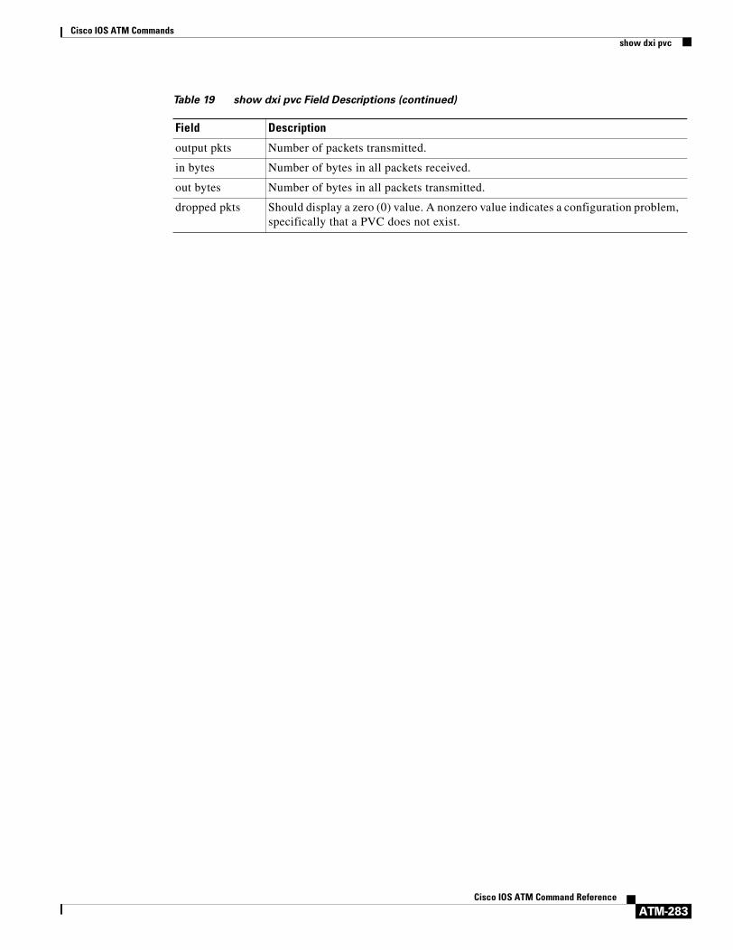
Cisco IOS ATM Commandsshow dxi pvc
ATM-283Cisco IOS ATM Command Reference
output pkts Number of packets transmitted.
in bytes Number of bytes in all packets received.
out bytes Number of bytes in all packets transmitted.
dropped pkts Should display a zero (0) value. A nonzero value indicates a configuration problem, specifically that a PVC does not exist.
Table 19 show dxi pvc Field Descriptions (continued)
Field Description

Cisco IOS ATM Commandsshow ima interface atm
ATM-284Cisco IOS ATM Command Reference
show ima interface atmTo display information about all configured inverse multiplexing over ATM (IMA) groups or a specific group, use the show ima interface atm command in privileged EXEC mode.
Cisco 2600 and 3600 Series
show ima interface atm [slot/imagroup-number] [detail]
Cisco 7200 Series
show ima interface atm [slot/port] [detail]
or
show ima interface atm [slot/port-adapter/imagroup-number] [detail]
Cisco 7500 Series
show ima interface atm [slot/port-adapter/slot] [detail]
or
show ima interface atm [slot/port-adapter/imagroup-number] [detail]
Syntax Description
Command Modes Privileged EXEC
Command History
Usage Guidelines Use this command to monitor the status of IMA group links.
slot/ (Optional) ATM slot number.
ima (Optional) This keyword indicates an IMA group specification rather than a port value for a UNI interface.
group-number (Optional) Enter an IMA group number from 0 to 3. If you specify the group number, do not insert a space between ima and the number.
port (Optional) ATM port number.
port-adapter/ (Optional) ATM port adapter.
detail (Optional) To obtain detailed information, use this keyword.
Release Modification
12.0(5)XK This command was introduced.
12.0(5)XE Support for Cisco 7200 and 7500 series routers was added.
12.0(7)XE1 Support for Cisco 7100 series routers was added.
12.1(5)T Support for Cisco 7100, 7200, and 7500 series routers was integrated in Cisco IOS Release 12.1(5)T.

Cisco IOS ATM Commandsshow ima interface atm
ATM-285Cisco IOS ATM Command Reference
Examples On Cisco 7100 or 7200 series routers, the following example displays detailed information about IMA group 0 on ATM interface 2. If you do not enter the detail keyword, you do not see the IMA MIB information or the “Detailed Link Information” output.
Router# show ima interface atm 5/ima0 detail
ATM5/ima0 is up ImaGroupState:NearEnd = operational, FarEnd = operational ImaGroupFailureStatus = noFailureIMA Group Current Configuration: ImaGroupMinNumTxLinks = 2 ImaGroupMinNumRxLinks = 2 ImaGroupDiffDelayMax = 250 ImaGroupNeTxClkMode = common(ctc) ImaGroupFrameLength = 128 ImaTestProcStatus = disabled ImaGroupTestLink = 0 ImaGroupTestPattern = 0xFFIMA MIB Information: ImaGroupSymmetry = symmetricOperation ImaGroupFeTxClkMode = common(ctc) ImaGroupRxFrameLength = 128 ImaGroupTxTimingRefLink = 0 ImaGroupRxTimingRefLink = 0 ImaGroupTxImaId = 0 ImaGroupRxImaId = 0 ImaGroupNumTxCfgLinks = 2 ImaGroupNumRxCfgLinks = 2 ImaGroupNumTxActLinks = 2 ImaGroupNumRxActLinks = 2 ImaGroupLeastDelayLink = 0 ImaGroupDiffDelayMaxObs = 0IMA group counters: ImaGroupNeNumFailures = 1 ImaGroupFeNumFailures = 2 ImaGroupUnAvailSecs = 18 ImaGroupRunningSecs = 241IMA Detailed Link Information:
ATM5/0 is up ImaLinkRowStatus = active ImaLinkIfIndex = 1 ImaLinkGroupIndex = 47 ImaLinkState: NeTx = active NeRx = active FeTx = active FeRx = active ImaLinkFailureStatus: NeRx = noFailure FeRx = noFailure ImaLinkTxLid = 0 ImaLinkRxLid = 0 ImaLinkRxTestPattern = 64 ImaLinkTestProcStatus = disabled ImaLinkRelDelay = 0IMA Link counters : ImaLinkImaViolations = 1 ImaLinkNeSevErroredSec = 10 ImaLinkFeSevErroredSec = 10 ImaLinkNeUnavailSec = 7 ImaLinkFeUnAvailSec = 8 ImaLinkNeTxUnusableSec = 17 ImaLinkNeRxUnUsableSec = 16 ImaLinkFeTxUnusableSec = 17 ImaLinkFeRxUnusableSec = 16 ImaLinkNeTxNumFailures = 0 ImaLinkNeRxNumFailures = 2 ImaLinkFeTxNumFailures = 1 ImaLinkFeRxNumFailures = 1
ATM5/1 is up ImaLinkRowStatus = active ImaLinkIfIndex = 2 ImaLinkGroupIndex = 47 ImaLinkState: NeTx = active NeRx = active FeTx = active FeRx = active ImaLinkFailureStatus: NeRx = noFailure FeRx = noFailure ImaLinkTxLid = 1 ImaLinkRxLid = 1

Cisco IOS ATM Commandsshow ima interface atm
ATM-286Cisco IOS ATM Command Reference
ImaLinkRxTestPattern = 64 ImaLinkTestProcStatus = disabled ImaLinkRelDelay = 0IMA Link counters : ImaLinkImaViolations = 1 ImaLinkNeSevErroredSec = 10 ImaLinkFeSevErroredSec = 10 ImaLinkNeUnavailSec = 7 ImaLinkFeUnAvailSec = 8 ImaLinkNeTxUnusableSec = 16 ImaLinkNeRxUnUsableSec = 16 ImaLinkFeTxUnusableSec = 16 ImaLinkFeRxUnusableSec = 16 ImaLinkNeTxNumFailures = 0 ImaLinkNeRxNumFailures = 2 ImaLinkFeTxNumFailures = 1 ImaLinkFeRxNumFailures = 1
On a Cisco 2600 or 3600 series router, the following example displays detailed information about IMA group 0 on ATM interface 2. Without the detail keyword, only the information up to “Detailed group Information:” appears.
Router# show ima interface atm 4/ima0 detail
Interface ATM2/IMA2 is up Group index is 2 Ne state is operational, failure status is noFailure active links bitmap 0x30 IMA Group Current Configuration: Tx/Rx configured links bitmap 0x30/0x30 Tx/Rx minimum required links 1/1 Maximum allowed diff delay is 25ms, Tx frame length 128 Ne Tx clock mode CTC, configured timing reference link ATM2/4 Test pattern procedure is disabled Detailed group Information: Tx/Rx Ima_id 0x22/0x40, symmetry symmetricOperation Number of Tx/Rx configured links 2/2 Number of Tx/Rx active links 2/2 Fe Tx clock mode ctc, Rx frame length 128 Tx/Rx timing reference link 4/4 Maximum observed diff delay 0ms, least delayed link 5 Running seconds 32 GTSM last changed 10:14:41 UTC Wed Jun 16 1999 IMA Group Current Counters (time elapsed 33 seconds): 3 Ne Failures, 3 Fe Failures, 4 Unavail Secs IMA Group Total Counters (last 0 15 minute intervals): 0 Ne Failures, 0 Fe Failures, 0 Unavail Secs Detailed IMA link Information: Interface ATM2/4 is up ifIndex 13, Group Index 2, Row Status is active Tx/Rx Lid 4/4, relative delay 0ms Ne Tx/Rx state active/active Fe Tx/Rx state active/active Ne Rx failure status is noFailure Fe Rx failure status is noFailure Rx test pattern 0x41, test procedure disabled IMA Link Current Counters (time elapsed 35 seconds): 1 Ima Violations, 0 Oif Anomalies 1 Ne Severely Err Secs, 2 Fe Severely Err Secs 0 Ne Unavail Secs, 0 Fe Unavail Secs 2 Ne Tx Unusable Secs, 2 Ne Rx Unusable Secs 0 Fe Tx Unusable Secs, 2 Fe Rx Unusable Secs 0 Ne Tx Failures, 0 Ne Rx Failures 0 Fe Tx Failures, 0 Fe Rx Failures IMA Link Total Counters (last 0 15 minute intervals): 0 Ima Violations, 0 Oif Anomalies 0 Ne Severely Err Secs, 0 Fe Severely Err Secs 0 Ne Unavail Secs, 0 Fe Unavail Secs 0 Ne Tx Unusable Secs, 0 Ne Rx Unusable Secs 0 Fe Tx Unusable Secs, 0 Fe Rx Unusable Secs

Cisco IOS ATM Commandsshow ima interface atm
ATM-287Cisco IOS ATM Command Reference
0 Ne Tx Failures, 0 Ne Rx Failures 0 Fe Tx Failures, 0 Fe Rx Failures Interface ATM2/5 is up ifIndex 14, Group Index 2, Row Status is active Tx/Rx Lid 5/5, relative delay 0ms Ne Tx/Rx state active/active Fe Tx/Rx state active/active Ne Rx failure status is noFailure Fe Rx failure status is noFailure Rx test pattern 0x41, test procedure disabled IMA Link Current Counters (time elapsed 46 seconds): 1 Ima Violations, 0 Oif Anomalies 1 Ne Severely Err Secs, 2 Fe Severely Err Secs 0 Ne Unavail Secs, 0 Fe Unavail Secs 2 Ne Tx Unusable Secs, 2 Ne Rx Unusable Secs 0 Fe Tx Unusable Secs, 2 Fe Rx Unusable Secs 0 Ne Tx Failures, 0 Ne Rx Failures 0 Fe Tx Failures, 0 Fe Rx Failures IMA Link Total Counters (last 0 15 minute intervals): 0 Ima Violations, 0 Oif Anomalies 0 Ne Severely Err Secs, 0 Fe Severely Err Secs 0 Ne Unavail Secs, 0 Fe Unavail Secs 0 Ne Tx Unusable Secs, 0 Ne Rx Unusable Secs 0 Fe Tx Unusable Secs, 0 Fe Rx Unusable Secs 0 Ne Tx Failures, 0 Ne Rx Failures 0 Fe Tx Failures, 0 Fe Rx Failures
Related Commands Command Description
show controllers atm Displays information about an IMA group.

Cisco IOS ATM Commandsshow interface cbr
ATM-288Cisco IOS ATM Command Reference
show interface cbrTo display information about the constant bit rate (CBR) interface on the ATM-CES port adapter, use the show interface cbr command in privileged EXEC mode.
show interface cbr interface-number
Syntax Description
Command Modes Privileged EXEC
Command History
Examples The following is sample output from the show interface cbr command.
Router# show interface cbr 6/0
CBR6/0 is up, line protocol is up Hardware is DCU MTU 0 bytes, BW 1544 Kbit, DLY 0 usec, rely 255/255, load 248/255 Encapsulation ET_ATMCES_T1, loopback not set Last input 00:00:00, output 00:00:00, output hang never Last clearing of “show interface” counters never Queueing strategy: fifo Output queue 0/0, 0 drops; input queue 0/75, 0 drops 5 minute input rate 1507000 bits/sec, 3957 packets/sec 5 minute output rate 1507000 bits/sec, 3955 packets/sec 3025960 packets input, 142220120 bytes, 0 no buffer Received 0 broadcasts, 0 runts, 0 giants 0 input errors, 0 CRC, 0 frame, 0 overrun, 0 ignored, 0 abort 3030067 packets output, 142413149 bytes, 0 underruns 0 output errors, 0 collisions, 0 interface resets 0 output buffer failures, 0 output buffers swapped out
Table 20 describes the fields shown in the display.
interface-number Interface number (for example, 2/0).
Release Modification
11.1 This command was introduced.
Table 20 show interface cbr Field Descriptions
Field Description
CBR6/0 is... Type, slot, and port number of the interface and indicates whether the interface hardware is currently active (whether carrier detect is present), down, or if it has been taken down by an administrator.
line protocol is... Indicates whether the software processes that handle the line protocol think the line is usable (that is, whether keepalives are successful). Values are up, down, and administratively down.
Hardware is... Hardware type.
MTU Maximum transmission unit of the interface.

Cisco IOS ATM Commandsshow interface cbr
ATM-289Cisco IOS ATM Command Reference
BW Bandwidth of the interface in kilobits per second.
DLY Delay of the interface, in microseconds.
rely Reliability of the interface as a fraction of 255 (255/255 is 100% reliability), calculated as an exponential average over 5 minutes.
load Load on the interface as a fraction of 255 (255/255 is completely saturated), calculated as an exponential average over 5 minutes. The calculation uses the value from the bandwidth interface configuration command.
Encapsulation Encapsulation method assigned to interface.
loopback not set Indicates whether or not loopback is set.
Last input Number of hours, minutes, and seconds since the last packet was successfully received by an interface. Useful for knowing when a dead interface failed.
Last output Number of hours, minutes, and seconds since the last packet was successfully transmitted by an interface.
output hang Number of hours, minutes, and seconds (or never) since the interface was last reset because of a transmission that took too long. When the number of hours in any of the “last” fields exceeds 24 hours, the number of days and hours is printed. If that field overflows, asterisks are printed.
Last clearing The time at which the counters that measure cumulative statistics (such as number of bytes transmitted and received) shown in this report were last reset to zero. Note that variables that might affect routing (for example, load and reliability) are not cleared when the counters are cleared.
*** indicates that the elapsed time is too large to be displayed.0:00:00 indicates that the counters were cleared more than 231ms (and less than 232ms) ago.
Queueing strategy First-in, first-out queuing strategy (other queueing strategies you might see are priority-list, custom-list, and weighted fair).
Output queue, drops input queue, drops
Number of packets in output and input queues. Each number is followed by a slash, the maximum size of the queue, and the number of packets dropped due to a full queue.
5 minute input rate,5 minute output rate
Average number of bits and packets transmitted per second in the last 5 minutes.
packets input Total number of error-free packets received by the system.
bytes input Total number of bytes, including data and MAC encapsulation, in the error-free packets received by the system.
no buffer Number of received packets discarded because there was no buffer space in the main system. Compare with ignored count. Broadcast storms on Ethernets and bursts of noise on serial lines are often responsible for no input buffer events.
broadcasts Total number of broadcast or multicast packets received by the interface.
runts Number of packets that are discarded because they are smaller than the medium’s minimum packet size.
Table 20 show interface cbr Field Descriptions (continued)
Field Description

Cisco IOS ATM Commandsshow interface cbr
ATM-290Cisco IOS ATM Command Reference
Related Commands
giants Number of packets that are discarded because they exceed the medium’s maximum packet size.
input errors Total number of no buffer, runts, giants, CRCs, frame, overrun, ignored, and abort counts. Other input-related errors can also increment the count, so that this sum may not balance with the other counts.
CRC Cyclic redundancy checksum generated by the originating LAN station or far end device does not match the checksum calculated from the data received. On a LAN, this usually indicates noise or transmission problems on the LAN interface or the LAN bus itself. A high number of CRCs is usually the result of collisions or a station transmitting bad data. On a serial link, CRCs usually indicate noise, gain hits or other transmission problems on the data link.
frame Number of packets received incorrectly having a CRC error and a noninteger number of octets.
overrun Number of times the serial receiver hardware was unable to hand received data to a hardware buffer because the input rate exceeded the receiver’s ability to handle the data.
ignored Number of received packets ignored by the interface because the interface hardware ran low on internal buffers. These buffers are different than the system buffers mentioned previously in the buffer description. Broadcast storms and bursts of noise can cause the ignored count to be incremented.
abort Illegal sequence of one bits on the interface. This usually indicates a clocking problem between the interface and the data link equipment.
packets output Total number of messages transmitted by the system.
bytes Total number of bytes, including data and MAC encapsulation, transmitted by the system.
underruns Number of times that the transmitter has been running faster than the router can handle. This may never be reported on some interfaces.
output errors Sum of all errors that prevented the final transmission of datagrams out of the interface being examined. Note that this may not balance with the sum of the enumerated output errors, as some datagrams may have more than one error, and others may have errors that do not fall into any of the specifically tabulated categories.
collisions Because collisions do not occur on CBR interfaces, this statistic is always zero.
interface resets Number of times an interface has been reset. The interface may be reset by the administrator or automatically when an internal error occurs.
output buffer failures Number of no resource errors received on the output.
output buffers swapped out
Number of packets swapped to DRAM.
Table 20 show interface cbr Field Descriptions (continued)
Field Description
Command Description
show ces interface cbr Displays detailed CBR port information.

Cisco IOS ATM Commandsshow interfaces atm
ATM-291Cisco IOS ATM Command Reference
show interfaces atmTo display information about the ATM interface, use the show interfaces atm command in privileged EXEC mode.
Cisco 7500 series with AIP; Cisco 7200 series with ATM, ATM-CES, and enhanced ATM port adapter; Cisco 2600 and 3600 series with 1-port ATM-25 network module
show interfaces atm [slot/port]
Cisco 7500 series routers with the ATM port adapter and enhanced ATM port adapter
show interfaces atm [slot/port-adapter/port]
Syntax Description
Command Modes Privileged EXEC
Command History
Examples The following is sample output from the show interfaces atm command:
Router# show interfaces atm 4/0
ATM4/0 is up, line protocol is upHardware is cxBus ATMInternet address is 10.108.97.165, subnet mask is 255.255.255.0MTU 4470 bytes, BW 100000 Kbit, DLY 100 usec, rely 255/255, load 1/255ATM E164 Auto Conversion InterfaceEncapsulation ATM, loopback not set, keepalive set (10 sec)Encapsulation(s): AAL5, PVC mode256 TX buffers, 256 RX buffers, 1024 Maximum VCs, 1 Current VCsSignalling vc = 1, vpi = 0, vci = 5ATM NSAP address: BC.CDEF.01.234567.890A.BCDE.F012.3456.7890.1234.13Last input 0:00:05, output 0:00:05, output hang neverLast clearing of "show interface" counters neverOutput queue 0/40, 0 drops; input queue 0/75, 0 dropsFive minute input rate 0 bits/sec, 0 packets/sec
slot/port (Optional) ATM slot number and port number. Use this format for the following platform configurations:
• The AIP on Cisco 7500 series routers.
• The ATM port adapter, ATM-CES port adapter, or enhanced ATM port adapter on Cisco 7200 series routers.
• The 1-port ATM-25 network module on Cisco 2600 and 3600 series routers.
slot/port-adapter/port (Optional) ATM slot, port adapter, and port numbers. Use this format for the ATM port adapter or enhanced ATM port adapter on Cisco 2600 and 3600 series routers.
Release Modification
10.0 This command was introduced.

Cisco IOS ATM Commandsshow interfaces atm
ATM-292Cisco IOS ATM Command Reference
Five minute output rate 0 bits/sec, 0 packets/sec144 packets input, 3148 bytes, 0 no bufferReceived 0 broadcasts, 0 runts, 0 giants0 input errors, 0 CRC, 0 frame, 0 overrun, 0 ignored, 0 abort154 packets output, 4228 bytes, 0 underruns0 output errors, 0 collisions, 1 interface resets, 0 restarts
The following is sample output from the show interfaces atm command for the ATM port adapter on a Cisco 7500 series router:
Router# show interfaces atm 0/0/0
ATM0/0/0 is up, line protocol is up Hardware is cyBus ATMInternet address is 10.1.1.1/24MTU 4470 bytes, sub MTU 4470, BW 156250 Kbit, DLY 80 usec, rely 255/255, load 1/255Encapsulation ATM, loopback not set, keepalive set (10 sec)Encapsulation(s): AAL5, PVC mode256 TX buffers, 256 RX buffers,2048 maximum active VCs, 1024 VCs per VP, 1 current VCCsVC idle disconnect time: 300 secondsLast input never, output 00:00:05, output hang neverLast clearing of “show interface” counters neverQueueing strategy: fifoOutput queue 0/40, 0 drops; input queue 0/75, 0 drops5 minute input rate 0 bits/sec, 1 packets/sec5 minute output rate 0 bits/sec, 1 packets/sec
5 packets input, 560 bytes, 0 no bufferReceived 0 broadcasts, 0 runts, 0 giants0 input errors, 0 CRC, 0 frame, 0 overrun, 0 ignored, 0 abort5 packets output, 560 bytes, 0 underruns0 output errors, 0 collisions, 0 interface resets0 output buffer failures, 0 output buffers swapped out
Table 21 describes the fields shown in both the displays.
Table 21 show interfaces atm Field Descriptions
Field Description
ATM... is {up | down|administratively down}
Indicates whether the interface hardware is currently active (whether carrier detect is present) and if it has been taken down by an administrator.
line protocolis {up | down |administratively down}
Indicates whether the software processes that handle the line protocol think the line is usable (that is, whether keepalives are successful).
Hardware is Hardware type.
Internet address is Internet address and subnet mask.
MTU Maximum Transmission Unit of the interface.
sub MTU Maximum Transmission Unit of the subinterface.
BW Bandwidth of the interface in kilobits per second.
DLY Delay of the interface in microseconds.
rely Reliability of the interface as a fraction of 255 (255/255 is 100% reliability), calculated as an exponential average over 5 minutes.
load Load on the interface as a fraction of 255 (255/255 is completely saturated), calculated as an exponential average over 5 minutes. The calculation uses the value from the bandwidth interface configuration command.

Cisco IOS ATM Commandsshow interfaces atm
ATM-293Cisco IOS ATM Command Reference
ATM E164 Auto Conversion Interface
Indicates that ATM E164 auto conversion is enabled. When this field is not present, ATM E164 auto conversion is disabled.
Encapsulation Encapsulation method assigned to interface.
loopback Indicates whether the interface is configured for loopback testing.
keepalive Indicates whether keepalives are set or not.
Encapsulation(s) Type of encapsulation used on the interface (for example, AAL5, and either PVC or SVC mode).
TX buffers Number of buffers configured with the atm txbuff command.
RX buffers Number of buffers configured with the atm rxbuff command.
Maximum active VCs Maximum number of virtual circuits.
VCs per VP Number of virtual circuits per virtual path (the default is 1024).
Current VCs Number of virtual circuit connections currently open.
VC idle disconnect time Number of seconds the SVC must be idle before the SVC is disconnected.
Signalling vc Number of the signaling PVC.
vpi Virtual path identifier number.
vci Virtual channel identifier number.
ATM NSAP address NSAP address of the ATM interface.
Last input Number of hours, minutes, and seconds since the last packet was successfully received by an interface. Useful for knowing when a dead interface failed.
Last output Number of hours, minutes, and seconds since the last packet was successfully transmitted by an interface.
output hang Number of hours, minutes, and seconds (or never) since the interface was last reset because of a transmission that took too long. When the number of hours in any of the “last” fields exceeds 24 hours, the number of days and hours is printed. If that field overflows, asterisks are printed.
Last clearing The time at which the counters that measure cumulative statistics (such as number of bytes transmitted and received) shown in this report were last reset to zero. Note that variables that might affect routing (for example, load and reliability) are not cleared when the counters are cleared.
*** indicates that the elapsed time is too large to be displayed.0:00:00 indicates that the counters were cleared more than 231ms (and less than 232ms) ago.
Queueing strategy First-in, first-out queueing strategy (other queueing strategies you might see are priority-list, custom-list, and weighted fair).
Output queue, dropsinput queue, drops
Number of packets in output and input queues. Each number is followed by a slash, the maximum size of the queue, and the number of packets dropped due to a full queue.
5 minute input rate,5 minute output rate
Average number of bits and packets transmitted per second in the last 5 minutes.
packets input Total number of error-free packets received by the system.
Table 21 show interfaces atm Field Descriptions (continued)
Field Description

Cisco IOS ATM Commandsshow interfaces atm
ATM-294Cisco IOS ATM Command Reference
bytes input Total number of bytes, including data and MAC encapsulation, in the error free packets received by the system.
no buffer Number of received packets discarded because there was no buffer space in the main system. Compare with ignored count. Broadcast storms on Ethernets and bursts of noise on serial lines are often responsible for no input buffer events.
Received broadcasts Total number of broadcast or multicast packets received by the interface.
runts Number of packets that are discarded because they are smaller than the medium’s minimum packet size.
giants Number of packets that are discarded because they exceed the medium’s maximum packet size.
input errors Total number of no buffer, runts, giants, CRCs, frame, overrun, ignored, and abort counts. Other input-related errors can also increment the count, so that this sum may not balance with the other counts.
CRC Cyclic redundancy checksum generated by the originating LAN station or far-end device does not match the checksum calculated from the data received. On a LAN, this usually indicates noise or transmission problems on the LAN interface or the LAN bus itself. A high number of CRCs is usually the result of collisions or a station transmitting bad data. On a serial link, CRCs usually indicate noise, gain hits or other transmission problems on the data link.
frame Number of packets received incorrectly having a CRC error and a noninteger number of octets.
overrun Number of times the serial receiver hardware was unable to hand received data to a hardware buffer because the input rate exceeded the receiver’s ability to handle the data.
ignored Number of received packets ignored by the interface because the interface hardware ran low on internal buffers. These buffers are different than the system buffers mentioned previously in the buffer description. Broadcast storms and bursts of noise can cause the ignored count to be incremented.
abort Illegal sequence of one bits the interface. This usually indicates a clocking problem between the interface and the data link equipment.
packets output Total number of messages transmitted by the system.
bytes Total number of bytes, including data and MAC encapsulation, transmitted by the system.
underruns Number of times that the transmitter has been running faster than the router can handle. This may never be reported on some interfaces.
output errors Sum of all errors that prevented the final transmission of datagrams out of the interface being examined. Note that this may not balance with the sum of the enumerated output errors, as some datagrams may have more than one error, and others may have errors that do not fall into any of the specifically tabulated categories.
collisions This feature is not applicable for ATM interfaces.
Table 21 show interfaces atm Field Descriptions (continued)
Field Description

Cisco IOS ATM Commandsshow interfaces atm
ATM-295Cisco IOS ATM Command Reference
interface resets Number of times an interface has been completely reset. This can happen if packets queued for transmission were not sent within several seconds. On a serial line, this can be caused by a malfunctioning modem that is not supplying the transmit clock signal, or by a cable problem. If the system notices that the carrier detect line of a serial interface is up, but the line protocol is down, it periodically resets the interface in an effort to restart it. Interface resets can also occur when an interface is looped back or shut down.
output buffer failures Number of times that a packet was not output from the output hold queue because of a shortage of MEMD shared memory.
output buffers swapped out
Number of packets stored in main memory when the output queue is full; swapping buffers to main memory prevents packets from being dropped when output is congested. The number is high when traffic is bursty.
restarts Number of times the controller was restarted because of errors.
Table 21 show interfaces atm Field Descriptions (continued)
Field Description

Cisco IOS ATM Commandsshow lane bus
ATM-296Cisco IOS ATM Command Reference
show lane busTo display detailed LAN Emulation (LANE) information for the broadcast and unknown server (BUS) configured on an interface or any of its subinterfaces, on a specified subinterface, or on an emulated LAN (ELAN), use the show lane bus command in user EXEC or privileged EXEC mode.
AIP on the Cisco 7500 Series Routers; ATM Port Adapter on the Cisco 7200 Series
show lane bus [interface atm slot/port[.subinterface-number] | name elan-name] [brief]
ATM Port Adapter on the Cisco 7500 Series Routers
show lane bus [interface atm slot/port-adapter/port[.subinterface-number] | name elan-name] [brief]
Cisco 4500 and 4700 Routers
show lane bus [interface atm number[.subinterface-number] | name elan-name] [brief]
Syntax Description
Command Modes User EXECPrivileged EXEC
Command History
interface atm slot/port (Optional) ATM interface slot and port for the following:
• AIP on the Cisco 7500 series routers.
• ATM port adapter on the Cisco 7200 series routers.
interface atm slot/port-adapter/port (Optional) ATM interface slot, port adapter, and port number for the ATM port adapter on the Cisco 7500 series routers.
interface atm number (Optional) ATM interface number for the NPM on the Cisco 4500 or 4700 routers.
.subinterface-number (Optional) Subinterface number.
name elan-name (Optional) Name of the ELAN. The maximum length of the name is 32 characters.
brief (Optional) Displays the brief subset of available information.
Release Modification
11.0 This command was introduced.

Cisco IOS ATM Commandsshow lane bus
ATM-297Cisco IOS ATM Command Reference
Examples The following is sample output from the show lane bus command for an Ethernet ELAN:
Router# show lane bus
LE BUS ATM2/0.2 ELAN name: elan2 Admin: up State: operationaltype: ethernet Max Frame Size: 1516ATM address: 39.020304050607080910111213.00000CA05B42.02data forward: vcd 61, 2 members, 0 packets, 0 unicasts
lecid vcd pkts ATM Address 1 58 0 39.020304050607080910111213.00000CA05B40.02 2 82 0 39.020304050607080910111213.00602F557940.02
The following is sample output from the show lane bus command for a Token Ring LANE:
show lane bus
LE BUS ATM3/0.1 ELAN name: anubis Admin: up State: operationaltype: token ring Max Frame Size: 4544 Segment ID: 2500ATM address: 47.009181000000000000000000.00000CA01662.01data forward: vcd 14, 2 members, 0 packets, 0 unicasts lecid vcd pkts ATM Address 1 11 0 47.009181000000000000000000.00000CA01660.01 2 17 0 47.009181000000000000000000.00000CA04960.01
Table 22 describes significant fields shown in the display.
Table 22 show lane bus Field Descriptions
Field Description
LE BUS ATM2/0.2 Interface and subinterface for which information is displayed.
ELAN name Name of the ELAN for this BUS.
Admin Administrative state, either up or down.
State Status of this LANE BUS. Possible states include down and operational.
type Type of ELAN.
Max Frame Size Maximum frame size (in bytes) on the ELAN.
Segment ID The ring number of the ELAN. This field appears only for Token Ring LANE.
ATM address ATM address of this LANE BUS.
data forward Virtual channel descriptor of the Data Forward VCC, the number of LANE clients attached to the VCC, and the number of packets sent on the VCC.
lecid Identifier assigned to each LANE client on the Data Forward VCC.
vcd Virtual channel descriptor used to reach the LANE client.
pkts Number of packets sent by the BUS to the LANE client.
ATM Address ATM address of the LANE client.

Cisco IOS ATM Commandsshow lane client
ATM-298Cisco IOS ATM Command Reference
show lane clientTo display detailed LAN Emulation (LANE) information for all the LANE clients configured on an interface or any of its subinterfaces, on a specified subinterface, or on an emulated LAN (ELAN), use the show lane client command in user EXEC or privileged EXEC mode.
AIP on the Cisco 7500 Series Routers; ATM Port Adapter on the Cisco 7200 Series
show lane client detail [interface atm slot/port[.subinterface-number] | name elan-name] [brief]
ATM Port Adapter on the Cisco 7500 Series Routers
show lane client detail [interface atm slot/port-adapter/port[.subinterface-number] | name elan-name] [brief]
Cisco 4500 and 4700 Routers
show lane client detail [interface atm number[.subinterface-number] | name elan-name] [brief]
Syntax Description
Command Modes User EXECPrivileged EXEC
Command History
detail Displays additional FSSRP information.
interface atm slot/port (Optional) ATM interface slot and port for the following:
• AIP on the Cisco 7500 series routers.
• ATM port adapter on the Cisco 7200 series routers.
interface atm slot/port-adapter/port (Optional) ATM interface slot, port adapter, and port number for the ATM port adapter on the Cisco 7500 series routers.
interface atm number (Optional) ATM interface number for the NPM on the Cisco 4500 or 4700 routers.
.subinterface-number (Optional) Subinterface number.
name elan-name (Optional) Name of ELAN. The maximum length of the name is 32 characters.
brief (Optional) Displays the brief subset of available information.
Release Modification
11.0 This command was introduced.
12.0(5)T The detail option and command output line “This client is running in FSSRP mode” were added.

Cisco IOS ATM Commandsshow lane client
ATM-299Cisco IOS ATM Command Reference
Examples The following is sample output from the show lane client command for an Ethernet ELAN:
Router# show lane client
LE Client ATM2/0.2 ELAN name: elan2 Admin: up State: operationalClient ID: 1 LEC up for 11 minutes 49 secondsJoin Attempt: 1HW Address: 0000.0ca0.5b40 Type: ethernet Max Frame Size: 1516
ATM Address: 39.020304050607080910111213.00000CA05B40.02
VCD rxFrames txFrames Type ATM Address 0 0 0 configure 39.020304050607080910111213.00000CA05B43.00 55 1 4 direct 39.020304050607080910111213.00000CA05B41.02 56 6 0 distribute 39.020304050607080910111213.00000CA05B41.02 59 0 1 send 39.020304050607080910111213.00000CA05B42.02 60 3 0 forward 39.020304050607080910111213.00000CA05B42.02 84 3 5 data 39.020304050607080910111213.00602F557940.02
The following is sample output from the show lane client command for a Token Ring LANE:
Router# show lane client
LE Client ATM4/0.1 ELAN name: elan1 Admin: up State: operationalClient ID: 1 LEC up for 2 hours 26 minutes 3 seconds Join Attempt: 3 HW Address: 0060.4770.4180 Type: token ring Max Frame Size: 4544 Ring:100 Bridge:2 ELAN Segment ID: 2048ATM Address: 39.020304050607080910111213.006047704180.01
VCD rxFrames txFrames Type ATM Address 0 0 0 configure 39.020304050607080910111213.006047704183.00 10 1 3 direct 39.020304050607080910111213.006047704181.01 11 2 0 distribute 39.020304050607080910111213.006047704181.01 14 0 0 send 39.020304050607080910111213.006047704182.01 15 0 0 forward 39.020304050607080910111213.006047704182.01
The following is sample output from the show lane client detail command.
Router# show lane client detail
LE Client ATM1/0.1 ELAN name:xxx Admin:up State:operationalClient ID:2 LEC up for 5 days 40 minutes 45 secondsELAN ID:0This client is running in FSSRP mode.Join Attempt:14Known LE Servers:1Configured Idle Time:5 secondsLast Fail Reason:Config VC being releasedHW Address:00e0.8fcf.d820 Type:ethernet Max Frame Size:1516
ATM Address:47.0091810000000061705B0C01.00E08FCFD820.01VCD rxFramestxFramesTypeATM Address0 0 0 configure 47.00918100000000613E5A2F01.006070174823.00
LEC ID:2, State:LESBUS_ACTIVE
52 17783556direct47.00918100000000613E5A2F01.00000C5A0C59.0153 17780 distribute47.00918100000000613E5A2F01.00000C5A0C59.0154 0 0 send47.00918100000000613E5A2F01.00000C5A0C5A.0155 0 0 forward47.00918100000000613E5A2F01.00000C5A0C5A.01
LEC ID:3, State:LESBUS_ACTIVE

Cisco IOS ATM Commandsshow lane client
ATM-300Cisco IOS ATM Command Reference
93 122 234 direct47.00918100000000613E5A2F01.00000ABCD001.0994 122 0 distribute47.00918100000000613E5A2F01.00000ABCD001.0997 0 0 send47.00918100000000613E5A2F01.00000ABCD002.0908 0 0 forward47.00918100000000613E5A2F01.00000ABCD002.09
Table 23 describes significant fields shown in the display.
Related Commands
Table 23 show lane client Field Descriptions
Field Description
LE Client ATM2/0.2 Interface and subinterface of this client.
ELAN name Name of the ELAN.
Admin Administrative state, either up or down.
State Status of this LANE client. Possible states include initialState, lecsConnect, configure, join, busConnect, and operational.
Client ID The LANE 2-byte client ID assigned by the LANE server.
Join Attempt The number of attempts made before successfully joining the ELAN.
HW Address MAC address of this LANE client.
Type Type of ELAN.
Max Frame Size Maximum frame size (in bytes) on the ELAN.
Ring The ring number for the client. This field appears only for Token Ring LANE.
Bridge The bridge number for the client. This field appears only for Token Ring LANE.
ELAN Segment ID The ring number for the ELAN. This field appears only for Token Ring LANE.
ATM Address ATM address of this LANE client.
VCD Virtual channel descriptor for each of the VCCs established for this LANE client.
rxFrames Number of frames received.
txFrames Number of frames sent.
Type Type of VCC. The Configure Direct VCC is shown in this display as configure. The Control Direct VCC is shown as direct; the Control Distribute VCC is shown as distribute. The Multicast Send VCC and Multicast Forward VC are shown as send and forward, respectively. The Data Direct VCC is shown as data.
ATM Address ATM address of the LANE component at the other end of this VCC.
Command Description
lane client Activates a LANE client on the specified subinterface.
lane fssrp Enables the special LANE features so that LANE components (such as the LANE configuration server, the LANE client, the LANE server, and the BUS) become aware of FSSRP.

Cisco IOS ATM Commandsshow lane client
ATM-301Cisco IOS ATM Command Reference
lane server Activates a LANE server on the specified subinterface.
show lane config Displays global LANE information for the configuration server configured on an interface.
Command Description

Cisco IOS ATM Commandsshow lane config
ATM-302Cisco IOS ATM Command Reference
show lane configTo display global LAN Emulation (LANE) information for the configuration server configured on an interface, use the show lane config command in user EXEC or privileged EXEC mode.
AIP on the Cisco 7500 Series Routers; ATM Port Adapter on the Cisco 7200 Series
show lane config [interface atm slot/0]
ATM Port Adapter on the Cisco 7500 Series Routers
show lane config [interface atm slot/port-adapter/0]
Cisco 4500 and 4700 Routers
show lane config [interface atm number]
Syntax Description
Command Modes User EXECPrivileged EXEC
Command History
Examples The following is sample show lane config output for an Ethernet ELAN:
Router# show lane config
LE Config Server ATM2/0 config table: cisco_engAdmin: up State: operationalLECS Mastership State: active masterlist of global LECS addresses (30 seconds to update):39.020304050607080910111213.00000CA05B43.00 ATM Address of this LECS: 39.020304050607080910111213.00000CA05B43.00 (auto) vcd rxCnt txCnt callingParty 50 2 2 39.020304050607080910111213.00000CA05B41.02 LES elan2 0 activecumulative total number of unrecognized packets received so far: 0cumulative total number of config requests received so far: 30
interface atm slot/0 (Optional) ATM interface slot and port for the following:
• AIP on the Cisco 7500 series routers.
• ATM port adapter on the Cisco 7200 series routers.
interface atm slot/port-adapter/0 (Optional) ATM interface slot, port adapter, and port number for the ATM port adapter on the Cisco 7500 series routers.
interface atm number (Optional) ATM interface number for the NPM on the Cisco 4500 or 4700 routers.
Release Modification
11.0 This command was introduced.

Cisco IOS ATM Commandsshow lane config
ATM-303Cisco IOS ATM Command Reference
cumulative total number of config failures so far: 12 cause of last failure: no configuration culprit for the last failure: 39.020304050607080910111213.00602F557940.01
The following example shows sample show lane config output for TR-LANE:
Router# show lane config
LE Config Server ATM4/0 config table: engAdmin: up State: operationalLECS Mastership State: active masterlist of global LECS addresses (40 seconds to update):39.020304050607080910111213.006047704183.00 ATM Address of this LECS: 39.020304050607080910111213.006047704183.00 (auto) vcd rxCnt txCnt callingParty 7 1 1 39.020304050607080910111213.006047704181.01 LES elan1 0 activecumulative total number of unrecognized packets received so far: 0cumulative total number of config requests received so far: 2cumulative total number of config failures so far: 0
Table 24 describes significant fields shown in the display.
Table 24 show lane config Field Descriptions
Field Description
LE Config Server Major interface on which the LAN emulated Configuration Server (LECS) is configured.
config table Name of the database associated with the LECS.
Admin Administrative state, either up or down.
State State of the configuration server: down or operational. If down, the reasons field indicates why it is down. The reasons include the following: NO-config-table, NO-nsap-address, and NO-interface-up.
LECS Mastership State Mastership state of the configuration server. If you have configured simple server redundancy, the configuration server with the lowest index is the active LECS.
list of global LECS addresses List of LECS addresses.
40 seconds to update Amount of time until the next update.
39.020304050607080910111213.00000CA05B43.00
ATM address of the configuration server.
ATM Address of this LECS ATM address of the active configuration server.
auto Method of ATM address assignment for the configuration server. In this example, the address is assigned by the automatic method.
vcd Virtual circuit descriptor that uniquely identifies the configure VCC.
rxCnt Number of packets received.
txCnt Number of packets sent.
callingParty ATM NSAP address of the LANE component that is connected to the LECS. “elan1” indicates the ELAN name, “0” indicates the priority number, and “active” indicates that the server is active.
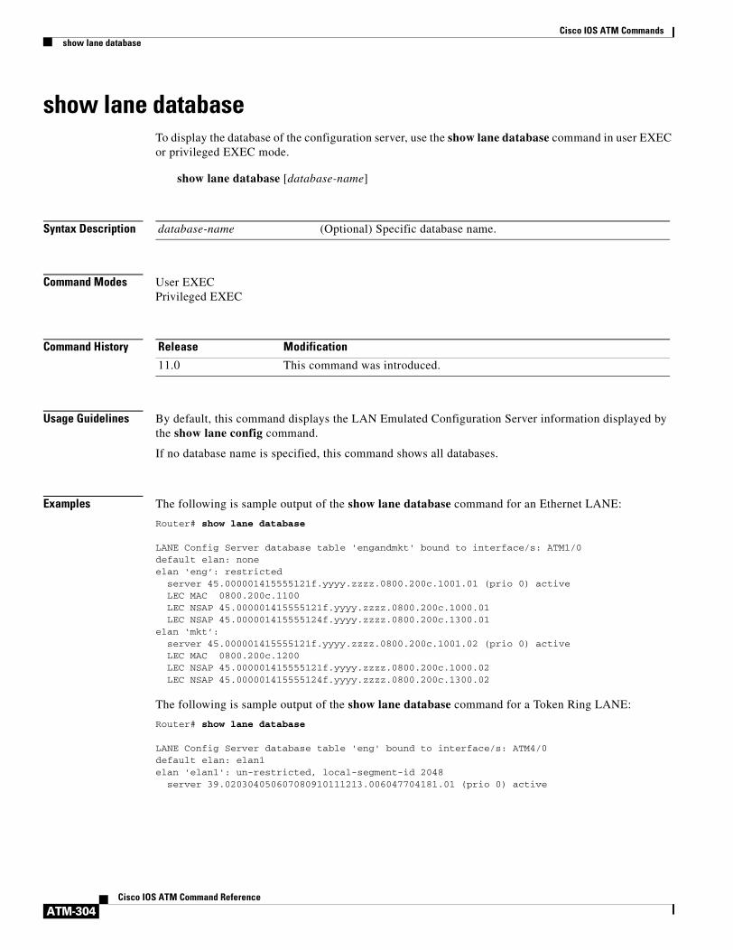
Cisco IOS ATM Commandsshow lane database
ATM-304Cisco IOS ATM Command Reference
show lane databaseTo display the database of the configuration server, use the show lane database command in user EXEC or privileged EXEC mode.
show lane database [database-name]
Syntax Description
Command Modes User EXECPrivileged EXEC
Command History
Usage Guidelines By default, this command displays the LAN Emulated Configuration Server information displayed by the show lane config command.
If no database name is specified, this command shows all databases.
Examples The following is sample output of the show lane database command for an Ethernet LANE:
Router# show lane database
LANE Config Server database table 'engandmkt' bound to interface/s: ATM1/0default elan: noneelan ‘eng’: restricted
server 45.000001415555121f.yyyy.zzzz.0800.200c.1001.01 (prio 0) active LEC MAC 0800.200c.1100 LEC NSAP 45.000001415555121f.yyyy.zzzz.0800.200c.1000.01 LEC NSAP 45.000001415555124f.yyyy.zzzz.0800.200c.1300.01elan ‘mkt’:
server 45.000001415555121f.yyyy.zzzz.0800.200c.1001.02 (prio 0) active LEC MAC 0800.200c.1200 LEC NSAP 45.000001415555121f.yyyy.zzzz.0800.200c.1000.02 LEC NSAP 45.000001415555124f.yyyy.zzzz.0800.200c.1300.02
The following is sample output of the show lane database command for a Token Ring LANE:
Router# show lane database
LANE Config Server database table 'eng' bound to interface/s: ATM4/0default elan: elan1elan 'elan1': un-restricted, local-segment-id 2048 server 39.020304050607080910111213.006047704181.01 (prio 0) active
database-name (Optional) Specific database name.
Release Modification
11.0 This command was introduced.

Cisco IOS ATM Commandsshow lane database
ATM-305Cisco IOS ATM Command Reference
Table 25 describes significant fields shown in the display.
Table 25 show lane database Field Descriptions
Field Description
LANE Config Server database Name of this database and interfaces bound to it.
default elan Default name, if one is established.
elan Name of the ELAN whose data is reported in this line and the following indented lines.
un-restricted Indicates whether this ELAN is restricted or unrestricted.
local-segment-id 2048 Ring number of the ELAN.
server ATM address of the configuration server.
(prio 0) active Priority level and simple server redundancy state of this configuration server. If you have configured simple server redundancy, the configuration server with the lowest priority will be active.
LEC MAC MAC addresses of an individual LANE client in this ELAN. This display includes a separate line for every LANE client in this ELAN.
LEC NSAP ATM addresses of all LANE clients in this ELAN.

Cisco IOS ATM Commandsshow lane default-atm-addresses
ATM-306Cisco IOS ATM Command Reference
show lane default-atm-addressesTo display the automatically assigned ATM address of each LANE component in a router or on a specified interface or subinterface, use the show lane default-atm-addresses command in user EXEC or privileged EXEC mode.
AIP on the Cisco 7500 series routers; ATM port adapter on the Cisco 7200 series
show lane default-atm-addresses [interface atm slot/port.subinterface-number]
ATM Port Adapter on the Cisco 7500 Series Routers
show lane default-atm-addresses [interface atm slot/port-adapter/port.subinterface-number]
Cisco 4500 and 4700 Routers
show lane default-atm-addresses [interface atm number.subinterface-number]
Syntax Description
Command Modes User EXECPrivileged EXEC
Command History
Usage Guidelines It is not necessary to have any of the LANE components running on this router before you use this command.
interface atm slot/port (Optional) ATM interface slot and port for the following:
• AIP on the Cisco 7500 series routers.
• ATM port adapter on the Cisco 7200 series routers.
interface atm slot/port-adapter/port (Optional) ATM interface slot, port adapter, and port number for the ATM port adapter on the Cisco 7500 series routers.
interface atm number (Optional) ATM interface number for the NPM on the Cisco 4500 or 4700 routers.
.subinterface-number (Optional) Subinterface number.
Release Modification
11.0 This command was introduced.
11.1 The number.subinterface-number argument was added.

Cisco IOS ATM Commandsshow lane default-atm-addresses
ATM-307Cisco IOS ATM Command Reference
Examples The following is sample output of the show lane default-atm-addresses command for the ATM interface 1/0 when all the major LANE components are located on that interface:
Router# show lane default-atm-addresses interface atm1/0
interface ATM1/0:LANE Client: 47.000000000000000000000000.00000C304A98.**LANE Server: 47.000000000000000000000000.00000C304A99.**LANE Bus: 47.000000000000000000000000.00000C304A9A.**LANE Config Server: 47.000000000000000000000000.00000C304A9B.00note: ** is the subinterface number byte in hex
Table 26 describes the significant fields shown in the display.
Table 26 show lane default-atm-addresses Field Descriptions
Field Description
interface ATM1/0: Specified interface.
LANE Client: ATM address of the LANE client on the interface.
LANE Server: ATM address of the LANE server on the interface.
LANE Bus: ATM address of the LANE broadcast and unknown server on the interface.
LANE Config Server: ATM address of the LAN Emulated Configuration Server on the interface.

Cisco IOS ATM Commandsshow lane le-arp
ATM-308Cisco IOS ATM Command Reference
show lane le-arpTo display the LANE ARP table of the LANE client configured on an interface or any of its subinterfaces, on a specified subinterface, or on an emulated LAN (ELAN), use the show lane le-arp command in user EXEC or privileged EXEC mode.
AIP on the Cisco 7500 series routers; ATM Port Adapter on the Cisco 7200 series
show lane le-arp [interface atm slot/port[.subinterface-number] | name elan-name]
ATM Port Adapter on the Cisco 7500 Series Routers
show lane le-arp [interface atm slot/port-adapter/port[.subinterface-number] | name elan-name]
Cisco 4500 and 4700 Routers
show lane le-arp [interface atm number[.subinterface-number] | name elan-name]
Syntax Description
Command Modes User EXECPrivileged EXEC
Command History
Examples The following is sample output of the show lane le-arp command for an Ethernet LANE client:
Router# show lane le-arp
Hardware Addr ATM Address VCD Interface0000.0c15.a2b5 39.000000000000000000000000.00000C15A2B5.01 39 ATM1/0.10000.0c15.f3e5 39.000000000000000000000000.00000C15F3E5.01 25* ATM1/0.1
interface atm slot/port (Optional) ATM interface slot and port for the following:
• AIP on the Cisco 7500 series routers.
• ATM port adapter on the Cisco 7200 series routers.
interface atm slot/port-adapter/port (Optional) ATM interface slot, port adapter, and port number for the ATM port adapter on the Cisco 7500 series routers.
interface atm number (Optional) ATM interface number for the NPM on the Cisco 4500 or 4700 routers.
.subinterface-number (Optional) Subinterface number.
name elan-name (Optional) Name of the ELAN. The maximum length of the name is 32 characters.
Release Modification
11.0 This command was introduced.

Cisco IOS ATM Commandsshow lane le-arp
ATM-309Cisco IOS ATM Command Reference
The following is sample output of the show lane le-arp command for a Token Ring LANE client:
Router# show lane le-arp
Ring Bridge ATM Address VCD Interface512 6 39.020304050607080910111213.00602F557940.01 47 ATM2/0.1
Table 27 describes the significant fields shown in the display.
Table 27 show lane le-arp Field Descriptions
Field Description
Hardware Addr MAC address, in dotted hexadecimal notation, assigned to the LANE component at the other end of this VCD.
Ring Route descriptor segment number for the LANE component.
Bridge Bridge number for the LANE component.
ATM Address ATM address of the LANE component at the other end of this VCD.
VCD Virtual circuit descriptor.
Interface Interface or subinterface used to reach the specified component.

Cisco IOS ATM Commandsshow lane server
ATM-310Cisco IOS ATM Command Reference
show lane serverTo display global information for the LANE server configured on an interface, on any of its subinterfaces, on a specified subinterface, or on an emulated LAN (ELAN), use the show lane server command in user EXEC or privileged EXEC mode.
AIP on the Cisco 7500 Series Routers; ATM Port Adapter on the Cisco 7200 Series
show lane server [interface atm slot/port[.subinterface-number] | name elan-name] [brief]
ATM Port Adapter on the Cisco 7500 Series Routers
show lane server [interface atm slot/port-adapter/port[.subinterface-number] | name elan-name] [brief]
Cisco 4500 and 4700 Routers
show lane server [interface atm number[.subinterface-number] | name elan-name] [brief]
Syntax Description
Command Modes Privileged EXEC
Command History
Examples The following is sample output from the show lane server command for an Ethernet ELAN:
Router# show lane server
LE Server ATM2/0.2 ELAN name: elan2 Admin: up State: operationaltype: ethernet Max Frame Size: 1516
interface atm slot/port (Optional) ATM interface slot and port for the following:
• AIP on the Cisco 7500 series routers.
• ATM port adapter on the Cisco 7200 series routers.
interface atm slot/port-adapter/port (Optional) ATM interface slot, port adapter, and port number for the ATM port adapter on the Cisco 7500 series routers.
interface atm number (Optional) ATM interface number for the NPM on the Cisco 4500 or 4700 routers.
.subinterface-number (Optional) Subinterface number.
name elan-name (Optional) Name of the ELAN. The maximum length of the name is 32 characters.
brief (Optional) Keyword used to display the brief subset of available information.
Release Modification
11.0 This command was introduced.

Cisco IOS ATM Commandsshow lane server
ATM-311Cisco IOS ATM Command Reference
ATM address: 39.020304050607080910111213.00000CA05B41.02LECS used: 39.020304050607080910111213.00000CA05B43.00 connected, vcd 51control distribute: vcd 57, 2 members, 2 packets
proxy/ (ST: Init, Conn, Waiting, Adding, Joined, Operational, Reject, Term)lecid ST vcd pkts Hardware Addr ATM Address 1 O 54 2 0000.0ca0.5b40 39.020304050607080910111213.00000CA05B40.02 2 O 81 2 0060.2f55.7940 39.020304050607080910111213.00602F557940.02
The following is sample output from the show lane server command for a Token Ring ELAN:
Router# show lane server
LE Server ATM3/0.1 ELAN name: anubis Admin: up State: operationaltype: token ring Max Frame Size: 4544 Segment ID: 2500ATM address: 47.009181000000000000000000.00000CA01661.01LECS used: 47.009181000000000000000000.00000CA01663.00 connected, vcd 6control distribute: vcd 10, 2 members, 4 packetsproxy/ (ST: Init, Conn, Waiting, Adding, Joined, Operational, Reject, Term)lecid ST vcd pkts Hardware Addr ATM Address 1 O 7 3 400.1 47.009181000000000000000000.00000CA01660.01 0000.0ca0.1660 47.009181000000000000000000.00000CA01660.01 2 O 16 3 300.1 47.009181000000000000000000.00000CA04960.01 0000.0ca0.4960 47.009181000000000000000000.00000CA04960.01
Table 28 describes the significant fields shown in the display.
Table 28 show lane server Field Descriptions
Field Description
LE Server ATM2/0.2 Interface and subinterface of this server.
ELAN name Name of the ELAN.
Admin Administrative state, either up or down.
State Status of this LANE server. Possible states for a LANE server include down, waiting_ILMI, waiting_listen, up_not_registered, operational, and terminating.
type Type of ELAN.
Max Frame Size Maximum frame size (in bytes) of this type of emulated LAN.
Segment ID The ring number of the ELAN. This field appears only for Token Ring LANE.
ATM address ATM address of this LANE server.
LECS used ATM address of the LANE configuration server being used. This line also shows the current state of the connection between the LANE server and the LAN Emulated Configuration Server (LECS), and the virtual circuit descriptor (VCD) of the circuit connecting them.
control distribute VCD of the Control Distribute VCC.
proxy Status of the LANE client at the other end of the Control Distribute VCC.
lecid Identifier for the LANE client at the other end of the Control Distribute VCC.

Cisco IOS ATM Commandsshow lane server
ATM-312Cisco IOS ATM Command Reference
ST Status of the LANE client at the other end of the Control Distribute VCC. Possible states are Init, Conn, Waiting, Adding, Joined, Operational, Reject, and Term.
vcd Virtual channel descriptor used to reach the LANE client.
pkts Number of packets sent by the LANE server on the Control Distribute VCC to the LANE client.
Hardware Addr The top number in this column is the router descriptor, and the second number is the MAC-layer address of the LANE client.
ATM Address ATM address of the LANE client.
Table 28 show lane server Field Descriptions (continued)
Field Description

Cisco IOS ATM Commandsshow lane
ATM-313Cisco IOS ATM Command Reference
show laneTo display detailed information for all the LAN Emulation (LANE) components configured on an interface or any of its subinterfaces, on a specified subinterface, or on an emulated LAN (ELAN), use the show lane command in user EXEC or privileged EXEC mode.
AIP on the Cisco 7500 Series Routers; ATM Port Adapter on the Cisco 7200 Series
show lane [interface atm slot/port[.subinterface-number] | name elan-name] [brief]
ATM Port Adapter on the Cisco 7500 Series Routers
show lane [interface atm slot/port-adapter/port[.subinterface-number] | name elan-name] [brief]
Cisco 4500 and 4700 Routers
show lane [interface atm number[.subinterface-number] | name elan-name] [brief]
Syntax Description
Command Modes User EXECPrivileged EXEC
Command History
Usage Guidelines Using the show lane command is equivalent to using the show lane config, show lane server, show lane bus, and show lane client commands. The show lane command shows all LANE-related information except the show lane database command information.
interface atm slot/port (Optional) ATM interface slot and port for the following:
• AIP on the Cisco 7500 series routers.
• ATM port adapter on the Cisco 7200 series routers.
interface atm slot/port-adapter/port (Optional) ATM interface slot, port adapter, and port number for the ATM port adapter on the Cisco 7500 series routers.
interface atm number (Optional) ATM interface number for the NPM on the Cisco 4500 or 4700 routers.
.subinterface-number (Optional) Subinterface number.
name elan-name (Optional) Name of the ELAN. The maximum length of the name is 32 characters.
brief (Optional) Keyword used to display the brief subset of available information.
Release Modification
11.0 This command was introduced.

Cisco IOS ATM Commandsshow lane
ATM-314Cisco IOS ATM Command Reference
Examples The following is sample output from the show lane command for an Ethernet ELAN:
Router# show lane
LE Config Server ATM2/0 config table: cisco_engAdmin: up State: operationalLECS Mastership State: active masterlist of global LECS addresses (30 seconds to update):39.020304050607080910111213.00000CA05B43.00 <-------- meATM Address of this LECS: 39.020304050607080910111213.00000CA05B43.00 (auto) vcd rxCnt txCnt callingParty 50 2 2 39.020304050607080910111213.00000CA05B41.02 LES elan2 0 activecumulative total number of unrecognized packets received so far: 0cumulative total number of config requests received so far: 30cumulative total number of config failures so far: 12 cause of last failure: no configuration culprit for the last failure: 39.020304050607080910111213.00602F557940.01
LE Server ATM2/0.2 ELAN name: elan2 Admin: up State: operationaltype: ethernet Max Frame Size: 1516ATM address: 39.020304050607080910111213.00000CA05B41.02LECS used: 39.020304050607080910111213.00000CA05B43.00 connected, vcd 51control distribute: vcd 57, 2 members, 2 packets
proxy/ (ST: Init, Conn, Waiting, Adding, Joined, Operational, Reject, Term)lecid ST vcd pkts Hardware Addr ATM Address 1 O 54 2 0000.0ca0.5b40 39.020304050607080910111213.00000CA05B40.02 2 O 81 2 0060.2f55.7940 39.020304050607080910111213.00602F557940.02
LE BUS ATM2/0.2 ELAN name: elan2 Admin: up State: operationaltype: ethernet Max Frame Size: 1516ATM address: 39.020304050607080910111213.00000CA05B42.02data forward: vcd 61, 2 members, 0 packets, 0 unicasts
lecid vcd pkts ATM Address 1 58 0 39.020304050607080910111213.00000CA05B40.02 2 82 0 39.020304050607080910111213.00602F557940.02
LE Client ATM2/0.2 ELAN name: elan2 Admin: up State: operationalClient ID: 1 LEC up for 11 minutes 49 secondsJoin Attempt: 1HW Address: 0000.0ca0.5b40 Type: ethernet Max Frame Size: 1516
ATM Address: 39.020304050607080910111213.00000CA05B40.02
VCD rxFrames txFrames Type ATM Address 0 0 0 configure 39.020304050607080910111213.00000CA05B43.00 55 1 4 direct 39.020304050607080910111213.00000CA05B41.02 56 6 0 distribute 39.020304050607080910111213.00000CA05B41.02 59 0 1 send 39.020304050607080910111213.00000CA05B42.02 60 3 0 forward 39.020304050607080910111213.00000CA05B42.02 84 3 5 data 39.020304050607080910111213.00602F557940.02
The following is sample output from the show lane command for a Token Ring LANE network:
Router# show lane
LE Config Server ATM4/0 config table: engAdmin: up State: operationalLECS Mastership State: active masterlist of global LECS addresses (35 seconds to update):39.020304050607080910111213.006047704183.00 ATM Address of this LECS: 39.020304050607080910111213.006047704183.00 (auto) vcd rxCnt txCnt callingParty

Cisco IOS ATM Commandsshow lane
ATM-315Cisco IOS ATM Command Reference
7 1 1 39.020304050607080910111213.006047704181.01 LES elan1 0 activecumulative total number of unrecognized packets received so far: 0cumulative total number of config requests received so far: 2cumulative total number of config failures so far: 0
LE Server ATM4/0.1 ELAN name: elan1 Admin: up State: operationaltype: token ring Max Frame Size: 4544 Segment ID: 2048ATM address: 39.020304050607080910111213.006047704181.01LECS used: 39.020304050607080910111213.006047704183.00 connected, vcd 9control distribute: vcd 12, 1 members, 2 packets
proxy/ (ST: Init, Conn, Waiting, Adding, Joined, Operational, Reject, Term)lecid ST vcd pkts Hardware Addr ATM Address 1 O 8 3 100.2 39.020304050607080910111213.006047704180.01 0060.4770.4180 39.020304050607080910111213.006047704180.01
LE BUS ATM4/0.1 ELAN name: elan1 Admin: up State: operationaltype: token ring Max Frame Size: 4544 Segment ID: 2048ATM address: 39.020304050607080910111213.006047704182.01data forward: vcd 16, 1 members, 0 packets, 0 unicasts
lecid vcd pkts ATM Address 1 13 0 39.020304050607080910111213.006047704180.01
LE Client ATM4/0.1 ELAN name: elan1 Admin: up State: operationalClient ID: 1 LEC up for 2 hours 25 minutes 39 seconds Join Attempt: 3 HW Address: 0060.4770.4180 Type: token ring Max Frame Size: 4544 Ring:100 Bridge:2 ELAN Segment ID: 2048ATM Address: 39.020304050607080910111213.006047704180.01
VCD rxFrames txFrames Type ATM Address 0 0 0 configure 39.020304050607080910111213.006047704183.00 10 1 3 direct 39.020304050607080910111213.006047704181.01 11 2 0 distribute 39.020304050607080910111213.006047704181.01 14 0 0 send 39.020304050607080910111213.006047704182.01 15 0 0 forward 39.020304050607080910111213.006047704182.01
Table 29 describes significant fields shown in the display.
Table 29 show lane Field Descriptions
Field Description
LE Config Server Identifies the following lines as applying to the LANE configuration server. These lines are also displayed in output from the show lane config command. See the show lane config command for explanations of the output.
LE Server Identifies the following lines as applying to the LANE server. These lines are also displayed in output from the show lane server command. See the show lane server command for explanations of the output.
LE BUS Identifies the following lines as applying to the LANE broadcast and unknown server. These lines are also displayed in output from the show lane bus command. See the show lane bus command for explanations of the output.
LE Client Identifies the following lines as applying to a LANE client. These lines are also displayed in output from the show lane client command. See the show lane bus command for explanations of the output.

Cisco IOS ATM Commandsshow mpoa client cache
ATM-316Cisco IOS ATM Command Reference
show mpoa client cacheTo display the ingress or egress cache entries matching the IP addresses for the Multiprotocol over ATM (MPOA) clients (MPCs), use the show mpoa client cache command in user EXEC or privileged EXEC mode.
show mpoa client [name mpc-name] cache [ingress | egress] [ip-address ip-address]
Syntax Description
Command Modes User EXECPrivileged EXEC
Command History
Examples The following is sample output from the show mpoa client cache command for a specific MPC:
Router# show mpoa client ip_mpc cache
MPC Name: ip-mpc, Interface: ATM1/0, State: UpMPC actual operating address: 47.00918100000000613E5A2F01.0010A6943825.00Shortcut-Setup Count: 1, Shortcut-Setup Time: 1Number of Ingress cache entries: 1MPC Ingress Cache Information: Dst IP addr State vcd Expires Egress MPC Atm address20.20.20.1 RSVLD 35 11:38 47.00918100000000613E5A2F01.00000C5A0C5D.00Number of Egress cache entries: 1MPC Egress Cache Information: Dst IP addr Dst MAC Src MAC MPSid Elan Expires CacheId Tag10.10.10.1 0000.0c5a.0c58 0060.7017.4820 9 2 11:55 1 1
Table 30 describes the significant fields shown in the display.
name mpc-name (Optional) Name of the MPC with the specified name.
ingress (Optional) Displays ingress cache entries associated with an MPC.
egress (Optional) Displays egress cache entries associated with an MPC.
ip-address ip-address (Optional) Displays cache entries that match the specified IP address.
Release Modification
11.3(3a)WA4(5) This command was introduced.
Table 30 show mpoa client cache Field Descriptions
Field Description
MPC Name Name specified for the MPC.
Interface Interface to which the MPC is attached.
State Current state of the MPC (up or down).
MPC actual operating address ATM address of the MPC.
Shortcut-Setup Count Current number specified by the shortcut-frame-count command.

Cisco IOS ATM Commandsshow mpoa client cache
ATM-317Cisco IOS ATM Command Reference
Number of Ingress cache entries
Number of entries in the ingress cache.
MPC Ingress Cache Information
Dst IP addr IP address of the destination.
State State of the ingress cache entry. (Valid states are initialized, trigger, refresh, hold-down, resolved, and suspended.)
vcd Number that identifies the virtual circuit.
Expires Time in minutes or seconds until the ingress cache entry expires.
Egress MPC Atm address ATM address of the egress MPC.
Number of Egress cache entries
Number of entries in the egress cache.
MPC Egress Cache Information
Dst IP addr IP address of the destination.
Dst MAC MAC address of the destination.
Src MAC MAC address of the source.
MPSid Unique number representing the egress MPS.
Elan ELAN identifier of the ELAN serving this destination IP address.
Expires Time in minutes or seconds until the egress cache entry expires.
CacheID Cache identifier.
Tag Label (tag) identifier.
Table 30 show mpoa client cache Field Descriptions (continued)
Field Description

Cisco IOS ATM Commandsshow mpoa client statistics
ATM-318Cisco IOS ATM Command Reference
show mpoa client statisticsTo display all the statistics collected by a Multiprotocol over ATM (MPOA) client (MPC), use the show mpoa client statistics command in user EXEC or privileged EXEC mode.
show mpoa client [name mpc-name] statistics
Syntax Description
Command Modes User EXECPrivileged EXEC
Command History
Usage Guidelines This command displays all the statistics collected by an MPC.
Examples The following is sample output from the show mpoa client statistics command for the MPC named ip_mpc:
Router# show mpoa client name ip_mpc statistics
MPC Name: ip_mpc, Interface: ATM1/0, State: UpMPC actual operating address: 47.00918100000000613E5A2F01.0010A6943825.00Shortcut-Setup Count: 1, Shortcut-Setup Time: 1
Transmitted ReceivedMPOA Resolution Requests 2 0MPOA Resolution Replies 0 2MPOA Cache Imposition Requests 0 0MPOA Cache Imposition Replies 0 0MPOA Cache Purge Requests 0 0MPOA Cache Purge Replies 0 0MPOA Trigger Request 0 0NHRP Purge Requests 0 0
Invalid MPOA Data Packets Received: 0
name mpc-name (Optional) Specifies the name of the MPC.
Release Modification
11.3(3a)WA4(5) This command was introduced.

Cisco IOS ATM Commandsshow mpoa client
ATM-319Cisco IOS ATM Command Reference
show mpoa clientTo display a summary of information regarding one or all Multiprotocol over ATM (MPOA) clients (MPCs), use the show mpoa client command in user EXEC or privileged EXEC mode.
show mpoa client [name mpc-name] [brief]
Syntax Description
Command Modes User EXECPrivileged EXEC
Command History
Usage Guidelines If you omit the name keyword, the command displays information for all MPCs.
Examples The following is sample output from the show mpoa client command:
Router# show mpoa client name ip_mpc brief
MPC Name: ip_mpc, Interface: ATM1/0, State: UpMPC actual operating address: 47.00918100000000613E5A2F01.0010A6943825.00Shortcut-Setup Count: 1, Shortcut-Setup Time: 1Lane clients bound to MPC ip_mpc: ATM1/0.1 Discovered MPS neighbors kp-alv vcd rxPkts txPkts47.00918100000000613E5A2F01.006070174824.00 59 30 28 2Remote Devices known vcd rxPkts txPkts47.00918100000000613E5A2F01.00000C5A0C5D.00 35 0 10
Table 31 describes the significant fields shown in the display.
name mpc-name (Optional) Name of the MPC with the specified name.
brief (Optional) Output limit of the command.
Release Modification
11.3(3a)WA4(5) This command was introduced.
Table 31 show mpoa client Field Descriptions
Field Description
MPC Name Name specified for the MPC.
Interface Interface to which the MPC is attached.
State Current state of the MPC.
MPC actual operating address ATM address of the MPC.
Shortcut-Setup Count Current number specified by the shortcut-frame-count command.
Shortcut-Setup Time Current value specified by the shortcut-frame-time command.
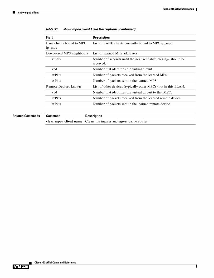
Cisco IOS ATM Commandsshow mpoa client
ATM-320Cisco IOS ATM Command Reference
Related Commands
Lane clients bound to MPC ip_mpc
List of LANE clients currently bound to MPC ip_mpc.
Discovered MPS neighbours List of learned MPS addresses.
kp-alv Number of seconds until the next keepalive message should be received.
vcd Number that identifies the virtual circuit.
rxPkts Number of packets received from the learned MPS.
txPkts Number of packets sent to the learned MPS.
Remote Devices known List of other devices (typically other MPCs) not in this ELAN.
vcd Number that identifies the virtual circuit to that MPC.
rxPkts Number of packets received from the learned remote device.
txPkts Number of packets sent to the learned remote device.
Table 31 show mpoa client Field Descriptions (continued)
Field Description
Command Description
clear mpoa client name Clears the ingress and egress cache entries.

Cisco IOS ATM Commandsshow mpoa default-atm-addresses
ATM-321Cisco IOS ATM Command Reference
show mpoa default-atm-addressesTo display the default ATM addresses for the Multiprotocol over ATM (MPOA) client (MPC), use the show mpoa default-atm-addresses command in user EXEC or privileged EXEC mode.
show mpoa default-atm-addresses
Syntax Description This command has no arguments or keywords.
Command Modes User EXECPrivileged EXEC
Command History
Examples The following is sample output from the show mpoa default-atm-addresses command when the switch prefix is not available:
Router# show mpoa default-atm-addresses
interface ATM1/0:MPOA Server: ...006070174824.**MPOA Client: ...006070174825.**note: ** is the MPS/MPC instance number in hex
interface ATM2/0:MPOA Server: ...006070174844.**MPOA Client: ...006070174845.**note: ** is the MPS/MPC instance number in hex
The following is sample output from the show mpoa default-atm-addresses command when the switch prefix is available:
Router# show mpoa default-atm-addresses
interface ATM1/0:MPOA Server: 47.00918100000000613E5A2F01.006070174824.**MPOA Client: 47.00918100000000613E5A2F01.006070174825.**note: ** is the MPS/MPC instance number in hex
interface ATM2/0:MPOA Server: 47.100000000000000000000000.006070174844.**MPOA Client: 47.100000000000000000000000.006070174845.**note: ** is the MPS/MPC instance number in hex
Table 32 describes the significant fields shown in the display.
Release Modification
11.3(3a)WA4(5) This command was introduced.
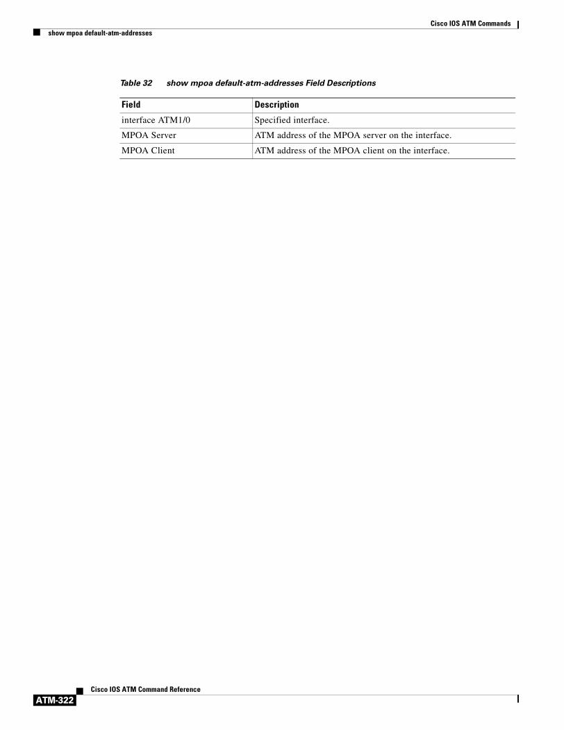
Cisco IOS ATM Commandsshow mpoa default-atm-addresses
ATM-322Cisco IOS ATM Command Reference
Table 32 show mpoa default-atm-addresses Field Descriptions
Field Description
interface ATM1/0 Specified interface.
MPOA Server ATM address of the MPOA server on the interface.
MPOA Client ATM address of the MPOA client on the interface.

Cisco IOS ATM Commandsshow mpoa server cache
ATM-323Cisco IOS ATM Command Reference
show mpoa server cacheTo display ingress and egress cache entries associated with an Multiprotocol over ATM (MPOA) server (MPS), use the show mpoa server cache command in user EXEC or privileged EXEC mode.
show mpoa server [name mps-name] cache [ingress | egress] [ip-address ip-address]
Syntax Description
Command Modes User EXECPrivileged EXEC
Command History
Usage Guidelines This command displays ingress and egress cache entries associated with an MPS.
Examples The following is sample output from the show mpoa server cache command, with a name specified:
Router# show mpoa server name ip_mps cache
MPS Name: ip_mps, MPS id: 0, Interface: ATM1/0, State: upnetwork-id: 1, Keepalive: 25 secs, Holding time: 1200 secsKeepalive lifetime: 75 secs, Giveup time: 40 secsMPS actual operating address: 47.00918100000000613E5A2F01.006070174824.00Number of Ingress cache entries: 1Ingress Cache information: IP address Ingress MPC ATM Address Remaining Time 20.20.20.1 47.00918100000000613E5A2F01.0010A6943825.00 19:07Number of Egress cache entries: 1Egress Cache information: Dst IP address Ingress MPC ATM Address Remaining Time 20.20.20.1 47.00918100000000613E5A2F01.0010A6943825.00 19:06
src IP 20.20.20.2, cache Id 1
Table 33 describes the significant fields shown in the display.
name mps-name (Optional) Specifies the name of an MPS.
ingress (Optional) Displays ingress cache entries associated with a server.
egress (Optional) Displays egress cache entries associated with a server.
ip-address ip-address (Optional) Displays the entries that match the specified IP address.
Release Modification
12.0 This command was introduced.
Table 33 show mpoa server cache Field Descriptions
Field Description
MPS Name Name of the MPOA server.
MPS id ID of the MPOA server.
Interface Interface to which the MPS is attached.

Cisco IOS ATM Commandsshow mpoa server cache
ATM-324Cisco IOS ATM Command Reference
State State of the MPOA server: up or down.
network-id Network ID used for partitioning.
Keepalive Keepalive time value.
Holding time Holding time value.
Keepalive lifetime Keepalive lifetime value.
Giveup time Minimum time to wait before giving up on a pending resolution request.
MPS actual operating address Actual control address of this MPS.
Number of Ingress cache entries Number of entries in the ingress cache.
Ingress Cache information Information of ingress cache.
IP address IP address of the MPC.
Ingress MPC ATM Address ATM address of the ingress MPC.
Remaining Time Time for which the cache entry is valid.
Number of Egress cache entries Number of entries in the egress cache.
Egress Cache information Information of egress cache.
Dst IP address IP address of the destination.
src IP IP address of the source MPS that originated the NHRP resolution request.
cache Id Cache identifier.
Table 33 show mpoa server cache Field Descriptions (continued)
Field Description
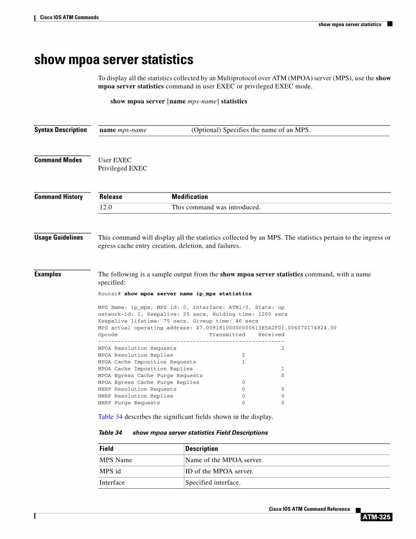
Cisco IOS ATM Commandsshow mpoa server statistics
ATM-325Cisco IOS ATM Command Reference
show mpoa server statisticsTo display all the statistics collected by an Multiprotocol over ATM (MPOA) server (MPS), use the show mpoa server statistics command in user EXEC or privileged EXEC mode.
show mpoa server [name mps-name] statistics
Syntax Description
Command Modes User EXECPrivileged EXEC
Command History
Usage Guidelines This command will display all the statistics collected by an MPS. The statistics pertain to the ingress or egress cache entry creation, deletion, and failures.
Examples The following is a sample output from the show mpoa server statistics command, with a name specified:
Router# show mpoa server name ip_mps statistics
MPS Name: ip_mps, MPS id: 0, Interface: ATM1/0, State: upnetwork-id: 1, Keepalive: 25 secs, Holding time: 1200 secsKeepalive lifetime: 75 secs, Giveup time: 40 secsMPS actual operating address: 47.00918100000000613E5A2F01.006070174824.00Opcode Transmitted Received---------------------------------------------------------MPOA Resolution Requests 2MPOA Resolution Replies 2 MPOA Cache Imposition Requests 1 MPOA Cache Imposition Replies 1MPOA Egress Cache Purge Requests 0MPOA Egress Cache Purge Replies 0 NHRP Resolution Requests 0 0NHRP Resolution Replies 0 0NHRP Purge Requests 0 0
Table 34 describes the significant fields shown in the display.
name mps-name (Optional) Specifies the name of an MPS.
Release Modification
12.0 This command was introduced.
Table 34 show mpoa server statistics Field Descriptions
Field Description
MPS Name Name of the MPOA server.
MPS id ID of the MPOA server.
Interface Specified interface.

Cisco IOS ATM Commandsshow mpoa server statistics
ATM-326Cisco IOS ATM Command Reference
State State of the MPOA server: up or down.
network-id Network ID used for partitioning.
Keepalive Keepalive time value.
Holding time Holding time value.
Keepalive lifetime Keepalive lifetime value.
Giveup time Minimum time to wait before giving up on a pending resolution request.
MPS actual operating address
Actual control address of this MPS.
Table 34 show mpoa server statistics Field Descriptions (continued)
Field Description

Cisco IOS ATM Commandsshow mpoa server
ATM-327Cisco IOS ATM Command Reference
show mpoa serverTo display information about any specified Multiprotocol over ATM (MPOA) server (MPS) or all MPSs in the system, depending on whether the name of the required MPS is specified, use the show mpoa server command in user EXEC or privileged EXEC mode.
show mpoa server [name mps-name]
Syntax Description
Command Modes User EXECPrivileged EXEC
Command History
Usage Guidelines The command displays information about server configuration parameters. It also displays information about LAN Emulated Clients (LECs) that are bound to the MPOA server neighbors (both MPC and MPS).
Examples The following is sample output from the show mpoa server command, with a specified name:
Router# show mpoa server name ip_mps
MPS Name: ip_mps, MPS id: 0, Interface: ATM1/0, State: upnetwork-id: 1, Keepalive: 25 secs, Holding time: 1200 secsKeepalive lifetime: 75 secs, Giveup time: 40 secsMPS actual operating address: 47.00918100000000613E5A2F01.006070174824.00Lane clients bound to MPS ip_mps: ATM1/0.1 ATM1/0.2 Discovered neighbours:MPC 47.00918100000000613E5A2F01.00000C5A0C5D.00 vcds: 39(R,A) MPC 47.00918100000000613E5A2F01.0010A6943825.00 vcds: 40(R,A)
Table 35 describes the significant fields shown in the display.
name mps-name (Optional) Specifies the name of the MPS.
Release Modification
11.3(3a)WA4(5) This command was introduced.
Table 35 show mpoa server Field Descriptions
Field Description
MPS Name Name of the MPOA server.
MPS id ID of the MPOA server.
Interface Interface to which the MPS is attached.
State State of the MPOA server: up or down.
network-id Network ID used for partitioning.
Keepalive Keepalive time value.

Cisco IOS ATM Commandsshow mpoa server
ATM-328Cisco IOS ATM Command Reference
Related Commands
Holding time Holding time value.
Keepalive lifetime Keepalive lifetime value.
Giveup time Minimum time to wait before giving up on a pending resolution request.
MPS actual operating address Actual control address of this MPS.
Lane clients bound to MPS ip_mps
List of LANE clients served by the MPS.
Discovered neighbours MPOA devices discovered by the clients bound to this MPS.
Table 35 show mpoa server Field Descriptions (continued)
Field Description
Command Description
clear mpoa server name Clears the ingress and egress cache entries of one or all MPCs.
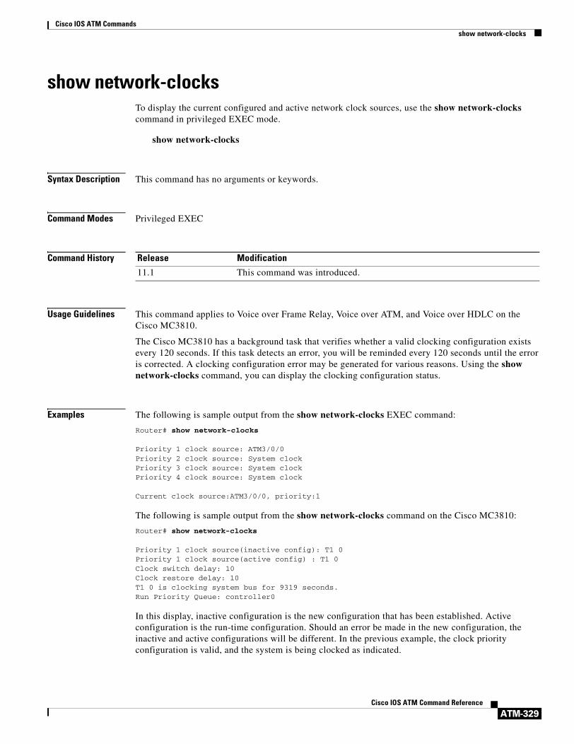
Cisco IOS ATM Commandsshow network-clocks
ATM-329Cisco IOS ATM Command Reference
show network-clocksTo display the current configured and active network clock sources, use the show network-clocks command in privileged EXEC mode.
show network-clocks
Syntax Description This command has no arguments or keywords.
Command Modes Privileged EXEC
Command History
Usage Guidelines This command applies to Voice over Frame Relay, Voice over ATM, and Voice over HDLC on the Cisco MC3810.
The Cisco MC3810 has a background task that verifies whether a valid clocking configuration exists every 120 seconds. If this task detects an error, you will be reminded every 120 seconds until the error is corrected. A clocking configuration error may be generated for various reasons. Using the show network-clocks command, you can display the clocking configuration status.
Examples The following is sample output from the show network-clocks EXEC command:
Router# show network-clocks
Priority 1 clock source: ATM3/0/0Priority 2 clock source: System clockPriority 3 clock source: System clockPriority 4 clock source: System clock
Current clock source:ATM3/0/0, priority:1
The following is sample output from the show network-clocks command on the Cisco MC3810:
Router# show network-clocks
Priority 1 clock source(inactive config): T1 0Priority 1 clock source(active config) : T1 0Clock switch delay: 10Clock restore delay: 10T1 0 is clocking system bus for 9319 seconds.Run Priority Queue: controller0
In this display, inactive configuration is the new configuration that has been established. Active configuration is the run-time configuration. Should an error be made in the new configuration, the inactive and active configurations will be different. In the previous example, the clock priority configuration is valid, and the system is being clocked as indicated.
Release Modification
11.1 This command was introduced.

Cisco IOS ATM Commandsshow network-clocks
ATM-330Cisco IOS ATM Command Reference
The following is another sample output from the show network-clocks command:
Router# show network-clocks
Priority 1 clock source(inactive config) : T1 0Priority 2 clock source(inactive config) : T1 1Priority 1 clock source(active config) : T1 0Clock switch delay: 10Clock restore delay: 10T1 0 is clocking system bus for 9319 seconds.Run Priority Queue: controller0
In this display, the new clocking configuration has an error for controller T1 1. This is indicated by checking differences between the last valid configuration (active) and the new proposed configuration (inactive). The error may result from hardware (the system controller board or MFT) unable to support this mode, or controller T1 1 is currently configured as “clock source internal.”
Since the active and inactive configurations are different, the system will periodically display the warning message about the wrong configuration.
Related Commands Command Description
network-clock-select (ATM) Establishes the sources and priorities of the requisite clocking signals for an ATM-CES port adapter.

Cisco IOS ATM Commandsshow sscop
ATM-331Cisco IOS ATM Command Reference
show sscopTo show Service-Specific Connection-Oriented Protocol (SSCOP) details for all ATM interfaces, use the show sscop command in privileged EXEC mode.
show sscop
Syntax Description This command has no arguments or keywords.
Command Modes Privileged EXEC
Command History
Examples The following is sample output from the show sscop command:
Router# show sscop
SSCOP details for interface ATM4/0 Current State = Data Transfer Ready Send Sequence Number: Current = 2, Maximum = 9 Send Sequence Number Acked = 3 Rcv Sequence Number: Lower Edge = 2, Upper Edge = 2, Max = 9 Poll Sequence Number = 1876, Poll Ack Sequence Number = 2 Vt(Pd) = 0
Connection Control: timer = 1000 Timer currently Inactive Keep Alive Timer = 30000 Current Retry Count = 0, Maximum Retry Count = 10
Statistics - Pdu's Sent = 0, Pdu's Received = 0, Pdu's Ignored = 0 Begin = 0/1, Begin Ack = 1/0, Begin Reject = 0/0 End = 0/0, End Ack = 0/0 Resync = 0/0, Resync Ack = 0/0 Sequenced Data = 2/0, Sequenced Poll Data = 0/0 Poll = 1591/1876, Stat = 0/1591, Unsolicited Stat = 0/0 Unassured Data = 0/0, Mgmt Data = 0/0, Unknown Pdu's = 0
Table 36 describes the fields shown in the display. Interpreting this output requires a good understanding of the SSCOP; it is usually displayed by our technicians to help diagnose network problems.
Release Modification
10.0 This command was introduced.
Table 36 show sscop Field Descriptions
Field Description
SSCOP details for interface Interface slot and port.
Current State SSCOP state for the interface.
Send Sequence Number Current and maximum send sequence number.
Send Sequence Number Acked Sequence number of packets already acknowledged.

Cisco IOS ATM Commandsshow sscop
ATM-332Cisco IOS ATM Command Reference
Rcv Sequence Number Sequence number of packets received.
Poll Sequence Number Current poll sequence number.
Poll Ack Sequence Number Poll sequence number already acknowledged.
Vt(Pd) Number of sequenced data (SD) frames sent, which triggers a sending of a Poll frame.
Connection Control Timer used for establishing and terminating SSCOP.
Keep Alive Timer Timer used to send keepalives on an idle link.
Current Retry Count Current count of the retry counter.
Maximum Retry Count Maximum value the retry counter can take.
Pdu’s Sent Total number of SSCOP frames sent.
Pdu’s Received Total number of SSCOP frames received.
Pdu’s Ignored Number of invalid SSCOP frames ignored.
Begin Number of Begin frames sent/received.
Begin Ack Number of Begin Ack frames sent/received.
Begin Reject Number of Begin Reject frames sent/received.
End Number of End frames sent/received.
End Ack Number of End Ack frames sent/received.
Resync Number of Resync frames sent/received.
Resync Ack Number of Resync Ack frames sent/received.
Sequenced Data Number of Sequenced Data frames sent/received.
Sequenced Poll Data Number of Sequenced Poll Data frames sent/received.
Poll Number of Poll frames sent/received.
Stat Number of Stat frames sent/received.
Unsolicited Stat Number of Unsolicited Stat frames sent/received.
Unassured Data Number of Unassured Data frames sent/received.
Mgmt Data Number of Mgmt Data frames sent/received.
Unknown Pdu’s Number of Unknown Pdu’s frames sent/received.
Table 36 show sscop Field Descriptions (continued)
Field Description

Cisco IOS ATM Commandssscop cc-timer
ATM-333Cisco IOS ATM Command Reference
sscop cc-timerTo change the connection control timer, use the sscop cc-timer interface configuration command. To restore the default value, use the no form of this command.
sscop cc-timer seconds
no sscop cc-timer
Syntax Description
Defaults 1 second
Command Modes Interface configuration
Command History
Usage Guidelines The connection control timer determines the time between transmission of BGN (establishment), END (release), or RS (resynchronization) protocol data units (PDUs) as long as an acknowledgment has not been received.
Examples The following example sets the connection control timer 15 seconds:
sscop cc-timer 15
Related Commands
seconds Number of seconds between Begin messages.
Release Modification
10.0 This command was introduced.
Command Description
sscop max-cc Changes the SSCOP retry count of connection control.

Cisco IOS ATM Commandssscop keepalive-timer
ATM-334Cisco IOS ATM Command Reference
sscop keepalive-timerTo change the keepalive timer, use the sscop keepalive-timer interface configuration command. To restore the default value, use the no form of this command.
sscop keepalive-timer seconds
no sscop keepalive-timer seconds
Syntax Description
Defaults 5 seconds
Command Modes Interface configuration
Command History
Examples The following example sets the keepalive timer to 15 seconds:
sscop keepalive-timer 15
seconds Number of seconds the router waits between transmission of POLL PDUs when no sequential data (SD) or SDP PDUs are queued for transmission or are outstanding pending acknowledgments.
Release Modification
10.0 This command was introduced.

Cisco IOS ATM Commandssscop max-cc
ATM-335Cisco IOS ATM Command Reference
sscop max-ccTo change the retry count of connection control, use the sscop max-cc interface configuration command. To restore the default value, use the no form of this command.
sscop max-cc retries
no sscop max-cc
Syntax Description
Defaults 10 retries
Command Modes Interface configuration
Command History
Examples The following example sets the retry count of the connection control to 20:
sscop max-cc 20
Related Commands
retries Number of times that SSCOP will retry to transmit BGN (establishment), END (release), or RS (resynchronization) PDUs as long as an acknowledgment has not been received. Valid range is from 1 to 6000.
Release Modification
10.0 This command was introduced.
Command Description
sscop cc-timer Changes the SSCOP connection control timer.

Cisco IOS ATM Commandssscop poll-timer
ATM-336Cisco IOS ATM Command Reference
sscop poll-timerTo change the poll timer, use the sscop poll-timer interface configuration command. To restore the default value, use the no form of this command.
sscop poll-timer seconds
no sscop poll-timer
Syntax Description
Defaults 100 seconds
Command Modes Interface configuration
Command History
Usage Guidelines The poll timer controls the maximum time between transmission of POLL PDUs when SD or SDP PDUs are queued for transmission or are outstanding pending acknowledgments.
Examples The following example sets the poll timer to 15 seconds:
sscop poll-timer 15
seconds Number of seconds that the router waits between transmission of POLL PDUs.
Release Modification
10.0 This command was introduced.

Cisco IOS ATM Commandssscop receive-window
ATM-337Cisco IOS ATM Command Reference
sscop receive-windowTo change the receiver window, use the sscop receive-window interface configuration command. To restore the default value, use the no form of this command.
sscop receive-window packets
no sscop receive-window
Syntax Description
Defaults 7 packets
Command Modes Interface configuration
Command History
Examples The following example sets the receiver’s window to 10 packets:
sscop rcv-window 10
packets Number of packets the interface can receive before it must send an acknowledgment to the ATM switch. Valid range is from 1 to 6000.
Release Modification
10.0 This command was introduced.

Cisco IOS ATM Commandssscop send-window
ATM-338Cisco IOS ATM Command Reference
sscop send-windowTo change the transmitter window, use the sscop send-window interface configuration command. To restore the default value, use the no form of this command.
sscop send-window packets
no sscop send-window
Syntax Description
Defaults 7 packets
Command Modes Interface configuration
Command History
Examples The following example sets the transmitter’s window to 10 packets:
sscop send-window 10
packets Number of packets the interface can send before it must receive an acknowledgment from the ATM switch. Valid range is from 1 to 6000.
Release Modification
10.0 This command was introduced.

Cisco IOS ATM Commandssvc
ATM-339Cisco IOS ATM Command Reference
svcTo create an ATM switched virtual circuit (SVC) and specify the destination network service access point (NSAP) address on a main interface or subinterface, use the svc interface configuration command. To disable the SVC, use the no form of this command.
svc [name] [nsap address] [ces]
no svc [name] [nsap address] [ces]
Syntax Description
Defaults No NSAP address is defined.
Command Modes Interface configuration
Command History
Usage Guidelines After configuring the parameters for an ATM SVC, you must exit the interface-ATM-VC or interface-CES-VC configuration mode in order to enable the SVC settings.
Once you specify a name for an SVC, you can reenter the interface-ATM-VC or interface-CES-VC configuration mode by simply entering svc name.
You can remove an NSAP address and any associated parameters by entering no svc name or no svc nsap address.
Creating an SVC without a specific NSAP address will allow a router to accept calls from any ATM address, and allow multiple VCs to be set up using the same configuration.
Use the ces keyword to configure an active or passive CES SVC. An active CES SVC can originate and terminate SVC calls. A passive CES SVC can only terminate calls.
name (Optional) The name of the SVC and map. The name can be up to 16 characters long. A name is required when creating passive a CES SVC.
nsap address (Optional) The destination ATM NSAP address. Must be exactly 40 hexadecimal digits long and in the correct format. See the “Usage Guidelines” section. An NSAP address is required when creating an active CES SVC.
ces (Optional) Circuit Emulation Service encapsulation. This keyword is available on the OC-3/STM-1 ATM Circuit Emulation Service network module only.
Release Modification
11.3 This command was introduced.
12.1(2)T The ces keyword was added to configure CES encapsulation when using the OC-3/STM-1 ATM Circuit Emulation Service network module on Cisco 2600 and Cisco 3600 series platform.
12.1(3)T This command was modified to allow an SVC to be created without having a specific NSAP address associated with it.

Cisco IOS ATM Commandssvc
ATM-340Cisco IOS ATM Command Reference
Examples SVC Example
The following example creates an SVC called “chicago” on ATM interface 2/0/0:
interface atm 2/0/0svc chicago
SVC with NSAP Address Example
The following example creates an SVC with the name “lion” and specifies the 40-digit hexadecimal destination ATM NSAP address:
svc lion nsap 47.0091.81.000000.0040.0B0A.2501.ABC1.3333.3333.05
Active CES SVC Example
The following example creates an active CES SVC named “ces1”:
interface atm 1/0 svc ces1 nsap 47.00.00.000000.0040.0B0A.2501.ABC1.01.01.00 ces
Passive CES SVC Example
The following example creates a passive CES SVC named “ces2”:
interface atm 1/0 svc ces2 ces

Cisco IOS ATM Commandsubr
ATM-341Cisco IOS ATM Command Reference
ubrTo configure unspecified bit rate (UBR) quality of service (QoS) and specify the output peak cell rate (PCR) for an ATM permanent virtual circuit (PVC), PVC range, switched virtual circuit (SVC), virtual circuit (VC) class, or VC bundle member, use the ubr command in the appropriate command mode. To remove the UBR parameter, use the no form of this command.
ubr output-pcr [input-pcr]
no ubr output-pcr [input-pcr]
Syntax Description
Defaults UBR QoS at the maximum line rate of the physical interface.
Command Modes Interface-ATM-VC configuration (for an ATM PVC or SVC)
VC-class configuration (for a VC class)
Bundle-vc configuration (for ATM VC bundle members)
PVC range configuration (for an ATM PVC range)
PVC-in-range configuration (for an individual PVC within a PVC range)
Command History
Usage Guidelines To configure ATM SVCs with an output PCR and an input PCR that differ from each other, you must expressly configure an output value and an input value using the output-pcr and input-pcr arguments, respectively.
Configure QoS parameters using the ubr, ubr+, or vbr-nrt command. The last command you enter will apply to the PVC or SVC you are configuring.
If the ubr command is not explicitly configured on an ATM PVC, SVC, or VC bundle member, the VC inherits the following default configuration (listed in order of next highest precedence):
• Configuration of any QoS command (ubr, ubr+, or vbr-nrt) in a VC class assigned to the PVC or SVC itself.
• Configuration of any QoS command (ubr, ubr+, or vbr-nrt) in a VC class assigned to the PVC’s or SVC’s ATM subinterface.
output-pcr The output PCR in kbps.
input-pcr (Optional for SVCs only) The input peak cell rate (PCR) in kilobits per second. If this value is omitted, the input-pcr will equal the output-pcr.
Release Modification
11.3 T This command was introduced.
12.0(3)T This command was enhanced to support selection of UBR QoS and configuration of output PCR for ATM VC bundles and ATM VC bundle members.
12.1(5)T This command was made available in PVC range and PVC-in-range configuration modes.

Cisco IOS ATM Commandsubr
ATM-342Cisco IOS ATM Command Reference
• Configuration of any QoS command (ubr, ubr+, or vbr-nrt) in a VC class assigned to the PVC’s or SVC’s ATM main interface.
• Global default: UBR QoS at the maximum line rate of the PVC or SVC.
To use this command in VC-class configuration mode, enter the vc-class atm global configuration command. This command has no effect if the VC class that contains the command is attached to a standalone VC, that is, if the VC is not a bundle member.
To use this command in bundle-vc configuration mode, first enter the bundle command to specify the bundle, then enter bundle configuration mode. Then enter the pvc-bundle configuration command to add the VC to the bundle as a member of it and enter bundle-vc configuration mode.
VCs in a VC bundle are subject to the following configuration inheritance rules (listed in order of next highest precedence):
• VC configuration in bundle-vc mode
• Bundle configuration in bundle mode (with effect of assigned VC-class configuration)
• Subinterface configuration in subinterface mode
Examples The following example specifies the output-pcr argument for an ATM PVC to be 100,000 kbps:
pvc 1/32ubr 100000
The following example specifies the output-pcr and input-pcr arguments for an ATM SVC to be 10,000 kbps and 9,000 kbps, respectively:
svc lion nsap 47.0091.81.000000.0040.0B0A.2501.ABC1.3333.3333.05ubr 10000 9000
Related Commands Command Description
abr Selects ABR QoS and configures output peak cell rate and output minimum guaranteed cell rate for an ATM PVC or virtual circuit class.
broadcast Configures broadcast packet duplication and transmission for an ATM VC class, PVC, SVC, or VC bundle.
bump Configures the bumping rules for a virtual circuit class that can be assigned to a virtual circuit bundle.
bundle Creates a bundle or modifies an existing bundle to enter bundle configuration mode.
class-int Assigns a VC class to an ATM main interface or subinterface.
class-vc Assigns a VC class to an ATM PVC, SVC, or VC bundle member.
encapsulation Sets the encapsulation method used by the interface.
inarp Configures the Inverse ARP time period for an ATM PVC, VC class, or VC bundle.
oam-bundle Enables end-to-end F5 OAM loopback cell generation and OAM management for a virtual circuit class that can be applied to a virtual circuit bundle.
oam retry Configures parameters related to OAM management for an ATM PVC, SVC, VC class, or VC bundle.

Cisco IOS ATM Commandsubr
ATM-343Cisco IOS ATM Command Reference
precedence Configures precedence levels for a virtual circuit class that can be assigned to a virtual circuit bundle and thus applied to all virtual circuit members of that bundle.
protect Configures a virtual circuit class with protected group or protected virtual circuit status for application to a virtual circuit bundle member.
protocol (ATM) Configures a static map for an ATM PVC, SVC, VC class, or VC bundle. Enables Inverse ARP or Inverse ARP broadcasts on an ATM PVC by either configuring Inverse ARP directly on the PVC, on the VC bundle, or in a VC class (applies to IP and IPX protocols only).
pvc-bundle Adds a PVC to a bundle as a member of the bundle and enters bundle-vc configuration mode in order to configure that PVC bundle member.
ubr+ Configures UBR QoS and specifies the output peak cell rate and output minimum guaranteed cell rate for an ATM PVC, SVC, VC class, or VC bundle member.
vbr-nrt Configures the VBR-NRT QoS and specifies output peak cell rate, output sustainable cell rate, and output maximum burst cell size for an ATM PVC, SVC, VC class, or VC bundle member.
Command Description

Cisco IOS ATM Commandsubr+
ATM-344Cisco IOS ATM Command Reference
ubr+To configure unspecified bit rate (UBR) quality of service (QoS) and specify the output peak cell rate and output minimum guaranteed cell rate for an ATM permanent virtual circuit (PVC), PVC range, switched virtual circuit (SVC), virtual circuit (VC) class, or VC bundle member, use the ubr+ command in the appropriate command mode. To remove the UBR+ parameters, use the no form of this command.
ubr+ output-pcr output-mcr [input-pcr] [input-mcr]
no ubr+ output-pcr output-mcr [input-pcr] [input-mcr]
Syntax Description
Command Default UBR QoS is at the maximum line rate of the physical interface.
Command Modes Interface-ATM-VC configuration (for an ATM PVC on non-DSL interfaces only or an ATM SVC on non-DSL interfaces only)VC-class configuration (for a VC class)Bundle-VC configuration (for ATM VC bundle members)PVC range configuration (for an ATM PVC range)PVC-in-range configuration (for an individual PVC within a PVC range)
Command History
Usage Guidelines To configure ATM SVCs with an output PCR and an input PCR that differ from each other, you must expressly configure an output value and an input value using the output-pcr, output-mcr, input-pcr, and input-mcr arguments.
Configure QoS parameters using the ubr, ubr+, or vbr-nrt command. The last command that you enter will apply to the PVC or SVC that you are configuring.
output-pcr The output peak cell rate (PCR) in kbps.
output-mcr The output minimum guaranteed cell rate in kbps.
input-pcr (Optional for SVCs only) The input PCR in kbps. If this value is omitted, the input-pcr equals the output-pcr.
input-mcr (Optional for SVCs only) The input minimum guaranteed cell rate in kbps. If this value is omitted, the input-mcr equals the output-mcr.
Release Modification
11.3 T This command was introduced.
12.0(3)T This command was enhanced to support selection of UBR+ QoS and configuration of output PCR and output minimum guaranteed cell rate for ATM VC bundles and VC bundle members.
12.1(5)T This command was made available in PVC range and PVC-in-range configuration modes.
12.4(2)XA This command was enabled on DSL ATM interfaces.
12.4(6)T This command was enabled on DSL ATM interfaces.

Cisco IOS ATM Commandsubr+
ATM-345Cisco IOS ATM Command Reference
If the ubr+ command is not explicitly configured on an ATM PVC or SVC, the VC inherits the following default configuration (in order of precedence):
• Configuration of any QoS command (ubr, ubr+, or vbr-nrt) in a VC class assigned to the PVC or SVC itself
• Configuration of any QoS command (ubr, ubr+, or vbr-nrt) in a VC class assigned to the PVC ATM subinterface or SVC ATM subinterface
• Configuration of any QoS command (ubr, ubr+, or vbr-nrt) in a VC class assigned to the PVC main interface or SVC ATM main interface
• Global default: UBR QoS at the maximum line rate of the PVC or SVC
To use this command in VC-class configuration mode, enter the vc-class atm global configuration command before you enter the ubr+ command. This command has no effect if the VC class that contains the command is attached to a standalone VC (meaning a VC that is not a bundle member).
To use this command in bundle-VC configuration mode, enter the bundle command to specify the bundle to which the VC member belongs, then enter bundle configuration mode. Finally, enter the pvc-bundle bundle configuration command to add the VC to the bundle as a member.
VCs in a VC bundle use the following configuration inheritance rules (in order of next-highest precedence):
• VC configuration in bundle-VC mode
• Bundle configuration in bundle mode (with effect of assigned VC-class configuration)
• Subinterface configuration in subinterface mode
DSL ATM interfaces do not support switched virtual circuits (SVCs).
Examples The following example configures UBR+ PVC on a DSL line:
interface atm 0/0pvc 4/100ubr+ 2304 2304
The following example specifies the output-pcr argument for an ATM PVC to be 100000 kbps and the output-mcr to be 3000 kbps:
pvc 1/32ubr+ 100000 3000
The following example specifies the output-pcr, output-mcr, input-pcr, and input-mcr arguments for an ATM SVC to be 10000 kbps, 3000 kbps, 9000 kbps, and 1000 kbps, respectively:
svc lion nsap 47.0091.81.000000.0040.0B0A.2501.ABC1.3333.3333.05ubr+ 10000 3000 9000 1000
Related Commands Command Description
abr Selects ABR QoS and configures the output peak cell rate and the output minimum guaranteed cell rate for an ATM PVC or VC class.
broadcast Configures broadcast packet duplication and transmission for an ATM VC class, PVC, SVC, or VC bundle.
bump Configures the bumping rules for a VC class that can be assigned to a VC bundle.

Cisco IOS ATM Commandsubr+
ATM-346Cisco IOS ATM Command Reference
bundle Creates a bundle or enters bundle configuration mode to modify an existing bundle.
class Assigns a VC class to an ATM main interface, subinterface, PVC, SVC, VC bundle, or VC bundle member.
encapsulation Sets the encapsulation method used by the interface.
inarp Configures the InARP time period for an ATM PVC, VC class, or VC bundle.
oam-bundle Enables end-to-end F5 OAM loopback cell generation and OAM management for a VC class that can be applied to a VC bundle.
oam retry Configures parameters related to OAM management for an ATM PVC, SVC, VC class, or VC bundle.
precedence Configures precedence levels for a VC class that can be assigned to a VC bundle and thus applied to all VC members of that bundle.
protect Configures a VC class with protected group or protected VC status for application to a VC bundle member.
protocol (ATM) Configures a static map for an ATM PVC, SVC, VC class, or VC bundle.
pvc-bundle Adds a PVC to a bundle as a member of the bundle and enters bundle-VC configuration mode to configure that PVC bundle member.
ubr Configures UBR QoS and specifies the output peak cell rate for an ATM PVC, SVC, VC class, or VC bundle member.
vbr-nrt Configures the VBR-NRT QoS and specifies output peak cell rate, output sustainable cell rate, and output maximum burst cell size for an ATM PVC, SVC, VC class, or VC bundle member.
vbr-rt Configures variable bit rate real-time for VoATM voice connections.
Command Description

Cisco IOS ATM Commandsvbr-nrt
ATM-347Cisco IOS ATM Command Reference
vbr-nrtTo configure the variable bit rate-nonreal time (VBR-NRT) quality of service (QoS) and specify output peak cell rate (PCR), output sustainable cell rate, and output maximum burst cell size for an ATM permanent virtual circuit (PVC), PVC range, switched virtual circuit (SVC), VC class, or VC bundle member, use the vbr-nrt command in the appropriate command mode. To remove the VBR-NRT parameters, use the no form of this command.
vbr-nrt output-pcr output-scr output-mbs [input-pcr] [input-scr] [input-mbs]
no vbr-nrt output-pcr output-scr output-mbs [input-pcr] [input-scr] [input-mbs]
Syntax Description
Defaults UBR QoS at the maximum line rate of the physical interface.
Command Modes Interface-ATM-VC configuration (for an ATM PVC or SVC)
VC-class configuration (for a VC class)
Bundle-vc configuration (for ATM VC bundle members)
PVC range configuration (for an ATM PVC range)
PVC-in-range configuration (for an individual PVC within a PVC range)
Command History
Usage Guidelines Configure QoS parameters using the ubr, ubr+, or vbr-nrt command. The last command you enter will apply to the PVC or SVC you are configuring.
output-pcr The output PCR, in kbps.
output-scr The output SCR, in kbps.
output-mbs The output maximum burst cell size, expressed in number of cells.
input-pcr (Optional for SVCs only) The input PCR, in kbps.
input-scr (Optional for SVCs only) The input SCR, in kbps.
input-mbs (Optional for SVCs only) The input maximum burst cell size, expressed in number of cells.
Release Modification
11.3 T This command was introduced.
12.0(3)T This command was enhanced to support configuration of VBR-NRT QoS and specification of output PCR, output SCR, and output maximum burst cell size for ATM bundles and VC bundle members.
12.1(5)T This command was made available in PVC range and PVC-in-range configuration modes.

Cisco IOS ATM Commandsvbr-nrt
ATM-348Cisco IOS ATM Command Reference
If the vbr-nrt command is not explicitly configured on an ATM PVC or SVC, the VC inherits the following default configuration (listed in order of precedence):
• Configuration of any QoS command (ubr, ubr+, or vbr-nrt) in a VC class assigned to the PVC or SVC itself.
• Configuration of any QoS command (ubr, ubr+, or vbr-nrt) in a VC class assigned to the PVC’s or SVC’s ATM subinterface.
• Configuration of any QoS command (ubr, ubr+, or vbr-nrt) in a VC class assigned to the PVC’s or SVC’s ATM main interface.
• Global default: UBR QoS at the maximum line rate of the PVC or SVC.
To use this command in VC-class configuration mode, enter the vc-class atm global configuration command before you enter the vbr-nrt command. This command has no effect if the VC class that contains the command is attached to a standalone VC, that is, if the VC is not a bundle member.
To use this command in bundle-vc configuration mode, first enter the pvc-bundle configuration command to add the VC to the bundle as a member of it, then and enter bundle-vc configuration mode.
VCs in a VC bundle are subject to the following configuration inheritance rules (listed in order of precedence):
• VC configuration in bundle-vc mode
• Bundle configuration in bundle mode (with effect of assigned VC-class configuration)
• Subinterface configuration in subinterface mode
Examples The following example specifies the output-pcr argument for an ATM PVC to be 100,000 kbps, the output-scr argument to be 50,000 kbps, and the output-mbs to be 64:
pvc 1/32vbr-nrt 100000 50000 64
The following example specifies the VBR-NRT output and input parameters for an ATM SVC:
svc lion nsap 47.0091.81.000000.0040.0B0A.2501.ABC1.3333.3333.05vbr-nrt 10000 5000 32 20000 10000 64
Related Commands Command Description
abr Selects ABR QoS and configures output peak cell rate and output minimum guaranteed cell rate for an ATM PVC or virtual circuit class.
broadcast Configures broadcast packet duplication and transmission for an ATM VC class, PVC, SVC, or VC bundle.
bump Configures the bumping rules for a virtual circuit class that can be assigned to a virtual circuit bundle.
bundle Creates a bundle or modifies an existing bundle to enter bundle configuration mode.
class-int Assigns a VC class to an ATM main interface or subinterface.
class-vc Assigns a VC class to an ATM PVC, SVC, or VC bundle member.
encapsulation Sets the encapsulation method used by the interface.
inarp Configures the Inverse ARP time period for an ATM PVC, VC class, or VC bundle.

Cisco IOS ATM Commandsvbr-nrt
ATM-349Cisco IOS ATM Command Reference
oam-bundle Enables end-to-end F5 OAM loopback cell generation and OAM management for a virtual circuit class that can be applied to a virtual circuit bundle.
oam retry Configures parameters related to OAM management for an ATM PVC, SVC, VC class, or VC bundle.
precedence Configures precedence levels for a virtual circuit class that can be assigned to a virtual circuit bundle and thus applied to all virtual circuit members of that bundle.
protect Configures a virtual circuit class with protected group or protected virtual circuit status for application to a virtual circuit bundle member.
protocol (ATM) Configures a static map for an ATM PVC, SVC, VC class, or VC bundle. Enables Inverse ARP or Inverse ARP broadcasts on an ATM PVC by either configuring Inverse ARP directly on the PVC, on the VC bundle, or in a VC class (applies to IP and IPX protocols only).
pvc-bundle Adds a PVC to a bundle as a member of the bundle and enters bundle-vc configuration mode in order to configure that PVC bundle member.
ubr Configures UBR QoS and specifies the output peak cell rate for an ATM PVC, SVC, VC class, or VC bundle member.
ubr+ Configures UBR QoS and specifies the output peak cell rate and output minimum guaranteed cell rate for an ATM PVC, SVC, VC class, or VC bundle member.
Command Description

Cisco IOS ATM Commandsvc-class atm
ATM-350Cisco IOS ATM Command Reference
vc-class atmTo create a virtual circuit (VC) class for an ATM permanent virtual circuit (PVC), switched virtual circuit (SVC), or ATM interface and enter vc-class configuration mode, use the vc-class atm global configuration command. To remove a VC class, use the no form of this command.
vc-class atm name
no vc-class atm name
Syntax Description
Defaults No VC class is defined.
Command Modes Global configuration
Command History
Usage Guidelines If an SVC command (for example, the idle-timeout or oam-svc command) is applied on a PVC, the command is ignored. This is also true if a PVC command is applied to an SVC.
Examples The following example creates a VC class named “pvc-qos”:
vc-class atm pvc-qos
name Name of your VC class.
Release Modification
11.3 T This command was introduced.