cisco hyperflex 3.5 systems hx series common criteria ... · this document is cisco public. cisco...
TRANSCRIPT
Americas Headquarters:
Cisco Systems, Inc., 170 West Tasman Drive, San Jose, CA 95134-1706 USA
© 2019 Cisco and/or its affiliates. All rights reserved. This document is Cisco Public.
Cisco HyperFlex 3.5 Systems HX Series
Common Criteria Security Target
Version 1.0 7 October 2019
[DRAFT] Cisco HyperFlex Systems HX 3.5 Series Security Target [DRAFT]
Page 2 of 59
Table of Contents
1 SECURITY TARGET INTRODUCTION .........................................................................10 1.1 ST and TOE Reference ............................................................................................... 10
1.2 TOE Overview ............................................................................................................ 11 1.2.1 TOE Product Type ............................................................................................... 16
1.2.2 Supported non-TOE Hardware/ Software/ Firmware ............................................ 17 1.3 TOE DESCRIPTION .................................................................................................. 18
1.4 TOE Evaluated Configuration ..................................................................................... 22 1.5 Physical Scope of the TOE .......................................................................................... 23
1.6 Logical Scope of the TOE ........................................................................................... 28 1.6.1 Security Audit ...................................................................................................... 28
1.6.2 User Data Protection ............................................................................................ 29 1.6.3 Identification and authentication .......................................................................... 29
1.6.4 Security Management .......................................................................................... 30 1.6.5 Protection of the TSF ........................................................................................... 30
1.6.6 Resource Utilization ............................................................................................. 30 1.6.7 TOE Access ......................................................................................................... 30
1.6.8 Trusted Path ......................................................................................................... 31 1.7 Excluded Functionality ............................................................................................... 31
1.8 TOE Documentation ................................................................................................... 31 2 Conformance Claims .........................................................................................................32
2.1 Common Criteria Conformance Claim ........................................................................ 32 2.2 Protection Profile Conformance .................................................................................. 32
3 SECURITY PROBLEM DEFINITION .............................................................................33 3.1 Assumptions ............................................................................................................... 33 3.2 Threats ........................................................................................................................ 33
3.3 Organizational Security Policies .................................................................................. 34 4 SECURITY OBJECTIVES ...............................................................................................35
4.1 Security Objectives for the TOE .................................................................................. 35 4.2 Security Objectives for the Environment ..................................................................... 36
5 SECURITY REQUIREMENTS ........................................................................................37 5.1 Conventions ................................................................................................................ 37 5.2 TOE Security Functional Requirements ...................................................................... 37
5.2.1 Security audit (FAU) ............................................................................................ 38 5.2.2 User data protection (FDP)................................................................................... 40 5.2.3 Identification and authentication (FIA) ................................................................. 41
5.2.4 Security management (FMT) ............................................................................... 42 5.2.5 Protection of the TSF (FPT) ................................................................................. 42
5.2.6 Resource Utilisation (FRU) .................................................................................. 43 5.2.7 TOE Access (FTA) .............................................................................................. 43
5.2.8 Trusted Path (FTP) ............................................................................................... 43 5.3 TOE SFR Dependencies Rationale .............................................................................. 43
5.4 Security Assurance Requirements ............................................................................... 44 5.4.1 SAR Requirements............................................................................................... 44

[DRAFT] Cisco HyperFlex Systems HX 3.5 Series Security Target [DRAFT]
Page 3 of 59
5.4.2 Security Assurance Requirements Rationale ........................................................ 45 5.5 Assurance Measures .................................................................................................... 45
6 TOE Summary Specification .............................................................................................48 6.1 TOE Security Functional Requirement Measures ........................................................ 48 6.2 TOE Bypass and interference/logical tampering Protection Measures ......................... 52
7 RATIONALE ...................................................................................................................53 7.1 Rationale for TOE Security Objectives ........................................................................ 53
7.2 Rationale for the Security Objectives for the Environment .......................................... 54 7.3 Rationale for requirements/TOE Objectives ................................................................ 55
8 Annex A: References ........................................................................................................59
[DRAFT] Cisco HyperFlex Systems HX 3.5 Series Security Target [DRAFT]
Page 4 of 59
List of Tables TABLE 1 ACRONYMS AND ABBREVIATIONS ............................................................................................................................................. 5 TABLE 2 TERMS ......................................................................................................................................................................................... 6 TABLE 3 ST AND TOE IDENTIFICATION ............................................................................................................................................... 10 TABLE 4 IT ENVIRONMENT COMPONENTS ........................................................................................................................................... 17 TABLE 5 HARDWARE MODELS AND SPECIFICATIONS .......................................................................................................................... 24 TABLE 6 TOE ASSUMPTIONS ................................................................................................................................................................ 33 TABLE 7 THREATS .................................................................................................................................................................................. 33 TABLE 8 SECURITY OBJECTIVES FOR THE TOE.................................................................................................................................... 35 TABLE 9 SECURITY OBJECTIVES FOR THE ENVIRONMENT ................................................................................................................... 36 TABLE 10 SECURITY FUNCTIONAL REQUIREMENTS............................................................................................................................ 37 TABLE 11 AUDITABLE EVENTS ............................................................................................................................................................. 38 TABLE 12 SFR DEPENDENCY RATIONALE............................................................................................................................................ 44 TABLE 13 SAR REQUIREMENTS ............................................................................................................................................................ 44 TABLE 14 SAR ASSURANCE MEASURES ............................................................................................................................................... 45 TABLE 15 HOW TOE SFRS MEASURES ................................................................................................................................................ 48 TABLE 16 THREATS & IT SECURITY OBJECTIVES MAPPINGS ............................................................................................................. 53 TABLE 17 TOE THREAT/POLICY/OBJECTIVE RATIONALE ................................................................................................................ 53 TABLE 18 THREATS & IT SECURITY OBJECTIVES MAPPINGS FOR THE ENVIRONMENT .................................................................... 54 TABLE 19 ASSUMPTIONS/THREATS/OBJECTIVES RATIONALE .......................................................................................................... 55 TABLE 20 SECURITY OBJECTIVE TO SECURITY REQUIREMENTS MAPPINGS ...................................................................................... 56 TABLE 21 OBJECTIVES TO REQUIREMENTS RATIONALE ...................................................................................................................... 57 TABLE 22 REFERENCES .......................................................................................................................................................................... 59
List of Figures FIGURE 1 CISCO HYPERFLEX STANDARD CLUSTER TOPOLOGY........................................................................................................... 12 FIGURE 2 CISCO HYPERFLEX EXTENDED CLUSTER TOPOLOGY ........................................................................................................... 12 FIGURE 3 CISCO HYPERFLEX STRETCHED CLUSTER (SC) TOPOLOGY ................................................................................................ 14 FIGURE 4 CISCO HX DATA LOGICAL DATA PATHS ................................................................................................................................. 15 FIGURE 5 CISCO HX DATA NETWORK DESIGN ...................................................................................................................................... 16 FIGURE 6 CISCO HYPERFLEX HXAF220C-M5SX ALL-FLASH NODE ............................................................................................... 18 FIGURE 7 CISCO HYPERFLEX HXAF240C-M5SX ALL-FLASH NODE ................................................................................................ 19 FIGURE 8 CISCO HYPERFLEX HX220C-M5SX HYBRID NODE ........................................................................................................... 19 FIGURE 9 CISCO HYPERFLEX HX240C-M5SX HYBRID NODE ........................................................................................................... 19 FIGURE 10 CISCO HYPERFLEX HX240C-M5L HYBRID NODE ........................................................................................................... 20 FIGURE 11 CISCO HYPERFLEX HXAF220C-M4S ALL FLASH NODE ................................................................................................. 20 FIGURE 12 CISCO HYPERFLEX HXAF240C-M4SX ALL-FLASH NODE ............................................................................................. 20 FIGURE 13 CISCO HYPERFLEX HX220C-M4S HYBRID NODE ........................................................................................................... 21 FIGURE 14 CISCO HYPERFLEX HX240C-M4SX HYBRID NODE ......................................................................................................... 21

[DRAFT] Cisco HyperFlex Systems HX 3.5 Series Security Target [DRAFT]
Page 5 of 59
Acronyms and Abbreviations
The following acronyms and abbreviations are common and may be used in this Security Target:
Table 1 Acronyms and Abbreviations
Acronyms /
Abbreviations
Definition
AAA Administration, Authorization, and Accounting
ACL Access Control Lists
API Application Programming Interface
CC Common Criteria
CEM Common Evaluation Methodology
CIMC Cisco Integrated Management Controller
CIM-XML Common Information Model XML
CLI Command Line Interface
CM Configuration Management
EAL Evaluation Assurance Level
FC Fibre Channel
HDD Hard-disk drives
HTTPS Hyper-Text Transport Protocol Secure
IP Internet Protocol
OS Operating System
SAR Security Assurance Requirement
SFP Security Functional Policy
SFR Security Functional Requirement
SM Service Module
SSD Solid-state disk
SSL Secure Socket Layer
ST Security Target
TCP Transport Control Protocol
TCP/IP Transmission Control Protocol/Internet Protocol
TLS Transport Layer Security
TOE Target of Evaluation
TSC TSF Scope of Control
TSF TOE Security Function
TSP TOE Security Policy
UCS [Cisco] Unified Computing System
UCSM UCS Manager
UDP User datagram protocol
VIB VMware ESXi vSphere Installation Bundles
VLAN Virtual Local Area Network
VM Virtual Machine, a virtualized guest operating system installed to a hypervisor.
VMM Virtual Machine Manager, a hypervisor.
VSAN Virtual Storage Area Network
XML Extensible Markup Language
[DRAFT] Cisco HyperFlex Systems HX 3.5 Series Security Target [DRAFT]
Page 6 of 59
Acronyms /
Abbreviations
Definition
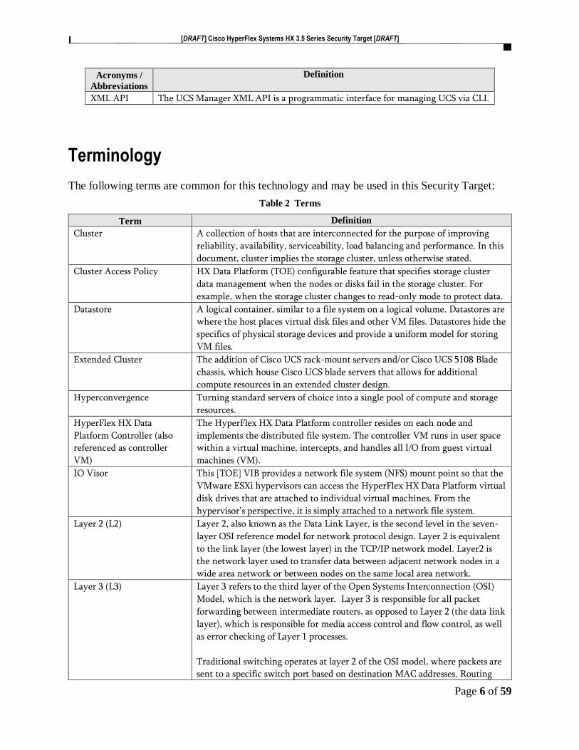
XML API The UCS Manager XML API is a programmatic interface for managing UCS via CLI.
Terminology
The following terms are common for this technology and may be used in this Security Target:
Table 2 Terms
Term Definition
Cluster A collection of hosts that are interconnected for the purpose of improving
reliability, availability, serviceability, load balancing and performance. In this
document, cluster implies the storage cluster, unless otherwise stated.
Cluster Access Policy HX Data Platform (TOE) configurable feature that specifies storage cluster
data management when the nodes or disks fail in the storage cluster. For
example, when the storage cluster changes to read-only mode to protect data.
Datastore A logical container, similar to a file system on a logical volume. Datastores are
where the host places virtual disk files and other VM files. Datastores hide the
specifics of physical storage devices and provide a uniform model for storing
VM files.
Extended Cluster The addition of Cisco UCS rack-mount servers and/or Cisco UCS 5108 Blade
chassis, which house Cisco UCS blade servers that allows for additional
compute resources in an extended cluster design.
Hyperconvergence Turning standard servers of choice into a single pool of compute and storage
resources.
HyperFlex HX Data
Platform Controller (also
referenced as controller
VM)
The HyperFlex HX Data Platform controller resides on each node and
implements the distributed file system. The controller VM runs in user space
within a virtual machine, intercepts, and handles all I/O from guest virtual
machines (VM).
IO Visor This [TOE] VIB provides a network file system (NFS) mount point so that the
VMware ESXi hypervisors can access the HyperFlex HX Data Platform virtual
disk drives that are attached to individual virtual machines. From the
hypervisor’s perspective, it is simply attached to a network file system.
Layer 2 (L2) Layer 2, also known as the Data Link Layer, is the second level in the seven-
layer OSI reference model for network protocol design. Layer 2 is equivalent
to the link layer (the lowest layer) in the TCP/IP network model. Layer2 is
the network layer used to transfer data between adjacent network nodes in a
wide area network or between nodes on the same local area network.
Layer 3 (L3) Layer 3 refers to the third layer of the Open Systems Interconnection (OSI)
Model, which is the network layer. Layer 3 is responsible for all packet
forwarding between intermediate routers, as opposed to Layer 2 (the data link
layer), which is responsible for media access control and flow control, as well
as error checking of Layer 1 processes.
Traditional switching operates at layer 2 of the OSI model, where packets are
sent to a specific switch port based on destination MAC addresses. Routing

[DRAFT] Cisco HyperFlex Systems HX 3.5 Series Security Target [DRAFT]
Page 7 of 59
Term Definition
operates at layer 3, where packets are sent to a specific next-hop IP address,
based on destination IP address. Devices in the same layer 2 segment do not
need routing to reach local peers. What is needed however is the destination
MAC address which can be resolved through the Address Resolution Protocol
(ARP)
Private Fiber The term Private Fiber’ encompasses the leasing ‘private’ fiber optic cables
from network providers. A client leases or purchases unused strands of
‘private’ fiber optic cable to create their own privately-operated optical fiber
network rather than simply leasing bandwidth.
The Private Fiber network is separate from the public (main) network and is
controlled by the client and not the network provider.
Private Fiber networks can be set up in a variety of ways, including Private
Fiber rings, point to point or point-to-multipoint configurations. With Private
Fiber, a client can expect higher levels of performance, a highly secure
network and superfast speeds.
Split Brain In the Stretched Cluster (SC) deployment this is where the two sides of the
system lose communication with one another, but the system has not actually
failed. In this circumstance, if either side has no secondary method besides
network communication for determining if the other side has actually failed,
in the interest of maximizing system availability it will decide that it is now
the authoritative or active half. As such, both sides would make the same
determination, therefore both sides would think they are active and in charge
of the overall system, hence the term “split brain”.
Standard Cluster Composed of a pair of Cisco UCS Fabric Interconnects along with up to
thirty-two HX-Series rack-mount servers per cluster.
Storage Cluster The storage cluster contains the converged nodes and their associated storage
that the HX Data Platform (TOE) manages. This storage cluster can also
include compute nodes, that do not include storage, and that the HX Data
Platform (TOE) monitors.
Stretched Cluster (SC) Stretched Cluster (SC) allow nodes to be evenly split between two physical
locations, keeping a duplicate copy of all data in both locations, thereby
providing protection in case of an entire site failure.
The connection between the two sites is secured using the Private Fiber for
point-to-point network configuration.
Users The users of the TOE are the processes and applications on the VMs that are
on the TOE that access the storage clusters and datastores which are provided
by the TOE.
Virtual Local Area Network
(VLAN)
The VLANs enable efficient traffic separation, provide better bandwidth
utilization, and alleviate scaling issues by logically segmenting the physical
local-area network (LAN) infrastructure into different subnets so that VLAN
packets are presented to interfaces within the same VLAN. The most
important requirement of VLANs is the ability to identify the origination
point for packets with a VLAN tag to ensure packets can only travel to
[DRAFT] Cisco HyperFlex Systems HX 3.5 Series Security Target [DRAFT]
Page 8 of 59
Term Definition
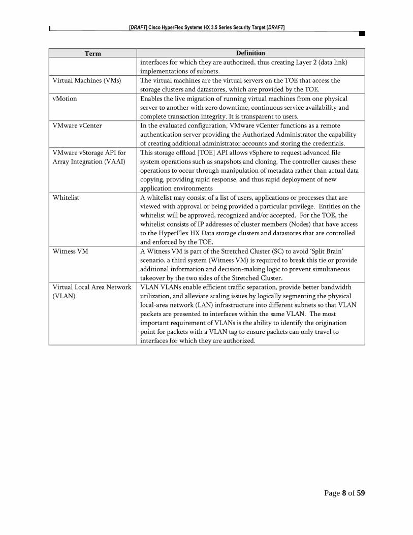
interfaces for which they are authorized, thus creating Layer 2 (data link)
implementations of subnets.
Virtual Machines (VMs) The virtual machines are the virtual servers on the TOE that access the
storage clusters and datastores, which are provided by the TOE.
vMotion Enables the live migration of running virtual machines from one physical
server to another with zero downtime, continuous service availability and
complete transaction integrity. It is transparent to users.
VMware vCenter In the evaluated configuration, VMware vCenter functions as a remote
authentication server providing the Authorized Administrator the capability
of creating additional administrator accounts and storing the credentials.
VMware vStorage API for
Array Integration (VAAI)
This storage offload [TOE] API allows vSphere to request advanced file
system operations such as snapshots and cloning. The controller causes these
operations to occur through manipulation of metadata rather than actual data
copying, providing rapid response, and thus rapid deployment of new
application environments
Whitelist A whitelist may consist of a list of users, applications or processes that are
viewed with approval or being provided a particular privilege. Entities on the
whitelist will be approved, recognized and/or accepted. For the TOE, the
whitelist consists of IP addresses of cluster members (Nodes) that have access
to the HyperFlex HX Data storage clusters and datastores that are controlled
and enforced by the TOE.
Witness VM A Witness VM is part of the Stretched Cluster (SC) to avoid ‘Split Brain’
scenario, a third system (Witness VM) is required to break this tie or provide
additional information and decision-making logic to prevent simultaneous
takeover by the two sides of the Stretched Cluster.
Virtual Local Area Network
(VLAN)
VLAN VLANs enable efficient traffic separation, provide better bandwidth
utilization, and alleviate scaling issues by logically segmenting the physical
local-area network (LAN) infrastructure into different subnets so that VLAN
packets are presented to interfaces within the same VLAN. The most
important requirement of VLANs is the ability to identify the origination
point for packets with a VLAN tag to ensure packets can only travel to
interfaces for which they are authorized.

[DRAFT] Cisco HyperFlex Systems HX 3.5 Series Security Target [DRAFT]
Page 9 of 59
DOCUMENT INTRODUCTION
Prepared By:
Cisco Systems, Inc.
170 West Tasman Dr.
San Jose, CA 95134
This document provides the basis for an evaluation of a specific Target of Evaluation (TOE), the
Cisco HyperFlex Systems HX Series running Cisco HyperFlex HX Data Platform Software,
version 3.5(2a). This Security Target (ST) defines a set of assumptions about the aspects of the
environment, a list of threats that the product intends to counter, a set of security objectives, a set
of security requirements, and the IT security functions provided by the TOE, which meet the set
of requirements.

[DRAFT] Cisco HyperFlex Systems HX 3.5 Series Security Target [DRAFT]
Page 10 of 59
1 SECURITY TARGET INTRODUCTION
The Security Target contains the following sections:
• Security Target Introduction [Section 1]
• Conformance Claims [Section 2]
• Security Problem Definition [Section 3]
• Security Objectives [Section 4]
• IT Security Requirements [Section 5]
• TOE Summary Specification [Section 6]
• Rationale [Section 7]
The structure and content of this ST comply with the requirements specified in the Common
Criteria (CC), Part 1, Annex A, and Part 3, Chapter 4
1.1 ST and TOE Reference
This section provides information needed to identify and control this ST and its TOE.
Table 3 ST and TOE Identification
Name Description
ST Title Cisco HyperFlex 3.5 Systems HX Series Common
Criteria Security Target
ST Version 1.0
Publication Date 7 October 2019
ST Author Cisco Systems, Inc.
Developer of the TOE Cisco Systems, Inc.
TOE Reference Cisco HyperFlex Systems HX Series
TOE Hardware Models • Cisco HyperFlex HXAF220c – M5SX All –
Flash Node
• Cisco HyperFlex HXAF240c – M5SX All –
Flash Node
• Cisco HyperFlex HX220c – M5SX Hybrid
Node
• Cisco HyperFlex HX240c – M5SX Hybrid
Node
• Cisco HyperFlex HX240c – M5L Hybrid
Node
• Cisco HyperFlex HXAF220c – M4S All-Flash
Node
• Cisco HyperFlex HXAF240c – M4SX All-
Flash Node
• Cisco HyperFlex HX220c – M4S Hybrid
Node
• Cisco HyperFlex HX240c – M4SX Hybrid
Node
[DRAFT] Cisco HyperFlex Systems HX 3.5 Series Security Target [DRAFT]
Page 11 of 59
Name Description
TOE Software Version Cisco HyperFlex HX Data Platform Software, version
3.5(2a), for VMware ESXi
TOE Guidance Cisco HyperFlex Systems HX Series Common Criteria
Operational User Guidance and Preparative
Procedures, Version 1.0
Keywords HyperFlex, Convergent, Cluster, Storage, Data
Protection, Authentication
1.2 TOE Overview
The TOE is the Cisco HyperFlex 3.5 Systems HX Series (herein after also referred to as Converged
Hosts or TOE). The TOE is a hyper-convergent software-centric solution that tightly integrates
computing, storage, networking and virtualization resources in a single hardware platform.
The TOE is installed in a hypervisor environment, such as VMware vSphere. The TOE manages
the storage of a storage cluster that has a minimum three servers (HyperFlex HX Series Nodes
(Converged Host)) with Solid-state disk (SSD) and Hard-disk drives (HDD) attached storage. The
clustered servers are networked with switches and fabric interconnects. Optionally, non-storage
servers, (compute nodes), can be included in the storage cluster. HX Data Platform manages the
storage for the data and VMs stored on the associated storage cluster.
The HyperFlex HX Series installer is loaded on a UCS platform that is networked to the storage
cluster to be managed. During the installation of the TOE, the initial cluster with at least three
HyperFlex HX Series Nodes is created. The datastores are added to the storage cluster after the
installation is complete. The HyperFlex HX Series provides a highly fault-tolerant distributed
storage system that preserves data integrity and optimizes performance for virtual machine (VM)
storage workloads.
The HyperFlex HX Series includes HyperFlex Connect (HX Connect) GUI that is used as the
primary management tool for Cisco HyperFlex. Through this centralized point of control for the
cluster, administrators can create volumes, monitor the data platform health, and manage resource
use. Administrators can also use this data to predict when the cluster will need to be scaled.
The HyperFlex HX Series also includes a HXCLI with a set of commands that can be used to
monitor and manage the storage clusters. The HXCLI also provides the Authorized Administrator
the ability to add nodes as the storage capacity and the storage needs grow within the organization.
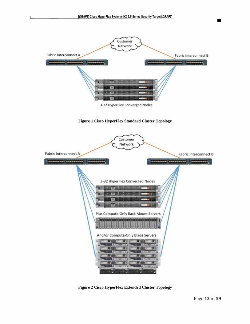
The following diagram, Figure 1 Cisco HyperFlex Standard Cluster Topology illustrates the Cisco
HyperFlex system, composed of a pair of Cisco UCS Fabric Interconnects along with up to thirty-
two HX-Series rack-mount servers per cluster. Up to thirty-two compute-only, servers can also be
added per HyperFlex cluster. The diagram, Figure 2 Cisco HyperFlex Extended Cluster Topology
illustrates the addition of Cisco UCS rack-mount servers and/or Cisco UCS 5108 Blade chassis,
which house Cisco UCS blade servers that allows for additional compute resources in an extended
cluster design. Up to eight separate HX clusters can be installed under a single pair of Fabric
Interconnects. The two Fabric Interconnects, [both] connect to every HX-Series rack-mount server
and both connect to every Cisco UCS 5108 blade chassis, and Cisco UCS rack-mount server.
[DRAFT] Cisco HyperFlex Systems HX 3.5 Series Security Target [DRAFT]
Page 12 of 59
Figure 1 Cisco HyperFlex Standard Cluster Topology
Figure 2 Cisco HyperFlex Extended Cluster Topology

[DRAFT] Cisco HyperFlex Systems HX 3.5 Series Security Target [DRAFT]
Page 13 of 59
Fabric Interconnects (FI) are deployed in pairs, wherein the two units operate as a management
cluster, while forming two separate network fabrics, referred to as the A side and B side fabrics.
Therefore, many design elements will refer to FI A or FI B, alternatively called fabric A or fabric
B. Both Fabric Interconnects are active at all times, passing data on both network fabrics for a
redundant and highly available configuration. Management services, including Cisco UCS
Manager, are also provided by the two FIs but in a clustered manner, where one FI is the primary,
and one is secondary, with a roaming clustered IP address. This primary/secondary relationship
is only for the management cluster and has no effect on data transmission.
The following diagram, Figure 3 Cisco HyperFlex Stretched Cluster (SC) Topology illustrates the
Stretched Cluster (SC). Note, the Stretched Cluster (SC) can only be deployed on the M5 Nodes,
M4/M5 mixed cluster is not supported.
The Stretched Cluster (SC) deployment is physically locating half of the cluster nodes in one
location, while the remaining half are located in a distant secondary location. The data written to
the stretched HyperFlex cluster is stored concurrently in both physical locations, therefore this
system design provides for additional data protection and availability because the data in the
cluster remains available and the cluster remains online, even if an entire site experiences a failure.
Since all data written to the cluster is written simultaneously to the two sites, this design can be
considered an active/active disaster recovery design. The recovery point objective (RPO), or the
maximum amount of data that can potentially be lost prior to a failure is essentially zero, due to
all data being immediately and continuously available in both sites.
The connection between the two sites is a dedicated (Private Fiber) Layer 2 (L2) data link that is
protected by virtue of the VLAN that is stretched on the L2 as well. The storage data VLAN on
the L2 is non-routed and isolated the same as it is on the switches locally in the standard or
extended deployments. The management VLAN also behaves the same as it is on the switches
locally in the standard or extended deployments and routed to places that have management access.
As such, the management network is also extended over the L2 connection.
A Witness VM is part of the Stretched Cluster (SC) to avoid ‘Split Brain’ scenario, a third system
(Witness VM) is required to break this tie or provide additional information and decision-making
logic to prevent simultaneous takeover by the two sides of the Stretched Cluster. The Witness VM
is a platform running ESXi server in the environment that is running the Cisco HyperFlex Data
Platform Stretched Cluster Witness software. It is recommended that the Witness VM is physically
separated from the two halves of the stretched cluster, installed within a protected area. The
connection from the Witness VM is also a dedicated network connection to both of the other two
sites within the Stretched Cluster (SC).

[DRAFT] Cisco HyperFlex Systems HX 3.5 Series Security Target [DRAFT]
Page 14 of 59
Figure 3 Cisco HyperFlex Stretched Cluster (SC) Topology
Trunk ports with VLANs are the access points between the physical and virtual environments. The
VLANs are VLAN tagged External Switch VLAN Tagging (EST). The VLAN used for HX
storage traffic must be able to traverse the network uplinks from the UCS domain, reaching FI A
from FI B, and vice-versa. The VLANs are configured during install of the TOE, and then
managed by VMware ESXi.
The Cisco HyperFlex system has communication pathways that fall into four defined zones as
depicted in Figure 4 Cisco HX Data logical data paths below. The zones are defined as:
The zones are defined as:
• Management Zone: This zone comprises the connections needed to manage the physical
hardware, the hypervisor hosts, and the storage platform controller virtual machines
(SCVM). These interfaces and IP addresses need to be available to the Authorized
Administrator that will manage and administer the TOE, throughout the LAN/WAN. This
zone must provide access to Domain Name System (DNS) and Network Time Protocol
(NTP) services and allow for secure HXCLI management using Secure Shell (SSHv2) and
HTTPS/TLSv1.2 for secure HX Connect GUI management.
• VM Zone: This zone comprises the connections needed to service network IO to the guest
VMs that will run inside the HyperFlex hyperconverged system. This zone typically
contains multiple VLANs, that are trunked to the Cisco UCS Fabric Interconnects via the
network uplinks and tagged with 802.1Q VLAN IDs. These interfaces and IP addresses
need to be available to the Authorized Administrator that will manage and administer the

[DRAFT] Cisco HyperFlex Systems HX 3.5 Series Security Target [DRAFT]
Page 15 of 59
TOE, throughout the LAN/WAN and the other computer endpoints which need to
communicate with the guest VMs in the HX system, throughout the LAN/WAN.
• Storage Zone: This zone comprises the connections used by the Cisco HX Data Platform
software, ESXi hosts and the storage controller VMs to service the HX Distributed Data
File system. These interfaces and IP addresses need to be able to communicate with each
other at all times for proper operation.
• VMotion Zone: This zone comprises the connections used by the ESXi hosts to enable
vMotion of the guest VMs from host to host.
The following figure provides a visual depiction of the logical data path in the TOE deployment.
Figure 4 Cisco HX Data logical data paths
The following figure provides a visual depiction of the network design in the TOE deployment.

[DRAFT] Cisco HyperFlex Systems HX 3.5 Series Security Target [DRAFT]
Page 16 of 59
Figure 5 Cisco HX Data network design
1.2.1 TOE Product Type
The Cisco HyperFlex Systems HX Series product type is a type of infrastructure system with a
software-centric architecture that tightly integrates compute, storage, networking and
virtualization resources.
The HyperFlex Systems HX Series provides connectivity and security services across the set of
HX Series platforms that comprise the TOE. The TOE offers:
• Enterprise-class data management features that are required for complete lifecycle
management and enhanced data protection in distributed storage
• Simplified data management that integrates storage functions into existing management
tools and allowing instant provisioning for dramatically simplified daily operations
• Independent scaling of the computing, caching, and capacity tiers, giving you the flexibility
to scale the environment based on evolving business needs
• Continuous data optimization with inline data deduplication and compression that
increases resource utilization with more headroom for data scaling
• Dynamic data placement in node memory, enterprise-class flash memory (on solid-state
disk [SSD] drives), and persistent storage tiers (on hard-disk drives [HDDs]) to optimize
performance and resiliency—and to readjust data placement as you scale your cluster
The HyperFlex Systems HX Series delivers the combination of the essential features in a single
solution.

[DRAFT] Cisco HyperFlex Systems HX 3.5 Series Security Target [DRAFT]
Page 17 of 59
1.2.2 Supported non-TOE Hardware/ Software/ Firmware
The TOE supports the following hardware, software, and firmware components in its operational
environment. Each component is identified as being required or not based on the claims made in
this Security Target. All of the following environment components are supported by all TOE
evaluated configurations.
Table 4 IT Environment Components
Component Required Usage/Purpose Description for TOE performance
DNS Server Yes The DNS Server is required to support IP addresses that are provided as host
names for the various components that may be used for traffic and access
control.
Fabric
Interconnects
(FI) (Cisco UCS)
Yes The FIs provides the connections to the larger network including the
switches and servers. The TOE deployment requires a minimum of two FIs
for each Cisco HyperFlex Cluster to create high availability. The FI provides
the single point of connectivity and hardware management that integrates
Cisco HyperFlex HX Series nodes and Cisco UCS B-Series Blade Servers into
a single unified cluster. The two FIs must be directly connected together
using Ethernet cables between the two FI ports. This allows both the FIs to
continuously monitor the status of each other. Cisco UCS Manager is an
embedded software on the pair of fabric interconnects.
Management
Workstation
Yes To manage the TOE via the HXCLI, this includes any IT Environment
Management workstation installed with the SSHv2 client to support the
TOE HXCLI interface for management of the TOE. The connection of the
HXCLI management workstation to the TOE is protected through SSHv2
channel.
To manage the TOE via the HX Connect GUI this includes any IT
Environment Management workstation that supports the following
browsers, Microsoft IE 11 or higher, Google Chrome, 54 or higher and
Mozilla Firefox 52 or higher. The connection of the HX Connect
management workstation to the TOE is protected through HTTPS/TLSv1.2
channel.
NTP Server Yes The TOE supports communications with an NTP server to receive clock
updates.
Private Fiber Yes In Stretched Cluster configuration, Private Fiber from the network provider
is required to create the secured, privately-operated optical fiber network connection between the two sites.
SNMP Server No The server is required for the AutoSupport service, an alert notification
service that is an optional service.
Switches Yes The switches provide data transmission and tracking
Trunk Ports Yes Trunk ports with VLANs are the access points between the physical and
virtual environments. The VLANs are VLAN tagged External Switch VLAN
Tagging (EST). The VLAN used for HX storage traffic must be able to
traverse the network uplinks from the UCS domain, reaching FI A from FI
B, and vice-versa. The VLANs are configured during install of the TOE, and
then managed by VMware ESXi.

[DRAFT] Cisco HyperFlex Systems HX 3.5 Series Security Target [DRAFT]
Page 18 of 59
Component Required Usage/Purpose Description for TOE performance
VMware
vSphere1
Yes VMware vSphere ESXi 6.0 software preinstalled (ESXi 6.5 is supported but is
not preinstalled). vSphere Editions include Enterprise, Enterprise Plus,
Standard, Essentials Plus, ROBO.
VMware vCenter Yes In the evaluated configuration, VMware vCenter functions as a remote
authentication server providing the Authorized Administrator the capability of
creating additional administrator accounts and storing the credentials.
Witness VM Yes The Witness VM is required in the Stretched Cluster deployment to avoid
‘Split Brain’ scenario. The Witness VM is a platform running ESXi server in
the environment that is running the Cisco HyperFlex Data Platform
Stretched Cluster Witness software.
1.3 TOE DESCRIPTION
This section provides an overview of the Cisco HyperFlex Systems HX Series Target of Evaluation
(TOE). The TOE is comprised of both software and hardware.
The TOE software is Cisco HyperFlex HX Data Platform Software, version 3.5(2a), VMware
ESXi version. Cisco HyperFlex HX Data Platform™ Software is a Cisco-developed highly
configurable proprietary operating system that provides for efficient and effective scaling for
storage capacity and performance.
The TOE hardware is the Cisco HyperFlex HX Series Nodes that includes the following nine
models:
The small footprint Cisco HyperFlex HXAF220c-M5SX all-flash model contains:
• a 240 GB M.2 form factor solid-state disk (SSD) that acts as the boot drive,
• a 240 GB housekeeping SSD drive,
• either a single 375 GB Optane NVMe SSD, a 1.6 TB NVMe SSD or 400GB SAS SSD
write-log drive,
• and six to eight 960GB or 3.8TB SATA SSD drives for storage capacity.
Figure 6 Cisco HyperFLex HXAF220c-M5SX All-Flash Node
This capacity optimized Cisco HyperFlex HXAF240c-M5SX all-flash model contains:
• a 240 GB M.2 form factor solid-state disk (SSD) that acts as the boot drive,
• a 240 GB housekeeping SSD drive, either a single 375 GB Optane NVMe SSD, a 1.6 TB
NVMe SSD or 400GB SAS SSD write-log drive installed in a rear hot swappable slot,
1 HyperFlex Systems may be pre-installed with VMware vSphere with licensing applied at purchase

[DRAFT] Cisco HyperFlex Systems HX 3.5 Series Security Target [DRAFT]
Page 19 of 59
• and six to twenty-three 960 GB or 3.8 TB SATA SSD drives for storage capacity.
Figure 7 Cisco HyperFlex HXAF240c-M5SX All-Flash Node
This small footprint Cisco HyperFlex HX220c-M5SX hybrid model contains:
• a minimum of six, and up to eight 1.8 terabyte (TB) or 1.2 TB SAS hard disk drives (HDD)
that contribute to cluster storage capacity,
• a 240 GB SSD housekeeping drive, a 480 GB or 800 GB SSD caching drive,
• and a 240 GB M.2 form factor SSD that acts as the boot drive
Figure 8 Cisco HyperFlex HX220c-M5SX Hybrid Node
This capacity optimized Cisco HyperFlex HX240c-M5SX hybrid model contains:
• a minimum of six and up to twenty-three 1.8 TB or 1.2 TB SAS small form factor (SFF)
harddisk drives (HDD) that contribute to cluster storage,
• a 240 GB SSD housekeeping drive, a single 1.6 TB SSD caching drive installed in a rear
hot swappable slot,
• and a 240 GB M.2 form factor SSD that acts as the boot drive.
Figure 9 Cisco HyperFlex HX240c-M5SX Hybrid Node
This density optimized Cisco HyperFlex HX240c-M5L hybrid model contains:
• a minimum of six and up to twelve 6 TB or 8 TB SAS large form factor (LFF) hard disk
drives (HDD) that contribute to cluster storage,
• a 240 GB SSD housekeeping drive and a single 3.2 TB SSD caching drive, both installed
in the rear hot swappable slots,
• and a 240 GB M.2 form factor SSD that acts as the boot drive
[DRAFT] Cisco HyperFlex Systems HX 3.5 Series Security Target [DRAFT]
Page 20 of 59
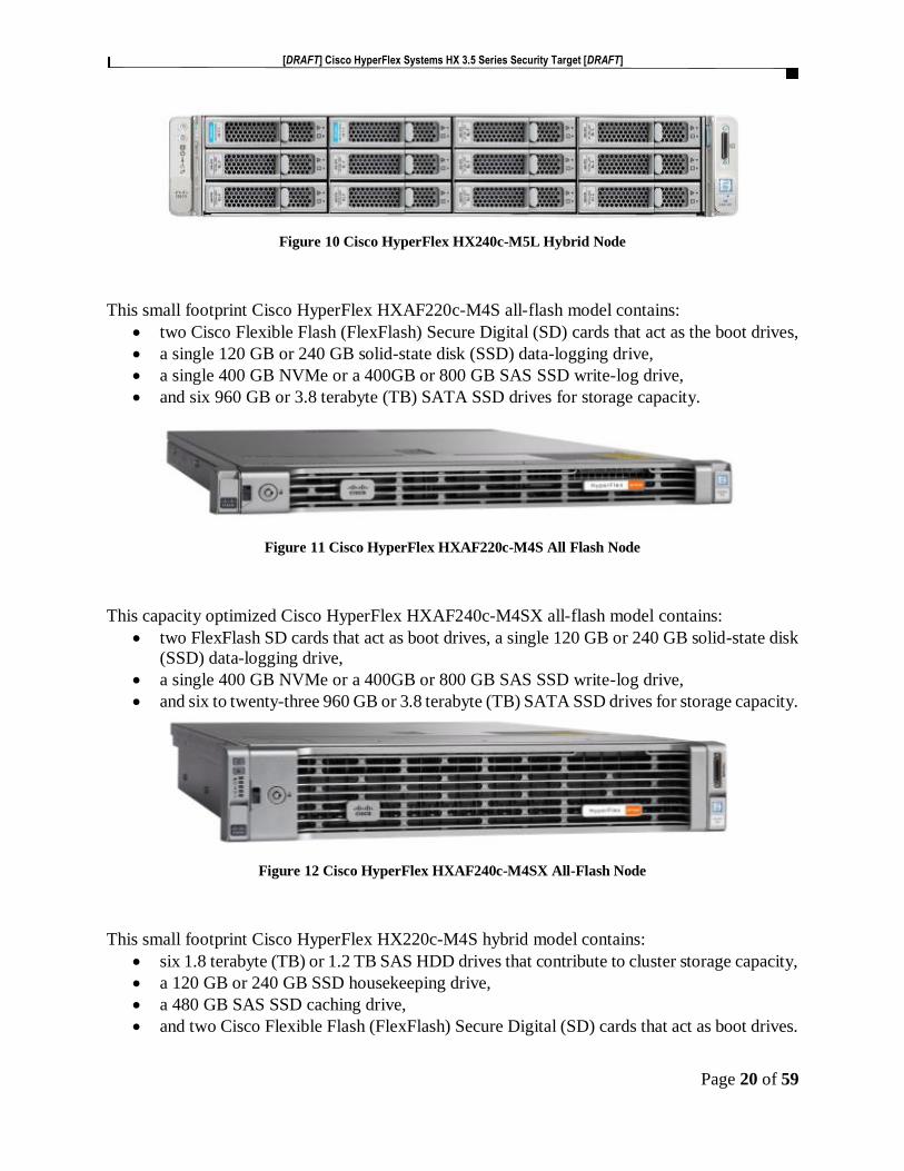
Figure 10 Cisco HyperFlex HX240c-M5L Hybrid Node
This small footprint Cisco HyperFlex HXAF220c-M4S all-flash model contains:
• two Cisco Flexible Flash (FlexFlash) Secure Digital (SD) cards that act as the boot drives,
• a single 120 GB or 240 GB solid-state disk (SSD) data-logging drive,
• a single 400 GB NVMe or a 400GB or 800 GB SAS SSD write-log drive,
• and six 960 GB or 3.8 terabyte (TB) SATA SSD drives for storage capacity.
Figure 11 Cisco HyperFlex HXAF220c-M4S All Flash Node
This capacity optimized Cisco HyperFlex HXAF240c-M4SX all-flash model contains:
• two FlexFlash SD cards that act as boot drives, a single 120 GB or 240 GB solid-state disk
(SSD) data-logging drive,
• a single 400 GB NVMe or a 400GB or 800 GB SAS SSD write-log drive,
• and six to twenty-three 960 GB or 3.8 terabyte (TB) SATA SSD drives for storage capacity.
Figure 12 Cisco HyperFlex HXAF240c-M4SX All-Flash Node
This small footprint Cisco HyperFlex HX220c-M4S hybrid model contains:
• six 1.8 terabyte (TB) or 1.2 TB SAS HDD drives that contribute to cluster storage capacity,
• a 120 GB or 240 GB SSD housekeeping drive,
• a 480 GB SAS SSD caching drive,
• and two Cisco Flexible Flash (FlexFlash) Secure Digital (SD) cards that act as boot drives.

[DRAFT] Cisco HyperFlex Systems HX 3.5 Series Security Target [DRAFT]
Page 21 of 59
Figure 13 Cisco HyperFlex HX220c-M4S Hybrid Node
This capacity optimized Cisco HyperFlex HX240c-M4SX hybrid model contains:
• a minimum of six and up to twenty-three 1.8 TB or 1.2 TB SAS HDD drives that contribute
to cluster storage,
• a single 120 GB or 240 GB SSD housekeeping drive,
• a single 1.6 TB SAS SSD caching drive,
• and two FlexFlash SD cards that act as the boot drives.
Figure 14 Cisco HyperFlex HX240c-M4SX Hybrid Node
[DRAFT] Cisco HyperFlex Systems HX 3.5 Series Security Target [DRAFT]
Page 22 of 59
1.4 TOE Evaluated Configuration
The TOE consists of one or more physical devices as specified in Section 1.5 Physical Scope of
the TOE below and includes the Cisco HyperFlex HX Data Platform Software, version 3.5(2a),
VMware ESXi version.
The TOE is installed in a hypervisor environment, such as VMware vSphere where it manages the
storage clusters and datastores that has a minimum three servers, (TOE Converged hosts), with
SSD and HDD attached storage. The clustered servers (TOE Converged hosts) are networked with
switches and fabric interconnects. Optionally, non-storage servers, (compute nodes), can be
included in the storage cluster (TOE Converged hosts). HyperFlex HX Series manages the storage
for the data and VMs stored on the associated storage cluster (TOE Converged hosts).
The evaluated configuration is the configuration of the TOE that satisfies the requirements as
defined in this Security Target (ST). For example,
• Security Audit – The TOE generates audit records to assist the Authorized Administrator
in monitoring the security state of the HyperFlex HX Data Platform as well as trouble
shooting various problems that arise throughout the operation of the system
• User Data Protection – The TOE provides access controls to the TOE Converged hosts,
clusters and datastores.
• Identification and authentication – The TOE ensures that all Authorized Administrator are
successfully identified and authenticated prior to gaining access to the TOE and terminates
connection after a configured period of inactivity.
• Secure Management – The TOE provides secure administrative services for management
of general TOE configuration and the security functionality provided by the TOE. All TOE
administration occurs through the HX Connect GUI (over HTTPS/TLSv1.2) or the HXCLI
(over SSHv2). All the TOE management functions are restricted to Authorized
Administrator. The term "Authorized Administrator" is used in this ST to refer to any user
account that has been assigned the privileges to perform the relevant action. The TOE
provides the ability to perform the following actions:
• Administer the TOE remotely
• Manage access control attributes
• Manage Authorized Administrator’s security attributes
• Review audit record logs
• Configure and manage the system time
• Protection of the TSF - The TOE protects against interference and tampering by untrusted
subjects by implementing identification and authentication, access control to the TOE
Converged hosts, clusters and datastores and limits configuration options to the Authorized
Administrator. Additionally, Cisco HyperFlex HX Series is not a general-purpose
operating system and access to Cisco HyperFlex HX Series memory space is restricted to
only Cisco HyperFlex HX Series functions. The TOE also provides the capability to
protect unavailability of capabilities and system resources and to revert to a saved space in
the case of hardware or system disruption of failure. Finally, the TOE is configured to use
NTP to synchronize the TOE’s clock with an external time source. This date and time is
used as the timestamp that is applied to audit records generated by the TOE.

[DRAFT] Cisco HyperFlex Systems HX 3.5 Series Security Target [DRAFT]
Page 23 of 59
• TOE Access - The TOE can enforce the termination of inactive sessions after an Authorized
Administrator configurable time-period. Once a session has been terminated, the TOE
requires the Authorized Administrator to re-authenticate to establish a new session.
• Resource Utilization - Ensures the system, resources and data is preserved in case of a
failure or degradation of services.
• Trusted Path/Channel – Ensures a trusted path is established between the TOE and the HX
Connect GUI using HTTPS/TLSv1.2 and for the HXCLI using SSHv2.
The TOE is remotely administered using HX Connect GUI and HXCLI, therefore, the management
station must be connected to an internal network the supports HTTPS/TLSv1.2 and SSHv2 for
secure connect to the TOE.
As noted above, the TOE is configured to connect to an NTP server and it is recommended that
the NTP server be installed on an internal protected network, which is only accessible via the
protected internal network. The NTP server is used for clock synchronization between services
running on the Cisco HyperFlex HX Series Nodes, the storage controller VMs (storage controller)
and ESXi hosts (Hypervisor).
1.5 Physical Scope of the TOE
The TOE is a hardware and software solution that makes up the Cisco HyperFlex Systems HX
Series.
The hardware platforms include the Cisco HyperFlex HX Series as described in Table 5 Hardware
Models and Specifications. For ordering of the TOE and delivery via commercial carriers, see
https://apps.cisco.com/ccw/cpc/guest/content/ucsSeriesDetails/series_hyperflex
The software is the Cisco HyperFlex HX Data Platform™ Software v3.5(2), VMware ESXi
version. The network, on which they reside, is considered part of the environment. The software
file format for the HyperFlex Platform is an ova file. For ordering and downloading the TOE
software, see https://software.cisco.com/#
The TOE guidance documentation that is considered to be part of the TOE is the Cisco HyperFlex
Systems HX Series Common Criteria Operational User Guidance and Preparative Procedures, a
PDF document that can be downloaded from the http://cisco.com web site.
The TOE is comprised of the following physical specifications as illustrated and described in the
Figures and Tables below:

[DRAFT] Cisco HyperFlex Systems HX 3.5 Series Security Target [DRAFT]
Page 24 of 59
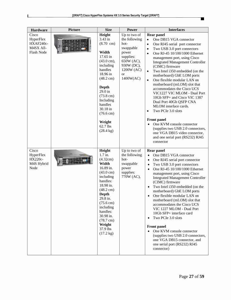
Table 5 Hardware Models and Specifications
Hardware Picture Size Power Interfaces
Cisco
HyperFLex HXAF220c-
M5SX All-
Flash Node
Height
1.7 in. (4.32 cm)
Width
16.89 in.
(43.0 cm)
including
handles:
18.98 in.
(48.2 cm)
Depth
29.8 in.
(75.6 cm)
including handles:
30.98 in.
(78.7 cm)
Weight
37.5lbs
(17.0kg)
Up to two of
the following hot-
swappable
power
supplies: 770
W (AC) or
1050 W (AC)
power supply,
or 1050 W
V2 (DC)
Rear panel
• One 1-Gbps RJ-45 management port (Marvell 88E6176)
• Two 10GBase-T LOM ports (Intel
• X550 controller embedded on the
motherboard
• One RS-232 serial port (RJ45
connector)
• One DB15 VGA connector
• Two USB 3.0 port connectors
• One flexible modular LAN on
motherboard (mLOM) slot that can
accommodate various interface cards
Front panel
• One KVM console connector
(supplies
• Two USB 2.0 connectors, one VGA
• DB15 video connector, and one
serial port (RS232) RJ45 connector
Cisco
HyperFlex
HXAF240c-M5SX All-
Flash Node
Height
3.43 in.
(8.70 cm) Width
(including
slam
latches)
17.65
in.(44.8
cm)
Including
handles:
18.96 in
(48.2 cm) Depth
29.0 in.
(73.8 cm)
Including
handles:
30.18 in
(76.6 cm)
Weight
37.0 lbs
(16.8 kg)
Up to two of
the following
hot-swappable
power
supplies:
1050W (AC),
or 1050 W
V2 (DC) or
1600 W (AC)
Rear panel
• One 1-Gbps RJ-45 management
port (Marvell 88E6176)
• Two 10GBase-T LOM ports (Intel
• X550 controller embedded on the
motherboard)
• One RS-232 serial port (RJ45
connector)
• One DB15 VGA connector
• Two USB 3.0 port connectors
• One flexible modular LAN on
motherboard (mLOM) slot that
can accommodate various
interface cards
Front panel
• One KVM console connector
(supplies two USB 2.0 connectors,
one VGA

[DRAFT] Cisco HyperFlex Systems HX 3.5 Series Security Target [DRAFT]
Page 25 of 59
Hardware Picture Size Power Interfaces
Cisco
HyperFlex
HX220c-
M5SX
Hybrid
Node
Height
1.7 in.
(4.32cm)
Width
16.89 in.
(43.0 cm)
including
handles:
18.98 in. (48.2 cm)
Depth
29.8 in.
(75.6 cm)
including
handles:
30.98 in.
(78.7 cm)
Weight
37.5 lbs
(17.0 kg)
Up to two of
the following
hot-
swappable
power
supplies:
770W (AC),
or 1050 W
(AC) or 1050W V2
(DC)
Rear panel
• One 1-Gbps RJ-45 management
port (Marvell 88E6176)
• Two 1/10GBase-T LOM ports
(Intel X550 controller embedded on
the motherboard
• One RS-232 serial port (RJ45
connector)
• One DB15 VGA connector
• Two USB 3.0 port connectors
• One flexible modular LAN on
motherboard (mLOM) slot that can
accommodate various interface
cards
Front panel
• One KVM console connector
(supplies two USB 2.0 connectors,
one VGA
• DB15 video connector, and one serial port (RS232) RJ45 connector)
Cisco
HyperFlex
HX240c-
M5SX
Hybrid
Node
Height
3.43 in.
(8.70 cm)
Width
17.65
in.(43.0
cm)
Including
handles: 18.96 in
(48.2 cm)
Depth
29.0 in.
(73.8 cm)
Including
handles:
30.18 in
(76.6 cm)
Weight
57.5 lbs
(26.1 kg)
Up to two of
the following
hot-
swappable
power
supplies:
1050W (AC),
or 1050 W
V2 (DC) or
1600 W (AC)
Rear panel
• One 1-Gbps RJ-45 management
port (Marvell 88E6176) • Two 10GBase-T LOM ports (Intel
X550 controller embedded on the
motherboard)
• One RS-232 serial port (RJ45
connector)
• One DB15 VGA connector
• Two USB 3.0 port connectors
• One flexible modular LAN on
motherboard (mLOM) slot that
can accommodate various
interface cards
Front panel
• One KVM console connector
(supplies two USB 2.0 connectors,
one VGA DB15 video connector,
and one serial port (RS232)

[DRAFT] Cisco HyperFlex Systems HX 3.5 Series Security Target [DRAFT]
Page 26 of 59
Hardware Picture Size Power Interfaces
Cisco
HyperFlex
HX240c-
M5L Hybrid
Node
Height
3.43 in
(8.70 cm)
Width
17.65 in
(43.0 cm),
including
handles 18.96 in
(48.2 cm)
Depth
29.0 in
(73.8 cm)
Including
handles
30.18 in
(76.6 cm)
Weight
45.5 lbs
(20.4 kg)
Up to two of
the following
hot-
swappable
power
supplies:
1050W (AC),
or 1050 W
V2 (DC) or 1600 W (AC)
Rear panel
• One 1-Gbps RJ-45 management
port (Marvell 88E6176)
• Two 10GBase-T LOM ports (Intel
X550 controller embedded on the
motherboard
• One RS-232 serial port (RJ45
connector)
• One DB15 VGA connector
• Two USB 3.0 port connectors
• One flexible modular LAN on
motherboard (mLOM) slot that
can accommodate various
interface cards
Front panel
One KVM console connector (supplies
two USB 2.0 connectors, one VGA
DB15 video connector, and one serial
port (RS232)
Cisco
HyperFlex
HXAF220c-
M4S All
Flash Node
Height
1.7 in.
(4.32cm)
Width
16.89 in.
(43.0 cm)
including
handles:
18.98 in. (48.2 cm)
Depth
29.8 in.
(75.6 cm)
including
handles:
30.98 in.
(78.7 cm)
Weight
37.5 lbs
(17.0 kg)
Up to two of
the following
hot-
swappable
power
supplies:
770W (AC),
Rear panel
• One DB15 VGA connector
• One RJ45 serial port connector
• Two USB 3.0 port connectors
• One RJ-45 10/100/1000 Ethernet
management port, using Cisco
Integrated Management Controller
(CIMC) firmware
• Two Intel i350 embedded (on the
motherboard) GbE LOM ports
• One flexible modular LAN on
motherboard (mLOM) slot that
accommodates the Cisco UCS
VIC 1227 MLOM - Dual Port
10Gb SFP+ interface card or the
VIC 1387 Cisco VIC 1387 Dual
Port 40Gb QSFP CNA.
• Two PCIe 3.0 slots
Front panel
• One KVM console connector
(supplies two USB 2.0 connectors,
one VGA DB15 connector, and
one serial port (RS232) RJ45
connector)
[DRAFT] Cisco HyperFlex Systems HX 3.5 Series Security Target [DRAFT]
Page 27 of 59
Hardware Picture Size Power Interfaces
Cisco
HyperFlex
HXAF240c-
M4SX All-
Flash Node
Height
3.43 in
(8.70 cm)
Width
17.65 in
(43.0 cm),
including
handles 18.96 in
(48.2 cm)
Depth
29.0 in
(73.8 cm)
Including
handles
30.18 in
(76.6 cm)
Weight
62.7 lbs
(28.4 kg)
Up to two of
the following
hot-
swappable
power
supplies:
650W (AC),
930W (DC),
1200W (AC) or
1400W(AC)
Rear panel
• One DB15 VGA connector
• One RJ45 serial port connector
• Two USB 3.0 port connectors
• One RJ-45 10/100/1000 Ethernet
management port, using Cisco
Integrated Management Controller
(CIMC) firmware
• Two Intel i350 embedded (on the motherboard) GbE LOM ports
• One flexible modular LAN on
motherboard (mLOM) slot that
accommodates the Cisco UCS
VIC1227 VIC MLOM - Dual Port
10Gb SFP+ and Cisco VIC 1387
Dual Port 40Gb QSFP CNA
MLOM interface cards.
• Two PCIe 3.0 slots
Front panel
• One KVM console connector
(supplies two USB 2.0 connectors,
one VGA DB15 video connector,
and one serial port (RS232) RJ45
connector
Cisco
HyperFlex
HX220c-
M4S Hybrid
Node
Height
1.7 in.
(4.32cm)
Width
16.89 in.
(43.0 cm) including
handles:
18.98 in.
(48.2 cm)
Depth
29.8 in.
(75.6 cm)
including
handles:
30.98 in.
(78.7 cm) Weight
37.9 lbs
(17.2 kg)
Up to two of
the following
hot-
swappable
power
supplies: 770W (AC),
Rear panel
• One DB15 VGA connector
• One RJ45 serial port connector
• Two USB 3.0 port connectors
• One RJ-45 10/100/1000 Ethernet
management port, using Cisco Integrated Management Controller
(CIMC) firmware
• Two Intel i350 embedded (on the
motherboard) GbE LOM ports
• One flexible modular LAN on
motherboard (mLOM) slot that
accommodates the Cisco UCS
VIC 1227 MLOM - Dual Port
10Gb SFP+ interface card
• Two PCIe 3.0 slots
Front panel
• One KVM console connector
(supplies two USB 2.0 connectors,
one VGA DB15 connector, and
one serial port (RS232) RJ45
connector)

[DRAFT] Cisco HyperFlex Systems HX 3.5 Series Security Target [DRAFT]
Page 28 of 59
Hardware Picture Size Power Interfaces
Cisco
HyperFlex
HX240c-
M4SX
Hybrid
Node
Height
3.43 in
(8.70 cm)
Width
17.65 in
(43.0 cm),
including
handles 18.96 in
(48.2 cm)
Depth
29.0 in
(73.8 cm)
Including
handles
30.18 in
(76.6 cm)
Weight
62.7 lbs
(28.4 kg)
Up to two of
the following
hot-
swappable
power
supplies:
650W (AC),
930W (DC),
1200W (AC) or
1400W(AC)
Rear panel
• One DB15 VGA connector
• One RJ45 serial port connector
• Two USB 3.0 port connectors
• One RJ-45 10/100/1000 Ethernet
management port, using Cisco
Integrated Management Controller
(CIMC) firmware
• Two Intel i350 embedded (on the motherboard) GbE LOM ports
• One flexible modular LAN on
motherboard (mLOM) slot that
accommodates the Cisco UCS
VIC1227 VIC MLOM - Dual Port
10Gb SFP+ and Cisco VIC 1387
Dual Port 40Gb QSFP CNA
MLOM interface cards.
• Two PCIe 3.0 slots
Front panel
• One KVM console connector
(supplies two USB 2.0 connectors,
one VGA DB15 video connector,
and one serial port (RS232) RJ45
connector
1.6 Logical Scope of the TOE
The TOE is comprised of several security features. Each of the security features identified above
consists of several security functionalities, as identified below.
• Security audit
• User data protection
• Identification and authentication
• Secure Management
• Protection of the TSF
• Resource Utilization
• TOE Access
• Trusted Path
These features are described in more detail in the subsections below.
1.6.1 Security Audit
The TOE generates audit messages that identify specific TOE operations. For each event, the
TOE records the date and time of each event, the type of event, the subject identity, and the
outcome of the event. Auditable events include:

[DRAFT] Cisco HyperFlex Systems HX 3.5 Series Security Target [DRAFT]
Page 29 of 59
• all use of the user identification mechanism;
• all use of the authentication mechanism;
• all modification in the behavior of the functions in the TSF;
• all modifications of the default settings;
• all modifications to the values of the TSF data;
• use of the management functions;
• changes to the time;
• terminations of an interactive session; and
• attempts to use the trusted path functions
The TOE will write audit records to the local logging buffer by default . The TOE provides an
interface available for the Authorized Administrator to delete audit data stored locally on the
TOE to manage the audit log space.
The logs can be viewed on the TOE using HX Connect GUI interfaces. The records include the
date/time the event occurred, the event/type of event, the user associated with the event, and
additional information of the event and its success and/or failure.
1.6.2 User Data Protection
The TOE provides the Authorized Administrator with the ability to control remote host (VMs)
access to the TOE Converged hosts, clusters and datastores with whitelisting.
The whitelist controls access using IP addresses. If the Remote Host (VM) host IP address is
included on the whitelist and there is sufficient storage capacity, access is granted otherwise access
is denied.
The three sets of addressing that may be used:
• Management addresses identify the TOE Converged hosts and their clusters and datastores
and the Storage Controller VM management interfaces
• VM addresses identify the guest VMs that run in the TOE HyperFlex hyperconverged
system
• Storage addresses that are used by Cisco HX Data Platform software, ESXi hosts, and the
storage controller VMs to service the HX Distributed Filesystem. These interfaces and IP
addresses need to be able to communicate with each other at all times for proper operation.
1.6.3 Identification and authentication
The TOE provides authentication services for the Authorized Administrator to connect to the
TOE’s HX Connect GUI and HXCLI administrator interfaces. The TOE requires the Authorized
Administrator to be successfully identified and authenticated prior to being granted access to any
of the management functionality. The TOE can be configured to enforce password minimum
length as well as mandatory password complexity rules. The TOE provides administrator
authentication against a local user database. Password-based authentication is performed on the
HX Connect GUI and HXCLI session interface connections.
[DRAFT] Cisco HyperFlex Systems HX 3.5 Series Security Target [DRAFT]
Page 30 of 59
For each Authorized Administrator account, they must have a unique user name. For authentication
purposes, a password is required for each Authorized Administrator account.
1.6.4 Security Management
The TOE provides secure administrative services for management of general TOE configuration
and the security functionality provided by the TOE. All TOE administration occurs through the
HX Connect GUI using HTTPS/TLSv1.2 and for the HXCLI using SSHv2 secure connection.
The TOE provides the ability to securely:
• Administer the TOE remotely
• Manage access control attributes
• Manage Authorized Administrator’s security attributes, noting the TOE allows for more
than one administrator account to be configured. Each Authorized Administrator must be
assigned a unique username and password
• Review audit record logs
• Configure and manage the system time
1.6.5 Protection of the TSF
The TOE protects against interference and tampering by untrusted subjects by implementing
identification, authentication and limit configuration options to the Authorized Administrator.
Additionally, Cisco HyperFlex HX Data Platform™ Software v3.5(2a) is not a general-purpose
operating system and access to the HyperFlex memory space is restricted to only Cisco HyperFlex
v3.5(2a) functions.
The TOE provides the capability called native snapshot to save the current state of the VMs, so
the Authorized Administrator has the option to revert to the saved state in the case of disruption or
failure.
The TOE internally maintains the date and time. This date and time is used as the timestamp that
is applied to audit records generated by the TOE. The TOE is configured to use NTP to
synchronize the TOE’s clock with an external time source. It is recommended that NTP server be
installed on the internal protected network for time services, which is only accessible via the
protected internal network. The NTP server is used for clock synchronization between services
running on the Cisco HyperFlex HX Series Nodes, the storage controller VMs (storage controller)
and ESXi hosts (Hypervisor).
1.6.6 Resource Utilization
The TOE protects against unavailability of capabilities and system resources caused by failure or
degradation of services by supporting redundancy and failover capabilities of the storage
management network and the storage data networks.
1.6.7 TOE Access
The TOE enforces the termination of inactive sessions after an Authorized Administrator
configurable time-period has expired. Once a session has been terminated, the TOE requires the
Authorized Administrator to re-authenticate to establish a new session.

[DRAFT] Cisco HyperFlex Systems HX 3.5 Series Security Target [DRAFT]
Page 31 of 59
1.6.8 Trusted Path
The TOE allows trusted paths to be established to itself from remote administrators over
HTTPS/TLSv1.2 for remote HX Connect GUI and SSHv2 for remote HXCLI access.
1.7 Excluded Functionality
The following functionality is excluded from the evaluation.
• Telnet: Sends authentication data in plain text. This feature is disabled by default and
must remain disabled in the evaluated configuration.
1.8 TOE Documentation
This section identifies the guidance documentation included in the TOE. The documentation for
the Cisco HyperFlex Systems HX Series comprises:
• Cisco HyperFlex Systems HX Series Common Criteria Operational User Guidance and
Preparative Procedures, v1.0 dated [7 October 2019].

[DRAFT] Cisco HyperFlex Systems HX 3.5 Series Security Target [DRAFT]
Page 32 of 59
2 CONFORMANCE CLAIMS
2.1 Common Criteria Conformance Claim
The ST and the TOE it describes are conformant with the following CC specifications:
• Common Criteria for Information Technology Security Evaluation Part 2: Security
Functional Components, Version 3.1, Revision 5, April 2017
o Part 2 Conformant
• Common Criteria for Information Technology Security Evaluation Part 3: Security
Assurance Components, Version 3.1, Revision 5, April 2017
o Part 3 Conformant
The ST and TOE are package conformant to evaluation assurance package:
• EAL2
2.2 Protection Profile Conformance
This ST claims no compliance to any Protection Profiles

[DRAFT] Cisco HyperFlex Systems HX 3.5 Series Security Target [DRAFT]
Page 33 of 59
3 SECURITY PROBLEM DEFINITION This section describes the following security environment in which the TOE is intended to be used.
• Significant assumptions about the TOE’s operational environment
• IT related threats to the organization countered by the TOE
• Environmental threats requiring controls to provide sufficient protection
• Organizational security policies for the TOE as appropriate
This document identifies assumptions as A.assumption with “assumption” specifying a unique
name. Threats are identified as T.threat with “threat” specifying a unique name.
3.1 Assumptions
The specific conditions listed in the following subsections are assumed to exist in the TOE’s
environment. These assumptions include both practical realities in the development of the TOE
security requirements and the essential environmental conditions on the use of the TOE.
Table 6 TOE Assumptions
Assumptions Assumption Definition A.ADMIN All Authorized Administrator are assumed not evil, will follow the
administrative guidance and will not disrupt the operation of the TOE
intentionally.
A.CONNECTIONS The operational environment in which the TOE is installed will allow
the users of the TOE to access the stored information.
A.LOCATE The processing resources of the TOE and those services provided by
the operational environment will be located within controlled access
facilities, which will prevent unauthorized physical access.
3.2 Threats
The following table lists the threats addressed by the TOE and the IT Environment. The assumed
level of expertise of the attacker for all the threats identified below is Basic.
Table 7 Threats
Threat Threat Definition T.ACCOUNTABILITY An authorized administrator is not held accountable for their
actions on the TOE because the audit records are not generated,
do not include the required data, including properly sequenced
through application of correct timestamps or reviewed.
T.NOAUTH An unauthorized person (attacker) may attempt to bypass the
security of the TOE so as to access data and use security
functions and/or non-security functions provided by the TOE to
disrupt operations of the TOE.
T.RESOURCE_AVAILABILITY The TOE user data could become corrupted or unavailable due to
hardware or system operation failures.

[DRAFT] Cisco HyperFlex Systems HX 3.5 Series Security Target [DRAFT]
Page 34 of 59
3.3 Organizational Security Policies
No Organizational Security Polices (OSPs) have been defined for this TOE.
[DRAFT] Cisco HyperFlex Systems HX 3.5 Series Security Target [DRAFT]
Page 35 of 59
4 SECURITY OBJECTIVES This Section identifies the security objectives of the TOE and the IT Environment. The security
objectives identify the responsibilities of the TOE and the TOE’s IT environment in meeting the
security needs.
This document identifies objectives of the TOE as O.objective with objective specifying a unique
name. Objectives that apply to the IT environment are designated as OE.objective with objective
specifying a unique name.
4.1 Security Objectives for the TOE
The following table, Security Objectives for the TOE, identifies the security objectives of the TOE.
These security objectives reflect the stated intent to counter identified threats and/or comply with
any security policies identified. An explanation of the relationship between the objectives and the
threats/policies is provided in the rationale section of this document.
Table 8 Security Objectives for the TOE
TOE Objective TOE Security Objective Definition O.ACCESS_CONTROL The TOE will restrict access to the TOE management
functions to the Authorized Administrator.
O.ADMIN The TOE will provide the Authorized Administrator
with a set of privileges to isolate administrative actions
and to make the administrative functions available
remotely.
O.AUDIT_GEN The TOE will generate audit records that will include
the event, the time that the event occurred, the identity
of the user performing the event and the outcome of
the event.
O.AVAILABILITY The TOE will provide mechanisms to maintain a
secure state and mitigate against user data loss or
corruption due to hardware or system operation
failures.
O.AUDIT_VIEW The TOE will provide the Authorized Administrator
the capability to review audit data.
O.DATA The TOE will protect the configuration and user data
from unauthorized disclosure.
O.IDAUTH The TOE must uniquely identify and authenticate the
claimed identity of all administrative users before
granting management access.
O.SELFPRO The TOE must protect itself against attempts by
unauthorized users to bypass, deactivate, or tamper
with TOE security functions.
O.TIME The TOE will provide a reliable time stamp for its own
use.

[DRAFT] Cisco HyperFlex Systems HX 3.5 Series Security Target [DRAFT]
Page 36 of 59
4.2 Security Objectives for the Environment
All of the assumptions stated in Section 3.1 are considered to be security objectives for the
environment. The following are the non-IT security objectives, which, in addition to those
assumptions, are to be satisfied without imposing technical requirements on the TOE. That is, they
will not require the implementation of functions in the TOE hardware and/or software. Thus, they
will be satisfied largely through application of procedural or administrative measures.
Table 9 Security Objectives for the Environment
Environment
Security Objective
IT Environment Security Objective Definition
OE.ADMIN The Authorized Administrator are well trained and trusted to manage the
TOE and to configure the IT environment and required non-TOE devices
for the proper network support.
OE.CONNECTION The operational environment will have the required protected network
support for the operation of the TOE to prevent unauthorized access to
the TOE.
OE_SC.CONNECTION The operational environment will have the required Private Fiber network
when the TOE is deployed in the Stretched Cluster configuration to
prevent unauthorized access to the TOE.
OE.LOCATE The processing resources of the TOE and those services provided by the
operational environment will be located within controlled access
facilities, which will prevent unauthorized physical access.

[DRAFT] Cisco HyperFlex Systems HX 3.5 Series Security Target [DRAFT]
Page 37 of 59
5 SECURITY REQUIREMENTS This section identifies the Security Functional Requirements for the TOE. The Security Functional
Requirements included in this section are derived from Part 2 of the Common Criteria for
Information Technology Security Evaluation, Version 3.1, Revision 5, dated: April 2017 and all
international interpretations.
5.1 Conventions The CC defines operations on Security Functional Requirements: assignments, selections, assignments
within selections and refinements. This document uses the following font conventions to identify the
operations defined by the CC:
• Assignment: allows the specification of an identified parameter. Assignments are indicated
using bold and are surrounded by brackets (e.g., [assignment]). Note that an assignment
within a selection would be identified in italics and with embedded bold brackets (e.g.,
[[selected-assignment]]).
• Selection: allows the specification of one or more elements from a list. Selections are
indicated using bold italics and are surrounded by brackets (e.g., [selection]).
• Iteration: allows a component to be used more than once with varying operations. In the
ST, iteration is indicated by a number placed at the end of the component. For example,
FDP_IFF.1(1) and FDP_IFF.1(2) indicate that the ST includes two iterations of the
FDP_IFF.1 requirement, (1) and (2).
• Refinement: allows the addition of details. Refinements are indicated using bold, for
additions, and strike-through, for deletions (e.g., “… all objects …” or “… some big things
…”).
• Extended Requirements (i.e., those not found in Part 2 of the CC) are identified with
“(EXT)” in of the functional class/name.
• Other sections of the ST use bolding to highlight text of special interest, such as captions.
5.2 TOE Security Functional Requirements
This section identifies the Security Functional Requirements for the TOE. The TOE Security
Functional Requirements that appear in the following table are described in more detail in the
following subsections.
Table 10 Security Functional Requirements
Functional Component
Requirement Class Requirement Component FAU: Security audit FAU_GEN.1: Audit data generation
FAU_GEN.2: User identity association
FAU_SAR.1: Audit review
FAU_STG.1: Protected audit trail storage
FDP: User data protection FDP_ACC.2: Complete access control
FDP_ACF.1: Security attribute based access control
FIA: Identification and authentication
FIA_ATD.1 User attribute definition
FIA_SOS.1 Verification of secrets
FIA_UAU.2 User authentication before any action
FIA_UAU.7: Protected authentication feedback

[DRAFT] Cisco HyperFlex Systems HX 3.5 Series Security Target [DRAFT]
Page 38 of 59
Functional Component FIA_UID.2 User identification before any action
FMT: Security management FMT_MSA.1 Secure Security Attributes (Access Control)
FMT_MSA.3 Static Attribute Initialization (Access Control)
FMT_MTD.1: Management of TSF data
FMT_SMF.1: Specification of management functions
FMT_SMR.1: Security roles
FPT: Protection of the TSF FPT_FLS.1 Failure with preservation of secure state
FPT_STM.1: Reliable time stamps
FRU: Resource Utilization FRU_FLT.2 Limited fault tolerance
FTA: TOE Access FTA_SSL.3: TSF-initiated termination
FTP: Trusted Path FTP_TRP.1: Trusted Path
5.2.1 Security audit (FAU)
5.2.1.1 FAU_GEN.1 Audit data generation
FAU_GEN.1.1 The TSF shall be able to generate an audit record of the following auditable
events:
a) Start-up and shut-down of the audit functions;
b) All auditable events for the [not specified] level of audit specified in Table 11
Auditable Events; and
c) [no additional events].
FAU_GEN.1.2 The TSF shall record within each audit record at least the following information:
a) Date and time of the event, type of event, subject identity, and the outcome (success or
failure) of the event; and
b) For each audit event type, based on the auditable event definitions of the functional
components included in the PP/ST, [information specified in the Additional Audit
Record Contents column of Table 11 Auditable Events].
Table 11 Auditable Events
Requirement Auditable Events Additional Audit
Record Contents
FAU_GEN.1 None.
FAU_GEN.2 None.
FAU_SAR.1 None.
FAU_STG.1 None.
FDP_ACC.2 None
FDP_ACF.1 None
FIA_ATD.1 None
FIA_SOS.1 None

[DRAFT] Cisco HyperFlex Systems HX 3.5 Series Security Target [DRAFT]
Page 39 of 59
Requirement Auditable Events Additional Audit
Record Contents
FIA_UAU.2 All use of the authentication
mechanism.
Provided user identity,
origin of the attempt (e.g.,
IP address).
FIA_UAU.7 None
FIA_UID.2 All use of the identification
mechanism.
Provided user identity,
origin of the attempt (e.g.,
IP address).
FMT_MSA.1 None
FMT_MSA.3 Modifications of the default
setting of permissive or
restrictive rules and all
modifications of the initial
values of security attributes.
None
FMT_MTD.1 All modifications to the
values of TSF data
The identity of the
authorized administrator
performing the operation.
FMT_SMF.1 Use of the management
functions
The identity of the
authorized administrator
performing the operation.
FMT_SMR.1 None
FPT_FLS.1 Failure of the TSF None
FPT_STM.1 Changes to the time. The identity of the
authorized administrator
performing the operation.
FRU_FLT.2 Any failure detected by the
TSF None
FTA_SSL.3 Termination of an interactive
session by the session
locking mechanism.
None
FTP_TRP.1 Attempts to use the trusted
path functions.
Identification of the user
associated with all trusted
path invocations including
failures, if available.
5.2.1.2 FAU_GEN.2 User Identity Association
FAU_GEN.2.1 For audit events resulting from actions of identified users, the TSF shall be able
to associate each auditable event with the identity of the user that caused the event.

[DRAFT] Cisco HyperFlex Systems HX 3.5 Series Security Target [DRAFT]
Page 40 of 59
5.2.1.3 FAU_SAR.1 Audit Review
FAU_SAR.1.1 The TSF shall provide [Authorized Administrator,] with the capability to read
[all TOE audit trail data] from the audit records.
FAU_SAR.1.2 The TSF shall provide the audit records in a manner suitable for the user to
interpret the information.
5.2.1.4 FAU_STG.1 Protected audit trail storage
FAU_STG.1.1 The TSF shall protect the stored audit records in the audit trail from unauthorised
deletion.
FAU_STG.1.2 The TSF shall be able to [prevent] unauthorised modifications to the stored audit
records in the audit trail.
5.2.2 User data protection (FDP)
5.2.2.1 FDP_ACC.2 Complete access control
FDP_ACC.2.1 The TSF shall enforce the [Access Control SFP] on [
Subjects:
• Remote Host (VMs)
Objects:
• Clusters (Converged Host)
• Datastores]
and all operations among subjects and objects covered by the SFP.
FDP_ACC.2.2 The TSF shall ensure that all operations between any subject controlled by the TSF
and any object controlled by the TSF are covered by an access control SFP.
5.2.2.2 FDP_ACF.1 Security attribute based access control
FDP_ACF.1.1 The TSF shall enforce the [Access Control SFP] to objects based on the following:
[
Subject security attributes:
• Remote Host IP address
Object security attributes:
• Cluster Datastore IP address
• Whitelist
• Storage capacity
].

[DRAFT] Cisco HyperFlex Systems HX 3.5 Series Security Target [DRAFT]
Page 41 of 59
FDP_ACF.1.2 The TSF shall enforce the following rules to determine if an operation among
controlled subjects and controlled objects is allowed: [if the Remote Host IP address is on the
Cluster Datastore whitelist, access is granted].
FDP_ACF.1.3 The TSF shall explicitly authorise access of subjects to objects based on the
following additional rules: [none].
FDP_ACF.1.4 The TSF shall explicitly deny access of subjects to objects based on the following
additional rules: [if the Cluster Datastore storage space is not available, access is denied].
5.2.3 Identification and authentication (FIA)
5.2.3.1 FIA_ATD.1 User Attribute Definition
FIA_ATD.1.1 The TSF shall maintain the following list of security attributes belonging to
individual users: [For interactive users:
a) user identity;
b) password].
5.2.3.2 FIA_SOS.1 Verification of secrets
FIA_SOS.1.1 The TSF shall provide a mechanism to verify that secrets meet [at least eight
characters long; includes upper and lower alpha characters and alpha numeric characters].
5.2.3.3 FIA_UAU.2 User Authentication Before Any Action
FIA_UAU.2.1 The TSF shall require each user to be successfully authenticated before allowing
any other TSF mediated actions on behalf of that user.
5.2.3.4 FIA_UAU.7: Protected authentication feedback
FIA_UAU.7.1 The TSF shall provide only [no feedback or any locally visible representation of
the user-entered password] to the user while the authentication is in progress.
5.2.3.5 FIA_UID.2 User Identification Before Any Action
FIA_UID.2.1 The TSF shall require each user to identify itself before allowing any other TSF-
mediated actions on behalf of that user.

[DRAFT] Cisco HyperFlex Systems HX 3.5 Series Security Target [DRAFT]
Page 42 of 59
5.2.4 Security management (FMT)
5.2.4.1 FMT_MSA.1 Management of security attributes
FMT_MSA.1.1 The TSF shall enforce the [Access Control SFP] to restrict the ability to [modify,
[none]] the security attributes [listed in section FDP_ACF1.1] to [Authorized Administrator]
5.2.4.1 FMT_MSA.3 Static attribute initialization
FMT_MSA.3.1 The TSF shall enforce the [Access Control SFP] to provide [restrictive] default
values for security attributes that are used to enforce the SFP.
FMT_MSA.3.2 The TSF shall allow [Authorized Administrator] to specify alternative initial
values to override the default values when an object or information is created.
5.2.4.2 FMT_MTD.1 Management of TSF Data
FMT_MTD.1.1 The TSF shall restrict the ability to [modify] the [all TSF data] to [Authorized
Administrator].
5.2.4.3 FMT_SMF.1 Specification of Management Functions
FMT_SMF.1.1 The TSF shall be capable of performing the following management functions:[
• Ability to administer the TOE remotely
• Manage the access control security attributes
• Manage Authorized Administrator’s security attributes
• Review audit record logs
• Configure and manage the system time].
5.2.4.4 FMT_SMR.1 Security Roles
FMT_SMR.1.1 The TSF shall maintain the following roles [Authorized Administrator].
FMT_SMR.1.2 The TSF shall be able to associate users with roles.
5.2.5 Protection of the TSF (FPT)
5.2.5.1 FPT_FLS.1 Failure with preservation of secure state
FPT_FLS.1.1 The TSF shall preserve a secure state when the following types of failures occur: [
• Failure of a Node (HX Data Platform) within a Cluster
• Failure of one or more HDD of a Node (HX Data Platform) within a Cluster
[DRAFT] Cisco HyperFlex Systems HX 3.5 Series Security Target [DRAFT]
Page 43 of 59
• Failure of one or more SSD of a Node (HX Data Platform) within a Cluster
].
5.2.5.2 FPT_STM.1 Reliable time stamps
FPT_STM.1.1 The TSF shall be able to provide reliable time stamps for its own use.
5.2.6 Resource Utilisation (FRU)
5.2.6.1 FRU_FLT.2 Limited fault tolerance
FRU_FLT.2.1 The TSF shall ensure the operation of all the TOE's capabilities when the following
failures occur: [
• Failure of a Node (HX Data Platform) within a Cluster
• Failure of one or more HDD of a Node (HX Data Platform) within a Cluster
• Failure of one or more SSD of a Node (HX Data Platform) within a Cluster
].
5.2.7 TOE Access (FTA)
5.2.7.1 FTA_SSL.3: TSF-initiated termination
FTA_SSL.3.1 The TSF shall terminate a remote interactive session after a [Authorized
Administrator configurable time interval of session inactivity].
5.2.8 Trusted Path (FTP)
5.2.8.1 FTP_TRP.1 Trusted path
FTP_TRP.1.1 The TSF shall provide a communication path between itself and [remote] users that
is logically distinct from other communication paths and provides assured identification of its end
points and protection of the communicated data from [modification, disclosure].
FTP_TRP.1.2 The TSF shall permit [remote users] to initiate communication via the trusted path.
FTP_TRP.1.3 The TSF shall require the use of the trusted path for [initial user authentication,
[management of the TOE via administrative interfaces]].
5.3 TOE SFR Dependencies Rationale
This section of the Security Target demonstrates that the identified TOE Security Functional
Requirements include the appropriate hierarchical SFRs and dependent SFRs. The following table
lists the TOE Security Functional Components and the Security Functional Components, each are
hierarchical to and dependent upon and any necessary rationale.
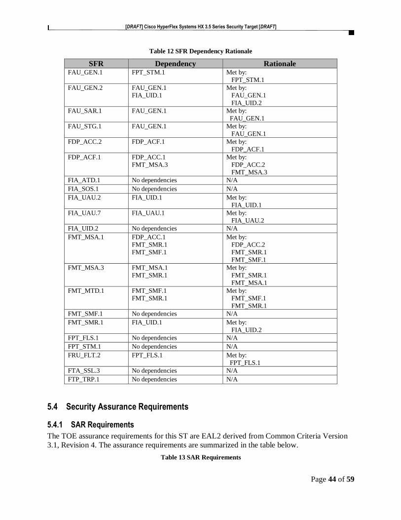
[DRAFT] Cisco HyperFlex Systems HX 3.5 Series Security Target [DRAFT]
Page 44 of 59
Table 12 SFR Dependency Rationale
SFR Dependency Rationale FAU_GEN.1 FPT_STM.1 Met by:
FPT_STM.1
FAU_GEN.2 FAU_GEN.1
FIA_UID.1
Met by:
FAU_GEN.1
FIA_UID.2
FAU_SAR.1 FAU_GEN.1 Met by:
FAU_GEN.1
FAU_STG.1 FAU_GEN.1 Met by:
FAU_GEN.1
FDP_ACC.2 FDP_ACF.1 Met by:
FDP_ACF.1
FDP_ACF.1 FDP_ACC.1
FMT_MSA.3
Met by:
FDP_ACC.2
FMT_MSA.3
FIA_ATD.1 No dependencies N/A
FIA_SOS.1 No dependencies N/A
FIA_UAU.2 FIA_UID.1 Met by:
FIA_UID.1
FIA_UAU.7 FIA_UAU.1 Met by:
FIA_UAU.2
FIA_UID.2 No dependencies N/A
FMT_MSA.1 FDP_ACC.1
FMT_SMR.1
FMT_SMF.1
Met by:
FDP_ACC.2
FMT_SMR.1
FMT_SMF.1
FMT_MSA.3 FMT_MSA.1
FMT_SMR.1
Met by:
FMT_SMR.1
FMT_MSA.1
FMT_MTD.1 FMT_SMF.1
FMT_SMR.1
Met by:
FMT_SMF.1
FMT_SMR.1
FMT_SMF.1 No dependencies N/A
FMT_SMR.1 FIA_UID.1 Met by:
FIA_UID.2
FPT_FLS.1 No dependencies N/A
FPT_STM.1 No dependencies N/A
FRU_FLT.2 FPT_FLS.1 Met by:
FPT_FLS.1
FTA_SSL.3 No dependencies N/A
FTP_TRP.1 No dependencies N/A
5.4 Security Assurance Requirements
5.4.1 SAR Requirements
The TOE assurance requirements for this ST are EAL2 derived from Common Criteria Version
3.1, Revision 4. The assurance requirements are summarized in the table below.
Table 13 SAR Requirements
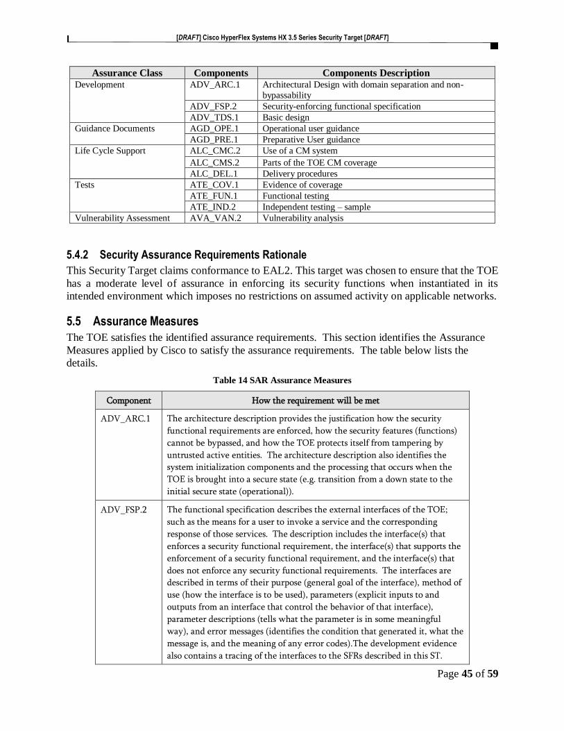
[DRAFT] Cisco HyperFlex Systems HX 3.5 Series Security Target [DRAFT]
Page 45 of 59
Assurance Class Components Components Description Development ADV_ARC.1 Architectural Design with domain separation and non-
bypassability
ADV_FSP.2 Security-enforcing functional specification
ADV_TDS.1 Basic design
Guidance Documents AGD_OPE.1 Operational user guidance
AGD_PRE.1 Preparative User guidance
Life Cycle Support ALC_CMC.2 Use of a CM system
ALC_CMS.2 Parts of the TOE CM coverage
ALC_DEL.1 Delivery procedures
Tests ATE_COV.1 Evidence of coverage
ATE_FUN.1 Functional testing
ATE_IND.2 Independent testing – sample
Vulnerability Assessment AVA_VAN.2 Vulnerability analysis
5.4.2 Security Assurance Requirements Rationale
This Security Target claims conformance to EAL2. This target was chosen to ensure that the TOE
has a moderate level of assurance in enforcing its security functions when instantiated in its
intended environment which imposes no restrictions on assumed activity on applicable networks.
5.5 Assurance Measures
The TOE satisfies the identified assurance requirements. This section identifies the Assurance
Measures applied by Cisco to satisfy the assurance requirements. The table below lists the
details.
Table 14 SAR Assurance Measures
Component How the requirement will be met
ADV_ARC.1 The architecture description provides the justification how the security
functional requirements are enforced, how the security features (functions)
cannot be bypassed, and how the TOE protects itself from tampering by
untrusted active entities. The architecture description also identifies the
system initialization components and the processing that occurs when the
TOE is brought into a secure state (e.g. transition from a down state to the
initial secure state (operational)).
ADV_FSP.2 The functional specification describes the external interfaces of the TOE;
such as the means for a user to invoke a service and the corresponding
response of those services. The description includes the interface(s) that
enforces a security functional requirement, the interface(s) that supports the
enforcement of a security functional requirement, and the interface(s) that
does not enforce any security functional requirements. The interfaces are
described in terms of their purpose (general goal of the interface), method of
use (how the interface is to be used), parameters (explicit inputs to and
outputs from an interface that control the behavior of that interface),
parameter descriptions (tells what the parameter is in some meaningful
way), and error messages (identifies the condition that generated it, what the
message is, and the meaning of any error codes).The development evidence
also contains a tracing of the interfaces to the SFRs described in this ST.

[DRAFT] Cisco HyperFlex Systems HX 3.5 Series Security Target [DRAFT]
Page 46 of 59
Component How the requirement will be met
ADV_TDS.1 The TOE design describes the TOE security functional (TSF) boundary and
how the TSF implements the security functional requirements. The design
description includes the decomposition of the TOE into subsystems and/or
modules, thus providing the purpose of the subsystem/module, the behavior
of the subsystem/module and the actions the subsystem/module performs.
The description also identifies the subsystem/module as SFR (security
function requirement) enforcing, SFR supporting, or SFR non-interfering;
thus identifying the interfaces as described in the functional specification.
In addition, the TOE design describes the interactions among or between the
subsystems/modules; thus providing a description of what the TOE is doing
and how.
AGD_OPE.1 The Administrative Guide provides the descriptions of the processes and
procedures of how the administrative users of the TOE can securely
administer the TOE using the interfaces that provide the features and
functions detailed in the guidance.
AGD_PRE.1 The Installation Guide describes the installation, generation, and startup
procedures so that the users of the TOE can put the components of the TOE
in the evaluated configuration.
ALC_CMC.2 The Configuration Management (CM) document(s) describes how the
consumer (end-user) of the TOE can identify the evaluated TOE (Target of
Evaluation). The CM document(s), identifies the configuration items, how
those configuration items are uniquely identified, and the adequacy of the
procedures that are used to control and track changes that are made to the
TOE. This includes details on what changes are tracked, how potential
changes are incorporated, and the degree to which automation is used to
reduce the scope for error.
ALC_CMS.2
ALC_DEL.1 The Delivery document describes the delivery procedures for the TOE to
include the procedure on how to download certain components of the TOE
from the Cisco website and how certain components of the TOE are
physically delivered to the user. The delivery procedure detail how the end-
user may determine if they have the TOE and if the integrity of the TOE has
been maintained. Further, the delivery documentation describes how to
acquire the proper license keys to use the TOE components.
ATE_COV.1 The Test document(s) consist of a test plan describes the test configuration,
the approach to testing, and how the subsystems/modules and TSFI (TOE
security function interfaces) has been tested against its functional
specification and design as described in the TOE design and the security
architecture description. The test document(s) also include the test
cases/procedures that show the test steps and expected results, specify the
actions and parameters that were applied to the interfaces, as well as how
the expected results should be verified and what they are. Actual results are
also included in the set of Test documents.
ATE_FUN.1
ATE_IND.2 Cisco will provide the TOE for testing.

[DRAFT] Cisco HyperFlex Systems HX 3.5 Series Security Target [DRAFT]
Page 47 of 59
Component How the requirement will be met
AVA_VAN.2 Cisco will provide the TOE for testing.

[DRAFT] Cisco HyperFlex Systems HX 3.5 Series Security Target [DRAFT]
Page 48 of 59
6 TOE SUMMARY SPECIFICATION
6.1 TOE Security Functional Requirement Measures
This section identifies and describes how the Security Functional Requirements identified above
are met by the TOE.
Table 15 How TOE SFRs Measures
TOE SFRs How the SFR is Met
FAU_GEN.1 Auditing is on by default at TOE startup and cannot be turned off A record is generated when
the TOE starts and when the TOE is shutdown, thus indicating the starting and stopping of
auditing.
Each auditable event, the recorded information includes the user that triggered the event, the
outcome or result of the event and when the event occurred.
The user that triggered the event could be a human user where the user identity or related
session ID would be included in the audit record. For an IT entity or device, the IP address,
MAC address, host name, or other configured identification is presented.
The auditable events include:
Auditable Events Rationale Additional Audit
Record Contents
FIA_UAU.2 - All use of the
authentication mechanism.
All login attempts
(Successful and failed) to the
TOE HX Connect GUI and
HXCLI are logged. The
record is logged to the local
audit storage
Provided user identity,
origin of the attempt
(e.g., IP address). FIA_UID.2 - All use of the
identification mechanism.
FMT_MSA.3 -
Modifications of the default
setting of permissive or
restrictive rules and all
modifications of the initial
values of security attributes
Successful and failed
attempts to change the
configuration data are logged
in the local audit log
None
FMT_MTD.1 - All
modifications to the values
of TSF data
Successful and failed
attempts to change the
configuration data are logged
in the local audit log
The identity of the
authorized administrator
performing the operation.
FMT_SMF.1 - Use of the
management functions
Successful and failed
attempts to change the
configuration data are logged
in the local audit log
The identity of the
authorized administrator
performing the operation.
FPT_FLS.1 – Failure with a
preservation of secure state
Failure of the TSF None
FAU_GEN.2

[DRAFT] Cisco HyperFlex Systems HX 3.5 Series Security Target [DRAFT]
Page 49 of 59
TOE SFRs How the SFR is Met
FPT_STM.1 - Changes to
the time
Successful and failed
attempts to change the time
zone and any time-related parameters including NTP
server configuration are
logged in the local audit log.
Manual setting of the clock
can only be performed via the
CLI
The identity of the
authorized administrator
performing the operation.
FRU_FLT.2 – Limited fault
tolerance
Any failure detected by the
TSF. None
FTA_SSL.3 - Termination of
an interactive session by the
session locking mechanism
Termination of the inactive
session. None
FTP_TRP.1 - Attempts to
use the trusted path
functions.
Successful and failed
attempts to use SSHv2 or
HTTPS/TLSv1.2 are logged
in the local audit log
Identification of the user
associated with all
trusted path invocations
including failures, if
available.
FAU_SAR.1 The TOE provides the Authorized Administrator the ability to delete the audit records to
manage audit log space.
These audit records are available for review through the HX Connect GUI and the HXCLI
interfaces. There are no other methods to view the audit records.
The audit records include sufficient information for the Authorized Administrator to determine
the event, the user who initiated the event, the date and time of the event and the outcome.
Audit records are generated for all of the Converged Host clusters and datastores.
FAU_STG.1 The audit records are stored in an internal file and this internal file cannot be altered.
Using the HX Connect GUI webpages and the HXCLI commands, Task Viewer, the
Authorized Administrator can view the audit records once they have been successfully
identified and authenticated. The HX Connect GUI webpages and the HXCLI commands
interface also provides the Authorized Administrator the capability to delete the audit logs to
manage the audit log space.
FDP_ACC.2
and
FDP_ACF.1
The Converged Host spans three or more Cisco HyperFlex HX Series nodes to create a highly
available Cluster and datastores. Each node includes a Cisco HyperFlex HX Data Platform
controller that implements the distributed file system using internal flash-based SSD drives
and high-capacity HDDs to store data.
The TOE implements whitelist access controls of the Remote Host access to the Converged
Host clusters and datastores. The whitelist is an IP table that includes the IP addresses of the
Host VMs that have access to the HX nodes clusters and datastores. If the IP address is
included on the whitelist and if there is sufficient storage capacity, access is granted otherwise
access is denied.

[DRAFT] Cisco HyperFlex Systems HX 3.5 Series Security Target [DRAFT]
Page 50 of 59
TOE SFRs How the SFR is Met
The Cisco HyperFlex HX Data Platform controller handles all read and write requests for
volumes that the hypervisor accesses and thus mediates all I/O from the virtual machines. The
data platform implements a log-structured file system that uses a caching layer in SSD drives
to accelerate read requests and write responses, and a persistence layer implemented with
HDDs.
FIA_ATD.1 The TOE supports definition of Authorized Administrator by individual user IDs. For each
Authorized Administrator, the TOE maintains the following attributes:
a) user identity
b) password
Authorized Administrator are administrators that are granted access to specific resources and
permission to perform specific tasks.
FIA_SOS.1 To prevent users from choosing insecure passwords, the TOE prompts the user that the
password should meet the following requirements:
• At least eight characters long
• includes upper and lower characters
• Includes alpha numeric characters
This requirement applies to the local password database and on the password selection
functions provided by the TOE.
FIA_UID.2
and
FIA_UAU.2
By default, the TOE uses the local database for identification and authentication.
No access is allowed prior encountering an authentication prompt and then being successfully
identified and authenticated.
Only after authentication, is the Authorized Administrator able to perform any actions.
FIA_UAU.7 When a user enters their password for remote session authentication, the TOE does not echo
any characters as they are entered.
FMT_MSA.1 The TOE provides the Authorized Administrator the ability to modify the default security
attribute values used for resource and access control.
FMT_MSA.3 The TOE provides restrictive default values for resources and access control.
No access is allowed to the protected resources unless the attributes match, and resources are
available.
FMT_MTD.1 The TOE provides the ability for Authorized Administrator to access TOE data, such as audit
data, configuration data, security attributes, session thresholds and updates.
FMT_SMF.1 The TOE provides all the capabilities necessary to securely manage the TOE. The Authorized
Administrator can connect to the TOE using the HX Connect GUI webpages using
HTTPS/TLSv1.2 and the HXCLI commands using SSHv2 to perform these functions.

[DRAFT] Cisco HyperFlex Systems HX 3.5 Series Security Target [DRAFT]
Page 51 of 59
TOE SFRs How the SFR is Met
The specific management capabilities available from the TOE include:
• Administer the TOE remotely
• Manage access control attributes
• Manage Authorized Administrator’s security attributes
• Review audit record logs
• Configure and manage the system time
FMT_SMR.1 The TOE maintains Authorized Administrator role to administer the TOE remotely. The TOE
maintains Authorized Administrator role to administer the TOE remotely. During the installation
of the TOE Authorized Administrator user is created. Additional Authorized Administrator users
may be created; each must be assigned a unique user name and password.
All users of the TOE are considered Authorized Administrators. It is assumed all administrators
are trusted, trained, knowledgeable, and will follow the guidance to ensure the TOE is properly
monitored and operated in a secure manner.
The Authorized Administrator can connect to the TOE using the HX Connect GUI webpages
using HTTPS/TLSv1.2 and the HXCLI commands using SSHv2 to secure the connection.
FPT_FLS.1 The TOE provides the capability to take a snapshot in time of the HX Data Platform VMs.
Snapshots help facilitate backup and remote-replication operations where the organization
requires an ‘always-on’ data availability. The snapshot is a reproduction of the VM that
includes the state of the data on all VM disks and the VM poser state ((on, off or suspended) at
the time, the snapshot is taken. The snapshot is saved so the Authorized Administrator has the
option to revert to the saved state.
For each VM in your storage cluster, you can schedule hourly, daily, or weekly snapshots. You
can schedule snapshots to adjust to the organizations backup requirements. For example, you
can retain more frequent snapshots of critical data so if there is a failure, you can restore the
most recent snapshots. For example, the initial HyperFlex native snapshot with the virtual
machine powered off. This creates what is called the Sentinel snapshot. The Sentinel snapshot
becomes a base snapshot that all future snapshots are added. Snapshots can be scheduled to
occur at specific days and times.
If a disk failure happens, the TOE cluster states turns to ‘unhealthy’ and a rebalancing job is
triggered to return the system to the specified replication factor, replicating the missing data
on the disk from the remaining copies and once the job completes the cluster returns to a
healthy state.
FPT_STM.1 The TOE provides a source of date and time information used in audit event timestamps. The
TOE is configured to use NTP to synchronize the TOE’s clock with an external time source.
This date and time is used as the timestamp that is applied to audit records generated by the
TOE and to track inactivity of administrative sessions. The timestamps are synchronized
across the Cisco HyperFlex HX Series Nodes, the storage controller VMs (storage controller)
and ESXi hosts (Hypervisor).
FRU_FLT.2 The TOEs High Availability (HA) feature ensures that the storage cluster maintains at least
two copies of all data during normal operation with three or more fully functional nodes.

[DRAFT] Cisco HyperFlex Systems HX 3.5 Series Security Target [DRAFT]
Page 52 of 59
TOE SFRs How the SFR is Met
If one or more nodes in the storage cluster fail, the state of the storage cluster is affected,
however data is preserved. If more than one node and/or disk fail, it is called a simultaneous
failure. The number of nodes in the storage cluster, the Data Replication Factor and Access
Policy settings determine the state of the storage cluster that results from node failures. The
strict setting helps protect the data in event of simultaneous failures.
Data Replication Factor provides the option to set the number of redundant replicas of data
across the storage cluster. The choices are:
• Data Replication Factor 3 — Keep three redundant replicas of the data. This
consumes more storage resources and ensures the maximum protection for your data
in the event of node or disk failure.
o Data Replication Factor 3 is the recommended option.
• Data Replication Factor 2 — Keep two redundant replicas of the data. This consumes
fewer storage resources but reduces your data protection in the event of node or disk
failure.
FTA_SSL.3 When a session is inactive (i.e. no session input) for more than the Authorized Administrator
configured time, the TOE will terminate the session and no further activity is allowed,
requiring the Authorized Administrator to log in (be successfully identified and
authenticated) again to establish a new session.
The timeout value is configurable. The default setting is 120 minutes of idle time.
FTP_TRP.1 The TOE ensures the communication path and the remote administer interfaces is protected
and distinct from other communications paths. The HX Connect GUI uses HTTPS/TLSv1.2
and HXCLI uses SSHv2.
6.2 TOE Bypass and interference/logical tampering Protection Measures
The TOE consists of a hardware platform in which all operations in the TOE scope are
protected from interference and tampering by untrusted subjects. All administration and
configuration operations are performed within the physical boundary of the TOE. In
addition, all security policy enforcement functions must be invoked and succeed prior to
functions proceeding.
The TOE has been designed so that all locally maintained TSF data can only be manipulated
via the HX Connect GUI and HXCLI interfaces. There are no undocumented interfaces for
managing the product.
All sub-components included in the TOE rely on the main chassis for power and memory
while the TOE software provides the management functions and control. In order to access
any portion of the TOE, the Identification and Authentication mechanisms of the TOE must
be invoked and succeed.

[DRAFT] Cisco HyperFlex Systems HX 3.5 Series Security Target [DRAFT]
Page 53 of 59
No processes outside of the TOE are allowed direct access to any TOE memory. The TOE
only accepts traffic through legitimate TOE interfaces. Specifically, processes outside the
TOE are not able to execute code on the TOE. None of these interfaces provides any access
to internal TOE resources.
Only the Authorized Administrator has access to the TOE security functions.
There are no unmediated traffic flows into or out of the TOE or unauthenticated access,
thus providing a distinct protected domain for the TOE that is logically protected from
interference and is not bypassable.
7 RATIONALE This section describes the rationale for the Security Objectives and Security Functional
Requirements as defined within this Security Target.
7.1 Rationale for TOE Security Objectives
Table 16 Threats & IT Security Objectives Mappings
T.A
CC
OU
NT
AB
ILIT
Y
T.N
OA
UT
H
T.R
ES
OU
RC
E_
AV
AIL
AB
ILIT
Y
O.ACCESS_CONTROL X
O.ADMIN X X
O.AUDIT_GEN X
O.AVAILABILITY X
O.AUDIT_VIEW X
O. DATA X
O.IDAUTH X
O.SELFPRO X
O.TIME X
Table 17 TOE Threat/Policy/Objective Rationale
Threat / Policy Rationale for Coverage T.ACCOUNTABILITY An authorized administrative is not held accountable for their
actions on the TOE because the audit records are not generated, do
not include the required data, including properly sequenced

[DRAFT] Cisco HyperFlex Systems HX 3.5 Series Security Target [DRAFT]
Page 54 of 59
Threat / Policy Rationale for Coverage through application of correct timestamps or reviewed. The
O.AUDIT_GEN objective mitigates the threat by requiring the
TOE generate audit records for events performed on the TOE.
The O.AUDIT_VIEW requires the TOE to provide the
authorized administrator with the capability to view audit data.
The O.TIME objective mitigates this threat by providing the
accurate time to the TOE for use in the audit records
O.AUDIT_GEN.
T.NOAUTH O.SELFPRO objective ensures that an unauthorized person
(attacker) that may attempt to bypass the security of the TOE to
access data and use security functions and/or non-security
functions provided by the TOE to disrupt operations of the
TOE is not successful. The O.DATA objective protects the
configuration and user data from unauthorized disclosure. The
O.IDAUTH objective requires the administrative user to enter a
unique identifier and authentication credentials before
management access is granted. The O.ADMIN objective ensures
the authorized administrator has access to the TOE to configure
access controls and the O.ACCESS_CONTROL objective
restricts access to the TOE management functions to the
Authorized Administrator.
T.RESOURCE_AVAILABILITY The TOE user data could become corrupted or unavailable due
to hardware or system operation failures. The
O.AVAILABILITY objective to maintain a secure state and to
protect user data from loss or corruption due to hardware or
system operation failures. The O.ADMIN ensures the
administrator has the capabilities to ensure proper
configuration for maintaining a secure state and resource
availability.
7.2 Rationale for the Security Objectives for the Environment
The security requirements are derived according to the general model presented in Part 1
of the Common Criteria. Specifically, the tables below illustrate the mapping between the
security requirements and the security objectives and the relationship between the threats,
policies and IT security objectives. The functional and assurance requirements presented
in this Security Target are mutually supportive and their combination meets the stated
security objectives.
Table 18 Threats & IT Security Objectives Mappings for the Environment
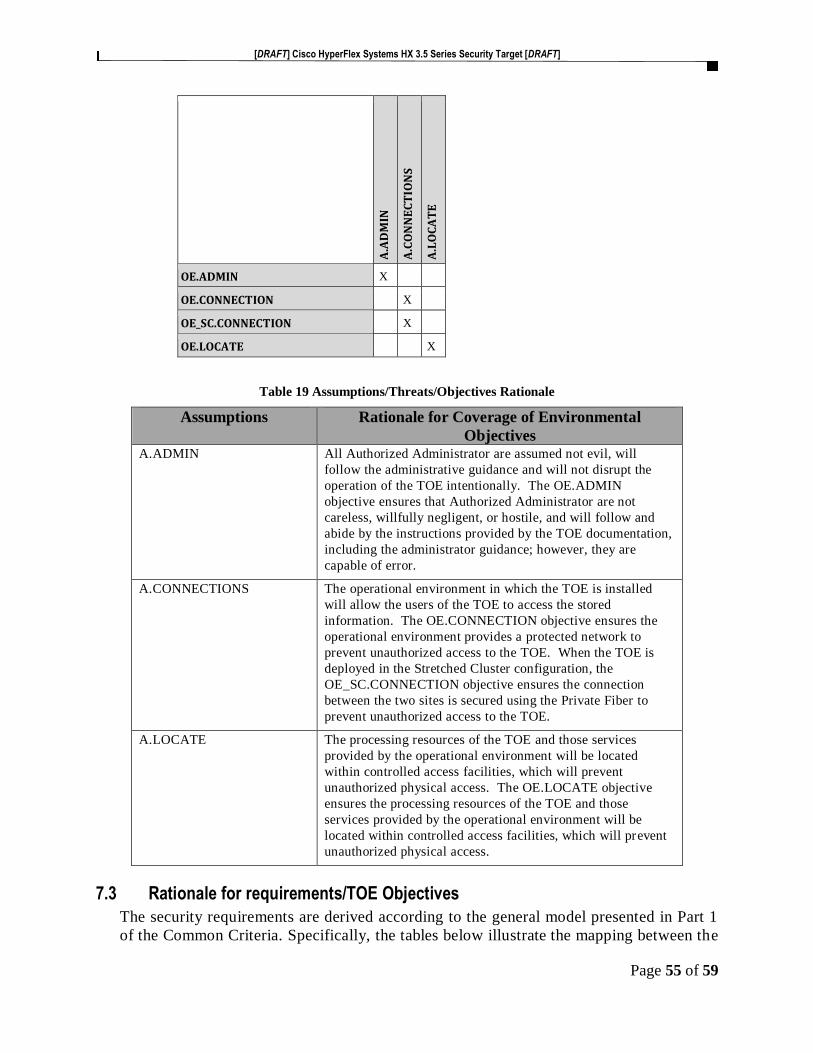
[DRAFT] Cisco HyperFlex Systems HX 3.5 Series Security Target [DRAFT]
Page 55 of 59
A.A
DM
IN
A.C
ON
NE
CT
ION
S
A.L
OC
AT
E
OE.ADMIN X
OE.CONNECTION X
OE_SC.CONNECTION X
OE.LOCATE X
Table 19 Assumptions/Threats/Objectives Rationale
Assumptions Rationale for Coverage of Environmental
Objectives A.ADMIN All Authorized Administrator are assumed not evil, will
follow the administrative guidance and will not disrupt the
operation of the TOE intentionally. The OE.ADMIN
objective ensures that Authorized Administrator are not
careless, willfully negligent, or hostile, and will follow and
abide by the instructions provided by the TOE documentation,
including the administrator guidance; however, they are
capable of error.
A.CONNECTIONS The operational environment in which the TOE is installed
will allow the users of the TOE to access the stored
information. The OE.CONNECTION objective ensures the
operational environment provides a protected network to
prevent unauthorized access to the TOE. When the TOE is
deployed in the Stretched Cluster configuration, the
OE_SC.CONNECTION objective ensures the connection
between the two sites is secured using the Private Fiber to
prevent unauthorized access to the TOE.
A.LOCATE The processing resources of the TOE and those services
provided by the operational environment will be located
within controlled access facilities, which will prevent
unauthorized physical access. The OE.LOCATE objective
ensures the processing resources of the TOE and those
services provided by the operational environment will be
located within controlled access facilities, which will prevent
unauthorized physical access.
7.3 Rationale for requirements/TOE Objectives
The security requirements are derived according to the general model presented in Part 1
of the Common Criteria. Specifically, the tables below illustrate the mapping between the

[DRAFT] Cisco HyperFlex Systems HX 3.5 Series Security Target [DRAFT]
Page 56 of 59
security requirements and the security objectives and the relationship between the threats,
and IT security objectives.
Table 20 Security Objective to Security Requirements Mappings
O.A
CC
ES
S_C
ON
TR
OL
L
O.A
DM
IN
O.A
UD
IT_G
EN
O.A
VA
ILA
BIL
ITY
O.A
UD
IT_
VIE
W
O.D
AT
A
O.I
DA
UT
H
O.S
EL
PR
O
O.T
IME
FAU_GEN.1 X X X
FAU_GEN.2 X X
FAU_SAR.1 X
FAU_STG.1 X
FDP_ACC.2 X X
FDP_ACF.1 X X
FIA_ATD.1 X X X
FIA_SOS.1 X
FIA_UAU.2 X X X
FIA_UAU.7 X
FIA_UID.2 X X X
FMT_MSA.1 X X X
FMT_MSA.3 X X X
FMT_MTD.1 X X
FMT_SMF.1 X X X
FMT_SMR.1 X X
FPT_FLS.1 X
FPT_STM.1 X X
FRU_FLT.2 X
FTA_SSL.3 X X X
FTP_TRP.1 X X X

[DRAFT] Cisco HyperFlex Systems HX 3.5 Series Security Target [DRAFT]
Page 57 of 59
Table 21 Objectives to Requirements Rationale
Objective Rationale O.ACCESS_CONTROL The TOE will restrict access to the TOE Management functions to the
Authorized Administrator. The TOE is required to provide the ability
to restrict the use of TOE management/administration/security
functions to Authorized Administrator of the TOE. The Authorized
Administrator performs these functions on the TOE. Only Authorized
Administrator of the TOE may modify TSF data [FMT_MTD.1] and
delete audit data stored locally on the TOE [FAU_STG.1]. The TOE
must be able to recognize the administrative privilege level that exists
for the TOE [FIA_ATD.1, FMT_SMR.1]. The TOE must allow the
Authorized Administrator to specify alternate initial values when an
object is created [FMT_MSA.1, FMT_MSA.3]. The TOE ensures that
all user actions resulting in the access to TOE security functions and configuration data are controlled [FMT_SMF.1] and audited
[FAU_GEN.1, FAU_GEN.2]. The SFR FTA_SSL.3 also meets this
objective by terminating a session due to meeting/exceeding the
inactivity time limit.
O.ADMIN The TOE will provide administrative functions to isolate
administrative actions by configuring and assigning Authorized
Administrator accounts [FIA_ATD.1, FMT_SMR.1], thus controlling
access to the TSF data and configuration [FMT_MSA.1,
FMT_MSA.3, FMT_MTD.1, FMT_SMF.1, FMT_SMR.1]. The TOE
will also make the administrative functions available remotely via
SSHv2 and HTTPS/TLSv1.2 [FTP_TRP.1].
O.AUDIT_GEN The TOE will generate audit records which will include the time
[FPT_STM.1] that the event occurred and if applicable, the identity of
the user performing the event [FAU_GEN.2]. All TOE security
relevant events are auditable and will include the required information
to identify when the event occurred, the event, who performed the
action, and the success or failure of the event [FAU_GEN.1 and
FAU_GEN.2]. Timestamps associated with the audit record must be
reliable [FPT_STM.1].
O.AVAILABILITY The TOE will provide mechanisms to maintain a secure state and
mitigate against user data disclosure, loss or corruption due to
hardware or system operation failures [FPT_FLS.1 and
FRU_FTL.2].
O.AUDIT_VIEW The TOE will provide the Authorized Administrator the capability to
review Audit data via the HX Connect GUI and HXCLI interfaces.
Security relevant events are available for review by Authorized
Administrator [FAU_SAR.1].
O.DATA The TOE is required to protect the TSF data from unauthorized access
therefore each Authorized Administrator must be identified and
authenticated prior to gaining access [FIA_UAU.2 and FIA_UID.2].
The TOE ensures that access to TOE configuration settings (HX
Connect GUI webpages and HXCLI commands), data and resources is
done in accordance with the management functions [FMT_SMF.1].
The TOE is also required to restrict access to the HX clusters and
datastores [FDP_ACC.2, FDP_ACF.1].

[DRAFT] Cisco HyperFlex Systems HX 3.5 Series Security Target [DRAFT]
Page 58 of 59
Objective Rationale
O.IDAUTH The TOE must uniquely identify and authenticate the claimed identity of all administrative users before granting management access. The
Authorized Administrators’ password must meet formatting
requirements to prevent the use of weak credentials [FIA_SOS.1]. The
TOE is required to store user security attributes to enforce the
authentication policy of the TOE and to associate security attributes
with users [FIA_ATD.1]. Users authorized to access the TOE must be
defined using an identification and authentication process and all
users must be successfully identified and authenticated [FIA_UID.2
and FIA_UAU.2]. The password is obscured when entered
[FIA_UAU.7]. If the period of inactivity has been exceeded, the user
is required to re-authenticate to re-establish the session [FTA_SSL.3].
O.SELFPRO The TOE must protect itself against attempts by unauthorized users to bypass, deactivate, or tamper with TOE security functions.
[FDP_ACC.2, FDP_ACF.1, FIA_UID.2 and FIA_UAU.2] supports
this objective by ensuring access to the resources is controlled and
only Authorized Administrator can manage the resources
[FMT_MSA.1 and FMT_MSA.3]. The [FTP_TRP.1] ensures the
communication path and the remote administer interfaces is protected
and distinct from other communications paths. The SFR
[FTA_SSL.3] also meet this objective by terminating a session due to
meeting/exceeding the inactivity time limit thus ensuring the session
does not remain active and subject to attack.
O.TIME The TSF will provide a reliable time stamp for its own use. The TOE is required to provide reliable timestamps for use with the audit record
[FAU_GEN.1, FPT_STM.1]. The TOE is configured to synchronize
its clock with an NTP server.
[DRAFT] Cisco HyperFlex Systems HX 3.5 Series Security Target [DRAFT]
Page 59 of 59
8 ANNEX A: REFERENCES
The following documentation was used to prepare this ST:
Table 22 References
Identifier Description
[CC_PART1] Common Criteria for Information Technology Security Evaluation – Part 1: Introduction
and general model, dated September 2012, version 3.1, Revision 5, dated April 2017
[CC_PART2] Common Criteria for Information Technology Security Evaluation – Part 2: Security
functional components, dated September 2012, version 3.1, Revision 5, dated April 2017
[CC_PART3] Common Criteria for Information Technology Security Evaluation – Part 3: Security
assurance components, dated September 2012, version 3.1, Revision 5, dated April 2017
[CEM] Common Methodology for Information Technology Security Evaluation – Evaluation
Methodology, dated September 2012, version 3.1, Revision 5, dated April 2017