cisco enterprise network functions virtualization white paper
TRANSCRIPT
White Paper
© 2017 Cisco and/or its affiliates. All rights reserved. This document is Cisco Public Information. Page 1 of 18
Cisco Enterprise Network Functions Virtualization
Introduction
Network functions virtualization (NFV) is becoming the next disruptive wave in networking. NFV is an architectural
approach that focuses on decoupling individual services such as Network Address Translation (NAT), access
control lists (ACL), quality of service (QoS), Layer 3 routing, intrusion prevention and intrusion detection systems
(IPS and IDS), and more from the underlying hardware platform. Allowing such functions to run inside virtual
machines, on top of standard x86 resources, increases the deployment flexibility in the network. NFV is typically
accompanied by software-defined networking (SDN) approaches (network controllers and orchestration) to offer
automation and rapid service deployment of networking functions. Therefore, it promises to significantly contribute
to network operating expenditure (OpEx) reductions.
This white paper provides a technical overview of the Cisco® Enterprise Network Functions Virtualization
(Enterprise NFV) solution. Cisco Enterprise NFV is an end-to-end solution that addresses all requirements for
deploying virtualized network and application services, from orchestration and management to the virtualization
software package, as well as options for different hardware platforms. The solution also addresses the use of Cisco
and third-party service functions.
Motivation
Today’s enterprise branch architectures often host a myriad of devices to accomplish required network
functionality. Network appliances that perform WAN optimization, firewall protection, intrusion detection system
(IDS) and prevention (IPS) or voice services are operated alongside routers and switches. In high-end branch
environments, these devices are even deployed with redundancy, further adding to the hardware landscape that
has to be installed and operated in the branch.
© 2017 Cisco and/or its affiliates. All rights reserved. This document is Cisco Public Information. Page 2 of 18
Cisco Enterprise NFV reduces the operational complexity of such branch environments by running the required
networking functions as software on standard x86-based hosts. In particular, the Cisco Enterprise NFV solution:
● Reduces the number of hardware elements to be managed at the branch, therefore reducing the need to
perform costly site visits for hardware installations or upgrades
● Increases speed of deployment for networking services by offering a software-only approach to service
delivery
● Automates the deployment, management, and operations of branch functions, which diminishes operational
expenses
● Facilitates the deployment of best-of-breed functions by taking an open approach to networking
● Enhances network operations flexibility by taking full advantage of virtualization techniques such as virtual
machine moves, snapshots, or upgrades
Solution Architecture
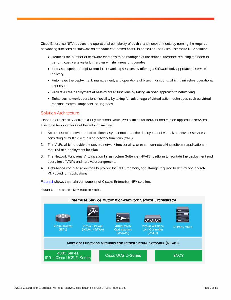
Cisco Enterprise NFV delivers a fully functional virtualized solution for network and related application services.
The main building blocks of the solution include:
1. An orchestration environment to allow easy automation of the deployment of virtualized network services,
consisting of multiple virtualized network functions (VNF)
2. The VNFs which provide the desired network functionality, or even non-networking software applications,
required at a deployment location
3. The Network Functions Virtualization Infrastructure Software (NFVIS) platform to facilitate the deployment and
operation of VNFs and hardware components
4. X-86-based compute resources to provide the CPU, memory, and storage required to deploy and operate
VNFs and run applications
Figure 1 shows the main components of Cisco’s Enterprise NFV solution.
Figure 1. Enterprise NFV Building Blocks
© 2017 Cisco and/or its affiliates. All rights reserved. This document is Cisco Public Information. Page 3 of 18
Orchestration and Management
Most WANs today support or require several functions, including routing, intelligent path selection, WAN and
application performance, caching, security, Internet of Things (IoT), and more. Imagine if you had a software
platform that helps you create new services and launch them in a fraction of the time it takes now. Cisco Enterprise
Services Automation (ESA), the Cisco Application Policy Infrastructure Controller Enterprise Module (APIC-EM),
and Cisco Prime™
Infrastructure provide management and orchestration functionality in the Cisco Enterprise NFV
solution. One of the main functions of Cisco ESA is to turn up new locations or deployment of new virtualized
services in place of existing dedicated hardware.
Cisco Enterprise NFV orchestration and management delivers a unique capability that automates the highly
dynamic delivery of virtualized network services based on business or service intent, compared to traditional
management for physical appliances. Even though the movement to NFV is based on delivery of network services
using virtualized instances, there will still be a need for some dedicated physical devices for some time to come.
For this reason, Cisco Enterprise NFV supports services deployed in virtual and physical devices.
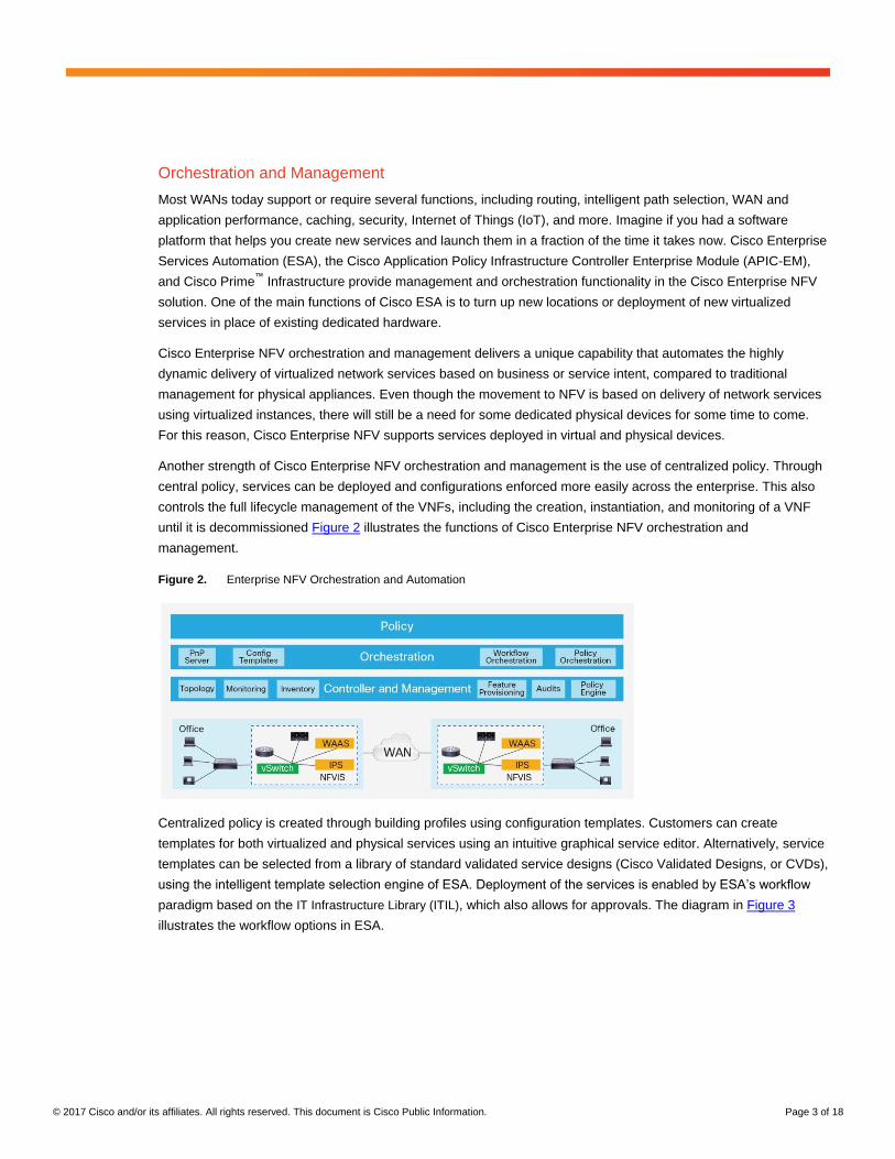
Another strength of Cisco Enterprise NFV orchestration and management is the use of centralized policy. Through
central policy, services can be deployed and configurations enforced more easily across the enterprise. This also
controls the full lifecycle management of the VNFs, including the creation, instantiation, and monitoring of a VNF
until it is decommissioned Figure 2 illustrates the functions of Cisco Enterprise NFV orchestration and
management.
Figure 2. Enterprise NFV Orchestration and Automation
Centralized policy is created through building profiles using configuration templates. Customers can create
templates for both virtualized and physical services using an intuitive graphical service editor. Alternatively, service
templates can be selected from a library of standard validated service designs (Cisco Validated Designs, or CVDs),
using the intelligent template selection engine of ESA. Deployment of the services is enabled by ESA’s workflow
paradigm based on the IT Infrastructure Library (ITIL), which also allows for approvals. The diagram in Figure 3
illustrates the workflow options in ESA.
© 2017 Cisco and/or its affiliates. All rights reserved. This document is Cisco Public Information. Page 4 of 18
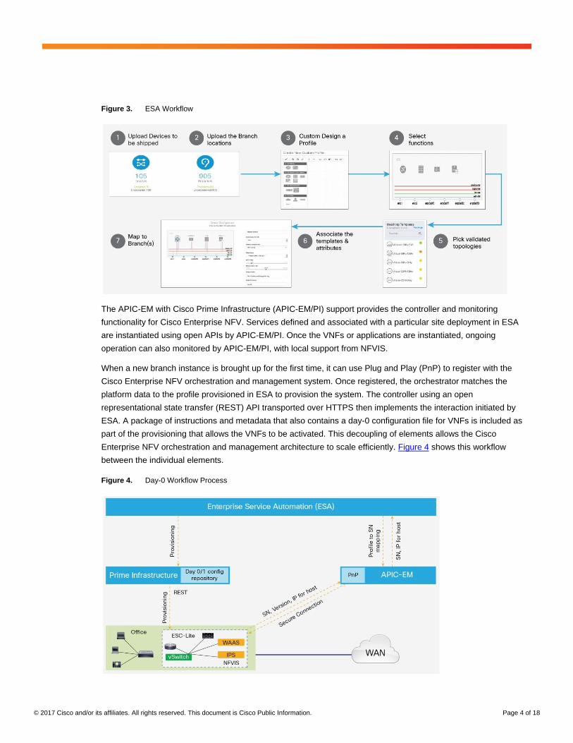
Figure 3. ESA Workflow
The APIC-EM with Cisco Prime Infrastructure (APIC-EM/PI) support provides the controller and monitoring
functionality for Cisco Enterprise NFV. Services defined and associated with a particular site deployment in ESA
are instantiated using open APIs by APIC-EM/PI. Once the VNFs or applications are instantiated, ongoing
operation can also monitored by APIC-EM/PI, with local support from NFVIS.
When a new branch instance is brought up for the first time, it can use Plug and Play (PnP) to register with the
Cisco Enterprise NFV orchestration and management system. Once registered, the orchestrator matches the
platform data to the profile provisioned in ESA to provision the system. The controller using an open
representational state transfer (REST) API transported over HTTPS then implements the interaction initiated by
ESA. A package of instructions and metadata that also contains a day-0 configuration file for VNFs is included as
part of the provisioning that allows the VNFs to be activated. This decoupling of elements allows the Cisco
Enterprise NFV orchestration and management architecture to scale efficiently. Figure 4 shows this workflow
between the individual elements.
Figure 4. Day-0 Workflow Process
© 2017 Cisco and/or its affiliates. All rights reserved. This document is Cisco Public Information. Page 5 of 18
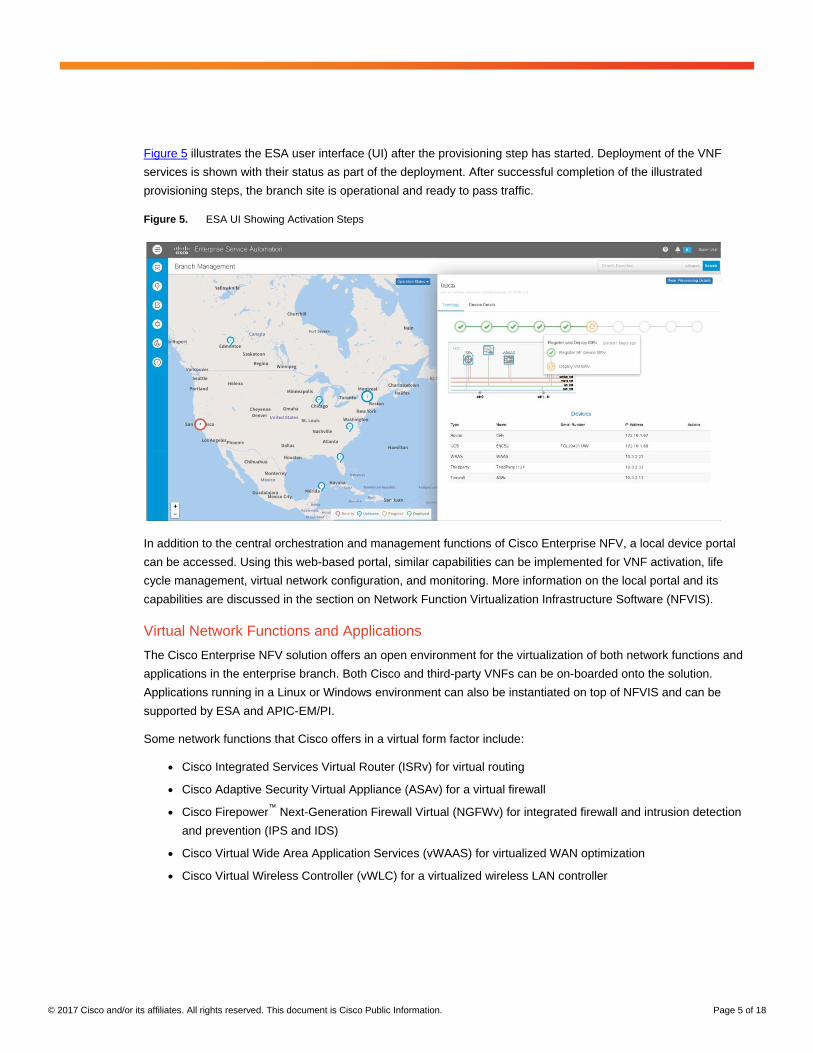
Figure 5 illustrates the ESA user interface (UI) after the provisioning step has started. Deployment of the VNF
services is shown with their status as part of the deployment. After successful completion of the illustrated
provisioning steps, the branch site is operational and ready to pass traffic.
Figure 5. ESA UI Showing Activation Steps
In addition to the central orchestration and management functions of Cisco Enterprise NFV, a local device portal
can be accessed. Using this web-based portal, similar capabilities can be implemented for VNF activation, life
cycle management, virtual network configuration, and monitoring. More information on the local portal and its
capabilities are discussed in the section on Network Function Virtualization Infrastructure Software (NFVIS).
Virtual Network Functions and Applications
The Cisco Enterprise NFV solution offers an open environment for the virtualization of both network functions and
applications in the enterprise branch. Both Cisco and third-party VNFs can be on-boarded onto the solution.
Applications running in a Linux or Windows environment can also be instantiated on top of NFVIS and can be
supported by ESA and APIC-EM/PI.
Some network functions that Cisco offers in a virtual form factor include:
● Cisco Integrated Services Virtual Router (ISRv) for virtual routing
● Cisco Adaptive Security Virtual Appliance (ASAv) for a virtual firewall
● Cisco Firepower™
Next-Generation Firewall Virtual (NGFWv) for integrated firewall and intrusion detection
and prevention (IPS and IDS)
● Cisco Virtual Wide Area Application Services (vWAAS) for virtualized WAN optimization
● Cisco Virtual Wireless Controller (vWLC) for a virtualized wireless LAN controller
© 2017 Cisco and/or its affiliates. All rights reserved. This document is Cisco Public Information. Page 6 of 18
In the case of third-party or application workloads (such as Domain Name System and Dynamic Host Configuration
Protocol [DNS/DHCP], web server, active directory, or software distribution), NFVIS instantiates the Linux or
Windows VMs where other applications can be installed.
Services running on Cisco Enterprise NFV as a virtual network function (VNF) can process packet flows in several
ways, depending on the operation that the specific VNF needs to perform. Examples include:
● Direct IP address
● Transparently in-line
● Packet diversion from another VNF
● Network Services Header (NSH)1
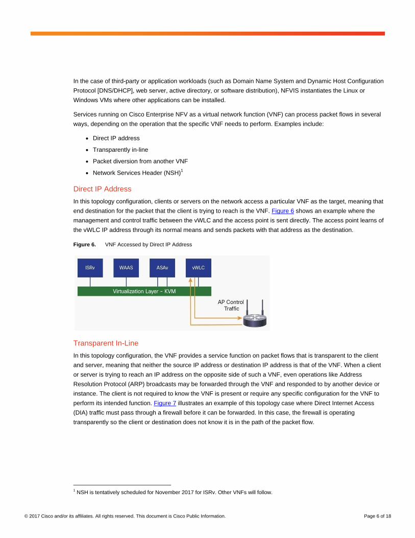
Direct IP Address
In this topology configuration, clients or servers on the network access a particular VNF as the target, meaning that
end destination for the packet that the client is trying to reach is the VNF. Figure 6 shows an example where the
management and control traffic between the vWLC and the access point is sent directly. The access point learns of
the vWLC IP address through its normal means and sends packets with that address as the destination.
Figure 6. VNF Accessed by Direct IP Address
Transparent In-Line
In this topology configuration, the VNF provides a service function on packet flows that is transparent to the client
and server, meaning that neither the source IP address or destination IP address is that of the VNF. When a client
or server is trying to reach an IP address on the opposite side of such a VNF, even operations like Address
Resolution Protocol (ARP) broadcasts may be forwarded through the VNF and responded to by another device or
instance. The client is not required to know the VNF is present or require any specific configuration for the VNF to
perform its intended function. Figure 7 illustrates an example of this topology case where Direct Internet Access
(DIA) traffic must pass through a firewall before it can be forwarded. In this case, the firewall is operating
transparently so the client or destination does not know it is in the path of the packet flow.
1 NSH is tentatively scheduled for November 2017 for ISRv. Other VNFs will follow.
© 2017 Cisco and/or its affiliates. All rights reserved. This document is Cisco Public Information. Page 7 of 18
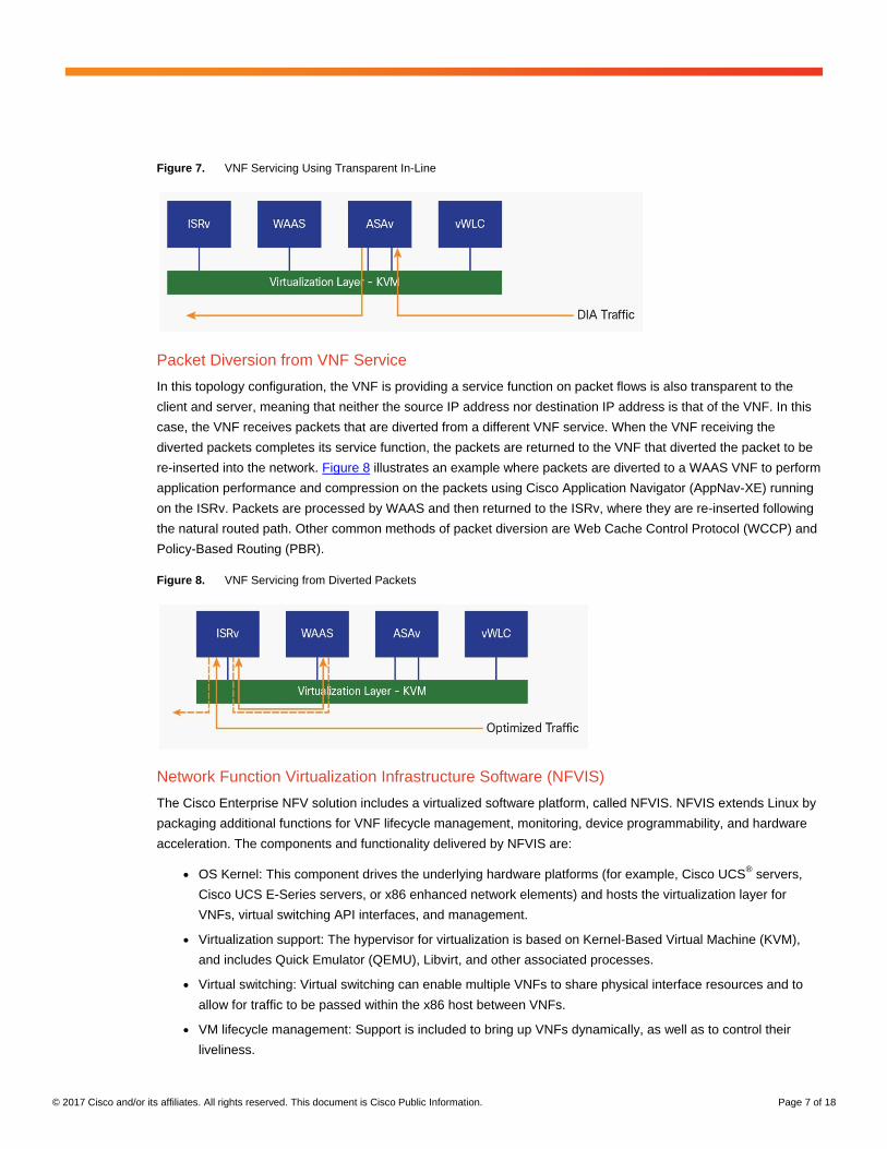
Figure 7. VNF Servicing Using Transparent In-Line
Packet Diversion from VNF Service
In this topology configuration, the VNF is providing a service function on packet flows is also transparent to the
client and server, meaning that neither the source IP address nor destination IP address is that of the VNF. In this
case, the VNF receives packets that are diverted from a different VNF service. When the VNF receiving the
diverted packets completes its service function, the packets are returned to the VNF that diverted the packet to be
re-inserted into the network. Figure 8 illustrates an example where packets are diverted to a WAAS VNF to perform
application performance and compression on the packets using Cisco Application Navigator (AppNav-XE) running
on the ISRv. Packets are processed by WAAS and then returned to the ISRv, where they are re-inserted following
the natural routed path. Other common methods of packet diversion are Web Cache Control Protocol (WCCP) and
Policy-Based Routing (PBR).
Figure 8. VNF Servicing from Diverted Packets
Network Function Virtualization Infrastructure Software (NFVIS)
The Cisco Enterprise NFV solution includes a virtualized software platform, called NFVIS. NFVIS extends Linux by
packaging additional functions for VNF lifecycle management, monitoring, device programmability, and hardware
acceleration. The components and functionality delivered by NFVIS are:
● OS Kernel: This component drives the underlying hardware platforms (for example, Cisco UCS® servers,
Cisco UCS E-Series servers, or x86 enhanced network elements) and hosts the virtualization layer for
VNFs, virtual switching API interfaces, and management.
● Virtualization support: The hypervisor for virtualization is based on Kernel-Based Virtual Machine (KVM),
and includes Quick Emulator (QEMU), Libvirt, and other associated processes.
● Virtual switching: Virtual switching can enable multiple VNFs to share physical interface resources and to
allow for traffic to be passed within the x86 host between VNFs.
● VM lifecycle management: Support is included to bring up VNFs dynamically, as well as to control their
liveliness.
© 2017 Cisco and/or its affiliates. All rights reserved. This document is Cisco Public Information. Page 8 of 18
● Plug and Play (PnP): This client automates the bringing up of any NFVIS-based host. The PnP client can
then communicate with a PnP server running in the DNA controller, and be loaded with the right host
configuration.
● REST, CLI, or NETCONF/YANG models are supported for orchestration and management.
● Web server: The web server can enable connectivity into NFVIS through HTTPS, which is particularly used
to support local management tools and orchestration APIs.
● Device management: Tools are packaged into NFVIS to support device management, including a resource
manager.
● Statistics: Tools like syslogd, snmpd, and collected assist in statistics collection and reporting.
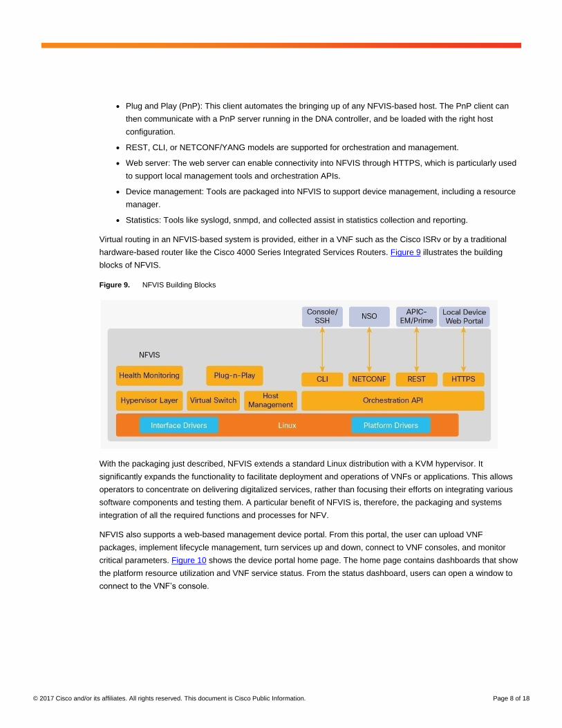
Virtual routing in an NFVIS-based system is provided, either in a VNF such as the Cisco ISRv or by a traditional
hardware-based router like the Cisco 4000 Series Integrated Services Routers. Figure 9 illustrates the building
blocks of NFVIS.
Figure 9. NFVIS Building Blocks
With the packaging just described, NFVIS extends a standard Linux distribution with a KVM hypervisor. It
significantly expands the functionality to facilitate deployment and operations of VNFs or applications. This allows
operators to concentrate on delivering digitalized services, rather than focusing their efforts on integrating various
software components and testing them. A particular benefit of NFVIS is, therefore, the packaging and systems
integration of all the required functions and processes for NFV.
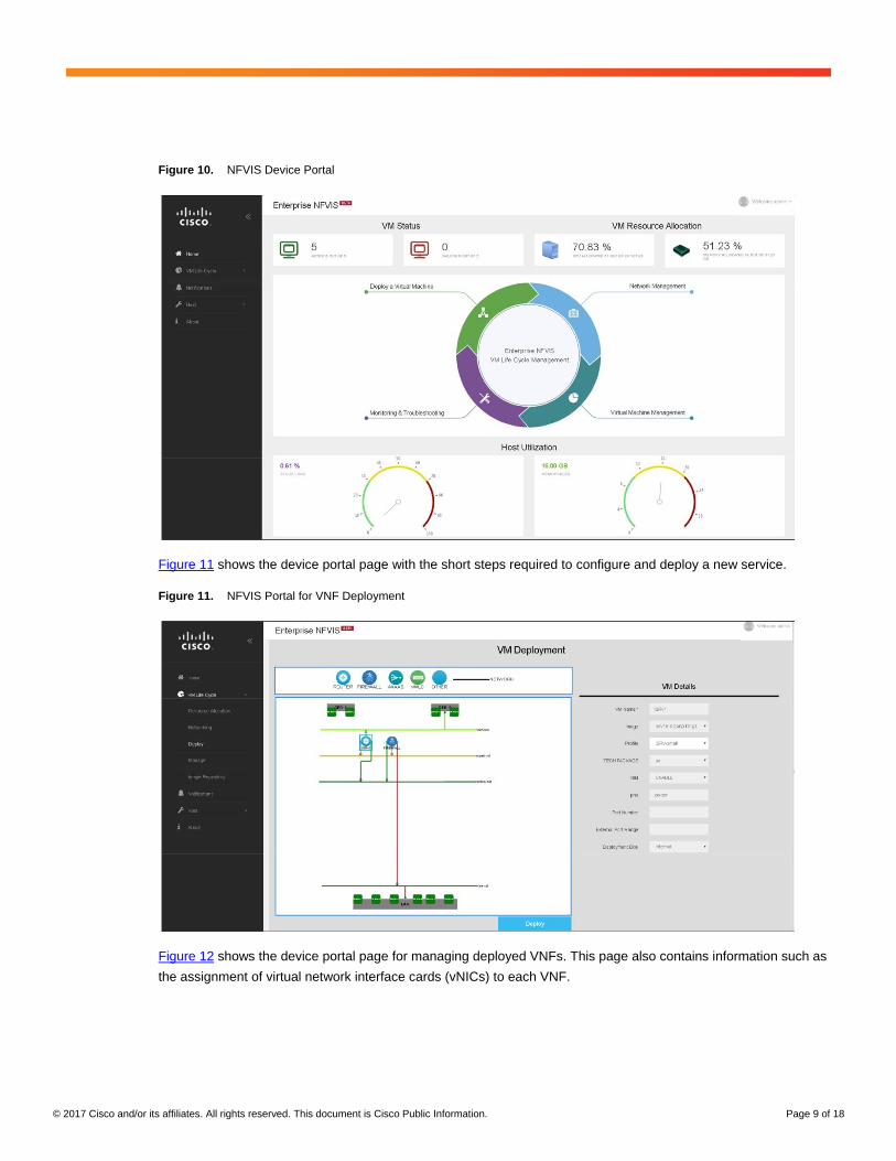
NFVIS also supports a web-based management device portal. From this portal, the user can upload VNF
packages, implement lifecycle management, turn services up and down, connect to VNF consoles, and monitor
critical parameters. Figure 10 shows the device portal home page. The home page contains dashboards that show
the platform resource utilization and VNF service status. From the status dashboard, users can open a window to
connect to the VNF’s console.
© 2017 Cisco and/or its affiliates. All rights reserved. This document is Cisco Public Information. Page 9 of 18
Figure 10. NFVIS Device Portal
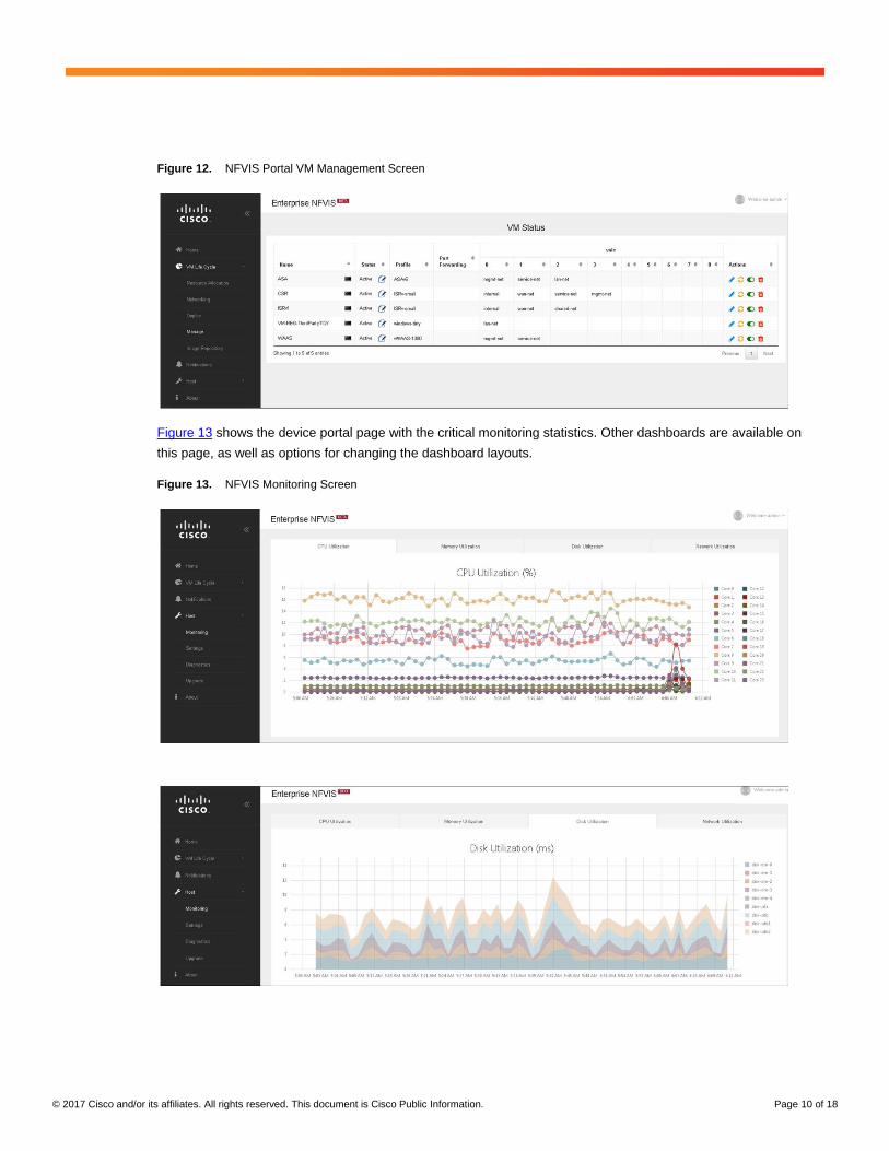
Figure 11 shows the device portal page with the short steps required to configure and deploy a new service.
Figure 11. NFVIS Portal for VNF Deployment
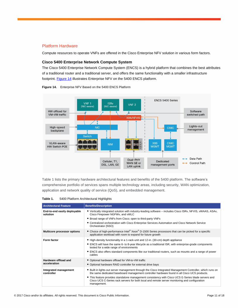
Figure 12 shows the device portal page for managing deployed VNFs. This page also contains information such as
the assignment of virtual network interface cards (vNICs) to each VNF.
© 2017 Cisco and/or its affiliates. All rights reserved. This document is Cisco Public Information. Page 10 of 18
Figure 12. NFVIS Portal VM Management Screen
Figure 13 shows the device portal page with the critical monitoring statistics. Other dashboards are available on
this page, as well as options for changing the dashboard layouts.
Figure 13. NFVIS Monitoring Screen
© 2017 Cisco and/or its affiliates. All rights reserved. This document is Cisco Public Information. Page 11 of 18
Platform Hardware
Compute resources to operate VNFs are offered in the Cisco Enterprise NFV solution in various form factors.
Cisco 5400 Enterprise Network Compute System
The Cisco 5400 Enterprise Network Compute System (ENCS) is a hybrid platform that combines the best attributes
of a traditional router and a traditional server, and offers the same functionality with a smaller infrastructure
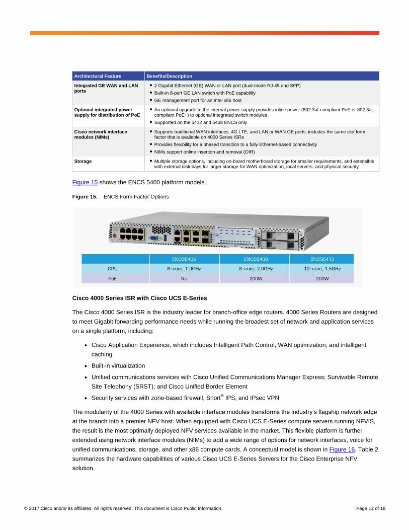
footprint. Figure 14 illustrates Enterprise NFV on the 5400 ENCS platform.
Figure 14. Enterprise NFV Based on the 5400 ENCS Platform
Table 1 lists the primary hardware architectural features and benefits of the 5400 platform. The software’s
comprehensive portfolio of services spans multiple technology areas, including security, WAN optimization,
application and network quality of service (QoS), and embedded management.
Table 1. 5400 Platform Architectural Highlights
Architectural Feature Benefits/Description
End-to-end easily deployable solution
● Vertically integrated solution with industry-leading software – includes Cisco ISRv, NFVIS, vWAAS, ASAv, Cisco Firepower NGFWv, and vWLC
● Broad range of VNFs from Cisco; open to third-party VNFs
● Centralized orchestration with Cisco Enterprise Services Automation and Cisco Network Service Orchestrator (NSO)
Multicore processor options ● Choice of high-performance Intel® Xeon
® D-1500 Series processors that can be picked for a specific
application workload with room to expand for future growth
Form factor ● High-density functionality in a 1-rack-unit and 12-in. (30-cm) depth appliance
● ENCS will have the same 6- to 8-year lifecycle as a traditional ISR, with enterprise-grade components tested for a wide range of environments
● ENCS also offers standard components like our traditional routers, such as mounts and a range of power cables
Hardware offload and acceleration
● Optional hardware offload for VM-to-VM traffic
● Optional hardware RAID controller for external drive bays
Integrated management controller
● Built-in lights-out server management through the Cisco Integrated Management Controller, which runs on the same dedicated baseboard management controller hardware found in all Cisco UCS products.
● This feature provides standalone management consistency with Cisco UCS E-Series blade servers and Cisco UCS C-Series rack servers for both local and remote server monitoring and configuration management.
© 2017 Cisco and/or its affiliates. All rights reserved. This document is Cisco Public Information. Page 12 of 18
Architectural Feature Benefits/Description
Integrated GE WAN and LAN ports
● 2 Gigabit Ethernet (GE) WAN or LAN port (dual-mode RJ-45 and SFP)
● Built-in 8-port GE LAN switch with PoE capability
● GE management port for an Intel x86 host
Optional integrated power supply for distribution of PoE
● An optional upgrade to the internal power supply provides inline power (802.3af-compliant PoE or 802.3at-compliant PoE+) to optional integrated switch modules
● Supported on the 5412 and 5408 ENCS only
Cisco network interface modules (NIMs)
● Supports traditional WAN interfaces, 4G LTE, and LAN or WAN GE ports; includes the same slot form factor that is available on 4000 Series ISRs
● Provides flexibility for a phased transition to a fully Ethernet-based connectivity
● NIMs support online insertion and removal (OIR)
Storage ● Multiple storage options, including on-board motherboard storage for smaller requirements, and extensible with external disk bays for larger storage for WAN optimization, local servers, and physical security
Figure 15 shows the ENCS 5400 platform models.
Figure 15. ENCS Form Factor Options
Cisco 4000 Series ISR with Cisco UCS E-Series
The Cisco 4000 Series ISR is the industry leader for branch-office edge routers. 4000 Series Routers are designed
to meet Gigabit forwarding performance needs while running the broadest set of network and application services
on a single platform, including:
● Cisco Application Experience, which includes Intelligent Path Control, WAN optimization, and intelligent
caching
● Built-in virtualization
● Unified communications services with Cisco Unified Communications Manager Express; Survivable Remote
Site Telephony (SRST); and Cisco Unified Border Element
● Security services with zone-based firewall, Snort® IPS, and IPsec VPN
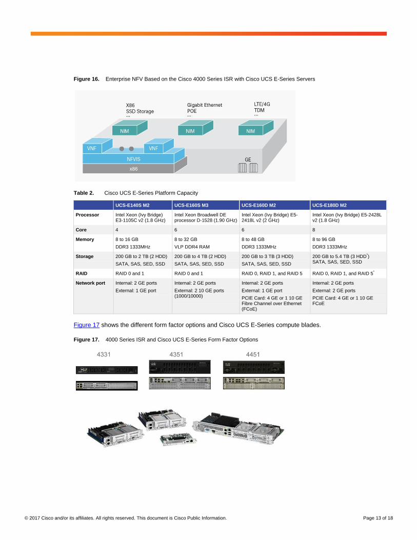
The modularity of the 4000 Series with available interface modules transforms the industry’s flagship network edge
at the branch into a premier NFV host. When equipped with Cisco UCS E-Series compute servers running NFVIS,
the result is the most optimally deployed NFV services available in the market. This flexible platform is further
extended using network interface modules (NIMs) to add a wide range of options for network interfaces, voice for
unified communications, storage, and other x86 compute cards. A conceptual model is shown in Figure 16. Table 2
summarizes the hardware capabilities of various Cisco UCS E-Series Servers for the Cisco Enterprise NFV
solution.
© 2017 Cisco and/or its affiliates. All rights reserved. This document is Cisco Public Information. Page 13 of 18
Figure 16. Enterprise NFV Based on the Cisco 4000 Series ISR with Cisco UCS E-Series Servers
Table 2. Cisco UCS E-Series Platform Capacity
UCS-E140S M2 UCS-E160S M3 UCS-E160D M2 UCS-E180D M2
Processor Intel Xeon (Ivy Bridge) E3-1105C v2 (1.8 GHz)
Intel Xeon Broadwell DE processor D-1528 (1.90 GHz)
Intel Xeon (Ivy Bridge) E5-2418L v2 (2 GHz)
Intel Xeon (Ivy Bridge) E5-2428L v2 (1.8 GHz)
Core 4 6 6 8
Memory 8 to 16 GB
DDR3 1333MHz
8 to 32 GB
VLP DDR4 RAM
8 to 48 GB
DDR3 1333MHz
8 to 96 GB
DDR3 1333MHz
Storage 200 GB to 2 TB (2 HDD)
SATA, SAS, SED, SSD
200 GB to 4 TB (2 HDD)
SATA, SAS, SED, SSD
200 GB to 3 TB (3 HDD)
SATA, SAS, SED, SSD
200 GB to 5.4 TB (3 HDD*)
SATA, SAS, SED, SSD
RAID RAID 0 and 1 RAID 0 and 1 RAID 0, RAID 1, and RAID 5 RAID 0, RAID 1, and RAID 5*
Network port Internal: 2 GE ports
External: 1 GE port
Internal: 2 GE ports
External: 2 10 GE ports (1000/10000)
Internal: 2 GE ports
External: 1 GE port
PCIE Card: 4 GE or 1 10 GE Fibre Channel over Ethernet (FCoE)
Internal: 2 GE ports
External: 2 GE ports
PCIE Card: 4 GE or 1 10 GE FCoE
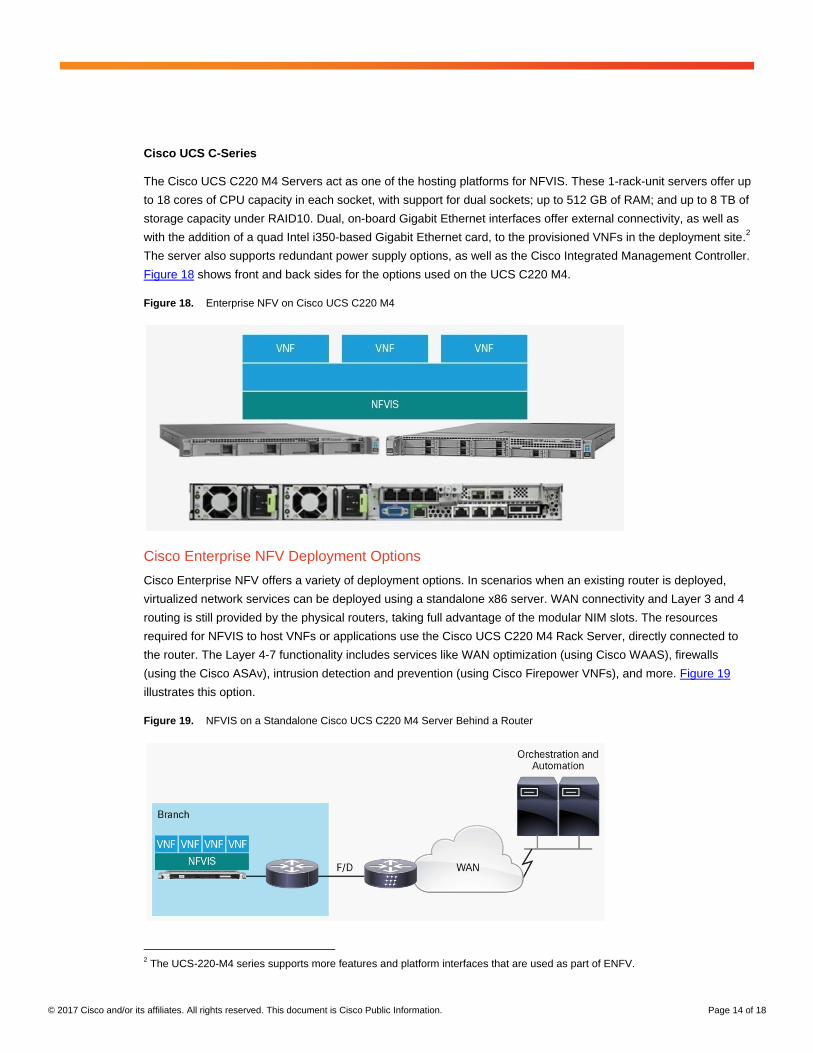
Figure 17 shows the different form factor options and Cisco UCS E-Series compute blades.
Figure 17. 4000 Series ISR and Cisco UCS E-Series Form Factor Options
© 2017 Cisco and/or its affiliates. All rights reserved. This document is Cisco Public Information. Page 14 of 18
Cisco UCS C-Series
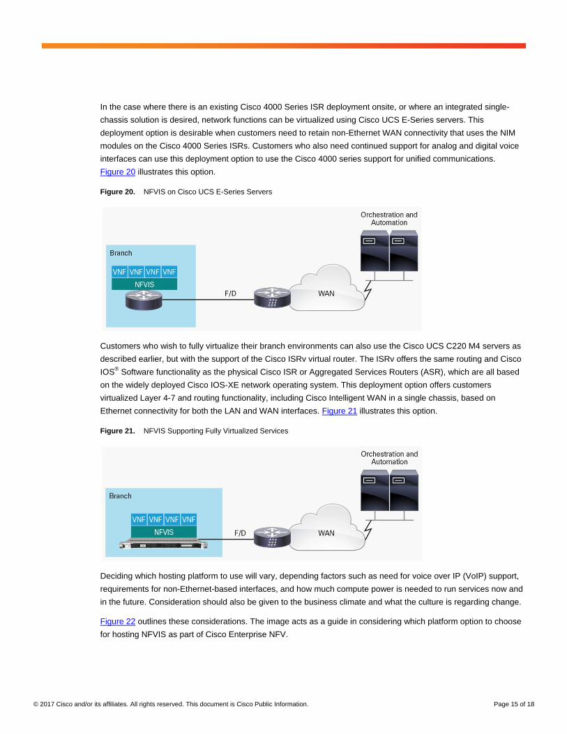
The Cisco UCS C220 M4 Servers act as one of the hosting platforms for NFVIS. These 1-rack-unit servers offer up
to 18 cores of CPU capacity in each socket, with support for dual sockets; up to 512 GB of RAM; and up to 8 TB of
storage capacity under RAID10. Dual, on-board Gigabit Ethernet interfaces offer external connectivity, as well as
with the addition of a quad Intel i350-based Gigabit Ethernet card, to the provisioned VNFs in the deployment site.2
The server also supports redundant power supply options, as well as the Cisco Integrated Management Controller.
Figure 18 shows front and back sides for the options used on the UCS C220 M4.
Figure 18. Enterprise NFV on Cisco UCS C220 M4
Cisco Enterprise NFV Deployment Options
Cisco Enterprise NFV offers a variety of deployment options. In scenarios when an existing router is deployed,
virtualized network services can be deployed using a standalone x86 server. WAN connectivity and Layer 3 and 4
routing is still provided by the physical routers, taking full advantage of the modular NIM slots. The resources
required for NFVIS to host VNFs or applications use the Cisco UCS C220 M4 Rack Server, directly connected to
the router. The Layer 4-7 functionality includes services like WAN optimization (using Cisco WAAS), firewalls
(using the Cisco ASAv), intrusion detection and prevention (using Cisco Firepower VNFs), and more. Figure 19
illustrates this option.
Figure 19. NFVIS on a Standalone Cisco UCS C220 M4 Server Behind a Router
2 The UCS-220-M4 series supports more features and platform interfaces that are used as part of ENFV.
© 2017 Cisco and/or its affiliates. All rights reserved. This document is Cisco Public Information. Page 15 of 18
In the case where there is an existing Cisco 4000 Series ISR deployment onsite, or where an integrated single-
chassis solution is desired, network functions can be virtualized using Cisco UCS E-Series servers. This
deployment option is desirable when customers need to retain non-Ethernet WAN connectivity that uses the NIM
modules on the Cisco 4000 Series ISRs. Customers who also need continued support for analog and digital voice
interfaces can use this deployment option to use the Cisco 4000 series support for unified communications.
Figure 20 illustrates this option.
Figure 20. NFVIS on Cisco UCS E-Series Servers
Customers who wish to fully virtualize their branch environments can also use the Cisco UCS C220 M4 servers as
described earlier, but with the support of the Cisco ISRv virtual router. The ISRv offers the same routing and Cisco
IOS® Software functionality as the physical Cisco ISR or Aggregated Services Routers (ASR), which are all based
on the widely deployed Cisco IOS-XE network operating system. This deployment option offers customers
virtualized Layer 4-7 and routing functionality, including Cisco Intelligent WAN in a single chassis, based on
Ethernet connectivity for both the LAN and WAN interfaces. Figure 21 illustrates this option.
Figure 21. NFVIS Supporting Fully Virtualized Services
Deciding which hosting platform to use will vary, depending factors such as need for voice over IP (VoIP) support,
requirements for non-Ethernet-based interfaces, and how much compute power is needed to run services now and
in the future. Consideration should also be given to the business climate and what the culture is regarding change.
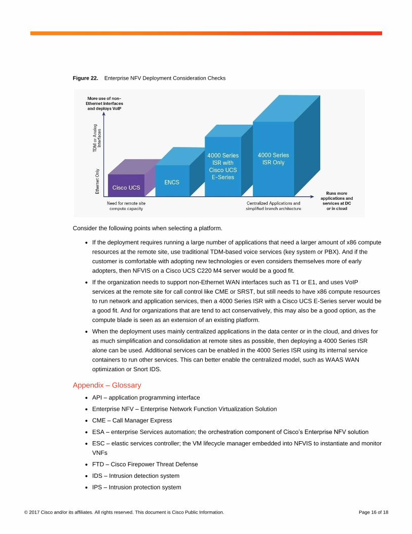
Figure 22 outlines these considerations. The image acts as a guide in considering which platform option to choose
for hosting NFVIS as part of Cisco Enterprise NFV.
© 2017 Cisco and/or its affiliates. All rights reserved. This document is Cisco Public Information. Page 16 of 18
Figure 22. Enterprise NFV Deployment Consideration Checks
Consider the following points when selecting a platform.
● If the deployment requires running a large number of applications that need a larger amount of x86 compute
resources at the remote site, use traditional TDM-based voice services (key system or PBX). And if the
customer is comfortable with adopting new technologies or even considers themselves more of early
adopters, then NFVIS on a Cisco UCS C220 M4 server would be a good fit.
● If the organization needs to support non-Ethernet WAN interfaces such as T1 or E1, and uses VoIP
services at the remote site for call control like CME or SRST, but still needs to have x86 compute resources
to run network and application services, then a 4000 Series ISR with a Cisco UCS E-Series server would be
a good fit. And for organizations that are tend to act conservatively, this may also be a good option, as the
compute blade is seen as an extension of an existing platform.
● When the deployment uses mainly centralized applications in the data center or in the cloud, and drives for
as much simplification and consolidation at remote sites as possible, then deploying a 4000 Series ISR
alone can be used. Additional services can be enabled in the 4000 Series ISR using its internal service
containers to run other services. This can better enable the centralized model, such as WAAS WAN
optimization or Snort IDS.
Appendix – Glossary
● API – application programming interface
● Enterprise NFV – Enterprise Network Function Virtualization Solution
● CME – Call Manager Express
● ESA – enterprise Services automation; the orchestration component of Cisco’s Enterprise NFV solution
● ESC – elastic services controller; the VM lifecycle manager embedded into NFVIS to instantiate and monitor
VNFs
● FTD – Cisco Firepower Threat Defense
● IDS – Intrusion detection system
● IPS – Intrusion protection system
© 2017 Cisco and/or its affiliates. All rights reserved. This document is Cisco Public Information. Page 17 of 18
● Key system – A small PBX used to control telephones in small business offices
● KVM – Kernel virtual machine; a hypervisor to run VNFs on top of Linux
● NFV – network functions virtualization; the concept of vitalizing one or more network functions by running
these in software on top of an x-86 based hypervisor environment
● NFVIS – Network Functions Virtualization Infrastructure Software; the operating system used in Enterprise
NFV to support the virtualization of network functions
● NIM – network interface module
● NSO – Network Services Orchestrator
● OVS – open virtual switch
● PBX – Private Branch Exchange
● PnP – Plug and Play
● REST – representational state transfer
● SRST – Survivable Remote Site Telephony
● Cisco UCS – Cisco Unified Computing System™
● Cisco UCS E-Series – Unified Computing System E-Series
● VNF – virtual network function; an instance of a network function running in a virtual machine on top of a
hypervisor
● VM – virtual machine
For More Information
Cisco ENCS 5400 Platform
http://www.cisco.com/c/en/us/products/collateral/routers/5400-enterprise-network-compute-system/datasheet-c78-
738512.html.
Cisco 4000 Series ISR Platforms
http://www.cisco.com/c/en/us/products/routers/4000-series-integrated-services-routers-isr/models-
comparison.html.
Cisco UCS E-Series Compute Engines
http://www.cisco.com/c/en/us/products/collateral/servers-unified-computing/ucs-e-series-servers/data_sheet_c78-
705787.html.
Cisco UCS C220 M4 Rack Server
http://www.cisco.com/c/en/us/products/servers-unified-computing/ucs-c220-m4-rack-server/index.html.

© 2017 Cisco and/or its affiliates. All rights reserved. This document is Cisco Public Information. Page 18 of 18
Printed in USA C11-736783-01 04/17