cisco collaborations security
DESCRIPTION
Cisco CollaborationTRANSCRIPT
OL-29367-05
C H A P T E R 4
Cisco Collaboration SecurityRevised: April 2, 2013; OL-29367-05
Securing the various components in a Cisco Collaboration Solution is necessary for protecting the integrity and confidentiality of voice and video calls.
This chapter presents security guidelines pertaining specifically to collaboration applications and the voice and video network. For more information on data network security, refer to the Cisco SAFE Blueprint documentation available at
http://www.cisco.com/en/US/netsol/ns744/networking_solutions_program_home.html
Following the guidelines in this chapter does not guarantee a secure environment, nor will it prevent all penetration attacks on a network. You can achieve reasonable security by establishing a good security policy, following that security policy, staying up-to-date on the latest developments in the hacker and security communities, and maintaining and monitoring all systems with sound system administration practices.
This chapter addresses centralized and distributed call processing, including clustering over the WAN but not local failover mechanisms such as Survivable Remote Site Telephony (SRST). This chapter assumes that all remote sites have a redundant link to the head-end or local call-processing backup in case of head-end failure. The interaction between Network Address Translation (NAT) and IP Telephony, for the most part, is not addressed here. This chapter also assumes that all networks are privately addressed and do not contain overlapping IP addresses.
4-1Cisco Collaboration System 9.x SRND
Chapter 4 Cisco Collaboration SecurityWhat's New in This Chapter
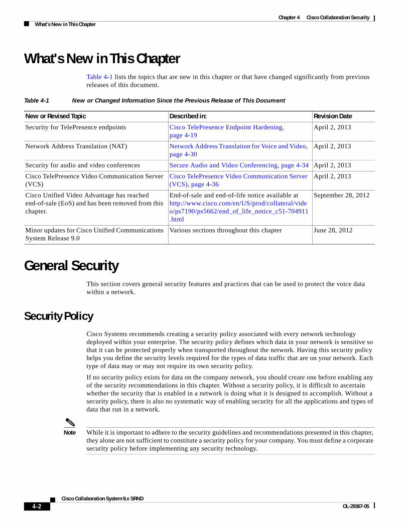
What's New in This ChapterTable 4-1 lists the topics that are new in this chapter or that have changed significantly from previous releases of this document.
General SecurityThis section covers general security features and practices that can be used to protect the voice data within a network.
Security PolicyCisco Systems recommends creating a security policy associated with every network technology deployed within your enterprise. The security policy defines which data in your network is sensitive so that it can be protected properly when transported throughout the network. Having this security policy helps you define the security levels required for the types of data traffic that are on your network. Each type of data may or may not require its own security policy.
If no security policy exists for data on the company network, you should create one before enabling any of the security recommendations in this chapter. Without a security policy, it is difficult to ascertain whether the security that is enabled in a network is doing what it is designed to accomplish. Without a security policy, there is also no systematic way of enabling security for all the applications and types of data that run in a network.
Note While it is important to adhere to the security guidelines and recommendations presented in this chapter, they alone are not sufficient to constitute a security policy for your company. You must define a corporate security policy before implementing any security technology.
Table 4-1 New or Changed Information Since the Previous Release of This Document
New or Revised Topic Described in: Revision Date
Security for TelePresence endpoints Cisco TelePresence Endpoint Hardening, page 4-19
April 2, 2013
Network Address Translation (NAT) Network Address Translation for Voice and Video, page 4-30
April 2, 2013
Security for audio and video conferences Secure Audio and Video Conferencing, page 4-34 April 2, 2013
Cisco TelePresence Video Communication Server (VCS)
Cisco TelePresence Video Communication Server (VCS), page 4-36
April 2, 2013
Cisco Unified Video Advantage has reached end-of-sale (EoS) and has been removed from this chapter.
End-of-sale and end-of-life notice available at http://www.cisco.com/en/US/prod/collateral/video/ps7190/ps5662/end_of_life_notice_c51-704911.html
September 28, 2012
Minor updates for Cisco Unified Communications System Release 9.0
Various sections throughout this chapter June 28, 2012
4-2Cisco Collaboration System 9.x SRND
OL-29367-05
Chapter 4 Cisco Collaboration SecurityGeneral Security
This chapter details the features and functionality of a Cisco Systems network that are available to protect the Unified Communications data on a network. It is up to the security policy to define which data to protect, how much protection is needed for that type of data, and which security techniques to use to provide that protection.
One of the more difficult issues with a security policy that includes voice and video traffic is combining the security policies that usually exist for both the data network and the traditional voice network. Ensure that all aspects of the integration of the media onto the network are secured at the correct level for your security policy or corporate environment.
The basis of a good security policy is defining how important your data is within the network. Once you have ranked the data according to its importance, you can decide how the security levels should be established for each type of data. You can then achieve the correct level of security by using both the network and application features.
In summary, you can use the following process to define a security policy:
• Define the data that is on the network.
• Define the importance of that data.
• Apply security based on the importance of the data.
4-3Cisco Collaboration System 9.x SRND
OL-29367-05

Chapter 4 Cisco Collaboration SecurityGeneral Security
Security in LayersThis chapter starts with hardening the IP phone endpoints in a Cisco Unified Communications Solution and works its way through the network from the phone to the access switch, to the distribution layer, into the core, and then into the data center. (See Figure 4-1.) Cisco recommends building layer upon layer of security, starting at the access port into the network itself. This design approach gives a network architect the ability to place the devices where it is both physically and logically easy to deploy Cisco Unified Communications applications. But with this ease of deployment, the security complexity increases because the devices can be placed anywhere in a network as long as they have connectivity.
Figure 4-1 Layers of Security
1484
89
Core
Distribution
Access
V
Si Si
IP IP IP IP
Unified CM Cluster
M
M
M M
M
V
4-4Cisco Collaboration System 9.x SRND
OL-29367-05
Chapter 4 Cisco Collaboration SecurityGeneral Security
Secure InfrastructureAs the IP Telephony data crosses a network, that data is only as safe and secure as the devices that are transporting the data. Depending on the security level that is defined in your security policy, the security of the network devices might have to be improved or they might already be secure enough for the transportation of IP Telephony traffic.
There are many best practices within a data network that, if used, will increase the entire security of your network. For example, instead of using Telnet (which sends passwords in clear text) to connect to any of the network devices, use Secure Shell (SSH, the secure form of Telnet) so that an attacker would not be able to see a password in clear text.
Cisco Routers configured as gateways, Cisco Unified Border Element, and media resources can be configured with Cisco IOS feature sets that provide the required media functionality but support only Telnet and not Secure Shell (SSH). Cisco recommends that you use access control lists (ACLs) to control who is permitted to connect to the routers using Telnet. It is more secure to connect to the gatekeeper from a host that is in a secure segment of the network, because user names and passwords are sent over Telnet in clear text.
You should also use firewalls, access control lists, authentication services, and other Cisco security tools to help protect these devices from unauthorized access.
Physical SecurityJust as a traditional PBX is usually locked in a secure environment, the IP network should be treated in a similar way. Each of the devices that carries media traffic is really part of an IP PBX, and normal general security practices should be used to control access to those devices. Once a user or attacker has physical access to one of the devices in a network, all kinds of problems could occur. Even if you have excellent password security and the user or attacker cannot get into the network device, that does not mean that they cannot cause havoc in a network by simply unplugging the device and stopping all traffic.
For more information on general security practices, refer to the documentation at the following locations:
• http://www.cisco.com/en/US/netsol/ns744/networking_solutions_program_home.html
• http://www.cisco.com/en/US/products/svcs/ps2961/ps2952/serv_group_home.html
IP AddressingIP addressing can be critical for controlling the data that flows in and out of the logically separated IP Telephony network. The more defined the IP addressing is within a network, the easier it becomes to control the devices on the network.
As stated in other sections of this document (see Campus Access Layer, page 3-5), you should use IP addressing based on RFC 1918. This method of addressing allows deployment of an IP Telephony system into a network without redoing the IP addressing of the network. Using RFC 1918 also allows for better control in the network because the IP addresses of the voice endpoints are well defined and easy to understand. If the voice and video endpoints are all addressed within a 10.x.x.x. network, access control lists (ACLs) and tracking of data to and from those devices are simplified.
If you have a well defined IP addressing plan for your voice deployments, it becomes easier to write ACLs for controlling the IP Telephony traffic and it also helps with firewall deployments.
4-5Cisco Collaboration System 9.x SRND
OL-29367-05
Chapter 4 Cisco Collaboration SecurityAccess Security
Using RFC 1918 enables you easily to deploy one VLAN per switch, which is a best practice for campus design, and also enables you to keep the Voice VLAN free of any Spanning Tree Protocol (STP) loops.
If deployed correctly, route summarization could help to keep the routing table about the same as before the voice and video deployment, or just slightly larger.
IPv6 AddressingThe introduction of IPv6 addressing has extended the network address space and increased the options for privacy and security of endpoints. Though both IPv4 and IPv6 have similar security concerns, IPv6 provides some advantages. For example, one of the major benefits with IPv6 is the enormous size of the subnets, which discourages automated scanning and reconnaissance attacks.
For a comparison of IPv6 and IPv4 in terms of security, refer to the IPv6 and IPv4 Threat Comparison and Best-Practice Evaluation, available at:
http://www.cisco.com/web/about/security/security_services/ciag/documents/v6-v4-threats.pdf
When considering IPv6 as your IP addressing method, adhere to the best practices documented in the following campus and branch office design guides:
• Deploying IPv6 in Campus Networks
http://www.cisco.com/en/US/docs/solutions/Enterprise/Campus/CampIPv6.html
• Deploying IPv6 in Branch Networks
http://www.cisco.com/en/US/docs/solutions/Enterprise/Branch/BrchIPv6.html
Access SecurityThis section covers security features at the Access level that can be used to protect the voice and data within a network.
Voice and Video VLANsBefore the phone has its IP address, the phone determines which VLAN it should be in by means of the Cisco Discovery Protocol (CDP) negotiation that takes place between the phone and the switch. This negotiation allows the phone to send packets with 802.1q tags to the switch in a "voice VLAN" so that the voice data and all other data coming from the PC behind the phone are separated from each other at Layer 2. Voice VLANs are not required for the phones to operate, but they provide additional separation from other data on the network.
Voice VLANs can be assigned automatically from the switch to the phone, thus allowing for Layer 2 and Layer 3 separations between voice data and all other data on a network. A voice VLAN also allows for a different IP addressing scheme because the separate VLAN can have a separate IP scope at the Dynamic Host Configuration Protocol (DHCP) server.
Applications use CDP messaging from the phones to assist in locating phones during an emergency call. The location of the phone will be much more difficult to determine if CDP is not enabled on the access port to which that phone is attached.
4-6Cisco Collaboration System 9.x SRND
OL-29367-05

Chapter 4 Cisco Collaboration SecurityAccess Security
There is a possibility that information could be gathered from the CDP messaging that would normally go to the phone, and that information could be used to discover some of the network. Not all devices that can be used for voice or video with Unified CM are able to use CDP to assist in discovering the voice VLAN.
Third-party endpoints do not support Cisco Discovery Protocol (CDP) or 802.1Q VLAN ID tagging. To allow device discovery when third-party devices are involved, use the Link Layer Discovery Protocol (LLDP). LLDP for Media Endpoint Devices (LLDP-MED) is an extension to LLDP that enhances support for voice endpoints. LLDP-MED defines how a switch port transitions from LLDP to LLDP-MED if it detects an LLDP-MED-capable endpoint. Support for both LLDP and LLDP-MED on IP phones and LAN switches depends on the firmware and device models. To determine if LLDP-MED is supported on particular phone or switch models, check the specific product release notes or bulletins available at:
• http://www.cisco.com/en/US/products/hw/phones/ps379/prod_release_notes_list.html
• http://www.cisco.com/en/US/products/sw/iosswrel/ps5012/prod_bulletins_list.html
Note If an IP phone with LLDP-MED capability is connected to a Cisco Catalyst switch running an earlier Cisco IOS release that does not support LLDP, the switch might indicate that an extra device has been connected to the switch port. This can happen if the Cisco Catalyst switch is using Port Security to count the number of devices connected. The appearance of an LLDP packet might cause the port count to increase and cause the switch to disable the port. Verify that your Cisco Catalyst switch supports LLDP, or increase the port count to a minimum of three, before deploying Cisco IP Phones with firmware that supports LLDP-MED Link Layer protocol.
H.323 clients, Multipoint Control Units (MCUs), and gateways communicate with Unified CM using the H.323 protocol. Unified CM H.323 trunks (such as H.225 and intercluster trunk variants as well as the RASAggregator trunk type) use a random port range rather than the well-known TCP port 1720. Therefore, you must permit a wide range of TCP ports between these devices and the Unified CM servers. For port usage details, refer to the latest version of the Cisco Unified Communications Manager TCP and UDP Port Usage guide, available at:
http://www.cisco.com/en/US/products/sw/voicesw/ps556/prod_maintenance_guides_list.html
MCUs and gateways are considered infrastructure devices, and they typically reside within the datacenter adjacent to the Unified CM servers. H.323 clients, on the other hand, typically reside in the data VLAN.
Cisco TelePresence MCUs configured to run in SCCP mode communicate with the TFTP server(s) to download their configuration, with the Unified CM servers for signaling, and with other endpoints for RTP media traffic. Therefore, TFTP must be permitted between the MCU and the TFTP server(s), TCP port 2000 must be permitted between the MCUs and the Unified CM server(s), and UDP ports for RTP media must be permitted between the MCUs and the voice, data, and gateway VLANs.
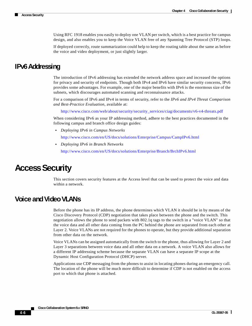
Switch PortThere are many security features within a Cisco switch infrastructure that can be used to secure a data network. This section describes some of the features that can be used in Cisco Access Switches to protect the IP Telephony data within a network. (See Figure 4-2.) This section does not cover all of the security features available for all of the current Cisco switches, but it does list the most common security features
4-7Cisco Collaboration System 9.x SRND
OL-29367-05
Chapter 4 Cisco Collaboration SecurityAccess Security
used across many of the switches that Cisco manufactures. For additional information on the security features available on the particular Cisco gear deployed within your network, refer to the appropriate product documentation available at
http://www.cisco.com
Figure 4-2 A Typical Access Layer Design to Which the Phones Attach
Port Security: MAC CAM Flooding
A classic attack on a switched network is a MAC content-addressable memory (CAM) flooding attack. This type of attack floods the switch with so many MAC addresses that the switch does not know which port an end station or device is attached to. When the switch does not know which port a device is attached to, it broadcasts the traffic destined for that device to the entire VLAN. In this way, the attacker is able to see all traffic that is coming to all the users in a VLAN.
To disallow malicious MAC flooding attacks from hacker tools such as macof, limit the number of MAC addresses allowed to access individual ports based on the connectivity requirements for those ports. Malicious end-user stations can use macof to originate MAC flooding from random-source to random-destination MAC addresses, both directly connected to the switch port or through the IP phone. The macof tool is very aggressive and typically can fill a Cisco Catalyst switch content-addressable memory (CAM) table in less than ten seconds. The flooding of subsequent packets that remain unlearned because the CAM table is filled, is as disruptive and unsecure as packets on a shared Ethernet hub for the VLAN that is being attacked.
Either port security or dynamic port security can be used to inhibit a MAC flooding attack. A customer with no requirement to use port security as an authorization mechanism would want to use dynamic port security with the number of MAC addresses appropriate to the function attached to a particular port. For example, a port with only a workstation attached to it would want to limit the number of learned MAC addresses to one. A port with a Cisco Unified IP Phone and a workstation behind it would want to set the number of learned MAC addresses to two (one for the IP phone itself and one for the workstation behind the phone) if a workstation is going to plug into the PC port on the phone. This setting in the past has been three MAC addresses, used with the older way of configuring the port in trunk mode. If you use the multi-VLAN access mode of configuration for the phone port, this setting will be two MAC addresses, one for the phone and one for the PC plugged into the phone. If there will be no workstation on the PC port, then the number of MAC addresses on that port should be set to one. These configurations are for a multi-VLAN access port on a switch. The configuration could be different if the port is set to trunk mode (not the recommended deployment of an access port with a phone and PC).
1484
93
Access
IP IP IP IP
4-8Cisco Collaboration System 9.x SRND
OL-29367-05
Chapter 4 Cisco Collaboration SecurityAccess Security
Port Security: Gratuitous ARP
Just like any other data device on the network, the phones are vulnerable to traditional data attacks. The phones have features to prevent some of the common data attacks that can occur on a corporate network. One such feature is Gratuitous ARP (Gratuitous Address Resolution Protocol, or GARP). This feature helps to prevent man-in-the-middle (MITM) attacks to the phone. A MITM attack involves an attacker who tricks an end station into believing that he is the router and tricks the router into believing that he is the end station. This scheme makes all the traffic between the router and the end station travel through the attacker, thus enabling the attacker to log all of the traffic or inject new traffic into the data conversation.
The Gratuitous ARP feature configured on an IP phone protects the phone from a traditional MITM attack on the signaling and RTP voice streams that are sourced from the phone to the network. It helps protect the phones from having an attacker capture the signaling and RTP voice streams from the phone if the attacker was able to get onto the voice segment of the network. This feature protects only the phones; it does not protect the rest of the infrastructure from a Gratuitous ARP attack. This feature is of less importance if you are running a Cisco infrastructure because the switch port provides features that protect both the phones and the network gear. For a description of these switch port features see the section on Switch Port, page 4-7.
Note The Gratuitous ARP feature does not apply to devices configured using IPv6 addressing. IPv6 uses neighbor discovery (ND) and not ARP.
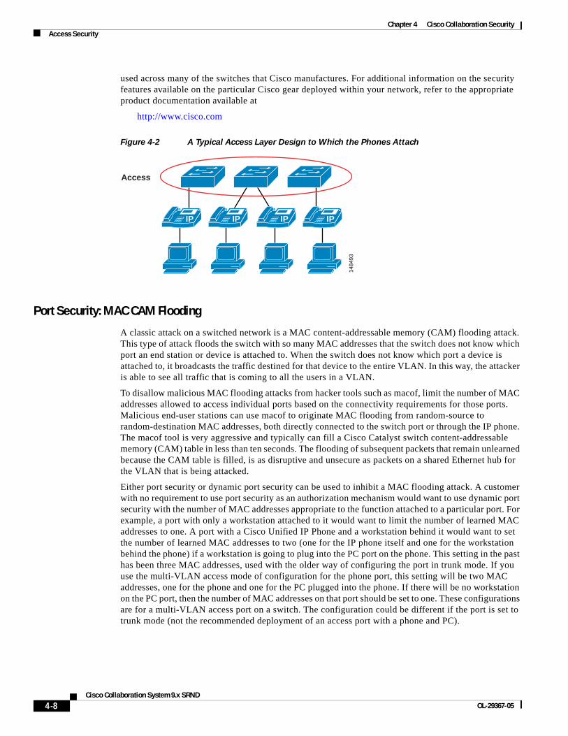
The downstream signaling and RTP voice streams coming from another phone or coming across the network are not protected by this feature in the phone. Only the data coming from the phone that has this feature enabled is protected. (See Figure 4-3.)
If the default gateway is running Hot Standby Router Protocol (HSRP), if the HSRP configuration uses the burned-in MAC address rather than the virtual MAC address for the default gateway, and if the primary router fails-over to a secondary router that has a new MAC address, the phones could maintain the old MAC address of the default gateway. This scenario could cause an outage for up to 40 minutes. Always use the virtual MAC address in an HSRP environment to avoid this potential problem.
Figure 4-3 Gratuitous ARP Protects the Phone that Has It but Not Other Traffic
As shown in Figure 4-3, the traffic from the phone that has Gratuitous ARP is protected, but the attacker could still see the traffic coming from another endpoint because that endpoint might not have the ability to protect the data flow.
1488
92
IP
Traffic from the phoneis protected
Traffic from the router isredirected to the attacker
4-9Cisco Collaboration System 9.x SRND
OL-29367-05
Chapter 4 Cisco Collaboration SecurityAccess Security
Port Security: Prevent Port Access
Prevent all port access except from those devices designated by their MAC addresses to be on the port. This is a form of device-level security authorization. This requirement is used to authorize access to the network by using the single credential of the device's MAC address. By using port security (in its non-dynamic form), a network administrator would be required to associate MAC addresses statically for every port. However, with dynamic port security, network administrators can merely specify the number of MAC addresses they would like the switch to learn and, assuming the correct devices are the first devices to connect to the port, allow only those devices access to that port for some period of time.
The period of time can be determined by either a fixed timer or an inactivity timer (non-persistent access), or it can be permanently assigned. In the latter case, the MAC address learned will remain on the port even in the event of a reload or reboot of the switch.
No provision is made for device mobility by static port security or persistent dynamic port security. Although it is not the primary requirement, MAC flooding attacks are implicitly prevented by port security configurations that aim to limit access to certain MAC addresses.
From a security perspective, there are better mechanisms for both authenticating and authorizing port access based on userid and/or password credentials rather than using MAC address authorization. MAC addresses alone can easily be spoofed or falsified by most operating systems.
Port Security: Prevent Rogue Network Extensions
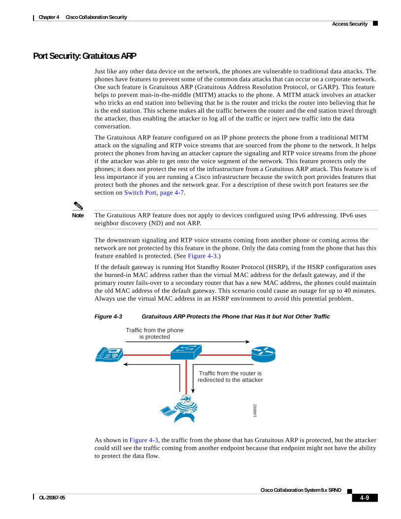
Port security prevents an attacker from flooding the CAM table of a switch and from turning any VLAN into a hub that transmits all received traffic to all ports. It also prevents unapproved extensions of the network by adding hubs or switches into the network. Because it limits the number of MAC addresses to a port, port security can also be used as a mechanism to inhibit user extension to the IT-created network. For example, if a user plugs a wireless access point (AP) into a user-facing port or data port on a phone with port security defined for a single MAC address, the wireless AP itself would occupy that MAC address and not allow any devices behind it to access the network. (See Figure 4-4.) Generally, a configuration appropriate to stop MAC flooding is also appropriate to inhibit rogue access.
Figure 4-4 Limited Number of MAC Addresses Prevents Rogue Network Extensions
If the number of MAC addresses is not defined correctly, there is a possibility of denying access to the network or error-disabling the port and removing all devices from the network.
1484
94
Only two MACaddresses
allowed on theport: Shutdown
4-10Cisco Collaboration System 9.x SRND
OL-29367-05
Chapter 4 Cisco Collaboration SecurityAccess Security
DHCP Snooping: Prevent Rogue DHCP Server Attacks
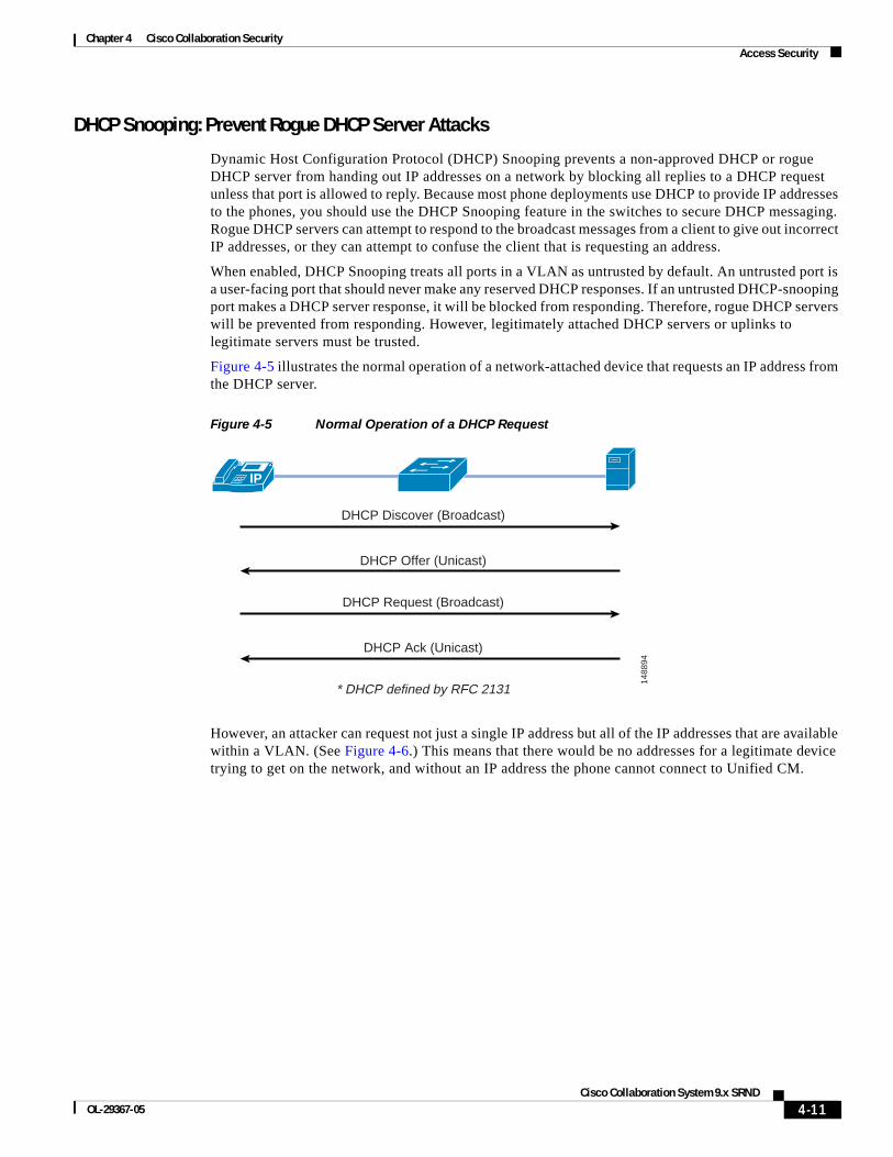
Dynamic Host Configuration Protocol (DHCP) Snooping prevents a non-approved DHCP or rogue DHCP server from handing out IP addresses on a network by blocking all replies to a DHCP request unless that port is allowed to reply. Because most phone deployments use DHCP to provide IP addresses to the phones, you should use the DHCP Snooping feature in the switches to secure DHCP messaging. Rogue DHCP servers can attempt to respond to the broadcast messages from a client to give out incorrect IP addresses, or they can attempt to confuse the client that is requesting an address.
When enabled, DHCP Snooping treats all ports in a VLAN as untrusted by default. An untrusted port is a user-facing port that should never make any reserved DHCP responses. If an untrusted DHCP-snooping port makes a DHCP server response, it will be blocked from responding. Therefore, rogue DHCP servers will be prevented from responding. However, legitimately attached DHCP servers or uplinks to legitimate servers must be trusted.
Figure 4-5 illustrates the normal operation of a network-attached device that requests an IP address from the DHCP server.
Figure 4-5 Normal Operation of a DHCP Request
However, an attacker can request not just a single IP address but all of the IP addresses that are available within a VLAN. (See Figure 4-6.) This means that there would be no addresses for a legitimate device trying to get on the network, and without an IP address the phone cannot connect to Unified CM.
1488
94
IP
DHCP Discover (Broadcast)
DHCP Offer (Unicast)
DHCP Request (Broadcast)
DHCP Ack (Unicast)
* DHCP defined by RFC 2131
4-11Cisco Collaboration System 9.x SRND
OL-29367-05
Chapter 4 Cisco Collaboration SecurityAccess Security
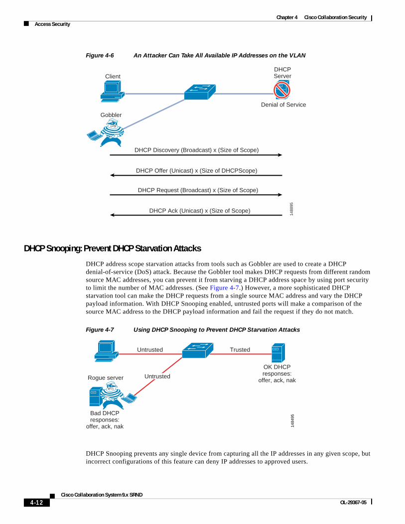
Figure 4-6 An Attacker Can Take All Available IP Addresses on the VLAN
DHCP Snooping: Prevent DHCP Starvation Attacks
DHCP address scope starvation attacks from tools such as Gobbler are used to create a DHCP denial-of-service (DoS) attack. Because the Gobbler tool makes DHCP requests from different random source MAC addresses, you can prevent it from starving a DHCP address space by using port security to limit the number of MAC addresses. (See Figure 4-7.) However, a more sophisticated DHCP starvation tool can make the DHCP requests from a single source MAC address and vary the DHCP payload information. With DHCP Snooping enabled, untrusted ports will make a comparison of the source MAC address to the DHCP payload information and fail the request if they do not match.
Figure 4-7 Using DHCP Snooping to Prevent DHCP Starvation Attacks
DHCP Snooping prevents any single device from capturing all the IP addresses in any given scope, but incorrect configurations of this feature can deny IP addresses to approved users.
1488
95
Denial of Service
ClientDHCPServer
Gobbler
DHCP Discovery (Broadcast) x (Size of Scope)
DHCP Offer (Unicast) x (Size of DHCPScope)
DHCP Request (Broadcast) x (Size of Scope)
DHCP Ack (Unicast) x (Size of Scope)
1484
95
Rogue server
Bad DHCPresponses:
offer, ack, nak
OK DHCPresponses:
offer, ack, nak
Untrusted Trusted
Untrusted
4-12Cisco Collaboration System 9.x SRND
OL-29367-05
Chapter 4 Cisco Collaboration SecurityAccess Security
DHCP Snooping: Binding Information
Another function of DHCP Snooping is to record the DHCP binding information for untrusted ports that successfully get IP addresses from the DHCP servers. The binding information is recorded in a table on the Cisco Catalyst switch. The DHCP binding table contains the IP address, MAC address, lease length, port, and VLAN information for each binding entry. The binding information from DHCP Snooping remains in effect for the length of the DHCP binding period set by the DHCP server (that is, the DHCP lease time). The DHCP binding information is used to create dynamic entries for Dynamic ARP Inspection (DAI) to limit ARP responses for only those addresses that are DHCP-bound. The DHCP binding information is also used by the IP source guard to limit sourcing of IP packets to only those addresses that are DHCP-bound.
There is a maximum limit to the number of binding table entries that each type of switch can store for DHCP Snooping. (Refer to the product documentation for your switch to determine this limit.) If you are concerned about the number of entries in your switch’s binding table, you can reduce the lease time on the DHCP scope so that the entries in the binding table time-out sooner. The entries remain in the DHCP binding table until the lease runs out. In other words, the entries remain in the DHCP Snooping binding table as long at the DHCP server thinks the end station has that address. They are not removed from the port when the workstation or phone is unplugged.
If you have a Cisco Unified IP Phone plugged into a port and then move it to a different port, you might have two entries in the DHCP binding table with the same MAC and IP address on different ports. This behavior is considered normal operation.
Requirement for Dynamic ARP Inspection
Dynamic Address Resolution Protocol (ARP) Inspection (DAI) is a feature used on the switch to prevent Gratuitous ARP attacks on the devices plugged into the switch and on the router. Although it is similar to the Gratuitous ARP feature mentioned previously for the phones, Dynamic ARP protects all the devices on the LAN, and it is not just a phone feature.
In its most basic function, Address Resolution Protocol (ARP) enables a station to bind a MAC address to an IP address in an ARP cache, so that the two stations can communicate on a LAN segment. A station sends out an ARP request as a MAC broadcast. The station that owns the IP address in that request will give an ARP response (with its IP and MAC address) to the requesting station. The requesting station will cache the response in its ARP cache, which has a limited lifetime. The default ARP cache lifetime for Microsoft Windows is 2 minutes; for Linux, the default lifetime is 30 seconds; and for Cisco IP phones, the default lifetime is 40 minutes.
ARP also makes the provision for a function called Gratuitous ARP. Gratuitous ARP (GARP) is an unsolicited ARP reply. In its normal usage, it is sent as a MAC broadcast. All stations on a LAN segment that receive a GARP message will cache this unsolicited ARP reply, which acknowledges the sender as the owner of the IP address contained in the GARP message. Gratuitous ARP has a legitimate use for a station that needs to take over an address for another station on failure.
However, Gratuitous ARP can also be exploited by malicious programs that want to illegitimately take on the identity of another station. When a malicious station redirects traffic to itself from two other stations that were talking to each other, the hacker who sent the GARP messages becomes the man-in-the-middle. Hacker programs such as ettercap do this with precision by issuing "private" GARP messages to specific MAC addresses rather than broadcasting them. In this way, the victim of the attack does not see the GARP packet for its own address. Ettercap also keeps its ARP poisoning in effect by repeatedly sending the private GARP messages every 30 seconds.
4-13Cisco Collaboration System 9.x SRND
OL-29367-05
Chapter 4 Cisco Collaboration SecurityAccess Security
Dynamic ARP Inspection (DAI) is used to inspect all ARP requests and replies (gratuitous or non-gratuitous) coming from untrusted (or user-facing) ports to ensure that they belong to the ARP owner. The ARP owner is the port that has a DHCP binding which matches the IP address contained in the ARP reply. ARP packets from a DAI trusted port are not inspected and are bridged to their respective VLANs.
Using DAI
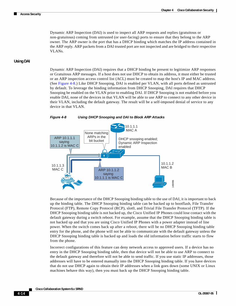
Dynamic ARP Inspection (DAI) requires that a DHCP binding be present to legitimize ARP responses or Gratuitous ARP messages. If a host does not use DHCP to obtain its address, it must either be trusted or an ARP inspection access control list (ACL) must be created to map the host's IP and MAC address. (See Figure 4-8.) Like DHCP Snooping, DAI is enabled per VLAN, with all ports defined as untrusted by default. To leverage the binding information from DHCP Snooping, DAI requires that DHCP Snooping be enabled on the VLAN prior to enabling DAI. If DHCP Snooping is not enabled before you enable DAI, none of the devices in that VLAN will be able to use ARP to connect to any other device in their VLAN, including the default gateway. The result will be a self-imposed denial of service to any device in that VLAN.
Figure 4-8 Using DHCP Snooping and DAI to Block ARP Attacks
Because of the importance of the DHCP Snooping binding table to the use of DAI, it is important to back up the binding table. The DHCP Snooping binding table can be backed up to bootflash, File Transfer Protocol (FTP), Remote Copy Protocol (RCP), slot0, and Trivial File Transfer Protocol (TFTP). If the DHCP Snooping binding table is not backed up, the Cisco Unified IP Phones could lose contact with the default gateway during a switch reboot. For example, assume that the DHCP Snooping binding table is not backed up and that you are using Cisco Unified IP Phones with a power adapter instead of line power. When the switch comes back up after a reboot, there will be no DHCP Snooping binding table entry for the phone, and the phone will not be able to communicate with the default gateway unless the DHCP Snooping binding table is backed up and loads the old information before traffic starts to flow from the phone.
Incorrect configurations of this feature can deny network access to approved users. If a device has no entry in the DHCP Snooping binding table, then that device will not be able to use ARP to connect to the default gateway and therefore will not be able to send traffic. If you use static IP addresses, those addresses will have to be entered manually into the DHCP Snooping binding table. If you have devices that do not use DHCP again to obtain their IP addresses when a link goes down (some UNIX or Linux machines behave this way), then you must back up the DHCP Snooping binding table.
1484
96
10.1.1.3MAC C
ARP 10.1.1.1saying
10.1.1.2 is MAC C
None matchingARPs in thebit bucket
10.1.1.1MAC A
DHCP snooping enabled;Dynamic ARP Inspectionenabled
10.1.1.2MAC B
ARP 10.1.1.2saying
10.1.1.1 is MAC C
4-14Cisco Collaboration System 9.x SRND
OL-29367-05
Chapter 4 Cisco Collaboration SecurityAccess Security
802.1X Port-Based Authentication
The 802.1X authentication feature can be used to identify and validate the device credentials of a Cisco Unified IP Phone before granting it access to the network. 802.1X is a MAC-layer protocol that interacts between an end device and a RADIUS server. It encapsulates the Extensible Authentication Protocol (EAP) over LAN, or EAPOL, to transport the authentication messages between the end devices and the switch. In the 802.1X authentication process, the Cisco Unified IP Phone acts as an 802.1X supplicant and initiates the request to access the network. The Cisco Catalyst Switch, acting as the authenticator, passes the request to the authentication server and then either allows or restricts the phone from accessing the network.
802.1X can also be used to authenticate the data devices attached to the Cisco Unified IP Phones. An EAPOL pass-through mechanism is used by the Cisco Unified IP Phones, allowing the locally attached PC to pass EAPOL messages to the 802.1X authenticator. The Cisco Catalyst Switch port needs to be configured in multiple-authentication mode to permit one device on the voice VLAN and multiple authenticated devices on the data VLAN.
Note Cisco recommends authenticating the IP phone before the attached data device is authenticated.
The multiple-authentication mode assigns authenticated devices to either a data or voice VLAN, depending on the attributes received from the authentication server when access is approved. The 802.1X port is divided into a data domain and a voice domain.
In multiple-authentication mode, a guest VLAN can be enabled on the 802.1x port. The switch assigns end clients to a guest VLAN when the authentication server does not receive a response to its EAPOL identity frame or when EAPOL packets are not sent by the client. This allows data devices attached to a Cisco IP Phone, that do not support 802.1X, to be connected to the network.
A voice VLAN must be configured for the IP phone when the switch port is in a multiple-host mode. The RADIUS server must be configured to send a Cisco Attribute-Value (AV) pair attribute with a value of device-traffic-class=voice. Without this value, the switch treats the IP phone as a data device.
Dynamic VLAN assignment from a RADIUS server is supported only for data devices.
When a data or a voice device is detected on a port, its MAC address is blocked until authorization succeeds. If the authorization fails, the MAC address remains blocked for 5 minutes.
When the 802.1x authentication is enabled on an access port on which a voice VLAN is configured and to which a Cisco IP Phone is already connected, the phone loses connectivity to the switch for up to 30 seconds.
Most Cisco IP Phones support authentication by means of X.509 certificates using the EAP-Transport Layer Security (EAP-TLS) or EAP-Flexible Authentication with Secure Tunneling (EAP-FAST) methods of authentication. Some of the older models that do not support either method can be authenticated using MAC Authentication Bypass (MAB), which enables a Cisco Catalyst Switch to check the MAC address of the connecting device as the method of authentication.
To determine support for the 802.1X feature configuration, refer to the product guides for the Cisco Unified IP Phones and the Cisco Catalyst Switches, available at http://www.cisco.com.
For configuration information, refer to the IP Telephony for 802.1x Design Guide, available at
http://www.cisco.com/en/US/docs/solutions/Enterprise/Security/TrustSec_1.99/IP_Tele/IP_Telephony_DIG.html
4-15Cisco Collaboration System 9.x SRND
OL-29367-05
Chapter 4 Cisco Collaboration SecurityEndpoint Security
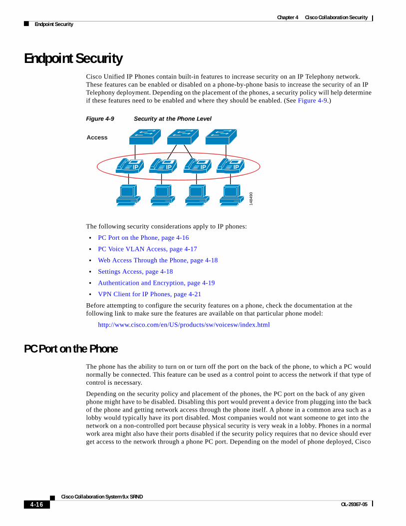
Endpoint SecurityCisco Unified IP Phones contain built-in features to increase security on an IP Telephony network. These features can be enabled or disabled on a phone-by-phone basis to increase the security of an IP Telephony deployment. Depending on the placement of the phones, a security policy will help determine if these features need to be enabled and where they should be enabled. (See Figure 4-9.)
Figure 4-9 Security at the Phone Level
The following security considerations apply to IP phones:
• PC Port on the Phone, page 4-16
• PC Voice VLAN Access, page 4-17
• Web Access Through the Phone, page 4-18
• Settings Access, page 4-18
• Authentication and Encryption, page 4-19
• VPN Client for IP Phones, page 4-21
Before attempting to configure the security features on a phone, check the documentation at the following link to make sure the features are available on that particular phone model:
http://www.cisco.com/en/US/products/sw/voicesw/index.html
PC Port on the PhoneThe phone has the ability to turn on or turn off the port on the back of the phone, to which a PC would normally be connected. This feature can be used as a control point to access the network if that type of control is necessary.
Depending on the security policy and placement of the phones, the PC port on the back of any given phone might have to be disabled. Disabling this port would prevent a device from plugging into the back of the phone and getting network access through the phone itself. A phone in a common area such as a lobby would typically have its port disabled. Most companies would not want someone to get into the network on a non-controlled port because physical security is very weak in a lobby. Phones in a normal work area might also have their ports disabled if the security policy requires that no device should ever get access to the network through a phone PC port. Depending on the model of phone deployed, Cisco
1484
90
Access
IP IP IP IP
4-16Cisco Collaboration System 9.x SRND
OL-29367-05
Chapter 4 Cisco Collaboration SecurityEndpoint Security
Unified Communications Manager (Unified CM) can disable the PC port on the back of the phone. Before attempting to enable this feature, check the documentation at the following link to verify that this features is supported on your particular model of Cisco Unified IP Phone:
http://www.cisco.com/en/US/products/hw/phones/ps379/tsd_products_support_series_home.html
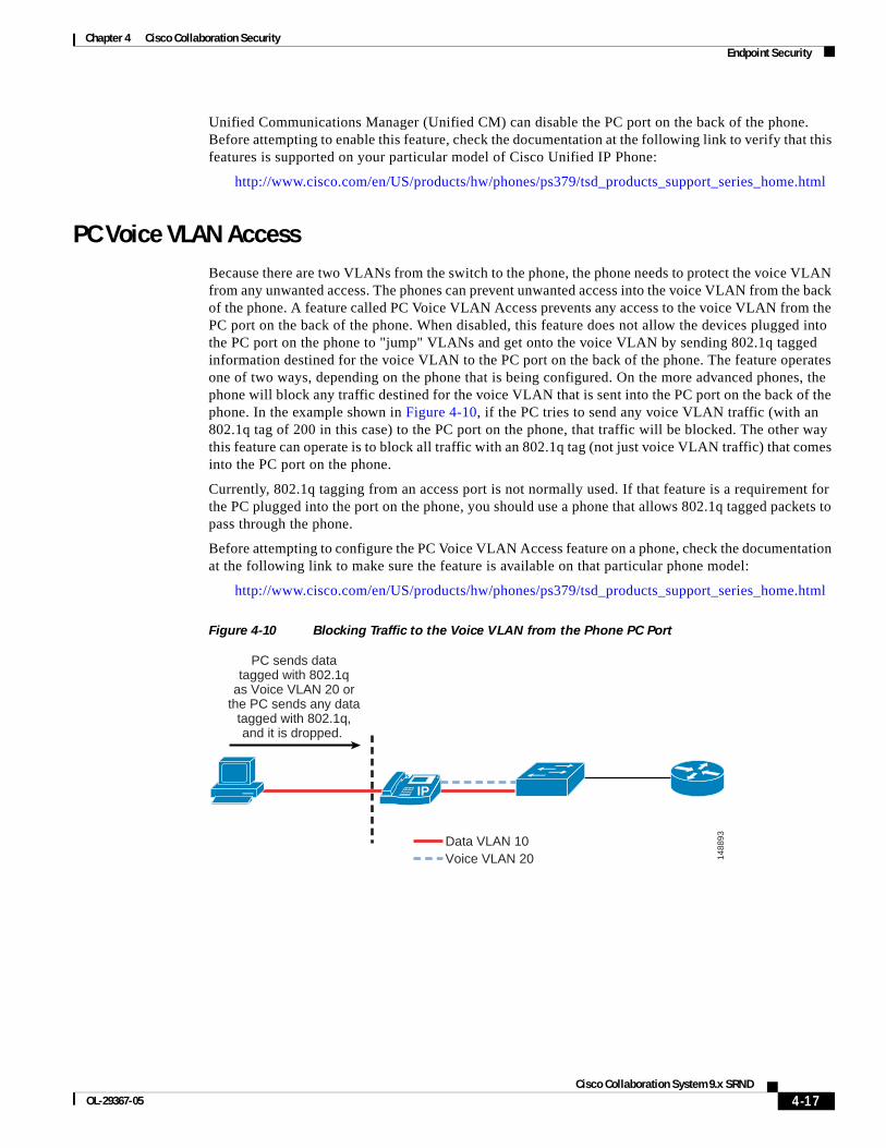
PC Voice VLAN AccessBecause there are two VLANs from the switch to the phone, the phone needs to protect the voice VLAN from any unwanted access. The phones can prevent unwanted access into the voice VLAN from the back of the phone. A feature called PC Voice VLAN Access prevents any access to the voice VLAN from the PC port on the back of the phone. When disabled, this feature does not allow the devices plugged into the PC port on the phone to "jump" VLANs and get onto the voice VLAN by sending 802.1q tagged information destined for the voice VLAN to the PC port on the back of the phone. The feature operates one of two ways, depending on the phone that is being configured. On the more advanced phones, the phone will block any traffic destined for the voice VLAN that is sent into the PC port on the back of the phone. In the example shown in Figure 4-10, if the PC tries to send any voice VLAN traffic (with an 802.1q tag of 200 in this case) to the PC port on the phone, that traffic will be blocked. The other way this feature can operate is to block all traffic with an 802.1q tag (not just voice VLAN traffic) that comes into the PC port on the phone.
Currently, 802.1q tagging from an access port is not normally used. If that feature is a requirement for the PC plugged into the port on the phone, you should use a phone that allows 802.1q tagged packets to pass through the phone.
Before attempting to configure the PC Voice VLAN Access feature on a phone, check the documentation at the following link to make sure the feature is available on that particular phone model:
http://www.cisco.com/en/US/products/hw/phones/ps379/tsd_products_support_series_home.html
Figure 4-10 Blocking Traffic to the Voice VLAN from the Phone PC Port
1488
93
IP
PC sends datatagged with 802.1q
as Voice VLAN 20 orthe PC sends any data
tagged with 802.1q,and it is dropped.
Data VLAN 10Voice VLAN 20
4-17Cisco Collaboration System 9.x SRND
OL-29367-05
Chapter 4 Cisco Collaboration SecurityEndpoint Security
Web Access Through the PhoneEach Cisco Unified IP Phone has a web server built into it to help with debugging and remote status of the phone for management purposes. The web server also enables the phones to receive applications pushed from Cisco Unified Communications Manager (Unified CM) to the phones. Access to this web server can be enabled or disabled on a phone by means of the Web Access feature in the Unified CM configuration. This setting can be global, or it could be enabled or disabled on a phone-by-phone basis.
If the web server is globally disable but it is needed to help with debugging, then the administrator for Unified CM will have to enable this feature on the phones. The ability to get to this web page can be controlled by an ACL in the network, leaving network operators with the capability to get to the web page when needed.
With the Web Access feature disabled, the phones will be unable to receive applications pushed to them from Unified CM.
Unified CM can be configured to use either HTTPS only or both HTTPS and HTTP for web traffic to and from the IP phones. However, if HTTPS only is configured, this does not by itself close port 80 on the IP phone's web server. It is preferable to use ACLs to restrict HTTP traffic, and configure Unified CM for HTTPS only.
Settings AccessEach Cisco Unified IP Phone has a network settings page that lists many of the network elements and detailed information that is needed for the phone to operate. This information could be used by an attacker to start a reconnaissance on the network with some of the information that is displayed on the phone's web page. For example, an attacker could look at the settings page to determine the default gateway, the TFTP server, and the Unified CM IP address. Each of these pieces of information could be used to gain access to the voice network or to attack a device in the voice network.
This access can be disabled on individual phones or by using bulk management to prevent end users or attackers from obtaining the additional information such as Unified CM IP address and TFTP server information. With access to the phone settings page disabled, end users lose the ability to change many of the settings on the phone that they would normally be able to control, such as speaker volume, contrast, and ring type. It might not be practical to use this security feature because of the limitations it places on end users with respect to the phone interface. The settings access can also be set as restricted, which prevents access to network configuration information but allows users to configure volume, ring tones, and so forth.
For more information on the phone settings page, refer to the latest version of the Cisco Unified Communications Manager Administration Guide, available at
http://www.cisco.com/en/US/products/sw/voicesw/ps556/prod_maintenance_guides_list.html
4-18Cisco Collaboration System 9.x SRND
OL-29367-05
Chapter 4 Cisco Collaboration SecurityEndpoint Security
Cisco TelePresence Endpoint HardeningCisco TelePresence endpoints have multiple configuration options for securing them against attacks. The security features vary among the different endpoints, and not all are enabled at default. These features include:
• Secure management over HTTPS and SSH
• Administrative passwords
• Device access
• Signaling and media encryption
Cisco TelePresence endpoints support management through Secure Shell (SSH) and Hyper-Text Transfer Protocol over Secure Sockets Layer (HTTPS). Access to the endpoints using HTTP, HTTPS, SSH, or Telnet can be configured in the Network Services setting on the endpoint itself.
The endpoints ship with default administrative passwords, and Cisco recommends changing the passwords at the time of installation. Access to management functions should be restricted to authorized users with administrative privileges. If the default administrative passwords are used, then the video stream can be viewed by anyone accessing the administrative page with the password.
The endpoints can be assigned to users who are given access based on defined roles and privileges. Passwords and PINs can be specified for those users to enable SSH or Telnet and web-based access. A credential management policy should be implemented to expire and change passwords periodically and to time-out logins when idle. This is necessary for limiting access to the devices to verified users.
Authentication and EncryptionCisco Collaboration Solutions use Transport Layer Security (TLS) and Secure Real-time Transport Protocol (SRTP) for signaling and media encryption.
Transport Layer Security (TLS)
The Transport Layer Security (TLS) protocol is designed to provide authentication, data integrity, and confidentiality for communications between two applications. TLS is based on Secure Sockets Layer (SSL) version 3.0, although the two protocols are not compatible. TLS operates in a client/server mode with one side acting as the "server" and the other side acting as the "client." TLS requires TCP as the reliable transport layer protocol to operate over.
Cisco Collaboration devices use TLS to secure SIP or SCCP signaling in the following scenarios:
• Between Unified CM and the endpoints registered to it
• Between TelePresence devices and the TelePresence primary codec
• Between Cisco TelePresence Management Suite (TMS), Unified CM, and/or Cisco TelePresence Video Communication Server (VCS)
Secure Real-Time Transport Protocol (SRTP)
Secure RTP (SRTP), defined in IETF RFC 3711, details the methods of providing confidentiality and data integrity for both Real-time Transport Protocol (RTP) voice and video media, as well as their corresponding Real-time Transport Control Protocol (RTCP) streams. SRTP accomplishes this through the use of encryption and message authentication headers.
In SRTP, encryption applies only to the payload of the RTP packet. Message authentication, however, is applied to both the RTP header and the RTP payload. Because message authentication applies to the RTP sequence number within the header, SRTP indirectly provides protection against replay attacks as well.
4-19Cisco Collaboration System 9.x SRND
OL-29367-05
Chapter 4 Cisco Collaboration SecurityEndpoint Security
SRTP uses Advanced Encryption Standards (AES) with a 128-bit encryption key as the encryption cipher. It also uses Hash-based Message Authentication Code Secure Hash Algorithm-1 (HMAC-SHA1) as the authentication method.
Voice and Video System
Unified CM can be configured to provide multiple levels of security to the phones within a voice system, if those phones support those features. This includes device authentication and media and signaling encryption using X.509 certificates. Depending on your security policy, phone placement, and phone support, the security can be configured to fit the needs of your company.
For information on which Cisco Unified IP Phone models support specific security features, refer to the documentation available at
http://www.cisco.com/en/US/products/hw/phones/ps379/tsd_products_support_series_home.html
To enable security on the phones and in the Unified CM cluster, refer to the Cisco Unified Communications Manager Security Guide, available at
http://www.cisco.com/en/US/products/sw/voicesw/ps556/prod_maintenance_guides_list.html
When the Public Key Infrastructure (PKI) security features are properly configured in Unified CM, all supported phones will have the following capabilities:
• Integrity — Does not allow TFTP file manipulation but does allow Transport Layer Security (TLS) signaling to the phones when enabled.
• Authentication — The image for the phone is authenticated from Unified CM to the phone, and the device (phone) is authenticated to Unified CM. All signaling messages between the phone and Unified CM are verified as being sent from the authorized device.
• Encryption — For supported devices, signaling and media can be encrypted to prevent eavesdropping.
• Secure Real-time Transport Protocol (SRTP) — Is supported to Cisco IOS gateways and on phone-to-phone communications. Cisco Unity also supports SRTP for voicemail.
Unified CM supports authentication, integrity, and encryption for calls between two Cisco Unified IP Phones but not for all devices or phones. To determine if your device supports these features, refer to the documentation available at
http://www.cisco.com/en/US/products/hw/phones/ps379/tsd_products_support_series_home.html
Unified CM uses certificates for securing identities and enabling encryption. The certificates can be either Manufacturing Installed Certificates (MIC) or Locally Significant Certificates (LSC). MICs are already pre-installed and LSCs are installed by Unified CM's Cisco Certificate Authority Proxy Function (CAPF). Unified CM creates self-signed certificates, but signing of certificates by a third-party certificate authority (CA) using PKCS #10 Certificate Signing Request (CSR) is also supported. When using third-party CAs, the CAPF can be signed by the CA, but the phone LSCs are still generated by the CAPF. When MICs are used, the Cisco CA and the Cisco Manufacturing CA certificates act as the root certificates. When LSCs are generated for natively registered endpoints, the CAPF certificate is the root certificate.
Auto-registration does not work if you configure the cluster for mixed mode, which is required for device authentication. The cluster mixed-mode information is included in the CTL file downloaded by the endpoints. The CTL file configuration requires using a CTL client to sign the file. The CTL client is a separate application that is installed on a Windows PC, and it uses the Cisco Security Administrator Security Token (SAST), USB hardware device, to sign the CTL file.
Cisco TelePresence Management Suite (TMS) provides TLS certificates to verify its identity when generating outbound connections.
4-20Cisco Collaboration System 9.x SRND
OL-29367-05
Chapter 4 Cisco Collaboration SecurityEndpoint Security
Application layer protocol inspection and Application Layer Gateways (ALGs) that allow IP Telephony traffic to traverse firewalls and Network Address Translation (NAT) also do not work with signaling encryption. Not all gateways, phones, or conference are supported with encrypted media.
Encrypting media makes recording and monitoring of calls more difficult and expensive. It also makes troubleshooting VoIP problems more challenging.
VPN Client for IP PhonesCisco Unified IP Phones with an embedded VPN client provide a secure option for connecting phones outside the network to the Unified Communications solution in the enterprise. This functionality does not require an external VPN router at the remote location, and it provides a secure communications tunnel for Layer 3 and higher traffic over an untrusted network between the phone at the deployed location and the corporate network.
The VPN client in Cisco Unified IP Phones uses Cisco SSL VPN technology and can connect to both the Cisco ASA 5500 Series VPN head-end and the Cisco Integrated Services Routers with the Cisco IOS SSL VPN software feature. The voice traffic is carried in UDP and protected by Datagram Transport Layer Security (DTLS) protocol as part of the VPN tunnel. The integrated VPN tunnel applies only to voice and IP phone services. A PC connected to the PC port cannot use this tunnel and needs to establish its own VPN tunnel for any traffic from the PC. Cisco Virtualization Experience Infrastructure (VXI) clients connected to the PC port on a Cisco Unified IP Phone can be configured to join the VPN tunnel. The MAC address of the VXI client must be added to the phone's device profile configuration to allow it access to the tunnel.
For a phone with the embedded VPN client, you must first configure the phone with the VPN configuration parameters, including the VPN concentrator addresses, VPN concentrator credentials, user or phone ID, and credential policy. Because of the sensitivity of this information, the phone must be provisioned within the corporate network before the phone can attempt connecting over an untrusted network. Deploying the phone without first staging the phone in the corporate network is not supported.
The settings menu on the phone's user interface allows the user to enable or disable VPN tunnel establishment. When the VPN tunnel establishment is enabled, the phone starts to establish a VPN tunnel. The phone can be configured with up to three VPN concentrators to provide redundancy. The VPN client supports redirection from a VPN concentrator to other VPN concentrators as a load balancing mechanism.
For instructions on configuring the phones for the VPN client, refer to the latest version of the Cisco Unified Communications Manager Administration Guide, available at:
http://www.cisco.com/en/US/products/sw/voicesw/ps556/prod_maintenance_guides_list.html
Quality of ServiceQuality of Service (QoS) is a vital part of any security policy for an enterprise network. Even though most people think of QoS as setting the priority of traffic in a network, it also controls the amount of data that is allowed into the network. In the case of Cisco switches, that control point is at the port level when the data comes from the phone to the Ethernet switch. The more control applied at the edge of the network at the access port, the fewer problems will be encountered as the data aggregates in the network.
QoS can be used to control not only the priority of the traffic in the network but also the amount of traffic that can travel through any specific interface. Cisco Smartports templates have been created to assist in deploying voice QoS in a network at the access port level.
4-21Cisco Collaboration System 9.x SRND
OL-29367-05
Chapter 4 Cisco Collaboration SecurityAccess Control Lists
A rigorous QoS policy can control and prevent denial-of-service attacks in the network by throttling traffic rates.
As mentioned previously in the lobby phone example, Cisco recommends that you provide enough flow control of the traffic at the access port level to prevent any attacker from launching a denial-of-service (DoS) attack from that port in the lobby. The configuration for that example was not as aggressive as it could be because the QoS configuration allowed traffic sent to the port to exceed the maximum rate, but the traffic was remarked to the level of scavenger class. Given a more aggressive QoS policy, any amount of traffic that exceeded that maximum limit of the policy could just be dropped at the port, and that "unknown" traffic would never make it into the network. QoS should be enabled across the entire network to give the IP Telephony data high priority from end to end.
For more information on QoS, refer to the chapter on Network Infrastructure, page 3-1, and the Enterprise QoS Solution Reference Network Design (SRND) Guide available at
http://www.cisco.com/go/designzone
Access Control ListsThis section covers access control lists (ACLs) and their uses in protecting voice data.
VLAN Access Control ListsYou can use VLAN access control lists (ACLs) to control data that flows on a network. Cisco switches have the capability of controlling Layers 2 to 4 within a VLAN ACL. Depending on the types of switches in a network, VLAN ACLs can be used to block traffic into and out of a particular VLAN. They can also be used to block intra-VLAN traffic to control what happens inside the VLAN between devices.
If you plan to deploy a VLAN ACL, you should verify which ports are needed to allow the phones to function with each application used in your IP Telephony network. Normally any VLAN ACL would be applied to the VLAN that the phones use. This would allow control at the access port, as close as possible to the devices that are plugged into that access port.
ACLs provide the ability to control the network traffic in and out of a VLAN as well as the ability to control the traffic within the VLAN.
VLAN ACLs are very difficult to deploy and manage at an access-port level that is highly mobile. Because of these management issues, care should be taken when deploying VLAN ACLs at the access port in the network.
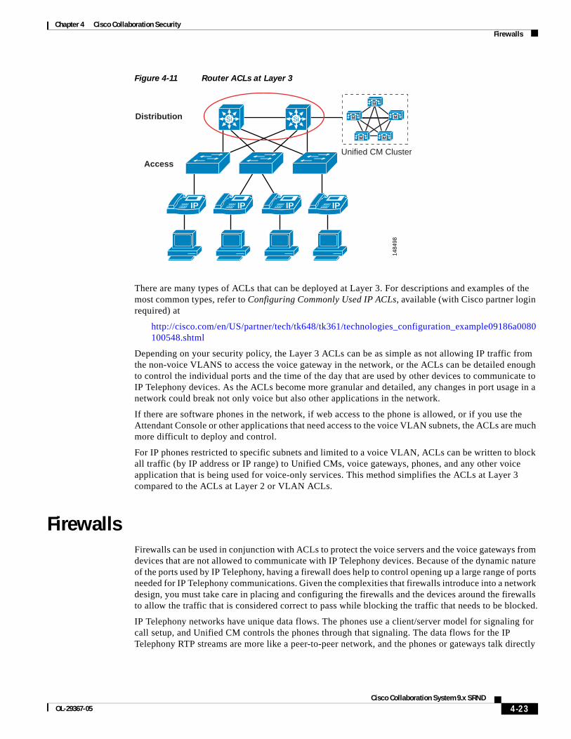
Router Access Control ListsAs with VLAN ACLs, routers have the ability to process both inbound and outbound ACLs by port. The first Layer 3 device is the demarcation point between voice data and other types of data when using voice and data VLANs, where the two types of data are allowed to send traffic to each other. Unlike the VLAN ACLs, router ACLs are not deployed in every access device in your network. Rather, they are applied at the edge router, where all data is prepared for routing across the network. This is the perfect location to apply a Layer 3 ACL to control which areas the devices in each of the VLANs have the ability to access within a network. Layer 3 ACLs can be deployed across your entire network to protect devices from each other at points where the traffic converges. (See Figure 4-11.)
4-22Cisco Collaboration System 9.x SRND
OL-29367-05
Chapter 4 Cisco Collaboration SecurityFirewalls
Figure 4-11 Router ACLs at Layer 3
There are many types of ACLs that can be deployed at Layer 3. For descriptions and examples of the most common types, refer to Configuring Commonly Used IP ACLs, available (with Cisco partner login required) at
http://cisco.com/en/US/partner/tech/tk648/tk361/technologies_configuration_example09186a0080100548.shtml
Depending on your security policy, the Layer 3 ACLs can be as simple as not allowing IP traffic from the non-voice VLANS to access the voice gateway in the network, or the ACLs can be detailed enough to control the individual ports and the time of the day that are used by other devices to communicate to IP Telephony devices. As the ACLs become more granular and detailed, any changes in port usage in a network could break not only voice but also other applications in the network.
If there are software phones in the network, if web access to the phone is allowed, or if you use the Attendant Console or other applications that need access to the voice VLAN subnets, the ACLs are much more difficult to deploy and control.
For IP phones restricted to specific subnets and limited to a voice VLAN, ACLs can be written to block all traffic (by IP address or IP range) to Unified CMs, voice gateways, phones, and any other voice application that is being used for voice-only services. This method simplifies the ACLs at Layer 3 compared to the ACLs at Layer 2 or VLAN ACLs.
FirewallsFirewalls can be used in conjunction with ACLs to protect the voice servers and the voice gateways from devices that are not allowed to communicate with IP Telephony devices. Because of the dynamic nature of the ports used by IP Telephony, having a firewall does help to control opening up a large range of ports needed for IP Telephony communications. Given the complexities that firewalls introduce into a network design, you must take care in placing and configuring the firewalls and the devices around the firewalls to allow the traffic that is considered correct to pass while blocking the traffic that needs to be blocked.
IP Telephony networks have unique data flows. The phones use a client/server model for signaling for call setup, and Unified CM controls the phones through that signaling. The data flows for the IP Telephony RTP streams are more like a peer-to-peer network, and the phones or gateways talk directly
1484
98
Distribution
Access
Si Si
IP IP IP IP
Unified CM Cluster
M
M
M M
M
4-23Cisco Collaboration System 9.x SRND
OL-29367-05
Chapter 4 Cisco Collaboration SecurityFirewalls
to each other via the RTP streams. If the signaling flows do not go through the firewall so that the firewall can inspect the signaling traffic, the RTP streams could be blocked because the firewall will not know which ports need to be opened to allow the RTP streams for a conversation.
A firewall placed in a correctly designed network can force all the data through that device, so capacities and performance need to be taken into account. Performance includes the amount of latency, which can be increased by a firewall if the firewall is under high load or even under attack. The general rule in an IP Telephony deployment is to keep the CPU usage of the firewalls to less than 60% for normal usage. If the CPU runs over 60%, it increases the chance of impacting IP phones, call setup, and registration. If the CPU usage stays at a sustained level above 60%, the registered IP phones will be affected, quality of calls in progress will degrade, and call setup for new calls will suffer. In the worst case, if the sustained CPU usage stays above 60%, phones will start to unregister. When this happens, they will attempt to re-register with Unified CM, thus increasing the load on the firewalls even more. If this were to happen, the effect would be a rolling blackout of phones unregistering and attempting to re-register with Unified CM. Until the CPU usage of the firewall decreases to under 60% sustained load, this rolling blackout would continue and most (if not all) of the phones would be affected. If you are currently using a Cisco firewall in your network, you should monitor the CPU usage carefully when adding IP Telephony traffic to your network so that you do not adversely affect that traffic.
There are many ways to deploy firewalls. This section concentrates on the Cisco Adaptive Security Appliance (ASA) in the active/standby mode in both routed and transparent scenarios. Each of the configurations in this section is in single-context mode within the voice sections of the firewall configurations.
All of the Cisco firewalls can run in either multiple-context or single-context mode. In single-context mode, the firewall is a single firewall that controls all traffic flowing through it. In multiple-context mode, the firewalls can be turned into many virtual firewalls. Each of these contexts or virtual firewalls have their own configurations and can be controlled by different groups or administrators. Each time a new context is added to a firewall, it will increase the load and memory requirements on that firewall. When you deploy a new context, make sure that the CPU requirements are met so that voice RTP streams are not adversely affected.
Adaptive Security Appliances have limited support for application inspection of IPv6 traffic for Unified Communications application servers and endpoints. Cisco recommends not using IPv6 for Unified Communications if ASAs are deployed in your network.
Note An ASA with No Payload Encryption model disables Unified Communications features.
A firewall provides a security control point in the network for applications that run over the network. A firewall also provides dynamic opening of ports for IP Telephony conversations if that traffic is running through the firewall.
Using its application inspection capability, the firewall can inspect the traffic that runs though it to determine if that traffic is really the type of traffic that the firewall is expecting. For example, does the HTTP traffic really look like HTTP traffic, or is it an attack? If it is an attack, then the firewall drops that packet and does not allow it to get to the HTTP server behind the firewall.
Not all IP Telephony application servers or applications are supported with firewall application layer protocol inspection. Some of these applications include Cisco Unity voicemail servers, Cisco Unified Attendant Console, Cisco Unified Contact Center Enterprise, and Cisco Unified Contact Center Express. ACLs can be written for these applications to allow traffic to flow through a firewall.
4-24Cisco Collaboration System 9.x SRND
OL-29367-05
Chapter 4 Cisco Collaboration SecurityFirewalls
Note The timers for failover on the firewalls are set quite high by default. To keep from affecting voice RTP streams as they go through the firewall if there is a failover, Cisco recommends reducing those timer settings to less than one second. If this is done, and if there is a failover, the amount of time that the RTP streams could be affected will be less because the firewalls will fail-over quicker and there will be less impact on the RTP streams during the failover time.
When firewalls are placed between different Unified Communications components, the application inspection must be enabled for all protocols used for communications between the components. Application inspection can fail in call flow scenarios used by features such as Silent Monitoring by Unified Communications Manager, when the firewall is between the remote agent phones and the supervisor phones.
Unified Communications devices using TCP, such as Cisco Unified Communications Manager, support the TCP SACK option to speed up data transfer in case of packet loss. But not all firewalls support the TCP SACK option. In that case, TCP sessions established between Unified Communications devices through such a firewall will encounter problems if they attempt to use the TCP SACK option, and the TCP session might fail. Therefore, the firewalls should provide full support for the TCP SACK option. If support is not available, then the firewalls should be able to modify the TCP packets during the three-way handshake and to disable TCP SACK option support so that the endpoints will not attempt to use this option.
To determine if the applications running on your network are supported with the version of firewall in the network or if ACLs have to be written, refer to the appropriate application documentation available at
http://www.cisco.com
Routed ASAThe ASA firewall in routed mode acts as a router between connected networks, and each interface requires an IP address on a different subnet. In single-context mode, the routed firewall supports Open Shortest Path First (OSPF) and Routing Information Protocol (RIP) in passive mode. Multiple-context mode supports static routes only. ASA version 8.x also supports Enhanced Interior Gateway Routing Protocol (EIGRP). Cisco recommends using the advanced routing capabilities of the upstream and downstream routers instead of relying on the security appliance for extensive routing needs. For more information on the routed mode, refer to the Cisco Security Appliance Command Line Configuration Guide, available at
http://www.cisco.com/en/US/products/ps6120/products_installation_and_configuration_guides_list.html
The routed ASA firewall supports QoS, NAT, and VPN termination to the box, which are not supported in the transparent mode (see Transparent ASA, page 4-26). With the routed configuration, each interface on the ASA would have an IP address. In the transparent mode, there would be no IP address on the interfaces other then the IP address to manage the ASA remotely.
The limitations of this mode, when compared to the transparent mode, are that the device can be seen in the network and, because of that, it can be a point of attack. In addition, placing a routed ASA firewall in a network changes the network routing because some of the routing can be done by the firewall. IP addresses must also be available for all the interfaces on the firewall that are going to be use, so changing the IP addresses of the routers in the network might also be required. If a routing protocol or RSVP is to be allowed through the ASA firewall, then an ACL will have to be put on the inside (or most trusted) interface to allow that traffic to pass to the outside (or lesser trusted) interfaces. That ACL must also define all other traffic that will be allowed out of the most trusted interface.
4-25Cisco Collaboration System 9.x SRND
OL-29367-05
Chapter 4 Cisco Collaboration SecurityFirewalls
Transparent ASAThe ASA firewall can be configured to be a Layer 2 firewall (also known as "bump in the wire" or "stealth firewall"). In this configuration, the firewall does not have an IP address (other than for management purposes), and all of the transactions are done at Layer 2 of the network. Even though the firewall acts as a bridge, Layer 3 traffic cannot pass through the security appliance unless you explicitly permit it with an extended access list. The only traffic allowed without an access list is Address Resolution Protocol (ARP) traffic.
This configuration has the advantage that an attacker cannot see the firewall because it is not doing any dynamic routing. Static routing is required to make the firewall work even in transparent mode.
This configuration also makes it easier to place the firewall into an existing network because routing does not have to change for the firewall. It also makes the firewall easier to manage and debug because it is not doing any routing within the firewall. Because the firewall is not processing routing requests, the performance of the firewall is usually somewhat higher with inspect commands and overall traffic than the same firewall model and software that is doing routing.
With transparent mode, if you are going to pass data for routing, you will also have to define the ACLs both inside and outside the firewall to allow traffic, unlike with the same firewall in routed mode. Cisco Discovery Protocol (CDP) traffic will not pass through the device even if it is defined. Each directly connected network must be on the same subnet. You cannot share interfaces between contexts; if you plan on running multiple-context mode, you will have to use additional interfaces. You must define all non-IP traffic, such as routing protocols, with an ACL to allow that traffic through the firewall. QoS is not supported in transparent mode. Multicast traffic can be allowed to go through the firewall with an extended ACL, but it is not a multicast device. In transparent mode, the firewall does not support VPN termination other than for the management interface.
If a routing protocol or RSVP is to be allowed through the ASA firewall, then an ACL will have to be put on the inside (or most trusted) interface to allow that traffic to pass to the outside (or lesser trusted) interfaces. That ACL must also define all other traffic that will be allowed out of the most trusted interface.
For more information on the transparent mode, refer to the Cisco Security Appliance Command Line Configuration Guide, available at
http://www.cisco.com/en/US/products/ps6120/products_installation_and_configuration_guides_list.html
Note Using NAT in transparent mode requires ASA version 8.0(2) or later. For more information, refer to the Cisco ASA 5500 Series Release Notes at http://www.cisco.com/en/US/docs/security/asa/asa80/release/notes/asarn80.html.
ASA Intercompany Media Engine ProxyThe ASA Cisco Intercompany Media Engine (IME) proxy is a required component of the Cisco IME solution for IME call processing. The IME enables secure business-to-business communication systems that support enhanced Unified Communications features and that do not have to go through the PSTN network. For more information about the IME call processing phase of the solution, see Cisco Intercompany Media Engine, page 10-50. The IME-enabled ASA provides perimeter security functions such as anti-spam blocking of non-IME calls and audio quality monitoring for the Fallback feature, inspects SIP messages, and acts as a proxy for SIP to SIP/TLS and RTP/SRTP conversions. The IME-enabled ASA terminates and re-initiates connections, which allows it to inspect the SIP messaging
4-26Cisco Collaboration System 9.x SRND
OL-29367-05

Chapter 4 Cisco Collaboration SecurityFirewalls
and apply SIP ALG processing. The ASA will convert the SIP/TLS traffic to TCP going toward Unified CM if Unified CM is not secure, or it will connect through TLS if Unified CM is secure. The following deployment models apply to the IME-enabled ASA:
• Basic (Inline)
• Offpath
Basic Deployment
In a basic (inline) deployment, the Internet ASA is configured with the IME feature, and all Internet-bound traffic from the Unified CM cluster will naturally traverse this IME-enabled ASA. As shown in Figure 4-12, the IME-enabled ASA resides on the edge of the enterprise and proxies all IME-related SIP trunk signaling and audio/video RTP media to remote enterprises.
Figure 4-12 Intercompany Media Engine ASA Basic (Inline) Deployment Model
Offpath Deployment
In deployments where there are existing firewalls in the enterprise network, it might not be possible to replace or upgrade the existing firewall to support the IME feature or to change the existing security architecture by adding an IME-enabled ASA inline with the Internet firewall. In this scenario, the ASA can be implemented in an offpath model for IME. Offpath is the recommended deployment method.
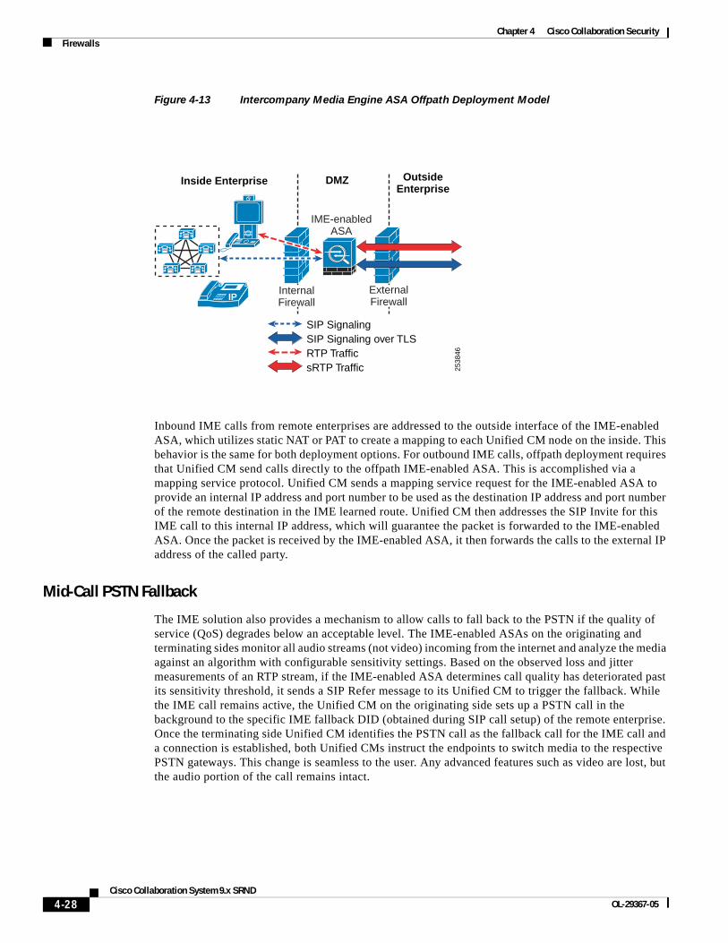
In an offpath deployment, inbound and outbound IME calls pass through an IME-enabled ASA that is located in the DMZ, as illustrated in figure 4-20. Unified CM is configured to direct all SIP signaling to the IME-enabled ASA. All other Internet-bound traffic does not flow through the IME-enabled ASA.
Inside Enterprise
2538
45
SIP SignalingSIP Signaling over TLSRTP TrafficsRTP Traffic
Outside Enterprise
IP
IME-enabledASA
4-27Cisco Collaboration System 9.x SRND
OL-29367-05
Chapter 4 Cisco Collaboration SecurityFirewalls
Figure 4-13 Intercompany Media Engine ASA Offpath Deployment Model
Inbound IME calls from remote enterprises are addressed to the outside interface of the IME-enabled ASA, which utilizes static NAT or PAT to create a mapping to each Unified CM node on the inside. This behavior is the same for both deployment options. For outbound IME calls, offpath deployment requires that Unified CM send calls directly to the offpath IME-enabled ASA. This is accomplished via a mapping service protocol. Unified CM sends a mapping service request for the IME-enabled ASA to provide an internal IP address and port number to be used as the destination IP address and port number of the remote destination in the IME learned route. Unified CM then addresses the SIP Invite for this IME call to this internal IP address, which will guarantee the packet is forwarded to the IME-enabled ASA. Once the packet is received by the IME-enabled ASA, it then forwards the calls to the external IP address of the called party.
Mid-Call PSTN Fallback
The IME solution also provides a mechanism to allow calls to fall back to the PSTN if the quality of service (QoS) degrades below an acceptable level. The IME-enabled ASAs on the originating and terminating sides monitor all audio streams (not video) incoming from the internet and analyze the media against an algorithm with configurable sensitivity settings. Based on the observed loss and jitter measurements of an RTP stream, if the IME-enabled ASA determines call quality has deteriorated past its sensitivity threshold, it sends a SIP Refer message to its Unified CM to trigger the fallback. While the IME call remains active, the Unified CM on the originating side sets up a PSTN call in the background to the specific IME fallback DID (obtained during SIP call setup) of the remote enterprise. Once the terminating side Unified CM identifies the PSTN call as the fallback call for the IME call and a connection is established, both Unified CMs instruct the endpoints to switch media to the respective PSTN gateways. This change is seamless to the user. Any advanced features such as video are lost, but the audio portion of the call remains intact.
Inside Enterprise
2538
46
SIP SignalingSIP Signaling over TLSRTP TrafficsRTP Traffic
OutsideEnterprise
DMZ
IP
IME-enabledASA
InternalFirewall
ExternalFirewall
4-28Cisco Collaboration System 9.x SRND
OL-29367-05
Chapter 4 Cisco Collaboration SecurityFirewalls
Cisco recommends starting with the default fallback sensitivity level and making revisions after determining how many calls are in fact falling back to PSTN connectivity. For more details regarding the IME solution and ASA configuration, refer to the Cisco Intercompany Media Engine Proxy information in the Cisco ASA 5500 Series Configuration Guide using the CLI, available at
http://www.cisco.com/en/US/docs/security/asa/asa83/configuration/guide/config.html
Design Considerations
The IME-enabled ASA requires at least two external (global) IP addresses, one for SIP signaling and one for media termination if PAT is used for incoming calls from remote enterprises. If NAT is implemented, more may be required. The external IP address on the IME-enabled ASA for SIP signaling is what is advertised in IME learned routes.
The IME-enabled ASA also requires at least two internal IP addresses, one for SIP signaling and one for media termination. PAT is used for incoming IME calls from Unified CM.
Note Although the IME-enabled ASA interfaces are referred to as external and internal, if the ASA is deployed in a DMZ, both interfaces may be on subnets that exist within the DMZ. At a minimum, the external interface subnet needs to be accessible from the Internet, and the internal interface subnet must be accessible from the intranet.
For any non-IME firewalls in the network that separate two components of the solution, it is imperative to open the proper pinholes to allow IME communications between the following components:
• IME server and Unified CM
• IME server and GoDaddy Enrollment Server
• IME server and the peer-to-peer IME server network (Distributed Cache Ring)
• IME-enabled ASA (internal) and Unified CM
• IME-enabled ASA (internal) and IME internal endpoints (media)
• IME-enabled ASA (external) and remote enterprise IME-enabled ASA
For a complete list of ports for the IME solution components, refer to the Cisco Intercompany Media Engine Installation and Configuration Guide, available at
http://cisco.com/en/US/products/sw/voicesw/ps556/prod_maintenance_guides_list.html
If there is an intranet firewall between the IME-enabled ASA and the Unified CM that is performing NAT, the following conditions must be met:
• This intranet firewall must be a Cisco ASA capable of SIP ALG functionality to allow the proper fixup of incoming and outgoing SIP messaging.
• There must be a static NAT entry to translate Unified CM's real IP address to an address reachable by the IME-enabled ASA.
The Cisco IME-enabled ASA typically has a default route for reaching Internet subnets. It also requires IP routes to all potential subnets containing internal endpoints. This includes data subnets that may include Cisco Unified Video Advantage cameras.
The IME solution requires its own Certificate Authority for validating ASA certificates used for establishing SIP/TLS connections. The IME-enabled ASA must verify SIP SSL certificates against this Certificate Authority (CA).
4-29Cisco Collaboration System 9.x SRND
OL-29367-05
Chapter 4 Cisco Collaboration SecurityNetwork Address Translation for Voice and Video
Note GoDaddy.com is the only authorized certificate provider for establishing secure SIP TLS connections with remote enterprises.
High Availability
IME-enabled ASAs can be deployed in an active/standby failover mode to provide stateless failover of IME communications. If an outage occurs, all calls being established, as well as existing calls, will be lost. Stateful failover is not supported.
With the offpath deployment method, Unified CM is capable of configuring multiple IME Services (sets of enrolled and excluded DIDs), each with its own IME firewall. This can add further resiliency to the solution.
With the offpath model, each IME Service (set of enrolled and excluded DIDs) configured in Unified CM is associated with an IME-enabled ASA. Multiple IME Services can exist in Unified CM, allowing an administrator to spread the load across multiple IME-enabled ASAs, thus increasing overall capacity.
Note The ASA Phone Proxy and TLS Proxy features are not compatible with Cisco Unified CM 9.x.
Network Address Translation for Voice and VideoThe Network Address Translation (NAT) device translates the private IP addresses inside the enterprise into public IP addresses visible on the public Internet. Endpoints inside the enterprise are internal endpoints, and endpoints in the public Internet are external endpoints.
When a device inside the enterprise connects out through the NAT, the NAT dynamically assigns a public IP address to the device. This public IP address is referred to as the public mapped address or the reflexive transport address. When the NAT forwards this packet to a device on the public Internet, the packet appears to come from its assigned public address. When external devices send packets back to the NAT at the public address, the NAT translates the IP addresses back to the internal private addresses and then forwards the packets to the internal network.
The NAT functionality is often part of the firewall and is therefore sometimes referred to as a NAT/FW. NATs map a large set of internal, private IP addresses into a smaller set of external, public IP addresses. The current public IPv4 address space is limited, and until IPv6 emerges as a ubiquitous protocol, most enterprises will have a limited number of IPv4 public addresses available. The NAT allows an enterprise with a large number of endpoints to make use of a small pool of public IP addresses. The NAT implements this functionality by dynamically mapping an internal IP address to an external IP address whenever an internal endpoint makes a connection out through the NAT. Each of these mappings is called a NAT binding.
The major complication in implementing NAT for voice and video devices occurs because the signaling protocols for voice and video include source addresses and ports in the protocol signaling messages. These source addresses provide the destination addresses that remote endpoints should use for return packets. However, internal endpoints use addresses from the private address space, and a NAT without an Application Layer Gateway (ALG) does not alter these internal addresses. When the remote endpoint receives a message, it cannot route packets to the private IP address in the message. Fixing this problem requires enabling an ALG, for example a SIP, H.323, or SCCP 'fixup', on the NAT device that can inspect the contents of the packet and implement address translation for the media IP addresses and port numbers encapsulated in the signaling messages.
4-30Cisco Collaboration System 9.x SRND
OL-29367-05
Chapter 4 Cisco Collaboration SecurityData Center
A NAT ALG is similar to a firewall ALG, but a NAT ALG actually changes (maps) the addresses and ports in the signaling messages. The NAT ALG cannot inspect the contents of encrypted signaling messages.
Data CenterWithin the data center, the security policy should define what security is needed for the IP Telephony applications servers. Because the Cisco Unified Communications servers are based on IP, the security that you would put on any other time-sensitive data within a data center could be applied to those servers as well.
If clustering over the WAN is being used between data centers, any additional security that is applied both within and between those data centers has to fit within the maximum round-trip time that is allowed between nodes in a cluster. In a multisite or redundant data center implementation that uses clustering over the WAN, if your current security policy for application servers requires securing the traffic between servers across data center firewalls, then Cisco recommends using IPSec tunnels for this traffic between the infrastructure security systems already deployed.
To design appropriate data center security for your data applications, Cisco recommends following the guidelines presented in the Data Center Networking: Server Farm Security SRND (Server Farm Security in the Business Ready Data Center Architecture), available at
http://www.cisco.com/go/designzone
Gateways, Trunks, and Media ResourcesGateways and media resources are devices that convert an IP Telephony call into a PSTN call. When an outside call is placed, the gateway or media resource is one of the few places within an IP Telephony network to which all the voice RTP streams flow.
Because IP Telephony gateways and media resources can be placed almost anywhere in a network, securing an IP Telephony gateway or media resource might be considered more difficult than securing other devices, depending on your security policy. However, depending on which point trust is established in the network, the gateways and media resources can be quite easy to secure. Because of the way the gateways and media resources are controlled by Unified CM, if the path that the signaling takes to the gateway or media resource is in what is considered a secure section of the network, a simple ACL can be used to control signaling to and from the gateway or media resource. If the network is not considered secure between the gateways (or media resources) and where the Unified CMs are located (such as when a gateway is located at a remote branch), the infrastructure can be used to build IPSec tunnels to the gateways and media resources to protect the signaling. Most networks would most likely use a combination of the two approaches (ACL and IPSec) to secure those devices.
For H.323 videoconferencing devices, an ACL can be written to block port 1720 for H.225 trunks from any H.323 client in the network. This method would block users from initiating an H.225 session with each other directly. Cisco devices might use different ports for H.225, so refer to the product documentation for your equipment to see which port is used. If possible, change the port to 1720 so that only one ACL is needed to control signaling.
Because we use QoS at the edge of the network, if an attacker can get into the voice VLAN and determine where the gateways and media resources are, QoS at the port would limit how much data the attacker would be able to send to the gateway or media resource. (See Figure 4-14.)
4-31Cisco Collaboration System 9.x SRND
OL-29367-05
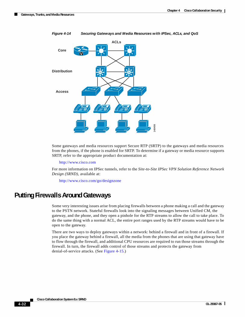
Chapter 4 Cisco Collaboration SecurityGateways, Trunks, and Media Resources
Figure 4-14 Securing Gateways and Media Resources with IPSec, ACLs, and QoS
Some gateways and media resources support Secure RTP (SRTP) to the gateways and media resources from the phones, if the phone is enabled for SRTP. To determine if a gateway or media resource supports SRTP, refer to the appropriate product documentation at:
http://www.cisco.com
For more information on IPSec tunnels, refer to the Site-to-Site IPSec VPN Solution Reference Network Design (SRND), available at:
http://www.cisco.com/go/designzone
Putting Firewalls Around GatewaysSome very interesting issues arise from placing firewalls between a phone making a call and the gateway to the PSTN network. Stateful firewalls look into the signaling messages between Unified CM, the gateway, and the phone, and they open a pinhole for the RTP streams to allow the call to take place. To do the same thing with a normal ACL, the entire port ranges used by the RTP streams would have to be open to the gateway.
There are two ways to deploy gateways within a network: behind a firewall and in front of a firewall. If you place the gateway behind a firewall, all the media from the phones that are using that gateway have to flow through the firewall, and additional CPU resources are required to run those streams through the firewall. In turn, the firewall adds control of those streams and protects the gateway from denial-of-service attacks. (See Figure 4-15.)
1484
99
Core
Distribution
Access
ACLs
Si Si
IP IP IP IP
V
4-32Cisco Collaboration System 9.x SRND
OL-29367-05

Chapter 4 Cisco Collaboration SecurityGateways, Trunks, and Media Resources
Figure 4-15 Gateway Placed Behind a Firewall
The second way to deploy the gateway is outside the firewall. Because the only type of data that is ever sent to the gateway from the phones is RTP streams, the access switch's QoS features control the amount of RTP traffic that can be sent to that gateway. The only thing that Unified CM sends to the gateway is the signaling to set up the call. If the gateway is put in an area of the network that is trusted, the only communication that has to be allowed between Unified CM and the gateway is that signaling. (See Figure 4-15.) This method of deployment decreases the load on the firewall because the RTP streams are not going through the firewall.
Unlike an ACL, most firewall configurations will open only the RTP stream port that Unified CM has told the phone and the gateway to use between those two devices as long as the signaling goes through the firewall. The firewall also has additional features for DoS attacks and Cisco Intrusion Prevention System (IPS) signatures to look at interesting traffic and determine if any attackers are doing something they should not be doing.
As stated in the section on Firewalls, page 4-23, when a firewall is looking at all the signaling and RTP streams from phones to a gateway, capacity could be an issue. Also, if data other than voice data is running through the firewall, CPU usage must be monitored to make sure that the firewall does not affect the calls that are running through the firewall.
Firewalls and H.323H.323 utilizes H.245 for setting up the media streams between endpoints, and for the duration of that call the H.245 session remains active between Unified CM and the H.323 gateway. Subsequent changes to the call flow are done through H.245.
By default, a Cisco firewall tracks the H.245 session and the associated RTP streams of calls, and it will time-out the H.245 session if no RTP traffic crosses the firewall for longer than 5 minutes. For topologies where at least one H.323 gateway and the other endpoints are all on one side of the firewall, the firewall will not see the RTP traffic. After 5 minutes, the H.245 session will be blocked by the firewall, which stops control of that stream but does not affect the stream itself. For example, no supplementary services will be available. This default behavior can be changed in firewall configuration so that the maximum anticipated call duration is specified.
The advantage of the configuration change from default is that it prevents H.323 from losing any call functionality when all endpoints are on the same side of the firewall.
SignalingMedia 14
8896
V
IP M
M
M M
M
IP
PSTN
4-33Cisco Collaboration System 9.x SRND
OL-29367-05
Chapter 4 Cisco Collaboration SecurityGateways, Trunks, and Media Resources
SAF ServiceUnified CM employs the Cisco Service Advertisement Framework (SAF) network service for its Call Control Discovery (CCD) feature (see Service Advertisement Framework (SAF), page 3-69). This capability uses a SIP trunk or a non-gatekeeper controlled H.323 trunk associated with the Call Control Discovery advertising service. The service advertises the call negotiation information for these trunks, including the dynamic port number for the H.323 trunk, the standard port 5060 for the SIP trunk, and the SIP route header information.
The Adaptive Security Appliances do not have application inspection for the SAF network service. When Unified CM uses a SAF-enabled H.323 trunk to place a call, the ASA cannot inspect the SAF packet to learn the ephemeral port number used in the H.225 signalling. Therefore, in scenarios where call traffic from SAF-enabled H.323 trunks traverses the ASAs, ACLs must be configured on the ASAs to allow this signaling traffic. The ACL configuration must account for all the ports used by the H.225 and H.245 signaling. ACL configuration is not required when SAF-enabled SIP trunks with the standard 5060 port are used.
Secure Audio and Video ConferencingA Cisco TelePresence MCU conference bridge is required for providing secure voice and video conferencing for both video-enabled Cisco IP Phones and Cisco TelePresence endpoints. While Cisco IOS ISR G2 routers can support audio and video conferencing, they do not yet support encryption for such conferences.
Implementing encrypted media and signaling between Unified CM, its endpoints, and the MCU, requires configuring the SIP trunk between the Unified CM server and the MCU as a secure SIP trunk. The SIP trunk configuration must also be set to allow SRTP. (See Figure 4-16.) The MCU certificates need to be uploaded to the Unified CM trust store, and the certificate Common Name should be configured as the X.509 subject name on the SIP trunk profile. The callmanager.pem certificate from Unified CM should, in turn, be uploaded to the MCU.
This configuration enables both secure signaling and HTTPS for management traffic between Unified CM and the Cisco TelePresence MCU.
4-34Cisco Collaboration System 9.x SRND
OL-29367-05
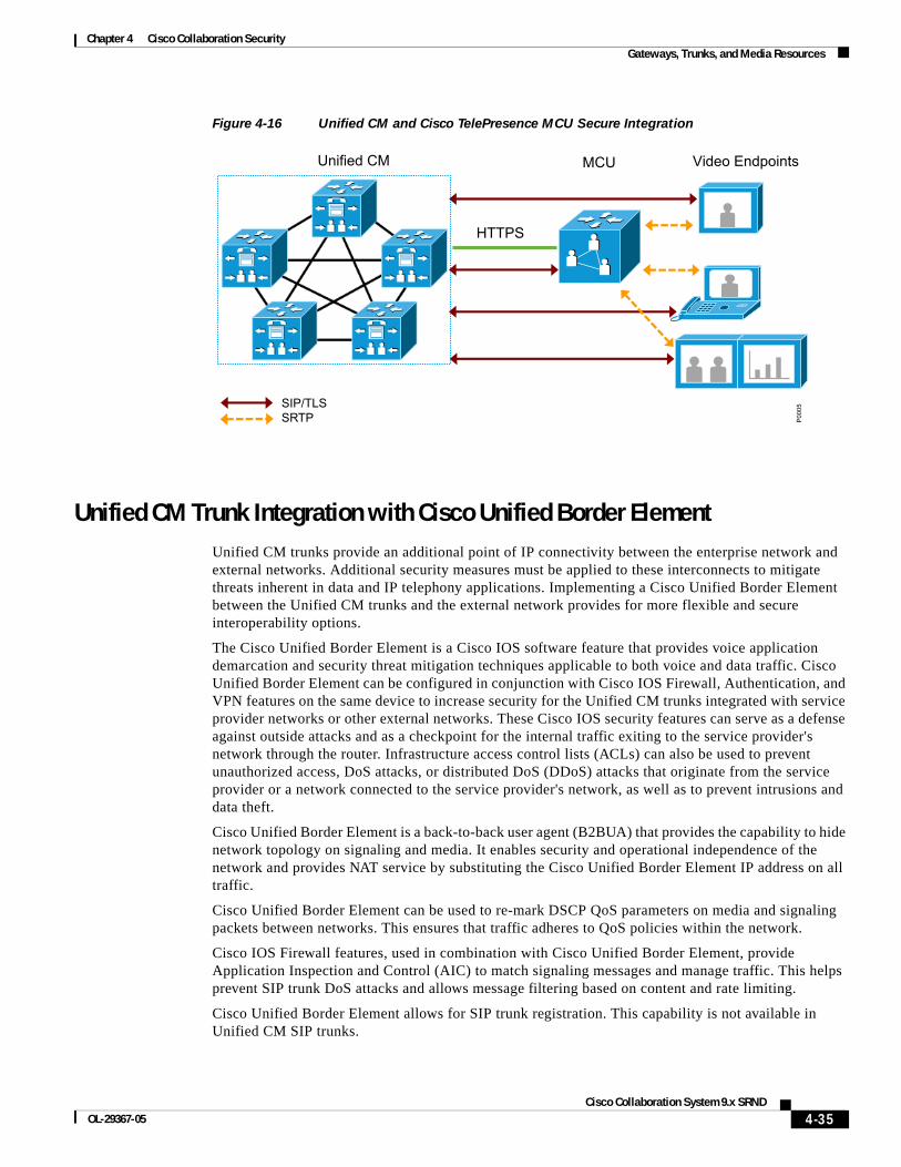
Chapter 4 Cisco Collaboration SecurityGateways, Trunks, and Media Resources
Figure 4-16 Unified CM and Cisco TelePresence MCU Secure Integration
Unified CM Trunk Integration with Cisco Unified Border ElementUnified CM trunks provide an additional point of IP connectivity between the enterprise network and external networks. Additional security measures must be applied to these interconnects to mitigate threats inherent in data and IP telephony applications. Implementing a Cisco Unified Border Element between the Unified CM trunks and the external network provides for more flexible and secure interoperability options.
The Cisco Unified Border Element is a Cisco IOS software feature that provides voice application demarcation and security threat mitigation techniques applicable to both voice and data traffic. Cisco Unified Border Element can be configured in conjunction with Cisco IOS Firewall, Authentication, and VPN features on the same device to increase security for the Unified CM trunks integrated with service provider networks or other external networks. These Cisco IOS security features can serve as a defense against outside attacks and as a checkpoint for the internal traffic exiting to the service provider's network through the router. Infrastructure access control lists (ACLs) can also be used to prevent unauthorized access, DoS attacks, or distributed DoS (DDoS) attacks that originate from the service provider or a network connected to the service provider's network, as well as to prevent intrusions and data theft.
Cisco Unified Border Element is a back-to-back user agent (B2BUA) that provides the capability to hide network topology on signaling and media. It enables security and operational independence of the network and provides NAT service by substituting the Cisco Unified Border Element IP address on all traffic.
Cisco Unified Border Element can be used to re-mark DSCP QoS parameters on media and signaling packets between networks. This ensures that traffic adheres to QoS policies within the network.
Cisco IOS Firewall features, used in combination with Cisco Unified Border Element, provide Application Inspection and Control (AIC) to match signaling messages and manage traffic. This helps prevent SIP trunk DoS attacks and allows message filtering based on content and rate limiting.
Cisco Unified Border Element allows for SIP trunk registration. This capability is not available in Unified CM SIP trunks.
HTTPS
SIP/TLS SRTP
Unified CM MCU Video Endpoints
P00
05
4-35Cisco Collaboration System 9.x SRND
OL-29367-05
Chapter 4 Cisco Collaboration SecurityCisco TelePresence Video Communication Server (VCS)
Cisco Unified Border Element can register the enterprise network's E.164 DID numbers to the service provider's SIP trunk on behalf of the endpoints behind it. If Cisco Unified Border Element is used to proxy the network's E.164 DID numbers, the status of the actual endpoint is not monitored. Therefore unregistered endpoints might still be seen as available.
Cisco Unified Border Element can connect RTP enterprise networks with SRTP over an external network. This allows secure communications without the need to deploy SRTP within the enterprise. It also supports RTP-SRTP interworking, but this is limited to a small number of codecs, including G.711 mulaw, G.711 alaw, G.729abr8, G.729ar8, G.729br8, and G.729r8.
Certain SIP service providers require SIP trunks to be registered before they allow call service. This ensures that calls originate only from well-known endpoints, thus making the service negotiation between the enterprise and the service provider more secure. Unified CM does not support registration on SIP trunks natively, but this support can be accomplished by using a Cisco Unified Border Element. The Cisco Unified Border Element registers to the service provider with the phone numbers of the enterprise on behalf of Cisco Unified Communications Manager.
For configuration and product details about Cisco Unified Border Element, refer to the documentation at:
• http://www.cisco.com/en/US/products/sw/voicesw/ps5640/index.html
• http://www.cisco.com/en/US/products/sw/voicesw/ps5640/products_installation_and_configuration_guides_list.html
Cisco TelePresence Video Communication Server (VCS)The Cisco TelePresence Video Communication Server (VCS) and Unified CM can be configured to interwork with each other using SIP trunks.
Secure interworking of these two systems when using a SIP trunk is achieved by configuring the SIP trunk to use TLS for signaling. For Unified CM to make a TLS connection to Cisco VCS, the Unified CM server must trust the VCS's server certificate. The VCS certificate from the issuing Certificate Authority (CA) used by VCS needs to be uploaded to the Unified CM server's trust store, allowing it to trust a root certificate that in turn trusts the VCS's certificate. Unified CM's callmanager.pem certificate, in turn, needs to be available in the CA's trust.
This process can be simplified by using a common certificate authority for both Unified CM and VCS. If both VCS and Unified CM have been loaded with valid certificates from the same certificate authority and the root CA is already loaded onto Unified CM, then no further work is required.
The Unified CM SIP trunk for the VCS then needs to be configured to have a SIP trunk security profile that specifies the VCS certificate's Common Name (CN) as the X.509 Subject Name, has TLS enabled, and allows SRTP.
On VCS, the neighbor zone to Unified CM must be configured to allow TLS. When the zone is configured to use media encryption for calls, end-to-end TLS and SRTP are enabled for calls between Unified CM and VCS endpoints (see Figure 4-17).
4-36Cisco Collaboration System 9.x SRND
OL-29367-05
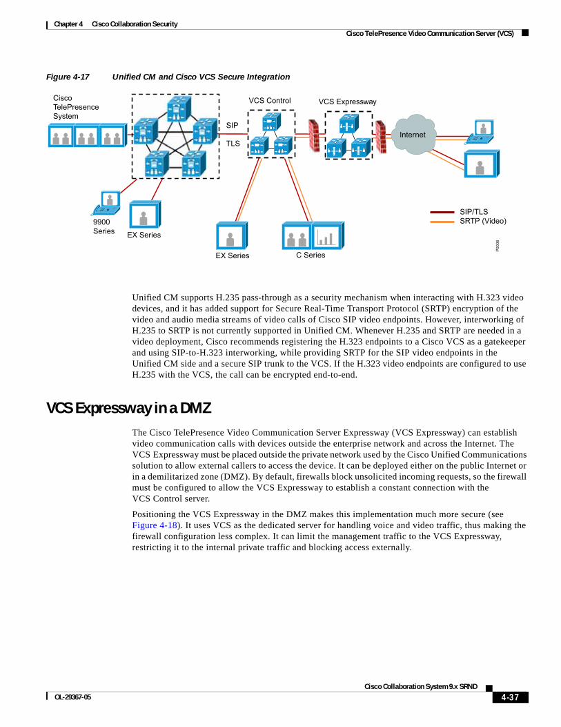
Chapter 4 Cisco Collaboration SecurityCisco TelePresence Video Communication Server (VCS)
Figure 4-17 Unified CM and Cisco VCS Secure Integration
Unified CM supports H.235 pass-through as a security mechanism when interacting with H.323 video devices, and it has added support for Secure Real-Time Transport Protocol (SRTP) encryption of the video and audio media streams of video calls of Cisco SIP video endpoints. However, interworking of H.235 to SRTP is not currently supported in Unified CM. Whenever H.235 and SRTP are needed in a video deployment, Cisco recommends registering the H.323 endpoints to a Cisco VCS as a gatekeeper and using SIP-to-H.323 interworking, while providing SRTP for the SIP video endpoints in the Unified CM side and a secure SIP trunk to the VCS. If the H.323 video endpoints are configured to use H.235 with the VCS, the call can be encrypted end-to-end.
VCS Expressway in a DMZThe Cisco TelePresence Video Communication Server Expressway (VCS Expressway) can establish video communication calls with devices outside the enterprise network and across the Internet. The VCS Expressway must be placed outside the private network used by the Cisco Unified Communications solution to allow external callers to access the device. It can be deployed either on the public Internet or in a demilitarized zone (DMZ). By default, firewalls block unsolicited incoming requests, so the firewall must be configured to allow the VCS Expressway to establish a constant connection with the VCS Control server.
Positioning the VCS Expressway in the DMZ makes this implementation much more secure (see Figure 4-18). It uses VCS as the dedicated server for handling voice and video traffic, thus making the firewall configuration less complex. It can limit the management traffic to the VCS Expressway, restricting it to the internal private traffic and blocking access externally.
VCS Control VCS Expressway
Internet
Cisco TelePresence System
C Series
SIP TLS
9900 Series EX Series
SIP/TLS SRTP (Video)
EX Series
P00
06
4-37Cisco Collaboration System 9.x SRND
OL-29367-05
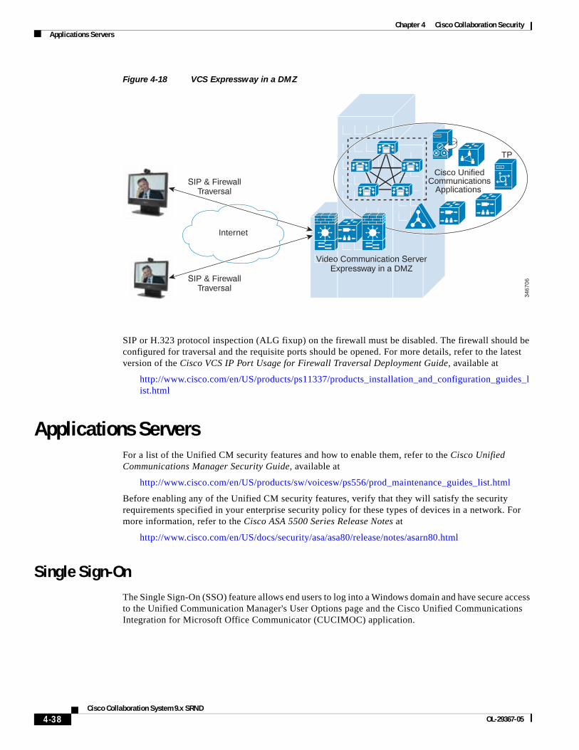
Chapter 4 Cisco Collaboration SecurityApplications Servers
Figure 4-18 VCS Expressway in a DMZ
SIP or H.323 protocol inspection (ALG fixup) on the firewall must be disabled. The firewall should be configured for traversal and the requisite ports should be opened. For more details, refer to the latest version of the Cisco VCS IP Port Usage for Firewall Traversal Deployment Guide, available at
http://www.cisco.com/en/US/products/ps11337/products_installation_and_configuration_guides_list.html
Applications ServersFor a list of the Unified CM security features and how to enable them, refer to the Cisco Unified Communications Manager Security Guide, available at
http://www.cisco.com/en/US/products/sw/voicesw/ps556/prod_maintenance_guides_list.html
Before enabling any of the Unified CM security features, verify that they will satisfy the security requirements specified in your enterprise security policy for these types of devices in a network. For more information, refer to the Cisco ASA 5500 Series Release Notes at
http://www.cisco.com/en/US/docs/security/asa/asa80/release/notes/asarn80.html
Single Sign-OnThe Single Sign-On (SSO) feature allows end users to log into a Windows domain and have secure access to the Unified Communication Manager's User Options page and the Cisco Unified Communications Integration for Microsoft Office Communicator (CUCIMOC) application.
Internet
TP
Cisco UnifiedCommunications
Applications
Video Communication ServerExpressway in a DMZ
SIP & FirewallTraversal
SIP & FirewallTraversal
3467
06
4-38Cisco Collaboration System 9.x SRND
OL-29367-05

Chapter 4 Cisco Collaboration SecurityApplications Servers
Configuring Single Sign-On requires integration of Cisco Unified CM with third-party applications, including Microsoft Windows Servers, Microsoft Active Directory, and the ForgeRock Open Access Manager (OpenAM). For configuration details, refer to the latest version of the Cisco Unified Communications Manager Features and Services Guide, available at
http://www.cisco.com/en/US/products/sw/voicesw/ps556/prod_maintenance_guides_list.html
SELinux on the Unified CM and Application ServersCisco Unified Communications System application servers use Security Enhanced Linux (SELinux) as the Host Intrusion Prevention software. SELinux enforces policies that look at the behavior of the traffic to and from the server, and the way the applications are running on that server, to determine if everything is working correctly. If something is considered abnormal, then SELinux's access rules prevent that activity from happening.
Connection rate limiting for DoS protection, and network shield protection for blocking specific ports, are configured using IPTables. The settings for the host-based firewall can be accessed using the Operating System Administration page of the Cisco Unified Communications server.
SELinux cannot be disabled by an administrator, but it can be set to a permissive mode. It should be made permissive strictly for troubleshooting purposes. Disabling SELinux requires root access and can be done only by remote support from Cisco Technical Assistance Center (TAC).
General Server GuidelinesYour Unified CM and other IP Telephony application servers should not be treated as normal servers. Anything you do while configuring the system could affect calls that are trying to be places or that are in progress. As with any other business-class application, major configuration changes should be done within maintenance windows to keep from disrupting phone conversations.
Standard security policies for application servers might not be adequate for IP Telephony servers. Unlike email servers or web servers, voice servers will not allow you to refresh a screen or re-send a message. The voice communications are real-time events. Any security policy for IP Telephony servers should ensure that work that is not related to configuring or managing the voice systems is not done on the IP Telephony servers at any time. Activities that might be considered normal on application servers within a network (for example, surfing the internet) should not take place on the IP Telephony servers.
In addition, Cisco provides a well defined patch system for the IP Telephony servers, and it should be applied based on the patch policy within your IT organization. You should not patch the system normally using the OS vendor’s patch system unless it is approved by Cisco Systems. All patches should be downloaded from Cisco or from the OS vendor as directed by Cisco Systems, and applied according to the patch installation process.
You should use the OS hardening techniques if your security policy requires you to lock down the OS even more than what is provided in the default installation.
To receive security alerts, you can subscribe to the Cisco Notification service at:
http://www.cisco.com/cisco/support/notifications.html
4-39Cisco Collaboration System 9.x SRND
OL-29367-05
Chapter 4 Cisco Collaboration SecurityDeployment Examples
Deployment ExamplesThis section presents examples of what could be done from a security perspective for a lobby phone and a firewall deployment. A good security policy should be in place to cover deployments similar to these types.
Lobby Phone ExampleThe example in this section illustrates one possible way to configure a phone and a network for use in an area with low physical security, such as a lobby area. None of the features in this example are required for a lobby phone, but if your security policy states more security is needed, then you could use the features listed in this example.
Because you would not want anyone to gain access to the network from the PC port on the phone, you should disable the PC port on the back of the phone to limit network access (see PC Port on the Phone, page 4-16). You should also disable the settings page on the phone so that potential attackers cannot see the IP addresses of the network to which the lobby phone is connected (see Settings Access, page 4-18). The disadvantage of not being able to change the settings on the phone usually will not matter for a lobby phone.
Because there is very little chance that a lobby phone will be moved, you could use a static IP address for that phone. A static IP address would prevent an attacker from unplugging the phone and then plugging into that phone port to get a new IP address (see IP Addressing, page 4-5). Also, if the phone is unplugged, the port state will change and the phone will no longer be registered with Unified CM. You can track this event in just the lobby phone ports to see if someone is trying to attach to the network.
Using static port security for the phone and not allowing the MAC address to be learned would mean that an attacker would have to change his MAC address to that of the phone, if he were able to discover that address. Dynamic port security could be used with an unlimited timer to learn the MAC address (but never unlearn it), so that it would not have to be added. Then the switch port would not have to be changed to clear that MAC address unless the phone is changed. The MAC address is listed in a label on the bottom of the phone. If listing the MAC address is considered a security issue, the label can be removed and replaced with a "Lobby Phone" label to identify the device. (See Switch Port, page 4-7.)
A single VLAN could be used and Cisco Discovery Protocol (CDP) could be disabled on the port so that attackers would not be able to see any information from the Ethernet port about that port or switch to which it is attached. In this case, the phone would not have a CDP entry in the switch for E911 emergency calls, and each lobby phone would need either a label or an information message to local security when an emergency number is dialed.
A static entry in the DHCP Snooping binding table could be made because there would be no DHCP on the port (see DHCP Snooping: Prevent Rogue DHCP Server Attacks, page 4-11). Once the static entry is in the DHCP Snooping binding table, Dynamic ARP Inspection could be enabled on the VLAN to keep the attacker from getting other information about one of the Layer 2 neighbors on the network (see Requirement for Dynamic ARP Inspection, page 4-13).
With a static entry in the DHCP Snooping binding table, IP Source Guard could be used. If an attacker got the MAC address and the IP address and then started sending packets, only packets with the correct IP address could be sent.
A VLAN ACL could be written to allow only the ports and IP addresses that are needed for the phones to operate (see VLAN Access Control Lists, page 4-22). The following example contains a very small ACL that can be applied to a port at Layer 2 or at the first Layer 3 device to help control access into the network (see Router Access Control Lists, page 4-22). This example is based on a Cisco 7960 IP Phone being used in a lobby area, without music on hold to the phone or HTTP access from the phone.
4-40Cisco Collaboration System 9.x SRND
OL-29367-05

Chapter 4 Cisco Collaboration SecurityDeployment Examples
Firewall Deployment Example (Centralized Deployment)The example in this section is one way that firewalls could be deployed within the data center, with Unified CMs behind them (see Figure 4-19). In this example, the Unified CMs are in a centralized deployment, single cluster with all the phones outside the firewalls. Because the network in this deployment already contained firewalls that are configured in routed mode within the corporate data center, the load was reviewed before the placement of gateways was determined. After reviewing the average load of the firewall, it was decided that all the RTP streams would not transverse the firewall in order to keep the firewalls under the 60% CPU load (see Putting Firewalls Around Gateways, page 4-32). The gateways are placed outside the firewalls, and ACLs within the network are used to control the TCP data flow to and from the gateways from the Unified CMs. An ACL is also written in the network to control the RTP streams from the phones because the IP addresses of the phones are well defined (see IP Addressing, page 4-5). The voice applications servers are placed within the demilitarized zone (DMZ), and ACLs are used at the firewalls to control access to and from the Unified CMs and to the users in the network. This configuration will limit the amount of RTP streams through the firewall using inspects, which will minimize the impact to the firewalls when the new voice applications are added to the existing network.
Figure 4-19 Firewall Deployment Example
1489
96PSTN
M
M
M M
M
Access
VoiceGateways V
VVoice
Applications
DMZ
Cisco Unified CM
DataCenter
IP
IP
IP
IP
4-41Cisco Collaboration System 9.x SRND
OL-29367-05
Chapter 4 Cisco Collaboration SecuritySecuring Network Virtualization
Securing Network VirtualizationThis section describes the challenges with providing homogenous connectivity for communications between virtual networks and a technique for overcoming these challenges. It assumes familiarity with Virtual Route Forwarding and Network Virtualization. Network design principles for these technologies are described in the Network Virtualization documentation available at http://www.cisco.com/go/designzone.
This discussion is not meant as an endorsement to use virtualization as a method to increase the security of a Unified Communications solution. Its purpose is to explain how such deployments can layer Unified Communications onto the existing infrastructure. Refer to the Network Virtualization documentation for evaluating the advantages and disadvantages of virtualization technology.
When a network is based on virtualization technology, there is a logical separation of traffic at Layer 3, and separate routing tables exist for each virtual network. Due to the lack of routing information, devices in different virtual networks cannot communicate with one another. This environment works well for client-server deployments where all user endpoints communicate with devices in the data center only, but it has issues for providing peer-to-peer communication. Regardless of how the virtual networks are arranged – whether by department, location, type of traffic (data or voice), or some other basis – the core issue is the same: endpoints in different Virtual Private Network Routing and Forwarding tables (VRFs) do not have the capability to communicate to one another. Figure 4-20 shows a solution that uses a shared VRF located in the data center to provide connectivity between a software-based phone located in one VRF and a hardware phone located in another VRF. This solution may also apply to other variants of this situation. Network Virtualization requires that fire-walling of the data center be implemented for the demarcation between the data center and the campus networks, and the following discussion shows how this can be implemented.
4-42Cisco Collaboration System 9.x SRND
OL-29367-05
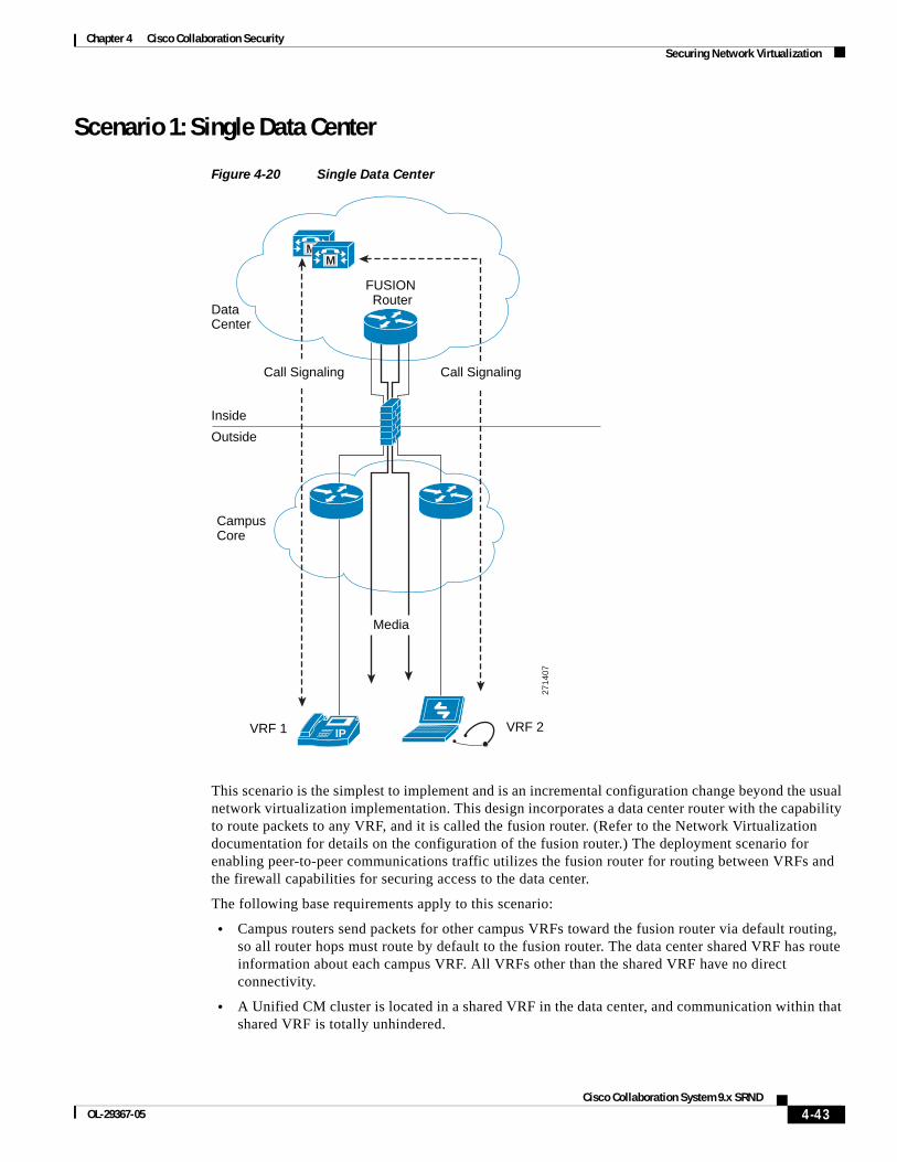
Chapter 4 Cisco Collaboration SecuritySecuring Network Virtualization
Scenario 1: Single Data Center
Figure 4-20 Single Data Center
This scenario is the simplest to implement and is an incremental configuration change beyond the usual network virtualization implementation. This design incorporates a data center router with the capability to route packets to any VRF, and it is called the fusion router. (Refer to the Network Virtualization documentation for details on the configuration of the fusion router.) The deployment scenario for enabling peer-to-peer communications traffic utilizes the fusion router for routing between VRFs and the firewall capabilities for securing access to the data center.
The following base requirements apply to this scenario:
• Campus routers send packets for other campus VRFs toward the fusion router via default routing, so all router hops must route by default to the fusion router. The data center shared VRF has route information about each campus VRF. All VRFs other than the shared VRF have no direct connectivity.
• A Unified CM cluster is located in a shared VRF in the data center, and communication within that shared VRF is totally unhindered.
2714
07
CampusCore
DataCenter
VRF 1 VRF 2
FUSION Router
Inside
Outside
MM
IP
Media
Call SignalingCall Signaling
4-43Cisco Collaboration System 9.x SRND
OL-29367-05
Chapter 4 Cisco Collaboration SecuritySecuring Network Virtualization
• The shared VRF is located in the data center. If multiple data centers exist, the shared VRF spans all the data centers.
The application layer gateway at the data center edge specifies access lists to open ports for TFTP and SCCP or SIP sessions originated on the outside toward the Unified CM cluster in the data center. TFTP is required to allow phones to download their configuration and software images from their TFTP server, and SCCP or SIP is required to allow them to register with the Unified CM cluster. Refer to Unified CM product documentation for a list of appropriate port numbers for the particular version of software used.
In this scenario, all call signaling from communication devices in each VRF passes through the application layer gateway, and inspection of that signaling allows the application layer gateway to dynamically open the necessary UDP pinholes for each VRF for the RTP traffic to pass from the outside of the firewall toward the fusion router. Without the inspection occurring on the firewalls, each RTP stream that originates from an endpoint on the outside is not allowed to pass through the firewall. It is the inspection of the call control signaling that allows the UDP traffic to be forwarded through the firewall.
This deployment model provides a method to allow communication devices on a VRF-enabled network to have peer-to-peer connectivity. The application layer gateway provides secure access to the shared VLAN and the fusion router. All media streams between different VRFs do not take the most direct path between endpoints. The media is backhauled to the data center to be routed via the fusion router.
Scenario 2: Redundant Data CentersWhen redundant data centers are involved, the scenario becomes more complicated. It is necessary to ensure that the call setup signaling passes though the same application layer gateway that the corresponding RTP stream is going to use. If the signaling and media take different paths, a UDP pinhole is not opened. Figure 4-21 illustrates an example of a problematic scenario. The hardware phone on the left is controlled by the subscribers in the data center on the left, and the corresponding call control signaling passes through the left firewall. Pinholes are opened in that firewall for the RTP stream. However, the routing might not guarantee that the RTP media stream follows the same path, and the firewall on the right blocks that stream.
4-44Cisco Collaboration System 9.x SRND
OL-29367-05
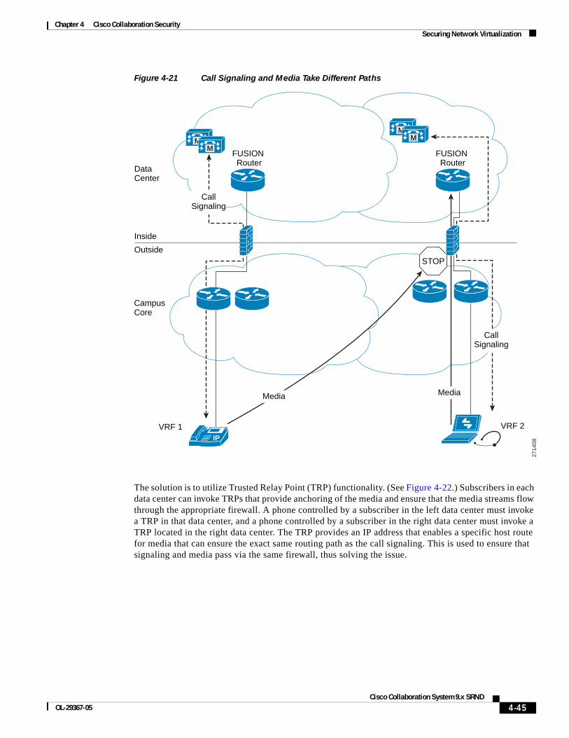
Chapter 4 Cisco Collaboration SecuritySecuring Network Virtualization
Figure 4-21 Call Signaling and Media Take Different Paths
The solution is to utilize Trusted Relay Point (TRP) functionality. (See Figure 4-22.) Subscribers in each data center can invoke TRPs that provide anchoring of the media and ensure that the media streams flow through the appropriate firewall. A phone controlled by a subscriber in the left data center must invoke a TRP in that data center, and a phone controlled by a subscriber in the right data center must invoke a TRP located in the right data center. The TRP provides an IP address that enables a specific host route for media that can ensure the exact same routing path as the call signaling. This is used to ensure that signaling and media pass via the same firewall, thus solving the issue.
2714
08
CampusCore
DataCenter
VRF 1 VRF 2
FUSION Router
Inside
Outside
MM
IP
CallSignaling
FUSION Router
MM
CallSignaling
STOP
MediaMedia
4-45Cisco Collaboration System 9.x SRND
OL-29367-05
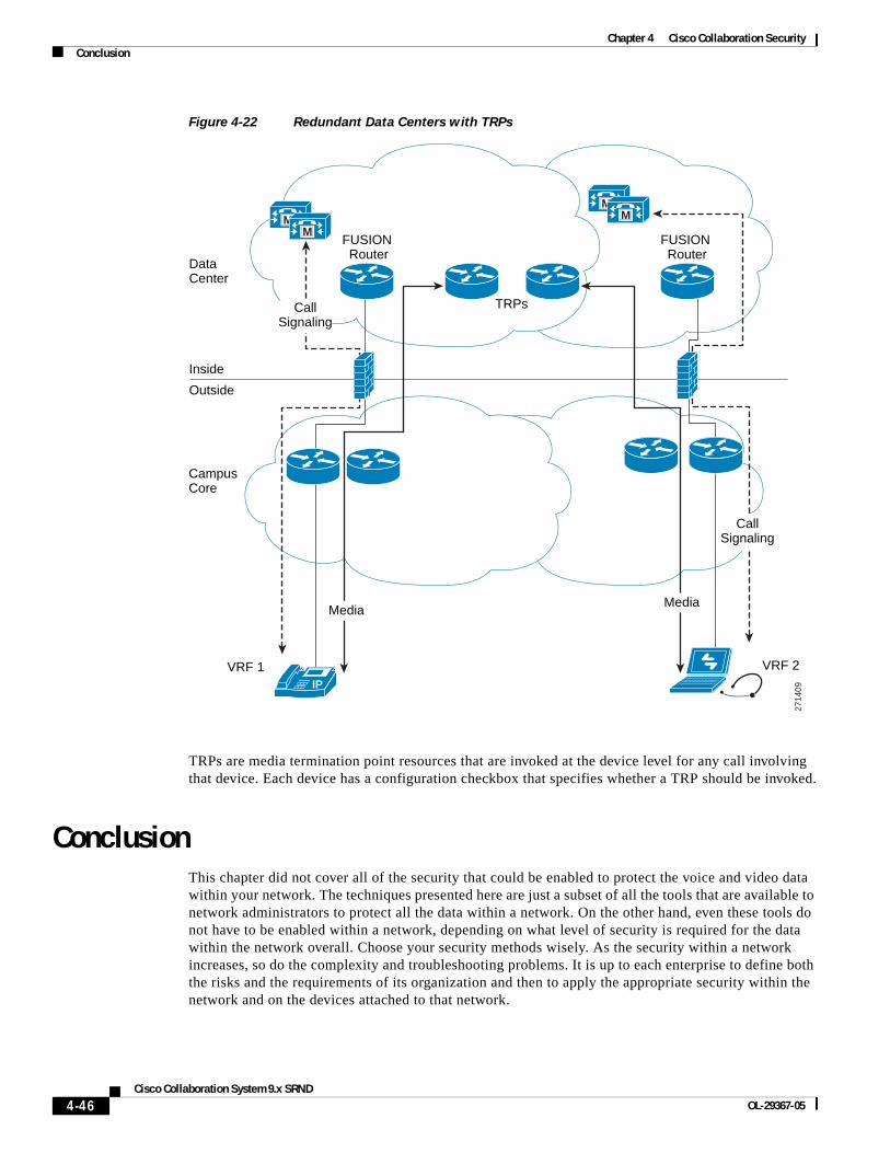
Chapter 4 Cisco Collaboration SecurityConclusion
Figure 4-22 Redundant Data Centers with TRPs
TRPs are media termination point resources that are invoked at the device level for any call involving that device. Each device has a configuration checkbox that specifies whether a TRP should be invoked.
ConclusionThis chapter did not cover all of the security that could be enabled to protect the voice and video data within your network. The techniques presented here are just a subset of all the tools that are available to network administrators to protect all the data within a network. On the other hand, even these tools do not have to be enabled within a network, depending on what level of security is required for the data within the network overall. Choose your security methods wisely. As the security within a network increases, so do the complexity and troubleshooting problems. It is up to each enterprise to define both the risks and the requirements of its organization and then to apply the appropriate security within the network and on the devices attached to that network.
2714
09
CampusCore
DataCenter
VRF 1 VRF 2
FUSION Router
Inside
Outside
MM
IP
TRPsCallSignaling
FUSION Router
MM
CallSignaling
MediaMedia
4-46Cisco Collaboration System 9.x SRND
OL-29367-05