circuit switching under the radar with...
TRANSCRIPT
Circuit Switching Under the Radar with REACToR
He Liu, Feng Lu, Alex Forencich, Rishi Kapoor, Malveeka TewariGeoffrey M. Voelker, George Papen, Alex C. Snoeren, and George Porter
University of California, San Diego
AbstractThe potential advantages of optics at high link speedshave led to significant interest in deploying opticalswitching technology in data-center networks. Initialefforts have focused on hybrid approaches that rely onmillisecond-scale circuit switching in the core of thenetwork, while maintaining the flexibility of electricalpacket switching at the edge. Recent demonstrations ofmicrosecond-scale optical circuit switches motivate con-sidering circuit switching for more dynamic traffic suchas that generated from a top-of-rack (ToR) switch. Basedon these technology trends, we propose a prototype hy-brid ToR, called REACToR, which utilizes a combina-tion of packet switching and circuit switching to appearto end-hosts as a packet-switched ToR.
In this paper, we describe a prototype REACToR con-trol plane which synchronizes end host transmissionswith end-to-end circuit assignments. This control planecan react to rapid, bursty changes in the traffic fromend hosts on a time scale of 100s of microseconds, sev-eral orders of magnitude faster than previous hybrid ap-proaches. Using the experimental data from a system ofeight end hosts, we calibrate a hybrid network simula-tor and use this simulator to predict the performance oflarger-scale hybrid networks.
1 IntroductionDesigning scalable, cost-effective, packet-switched in-terconnects that can support the traffic demands foundin modern data centers is already an extremely challeng-ing problem that is only getting harder as per-server linkrates move from 10 to 40 to 100 Gb/s and beyond. Inthis paper, we focus particularly on the challenge of up-grading an existing network fabric that supports 10-Gb/send hosts to a network that can deliver 100 Gb/s to eachend host. We argue that this transition is inevitable be-cause the PCIe Gen3 bus found in many current serverscan support 128 Gb/s, making emerging 100-Gb/s NICsa drop-in upgrade for existing hardware.
Unlike previous generational upgrades, moving from10- to 100-Gb/s link rates requires a fundamental tran-sition in the way a data center is wired. At 100 Gb/s,inexpensive copper cabling can no longer be used at dis-
tances greater than a few meters: virtually all cablesother than those internal to an individual rack must beoptical. If these cables interconnect electronic packetswitches, they further require optoelectronic transceiversat both ends. Many popular packet-switched data-centertopologies like multi-rooted trees [25] require large num-bers of connections between racks. Hence, the cost ofthese designs begins to be dominated not by the con-stituent packet switches, but instead by the transceiversmandated by the optical interconnects necessary to sup-port the increased link speed [10].
In contrast, if the switches internal to the networkfabric are themselves optical, the need for transceiverscan be significantly reduced. Researchers have previ-ously proposed hybrid architectures consisting of a com-bination of packet switches and optical circuit switchesmanaged by a common logical control plane [7, 10, 26].Traditionally, however, their applicability has been lim-ited by the delay incurred when reconfiguring the circuitswitches, as traffic has to be buffered while waiting for acircuit assignment. Architectures based upon legacy op-tical circuit switches designed for wire-area applicationsare fundamentally dependent on stable, aggregated traf-fic to amortize their long reconfiguration delays. There-fore, their use has been restricted to either the core of thenetwork [10] or to highly constrained workloads [26].
Researchers have recently demonstrated optical circuitswitch prototypes with microsecond-scale reconfigura-tion delays [6, 17, 19]. In prior work, we showed thatsuch a switch, when coupled with an appropriate controlplane [23], has the potential to support more dynamictraffic patterns, potentially extending the applicability ofcircuit switches to cover the entire network fabric re-quired to interconnect racks of servers within a data cen-ter. Circuit switching alone, however, incurs substantialdelays in order to achieve efficiency (e.g., 61–300 µs todeliver 65–95% of the bandwidth of a comparable packetswitch in the case of our switch [23]), rendering it inad-equate to meet the demands of latency sensitive trafficwithin a data center. Moreover, the buffering required totolerate such delays with large port counts at 100 Gb/sis substantial. By integrating a certain level of packetswitching, hybrid fabrics have the potential to address
these shortcomings. Existing hybrid designs, however,are not capable of coping with the lack of traffic stabilityand aggregation present at the rack level of today’s datacenters [2, 4, 15, 16].
In this paper, we propose a hybrid network architec-ture in which optical circuit switching penetrates thedata center network to the top-of-rack (ToR) switch.We leverage our recent work on the Mordia opticalcircuit switch to build and experimentally prototypethe first hybrid network control plane that uses rapidlyreconfigurable optical circuit switches to potentiallyprovide packet-switch-like performance at substantiallylower cost than an entirely packet-switched network.Our hybrid network design consists of a 100-Gb/s op-tical circuit-switched network deployed alongside a pre-existing 10-Gb/s electrical packet-switched network. Inthis model, ToR switches support 100-Gb/s downlinksto servers, and are “dual-homed” to a legacy 10-Gb/selectrical packet switched network (EPS) and a new 100-Gb/s optical circuit switched network (OCS).
REACToR’s design is based on two key insights. Thefirst is that it is impractical to buffer incoming trafficbursts from each end host within the ToR’s switch mem-ory. For a traditional in-switch time-division, multiple-access (TMDA) queueing discipline, this architecturewould require a dedicated input buffer for each potentialcircuit destination. Given the unpredictable nature of theend-host network stack [16], these buffers would likelyneed to be quite large.
Instead, REACToR buffers bursts of packets in low-cost end-host DRAM memory until a circuit is provi-sioned, at which point the control plane explicitly re-quests the appropriate burst from each end host using asynchronous signaling protocol that ensures that the in-stantaneous offered load matches the current switch con-figuration. Because each REACToR is dual-homed toan EPS, the control plane can simultaneously schedulethe latency-sensitive traffic over the packet switch. Thepacket switch can also service unexpected demand dueto errors in demand estimation or circuit scheduling.
The second insight is that if circuit switching is suf-ficiently fast, then delays due using flow-level circuit-switched TDMA at the end-host network stack will notdegrade the performance of higher-level packet-basedprotocols; in a sense the circuit switch will “fly under theradar” of these end-host transport protocols. As technol-ogy trends enable faster OCS reconfiguration times, thishybrid architecture blurs the distinction between packetsand circuits. By combining the strengths of each switch-ing technology, a hybrid network can deliver higher per-formance at lower cost than either technology alone,even at the level of a ToR switch.
We evaluate our design for a 100/10-Gb/s OCS/EPShybrid network using a scaled-down 10/1-Gb/s hard-
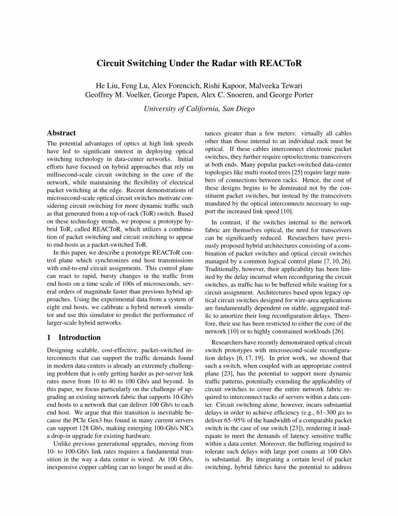
Link rate Full fat tree Helios-like REACToR10 Gb/s 2−4 1−3 N/A100 Gb/s 4 3 1†
Table 1: Number of transceivers required per upward-facingToR port for different network architectures. (†Presuming a 10-Gb/s packet network is already in place.)
ware prototype that supports eight end hosts. The proto-type consists of two FPGA-based REACToRs with fourdownward-facing 10-Gb/s ports each. Both REACToRsconnect to the Mordia [23] microsecond OCS and a com-modity electrical packet switch. The circuit switch sup-ports a line rate of 10 Gb/s while the packet switch israte limited to 1 Gb/s to enforce a 10:1 speed ratio. Endhosts connect to our prototype using commodity Intel 10-Gb/s Ethernet NICs that we synchronize using standard802.1Qbb PFC signaling.
Our experiments show that our REACToR prototypecan provide packet-switch-like performance by deliver-ing efficient link utilization while reacting to changes intraffic demand, and that its control plane is sufficientlyfast that changes in circuit assignment and schedule canbe made without disrupting higher-level transport pro-tocols like TCP. Using simulation of more hosts, wealso illustrate the large benefits that a small underprovi-sioned packet switch provides to a hybrid ToR relative toa pure circuit ToR. We conclude that REACToR can ser-vice published data-center demands with available tech-nology, and can easily scale up to make effective useof next-generation optical switches and 100-Gb/s hostsby reusing an existing 10-Gb/s electrical packet-switchednetwork fabric.
2 BackgroundWe start by motivating the benefits of a hybrid-ToR net-work design, describing the work that REACToR buildsupon, and then discussing our design assumptions.
2.1 MotivationConsider a data-center operator that wants to upgradean existing 10-Gb/s data center network—i.e., the partof the network that connects the top-of-rack switchestogether—to 100 Gb/s.
Table 1 shows the number of optical transceivers re-quired for each upward-looking port of the ToR for threedifferent network architectures. The first architecture isa fully provisioned three-level fat-tree network [1]. If allof the links in the backbone network are optical, then thisnetwork requires four transceivers per upward port. In aHelios-like [10] architecture an optical circuit switch isplaced at the uppermost layer of the network, saving onetransceiver per port as compared to the number used in afat-tree network.
2
At 10 Gb/s, if the links between aggregation switchesare short enough to be electrical, then transceivers mayonly be required between aggregation and core switches,potentially reducing the number of transceivers by up tothree per port. At 100 Gb/s, however, while electrical in-terconnects may still be viable from an end host to a ToR(i.e., distances less than 5 meters), all connections fromthe ToR to the rest of the network are likely to be optical.Hence, either architecture will require a full complimentof optical transceivers. Moreover, in order to upgradethe network the operator will have to replace the existing10-Gb/s transceivers with new 100 Gb/s transceivers.
The REACToR architecture, in contrast, re-uses theexisting 10-Gb/s packet-based network and deploys aparallel 100-Gb/s circuit-switched optical network un-der a common control plane. As compared to the othertwo architectures listed in Table 1, REACToR requiresonly one 100-Gb/s transceiver per upward-facing portof the ToR because the OCS does not use transceivers.This means that for a fully provisioned three-level fat-tree network, if the per-port cost of the OCS used in RE-ACToR is less than three times the cost of a 100-Gb/soptical transceiver, then a REACToR hybrid networkwill cost less than an equivalent 100-Gb/s packet-basednetwork—even if the 100 Gb/s switches themselves werefree. Larger networks require even more transceiversper end host: a five-level network requires eight trans-ceivers to support each upward facing port, making theeconomics of REACToR even more compelling. Over-subscribed networks will use fewer transceivers in thecore network, but the scaling trends are still applicable.
While this example uses a 10-Gb/s EPS and a 100-Gb/s OCS, the actual link rates for which a REACToRarchitecture will be cost competitive with a fully provi-sioned or over-subscribed packet-switched network de-pends on market trends. Many OCS architectures arebased on MEMs devices and can easily support link ratesin excess of 100 Tb/s1 per port. For this kind of de-vice, the cost per optically switched bit is decreasingand is fundamentally inversely proportional to link rate.While the costs per switched bit of optical transceiversand packet switches are also decreasing, the rate of de-crease is much slower. These trends imply the cost perswitched bit will eventually become comparable at somelink rate. What is less clear is the precise link rate whenthis crossover point will occur and the economic viabilityof a data-center network that supported such a link rate.
2.2 Related workHybrid data-center network architecture design is an ac-tive research area. Helios [10] and c-Through [26] both
1The mirrors are typically reflective from approximately 1.3 µm to1.6 µm which corresponds to a bandwidth of approximately 400 THz.
Rank-Ordered Connection Numbern21 n
Circuittra�c
Tra�
c pe
r Con
nect
ion
Packettra�c
90%
10%
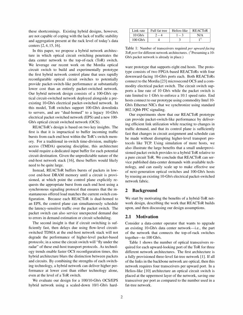
Figure 1: Rank-ordered traffic for each of the n2 elements ofa demand matrix, for which most of the traffic (e.g. 90%) iscarried in a few (O(n)) flows.
rely on slower 3D-MEMs based optical circuit switch-ing, restricting their use to either highly aggregated traf-fic (i.e., in the core of the network), or highly stabletraffic (e.g., long file transfers). OSA [7] combinesan OCS-based reconfigurable topology with multi-hopoverlay networking. The bandwidths of links in OSAcan be varied through the use of wavelength-selectiveswitching. In addition to optical switching, reconfig-urable wireless links have also been proposed in data-center contexts [12, 14, 28]. In contrast to these previousapproaches, which employ switching technologies withrelatively long reconfiguration times, REACToR reliesupon the Mordia [8, 23] OCS, which can be reconfig-ured in 10s of microseconds, in order to service a muchlarger portion of the offered demand through the circuit-switched portion of the hybrid network fabric.
The question of how much buffering should be de-ployed in a network has been considered under a widevariety of settings. In the Internet, a common rule ofthumb has been that at least a delay-bandwidth productis necessary to support TCP effectively. Appenzeller etal. [3] challenged this assumption for core switches, andargue that for links carrying many TCP flows, less buffer-ing is necessary. In the data center, Alizadeh et al. pro-pose modifications to TCP that, along with appropriateswitch support, can reduce the amount of buffering re-quired down to a single packet per flow [2]. Other net-work technologies have also been created that reduce in-network buffering, including Myrinet [5] and ATM [20].Numerous proposals for entirely bufferless “network-on-chip” (NoC) networks have been proposed [21], in-cluding hybrid NoC networks that also leverage packetswitches [13].
2.3 Design assumptionsStudies of data-center traffic show that the traffic demandinside a data center is frequently concentrated, with alarge fraction of the traffic at each switch port of a ToR
3
destined to a small number of output ports [15]. Such lo-cality is not surprising, as application programmers andworkload managers frequently use knowledge about thelocation of end hosts to coordinate workloads to mini-mize inter-rack traffic. Based on these empirical obser-vations, a fundamental premise of all hybrid networks—including REACToR—is that a large fraction of the net-work traffic is carried by a small number of relativelylong-lived flows. This observation can be expressed interms of the n2 rank-ordered elements of a demand ma-trix for a network that connects n ToRs. Figure 1 showsan example where 90% of the inter-ToR traffic is carriedby only n flows.
In such settings, the demand matrix is frequently bothsparse and stable [9, 12, 14]. This kind of traffic demandis generally suitable for a large port-count optical circuitswitch, but these assumptions can be violated for specificworkflows over any given time interval. Therefore, RE-ACToR switches the few high-traffic flows using an OCSwhile forwarding the relatively small amount of trafficbetween most ToRs using an under-provisioned standardpacket switch.
While rack-level coordination can lead to bursty traf-fic at the upward looking ports of a ToR, we carry thisassumption one step further. Unlike previous hybrid de-signs that focus on the core of the network, REACToRcritically depends upon individual hosts being able to fillcircuits assigned to them with data, which in turn de-pends on hosts transmitting groups of packets to the samedestination ToR at fine time scales.
To verify this assumption, in previous work we mea-sured individual flows, at microsecond granularity, em-anating from a single host under a variety of work-loads [16]. We find that host mechanisms such as TCPsegmentation offloading in the NIC and generalized seg-mentation offloading in the operating system, cause traf-fic to frequently leave the NIC in bursts of 10s to 100s ofmicroseconds. In Section 5.1, we expand upon this anal-ysis to show that circuit switching these flows can furtherenhance this behavior while not disturbing the transportprotocol. For regimes in which circuit switching does notaffect the transport performance of an end host, we saythat its flows are “flying under the radar”.
3 Design
A REACToR-enabled data center consists of N serversgrouped into R racks, each consisting of n nodes. Weassume that a preexisting 10-Gb/s packet-switched net-work is already deployed within the data center. Overlaidon top of this packet-switched network is an additional100-Gb/s circuit-switched network. At each rack is a hy-brid ToR called a REACToR, which is connected to thepacket-switched network with up ≤ n uplinks and is con-
10#Gb/s#Packet.switched#Network#(EPS)#
100#Gb/s#Circuit.switched#Network#(OCS)#
REAC
ToR#
up ≤ n uc ≤ n !!!!!op$cal!transceivers!uc
qP! q0! q1! qN41!...!TDMA!link!arbiter!
IP!Tables!
qP! q0! q1! qN41!...!TDMA!link!arbiter!
IP!Tables!
...!
C!C! C! C!
100!Gb/s! 100!Gb/s!
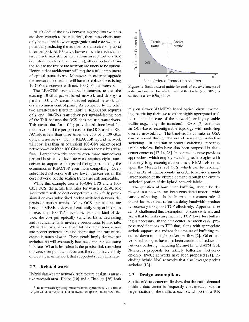
Figure 2: 100-Gb/s hosts connect to REACToRs, which are inturn dual-homed to a 10-Gb/s packet-switched network and a100-Gb/s circuit-switched optical network.
nected to the circuit-switched network with a separate setof uc ≤ n uplinks. This means that the packet-switchednetwork supports R× up ports, and the circuit-switchednetwork supports R× uc ports. Each REACToR has ndownward-facing 100-Gb/s ports to its n local servers. Inthis work, we consider the fully provisioned case whereup = uc = n; however, additional cost savings are possi-ble when either or both of up and uc are less than n. Ourarchitecture is agnostic to the particular technology usedto build the circuit-switched fabric, but, given technologytrends, we presume it is optical.
Referring to Figure 2, an (n,up,uc)-port REACToRconsists of n downward-facing ports connected to serversat 100 Gb/s, up = n uplinks connected to the packet-switched network at 10 Gb/s, and uc = n uplinks con-nected to the 100-Gb/s circuit-switched network. Ateach of the n server-facing input ports, there is a clas-sifier (labeled ‘C’ in the figure) which directs incom-ing packets to one of three destinations: to packet up-links, to circuit uplinks, or through an interconnect fabricto downward-facing ports to which the other rack-localservers are attached. There is no buffering on the pathto the packet uplinks, as buffering is provided within thepacket switches themselves. There is also no bufferingon the path to the circuit uplinks; instead, packets arebuffered in the end-host where they originate. When acircuit is established from the REACToR to a given des-tination, the REACToR explicitly pulls the appropriatepackets from the attached end-host and forwards them tothe destination.
REACToR relies upon a control protocol to interactwith each of its n local end-hosts to: (1) direct the endhost to start or stop draining traffic from its output queues(which we refer to as unpausing or pausing the queue, re-spectfully), (2) set per-queue rate limits, (3) provide cir-cuit schedules to the end-host, and (4) retrieve demand
4
estimates for use in computing future circuit schedules.We first motivate the need for this functionality by de-scribing the various other aspects of REACToR’s designbefore detailing the host control protocol in Section 3.4.
3.1 End-host bufferingEach end-host buffers packets destined to the REAC-ToR in its local memory, which is organized into traf-fic classes, one per destination ToR, with an additionalclass for packets specifically destined for the EPS (e.g.,latency-sensitive requests). Each traffic class has its owndedicated output queue (i.e., {Q0, Q1, ..., QN−1}), withan additional queue for the EPS class, QP, as shown inFigure 2. At any moment in time, the REACToR can askan end host to send packets from at most two classes:one forwarded at line rate to an OCS uplink (or localdownlink port), and another forwarded to an EPS up-link. This latter class of traffic must be rate limited atthe source NIC to conform to the link speed of the EPSto prevent overdriving the EPS. In the reverse direction,the EPS may emit packets into the REACToR at its fullrate to a particular downward-facing port. Because thatdownward-facing port could potentially be shared by in-coming line-rate circuit traffic heading to the same des-tination, REACToR must further ensure that the circuittraffic is sufficiently rate-limited so that there is enoughexcess capacity to multiplex both flows at the destina-tion. Hence, end hosts will be directed by REACToR tosimilarly rate-limit traffic classes destined to the OCS atthe source NIC, but at much higher rates. Further detailson rate limiting are provided in Section 3.3.
Today, end-host NICs support modest amounts ofbuffering, on the order of a few megabytes. However,it is not organized in a way that can be directly used tosupport circuits. NICs partition their buffers into a smallset of 8 to 64 transmit queues, which the OS uses to batchand store packets waiting to be sent. The scheduling pol-icy for these queues is typically built into the NIC (e.g.,round robin), so the actual transmit time of individualpackets is outside the control of the OS.
To achieve high circuit utilization in REACToR, theNIC needs the ability to send data for a particular circuitdestination to the ToR as soon as a circuit becomes estab-lished, and to fill that circuit continuously until it is torndown. At any one time, each circuit uplink within a RE-ACToR is exclusive to a particular source port (attachedend host), so efficiency degrades any time that source hasno data to send. Thus, packets headed to the same circuitdestination (i.e., remote host) should be grouped togetherwithin a host’s memory, so that when a circuit to that des-tination becomes available, that group of packets can besent from the NIC to the REACToR at line rate.
Within each host, we define a traffic class per desti-nation host, and task the OS with classifying outgoing
packets into the appropriate class based on, e.g., the des-tination IP address. REACToR then uses the host controlprotocol to pause and unpause end-host queues. In thismodel, the role of the OS and of the NIC changes some-what: rather than the OS “pushing” packets to the NICbuffers based on queuing policies in the host, the NIC isresponsible for “pulling” packets from the host memoryinto the NIC buffers according to the circuit schedule justin time to transmit them to the connected circuit. (Wenote that the NIC design advocated by Radhakrishnan etal. [24] would be especially well suited for this model.)
Demand estimation. Over a short time scale (i.e.,100s of µs, depending on the size of the NIC buffers), theoccupancy of these traffic classes defines the imminentend-host demand because the packets in these queueshave already been committed to the network by the OS.It is possible to query the OS, the application, or even acluster-wide job scheduler to form longer-term demandestimates. For example, Wang et al. [26] use TCP sendbuffer sizes as estimates of future demand. Our prototypeuses a demand oracle. In any case, the circuit scheduleruses these demand estimates to determine a set of futureOCS circuit configurations.
3.2 Circuit schedulingTo make effective use of the capacity of the circuitswitch, REACToR must determine an appropriate sched-ule of circuit switch configurations to service the esti-mated demand over an accumulation period W . This isthe responsibility of a logically centralized, but poten-tially physically distributed, circuit scheduling service,which implements a hybrid circuit scheduling algorithm.This service collects estimates of network-wide demand,in the form of an N×N matrix D. The service computesa schedule, Pk, of m circuit switch configurations, whichare permutation matrices2, and corresponding durations,φk.
The number m of configurations that comprise theschedule is constrained because each circuit configu-ration requires a finite reconfiguration time δ , duringwhich time no data can be forwarded over the circuitswitch. When δ is large with respect to W , it is more ef-ficient to use fewer configurations. When δ is small withrespect to W , more configurations can be used. Includingthis reconfiguration delay, the duration of the schedule isconstrained by the length of the accumulation period sothat ∑
mk=1 φk +δm≤W . The goal of the scheduling algo-
rithm is to maximize ∑mk=1 φk subject to these constraints.
Obviously, if the switch introduces a reconfigura-tion delay, then it is impossible to service fully satu-rated demand at line rate. Existing research in con-strained scheduling has focused on switches that run
2A permutation matrix is a matrix of 0s and 1s in which each rowand column has and only has a single 1.
5
faster than the link rate, with the ratio of the switch rateto the link rate called the speedup factor. These algo-rithms [11, 18, 27] produce a variable-length schedulewhich is dependent on the actual reconfiguration delay.
Hybrid networks in general, and REACToR in partic-ular, do not use a speedup factor. Instead, REACToRuses the lower-speed packet switch as a way to make upfor the reconfiguration delay and any scheduling ineffi-ciency. This “back channel” is a key distinction betweenREACToR and traditional blocking circuit schedulingbecause REACToR continues to service a subset of flowsover the EPS when circuits are not available, thereby in-creasing support for latency sensitive workloads.
We leave the selection and evaluation of an circuitswitch algorithm as future work; for now we compute theschedule offline using a variant of existing constrainedswitching algorithms based on a predetermined demandmatrix D. Any schedule computed for use in REACToR,however, is subject to a number of constraints.
Class constraints. In order to ensure the offered loadcan be effectively serviced by the ToR, REACToR im-poses a number of constraints on the set of queues thatcan be unpaused at any particular time. First, the ded-icated EPS queue (QP) is always unpaused but rate-limited to at most 10 Gb/s, providing the host with theability to send latency-sensitive traffic directly to the EPSat any point in time. Second, at most one additionalqueue can be unpaused at any one time for transmissionat (near) link rate (i.e., 100 Gb/s). When such circuit-bound (or rack-local) traffic arrives at an input classifierin the REACToR, it is directly forwarded to the appropri-ate circuit uplink (or downward-facing port) without anyintermediate buffering. The third constraint is that, if aqueue is unpaused for link-rate transmission in the cur-rent scheduling period, then it should never be unpausedfor transmission to the EPS. This constraint serves twopurposes: it prevents the EPS from being burdened withhigh-bandwidth traffic better served by circuits, and itgives that traffic class additional time to accumulate de-mand so that the circuits are highly utilized.
Fourth, any traffic class which is not assigned to a cir-cuit (or downward port) during a scheduling period is in-stead remapped to the EPS, meaning that any packets inthat class’s queue are routed to the EPS uplink. Finally,all of the queues corresponding to EPS-bound traffic (i.e.,both the dedicated EPS queue and and any classes notscheduled for a circuit in this period) must be rate lim-ited such that the sum of their limits is less than or equalto the EPS link rate (e.g., 10 Gb/s).
3.3 End-host rate limitingAt any given time, each of the REACToR’s downward-facing server ports can transmit data from two sources:a circuit from a single source established through the
OCS (or rack-local connection) fabric, and traffic fromany number of sources forwarded through the EPS. Ateach downward-facing port there is a multiplexer whichperforms this mixing. When the sum of bandwidthfrom the EPS (BEPS) and OCS (BOCS) exceeds the rateof the REACToR port (BToR), then without intervention,(BEPS+BOCS)−BToR traffic would be dropped. To preventsuch drops, and to ensure high overall utilization, we relyon end-host rate limiting.
The first way that we use end-host rate limiting is toensure that in steady state, BEPS + BOCS ≤ BTOR. Sincethe OCS is bufferless, the multiplexer gives priority topackets arriving from the OCS because otherwise theywould have to be dropped. Assuming a REACToR with a100-Gb/s OCS and 10-Gb/s EPS as an example, each endhost would rate limit its circuit-bound traffic in the rangeof 90–100% of the link capacity to leave sufficient headroom for the EPS traffic, based on the estimate of EPSdemand in the current schedule. Each time that a set ofconfigurations for a scheduling period is computed, a ratelimit is also computed per configuration, reflecting theestimated load from the EPS. Note that this estimate neednot be perfect, and in fact we expect the EPS to absorbinaccuracies in scheduling, demand estimation, and ratelimiting. For each scheduling interval, the associated ratelimits are computed and sent to each end-host via the hostcontrol protocol.
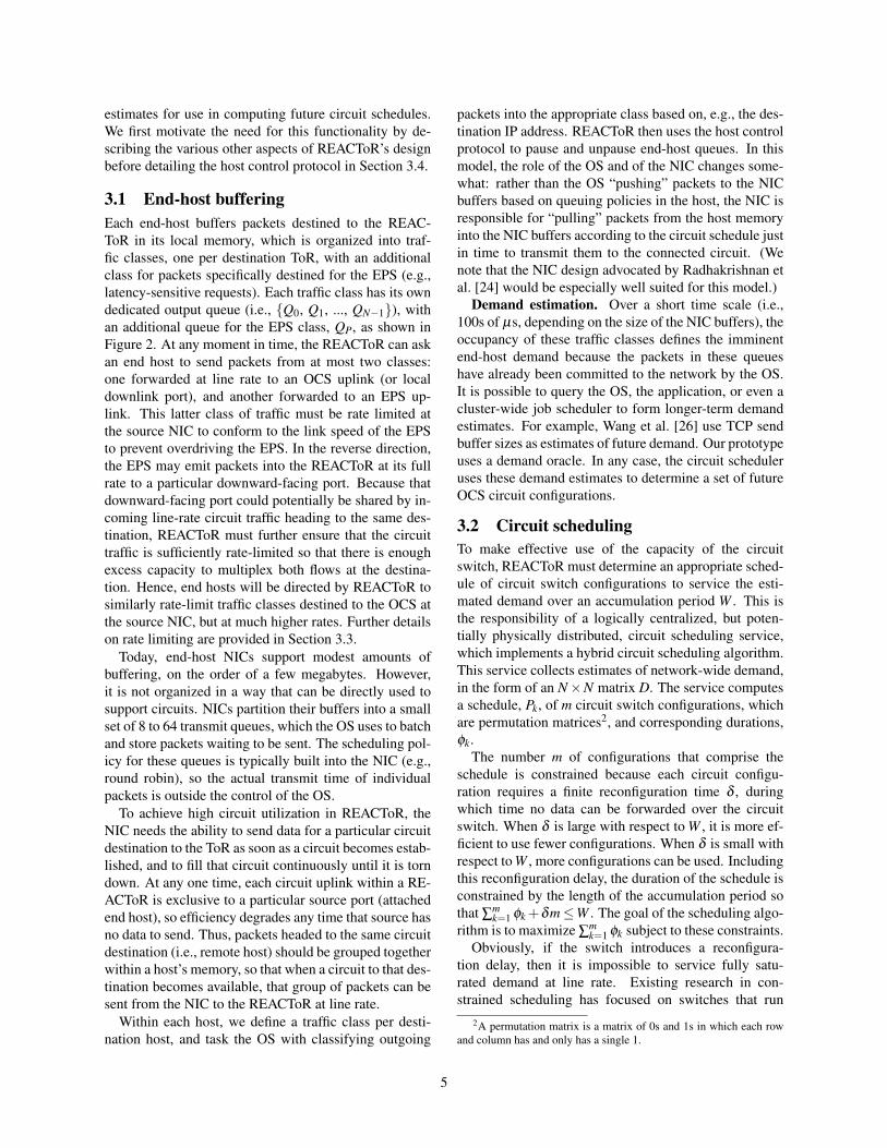
The circuit rate limit also serves a second pur-pose, which is providing statistical multiplexing at thedownward-facing REACToR port. Underpinning the de-sign of REACToR is the assumption that on short timescales, traffic emanating to a single destination is bursty.Each burst by definition consists of a number of packetssent back-to-back. From the point of view of the RE-ACToR port multiplexer, this means that, absent othercontrols, during the first portion of a given circuit-switchconfiguration interval φk, the entire port’s bandwidthwould be dedicated to servicing a single burst of traf-fic from the OCS. Thus, any packets originating from theEPS would be delayed until the end of φk. Figure 3(a)shows a pictorial representation of this behavior. Thechallenge that arises is that the line rate of the EPS ispresumed to be lower than the REACToR port speed andthe OCS. Hence, the open region at the end of φk canonly be filled with packets at the rate of the EPS (e.g., 10Gb/s) instead of the OCS (100 Gb/s). Thus, for this ex-ample, the region at the end of φk only gets 10% utilizedsince the EPS can only drive 10% of the outgoing portbandwidth.
Instead, REACToR seeks to ensure that the circuit traf-fic is spread out across φk by limiting it to less than fullline rate (e.g., 90 Gb/s of a 100-Gb/s link). Rate limit-ing over time allows the EPS-serviced traffic to be mul-tiplexed on REACToR’s downward-facing ports at a uni-
6
EPS$EPS$ EPS$
Burst$to$A$
Burst$to$C$
Burst$to$B$
100G$
10G$
Waste$
Waste$
Waste$
φ{k−1} φk φ{k+1}
(a) When a circuit-switch configuration interval φk begins,queued traffic forms bursts which saturate the link during the firstpart of the configuration, leaving capacity for EPS traffic at theend of φk; since the EPS runs at a fraction of the line rate, it can-not efficiently use the remaining time.
EPS$
Burst$to$A$(90%$Rate)$
Burst$to$C$(90%$Rate)$
Burst$to$B$(90%$Rate)$
100G$
90G$
φ{k−1} φk φ{k+1}
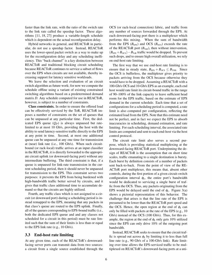
(b) By rate limiting circuit traffic, the EPS can spread its trafficout over the entire configuration interval.
Figure 3: Rate limiting prevents bursts from the OCS fromstarving the EPS, which would otherwise be unable to makefull use of each circuit-switch configuration interval φk. In bothcases, the circuit-switched traffic achieves 90 Gb/s during eachinterval.
form rate across all configuration intervals φk, enablingthe entire interval to be utilized by both circuit traffic andpacket traffic. By setting circuit rate limits in the endhost, as described above, the traffic headed to the circuitis paced to the appropriate rate. Figure 3(b) shows theresulting treatment of circuit and packet data within thatsame configuration interval φk.
3.4 REACToR host control protocolAn instance of the REACToR host control protocol runsbetween each end-host and its REACToR switch. RE-ACToR uses the protocol to retrieve demand estimatescollected by end-hosts, to set per-queue rate limits, asdescribed above, and to convey impending schedules tothe end host from the circuit scheduler. These functionsare relatively straight forward. In this section, we exam-ine the fourth use of the host control protocol: managingend-host traffic classes and buffering. The key to achiev-
ing efficient use of the hybrid network is being able todrain the appropriate classes with fine-grained precisionat the right times. We now describe the host control pro-tocol that achieves this precision.
Overview: To ensure reliable transmission, we cannotreconfigure the OCS until all incoming circuit traffic hasceased, since the OCS is unable to carry traffic duringthe time δ when it is being reconfigured. While classi-fiers on each REACToR input port can shunt all trafficto the EPS nearly instantaneously, in general we wouldlike to ensure that almost all circuit-bound traffic hasbeen paused before reconfiguring the OCS. Otherwise,a massive queue would build up at the EPS at the endof each schedule. To avoid this buildup, we leverage the802.1Qbb Priority Flow Control (PFC) protocol to pausetraffic at the end host. Each traffic class in the end hostcorresponds to a PFC class.3 At the end of each sched-ule, for each attached host, the REACToR first sends aPFC frame to pause the traffic class destined for the cur-rent schedule’s circuit (if any). Note that PFC frames areselective, so traffic destined to the EPS will continue toflow while the OCS is being reconfigured. Once inboundcircuit traffic has ceased, the OCS can be reconfigured.After reconfiguration, the traffic class corresponding tothe next schedule’s circuit can be enabled by a PFC un-pause frame.
Performance: The overall speed of the control planeis bounded by the speed at which REACToR can pauseand unpause traffic classes buffered at the end hosts. Be-cause the PFC frame must be both received and pro-cessed at the NIC before traffic stops, there will be somedelay between when the controller wants to pause trafficand when the traffic finally stops arriving at the incom-ing ports at the REACToR. To quantify this delay, weextended the classifiers on our prototype to timestamp allincoming packets and mirror these timestamped packetsto a collection host. We then measured the time fromwhen the classifier sends a PFC frame to a host until itstops receiving packets from that host.
We measured the minimum (maximum) delay on anIntel 82599-based 10 Gb/s NIC as 1,014 (2,188) ns, withthe actual delay varying as a function of PFC offset,meaning that if the PFC frame arrives more than 185.6 nsafter the start of the current frame, the NIC will generatean additional frame before pausing, likely due to pipelin-ing within the NIC implementation.
Once the OCS has established a circuit and is ready toreceive traffic, the REACToR needs to restart traffic forthe newly connected destination by sending another PFCframe. The measured ‘on’ delay (i.e., from when the con-figuration is started by the transmission of a PFC frame
3Although the current PFC specification is limited to eight framepriority levels, it is possible to reuse classes across schedule periods byrecoloring.
7
H
REACToRVirtex 6 FPGA
REACToRVirtex 6 FPGA
Circuit SwitchMordia OCS [SIGCOMM'13]
EPSFulcrum Monaco 10G Switch
ControlComputer
DemandInformation
Schedule
CircuitControl
Schedule
Control Path
10G Data Path
1G Data Path
H H H H H H H
H End Host
Transceiver
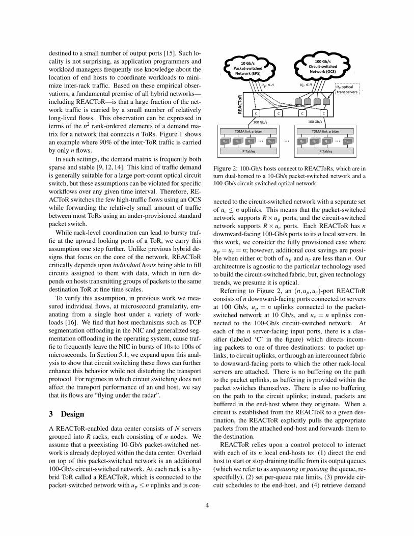
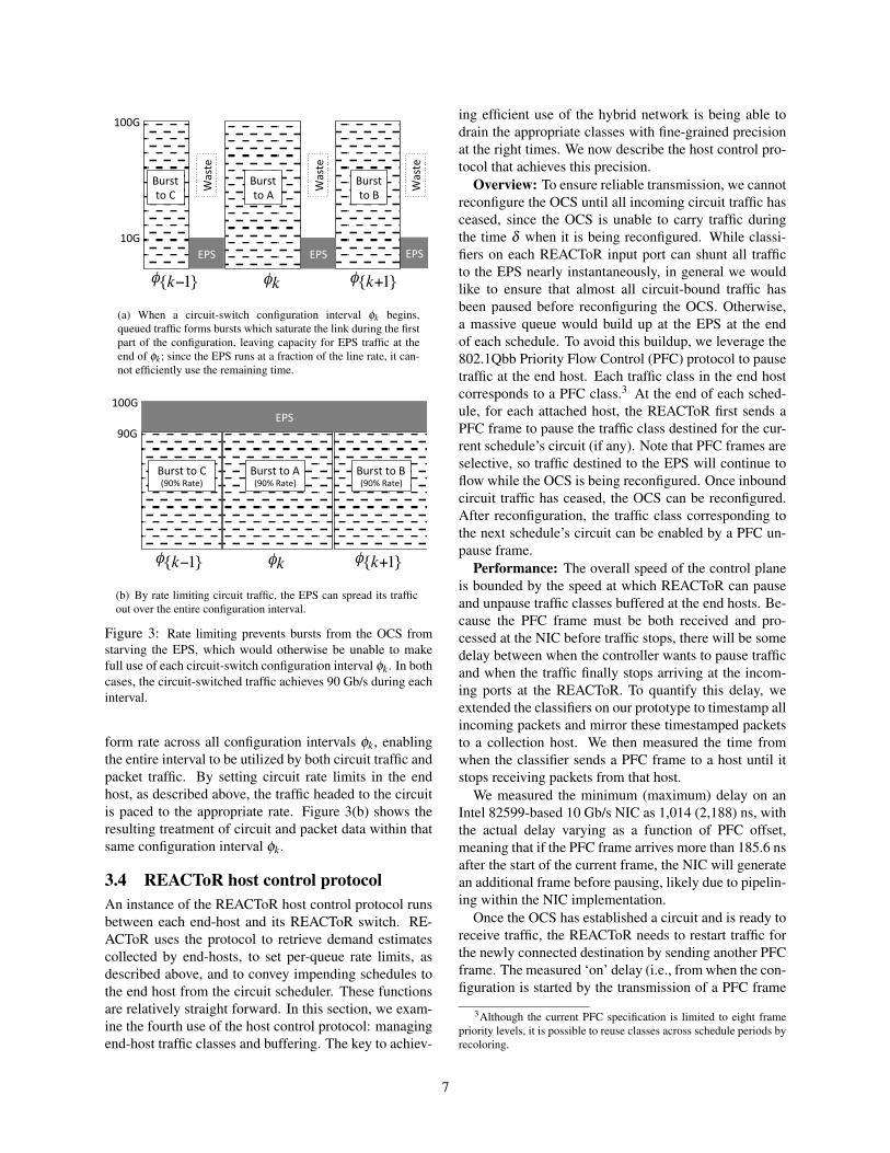
Figure 4: Our prototype REACToR network.
unpausing the traffic) ranges between 1.2 µs and 1.3 µs.From the ‘off’ delay measurement, it is clear that we canhide the first microsecond of delay by sending the PFCframe before we actually want the traffic to stop, but itmay take an additional 1.3 µs for all ports to cease send-ing. There is one additional source of delay: a port maybe busy sending an outgoing packet at the moment theclassifier wishes to send the PFC frame. This delay isbounded by the 1500-byte MTU in our prototype, lead-ing to a worst-case combined delay of approximately 2.5µs, which is the lower bound of the speed of the controlplane achievable in REACToR with 10-Gb/s end hosts, a1500-byte MTU size, and the 802.1Qbb implementationon our NIC.
4 Implementation
To evaluate our design, we have implemented two proto-type four-port 10-Gb/s REACToRs (shown in Figure 4)using two FGPAs, a Fulcrum Monaco 10-Gb/s electricalpacket switch, and the Mordia microsecond OCS [23].Mordia is 24-port reconfigurable OCS built from six4-port “binary MEMs” wavelength-selective switches,with a reconfiguration delay of δ = 12µs, which includesthe physical switching time of the MEMs devices andthe time to reinitialize the attached 10-Gb/s transceivers.Thus, our REACToR prototype supports the same 10:1bandwidth ratio described earlier, but at 10 Gb/s (OCS)and 1 Gb/s (EPS) rather than 100/10 Gb/s.
Each REACToR is implemented with a HiTech GlobalHTG-V6HXT-100GIG-565 FPGA development board,which supports 24 ports of 10-Gb/s I/O. The circuitscheduling service runs as a user-level process on a ded-icated Linux-based control server, and transmits sched-ules to the FPGA via a dedicated 10-Gb/s Ethernet con-nection. In our implementation, the end hosts are serversequipped with Intel 82599-based NICs. The end hostsclassify traffic according to the destination using theLinux tc facility. The classifier on the FPGA selectively
0 5 10 15
0.0
0.2
0.4
0.6
0.8
1.0
End−to−End Flow Switch Time (microsecond)
CD
F o
f Lat
ency
Dis
trib
utio
n
●
14.84us
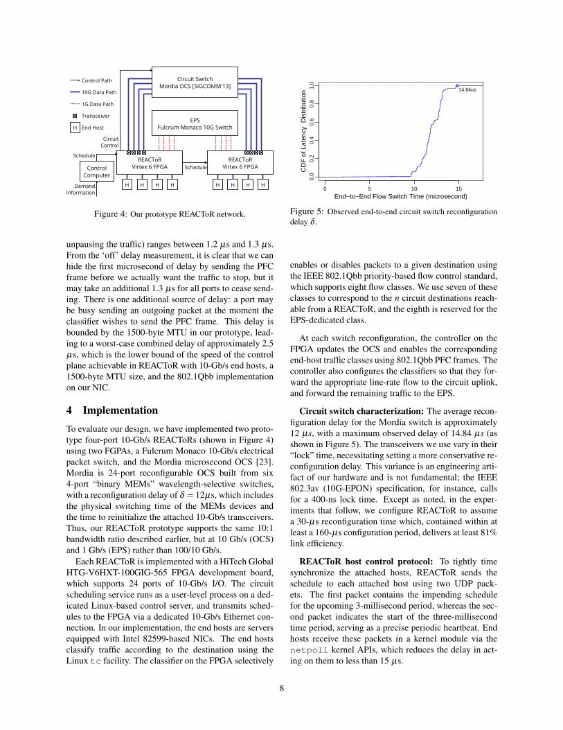
Figure 5: Observed end-to-end circuit switch reconfigurationdelay δ .
enables or disables packets to a given destination usingthe IEEE 802.1Qbb priority-based flow control standard,which supports eight flow classes. We use seven of theseclasses to correspond to the n circuit destinations reach-able from a REACToR, and the eighth is reserved for theEPS-dedicated class.
At each switch reconfiguration, the controller on theFPGA updates the OCS and enables the correspondingend-host traffic classes using 802.1Qbb PFC frames. Thecontroller also configures the classifiers so that they for-ward the appropriate line-rate flow to the circuit uplink,and forward the remaining traffic to the EPS.
Circuit switch characterization: The average recon-figuration delay for the Mordia switch is approximately12 µs, with a maximum observed delay of 14.84 µs (asshown in Figure 5). The transceivers we use vary in their“lock” time, necessitating setting a more conservative re-configuration delay. This variance is an engineering arti-fact of our hardware and is not fundamental; the IEEE802.3av (10G-EPON) specification, for instance, callsfor a 400-ns lock time. Except as noted, in the exper-iments that follow, we configure REACToR to assumea 30-µs reconfiguration time which, contained within atleast a 160-µs configuration period, delivers at least 81%link efficiency.
REACToR host control protocol: To tightly timesynchronize the attached hosts, REACToR sends theschedule to each attached host using two UDP pack-ets. The first packet contains the impending schedulefor the upcoming 3-millisecond period, whereas the sec-ond packet indicates the start of the three-millisecondtime period, serving as a precise periodic heartbeat. Endhosts receive these packets in a kernel module via thenetpoll kernel APIs, which reduces the delay in act-ing on them to less than 15 µs.
8
5 Evaluation
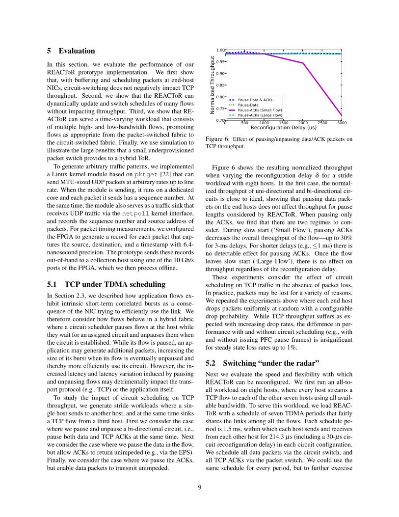
In this section, we evaluate the performance of ourREACToR prototype implementation. We first showthat, with buffering and scheduling packets at end-hostNICs, circuit-switching does not negatively impact TCPthroughput. Second, we show that the REACToR candynamically update and switch schedules of many flowswithout impacting throughput. Third, we show that RE-ACToR can serve a time-varying workload that consistsof multiple high- and low-bandwidth flows, promotingflows as appropriate from the packet-switched fabric tothe circuit-switched fabric. Finally, we use simulation toillustrate the large benefits that a small underprovisionedpacket switch provides to a hybrid ToR.
To generate arbitrary traffic patterns, we implementeda Linux kernel module based on pktget [22] that cansend MTU-sized UDP packets at arbitrary rates up to linerate. When the module is sending, it runs on a dedicatedcore and each packet it sends has a sequence number. Atthe same time, the module also serves as a traffic sink thatreceives UDP traffic via the netpoll kernel interface,and records the sequence number and source address ofpackets. For packet timing measurements, we configuredthe FPGA to generate a record for each packet that cap-tures the source, destination, and a timestamp with 6.4-nanosecond precision. The prototype sends these recordsout-of-band to a collection host using one of the 10 Gb/sports of the FPGA, which we then process offline.
5.1 TCP under TDMA schedulingIn Section 2.3, we described how application flows ex-hibit intrinsic short-term correlated bursts as a conse-quence of the NIC trying to efficiently use the link. Wetherefore consider how flows behave in a hybrid fabricwhere a circuit scheduler pauses flows at the host whilethey wait for an assigned circuit and unpauses them whenthe circuit is established. While its flow is paused, an ap-plication may generate additional packets, increasing thesize of its burst when its flow is eventually unpaused andthereby more efficiently use its circuit. However, the in-creased latency and latency variation induced by pausingand unpausing flows may detrimentally impact the trans-port protocol (e.g., TCP) or the application itself.
To study the impact of circuit scheduling on TCPthroughput, we generate stride workloads where a sin-gle host sends to another host, and at the same time sinksa TCP flow from a third host. First we consider the casewhere we pause and unpause a bi-directional circuit, i.e.,pause both data and TCP ACKs at the same time. Nextwe consider the case where we pause the data in the flow,but allow ACKs to return unimpeded (e.g., via the EPS).Finally, we consider the case where we pause the ACKs,but enable data packets to transmit unimpeded.
0 500 1000 1500 2000 2500 3000Reconfiguration Delay (us)
0.70
0.75
0.80
0.85
0.90
0.95
1.00
Norm
aliz
ed T
hrou
ghpu
t
Pause Data & ACKsPause-DataPause-ACKs (Small Flow)Pause-ACKs (Large Flow)
Figure 6: Effect of pausing/unpausing data/ACK packets onTCP throughput.
Figure 6 shows the resulting normalized throughputwhen varying the reconfiguration delay δ for a strideworkload with eight hosts. In the first case, the normal-ized throughput of uni-directional and bi-directional cir-cuits is close to ideal, showing that pausing data pack-ets on the end hosts does not affect throughput for pauselengths considered by REACToR. When pausing onlythe ACKs, we find that there are two regimes to con-sider. During slow start (‘Small Flow’), pausing ACKsdecreases the overall throughput of the flow—up to 30%for 3-ms delays. For shorter delays (e.g., ≤1 ms) there isno detectable effect for pausing ACKs. Once the flowleaves slow start (‘Large Flow’), there is no effect onthroughput regardless of the reconfiguration delay.
These experiments consider the effect of circuitscheduling on TCP traffic in the absence of packet loss.In practice, packets may be lost for a variety of reasons.We repeated the experiments above where each end hostdrops packets uniformly at random with a configurabledrop probability. While TCP throughput suffers as ex-pected with increasing drop rates, the difference in per-formance with and without circuit scheduling (e.g., withand without issuing PFC pause frames) is insignificantfor steady state loss rates up to 1%.
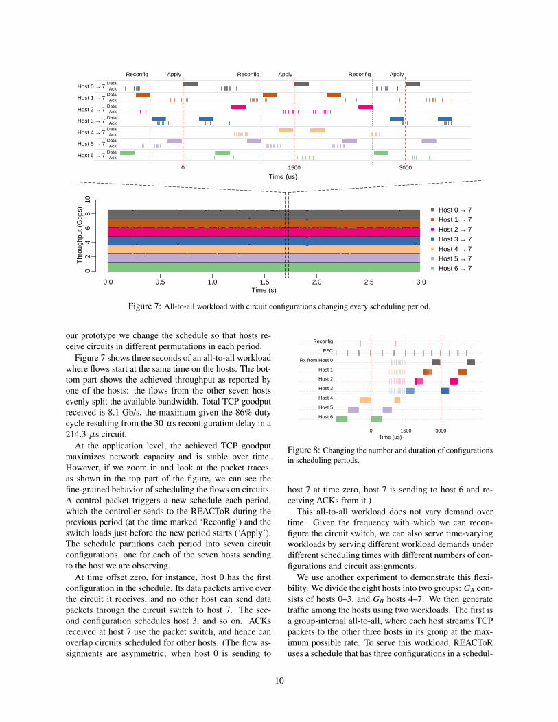
5.2 Switching “under the radar”Next we evaluate the speed and flexibility with whichREACToR can be reconfigured. We first run an all-to-all workload on eight hosts, where every host streams aTCP flow to each of the other seven hosts using all avail-able bandwidth. To serve this workload, we load REAC-ToR with a schedule of seven TDMA periods that fairlyshares the links among all the flows. Each schedule pe-riod is 1.5 ms, within which each host sends and receivesfrom each other host for 214.3 µs (including a 30-µs cir-cuit reconfiguration delay) in each circuit configuration.We schedule all data packets via the circuit switch, andall TCP ACKs via the packet switch. We could use thesame schedule for every period, but to further exercise
9
Time (us)
Ack
Ack
Ack
Ack
Ack
Ack
Ack
Data
Data
Data
Data
Data
Data
Data
Host 6 → 7
Host 5 → 7
Host 4 → 7
Host 3 → 7
Host 2 → 7
Host 1 → 7
Host 0 → 7
Apply Apply Apply
0 1500 3000
Reconfig Reconfig Reconfig
0.0 0.5 1.0 1.5 2.0 2.5 3.0
02
46
810
Time (s)
Thr
ough
put (
Gbp
s) Host 0 → 7Host 1 → 7Host 2 → 7Host 3 → 7Host 4 → 7Host 5 → 7Host 6 → 7
Figure 7: All-to-all workload with circuit configurations changing every scheduling period.
our prototype we change the schedule so that hosts re-ceive circuits in different permutations in each period.
Figure 7 shows three seconds of an all-to-all workloadwhere flows start at the same time on the hosts. The bot-tom part shows the achieved throughput as reported byone of the hosts: the flows from the other seven hostsevenly split the available bandwidth. Total TCP goodputreceived is 8.1 Gb/s, the maximum given the 86% dutycycle resulting from the 30-µs reconfiguration delay in a214.3-µs circuit.
At the application level, the achieved TCP goodputmaximizes network capacity and is stable over time.However, if we zoom in and look at the packet traces,as shown in the top part of the figure, we can see thefine-grained behavior of scheduling the flows on circuits.A control packet triggers a new schedule each period,which the controller sends to the REACToR during theprevious period (at the time marked ‘Reconfig’) and theswitch loads just before the new period starts (‘Apply’).The schedule partitions each period into seven circuitconfigurations, one for each of the seven hosts sendingto the host we are observing.
At time offset zero, for instance, host 0 has the firstconfiguration in the schedule. Its data packets arrive overthe circuit it receives, and no other host can send datapackets through the circuit switch to host 7. The sec-ond configuration schedules host 3, and so on. ACKsreceived at host 7 use the packet switch, and hence canoverlap circuits scheduled for other hosts. (The flow as-signments are asymmetric; when host 0 is sending to
Time (us)
Host 6
Host 5
Host 4
Host 3
Host 2
Host 1
Rx from Host 0
PFC
Reconfig
Host 6
0 1500 3000
Figure 8: Changing the number and duration of configurationsin scheduling periods.
host 7 at time zero, host 7 is sending to host 6 and re-ceiving ACKs from it.)
This all-to-all workload does not vary demand overtime. Given the frequency with which we can recon-figure the circuit switch, we can also serve time-varyingworkloads by serving different workload demands underdifferent scheduling times with different numbers of con-figurations and circuit assignments.
We use another experiment to demonstrate this flexi-bility. We divide the eight hosts into two groups: GA con-sists of hosts 0–3, and GB hosts 4–7. We then generatetraffic among the hosts using two workloads. The first isa group-internal all-to-all, where each host streams TCPpackets to the other three hosts in its group at the max-imum possible rate. To serve this workload, REACToRuses a schedule that has three configurations in a schedul-
10
ing period. The period lasts 1,500 µs, and each config-uration lasts 500 µs (including a 30-µs reconfigurationdelay). The second is a cross-talking all-to-all workloadwhere each host in GA streams to all the other four hostsin GB, and vice versa. For this workload, REACToR usesschedules with four configurations. These scheduling pe-riods also last 1,500 µs, but each configuration lasts 375µs (again including a 30-µs reconfiguration delay).
In the experiment, we change from the group-internalto the cross-talk workloads midway through, loadingthe REACToR with correspondingly different schedules.Figure 8 shows the incoming packets to host 7 aroundthe workload transition time. We controlled the exper-iment so that the workload changes at an inconvenient,but more realistic, time for REACToR: during a schedul-ing period, at time 750 µs on the graph. REACToR’sschedules commit the switch based on predicted demand,and workloads are apt to change their demand indepen-dent of when REACToR can conveniently accommodatethem. At this workload transition, REACToR is halfwaythrough its scheduling period and packets already queuedat the first three hosts continue to arrive via circuits.Overlapping these flows, the other four hosts start send-ing packets to host 7. These hosts do not have circuits,so the packets arrive via the EPS at a much lower rate.
At the end of its committed scheduling period (time1,500 µs), REACToR can then react to the workloadtransition and schedule circuit configurations that matchthe workload. At this time, host 7 changes from receivingpackets in 500-µs configurations, scheduled round-robinfrom hosts 4–6, to receiving packets in 375-µs configu-rations from hosts 0–3.
In summary, these experiments demonstrate the speedand flexibility with which REACToR can reconfigure itscircuit schedules given a known demand. Applicationsachieve their expected goodput at a high level, while in-dividual flows are paused and released at fine time scaleswhen their circuits are scheduled. Further, REACToRcan adjust the circuit schedule to adapt to changes in ap-plication behavior and demand.
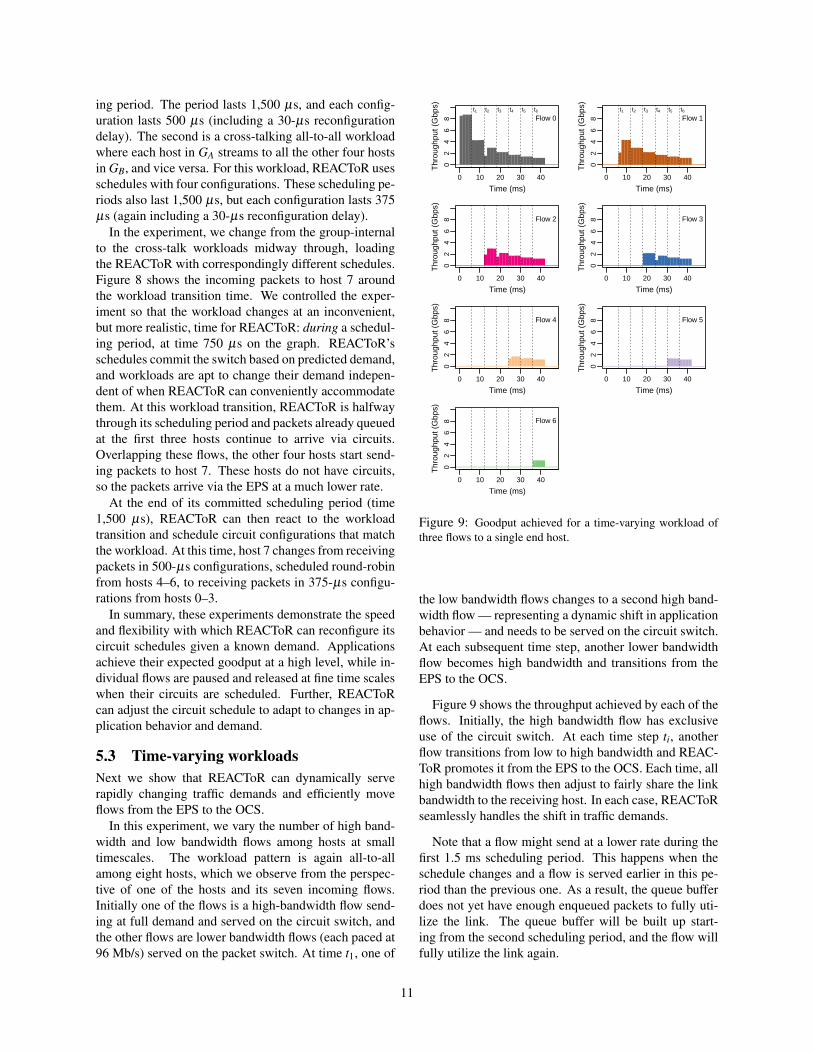
5.3 Time-varying workloadsNext we show that REACToR can dynamically serverapidly changing traffic demands and efficiently moveflows from the EPS to the OCS.
In this experiment, we vary the number of high band-width and low bandwidth flows among hosts at smalltimescales. The workload pattern is again all-to-allamong eight hosts, which we observe from the perspec-tive of one of the hosts and its seven incoming flows.Initially one of the flows is a high-bandwidth flow send-ing at full demand and served on the circuit switch, andthe other flows are lower bandwidth flows (each paced at96 Mb/s) served on the packet switch. At time t1, one of
02
46
8
Time (ms)
Thr
ough
put (
Gbp
s)
0 10 20 30 40
Flow 0t1 t2 t3 t4 t5 t6
02
46
8
Time (ms)
Thr
ough
put (
Gbp
s)
0 10 20 30 40
Flow 1t1 t2 t3 t4 t5 t6
02
46
8
Time (ms)
Thr
ough
put (
Gbp
s)
0 10 20 30 40
Flow 2
02
46
8
Time (ms)
Thr
ough
put (
Gbp
s)
0 10 20 30 40
Flow 3
02
46
8
Time (ms)
Thr
ough
put (
Gbp
s)
0 10 20 30 40
Flow 4
02
46
8
Time (ms)
Thr
ough
put (
Gbp
s)
0 10 20 30 40
Flow 5
02
46
8
Time (ms)
Thr
ough
put (
Gbp
s)
0 10 20 30 40
Flow 6
Figure 9: Goodput achieved for a time-varying workload ofthree flows to a single end host.
the low bandwidth flows changes to a second high band-width flow — representing a dynamic shift in applicationbehavior — and needs to be served on the circuit switch.At each subsequent time step, another lower bandwidthflow becomes high bandwidth and transitions from theEPS to the OCS.
Figure 9 shows the throughput achieved by each of theflows. Initially, the high bandwidth flow has exclusiveuse of the circuit switch. At each time step ti, anotherflow transitions from low to high bandwidth and REAC-ToR promotes it from the EPS to the OCS. Each time, allhigh bandwidth flows then adjust to fairly share the linkbandwidth to the receiving host. In each case, REACToRseamlessly handles the shift in traffic demands.
Note that a flow might send at a lower rate during thefirst 1.5 ms scheduling period. This happens when theschedule changes and a flow is served earlier in this pe-riod than the previous one. As a result, the queue bufferdoes not yet have enough enqueued packets to fully uti-lize the link. The queue buffer will be built up start-ing from the second scheduling period, and the flow willfully utilize the link again.
11
10 20 30 40 50 60 70 80 90 100Large-flow demand (percent of link b/w)
70
75
80
85
90
95
100
Good
put (
perc
ent o
f lin
k b/
w)
CircuitHybrid with 10 Gbps EPSHybrid with 20 Gbps EPS
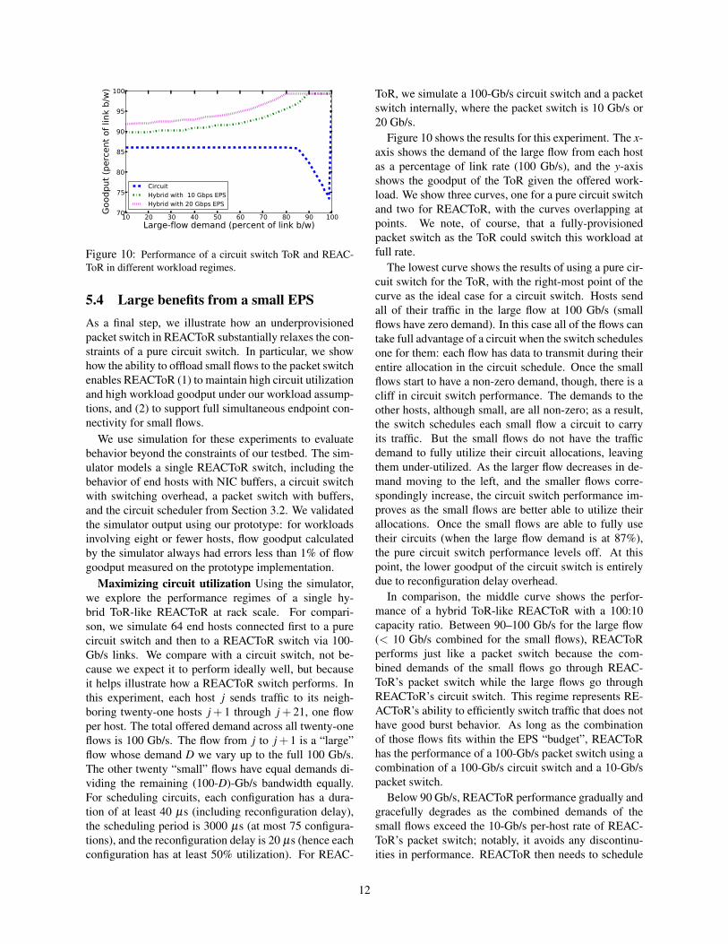
Figure 10: Performance of a circuit switch ToR and REAC-ToR in different workload regimes.
5.4 Large benefits from a small EPSAs a final step, we illustrate how an underprovisionedpacket switch in REACToR substantially relaxes the con-straints of a pure circuit switch. In particular, we showhow the ability to offload small flows to the packet switchenables REACToR (1) to maintain high circuit utilizationand high workload goodput under our workload assump-tions, and (2) to support full simultaneous endpoint con-nectivity for small flows.
We use simulation for these experiments to evaluatebehavior beyond the constraints of our testbed. The sim-ulator models a single REACToR switch, including thebehavior of end hosts with NIC buffers, a circuit switchwith switching overhead, a packet switch with buffers,and the circuit scheduler from Section 3.2. We validatedthe simulator output using our prototype: for workloadsinvolving eight or fewer hosts, flow goodput calculatedby the simulator always had errors less than 1% of flowgoodput measured on the prototype implementation.
Maximizing circuit utilization Using the simulator,we explore the performance regimes of a single hy-brid ToR-like REACToR at rack scale. For compari-son, we simulate 64 end hosts connected first to a purecircuit switch and then to a REACToR switch via 100-Gb/s links. We compare with a circuit switch, not be-cause we expect it to perform ideally well, but becauseit helps illustrate how a REACToR switch performs. Inthis experiment, each host j sends traffic to its neigh-boring twenty-one hosts j + 1 through j + 21, one flowper host. The total offered demand across all twenty-oneflows is 100 Gb/s. The flow from j to j+ 1 is a “large”flow whose demand D we vary up to the full 100 Gb/s.The other twenty “small” flows have equal demands di-viding the remaining (100-D)-Gb/s bandwidth equally.For scheduling circuits, each configuration has a dura-tion of at least 40 µs (including reconfiguration delay),the scheduling period is 3000 µs (at most 75 configura-tions), and the reconfiguration delay is 20 µs (hence eachconfiguration has at least 50% utilization). For REAC-
ToR, we simulate a 100-Gb/s circuit switch and a packetswitch internally, where the packet switch is 10 Gb/s or20 Gb/s.
Figure 10 shows the results for this experiment. The x-axis shows the demand of the large flow from each hostas a percentage of link rate (100 Gb/s), and the y-axisshows the goodput of the ToR given the offered work-load. We show three curves, one for a pure circuit switchand two for REACToR, with the curves overlapping atpoints. We note, of course, that a fully-provisionedpacket switch as the ToR could switch this workload atfull rate.
The lowest curve shows the results of using a pure cir-cuit switch for the ToR, with the right-most point of thecurve as the ideal case for a circuit switch. Hosts sendall of their traffic in the large flow at 100 Gb/s (smallflows have zero demand). In this case all of the flows cantake full advantage of a circuit when the switch schedulesone for them: each flow has data to transmit during theirentire allocation in the circuit schedule. Once the smallflows start to have a non-zero demand, though, there is acliff in circuit switch performance. The demands to theother hosts, although small, are all non-zero; as a result,the switch schedules each small flow a circuit to carryits traffic. But the small flows do not have the trafficdemand to fully utilize their circuit allocations, leavingthem under-utilized. As the larger flow decreases in de-mand moving to the left, and the smaller flows corre-spondingly increase, the circuit switch performance im-proves as the small flows are better able to utilize theirallocations. Once the small flows are able to fully usetheir circuits (when the large flow demand is at 87%),the pure circuit switch performance levels off. At thispoint, the lower goodput of the circuit switch is entirelydue to reconfiguration delay overhead.
In comparison, the middle curve shows the perfor-mance of a hybrid ToR-like REACToR with a 100:10capacity ratio. Between 90–100 Gb/s for the large flow(< 10 Gb/s combined for the small flows), REACToRperforms just like a packet switch because the com-bined demands of the small flows go through REAC-ToR’s packet switch while the large flows go throughREACToR’s circuit switch. This regime represents RE-ACToR’s ability to efficiently switch traffic that does nothave good burst behavior. As long as the combinationof those flows fits within the EPS “budget”, REACToRhas the performance of a 100-Gb/s packet switch using acombination of a 100-Gb/s circuit switch and a 10-Gb/spacket switch.
Below 90 Gb/s, REACToR performance gradually andgracefully degrades as the combined demands of thesmall flows exceed the 10-Gb/s per-host rate of REAC-ToR’s packet switch; notably, it avoids any discontinu-ities in performance. REACToR then needs to schedule
12
0 10 20 30 40 50 60 70#Small flows
20
30
40
50
60
70
80
90
100
Good
put (
perc
ent o
f lin
k b/
w)
HybridCircuit
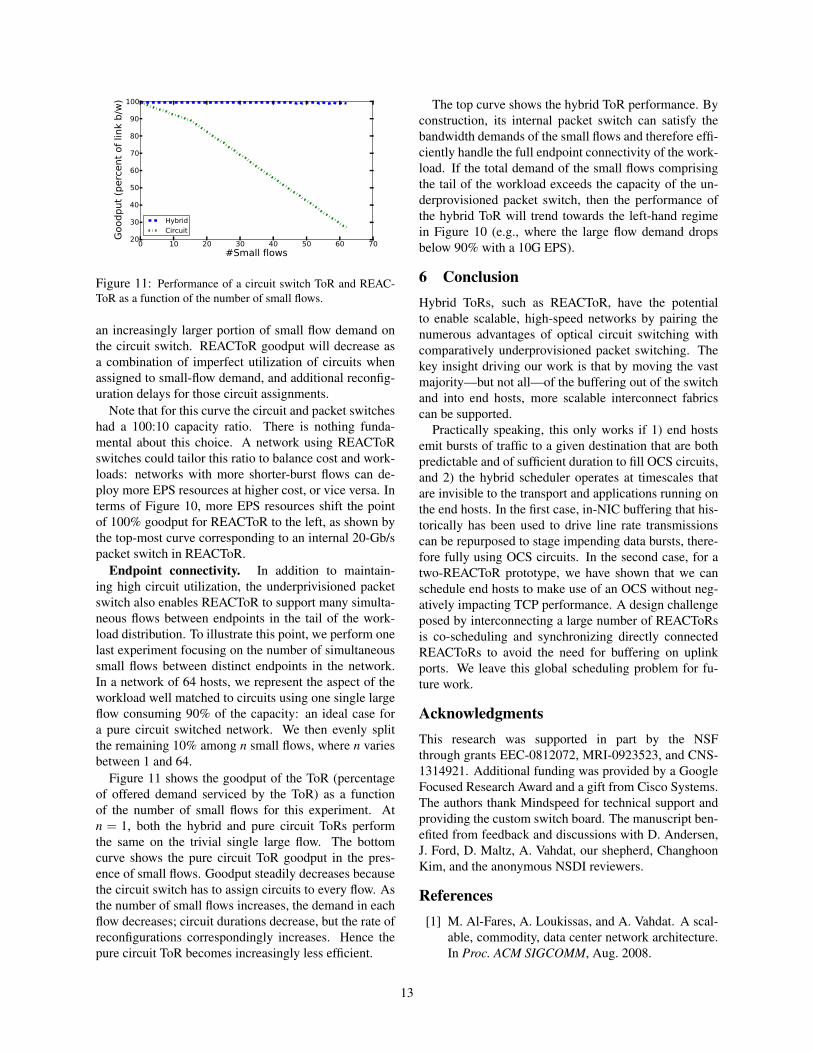
Figure 11: Performance of a circuit switch ToR and REAC-ToR as a function of the number of small flows.
an increasingly larger portion of small flow demand onthe circuit switch. REACToR goodput will decrease asa combination of imperfect utilization of circuits whenassigned to small-flow demand, and additional reconfig-uration delays for those circuit assignments.
Note that for this curve the circuit and packet switcheshad a 100:10 capacity ratio. There is nothing funda-mental about this choice. A network using REACToRswitches could tailor this ratio to balance cost and work-loads: networks with more shorter-burst flows can de-ploy more EPS resources at higher cost, or vice versa. Interms of Figure 10, more EPS resources shift the pointof 100% goodput for REACToR to the left, as shown bythe top-most curve corresponding to an internal 20-Gb/spacket switch in REACToR.
Endpoint connectivity. In addition to maintain-ing high circuit utilization, the underprivisioned packetswitch also enables REACToR to support many simulta-neous flows between endpoints in the tail of the work-load distribution. To illustrate this point, we perform onelast experiment focusing on the number of simultaneoussmall flows between distinct endpoints in the network.In a network of 64 hosts, we represent the aspect of theworkload well matched to circuits using one single largeflow consuming 90% of the capacity: an ideal case fora pure circuit switched network. We then evenly splitthe remaining 10% among n small flows, where n variesbetween 1 and 64.
Figure 11 shows the goodput of the ToR (percentageof offered demand serviced by the ToR) as a functionof the number of small flows for this experiment. Atn = 1, both the hybrid and pure circuit ToRs performthe same on the trivial single large flow. The bottomcurve shows the pure circuit ToR goodput in the pres-ence of small flows. Goodput steadily decreases becausethe circuit switch has to assign circuits to every flow. Asthe number of small flows increases, the demand in eachflow decreases; circuit durations decrease, but the rate ofreconfigurations correspondingly increases. Hence thepure circuit ToR becomes increasingly less efficient.
The top curve shows the hybrid ToR performance. Byconstruction, its internal packet switch can satisfy thebandwidth demands of the small flows and therefore effi-ciently handle the full endpoint connectivity of the work-load. If the total demand of the small flows comprisingthe tail of the workload exceeds the capacity of the un-derprovisioned packet switch, then the performance ofthe hybrid ToR will trend towards the left-hand regimein Figure 10 (e.g., where the large flow demand dropsbelow 90% with a 10G EPS).
6 ConclusionHybrid ToRs, such as REACToR, have the potentialto enable scalable, high-speed networks by pairing thenumerous advantages of optical circuit switching withcomparatively underprovisioned packet switching. Thekey insight driving our work is that by moving the vastmajority—but not all—of the buffering out of the switchand into end hosts, more scalable interconnect fabricscan be supported.
Practically speaking, this only works if 1) end hostsemit bursts of traffic to a given destination that are bothpredictable and of sufficient duration to fill OCS circuits,and 2) the hybrid scheduler operates at timescales thatare invisible to the transport and applications running onthe end hosts. In the first case, in-NIC buffering that his-torically has been used to drive line rate transmissionscan be repurposed to stage impending data bursts, there-fore fully using OCS circuits. In the second case, for atwo-REACToR prototype, we have shown that we canschedule end hosts to make use of an OCS without neg-atively impacting TCP performance. A design challengeposed by interconnecting a large number of REACToRsis co-scheduling and synchronizing directly connectedREACToRs to avoid the need for buffering on uplinkports. We leave this global scheduling problem for fu-ture work.
AcknowledgmentsThis research was supported in part by the NSFthrough grants EEC-0812072, MRI-0923523, and CNS-1314921. Additional funding was provided by a GoogleFocused Research Award and a gift from Cisco Systems.The authors thank Mindspeed for technical support andproviding the custom switch board. The manuscript ben-efited from feedback and discussions with D. Andersen,J. Ford, D. Maltz, A. Vahdat, our shepherd, ChanghoonKim, and the anonymous NSDI reviewers.
References[1] M. Al-Fares, A. Loukissas, and A. Vahdat. A scal-
able, commodity, data center network architecture.In Proc. ACM SIGCOMM, Aug. 2008.
13
[2] M. Alizadeh, A. Greenberg, D. A. Maltz, J. Padhye,P. Patel, B. Prabhakar, S. Sengupta, and M. Sridha-ran. Data center TCP (DCTCP). In Proc. ACMSIGCOMM, Aug. 2010.
[3] G. Appenzeller, I. Keslassy, and N. McKeown. Siz-ing router buffers. In Proc. ACM SIGCOMM, Oct.2004.
[4] T. Benson, A. Akella, and D. A. Maltz. Networktraffic characteristics of data centers in the wild. InProc. ACM IMC, 2010.
[5] N. J. Boden, D. Cohen, R. E. Felderman, A. E.Kulawik, C. L. Seitz, J. N. Seizovic, and W. Su.Myrinet: A Gigabit-per-Second Local Area Net-work. IEEE Micro, 15(1):29–36, Feb. 1995.
[6] N. Calabretta, R. Centelles, S. Di Lucente, andH. Dorren. On the Performance of a Large-ScaleOptical Packet Switch Under Realistic Data CenterTraffic. Journal of Optical Communications andNetworking, 5(6):565–573, June 2013.
[7] K. Chen, A. Singla, A. Singh, K. Ramachandran,L. Xu, Y. Zhang, and X. Wen. OSA: An OpticalSwitching Architecture for Data Center Networksand Unprecedented Flexibility. In Proc. USENIXNSDI, Apr. 2012.
[8] N. Farrington, A. Forencich, G. Porter, P.-C. Sun,J. Ford, Y. Fainman, G. Papen, and A. Vahdat. AMultiport Microsecond Optical Circuit Switch forData Center Networking. IEEE Photonics Technol-ogy Letters, 25(16):1589–1592, June 2013.
[9] N. Farrington, G. Porter, Y. Fainman, G. Papen, andA. Vahdat. Hunting mice with microsecond circuitswitches. In Proc. ACM HotNets, Oct. 2012.
[10] N. Farrington, G. Porter, S. Radhakrishnan, H. Baz-zaz, V. Subramanya, Y. Fainman, G. Papen, andA. Vahdat. Helios: A hybrid electrical/opticalswitch architecture for modular data centers. InProc. ACM SIGCOMM, Aug. 2010.
[11] S. Fu, B. Wu, X. Jiang, A. Pattavina, L. Zhang,and S. Xu. Cost and delay tradeoff in three-stageswitch architecture for data center networks. InProc. IEEE High Performance Switching and Rout-ing, July 2013.
[12] D. Halperin, S. Kandula, J. Padhye, P. Bahl, andD. Wetherall. Augmenting Data Center Networkswith Multi-gigabit Wireless Links. In Proc. ACMSIGCOMM, Aug. 2011.
[13] N. Jerger, M. Lipasti, and L. Peh. Circuit-SwitchedCoherence. Computer Architecture Letters, 6(1):5–8, July 2007.
[14] S. Kandula, J. Padhye, and P. Bahl. Flyways ToDe-Congest Data Center Networks. In Proc. ACMHotNets, Oct. 2009.
[15] S. Kandula, S. Sengupta, A. Greenberg, P. Patel,and R. Chaiken. The Nature of Data Center Traf-fic: Measurements & Analysis. In Proc. ACM IMC,Nov. 2009.
[16] R. Kapoor, A. C. Snoeren, G. M. Voelker, andG. Porter. Bullet Trains: A Study of NIC Burst Be-havior at Microsecond Timescales. In Proc. ACMCoNEXT, Dec. 2013.
[17] B. Lee, A. Rylyakov, W. Green, S. Assefa, C. Baks,R. Rimolo-Donadio, D. Kuchta, M. Khater, T. Bar-wicz, C. Reinholm, E. Kiewra, S. Shank, C. Schow,and Y. Vlasov. Four- and Eight-Port PhotonicSwitches Monolithically Integrated with DigitalCMOS Logic and Driver Circuits. In Proc.OFC/NFOEC, Mar. 2013.
[18] X. Li and M. Hamdi. On scheduling optical packetswitches with reconfiguration delay. IEEE Journalon Selected Areas in Communications, 21(7), Sept.2003.
[19] D. Marom. Switching Capacity of MEMS TiltingMicromirrors. In Proc. IEEE Optical MEMS andNanophotonics, Aug. 2012.
[20] J. Martin, K. K. Chapman, and J. Leben. Asyn-chronous Transfer Mode: ATM Architecture andImplementation. Prentice-Hall, Inc., 1997.
[21] T. Moscibroda and O. Mutlu. A Case for BufferlessRouting in On-Chip Networks. In Proc. ISCA, June2009.
[22] R. Olsson. pktgen the linux packet generator. Proc.Linux Symposium, July 2005.
[23] G. Porter, R. Strong, N. Farrington, A. Forencich,P.-C. Sun, T. Rosing, Y. Fainman, G. Papen, andA. Vahdat. Integrating microsecond circuit switch-ing into the data center. In Proc. ACM SIGCOMM,Aug. 2013.
[24] S. Radhakrishnan, Y. Geng, V. Jeyakumar, A. Kab-bani, G. Porter, and A. Vahdat. SENIC: A scalableNIC for end-host rate limiting. In Proc. USENIXNSDI, Apr. 2014.
14
[25] A. Vahdat, M. Al-Fares, N. Farrington, R. N.Mysore, G. Porter, and S. Radhakrishnan. Scale-out networking in the data center. IEEE Micro,30(4):29–41, Aug. 2010.
[26] G. Wang, D. G. Andersen, M. Kaminsky, K. Papa-giannaki, T. S. E. Ng, M. Kozuch, and M. Ryan.c-Through: Part-time Optics in Data Centers. InProc. ACM SIGCOMM, Aug. 2010.
[27] B. Wu, K. L. Yeung, and X. Wang. Improvingscheduling efficiency for high-speed routers withoptical switch fabrics. In Proc. IEEE Globecom,Dec. 2006.
[28] X. Zhou, Z. Zhang, Y. Zhu, Y. Li, S. Kumar,A. Vahdat, B. Y. Zhao, and H. Zheng. Mirror Mir-ror on the Ceiling: Flexible Wireless Links for DataCenters. In Proc. ACM SIGCOMM, Aug. 2012.
15