circuit implementations of soliton systemssinger/pub_files/circuit...circuit implementations of...
TRANSCRIPT
Tutorials and Reviews
International Journal of Bifurcation and Chaos, Vol. 9, No. 4 (1999) 571–590c© World Scientific Publishing Company
CIRCUIT IMPLEMENTATIONS OF SOLITON SYSTEMS∗
ANDREW C. SINGERDepartment of Electrical and Computer Engineering,
University of Illinois, Urbana, IL 61801, USA
ALAN V. OPPENHEIMDepartment of Electrical Engineering, MIT, Cambridge, MA 02139, USA
Received May 27, 1998; Revised October 6, 1998
Recently, a large class of nonlinear systems which possess soliton solutions has been discoveredfor which exact analytic solutions can be found. Solitons are eigenfunctions of these systemswhich satisfy a form of superposition and display rich signal dynamics as they interact. In thispaper, we view solitons as signals and consider exploiting these systems as specialized signalprocessors which are naturally suited to a number of complex signal processing tasks. Newcircuit models are presented for two soliton systems, the Toda lattice and the discrete-KdVequations. These analog circuits can generate and process soliton signals and can be used asmultiplexers and demultiplexers in a number of potential soliton-based wireless communicationapplications discussed in [Singer et al.]. A hardware implementation of the Toda lattice circuitis presented, along with a detailed analysis of the dynamics of the system in the presence ofadditive Gaussian noise. This circuit model appears to be the first such circuit sufficientlyaccurate to demonstrate true overtaking soliton collisions with a small number of nodes. Thediscrete-KdV equation, which was largely ignored for having no prior electrical or mechanicalanalog, provides a convenient means for processing discrete-time soliton signals.
1. Introduction
Many traditional signal processing applications relyon models that are inherently linear and time-invariant (LTI). Much of the success of such meth-ods can be attributed to their being mathemat-ically tractable, often leading to efficient signalrepresentations and fast algorithms. Linear tech-niques have also proven effective for modeling avariety of signals of practical interest such asspeech or financial time-series and systems of in-terest such as telephone or radio broadcast chan-nels. However, we increasingly turn to nonlin-ear models to capture some of the more salientbehavior of physical or natural systems that
cannot be expressed by linear means, such asthreshold phenomena, amplitude-dependence, orchaotic behavior. Nonlinear systems also hold thepotential to produce more efficient algorithms ormodels for a variety of signal processing and com-munication problems where linear techniques aresuboptimal.
The class of nonlinear systems that supportsoliton solutions appears to be of particular interestto explore for signal synthesis and analysis. Soli-tons have been observed in a variety of naturalphenomena from water and plasma waves [Infeld &Rowlands, 1990; Scott et al., 1973] to crystal latticevibrations [Fermi et al., 1965] and energy transport
∗This work has been supported in part by the Department of the Navy, Office of the Chief of Naval Research, contract numberN00014-93-1-0686 as part of the Advanced Research Projects Agency’s RASSP program, the Air Force Office of ScientificResearch under contract number F49620-92-J-0255, and was prepared through collaborative participation in the AdvancedSensors Consortium sponsored by the U.S. Army Research Laboratory under Cooperative Agreement DAAL01-96-2-0001.
571
572 A. C. Singer & A. V. Oppenheim
in proteins [Infeld & Rowlands, 1990]. Recently,solitons have become of significant interest for op-tical telecommunications, where optical pulses havebeen shown to propagate as solitons in appropri-ately tailored nonlinear media for tremendous dis-tances without significant loss or dispersion [Haus,1993].
In this paper, we view solitons from a very dif-ferent perspective. Rather than focusing on thepropagation of solitons through nonlinear media, weconsider the implementation of circuits which cangenerate and process signals for transmission overideal linear channels. In this context, we then con-sider these nonlinear circuits as specialized signalprocessors for exploiting soliton signals.
Systems that support solitons share many ofthe properties that make LTI systems attractivefrom an engineering standpoint. Although nonlin-ear, these systems are analytically solvable througha technique called inverse scattering, which is anal-ogous to the Fourier transform for linear systems[Ablowitz & Clarkson, 1991]. Solitons are eigen-functions of these systems and satisfy a nonlinearform of superposition. We can therefore decomposecomplex solutions in terms of a class of signals withsimple dynamical structure.
In this paper, we examine the properties ofsolitons as signals and propose and investigate cir-cuits that can be used to generate them. Section 2provides an introduction to some of the proper-ties of soliton systems paying particular attentionto two such systems: The Toda lattice equationand the discrete Korteweg deVries (KdV) equa-tion. In Sec. 3, we develop new circuit modelsfor these two soliton systems. The first is a diodeladder implementation of the Toda lattice equa-tion which appears to be the first Toda latticecircuit implementation sufficiently accurate to dis-play true soliton behavior over a small number ofnodes. We also develop a lattice-circuit implemen-tation of the discrete-KdV equation, which is im-portant for processing discrete-time soliton signals.These circuit models form the basis for a commu-nication paradigm in which multiple signals canbe multiplexed onto soliton carriers using such cir-cuits as tuned modulators and demodulators. Thisparadigm is developed in a related paper [Singeret al.]. In order to utilize soliton systems in anypractical context, accurate models are needed forthe effects of disturbances on the dynamics of thesesystems. In Sec. 4, we analyze the effects of smallamplitude noise on the dynamics of solitons in the
Toda lattice and characterize the statistics of thenoise as it is propagates through the system.
2. Soliton Systems
An important class of solutions to certain nonlin-ear evolution equations are traveling wave solutionsthat propagate with constant shape and velocity;these are referred to as “solitary waves”. Specif-ically, a solitary wave solution with temporal andspatial variables, t and n, is a traveling wave of theform, u(n, t) = f(n− ct) = f(z), where c is a fixedconstant, and the energy of f(z) is localized in z.
There are many physical systems that supportsolitary wave solutions [Ablowitz & Clarkson, 1991;Haus, 1993; Scott, 1970]. In this paper we focusprimarily on two, referred to as the Toda lattice[Toda, 1989] and discrete-KdV [Ablowitz & Clark-son, 1991; Toda, 1981] equations.
2.1. The Toda lattice
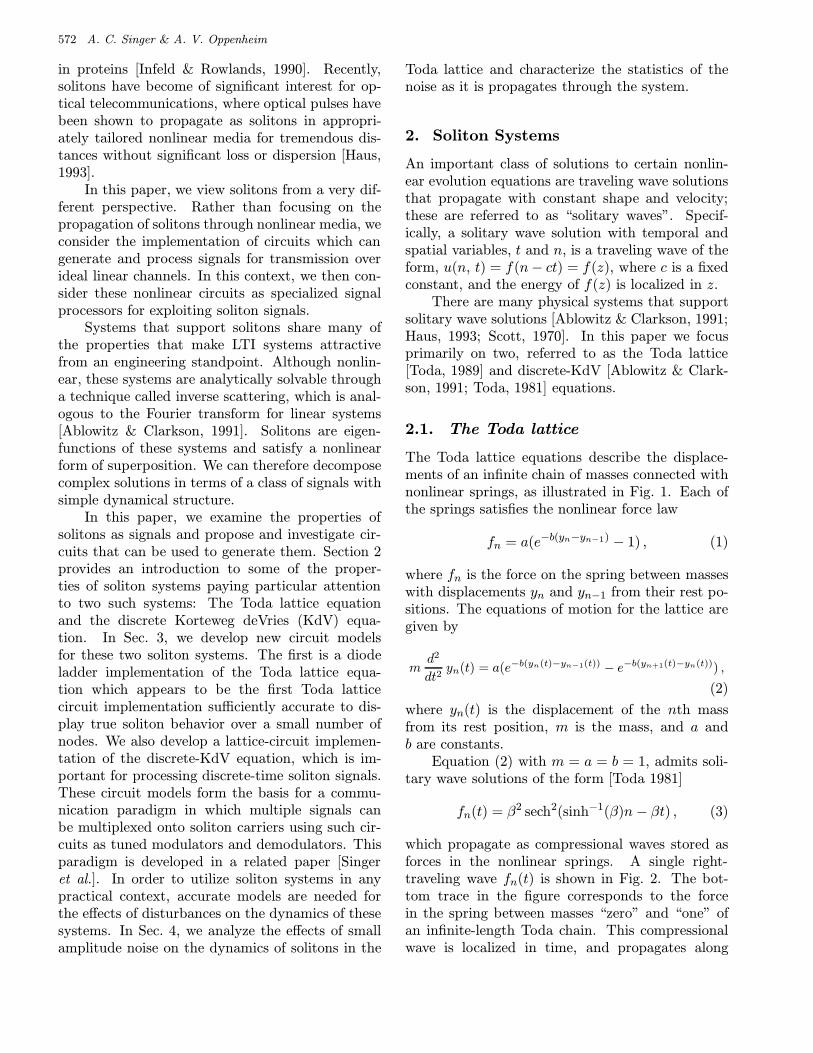
The Toda lattice equations describe the displace-ments of an infinite chain of masses connected withnonlinear springs, as illustrated in Fig. 1. Each ofthe springs satisfies the nonlinear force law
fn = a(e−b(yn−yn−1) − 1) , (1)
where fn is the force on the spring between masseswith displacements yn and yn−1 from their rest po-sitions. The equations of motion for the lattice aregiven by
md2
dt2yn(t) = a(e−b(yn(t)−yn−1(t)) − e−b(yn+1(t)−yn(t))) ,
(2)
where yn(t) is the displacement of the nth massfrom its rest position, m is the mass, and a andb are constants.
Equation (2) with m = a = b = 1, admits soli-tary wave solutions of the form [Toda 1981]
fn(t) = β2 sech2(sinh−1(β)n− βt) , (3)
which propagate as compressional waves stored asforces in the nonlinear springs. A single right-traveling wave fn(t) is shown in Fig. 2. The bot-tom trace in the figure corresponds to the forcein the spring between masses “zero” and “one” ofan infinite-length Toda chain. This compressionalwave is localized in time, and propagates along
Circuit Implementations of Soliton Systems 573
......
yn+1
yn
yn-1
Fig. 1. The Toda lattice.
0 5 10 15 20 25 300
5
10
15
20
25
30
35
time
mas
s in
dex
Fig. 2. A propagating wave solution to the Toda latticeequations. Each trace corresponds to the force fn(t) storedin the spring between mass n and n− 1.
the chain maintaining constant shape and velocity.The parameter β appears in both the amplitudeand in the temporal- and spatial-scales of this one-parameter family of solutions. As a result, the ve-locity of the pulses is monotonic in β, while for βlarge, the pulses are tall and narrow and for β small,they are short and wide.
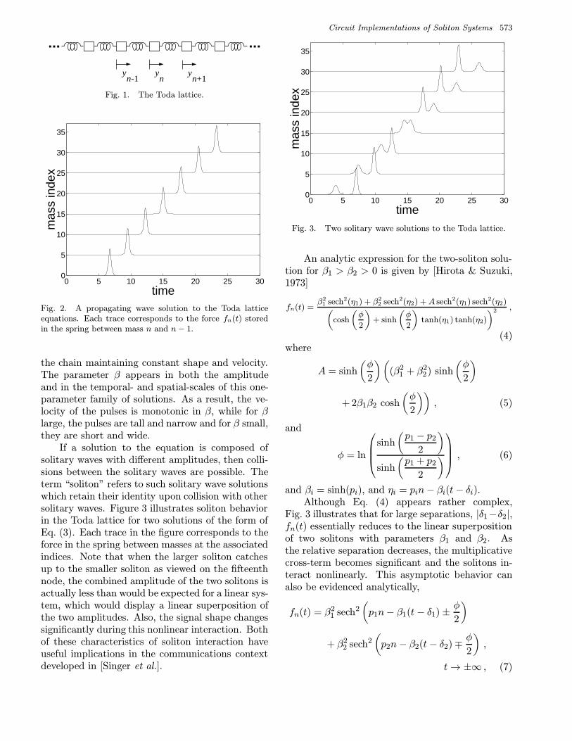
If a solution to the equation is composed ofsolitary waves with different amplitudes, then colli-sions between the solitary waves are possible. Theterm “soliton” refers to such solitary wave solutionswhich retain their identity upon collision with othersolitary waves. Figure 3 illustrates soliton behaviorin the Toda lattice for two solutions of the form ofEq. (3). Each trace in the figure corresponds to theforce in the spring between masses at the associatedindices. Note that when the larger soliton catchesup to the smaller soliton as viewed on the fifteenthnode, the combined amplitude of the two solitons isactually less than would be expected for a linear sys-tem, which would display a linear superposition ofthe two amplitudes. Also, the signal shape changessignificantly during this nonlinear interaction. Bothof these characteristics of soliton interaction haveuseful implications in the communications contextdeveloped in [Singer et al.].
0 5 10 15 20 25 300
5
10
15
20
25
30
35
time
mas
s in
dex
Fig. 3. Two solitary wave solutions to the Toda lattice.
An analytic expression for the two-soliton solu-tion for β1 > β2 > 0 is given by [Hirota & Suzuki,1973]
fn(t) =β2
1 sech2(η1) + β22 sech2(η2) +A sech2(η1) sech2(η2)(
cosh
(φ
2
)+ sinh
(φ
2
)tanh(η1) tanh(η2)
)2 ,
(4)where
A = sinh
(φ
2
)((β2
1 + β22) sinh
(φ
2
)
+ 2β1β2 cosh
(φ
2
)), (5)
and
φ = ln
sinh
(p1 − p2
2
)sinh
(p1 + p2
2
) , (6)
and βi = sinh(pi), and ηi = pin− βi(t− δi).Although Eq. (4) appears rather complex,
Fig. 3 illustrates that for large separations, |δ1−δ2|,fn(t) essentially reduces to the linear superpositionof two solitons with parameters β1 and β2. Asthe relative separation decreases, the multiplicativecross-term becomes significant and the solitons in-teract nonlinearly. This asymptotic behavior canalso be evidenced analytically,
fn(t) = β21 sech2
(p1n− β1(t− δ1)± φ
2
)
+ β22 sech2
(p2n− β2(t− δ2)∓ φ
2
),
t→ ±∞ , (7)
574 A. C. Singer & A. V. Oppenheim
where each component soliton experiences a net dis-placement φ from the nonlinear interaction.
The Toda lattice also admits periodic solutionswhich can be written in terms of the Jacobian el-liptic functions dn(·) and sn(·). These solutions canbe expressed
fn(t) = (2Kν)2
dn2[2
(n
λ± νt
)K
]− E
K
, (8)
for wavelength λ and frequency ν, with
2Kν =
(sn−2
(2K
λ
)− 1 +
E
K
)−1/2
, (9)
where K and E are complete elliptic integrals of thefirst and second kind, respectively [Toda, 1981].
When written in terms of the spring forces, theToda lattice equations become
d2
dt2ln(1 + fn(t)) = (fn+1(t)− 2fn(t) + fn−1(t)) .
(10)If the substitution
fn(t) =d2
dt2ln ψn(t) (11)
is made into Eq. (10), then the lattice equationsbecome,
ψ2n − ψnψn = ψ2
n − ψn−1ψn+1 . (12)
In view of the Teager energy operator introducedby Kaiser [1990], the left-hand side of Eq. (12) isthe Teager instantaneous-time energy at the noden,and the right-hand side is the Teager instantaneous-space energy at time t. In this form, we may viewsolutions to Eq. (12) as propagating waveforms thathave equal Teager energy as calculated in time andin space, a relationship also observed by Kaiser.
2.2. Discrete-KdV
The discrete-KdV (dKdV) equation, sometimesreferred to as the nonlinear ladder equations[Ablowitz & Clarkson, 1991] or the KM system (Kacand van Moerbeke) [Toda, 1981], is governed by theequations,
d
dtun(t) = eun−1(t) − eun+1(t) . (13)
These equations are first-order in time, which makesthe dynamics less complex than the Toda lattice
to which the dKdV equation is closely related. Al-though much of the theory for this nonlinear systemhas been developed in association with the theoryfor the Toda lattice, the discrete-KdV equations aregenerally ignored since there is no clear physicalanalog of these equations. However, there is specialrelationship known as a Backlund transformationwhich provides a connection between this systemand the Toda lattice [Kac & van Moerbeke, 1975a,1975b; Toda, 1981].
Following [Kac & van Moerbeke, 1975a, 1975b;Toda, 1981], let
un(t)→ −Rn(t) , t→ −t , (14)
which transforms (13) to
d
dtRn(t) = e−Rn−1(t) − e−Rn+1(t) . (15)
Letting qn = Rn +Rn+1, then qn satisfies
d2
dt2qn(t) = 2e−qn(t) − e−qn−2(t) − eqn+2(t) . (16)
Taking every other term, i.e. q1,n = q2n, q2,n =q2n+1, we have
d2
dt2qi,n(t) = 2e−qi,n(t) − e−qi,n−1(t)
− eqi,n+1(t) , i = 1, 2 . (17)
Setting qi,n = − ln(1 + fi,n), yields
d2 ln(1 + fi,n(t))
dt2= fi,n−1(t)− 2fi,n(t)
+ fi,n+1(t) , i = 1, 2 , (18)
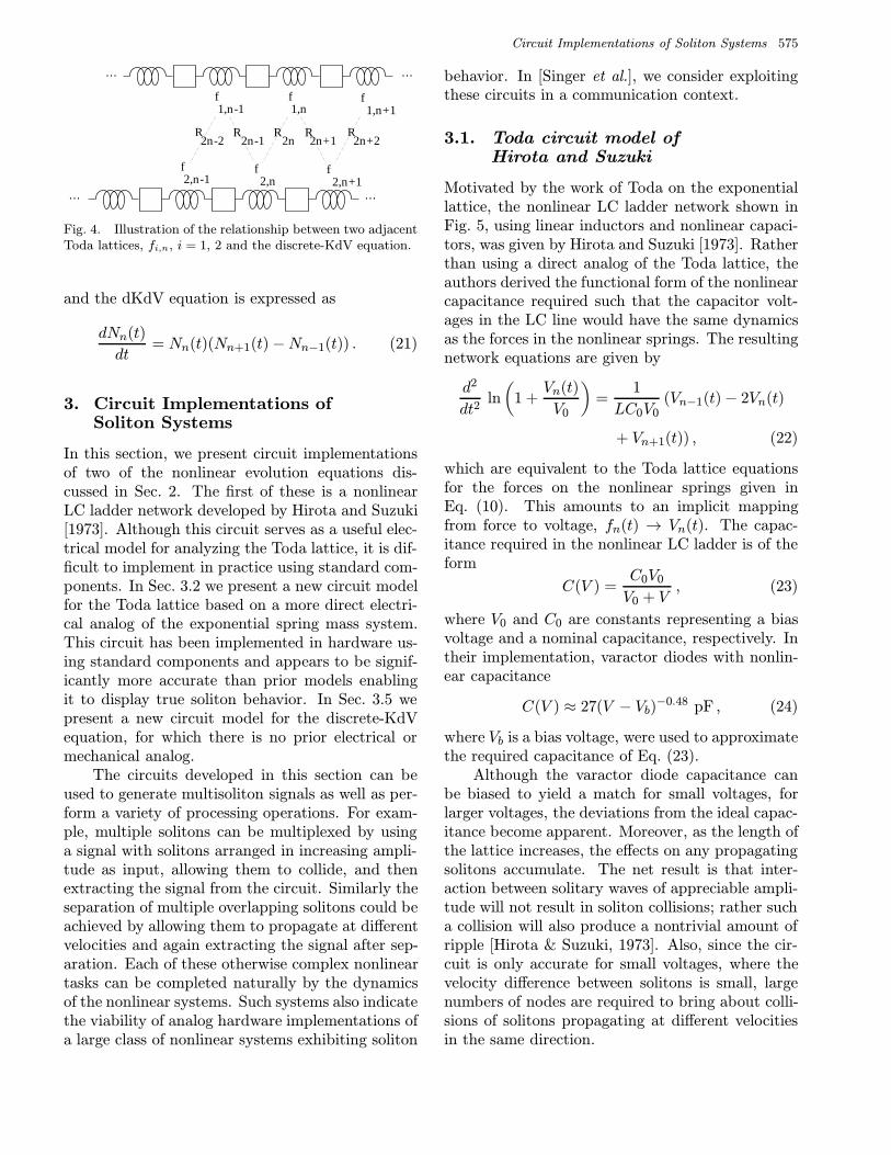
which are each a Toda lattice equation. The phys-ical interpretation of this transformation is the fol-lowing: If f1,n and f2,n are each defined within adifferent Toda lattice, then Rn defined by R2n =f1,n − f2,n, R2n+1 = f2,n+1 − f1,n satisfies thediscrete-KdV equation in the form (15). This pro-cess is illustrated in Fig. 4.
The single soliton solution for Nn = eun is givenby [Manakov, 1975]
Nn(t)=cosh(η(n−x0(t)−2)) cosh(η(n−x0(t)+1))
cosh(η(n−x0(t)−1)) cosh(η(n−x0(t))),
(19)
where
x0(t) = x0(0) +sinh(2η)
ηt , (20)
Circuit Implementations of Soliton Systems 575
f 1,n-1
f 1,n
f 1,n+1
R2n-1
R2n
R2n+1
R2n+2
f 2,n-1
f 2,n
f 2,n+1
R2n-2
… …
… …
Fig. 4. Illustration of the relationship between two adjacentToda lattices, fi,n, i = 1, 2 and the discrete-KdV equation.
and the dKdV equation is expressed as
dNn(t)
dt= Nn(t)(Nn+1(t)−Nn−1(t)) . (21)
3. Circuit Implementations ofSoliton Systems
In this section, we present circuit implementationsof two of the nonlinear evolution equations dis-cussed in Sec. 2. The first of these is a nonlinearLC ladder network developed by Hirota and Suzuki[1973]. Although this circuit serves as a useful elec-trical model for analyzing the Toda lattice, it is dif-ficult to implement in practice using standard com-ponents. In Sec. 3.2 we present a new circuit modelfor the Toda lattice based on a more direct electri-cal analog of the exponential spring mass system.This circuit has been implemented in hardware us-ing standard components and appears to be signif-icantly more accurate than prior models enablingit to display true soliton behavior. In Sec. 3.5 wepresent a new circuit model for the discrete-KdVequation, for which there is no prior electrical ormechanical analog.
The circuits developed in this section can beused to generate multisoliton signals as well as per-form a variety of processing operations. For exam-ple, multiple solitons can be multiplexed by usinga signal with solitons arranged in increasing ampli-tude as input, allowing them to collide, and thenextracting the signal from the circuit. Similarly theseparation of multiple overlapping solitons could beachieved by allowing them to propagate at differentvelocities and again extracting the signal after sep-aration. Each of these otherwise complex nonlineartasks can be completed naturally by the dynamicsof the nonlinear systems. Such systems also indicatethe viability of analog hardware implementations ofa large class of nonlinear systems exhibiting soliton
behavior. In [Singer et al.], we consider exploitingthese circuits in a communication context.
3.1. Toda circuit model ofHirota and Suzuki
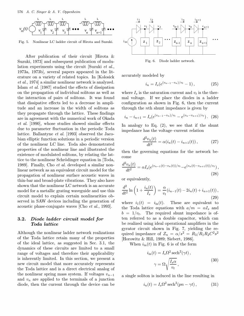
Motivated by the work of Toda on the exponentiallattice, the nonlinear LC ladder network shown inFig. 5, using linear inductors and nonlinear capaci-tors, was given by Hirota and Suzuki [1973]. Ratherthan using a direct analog of the Toda lattice, theauthors derived the functional form of the nonlinearcapacitance required such that the capacitor volt-ages in the LC line would have the same dynamicsas the forces in the nonlinear springs. The resultingnetwork equations are given by
d2
dt2ln
(1 +
Vn(t)
V0
)=
1
LC0V0(Vn−1(t)− 2Vn(t)
+ Vn+1(t)) , (22)
which are equivalent to the Toda lattice equationsfor the forces on the nonlinear springs given inEq. (10). This amounts to an implicit mappingfrom force to voltage, fn(t) → Vn(t). The capac-itance required in the nonlinear LC ladder is of theform
C(V ) =C0V0
V0 + V, (23)
where V0 and C0 are constants representing a biasvoltage and a nominal capacitance, respectively. Intheir implementation, varactor diodes with nonlin-ear capacitance
C(V ) ≈ 27(V − Vb)−0.48 pF , (24)
where Vb is a bias voltage, were used to approximatethe required capacitance of Eq. (23).
Although the varactor diode capacitance canbe biased to yield a match for small voltages, forlarger voltages, the deviations from the ideal capac-itance become apparent. Moreover, as the length ofthe lattice increases, the effects on any propagatingsolitons accumulate. The net result is that inter-action between solitary waves of appreciable ampli-tude will not result in soliton collisions; rather sucha collision will also produce a nontrivial amount ofripple [Hirota & Suzuki, 1973]. Also, since the cir-cuit is only accurate for small voltages, where thevelocity difference between solitons is small, largenumbers of nodes are required to bring about colli-sions of solitons propagating at different velocitiesin the same direction.
576 A. C. Singer & A. V. Oppenheim
v1
L L L L L
v2
v3
vn
vn+1
v (t)in
Fig. 5. Nonlinear LC ladder circuit of Hirota and Suzuki.
After publication of their circuit [Hirota &Suzuki, 1973] and subsequent publication of modu-lation experiments using the circuit [Suzuki et al.,1973a, 1973b], several papers appeared in the lit-erature on a variety of related topics. In [Kolosicket al., 1974] a similar nonlinear network is analyzed.Islam et al. [1987] studied the effects of dissipationon the propagation of individual solitons as well asthe interaction of pairs of solitons. It was foundthat dissipative effects led to a decrease in ampli-tude and an increase in the width of solitons asthey propagate through the lattice. These findingsare in agreement with the numerical work of Okadaet al. [1990], whose studies showed similar effectsdue to parameter fluctuation in the periodic Todalattice. Ballantyne et al. [1993] observed the Jaco-bian elliptic function solutions in a periodic versionof the nonlinear LC line. Toda also demonstratedproperties of the nonlinear line and illustrated theexistence of modulated solitons, by relating the lat-tice to the nonlinear Schrodinger equation in [Toda,1989]. Finally, Cho et al. developed a similar non-linear network as an equivalent circuit model for thepropagation of nonlinear surface acoustic waves inthin-bar and broad-plate vibrations. They also haveshown that the nonlinear LC network is an accuratemodel for a metallic grating waveguide and use thiscircuit model to explain certain nonlinearities ob-served in SAW devices including the generation ofacoustic phase-conjugate waves [Cho et al., 1993].
3.2. Diode ladder circuit model forToda lattice
Although the nonlinear ladder network realizationsof the Toda lattice retain many of the propertiesof the ideal lattice, as suggested in Sec. 3.1, thedynamics of these circuits are limited to a smallrange of voltages and therefore their applicabilityis inherently limited. In this section, we present anew circuit model that more accurately representsthe Toda lattice and is a direct electrical analog ofthe nonlinear spring mass system. If voltages vn−1
and vn are applied to the terminals of a junctiondiode, then the current through the device can be
v
z z z
v vn-1 n n+1
i in n+1
n-1 n n+1z
v v1 2
i i1 2
1 z2i in
Fig. 6. Diode ladder network.
accurately modeled by
in = Is(e(vn−1−vn)/vt − 1) , (25)
where Is is the saturation current and vt is the ther-mal voltage. If we place the diodes in a ladderconfiguration as shown in Fig. 6, then the currentthrough the nth shunt impedance is given by
in − in+1 = Is(e(vn−1−vn)/vt − e(vn−vn+1)/vt) . (26)
In analogy to Eq. (2), we see that if the shuntimpedance has the voltage–current relation
d2vn(t)
dt2= α(in(t)− in+1(t)) , (27)
then the governing equations for the network be-come
d2vn(t)
dt2= αIs(e
(vn−1(t)−vn(t))/vt−e(vn(t)−vn+1(t))/vt) ,
(28)or equivalently,
d2
dt2ln
(1 +
in(t)
Is
)=α
vt(in−1(t)− 2in(t) + in+1(t)) ,
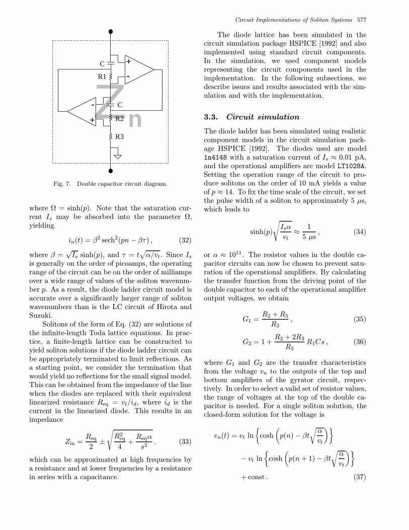
(29)where i1(t) = iin(t). These are equivalent tothe Toda lattice equations with a/m = αIs andb = 1/vt. The required shunt impedance is of-ten referred to as a double capacitor, which canbe realized using ideal operational amplifiers in thegyrator circuit shown in Fig. 7, yielding the re-quired impedance of Zn = α/s2 = R3/R1R2C
2s2
[Horowitz & Hill, 1989; Siebert, 1986].When iin(t) in Fig. 6 is of the form
iin(t) = IsΩ2 sech2(γt) ,
γ = Ω
√Isα
vt,
(30)
a single soliton is induced in the line resulting in
in(t) = IsΩ2 sech2(pn− γt) , (31)
Circuit Implementations of Soliton Systems 577
nZ+-
+-
C
C
R1
R2
R3
Fig. 7. Double capacitor circuit diagram.
where Ω = sinh(p). Note that the saturation cur-rent Is may be absorbed into the parameter Ω,yielding
in(t) = β2 sech2(pn− βτ) , (32)
where β =√Is sinh(p), and τ = t
√α/vt. Since Is
is generally on the order of picoamps, the operatingrange of the circuit can be on the order of milliampsover a wide range of values of the soliton wavenum-ber p. As a result, the diode ladder circuit model isaccurate over a significantly larger range of solitonwavenumbers than is the LC circuit of Hirota andSuzuki.
Solitons of the form of Eq. (32) are solutions ofthe infinite-length Toda lattice equations. In prac-tice, a finite-length lattice can be constructed toyield soliton solutions if the diode ladder circuit canbe appropriately terminated to limit reflections. Asa starting point, we consider the termination thatwould yield no reflections for the small signal model.This can be obtained from the impedance of the linewhen the diodes are replaced with their equivalentlinearized resistance Req = vt/id, where id is thecurrent in the linearized diode. This results in animpedance
Zin =Req
2±
√R2
eq
4+Reqα
s2. (33)
which can be approximated at high frequencies bya resistance and at lower frequencies by a resistancein series with a capacitance.
The diode lattice has been simulated in thecircuit simulation package HSPICE [1992] and alsoimplemented using standard circuit components.In the simulation, we used component modelsrepresenting the circuit components used in theimplementation. In the following subsections, wedescribe issues and results associated with the sim-ulation and with the implementation.
3.3. Circuit simulation
The diode ladder has been simulated using realisticcomponent models in the circuit simulation pack-age HSPICE [1992]. The diodes used are model1n4148 with a saturation current of Is ≈ 0.01 pA,and the operational amplifiers are model LT1028A.Setting the operation range of the circuit to pro-duce solitons on the order of 10 mA yields a valueof p ≈ 14. To fix the time scale of the circuit, we setthe pulse width of a soliton to approximately 5 µs,which leads to
sinh(p)
√Isα
vt≈ 1
5 µs, (34)
or α ≈ 1011. The resistor values in the double ca-pacitor circuits can now be chosen to prevent satu-ration of the operational amplifiers. By calculatingthe transfer function from the driving point of thedouble capacitor to each of the operational amplifieroutput voltages, we obtain
G1 =R2 +R3
R3, (35)
G2 = 1 +R2 + 2R3
R3R1Cs , (36)
where G1 and G2 are the transfer characteristicsfrom the voltage vn to the outputs of the top andbottom amplifiers of the gyrator circuit, respec-tively. In order to select a valid set of resistor values,the range of voltages at the top of the double ca-pacitor is needed. For a single soliton solution, theclosed-form solution for the voltage is
vn(t) = vt ln
cosh
(p(n)− βt
√α
vt
)
− vt ln
cosh
(p(n+ 1)− βt
√α
vt
)+ const . (37)
578 A. C. Singer & A. V. Oppenheim
The limiting voltage in Eq. (37) is given by
limt→∞
vn(t) = vtp+ const , (38)
andlim
t→−∞vn(t) = −vtp+ const . (39)
Selecting the constants such that vn(−∞) = 0, gives
limt→∞
vn(t) = 2vtp . (40)
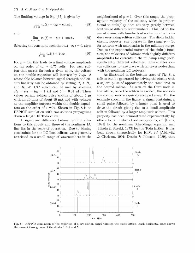
For p ≈ 14, this leads to a final voltage amplitudeon the order of vn ≈ 0.75 volts. For each soli-ton that passes through a given node, the voltageon the double capacitor will increase by 2vtp. Areasonable balance between signal strength and cir-cuit linearity can be obtained by setting R2 ≈ R3,and R1 1/C which can be met by selectingR1 = R2 = R3 = 1 kΩ and C = 0.01 µF. Thesevalues permit soliton pulse widths of about 5 µswith amplitudes of about 10 mA and with voltagesat the amplifier outputs within the double capaci-tors on the order of 1 volt. Shown in Fig. 8 is anHSPICE simulation with two solitons propagatingdown a length 10 Toda chain.
A significant difference between soliton solu-tions to this circuit and those of the nonlinear LCline lies in the scale of operation. Due to biasingconstraints for the LC line, solitons were generallyrestricted to a small range of wavenumbers in the
neighborhood of p ≈ 1. Over this range, the prop-agation velocity of the solitons, which is propor-tional to sinh(p)/p does not vary greatly betweensolitons of different wavenumbers. This led to theuse of chains with hundreds of nodes in order to in-duce overtaking soliton collisions. The diode laddercircuit, however, can operate in the range p ≈ 14for solitons with amplitudes in the milliamp range.Due to the exponential nature of the sinh(·) func-tion, the velocities of solitons with slightly differentamplitudes for currents in the milliamp range yieldsignificantly different velocities. This enables soli-ton collisions to take place with far fewer nodes thanwith the nonlinear LC network.
As illustrated in the bottom trace of Fig. 8, asoliton can be generated by driving the circuit witha square pulse of approximately the same area asthe desired soliton. As seen on the third node inthe lattice, once the soliton is excited, the nonsoli-ton components are quickly stripped away. For theexample shown in the figure, a signal containing asmall pulse followed by a larger pulse is used todrive the circuit giving rise to a small amplitudesoliton followed by a larger amplitude soliton. Thisproperty has been demonstrated experimentally byothers for a number of soliton systems, c.f. [Haus,1993] for the nonlinear Schrodinger equation and[Hirota & Suzuki, 1973] for the Toda lattice. It hasbeen shown theoretically for KdV, c.f. [Ablowitz& Clarkson, 1991; Drazin & Johnson, 1989], that
10
20
0
diode1
(mA)
0
10
20diode
3(mA)
0 100 200 300 400 500(µs)
10
20
0
diode4
(mA)
10
20
0
diode5(mA)
dio
de
curr
ent
time
Fig. 8. HSPICE simulation of the evolution of a two-soliton signal through the diode lattice. Each horizontal trace showsthe current through one of the diodes 1, 3, 4 and 5.
Circuit Implementations of Soliton Systems 579
practically any smooth, localized disturbance of theproper area will result in a soliton with that area,if such a solution exists.
Note that as the faster soliton overtakes theslower as viewed on the fourth node in Fig. 8, thejoint signal amplitude is significantly less than thesum of the individual amplitudes. Also, the signalshape changes significantly during the nonlinear in-teraction. These two effects will impact both theenergy of multisoliton signals and the ability to re-cover their signal parameters as described in [Singeret al.].
3.4. Circuit implementation
To perform real-time experimentation and to verifythe operation of the model, a diode ladder circuitwith twenty nodes has been implemented with stan-dard circuit components. Real-time implementa-tion also enables rapid testing of soliton processingtechniques and enables measurements of actual cir-cuit noise levels. Such noise measurements permitexperimental verification of some of the theoreticalresults concerning system noise in Sec. 4.
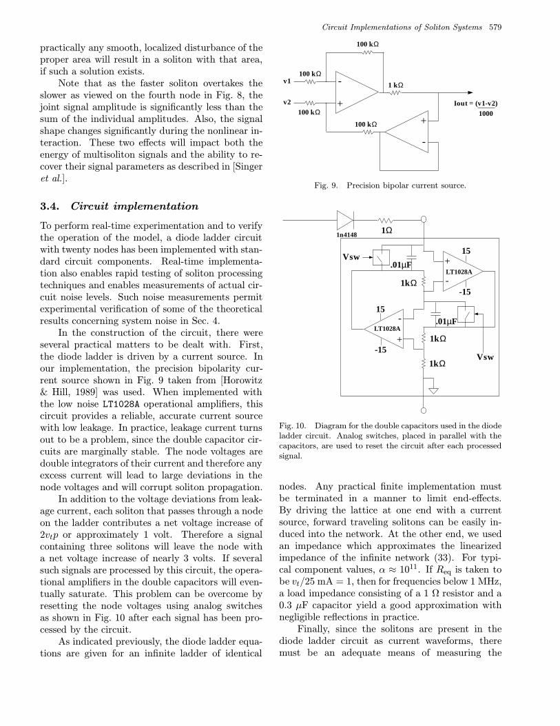
In the construction of the circuit, there wereseveral practical matters to be dealt with. First,the diode ladder is driven by a current source. Inour implementation, the precision bipolarity cur-rent source shown in Fig. 9 taken from [Horowitz& Hill, 1989] was used. When implemented withthe low noise LT1028A operational amplifiers, thiscircuit provides a reliable, accurate current sourcewith low leakage. In practice, leakage current turnsout to be a problem, since the double capacitor cir-cuits are marginally stable. The node voltages aredouble integrators of their current and therefore anyexcess current will lead to large deviations in thenode voltages and will corrupt soliton propagation.
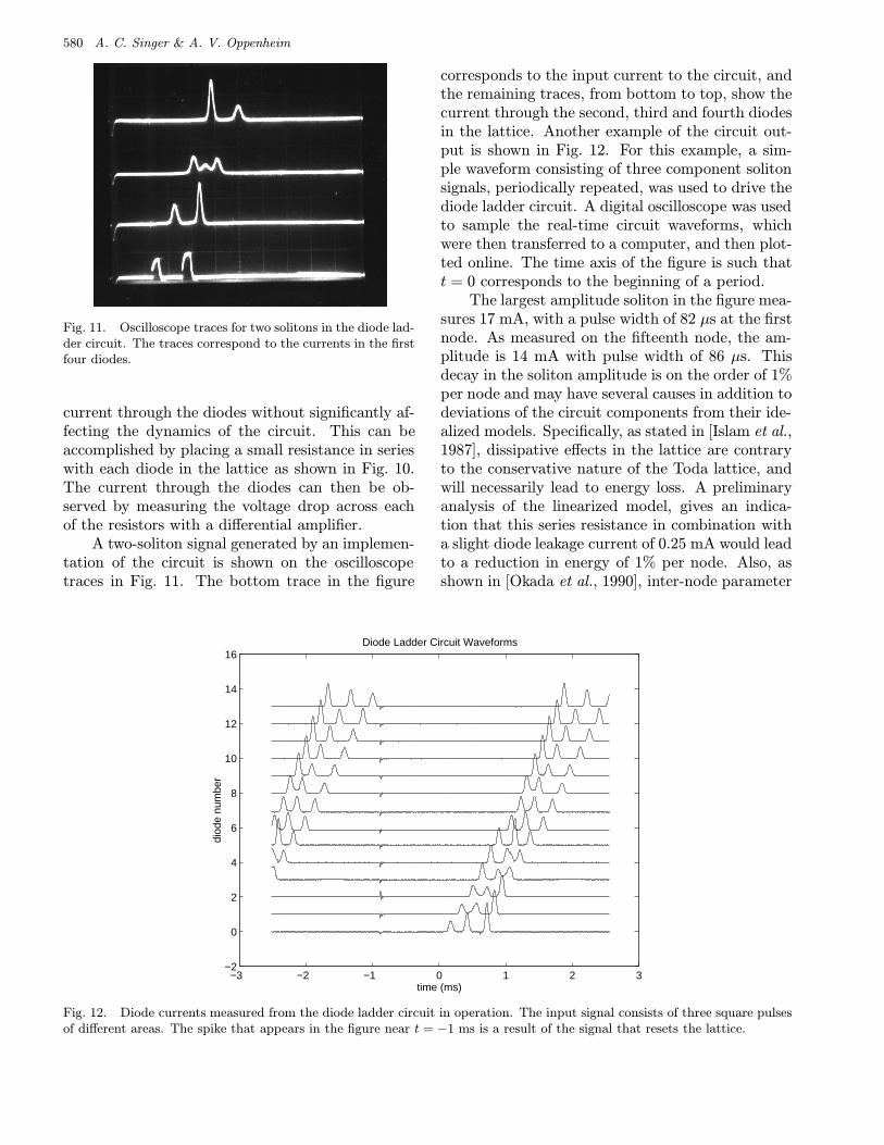
In addition to the voltage deviations from leak-age current, each soliton that passes through a nodeon the ladder contributes a net voltage increase of2vtp or approximately 1 volt. Therefore a signalcontaining three solitons will leave the node witha net voltage increase of nearly 3 volts. If severalsuch signals are processed by this circuit, the opera-tional amplifiers in the double capacitors will even-tually saturate. This problem can be overcome byresetting the node voltages using analog switchesas shown in Fig. 10 after each signal has been pro-cessed by the circuit.
As indicated previously, the diode ladder equa-tions are given for an infinite ladder of identical
+
-
+
-
100 kΩ
100 kΩ
100 kΩ
100 kΩ
1 kΩv1
v2 Iout = (v1-v2)1000
Fig. 9. Precision bipolar current source.
.01
F +
-
+
-
1kΩ
1kΩ
1kΩ
µF
Vsw
.01µVsw
LT1028A
LT1028A
-15
-15
15
15
1Ω1n4148
Fig. 10. Diagram for the double capacitors used in the diodeladder circuit. Analog switches, placed in parallel with thecapacitors, are used to reset the circuit after each processedsignal.
nodes. Any practical finite implementation mustbe terminated in a manner to limit end-effects.By driving the lattice at one end with a currentsource, forward traveling solitons can be easily in-duced into the network. At the other end, we usedan impedance which approximates the linearizedimpedance of the infinite network (33). For typi-cal component values, α ≈ 1011. If Req is taken tobe vt/25 mA = 1, then for frequencies below 1 MHz,a load impedance consisting of a 1 Ω resistor and a0.3 µF capacitor yield a good approximation withnegligible reflections in practice.
Finally, since the solitons are present in thediode ladder circuit as current waveforms, theremust be an adequate means of measuring the
580 A. C. Singer & A. V. Oppenheim
Fig. 11. Oscilloscope traces for two solitons in the diode lad-der circuit. The traces correspond to the currents in the firstfour diodes.
current through the diodes without significantly af-fecting the dynamics of the circuit. This can beaccomplished by placing a small resistance in serieswith each diode in the lattice as shown in Fig. 10.The current through the diodes can then be ob-served by measuring the voltage drop across eachof the resistors with a differential amplifier.
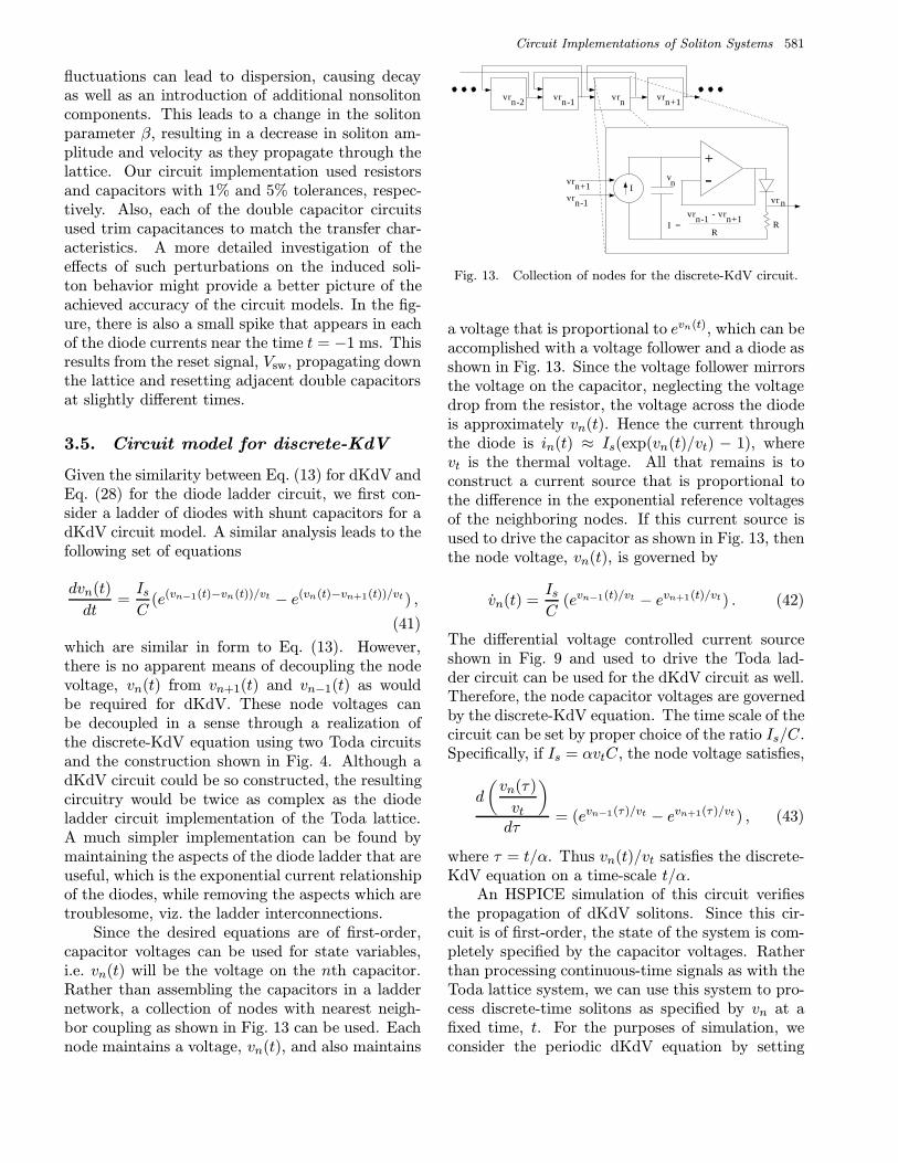
A two-soliton signal generated by an implemen-tation of the circuit is shown on the oscilloscopetraces in Fig. 11. The bottom trace in the figure
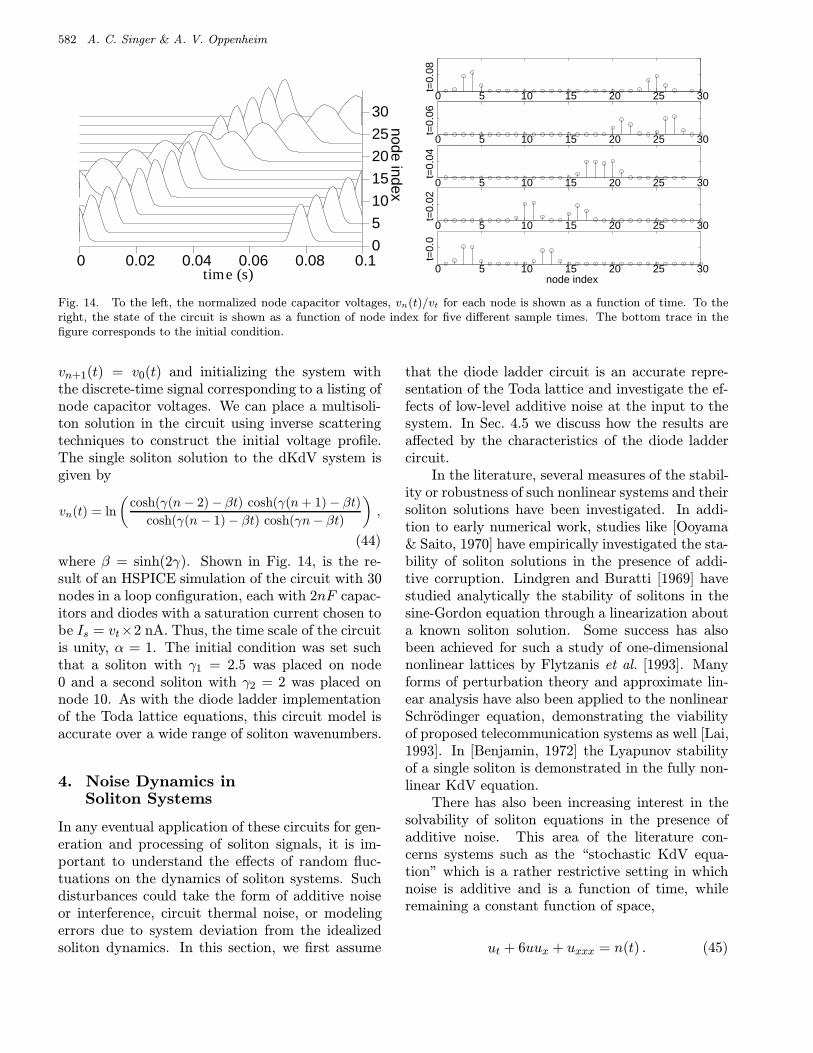
corresponds to the input current to the circuit, andthe remaining traces, from bottom to top, show thecurrent through the second, third and fourth diodesin the lattice. Another example of the circuit out-put is shown in Fig. 12. For this example, a sim-ple waveform consisting of three component solitonsignals, periodically repeated, was used to drive thediode ladder circuit. A digital oscilloscope was usedto sample the real-time circuit waveforms, whichwere then transferred to a computer, and then plot-ted online. The time axis of the figure is such thatt = 0 corresponds to the beginning of a period.
The largest amplitude soliton in the figure mea-sures 17 mA, with a pulse width of 82 µs at the firstnode. As measured on the fifteenth node, the am-plitude is 14 mA with pulse width of 86 µs. Thisdecay in the soliton amplitude is on the order of 1%per node and may have several causes in addition todeviations of the circuit components from their ide-alized models. Specifically, as stated in [Islam et al.,1987], dissipative effects in the lattice are contraryto the conservative nature of the Toda lattice, andwill necessarily lead to energy loss. A preliminaryanalysis of the linearized model, gives an indica-tion that this series resistance in combination witha slight diode leakage current of 0.25 mA would leadto a reduction in energy of 1% per node. Also, asshown in [Okada et al., 1990], inter-node parameter
−3 −2 −1 0 1 2 3−2
0
2
4
6
8
10
12
14
16
time (ms)
diod
e nu
mbe
r
Diode Ladder Circuit Waveforms
Fig. 12. Diode currents measured from the diode ladder circuit in operation. The input signal consists of three square pulsesof different areas. The spike that appears in the figure near t = −1 ms is a result of the signal that resets the lattice.
Circuit Implementations of Soliton Systems 581
fluctuations can lead to dispersion, causing decayas well as an introduction of additional nonsolitoncomponents. This leads to a change in the solitonparameter β, resulting in a decrease in soliton am-plitude and velocity as they propagate through thelattice. Our circuit implementation used resistorsand capacitors with 1% and 5% tolerances, respec-tively. Also, each of the double capacitor circuitsused trim capacitances to match the transfer char-acteristics. A more detailed investigation of theeffects of such perturbations on the induced soli-ton behavior might provide a better picture of theachieved accuracy of the circuit models. In the fig-ure, there is also a small spike that appears in eachof the diode currents near the time t = −1 ms. Thisresults from the reset signal, Vsw, propagating downthe lattice and resetting adjacent double capacitorsat slightly different times.
3.5. Circuit model for discrete-KdV
Given the similarity between Eq. (13) for dKdV andEq. (28) for the diode ladder circuit, we first con-sider a ladder of diodes with shunt capacitors for adKdV circuit model. A similar analysis leads to thefollowing set of equations
dvn(t)
dt=IsC
(e(vn−1(t)−vn(t))/vt − e(vn(t)−vn+1(t))/vt) ,
(41)
which are similar in form to Eq. (13). However,there is no apparent means of decoupling the nodevoltage, vn(t) from vn+1(t) and vn−1(t) as wouldbe required for dKdV. These node voltages canbe decoupled in a sense through a realization ofthe discrete-KdV equation using two Toda circuitsand the construction shown in Fig. 4. Although adKdV circuit could be so constructed, the resultingcircuitry would be twice as complex as the diodeladder circuit implementation of the Toda lattice.A much simpler implementation can be found bymaintaining the aspects of the diode ladder that areuseful, which is the exponential current relationshipof the diodes, while removing the aspects which aretroublesome, viz. the ladder interconnections.
Since the desired equations are of first-order,capacitor voltages can be used for state variables,i.e. vn(t) will be the voltage on the nth capacitor.Rather than assembling the capacitors in a laddernetwork, a collection of nodes with nearest neigh-bor coupling as shown in Fig. 13 can be used. Eachnode maintains a voltage, vn(t), and also maintains
vn
R
vrn
+-
vrnvrn-1vrn-2 vrn+1
vrn-1
vrn+1
RI =
vrn+1vr -n-1
I
Fig. 13. Collection of nodes for the discrete-KdV circuit.
a voltage that is proportional to evn(t), which can beaccomplished with a voltage follower and a diode asshown in Fig. 13. Since the voltage follower mirrorsthe voltage on the capacitor, neglecting the voltagedrop from the resistor, the voltage across the diodeis approximately vn(t). Hence the current throughthe diode is in(t) ≈ Is(exp(vn(t)/vt) − 1), wherevt is the thermal voltage. All that remains is toconstruct a current source that is proportional tothe difference in the exponential reference voltagesof the neighboring nodes. If this current source isused to drive the capacitor as shown in Fig. 13, thenthe node voltage, vn(t), is governed by
vn(t) =IsC
(evn−1(t)/vt − evn+1(t)/vt) . (42)
The differential voltage controlled current sourceshown in Fig. 9 and used to drive the Toda lad-der circuit can be used for the dKdV circuit as well.Therefore, the node capacitor voltages are governedby the discrete-KdV equation. The time scale of thecircuit can be set by proper choice of the ratio Is/C.Specifically, if Is = αvtC, the node voltage satisfies,
d
(vn(τ)
vt
)dτ
= (evn−1(τ)/vt − evn+1(τ)/vt) , (43)
where τ = t/α. Thus vn(t)/vt satisfies the discrete-KdV equation on a time-scale t/α.
An HSPICE simulation of this circuit verifiesthe propagation of dKdV solitons. Since this cir-cuit is of first-order, the state of the system is com-pletely specified by the capacitor voltages. Ratherthan processing continuous-time signals as with theToda lattice system, we can use this system to pro-cess discrete-time solitons as specified by vn at afixed time, t. For the purposes of simulation, weconsider the periodic dKdV equation by setting
582 A. C. Singer & A. V. Oppenheim
0 0.02 0.04 0.06 0.08 0.10
5
10
15
20
25
30
time (s)
node index
0 5 10 15 20 25 30
0 5 10 15 20 25 30
0 5 10 15 20 25 30
0 5 10 15 20 25 30
0 5 10 15 20 25 30
node index
t=0.
08t=
0.06
t=0.
04t=
0.02
t=0.
0
Fig. 14. To the left, the normalized node capacitor voltages, vn(t)/vt for each node is shown as a function of time. To theright, the state of the circuit is shown as a function of node index for five different sample times. The bottom trace in thefigure corresponds to the initial condition.
vn+1(t) = v0(t) and initializing the system withthe discrete-time signal corresponding to a listing ofnode capacitor voltages. We can place a multisoli-ton solution in the circuit using inverse scatteringtechniques to construct the initial voltage profile.The single soliton solution to the dKdV system isgiven by
vn(t) = ln
(cosh(γ(n− 2)− βt) cosh(γ(n+ 1)− βt)
cosh(γ(n− 1)− βt) cosh(γn− βt)
),
(44)
where β = sinh(2γ). Shown in Fig. 14, is the re-sult of an HSPICE simulation of the circuit with 30nodes in a loop configuration, each with 2nF capac-itors and diodes with a saturation current chosen tobe Is = vt×2 nA. Thus, the time scale of the circuitis unity, α = 1. The initial condition was set suchthat a soliton with γ1 = 2.5 was placed on node0 and a second soliton with γ2 = 2 was placed onnode 10. As with the diode ladder implementationof the Toda lattice equations, this circuit model isaccurate over a wide range of soliton wavenumbers.
4. Noise Dynamics inSoliton Systems
In any eventual application of these circuits for gen-eration and processing of soliton signals, it is im-portant to understand the effects of random fluc-tuations on the dynamics of soliton systems. Suchdisturbances could take the form of additive noiseor interference, circuit thermal noise, or modelingerrors due to system deviation from the idealizedsoliton dynamics. In this section, we first assume
that the diode ladder circuit is an accurate repre-sentation of the Toda lattice and investigate the ef-fects of low-level additive noise at the input to thesystem. In Sec. 4.5 we discuss how the results areaffected by the characteristics of the diode laddercircuit.
In the literature, several measures of the stabil-ity or robustness of such nonlinear systems and theirsoliton solutions have been investigated. In addi-tion to early numerical work, studies like [Ooyama& Saito, 1970] have empirically investigated the sta-bility of soliton solutions in the presence of addi-tive corruption. Lindgren and Buratti [1969] havestudied analytically the stability of solitons in thesine-Gordon equation through a linearization abouta known soliton solution. Some success has alsobeen achieved for such a study of one-dimensionalnonlinear lattices by Flytzanis et al. [1993]. Manyforms of perturbation theory and approximate lin-ear analysis have also been applied to the nonlinearSchrodinger equation, demonstrating the viabilityof proposed telecommunication systems as well [Lai,1993]. In [Benjamin, 1972] the Lyapunov stabilityof a single soliton is demonstrated in the fully non-linear KdV equation.
There has also been increasing interest in thesolvability of soliton equations in the presence ofadditive noise. This area of the literature con-cerns systems such as the “stochastic KdV equa-tion” which is a rather restrictive setting in whichnoise is additive and is a function of time, whileremaining a constant function of space,
ut + 6uux + uxxx = n(t) . (45)
Circuit Implementations of Soliton Systems 583
This system can be shown to possess an exact soli-ton solution with a phase drift that is given by aWiener process, when n(t) is a stationary whiteGaussian process [Loginov, 1993; Wadati, 1983].
With the development of the inverse scatteringframework and the discovery that many soliton sys-tems were conservative Hamiltonian systems, manyof the questions regarding the stability of solitonsolutions are readily answered. For example, anysolitons that are initially present in a system mustremain present for all time, regardless of their in-teractions. Similarly, the dynamics of any nonsoli-ton components that are present in the system areuncoupled from the dynamics of the solitons. How-ever, in the communication scenario discussed in[Singer et al.], soliton waveforms are generated andextracted from the circuit and then propagated overa noisy channel. During transmission, these wave-forms are susceptible to additive corruption fromthe channel.
In this section, we will assume that soliton sig-nals generated with the circuits described in Sec. 3have been transmitted over an additive white Gaus-sian noise channel. We can then consider the ef-fects of additive corruption on the processing of soli-ton signals with their nonlinear evolution equations.Two general approaches are taken to this problem.The approach taken in this paper primarily dealswith linearized models and investigates the dynamicbehavior of the noise component of signals contain-ing an information bearing soliton signal and addi-tive noise. The second approach, which is developedin [Singer et al.], is taken in the framework of in-verse scattering and is based on some results fromrandom matrix theory. Although the analysis tech-niques developed in this section are applicable to alarge class of soliton systems, we focus our attentionon the Toda lattice equations as a representativeexample.
4.1. Toda lattice smallsignal model
If a signal that is processed in a receiver circuitrepresenting a Toda lattice contains only a smallamplitude noise component, then the dynamics ofthe receiver can be approximated by a small signalmodel. Starting with the nonlinear transmissionline model,
d2
dt2ln(1+Vn(t)) =
ω20
4(Vn−1(t)−2Vn(t)+Vn+1(t)) ,
(46)
and using the approximation, ln(1+x) ≈ x, the lat-tice equations can be approximately described bythe linear lattice equations
d2Vn(t)
dt2=ω2
0
4(Vn−1(t)− 2Vn(t) + Vn+1(t)) , (47)
when the amplitude of Vn(t) is appropriately small.Since this model is linear, we may decompose solu-tions into harmonic components of the form
Vn(t) = V+ej(kn−ωt) + V−e
j(kn+ωt) . (48)
From Eqs. (47) and (48) the frequency of a singleforward propagating solution must satisfy the dis-persion relation
−ω2 =ω2
0
4(e−jk − 2 + ejk) , (49)
which reduces to ω = ω0 sin(k/2). Thereforethe lattice is dispersive, with frequency-dependentvelocity,
c(k) =ω0 sin
(k
2
)k
, (50)
orc(ω) =
ω
2 sin−1
(ω
ω0
) . (51)
Note that we can also write the dispersion relationas
k = 2 sin−1(ω
ω0
), (52)
from which k is only real if |ω| ≤ ω0, for which thereare propagating waves. When ω is outside this re-gion, the wavenumber, k, is complex, correspondingto evanescent waves of the form
ω = ω0 cosh
(Im(k)
2
), Re(k) = π . (53)
These solutions decay as they pass through thelattice,
|Vn| = |V+|e−2 cosh−1(ω/ω0)n , (54)
which for ω ω0 corresponds to
Vn = V+
(−ω2
0
4ω2
)n. (55)
If we consider processing signals with an infinitelinear lattice and obtain an input–output relation-ship, where a signal is input at the zeroth node andthe output is taken as the voltage on the Nth node,
584 A. C. Singer & A. V. Oppenheim
0 0.2 0.4 0.6 0.8 1 1.2 1.4 1.6 1.8 2−250
−200
−150
−100
−50
0
50 |
HN
(jω)|
(d
B)
frequency normalized by ω0
N=2
N=4
N=6
N=8
N=10
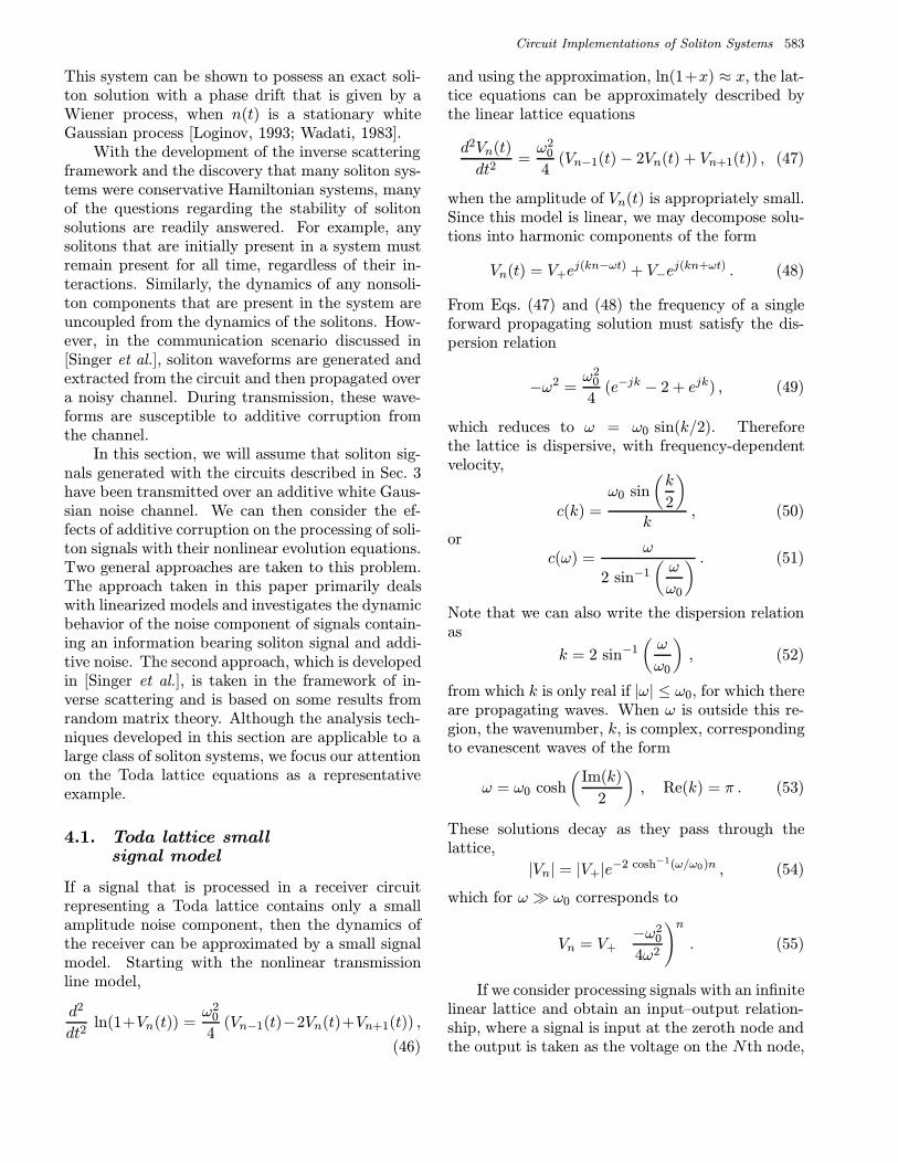
Fig. 15. The log magnitude of the frequency response fromthe input node to the Nth node as a function of normalizedfrequency. As indicated, the response rapidly drops off as afunction of N for ω > ω0.
the input–output frequency response of the systemcan be given by
HN (jω) =
e−2j sin−1(ω/ω0)N , |ω| < ω0,
e[jπ−2 cosh−1(ω/ω0)]N , otherwise.(56)
As shown in Fig. 15, the lattice behaves as a lowpass filter, and for N 1, approaches
|HN (jω)|2 =
1, |ω| < ω0,
0, otherwise.(57)
4.2. Linearized model
The small signal model indicates that in the ab-sence of solitons in the received signal, small ampli-tude noise will be processed by a low pass filter. Ifthe received signal also contains solitons, then thesmall signal model of Eq. (47) will no longer hold.A linear small signal model can still be used if welinearize Eq. (46) about the known soliton signal ofthe form
Sn(t) = Ω2 sech2(pn− ω0Ωt
2
). (58)
Assuming that the solution contains a single solitonin small amplitude noise, Vn(t) = Sn(t) + vn(t), we
can write Eq. (46) as
d2
dt2ln(1+Sn+vn)
=ω2
0
4(Sn−1−2Sn+Sn+1+vn−1−2vn+vn+1) .
(59)
After factoring the argument of the logarithm andcancelling terms from both sides that correspond tothe known soliton solution, we have an exact equa-tion that is satisfied by the nonsoliton component,
d2
dt2ln
(1 +
vn(t)
1 + Sn(t)
)
=ω2
0
4(vn−1(t)− 2vn(t) + vn+1(t)) , (60)
which can be viewed as the fully nonlinear modelwith a time-varying parameter, (1 + Sn(t)). As aresult, over short time scales relative to Sn(t), wewould expect this model to behave in a similar man-ner to the small signal model of Eq. (47). Withvn(t) (1 + Sn(t)), we obtain
d2
dt2vn(t)
1 + Sn(t)≈ ω2
0
4(vn−1(t)− 2vn(t) + vn+1(t)) .
(61)
When the contribution from the soliton is small,Eq. (61) reduces to the linear system of Eq. (47).We would therefore expect that both before and af-ter a soliton has passed through the lattice, the sys-tem essentially lowpass filters the noise. However,as the soliton is processed, there will be a time-varying component to the filter.
4.3. Simulation of the lattice in noise
To confirm the intuition developed through smallsignal analyses, we have simulated the fully nonlin-ear dynamics. We work with a finite-length latticewhich is terminated with its linearized impedanceas described in Sec. 3. We then focus on the dy-namics of the small amplitude noise component inthe response of the lattice to a signal containinga single soliton in white Gaussian noise with noisepower N0.
Our primary interest in this section is to char-acterize the effects of additive noise in a receiverfor a potential soliton modulation system. Sincethe bandwidth limitations of the receiver for anyof the communication scenarios discussed in [Singer
Circuit Implementations of Soliton Systems 585
et al.], will restrict the possible range of solitonparameters, without loss of generality, we may as-sume that the receiver contains a lowpass filter fol-lowed by a Toda lattice circuit. We also assumethat the bandwidth, 2π/∆, of the lowpass filter iswide enough to pass the soliton component of thereceived signal completely. The input to the Todalattice circuit, V0(t), then contains the soliton sig-nal in lowpass Gaussian noise. Simulations wereperformed using a Runge–Kutta integration rou-tine with a fixed step size, ∆. To model the effectsof the noise, an i.i.d. Gaussian random sequence,w(k∆) ∼ N(0, σ2
w), was added to the samples ofthe input sequence V0(k∆) resulting in an effectivewhite noise power of N0 = ∆σ2
w.Specifically, the circuit equations governing the
resistance-terminated nonlinear LC ladder modelare given in Eq. (46) for n < N and ω0 = 2/
√LC.
At the termination, n = N , we have
VN (t) =
(VN−1(t)− VN (t)
LC− VN (t)
RC
)(1 + VN (t))
+V 2N (t)
1 + VN (t). (62)
Writing Eq. (46) and (62) as 2N first-order differ-ential equations, we obtain
Vn(t) = Wn(t) , 1 ≤ n ≤ N (63)
Wn(t) =W 2n(t)
1 + Vn(t)+
1 + Vn(t)
LC
× (Vn+1(t)− 2Vn(t) + Vn−1(t)) ,
1 ≤ n < N
WN (t) =
(VN−1(t)− VN (t)
LC− WN (t)
RC
)(1 + VN (t))
+W 2N (t)
1 + VN (t).
Note that since (62) and (63) are the exact non-linear Toda lattice equations, their numerical inte-gration will simulate both the nonlinear LC ladderand the diode ladder circuit implementations. How-ever, while the diode ladder implementation withideal components exactly matches the Toda lat-tice equations, the nonlinear LC ladder does not,even with ideal components. These simulationscould have equally been carried out using diodeladder currents, with the substitution, in(t)/Is =Vn(t)/V0, and αIs/vt = 1/LC.
0 5 10 15 20 25 30 35 40
0
2
4
6
8
10
12
14
16
18
20
SNR = 20 dB
time
nod
e in
dex
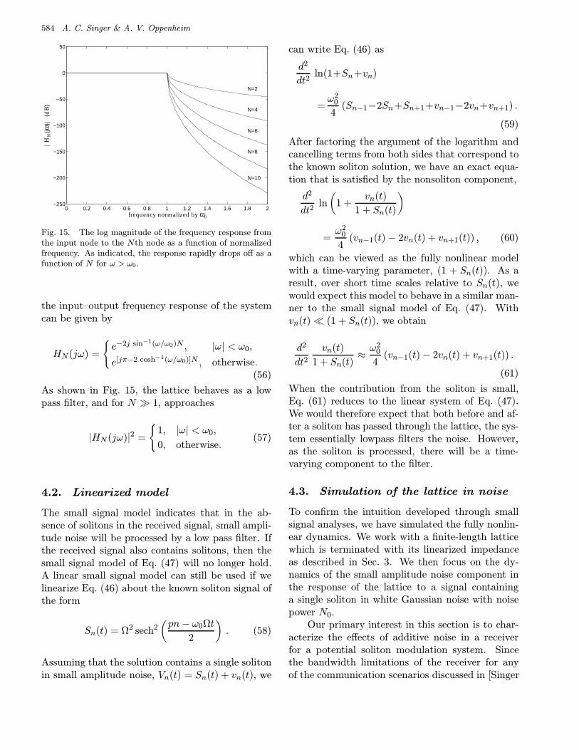
Fig. 16. Response to a single soliton with β = sinh(1) in20 dB Gaussian noise. The spectrum of the noise processis flat out to half the sample-rate of the integration routine.The corresponding in-band SNR is approximately 24 dB.
From our linearized analyses, we anticipate thatthe response of the lattice to a soliton in smallamplitude Gaussian noise will essentially containthe unperturbed soliton with an additional smallamplitude lowpass Gaussian component. Throughnumerical simulation, in Fig. 16 we show the re-sponse of the fully nonlinear lattice to a single soli-ton at 20 dB signal-to-noise ratio, where the SNR isdefined as
SNR = 10 log
(1
N0
∫ ∞−∞
s(t)2dt
), (64)
where s(t) = β2 sech2(βτ) is a signal contain-ing a single soliton waveform, and for the diodelattice,τ = t
√α/vt. As expected, the re-
sponse to the lattice has the appearance of anunperturbed soliton with an additional lowpassperturbation.
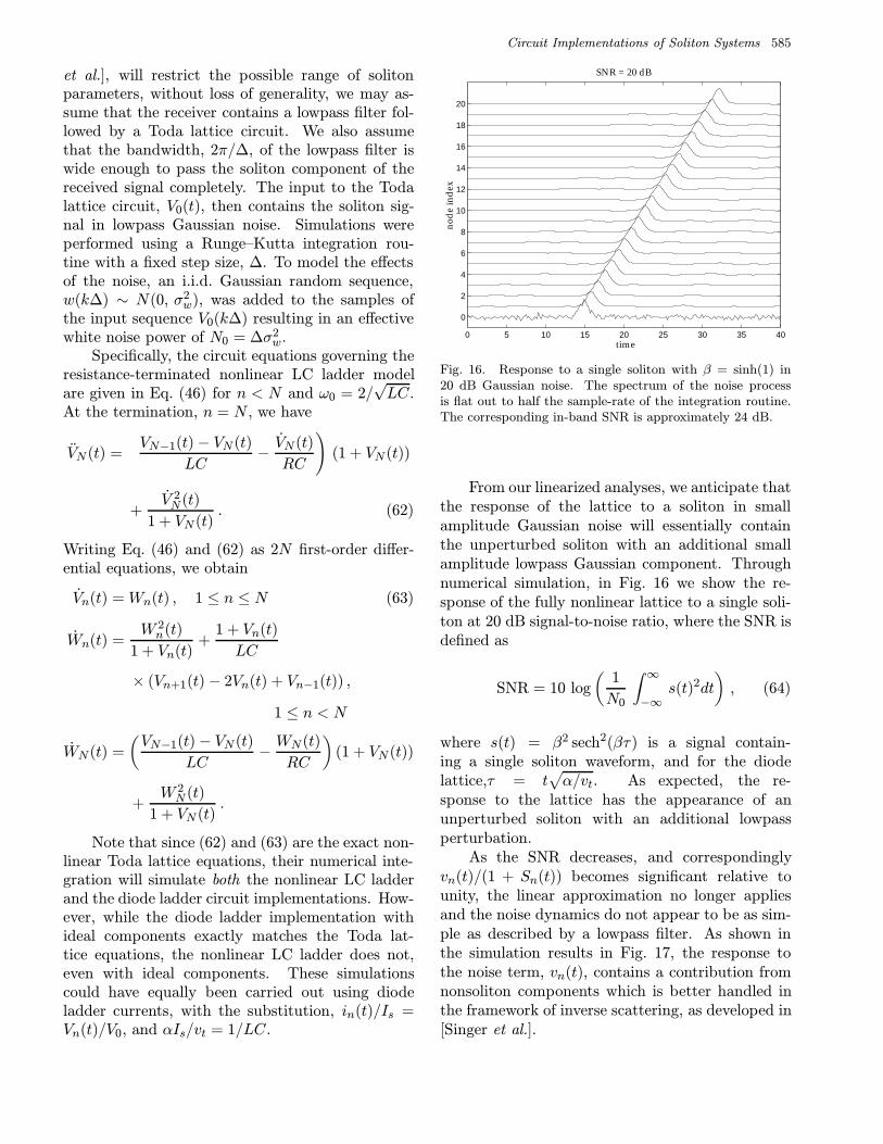
As the SNR decreases, and correspondinglyvn(t)/(1 + Sn(t)) becomes significant relative tounity, the linear approximation no longer appliesand the noise dynamics do not appear to be as sim-ple as described by a lowpass filter. As shown inthe simulation results in Fig. 17, the response tothe noise term, vn(t), contains a contribution fromnonsoliton components which is better handled inthe framework of inverse scattering, as developed in[Singer et al.].
586 A. C. Singer & A. V. Oppenheim
0 5 10 15 20 25 30 35 40−5
0
5
10
15
20
SNR = 10 dB
time
nod
e in
dex
Fig. 17. Response to a single soliton with β = sinh(1) in10 dB Gaussian noise.
4.4. Noise correlation
The statistical correlation of the system responseto the noise component can also be estimated fromour linear analyses. From Sec. 4.1, the small sig-nal model for the nonlinear lattice approximatelysatisfies the linear lattice equations, which have amagnitude-squared frequency response at the nthnode, n 1, of Eq. (57). Therefore, vn(t) is zeromean and has an autocorrelation function given by
Rn,n(τ)=Evn(t)vn(t+τ)≈N0sin(ω0τ)
πτ, (65)
and a variance σ2vn ≈ N0ω0/π, for n 1.
Although the autocorrelation of the noise ateach node is only affected by the magnitude re-sponse of Eq. (56), the cross-correlation betweennodes is also affected by the phase response. Thecross-correlation between nodes m and n is givenby
Rm,n(τ) = hn−m(−τ) ∗Rm,m(τ) , (66)
where hm(τ) is the inverse Fourier transform ofHm(jω) in Eq. (56). Since hm(τ) ∗ hm(−τ) ap-proaches the impulse response of an ideal lowpassfilter for m 1, we have
Rm,n(τ) ≈ N0sin(ω0τ)
πτ∗ hn−m(τ) . (67)
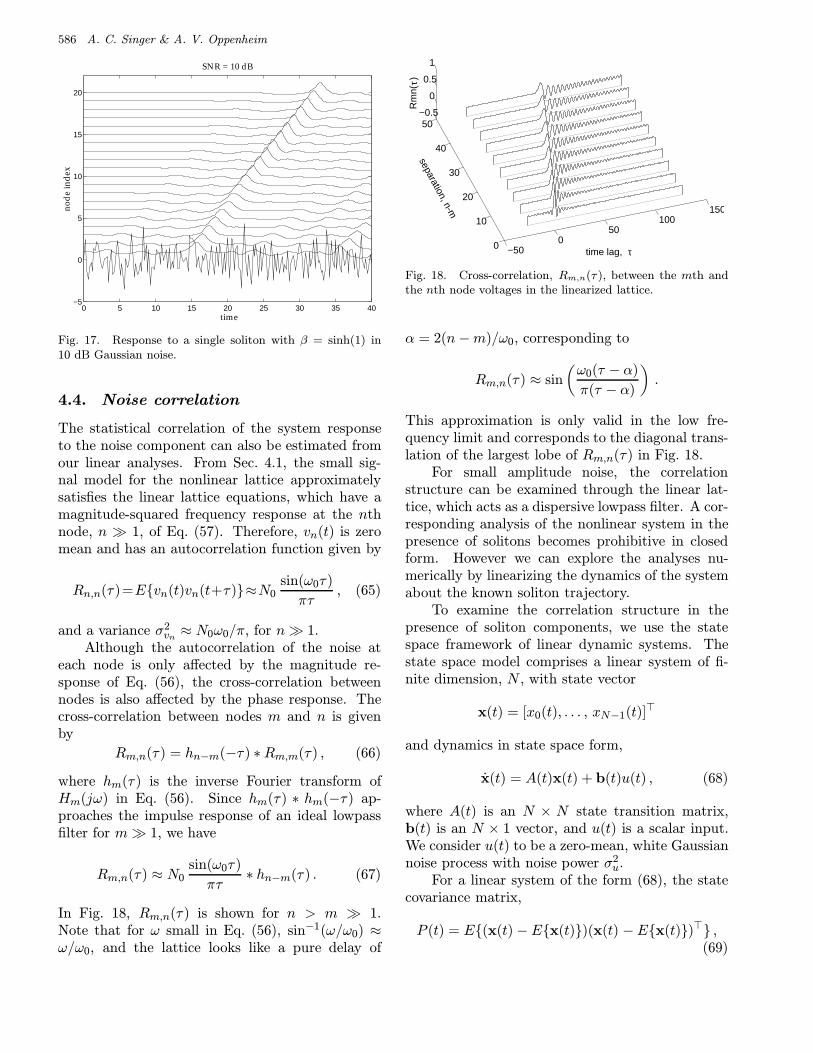
In Fig. 18, Rm,n(τ) is shown for n > m 1.Note that for ω small in Eq. (56), sin−1(ω/ω0) ≈ω/ω0, and the lattice looks like a pure delay of
−500
50100
150
0
10
20
30
40
50−0.5
0
0.5
1
time lag,
separation, n-m
Rm
n( ) τ
τ
Fig. 18. Cross-correlation, Rm,n(τ ), between the mth andthe nth node voltages in the linearized lattice.
α = 2(n−m)/ω0, corresponding to
Rm,n(τ) ≈ sin
(ω0(τ − α)
π(τ − α)
).
This approximation is only valid in the low fre-quency limit and corresponds to the diagonal trans-lation of the largest lobe of Rm,n(τ) in Fig. 18.
For small amplitude noise, the correlationstructure can be examined through the linear lat-tice, which acts as a dispersive lowpass filter. A cor-responding analysis of the nonlinear system in thepresence of solitons becomes prohibitive in closedform. However we can explore the analyses nu-merically by linearizing the dynamics of the systemabout the known soliton trajectory.
To examine the correlation structure in thepresence of soliton components, we use the statespace framework of linear dynamic systems. Thestate space model comprises a linear system of fi-nite dimension, N , with state vector
x(t) = [x0(t), . . . , xN−1(t)]>
and dynamics in state space form,
x(t) = A(t)x(t) + b(t)u(t) , (68)
where A(t) is an N × N state transition matrix,b(t) is an N × 1 vector, and u(t) is a scalar input.We consider u(t) to be a zero-mean, white Gaussiannoise process with noise power σ2
u.For a linear system of the form (68), the state
covariance matrix,
P (t) = E(x(t) −Ex(t))(x(t) −Ex(t))> ,(69)
Circuit Implementations of Soliton Systems 587
satisfies the following differential equation [Gelb,1974]
P (t) = A(t)P (t) +P (t)A(t)>+ b(t)σ2ub(t)> . (70)
To limit the number of state variables in x, we againterminate the nonlinear lattice with its linearizedimpedance. If we assume that the input to the non-linear lattice is of the form,
Vin(t) = V 00 (t) + u(t) , (71)
where u(t) is a small amplitude white Gaussiannoise process, and V 0
0 (t) corresponds to a knownsoliton input, we may linearize the dynamics aboutthe known response of the system.
By seeking a response of the nonlinear LC lad-der model of the form Vn(t) = V 0
n (t) + vn(t), andWn(t) = Vn(t) = W 0
n(t) + wn(t), where V 0n (t) and
W 0n(t) are the known responses to the input V 0
0 (t),and vn(t) and wn(t) are the responses to the smallamplitude noise component, u(t), we obtain
V 0n + vn = W 0
n + w0n , 1 ≤ n ≤ N ,
W 0n + wn =
(W 0n + wn)2
1 + V 0n + vn
+1 + V 0
n + vnLC
(Vn+1 − 2Vn + Vn−1 + vn+1 − 2vn + vn−1) ,
for 1 ≤ n < N , and
W 0N + wN =
(VN−1 − VN + vN−1 − vN
LC− WN + wN
RC
)(1 +WN + wN )
+(WN + wN )2
1 + VN + vN,
where V 00 = V 0
0 (t) and v0 = u(t). Cancelling terms that correspond to the known input and response andterms higher than first-order, we obtain
vn = w0n , 1 ≤ n ≤ N (72)
wn =
[V 0n+1 − 2V 0
n + Vn−1
LC− (W 0
n)2
(1 + V 0n )2− 2(1 + V 0
n )
LC
]vn
+1 + V 0
n
LC(vn+1 + vn−1) +
2W 0n
1 + V 0n
wn , 1 ≤ n < N
wN =
[V 0N−1 − V 0
N
LC− W 0
N
RC
]vN +
[vN−1 − vN
LC− wNRC
](1 + V 0
N ) +2W 0
N
1 + V 0N
wN .
Equations (72) can be written in the form,
[v(t)
w(t)
]= A(t)
[v(t)
w(t)
]+ b(t)u(t) , (73)
where v(t) = [v1(t), . . . , vN (t)]>, and w(t) = [w1(t), . . . , wN (t)]>.
588 A. C. Singer & A. V. Oppenheim
0
50
100
150
200
250
300
350 0
20
40
60
80
1000
1
2
x 10−6
timenode index
vari
ance
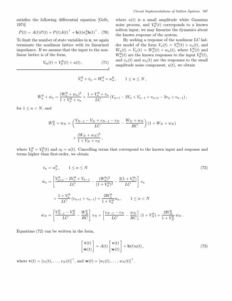
Fig. 19. The variance of each node voltage as a function oftime.
From our earlier linearized analyses, the lineartime-varying small signal model can be viewed overshort time scales as linear and time-invariant witha slowly varying parameter. The resulting input–output transfer function can be viewed as a low-pass filter with time-varying cutoff frequency equalto ω0 when a soliton is far from the node, and toω0
√1 + V 0
n as a soliton passes through. Thus, wewould expect the variance of the node voltage to risefrom a nominal value as a soliton passes through.
We numerically integrate the correspondingRiccati equation, Eq. (70), for the node covarianceand in Fig. 19, the resulting variance of the noisecomponent on each node is shown. In this example,the input to the lattice was a periodically repeatedsingle soliton with an initial SNR of 30 dB. Sincethe lattice was assumed initially at rest, there is astartup transient, as well as an initial spatial tran-sient at the beginning of the lattice, after which wesee that the variance of the noise is amplified fromthe nominal variance as each soliton passes through,confirming our earlier intuition.
4.5. Noise dynamics for the diodeladder circuit
The prior analyses developed in this section applyto the Toda lattice when the noise component ofthe signal can be considered small in comparison tothe remaining arguments of the logarithm in
d2
dt2ln
(1 +
Vn(t)
V0
)
=1
LC0V0(Vn−1(t)− 2Vn(t) + Vn+1(t)) . (74)
When Vn(t) is small as compared with V0, thenEq. (74) behaves like a linear LC ladder. However,for the diode ladder circuit which satisfies,
d2
dt2ln
(1 +
In(t)
Is
)=α
vt(In−1(t)−2In(t)+In+1(t)) ,
(75)
for a similar small signal analysis, In(t) would haveto be small in comparison to the saturation current,Is. This would either require diodes with an unusu-ally large saturation current or very small signallevels.
For a solution containing a soliton signal, In(t),and a small amplitude noise signal, in(t), an ex-act expression for the small amplitude componentis given by
d2
dt2ln
(1 +
in(t)
In(t) + Is
)=α
vt(in−1(t)− 2in(t) + in+1(t)) . (76)
The linearization that results from the assump-tion that the current in(t) is small in comparisonto the saturation current is tantamount to replac-ing the diodes with their equivalent linearized resis-tance, Req = vt/Is, which is on the order of MΩ.The resulting small signal model has a lowpass char-acteristic with a cutoff frequency of ω0 = α/Req ≈8 kHz for the range of circuit parameters used inSec. 3. Since the soliton pulse-widths consideredwere on the order of µs for mA amplitudes, thebandwidth of the small signal model is extremelynarrow in comparison to that of the soliton.
Observations of our circuit implementation ofthe diode ladder circuit seem to indicate that thisbandwidth is too narrow to explain the level ofhigher-frequency circuit noise present. This is par-tially explained by the change in the cutoff fre-quency as solitons are processed through a node.That is, over regions where the soliton componentis significant, the equivalent resistance of the diodebecomes Req = vt/In(t), which is on the order of25 Ω for a 1 mA soliton. The effect this has on thelinearized lattice is to make the lattice effectively anall-pass filter in the vicinity of propagating solitons.
As a practical matter, we note that there ap-pears to be a small amount of diode leakage cur-rent present in the circuit implementation and willexplore the effect of a small bias current on thedynamics of both the soliton components and the
Circuit Implementations of Soliton Systems 589
small amplitude perturbation. For a solution con-taining a soliton, In(t), a small amplitude compo-nent, in(t), and a small bias current, Ib, the result-ing system dynamics are
d2
dt2ln
(1 +
In + in + IbIs
)
=α
vt(In−1 − 2In + In+1 + in−1 − 2in + in+1) ,
(77)which reduces to
d2
dt2ln
(1 +
in(t) + IbIn(t) + Is
)
=α
vt(in−1(t)− 2in(t) + in+1(t)) . (78)
When the noise component in(t) is small as com-pared with Ib, and away from the peaks of the soli-ton signal, In(t) < Ib, the dynamics further reduceto
d2
dt2in(t) ≈ Ibα
vt(in−1(t)− 2in(t) + in+1(t)) , (79)
where the diodes are replaced by their linearizationabout the bias current, Req = vt/Ib, leading to anincrease in the bandwidth of the effective lowpassfilter.
In summary, due of the scaling of the diode lad-der circuit, in order for the linear analyses to hold,the noise must be small in comparison to the diodesaturation current, Is. When a soliton is present, ifthe noise is small compared with the soliton, then alinear model can hold as with the LC ladder. Whenthere is no soliton, if there is a small bias currentthat is larger than the noise, this can also lead to asimple linear model. When there is neither a biasnor a soliton present, if the noise is not small ascompared with the diode saturation current, thenthe noise satisfies the fully nonlinear system. Theresulting disturbance is better described in terms ofinverse scattering and leads to the problem of de-termining the spectrum of random linear operators,or random matrices [Singer et al.].
5. Conclusions
In this paper, we have developed a framework forexploring the generation and processing of soli-
ton signals using analog circuits. We have takenthe viewpoint of using solitons as carrier signalsfor transmission over linear, rather than nonlinearchannels. The nonlinear evolution equations canthen be viewed as specialized processors of this classof signals, which are naturally suited to perform-ing a number of complex signal processing tasks.For example, these systems can efficiently gener-ate soliton signals and can perform the nonlinearsignal separation of multisoliton carriers necessaryfor multiplexing and demultiplexing multiple usersin the soliton communications context presented in[Singer et al.].
Focusing specifically on two soliton systems,the Toda lattice and the discrete-KdV equation,we develop new electrical analogs for the generationand processing of soliton signals. Although analogcircuit models have been previously developed for avariety of nonlinear wave equations in general, andfor the Toda lattice in particular, our diode ladderimplementation is the first direct electrical analogof this soliton system. Further, this appears to bethe first circuit model of the Toda lattice whichis sufficiently accurate to demonstrate true over-taking soliton interactions over a small number ofnodes. The diode ladder circuit was implementedin hardware using standard components and pro-vides a platform for the further development andtesting of real-time soliton processing techniques.We have also developed a new circuit model for thediscrete-KdV equation; a nonlinear system whichwas largely ignored for having no prior electrical ormechanical analog. The discrete-KdV circuit pro-vides a framework for processing discrete-time soli-ton signals.
In a companion paper [Singer et al.], we showthe potential for wireless multisoliton communica-tion techniques which appear to simultaneously re-duce the transmitted signal energy and enhancecommunication performance. To assess the efficacyand the robustness of these communication tech-niques in the presence of background noise, we haveanalyzed the effects of small amplitude disturbanceson the processing of soliton signals in the Toda lat-tice and characterized the statistics of the noise asit is processed. We have shown that in a high SNRwhite Gaussian noise background, the dynamics ofsoliton signals are practically unperturbed. Also,the noise component of the received signal remainsessentially lowpass and Gaussian.
590 A. C. Singer & A. V. Oppenheim
ReferencesAblowitz, M. J. & Clarkson, A. P. [1991] Solitons, Non-
linear Evolution Equations and Inverse Scattering,London Mathematical Society Lecture Note Series149 (Cambridge University Press, Cambridge).
Ballantyne, G. J., Gough, P. T. & Taylor, D. P. [1993]“Periodic solutions of Toda lattice in loop nonlineartransmission line,” Electron. Lett. 29(7), 607–609.
Benjamin, T. B. [1972] “The stability of solitary waves,”Proc. Roy. Soc. London A328, 153–183.
Cho, Y., Wakita, J. & Miyagawa, N. [1993] “Nonlinearequivalent circuit model analysis of acoustic devicesand propagation of surface acoustic wave,” Jpn. J.Appl. Phys. 32(5B), 2261–2264.
Drazin, P. G. & Johnson, R. S. [1989] Solitons: An In-troduction, Cambridge Texts in Applied Mathematics,(Cambridge University Press, NY).
Fermi, E., Pasta, J. R. & Ulam, S. M. [1965] “Studies ofnonlinear problems,” in Collected Papers of E. Fermi,Vol. II (University of Chicago Press), pp. 977–988.
Flytzanis, N., Malomed, B. & Wattis, J. A. D. [1993]“Analysis of stability of solitons in one-dimensionallattices,” Phys. Lett. A180, 107–112.
Gelb, A. (ed.) [1974] Applied Optimal Estimation (MITPress, Cambridge, MA).
Haus, H. A. [1993] “Molding light into solitons,” IEEESpectrum, March, 48–53.
Hirota, R. & Suzuki, K. [1973] “Theoretical and experi-mental studies of lattice solitons in nonlinear lumpednetworks,” Proc. IEEE 61(10), 1483–1491.
Horowitz, P. & Hill, W. [1989] The Art of Electronics,2nd edition (Cambridge University Press, NY).
HSPICE User’s Manual [1992] (Meta Software Inc.,Campbell, CA).
Infeld, E. & Rowlands, G. [1990] Nonlinear Waves, Soli-tons and Chaos (Cambridge University Press, NY).
Islam, N., Singh, J. P. & Steiglitz, K. [1987] “Solitonphase shifts in a dissipative lattice,” J. Appl. Phys.62(2), 689–693.
Kac, M. & van Moerbeke, P. [1975a] “On an explic-itly soluble system of nonlinear differential equationsrelated to certain Toda lattices,” Adv. Math. 16,160–169.
Kac, M. & van Moerbeke, P. [1975b] “On some pe-riodic Toda lattices,” Proc. Nat. Acad. Sci. 72(4),1627–1629.
Kaiser, J. F. [1990] “On a simple algorithm to calculatethe ‘energy’ of a signal,” in Proc. Int. Conf. Acous-tic Speech, Signal Processing (Albuquerque, NM),pp. 381–384.
Kolosick, J. A., Landt, D. L., Hsuan, H. C. &Lonngren, K. E. [1974] “Properties of solitary waves asobserved on a nonlinear dispersive transmission line,”Proc. IEEE 62(5), 578–581.
Lai, Y. [1993] “Noise analysis of soliton communicationsystems — a new approach,” J. Lightwave Techn.11(3), 462–467.
Lindgren, A. G. & Buratti, R. J. [1969] “Stability ofwaveforms on active nonlinear transmission lines,”IEEE Trans. Circuit Theor. CT-16, 274–279.
Loginov, V. M. [1993] “Exact separation of an additivemixture of a determinate signal and Gaussian noiseby the use of Korteweg-de Vries solitons,” Tech. Phys.Lett. (Pis’ma Zh. Tekh. Fiz.) 19(7), 433–434.
Manakov, S. V. [1975] “Complete integrability andstochastization of discrete dynamical systems,” Sov.Phys. JETP 40(2), 269–274.
Okada, Y., Watanabe, S. & Tanaca, H. [1990] “Solitarywave in periodic nonlinear lattice,” J. Phys. Soc. Jpn.59(8), 2647–2658.
Ooyama, N. & Saito, N. [1970] “On the stability of latticesolitons,” Suppl. Progress Theoret. Phys. 45, 201–208.
Scott, A. C. [1970] Active and Nonlinear Wave Propaga-tion in Electronics (Wiley, Interscience, NY).
Scott, A. C., Chu, F. Y. F. & McLaughlin, D. [1973] “Thesoliton: A new concept in applied science,” Proc. IEEE61(10), 1443–1483.
Siebert, W. McC. [1986] Circuits, Signals, and Sys-tems, The MIT Electrical Engineering and ComputerScience Series (MIT Press and McGraw-Hill BookCompany, Cambridge MA).
Singer, A. C., Oppenheim, A. V. & Wornell, G. W.“Detection and estimation of multiplexed solitonsignals,” IEEE Trans. Signal Process., to appear.
Suzuki, K., Hirota, R. & Yoshikawa, K. [1973a] “Am-plitude modulated soliton trains and coding-decodingapplications,” Int. J. Electron. 34(6), 777–784.
Suzuki, K., Hirota, R. & Yoshikawa, K. [1973b] “Theproperties of phase modulated soliton trains,” Jpn. J.Appl. Phys. 12(3), 361–365.
Toda, M. [1981] Theory of Nonlinear Lattices, SpringerSeries in Solid-State Science 20 (Springer-Verlag,NY).
Toda, M. [1983] “Nonlinear lattice and soliton theory,”IEEE Trans. Circuits Syst. CAS-30(8), 542–554.
Toda, M. [1989] Nonlinear Waves and Solitons, Mathe-matics and Its Applications (Klewer Academic Pub-lishers, Boston).
Wadati, M. [1983] “Stochastic Korteweg-de Vriesequation,” J. Phys. Soc. Jpn. 52(8), 2642–2648.