circuit electricity 4 th form igcse textbook: parts of chapters 7,9 & 10
TRANSCRIPT

Circuit Electricity
4th form IGCSETextbook: parts of Chapters 7,9 & 10

A quick recap
• You should already know (so write down):– A definition of electric current– An equation for current in terms of charge– The symbols and units of charge and current– A definition of voltage– An equation for voltage in terms of energy– The symbols and units of voltage and energy– A definition of resistance– An equation relating resistance to current and voltage– The symbol and unit of resistance
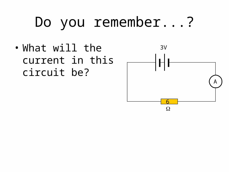
Do you remember...?
• What will the current in this circuit be?
A
6W
3V
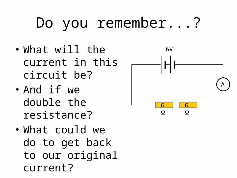
Do you remember...?
• What will the current in this circuit be?
• And if we double the resistance?
• What could we do to get back to our original current?
A
3V
6W
6W
6V

Do you remember...?
• What will the current in this circuit be?
• And if we double the resistance?
• What would happen as we adjust this variable resistor?
A
3V
RSo, in general, what can we say about the relationship between current and resistance?
R
I?

Current and Resistance
• Resistance is a measure of how much a component opposes the flow of charge through it.
• In a circuit, the higher the total resistance, the lower the current will be (for fixed applied voltage).
• If we increase the voltage we will increase the current (for a fixed circuit resistance).

Resistors to Limit Current
• A resistor can be used to limit the current that can flow through a delicate component
• For example, the circuit above ensures that the indicator lamp doesn’t experience a current high enough to melt its filament.
bulbresistor RR
VI

How Can We Investigate Resistance?
• Draw a circuit which would allow us to measure the resistance of a component.– What quantities do we
need to measure?– How will we use them?– What factors do we
need to control?
device under test

How Can We Investigate Resistance?
• • Measure V and I,
calculate R• By adjusting the
variable resistor we can change V and see how I changes– What might you expect?– It depends what the
device is...
device under test
I
VR
V
I?

Current-Voltage Graphs
• A useful way of characterising the behaviour of electronic components
• Let’s plot I-V graphs for some common components and see how to interpret them...
• Note: be careful! Sometimes the axes are swapped over. Make sure you know which is which.
V
I?

I-V Graph for a wire
• For a wire, we find:– Current is proportional to
voltage• We find the resistance by
calculating V/I for a point(s) on the line
• Proportional means I increases at the same rate as V, so R is a constant value– Also true for resistors, but not
for all components
V
I
V1
I1
I
VR
I2
V2
2
2
1
1
I
V
I
VR
Flash simulation

Ohm’s Law• Metals and resistors usually obey Ohm’s Law:
• Not generally true, note the bold type• Take care if a high current leads to heating:
“The current through a conductor is proportional to the voltage across it, provided
the temperature remains constant”
V
I
No longer obeys Ohm’s Law

Non-Ohmic Conductors
• Lots of components don’t follow Ohm’s Law
• e.g. Filament bulb– The filament is
designed to get hot and glow
– Its resistance increases with temperature
Same behaviour for reversed current

Diodes
• A “one way valve” for electricity.
• Low resistance to +V (after a small threshold ~0.6V)
• High resistance to –V (up to a maximum voltage)
• Can be light-emitting when conducting (LED)
0.6V

Light dependent resistor
• A semiconductor device• Resistance decreases as more light falls on it– (Extra energy releases more charge carriers)
Flash simulation

Thermistor
• A semiconductor device• Resistance decreases as it gets hotter• (Extra energy releases more charge carriers)
Flash simulation

What does this circuit do?
• ...in terms of energy?• So how much energy is
converted?– What factors will this depend on?
• Can we work out a formula for the energy converted in an electric circuit?

Electrical Energy
• Remember• So• But how can we measure Q?• Remember , so• So the energy transferred in an
electric circuit is given by:
V
I
Q
EV
VQE
t
QI ItQ
VItE Joules Volts Amps seconds We pay for the energy we use

Electrical Power
• Do you remember the relationship between energy and power?
• Power is the rate of transfer of energy – i.e. energy transferred per second
VIt
ItVP
power current voltage
Units of power: Watts (W)
Appliances which heat (e.g. kettle) use more power than most others (e.g. radio)
t
EP

Students will be assessed on their ability to:
2.1 use the following units: ampere (A), coulomb (C), joule (J), ohm (Ω), second (s), volt (V), watt (W).
2.6 recall and use the relationship: power = current × voltage (P = I × V) and apply the relationship to the selection of appropriate fuses
2.7 use the relationship between energy transferred, current, voltage and time: energy transferred = current × voltage × time (E = I × V × t)
2.10 understand that the current in a series circuit depends on the applied voltage and the number and nature of other components
2.11 describe how current varies with voltage in wires, resistors, metal filament lamps and diodes, and how this can be investigated experimentally
2.12 describe the qualitative effect of changing resistance on the current in a circuit
2.13 describe the qualitative variation of resistance of LDRs with illumination and of thermistors with temperature